

Federal Court of Australia
OrthAlign, Inc v Navbit Pty Ltd [2026] FCA 1542
File number: | VID 678 of 2022 |
Judgment of: | O'BRYAN J |
Date of judgment: | 20 October 2026 |
Catchwords: | PATENTS – innovation patent for a hip navigation system comprising an impactor adapter and an inertial navigation device – claim construction – infringement – validity PATENTS – infringement – whether respondent’s device has a clamp comprising a first clamp member and a second clamp member opposite the first clamp member – whether respondent’s device has a channel between the clamp members comprising a round inner surface configured to receive a round outer surface of the impactor – whether respondent’s device has an actuator knob – whether respondent’s device has an elongate post configured to receive a component of the inertial navigation device – no infringement found PATENTS – validity – whether the claims are supported by matter disclosed in the specification within s 40(3) of the Patents Act 1990 (Cth) – whether the complete specification discloses the invention in a manner which is clear enough and complete enough for it to be performed by a person skilled in the relevant art within s 40(2)(a) of the Patents Act 1990 (Cth) – whether the invention, so far as claimed in any claim, is useful within the meaning of section 18(1A)(c) of the Patents Act 1990 (Cth) – whether the invention, so far as claimed in any claim, involves an innovative step within the meaning of section 18(1A)(b)(ii) of Patents Act 1990 (Cth) – grounds of invalidity dismissed |
Legislation: | Evidence Act 1995 (Cth) s 79 Intellectual Property Laws Amendment (Raising the Bar) Act 2012 (Cth) Patents Act 1990 (Cth) ss 7, 7A, 18(1A)(b)(ii), 18(1A)(c), 40(2)(a), 40(3), 43, 79B, 114, 122(1A) Federal Court Rules 2011 (Cth) r 30.01 |
Cases cited: | Actavis UK Ltd & Ors v Eli Lilly & Co [2017] UKSC 48; Aktiebolaget Hassle v Alphapharm Pty Ltd (2002) 212 CLR 411 AstraZeneca AB v Apotex Pty Ltd (2015) 257 CLR 356; Australian Mud Company v Coretell Pty Ltd [2011] FCAFC 121; 93 IPR 188 Avel Pty Ltd v Multicoin Amusements Pty Ltd (1990) 171 CLR 88 C Van der Lely NV v Bamfords Ltd [1963] RPC 61 Calix Ltd v Grenof Pty Ltd [2023] FCA 378; 171 IPR 582 Catnic Components Ltd v Hill & Smith Ltd [1982] RPC 183 Clark v Adie (1877) LR 2 App Cas 315 Cytec Industries Inc v Nalco Company [2021] FCA 970; 162 IPR 202 Dura-Post (Australia) Pty Ltd v Delnorth Pty Ltd (2009) 177 FCR 239 Elconnex Pty Ltd v Gerard Industries Pty Ltd (1991) 32 FCR 491 Erickson's Patent (1923) 40 RPC 477 Esco Corporation v Ronneby Road Pty Ltd [2018] FCAFC 46; 131 IPR 1 Flexible Steel Lacing Co v Beltreco Ltd [2001] FCA 890; 49 IPR 331 Fresenius Medical Care Australia Pty Ltd v Gambro Pty Ltd [2005] FCAFC 220; 67 IPR 230 General Tire & Rubber Co v Firestone Tyre & Rubber Co Ltd [1972] RPC 457 GlaxoSmithKline Australia Pty Ltd v Reckitt Benckiser Healthcare (UK) Ltd [2016] FCAFC 90; 120 IPR 406 GlaxoSmithKline Consumer Healthcare Investments (Ireland) (No 2) Limited v Generic Partners Pty Limited (2018) 264 FCR 474 Globaltech Corporation Pty Ltd v Australian Mud Company Pty Ltd [2019] FCAFC 162; 145 IPR 39 Insta Image Pty Ltd v KD Kanopy Australasia Pty Ltd (2008) 239 FCR 117 Interlego AG v Toltoys Pty Ltd (1973) 130 CLR 461; Jupiters Ltd v Neurizon Pty Ltd [2005] FCAFC 90; 65 IPR 86 Jusand Nominees Pty Ltd v Rattlejack Innovations Pty Ltd [2022] FCA 540; 167 IPR 1 Jusand Nominees Pty Ltd v Rattlejack Innovations Pty Ltd (2023) 300 FCR 408 KD Kanopy Australasia Pty Ltd v Insta Image Pty Ltd [2007] FCA 481; 71 IPR 615 Kimberly-Clark Australia Pty Ltd v Arico Trading International Pty Ltd (2001) 207 CLR 1 Kimberly-Clark Australia Pty Ltd v Multigate Medical Products Pty Ltd [2011] FCAFC 86; 92 IPR 21 Kirin-Amgen Inc v Hoechst Marion Roussel Ltd [2004] UKHL 46; 64 IPR 444 Leonardis v Sartas No 1 Pty Ltd (1996) 67 FCR 126 Martin v Scribal Proprietary Limited (1954) 92 CLR 17 Meat and Livestock Australia Ltd v Cargill, Inc [2018] FCA 51; 354 ALR 95 Mentor Corp v Hollister Inc (No 2) [1991] FSR 557; Merck Sharp & Dohme Corp v Wyeth LLC (No 3) [2020] FCA 1477; 155 IPR 1 Minnesota Mining & Manufacturing Co v Tyco Electronics Pty Ltd [2002] FCAFC 315; 56 IPR 248 Minnesota Mining & Manufacturing Company v Tyco Electronics Pty Limited [2001] FCA 1359; 53 IPR 32 Nicaro Holdings Pty Ltd v Martin Engineering Co [1990] FCA 37; 16 IPR 545 Novartis AG v Johnson & Johnson Medical Ltd (t/as Johnson & Johnson Vision Care) [2011] ECC 10 Novartis AG v Pharmacor Pty Ltd (No 3) [2024] FCA 1307; 186 IPR 24 Olin Corporation v Super Cartridge Co Pty Ltd (1977) 180 CLR 236 Otsuka Pharmaceutical Co Ltd v Generic Health Pty Ltd (No 2) [2016] FCAFC 111; 120 IPR 431 Pfizer Overseas Pharmaceuticals v Eli Lilly & Co [2005] FCAFC 224; 225 ALR 416 Populin v HB Nominees Pty Ltd (1982) 41 ALR 471 Rakman International Pty Ltd v Trafalgar Group Pty Ltd [2022] FCA 464; 166 IPR 264 Realestate.com.au Pty Ltd v Hardingham (2022) 277 CLR 115 Rehm Pty Ltd v Websters Security Systems (International) Pty Ltd [1988] FCA 232; 11 IPR 289 Rodi & Wienenberger AG v Henry Showell Ltd [1969] RPC 367 Root Quality Pty Ltd v Root Control Technologies Pty Ltd [2000] FCA 980; 177 ALR 231 Sachtler GmbH & Co KG v RE Miller Pty Ltd [2005] FCA 788; 221 ALR 373 Schering Biotech Corp's Application [1993] RPC 249 ToolGen Incorporated v Fisher (No 2) [2023] FCA 794 Vax Appliances Limited v Hoover [1991] FSR 307 Walker v Alemite Corporation (1933) 49 CLR 643 Welch Perrin & Co Pty Ltd v Worrel (1961) 106 CLR 588 Yamazaki Mazak Corporation v Interact Machine Tools (NSW) Pty Ltd [1991] FCA 572; 22 IPR 79 |
Division: | General Division |
Registry: | Victoria |
National Practice Area: | Intellectual Property |
Sub-area: | Patents and associated Statutes |
Number of paragraphs: | 313 |
Date of hearing: | 7, 8 and 10 April 2025 |
Counsel for the Applicant and Cross-Respondent: | T Cordiner KC and M Fleming |
Solicitors for the Applicant and Cross-Respondent: | Phillips Ormonde Fitzpatrick Lawyers |
Counsel for the Respondent and Cross-Claimant: | C Dimitriadis SC and C Cunliffe |
Solicitors for the Respondent and Cross-Claimant: | Maddocks Lawyers |
ORDERS
VID 678 of 2022 | ||
| ||
BETWEEN: | ORTHALIGN, INC. Applicant | |
AND: | NAVBIT PTY LTD Respondent | |
AND BETWEEN: | NAVBIT PTY LTD Cross-Claimant | |
AND: | ORTHALIGN, INC. Cross-Respondent | |
order made by: | O'BRYAN J |
DATE OF ORDER: | 20 October 2026 |
THE COURT ORDERS THAT:
1. The Applicant’s originating application dated 16 November 2022 be dismissed.
2. The Cross-Claimant’s notice of cross-claim dated 6 March 2023 be dismissed.
3. Within 14 days of the date of these orders, the Respondent/Cross-Claimant file a written submission in respect of the costs of the proceeding (both the claim and cross-claim) limited to 4 pages, together with any necessary affidavit evidence in support.
4. Within 28 days of the date of these orders, the Applicant/Cross-Respondent file a written submission in respect of the costs of the proceeding (both the claim and cross-claim) limited to 4 pages, together with any necessary affidavit evidence in support.
5. Within 35 days of the date of these orders, the Respondent/Cross-Claimant file a written submission in reply limited to 2 pages.
6. The question of costs will be determined on the papers unless a party indicates in its written submissions that it seeks an oral hearing.
Note: Entry of orders is dealt with in Rule 39.32 of the Federal Court Rules 2011.
REASONS FOR JUDGMENT
O’BRYAN J:
A. Introduction
1 The applicant, OrthAlign Inc, is the registered owner of Australian Innovation Patent No. 2022100061 B4 titled “Hip Replacement Navigation Systems and Methods” granted under the Patents Act 1990 (Cth) (Act) on 11 May 2022 (the Patent). OrthAlign claims that the Patent has an effective patent date of 13 March 2018.
2 The technical field of the invention is stated in the specification (at [0002]) as directed to the field of hip replacement, and particularly to surgical tools and methods for establishing a reference plane. The formal medical term for a hip replacement is hip arthroplasty. In referring to hip replacement surgery, the parties generally used the expression total hip arthroplasty (abbreviated to THA), and that abbreviation is used on occasions in these reasons.
3 The specification states by way of background (at [0003] and [0004]) that one persistent issue with hip replacement surgery is poor placement of the cup and ball components of the prosthetic hip joint. The cup is optimally placed in specific abduction and anteversion orientations. While an acceptable window of deviation from the optimal abduction and anteversion angles has been observed in clinical practice, for several reasons an unacceptably high percentage of patients have the cup of the artificial hip joint out of this window. Misalignment can lead to dislocation of the hip as soon as within one year of the implantation procedure.
4 The Patent is a very lengthy document comprising 103 pages of description and 89 diagrams. These address numerous features of a “hip joint navigation system” and methods of using the same; that is, a system and methods for assisting with the proper alignment of artificial hip components during hip replacement surgery. The five claims of the Patent are, however, much narrower. Claim 1 describes a hip joint navigation system comprising two components: an ‘impactor adapter’ wherein one end of the impactor adapter couples with an impactor using a clamp and the second end couples with an inertial navigation device; and an inertial navigation device configured to couple with the coupler at the second end of the impactor adapter wherein the inertial navigation device is configured to determine cup angles. The use of an impactor, guided by an inertial navigation device which is coupled to the impactor, during hip replacement surgery is described below.
5 OrthAlign alleges that, from a date unknown to it but after 13 March 2018 and without its licence or authority, the respondent, Navbit Pty Ltd, has offered for sale, sold and supplied, and kept for the purpose of offering for sale, selling or supplying, a hip joint navigation system referred to by the name Navbit Sprint. OrthAlign further alleges that the Navbit Sprint is a hip joint navigation system having each of the features of claims 1 to 5 of the Patent and, as a consequence, Navbit has infringed claims 1 to 5 of the Patent. OrthAlign seeks a range of remedies including a declaration of infringement, injunctive relief, orders for the delivery up or destruction of infringing articles, damages or an account of profits and additional damages pursuant to s 122(1A) of the Act.
6 By its defence, Navbit admits that, from a date after 13 March 2018 and without the licence or authority of OrthAlign, it has offered for sale, sold and supplied, and kept for the purpose of offering for sale, selling or supplying, a hip joint navigation system referred to by the name Navbit Sprint. It denies, however, that it has infringed any of claims 1 to 5 of the Patent. It contends that the Navbit Sprint does not embody a number of the essential integers of claims 1 to 5.
7 Prior to trial, the parties provided the following list of issues for determination concerning construction and infringement:
1. The construction of the term “comprise” as it is used in the claims.
2. The construction of the term “clamp” as it is used in claim 1.
3. The construction of the terms “first clamp member” and “second clamp member opposite the first clamp member” as they are used in claim 1.
4. The construction of the term “channel” as it is used in claim 1.
5. The construction of the phrase “a round inner surface configured to receive a round outer surface of the impactor” as it is used in claim 1.
6. The construction of the term “knob” as it is used in claim 1.
7. The construction of the term “rod” as it is used in claim 1.
8. The construction of the term "inertial navigation device” as it is used in claim 1.
9. The construction of the term “slot” as it is used in claim 2.
10. The construction of the terms “elongate post” and “wherein the elongate post is configured to receive a component of the inertial navigation device” as it is used in claim 3.
11. Whether the Navbit Sprint has a clamp which comprises a first clamp member and a second clamp member opposite the first clamp member as defined in claim 1.
12. Whether the Navbit Sprint has a channel disposed between the first clamp member and the second clamp member, the channel comprising a round inner surface configured to receive a round outer surface of the impactor as defined in claim 1.
13. Whether the Navbit Sprint has an actuator knob and a rod disposed between the first end and the second end of the impactor adapter as defined in claim 1.
14. Whether the Navbit Sprint has a coupler comprising a slot configured to lock with a component of the inertial navigation device to rigidly couple the inertial navigation device with the coupler as defined in claim 2.
15. Whether the Navbit Sprint has a coupler comprising an elongate post disposed opposite the clamp as defined in claim 3.
8 At trial, Navbit did not press infringement issue 14, and it is unnecessary to determine that issue and the associated construction issues 7, 8 and 9. Accordingly, there are seven construction issues (being issues 1 to 6 and 10) and four infringement issues (being issues 11, 12, 13 and 15) to be determined.
9 By notice of cross-claim, Navbit seeks a declaration that each of claims 1 to 5 of the Patent are invalid and an order for the revocation of claims 1 to 5. The grounds of invalidity were pleaded in the statement of cross-claim. At trial, Navbit did not press its allegations concerning the priority date, lack of novelty and lack of clarity. Navbit maintained the following grounds of invalidity:
(a) the specification of the Patent does not comply with s 40(3) of the Act in that each of claims 1 to 5 is not supported by matter disclosed in the specification (lack of support);
(b) the specification of the Patent does not comply with s 40(2)(a) of the Act in that it does not disclose the invention in a manner which is clear enough and complete enough for it to be performed by a person skilled in the relevant art (lack of enablement);
(c) the invention claimed in each of claims 1 to 5 of the Patent is not a patentable invention within the meaning of section 18(1A)(c) of the Act in that the claimed invention is not useful - the Patent includes the promise that the impactor adapter is a “universal impactor adapter” and that promise is not met (lack of utility); and
(d) the invention claimed in each of claims 1 to 5 of the Patent is not a patentable invention within the meaning of section 18(1A)(b)(ii) of the Act in that the claims lack an innovative step when compared with two prior patent specifications, being WO2015054745A1 (WO 745) and WO2014063181A1 (WO 181) (lack of innovative step).
10 Prior to trial, the parties provided a list of issues for determination concerning validity. However, the grounds of invalidity ultimately pressed by Navbit at trial comprised only a subset of those issues. The relevant issues were ultimately defined by Navbit’s closing submissions at trial. As discussed below, the lack of innovative step ground of invalidity fell away in closing submissions.
11 Pursuant to r 30.01 of the Federal Court Rules 2011 (Cth), an order was made that all issues relating to liability for infringement (including validity) of the Patent (including the entitlement of the applicant to declaratory or injunctive relief) be determined prior to and separately from any issues of election and quantification of pecuniary relief (including any entitlement to and quantum of additional damages).
12 For the reasons set out below, I have concluded that OrthAlign’s claim for infringement of the Patent fails, and Navbit’s cross-claim alleging invalidity of the Patent also fails.
B. The Witnesses
13 At trial, each of the parties called a single expert witness. The parties elected not to take threshold objections in relation to the admissibility of the expert evidence, but each party advanced submissions as to the weight to be given to the evidence.
Brent Mittelstadt
14 OrthAlign called Brent Mittelstadt to give evidence. Mr Mittelstadt described his occupation as an independent Medical Device Consultant.
15 Mr Mittelstadt completed a Bachelor of Science, General Biology, at the University of Arizona in 1984. Between 1984 and 1990, Mr Mittelstadt was a Ph.D. candidate in Biomedical Engineering at the University of California - Davis (UCD), but did not ultimately take out that degree. In the same period, Mr Mittelstadt was first (from June 1986 to June 1987) a Visiting Research Scientist at IBM Thomas J. Watson Research Center in New York, completing a feasibility study for the use of robotics in human total hip replacement surgery, and second (between 1987 and 1990) a Post Graduate Research Associate at the UCD Orthopaedic Research Lab, completing the design, development and testing of a laboratory prototype surgical robotic system for hip replacement surgery. Prior to the completion of his Ph.D, Mr Mittelstadt left UCD to co-found Integrated Surgical Systems Inc. (ISS) and commercialise the orthopaedic robotic system that he and others had developed while at UCD.
16 Between 1990 and 2002, Mr Mittelstadt was the Technical Lead, Surgical Applications for ISS. He managed and led the development of surgical application related projects (hardware and software). Mr Mittelstadt deposed that, in 1992, the ISS technology was first used to complete a robotic orthopaedic hip replacement surgery in the USA and, in 1994, it was first used to complete a robotic THA procedure in Germany.
17 Mr Mittelstadt deposed that, during his time with ISS, he was responsible for managing the design of application specific THA mechanical components including bone stabilization systems, bone cutting systems, bone reference systems, surgical drapes, bone motion detection systems and the robot base. He also managed the Implant Support Development team which developed the process for releasing the software/hardware and test methods to support THA implants from third party manufacturers. Mr Mittelstadt deposed that he worked closely with surgeons and software developers to define, implement and verify the software for the pre-operative planning and intra-operative robotic surgical workflow.
18 ISS ceased operations in 2002 and its assets, including its intellectual property, were eventually sold to Curexo Technology Corporation (Curexo).
19 From 2003 to 2009, Mr Mittelstadt was a Director of Marketing at Consensus Orthopedics Inc. He was initially employed at Consensus as a technical consultant working in product development and then became part of a senior management team.
20 Between 2009 and 2011, Mr Mittelstadt was President and CEO of Curexo.
21 From 2012 to 2013, Mr Mittelstadt worked privately as a Medical Device Consultant for a number of small orthopaedic/technology development companies.
22 In 2013, Mr Mittelstadt was employed as a Medical Device Consultant by the Incubation of Medical Technology division of Stryker to provide technical guidance and input for an image guided robotic platform for total joint replacement surgery. During this time, Mr Mittelstadt was tasked with defining concepts and functionality for a significantly improved THA product.
23 In 2016, Mr Mittelstadt became Chief Engineer, Robotic Platforms for Stryker/MAKO Surgical Corp. He was a lead system designer for the next generation robotic platform as part of a team that included lead system designers for, amongst other procedures, THA.
24 Over the course of his career, Mr Mittelstadt has been an author on a number of publications and presentations relating to surgical robotic systems, particularly for use in THA. He is also named as an inventor on a number of patents and patent applications relating to that field of technology.
25 Mr Mittelstadt affirmed three affidavits, each of which was read at the trial, dated 15 November 2023 (first Mittelstadt affidavit), 20 June 2024 (second Mittelstadt affidavit), and 15 August 2024 (third Mittelstadt affidavit).
26 Mr Mittelstadt gave oral testimony and was cross-examined concurrently with Mr Hunter.
William Hunter
27 Navbit called William Hunter to give evidence. Mr Hunter described his occupation as a mechanical design engineer.
28 Mr Hunter obtained a Bachelor of Engineering Science (Mechanical) with first class honours from the University of Melbourne in 1982, and a Master of Engineering Science (Mechanical) from the University of Melbourne in 1985. He is a Member of the Institution of Engineers Australia (MIEAust).
29 Throughout his career, Mr Hunter has worked as an engineer in a range of industries including within the medical, pharmaceutical and biotechnology sectors. Since 2007, Mr Hunter has worked as a contract project management and development engineer within the fields of in-vitro diagnostics and medical device development. Between 2004 and 2007, Mr Hunter was the Senior Consultant in Instrument Design and Development at Invetech Pty Ltd, one of the world’s leading contract instrument development firms.
30 Mr Hunter affirmed three affidavits in the proceeding, each of which was read at the trial, dated 26 March 2024 (first Hunter affidavit), 21 June 2024 (second Hunter affidavit), and 22 August 2024 (third Hunter affidavit).
31 Mr Hunter gave oral testimony and was cross-examined concurrently with Mr Mittelstadt.
Joint expert report
32 In accordance with the orders of the Court, the parties prepared a protocol for the conduct of a conference between the experts prior to trial, including a list of questions for the experts to consider during the conferral. In accordance with the protocol, Mr Mittelstadt and Mr Hunter conferred prior to trial and prepared a joint expert report dated 19 November 2024 (the joint report) addressing the questions framed by the parties. The joint expert report was tendered at the hearing.
Assessment of the experts
33 In my view, both expert witnesses gave considered answers to the questions they were asked, and I formed the impression that their answers reflected the opinions held by each of them.
34 Each of the parties advanced submissions to the effect that their respective expert was better qualified to express an opinion on the issues arising in the proceeding. There is no doubt that the expertise and experience of the experts differ, and this must be borne in mind when evaluating their opinions.
35 Mr Hunter has considerable experience as an engineer, including in the development of medical devices of various kinds and in the mechanical engineering role in that process. However, as submitted by OrthAlign, Mr Hunter has no specialised knowledge or experience in relation to hip replacement surgery, including the surgical tools and methods used in such procedures. Mr Hunter confirmed during cross-examination that, prior to his engagement in this proceeding: he had no prior knowledge of THA procedures; he had never seen a THA performed in person; he had not previously designed a surgical component or system for use in THA; and he had no prior knowledge of the types or kinds of impactors used in THA. Mr Hunter stated that, for the purposes of the proceeding, he had conducted searches on the internet to acquaint himself with the THA procedure and the devices used in it, and that the extent of his knowledge in relation to THA is what he learned from that research. Prior to his engagement in this matter, he was not aware of the impact forces involved in THA procedures.
36 In his first affidavit, Mr Hunter exhibited two papers concerning impact forces in THA procedures, being:
(a) a paper titled ‘Impact Biomechanics and Pelvic Deformation During Insertion of Press-Fit Acetabular Cups’ by Markus Kroeber, MD et al and published in the Journal of Arthroplasty in 2002; and
(b) a paper titled ‘Experimental analysis of insertion torques and forces of threaded and press-fit acetabular cups by means of ex vivo and in vivo measurements’ by Danny Vogel et al and published in the Acta of Bioengineering and Biomechanics in 2016.
37 Mr Hunter confirmed during cross-examination that, to the extent that he relied upon those articles as informing his views in relation to such forces, his evidence was based on an assumption that the information in those articles was ‘up to date’ as at the priority date of the Patent. However, he had not spoken to any surgeons about whether the papers were up to date.
38 Mr Hunter also confirmed during cross-examination that he had not spoken to any surgeons about the process of THA and what information on the navigation device they need and at what times. Mr Hunter was not aware whether a surgeon might remove the navigation device from the impactor from time to time between impactions. Mr Hunter had not spoken to any surgeons about whether there would be a major concern about the adapter moving, either axially or rotationally, around the impactor.
39 Having regard to the foregoing, OrthAlign submitted that the Court should give little or no weight to opinions expressed by Mr Hunter in relation to matters concerning the field of hip replacement procedures, and the surgical methods and tools used in such procedures, given those opinions are not based on any relevant “training, study or experience” (as required by s 79 of the Evidence Act 1995 (Cth)). I accept that submission, whilst noting that many aspects of the evidence given by Mr Hunter with respect to hip replacement surgery did not appear to be disputed by Mr Mittelstadt or OrthAlign.
40 In contrast to Mr Hunter, Mr Mittelstadt has considerable specialised experience in relation to hip replacement surgery, including the surgical tools and methods used in such procedures. However, I consider that Mr Mittelstadt has less direct expertise and experience in mechanical engineering. It is apparent from his evidence that Mr Mittelstadt has experience in managing the design of components for use in hip arthroplasty, in marketing and regulatory/quality assurance, and in designing concepts and functionality for total hip arthroplasty. However, Mr Mittelstadt acknowledged in the joint expert report that he does not have any experience as a mechanical engineer or as a sensor or software engineer. Overall, it is apparent that a large part of Mr Mittelstadt’s experience has been gained in management roles, supervising relevant teams of specialists including mechanical engineers. In cross-examination, Mr Mittelstadt acknowledged that, in contrast to Mr Hunter, he did not claim to have expertise in mechanical engineering:
I’ve done a lot of mechanical design work, and I have some education towards that, and I have been responsible for designing and actually manufacturing things, early on, when I was in graduate school. So the – the thing that I would say is that I would always prefer to work with somebody like Mr Hunter, who – that’s their expertise, and so – and that’s what I have done. You know, so, typically, electrical engineering, software, and mechanical are, kind of, three of the disciplines that I’ve worked the most with, and I’ve managed teams working on those parts of things, but I wouldn’t claim to have expertise.
41 Having regard to the foregoing, Navbit submitted that Mr Hunter’s evidence should be preferred to the evidence of Mr Mittelstadt on matters of mechanical engineering, such as the degree of contact required to effect clamping of the impactor adapter to the impactor. Contrary to Navbit’s submission, I am not persuaded that Mr Hunter’s evidence concerning matters of mechanical engineering should be generally preferred to that of Mr Mittelstadt. I have, however, approached the evidence of the experts with an acceptance that Mr Hunter has deeper expertise and experience on such matters.
C. Technical background
42 Each of Mr Mittelstadt and Mr Hunter gave evidence with respect to hip replacement surgery. The evidence is necessary technical background to construing the claims of the Patent. The following distillation of that evidence is largely drawn from Mr Mittelstadt’s evidence, as I have found that he has greater expertise with respect to hip replacement surgery. However, Mr Hunter’s evidence on this topic, which was the subject of research undertaken by Mr Hunter for the purposes of the proceeding, did not differ materially from Mr Mittelstadt’s evidence.
43 THA is a surgical procedure in which a damaged or deteriorated hip joint is replaced with an artificial prosthetic joint. THA is commonly performed to overcome the effects of osteoarthritis caused by the degeneration of cartilage in the hip joint.
44 The human hip joint is a ball-and-socket joint in which a rounded head of the femur fits into a socket of the pelvic bone known as the acetabulum. Cartilage provides protection in joints such as the hip where bones engage and allows the joint to move smoothly and freely. The cartilage in a joint like the hip can become damaged over time, by conditions like osteoarthritis, rheumatoid arthritis or as a result of traumatic injury, leading to direct bone contact within the joint and a reduction of movement and pain, particularly when weight bearing. THA is performed with the goal of relieving pain and improving the function of the hip joint.
45 Broadly, THA involves the removal of damaged cartilage and bone within the affected hip joint and the insertion of a new socket referred to as an acetabular cup and usually a new femoral head.
46 On the pelvic bone side of the joint, THA involves reaming to both remove the damaged tissue and create an appropriately sized socket for insertion of the new acetabular cup. The acetabular cup will typically consist of a metal shell which can be fitted with a plastic liner.
47 On the femoral side of the joint, THA involves removal of the entire femoral head and the creation of a central canal within the femur for receiving a stem of the femoral component which supports a ball joint for insertion into the acetabular cup.
48 Two of the key factors in successful THA are the proper fixation of the acetabular cup and femoral stem to the pelvic bone and femur respectively and the proper relative positioning of those two components of the prosthetic joint.
49 With respect to the proper alignment of the acetabular cup and the femoral stem, incorrect positioning of these components during THA can lead to hip dislocation requiring the surgery to be repeated. The main issue with positioning of the femoral component is achieving the correct leg length. It is common for patients requiring THA to have different leg lengths or to have a leg length which has changed over time. Achieving correct leg length as part of THA is important for ensuring stability and balance, reducing pain and improving overall function of the joint and movement of the patient. Correct alignment of the acetabular cup is also very important in THA. As with leg length, proper alignment of the acetabular cup promotes stability and balance, reduction of pain and improvement of the overall function of the joint. It is also an important factor in the longevity of the prosthesis as improper alignment can lead to excessive wear which can ultimately lead to a need for revision surgery.
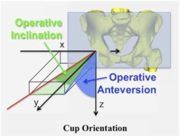
50 After reaming of damaged tissue in the pelvic bone to expose healthy solid bone, the surgeon then needs to position the acetabular cup within the newly exposed socket. This is achieved by connecting the acetabular cup to an impactor which is then physically impacted by the surgeon using a hammer. Prior to impacting the acetabular cup, the surgeon orients the impactor with respect to the pelvic bone to provide the correct angular placement. The correct orientation of the acetabular cup with respect to the pelvic bone involves two degrees of freedom referred to as inclination and version (or anteversion) as illustrated in the following diagram:
51 Historically, correct location of the acetabular cup relied upon careful placement and alignment of the patient on the operating table and the skill and experience of the surgeon to make a visual assessment of the inclination and version of the impactor prior to impaction. For THA, the patient is placed in either a supine or lateral position. In the supine position, the patient is placed on their back. In the lateral position, the patient is placed on their side. On the understanding that the patient has been correctly placed on either their back or side and that they are aligned with the centreline of the operating table, the surgeon relies upon their training to visually assess whether the angle of the impactor carrying the acetabular cup is at the correct inclination and version for proper cup orientation. Post-operative radiographic assessment of the inclination and version of the acetabular cup is used to confirm that placement is within a “safe-zone” which typically requires it to be no more than 10 degrees from the target angles.
52 Mr Mittelstadt stated that he is aware that mechanical alignment guides have been developed for the purpose of assisting a surgeon in visually confirming the alignment of the impactor, and hence the attached acetabular cup, at the correct angles of inclination and version. Mr Mittelstadt stated that he is also aware of and has himself been involved in the development of image-based navigation for use in THA.
53 The procedure for image-based navigation typically begins with imaging of the patient, often by CT scan, to evaluate the patient’s hip anatomy and to create a 3D model of that anatomy. The 3D model can then be used to plan the THA including implant size, positioning and alignment.
54 When performing THA using image-based navigation it is necessary to register the anatomy of the patient as positioned on the operating table with the pre-operative 3D model used to plan the surgery. The registration process and also subsequent tracking of the position of, for example the impactor, relies on 3D positional sensors. A common way of providing such sensors involves the use of an optical system with cameras positioned in the operating theatre and infrared light emitters which act as trackers and which can be attached to the various locations to be tracked.
55 The registration process can involve the use of pre-operatively placed fiducial markers in the form of metallic pins secured to the patient’s pelvic bone which can be seen in the pre-operative imaging and form part of the 3D model of the patient’s anatomy. A probe having a light emitting tracker at its tip can be brought into contact with a defined location on the fiducial markers to determine the location of the marker within the 3D space of the operating theatre. The known position of the markers relative to the patient’s anatomy can thereby be mapped to the 3D space of the operating theatre as defined by the optical tracking system.
56 As an alternative to the above, patient registration can occur without fiducial markers by using a probe as described above to record the position of known anatomical markers on the patient’s pelvic bone.
57 With the 3D model of the patient’s anatomy registered to the 3D space of the operating theatre, the navigation system can then be used to track the position of surgical tools such as the impactor relative to the 3D model of the patient’s anatomy through the use of light emitting trackers attached to the tool. This enables the navigation system to provide feedback to the surgeon as to whether the tool, for example the impactor, is in the correct position and alignment relative to the pre-planned position and alignment.
58 In the navigation system, the position of the acetabular cup, attached to one end of the impactor, is determined by reference to the position of a tracker attached to the impactor. Accordingly, another important aspect of the registration process is ensuring the correct attachment and registration of both the cup and the tracker on the impactor. It is also important that the tracker be attached in a way which means the relative position of the cup and tracker does not change during the procedure.
59 The stability of that attachment mechanism is also important. Impaction of the acetabular cup involves the surgeon striking the impactor with substantial force. Instability in the connection between the tracker and impactor could result in change to the relative position of the acetabular cup and tracker and incorrect placement of the cup.
60 During his oral evidence, Mr Mittelstadt explained that most impactors have a cylindrical portion that is parallel with the axis of the impaction or the axis of the acetabular cup.
D. The Patent
Details of the Patent
61 The Patent is an innovation patent titled “Hip Replacement Navigation Systems and Methods” and was granted on 11 May 2022. It is a divisional application under s 79B of the Act from Australian Patent Application No 2018236220, filed 13 March 2018, and claims a priority date of 14 March 2017 from US Convention application US62/471,185 (US185). The Patent expires on 13 March 2026.
The specification
62 As stated earlier, the technical field of the invention is stated (at [0002]) as directed to the field of hip replacement, and particularly to surgical tools and methods for establishing a reference plane. By way of background, the specification states (at [0003] and [0004]), that one persistent issue with hip replacement surgery is poor placement of the cup and ball components of the prosthetic hip joint. The cup is optimally placed in a specific abduction and anteversion orientations. While an acceptable window of deviation from the optimal abduction and anteversion angles has been observed in clinical practice, for several reasons an unacceptably high percentage of patients have the cup of the artificial hip joint out of this window. Misalignment can lead to dislocation of the hip as soon as within one year of the implantation procedure.
63 It can be observed that the Patent specification refers to two relevant angles for the orientation of the cup, being abduction and anteversion. In his evidence providing technical background to hip replacement surgery, Mr Mittelstadt referred to the relevant angles being inclination and version (or anteversion). I understood from the expert evidence as a whole that, in this field, the terms ‘abduction’ and ‘inclination’ are interchangeable terms referring to the same angle.
64 The summary of the invention commences with the statement (at [0005]) that it would be desirable to provide improved systems and methods for providing for proper alignment of hip components with the patient’s anatomy during a hip replacement procedure. It is then said that this can involve use of a table reference frame, a vertical reference plane and a reference plane that approximates the Anterior Pelvic Plane. Paragraphs [0006] to [0035b] contain a description of various embodiments of the invention.
65 Relevant to the claims of the Patent, the specification contains the following description of the invention:
[0028] In some embodiments, a hip joint navigation system is provided. The hip joint navigation system can include an impactor. The hip joint navigation system can include a coupler configured to be immovably coupled with and to be decoupled from the impactor. The hip joint navigation system can include an inertial navigation device configured to be immovably coupled to the coupler. In some embodiments, the inertial navigation device is configured to determine the orientation of the impactor as the impactor is moved.
[0029] The hip joint navigation system can include a universal impactor adaptor comprising the coupler. In some embodiments, the universal impactor adaptor is configured to be removably coupled to the impactor. In some embodiments, the universal impactor adaptor comprises a clamp. In some embodiments, the universal impactor adaptor comprises a magnet.
66 The consistory statement that corresponds with claim 1 of the Patent is as follows:
[0035a] Viewed from one aspect, the present invention provides a hip joint navigation system, comprising: an impactor adapter comprising a first end and a second end opposite the first end, wherein the first end of the impactor adapter comprises a clamp configured to couple with an impactor, wherein the second end of the impactor adapter comprises a coupler, wherein the impactor adapter comprises a longitudinal axis extending between the first end of the impactor adapter and the second end of the impactor adapter, wherein the clamp comprises a first clamp member and a second clamp member opposite the first clamp member, wherein a channel is disposed between the first clamp member and the second clamp member, the channel comprising a round inner surface configured to receive a round outer surface of the impactor; and wherein the clamp comprises an actuator knob and a rod disposed between the first end and the second end of the impactor adapter, wherein the rod is disposed transverse to the longitudinal axis of the impactor adapter, wherein the clamp is configured for relative movement between the first clamp member and the second clamp member to achieve clamping of the impactor by movement of the actuator knob; and an inertial navigation device configured to couple with the coupler at the second end of the impactor adapter, wherein the inertial navigation device comprises at least one inertial sensor, wherein the inertial navigation device is configured to determine cup angles.
67 The consistory statement that corresponds (in part) with claims 2 to 5 of the Patent is as follows (with the corresponding parts identified by the use of italics):
[0035b] The coupler may comprise a slot configured to lock with a component of the inertial navigation device to rigidly couple the inertial navigation device with the coupler. The inertial navigation device may comprise an extension, at least a portion of the extension configured to be received in the slot to rigidly couple the inertial navigation device with the coupler. The extension may comprise a detent configured to be received in the slot. Alternatively/additionally the coupler may comprise an elongate post disposed opposite the clamp, wherein the elongate post is configured to receive a component of the inertial navigation device. The elongate post may comprise a portion configured to provide for alignment of the inertial navigation device in a single orientation relative to the elongate post. The coupler may comprise a tapered portion configured to facilitate entry of a portion of the inertial navigation device past the tapered portion and into a locked configuration. Alternatively/additionally the coupler may comprise a first coupler, the system further comprising a fixation mount configured to be coupled to a patient, the fixation mount comprising a second coupler, wherein the inertial navigation device is configured to couple with the first coupler of the impactor adapter, and wherein the inertial navigation device is configured to couple with the second coupler of the fixation mount. The first coupler may be identical or substantially similar to the second coupler. The at least one inertial sensor may be configured to detect gravity. The hip joint navigation system may establish a reference frame without registering landmarks.
68 The detailed description of the invention commences with the following statement:
[0068] A variety of systems and methods are discussed below that can be used to improve outcomes for patients by increasing the likelihood of proper placement of a medical prosthesis. These systems can be focused on inertial navigation techniques to establish a reference plane. These systems can be focused on inertial navigation techniques to measure leg length and/or joint offset.
69 The detailed description extends from paragraph [0069] to [0315]. It is divided into the following sections:
(a) Section A, titled ‘Systems for Anterior and Poster Approach’, which in turn is divided into three subsidiary sections titled ‘Hip Navigation System’ (comprising [0069] to [0089]), ‘Optical Component’ (comprising [0090] to [0103]) and ‘Alternative Hip Navigation System’ (comprising [0104] to [0119]);
(b) Section B titled ‘Navigation For Cup Placement with Posterior Approach’, with a single subtitle ‘Methods for Posterior Approach’ (comprising [0120] to [0231]); and
(c) Section C titled ‘Navigation Using One or More Reference Planes with Anterior Approach’, which in turn is divided into three subsidiary sections titled ‘Methods for Anterior Approach’ (comprising [0232] to [0296]), ‘Adjusted Plane and Anterior Pelvic Plane Comparison’ (comprising [0297] to [0305]) and ‘Pelvis Tracking’ (comprising [0306] to [0315]).
70 Much of the detailed description has little, if any, direct relevance to the five claims of the Patent. The detailed description traverses a wide range of products, systems and procedures that may be used in hip replacement surgery, but most of those products, systems and procedures are not the subject of the five claims of the Patent.
71 The parties principally placed reliance on the following aspects of the detailed description, which relate to the invention the subject of the Patent claims.
72 The hip navigation systems described in the Patent can involve a surgical orientation device 172 and an orientation sensing device 204. The surgical orientation device 172 detects orientation and rotation of the device relative to a reference frame (see [0077]) and includes one or more sensors that together form an inertial measurement unit (see [0078]). The surgical orientation device 172 can include a transmitter for sending data or receiving data from one or more sensors of the system 600, such as one or more sensors of the orientation sensing device 204 (see [0078]).
73 Section B commences with a description of the inclination and anteversion angles which are with respect to the Anterior Pelvic Plane which, when the patient is in the lateral position, is oriented vertically and perpendicular to the plane of the operating table (see [0121], [0123], and [0158]).
74 The specification describes the use of a table reference frame to guide the orientation of the surgery, including particularly the calculation of abduction and anteversion angles in cup placement in total hip arthroplasty, and the recording of the reference data on the orientation sensing device:
[0171] The table reference frame can include two perpendicular planes. The two perpendicular planes can include a vertical plane and a horizontal plane. The table registration generates two planes, a plane including a vector for the force of gravity and a plane perpendicular to said plane. The table plane is considered a horizontal plane. In some methods of use, the vector for the down direction can be used by the system to verify that the table plane is a horizontal plane. Plane. The horizontal plane may be recorded and stored by the surgical orientation device 172 and/or the orientation sensing device 204.
[0172] In some methods of use, the vector for the down direction can be used by the system to establish a vertical plane. In some methods of use, the vector for the down direction can be used by the system to establish true vertical and true horizontal. The vertical plane can approximate the Anterior Pelvic Plane. For instance, abduction and anteversion angles can be calculated relative to the vertical plane. The vertical plane provides an estimation of the orientation of the Anterior Pelvic Plane. The vertical plane may be recorded and stored by the surgical orientation device 172 and/or the orientation sensing device 204. The system 700 can calculate cup angles based on the vertical plane based on the assumption that the pelvis of the patient is correctly positioned such that the Anterior Pelvic Plane is vertical. In some methods of use, the abduction and anteversion angles in cup placement in total hip arthroplasty can be with respect to the vertical plane determined during table registration.
[0173] The orientation of the vertical plane can be a baseline for placement of the cup portion of a hip prosthesis. The surgical orientation device 172 can display information with respect to the vertical plane. In some methods of use, the abduction and anteversion angles in cup placement in total hip arthroplasty can be with respect to the vertical plane. In some embodiments, the vertical plane is determined by the surgical orientation device 172 and/or the orientation sensing device 204. In some embodiments, the surgical orientation device 172 and/or the orientation sensing device 204 can provide orientation and/or position data related to the table reference frame. In some embodiments, the surgical orientation device 172 and/or the orientation sensing device 204 can provide orientation and/or position data related to vertical plane. In some embodiments, the surgical orientation device 172 and/or the orientation sensing device 204 can provide orientation and/or position data related to horizontal plane.
75 Of most relevance to the claims of the Patent, [0192] to [0199] describe embodiments of an impactor and an orientation sensing device 204 coupled to the impactor which are illustrated in Figures 18A, 18B, 18C and 18D. Figure 18A illustrates an embodiment of an impactor including the orientation sensing device and figures 18B-18D illustrate embodiments of a universal impactor adapter (see [0054]). Those figures are as follows:
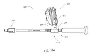
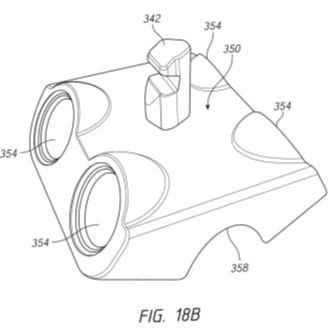
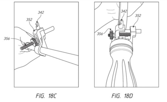
76 The detailed description of the embodiments illustrated in those figures is relevantly as follows:
[0192] Figure 18A illustrates an embodiment of an impactor 300A. In some methods of use, the orientation sensing device 204 can be coupled to the impactor 300A. The orientation sensing device 204 can determine cup angles relative to a reference plane as the impactor 300A is moved. The impactor 300A can include a shell 312A. The movement of the shell 312A is cushioned by a plurality of spring members 340, 344 which are configured to absorb at least some of the shock of the impact on the impactor 300A. The shell 312A can include a fourth coupler 342 (see Figures 18B-18D). This fourth coupler 342 permits the orientation sensing device 204 to couple to the shell 312A. The orientation sensing device 204 can be removably coupled to the fourth coupler 342. The orientation sensing device 204 can be coupled to the impactor 300A in order to navigate cup angles, as described herein.
[0193] In some embodiments, the fourth coupler 342 can be a universal coupler. This permits the fourth coupler 342 couple to any other device or subsystem, as described herein. In some embodiments, the fourth coupler 342 is identical or substantially similar to the first coupler 632, second coupler 648, and/or the third coupler 668. The fourth coupler 342 can couple to one or more components of the system 600, such as the orientation sensing device 204. The fourth coupler 342 can include an elongate post. The fourth coupler 342 can include a slot. The slot can be designed to lock with the orientation sensing device 204, or a component thereof such as the extension 670. The extension 670 can include a detent. The detent can be sized and shaped to be received within the slot of the fourth coupler 342. The engagement of the detent and the slot can rigidly couple the orientation sensing device 204 with the fourth coupler 342. The engagement between the fourth coupler 342 and the extension 670 of the orientation sensing device 204 minimizes or prevents relative movement therebetween to avoid any mechanical relative movement during navigation procedures.
…
[0196] … Figures 18B-18D illustrate embodiments of a universal impactor adapter. The universal impactor adapter can allow any impactor to be used with the systems described herein. The universal impactor adapter can allow the orientation sensing device 204 to couple with any impactor. In some embodiments, the universal impactor adapter can be an attachment which provides the fourth coupler 342 to allow the orientation sensing device 204 to mount thereon. The orientation sensing device 204 can mount on a large array of impactors, not only impactor 300A. The universal impactor adapter can be coupled to any impactor to provide the fourth coupler 342. The universal impactor adapter can provide a means to rigidly couple the fourth coupler 342 to the impactor. The universal impactor adapter can provide a means to rigidly couple the orientation sensing device 204 to the impactor.
[0197] Figure 18B is an embodiment of a universal impactor adapter 350. Figures 18C-18D is an embodiment of a universal impactor adapter 352. The universal impactor adapter 350, 352 can be designed to couple to a plurality of impactors. The universal impactor adapter 350, 352 can be designed to couple to impactors having a certain range of sizes of shafts or coupling portions. The universal impactor adapter 350, 352 can be designed to couple to impactors having a different shapes or configurations. The universal impactor adapter 350, 352 can include the fourth coupler 342. The universal impactor adapter 350, 352 can include any coupler designed to couple to the orientation sensing device 204. The universal impactor adapter 350, 352 can couple to a shaft of an impactor by any manner of connections. The universal impactor adapter 350 can connect to a shaft of an impactor with one or more magnets 354. The one or more magnets 354 of the universal impactor adapter 350 can be configured to attract and couple to the one or more magnets (not shown) of an impactor. The impactor is configured to be inserted within the recess 358. The recess 354 is an arcuate channel for receiving a shaft of an impactor within a range of impactor shaft sizes. … The one or more magnets 354 of the universal impactor adapter 350 can reduce or prevent unwanted movement between the impactor and the orientation sensing device 204.
[0198] The universal impactor adapter 352 can connect to a shaft of an impactor with one or more clamps 356. Figure 18C illustrates the clamp 356 when tightened and Figure 18D illustrates the clamp 356 when loosened. The clamp is an example of a mechanical connection between the universal impactor adapter 352 and any impactor. The clamp 356 can include a round inner surface to connect to a round outer surface an impactor.
[0199] The clamp 356 of the universal impactor adapter 352 can allow the universal impactor adapter 352 and the fourth coupler 342 to form self-supporting structure with the impactor. The clamp 356 of the universal impactor adapter 352 can reduce or prevent unwanted movement between the impactor and the orientation sensing device 204. The clamp 356 can apply a force necessary to rigidly couple to the exterior surface of the impactor. Other configurations of the universal impactor adapter are contemplated.
The claims
77 Claim 1 is to a ‘hip joint navigation system’ in the following terms:
A hip joint navigation system, comprising:
an impactor adapter comprising a first end and a second end opposite the first end, wherein the first end of the impactor adapter comprises a clamp configured to couple with an impactor, wherein the second end of the impactor adapter comprises a coupler, wherein the impactor adapter comprises a longitudinal axis extending between the first end of the impactor adapter and the second end of the impactor adapter,
wherein the clamp comprises a first clamp member and a second clamp member opposite the first clamp member, wherein a channel is disposed between the first clamp member and the second clamp member, the channel comprising a round inner surface configured to receive a round outer surface of the impactor; and
wherein the clamp comprises an actuator knob and a rod disposed between the first end and the second end of the impactor adapter, wherein the rod is disposed transverse to the longitudinal axis of the impactor adapter, wherein the clamp is configured for relative movement between the first clamp member and the second clamp member to achieve clamping of the impactor by movement of the actuator knob; and
an inertial navigation device configured to couple with the coupler at the second end of the impactor adapter, wherein the inertial navigation device comprises at least one inertial sensor, wherein the inertial navigation device is configured to determine cup angles.
78 The structure and components of the claim can be noted.
79 First, the hip navigation system is described as having two components: first, an impactor adapter which, at one end, comprises a clamp configured to couple with an impactor and, at the other end, comprises a coupler; and second, an inertial navigation device configured to couple with the coupler at the second end of the impactor adapter.
80 Second, the clamp has two elements: first, it comprises two members opposite each other, with a channel disposed between them, where the channel comprises a round inner surface configured to receive a round outer surface of an impactor; and second, it comprises an actuator knob and a rod, where the rod is transverse to the longitudinal axis of the impactor adapter, and the clamp is configured for relative movement between the first clamp member and the second clamp member to achieve clamping.
81 Without losing sight of the overall structure and components of the claim, the integers of the claim can be identified and numbered as follows (with the terms in dispute highlighted in bold type):
1 A hip joint navigation system, comprising:
1.1 an impactor adapter comprising a first end and a second end opposite the first end,
1.2 wherein the first end of the impactor adapter comprises a clamp configured to couple with an impactor,
1.3 wherein the second end of the impactor adapter comprises a coupler,
1.4 wherein the impactor adapter comprises a longitudinal axis extending between the first end of the impactor adapter and the second end of the impactor adapter,
1.5 wherein the clamp comprises a first clamp member and a second clamp member opposite the first clamp member,
1.6 wherein a channel is disposed between the first clamp member and the second clamp member,
1.7 the channel comprising a round inner surface configured to receive a round outer surface of the impactor; and
1.8 wherein the clamp comprises an actuator knob and a rod disposed between the first end and the second end of the impactor adapter,
1.9 wherein the rod is disposed transverse to the longitudinal axis of the impactor adapter,
1.10 wherein the clamp is configured for relative movement between the first clamp member and the second clamp member to achieve clamping of the impactor by movement of the actuator knob; and
1.11 an inertial navigation device configured to couple with the coupler at the second end of the impactor adapter,
1.12 wherein the inertial navigation device comprises at least one inertial sensor,
1.13 wherein the inertial navigation device is configured to determine cup angles.
82 Claims 2 to 5 of the Patent are dependent claims.
83 Claim 2 is to the hip joint navigation system of claim 1 “wherein the coupler comprises a slot configured to lock with a component of the inertial navigation device to rigidly couple the inertial navigation device with the coupler”.
84 Claim 3 is to a hip joint navigation system of any one of the preceding claims “wherein the coupler comprises an elongate post disposed opposite the clamp, wherein the elongate post is configured to receive a component of the inertial navigation device”.
85 Claim 4 is to a hip joint navigation system of any one of the preceding claims “wherein the coupler comprises a first coupler, the system further comprising a fixation mount configured to be coupled to a patient, the fixation mount comprising a second coupler, wherein the inertial navigation device is configured to couple with the first coupler of the impactor adapter, and wherein the inertial navigation device is configured to couple with the second coupler of the fixation mount”.
86 Claim 5 is to a hip joint navigation system of any one of the preceding claims “wherein the at least one inertial sensor is configured to detect gravity”.
E. Person skilled in the art
Introduction
87 Each of the parties advanced submissions on the question of the persons to whom the Patent is addressed, also referred to as the ‘skilled addressee’ or ‘person skilled in the art’.
88 The construct of a ‘person skilled in the art’ is used in patent law in a number of ways. The phrase appears in the key provisions in the Act relevant to the assessment of the validity of a patent, including the definitions of ‘novelty’, ‘inventive step’ and ‘innovative step’ in s 7, the definition of ‘useful’ in s 7A, the requirements relating to specifications in s 40 and the determination of the priority date of a claim in ss 43 and 114. In addition, the construct is relevant to the construction of patents. A claim is construed from the perspective of a person skilled in the relevant art as to how such a person would have understood the patentee to be using the words of the claim in the context of the specification as a whole: Meat and Livestock Australia Ltd v Cargill, Inc [2018] FCA 51; 354 ALR 95 at [219] (Beach J). However, as discussed further below, ordinary words used in a patent are given their ordinary meaning unless the skilled addressee (a person skilled in the relevant art) would give them a technical meaning: Kimberly-Clark Australia Pty Ltd v Multigate Medical Products Pty Ltd [2011] FCAFC 86; 92 IPR 21 (Multigate) at [39] (Greenwood and Nicholas JJ).
89 In the present case, the identification of the person skilled in the art, as a legal construct, is relevant to both the construction of the Patent and the lack of enablement, lack of utility and lack of innovative step grounds of invalidity advanced by Navbit.
90 In AstraZeneca AB v Apotex Pty Ltd (2015) 257 CLR 356 (AstraZeneca), French CJ described the statutory term ‘person skilled in the relevant art’ in the following terms (at [18], citations omitted):
The judicial determination whether want of inventive step is established pursuant to s 7 is mediated through the legal construct of the hypothetical person skilled in the relevant art. The construct is of a kind well-known to the law and used for setting parameters for evaluative judgments. It is a tool of analysis and is given statutory recognition, for that limited purpose, in s 7.
91 Similarly, Kiefel J explained (at [70], citations omitted):
In addressing s 7(2), it is to be borne in mind that the skilled person is an artificial construct, intended as an aid to the courts in addressing the hypothetical question of whether a person, with the same knowledge in the field and aware of the problem to which the patent was directed, would be led directly to the claimed invention. The statute’s creation of the skilled person construct for this purpose is not to be taken as an invitation to deal with the question posed by s 7(2) entirely in the abstract. Whilst the question remains one for the courts to determine, the courts do so by reference to the available evidence including that of persons who might be representative of the skilled person.
Applicable principles
92 A person skilled in the art – or ‘skilled addressee’ – is a person of the kind to whom a patent specification is addressed: General Tire & Rubber Co v Firestone Tyre & Rubber Co Ltd [1972] RPC 457 at 485 (General Tire), cited with approval in Nicaro Holdings Pty Ltd v Martin Engineering Co [1990] FCA 37; 16 IPR 545 (Gummow J). A patent specification is addressed to those likely to have a practical interest in the subject matter of the invention: Catnic Components Ltd v Hill & Smith Ltd [1982] RPC 183 at 242 (Lord Diplock). The skilled addressee comes to a reading of the specification with the common general knowledge of persons skilled in the relevant art, and they read it in a common sense and practical manner knowing that its purpose is to describe and demarcate an invention and not to be a textbook in the relevant field: Kirin-Amgen Inc v Hoechst Marion Roussel Ltd [2004] UKHL 46; 64 IPR 444 (Kirin-Amgen) at [33] (Hoffmann LJ). The skilled addressee is assumed to be of ordinary skill and non-inventive: Root Quality Pty Ltd v Root Control Technologies Pty Ltd [2000] FCA 980; 49 IPR 225 at [70]-[72].
93 If the art is one having a highly developed technology, the notional skilled addressee may not be a single person but a team, whose combined skills would normally be employed in that art in interpreting and carrying into effect instructions such as those which are contained in the document to be construed: General Tire at 485; Elconnex Pty Ltd v Gerard Industries Pty Ltd (1991) 32 FCR 491 at 507; Minnesota Mining & Manufacturing Co v Tyco Electronics Pty Ltd [2002] FCAFC 315; 56 IPR 248 at [40]. Although skills drawn from different areas of expertise may be relevant, the person skilled in the art thinks with one mind, speaks with one voice, and draws, when and to the extent necessary, on the disparate knowledge and skills of all of the members of the team: Novartis AG v Pharmacor Pty Ltd (No 3) [2024] FCA 1307; 186 IPR 24 at [149] (Yates J).
94 The knowledge and skills of the person skilled in the art can be informed by the evidence of expert witnesses. However, the person skilled in the art is not a mere avatar of those witnesses: AstraZeneca at [23] (French CJ). The person skilled in the art is not a reference to a specific person but is a legal construct, albeit the legal construct is informed by the available evidence including the evidence of persons who might be representative of the skilled person: AstraZeneca at [18] (French CJ) and [70] (Kiefel J).
Expert evidence
95 In the joint expert report, the experts agreed that hip surgery navigation systems are relatively complex and require a specialised team ideally including some or all of a technical design lead, product manager, systems engineer, sensor and software engineer, electrical engineer, mechanical engineer, regulatory/quality assurance engineer, project manager and surgeon adviser.
96 Mr Hunter observed that the Patent specification, which describes a complete navigation system for hip surgery, is very broad-reaching and comprises 103 pages. The specification relates to many embodiments of a complete navigation system for ensuring that hip joint components are correctly aligned during hip replacement surgery, and methods for use of such a navigation system. Accompanying the text of the specification, there are 89 diagrams over 54 pages. Accordingly, to address all of the different aspects of the complete specification of the Patent, a substantial multi-disciplinary design team would be required as described above. In respect of the five claims of the Patent, however, Mr Hunter observed that they are of much narrower compass and are directed to the components of an impactor adapter, which couples with an impactor at one end and with an inertial navigation device at the other end. Mr Hunter expressed the opinion that the claimed invention could be implemented by a sole mechanical design engineer with experience in medical device design.
97 In contrast, in the joint expert report, Mr Mittelstadt emphasised that claim 1 concerns a ‘hip navigation system’ and not merely an impactor adapter. Mr Mittelstadt expressed the opinion that the specification defines important features necessary to ensure that the invention achieves the desired function which is to provide angular feedback during hip replacement surgery and as a result, is directed toward a broader team as described below. Mr Mittelstadt stated that if the invention was intended to be an impactor adapter with clamp, he did not believe it would be novel or provide utility and therefore would not be patentable.
98 Despite that disagreement, the experts agreed that the required mechanical engineer would ideally be experienced with both durable and disposable surgical instrument design to design sensor enclosure, bone attachment components, sensor coupling attachments and impactor and or instrument attachment components. During oral testimony, Mr Mittelstadt confirmed (and Mr Hunter agreed) that this included the clamp and the coupler, and that the mechanical engineer would be the person responsible for designing those particular components. Mr Mittelstadt added that technical leads and product managers would provide input into usability and the design requirements: for example, whether the clamp was reusable or disposable, or how the design might reflect the conditions of use, such as designing the surface of the knob so it could be held by surgeons wearing gloves.
99 In the joint expert report, Mr Mittelstadt expressed the opinion that, ideally, the mechanical engineer would have experience designing components for hard tissue robotic or navigated systems which use similar methods for tracking bones and instruments during joint replacement or spinal surgical procedures. Mr Hunter stated that he did not agree that this is necessary to fulfill the claims of the Patent. During oral testimony, it became apparent that the opinions of the experts were not far apart. Mr Hunter explained his opinion as follows:
… the clamp design is really pure mechanical – a purely mechanical engineering task. Ideally, there are some – yes, there are some issues that relate to the fact that this clamp is for an impactor, which makes – you know, experience that a mechanical engineer may have had in medical device design would be desirable. But a – an ordinary mechanical engineer could design such a clamp with supervision from the rest of the project team.
100 Mr Mittelstadt stated that he agreed with the foregoing statement, but then explained why he considered that the claims of the Patent are not limited to mechanical components:
So the claims of the patent, in my mind, are relatively simple, right? You have a clamp, you got a coupler. You know, it’s relatively simple things. But it’s the context of it that is going to take the design one way or the other, right? So it’s the surgical use. It’s the impactor. It’s the impactor – range of impactors. So it’s, like, all of that information is what is going to make the design work or not, right? But you can design a clamp that satisfies the claim. I just looked at it as – that was kind of limiting it to the mechanical components. But the claims, in my mind, include that navigation system. So as soon as you bring in the navigation system, they have to understand the whole environment in which that mechanical design will be used, which is surgeons pounding things, the cleaning of instruments – if it’s a reusable – and how abusive that is. And so you want somebody who is going to design it for all of that. And the claims aren’t clear enough for taking all of that into account, in – in my opinion.
101 Ultimately the experts appeared to agree that, although the design of the clamp and the coupler on the impactor adapter would be done by a mechanical engineer, the design would still be done in the context of an overall project team.
Conclusion
102 I accept aspects of the evidence of both Mr Hunter and Mr Mittelstadt.
103 Specifically, I accept Mr Hunter’s opinion that, while the Patent specification describes a complete navigation system for hip surgery, the Patent claims have a much narrower focus and describe a mechanical device – an impactor adapter – that is used in a hip navigation system. As such, I also accept Mr Hunter’s opinion that the design of the impactor adapter is a mechanical engineering task.
104 However, I also accept Mr Mittelstadt’s opinion that the use of the impactor adapter, as part of a hip navigation system for the purposes of hip replacement surgery, means that the design of the mechanical device would require other skills associated with the design of medical instruments including particularly technical design, system engineering, regulatory and quality assurance engineering and a surgeon advisor.
105 As the experts ultimately appeared to agree, although the design of the clamp and the coupler on the impactor adapter would be done by a mechanical engineer, the design would still be done in the context of those other skills necessary for a hip navigation system for hip replacement surgery.
F. Construction issues
106 As stated earlier, the parties identified seven issues of construction for determination, being the meaning of the words: ‘comprise’ (issue 1); ‘clamp’ (issue 2); ‘first clamp member’ and ‘second clamp member’ (issue 3); ‘channel’ (issue 4); ‘the channel comprising a round inner surface configured to receive a round outer surface of the impactor’ (issue 5); ‘knob’ (issue 6); and ‘elongate post’ and ‘wherein the elongate post is configured to receive a component of the inertial navigation device’ (issue 10). All of the construction issues arise in the context of claim 1 of the Patent, save for issue 10 which arises in the context of claim 3.
107 This section of the reasons summarises the relevant legal principles that are applicable to the construction of a patent and then determines each of the issues of construction that are disputed. As identified below, by the time of closing submissions at trial, some of the issues of construction were no longer disputed.
Relevant legal principles
108 The principles of law governing the construction of patent specifications, including claims, are well established. They have been summarised in many previous Full Court cases, including those referred to by the Full Court in Jupiters Ltd v Neurizon Pty Ltd [2005] FCAFC 90; 65 IPR 86 (Jupiters) at [67], Esco Corporation v Ronneby Road Pty Ltd [2018] FCAFC 46; 131 IPR 1 (Esco) at [144] and GlaxoSmithKline Consumer Healthcare Investments (Ireland) (No 2) Limited v Generic Partners Pty Limited (2018) 264 FCR 474 (GSK Appeal) at [102].
109 The proper construction of a claim is a question of law, noting that the function of the claims is to define the scope of a claimed monopoly, a function different to the separate descriptive and ‘teaching’ purpose of the body of a patent specification. Evidence can be given by experts as to the meaning which those skilled in the art would give to technical or scientific terms and phrases, and on unusual or special meanings given by skilled addressees to words which might otherwise bear their ordinary meaning, but the construction of claims is ultimately a matter for the Court: Minnesota Mining & Manufacturing Company v Tyco Electronics Pty Limited [2001] FCA 1359; 53 IPR 32 at [92]; Fresenius Medical Care Australia Pty Limited v Gambro Pty Limited [2005] FCAFC 220; 67 IPR 230 at [34]; Insta Image Pty Ltd v KD Kanopy Australasia Pty Ltd (2008) 239 FCR 117 at [82]; Multigate at [39] (Greenwood and Nicholas JJ). Where terms within a claim are ordinary English words, their meaning both individually and together is not, properly understood, a matter for expert evidence: Multigate at [12]-[14] (Emmett J) and [38] (Greenwood and Nicholas JJ).
110 A specification should be read in a practical and common-sense way through the eyes of the skilled addressee: GSK Appeal at [106]; KD Kanopy Australasia Pty Ltd v Insta Image Pty Ltd [2007] FCA 481; 71 IPR 615 at [16]. The Court should avoid too technical or narrow a construction of claims: Pfizer Overseas Pharmaceuticals v Eli Lilly & Co [2005] FCAFC 224; 225 ALR 416 (Pfizer) at [250] (French and Lindgren JJ). The relevant question is always what the skilled addressee would have understood the patentee to mean in using the language of the claim: Kirin-Amgen at [34] (Hoffmann LJ).
111 A patent specification is to be given a purposive construction and must be read as a whole through the eyes of a skilled addressee in light of the common general knowledge as at the priority date: Kimberly-Clark Australia Pty Ltd v Arico Trading International Pty Ltd (2001) 207 CLR 1 at [24] (Gleeson CJ, McHugh, Gummow, Hayne and Callinan JJ). However, a purposive construction does not displace the clear ordinary meaning of the words chosen by the patentee. As stated by Gummow J in Rehm Pty Ltd v Websters Security Systems (International) Pty Ltd [1988] FCA 232; 11 IPR 289 at 298, citing Interlego AG v Toltoys Pty Ltd (1973) 130 CLR 461 at 478-479:
The settled rule is that in ascertaining the width of a particular claim, it is not permissible to vary or qualify the plain and unambiguous meaning of the claim by reference to the body of the specification; provided that if an expression in the claim is not clear, then it is permissible to resort to the body of the specification to define or clarify the meaning of the words used in the claim.
112 Although the claims are construed in the context of the specification as a whole, it is not legitimate to confine the scope of the claims by reference to limitations which may be found in the body of the specification, but which are not reproduced in the claims themselves. To put it another way, it is not legitimate to narrow or expand the boundaries of the monopoly as fixed by a claim by adding glosses drawn from other parts of the specification: Martin v Scribal Proprietary Limited (1954) 92 CLR 17 at 97 (Taylor J), cited with approval by Besanko and Nicholas JJ in Otsuka Pharmaceutical Co Ltd v Generic Health Pty Ltd (No 2) [2016] FCAFC 111; 120 IPR 431 at [95].
113 Relatedly, claims in a patent are not to be narrowed by reference to the preferred embodiment: Rehm Pty Ltd v Websters Security Systems (International) Pty Ltd [1988] FCA 232; 81 ALR 79 at 89. The preferred embodiment cannot properly be used to introduce into the definite words of a claim an additional definition or qualification of the patentee’s invention: Erickson’s Patent (1923) 40 RPC 477 at 491; Globaltech Corporation Pty Ltd v Australian Mud Company Pty Ltd [2019] FCAFC 162; 145 IPR 39 at [111]. A proper analysis of the specification may show that references to a particular embodiment are by way of “illustration and explanation of the invention” rather than a “definition of it”: Welch Perrin & Co Pty Ltd v Worrel (1961) 106 CLR 588 at 612 (Dixon CJ, Kitto and Windeyer JJ).
114 Drawings within the specification are generally not designed to be used to denote precise measurements unless so stated; they are there to illustrate the concept and the overall relationship of the parts, in conjunction with the language used in the description: Leonardis v Sartas No 1 Pty Ltd (1996) 67 FCR 126 (Leonardis) at 136, citing Vax Appliances Limited v Hoover [1991] FSR 307 (Vax Appliances) at 313. Expert evidence may be given to assist the Court to understand a detailed drawing: C Van Der Lely NV v Bamfords Ltd [1963] RPC 61 (Bamfords) at 71; Leonardis at 137-138; Flexible Steel Lacing Co v Beltreco Ltd [2001] FCA 890; 49 IPR 331 at [82]-[88]. Indeed, drawings should not be construed by the Court in the absence of evidence as to how they would appear to the eye of the skilled addressee: Bamfords at 71; Nicaro Holdings Pty Ltd v Martin Engineering Co [1990] FCA 37; 91 ALR 513 at 542; Vax Appliances at 309-310; Yamazaki Mazak Corporation v Interact Machine Tools (NSW) Pty Ltd [1991] FCA 572; 22 IPR 79 at 89.
Construction issue 1: comprise
115 The claims of the Patent use the word ‘comprises’ (and ‘comprising’) in various places. The experts understood that the word was intended to have an inclusive meaning, not an exhaustive meaning. In closing submissions, both parties adopted that meaning. I consider that to be the correct construction of the word as used in the Patent. It reflects [0314a] of the specification which states:
Where any or all of the terms "comprise", "comprises", "comprised" or "comprising" are used in this specification (including the claims) they are to be interpreted as specifying the presence of the stated features, integers, steps or components, but not precluding the presence of one or more other features, integers, steps or components.
Construction issues 2 and 3: a clamp comprising a first clamp member and a second clamp member opposite the first clamp member
116 It is convenient to discuss issues 2 and 3 concurrently as the issues are interrelated.
117 Integer 1.2 of claim 1 of the Patent states that the first end of the impactor adapter comprises a clamp configured to couple with an impactor. Integer 1.5 states that the clamp comprises a first clamp member and a second clamp member opposite the first clamp member.
118 The word ‘clamp’ is a common English word and neither of the experts expressed the opinion that it had a specialised meaning or is used in the Patent with a specialised meaning. Two of the definitions from the Macquarie Dictionary are “a device, usually of some rigid material, for strengthening or supporting objects or fastening them together” or “an appliance with opposite sides or parts that may be screwed or otherwise brought together to hold or compress something”. In the joint expert report (at [21]), Mr Hunter gave the following definition of a clamp which is largely consistent with the ordinary meaning of the word:
A clamp is a device or sub-component which is intended to be operated so that it can hold or grasp something with mechanical force or pressure applied by the clamp. In ordinary use a clamp consists of two separate members which are moved together to apply the gripping pressure.
119 There is no dispute between the parties that a clamp is a device which has two members which are moved together to apply gripping pressure on something. The dispute is whether the two members that apply the gripping pressure must be separate or separable components of the device, or whether a device in which the two members are part of a single component (for example, because the two members are moulded as a single component, or are welded or otherwise joined together) is a clamp within the meaning of the Patent.
120 OrthAlign submitted that Integer 1.5 is satisfied regardless of whether the first and second clamp members are discrete components or if they are formed as part of a unitary whole. OrthAlign argued that Integer 1.5 merely requires the first and second clamp members to be opposite each other (such that there can be relative movement between them to achieve clamping), and it is irrelevant whether the two members are physically joined and how they are physically joined.
121 Navbit submitted that the ‘clamp’ referred to in the claims consists of two members which are moved together to apply gripping pressure, the use of the word ‘member’ indicates two separate components, and the only clamp that is disclosed in the Patent specification has separate clamp members.
122 In his second report concerning infringement (and not construction), Mr Hunter expressed the following opinion:
In my experience, the term “member” is used to refer to a discrete or separate part or component. I understand that a clamp which comprises two clamp members (i.e. a “first” and a “second” clamp member) has two discrete components.
123 Mr Hunter reiterated that opinion in the joint expert report in the passage cited above, in which he states that, in ordinary use, a clamp consists of two separate members.
124 Beyond referring to his experience, Mr Hunter offered no justification, from a mechanical engineering perspective, for why the two members of a clamp must be separate (or separable) components. In particular, Mr Hunter did not suggest that a device, which comprises two members being moved together to apply gripping pressure on something, but where the two members are moulded as a single component or otherwise joined together as a single component, is ineffective or materially less effective in applying mechanical force or pressure and therefore would not be described as a clamp.
125 In oral testimony, Mr Hunter proffered that his understanding of the term ‘member’ means a separate element. However, he also accepted that the word ‘member’ is an ordinary English word. During oral testimony, the Court asked Mr Hunter to explain why he considered that, in a clamp, the two members must be separate (in the sense of not being one component, or joined, or hinged), to which Mr Hunter replied:
I would regard the term “member” as meaning an independent component – in other words, one component that was physically separate from another one. So the overall clamp can be regarded as an assembly. Ordinarily, I – I think a clamp is an assembly of two independent members. Typically, in a clamp, we would have one stationary member and one moving member, although there can be clamps where both members move together. But that is my understanding of the term “member”: a physically independent component.
…
Once we start talking about a clamp which has integral features which join together, such a – such a device can be a clamp, but we’re no longer talking about members. We’re talking about features or integrated arms or something else, but not member. So that’s my understanding.
126 It can be accepted that the only illustration of a clamp in the Patent specification is contained in Figures 18C and 18D. The experts agreed that, in those illustrations, the two members of the clamp are separate components. However, as stated at [0196], the illustration in those figures is an embodiment of an impactor adapter, and the claims in the Patent are not to be narrowed by reference to a preferred embodiment.
127 In that regard, it is significant that Integer 1.5 does not refer to the two clamp members being separate or separable. The integer states simply that the clamp comprises a first clamp member and a second clamp member opposite the first clamp member. Mr Hunter’s definition of a clamp seeks to impose a further integer that the two members be separate (in the sense of not being joined at any point) which is not found in the text of the claim. In my view, there is no justification for that addition. Whilst Mr Hunter stated that he understood the word ‘member’ to mean a physically independent component, I do not accept that is the ordinary meaning of the word ‘member’ as used in claim 1 of the Patent. Integer 1.5 is a simple description of a mechanical clamp, in which two members can be moved together to apply gripping pressure on something. The description does not require the two members to be physically separate components, as no mechanical reason was offered for why such a limitation should be read into the integer.
128 For those reasons, I reject Navbit’s contention that Integer 1.5 requires the two members of the clamp to be physically separate components.
Construction issue 4: channel
129 Integer 1.6 stipulates, in respect of the clamp, that “a channel is disposed between the first clamp member and the second clamp member”.
130 Although the meaning of the word ‘channel’ was identified as an issue in dispute between the parties prior to trial, it was made clear in opening submissions that the dispute with respect to Integer 1.6 concerned the meaning of the first and second clamp members, the subject of issue 3. On Navbit’s case, if a device did not satisfy Integer 1.5 because the first and second members of the device were not separate components, then the device also would not satisfy Integer 1.6 for the same reason. Conversely, Navbit acknowledged that if its construction of Integer 1.5 were not accepted by the Court, no separate issue arises in respect of Integer 1.6. For the reasons given earlier, Navbit’s construction of Integer 1.5 is not accepted.
131 Nevertheless, by way of introduction to issue 5, it is appropriate to say something further about Integer 1.6. The experts were largely agreed on the meaning of the word ‘channel’. In the joint expert report, Mr Mittelstadt expressed the following opinion:
In ordinary usage a channel in a part is a recessed or grooved region which follows an axis and has some depth and length. The importance of having a channel can be understood by the context in which the channel is used in the navigation system. My opinion is that the channel is important to ensure that axis of the channel aligns with a defined axis on the impactor. In order to do so reliably, it does require adequate length so that it can reliably align with the axis of the impactor.
132 Mr Hunter largely agreed, stating: “The channel is a passageway formed between the first and second clamp members. I agree with [Mr Mittelstadt] that the passageway has a depth or length.”
133 Those opinions are consistent with the ordinary meaning of the word ‘channel’ as given by the Macquarie Dictionary, being “a course into which something may be directed” or “a groove or furrow”. But the opinions also advert to the function of the channel integer within the claim: the integers of the claim indicate that the axis of the channel is intended to align with a defined axis of the impactor. This function is apparent from a combination of integer 1.2 which stipulates that the first end of the impactor adapter comprises a clamp configured to couple with an impactor, integer 1.6 which stipulates that there be a channel disposed between the first clamp member and the second clamp member, and integer 1.7 which stipulates that the channel be configured to receive a round outer surface of the impactor.
134 It is a surprising feature of the Patent specification that the word ‘channel’ is used on only one occasion in the specification, beyond claim 1 and its consistory clause [0035a]. The word appears in [0197] which describes the embodiment of a universal impactor adapter depicted in Figures 18B, 18C and 18D, reproduced earlier. Figure 18B depicts an impactor adapter that couples to an impactor by the use of magnets rather than a clamp, and therefore is not an impactor adapter that is described in claim 1. Figures 18C and 18D each depict an impactor adapter that couples to an impactor by the use of a clamp. However, in [0197], the word ‘channel’ is only used expressly to describe a feature of the impactor adapter illustrated in Figure 18B. In that context, the specification states that the “recess 354 is an arcuate channel for receiving a shaft of an impactor within a range of impactor shaft sizes”. It is common ground that the reference to “recess 354” is a typographic error, and the sentence should refer to “recess 358”. The specification thereby indicates that the function of the channel is to align the impactor adapter with the shaft of the impactor.
135 The impactor adapters depicted in Figures 18C and 18D, being impactor adapters that couple to an impactor using a clamp, are further described in [0198] and [0199]. The word ‘channel’ is not expressly referred to in the descriptions. Nevertheless, the combined effect of the textual descriptions and the illustrations in the specification indicate that the function of the channel (being the area disposed between the first clamp member and the second clamp member) is to align the impactor adapter with the shaft of the impactor. This function is apparent from the teaching of the specification that:
(a) at [0171]-[0173], the reference planes are defined to guide hip replacement surgery, including particularly the calculation of abduction and anteversion angles for cup placement, which can be recorded and stored on the orientation sensing device;
(b) at [0192], the orientation sensing device can be coupled to the impactor so that the orientation sensing device can determine cup angles relative to a reference plane as the impactor is moved, and the orientation sensing device can be coupled to the impactor in order to navigate cup angles;
(c) at [0196], the universal impactor adapter can provide a means to rigidly couple the orientation sensing device to the impactor;
(d) at [0198], the universal impactor adapter can connect to a shaft of an impactor with one or more clamps, and Figure 18C illustrates the clamp when tightened and Figure 18D illustrates the clamp when loosened; and
(e) at [0199], the clamp of the universal impactor adapter can reduce or prevent unwanted movement between the impactor and the orientation sensing device.
136 I did not understand there to be any dispute between the parties with respect to the foregoing understanding of the meaning and function of the word ‘channel’ within claim 1.
Construction issue 5: the channel comprising a round inner surface configured to receive a round outer surface of the impactor
137 Integer 1.7 specifies that the channel comprises “a round inner surface configured to receive a round outer surface of the impactor”.
138 The dispute between the parties is whether the phrase ‘configured to receive’ qualifies the word ‘channel’ or qualifies the phrase ‘round inner surface’. On OrthAlign’s construction, Integer 1.7 requires that the channel of the clamp (being the area disposed between the first clamp member and the second clamp member) must include a round inner surface, but it is unnecessary for the round inner surface to be configured to receive a round outer surface of the impactor; the integer only requires that the channel receive a round outer surface of the impactor. Navbit contends that, consistently with the ordinary meaning of the words used, and the disclosure given in Figure 18C of the specification, Integer 1.7 specifies that it is the round inner surface of the channel which is configured to receive the round outer surface of the impactor.
139 The difference in the parties’ construction of the integer can be best explained through the progression of the evidence given by the experts as to their understanding of this integer.
The expert evidence
140 In his first affidavit, Mr Mittelstadt expressed the opinion that the requirement of “configured to receive a round outer surface of the impactor” could be understood to qualify either the channel or the round inner surface which is part of the channel. If the requirement qualifies the round inner surface which is part of the channel, then the requirement could on one view be interpreted to mean that the round inner surface has the same or a matching curvature as the round outer surface of the impactor. Alternatively, it could be understood as requiring that the channel which has a round inner surface is also able to receive or accommodate the round outer surface of the impactor for the purpose of coupling the impactor adapter to an impactor. Mr Mittelstadt understood that the clamp as defined in claim 1 “correlates” to the clamp of the universal impactor adapter described at [0192] to [0199] and, as such, is intended to allow the impactor adapter to connect (via the clamp) with a range of impactor shaft diameters. Mr Mittelstadt interpreted Figures 18C and 18D of the specification as illustrating one of the clamp members taking the form of a shallow ‘V’ block with a rounded section at the transition between the two straight sides of the V. Mr Mittelstadt stated:
I consider that such an arrangement would be useful for allowing the clamp to attach to a range of different diameter impactor shafts because it will provide multiple points of contact between the clamp and the shaft across a range of diameters. If the diameter of the rounded section was larger than the diameter of an impactor shaft to which it was to be attached, the connection would only make a single point of contact with that part of the clamp. In order to allow a rigid connection to a range of different diameter impactor shafts, the rounded transition would ideally be small to avoid the impactor shaft bottoming out in this manner.
As noted above, paragraph [0198] describes that the clamp can include a round inner surface to connect to a round outer surface of an impactor. I do not understand this to mean that the portion of the clamp which has a round inner surface is of a diameter which matches the diameter of the shaft to which it is connected because as previous discussed, the adapter is intended to allow connection to a range of different diameter shafts. It would not be possible for the clamp to include a portion which has a round inner surface of a diameter which matches the different diameters of a range of impactor shafts. Rather, I understand paragraph [0198] to described that a portion of the clamp can have a round inner surface to allow the clamp to connect to a round outer surface of an impactor. I consider this to be consistent with the “V” block having a rounded transition as shown in figures 18C and 18D.
141 It is apparent that Mr Mittelstadt’s interpretation of Integer 1.7 is premised on his understanding that the impactor adapter described in claim 1 is intended to be capable of coupling with impactors having a range of shaft diameters. Based on that understanding, Mr Mittelstadt expressed the following opinion:
Accordingly, I understand that feature 1.7 does not require that the round inner surface of the channel has the same or a matching curvature as the round outer surface of the impactor. Such a requirement would be inconsistent with the impactor adapter being able to be coupled to impactors have [sic] different diameter shafts as described. Rather, the round inner surface is part of the channel which is configured be able to receive or accommodate the round outer surface of an impactor which may have a curvature which differs from the round inner surface, for the purpose of coupling the impactor adaptor to an impactor as defined in feature 1.2.
142 In his first affidavit, Mr Hunter reproduced a copy of Figure 18C of the specification and added colours and labels to the different components. As stated earlier, the specification states that Figure 18C illustrates an embodiment of a universal impactor adapter (at [0054]). It is convenient to have regard to Mr Hunter’s coloured version of Figure 18C as it highlights the clamp and channel:
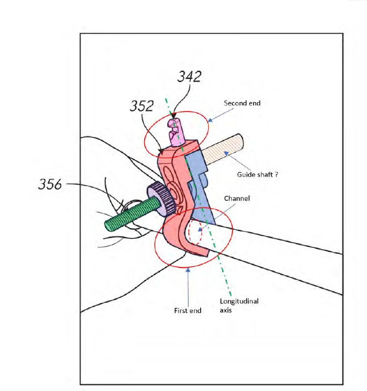
143 In his first report, Mr Hunter explained that he coloured the first clamp member in red and the second clamp member in blue. Mr Hunter expressed the opinion that Integer 1.7 means that (considered in a cross-section view) at least some portion of the channel (disposed between the first and second clamp members) must include a surface which is rounded to mate with a matching rounded surface portion present on the impactor shaft. Mr Hunter considered that the integer specifically requires that the rounded portion of the channel must make full contact with a matching rounded portion of the impactor shaft.
144 In his third affidavit, Mr Hunter further responded to Mr Mittelstadt’s opinion concerning the clamp shown in Figure 18C and the requirement of Integer 1.7. Mr Hunter stated that, to his observation, the first clamp member shown in Figure 18C has a round inner surface which makes full contact with the round outer surface of the impactor, and that it is not apparent from Figure 18C that there is any straight inner surface of the first clamp member in contact with the outer surface of the impactor shaft.
145 As a matter of concept, Mr Hunter expressed his agreement with Mr Mittelstadt that a ‘V’ block arrangement would be useful for clamping a range of different diameter impactor shafts, because it would provide multiple points of contact between the clamp and the shaft across a range of diameters. However, Mr Hunter considered that claim 1 of the Patent does not refer to a ‘V’ block arrangement (instead requiring that the channel comprise a round inner surface configured to receive a round outer surface of the impactor) and that neither Figure 18C nor Figure 18D illustrates a ‘V’ block arrangement. Mr Hunter considered that there is no reference in the Patent to a ‘V’ block arrangement.
146 In his third affidavit, Mr Hunter was instructed to consider a clamp comprising two members having cross-sectional profiles as shown in the following diagram, and prepare diagrams representing his understanding as to how the clamp would interact with circular impactor shafts of different diameters:
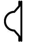
147 Mr Hunter produced a series of diagrams in response to those instructions, which are discussed below. At the trial, OrthAlign supplemented the diagrams with further variations which were considered by the experts. Whilst the diagrams merely illustrate clamp design concepts, the diagrams and the expert evidence given in respect of the diagrams helps to inform the debate between the parties with respect to the construction of Integer 1.7. In Mr Hunter’s affidavit, and in the discussion that follows, the clamp member on the left in each diagram is referred to as the ‘first’ clamp member and the clamp member on the right is referred to as the ‘second’ clamp member.
148 In the first diagram produced by Mr Hunter (Diagram 23), the diameter of the impactor shaft is such that the semi-circular outer surface of the impactor shaft mates with the semicircular inner surface of the first clamp member:
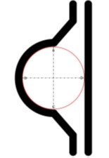
149 In the above Diagram 23, Mr Hunter labelled four points as A, B, C and D. Mr Hunter observed that continuous surface contact between the round inner surface of the first clamp member and the round outer surface of the impactor shaft occurs from A to B to C.
150 In the second diagram produced by Mr Hunter (Diagram 24), the impactor shaft has a diameter that is larger than the inner diameter of the semicircular portion of the first clamp member:
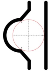
151 In the above Diagram 24, Mr Hunter labelled three points as A, B and D. He observed that there are two points (or axial lines) of contact between the first clamp member and the impactor shaft, labelled A and B. During cross-examination, the experts agreed that, in the above diagram, there is no point of contact between the round inner surface of the first clamp member and the round outer surface of the impactor shaft.
152 In the third diagram produced by Mr Hunter (Diagram 25), the impactor shaft has a diameter that is smaller than the inner diameter of the semicircular portion of the first clamp member:
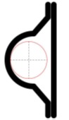
153 Mr Hunter observed that, in the above Diagram 25, no clamping is possible.
154 Overall, Mr Hunter stated his opinion that a clamp having the design depicted in the above diagrams is designed to hold an impactor shaft having a particular diameter, such that the curved inner surface of the first clamp member mates with the curved outer surface of the impactor shaft.
155 During cross-examination, Mr Hunter was asked to consider a variation to Diagram 25 (referred to as Diagram B), which expanded the diameter of the impactor shaft:
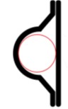
156 Mr Hunter explained that, in the above diagram, there would be only one point (or axial line) of contact between the first clamp member and the impactor shaft (and a second point of contact with the second clamp member).
157 The experts were also asked to comment upon a series of modified diagrams as follows:
(a) a modified Diagram 23:
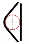
(b) a modified Diagram 24:
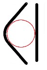
(c) a modified Diagram B:
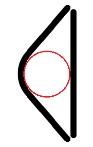
158 Mr Hunter agreed that, in the above diagrams, there would be either two or three points (or axial lines) of contact between the clamp and the impactor shaft. Mr Hunter also agreed that such a clamp design could accommodate a range of shaft diameters. Mr Hunter also agreed that there would be some degree of clamping force or pressure, but he considered that he could not express any opinion with respect to the degree of force or pressure without testing. As to whether the clamps depicted in the above modified diagrams satisfied Integer 1.7, Mr Hunter stated that modified Diagram 23 at least partly has the attribute that the round inner surface of the channel is configured to receive the round outer surface of the impactor.
159 During cross-examination, Mr Mittelstadt agreed with Mr Hunter’s interpretation of the diagrams, but maintained his disagreement with the construction of Integer 1.7.
160 In the joint expert report, Mr Mittelstadt acknowledged that one possible interpretation of Integer 1.7 is that the round inner surface of the channel mates with the outer diameter of the impactor shaft. However, Mr Mittelstadt stated that he did not believe that the wording of the integer requires the rounded portion of the channel to make full contact with a matching rounded portion of the impactor. Mr Mittelstadt stated that while the channel must have a round inner surface, it could have other surfaces as well, explaining:
… the round inner surface (cross section of the channel) can have either a constant radius (to mate with a single impactor diameter) or be designed to have varying radii to enable receiving round cylindrical impactor shafts of different diameters. This could resemble a V-groove that has a fillet radius at the apex of the grove [sic].
161 During cross-examination, Mr Mittelstadt confirmed that, while he did not believe that the integer requires the rounded portion of the channel to match or fit the rounded portion of the impactor, he did believe that the integer requires there to be contact between the rounded portion of the channel and the rounded portion of the impactor. The following exchange occurred:
MR DIMITRIADIS: A surface cannot receive another surface unless there’s a fit between them, can it?
MR MITTELSTADT: No, I – yes, they can receive. It doesn’t have to be a fit.
MR DIMITRIADIS: Does it have to be contact?
MR MITTELSTADT: Yes.
MR DIMITRIADIS: So, without contact between the round inner surface and the round outer surface, the round inner surface is not receiving the round outer surface, is it?
MR MITTELSTADT: Without contact – without contact within the channel, it would not be receiving it. So, I mean, your question is – is not very straightforward.
MR DIMITRIADIS: How does the round inner surface receive the round outer surface if there’s no contact between them?
MR MITTELSTADT: It doesn’t.
162 Mr Hunter agreed with that opinion.
163 Mr Mittelstadt also acknowledged that the requirement for there to be contact between the round surfaces flows from the words “to receive”. The following further exchange then occurred:
MR DIMITRIADIS: … The part of the claim that we’re considering, Mr Mittelstadt, the channel comprising a round inner surface configured to receive a round outer surface, is telling you, isn’t it, that one surface receives another surface because of the complementarity in shape between them; that’s right, isn’t it?
MR MITTELSTADT: Yes.
MR DIMITRIADIS: And, Mr Hunter, do you agree?
MR HUNTER: I agree.
164 During cross-examination, Mr Mittelstadt was questioned with respect to his opinion, also stated in the joint expert report, that the round inner surface could “resemble a V-groove that has a fillet radius at the apex of the grove [sic]”. It was put to Mr Mittelstadt that he had in mind the alleged infringing device, the Navbit Sprint, when he included that statement in the joint expert report. Mr Mittelstadt acknowledged that he had viewed the Navbit Sprint when he wrote that statement in the joint expert report, and Mr Mittelstadt also agreed that each of the two ‘clamping’ members of the Navbit Sprint have a fillet radius. But Mr Mittelstadt denied that he made the statement with the Navbit Sprint in mind. I do not accept Mr Mittelstadt’s denial. I consider that the statement in the joint expert report was at least unconsciously influenced by Mr Mittelstadt’s knowledge of the Navbit Sprint. I have reached that conclusion because Mr Mittelstadt’s explanation for including the statement in the joint expert report lacked coherence, and the statement introduced an inconsistency with his previously expressed opinion.
165 When questioned about this aspect of the joint expert report, Mr Mittelstadt initially appeared uncertain of the meaning of the term ‘fillet radius’. Nevertheless, he agreed with Mr Hunter that a ‘fillet’ refers to a rounding of a corner between an intersection of two surfaces or lines (there being a small radius at the join). In a further question asked by the Court, Mr Mittelstadt confirmed that, if a clamp member comprises two straight elements which are joined by a round section (the fillet radius), and if it is the straight elements of the clamp member that place clamping pressure on the round outer surface of an impactor, Mr Mittelstadt would consider that the round inner surface of the channel is not configured to receive the round outer surface of the impactor. It follows from Mr Mittelstadt’s earlier evidence that the clamp member would not satisfy Integer 1.7; that is because Mr Mittelstadt had earlier expressed the opinion that the integer requires there to be contact between the rounded portion of the channel and the rounded portion of the impactor. Mr Mittelstadt’s reference to a V-groove that has a fillet radius at the apex of the groove therefore introduces incoherence in his evidence.
Consideration
166 In my view, Navbit’s construction of Integer 1.7 should be accepted. It is the round inner surface of the channel which is configured to receive the round outer surface of the impactor. Navbit’s construction, which I accept, is that at least some portion of the channel (considered in cross-section) must include a surface which is rounded to receive, in the sense of making contact with, a complementary or matching rounded surface portion present on the impactor shaft. Navbit did not propound the view that the entire channel must make full contact with the impactor shaft. It is sufficient if at least some portion of the channel, being a round surface, makes contact with the round surface of the impactor shaft.
167 Navbit’s construction is supported by the ordinary meaning of the words used in the claim, when read in context. The juxtaposition of the phrases ‘round inner surface’ and ‘round outer surface’ compels a conclusion that it is the round inner surface of the channel that is configured to receive the round outer surface of the impactor. In my view, reading claim 1 in the context of the Patent specification as a whole does not indicate a different conclusion (as explained further below).
168 To the extent that it is relevant, I consider that the expert evidence is largely consistent with Navbit’s construction. It is possible that Mr Hunter’s evidence can be understood as requiring a closer ‘fit’ or ‘match’ between the round inner surface of the channel and the round outer surface of the impactor, although in cross-examination Mr Hunter appeared to acknowledge that the integer would be satisfied provided a part of the round inner surface of the channel matched with a part of the round outer surface of the impactor. Ultimately, I understood Mr Mittelstadt to accept that the integer required the round inner surface of the channel to “receive” the round outer surface of the impactor, and this required there to be contact between the two.
169 In contrast, OrthAlign’s alternative construction, that the integer merely requires the channel to be configured to receive a round outer surface of the impactor, involves a strained, indeed somewhat perverse, construction of the integer. It renders the reference to the “round inner surface” of the integer seemingly otiose.
170 In support of its alternative construction, OrthAlign submitted that a surface does not ‘receive’ another surface as that term is used in the specification and that, in the context of describing a mechanical connection, a structure may be received in, or held or contained by, a hole or opening, a passage, a channel or another similar receptacle. I do not accept that submission, and it is not supported by the expert evidence. In construing the integer, neither of the experts suggested any difficulty in understanding the description of a surface receiving another surface. Both experts understood that the description of a round inner surface receiving a round outer surface conveys that the two surfaces are brought into contact.
171 OrthAlign also placed considerable reliance on the description of a ‘universal impactor adapter’ in the specification. For the following reasons, I consider that the description of a universal impactor adapter in the specification does not assist OrthAlign’s argument.
172 In the course of their evidence, each of the experts expressed an opinion with respect to the meaning of the phrase ‘universal impactor adapter’ in the specification, and whether the impactor adapter described in claim 1 is a universal impactor adapter as disclosed in the specification.
173 In determining the issue of construction that arises, it is not strictly necessary to form a concluded view whether the impactor adapter described in claim 1 is a ‘universal impactor adapter’ as described in the specification. However, the issue has relevance in the context of the grounds of invalidity, and it is therefore appropriate that the issue be addressed when considering issues of construction generally.
174 It can be observed that the word ‘universal’ does not appear in claim 1. A likely explanation for the absence of the word ‘universal’ is that the invention described in claim 1 comprises a subset of universal impactor adapters as disclosed in the specification. That conclusion finds support in the summary of the invention at [0035] and [0035a]. At [0035], the specification describes an embodiment in which the hip joint navigation system can include a universal impactor adapter comprising a coupler, wherein the second inertial navigation (device) is configured to couple to an impactor with the adapter and where, in some embodiments, the universal impactor adapter comprises a clamp. At [0035a], the specification sets out the consistory clause for claim 1. The consistory clause is the only part of the specification which refers to an ‘impactor adapter’ without the further adjective ‘universal’. The choice of language appears to be deliberate, indicating that the impactor adapter the subject of the consistory clause is a subset of the universal impactor adapter described in the specification. The conclusion is also supported by the fact that the embodiments of a universal impactor adapter that are described and depicted in the specification use two different methods of coupling with an impactor, magnets and a clamp, whereas the impactor adapter the subject of claim 1 specifies the use of a clamp only.
175 Mr Hunter expressed the view that the term ‘impactor adapter’ used in claim 1 is described in the specification as a ‘universal impactor adapter'. Mr Hunter further stated that the word ‘universal’, as used in the specification, conveys that the impactor adapter is capable of being fitted to any impactor. Based on that interpretation of the word, Mr Hunter expressed the opinion that the Patent specification does not disclose how that can be achieved. Mr Hunter observed that it is known that impactors have shafts in a wide range of shapes and sizes, and that impactors may have a combination of flat and round surfaces on the impactor shaft cross-sections.
176 Mr Mittelstadt’s evidence was more equivocal, which is not intended as a criticism. Mr Mittelstadt recognised the disconformity between the language of the claims and the language of the specification. In particular, Mr Mittelstadt recognised, first, that the claims used the phrase ‘impactor adapter’ rather than ‘universal impactor adapter’ and, second, the impactor adapter described in claim 1 has certain features which means it would not be capable of coupling with any (or every) impactor. Mr Mittelstadt acknowledged that the Patent specification described a ‘universal impactor adapter’, but did not consider that the promise of the invention was an impactor adapter that could couple to any impactor. In his first affidavit, Mr Mittelstadt gave the following evidence:
I am aware that there are many different manufacturers of impactors for use in the placement of the acetabular cup during THA and different manufactures produce more than one type of impactor. Amongst the differences between impactors of different manufactures or different models is difference in the diameter of the impactor shaft to which the orientation sensing device is to be mounted. When the specification of [the Patent] describes that:
(a) the universal impactor adapter can allow any impactor to be used with the systems described;
(b) the universal impactor adapter can allow the orientation sensing device to couple with any impactor; and
(c) the orientation sensing device can mount on a large array of impactors,
I understand this to be referring to the fact that impactors have a range of different diameter shafts to which the orientation sensing device would need to be attached and that the universal impactor adapter provides a mechanism which allows connection to such a range of shaft diameters. Further, the universal impact adapter provides a means to rigidly couple the orientation sensing device to the range of impactors having different diameter shafts.
177 In responding to Mr Hunter’s evidence, Mr Mittelstadt explained:
… I do not understand the use of the term “impactor adaptor” in claim 1 to imply that claim 1 defines a universal impactor adapter as opposed to an impactor adaptor having certain features which correspond to features disclosed in connection with the universal impactor adapter described in the specification.
178 I accept Mr Hunter’s opinion that the ‘universal impactor adapter’ as described in the Patent specification is stated to be an adapter that can be designed to couple with any impactor, including impactors having a round shaft of different diameters and impactors that do not have a round shaft. The ‘universal impactor adapter’ is also stated to be an adapter that can be designed to couple to a shaft of an impactor by any manner of connections. However, the specification does not disclose how those designs can be achieved. The disclosure in the specification is limited to two types of coupling technology, the use of magnets and the use of a clamp. The only design of a clamp that is illustrated in the specification has a clamp member with a round inner surface that connects with a round outer surface of an impactor.
179 The design of the ‘universal impactor adapter’ is described at [0196] to [0198] and in Figures 18B, 18C and 18D. The following aspects of those descriptions and diagrams can be noted.
180 First, at [0196], the specification states that the universal impactor adapter: can allow any impactor to be used with the systems described in the Patent; can allow the orientation sensing device 204 to couple with any impactor; and can be coupled to any impactor to provide the fourth coupler 342. Despite the breadth of those statements, the two embodiments of a universal impactor adapter that are illustrated in the Patent are the adapter 350 depicted in Figure 18B, and which couples with an impactor by the use of magnets, and the adapter 352 depicted in Figures 18C and 18D, which couples with an impactor by the use of a clamp.
181 Second, at [0197], the description of the universal impactor adapter continues with the disclosure that the universal impactor adapter: can be designed to couple to a plurality of impactors; can be designed to couple to impactors having a certain range of sizes of shafts or coupling portions; can be designed to couple to impactors having a different shapes or configurations; can couple to a shaft of an impactor by any manner of connections. The disclosure clearly contemplates that the universal impactor adapter is able to couple to impactor shafts having different shapes, and not merely round shafts. Again, despite the breadth of those statements, the only two embodiments of a universal impactor adapter that are illustrated in the Patent are the adapter 350 depicted in Figure 18B and the adapter 352 depicted in Figures 18C and 18D, and those figures also illustrate (or contemplate) the impactor shaft having a round profile.
182 Third, at [0198], the specification states that the universal impactor adapter 352 can connect to a shaft of an impactor with one or more clamps 356. This appears to suggest the use of multiple clamps for a single coupling. The specification then states that the clamp (implicitly, clamp 356) is an example of a mechanical connection between the universal impactor adapter 352 and any impactor. Thus, the specification appears to contemplate that the clamp of the universal impactor adapter 352 can be used to couple with the shaft of any impactor, although the only impactor that is illustrated is one with a round shaft. The specification further states that the clamp 356 can include a round inner surface to connect to a round outer surface an impactor. This appears to be one configuration of the clamp, and is the configuration that is illustrated, but the specification does not teach that it is a necessary configuration.
183 Whilst I accept Mr Hunter’s opinion that the ‘universal impactor adapter’ as described in the Patent specification is stated to be an adapter that can be designed to couple with any impactor, I also accept Mr Mittelstadt’s opinion that the impactor adapter that is the subject of claim 1 is not a universal impactor adapter as described in the specification. Rather, it is an impactor adapter having certain features which correspond to features described in the specification.
184 In that sense, the impactor adapter that is the subject of claim 1 might be described as a subset of the ‘universal impactor adapter’ that is described in the specification. First, it is an impactor adapter which couples with an impactor using a clamp (and not a magnetic or other ‘manner of connection’). Second, the clamp has a channel between the two clamp members comprising a round inner surface configured to receive a round outer surface of the impactor (and not a square or other profile shaft of an impactor).
185 It also follows, in my view, that reading claim 1 in the context of the Patent specification as a whole does not support OrthAlign’s construction of Integer 1.7. Specifically, it does not lead to a construction of Integer 1.7 that is broader than the plain language of the integer allows.
186 In conclusion, I reject OrthAlign’s submission that Integer 1.7 merely contemplates a channel configured to receive a part of the round outer surface of the impactor by touching any two or more axial lines of the channel, which could be anywhere from the edges of the channel to inside the channel.
Construction issue 6: actuator knob
187 Integer 1.8 requires that “the clamp comprises an actuator knob and a rod disposed between the first end and the second end of the impactor adapter”.
188 The parties were in dispute as to whether the ‘knob’, referred to in the integer, must have a round shape.
189 OrthAlign submitted that the integer did not require the knob to have a round shape. OrthAlign noted that the dictionary definition (Macquarie Dictionary) of the word ‘knob’ is “a projecting part, usually rounded, forming the handle of a door, drawer, or the like”. It submitted that, while a knob may be round – or even if it is usually rounded – that does not mean that the term is limited to something the totality of which must be round in shape. In the context of claim 1, the function of the ‘knob’ is to “achieve clamping of the impactor by movement of the actuator knob” causing relative movement between the first clamp member and the second clamp member” (Integer 1.10). Put simply, the clamp is tightened over an impactor by the user turning an actuator knob to bring the first clamp member and second clamp member together. OrthAlign’s submission was supported by the evidence of Mr Mittelstadt. In the joint expert report, Mr Mittelstadt expressed the view that, generally speaking, a knob is a protruding feature that is used to achieve a function such as grasping with someone’s hand and pulling, turning or tightening. The shape of the knob is often different depending on the desired function. Mr Mittelstadt acknowledged that knobs are often round and that the claim and specification both support one which is round. However, Mr Mittelstadt does not agree that the claim limits the knob to be only round. Mr Mittelstadt observed that actuating knobs on surgical instruments that are specifically designed for tightening (whether a screw or nut) often have a profile that enables applying a torque while wearing gloves that may have slippery substance on them. As a result, these knobs generally have an outer geometry with deep scallops, dimples, knurling (when round) or may be shaped like a cross, triangle, bar or a wing.
190 Conversely, Navbit submitted that the word ‘knob’ is intended to define a feature having a particular shape, being a rounded actuating component. Navbit submitted that this reflects the ordinary meaning of the word and is consistent with the illustration of an actuating knob in Figures 18C and 18D. Navbit’s submission was supported by the evidence of Mr Hunter. In the joint expert report, Mr Hunter expressed the view that the word ‘knob’ is a rounded actuating component of some shape whereby turning the knob (actuating) results in the clamp being tightened. Mr Hunter based his opinion on the dictionary meaning of the word ‘knob’ as well as the illustration of a knob on an impactor adapter in Figures 18C and 18D.
191 For the reasons given by OrthAlign, the ‘knob’ referred to in Integer 1.8 need not have a round shape. While in ordinary language the word ‘knob’ suggests an object with a round shape, I do not consider that the word is limited to that shape. Read as part of the phrase ‘actuator knob’ within claim 1, it is apparent that the word ‘knob’ is used to refer to a protruding part of the clamp that can be ‘moved’ so as to cause relative movement between the first clamp member and the second clamp member to achieve clamping. Although the nature of the ‘movement’ of the actuator knob in claim 1 is not described, it can be inferred that the movement is circular (to rotate the ‘rod’ causing the clamp to close). This is consistent with the illustration in Figures 18C and 18D. I consider that Mr Mittelstadt’s evidence on this integer is consistent with how the integer would be understood by the skilled addressee.
Construction issue 10: elongate post … configured to receive a component of the inertial navigation device
192 Claim 3 introduces the requirement that the coupler of the hip joint navigation system “comprises an elongate post disposed opposite the clamp, wherein the elongate post is configured to receive a component of the inertial navigation device”.
193 The dispute between the parties concerns both the shape and function of the elongate post described in claim 3, including whether it describes a ‘male’ coupling component.
194 OrthAlign submitted that the broad language of ‘elongate post’ should not be limited to any particular preferred embodiment disclosed in the Patent and should have its ordinary meaning. OrthAlign argued that, in claim 3, the ‘elongate post’ describes an upright support or point of attachment, or an upstanding feature, which is located opposite the clamp and extends outward from it. OrthAlign submitted that the purpose of having an elongate post is to allow for a separation of distance that is upstanding and will ensure there is adequate clearance between the navigation device and the impactor shaft. According to the claim, the elongate post is “configured to receive a component of the inertial navigation device”. On OrthAlign’s construction, the elongate post need not be a ‘male’ component, but could include a slot for receiving a component of the inertial navigation device in order to couple with the inertial navigation device. OrthAlign’s construction was supported by the evidence of Mr Mittelstadt. In the joint expert report, Mr Mittelstadt observed that, although the Patent specification illustrates one embodiment of a coupler the navigation device can attach to, which is a ‘male’ version, Mr Mittelstadt considered that neither the claim nor the specification required a male coupling component. Mr Mittelstadt expressed the opinion that “the elongate post configured to receive a component of the inertial navigation device does not constrain the device to be either male or female, but only that it needs to be an elongate post with some means for coupling to the navigation device”.
195 Navbit submitted the phrase ‘elongate post’ in claim 3 refers to an upstanding feature or member which fits into a correspondingly-shaped mating hole on a component of the inertial navigation device. Navbit’s construction was supported by the evidence of Mr Hunter. In the joint expert report, Mr Hunter expressed the view that he understood the phrase ‘elongate post’ to refer to an upstanding feature and that an upstanding feature in engineering terms is often described as a ‘male’ component. Mr Hunter interpreted the words ‘elongate post configured to receive a component of the inertial navigation device’ as meaning that the upstanding male feature is capable of receiving the inertial navigation device. Mr Hunter observed that, in the only diagrams of an elongate post for an impactor adapter clamp (Figure 18C and 18D), the elongate post is an upstanding male component. The male component is capable of receiving a matching female aperture present in the inertial navigation device.
196 Navbit’s construction of claim 3 should be accepted.
197 Claim 3 is dependent upon claim 1. As seen earlier, claim 1 describes a hip joint navigation system comprising, relevantly:
(a) an impactor adapter comprising a first end and a second end opposite the first end, wherein the first end comprises a clamp configured to couple with an impactor, and the second end comprises a coupler; and
(b) an inertial navigation device configured to couple with the coupler at the second end of the impactor adapter.
198 Claim 3 specifies that the coupler comprises an elongate post disposed opposite the clamp, wherein the elongate post is configured to receive a component of the inertial navigation device. The ordinary meaning of the word ‘post’, in this context, is an upright or support (Macquarie Dictionary). The ordinary meaning of the verb ‘elongate’ is to lengthen or extend, and the word has an equivalent meaning as an adjective (Macquarie Dictionary). During cross-examination, each of the experts agreed that the word ‘elongate’ conveyed to them that the post would have a greater length than width. Going no further, claim 3, when read with claim 1, describes a coupler at the second end of the impactor adapter which has an extended upright or support which is capable of receiving a component of the inertial navigation device. I accept Mr Hunter’s evidence that, in engineering terms, the element described in the claim would be understood as a ‘male’ coupling component. That understanding is supported by the disclosure given in the specification.
199 At [0192] to [0199], the Patent describes the inclusion of a “fourth coupler 342” by which the orientation sensing device 204 can be coupled to either the shell 312A of an impactor (as per [0192]), other components of the hip navigation system 600 (as per [0193]) or, relevantly, the impactor adapter (as per [0196] to [0199]). In each of Figures 18B, 18C and 18D, the fourth coupler 342 is depicted as a male coupling component. It is convenient to reproduce Figure 18C as coloured by Mr Hunter, in which the fourth coupler 342 has been coloured pink.
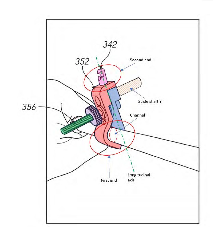
200 At [0193], the specification describes the use of the fourth coupler 342 as a universal coupler which can couple to one or more components of the hip navigation system 600. Even in that context, however, the specification illustrates the concept of the fourth coupler in an identical manner. The specification states that the fourth coupler may be identical or substantially similar to the first coupler 632, which is depicted in Figure 2 of the specification as follows:
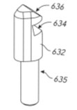
201 Continuing at [0193], the specification discloses that the fourth coupler 342 can include an elongate post, and can include a slot, and the slot can be designed to lock with the orientation sensing device 204.
202 At [0194], the specification describes different shapes of the fourth coupler 342:
In some embodiments, the fourth coupler 342 can have a regular shape (e.g., cylindrical). In some, the orientation sensing device 204 can mate with the fourth coupler 342 in a plurality of orientations. In some embodiments, the fourth coupler 342 can have an irregular shape (e.g., triangular, teardrop, elliptical, rectangular). The irregular shape can facilitate alignment of the orientation sensing device 204 relative to the fourth coupler. In some, the orientation sensing device 204 can mate with the fourth coupler 342 in a single orientation.
203 The foregoing disclosure indicates that the ‘elongate post’ in claim 3 need not have a cylindrical shape. It could, for example, have an elliptical or rectangular shape.
204 At [0196], the specification describes the function of the impactor adapter having the fourth coupler 342 to allow the orientation sensing device 204 to “mount thereon”, and provide a means to rigidly couple the orientation sensing device 204 to the impactor.
205 In my view, the ordinary meaning of claim 3, when read in the context of claim 1 and the specification as a whole, indicates that the phrase ‘elongate post’ refers to an upright or support, which can be broadly described as ‘extended’ (conveying, at least, that the length of the post is greater than its width), and which is configured to fit into a correspondingly-shaped mating hole on a component of the inertial navigation device.
G. The Navbit Sprint
206 In the proceeding, Navbit admits that, from a date after 13 March 2018 and without the licence or authority of OrthAlign, it has offered for sale, sold and supplied, and kept for the purpose of offering for sale, selling or supplying, a hip joint navigation system referred to by the name Navbit Sprint.
207 In preparing his evidence with respect to infringement, Mr Mittelstadt relied upon a document titled “Navbit Sprint Surgical Technique Guide Lateral Patient Registration” which describes the use of the Navbit Sprint in surgery and contains photographs of the components of the device, as well as a demonstration sample of the device with accompanying photographs.
208 In responding to Mr Mittelstadt’s evidence with respect to infringement, Mr Hunter relied upon materially the same evidence, although Mr Hunter was also provided with a document referred to as “Navbit Instructions for Use”. Further, the Navbit Sprint is supplied in two forms: one for surgery with patients in the lateral (side) position and one for surgery with patients in the supine (back) position. Mr Hunter was provided with a demonstration model of the Navbit Sprint – Lateral and the Navbit Sprint – Supine, as well as the Instructions for Use and Surgical Technique Guide for each of the lateral and supine versions.
209 It is common ground that there is no relevant difference between the lateral and supine versions.
210 The Surgical Technique Guide contains the following photograph of the components of the Navbit Sprint:
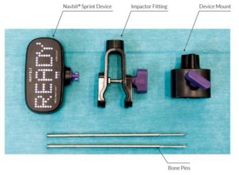
211 The Surgical Technique Guide describes the following steps associated with the use of the Navbit Sprint in surgery.
212 First, the Impactor Fitting is attached to the impactor. The Guide depicts the Impactor Fitting being attached to both a straight impactor and an ‘offset’ impactor as follows:
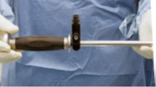
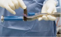
213 The Guide depicts the surgeon tightening the “thumbscrew” on the Impactor Fitting, and states that the “Impactor Fitting can be rotated around the shaft of the impactor to suit the surgeon without affecting measurement accuracy, but it must be tight enough not to wobble”:

214 Second, the Bone Pins are attached to the pelvis (using an electric drill), and the Device Mount is then attached to the Bone Pins, as depicted below:
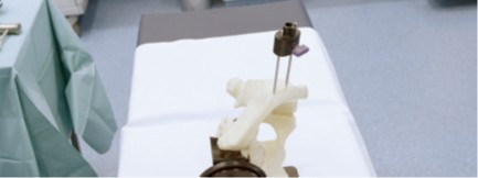
215 Third, pelvic registration is then performed by inserting the Device into the Device Mount and ‘locking’ it by a 90-degree rotation, as depicted below:
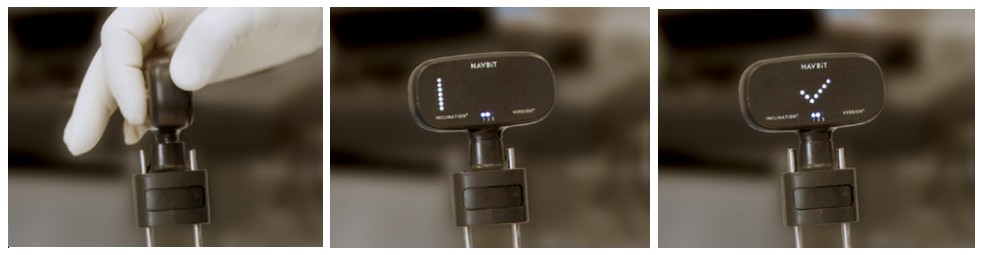
216 Fourth, to insert the acetabular cup with the impactor, the Device is transferred from the Device Mount to the Impactor Fitting, which enables the position of the impactor to be adjusted until the “target angles of radiographic inclination and version are achieved”, as depicted below:
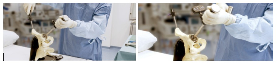
217 In the Frequently Asked Questions section, the Guide states that the Impactor Fitting has been designed to fit a range of diameters from 9.5–20 millimetres (3/8–25/32 inches) and must be attached to a surface parallel to the impaction axis.
218 In his first affidavit, Mr Mittelstadt reproduced the photograph of the components of the Navbit Sprint device contained in the Surgical Technique Guide (shown above), and marked the photograph with features of the Patent claims that Mr Mittelstadt considered were contained within the Navbit Sprint:
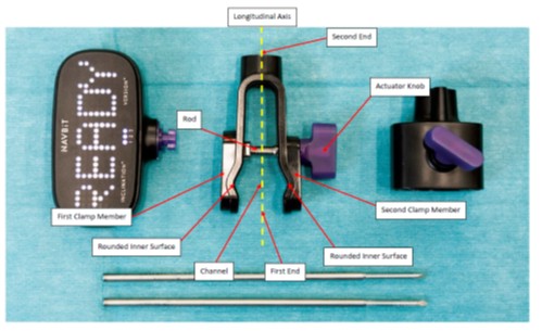
H. Infringement issues
Relevant legal principles
219 To establish infringement, the patentee must show that the defendant has taken each and every one of the essential integers of the patentee’s claim: Rodi & Wienenberger AG v Henry Showell Ltd [1969] RPC 367 at 391. Where the claim is to a combination, there is no infringement where what has been exploited is only a part of what has been claimed: Walker v Alemite Corporation (1933) 49 CLR 643 at 657-658 per Dixon J, with whom McTiernan J agreed.
220 In argument, the parties adverted to the somewhat vexed issue of ‘non-literal’ or ‘non-textual’ infringement, comprising cases in which infringement has been found on the basis that the defendant has taken the essence (more descriptively, the ‘pith and marrow’) of the invention and cases in which infringement has been found on the basis that an omitted or altered integer was inessential. The principles that underpin those cases must be approached with care. The use of the expression “the pith and marrow of the invention” in the context of infringement can be traced to the decision of Lord Cairns in Clark v Adie (1877) LR 2 App Cas 315 at 320, a time when it was not a requirement that a patent specification include formal claims defining the invention. Over time, the formulation of the relevant enquiry has focussed upon the integers of the claim and whether an omitted or altered integer is an essential feature of the patentee’s claimed invention or is inessential. In C Van der Lely NV v Bamfords Ltd [1963] RPC 61, Viscount Radcliffe observed (at 78) that the ‘pith and marrow’ principle is directed to the prevention of abuse of patent rights by colourable evasion, but that “the modern practice of building up patent claims by a meticulous accumulation of separate or combined elements has left a good deal less room for a patentee to complain of abuse, where there is no textual infringement, than may have been allowed to him at some periods in the past”. Likewise, in Rodi and Wienenberger AG v Henry Showell Limited [1969] RPC 367, Lord Upjohn observed (at 391) that:
To constitute infringement the article must take each and every one of the essential integers of the claim. Non-essential integers may be omitted or replaced by mechanical equivalents; there will still be infringement. I believe that this states the whole substance of the ‘pith and marrow’ theory of infringement.
221 Those observations were approved by Gibbs J in Olin Corporation v Super Cartridge Co Pty Ltd (1977) 180 CLR 236 where his Honour stated (at 246, citations omitted):
… as was pointed out in C Van der Lely NV v Bamfords Ltd, the principle that there may be infringement by taking the “pith and marrow” or the substance of an invention does not mean that there will be an infringement where the patentee has by the form of his claim left open that which the alleged infringer has done. And it does not affect the fundamental rule that there will be no infringement unless the alleged infringer has taken all of the essential features or integers of the patentee's claim.
222 The foregoing principles were further explained by the Full Federal Court (Bowen CJ, Deane and Ellicott JJ) in Populin v HB Nominees Pty Ltd (1982) 41 ALR 471 as follows (at 475, citations omitted):
The patentee must be vigilant to claim only the essence of the invention. This is particularly so in relation to a combination patent. It is important to claim only the essential integers in the combination or to distinguish what is essential from what is inessential. For to establish infringement of a combination patent, the patentee must show that the defendant has taken each and every one of the essential integers of the patentee’s claim. Therefore if, on its true construction, the claim in a patent claims a particular combination of integers and the alleged infringer of it omits one of them he will escape liability.
At the same time, however, the courts have avoided too technical or narrow a construction of claims. In Radiation Ltd v Galliers and Klaerr Pty Ltd Dixon J said: “But, on a question of infringement, the issue is not whether the words of the claim can be applied with verbal accuracy or felicity to the article or device alleged to infringe. It is whether the substantial idea disclosed by the specification and made the subject of a definite claim has been taken and embodied in the infringing thing”.
It is in reliance on this approach that the courts have held that a defendant will not escape infringement by adopting what are immaterial variations, for example, by omitting an inessential part or step and substituting another part or step as its equivalent (see Marconi v British Radio-Telegraph and Telephone Co Ltd per Parker J). It was considerations such as this that led early in the history of patent law to the development of what has been termed the “pith and marrow” or “pith and substance” test. …
223 While an integer that is included in a claim could be expected to have been intended by the patentee to be treated as essential to the invention as defined in that claim, the foregoing cases indicate that, in some circumstances, an integer will be regarded as inessential. As subsequent cases have shown, however, the difficulty lies in distinguishing between essential and inessential integers. Indeed, the difficulty extends to enunciating a principled basis upon which to draw the distinction.
224 In more recent times, the Full Federal Court has cautioned against an approach to infringement which is not closely tied to the claims of the patent as framed by the patentee. In Fresenius Medical Care Australia Pty Ltd v Gambro Pty Ltd [2005] FCAFC 220; 224 ALR 168, the Full Court (Wilcox, Branson and Bennett JJ) stated (at [91]-[94]), with reference to the reasoning of Bennett J in Sachtler GmbH & Co KG v RE Miller Pty Ltd [2005] FCA 788; 221 ALR 373:
91 … The application of purposive construction has recently been considered in Sachtler at [42]–[44], [46]–[56], [62] and [114]. As discussed in Sachtler, previous cases in Australia (such as Populin) and the United Kingdom (such as Catnic) stand for the proposition that the essential integers are determined by a common sense assessment of what the words of the claims convey in the context of then-existing published knowledge. So-called “purposive construction” does not propound a novel principle.
92 One does not look to see whether the allegedly infringing article is the same in substance and effect as the disclosures of the specification or of the claims. The principle of “pith and marrow” applies to immaterial variations where an inessential part or step is omitted or substituted. There is no infringement if a variant has a material effect on the way the invention works: Sachtler at [51]–[52]. However, this does not mean that there is infringement where there has been no taking of all the essential integers of the claim: Olin at CLR 246; ALR 157 per Gibbs J. The form and wording of the claim are determinative.
93 As Gyles J said in Grove Hill (at [311]) “a patentee cannot eat the cake and have it too by persuading a court to construe a claim more widely than the patentee was prepared to risk when framing the claims under the guise of purposive construction”.
94 The whole of the specification must be read in order to construe the claim. So much is not in dispute. However, that does not mean that the words of the claim are to be ignored. Nor can it be ignored that the patentee has chosen not to include in a claim matters, integers or aspects of the invention that have been referred to in the body of the specification. This accords with the well-accepted principle enunciated in Welch Perrin (at 610) that glosses drawn from the body of the specification cannot be used to narrow or expand the boundaries of the monopoly as fixed by the words of a claim.
225 Similarly, in Australian Mud Company Pty Ltd v Coretell Pty Ltd [2011] FCAFC 121; 93 IPR 188, the Full Court (Bennett, Gilmour and Yates JJ) stated (at [69]):
To give a purposive construction to a patent specification, and in particular its claims, is not to engage in a process of reasoning that extends the patentee’s monopoly to the “ideas” disclosed in the specification. Nor does it extend the patentee’s monopoly to products or processes that the patentee did not, by the claims, define as the invention, even if those products or processes can be seen to perform the same function as the invention or to be based on the patentee’s “ideas”.
226 Even more recently, the Full Court (Allsop CJ, Yates and Robertson JJ) in GlaxoSmithKline Australia Pty Ltd v Reckitt Benckiser Healthcare (UK) Ltd [2016] FCAFC 90; 120 IPR 406 observed (at [52]) that it would be a “most unusual case where a feature expressly set out in the claim is not essential”. Two months later in Otsuka Pharmaceutical Co Ltd v Generic Health Pty Ltd (No 2) [2016] FCAFC 111; 120 IPR 431, the Full Court (Besanko, Nicholas and Beach JJ) did not question the proposition that, although it is open to a court to hold that an express feature is not an essential feature, that in fact is done very rarely and the court must be cautious in holding that an express feature is an inessential feature or integer.
227 In closing submissions, OrthAlign confirmed that it did not advance an argument based upon the principle of a ‘mechanical equivalent’, whether under existing Australian law or by adoption of the expanded doctrine as discussed in Actavis UK Ltd & Ors v Eli Lilly & Co [2017] UKSC 48 (Actavis). In other words, it did not contend that the Navbit Sprint satisfied an integer of a claim on the basis that the relevant element of the Navbit Sprint was a mechanical equivalent to the integer.
228 It is uncontroversial that OrthAlign bears the onus of establishing that Navbit has infringed the Patent: Avel Pty Ltd v Multicoin Amusements Pty Ltd (1990) 171 CLR 88 at 94-95 (Mason CJ, Deane and Gaudron JJ), 105-106 (Dawson J), 119 (McHugh J), recently cited with approval in Realestate.com.au Pty Ltd v Hardingham (2022) 277 CLR 115 at [40] (Kiefel CJ and Gageler J).
Infringement issue 1: a clamp comprising a first clamp member and a second clamp member opposite the first clamp member
229 OrthAlign submitted that the Impactor Fitting component of the Navbit Sprint has a clamp which comprises a first clamp member and a second clamp member opposite the first clamp member within the meaning of Integer 1.5 of claim 1, as identified on the photograph of the Navbit Sprint that was labelled by Mr Mittelstadt (and shown above). The two clamp members were also identified by OrthAlign in the following photograph (prepared as an annexure to its submissions at trial):
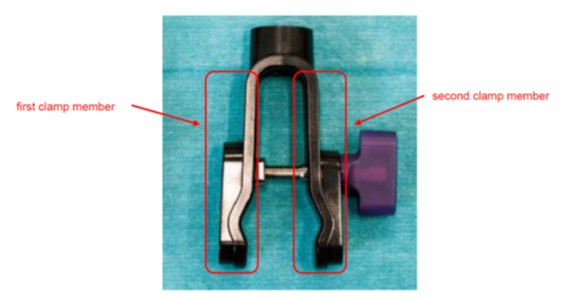
230 Navbit submitted that the Navbit Sprint does not satisfy this integer of claim 1 for the reason that the Impactor Fitting component of the Navbit Sprint is integrally formed. As discussed in the context of construction, Navbit submitted that claim 1 requires the two members of the clamp to be physically separate components.
231 I have earlier rejected Navbit’s construction of this integer of claim 1. It follows that I reject Navbit’s submission that the Navbit Sprint does not satisfy this integer of claim 1 for the reason that the Impactor Fitting component of the Navbit Sprint is integrally formed.
232 Navbit advanced no other reason why the Navbit Sprint does not satisfy this integer of claim 1. I accept OrthAlign’s submission that the Navbit Sprint satisfies this integer of claim 1.
Infringement issue 2: the channel comprising a round inner surface configured to receive a round outer surface of the impactor
233 OrthAlign submitted that the Impactor Fitting component of the Navbit Sprint has “a channel … disposed between the first clamp member and the second clamp member”, within the meaning of Integer 1.6 of claim 1, where the “channel compris[es] a round inner surface configured to receive a round outer surface of the impactor” within the meaning of Integer 1.7 of claim 1. The round inner surface of the channel was identified on the photograph of the Navbit Sprint that was labelled by Mr Mittelstadt (and shown above), and was also identified by OrthAlign in the following photograph (prepared as an annexure to its submissions at trial):
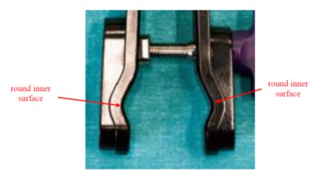
234 With respect to integer 1.6, Navbit acknowledged that if its construction of Integer 1.5 were not accepted by the Court, no separate issue arises in respect of Integer 1.6. In other words, Navbit accepted that if the two arms of the Impactor Fitting component of the Navbit Sprint satisfy the description of being a first and second clamp member opposite each other within Integer 1.5, then the area disposed between those arms comprises a channel within the meaning of Integer 1.6. It follows from the conclusion I have reached with respect to Integer 1.5 that no separate issue arises with respect to Integer 1.6. It was common ground that the channel is defined by the area between the approximately V-shaped portion of the two arms of the Impactor Fitting.
235 With respect to integer 1.7, it is also not in dispute that the channel of the Impactor Fitting component of the Navbit Sprint has a round inner surface. The experts identified this as the ‘fillet radius’ at the base of the V-shape in each arm of the clamp, and both parties accepted that the fillet radius in each clamp member is a round inner surface of the channel. In his second affidavit, Mr Hunter identified the fillet radius at the base of the V-shape in the arm of the clamp by the arrow in the following picture:
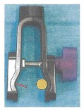
236 Significantly, however, the experts confirmed their agreement in the joint expert report that the fillet radii in the arms of the Impactor Fitting component of the Navbit Sprint are not designed to receive the round outer surface of the impactor. Rather, the round outer surface of the impactor will be received on the flat sides of the V-shape forming part of the channel.
237 The mechanical operation of the arms of the Impactor Fitting component of the Navbit Sprint was described in Mr Hunter’s second affidavit as follows:
Each of the two arms of the Impactor Fitting comprises a roughly V-shaped portion wherein the open (or top) parts of the Vs face each other across the channel. The impactor shaft is placed between these V-shaped portions and, when the thumbscrew is tightened, the Impactor Fitting is clamped to the impactor shaft. The base of these roughly V-shaped portions is a "fillet radius", being a radiused (curved) surface between two straight sides. If, instead, this were a sharp corner (i.e. truly V-shaped) then, when the clamp is tightened, the sharp corner (i.e. the bottom of the V) would be liable to cracking under stress. The fillet radius distributes this stress and, thus, reduces the risk of cracking.
238 Mr Hunter explained that, having regard to the dimensions of the radiused bases of the roughly V-shaped portions of the arms of the Impactor Fitting, the diameter of an impactor shaft with a round outer surface small enough to fit within the radius would be too small to be clamped by the Impactor Fitting. Conversely, an impactor shaft with a diameter large enough to be clamped would not touch the round inner surface of the V-shaped portion. Mr Hunter prepared the following diagram as an illustration:
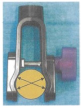
239 Mr Hunter explained the above diagram (labelled Diagram 16) as follows:
As can be seen from Diagram 16 above, the Impactor Fitting clamps the impactor shaft because there are four points of contact between the two roughly V-shaped portions of the arms (specifically, the two straight sides of each of the roughly V-shaped portions) of the Impactor Fitting and the impactor shaft (as indicated by the black arrows in Diagram 16 above). This enables the Impactor Fitting to clamp to impactor shafts of different diameters (within a particular range). As can be seen in Diagram 16 above, the radiused bases of the roughly V-shaped portions of the Impactor Fitting do not sit flush with the round outer surface of the impactor shaft. Indeed, they do not contact the round outer surface of the impactor shaft at all.
240 As noted earlier, the experts agreed that the fillet radii in the arms of the Impactor Fitting component of the Navbit Sprint are not designed to receive the round outer surface of the impactor.
241 I have earlier concluded that Integer 1.7 requires that the round inner surface of the channel be configured to receive the round outer surface of the impactor. As a consequence, at least some portion of the channel must include a surface which is rounded so as to make contact with a complementary or matching rounded surface portion present on the impactor shaft. The parties accept that the Impactor Fitting component of the Navbit Sprint does not satisfy that requirement.
242 To the extent (which was unclear) that OrthAlign pressed an argument that Integer 1.7 was not an essential integer, and that the clamping members of the Impactor Fitting component of the Navbit Sprint were a mechanical equivalent to what is claimed in the Patent, I do not accept the argument. The language of the integer is clear and precise. The invention the subject of claim 1 does not merely comprise an impactor adapter having a clamp configured to couple with an impactor; it comprises a clamp with two members, where a channel is disposed between the members and the channel comprises a round inner surface configured to receive a round outer surface of the impactor. As discussed in the context of construction, the specification does not disclose any different type of clamp other than one having a channel with a round inner surface “to connect to a round outer surface an impactor [sic]” (at [0198]) and as illustrated in Figure 18C. Whilst Mr Mittelstadt expressed the opinion in the joint expert report that Integer 1.7 could be satisfied by a channel that resembles “a V-groove that has a fillet radius at the apex of the grove [sic]”, I have earlier concluded that that opinion was at least unconsciously influenced by the Navbit Sprint. In any event, Mr Mittelstadt accepted during cross-examination that the words “configured to receive” convey that the round inner surface of the channel makes contact with the round outer surface of the impactor shaft.
243 In conclusion, I consider that the Navbit Sprint does not satisfy Integer 1.7 and, as a consequence, the Navbit Sprint does not infringe the Patent.
Infringement issue 3: actuator knob
244 OrthAlign submitted that it is clear that the Impactor Fitting component of the Navbit Sprint has an “actuator knob” within the meaning of Integer 1.8 of claim 1. The actuator knob was identified on the photograph of the Navbit Sprint that was labelled by Mr Mittelstadt (and shown above), and was also identified by OrthAlign in the following photograph (prepared as an annexure to its submissions at trial):
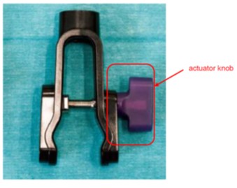
245 Navbit submitted that the Navbit Sprint does not satisfy this integer of claim 1 for the reason that the actuating element of the Impactor Fitting is not rounded but a winged lever. As discussed in the context of construction, Navbit submitted that the word ‘knob’ is intended to define a feature having a particular shape, being a rounded actuating component.
246 I have earlier rejected Navbit’s construction of this integer of claim 1. It follows that I reject Navbit’s submission that the Navbit Sprint does not satisfy this integer of claim 1 for the reason that the actuating element of the Impactor Fitting is not rounded.
247 Navbit advanced no other reason why the Navbit Sprint does not satisfy this integer of claim 1. I have earlier concluded that the word ‘knob’ is used in the claim to refer a protruding part of the clamp that can be ‘moved’ so as to cause relative movement between the first clamp member and the second clamp member to achieve clamping. Although the nature of the ‘movement’ of the actuator knob in claim 1 is not described, it can be inferred that the movement is circular (to rotate the ‘rod’ causing the clamp to close). The actuator element of the Impactor Fitting component of the Navbit Sprint satisfies that description. I therefore accept OrthAlign’s submission that the Navbit Sprint satisfies this integer of claim 1.
Infringement issue 4: elongate post … configured to receive a component of the inertial navigation device
248 OrthAlign submitted that the Impactor Fitting component of the Navbit Sprint includes a coupler comprising an elongate post disposed opposite the clamp, wherein the elongate post is configured to receive a component of the inertial navigation device, within the meaning of claim 3. The elongate post was identified by OrthAlign in the following photograph (prepared as an annexure to its submissions at trial):
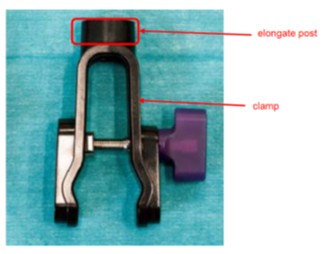
249 OrthAlign submitted that this part of the Impactor Fitting (the impactor adapter) is an “upstanding feature” which is disposed opposite the clamp. It is configured to receive a component of the inertial navigation device. It receives a component of the inertial navigation device in a “slot” or recess which forms part of the elongate post, which itself forms part of the coupler of the impactor adapter. The “slot” or recess is configured to lock with a component of the inertial navigation device to rigidly couple the device with the coupler.
250 Navbit submitted that it is inapt to describe the mount point of the Impactor Fitting component of the Navbit Sprint as an “elongate post … configured to receive a component of the inertial navigation device”, and that the mount point on the Impactor Fitting component cannot fairly be described as either ‘elongate’ or a ‘post’. In that regard, Navbit relied on the evidence of Mr Hunter in respect of the method by which, in the Navbit Sprint, the Device is mounted to the Impactor Fitting. In his second affidavit, Mr Hunter described that method as disclosed in the Navbit Instructions for Use, which was as follows.
251 The Instructions for Use contains the following labelled diagram of the “Navbit Sprint Device”:
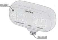
252 The Instructions for Use also contains the following labelled diagram of the Impactor Fitting:
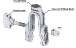
253 Above the latter diagram is a statement that the Impactor Fitting enables the fixation of the Navbit Sprint Device onto the shaft of an impactor.
254 Mr Hunter observed that the “mount point” of the Impactor Fitting comprises an opening that fits together with the bayonet at the base of the Navbit Sprint Device. Mr Hunter explained that a bayonet fit is a standard locking system used in mechanical engineering. It typically involves a ‘male’ component (in this case, the bayonet) which locks into a ‘female’ component (in this case, the mount point) by a 90-degree turn.
255 I have earlier concluded that the ordinary meaning of claim 3, when read in the context of claim 1 and the specification as a whole, indicates that the phrase ‘elongate post’ refers to an upright or support, which can be broadly described as ‘extended’ (conveying, at least, that the length of the post is greater than its width), and which is configured to fit into a correspondingly-shaped mating hole on a component of the inertial navigation device. It follows from that construction of claim 3 that the Navbit Sprint does not infringe claim 3. The part of the Impactor Fitting to which the Device is fitted is neither a post nor elongate, and it is not a male coupler configured to fit into a correspondingly shaped mating hole on a component of an inertial navigation device. The part of the Impactor Fitting to which the Device is fitted is an entirely different form of coupling method, involving a bayonet protruding from the Device (the orientation sensing device) inserted into a hole or slot within the Impactor Fitting (the impactor adapter).
Conclusion
256 In conclusion, the Navbit Sprint does not infringe claim 1 of the Patent because it does not take Integer 1.7. The channel which is disposed between the first and second clamp members of the Impactor Fitting component of the Navbit Sprint does not comprise a round inner surface configured to receive a round outer surface of the impactor. It follows that OrthAlign’s claim for infringement of its Patent must be dismissed.
257 Although it does not affect the result, I have also concluded that the Navbit Sprint does not infringe claim 3 of the Patent. Relevantly, the Impactor Fitting component of the Navbit Sprint does not include a coupler disposed opposite the clamp which comprises an elongate post configured to receive a component of the inertial navigation device.
I. Invalidity
Introduction
258 By its cross-claim, Navbit seeks a declaration that each of claims 1 to 5 of the Patent is invalid and an order that the claims be revoked. At trial, Navbit pressed four grounds of invalidity, which were as follows:
(a) lack of support – the specification of the Patent does not comply with s 40(3) of the Act in that each of claims 1 to 5 is not supported by matter disclosed in the specification;
(b) lack of enablement – the specification of the Patent does not comply with s 40(2)(a) of the Act in that it does not disclose the invention in a manner which is clear enough and complete enough for it to be performed by a person skilled in the relevant art;
(c) lack of utility – the invention claimed in each of claims 1 to 5 of the Patent is not a patentable invention within the meaning of section 18(1A)(c) of the Act in that the claimed invention is not useful - the Patent includes the promise that the impactor adapter is a ‘universal impactor adapter’ and that promise is not met; and
(d) lack of innovative step – the invention claimed in each of claims 1 to 5 of the Patent is not a patentable invention within the meaning of section 18(1A)(b)(ii) of the Act in that the claims lack an innovative step when compared with two prior patent specifications, being WO 745 and WO 181.
259 Many of the arguments advanced by Navbit on the invalidity grounds were dependent upon the construction of the claims of the Patent and the identification of the invention claimed. It is therefore necessary to reiterate certain of the construction findings that have already been made, and to describe the invention claimed by the Patent.
260 The invention claimed in claim 1 has two components: first, an impactor adapter which, at one end, comprises a clamp configured to couple with an impactor and, at the other end, comprises a coupler; and second, an inertial navigation device configured to couple with the coupler at the second end of the impactor adapter. The clamp has two clamp members opposite each other, with a channel disposed between them, where the channel comprises a round inner surface configured to receive a round outer surface of an impactor.
261 I have earlier found that the claim is to be understood as requiring that at least some portion of the channel between the two clamp members (considered in cross-section) must include a surface which is rounded to receive, in the sense of making contact with, a complementary or matching rounded surface portion present on the impactor shaft. The claim does not require that the entirety of the channel (in so far as it comprises a round inner surface) must make full contact with the round outer surface of the impactor shaft, in the sense of the two surfaces ‘mating’ or being a ‘match’. It is sufficient if at least some portion of the channel, being a round surface, makes contact with the round surface of the impactor shaft.
262 It follows from that construction of the claim that the impactor adapter as so described will be capable of coupling to impactors having a rounded shaft with a range of sizes (diameters). The impactor adapter described in the claim is not an impactor adapter that is limited to coupling with a single impactor having a shaft size and profile that matches the inner surface of the clamp.
263 It also follows, and I have earlier concluded, that at the highest, the impactor adapter that is described in claim 1 can only be regarded as a subset of the ‘universal impactor adapter’ that is described in the specification. First, it is an impactor adapter which couples with an impactor using a clamp (and not a magnetic or other “manner of connection”, as contemplated and disclosed in the specification). Second, the clamp has a channel between the two clamp members comprising a round inner surface configured to receive a round outer surface of the impactor (and not a square or other profile shaft of an impactor, as contemplated and disclosed in the specification).
264 Although the Patent specification is a lengthy document and traverses a wide range of products, systems and procedures that may be used in hip replacement surgery, most of those products, systems and procedures are not the subject of the five claims of the Patent. In cross-examination, Mr Mittelstadt expressed the following opinion with respect to the claimed invention, which I accept:
So the claims of the patent, in my mind, are relatively simple, right? You have a clamp, you got a coupler. You know, it’s relatively simple things. But it’s the context of it that is going to take the design one way or the other, right? So it’s the surgical use. It’s the impactor. It’s the impactor – range of impactors. So it’s, like, all of that information is what is going to make the design work or not, right? But you can design a clamp that satisfies the claim. I just looked at it as – that was kind of limiting it to the mechanical components. But the claims, in my mind, include that navigation system. So as soon as you bring in the navigation system, they have to understand the whole environment in which that mechanical design will be used, which is surgeons pounding things, the cleaning of instruments – if it’s a reusable – and how abusive that is. And so you want somebody who is going to design it for all of that. And the claims aren’t clear enough for taking all of that into account, in – in my opinion.
265 Navbit bears the onus of proving that the Patent is invalid on the bases alleged by it: Aktiebolaget Hassle v Alphapharm Pty Ltd (2002) 212 CLR 411 at [21] (Gleeson CJ, Gaudron, Gummow and Hayne JJ).
Lack of support
Applicable principles
266 Navbit contends that the Patent claims lack support and are accordingly invalid for failure to comply with s 40(3) of the Act, which provides (emphasis added):
(3) The claim or claims must be clear and succinct and supported by matter disclosed in the specification.
267 The requirement that the claims be supported by matter disclosed in the specification was introduced to the Act by the Intellectual Property Laws Amendment (Raising the Bar) Act 2012 (Cth) (Raising the Bar Act), replacing the requirement that the claims be fairly based on the matter disclosed in the specification.
268 The meaning of the support requirement was considered by Burley J in Merck Sharp & Dohme Corp v Wyeth LLC (No 3) [2020] FCA 1477; 155 IPR 1, where his Honour observed:
(a) there can be little doubt that Parliament considers that it is appropriate for the Court to have regard to the law in the European Union and the United Kingdom in considering the scope of the requirement for “support” (at [514]);
(b) the claim support obligation is based on a requirement that the technical contribution to the art disclosed by the specification justifies the breadth of the monopoly claimed (at [533]);
(c) the theme common to both the enablement requirement and the support requirement is that in exchange for the exclusive rights given to the patentee, the patentee must share with the public the information necessary to make and use the invention – this is the essential exchange between inventors and the public which has long been a feature of patent law in Australia (at [545]).
269 Justice Burley observed (at [546]-[547]) that Aldous J’s summary in Schering Biotech Corp’s Application [1993] RPC 249 at 252-253 broadly encapsulates the claim support obligation under s 40(3):
… to decide whether the claims are supported by the description it is necessary to ascertain what is the invention which is specified in the claims and then compare that with the invention which has been described in the specification. Thereafter the court’s task is to decide whether the invention in the claims is supported by the description. I do not believe that the mere mention in the specification of features appearing in the claim will necessarily be a sufficient support. The word “support” means more than that and requires the description to be the base which can fairly entitle the patentee to a monopoly of the width claimed.
270 This approach was also applied in Rakman International Pty Ltd v Trafalgar Group Pty Ltd [2022] FCA 464; 166 IPR 264 at [120], Cytec Industries Inc v Nalco Company [2021] FCA 970; 162 IPR 202 at [120], Jusand Nominees Pty Ltd v Rattlejack Innovations Pty Ltd [2022] FCA 540; 167 IPR 1 at [370]-[372] and [481]; Jusand Nominees Pty Ltd v Rattlejack Innovations Pty Ltd (2023) 300 FCR 408 (Jusand Appeal) at [177].
271 In ToolGen Incorporated v Fisher (No 2) [2023] FCA 794 at [410], Nicholas J observed that a claim might meet the requirement of s 40(2)(a) by providing an enabling disclosure, and not meet the support requirement of s 40(3); but that it is difficult to see how a claim to an invention for which there was no enabling disclosure could meet the support requirement.
272 In Calix Ltd v Grenof Pty Ltd [2023] FCA 378; 171 IPR 582 at [128], Nicholas J explained:
Although discussion of s 40(3) is often focused on the breath [sic] of the claim, there may be some claims which lack support not because they are too broad, but because they define an invention that is materially different to what is described in the body of the specification. Hence, a claim that includes a feature not disclosed in the specification, or omits a feature that is disclosed, may lack support because the invention claimed is materially different from the invention disclosed. Whether or not the claim will lack support in such circumstances will depend on the proper characterisation of the invention disclosed in the body of the specification and the invention claimed. See, for example, the invention described in the relevant priority document and the invention claimed in AstraZeneca at [254]–[255] which were characterised by the Full Court of the Federal Court as “fundamentally different” inventions. It is difficult to see how a claim to an invention that is fundamentally different from that which is disclosed in the specification could be “supported by matter disclosed” in accordance with s 40(3) of the Act.
Navbit’s contentions
273 Navbit’s submissions with respect to lack of support presented a confusing array of alternative arguments. However, the focus of the submissions was whether the impactor adapter, the subject of claim 1, is a universal impactor adapter as that term is used in the specification. Navbit submitted that, if the Court concludes that the claimed impactor adapter is not a ‘universal impactor adapter’ on the proper construction of that term, then the claims are not supported by the disclosure. That is because, with the exception of the consistory clauses, every reference in the Patent to an impactor adapter is to a ‘universal impactor adapter’. Navbit argued that, to the extent that the claims are not to a ‘universal impactor adapter’, they are to an invention which is fundamentally different to that which is disclosed, relying upon Calix at [128] referred to above.
274 I have earlier considered the question whether the impactor adapter that is the subject of claim 1 is a ‘universal impactor adapter’ as disclosed in the specification, and concluded that the impactor adapter that is the subject of claim 1 can only be regarded as a subset of the ‘universal impactor adapter’ that is described in the specification. However, I do not accept Navbit’s submission that the claimed invention is fundamentally different to that which is disclosed in the specification. I consider that the claimed invention is merely narrower than what is described in the specification.
275 The relevant question is whether the invention which is the subject of the claims is supported by the description of the invention in the specification. In my view, as stated by Mr Mittelstadt, the invention the subject of the claims is relatively simple. At its core, the invention has two components, being the impactor adapter (which, at one end, comprises a clamp configured to couple with an impactor and, at the other end, comprises a coupler) and an inertial navigation device configured to couple with the coupler at the second end of the impactor adapter. The specification describes that invention, particularly at [0196] to [0199], with illustrations in Figures 18C and 18D.
276 Navbit argued that, in so far as the claimed invention encompasses a clamp with two members that are not separate, the description in the specification was insufficient because the clamp illustrated in Figures 18C and 18D has two separate clamp members. I have earlier found that the claimed invention encompasses a clamp with two members that are not separate. However, I do not accept Navbit’s criticism of the adequacy of the specification. The specification describes the use of a clamp to couple the impactor adapter to an impactor, discloses that the clamp can include a round inner surface to connect to a round outer surface of an impactor, discloses that the clamp of the impactor adapter can reduce or prevent unwanted movement between the impactor and the orientation sensing device, and that the clamp can apply a force necessary to rigidly couple to the exterior surface of the impactor. The specification does not disclose any necessity for the clamp to have two separate members. Whilst the clamp illustrated in Figures 18C and 18D has two members, the illustration does not limit the description.
277 In the joint expert report, Mr Mittelstadt expressed the following opinion:
My view is that the specification describes the need for an impactor adapter to clamp to impactors that have a cylindrical region which is aligned with the cup axis and also have a limited set of possible diameters. Designers skilled in the art would be able to use the information in the specifications to develop designs to meet these requirements.
278 I accept that evidence. I consider that the claimed invention, which has those features, is supported by the specification.
279 In conclusion, Navbit has failed to persuade me that the claims are not supported by matter disclosed in the specification.
Lack of enablement
Applicable principles
280 Navbit contends that the Patent claims are invalid because the specification does not comply with s 40(2)(a) of the Act, which provides as follows:
(2) A complete specification must:
(a) disclose the invention in a manner which is clear enough and complete enough for the invention to be performed by a person skilled in the relevant art;
…
281 Lack of enablement arises when the disclosure is not clear or complete enough for the claims to be worked across their width by a person skilled in the art, using the matters disclosed and common general knowledge, without undue burden or further invention: Kirin-Amgen at [103]; Novartis AG v Johnson & Johnson Medical Ltd (t/as Johnson & Johnson Vision Care) [2011] ECC 10 at [74]; ToolGen Inc v Fisher (No 2) [2023] FCA 794 at [238]. This reflects the Explanatory Memorandum to the Intellectual Property Laws (Raising the Bar) Bill 2011 (Cth) which stated (at 46) that the amendment to s 40(2)(a):
… is intended to align the disclosure requirement with that applying in other jurisdictions with the effect that sufficient information must be provided to enable the whole width of the claimed invention to be performed by the skilled person without undue burden, or the need for further invention.
282 Whether a specification is sufficient to enable the skilled addressee to practise the invention across the whole scope of the monopoly without undue burden is ultimately a question of fact. In Mentor Corp v Hollister Inc (No 2) [1991] FSR 557, Aldous J said (at 562):
The section requires the skilled man to be able to perform the invention, but does not lay down the limits as to the time and energy that the skilled man must spend seeking to perform the invention before it is sufficient. The subsection by using the words “clearly enough and completely enough” contemplates that patent specifications need not set out every detail necessary for performance, but can leave the skilled man to use his skill to perform the invention. In so doing, he must seek success. He should not be required to carry out any prolonged research, enquiry or experiment. He may need to carry out the ordinary methods of trial and error, which involve no inventive step and generally are necessary in applying the particular discovery to produce a practical result. In each case, it is a question of fact depending on the nature of the invention, as to whether the steps needed to perform the invention are ordinary steps of trial and error which a skilled man would realise would be necessary and normal to produce a practical result.
Navbit’s contentions
283 On the issue of enablement, Navbit advanced a single contention in closing submissions: that the specification does not enable the skilled addressee to make an impactor adapter which is the subject of the claim, where the inner circumference of the clamp on the impactor adapter does not correspond to the outer circumference of the impactor shaft.
284 In support of that contention, Navbit relied principally on the evidence given by Mr Hunter, during cross-examination, with respect to the effectiveness of clamps comprising two members having rounded cross-sectional profiles, but where the round inner surface of the clamp did not perfectly match or mate with the round outer surface of the impactor shaft. Mr Hunter proffered during cross-examination that, if the clamp had only two or three points (or axial lines) of contact with an impactor shaft, he did not know how effective the clamping pressure would be, and it is not something that he could know without “prototyping and testing”. On the basis of that evidence, Navbit submitted that the work which would be required to practise the claimed invention amounts to prolonged research, enquiry or experiment, and that the claim would not be enabled on this basis.
285 In my view, Mr Hunter’s evidence falls a long way short of supporting Navbit’s submission. Whilst Mr Hunter believed that he would need to undertake prototyping and testing to develop a suitable clamp to couple securely with an impactor shaft, Mr Hunter gave no evidence about the scale of work that would be involved. Further, I consider that the weight that should be given to Mr Hunter’s evidence on this topic is diminished by his relative lack of expertise and experience in the field of hip replacement procedures, and the surgical methods and tools used in such procedures.
286 In the joint expert report, Mr Mittelstadt expressed the following opinion:
Paragraphs [0197]-[0198] together with Figures 18C and 18D of the Patent specification along with an understanding of the intent of the impactor adaptor provide a design team with enough information. The information in the specification clearly limits the requirements for the adapter to allow it to securely attach to impactors that have a range of shaft diameters and not to every conceivable impactor geometry. In addition, by understanding the manner in which the navigation system is used for cup impaction should inform the design team that the impactor adapter does not need to “lock onto an impactor so that it is completely immobile”. Although it would be desirable for the impactor adapter to make a 100% reliable and “rock solid” connection with the impactor, a designer, skilled in the art would understand that this requirement can add cost, complexity and result in a device that is hard to use by the surgeon. My opinion is that a design team as described above would understand from the specification that it is desirable for the impactor adapter to be universal (within reason) and should not be constrained to a single impactor shaft diameter. My view is that the specification describes the need for an impactor adapter to clamp to impactors that have a cylindrical region which is aligned with the cup axis and also have a limited set of possible diameters. Designers skilled in the art would be able to use the information in the specifications to develop designs to meet these requirements.
287 I accept that opinion. I consider that the specification discloses the invention in a manner which is clear enough and complete enough for the invention to be performed by a person skilled in the relevant art.
288 In conclusion, Navbit has failed to persuade me that the invention is not enabled by matter disclosed in the specification.
Lack of utility
289 Navbit contends that the invention claimed in each of claims 1 to 5 of the Patent is not a patentable invention within the meaning of section 18(1A)(c) of the Act in that the claimed invention is not useful: the Patent includes the promise that the impactor adapter is a ‘universal impactor adapter’ and that promise is not met.
Applicable principles
290 Section 18(1A)(c) of the Act relevantly provides that an invention is a patentable invention for the purposes of an innovation patent if the invention, so far as claimed in any claim, is useful.
291 The meaning of the word ‘useful’ is affected by s 7A which provides as follows:
7A Meaning of useful
(1) For the purposes of this Act, an invention is taken not to be useful unless a specific, substantial and credible use for the invention (so far as claimed) is disclosed in the complete specification.
(2) The disclosure in the complete specification must be sufficient for that specific, substantial and credible use to be appreciated by a person skilled in the relevant art.
(3) Subsection (1) does not otherwise affect the meaning of the word useful in this Act.
292 The meaning of the word ‘useful’ was considered by the Full Court in Esco. Although the patent under consideration in that case pre-dated the introduction of s 7A by the Raising the Bar Act, the Full Court also gave some consideration to the effect of s 7A. The Full Court stated the following relevant principles:
(a) First, utility depends upon whether, by following the teaching of the specification, the result claimed is produced. That involves identifying, as a matter of construction, the promise of the invention and asking whether the invention as claimed does what it is intended by the patentee to do (at [233]).
(b) Second, in determining the utility of the invention, it is necessary to follow the teaching of the complete specification to isolate the promise of the invention and determine whether the result claimed is produced. In determining the teaching of the specification and the promise of the invention, it is necessary to consider the claims and the body of the specification. In this context, the term ‘invention’ means the embodiment which is described and around which the claims are drawn (at [279]).
(c) Third, all that is within the scope of a claim must be useful (at [235]).
(d) Fourth, if the Patent, properly understood having regard to the whole of the specification including the claims, contains a “composite” promise for the described invention, a failure to attain any one of the elements of the composite promise in any claim defining the invention renders the invention, so far as claimed in any claim, inutile (at [239]).
Navbit’s contentions
293 Navbit contended that the promise of the Patent includes the promise that the impactor adapter is a ‘universal impactor adapter’ and that promise is not met. In support, Navbit submitted that, with the exception of the consistory clauses (at [0035a] to [0035b]), every reference to ‘impactor adapter’ in the Patent describes the impactor adapter as a ‘universal impactor adapter’. Navbit also relied on the evidence of Mr Hunter to the effect that he understands that the Patent includes that promise. As discussed earlier in these reasons, Mr Hunter expressed the view that the word ‘universal’, as used in the specification, conveys that the impactor adapter is capable of being fitted to any impactor. Based on that interpretation of the word, Mr Hunter expressed the opinion that the Patent specification does not disclose how that can be achieved. Mr Hunter observed that it is known that impactors have shafts in a wide range of shapes and sizes, and that impactors may have a combination of flat and round surfaces on the impactor shaft cross-sections.
294 Navbit’s contentions on this ground of invalidity again highlight the disconformity between the disclosures in the specification concerning a ‘universal impactor adapter’ and the more limited claims concerning a hip navigation system comprising an ‘impactor adapter’ with certain elements. This disconformity was considered earlier in these reasons in the context of construing the claims. The disconformity must now be considered in a different but related context: identifying, as a matter of construction, the promise of the invention for the purposes of assessing utility. As stated in Esco, in the context of assessing whether the invention, so far as claimed in any claim, is useful, the term ‘invention’ means the embodiment which is described and around which the claims are drawn.
295 As stated earlier in these reasons, I accept Mr Hunter’s opinion that the ‘universal impactor adapter’ as described in the Patent specification is stated to be an adapter that can be designed to couple with any impactor, including impactors having a round shaft of different diameters and impactors that do not have a round shaft. The ‘universal impactor adapter’ is also stated to be an adapter that can be designed to couple to a shaft of an impactor by any manner of connections. However, the specification does not disclose how those designs can be achieved.
296 Despite that, and for the reasons given earlier, I consider that the invention around which the claims are drawn, and the associated promise of the invention, is narrower than the ‘universal impactor adapter’ that is described in the specification. The promise of the impactor adapter which is the subject of claim 1 is simply the ability to couple:
(a) at one end, to impactors having a rounded shaft with a range of sizes (diameters) using a clamp where there is a channel between the clamp members that has a round inner surface that can receive the round outer surface of the impactor; and
(b) at the other end, to an inertial navigation device.
297 As such, the impactor adapter that is described in claim 1 can only be regarded as a subset of the ‘universal impactor adapter’ that is described in the specification: it is an impactor adapter which couples with an impactor using a clamp (and not a magnetic or other ‘manner of connection’, as contemplated and disclosed in the specification); and the clamp has a channel between the two clamp members comprising a round inner surface configured to receive a round outer surface of the impactor (and not a square or other profile shaft of an impactor, as contemplated and disclosed in the specification).
298 This conclusion is supported by the evidence of Mr Mittelstadt, which I accept, that the ‘impactor adapter’ the subject of claim 1 is an adapter designed to couple to a plurality of impactors, having a certain range of sizes of shafts. Mr Mittelstadt considered that:
… the specification describes the need for an impactor adapter to clamp to impactors that have a cylindrical region which is aligned with the cup axis and also have a limited set of possible diameters. Designers skilled in the art would be able to use the information in the specifications to develop designs to meet these requirements.
299 It follows that I do not accept the premise of Navbit’s challenge to the validity of the Patent on this ground: that the promise of the invention, claimed in the Patent, includes the promise that the impactor adapter is a ‘universal impactor adapter’ as described in the specification. For that reason, I reject the ground of invalidity.
Lack of innovative step
300 Navbit contended that the invention claimed in each of claims 1 to 5 of the Patent is not a patentable invention within the meaning of section 18(1A)(b)(ii) of the Act in that the claims lack an innovative step when compared with two prior patent specifications, being WO 745 and WO 181.
301 In oral closings, Navbit abandoned this ground of invalidity. This section of the reasons briefly records the argument advanced by Navbit in its written closing submissions, and the reason that Navbit abandoned the ground in oral closing.
Applicable principles
302 Section 18(1A)(b)(ii) of the Act relevantly provides that an invention is a patentable invention for the purposes of an innovation patent if the invention, so far as claimed in any claim, involves an innovative step when compared with the prior art base as it existed before the priority date of that claim. Section 7 governs the application of the ‘innovative step’ criterion:
(4) For the purposes of this Act, an invention is to be taken to involve an innovative step when compared with the prior art base unless the invention would, to a person skilled in the relevant art, in the light of the common general knowledge as it existed (whether in or out of the patent area) before the priority date of the relevant claim, only vary from the kinds of information set out in subsection (5) in ways that make no substantial contribution to the working of the invention.
(5) For the purposes of subsection (4), the information is of the following kinds:
(a) prior art information made publicly available in a single document or through doing a single act;
(b) prior art information made publicly available in 2 or more related documents, or through doing 2 or more related acts, if the relationship between the documents or acts is such that a person skilled in the relevant art would treat them as a single source of that information.
(6) For the purposes of subsection (4), each kind of information set out in subsection (5) must be considered separately.
303 The relevant test, as stated in s 7(4), is whether the invention, to a person skilled in the relevant art, only varies from the prior art information in ways that make no substantial contribution to the working of the invention. The Revised Explanatory Memorandum for the Patents Amendment (Innovation Patents) Bill 2000 (Cth) (which introduced innovation patents into the Act) explained the innovative step criterion as follows (emphasis added):
6. This item adds new provisions which set out the test for innovative step. This is not a mere novelty test. It requires a level of inventiveness that is greater than the invention simply being “new”. The test requires that the invention is not only new but that it also differs from what was already known in a way that is not merely superficial or peripheral to the invention. The variation must be of practical significance to the way the invention works. However, in contrast to a standard patent there is no requirement that an invention claimed in an innovation patent must be non-obvious. Therefore the test for innovative step will require an inventive contribution lower than that required to meet the inventive step threshold set for standard patents.
7. Innovative step is determined taking into account the prior art base. The prior art base is the same as that used to determine inventive step in relation to standard patents. The person assessing the innovative step is a person skilled in the art who assesses the invention in the light of common general knowledge in the field of the invention as it existed before the priority date.
304 In Dura-Post (Australia) Pty Ltd v Delnorth Pty Ltd (2009) 177 FCR 239, after referring to the above passage from the Revised Explanatory memorandum, the Full Court (Kenny and Stone JJ, Perram J agreeing) stated:
73 Section 7(4) requires a comparison to be made between the invention as claimed in each claim with the information s 7(5) describes. That is, s 7(5) identifies the kinds of information to which the invention as claimed in each claim is to be compared. This information is particular kinds of prior disclosures. Section 7(6) requires that each such prior disclosure be considered separately. That is, the invention as claimed in each claim must be compared separately with each relevant prior disclosure.
74 In making this comparison, s 7(4) requires that each comparison be made from the perspective of a person skilled in the art, whose task is to identify and assess the variations between the invention as claimed in each claim and the prior disclosure and determine whether or not these variations make a substantial contribution to the working of the invention as claimed in each claim. Dura-Post accepted, as do we, that the primary judge was correct in holding that “substantial” contribution in the context of s 7(4) meant “real” or “of substance”. The place of common general knowledge in this provision is straightforward enough. Section 7(4) contemplates that, in performing this task, a person skilled in the art has certain background knowledge that that person uses in identifying and assessing these variations.
Navbit’s contentions
305 Navbit submitted that WO 181 discloses a hip joint navigation system including a component, referred to as a ‘mounting’, configured to connect an orientation sensor such as an inertial navigation device to an impactor (see, in particular, Fig 8). The ‘mounting’ is equivalent to the ‘impactor adapter’ of the claims of the Patent. Navbit acknowledged that the clamps of the ‘mounting’ in WO 181 are not described in identical terms to the clamp disclosed in the Patent and claimed in the claims. Nevertheless, Navbit submitted that WO 181 discloses each of the following integers of the claims of the Patent:
(a) a hip joint navigation system (at [0014]) (being Integer 1);
(b) an impactor adapter comprising a first end and a second end opposite the first end (at [0040], [0043], [0242], [0243] and Figure 8) (being Integer 1.1);
(c) wherein the first end of the impactor adapter comprises a clamp configured to couple with an impactor (at [0042] and [0245]) (being Integer 1.2);
(d) wherein the second end of the impactor adapter comprises a coupler (at [0040], [0043], [0242], [0243] and Figure 8) (being Integer 1.3);
(e) wherein the impactor adapter comprises a longitudinal axis extending between the first end of the impactor adapter and the second end of the impactor adapter (see [0243] and Figure 8), noting that the ‘mounting 40’ comprises a longitudinal axis extending between the first and second ends (being Integer 1.4);
(f) wherein the clamp comprises a first clamp member and a second clamp member opposite the first clamp member, on the basis the reference to a ‘clamp’ in [0042] and/or [0245] inherently discloses a clamp comprising a first clamp member and a second clamp member opposite the first clamp member (being Integer 1.5);
(g) wherein a channel is disposed between the first clamp member and the second clamp member ([0042], [0245] and Figure 8), on the basis that the clamp described in those paragraphs and shown in Figure 8 necessarily comprises a channel (being Integer 1.6);
(h) an inertial navigation device configured to couple with the coupler at the second end of the impactor adapter, since [0015] discloses the use of an orientation sensor which [0025] discloses may be an inertial sensor (being Integer 1.11);
(i) wherein the inertial navigation device comprises at least one inertial sensor (for the reasons set out in the preceding paragraph) (being Integer 1.12); and
(j) wherein the inertial navigation device is configured to determine cup angles (at [0025]) (being Integer 1.13).
306 Navbit submitted that, arguably, WO 181 also discloses that the channel comprises a round inner surface configured to receive a round outer surface of the impactor (at [0164] and Figure 24) (being Integer 1.7). However, if it does not, and if the Court concludes that the Navbit Sprint infringes the Patent notwithstanding that the round inner surface of the channel does not make contact with the round outer surface of the impactor, Navbit submitted that it must follow that that integer does not make a substantial contribution to the working of the claimed invention.
307 Navbit further submitted that WO 181 discloses that the clamp includes a ‘fastener 63’ such as bolts and lock nuts (at [0245]). Navbit argued that, on the basis of OrthAlign’s broad construction of the phrase ‘actuator knob’, the bolts and lock nuts either constitute an actuator knob and a rod (being Integer 1.8) or, at the very least, the use of such components makes no substantial contribution to the working of the claimed invention. Further, since each ‘bolt 63’ in Figure 8 is disposed transverse to the impactor adapter, that requirement of the claims is also present (being Integer 1.9) or does not confer an innovative step. For the same reason, the ‘relative movement’ requirement of the claims is also present (Integer 1.10) or, at the very least, any difference in this aspect does not confer an innovative step.
Reason for abandoning the contentions
308 There was considerable force in Navbit’s contentions with respect to lack of innovative step. As Mr Mittelstadt frankly acknowledged during cross-examination, the claims of the patent are relatively simple, being a device by which an inertial navigation device is attached to an impactor by way of a clamp at one end and a coupler at the other end. There is considerable force in the contention that the invention claimed in the Patent differs from what was disclosed in WO 181 in a way that is merely superficial or peripheral to the invention.
309 Nevertheless, in oral closing submissions, Navbit did not press this ground of invalidity. Navbit explained that the ground had been advanced in response to anticipated arguments from OrthAlign based upon the principle of a ‘mechanical equivalent’, including by reference to the expanded doctrine as discussed in Actavis. Specifically, Navbit had anticipated an argument that the Navbit Sprint satisfied Integer 1.7 (the channel between the clamp members comprising a round inner surface configured to receive a round outer surface of the impactor) on the basis that the relevant element of the Navbit Sprint was a mechanical equivalent to that integer. However, OrthAlign confirmed in its closing submissions that it did not rely upon those principles. On that basis, Navbit did not press this ground of invalidity. It is therefore unnecessary, and would be inappropriate, to express a concluded view on the ground.
Conclusion
310 In conclusion, Navbit has failed to persuade me that any of its grounds of invalidity are made out.
J. Conclusion
311 In conclusion, I have found that the Navbit Sprint does not infringe claim 1 of the Patent because it does not take Integer 1.7. Although it does not affect the result, I have also concluded that the Navbit Sprint does not infringe claim 3 of the Patent. It follows that OrthAlign’s claim for infringement of its Patent must be dismissed.
312 I have also found that none of Navbit’s grounds of invalidity are made out. It follows that Navbit’s cross-claim must be dismissed.
313 Ordinarily, I would make orders for costs that follow the event, being orders that OrthAlign pay Navbit’s costs of the principal claim and that Navbit pay OrthAlign’s costs of the cross-claim. However, in closing submissions, Navbit foreshadowed that, if successful, it would seek its costs of the proceeding on a special basis. In the circumstances, I will make orders for the parties to file sequential submissions on the question of costs, commencing with Navbit, with the question of costs to be determined on the papers unless a party seeks an oral hearing.
I certify that the preceding three hundred and thirteen (313) numbered paragraphs are a true copy of the Reasons for Judgment of the Honourable Justice O'Bryan. |
Associate:
Dated: 20 October 2026