
FEDERAL COURT OF AUSTRALIA
The NOCO Company v Brown and Watson International Pty Ltd [2025] FCA 887
File number: | VID 264 of 2023 |
Judgment of: | MOSHINSKY J |
Date of judgment: | 7 August 2025 |
Catchwords: | PATENTS – jump starter device for jump starting a depleted or discharged battery (eg in a vehicle) – priority date – where the patents in suit claimed an earliest priority date based on the filing date of a PCT application – where the cross-claimant contended that the patents were not entitled to the asserted priority date – whether, for each asserted claim, the invention in the claim was disclosed in the PCT application PATENTS – jump starter device for jump starting a depleted or discharged battery (eg in a vehicle) – novelty and inventive step –whether the claims in the patents in suit were anticipated by one or other of two documents – whether the claims in the patents in suit would have been obvious to the person skilled in the art in light of the common general knowledge (CGK) alone, or in light of the CGK together with one or other of two documents PATENTS – jump starter device for jump starting a depleted or discharged battery (eg in a vehicle) – best method – where the cross-claimant contended that the patentee had not disclosed the best method known to the patentee for performing the invention – whether the knowledge element was to be determined as at the international filing date or as at the filing date for the patents in suit PATENTS – jump starter device for jump starting a depleted or discharged battery (eg in a vehicle) – infringement – whether the impugned products infringed the claims in the patents in suit – construction issues – whether the claims required that the device automatically start upon satisfaction of preconditions – whether a product that is capable of operating in manual mode falls outside the scope of the claims – whether references to “USB” in the claims encompass USB-C, which had not been released as at the asserted priority date |
Legislation: | Evidence Act 1995 (Cth), s 136 Intellectual Property Laws Amendment (Productivity Commission Response Part 2 and Other Measures) Act 2020 (Cth) Patents Act 1990 (Cth), ss 7, 18, 29A, 40, 43, 79B Patents Regulations 1991 (Cth), regs 3.12, 3.13A, 3.13D |
Cases cited: | Aktiebolaget Hässle v Alphapharm Pty Ltd [2002] HCA 59; 212 CLR 411 Allied Pumps Pty Ltd v LAA Industries Pty Ltd [2023] FCA 1457; 179 IPR 1 Arbitron Inc v Telecontrol Aktiengesellschaft [2010] FCA 302; 86 IPR 110 AstraZeneca AB v Apotex Pty Ltd [2014] FCAFC 99; 226 FCR 324 AstraZeneca AB v Apotex Pty Ltd [2015] HCA 30; 257 CLR 356 Austal Ships Sales Pty Ltd v Stena Rederi Aktiebolag [2008] FCAFC 121; 77 IPR 229 Bristol-Myers Squibb Company v FH Faulding & Company Ltd [2000] FCA 316; 97 FCR 524 Brugger v Medic-Aid Ltd [1996] RPC 635 Commissioner of Patents v Rokt Pte Ltd [2020] FCAFC 86; 277 FCR 267 Dometic Australia Pty Ltd v Houghton Leisure Products Pty Ltd [2018] FCA 1573; 135 IPR 403 Flexible Steel Lacing Co v Beltreco Ltd [2000] FCA 890; 49 IPR 331 Flour Oxidizing Company Ltd v Carr & Company Ltd (1908) 25 RPC 428 Generic Health Pty Ltd v Bayer Pharma Aktiengesellschaft [2014] FCAFC 73; 222 FCR 336 GlaxoSmithKline Consumer Healthcare Investments (Ireland) (No 2) Ltd v Generic Partners Pty Ltd [2018] FCAFC 71; 264 FCR 474 Globaltech Corporation Pty Ltd v Australian Mud Company Pty Ltd [2019] FCAFC 162; 145 IPR 39 Hytera Communications Corporation Ltd v Motorola Solutions Inc [2024] FCAFC 168 Icescape Ltd v Ice-World International BV [2018] EWCA Civ 2219; [2019] FSR 5 Jupiters Ltd v Neurizon Pty Ltd [2005] FCAFC 90; 222 ALR 155 Kinabalu Investments Pty Ltd v Barron & Rawson Pty Ltd [2008] FCAFC 178 Kirin-Amgen Inc v Hoechst Marion Roussel Ltd (2004) 64 IPR 444 Les Laboratoires Servier v Apotex Pty Ltd [2016] FCAFC 27; 247 FCR 61 Lockwood Security Products Pty Ltd v Doric Products Pty Ltd (No 2) [2007] HCA 21; 235 CLR 173 MedImmune Ltd v Novartis Pharmaceuticals UK Ltd [2013] RPC 27 Merck Sharp & Dohme Corp v Wyeth LLC (No 3) [2020] FCA 1477; 155 IPR 1 Miele & Cie KG v Bruckbauer [2025] FCA 537 Minnesota Mining and Manufacturing Co v Beiersdorf (Australia) Ltd [1980] HCA 9; 144 CLR 253 Mont Adventure Equipment Pty Ltd v Phoenix Leisure Group Pty Ltd [2009] FCAFC 84; 176 FCR 575 Multigate Medical Devices Pty Ltd v B Braun Melsungen AG [2016] FCAFC 21; 117 IPR 1 Nichia Corporation v Arrow Electronics Australia Pty Ltd [2019] FCAFC 2; 175 IPR 187 Novartis AG v Pharmacor Pty Ltd (No 3) [2024] FCA 1307 PAC Mining Pty Ltd v Esco Corp [2009] FCAFC 18; 80 IPR 1 Pfizer Overseas Pharmaceuticals v Eli Lilly & Co [2005] FCAFC 224; 68 IPR 1 Rescare Ltd v Anaesthetic Supplies Pty Ltd [1992] FCA 811; 25 IPR 119 Root Quality Pty Ltd v Root Control Technologies Pty Ltd [2000] FCA 980; 49 IPR 225 Sandvik Intellectual Property AB v Quarry Mining & Construction Equipment Pty Ltd [2017] FCAFC 138; 126 IPR 427 ToolGen Incorporated v Fisher (No 2) [2023] FCA 794 UbiPark Pty Ltd v TMA Capital Australia Pty Ltd (No 2) [2023] FCA 885 Welch Perrin & Co Pty Ltd v Worrel [1961] HCA 91; 106 CLR 588 Wellcome Foundation Ltd v VR Laboratories (Aust) Pty Ltd (1981) 148 CLR 262 |
Division: | General Division |
Registry: | Victoria |
National Practice Area: | Intellectual Property |
Sub-area: | Patents and associated Statutes |
Number of paragraphs: | 413 |
Date of hearing: | 10-14, 17-21 February 2025 |
Counsel for the Applicant: | Mr IP Horak KC with Mr MB Fleming and Ms LE Davis |
Solicitor for the Applicant: | Griffith Hack Lawyers |
Counsel for the Respondent: | Mr TD Cordiner KC with Mr P Creighton-Selvay |
Solicitor for the Respondent: | Ashurst Australia |
ORDERS
VID 264 of 2023 | ||
| ||
BETWEEN: | THE NOCO COMPANY Applicant | |
AND: | BROWN AND WATSON INTERNATIONAL PTY LTD Respondent | |
AND BETWEEN: | BROWN AND WATSON INTERNATIONAL PTY LTD Cross-Claimant | |
AND: | THE NOCO COMPANY Cross-Respondent | |
order made by: | MOSHINSKY J |
DATE OF ORDER: | 7 AUGUST 2025 |
THE COURT DECLARES THAT:
1. Claims 1 to 8, 11 to 14 and 16 to 21 of Australian Patent 2020201223 are invalid.
2. Claims 1 to 4, 6 to 12 and 14 to 24 of Australian Patent 2021258059 are invalid.
3. Claims 1 to 8, 10 to 14, 16 to 26 and 29 to 36 of Australian Patent 2022201338 are invalid.
THE COURT ORDERS THAT:
4. Claims 1 to 8, 11 to 14 and 16 to 21 of Australian Patent 2020201223 be revoked.
5. Claims 1 to 4, 6 to 12 and 14 to 24 of Australian Patent 2021258059 be revoked.
6. Claims 1 to 8, 10 to 14, 16 to 26 and 29 to 36 of Australian Patent 2022201338 be revoked.
7. The applicant’s claim be dismissed.
8. Pursuant to s 37AI(1) of the Federal Court of Australia Act 1976 (Cth), [371] (third and fourth sentences) and [392]-[395] of the reasons for judgment of the Court dated today be published only to the parties and be kept confidential and not otherwise be disclosed for a period of 30 days. [THIS ORDER HAS SUBSEQUENTLY BEEN VACATED]
9. If any party seeks suppression or non-disclosure orders in respect of those paragraphs, the party may within 10 days file and serve an interlocutory application supported by an affidavit and an outline of submissions. The other party may within a further seven days file any responding material, and the party seeking the order may within a further two business days file any material in reply. The application will then be determined on the papers.
10. In relation to costs:
(a) within 14 days, the parties submit any agreed proposed orders as to costs;
(b) if the parties cannot agree, then within 21 days, each party file and serve a short written submission on costs, and within 28 days each party file and serve a short responding written submission. The issue of costs will then be determined on the papers.
11. Paragraphs 1 to 6 above be stayed:
(a) for a period of 28 days; or
(b) if the applicant files a notice of appeal within 28 days, until the hearing and determination of the appeal.
Note: Entry of orders is dealt with in Rule 39.32 of the Federal Court Rules 2011.
TABLE OF CONTENTS
[1] | |
[21] | |
[21] | |
[47] | |
[51] | |
[54] | |
[73] | |
[78] | |
[81] | |
[85] | |
[88] | |
[89] | |
[89] | |
[99] | |
[101] | |
[108] | |
[110] | |
[132] | |
Construction issue 5(ii): Operation across the voltage range | [148] |
[149] | |
[171] | |
[172] | |
Construction issue 10: USB charging circuit including DC-DC converter | [173] |
Construction issue 11: DC-DC converter controlled by microcontroller | [190] |
[191] | |
[192] | |
[193] | |
[196] | |
[198] | |
[208] | |
[216] | |
[225] | |
[233] | |
[239] | |
[255] | |
[256] | |
[259] | |
[264] | |
[283] | |
[306] | |
[311] | |
[317] | |
[321] | |
[337] | |
[347] | |
[355] | |
[362] | |
[369] | |
[399] | |
[400] | |
[413] |
REASONS FOR JUDGMENT
MOSHINSKY J:
Introduction
1 The applicant, The NOCO Company (NOCO), a company organised under the laws of Ohio in the United States of America, is the patentee of (relevantly) three Australian patents titled “Portable vehicle battery jump starter apparatus with safety protection”, namely:
(a) Australian Patent 2020201223 (the 223 Patent);
(b) Australian Patent 2021258059 (the 059 Patent);
(c) Australian Patent 2022201338 (the 338 Patent),
(together, the Patents).
2 In broad terms, each of the Patents relates to a jump starter apparatus for boosting a depleted or discharged battery (eg, a car battery). The specifications of each of the Patents are in substantially the same terms aside from the consistory clauses. In each specification, in the section dealing with the background to the invention, the following problem is outlined at [0003]:
Problems with the prior art arose when either the jumper terminals or clamps of the cables were inadvertently brought into contact with each other while the other ends were connected to a charged battery, or when the positive and negative terminals were connected to the opposite polarity terminals in the vehicle to be jumped, thereby causing a short circuit resulting in sparking and potential damage to batteries and/or bodily injury.
3 In [0013] of the specification of each Patent, it is stated that, while the prior art attempted solutions to the abovementioned problems, each of the prior art solutions suffers from other shortcomings, namely complexity, cost or potential for malfunction; accordingly, there exists a need in the art for further improvements to vehicle jump start devices.
4 Although many claims are in issue in this proceeding, much attention was given to Claim 1 of the 223 Patent, which is in the following terms (with numbers added for ease of reference):
(1.1) A jump starter apparatus for boosting or charging a depleted or discharged battery having a positive battery terminal and a negative battery terminal, the apparatus comprising:
(1.2) a power supply;
(1.3) a positive battery connector for connecting the jump starter apparatus to the positive battery terminal of the depleted or discharged battery;
(1.4) a negative battery connector for connecting the jump starter apparatus to the negative battery terminal of the depleted or discharged battery;
(1.5) a power switch connected in circuit with the power supply and the positive and negative battery connectors, the power switch configured to turn power on or off from the power supply to the positive and negative battery connectors;
(1.6) a control system or circuit connected to and controlling the power switch, the control system or circuit configured (1.6.1) to detect presence of the depleted or discharged battery when connected between the positive and negative battery connectors and (1.6.2) to detect polarity of the depleted or discharged battery when connected between the positive and negative battery connectors;
(1.7) wherein the control system or circuit switches on the power switch to connect the power supply to the depleted or discharged battery only when (1.7.1) the depleted or discharged battery is present and properly connected between the positive and negative battery connectors and (1.7.2) the depleted or discharged battery is properly connected with a correct polarity between the positive and negative battery terminals.
(Emphasis added.)
5 All of the claims in the Patents are product claims.
6 The filing dates of the Patents were 20 February 2020, 29 October 2021 and 25 February 2022 respectively.
7 The Patents are from the same patent family, each claiming an earliest priority date of 3 July 2014 (the asserted priority date), based on the filing date of PCT/US2014/045434 (PCT434), which was filed on 3 July 2014. A chart showing the relationship between the Patents and earlier filed documents is set out in Annexure C to NOCO’s opening submissions on infringement.
8 NOCO brings this proceeding against the respondent, Brown & Watson International Pty Ltd (B&W), a company incorporated in Australia, alleging infringement of the Patents. The infringement claims relate to four B&W products (branded as “Projecta” jump starters), known as the IS 920, IS 1220, IS 1400 and IS 2000 (the B&W impugned products or the impugned products). It appears that the letters “IS” stand for Intelli-Start.
9 The claims in the Patents relied on by NOCO in opening (the asserted claims) are set out in Annexure F to NOCO’s opening written submissions on infringement and are as follows:
Projecta product | 223 Patent | 059 Patent | 338 Patent |
IS 920 and IS 1220 | Claims 1 to 8, 11 to 14, 16 to 21. | Claims 1 to 4, 6 to 12, 14 to 24. | Claims 1 to 8, 10 to 14, 16 to 26, 29 to 36. |
IS 1400 | Claims 1 to 8, 11, 12, 14, 16 to 21. | Claims 1, 2, 4, 6 to 8, 10 to 12, 14 to 24. | Claims 1 to 8, 10 to 14, 16 to 24, 26, 30, 32 to 34, 36. |
IS 2000 | Claims 1 to 8, 11, 12, 14, 16 to 21. | Claims 1, 2, 4, 6 to 8, 10 to 12, 14 to 24. | Claims 1 to 8, 10 to 14, 16 to 24, 26, 30, 32 to 34, 36. |
10 On day 9 of the hearing (which occupied 10 days), counsel for NOCO indicated that certain claims were no longer pressed by NOCO in respect of some or all of the impugned products (T874-875). As a result of that narrowing of NOCO’s case, the claims that are relied on by NOCO to allege infringement with respect to the B&W impugned products are as follows:
Projecta product | 223 Patent | 059 Patent | 338 Patent |
IS 920 and IS 1220 | Claims 1 to 8, 11 to 14, 16 to 18, 20, 21. | Claims 1 to 4, 6 to 10, 12, 14 to 24. | Claims 1, 2, 5 to 8, 10 to 14, 16 to 26, 29 to 36. |
IS 1400 | Claims 1 to 5, 7, 8, 11, 12, 16 to 18, 20, 21. | Claims 1, 2, 4, 6 to 8, 10, 12, 15 to 19, 21 to 24. | Claims 1, 2, 5 to 8, 10 to 14, 16 to 22, 24, 30, 32 to 34, 36. |
IS 2000 | Claims 1 to 5, 7, 8, 11, 12, 16 to 18, 20, 21. | Claims 1, 2, 4, 6 to 8, 10, 12, 15 to 19, 21 to 24. | Claims 1, 2, 5 to 8, 10 to 14, 16 to 22, 24, 30, 32 to 34, 36. |
11 B&W has cross-claimed against NOCO, alleging invalidity of the asserted claims. In B&W’s opening submissions on invalidity, B&W states in paragraph 1 that it alleges that “all asserted claims” are invalid on multiple grounds. B&W indicated in closing submissions that it pressed its invalidity case in respect of all of the originally asserted claims (T919). I note for completeness that, at a later point in closing submissions, B&W said that the claims it sought to invalidate were those set out in its Consolidated Particulars of Invalidity dated 6 February 2025 (T940). That document refers to a larger group of claims than the asserted claims. For example, in relation to the 223 Patent, it refers to all of the claims in the patent. This is inconsistent with [1] of B&W’s opening submissions on invalidity, which states that B&W alleges that “all asserted claims” are invalid. I propose to deal with B&W’s invalidity case on the basis put forward in [1] of its opening submissions on invalidity, namely that it is directed to all asserted claims (that is, all originally asserted claims). This reflects the way in which I understood the case to be run.
12 B&W relies on the following grounds in its Consolidated Particulars of Invalidity dated 6 February 2025:
(a) lack of novelty;
(b) lack of inventive step;
(c) disclosure does not include best method;
(d) lack of support;
(e) insufficiency; and
(f) lack of utility.
13 B&W contends that the Patents are not entitled to the asserted priority date of 3 July 2014. In summary, B&W contends that the invention claimed in each of the asserted claims is not disclosed in PCT434, as required by s 43 of the Patents Act 1990 (Cth) and the relevant regulations of the Patents Regulations 1991 (Cth) (the Regulations). For the purpose of this proceeding, NOCO accepts that, if any claim is found not to be entitled to the 3 July 2014 priority date, the claim will be invalid for lack of novelty (see NOCO’s opening submissions on invalidity, [61]). I will refer to the issue whether the Patents are entitled to the asserted priority date of 3 July 2014 as the Priority Date issue.
14 A number of issues relating to the correct construction of the Patents are raised in the proceeding. These issues relate to the infringement claim or the invalidity cross-claim or both. The main construction issues are:
(a) There is an issue whether it is a requirement of the claims that the switch turn on (or close) automatically upon satisfaction of a precondition or preconditions. I will refer to this as the Automatic Start issue. For example, in relation to integer 1.7 of Claim 1 of the 223 Patent, the issue is whether the switch may turn on at any time after the preconditions are satisfied (as contended by NOCO), or whether it is a requirement that the switch turn on automatically upon satisfaction of the preconditions (as contended by B&W).
(b) There is an issue whether a device that can be operated in “manual mode” (thereby allowing a user to use the device without resorting to some or all of the safety features) falls within certain claims in the Patents. NOCO contends that the fact that a device can be operated in manual mode does not mean that it falls outside the scope of the relevant claims. B&W contends that such a device does not meet the requirements of the relevant claims. I will refer to this as the Manual Mode issue.
(c) In relation to claims that refer to “USB charging port”, “USB charging circuit”, etc, there is an issue whether these references encompass USB-C, which had not been released at the asserted priority date. NOCO contends that the relevant claims are not specific as to the type of USB and therefore include USB-C. B&W contends that the relevant claims do not include USB-C. I will refer to this as the USB issue.
15 The infringement issues that remained live at the time of closing submissions turned largely, if not entirely, on the outcome of the construction issues.
16 In relation to the lack of novelty ground, B&W relies on its contentions in relation to the Priority Date issue. B&W contends that, in any event, the Patents lack novelty. B&W relies on two pieces of prior art, namely:
(a) a user manual for the Projecta HP 2012 and HP 2200 jump starters dated 9 August 2013 (the HP Manual). It appears that the letters “HP” in the product name stand for “High Performance”;
(b) a one-page document titled “Multi-Function Power Bank with JUMP START feature” that was circulated by Quitewin Technology Corporation in April 2014 (the QTC Brochure).
17 In relation to the lack of inventive step ground, B&W relies on:
(a) the common general knowledge alone; or
(b) the common general knowledge, together with either the HP Manual or the QTC Brochure (see s 7(2) and (3)(a) of the Patents Act).
18 In relation to the best method ground, a significant issue is the time at which knowledge is to be assessed. B&W contends that NOCO was required to disclose the best method known to it at the time of filing the complete application for each Patent (i.e. dates in 2020, 2021 and 2022). NOCO contends that the knowledge requirement should be assessed as at the filing date of PCT434, namely 3 July 2014.
19 The following is a summary of my conclusions in relation to the main issues in the proceeding:
(a) As to construction issues:
(i) In relation to the Automatic Start issue, in my view Claim 1 of the 223 Patent does not require that the switch automatically turn on upon satisfaction of the preconditions in 1.7.1 and 1.7.2. The same reasoning applies to the asserted claims with comparable wording. It does not apply to all of the asserted claims.
(ii) In relation to the Manual Mode issue, in my view a device that has a manual mode that allows the user to turn on the power switch in circumstances where no depleted/discharged battery is present, or in circumstances where the voltage of the depleted/discharged battery is so low that it cannot be detected, is inconsistent with and therefore outside the scope of Claim 1 of the 223 Patent and the other asserted claims that are relevant to this issue.
(iii) In relation to the USB issue, in my view the expressions in the Patents using “USB” encompass USB-C.
(b) In relation to the Priority Date issue, I consider that, for many of the asserted claims, the invention in the claim is not disclosed in PCT434. It follows that those asserted claims are not entitled to the asserted priority date. Further, it follows from NOCO’s concession that such claims are invalid for lack of novelty.
(c) I consider the particular grounds of invalidity relied on by B&W on the assumption that all asserted claims are entitled to the asserted priority date. On that basis:
(i) In my view, none of the asserted claims are invalid for lack of novelty.
(ii) I consider that all of the asserted claims are invalid for lack of inventive step.
(iii) I conclude that the best method ground is not made out.
(iv) It is unnecessary to consider, and I do not consider, the remaining grounds of invalidity.
20 I then consider the infringement issues on the assumption that (contrary to the above) all the asserted claims are valid. On this basis, I resolve each of the infringement issues raised by the parties. It is not practicable to summarise those conclusions.
Patents
223 Patent
21 The specification states at [0001] that the present invention relates generally to an apparatus for jump starting a vehicle having a depleted or discharged battery.
22 The section relating to the background to the invention has been referred to briefly in the Introduction to these reasons. The problems with the prior art are outlined in [0003] of the specification, which has been set out above.
23 The summary of the invention commences at [0013a], which is a consistory clause reflecting Claim 1. [0013a] is in the following terms:
The present invention provides a jump starter apparatus for boosting or charging a depleted or discharged battery having a positive battery terminal and a negative battery terminal, the apparatus comprising:
a power supply;
a positive battery connector for connecting the jump starter apparatus to the positive battery terminal of the depleted or discharged battery;
a negative battery connector for connecting the jump starter apparatus to the negative battery terminal of the depleted or discharged battery;
a power switch connected in circuit with the power supply and the positive and negative battery connectors, the power switch configured to turn power on or off from the power supply to the positive and negative battery connectors;
a control system or circuit connected to and controlling the power switch, the control system or circuit configured to detect presence of the depleted or discharged battery when connected between the positive and negative battery connectors and to detect polarity of the depleted or discharged battery when connected between the positive and negative battery connectors;
wherein the control system or circuit switches on the power switch to connect the power supply to the depleted or discharged battery only when the depleted or discharged battery is present and properly connected between the positive and negative battery connectors and the depleted or discharged battery is properly connected with a correct polarity between the positive and negative battery terminals.
(Emphasis added.)
24 [0013b]-[0013u] are consistory clauses that reflect the terms of Claims 2 to 21. [0014]-[0016] state as follows:
[0014] Also described herein is an apparatus for jump starting a vehicle engine, comprising: an internal power supply; an output port having positive and negative polarity outputs; a vehicle battery isolation sensor connected in circuit with said positive and negative polarity outputs, configured to detect presence of a vehicle battery connected between said positive and negative polarity outputs; a reverse polarity sensor connected in circuit with said positive and negative polarity outputs, configured to detect polarity of a vehicle battery connected between said positive and negative polarity outputs and to provide an output signal indicating whether positive and negative terminals of said vehicle battery are properly connected with said positive and negative polarity outputs of said output port; a power switch connected between said internal power supply and said output port; and a microcontroller configured to receive input signals from said vehicle isolation sensor and said reverse polarity sensor, and to provide an output signal to said power switch, such that said power switch is turned on to cause said internal power supply to be connected to said output port in response to signals from said sensors indicating the presence of a vehicle battery at said output port and proper polarity connection of positive and negative terminals of said vehicle battery with said positive and negative polarity outputs, and is not turned on when signals from said sensors indicate either the absence of a vehicle battery at said output port or improper polarity connection of positive and negative terminals of said vehicle battery with said positive and negative polarity outputs.
[0015] In accordance with an embodiment described herein, the internal power supply is a rechargeable lithium ion battery pack.
[0016] A jumper cable device may also be provided, having a plug configured to plug into said output port; a pair of cables integrated with the plug at one respective end thereof; said pair of cables being configured to be separately connected to terminals of a battery at another respective end thereof.
(Emphasis added.)
I note that, unlike [0013a] and Claim 1, which use the language of “only when”, [0014] uses the language of “in response to”.
25 At [0018]-[0021], reference is made to Figures 1, 2A-2C, 3 and 4. Figure 1 is described as a functional block diagram of a handheld vehicle battery boost apparatus in accordance with one aspect of the present invention. Figure 1 is as follows:
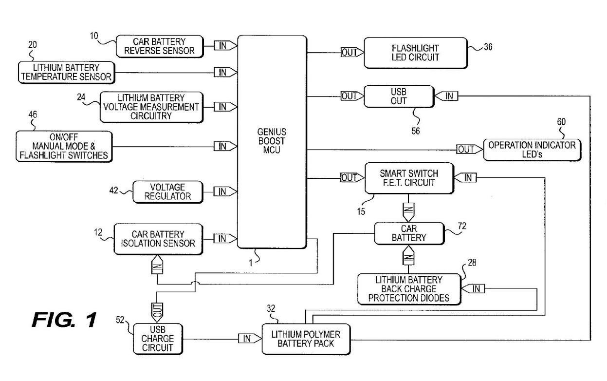
26 The detailed description of the invention commences at [0022], which states (in relation to the preferred embodiment):
FIG. 1 is a functional block diagram of a handheld battery booster according to one aspect of the invention. At the heart of the handheld battery booster is a lithium polymer battery pack 32, which stores sufficient energy to jump start a vehicle engine served by a conventional 12 volt lead-acid or valve regulated lead-acid battery.
27 The apparatus can be controlled by a programmable microcontroller (MCU) and this unit is described at [0023].
28 Aspects of the operation of the apparatus of one aspect of the invention are elaborated upon at [0024] and [0025] by reference to circuits identified as a car battery reverse sensor (10) and a car battery isolation sensor (12). The isolation sensor is also known as the presence sensor. The specification provides at [0024]:
A car battery reverse sensor 10 monitors the polarity of the vehicle battery 72 when the handheld battery booster device is connected to the vehicle’s electric system. As explained below, the booster device prevents the lithium battery pack from being connected to the vehicle battery 72 when the terminals of the battery 72 are connected to the wrong terminals of the booster device. A car battery isolation sensor 12 detects whether or not a vehicle battery 72 is connected to the booster device, and prevents the lithium battery pack from being connected to the output terminals of the booster device unless there is a good (e.g. chargeable) battery connected to the output terminals.
29 As identified in [0024], the apparatus described operates so as to prevent the lithium battery pack from being connected to the vehicle battery when the terminals of the battery are connected to the wrong terminals of the booster device. This paragraph also refers to the other precondition, relating to presence of a vehicle battery.
30 This is explained further in [0025], which states in part:
A smart switch FET circuit 15 electrically switches the handheld battery booster lithium battery to the vehicle’s electric system only when the vehicle battery is determined by the MCU 1 to be present (in response to a detection signal provided by isolation sensor 12) and connected with the correct polarity (in response to a detection signal provided by reverse sensor 10).
31 The above passage refers to a smart switch “FET” circuit. “FET” stands for Field Effect Transistor. A FET switch is one example of an electrically operable electric switch (as opposed to a mechanically operable electric switch).
32 Features of the apparatus are discussed at [0026], where reference is made to the apparatus having a “manual mode”. That paragraph states in part:
On/Off manual mode and flashlight switches 46 allow the user to control power-on for the handheld battery booster device, to control manual override operation if the vehicle has no battery, and to control the flashlight function. The manual button functions only when the booster device is powered on. This button allows the user to jump-start vehicles that have either a missing battery, or the battery voltage is so low that automatic detection by the MCU is not possible. When the user presses and holds the manual override button for a predetermined period [of] time (such as three seconds) to prevent inadvertent actuation of the manual mode, the internal lithium ion battery power is switched to the vehicle battery connect port. The only exception to the manual override is if the car battery is connected in reverse. If the car battery is connected in reverse, the internal lithium battery power shall never be switched to the vehicle battery connect port.
33 Figure 1 of the specification (set out above) includes a manual mode button at item 46.
34 The specification refers to a USB charging circuit and USB charger power source in the preferred embodiment at [0027]:
USB charge circuit 52 converts power from any USB charger power source, to charge voltage and current for charging the lithium battery pack 32. USB output 56 provides a USB portable charger for charging smartphones, tablets, and other rechargeable electronic devices. Operation indicator LEDs 60 provide visual indication of lithium battery capacity status as well as an indication of smart switch activation status (indicating that power is being provided to the vehicle's electrical system).
35 The way in which the reverse sensor and the isolation sensor (each being optically coupled isolator phototransistors) operate in the preferred embodiment is explained in [0028] and [0029]:
[0028] Detailed operation of the handheld booster device will now be described with reference to the schematic diagrams of Figs. 2A-2C. As shown in Fig. 2A, the microcontroller unit 1 is the center of all inputs and outputs. The reverse battery sensor 10 comprises an optically coupled isolator phototransistor (4N27) connected to the terminals of vehicle battery 72 at input pins 1 and 2 with a diode D8 in the lead conductor of pin 1 (associated with the negative terminal CB-), such that if the battery 72 is connected to the terminals of the booster device with the correct polarity, the optocoupler LED 11 will not conduct current, and is therefore turned off, providing a “1” or high output signal to the MCU 1. The car battery isolation sensor 12 comprises an optically coupled isolator phototransistor (4N27) connected to the terminals of vehicle battery 72 at input pins 1 and 2 with a diode D7 in the lead conductor of pin 1 (associated with the positive terminal CB+), such that if the battery 72 is connected to the terminals of the booster device with the correct polarity, the optocoupler LED 11A will conduct current, and is therefore turned on, providing a “0” or low output signal to the MCU, indicating the presence of a battery across the jumper output terminals of the handheld booster device.
[0029] If the car battery 72 is connected to the handheld booster device with reverse polarity, the optocoupler LED 11 of the reverse sensor 10 will conduct current, providing a “0” or low signal to microcontroller unit 1. Further, if no battery is connected to the handheld booster device, the optocoupler LED 11A of the isolation sensor 12 will not conduct current, and is therefore turned off, providing a “1” or high output signal to the MCU, indicating the absence of any battery connected to the handheld booster device. Using these specific inputs, the microcontroller software of MCU 1 can determine when it is safe to turn on the smart switch FET 15, thereby connecting the lithium battery pack to the jumper terminals of the booster device. Consequently, if the car battery 72 either is not connected to the booster device at all, or is connected with reverse polarity, the MCU 1 can keep the smart switch FET 15 from being turned on, thus prevent[ing] sparking/short circuiting of the lithium battery pack.
36 As explained in the above paragraphs, each of the sensors will provide either a “0” (or low signal) or “1” (or high signal) to the MCU and these inputs can be used by the microcontroller software to determine when it is safe to turn on the power. The outputs from those circuits can be illustrated in the following table (based on NOCO’s opening submissions on infringement, as adjusted during the hearing):
Car battery 72 connection to the handheld booster device | Reverse | Isolation | Smart switch 15 |
Correct polarity | “1” or high | “0” or low | Closed (on) |
Reverse polarity | “0” or low | “1” or high | Open (off) |
Not connected | “1” or high | “1” or high | Open (off) |
37 One configuration of the power switch known as a FET switch is included in the circuit illustrated in the preferred embodiment and discussed at [0030] of the specification.
38 The specification at [0031] discusses the measurement of the voltage of the lithium battery, indicating that if the voltage is too low during discharge operation (or too high during charge) the MCU will not operate.
39 The temperature of the lithium battery is also monitored in the preferred embodiment. This is discussed in [0032]. The MCU will not allow jump starting if the internal lithium battery is too hot. The input of this sensor is shown in Fig 1 as Lithium Battery Temperature Sensor (20).
40 There is reference to a USB output circuit that allows for charging portable electronic devices in the description of the preferred embodiment at [0036]:
A USB output 56 circuit (Fig. 2C) is included to provide a USB output for charging portable electronic devices such as smartphones from the internal lithium battery pack 32. Control circuit 57 from the microcontroller 1 allows the USB Out 56 to be turned on and off by software control to prevent the internal lithium battery getting too low in capacity. The USB output is brought to the outside of the device on a standard USB connector 58, which includes the standard voltage divider required for enabling charge to certain smartphones that require it.
41 There is a further disclosure of a USB charge circuit that allows the internal lithium battery pack to be charged using a standard USB charger. It is stated at [0037]:
The USB charge circuit 52 allows the internal lithium battery pack 32 to be charged using a standard USB charger. This charge input uses a standard micro-USB connector 48 allowing standard cables to be used. The 5V potential provided from standard USB chargers is up-converted to the 12.4VDC voltage required for charging the internal lithium battery pack using a DC-DC converter 49. The DC-DC converter 49 can be turned on and off via circuit 53 by an output from the microcontroller 1.
42 The specification describes the physical features of a handheld device and a jumper cable device of the preferred embodiment at [0039]-[0040] by reference to Figures 3 and 4, which provide a depiction of the device and its jumper cables respectively.
43 The 223 Patent has 21 claims. There are two independent claims, namely Claims 1 and 21. Claim 1 has been set out in the Introduction to these reasons.
44 Claim 12 incorporates a lithium ion battery. Claim 12 is as follows (with numbers added):
(12.1) The apparatus according to any one of the preceding claims,
(12.2) wherein the power supply comprises a lithium-ion battery disposed within the jump starting apparatus, and
(12.3) wherein the lithium-ion battery comprises a battery pack comprising multiple lithium ion batteries.
45 Claims 16, 17 and 18 refer to a USB charging port and a USB charging circuit, allowing the internal lithium battery pack to be charged using a USB charger. These claims are in the following terms (with numbers added):
(16.1) The apparatus according to any one of the preceding claims,
(16.2) further comprising a USB charging port configured to provide charging power from an external power source to the power supply.
(17.1) The apparatus according to claim 16,
(17.2) further comprising a USB charging circuit connecting the USB charging port to the power supply.
(18.1) The apparatus according to claim 17,
(18.2) wherein the USB charging circuit comprises a DC-DC converter.
46 Claim 20 has the language “wherein the DC-DC converter is configured to be turned on and off via a circuit by an output from a microcontroller”, anticipating the possibility of the MCU controlling that component.
059 Patent
47 The specification of the 059 Patent, including the description and figures, is largely in the same form as the body of the 223 Patent. The summary of the invention differs in that it contains different consistory clauses, reflecting the different claims.
48 The 059 Patent contains 25 claims. There are five independent claims – Claims 1, 14, 15, 21 and 24.
49 Claim 1 of the 059 Patent is in the following terms (with numbers added for ease of reference):
(1.1) A jump starting apparatus configured for boosting or charging a depleted or discharged battery having a positive polarity battery terminal and a negative polarity battery terminal, the jump starting apparatus comprising:
(1.2) a rechargeable battery;
(1.3) a positive polarity battery terminal connector configured for connecting the jump starting apparatus to the positive polarity battery terminal of the depleted or discharged battery;
(1.4) a negative polarity battery terminal connector configured for connecting the jump starting apparatus to the negative polarity battery terminal of the depleted or discharged battery;
(1.5) a power switch or circuit configured to turn on power from the rechargeable battery to the positive and negative polarity battery terminal connectors;
(1.6) a control system or circuit connected to and controlling the power switch, the control system or circuit configured to detect whether the positive and negative polarity battery terminal connectors have a proper or improper connection with the positive and negative polarity battery terminals of the depleted or discharged battery prior to turning on the power switch or circuit;
(1.7) a USB input charge circuit connected to the rechargeable battery, the USB input charge circuit comprising a DC/DC converter, the USB input charge circuit configured for converting power from a USB charger to increase charge voltage for charging the rechargeable battery; and
(1.8) a USB input connector connected to the USB input charge circuit, the USB input connector configured for connecting to the USB charger and providing charge input from the USB charger through the USB input connector and the USB input charge circuit to the rechargeable battery.
(Emphasis added.)
50 Claim 2 of the 059 Patent then further defines the rechargeable battery as a lithium ion battery.
338 Patent
51 The specification of the 338 Patent, including the description and figures, is also largely in the same form as the body of the 223 Patent. Again, the summary of the invention differs in that it contains different consistory clauses reflecting different claims.
52 The 338 Patent contains 36 claims. There are two independent claims – Claims 1 and 36.
53 Claim 1 of the 338 Patent is in the following terms (with numbers added for ease of reference):
(1.1) A jump starting device for boosting or charging a depleted or discharged battery having a positive battery terminal and a negative battery terminal, the jump starting device comprising:
(1.2) a rechargeable battery;
(1.3) a positive battery connector for electrically connecting the jump starting device to the positive battery terminal of the depleted or discharged battery;
(1.4) a negative battery connector for electrically connecting the jump starting device to the negative battery terminal of the depleted or discharged battery;
(1.5) a power switch or switch circuit connected in series with the rechargeable battery and the positive and negative battery connectors, the power switch or switch circuit configured to switch power on from the rechargeable battery to boost or charge the depleted or discharged battery when connected between the positive and negative battery connectors;
(1.6) a USB input connector; and
(1.7) a USB charge circuit electrically connecting the USB input connector to the rechargeable battery, the USB charge circuit comprising a DC-DC converter configured to upconvert voltage from the USB input connector to the rechargeable battery.
The hearing and the evidence
54 The hearing, which was on liability only, occupied ten days.
55 Originally, this proceeding (VID 264 of 2023) was due to be heard together with The NOCO Company v Hong Kong Haowei Technology Co., Ltd. (VID 122 of 2023) (the Carku proceeding). However, that proceeding settled on 6 February 2025, shortly before the hearing was due to commence.
56 The Carku proceeding concerned the same patents as this proceeding and included a cross-claim alleging invalidity of the Patents. There was considerable overlap in the grounds of invalidity, but there were some differences. Prior to the settlement, the parties in both proceedings filed their opening submissions in chief (both on infringement and invalidity). In preparing those submissions, B&W and the Carku parties divided responsibility for the invalidity case. In other words, some grounds of invalidity were dealt with in the submissions of one party rather than by both parties.
57 Following the settlement of the Carku proceeding, B&W adopted some of the grounds of invalidity that the Carku parties had relied on as part of their case, but which had not formed part of B&W’s case. This was reflected in a document titled “Consolidated Particulars of Invalidity” dated 6 February 2025, which made clear which grounds of invalidity B&W relied on in this proceeding. B&W also adopted some of the submissions made by the Carku parties in their outline of opening submissions.
58 In relation to the best method ground, the parties proceeded on the basis that the contentions and submissions comprise or include material that is commercially sensitive. Accordingly, the Consolidated Particulars of Invalidity set out the details of this ground in a confidential annexure. The parties’ outlines of submissions similarly deal with this ground in confidential sections. In these circumstances, the parts of this judgment dealing with factual issues concerning the best method ground will be redacted for an initial period of time. The parties will be given the opportunity to apply for a further suppression or non-publication order in respect of that part of these reasons.
59 NOCO relied on evidence from the following lay witnesses:
(a) Mr James Richard (Rick) Stanfield, the Chief Technical Officer of NOCO. Mr Stanfield is an electrical engineer and one of the named inventors of the Patents;
(b) Mr Gavin Adkins, a solicitor and principal of Griffith Hack Lawyers, the solicitors acting for NOCO in the proceeding. Mr Adkins’s evidence related to B&W jump starters he purchased; and
(c) Ms Ellen Baker, a solicitor employed by Griffith Hack Lawyers. Ms Baker’s evidence related to certain website images.
60 Mr Stanfield was cross-examined during the hearing. Neither Mr Adkins nor Ms Baker was required to attend for cross-examination.
61 Mr Stanfield was a good witness. He gave clear answers to questions and accepted propositions without regard to whether they helped or harmed NOCO’s case. He was careful and considered. I generally accept his evidence. Where there are differences between his affidavit and oral evidence, I prefer his oral evidence.
62 B&W called expert evidence from Mr Jonathan (Jo) Banks, an industrial designer. Although Mr Banks was put forward as an independent expert, he had worked for B&W for many years. I would therefore not regard him as independent. However, I accept that he has considerable experience and expertise as an industrial designer. Mr Banks was cross-examined.
63 Mr Banks was a good witness. He answered questions clearly and succinctly. He was precise in his answers. He gave evidence in a straightforward way and made appropriate concessions. I will consider his evidence later in these reasons.
64 Both parties called evidence that comprised the translation of certain documents from the Chinese (Mandarin) language to the English language.
65 NOCO called evidence from Dr Xiangtong Xu, a registered Chinese patent attorney. Dr Xu prepared two affidavits, which went into evidence. Dr Xu was not required for cross-examination.
66 B&W called evidence from Ms Yang Liu, a registered Chinese patent attorney. Ms Liu’s evidence comprised a translation of Chinese Patent Utility Model Patent CN202696190 (CN190), which was published on 23 January 2013. In its opening submissions, B&W relied on CN190 as prior art for the purposes of its lack of novelty and lack of inventive step grounds. Ms Liu gave evidence by video-conference with the assistance of an interpreter. Ms Liu was cross-examined by one of the junior counsel for NOCO. Following the cross-examination (and, I infer, in light of it) B&W abandoned reliance on CN190. Accordingly, CN190 and Ms Liu’s evidence can be put to one side.
67 Each party called an expert witness in relation to electrical engineering and power electronics issues. The experts were:
(a) Mr Darrin Wilson, an electronic engineer, called by NOCO; and
(b) Professor Grahame Holmes, an electrical engineer, called by B&W.
68 Mr Wilson’s qualifications and experience are summarised in paragraphs 2, 3 and 10 to 14 of his affidavit dated 5 June 2024 (Wilson 1):
A. Engagement
2. I am an Electronic Engineer with over 30 years’ experience in power electronics, analogue and digital electronic hardware design, manufacturing and laboratory management. I have worked across a range of engineering roles, including Senior Project Engineer, Design Engineer and Product Manager and my qualifications are set out further in Section B below.
3. I am currently a Senior Design Engineer at Clevertronics Pty Ltd (Clevertronics). [Clevertronics] is an Australian emergency lighting specialist that designs, prototypes and tests all its luminaires and systems. I am also self-employed and provide consulting services in electronic design and manufacturing.
…
B. Training, study and experience
10. My qualifications and experience are largely in the area of Electronic Engineering. Electronic engineering is a discipline of electrical engineering focusing on low current and voltage electrical circuits (such as battery operated devices, computers, handheld devices, mobile phones and remote controls) and communications systems (such as hardware for radio transceivers and hardware for wireless and wired communications).
11. In my professional career I have worked across a range of engineering roles, including Senior Project Engineer, Design Engineer and Production Manager. My formal qualifications consist of a Bachelor of Engineering in Electronic Engineering from the Royal Melbourne Institute of Technology (1991) and Master of Business Administration (MBA) from Monash University in 2012.
12. A detailed summary of my relevant qualifications and experience are set out in detail in my curriculum vitae (CV). Attached and marked Annexure DJW-47 is a copy of my CV.
13. I have been asked by Griffith Hack Lawyers to summarise my professional work experience up to and including 2014. I have set out that summary in paragraphs 13 to 31 of my First VID122/2023 Affidavit which I have already annexed as Annexure DJW-45.
14. As a result of my training, study and experience I believe that I have developed specialised knowledge of at least the following:
(a) the design and components of electronic engineering systems, including hardware, firmware and software;
(b) the functionality and integration of sensors in electronic engineering systems, including voltage, current, light, temperature and magnetic sensors; and
(c) the functionality and integration of power supply solutions in the design of electronic engineering systems.
69 Professor Holmes is an Honorary Professor of Smart Energy Systems at RMIT University, Melbourne. He has held that position since retiring as Professor of Smart Energy Systems at RMIT in 2020. Professor Holmes’s qualifications and experience are set out in Section B of his affidavit dated 6 September 2024 (Holmes 1). In that section, Professor Holmes states that he is an electrical engineer and that electrical engineering encompasses a range of specialties and sub-areas. Since 1984, he has specialised in power electronics, which is an area of electrical engineering that deals with the control and conversion of electrical energy, and the design of electrical circuits to achieve that control and conversion. Professor Holmes’s relevant experience, as detailed in Section B of that affidavit, is extensive.
70 Each of the experts prepared a number of affidavits.
71 A process was put in place for the preparation of a joint expert report. This process included the expert witness to be called by the respondents to the Carku proceeding, Professor David Ricketts. The three experts – Mr Wilson, Professor Holmes and Professor Ricketts – prepared a joint expert report dated 23 January 2025 (the Joint Expert Report). In circumstances where, because of the resolution of the Carku proceeding, Professor Ricketts was not called to give evidence, an evidentiary issue arose in relation to the parts of the report that were authored by Professor Ricketts. These fall into two categories: in some places, opinions are expressed by Professor Ricketts individually; in other places, opinions are expressed by Professor Ricketts together with one or both of Mr Wilson and Professor Holmes. While it was a straightforward matter simply to not admit into evidence the opinions expressed individually by Professor Ricketts and to treat jointly expressed opinions as the opinions of Mr Wilson or Professor Holmes or both (as applicable), in some cases the opinions expressed individually by Professor Ricketts provided context for opinions expressed by the other experts. In light of this, I made a ruling pursuant to s 136 of the Evidence Act 1995 (Cth) that the Joint Expert Report be admitted into evidence subject to the limitation that all statements attributed to “Professor Ricketts” or “DR” (or “the Experts” to the extent it is a reference to Professor Ricketts) be admitted solely for the purpose of providing context for any response to such statements provided by another expert or experts.
72 Mr Wilson and Professor Holmes gave evidence concurrently during the hearing, over four days. The evidence was structured around a series of topics, as agreed between the parties. Both experts gave evidence in a careful and considered way. Both had a command of the subject matter and were of considerable assistance to the Court.
Person skilled in the art
73 The “skilled addressee”, or “person skilled in the relevant art” (Patents Act, s 7(2)), is a hypothetical person (or team) who has a “practical interest in the subject matter of [the] invention” and who might be “interested in making, constructing, compounding or using the invention”: Root Quality Pty Ltd v Root Control Technologies Pty Ltd [2000] FCA 980; 49 IPR 225 (Root Quality) at [70]-[71] per Finkelstein J.
74 Such a person was described by French CJ in AstraZeneca AB v Apotex Pty Ltd [2015] HCA 30; 257 CLR 356 at [23] as a “tool of analysis”, and his Honour explained that this hypothetical person is not an “avatar” for the views of the particular expert witnesses who give evidence in a proceeding – it is a “pale shadow of a real person”.
75 The person skilled in the art is assumed to be a skilled but non-inventive worker in the field of the invention: Minnesota Mining and Manufacturing Co v Beiersdorf (Australia) Ltd [1980] HCA 9; 144 CLR 253 (Minnesota Mining) at 293 per Aickin J. The person skilled in the art may comprise a team: Pfizer Overseas Pharmaceuticals v Eli Lilly & Co [2005] FCAFC 224; 68 IPR 1 (Pfizer) at [288] per French and Lindgren JJ; Novartis AG v Pharmacor Pty Ltd (No 3) [2024] FCA 1307 at [149] per Yates J.
76 In the present case, there is no real issue between the parties as to the identification of the person or team that constitutes the “person skilled in the art”. It is common ground that the “person skilled in the art” is or includes an electrical engineer with experience in power electronics, such as Mr Wilson and Professor Holmes.
77 B&W submits that, in addition, if a company was seeking to design a new jump starter at the asserted priority date, an industrial designer would also be involved. NOCO accepts that the notional team includes a manufacturer (product designer). Thus, it appears to be common ground that, for the purposes of the inventive step issue, the “person skilled in the art” is a team that includes a product designer.
Common general knowledge
78 The common general knowledge may be described as “the background knowledge and experience which is available to all in the trade in considering the making of new products, or the making of improvements in old”: Minnesota Mining at 292.
79 Professor Holmes describes the underlying core concepts and well understood components and safety features used in power electronics circuitry before the asserted priority date in Holmes 1 at [69]-[149]. Mr Wilson describes Professor Holmes’s evidence as “reasonably comprehensive” and only seeks to “clarify” a small number of points: see Mr Wilson’s third affidavit (dated 15 November 2024) (Wilson 3) at [16]-[22]. Professor Holmes’s evidence is summarised in B&W’s opening submissions on invalidity at [11]-[17]. In closing submissions, NOCO provided a document headed “NOCO’s Response to CGK alleged in BWI’s Aide-memoire to BWI’s s 7(2) arguments”. It appears from [3.2] and [3.3] of NOCO’s response that it accepts the summary at [11]-[17] of B&W’s opening submissions on invalidity.
80 In light of the above, I find that the common general knowledge relating to power electronics as at the asserted priority date included the matters set out at [81]-[87] below. In addition, I make findings about the common general knowledge at [88]. I will refer to other aspects of the common general knowledge later in these reasons.
Power electronics – basic electrical concepts
81 Power electronics is an area of electrical engineering that deals with the control and conversion of electronic energy, and the design of electrical circuits that achieve that control and conversion.
82 It was common general knowledge in the field of power electronics that current (I) is measured in amps (A) and refers to the amount of flow of electricity in a system, whereas voltage is measured in volts (V) and refers to the degree of force behind current. There are two forms of current – direct current (DC), which refers to circuits with a one-way flow of electricity, and alternating current (AC), which refers to circuits in which the flow of electricity alternates backward and forward and swaps polarity. Energy is the product of voltage and current. The equation for electrical power is Power (P) (being measured in watts (W)) = Current (I) x Voltage (V), (P=IV); so that, for example, 5V applied at 2A gives 10 watts of power. Resistance (R) is measured in Ohms (Ω) and refers to the degree to which a circuit (or, more broadly, any substance or component) impedes the flow of electrical current induced by a particular voltage. Ohm’s law provides that Voltage (V) = Current (I) x Resistance (R).
83 The arrangement of electronic components to achieve a function (i.e., a conversion of power from one type to another) is often described as a topology or circuit topology. Where components are connected in a single path through which energy will flow, they are described as being in series, whereas where components are connected in multiple paths through which electricity may flow simultaneously, they are described as being in parallel.
84 Electrical circuits may deal with signals that are binary (eg, either “0” or “1”, such as a switch that is open or closed) and described as digital; or signals that are continuously variable (eg, a measurement of voltage) and described as analog.
Power electronics – components and protective features
85 By the asserted priority date, there were a range of well-understood components that were routinely used in power electronics circuitry, including:
(a) Integrated circuits (IC), a semiconductor (typically silicon) bearing many transistors and other electronics on a single “wafer” or “board”.
(b) Control circuitry, being the circuit components which handle the processing of inputs and outputs. The most common “programmable” ICs, by the asserted priority date, were microprocessors (sometimes called microcontrollers or MCUs), being digital electronic circuits built into an IC that would be programmed to execute software.
(c) Transistors and switches, being the components used to close (i.e., connect) or open (i.e., disconnect) an electrical circuit (or portion thereof). Switch circuitry controls the flow of energy by withstanding voltage when turned “off” and conducting current when turned “on”. Necessarily, this requires such components to withstand the maximum voltage and current of a product. At the asserted priority date, relevant switches included: (i) solenoids (also called relays), which provided robust switching, but were relatively large and slow; and (ii) semiconductor switches, including field-effect transistors (FET), which could switch faster and were smaller and lighter than solenoid switches.
(d) Sensors and sensing circuits, which are used to measure a parameter, commonly voltage and current (as a direct value and as a proxy for other parameters), and provide an input to an electrical circuit. Voltage and current are both analog signals. At the asserted priority date, the measurement of those signals typically involved electrically isolating the signal, conditioning the signal to a reduced voltage or current suitable for control circuitry, and then converting the analog signal to a digital signal to be “read” by a microcontroller. It was common to measure voltage by using: (i) an optical isolation structure (to isolate the power circuit from the control circuit); or (ii) a resistor divider (to reduce the measured voltage without isolation). It was common to measure current by using a Hall-effect sensor (a device that detects magnetic fields produced by current, with the magnetic field changing as a current changes). There were a very large number of sensors available at the asserted priority date that were purpose built for particular sensing operations.
(e) Isolation components, being components which allow a signal to be transferred between circuitry, without an electrical connection. At the asserted priority date there were a range of isolation components that were commonly used in power electronics circuits. A particularly common isolation component was an optocoupler, being a device with: (i) a light emitting diode (LED), connected to the circuit that is to transmit a signal; and (ii) a phototransistor, which is connected to the circuit that is to receive a signal. If the LED is illuminated, the phototransistor will turn on in response, allowing a signal to transfer from the circuit connected to the LED to the circuit connected to the phototransistor, without an electrical connection between the two.
(f) Power converters, being the electrical components which convert one voltage or current to another voltage or current, including where necessary converting from AC to DC (and vice versa). There were step down or buck converters (where the output voltage was lower than the input voltage) and step up or boost converters (where the output voltage was higher than the input voltage). A common type of power converter was a DC-DC converter.
(g) Analog to digital converters (being the circuitry used to convert a variable analog signal into a binary value) and digital to analog converters (vice versa).
(h) Batteries, being remote energy sources that allow a power electronics circuit to be used when disconnected from a fixed electrical circuit. It was common general knowledge that: (i) power generated by batteries is always DC (and so must be converted to AC where the load being powered requires AC power); (ii) batteries can be single use or rechargeable; and (iii) two common battery chemistries in power electronics were lead acid batteries and lithium-based batteries. The growing availability of lithium-based batteries was a key advance before the asserted priority date, as they could generate higher energy density and currents than lead acid-based batteries (thereby enabling the use of smaller and lighter batteries). To charge a rechargeable battery, it was known that DC current must be used and that as the charge of a battery increases, so does its voltage (such that level of charge can be measured by sensing voltage). Battery control circuitry was commonly used (often in the form of “off-the-shelf” ICs and microprocessors) to: (i) take measurements indicating the status of a battery; (ii) manage the charging process; (iii) prevent excessive charging; and (iv) prevent the battery from discharging too much power.
(i) Connection components, being the components used to electrically connect a power electronics circuit to another circuit. Such connections could be permanent (eg, soldered) or temporary (i.e., “quick fit” connections, such as three-pin wall connectors, USB connectors, and alligator clips).
86 Irrespective of the precise components used, it was common general knowledge at the asserted priority date that an important aspect of power electronics was the potential for hazard and damage if something went wrong. Accordingly, a key aspect of designing a power electronics circuit involved the incorporation of safety features, to avoid hazard or damage if a product was connected or operated improperly.
87 At the asserted priority date, common safety features incorporated in power electronics circuits included: (i) short-circuit protection (a way of detecting and protecting against the over-current created by an unintended direct connection); (ii) controlled shut down (circuits designed to detect a failing input power supply and shut down the system in a controlled fashion); (iii) reverse polarity protection (circuits designed to detect whether a power electronic circuit and load are connected with correct polarity and, in the event of reverse polarity, either prevent power from flowing the wrong way back into the power electronic circuit or avoid connecting the power electronic circuit to the load); and (iv) temperature overload protection (circuits designed to detect excessive heat and either shut down the system or reduce performance of the system to reduce heat).
Lithium batteries
88 During the course of Mr Banks’s oral evidence, reference was made to different types of lithium batteries. Mr Banks gave evidence, which I accept, that the overarching category is lithium ion batteries and that, within that category, one subset is lithium iron phosphate batteries and another subset is lithium cobalt batteries (T403). He also said (and I accept) that the expression lithium polymer batteries would generally be associated with lithium cobalt batteries (T403). Mr Wilson gave evidence to the same effect (T795). Having regard to the context in which Mr Wilson gave that evidence, I find that these categories formed part of the common general knowledge as at the asserted priority date.
Construction issues
Applicable principles
89 In UbiPark Pty Ltd v TMA Capital Australia Pty Ltd (No 2) [2023] FCA 885, I summarised the applicable principles relating to claim construction at [55]-[63]. I adopt that summary. For ease of reference, I set out that summary in the following paragraphs.
90 In Jupiters Ltd v Neurizon Pty Ltd [2005] FCAFC 90; 222 ALR 155, the Full Court of this Court (Hill, Finn and Gyles JJ) summarised the principles of construction as follows (at [67]):
There is no real dispute between the parties as to the principles of construction to be applied in this matter although there is some difference in emphasis. It suffices for present purposes to refer to the following:
(i) the proper construction of a specification is a matter of law: Décor Corporation Pty Ltd v Dart Industries Inc (1988) 13 IPR 385 at 400;
(ii) a patent specification should be given a purposive, not a purely literal, construction: Flexible Steel Lacing Co v Beltreco Ltd (2000) 49 IPR 331; [2000] FCA 890 at [81] (Flexible Steel Lacing); and it is not to be read in the abstract but is to be construed in the light of the common general knowledge and the art before the priority date: Kimberley-Clark Australia Pty Ltd v Arico Trading International Pty Ltd (2001) 207 CLR 1; 177 ALR 460; 50 IPR 513; [2001] HCA 8 at [24];
(iii) the words used in a specification are to be given the meaning which the normal person skilled in the art would attach to them, having regard to his or her own general knowledge and to what is disclosed in the body of the specification: Décor Corporation Pty Ltd at 391;
(iv) while the claims are to be construed in the context of the specification as a whole, it is not legitimate to narrow or expand the boundaries of monopoly as fixed by the words of a claim by adding to those words glosses drawn from other parts of the specification, although terms in the claim which are unclear may be defined by reference to the body of the specification: Kimberley-Clark v Arico at [15]; Welch Perrin & Co Pty Ltd v Worrel (1961) 106 CLR 588 at 610; Interlego AG v Toltoys Pty Ltd (1973) 130 CLR 461 at 478; the body of a specification cannot be used to change a clear claim for one subject matter into a claim for another and different subject matter: Electric & Musical Industries Ltd v Lissen Ltd [1938] 4 All ER 221 at 224-5; (1938) 56 RPC 23 at 39;
(v) experts can give evidence on the meaning which those skilled in the art would give to technical or scientific terms and phrases and on unusual or special meanings to be given by skilled addressees to words which might otherwise bear their ordinary meaning: Sartas No 1 Pty Ltd v Koukourou & Partners Pty Ltd (1994) 30 IPR 479 at 485-6 (Sartas No 1 Pty Ltd); the court is to place itself in the position of some person acquainted with the surrounding circumstances as to the state of the art and manufacture at the time (Kimberley-Clark v Arico at [24]); and
(vi) it is for the court, not for any witness however expert, to construe the specification; Sartas No 1 Pty Ltd at 485-6.
91 In Globaltech Corporation Pty Ltd v Australian Mud Company Pty Ltd [2019] FCAFC 162; 145 IPR 39, the Full Court set out, at [93]-[96], a number of key principles that are also relevant here. I refer to those principles without setting them out. I note also the following principles and observations.
92 In GlaxoSmithKline Consumer Healthcare Investments (Ireland) (No 2) Ltd v Generic Partners Pty Ltd [2018] FCAFC 71; 264 FCR 474 (GSK), the Full Court (Middleton, Nicholas and Burley JJ) provided the following guidance in relation to purposive construction (at [106]):
More recent cases have continued to emphasise the need to read a patent specification as a whole and in light of the common general knowledge. They also confirm that a patent specification should be read in a practical and common sense way and given a “purposive” construction. This approach to construction requires the court to read the specification through the eyes of the skilled addressee with practical knowledge and experience in the field of work in which the invention was intended to be used and a proper understanding of the purpose of the invention.
93 In GSK (at [108]) the Full Court quoted with apparent approval the following passage from the judgment of Lord Hoffmann in Kirin-Amgen Inc v Hoechst Marion Roussel Ltd (2004) 64 IPR 444 at [34]:
“Purposive construction” does not mean that one is extending or going beyond the definition of the technical matter for which the patentee seeks protection in the claims. The question is always what the person skilled in the art would have understood the patentee to be using the language of the claim to mean. And for this purpose, the language he has chosen is usually of critical importance. The conventions of word meaning and syntax enable us to express our meanings with great accuracy and subtlety and the skilled man will ordinarily assume that the patentee has chosen his language accordingly. As a number of judges have pointed out, the specification is a unilateral document in words of the patentee’s own choosing. Furthermore, the words will usually have been chosen upon skilled advice. The specification is not a document inter rusticos for which broad allowances must be made. On the other hand, it must be recognised that the patentee is trying to describe something which, at any rate in his opinion, is new; which has not existed before and of which there may be no generally accepted definition. There will be occasions upon which it will be obvious to the skilled man that the patentee must in some respect have departed from conventional use of language or included in his description of the invention some element which he did not mean to be essential. But one would not expect that to happen very often.
94 Consistently with the above, an expert witness cannot assist the court with the meaning of an ordinary English word (or phrase) unless it has a special or unusual meaning within an area of technology: see Minnesota Mining at 272; see also Kinabalu Investments Pty Ltd v Barron & Rawson Pty Ltd [2008] FCAFC 178 (Kinabalu) at [45] per Sundberg, Emmett and Greenwood JJ.
95 In Commissioner of Patents v Rokt Pte Ltd [2020] FCAFC 86; 277 FCR 267, Rares, Nicholas and Burley JJ explained at [73]:
The role of expert evidence in construing the patent specification and the claims is limited. It is to place the Court in the position of the person acquainted with the surrounding circumstances as to the state of the art and manufacture as at the priority date …
96 To similar effect, in Flexible Steel Lacing Co v Beltreco Ltd [2000] FCA 890; 49 IPR 331, Hely J stated at [81]:
[T]he construction of the specification is for the court, not for the expert. In so far as a view expressed by an expert depends upon a reading of the patent, it cannot carry the day unless the court reads the patent in the same way.
97 The above passage has been cited with approval by three Full Courts: Kinabalu at [44]-[45]; Austal Ships Sales Pty Ltd v Stena Rederi Aktiebolag [2008] FCAFC 121; 77 IPR 229 at [14]; and PAC Mining Pty Ltd v Esco Corp [2009] FCAFC 18; 80 IPR 1 at [29].
98 In Multigate Medical Devices Pty Ltd v B Braun Melsungen AG [2016] FCAFC 21; 117 IPR 1 at [23]-[28], Bennett, Yates and Beach JJ made a series of related observations about the role of expert evidence in patent cases on issues of construction.
Consideration
99 I will now consider, in turn, each of the construction issues identified in NOCO’s opening submissions on infringement. The issues are relevant to infringement or invalidity or both. Some of the issues have fallen away in light of the narrowing of the parties’ cases during the hearing. This will be indicated below.
100 I will approach the construction issues as at the asserted priority date. That is, I will approach the issues on the basis of how the skilled addressee would have understood the Patents as at that date.
Construction issue 1: sensor to detect polarity
101 Construction issue 1 (as identified by NOCO) relates to integer 1.6.2 in Claim 1 of the 223 Patent (and comparable wording in other asserted claims). That integer requires the control system or circuit to be configured “to detect polarity of the depleted or discharged battery when connected between the positive and negative battery connectors”. In B&W’s opening submissions on infringement (which deal with construction issues) this construction issue is discussed in terms that relate to integer 1.6.1 as well as 1.6.2. Integer 1.6.1 requires the control system or circuit to be configured “to detect presence of the depleted or discharged battery when connected between the positive and negative battery connectors”.
102 There is a lack of clarity in the parties’ submissions as to the identification of this issue.
103 NOCO’s submissions are directed to whether detection of polarity is to occur regardless of whether the connectors are connected.
104 B&W submits that “when connected” is a temporal limitation that requires the control system, circuit or sensors (depending on the particular claim) to be configured to make the specific detections (i.e. present or not, correct polarity or not) at the time specified in the asserted claims. However, B&W submits, the asserted claims do not assume battery presence. B&W submits that: the asserted claims are directed to an apparatus, not a method; the control system, circuit or sensors of that apparatus must be “configured” to make the specified detections; the asserted claims encompass such an apparatus, irrespective of whether it is, in fact, connected to a vehicle battery. In B&W’s closing propositions (at [8]) and in its closing oral submissions (at T881) it seemed to be making a different point, namely that a reasonable construction of “when connected” is “upon and while connected”, thus including the time after switch closure.
105 In relation to whether the vehicle battery needs to be connected at the time of detection for the purposes of integer 1.6.2, in my view, the answer is Yes. This is clear from the words “when connected” in integer 1.6.2. Further, as a matter of practicality, detection of polarity can only occur when the vehicle battery is connected. This conclusion is supported by the opinion of both experts expressed in the Joint Expert Report, Section A, page 3, lines 86 to 88, where they state:
All claims that refer to “configured for detection” or “detection of”, “polarity”, “correct polarity”, “proper polarity” and “improper polarity”, require the vehicle battery to be connected to the jumpstarter connectors to make the polarity determination.
106 In relation to whether the asserted claims assume battery presence, I accept that they do not, for the reasons given by B&W in its opening submissions.
107 In relation to whether “when connected” is to be construed as “upon and while connected”, this issue appears to overlap with construction issue 2, which I deal with next.
Construction issue 2: Operation before switch closure
108 This construction issue relates to integer 1.7 in Claim 1 of the 223 Patent (and comparable wording in other asserted claims). NOCO’s contention is that the claim does not concern the operation of the apparatus after the circuit switches on the power switch.
109 B&W questioned Mr Wilson about this issue (eg, at T441, 447-450, 455). Mr Wilson accepted that if you do not detect presence after the switch is turned on, there is a risk that one lead will come off, there will be shorting, and you will not have solved the problems identified in the patent. Notwithstanding this and other concessions in Mr Wilson’s evidence, in my view the focus of Claim 1 is on turning on the power switch. Thus, it is concerned with detection of polarity and presence before that occurs and not after it occurs.
Construction issues 3 and 4: Automatic Start issue
110 It is convenient to deal with NOCO’s construction issues 3 and 4 together, as they overlap. In essence, they both raise the Automatic Start issue. This issue may be stated generally as: whether it is a requirement of the claims that the switch turn on (or close) automatically upon satisfaction of a precondition or preconditions. The issue may be more precisely stated in relation to particular claims. For example, in relation to integer 1.7 of Claim 1 of the 223 Patent, the issue may be stated as: whether the switch may turn on at any time after the preconditions in 1.7.1 and 1.7.2 are satisfied (as contended by NOCO) or whether it is a requirement that the switch turn on automatically upon satisfaction of those preconditions (as contended by B&W).
111 This issue is relevant to the infringement case and the invalidity case. If the issue is determined in B&W’s favour, it would resolve a large part of the infringement case. This is because the B&W impugned products do not start automatically (upon satisfaction of preconditions) but have push button operation: see Professor Holmes’s third affidavit (dated 7 November 2024) (Holmes 3), at [27]. However, even if this issue is determined in B&W’s favour, it would not resolve all of the infringement issues, because B&W accepts that some of the asserted claims do not require automatic start.
112 Integer 1.7 of Claim 1 of the 223 Patent states that the control system or circuit switches on the power switch “only when” the depleted or discharged battery is present and properly connected (integer 1.7.1) and the depleted or discharged battery is properly connected with correct polarity (integer 1.7.2).
113 I note at the outset that the words “only when” may be contrasted with the words “when, and only when”, which appear in integer 21.7 in Claim 21. Claim 21 of the 223 Patent is in the following terms (with numbers added):
(21.1) A jump starter apparatus for boosting or charging a depleted or discharged battery having a positive battery terminal and a negative battery terminal, the apparatus comprising:
(21.2) a power supply;
(21.3) a positive battery connector for connecting the jump starter apparatus to the positive battery terminal of the depleted or discharged battery;
(21.4) a negative battery connector for connecting the jump starter apparatus to the negative battery terminal of the depleted or discharged battery;
(21.5) a power switch connected in circuit with the power supply and the positive and negative battery connectors, the power switch configured to turn power on or off from the power supply to the positive and negative battery connectors;
(21.6) a control system or circuit connected to and controlling the power switch, the control system or circuit configured to detect presence of the depleted or discharged battery when connected between the positive and negative battery connectors and to detect polarity of the depleted or discharged battery when connected between the positive and negative battery connectors;
(21.7) wherein the control system or circuit switches on the power switch to cause the power supply to be connected to the depleted or discharged battery when, and only when, the depleted or discharged battery is present and properly connected between the positive and negative battery connectors and the depleted or discharged battery is properly connected with a correct polarity between the positive and negative battery terminals.
(Emphasis added.)
114 I will now summarise the parties’ submissions in relation to the Automatic Start issue. The parties’ submissions generally focus on integer 1.7 of Claim 1 of the 223 Patent.
115 NOCO submits that, properly understood, the switch may turn on at any time after the preconditions are satisfied, but it does not need to turn on automatically upon that occurrence. NOCO submits:
(a) First, this aspect of the invention introduces a safety feature where the switch is prevented from closing (turning on) unless the preconditions (of presence and polarity) are met. Such a safety advantage is not dependent on there being an automatic or immediate closure; rather, it depends on the switch being kept open unless the preconditions are met.
(b) Second, the claim language does not support the position that there is automatic closing. Claim 1 of the 223 Patent, for example, uses permissive language to indicate that the switch be operatable (but not necessarily operated) when the precondition is met:
… wherein the control system or circuit switches on the power switch to connect the power supply to the depleted or discharged battery only when the depleted or discharged battery is present …
(Emphasis added.)
(c) This is reinforced by the language of Claim 2, which makes it clear that the control system or circuit refrains from doing something (i.e. does not switch on the power switch) unless the preconditions are met.
(d) The consistory statements in paragraphs [0013a] and [0013b] of the 223 Patent are relevantly in the same terms as Claims 1 and 2 of the 223 Patent, using language which requires the precondition to be met before the switch is closed; but that is not to say that the switch must close immediately and without further intervention.
(e) Third, NOCO’s construction is consistent with the passages in the specification of the 223 Patent, which at [0024] observes that the device “prevents the lithium battery pack from being connected” and at [0025] states that a smart switch “switches the handheld battery booster lithium battery to the vehicle’s electric system only when …”. This reinforces that those words are about prevention rather than requiring a positive action.
(f) Fourth, even if the preferred embodiment describes an MCU that allows the connection immediately upon determining that the relevant preconditions of polarity and presence are satisfied, this does not provide a basis to limit the claims. It is a well-established principle in claim construction that the claims should not be limited to the operation of the preferred embodiment: see Welch Perrin & Co Pty Ltd v Worrel [1961] HCA 91; 106 CLR 588 at 610; Arbitron Inc v Telecontrol Aktiengesellschaft [2010] FCA 302; 86 IPR 110 at [77].
(g) Fifth, in any event, in so far as the preferred embodiment is concerned, this device does not necessarily connect automatically upon the preconditions being established; rather the device leaves open the possibility that it can look for other inputs such as temperature.
116 B&W contends that Claim 1 and Claim 21 of the 223 Patent are relevantly the same (i.e. they both require automatic start upon satisfaction of the preconditions). B&W submits:
(a) Each of those claims requires that it is the “control system or circuit” which must switch on the power switch. The claims require that this occur “when” two antecedent conditions are satisfied. For example, the claims do not contemplate (or permit) that the power switch is to be turned on by some manual act of (and at the discretion of) a user of the jump starter apparatus, at a time after the requisite conditions are satisfied. In that case, the power switch will have failed to have been turned on for a period “when the depleted or discharged battery is present and properly connected”, contrary to the requirements of the claims.
(b) If, contrary to the above, the word “when” in the claims was construed to mean “at any point in time when”, then the claims would encompass jump starters that only switched on for a period of time which, for example, was insufficient to jump start a vehicle. The claims should not be construed to encompass inutile products if they can be construed in a way which avoids this.
(c) To construe Claims 1 and 21 as requiring the control system or circuit to automatically switch on the power switch when the depleted or discharged battery is present and properly connected is consistent with the specification, which explains that it is the MCU (i.e., control system) which determines whether to close the FET switch based on the inputs received from reverse sensor 10 and battery isolation sensor 12. In the event that the MCU receives a “1” signal from the reverse polarity sensor and a “0” signal from the battery isolation sensor, the MCU output will be “driven to a logic high” which will place the FET switch “in a low resistance state, allowing current to flow” (emphasis added). This occurs based only on the binary inputs received from reverse sensor 10 and battery isolation sensor 12 – the switch turns on automatically once those inputs are received.
(d) Both experts agree that there is no disclosure in the body of the 223 Patent (or the body of the 059 Patent or the 338 Patent) of a jump starter apparatus which “does not turn ‘on’ immediately under normal operating conditions … upon the control system or circuit detecting the vehicle battery being properly connected”. To construe the claims otherwise would be to introduce a lack of support.
(e) A construction which requires the control circuit or switch to automatically turn on is also consistent with the language used in the dependent claims of the 223 Patent, including Claim 2 (“…the control system or circuit does not switch on the power switch…”), Claim 3 (“…wherein the control system or circuit is configured to detect … prior to turning power on …”) and Claim 8 (“… wherein the microcontroller switches the power switch on … only when…”). By contrast, NOCO’s construction would render Claims 2, 3 and 8 redundant.
(f) Thus, all claims of the 223 Patent require that the power switch will be turned on immediately upon a vehicle battery being detected as being present and properly connected to the jump starter.
117 In the Joint Expert Report, Section A, pages 7 and 8, Professor Holmes identifies three groups of claims, which he labels (i), (ii) and (iii). Claim 1 of the 223 Patent is in group (iii). He expresses the opinion that the claims in groups (ii) and (iii) “require that as soon as an (undefined) battery connection has been established for the claims in (ii), or a ‘proper’ battery connection has been established for the claims in (iii), the power switch will be turned on immediately thereafter”. He refers back to Holmes 3, Section D.2.
118 Contrastingly, Mr Wilson expresses the opinion (in Section A of the Joint Expert Report, page 9) that Claim 1 does not require, “implicitly or explicitly, that the control system automatically switch on the power switch when the stated conditions are satisfied”. He expresses the opinion that the wording of the relevant claims “indicates that the conditions are necessary for the action (the power switch closing), but it does not imply that the switch must automatically close once the conditions are met. Other factors could still prevent the switch from closing”. Mr Wilson expresses the same view in relation to Claim 21, notwithstanding the difference in wording (“when, and only when”).
119 During the concurrent evidence session, the experts were questioned on the Automatic Start issue. Professor Holmes was questioned at T457-501 and maintained the position he expressed in the Joint Expert Report. At T493, he said that he interpreted the words “only when” in [0025] of the specification of the 223 Patent (which relates to the preferred embodiment) as meaning “upon”.
120 Mr Wilson was questioned about this issue at T527-549 and T552-554. Mr Wilson appeared to make concessions in relation to Claims 1, 2 and 36 of the 338 Patent (at T531-533). Further, he conceded that [0025], [0026], [0029] and [0030] of the specification of the 223 Patent (which relate to the preferred embodiment) describe the MCU acting automatically in response to the detection signals (T538, 542-544, 546).
121 In my view, and notwithstanding the opinion of Professor Holmes to the contrary and the concessions made by Mr Wilson, integer 1.7 in Claim 1 of the 223 Patent does not require that the switch automatically turn on upon satisfaction of the preconditions in 1.7.1 and 1.7.2.
122 First, the words of integer 1.7 (in particular, “only when”) do not naturally suggest a requirement that the switch automatically turn on upon satisfaction of the preconditions. Rather, they suggest that the switch will not turn on unless the preconditions set out in 1.7.1 and 1.7.2 are satisfied. That is different from a requirement that the switch will turn on upon, or immediately upon, satisfaction of the two preconditions.
123 Secondly, the problems that the invention is designed to address and the solution provided by the invention do not require automatic start. The problems are identified in [0003] of the specification and concern: (a) the terminals or clamps of the jumper cables inadvertently coming into contact with each other; and (b) the positive and negative terminals being connected to the opposite polarity terminals in the vehicle. The solution is achieved by preventing the switch from closing unless the preconditions in 1.7.1 and 1.7.2 are satisfied. The solution does not require that the switch turn on automatically upon satisfaction of the two preconditions.
124 Thirdly, the contrast between the language of Claim 1 and that of Claim 21 supports this construction. While Claim 1 (integer 1.7) uses the words “only when”, Claim 21 (integer 21.7) uses the words “when, and only when”. The latter wording, read in context, implies both: (a) if the preconditions are not satisfied, the switch will not turn on; and (b) if the preconditions are satisfied, and upon that satisfaction, the switch will turn on. Therefore, in my view, Claim 21 does require that the switch turn on automatically upon satisfaction of the two preconditions. The difference in language between Claims 1 and 21 supports the view that Claim 1 does not require automatic start.
125 Fourthly, it may be said that the preferred embodiment described in the specification is an apparatus in which the switch automatically turns on upon satisfaction of the two preconditions, in that it does not refer to user input to turn the switch on. However, the preferred embodiment includes a lithium battery temperature sensor, which detects overheating, such that the device does not switch on if overheating is detected. In any event, for the reasons set out above, I consider that Claim 1 does not require automatic start upon satisfaction of the preconditions in 1.7.1 and 1.7.2. As noted in NOCO’s submissions, it is a well-established principle in claim construction that the claims should not be limited to the operation of the preferred embodiment.
126 I note for completeness that the words “in response to” appear in [0014] of the specification. These words may suggest automatic start. However, in any event, for the reasons given above, I consider that Claim 1 does not require automatic start.
127 Fifthly, in relation to B&W’s contention that the non-automatic start construction would render Claims 2, 3 and 8 redundant, I reason as follows. I do not accept that that construction would render Claim 2 of the 223 Patent redundant. The preconditions in Claim 2 are expressed in negative rather than positive terms, creating a point of difference. In relation to Claim 3, it may be that that claim is redundant on the non-automatic start construction, but that would appear to be the case on either construction. In any event, I consider the textual factors set out above to be compelling and to be preferred to any redundancy of Claim 3 in the construction exercise. In relation to Claim 8, I do not accept that the non-automatic start construction would render the claim redundant. The claim introduces an additional integer, namely that it is the MCU that switches the power on.
128 For these reasons, I consider that integer 1.7 in Claim 1 of the 223 Patent does not require that the switch automatically turn on upon satisfaction of the preconditions in 1.7.1 and 1.7.2.
129 I will now address the other relevant claims of the 223 Patent. In doing so, I have had regard to the expert evidence and the parties’ submissions to the extent that they touch on these claims. The other asserted claims of that Patent are 2-8, 11-14 and 16-21.
(a) In relation to Claim 2, the language is expressed in terms of not switching on the power switch “when” the depleted or discharged battery is absent etc. This language is clearly concerned with preventing the switch turning on. It therefore does not require automatic start.
(b) Claim 3 uses the words “prior to”, which make clear that the switch does not turn on automatically upon satisfaction of the preconditions. It therefore does not require automatic start.
(c) Claims 4, 5, 6 and 7 do not have relevant integers; therefore they follow the construction of the earlier relevant claims on this issue.
(d) Claim 8 uses the words “only when” – the reasoning in relation to Claim 1 of this Patent applies equally to this claim. It therefore does not require automatic start.
(e) Claims 11-14 and 16-20 do not have relevant integers; therefore they follow the construction of the earlier relevant claims on this issue.
(f) I have already concluded, above, that Claim 21 does require that the switch turn on automatically upon satisfaction of the preconditions. As set out above, the wording implies both: (a) if the preconditions are not satisfied, the switch will not turn on; and (b) if the preconditions are satisfied, and upon satisfaction of the preconditions, the switch will turn on.
130 I will now address the asserted claims of the 059 Patent. The asserted claims are: Claims 1-4, 6-12 and 14-24. B&W accepts that Claims 1, 14 and 24 (and claims dependent on them) do not require automatic start. This resolves Claims 1-4, 6-12, 14 and 24. It remains to consider Claims 15-23. In doing so, I have had regard to the expert evidence and the parties’ submissions to the extent that they touch on these claims.
(a) Claim 15 requires the power switch to be “configured to turn power on or off” from the rechargeable battery to the depleted or discharged battery “when” the positive and negative battery terminal connectors are “properly connected to the positive and negative battery connectors” (integer 15.5). It may be inferred that the power is to be turned on when there is a proper connection. In my view, the language of this claim requires automatic start upon proper connection. This is because the claim refers to a specific action occurring (the power switch turning power on) when there is a proper connection.
(b) The same conclusion applies to the dependent claims (Claims 16-20).
(c) Claim 21 refers (in integer 21.5) to the power switch being configured “to turn power on or off” from the rechargeable battery to the depleted or discharged battery “when connected to the positive and negative connectors”. It does not, however, refer to there being a proper connection (unlike Claim 15). Integer 21.6 then speaks of the power switch control system or circuit being configured to detect presence of the depleted or discharged battery and to detect proper or improper polarity of the depleted or discharged battery. The relationship, if any, between the detection of these matters and the turning on or off of the power switch is not made clear. On balance, in my view Claim 21 does not require that the power switch turn on automatically upon satisfaction of a precondition. Although integer 21.5 refers to a specific action occurring (the power switch turning power on), it seems unlikely that this is intended to occur upon the rechargeable battery merely being connected to the positive and negative battery connectors, as this would not provide any of the safety features of the invention.
(d) The same conclusion applies to the dependent claims (namely, Claims 22 and 23), which do not introduce any additional relevant integers.
131 I will now address the asserted claims of the 338 Patent. In doing so, I have had regard to the expert evidence and the parties’ submissions to the extent that they touch on these claims. The asserted claims are: Claims 1-8, 10-14, 16-26, and 29-36.
(a) Claim 1 refers to the power switch or switch circuit being configured “to switch power on … when connected between the positive and negative battery connectors” (integer 1.5). The claim does not refer to there being a proper connection or detection of correct polarity (cf Claim 2 of this Patent). In the context of the specification as a whole, including the safety objects of the invention, I construe integer 1.5 as not requiring power to be switched on automatically upon there being a connection. I note also that this construction fits comfortably with Claim 2 of this Patent, which adds an “only when” integer.
(b) Claim 2 adds an “only when” requirement, providing that power is to be turned on “only when” the jump starting device is connected with correct polarity to the depleted or discharged battery. For similar reasons as for Claim 1 of the 223 Patent, I consider that this means that power is not to be turned on unless the precondition is satisfied; it does not require that power be turned on automatically upon satisfaction of the precondition.
(c) Claims 3-8 and 10-14 are dependent claims and do not introduce any additional relevant integers. Accordingly, they follow the claims discussed above.
(d) Claim 16 is a dependent claim (referring to the device according to any one of the preceding claims) that refers to a power switch or switch circuit being configured “to turn power on from the rechargeable battery to the depleted or discharged battery when connected to the positive and negative battery connectors”. This wording is very similar to integer 1.5 of Claim 1 of this Patent. There is no reference to a proper connection or correct polarity. In my view, this claim does not specify the time when power is turned on; it merely states that power will be turned on when (in the sense of while) there is a connection.
(e) Claim 17 (which is a dependent claim) refers to detection of whether there is a proper connection “prior to” the power switch or switch circuit being turned on. This language does not require automatic start upon satisfaction of the precondition.
(f) Claims 18 and 19 (which are dependent claims) do not refer to power being switched on. They follow the outcome of the preceding relevant claims.
(g) Claim 20 is a dependent claim that uses the language of “only when”. It is relevantly similar to Claim 2 of this Patent. For the same reasons, it does not require the rechargeable battery to be switched on automatically upon satisfaction of the preconditions.
(h) Claims 21-23 (which are dependent claims) do not refer to power being switched on. They follow the outcome of the preceding relevant claims.
(i) Claim 24 (which is a dependent claim) refers to the MCU switching the power switch or switch circuit on “only when” the depleted or discharged battery is determined to be present and connected with correct polarity. This claim is relevantly similar to Claim 2 of this Patent. For the same reasons, it does not require the MCU to switch the power switch or switch circuit on automatically upon satisfaction of the preconditions.
(j) Claims 25, 26 and 29-31 (which are dependent claims) do not refer to power being switched on. They follow the outcome of the preceding relevant claims.
(k) Claim 32 is a dependent claim that refers to the power switch or switch circuit being configured to switch power on “only when” the jump starting device is properly connected to the depleted or discharged battery. This claim is relevantly the same as Claim 2 of this Patent and the same reasoning applies. Accordingly, the claim does not require automatic start upon satisfaction of the precondition.
(l) Claims 33-35 (which are dependent claims) do not refer to power being switched on. They follow the outcome of the preceding relevant claims.
(m) Claim 36 is an independent claim. Integer 36.5 refers to the power switch or switch circuit being configured to switch power on “when connected between the positive and negative battery connectors”. There is no reference to this being a proper connection and no reference to detection of proper connection or correct polarity. This claim is relevantly the same as Claim 1 of this Patent. In the context of the specification as a whole, including the safety objects of the invention, I construe integer 36.5 as not requiring power to be switched on automatically upon there being a connection.
Construction issue 5(i): Manual Mode issue
132 This construction issue may be stated as: whether a device that can be operated in ‘manual mode’ (thereby allowing a user to use the device without resorting to some or all of the safety features) falls within certain of the asserted claims in the Patents. More specifically, the issue concerns a device that allows the user to turn the power switch on in circumstances where a depleted or discharged battery (i.e. vehicle battery) is not present or the voltage of the vehicle battery is so low that it is not detected as being present.
133 This issue does not apply to all of the asserted claims. It applies only to the asserted claims that use the “only when” language and those that use the “does not switch on” language. Thus, the issue applies to all of the asserted claims of the 223 Patent, Claim 16 of the 059 Patent and Claims 2, 20, 24 and 32 of the 338 Patent: see B&W’s opening submissions on infringement, [96] and T886. I will refer to these claims as the relevant asserted claims in this section of these reasons (i.e. the section dealing with construction issue 5(i)).
134 NOCO contends that the fact that a device can be operated in manual mode (as described above) does not mean that it falls outside the scope of the relevant asserted claims. B&W contends that such a device does not meet the requirements of the relevant asserted claims.
135 This issue is relevant for the infringement case, and arises in circumstances where the B&W impugned products have a manual override function: Holmes 3 at [55].
136 This issue is quite different from the Automatic Start issue. That issue was concerned with whether it is a requirement of the asserted claims that the power switch turn on automatically upon satisfaction of a precondition or preconditions (eg, detection that the vehicle battery is present and detection that the vehicle battery is connected with correct polarity). In contrast, the Manual Mode issue is concerned with whether a device that allows a user to override one of those preconditions (detection that a vehicle battery is present) falls within the scope of the relevant asserted claims.
137 NOCO’s submissions can be summarised as follows. It should be noted that some of NOCO’s submissions refer to “automatic mode”. As I understand these submissions, “automatic mode” does not correspond with a requirement that the power switch turn on automatically upon satisfaction of a precondition or preconditions. Rather, NOCO uses the expression “automatic mode” to refer to the mode of operation of the device that is not manual mode.
(a) The fact that a device can be operated in a mode outside of the claims of the Patent (being a manual mode) does not mean that it falls outside the scope of the claims where it is configured to be operated in an automatic mode which falls within the scope of the claims. The manual mode is an additional feature added to the device and adding a feature does not bring the device outside the scope of the claim.
(b) To construe the claims as incorporating a device which must necessarily not have a manual mode would construe the Patent to exclude the preferred embodiment. This would not be a practical, common-sense reading of the Patent. It is also notable that the specification describes the need for a manual mode because there will be low ranges of voltage where the device does not operate in automatic mode as explained in [0026] of the specification of the 223 Patent.
(c) As noted in discussion of the 223 Patent at [0026], the apparatus described in the preferred embodiment is configured to be operated in automatic mode. The pressing of the manual button changes the operation of the microcontroller and reconfigures it so that the microcontroller is then operated in manual mode. This does not detract from the fact that the apparatus can also be configured to be operated in an automatic mode as required by the claims.
138 B&W’s submissions can be summarised as follows:
(a) Claims 1 and 21 of the 223 Patent require that the “control system or circuit” switch on the power switch “only when” or “when, and only when” the “depleted or discharged battery is present and properly connected” (emphasis added).
(b) Claim 8 of the 223 Patent is expressed in relevantly identical terms, save that it is the microcontroller that “switches the power switch on … only when” the vehicle battery is present and properly connected (emphasis added).
(c) Claim 2 of the 223 Patent is expressed differently and requires that the control system or circuit “does not switch on the power switch” if it is detected that the battery is “absent or not connected” or “is not connected with correct polarity” (emphasis added). This is merely the inverse corollary of that claim.
(d) A relevantly identical requirement appears in Claim 16 of the 059 Patent (“does not switch on”) and Claims 2, 20, 24 and 32 of the 338 Patent (“only when”).
(e) In all instances, the claim language is clear – the control system or circuit (including the microcontroller) must not switch on the power switch unless the stipulated antecedent conditions are satisfied.
(f) A control system or circuit which is able to turn on a power switch when a vehicle battery is not properly connected is not a control system or circuit which switches on that power switch “only when” that battery is properly connected. It is irrelevant, in this respect, whether the control system or circuit turns on the power switch automatically or otherwise.
(g) Further, it is irrelevant that manual override functionality is disclosed in the Patents. There are two key points in this respect. First, manual override functionality is not claimed. Notably, this is common ground between the experts. Secondly, and relatedly, B&W does not contend that manual override functionality is precluded by all of the asserted claims. Thus, the construction for which B&W contends does not result in the preferred embodiment falling outside of all of the asserted claims.
(h) Finally, it is irrelevant that the apparatus described in the Patents may be configured to operate in both automatic and manual modes. The claims identified above are directed to an automatic mode apparatus and expressly exclude an apparatus with a different mode of operation. An apparatus with a manual override mode contravenes the clear requirement of the relevant claims – it does not have a control system or circuit which switches on the power switch “only when” a vehicle battery is properly connected.
139 The Joint Expert Report deals with this construction issue in Section A at pages 15 to 17. Both experts express the following opinions (at pp 15-16):
All claims listed above for AU233, AU059 and AU338, require that the “control system or circuit”, as identified in all associated claims in AU223 and AU059, or the “power switch or switch circuit” and/or “microcontroller”, as identified in all associated claims in AU338, will not turn on the “power switch” to connect the internal battery to the vehicle battery when the conditions of battery presence and polarity (i.e. a proper connection) are not met. None of these claims (or any other claims in the AU patents) disclose any form of a manual mode or override feature that would turn on the power switch if these conditions are not satisfied. Thus, the claims listed above do not disclose any switch closure unless battery presence with correct polarity is detected.
However, none of the claims listed above for AU233 and AU059 exclude the use of a separate independent control system to turn on the power switch if the proper battery conditions are not met, since all claims only require the “control system or circuit” to abide by the proper connection conditions. For AU338, none of [the] claims listed above exclude the use of a separate independent “power switch or switch circuit” to connect the internal battery to the vehicle battery if the proper connection conditions are not satisfied. However, for avoidance of doubt, while the preferred embodiments of the AU patents describe a form of manual override, it is not disclosed as part of the invention in any claim of the AU patents.
A Skilled Person could have envisaged an unclaimed, separate and independent control circuit or system, to control the power switch when the presence sensor, for example, does not detect presence. Such an unclaimed circuit or system could be a manual override circuit.
140 Professor Holmes was questioned about this issue at T501-506 and 515-527. Professor Holmes’s opinion was that the device depicted in Fig 1 of the 223 Patent (i.e. the preferred embodiment) did not fall within the scope of Claim 1 in this aspect (T504). Professor Holmes accepted that the claims are silent on the manual mode override being implemented by separate circuitry to the control system or circuit (T516). He accepted that the claims do not exclude an apparatus having a manual override function (T516-517). However, if an apparatus has a single control system that has two modes – one mode that is automatic and one mode that is manual – in Professor Holmes’s opinion this would bring the control system outside the scope of the claims (T518). Professor Holmes expressed the opinion that the detailed description is not consistent with the disclosure of the claims (T523, 526).
141 Mr Wilson was questioned about this issue at T549-551. It was put to Mr Wilson that if there is a device with a control system or circuit that allows the switch to be closed when it is not connected to the vehicle battery, the device would not fall within Claim 1 of the 223 Patent, in that it would not meet the requirement of integer 1.7. Mr Wilson agreed that it would not meet that requirement of the claim (T550-551). However, when asked more directly about a manual override, Mr Wilson expressed the opinion that Claim 1 did not exclude having an additional function such as a manual override (T551).
142 In my view, a device that has a manual mode that allows the user to turn on the power switch in circumstances where no depleted/discharged battery is present or in circumstances where the voltage of the depleted/discharged battery is so low that it cannot be detected, is inconsistent with and therefore outside the scope of the relevant asserted claims.
143 Taking Claim 1 of the 223 Patent as an example, an integer of the claim is that the control system or circuit switches on the power switch to connect the power supply to the depleted or discharged battery “only when” (relevantly) “the depleted or discharged battery is present and properly connected between the positive and negative battery connectors” (integer 1.7.1). In my view, this integer means that the power switch is not to turn on unless that precondition is satisfied. It is inconsistent with that integer to have a manual mode as described above because this would mean that the control system or circuit would be capable of switching on the power switch in circumstances where the depleted or discharged battery is not present or is not detected as being present.
144 NOCO’s submission, as I understand it, is that a device that is capable of operating in two modes – automatic mode and manual mode – does not fall outside of the relevant asserted claims, because the manual mode should be seen as an additional feature; provided the device satisfies the integers of the claim in its automatic mode, it does not matter that it also has an alternative mode of operation. On this submission, the manual mode may be conceived of as an additional feature. The difficulty with these submissions is that the wording of the relevant asserted claims (“only when”) is essentially negative and unqualified (as described above). That is, the relevant claims preclude the power switch turning on if the precondition is not satisfied, without allowing for or describing any alternative mode of operation to which this negative integer does not apply. A device with that type of alternative operation is capable of operating inconsistently with that negative integer.
145 I acknowledge that, on the above construction, the preferred embodiment described in the 223 Patent would fall outside the scope of all of the claims in that Patent. (This would not be the case in relation to the 059 Patent and the 338 Patent, as some of the claims in those Patents are not affected by this issue.) I am conscious of the principle that the claims are to be construed in the context of the specification as a whole, which includes the description of the preferred embodiment. However, I consider the wording of integer 1.7 to be intractable. In my view, it is clear that it has the construction outlined above, and that a manual mode of operation is inconsistent with that integer.
146 For these reasons, I consider that a device that has a manual mode as described above is inconsistent with and therefore outside the scope of Claim 1 of the 223 Patent.
147 The same reasoning applies to the other relevant asserted claims.
Construction issue 5(ii): Operation across the voltage range
148 Although this is identified as one of the construction issues in NOCO’s opening submissions on infringement, there does not appear to be any real dispute between the parties about this issue. The proposition in NOCO’s opening submissions on infringement is that the asserted claims define a device with circuitry that operates across a practical range of operation; more particularly, a device that does not operate where the battery is in a particularly low voltage range does not fall outside the claims. I will proceed on this basis.
Construction issues 6 and 7: USB issue
149 These construction issues are conveniently dealt with together. The issue may be stated as: in relation to the asserted claims that refer to “USB charging port”, “USB charging circuit”, etc, whether these references encompass USB-C, which had not been released at the asserted priority date. NOCO contends that the relevant claims are not specific as to the type of USB and therefore include USB-C. B&W contends that the relevant claims do not include USB-C.
150 This issue is relevant to the infringement part of the case, as some of the B&W impugned products utilise USB-C.
151 The description of the preferred embodiment in the specification of the 223 Patent refers to the USB output circuit that allows for charging portable electronic devices at [0036] (set out at [40] above). The description of the preferred embodiment also refers to a USB charge circuit that allows the internal lithium battery pack to be charged using a standard USB charger at [0037] (set out at [41] above).
152 Claims 16, 17 and 18 of the 223 Patent, which use the expression “USB”, have been set out at [45] above.
153 The expression “USB” is also used in the 059 Patent and the 338 Patent. All of the asserted claims of the 059 Patent require a “USB input charge circuit” and “USB input connector”. All of the asserted claims of the 338 Patent require a “USB input connector” and a “USB charge circuit”.
154 NOCO adopts Mr Wilson’s opinions that the claims are not specific regarding the type of USB and that the claims use forward-looking language that allows for future advancements or changes: see the Joint Expert Report, Section A, page 18, lines 440 to 447.
155 B&W adopts Professor Holmes’s opinions that the term “USB” refers to “standard USB connection types” available at the asserted priority date, including USB-A, Mini-USB and Micro-USB, and that “USB-C is a different type of connection to the set of standard USB-type plugs or sockets available” at the asserted priority date.
156 B&W submits that it is common ground between the experts that there are no USB-C input charging circuits, output circuits or connectors disclosed in the Patents; as such, if NOCO’s construction were accepted, it would introduce a lack of support. On the basis of Professor Holmes’s evidence, B&W submits that USB-C differs significantly (both in connector and electrical functionality) from the USB connections that were known and used in the field at the asserted priority date.
157 This issue is dealt with in the Joint Expert Report in Section A, pages 18 to 20.
158 Professor Holmes states that the earliest standard for USB-C was published on 11 August 2014 (that is, after the asserted priority date). There does not appear to be any dispute about this, and I accept it.
159 As set out in the Joint Expert Report, both experts agree that the term “USB Input Connector” means the mechanical structure that mates/connects to the physical structure of an incoming USB cable to create an electrical connection between the pins of the Input Connector and the incoming cable; the term “USB Input Socket” can be used interchangeably with the term USB Input Connector.
160 Further, the experts agree that the term “USB Charging Port” is a broader definition that includes the USB Input Connector and all associated circuitry and wiring connections that are necessary to enable USB power to be supplied to the internal circuitry of the apparatus from an incoming cable.
161 The experts also agree that the term “USB Output Connector” means the mechanical structure that mates/connects to the physical structure of an outgoing USB cable to create an electrical connection between the pins of the Output Connector and the outgoing cable; the term USB Output Socket can be used interchangeably with the term USB Output Connector.
162 The experts agree that the term “USB Output Circuit” defines the circuitry that is required to support the functionality of the USB Output Port (see below). This includes circuitry to create a regulated 5V output supply, output overcurrent protection and whatever other functionality is required to supply power to equipment that connects to the USB Output Connector.
163 The experts agree that the term “USB Output Port” is a broader definition that includes the USB Output Connector, the USB Output Circuit and any other circuitry and wiring connections that are necessary to allow equipment to be powered by connection to the USB Output Connector.
164 Mr Wilson was questioned on this topic at T555-557 and T593-594. He accepted that, as at the asserted priority date, although he was aware of the potential of USB-C, the actual specification had not been released and he was not aware of the number of pins it would have.
165 Professor Holmes was questioned on this issue at T559-590. Professor Holmes was taken to Holmes 1, where he referred to “quickfit connections” and explained that this is an umbrella term used to describe connectors that can be connected and removed easily without requiring a tool. Professor Holmes explained in his oral evidence that an input port provides power into the device and an output port is a means by which the device provides power to something else (eg, to charge a phone) (T563). Professor Holmes accepted that the definitions of terms relating to USB in the Joint Expert Report identified USB in broad functional terms (T569). Professor Holmes stated that USB-C is a completely different pin structure, a completely different connection arrangement; he said that you cannot plug a USB-C plug into a USB-A outlet (T574).
166 Professor Holmes was taken to the “Universal Series Bus Type-C Cable and Connector Specification”, Revision 1.0, 11 August 2014 (CB, tab 213). He said that he was not familiar with the document (T576). (Later, Mr Wilson said that he was not familiar with it either: T593). In the absence of considered expert evidence about this document, I am not able to draw much assistance from it.
167 Professor Holmes accepted that, as of 2014, a primary function of USB-A was providing power to another device (T589). He also accepted that USB-C can provide that function (T589-590).
168 The parties approached this issue on the basis that it is to be resolved in the same way in relation to all expressions including “USB” across all three Patents. I consider that approach to be correct. There does not appear to be any basis to distinguish between the various expressions that contain “USB”.
169 In my view, the expressions that contain “USB”, such as “USB charging port” in Claim 16 of the 223 Patent, “USB charging circuit” in Claim 17 of the 223 Patent, and “USB input charge circuit” in Claim 1 of the 059 Patent, are referring to a type or category of quickfit connection, rather than to the specific ports, charging circuits, etc that were in use at the asserted priority date. More specifically, “USB” is a type of quickfit connector defined by specifications published from time to time and recognised within the field of power electronics as the specifications to which USB products are to conform. Accordingly, there is some capacity for new technology or specifications to be developed after the asserted priority date and to still fall within the type or category referred to as “USB” in the Patents. The real issue is whether any such new technologies or specifications fall within the type or category referred to as “USB” in the Patents.
170 In my view, USB-C does fall within the type or category referred to as “USB” in the Patents. It is apparent that USB-C ports and connectors are recognised in the field of power electronics as a form of USB technology. On the basis of the expert evidence, it appears that USB-C performs a functionally equivalent role to USB for the purposes of the Patents. For example, in relation to the “USB charging port” referred to in Claim 16 of the 223 Patent, a charging port using USB-C performs a functionally equivalent role for the purposes of the 223 Patent. The same applies for the other expressions using “USB”. Further, I consider that there is sufficient technical similarity between USB-C and the earlier USB specifications that existed as at the asserted priority date to conclude that USB-C falls within the type or category referred to as “USB” in the Patents. Having regard to these matters, I consider that the expressions in the Patents using “USB” encompass USB-C.
Construction issue 8: Power switch etc
171 There does not appear to be any real dispute between the parties about this issue. NOCO and B&W each make submissions in their opening submissions on infringement about the construction of the expressions “power switch”, “power switch or circuit” and “power switch or switch circuit”, which appear in the asserted claims. While the submissions are slightly different, and each party emphasises different matters, it does not appear that there is any real dispute between the parties as to the construction of these expressions. Neither party made oral closing submissions on this issue. Accordingly, it does not appear necessary to deal with this issue.
Construction issue 9: Output controlling the power switch
172 There does not appear to be any real dispute between the parties about this issue. While NOCO and B&W each made submissions about this issue in their opening submissions on infringement, the differences are not substantial. Neither party made closing oral submissions about this issue. Accordingly, it does not appear necessary to deal with this issue.
Construction issue 10: USB charging circuit including DC-DC converter
173 In NOCO’s submissions on infringement, construction issue 10 is described as comprising two interwoven issues, namely: (a) what is meant by “DC-DC converter” in claims such as Claim 18 of the 223 Patent; and (b) whether a DC-DC converter is, as a matter of claim construction, mandatory in claims such as Claim 17 of the 223 Patent that are otherwise silent on that feature. However, it appears from B&W’s submissions on infringement that only (a) is in issue between the parties. I will therefore deal only with that issue.
174 Claim 18 requires a USB charging circuit that “comprises a DC-DC converter”. Other asserted claims that require a DC-DC converter are Claim 20 of the 223 Patent, Claims 1 to 4, 6 to 10, 12, and 22 to 24 of the 059 Patent, and all the asserted claims of the 338 Patent. The parties proceeded on the basis that this issue is to be resolved in the same way for all claims referring to a DC-DC converter.
175 The difference between the parties can be summarised as follows:
(a) NOCO contends that a DC-DC converter refers to a component that effects the power conversion, being what is referred to as a “power stage” (whether or not it has a controller).
(b) B&W contends that a DC-DC converter refers to a component that has both a power stage and a controller.
176 The issue is relevant to the infringement part of the case.
177 NOCO’s submissions can be summarised as follows:
(a) First, Professor Holmes states that “[t]he term ‘DC-DC converter’ is widely used and its meaning depends on its usage context”. He then interprets the DC-DC converter by reference to the preferred embodiment in the Patents and then resorts to selected DC-DC converters that are advertised as having both a power stage and a controller. This approach attempts to unduly limit the term “DC-DC converter” by reference to the preferred embodiment.
(b) Secondly, Professor Holmes accepts that textbooks commonly focus on the basic circuit topology and in these cases use the term “DC-DC converter” to refer to the power conversion stage, or DC-DC conversion function, only. The fact that the preferred embodiment has a DC-DC converter with a controller, or that standalone DC-DC converters can be sold with a controller, does not mean that a DC-DC converter must have a controller. The commonly available definition suggests DC-DC conversion relates to the power stage.
(c) Third, the consideration of the DC-DC converter according to the claims as mandatorily requiring a controller is not consistent with the 223 Patent, which states at [0037] that the DC-DC converter can be turned on and off by an output from the microcontroller. This suggests a form of control outside of the converter.
(d) It follows that a reference to a DC-DC converter should be understood as a reference to a power converter whether or not it also includes a controller. The fact that the DC-DC converter is controlled either internally or externally by say a microcontroller is beside the point.
178 B&W’s submissions start by noting the following background matters: USB, as a power source, is standardised to provide 5V DC; thus, a USB charging circuit must include circuitry to convert that 5V DC to the appropriate voltage and current for charging the power supply (rechargeable battery) of the jump starter; the voltage of a vehicle battery will invariably be higher than 5V; thus, there is a need for “boost” conversion, to up-convert the voltage so the power supply has sufficient voltage to charge a vehicle battery; this is achieved by using a DC-DC converter, which converts the 5V DC USB voltage to the appropriate voltage for charging the lithium battery of the jump starter. There does not appear to be any dispute about these background matters, and I accept them.
179 B&W’s further submissions can be summarised as follows:
(a) The “DC-DC converter” must up-convert voltage from the USB charger. To do so, a DC-DC converter must have two sections: (i) a power stage (being the circuitry that performs the power conversion function); and (ii) a controller (which controls the operation of the circuitry). If a DC-DC converter does not have both sections, it will not be able (by itself) to up-convert voltage.
(b) The meaning of the term “DC-DC converter” depends on the context in which it is used. NOCO does not appear to dispute this. Here, the context is the manner in which that term is used in the Patents, where it is used to identify a “complete standalone assembly within the apparatus, made up of a power stage and a controller” (Professor Holmes’s evidence in the Joint Expert Report, Section C, page 19). The DC-DC converter identified in both Fig 2C-2 (item 49) and the detailed description (the 223 Patent at [0037]) is identified as a discrete, standalone assembly, which is separate to the microcontroller.
(c) The evidence cited by NOCO does not support its submissions.
(d) In relation to NOCO’s submission that the 223 Patent discloses, at [0037], that “[t]he DC-DC converter 49 can be turned on and off via circuit 53 by an output from the microcontroller”, there is nothing in that passage which assists NOCO. That passage discloses that the DC-DC converter, itself, can be turned on/off by an output from the microcontroller. This discloses that the DC-DC converter is discrete from and separate to the microcontroller. [0037] says nothing about the control of the circuitry within the DC-DC converter. Fig 2C-2 makes clear that the DC-DC converter is turned on by a signal from transistor Q2 to enable (turn on) the standalone DC-DC converter (49). It depicts a DC-DC converter with both a power stage (“SW” for switch) and controller (“FB” for feedback).
180 The experts deal with this issue in Section A of the Joint Expert Report at page 23. In the first part of that page, under the heading “Both Experts Agree:”, the following appears:
Holmes 3 [99] identifies that the process of DC-DC conversion requires both a power stage and a controller. Holmes 3 [102]-[105] further concludes that for the AU patents, the term DC-DC converter should be interpreted as referring to a complete DC-DC conversion system that includes both a power stage and a controller.
It is ambiguous whether the experts were: (a) agreeing that these opinions were expressed in Holmes 3; or (b) agreeing to the propositions.
181 The Joint Expert Report refers to variations in the claim wording relating to the USB charging circuit, and then sets out the following as opinions of both experts:
These variations can be readily reconciled by recognising that the central core of the connection between the USB input port and the rechargeable internal battery is the DC-DC conversion system. Additional circuitry can be connected to this core system to provide functions such as a reverse connection blocking diode (D1), filtering (EC1), input voltage detection (op amp Fig 2C-1), diode over voltage protection (D4), etc., as shown in Fig’s 2C-1 and 2C-2, AU Patents. Collectively, the combination of the core DC-DC converter and the additional circuitry is better referred to as the “USB input charge circuit”. Alternatively, the additional circuitry could be identified as separate from the DC-DC converter, as appears to be the case for AU059 integer 22.2. However, for all claim integers, a core DC-DC converter must be included within, or at least connected to, the “USB input charge circuit”.
182 In oral evidence, Professor Holmes explained that the power stage is the power circuitry that performs the power conversion function and the controller controls the operation of the circuitry (T596). I accept that evidence, which was not disputed.
183 Professor Holmes accepted that the term DC-DC converter is very widely used and its meaning depends on the context (T596). He accepted that, in some textbooks, the term DC-DC converter refers to the power conversion stage (T597).
184 Professor Holmes expressed the following opinion (T601):
I understand the term DC-DC converter describes a system that is capable of stepping up the input five volts to a higher voltage such that it can be used to charge the battery, and that requires both a power stage and a control system in order to achieve that function.
185 Mr Wilson expressed the following opinion (T601):
I, essentially, agree with what Professor Holmes is saying. Yes, a DC-DC converter does require a power stage and a control system. In – in terms of the patent, that is the circuit that I see.
186 In the context of discussing the B&W impugned products, Professor Holmes expressed the view that the circuits in those products are not DC-DC converters within the spirit and context of the Patents (T605). He said that this was, in part, because the DC-DC converter in the preferred embodiment in the Patents was an off-the-shelf component and, in part, because, even within the claims, the Patents refer to the control system – the MCU – controlling the DC-DC converter, and that suggests that the DC-DC converter is a standalone circuit (T605-606).
187 Mr Wilson accepted that the reference in Claim 18 of the 223 Patent to a DC-DC converter was to a “distinct thing” (T616). However, when it was put to him that that distinct thing is “something that is separate to the control system or circuit”, he did not accept that proposition (T617). While he accepted that Claim 18 requires there to be a distinct DC-DC converter (T618), he said that he would see the impugned products as having a distinct DC-DC converter (T618). He said: “It’s still distinct in terms of – so the microcontroller is controlling the power section of the DC-DC converter but it’s still a distinct DC-DC converter”. This evidence seems to qualify Mr Wilson’s concession at T601. It is necessary to have regard to Mr Wilson’s evidence as a whole.
188 In my view, notwithstanding the opinion of Professor Holmes and the concessions made by Mr Wilson (particularly at T601), NOCO’s construction on this issue is the better construction. In circumstances where the term DC-DC converter can have different meanings in different contexts, and can refer to a component that effects the power conversion (even if it does not include a controller), I construe the term DC-DC converter as used in the Patents as referring to a component that effects the power conversion. While (on the evidence referred to above) such a component requires a controller to effectively operate, it does not follow that the controller needs to be part of the component that comprises the power stage, in order for the component to be a DC-DC converter. While it is true that in the preferred embodiment in each of the Patents the DC-DC converter is a stand-alone component having both a power stage and a controller, the construction of the claims should not be limited by the preferred embodiment. I do not read the language of the relevant claims as requiring that the DC-DC converter be a stand-alone device that includes both a power stage and a controller. I do not see why, in the context of the Patents (including the specification as a whole), the DC-DC converter referred to in the claims needs to include a controller.
189 For these reasons, I consider NOCO’s construction in relation to this issue to be correct.
Construction issue 11: DC-DC converter controlled by microcontroller
190 There does not appear to be any real dispute between the parties about this issue. The issue is dealt with briefly in NOCO’s opening submissions on infringement. In B&W’s opening submissions on infringement, the issue is touched on (together with construction issue 9). While some brief submissions are made, there does not appear to be any real disagreement. Neither side made closing submissions on this issue. Accordingly, I do not need to deal with it.
Construction issue 12: Charging to at least 11.1V or 12.4V
191 In NOCO’s closing notes on infringement, it states in [35] that because it no longer presses certain claims in its infringement case (namely, Claim 19 of the 223 Patent, Claim 11 of the 059 Patent and Claim 4 of the 338 Patent), this construction issue falls away. Accordingly, I do not need to deal with it.
Construction issue 13: Voltage measurement circuit
192 I was informed by junior counsel for NOCO during opening submissions that this issue had gone away (T54). Accordingly, I do not need to deal with this issue.
Further construction issue: two sensors
193 In B&W’s opening submissions on infringement, it raised (at [72]-[75]) a potential further construction issue, relating to the two sensor requirement of certain claims. B&W noted that a number of the asserted claims (eg Claim 6 of the 223 Patent) refer to two sensors, namely (a) a sensor configured to detect presence of the depleted or discharged battery; and (b) another sensor configured to detect polarity of the depleted or discharged battery. B&W’s contention is that each such claim requires the use of two sensors; it follows that such claims will not be satisfied by a jump starter in which a single sensor or circuit functions, or is configured, to detect both presence and polarity.
194 Insofar as this issue relates to the infringement part of the case, it has fallen away, as NOCO no longer presses the relevant claims (T874-876).
195 If and to the extent that this issue is relevant to the invalidity part of the case, I accept the contentions set out in [193] above. NOCO did not dispute those propositions in its closing submissions. They appear to me to be self-evidently correct.
Priority Date issue
196 The Patents, via the filing of a series of divisional applications, claim the priority date of 3 July 2014 (referred to in these reasons as the “asserted priority date”) from PCT434.
197 As noted above, B&W contends that the claims are not entitled to the asserted priority date. In summary, B&W contends that the invention claimed in each of the asserted claims is not disclosed in PCT434, as required by s 43 of the Patents Act and the relevant regulations. For the purposes of this proceeding, NOCO accepts that, if any claim is found to be not entitled to the 3 July 2014 priority date, the claim will be invalid for lack of novelty.
Relevant provisions
198 The parties agree that, for the purposes of assessing grounds of invalidity, the applicable version of the Patents Act is the version that was in force at the date of filing of the Patents. The Patents were filed on 20 February 2020, 29 October 2021 and 25 February 2022 respectively. I will set out and refer to the relevant provisions of the Patents Act as they stood at 20 February 2020, and then note any relevant amendments as at 29 October 2021 and 25 February 2022.
199 In relation to the Regulations, the parties agree that compilation No. 75, dated 14 October 2024, contains the regulations as they stood at the relevant times.
200 Section 43(1) of the Patents Act provided that each claim of a specification must have a priority date. Section 43(2) provided:
(2) The priority date of a claim is:
(a) if subsection (2A) applies to the claim—the date determined under the regulations; or
(b) otherwise—the date of the filing of the specification.
This section was subsequently amended in a minor respect by the Intellectual Property Laws Amendment (Productivity Commission Response Part 2 and Other Measures) Act 2020 (Cth). The parties agree that the amendment did not impact the operation of s 43.
201 Section 43(2A) of the Patents Act provided:
(2A) This subsection applies to a claim if:
(a) prescribed circumstances apply in relation to the invention defined in the claim; and
(b) a prescribed document discloses, or a prescribed set of prescribed documents considered together disclose, the invention in the claim in a manner that is clear enough and complete enough for the invention to be performed by a person skilled in the relevant art.
(Emphasis added.)
202 It is NOCO’s case that s 43(2A) applies to each of the asserted claims, and therefore the priority date of each claim is the date determined under the regulations: s 43(2).
203 Before turning to the relevant regulations, it is relevant to note ss 29A and 79B of the Patents Act. Section 29A(1) provided that a PCT application is to be treated as a complete application under the Act for a standard patent. Section 79B provided in part:
79B Divisional applications prior to grant of patent
(1) If:
(a) a complete application (the first application) for a patent is made; and
(b) the first application is not a divisional application for an innovation patent provided for in section 79C;
the applicant may make a further complete application for a patent for an invention disclosed in the specification filed in relation to the first application.
204 Here, the family of relevant patents is set out in Annexure C to NOCO’s opening submissions on infringement. Each of the Patents is a divisional of an earlier patent application. The ultimate Australian divisional application is Australian Patent Application No. 2015258229 (filed 18 November 2015), which was a divisional of PCT434 (filed 3 July 2014).
205 Regulations 3.12 and 3.13D of the Regulations are relevant. Both of those regulations are contained in Div 2 of Pt 1 of the Regulations. Regulation 3.12 relevantly provided:
(4) In this Division, a document, or a set of documents considered together, clearly discloses an invention if the document, or set of documents, discloses the invention in a manner that is clear enough, and complete enough, for the invention to be performed by a person skilled in the relevant art.
206 Regulation 3.13D relevantly provided:
3.13D Priority date for divisional application filed prior to grant of patent
(1) This regulation applies to a claim if:
(a) the specification containing the claim that defines the invention was filed for:
(i) a divisional application under section 79B of the Act; or
(ii) a complete application that has been amended to become a divisional application under section 79B of the Act; and
(b) the specification mentioned in subsection 79B(1) of the Act (the earlier specification) clearly discloses the invention in the claim.
…
(3) Subject to regulation 3.12, the priority date is the priority date that the claim would have had if the claim was in the earlier specification.
(4) For subsection 43(2A) of the Act:
(a) the circumstance mentioned in paragraph (1)(a) is a prescribed circumstance; and
(b) the document mentioned in paragraph (1)(b) is a prescribed document.
(Emphasis added.)
207 In the circumstances of this case, the issue to be determined in respect of each asserted claim is whether the invention in the claim is disclosed in PCT434 as required by s 43(2A)(b) and reg 3.13D. If so, the claim will be entitled to the asserted priority date. If not, the priority date of the claim will be the priority date of the first earlier divisional that does make such a disclosure (or, failing this, the date of filing of the relevant Patent).
Applicable principles
208 The most directly relevant discussion of the applicable principles is in Nicholas J’s judgment in ToolGen Incorporated v Fisher (No 2) [2023] FCA 794 (ToolGen) at [160]-[193]. In that passage, his Honour considered the meaning of s 43(2A)(b) and reg 3.13A of the Regulations. Although that case concerned reg 3.13A while the present case concerns reg 3.13D, I consider that the discussion is equally applicable. The contrary was not suggested.
209 In relation to priority dates and the requirements of s 43(2A), Nicholas J set out at [176] the following passage from the Explanatory Memorandum:
Applicants should not be able to secure a priority date on the basis of a disclosure in a provisional or other relevant application that is less complete than required in a complete specification. Otherwise the applicant is in a position to deter competitors before they have fully realised the invention. Since an enabling disclosure will be required, the amendment will also align the requirements for securing a priority date with most other major patent jurisdictions.
210 Nicholas J set out (at [177]) Art 87 of the EPC, which includes the words “in respect of the same invention”. (I note that the words “in respect of the same invention” do not appear in the provisions that are presently under consideration.) His Honour noted at [178] that that requirement was considered by the English Court of Appeal in MedImmune Ltd v Novartis Pharmaceuticals UK Ltd [2013] RPC 27. At [180], Nicholas J quoted from Icescape Ltd v Ice-World International BV [2018] EWCA Civ 2219; [2019] FSR 5 (Icescape) at [43] per Lord Kitchin (Floyd and Longmore LJJ agreeing). The passage from Icescape at [43] is as follows:
In my judgment the application of these principles provides a clear answer to the question before us. I accept that the key novel and inventive feature of the claimed invention is the use of joint elements (70) which enable the folding of the unit to take place. I am also prepared to accept that the skilled person would readily appreciate that one element of the kind depicted in figure 6 of the priority document could be joined to another to increase the width of the ice rink. But that does not alter the fact that there is no express or implicit disclosure in the priority document of two such elements joined together or of features A, D or E of claim 1 of the patent. Nor is it possible to derive these features directly and unambiguously, using common general knowledge, from the priority document as a whole. The skilled person seeking to implement the teaching of the priority document might join two elements together, but equally he might not, for he might have no need to do so. In these circumstances I have no doubt that Mr Alexander is inviting us to take a course which has been closed to us by the decision of the Enlarged Board in decision G2/98. It is not enough to say that features A, D and E do not relate to the function and effect, and hence to the character and nature, of the invention. The claim to priority depends upon the express or implicit disclosure of those features in the priority document and, since there is no such disclosure, the claim to priority must fail.
(Emphasis added.)
211 Nicholas J then said at [181]:
For the purposes of s 40(2)(a) it is necessary to identify the invention in the relevant claim of the complete specification and then ask whether there is a disclosure that is clear enough and complete enough for the invention to be performed by a person skilled in the art. Where the requirement of s 40(2)(a) is in issue, the claim and any related disclosure will be found within the one document (ie. the complete specification). However, where the requirement of s 43(2A)(b) is in issue, the sufficiency of the disclosure of the priority document will be assessed against the invention of the claim in the complete specification. Since that claim may not be reproduced in the priority document (which … might not include any claims at all) it is necessary to determine whether there is any disclosure of the invention in the claim in the priority document and, if so, whether it is clear enough and complete enough for it to be performed by the person skilled in the art.
(Emphasis added.)
212 His Honour noted at [182] that, in its submissions, ToolGen had drawn attention to the phrase “in respect of the same invention” in Art 87(1) of the EPC and the absence of those words in s 43(2A)(b) of the Patents Act. On the basis of that difference, ToolGen had submitted that s 43(2A)(b) imposed no requirement that the priority document and the patent application be in respect of the same invention. His Honour rejected that argument at [183]:
The implication of ToolGen’s submission is that, under the Act, unlike the position under Art 87(1) of the EPC, a claim may be entitled to a priority date earlier in time than would otherwise be the case based on a prior application that is directed to an invention that is different from that in the claim. I do not think that is correct. In my opinion, the invention of the claim must be disclosed in the prior application and must be also disclosed in a manner that is clear enough and complete enough for the invention in the claim to be performed by the person skilled in the art.
(Emphasis added.)
213 Ultimately, Nicholas J concluded at [193]:
Although neither s 43(2A) nor reg 3.13A(2) requires that the invention as claimed be “in respect of the same invention”, it does not follow that the priority document need not disclose the invention claimed. The invention claimed must be disclosed in the priority document if priority is to be obtained. It is not sufficient for the priority document to provide a starting point from which the person skilled in the art may transition from one invention to another by the use of the common general knowledge. The mere fact that it would be obvious to the person skilled in the art to use the disclosure in the priority document to produce what is claimed is not enough to obtain priority if, properly characterised, the priority document and the claim are for different inventions. In this respect, and notwithstanding differences between statutory language in the relevant UK and EPC provisions and s 40(2)(a) of the Act, I consider the position under Australian law is not materially different from the UK law as explained in the English authorities to which I have referred. The question is not what is made obvious to the person skilled in the art from the disclosure of the priority document but what it explicitly or implicitly discloses to that person. The distinction is important even though it is often not easily drawn.
(Emphasis added.)
214 The above passages from ToolGen were applied by Downes J in Allied Pumps Pty Ltd v LAA Industries Pty Ltd [2023] FCA 1457; 179 IPR 1 at [547] and by Rofe J in Miele & Cie KG v Bruckbauer [2025] FCA 537 (Miele). In Miele, Rofe J said:
300 Where the requirement of s 43(2A)(b) is in issue, the sufficiency of the disclosure of the priority document will be assessed against the invention of the claim in the complete specification. Since that claim may not be reproduced in the priority document (which might not include any claims at all) it is necessary to determine whether there is any disclosure of the invention (as claimed in the Patent) in the claim in the priority document and, if so, whether it is clear enough and complete enough for it to be performed by the person skilled in the art: ToolGen Incorporated v Fisher (No 2) [2023] FCA 794 at [181] (per Nicholas J).
301 The invention in the claim of the complete specification must be disclosed in the priority document and must be also disclosed in a manner that is clear enough and complete enough for the invention in the claim to be performed by the person skilled in the art: ToolGen at [181]–[183].
…
304 In assessing whether the PCT as filed disclosed the invention claimed, the observations of Nicholas J in ToolGen at [193] must be kept in mind. It is not sufficient for the priority document to provide a starting point from which the person skilled in the art may transition from one invention to another by the use of common general knowledge. The question is not what is made obvious to the person skilled in the art from the disclosure of the priority document but what it explicitly or implicitly discloses to that person.
(Emphasis added.)
215 Based on the cases discussed above, I would summarise the applicable principles as follows:
(a) it is necessary to determine both: (1) whether the invention in the claim is disclosed in the priority document; and (2) if so, whether it is clear enough and complete enough for it to be performed by the person skilled in the art: ToolGen at [181], [183], [193]; Miele at [300]-[301];
(b) it is not sufficient for the priority document to provide a starting point from which the person skilled in the art may transition from one invention to another by use of the common general knowledge; the mere fact that it would be obvious to the person skilled in the art to use the disclosure in the priority document to produce what is claimed is not enough to obtain priority if, properly characterised, the priority document and the claim are for different inventions: ToolGen at [193]; Miele at [304];
(c) the position under Australian law is not materially different from the UK law as explained in the English authorities to which Nicholas J referred (such as Icescape): ToolGen at [193].
PCT434
216 PCT434 is an international patent application filed by NOCO on 3 July 2014 under the Patent Cooperation Treaty. The title is “Portable vehicle battery jump start apparatus with safety protection”.
217 The section headed “Background of the invention” is in substantially the same terms as the sections headed “Field of the invention” and “Background to the invention” in each of the Patents. One superficial difference is that, in PCT434, the paragraphs are not numbered, while in the Patents the paragraphs are numbered. However, the text of the “Background of the invention” section is the same, or virtually the same, as in the Patents.
218 The section headed “Summary of the invention” in PCT434 is in the following terms:
In accordance with an aspect of the invention, apparatus is provided for jump starting a vehicle engine, including: an internal power supply; an output port having positive and negative polarity outputs; a vehicle battery isolation sensor connected in circuit with said positive and negative polarity outputs, configured to detect presence of a vehicle battery connected between said positive and negative polarity outputs; a reverse polarity sensor connected in circuit with said positive and negative polarity outputs, configured to detect polarity of a vehicle battery connected between said positive and negative polarity outputs; a power FET switch connected between said internal power supply and said output port; and a microcontroller configured to receive input signals from said vehicle isolation sensor and said reverse polarity sensor, and to provide an output signal to said power FET switch, such that said power FET switch is turned on to connect said internal power supply to said output port in response to signals from said sensors indicating the presence of a vehicle battery at said output port and proper polarity connection of positive and negative terminals of said vehicle battery with said positive and negative polarity outputs.
In accordance with another aspect of the invention, the internal power supply is a rechargeable lithium ion battery pack.
In accordance with yet another aspect of the invention, a jumper cable device is provided, having a plug configured to plug into an output port of a handheld battery charger booster device having an internal power supply; a pair of cables integrated with the plug at one respective end thereof; said pair of cables being configured to be separately connected to terminals of a battery at another respective end thereof.
(Emphasis added.)
219 The wording of the above paragraphs is similar to [0014] to [0016] of the 223 Patent (set out above), [0019] to [0021] of the 059 Patent, and [0041] to [0043] of the 338 Patent, which paragraphs appear in the “Summary of the invention” section of the Patents. However, each of the Patents also includes (in that section) a series of consistory clauses before those paragraphs.
220 I note that the first paragraph in the “Summary of the invention” in PCT434 (and the corresponding paragraph in each of the Patents) uses the language of “in response to” in the context of when the power switch is turned on. This language is different from the language of the asserted claims. None of the asserted claims uses the language of “in response to”. For example, Claim 1 of the 223 Patent uses the words “only when”.
221 The next section of PCT434 is headed “Brief description of the drawings” and contains a summary of the figures that are attached to the specification. These figures were subsequently corrected (see Holmes 1 at [411]). The corrected version appears at Annexure GH-13 (CB tab 359). The figures as corrected are, with one minor exception, the same as the figures forming part of the Patents. The one exception is the inversion of the orientation of a diode in the figures in PCT434; that is an error in the corrections to PCT434 (see Professor Holmes’s evidence at T634).
222 The next section of PCT434 is headed “Detailed description of the invention” and contains a description of the preferred embodiment by reference to the figures. The text of this section is the same, or virtually the same, as in the Patents.
223 PCT434 contains 26 claims. There are two independent claims: Claims 1 and 24. Claim 1 is as follows:
Apparatus for jump starting a vehicle engine, comprising:
an internal power supply;
an output port having positive and negative polarity outputs;
a vehicle battery isolation sensor connected in circuit with said positive and negative polarity outputs, configured to detect presence of a vehicle battery connected between said positive and negative polarity outputs;
a reverse polarity sensor connected in circuit with said positive and negative polarity outputs, configured to detect polarity of a vehicle battery connected between said positive and negative polarity outputs;
a power FET switch connected between said internal power supply and said output port; and
a microcontroller configured to receive input signals from said vehicle isolation sensor and said reverse polarity sensor, and to provide an output signal to said power FET switch, such that said power FET switch is turned on to connect said internal power supply to said output port in response to signals from said sensors indicating the presence of a vehicle battery at said output port and proper polarity connection of positive and negative terminals of said vehicle battery with said positive and negative polarity outputs.
(Emphasis added.)
224 I note that the above claim uses the language of “in response to” to describe when the power FET switch is turned on. As has been noted, this is different from the language of the asserted claims. Further, the claim set out above refers to a power FET switch; many of the asserted claims do not. Another point to note is that the claim set out above refers to two specific sensors – a vehicle battery isolation sensor and a reverse polarity sensor. In contrast, many of the asserted claims do not refer to two specific sensors.
Expert evidence
225 In the concurrent evidence session, the experts were questioned on the Priority Date issue at T625-651.
226 Mr Wilson accepted that the two sensors described in PCT434 (the vehicle battery isolation sensor and the reverse polarity sensor) have discrete functions (T626). Mr Wilson accepted that PCT434 repeatedly and consistently teaches that the two sensors performing discrete functions are to be used as part of the invention (T627). He accepted that there is no disclosure in PCT434 of a jump starter in which a single sensor is used to monitor both polarity and whether or not a battery is present (T627). It was put to Mr Wilson that there is no disclosure in PCT434 of a user pushing a button, or taking some other action, to close the power switch if the MCU has determined (based on signals from the two sensors) that a battery is present and connected with correct polarity. Although Mr Wilson initially referred to the manual mode, he subsequently accepted the proposition that had been put to him (T627).
227 Mr Wilson was asked questions about power switches based on his knowledge as at the asserted priority date. Mr Wilson accepted that it was well known that the two main categories of power switches were electromagnetic switches and semiconductor switches (T628). Mr Wilson accepted that a well-known example of an electromagnetic switch was a relay (T628-629). He gave evidence about how a relay switch works (T629-630). Mr Wilson was then asked questions about semiconductor switches. He accepted that, unlike electromagnetic switches, semiconductor switches do not rely on physical movement of components to open or close the switch (T630). He accepted that it was well known at the asserted priority date that a FET is generally smaller and lighter and can generally switch faster than a relay (T630). He accepted that it was well known at that date that each of FETs and relays had their own respective advantages and disadvantages depending on the particular application (T631).
228 Mr Wilson accepted that in PCT434 the invention is described as including a FET power switch (T632). He accepted that the only type of power switch that PCT434 identifies to be used in the invention to control the flow of current in the jump starter apparatus is a FET power switch (T632). He accepted that there is no disclosure in PCT434 of the use in the invention of an electromagnetic power switch instead of a semiconductor switch (T632-633). He accepted that PCT434 repeatedly and consistently teaches the use of a FET power switch as a core part of the invention (T633).
229 Professor Holmes was asked questions about PCT434, on the basis of what was widely known in the field of power electronics at the asserted priority date. Professor Holmes was taken to Holmes 1, where he had observed at [258] (in a different context) that, if a relay component is to be used, there is a certain set of power electronics circuitry required; if a semiconductor device component is to be used, there is a different set of power electronics circuitry required; neither set of circuitry is out of the ordinary or particularly complex, but each must be designed in light of and in response to the specific components that have been selected (T638). Professor Holmes accepted that, at the asserted priority date, he would not have had any difficulty substituting a FET for another type of switch (such as a relay), with appropriate associated ancillary circuit changes (T639). He said the changes were not substantial (T639). Professor Holmes accepted that each type of switch had its own advantages and disadvantages, and these were known at the asserted priority date (T640). Professor Holmes gave evidence that the only switch referred to in the preferred embodiment and the claims in PCT434 is a FET switch (T640). Professor Holmes accepted that he could have built a jump starter using a relay or a FET switch at the asserted priority date (T640). He accepted that the switch is not germane to management of the preconditions; it is the control system that manages the preconditions (T641). He accepted that the same safety advantage (in relation to prevention of closure of the switch) can be obtained regardless of the type of switch used (T641).
230 Professor Holmes said that at the asserted priority date there were many ways to build a sensor (T646). He accepted that it would have been a matter of routine for him to implement a sensor or sensors capable of detecting presence or polarity (T646). Professor Holmes said that there were various ways to do this, and it could involve separate sensors or one sensor (T647). He accepted that PCT434 only refers to one particular sensor arrangement, which has two separate sensors (T647). He accepted that, provided that the sensor or sensors determined whether the two preconditions were satisfied, one would not be limited to the particular arrangement of sensors described in PCT434 to provide the safety benefits (T647-648).
231 In the context of a later topic in the concurrent evidence session, Professor Holmes was asked if he accepted that the disclosure in PCT434 and the Patents is very similar. He accepted that the background and the detailed description are essentially word for word the same (T658). He accepted that the figures are the same apart from the error regarding one diode referred to above (T658). The following exchange then occurred:
[JUNIOR COUNSEL FOR NOCO]: Yes. So, do you agree that in substance, the invention which is disclosed in all of those documents, that is PCT434 and each of the AU patents, is essentially the same?
PROF HOLMES: Yes.
232 Further, after Professor Holmes was taken to Claim 1 of the 223 Patent and specifically integer 1.7, the following exchange took place:
[JUNIOR COUNSEL FOR NOCO]: … So, in your view, that’s not a materially different invention to what’s in PCT434?
PROF HOLMES: It’s not.
The parties’ submissions
233 In closing submissions, junior counsel for B&W submitted that there are three key reasons why PCT434 does not disclose the invention in each asserted claim:
(a) PCT434 does not disclose any switch other than a FET switch, whereas many of the asserted claims are not so limited;
(b) PCT434 requires two sensors, whereas the asserted claims extend to a single sensor or to other means; and
(c) PCT434 discloses only an invention with an automatic start configuration, whereas (if NOCO’s submissions on the Automatic Start issue are accepted) the asserted claims are not so limited. (This submission is in the alternative to B&W’s submissions on the Automatic Start issue.)
234 B&W relied heavily on Nicholas J’s discussion of the applicable principles in ToolGen at [160]-[193], in particular at [193]. B&W also relied on Icescape.
235 In relation to Claims 3 and 4 of the 338 Patent, B&W relies on two additional points, which are set out in its opening submissions on invalidity at [42].
236 In closing submissions, junior counsel for NOCO said that the issue ultimately comes down to a matter of characterisation of the invention. He said that there was no dispute that the preferred embodiment in PCT434 only describes the use of a FET switch. He also said that there was no dispute that the detection means in the preferred embodiment in PCT434 involves the use of two sensors to determine presence and polarity (T981). However, he submitted that, for each asserted claim, PCT434 does disclose the invention in the claim within the meaning of s 43(2A)(b) and reg 3.13D.
237 NOCO submitted that the disclosure in PCT434 and the Patents is very similar; in particular, the detailed description and the figures are identical or nearly identical. NOCO submitted that the invention disclosed in PCT434 and in the Patents is “essentially the same”.
238 NOCO submitted that the adequacy of disclosure needed to be assessed in light of the technical contribution to the art; the invention in PCT434 is, broadly speaking, directed at improvements to jump starter devices; the improvements are in a device which has a combination of features; in particular, the device has safety features to ensure the satisfaction of two preconditions (namely battery presence and correct polarity) prior to jump starting, controlled by a control system or circuit. NOCO submitted that the use of a particular type of switch or the two sensor arrangement is not the technical contribution to the art; at the asserted priority date, the person skilled in the art understood that other types of switches (including a relay) could be substituted with minor and not substantial changes to the circuit; the safety advantage is achieved regardless of the type of switch used. NOCO submitted that the purpose of the sensors is to inform the MCU or the control system that the two preconditions have been met to allow switch closure; there were other sensor options available at the asserted priority date; the person skilled in the art could have implemented a sensor or sensors capable of detecting presence and polarity using the method described in PCT434 or via other means without difficulty.
Consideration
239 I start by considering Claim 1 of the 223 Patent. The issues are whether the invention in the claim is disclosed in PCT434, and, if so, whether it is disclosed in a manner that is clear enough and complete enough for the invention in the claim to be performed by the person skilled in the art. (I will refer to the second aspect as the sufficiency test or requirement.)
240 As noted above, the detailed description of the invention in PCT434 is the same, or virtually the same, as the detailed description of the invention in the 223 Patent (and the other Patents). However, it is necessary to consider whether the invention in the claim is expressly or implicitly disclosed in PCT434. B&W contends that there are three features of Claim 1 that are not disclosed in PCT434 (see [233] above). I will address each in turn.
241 The first contention relates to the power switch. Claim 1 of the 223 Patent (set out in the Introduction to these reasons) requires a “power switch” connected in circuit with the power supply; a control system or circuit connected to and controlling the “power switch”, wherein the control system or circuit switches on the “power switch” to connect the power supply to the depleted/discharged battery only when two preconditions are satisfied. The power switch is not further defined in this claim. The claim therefore includes electromagnetic switches and semiconductor switches. These types of switches, which were well known at the asserted priority date, work in different ways. Each of these types of switches had their own advantages and disadvantages. I consider the reference to a “power switch” of that breadth to be a feature of the invention in the claim that needs to be disclosed in the priority document. The device works in different ways depending on the type of power switch. The power switch is closely connected to the safety features that the invention is designed to achieve. PCT434 does not (expressly or implicitly) disclose a power switch of that breadth; the only type of switch it discloses is a FET switch. I therefore accept B&W’s first contention.
242 The second contention relates to the two sensors referred to in PCT434. Claim 1 of the 223 Patent describes a “control system or circuit” that is configured (1) to detect presence of the depleted/discharged battery and (2) to detect polarity of the depleted/discharged battery (integer 1.6). The way in which the control system or circuit detects the two matters is not specified and is left at large. In particular, the claim is not limited to a device that has two sensors to detect these matters. I consider the reference to a “control system or circuit” of that breadth to be a feature of the invention in the claim that needs to be disclosed in the priority document. The device would work in different ways depending on whether, for example, one sensor is used or two sensors are used or some other system is used. The expert evidence establishes that there were various ways of achieving the safety features; a two sensor arrangement was not the only way. The control system or circuit is central to achieving the safety features that the invention in Claim 1 is designed to achieve. PCT434 does not (expressly or implicitly) disclose a control system or circuit of the breadth of Claim 1; PCT434 describes only an arrangement that utilises two sensors. I therefore accept B&W’s second contention.
243 The third contention relates to automatic start. B&W contends that, if NOCO’s construction on the Automatic Start issue is accepted (i.e. automatic start is not required by Claim 1), PCT434 does not disclose the invention in the claim because PCT434 discloses only an automatic start device. Earlier in these reasons, I concluded that Claim 1 of the 223 Patent does not require that the switch automatically turn on upon satisfaction of the preconditions in 1.7.1 and 1.7.2 (see [121] above). The question that arises for present purposes is whether PCT434 discloses a device of that breadth or whether it discloses only a device in which the switch automatically turns on upon satisfaction of the preconditions. The summary of the invention in PCT434 (set out at [218] above) and Claim 1 (set out at [223] above) use the language of “in response to”. This language, at least at first blush, suggests that the switch is turned on immediately upon satisfaction of the two preconditions (presence of a vehicle battery and proper polarity). However, the detailed description of the invention refers to other matters that affect the analysis. The fourth paragraph of the detailed description in PCT434 is in the following terms:
A smart switch FET circuit 15 electrically switches the handheld battery booster lithium battery to the vehicle’s electric system only when the vehicle battery is determined by the MCU 1 to be present (in response to a detection signal provided by isolation sensor 12) and connected with the correct polarity (in response to a detection signal provided by reverse sensor 10). A lithium battery temperature sensor 20 monitors the temperature of the lithium battery pack 32 to detect overheating due to high ambient temperature conditions and overextended current draw during jump starting. A lithium battery voltage measurement circuit 24 monitors the voltage of the lithium battery pack 32 to prevent the voltage potential from rising too high during a charging operation and from dropping too low during a discharge operation.
(Emphasis added.)
244 Further, in the second new paragraph on page 9 of PCT434, it is stated that the “microcontroller software can … determine when the internal lithium battery is too hot to allow jumpstarting, adding safety to the design”. The effect of the temperature sensing feature is that the switch does not necessarily turn on upon satisfaction of the two preconditions referred to in the summary of the invention. Having regard to these matters, I consider that PCT434 discloses a device in which the power switch does not necessarily turn on upon satisfaction of the preconditions relating to presence of the vehicle battery and a connection with correct polarity. I therefore reject B&W’s third contention.
245 It is true that, in the concurrent evidence session, Professor Holmes accepted that, in substance, the invention disclosed in PCT434 and the 223 Patent is essentially the same. He also accepted that Claim 1 of the 223 Patent is not materially different from the invention in PCT434. However, these opinions were qualified by the use of words such as “in substance” and “essentially”. In any event, they were not opinions expressed in the context of the applicable legal principles.
246 For the reasons set out above (in relation to B&W’s first and second contentions), I consider that PCT434 does not expressly or implicitly disclose the invention in Claim 1 of the 223 Patent. It is therefore unnecessary to consider the sufficiency requirement.
247 I now consider the other asserted claims of the 223 Patent:
(a) In relation to Claims 2, 3 and 4, the analysis set out above for Claim 1 applies.
(b) Claims 5, 6 and 7 are in the following terms (with numbers added):
(5.1) The apparatus according to claim 4,
(5.2) wherein the microcontroller receives input from one or more sensors configured to detect presence of the depleted or discharged battery when connected between the positive and negative battery connectors and
(5.3) to detect polarity of the depleted or discharged battery when connected between the positive and negative battery connectors.
(6.1) The apparatus according to claim 5,
(6.2) wherein the one or more sensors includes one sensor configured to detect presence of the depleted or discharged battery when connected between the positive and negative battery connectors, and
(6.3) another sensor configured to detect polarity of the depleted or discharged battery when connected between the positive and negative battery connectors.
(7.1) The apparatus according to claim 5 or claim 6,
(7.2) wherein the one or more sensors comprises one or more sensing circuits.
(Emphasis added.)
In relation to these claims, the “power switch” analysis for Claim 1 is equally applicable. For this reason, the invention in the claim in each of Claims 5, 6 and 7 is not disclosed in PCT434. However, the analysis in relation to the “control system or circuit” for Claim 1 is not necessarily applicable. That is because, unlike Claim 1, Claims 5, 6 and 7 refer to sensors. Claim 5 refers to the MCU receiving inputs from “one or more sensors” configured to detect presence of the depleted/discharged battery and to detect polarity of the depleted/discharged battery. This claim includes a device with one sensor. Such a device is not disclosed in PCT434, which only discloses a two-sensor device. Turning to Claim 6, this claim refers to two specific sensors – one sensor to detect presence of the vehicle battery and the other sensor to detect polarity. These two sensors are disclosed in PCT434. While, on one view, Claim 6 could include more than two sensors, it appears that B&W’s point is focussed on claims in the Patents where presence and polarity may be detected by one sensor. B&W’s opening submissions on invalidity at [37] and [38] exclude Claims 6, 14 and 15 of the 223 Patent from B&W’s submissions on this point. Accordingly, in relation to the sensors feature of Claim 6, I consider that PCT434 does disclose that aspect of the invention in the claim. In relation to Claim 7 and this feature, the analysis will be the same as either Claim 5 or 6 (as applicable).
(c) In relation to Claims 8, 11 and 12, which are dependent claims, and which do not add any integers that are relevant for present purposes, the analysis is the same as for the earlier claims (as applicable).
(d) Claim 13 (with numbers added) is as follows:
(13.1) The apparatus according to any one of the preceding claims,
(13.2) wherein the power switch comprises a plurality of FETs arranged in parallel.
Unlike the earlier claims, Claim 13 refers to FETs and states that the power switch comprises “a plurality of FETs arranged in parallel”. PCT434 discloses the use of three FETs in parallel (in the last paragraph on page 8). While the wording is not the same, I consider that this feature of the invention in this claim is expressly or impliedly disclosed in PCT434. I note that, in the course of closing submissions, junior counsel for B&W said that his argument relating to the FET switch would not apply to Claim 13 (T904). Accordingly, the “power switch” analysis for Claim 1 is inapplicable. However, apart from that issue, the analysis is the same as for the earlier claims (as applicable). It follows that, if Claim 13 is read with Claim 6 (or any earlier claim that includes Claim 6), the invention in the claim is disclosed in PCT434. Further, because the disclosure of the relevant features in Claims 6 and 13 is express, the sufficiency test is satisfied by PCT434. Thus, Claim 13 read with Claim 6 (or any other earlier claim that includes Claim 6) is entitled to the asserted priority date.
(e) Claim 14 (with numbers added) is as follows:
(14.1) The apparatus according to claim 6,
(14.2) or any one of claims 7 to 13 when appended to claim 6,
(14.3) wherein the one sensor is a depleted or discharged battery presence sensor and the other sensor is a reverse polarity sensor.
Claim 14 refers to two sensors – one sensor that is a depleted or discharged battery sensor and one sensor that is a reverse polarity sensor. The analysis of this feature is the same as for Claim 6. In summary, the two-sensor feature of this claim is disclosed in PCT434. It follows that, if Claim 14 is read with Claim 13 (when appended to Claim 6), both the two-sensor feature and the plurality-of-FETs-in-parallel feature are disclosed by PCT434. Further, given the express disclosure of these features in PCT434, the sufficiency test is satisfied in respect of these features. It follows that Claim 14 (when read with Claim 13, when appended to Claim 6) is entitled to the asserted priority date.
(f) Claims 16-20 are dependent claims. They do not raise any issues beyond those already discussed. The analysis is the same as for the earlier claims (as applicable).
(g) Claim 21 is an independent claim that refers to a “power switch” in a similar way to Claim 1, and refers to a “control system or circuit” in a similar way to Claim 1. The “power switch” analysis and the “control system or circuit” analysis for Claim 1 apply equally to this claim.
248 In summary, in relation to the 223 Patent, I have concluded that the following asserted claims are entitled to the asserted priority date:
(a) Claim 13, when read with Claim 6 (or any other earlier claim that includes Claim 6);
(b) Claim 14, when read with Claim 13 (when appended to Claim 6);
(c) Claims 16-20, when read with the claims referred to in (a) or (b).
249 Otherwise, I have concluded that the asserted claims in the 223 Patent are not entitled to the asserted priority date. It follows from NOCO’s concession set out at [13] above that all such claims are invalid on the ground of lack of novelty.
250 I will now address the asserted claims of the 059 Patent:
(a) In relation to Claims 1 and 2, the analysis in relation to Claim 1 of the 223 Patent is equally applicable.
(b) Claim 3 adds an integer, namely that “the power switch comprises one or more FETs”. PCT434 discloses a device with one FET (in the summary of the invention) and a device with three FETs in parallel (in the last paragraph on page 8). Although there is some difference between the disclosure in PCT434 and in this claim, I consider that there is sufficient similarly to conclude that this integer is disclosed. Claim 3 incorporates the “control system or circuit” referred to in Claim 1 of the 059 Patent. In relation to this feature, the analysis relating to “control system or circuit” in Claim 1 of the 223 Patent is equally applicable. Accordingly, PCT434 does not disclose the invention in the claim.
(c) In relation to Claims 4, 6, 7, 8, 9, 10 and 11, the analysis is the same as for the earlier claims (as applicable).
(d) Claim 12 adds an integer, namely that the control system or circuit “comprises one or more sensors connected to a microprocessor” for determining whether the depleted/discharged battery is present and properly connected. The analysis of this aspect of the claim is the same as for the comparable aspect in Claim 5 of the 223 Patent. Accordingly, PCT434 does not disclose this feature, and therefore does not disclose the invention in the claim.
(e) Claim 14, which is an independent claim, refers to a “battery presence sensor or circuit” and a “reverse polarity sensor or circuit”. I consider that these features are expressly or implicitly disclosed in PCT434. The “power switch” analysis for Claim 1 of the 223 Patent is equally applicable. Therefore, the invention in the claim is not disclosed by PCT434.
(f) In relation to Claim 15, which is an independent claim, the “power switch” analysis for Claim 1 of the 223 Patent is equally applicable. Further, although the language is not precisely the same, the “control system or circuit” analysis for Claim 1 of the 223 Patent is in substance applicable. Therefore, the invention in the claim is not disclosed by PCT434.
(g) Claims 16, 17 and 18 are relevantly the same as Claim 15.
(h) Claim 19, which is a dependent claim, refers to the MCU receiving input from “one or more sensors” configured to detect presence of the depleted/discharged battery and polarity. This analysis of the comparable feature in Claim 5 of the 223 Patent is equally applicable. Further, the “power switch” analysis for Claim 1 of the 223 Patent is applicable.
(i) Claim 20, which is a dependent claim, refers to two sensors – one sensor configured to detect presence and another sensor configured to detect polarity. I consider that the two-sensor feature of this claim is disclosed in PCT434. Claim 20 incorporates a “power switch” as referred to in Claim 15. That power switch is broader than a FET switch. Therefore, the “power switch” analysis for Claim 1 of the 223 Patent is equally applicable. Therefore, the invention in the claim is not disclosed by PCT434.
(j) Claim 21 is an independent claim. The analysis for Claim 1 of the 223 Patent is equally applicable.
(k) In relation to Claims 22 and 23, the analysis is the same as for Claim 21.
(l) Claim 24 is an independent claim. The analysis is the same as for Claim 1 of the 223 Patent.
251 In summary, I have concluded that none of the asserted claims in the 059 Patent is entitled to the asserted priority date. It follows from NOCO’s concession set out at [13] above that all of these claims are invalid on the ground of lack of novelty.
252 I now consider the asserted claims of the 338 Patent:
(a) In relation to Claim 1, the analysis for Claim 1 of the 223 Patent is equally applicable.
(b) In relation to Claims 2, 3, 4, 5, 6, 7, 8, 10, 11, 12, 13, 14 and 16, the same analysis applies. It is therefore unnecessary to consider the two additional points relied on by B&W in relation to Claims 3 and 4.
(c) Claim 17 refers to “one or more sensors” configured to detect whether the positive and negative battery connectors are properly connected to the depleted/discharged battery. The analysis of the comparable feature of Claim 5 of the 223 Patent is equally applicable. The analysis of “power switch” in relation to Claim 1 of the 223 Patent is also applicable.
(d) In relation to Claims 18, 19, 20 and 21, the analysis is the same as for Claim 16 or 17 (as applicable).
(e) Claim 22 refers to “one or more sensors” configured to detect presence and polarity. The analysis of the comparable feature of Claim 5 of the 223 Patent is equally applicable. The analysis of “power switch” in relation to Claim 1 of the 223 Patent is also applicable.
(f) Claim 23 (with numbers added) is in the following terms:
(23.1) The device according to claim 22,
(23.2) wherein the one or more sensors includes one sensor configured to detect presence of the depleted or discharged battery when connected between the positive and negative battery connectors, and
(23.3) another sensor configured to detect polarity of the depleted or discharged battery when connected between the positive and negative battery connectors.
(Emphasis added.)
This claim refers to two specific sensors: one to detect presence; the other to detect polarity. I consider that these features are expressly disclosed in PCT434. Otherwise, the analysis is the same as for the earlier claims (as applicable).
(g) In relation to Claim 24, the analysis is the same as for the earlier claims (as applicable).
(h) Claim 25 (with numbers added) is in the following terms:
(25.1) The device according to any one of the preceding claims,
(25.2) wherein said power switch or switch circuit comprises a plurality of FETs in parallel.
This claim refers to a “plurality of FETs in parallel”. The analysis of this feature is the same as for the comparable feature in Claim 13 of the 223 Patent. If Claim 25 is read with Claim 23, both the two-sensor feature and the plurality-of-FETs-in-parallel feature are disclosed in PCT434. Further, the disclosure in PCT434 is express and meets the sufficiency requirement. Accordingly, Claim 25 read with Claim 23 is entitled to the asserted priority date.
(i) Claim 26 refers to two specific sensors – a presence sensor and a reverse polarity sensor. The analysis of the two-sensor feature of this claim is the same as for that feature of Claim 23. Otherwise, the analysis is the same as for the earlier claims (as applicable).
(j) In relation to Claims 29, 30, 31, 32, 33, 34 and 35, if these claims are read with Claim 25 (when read with Claim 23), the claim is entitled to the asserted priority date. Otherwise, the analysis is the same as for the earlier claims (as applicable).
(k) Claim 36 is an independent claim. The analysis in relation to Claim 1 of the 223 Patent is equally applicable.
253 In summary, in relation to the 338 Patent, I have concluded that:
(a) Claim 25, when read with Claim 23, is entitled to the asserted priority date;
(b) Claims 29, 30, 31, 32, 33, 34 and 35 when read with the claims in (a) are entitled to the asserted priority date.
254 Otherwise, I have concluded that the asserted claims in the 338 Patent are not entitled to the asserted priority date. It follows from NOCO’s concession set out in [13] above that all such claims are invalid for lack of novelty.
Other invalidity issues
255 I now turn to consider the particular grounds of invalidity relied on by B&W. Although it is not necessary to consider those grounds in respect of asserted claims that I have concluded are not entitled to the asserted priority date, for the sake of completeness I will consider those grounds in relation to those claims. In considering such claims, I will assume that (contrary to my conclusion above) such claims are entitled to the asserted priority date. Accordingly, in the sections that follow, I will consider B&W’s particular grounds of invalidity in respect of all of the asserted claims and on the basis that all of those claims are entitled to the asserted priority date.
Lack of novelty
256 Section 18(1)(b)(i) of the Patents Act requires that an invention, so far as claimed in any claim, when compared with the prior art base, be “novel”.
257 Section 7(1) relevantly provides that an invention will not be taken to be novel if it is not novel in light of prior art information made publicly available in a single document.
258 As noted above, B&W relies on two pieces of prior art for the purposes of its lack of novelty ground: the HP Manual and the QTC Brochure. B&W relies on the HP Manual in relation to only one of the Patents: the 223 Patent. B&W relies on the QTC Brochure in relation to each of the Patents.
Applicable principles
259 There is no real issue between the parties as to the applicable principles, but the parties emphasised different aspects of those principles.
260 Both parties relied on the judgment of the plurality in AstraZeneca AB v Apotex Pty Ltd [2014] FCAFC 99; 226 FCR 324 (AstraZeneca). The relevant principles are set out in that judgment at [293]-[302].
261 The plurality in AstraZeneca referred at [299] to the notion of reverse infringement, which is the basic test for anticipation or want of novelty. However, at [300], the plurality said that it is important to note that the reverse infringement test is not applied by simply asking whether something within the prior art document would, if carried out after the grant of the patent, infringe the invention as claimed. Their Honours cited with approval the observation of Parker J in Flour Oxidizing Company Ltd v Carr & Company Ltd (1908) 25 RPC 428 at 457 that, where the question is solely a question of prior publication, it is not enough to prove that an apparatus described in an earlier specification could have been used to produce this or that result; it must also be shown that the specification contains clear and unmistakable directions so to use it. The plurality in AstraZeneca said at [301] that a long line of cases recognises that, in order for a prior art document to be anticipatory, there must be “a clear description of, or clear instructions to do or make, something that would infringe the patentee’s claim if carried out after the grant of the patentee’s patent”.
262 The plurality then set out, with approval, a quotation from the judgment of Black CJ and Lehane J in Bristol-Myers Squibb Company v FH Faulding & Company Ltd [2000] FCA 316; 97 FCR 524. In the passage quoted (from [67] of that case), Black CJ and Lehane J said:
What all those authorities contemplate, in our view, is that a prior publication, if it is to destroy novelty, must give a direction or make a recommendation or suggestion which will result, if the skilled reader follows it, in the claimed invention. A direction, recommendation or suggestion may often, of course, be implicit in what is described and commonly the only question may be whether the publication describes with sufficient clarity the claimed invention or, in the case of a combination, each integer of it.
263 In the above passage, Black CJ and Lehane J referred to a combination. In the present case, NOCO submits, and I accept, that each claim is to be assessed as a combination. There was no issue about this.
HP Manual
264 As noted above, B&W relies on the HP Manual in relation to the 223 Patent. In B&W’s outline of submissions on invalidity, it submits (at [53]) that the HP Manual anticipates all claims of the 223 Patent except for Claims 6, 9, 10 and 12-20 (and other claims when and to the extent dependent on those claims). Accordingly, it is necessary to consider whether the HP Manual anticipates the following asserted claims: Claims 1-5, 7, 8, 11 and 21.
265 The HP Manual is a user manual that relates to the HP2012 and the HP2200 products, which were lead acid battery jump starters designed and sold by B&W. The document comprises 20 pages (including some blank pages at the end). It is described as issue 3 and dated 9 August 2013 at the foot of the last page, indicating that it was the third iteration of the manual and made available at about that date. An image of the HP2200 is shown on page 6. The image is annotated to identify various parts of the jump starter. On pages 3 and 4 of the document, certain features of the products are listed. These include:
TOTAL SAFEGUARD PROTECTION
POLARITY & SURGE PROTECTION
Prevents sparking from accidental reverse connection, as well as protecting your vehicle from spikes in voltage levels.
…
UNDER & OVER VOLTAGE PROTECTION
The jumpstarter will deactivate and sound an alarm if connected to a battery of a different voltage to the setting of the jumpstarter, preventing reverse charge and damage to the jumpstarter battery. This feature will also disconnect the jumpstarter if the [vehicle’s] alternator is malfunctioning with high voltage.
…
REVERSE POLARITY PROTECTION & ALARM
Prevents sparking from accidental reverse connection. The alarm sounds when the jumpstarter clamps are connected incorrectly.
266 On page 5 of the document, the specifications of each product are provided in relation to particular topics. The specifications indicate that each product uses two 12 volt batteries. The specifications include:
Jumpstarter Leads | ||
Length | 1.6 meters | 1.6 meters |
Cable | 35mm2 | 35mm2 |
Polarity Protection | MCU controlled solenoid | MCU controlled solenoid |
Overload Protection | MCU controlled solenoid | MCU controlled solenoid |
267 Page 7 of the document contains instructions for jump starting a vehicle using the jump starters described in the manual. The instructions include:
6. Connect the Red Positive (+) clamp to the positive (+) terminal of the battery in the vehicle and the Black Negative (-) clamp to any non-moving metal part of the engine block. DO NOT CONNECT TO FUEL LINE. Always double check that you have the proper connections.
If the jumpstarter fails to start your vehicle refer to the LCD screen for any error it may indicate & check that the clamps are correctly connected with good contact. If the vehicle’s battery is below 1.2V ensure all connections are correct and then press the OVER RIDE button to manually engage the jumpstarter.
268 Page 8 of the manual sets out the screen display in a number of error-type situations, including “Reverse Connection”.
269 Given its nature as a user manual, the document does not contain drawings of the circuitry of the products.
270 The Joint Expert Report deals with novelty and the HP Manual in section E, pages 3 to 25. In this part of the report, each expert indicates his opinions on whether each integer of the claims in the 223 Patent is disclosed in the HP Manual. Some of the opinions set out here by Mr Wilson were revised in his affidavit dated 12 February 2025 or in his oral evidence.
271 In the Joint Expert Report, Professor Holmes expresses the view that integer 1.7.1 in Claim 1 of the 223 Patent is not disclosed. He notes that the HP Manual discloses a manual override feature in paragraph 6 of the instructions (set out above). He notes that this feature can be used to manually engage the jump starter (i.e. close the power switch) when the battery is not detected as correctly connected (i.e. voltage below 1.2 volts). Professor Holmes’s opinion is that this does not meet the requirement of integer 1.7.1 since it closes the power switch without requiring a battery to be detected as properly connected.
272 In the concurrent evidence session, the issue of novelty and the HP Manual was dealt with at T685-741.
273 Professor Holmes was taken to the reference to “POLARITY & SURGE PROTECTION” on page 3 of the manual (set out above), and accepted that it did not indicate, in terms of detailed circuitry, how any polarity and surge protection might be implemented (T693). Professor Holmes was also taken to the reference to “REVERSE POLARITY PROTECTION & ALARM” on page 4 (set out above). It was put to him that the alarm sounding constituted the reverse polarity protection. He disputed this, and said that the alarm was merely an indication (T694). In his view, given the reference to “[p]revents sparking”, the device had a switch to prevent connection (T694-696). In response to questions about other ways to achieve reverse polarity protection, Professor Holmes maintained his position that, from everything in the manual, he could not see any other way the reverse polarity safety feature in the HP product could be implemented except by not connecting (T706).
274 Professor Holmes was taken to the specifications on page 5, and in particular the row for “Polarity Protection” in the section relating to “Jumpstarter Leads”. In that row, the information is “MCU controlled solenoid”. Professor Holmes said “MCU” is a reference to microcontroller and a “solenoid” is a reference to a switch (T709-710). Although this row is under the heading “Jumpstarter Leads”, Professor Holmes said that the solenoid could not be in the leads (based on the picture) (T710). Professor Holmes said that it was quite clear that the product is using a solenoid (a relay) to control the connection to the leads (T710). Professor Holmes accepted that there are no further details of the operation of the reverse polarity protection and the alarm (T711).
275 Mr Wilson was taken to the section headed “REVERSE POLARITY PROTECTION & ALARM” on page 4 (set out above) and accepted that it was explaining two things that are happening: a prevention of sparking and a sounding of an alarm (T723). Mr Wilson was taken to several parts of the manual and it was then put to him that, putting all that together, the manual discloses that there is a solenoid which is used to protect against sparking caused by reverse polarity connection. Mr Wilson accepted this, but said he could not tell how it would be configured (T726). Mr Wilson was taken to the reference on page 5 to “MCU controlled solenoid”, the passage on page 7 that states “[i]f the jumpstarter fails to start your vehicle refer to the LCD screen for any error …” and the reference on page 8 to a screen display for “Reverse Connection” (T728-729). It was put to him that, when you put all that together, common sense dictates that what is happening in this product is that there is a solenoid acting as a switch between the internal battery and the external battery, and the switch will not turn on unless there is a correct polarity detection. Mr Wilson said he read it to mean that, if there is a switch in the product, it will be open, so that there is no connection to the external battery (T729). He said he was uncertain how it closes (T729). Mr Wilson was taken to page 16 of the HP Manual, which is headed “Q. Why didn’t my jumpstarter start my vehicle?” and includes “[t]he vehicle’s battery may be below 1.2V, the minimum start voltage for the jumpstarter”. Mr Wilson accepted that this is saying that the jump starter will not provide power to an external battery unless it detects an external battery connected to at least 1.2 volts, and that this involves the use of a switch to keep power off until such time as there has been detection of an external battery connected with 1.2 volts (T730-731).
276 In relation to integer 1.5 of Claim 1 (“a power switch …”), Mr Wilson accepted that, reading the HP Manual in a common-sense way, he would imply the presence of this integer (T737). In relation to integer 1.6 (“a control system or circuit …”), including 1.6.1 and 1.6.2, Mr Wilson’s evidence was that this integer was not disclosed by the HP Manual, but would be implied (T738-739). In relation to integer 1.7 (“wherein the control system …”), including 1.7.1 and 1.7.2, Mr Wilson’s evidence was that this integer was not disclosed by the HP Manual, but that he would imply it (T739-741).
277 Having summarised the evidence, I now consider whether the HP Manual anticipates the relevant asserted claims of the 223 Patent.
278 In B&W’s opening submissions on invalidity, it states at [53] that whether the HP Manual anticipates the claims of the 223 Patent (and, if so, which claims) will depend (at least in part) on how the Court construes the patent and, in particular, whether the claims prohibit manual override functionality. This is because, as B&W notes at [52] of those submissions, the HP Manual discloses a manual override button, so that a user can manually connect the jump starter batteries to the vehicle battery where the vehicle battery is so flat that the presence of that battery has not been detected.
279 I have considered the Manual Mode issue of construction earlier in these reasons. That issue related only to claims that use the “only when” language or the “does not switch on” language: see [133] above. I concluded that a device that has a manual mode that allows the user to turn on the power switch in circumstances where no depleted/discharged battery is present or in circumstances where the voltage of the depleted/discharged battery is so low that it cannot be detected, is inconsistent with and therefore outside the scope of the relevant claims: see [142] above.
280 It follows from that conclusion that the HP Manual does not anticipate Claim 1 of the 223 Patent (which uses the “only when” language). This is because the products described in the HP Manual have a manual override feature of the type referred to above. They are therefore outside the scope of the claim. It follows that the document does not provide a clear description of, or clear instructions to make, something that would infringe Claim 1 of the 223 Patent (if made after the grant of the patent).
281 The same result follows for Claims 2, 3, 4, 5, 7, 8 and 11 of the 223 Patent as these are dependent claims that incorporate the “only when” language and therefore are to be construed relevantly in the same way as Claim 1. The same reasoning applies to Claim 21 of the 223 Patent, which has the “only when” language.
282 For the above reasons, I conclude that the HP Manual does not anticipate Claims 1-5, 7, 8, 11 and 21 of the 223 Patent.
QTC Brochure
283 As noted above, B&W relies on the QTC Brochure in relation to all three Patents. B&W contends that the QTC Brochure anticipates:
(a) all claims of the 223 Patent except for Claims 6, 9, 10, 13-15 and 20 (and other claims to the extent dependent on those claims);
(b) all claims of the 059 Patent except for Claims 3, 5, 6, 11, 13, 20 and 23-25 (and other claims to the extent dependent on those claims); and
(c) all claims of the 338 Patent except for Claims 3, 6-9, 14, 15, 23, 25-28, 34 and 35 (and other claims to the extent dependent on those claims).
284 Accordingly, it is necessary to consider whether the QTC Brochure anticipates the following asserted claims:
(a) Claims 1-5, 7, 8, 11, 12, 16-19 and 21 of the 223 Patent;
(b) Claims 1, 2, 4, 7-10, 12, 14-19, 21 and 22 of the 059 Patent; and
(c) Claims 1, 2, 4, 5, 10-13, 16-22, 24, 29-33 and 36 of the 338 Patent.
285 The QTC Brochure is a one-page quotation for a product that was provided by Quitewin Technology Corporation, a company based in Taiwan, to Mr Banks in April 2014: see Mr Banks’s affidavit at [72] (first sentence) and Annexure JLB-11 to that affidavit. The document has the letterhead of that company. In the top part of the page, the following information is set out:
Date: | : | April 25th, 2014 |
REF.# | : | Jump Start Power Bank |
Valid Date | : | Within one month |
Terms | : | FOB Hong Kong |
Payment | : | 40% deposit after order confirmation & 60% T/T before shipment |
Remarks | : | 1. We will include an extra charge of US$ 150 for air-shipment and US$250 for sea-shipment to cover the forwarder handling fee if the Invoice value is between US$4,000 to US$8,000. |
2. The quotation term will become EX-works if the Invoice value is less than US$ 4,000. |
286 The document then has a heading followed by a table. The heading is “Multi-Function Power Bank with JUMP START feature”. The table comprises four columns, which are headed “Item#”, “Description”, “FOB HONG KONG” and “Photo”. In the column headed “Item#”, only one item number appears: K100. In the column headed “Description” the following information is set out:
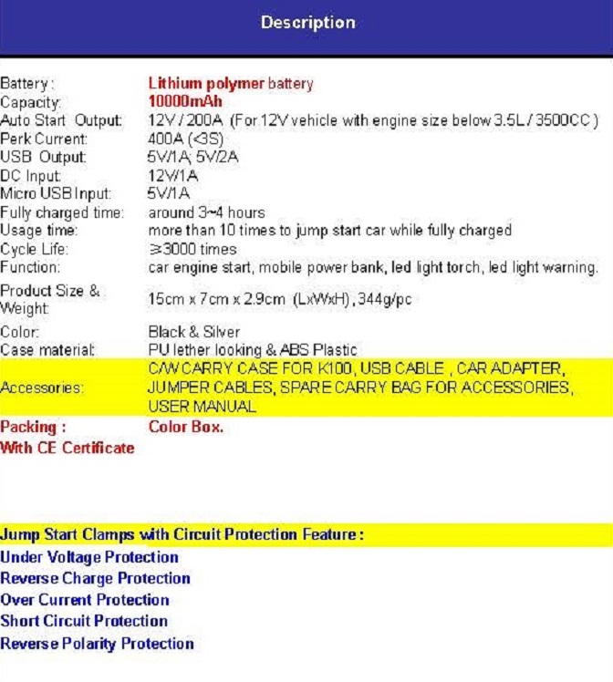
287 In the column headed “FOB HONG KONG”, prices are provided for various quantities, including for 100,000 units.
288 Given the nature of the document, it does not include drawings of any circuitry.
289 In the Joint Expert Report, the issue of novelty and the QTC Brochure is dealt with in section E, pages 26-48, 118-136 and 156-171.
290 During the concurrent evidence section, the issue of novelty and the QTC Brochure was the subject of questions at T741-781.
291 Mr Wilson gave evidence that he would expect the “lithium polymer battery” to be a three lithium battery pack in series or something like that (T743). Mr Wilson was taken to the words “Under Voltage Protection” that appear near the end of the product description. Mr Wilson explained that this meant protecting the internal battery from being discharged too low, and to achieve that function it would need to measure the voltage of the internal battery (T748). Mr Wilson accepted that in order to achieve that function it would need to have some mechanism to stop the discharge, and that would be a switch (T748-749). He accepted there would need to be something like a microcontroller controlling the process (T749). It was put to Mr Wilson that for “Reverse Polarity Protection” (being the last item in the product description), there will be a sensing of whether or not the external battery is connected with reverse polarity and, if it is, the sensor in the MCU will keep the switch open. Mr Wilson said that this would be one method of doing this, but there were others, such as a simple fuse (T750). He said that a fuse would not be an ideal option (T751). The following exchange took place with Mr Wilson (T752):
[SENIOR COUNSEL FOR B&W]: … Would you say that the most logical way to address reverse polarity protection would be to have a sensing which can – is sensed of reverse polarity protection that’s sensing to go to an MCU, and then to turn on or off a switch – a solenoid?
MR WILSON: That would be the most logical way, yes.
[SENIOR COUNSEL FOR B&W]: And that’s a way which was known to you in terms of ways of protecting circuits before the relevant date?
MR WILSON: Yes
It may be that the above transcript is not entirely accurate, as the first question is not clearly formulated. In any event, I took Mr Wilson to accept that the most logical way to address reverse polarity as at the asserted priority date would be to have a sensor that goes to an MCU, which turns a switch on or off.
292 Mr Wilson was asked questions about the “Micro USB Input” referred to in the product description. He accepted that to make the charging work you would need to have an internal USB charging circuit (T753). He accepted that the device would need to include a DC-DC converter to lift the power from 5 volts in order to charge the lithium battery (T753). Mr Wilson accepted that one would want the circuitry to involve charging control software to ensure that the lithium battery was not overcharged (T753). Mr Wilson accepted that at the asserted priority date, one would want to include a temperature sensor to ensure that the lithium battery did not overheat (T753). Mr Wilson said you would want to control maximum charge, that is, to stop charging when it reached the maximum charge voltage (T753). He said this could be done by an MCU or it could just be the charging circuit itself (T754). He accepted that they were both reasonable things to have done at the asserted priority date (T754). Mr Wilson accepted that one could have the microcontroller turning the DC-DC converter off once it had reached a proper charge of the internal battery (T754). He accepted that all of these are the kinds of design considerations which one would apply as a matter of routine (T754).
293 Mr Wilson was asked questions about “USB Output” in the description of the device and said he would read this as two USB outputs (T754). He was asked whether, if you were designing a product like this, you would want to make sure that it didn’t over discharge the battery. He said you would want something like that (T755). He was asked what type of power switches he would consider for this kind of product as at the asserted priority date. He said he would consider FETs and relays. In relation to FETs, he said you would likely utilise multiple FETs in parallel as these were a lot cheaper than one single higher-power, high-current FET (T755). He said that you would want to build a prototype and test it. He accepted that that kind of testing is the natural thing that electrical engineers do before putting out a product (T755-756).
294 Mr Wilson was asked questions about the LED light warning referred to at the end of the “Function” description for the product. He said that an LED light warning could be used to show that the internal battery was too flat (that is, power level) (T759). He was asked questions assuming that he was a member of a design team that includes a manufacturer of battery-powered jump starters, and that that manufacturer has a concern about using lithium polymer batteries and has a preference for using lithium iron phosphate batteries. He was asked if there would be any major difficulties in using a lithium iron phosphate battery. He said the cell voltages are different between the two, so you would need to adjust the charging circuit to accommodate this. He accepted that this work would be within the general calling of his profession (T759). Mr Wilson was asked whether features such as reverse-charge protection would work equally well in combination with a lithium iron phosphate battery as opposed to a lithium cobalt battery. He said they would be the same (T762). He was asked whether the QTC Brochure would encourage him to ensure that a product he was developing had protections against short-circuiting and reverse polarity. He responded that he would want those protections (T762).
295 Mr Wilson was asked about integer 1.5 of Claim 1 of the 338 Patent (“a power switch …”). He accepted that a power switch would be implied in the QTC Brochure (T762). In relation to integer 1.7 of that claim (“a USB charge circuit …”), Mr Wilson accepted that he would imply those features from the QTC Brochure (T763). Mr Wilson accepted that one would need to use a DC-DC converter to achieve the functionality as disclosed in the QTC Brochure (T763).
296 Professor Holmes expressed concerns about the jumper cables being quite thin and about the low price of the device disclosed by the QTC Brochure (T766). He had some concerns that the physical product was smaller, lighter and cheaper than he would expect for something that incorporates a 10-amp-hour lithium battery and the additional components that would be required for the functionality described (T766). He said he had reservations about its capacity to do what they claimed it could do (T766). His reservations included whether the battery was actually a 10,000-milliamp-hour battery (T766).
297 Professor Holmes’s opinion was that there was an implied disclosure of a reverse polarity sensor by the QTC Brochure because one cannot offer “Reverse Polarity Protection” without detecting reverse polarity (T770). Professor Holmes was asked questions about cables that correct themselves and allow the current to effectively self-correct. He said that he would not describe such an apparatus as having reverse polarity protection because reverse polarity is no longer there and the protection is no longer required (T770). He said that he would not describe a fuse within a cable as reverse polarity protection, but rather as overload protection (T770). He accepted that it was possible that someone seeking to sell their products might describe this as reverse polarity protection (T770). Professor Holmes was taken to the description of a patent in [0008] of the specification of the 223 Patent. That paragraph describes a form of reversible battery jumper cables. It was put to Professor Holmes that that paragraph describes a form of reverse polarity protection. Professor Holmes said that there is no reverse polarity protection required because it is not possible to make a reverse connection (T772).
298 It was put to Professor Holmes that it was possible that the safety protection, as viewed in the QTC Brochure, is an LED light that lights up so that the user can manually disconnect. He responded that he would not consider that to be protection (T774). He accepted that the writer of the document may have seen that as a form of protection (T774).
299 Professor Holmes accepted that in the Joint Report at Section F, page 3, he had identified the effectiveness of the safety features of the product disclosed in the QTC Brochure as being of concern (T775). In [579] of Holmes 1, Professor Holmes identified the safety features that he would wish to ensure were properly managed; he said that he could not make any comment as to how well they are managed in the product in the QTC Brochure (T776). Professor Holmes was taken to [581] of Holmes 1. He gave the following clarification of his opinions:
… What I meant is, I don’t know when the QTC would decide that it is ready to close the connection. I don’t know whether it’s when it sees automatic conditions. I don’t know what the word “auto” really means. I’m unable to determine exactly how it will switch, but it doesn’t mean that I’m assuming it will start with a closed switch.
300 Professor Holmes gave evidence that, while the QTC Brochure does not explicitly describe the circuitry of the product, he strongly expects that the product incorporates a semiconductor switch and a microcontroller (T778). He said that he based this on the fact that it is challenging to achieve the functionality without a switch and a microcontroller (T778). He accepted that there were other ways to achieve the functionality, but said they would be highly unlikely at the asserted priority date (T779). Professor Holmes said that there was an implication in the QTC Brochure of a power switch being maintained in an open position based on both presence and polarity (T781).
301 I will start by considering Claim 1 of the 223 Patent. In my opinion, the QTC Brochure does not provide a clear description of, or clear instructions to make, something that would infringe Claim 1 of the 223 Patent (if carried out after the grant of the Patents). The QTC Brochure is a brief document and the experts expressed reservations about whether the features it describes (in particular, the battery capacity) were accurate. The person skilled in the art would approach the document with some scepticism. Further, the document merely provides a list of features. It does not provide any detailed description of how the functionality that it offers is achieved. In particular, while the document does disclose “Reverse Polarity Protection”, it does not make clear what is meant by such protection or how it is provided. The questioning of Professor Holmes, as summarised above, referred to a number of different mechanisms that could be adopted, such as cables that can correct themselves and allow the current to effectively self-correct; a fuse within a cable; and an LED light that lights up so that the user can manually disconnect. While Professor Holmes would not describe these as reverse polarity protection (for the reasons he gave), in my view, those mechanisms could be described as forms of reverse polarity protection in an everyday sense, and it is possible that the brochure uses the label “Reverse Polarity Protection” to describe such an arrangement. It is therefore unclear whether, in referring to “Reverse Polarity Protection”, the brochure is describing a device that has an arrangement to detect presence of the vehicle battery and correct polarity and a switch that turns power on or off based on that detection. The QTC Brochure therefore does not anticipate Claim 1 of the 223 Patent.
302 The same outcome follows for the dependent claims in the 223 Patent. The same reasoning applies for Claim 21 of the 223 Patent.
303 In relation to the relevant claims of the 059 Patent, the same reasoning applies to Claims 1, 14, 15 and 21, which are the relevant independent claims. The same outcome follows for the dependent claims in that patent.
304 In relation to the relevant claims of the 338 Patent:
(a) Claim 1 is expressed in a very general way. Mr Wilson accepted that the integers of this claim would be implied from the QTC Brochure. However, I am not satisfied that the QTC Brochure contains clear and unmistakable directions to make a product falling within Claim 1. In particular, it does not (expressly or implicitly) describe a USB charge circuit of the type specified in integer 1.7. Accordingly, I consider that the QTC Brochure does not anticipate Claim 1.
(b) The same outcome follows for the dependent claims.
(c) Claim 36 is an independent claim that is relevantly similar to Claim 1 of the 338 Patent. For the same reasons as for that claim, I consider that this claim is not anticipated by the QTC Brochure.
305 For the reasons set out above, the QTC Brochure does not anticipate the asserted claims in the Patents.
Lack of inventive step
306 Section 18(1)(b) of the Patents Act requires that an invention, so far as claimed in any claim, when compared with the prior art base as it existed before the priority date of that claim, involve “an inventive step”.
307 Section 7 relevantly provides:
(2) For the purposes of this Act, an invention is to be taken to involve an inventive step when compared with the prior art base unless the invention would have been obvious to a person skilled in the relevant art in the light of the common general knowledge as it existed (whether in or out of the patent area) before the priority date of the relevant claim, whether that knowledge is considered separately or together with the information mentioned in subsection (3).
(3) The information for the purposes of subsection (2) is:
(a) any single piece of prior art information; or
(b) a combination of any 2 or more pieces of prior art information that the skilled person mentioned in subsection (2) could, before the priority date of the relevant claim, be reasonably expected to have combined.
308 As noted above, in relation to the lack of inventive step ground, B&W relies on:
(a) the common general knowledge alone; or
(b) the common general knowledge, together with either the HP Manual or the QTC Brochure.
309 I note that B&W’s opening submissions on invalidity did not contain submissions relying on the common general knowledge alone. However, the Consolidated Particulars of Invalidity dated 6 February 2025 do rely on the common general knowledge alone and B&W adopted the passage in the Carku submissions that relied on the common general knowledge alone ([82]-[87]). This was therefore part of B&W’s case as run.
310 In its response to B&W’s lack of inventive step ground, NOCO emphasises that each claim is to a combination of features and there is, at least, a scintilla of invention in the combination. In addition to the safety features of the claims, NOCO emphasised the utilisation of a lithium battery for a jump starter device and the inclusion of a USB charging facility.
Applicable principles
311 The applicable principles are well established, and there is no real issue between the parties as to those principles.
312 One approach for assessing whether a claimed invention is obvious is to consider whether the person skilled in the art would directly be led as a matter of course to try a particular approach in the expectation that it might well produce a useful result: Aktiebolaget Hässle v Alphapharm Pty Ltd [2002] HCA 59; 212 CLR 411 (Alphapharm) at [53] per Gleeson CJ, Gaudron, Gummow and Hayne JJ. This test is referred to as the “modified Cripps question”. The test can be useful, but it is not always appropriate: Generic Health Pty Ltd v Bayer Pharma Aktiengesellschaft [2014] FCAFC 73; 222 FCR 336 (Generic Health) at [71]. In Generic Health, the Full Court noted at [71] that the plurality in Alphapharm did not reject as an alternative expression of the test the question whether experiments were of a routine character to be tried as a matter of course (Wellcome Foundation Ltd v VR Laboratories (Aust) Pty Ltd (1981) 148 CLR 262 at 280-281, 286). The Full Court in Generic Health stated in the same paragraph that a test formulated in terms of “worthwhile to try” was firmly rejected by the High Court in Alphapharm.
313 In Lockwood Security Products Pty Ltd v Doric Products Pty Ltd (No 2) [2007] HCA 21; 235 CLR 173, the High Court (Gummow, Hayne, Callinan, Heydon and Crennan JJ) considered the issue of lack of inventive step in relation to a door lock. The Court did not use the modified Cripps question, and said that the issue of obviousness involved a question of fact that was once a “jury question” (at [51]), saying further that a “scintilla of invention” remains sufficient in Australian law to support the validity of a patent (at [52]). Otherwise put, there must be “some difficulty overcome, some barrier crossed” or something “beyond the skill of the calling” (at [52]). See also Merck Sharp & Dohme Corp v Wyeth LLC (No 3) [2020] FCA 1477; 155 IPR 1 at [249]-[250] per Burley J.
314 It is established that an invention may be obvious despite the fact that “there are a number, and perhaps a large number, of other obvious routes as well”: Nichia Corporation v Arrow Electronics Australia Pty Ltd [2019] FCAFC 2; 175 IPR 187 at [93] per Jagot J (Besanko and Nicholas JJ agreeing), citing Brugger v Medic-Aid Ltd [1996] RPC 635 at 661. See also AstraZeneca AB v Apotex Pty Ltd [2015] HCA 30; 257 CLR 356 at [114]; Hytera Communications Corporation Ltd v Motorola Solutions Inc [2024] FCAFC 168 at [554].
315 In Alphapharm, the plurality said the following in relation to a combination claim:
41 … The claim is for a combination, the interaction between the integers of which is the essential requirement for the presence of an inventive step. It is the selection of the integers out of “perhaps many possibilities” which must be shown by Alphapharm to be obvious, bearing in mind that the selection of the integers in which the invention lies can be expected to be a process necessarily involving rejection of other possible integers. This expression of the issue follows what was said by Aickin J in Minnesota Mining.
…
72 … Several points are to be made. First, the statute does not ask whether a particular avenue of research was obvious to try so that the result claimed therefore is obvious; the adoption of a criterion of validity expressed in terms of “worth a try” or “obvious to try” and the like begs the question presented by the statute. In a sense, any invention that would in fact have been obvious under the statute would also have been worth trying. Paragraph (e) of s 100(1) of the 1952 Act, applied to the present case, asks whether the combination claimed in claim 1 was obvious. The paragraph does not fix upon the direction to be taken in making efforts or attempts to reach that particular solution to the problem identified in the Patent. Nor does it direct an inquiry respecting each integer of the claimed combination. The paragraph asks whether “the invention ... as claimed”, here the combination, was obvious, not each of its integers.
(Emphasis added.)
316 In the same case, Callinan J referred to the danger of hindsight in considering whether a combination claim is obvious. His Honour said at [196]:
There are, it may be accepted, problems unique to combination patents in assessing obviousness and novelty. A combination patent combines known information and is therefore susceptible to allegations of obviousness and lack of novelty. A particular danger, “that a court will assume, in retrospect, that anyone would have understood the desirability of combining the individual components” was acknowledged by Fletcher-Moulton LJ in British United Shoe Machinery Co Ltd v A Fussell & Sons Ltd …
(Footnotes omitted.)
Common general knowledge – further findings
317 I have made some findings about the common general knowledge known to the power electronics engineer in the team constituting the person skilled in the art as at the asserted priority date at [81]-[88] above. I now make some further findings as to the common general knowledge, focussing on the product designer.
318 During the hearing, B&W handed up an aide-memoire to its s 7(2) arguments. This was later updated to remove evidence not admitted. The aide-memoire included B&W’s contentions as to the common general knowledge as at the asserted priority date. NOCO then provided a responding document, in which it indicated (with strike-through) the parts of B&W’s document that NOCO did not accept were common general knowledge. Accordingly, the parts that are not struck-through are common ground between the parties. Thus, it is common ground between the parties (and I find) that the following matters form part of the common general knowledge known to at least the product designer (or industrial designer) in the team constituting the person skilled in the art as at the asserted priority date:
(a) One way to jump start a vehicle with a depleted battery was to use a pair of jumper cables to connect the depleted battery to a charged battery in another vehicle.
(b) That method was not particularly safe if the jumper cables did not have safety protections and were: (i) not correctly connected to the depleted battery; (ii) connected with incorrect polarity; or (iii) touched together or connected to the same conductive material (in either case, forming a short circuit), because sparking or even destruction of the cables and damage to the batteries and the user might occur.
(c) Jump starter devices with internal batteries. They suffered from the same concerns as jump starter cables if no safety protection was provided.
(d) Jump starter devices for industrial or professional users had been on the market for many years and were large and relatively heavy because they used lead acid batteries.
(e) The proliferation of cheaper lithium batteries.
(f) Pre-packaged battery management systems and other integrated circuits to implement charging control circuitry for lithium batteries were readily available.
(g) Lithium batteries had a much higher energy density than lead acid batteries and could be significantly smaller and lighter than a lead acid battery of equivalent energy capacity and amperage.
(h) Lithium batteries held their charge over a longer period than a lead acid battery.
(i) USB input and output ports in electronic devices, including USB charging.
(j) A cranking capacity of 200A to 300A for 2 seconds would be needed to start a small to medium vehicle, with 300A to 600A for larger vehicles.
319 The main issues between the parties as to the common general knowledge were as follows. B&W contended, and NOCO disputed, that the common general knowledge as at the asserted priority date included:
(a) jump starter devices with lithium batteries; and
(b) lithium-battery jump starters with reverse polarity protection and short circuit protection.
320 In my view, the evidence adduced by B&W did not establish that these matters were common general knowledge as at the asserted priority date. B&W principally relied on Mr Banks’s evidence. But his knowledge was greater than the notional product designer (see further below) and his evidence did not establish that these matters were widely known to the product designer (or industrial designer) member of the team constituting the person skilled in the art as at the asserted priority date.
Evidence
321 I will first deal with Mr Banks’s evidence, then the evidence of Mr Wilson and Professor Holmes. I will then refer briefly to Mr Stanfield’s evidence.
322 Mr Banks gave expert evidence in relation to matters of industrial design. Between 2007 and 2018, Mr Banks was employed by B&W. He was a Product Manager from 2007 to about 2011. He was a Product Development Manager from about 2011 to 2018. In that role, he was responsible for leading the product design and development team, which developed a range of products for B&W, including battery chargers (largely under the “PROJECTA” brand).
323 In Section D of Mr Banks’s affidavit, he describes the preparation of a design brief for a new jump starter. He was asked by the lawyers acting for B&W to describe a design brief that he would have prepared if, at the asserted priority date, he had been asked to provide such a brief to an engineer working in power electronics, for the purpose of assisting them in the development of a new jump starter. Annexure “JLB-16” to Mr Banks’s affidavit is the design brief he prepared (the Design Brief). The Design Brief comprises two sections: the first is a basic overview of the design task; the second sets out specific features to be considered for inclusion in the jump starter. Mr Banks explains his reasoning for including these features in the Design Brief in his affidavit at [78]-[97].
324 The basic difficulty with the Design Brief and associated evidence is that it was prepared on the basis of Mr Banks’s knowledge as at the asserted priority date, but that knowledge goes beyond that which I have found to be the common general knowledge of the product designer in the team that constitutes the person skilled in the art. I therefore do not accept that the Design Brief provides a sound basis to evaluate the issue of inventive step.
325 I now turn to the evidence of Mr Wilson and Professor Holmes. The issue of inventive step is dealt with in Section F of the Joint Expert Report. In the concurrent evidence session, the topic of inventive step was dealt with at T787-826. However, some of the evidence provided earlier in the concurrent evidence session is also relevant to the inventive step issue.
326 During the concurrent evidence session, in the course of dealing with the topic relating to the HP Manual and novelty, senior counsel for B&W asked Mr Wilson a series of questions that are also relevant to the inventive step issue. In this passage, senior counsel referred back to an earlier exchange that had taken place between junior counsel for NOCO and Professor Holmes (at T646-648, in relation to the Priority Date issue). In summary, senior counsel for B&W asked Mr Wilson whether he agreed with a series of propositions that had been put to, and accepted by, Professor Holmes. Mr Wilson largely agreed with those propositions. Although the exchange with Mr Wilson is lengthy, I set it out in full as it contains some important evidence of Mr Wilson and it is necessary to see the full context. Immediately before this passage, senior counsel had been asking Mr Wilson questions about the HP Manual. The following exchange then took place (at T731-737):
[SENIOR COUNSEL FOR B&W]: … Now, just coming back to the problem in the patents. So the problem identified in the patents refers to, I think, jump starter cables, but also jump starter self-powered batteries, which is what we’re concerned with here. Do you agree with that?
MR WILSON: Yes.
[SENIOR COUNSEL FOR B&W]: Yes. And your evidence is you had not operated a battery-powered jump starter before the relevant date?
MR WILSON: That’s correct, yes.
[SENIOR COUNSEL FOR B&W]: Yes. And before the relevant date, nevertheless, you were aware of the risks of short circuiting and connecting with reverse polarity in the context of jump-starting vehicles?
MR WILSON: Yes.
[SENIOR COUNSEL FOR B&W]: Thank you. And one major risk was short circuiting caused by bringing one of the 12 volt cables in contact with the other?
MR WILSON: Yes. So shorting the positive and negative cables together?
[SENIOR COUNSEL FOR B&W]: Correct.
MR WILSON: Yes.
[SENIOR COUNSEL FOR B&W]: And the other major risk was connecting the cables to a battery source of different polarity.
MR WILSON: That’s correct, yes.
[SENIOR COUNSEL FOR B&W]: Now, as an electronics engineer at the relevant date, you would have readily appreciated that one way to avoid those problems was to ensure the cables of the jump starter were not energised until the cables were properly connected?
MR WILSON: That would be logically correct, yes.
[SENIOR COUNSEL FOR B&W]: Thank you. Now, do you [recall] [Counsel for NOCO] yesterday asking Professor Holmes to agree with a number of propositions yesterday regarding the use of one and two sensors – one or two sensors – to detect presence and polarity?
MR WILSON: Yes.
[SENIOR COUNSEL FOR B&W]: Thank you. I just want to check … whether you agree with what [Counsel for NOCO] put to Professor Holmes. So this is in the context of the patent and the description of the two sensors, yes? The reverse polarity sensor and the battery isolation sensor?
MR WILSON: Yes.
[SENIOR COUNSEL FOR B&W]: Yes.
MR WILSON: Yes.
[SENIOR COUNSEL FOR B&W]: That’s where the conversation started. Now, [Counsel for NOCO] said:
Yes. And I think it’s your view –
this is to Professor Holmes –
you expressed this in your third affidavit, I will take you there if you need - but there’s nothing unusual whatever about that arrangement.
That arrangement being the two sensors: the reverse polarity in the battery isolation [sensor]. Are you with me so far?
MR WILSON: Yes. I am.
[SENIOR COUNSEL FOR B&W]: Yes. And he said:
There’s no magic in that.
And Professor Holmes said:
No. There’s nothing - nothing exceptional whatsoever.
…
[SENIOR COUNSEL FOR B&W]: Then, a little bit further down on [T]646, [Counsel for NOCO] … then said:
And it would have been a matter of routine for you to implement a sensor or sensors capable of detecting presence or polarity, or presence and polarity.
And Professor Holmes said, “Yes.” And [Counsel for NOCO] said:
So no difficulty for you or someone of your skill – someone with [your] skill set.
And Professor Holmes said:
No difficulty for my students, who I would like to think have less skill than me –
in a very self-deprecating way. But putting aside that flourish, would you agree with Professor Holmes?
MR WILSON: I would, yes.
[SENIOR COUNSEL FOR B&W]: Thank you. And then [Counsel for NOCO] said:
Yes. Thank you. And that would be so whether using the particular manner of sensing which is described in the patent there –
it was the PCT434 specification –
that is what I think you describe as a simple – simple binary output.
And Professor Holmes said, “Yes.”
Continuing:
Or via other means.
And Professor Holmes said, “Exactly.” Then [Counsel for NOCO] said:
Yes. Thank you. And that’s [whether] … using one or two sensors.
Now, do you agree with Professor Holmes’ responses to [Counsel for NOCO] there?
MR WILSON: I do, yes.
[SENIOR COUNSEL FOR B&W]: And then … Professor Holmes said:
As I said, there’s various ways of doing it.
And [Counsel for NOCO said], “Yes.” Professor Holmes said:
You could conceive of separate sensors, one for reverse polarity and one for presence/correct polarity. You can conceive of one sensor that spans the entire range. I think I note that there is a limitation in the implementation of the 434 patent, whereby they have a significant dead period where if the battery voltage is too low, they won’t respond[.] [Either] way[,] [if] I was asked to design a sensor in this context, I would probably have gone for a sensor that [spanned] that dead period.
[SENIOR COUNSEL FOR B&W]: Now, do you understand Professor Holmes by referring to “period” there, is it the voltage between - - -
MR WILSON: It’s the voltage range. So it’s that – that’s that width of that dead band - - -
[SENIOR COUNSEL FOR B&W]: Yes. Zero to two volts - - -
MR WILSON: - - - that he is referring to.
[SENIOR COUNSEL FOR B&W]: - - - which is referred to, isn’t it.
MR WILSON: Yes, or minus whatever. Minus, what, two volts to plus two volts, yes.
[SENIOR COUNSEL FOR B&W]: Yes. But other than that, identifying the period, would you agree with Professor Holmes[?]
MR WILSON: I would, yes.
[SENIOR COUNSEL FOR B&W]: Thank you. And then [Counsel for NOCO] said at [T]647, a bit further down:
But provided there are sensing means to determine whether the two necessary preconditions have been satisfied, that is, you are connected with – you’re present and connected with [correct] polarity, you would not be limited to the particular arrangement of sensors that are – that’s described in PCT 434 to provide the safety benefits that we discussed earlier, that is, do not turn on the switch unless those two preconditions are satisfied.
[SENIOR COUNSEL FOR B&W]: Professor Holmes says “Yes,” and you would agree.
MR WILSON: Yes.
[SENIOR COUNSEL FOR B&W]: And then he said:
So that is to say if you are using a different arrangement of sensors, one of the many arrangements that you say … would have been available at the relevant date, it would provide the same advantage.
And Professor Holmes said:
Yes, because the sensors provide the information. It’s the microcontroller or the control circuit that then makes the decision to close, and provided it has the same functional information, it’s the same outcome.
Do you agree with that?
MR WILSON: Yes, I do. Yes.
[SENIOR COUNSEL FOR B&W]: Yes. And this is all directed to providing the safety advantages of non-sparking from short circuiting or reverse polarity connection.
MR WILSON: Yes.
[SENIOR COUNSEL FOR B&W]: Thank you. So do you agree that an uninventive power electronics engineer would understand that there were many obvious or plain ways to determine whether an external battery was properly connected, and those included what Professor Holmes described as the – first of all, the binary sensing.
MR WILSON: Yes, there are several ways.
[SENIOR COUNSEL FOR B&W]: Yes.
MR WILSON: Yes.
[SENIOR COUNSEL FOR B&W]: Yes, but one obvious way is the binary sensing with two sensors.
MR WILSON: Yes, that would – I won’t say obvious, but, yes, it’s a way.
[SENIOR COUNSEL FOR B&W]: Well, would it be something that would require any great difficulty or thought for you to put together as at the relevant date.
MR WILSON: No, it wouldn’t. No.
[SENIOR COUNSEL FOR B&W]: No. And is it … a potential way of dealing with the safety concerns? Having two sensors in the binary way that Professor Holmes identified.
MR WILSON: Well, that’s one way of doing it.
[SENIOR COUNSEL FOR B&W]: Yes.
MR WILSON: Of – of achieving that outcome, yes.
[SENIOR COUNSEL FOR B&W]: Yes. So it’s one way that you would think about out of many.
MR WILSON: Yes.
[SENIOR COUNSEL FOR B&W]: Yes.
MR WILSON: Yes.
[SENIOR COUNSEL FOR B&W]: And so when you say it’s not obvious, are you saying there could be many obvious ways to do it.
MR WILSON: Yes, though, I guess - - -
[SENIOR COUNSEL FOR B&W]: That’s just one of them.
MR WILSON: - - - more of an obvious way is to just use a simple voltage measurement. You know, a voltage - - -
[SENIOR COUNSEL FOR B&W]: Yes. So when I said “obvious”, I didn’t mean preferred. I meant available to you.
MR WILSON: Okay.
[SENIOR COUNSEL FOR B&W]: So do you agree with me that the binary version, that is, having two sensors, is obvious in the sense of, it was available to you as an idea in the relevant date.
MR WILSON: Yes.
[SENIOR COUNSEL FOR B&W]: Yes. It’s one of the things you would think of, but it’s not your preferred way.
MR WILSON: Yes.
[SENIOR COUNSEL FOR B&W]: Yes. And your preferred way was the single sensor, and I think Professor Holmes might have agreed that ..... a single sensor which doesn’t have that dead period.
MR WILSON: That would possibly be a preferred way of doing it.
[SENIOR COUNSEL FOR B&W]: Yes. Thank you. Yes. And just to – I think you said this before, but in terms of bringing about that sensing, if I could put it that way, with a microcontroller, it’s not technically difficult. It would take time and effort and skill, but it’s within the calling of your profession.
MR WILSON: Well, that’s right, yes. It’s mostly in the software.
(Emphasis added.)
327 I note for completeness that in Mr Wilson’s affidavit dated 4 June 2024 filed in the Carku proceeding, which was incorporated by reference into his first affidavit in this proceeding, he described (at [41]) the two sensor arrangement in the preferred embodiment in the Patents as “quite clever”. However, I place more weight on his oral evidence at the hearing, including in the passage set out above.
328 In the part of the concurrent evidence session dealing specifically with the topic of inventive step, Mr Wilson was asked to put out of his mind the Patents, the Design Brief, the QTC Brochure, the HP Manual and all post-asserted-priority-date information. He was also asked to base his answers on what would be well known to, or appreciated by, a power electronics engineer with four years’ experience and without any inventive faculty (T787-788). Mr Wilson was asked questions about a project to design a battery-powered jump starter. Mr Wilson accepted that you would have means for recharging the rechargeable battery (T792). He accepted that you would have voltage sensing of the internal and external battery (T792). He said that various power outs (such as 12 volt cigarette lighter outs, barrel connector outs or USB outs) would be optional (T792-793). But he accepted that they were available as at the asserted priority date (T793). He accepted that the device would require circuitry and software to ensure the internal battery was charged and safely discharged (T793). He said that an MCU that controls all those various electronic features would likely be required; he said that it could be done without an MCU, but it was more likely to be an MCU (as at the relevant date) (T793). Mr Wilson was asked whether combining all those features would create any obvious adverse effects or problems. He responded that there was no reason why you could not combine them (T793-795). Mr Wilson accepted that combining all those features was within the skill and experience of a power electronics engineer with four years’ experience (T795).
329 Mr Wilson accepted that lithium ion batteries were a well-known source of power (T795). He said he did not disagree that lithium ion batteries have a higher current capability and a higher energy density (than other batteries) (T797). He agreed that they would be a sensible choice for a jump starter product as at the asserted priority date (T798). Mr Wilson accepted that USB charging of lithium batteries was well known as at the asserted priority date (T799). Mr Wilson was asked whether there was any adverse effect or problem in using lithium batteries and having USB charging in combination. He responded: not that he could see (T805).
330 Mr Wilson was asked questions with reference to the HP Manual. He accepted that if he was designing a jump starter device, he could discern features from the HP Manual that might be worth including (T805).
331 Mr Wilson was asked questions about the QTC Brochure. He accepted that if he was designing a jump starter, the document would at least give him an indication that there was a competitor out there who was offering a jump starter with polarity protection, USB charging and a lithium internal battery (T805-806).
332 Professor Holmes was asked questions about the design process that he discussed in Holmes 1 at [254] and following. Professor Holmes accepted that one of the main components was the battery (T819). He said that the power switch was probably as significant in terms of designing an effective product (T819). Professor Holmes said that he would proceed to acquire specifications for various types of batteries and then assess them against what he understood to be the electrical performance requirements (T821). He said that he knew that lithium batteries come in a wide variety of shapes and electrical characteristics; and he would expect some of those to have electrical characteristics that were more satisfactory or more suitable, and some to have electrical characteristics that were less suitable (T821). He said he would look at all possible battery options that he could find at the time (T822).
333 Professor Holmes was asked questions about the evidence in Holmes 1 at [571] and following, which related to a brief to design a jump starter with reference to the QTC Brochure. He said that the brochure lists a series of features, and he assumes in the first instance that it achieves what it states that it achieves (T824). Professor Holmes said he had reservations as to whether the specifications of the battery in the QTC Brochure were consistent with the photograph of the battery and whether the battery would give an effective cranking performance (T825).
334 In Holmes 1, Section K2, Professor Holmes identifies a number of issues associated with the QTC Brochure, such as the adequacy of the battery shown in the document, the effectiveness of the safety protection provided with the product, and a number of other issues.
335 Some of the evidence of Mr Wilson and Professor Holmes relating to the HP Manual and the QTC Brochure, in the context of novelty, is also relevant to the inventive step issue. That evidence has been summarised earlier in these reasons.
336 I note for completeness that Mr Stanfield’s evidence as to the steps he undertook in developing NOCO’s product is potentially relevant. In his oral evidence, Mr Stanfield said that he felt that the most dangerous part of a lithium ion battery jump starter was the fact that the customer could hold it in their hand while they were connecting it to a battery; if the jump starter were connected to a car battery in reverse, the user could get a major shock. He said it was “so dangerous that you can’t imagine that you ever would want that to happen to a customer” (T251). He said that was where his idea for safety came from. He said that they decided to have not only protection, but redundancy; having two sensors rather than one provided redundancy (T251-252). Mr Stanfield also said that the large lead acid jump starters were just too big and heavy to hold; the user would set it down somewhere; while they still had the capacity for sparking, damage and injury, there is a little more protection (T251-252).
Parties’ submissions
337 In B&W’s oral closing submissions, it relied primarily on the common general knowledge together with the QTC Brochure to establish obviousness. B&W submitted, in summary, that the QTC Brochure describes, in terms, the combination of features that NOCO appears to assert is the invention. B&W submitted that, to the extent that the QTC Brochure does not, in terms, disclose each feature of the asserted claims, the person skilled in the art would either understand those features to be implicitly disclosed, or would arrive at those features when implementing the teaching of the brochure.
338 In oral closing submissions, B&W also relied on the common general knowledge alone to establish obviousness.
339 B&W also made submissions based on the common general knowledge together with the HP Manual.
340 In closing submissions, NOCO emphasised that not everything that Mr Banks knew was common general knowledge. I have accepted that submission above. NOCO also submitted that the Design Brief prepared by Mr Banks tended to lead towards the invention. I have concluded, above, that the Design Brief does not provide a sound basis upon which to assess inventive step.
341 NOCO did not put in issue publication of the QTC Brochure (T1011-1012).
342 NOCO submitted that the experts had significant reservations about the QTC Brochure. NOCO submitted that that was natural given that it is such a cursory document. NOCO submitted that Professor Holmes’s affidavit evidence relating to the QTC Brochure was based on an assumption that the document was delivering safety features, when his own evidence questioned whether it did so. NOCO submitted that Professor Holmes, who is a very experienced electrical engineer, read a significant amount of information into the QTC Brochure.
343 NOCO submitted that Professor Holmes considered USB charging an unattractive option when considering the HP Manual; in this regard, Professor Holmes’s initial inclination was not dissimilar to that of Mr Stanfield. NOCO emphasised that in the process of designing an apparatus such as a jump starter, one is dealing with different combinations and making different choices. It was submitted that this was fatal both to B&W’s case based on common general knowledge alone, and to B&W’s case based on common general knowledge together with the HP Manual or the QTC Brochure.
344 NOCO submitted that: the QTC Brochure did not represent a document that Mr Banks thought worth development; Professor Holmes gave his evidence on the QTC Brochure after seeing the Patents and after opining on the protection features of the HP Manual. NOCO emphasised Professor Holmes’s reservations about the battery in the product the subject of the QTC Brochure: see Holmes 1, [573] (where he queries whether the battery has the stated 10-amp-hour capacity). NOCO relied on Professor Holmes’s evidence that he would not see all lithium batteries as being suitable and he would not be limited to a particular battery type. NOCO submitted that all options were open on the batteries and that one cannot just “jump over” the battery selection and then go on to the selection of other features.
345 NOCO submitted that, when one looks at the QTC Brochure, it gives you a cause for concern; in other words, people were not looking at the QTC Brochure and saying that is going to be able to jump start a car; it was a teaching away from the invention.
346 NOCO emphasised that the invention as claimed was a combination; NOCO submitted that the combination has at least a scintilla of inventiveness; it is not very plain.
Consideration – CGK alone
347 I will consider the issue of inventive step on the basis of the common general knowledge alone before considering the issue on the basis of the common general knowledge together with either the HP Manual or the QTC Brochure.
348 In my view, Claim 1 of the 223 Patent would have been obvious to the person skilled in the art in the light of the common general knowledge as at the asserted priority date. The common general knowledge has been set out above. The common general knowledge included the safety issues relating to jumper cables being not correctly connected to the depleted battery, or being connected with incorrect polarity, or being touched together. The common general knowledge also included jump starter devices with internal batteries, and that they suffered from the same concerns. There does not appear to be anything inventive about integers 1.1, 1.2, 1.3, 1.4 or 1.5 of Claim 1. The part of Claim 1 that is potentially inventive is the arrangement in integers 1.6 and 1.7 for there to be (in summary) a control system or circuit connected to and controlling the power switch with the control system or circuit configured to detect presence and polarity of the depleted/discharged battery and to switch on the power switch (to connect the power supply to the depleted/discharged battery) only when the depleted/discharged battery is present and connected with correct polarity. But the expert evidence suggests that the inclusion of such an arrangement in a jump starter device would have been a matter of routine. As set out above, Professor Holmes gave evidence that it would have been a matter of routine to implement a sensor or sensors capable of detecting presence and polarity. Indeed, he said it would be of no difficulty for his students. Mr Wilson agreed with Professor Holmes’s evidence. Further, Mr Wilson accepted that binary sensing with two sensors would not involve any great difficulty or require any great thought as at the asserted priority date. He accepted that the binary version, that is, having two sensors, was available to him as an idea at the asserted priority date. He accepted that it would take time and effort, but it was within the calling of his profession. While this evidence was couched in terms of sensors, I consider it to be equally applicable to the arrangement described in integers 1.6 and 1.7. In light of the expert evidence, I am satisfied that Claim 1 is obvious in the relevant sense.
349 I will now consider each of the other asserted claims of the 223 Patent:
(a) Claims 2 and 3 are dependent claims that do not introduce additional features that affect the analysis. Accordingly, the analysis for Claim 1 is equally applicable.
(b) Claim 4 is a dependent claim wherein the control system or circuit comprises a microcontroller configured for providing an output controlling the power switch. I am satisfied on the basis of the expert evidence that the inclusion of a microcontroller, and the combination of this feature with the other features, are obvious in the relevant sense. In Mr Wilson’s evidence (set out above) he said that an MCU that controls all the various electronic features to which he had been referred would likely be required (as at the relevant date).
(c) Claim 5 states (in summary) that the microcontroller receives input from “one or more sensors” configured to detect presence and polarity of the depleted/discharged battery. As discussed above (in the context of Claim 1), Professor Holmes gave evidence that it would have been a matter of routine to implement a sensor or sensors capable of detecting presence and polarity. Indeed, he said that it would be of no difficulty for his students. Mr Wilson agreed with Professor Holmes’s evidence. Further, Mr Wilson accepted that binary sensing with two sensors would not involve any great difficulty or require any great thought as at the asserted priority date. He accepted that the binary version, that is, having two sensors, was available to him as an idea at the asserted priority date. He accepted that it would take time and effort, but it was within the calling of his profession. While that evidence focussed to some extent on two sensors, I consider it equally applicable to a single sensor arrangement. In light of the expert evidence, I am satisfied that Claim 5 is obvious in the relevant sense.
(d) Claim 6 is a dependent claim that refers to two specific types of sensors. The analysis in relation to Claim 5 is applicable also to Claim 6.
(e) Claims 7, 8 and 11 are dependent claims. To the extent they introduce additional integers, they do not affect the analysis. Accordingly, the analysis set out above for the earlier claims (as applicable) applies also to these claims.
(f) Claim 12 refers to an apparatus according to any one of the preceding claims, wherein the power supply comprises a lithium ion battery disposed within the jump starter apparatus, and wherein the lithium ion battery comprises a battery pack comprising multiple lithium ion batteries. In my view, Claim 12 would have been obvious to the person skilled in the art in the light of the common general knowledge as at the asserted priority date. The common general knowledge has been set out above. The common general knowledge included that: two common battery chemistries in power electronics were lead acid batteries and lithium-based batteries; and the growing availability of lithium-based batteries was a key advance before the asserted priority date, as they could generate higher energy density and currents than lead acid-based batteries. Further, the common general knowledge known to the product designer in the team constituting the person skilled in the art included: the proliferation of cheaper lithium batteries; pre-packaged battery management systems and other integrated circuits to implement charging control circuitry for lithium batteries were readily available; lithium batteries had a much higher energy density than lead acid batteries and could be significantly smaller and lighter than a lead acid battery of equivalent energy capacity and amperage; and lithium batteries held their charge over a longer period of time than did lead acid batteries. The expert evidence suggests that the use of a lithium ion battery or a battery pack comprising multiple lithium ion batteries in a jump starter device was a matter of routine. As set out above, Mr Wilson accepted that lithium ion batteries were a well-known source of power. He agreed that they would be a sensible choice for a jump starter as at the asserted priority date. This evidence suggests that the use of a lithium ion battery, or a battery pack comprising multiple lithium ion batteries, in a jump starter device was available to, and not difficult for, the person skilled in the art as at the asserted priority date. To the extent that Professor Holmes gave evidence in the concurrent evidence session that he would look at all possible battery options that he could find at the time, I do not consider that that leads to any different conclusion. Further, having regard to the evidence generally, I am satisfied that the combination of features claimed in Claim 12 would have been a matter of routine. Although Mr Wilson was not asked directly about this particular combination of features, the tenor of his evidence was that there was no problem combining the features that were the subject of his evidence. In my view, the combination of lithium ion batteries with the features set out in earlier claims in the 223 Patent is merely a design choice rather than a barrier crossed or difficulty overcome. I consider that combining those features was available to the team constituting the person skilled in the art. For these reasons, I conclude that Claim 12 is obvious in the relevant sense.
(g) Claim 13 refers to an apparatus according to one of the preceding claims, wherein the power switch comprises a plurality of FETs arranged in parallel. In my view, Claim 13 would have been obvious to the person skilled in the art in light of the common general knowledge as at the asserted priority date. The common general knowledge has been set out above. By the asserted priority date, there were a range of well-understood components that were routinely used in power electronics circuitry, including switches. At the asserted priority date, relevant switches included semiconductor switches, including FETs, which could switch faster and were smaller and lighter than solenoid switches. In the context of the Priority Date issue, Mr Wilson gave evidence that it was well known at the asserted priority date that a FET is generally smaller and lighter and can generally switch faster than a relay; and that each of FETs and relays had their own respective advantages and disadvantages depending on the particular application. I find that these matters formed part of the common general knowledge of the power electronics engineer in the team comprising the person skilled in the art. In the context of the Priority Date issue, Professor Holmes accepted that he could have built a jump starter using a relay or a FET switch at the asserted priority date; he accepted that the choice of switch is not germane to management of the preconditions; he accepted that the same safety advantage (in relation to prevention of closure of the switch) can be obtained regardless of the type of switch used. Having regard to this evidence and the evidence generally, the use of a FET switch or a plurality of FETs arranged in parallel would have been a matter of routine. Further, having regard to the evidence generally, combining the features in Claim 13 would have been a matter of routine. For these reasons, I consider that Claim 13 is obvious in the relevant sense.
(h) Claim 14 is a dependent claim. It does not include additional integers that affect the analysis for present purposes. The analysis set out for the earlier claims (as applicable) applies.
(i) Claim 16 refers to the apparatus according to any one of the preceding claims, further comprising a USB charging port configured to provide charging power from an external power source to the power supply. In my view, Claim 16 would have been obvious to the person skilled in the art in light of the common general knowledge as at the asserted priority date. The common general knowledge has been set out above. By the asserted priority date, there were a range of well-understood components that were routinely used in power electronics circuitry including connection components, being components used to electrically connect a power electronics circuit to another circuit. Such connections could be permanent or temporary (i.e. “quick fit” connections, such as USB connectors). Further, the common general knowledge known to the product designer in the team constituting the person skilled in the art included USB input and output ports in electronic devices, including USB charging. As set out above, Mr Wilson accepted that USB charging of lithium batteries was well known as at the asserted priority date. He said that he could not see any adverse effect or problem in using lithium batteries and having USB charging in combination. Having regard to this evidence, I am satisfied that the inclusion of a USB charging port to provide charging power from an external power source to the power supply in a jump starter device would have been a matter of routine. Further, having regard to the evidence generally, I consider that combining the features in Claim 16 would have been a matter of routine. For these reasons, I consider that Claim 16 is obvious in the relevant sense.
(j) Claim 17 refers to the apparatus according to Claim 16, further comprising a USB charging circuit connecting the USB charging port to the power supply. The analysis for Claim 16 is substantially applicable to Claim 17.
(k) Claim 18 refers to the apparatus according to Claim 17, wherein the USB charging circuit comprises a DC-DC converter. In my view, Claim 18 would have been obvious to the person skilled in the art in light of the common general knowledge as at the asserted priority date. The common general knowledge has been set out above. By the asserted priority date, there were a range of well-understood components that were routinely used in power electronics, including power converters, being electrical components that convert one voltage or current to another voltage or current; a common type of power converter was a DC-DC converter. Having regard to the evidence generally, I am satisfied that the inclusion of a USB charging circuit that comprises a DC-DC converter in a jump starter would have been a matter of routine. Further, having regard to the evidence generally, I consider that combining the features in Claim 18 would have been a matter of routine. For these reasons, I conclude that Claim 18 is obvious in the relevant sense.
(l) Claim 19 refers to the apparatus according to Claim 18, wherein the DC-DC converter is configured to convert 5V potential provided from a USB charger to 12.4VDC. The evidence generally indicates that these conversion parameters were available to the person skilled in the art. For substantially the same reasons as for Claim 18, I consider that Claim 19 is obvious in the relevant sense.
(m) Claim 20 refers to the apparatus according to Claim 18 or 19, wherein the DC-DC converter is configured to be turned on and off via a circuit by an output from a microcontroller. The evidence generally indicates that this additional integer was available to the person skilled in the art. For substantially the same reasons as for Claim 18, I consider that Claim 20 is obvious in the relevant sense.
(n) Claim 21 is an independent claim. It differs from Claim 1 in that it uses the language “when, and only when” rather than “only when”. However, it is not suggested that the distinction between claims that require automatic start and those that do not is relevant for the purposes of the inventive step analysis. Putting that aspect to one side, the integers of Claim 21 are similar to those of Claim 1. The analysis set out above in relation to Claim 1 is substantially applicable to Claim 21. I therefore conclude that the claim is obvious in the relevant sense.
350 It follows from the above that all of the asserted claims of the 223 Patent are obvious in the relevant sense and therefore invalid.
351 I turn now to consider the asserted claims of the 059 Patent:
(a) Claim 1 refers to a rechargeable battery. As set out above, it was common general knowledge that batteries can be single use or rechargeable. The inclusion of this type of battery was a matter of routine. Claim 1 refers to a control system or circuit that is configured to detect (in summary) whether there is a proper or improper connection with the positive and negative polarity battery terminals of the depleted/discharged battery prior to turning on the power switch or circuit. In relation to this feature, the analysis set out above in relation to Claim 1 of the 223 Patent is equally applicable. Claim 1 of the 059 Patent also refers (in summary) to a USB input charge circuit connected to the rechargeable battery, the USB input charge circuit comprising a DC-DC converter. In relation to these features, the analysis set out above in relation to Claims 16 and 18 of the 223 Patent is equally applicable. Integer 1.8 of Claim 1 of the 059 Patent refers to a USB input connector connected to the USB input charge circuit. This feature does not affect the present analysis. Having regard to the evidence generally, I am satisfied that combining the features of Claim 1 would have been a matter of routine. I am therefore satisfied that this claim would have been obvious to the person skilled in the art in the light of the common general knowledge as at the asserted priority date.
(b) Claim 2 refers to the apparatus according to Claim 1, wherein the rechargeable battery comprises a lithium ion battery and preferably comprises a battery pack of multiple lithium ion batteries. The analysis set out above in relation to Claim 12 of the 223 Patent is equally applicable. I therefore consider this claim to be obvious in the relevant sense.
(c) Claim 3 refers to the apparatus of Claim 1 or 2, wherein the power switch comprises one or more FETs. The analysis set out above in relation to Claim 13 of the 223 Patent is substantially applicable. I therefore consider this claim to be obvious in the relevant sense.
(d) Claim 4 is a dependent claim that does not introduce any integers that raise an issue for present purposes. The analysis for the earlier claims (as applicable) therefore applies.
(e) Claim 6 refers to the apparatus of any one of the preceding claims, further comprising a temperature sensor configured to detect temperature of the rechargeable battery and to provide a temperature signal to a microcontroller. I have found, above, that as at the asserted priority date, common safety features incorporated in power electronics circuits included temperature overload protection, and that this would have been a matter of common general knowledge. In the context of questions about the QTC Brochure and novelty, Mr Wilson accepted that, as at the asserted priority date, one would want to include a temperature sensor to ensure that the lithium battery did not overheat. I do not consider that evidence to be limited to the device in the QTC Brochure. The question was asked and the evidence given in a more general way (at T753). Having regard to that evidence, I consider that the inclusion of a temperature sensor would have been a matter of routine. Further, having regard to the evidence generally, I consider that combining the features in Claim 6 would have been a matter of routine. I therefore consider Claim 6 to be obvious in the relevant sense.
(f) Claim 7 refers to the apparatus of any one of the preceding claims, further comprising a voltage measurement circuit configured to measure output voltage of the rechargeable battery and to provide a voltage measurement signal to a microcontroller. In the concurrent evidence session, Mr Wilson accepted that, in a project to design a battery-powered jump starter, you would have voltage sensing of the internal and external battery. He accepted that the device would require circuitry and software to ensure the internal battery was charged and safely discharged. He said an MCU that controls all those various electronic features would likely be required. Having regard to that evidence, I consider that the inclusion of a voltage measurement circuit as described in Claim 7 would have been a matter of routine. Further, having regard to the evidence generally, I consider that combining the features in Claim 7 would have been a matter of routine. I therefore consider Claim 7 to be obvious in the relevant sense.
(g) Claim 8 refers to the apparatus of any one of the preceding claims, further comprising a USB output port configured to provide charging power from the rechargeable battery to a USB-chargeable device. In my view, Claim 8 would have been obvious to the person skilled in the art in light of the common general knowledge as at the asserted priority date. The common general knowledge has been set out above. By the asserted priority date, there were a range of well-understood components that were routinely used in power electronics circuitry including connection components, being components used to electrically connect a power electronics circuit to another circuit. Such connections could be permanent or temporary (i.e. “quick fit” connections, such as USB connectors). Further, the common general knowledge known to the product designer in the team constituting the person skilled in the art included USB input and output ports in electronic devices, including USB charging. In the concurrent evidence session, Mr Wilson said (in the context of a project to design a battery-powered jump starter) that various power outs (including USB outs) would be optional. He accepted that they were available as at the asserted priority date. Having regard to that evidence and the evidence generally, I consider that the inclusion of a USB output port configured to provide charging power from the rechargeable battery to a USB-chargeable device would have been a matter of routine. Further, having regard to the evidence generally, I consider that combining the features in Claim 8 would have been a matter of routine. I therefore consider Claim 8 to be obvious in the relevant sense.
(h) Claim 9 is a dependent claim. It does not add integers that affect the analysis. The analysis for the earlier claims (as applicable) will therefore apply.
(i) Claim 10 refers to the apparatus according to any one of the preceding claims, wherein the DC-DC converter is configured for up-converting the input voltage received by the USB input connector. For substantially the same reasons as for Claim 18 of the 223 Patent, I consider that Claim 10 of the 059 Patent is obvious in the relevant sense.
(j) Claim 11 refers to the apparatus according to Claim 10, wherein the input is 5V that is up-converted to 12.4VDC for charging the rechargeable battery. For substantially the same reasons as for Claim 18 of the 223 Patent, I consider that Claim 11 of the 059 Patent is obvious in the relevant sense.
(k) Claim 12 refers to the apparatus according to any one of the preceding claims, wherein the control system or circuit comprises “one or more sensors” connected to a microprocessor for determining (in summary) whether the depleted/discharged battery is present and properly connected to the positive and negative polarity battery terminal connectors. The additional integer in this claim is similar to that in Claim 5 of the 223 Patent. The analysis for that claim is substantially applicable to this additional integer. Further, having regard to the evidence generally, I consider that combining the features in Claim 12 would have been a matter of routine. I am therefore satisfied that Claim 12 is obvious in the relevant sense.
(l) Claim 14 is an independent claim that refers to two specific types of sensors or circuits: a battery presence sensor or circuit and a reverse polarity sensor or circuit. It also refers to a microcontroller configured to receive input signals provided by those sensors, and a USB input charge circuit connected to the rechargeable battery. In relation to the two specific types of sensors, the analysis for Claim 5 of the 223 Patent is substantially applicable. In relation to the microcontroller, the analysis for Claim 4 of the 223 Patent is substantially applicable. In relation to the USB input charge circuit, the analysis for Claim 16 of the 223 Patent is substantially applicable. Having regard to the evidence generally, I consider that combining the features in Claim 14 would have been a matter of routine. For these reasons, I consider that Claim 14 is obvious in the relevant sense.
(m) Claim 15 is an independent claim that refers to a power switch or circuit configured to turn power on or off from the rechargeable battery to the depleted/discharged battery “when” the positive and negative battery terminal connectors are properly connected to the positive and negative battery connectors. It also refers to a power switch control system or circuit configured to detect presence of the depleted/discharged battery and to detect polarity. It also refers to a USB input charge circuit and a USB input connector for providing charge input to the rechargeable battery. In relation to the power switch or circuit being configured to turn power on or off “when” the positive and negative terminal connectors are properly connected, and the switch or circuit being configured to detect presence and polarity, the claim is similar for present purposes to Claim 1 of the 223 Patent and the analysis for that claim is substantially applicable. In relation to the USB input charge circuit and USB input connector, the claim is similar to Claim 16 of the 223 Patent and the analysis for that claim is substantially applicable. Further, having regard to the evidence generally, I consider that combining the features in Claim 15 would have been a matter of routine. For these reasons, I consider that Claim 15 is obvious in the relevant sense.
(n) Claims 16 and 17 are dependent claims that do not introduce new features that affect the analysis. Accordingly, the analysis for Claim 15 is equally applicable.
(o) Claim 18 is a dependent claim wherein the power switch control system comprises a microcontroller configured for providing an output controlling the power switch. In his evidence, Mr Wilson said that an MCU that controls all the various electronic features to which he had been referred would likely be required. I am satisfied on the basis of the expert evidence that the inclusion of a microcontroller, and the combination of this feature with the other features, are obvious in the relevant sense.
(p) Claim 19 is a dependent claim that refers to “one or more sensors” configured to detect presence and polarity of the depleted/discharged battery. The analysis for Claim 5 of the 223 Patent is substantially applicable. Further, on the basis of the expert evidence generally, I am satisfied that combining the features in Claim 19 would have been a matter of routine. I therefore consider that Claim 19 is obvious in the relevant sense.
(q) Claim 20 is a dependent claim that refers to two specific sensors, namely one to detect presence of the depleted/discharged battery and one to detect polarity. The analysis in relation to Claim 19 is applicable also to Claim 20.
(r) Claim 21 is an independent claim that refers to a power switch control system or circuit that is configured to detect presence of the depleted/discharged battery and proper or improper polarity. The claim also refers to a USB input charge circuit and a USB input connector. In relation to the power switch control system or circuit that is configured in that way, the analysis is substantially the same as for Claim 1 of the 223 Patent. In relation to the USB input charge circuit and the USB input connector, the analysis is substantially the same as for Claim 16 of the 223 Patent. Further, I am satisfied having regard to the evidence generally that combining the features of Claim 21 would have been a matter of routine. For these reasons, I consider that Claim 21 is obvious in the relevant sense.
(s) Claim 22 refers to the apparatus according to Claim 21, further comprising a DC-DC converter connected to the USB input charge circuit. The analysis for Claim 18 of the 223 Patent is substantially applicable to this additional integer. Further, having regard to the evidence generally, I am satisfied that combining the features of Claim 22 would have been a matter of routine. For these reasons, I consider that Claim 22 is obvious in the relevant sense.
(t) Claim 23 refers to the apparatus according to Claim 22, wherein the USB input charge circuit is configured to turn on and off the DC-DC converter by an output of the control system or circuit comprising a microcontroller. The inclusion of this additional integer does not affect the analysis. For substantially the same reasons as for Claim 22, I consider that Claim 23 is obvious in the relevant sense.
(u) Claim 24 is an independent claim. For present purposes, this claim is similar to Claim 21, save that this claim also refers to the USB input charge circuit comprising a DC-DC converter and the DC-DC converter being able to be turned on and off by an output of the microcontroller. The analysis for Claims 21, 22 and 23 is substantially applicable. Further, having regard to the evidence generally, I am satisfied that combining the features of Claim 24 would have been a matter of routine. For these reasons, I consider Claim 24 to be obvious in the relevant sense.
352 It follows from the above that all of the asserted claims of the 059 Patent are obvious in the relevant sense and therefore invalid.
353 I will now consider the asserted claims of the 338 Patent:
(a) Claim 1 refers to a rechargeable battery; a power switch or switch circuit, the power switch or switch circuit configured to switch power on from the rechargeable battery to boost or charge the depleted/discharged battery when connected between the positive and negative battery connectors; a USB input connector; and a USB charge circuit comprising a DC-DC converter configured to upconvert voltage. In relation to the rechargeable battery, the analysis of this feature in relation to Claim 1 of the 059 Patent is equally applicable. In relation to the power switch or switch circuit configured in the way described, I am satisfied on the basis of the common general knowledge and the expert evidence that this would have been a matter of routine. In relation to the USB input connector, this was part of the common general knowledge and inclusion of this feature would have been a matter of routine. In relation to the USB charge circuit comprising a DC-DC converter configured as described, the analysis for Claim 18 of the 223 Patent is substantially applicable. Further, having regard to the evidence generally, I consider that combining the features of Claim 1 would have been a matter of routine. For these reasons, I consider that Claim 1 is obvious in the relevant sense.
(b) Claims 2, 3, 4 and 5 are dependent claims that do not introduce additional features that affect the analysis. Accordingly, the analysis for Claim 1 is equally applicable.
(c) Claim 6 refers to the device according to any one of the preceding claims, wherein the DC-DC converter is configured to be turned on and off via a circuit by an output from a microcontroller. The evidence generally indicates that this additional integer was available to the person skilled in the art. For substantially the same reasons as for Claim 1, I consider that Claim 6 is obvious in the relevant sense.
(d) Claim 7 refers to the device according to Claim 6, wherein the microcontroller software can turn charge off if the rechargeable battery voltage is measured to be too high by an A/D input. Professor Holmes states in Holmes 1 at [520] that he understands “A/D input” to refer to an analog to digital input. This integer was not addressed specifically in the concurrent evidence session. However, Mr Wilson accepted (in the context of a project to design a battery-powered jump starter) that you would have means for recharging the rechargeable battery and that you would have voltage sensing of the internal and external battery. Having regard to the common general knowledge and that evidence, I consider that the inclusion of this additional integer would have been a matter of routine. Further, having regard to the evidence generally, I consider that combining the features of Claim 7 would have been a matter of routine. For these reasons, I consider that Claim 7 is obvious in the relevant sense.
(e) Claim 8 refers to the device according to Claim 7, wherein the rechargeable battery is a rechargeable lithium battery, and further comprising a rechargeable lithium battery charge controller configured to provide charge balance to internal lithium battery cells of the rechargeable lithium battery. The analysis for Claim 12 of the 223 Patent is substantially applicable to this additional integer. Further, having regard to the evidence generally, and for substantially the same reasons as for Claim 12 of the 223 Patent, I am satisfied that the combination of features in Claim 8 was also a matter of routine. For these reasons, I consider that Claim 8 is obvious in the relevant sense.
(f) Claim 10 refers to the device according to any one of the preceding claims, further comprising a USB output connector for providing a power output from the rechargeable battery to a USB-chargeable device. The analysis for Claim 8 of the 059 Patent is substantially applicable to this additional integer. Further, having regard to the evidence generally, I consider that combining the features of Claim 10 would have been a matter of routine.
(g) Claims 11, 12 and 13 are dependent claims that do not introduce additional features that affect the analysis. Accordingly, the analysis for Claim 10 is equally applicable.
(h) Claim 14 refers to the device according to Claim 11, further comprising a microcontroller with a control circuit, allowing the USB output circuit to be turned on and off by software control to prevent the rechargeable battery getting too low in capacity. In his evidence, Mr Wilson said that an MCU that controls all the various electronic features to which he had been referred would likely be required. I am satisfied on the basis of the expert evidence that the inclusion of a microcontroller with a control circuit as described, and the combination of this feature with the other features, would have been a matter of routine. For these reasons, I consider that Claim 14 is obvious in the relevant sense.
(i) Claim 16 is a dependent claim that does not add integers that affect the analysis. Accordingly, the analysis for the earlier claims (as applicable) applies to Claim 16.
(j) Claim 17 refers to the device according to Claim 16, wherein the power switch or switch circuit comprises “one or more sensors” configured to detect whether the positive and negative battery connectors are properly connected to the depleted/discharged battery prior to switching on the power switch or switch circuit. The analysis for Claim 5 of the 223 Patent is substantially applicable to this additional integer. Further, having regard to the evidence as a whole, I consider that combining the features of Claim 17 would have been a matter of routine. For these reasons, I consider that Claim 17 is obvious in the relevant sense.
(k) Claim 18 is a dependent claim (being dependent on Claim 17) that does not add integers that affect the analysis. Accordingly, for the reasons set out in relation to Claim 17, I consider Claim 18 to be obvious in the relevant sense.
(l) Claim 19 is a dependent claim (being dependent on Claim 17) that does not add integers that affect the analysis. Accordingly, for the reasons set out in relation to Claim 17, I consider Claim 19 to be obvious in the relevant sense.
(m) Claim 20 is a dependent claim (being dependent on Claim 17) that refers to the power switch or switch circuit being configured to detect presence of the depleted/discharged battery and polarity of the depleted/discharged battery. It also refers to the power switch or switch circuit switching on the rechargeable battery to connect it with the depleted/discharged battery “only when” the depleted/discharged battery is present and connected with correct polarity. The additional integers introduced by this claim do not affect the analysis for present purposes. Accordingly, for the reasons set out in relation to Claim 17, I consider Claim 20 to be obvious in the relevant sense.
(n) Claim 21 refers to the device according to Claim 16, wherein the power switch or switch circuit comprises a microcontroller configured for providing an output controlling the power switch or switch circuit. The analysis for Claim 4 of the 223 Patent is substantially applicable for this additional integer. Further, having regard to the evidence generally, I consider that combining the features of Claim 21 would have been a matter of routine. For these reasons, I consider Claim 21 to be obvious in the relevant sense.
(o) Claim 22 refers to the device according to Claim 21, wherein the microcontroller receives input from “one or more sensors” configured to detect presence of the depleted/discharged battery and polarity. The analysis for Claim 5 of the 223 Patent is substantially applicable to this additional integer. Further, having regard to the evidence generally, I consider that combining the features of Claim 22 would have been a matter of routine. For these reasons, I consider Claim 22 to be obvious in the relevant sense.
(p) Claim 23 refers to the device according to Claim 22 and to two specific types of sensors: one configured to detect presence of the depleted/discharged battery, another to detect polarity. The analysis in relation to Claim 22 is applicable also to this claim.
(q) Claim 24 refers to the device according to any one of Claims 21 to 23, wherein the microcontroller switches the power switch or switch circuit on to provide power from the rechargeable battery to the depleted/discharged battery “only when” the depleted/discharged battery is determined by the microcontroller to be present and connected with correct polarity. The addition of this integer does not affect the analysis for present purposes. Accordingly, the analysis will be the same as for the earlier claims (as applicable).
(r) Claim 25 refers to the device according to any one of the preceding claims, wherein the power switch or switch circuit comprises a plurality of FETs in parallel. The analysis for Claim 13 of the 223 Patent is substantially applicable for this additional integer. Further, having regard to the evidence generally, I consider that combining the features in Claim 25 would have been a matter of routine. For these reasons, I consider Claim 25 to be obvious in the relevant sense.
(s) Claim 26 refers to the device according to Claim 22, wherein the sensors comprise a presence sensor and a reverse polarity sensor. The analysis for Claim 5 of the 223 Patent is substantially applicable to this additional integer. Further, having regard to the evidence generally, I consider that combining the features of Claim 26 would have been a matter of routine. For these reasons, I consider that Claim 26 is obvious in the relevant sense.
(t) Claim 29 is a dependent claim that does not add integers that affect the present analysis. Accordingly, the analysis for the earlier claims (as applicable) applies.
(u) Claim 30 refers to various earlier claims and to a voltage measurement circuit configured to measure output voltage of the rechargeable battery and to provide a voltage measurement signal to the microcontroller. The analysis for Claim 7 of the 059 Patent is substantially applicable to this claim. Further, having regard to the evidence generally, I consider that combining the features of this claim would have been a matter of routine. For these reasons, I consider Claim 30 to be obvious in the relevant sense.
(v) Claim 31 is a dependent claim that does not add any integers that affect the present analysis. Accordingly, the analysis for the earlier claims (as applicable) applies.
(w) Claim 32 refers to the device according to any one of the preceding claims, wherein the power switch or switch circuit is configured to switch power on “only when” the jump starting device is properly connected to the depleted/discharged battery. The addition of that integer does not affect the analysis for present purposes. Accordingly, the analysis for the earlier claims (as applicable) applies.
(x) Claim 33 refers to a device according to any one of the preceding claims, wherein the rechargeable battery is a rechargeable lithium battery pack. The analysis for Claim 12 of the 223 Patent is substantially applicable to this claim. Further, having regard to the evidence generally, I consider that combining the features of Claim 33 would have been a matter of routine. For these reasons, I consider that Claim 33 is obvious in the relevant sense.
(y) Claim 34 refers to the device according to Claim 33, further comprising a rechargeable lithium battery pack voltage measurement circuit configured to monitor the rechargeable battery pack to prevent voltage potential from rising too high during a charging operation and from dropping too low during a discharge operation. The analysis for Claim 7 of the 059 Patent is substantially applicable to this claim. Further, having regard to the evidence generally, I consider that combining the features of Claim 34 would have been a matter of routine. For these reasons, I consider that Claim 34 is obvious in the relevant sense.
(z) Claim 35 refers to a device according to Claim 33 or 34, further comprising a fuel gauge LED for indicating a charge level of the rechargeable lithium battery pack. The common general knowledge has been set out above. It was common general knowledge that battery control circuitry was commonly used (often in the form of “off-the-shelf” ICs and microprocessors) to (among other things) take measures indicating the status of the battery. In light of this, and having regard to the evidence generally, I consider that the addition of this integer would have been a matter of routine. Further, I consider that combining the features of Claim 35 would have been a matter of routine. For these reasons, I consider that Claim 35 is obvious in the relevant sense.
(aa) Claim 36 is an independent claim that refers to: a rechargeable battery; a power switch or switch circuit configured to switch power on from the rechargeable battery to boost or charge the depleted battery when connected between the positive and negative battery connectors; a USB input connector; a USB charge circuit configured to upconvert voltage from a USB charger using a DC-DC converter; a USB output connector; and a USB output circuit electrically connecting the rechargeable battery to a USB output connector. Save for the USB output connector and the USB output circuit, this claim is similar for present purposes to Claim 1 of the 338 Patent. The analysis for Claim 1 is therefore substantially applicable. In relation to the USB output connector and the USB output circuit, the analysis in relation to Claim 8 of the 059 Patent is substantially applicable. Further, having regard to the evidence generally, I consider that combining the features of Claim 36 would have been a matter of routine. For these reasons, I consider that Claim 36 is obvious in the relevant sense.
354 It follows from the above that all of the asserted claims of the 338 Patent are obvious in the relevant sense and therefore invalid.
Consideration – CGK and HP Manual
355 In light of the conclusions I have reached above based on the common general knowledge alone, it is unnecessary to consider the inventive step issue on the basis of the common general knowledge together with the HP Manual. Nevertheless, for the sake of completeness, I will consider the issue on that basis.
356 The HP Manual has been described above in the section of these reasons dealing with novelty. Also in that section, I have summarised the expert evidence relating to the HP Manual. That evidence is relevant to the inventive step issue as well as to novelty.
357 As set out above, the HP Manual describes a jump starter with an internal (lead acid) battery. The description included that the jump starter had reverse polarity protection and an alarm. The brochure stated that the product “[p]revents sparking from accidental reverse connection”. I think the better reading of this is that the product actually prevents reverse polarity connection rather than merely sounding an alarm if the device is connected with reverse polarity. The brochure also states (on page 5) that polarity protection is provided by an MCU-controlled solenoid (a type of switch, also called a relay). Although that information appears under the heading “Jumpstart Leads”, it seems more likely that the polarity protection and switch were in the body of the device rather than in the leads. In any event, the feature is disclosed.
358 As set out above, in the concurrent evidence session, Mr Wilson was taken to several parts of the manual and it was then put to him that, putting all that together, the manual discloses that there is a solenoid which is used to protect against sparking caused by reverse polarity connection. Mr Wilson accepted this, but said he could not tell how it would be configured. Further, Mr Wilson was taken to page 16 of the manual, which is headed “Q. Why didn’t my jumpstarter start my vehicle?” and includes “the vehicle’s battery may be below 1.2V, the minimum voltage for the jumpstarter”. Mr Wilson accepted that this was saying that the jump starter will not provide power to an external battery unless it detects an external battery connected to at least 1.2 volts, and that this involves the use of a switch to keep power off until such time as there has been detection of an external battery connected with 1.2 volts. This provides protection against sparking by the two cables touching each other.
359 In my view, Claim 1 of the 223 Patent would have been obvious to the person skilled in the art in the light of the common general knowledge as at the asserted priority date taken together with the HP Manual. I have already described key aspects of the common general knowledge. The HP Manual describes a product that has a form of reverse polarity protection involving the use of a solenoid. Further, the HP Manual describes a product that detects whether the depleted/discharged battery is present with 1.2 volts and thereby provides protection against sparking by the cables touching. In light of these matters, I am satisfied that a combination as described in Claim 1 was a matter of routine. There does not appear to be anything inventive about integers 1.1, 1.2, 1.3, 1.4 or 1.5 of Claim 1. Further, in light of the common general knowledge and the HP Manual, developing the arrangement described in integers 1.6 and 1.7 would have been a matter of routine. Although the HP Manual does not describe how the reverse polarity protection is achieved, or how the presence detection works, it would have been a matter of routine for the person skilled in the art to develop a device with these features. Further, I consider that it would have been a matter of routine to combine the features referred to in Claim 1. For these reasons, I am satisfied that Claim 1 is obvious in the relevant sense.
360 I do not consider it necessary to consider each of the other asserted claims individually. It is sufficient to express my views in the following general way. These views apply to the asserted claims in all three Patents. Although in the context of novelty, the HP Manual was relied on only in relation to the 223 Patent, in relation to inventive step the HP Manual is relevant to all three Patents. In relation to each asserted claim that includes a feature broadly to the effect that the power switch does not turn on to connect the internal battery to the depleted/discharged battery unless the device detects that the depleted/discharged battery is connected with correct polarity and that the depleted/discharged battery is present, the HP Manual provides further support for the conclusion that the claim is obvious in the relevant sense. In relation to the balance of the asserted claims, the analysis will be the same as set out above under the heading “Consideration – CGK alone”.
361 For these reasons, assessing the matter on the basis of the common general knowledge together with the HP Manual, I conclude that all of the asserted claims are obvious in the relevant sense and invalid.
Consideration – CGK and QTC Brochure
362 In light of the conclusions I have reached above based on the common general knowledge alone, and the common general knowledge together with the HP Manual, it is unnecessary to consider the inventive step issue on the basis of the common general knowledge together with the QTC Brochure. Nevertheless, for the sake of completeness, I will consider the issue on that basis.
363 The QTC Brochure has been described above in the section of these reasons dealing with novelty. Also in that section, I have summarised the expert evidence relating to the QTC Brochure. That evidence is relevant to the inventive step issue as well as to novelty.
364 As set out above, the QTC Brochure is a one-page quotation. The description of the product includes: a lithium polymer battery; USB output; Micro USB input; short circuit protection; and reverse polarity protection. The description also states that the capacity (of the battery) is 10,000 milliamp hours.
365 As set out above, both Professor Holmes and Mr Wilson expressed reservations about whether the features the brochure describes (in particular, the battery capacity) are accurate. Notwithstanding those concerns, I consider that the person skilled in the art would have some regard to the document and draw something from the features of the device that it identifies.
366 In my view, Claim 1 of the 223 Patent would have been obvious to the person skilled in the art in light of the common general knowledge as at the asserted priority date together with the QTC Brochure. I have already described key aspects of the common general knowledge. The QTC Brochure describes a product that has a form of reverse polarity protection and short circuit protection (albeit no detail is provided as to how these are achieved). In light of these matters, I am satisfied that Claim 1 was a matter of routine. Although the QTC Brochure does not describe how the reverse polarity protection or the short circuit protection are achieved, it would have been a matter of routine for the person skilled in the art to develop a device with those features. Further, I consider that it would have been a matter of routine to combine the features referred to in Claim 1. For these reasons, I am satisfied that Claim 1 is obvious in the relevant sense.
367 I do not consider it necessary to consider each of the other asserted claims individually. In relation to each asserted claim that includes a lithium ion battery and/or a USB input connector and/or a USB output port, the QTC Brochure provides further support for the conclusion that the claim would have been obvious. Although the QTC Brochure does not contain any description of the lithium polymer battery, the micro USB input or the USB output, the reference to these features provides further support for that conclusion. Moreover, the reference to those features in the one device provides further support for the conclusion that combining the features of the claims would have been a matter of routine. In relation to the balance of the asserted claims, the analysis will be the same as set out above under the heading “Consideration – CGK alone”.
368 For these reasons, assessing the matter on the basis of the common general knowledge together with the QTC Brochure, I conclude that the asserted claims are obvious in the relevant sense and invalid.
Best method
369 In light of the conclusions I have reached above in relation to inventive step, it is unnecessary to consider the remaining grounds of invalidity. Nevertheless, I will consider the best method ground for completeness.
370 Section 40(2)(aa) of the Patents Act requires that a complete specification “disclose the best method known to the applicant of performing the invention”. The applicable principles were discussed by the Full Court of this Court in Sandvik Intellectual Property AB v Quarry Mining & Construction Equipment Pty Ltd [2017] FCAFC 138; 126 IPR 427 (Sandvik) at [93]-[115].
371 B&W contends, in relation to each of the Patents, that the complete specification does not comply with the requirements of s 40(2)(aa) of the Patents Act, in that the complete specification does not disclose the best method known to NOCO of performing the invention. B&W provides particulars in Confidential Annexure A to the Consolidated Particulars of Invalidity dated 6 February 2025. In summary, B&W contends that in late 2014 and early 2015 (that is, after the filing date of PCT434) NOCO became aware of problems with its commercial product, the GB30 (or Genius Boost 30), which is the commercial embodiment of the invention, and made improvements to that product. B&W contends that, as at the filing date of each of the Patents (i.e. dates in 2020, 2021 and 2022), NOCO had knowledge that there was an improved embodiment of the invention, but NOCO did not disclose this embodiment in the complete specification for each Patent.
372 This ground raises both factual and legal issues. A threshold legal issue is whether the relevant date for the purposes of ascertaining NOCO’s knowledge of the best method is the date of filing PCT434 (3 July 2014) or the date of filing of each of the Patents. If the relevant date is the date of filing PCT434, this ground of invalidity fails. If the relevant date is the filing date of each of the Patents, there is a factual issue as to whether NOCO was aware of a better method of performing the invention in late 2014 and early 2015 than that which was disclosed in each of the Patents.
373 I will start by considering the threshold legal issue.
374 B&W contends that the best method known to a patentee which must be disclosed is that known at the time of filing of the complete application; thus, where a complete specification (such as each of the Patents) claims priority from an earlier filed PCT application (or earlier filed divisional application), it is the best method known to the applicant at the filing date of the complete specification of the patent in suit that must be disclosed, not the best method known to the patentee at some antecedent date, such as the date of filing of the PCT application from which priority is claimed. B&W relies on Pfizer at [375]-[379]; Les Laboratoires Servier v Apotex Pty Ltd [2016] FCAFC 27; 247 FCR 61 (Servier) at [111]-[114], [116]; Dometic Australia Pty Ltd v Houghton Leisure Products Pty Ltd [2018] FCA 1573; 135 IPR 403 (Dometic) at [229]-[234]. B&W submits that the Court should follow Dometic unless satisfied it is plainly wrong.
375 NOCO contends that the knowledge requirement should be assessed at 3 July 2014, being the filing date of PCT434, which is the first filed application in the claim of divisional applications and the date from which the term of each patent runs. NOCO relies on Rescare Ltd v Anaesthetic Supplies Pty Ltd [1992] FCA 811; 25 IPR 119 (Rescare) at 135 per Gummow J. NOCO contends that the reasoning of Gummow J in that passage was approved by the Full Court in Pfizer at [375]-[379] and by the Full Court in Servier at [113], [114]. NOCO also relies on Mont Adventure Equipment Pty Ltd v Phoenix Leisure Group Pty Ltd [2009] FCAFC 84; 176 FCR 575 (Mont Adventure) at [14], [18]. NOCO submits that the Court ought not follow Dometic on the basis that it is inconsistent with Pfizer, Servier and Mont Adventure and because the arguments now put were not considered. NOCO submits that Dometic is plainly wrong.
376 In my view, for the reasons that follow, NOCO’s position is to be preferred.
377 In Rescare, in relation to best method, there was both a factual issue and an issue of law. The factual issue arose because the use of a “one tube” apparatus had distinct advantages over a “two tube” apparatus (see at 132). The evidence indicated that the “one tube” apparatus was not known to the relevant person (Professor Sullivan) as the best method for performing the invention on the international filing date (23 April 1982). On the other hand, it was contended that he was aware of that method on the date of publication (4 November 1982). Gummow J first dealt with the factual issue and concluded that he was not satisfied that by 4 November 1982 the “one tube” method was known to Professor Sullivan. It was therefore unnecessary to determine the issue of law, which concerned the relevant date as at which the best method known to the applicant for performing the invention is to be identified. Nevertheless, his Honour considered that issue for completeness (at 133-135), concluding (at 135) that the “adequacy of the disclosure should be judged by reference to the time from which dated the monopoly granted the applicant in exchange for the disclosure”. His Honour said that, in this case, it was the international filing date, 23 April 1982, being the “date from which the term of the patent runs”. In his Honour’s view, one of the two historical rationales of the best method requirement was to prevent the patentee from obtaining “the benefit of a monopoly without giving to the public the corresponding consideration of the best method of performing the invention” (at 133).
378 I would make the following observations about Rescare. Clearly, Gummow J’s conclusion on the issue of law was obiter. Nevertheless, it was a considered view on the issue. The issue in that case was not the same as the issue in the present case. In Rescare, the contest was between the international filing date and the date of publication, whereas here it is between the international filing date and the filing date of the divisional application. Nevertheless, Gummow J’s view supports NOCO’s position. Gummow J considered that the relevant date for the best method ground was the international filing date, which was, in that case, the date from which the term of the patent ran. By parity of reasoning, in the present case, the relevant date is the date of filing PCT434, being the date from which the term of each of the Patents runs (on the assumption that I am making in this section of my reasons – see [255] above).
379 In Pfizer, French and Lindgren JJ considered the best method issue at [348] and following. Crennan J agreed with their Honours’ reasons in relation to best method (at [408]). The positions of the parties in that case were as follows. Lilly contended that the best method must be included in the complete specification at the filing date, which, in that case, was the international filing date of the PCT application (13 May 1994) (see [350]). Pfizer submitted that the date by which disclosure of the best method must be made was either the date of grant (10 July 1997) or the date of commencement of the proceeding at first instance (17 September 2002) (see [351]). The primary judge in that case held that the relevant date was the date of commencement of the proceeding or, alternatively, the date of grant. The primary judge’s conclusion was that the relevant date was, at the earliest, the date of grant. By that date, the best method of claim 8 was included in the specification (see [356]).
380 At [366] and [375], their Honours drew a distinction between two dates:
(a) the date as at which the best method known to the applicant is to be identified (the knowledge element); and
(b) the date by which the specification’s full description of the invention must include a disclosure of the best method.
381 Their Honours stated at [375]:
The date as at which the best method known to the applicant is to be identified is conceptually distinct from the date by which the specification’s full description of the invention must include a disclosure of it. The parties correctly proceeded on the basis that it is the best method known to the applicant as at the filing date that must be disclosed. In Rescare, Gummow J expressed the opinion (at ALR 223; IPR 135) that this was so under s 40 of the 1952 Act, and s 40(2)(a) is to the same effect as s 40(1)(a) of the 1952 Act.
382 In the second sentence of that paragraph, their Honours accepted as correct that the knowledge element is to be assessed as at the filing date (which, in that case, was accepted as being the international filing date (see [350])). In the third sentence, their Honours referred to the judgment of Gummow J in Rescare as providing support for the view that they had just expressed.
383 At [376], French and Lindgren JJ discussed the facts of Rescare. At [377], their Honours set out Gummow J’s conclusion on the issue of law (which has been referred to above). At [378], French and Lindgren JJ said that in Rescare Gummow J was concerned with the date as at which the best method known to the applicant for the patent is to be identified (i.e. the first date referred to in [375]). At [379], their Honours stated:
Once it is accepted, however, that an applicant for a patent must disclose the best method known to the applicant at the date of filing, it is also not difficult to think, as Gummow J appears to have done and as we do, that disclosure must be made in the complete specification when it is filed. Lest there be any doubt, we would make it clear that s 40(2)(a) requires an applicant for a patent to disclose in the complete specification at the time of filing it the best method of performing it known to the applicant at that time: compare C Van Der Lely NV at 56 and Rediffusion Simulation Ltd v Link-Miles Ltd [1993] FSR 369 at 405, which were decided on ss 4(3)(b) and 32(1)(h) of the Patents Act 1949 (UK).
384 In this paragraph, their Honours were primarily directing themselves to the second of the two dates they had identified in their reasons at [375], that is, the date by which the specification’s full description of the invention must include disclosure of it. Their Honours held that the disclosure of the best method must be made in the complete specification when it is filed (which was, in that case, the date of filing the international patent application). Thus, it was insufficient for the best method to be included in the complete specification later by way of amendment.
385 During some of B&W’s submissions before me, there seemed to be a suggestion that the Full Court in Pfizer had qualified Gummow J’s statement in Rescare in some way. I do not read the reasons of the Full Court in that way. In my opinion, French and Lindgren JJ’s view as to the first date referred to in [375] aligns with the view expressed by Gummow J in Rescare. Their Honours explained that Gummow J was concerned with the first date rather than the second date referred to in [375] of Pfizer.
386 The important point for present purposes is that at [375], French and Lindgren JJ held that the relevant date for the purposes of the knowledge element is the filing date of the complete specification (which was, in that case, the international filing date). In this regard, I note that s 29A(2) of the Patents Act provides that “[t]he description, drawings, graphics, photographs and claims contained in a PCT application are to be treated as a complete specification filed in respect of the application”. For this reason, the filing date of a PCT specification (i.e. the international filing date) is capable of constituting the filing date of the complete specification. It is not clear to me why the analysis in Pfizer at [375] would not apply in the circumstances of this case. In other words, it is not clear to me why the filing date would not be treated as the filing date of PCT434. This is the date from which the term of each of the Patents runs, a matter to which Gummow J referred in Rescare at 135. Thus, by parity of reasoning, the relevant date for the knowledge element is the filing date of PCT434. Further, the disclosure was required to be made in the complete specification for PCT434 when it was filed.
387 The judgment of the Full Court in Servier at [111]-[114] does not take the issue any further. In that case, the Full Court adopted the relevant statements of principle in Pfizer in substantially the same terms.
388 While a different view was taken in Dometic at [233], I consider that I should follow (what I understand to be) the view of the Full Court in Pfizer rather than the holding in that case. I do not consider it necessary for me to form a view on whether the holding in Dometic is plainly wrong.
389 For these reasons, applying Pfizer, I consider that the relevant date for the knowledge element is the date of filing PCT434. Further, the disclosure was required to be made in the complete specification for PCT434 when it was filed. The earliest date on which NOCO is said to have become aware of a better method of performing the invention than was disclosed in PCT434 was, relevantly, after the date on which PCT434 was filed. It follows that the best method ground of invalidity is not made out.
390 I will now consider the remaining factual issues relating to best method on the assumption that (contrary to my conclusion above) the relevant date for the knowledge element is the date of filing each of the Patents (i.e. dates in 2020, 2021 and 2022).
391 The GB30 was launched in September 2014. The preferred embodiment described in the Patents reflects the GB30 as launched.
392 B&W relies on seven documents, and the evidence of the experts and Mr Stanfield in relation to those documents, to make out its case. The seven documents are annexed to the second affidavit of Professor Holmes as “GH-18” through to “GH-24”. These documents, and the evidence in relation to them, establish that, in late 2014 and early 2015, NOCO experienced certain problems with the GB30 as launched and made changes to address those problems, thereby improving the product. In particular:
(a) The GB30 as launched used a lithium ion battery pack and generated a continuous discharge current of 25C and a burst discharge current of 50C. The battery discharge capability was considered insufficient and the size of the battery was increased.
(b) The GB30 as launched used three FETs in parallel. However, problems were experienced with the FETs and they were replaced with relays.
393 In relation to the first issue, on 11 September 2014, Mr Jonathan Nook (the President of NOCO) sent an email to Mr Stanfield and Mr Derek Underhill (an industrial designer working for NOCO) that included “OK. We f***ed up. The Gb30 battery needs to be bigger – in fact double its size”. Mr Stanfield during cross-examination accepted that Mr Nook was expressing the need for the battery in the GB30 to be able to put out more discharge current. The solution that was contemplated at that time was to adopt a 90C rated battery. During cross-examination, Mr Stanfield said that, among the improvements to the product, the higher power batteries were “the most important thing” and the main advantage was “the higher discharge rate from the batteries” (T268-269).
394 In relation to the second issue, in an email dated 25 September 2014, Mr Stanfield wrote to Mr Jonathan Nook and Mr Underhill that “[w]e can remove the FET/DIODE smart switch and replace it with the RELAY/DIODE smart switch”. Mr Stanfield accepted in cross-examination that the relay was a simpler solution. While he said that it had some advantages and some disadvantages, I am satisfied based on his evidence as a whole that it represented an improvement because it was more durable and could handle a higher discharge current as the battery size increased.
395 I find that NOCO as a corporate entity was aware of these improvements to the product. Mr Jonathan Nook, the President of NOCO, authored or received the relevant correspondence.
396 Having regard to the nature of the invention (see Sandvik at [107]), I am satisfied that the improved product constituted the best method for performing the invention and that NOCO was aware of this.
397 Therefore, if the relevant date for the purpose of the knowledge element is the date of filing of each of the Patents, NOCO failed to disclose the best method known to it as at each of those dates.
398 However, for the reason set out in [389] above, I consider that the best method ground of invalidity is not made out.
Other invalidity grounds
399 In light of the conclusions that I have reached in relation to inventive step, it is not necessary to consider the remaining grounds of invalidity, namely lack of support, insufficiency and lack of utility.
Infringement issues
400 In light of my conclusion that all of the asserted claims are invalid on the basis of lack of inventive step, it is unnecessary to consider the infringement issues. However, I do so for completeness. I proceed in this section on the assumption that the asserted claims are valid.
401 In NOCO’s opening submissions on infringement, it identifies 10 infringement issues. I will address each of these in turn.
402 In B&W’s opening submissions on infringement, it accepts that the IS 920 and IS 1220 products do infringe Claim 14 of the 059 Patent.
403 Infringement issue 1 concerns automatic start. The expert evidence establishes that each of the B&W impugned products requires an extra step to turn on the power switch after the battery presence and polarity conditions have been met. B&W contends that that extra step avoids infringement in respect of many of the asserted claims on the basis that those claims require automatic start after satisfaction of the preconditions. The outcome of this infringement issue follows the conclusions I have reached in relation to the Automatic Start issue. In respect of the asserted claims that I have concluded do not require automatic start, infringement is not avoided on the basis put forward by B&W. In respect of the asserted claims that I have concluded do require automatic start, infringement is avoided.
404 Infringement issue 2 relates to manual override. The expert evidence establishes that each of the B&W impugned products includes an override feature, where a user can force the power switch to turn on where the jump starter has not detected presence. B&W contends that all of the asserted claims of the 223 Patent, Claim 16 of the 059 Patent and Claims 2, 20, 24 and 32 of the 338 Patent require that the control system or circuit (including the microcontroller) must not switch on the power switch unless the depleted/discharged battery is both present and properly connected (see [133] above). B&W contends that the impugned products therefore do not infringe the claims identified in this paragraph. The outcome of this infringement issue follows the conclusions I have reached in relation to the Manual Mode issue. I have concluded that a device that has a manual mode as described above is inconsistent with and therefore outside the scope of the claims identified in this paragraph. Accordingly, the impugned products do not infringe those claims.
405 Infringement issue 3 relates to the DC-DC converter. Claims 18-20 of the 223 Patent, Claims 1-13 and 22-25 of the 059 Patent and all claims of the 338 Patent require the use of a “DC-DC converter” to up-convert voltage (either generally or to a specific voltage). The expert evidence establishes that the USB charging circuit identified by Mr Wilson in each of the impugned products only includes the power stage section and excludes the controller section; the controller section of the alleged DC-DC converter is, instead, incorporated within the software of the microcontroller. On this basis, B&W contends that the impugned products do not infringe the claims referred to in this paragraph. The outcome of this infringement issue follows the conclusions I have reached in relation to construction issue 10. I have accepted NOCO’s construction in relation to this construction issue. It follows that I reject B&W’s non-infringement contention.
406 Infringement issue 4 relates to charging to at least 11.1V or 12.4V. B&W’s non-infringement contention in this regard related to Claim 19 of the 223 Patent, Claim 11 of the 059 Patent and Claim 4 of the 338 Patent. NOCO no longer relies on those claims. As a result, this infringement issue falls away.
407 Infringement issues 5 and 6 relate to the power switch and the output controlling the power switch. It appears from NOCO’s closing notes on infringement at [37] that B&W does not press the relevant non-infringement contentions. Accordingly, these infringement issues fall away.
408 Infringement issue 7 concerns the USB input charge circuit. Claims 16 and 17 of the 223 Patent (and dependent claims), all asserted claims in the 059 Patent, and all asserted claims in the 338 Patent require the use of a “USB charging port”, “USB charging circuit”, “USB input charge circuit” or “USB input connector”. B&W accepts that the IS 920 and the IS 1220 products satisfy the USB connector requirements in these claims. However, B&W contends that the IS 1400 and IS 2000 products do not fall within these claims on the basis that they are each charged through a USB-C connector and charging port. B&W contends that the person skilled in the art would not have understood, as at the asserted priority date, the claims referred to in this paragraph as encompassing USB-C. I accept that the IS 1400 and IS 2000 products are each charged through a USB-C connector and charging port. However, for similar reasons as discussed above in relation to the USB issue, I consider that the expression “USB” is broad enough to encompass USB-C. Accordingly, I reject B&W’s non-infringement contention.
409 Infringement issue 8 relates to the use of two sensors to make detections. B&W contended that Claims 6 and 14 of the 223 Patent, Claims 14 and 20 of the 059 Patent and Claims 23 and 26 of the 338 Patent (and their dependent claims) all require the use of two sensors. B&W contended that the IS 1400 and the IS 2000 products do not fall within the scope of these claims because they do not involve the use of the two sensors required by these claims. NOCO no longer relies on these claims in relation to the IS 1400 and the IS 2000. Accordingly, this infringement issue falls away.
410 Infringement issue 9 relates to the DC-DC converter controlled by a microcontroller. It appears from [37] of NOCO’s closing notes on infringement that B&W does not press the relevant non-infringement contention. Accordingly, this infringement issue falls away.
411 Infringement issue 10 relates to the voltage measurement circuit. It appears from [37] of NOCO’s closing notes on infringement that B&W does not press the relevant non-infringement contention. Accordingly, this infringement issue falls away.
412 In the circumstances of this case, it is unnecessary to identify which, if any, of the impugned products infringe claims in the Patents. This can be worked out by applying the above conclusions.
Conclusion
413 For the reasons set out above, I have concluded that all of the asserted claims are invalid. It is appropriate to make declarations and orders to give effect to that conclusion. I will give the parties the opportunity to make submissions on costs.
I certify that the preceding four hundred and thirteen (413) numbered paragraphs are a true copy of the Reasons for Judgment of the Honourable Justice Moshinsky. |
Associate:
Dated: 7 August 2025

