
FEDERAL COURT OF AUSTRALIA
Dyno Nobel Asia Pacific Pty Ltd v Orica Explosives Technology Pty Ltd [2025] FCA 767
File number(s): | NSD 345 of 2022 |
Judgment of: | DOWNES J |
Date of judgment: | 14 July 2025 |
Catchwords: | PATENTS – validity – infringement – standard patent entitled “Wireless detonator assembly, and methods of blasting” – standard patent entitled “Wireless electronic booster and methods of blasting” – standard patent entitled “Selective control of wireless initiation devices at a blast site” – standard patent entitled “A method of underground rock blasting” PATENTS – claim construction – utility – clarity – fair basis – identification of members of notional skilled team – person skilled in the art – where witnesses had peculiar or specialised knowledge – lack of inventive step – novelty – availability of prior art information – date on which prior art is to be construed for purposes of novelty – whether person skilled in the art could be reasonably expected to have ascertained and regarded as relevant certain prior art publications – whether obviousness established on the evidence PATENTS – best method – whether best method disclosed because of failure to disclose details of commercial embodiment of invention – proper characterisation of invention in patent – manner of manufacture – whether statements in patent constituted admissions that matters were known – whether new method disclosed |
Legislation: | Evidence Act 1995 (Cth) s 136 Patents Act 1990 (Cth) ss 7(1), 7(2), 7(3), 18(1), 40(2), 117(2), 128, 129, 131 |
Cases cited: | Aktiebolaget Hässle v Alphapharm Pty Ltd (2002) 212 CLR 411; [2002] HCA 59 Alcon Research LLC v Actavis Group PTC ehf [2021] EWHC 1026 Aristocrat Technologies Australia Pty Ltd v Konami Australia Pty Ltd (2015) 114 IPR 28; [2015] FCA 735 AstraZeneca AB v Apotex Pty Ltd (2014) 226 FCR 324; [2014] FCAFC 99 Australian Steel Co (Operations) Pty Ltd v Steel Foundations Ltd (2003) 58 IPR 69; [2003] FCA 374 Axent Holdings Pty Ltd (t/as Axent Global) v Compusign Australia Pty Ltd (2020) 154 IPR 431; [2020] FCA 1373 Betfair Pty Limited v Racing New South Wales (2010) 189 FCR 356; [2010] FCAFC 133 BlueScope Steel Limited v Dongkuk Steel Mill Co, Ltd (No 2) (2019) 152 IPR 195; [2019] FCA 2117 Boehringer Ingelheim Animal Health USA Inc v Elanco New Zealand (2021) 164 IPR 17; [2021] FCA 1457 Bradken Resources Pty Ltd v Lynx Engineering Consultants Pty Ltd (2012) 210 FCR 21; [2012] FCA 944 British Acoustic Films Ltd v Nettlefold Productions Ltd (1935) 53 RPC 221 CQMS Pty Ltd v Bradken Resources Pty Ltd (2016) 120 IPR 44; [2016] FCA 847 Dometic Australia Pty Ltd v Houghton Leisure Products Pty Ltd (2018) 135 IPR 403; [2018] FCA 1573 Dyson v Hoover [2002] RPC 22 EI Dupont de Nemours & Co v Imperial Chemical Industries plc (2002) 54 IPR 304; [2002] FCA 230 Firebelt Pty Ltd v Brambles Australia Ltd (2002) 54 IPR 449; [2002] HCA 21 General Tire & Rubber Company v Firestone Tyre and Rubber Company Ltd (1971) 1A IPR 121 Gilead Sciences Pty Ltd v Idenix Pharmaceuticals LLC (2016) 117 IPR 252; [2016] FCA 169 GlaxoSmithKline Consumer Healthcare Investments (Ireland) (No 2) Ltd v Apotex Pty Ltd (2016) 119 IPR 1; [2016] FCA 608 GlaxoSmithKline Consumer Healthcare Investments (Ireland) (No 2) Ltd v Generic Partners Pty Ltd (2018) 264 FCR 474; [2018] FCAFC 71 Globaltech Corporation Pty Ltd v Reflex Instruments Asia Pacific Pty Ltd (2022) 167 IPR 515; [2022] FCA 797 Hanwha Solutions Corporation v REC Solar Pte Ltd (2023) 180 IPR 315; [2023] FCA 1017 Hicks v Minister for Immigration & Multicultural & Indigenous Affairs [2003] FCA 757 ICI Chemicals & Polymers Ltd v Lubrizol Corporation Inc (1999) 45 IPR 577; [1999] FCA 345 ICI Chemicals & Polymers Ltd v The Lubrizol Corporation Inc (2000) 106 FCR 214; [2000] FCA 1349 Idenix Pharmaceuticals LLC v Gilead Sciences Pty Ltd (2017) 134 IPR 1; [2017] FCAFC 196 Illumina Cambridge Limited v Latvia MGI Tech SIA [2021] EWHC 57 Interlego A.G. v Toltoys Proprietary Limited (1973) 130 CLR 461 JMVB Enterprises Pty Ltd (formerly known as A’Van Campers Pty Ltd) v Camoflag Pty Ltd (2005) 67 IPR 68; [2005] FCA 1474 Les Laboratoires Servier v Apotex Pty Ltd (2016) 247 FCR 61; [2016] FCAFC 27 Lido Manufacturing Co Pty Ltd v Meyers & Leslie Pty Ltd (1964) 5 FLR 443; [1964–5] NSWR 889 MedImmune Limited v Novartis Pharmaceuticals UK Limited [2012] EWCA Civ 1234 Merck & Co Inc v Arrow Pharmaceutical Ltd (2006) 154 FCR 31; [2006] FCAFC 91 Minnesota Mining & Manufacturing Co v Bondina Ltd [1972] FSR 417; [1973] RPC 491 Minnesota Mining & Manufacturing Co v Tyco Electronics Pty Ltd (2002) 56 IPR 248; [2002] FCAFC 315 Minnesota Mining and Manufacturing Company v Beiersdorf (Australia) Ltd (1980) 144 CLR 253 Mullard Radio Valve Co. Ltd. v British Belmont Radio Ltd. (1939) 56 RPC 1 Neurim Pharmaceuticals (1991) Ltd v Generic Partners Pty Ltd (No 5) [2024] FCA 360 Nicaro Holdings Pty Ltd v Martin Engineering Co (1990) 16 IPR 545; (1990) AIPC 90-670 Novartis AG v Pharmacor Pty Limited (No 3) [2024] FCA 1307 Occupational and Medical Innovations Ltd v Retractable Technologies Inc (2007) 73 IPR 312; [2007] FCA 1364 Ore Concentration Company Ld v Sulphide Corporation Ld [1914] 31 RPC 206 Otsuka Pharmaceutical Co Ltd v Generic Health Pty Ltd (No 4) (2015) 113 IPR 191; [2015] FCA 634 Pharmacia LLC v Juno Pharmaceuticals Pty Ltd (2022) 168 IPR 431; [2022] FCAFC 167 Product Management Group Pty Ltd v Blue Gentian LLC (2015) 240 FCR 85; [2015] FCAFC 179 Rakman International Pty Ltd v Boss Fire & Safety Pty Ltd (2023) 178 IPR 20; [2023] FCAFC 202 Ramset Fasteners (Aust) Pty Ltd v Advanced Building Systems Pty Ltd (1999) 44 IPR 481; [1999] FCA 898 Sandoz AG v Bayer Intellectual Property GmbH (2024) 183 IPR 309; [2024] FCAFC 135 Sandvik Intellectual Property AB v Quarry Mining & Construction Equipment Pty Ltd (2017) 126 IPR 427; [2017] FCAFC 138 SARB Management Group Pty Ltd (t/as Database Consultants Australia) v Vehicle Monitoring Systems Pty Ltd (2024) 176 IPR 391; [2024] FCAFC 6 Schlumberger Holdings Limited v Electromagnetic Geoservice AS [2010] EWCA Civ 819 Sequenom, Inc v Ariosa Diagnostics, Inc (2019) 143 IPR 24; [2019] FCA 1011 Sigma Pharmaceuticals (Australia) Pty Ltd v Wyeth (2010) 88 IPR 459; [2010] FCA 1211 Sydney Cellulose Pty Ltd v Ceil Comfort Home Insulation Pty Ltd (2001) 53 IPR 359; [2001] FCA 1350 Townsend Controls Pty Ltd v Gilead (1989) 16 IPR 469; (1989) AIPC 90-602 U & I Global Trading (Australia) Pty Ltd v Tasman-Warajay Pty Ltd (1995) 60 FCR 26; (1995) 32 IPR 494 Wellcome Foundation Limited v V.R. Laboratories (Aust.) Proprietary Limited (1981) 148 CLR 262 Zoetis Services LLC v Boehringer Ingelheim Animal Health USA Inc (2024) 306 FCR 19; [2024] FCAFC 145 |
Division: | General Division |
Registry: | New South Wales |
National Practice Area: | Intellectual Property |
Sub-area: | Patents and associated Statutes |
Number of paragraphs: | 1331 |
Date of hearing: | 30 September 2024, 1–4, 8–11, 14–18, 21–23, 30–31 October 2024, 1 November 2024 |
Counsel for the Applicant: | Ms C Cochrane SC with Mr B Mee, Mr J Elks and Ms J Thornton |
Solicitor for the Applicant: | Spruson & Ferguson |
Counsel for the Respondents: | Mr N Murray SC with Ms K Beattie SC, Ms F St John and Ms S Yates |
Solicitor for the Respondents: | Davies Collison Cave Law |
ORDERS
NSD 345 of 2022 | ||
| ||
BETWEEN: | DYNO NOBEL ASIA PACIFIC PTY LTD (ACN 003 269 010) Applicant | |
AND: | ORICA EXPLOSIVES TECHNOLOGY PTY LTD (ACN 075 659 353) First Respondent ORICA AUSTRALIA PTY LTD (ACN 004 117 828) Second Respondent ORICA LIMITED (ACN 004 145 868) Third Respondent | |
AND BETWEEN: | ORICA AUSTRALIA PTY LTD (ACN 004 117 828) Cross-Claimant | |
AND: | DYNO NOBEL ASIA PACIFIC PTY LTD (ACN 003 269 010) Cross-Respondent | |
order made by: | DOWNES J |
DATE OF ORDER: | 14 JULY 2025 |
THE COURT ORDERS THAT:
1. Pursuant to ss 37AF(1)(b) and 37AG(1)(a) of the Federal Court of Australia Act 1976 (Cth), access to and disclosure (by publication or otherwise) of the unredacted text of the reasons for judgment delivered today be restricted to the external legal representatives of the parties, and those persons to whom access is allowed under the terms of the confidentiality regime agreed by the parties, until 12.00pm on 21 July 2025.
2. The parties confer and communicate to the associate to Downes J those parts of these reasons which should be restricted from publication by 4.00 pm on 18 July 2025, with a brief explanation for the proposed redactions.
3. The parties provide to the associate to Downes J agreed or, if not agreed, competing, draft orders giving effect to these reasons by no later than 4.00 pm on 21 July 2025.
Note: Entry of orders is dealt with in Rule 39.32 of the Federal Court Rules 2011.
REASONS FOR JUDGMENT
[1] | |
[11] | |
[24] | |
[35] | |
[35] | |
[43] | |
[44] | |
[44] | |
[45] | |
[56] | |
[69] | |
[71] | |
[72] | |
[73] | |
[80] | |
[85] | |
[86] | |
[87] | |
[89] | |
[89] | |
[92] | |
6.3 Information capable of forming part of CGK at the priority date | [93] |
[101] | |
[107] | |
[107] | |
[117] | |
[122] | |
[122] | |
[124] | |
[130] | |
[139] | |
[141] | |
[150] | |
[158] | |
[162] | |
[187] | |
[191] | |
[203] | |
[208] | |
[209] | |
[213] | |
[214] | |
[224] | |
[227] | |
[230] | |
[230] | |
[230] | |
[250] | |
[263] | |
[270] | |
[282] | |
[285] | |
[294] | |
[309] | |
[322] | |
[340] | |
[342] | |
A detonator of the type disclosed in the 079 patent (integer 1.1) | [342] |
[354] | |
[358] | |
Internal power source to power the receiving means (integer 1.5) | [359] |
[360] | |
[365] | |
[372] | |
[377] | |
[384] | |
[389] | |
[394] | |
[400] | |
[406] | |
[412] | |
[415] | |
[421] | |
[423] | |
[424] | |
8.2.1 No disclosure of a detonator of the type disclosed in the 079 patent | [429] |
8.2.2 No disclosure of wireless command signal and wireless detonator assembly | [438] |
[450] | |
[453] | |
[455] | |
[457] | |
[458] | |
[459] | |
[468] | |
9.1.2 Removal of wires from detonators was counter-intuitive | [478] |
[484] | |
[494] | |
[495] | |
[497] | |
[499] | |
[504] | |
[522] | |
[530] | |
[533] | |
[537] | |
[538] | |
[540] | |
[544] | |
[562] | |
[570] | |
[575] | |
[582] | |
[600] | |
[608] | |
[609] | |
[626] | |
[628] | |
[628] | |
[632] | |
[637] | |
[639] | |
[647] | |
[649] | |
[659] | |
[661] | |
[673] | |
[675] | |
[678] | |
[683] | |
[689] | |
[691] | |
[693] | |
[695] | |
[697] | |
[698] | |
[699] | |
[714] | |
[722] | |
[724] | |
[724] | |
[725] | |
[725] | |
[734] | |
[745] | |
[745] | |
[750] | |
[759] | |
[767] | |
[767] | |
[771] | |
[772] | |
[773] | |
[776] | |
[779] | |
[790] | |
[797] | |
[810] | |
[813] | |
25.6 Whether claims 1 and 2 were part of the CGK as at 873 priority date | [814] |
[818] | |
[820] | |
[821] | |
[822] | |
Whether a wireless initiation device must include a detonator | [824] |
Whether the detonator in the wireless initiation device is confined to EDs | [853] |
26.1.2 “predetermined group … within a plurality… at a blast site” | [856] |
26.1.3 “transmitting to” and “receiving the wireless command signal” | [860] |
26.1.4 “determining whether… part of the predetermined group” | [864] |
[867] | |
26.2.1 “group identification component” and “stored group identification” | [868] |
[876] | |
[884] | |
[890] | |
[891] | |
[891] | |
[907] | |
[911] | |
[915] | |
[917] | |
[919] | |
[923] | |
[925] | |
[927] | |
[928] | |
[934] | |
[938] | |
[942] | |
[945] | |
[947] | |
[948] | |
[951] | |
[952] | |
[956] | |
[964] | |
[971] | |
[973] | |
[977] | |
[983] | |
[987] | |
[993] | |
[994] | |
[994] | |
[996] | |
[999] | |
[1007] | |
[1020] | |
[1028] | |
[1031] | |
[1033] | |
[1034] | |
[1047] | |
[1047] | |
[1052] | |
[1061] | |
[1062] | |
[1062] | |
[1069] | |
[1076] | |
32.4 Boucher, Papillon, Jacobson and Napier not members of the notional skilled team | [1086] |
[1093] | |
[1097] | |
[1104] | |
[1115] | |
[1122] | |
[1138] | |
[1156] | |
[1157] | |
[1157] | |
[1161] | |
[1172] | |
[1172] | |
35.2 Challenge to validity determined by disclosure in specification | [1184] |
[1186] | |
[1198] | |
[1207] | |
[1215] | |
[1216] | |
[1220] | |
[1223] | |
[1226] | |
[1229] | |
[1232] | |
[1237] | |
[1243] | |
[1244] | |
[1245] | |
[1253] | |
[1257] | |
[1266] | |
[1272] | |
[1278] | |
[1279] | |
[1281] | |
[1289] | |
[1293] | |
[1294] | |
[1294] | |
[1303] | |
[1308] | |
[1310] | |
[1313] | |
[1314] | |
[1318] | |
[1321] | |
[1325] | |
[1326] | |
[1329] | |
[1330] |
DOWNES J:
1. SYNOPSIS
1 The first respondent and cross-claimant (Orica) is the registered owner of the following patents:
(1) Australian Patent No. 2006225079 (079 patent) entitled “Wireless detonator assembly, and methods of blasting”;
(2) Australian Patent No. 2007246165 (165 patent) entitled “Wireless electronic booster, and methods of blasting”;
(3) Australian Patent No. 2010207873 (873 patent) entitled “Selective control of wireless initiation devices at a blast site”; and
(4) Australian Patent No. 2010302943 (943 patent) entitled “A method of underground rock blasting”;
(together, the patents).
2 Since at least 1 June 2021, the applicant and cross-respondent (DNAP) has been making and supplying “CyberDet I” wireless electronic detonators (CyberDet I Device). DNAP has used CyberDet I Devices, and supplied CyberDet I Devices for use, in certain blasts at the Big Bell Mine (Big Bell) from at least 1 June 2021 and AngloGold Ashanti’s Sunrise Dam Mine (Sunrise Dam) from at least 17 October 2021.
3 By its application, DNAP seeks revocation of the claims of the patents, and associated declaratory relief, and relies upon numerous grounds of invalidity.
4 DNAP also contends that Orica made unjustified threats within the meaning of s 128 of the Patents Act 1990 (Cth) in the period between 26 October 2021 and 7 July 2022. DNAP seeks a declaration, injunction and damages. The claim for additional damages was not pressed.
5 By its cross-claim, Orica alleges that DNAP has infringed various claims of the patents:
(1) 079 patent. Subject to validity, DNAP admits infringement of claims 1, 3, 5, 12, 13, 16, 25, 26, 30 and 31 but denies infringement of claims 2 and 17 (and claims 25, 26, 30, and 31, insofar as they depend on earlier disputed claims);
(2) 165 patent. Subject to validity, DNAP admits infringement of claims 1, 2, 5–10, 12–15, 23, 26–29 but denies infringement of claims 4 and 11 (and claims 26–29, insofar as they depend on claims 4 and 11);
(3) 873 patent. Orica alleges, and DNAP denies, infringement of claims 1–4, 6, 8, 9, 11, 13 and 15;
(4) 943 patent. Orica alleges, and DNAP denies, infringement of claims 1–7, 9, 11, 14 and 19–20 and that DNAP has threatened to infringe claim 8.
6 The hearing on liability only was held in 2024. As the trial concerned discrete issues in relation to the four patents, it is convenient to divide these reasons into the issues as they relate to each of the patents except where otherwise indicated.
7 It also convenient to identify particular initiation systems which receive regular mention in these reasons.
8 The first of these is the BlastPED system, which was created by Mine Site Technologies Pty Limited (MST).
9 The second is the Rothenbuhler system, versions of which have been supplied by Rothenbuhler Engineering Company (Rothenbuhler).
10 For the reasons which follow, I have concluded that Orica has achieved almost complete success in its infringement case in relation to the 079, 165 and 943 patents, but did not succeed in its infringement case in relation to the 873 patent. DNAP’s validity attacks on the patents have failed completely, as did its claim based on unjustified threats.
2. THE MANNER IN WHICH THE PROCEEDING WAS CONDUCTED
11 When the case was opened by it at trial, DNAP’s then version of its statement of claim, being the Fifth Further Amended Statement of Claim (5FASOC), pleaded an extensive range of validity attacks on each of the patents. The 5FASOC also pleaded matters which DNAP alleged were CGK as at the priority dates of each of the patents. Prior to trial, Orica filed a document entitled “Statement of Particulars: Matters of common general knowledge” (SOP). In the SOP, certain allegations of CGK made by DNAP were admitted but the majority were denied, in their entirety or in part, with explanations given.
12 By its closing submissions, DNAP is critical of Orica’s refusal to admit its allegations concerning CGK, and even submits that Orica sought to “artificially limit the CGK”, which approach should be rejected. However, DNAP bore the onus of establishing its case, and Orica was entitled to either deny or not admit DNAP’s allegations, and to put DNAP to proof. Such an approach is not artificial, as DNAP submits, and whether it should be rejected turns on the evidence.
13 Many of the grounds on which DNAP alleged that one or more of the patents was invalid were abandoned by the close of the trial, namely:
(1) the false suggestion challenge to the 079 and 165 patents;
(2) the entitlement challenge to the 079 patent;
(3) the novelty citation of US Patent No. 5,476,044 entitled “Electronic Safe/Arm Device” (US’044) to the 079 patent;
(4) the novelty and inventive step citations of Australian Patent No. 614183 entitled “Primer” (ICI Primer Patent), published 20 March 1990; United States Patent No. 5,038,682 entitled “Electronic Device”, published 13 August 1991; and United States Patent No. 5,159,149 entitled “Electronic Device”, published 27 October 1992, to the 165 patent;
(5) the clarity challenge to the 943 patent.
14 DNAP was granted leave to file its Sixth Further Amended Statement of Claim (6FASOC) during closing submissions which reflected its abandonment of various grounds of invalidity. At the same time, it relied on extensive written closing submissions which, in certain respects, addressed a different case to that pleaded in the 6FASOC.
15 These proceedings were commenced by DNAP in May 2022, and they relate to four patents. Prior to the trial, DNAP had amended its original statement of claim in June 2022, November 2022, April 2023, June 2023, March 2024, and August 2024. In addition to the SOP, other formal documents had been prepared and exchanged between the parties including novelty tables. DNAP therefore had ample opportunities to plead its case.
16 The proceedings were case managed leading up to trial, with multiple experts engaged and numerous affidavits prepared. Three joint expert conclaves occurred over a number of days resulting in three joint expert reports. It is apparent and is to be expected that this evidence was prepared by the parties having regard to the issues as identified by the pleadings and other documents such as the SOP.
17 Thus, each side went to significant lengths over a long period of time and through various pre-trial steps to identify to the other party and to the Court the case which it intended to advance at trial.
18 Further, the parties took an admirable and pragmatic approach to objections, with no objections being taken to the evidence-in-chief of the experts, which evidence was voluminous. Further, having regard to the welter of issues raised by DNAP in its validity attacks on the patents, with overlapping issues connected with many of the attacks, Orica cannot be criticised for not objecting to questions being asked of the experts during the trial on the grounds of relevance.
19 By its closing submissions, DNAP does not address many of the facts in issue as they arose from the pleadings. This includes the allegations relating to CGK but also extends to the material facts pleaded by it in relation to the alleged bases of invalidity of each of the patents. Instead, DNAP’s closing submissions tend to focus on aspects of evidence given during the hearing, and it presses for numerous findings to be made based on that evidence, some of which fall outside the scope of its pleaded case.
20 As a consequence of DNAP’s approach, the parties’ closing submissions address different issues in many respects. That is, while Orica has addressed DNAP’s pleaded case as well as (to some extent) the case as opened by DNAP, DNAP has made submissions about a different or (in some instances) an expanded case, without proper notice to Orica of that different case.
21 The problem with such an approach is that, had Orica been given notice of that different or expanded case through DNAP’s pleadings or other documents served prior to trial, this could have impacted upon, for example, the evidence-in-chief which Orica adduced from its experts or the questions asked of the expert for the purposes of the joint expert reports or during the trial. In such a complex case as this one with the pre-trial steps identified above, it is not necessarily an answer for DNAP to point to its opening submissions to say that Orica knew the case it had to meet at trial.
22 For these reasons and generally, I have taken the approach to decline to make findings sought by DNAP in closing submissions about a matter which was not pleaded by it, and when objection has been taken by Orica and I was not satisfied that Orica knew the nature of the case it had to meet at trial: see, generally, Betfair Pty Limited v Racing New South Wales (2010) 189 FCR 356; [2010] FCAFC 133 at [49]–[53] (Keane CJ, Lander and Buchanan JJ). I have adopted a similar approach in relation to one aspect of Orica’s infringement case which was not part of its pleaded case.
23 When I have taken this approach, it has been identified in these reasons.
3. 079 PATENT
24 The 079 patent is entitled “Wireless detonator assembly, and methods of blasting” and claims a priority date of 18 March 2005 (079 priority date).
25 The invention relates to the field of wireless detonator assemblies and methods of blasting employing such assemblies. In particular, the invention relates to detonator assemblies that are substantially free of physical connections with an associated blasting machine and to improvements in the safety of such wireless detonator assemblies.
26 The abstract of the 079 patent states as follows:
A wireless detonator assembly (10) for blasting arrangements comprising a detonator with a base charge (18), command signal receiving (11) and processing means (12), a charge storage device (13) with a firing circuit (15) for storing electrical energy, at least one power source (14) to power said command signal receiving (11) and processing means (12), and to charge said charge storage device (13), each of said at least one power source (14) capable of supplying a maximum voltage or current that is less than a threshold voltage or current to actuate said base charge (18), and said base charge (18) actuating if a voltage or current in the firing circuit (15) resulting from discharge of the electrical energy from said charge storage device (13) exceeds said threshold voltage or current.
27 Figure 1 of the 079 patent is reproduced below:
28 The Background to the Invention states the following:
In mining operations, the efficient fragmentation and breaking of rock by means of explosive charges demands considerable skill and expertise. In most mining operations explosive charges are planted in appropriate quantities at predetermined positions within the rock. The explosive charges are then actuated via detonators having predetermined time delays, thereby providing a desired pattern of blasting and rock fragmentation. Traditionally, signals are transmitted to the detonators from an associated blasting machine via non-electric systems employing low energy detonating cord (LEDC) or shock tube. Alternatively, electrical wires may be used to transmit more sophisticated signals to and from electronic detonators. For example, such signaling [sic] may include ARM, DISARM, and delay time instructions for remote programming of the detonator firing sequence. Moreover, as a security feature, detonators may store firing codes and respond to ARM and FIRE signals only upon receipt of matching firing codes from the blasting machine. Electronic detonators can be programmed with time delays with an accuracy of 1ms or less.
The establishment of a wired blasting arrangement involves the correct positioning of explosive charges within boreholes in the rock, and the proper connection of wires between an associated blasting machine and the detonators. The process is often labour intensive and highly dependent upon the accuracy and conscientiousness of the blast operator. Importantly, the blast operator must ensure that the detonators are in proper signal transmission relationship with a blasting machine, in such a manner that the blasting machine at least can transmit command signals to control each detonator, and in turn actuate each explosive charge. Inadequate connections between components of the blasting arrangement can lead to loss of communication between blasting machines and detonators, and therefore increased safety concerns. Significant care is required to ensure that the wires run between the detonators and an associated blasting machine without disruption, snagging, damage or other interference that could prevent proper control and operation of the detonator via the attached blasting machine.
Wireless detonator systems offer the potential for circumventing these problems, thereby improving safety at the blast site. By avoiding the use of physical connections (e.g. electrical wires, shock tubes, LEDC, or optical cables) between detonators, and other components at the blast site (e.g. blasting machines) the possibility of improper setup of the blasting arrangement is reduced. Another advantage of wireless detonators relates to facilitation of automated establishment of the explosive charges and associated detonators at the blast site…
However, the development of wireless blasting systems presents new challenges with regard to safety issues. In one example, each wireless detonator assembly must include some form of communication means to allow the receipt, and processing by the wireless detonator assembly of command signals (e.g. ARM, DISARM, FIRE signals etc.) received wirelessly from an associated blasting machine, and optionally the transmission of signals (e.g. including status information, firing codes, delay times etc.) back to an associated blasting machine. For this purpose, each wireless detonator assembly must include some form of independent power supply (an “operating power supply”) sufficient to power the signal receiving, processing, and transmission components of the assembly. However, the presence of the operating power supply itself presents an inherent risk of inadvertent detonator actuation resulting from accidental or inappropriate application of the operating electrical power to the firing circuitry. This problem is recognized in the art, and several systems have previously been developed to reduce the risk of inadvertent detonator actuation.
…
Progress has been made in the development of wireless detonator assemblies with internal safety features. Nonetheless, existing wireless blasting systems still present significant safety concerns, and improvements are required if wireless blasting systems are to become a more viable alternative to traditional “wired” blasting systems.
29 The Summary of the Invention states the following:
The present invention seeks to provide, at least in preferred embodiments, an assembly comprising a detonator or detonator assembly that is capable of wireless communication with an associated blasting machine.
The present invention also seeks to provide, at least in preferred embodiments, a detonator or detonator assembly in which the risk of inadvertent activation of the firing circuit, and actuation of the base charge is essentially eliminated.
The present invention further seeks to provide, at least in preferred embodiments, a method for wireless communication with a detonator, including an option to fire the detonator, where the risk of inadvertent detonator actuation is substantially eliminated.
The inventors have succeeded in the development of a wireless detonator assembly for use in mining operations, the wireless detonator assembly being capable of communication with a corresponding blasting machine and including features that substantially avoid the risk of accidental detonator actuation resulting from inappropriate use of operating power for communications. In this way, a blast operator working at a blast site can position explosive charges, associate wireless detonator assemblies of the invention with the explosive charges and move away from the blasting site, without the need to establish and lay a multitude of wired connections between the components of the blasting system. Not only does this reduce the time and cost of the blasting operation, but the safety of the overall system is improved.
In one preferred embodiment, the invention includes a wireless detonator assembly comprising a small power source of sufficient strength to power wireless communications circuitry, but insufficient strength to cause actuation of the base charge of the detonator via the firing circuitry. The assembly may further comprise a charge storage device or other form of voltage multiplier that may be charged by the operating power supply, the charge stored therein being discharged to the firing circuitry only in response to a fire signal.
…
Preferably, the “keep alive” command signal comprises a continuous signal transmitted by the blasting machine, the charging switch adopting an open position upon removal of, or in the absence of the continuous signal. Alternatively, the “keep alive” command signal causes the charging switch to maintain a closed position for a time period following receipt of the "keep alive" signal by the command signal receiving and processing means, the charging switch adopting an open position at the end of the time period unless the command signal receiving and processing means has received another “keep alive” signal from the blasting machine during the time period. Preferably, the blasting machine transmits a series of “keep alive” signals to maintain the charging switch in the closed position so that the charge storage device remains at least substantially charged, the base charge being actuatable by discharge of the electrical energy into the firing circuit upon receipt of a command signal to FIRE.
Preferably, the discharging means is in electrical connection with the charging switch, such that when the charging switch is in an open position the charge storage device is connected to the discharging means but is not connected to the power supply thereby to cause bleeding of the charge in the charge storage device, and when the charging switch is in a closed position the charge storage device is connected to the power supply but is not connected to the discharging means thereby to cause charging of the charge storage device.
Preferably, the charge storage device is selected from the group consisting of: a capacitor, diode, rechargeable battery or activatable battery.
Preferably, the command signals are selected from the group consisting of: ARM signals, DISARM signals, FIRE signals, detonator delay times, and detonator firing codes.
Preferably, the wireless detonator assembly further comprises signal transmission means for generating and transmitting at least one communication signal for receipt by the blasting machine. More preferably, each communication signal comprises detonator delay times, detonator firing codes, or detonator status information.
Preferably, in use the base charge is located in a detonator shell down a borehole in association with an explosive charge, and at least the signal receiving and processing means, the charge storage device, and the power supply are located at or near a surface of the ground. More preferably, at least the signal receiving and processing means, the charge storage device, and the power supply are located in a top-box at or near a surface of the ground.
Preferably, the at least one power source comprises an active power source to provide power at least to the signal receiving and processing means, and an energy receiving means for receiving energy from a remote energy source, the energy receiving means transferring the energy to a converting means for converting the energy to electrical energy, the converting means providing the electrical energy to charge the charge storage device.
…
Preferably, in accordance with the methods of the invention, each detonator comprises a stored firing code, and the command signals further comprise firing codes, each detonator firing only if a stored firing code and a firing code from a command signal correspond…
30 Various terms are then defined on pages 11 to 15 of the specification. Where relevant, these are addressed later in these reasons.
31 In the Detailed Description of the Preferred Embodiments, the following is stated:
Wireless blasting systems help circumvent the need for complex wiring systems at the blast site, and associated risks of improper placement, association and connection of the components of the blasting system. However, the development of wireless communications systems for blasting operations has presented significant new challenges for the industry, including new safety issues.
Through careful investigation, the inventors have determined that the wireless detonators and blasting systems of the prior art are problematic with regard to inadvertent or accidental actuation of the detonators. Rapid and accurate communication between a blasting machine, and associated detonators presents a difficult challenge, regardless of the nature of the wireless communication systems. One of the most important signals that must be properly and accurately processed by a wireless detonator is the signal to FIRE. Failure of the communication systems to fire detonators on command, or improper detonator actuation at any other time, can result in a significant risk of serious injury or death for those blast operators working at the blast site. Therefore, prevention of inadvertent or accidental detonator actuation is of paramount importance to blasting operations.
The present invention provides a wireless detonator assembly, a corresponding blasting apparatus comprising the wireless detonator assembly, and a method involving the wireless detonator assembly. The wireless detonator assembly of the present invention utilizes a combination of components to provide a way to substantially avoid inadvertent detonator actuation. In a particularly preferred feature, the wireless detonator assembly of the invention involves the use of a power source of sufficient power to operate the command signal receiving and processing circuitry of the assembly, but of insufficient power to accidentally activate the firing circuitry, or actuate the base charge. In this way, wireless communication by an associated blasting machine with the wireless detonator assembly, for example to communicate ARM, DISARM, or FIRE signals, as well as delay times and firing codes, will substantially avoid inadvertent detonator firing since the intrinsic nature of the detonator is to be in a “safe mode”.
The wireless detonator assembly of the invention generally comprises a detonator comprising a base charge; command signal receiving and processing means for receiving and processing at least one wireless command signal from an associated blasting machine; a charge storage device for storing electrical energy; at least one power source to power said command signal receiving and processing means, and to charge said charge storage device; and a firing circuit in electrical connection with said charge storage device. Upon receipt of a signal to FIRE from an associated blasting machine, electrical energy stored in the charge storage device discharges into the firing circuit to generate an electric current in the firing circuit, thereby to actuate the base charge.
32 By reference to Figure 1 (which appears above) the following is stated:
The wireless detonator assembly 10 further comprises a charge storage device 13 suitable for storing electrical charge and releasing the stored electrical charge as required. The charge storage device 13 may take the form of any suitable device capable of being charged by the application thereto of an electric current, and capable of being discharged in response to a suitable signal, as will become apparent below.
Switch 16 is located between charge storage device 13 and firing circuit 15, which includes base charge 18. In other embodiments, switch 16 may form part of firing circuit 15 to achieve a similar effect. Signal processing means 12 controls the switch 16 to determine whether switch 16 adopts an open state, in which no electrical connection exists between the charge storage device 13 and the base charge 18. However, upon receipt by the receiving means of a wireless command signal to FIRE, the signal processing means 12 provides an electrical signal to cause switch 16 to close, thereby establishing electrical connection between charge storage device 13 and base charge 18. As a result, the charge in charge storage device 13 is discharged into the firing circuit 15, and if the resulting electric current or voltage in the firing circuit is sufficiently high, the base charge is induced to actuate.
Figure 1 also illustrates a particularly preferred embodiment of the invention, which involves the use of a top-box 19. Typically, a top box is a unit for containing selected components of the wireless detonator assembly and retaining those components at or near a surface of the ground when the wireless detonator assembly is in use at a blast site in association with a bore-hole and explosive charge located therein. Top-boxes are typically located above-ground or at least in a position in, at or near the borehole that is more suited to receipt and transmission of wireless signals, and for relaying these signals to the detonator down the borehole. In preferred embodiments, each top-box comprises one or more selected components of the wireless detonator assembly of the present invention. Moreover, use of a top-box allows for sensitive components (e.g. clock components) to be retained away from the bore-hole, and explosive charge contained therein.
In Figure 1, the power supply 14 is shown to supply power to three components, namely the signal receiving means 11, the signal processing means 12, and the charge storage device 13. In this way, the power supply may comprise a voltage sufficient to power the communications devices 11 and 12 of the wireless detonator assembly, and sufficient to supply charge to the charge storage device. However, the power supply 14 has a voltage insufficient to cause actuation of the base charge, under circumstances where the power supply is somehow accidentally or inadvertently in direct contact with
the firing circuit. In this way, the base charge can actuate only in response to a voltage that is higher than a predetermined threshold voltage, and the threshold voltage is higher than any voltage that can be supplied by the power supply. In effect, the charge storage device 13 functions as a voltage multiplier. By accepting electrical energy supplied by the power supply, temporarily storing this energy, and discharging the energy into the firing circuit in response to a FIRE signal, the charge storage device can supply a voltage or current to the firing circuit that exceeds the threshold voltage or current for actuation of the base charge.
In the embodiment illustrated in Figure l, and indeed in any of the embodiments described herein, the power supply 14 may supply power only to the communications components 11, 12 of the wireless detonator assembly. A separate power supply (not shown) may be used to provide power to the charge storage device. This separate power supply may form an integral component of the wireless detonator assembly, and for example may take the form of a battery.
33 The 079 patent has 33 independent and dependent claims, relevantly a wireless detonator assembly (claims 1 to 24); a corresponding blasting apparatus including the wireless detonator assembly (claims 25 and 26); and a method of blasting involving the aforementioned blasting apparatus (claims 27 to 32). Claim 33 is an omnibus claim. The relevant claims are set out below, with integer numbering added.
34 Claim 1 of the 079 patent states as follows (with integers identified):
A wireless detonator assembly for use in connection with a blasting machine that transmits at least one wireless command signal to the wireless detonator assembly, the wireless detonator assembly comprising [integer 1.1]:
a detonator comprising a base charge [integer 1.2];
command signal receiving and processing means for receiving and processing said at least one wireless command signal from said blasting machine [integer 1.3];
a charge storage device for storing electrical energy [integer 1.4];
at least one power source to power said command signal receiving and processing means, and to charge said charge storage device [integer 1.5], each of said at least one power source capable of supplying a maximum voltage or current that is less than a threshold voltage or current to actuate said base charge [1.6]; and
a firing circuit in electrical connection with said charge storage device [integer 1.7]; whereupon receipt by said command signal receiving and processing means of a command signal to FIRE causes said electrical energy stored in said charge storage device to discharge into said firing circuit [integer 1.8], said base charge actuating if a voltage or current in said firing circuit resulting from discharge of said electrical energy from said charge storage device exceeds said threshold voltage or current [integer 1.9].
4. PERSON SKILLED IN THE ART
4.1 General legal principles
35 The person skilled in the art (or PSA) is the hypothetical person to whom the patent specification is addressed and who, generally speaking, works in the art or science with which the invention is connected. It is a notional person who may have an interest in (inter alia) using the products or methods of the invention: see e.g. Aristocrat Technologies Australia Pty Ltd v Konami Australia Pty Ltd (2015) 114 IPR 28; [2015] FCA 735 at [26] (Nicholas J); Hanwha Solutions Corporation v REC Solar Pte Ltd (2023) 180 IPR 315; [2023] FCA 1017 at [86] (Burley J).
36 The first step in identifying the PSA is to identify the field of knowledge to which the invention relates: see e.g. Neurim Pharmaceuticals (1991) Ltd v Generic Partners Pty Ltd (No 5) [2024] FCA 360 at [72]–[74] (Nicholas J). The “subject matter of the invention” is the area “in which the invention is intended to be used”: Neurim at [74]. The “patent specification is directed to those with a real, not a peripheral, interest in its subject matter”: Novartis AG v Pharmacor Pty Limited (No 3) [2024] FCA 1307 at [157] (Yates J).
37 The PSA is the “non-inventive worker in the field”: Wellcome Foundation Limited v V.R. Laboratories (Aust.) Proprietary Limited (1981) 148 CLR 262 at 270 (Aickin J, with whom Gibbs, Stephen, Mason and Wilson JJ agreed); Minnesota Mining and Manufacturing Company v Beiersdorf (Australia) Ltd (1980) 144 CLR 253 at 293 (Aickin J, with whom Barwick CJ, Stephen, Mason and Wilson JJ agreed). Evidence must be directed to showing what the notional skilled worker would have known, not what a leading expert in the field would have known: Globaltech Corporation Pty Ltd v Reflex Instruments Asia Pacific Pty Ltd (2022) 167 IPR 515; [2022] FCA 797 at [277] (Jagot J). An expert witness should have no “excess of any peculiar or special knowledge” and should not be over-qualified: see JMVB Enterprises Pty Ltd (formerly known as A’Van Campers Pty Ltd) v Camoflag Pty Ltd (2005) 67 IPR 68; [2005] FCA 1474 at [91] (Crennan J).
38 The notional PSA may be a team. As observed by Yates J in Novartis at [148]–[152]:
The “person skilled in the art” is a construct that is used to analyse questions that arise in patent law.
It is well-recognised that this construct can be understood as a “team”, particularly if the art is one having a highly developed technology. As such, the construct combines and deploys the knowledge and skills of the members of the “team”. This means that, in real life, the knowledge and skills of some members of the “team” may not be known or shared by others in the “team”. There is, however, but one construct. The person skilled in the art thinks with one mind, speaks with one voice, and draws, when and to the extent necessary, on the disparate knowledge and skills of all the members of the “team”. The person skilled in the art is indivisible.
Depending on the relevant art, the members of the “team” may be highly skilled with research capabilities…
This does not mean, however, that the person skilled in the art, understood as a highly skilled team or a notional research group, exhibits the capacity for invention. The person skilled in the art, even when understood as a highly skilled team or a notional research group, is taken to have no inventive capacity whatsoever, and is constrained to act only with knowledge that is publicly known, and commonly accepted, by those within the calling of the art in question.
The knowledge and skills of the person skilled in the art can be informed by the evidence of expert witnesses. It is important to bear in mind, however, that the person skilled in the art is not a mere avatar of those witnesses.
(Citations omitted.)
39 The combined skills and mind-sets of the real research teams in the identified field make up the notional PSA team: see e.g. MedImmune Limited v Novartis Pharmaceuticals UK Limited [2012] EWCA Civ 1234 at [76]–[77] (Kitchin LJ, Lewison and Moore-Bick LJJ agreeing); Schlumberger Holdings Limited v Electromagnetic Geoservice AS [2010] EWCA Civ 819 at [42] (Jacob LJ); Illumina Cambridge Limited v Latvia MGI Tech SIA [2021] EWHC 57 at [64], [68] (Birss J); Alcon Research LLC v Actavis Group PTC ehf [2021] EWHC 1026 at [30] (Meade J).
40 In Schlumberger, Jacob LJ observed at [42], with reference to Dyson v Hoover [2002] RPC 22 (UK Court of Appeal):
I think one can draw from this case that the Court, in considering the skills of the notional “person skilled in the art” for the purposes of obviousness will have regard to the reality of the position at the time. What the combined skills (and mind-sets) of real research teams in the art is what matters when one is constructing the notional research team to whom the invention must be obvious if the Patent is to be found invalid on this ground.
41 As the PSA team may involve the joint efforts of experts in more than one field, the evidence must deal with the way in which that notional joint effort would have come about. As the Full Court observed in Minnesota Mining & Manufacturing Co v Tyco Electronics Pty Ltd (2002) 56 IPR 248; [2002] FCAFC 315 at [91] (Emmett, Hely and Dowsett JJ):
The team approach is, of course, designed to solve a problem which requires the joint efforts of experts in more than one field. Such an approach must involve interaction between or amongst the experts so that common general knowledge can be shared…
42 The Court may focus on particular characteristics of the PSA depending on the legal issue involved: see e.g. Otsuka Pharmaceutical Co Ltd v Generic Health Pty Ltd (No 4) (2015) 113 IPR 191; [2015] FCA 634 at [127] (Yates J); Axent Holdings Pty Ltd (t/as Axent Global) v Compusign Australia Pty Ltd (2020) 154 IPR 431; [2020] FCA 1373 at [251] (Kenny J). The fact that aspects of knowledge from a particular discipline are relevant to understanding a claim does not mean this discipline is necessarily part of the “team”: Novartis at [162].
4.2 PSA – 079 patent
43 In relation to the 079 patent, there is no dispute between the parties, and it was agreed by the relevant experts, that the “qualifications and experience of the hypothetical, skilled but uninventive, person or team who may have had a practical interest in the claimed products and methods of [the 079 patent] and may have wanted to put them into practical use” is a team with “a wide range of experience and qualifications in communication technology and detonator science”, including people with experience or qualifications in (inter alia) systems engineering, electronics engineering, communications engineering, and detonator and explosives engineering, and experience working with a varied customer base, including people in related fields (such as blast or mine site management and blast operators, or technology and operations managers).
5. WITNESSES CALLED BY THE PARTIES
5.1 Witnesses called by DNAP – 079 and 165 patents
44 DNAP relies on the evidence of three expert witnesses in relation to the 079 and 165 patents: Mr Craig Boucher, Mr Anthony Napier and Dr George Mokdsi.
5.1.1 Mr Boucher
45 Mr Boucher affirmed two affidavits in the proceeding dated 18 December 2023 (Boucher 1) and 10 July 2024 (Boucher 2).
46 Mr Boucher has a Bachelor of Computer and Systems Engineering. He retired in 2022 with over 40 years’ experience as an engineer, which includes 34 years as an explosive initiation systems engineer. Mr Boucher has experience in commercial blasting systems and products, including work on projects in the 1990s concerning electronic detonators or EDs and the development of wireless devices. In the late 1990s, Mr Boucher worked on the “Cyberdet” (wireless detonator) project within Ensign-Bickford Aerospace & Defense Company (Ensign-Bickford).
47 Mr Boucher was appointed as an Advanced Development Manager at Ensign-Bickford in 1998. He became the Engineering Vice President at that company in 2011, and in 2017 he became the Chief Engineer. His role as the Advanced Development Manager involved the “advancement of existing explosive initiation systems technologies” and the development of “disruptive explosive initiation systems technology products”. He agreed that by “disruptive”, he meant “disrupting the status quo through innovation”. Mr Boucher’s work on those projects included product concept development and product design.
48 Mr Boucher has professional experience in battlefield electronics, in the development of flight control and air data systems for military aircraft, including the B-2 stealth bomber, and in explosive initiation systems in aerospace, commercial blasting and oil and gas contexts. He has also done pioneering work in laser-initiated and networked ordnance systems, and he has worked on explosive initiation in rockets.
49 Mr Boucher is an inventor of new products in the field of explosive initiation systems. He is the sole inventor of US’044 in the name of Ensign-Bickford. Mr Boucher is also a named inventor on about 20 other patents and patent applications, including at least three other patent applications relating to detonator or initiation technology. He also worked on projects that were the subject of other patent applications in the name of Ensign-Bickford where he was not the named inventor. Mr Boucher accepted during the concurrent evidence session that he is an inventor of new products in the field of explosive initiation systems.
50 Mr Boucher was, in many respects, an impressive witness who often gave detailed oral evidence during the concurrent expert sessions. Subject to below, my perception was that he generally did this because he wished to assist me, rather than because he was seeking to advance a particular stance on behalf of DNAP.
51 However, the weight to be attached to Mr Boucher’s evidence must be reduced for four reasons.
52 First, at least some of Mr Boucher’s opinions were based upon the information and opinions provided by other experts in the case. He conceded during cross-examination that in giving some of his evidence, he had relied on the affidavits of other witnesses and had no direct knowledge of the facts himself. The extent to which he did this is not known, and for this reason, I have concerns about the extent to which Mr Boucher’s opinions are truly his own, and the extent to which they are based on admissible evidence or identified facts. Of particular concern is Mr Boucher’s adoption of opinions expressed by Mr Napier, for reasons I explain below in relation to Mr Napier.
53 Secondly, when expressing opinions, Mr Boucher drew heavily on his own personal experience and knowledge. That included knowledge of confidential, proprietary information that he had acquired during the course of his employment.
54 Thirdly, Mr Boucher is not representative of the PSA as he is too highly qualified and too inventive.
55 Finally, Mr Boucher appeared to take a semantic and overly technical approach to the construction of the words used in the patents considered by him and in this limited regard, he did appear to be acting as an advocate for DNAP on occasion, rather than giving evidence as an independent expert. Further and to some extent, it appeared that his views on construction were influenced by his own understanding of patent law in the USA.
5.1.2 Mr Napier
56 Mr Napier affirmed three affidavits in this proceeding: the first on 6 September 2023 (Napier 1), the second on 19 December 2023 (Napier 2), and a third on 11 July 2024 (Napier 3).
57 Mr Napier is the Chief Operating Officer and Managing Director APAC of Strata Products Australia. Mr Napier has approximately 37 years of experience and expertise with respect to wireless and other communications systems used in mining.
58 Mr Napier does not have expertise in EDs or detonator technology and had no direct involvement with wireless blasting initiation systems after late 2003.
59 Mr Napier held managerial roles at MST between 1992 and November 2003, commencing as a Technical Support Manager and being appointed CEO in mid-2001. In his affidavit evidence, Mr Napier refers to multiple MST company documents that are not pleaded as prior art and are either not pleaded or were not shown to be CGK.
60 MST is the creator of the PED system. The PED system is not a blast initiation system, but is a safety alert system. MST is also the creator of the BlastPED system, which is a variation of the PED system and which has different versions.
61 During the concurrent evidence session, Mr Napier referred to himself as “PED biased” or exhibiting “PED bias”. He also accepted that it was difficult for him to separate his personal knowledge of the BlastPED system from public knowledge when giving his evidence about webpages which appeared on the MST website in 2003 (defined in the 6FASOC as the MST Website 2003).
62 Mr Napier’s personal involvement with the PED system and the BlastPED system is pertinent because, in this proceeding, DNAP alleges that these systems were CGK at the priority date of each of the patents and relies on his evidence to prove that case. DNAP also relies on the MST Website 2003 as prior art with respect to each patent.
63 Because of these matters, Mr Napier is not a proper representative of the PSA insofar as his evidence relates to MST’s products and the MST Website 2003. In particular, his evidence was infected with personal knowledge derived from his work at MST, and his knowledge of its products including knowledge derived from MST’s company documents.
64 For the following reasons, Mr Napier was in many respects an unsatisfactory witness.
65 Firstly, Mr Napier did not appear to recall many of the facts and opinions expressed by him in his affidavits, and often hesitated after being asked questions, appearing to be unsure of what the answer should be. He also gave confusing evidence about certain topics. For example, in Napier 1, Mr Napier deposed that to his knowledge, the Canary Mine Messenger System was “not successfully commercialised in Australia”. However, when it was suggested to Mr Napier during the hearing that the Canary Mine Messenger System could not be CGK because it was not widely sold and taken up by customers, Mr Napier disagreed and said “I don’t know the exact numbers, I believe they were successful. I heard they were successful, the sales and deployments that MST didn’t win, but I couldn’t quantify the numbers”. He then went on to contradict that statement a short time later, saying “in Australia, it would be fair to say Canary was not that well represented”.
66 Secondly, Mr Napier was willing to attest to the truth of facts based on documents which had been supplied to him by DNAP’s solicitors, which shows that he did not understand his role as an independent expert. For example, in Napier 2 at [16], Mr Napier gave evidence to the effect that various devices and systems supplied by Rothenbuhler were promoted, supplied and used in mines in Australia and other countries. However, during the hearing, Mr Napier conceded that this evidence was based on manuals that were provided to him by the lawyers for DNAP, being documents that he had not previously seen, and that he was “a bit aware of Rothenbuhler at the time”.
67 Finally, during the concurrent evidence sessions, Mr Napier gave what appeared to be rehearsed speeches which were not responsive to the questions asked. For example, when Mr Napier was asked about the internal battery source of the remote unit which formed part of the BlastPED system, Mr Napier provided an unresponsive answer that concluded with his expressed view that the remote device was a “top-box configuration”. Mr Napier returned to that topic again, uninvited, shortly afterwards. By volunteering this evidence, it appeared that Mr Napier was anxious to advance the argument that the remote device in the BlastPED system was a top-box within the meaning of the 079 patent, being evidence which was helpful to DNAP’s case.
68 For these reasons and unless otherwise indicated, I generally do not accept the evidence of Mr Napier. As Mr Boucher in turn expressed some of his opinions based upon the evidence of Mr Napier, Mr Boucher’s evidence must be given less weight for the same reasons. As already observed, the extent to which Mr Boucher was influenced by Mr Napier’s evidence is unknown.
5.1.3 Dr Mokdsi
69 Dr Mokdsi is an expert patent searcher and a director of The Patent Searcher Pty Ltd. He holds a Bachelor of Science and a PhD in Chemistry from the University of Sydney and is a Qualified Patent Information Professional. Dr Mokdsi has over twenty years’ experience in the searching of patents and scientific literature using patent databases, search platforms and online scientific literature search tools. Dr Mokdsi affirmed one affidavit in this proceeding on 19 December 2023.
70 The extent to which I accept the evidence of Dr Mokdsi is addressed later in these reasons.
5.2 Other witnesses called by DNAP at trial
71 Additional witnesses called by DNAP were:
(1) Mr Thomas Jacobson in relation to the 873 patent.
(2) Mr Geoffrey Dunstan in relation to the 943 patent.
5.3 Witnesses called by Orica
72 Orica relies on the evidence of two expert witnesses in relation to the 079 and 165 patents: Mr Bryan Papillon and Professor Efstratios (Stan) Skafidas.
5.3.1 Mr Papillon
73 Mr Papillon swore seven affidavits in this proceeding, dated 27 December 2023 (Papillon 1), 11 April 2024 (Papillon 2), 2 May 2024, 19 July 2024 (Papillon 4), 31 July 2024 (Papillon 5), 31 July 2024 (Papillon 6) and 16 September 2024.
74 Mr Papillon is an independent consultant with over 40 years’ experience in the explosives and mining industry. Mr Papillon holds a Bachelor of Science in Civil Engineering and has specialist knowledge and experience in developing detonators. At the priority dates for the 079, 165 and 873 patents, Mr Papillon was employed by Austin Powder Co in the United States as Director – E-Technology. He led the team responsible for developing Austin Powder Co’s ED initiation system.
75 For the purposes of the 079, 165 and 873 patents and subject to one issue, Mr Papillon is a proper representative of the non-inventive skilled person working in the field (being someone with certain skills of a member of the notional PSA team). Mr Papillon was working on the development and design of an ED for Austin Powder Co at the priority dates. Further, although he had no qualifications in electronics or communications engineering and he had not been involved in the design of an electrical circuit for an ED, he was responsible for and involved with all aspects of the ED, and he acted as a conduit between what the customers wished to do with a detonator in terms of functionality and the technical people who were designing the intricacies of such circuits. Importantly, he did not stand apart from the “technical people” but was in close communication with the “primary inventor of the inner workings” of detonators, the manufacturers of the control equipment, and manufacturers of the wire used in EDs, and was responsible for the design and development of the connector external to the detonator. Mr Papillon has direct experience of blasting and holds a current blasting licence.
76 Mr Papillon’s knowledge exceeded the CGK in Australia in relation to the Rothenbuhler system. That is because, while working at Austin Powder Co, Mr Papillon had purchased some modified Rothenbuhler products for testing. This peculiar knowledge which was derived by Mr Papillon through his role at Austin Powder Co is not representative of the knowledge of the hypothetical PSA in Australia.
77 During the hearing, Mr Papillon gave careful, considered and helpful evidence. Mr Papillon made appropriate concessions and did not at any time appear to be partisan to any party or cause. He was often the subject of cross-examination towards the end of the day (with several hearing days commencing at 9.30am) and this appeared to affect the quality of his answers given at this time, with more detailed answers being given to questions asked of him in the mornings.
78 At times, it did not appear that he could physically hear the cross-examiner or (by the end of the question) recall the entirety of the questions asked of him, some of which were very long and contained more than one question or multiple assumptions. When this occurred, Mr Papillon appeared to answer the final question in the series of ‘questions within a question’, at least on occasion.
79 During the hearing, it was put to Mr Papillon by counsel for DNAP that he was acting as an advocate for Orica. I observe that the fact that Mr Papillon gave answers that did not suit DNAP’s case, or which involved him not agreeing with questions posed to him, does not of itself make him an advocate for Orica, and so the basis for the challenges to his independence during the hearing was and remains opaque. In any event, any such suggestion was abandoned by the time that closing submissions were made when reliance was sought to be placed on Mr Papillon’s evidence for the purposes of the 943 patent.
5.3.2 Professor Skafidis
80 Professor Skafidas swore two affidavits in this proceeding dated 18 July 2024 (Skafidas 1) and 31 July 2024 (Skafidas 2).
81 Professor Skafidas is a Professor of Nanoelectronics at the University of Melbourne, specialising in electrical and electronics engineering and wireless communications. He has attained the following degrees: a Bachelor of Engineering (Honours), a Bachelor of Science, a Masters of Engineering Science, and a PhD in Electrical Engineering. He has worked and researched in the field of electrical and electronics engineering and wireless communications for over 30 years. His core expertise is in electrical and electronic engineering. He has published extensively on hardware circuits and electronic circuits. His experience extends to building commercial products, as well as communications in certain military applications, to propagate signals through earth and reinforced concrete.
82 Professor Skafidas has two areas of expertise that would be brought to bear in the notional skilled team: first, as an electrical engineer, experienced in implementing the types of systems described in the 079 and 165 patents, and secondly, as a wireless communications expert. As Professor Skafidas explained, which evidence I accept, it is necessary to have a wireless communications engineer, with experience in networking, electrical and electronics engineering, in such a team.
83 DNAP was critical of the evidence given by Professor Skafidas because (for example) he had never designed a circuit for a detonator, or an electrical circuit containing a firing capacitor for the purpose of firing a detonator; and had never designed a commercial product (as opposed to a military product) that seeks to communicate wirelessly through the earth (TTE). However, while it is the case that Professor Skafidas had no direct experience of communications systems for underground mining before the 079 priority date, and no expertise in relation to detonators and explosive initiation systems, he has significant experience in electronics and communications, including circuit design and systems for communicating through dirt, soil and underwater.
84 During the concurrent expert sessions, Professor Skafidas appeared to take his role as an expert witness seriously, and (like Mr Boucher) he seemed anxious to ensure that sufficient information was provided in relation to each topic being addressed. Such enthusiasm does not translate to a conclusion that he was being partisan, evasive or argumentative. Nor did he treat the concurrent evidence session as a combative exercise, as DNAP submits. To the contrary, Professor Skafidas was a forthright and genuine witness who was not prepared to agree with scientific propositions which, while technically accurate at a superficial level, could lead to a concealment of what he regarded as being the complete and relevant information necessary to answer a question correctly. That an expert witness took such an approach is to be commended, not criticised; indeed, it is essential that an expert witness give such fulsome evidence.
5.3.3 Mr Campbell
85 Orica also relies on the evidence of Mr Rory Campbell, a registered patent and trade marks attorney. Mr Campbell swore one affidavit in this proceeding dated 11 July 2024 which annexes copies of patent search results regarding relevant patent applications filed by Ensign-Bickford. Mr Campbell was not required for cross-examination.
5.4 Other witnesses called by Orica at trial
86 Additional witnesses called by Orica were:
(1) Mr John Meneghini in relation to the 943 patent;
(2) Mr Peter (Billy) Grace in relation to the 943 patent.
5.5 Joint expert report (079 and 165 patents)
87 Three joint expert reports (JERs) were prepared in this proceeding. The first JER was in respect of the 079 and 165 patents and is dated 6 September 2024 (079 & 165 JER). It followed joint conferences which were attended by Mr Boucher, Mr Napier and Mr Papillon on all topics, and Professor Skafidas in relation to certain topics.
88 As it transpired, the 079 & 165 JER required close scrutiny. That is because, on occasion, a proposition appears in the “Matters agreed” column but when the corresponding comments of the experts are reviewed, it appears that the matter was not agreed, either in its entirety or at all. For example, it is stated that sections C.4 and C.5 of Boucher 1 were “generally agreed” by the experts in response to topic 3a, and yet Mr Papillon stated that “[c]omments on an electronic detonator mirror those as stated in affidavit [sic]” and “it is critically important that one reads this part of the joint expert report having regard to the [passages] from Papillon 4”, which are then identified. The reference to the matters being “agreed” by the experts in the 079 & 165 JER must therefore be read subject to additional statements made by the experts in relation to the topic.
6. COMMON GENERAL KNOWLEDGE
6.1 Overview
89 As the patents pre-date the Intellectual Property Laws Amendment (Raising the Bar) Act 2012 (Cth), CGK in this case must be assessed as it existed in Australia before the priority date of the claims of each of the patents: Patents Act, s 7(2).
90 Whilst the CGK in Australia (the patent area) was generally the same as that in North America, this was not the case with respect to all of the matters alleged by DNAP to be CGK. Nor is it the case, as DNAP submits, that the parties advanced their cases on the basis that it was the same in all respects because both parties called experts from the USA. In particular, counsel for Orica sought to differentiate between the knowledge of those skilled in the art located in Australia and the USA in relation to specific topics during the joint expert conferences.
91 The priority date of the 165 patent is 28 April 2006 (165 priority date). As it transpired, neither the experts nor the parties considered that the CGK differed between the priority dates of the 079 and 165 patents, and so I will address them together.
6.2 Lapse of time since 079 and 165 priority dates
92 The priority dates of the 079 and 165 patents are about 18 years before the experts’ affidavits were prepared. In this regard, I note that, by the 079 & 165 JER, the experts agreed by reference to the relevant priority dates that:
The relevant technologies were continuously evolving at the time until today, not everything that is known today was known at that time. It is difficult to pinpoint specific things that were known and understood (or not known or not understood) at that date.
(Emphasis added.)
6.3 Information capable of forming part of CGK at the priority date
93 The kinds of information that form part of the CGK differ from industry to industry and from one technical field to another. The qualifications of the skilled addressee, the setting in which and the resources with which he or she operates, and the practices and techniques that he or she regards as commonplace and known are important considerations in determining the CGK in any case: Aktiebolaget Hässle v Alphapharm Pty Ltd (2002) 212 CLR 411; [2002] HCA 59 at [153] (Kirby J).
94 It has been observed that the CGK might include standard texts and handbooks, standard English dictionaries, technical dictionaries relevant to the field, and magazines and other publications specific to the field: ICI Chemicals & Polymers Ltd v Lubrizol Corporation Inc (1999) 45 IPR 577; [1999] FCA 345 at [112] (Emmett J).
95 However, an article or standard reference work is not part of the CGK simply because skilled persons could readily locate and assimilate its contents. It is well-established that information does not constitute CGK merely because it might be found in a journal, even if widely read, or by a literature search. The critical question is whether the contents were known to and accepted by all or the bulk of those skilled in the trade: Boehringer Ingelheim Animal Health USA Inc v Elanco New Zealand (2021) 164 IPR 17; [2021] FCA 1457 at [179] (Besanko J).
96 As Jagot J observed in Gilead Sciences Pty Ltd v Idenix Pharmaceuticals LLC (2016) 117 IPR 252; [2016] FCA 169 at [217] (affirmed in Idenix Pharmaceuticals LLC v Gilead Sciences Pty Ltd (2017) 134 IPR 1; [2017] FCAFC 196 (Nicholas, Beach and Burley JJ) (Idenix FCAFC):
… It may be accepted that instant recall of an article is not required. This does not mean, however, that documents found by searching for a subject-matter, rather than by some form of recall or reminder of what is already known to exist, are common general knowledge. This is so irrespective of the fact that experts in the field read widely. Further, it is not the case that mere publication and republication proves that a document and its contents have entered the common general knowledge. Nor is it the fact that a document and its contents necessarily form part of the common general knowledge merely because one expert knows or has managed to locate it and assimilate its contents. Such a document may or may not form part of the common general knowledge. The relevant inferences are to be drawn on the basis of the whole of the evidence.
(Emphasis added.)
97 Further, as Luxmoore J said in British Acoustic Films Ltd v Nettlefold Productions Ltd (1935) 53 RPC 221 at 250:
In my judgment it is not sufficient to prove common general knowledge that a particular disclosure is made in an article, or series of articles, in a scientific journal, no matter how wide the circulation of that journal may be, in the absence of any evidence that the disclosure is accepted generally by those who are engaged in the art to which the disclosure relates. A piece of particular knowledge as disclosed in a scientific paper does not become common general knowledge merely because it is widely read, and still less because it is widely circulated. Such a piece of knowledge only becomes general knowledge when it is generally known and accepted without question by the bulk of those who are engaged in the particular art; in other words, when it becomes part of their common stock of knowledge relating to the art. Whatever else common general knowledge may be, it has never in my judgment included public knowledge of particular documents reports or scientific papers and the like. The knowledge of a number of individuals that a particular suggestion or particular suggestions has or have been made for the use of biasing in a particular apparatus, or a number of particular apparatus, cannot be held to be common general knowledge. It is certainly difficult to appreciate how the use of something which has in fact never been used in a particular art can ever be held to be common general knowledge in the art.
98 Similarly, while information that has been made available orally or by demonstration, such as at an exhibition or conference, may form part of the CGK, it can only be because a large proportion of people skilled in the relevant field attended the disclosure or the demonstration, or that the information has otherwise been assimilated into the CGK: see Firebelt Pty Ltd v Brambles Australia Ltd (2002) 54 IPR 449; [2002] HCA 21.
99 It follows that the fact that a witness, or even a number of witnesses, had particular knowledge at the priority date does not of itself establish that such knowledge was CGK. The witness may be an expert who has specialised expertise and knowledge: British Acoustic Films at 250; Idenix FCAFC at [192]. At the same time, evidence that an expert, or number of experts, were not aware of certain information may be evidence, possibly powerful evidence depending on the circumstances, that the information was not CGK: Elanco at [180].
100 Further, material or information cannot be regarded as CGK based upon the personal knowledge of a witness by reason of their individual experiences in the absence of evidence of its general acceptance and assimilation by the bulk of those in the relevant field: see Aktiebolaget at [31]. It follows that, research or other work carried out by witnesses in the course of their employment or matters which became known to them by reason of that employment or individual experiences is not, for that reason alone, knowledge and experience which is available to all in the trade, and nor is it probative of CGK.
6.4 Mr Boucher’s misunderstanding of CGK
101 Mr Boucher misunderstood the concept of CGK, stating in the 079 & 165 JER that a particular patent represents prior art that should have been known by a PSA. Whether something “should have been known” does not make it CGK.
102 Relatedly, Mr Boucher also gave evidence in the 079 & 165 JER as follows:
The items listed in 3e are building blocks used to create a wireless detonator. Examples of each item existed prior to 2005 where these building blocks were combined to produce a wireless detonator system (PlastPED [sic], ICI, Inco, Rothenbuhler) and had been published in patents, journals, adverts, web sites etc. These are the locations that a PSA would review to stay up-to-date as described in topic 2. So the PSA likely would have seen it. If there were one example this would likely not be CGK, but the number of instances as indicated in Napier AN-2, 3, 4, 5, 6, 7, 8, 10, 11, 12, 13, 14, 15,18, 19, 20, 22, 23, 24, 25, 26, 27, 28, 29, 30, 31, 32, 33, 39 and 40 indicate strongly that 3e describes CGK.
(Emphasis added.)
103 Before this proceeding, Mr Boucher had not seen the Inco Patent and the ICI Remote Firing Patent (as defined below) and he was not aware of any specific technology sold by Rothenbuhler prior to 2005. Mr Boucher had also not seen the MST Website 2003, and gave oral evidence that he expressed the opinion that a particular patent represents prior art that should have been known by a PSA because the information was contained in a published patent, even though he had not seen the patent himself prior to this proceeding. Mr Boucher therefore appears to have assumed that publication of information is sufficient for the information to be CGK, which assumption is flawed, especially as even he was not aware of it.
104 Mr Boucher also stated in the 079 & 165 JER that “the existence and use of these wireless detonators [i.e. BlastPED and Rothenbuhler device] for many years at multiple mine sites in multiple countries makes it CGK”. Under cross-examination, Mr Boucher admitted that he had no direct knowledge of those matters, but had expressed his opinion based on the evidence of other witnesses in the case:
MR MURRAY: And you say, in your column:
The existence and use of these wireless detonators for many years at multiple mine sites in multiple countries make it CGK?
MR BOUCHER: Yes.
MR MURRAY: Yes. But you have no direct knowledge of those matters, do you?
MR BOUCHER: The knowledge I have of those matters is based upon what I read in the affidavits of the other experts.
MR MURRAY: I see. I think you’re agreeing with me that you have no direct knowledge. You’re relying on the knowledge of others, aren’t you?
MR BOUCHER: Yes.
MR MURRAY: Yes. And so you’re expressing an opinion based on matters advanced by other witnesses in the case.
MR BOUCHER: I’m expressing an opinion based upon sworn statements of the other experts.
105 As already observed, the extent to which Mr Boucher has expressed opinions (including during the trial) based upon the evidence of other experts is unknown.
106 These matters have the consequence that I have approached the evidence given by Mr Boucher about what was CGK with caution.
6.5 CGK as at 079 and 165 priority dates
6.5.1 Types of detonators
107 A “detonator” is a device or assembly used to trigger explosives. Detonators are sensitive to stimulus (subject to various safeguards and protection measures) and, when triggered, cause a release of explosive energy that is sufficient to initiate other surrounding or nearby forms of explosive material that have higher energy thresholds to release their own explosive energy.
108 In most blasting conducted in mining and construction, detonators are the first step in an “initiation train” that ultimately initiates large volumes of bulk explosives contained within a blasthole—whether drilled into the surface or “bench” above ground, or into a face, wall, ceiling or floor underground.
109 In many applications, there will be a detonator inserted into a “booster” which is placed somewhere near the bottom of the blasthole (known as “bottom priming”). The booster comprises an explosive material that is sensitive to the energy released by the initiation of the detonator. Following the initiation of the detonator, the booster initiates to release sufficient energy to initiate “bulk” explosive material and therefore perform the blast. The booster therefore acts as a link component in the initiation train, between the relatively low energy output of a detonator and the relatively high energy input required to initiate typical bulk explosives. Different delays are assigned to individual detonators used across a blast so that the detonators initiate in a particular order, with particular time gaps between them, to encourage the rock to fragment and move in the desired way.
110 As at the priority dates of the 079 and 165 patents, there were five known types of detonators, being fuse cap, electric, shock tube (also referred to by the witnesses as ‘non-el’ or ‘non-electric’), shock tube electronic delay and wired EDs.
111 These types are generally depicted in the diagram below which has been extracted from the 079 & 165 JER, being the first five which appear from left to right:
112 Notwithstanding what appears in the “Matters agreed” column, the experts did not intend for this diagram to reflect an agreed position as to CGK at the priority date of the 079 and 165 patents.
113 Electric detonators comprise a metal tube, with a fuse head and base charge at one end. Electric detonators were connected to a manual or electric shooter that provided the stimulus (high current of electrical energy) to cause detonation. Delays in electric detonators were created using a chemical pyrotechnic composition.
114 Shock tube detonators comprise layered plastic tubing with a fine dusting of explosive material. The stimulus for the shock tube detonators is heat and shock wave energy (created by electrical energy) supplied by a blasting machine. Once initiated, the dusting inside the tube acts like a dust explosion and propagates the reaction inside the tube at a predetermined rate. Shock tube detonators continue to be used today.
115 According to Mr Boucher, EDs were in “early development” … “throughout the 1990s and early 2000s”: Boucher 1 [68]. This accords with the evidence of Mr Papillon that he first heard about EDs “in 1995”, and that it took until the early 2000s for EDs to start to appear in the market: Papillon 4 [12]–[13]. This evidence related to wired EDs, which are also described as “wired electronic delay detonators” in the diagram above.
116 Wired EDs and wireless EDs are addressed in further detail below.
6.5.2 Blasting machines
117 Leaving aside fuse cap detonators, detonators required some sort of blasting machine or a link to other detonators to initiate. The term “blasting machine” was synonymous with “controller” and, in the context of electric and non-electric detonators, a blasting machine was also known as an “exploder” or “shooter”.
118 The function of a blasting machine as at the 079 and 165 priority dates was as follows. In a non-electric detonator, the blasting machine provides the stimulus to initiate the shock tube. In an electric detonator, the blasting machine sends electrical stimulus down the wire to the detonator.
119 Blasting machines could not be used interchangeably across different types of detonators. Further, as at the 079 and 165 priority dates, there was no device that could operate as a blasting machine for both electric and/or non-electric detonators, as well as for EDs.
120 Electric blasting machines were compatible with various electric detonators made by different manufacturers, while shock tube blasting machines were compatible with various shock tube detonators made by different manufacturers.
121 Electronic blasting machines manufactured by a particular manufacturer could only be used with EDs and, more specifically, that manufacturer’s own ED. Further, the electronic blasting machine was specifically programmed to work with the associated ED.
6.5.3 Wired electronic detonators
Differences in firing circuits
122 Firing circuits for EDs were structured differently to electric detonators. Relevantly:
(1) in electric detonator firing circuits, the high voltage energy is delivered directly from the blasting machine to the detonator. Therefore, the charge storage device for an electric detonator is located in the blasting machine. A typical firing circuit for electric detonators involves those detonators being connected to each other by wires, in a series or parallel circuit, and connected to the blasting machine;
(2) in an ED firing circuit, the charge storage device is located in the detonator. An ED requires a much lower level of electrical energy to fire. A typical firing circuit for EDs involves not only the physical connection of those detonators in a series or parallel circuit but also includes the complex circuitry within the ED, as well as the connection back to the blasting machine.
123 While firing circuits for electric detonators were CGK, firing circuits for EDs were not CGK because the design of each ED differs between each manufacturer such that the internal workings of the detonator and the structure of its firing circuit are unique. Notably, the experts agreed in the 079 & 165 JER (topic 3d) that “every [manufacturer’s] electronic systems will be different and proprietary”.
Role of wires in EDs
124 Wires were the means by which EDs received their energy to fire from the controlling device supplying the requisite stimulus (i.e. a blasting machine). The PSA was not aware of any detonator on the market that housed its own internal power source (such as a battery) so as to dispense with the need for a wired connection to power.
125 Wires performed the further significant function of two-way communication with the blasting machine. This was a significant advantage as it provided blasting machines with important information about the status of each ED in a blast array so as to diagnose and pinpoint any connection issues prior to blasting, without which the risks of a misfire or inadvertent detonation increased. A wired two-way communication also allowed blasters to confirm that a signal had been received by the detonators. Wires were also a more reliable interface for providing signals to a detonator than transmitting signals via radio.
126 To protect against inadvertent detonation, detonators were not connected to power until they were “wired in” or hooked up to that external power source.
127 Removing the wires or other physical connection to a detonator introduced risk, complexity and more opportunities for failure. As Mr Boucher observed in Boucher 1 at [68(g)]:
…With an electronic detonator being required to provide signal discrimination, signal communication, timing, and initiation functions, energy management became a significant design driver for me (and, to my observation, others in the industry). Wired systems were simpler, from the perspective of energy management, since they tended to have access to power from a blast controller, and often received power at different voltages from different physical wires… By contrast, in systems without physical wires or connectors, detonators needed to operate on internal power, creating additional hazard to be managed due to the proximity of sensitive primary explosives (and secondary explosives)…
128 Mr Boucher also gave evidence (which evidence I accept) that it “was CGK that having a device capable of storing and releasing electrical energy within a detonator presented a hazard … as energy existed within the same device as the sensitive primary explosives that can be initiated by said energy”: Boucher 1 [398].
129 The experts agreed that the control of energy within a detonator system was a “well known safety feature at the relevant date”: 079 & 165 JER (topic 3e). The experts also agreed that the “incorporation of voltage sources with a voltage below a critical level so as to provide “inherent safety” was CGK”: 079 & 165 JER (topic 8).
General characteristics
130 By the 079 & 165 JER, the experts agreed that PSA would have generally known and understood the following matters about what constituted an ED (subject to Mr Papillon’s evidence in Papillon 4, some of which is referred to above):
(1) EDs received power or energy to fire from the blasting machine connected by wire to the ED. The energy they were able to store to enable firing was sent to and stored in capacitors just prior to firing of the detonator. There was no battery in the detonator.
(2) An ED would bleed internally stored energy.
(3) EDs contained multiple electronic semiconductor components that together provided the means to achieve detonation.
(4) An ED would be controlled by external blasting box or similar.
(5) There was not a worldwide industry standard to which detonators, including EDs, were designed and built. The “gold” standard to which all detonator and explosives manufacturers self-mandated to adhere to was driven by safety.
(Emphasis original.)
131 Again, subject to Mr Papillon’s evidence identified in the 079 & 165 JER, the experts also agreed “generally” with sections C.4 and C.5 of Boucher 1. As to EDs, I have had particular regard to Mr Boucher’s evidence at [46(j)], [46(k)], [55] and [65]–[68] of Boucher 1 (aspects of which are set out below and which is contained in sections C.4 and C.5), which evidence stands in stark contrast to the assertion by Mr Boucher, both elsewhere in the 079 & 165 JER and during the hearing, that an ED is a “detonator that contains electronics”.
132 Relevantly, Mr Boucher’s affidavit evidence included the following passages:
Wired Electronic Delay Detonator: A detonator that used an ignitor that was controlled by an electronic delay, where that electronic delay was controlled by an external controller via electrical wires.
Electronic Delay (ASIC, Timer, Firing Capacitor): An electronic detonator contained electronic circuitry, such as an “ASIC” (application specific integrated circuit), for controlling the flows of energy and ultimately detonation of an igniter. The ASIC included “logic” to interpret and send digital messages and a timer (e.g., a crystal oscillator or resistance capacitance oscillator) that could be programmed to count down a particular millisecond delay between a “FIRE” instruction being received and energy being released into the igniter (e.g., fusehead or primary charge) to detonate the base charge. These components comprising the electronic delay of the detonator were connected to external control equipment via physical electrical wires. The external control equipment communicated, over the electrical wires, with the electronic delay to program the detonation delay time of the wired electronic delay detonator and to give instructions to “FIRE” it, typically after first giving an instruction to “ARM” the device by charging the firing capacitor with sufficiently high voltage to fire. The control equipment also communicated via the physical wires to verify the operational status of the electronic delay. To facilitate operation in a multi detonator blast, the wired electronic delay detonators were connected and each had an unique identification number or address. The external controller then used the unique identification number or address to control the detonation time of each wired electronic delay detonator. Typically, the same physical wires used for communication between the control equipment and electronic delay detonators also supplied power from the external source. Most commonly, firing energy was drawn directly from the electrical wires and stored in an internal energy storage component (typically a capacitor or battery) for firing the igniter. This internal energy storage component would, when the device was “armed” in preparation for firing, store the supplied energy within the device in readiness for discharge into the fusehead (igniter) or primer charge at the time of firing. This arrangement had the advantage that each individual electronic detonator, from the time it received a fire command, held its own energy in its energy storage component (e.g., capacitor) and used that energy to countdown its delay and then to fire - without any dependence on power or countdown instructions being received from remote control equipment via the physical wires, which could be damaged by ground movement or shock from earlier-firing blastholes in the same blast. This approach avoided issues of physical wires to detonators in later blastholes being “cut-off” by shock or ground movement created by earlier firing blastholes, which was a significant constraint in firing shock tube and electric detonator systems.
133 The departure from the detailed evidence in Boucher 1, and to the experts’ agreed evidence on the same topic, was not satisfactorily explained by Mr Boucher (or, for that matter, by Mr Napier).
134 For these reasons, I do not accept Mr Boucher’s evidence that “[a]n electronic detonator is a detonator that has electronics”.
135 Nor am I able to accept Mr Napier’s statement made during the hearing that there was “no definition of an electronic detonator” as at April 2006. Such evidence undermines the agreement reached by the experts (including him) which is referred to above.
136 Mr Papillon’s evidence in Papillon 4 was that EDs presented significant potential advantages to the blasting and mining process, particularly as they provided the blaster with real-time information about the system, and the ability to test and check that the electronic system was functioning properly before the detonators were fired, to prevent misfires.
137 According to Mr Papillon, the main features of EDs at the 079 and 165 priority dates which distinguished them from electric and non-electric detonators included:
(1) the ability to program delay times into each individual ED, on-site;
(2) the ability of the ED to receive both analog and digital signals;
(3) an expanded range of signals that could be sent to the ED than was possible with electric or non-electric detonators (such as DISARM);
(4) an internal logic component for processing the incoming signals;
(5) the ability for two-way communication between the blasting machine and the ED via a cable, which enabled the blaster to receive real-time information about the status of the detonator in the blast hole prior to firing, to improve the reliability of the blast and avoid misfires;
(6) the use of a logger to program information into EDs prior to loading the detonators into blast holes, and extract data from EDs, including detonator ID information (firing codes);
(7) each ED system required its own dedicated blasting machine. Each manufacturer’s ED uses a different communication protocol and voltage, and contains proprietary components such as the ASIC and related coded commands.
138 I accept Mr Papillon’s evidence.
Safety risks of wired EDs
139 As at 2005 and 2006, and indeed as late as 2009, EDs presented safety risks that did not apply to electric and non-electric detonators. They included: (1) failures of the electronic components and circuit boards caused by damage to the components and board, related to workmanship issues or other mechanical failures; (2) latent component defects arising from the manufacturing process; and (3) interference, including radio frequency or “RF” interference.
140 Those in the detonator industry were particularly concerned about using RF emitting devices (e.g. a transceiver) in close proximity to an ED or explosive charge. This risk was unique to EDs: by contrast, shock tube detonators could not be set off by RF interference. Mr Boucher and Mr Napier accepted during the hearing that this risk was unique to EDs.
Inner componentry
141 As noted above, the experts agreed in the 079 & 165 JER that “every [manufacturer’s] electronic systems will be different and proprietary”.
142 This has the consequence that, given the proprietary and commercially sensitive nature of their inner componentry, the precise manner by which the signal processing means in a wired ED functioned was not CGK. In particular, the ASICs used in wired EDs were not well known or understood; rather, only those directly involved in building or programming the ASIC for a specific wired ED would know how that specific ED worked.
143 As Mr Papillon explained at [123] of Papillon 4:
However, for the reasons I explained in paragraph 83(a) above, (including due to the unique manufacturer-specific and commercially sensitive nature of the inner componentry of wired electronic detonators), it is my opinion that the internal workings of wired electronic detonators, including the manner in which a signal receiving or processing means in a wired electronic detonator functioned, were not commonly and generally known. The inner workings of an ASIC, in particular, were not in March 2005 (and still are not) well known or understood within the detonator design and manufacture industry, other than amongst those personnel who had been directly involved in building or programming the ASIC for their company’s specific electronic detonator, because of the uniqueness, complexity and commercial sensitivity of the electronic detonator device.
144 When taken to this aspect of Mr Papillon’s affidavit evidence during the concurrent session, Mr Napier gave this evidence:
MR MURRAY: And I think to summarise where we were, but by all means speak up if you disagree, I think that you had agreed with Mr Papillon insofar as that paragraph was directed towards the ASIC, but otherwise you didn’t agree. Is that a fair summary?
MR NAPIER: That’s a fair summary, and I would probably just say the ASIC - correct, the internal workings with ASIC specialist knowledge are required. The internal workings or the objectives [of] the electronic detonator [are] not as specific, i.e. it was still there to safely control or initiate a base charge in a controlled manner, and I think the building blocks were fairly well known. And the reason I also say that is because there were many vendors of electronic detonators at the time.
145 As best as I can understand this evidence, Mr Napier appears to be saying that, even if the objectives of the internal workings or objectives of a wired ED were “fairly well known” (being what was intended to be achieved), “ASIC specialist knowledge” was required at the priority date to understand how those objectives were achieved. Mr Napier did not explain what he meant by “ASIC specialist knowledge” or how this could be obtained without access to the proprietary information referred to in the agreed statement in the 079 & 165 JER, and so this evidence is given little weight.
146 Nor did Mr Napier’s evidence overcome Mr Papillon’s further observation during the hearing that:
It wasn’t just the ASIC that made the design unique or proprietary. The methods to make it safe varied. The methods to store energy varied, although they were capacitors, but it was different approaches. So from my perspective, everything in [the wired ED] was proprietary. But the most precious part of it, I will agree, is the ASIC, and the number of people who knew how that worked within any of the companies was probably a handful, at most.
147 Mr Boucher gave evidence in Boucher 1 at [65]–[66] that, with respect to wired EDs that were released in the 1990s, there were several fundamental components and common functional features, although there were specific differences. During the hearing, Mr Boucher also observed that:
So while every solution is unique, and probably would be considered proprietary, [if] you were able to dive into the difference between two different devices made by two different manufacturers, and could really get into these kind of details, you’re going to be pretty close.
148 However, this evidence still begs the question: while it might be the case that a PSA could discern the nature of the inner workings of a wired ED, and the differences between those inner workings and the inner workings of other EDs, that would only occur if the PSA was “able to dive into the difference” and “really get into these kinds of details”. It says nothing about such details being CGK, or about the ability of a PSA being able to obtain these details and why that was so.
149 Mr Papillon provided a complete answer on this issue, and to the evidence of Mr Napier and Mr Boucher in Papillon 4, especially at [28]. In that affidavit, Mr Papillon also explained at [126(g)–(h)]:
…the flow of information about the inner workings of these devices was restricted by the following factors:
(i) the ability to obtain samples of competitors’ electronic detonators and disassemble them for the purposes of learning how they were operating was very difficult;
(ii) even in circumstances where the inner components of an electronic detonator could be inspected, limited information could be obtained from a visual inspection. For example, a visual inspection of an ASIC would not reveal the components, circuitry or the underlying software code required to make the ASIC work; and
(iii) most device designers and customers were subject to non-disclosure obligations regarding these devices.
This meant that knowledge learnt about one manufacturer’s electronic detonator did not necessarily apply to another manufacturer’s electronic detonator, and accordingly the knowledge was not transferrable across systems. Accordingly, although I agree there were some common core design features for an electronic detonator, the means of implementing these designs differed as between each manufacturer.
6.5.4 The Swedish Report and the Dent Workshop Paper
150 To establish its case concerning CGK, DNAP sought to rely upon:
(1) an article entitled “Safety and Reliability in Initiation Systems with Electronic Detonators” which purported to be published by the Swedish National Testing and Research Institute in 1996. The report describes a “research project” undertaken by the Institute, and includes a “market survey” of the products of 12 detonator manufacturers. This article was described as the Swedish Report during the hearing and was subject to a limitation imposed pursuant to s 136 Evidence Act 1995 (Cth) that it could not be relied upon to prove the truth of its contents, or evidence of any opinion contained therein (s 136 limitation);
(2) an article by Mr Noel Dent entitled “Electrodet: A New Precise, Reliable, Easy to Use and Cost Effective Electronic Detonator System” (Dent Workshop Paper), which DNAP submits was presented at a New Orleans conference in July 1994 of the International Society of Explosives Engineers or ISEE. This article was also subject to the s 136 limitation.
151 There is no evidence of the circulation or receipt of the Swedish Report among those in the field so as to have been assimilated into the CGK. Notwithstanding that DNAP included reference to the Swedish Report in its written submissions relating to CGK, DNAP did not submit that either the report or its contents were CGK. Rather, it submits that the report assists in “demonstrating the PSA’s knowledge of [EDs] from the mid-1990s…”. How that is so is not further explained.
152 Mr Papillon was aware of aspects of the content of the Swedish Report, such as certain stated advantages and disadvantages of EDs, and the names and products of some of the listed manufacturers, and features of some of their products. However, this does not assist in demonstrating what was commonly and generally known by persons in the industry about EDs, especially as Mr Papillon had not heard of the Institute or seen the Swedish Report before the trial. Mr Napier had also not seen the Swedish Report before the trial. The date of its publication only appears on the document itself, which is hearsay evidence of the date of publication (assuming it was published, about which there was no evidence).
153 Further, the term “electronic module” was used in the Swedish Report (such as in section 1.3). However, Mr Papillon had never heard of the term “electronic module”, and he did not know what it meant. It is not a term which is used in the patents and is not a term of art. This rendered answers to questions asked of Mr Papillon during the hearing by reference to “electronic modules” in the context of other systems not only ambiguous but irrelevant.
154 For these reasons, the Swedish Report does not reflect, or assist in demonstrating, what was CGK at the 079 and 165 priority dates.
155 As to the Dent Workshop Paper, there is no evidence from any person, whether from the ISEE, any attendee or Mr Dent himself, to attest that the article in this form and with this content was presented or distributed at that conference. Notably, the article itself asserts copyright from 2001 rather than 1994. The difference in dates was not explained by the evidence. There is also no evidence about the attendance of persons at the conference, or that the paper was ever published.
156 Mr Papillon has been a member of the ISEE since 1977 but could not recall if he saw the presentation of the paper at the 1994 New Orleans conference. He was aware of Mr Dent, his company and the ElectroDet product (being the product referred to in the paper). However, while that product was the first ED of which Mr Papillon became aware, Mr Papillon could not say when he became aware of it. He did not consider the ElectroDet system itself to be CGK. None of the other experts had heard of it. Further, although Mr Papillon (based in the USA) had heard of Mr Dent, Mr Meneghini (located in Australia) had not.
157 For these reasons, the Dent Workshop Paper does not reflect, or assist in demonstrating, what was CGK at the 079 and 165 priority dates. This is especially as the only evidence that the paper was presented at a conference in 1994 appears from the face of the document itself, which is also hearsay evidence.
6.5.5 Exhibit 20 articles
158 DNAP also relies on a bundle of three articles which became Exhibit 20 in this proceeding. One article is entitled “A centralised digital blasting system”, claims copyright from 2003 and appears to be authored by two people from a German company. The second article is entitled “Wireless programmable blasting – 3 year track record”, claims copyright from 2005 and appears to be authored by two people from a French company. The third article is entitled “Digitally Integrating the Blast Design with Remote Wireless Electronic Blasting”, claims copyright from 2005 and appears to be authored by a person from South Africa.
159 There is no evidence that any of the articles were published, other than what appears on their face, or when or where that occurred. For example, the second and third article might have been published after the 079 priority date—there is no evidence either way. There is no evidence that the articles were seen by a skilled addressee and even if they were seen, there is no evidence that they were known to and accepted by all or the bulk of those in the trade.
160 Further, these articles were admitted subject to the s 136 limitation.
161 For these reasons, the content of these articles do not reflect, or assist in demonstrating, what was CGK at the 079 and 165 priority dates.
6.5.6 BlastPED
162 By its closing submissions, Orica accepts that, by about “2003/2004, the focus of communications providers in the mining industry had turned to WiFi. Companies such as MST sought to take existing Wifi access point technology, and make it fit for purpose for use underground. That solution required the installation of Wifi infrastructure underground. Key advantages of Wifi included the ease of connectivity and the ability to transmit large amounts of data”.
163 Mr Papillon’s evidence was that TTE communications were not widely understood within the detonator design and manufacturing industry as at the 079 and 165 priority dates: Papillon 5 [78(e)], [311]; Papillon 4 [85(d)]. Mr Papillon also gave evidence during the hearing that a person skilled in the art in 2005/2006 would not necessarily have known about the ability to communicate wirelessly TTE.
164 Professor Skafidas gave evidence that very low-frequency (VLF) and ultra-low frequency (ULF) technologies were not generally well-known or understood in the wireless communications industry in 2005: Skafidas 1 [40]. He observed that ULF communications were not taught in undergraduate university courses, and while they had specialist applications (e.g. in some military and mining contexts), that did not make their use in those industries widely understood: Skafidas 1 [41].
165 Mr Napier’s evidence is, in summary, that MST’s PED system and its various derivatives, including BlastPED, were CGK by the 079 priority date. This includes not only the fact of the existence of each of those systems, but also each system’s basic componentry, underlying technology and its manner of operation.
166 However, Mr Napier’s oral and affidavit evidence was inconclusive, and at times inconsistent, in relation to the commercialisation and market knowledge of competitor products utilising TTE ULF and VLF communications. In particular, while Mr Napier’s affidavit evidence was that ULF communications systems were CGK and that there were “a number of competitors in the field….[that] included TTE systems”, his oral evidence revealed that he knew only of three TTE communications products globally. Of these, only BlastPED ULF was a communications system used in the context of blast initiation. As for the other two systems: (1) El-Equip’s Wavelynx was a paging system for evacuating miners; and (2) the Canary Mine Messenger System was a safety alert system using VLF to communicate with pagers and cap lamps, not blast initiators.
167 In Napier 1, Mr Napier gave evidence that “[t]o my observation, the Wavelynx system was not widely sold and taken up by customers”. However, in oral evidence, Mr Napier stated that “whether or not they were successful in deploying, I couldn’t say”. He observed that he “knew they were active. Elequip was active in Australia at the time with their communication systems”.
168 Similarly, as set out above, Mr Napier gave contradictory evidence as to whether the Canary Mine Messenger System was successfully commercialised in Australia.
169 For these reasons, I prefer the evidence of Mr Papillon and Professor Skafidas to that of Mr Napier, with the consequence that the evidence did not establish that MST’s PED system was CGK as at the 079 and 165 priority dates. Further, TTE ULF and VLF communications were not CGK as at the 079 and 165 priority dates.
170 BlastPED ULF and its prototype were the only blast initiation ULF systems of which Mr Napier knew that existed before 2009. It is important to distinguish between the PED system, the BlastPED ULF system and other versions of the BlastPED system for this reason.
171 BlastPED ULF comprises a PED system installed on a PC at the surface, which sends ULF commands for arming and firing TTE to a BlastPED receiver that is installed near the face to be blasted. Based on Mr Napier’s evidence, the only version of the BlastPED system which could be CGK as at the 079 and 165 priority dates was BlastPED ULF.
172 The only evidence concerning the use of BlastPED ULF in Australia was Mr Napier’s evidence that it was used in eight Australian mines (without evidence of the extent of use or knowledge of the use of the systems at these mines). Mr Dunstan gave evidence that there were “hundreds” of underground mines in Australia as at 2009. From this, I infer that there were many more than eight underground mines in 2005/2006, and of those eight mines, Mr Meneghini could not recall any BlastPED system installed at the Sons of Gwalia mine where he worked from 2000 to 2005, and he had never used, understood or heard of the PED system at the time. Mr Dunstan never saw it being used at any mine at which he worked. As for Mr Napier’s evidence that BlastPED was deployed at Ridgeway in 2002, Mr Dunstan said Ridgeway had “PED, but not BlastPED.” Such evidence casts serious doubt on whether BlastPED ULF was even used in eight Australian mines, as Mr Napier claims.
173 Mr Napier also gave evidence concerning an instruction manual entitled “BlastPED PED Version Remote Blast Initiation Operator Manual Revision 1” (BlastPED manual) which was published in or around June 2004 and which Mr Napier attests was “distributed widely” to all customers and mine personnel who underwent training. As there was limited usage of BlastPED ULF in Australia, and the extent of such usage at each mine is not known, evidence about the distribution of the BlastPED manual to customers and their staff does not take the matter very far. Relatedly, Mr Napier gave evidence about the distribution of promotional materials including manuals to distributors in Queensland and Western Australia between 1992 and 2003. However, the number of distributors is not identified.
174 Mr Napier gave evidence that he “prepared papers and presentations for various mining industry conferences” in the period from 1995 to 2003 and discussed and presented about (inter alia) BlastPED. However, Mr Napier’s evidence was that the conferences he presented at were “smaller”, with generally around 50 attendees. He does not give evidence about the attendees other than to say that they were in the mining industry and may have a focus on “specialised mining safety and mining technology”. It is therefore not apparent from Mr Napier’s evidence whether the conferences were attended by people who could be said to form part of the notional PSA team. Further, Mr Napier’s evidence is that he discussed and presented “MST communications and technology solutions, including BlastPED”. The extent to which BlastPED was discussed at the conferences, particularly relative to the remaining suite of MST products, is not explained. There is no evidence of the content of the conferences, such as papers that were presented, or evidence from any attendees of the conferences.
175 The articles annexed to Mr Napier’s affidavit and which are said to relate to BlastPED ULF carry little weight as there is insufficient evidence of their distribution or readership to support a finding that BlastPED ULF was CGK in Australia by reason of them. In particular, although Mr Napier attests that several of the journals were widely distributed and read among those in the mining industry in Australia, he does not attest that they would have been read by members of the notional PSA team and it is not explained how he would know this fact in any event. In addition, given Mr Napier’s position at MST and the fact that he promoted MST’s products, Mr Napier’s statement of his own awareness of the articles is not cogent evidence that the articles were generally known to skilled persons at the relevant date. Even if it could be inferred that those magazines or journals were distributed widely and read by skilled persons (which I do not accept), the mere fact that a product is referenced somewhere in a journal does not mean that the existence of that product and its configurations have entered the CGK. Further, several articles contain only brief references to BlastPED and do not refer to its configuration. For example, while the article “Byte Sized” published in World Mining Equipment references that BlastPED does not require “extensive cabling”, it does not state that BlastPED involved ULF/VLF wireless communications that propagate through rock for electronic blasting.
176 Finally, Mr Napier’s personal knowledge of the supply and features of BlastPED ULF is attributable to his intimate knowledge of MST’s products by reason of his role with MST. Such knowledge is not knowledge and experience which is available to all in the trade, let alone probative of CGK.
177 For these reasons, the evidence adduced through Mr Napier did not establish that BlastPED ULF was CGK as at the 079 and 165 priority dates.
178 The 079 & 165 JER records that the experts agreed that “[w]ireless detonators existed and were used in Australia and Canada as at March 2005”, including “BlastPED” but disagreed on whether the extent of the operational design details of the systems were sufficiently known to amount to CGK. DNAP relies on this agreement in its closing submissions.
179 However, Mr Papillon had never heard of BlastPED at the 079 priority date and he did not agree with the proposition stated to be agreed in the 079 & 165 JER (as recorded in his comments in the JER). He further observed in the 079 & 165 JER that BlastPED is not a wireless detonator; it is a device which is designed and used to initiate wired electric and non-electric detonators, and it is not designed to work or be used by an ED, wired or wireless.
180 As to this last point, Mr Napier confirmed that to his knowledge, neither the BlastPED system nor the Rothenbuhler device, as used in the industry prior to April 2006, were used with EDs.
181 When taken to his statement in the 079 & 165 JER that “the existence and use of these wireless detonators [i.e. BlastPED and Rothenbuhler] for many years at multiple mine sites in multiple countries makes it CGK”, Mr Boucher admitted that he had no direct knowledge of those matters but had expressed his opinion based upon the evidence of the other experts. Thus, any professed agreement by Mr Boucher as recorded in the 079 & 165 JER on this issue has no weight.
182 Finally, DNAP refers to an email from Mr Ron Stewart (a named inventor on the 079 patent), which referred to both El-Equip and MST in an email in respect of his visit to El-Equip Inc., in Sudbury in February 2001, stating:
3) That said, I suspect that we will have no choice but to work with more than one company due to the existing large installed bases of different species of mine communication systems. No matter how good is the i-kon system, it would be a tremendously hard sell to persuade a mine to rip out their existing mine communications and install another kind to allow them to blast remotelywith [sic] i-kon. At the present moment, I tend to favour El-Equip for a leaky feeder interface; and Mine Site Technologies for the BlastPed type. However, there are at least 3 other companies supplying in these kinds of areas.
183 Mr Williams of Orica responded stating: “[t]hanks for reporting on your visit to EL-Equip. There [sic] are an interesting group creating new technology”.
184 Reliance is also placed on an email dated May 2000 from Mr Kay of Orica, which stated:
Minesite Technologies have been successful in recent years in converting some major Australian underground operations to remote firing using BlastPED. The BlastPED is a box containing basically a receiver (and sometimes transmitter) plus necessary firing equipment that can be placed underground near the blast site, and fire blasts upon receipt of a suitably encoded signal… Our two hottest prospects for conversion to Electronic Blasting at Mt Isa both use thru ground BlastPED. To achieve conversion we must be BlastPED compatible. We have approached MST who have been helpful in sketching out a suitable system using the Ex Ex Blaster given a suitable configuration.
185 However, that an inventor and two people within Orica (whose qualifications are unknown) had personal awareness of BlastPED in 2000 and 2001 carries little weight in demonstrating that BlastPED ULF was CGK.
186 For these reasons, the evidence did not establish that BlastPED ULF (or any version of BlastPED) formed part of the CGK as at the 079 and 165 priority dates.
6.5.7 Rothenbuhler
187 DNAP submits that the Rothenbuhler system formed part of the CGK in Australia at the 079 priority date, which is denied by Orica.
188 In general terms, the Rothenbuhler Remote Firing Device (RFD or Rothenbuhler device) is a remote firing device that involves a blast controller and a remote transceiver which is physically connected to one or more detonators.
189 Although the Rothenbuhler system was not pleaded by DNAP to be CGK, no objection was taken to this by Orica, and it was a matter which was addressed in the 079 & 165 JER.
190 Importantly, however, many of its questions asked of the experts during the hearing referred to “Rothenbuhler” without identifying which version of the Rothenbuhler system was being addressed. This lack of clarity also reduces the weight to be given to the evidence in the 079 & 165 JER about whether “Rothenbuhler” was CGK.
Mr Jacobson’s evidence
191 Mr Jacobson, who is Rothenbuhler’s Chief Engineer, has worked at Rothenbuhler since 1990, and gave evidence based on his review of company records, experience, conversations with unidentified personnel and conversations with Mr Neal Rothenbuhler, the “President and Owner”. He gave evidence that Rothenbuhler began designing and supplying RFDs since in or around 1983 to 1984 but does not identify the characteristics of the RFD and does not give evidence of the sale of the RFD to any Australian distributor or customer. No weight can be attached to this evidence because it is (a) based on hearsay evidence (b) vague as to the characteristics of the product and (c) is not relevant to the issue at hand, being the CGK in Australia as at the 079 and 165 priority dates.
192 Mr Jacobson gave evidence about the development of the “1662 model” from the “original RFD design” (which is not described by him) for use in mining, in conjunction with another model for military use. This development occurred between 1990 to 1993. Mr Jacobson does not give evidence of the sale of the 1662 model to any Australian distributor or customer. No weight is attached to this evidence for these reasons.
193 Mr Jacobson gave evidence about the next iteration of the RFD being the “1664 model” which, “[i]n around 1996 to 1998”, was designed and began to be offered for sale to existing and potential customers, primarily in the USA, Canada and Australia. He said that 240 of the 1664 model was exported outside of the USA, including to Australia. Although Mr Jacobson has access to the company records of his employer, he does not identify the precise number of the 1664 models exported to Australia and when that occurred. No weight is attached to this evidence for this reason.
194 Mr Jacobson also referred to a brochure and a manual for the 1664 model which were “distributed widely to customers and distributors” but such evidence can be given no weight without first knowing the number of such customers and distributors in Australia, and when such distribution occurred.
195 The next model addressed by Mr Jacobson is the “1670 model” with the corresponding 1669 model being designed for military use. His evidence was that the 1670 model was developed “[i]n or around 2003 to 2004” and “[f]rom around 2004 to 2005”, the 1670 model was distributed in Australia, Canada and the USA.
196 Mr Jacobson is a named inventor on Australian Patent Application No. 2005207595 entitled “Remote firing system” (Rothenbuhler patent) which, according to Mr Jacobson, describes some features of the 1670 model. The Rothenbuhler patent was published on 4 August 2005 and has an earliest priority date of 16 January 2004. The Rothenbuhler patent describes a remote firing system for “remotely detonating explosive charges”.
197 Mr Jacobson was involved in writing a manual for the 1670 model, entitled “1670 Remote Firing Device Operation Manual” (1670 Operation Manual), and a brochure used to promote the 1670 model entitled “1670 Remote Firing Device” (1670 Brochure).
198 Mr Jacobson gave evidence that Global Communication Services or GCS was “Rothenbuhler’s Australian distributor” of “Rothenbuhler products” (without identifying which ones). He does not say when GCS first commenced to be a distributor. Mr Jacobson said that he visited the offices of GCS in Perth and Kalgoorlie, Western Australia in 2011: Jacobson 1 [29]. He also gave evidence that the Rothenbuhler’s “RFD products” (without identifying which ones) were used in underground applications by distributors (plural) in Australia from about 2004, “including GCS and Becker Mining”: Jacobson 1 [32(b)]. The identification of more than one distributor contradicts his earlier evidence that GCS was “Rothenbuhler’s Australian distributor”. Mr Jacobson does not identify the total number of distributors, what RFD products they distributed, in what numbers and over what period.
199 This is a serious deficiency as Mr Jacobson was in a position to produce and rely on Rothenbuhler’s internal records to demonstrate the extent of Rothenbuhler’s Australian business, but he did not do so. I infer from this that the evidence which Mr Jacobson could have given, but did not, would not have supported DNAP’s case.
200 Mr Jacobson referred to the 1670 Operation Manual and the 1670 Brochure being “distributed widely to customers and distributors” but such evidence can be given no weight without first knowing the number of such customers and distributors in Australia, and when such distribution occurred. He gave evidence that the 1670 Brochure was “available on the Rothenbuhler website” without identifying when it was so available. He referred to magazine advertisements and trade shows, but did not identify whether such magazines were published or available for purchase in Australia (and during what period) and whether such trade shows took place in Australia.
201 Mr Jacobson also gave evidence about a “triple output variation” of the 1670 model which was developed in or around 2009. It was capable of firing both shock tube and electric detonators but also had a circuit to connect to an electronic detonator circuit via a serial port, interface cable and blast box: Jacobson 1 [102]. He said that, essentially, the radio link was from the controller to the remote, which remote then connected via the interface cable to a third party ED control box which was connected to the third party ED: Jacobson 1 [103]. Mr Jacobson said that the triple output variation was sold on a limited basis, and did not refer to any sales to a distributor or customer in Australia: Jacobson 1 [105]. He also referred to a manual which was “distributed widely to customers and distributors” and which was published in or around February 2010: Jacobson 1 [101].
202 Importantly and notwithstanding his evidence about the various models of the RFD prior to the 079 and 165 priority dates, Mr Jacobson was not asked and did not opine that any of these models were CGK in Australia as at the 079 and 165 priority dates. Further, Mr Jacobson did not participate in the joint expert conclaves resulting in the 079 & 165 JER. The absence of evidence from Mr Jacobson on this topic supports an inference that he would not have given evidence that the Rothenbuhler systems were CGK as at the 079 and 165 priority dates.
Mr Napier’s evidence
203 Mr Napier opined in the 079 & 165 JER that the Rothenbuhler device was CGK as at the 079 priority date. He also stated that “products such as … Rothenbuhler for many years prior to 2005 had been continually improved and enhanced. They made use of extensive electronics and various forms of wireless communications. The proprietary solutions made use of command signals such as Arm and Fire to provide safe, remote wireless initiation”, and “[t]hese devices essentially blended detonators with wireless communications technology to form wireless detonator assemblies”.
204 Mr Napier also stated in Napier 1 at [243]:
In the late-1990s, I understood from my discussions with customers and review of Rothenbuhler’s website and materials distributed into the market that Rothenbuhler products were utilised with a mine’s leaky feeder communication system infrastructure. These remote firing devices had two-way communication, via through-the-air UHF or VHF radio signals or otherwise via leaky feeder, enabling the status of the receiver to be monitored. In addition, the Rothenbuhler firing devices included a rechargeable battery.
205 However, this evidence was inconsistent with Mr Napier’s oral evidence. For example, Mr Napier had never seen a Rothenbuhler device in Australia (or in any country) by 2009. He said that Rothenbuhler “were just starting to be active in the early 2000s” and “the only reason I was more conscious of them at the time is because they had aligned with a previous distributor of MSTs”.
206 Mr Napier also swore to the truth of a fact that he had read on the Rothenbuhler website, and accepted that his affidavit evidence about Rothenbuhler devices was “heavily reliant” on screenshots from the Rothenbuhler website, and he had seen “a little bit” from attending trade shows at the time.
207 For these reasons, I give no weight to Mr Napier’s evidence on this issue.
Mr Boucher’s evidence
208 Although Mr Boucher also agreed in the 079 & 165 JER that the Rothenbuhler device was CGK in Australia, he acknowledged that he did not have direct knowledge of Rothenbuhler at the priority date of the 079 patent. His opinion that Rothenbuhler was CGK was based on the evidence of the other experts, in particular that of Mr Napier. It follows that Mr Boucher’s evidence does not support DNAP’s submission that the Rothenbuhler device was CGK at the 079 and 165 priority dates.
Mr Papillon’s evidence
209 In the 079 & 165 JER, Mr Papillon did not agree that the Rothenbuhler device was a wireless detonator and did not agree it was CGK in Australia as at March 2005. He also stated that it was a device “designed and used to initiate wired electric and non-electric detonators [and was not] designed to work or be used by an electronic detonator, wired or wireless”.
210 Mr Papillon’s evidence was that he did not consider that the “Rothenbuhler … systems were commonly and generally known within the detonator design and manufacturing industry in March 2005”.
211 Mr Papillon was aware of a Rothenbuhler device in 2005, as he saw it in Austin Powder Co’s field office and he observed it in use in the United States on approximately six occasions by 2005. However, Mr Papillon did not use a Rothenbuhler device until 2008 and only became familiar with its operation at that time. He also gave evidence that the Rothenbuhler device addressed “a specific blasting need which would only impact a very small percentage of Austin Powder Co’s mining customers”, being less than 3%, and thus was not commonly known.
212 In support of its submission that Rothenbuhler was CGK, DNAP relies on Mr Papillon’s oral evidence that while he did not witness any of Austin Powder Co’s competitors using the Rothenbuhler system as at 2005, he “would have concluded if they were blasting the same place that [Austin Powder Co] were blasting, they would have considered the use of the device” (emphasis added). Mr Papillon also agreed that, because he was not aware of any competitive products to the Rothenbuhler system before 2005, it “would have been the conclusion” that if his competitors were conducting the blast described above, then they would have been using the Rothenbuhler device. However, these blasts took place in the USA, which provides scant support for the proposition that the Rothenbuhler device was CGK in Australia as at the 079 priority date, especially in light of Mr Papillon’s other evidence.
Conclusion
213 For these reasons, the evidence did not establish that the Rothenbuhler device formed part of the CGK as at the 079 and 165 priority dates.
6.5.8 Wireless detonators
214 In the “[m]atters agreed” column concerning topic 8 of the 079 & 165 JER, it is stated that “[w]ireless detonators existed and were used in Australia and Canada as at March 2005: [BlastPED and Rothenbuhler]”.
215 However, as already explained, this does not reflect that there was agreement by the experts, especially as the column relating to Mr Papillon states “[n]ot agreed”, which statement is consistent with his affidavit evidence on this issue.
216 For example, Mr Papillon explained at [83(e)] of Papillon 4 that, “as at March 2005, wireless signals for use in controlling blasts of electric, non-electric or electronic detonators, were not commonly and generally known”. That Mr Papillon did not resile from his affidavit evidence was also apparent during the concurrent evidence session.
217 The two examples given in the 079 & 165 JER of wireless detonators were “BlastPED” and “Rothenbuhler”, but these systems were not used with EDs or with wireless detonators (having regard to the meaning of “wireless” in the 079 and 165 patents as addressed below) and nor were they CGK. For the same reasons and contrary to the submissions of DNAP, the systems depicted in the Exhibit 20 articles (which had wires between the detonators and the remote electronic modules) were not used with wireless detonators within the meaning of the 079 and 165 patents.
218 DNAP contends that Orica’s own documents disclosed that consideration of wireless communications between blasting machines and detonators (at least using line of sight) were known. However, the extract of the document relied upon by DNAP is entitled “Invention Report” which stated:
While in some cases line-of-sight means of communication between the blaster and the tops of the holes can be achieved it is not always the case. Over many years, laser beams and sound waves and low frequency electromagnetic communications have been suggested as has radio communication [1], [2] which seems to be the most likely method.
However, regulations enforced for safety reasons have generally inhibited any application of radio in blasting operations because of the small but possible risk of conventional electric (not electronic) detonators being initiated by the energy emitted by radio equipment.
(Emphasis added.)
219 The fact that something has been recognised internally within Orica as something which has been suggested over time during the course of the inventive process (but then problems recognised with it) does not support a finding that wireless detonators were CGK. In fact, to the contrary—the document tends to suggest that they were not being used because of regulatory and safety issues.
220 For these reasons, wireless signals for use in controlling blasts of electric, non-electric or EDs, were not CGK as at the 079 and 165 priority dates.
221 In particular, wireless electronic detonators were not CGK. That conclusion is reached for the following reasons.
222 Wireless EDs would require a battery because electronics need power, and without wires there is no other way to connect to power. Mr Jacobson described a “truly wireless electronic detonator” as: “electronic detonators, each having their own processes to interpret and execute received signals, as well as their own antennae for receiving the wireless signals and their own power sources”. He accepted that he had not seen a product of that type on the market prior to January 2009, being approximately four years after the 079 priority date. Mr Boucher agreed that he had also not seen such a product before 2009, with the caveat that he stopped working in commercial blasting products in around 2003. Similarly, Mr Napier agreed that “…all of the electronic detonators I read and heard about prior to January 2009 were controlled using physical wires…”: Napier 2 [18].
223 Further, Mr Papillon was involved in developing new EDs for Austin Powder Co in 2004, and despite being in regular contact with customers, colleagues and equipment suppliers, it never occurred to his team to attempt to build a wireless ED as at 2005: Papillon 4 [247]. Mr Papillon’s opinion was that, in March 2005, he would not have attempted to make a wireless detonator assembly nor would he have expected such a project, if attempted, to succeed: Papillon 4 [248]. Indeed, the prospect of developing a wireless ED was only raised at Austin Powder Co in 2014 when Mr Papillon claims they started to hear reports that Orica had developed a wireless ED: Papillon 4 [248(b)].
6.5.9 Voltage multipliers
224 A voltage multiplier (or VM) is, in general terms, a device that generates an output voltage that is greater than its input voltage: Skafidas 1 [24]. A voltage multiplication device is comprised of well-known electrical components such as (but not limited to) capacitors, diodes, switches, transformers and/or inductors, arranged in a circuit in such a way so as to multiply, store and moderate the discharge of, electromagnetic energy at a voltage greater than the voltage of the input source: Skafidas 1 [26]. Mr Boucher’s evidence was that devices performing this function were well-known “decades before the priority date”.
225 Both Mr Boucher and Professor Skafidas agreed that different circuit architectures existed for achieving voltage multiplication. Some well-known VM circuits included charge pumps, pulse generators, boost converters, Marx generators and Cockroft Walton (diode-capacitor ladder) generators: Skafidas 1 [28]. Mr Boucher agreed that these well-known circuits were straightforward to make.
226 Mr Boucher gave evidence, and Professor Skafidas agreed, that for some of those circuits (e.g. charge pumps and boost converters), integrated chips providing the platform for the circuit were readily available as at the 079 and 165 priority dates, to be combined with additional elements, such as standard diodes and capacitors (also readily available), which were necessary to add the voltage multiplication to that base circuit. Often, manufacturers of the integrated chips would publish guidance in their data sheets as to the choice and layout of componentry to be used with their integrated circuit in order to ensure the circuit operates to its highest possible efficiency.
6.5.10 Primers and boosters
227 Electric, non-electric and wired EDs were used in conjunction with explosive material such as emulsions and other composition (also known as “bulk explosive” or “bulk material”) for detonation at a blast site. The explosive material would be packed in and around a detonator and primer after loading into a bore hole.
228 That actuation of an explosive charge by a nearby detonator would cause detonation of explosive material loaded into the same blast hole or located nearby.
229 Electric, non-electric and wired EDs could also be used in association with an explosive charge (primer or booster). The conventional understanding of a primer was that it is an intermediate explosive charge component of the device.
7. CLAIM CONSTRUCTION
7.1 Claim 1
7.1.1 Wireless detonator assembly and blasting machine
230 Integer 1.1 refers to a wireless detonator assembly, which term is defined on page 15 of the 079 patent in the Definitions section. The definition includes the following statement:
In general the expression “wireless detonator assembly” encompasses a detonator, most preferably an electronic detonator (typically comprising at least a detonator shell and a base charge) as well as means to cause actuation of the base charge upon receipt by said wireless detonator assembly of a signal to FIRE from at least one associated blasting machine…
231 The 079 patent states that “wireless”:
refers to there being no physical wires (such as electrical wires, shock tubes, LEDC, or optical cables) connecting the detonator of the invention or components thereof to an associated blasting machine or power source.
232 Integer 1.1 provides that the wireless detonator assembly is “for use in connection with a blasting machine” and integer 1.2 requires that the wireless detonator assembly comprises “a detonator comprising a base charge”.
233 “Blasting machine” is defined in the 079 patent as follows:
Blasting machine: refers to any device that is capable of being in signal communication with electronic detonators, for example to send ARM, DISARM, and FIRE signals to the detonators, and / or to program the detonators with delay times and / or firing codes. The blasting machine may also be capable of receiving information such as delay times or firing codes from the detonators directly, or this may be achieved via an intermediate device such as a logger to collect detonator information and transfer the information to the blasting machine.
234 As to the definition of wireless detonator assembly, DNAP emphasises the phrase “most preferably an electronic detonator” in the definition and submits that it indicates that the definition does not limit the type of detonator, such that an ED is a mere preferment. It further submits that the definition does not limit a wireless detonator assembly to a “wholly wireless discrete unit”.
235 DNAP submits that the blasting machine is simply the user interface with which the user interacts to control and initiate detonators. It submits that a PSA at the 079 priority date would not assume that the reference to the blasting machine being capable of communicating with EDs means that it is only capable of communicating with an ED, as opposed to shock tube or electric detonators. DNAP also submits that there is no basis, on the face of the specification, for “detonator” in claim 1 to be limited to a particular form of detonator, such as an ED. DNAP relies on the evidence of Mr Boucher and Mr Napier who both considered that the PSA would understand the term “detonator” in the 079 patent to refer to any device used to initiate an explosive, including but not limited to shock / signal tube, electric and EDs.
236 During cross-examination, Mr Papillon agreed that, when integer 1.2 is viewed in isolation, “any of the detonator assemblies” in the experts’ agreed diagram (which includes electric and non-electric detonators) could satisfy integer 1.2 because each of those detonators “do comprise a base charge” although he also said “[n]ot to describe the detonator in complete form”. Mr Papillon further agreed that the words “most preferably an electronic detonator” in the definition of wireless detonator assembly emphasises that claim 1 is not limited such that the reference to a detonator in integer 1.2 excludes electric and shock tube detonators.
237 However, such evidence, given by reference to particular words or integers in the claims of the 079 patent in isolation, carries no weight in construing the claims of the patent: see Product Management Group Pty Ltd v Blue Gentian LLC (2015) 240 FCR 85; [2015] FCAFC 179 at [39] (Kenny and Beach JJ).
238 Further, the evidence given by Mr Papillon referred to above does not overcome the detailed evidence given by him in Papillon 4 about this issue, some of which is highlighted below.
239 In my view, on the proper construction of the claims in the 079 patent, the term “wireless detonator assembly”, which is not a term of art, is limited to a wholly wireless discrete unit, being a unit which has no physical wires between that unit and the blasting machine or power source. That is because it contains the word “wireless” which is a defined term. My construction of “wireless detonator assembly” accords with that definition.
240 Such a construction is also consistent with the affidavit evidence of Mr Papillon that the term “wireless detonator assembly” means a detonator assembly that has no physical wires connecting it to either the blasting machine or the power source: Papillon 4 at [57]. It also accords with Mr Papillon’s evidence in Papillon 4 at [71] that:
I also ascribe the glossary definition of “wireless” in relation to “wireless command signal”. That is, I understand that the term “wireless command signal” means a command signal that is sent from the blasting machine to the wireless detonator assembly without any physical wired connections between the blasting machine and the wireless detonator assembly.
241 Further, notwithstanding that the definition of “wireless detonator assembly” refers to “a detonator, most preferably an electronic detonator”, the “wireless detonator assembly” is confined to an assembly which encompasses an ED. That is for the following reasons.
242 An “assembly” refers to parts assembled into a machine or composite article, according to the Oxford English Dictionary online. According to the definition on page 15, the assembly must encompass “means to cause actuation of the base charge upon receipt by said wireless detonator assembly of a signal to FIRE from at least one associated blasting machine.” It follows that the assembly must be capable of receiving signals from an associated blasting machine.
243 The definition of “blasting machine” refers to “any device that is capable of being in signal communication with electronic detonators”. Particular functionality is identified: sending ARM, DISARM and FIRE signals; and programming the detonators with delay times and/or firing codes. As already observed and critically, it was CGK that blasting machines for EDs cannot be used with electric or non-electric detonators. On this basis, the PSA would have understood that a blasting machine as it was defined in the 079 patent was a blasting machine specifically for use with, and only with, an ED. That construction is consistent with Mr Papillon’s understanding in Papillon 4 at [59]–[62], which evidence I accept.
244 In short, if a blasting machine is capable of being in signal communication with an ED, which is what the definition of blasting machine requires, then that blasting machine cannot in fact be used with electric or non-electric detonators.
245 If the wireless detonator assembly must be capable of receiving signals from an associated blasting machine (as identified above), and that blasting machine cannot be used with electric or non-electric detonators, then it follows that the detonator in the wireless detonator assembly is an ED.
246 The body of the specification is consistent with this construction.
247 For example, there are references in the 079 patent to the characteristics of EDs (which existed as at the 079 priority date) (see Papillon 4 [65]–[66], [69]):
(1) EDs are capable of receiving and sending more sophisticated signals than non-electric detonators, including ARM, DISARM, and delay time instructions for remote programming of the detonator firing sequence: see page 1, second paragraph of the 079 patent. The DISARM command and signals to program detonators with delay times are commands that only apply to EDs, and do not apply to electric or shock tube (non-electric) detonators;
(2) EDs can be programmed with time delays with an accuracy of 1ms or less: page 1, second paragraph of the 079 patent. As at March 2005, electric and non-electric detonators were not programmable;
(3) EDs, unlike electric and non-electric detonators, have a unique digital factory assigned device identification number. Within the definition of “logging device” in the 079 patent, it is stated that the logging device may record information such as identification codes for each detonator: page 13 of the 079 patent;
(4) data could be extracted from EDs but not from electric or non-electric detonators. Within the definition of “logging device” in the 079 patent, reference is made to storing and transferring data from the detonator: page 14 of the 079 patent;
(5) EDs are able to store firing codes and respond to ARM and FIRE signals only upon receipt of matching firing codes from the blasting machine: page 1, second paragraph of the 079 patent.
248 Further, as Mr Papillon also explained in Papillon 4 at [63]–[64], the definition of “blasting machine” in the 079 patent provides further guidance as to the capability and functions of EDs as referred to in the 079 patent, being functions specific to EDs as at the priority date, including:
(1) they may be able to receive and process ARM, DISARM and FIRE signals from the blasting machine and/or be capable of being programmed with delay times and/or firing codes. There is also reference to this functionality in the specification in the final paragraph on page 16 of the 079 patent; and
(2) they may be capable of sending information such as delay times or firing codes to the blasting machine directly, or via an intermediate device such as a logger.
249 Mr Papillon concludes that, for these reasons, claim 1 of the 079 patent does not encompass the use of electric or non-electric detonators: Papillon 4 [52]–[62], [98]. I agree.
7.1.2 Top-box
250 The definition of “wireless detonator assembly” in the 079 patent further states that:
A wireless detonator assembly may further include a top-box, as defined herein, for retaining specific components of the assembly away from an underground portion of the assembly during operation, and for location in a position better suited for receipt of wireless signals derived for example from a blasting machine or relayed by another wireless detonator assembly.
(Emphasis added.)
251 The 079 patent defines “top-box” as follows:
Top-box: refers to any device forming part of a wireless detonator assembly that is adapted for location at or near the surface of the ground when the wireless detonator assembly is in use at a blast site in association with a bore-hole and explosive charge located therein. Top-boxes are typically located above-ground or at least in a position in, at or near the borehole that is more suited to receipt and transmission of wireless signals, and for relaying these signals to the detonator down the borehole. In preferred embodiments, each top-box comprises one or more selected components of the wireless detonator assembly of the present invention.
(Emphasis added.)
252 For illustration purposes only, a top-box is depicted in blue in the following diagram (not taken from the 079 patent):
253 By reason of the definitions in the 079 patent, the top-box is a part of the wireless detonator assembly in this diagram. This is consistent with the proper construction of “wireless detonator assembly” being that it is an assembly comprised of parts, a part of which may be a top-box. In the diagram above and on the assumption that it is an embodiment of the invention claimed in the 079 patent, the wireless detonator assembly is the combination of the red and blue components, whereas the blasting machine (as defined in the 079 patent) is depicted in yellow in the diagram (albeit called the base station in the diagram), and it sends wireless signals to the wireless detonator assembly.
254 By contrast and in general terms, in the BlastPED and Rothenbuhler systems, the blasting machine would be depicted by the blue and yellow components in the diagram, and wireless signals are sent between those two parts of the blasting machine. One part of the blasting machine (blue) is connected by wire or shock tube to the detonator (red). Further, the part of the blasting machine which is blue would typically be positioned away from the borehole so that it was not consumed in the blast, and could be reused, and it was also able to be physically connected to more than one detonator.
255 Returning to the 079 patent, the top-box is not a component of the blasting machine or the blasting machine itself, because the definition of “top-box” refers to the top-box receiving wireless signals from a blasting machine. Further, claim 1 requires that the wireless detonator assembly is for use in connection with a blasting machine. As these are separate things, it follows that a top-box, as part of a wireless detonator assembly, does not contain components of a blasting machine.
256 Nor does the 079 patent teach that a top-box can be used for more than one wireless detonator assembly—indeed, to the contrary, it teaches that each top-box forms part of each respective wireless detonator assembly.
257 The issue which arose in relation to the meaning of top-box was whether the 079 patent teaches that each top-box is completely consumed in the blast along with the other components of the wireless detonator assembly.
258 DNAP submits that a construction of the “top-box” as an embodiment that is completely consumed in the blast is an “overly narrow and incorrect reading” of the 079 patent. DNAP cites the evidence of Mr Papillon who agreed during the hearing that the definition of top-box in the 079 patent “include[s] an embodiment where integer 1.2 is down the hole and integers 1.3, 1.4, 1.5 and 1.7 are in the top-box”, which could in turn be connected by a wire.
259 The references to the location of the top-box (at or near the surface of the ground, in, at or near the borehole), accompanied by the fact that it forms part of the wireless detonator assembly, demonstrate that a top-box within the meaning of the 079 patent is in close proximity to the borehole in which the other components of the wireless detonator assembly (of which it forms part) are located.
260 Further, part of the context relevant to the understanding of a top-box in the 079 patent is the definition of “Clock”, which provides that the fragile nature of crystal clocks (comprising an oscillating quartz crystal) may be overcome by the teachings of the specification. The specification at page 18 provides that “use of a top-box allows for sensitive components (e.g. clock components) to be retained away from the bore-hole, and explosive charge contained therein”. The PSA would have understood that this referred to protecting components such as the clock from adjacent blasts prior to the blasting of the borehole in question, and that it was not directed to preserving any components from destruction as a result of the blast at their own borehole. Mr Boucher and Mr Napier accepted this.
261 When the specification is read as a whole, it is not referring to, and nowhere does it teach, that the top box (or its components) will be or is intended to survive the blast, and why that is the case. In particular, there is nothing in the definition of top-box which supports a construction that the location of the top-box is intended to be such that the components in the top-box are preserved or are not consumed in the blast. Rather, the definition makes plain that the location is above-ground or at least in a position in, at or near the borehole that is more suited to receipt and transmission of wireless signals, and for relaying those signals to the detonator down the borehole (i.e. the location is chosen because of its suitability to receive and transmit signals). That this is the intended location of the top-box (and the implicit purpose of having the top-box) is reinforced by the final sentence of the definition of “wireless detonator assembly”, which refers to the location of the top-box as “in a position better suited for receipt of wireless signals”.
262 The 079 patent does not require that a top-box be used. Where one is not used, all of the components of the wireless detonator assembly are likely to be together with the detonator at the bottom of the borehole and destroyed in the blast. Where one is used, the 079 patent is not concerned with protecting any of the components of the wireless detonator assembly from destruction in the blast initiated by its detonator. Rather, it teaches that the top-box, like the other components of the wireless detonator assembly, will be destroyed in the blast.
7.1.3 Wireless command signal
263 Claim 1 of the 079 patent refers to “at least one wireless command signal” transmitted from the blasting machine to the wireless detonator assembly. The terms “wireless command signal” or “command signal” are not defined in the 079 patent.
264 The parties are apart on whether command signals are different from control signals. Orica submits (consistently with its construction above) that command signals must be signals capable of being received by an ED. DNAP submits that wireless command signals should not be limited in the way advocated for by Orica.
265 Mr Papillon gave evidence to the effect that “command” signals are distinct from “control signals”, the latter being much simpler signals that electric and non-electric detonators are capable of receiving because they do not need any processing in order for the intended action to be carried out: Papillon 4 [75]–[76]. According to Mr Papillon, DISARM command signals were CGK in the detonator design and manufacturing industry at the 079 priority date in relation to EDs but were not known and were not applicable to electric or non-electric detonators: Papillon 4 [440(c)].
266 The reference to DISARM signals appears in the first paragraph in the Background section of the 079 patent, and as an example of a “command signal” at the bottom of page 2 of the 079 specification. If an ED was only capable of receiving and acting on a DISARM signal, it must follow that the reference to command signal is a reference to signals capable of being received by an ED.
267 DNAP’s experts did not express any different opinion to that of Mr Papillon in their affidavit evidence. In the 079 & 165 JER, Mr Napier and Mr Boucher stated they were not aware of the distinction between “command signals” and “control signals”.
268 In any event and consistently with my finding that the detonator in the wireless detonator assembly in claim 1 is an ED, a wireless command signal within the meaning of claim 1 can only be a signal capable of being received and processed by an ED.
269 For these reasons, I adopt Mr Papillon’s construction at Papillon 4 [75] with the consequence that the term “command signal” within the meaning of claim 1 is a set of instructions that is sent to a device (in this case, sent by the blasting machine to a wireless detonator assembly including an ED), and which is then processed or interpreted and actioned upon by the device. By contrast, control signals do not need any processing in order for the intended action to be carried out.
7.1.4 Charge storage device
270 Integer 1.4 of the 079 patent refers to the wireless detonator assembly comprising “a charge storage device for storing electrical energy”.
271 The definition of charge storage device in the 079 patent states:
[Charge storage device] refers to any device capable of storing electrical charge. Such a device may include, for example, a capacitor, diode, rechargeable battery or activatable battery. At least in preferred embodiments, the potential difference of electrical energy used to charge the charge storage device is less or significantly less than the potential difference of the electrical energy upon discharge of the charge storage device into a firing circuit. In this way, the charge storage device may act as a voltage multiplier, wherein the device enables the generation of a voltage that exceeds a predetermined threshold voltage to cause actuation of a base charge connected to the firing circuit.
272 In the context of claim 1, the PSA would have understood that the power source in the wireless detonator assembly was capable of supplying a maximum voltage or current that is less than a threshold voltage or current to actuate the base charge (integer 1.6). As Mr Papillon explained, the PSA reading claim 1 understood that the point of having the power source capable of only supplying a maximum voltage or current less than a threshold voltage or current to actuate the base charge is to avoid inadvertent firing of the detonator: Papillon 4 [181], [183(a)].
273 The PSA would have also understood that one of the functions of the power source was to charge the charge storage device (integer 1.5), and that the base charge would actuate if a voltage or current in the firing circuit discharged from the charge storage device exceeds said threshold voltage or current (integer 1.9).
274 There is thus a sub-threshold level of power or energy going into the charge storage device and, for the device to fire, a super-threshold level must come out. The charge storage device must increase the sub-level threshold voltage or current to achieve actuation.
275 Thus, the PSA would have understood that the features of the charge storage device are that:
(1) it is a device capable of storing electrical charge which forms part of the wireless detonator assembly;
(2) it may include, for example, a capacitor, diode, rechargeable battery or activatable battery. The definition does not state that it may or must be any of those things. This distinction will be important for reasons which will become apparent;
(3) it acts as a VM. Although the definition says “in preferred embodiments”, this functionality is mandated by claim 1. It is also supported by other parts of the 079 specification, namely the paragraph at page 4 line 24 to page 5 line 3 and the paragraph straddling pages 18 to 19.
276 DNAP presses a construction which is, in essence, that the “charge storage device” is a single component which stores charge. On that premise, it then points to the examples given of this single component and submits that those examples cannot perform the task of voltage multiplication, which has other consequences for the claims. Thus, so the argument runs, the charge storage device is a component of the wireless detonator assembly which stores charge, and has no other role, especially as no other components are referred to expressly, and claim 1 does not refer to voltage multiplication. Heavy reliance is placed by it on the ordinary English meaning of the words “charge storage device”.
277 However, such a construction cannot be accepted for a number of reasons.
278 First, even applying the ordinary English meaning of the word “device”, a mobile telephone could be described as a communication device—yet it is a device which has several components. One component (the battery) stores charge while other components perform other tasks. However, even though it has more than one component, and not all of those components have a direct involvement with the communication function (such as the battery), it is still a device and it is not inappropriate to describe it as a communication device.
279 Secondly, it may be accepted that the examples given in the definition of charge storage device, namely “a capacitor, diode, rechargeable battery or activatable battery”, were devices which, used individually, would be unable to perform a voltage multiplication function. However, the PSA would understand that the charge storage device referred to in claim 1 is a device which has components which include, for example, a capacitor, diode, rechargeable battery or activatable battery as well as other components, including a component or components which will achieve the voltage multiplication function. The PSA would have that understanding because it was CGK that capacitors, diodes and switches could be combined to create a charge pump, and that a capacitor and a diode could be combined with an inductor and a switch to create a boost circuit, each of which is a voltage multiplication device. In this regard, I refer to my findings as to the CGK concerning VMs as at the 079 priority date.
280 Thirdly, the definition of charge storage device does not state or require that the charge storage device be comprised of a single component. To the contrary, the reference to the charge storage device including examples of known charge storage devices, but also referring to the device performing the voltage multiplication role which cannot be performed by those same examples, is a compelling indication that the “charge storage device” within the meaning of the claims has more than one component, which device includes the identified component. Mr Papillon’s evidence was to this effect: see Papillon 4 [138], [139], [141]. I agree with and accept Mr Papillon’s evidence in this regard.
281 For these reasons, the PSA would understand that the “charge storage device” for the purposes of the 079 patent is a combination of components working together to store electrical charge and multiply voltage. The PSA would also understand that the components of the “charge storage device” would be connected to each other so as to form one device.
7.1.5 Threshold voltage or current
282 The experts agreed that the terms and concepts of initiator “threshold”, “all-fire” and “no-fire” were all known: 079 & 165 JER (topic 8). Mr Boucher and Mr Napier agreed that these were industry standard terms commonly used in the industry: 079 & 165 JER (topic 8).
283 The “no-fire” voltage or current in a detonator is the maximum voltage or current at which there is a 0%, or virtually 0%, likelihood that the detonator will fire: Papillon 2 [14]; also see Boucher 2, Confidential Annexure CJB-28 [86] chapeau and (e). The experts agreed that “threshold current” means the “no-fire” current: Papillon 2 [16]; Boucher 1 [233]; Boucher 2, Confidential Annexure CJB-28 [89]; Napier 3, Confidential Annexure AN-51 [130]. To the extent that Mr Boucher sought to resile from this agreed position during the hearing, that evidence is not accepted.
284 The “all-fire” voltage or current refers to the minimum voltage or current at which there is virtually a 100% statistical likelihood that the detonator will fire: Papillon 2 [14(b)]. It is higher than the no-fire level and is the mean voltage or current at which the particular type of detonator actually fires.
7.1.6 Whether claim 1 is a claim limited by result
285 An issue arose between the parties as to whether claim 1 is a claim limited by result.
286 Orica submits that claim 1 is a claim limited by result because the base charge is to actuate “if a voltage or current in said firing circuit resulting from discharge of said electrical energy from said charge storage device exceeds said threshold voltage or current”.
287 DNAP submits that claim 1 is not a claim limited by result. It submits that:
… Integer 1.9 describes a characteristic of the base charge and firing circuit, namely, a condition (if a voltage or current…exceeds said threshold…). In particular, integers 1.8 and 1.9 provide that, upon receipt and processing of a FIRE command signal:
(a) electrical energy stored in the charge storage device discharges into the firing circuit (in Fig 1, Fig 3, and claim 3, of the 079 Patent, this occurs through the operation of the firing switch 18: see the arrow from “processing means”).
(b) The base charge actuates if a voltage or current in said firing circuit exceeds said threshold.
It is not a claim by result (for example, wherein a voltage or current…exceeds said threshold…)…
(Emphasis original.)
288 In Axent, Kenny J observed at [262] and [263] that:
…the authorities draw a distinction between a product claim containing a limitation by result (or functionality limitation) and a method (or process) claim. In Blanco White’s Patents for Inventions and the Protection of Industrial Designs (5th ed, 1983) (Blanco White) at 4–413, the author stated:
To amount to a limitation by result, what is in the claim must at least be a limitation: something that draws a line between two classes of things that would otherwise fall within the claim: with the implication that conditions of the manufacture can be adjusted, by the reader of the specification, to secure the specified result. It is, of course, a matter of construction to determine whether words in the claim effect a limitation or merely assert that complying with the claim will secure a certain result, and this like other questions of construction affecting validity is likely in present-day conditions to be decided in favour of an otherwise meritorious patentee.
A claim will be construed as a method or process claim if it employs a method of definition appropriate only to a method or process claim: see Rescare Ltd v Anaesthetic Supplies Pty Ltd (1992) 111 ALR 205; 25 IPR 119 at 126, citing Mullard Radio Valve Co Ltd v British Belmont Radio Ltd (1938) 56 RPC 1, at 10–11.
(Emphasis omitted.)
289 In Mullard Radio Valve Co. Ltd. v British Belmont Radio Ltd. (1939) 56 RPC 1 at 10, Sir Wilfrid Greene, M.R. (as his Lordship then was) stated:
Unlike Claim 1, which is a process claim, the amended Claim 2 is, as was the original Claim 2, an apparatus claim and it must stand or fall as such. In such a claim it is permissible in a proper case to define the physical characteristics of the article by a suitable reference to the results which it is to achieve. It is no objection to such a method of definition in cases where it is appropriate that experiment may be required in order that a worker in the art may know whether an article which he has made does or does not infringe the patent. A permissible reference to results is in truth as much a description of the physical characteristics of the article as a reference to its size or strength or chemical composition would be, and in many cases such a reference is the only practical method of describing the article or some characteristic which it possesses...
290 In Interlego A.G. v Toltoys Proprietary Limited (1973) 130 CLR 461 at 480, Barwick CJ and Mason J observed that it is permissible to limit a claim by reference to result, so long as, in the case of an article, the limitation is “sufficient to characterize the construction of the article claimed” (quoting Mullard at 16): see also GlaxoSmithKline Consumer Healthcare Investments (Ireland) (No 2) Ltd v Apotex Pty Ltd (2016) 119 IPR 1; [2016] FCA 608 at [700] (Beach J).
291 In this case and contrary to DNAP’s submission, the use of the word “if” in the claim as opposed to words such as “wherein” or “when” is not decisive. Nor can it be said that the fact that integer 1.9 describes a characteristic of the base charge and firing circuit (being the circumstances in play in the firing circuit which results in the base charge actuating) means that the claim is not limited by result.
292 On its proper construction, claim 1 describes the physical characteristics of the wireless detonator assembly by reference to the results which it is to achieve—namely, the actuation of the base charge in the circumstances described in integer 1.9. This is permissible (Mullard) and the limitation is sufficient to characterise the construction of the assembly (Interlego; Glaxo). Further, what is described in integer 1.9 is something that draws a line between two classes of things that would otherwise fall within the claim with the implication that conditions of the manufacture can be adjusted, by the reader of the specification, to secure the specified result (Axent).
293 For these reasons, claim 1 is a claim limited by result.
7.2 Claim 2
294 Claim 2 of the 079 patent, which is dependent on claim 1, states as follows (with integer numbering):
The wireless detonator assembly of claim 1 [integer 2.1], wherein said base charge actuates in response to a signal to FIRE only if said electrical current in said firing circuit is at least 20% greater than a threshold current for firing [integer 2.2].
295 Claim 1 defines an assembly in which:
(a) the “base charge actuat[es] if a voltage or current in said firing circuit resulting from discharge of said electrical energy from said charge storage device exceeds said threshold voltage or current”;
(b) “said threshold voltage or current” is “a threshold voltage or current to actuate said base charge”.
296 Claim 2 claims the assembly in claim 1 wherein said base charge actuates in response to a signal to FIRE only if said electrical current in said firing circuit is at least 20% greater than a threshold current for firing.
297 Taking into account the CGK as at the 079 priority date:
(1) the threshold voltage or current as referred to in claims 1 and 2 is the no-fire voltage or current, below which the probability of the base charge firing is practically 0%. The PSA would understand this to be a reference to the “no-fire” current;
(2) the “all-fire” voltage or current refers to the minimum voltage or current at which there is virtually a 100% statistical likelihood that the detonator will fire. That is, it is the mean voltage or current at which the particular type of detonator actually fires.
298 A voltage or current above the “no-fire” or threshold voltage or current, but below the “all-fire” voltage or current, involves a probability of the base charge firing that is not practically 0% in the sense that the detonator can fire, but nor can it be said that there is virtually a 100% likelihood that the detonator will fire. This is shown in the diagram below, being the area above the words “Increasing probability (reliability) of firing”:
299 DNAP contends that the requirement that the base charge not initiate unless the electrical current supplied to it is at least 20% greater than the no-fire threshold is impossible because there is at least a possibility that the base charge will initiate at any level of current above the no-fire threshold.
300 DNAP cites the following evidence given by Mr Boucher:
In particular, I do not understand how a base charge can only actuate at a current that is 20% above the threshold current for firing, when – by definition – the threshold current is the current above which, as a matter of probability, the base charge might actuate. Even if, as I understand to be the case, the “threshold current for firing” is the “no fire” voltage, applying any current at or above that threshold could actuate the base charge (including from 0.1% to 19.9% above that threshold, noting that the effect on firing probability is not a linear function of firing current but more likely a squared function). If the “threshold current for firing” is higher, or even the “all fire” current, the likelihood of the base charge being actuated by currents less than 20% greater than that “threshold current for firing” would be even greater. The requirement that the base charge only actuate if the current is at least 20% above the threshold current for firing is therefore nonsensical, however the “threshold current for firing” is defined.
Further, according to engineering principles, current must flow before current can be measured. That is, before current in a circuit could reach the point of being 20% above the threshold, it must have been flowing at (and below) the threshold, and then between that threshold and 20% above that threshold. A further difficulty arises with integer 2.2 because, as soon as the current flowing is at or just above the firing current threshold (e.g., over 1%), there is a probability that the firing circuit will initiate the base charge of the detonator due to the current exceeding the firing threshold. It is not possible for the firing circuit to delay the actuation of the base charge of the detonator until the current is 20% above the threshold current, as there is a significant probability that the base charge will already be actuated well before the 20% threshold is reached. I do not understand how integer 2.2 could be implemented such that the firing circuit would only initiate a detonator when the current is 20% above the firing threshold.
(Emphasis original.)
301 However, by this and other evidence which is relied upon by DNAP, Mr Boucher and Mr Napier (and DNAP) are adopting an overly technical reading of the words of the claim, rather than taking a practical and common-sense approach. For that reason, I do not accept that claim 2 would be understood by the hypothetical non-inventive PSA in the way that DNAP submits.
302 The wording of claims 1 and 2 would not be confusing or difficult to understand by the PSA. Nor are the words of claim 2 “nonsensical, and technically unworkable” as DNAP submits.
303 Claim 1 requires the output of the power source to be below the no-fire level, but for the base charge to actuate if the output from the charge storage device exceeds the no-fire level. Claim 2 takes the wireless detonator assembly of claim 1 but is more specific with respect to the output of the charge storage device into the firing circuit, requiring it to be at least 20% higher than the no-fire level. There is no difficulty in understanding this; it is a narrowing typical of a dependent claim.
304 During the trial, Mr Boucher accepted that a design choice available to the PSA when implementing a device that falls within claim 1 or claim 2 is to adjust the parameters of their circuits to deliver a firing voltage or current of their choosing, and that a PSA could choose to set that firing current or voltage at 20% above the no-fire current.
305 With this in mind, the PSA reading claim 2 in a practical and common-sense way would understand the reference to “at least 20%” to mean that they could choose to set the firing current at 20% above the no-fire current or at a level higher than that (because of the use of the phrase “at least”).
306 Further, the requirement imposed by integer 2.2 (including by the use of the word “only”) is a limitation on the assembly as a whole as to the circumstances in which the base charge actuates, not on an attribute of the base charge itself that would be impossible to achieve. On this construction, which is aligned with the construction posited by Mr Papillon in Papillon 2 [19]–[20], there must be included in the assembly a mechanism which ensures that the base charge does not receive electrical current above the no-fire threshold that is less than a level at least 20% greater than the no-fire threshold (e.g. through the use of a capacitor that does not discharge current into the base charge until it reaches the requisite level).
307 The fact that there might be a delay in the current in the firing circuit before it reached its level of at least 20% above the no-fire level is of no significance to the proper construction of claim 2. Mr Papillon regarded this as taking place at the speed of light, which he considered to be instantaneous.
308 An issue also arose between the parties as to whether claim 2 is a claim limited by result. For the same reasons that apply in relation to claim 1, claim 2 is a claim limited by result.
7.3 Claim 17
309 Claim 17 states (with integer numbering):
The wireless detonator assembly of claim 16, [integer 17.1] wherein the wireless command signals comprise ULF radio waves [integer 17.2].
310 Claim 16 states (with integer numbering):
The wireless detonator assembly of any one of claims 1 to 15 [integer 16.1], wherein the wireless command signals comprise radio waves, electromagnetic energy, or acoustic energy [integer 16.2].
311 As to integer 17.2, the 079 patent does not define ULF or refer to the range of radio wave frequencies constituting ULF frequencies as such.
312 Mr Napier’s evidence in Napier 1 was that the following information was CGK prior to the 079 priority date:
Ultra-low frequency (ULF, generally defined as the frequency range of 300 Hz to 3,000 Hz) and very-low frequency (VLF, generally defined as the frequency range of 3,000 Hz to 30,000 Hz) through-the-earth (TTE) communications systems were used to send alphanumeric messages wirelessly through rock strata to receivers which displayed the transmitted message. …
(Emphasis omitted.)
313 His evidence that ULF was an acronym for ultra-low-frequency was adopted by the parties and the other experts.
314 In Napier 3, Mr Napier reiterated that he considered it to be CGK prior to the 079 priority date that ULF was generally defined as the frequency range of 300 Hz to 3,000 Hz. His evidence also was “[t]his was (and remains) a known and well understood frequency range in the field of wireless communication”. Neither Mr Papillon nor Mr Boucher were aware of the specific frequencies within the ULF range as at March 2005. However, Mr Papillon accepted that he was not qualified to express an opinion on how ULF would have been read by the PSA as at March 2005.
315 In evidence is a document entitled “Nomenclature of the Frequency and Wavelength Bands Used in Telecommunications” issued by the ITU Radiocommunication Assembly (ITU Recommendation). ITU is an acronym for International Telecommunication Union, which is an agency of the United Nations. The version of the ITU Recommendation which is in evidence is dated 1993 but states that it was updated in 1997 for editorial purposes only. It contains recommendations, including that administrations should always use the nomenclature of the frequency and wavelength bands given in Table 1. Table 1 refers to ULF as having a frequency range of 300 Hz to 3,000 Hz. In oral evidence, Mr Napier described this as an international standard and maintained under cross-examination that ULF refers to the range between 300 Hz and 3,000 Hz.
316 As to claim 17, Mr Napier’s affidavit evidence was that ULF radio waves must have a frequency of “generally” 300 Hz to 3,000 Hz: Napier 3, Confidential Annexure AN-51 [156]. Orica submits that, even on Mr Napier’s evidence, strict adherence to any particular frequency range is not required by claim 17. However, when one considers Mr Napier’s evidence as a whole (including his oral evidence) coupled with the consistency between his evidence and the ITU Recommendation (which Mr Napier described as an international standard and which evidence was not contradicted), his use of the word “generally” does not lead to the construction advanced by Orica.
317 Further, Mr Napier’s construction is supported by the words used in claims 18 and 19.
318 Claim 18 states:
The wireless detonator assembly of claim 16 [integer 18.1], wherein the wireless command signals comprise radio waves having a frequency of from 100 to 2000 Hz [integer 18.2].
319 Claim 19 states:
The wireless detonator assembly of claim 16 [integer 19.1], wherein the wireless command signals comprise radio waves having a frequency of from 200 to 1200 Hz [integer 19.2].
320 These claims refer to ranges of frequencies which do not fall within any of the defined ranges in the ITU Recommendation, and which therefore required specific identification. The logical reason why claims 18 and 19 specify particular numerical values, rather than an established band like ULF, is that they each span across two different ITU bands (that is, ULF, and the band below it).
321 For these reasons, the reference to ULF radio waves in claim 17 would be understood by a PSA to refer to radio waves with a frequency of 300 Hz to 3,000 Hz.
8. NOVELTY
322 An invention must be novel insofar as claimed in any claim and when compared with the prior art base as it existed before the priority date of the claim: ss 18(1)(b)(i), 7(1) Patents Act. A prior art disclosure can only render a claim not novel if, read as a whole, it clearly discloses each of the essential integers of the claim: Nicaro Holdings Pty Ltd v Martin Engineering Co (1990) 16 IPR 545; (1990) AIPC 90-670 at 527–528 (Gummow J). The prior art is read by the PSA in light of the CGK, but it is impermissible to add CGK to fill the gap between what is disclosed in the prior publication and the claimed invention: BlueScope Steel Limited v Dongkuk Steel Mill Co, Ltd (No 2) (2019) 152 IPR 195; [2019] FCA 2117 at [1029] (Beach J).
323 For the 079 patent, DNAP relies on two novelty citations, namely Australian Patent No. 568226, “Remotely controlled firing of ignition elements” (ICI Remote Firing Patent) and the MST Website 2003.
324 A preliminary issue is the date at which the prior art is to be construed by the PSA. DNAP submits that the prior art should be construed at the priority date of the patent in suit, while Orica contends that construction should occur at the date of publication of the prior art.
325 The starting point is the decision of the English Court of Appeal in General Tire & Rubber Company v Firestone Tyre and Rubber Company Ltd (1971) 1A IPR 121 at 137 where Sachs LJ, delivering judgment of the Court, said:
To determine whether a patentee’s claim has been anticipated by an earlier publication it is necessary to compare the earlier publication with the patentee’s claim. The earlier publication must, for this purpose, be interpreted as at the date of its publication, having regard to the relevant surrounding circumstances which then existed, and without regard to subsequent events. The patentee’s claim must similarly be construed as at its own date of publication having regard to the relevant surrounding circumstances then existing. If the earlier publication, so construed, discloses the same device as the device which the patentee by his claim, so construed, that he has invented, the patentee’s claim has been anticipated, but not otherwise. In such circumstances the patentee is not the true and first inventor of the device and the claimed invention is not new within the terms of s 32(1)(e).
The earlier publication and the patentee’s claim must each be construed as they would be at the relevant respective dates by a reader skilled in the art to which they relate having regard to the state of knowledge of such art at the relevant date.
(Emphasis added.)
326 The same approach was adopted by the English Court of Appeal in Minnesota Mining & Manufacturing Co v Bondina Ltd [1972] FSR 417; [1973] RPC 491, and the Privy Council in Ore Concentration Company Ld v Sulphide Corporation Ld [1914] 31 RPC 206 at 223.
327 In ICI Chemicals & Polymers Ltd v Lubrizol Corporation Inc (1999) 45 IPR 577; [1999] FCA 345 (ICI SJ), Emmett J observed at [71] that:
… The contention appears to entail the proposition that, even if the claim under attack would have been novel if first disclosed at the time of the publication of the alleged anticipating document, it was not novel at the time of its actual disclosure, simply because the hypothetical skilled addressee would know more in 1989 than in 1957. Such a proposition appears to me to blur the distinction between lack of novelty and obviousness. Common general knowledge is clearly an expanding, or at least variable, universe. Something, which might be obvious in 1989 may not have been obvious in 1957 because common general knowledge has expanded during the intervening time. On the other hand, ICI’s proposition appears to entail the notion that the prior art base might expand or at least be varied.
(Emphasis added.)
328 In Ramset Fasteners (Aust) Pty Ltd v Advanced Building Systems Pty Ltd (1999) 144 IPR 481; [1999] FCA 898 at [18] (Burchett, Sackville and Lehane JJ), it was assumed (without deciding the point) that it is the priority date for the purposes of anticipation. No reference was made in Ramset Fasteners to the English decisions referred to above or to ICI SJ.
329 On the appeal from ICI SJ to the Full Court in ICI Chemicals & Polymers Ltd v The Lubrizol Corporation Inc (2000) 106 FCR 214; [2000] FCA 1349 (Lee, Heerey and Lehane JJ) (ICI FC), the Full Court stated at [40]–[46]:
The appellants argued that the Williamitis patent had to be read from the point of view of the skilled addressee in light of the common general knowledge in the relevant field as at the priority date of 25 April 1989. In advancing this argument, the appellants accepted that the construction of the Williamitis patent was to be determined as at the date of its publication in 1957 and that there had been no change in its construction since then. However, the argument drew a distinction between, on the one hand, construction, a question of law, and, on the other, “assessment of lack of novelty”, which was a question of fact.
The suggested distinction begs the question. How is lack of novelty to be assessed where a document is relied on as anticipation? Is the document to be read by the hypothetical skilled addressee as at the date of its publication or as at the priority date of the patent in suit?
In the context of the present case, the appellant’s argument assumes that the primary judge was correct in construing the Williamitis patent as not disclosing in 1957 an invention which included refrigerants without chlorine. Nevertheless, as at 25 April 1989 the skilled addressee would, in light of knowledge acquired over the intervening 32 years, read the Williamitis patent as a disclosure that the lubricants therein mentioned could work with non-chlorine refrigerants.
The question thus raised is not as straightforward as might at first sight appear. There is, of course, ample authority (including Minnesota Mining & Manufacturing Co v Beiersdorf (Australia) Ltd (1980) 144 CLR 253 at 292, 293; Nicaro at 526, 532 et seq) for the proposition that it is not permissible, in considering novelty, to make a mosaic. Each prior publication must be looked at separately. Thus it is not permissible to supplement a prior publication by reference to some other disclosure, forming part of the common general knowledge, in order to assess whether the publication truly amounts to an anticipation. It is, on the other hand, equally clear that, though construction is a matter for the Court, a prior publication is to be assessed by reference to what it would disclose to the skilled addressee. The question then is whether the skilled addressee is taken to consider the publication at its date or (as the Full Court assumed, but without needing to decide the point, in Ramset Fasteners (Aust) Pty Ltd v Advanced Building Systems Pty Ltd (1999) 164 ALR 239 at 248) at the priority date of the patent the claims of which are under challenge.
To that question the English Court of Appeal gave what appeared to be a clear answer in General Tire & Rubber Company v Firestone Tyre & Rubber Co Ltd [1972] RPC 457 at 485:
“The earlier publication and the patentee’s claim must each be construed as they would be at the respective relevant dates by a reader skilled in the art to which they relate having regard to the state of knowledge in such art at the relevant date. The construction of these documents is a function of the court, being a matter of law, but, since documents of this nature are almost certain to contain technical material, the court must, by evidence, be put in the position of a person of the kind to whom the document is addressed, that is to say, a person skilled in the relevant art at the relevant date.”
That statement of principle was quoted with approval by Gummow J, with whom Jenkinson J agreed, in Nicaro at 523–524. The context makes clear, however, that Gummow J was not there concerned particularly with identifying the “relevant date”. Later in his Honour’s judgment, in dealing with a particular claimed anticipation, his Honour referred, again with evident approval, to a passage in the speech of Lord Reid in C Van der Lely NV v Bamfords Ltd [1963] RPC 61 at 71:
“… the judge ought not, in my opinion, to attempt to read or construe the photograph himself; he looks at the photograph in determining which of the explanations given by the witnesses appears to be most worthy of acceptance.
The photograph must be looked at through the eyes of the typical addressee of the appellants’ specification – the kind of person who would be expected to make a machine of this kind.”
The photograph referred to was, of course, part of the alleged anticipation; the appellants’ specification was the specification of the patent in suit. Again, plainly enough, neither Lord Reid nor Gummow J should be taken to have been directing his attention particularly to the question whether what is disclosed to the skilled addressee is to be judged as at the priority date of the patent in suit or at an earlier date. Probably, on the facts of C Van der Lely, it did not matter. But the assumption appears to be that made by the Full Court in Ramset. The same assumption seems to us to underlie what was said by Lord Dunedin (with whom Lord Sumner and Lord Blanesburgh agreed) in a case to which senior counsel for Lubrizol referred us, British Thomson-Houston Co Ltd v Metropolitan-Vickers Electrical Co Ltd (1928) 45 RPC 1. Lord Dunedin construed the claim in question and proceeded to consider the Tesla Patent, the alleged anticipation (at 22):
“Now that being my view of the Claim, I turn to Tesla, and what I have to ask myself is this – Would a man who was grappling with Rosenberg’s problem, without having seen Rosenberg’s Patent, and who had Tesla’s Specification in his hand, have said: ‘That gives me what I wish?’ I do not think he would. I do not think it would have occurred to him that Tesla had actually solved a problem which was not before him by one of his arrangements used in a particular way – for that must be done, the switches must be operated in a certain procession – in a machine which was intended to solve another problem altogether.”
If it is true that the skilled addressee is taken to consider the alleged anticipation at the priority date – and, as will appear, it is not necessary for us to decide that issue – the question would be whether the skilled reader would in 1989 (when a switch to ozone friendly refrigerants was required, and there was a need to find a compatible lubricant) have noticed what might have escaped that reader’s counterpart in 1957: that among the refrigerants which the Williamitis patent, at least by cross-reference, disclosed were a number of HFCs, including R-134a. To treat that as a relevant question would not, we think, be to engage in mosaic-making.
330 The Full Court also stated at [51]:
…A familiar metaphor illustrating the concept of anticipation is that the prior inventor must clearly be shown to have planted his flag at the precise destination before the patentee: General Tire at 485–486. In the present case, the appellants’ argument involved the skilled addressee rummaging through the Williamitis flag locker to find a flag which Williamitis possessed and could have planted.
331 In EI Dupont de Nemours & Co v Imperial Chemical Industries plc (2002) 54 IPR 304; [2002] FCA 230, Branson J stated at [62]:
Understandably, counsel in these proceedings appear to have acted on the assumption that prior art is to be considered at the priority date of the patent the claims of which are under challenge. In the circumstances I shall also proceed on that basis. I note, however, that in Ore Concentration Co Ltd v Sulphide Corp Ltd the Privy Council expressed the firm view that prior art is to be construed as at the date of its publication. It seems to me that this issue awaits authoritative determination in Australia.
332 In JMVB, Crennan J stated at [55] that “[w]hen determining the degree of disclosure required [to show lack of novelty] one must construe the [prior art] document as at the date of its publication”, citing General Tire.
333 The decision of Bradken Resources Pty Ltd v Lynx Engineering Consultants Pty Ltd (2012) 210 FCR 21; [2012] FCA 944 is the most recent consideration of the point. After surveying the conflicting authorities, McKerracher J stated at [214]:
Although the authorities on this point seem to be divided, I consider that the reasoning of the Full Court (and Emmett J at first instance) in ICI Chemicals has force. Further, for the reasons outlined at [219] by reference to Crennan J’s decision in JMVB, I consider that the prior art should be construed at the date of its publication, not at the priority date. It is conceivable that the division in the authorities is driven by the fact that there should not be a hard and fast rule and that it will depend on the circumstances of each case. In this case, the construction should be in the context of 1936, not 60 years later.
334 Finally, in Bodkin C, Patent Law in Australia (4th ed, Lawbook Co, 2024), it is stated that the priority date of the claim under consideration is the proper date for construing the prior art. At [13040] it is observed that:
… there is no blurring of the distinction between lack of novelty and obviousness in [interpreting the prior art at the priority date] if it is remembered that where novelty is concerned, the addition of common general knowledge to the disclosure of a published document is improper.
… the definition of “prior art base” in the Patents Act 1990 for the purpose of assessing obviousness provides, in some circumstances at least, for the disclosure of one or more documents to be considered together with the common general knowledge as it existed at the relevant priority date. It follows that the prior art base, for inventive step purposes, can “expand” in the way referred to by Emmett J and there seems to be no fundamental reason why the prior art base for novelty purposes should not “expand” in a similar way.
335 DNAP submits that s 18(1)(b) of the Patents Act requires, for novelty and inventive step, a comparison with “the prior art base as it existed before the priority date”, and the “prior art base” is comprised of “prior art information”: s 7(1)–(3), Schedule 1 “prior art base” and “prior art information”. It is argued that it would be incongruous for different “information” to be made available by a particular document for the purpose of novelty, on the one hand, and inventive step, on the other.
336 However, I disagree that it would be incongruous: the issues of novelty and inventive step involve two separate inquiries, and it does not matter that the prior art for each of those inquiries is approached in a different way.
337 In any event, DNAP did not submit that the decisions of ICI SJ, JMVB and Bradken Resources were plainly wrong such that I should decline to follow them. This has the consequence that I should, and will, follow them for the reasons given by French J in Hicks v Minister for Immigration & Multicultural & Indigenous Affairs [2003] FCA 757 at [75]–[76].
338 This is especially because, although obiter dicta, the discussion in ICI FC is very persuasive, and I respectfully agree with the observations of the Full Court in that case. In particular, the English Court of Appeal provided a clear answer to the question in General Tire. Further, that decision post-dated the earlier Full Court decision of Ramset Fasteners which contains an assumption made without consideration of the relevant English decisions (likely because it was not an issue on the appeal). In addition, the parties adopted a particular approach in EI Dupont which was accepted by the trial judge in that case, although it appears that this was done so with reluctance as her Honour was conscious of the authority to the contrary.
339 For these reasons, when determining the degree of disclosure required to show lack of novelty, one must construe the prior art document as at the date of its publication.
8.1 ICI Remote Firing Patent
340 The ICI Remote Firing Patent is in the name of Imperial Chemical Industries plc. It was published on 13 March 1986 and describes a firing system to detonate blasting explosives in rock blasting applications.
341 DNAP contends that the ICI Remote Firing Patent discloses each feature of claims 1, 3–13, 16, 20–22, 25, 26, 30, 31 and 33 of the 079 patent.
8.1.1 Claim 1
A detonator of the type disclosed in the 079 patent (integer 1.1)
342 At the heart of DNAP’s case is its contention that the ICI Remote Firing Patent discloses a detonator within the meaning of claim 1 of the 079 patent. It advances such a case even if, as I have found, the 079 patent is confined to EDs.
343 For the following reasons, there is no such disclosure.
344 First, the evidence did not establish that EDs formed part of the CGK in March 1986 when the ICI Remote Firing Patent was published. To the contrary, (wired) EDs were in early development throughout the 1990s and early 2000s, and it was not until the early 2000s that they started to appear in the market.
345 When Mr Papillon was asked about the ICI Remote Firing Patent during the trial, he gave evidence that the patent “is describing what would have come to be known as part of an electronic detonator. I don’t know that electronic detonator was in very many people’s vocabulary in 1986” (emphasis added).
346 Mr Boucher’s evidence during the concurrent evidence session was that he “generally” tried to read the prior art with his knowledge as at the “date of the 079 patent”. When asked about the ICI Remote Firing Patent, he said he only tried to put himself back in 1986 shoes when reading it “a little bit”. Similarly, Mr Napier said that he believed he was “trying to refer to the period of time 2005”, although he also made a comment that it was “hard not to step back in time and understand what was taking place”. Although this last comment was ambiguous, it did not appear that Mr Napier had construed the ICI Remote Firing Patent as it would have been construed by a PSA in 1986.
347 It follows that Mr Boucher and Mr Napier have construed the ICI Remote Firing Patent by reference to the 079 priority date, which is the incorrect approach.
348 Secondly, at page 26, lines 1–2, the ICI Remote Firing Patent refers to an “electrically ignitable ignition element,” which is an electric detonator according to Mr Papillon, and not an ED “as specified in the 079 patent definition of blasting machine”: see Papillon 4, Annexure BEP-25.
349 When describing the ICI Remote Firing Patent in Boucher 1 at [692]–[700], Mr Boucher made no reference to any disclosure of an ED. Neither did Mr Napier, who instead (like Mr Papillon) focussed upon the reference to “electrical” in the patent: see Napier 1 [844]–[846].
350 Thirdly, DNAP places heavy reliance in its submissions on the evidence of Mr Boucher and Mr Napier that if a detonator “has electronics”, it is an ED. For the reasons given above, I do not accept this simplistic definition of an ED. To that end, much of the cross-examination of Mr Papillon was directed at demonstrating that the detonator in the ICI Remote Firing Patent “involves electronics” but, even if that is the case, that does not establish that the ICI Remote Firing Patent discloses an ED, even as at 2005, let alone 1986.
351 Fourthly, Mr Boucher’s affidavit evidence to support his opinion that the ICI Remote Firing Patent discloses each of the features in combination of the claims asserted by DNAP is contained in three paragraphs of Boucher 1 (being [701]–[703]) and Annexure CJB-22. This evidence consists of assertions by Mr Boucher that a particular “feature” of the identified claims is disclosed with a reference to where he considers it to be disclosed in the ICI Remote Firing Patent. There are no reasons provided for these opinions, or any reference back to the 079 patent and its contents, such as its definitions. Little weight is attached to this evidence for these reasons. Mr Napier’s affidavit evidence concerning the ICI Remote Firing Patent is, for the most part, of a similar style to that of Mr Boucher in that it contains many assertions that something is disclosed with no further explanation or reasons given. For the same reasons, I attach little weight to Mr Napier’s evidence.
352 Fifthly, my observations of Mr Boucher and Mr Napier during the part of the concurrent evidence session concerning this topic is that Mr Napier did not appear to understand many aspects of the content of the ICI Remote Firing Patent, with the consequence that he had difficulty answering questions about it and even recalling his affidavit evidence, and that Mr Boucher’s answers tended towards advocating a position which was favourable to DNAP rather than giving impartial evidence. This was particularly evident when Mr Boucher could not decide whether he agreed, or not, with Mr Papillon’s description of a logic device.
353 Finally, Mr Papillon’s evidence was that an ED is not disclosed in the ICI Remote Firing Patent because, “[a]lthough there is a reference in the patent to timing delays, this is not a reference to an electronic detonator capable of being programmed with detonator delay times. These time delays originate from the device, not from a signal sent to the detonator assembly (as required by the 079 patent). The time delay is pre-set within the device”: Papillon 4, Annexure BEP-25. During the hearing, Mr Papillon explained that the delay is programmed at the factory and not in the field. I accept this evidence.
Command signals (integer 1.1)
354 Figure 3 of the ICI Remote Firing Patent is depicted below:
355 The ICI Remote Firing Patent discloses that the induction loop 16 sends high-frequency energy signals to the pickup coil 21. The firing control unit or FCU sends a firing control signal “merely by interrupting the high-frequency energy signal briefly at precisely timed intervals” (page 12, line 30 to page 13, line 4). Those signals, which are not digital signals, are interrupted periodically. A counter 29 counts the number of interruptions, which are recognised as control signals. Then the device uses an internal clock to mark time. When the count gets to zero, the device will fire.
356 When Mr Papillon was asked about the signals as disclosed in the ICI Remote Firing Patent, he explained that the device is “different in function” in the “type of signal it receives, what it does with it once it receives it” and for that reason, it “does not meet what I understand [an] electronic detonator to be”. He said it was not making any decision and was like a light switch. This evidence was consistent with his novelty analysis in which he explained that the detonator in the ICI Remote Firing Patent is not interpreting a coded instruction. It is also consistent with the evidence of Mr Boucher that an ED “contained electronic circuitry, such as an “ASIC” (application specific integrated circuit)… The ASIC included “logic” to interpret and send digital messages…”: Boucher 4 [46(k)]. Mr Boucher described an ASIC “or other circuit, logic or processor within the detonator” as a “common core design feature” of an ED: Boucher 4 at [66]. Contrary to Mr Boucher’s evidence at the hearing, the ICI Remote Firing Patent does not disclose or describe electronic circuitry of this kind. As Mr Boucher accepted, for example, there is no two-way communication between the FCU and the remote unit in the ICI Remote Firing Patent; there is no functionality equivalent to a blasting machine for an ED, which knows when detonators have been connected. Rather, as Mr Boucher put it, “[i]t’s like a shock tube system. You assume the detonator is going to go off”. Mr Boucher also accepted that it was “a different solution to the same problem”, and that reacting to interruptions in energy signals was “a different design solution”. Mr Napier accepted that the signals in the ICI Remote Firing Patent are “a different kind, they’re more analogue”. He also agreed that the ICI Remote Firing Patent “discloses mid-1980s technology with a very rudimentary signal discriminator”, and that it was “not compatible with the transmission of digital signals”.
357 For these reasons, the signals in the ICI Remote Firing Patent are simply pulses or outputs of electricity with the consequence that they are not command signals within the meaning of claim 1 of the 079 patent.
Command signal receiving and processing means (integer 1.3)
358 Although the ICI Remote Firing Patent refers to receiving means (the pick-up coil 21 in Figure 3) and processing means (the pulse length discriminator 27 in Figure 3), those components do not receive or process wireless command signals. The pulse length discriminator senses the frequency at which the signal is sent and responds accordingly. It is not interpreting a coded instruction.
Internal power source to power the receiving means (integer 1.5)
359 Integer 1.5 refers to the power source that is comprised in the wireless detonator assembly; it says that the power source must power (inter alia) the receiving means. In the device disclosed in the ICI Remote Firing Patent, the internal power source is the battery and the receiving means is the pick-up coil. However, the battery does not power the pick-up coil. Rather, the pick-up coil gets its power from the wireless signal. This was accepted by Mr Boucher.
Conclusion on claim 1
360 Because the ICI Remote Firing Patent does not disclose an ED (integer 1.1), command signals (integer 1.1), or a command signal receiving and processing means (integer 1.3), there is also no detonator within the meaning of the 079 patent (integer 1.2), no “wireless detonator assembly” or “blasting machine” (integer 1.1), no command signal receiving and processing means for receiving and processing signals from a blasting machine (integer 1.3) or power source for it (integers 1.5 and 1.6) and no causing the device to fire by reason of receipt of a command signal by the command signal receiving and processing means (integers 1.8 and 1.9). Further, integers 1.3 and 1.5 are not disclosed for the additional reasons explained above.
361 Because the integers of claim 1 of the 079 patent are not disclosed, claim 1 is not anticipated by the ICI Remote Firing Patent.
362 For the same reasons, none of claims 3–13, 16, 20–22, 25, 26, 30, 31 and 33 are anticipated by the ICI Remote Firing Patent.
363 For completeness, those claims are set out below (with integers identified):
3. The wireless detonator assembly of claim 1 [integer 3.1], further comprising a firing switch between the charge storage device and the base charge, as part of or in series with the firing circuit, the firing switch biased to an open position and switching to a closed position upon receipt by said command signal receiving and processing means of a signal to FIRE, thereby to cause said electrical energy to discharge from said charge storage device into said firing circuit, to actuate said base charge [integer 3.2].
4. The wireless detonator assembly of any one of claims 1 to 3 [integer 4.1], further comprising a charging switch between a power source and the charge storage device, said charging switch having an open position and a closed position, electrical contact being established between said power source and said charge storage device when said charging switch adopts said closed position, thereby to cause charging of said charge storage device [integer 4.2].
5. The wireless detonator assembly of any one of claims 1 to 4 [integer 5.1], further comprising a discharging means to bleed charge from said charge storage device via any path except for said firing circuit [integer 5.2].
6. The wireless detonator assembly of claim 5 [integer 6.1], wherein said discharging means comprises an earth [integer 6.2].
7. The wireless detonator assembly of claim 1 [integer 7.1], said wireless detonator assembly further comprising:
a charging switch between the power source and the charge storage device, said charging switch having an open position and a closed position, electrical contact being established between said power source and said charge storage device when said charging switch adopts said closed position, thereby to cause charging of said charge storage device [integer 7.2]; and
a discharging means to bleed charge from said charge storage device via any path except for said firing circuit [integer 7.3];
wherein said charging switch is biased towards an open position such that said charge storage device discharges via said discharging means, and receipt of at least one “keep alive” command signal by said command signal receiving and processing means causes said charging switch to adopt a closed position, thereby to cause charging of said charge storage device [integer 7.4].
8. The wireless detonator assembly of claim 7 [integer 8.1], wherein said “keep alive” command signal comprises a continuous signal transmitted by said blasting machine, said charging switch adopting an open position upon removal of, or in the absence of said continuous signal [integer 8.2].
9. The wireless detonator assembly of claim 7 [integer 9.1], wherein said “keep alive” command signal causes said charging switch to maintain a closed position for a time period following receipt of said “keep alive” signal by said command signal receiving and processing means, said charging switch adopting an open position at the end of said time period unless said command signal receiving and processing means has received another “keep alive” signal from said blasting machine during said time period [integer 9.2].
10. The wireless detonator assembly of claim 9 [integer 10.1], wherein said blasting machine transmits a series of “keep alive” signals to maintain said charging switch in said closed position so that the charge storage device remains at least substantially charged [integer 10.2], said base charge being actuatable by discharge of said electrical energy into said firing circuit upon receipt of a command signal to FIRE [integer 10.3].
11. The wireless detonator assembly of claim 7 [integer 11.1], wherein the discharging means is in electrical connection with the charging switch, such that when the charging switch is in an open position the charge storage device is connected to the discharging means but is not connected to the power supply thereby to cause bleeding of the charge in the charge storage device, and when the charging switch is in a closed position the charge storage device is connected to the power supply but is not connected to the discharging means thereby to cause charging of the charge storage device [integer 11.2].
12. The wireless detonator assembly of claim 1 [integer 12.1], wherein the charge storage device is selected from the group consisting of: a capacitor, diode, rechargeable battery or activatable battery [integer 12.2].
13. The wireless detonator assembly of claim 1 [integer 13.1], wherein the command signals are selected from the group consisting of: ARM signals, DISARM signals, FIRE signals, detonator delay times, and detonator firing codes [integer 13.2].
16. The wireless detonator assembly of any one of claims 1 to 15 [integer 16.1], wherein the wireless command signals comprise radio waves, electromagnetic energy, or acoustic energy [integer 16.2].
20. The wireless detonator assembly of any one of claims 1 to 19 [integer 20.1], wherein in use the base charge is located in a detonator shell down a borehole in association with an explosive charge [integer 20.2], and at least said signal receiving and processing means, said charge storage device, and said power supply are located at or near a surface of the ground [integer 20.3].
21. The wireless detonator assembly of claim 20 [integer 21.1], wherein at least said signal receiving and processing means, said charge storage device, and said power supply are located in a top-box at or near a surface of the ground [integer 21.2].
22. The wireless detonator assembly of claim 1 [integer 22.1], wherein said at least one power source comprises an active power source to provide power at least to said signal receiving and processing means [integer 22.2], and an energy receiving means for receiving energy from a remote energy source [integer 22.3], said energy receiving means transferring said energy to a converting means for converting said energy to electrical energy [integer 22.4], said converting means providing said electrical energy to charge said charge storage device [integer 22.5].
25. A blasting apparatus comprising [integer 25.1]:
at least one blasting machine capable of transmitting command signals to associated wireless detonator assemblies via wireless communications [integer 25.2];
at least one explosive charge [integer 25.3];
at least one wireless detonator assembly of any one of claims 1 to 24 associated with each explosive charge and in wireless signal communication with said at least one blasting machine [integer 25.4].
26. The blasting apparatus of claim 25 further comprising a central command station [integer 26.1], said central command station transmitting command signals to said at least one blasting machine, said at lease one blasting machine responding to said command signals or relaying said command signals to said at least one wireless detonator assembly [integer 26.2].
30. Use of the wireless detonator assembly of any one of claims 1 to 24, in a mining operation [integer 30.1].
31. Use of the blasting system of claim 25, in a mining operation [integer 31.1].
33. The wireless detonator assembly according to claim 1 or claim 24 [integer 33.1], the blasting apparatus of claim 25 [integer 33.2], the method of claim 27 or the use of claim 30 or 31, substantially as hereinbefore described [integer 33.3].
364 Additional reasons for finding that certain claims of the 079 patent are not anticipated will now be addressed.
8.1.2 Claim 4
365 Claim 4 states (with integers identified):
The wireless detonator assembly of any one of claims 1 to 3 [integer 4.1] further comprising a charging switch between a power source and the charge storage device, said charging switch having an open position and a closed position, electrical contact being established between said power source and said charge storage device when said charging switch adopts said closed position, thereby to cause charging of said charge storage device [integer 4.2].
366 As to integer 4.2, Mr Papillon’s evidence is that there is no charging switch disclosed in the ICI Remote Firing Patent at all: Papillon 4 [303(b)], [304]–[306].
367 Mr Napier accepted that this integer is not expressly disclosed: Napier 1 [853]. However, he attempted to contend, in effect, that it was disclosed indirectly because the ICI Remote Firing Patent discloses “variation in frequency or interruptions of the low control energy signal” and that variation or interruption in that signal, “would mean that the power source…would change frequency or be temporarily disconnected (interrupted) from the amplifier (and in turn the capacitor).” I do not accept Mr Napier’s evidence; it is inconsistent with other evidence given by Mr Napier to the effect that the charging switch in integer 4.2 must enable or disable energy flow by closing and opening: Napier 3, Confidential Annexure AN-51 [135]; see also Napier 1 [349].
368 Mr Boucher considered that a charging switch between the power source and the charge storage device was disclosed because “the ICI Remote Firing Patent describes a DC block that acts as a switch to allow AC signals to pass through but block DC signals” citing the ICI Remote Firing Patent at page 7, lines 9–15: Boucher 1, Annexure CJB-22 [803(b)]. However, as Mr Papillon explains, the DC Block does not act as a charging switch, including because it does not close or open in order to enable or prevent charging of the charge storage device: Papillon 4 [306(b)].
369 As Mr Papillon explains, and which evidence I accept because it accords with what is shown in Figure 3 and as otherwise described in the ICI Remote Firing Patent:
The device disclosed in the ICI Remote Firing Patent does not have a switch for controlling when charging of the charge storage device occurs. The charging process commences when the FCU sends a signal to the receiving means (pick-up coil 21) to arm/charge the device. The pick-up coil 21 sends the energy to the amplifier 22 and rectifier 24 where it is converted from AC to DC energy, and is then, without further intervention, sent to the charge storage device (storage capacitor 25) (see pg. 13, lines 5-17).
There is no switch between the power source and the charge storage device for turning this charging function on or off. The charging of the charge storage device only stops if the FCU stops sending a signal to the receiving means (pick-up coil 21).
370 Although there are switches shown in Figure 3, they are not located between the power source and the charge storage device as required by integer 4.2. For example, switch 34 in Figure 3 cannot be the charging switch within the meaning of integer 4.2, because it is located between the capacitor 25 and dissipation means (energy dissipator 33). This was accepted by Mr Boucher.
371 For these reasons, there is no charging switch disclosed which is between the power source and the charge storage device as required by integer 4.2, with the consequence that claim 4 is not anticipated by the ICI Remote Firing Patent.
8.1.3 Claim 7
372 Claim 7 of the 079 patent (with integers identified) states as follows:
The wireless detonator assembly of claim 1 [integer 7.1], said wireless detonator assembly further comprising:
a charging switch between the power source and the charge storage device, said charging switch having an open position and a closed position, electrical contact being established between said power source and said charge storage device when said charging switch adopts said closed position, thereby to cause charging of said charge storage device [integer 7.2]; and
a discharging means to bleed charge from said charge storage device via any path except for said firing circuit [integer 7.3];
wherein said charging switch is biased towards an open position such that said charge storage device discharges via said discharging means, and receipt of at least one “keep alive” command signal by said command signal receiving and processing means causes said charging switch to adopt a closed position, thereby to cause charging of said charge storage device [integer 7.4].
373 The ICI Remote Firing Patent does not disclose claim 7 because it does not disclose the integers addressed above in relation to claim 1. Those findings also flow on into integer 7.4. It is not disclosed because there are no command signals and there is no command signal receiving and processing means.
374 As to whether there is a “keep alive” command signal as required by integer 7.4, it is not disclosed for the same reasons that a command signal within integer 1.1 is not disclosed. I accept Mr Papillon’s evidence in this regard.
375 Further, applying the same findings as in relation to integer 4.2, there is no charging switch disclosed which is between the power source and the charge storage device as required by integer 7.2 and so there is no charging switch within the meaning of integer 7.4.
376 These matters have the consequence that claim 7 is not anticipated by the ICI Remote Firing Patent.
8.1.4 Claims 8, 9 and 10
377 Claim 8 of the 079 patent (with integers identified) states that:
The wireless detonator assembly of claim 7 [integer 8.1], wherein said “keep alive” command signal comprises a continuous signal transmitted by said blasting machine, said charging switch adopting an open position upon removal of, or in the absence of said continuous signal [integer 8.2].
378 Claim 9 of the 079 patent (with integers identified) states that:
The wireless detonator assembly of claim 7 [integer 9.1], wherein said “keep alive” command signal causes said charging switch to maintain a closed position for a time period following receipt of said “keep alive” signal by said command signal receiving and processing means, said charging switch adopting an open position at the end of said time period unless said command signal receiving and processing means has received another “keep alive” signal from said blasting machine during said time period [integer 9.2].
379 Claim 10 of the 079 patent (with integers identified) states that:
The wireless detonator assembly of claim 9 [integer 10.1], wherein said blasting machine transmits a series of “keep alive” signals to maintain said charging switch in said closed position so that the charge storage device remains at least substantially charged [integer 10.2], said base charge being actuatable by discharge of said electrical energy into said firing circuit upon receipt of a command signal to FIRE [integer 10.3].
380 The ICI Remote Firing Patent does not disclose claim 8, because it does not disclose the integers addressed above in relation to claims 1 and 7. Those findings also flow on into integer 8.2. It is not disclosed because there are no command signals, and there is no blasting machine within the definition in the 079 patent.
381 The ICI Remote Firing Patent does not disclose claim 9, because it does not disclose the integers addressed above in relation to claims 1 and 7. Those findings also flow on into integer 9.2. It is not satisfied because there are no command signals (and, for that reason, there is no “keep alive” command signal), there is no command signal receiving and processing means, and there is no blasting machine within the definition in the 079 patent.
382 The ICI Remote Firing Patent does not disclose claim 10, because it does not disclose the integers already addressed above in relation to claims 1, 7 and 9. Those findings also flow on into integer 10.2. It is not satisfied because there is no blasting machine within the definition in the 079 patent and there are no “keep alive” command signals.
383 These matters have the consequence that claims 8, 9 and 10 are not anticipated by the ICI Remote Firing Patent.
8.1.5 Claim 11
384 Claim 11 states as follows (with integers identified):
The wireless detonator assembly of claim 7 [integer 11.1], wherein the discharging means is in electrical connection with the charging switch, such that when the charging switch is in an open position the charge storage device is connected to the discharging means but is not connected to the power supply thereby to cause bleeding of the charge in the charge storage device, and when the charging switch is in a closed position the charge storage device is connected to the power supply but is not connected to the discharging means thereby to cause charging of the charge storage device [integer 11.2].
385 The ICI Remote Firing Patent does not disclose claim 11 because it does not disclose the integers addressed above in relation to claims 1 and 7.
386 In relation to integer 11.2, Mr Papillon’s evidence (Papillon 4, Annexure BEP-25) was as follows:
The process by which the charge storage device (capacitor 25) in the ICI Remote Firing Patent is charged, and/or discharged, is different from the process described in 11.2.
In the ICI Remote Firing Patent, the charge storage device is charged whenever the energy control signals are sent to and received by the pulse length discriminator 27, and energy is only discharged from the charge storage device when the pulse length discriminator 27 no longer receives an input signal or pulse, resulting in the closure of switch 34. This causes energy to flow to the dissipator 33 and no longer flow to the storage capacitor 25. That is, the switch 34 reroutes the energy to the dissipator when the energy control signal from the FCU stops or fails.
387 Neither Mr Boucher nor Mr Napier gave evidence comparing the specific requirements of integer 11.2 with the disclosure in the ICI Remote Firing Patent, and no submissions were made by DNAP about this integer.
388 These matters have the consequence that I accept Mr Papillon’s evidence and find that claim 11 is not anticipated by the ICI Remote Firing Patent.
8.1.6 Claims 13 and 16
389 Claim 13 of the 079 patent (with integers identified) states that:
The wireless detonator assembly of claim 1 [integer 13.1], wherein the command signals are selected from the group consisting of: ARM signals, DISARM signals, FIRE signals, detonator delay times, and detonator firing codes [integer 13.2].
390 Claim 16 of the 079 patent (with integers identified) states that:
The wireless detonator assembly of any one of claims 1 to 15 [integer 16.1], wherein the wireless command signals comprise radio waves, electromagnetic energy, or acoustic energy [integer 16.2].
391 The ICI Remote Firing Patent does not disclose claim 13, because it does not disclose the integers addressed above in relation to claim 1. Those findings also flow on into integer 13.2, which is not disclosed because there are no command signals.
392 The ICI Remote Firing Patent does not disclose claim 16, because it does not disclose the integers addressed above, including in relation to claim 1. Those findings also flow on into integer 16.2, which is not satisfied because there are no wireless command signals.
393 These matters have the consequence that claims 13 and 16 are not anticipated by the ICI Remote Firing Patent.
8.1.7 Claim 20
394 Claim 20 states as follows (with integers identified):
The wireless detonator assembly of any one of claims 1 to 19 [integer 20.1], wherein in use the base charge is located in a detonator shell down a borehole in association with an explosive charge [integer 20.2], and at least said signal receiving and processing means, said charge storage device, and said power supply are located at or near a surface of the ground [integer 20.3].
395 The ICI Remote Firing Patent does not disclose claim 20 because it does not disclose the integers addressed above, including in relation to claim 1. Those findings also flow on into integer 20.3, which is not disclosed because there is no signal receiving and processing means.
396 Mr Papillon’s evidence (Papillon 4, Annexure BEP-25) stated the following in relation to integer 20.3:
The ICI Remote Firing Patent discloses that the receiving means may be located outside the shothole (see pg. 10 lines 22-25), but does not disclose the location of the processing means or charge storage device at or near a surface of the ground. Figure 2 depicts these components (as part of ignition assembly 15) deep within the shothole.
397 By his evidence and other than a passing reference to the receiver being outside the shothole, Mr Napier did not identify the disclosure of integer 20.3 in the ICI Remote Firing Patent.
398 Mr Boucher’s evidence was that the ICI Remote Firing Patent describes placing [the signal receiving and processing means, charge storage device, and power supply] in the borehole but that the placement of these components is a design choice: Boucher 1, Annexure CJB22 [809(b)]. However, that is inadequate to constitute disclosure for the purposes of anticipation. Further, Mr Papillon did not agree that the placement of components is a mere “design choice” and that other parameters will be relevant to the question of whether it is possible to locate particular components inside or outside the blast hole: Papillon 4 [537(c)]. I accept Mr Papillon’s evidence.
399 These matters have the consequence that I find that claim 20 is not anticipated by the ICI Remote Firing Patent for the additional reason that integer 20.3 is not disclosed.
8.1.8 Claim 21
400 Claim 21 states as follows (with integers identified):
The wireless detonator assembly of claim 20 [integer 21.1], wherein at least said signal receiving and processing means, said charge storage device, and said power supply are located in a top-box at or near a surface of the ground [integer 21.2].
401 The ICI Remote Firing Patent does not disclose claim 21 because it does not disclose the integers addressed above, including in relation to claims 1 and 20. Those findings also flow on into integer 21.2, which is not disclosed because there is no signal receiving and processing means.
402 Mr Papillon’s evidence (Papillon 4, Annexure BEP-25) included the following evidence in relation to integer 21.2:
There is no disclosure of a top-box, nor is there disclosure of the processing means and charge storage device at or near a surface of the ground. …
403 By his evidence, Mr Napier did not identify the disclosure of integer 21.2 in the ICI Remote Firing Patent.
404 Mr Boucher’s evidence is as follows: “the ICI Remote Firing Patent describes placing these components in the borehole, but as I discussed in paragraph 325 above the placement of these components is a design choice.” That is, there is no disclosure of a top-box, but a PSA could add one. However, that is inadequate to constitute disclosure for the purposes of anticipation. In any event, Mr Papillon does not agree that adding a top-box is a mere “design choice”. He said that placing these elements outside the blasthole “adds complexity to the system and has an associated risk of power inefficiency and misfire” and that it would not be a logical choice: Papillon 4 at [549(b)].
405 These matters have the consequence that I accept Mr Papillon’s evidence and find that claim 21 is not anticipated by the ICI Remote Firing Patent for the additional reason that integer 21.2 is not disclosed.
8.1.9 Claim 22
406 Claim 22 of the 079 patent (with integers identified) states that:
The wireless detonator assembly of claim 1 [integer 22.1], wherein said at least one power source comprises an active power source to provide power at least to said signal receiving and processing means [integer 22.2], and an energy receiving means for receiving energy from a remote energy source [integer 22.3], said energy receiving means transferring said energy to a converting means for converting said energy to electrical energy [22.4], said converting means providing said electrical energy to charge said charge storage device [22.5].
407 The ICI Remote Firing Patent does not disclose claim 22 because it does not disclose the integers addressed above in relation to claim 1. Those findings also flow on into integer 22.2, which is not disclosed because there is no signal receiving and processing means.
408 Mr Papillon’s evidence (Papillon 4, Annexure BEP-25) was that integer 22.4 was not disclosed because:
The energy receiving means (pick-up coil 21) is also the converting means (see pg. 13 lines 5-9). Accordingly, there is no transfer of energy between the energy receiving means and converting means.
409 By his evidence, Mr Napier did not identify the disclosure of integer 22.4 in the ICI Remote Firing Patent.
410 Mr Boucher states in Boucher 1, Annexure CJB-22 at [810(a)] that claim 22 is disclosed, but does not provide adequate reasons for this opinion. I do not accept this evidence for this reason.
411 These matters have the consequence that I accept Mr Papillon’s evidence and find that claim 22 is not anticipated by the ICI Remote Firing Patent.
8.1.10 Claim 25
412 Claim 25 of the 079 patent (with integers identified) states that:
A blasting apparatus comprising [integer 25.1]:
at least one blasting machine capable of transmitting command signals to associated wireless detonator assemblies via wireless communications [integer 25.2];
at least one explosive charge [integer 25.3];
at least one wireless detonator assembly of any one of claims 1 to 24 associated with each explosive charge and in wireless signal communication with said at least one blasting machine [integer 25.4].
413 The ICI Remote Firing Patent does not disclose claim 25 because it does not disclose the integers addressed above in relation to claim 1, which findings flow on into integers 25.2 (no blasting machine, no command signals and no wireless detonator assembly) and 25.4 (no wireless detonator assembly and no blasting machine).
414 These matters have the consequence that claim 25 is not anticipated by the ICI Remote Firing Patent.
8.1.11 Claim 26
415 Claim 26 of the 079 patent (with integers identified) states that:
The blasting apparatus of claim 25 further comprising a central command station [integer 26.1], said central command station transmitting command signals to said at least one blasting machine, said at least one blasting machine responding to said command signals or relaying said command signals to said at least one wireless detonator assembly [integer 26.2].
416 The ICI Remote Firing Patent does not disclose claim 26 because it does not disclose the integers addressed above in relation to claim 1. Those findings also flow on into integer 26.2, which is not disclosed because there are no command signals, no blasting machine and no wireless detonator assembly.
417 Mr Papillon’s evidence (Papillon 4, Annexure BEP-25) was that the “central command station” in integer 26.1 and integer 26.2 was not disclosed because:
The ICI Remote Firing Patent does not disclose a central command station.
The FCU is not a central command station (as defined in the 079 patent at pg. 11-12) because it does not transmit signals to one or more blasting machines.
418 Mr Napier says the ICI Remote Firing Patent discloses a central command station, and cites the definition of “central command station” from the 079 patent. He states that “[i]n the ICI Patent there are various descriptions of signal generators, including a reference to British Patent Specification No. 2,015,791B on page 5 line 33 to page 6 line 3”: Napier 1 [883]. However, Mr Napier does not give adequate reasons for his opinion that a “central command station” is disclosed because of these references. I do not accept this evidence for that reason.
419 Similarly, Mr Boucher attests that all of the features of claim 26 are disclosed and notes “relevantly”: “[a] central command station (ICI Remote Firing Patent at page 16, lines 31 to 33; Figure 4)”: Boucher 1, Annexure CJB-22 at [811]. However, no reasons are given for this opinion, nor is an explanation given as to why the reference in the ICI Remote Firing Patent to a “suitable form of signal generator 19” is a central command station within the meaning of claim 26 of the 079 patent. I do not accept this evidence for that reason.
420 These matters have the consequence that I accept Mr Papillon’s evidence and find that claim 26 is not anticipated by the ICI Remote Firing Patent.
8.1.12 Claim 31
421 The ICI Remote Firing Patent does not disclose claim 31, because it does not disclose the blasting system of claim 25, for the reasons set out above in relation to claim 25.
422 These matters have the consequence that claim 31 is not anticipated by the ICI Remote Firing Patent.
8.1.13 Conclusion
423 For these reasons, none of the impugned claims of the 079 patent are anticipated by the ICI Remote Firing Patent.
8.2 MST Website 2003
424 DNAP alleges that the MST Website 2003 demonstrates the functionality of the MST BlastPED system, and anticipates each of claims 1, 3–6, 12–20, 25, 30, 31 and 33 of the 079 patent.
425 Many of these claims are set out above and will not be repeated here. The following are those which are not set out above (with integers identified):
14. The wireless detonator assembly of claim 1 [integer 14.1], further comprising signal transmission means for generating and transmitting at least one communication signal for receipt by the blasting machine [integer 14.2].
15. The wireless detonator assembly of claim 14 [integer 15.1], wherein each communication signal comprises detonator delay times, detonator firing codes, or detonator status information [integer 15.2].
17. The wireless detonator assembly of claim 16 [integer 17.1], wherein the wireless command signals comprise ULF radio waves [integer 17.2].
18. The wireless detonator assembly of claim 16 [integer 18.1], wherein the wireless command signals comprise radio waves having a frequency of from 100 to 2000 Hz [integer 18.2].
19. The wireless detonator assembly of claim 16 [integer 19.1], wherein the wireless command signals comprise radio waves having a frequency of from 200 to 1200 Hz [integer 19.2].
426 The MST Website 2003 consists of copies of nine historical webpages that describe variations of the PED system by reference to what is described as the “BlastPED System”. It refers to three versions, being the BlastPED EXEL (or ST) version, the BlastPED LF version, and the PED version (which is called BlastPED).
427 DNAP relied upon evidence given by Mr Napier about the disclosure in the MST Website 2003. However, in addition to Mr Napier being an unsatisfactory witness generally, Mr Napier’s evidence on this topic was coloured by his intimate knowledge of the BlastPED systems with the consequence that I give no weight to his evidence.
428 For example, on one occasion when Mr Napier gave oral evidence about a matter that did not appear to arise from the content of the MST Website 2003, the following exchange took place:
MR MURRAY: And the – you are supplementing, aren’t you – a person skilled in the art reading the website has the words set out in the table next to “addressing”, and I suggest to you that in the evidence you’ve just been describing, you’ve been, in a sense, reading between the lines based on your personal knowledge of the operation of the system rather than what the reader of the website would take from that.
MR NAPIER: It’s hard to separate the – the knowledge. I appreciate that. I do believe there’s other sections in the website – it may be in the manual, though, I – I accept – that refers to how you actually send messages to individual units and so forth. …
8.2.1 No disclosure of a detonator of the type disclosed in the 079 patent
429 For the following reasons, the MST Website 2003 does not disclose a detonator within the meaning of claim 1 of the 079 patent.
430 It is plain from the content of the website pages themselves that the BlastPED and BlastPED LF use an electric or non-electric detonator, and BlastPED EXEL uses a shock tube detonator. Mr Napier accepted that this was the case, and that the detonator in the assembly disclosed in the website pages is not an ED. Mr Napier also accepted that a person reading the MST Website 2003 would not understand from those pages that BlastPED was suitable for use with EDs.
431 Mr Boucher’s evidence at the hearing was, “…I don’t see any instance where [the MST website pages] discusses the use of an electronic detonator in relation to any of the BlastPED devices”. I agree, as there is no such discussion.
432 As there is no detonator within the meaning of claim 1 of the 079 patent, there can be no blasting machine within the meaning of claim 1. If there is no detonator and no blasting machine, there is no wireless detonator assembly as that term is defined in, and within the meaning of, claim 1 of the 079 patent.
433 As Mr Papillon explains in Papillon 4 at Annexure BEP-26:
… the blasting machine in the 079 patent is for electronic detonators, not electric or non-electric detonators, and thus the wireless detonator assembly in the 079 patent is also limited to electronic detonators. The device disclosed in the MST Website Pages is for electric or non-electric detonators (see pg. 437, 440 and 444 of Annexure CJB-13). That means the MST Website Pages do not disclose a blasting machine or a wireless detonator assembly within the meaning of the 079 patent.
Because there is no blasting machine, there are no wireless command signals being transmitted from a blasting machine to a wireless detonator assembly.
…
The BlastPED device is not designed for use with electronic detonators (see integer 1.1).
434 The attempts to cause Mr Papillon to resile from this evidence during the concurrent evidence session fell flat. In any event, even if it could be said that he resiled from this evidence, it would not have altered my conclusions.
435 It follows that integer 1.1 and integer 1.2 are not disclosed by the MST Website 2003. Nor is integer 1.3. As Mr Papillon states in Papillon 4 at Annexure BEP-26, because there is no blasting machine, the command signal receiving and processing means does not receive a wireless command signal from a blasting machine as required by integer 1.3.
436 Integers 1.5 and 1.8 are not disclosed because integer 1.3 is not disclosed. Integer 1.6 is not disclosed because integer 1.5 is not disclosed. Integer 1.9 is not disclosed because integer 1.8 is not disclosed.
437 Because the integers of claim 1 are not disclosed, claim 1 of the 079 patent is not anticipated by the MST Website 2003. Further, by reason of these findings as to the integers of claim 1, it follows that integers 3.1, 4.1, 5.1, 6.1, 12.1, 13.1, 14.1, 14.2, 15.1, 15.2, 16.1, 17.1, 18.1, 19.1, 20.1, 20.2, 25.2, 25.4, 30.1, 31.1, 33.1, 33.2 and 33.3 are not disclosed by the MST Website 2003.
8.2.2 No disclosure of wireless command signal and wireless detonator assembly
438 The function of a conventional blasting machine (as understood by a PSA at the 079 priority date) is as follows. In a non-electric detonator, the blasting machine provides the stimulus to initiate the shock tube. In an electric detonator, the blasting machine sends electrical stimulus down the wire to the detonator.
439 In the system disclosed in the MST Website 2003, that function is performed by the master control unit (MCU) (in the case of BlastPED EXEL) or computer (PC) (BlastPED and BlastPED LF) in combination with the remote receiver. The two components work together to cause the detonator to fire: the MCU or PC provides the commands to arm and fire the detonator, and the remote receiver provides the energy required to fire the detonator. The two components therefore work together as a two-part conventional blasting machine.
440 This accords with the evidence of Mr Papillon in Papillon 4 [91(c)]:
The MST Website describes the BlastPED device working in conjunction with the MCU or PC to perform the function of a (conventional) blasting machine. The MCU or PC provides the commands to arm and fire the device, whilst the remote receiver provides the energy required to fire the detonator (see, for example page 438 of the MST Website Pages)…
441 In the concurrent evidence session, Mr Papillon explained that “…individually, neither is a blasting machine. They have to be used together to be a blasting machine from my experience and understanding of what [its] role is”. Mr Papillon expanded upon this evidence:
I think it’s simply that the two of them together are the blasting machine. The controller by itself to a person skilled in the art in 2003 or 2005 would look at that and would say, “Well, what does it control? What do I do with this?” And there would be someone else in that group that would say, “There’s another device that supplies the energy.” So it’s a blasting machine that has a remote means of firing what is ever attached to the – to this other device you describe. So that – I’m not trying to be cagey or evasive. I – simply from a practical and engineering perspective, unless they are working together, they can’t be called a blasting machine. One can be called one part of the blasting machine; the receiver can be called another part. I – I don’t know how else to state my position…
442 The position taken by DNAP, through Mr Boucher and Mr Napier, was that the remote receiver was not part of the blasting machine but is a top-box within the meaning of the 079 patent and therefore forms a wireless detonator assembly with the detonator. However, on the proper construction of the claims of the 079 patent, the remote receiver does not meet the requirements of a top-box within the meaning of claim 1. Instead, the remote receiver is functionally part of the blasting machine and does not form part of an assembly with the detonator.
443 DNAP’s contention ignores the function of the conventional blasting machine as described above, being to provide the energy required to fire the detonator. The MCU or PC provides the commands, but not the energy, and so would not be regarded by the PSA as being the blasting machine on its own (whether as at 1986 or 2005).
444 This is particularly so because during the trial in relation to a different topic, Mr Napier accepted that the BlastPED system (excluding the detonator) was a blasting machine. Specifically, on day 4 of the trial, he was asked if it was consistent with his experience that an external component that provides power to a detonator by a wire was sometimes called a “blasting machine”, and he agreed that it was. Mr Napier was then asked whether there were other terms that he regarded as synonymous with “blasting machine”, and he responded, “There were. Trade names like BlastPED…”. When Mr Napier was taken back to that evidence on day 8, he attempted to resile from his earlier characterisation of the BlastPED system as a blasting machine, but did not give a plausible explanation for the change in his evidence. This volte-face is particularly difficult to understand when Mr Napier also gave this evidence:
MR MURRAY: The context in which I was asking you questions, in the passage to which I’ve just taken you, was an external component connected by a wire to a detonator, where the power in order to fire the detonator was provided by that external component.
MR NAPIER: Yes. I believe that was the case.
MR MURRAY: Right. And you accepted that those components are called blasting machines.
MR NAPIER: In the case of the wired detonators, I did.
445 In circumstances where the MST Website 2003 discloses that the detonator is a separate component to the remote receiver, that the remote receiver is connected by wire or shock tube to the detonator, and that the remote receiver provides the power to fire the detonator, the remote receiver is acting as a blasting machine, even on Mr Napier’s evidence. That is, it discloses systems where the detonator is connected by wire or shock tube to the associated blasting machine.
446 The definition of “wireless” in the 079 patent refers to there being no physical wires (such as electrical wires, shock tubes, LEDC, optical cables) connecting the detonator of the invention or components thereof to an associated blasting machine or power source.
447 As the remote receiver in the BlastPED devices (which receiver forms part of the blasting machine) and the detonator are connected by physical wire, the MST Website 2003 does not disclose wireless command signals or a wireless detonator assembly within the meaning of integer 1.1 of the 079 patent.
448 It follows that integer 1.1 and integer 1.3 are not disclosed by the MST Website 2003. Integers 1.5 and 1.8 are not disclosed because integer 1.3 is not disclosed. Integer 1.6 is not disclosed because integer 1.5 is not disclosed. Integer 1.9 is not disclosed because integer 1.8 is not disclosed.
449 Because the integers of claim 1 are not disclosed, claim 1 of the 079 patent is not anticipated by the MST Website 2003. By reason of these findings as to the integers of claim 1, it also follows that integers 3.1, 4.1, 5.1, 6.1, 12.1, 13.1, 14.1, 15.1, 16.1, 16.2, 17.1, 17.2, 18.1, 18.2, 19.1, 19.2, 20.1, 25.4, 30.1, 31.1, 33.1, 33.2 and 33.3 are not disclosed by the MST Website 2003.
8.2.3 No disclosure of command signal and processing means
450 The MST Website 2003 does not disclose a wireless detonator assembly which comprises (inter alia) “command signal receiving and processing means” as required by integer 1.3. That is because there is no such means in the disclosed detonator. Rather, the part of the disclosed BlastPED systems that receives and processes the signals is the remote receiver, which is functionally part of the blasting machine and does not form a composite article with the detonator.
451 Further, because there is no blasting machine within the meaning of the 079 patent, the command signal receiving and processing means in the remote receiver does not receive a wireless command signal from a blasting machine as required by integer 1.3.
452 For these reasons, each of integers 1.3, 3.1, 4.1, 5.1, 6.1, 12.1, 13.1, 14.1, 15.1, 16.1, 17.1, 19.1, 20.1, 20.3, 25.4, 30.1, 31.1 and 33.1 is not disclosed by the MST Website 2003.
8.2.4 Claims 3 to 6 and 12 to 17
453 The MST Website 2003 does not disclose claim 3, claim 4, claim 5, claim 6, claim 12, claim 13, claim 14, claim 15, claim 16 and claim 17 because they do not disclose the integers which are identified above.
454 Further, the following integers are also not disclosed:
(1) integer 3.2 is not disclosed because there are no command signals and there is no command signal receiving and processing means;
(2) integer 13.2 is not disclosed because there are no command signals;
(3) integer 14.2 is not disclosed because there is no blasting machine;
(4) integers 16.2 and 17.2 are not disclosed because there are no wireless command signals.
8.2.5 Claims 18 and 19
455 The MST Website 2003 does not disclose claims 18 and 19 because they do not disclose the integers which are identified above in relation to claim 1, claim 3, claim 4, claim 5, claim 6, claim 12, claim 13, claim 14, claim 15 and claim 16. Further, integer 19.2 does not disclose wireless command signals within the meaning of the 079 patent.
456 The following integers are also not disclosed:
(1) integer 18.2 requires that the wireless command signals comprise radio waves with a frequency between 100 and 2000 Hz. There is no disclosure of radio signals with that frequency in the MST Website 2003. This has the consequence that claim 18 is not anticipated by the MST Website 2003 for this additional reason;
(2) integer 19.2 requires that the wireless command signals comprise radio waves with a frequency between 200 and 1200 Hz. There is no disclosure of radio signals with that frequency in the MST Website 2003. This has the consequence that claim 19 is not anticipated by the MST Website 2003 for this additional reason.
8.2.6 Claims 20, 25, 30, 31 and 33
457 The MST Website 2003 does not disclose claims 20, 25, 30, 31 and 33 because they do not disclose the integers which are identified above for the reasons explained above.
8.2.7 Conclusion
458 For these reasons, none of the impugned claims of the 079 patent are anticipated by the MST Website 2003.
9. INVENTIVE STEP
459 DNAP contends that each claim of the 079 patent is invalid for want of an inventive step, in light of:
(1) the CGK alone and/or the CGK together with one of (2), (3) or (4);
(2) International Patent Application No. WO 01/59401, “Remote wireless detonator system” (Inco Patent), which was published on 16 August 2001;
(3) MST Website 2003; and
(4) the ICI Remote Firing Patent.
460 The MST Website 2003 and the ICI Remote Firing Patent are addressed above, as is CGK.
461 As for the Inco Patent, its title is “Remote Wireless Detonator System”.
462 The Summary of the Invention states as follows:
Accordingly, there is provided a wireless detonator system that is adapted to initiate a timed sequential blast pattern by direct wireless connection to each individual detonator.
A remote central processing unit (CPU) programmed with detonator programming software communicates to an RF base transceiver. The transceiver communicates to at least one dedicated RF detonator affixed to an individual charge via a RF signal. The detonator interprets the signal and fires off an internal fuse directly setting off the associated charge.
463 Figure 1 (below) is an overall schematic design of an embodiment of the invention.
464 Relevantly:
(1) 12 is described as a programmable controller, preferably a personal computer;
(2) 14 is explosive charge which “includes its own affixed and dedicated micro RF detonator 16 (A + 1)”;
(3) 18 is a local RF base transceiver;
(4) 16 is a remote RF detonator.
465 The terms “RF base transceiver” and “RF detonator” are not defined terms. According to Mr Papillon in Papillon 4 at [264(a)], an “RF detonator” is a “specialty radio frequency resistant electric detonator” (emphasis added).
466 The specification further states:
In the embodiment shown, the controller 12 ultimately communicates with the RF base transceiver 18 using its serial communications port (COMl) via a RS-232 serial bus 44. The RF base transceiver 18 modulates the data stream coming from the controller 12 onto a radio signal 36. The signal 36 is received by each individual RF detonator 16 and demodulated to provide intelligence to a detonator internal central processing unit (CPU) 38. (See Figure 3).
…
The system 10 unabashedly takes advantage of the ever increasing and amazing reductions in electronic component size and cost. The components making up the RF detonator 16 can be made so small and cheaply that they are literally expendable. By physically mating the RF detonator 16 to each specific charge 14, the safety and efficiency of explosive blasting is considerably ramped up.
…
What must be borne in mind that a remote safety-triggering signal is transmitted from a remote initiation site to a transceiver 18. The transceiver 18 in turn broadcasts a wireless signal to a distinct explosive charge 14. Each charge 14 includes its own stand-alone dedicated transceiver detonator 16. The detonator 16 interprets the signal from the transceiver 18 and, if conditions are appropriate, initiates the explosive sequence.
Turning to Figures 2 and 3, the controller 12 is shown connected to the RF base transceiver 18 (minus intermediate connections).
The controller 12 is programmed with the appropriate software and commands the system 10. The Teleblast blast control software:
a) computes the CRC for communication verification and integrity. This is a method for checking the accuracy of a digital transmission over a communications link. The computer 12 performs a calculation on the data and attaches the resulting CRC value to the communication data stream; the receiving CPU 38 performs the same calculation and compares its result to the original value in anticipation of a hand shake confirmation. If they do not match, a transmission error has occurred and the receiving computer requests retransmission of the data;
b) allows the operator to program a blast batch identification number, a detonator identification number and detonator (cap) delay time in milliseconds (0 to 10000) into each detonator 16; and
c) allows the operator to initiate a common fire command to start a countdown from each individual detonator delay setting for all detonators 16 within a blast batch.
467 Figures 2 and 3 of the Inco Patent appear below:
9.1 CGK alone
468 DNAP’s case depends to a significant degree on the acceptance of expert evidence given by Mr Boucher and Mr Napier, and upon acceptance of their evidence as to CGK at the 079 priority date on which their evidence in relation to inventive step is premised. However, in many respects, I have not accepted the evidence given by Mr Boucher and Mr Napier concerning CGK, which in turn must cause me to place less weight on their evidence relating to the issue of inventive step. This is especially as Mr Boucher misunderstood the concept of CGK.
469 In any event, it will be recalled that:
(1) Mr Boucher is not representative of the hypothetical, non-inventive PSA as he is too highly qualified and too inventive;
(2) Mr Boucher expressed opinions (including during the trial) based upon the evidence of other experts and the extent to which this occurred is not known;
with the consequence that Mr Boucher is also not representative of the hypothetical, non-inventive PSA.
470 Further, the hypothetical task given to Mr Boucher went beyond the CGK, and, as a question for the PSA, was leading. He was asked to consider the narrow task of developing an ED which could be controlled using wireless signals. For the reasons explained below, that starting point does not reflect what the non-inventive worker in the field would try as a matter of course.
471 Mr Boucher’s evidence in this respect was that he, an inventor, had already turned his mind to such a task in the course of his work while at Ensign-Bickford. This provides further support for the conclusion that Mr Boucher is unrepresentative of the hypothetical, non-inventive PSA.
472 For these reasons, I do not accept Mr Boucher’s opinion given in response to the question asked of him (as referred to at Boucher 1 at [151]) or his oral evidence at trial about this issue.
473 As to Mr Napier’s evidence for the purposes of assessing his inventive step analysis, the following facts deserve emphasis:
(1) Mr Napier does not have expertise in EDs or detonator technology;
(2) Mr Napier’s evidence was infected with personal knowledge of facts derived from his work at MST, which facts were not CGK. This is addressed below;
(3) Mr Napier referred to himself as “PED biased” or exhibiting “PED bias” (being a reference to MST’s PED system) and accepted that this “bias” would have impacted his response to the hypothetical task that was posed to him;
with the consequence that Mr Napier is not representative of the hypothetical, non-inventive PSA.
474 For the purposes of the inventive step analysis, Mr Napier was given two tasks. The first task (relevant to CGK alone) was to “consider… how [he] would have gone about improving upon electronic detonators”. During the trial, Mr Napier agreed this task was unrealistic for him.
475 Further, Mr Napier responded to the first task after he had described, at length, confidential interactions between Orica and MST personnel, including Mr Napier, “many times from 2000 through [to] the end of 2003”. These occurred after Orica had approached MST asking for assistance with respect to communications technologies for controlling its explosive initiation products, particularly using its new i-kon EDs. Amongst other things, Mr Napier understood from these discussions that:
(1) the solution/product that Orica was most interested in—what it called its “utopia”—was an ED that could be controlled entirely wirelessly, i.e. with no physical wires connecting the control equipment in any way to the EDs loaded within the blastholes with the boosters and bulk explosives;
(2) Orica’s “utopia” involved removing all of those physical wires and controlling its EDs, when loaded in the blastholes, using wireless signals;
(3) Orica’s “utopia” also involved the EDs being programmable when loaded into blastholes and capable of two-way communication, i.e. not only receiving and executing messages received from the surface but sending back messages to the control equipment at the surface, e.g. to confirm instructions were received or the status of the detonators;
(4) a critical aspect of Orica’s “utopia” was that each ED would be self-sufficient with its own antenna and processor for receiving instructions and its own power source to operate and fire, and that it would also be sacrificial, i.e. entirely consumed during the blast (or, at least, incapable of being reused).
476 Such personal knowledge was derived from Mr Napier’s employment at MST and could not form part of the CGK.
477 For these reasons, I attach no weight to Mr Napier’s opinion given in response to the question asked of him as referred to in Napier 1 at [274], or to his oral evidence at trial about this issue.
9.1.2 Removal of wires from detonators was counter-intuitive
478 Wireless signals for use in controlling blasts of electric, non-electric or EDs, were not CGK. In particular, wireless EDs were not CGK.
479 Further, non-inventive, skilled persons seeking to develop initiation systems for the mining industry at the 079 priority date would have considered the removal of wires from detonators to be counter-intuitive for the following reasons.
480 First, removing the wires, without more, would have removed one of the major benefits of an ED, being the ability to obtain status information from the detonator: Papillon 4 at [248(a)].
481 Secondly, a wireless detonator would require its own power source, which would create significant safety issues: Papillon 4 at [248(c)]. However, the PSA would not have considered using the wireless transmission of power, given it was known to be seriously inefficient.
482 Thirdly, introducing wireless communications would have introduced the concomitant risks of electromagnetic interference and inadvertent detonation: Papillon 4 at [248(g)]. Mr Boucher’s evidence was that those skilled in detonator design in 2005 were primarily concerned with safety, and that the removal of wires from EDs introduced safety issues. Such risks included RF interference. According to Mr Papillon, who was asked about the articles which comprised Exhibit 20, one article acknowledged the risks of RF interference expressly and another did so indirectly.
483 Fourthly, there were difficulties in the reliability of TTE communication systems because of high signal loss/attenuation that reduced the probability of the receiver successfully detecting, receiving and decoding a signal (Skafidas 1 [39(a)]; 079 & 165 JER (topic 3d) (Professor Skafidas, Mr Napier agreeing)) which increased the risk of misfires: Papillon 4 [248(h)]. ULF and VLF communications with detonators were not CGK. The only ULF blast initiation product before the 079 priority date was BlastPED ULF which was not CGK and which was installed in no more than eight mines in Australia, if that.
9.1.2 Objective evidence shows the true state of affairs
484 Objective contemporaneous evidence of the true circumstances at the 079 priority date, unaffected by hindsight or the exigencies of the proceedings, can be relevant when assessing obviousness: see, for example, Sigma Pharmaceuticals (Australia) Pty Ltd v Wyeth (2010) 88 IPR 459; [2010] FCA 1211 at [332] (Jagot J).
485 Relevantly, Mr Boucher, an inventor, actually attempted to, but did not succeed in, developing a wireless ED before the priority date of any of the patents. Based on Mr Boucher’s evidence at trial, the realities faced by his team at Ensign-Bickford reflects that there existed significant challenges along the development pathway: (i) the team did not commence the development pathway with EDs. They needed to start by building a product compatible with shock tube detonators; (ii) the development team was unsure how the detonators could accurately receive wireless communications; (iii) the concept of a wholly wireless detonator was so foreign to the industry that it was necessary to communicate it by way of a cartoon embodiment; (iv) use of TTE signals was not one of the primary objectives of the project on which Mr Boucher in fact worked; (v) it was not possible to define a physical configuration of the product into the future; (vi) communications technology needed to be developed that did not exist. This presented a significant technical challenge. If that technology was able to be developed, Mr Boucher would have sought to patent it.
486 Mr Papillon was, in fact, developing EDs for Austin Powder Co in 2004. This work included regular contact with customers, colleagues and equipment suppliers. It never occurred to him to make a wireless ED and it was never suggested to him.
487 As at the 079 priority date, MST’s BlastPED devices were ones in which wireless signals were transmitted to an intermediate remote unit that, in turn, sent signals to, and powered, the detonators by wire or shock tube. While MST had sought to develop a wireless detonator (in collaboration with Orica), it was unable to achieve that end. MST had sought to meet Orica’s “utopia” requirements for over two years, including to consider whether the BlastPED system could be connected to an ED, but it did not result in a product that could control EDs, let alone control them wirelessly.
488 Similarly, while Rothenbuhler developed a system compatible with EDs, it was not a wireless ED. Instead, wireless signals were transmitted to an intermediate remote unit that, in turn, sent signals to, and powered, the detonators by wire.
489 In each of these real world examples, the development pathway did not lead to a wireless ED being developed.
490 Further, wireless EDs did not become available commercially until 12 years after the 079 priority date.
491 These objective facts provide compelling support for a conclusion that the invention claimed in the 079 patent was not achieved by mere “routine” steps, or that the PSA would be directly led to carry out particular steps in the expectation that a particular research path “might well produce” a useful result: Pharmacia LLC v Juno Pharmaceuticals Pty Ltd (2022) 168 IPR 431; [2022] FCAFC 167 at [145] (Jagot, Yates and Downes JJ).
492 To the contrary, these facts demonstrate that, to the extent that there was any focus on removing wires, the industry trend was in favour of wireless transmission to a receiver which contained components of the blasting machine and which in turn was connected to the detonator. By its invention in the 079 patent, Orica bucked that trend: instead of dividing the components of the blasting machine and having wireless signals between those, it incorporated a receiver into the detonator assembly, with the blasting machine transmitting signals wirelessly to the detonator assembly (including to an assembly the components of which were separated to enable better receipt of the wireless signal).
493 For these reasons, I disagree with Mr Napier’s evidence that “there were wireless systems at the time which reduced the wiring and labour intensity, while also providing a safe solution”, that the 079 patent did not “seem to provide a new solution”, and that there was no “long-felt want or need to be solved that was defined by the patent”: 079 & 165 JER (topic 7). This is especially as, somewhat ironically, Mr Napier and others at MST were unable to provide this solution.
9.1.3 Conclusion – CGK alone
494 For these reasons, the evidence failed to establish that the claims of the 079 patent are invalid for want of an inventive step in light of the CGK as at the 079 priority date.
9.2 CGK and s 7(3) documents
495 This aspect of DNAP’s case again relies upon the expert evidence of Mr Boucher and Mr Napier, and upon acceptance of its case as to CGK, with the consequences identified above.
496 For the following reasons and in any event, the evidence failed to establish that each claim of the 079 patent is invalid for want of an inventive step in light of the CGK and each of the s 7(3) documents as at the 079 priority date.
9.2.1 s 7(3) Patents Act
497 When the ascertainment or relevance of a document is in dispute, it is necessary to have evidence that the relevant document would have been ascertained by the skilled addressee by appropriate means. That is, s 7(3) of the Patents Act requires proof sufficient to demonstrate, on the balance of probabilities, a reasonable expectation that the skilled person would ascertain the document and regard it as relevant: Sandoz AG v Bayer Intellectual Property GmbH (2024) 183 IPR 309; [2024] FCAFC 135 at [49] (Yates, Burley and Downes JJ).
498 Furthermore, evidence that a non-inventive skilled worker who did in fact consider the “task” before the priority date and did or did not find the alleged s 7(3) documents, has weight in terms of what a hypothetical skilled person might reasonably be expected to have done: see, for example, Sequenom, Inc v Ariosa Diagnostics, Inc (2019) 143 IPR 24; [2019] FCA 1011 at [689] (Beach J).
Real world evidence more cogent than hypothetical evidence
499 Mr Papillon’s evidence was that he did not carry out patent searches in 2004 when heading the ED project at Austin Powder Co: Papillon 4 at [252]. Further, Mr Papillon had never seen the MST Website 2003 prior to his involvement in this proceeding: Papillon 4 [250].
500 Mr Boucher (an inventive addressee) did in fact consider the “task” before the 079 priority date but did not find any of the alleged s 7(3) documents. In particular, Mr Boucher did not carry out any patent searching.
501 Mr Napier did not undertake patent searches as part of his practice for keeping up to date. However, Mr Napier’s affidavit evidence was to the effect that, in response to the first task, he would have engaged in a patent search, but did not identify any terms that he would have searched. He gave no evidence as to his process with respect to conducting any such search and said that he would have engaged a specialist. He was also not given the results of any such search. Critically, he did not explain why he (and MST) did not conduct such a search when working with Orica.
502 Once again, the contemporaneous real world evidence is significant in that each expert in the 079 and 165 patent validity attack in this case was working in the field of improving ED design (and in Mr Boucher’s case, wireless EDs) or wireless communications for use in mines before the 079 and 165 priority dates, and no expert was aware of any of the alleged s 7(3) documents (other than Mr Napier being aware of his own company’s website).
503 Even if any of these experts had become aware of the s 7(3) documents during their work, it may be inferred that they did not regard them as relevant or, if they did regard them as relevant, each of those documents (coupled with the CGK) did not lead them to the invention in the 079 patent by mere routine steps, or to be directly led to carry out particular steps in the expectation that a particular research path might well produce a useful result.
Patent searches conducted by Dr Mokdsi
504 DNAP relies on patent searches conducted by Dr Mokdsi. Dr Mokdsi is an experienced patent searcher, but is not the skilled addressee of any of the patents.
505 Dr Mokdsi was given a 44 page report entitled “RF Initiation System Feasibility Study” dated 16 March 1999 (the Diablo Report) and certain instructions which are referred to in his affidavit. In particular, DNAP’s lawyers asked Dr Mokdsi to carefully review the Diablo Report and assume that the Diablo Report was provided to him directly by a client rather than through a patent attorney, to the extent that might be material. He was informed that: (a) the Diablo Report was prepared as a technical brief as part of a product development project undertaken by the client; (b) the purpose of the patent search to be undertaken by him is of a hybrid nature, namely, a combination of patentability, freedom to operate, and for the client to assess the state of the technology or “art” in the field so as to assist the client in research and development.
506 DNAP’s lawyers also instructed Dr Mokdsi to design and implement a patent search strategy based on his review of the Diablo Report, and the following instructions from the “client” were provided to him, namely that the client:
(1) prefers that a “start date” not be used, as he considers that expired patents may still be of relevance to the project;
(2) is generally interested in patents filed in countries with significant mining operations or production of explosive products, such as South Africa, Australia, India, Venezuela, Chile, Brazil, Mexico, Canada, USA, Sweden, Norway Great Britain, France and Germany;
(3) expects the relevant results to be predominantly from major (or occasionally, smaller) explosives companies, mining companies, government organisations or research institutions;
(4) prefers that the search results be reviewed to the extent necessary so that irrelevant or less helpful results be identified and/or excluded.
507 Contrary to Dr Mokdsi’s usual practice, he did not discuss the content of the Diablo Report with anybody to “check what it is that [he has] understood needs to be searched”. That was so notwithstanding that Dr Mokdsi had a limited understanding of the Diablo Report and the “proposed technological solution” of his “client” (namely, Mr Boucher). He was not instructed and did not understand that the project related to EDs.
508 Dr Mokdsi gave evidence during the trial about his task as follows:
Because of the instruction and what I considered the scope of the exercise, it was meant to be, you know, broad in that coverage of all patents to do with radiofrequency detonation. And there – so my judgment stops there. This is to do with the technology. I put it in as potentially relevant when I review.
…
…I understood that my task in choosing what was potentially relevant was just to flag anything that was potentially relevant to wireless detonation. And then I would leave the specifics to the degree that you’re describing to, like, a particular range to the client to assess…I just deemed it appropriate to run a search – conduct a search that was more encompassing ... the ones that I didn’t think have anything to do with wireless detonation and then leave the rest to the client.
509 Notably, the manner in which Dr Mokdsi was briefed differed from the manner in which he would have been instructed by Mr Boucher.
510 Mr Boucher (an inventive addressee) gave the only evidence as to the search process that he would have adopted in response to the hypothetical task. The weight given to his evidence is necessarily lessened by the fact that, when Mr Boucher was in fact confronted with that task before the 079 priority date, he did not carry out any patent searching.
511 In any event, Mr Boucher gave evidence to the effect that, for the purposes of providing instructions to a patent searcher, he would prepare or oversee the preparation of a short brief (“typically 2-5 pages in length”) that summarised what he considered to be the state of the relevant art, the problems he had identified and intended to address, and the proposed technological solution. Mr Boucher gave oral evidence to the effect that a good “problem statement” for the patent searcher was important.
512 For these reasons, the manner in which Dr Mokdsi was instructed bore little resemblance to the manner in which he would have been instructed by the PSA (on DNAP’s own case), and likely resulted in a broader search being conducted by Dr Mokdsi than would otherwise have occurred.
513 Mr Boucher also gave evidence to the effect that he would review the search results summary received from the patent searcher, identify the most relevant search results and review those patents in full and then work through the rest of the search results. He agreed that the selection from the search summary and process of identifying documents for detailed review was a task that he undertook himself.
514 However, in this case, Dr Mokdsi (not the PSA) reviewed the search results for those that he thought “could be potentially relevant”. This involved the identification of all patents “potentially relevant to wireless detonation”, leaving the “rest to the client”. Dr Mokdsi sent the results of his first patent search to lawyers for DNAP and had a conversation with them. These matters (including any further oral instructions) were not disclosed in Dr Mokdsi’s affidavit. There is no evidence that the results were sent to a PSA for review.
515 Dr Mokdsi’s evidence is that he then identified further searches based on further key words after he sent his final set of patents search results to DNAP’s lawyers. His evidence was as follows:
So sometimes I do the iterations, because I – say it was a situation where I was within budget, and I could do it within the budget, then I would do those further iterations until I reach budget. Because searching is pretty much an endless task, you’re only constrained by budget. So sometimes it’s appropriate to say look, here’s what I’ve got done so far and I’ve got. I can see that I would do another – it would be suitable, on my recommendation, to do another further search based on these keywords which I’ve seen being used, “Would you like me to go ahead and do that?” And – and that was yes.
And that’s the communication you – that’s the communication you say you had with Spruson’s lawyers?---Yes.
And was that communication in writing?---No.
And is it actually the effect that you sent them GM8 and you said, “Do you want me to keep going?” And the instruction was yes?---Based on this extra search criteria, yes.
516 The evidence did not establish that the PSA would have reviewed the search results provided by Dr Mokdsi and then asked him to continue searching using the key words he had identified. This is important as Dr Mokdsi’s supplementary search significantly broadened the scope of the first search, and it retrieved an additional 407 patent families. Although not relevant to the 079 and 165 patents, it was this supplementary search that identified a US patent in the same patent family as the Rothenbuhler patent (which is relevant to the 873 patent).
517 Nor was there any cogent evidence that Mr Boucher, Mr Napier (or any PSA) would have selected the Inco Patent and the ICI Remote Firing Patent from the results of the patent searches carried out by Dr Mokdsi. In this regard, no weight can be placed on the evidence of Mr Boucher to the effect the he would “expect” the s 7(3) documents to be returned on his hypothetical searches, as this evidence was given only after he was provided with the 079 patent, the 165 patent and each of the s 7(3) documents, and was based on the information disclosed in each s 7(3) document.
518 As for Mr Napier, he did not undertake patent searches as part of his practice for keeping up to date. Although Mr Napier gave evidence to the effect that he would have engaged in a patent search, I do not accept it. It was not something that Mr Napier routinely did. In any event, Mr Napier did not identify any terms that he would have searched or his process with respect to conducting any such search.
519 At best for DNAP, the results of the patent searches conducted by Dr Mokdsi establish no more than that certain alleged s 7(3) documents in the present case were capable of being returned by a literature search, which is insufficient: Sequenom at [668].
520 For these reasons, the evidence did not demonstrate a reasonable expectation that the skilled non-inventive addressee would have ascertained and regarded as relevant the s 7(3) documents.
521 On the assumption that this conclusion is incorrect, and that the skilled non-inventive addressee would have ascertained and regarded as relevant the s 7(3) documents, I turn to address the evidence of the experts.
9.2.3 Mr Napier’s evidence
522 The second task given to Mr Napier was to consider whether each of the s 7(3) documents with which he was provided (Inco Patent and ICI Remote Firing Patent) “could be adapted to a truly wireless initiation device for TTE communication in light of the CGK as at March 2005, including the BlastPED system”: Napier 1 [791], [834], [894].
523 That task was based on a premise which has not been established in this case, being that the “BlastPED system” was CGK as at the 079 priority date. It is not apparent which version of the BlastPED system is being referenced in these instructions, or which one Mr Napier understood was being referred to in them. This is important as BlastPED ULF and its prototype were the only blast initiation ULF systems of which Mr Napier knew that existed before 2009, and it was not CGK.
524 That task was also leading as it invited Mr Napier to adopt, as his starting point, the “BlastPED system” —and to modify it so as to be truly wireless and TTE.
525 However, there is no evidence that the PSA would have perceived their starting point as any iteration of the BlastPED system in existence as at the 079 priority date. To the contrary, there is positive evidence that the PSA would not have been motivated to modify BlastPED at the 079 priority date even if it had been CGK. Mr Napier agreed that BlastPED was efficient, that customers were “very happy with” it, and that it was reliable. Further, Mr Napier had previously considered adapting BlastPED for EDs, but that the “actual methodology…of how it would be deployed or developed” was so uncertain that he considered it to be a “bridge too far” for MST, even with the collaboration of Orica.
526 In any event, the adaptations which Mr Napier proposed that he would have made to the BlastPED system armed with the Inco Patent would not have produced the wholly wireless system in accordance with the hypothetical task. That is because the device would still have retained a wire from the receiver to the detonator (i.e. it would not be wireless within the meaning of the 079 patent).
527 As for the ICI Remote Firing Patent, Mr Napier acknowledged the inherent limitations in a PSA attempting to adapt the invention disclosed in that patent so as to be capable of TTE communication: the ICI Remote Firing Patent represented “rudimentary” mid 1980s technology and was incompatible with the transmission of digital signals (such as that used in the PED system). The ICI Remote Firing Patent only had superficial TTE capability, in that it could only propagate through “metres” (not hundreds of metres) of rock. That reflected a “tangible” difference between the ICI Remote Firing Patent, and a system using “true” TTE signals. Mr Napier provided no evidence as to how those challenges would be overcome.
528 Importantly, Mr Napier does not undertake an analysis of the inventive step pathway that would lead the uninventive PSA from each of the Inco Patent and ICI Remote Firing Patent coupled with the CGK to the claimed invention.
529 For these additional reasons, Mr Napier’s evidence which was given in response to the second task is given no weight.
9.2.3 Mr Boucher’s evidence
530 Like Mr Napier, Mr Boucher gives no evidence of a routine pathway from the prior art to the invention as claimed.
531 As for the Inco Patent, Mr Boucher performs no comparison of that patent against the claims of the 079 patent. Rather, following a detailed description of the contents of the Inco Patent, he states at Boucher 1 at [688] that it “teaches many of the features claimed in the [165] patent” without giving any reasons for this statement. Even if those same features also appear in the 079 patent (which DNAP’s submissions appear to assume), this evidence provides scant support for a submission that every claim of the 079 patent is invalid for want of an inventive step in light of the CGK and the Inco Patent as at the 079 priority date.
532 For these additional reasons, Mr Boucher’s evidence is given no weight.
9.2.4 Mr Papillon’s evidence
533 Mr Papillon’s evidence in the 079 & 165 JER (topics 7 and 20) was that:
People were still trying to improve wired systems at the time, because there were problems associated with these products.
The problems indicated in the patent are real and drove the need to remove the wire. In other applications, it was not as significant an issue because there were improvements being made.
In mining where they want to preload holes and not fire all at once, it is useful. In a particular type of mining it was a long-felt need because the wiring of wired detonators could be damaged during detonation.
The inventions of [the 079 patent] and [the 165 patent] solve the problem.
534 Mr Papillon would not have attempted to make a wireless detonator assembly of claim 26 (or claim 1) armed only with the CGK and the Inco Patent; and the fact of having the Inco Patent would not have improved his expectations of success, nor did he consider it to disclose any material relevant to the invention of claim 26: Papillon 4 [782]. I accept this evidence.
535 During the hearing, Mr Papillon described the device disclosed in the Inco Patent and the 079 patent as “very different devices”. In particular, as addressed in further detail below, the Inco Patent did not disclose an ED. Mr Papillon also gave evidence that he would not have attempted to make a wireless detonator assembly claimed by claim 26 of the 079 patent (or, for that matter, claims 2–23, 25, or 27–33) armed only with the CGK and ICI Remote Firing Patent, nor would having the ICI Remote Firing Patent have improved his expectations of success when considering the hypothetical task. I accept this evidence.
536 Mr Papillon also identified that many of the features of the antecedent claims are absent from the Inco Patent, namely: (1) a 20% safety buffer over the threshold voltage (relevant to claim 2); (2) a “charging switch” (relevant to claims 4, 7–11, 24); (3) an active discharging means (claims 5–7, 11, 24); (4) a “keep alive” signal (claims 7–10); (5) communication signals from the detonator to the blasting machine (claims 14–15) (6) ULF and low frequency signals (claims 17–19); (7) a top box configuration (claims 20–21); and (8) a means of remote charging (claims 22 and 23): Papillon 4 [781]. These missing integers further support a conclusion that the steps between the Inco Patent and the claims of the 079 patent would not have been routine.
9.2.5 Conclusion – CGK and s 7(3) documents
537 For these reasons, the evidence failed to establish that each claim of the 079 patent is invalid for want of an inventive step in light of the CGK and each of the s 7(3) documents as at the 079 priority date.
10. FAIR BASIS
538 This ground of invalidity is advanced in closing by DNAP on the premise that “if the Court finds that the invention disclosed in the specification of the 079 [p]atent is limited [to EDs], but does not agree that the invention as claimed (in at least claim 1) of the 079 [p]atent is so limited, then each claim of the 079 [p]atent must lack fair basis”.
539 That premise was not established and so this ground of invalidity fails.
11. BEST METHOD – 079 AND 165 PATENTS
540 It is convenient to address this ground of invalidity in relation to both the 079 and 165 patents as the parties did.
541 Section 40(2)(a) of the Patents Act requires that a complete specification “describe the invention fully, including the best method known to the applicant of performing the invention” at the filing date. DNAP contends that the requirements of s 40(2)(a) have not been met.
542 There was no dispute about the legal principles concerning the requirement to disclose the best method, and the question is essentially one of fact in that it depends on the facts and circumstances of the particular case: Zoetis Services LLC v Boehringer Ingelheim Animal Health USA Inc (2024) 306 FCR 19; [2024] FCAFC 145 at [26] (Perram, Nicholas and Downes JJ).
543 The answers to the following questions have been regarded as relevant when deciding whether the best method requirement is satisfied:
(1) What is the invention (being the embodiment which is described and around which the claims are drawn)? Zoetis at [15]; SARB Management Group Pty Ltd (t/as Database Consultants Australia) v Vehicle Monitoring Systems Pty Ltd (2024) 176 IPR 391; [2024] FCAFC 6 at [122]–[123] (Burley, Jackson and Downes JJ); Sandvik Intellectual Property AB v Quarry Mining & Construction Equipment Pty Ltd (2017) 126 IPR 427; [2017] FCAFC 138 at [94], [115] (Greenwood, Rares and Moshinsky JJ); Les Laboratoires Servier v Apotex Pty Ltd (2016) 247 FCR 61; [2016] FCAFC 27 at [59] (Bennett, Besanko and Beach JJ). The nature of the invention is to be discerned from the invention as described in the whole of the specification: Zoetis at [15], [25].
(2) What is the promise or nature of the invention as described in the whole of the specification? Servier at [124], [129]. For example, does the specification claim that the invention has any advantages?
(3) What information is not disclosed in the specification? Is that information required to perform the invention? Servier at [126].
(4) How material or important is the omitted information to the advantages it is claimed the invention brings? Zoetis at [16]; GlaxoSmithKline Consumer Healthcare Investments (Ireland) (No 2) Ltd v Generic Partners Pty Ltd (2018) 264 FCR 474; [2018] FCAFC 71 at [187], [194] (Middleton, Nicholas and Burley JJ) (Glaxo FC); Sandvik at [126]. Does the information relate to a real issue which needs to be overcome? Sandvik at [118], [125].
(5) Does the omitted information take the methodology to a more satisfactory stage or provide more certainty so that the public may more quickly and easily utilise the invention for which a monopoly is granted? Servier at [64].
(6) Was the omitted information CGK? What is the burden on the PSA arising from the non-disclosure of the information? Would the disclosure save the PSA the possible dead ends and false starts (or difficulties and uncertainties) that would otherwise have been risked? Servier at [173]–[174]. Does the omission of the information leave the PSA at risk of failure? Servier at [173]. Was it information which would have been discovered by routine experimentation by the PSA? What are the qualifications, knowledge and capabilities attributed to the PSA, and will the required experimentation be time consuming and expensive? Glaxo FC at [190]–[191].
(7) What is the practicality of disclosing the omitted information? What is the burden imposed on the patent applicant by requiring its disclosure? Glaxo FC at [191]–[192].
(8) Is the omitted information required to perform or carry out the invention in the best manner known to the patent applicant at the relevant time? Servier at [101].
(9) Did the patent applicant know the embodiment to be the “best” embodiment of the invention (being a method which is better than the method described in the specification)? Servier at [99]; see also [106].
11.1 DNAP’s pleaded case
544 By the 6FASOC, the following facts are pleaded:
REVOCATION GROUND 7: FAILURE TO DESCRIBE THE BEST METHOD
[079 patent] and [165 patent] (failure to describe the best method)
167. Further, or in the alternative, by reason of one or more of the circumstances in paragraphs 168 to 171, below, each of claims 1 to 33 of [the 079 patent] and claims 1 to 31 of [the 165 patent] is invalid and liable to be revoked pursuant to s 138(3)(f) of the Act on the ground that the complete specification of each of [the 079 patent] and [the 165 patent] does not comply with s 40(2)(a) because it does not describe the alleged invention fully, including the best method known to the applicant of performing the alleged invention.
168. Each of [the 079 patent] and [the 165 patent] represents that a device having the features of the claims of [the 079 patent], and device having the features of the claims of [the 165 patent], respectively, is a wireless detonator assembly, or wireless electronic booster, for use in mining operations.
Particulars
(A) [the 079 patent] at page 4, beginning line 14, and [the 165 patent] at page 12, beginning line 19.
169. The Respondents contend (which is not admitted by the Applicant) that the power source for firing the initiation system, including whether the power source is capable of supplying a maximum voltage or current that is less than a threshold voltage or current to fire a detonator in the initiation system, forms part of the inventive step described in [the 079 patent] and/or [the 165 patent].
Particulars
(A) Letter dated 23 March 2023 from Davies Collison Cave Law to Spruson & Ferguson Lawyers.
(B) Letter dated 26 May 2023 from Spruson & Ferguson Lawyers to Davies Collison Cave Lawyers.
(C) Email dated 31 May 2023 from Davies Collison Cave Law to Spruson & Ferguson Lawyers.
170. In the premises of paragraphs 160, 161 and 168 and/or 169, above, each of [the 079 patent] and [the 165 patent] does not describe how to make devices so as to obtain the alleged benefits of each of the alleged inventions.
171. Further or in the alternative, in the premises of paragraphs 160, 161, 162 and 168 and/or 169, above, each of [the 079 patent] and [the 165 patent] does not describe the best method known to the First Respondent of performing each invention as claimed, being an embodiment of each claimed invention, known to the First Respondent at the time of filing each of [the 079 patent] and [the 165 patent], that includes the means by which “a voltage or current in said firing circuit resulting from discharge of said electrical energy from said charge storage device exceeds said threshold voltage or current” in circumstances where the “said charge storage device” is charged by “at least one power source”, each of which is “capable of supplying a maximum voltage or current that is less than a threshold voltage or current to actuate said base charge” (see, e.g., claim 1 of [the 079 patent] and claim 5 of [the 165 patent]).
Particulars
(A) The Applicant relies upon the particulars to paragraph 169, above.
(A1) Further or alternatively, the Applicant relies upon the matters in the affidavit of Geraldine Therese Farrell sworn 27 September 2023, and sections J and K of the affidavit of Craig Boucher affirmed 18 December 2023 including CONFIDENTIAL Annexures CJB-26 and CJB-27.
(B) The Applicant reserves the right to provide further particulars following the completion of evidence and any interlocutory steps such as discovery or interrogatories.
545 Of these paragraphs, the only paragraph which is admitted in the Second Further Amended Defence (Defence) is [168].
546 In response to [169], the Defence pleads that the 079 and 165 patents each have an inventive step unless DNAP proves otherwise, says that Orica is not obliged to identify a particular inventive step or steps and has not done so, and otherwise Orica does not know and cannot admit the paragraph. The letters identified in the particulars to [169] do not appear to support the pleaded fact.
547 Paragraphs [170] and [171] are premised on any or all of [160] and [161], in addition to [168] and [169]. Paragraph [171] is also premised on [162]. Those additional paragraphs are set out below:
160. Each of [the 079 patent] and [the 165 patent] was obtained on each of the following representations contained in each complete specification:
(a) In [the 079 patent] at page 4, beginning line 14, and [the 165 patent] at page 12, beginning line 19:
The inventors have succeeded in the development of [a wireless detonator assembly / wireless electronic boosters] for use in mining operations, the wireless detonator assembly being capable of communication with a corresponding blasting machine [and including / … [i]n preferred embodiments, the detonator may include] features that substantially avoid the risk of accidental detonator actuation resulting from inappropriate use of operating power for communications.
(b) In [the 079 patent] at page 12, beginning line 12, and [the 165 patent] at page 7, beginning line 14:
[T]he potential difference of electrical energy used to charge the charge storage device [defined as any device capable of storing electrical energy, such as, for example, a capacitor, diode, rechargeable battery or activatable battery] is less or significantly less than the potential difference of the electrical energy upon discharge of the charge storage device into a firing circuit.
(c) In [the 079 patent] at page 12, beginning line 15 (see also page 4, beginning line 27) and [the 165 patent] at page 7, beginning line 17:
[T]he charge storage device may act as a voltage multiplier, wherein the device enables the generation of a voltage that exceeds a predetermined threshold voltage to cause actuation of a base charge connected to the firing circuit.
161. Each of the representations described in paragraph 160, above, was false, in that:
(a) for the assembly described and claimed in [the 079 patent], and the boosters described and claimed in [the 165 patent], to operate as a wireless detonator assembly, and wireless electronic boosters, respectively, for use in mining operations:
(i) requires a means by which “a voltage or current in said firing circuit resulting from discharge of said electrical energy from said charge storage device exceeds said threshold voltage or current”;
(ii) in circumstances where the “said charge storage device” is charged by “at least one power source”, each of which is “capable of supplying a maximum voltage or current that is less than a threshold voltage or current to actuate said base charge” (see, e.g., claim 1 of AU’079 and claim 5 of the AU’65);
(b) neither [the 079 patent] nor [the 165 patent] describes nor claims such a means as described in sub-paragraph (a), above;
(c) the potential difference of electrical energy used to charge the charge storage device, defined as any device capable of storing electrical energy, such as, for example, a capacitor, diode, rechargeable battery or activatable battery, is not less or significantly less than the potential difference of the electrical energy upon discharge of the charge storage device into a firing circuit;
(d) the charge storage device, defined as any device capable of storing electrical energy, such as a capacitor, diode, rechargeable battery or activatable battery, may not act as a voltage multiplier, wherein the device enables the generation of a voltage that exceeds a predetermined threshold voltage to cause actuation of a base charge connected to the firing circuit.
162. At the time of making each of the representations in paragraph 160, above, the First Respondent knew each of the matters in each of the sub-paragraphs (a) to (d) in paragraph 161, above.
(Emphasis original.)
548 As can be seen, [160] identifies statements in the 079 and 165 patents and alleges that those patents were obtained on the basis of representations contained in the specification. By its Defence, Orica accepts that the statements are contained in the specifications as set out in [160] but does not accept that those patents were obtained on each of those representations as alleged. DNAP did not address me on this issue.
549 Similarly, DNAP did not address me on the allegation in [162] or direct me to the evidence which established it. This was necessary as, other than [162(a)], the allegation was denied by Orica.
550 As to [161], DNAP abandoned the allegation of falsity made in that paragraph, but did seek to rely upon the facts pleaded in the sub-paragraphs of [161], which, together with [170], was described by the parties as the no working embodiment case which formed part of the best method attack on the validity of the 079 and 165 patents. That case is, in effect, a complaint that the 079 and 165 patents do not describe how to make devices so as to obtain the alleged benefits of each of the alleged inventions.
551 Paragraph [171] makes a different complaint, being that the 079 and 165 patents did not describe the best method known to Orica of performing each invention as claimed “being an embodiment of each claimed invention, known to [Orica] at the time of filing each of” the 079 and 165 patents. This complaint was described by the parties as the Orica embodiment case. Leaving aside the references to the 079 and 165 patents themselves and to the correspondence, the other particulars to this allegation are said to be the matters in the affidavit of Ms Geraldine Louise Farrell sworn 17 September 2023 (which is relevant to certain discovery provided by Orica), and sections J and K of the affidavit of Mr Boucher affirmed 18 December 2023 (being Boucher 1) including Confidential Annexures CJB-26 and CJB-27.
552 Annexure CJB-27 (which forms part of the particulars) is a document which is nearly eight pages in length. It contains Mr Boucher’s evidence concerning documents contained in Annexure CJB-26 (also part of the particulars), being an 80 page bundle of documents taken from Orica’s discovery.
553 The particularisation of a material fact by reference to evidence as was done in this case (by both sides in their pleadings) gives rise a real likelihood of prejudice to the opposing party, which party must attempt to understand the case which it is to meet at trial through its own interpretation of the evidence. It may be expected that this is one of the reasons that the evidence by which the material facts are to be proved should not be pleaded: see r 16.02(d) of the Federal Court Rules. Such an approach also fails to identify the parameters of the dispute between the parties, including identifying the facts in issue which the Court is being called upon to decide, which is a fundamental purpose of pleadings: see Betfair at [49]; also r 16.02(c) of the Federal Court Rules.
554 Although Orica did not object to the manner in which DNAP pleaded this part of the 6FASOC, that is likely because it believed that it understood the case which it had to meet at trial.
555 To compound the pleading deficiency, DNAP advanced a case in closing submissions which was neither pleaded with adequate particularity nor opened. Indeed, DNAP’s case was advanced in closing submissions based on selected passages within the 80 page bundle of Orica Documents which formed part of the “particulars”. However, Orica could not be expected to have selected these passages, joined the dots by reference to Mr Boucher’s evidence and thereby worked out the case to be advanced by DNAP prior to the closing submissions.
556 The more detailed case as presented by DNAP in the closing submissions included the following (quoting from the submissions):
(1) The Orica Documents, many of which are included in Confidential Annexure CJB-26 (CB124), confirm that OET had successfully developed a means of managing electrical energy within a wireless detonator assembly or wireless electronic booster (including a means of stepping up voltage to a sufficiently high level) so as to achieve the safety promises of the invention of the 079 and 165 patents, before the Filing Date, and failed to disclose it.
(2) [redacted]
(3) [redacted]
(4) [redacted]
(5) The Orica Documents confirm that, before the Filing Dates of each of the 079 and 165 patents, OET knew of a way of constructing the invention (and had taken the invention to a more satisfactory stage than what is disclosed, including [redacted]. A more generalised schematic appears at CJB-26 pp 643-646 (CB124/3764-3767), which does not resemble any figures in the 079 or 165 Patents (compare 079 Patent, Figs 1-3)] which embodiment is:
(a) inconsistent with what is described in the 079 and 165 specifications; or
(b) in any event, not described in the 079 and 165 specifications at all, or in such a way as to meet the requirements of s 40(2)(a);
see 5FASC [171] (CB2/74), and Annexure A to these submissions. [Annexure A not reproduced here].
(6) [redacted]
(7) As developed below, each of these was required to be disclosed, but the failure to disclose any of them is sufficient to demonstrate that OET failed to meet its obligation. The 079 and 165 patents “do not include any circuit layouts or product specifications at all” (Boucher 1, CJB-27, [873] {CB125/3801}).
(8) Orica has not suggested that the 165 Patent could survive if the 079 Patent is found non-compliant with the best method obligation: see T153.4-16; OOSV [15.1]. Nor did Orica’s expert, Professor Skafidas, differentiate between the 079 and 165 patents (other than a discussion of inherent safety), or dispute Mr Boucher’s opinion that the same matters applied to both: see Skafidas 1, [65]-[67] (CB176/4911); Boucher 1 [765] (CB41/1392).
(9) The Orica Documents demonstrate OET’s understanding as to the importance of safely managing voltage within the system, the reasoning process underlying the development of the Orica embodiment up to the Filing Dates, and the ease with which the idea of a VM Means, and the means for controlling it, known to Orica, could have been appropriately and sufficiently described in the Patents (and claimed).
(10) [redacted]
(11) Although these matters cannot bear on the correct construction of the 079 and 165 patents, they are directly relevant to the question of fact whether OET failed to comply with the best method obligation.
(12) The Orica Documents confirm that OET knew of, and had carefully developed and selected, the design of a system and components through which voltage would be safely managed for devices within the 079 and 165 patents, but failed to describe that embodiment (or any working embodiment). Orica has not adduced evidence from any named inventor, any Orica personnel, or Dr Mee (the patent attorney who drafted the 079 priority document).
(Emphasis original; footnotes omitted.)
557 While aspects of this case were touched upon in the oral opening, such a case was not pleaded or particularised either at all or in sufficiently clear terms for Orica to be on notice that this was the case that it was to meet at trial. So much is apparent from a simple comparison between the relevant paragraphs of the 6FASOC and the case as outlined in the previous paragraph of these reasons. Nor was such a case opened by DNAP in these terms.
558 Even had DNAP’s case been opened with the same degree of particularity as appeared in the closing submissions, that would have been “too late” as Mr Murray SC for Orica submits. Considering the pre-trial steps which I have addressed above, DNAP’s approach in pleading and running the best method case in the way that it did caused prejudice to Orica, and Orica’s complaints during closing submissions about DNAP’s approach to the best method case were justified.
559 In these circumstances, it is no answer for DNAP to submit (as it did) that the case it advanced in its closing submissions was the way that the case was run at trial. It might have been the way that DNAP ran its case, but it was not the way that the parties ran it.
560 In such a serious case involving a multi-pronged validity attack on Orica’s patents, many aspects of which were abandoned by DNAP at the close, and having regard to the requirements of the Federal Court Rules, Orica was entitled to be put on proper notice of the case which it was to meet at trial and not be met with the full particulars of that case for the first time during closing submissions, as occurred in this case.
561 DNAP submits that Orica did not make submissions about aspects of its best method case, and its counsel expressed surprise about this. However, in the circumstances which transpired at trial as described above, I am in no doubt that any such lacuna was due to a lack of awareness by Orica of the true nature of DNAP’s best method case by reason of the manner in which DNAP pleaded, particularised and ran that case at trial. The consequences of DNAP’s approach are that the best method case which was pleaded and opened by it, rather than as advanced in closing submissions, will be addressed. The case as advanced by DNAP in closing submissions above is rejected, as it would be contrary to the interests of justice to permit it to succeed.
11.2 Particulars to paragraph 171
562 Returning then to the particulars to [171] at (A1), Ms Farrell’s affidavit concerned discovery and was subsequent to an order made on 23 June 2023, which required Orica to give discovery of certain documents. Annexed to the affidavit of Ms Farrell is a list of confidential documents discovered by Orica and their descriptions.
563 Section J of Boucher 1 contains evidence given by Mr Boucher who was asked, based upon CGK before 17 March 2006 and the information in the 079 patent, how he would have gone about making the wireless detonator assembly defined in claim 1 of the 079 patent, and to focus his comments in particular on any “features that substantially avoid the risk of accidental detonator actuation resulting from inappropriate use of operating power for communications” (079 task). Mr Boucher gave similar evidence when asked the same question in relation to the wireless electronic booster defined in claim 1 of the 165 patent (165 task).
564 Pausing there, a fundamental plank in DNAP’s best method case relies upon the evidence of Mr Boucher. That evidence was premised upon Mr Boucher’s understanding of the CGK as at the priority dates of the 079 and 165 patents. For the reasons explained above, Mr Boucher misunderstood the concept of CGK. This in turn has the consequence that I attach reduced weight to Mr Boucher’s evidence concerning the 079 task and the 165 task.
565 A further reason to reduce the weight to attach to Mr Boucher’s evidence (especially his list of matters which he complains is not disclosed in the 079 patent) is that he was influenced by the law in the United States. This emerged from the following exchange during the trial:
MR MURRAY: …Do you recall saying yesterday that a person of skill in the art would, if they had a product with a top box component, would wish to have their firing capacitor with the detonator in the borehole?
MR BOUCHER: Yes, they would.
MR MURRAY: Thanks. And if you were implementing a product, that’s the design you would adopt?
MR BOUCHER: Yes, it is.
MR MURRAY: Thanks. And that’s got nothing to do with anything you learned from the Orica documents, doesn’t it?
MR BOUCHER: No.
MR MURRAY: No. And you had no difficulty in making a boost circuit in 2005 or 2006?
MR BOUCHER: I did not.
MR MURRAY: And you knew that in choosing a detonator to use with a device of the kind described in claim 1, that it was essential to know the no-fire and all-fire voltages?
MR BOUCHER: That’s where I would begin.
MR MURRAY: And you would, from that starting point, adjust the parameters in your circuit so as to ensure the power source was below the no-fire voltage?
MR BOUCHER: Power source, yes, I would.
MR MURRAY: And you would ensure that your voltage step-up means exceeded the all-fire voltage.
MR BOUCHER: Yes, I would.
MR MURRAY: And so, in light of those matters well-known to you as at 2005, when it comes to looking at claim 1 of the 079 patent and looking to build a device, what is it that you’re missing?
MR BOUCHER: The specific things that I articulated in my affidavit, the 079 does not describe how I turn on and turn off the voltage multiplier. It tells me it’s in the charge storage device, so I will take that. And it doesn’t give me any other information regarding the all-fire and no-fire that I would use. And one of the reasons I say that is when I read a US patent, and this is maybe unique to the United States, it’s normally required that the method is described. The purpose of the patent is so that someone could – it’s not the purpose, but you should be able to read the patent, understand it, and build one. And that’s the trade-off you would get, the government makes you disclose the patent in exchange for your 17 years of royalty or ownership, if you will. So I could come up with something that would be as described in the 079, but it may be different. It may be very different than what the inventor created
566 Section K of Boucher 1 is contained in Confidential Annexure CJB-27. It contains evidence given by him concerning his understanding of a subset of the confidential Orica documents referred to in Ms Farrell’s affidavit as set out at [767] of Boucher 1 (Orica Documents), which documents were presented to Mr Boucher following the formation of his views set out in Section J. As noted above, Confidential Annexure CJB-26 is a bundle of copies of those Orica Documents.
567 Much of Mr Boucher’s evidence in Confidential Annexure CJB-27 is vague and is, in some respects, speculative as it involved Mr Boucher attempting to interpret statements made in Orica’s internal documents without having full information (through no fault of his). For this additional reason, little weight can be given to much of this evidence, especially as it included opinions expressed by Mr Boucher based upon assumptions which were made by him.
568 In circumstances where a party such as Orica is presented with “particulars” of a pleaded material fact as part of a best method case which is comprised of evidence of such low quality, it is not surprising that Orica did not call any inventor or author of the Orica Documents (being something which DNAP highlights). At the least, it is self-evident that doing so would run the risk that the assumptions underlying Mr Boucher’s opinions could be established through cross-examination of these witnesses. Contrary to DNAP’s submissions that I do so, I therefore draw no adverse inference from the failure by Orica to call such persons as witnesses as there was an obvious forensic reason not to do so.
11.3 DNAP’s opening submissions in chief
569 DNAP’s written opening submissions on best method are brief, being some 12 paragraphs. These submissions were aligned substantially with the pleaded case in the 6FASOC.
570 An issue which Mr Boucher had identified in his evidence relevant to best method concerned disclosure of a voltage step-up or multiplication means (VM Means). DNAP’s opening submissions in chief confirmed that its best method case is confined to the alleged failure to disclose the VM Means. That is the case which Orica understood that it had to meet at trial.
571 [redacted] It submits that the failure to properly disclose and claim the VM Means in the 079 and 165 patents was a “calculated risk”. That submission can be given short shrift. The query of a patent attorney and a response to that query of the kind given in this case provides no evidentiary basis for inferring that there has not been proper disclosure of the VM Means. Further, DNAP’s reference to “calculated risk” is misconceived. There is no subjective element in the best method requirement. As stated by the Full Court in Zoetis at [90]:
Whilst it is not to be doubted that historically good faith on the patent applicant’s part explains why the best method known to the patent applicant needs to be disclosed, it does not seem to assist analytically in any particular case. The best method known to the patent applicant is either disclosed or it is not disclosed. If it is disclosed, then bad faith on the part of the patent applicant is irrelevant. If it is not disclosed, then its good faith is likewise irrelevant. Put another way, debating the bona fides of the patent applicant is incapable of bearing upon the question the statute poses.
572 DNAP then submits that none of what it considers to be “the exemplified “charge storage devices” (a capacitor, diode, rechargeable battery or activatable battery)” contained within the definition of “charge storage device” in the 079 and 165 patents is capable of acting as a VM Means. Further, it submits that neither the 079 patent nor the 165 patent discloses or claims:
(1) any means by which any charge storage device can in fact act as a voltage multiplier or otherwise step-up or increase voltage;
(2) any component(s) to be added to a wireless detonator assembly or wireless electronic booster in order to increase the below-threshold voltage or current to the threshold voltage or current required to actuate the base charge;
(3) any means by which such voltage multiplication, step-up or increase is to be controlled.
573 DNAP submits that the experts agreed that a VM Means would be required.
574 DNAP draws these complaints together to summarise the two strands of its best method case respectively:
(1) the 079 and 165 patents fail to describe any embodiment that works without the addition of other undisclosed components to the wireless detonator assembly (or booster), in circumstances where the inventors assert to have successfully developed one [being the no working embodiment case].
(2) the Orica Documents confirm that, before the filing dates of each of the 079 and 165 patents, the patent applicant (OET) knew of a way of constructing the invention (and had taken the invention to a more satisfactory stage than what is disclosed), which included a VM Means [redacted] and which used [redacted] (Orica embodiment), which embodiment is:
(a) inconsistent with what is described in the 079 and 165 patents; or
(b) in any event, not described in the 079 and 165 specifications at all, or in such a way as to meet the requirements of s 40(2)(a);
[being the Orica embodiment case].
11.4 Premise of DNAP’s best method case
575 DNAP submits that “[e]ach of the 079 and 165 patents discloses an alleged invention for use in mining directed to improved safety and avoiding the risk of inadvertent detonator actuation, achieved through the safe management of electrical energy” and that the “promise of the invention is a wireless detonator assembly (079 [patent]) or wireless electronic booster (165 [patent]) that the inventors have successfully developed, which substantially eliminates the known safety risk of wireless detonators of inadvertent actuation by application of the operating voltage, and which is useful in mining. In particular, that promise is concerned with improved safety”. DNAP further submits that “[i]nherent safety is of paramount importance to both patents” and that neither patent is directed to a wireless detonator assembly or wireless electronic booster per se.
576 Contrary to DNAP’s characterisation of the invention, DNAP’s own experts consider the “essence” of the 079 and 165 patents to be a “wireless detonator assembly” and a “wireless electronic booster”, respectively, each comprising a combination of features. That opinion is consistent with Professor Skafidas’ evidence that the 079 and 165 patents are concerned with the “architecture” of features in the detonator assembly and booster, working as a system. It is also consistent with the patents themselves, and it is a characterisation with which I agree.
577 In the 079 patent, the Summary of the Invention identifies the invention as seeking to provide “an assembly comprising a detonator or detonator assembly that is capable of wireless communication with an associated blasting machine”. The references in the Field of the Invention and the Summary of the Invention in the 079 patent to “improvements in safety” and eliminating the risk of inadvertent actuation of the base charge reflect the “architecture” referred to by Professor Skafidas. It is achieved by having a power source with sub-threshold voltage and requiring a super-threshold voltage to actuate the base charge, and the use of a charge storage device functioning as a VM. The 079 patent is not, and need not be, concerned with how the VM works. As found above, the various types of VMs are matters of CGK.
578 In the 165 patent, the Summary of the Invention refers to a booster (first aspect), a method involving a booster (second aspect), utilisation of the booster in other methods and a booster wherein the transceiver comprises an antenna. No reference is made in the Field of the Invention or the Summary of the Invention to safety, although there are some passing references to safety issues with existing systems in the Background to the Invention. On any view, it cannot be accepted that “inherent safety is paramount” to the invention in the 165 patent.
579 For these reasons, the invention (being the embodiment which is described and around which the claims are drawn) in the 079 patent is a “wireless detonator assembly” and the 165 patent is a “wireless electronic booster”, each comprising a combination of features.
580 Further, although the VM Means is one of those features, the invention in each of these patents is not, and is not directed towards, specific VM means. The precise components selected by the PSA for the purposes of constructing the assembly or booster, including the VM Means, and the arrangement of those components, was subject to the PSA’s choice of detonator, which is also not the subject of the inventions.
11.5 No working embodiment case
581 By the no working embodiment case, DNAP alleges that each of the 079 and 165 patents do not describe how to make devices so as to obtain the alleged benefits of each of the alleged inventions.
582 By its pleaded case, the allegations within the sub-paragraphs of [161] were sought to be maintained by DNAP as part of its best method case. However, [161] pleads a composite allegation that certain representations in the 079 and 165 patents were false, and the sub-paragraphs plead why that was the case. The fundamental problem with DNAP’s approach is that a party cannot abandon one part of a composite plea of a material fact, but then seek to maintain other parts of the same pleaded fact in the manner which DNAP seeks to do without amending the pleading. A further problem with this is that no part of the case culminating in the pleaded fact at [170] relies upon, or provides particulars referable to, anything other than the 079 and 165 patents themselves and the correspondence which is the subject of particulars in [169].
583 As to the patents, the 079 patent describes a working embodiment on pages 18–19 in the context of Figure 1 where the charge storage device functions as a VM. Based on the proper construction of charge storage device in claim 1 of the 079 patent, the patent’s disclosure of a VM Means as part of that charge storage device is sufficient for a PSA to be able to design a working embodiment of the invention. That the PSA would know how to step up the voltage at the 079 priority date without being told how to do it was accepted by senior counsel for DNAP during closing submissions.
584 Critically, no relevant witness says that as a matter of CGK he did not know how to implement a VM Means. To the contrary, Mr Boucher and Professor Skafidas both gave evidence that they could have “made a product that reached satisfactory standards of safety and functionality” based on the disclosure in the 079 or 165 patents. Further, although the allegation of failure to disclose a working embodiment at all is more aligned with a sufficiency argument, DNAP does not argue lack of sufficiency—it accepts that the PSA, armed with the 079 and 165 patents, could make something within each claim of those patents.
585 It follows that the working embodiment case must fail.
586 DNAP’s written closing submissions contain the following additional submissions as part of its best method case (by way of overview and the no working embodiment case):
[redacted]
(Emphasis original; footnotes omitted.)
587 [redacted] It follows that these submissions impermissibly fall outside of the scope of DNAP’s pleaded case, being a case of which Orica had no notice, and are rejected for that reason.
588 [redacted] This harks back to the premise of DNAP’s case, which is the incorrect characterisation of the inventions in the patents (especially the 165 patent). However, when one reviews the transcript reference provided in DNAP’s closing submissions, counsel for DNAP asked two questions, one after the other, without waiting for a response to the first one as follows:
[redacted]
589 Mr Papillon said “correct” to this, but it was unclear whether, in giving this answer, he was agreeing to both propositions, or just the second one. For that reason, I do not accept that Mr Papillon gave the evidence which is attributed to him. [redacted]
590 [redacted]. As Mr Boucher observed by reference to the Orica Documents:
[redacted]
(Emphasis added.)
591 For these additional reasons, the no working embodiment case, as advanced by DNAP in its closing submissions, fails.
592 Finally, DNAP submits that the obligation to disclose best method is based on “subjective knowledge”, which I understand to mean that DNAP accepts that it must prove that Orica had actual knowledge within the meaning of s 40(2)(a).
593 This issue is captured by the final question identified above:
Did the patent applicant know the embodiment to be the “best” embodiment of the invention (being a method which is better than the method described in the specification)? Expo-Net at [116] cited in Servier at [99]; see also [106].
594 As part of its tender bundle, DNAP tendered a document entitled “DNAP’s Particulars of knowledge – Best method”. One aspect of these particulars concerns the attribution of knowledge to Orica by reason of the knowledge of other companies in its corporate group. That Orica had the knowledge of others in its corporate group (such as OET) was conceded by Orica, and it also accepted that the contents of the Orica Documents were known to it.
595 The issue of corporate knowledge in the best method context was considered in Dometic Australia Pty Ltd v Houghton Leisure Products Pty Ltd (2018) 135 IPR 403; [2018] FCA 1573. In that case, it was submitted that the patent applicant knew of the best method because it had the files of the inventor and the files of the patent attorneys under its control which referred to the best method of performing the invention.
596 At [243] in Dometic, White J observed that:
… the attribution of knowledge of a person to a company depends on whether the person is “so closely and relevantly connected” with the company that his or her state of mind can be treated as the state of mind of the company. … such a person need not be an officer or employee of the company …
597 It was further stated in Dometic at [256]:
… although there may be some circumstance in which a person’s control of a means of access to information may be equated with knowledge of the information (see, for example, Hammer Waste at [56]), there is no general principle to that effect. Control of a source of knowledge cannot be equated with knowledge of the information contained in that source. One’s possession of an encyclopaedia does not mean that one knows the content of the encyclopaedia. …
598 The decision of Dometic makes plain that more is required to prove knowledge by a corporation than proof that a corporation is in control of documents which have certain content.
599 As I have not accepted DNAP’s characterisation of the invention, I do not accept that, based on the Orica Documents, Orica had actual knowledge that the Orica embodiment was the “best” embodiment of the invention. For this additional reason, the no working embodiment case, as advanced by DNAP in its closing submissions, fails.
11.6 Orica embodiment case
600 For the following reasons, the Orica embodiment case as opened by DNAP fails.
601 First, it was premised upon:
(1) an incorrect construction of charge storage device in the claims of the 079 and 165 patents;
(2) an incorrect characterisation of the invention in the 079 and 165 patents. This is especially the case in relation to the 165 patent;
(3) Mr Boucher’s evidence as referred to in the “particulars” to [171] of its pleading, which is generally unsatisfactory for the reasons explained above, including because it contains opinions based upon Mr Boucher’s flawed understanding of what CGK means (and what the CGK was). His evidence is also based on an incorrect construction of “charge storage device” in the 079 and 165 patents, and his conflation of the requirements of US patent law with Australian patent law in terms of what is required to be disclosed in a patent in Australia.
602 Secondly, the general structure of the wireless detonator assembly of the 079 patent has been disclosed to the PSA, including its sub-threshold power source and charge storage device acting as a VM. Taking into account the CGK as at the 079 and 165 priority dates, the invention does not require the addition of components “undisclosed” by Orica (i.e. components for voltage multiplication).
603 [redacted]. The PSA will be more than able to avail themselves of the inventions on expiry of the patents as the choice of components was a design choice well within the CGK.
604 Fourthly, Orica is not required to disclose idiosyncratic features of the VM Means which it has decided to use in relation to its commercial embodiment of the invention. The selection of an appropriate VM Means depends on the particular commercial product being built, and the componentry used elsewhere in the product, all of which is likely to be adjusted in the course of product optimisation. The arrangement of the individual components in the design disclosed in the Orica Documents (for the purposes of use with [redacted]) was unremarkable.
605 Fifthly, further information that might have been disclosed if the component choices in the Orica Documents had been described in the patents would be useful and save time if one wanted to build the Orica embodiment, being an embodiment for use with an i-kon detonator. However, the patents do not claim an assembly or booster specifically for use with the i-kon detonator, or for a detonator with the i-kon detonator’s characteristics.
606 In oral evidence, Mr Boucher agreed that component choices would be made by the PSA, and that the assembly described in the Orica Documents (being the one which the relevant information concerning component choices is outlined, not the documents in which the design program is generally outlined) was “[redacted]”, and that it was not “necessarily configured to operate with a different detonator”, and in fact “wouldn’t work” with other detonators.
607 Finally, as I have not accepted DNAP’s characterisation of the invention, I do not accept that, based on the Orica Documents, Orica had actual knowledge that the Orica embodiment was the “best” embodiment of the invention.
11.7 Conclusion
608 For these reasons, DNAP failed to establish that the 079 and 165 patents did not comply with s 40(2)(a) of the Patents Act.
12. UTILITY – 079 AND 165 PATENTS
609 It is convenient to address this ground of invalidity in relation to both the 079 and 165 patents, where relevant.
610 As appears in [164] of the 6FASOC, DNAP alleges that the invention in the 079 and 165 patents is not useful by reference to [165] and [166] of the 6FASOC which plead:
(1) Each of the patents makes the following promise:
The inventors have succeeded in the development of [a wireless detonator assembly / wireless electronic boosters] for use in mining operations.
(2) The promise will not be met by wireless detonator assemblies having the features of the claims of the 079 patent and wireless electronic boosters having the features of the claims of the 165 patent because neither patent describes nor claims:
(a) a means by which “a voltage or current in said firing circuit resulting from discharge of said electrical energy from said charge storage device exceeds said threshold voltage or current”;
(b) in circumstances where the “said charge storage device” is charged by “at least one power source”, each of which is “capable of supplying a maximum voltage or current that is less than a threshold voltage or current to actuate said base charge” (see, e.g., claim 1 of the 079 patent and claim 5 of the 165 patent).
611 The first step is to ask: what is the promise of the invention, derived from the whole of the specification?
612 By its closing submissions, DNAP submits that a different promise is made by the patents in relation to safety, being a promise which expands upon its pleaded case in the 6FASOC. By its written closing submissions, Orica addresses DNAP’s pleaded case. I am not satisfied that Orica knew that it had to meet DNAP’s new case, and so I will address DNAP’s pleaded case. However, in any event, for the reasons outlined above, I do not consider that the promise of the 079 and 165 patents relates to safety.
613 The pleaded statement that “[t]he inventors have succeeded in the development of a wireless detonator assembly [or wireless electronic boosters] for use in mining operations” is not a relevant promise for the purposes of an allegation of lack of utility, as it conveys no promise as to the invention; rather, it is a mere statement of fact. For this reason, the utility case advanced by DNAP fails.
614 The second step is to ask: by following the teaching of the specification, does the invention as claimed attain the result promised for it?
615 On the assumption that the promise pleaded by DNAP is a relevant promise for the purposes of an allegation of lack of utility, this aspect of DNAP’s case necessarily turns on acceptance of its construction of “charge storage device” in the claims, which construction has been rejected for the reasons explained above.
616 Further, claim 1 of the 079 patent (and, applying the same reasoning, claim 5 of the 165 patent) (and their dependent claims) are claims limited by result. As claimed, the invention is necessarily useful since it is claimed in terms of the result said to be achieved: Interlego at 472.
617 For these reasons, the utility case advanced by DNAP in [164]–[166] 6FASOC fails.
618 By [166A] of the 6FASOC, DNAP alleges that the invention in claim 2 of the 079 patent is not useful by reference to [166B] and [166C] of the 6FASOC which plead:
(1) The 079 patent makes the following promises with respect to the level of electric current in the firing circuit for actuation:
(a) in the specification at page 5, beginning at line 23:
Preferably, the base charge actuates in response to a signal to FIRE only if the electric current in the firing circuit is at least 20% greater than a threshold current for firing.
(b) in claim 2:
The wireless detonator assembly of claim 1, wherein said base charge actuates in response to a signal to FIRE only if said electrical current in said firing circuit is at least 20% greater than a threshold current for firing.
(2) The promises will not be met by wireless detonator assemblies having the features of claim 2 for the following reasons:
(a) The requirement that the base charge actuate “only” if the electrical current in the firing circuit is “at least 20% greater than a threshold current for firing” is nonsensical.
(b) By definition, any current that is above “a threshold current for firing” will, or at least could, actuate the base charge.
(c) There is no feature of claim 2, and no description of any feature or component in the specification of the 079 patent, which could serve to prevent the base charge from actuating when subjected to a current that is above the threshold for firing.
619 These paragraphs of the 6FASOC are denied.
620 The first step is to ask: what is the promise of the invention, derived from the whole of the specification?
621 DNAP submits that the promise of the invention is that the “base charge actuates in response to a FIRE signal only if the electric current in the firing circuit is at least 20% greater than a threshold current for firing” (emphasis in submissions). Orica did not submit to the contrary, and so I will proceed on the basis that this is the promise as described in claim 2.
622 The second step is to ask: by following the teaching of the specification, does the invention as claimed attain the result promised for it?
623 For the reasons given above, the answer to this question is yes. Claim 2 is not, as DNAP asserts, “nonsense”. Like its contentions on the construction of claim 2, DNAP seeks to read claim 2 in a narrow and overly-technical way, which is not the practical and common-sense manner in which it would be construed by the PSA.
624 In any event, the claim is a claim limited by result (there being actuation “only if said electrical current in said firing circuit is at least 20% greater than a threshold current for firing”). As claimed, the invention is necessarily useful since it is claimed in terms of the result said to be achieved: Interlego at 472.
625 For these reasons, the utility case advanced by DNAP in [166A]–[166C] 6FASOC fails.
13. CLARITY
626 DNAP advances the same arguments in relation to claim 2 of the 079 patent as it advanced on the construction of claim 2 and the utility case.
627 For the same reasons, claim 2 is not invalid for lack of clarity.
14. INFRINGEMENT
14.1 Overview
628 The CyberDet I Device incorporates, [redacted]: an ED; a booster; an internal power source; and a receiver with an integrated antenna. Each of these components is identified in Papillon 1, Confidential Annexure BEP-8, Figure 3 as follows:
[redacted]
629 In blasting, the CyberDet I Device is used together with the blasting machine (a “blast control unit” or BCU), which works in conjunction with a “surface blast controller”; the radio transmitter and its associated antenna; and the “tagger”.
630 The BCU is the primary device used to control and fire the CyberDet I Device. The BCU sends signals containing the commands to the transmitter, which is connected to the antenna, in order to wirelessly communicate with CyberDet I Devices.
631 DNAP admits infringement of claims 1, 3, 5, 12, 13, 16, 25, 26, 30 and 31 but denies infringement of claims 2 and 17 of the 079 patent (and claims 25, 26, 30, and 31, insofar as they depend on earlier disputed claims).
14.2 Whether infringement of claim 2
632 The no-fire current in the CyberDet 1 Device is [redacted], which is the threshold current for firing within the meaning of claim 2. The all-fire current is [redacted], which is at least 20% greater than [redacted].
633 As Mr Papillon explained:
In order for claim 2 to be satisfied, the CyberDet I detonator must not actuate unless the current in the firing circuit is at least [redacted] (being 20% greater than [redacted]).
Comparing the no-fire (threshold) and all-fire currents referred to in Document CD.02 reveals that the all-fire current ([redacted]) is at least 50% greater than the no-fire current ([redacted])…
Accordingly, it is my opinion that feature 2(b) [namely wherein said base charge actuates in response to a signal to FIRE only if said electrical current in said firing circuit is at least 20% greater than a threshold current for firing] is present in the CyberDet I Device, and claim 2 of the 079 patent is infringed.
634 DNAP does not dispute that the all-fire current of the CyberDet I Device is at least 20% greater than the no-fire current. However, it submits that, by definition, a current anywhere above the no-fire current of [redacted] can cause the CyberDet I Device to actuate (whether 0.1%, 1%, 10%, 20% or more above that level) and that, accordingly, the condition of claim 2 is not, and cannot, be met by the CyberDet I Device (or any device). DNAP submits that the same answer pertains if the relevant threshold is something other than no-fire (for example, threshold or all-fire), because anywhere above those levels the CyberDet I Device can (if it is threshold) or will (if it is all-fire) actuate.
635 These submissions (and the associated evidence of Mr Boucher) are premised on an incorrect construction of claim 2 for the reasons given above. It follows that DNAP’s submissions cannot be accepted.
636 For these reasons, the CyberDet I Device infringes claim 2 of the 079 patent, along with claims 25, 26, 30 and 31, insofar as they depend on claim 2.
14.3 Whether infringement of claim 17
637 CyberDet I operates between [redacted] and [redacted] (in the [redacted] range, as defined by Mr Napier, which falls outside the ULF range). Mr Napier opines in Confidential Annexure AN-51 at [158] that:
The frequency used to transmit wireless command signals to the CyberDet I Device [redacted] is materially different from the ULF range (300 Hz to 3,000 Hz) and it cannot be assumed that these frequencies operate in the same way. The CyberDet I System’s wireless command signals are transmitted within the [redacted]…
(Emphasis omitted.)
638 As the wireless command signals in CyberDet I do not comprise ULF radio waves (based on my construction of claim 17), the CyberDet I Devices do not infringe claim 17 of the 079 patent along with claims 25, 26, 30 and 31, insofar as they depend on claim 17.
15. 165 PATENT
639 The 165 patent is entitled “Wireless electronic booster, and methods of blasting” and claims a priority date of 28 April 2006.
640 The invention relates to the field of wireless blasting, apparatuses and components thereof, for effecting blasting employing wireless communication, and methods of blasting employing such apparatuses and components thereof.
641 The invention claimed in the 165 patent provides a wireless electronic booster (claims 1 to 25) and a method involving the use of a wireless electronic booster (claims 26 to 31). The abstract of the 165 patent is as follows:
Disclosed herein are boosters that include components sufficient for wireless communications with an associated blasting machine. In selected aspects, there are disclosed wireless electronic boosters that are self-contained and robust. Such boosters are especially suited for underground mining operations, optionally employing automated placement of boosters at a blast site.
642 Similar statements to that contained in the 079 patent also appear in the section entitled “Background of the Invention” in the 165 patent.
643 In the Summary of the Invention, the following is stated:
In one aspect the present invention provides a wireless electronic booster for use in connection with a blasting machine and for detonation of an explosive material at a blast site, said blasting machine controlling said electronic booster via at least one wireless command signal, the electronic booster comprising:
a detonator comprising a firing circuit and a base charge;
an explosive charge in operative association with said detonator, such that actuation of said base charge via said firing circuit causes actuation of said explosive charge, which causes detonation of said explosive material; and
a transceiver for receiving and processing said at least one wireless command signal from said blasting machine, said transceiver being in signal communication with said firing circuit such that upon receipt of a command signal to FIRE said firing circuit causes actuation of said base charge.
In another aspect of the invention there is provided a method of establishing and controlling a blasting apparatus at a blast site, the method comprising the steps of:
providing at least one wireless electronic booster of the invention, together with at least one blasting machine;
positioning the at least one booster at a blast site each in wireless signal communication with at least one of said at least one blasting machine, each booster being in association with explosive material at the blast site;
transmitting to each booster from said associated blasting machine, at least one wireless command signal, thereby to control the at least one booster, said at least one wireless command signal optionally including at least one wireless command signal to FIRE, thereby causing actuation of the at least one booster and detonation of the associated explosive material.
…
The invention also encompasses a wireless electronic booster as previously described, wherein the transceiver comprises an antenna at least for receiving said at least one wireless command signal from said associated blasting machine. In one embodiment, the antenna has a configuration suitable to receive said at least one wireless command signal from any direction.
644 Like the 079 patent, the 165 patent has definitions which are set out at pages 5 to 12 of the specification, and many are the same in both patents.
645 One embodiment of a preferred booster of the present invention is illustrated with reference to Figure 1, which appears below. The booster shown generally at 10 includes a transceiver 11 for receiving and/or transmitting wireless signals 20 to and/or from a blasting machine 21. The booster 10 further includes a detonator 12 including a firing circuit 13, and a base charge 14. The base charge 14 is positioned such that actuation thereof causes actuation of an explosive charge 15. In selected embodiments, casing 22 may comprise a rigid or robust material suitable for shock absorption and/or preventing egress of water and/or dirt into the internal regions of the booster.
646 The claims are set out below where relevant.
16. PSA – 165 PATENT
647 The experts agreed that there is no change in qualifications or expertise for the PSA of the 165 patent relative to the 079 patent, save for Professor Skafidas’ comment that the skilled team would also include an engineer with skills relating to antennae.
648 The PSA of the 165 patent was not the subject of any substantive debate between the parties at trial.
17. CLAIM CONSTRUCTION
649 Other than the construction issues which arise in relation to claims 4 and 11 (which are addressed below), the remaining contentious term in claim 1 which requires construction is “wireless electronic booster” and, as a related issue, whether the detonator in the booster is confined to EDs.
650 For the same reasons as appear in relation to the 079 patent, the terms “blasting machine”, “wireless”, “wireless command signals” and “charge storage device” are to be construed in the same way in the 165 patent. Notably, DNAP did not advance any different submissions in relation to the construction of these terms as between the two patents.
651 There is no definition of “wireless electronic booster” in the 165 patent. However, “wireless booster” is defined on page 12 of the 165 patent. The first part of the definition provides, “[i]n general the expression “wireless booster” or “electronic booster” encompasses a device comprising a detonator, most preferably an electronic detonator (typically comprising at least a detonator shell and a base charge) as well as means to cause actuation of the base charge upon receipt by said booster of a signal to FIRE from at least one associated blasting machine”.
652 “Booster” is defined on page 6 of the 165 patent as follows:
Booster: refers to any device of the present invention that can receive wireless command signals from an associated blasting machine, and in response to appropriate signals such as a wireless signal to FIRE, can cause actuation of an explosive charge that forms an integral component of the booster. In this way, the actuation of the explosive charge may induce actuation of an external quantity of explosive material, such as material charged down a borehole in rock. In selected embodiments, a booster may comprise the following non-limiting list of components: a detonator comprising a firing circuit and a base charge;
an explosive charge in operative association with said detonator, such that actuation of said base charge via said firing circuit causes actuation of said explosive charge; a transceiver for receiving and processing said at least one wireless command signal from said blasting machine, said transceiver in signal communication with said firing circuit such that upon receipt of a command signal to FIRE said firing circuit causes actuation of said base charge and actuation of said explosive charge.
653 Taking into account the words used in these definitions, the booster must be capable of receiving wireless command signals from an associated blasting machine. As noted above, “blasting machine” is defined in the 165 patent in the same terms as in the 079 patent, with the same implications with respect to EDs having particular functionality. It controls the wireless electronic booster via at least one wireless command signal. It follows that the “detonator” referred to in the claims of the 165 patent is an ED.
654 This construction is reinforced by the fact that the booster of claim 1 is a “wireless electronic booster” (emphasis added). Further, by their affidavit evidence, the experts agreed that the 165 patent is confined to EDs. To the extent that any expert could be said to have altered his opinion about this during the hearing, I do not accept that evidence as it is plainly wrong as a matter of construction.
655 Other terms referred to in the definition of “booster” are themselves defined: being “base charge”, “explosive charge” and “explosive material”.
656 As for “base charge”, this is defined on page 6 of the 165 patent as follows:
Base charge: refers to any discrete portion of explosive material in the proximity of other components of the detonator and associated with those components in a manner that allows the explosive material to actuate upon receipt of appropriate signals from the other components. The base charge may be retained within the main casing of a detonator, or alternatively may be located nearby the main casing of a detonator. The base charge may be used to deliver output power to an external explosives charge to initiate the external explosives charge.
657 As for “explosive charge”, this is defined on page 8 of the 165 patent as follows:
Explosive charge: includes any discreet [sic] portion of an explosive substance contained or substantially contained within a booster of the present invention. The explosive charge is typically of a form and sufficient size to receive energy derived from the actuation of a base charge of a detonator, thereby to cause ignition of the explosive charge. Where the explosive charge is located adjacent or near to a further quantity of explosive material, such as for example explosive material charged into a borehole in rock, then the ignition of the explosive charge may, under certain circumstances, be sufficient to cause ignition of the entire quantity of explosive material, thereby to cause blasting of the rock. The chemical constitution of the explosive charge may take any form that is known in the art, most preferably the explosive charge may comprise TNT or pentolite.
658 As for “explosive material”, this is defined on page 8 of the 165 patent as follows:
Explosive material: refers to any quantity and type of explosive material that is located outside of a booster of the present invention, but which may be in operable association with the booster, such that ignition of the explosive charge within the booster causes subsequent ignition of the explosive material. For example, the explosive material may be located or positioned down a borehole in the rock, and a booster may be located in operative association with the explosive material down or near to the borehole. In preferred embodiments the explosive material may comprise pentolite or TNT.
18. NOVELTY
659 DNAP relies upon the Inco Patent for the purposes of lack of novelty of the 165 patent.
660 DNAP contends that the Inco Patent discloses each feature of claims 1, 2, 6, 7, 23, 26 and 31 of the 165 patent.
18.1 Claim 1
661 Claim 1 of the 165 patent is as follows (with integers identified):
A wireless electronic booster for use in connection with a blasting machine and for detonation of an explosive material at a blast site, said blasting machine controlling said electronic booster via at least one wireless command signal, the electronic booster comprising: [integer 1.1]
a detonator comprising a firing circuit and a base charge; [integer 1.2]
an explosive charge in operative association with said detonator, such that actuation of said base charge via said firing circuit causes actuation of said explosive charge, which causes detonation of said explosive material; and [integer 1.3]
[a transceiver for receiving and processing said at least one wireless command signal from said blasting machine, said transceiver being in signal communication with said firing circuit such that upon receipt of a command signal to FIRE said firing circuit causes actuation of said base charge. [integer 1.4]
662 Mr Napier opines that the integers of claim 1 are disclosed in the Inco Patent at Napier 1 [793]. However, he does not give any reasons for his opinions. In a similar vein, Mr Boucher states that the Inco Patent discloses “all the features of claim 1” but does not provide any reasons for his opinion: see Boucher 1 at [691] and Annexure CJB-21. For these reasons, I attach no weight to their evidence.
663 As already found, it was CGK at the 165 priority date that those in the detonator industry were particularly concerned about using RF emitting devices in close proximity to an ED or explosive charge.
664 The Inco Patent discloses an RF base transceiver to be used in conjunction with an RF detonator with communication occurring via an RF signal (see, for example, page 4 lines 9–13). If the RF detonator was an ED, then one would have expected some reference to the safety risks of using an RF base transceiver with an ED in the specification of the Inco Patent. However, there is no such reference. That supports a conclusion that the detonator in the Inco Patent is not an ED.
665 Further, according to Mr Papillon, an RF detonator is a specialty radio frequency resistant electric detonator. Mr Papillon also described it as a modified electric detonator. His view was that the Inco Patent discloses use of electric RF detonators, not EDs as required by integer 1.1 of the 165 patent: Papillon 5, Annexure BEP-28.
666 Towards the end of day 8, the following evidence was given by Mr Papillon:
MS COCHRANE: Thank you. So you would agree, wouldn’t you, that this – the detonators that have been described here contain electronics in them?
MR PAPILLON: Yes.
MS COCHRANE: Thank you. And that these detonators also have a number of features in those electronics that are common to electronic delay detonators as at 2005?
MR PAPILLON: Yes.
MS COCHRANE: And so it’s right, isn’t it, that in looking at this from the perspective of the person skilled in the art in 2005, they would regard this as a type of electronic detonator?
MR PAPILLON: A type of, yes.
MS COCHRANE: Thank you. And if the person skilled in the art was adopting a 2001 persona, it’s right they would regard this detonator as containing electronic components?
MR PAPILLON: Yes.
MS COCHRANE: And they would also regard it as a type of electronic detonator.
MR PAPILLON: Yes.
667 It can be seen from this passage that Mr Papillon agreed that, if the PSA “was adopting a 2001 persona,” they would also regard the RF detonator as a “type of electronic detonator”. This was in the context of questions identifying that the RF detonators contained electronic components, not that they were EDs of the kind referred to in his affidavit evidence. Even assuming that Mr Papillon understood what “adopting a 2001 persona” meant (and it was not clear that he did) and what a “type of electronic detonator” means, this vague evidence was insufficient to displace the evidence contained in Mr Papillon’s affidavit as referred to above. Notably, Mr Papillon was not taken back to his affidavit evidence and so it is uncertain whether he was resiling from it, or whether he had a different understanding of what was meant by a “type of electronic detonator” when he agreed with the proposition, or something else.
668 On the next day of trial and in the context of addressing the Inco Patent, Mr Papillon gave evidence that the definition of “detonator” and “blasting machine” has changed over time, and the process of firing a detonator is described in many different ways “across these patents”.
669 In the context of being asked about the components of Figure 2 and 3 of the Inco Patent which were the blasting machine, Mr Papillon said that it gets very complicated “because they are very different devices”. Mr Papillon initially disagreed that the system disclosed in Figures 2 and 3 of the Inco Patent falls within claim 1 of the 079 patent. When he was asked the question “more generally”, based on a number of assumptions including an assumption that additional items would be added to the device disclosed in Figure 3 of the Inco Patent, and not tied to any particular date, Mr Papillon appeared to accept that the system disclosed in Figures 2 and 3 of the Inco Patent falls within claim 1 of the 079 patent. However, when the evidence is a read as a whole, I did not understand this passage of evidence given by Mr Papillon (which had commenced on day 8) to amount to acceptance by Mr Papillon that the Inco Patent disclosed an ED when construed by a PSA as at 2001. This is especially as the focus during the line of questioning on day 9 was upon whether Figures 2 and 3 of the Inco Patent disclosed a blasting machine within the meaning of the 079 patent.
670 In light of the fact that wired EDs were in “early development” as late as the early 2000s (according to Mr Boucher) and it took until the early 2000s for such EDs to start to appear in the market (according to Mr Papillon), the evidence as a whole did not establish that the Inco Patent discloses an ED when it is construed through the eyes of a PSA as at 2001. This is especially as it is apparent from the content of the Inco Patent itself that it does not disclose a detonator with the functionality of an ED as described by Mr Boucher (and referred to above) and which is required by the 165 patent (being the same as is required by the 079 patent).
671 For these reasons, the evidence did not establish that the Inco Patent disclosed an ED, and therefore did not disclose a detonator within the meaning of integer 1.2.
672 Because there is no ED disclosed in the Inco Patent and on the proper construction of claim 1 of the 165 patent, there is no disclosure of a wireless electronic booster (integer 1.1), blasting machine (integer 1.1), wireless command signals (integer 1.1), explosive charge in operative association with a detonator (integer 1.3) and transceiver for receiving and processing a wireless command signal from a blasting machine (integer 1.4).
18.2 Claim 2
673 Claim 2 of the 165 patent is as follows (with integers identified):
The electronic booster of claim 1 [integer 2.1], wherein the detonator and the transceiver are connected via wire or crimped connection [integer 2.2].
674 The Inco Patent does not disclose claim 2 because it does not disclose the “electronic booster” of claim 1 (integer 2.1). That finding also flows on into integer 2.2, which is not disclosed because there is no “detonator” within the meaning of the 165 patent.
18.3 Claim 6
675 Claim 6 of the 165 patent is as follows (with integers identified):
The electronic booster of any one of the preceding claims [integer 6.1], wherein the transceiver or said detonator further comprises a memory for recording a delay time for actuation of said base charge [integer 6.2] and a clock for counting down said delay time upon receipt by said wireless detonator assembly of a communal signal to FIRE [integer 6.3].
676 The Inco Patent does not disclose claim 6, because it does not disclose the integers already addressed above in relation to claims 1 and 2. Those findings also flow on into integer 6.2, which is not disclosed because there is no “detonator” within the meaning of the 165 patent. There is also a flow-on to integer 6.3, “wireless detonator assembly”, which Mr Papillon said he understands to mean a “wireless electronic booster”: Papillon 5 [240]–[241], [251(e)].
677 The Inco Patent also does not disclose the following additional integers of claim 6.
18.3.1 Memory – integer 6.2
678 For the following reasons, there is no memory disclosed in the Inco Patent within the meaning of integer 6.2.
679 Mr Napier’s evidence was that memory is disclosed in the Inco Patent in the form of “a small programmable microprocessor or CPU 46,” at page 9 line 2: Napier 1 [800(b)]. Mr Papillon disagreed. He said “the CPU 46 in the Inco Patent has the ability to process commands containing delay times, but there is no indication that the delay times are stored in [that component]”: Papillon 5 [251(c)].
680 I prefer the evidence of Mr Papillon in relation to this issue, especially as Mr Napier did not give reasons for his opinion. Further, the words relied upon by Mr Napier appear in a paragraph of the Inco Patent at page 9 lines 1–11. When the paragraph in which those words appear is read as a whole, it is apparent that detonation delay times are one type of “recognition protocol” which is “recognized [sic]and respond[ed] to” but not stored.
681 Mr Boucher agreed that a memory function is not explicitly disclosed in the Inco Patent. However, he opined that a memory function is required to implement the delay time programming described at page 8 lines 17–20. Once again, no reasons were given for this opinion and so I give no weight to it.
682 Mr Papillon said that there are other ways in which the delay time programming can be implemented without the presence of a memory function in the electronic booster. He said that it is possible that the delay time is not stored in memory at all, but is simply passed on to the detonator when the FIRE command signal is sent: Papillon 5 [251(c)]. I accept this evidence in preference to that of Mr Boucher for the reason given above.
18.3.2 Clock – integer 6.3
683 For the following reasons, the Inco Patent does not disclose a clock to count down the delay time upon receipt of a fire signal within the meaning of integer 6.3.
684 Part of the definition of “Clock” in the 165 patent states that it encompasses “any clock suitable for use in connection with a wireless detonator assembly and blasting system of the invention, for example to time delay times for detonator actuation during a blasting event.”
685 Mr Boucher states that a “clock” is disclosed, but without giving reasons: Annexure CJB-21 [796(a)]. While Mr Boucher refers to page 8 of the specification, there is no express reference to a clock on that page. As he does not explain why there is an implicit disclosure of a clock, this evidence can be given no weight.
686 Mr Napier does not even opine that a “clock” is disclosed, or explain why that is so: Napier 1 [800(c)].
687 Mr Papillon said there is no disclosure of a clock. He said there was insufficient information in the Inco Patent for him to understand how the timing function works—but in his view, the countdown does not function to count down the delay time upon receipt of a FIRE command signal: Papillon 5 [251(d)]. I accept this evidence.
688 The fact that Mr Papillon gave evidence in a different context that an ED needs a memory and a clock to effect the delay of the detonator is of no import. The Inco Patent does not disclose an ED but even if it did, Mr Papillon’s evidence does not have the consequence that the PSA in 2001 would understand that the Inco Patent discloses a clock within the meaning of the definition of “clock” in the 165 patent.
18.4 Claim 7
689 Claim 7 of the 165 patent is as follows (with integers identified):
The electronic booster of any one of the preceding claims [integer 7.1], wherein said transceiver comprises an antenna at least for receiving said at least one wireless command signal from said at least one blasting machine [integer 7.2].
690 The Inco Patent does not disclose claim 7, because it does not disclose the integers already addressed above. Those findings also flow on into integer 7.2, which is not disclosed because there is no electronic booster, no wireless command signals controlling an electronic booster and no blasting machine.
18.5 Claim 23
691 Claim 23 of the 165 patent is as follows (with integers identified):
The electronic booster of any one of the preceding claims [integer 23.1], wherein said at least one wireless command signal is selected from the group consisting of [integer 23.2]: an ARM signal, a FIRE signal, a DISARM signal, a booster activation signal, a booster deactivation signal, a delay time to be stored by one or more components of the electronic booster, a signal to increase an operating voltage of the electronic booster, and a calibration signal to calibrate a clock in the electronic booster [integer 23.3].
692 The Inco Patent does not disclose claim 23, because it does not disclose the integers already addressed above. Those findings also flow on into integers 23.2 and 23.3, which are not disclosed because there is no electronic booster and there are no wireless command signals controlling an electronic booster.
18.6 Claim 26
693 Claim 26 of the 165 patent is as follows (with integers identified):
A method of establishing and controlling a blasting apparatus at a blast site, the method comprising the steps of [integer 26.1]:
[integer 26.2] providing at least one wireless electronic booster of any one of the preceding claims, together with at least one blasting machine;
[integer 26.3] positioning the at least booster at a blast site each in wireless signal communication with at least one of said at least one blasting machine, each booster being in association with explosive material at the blast site;
[integer 26.4] transmitting to each booster from said associated blasting machine at least one wireless command signal, thereby to control the at least one booster, said at least one wireless command signal optionally including at least one wireless command signal to FIRE, thereby causing actuation of the at least one booster and detonation of the associated explosive material.
694 The Inco Patent does not disclose claim 26 because, for the reasons given, there is no wireless electronic booster of any of the preceding claims, no associated blasting machine and no wireless signal communication or command signals passing between them.
18.7 Claim 31
695 Claim 31 of the 165 patent is as follows (with integers identified):
The method of any one of claims 26 to 30 [integer 31.1], wherein each of said at least one booster is located underground, and each of said at least one blasting machine is located at or above a surface of the ground [integer 31.2].
696 The Inco Patent does not disclose claim 31 because it does not disclose the method of any one of claims 26 to 30 (integer 31.1), for the reasons given above. Those findings also flow on into integer 31.2, which is not disclosed because there is no electronic booster and no associated blasting machine.
18.8 Conclusion
697 For these reasons, none of the claims of the 165 patent which are alleged to be anticipated by the Inco Patent lack novelty.
19. INVENTIVE STEP
698 DNAP contends that the 165 patent is obvious in light of the CGK only, and/or the CGK when considered with the Inco Patent or the MST Website 2003.
19.1 CGK alone
699 At the heart of DNAP’s inventive step case is that it was CGK to use boosters with detonators, such that it would have been obvious to use boosters with wireless electronic detonators.
700 The 165 patent defines the expression “wireless booster” as a complete device comprised of a number of components, including an ED, explosive charge and transceiver for receiving signals from a blasting machine. However, by its submissions, DNAP conflates the concept of conventional boosters, and their known use with detonators, with a “wireless electronic booster” which falls within the claims of the 165 patent, as addressed above.
701 DNAP also relies on the matters summarised by it in respect of the CGK-only inventive step analysis for the 079 patent. As I have rejected that analysis, this has the consequence that DNAP’s case in this regard and to the extent that it relies on that analysis must also be rejected.
702 DNAP’s case also relies on the acceptance of expert evidence given by Mr Boucher and Mr Napier, and upon acceptance of their evidence as to CGK at the 165 priority date on which their evidence in relation to inventive step is premised. However, in many respects, I have not accepted the evidence given by Mr Boucher and Mr Napier concerning CGK, which in turn must cause me to place less weight on their evidence relating to the issue of inventive step. This is especially as Mr Boucher misunderstood the concept of CGK.
703 As for Mr Boucher’s evidence for the purposes of assessing his inventive step analysis, the following findings made above provide further reasons not to accept his evidence:
(1) Mr Boucher is not representative of the hypothetical, non-inventive PSA as he is too highly qualified and too inventive;
(2) Mr Boucher expressed opinions (including during the trial) based upon the evidence of other experts and the extent to which this occurred is not known;
(3) the hypothetical task given to Mr Boucher went well beyond what was shown to be CGK, and, as a question for the PSA, was leading because it assumes a starting point (wireless EDs) that the PSA would not have been motivated to attempt to design for the reasons explained above.
704 In addition, Mr Boucher’s opinion that it was obvious to design an ED which “could be connected to a booster”, and that it was a likely design choice for a wholly wireless ED, can be given no weight. That is because Mr Boucher’s evidence refers to a conventional booster rather than a booster (or electronic booster) within the meaning of claim 1 of the 165 patent. While I have accepted that conventional boosters (and their use and operation with detonators) were CGK as at the 165 priority date, that does not establish that the use of a “wireless electronic booster” (within the meaning of claim 1 of the 165 patent) with a wireless ED was obvious, especially as wireless EDs were themselves not CGK.
705 Mr Napier stated at Napier 1 [689] (and elsewhere, such as [698] and [705]) that, “[t]he use and operation of boosters or other explosive charges was beyond the scope of my experience”. EDs and detonator technology were also beyond his expertise. Notwithstanding his lack of experience, Mr Napier agreed with Mr Boucher’s opinion in the 079 & 165 JER that, “[s]ince boosters are designed for use with detonators independent of the detonator type, the use of wireless detonators with boosters was an obvious use for wireless detonators”. His agreement with Mr Boucher in this regard can be given no weight and that he expressed such agreement when not qualified to do so is of real concern.
706 Mr Napier’s evidence concerning the invention claimed in the 165 patent also ignores the definition of “wireless electronic booster” for the purposes of claim 1, and he draws from statements made in the 165 patent as to what was the “common approach” to then express opinions about matters which are beyond his expertise.
707 Mr Napier’s evidence concerning the invention claimed in the 165 patent is also infected by his idiosyncratic knowledge of BlastPED. However, I have found that the BlastPED ULF system was not CGK as at the 165 priority date, and that Mr Napier is not representative of the hypothetical, non-inventive PSA.
708 For these additional reasons, Mr Napier’s evidence is not accepted.
709 Mr Papillon’s affidavit evidence was that it was not CGK to use “wireless electronic boosters” as defined in the 165 patent. In the 079 & 165 JER, Mr Papillon stated that wireless boosters were not CGK as at the 165 priority date and “did not exist”. Further, Mr Papillon’s evidence was that he would not have attempted to make the electronic booster of claim 1, nor would he have expected such a project to succeed even if attempted, for the same reasons that he would not have attempted to make a wireless ED in 2005: Papillon 5 [117].
710 Oral evidence given by Mr Papillon during the hearing and which is relied upon by DNAP in its closing submissions does not detract from his affidavit evidence, which evidence I accept.
711 In particular, DNAP relies upon Mr Papillon’s agreement to the proposition put to him that “once [they] remove the wires between a detonator and a blasting machine”, the PSA knew that a primer/booster needed to be affixed to a detonator. However, that question (1) ignores the fact the “wireless booster” within the claims of the 165 patent has a particular definition; and (2) is premised on the assumption the PSA would seek to remove wires between a detonator and a blasting machine, which assumption was not established by the evidence.
712 For these reasons, the evidence failed to establish that claim 1 of the 165 patent is invalid for want of an inventive step in light of the CGK as at the 165 priority date.
713 Because all of the claims of the 165 patent are dependent on claim 1, none of the claims of the 165 patent is invalid for want of an inventive step in light of the CGK as at the 165 priority date.
19.2 CGK and s 7(3) documents
714 This aspect of DNAP’s case again relies upon the expert evidence of Mr Boucher and Mr Napier, and upon acceptance of its case as to CGK, with the consequences identified above.
715 Further, for the reasons given above, the evidence did not establish a reasonable expectation that the skilled non-inventive addressee would ascertain and regard as relevant the s 7(3) documents relied upon by DNAP, being the Inco Patent and the MST Website 2003.
716 Further, as I have found, the Inco Patent does not disclose the use of an ED having the requisite functionality. That represents a significant gap between the device of the Inco Patent, and claim 1 of the 165 patent.
717 Mr Papillon’s evidence was that, even when armed with the Inco Patent, a “significant amount of research and testing” would be required, and the information contained in the Inco Patent would not have caused him to try to implement that technology in respect of EDs in 2006.
718 DNAP relies upon Mr Napier’s evidence to submit that the method and apparatus disclosed in the Inco Patent “could be” adapted in a particular way; however, the fact that something “could” be done says nothing of whether the PSA “would” have been led to modify the method and apparatus disclosed in the Inco Patent in that way.
719 As for the MST Website 2003, there are significant differences between what is disclosed in that website and the claims of the 165 patent. For example, there is no reference to boosters connected to detonators. Nor is there disclosure of an ED: the three variants of BlastPED which are disclosed use either electric or non-electric detonators. Further, the MST Website 2003 does not disclose a “wireless” detonator within the meaning of the 165 patent.
720 Mr Papillon disagreed that a PSA would have thought it conventional to simply insert the detonator of the BlastPED device into a primer or booster. Mr Papillon’s further evidence, relied upon by DNAP, that the detonator of the BlastPED “could be” placed into a primer booster, and that “one method” of doing so would be to secure the wires (between the detonator and the BlastPED receiver) in the booster or by some other fastening means, is insufficient to establish the obviousness of claim 1 of the 165 patent. Again, the fact that something “could” be done says nothing of whether the PSA “would” have been led to modify the BlastPED device in that way.
721 For these reasons, the evidence failed to establish that each claim of the 165 patent is invalid for want of an inventive step in light of the CGK and the s 7(3) documents as at the 165 priority date.
20. FAIR BASIS
722 This ground of invalidity is advanced only if a finding is made that the invention disclosed in the specification of the 165 patent is limited to a “wireless electronic booster” that comprises an ED as a discrete unit, but that the claims of the 165 patent are not similarly limited.
723 As no such finding has been made, this ground of invalidity fails.
21. INFRINGEMENT
21.1 Overview
724 On the basis that the claims are valid, DNAP admits infringement of claims 1, 2, 5–10, 12–15, 23, 26, 27, 28 and 29. The only asserted claims that DNAP denies infringing are claims 4 and 11 (and claims 26, 27, 28 and 29, insofar as they depend on claims 4 and 11).
21.2 Claim 4
21.2.1 Proper construction of claim 4
725 Claim 4 requires that the electronic booster of the preceding claims “comprises a casing, such that at least the detonator, explosive charge and transceiver are contained within the casing to at least partially protect the detonator, explosive charge and transceiver from shock or loading forces imposed thereupon and / or ingress of water or dirt during use.”
726 The dispute concerns whether the references to “a casing” and “the casing” includes a casing which has been assembled from more than one component which are designed to fit together so as to form a casing, or whether it can only be a casing made from a single component.
727 Orica submits that claim 4 has no preconditions as to the manner in which the individual components are contained before they are assembled into the wireless electronic booster of claims 1 or 2 (infringement of each of which is admitted by DNAP). They further submit that a casing can be made up of multiple components that join together to form a casing within the meaning of claim 4.
728 DNAP describes an arrangement where the casing is formed from more than one component as “multiple casings” which falls outside claim 4, and (in their opening submissions) cites Mr Papillon’s evidence in Papillon 1 at [128]–[131] in support of this proposition. However, that evidence does not refer to multiple casings; rather, Mr Papillon gives evidence which supports Orica’s posited construction as follows (at [128]–[130]):
A casing for the wireless electronic booster is a component which encases and provides protection. Casing is described further on page 14 lines 16 to 29 of the 165 patent. In Figure 1, the casing is shown with simple solid line 22 and in Figure 2, the casing comprises the lid 24 and container 23, which can be connected by, for example, a screw or snap-fit (page 18B lines 8-9).
The reference in claim 4 to protection from ingress of water or dirt indicates to me the casing can comprise multiple parts, whose points of connection are designed to positively seal the device to prevent water or dirt to ingress into the device, and to provide a level of impact protection. An example of this can be seen in Figure 2 in which the casing effectively comprises two separate components (the lid 24 and cup 23), which, when connected, form a sealed unitary booster (see also page 18B lines 4-9).
Given the mining environment in which wireless electronic boosters may be used, the robustness of the device is an important factor. Mines are dirty, dusty, muddy, and poorly lit environments, and any device that is designed to be used in a mine needs to function in these conditions. For example, some blastholes contain water, and thus mud, which means that a wireless booster loaded into a hole may be potentially surrounded by water and mud during use. In addition, after being loaded into a hole, a wireless booster will be surrounded by a viscous, grease-like and corrosive explosive material which is pumped into the blasthole. Accordingly, the internal workings and electrical connections of the wireless electronic booster need to be protected and sealed off from these environmental conditions.
729 To understand this evidence, it is necessary to replicate Figures 1 and 2:
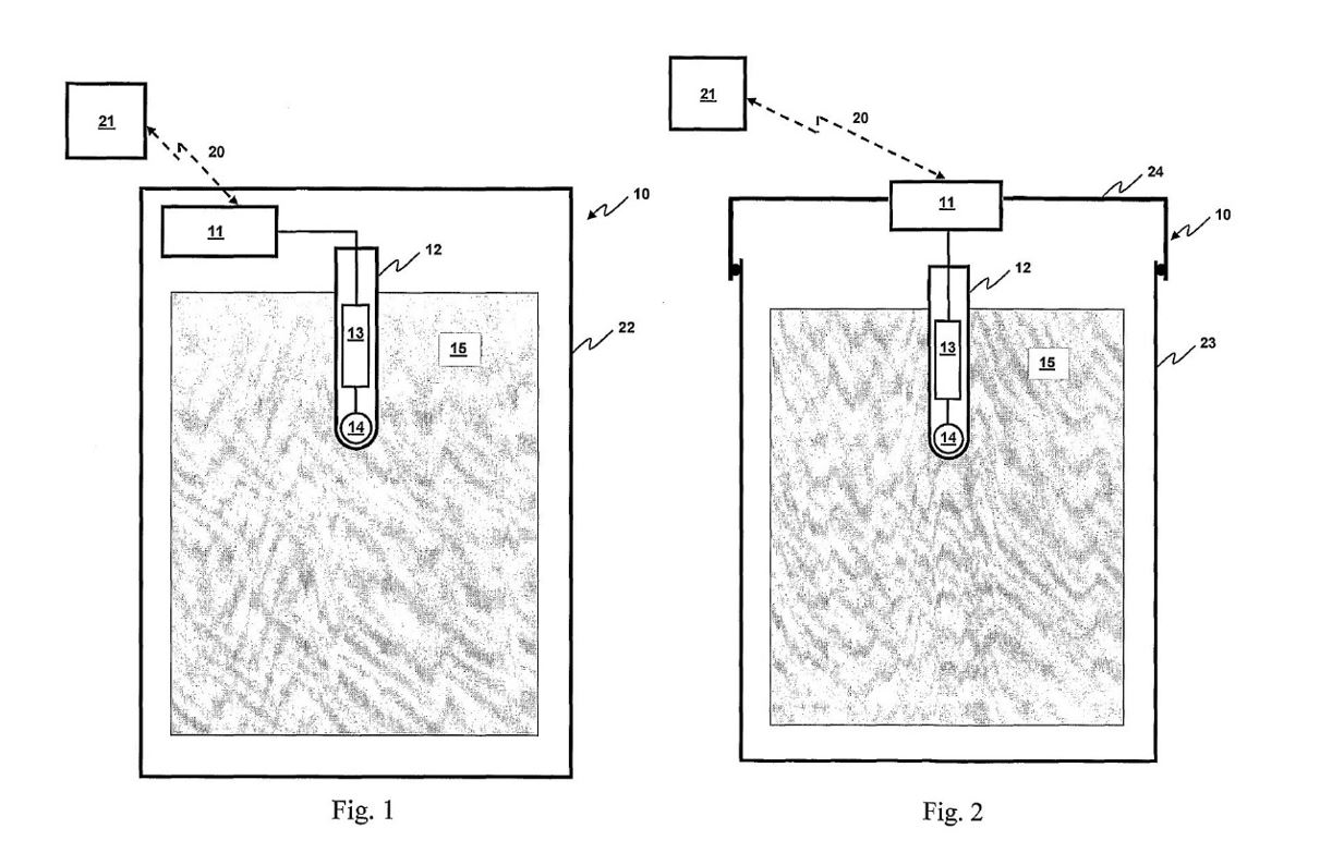
730 Mr Napier’s evidence in Napier 1 is that “the term “casing” refers to a protective covering comprising a material and structure suitable to at least partially protect the internal components of the booster from either or both the shock or loading forces imposed or the ingress of water or dirt during use”: Napier 1 [573]. Mr Napier expands on this view in Napier 3, stating that “[i]n my view, I consider that the intended meaning of this feature is that the detonator, explosive charge and transceiver components of a wireless initiation device (electronic booster) must be contained within the same casing or a single casing”: Confidential Annexure AN-51 [181]. However, he does not give any reasons for these opinions, and so I give them no weight. For this reason, to the extent that Mr Napier disagrees with Mr Papillon, I prefer Mr Papillon’s construction.
731 Mr Boucher’s evidence in Boucher 1 is that “[t]his integer requires the detonator, explosive charge, and transceiver to be placed in a casing. I understand that the term “casing” refers to a housing made of a material that is suitable to at least partially protect the components therein from shock, loading forces, water, and dirt during use”: Boucher 1 [501]. He therefore appears to agree with Mr Papillon, or at least to not disagree with him. Like Mr Napier, Mr Boucher does not give any reasons for his opinion, and so I give them less weight than I give Mr Papillon’s opinions on this issue for that reason.
732 Orica’s construction finds further support when one has regard to the relationship between claim 4 and claim 11. Claim 11 is dependent on any of the preceding claims, including claim 4. Claim 11 must therefore be an embodiment of claim 4. Claim 11 claims a configuration where the explosive charge and the detonator are “contained within a booster element in the form of an open container”, and the transceiver is “contained within a booster-cap” that engages with and closes the container. Once the two parts are joined, the casing is formed within the meaning of claim 4.
733 For these reasons, I construe the references to “a casing” and “the casing” in claim 4 to include a casing which has been assembled from more than one component which are designed to fit together so as to form a casing.
21.2.2 Whether infringement of claim 4
734 In the CyberDet I Device, according to Mr Papillon, the casing of the device is comprised of the combination of:
[redacted]
[See Papillon 1, Confidential Annexure BEP-8 [215]]
[redacted]
735 [redacted]
736 Mr Boucher’s view and Mr Napier’s view was that, even when assembled, it cannot be concluded that there is a single casing within the meaning of claim 4; rather, they each opined that [redacted].
737 DNAP submits that the evidence of Mr Boucher and Mr Napier should be accepted because they were not challenged on it. If this is intended to be a reference to the fact that they were not cross-examined on this evidence, then I do not accept this submission. Time limitations were placed on counsel during the concurrent evidence sessions in a trial which was extended beyond the original estimate with the consequence that not all of the voluminous evidence of each expert could be the subject of cross-examination. Further, the evidence of these experts was contradicted by Mr Papillon, and Mr Papillon’s evidence was referred to in Orica’s opening and closing submissions.
738 Turning then to the evidence, Mr Boucher stated in Boucher 2, Confidential Annexure CJB-28 at [176] that:
[redacted]
739 However, I do not accept this analysis, as it is inconsistent with evidence given by Mr Boucher about a casing being formed from a single piece when he considered the prior art. He opined that the ICI Primer Patent disclosed all of the features of claim 4, citing the passage from page 13 line 12 to page 14 line 37: Boucher 1, Annexure CJB-23 [815]. However, based on the passage cited by Mr Boucher, the casing in the ICI Primer Patent is comprised of multiple parts.
740 Mr Napier expressed the following opinion in Napier 3, Confidential Annexure AN-51 at [182]:
[redacted]
741 I also do not accept Mr Napier’s opinion. In my view, it is contrived and artificial to describe the combined components as having separate casings, or that there are “multiple casings”, so as to conclude that, after assembly of those components, there is not a casing within the meaning of claim 4.
742 Rather, the components of the CyberDet I Device are designed to, and do, combine together to form a casing within the meaning of, and which performs the role described in, claim 4.
743 That the components combine in this way is shown by this photograph, [redacted]:
[redacted]
744 As the CyberDet I Device has all of the features of claim 4, it follows that claim 4 of the 165 patent is infringed, along with claims 26, 27, 28 and 29 insofar as they depend on claim 4.
21.3 Claim 11
21.3.1 Proper construction of claim 11
745 Claim 11 claims any of the preceding claims for a wireless electronic booster wherein the explosive charge and detonator are contained within a booster element in the form of an open container, and the transceiver is contained within a booster-cap adapted to engage and close said container, thereby forming the wireless electronic booster.
746 Mr Papillon’s understanding of “open container” is that it is “a vessel which has an open end, into which the components can be inserted”. In the context of the claim, the open end of the booster element is sealed by the booster-cap which contains the transceiver. This is broadly similar to Mr Boucher’s construction of “open container” as a “housing that is partially open”, and Mr Napier’s construction of “open container” as an “uncovered or partially covered receptacle or enclosure”. For these reasons, I accept Mr Papillon’s construction.
747 While Mr Boucher and Mr Papillon did not address the meaning of “within”, Mr Napier’s construction is that “the term ‘within’ refers to be [sic] inside or internal relative to the container (in case of the explosive charge and detonator) or booster cap (in relation to the transceiver”. While I accept Mr Napier’s general definition of the meaning of “within”, I also note that the embodiment depicted in Figure 2, by reference to the transceiver 11 sitting within the lid portion 24, indicates that “within” is satisfied if the component is at least partially within the container or the booster-cap. That is, it does not require the element to be completely within the container or booster-cap.
748 Mr Boucher and Mr Napier also opine that claim 11 requires the detonator and explosive charge to be contained within the booster element prior to assembly (i.e. prior to the booster-cap engaging and closing the booster element). Mr Papillon considers that the claim only requires the booster element to contain the detonator and explosive charge when assembled.
749 However, the wording of the claim contains no specific requirement about the location of components prior to assembly. As such, I accept Mr Papillon’s construction that all that claim 11 requires is that the explosive charge and detonator are contained within the booster element after assembly.
21.3.2 Whether infringement of claim 11
750 It is admitted that the CyberDet I Device infringes claims 1, 2 and 5–10 of the 165 patent, and so has the features of the wireless electronic booster as claimed in those claims.
751 In terms of the additional integers of claim 11, DNAP contends that the booster element of the CyberDet I Device is not an open container because, as described in the evidence of all of Mr Boucher, Mr Napier and Mr Papillon, [redacted]:
[redacted]
752 Mr Boucher and Mr Napier both consider that, as a result, [redacted], it is not an “open container” within the meaning of the claim.
753 I do not agree. As shown in Figure 2 of the 165 patent, and consistent with my construction of “open container”, the booster element is open in the sense that it has an open end, which end facilitates the insertion of the detonator before being closed by the transceiver element (which acts as the booster-cap). Figure 2 depicts the detonator 12 sitting substantially within the explosive charge 15 in a similar configuration to the CyberDet I Device notwithstanding [redacted]. As such, I consider the booster element of the CyberDet I Device to be an open container within the meaning of claim 11.
754 Mr Papillon opines that the CyberDet I Device takes all of the features of claim 11. His evidence is that, for the purposes of the claim, [redacted].
[redacted]
755 Mr Papillon gives the following evidence as to how the CyberDet I Device is assembled:
[redacted]
756 Mr Boucher’s evidence as to how the CyberDet I Device is assembled accords with that description.
757 Mr Boucher and Mr Napier opine that the detonator in the CyberDet I Device is not contained within the booster element because [redacted]. However, as I have found, the detonator is not required to be contained within the booster element prior to assembly, but only after assembly. As the evidence and related images make clear, after assembly, the detonator sits within the booster element such that it is contained with the booster element, almost completely.
758 For these reasons, the CyberDet I Device has all of the features of claim 11. It follows that claim 11 of the 165 patent is infringed, along with claims 26, 27, 28 and 29 insofar as they depend on claim 11.
22. 873 PATENT
759 The 873 patent is entitled “Selective control of wireless initiation devices at a blast site” and the invention claimed in it relates to the control of detonators and detonator assemblies used in mining via wireless communication. The 873 patent has a priority date of 28 January 2009 (873 priority date).
760 The abstract states that:
Disclosed herein are methods for selective control of groups of wireless initiation devices such as wireless electronic boosters at a blast site. Such methods may be applied to a wide variety of blasting techniques that would benefit from the use of wireless control and initiation of explosive charges at the blast site.
761 The Field of the Invention states that:
The invention relates to the field of blasting for mining, and the control of detonators at a blast site. More specifically, the invention relates to the control of detonators and detonator assemblies via wireless communication.
762 In the section entitled Background to the Invention, similar statements are made as appear in the 079 and 165 patents concerning transmission of signals in a manner which is described as “traditional”, namely employing low energy detonating cord or shock tube, or electrical wires which are used to transmit more sophisticated signals to and optionally from EDs. It is then stated that:
The blasting systems discussed above employ physical connections between the detonators to be fired and a control unit such as a blasting machine. Typically, detonators are placed at the blast site in association with explosive charges, and connected to surface harness wires (e.g. wires, shock tubes, detonating cords or the like). Detonators present at the blast site may be selectively actuated in groups. In this way, a blast may be conducted in two or more stages. Care must be taken to ensure that later-stage detonators, their associated charges, and their connections to harness wires are not disrupted or suffer damage from explosive forces derived from earlier-stage firing. Nonetheless, it is possible to selectively actuate one group of detonators before other groups of detonators are actuated at a blast site. In such blasting systems selective, staged actuation of groups of detonators may be achieved via fairly simple means…
Recent years have seen the development of wireless blasting systems for use in blasting rock. Such systems present significant advantages over more traditional wired blasting systems. By avoiding the use of physical connections between detonators, and other components at the blast site (e.g. blasting machines) the possibility of improper set-up of the blasting arrangement, such as improper ‘tieing-in’ of detonators, is reduced…
Nonetheless, the development of wireless blasting systems, and components thereof, presents a formidable technological challenge. In just one example, selective control and firing of wireless detonators in pre-determined groups (as discussed above in the context of wired blasting systems) is not simple to achieve since there are no harness wires present for selective connection of the detonators. Hence there is a need in the art for methods of blasting that permit selective control of detonators and their corresponding wireless detonator assemblies, in the context of wireless blasting systems for mining.
763 The section entitled Summary of the Invention states the following:
Accordingly, in one embodiment the present invention provides a method of controlling a predetermined group of wireless initiation devices within a plurality of such devices at a blast site, which method comprises: transmitting to the plurality of wireless initiation devices a wireless command signal relating to some operation intended to be executed by the predetermined group of wireless initiation devices; for each wireless initiation device receiving the wireless command signal, determining whether the wireless initiation device forms part of the predetermined group; and for each wireless initiating device that determines that it forms part of the predetermined group, executing the operation on the basis of the command signal.
Thus, in accordance with this embodiment of the invention the wireless command signal is transmitted to (and received by) a plurality of wireless initiation devices, but only a predetermined group (or number) of the plurality of devices execute an (intended) operation on the basis of the signal. In embodiments of the present invention the wireless command signal comprises a component (group identification component) that allows each wireless initiation device receiving the signal to undertake analysis to determine whether that device forms part of the predetermined group. The nature of the group identification component is discussed in more detail below.
Optionally, the wireless initiation device may take the form of a wireless electronic booster by further comprising for example an associated explosive charge, such that actuation of the device causes actuation of each associated explosive charge. Such wireless electronic boosters may have alternative configurations or include other components, and are disclosed for example in international patent publication WO07/124539 published November 8, 2008, which is incorporated herein by reference.
Thus, in another embodiment of the present invention there is provided a method of controlling a predetermined group of wireless electronic boosters within a plurality of such boosters at a blast site, which method comprises: transmitting to the plurality of wireless electronic boosters a wireless command signal relating to some operation intended to be executed by the predetermined group of wireless electronic boosters; for each wireless electronic booster receiving the wireless command signal, determining whether the wireless electronic booster forms part of the predetermined group; and for each wireless electronic booster that determines that it forms part of the predetermined group, executing the operation on the basis of the command signal.
This embodiment relies on the same general principles as set out in relation to the first embodiment described, the difference being that the wireless electronic initiation device is a wireless electronic booster. In the following, unless otherwise stated or otherwise apparent, aspects of the present invention associated with the first embodiment described also apply in relation to the embodiments relating to the wireless electronic booster.
(Emphasis added.)
764 Definitions of terms used in the 873 patent appear from pages 4–13 of the specification, some of which are the same or substantially the same as the 079 and 165 patents (such as “blasting machine”, “top-box”, “wireless”).
765 In the Detailed Description of the Invention, the following statements are made:
The inventors have succeeded in the development of methods for the selective control of groups of wireless initiation devices or wireless electronic boosters at a blast site. In particular, these methods may be applied to wireless blasting systems wherein the devices or boosters communicate with one or more control units (i.e. blasting machines) via wireless communication at a blast site. The methods may be applied to blasting systems that employ any type of wireless electronic device for blasting, but will be described herein with reference to wireless initiation devices and wireless electronic boosters. The methods of the invention are not limited to a particular type of blasting or a particular type of rock. Indeed, the methods may be used for surface and/or underground blasting.
The methods of the present invention generally involve transmission of one or more wireless command signals to a plurality of wireless initiation devices or wireless electronic boosters, wherein selected wireless command signals are each targeted only to a pre-selected group of devices or boosters at the blast site. By ‘tagging’ each wireless command signal with an additional data element, each device or booster may ‘recognize’ [sic] whether or not the wireless command signal is intended for the device or booster, and whether or not the device or booster must undertake a required action.
766 The 873 patent has 16 claims. Claim 1 is a method claim and is the only independent claim. The claims are set out below where relevant.
23. WITNESSES CALLED BY THE PARTIES AND EVIDENCE
23.1 Witnesses called by DNAP
767 DNAP relies on the evidence of three expert witnesses in relation to the 873 patent: Mr Boucher, Mr Napier and Mr Jacobson.
768 Mr Jacobson affirmed two affidavits in this proceeding, dated 18 December 2023 (Jacobson 1) and 1 July 2024.
769 Mr Jacobson has been the Chief Engineer at Rothenbuhler Engineering Company since 1996. Among other things, Mr Jacobson gave evidence about the Rothenbuhler device, aspects of which he maintained confidentiality. He is the named inventor in Australian Patent Application No. 2005207595 entitled “Remote firing system” (Rothenbuhler patent) and an author of certain prior art documents relied upon by DNAP, as addressed below. For these reasons, Mr Jacobson, who agreed that he is inventive, is not representative of the hypothetical, non-inventive PSA.
770 Further, Mr Jacobson has extensive knowledge about the Rothenbuhler device, but not about detonators. That is because the Rothenbuhler device was designed to work with third-party detonators. It was therefore beyond Mr Jacobson’s expertise at the 873 priority date to design or modify detonators.
23.2 Witnesses called by Orica
771 Orica relies on the evidence of two expert witnesses in relation to the 873 patent, being Mr Papillon and Professor Skafidas.
23.3 Joint expert report (873 patent)
772 An expert report on the 873 patent dated 12 September 2024 (873 JER) was prepared by the experts following joint expert conferences on 20, 21 and 23 August 2024. Professor Skafidas did not contribute in relation to all topics.
24. PSA – 873 PATENT
773 There was no significant dispute about the qualifications of the members of the notional PSA team.
774 By the 873 JER (topic 1), the experts agreed that the PSA is a team with members who would have qualifications or experience in a range of areas such as communications engineering, detonator engineering, blast design engineering, safety engineering (described as a critical aspect), and with experience working with a varied customer base, including people in related fields (such as blast or mine site management, blast operators, site safety officers and operations managers).
775 Although the 873 JER recorded that the experts agreed on the qualifications of the notional PSA team, Mr Napier’s comments included his stated view that selective grouping expertise or knowledge is vital to the 873 patent, while Mr Papillon considered that a person reading the 873 patent without a “strong knowledge of blasting or mining” would have many questions left to ask before they could understand the invention.
25. COMMON GENERAL KNOWLEDGE
776 The matters which are alleged by DNAP to be CGK at the 873 priority date are pleaded in [122] of the 6FASOC, which list includes the matters alleged by it to be CGK as at the 079 and 165 priority dates.
777 Given that the 873 patent claims a priority date some three to four years later, the members of the notional PSA team for the 079, 165 and 873 patents comprise (more or less) the same qualifications and that, in broad terms, it relates to the same field as the 079 and 165 patents (i.e. wireless detonators for use in blasting), I accept that the findings which I have made concerning CGK relevant to the 079 and 165 patents are generally relevant CGK for the purposes of the 873 patent. To the extent that the relevant CGK has changed materially between 2005/2006 and 2009, that is addressed below.
778 I also observe that, as a general proposition, I give no weight to any observations by Mr Boucher concerning CGK for the same reasons as I gave in relation to the 079 and 165 patents. In particular, Mr Boucher misunderstood the concept of CGK. This is shown by, for example, Mr Boucher’s expressed opinion in the 873 JER (topic 3a) that the contents of the ICI Remote Firing Patent “should have been known by a PSA”, and the only basis for that opinion appears to be Mr Boucher’s understanding that the information was contained in a published patent. Further, by the 873 priority date, Mr Boucher had not been working in commercial blasting for about six years.
25.1 Wireless communications with devices
779 DNAP alleges and Orica admits in the SOP that the following matters were CGK:
(1) communicating with individual EDs within a blast field using roll-call signals sent by a blast [sic] machine;
(2) storing identification numbers or codes within individual EDs within a blast field.
780 By the 873 JER (topic 3e) and on the topic of the use of wireless communications in mining, there was general agreement by the experts (save for Professor Skafidas, who was not asked to respond) that the PSA would have known and understood the content of Jacobson 1 at [27]–[33] and Napier 1 at [53], [141] and [202]–[256]. In particular, by its closing submissions, DNAP emphasises Mr Jacobson’s evidence as follows:
(a) Radio control and communication systems were used to send information, including messages and commands to control products, wirelessly. …
(b) Very high frequency (VHF) or ultra-high frequency (UHF) radio signals were used in communications and blasting systems to send wireless messages and commands through line of sight, as well as in underground applications using radio repeaters (to maintain line of sight communication) and existing leaky feeder communications networks. …
(c) Remote blasting systems typically comprised a controller and one or more remote units which were each associated with at least one detonator, most commonly an electric detonator (blasting cap) or shock tube detonator. In such systems, command signals including STATUS, ARM, FIRE and DISARM would be sent to individual remotes, groups of remotes in any combination or all remotes.
(d) Multiple remote blasting systems could operate simultaneously within a blast site. In such a case, it was important to ensure for controller and remote units within a single system that they only operated (e.g., communicated) with units within the same system. Blasting using multiple remotes was typically achieved through information contained within the message or data structure in the wireless signal, where part of the message uniquely identified the system and only the remotes which were able to match that part of the message with their own stored data would execute the instruction or respond.
(e) In radio communications and blasting systems, VHF and UHF signals were broadcast at large (i.e., to all remote units) rather than to one or more specific remote units. This was an inherent part of the technology – radio signals could not target the direction of specific receivers. The signal sent was modulated, to be distinguishable from other signals and environmental noise (e.g., from other radio systems, heavy equipment moving around and blasting), and/or encoded.
(i) It was conventional to use an integrated circuit (chip) known as a modem to modulate a signal. At the transmitting end, a modem converted digital information into an analogue signal and modulated that analogue signal (i.e., by changing its amplitude, frequency and/or phase). At the receiving end, a modem demodulated the analogue signal and converted it back to digital information which was passed to a microcontroller. The term “modem” is a truncation of “modulate/demodulate”.
(ii) Encryption involved taking the original data (digital) message and performing mathematical operations on it so that it did not look like the original message. The encrypted message was then converted to analogue, modulated and transmitted. After being received, demodulated, and converted back to a digital message, the data (digital) message was decrypted using mathematical operations. While encryption provided extra security, it did not form part of all VHF and UHF communications and blasting systems… Although encryption was commonplace, it added overhead in processing capability of the microcontroller.
(f) In remote blasting systems, the following information was fundamental in messages sent between controller and remote units:
(i) a means to identify the system (i.e., to differentiate it from other remote blasting systems that might simultaneously be in operation);
(ii) a means to identify the individual remotes or groups of remote units for which the message was intended, such as a particular data structure or sequence of characters;
(iii) a means for the controller to receive a status reply from each individual remote unit (if two-way communication was used);
(iv) a means to identify the individual remote unit from which the controller received each status reply;
(v) structural elements including a preamble, header, start bits and stop bits;
(vi) commands which identify instructions to be executed by the remote units;
(vii) a means to avoid the duplication of controller and remote unit identification numbers, such as a sequence key number;
(viii) a means to validate the message and to ensure that the message received by the remote unit does not differ from the message sent (i.e. cyclic redundancy checking).
(g) The precise frequency used for VHF and UHF communication was determined based on customer requirements and regulatory requirements in each country. …
(h) VLF and ULF signals were used in communications (including in the field of submarine communications) and blasting systems (including in underground mining) to send wireless messages and commands through the earth. …
(i) Radio communication and blasting systems, including those using VHF and UHF signals, were capable of two-way communication. … However, two-way communication was not fundamental to operating wireless communication systems. …
(j) Remote firing systems required both the controller and remote(s) to have their own power source. These power sources were typically in the form of a battery but could include an alternating current (AC) power source for the controller unit. In remote units, the power of the battery was isolated from the firing circuit. Circuits were typically designed to avoid the risks of a dead short. Typically, the battery was a lower voltage than the initiation device required to fire so that a dead short from the battery to the firing circuit would not initiate the detonator. When an ARM command was sent, the circuit took the battery voltage and amplified it to a higher level so that the capacitor was charged to a much higher voltage than the battery. When a FIRE command was subsequently sent, the capacitor was then connected to the firing circuit through relay contacts or some other types of switch.
(Emphasis omitted.)
781 Mr Napier’s evidence in Napier 1 at [53] (as extracted in DNAP’s closing submissions) was:
(a) ULF, generally defined as the frequency range of 300 Hz to 3,000 Hz and VLF, generally defined as the frequency range of 3,000 Hz to 30,000 Hz… through-the-earth (TTE) communications systems were used to send alphanumeric messages wirelessly through rock strata to receivers which displayed the transmitted message. …
(b) ULF and VLF TTE communications systems were used to send commands or instructions (e.g., on/off) wirelessly through rock strata across to control equipment located underground such as fans, pumps, spray systems and underground lighting. …
(c) ULF and VLF TTE communications systems were used to send commands or instructions (e.g., ARM and BLAST) wirelessly through rock strata across several hundreds of metres to initiate blasts. …
(d) Since the mid-1990s, ULF and VLF technologies were reliably and effectively used for transmitting signals TTE (including through earth containing rock, water and other materials) over hundreds of metres to kilometres (subject to the size and power of the transmitting antennae) in several commercially-available systems installed in numerous mines throughout Australia and the world. The low frequency required in VLF and ULF systems to penetrate rock, water and other materials resulted in a relatively slow data transfer rate. …
(e) ULF and VLF systems generally were implemented as “one-way” communications systems in which signals were transmitted only from the surface to receivers underground. This was because underground mines generally required:
(i) large antennae, with lengths from hundreds of metres to kilometres (achievable by ULF systems), typically arranged in a loop at or just below the surface; and
(ii) significant power to transmit ULF or VLF signals TTE over distances of several hundred metres.
…
(j) Short simple ULF messages, such as ARM and FIRE commands, were sufficient to communicate instructions required to control equipment for initiating blasting using detonators.
(l) ULF TTE communications systems were used to send messages or commands to either individual or groups of multiple receivers, which included a group of select receivers in operation or all receivers in operation. … The need for separate blasts often arose for very large blasts, such as stope blasts, in order to separate the concussion effect.
(Emphasis omitted.)
782 In any event, as to the topic of the functionality, implementation and use of identifiers in wireless communications, including to control the initiation of explosives in blasting or otherwise in mining, the experts agreed in the 873 JER (topic 3f) that the implementation of identifiers would have been generally known and understood by the PSA, although the precise way to implement them in, for example, wireless detonators in each and every situation that may arise would not have been known.
783 In the 873 JER (topic 3f), Mr Napier’s comments included this statement:
It becomes quite complex with how detailed the identification can be and how broad the field of identifiers was at the time.
It was common general knowledge to the PSA to incorporate identifiers into a wireless device.
The nature of the identifier would depend heavily on the communications medium employed in the device.
784 In a similar vein, Professor Skafidas explained in the 873 JER (topic 3f) that:
There are significant challenges in implementing identifiers in wireless communication systems.
The PSA would be aware of their importance.
785 It was common ground that the following was CGK at the 873 priority date (being derived from Napier 2 at [19]):
In wireless communications systems, wireless signals containing identifiers were broadcast at large to all entities, units or devices within a system but only those which corresponded to the identifier(s) could execute the instructions within the signal. The receiving devices were necessarily programmed to receive and interpret the signals, using the identifiers within received signals, to determine whether and how they should respond to the message.
Additionally, wireless signals were often encrypted to provide additional security. Before a message was transmitted/broadcasted, it was converted to a different form using an encryption key (complex algorithm). That encrypted form of the message could only be converted to a form that could be interpreted and understood if it was first decrypted by a receiving device programmed with the corresponding encryption key. The encryption and decryption of wireless command signals could be used to ensure that only intended devices were capable of interpreting the wireless signal at all, as, without the encryption key, a receiving device within range could not interpret the content of the message. A receiving wireless device with the appropriate encryption key could decrypt a received encrypted message and could then interpret and act upon the command within the message, including detecting and comparing any identifiers within the message. The encryption of wireless messages and the identifiers (for system, device, etc, identification) were therefore conceptually and functionally different aspects of the wireless communication, and often were used together to provide both secure wireless messaging and to target those wireless commands to specific receiver and control devices within a system or within range.
786 Professor Skafidas gave evidence that it was CGK as at 2009 for each device in a wireless communication network to have a unique identifier and that RF signals are transmitted from, and received by, all devices at the physical layer provided they have a compatibly tuned antenna, are within range of the medium (i.e. RF signals) and use a similar frequency band: Skafidas 2 [9](b)–(d). He distinguished between a unicast (transmission to one device), broadcast (transmission to all on the network) and multicast (transmission to a subset of recipients on the network), and said that multicast was an open area of research in 2009. He maintained this position the next day when the issue was canvassed again, and stated that the exact way to implement multicast was not known in 2009.
787 Professor Skafidas accepted that, at a “very high level” and in relation to a “packet-based network”, communication to a single device, in a spoke and hub network, would involve each device storing its unique identifier in its memory component, and the wireless signal, which contains the data, or commands, also including the target device’s unique identifier; and each device which receives the wireless signal comparing the unique identifier, included in the wireless signal, with the unique identifier stored in its memory component. Mr Boucher, Mr Jacobson and Mr Papillon also agreed.
788 Professor Skafidas explained that a packet-based network involves breaking up the message into smaller chunks, but “you’re also encapsulating it with additional information in order to ensure the integrity of the information that’s being communicated”. He said that there is a section of the packet which is called the header, which is information that is relevant to the network, and the information that is intended for the recipient is included in the payload section.
789 Professor Skafidas and Mr Jacobson also accepted that the claims of the 873 patent are not limited to a packet-based network.
25.2 Types of detonators
790 As occurred in the 079 & 165 JER, the same diagram appears in the 873 JER which illustrates types of detonators and which includes a wireless electronic delay detonator system. That diagram is shown at [111] above. This diagram appeared in the section of the 873 JER dealing with CGK as at the 873 priority date.
791 However, as with the 079 & 165 JER, it was not agreed by the experts that wireless EDs were CGK as at the 873 priority date. Mr Papillon makes this plain in his comment in the 873 JER (topic 3f). It is also consistent with the evidence of Mr Napier: Napier 2 [18]. Mr Papillon also observed in Papillon 6 at [21] that, by January 2009, there were no wireless EDs on the market.
792 There were no significant “breakthrough” developments between 2006 and 2009 insofar as what was known about wired EDs. That was the effect of Mr Papillon’s evidence in the 873 JER (topic 3b) with which Mr Napier appeared to agree, noting only that there were “improvements and enhancements”.
793 Mr Papillon also stated in the 873 JER (topic 3a) that EDs “as known by the PSA at the priority date 28 January 2009 are a very complex combination and integration of both miniaturized solid state electronic components and very sensitive crystalline high explosives. All detonators are designed to detonate when and only when intended to do so”.
794 The details of the inner workings of EDs remained proprietary as at the 873 priority date. Mr Jacobson accepted this during the trial, which was consistent with Mr Papillon’s affidavit evidence that the same (low) level of CGK about the inner workings of EDs persisted from 2006 to 2009, because the barriers to information sharing (including the complexity of the ED, the high commercial sensitivity of each manufacturer’s ASIC, the non-disclosure obligations imposed on detonator designs and customers, the difficulty of obtaining and disassembling competitor’s EDs, and the relatively low movement of designers between companies) were still in existence: Papillon 6 [41].
795 The experts were asked to identify the CGK before the 873 priority date “in relation to [EDs] used in mining, functionality provided by physical wires or other connections, which needed to be replaced if those wires or other connections were removed”. The experts agreed in the 873 JER (topic 3d) that the following features of wired EDs used in mining would need to be replaced during the development of a wireless detonator:
(1) ability to supply safe power;
(2) ability to receive secure one-way communication, and ideally two-way communication;
(3) reliability.
796 Having said that, Mr Papillon stated that these features were stated in an overly simplified manner, and therefore the complexity to accomplish this task is understated. He stated that providing this functionality “wirelessly” is significantly more difficult than it is to provide this same functionality connecting the EDs using wire.
25.3 BlastPED and Rothenbuhler
797 DNAP relies upon its submissions that “BlastPED” and “Rothenbuhler” were CGK as at the 079 and 165 priority dates in support of its submission that they were also CGK as at the 873 priority date. For the reasons given above, those submissions also fail in relation to the 873 priority date.
798 The following matters deserve emphasis.
799 Neither Mr Napier nor Mr Jacobson are representative of the members of the notional PSA team in relation to BlastPED and Rothenbuhler because of their personal and peculiar knowledge which they acquired by reason of their employment. Mr Jacobson is also inventive.
800 Further, Mr Jacobson stated in the 873 JER (topic 22) that selective control of wireless detonation systems was CGK as at the 873 priority date, referring to the disclosure of such systems in the Rothenbuhler patent, the 1670 Operation Manual and the 1670 Brochure. However, no wireless initiation device is disclosed in these documents, and the system is not wireless within the meaning of the claims of the 873 patent. Further, the deficiencies in Mr Jacobson’s evidence concerning the 1670 model (and generally) are addressed above, which evidence was internally inconsistent and lacked important details with the consequence that I do not accept Mr Jacobson’s evidence on this topic, and nor do I accept that it supports DNAP’s submission that “Rothenbuhler” was CGK in Australia as at the 873 priority date.
801 Similarly, Mr Napier described BlastPED and BlastPED Exel as an existing wireless detonation system that was part of the CGK as at the 873 priority date: 873 JER (topic 22). However, these versions of BlastPED were not wireless within the meaning of the claims of the 873 patent.
802 That these experts gave this evidence demonstrates that they have a fundamental misunderstanding of when a device is wireless within the meaning of the claims of the 873 patent, and of a wireless initiation device (as defined in the 873 patent). This incorrect understanding necessarily undermines other evidence that they give about the availability of “wireless” detonator assemblies and “wireless” initiation devices as at the 873 priority date (see e.g. 873 JER, topic 3h). It also undermines the agreement stated to be reached by the experts that the features of claims 1 and 2 were CGK: 873 JER (topic 23).
803 Further, although DNAP refers to BlastPED in general terms in the 6FASOC and in its closing submissions (without identifying the precise product), BlastPED ULF and its prototype were the only blast initiation ULF systems of which Mr Napier knew that existed before 2009. Further, the only evidence concerning the use of BlastPED ULF in Australia was Mr Napier’s affidavit evidence which I have addressed above.
804 Mr Napier did not have any direct involvement with wireless blasting initiation systems after leaving MST in late 2003. He also gave evidence about the products promoted and sold by Rothenbuhler “based on documents provided to me by Sprusons”: Napier 2 [16]. Notwithstanding his evidence, Mr Napier had never seen the Rothenbuhler device installed in an Australian mine.
805 For these additional reasons beyond those already stated in terms of Mr Napier’s evidence generally, I do not accept Mr Napier’s evidence concerning CGK as at the 873 priority date.
806 Mr Papillon attested that neither BlastPED nor the Rothenbuhler device was CGK in January 2009: Papillon 6 [54], [56(b)].
807 By its closing submissions, DNAP seeks additional specific findings that it was CGK in 2009 that the 1670 model had particular features by reference to cross-examination of Mr Papillon. However, Mr Papillon’s knowledge exceeded the CGK in Australia in relation to the Rothenbuhler system. Further, Mr Papillon was not asked questions about whether something was CGK; rather he was asked about his knowledge. Whether Mr Papillon knew something does not, of itself, make it CGK in Australia at the 873 priority date.
808 Mr Boucher had personally not heard of BlastPED before these proceedings, and had no personal knowledge of the use by others of the BlastPED and Rothenbuhler devices.
809 For these reasons, the evidence was insufficient to establish that BlastPED ULF (or any other iteration of BlastPED), or the Rothenbuhler device, was CGK as at the 873 priority date.
25.4 Selective control of EDs
810 Selective control of wired EDs was known at the 873 priority date. The means for implementing selective control differed, for example, by separating firing circuits of wired EDs (including by using multiple blasting machines) or separating programmed firing times.
811 However, according to Mr Papillon, methods of selective control were not CGK for wireless blasting systems and the use of selective control of wireless electronic, electric or non-electric detonators was not commonly and generally known in January 2009: Papillon 6 [65(b)], [65(c)]. Further, in the 873 JER (topic 3c), Mr Papillon stated that, “[p]roducts and technologies were available for selective initiation of individual blasts, but it was not understood by the PSA how to selectively initiate “individual electronic detonators”, or small groups of “electronic detonators” that were subsets of a larger blast … The PSA did not know how to design and engineer a device to selectively initiate electronic detonators as of 28 January 2009…”.
812 That Mr Papillon agreed under cross-examination that selective control was a “desirable feature for wireless initiation devices to be able to do certain types of blasting” and that, “as at 2009, [he] would have been interested in any solution or product which could have assisted with selective control of loaded detonators using wireless initiation systems” does not detract from his evidence concerning what was CGK. That selective control was a desirable feature, or something of interest to Mr Papillon, does not have the consequence that the desire for such a feature, was “part of the CGK” as at the 873 priority date as DNAP submits.
25.5 Powering a device down
813 In the 873 JER (topic 3h), the experts agreed that powering a device down when it is not required to be active, including to conserve energy, was well known at the 873 priority date.
25.6 Whether claims 1 and 2 were part of the CGK as at 873 priority date
814 The experts were asked by the parties to consider and discuss whether (and if so how) the features of each of claims 1 to 16 of the 873 patent differs from the CGK as at the 873 priority date: 873 JER (topic 23).
815 The 873 JER records that the experts (being Mr Jacobson, Mr Napier and Mr Papillon only) agreed that the features of claims 1 and 2 of the 873 patent were part of the CGK. However, as addressed above, the agreement by Mr Jacobson and Mr Napier carries no weight because they have a flawed understanding of “wireless initiation device” within the meaning of these claims. Notably, that misunderstanding is repeated in Mr Napier’s response to topic 23 where he states that “… reference to Wireless Initiation Devices, reflects the prior art devices especially the BlastPED variants and Rothenbuhler products”. Mr Jacobson also appears in his answer to equate his personal knowledge and experience derived from his employment to equate to CGK, citing as an example of something which Rothenbuhler did in a military model, which I infer would be confidential in any event.
816 Mr Papillon states in the 873 JER that:
There are differences between the device of AU’873 and the prior art, for example in claim 13, the deactivating or shutting down of the device are controlled and managed differently. The CGK had to develop a new means of these means of controlling the AU‘873 device. The means to accomplish claims 1-16 had to be developed by the PSA by utilizing many different skills and technologies. This is why the PSA is comprised of people with a very diverse set of skills. Controlling a predetermined group of wireless initiation devices, including, not only the detonator, but the booster, a radio must supply all the power required to control and ultimately fire the device. This had never been accomplished before. The PSA also had to make the wireless initiation device SAFE and highly reliable.
…
Depending on how the phrase wireless initiation device is interpreted, this can change whether the features of claim 1 are part of the CGK. Claim 1 utilizes the words “wireless initiation device(s)” is used six (6) times and from reading AU‘873 that the wireless initiation device includes a detonator. If, for example, if the wireless initiation device did not include a detonator or detonator assembly, I would change my view. The same applies to claim 2.
Depending on how the phrase wireless initiation device is construed will change whether the features of claim 1 are part of the CGK. For example, if the wireless initiator device did not necessarily include a detonator or detonator assembly [then] I would possibly change my view.
If there is no detonator and booster contained in the “device” then my view would change. This wireless initiation device does contain each and every component in a single device to initiate an explosive charge in a highly controlled manner.
817 Based on my finding below that the PSA would understand that a wireless initiation device in claim 1 of the 873 patent must include a detonator or detonator assembly, being an assembly which includes a detonator, I understand from Mr Papillon’s position that he does not agree that a wireless initiation device within the meaning of claims 1 and 2 formed part of the CGK as at the 873 priority date. I accept this evidence.
25.7 Statements made in the 873 patent
818 By its closing submissions, DNAP appears to rely upon statements made in the specification of the 873 patent to establish its case on CGK. It does so by referring to the Background to the Invention on pages 1–2 of the specification, without further addressing why the statements made on those pages constitute admissions as to CGK.
819 On my review of these pages, I consider that, to the extent that the specification refers to matters which were “known”, this is not an admission that the matters described were CGK. This is especially as the reader is expressly told on page 37 lines 7–11 that such references should not be taken as an acknowledgement, admission or suggestion that they form part of the CGK. Rather, the statements on pages 1–2 identify matters which were known to the inventors, and do not constitute an admission as to the CGK in Australia as at the 873 priority date.
26. CLAIM CONSTRUCTION
820 The disputes between the parties concerning claim construction related to claims 1, 2 and 15 of the 873 patent.
26.1 Claim 1
821 Claim 1 of the 873 patent (with integer numbering added) states that:
A method for controlling a predetermined group of wireless initiation devices within a plurality of such devices at a blast site, which method comprises: [integer 1.1]
transmitting to the plurality of wireless initiation devices a wireless command signal relating to some operation to be executed only by the predetermined group of wireless initiation devices; [integer 1.2]
for each wireless initiation device receiving the wireless command signal, determining whether the wireless initiation device forms part of the predetermined group; and [integer 1.3]
for each wireless initiating device that determines that it forms part of the predetermined group, executing the operation on the basis of the command signal. [integer 1.4]
26.1.1 “wireless initiation device”
822 The term “wireless initiation device” appears in claim 1, being the independent claim, and so its construction is of central importance to this case.
823 Two issues arise being:
(1) whether a wireless initiation device must include a detonator; and
(2) if so, whether such a detonator is confined to EDs.
Whether a wireless initiation device must include a detonator
824 The definition of “wireless initiation device” is as follows:
“Wireless initiation device” – refers to any device and associated components that achieve initiation of an associated base charge via receipt of wireless command signals. Such devices typically include detonators or detonator assemblies, optionally comprising one or more top-boxes, power sources, associated antennae etc.
825 The definition of “wireless” is substantially the same as that in the 079 and 165 patents, namely:
“Wireless” – refers to there being no physical connections (such as electrical wires, shock tubes, LEDC, or optical cables) connecting the detonator of the invention or components thereof to an associated blasting machine or power source.
826 “Actuate” or “initiate” is defined in the 873 patent as:
“Actuate” or “initiate” – the initiation, ignition, or triggering of explosive materials, typically by way of a primer, detonator or other device capable of receiving an external signal and converting the signal to cause deflagration of the explosive material.
827 The definition of “wireless detonator assembly” extends over pages 11 and 12 of the 873 patent and commences with the words: “refers in general to an assembly encompassing a detonator, most preferably an electronic detonator”. More on this definition below.
828 DNAP emphasises that the definition of “wireless initiation device” states that such devices “typically include” denotators or detonator assemblies, which it submits supports its contention that a detonator need not be included. In this regard and based on the words used in the definition, Mr Jacobson and Mr Papillon agreed that a wireless initiation device did not necessarily include a detonator: Jacobson 1 [133(a)]; Papillon 6 [51]. However, their reasons for this conclusion were sparse and appear to be focussed on the words used in the definition only. In any event, as Orica submits, I am not bound by the conclusion reached by the experts.
829 DNAP also relies upon the definition of “wireless electronic delay detonator” which includes the statement, “[t]ypically, a [wireless electronic delay detonator] takes the form of, or forms an integral part of, a wireless detonator assembly as described herein”. However, that defined term does not appear in the 873 patent other than in the definition itself. It therefore does not provide any assistance in the construction of “wireless initiation device”.
830 Conversely, as part of having regard to the specification as a whole, Orica emphasises that the Field of the Invention identifies that the invention relates to the control of detonators and detonator assemblies via wireless communication to support its submission that a wireless initiation device must include a detonator.
831 Continuing the theme of control of detonators and detonator assemblies via wireless communication, the Background to the Invention refers to traditional blasting systems which “employ physical connections between the detonators to be fired and a control unit such as a blasting machine”. There is then reference to the development of “wireless blasting systems” which “present significant advantages over more traditional wired blasting systems”. Such wireless blasting systems are described as “avoiding the use of physical connections between detonators, and other components at the blast site (e.g. blasting machines)”. Wireless blasting systems such as those disclosed in four international patent publications (which list includes the 079 and 165 patents) are incorporated.
832 The Background to the Invention concludes with this statement:
… Nonetheless, the development of wireless blasting systems, and components thereof, presents a formidable technological challenge. In just one example, selective control and firing of wireless detonators in pre-determined groups (as discussed above in the context of wired blasting systems) is not simple to achieve since there are no harness wires present for selective connection of the detonators. Hence there is a need in the art for methods of blasting that permit selective control of detonators and their corresponding wireless detonator assemblies, in the context of wireless blasting systems for mining.
833 DNAP emphasises this passage as part of its obviousness case for the purposes of submitting that the identified need had already been met as at the 873 priority date by reference to systems which had wired connections to the detonator. However, I do not agree: read in context and having regard to the incorporation of the 079 and 165 patents, the need which is identified in the 873 patent relates to selective control of detonators which are not connected by wire to a control unit such as blasting machine. It is in that sense that the blasting systems in the 873 patent are “wireless” in that detonators and detonator assemblies are controlled via wireless communication. This conclusion accords with the definition of “wireless” in the 873 patent, which requires that there be no connection between the detonator of the invention or its components and an associated blasting machine or power source.
834 Even if one focuses only upon the words used in the definition of “wireless initiation device”, it is described by its terms as being one which is wireless, and which achieves initiation via receipt of wireless command signals.
835 If the wireless initiation device can but does not need to include a detonator, three questions arise for which there is no satisfactory answer if DNAP’s construction is correct:
(1) why is the word “wireless”, which has a defined meaning in the 873 patent, used in the term “wireless initiation device”? For example, it could just as easily have been called an “initiation device”. The addition of the word “wireless” means something, especially as the definition refers to the receipt of “wireless” command signals;
(2) how does the wireless initiation device receive a wireless command signal in circumstances where no source of wireless command signals other than from a blasting machine is described in the 873 patent, and a blasting machine is defined as being a device which is capable of being in signal communication with EDs?
(3) why is the word “initiation”, which has a defined meaning in the 873 patent, used in the term “wireless initiation device”? And how does the initiation device “achieve initiation of an associated base charge via receipt of wireless command signals” (as the definition requires) if it does not include a detonator or detonator assembly?
836 Conversely, if, as Orica submits, the wireless initiation device includes a detonator or detonator assembly, and it has no connection between an associated blasting machine or power source, then it is wireless within the meaning of the defined term in the 873 patent. That is, there are no physical connections connecting the detonator of the invention or components thereof to an associated blasting machine or power source. By this means, there is control of detonators and detonator assemblies via wireless communication. Further, the wireless initiation device must include a detonator in order to receive wireless command signals from the blasting machine. Finally, if the wireless initiation device includes a detonator or detonator assembly, it is the wireless initiation device itself that will initiate, ignite or trigger the explosive materials, which is what the definition requires of the wireless initiation device. Orica’s construction is to be preferred for these reasons.
837 Against this conclusion, it might be said that a wireless initiation device can also achieve “initiation of an associated base charge via receipt of wireless command signals” in circumstances where it is:
(1) a wireless detonator assembly (being one which does not include a detonator); or
(2) the blasting machine or power source.
838 As to (1), the only reference in the definition of “wireless detonator assembly” to an assembly which does not include a detonator is to a wireless signal relay device at page 12 lines 10–17:
The expression “wireless detonator assembly” may in very specific embodiments pertain simply to a wireless signal relay device, without any association to an electronic delay detonator or any other form of detonator. In such embodiments, such relay devices may form wireless trunk lines for simply relaying wireless signals to and from blasting machines, whereas other wireless detonator assemblies in communication with the relay devices may comprise all the usual features of a wireless detonator assembly, including a detonator for actuation thereof, in effect forming wireless branch lines in the wireless network.
(Emphasis added.)
839 Thus, as a matter of logic, it could be said that, as a wireless initiation device is defined to include a wireless detonator assembly, and as the definition of wireless detonator assembly includes an assembly which does not include a detonator, a wireless initiation device need not include a detonator.
840 The difficulty with such a construction, however, is that if the wireless initiation device is a wireless signal relay device which has no association with a detonator (adopting the words of the definition emphasised above), then such a device cannot achieve “initiation of an associated base charge via receipt of wireless command signals” within the defined meaning of “wireless initiation device”.
841 For these reasons, the reference to “detonator assemblies” in the definition of wireless initiation device does not include a wireless signal relay device, and can only be a detonator assembly which encompasses a detonator in order for the wireless initiation device to be able to initiate.
842 As to (2), “blasting machine” is defined in the 873 patent as:
… any device that is capable of being in signal communication with electronic detonators, for example to send ARM, DISARM, and FIRE signals to the detonators, and / or to program the detonators with delay times and / or firing codes. The blasting machine may also be capable of receiving information such as delay times or firing codes from the detonators directly, or this may be achieved via an intermediate device to collect detonator information and transfer the information to the blasting machine, such as a logger.
843 Although the definition of “wireless” refers to “an associated blasting machine or power source”, no external power source other than a blasting machine is disclosed in the 873 patent.
844 If the wireless initiation device can be a blasting machine (or part of the blasting machine, such as a remote receiver of the type described in the MST Website 2003) then it must be a device that is capable of being in signal communication with EDs (having regard to the definition of blasting machine), and it cannot be connected to that ED by any physical connection (having regard to the definition of wireless).
845 However, the proposition that the wireless initiation device can be a blasting machine must be rejected when one has regard to the steps of the method disclosed in claim 1, for example. Steps 1 and 3 refer to the fact that the wireless initiation device is required to execute an operation on the basis of the wireless command signal. Claim 3, which is dependent on claim 1, identifies that types of operations to be executed by the wireless initiation device are to (inter alia) FIRE. If the wireless initiation device is a blasting machine within the defined meaning of that term, it does not itself FIRE.
846 Further, the definition of “wireless initiation device” does not identify that the device includes a blasting machine or a component thereof and although it refers to “power sources”, it refers to a detonator or detonator assembly “optionally comprising” (inter alia) power sources which, in context, is a reference to a battery.
847 Other references in the specification support a construction that the wireless initiation device is not itself the blasting machine.
848 For example, in the Detailed Description of the Invention, reference is made to wireless communication between the control unit (that is, blasting machines) and the wireless initiation devices or wireless electronic boosters (emphasis added):
The inventors have succeeded in the development of methods for the selective control of groups of wireless initiation devices or wireless electronic boosters at a blast site. In particular, these methods may be applied to wireless blasting systems wherein the devices or boosters communicate with one or more control units (i.e. blasting machines) via wireless communication at a blast site. The methods may be applied to blasting systems that employ any type of wireless electronic device for blasting, but will be described herein with reference to wireless initiation devices and wireless electronic boosters…
… Although not stated above the wireless command signal is typically transmitted to the plurality of devices (or boosters) by at least one blasting machine.
849 Another example appears in the definition of “group identification component” which refers to a part, portion or component of a wireless command signal generated and transmitted by a blasting machine to one or more wireless devices “such as wireless detonators, wireless detonator assemblies, wireless electronic boosters etc”. Notably, a wireless initiation device is not given as an example of a wireless device.
850 By way of other examples:
(1) on page 16 of the specification, there is reference to a roll-call being conducted between a component of the blasting apparatus (e.g. a blasting machine) to each of the wireless initiation devices;
(2) on page 26 of the specification, example 1 identifies that each wireless initiation device at the blast site may be contacted several times by an associated communicating device such as a blasting machine;
(3) on page 36 of the specification, there is reference to the methods of the present invention permitting “blasting of groups of wireless initiation devices in stages”. If the devices are “blasted”, they are not blasting machines which provides the power to the devices to blast, but do not themselves “blast”.
851 It follows that to be a wireless initiation device within the meaning of claim 1, the device must itself initiate, ignite or trigger the explosive materials in response to the wireless command signals received by it. That device is not the blasting machine, or part of the blasting machine.
852 For these reasons, the PSA would understand that a wireless initiation device must include a detonator (or a detonator assembly which encompasses a detonator).
Whether the detonator in the wireless initiation device is confined to EDs
853 DNAP submits that, where the 873 patent intends to refer to EDs, it does so expressly. For example, in the definition of “wireless detonator assembly”, reference is made to “a detonator, most preferably an electronic detonator” and on page 12, reference is made to an “electronic delay detonator or any other form of detonator”. As noted above, it also relies on the fact that there is a definition provided of “wireless electronic delay detonator” but this term is not used in the definition of “wireless initiation device” or anywhere else in the 873 patent.
854 However, the definition of “wireless” refers to a connection between the detonator or components thereof with an associated blasting machine or power source. “Blasting machine” is defined in the 873 patent in almost identical terms to the definition in the 079 and 165 patents, and so, for the same reasons as applied to the 079 and 165 patents, the detonator in the wireless initiation device is confined to an ED.
855 For these reasons, the PSA would understand that the detonator which is contained in the wireless initiation device is confined to an ED.
26.1.2 “predetermined group … within a plurality… at a blast site”
856 Claim 1 refers to a method for controlling a predetermined group of wireless initiation devices within a plurality of such devices at a blast site (emphasis added). Thus, the predetermined group is either a subset or all of the plurality of such devices. This was the evidence of Mr Napier in Napier 2 at [88] with which Mr Papillon agreed in Papillon 6 at [47].
857 The first step in the method in claim 1 is the transmission of a wireless command signal to the plurality.
858 In this context, “plurality” refers to all wireless initiation devices in operation within a blast site. This was the evidence of Mr Napier in Napier 2 at [88] with which Mr Papillon agreed in Papillon 6 at [48]. That is, the plurality refers to all wireless initiation devices which are in receipt of the transmission of the wireless command signal referred to in the first step of the method.
859 “Blast site” means the area in which blasting of explosive material occurs including but not limited to a mine site. This was the evidence of Mr Napier in Napier 1 at [552] and Napier 2 at [91], with which Mr Papillon agreed in Papillon 6 at [49].
26.1.3 “transmitting to” and “receiving the wireless command signal”
860 As noted above, the first step in the method refers to “transmitting to the plurality of wireless initiation devices a wireless command signal” (emphasis added). The second step in the method commences with the words, “for each wireless initiation device receiving the wireless command signal” (emphasis added) after which receipt that wireless initiation device determines whether it forms part of the predetermined group.
861 By reference to this issue, Mr Napier gave evidence in Napier 2 at [96] that he understood that claim 1 “refers to the wireless command signal targeted to the predetermined group being broadcasted to all of the wireless initiation devices in operation (i.e. not only those which form part of the predetermined group), including those intended to execute the command which is the subject of the signal and those that are not”. Mr Papillon agreed in Papillon 6 at [63].
862 For these reasons and having regard to the CGK as at the 873 priority date, including by reference to Napier 2 [19] and [96] (which evidence I accept), the PSA would understand that the words “transmitting to” and “receiving” in claim 1 means that there is a transmission of the wireless command signal to all devices (in this case, the wireless initiation devices which form part of the plurality of devices) each of which in turn receives the wireless command signal. To paraphrase Mr Napier’s evidence in Napier 2 at [19], which DNAP emphasises in its closing submissions as to CGK, wireless signals containing identifiers are broadcast at large to all devices within the wireless communication system and each such device is programmed to receive and interpret the signals, using the identifiers within the received signals to determine whether and how they should respond to the message. Mr Napier’s evidence is consistent with the evidence of Mr Jacobson in Jacobson 1 at [152] and [155].
863 Consistently with the CGK, a device which then acts on the command signal (that is, executing an operation on the basis of the command signal as referred to in the third step of the method) is a different thing from the device receiving the signal which has been transmitted to it.
26.1.4 “determining whether… part of the predetermined group”
864 Mr Papillon’s evidence in Papillon 6 at [73]–[75] was as follows:
At paragraph 98 of Napier 2, Mr Napier identifies that it is the “wireless initiation device” that performs the process of “determining” whether it forms part of the predetermined group. Mr Jacobson (at paragraphs 152 and 155 of Jacobson 1) takes a similar view.
I agree with Mr Napier’s description of the “determination” process as at paragraph 98 of Napier 2:
“each wireless initiation device receiving the wireless command signals, processing the information received and each device itself establishing whether that device forms part of the predetermined group.”
I also agree with Mr Napier’s comment at paragraph 98 of Napier 2 that all wireless initiation devices within the “plurality” of devices to which the signal is broadcast must be capable of interpreting the signal and determining if they are part of the intended “pre-group” or not.
(Emphasis omitted.)
865 There is no limitation as to the means by which the determination process is required to be performed in claim 1. Contrary to DNAP’s submissions, the “determination” step of the method of claim 1 only requires that the device know that it is intended to execute the intended operation. It is not necessary that the device “first understand that the message is intended only for a predetermined group” before it makes that determination.
866 To the extent that Mr Jacobson and Mr Napier advanced a different construction, I do not accept it.
26.2 Claim 2
867 Claim 2 is dependent on claim 1 and states as follows (with integer numbering added):
The method of claim 1 [integer 2.1], wherein the wireless command signal comprises a group identification component that enables differentiation of wireless initiation devices forming part of the predetermined group from wireless initiating devices not forming part of the predetermined group, and wherein each wireless initiation device comprises: [integer 2.2]
a receiver for receiving a wireless command signal; [integer 2.3]
a memory component for storing a group identification; and [integer 2.4]
a control circuit for comparing the group identification component with a stored group identification, for determining on the basis of that comparison whether the wireless initiation device forms part of the predetermined group, and for executing the intended operation of the wireless initiation device if it is determined that it forms part of the predetermined group. [integer 2.5]
26.2.1 “group identification component” and “stored group identification”
868 “Group identification component” is defined on pages 6–7 of the 873 patent as:
“Group identification component” – refers to a part, portion, or component of a wireless command signal generated and transmitted by a blasting machine to one or more wireless devices (such as wireless detonators, wireless detonator assemblies, wireless electronic boosters etc.) at a blast site, wherein said part, portion, or component comprises a number, code, data packet, or other form of electronically transmitted information suitable for receipt and processing by the one or more wireless devices, such that the wireless devices can compare the group identification component to a previously stored group identification, for example stored in each memory component of each wireless device. The electronic coding for the group identification component, at least in selected embodiments, may be identical to or substantially correspond to the electronic coding of the group identification to which it is intended to correspond. For example, if the group identification for each wireless detonator assembly in a given group of wireless detonator assemblies is a particular 8-bit decimal number (e.g.12345678), then wireless command signals transmitted from a blasting machine and targeted to this group of wireless detonator assemblies may be "tagged" with a group identification component that corresponds to the group identification (e.g.12345678). Alternatively, the group identification component may be different to the group identification component of the wireless devices to which it is targeted providing the wireless devices can process the incoming group identification components to appropriately determine their relevancy.
869 “Group identification” is defined on page 7 of the 873 patent as:
“Group identification” (or GID) – refers to any number, digit or group of digits (whether numerical, alphanumerical, or other), code, data packet, or other form of electronically transmitted or stored information suitable to assign a group identity to a wireless device (such as a wireless detonator, a wireless detonator assembly, or a wireless electronic booster) at a blast site. The group identification may be numerical, alphanumeric, other forms of code, or combinations thereof, and if numerical may be in any base including but not limited to binary, decimal, and hexadecimal. Each group identification is assigned to wireless devices and preferably suitable for storage in the devices such as for example via a memory component of the device. Group identifications assigned to a particular group of wireless devices may be identical (for simplicity of communication with the group) or may be non-identical. For example, if the group identifications for a particular group of wireless devices are non-identical then they may fall within a pre-determined range of group identifications, or group identifications of a particular group may pertain to even or odd numbers.
870 It is common ground that these definitions should be applied to the terms in claim 2.
871 Further, a group identification which has been stored, as referred to in integers 2.4 and 2.5, is a group identification component that has been stored on the memory component of the wireless initiation device.
872 Unlike claim 1, claim 2 identifies the manner in which the device determines that it forms part of the predetermined group.
873 Notably, on DNAP’s case concerning the proper construction of “wireless initiation device”, an important substantive difference between claims 1 and 2 arises by reason of the definition of “group identification component”, which definition refers to “a part, portion, or component of a wireless command signal generated and transmitted by a blasting machine” (emphasis added). That is, the only source of the wireless command signal which is identified is a blasting machine as defined in the 873 patent.
874 As I have found, if a blasting machine is capable being in signal communication with an ED, which is what the definition of blasting machine in the 873 patent requires, then that blasting machine cannot be used with electric or non-electric detonators. That accords with the evidence of Mr Papillon in Papillon 6 at [143]–[145].
875 For these reasons and as the wireless initiation device must include a detonator, the detonator in the wireless initiation device within the meaning of claim 2 (and its dependent claims being 4–12 and 14) is confined to an ED. This is so irrespective of whether claim 1 is confined to EDs.
26.2.2 “control circuit for comparing” and “comparison”
876 “Control circuit” is defined on pages 5–6 of the 873 patent as follows:
“Control circuit” – refers to electronic circuitry that enables comparison to be performed between a received group identification that is stored in the memory component of a wireless initiation device or wireless electronic booster, and that is capable of determining whether the group identification component correlates with/matches the stored group identification. When it is determined that there is suitable correlation/matching the control circuit is also capable of implementing some operation of the device or booster on the basis of a wireless command signal…
(Emphasis added.)
877 Although integer 2.5 uses these terms, neither “compare” nor “comparison” is defined in the 873 patent. However, the idea of comparison is picked up in the definition of “control circuit” in the 873 patent, which describes a comparison between a received group identification through the circuit being “capable of determining whether the group identification component correlates with/matches the stored group identification”.
878 In Napier 2 at [111], Mr Napier identifies that the 873 patent refers to correlation or matching, yet in [112], he says that he understands that an intended operation is carried out “only in circumstances where the group identification component matches the stored group identification”. Although Mr Papillon agreed with [112] of Napier 2, I do not agree for the following reasons.
879 The words in the definition of “control circuit” refer to both correlation and matching, and not matching on its own.
880 One thing is correlative with another if “each necessarily implies, or is complementary to, the other; mutually interdependent”: Oxford English Dictionary online.
881 Thus, correlation is a different concept to matching which means that matching, as used in the definition of “control circuit”, is optional, but not required.
882 This construction is consistent with the definition of “group identification component”, which provides that it “may be different to the group identification component of the wireless devices to which it is targeted providing the wireless devices can process the incoming group identification components to appropriately determine their relevancy” (emphasis added). If they are different, as contemplated, then they would not match.
883 It is also consistent with the ordinary meaning of the word “compare” which is to “mark or point out the similarities and differences of (two or more things); to bring or place together (actually or mentally) for the purpose of noting the similarities and differences”: Oxford English Dictionary online. Thus, a comparison does not require the things compared to match.
26.3 Claim 15
884 Claim 15 is dependent on claim 1 and states as follows (with integers identified):
The method of claim 1 [integer 15.1], wherein each wireless initiation device forms part of a wireless electronic booster comprising an explosive charge [integer 15.2].
885 “Wireless electronic booster” is defined on page 5 of the 873 patent as follows:
“Wireless Electronic Booster” – refers to any device that can receive wireless command signals from an associated blasting machine, and in response to appropriate signals such as a wireless signal to FIRE, can cause actuation of an explosive charge that forms an integral component of the booster. In this way, the actuation of the explosive charge may induce actuation of an external quantity of explosive material, such as material charged down a borehole in rock. In selected embodiments, a booster may comprise the following non-limiting list of components: a detonator comprising a firing circuit and a base charge; an explosive charge in operative association with said detonator, such that actuation of said base charge via said firing circuit causes actuation of said explosive charge; a transceiver for receiving and processing said at least one wireless command signal from said blasting machine, said transceiver in signal communication with said firing circuit such that upon receipt of a command signal to FIRE said firing circuit causes actuation of said base charge and actuation of said explosive charge.
886 “Explosive charge” is defined on page 6 of the 873 patent as including “any discreet [sic] portion of an explosive substance contained or substantially contained within a booster” (with further detail then provided).
887 Having regard to the words used in claim 15, the wireless initiation device of claim 1 forms part of the wireless electronic booster of claim 15. Having regard to my construction of claim 1 above, on which claim 15 depends, the wireless initiation device which forms part of the booster must contain an ED.
888 However, the PSA would not understand that the wireless initiation device would include a detonator assembly because, if it did, it would not fit within the booster. It follows that the wireless initiation device which forms part of the wireless electronic booster would also not include the use of a top-box.
27. NOVELTY
889 DNAP asserts that claims 1–4, 6, 11 and 16 of the 873 patent lack novelty in light of each of three prior art documents describing the Rothenbuhler system, being the Rothenbuhler patent, the 1670 Operation Manual and the 1670 Brochure (together, the Rothenbuhler documents).
890 DNAP abandoned its novelty case with respect to claim 5 in closing submissions.
27.1 Claim 1
27.1.1 Rothenbuhler patent
891 DNAP submits that the Rothenbuhler patent “describes, in technical detail far exceeding that contained in the 873 Patent, each of the features of claim 1 of the 873 Patent”.
892 DNAP submits that:
The simplest implementation of the remote firing system, involving just one controller and one remote, is described on page 6 of the Rothenbuhler Patent with reference to Figure 2A:
“FIGURE 2A illustrates the constituent parts of a remote firing system 200 that include a remote device 208 and a controller device 202 that interoperate to provide safety communication in accordance with one embodiment of the present invention. The inputs 210 may include for example, user commands or safety interlock device signals. The remote device 208 is coupled to a lead line 212 to transmit a signal that initiates a detonator.”
(Original emphasis removed; emphasis added.)
893 Figure 2A is reproduced below:
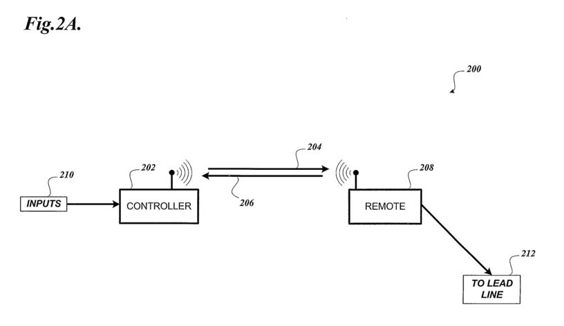
894 DNAP further submits that a more expansive implementation of the remote firing system, involving multiple controllers and their respective remotes, is described on pages 6–7 of the Rothenbuhler patent with reference to Figure 2B.
895 Figure 2B is reproduced below:
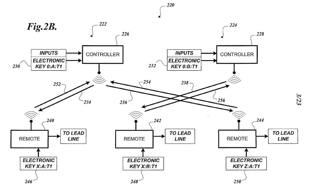
896 DNAP also reproduces Figure 4A in its submissions, which appears below:
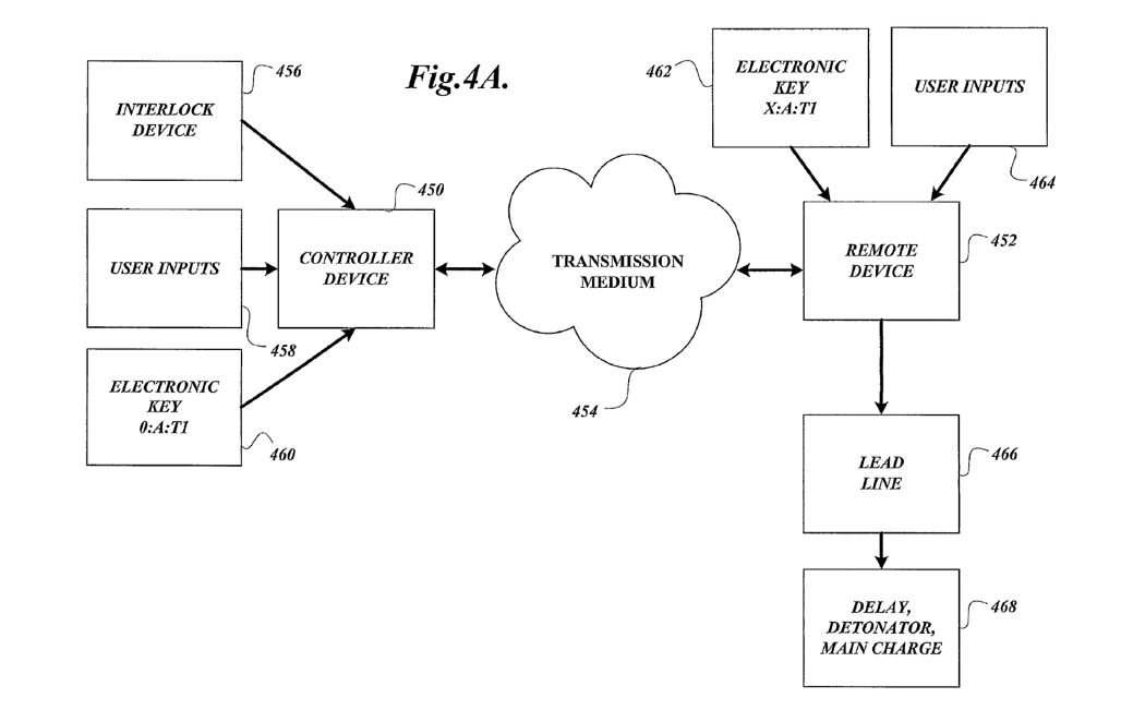
897 DNAP submits that there is disclosure in the Rothenbuhler patent of the selective control of a “predetermined group” (i.e. the remotes programmed with a system identifier so as to belong to the same system as a particular controller) of wireless initiation devices (i.e. remotes with detonators connected) within a plurality of such devices (i.e. all remotes with detonators connected belonging to all systems deployed at the same site and within range of the controller of the system comprising the predetermined group).
898 That is, on the premise of DNAP’s case, the wireless initiation device within the meaning of claim 1 is the remote (or the remote unit) with the detonator attached. It can be seen from the figures reproduced above (for example) that the remote unit is connected to the detonator by what is called the “lead line”.
899 However, contrary to DNAP’s submissions, the remote unit is not a wireless initiation device. That is for a number of reasons.
900 First, the remote unit does not itself initiate, ignite or trigger the explosive materials. That work is done by the detonator.
901 Secondly, the definition of “wireless” in the 873 patent requires that there be no physical connections between the detonator and an associated blasting machine or power source. In the system disclosed in the Rothenbuhler patent, the remote is connected by wire or shock tube to the detonator. As Mr Jacobson accepted, the reader would infer that there is a battery in the remote, and they would understand that the source of the stimulus for initiation of the detonator ultimately comes from that battery. That is, power flows down the wire or shock tube from the remote to the detonator.
902 Thirdly, the remote unit does not contain a detonator or components of a detonator. This also has the consequence that it is not a wireless detonator assembly as defined in the 873 patent and nor is it a top-box within the meaning of the 873 patent (because it does not form part of a wireless detonator assembly). In fact, like the system disclosed in the MST Website 2003, the Rothenbuhler patent discloses a two-part blasting machine. Neither the controller, nor the remote unit, is, on its own, a blasting machine. Rather, a PSA would understand that those two components need to be used together, and that when they are used together as designed, they act as a blasting machine. Contrary to DNAP’s submissions, this is a critical point of difference between the 873 patent and the disclosure in the Rothenbuhler document—it is not mere semantics.
903 As Mr Papillon explained at the hearing, a remote control blasting machine essentially separates a traditional blasting machine into two components: a remote device and a controller device. Mr Jacobson accepted that the Rothenbuhler system essentially separates a traditional blasting machine into two components, being the controller and the remote receiver. He said that the two parts together “perform the functions of a blasting machine remotely”. In his affidavit evidence, he described the remote units in the Rothenbuhler system as “intermediate control equipment”: Jacobson 1 [126]. That is also consistent with how the Rothenbuhler patent describes the system, being as a “remote control blasting machine”. Mr Jacobson said that was an accurate description of the controller and remote units.
904 In addition, the Rothenbuhler patent discloses use of the controller and remote device with electric or shock tube detonators (see page 4 lines 19–20), but not EDs.
905 The system disclosed in the Rothenbuhler patent is similar to traditional wired electric detonators. For those detonators, there is a device that supplies an electric current that travels down a wire to fire the detonator. Mr Jacobson said he would call the unit that supplies that electric current a blasting machine. Similarly, with a shock tube generator, Mr Jacobson said he would call the device that supplies the stimulus to the shock tube a blasting machine. The device disclosed in the Rothenbuhler patent is similar in that the component that supplies the stimulus to the detonator in the form of shock wave initiation or electric current is the remote unit, and the controller allows the operator to control that process remotely. The two, together, are a blasting machine. Mr Jacobson conceded that it was correct to say the detonator receives a wired signal to fire from part of the blasting machine.
906 The characterisation of the Rothenbuhler device as a two-part blasting machine is also consistent with the fact that it is designed to work with detonators made by third parties.
27.1.2 1670 Operations Manual
907 The 1670 Operations Manual states that the RFD is used to activate electric and non-electric detonator devices: [1.1.1]. There is no disclosure of its use with EDs.
908 During the hearing, Mr Jacobson accepted that the remote units disclosed in the 1670 Operations Manual can be described as part of a remotely controlled blasting machine.
909 Further, the 1670 Operations Manual discloses a physical connection between the detonator and the power source, being either wire or shock tube: see, for example, [2.2.2], [4.1.10] [4.1.11]. For this reason, the PSA would not understand that the 1670 Operations Manual was disclosing a wireless initiation device within the meaning of claim 1.
910 Nor is there disclosure that the detonator has a receiver for receiving wireless command signals. Instead, as Mr Jacobson accepted, the receiver is in the remote unit.
27.1.3 1670 Brochure
911 The 1670 Brochure refers to the system having the capability to initiate non-electric shock tube, as well as standard electric blasting caps. There is no disclosure of use with EDs. Further, the PSA reading the 1670 Brochure would understand that what was being promoted was the controller and remote device components, and that users would obtain the detonators elsewhere.
912 The 1670 Brochure refers to “Electric and Shock Tube Outputs” as a “Highlight” and thereby discloses a physical connection between the detonator and a power source, so that the system is not “wireless” within the meaning of the 873 Patent.
913 There is therefore no disclosure in the 1670 Brochure of a wireless initiation device within the meaning of claim 1, or a wireless command signal.
914 Nor is there disclosure in the 1670 Brochure of a device determining whether it forms part of the predetermined group.
27.1.4 Conclusion
915 Because the Rothenbuhler documents each do not disclose a wireless initiation device, there is no predetermined group of wireless initiation devices (integer 1.1); no plurality of such devices (integer 1.1); no transmission of wireless command signals to such devices (integer 1.2); no determination of whether a device forms part of a predetermined group of such devices (integer 1.3); and no operation executed or to be executed by such devices (integers 1.2 and 1.4).
916 For these reasons, claim 1 of the 873 patent is not anticipated by any of the Rothenbuhler documents.
27.2 Claim 2
917 The Rothenbuhler documents do not disclose claim 2, because they do not disclose the method of claim 1 (integer 2.1), for the reasons given above. It follows that integers 2.2 and 2.5 are not disclosed because there is no differentiation of wireless initiation devices (integer 2.2); no wireless initiation devices falling within or without of a predetermined group (integer 2.2); and no control circuit for determining whether a wireless initiation device is part of a group (integer 2.5).
918 The Rothenbuhler documents also do not disclose the following additional integers of claim 2.
27.2.1 Rothenbuhler Patent
919 In the Rothenbuhler patent, neither the controller on its own, nor the controller together with the remote unit, is in signal communication with EDs, because EDs are not disclosed. Accordingly, there is no blasting machine within the meaning of the 873 patent with the consequence that there is nothing meeting the definition of “group identification component”.
920 Because there is no group identification component, it follows that there is no control circuit for comparing the group identification component with a stored group identification (integer 2.5).
921 It also follows that there are no wireless command signals, because the wireless command signals comprise a group identification component which must be sent by a blasting machine. This means that the wireless command signals must also be sent by a blasting machine: Papillon 6 [156].
922 As there is no blasting machine for the reasons explained above, there are no wireless command signals (integer 2.1).
27.2.2 1670 Operations Manual
923 The 1670 Operations Manual does not disclose EDs. There is also no disclosure of a blasting machine capable of being in signal communication with an ED. It follows that there is no disclosure of a blasting machine within the meaning of the 873 patent, and no group identification component.
924 The 1670 Operations Manual also does not disclose the following additional integers.
(1) memory (integer 2.4). The 1670 Operations Manual discloses that the remote units read the system address and unit identification from the electronic key. However, there is no disclosure of a memory component for storing group identification information: Papillon 6 [188(e)].
(2) control circuit comparing the group identification component with a stored group identification (integer 2.5). The 1670 Operations Manual does not disclose a control circuit in the wireless initiation device which compares the group identification component with a stored group identification. While the manual describes a comparison process, it is carried out in the controller, not in the remote unit: Papillon 6 [188(g)]; Annexure BEP-32 (integer 2.5).
27.2.3 1670 Brochure
925 The 1670 Brochure does not disclose EDs. Further, there is no disclosure of a group identification component in the 1670 Brochure. That the remote units can be individually selected, armed, fired, and interrogated for status via the keypad on the controller is not sufficient to constitute disclosure of integer 2.2. Mr Jacobson accepted at trial that there is no disclosure of integer 2.2 in the 1670 Brochure.
926 The 1670 Brochure does not disclose a memory component for storing a group identification (integer 2.4). It also does not disclose a control circuit comparing the group identification component with a stored group identification (integer 2.5).
27.2.4 Conclusion
927 For these reasons, claim 2 of the 873 patent is not anticipated by any of the Rothenbuhler documents.
27.3 Claims 3 and 4
928 Claim 3 states (with integers identified):
The method of claim 1 [integer 3.1], wherein wireless command signal comprises a command selected from a command to FIRE the wireless initiation device, a command to ARM the wireless initiation device, a command to DISARM the wireless initiation device, a command to ACTIVATE the wireless initiation device, a command to DEACTIVATE the wireless initiation device, a command to SHUT-DOWN the wireless initiation device, and a command to CALIBRATE an internal clock of the wireless initiation device [integer 3.2].
929 Claim 4 states (with integers identified):
The method of claim 2 [integer 4.1], wherein the plurality of wireless initiation devices are divided into predetermined groups, with wireless initiation devices within the same predetermined group having the same stored group identification, and with wireless initiation devices in different predetermined groups having different stored group identifications, the group identification component of said wireless command signal corresponding to one of the stored group identifications [integer 4.2].
930 The Rothenbuhler documents do not disclose claim 3 or claim 4, because they do not disclose claim 1 and claim 2, for the reasons given above.
931 In particular, in relation to claim 4, there is no disclosure of a wireless initiation device, no plurality of wireless initiation devices or predetermined groups of wireless initiation devices, no group identification component, and no wireless command signals.
932 Further, because the 1670 Operations Manual and the 1670 Brochure do not disclose a memory, they do not disclose a stored group identification within claim 4.
933 For these reasons, claims 3 and 4 of the 873 patent are not anticipated by any of the Rothenbuhler documents.
27.4 Claim 6
934 Claim 6 states:
The method of claim 2 [integer 6.1], wherein the method further comprises an initial step of [integer 6.2]: programming each wireless initiation device with a group identification [integer 6.3].
935 The Rothenbuhler documents do not disclose claim 6, because they do not disclose the integers addressed above in relation to claim 2. In particular, there is no wireless initiation device within integer 6.3.
936 There is also no disclosure in the 1670 Operations Manual and the 1670 Brochure of programming each wireless initiation device with a group identification. The 1670 Operations Manual discloses a programming process, but it is programming of electronic keys by the controller unit, not programming of the remote unit (which is not, in any event, a wireless initiation device).
937 For these reasons, claim 6 of the 873 patent is not anticipated by any of the Rothenbuhler documents.
27.5 Claim 11
938 Claim 11 states (with integers identified):
The method of claim 2 [integer 11.1], wherein each wireless initiation device is placed at a desired position at the blast site and programmed with a group identification via short range wired or wireless communication using a portable programming device [integer 11.2].
939 The Rothenbuhler documents do not disclose claim 11, because they do not disclose the integers addressed above in relation to claim 2.
940 Further, for the same reasons, integer 11.2 is not disclosed because there is no wireless initiation device.
941 For these reasons, claim 11 of the 873 patent is not anticipated by any of the Rothenbuhler documents.
27.6 Claim 16
942 Claim 16 claims (with integers identified) “[t]he method of claim 1, substantially as hereinbefore described [integer 16.1]”.
943 The Rothenbuhler documents do not disclose claim 16 because they do not disclose the integers addressed above in relation to claim 1.
944 For these reasons, claim 16 of the 873 patent is not anticipated by any of the Rothenbuhler documents.
27.7 Conclusion
945 For these reasons, none of the impugned claims of the 873 patent are anticipated by the Rothenbuhler documents.
28. INVENTIVE STEP
946 DNAP contends that each claim of the 873 patent is invalid for want of an inventive step, in light of:
(1) the CGK alone and/or the CGK together with one of:
(2) the Rothenbuhler patent;
(3) the 1670 Operation Manual;
(4) the 1670 Brochure; and
(5) MST Website 2003.
947 For the following reasons, the evidence failed to establish that each claim of the 873 patent is invalid for want of an inventive step as at the 873 priority date.
28.1 DNAP’s witnesses
948 DNAP relies upon Mr Jacobson and Mr Napier and, to a lesser extent, Mr Boucher for the purposes of contending that each claim of the 873 patent was obvious as at the 873 priority date.
949 As found above, neither Mr Jacobson nor Mr Boucher are representative of the hypothetical, non-inventive PSA as each is inventive, and are named as inventors in a patent which was (Mr Boucher) or continues to be (Mr Jacobson) relied upon by DNAP in this proceeding. Further, as DNAP emphasises in its closing submissions, Mr Jacobson is not an expert in detonators. By the 873 priority date, Mr Boucher had not been working in commercial blasting for some six years.
950 Mr Napier does not have expertise in EDs or detonator technology, and had no direct involvement with wireless blasting initiation systems after late 2003. For the reasons explained above, Mr Napier is not representative of the hypothetical PSA at the relevant priority dates, including the 873 priority date, insofar as his evidence relates to BlastPED and other MST products.
28.2 Objective evidence shows the true state of affairs
951 Objective contemporaneous evidence of the true circumstances at or around the 873 priority date, unaffected by hindsight or the exigencies of the proceedings, is relevant (indeed, in this case, powerful) evidence that it was not obvious to remove the physical connection between the ED and the blasting machine. Further and having regard to the following evidence, the selective control and firing of wireless EDs was not within the contemplation of the PSA.
28.2.1 Mr Papillon’s evidence
952 Mr Papillon’s evidence in Papillon 6 at [21]–[23] was that:
By January 2009, there were still no wireless electronic detonators on the market. Instead, innovation work up to 2009 focussed on improving connectors and wiring for wired electronic detonators, with the shared aims of improving usability, ruggedness and cost-effectiveness…
Additionally, between 2006 and 2009, improvements to wired electronic blasting systems included modifying the blasting systems so that they could control a larger number of wired electronic detonators within a blast, and provide for increased programmable firing times.
The major technical development that occurred between 2006 and 2009 in relation to electronic detonators, was the development of wireless remote controllers for blasting machines for wired electronic detonators…
953 Mr Papillon also explained in Papillon 6 at [104] that:
[B]y January 2009 my team had designed and built a wired electronic detonator system for Austin Powder Co, but were continuing to work on improvements to the design and features of that detonator system, including improvements to the logger, the connectors, the wiring, the blasting machine and the firmware. Additionally, in January 2009 at Austin Powder Co we were in the process of testing a wireless remote controller for the wired electronic detonator blasting machine…
[B]y January 2009, it had not occurred to us in the electronic detonator team at Austin Powder Co, to attempt to build a wireless electronic detonator, nor was our team requested to do so.
954 According to Mr Papillon, there were known methods of selectively controlling blasts using wired ED systems which were working well, and there were other matters, such as optimising wired EDs or increasing capacity, that were of higher priority at January 2009 than developing a method of wireless selective control of blasting using a wireless blasting system: Papillon 6 [443(a)].
955 Mr Papillon also gave evidence that, as at January 2009, he would not have considered it useful or necessary to design a means for selective control of detonators within a blast using wireless detonators: Papillon 6 [105(b)]. He said that given wireless EDs were not yet on the market in 2009 (and in fact would not emerge on the market until at least the mid-2010s), Mr Papillon did not recall any discussion amongst customers or colleagues about researching improvements for wireless EDs: Papillon 6 [105(d)].
28.2.2 Mr Jacobson’s evidence
956 The hypothetical task given to Mr Jacobson was to consider how he would “develop improved methods of selectively controlling and actuating detonators for use in blasting, using wireless signals, including if cost was not an issue”. This task was given to Mr Jacobson notwithstanding that he is (a) inventive and (b) not an expert in detonators or boosters.
957 In response, Mr Jacobson identified two “scenarios”.
958 Scenario (a) involved a “two device” approach for connecting the detonators to a remote device that performed the role of receiving/interpreting/executing the wireless command. Mr Jacobson explained that this described “Rothenbuhler’s own RFD systems”, in which detonators connected to remotes could be selectively controlled and actuated using wireless signals transmitted from the controller.
959 Mr Jacobson also gave evidence that, during 2009, Rothenbuhler was already engaged in this scenario. He said that he was part of the senior engineering team at Rothenbuhler (together with the two other named inventors on the Rothenbuhler patent) that considered how Rothenbuhler might gain a position in the ED market, which “only ever amounted to the production of the triple output variation”. Their solution was to connect the remote unit by way of a new “interface cable” to the blasting machine, which in turn would be wired to an ED. That is, the devices involved the addition of a wired connection, not the removal of wire, contrary to DNAP’s submission that the latter was the motivation of the PSA.
960 As to scenario (b), Mr Jacobson said that this would have required EDs, each having their own processors to interpret and execute received signals, as well as their own antennae for receiving the wireless signals and their own power sources to run the electronics and to actuate the detonator. Mr Jacobson said that this was not something that he saw in the market prior to January 2009.
961 However, neither he nor his co-inventors devised this solution in 2009, notwithstanding that they worked in collaboration with DNAP. Considering that none of these three people are properly representative of a member of the notional PSA team, his evidence detracts from, rather than supports, a conclusion that the solution provided by scenario (b) (and claims 1 and 2 of the 873 patent) was obvious.
962 DNAP relies on various paragraphs of Mr Jacobson’s evidence in relation to both scenarios and emphasises that this evidence was unchallenged and should therefore be accepted. However, as already observed, time limitations were placed on counsel during the concurrent evidence sessions with the consequence that not all of the voluminous evidence of each expert could be the subject of cross-examination. In any event, Mr Jacobson’s evidence on inventive step was challenged by Orica on the basis that he was inventive, which challenge has proven to be successful.
963 Finally, as to the steps which Mr Jacobson says that he would have taken in response to the hypothetical task, Mr Papillon’s evidence was that he did not agree that the process of development would have been as straightforward as Mr Jacobson seems to contend, particularly given the large number of variables (including the type of communications systems to be used): Papillon 6 [443(c)]. I accept this evidence in light of Mr Papillon’s status as a member of the notional PSA team, including that he lacks inventive capacity.
28.3 CGK alone
964 DNAP’s case relies upon acceptance of its case as to CGK at the 079 and 165 priority dates as well as its case as to CGK at the 873 priority date. However, in critical respects, I have not accepted DNAP’s case concerning CGK as at each of those dates.
965 In particular, wireless remote controllers for blasting machines for wired EDs, and wireless blast controllers for use with a remote unit which was physically connected to electric and non-electric detonators (such as BlastPED ULF and the 1670 model) were in existence. However, the evidence did not establish that they were CGK in Australia as at the 873 priority date for the reasons explained above.
966 Even had the evidence established that BlastPED ULF and the 1670 model were CGK as at the 873 priority date, the fundamental premise of DNAP’s case (and the evidence of its experts) is that they were wireless within the meaning of the 873 patent. However, that is not the case. That is because those systems involved sending wireless signals to a “remote” unit which was connected by wire or shock tube to the detonator.
967 As Mr Papillon repeatedly stated and which evidence I accept, a wireless detonator within the meaning of the 873 patent, and whether it be electronic, electric or non-electric, was not CGK in 2009. It follows that selective control of wireless detonators (that is, wireless within the meaning of the 873 patent), being detonators which were EDs, and using the methods described in the claims of the 873 patent, was not CGK as at the 873 priority date.
968 Further, purported “wireless” systems such as BlastPED ULF and the 1670 model (that is, which had remote units connected to detonators) do not demonstrate that the “need or problem stated in the 873 Patent had already been addressed and solved years before January 2009…”, contrary to DNAP’s submissions. Nor does DNAP’s evidence establish (or even seek to establish) that the PSA would be directly led to try to remove the wires or shock tube between the remote unit and the detonator with any expectation of success.
969 For these reasons, the evidence failed to establish that the claims of the 873 patent are invalid for want of an inventive step in light of the CGK alone as at the 873 priority date.
970 This is especially as both Mr Jacobson and Mr Napier expressly acknowledged that the use of and operation of wireless electronic boosters went beyond the scope of their expertise, which provides a further reason to reject DNAP’s case that the method in claim 15 was obvious.
28.4 CGK and s 7(3) documents
971 This aspect of DNAP’s case again relies upon acceptance of its case as to CGK, with the consequences identified above.
972 For the following reasons and in any event, the evidence failed to establish that each claim of the 873 patent is invalid for want of an inventive step in light of the CGK and each of the s 7(3) documents as at the 873 priority date.
28.4.1 Patent searches
973 The additional expert on the 873 patent, Mr Jacobson, did not search for patents on a regular basis, and he did not read patent literature to keep up to date with technical developments. He therefore had no basis to state in the 873 JER (topic 2) that the “PSA would have monitored or consulted patents and patent applications of competitors”.
974 By contrast, Mr Papillon’s evidence was that it was not his practice in 2009 (or at any time in his career) to carry out patent searches in order to stay up to date with technological developments in the industry. Further, he said that he would not have carried out patent searches if he had been tasked, in January 2009, with designing a method for selective control of wireless detonators within a blast: Papillon 6 [111(b)]. I accept Mr Papillon’s evidence in preference to that of Mr Jacobson and Mr Boucher (both of whom are inventive) and Mr Napier (who I consider to be an unreliable witness).
975 The deficiencies in the evidence of Dr Mokdsi are addressed above. The particular problem in the process which Dr Mokdsi undertook is that the first patent search carried out by him did not return the Rothenbuhler patent. Dr Mokdsi sent the results of that first patent search to lawyers for DNAP and had a conversation with them. Dr Mokdsi was then instructed to perform the supplementary search. As observed above, it was this supplementary search that identified a US patent in the same patent family as the Rothenbuhler patent.
976 I infer that the instruction was given to perform the supplementary search because DNAP’s lawyers knew about the Rothenbuhler patent and that it had not been returned by Mr Mokdsi’s first search. For this reason and as the evidence did not establish that the PSA would have reviewed the search results provided by Dr Mokdsi after the first search and then asked him to continue searching using the key words that he had identified, the evidence did not demonstrate a reasonable expectation that the skilled non-inventive addressee would have ascertained the Rothenbuhler patent.
28.4.2 Rothenbuhler documents
977 Mr Jacobson is a named inventor of the Rothenbuhler patent, and was one of the authors of the 1670 Operation Manual and the 1670 Brochure.
978 The deficiencies in Mr Jacobson’s evidence concerning the distribution of the latter two documents and the placement of the 1670 Brochure on the Rothenbuhler website are addressed above. Having regard to those deficiencies, I do not accept DNAP’s submission that “the 1670 Operation Manual was broadly distributed to customers and the 1670 Brochure was distributed widely at trade shows and on the Rothenbuhler website, such that both would also have been ascertained, understood and regarded as relevant”.
979 Mr Napier was the CEO of MST, a company in direct competition to Rothenbuhler. Mr Napier had not seen the 1670 Operation Manual before being provided with it by DNAP’s lawyers and could not “sincerely say [he] saw” the 1670 Brochure before being given it by DNAP’s lawyers. Nor had he seen the Rothenbuhler patent. This was despite Mr Napier’s evidence that he had attended trade shows, and had seen the Rothenbuhler device exhibited.
980 Mr Papillon was engaged before the 873 priority date in a confidential project developing a modified Rothenbuhler device, including performing field testing in respect to those units before the priority date. Mr Papillon recalls reading the 1670 Operations Manual in early 2008, but considers that he would not have located the Rothenbuhler patent or the 1670 Brochure or regarded them as relevant for the design task given that the devices described in these documents were used for initiating electric and non-electric detonator blasts, and his focus would have been on designing a selective control system for EDs: Papillon 6 [106]–[112]. He also said that he would have concluded that the 1670 Operations Manual to not be useful for the design task: Papillon 6 [121]–[122].
981 That Mr Papillon agreed that the PSA coming across the 1670 Operations Manual during 2009 would have regarded it as an interesting source of potential ideas for wireless initiation systems for detonators does not detract from his affidavit evidence.
982 For these reasons, the evidence did not demonstrate a reasonable expectation that that the skilled non-inventive addressee would have ascertained and regarded as relevant each of the Rothenbuhler patent, the 1670 Operation Manual and the 1670 Brochure.
28.4.3 MST Website 2003
983 Neither Mr Jacobson nor Mr Boucher gave evidence as to whether they would have located and regarded the MST Website 2003 as being relevant to the hypothetical task.
984 Mr Napier treated BlastPED as a matter of CGK, when it was not.
985 Mr Papillon gave evidence that he does not believe that he would have located the MST Website 2003 if he had been tasked with the design task in January 2009, and if he had, he would not have considered that it was relevant: Papillon 6 [111(e)]–[112]. I accept Mr Papillon’s evidence in preference to that of Mr Napier, who acted on an incorrect basis.
986 For these reasons, the evidence did not demonstrate a reasonable expectation that the skilled non-inventive addressee would have ascertained and regarded as relevant the MST Website 2003.
28.4.4 Claims are not obvious in any event
987 Contrary to DNAP’s submissions, the evidence did not establish that the hypothetical, non-inventive PSA, armed with any of the prior art documents and with the CGK, would be led by any of the prior art documents to the methods disclosed in the claims of the 873 patent as a matter of routine steps. The device disclosed in the claims must involve a wireless detonator. However, for the reasons given above, the device of the Rothenbuhler patent, 1670 Manual and 1670 Brochure, and that disclosed in the MST Website 2003, were for use with detonators which were not wireless within the meaning of the claims.
988 Mr Papillon’s evidence on this topic is found in Papillon 6 at [113]–[117]. In summary, he disagrees that claim 1 is obvious in light of the CGK and the Rothenbuhler patent on the basis that:
(1) as at January 2009, he would not have considered developing a wireless ED for the purpose of designing a selective blasting method given that wireless EDs were not yet in existence, although EDs had become more common in use; and
(2) despite the Rothenbuhler patent suggesting, as Mr Papillon accepts, a method of carrying out wireless control of detonators for the purpose of selective blasting, Mr Papillon states that the information contained in the Rothenbuhler patent would not have caused him to try to implement that technology in EDs for reasons including that the Rothenbuhler patent is designed for use with electric and non-electric detonators and his focus would have been on implementing improvements to EDs (rather than electric or non-electric detonators), the device described in the Rothenbuhler patent was designed not to be consumed in the blast and the Rothenbuhler patent discloses a method of selective control of blasts which enables selection of groups of detonators connected to the same remote unit (rather than the selection of individual detonators within a blasthole).
989 Mr Papillon’s affidavit evidence in respect of the 1670 Operation Manual (and CGK) and the 1670 Brochure (and CGK) is to the same effect: see Papillon 6 [118]–[123], [124]–[130].
990 DNAP submits that this evidence should not be accepted because of concessions made by Mr Papillon during cross-examination, but it does not identify those concessions or explain why they undermine Mr Papillon’s affidavit evidence.
991 DNAP also submits that the “cogent affidavit evidence of Mr Napier and Mr Jacobson, which was undisturbed during cross-examination, provides a powerful exposition of how and why each of the features of the method of claim 1 of the 873 was CGK, routine and obvious to combine for the selective control of wireless initiation device”. I do not accept this submission: neither of these experts had expertise in detonators or boosters (unlike Mr Papillon). Mr Jacobson is not a proper representative of the member of the notional PSA team because of his inventive capacity, and (as addressed above) both of these witnesses have a fundamental misunderstanding of when a device is wireless within the meaning of the claims of the 873 patent, and of a wireless initiation device (as defined in the 873 patent).
992 For these reasons, I prefer the evidence of Mr Papillon to that of Mr Jacobson and Mr Napier.
28.6 Conclusion
993 For these reasons, the evidence failed to establish that each claim of the 873 patent is invalid for want of an inventive step in light of the CGK alone or with each of the s 7(3) documents as at the 873 priority date.
29. INFRINGEMENT
29.1 Overview
994 Orica alleges infringement of claims 1–4, 6, 8, 9, 11, 13 and 15, which allegations are denied by DNAP.
995 Orica’s infringement case can be divided into two parts:
(1) Orica’s formal infringement case, as articulated in its Position Statement on Infringement and in Confidential Annexure BEP-8 to Papillon 1, was that the relevant information included in wireless command signals transmitted to CyberDet I Devices, which those CyberDet I Devices each use to determine whether they are part of the predetermined group, was [redacted];
(2) Orica’s informal infringement case, as opened by Orica and to which DNAP raised no objection, is that the relevant information included in wireless command signals transmitted to CyberDet I Devices, which it contends those CyberDet I Devices each use to determine whether they are part of the predetermined group, is the [redacted].
29.2 Encryption generally
996 At a high level, encryption is used to alter “plaintext” data to make it unintelligible “ciphertext”, whereas decryption is used to restore the encrypted “ciphertext” data to “plaintext” data. Messages are encrypted before they are transmitted, typically using a software component that uses mathematical algorithms to scramble the message content (being the plaintext data). The way in which the encrypted message (being the ciphertext) is generated is based on the cryptographic algorithm working with the particular “encryption key” (a string of values or information, including characters and numbers) being used.
997 Encryption keys are generally pre-stored by, or pre-shared with, the transmitting/broadcasting device and each receiving device. This is done by using a different communications medium or channel to that which will be used for transmitting the encrypted messages themselves. This separation of communications mediums or channels seeks to ensure the encryption keys are not themselves capable of interception, which would then enable the intercepting party to use the encryption key to decrypt subsequently sent messages encrypted with that encryption key.
998 Encryption keys are stored on the microprocessors or microcontrollers of transmitting and receiving devices. The same encryption key can be used for both encryption and decryption (called “symmetric cryptography” or “symmetric key algorithm”), or different encryption keys can be used for encryption and decryption (called “asymmetric cryptography” or “asymmetric key algorithm”). In the case of symmetric cryptography, the microprocessors/microcontrollers use the same encryption key and algorithms in both the transmitter and receiver. If the receiver does not use the same encryption key and algorithms as the transmitter does, the encrypted data cannot be successfully decrypted and therefore the plaintext cannot be read.
29.3 Encryption in the CyberDet I System
999 The manner in which the CyberDet I System uses encryption was either not in dispute or was the subject of Mr Jacobson’s evidence in Jacobson 1, Confidential Annexure TLJ-11, many aspects of which Mr Papillon accepted as being correct during the hearing.
1000 The following evidence given by Mr Jacobson provides a useful overview:
[redacted]
1001 [redacted]
1002 Mr Jacobson explains that [redacted] is used in the CyberDet I system. [redacted].
1003 [redacted]
1004 [redacted]
1005 [redacted]
1006 [redacted]
29.4 Claim 1
1007 To be found to have infringed claim 1, it must be shown that there has been a transmission to, and receipt by, CyberDet I Devices of the wireless command signal (which I will call step 1) which CyberDet I Device then determines whether they form part of the predetermined group (step 2).
1008 As to step 1, DNAP contends that the wireless command signal has not been transmitted to, or received by, CyberDet I Devices that cannot decrypt [redacted]. Thus, so the argument goes, the wireless command signal has only been transmitted to and received by the predetermined group of devices that are to execute the operation, not the whole plurality of CyberDet I Devices.
1009 However, Mr Jacobson accepted during the hearing that:
(1) a CyberDet I Device that is not part of the predetermined group receives the wireless command signal that is intended for the subset if it is within range, and does so at a physical or “radio level”;
(2) the CyberDet I Devices are programmed to be able to recognise and respond to unencrypted wireless command signals;
(3) the CyberDet I System assumes that every CyberDet I Device that receives the wireless command signal will attempt to decrypt it, because otherwise the member of the predetermined group will not engage in the necessary decryption exercise.
1010 Mr Napier gave similar evidence:
A person skilled in the art would take receiving the wireless command signal at face value, and that in the case of, for example, a signal sent by radio frequency, that if the device had an antenna attuned for the correct frequency and within range, then the signal would be received.
1011 The evidence given by Mr Jacobson and Mr Napier is consistent with my construction of “transmitting to” and “receiving the wireless command signal” in claim 1.
1012 For these reasons, the wireless command signal is both transmitted to and received by the whole plurality of CyberDet I Devices, and not just the predetermined group of CyberDet I Devices that are to execute the operation.
1013 DNAP also contends that the CyberDet I Devices within the transmission range of the BCU, but at different locations (on the same level) or different levels of the mine, are not within “a plurality of such devices at a blast site” within the meaning of claim 1.
1014 However, based on my construction of claim 1, this contention must fail.
1015 It follows that the “plurality” referred to in claim 1 can be comprised of any CyberDet I Devices that are loaded in blastholes and are in communication range of the BCU at the time that the relevant wireless command signal is sent.
1016 As to step 2, the method of effecting selective control of CyberDet I Devices does not involve the inclusion of any information in the wireless command signal which the CyberDet I Devices use to determine if they are within a predetermined group. Contrary to Orica’s pleaded case, the CyberDet I System does not include [redacted] in wireless command signals transmitted to CyberDet I Devices, and [redacted] is not compared with any data element included in received wireless command signals. Rather, [redacted]. The encrypted content, in plaintext form, [redacted] does not identify any particular wireless initiation device, predetermined group of wireless initiation devices or plurality of wireless initiation devices.
1017 Therefore, the information derived, following successful decryption, from any received message [redacted]. That process does not involve each CyberDet I Device which receives the wireless command signal determining, on the basis of information included in the wireless command signal, whether or not it is part of the intended predetermined group.
1018 [redacted], it does not constitute information which a CyberDet I Device can use to determine whether it is part of the predetermined group of a plurality of CyberDet I Devices.
1019 For these reasons, claim 1 is not infringed.
29.5 Claim 2
1020 Claim 2 claims the method of claim 1. Both Orica’s pleaded case and its informal case on infringement are essentially the same with respect to claim 2 as with respect to claim 1, and so I reject it for the same reasons as I rejected claim 1. However, the following provide additional reasons for rejecting the allegations of infringement of claim 2.
1021 Orica’s original infringement case as articulated in its Position Statement on Infringement and in Confidential Annexure BEP-8 to Papillon 1 was that the group identification component included in wireless command signals transmitted to CyberDet I Devices was [redacted], which the CyberDet I Devices compared to [redacted]. However, as Orica now appears to accept and as I have found, [redacted], and so that case must fail.
1022 In support of its case that the CyberDet I System infringes claim 2, Orica contends that the [redacted] is the group identification component and the [redacted] is the stored group identification.
1023 Based on the evidence of Mr Jacobson referred to above, I accept that the [redacted] is sent as part of the wireless command signal, and that the [redacted] is stored on the CyberDet I devices forming part of the predetermined group. As addressed in the construction section above, I also accept that there is no requirement for the group identification component and the stored group identification to match.
1024 However, the wording of claim 2 which is particular relevance is “comparing the group identification component with a stored group identification, for determining on the basis of that comparison whether the wireless initiation device forms part of the predetermined group”.
1025 Although he was addressing Orica’s pleaded case, Mr Jacobson’s evidence was that:
[redacted].
(Emphasis added.)
1026 Having regard to their respective roles as addressed above, the [redacted] is not compared to [redacted]. There is no correlation or matching between the two, nor identification of any similarities or differences such that relevancy can be determined. Rather, the [redacted].
1027 For these reasons and on the assumption that the [redacted] is a group identification component and the [redacted] is a stored group identification within the meaning of claim 2, there is no comparing of the [redacted] with the [redacted] for determining on the basis of that comparison whether the CyberDet I Device forms part of the predetermined group, and it therefore follows that claim 2 is not infringed.
29.6 Claim 4
1028 Claim 4 is dependent on claim 2 and so is not infringed for the same reasons that claims 1 and 2 are not infringed.
1029 In addition, claim 4 requires that the group identification component of the wireless command signal correspond to one of the stored group identification. For the reasons set out above, I do not consider that the [redacted] would ever “correspond” to the [redacted], as it could not be “similar or analogous to”, applying the ordinary meaning of “correspond”: Oxford English Dictionary online.
1030 For this additional reason, claim 4 is not infringed.
29.7 Balance of claims
1031 Claims 3, 13 and 15 are dependent on claim 1 and so are not infringed for the same reasons outlined above with respect to claim 1.
1032 Claims 6, 8, 9 and 11 are dependent on claim 2 and so are not infringed for the same reasons outlined above with respect to claims 1 and 2.
29.8 Conclusion
1033 For these reasons, Orica’s claim that the CyberDet 1 Device infringes the 873 patent fails.
30. 943 PATENT
1034 The 943 patent is entitled “A method of underground rock blasting”. It has a priority date of 29 September 2009 (943 priority date), and the invention relates to an improved method of blasting of rock at a location underground.
1035 The Field of the Invention states:
The invention relates to the field of mining, including the blasting and fragmentation of rock. More specifically, the invention relates to the blasting of rock at a location underground.
1036 The abstract of the 943 patent states as follows:
A method of blasting rock at an underground blast site in which boreholes (11a, b, c) are drilled in a rock mass (10) from a drive defining face (12), each borehole is loaded with at least one charge of explosive material (13a-c, 14a-c, 15a-c), at least one detonator is placed in operative association with each charge, and a sequence of at least two initiation events is conducted to blast the rock mass, in each of which only some of the charges are initiated, by sending firing signals to only the detonators associated with said charges and in which each initiation event is a discrete user-controlled initiation event. In one of the at least two initiation events a stranded portion of the rock mass such as a pillar is created that has already been drilled and charged, and the stranded portion of the rock mass is blasted in a subsequent one or more of the at least two initiation events without personnel accessing said stranded portion. First explosive charges (13a, b, c and 15a, b, c) may be blasted in the one initiation event, leaving a pillar of stranded ore with the preloaded borehole (11 b) extending through it. The detonators may be wireless.
1037 Figure 1 b) appears above the abstract as follows:
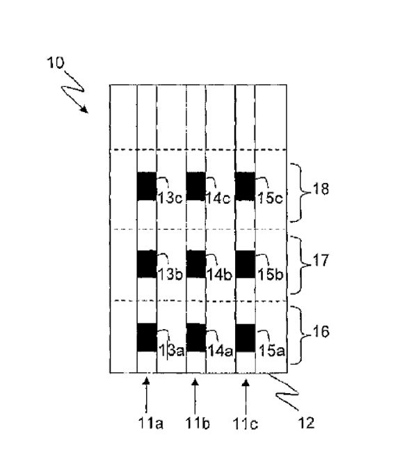
1038 The Background to the Invention refers to the process of retreat mining in these terms:
… Underground mining presents distinct challenges compared to surface mining. For example, the fragmentation and extraction of a body of ore located underground requires careful planning and execution. Typically, the body of ore is accessed via tunnelling, or one or more drives, to expose a face of the ore on at least one side. Boreholes are then drilled into the face, and loaded with explosive charges. Actuation of the charges by means of associated detonators fragments a portion of the rock behind the free face, thereby to expose a new face to be drilled and loaded. Meanwhile, fragmented rock from the initial blast can be removed via the access tunnel for processing. Through repeated cycles of drilling, loading, blasting and extraction, the exposed face retreats into the ore body and fragmented ore is retrieved.
1039 The Background then continues to identify specific challenges, which lead to a situation where valuable ore or remaining rock mass is “left behind”, either temporarily or permanently:
… Whilst simple in nature, underground blasting as described above presents significant technical and organizational challenges. For example, on the technical side, the void created must be structurally sound, and may require internal support to prevent ceiling collapse. To this end, columns or pillars of ore are frequently left in place to assist in providing ceiling support, particularly during the active phase of blasting and extraction of the remaining ore. Thus, portions of the valuable ore body are effectively “left behind” at the underground blast site, at least until the void has been structurally reinforced, reducing the efficiency of the ore extraction process.
…
Furthermore, fragmented material from one blast, or a void resulting from that blast, may prevent access to the ore body on a remote side of that blast, again meaning that portions of the valuable ore body are effectively “left behind”, at least until the fragmented material has been extracted or access has been otherwise facilitated. Moreover, team movement and co-ordination at the mine site is further complicated by safety concerns. Depending upon the integrity of the rock, or the safety rules at the mine site, it may be a requirement to completely evacuate the mine site of all mining personnel (and perhaps equipment) when blasting takes place. Alternatively, or in addition, it may be necessary to reinforce the remaining rock mass before personnel are allowed to access it for further drilling and blasting. Without such reinforcement, that remaining rock mass may also have to be “left behind”. All of these possibilities further constrain the scheduling of all other operations at the mine site for all working faces.
1040 In the Summary of the Invention, it is stated that:
It is an object of the present invention to provide methods for improved blasting of rock at an underground location.
1041 A method of such blasting the subject of the invention is then described:
In selected exemplary embodiments there is provided a method of blasting rock at an underground blast site, the method comprising the steps of:
a) drilling boreholes in a rock mass;
b) loading each borehole with at least one charge of explosive material;
c) placing at least one detonator in operative association with each charge;
d) conducting a sequence of at least two initiation events to blast the rock mass, in each of which only some of the charges are initiated, by sending firing signals to only the detonators associated with said charges and in which each initiation event is a discrete user-controlled initiation event;
wherein one of the at least two initiation events creates a stranded portion of the rock mass that has been drilled and charged in steps a), b) and c) and said stranded portion of the rock mass is blasted in a subsequent one or more of the at least two initiation events without personnel accessing said stranded portion.
1042 This method of blasting is claimed in claim 1 of the 943 patent, which is the only independent claim.
1043 According to the Summary of the Invention:
… By this method, the efficiency and safety of blasting underground can be greatly enhanced. By pre-drilling all of a selected rock mass or body of ore, or a selected portion of the mass or body, and then charging all of the drilled boreholes as desired and placing the detonators in operative association with the explosive charges, all of the charges may be initiated by at least two distinct initiation events in a desired sequence without personnel having to access any portion of the mass or body between initiation events. This means that a stranded portion of the rock mass can be readily and safely blasted and the fragmented material recovered.
The method of the invention allows entirely new sequences of blasting to be achieved. In particular, it is no longer necessary to perform retreat mining – that is, blasting at the furthest point of the rock mass from an access point – or to drill and blast individual levels at a time. It is now possible to perform steps a), b) and c) to the full height of the rock mass, or selected portion of the rock mass, and, if desired, selectively blast different levels of the rock mass in respective initiation events. …
1044 Particular embodiments of the method are also described, including, relevantly to infringement: page 6, lines 17–18, the embodiment the subject of claim 8; page 6, lines 19–28, the embodiment the subject of claim 9; and page 7, lines 3–6, the embodiment the subject of claim 11.
1045 “Definitions” of certain terms appear from page 9 to page 14. In particular, “stranded portion of the rock mass” is defined at page 12 lines 9 to 18 as follows:
Stranded portion of the rock mass: refers to any portion of the rock mass or ore that is “left behind”, or which will be “left behind”, at an underground location during a blasting process because it is physically inaccessible as a result of the one and/or an earlier one of the at least two initiation events and/or because it is unsupported ground that is potentially dangerous for personnel to access (so that personnel access may be prohibited under relevant regulation(s)) and/or because it may be required to remain at the blast site to maintain the structural integrity of the blast site, including any void created by extraction of rock ore at the blast site. The stranded portion of the rock mass comprises ore that has value and that in accordance with the invention is blasted in a subsequent one or more of the at least two initiation events without personnel accessing the stranded portion.
1046 The section entitled Detailed Description of the Invention states at page 14, lines 11 to 27:
Underground mining operations, including the blasting and extraction of ore bodies located underground, require considerable technical skill and expertise. Compared to surface mining, underground mining requires detailed planning. First, blasting must be conducted in a sequence and manner for optimal access to the ore body both prior to blasting (to set up the explosive charges and detonators), and during and after blasting (to extract the fragmented rock)…
Other complications of underground blasting include the structural integrity of the rock surrounding the body of ore to be fragmented and extracted. During blasting an underground void is created, and techniques are known in the art to help improve the structural integrity of the “walls” and “ceiling” of the void. These include refilling the void, or portions thereof, for example with materials such as previously fragmented waste rock, concrete or cement. Other techniques include “leaving behind” columns or other masses of the ore to be extracted, to help support the roof of the void. Whilst useful, these techniques inevitably reduce the efficiency of the blasting and extraction process, either due to increased costs or the need to leave behind valuable ore at the blast site.
31. THE WITNESSES
31.1 Witnesses called by DNAP
1047 DNAP relies on the evidence of one expert witness in relation to the 943 patent, being Mr Dunstan.
1048 Mr Dunstan affirmed two affidavits in this proceeding dated 18 December 2023 (Dunstan 1) and 8 July 2024 (Dunstan 2).
1049 Mr Dunstan is an experienced senior drill and blast engineer who has worked in managerial roles at large mines and been involved in mine planning and designing underground blasting methods. He holds a Bachelor of Mining Engineering (with Honours), a Graduate Diploma in Technology Management as well as a Masters of Business Administration. At the time of affirming his affidavits, Mr Dunstan was undertaking a PhD focussed on block cave mine design and operational logistics, which he expected to complete in 2024.
1050 Mr Dunstan is a specialist in cave mining. He had moved into managerial roles at mining companies by around 1997. Mr Dunstan is presently the technical director of Cave Mining 2040 Research Consortium, being a consortium directed to reshaping cave mining through “rigorous research, collaboration and innovation”. That appointment reflects Mr Dunstan’s status as a leader in the field of research and innovation in cave mining.
1051 At the 943 priority date, Mr Dunstan’s specialty was sub-level cave (SLC) mining. Before the 943 priority date, he had been responsible for developing and introducing new caving practices at the Ridgeway SLC mine and block cave (BC) mines, including those referred to in his paper entitled “The Truth is Stranger than Fiction – the Story of Ridgeway Gold Mine” and his paper entitled “Managing Technical Risk at Ridgeway Sublevel Caving Mining”.
31.2 Witnesses called by Orica
1052 Orica relies on the evidence of two expert witnesses in relation to the 943 patent, being Mr Meneghini and Mr Grace.
1053 Mr Meneghini swore one affidavit in this proceeding dated 11 July 2024.
1054 Mr Meneghini is a mining engineer and underground mining specialist who has worked in Australian underground mines since the 1970s, including as a drill and blast engineer. He holds a Bachelor of Applied Science—Mine Engineering and a West Australian First-Class Manager’s Certificate. Between 1980 and 2021, Mr Meneghini worked in and led numerous engineering teams in underground mines in Australia. Contrary to DNAP’s submissions, Mr Meneghini did not give evidence from a “narrow and conservative perspective” if that is intended to imply that his experience was anything other than extensive.
1055 By its submissions, DNAP was critical of Mr Meneghini, submitting that he was “argumentative” and “evasive”. To the contrary, I perceived Mr Meneghini to be a genuine, forthright and honest witness who was doing his best to assist me. At no time did I regard him to be anything other than objective. While he might have changed his evidence on an issue, that was his obligation as an expert if he remembered additional facts which caused him to do that. As to the criticism that Mr Meneghini could not recall the content of conversations from years ago, that is hardly a basis to discount his evidence overall. I regard DNAP’s criticisms of Mr Meneghini to be overblown, and I reject them.
1056 Mr Grace affirmed two affidavits in this proceeding dated 21 December 2023 (Grace 1) and 10 July 2024 (Grace 2).
1057 Mr Grace is a Canadian specialist underground mining engineer. He holds a Bachelor of Engineering, specialising in Mineral Resource Engineering.
1058 At the 943 priority date, Mr Grace was a mine planner (a junior engineer) within an engineering team at a large underground gold mine. Mr Grace was the mine planner for the majority of the 650 discrete production blasts carried out at Musslewhite mine between November 2007 and November 2009. His responsibilities included the design of production blasts. Mr Grace was promoted to Acting Senior Engineer in March 2010.
1059 Mr Grace had regularly used (wired) EDs before the 943 priority date.
1060 DNAP submits that Mr Grace “was polite and helpful but always defaulting to his narrow experience in stopping [sic] at Musselwhite before 2009, without ever considering broader or alternative options” citing T1667.16–20, 1678.44–1679.2. When one has regard to these passages in the transcript, they do not support the submission. Further, that Mr Grace gave answers including by reference to his actual experience is something that all of the experts did in this case and is to be expected.
31.3 Joint expert report
1061 The joint expert report in respect of the 943 patent was produced following joint conferences held on 6, 7, 8 and 9 August 2024 which were attended by Mr Dunstan (for DNAP) and Mr Grace (for Orica) and by Mr Meneghini (for Orica) on 6 and 9 August 2024 (for Orica) (943 JER). Mr Meneghini only contributed to certain topics.
32. PSA – 943 PATENT
32.1 The real research team in underground mining
1062 The field of the 943 patent is underground mining methods: Dunstan 1 [229]. As identified in the 943 patent itself, which is entitled “A method of underground rock blasting”, the invention relates to the blasting of rock at an underground location.
1063 The evidence of Mr Dunstan, with which Mr Grace agreed, is that the PSA of the 943 patent is a member of an engineering team with direct experience in drill and blast design as it applies to underground mining methods.
1064 According to Mr Dunstan, such engineering teams included: junior and senior mining engineers; draftsmen; geologists; mine planners; and surveyors. Further, such engineering teams operated in a collaborative manner and shared information within the team. Junior engineers worked closely with senior engineers (and were mentored by them) and the rest of the engineering team. As a consequence of that collaboration between members of the engineering team, each member of the team would be exposed to the decisions and issues being considered by other members of the team.
1065 During the hearing, Mr Dunstan also accepted that all members of that engineering team would be familiar with:
(1) the overall strategic objectives of the mine, and the mine design;
(2) the production requirements of the mine; and
(3) the availability of crew members and equipment within the mine.
1066 Mr Dunstan accepted that, as part of the operation of the engineering team, a senior engineer would lead discussions about lessons learned, and improvements and opportunities that arise from blasts that had been undertaken in the mine, and that junior engineers on that team would be exposed to all of those issues.
1067 Mr Dunstan also accepted that junior engineers:
(1) had knowledge of the standardised blasting plan for the mine and overall mine design, as well as the mine schedule and how the planned blast fit within that schedule;
(2) would generate drill and blast plans and charge plans, which would then be reviewed by senior members of the team;
(3) worked with the senior engineers on the team to design blasts that took account of the resources that were available in the mine in terms of equipment and personnel;
(4) were required to balance technical engineering requirements of drilling and blasting against broader infrastructure and operational considerations.
1068 Mr Dunstan also accepted that the junior engineer would be responsible for designing and executing a blast to fit within an existing standardised blasting plan, and that the objective of the junior engineer with every blast design was to achieve optimal productivity, efficiency and safety.
32.2 Mr Grace is a member of the notional skilled team
1069 Mr Grace was a person who, as at the 943 priority date:
(1) has obtained a Bachelor of Engineering, with a specialty in mining;
(2) worked in an engineering team in an underground mine (where production blasts occurred daily, if not twice daily);
(3) was a mine planner for the majority of 650 underground production blasts;
(4) was six to seven months short of becoming an acting senior engineer; and
(5) regularly used EDs.
1070 Mr Dunstan accepted that a person with these qualifications and experience may well be aware of something new “that they would see or be interested in working with” like the method discussed in the 943 patent, subject to the fact that, according to Mr Dunstan:
That would need to go higher up in the hierarchy of the mining team for approval and execution.
1071 However, even if that is so, it does not exclude a person with these qualifications (such as Mr Grace) from the notional skilled team to which the 943 patent is addressed.
1072 DNAP submits that Mr Grace “was not responsible for optimising blast design to improve productivity”. However, in Grace 2 at [52], Mr Grace stated:
It was my role, and it is the role of an underground mining engineer, to (using mine scheduling and planning software of the type mentioned in paragraph 20 above) apply the site drill and blast standards for the conditions present in the stope being fired, and in doing so prepare a drill and blast package (discussed below). This may include taking steps to optimize aspects of the design in order to maximize recovery of ore, improve fragmentation results, reduce ground vibrations, or minimize dilution…
1073 DNAP also submits that Mr Grace “has never worked as a drill and blast engineer”. However, Mr Grace does not use that term; he prefers the term “underground mining engineer”: Grace 2 [9]. Further, to the extent that DNAP is seeking to suggest that Mr Grace has not been involved in blast design work, that suggestion is rebutted by Grace 2 [11] wherein Mr Grace identified that he had been a “mine planner” for nearly two years at the 943 priority date and that:
… the Mine Planner (or equivalent) carries out the blast design work (i.e. preparation of the drill and blast packages). In my experience, it is the Mine Planner(s) that are the most skilled in using the drill and blast design software. The Mine Planner is effectively the caretaker of the drill and blast package throughout the entirety of the life cycle of the blast, from initial design until after it has been fired. Mine Planners interact the most with the front line mine workers, and relay any relevant information communicated by those workers to the rest of the engineering team. A Mine Planner is an “underground mining engineer” as I describe [above].
1074 For these reasons and contrary to DNAP’s submissions, Mr Grace did not do “simply as instructed”; rather, he had a practical interest in the claimed methods of the 943 patent and was a member of the notional skilled team as at the 943 priority date.
1075 For these reasons, I do not agree with DNAP that Mr Dunstan’s evidence should be preferred to that of Mr Grace.
32.3 The PSA is not a specialist in cave mining methods
1076 As explained by Mr Dunstan in Dunstan 1 at [79]:
The location of detonators and their delays is also impacted by the type of mining process and method implemented. For example:
(a) in an underground mining method where ore and waste rock are extracted, the open space that remains is referred to as a “stope”. Stopes are created to provide direct access to the ore body. Stoping methods can be used when the rock is strong enough to support the stope design;
(b) in tunnelling methods, the detonators and explosives were used to expose a face of the ore body on at least one side. Once blasting was carried out, waste rock was transported out of the tunnel before further blasting. Adequate support measures were typically required, particularly where tunnelling rock involves ground between hard rock and soft ground;
(c) in ring blasts, boreholes were drilled in a group. The boreholes in that grouping could be approximately parallel, or could be drilled at an angle to each other in a fan configuration (either a partial fan or a full radial fan), and could be 10 to 100m long. Different configurations of groups of explosives and detonators were used, especially where long boreholes were employed. Ring blasts often required many separate packets of explosives in each borehole to manage both density and energy requirements, especially where hole spacing and burden dimensions continuously changed; and
(d) in room-and-pillar mining… drilling and blasting techniques were implemented to initially mine the rock, which created the “room”, which could then be partially filled with cement and rock to enable the pillars to be subsequently mined.
1077 As at the 943 priority date and in terms of underground mining, stoping methods differed from caving methods, which involved SLC and block caving.
1078 As at the 943 priority date, there were approximately five or six SLC mines in Australia. That is a small fraction of the “hundreds” of underground mines which existed at that time, most of which were long-hole stoping operations of various forms.
1079 Mr Dunstan described SLC mining at least in the late 1990s and early 2000s as “unknown to the majority of mining and technical personnel”. During the hearing, he explained that there were “significant technical uncertainties associated with cave mining methods, including the SLC” in Australia. He said that people argue that a good deal remains to be determined about flow in block caving and SLC environments even today. Mr Meneghini agreed with this, stating in his affidavit at [65], “most drill and blast engineers and others in the Field in Australia were experienced with long-hole stoping methods, with very few having a working knowledge of specific caving techniques”.
1080 The methods of underground blasting which are the subject of the 943 patent include caving methods within their scope, but the Field of the Invention is not directed to such specialist methods. For these reasons and for the purposes of the 943 patent, the PSA in Australia would be experienced in long-hole stoping methods, but would have little or no experience in caving techniques as at the 943 priority date.
1081 Mr Dunstan delivered a technical paper in 2003 which he co-authored and which was entitled “Managing Technical Risk at Ridgeway Sub Level Caving Mine” which he defined as Dunstan 2003 in Dunstan 1 at [68]. He gave this evidence at [37] of Dunstan 1:
During this time [at Ridgeway], including between 1999 to 2003 and thereafter, I was encouraged by Newcrest to explore business improvement through this kind of development work, and through innovation and the use of different technology. In this regard, I refer to Dunstan 2003, which sets out several new processes developed at Ridgeway. For example, Dunstan 2003 refers to the development of innovative drill and blast practices including use of explosive density variation within blast rings, the development of procedures for the pre-loading and pre-priming of blast rings, and improved methods of creating slot rises…
1082 During the hearing, Mr Dunstan gave this evidence in relation to Dunstan 2003:
MS BEATTIE: And under your – does this article describe the fact that under your management, precharging was introduced as a new process at Ridgeway following the research you described?
MR DUNSTAN: Yes, I was part of the team that was involved in bringing it in, yes.
1083 As at 2008, the mining engineers and technical operations team at Newcrest did not have general knowledge of block caving methods. Mr Dunstan was responsible for introducing and implementing those methods, including a “single shot drawbell blast” at Ridgeway BC in 2008. Mr Dunstan explained that a single shot drawbell is where the entire drawbell is fired in a single blast, which comprises firing about 15–20 rings and around 2,500 to 5,000 tonnes in that single firing event.
1084 In 2012, Mr Dunstan delivered a paper which he co-authored and which was entitled “Innovative Cave Establishment Practices at Ridgeway Deeps”.
1085 While Mr Dunstan would be a member of the notional skilled team, and Orica did not submit otherwise, his evidence as to CGK and inventive step must be given less weight by reason of his specialised knowledge in cave mining methods, and his involvement in devising innovative mining methods. For the reasons given above, his knowledge as at the 943 priority date was not the knowledge that has been accepted and assimilated by the bulk of non-inventive skilled persons in the relevant field in Australia.
32.4 Boucher, Papillon, Jacobson and Napier not members of the notional skilled team
1086 As noted above, the agreed evidence of Messrs Grace and Dunstan was that the PSA (being a member or former member of the engineering team with direct experience in drill and blast design) would have been tasked with improving on existing mining methods.
1087 When asked to identify the qualifications and experience of the “hypothetical, skilled but uninventive, person or team who may have had a practical interest in the claimed method” in the 943 patent “and [who] may have wanted to put the claimed method into practical use”, Mr Dunstan did not identify any persons with the qualifications of Messrs Boucher, Papillon, Jacobson and Napier. Mr Grace also did not identify any persons with the qualifications of these witnesses as part of the notional PSA team.
1088 The actual deployment of detonators and the use of detonators in mining sites is not within Mr Boucher’s expertise, and he did not consider himself an expert on underground mining. Further, Mr Boucher was not involved in developing new products for commercial blasting from 2003.
1089 Further, none of Messrs Boucher, Papillon, Napier or Jacobson:
(1) gave any evidence on the 943 patent or participated in the 943 JER;
(2) gave evidence as to how they would come to work in a team with a drill and blast engineer to develop a new mining method and none gave evidence that they ever did work in such a team; or
(3) gave evidence as to how they would come to work in a team with a drill and blast engineer to develop a new mining method using a wireless ED.
1090 The evidence established that the PSA of the 943 patent (being the notional team of which Messrs Meneghini, Grace and Dunstan were members) might make inquiries of companies such as Orica or DNAP as to “all available technologies”, engage geotechnical consultants and rock mechanic specialists and, perhaps, when required, blast service providers.
1091 However, any such “joint effort” falls short of conceiving of and implementing the invention in the 943 patent. Nor did the evidence establish how the PSA of the 943 patent would have identified and utilised the knowledge of somebody such as Messrs Papillon, Napier, Jacobson or Boucher. Further, the fact that aspects of knowledge from a particular discipline are relevant to understanding a claim does not mean this discipline is necessarily part of the “team”: Novartis at [162].
1092 For these reasons, I do not give any weight to evidence given by any of Messrs Papillon, Napier, Jacobson or Boucher in relation to the 943 patent, as the evidence did not establish that they were persons who would use and have a practical interest in the subject matter of, the invention. That is, it did not establish that they would have a real, rather than a peripheral, interest in the subject matter of the 943 patent: see Novartis at [157].
33. COMMON GENERAL KNOWLEDGE
1093 By one paragraph of its written closing submissions relating to the 943 patent, DNAP lists the matters which it submits should be found to be CGK as at the 943 priority date.
1094 In support of the findings which it seeks in its closing submissions, DNAP relies upon evidence given by experts in the proceeding who did not form part of the notional PSA team for the 943 patent, including oral evidence given by Mr Papillon (whose evidence, it submits, corroborates that of Mr Dunstan). However, as Mr Papillon was not a member of the notional PSA team, I place no weight on this evidence.
1095 DNAP also relies upon evidence given as to the CGK at the priority dates of the earlier three patents for the purposes of establishing the CGK as at the 943 priority date. However, that something was established to be CGK as at the 165 priority date (for example) does not mean that it was CGK as at the 943 priority date when the members of the notional PSA team for the 165 patent do not form part of the notional team for the 943 patent, as in this case.
1096 For the following additional reasons and unless indicated otherwise, I decline to make the findings sought by DNAP.
33.1 Product developers worked in conjunction with drill and blast engineers/blasting applications specialists to develop suitable products
1097 This allegation is not pleaded and nor is it apparent how it is relevant, other than in support of DNAP’s submission as to the member of the notional PSA team, which has not been accepted. It is also such a general statement that it is difficult to understand it, or to accept it in any event. Which products were being developed, for example? Suitable for what?
1098 In support of this contention, reliance is placed by DNAP on Dunstan 1 at [199] and [244] about specific inquiries which Mr Dunstan made of Orica and DNAP in connection with the Ridgeway mine, which evidence does not support the finding. For example, how does Mr Dunstan making inquiries support a submission that the respective parties worked in conjunction with each other, or (more importantly) that this was CGK?
1099 Further and unhelpfully to other aspects of DNAP’s case (below), Mr Dunstan gave evidence about the responses to these inquiries in Dunstan 1 as follows:
(1) he recalls being told by Orica personnel in around 2006/07 that the i-kon EDs that were available had wires, while wireless EDs were “in the works” but not commercially available, with no projected timeline for commercial availability;
(2) around the same time, in 2006/07, he also asked personnel from DNAP, as incumbent supplier of Newcrest, how the ED products it sourced from its supplier in South Africa could be initiated, including whether there was a wireless option similar to BlastPED. He was told that Hotshot™ EDs supplied at Ridgeway Deeps were connected to the blast control equipment with physical wires and there was no wireless initiation option.
1100 Mr Dunstan referred to these inquiries in these terms during the hearing:
… So, yes, we were…just talking about the volumes of detonators that were being used in the blasts, the complications that came with that, you know, the large numbers of wires hanging down, all of these sorts of things that were being identified in our somewhat, you know, niche but, you know, high end of the mining industry, of the concerns that we had and things that we were looking for a solution to.
(Emphasis added.)
1101 This oral evidence provides further support for my finding that Mr Dunstan’s experience and knowledge were not that of the PSA because he had specialised knowledge. Indeed, by the finding it seeks, DNAP appears to accept this, referring to Mr Dunstan as a “specialist”.
1102 DNAP also relies upon oral evidence given by Mr Papillon who was not a member of the notional team and whose evidence is given no weight for that reason; upon particular passages in the transcript which do not support the finding sought (such as T256.1–6); or upon evidence which relates to collaboration generally rather than with a member of the notional team.
1103 Reliance is also placed on a facsimile from MST to a mine about a blasting receiver which was being developed. The content of that facsimile is no more than the provision of information to what is presumably a potential client and does not constitute collaboration.
33.2 Wireless detonator assemblies, electronic detonators and selective control of detonators were all CGK as at September 2009
1104 In support of this finding, DNAP relies upon the 079 & 165 JER (topic 3) and the 873 JER (topic 3), which contains evidence of experts who were not members of the notional team comprising the PSA for the 943 patent, and so this evidence has no weight.
1105 However, the agreed evidence in the 943 JER was that:
(1) regulatory constraints would not have allowed detonators to be left in a hole and not fired until a second event. There would be knowledge that this was possible, but execution would be very limited in the industry: topic 5B;
(2) the definition of “stranded portion of the rock mass” is not CGK: topics 5C and 5E;
(3) EDs were part of the CGK, but wireless detonators were not part of the CGK: topics 5F and 5G;
(4) wireless command signals were not part of the CGK: topic 5H;
(5) wireless detonator assemblies (and the wireless electronic booster) were not part of the CGK: topics 5H and 5I.
1106 While I accept that wired EDs were CGK as at the 943 priority date, Mr Dunstan gave evidence in Dunstan 1 at [172] and [200]–[201]:
… EDs had not yet (and have not yet) become the dominant system in underground mining by 29 September 2009… As at 29 September 2009, I considered EDs were more of a niche product, than pyrotechnic shock tube and electric detonator systems, that might be required for certain types of blasting applications … but not critical for routine underground blasting where non-electric was, and still is, the dominant system…
From [2006/07] until several years after 2009, I only ever saw and used EDs that were connected to control equipment by physical wires. I accepted the constraints of wired EDs in designing and conducting large and complex underground blasts, as the advantages of using EDs in such blasts were nonetheless very significant.
I only became aware of commercially-available wireless EDs in around 2018, when I was an independent consultant engaged by Orica to undertake work with respect to its “WebGen” wireless EDs.
1107 As all commercially available detonators had wires or other physical connections as at the 943 priority date, this meant that all blasts, regardless of the type of detonator used, had to be tied in. The wires on EDs were known to be essential because they were the means by which the energy would reach the electronic detonator.
1108 As Mr Dunstan observed in Dunstan 1 at [200], the advantages of using EDs were very significant. Mr Dunstan identified certain advantages in Dunstan 1 at [173], [176], [182], [183] and [185] (for example). Such advantages included two way communication (which Mr Grace described as a significant advantage in Grace 2 at [123]), greater accuracy to achieve the nominated firing time to within a millisecond and greater precision (meaning a small standard deviation around the average firing time), and, when a number of EDs were loaded, they would all receive the command to fire at the same time, and then commence their countdown. As a result, once they had received the command to fire, it did not matter if the wires were cut off.
1109 Mr Dunstan also identified limitations which he had experienced with wired EDs. For example, he explained that:
The physical wires used to connect EDs to control equipment were relatively brittle and prone to breakage, particularly compared to signal tube, during the process of loading a blast, caused by movement of the wire as bulk explosives were loaded into boreholes containing EDs or movement of people or machinery outside the boreholes where the network of wires ran from each borehole to the exploder or bench box.
1110 Mr Dunstan also referred to the process of connecting and “tying-in” EDs as being “laborious and time-consuming” and that “the physical wires used to connect EDs to control equipment were far more prone than shock tube to damage resulting from earlier blasts”. Mr Dunstan said that wired EDs were not considered by him to be suitable for use in pre-charging underground blasts due to the risk of damaging the connecting wires of pre-charged EDs, thereby creating misfires, which were difficult to rectify (particularly if it required going back to the brow to re-load pre-charged boreholes with new EDs): see, generally, Dunstan 1 [192]. Mr Dunstan said that these issues caused him to be frustrated by the “limitations of EDs”: see, generally, Dunstan 1 [194].
1111 However, Mr Dunstan’s frustrations with EDs were not shared by the PSA armed with the CGK as at the 943 priority date. That is because:
(1) Mr Dunstan’s only use of EDs before the 943 priority date was in the single shot drawbell blasts at Ridgeway between early 2008 and late 2008. That was the innovative blast practice that he introduced to Ridgeway BC. In that time, he was responsible for less than 75 drawbell firings. Further, Mr Dunstan and his colleagues blasted 150 drawbells using the single-shot method and none experienced any issue relating to the use of EDs as the initiation system;
(2) Mr Dunstan had limited experience in watching the tying in of EDs. His experience before the 943 priority date appears to be limited to observing the “first few times” a single shot draw bell was tied in which were also the “first few times” which the crew had set up that type of blast or ever used EDs in practice;
(3) as Mr Dunstan had only used EDs in single shot drawbell blasts (save for a “couple of test rings”), he could not compare how long it would take to load an ED versus a non-electronic detonator in the same blast type;
(4) Mr Dunstan’s expressed frustrations with EDs were experienced in the context of those single shot drawbell blasts. However, tying in a single shot drawbell blast is more complicated than other types of blasts. For example, Mr Dunstan gave evidence that he was frustrated that EDs were required to be hooked up to the firing line in a specific order. However, this was not an issue with the ordinary stoping operations engaged in by the PSA, which Mr Dunstan appeared to accept.
1112 By contrast, Mr Grace had been involved in approximately 650 blasts by the 943 priority date, regularly using EDs. Mr Grace was therefore more experienced than Mr Dunstan in hands-on blasting experience using EDs and for that reason, I prefer Mr Grace’s evidence to that of Mr Dunstan on this topic.
1113 Mr Grace’s evidence in Grace 2 at [116] was:
… I disagree that in 2009 I was or other underground mining engineers in the Field (or any other person involved in underground drilling and blasting) were lamenting the failures of EDs in the way that Mr Dunstan describes (not only in this section of the Dunstan Affidavit, but throughout the Dunstan Affidavit generally). I had used EDs regularly before the Relevant Date, and that suggestion is inconsistent with my experience.
1114 It was Mr Grace’s experience that it was potentially quicker to tie-in a blast using EDs than non-electric detonators, because the same EDs could be loaded in every hole and then connected to the harness wire in any order. Further, it was not his experience that ED wires were brittle or prone to breaking or were more prone to damage than shock tube used on non-electric detonators.
33.3 The concept of wireless detonators was CGK, and relatedly, the removal of wires would assist the PSA to conduct larger blasts
1115 In support of this finding (and overlooking the vague reference to “concept”), DNAP cites passages of oral evidence given by Mr Papillon in connection with the 079, 165 and 873 patents as well as evidence given in the 079 & 165 JER and 873 JER. For the reasons already given, none of this evidence assists in demonstrating the CGK as at the 943 priority date.
1116 DNAP also cites Dunstan 1 at [127] but this evidence relates to pre-charging, and does not support the finding sought.
1117 In Dunstan 1 at [262], Mr Dunstan stated that the method of claim 1 could only be performed using wireless EDs. However, as observed above, the agreed evidence in the 943 JER was that wireless detonators were not part of the CGK. DNAP’s submissions do not grapple with this evidence. Nor do its submissions grapple with the evidence of Mr Napier that the underground environment is extremely challenging for wireless communications.
1118 Contrary to DNAP’s case, the evidence at trial demonstrated that undertaking a blasting method that involved communicating wirelessly with detonators was not something that the PSA of the 943 patent had considered as at September 2009.
1119 Relevantly, Mr Meneghini gave this evidence:
MS COCHRANE: Thank you. And is it fair to say that, as at 2009, you didn’t have a practical interest in undertaking a blasting method that involved wireless communication with detonators?
MR MENEGHINI: I wasn’t aware of wireless communication in 2009.
MS COCHRANE: Thank you. And, as at 2009 or before 2009/up to 2009, was it something that you were interested in and looked out for, the ability - - -
MR MENEGHINI: No.
MS COCHRANE: - - - to undertake wireless?
MR MENEGHINI: No. Unlike electronic detonators, wireless detonators was nothing that I saw or ever thought of.
1120 Mr Grace gave similar evidence:
MS COCHRANE: Thank you. And as at 2009, were you aware of the Rothenbuhler remote wireless blasting initiation system?
MR GRACE: No. I had not heard of it.
MS COCHRANE: Thank you. And as at 2009, is it fair to say that you didn’t have a practical interest in undertaking a blasting method that involved communicating wirelessly with detonators?
MR GRACE: No. It wouldn’t have been something that had crossed my mind at that time.
1121 DNAP also relies upon what it contends are “admissions in WO2006/047823 (p 3.6) and WO2006/076777 (p 1 at ln 28-30), which are incorporated by reference in the 943 Patent (p 18 ln 6-7)”. This is addressed below.
33.4 Blasting larger volumes of rock and reducing the number of blast cycles was one of the primary goals of blast design
1122 By the 943 JER (topic 3A), the experts agreed that:
The PSA generally knew and understood that they should optimise the blast cycle but consider multiple engineering, geology and other operational factors to ensure the overall mine cycle was balanced in the blast design.
1123 That is, where appropriate, the PSA would look to increase production (by, for example, blasting larger volumes) and reduce cost (by, for example, reducing the number of blast cycles) but there would be other considerations which affected the decisions made including, importantly, safety and other constraints, including the type of ore being mined. That conclusion is supported by the evidence of the experts in their comments in the 943 JER (topic 3A).
1124 In particular, underground mining can be inherently dangerous, and safety is at the forefront of the mining engineer’s mind when designing a blast. As to this, Mr Dunstan’s evidence was:
MS BEATTIE: So, Mr Dunstan, in light of the risks that have been discussed, do you agree that a mining engineer designing a blast takes a conservative approach to doing so?
MR DUNSTAN: They certainly have safety at the forefront of their mind as to how they’re going to execute the blast, yes.
1125 Ground support is a mechanical means to ensure that the drift (roof and walls) is adequately supported so as to prevent injury from loose rock. Ground support typically involves rock bolts, mesh and/or “shotcrete”. Unsupported ground is any area of the mine where ground support has not been installed or pre-existing ground support has been damaged. It is a fundamental safety principle in underground mining that personnel are not permitted to enter unsupported ground. The regulatory requirement that personnel could not enter unsupported ground was a factor that dictated how a PSA would design a blast at the 943 priority date.
1126 An article which Mr Dunstan said described “thinking and approaches to blast design and implementation that are consistent with what I consider to be the CGK prior to 29 September 2009” stated that:
The opportunity to recover stopes from failed blasts may be hampered by limited access and safety of personnel and equipment. The approach taken therefore is one of caution, to minimise the risk associated with blast failure and the associated cost of recovery. This is often reflected in conservative mine design and production scheduling. Conservative approaches include; multiple stope access drives, firing progressive numbers of small blasts, full opening of rise and slots before commencing ring firing and close sublevel intervals. Some of these designs are dictated by local ground conditions, ore body geometry, pillar requirements to support openings, equipment limitations and considerations to the safety of personnel. Some, however, are limited by the capability of the current blast initiation systems to deliver the flexibility and accuracy of delay sequencing to perform blasts that can optimise all aspects of the mining process.
1127 Consistently with the conservative approach which was taken by the PSA to blast design in underground mining, the experts agreed in the 943 JER that, even if an idea (method) to solve a problem had been developed and analysed:
In mining ‘new, improved, or different’ ideas or methods are often rejected at this step as the hurdles for safety considerations are quite high and regarded as the most important consideration at an operation.
1128 To suggest that the PSA would always maximise the size of a given blast and/or reduce the overall frequency of blasting, or that this was the primary goal, is too simplistic, and I do not accept that it reflects the approach which would be taken by the PSA. That is because it fails to take account of the various factors involved in blast design, and of the conservative approach which would be taken by the PSA. Indeed, such a blanket approach is contradicted by Mr Dunstan’s comment in the 943 JER (topic 3A) that:
The engineer’s goal is to be as productive as possible, within other pre agreed constraints applicable to the specific areas within the mine and the overall mine operation itself.
1129 Those other constraints might mean that a different mining method is appropriate in order to be as productive as possible. As Mr Grace stated:
The PSA would select the most productive mining method that suits the ore body and that will not always be a move towards blasting more ore in fewer blasts.
1130 Further, the evidence at trial established that:
(1) underground mining is a “complex affair”;
(2) the PSA took a practical approach to blast design, informed by “the equipment that was available at the time and safety considerations;”
(3) the PSA had available to them a “toolbox” of resources to use when designing a blast. That toolbox was made up of “the templates of the mine or drill and blast guidelines” and “the equipment that was available to them”;
(4) the drill and blast function was about successful, repeatable blasts that have been proven to work;
(5) the particular mining method selected for use at any one underground mine depends on, for example, the size, shape and orientation of the ore body, the grade of mineralisation, the strength of the rock materials, and the depths involved;
(6) drill and blast standards for a mine were, in effect, the overarching design for drilling and blasting in that mine. That standardised blasting plan was important for efficiency and consistency at the mine and the mining engineer will not generally design a blast outside of the drill and blast standards unless there is a particular need to do so.
1131 The evidence also established that drill and blast design must:
(1) avoid creating damage around or outside of the blast zone;
(2) achieve suitable fragmentation of rock;
(3) optimise the powder factor;
(4) minimise dilution;
(5) minimise ground vibrations; and
(6) take into account the redistribution of stress following a blast; other geotechnical issues and constraints; the mine’s ventilation requirements; capacity, movement and utilisation of equipment; and other operations and scheduling issues, including other necessary mine operations.
1132 Additionally, mining methods could be categorised as “advancing” or “retreating”, both of which involve mining in a linear sequence.
1133 A primary objective of drill and blast design was to always maintain access to load the remaining drill holes in the stope as the stope is progressively mined. Any sequence other than a linear retreat sequence would have cut off access to the drill holes on the far side of a void created by a preceding blast.
1134 As to this issue, Mr Dunstan gave the following evidence:
MS BEATTIE: Do you agree that it was a fundamental premise of mining in September 2009 that blasting should be carried out in that linear sequence?
MR DUNSTAN: It’s the general way that mining was done, yes.
MS BEATTIE: Yes. And, indeed, I think you mentioned this before but, by not following that linear sequence, there’s a risk of isolating valuable ore behind the brow?
MR DUNSTAN: Yes, in a – yes, in a stoping operation, yes, or in a – yes. Yes, SLC, yes.
MS BEATTIE: And you would agree that it was common general knowledge of a skilled mining engineer at September 2009 that one should always blast in a manner to avoid isolating valuable ore?
MR DUNSTAN: Yes.
1135 If a linear sequence was not followed, there was a risk of isolating valuable ore.
1136 It was the evidence of Mr Grace, which I accept, that the PSA would not have contemplated mining at the 943 priority date in any sequence other than a linear sequence.
1137 For these reasons, it was CGK as at the 943 priority date that the blast design for an underground mine would be determined by the PSA by reference to a range of factors. Depending on the circumstances, such factors included maximising the size of a given blast or reducing the number of blasts, but it was not the case that such matters were the primary goals of blast design.
33.5 Pre-charging
1138 In Dunstan 1 at [67], Mr Dunstan distinguished between pre-loading and pre-charging:
Pre-loading is where the boreholes are drilled and the bulk explosive product is loaded into each borehole but the booster (containing the detonator) is not loaded until required. Pre-charging is where the boosters (containing the detonators) are also loaded into the borehole (often with the intention of firing them at a separate initiation event than a first initiation event in another production ring).
1139 In Dunstan 1 at [128] and [130], Mr Dunstan referred to the general practice of pre-charging in these terms:
… [T]he efficiency gains offered by pre-charging needed to be balanced against the inefficiencies and potential risks arising from the potential for the initiating equipment (detonators, boosters and their control equipment) for pre-charged boreholes to be damaged or otherwise lose function as a result of earlier blasts. For all types of initiation systems used in underground and surface mining as at 29 September 2009, instructions and power for firing was effected through physical connections – shock tube for non-electric detonators, electrical wire for electric and electronic detonators. Those physical connections could be damaged or broken if hit by rock propelled from a nearby blast, or by ground movement caused by a nearby blast, with the consequence that loaded detonators could no longer be communicated with or initiated and therefore became misfires – which were hazardous and involved time and complication to be removed. The closer pre-charged boreholes were to boreholes from an earlier blast, or to material to be fired or which would move as a result of an earlier blast, the greater the risk of damaging the physical connections to the pre-charged boreholes and being unable to fire them (at least without taking significant remedial action, such as entering the pre-charged area to re-connect or replace damaged wires – a time-consuming and potentially dangerous exercise after another nearby blast had occurred).
[In] a stope mining context pre-charging was often not considered by me to be worth the risk of damaging physical connections to pre-charged boreholes and causing misfires – or at least the need for remedial action that undermined the efficiencies of pre-charging in the first place (for example, my understanding was that it was not permissible, under the regulations, to drill within 10m of a charged borehole). The limited space available underground, and the fact that blasted material generally moved into what space/void there was, made the risk of damaging the physical connections to pre-charged blasts high (except where the pre-charged boreholes were distant from the earlier-firing boreholes (which is unusual) or where steps could be taken to protect the physical connections to the pre-charged boreholes, e.g., by introducing them from a different angle (such as from an existing drive or tunnel on the other side of the blast, if practical), or enclosing them within protective casing (costly and still not guaranteed to survive earlier blasts)). Therefore, it was not always worth attempting such an approach except in specific circumstances, such as in the SLC context at Ridgeway which I oversaw in the early 2000s…
1140 The only evidence of any “pre-charging” being carried out in Australia prior to the 943 priority date is the pre-charging as a “new process” introduced by Mr Dunstan in SLC at the Ridgeway mine, together with his oral evidence that it was occurring at one other cave mine in Australia, Northparkes (a BC mine).
1141 The process required to institute pre-charging at Ridgeway constituted a “significant process change”, requiring the PSA (and other mine staff) to engage in a formal risk assessment process, research and experimentation, and obtain approval from site management and regulatory officials.
1142 Mr Dunstan’s experience with pre-charging at Ridgeway occurred with non-electric detonators only. Mr Dunstan had never considered pre-charging with an ED before the 943 priority date. Further, the pre-charging carried out by Mr Dunstan did not have the claimed features of either (i) creating a stranded portion of the rock mass or (ii) blasting pre-charged rock (of any kind) in a subsequent initiation event without personnel accessing it.
1143 By its submissions, DNAP seeks a number of findings concerning pre-charging and relies upon (inter alia) oral evidence given by Mr Dunstan and Mr Papillon.
1144 The findings which are sought by DNAP, and my reasons for declining to make those findings, are as follows:
(1) the PSA was aware of pre-charging, which was conducted with signal tube detonators in the early 2000s in SLC and “block caves underground”. While I accept that the PSA was aware of pre-charging, as explained by the experts in the 943 JER, I decline to make the additional findings concerning SLC and BC mining as the PSA is not a specialist in cave mining methods and so would not have been aware of the manner in which it was used as described;
(2) pre-charging is particularly suited to underground mines, such as precious mineral mines. I decline to make this finding as it is irrelevant to any issue which I am required to decide. Further, the evidence cited by DNAP is that of Mr Papillon who is not a member of the notional team;
(3) the PSA was motivated to develop wireless detonator assemblies to use in pre-charging underground. I decline to make this finding for the reasons explained below;
(4) the ability to pre-charge with a wholly wireless detonator would mean that personnel could remain on the surface [and] there would be no need for them to re-enter during firings/blasts. I decline to make this finding for the reasons explained below;
(5) the ability to pre-charge with a wholly wireless detonator would mean that the mining method could be changed for efficiency and safety reasons and conducted in different configurations (i.e. non-retreat mining). I decline to make this finding for the reasons explained below;
(6) regulatory approval for pre-charging could be gained with routine testing, review of procedure and demonstrating results. I decline to make this finding for the reasons explained below, and because the evidence did not establish that it was CGK that regulatory approval could be gained in the manner described, including through “routine” testing.
1145 By its submissions in support of these findings, DNAP relies upon the 079 & 165 JER (to which no weight can be given as the experts who contributed to it were not members of the notional team) and it cites numerous extracts from the transcript, but it once again bypasses the 943 JER. Further and in many respects, DNAP relies upon the oral evidence of Mr Papillon. However, Mr Papillon is not a member of the notional team, and his oral evidence (as cited by DNAP in its submissions) was either given at large (that is, not by reference to the 943 priority date) or it was not directed to the issue of CGK as at the 943 priority date, or both.
1146 DNAP also relies upon statements made in the 079 and 165 patents which refer to a “desired pattern of blasting”. However, it is unclear whether DNAP contends that these statements are admissions, and why that is the case. Absent a precise submission, it is difficult to know what to make of this.
1147 To the extent that the findings sought by DNAP refer or relate to wholly wireless detonators (being 4 and 5 above) or wireless detonator assemblies (being 3 above), these findings will not be made because such detonators and assemblies were not CGK: 943 JER (topics 5G and 5I). How the PSA would be aware of facts relating to such detonators and assemblies, or have any particular motivation in relation to them, is impossible to say based on the evidence cited by DNAP in its submissions.
1148 As for Mr Dunstan, his ideas and motivations concerning the removal of wires carry little weight for the reasons explained above. That is, Mr Dunstan’s frustrations with wired EDs as expressed in his affidavit evidence were not shared by the PSA armed with the CGK. Further, Mr Dunstan’s specialised knowledge and idiosyncratic experience of pre-charging is not reflective of the CGK.
1149 Importantly, the 943 JER states the agreement of the experts on the topic of pre-charging at topics 3C and 5B:
Pre-charging is a concept the PSA would have heard of at the relevant date, but there were significant regulatory restrictions associated with pre-charging.
Implementation would have been difficult due to the need for regulatory changes, and mine-specific characteristics may have not been suitable for pre-charging.
There was limited execution of the pre-charging technique and the PSA was unlikely to have had practical experience with the method.
Regulatory constraints would not have allowed detonators to be left in a hole and not fired until a second event.
There would be knowledge that this was possible, but execution would be very limited in the industry.
1150 Mr Dunstan stated at topic 3C in the 943 JER (with implicit recognition of his own peculiar mining experience) that:
In the caving industry, pre-charging was not seen as a unique idea. Though in the broader underground mining environment, the PSA would have had limited exposure to the method.
(Emphasis added.)
1151 As to the emphasised sentence above, Mr Grace and Mr Meneghini agreed: 943 JER (topic 3C). Relevantly, their evidence in the 943 JER was that:
(1) although the PSA would have heard of pre-charging at the relevant date, they most likely would not have first-hand experience with pre-charging, and possibly would not have anyone in their professional network with first-hand experience with pre-charging due to the significant regulatory restrictions associated with pre-charging (Mr Grace);
(2) even in the scenario where the local regulations would allow for pre-charging to occur, at the relevant date the PSA would need to complete research and possibly test work before implementing the pre-charging blasting technique (Mr Grace);
(3) the PSA would have generally known, aside from regulatory restrictions, that pre-charging as a technique could not be adopted as an industry standard and would be unique to an individual mine’s circumstance. The PSA could not be confident of how rock masses and geotechnical factors would behave during multiple blasts using pre-charging methods and what additional uncertainties could be introduced. The PSA would have seen pre-charging as a unique process (Mr Meneghini).
1152 There were known risks and inefficiencies associated with pre-charging in an underground environment, including that it did not necessarily improve safety; it introduced additional risk (including, for example, in relation to explosive performance and potential inability to carry out necessary remedial work); it reduced blast site access; mine-specific characteristics meant some mines were not suitable for pre-charging; and it was not suitable for use in “stressed” mines, such as those experiencing seismic activity.
1153 Mr Dunstan characterised the risk introduced by pre-charging as “small”. Mr Meneghini disagreed. Indeed, Mr Meneghini had never engaged in pre-charging in an underground environment. Further, Mr Meneghini had worked at two of the “5 or 6” SLC mines in Australia before the 943 priority date and he did not consider that he would have been comfortable pre-charging in either due to the seismic activity in those mines.
1154 Mr Grace explained that there can be “more significant risk associated to your overall production schedule from pre-charging than not pre-charging”.
1155 To the extent that the evidence of Mr Dunstan (including his oral evidence) conflicts with that of Mr Grace and Mr Meneghini on the topic of pre-charging, I prefer the evidence of Mr Grace and Mr Meneghini as, for the reasons already explained, I consider that they better represent the members of the notional PSA team as at the 943 priority date.
33.6 The drill and blast engineer would use the products developed by the product developers, such as Orica and Dyno Nobel according to their capabilities
1156 Not only is this matter not pleaded as being CGK, it is not a finding which I am prepared to make as it is otherwise irrelevant to the issues which I am required to decide in this case.
34. CLAIM CONSTRUCTION
34.1 “stranded portion of the rock mass”
1157 The phrase “stranded portion of the rock mass”, and the words used in the definition of that phrase, do not have a technical meaning. Furthermore, the experts agreed that the definition of “stranded portion of the rock mass” in the 943 patent was not CGK at the 943 priority date: 943 JER (topics 4A and 5C).
1158 Mr Dunstan and Mr Grace also agreed that “stranded portion of the rock mass” refers to rock mass or ore that:
(1) is or will be “left behind” because:
(a) it is physically inaccessible as a result of the one and/or an earlier one of the at least two initiation events (i.e. the first of multiple blasts); and/or
(b) it is unsupported ground that is potentially dangerous for personnel to access (so that personnel may be prohibited from accessing it under relevant regulation(s)); and/or
(c) it may be required to maintain the structural integrity of the blast site, including any void created by extraction of rock ore at the blast site;
(2) in accordance with the invention, comprises ore that has value and is blasted in a subsequent one or more of the at least two initiation events without personnel accessing the stranded portion.
1159 Both Mr Dunstan and Mr Grace agreed that, in the context of the 943 patent, “left behind” means temporarily left behind because, in accordance with the invention, the stranded portion of the rock mass is “pre-charged” and blasted in a subsequent initiation event without personnel accessing that rock.
1160 I accept the construction of this phrase by these experts.
34.2 Whether an arbitrary integer
1161 There was mention in DNAP’s opening submissions on validity to the phrase “stranded portion of the rock mass” as being an “an arbitrary parameter/inessential integer that should be disregarded in assessing DNAP’s allegations of obviousness and no manner of manufacture”. It is also referred to this in its opening submissions in relation to infringement.
1162 By its closing submissions, DNAP seeks a finding that “stranded portion of the rock mass” is an arbitrary integer, and submits:
The difference between the 873 and 943 Patents, to the extent that there is one, hinges on the inclusion of a reference to a “stranded portion of rock mass”, which is a mere limitation (an arbitrary parameter or inessential integer), referring to no more than that there must be a “portion of rock” for each subsequent blast or initiation event to act upon. It is an [sic] limitation of no note or practical consequence.
1163 No version of DNAP’s pleadings allege that “stranded portion of the rock mass” is an arbitrary integer, or that this was relevant to either the manner of manufacture case, the lack of inventive step case or the infringement case, being issues which were addressed by the experts, both in their evidence in chief as well as the 943 JER.
1164 In a draft proposed version of the 6FASOC provided at trial, DNAP sought an amendment to [106]. That proposed amended paragraph stated as follows:
Further, or in the alternative, to paragraphs 104 and/or 105, above, the “invention” so far as claimed in claim 1 (and dependent claims) and claim 19 of AU’943 is not patentable subject matter because it contains a mere limitation on the scope of the claim that does not interact with the other essential integers of the claim to produce any new result or method.
Particulars
(A) The limitation “a stranded portion of the rock mass”, as defined on page 12 of the AU’943 specification, in claim 1 is a mere limitation on the scope of that claim and dependent claims.
(B) The limitation “wherein each borehole extends at from 0 to 45 degrees to vertical” in claim 19 is a mere limitation on the scope of that claim.
1165 The application to amend that paragraph was heard on 31 October 2024, being the second last day of the trial. The amendment application was opposed by Orica. In particular, Ms Beattie SC submitted to the effect that, if the amendment was allowed, it would reopen the infringement case.
1166 After oral argument, DNAP withdrew the amendment application in relation to [106] on the basis that the pleading already made the allegation elsewhere. However, I disagree that the allegation is pleaded elsewhere. As such an allegation would have had an impact upon the expert evidence obtained prior to trial, it ought to have been pleaded: see Betfair at [50]; also rr 16.02(1)(c) and 16.02(1)(d) Federal Court Rules. Further, the proposed pleading amendment to [106], even had it been pressed and allowed, would not have cured the failure to plead this material fact as part of the lack of inventive step case, or as part of its defence to the infringement case.
1167 For these reasons, the submission by DNAP that “stranded portion of the rock mass” is an arbitrary integer is rejected as it falls outside the scope of its pleaded case, and Orica was not on notice of the case which it had to meet at trial. To the extent that DNAP presses that submission as part of its manner of manufacture case, lack of inventive step case and in its defence to the infringement case, those submissions are rejected for the same reasons.
1168 In any event, even had it been pleaded, the contention would have failed for the following reasons.
1169 The premise of DNAP’s submission is that the definition requires that “one of the at least two initiation events” creates one or more of three results of an application of the method of claim 1 (being a reference to the first part of the definition). DNAP submits that each of the three matters specified in the definition of “stranded portion of the rock mass” are potential temporary results of working the method of claim 1 of the 943 patent and complains that the specification of the 943 patent does not suggest, nor provide any reason why, these three potential temporary results are relevant to the working of the method of claim 1. DNAP also submits that the definition of “stranded portion of the rock mass” also records that the stranded portion “comprises ore that has value and…is blasted…without personnel accessing the stranded portion” (page 12, lines 16–18) which “too involves no different or additional step in the method [but] it is simply a “limitation” on the circumstances in which the method is practiced”.
1170 However, on the proper construction of the phrase “stranded portion of the rock mass” in the claims in the context of the 943 specification as a whole (including the parts which are extracted above):
(1) the method of claim 1 is to drill and charge the portion of the rock mass which will be stranded before the first initiation event and then blast that portion in a subsequent initiation event without personnel accessing it;
(2) the creation of the stranded portion of the rock mass, and the blasting of that stranded portion after the first initiation event without personnel accessing it, is inherent to the advantage of the method in claim 1. It is a departure from the known method of mining in a linear sequence, but which avoids the potential adverse consequences of such a departure, including the permanent abandonment of valuable ore.
1171 For these reasons, “the stranded portion of the rock mass” is not an arbitrary integer.
35. MANNER OF MANUFACTURE
35.1 DNAP’s pleaded case
1172 This aspect of DNAP’s validity attack on the 943 patent is pleaded at [82]–[106] 6FASOC. Within those paragraphs, [91]–[101] of the 6FASOC plead a series of alleged statements in the 943 patent which are alleged to disclose that identified matters were “known”.
1173 However, by DNAP’s closing submissions, DNAP relies upon statements made in the 873 patent as constituting admissions by Orica that identified matters were known. It also relies upon the incorporation of the 079 and 165 patents into the 873 patent “on the basis that they were known”.
1174 Although DNAP applied to amend [106] of its pleading (which forms part of the pleaded manner of manufacture case), no application to amend any other part of the manner of manufacture case was brought by it.
1175 Objection was taken to the additional matters raised by DNAP in its closing submissions by Ms Beattie SC on behalf of Orica, including through closing submissions which identified that certain matters had not been pleaded by DNAP. Nothing was said in reply on behalf of DNAP to justify why it should be permitted to advance an unpleaded case in closing submissions, and nor do I accept that Orica was given proper notice of that case prior to trial.
1176 The problem with DNAP’s approach in relation to its unpleaded case concerning manner of manufacture is that its submissions in relation to that case rely upon evidence given by the experts in the 943 JER. It necessarily follows and I infer that, had Orica been given proper notice of the basis of DNAP’s manner of manufacture case prior to trial, it could have taken steps to meet that case at trial, including through adducing evidence of experts, consideration of questions to ask experts for the purposes of the joint expert conclaves and other pre-trial steps.
1177 For these reasons and for the reasons explained above, I will address DNAP’s pleaded case, and DNAP’s closing submissions about its pleaded case.
1178 By [82] of the 6FASOC, DNAP alleges that:
In the circumstances of paragraphs 83 to 106 below, claims 1 to 21 of AU’943 are invalid and liable to be revoked pursuant to s 138(3)(b) of the Act on the ground that the alleged invention so far as claimed in any claim is not a patentable invention within the meaning of s 18(1)(a) of the Act because it is not a manner of manufacture within the meaning of s 6 of the Statute of Monopolies because it is apparent on the face of the specification that the invention is nothing more than the use of known methods and known products being used for a purpose, or purposes, for which their known properties make them suitable (see Commissioner of Patents v Microcell Ltd (1959) 102 CLR 232 and/or does not satisfy the threshold test for patentability laid down in NV Philips Gloeilampenfabrieken v Mirabella International Pty Ltd (1995) 183 CLR 655.
1179 The 6FASOC pleads that the 943 patent incorporates by reference International Patent Publications WO2006/047823, WO2006/076777, WO2006/096920, WO2007/124539 and WO2010/085837, and that WO2010/085837 contains substantially the same information as the 873 patent.
1180 A series of statements are pleaded as being the problem sought to be solved as disclosed in the 943 patent or that the 943 patent discloses matters which were “known”: see [83], [91]–[101].
1181 It is then pleaded that:
102. There is no description or disclosure in the AU’943 Specification that:
(a) any of the methods, components, or combination of components, or concepts set out in paragraphs 83 to 101, above, were new, or that previously unknown properties of these methods, components, or combination of components, or concepts had been discovered;
(b) any new combination of the methods, components, or combination of components, set out in paragraphs 83 to 101, above, involved any discovery; or
(c) the use of sequential blasting using multiple initiation events and selective actuation of detonators was new or involved a discovery.
103. There is no description or disclosure in AU’943 that sequential blasting using multiple initiation events and selective actuation of detonators, was new or resulted in the discovery of a previously unknown property.
104. By reason of one or more of the circumstances in paragraphs 83 to 103, above, on the face of the AU’943 Specification, including the reference to and discussion of WO2010/085837, the WO equivalent of AU’873, incorporated by referenceclaims [sic] 1 to 21 of AU’943, involving sequential blasting using multiple initiation events and selective actuation of detonators, are no more than the use of known techniques, and/or known methods (including the use of known components or combination thereof), to perform functions for which their known properties make them suitable.
105. By reason of one or more of the circumstances in paragraphs 83 to 104, above, on the face of the AU’943 Specification, including the reference to and discussion of WO2010/085837, WO equivalent of AU’873, incorporated by reference, the “invention” claimed in claims 1 to 21 of AU’943 does not meet the threshold requirement for an invention, is a mere collocation of known techniques, and/or known methods (including the use of known components or combination thereof), being used for a purpose for which their known properties make the sequential blasting using multiple initiation events and selective actuation of detonators of the claims suitable.
(Emphasis added.)
1182 Each of these allegations direct attention to what is, or what is not, disclosed in the 943 patent.
1183 Paragraph 106 pleads an alternative allegation relating to claim 19, which allegation was not addressed by DNAP in any substantive way in its closing submissions. Rather, the allegation was referred to in passing during the amendment application only. As it was not addressed substantively, it is unclear what the allegation in [106] means, and why that has the consequence that the invention claimed in claim 19 is not patentable subject matter. As it was not addressed, it appears not to be pressed in any event.
35.2 Challenge to validity determined by disclosure in specification
1184 The basis of DNAP’s challenge to the validity of the claims of the 943 patent in the manner described in [82] of the 6FASOC is to be assessed on the basis of what the 943 patent specification discloses on its face: see AstraZeneca AB v Apotex Pty Ltd (2014) 226 FCR 324; [2014] FCAFC 99 at [385], [391] (Besanko, Foster, Nicholas and Yates JJ); Merck & Co Inc v Arrow Pharmaceutical Ltd (2006) 154 FCR 31; [2006] FCAFC 91 at [22], [26], [62] (Heerey, Kiefel and Dowsett JJ). As Yates J observed in Otsuka at [358], resort to CGK, falling outside the disclosures made on the face of the specification, is misplaced; attention must be confined to the specification itself.
1185 Although DNAP appears to accept this by the manner in which it pleaded its case and by some aspects of its closing submissions, other parts of its closing submission drift away from the disclosures in the 943 patent specification and seek to rely upon other matters, such as matters of CGK. In particular, reliance is placed on evidence given by the experts in the 943 JER about what was needed “[i]n relation to the Examples” in the 943 patent. Similarly, in relation to certain dependent claims, DNAP relies upon matters falling outside of the disclosures made on the face of the specification (such as CGK or Mr Dunstan’s evidence) to contend that claims 5 and 9–20 should be revoked. Such reliance is misconceived.
35.3 Incorporation of International Patent Publications
1186 As stated above, the 6FASOC pleads that the 943 patent incorporates by reference International Patent Publications WO2006/047823, WO2006/076777, WO2006/096920 (WO920), WO2007/124539 (WO539), and WO2010/085837 (WO837). These allegations are admitted by Orica.
1187 Orica also admits that:
(1) the body of the specification of WO837 is substantially identical to the body of the specification of the 873 patent;
(2) claims 1 to 15 of WO837 are substantially identical to claims 1 to 15 of the 873 patent;
(3) the difference between the claims of the 873 patent and WO837 is that the 873 patent includes as claim 16 a claim that is not included in WO837.
1188 However, Orica disputes that WO920 is substantially identical to, or contains substantially the same information as, the 079 patent. It also disputes that WO539 is substantially identical to, or contains substantially the same information as, the 165 patent.
1189 Instead, Orica admits that:
(1) the content of the Field of Invention, Background to the Invention, Summary of the Invention, Brief Description of the Drawings, Definitions, Detailed Description of the Preferred Embodiment and Figures sections of the specifications of the 079 patent and WO920 are identical, save for certain identified exceptions;
(2) the difference between the claims of the 079 patent and the claims of the WO920 is that the 079 patent includes as claim 33 a claim that is not included in WO920; and
(3) the content of the Field of Invention, Background to the Invention, Definitions and Figures sections of the specifications of the 165 patent and WO539 are identical.
1190 Rather than referring to the international patent publications which are pleaded in the 6FASOC, DNAP submits that “[b]y incorporating each of the 079, 165 and 873 Patents in the 943 Patent specification, Orica has invited [a comparison of the information contained in the specification, including each of the 079, 165 and 873 patents, with the claimed invention]”.
1191 However, the 943 patent does not incorporate (or even refer to) the 079, 165 and 873 patents. Therefore, the 943 patent does not invite a comparison with the 079, 165 and 873 patents, as DNAP submits.
1192 Further, DNAP’s submissions appear to proceed on the basis that everything in the 079, 165 and 873 patents is “admitted” to be known by the terms of the 943 patent because of their incorporation, which is not the case. That is because the manner of the incorporation of any document into the 943 patent (including the passage in the specification which contains that incorporation) is relevant to a determination of whether the specification discloses or admits on its face that particular information in each incorporated document is “known”, being the case as framed by DNAP. This is the first question to be answered before one proceeds to compare the information in the 943 patent with any information which is found to be admitted on the face of the 943 patent to be known, which is the second question.
1193 To constitute an admission within the patent that something is “known”, it must be more than just something which is “known” by the patentee. The authorities are replete with references to something being known, being that which is “well-known” and “well-understood”: see, for example, Commissioner of Patents v Microcell Limited (1959) 102 CLR 232; [1959] HCA 71 at 250–251 (Dixon CJ, McTiernan, Fullagar, Taylor and Windeyer JJ); Merck at [75]; Danisco A/S v Novozymes A/S (No 2) (2011) 91 IPR 209; [2011] FCA 282 at [372], [374] (Bennett J). By its closing submissions, DNAP appears to accept that the issue of whether something is “known” turns on whether it is “well-known and well-understood”.
1194 As to the first question, reference to another patent or published document in a specification may not be sufficient in and of itself to constitute an admission that the information in that patent or other publication is “known” in the sense required. So much is demonstrated by the decision of Yates J in Otsuka which also involved an invalidity attack based on manner of manufacture. The relevant extract of the patent in suit appears at [360] of that decision:
US Patent No 5,006,528; European Patent No 367,141 and Japanese Patent Kokai (Laid-open) 7-304,740 (1995) contain the same chemical structural formula as the carbostyril derivatives in the present invention, and their pharmacological properties are beneficial drug treatments for schizophrenia.
1195 At [365], his Honour stated:
I am not persuaded that the [passage at [360]) should be read as an admission that the patents referred to are common general knowledge or that it is common general knowledge that the pharmacological properties of the carbostyril derivatives there referred to render them beneficial drug treatments for schizophrenia. Indeed, the first passage does not even state that any of these matters (including the patents themselves) are known. The first passage is to be read as itself disclosing the very general matters to which it refers.
1196 DNAP places reliance on the Full Court decision of Merck, with which it submits this case is analogous. In that case, application was made for the grant of a patent on 28 August 2000 having a priority date of 2 September 1999: [10]. Two other patents (described in the judgment as Strein and Goodship) were incorporated into the patent: [39]. The Full Court observed that the application for Strein was filed on 29 January 1993 and the application for Goodship was filed on 24 April 1995: [40], [53] (that is, before the priority date of the patent in suit). The Full Court engaged in an analysis of the specification reading Strein and Goodship as part of the specification: [62], which is the second question identified above. However, the Full Court did not address the issue of whether Strein and Goodship were admitted to be known on the face of the specification (being the first question), presumably because that was not in issue.
1197 It follows that Merck is not authority for the principle that, if a patent is incorporated into a specification by reference, there has been an admission that the content of the incorporated patent is known. Instead, if there is a dispute as to whether there is an admission that the content of the incorporated patent is known (as in this case), then, as was done by Yates J in Otsuka, it is necessary to have regard to what the specification discloses on its face in relation to the incorporated patent.
35.3.1 Whether admission that WO837 is known
1198 By its closing submissions, DNAP relies upon the passage at page 15 lines 15–23 of the 943 patent to submit that WO837 was incorporated “on the basis that it was known, or at least that the “invention” of the 943 Patent is something that “is not limited to” that invention and is (asserted to be) an advance over it”. That passage states:
In selected embodiments, the invention disclosed herein extend previous advancements in the art relating to the selective control of detonators or detonator assemblies in groups. For example, WO2010/085837 and its corresponding United States patent application US2010/0212527 published 26 August 2010, which is incorporated herein by reference, discloses examples of methods that are suited to selective control of detonators in groups. The present invention is not limited to the methods of US2010/0212527 for selective control of detonators at the blast site, and other examples of such selective control methods and apparatuses that are known in the art, or which have yet to be developed in the art, may be applicable to the methods disclosed herein.
1199 The 943 priority date is 29 September 2009. The passage draws attention to the fact that the corresponding US patent application to WO837 was published on 26 August 2010 (that is, nearly a year after the 943 priority date). The express reference to the later publication date of a corresponding application to WO837 tells against a conclusion that this passage contains a disclosure or an admission that the methods disclosed in WO837 were known as at the 943 priority date.
1200 There is then a sentence which states that the present invention is not limited to identified methods in the US patent application, with no reference to WO837. That sentence has two distinct parts, namely:
[The present invention is not limited to the methods of US2010/0212527 for selective control of detonators at the blast site];
[and other examples of such selective control methods and apparatuses that are known in the art, or which have yet to be developed in the art, may be applicable to the methods disclosed herein].
1201 Thus, this sentence discloses that the present invention is not limited to the methods disclosed in the later published US patent application, with no assertion in the passage relied upon by DNAP that the methods disclosed in the US patent application (or, more importantly, WO837) are known. This is to be contrasted with the second part of the sentence which refers to examples that are “known in the art” expressly and other parts of the 943 patent specification which refer to matters that are known, such as at page 8 line 23: “methods that are known in the art”.
1202 On its proper construction, the references to WO837 and its corresponding US patent application in this passage as disclosing examples of methods that are suited to selective control of detonators in groups is no more than a description of the patentee’s knowledge. It does not assert or even imply that these methods are known. To the contrary, it makes express reference to information which contradicts such a conclusion (being the publication date of the corresponding US patent application) which is to be contrasted with other information which is identified as being “known” expressly.
1203 Therefore, the proper characterisation of this passage in the 943 patent is that the invention (an underground mining method) of the 943 patent is not limited to the particular selective control methods known to Orica and that the invention in the 943 patent may be carried out by any methods that are suited to the selective control of detonators.
1204 For these reasons, the 943 patent does not contain a disclosure or admission that the invention described in WO837, or any matters referred to in that publication, were known in the manner contended by DNAP.
1205 Thus, it is not necessary to address the second question.
1206 By its closing submissions, DNAP also submits that the specification of the 873 patent “incorporates WO 920 (the 079 equivalent) and WO 539 (the 165 equivalent) by reference (page 2, lines 17-21 and page 3, line 21) on the basis that they were known, or at least that the “invention” of the 873 Patent is something that is an advance over them”. This allegation falls outside the scope of DNAP’s pleaded case, but it is rejected in any event because there is no admission in the 943 patent that WO837 is known, for the reasons given above.
35.3.2 Whether admission that WO920 and WO539 are known
1207 By its closing submissions, DNAP submits that that the 943 patent incorporates by reference each of WO920 and WO539 at page 18 line 7 “on the basis that they were known, or at least that the “invention” of the 943 Patent is something that is an advance over them”.
1208 The passage relied upon by DNAP, and which appears at the cited passage of the 943 patent from lines 1–8, states:
The command signals may take any form, including signals transmitted over a wired network or harness, or alternatively they may be wireless command signals communicated via any wireless means, including electromagnetic signals such as radio signals. The use of wireless command signals, including the transmission of wireless command signals through the ground, has been proposed in, for example, international patent publications WO2006/047823, WO2006/076777, WO2006/096920, and WO2007/124539, all of which are incorporated herein by reference.
(Emphasis added.)
1209 However, that passage does not state or even imply that anything in the identified patent publications was known. Rather, it does no more than acknowledge that the use of wireless command signals has previously been proposed by the patentee in identified international patent publications.
1210 There is reference to WO920 on one further occasion in the 943 patent at page 18 line 31 to page 19 line 3:
For example, electronic boosters are known in the art, which include a housing for containing a portion of explosive booster material, and a detonator in operable association with the explosive booster material. International patent publication WO2006/096920 , [sic] which is incorporated herein by reference, discloses a wireless electronic booster that is substantially sealed, that is robust for underground placement and which is capable of receiving wireless command signals, for example LF radio signals through rock.
1211 That is no more than a description by the patentee of its earlier patent application. It is not an admission that the invention disclosed in that patent application is known.
1212 For these reasons, the 943 patent does not contain an admission that the matters described in WO920 and WO539, or any corresponding content of the 079 and 165 patents, were known in the manner contended by DNAP.
1213 Thus, it is not necessary to address the second question.
1214 In any event, the 079 patent and the 165 patent do not, on their face, disclose any blasting method, let alone the invention claimed in the 943 patent. In particular, the evidence did not demonstrate that the PSA would understand 079 patent or 165 patent to disclose a wireless detonator or wireless electronic booster with selective control and nor is there any evidence that such a feature is disclosed on the face of either of those patents.
35.4 Whether other alleged matters admitted to be known
1215 The 6FASOC alleges other matters are admitted as “known” on the face of the 943 patent.
35.4.1 Use of signals for remote detonation
1216 The 6FASOC alleges that the 943 patent discloses that the use of signalling for remote detonation was known as at the 943 priority date. The passage in the 943 patent that is relied upon to support this proposition is at page 1, lines 17 to 19.
1217 At page 1, lines 13 to 19, the following is stated:
Traditionally, signals are transmitted to the detonators from an associated blasting machine via non-electric systems employing low energy detonating cord (LEDC) or shock tube. Alternatively, electrical wires may be used to transmit firing signals to electrical detonators or more sophisticated signals to and from electronic detonators. For example, such signalling may include ARM, DISARM, and delay time instructions for remote programming of the detonator firing sequence. Moreover, as a security feature, detonators may store firing codes and respond to ARM…
1218 This passage does not describe “remote detonation” at all (on the assumption that the reference to “remote” is to “wireless” or lacking any physical connection with the detonator, such as a shock tube). Rather, the passage describes the use of “low energy detonating cord (LEDC) or shock tube” to transmit signals and of “electrical wires” to transmit signals to and from EDs for “remote programming” (i.e. by the electrical wire). It also refers to detonators storing firing codes as a security feature.
1219 Further, the passage does not state or even imply that what it discusses is known. It is to be read as disclosing a general description of different means of transmitting signals using physical connections to a detonator.
35.4.2 Wireless electronic detonators
1220 The 6FASOC pleads that the 943 patent discloses that wireless EDs were known as at the 943 priority date.
1221 The passage which is cited in the particulars is the definition of “Detonator”. The only aspect of that definition that could be said to constitute an admission is the statement that “[e]lectronic detonators are known in the art”.
1222 The passage relied upon by DNAP does not state or even imply that wireless EDs were known.
35.4.3 Blasting machines
1223 The 6FASOC pleads that the 943 patent discloses that blasting machines, being devices capable of being in signal communication with EDs, were known as at the 943 priority date.
1224 The passage which is cited in the particulars is the definition of “Blasting machine” in the “Definitions” section describing the invention in the 943 patent.
1225 The passage relied upon by DNAP does not state or even imply that blasting machines were known.
35.4.4 Wireless electronic boosters
1226 The 6FASOC pleads that the 943 patent discloses that the use of wireless electronic boosters was known as at the 943 priority date.
1227 Three passages in the 943 patent are cited in the particulars to support that allegation:
(1) page 10, lines 9 to 21, being the definition of “Booster” in the “Definitions” section describing the invention in the 943 patent;
(2) page 13, lines 18 to 31, being part of the definition of “Wireless electronic booster”; and
(3) page 18, lines 28 to 30, being the statement that “electronic boosters are known in the art”.
1228 However, none of these passages state or imply that the use of wireless electronic boosters was known.
35.4.5 Wireless command signals
1229 The 6FASOC pleads that the 943 patent discloses that the use of wireless command signals, including wireless radio signals, was known.
1230 The passage which is cited appears at page 18 lines 1 to 9 and is set out above. That passage does no more than acknowledge that the use of wireless command signals has previously been proposed by the patentee in identified international patent publications.
1231 As to the reference to wireless command signals, this passage forms part of the “Detailed Description of the Invention” which commences on page 14. The passage is therefore identifying the manner in which command signals may be transmitted in accordance with the disclosed methods; it does not state or even imply that the use of wireless radio signals is known.
35.5 Matters not admitted to be known
1232 DNAP does not allege, and nor is it the case, that the 943 patent admits on its face that the following matters were known as at the 943 priority date:
(1) pre-charging;
(2) sequential control to implement selective, sequential initiation of pre-charged boreholes. According to Mr Dunstan, this is required for the invention disclosed in the 943 patent: Dunstan 1 [360];
(3) blasting in two initiation events;
(4) blasting in two initiation events to create a “stranded portion of the rock mass” as defined and claimed in the 943 patent;
(5) blasting in which a “stranded portion of the rock mass” is created and then blasted in a second initiation event without personnel accessing it.
1233 Taking these matters into account as well as the statements contained in the 943 patent as extracted above, the method disclosed in the 943 patent is new. Indeed, this is recognised on the face of the 943 patent at page 5, lines 7–10 in these terms:
The method of the invention allows entirely new sequences of blasting to be achieved. In particular, it is no longer necessary to perform retreat mining – that is, blasting at the furthest point of the rock mass from an access point – or to drill and blast individual levels at a time.
1234 Thus, the blasting of a portion of the rock mass which has been stranded following the first initiation event is directly related to a claimed advantage of the invention—namely, it is no longer necessary to perform retreat mining.
1235 In Merck at [75], the Full Court observed of the patent in suit:
… The Patent specification discloses no new substance, no new characteristic of a known substance, no new use and no new method. There is, therefore, no manner of new manufacture.
1236 Unlike the patent in suit in Merck and contrary to DNAP’s submissions, the 943 patent does disclose a new method.
35.6 Dependent claims
1237 In relation to certain of the dependent claims, DNAP submits that there is no assertion in the 943 specification that a particular feature of a claim is “new”. It submits that:
(1) claim 5 involves the detonators associated with the “subsequent” event(s) entering a sleep mode prior to their actuation. The 943 patent does not assert that this sleep mode is new or part of the invention (see e.g. page 6.3–4, 18.9–15, 19.14–18, 25.7–9);
(2) claims 15, 16 and 17. The features of these claims are not asserted in the specification to be new.
1238 However, DNAP does not submit that, by failing to disclose that these features are new, there is an implied admission on the face of the specification that these features were known. As these submissions concerning the dependent claims were not developed in oral submissions, I do not know what to make of these submissions, or how they bear upon this invalidity attack.
1239 DNAP then submits that:
Alternatively, it is at best the application of well-known and well-understood methods (as asserted by the specification) to achieve advantages not previously thought of or practised…, with the result that each of claims 1, 2, 3, 4, 6, 7 and 8 of the 943 (and the additional claims referred directly above) should be revoked pursuant to s 138(3)(b) of the Act on the ground that the alleged invention is not a “patentable invention”.
(Emphasis added.)
1240 However, the “assertions” in the 943 patent which DNAP contends disclose the application of “well-known and well-understood methods” are not identified by it in the case of the dependent claims.
1241 For these additional reasons, the validity attack on claims 5 and 9–20 of the 943 patent, as pleaded at [82]–[106] of the 6FASOC, fails.
1242 Further, although the 6FASOC pleads that claim 21 of the 943 patent should be revoked on the same basis, DNAP’s submissions do not refer to claim 21 or press for revocation of that claim: see [103], [109] and [110] (which refer to claims 1, 2, 3, 4, 6, 7 and 8 expressly) and [109] which refers to claims 5 and 9–20 expressly and the “additional claims referred directly above” in [110]. It follows that, as the pleaded case relating to claim 21 was not pressed by DNAP in closing submissions, the validity attack on claim 21 also fails.
35.7 Conclusion
1243 For these reasons, DNAP’s challenge to validity on the basis that the invention claimed in claims 1 to 21 of the 943 patent is not a manner of manufacture fails.
36. INVENTIVE STEP
1244 DNAP contends that each claim of the 943 patent is invalid for want of an inventive step, in light of the CGK alone and/or the CGK together with one of the 079 patent, the 165 patent and the MST Website 2003.
36.1 Overview
1245 DNAP’s submissions contain an overview of its inventive step case in relation to the 943 patent, which submissions rely upon earlier submissions which have been addressed. In particular:
(1) DNAP submits that a detonator which is physically connected to a top-box is not a “wholly” or “truly” “wireless detonator assembly” within the meaning of the 079, 165 and 873 patents, which submission is rejected for the reasons explained above;
(2) DNAP submits that “wireless detonator assemblies” were commercially available and being used in underground mines in Australia (presumably at the 943 priority date) even though the experts agreed in the 943 JER that “wireless detonator assemblies” were not CGK;
(3) DNAP submits that “Rothenbuhler’s RFD 1670 system and MST’s BlastPED system” were “wireless detonator assemblies”. However, the definition of wireless detonator assembly in the 943 patent is substantially the same as in the 079 patent, and the 943 patent also includes the same opening sentence of the definition of “wireless” as appears in the 079 patent (i.e. no physical wires (such as electrical wires, shock tubes, LEDC, or optical cables) connecting the detonator of the invention or components thereof to an associated blasting machine or power source). For the same reasons as given above in relation to the construction of those terms in the claims of the 079 patent, the term “wireless detonator assembly” is limited to a wholly wireless discrete unit, being a unit which has no physical wires between that unit and the blasting machine or power source;
(4) DNAP seeks to rely upon the evidence of Mr Papillon, Mr Boucher, Mr Napier and Mr Jacobson (and the 079 & 165 JER)—but none of these experts fall within the notional team for the 943 patent for the reasons explained above. Further, Mr Boucher was not concerned with underground mining, it had never occurred to Mr Papillon to make a wireless ED before the 943 priority date; and Messrs Napier and Jacobson had no expertise in detonators or boosters, and their knowledge related to remote initiation systems which were connected to electric and non-electric detonators;
(5) DNAP seeks to rely upon an alleged admission in the 873 patent on the basis that the 873 patent is incorporated into the 943 patent. That submission is rejected for the reasons explained above;
(6) DNAP submits that notwithstanding that wireless EDs did not form part of the CGK (which reflects the position in the 943 JER), the “concept of wireless detonators was CGK”. That submission is rejected for the reasons explained above;
(7) DNAP submits that the phrase “stranded portion of the rock mass” is an arbitrary parameter/inessential integer. That submission is rejected for the reasons explained above.
1246 DNAP submits that the “CGK as at the [943 priority date] was broad” and relies on its submissions in that regard, which encompassed findings sought by it which it failed to obtain. It submits that, in light of that CGK, “each of the claims of the 943 [p]atent is an obvious use of a wireless” ED, which submission fails to grapple with (for example) the agreed fact that wireless EDs were not CGK as at the 943 priority date.
1247 Critically, the PSA would not have attempted the method claimed in the 943 patent without the availability of wireless detonators: see 943 JER (topic 8D).
1248 DNAP submits that pre-charging was known and desirable as a matter of CGK, but that fact was not established by the evidence. Further, while I accept that larger and fewer blasts were desirable (as DNAP submits), there were a range of other factors which come into play when engaged in mining planning underground, many of which are identified above and which might have the consequence that larger and fewer blasts cannot be achieved, however desirable.
1249 In substance, DNAP submits that the method of claim 1 does not involve any different method from pre-charging underground, and that the PSA, armed with the CGK alone or together with the 079 and 165 patents, would be directly led as a matter of course to try the claimed method with an expectation that it might well produce a useful result. It submits that the “stranded portion of the rock mass” integer “merely requires the creation of a temporary result that will depend on the geometry of the blast site”. It submits that the steps from the CGK to the claimed invention were of a “routine character” and even that the invention is a mere “description of a method [of which] the PSA was already aware”.
1250 However, these submissions do not grapple with (for example) the fact that underground mining was always undertaken in a linear sequence by the PSA as at the 943 priority date, that pre-charging was something to which the PSA in Australia had “limited exposure” as at the 943 priority date (according to Mr Dunstan), and that the method in claim 1, being one which involved pre-charging rock mass with the intention of stranding it, albeit temporarily, was “completely counter-intuitive”, according to Mr Grace.
1251 Further, any new method of blasting would involve significant research and development, such that the steps from the CGK to the claimed invention would not be of a “routine character”. The steps which would need to be taken are set out in the 943 JER (topic 6B). Mr Dunstan accepted that “significant research and development would be required, following an idea, until one could have a level of confidence that the new method could be successfully implemented”.
1252 If a PSA was looking to improve upon a blasting method as at the 943 priority date, they would first look to their “toolbox” of existing techniques and available equipment and look at optimising the drill and blast factors, including blast hole size, spacing and arrangement, explosive density, booster placement, timing and powder factor. They would not be led to the invention in the 943 patent as a matter of routine steps. Even if they conceived of the idea of such a method of blasting, they would be required to undertake a significant research project before they would have sufficient level of confidence in that method.
36.2 CGK alone
1253 DNAP’s case concerning CGK as at the 943 priority date has failed in many significant respects for the reasons explained above, which flows through to this invalidity attack on the claims of the 943 patent.
1254 DNAP submits that in the 943 JER, Mr Grace and Mr Dunstan agreed that claims 1, 2, 6–10, 12–14 and 18–20 of the 943 patent were CGK, save that:
(1) while pre-loading was a blasting technique the PSA would have known and used (943 JER (topic 3B)), and pre-charging was a concept the PSA would have heard of (943 JER (topic 3C)), there were regulatory constraints (which may or may not be overcome) on detonators being left in a blasthole and not fired until a second event (of relevance to integers 1(e) and 1(f));
(2) “stranded portion of rock mass” as defined in the 943 patent was not part of the CGK.
1255 DNAP also submits that the effect of Mr Grace and Mr Dunstan’s agreement, undisturbed in cross-examination, is that claims 1, 2, 6–10, 12–14 and 18–20 of the 943 patent were obvious.
1256 However, these submissions misstate the content and effect of the 943 JER (including by omitting other statements made in the 943 JER), and I do not accept them.
36.2.1 Mr Dunstan’s evidence
1257 DNAP adduced evidence from Mr Dunstan in support of this validity attack on the 943 patent.
1258 However:
(1) Mr Dunstan’s specialised knowledge as at the 943 priority date was not the knowledge that has been accepted and assimilated by the bulk of non-inventive skilled persons in the relevant field;
(2) Mr Dunstan’s frustrations with wired EDs as expressed in his affidavit evidence were not shared by the PSA armed with the CGK for the reasons explained above.
1259 In many respects, the evidence of Mr Dunstan told against a conclusion of obviousness. That is because:
(1) when Mr Dunstan made inquiries as to whether Orica or DNAP has a system like “BlastPED” that could be combined with EDs, he was told that they did not then have, or know when they might release, any wireless ED product: Dunstan 1 [208];
(2) the only evidence of any pre-charging being carried out in Australia is the pre-charging referred to by Mr Dunstan at two mines (one SLC and one BC). As Mr Dunstan explained in the JER (topic 3C), “[i]n the caving industry, pre-charging was not seen as a unique idea. Though in the broader underground mining environment, the PSA would have had limited exposure to the method”;
(3) Mr Dunstan’s experience with pre-charging at Ridgeway occurred with non-electric detonators only, and Mr Dunstan had never considered pre-charging with an ED before the 943 priority date;
(4) the pre-charging carried out by Mr Dunstan before the 943 priority date did not have the claimed features of either (a) creating a stranded portion of the rock mass or (b) blasting pre-charged rock (of any kind) in a subsequent initiation event without personnel accessing it.
1260 Mr Dunstan was asked to answer the following hypothetical question, which contained an assumption that he had access to procure and use wireless EDs:
Sprusons asked me to consider, in light of what I considered to be common general knowledge of persons involved in designing and performing underground blasting as at 29 September 2009 (as outlined above), what, if any, new, improved or different underground blasting methods I would have considered as at 29 September 2009 if I had access to procure and use wireless EDs, i.e., EDs with no physical wires or other physical connections, which could receive instructions when loaded within boreholes solely by way of wireless communications signals transmitted through rock from control equipment located remotely, either in another part of the underground mine or at or near the surface.
(Emphasis added.)
1261 Mr Dunstan became aware of Orica’s WebGen “wireless detonator” product in 2017. He first became aware of WebGen technology during a site visit to Orica’s Kurri Kurri Technical Centre in 2016, during which Orica representatives explained to Mr Dunstan how WebGen technology could be used in different methods of blasting. Before he affirmed his affidavits in this proceeding, Mr Dunstan understood that the proceeding concerned Orica’s WebGen technology.
1262 As to the “wireless ED” referred to in his instructions, Mr Dunstan assumed that he had access to procure and use a wireless ED like WebGen. Mr Dunstan also assumed that that wireless ED had:
(1) the functionality of a WebGen ED;
(2) been subjected to checks and that the wireless communication was secure and consistent to receive signals through the rock;
(3) undergone significant field testing;
(4) been proven to work in a large-scale underground blast;
(5) been tested sufficiently for the supplier to make it commercially available;
(6) selective control based on the functionality of wireless detonator products available post priority date.
1263 Mr Dunstan also assumed that the supplier would have done significant research and testing to confirm that there were not inappropriate electromagnetic inferences with that wireless ED.
1264 It will be recalled that Mr Dunstan agreed in the 943 JER that wireless detonators, wireless detonator assemblies and wireless command signals were not CGK as at the 943 priority date, and in his affidavit evidence he said that he only became aware of commercially-available wireless EDs in around 2018, some nine years after the 943 priority date.
1265 It follows that the PSA would not have been able to procure and use a wireless ED of the kind Mr Dunstan was asked to assume that he had for the purpose of answering the “task” given to him. During the hearing, Mr Dunstan accepted that he could not have obtained access to such a detonator as at September 2009. For these reasons, Mr Dunstan’s evidence in response to the hypothetical task is given no weight as it is based on an incorrect premise.
36.2.2 Claims of 943 patent not obvious based on CGK alone
1266 There were many aspects of the evidence which contradicted any notion that the claims of the 943 patent lack an inventive step based on CGK alone.
1267 As Mr Grace explained in Grace 2 at [212] and [224]–[227]:
…As a starting point, the only sequence I knew of or desired that time was a linear sequence. I would not have fired the blocks in any other sequence at that time because a primary objective of drill and blast design was to always maintain access to load the remaining drill holes in the stope as you progressively mined a stope. Any sequence other than a linear retreat sequence would have cut off access to the drill holes on the far side of a void created by a preceding blast. Additionally, it was, and still is, a concern to allow remote loading equipment to traverse large open voids to recover blasted muck. The stability of open voids varies from mine to mine, but in general, the larger the void, the higher the risk that there will be rock falling in the void as the ground conditions deteriorate. Mine operators do not want to put expensive machinery in unnecessarily risky environments where falling rocks could cause serious mechanical damage, or in a worst case scenario cause the equipment to become permanently trapped by large falling rocks in the void created by a stope.
The blasting method described in the 943 patent is completely different to any type of blasting method that I had seen or contemplated at the Relevant Date.
Fundamentally, the invention claimed allowed a departure from blasting a stope in a linear sequence … a linear sequence was the only sequence in which a stope would be planned to be blasted at the Relevant Date…
The approach described in the 943 patent (which intentionally creates “stranded rock”) was completely counter-intuitive to me as an underground mining engineer at the Relevant Date. It was the precise opposite of what I was taught both at university and on-site in terms of blast design, and what I was carrying out on site at the Relevant Date (and what was recorded in the site drill and blast standards).
What I had been taught about blast design up to the Relevant Date centred on the fundamental premise of underground mining that access to the next portion of ore to be blasted must always be maintained. It never occurred to me before the Relevant Date to design a blast where not only did I deliberately cut-off access to a portion of ore, but where I would also then retrieve that ore, in a separate initiation event, without excavating any additional access point or installing additional ground support to carry out that retrieval.
1268 Further and as found above, undertaking a blasting method that involved communicating wirelessly with detonators was not something that the PSA of the 943 patent had considered as at September 2009. Indeed, as Mr Grace explained in Grace 2 at [230]:
The method of blasting described in the 943 patent is not simply the use of a known feature of wireless EDs. Firstly, wireless EDs were not known... Secondly, as I have already explained in this section, the method in the 943 patent was an entirely new approach to blasting a body of ore, and counterintuitive to what I had been taught and how I designed blasts as an underground mining engineer at the Relevant Date. At the Relevant Date, it was necessary to maintain personnel access to all remaining collars in the stope after each blast. The method in the 943 patent allows the initiation of blast holes where access has been restricted by a previous blast.
1269 As Mr Grace explained in the 943 JER (topic 3G), “[t]he PSA would not have thought of wireless EDs at the relevant date”. Similarly, Mr Meneghini stated that “[c]onsideration of the use of wireless EDs would not have been the PSA’s focus. The PSA would need to consider the technological jump from hard wired initiation systems compared to wireless”: 943 JER (topic 3G).
1270 Further, the PSA would not have contemplated mining at the 943 priority date in any sequence other than a linear sequence. As to this, Mr Grace gave evidence that “[t]o plan to blast a stope in multiple initiation events in any sequence other than a linear sequence would have been incomprehensible to me and, I consider, to my colleagues”.
1271 Notably, with the conservative mindset of the PSA engaged in underground mining, the PSA would not have engaged in pre-charging with a wireless ED even had one been available. Mr Meneghini and Mr Grace rejected a suggestion that they would have been motivated to use such a device to pre-charge in an underground mine. This evidence was on the assumption that a “tried and true” detonator and reliable wireless TTE communications were both available; however, neither of these assumptions were established on the evidence as at the 943 priority date. Mr Dunstan, even with his innovative mindset and specialist interest in pre-charging in SLC, only said he would “consider” implementing it.
36.2.3 Dependent claims
1272 Additional matters support the conclusion that some of the dependent claims were not obvious.
1273 Specifically, as to claims 3 and 4, Mr Dunstan and Mr Grace agreed that wireless detonators, wireless command signals, wireless detonator assemblies and wireless electronic boosters were not part of the CGK: 943 JER (topics 5G and 5H). Contrary to DNAP’s submissions, these features were not “obvious in light of the CGK” and the evidence relied upon by DNAP did not establish that claims 3 and 4 lack an inventive step.
1274 As to claim 5, Mr Dunstan and Mr Grace agreed that “sleep mode” in the context of the 943 patent was not part of the CGK: 943 JER (topic 5J). DNAP submits that this feature was “obvious for any detonator device that depended on its own internal power source and could in use be placed in a blasthole days or even weeks before being fired, as was typical”. DNAP cites Dunstan 1 at [271], which contains Mr Dunstan’s evidence as to the meaning of integer 5.2. However, this evidence is inadequate to establish that claim 5 lacks an inventive step.
1275 Having regard to the agreement of the experts in the 943 JER by reference to the identified integers of claims 11, 15, 16 and 17, the evidence did not establish that these claims lack an inventive step.
1276 Having regard to the agreement of the experts in the 943 JER by reference to, for example, figure 7 (topic 5S), which DNAP does not address in its submissions, the evidence did not establish that claim 21 lacks an inventive step.
1277 Finally, DNAP submits that “Rothenbuhler and BlastPED” (without any more precise identification of the systems in question) were “within the CGK”, and then relies upon that contention to submit that the claims of the 943 patent were obvious in conjunction with the “concept” of a wireless ED. However, the evidence did not establish that “Rothenbuhler and BlastPED” formed part of the CGK as at the 943 priority date because:
(1) none of Messrs Dunstan, Grace or Meneghini had seen any remote system to initiate a blast in use before the 943 priority date;
(2) Mr Grace and Mr Meneghini had never heard of BlastPED or Rothenbuhler;
(3) Mr Dunstan had heard of a blast initiation system to initiate underground detonators known as BlastPED being used at the Olympic Dam mine, which is located in South Australia. The details he provides about BlastPED in Dunstan 1 at [197] is derived from a textbook entry brought to his attention by DNAP’s lawyers, rather than his own recollection of the system used at Olympic Dam. Mr Dunstan never saw that system in use prior to the 943 priority date, and it was not used at any mines where he had worked.
36.2.4 Conclusion – CGK alone
1278 For these reasons, the evidence failed to establish that the claims of the 943 patent lack an inventive step based on CGK alone.
36.3 CGK and s 7(3) documents
1279 This aspect of DNAP’s case again relies upon the expert evidence of Mr Dunstan, and upon acceptance of its case as to CGK, with the consequences identified above.
1280 For the following reasons and in any event, the evidence failed to establish that each claim of the 943 patent is invalid for want of an inventive step in light of the CGK and each of the s 7(3) documents as at the 079 priority date.
36.3.1 079 and 165 patents
1281 The evidence did not establish that the PSA of the 943 patent would ascertain or regard as relevant the 079 patent or the 165 patent.
1282 To the contrary, the evidence was that the PSA of the 943 patent did not search patents and did not consult them as a means of keeping up to date with developments in the field of underground blasting: 943 JER (topic 2), Meneghini 1 [55], Grace 1 [32].
1283 To bypass the agreement reached by the experts in the 943 JER, DNAP relies upon its expanded notional PSA team as including the experts who gave evidence in the 079 & 165 JER and the 873 JER. However, for the reasons explained above, the notional team does not include those experts.
1284 Further, there is no analysis by any expert of the disclosure in either the 079 patent or the 165 patent with respect to the underground blasting method claimed in the 943 patent.
1285 Instead, DNAP sought to establish this aspect of its validity attack by cross-examination which was premised on a series of three different hypothetical devices and multiple unproven assumptions about those devices. None of those assumptions reflect the position of the PSA at the 943 priority date armed with either the CGK or any alleged s 7(3) document.
1286 For example, the stated assumptions included the fact that the device had selective control. However, the evidence did not demonstrate that the PSA would understand the 079 patent or 165 patent to disclose a wireless detonator or wireless electronic booster with selective control, nor is there any evidence that such a feature is disclosed on the face of either of those patents.
1287 The assumptions also included that the device was “tried and true”. There is no basis for that assumption based on the 079 patent, the 165 patent or the CGK.
1288 For these reasons, the evidence failed to establish that the claims of the 079 patent are invalid for want of an inventive step in light of the CGK and the s 7(3) documents as at the 079 priority date.
36.3.2 MST Website 2003
1289 The evidence did not establish any pathway by which the PSA of the 943 patent would ascertain or regard as relevant the MST Website 2003, or any particular page on that website.
1290 DNAP relies upon its expanded notional PSA team as including the experts who gave evidence in the 079 & 165 JER. However, for the reasons explained above, the notional team does not include those experts and, in any event, the evidence did not establish that the MST Website 2003 (or any page on that website) would have been ascertained or regarded as relevant by the PSA for the 079 and 165 patents.
1291 Although Mr Dunstan had heard of BlastPED being used at a mine that he did not work at, he does not suggest this knowledge would have, or did, cause him to ascertain the MST Website 2003. Instead, he said it caused him to ask Orica and DNAP whether they had a system like BlastPED that worked with EDs. This real-world evidence tells against a conclusion that the PSA for the 943 patent would ascertain or regard as relevant the MST Website 2003.
1292 Further and contrary to DNAP’s submissions, the MST Website 2003 does not disclose a “wireless detonator assembly”. Further, there is no disclosure on the MST Website 2003 that the relevant BlastPED device works with EDs.
36.3.3 Conclusion – CGK and s 7(3) documents
1293 For these reasons, the evidence failed to establish that the claims of the 943 patent are invalid for want of an inventive step in light of the CGK and the s 7(3) documents as at the 943 priority date.
37. INFRINGEMENT
37.1 Direct infringement
1294 Orica’s allegations of infringement in relation to the 943 patent relate to blasts conducted at two mine sites in Western Australia, being at Sunrise Dam and Big Bell.
1295 That case alleges infringement of claims 1–7, 9, 11, 14 and 19–20 of the 943 patent.
1296 Mr Grace’s analysis in respect of the Sunrise Dam blasts is set out in Confidential Annexure PBG-5 to Grace 1, and his analysis in respect of the Big Bell blasts is set out in Confidential Annexure PBG-6 to Grace 1.
1297 In summary, Mr Grace opines that:
(1) the Relevant Sunrise Dam Blasts (as defined) had each of the integers of claim 1 of the 943 patent: Confidential Annexure PBG-5 [394];
(2) the Relevant Sunrise Dam Blasts had each of the integers of claim 2 of the 943 patent: Confidential Annexure PBG-5 [399];
(3) an identified blast had each of the integers of claim 3 of the 943 patent: Confidential Annexure PBG-5 [415];
(4) an identified blast had each of the integers of claim 4 of the 943 patent: Confidential Annexure PBG-5 [429];
(5) the Relevant Sunrise Dam Blasts had each of the integers of claim 5 of the 943 patent: Confidential Annexure PBG-5 [434];
(6) the Relevant Sunrise Dam Blasts had each of the integers of claim 6 of the 943 patent: Confidential Annexure PBG-5 [437];
(7) the Relevant Sunrise Dam Blasts had each of the integers of claim 7 of the 943 patent: Confidential Annexure PBG-5 [441];
(8) the Relevant Sunrise Dam Blasts had each of the integers of claim 9 of the 943 patent: Confidential Annexure PBG-5 [449];
(9) identified blasts had each of the integers of claim 14 of the 943 patent: Confidential Annexure PBG-5 [455];
(10) the Relevant Sunrise Dam Blasts had each of the integers of claim 19 of the 943 patent: Confidential Annexure PBG-5 [458];
(11) the Relevant Sunrise Dam Blasts had each of the integers of claim 20 of the 943 patent: Confidential Annexure PBG-5 [462];
(12) the Relevant Big Bell Blasts (as defined) had each of the integers of claim 1 of the 943 patent: Confidential Annexure PBG-6 [192], [193], [198];
(13) identified blasts had, or more likely than not had, each of the integers of claim 2 of the 943 patent: Confidential Annexure PBG-6 [205(a)], [205(b)];
(14) the Relevant Big Bell Blasts had each of the integers of claim 5 of the 943 patent: Confidential Annexure PBG-6 [213];
(15) the Relevant Big Bell Blasts had each of the integers of claim 6 of the 943 patent: Confidential Annexure PBG-6 [217];
(16) the Relevant Big Bell Blasts had each of the integers of claim 7 of the 943 patent: Confidential Annexure PBG-6 [220];
(17) the Relevant Big Bell Blasts (except for one blast) had each of the integers of claim 9 of the 943 patent: Confidential Annexure PBG-6 [227];
(18) three identified blasts had each of the integers of claim 11 of the 943 patent: Confidential Annexure PBG-6 [229];
(19) the Relevant Big Bell Blasts had each of the integers of claim 14 of the 943 patent: Confidential Annexure PBG-6 [238];
(20) the Relevant Big Bell Blasts had each of the integers of claim 19 of the 943 patent: Confidential Annexure PBG-6 [241];
(21) the Relevant Big Bell Blasts (except for three blasts) had each of the integers of claim 20 of the 943 patent: Confidential Annexure PBG-6 [245].
1298 Mr Grace did not consider that any blasts had each of the integers of claim 8 of the 943 patent, and the evidence given by him at [206]–[209] of Confidential Annexure PBG-5 was insufficient to establish infringement of claims 3 and 4 of the 943 patent in relation to the blasts conducted at Big Bell.
1299 In resisting infringement, DNAP relies on Mr Dunstan’s evidence in Confidential Annexures GFD-17 and GFD-18 to the effect that the allegedly infringing blasts did not create a “stranded portion of the rock mass” because the relevant rock could have been accessed. Mr Dunstan said that, in respect of certain blasts, DNAP could have drilled boreholes after the first initiation event; or could have created unsupported ground by the first initiation event and then rendering it supported with a “blast balloon” to allow personnel to access it; or pre-charged with wired detonators.
1300 However, Mr Dunstan’s evidence that the allegedly infringing blasts “could have been” (but were not) carried out differently to avoid creating a stranded portion of the rock mass is irrelevant to the infringement analysis.
1301 Mr Dunstan otherwise agreed with Mr Grace’s analysis that each of the infringing blasts:
(1) created a “stranded portion of the rock mass” as defined in the 943 patent for each of the reasons identified by Mr Grace: 943 JER (topic 8C); and
(2) included each of the other integers of claim 1 and each additional claim identified by Mr Grace.
1302 For these reasons, I find that the CyberDet I Device has infringed claims 1–7, 9, 11, 14 and 19–20 of the 943 patent by reference to the blasts described by Mr Grace in Confidential Annexures PBG-5 and PBG-6 to Grace 1, as summarised above.
37.2 Threatened infringement of claim 8
1303 Orica alleges that DNAP has threatened to infringe claims 1 and 8 of the 943 patent by way of the “Option 4” blast described in promotional instructions given to clients (respectively, the Option 4 Blast and the Option 4 Blast instructions).
1304 Mr Grace’s analysis in respect of the Option 4 Blast is set out in Confidential Annexure PBG-7 to Grace 1, in which he opines at [24] and [26] that the design the subject of Option 4 meets all of the features of claims 1 and 8 of the 943 patent.
1305 Mr Grace’s conclusions were not challenged by DNAP and no submission was made by DNAP that this evidence should not be accepted.
1306 The Option 4 Blast is an allegedly infringing blast. In reliance upon Mr Grace’s evidence which I accept, it follows and I find that DNAP has threatened to directly infringe claims 1 and 8 of the 943 patent by the Option 4 Blast.
1307 Further, DNAP has:
(1) threatened to authorise the direct infringement by its customers of claims 1 and 8 of the 943 Patent by the Option 4 Blast instructions;
(2) threatened to indirectly infringe claims 1 and 8 of the 943 patent;
(a) pursuant to s 117(2)(b) of the Patents Act by threatening to supply CyberDet I in circumstances where the use of CyberDet I by a customer would infringe claim 8 of the 943 patent and DNAP had reason to believe its customer would put CyberDet I to use in an Option 4 Blast;
(b) pursuant to s 117(2)(c) of the Patents Act by threatening to supply CyberDet I in circumstances where the use of that product by a customer in accordance with the Option 4 Blast instructions would infringe claim 8 of the 943 patent.
38. UNJUSTIFIED THREATS
1308 DNAP alleges that certain threats made by Orica during the period of 26 October 2021 to 7 July 2022 were unjustified threats within the meaning of s 128(1) of the Patents Act.
1309 As to this part of the case, DNAP relies on three documents: (a) a letter from Mr Angus Melbourne of Orica to Mr Robert Rounsley of DNAP dated 26 October 2021 (Letter #1); (b) a letter from Mr Melbourne to Mr Rounsley dated 23 December 2021 (Letter #2); and (c) a letter from Orica’s solicitors to Mr Rounsley dated 4 May 2022 (Letter #3). It contends that the unjustified threats were made in respect of the 079, 165 and 873 patents only.
38.1 Relevant legal principles
1310 Section 128(1) of the Patents Act relevantly provides that where a person:
… threatens a person with infringement proceedings, or other similar proceedings, a person aggrieved may apply to a prescribed court … for:
(a) a declaration that the threats are unjustifiable; and
(b) an injunction against the continuance of the threats; and
(c) the recovery of any damages sustained by the applicant as a result of the threats.
1311 Where a patentee makes a threat of patent infringement and the patentee fails to prove infringement or threatened infringement of any claim not shown to be invalid in subsequent proceedings, the threat may be unjustified and covered by s 128: CQMS Pty Ltd v Bradken Resources Pty Ltd (2016) 120 IPR 44; [2016] FCA 847 at [161] (Dowsett J).
1312 The legal principles are not in dispute and were summarised by the Full Court in Rakman International Pty Ltd v Boss Fire & Safety Pty Ltd (2023) 178 IPR 20; [2023] FCAFC 202 at [79]–[81] (Nicholas, Burley and Rofe JJ), relying in part on the observations of Crennan J in JMVB at [208]–[211]. Those principles relevantly include the following:
(1) A threat must be made in Australia, in that it must be received in Australia and relate to an Australian patent or design: see Townsend Controls Pty Ltd v Gilead (1989) 16 IPR 469; (1989) AIPC 90-602 at 474 (von Doussa J).
(2) A threat arises where the language, by direct words or implication, conveys to a reasonable person in the position of the recipient that the author of the communication intends to bring infringement proceedings against the person said to be threatened: U & I Global Trading (Australia) Pty Ltd v Tasman-Warajay Pty Ltd (1995) 60 FCR 26; (1995) 32 IPR 494 at 31–2 (Cooper J).
(3) A threat may arise without a direct reference to infringement proceedings: Lido Manufacturing Co Pty Ltd v Meyers & Leslie Pty Ltd (1964) 5 FLR 443; [1964–5] NSWR 889 at 450–451 (McLelland CJ).
(4) However, a communication merely notifying a person of the existence of a patent or a patent application, together with a statement that any suggestion that the recipient is entitled to replicate the invention is not maintainable, or a communication seeking confirmation that no improper or wrongful use or infringement of the patent has come to the recipient’s attention, is not a threat: see s 131 of the Patents Act and Australian Steel Co (Operations) Pty Ltd v Steel Foundations Ltd (2003) 58 IPR 69; [2003] FCA 374 at [17] (Kenny J).
(5) Once a threat has been established, it is prima facie unjustifiable unless the person making the threat establishes that it was justified. The court may grant the relief applied for unless the person threatening infringement proceedings establishes that the relevant conduct infringes or would infringe a valid claim of a patent: s 129 of the Patents Act.
(6) A threat can be made by means of a letter from a legal representative: Sydney Cellulose Pty Ltd v Ceil Comfort Home Insulation Pty Ltd (2001) 53 IPR 359; [2001] FCA 1350 at [36] (Conti J).
(7) Whether a communication amounts to a threat to commence infringement proceedings against the person said to be threatened for the purposes of s 128 is determined objectively.
(8) The conclusion of whether a document amounts to a threat of patent infringement proceedings is essentially one of fact: Occupational and Medical Innovations Ltd v Retractable Technologies Inc (2007) 73 IPR 312; [2007] FCA 1364 at [9] (Dowsett J).
38.2 Consideration
1313 To succeed, DNAP must demonstrate that: (a) the relevant communications involve the making of a threat; and (b) the threat is unjustifiable.
38.2.1 Letter #1
1314 In summary, Letter #1 states (inter alia) that:
(1) Orica has become aware of public communications by DNAP’s parent company, Incitec Pivot Limited (IPL), relating to DNAP’s “wireless blasting products”, including the “CyberDet I™ through the earth wireless blasting technology” and the “CyberDet II™ wireless-to-the-collar technology”;
(2) Orica “would like to ensure that [DNAP] is aware that Orica owns a number of wireless blasting technology patents” including the 079, 165 and 783 [sic] patents; and
(3) “[w]e hope you consider the above and I look forward to receiving your comments regarding these matters within 30 days”.
1315 While it may be accepted that a direct statement that action will be taken is not necessary to constitute a threat within the meaning of s 128(1) of the Patents Act, the language used in Letter #1 does not constitute a threat to commence infringement proceedings. Letter #1 identifies that certain patents are owned by Orica, outlines broad conduct by DNAP that is said to be of concern to Orica, and requests that DNAP comment on these matters. At most, Letter #1 may be characterised as a communication seeking confirmation that no improper or wrongful use or infringement of the patent has come to the recipient’s attention, which is not a threat: see Australian Steel Co at [17] cited with approval in Rakman.
1316 In my view, there is nothing in Letter #1 that would convey, to a reasonable person in DNAP’s position, that Orica intends to commence infringement proceedings against DNAP.
1317 For these reasons, Letter #1 contains no threat.
38.2.2 Letter #2
1318 Letter #2 refers to Letter #1 and a telephone conversation between Mr Melbourne (of Orica) and Mr Rounsley (of DNAP) which took place on 26 October 2021. In broad terms, Letter #2 sought an explanation as to why the patents identified in Letter #1 were not relevant to DNAP’s conduct. It stated (inter alia) that:
(1) based on press releases, Orica understands that DNAP has already used the CyberDet I system in Australia;
(2) Orica is “currently of the view that at least some claims among the patent families identified in [Letter #1] may be relevant to Dyno Nobel CyberDet I™ wireless blasting devices”;
(3) Orica requests a “written explanation” from IPL as to why it “does not believe, for each of the Orica patent families indicated in [Letter #1], the patent family is not relevant to [DNAP’s] current and planned wireless blasting activities”; and
(4) Orica “look[s] forward to [DNAP’s] timely response, no later than 31 January 2022”.
1319 DNAP relies upon the same matters as for Letter #1, applied mutatis mutandis, to support its submission that Letter #2 is a threat.
1320 For the same reasons as apply in relation to Letter #1, Letter #2 is not a threat.
38.2.3 Letter #3
1321 Letter #3 stated (inter alia) that:
(1) Orica is the patentee of the 165 patent and it has the “exclusive right in Australia to exploit the inventions claimed in the 165 patent”;
(2) Orica has become aware that, without its consent, DNAP has been offering for sale, using or otherwise exploiting in Australia the CyberDet I system;
(3) Orica considers that “CyberDet I and/or its use infringes at least claims 1, 4, 5, 6, 7, 12, 13, 14, 15, 23, 26, 27, 28, 29 and 31 of the 165 Patent”; and
(4) it is Orica’s policy to “rigorously enforce its intellectual property rights and it is prepared to do so where necessary”;
(5) Orica seeks various undertakings (in the form set out in Letter #3); and
(6) to avoid Orica instituting patent infringement proceedings in this Court, Orica requires DNAP to give and comply with the undertakings set out in Letter #3 by the time and date specified and, in the event that DNAP is not prepared to give undertakings by that date and time, Orica requests that DNAP appoint solicitors to accept service of proceedings.
1322 Orica admits that Letter #3 constituted a threat of infringement proceedings in respect of certain claims of the 165 patent within the meaning of s 128(1) of the Patents Act. However, Letter #3 did not mention any other patent.
1323 DNAP submits that Letter #3 is also a threat in respect of the 079 and 873 patents, because it refers to Letters #1 and #2. However, as I have found that Letters #1 and #2 are not threats, Letter #3 is not a threat with respect to the 079 and 873 patents.
1324 Having regard to my findings above that the 165 patent is valid and infringed, the threat made by Orica in Letter 3 is justified.
38.2.4 Orica’s application for preliminary discovery
1325 DNAP submits that Orica’s application for preliminary discovery (which was brought after Letter #3 was sent) establishes that it did not have sufficient information to decide whether to start a proceeding against Dyno for patent infringement, which it says makes the threats unjustified. That submission is rejected. On that application, Orica accepted that it had enough information to decide whether to sue on 14 claims of the 165 patent and ten claims of the 079 patent. However, Orica did not have enough information to decide whether to sue on other claims of those patents or various claims of the 873 and 943 patents. The preliminary discovery case was directed to whether it could add those other claims, as well as claims of another patent which are not relevant to this proceeding.
38.2.5 Orica’s cross-claim
1326 At [28(a)] of its Amended Statement of Cross-Claim, the following is pleaded by Orica:
Dyno Nobel continued its infringing conduct after being made aware of Orica’s allegations that it had infringed the 079 Patent, the 165 Patent, the 873 Patent, and the 943 Patent.
(Emphasis added.)
1327 The “further particulars” provided in support of that allegation are the letters referred to above, as well as Orica’s application for preliminary discovery.
1328 However, it does not follow that because Orica relies on the impugned letters as containing allegations by it of infringement, that Letter #1 and Letter #2 also contained the required threat, or that Orica had admitted as much.
38.3 Conclusion
1329 The claim that Orica made unjustified threats within the meaning of s 128(1) of the Patents Act fails for these reasons.
39. CONCLUSION AND DISPOSITION
1330 In summary and for these reasons:
(1) DNAP’s invalidity case in relation to the patents has failed;
(2) DNAP’s claim that Orica made unjustified threats has failed;
(3) the CyberDet I Device has infringed claims 1, 2, 3, 5, 12, 13, 16, 25, 26, 30 and 31 of the 079 patent;
(4) the CyberDet I Device has infringed claims 1, 2, 4–15, 23 and 26–29 of the 165 patent;
(5) the CyberDet I Device has infringed claims 1–7, 9, 11, 14, 19 and 20 of the 943 patent.
1331 I will order that the parties confer with a view to drafting a form of order giving effect to the conclusions which I have reached.
I certify that the preceding one thousand three hundred and thirty-one (1331) numbered paragraphs are a true copy of the Reasons for Judgment of the Honourable Justice Downes. |
Associate:
Dated: 14 July 2025

