
FEDERAL COURT OF AUSTRALIA
MSA 4x4 Accessories Pty Ltd v Clearview Towing Mirrors Pty Ltd [2024] FCA 24
ORDERS
DATE OF ORDER: | 24 JANUARY 2024 |
THE COURT ORDERS THAT:
1. The parties are to confer and provide to the chambers of Downes J an agreed form of order giving effect to the reasons for judgment and proposed directions as to the further conduct of this proceeding by 12.00 pm on 2 February 2024.
2. If the parties are unable to agree upon a form of order and proposed directions, the parties shall each provide their proposed draft of same to the chambers of Downes J by 12.00 pm on 6 February 2024 accompanied by any written submissions not exceeding three (3) pages.
3. The matter be listed for a case management hearing at 9.45 am on 7 February 2024.
Note: Entry of orders is dealt with in Rule 39.32 of the Federal Court Rules 2011.
[1] | |
[13] | |
[13] | |
[17] | |
[22] | |
[23] | |
[25] | |
[25] | |
[47] | |
[54] | |
[54] | |
[56] | |
[58] | |
[58] | |
[61] | |
[76] | |
[84] | |
[84] | |
[88] | |
[98] | |
[112] | |
[112] | |
[116] | |
[126] | |
[141] | |
[141] | |
[145] | |
[147] | |
[147] | |
[148] | |
[155] | |
[155] | |
[156] | |
[156] | |
[165] | |
[170] | |
[184] | |
[185] | |
[185] | |
[188] | |
[192] | |
[204] | |
[205] | |
[205] | |
[208] | |
[216] | |
[222] | |
[223] | |
[223] | |
[229] | |
[236] | |
[246] | |
7.5 Whether invention obvious in light of common general knowledge and Lutkus | [251] |
[255] | |
[261] | |
[270] | |
[276] | |
[277] | |
[277] | |
[282] | |
[285] | |
[293] | |
[307] | |
[307] | |
[309] | |
[309] | |
[317] | |
[331] | |
[333] | |
[336] | |
[337] | |
[337] | |
[342] | |
[342] | |
[345] | |
[346] | |
[352] | |
[362] | |
[367] | |
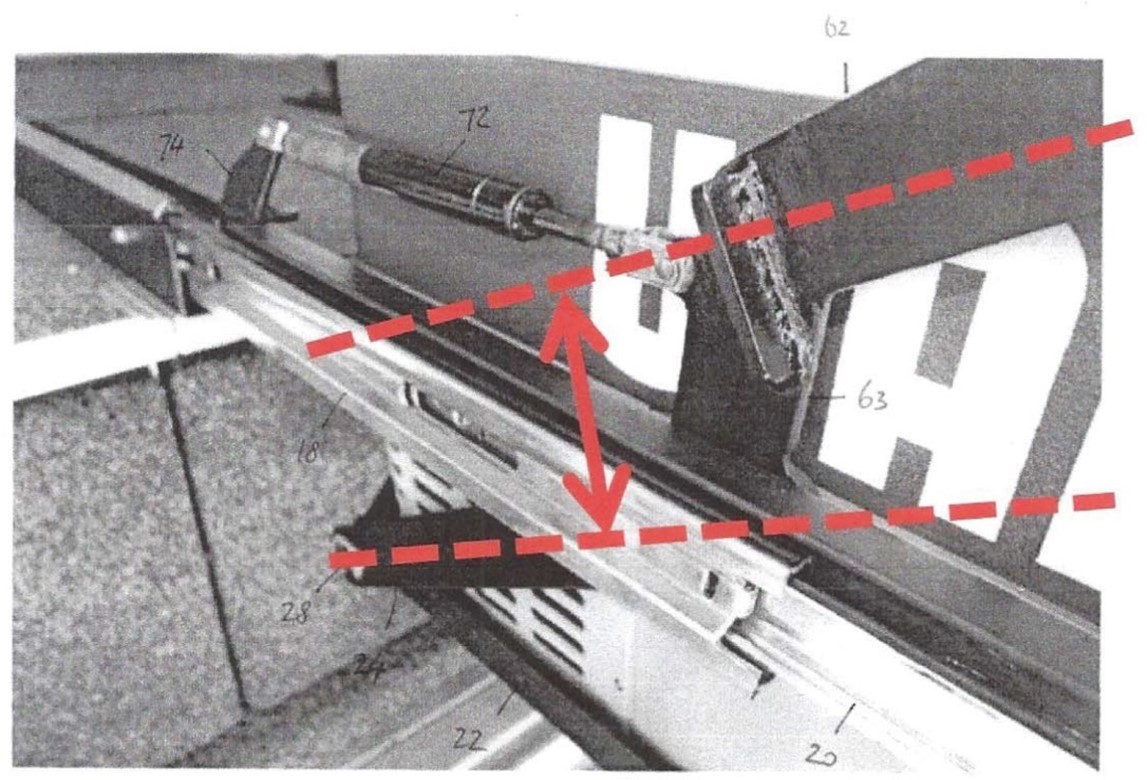
[374] | |
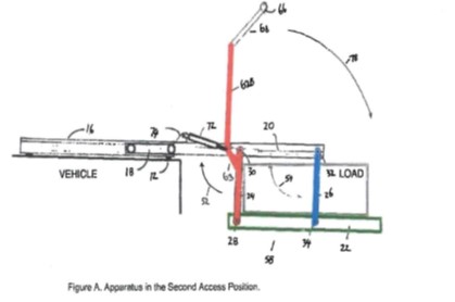
[383] | |
[383] | |
[387] | |
[387] | |
11.3.2.2 Whether representations were misleading or deceptive | [401] |
[403] | |
[404] | |
[405] |
DOWNES J:
1 This proceeding concerns Australian Patent No. 2009245888, which is directed to an apparatus for storing or holding items, particularly in vehicles and more particularly, for storing accessories typically used by off-road enthusiasts and tradesmen. Mr Shane Miles is the owner of the Patent, and the first applicant (MSA) is the exclusive licensee. On the first day of trial, Mr Miles was removed as the second respondent and joined as the second applicant on certain conditions.
2 The Patent claims an earliest priority date of 22 October 2007 (priority date). The application for the Patent was a divisional application of Australian Standard Patent Application No. 2007229415 filed on 22 October 2007. The version of the Patents Act 1990 (Cth) that applies to the Patent is that which appears in the compilation prepared on 27 March 2007.
3 Construction issues arise in relation to three terms in the claims of the Patent. These are: (a) “pivotally connected”, (b) “offset lever” and (c) “connected to” (disputed terms).
4 If MSA’s construction of “connected to” in the claims is accepted, then Clearview contends that the relevant claims are not fairly based because they travel beyond the invention disclosed in the Patent.
5 MSA alleges that the supply by the respondent/cross-claimant (Clearview) of its product infringes claims 1, 5, 6, 7, 8, 9, 10, 11, 12 and 15 of the Patent (the relevant claims). That product is called the Clearview Easy Slide.
6 Clearview denies infringement and alleges that claims 1, 8, 9, 10, 11, 12 and 15 are invalid for want of novelty, contending that:
(1) these claims lack novelty in light of United States Patent 6,019,567 (Lutkus);
(2) (if the construction of the disputed terms is found to be as posited by MSA), then these claims lack novelty in light of:
(a) German Patent Application Publication DE19606196A1 (Thomas);
(b) German Patent Application Publication DE19938727A1 (Dieter).
7 Clearview also contends that claims 1, 5, 6, 7, 8, 9, 10, 11, 12 and 15 lack an inventive step in light of the common general knowledge, or the common general knowledge together with Lutkus.
8 Clearview also alleges that Mr Miles and MSA have made unjustified threats in contravention of s 128 of the Patents Act and engaged in misleading or deceptive conduct in contravention of s 18 of the Australian Consumer Law, being Schedule 2 to the Competition and Consumer Act 2010 (Cth) (ACL).
9 For the reasons which follow, the claim for infringement has failed which has the consequence that the claim brought by MSA should be dismissed.
10 As to the cross-claim brought by Clearview, the attacks on the validity of the Patent have failed but I have accepted that MSA and Mr Miles made unjustified threats within the meaning of s 128 of the Patents Act in relation to a letter from their solicitors, and that MSA made an unjustified threat in contravention of that section in relation to an announcement. I have also accepted that MSA engaged in misleading or deceptive conduct in contravention of s 18 of the ACL, and that Mr Miles was knowingly involved in such conduct. Declaratory and injunctive relief will be the subject of orders to be made shortly after these reasons are published and after conferral by the parties. However, by reason of an order of Greenwood J dated 5 March 2021, issues concerning the quantum of any damages award will require determination at a further hearing. The cross-claim should otherwise be dismissed.
11 I will order the parties to confer with a view to drafting a form of order giving effect to my findings and draft directions in relation to the further hearing.
12 Additionally, the parties should have leave to appeal and, if necessary, leave to cross-appeal.
2. WITNESSES CALLED BY THE PARTIES
13 Dr Bruce William Field is a mechanical engineer, consultant and retired academic in the field of mechanical engineering, a subject in which he has a PhD. Since before 1990, Dr Field has worked primarily as a full-time academic. Between this time and the priority date, his role also included teaching with some research work and consulting work. Dr Field affirmed four affidavits in the proceeding dated 17 November 2021, 23 March 2022, 6 May 2022 and 9 June 2022.
14 My general perception was that Dr Field’s evidence was heavily influenced by his academic experience, and by reliance on abstract and theoretical concepts. I expand on this further below.
15 Mr Michael Simonetti was (and remains) an expert in digital marketing and advertising as at the priority date. Mr Simonetti is the founder of AndMine, a digital agency assisting clients with online marketing and advertising. Mr Simonetti swore two affidavits dated 23 March 2022 and 12 May 2023.
16 Ms Suzanne Madar, solicitor at King & Wood Mallesons, affirmed three affidavits in this proceeding, dated 17 November 2021, 22 March 2022 and 5 May 2023. Ms Madar was not cross-examined.
2.2 Witnesses called by Clearview
17 Mr William Hunter is a consulting engineer with Masters level qualifications in mechanical engineering. Mr Hunter has more than 30 years of experience in developing and designing industrial products. Mr Hunter affirmed three affidavits in the proceeding dated 17 November 2021, 22 March 2022 and 13 May 2022.
18 Mr Rodney Cruise is a patent attorney, with more than 33 years of experience in patent searching. As at the priority date, and for at least seven years prior to 2007, the majority of Mr Cruise’s work related to patent and literature searching. Mr Cruise affirmed three affidavits in the proceeding dated 17 November 2021, 13 May 2022 and 9 May 2023.
19 Mr Graeme Chapman, Project Engineer for Clearview, affirmed one affidavit dated 19 November 2021, regarding the development of the Clearview Easy Slide from the Black Widow Easy Slide. Mr Chapman was not cross-examined.
20 Ms Robynne Sanders, solicitor at DLA Piper, affirmed three affidavits dated 17 November 2021, 8 May 2023 and 9 May 2023. Ms Sanders was not cross-examined.
21 Mr Kenneth Stewart is a German to English translator who affirmed one affidavit dated 12 October 2021 annexing his translation of Dieter and Thomas from the original German documents. Mr Stewart was not cross-examined and MSA did not dispute the accuracy of these translations.
22 Dr Field and Mr Hunter prepared a joint expert report which was filed on 9 March 2023 (JER).
23 The person skilled in the art is the hypothetical person to whom the patent specification is addressed and who, generally speaking, works in the art or science with which the invention is connected: see, e.g., Root Quality Pty Ltd v Root Control Technologies Pty Ltd (2000) 49 IPR 225; [2000] FCA 980 (Finkelstein J) at [70]–[71]. It is not a reference to a specific person but is a legal construct or notional person who may have an interest in using the products or methods of the invention, making the products of the invention, or making products used to carry out the methods of the invention either alone or in collaboration with others having such an interest: Aristocrat Technologies Australia Pty Ltd v Konami Australia Pty Ltd (2015) 114 IPR 28; [2015] FCA 735 (Nicholas J) at [26]; Hanwha Solutions Corporation v REC Solar Pte Ltd [2023] FCA 1017 (Burley J) at [86].
24 In this case, the person skilled in the art is someone with expertise in and knowledge of mechanical engineering. There was no dispute in this case that both experts had such expertise.
25 The title of the Patent is “Apparatus for Storing or Holding Items”.
26 The Field of the Invention states that “[t]he present invention relates to an apparatus for storing or holding one or more items.”
27 The Background to the Invention describes known storage systems used in four-wheel drives and commercial vehicles, such as sliding drawers or other sliding arrangements, as follows:
Four-wheel drive and off-road enthusiasts frequently undertake lengthy journeys into wilderness areas. In order to provide for the necessities of life during such journeys, it is common for four [sic] drives and off-road enthusiasts to fit their vehicles with appropriate storage systems and refrigerators. Tradesmen often have to carry many tools in their vehicles and frequently use large tool boxes.
One common storage system fitted to four wheel drive and commercial vehicles includes sliding drawers mounted to the luggage compartment of four wheel drive vehicles. The sliding drawers typically have a common top surface that provides a further surface for storing further items. It will be understood that the top surface is positioned at a height above the height of the floor of the luggage compartment of the vehicle.
Refrigerators and tool boxes that are used by four-wheel-drive and off-road enthusiasts (which are typically called "car refrigerators" or “car fridges”) or tradesmen typically have a lid that pivots upwardly about a top edge thereof. In order to provide access to such refrigerators or tool boxes, they may be mounted on a sliding arrangement that itself is mounted to the common top surface of the storage drawers. In order to store the fridge or tool box, the sliding arrangement is slid into the vehicle such that the refrigerator or tool box sits over the top surface of the storage drawers. In order to access the refrigerator or tool box, it is slid outwardly so that the sliding arrangement is extended and the refrigerator or tool box extends out of the luggage compartment of the vehicle.
28 It also states that, throughout the specification, the term “comprising” and its grammatical equivalents shall be taken to have any inclusive meaning unless the context of use clearly indicates otherwise.
29 The specification then provides a Brief Description of the Invention, and states that it is an object of the present invention to provide an apparatus that provides an improvement over the prior art devices mentioned above, or at least provides a commercial alternative.
30 The specification goes on to describe aspects of the invention commencing at page 2 line 5. It states that:
In a first aspect, the present invention provides an apparatus for storing one or more items, the apparatus comprising a first part adapted to be mounted to a surface or a wall and a second part mounted to the first part, the second part adapted to store or hold one or more items, wherein the second part is movable relative to the first part such that the second part can be moved from a storage position to a first access position at which the second part is at one level, the second part being movable from the first access position to a second access position, the second access position being located at a lower level than the first access position.
31 The specification then progressively informs the reader of the componentry to be used in performing the invention.
32 For example, on page 2, the specification states:
In one embodiment, the second part slidably moves from the storage position to the first access position (and vice versa). When in the storage position, the second part may at least partially overlie the first part. In some embodiments, when in the storage position, the second part may be positioned at essentially the same level as the first part.
33 The concepts of “sliding mechanism” and “linkage arrangement” or “linkage mechanism” are introduced from page 2 line 17 as follows:
In some embodiments, the apparatus is provided with a sliding mechanism that can slidably move relative to the first part, the apparatus further including a linkage arrangement mounted to the sliding mechanism, the linkage mechanism mounting the second part to the sliding mechanism, the linkage mechanism operative to move the second part between the first access position and the second access position.
34 On page 2 commencing at line 23, the specification identifies that the first part, in one embodiment, may comprise opposed rails or sliding guides which are mounted to a surface or wall. One alternative which is stated is that “the opposed rails or sliding guides may be provided with attachment means for mounting to a surface. For example, the attachment means may comprise a strip of adhesive or adhesive tape”.
35 On page 3 commencing at line 3, by reference to another embodiment, it is stated that:
The second part may comprise a support frame. Alternatively, the second part may comprise a platform. In either case, the second part is adapted to support one or more items are thereon. For example, the second part may support a small refrigerator, such as a refrigerator commonly used in four-wheel-drive vehicles. It will be appreciated that the second part may provide support for a number of other items and that the present invention should not be considered to be limited solely to use in supporting small refrigerators.
36 The specification also refers to “actuating means”, “offset lever”, “biasing means” and “pivotally connected”. Such references appear in the specification commencing at page 3 line 10 as follows:
The apparatus may further comprise actuating means for moving the second part from the first access position to the second access position. The actuating means may comprise, for example, an offset lever connected to one or more linkages. Moving the lever, such as by rotating the lever upwardly or downwardly, causes the linkages to rotate and causes the second part to move between the first and second access positions. A biasing means, such as a spring, hydraulic cylinder, gas strut or the like, may be used to assist in moving the second part between the first access position and the second access position. A handle may be pivotally connected to the offset lever to facilitate movement of the offset lever.
Preferably movement from the first access position to the second access position comprises simultaneous vertical and horizontal movement. Even more preferably the second part extends further from the first part as it is lowered. Preferably the one or more items are maintained substantially level (i.e. not tilted or angled) when being moved from the storage position to the first access position, and also from the first access position to the second access position. The second part, or at least a portion of the second part, may by [sic] extendable in the second access position.
Preferably the second part is mounted to a mechanism that is adapted to lower the second part from the first access position to the second access position. The mechanism preferably moves/slides with the second part from the storage position to the first access position, and is actuated to move the second part from the first access position to the second access position…
37 Reference is made to the storage position commencing at page 4 line 3 as follows:
In the storage position the first part, second part, and mechanism are preferably adjacent and, even more preferably generally flat. If the second part is holding one or more items, it preferably holds those items from below, or at least at or near a lower region of the item.
38 A second embodiment is described at page 4 of the specification commencing at line 12:
In a second embodiment, the present invention provides an apparatus for storing a car fridge or a tool box in or on a vehicle, the apparatus comprising a base or frame adapted to be mounted in or on the vehicle, a sliding arrangement fixed to the base or frame, the sliding arrangement being slidably movable between a retracted position and an extended position, and a support platform being mounted to the sliding arrangement wherein the support platform is mounted to the sliding arrangement such that when the sliding arrangement is in the extended position, the support platform is movable between a first height that is at essentially the same height as the sliding arrangement and a second height that is lower than a height of the sliding arrangement. Preferably, the second height is lower than the level of the base or frame.
In another aspect, the present invention provides a storage device in which the first access position is lower than the second access position. This provides for easier access in situations where the first part is mounted at a low level.
There may be provided an apparatus for storing a car fridge or a tool box in a vehicle, the apparatus comprising a base or frame mounted in the vehicle, a sliding arrangement fixed to the base or frame, the sliding arrangement being slidably movable between a retracted position and an extended position, and a support platform being mounted to the sliding arrangement wherein the support platform is mounted to the sliding arrangement such that when the sliding arrangement is in the extended position, the support platform is movable between a first height that is at essentially the same height as the sliding arrangement and a second height that is higher than a height of the sliding arrangement.
In a further aspect, the present invention provides an apparatus for storing one or more items, the apparatus comprising a first part adapted to be mounted to a surface or a wall and a second part mounted to the first part, the second part adapted to store or hold one or more items, wherein the second part is movable relative to the first part such that the second part can be moved from a storage position to a first access position at which the second part is at one level, the second part being movable from the first access position to a second access position, the second access position being located at a higher level than the first access position.
39 On page 5, lines 11–25, there is described “another aspect” of the invention, in identical terms to claim 1 (being the first independent claim).
40 The specification then contains a further consistory clause commencing on page 5 at line 27, which is in the same terms as claim 15 (being the second independent claim):
In another aspect, the present invention provides an apparatus for storing a car fridge or a tool box in or on a vehicle, the apparatus comprising a base or frame adapted to be mounted in or on the vehicle, a sliding arrangement fixed to the base or frame, the sliding arrangement being slidably movable between a retracted position and an extended position, and a support platform being mounted to the sliding arrangement wherein the support platform is mounted to the sliding arrangement by a linkage arrangement including at least one arm pivotally connected at or near one end to the sliding mechanism and pivotally connected at or near another end to the support platform, and an offset lever connected to at least one of the at least one arm such that when the sliding arrangement is in the extended position, the support platform is movable between a first height that is at essentially the same height as the sliding arrangement and a second height that is lower than a height of the sliding arrangement by moving the offset lever.
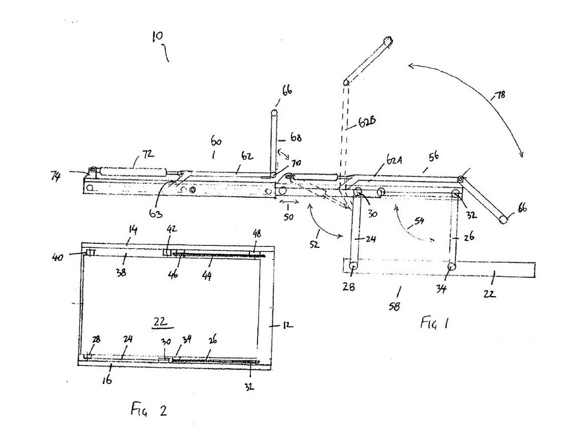
41 There is then a brief description of the drawings, which includes five drawings of the same embodiment of the invention (Figures 1 to 5). Figures 1 and 2 are reproduced below:
42 Figures 6 to 10 are photographs of the apparatus shown in Figure 1 moving from the first access position to the second access position.
43 At page 8, lines 10–25, the linkage arrangement of the invention is described as follows:
As shown in figures 1 to 5, the support platform 22 is mounted to the sliding arrangement by use of two pivoted linkage arms on either side of the support platform. For example, referring to figure 1, linkage arms 24, 26 are mounted to one side of the platform. Similarly, two other linkage arms are mounted to the other side of the support platform 22. As best shown in figure 5, linkage arm 24 is pivotally mounted as one end to a pin 28. Pin 28, in turn, is mounted to the support platform 22. The linkage arm 24 is pivotally mounted at its other end to a pin 30. Pin 30 is, in turn, mounted to the innermost sliding member 20.
The other linkage arms are mounted to the platform and sliding arrangement in a similar fashion. For example, as shown in figure 1, linkage arm 26 is mounted to the sliding arrangement via pin 32. The other end of linkage 26 is pivotally mounted to the support frame 22 by pin 34. Similarly, on the other side of support platform 22, linkage arm 38 is pivotally mounted at one end to the platform by pin 40 and is pivotally mounted at the other end to the sliding arrangement by pin 42. Linkage arm 44 is pivotally mounted at one end to platform [sic] by pin 46 and pivotally mounted at the other end to the sliding arrangement by pin 48.
44 At page 9, lines 4–23, there is a description of how the platform is moved between the first and second access position in the following terms:
…the apparatus is further provided with an actuating means 60. The actuating means 60 comprises an offset lever 62 having an offset portion 63 that is mounted to linkage arm 24. This may be achieved, for example, by welding the end of offset portion 63 to the linkage arm 24. A handle 66 is connected via pivoting arm 68 to the offset lever 62. A pin 70 is used to connect the pivoting arm 68 to the offset lever 62. A gas strut 72 is also provided. Gas strut 72 is connected at one end via bracket 74 to the sliding mechanism to which the platform 22 is connected. The other end of gas strut 72 is connected to the offset lever 62. As is shown in figure 1, as the platform 22 moves between the first access position 56 and the second access position 58, the gas strut extends to thereby ease lowering and raising of the platform 22.
…
In order to lower the platform 22 from the first access position 56 to the second access position 58, the handle 66 is grasped by a user and swung upwardly. This causes the offset lever 62 to move from the position 62A (see figure 1) to the position 62B (shown in figure 1 in dotted outline). As the end of the offset portion 63 of offset lever 62 is mounted to the linkage arm 24, moving the offset lever as described above (and as shown by reference to arrow 78) causes the linkage arm 24 to pivot downwardly. This also causes the linkage arm 26 to pivot downwardly. The support platform also moved downwardly.
45 At page 11, lines 1–9, it is stated that:
The present invention provides an apparatus that allows for storage of one or more items in the storage position. For ease of access, the apparatus allows the second part to be moved to a first access position. The first access position is normally located outwardly from the storage position so that easier access is provided. The first access position is normally at essentially the same vertical height as the storage position. If the first access position is inconveniently or uncomfortably high, the second part of the apparatus can be moved from the first access position to the second access position. As the second access position is located at a lower level than the first access position, easier access may be obtained.
46 At page 11, lines 10 to 19, the specification states that the invention may be susceptible to variations and modifications other than those specifically described and then provides several examples of modifications but does not suggest any modification to the linkage arrangement, the arrangement of the offset lever, or the way in which the offset lever is positioned and interacts with other components of the apparatus. This passage includes the statement that, “Although a support platform is shown in the embodiments…, it will be appreciated that an item to be stored or held by the apparatus may be directly connected to the linkage arms”.
47 The Patent concludes with 20 claims, of which the relevant claims are asserted to be infringed.
48 The relevant claims are set out below, with claims 1, 5, 6 and 15 broken down into their integers for convenience.
49 As to Claim 1:
50 As to Claim 5:
|
|
|
|
51 As to Claim 6:
|
|
|
|
|
|
52 Claims 7 to 12 are set out below:
|
|
|
|
|
|
|
|
|
|
|
|
53 As to Claim 15:
|
|
|
|
|
|
|
|
|
|
|
|
|
|
|
|
|
|
|
|
54 As already observed, the disputed terms appear in claims 1 and 15, and are: (a) “pivotally connected”, (b) “offset lever” and (c) “offset lever connected to at least one of the at least one or more arms” (claim 1) or “offset lever connected to at least one of the at least one arm” (claim 15) (emphasis added).
55 A further issue arose following the preparation of the JER in connection with the construction of integers 1.6 and 1.7 which, in combination, state that “one or more arms pivotally connected at or near one end to the sliding mechanism and pivotally connected at or near another end to the second part”. That issue will also be addressed.
5.2 Principles on construction
56 The principles applicable to patent claim construction are well-settled and were not in dispute. In Jupiters Ltd v Neurizon Pty Ltd (2005) 65 IPR 86; [2005] FCAFC 90 (Hill, Finn and Gyles JJ) at [67], the Full Court summarised the principles for the construction of patents as follows:
(1) the proper construction of a patent specification is a matter of law: Décor Corporation Pty Ltd v Dart Industries Inc (1988) 13 IPR 385 (Sheppard J) at page 400;
(2) a patent specification should be given a purposive, not a purely literal, construction: Flexible Steel Lacing Company v Beltreco Ltd (2000) 49 IPR 331; [2000] FCA 890 (Hely J) at [81]; and it is not to be read in the abstract but is to be construed in the light of the common general knowledge and the art before the priority date: Kimberly-Clark Australia Pty Limited v Arico Trading International Pty Limited (2001) 207 CLR 1; [2001] HCA 8 (Gleeson CJ, McHugh, Gummow, Hayne and Callinan JJ) at [24];
(3) the words used in a specification are to be given the meaning which a normal person skilled in the art would attach to them, having regard to his or her own general knowledge and to what is disclosed in the body of the specification: Décor Corporation at page 391;
(4) while the claims are to be construed in the context of the specification as a whole, it is not legitimate to narrow or expand the boundaries of monopoly as fixed by the words of a claim by adding to those words glosses drawn from other parts of the specification, although terms in the claim which are unclear may be defined by reference to the body of the specification: Kimberly-Clark at [15]; Welch Perrin & Co Pty Ltd v Worrel (1961) 106 CLR 588 (Dixon CJ, Kitto and Windeyer JJ) at page 610;
(5) the body of a specification cannot be used to change a clear claim for one subject matter into a claim for another and different subject matter: Electric & Musical Industries Ltd v Lissen Ltd [1938] 4 All ER 221; (1939) 56 RPC 23 at page 39;
(6) experts can give evidence on the meaning which those skilled in the art would give to technical or scientific terms and phrases and on unusual or special meanings to be given by skilled addressees to words which might otherwise bear their ordinary meaning: Sartas No 1 Pty Ltd v Koukourou & Partners Pty Ltd (1994) 30 IPR 479 (Gummow J) at pages 485–486;
(7) the Court is to place itself in the position of some person acquainted with the surrounding circumstances as to the state of the art and manufacture at the time: Kimberly-Clark at [24]; and
(8) it is for the Court, not for any witness however expert, to construe the specification: Sartas No 1 at pages 485–486.
57 This decision, and these principles, were cited with approval in Reflex Instruments Asia Pacific Pty Ltd v Globaltech Corporation Pty Ltd [2023] FCAFC 158 (Moshinsky, Burley and Kennett JJ) at [75].
5.3 Issue 1: meaning of “pivotally connected”
5.3.1 The competing contentions
58 The first disputed term appears in integer 1.6 and integer 15.7, namely “one or more arms pivotally connected at or near one end to the sliding mechanism” (emphasis added). It also appears in integers 1.7 and 15.8.
59 MSA submits that a pivotal connection is one in which the connection between components is rotational so as to allow one component to rotate with respect to the other around a point or axis, and that the point of rotation does not need to be fixed.
60 Clearview submits that “pivotally connected” refers to a connection between two components that permits only rotational movement of the components relative to one another.
61 The expert evidence indicated that the term “pivotally connected” has (and had as at the priority date) a technical meaning for skilled addressees. It is therefore necessary to have regard to this technical meaning: see Product Management Group Pty Ltd v Blue Gentian LLC (2015) 240 FCR 85; [2015] FCAFC 179 (Kenny and Beach JJ) at [36].
62 The experts were asked by senior counsel for MSA to explain their understanding of this term during the concurrent evidence session.
63 Dr Field’s response was as follows:
DR FIELD: Pivotally connected, to me, means connected as in not able to come apart in a way that has a rotation that is either a pivot or a rotation that could be or is equivalent to having a pivot. Rotations can occur around a pivot, such as the hinge pin in an ordinary door hinge. But rotations can occur because of the way mechanisms are arranged to cause a rotation or to allow a rotation about a point which isn’t an actual object. For example, a train going around a curve is pivotally connected to the ground, even though there is no pivot in the middle of the curve. It’s - - -
HER HONOUR: Sorry. It’s connected to the ground? Is that what you said?
DR FIELD: Yes. Pivoted relative to the ground.
HER HONOUR: Relative.
DR FIELD: Everything is relative. Kitchen cabinet doors open and shut without having a hinge pin. They have a mechanism which makes it pivot, but not on a pin or on an axle. So that’s what I mean by pivotally connected. Literally, with a pin, an axle, or as if on a pin as created by the mechanism design itself.
64 Mr Hunter’s response was as follows:
MR HUNTER: … So, in my view, pivotally connected simply means that, at the connection point, one component can only rotate with respect to the other component. So only rotate. And that’s consistent with the way in which the term “pivotally connected” is used in patent specification. In each and every instance, the way in which pivotally connected is described is that a pivot occurs at a pinned connection, and that pinned connection is a location at which only rotation is possible. So, for example, page 8, lines 15 to 17 of the patent:
The linkage arm 24 is pivotally mounted at its other end to pin 30. Pin 30 is, in turn, mounted to the inner most lighting member.
So that’s an example of that type of connection.
(Emphasis original.)
65 While Mr Hunter accepted that there are other ways of creating pivotal connections which did not involve a pinned connection (that is, the pivot point fixed at a particular location), he maintained that “pivotally connected” as explained in the specification of the Patent is, in all cases, a pinned connection and that a pinned connection is a connection where only rotation can occur. Mr Hunter further explained during the hearing:
[I have] from my engineering training an understanding of what a revolute joint is, which is a joint which is – allows – is a pivotal connection that allows one degree of motion only, which is rotation, and I read a patent specification and I’m trying to understand pivotal connection from claim 1 in the context of the patent specification, and in every instance, the patent specification provides me with examples of pivotal connection which confirm my understanding of what a pivotal connection is, ie, one degree of freedom, meaning rotation, why would I be taken to some other idea for pivotal connection in claim 1?
66 As to this, Dr Field said that a pivot point did not need to be fixed at a particular location – that broader view, he said, arose from specific teaching and design experience he had with various components including hidden hinges, linkages that have a rotational point that is not a hinge pin, ligamentous type joints, flexure joints, and a reclining mechanism in a wheelchair, which had a “virtual pivot”.
67 However, it was also Dr Field’s evidence that there was nothing in the Patent which suggested “directly” to him that the pivot (in the context of “pivotally connected”) was of the kind that did not need to be fixed at a particular location. I can find no such suggestion either. This tends to support the construction posited by Mr Hunter.
68 Leaving aside the issue of whether a fixed or pinned connection is required, Dr Field maintained the view that “pivotally connected” encompassed a connection which allowed rotation as well as other degrees of motion, such as a sliding motion.
69 Mr Hunter distinguished a pivotal connection from a sliding connection (which he considered to be a different type of connection), such that, even if the sliding connection had rotational movement, the connection would no longer (in engineering terms) be referred to as a pivotal connection.
70 Dr Field did not like the expression “sliding connection” as used by Mr Hunter and expressed the view that it was “confusing” and “not useful” to use the same word, being “sliding”, for a connection that allowed for both rotation and sliding movement, because it would involve the same word being used for two types of connection.
71 It is difficult to reconcile this stance with Dr Field’s view as to the meaning of “pivotally connected” which, on his evidence, requires the same word “pivotally” to encompass both a pivotal connection, and a pivotal and sliding connection. This is especially as, during the view of the Clearview Easy Slide (which occurred in the court room with these experts and was filmed), Dr Field again emphasised the importance of precision in names:
I accept that Mr Hunter and I have different backgrounds and therefore have different ways of approaching the terminology. I have, I think, more background than he – I’m not trying to one-up – about design of mechanisms. So I would tend to use more specific descriptions than perhaps he. So it’s not a matter of right or wrong. But, as far as I’m concerned, if this has got dual movement, sliding and pivoting, it doesn’t help to describe it as a sliding connector because over here we have another sliding connector when the device moves in and out, so if that’s a sliding connector, this is sliding and pivoting, it deserves a separate name. So I call it a sliding pivot to distinguish it from a straight slider. I think Mr Hunter is calling them both sliders and that, to me, isn’t useful.
(Emphasis added.)
72 Self-evidently, the descriptor “sliding pivot”, which encompasses both pivotal and sliding movements, is more precise than describing a connection as “pivotally connected” or as a pivotal connection, if the latter is intended to encompass a sliding movement as well.
73 Yet the claims do not use the term “sliding pivot”. They use the term “pivotally connected” and there is no disclosure or even suggestion in the claims or the specification of a connection which involves a sliding pivot. Based on Dr Field’s evidence that precision in names is important (which evidence makes sense in the context of the type of skilled addressee in this case to whom the Patent is addressed), this tends against a construction of “pivotally connected” as encompassing a sliding movement (for example) or any movement other than rotation.
74 This is supported by the fact that Dr Field accepted (quite correctly) that the consequence of his approach to “pivotally connected” would allow for what he referred to as a “sliding pivot” (being a term not used in the Patent) to be placed at all four pivot points of the parallelogram linkage arrangement in the Patent, that is, at points 28, 30, 32 and 34 as seen in Figure 1. He conceded that if this occurred, there would be too many degrees of freedom to maintain the platform substantially level, as referred to at page 3 of the specification, unless other links were added. The addition of such further links is not addressed anywhere in the Patent, but they would be required. These matters also tend against the construction of “pivotally connected” in the claims as encompassing a sliding movement (for example) or any movement other than rotation.
75 Dr Field also accepted (and I agree) that the invention in the Patent is a relatively simple mechanical invention. Yet, on occasion, he appeared to take an overly complicated and technical approach to construction of the claims. This was demonstrated by (for example) his view that the relevant axis of rotation in a pivotal connection could be a “virtual centre of rotation” or an “instantaneous centre” (which required an understanding of complex vector mechanics). By contrast, Mr Hunter explained that the concept of “instantaneous centre” was not widely understood or practised in mechanical engineering, and that he would have to resort to textbooks to understand what an “instantaneous centre” was, and how it was calculated. These matters tend to support a conclusion that a person skilled in the art as at the priority date would approach the construction of the term “pivotally connected” in the claims in the way that Mr Hunter did, without the need to resort to complex engineering concepts which require resort to be had to academic texts. This is especially having regard to the nature of the invention and the content of the specification (which includes hand-drawn figures and a reference to using adhesive tape as an attachment at page 2, line 31 of the specification).
76 I have indicated above that, for various reasons, I prefer Mr Hunter’s construction in preference to Dr Field’s construction although that is not, of course, decisive. I turn then to the arguments advanced by the parties, in particular those of MSA.
77 Both sides relied upon the dictionary definition of “pivot”, and MSA also relied upon the dictionary definition of “pivotally”. That was so even though they also called experts who were united that the meaning to be ascribed to “pivotally connected” would be interpreted by mechanical engineers in a way which went beyond the English meaning of the words. It follows that the dictionary definitions proffered by the parties do not provide much, if any, assistance in a determination of the meaning that a skilled addressee would give to “pivotally connected” in the claims as at the priority date, having regard to his or her own general knowledge and to what is disclosed in the body of the specification.
78 MSA’s posited construction, relying upon aspects of Dr Field’s evidence, appeared to be focused on an abstract debate about the meaning of the words “pivotally connected”, rather than the meaning of those words in the claims. Further, my impression was that its arguments tended to move away from the manner in which the term would be understood by a skilled addressee and were more focused on ensuring that the term would be construed in a way which had the consequence that the Clearview Easy Slide (which has a sliding pivot) would be regarded as having infringed the Patent.
79 Further, MSA’s submissions did not grapple with the following, each of which told against MSA’s contended construction:
(1) the lack of any disclosure in the Patent of a pivotal connection between the components identified in the integers in question and which included any kind of movement other than, or in addition to, a rotational one;
(2) the fact that the claims use the term “pivotally connected” and not “sliding pivot”, remembering that (according to Dr Field) the use of the precise term is important. That precision is required makes sense – the Patent is addressed to a person skilled in the art, the term “pivotally connected” has a technical meaning to those skilled in the art and the invention is for a mechanical device;
(3) the fact that, if a sliding pivot was used at each of the four “pivotal connections” in the device, this would render the device uncontrollable in the absence of other links or constraints in the device to control motion. However, such arrangements are not contemplated in the Patent. As to this, a construction according to which the invention will work is to be preferred to one in which it may not: see Blue Gentian at [39];
(4) the fact that the invention in the Patent is for a relatively simple mechanical device such that it would not be expected that a skilled addressee would be required to have an understanding of complex vector mechanics.
80 By contrast to the inconsistencies in Dr Field’s evidence, Mr Hunter’s evidence remained consistent that a pivotal connection (which he also referred to as a revolute joint) was a connection that had only one degree of freedom, that is, it allowed only rotational motion. As submitted by Clearview, that construction is also consistent with: (a) the manner in which a skilled person would understand the term in the context of a mechanical apparatus, and (b) the way that the term is used throughout the Patent.
81 It is therefore not correct to say, as MSA does, that Mr Hunter or Clearview are impermissibly restricting the meaning to be given to the term “pivotally connected” in the claims because of what is disclosed in the specification. That is because Mr Hunter’s position was that “pivotally connected” has a particular meaning which a normal person skilled in the art would attach to that term apart from the disclosure in the specification and that there is no disclosure in the Patent of anything which indicates to him that a different meaning should be given to that term. In other words, the meaning given by Mr Hunter to the term is not narrowed by the disclosure in the specification – rather, it is confirmed by what is disclosed in the specification.
82 When one looks at the specification, it is apparent that Mr Hunter is correct in terms of his description of what is disclosed in the Patent. That is because the specification refers repeatedly and in simple terms to a sliding movement when that is intended (such as “sliding mechanism that can slidably move” or “mechanism preferably moves/slides with the second part”) whereas in the case of connections in the linkage arrangement of the kind described in integers 1.6/1.7 and 15.7/15.8, there is no suggestion that these connections have anything other than a pivotal (i.e. rotational) movement. In particular, notwithstanding that the apparatus in claims 1 and 15 are defined by what they “comprise” and that this term is defined as being inclusive, the specification does not disclose the construction of an apparatus which has pivotal connections of a type which is something other than that which would be understood by the notional skilled addressee by reference to that term (i.e. rotational).
83 For these reasons, I accept Clearview’s construction as to the meaning of “pivotally connected” in claims 1 and 15. That is, I find that “pivotally connected” in the claims refers to a connection between two components that permits only rotational movement of the components relative to one another.
5.4 Issue 2: meaning of “offset lever”
5.4.1 The competing contentions
84 The second disputed term “offset lever” appears in integers 1.8, 1.11, 15.9 and 15.10.
85 Both experts agreed that the term “offset lever” is not a term of art in mechanical engineering.
86 MSA submits that:
(1) an offset lever is a lever that is modified by a geometric offset in its shape, which construction is based on the ordinary meaning of its two components, both being ordinary English words: “offset” and “lever”;
(2) in the context of “Machinery”, the word “offset” is defined in the Macquarie Dictionary (8th ed, 2020) as “a more or less abrupt bend in a pipe, bar, rod, or the like, to serve some particular purpose” and in the Concise Oxford English Dictionary (12th ed, 2011) as “a bend in a pipe etc. to carry it past an obstacle”;
(3) a lever is “a bar or rigid piece acted upon at different points by two forces, as a voluntarily applied force (the power) and a resisting force (the weight), which generally tend to rotate it in opposite directions about a fixed axis or support (the fulcrum)”: Macquarie Dictionary (8th ed, 2020);
(4) its construction is consistent with the specification and points to the exemplary embodiment, in which the offset portion (63) is a bend in the offset lever.
87 Clearview submits that:
(1) the term “offset” in a mechanical device means that one component is spaced apart from, or set to the side of, another component (relying upon Mr Hunter’s evidence);
(2) the term “lever” means a solid component which has a rotational point and is capable of transmitting torque or leverage (relying upon Dr Field’s evidence, with which Mr Hunter agreed);
(3) by itself, the term “offset lever” does not identify what the lever is offset from, and its meaning is not apparent from the claims alone. It submits that, as such, a skilled person would look to the specification to assist their understanding of the term in the context of the Patent and would not attempt to understand the term “offset lever” by hybridising one dictionary definition of “offset” and one dictionary definition of “lever”;
(4) an offset lever in the claims is a lever having a centre line that is offset (that is, spaced apart) in the plane of operation of the mechanism from the centre line of one of the linkage arms to which it is connected.
88 In his first affidavit, Mr Hunter stated at [48]–[53]:
I am familiar with the term “offset” as this is used in mechanical devices. When used in relation to a mechanical device I understand the term “offset” to mean that the item that is offset is spaced apart, or set to the side, from another component. Therefore, I understand an “offset lever” to mean a lever that is set off to one side or spaced apart from another component. However, the term “offset lever” alone does not tell me what the lever is offset from. Without this information, the term is not clear to me. Therefore, in order to understand this term, I have looked at the remaining language of claim 1 and references to “offset lever” that appear in the specification.
Neither the claims nor the remainder of the specification explain what is meant by an offset lever. The specification also does not explain the purpose of the lever being offset.
Claim 1 states that the “offset lever” is “connected to at least one of the one or more arms”. This suggest [sic] to me that the “offset” in “offset lever” is an offset between the lever and the arm to which it is connected. This understanding of “offset lever” is consistent with the single example of an “offset lever” that is given in the specification. This is described at page 9 lines 5 – 7 of the Patent, which refer to an offset lever 62 having an offset portion 63 which is mounted to linkage arm 24. From this, I understand that it is the offset portion 63 that is responsible for creating the offset in the offset lever 62.
Referring to Figure 1 of the Patent, I can see an offset between offset lever 62 and the linkage arm 24. This is most clearly seen when the offset lever is in its raised position (indicated as item 62B). If I was to draw a centre line through linkage arm 24 and a centre line through the lever arm 62B, those centre lines would be parallel and spaced apart, or set aside, from each other. This relationship between the lever and the linkage arm is consistent with my understanding of an “offset” in a mechanical device.
Similarly, in Figure 7 (extracted below), I see that offset portion 63 causes the centre line of lever 62 (which is marked by a red dashed line) to be spaced apart or set aside from the centre line of linkage arm 24 (also marked by a red dashed line) [sic] The red arrow shows the offset created between these two components.
I therefore understand the term “offset lever” as it is used in the claims to be referring to an active lever that is offset (i.e. set to one side or spaced away) from the component to which it is connected (i.e. the linkage arm).
89 In his second affidavit, Mr Hunter stated at [35]–[39] that:
… [I]n the context of the Patent, I understand that the “offset” refers to something that has a configuration and orientation that is not in line with another thing in the plane of motion of the device, so that it has functional significance in the way in which the device operates.
By way of explanation, a mechanism such as the one disclosed in the Patent can be understood in a two-dimensional plane (notwithstanding that the device itself is three dimensional). This is because the motion of the device only occurs in two dimensions.
The motion of the device described in the Patent is illustrated by reference to drawings such as that shown in Dr Field’s Figure A, which is extracted below. In this drawing, there is no motion of the device in or out of the page. All the motion takes place in the plane of the page. The relevant “offset” in the offset lever is between the lever 62 and the linkage arm 24, which are parallel and offset to each other in the plane of the page.
Handle 66 also has a configuration and orientation that is not in line with the lever 62 (as it extends into the page). However, this is not described by the Patent as being “offset”, and nor do I regard it as being any type of offset that is relevant to the way the device moves and operates. In contrast, the “offset” in the offset lever is between the lever 62 and the linkage arm 24, and provides the function I described in paragraph 35 above.
The function of the offset lever as providing a point of attachment for the gas strut is described at page 9 lines 9 – 13 of the Patent: “A gas strut 72 is also provided. Gas strut 72 is connected at one end via bracket 74 to the sliding mechanism to which the platform 22 is connected. The other end of gas strut 72 is connected to the offset lever 62. As is shown in figure 1, as the platform 22 moves between the first access position 56 and the second access position 58, the gas strut extends to thereby ease lowering and raising of the platform 22.”
(Emphasis original.)
90 In the JER, Mr Hunter reiterated that he interprets “offset lever” to mean a lever which has an offset portion which is spaced apart (in the plane of the mechanism’s operation) from the longitudinal centreline of the lever.
91 Mr Hunter is criticised by MSA for adding the words “in the plane of motion of the device” in his construction of the term in his second affidavit, and for his opinion given in the JER, when those words were not part of his initial definition. Mr Hunter explained his reasons for this during the hearing, which included that Dr Field had a different interpretation (to which he was responding) which “takes us into a different plane other than the two-dimensional plane of operation of the mechanism”. He also explained that he had not volunteered it initially because he considered it to be self-explanatory “because all of the explanation of the way in which the mechanism worked in diagrams was in a two-dimensional sense, as mechanisms are often explained in engineering terms in a 2D planar sense”. Mr Hunter’s explanations for the modification to his initial construction are satisfactory, and MSA’s criticism is misplaced.
92 Mr Hunter also gave the following oral evidence during the concurrent evidence session:
MR FRANKLIN: And I’m suggesting to you that it need not be in a vertical orientation. It could be in a different orientation and still operate.
MR HUNTER: Yes, but the difficulty there, Mr Franklin, is that as a person skilled in the art I’m reading the patent and I’m trying to interpret a term, offset lever, which doesn’t have a general meaning in engineering terms. So the only way I can understand that term is to go into the patent specification and see how the patentee uses that term. Now, [the] patentee uses the term precisely in the manner that you’ve just described, which is that the offset is in the plane of operation of the mechanism. So if that’s what the patentee says that an offset lever is, then that’s what I take the meaning to be. The only – the only explanation which helps is the one embodiment that’s described in the patent. There are no others. So I have no other way of understanding what an offset lever is, other than by referring to that embodiment.
93 Mr Hunter also explained that it was entirely “inappropriate” to construct the meaning of offset lever from a dictionary and said that “engineers reading patent specifications don’t look at every term and look at dictionary definitions. We look at the specification to make sense of things”. When it was pressed upon him that he should have “simply” gone to the dictionary to understand what offset meant, Mr Hunter said this:
Well, you can suggest that to me, but that’s not what I did and that [sic] not what I do when I read patents. If I’m doing things the wrong way, perhaps I should be looking at the dictionary more often. I don’t know, but there are terms which, obviously, when they’re used in patent claims have a common sense easy to understand definition. You don’t need the dictionary even to look them up. But there are also terms which we come across, or I come across in patents which do need to be understood with the specification in mind. This is one of those cases.
94 In his first affidavit, Dr Field identified that a lever is a solid component which has a rotational point and is capable of transmitting torque or leverage. Mr Hunter agreed with this definition.
95 Dr Field’s definition of lever became more expansive in his second affidavit, when he was asked to consider novelty issues relating to prior art. Dr Field described a “lever” to have the following features:
(1) (pivoting about a fulcrum) pivoting movement about an axis (a fulcrum) to provide a force or torque. The fulcrum is located on or near the longitudinal axis of the lever;
(2) (arc of motion) an arc of motion that is less than a full revolution. That is, in engineering, a lever is generally understood to rotate about a fulcrum less than 360 degrees;
(3) (perpendicular force) force components are applied in directions that are perpendicular to the longitudinal axis of the lever; and
(4) (elongation) levers are ordinarily rigid beams elongated in the direction of the axis of the lever.
96 In the JER, Dr Field stated that he interpreted “offset lever” as being one of the formally recognised lever types that has a portion or portions not parallel to the remaining portion, with the apparent principal purpose in the Patent of facilitating compact storage of the device.
97 Dr Field also gave oral evidence that:
…Offset in an engineering context is a physical dimensional measurement. Something is offset from something else... It has a measurement that you can measure in millimetres or metres or kilometres…And when applied to [the lever] it implies a physical distance associated with a lever. The word lever has a technical meaning which, in simple terms, is described as a beam with two forces perpendicular to the beam and [a] fulcrum, a seesaw is a lever in a simple form, or one form.
…As far as I’m concerned, there [are] dual meanings of the – the word offset and the one is that the lever is offset from something else, which is not the lever. It is using the word offset to mean a parallel displacement. A distance from something, is an offset. And the second meaning is the lever isn’t a classic lever, it contains offsets, so it’s no longer, for example, a straight beam, it’s a beam with – with zigzags or folds within it.
…
…That is, offset lever might be a lever with its own offset and offset from something else and still be an offset lever. I can’t exclude the possibility that both offset types apply in any one circumstance.
…
…When I now look at the 888 patent, I can ask does the patent say whether the offset lever is a lever which is offset from something, or is the lever a lever which has offsets in its shape.
And what I see most readily, is a lever with offsets in its shape, in the preferred embodiment. I don’t see anywhere in the general description and the specification, that it is one type or the other. In fact, I think lever or even offset lever are not generally mentioned in the overall. It’s – it’s the offset lever in the specification is used as a preferred way of causing the mechanism to work. So in the preferred embodiment that I see, I do see something which is very close to a first order lever, except that it has a an offset along its length. The two portions of the lever, like the seesaw, has one portion parallel to but not in line with the other, and that is clearly an offset.
98 Claims 1 and 15 do not describe the term “offset lever”. According to Dr Field, there are two possible meanings to be given to the term; however, which of those meanings is to be given to the term is unclear from the claims themselves.
99 As already observed, the claims must be construed in the context of the specification as a whole. As the meaning of the term “offset lever” in the claims is unclear, it is appropriate and indeed necessary to have resort to the specification to obtain an understanding of the meaning of “offset lever” in the claims. Contrary to MSA’s submission, such a course of action does not involve an impermissible use of the embodiment to define or restrict the claim; rather, it involves defining a term in a claim which is unclear by reference to the body of the specification.
100 Turning then to the specification, and other than in the consistory clauses or in the Detailed Description of the Drawings, the only references to “offset lever” appear at page 3 in a passage which commences at line 10:
The apparatus may further comprise actuating means for moving the second part from the first access position to the second access position. The actuating means may comprise, for example, an offset lever connected to one or more linkages. Moving the lever, such as by rotating the lever upwardly or downwardly, causes the linkages to rotate and causes the second part to move between the first and second access positions. A biasing means, such as a spring, hydraulic cylinder, gas strut or the like, may be used to assist in moving the second part between the first access position and the second access position. A handle may be pivotally connected to the offset lever to facilitate movement of the offset lever.
(Emphasis added.)
101 This passage tells the reader very little about why the word “offset” has been added before the word lever, rather than having the word “lever” appear on its own.
102 Because of this, it is necessary to have regard to the Figures in the specification, and to consider how they would be interpreted by the notional skilled addressee.
103 As to this, MSA is critical of an approach which is based on interpreting the apparatus in the Figures in a “2D planar sense” (as Mr Hunter did) but, again, its criticism is misplaced because it fails to grapple with the evidence of Mr Hunter (which Dr Field did not contradict) that mechanisms are often explained in engineering terms in a 2D planar sense. When asked by senior counsel for MSA why the offset portion must be spaced apart in the plane of the mechanisms operation, Mr Hunter gave this evidence:
Because that’s how I understand the mechanism is to be interpreted. That’s how all 2D planar mechanisms like this are interpreted in terms of how they function.
104 As the Patent is directed to a person with expertise in and knowledge of mechanical engineering, I will adopt the same approach (and, indeed, it is necessary that I do so).
105 Further, as Mr Hunter states in the JER, there is no description in the Patent of the offset being applied in any other plane.
106 The Figures depict that the “offset lever” has a centre line that is offset (ie. spaced apart) in the plane of operation of the mechanism from the centre line of one of the linkage arms to which it is connected. This is shown, for example, in the annotated version of Figure 7 prepared by Mr Hunter (see above at [88]), with 62 being the offset lever and 63 being the offset portion, which appears in his first affidavit. In this image, the red double-headed arrow is the offset of the centre line of the offset lever 62 from the linkage arm 24 to which it is connected.
107 If one uses the annotated Figure A from Dr Field’s affidavit, which Mr Hunter discussed in his second affidavit (see above at [89]), it is apparent that the offset lever 62 (when it is moved to position 62B) is offset (that is, spaced apart) from the centre line of the linkage arm 24 in the plane of motion of the device.
108 That offset occurs because of the displacement created by the offset portion 63. In the specification at page 9, lines 5–6, it is stated that, “The actuating means 60 comprises an offset lever 62 having an offset portion 63 that is mounted to linkage arm 24” (emphasis added). At page 9, lines 19–20, reference is made to “the offset portion 63 of offset lever 62 [which] is mounted to the linkage arm 24” (emphasis added). These sentences indicate that offset portion 63 forms part of the offset lever 62, and that offset portion 63 is the part of the lever which causes or creates the displacement referred to above.
109 Further, although the offset lever (including the offset portion) is depicted as a bent lever in the Figures, Mr Hunter’s evidence, which I accept, is that the bend has no functional significance in terms of how the mechanism works in a 2D planar sense. While Dr Field’s view was that the bend in the offset lever enabled the device to operate without the lever “snagging” on one of the arms, I did not understand this evidence was given by reference to the Figures and their interpretation in a 2D planar sense. This is confirmed by Dr Field’s evidence in the JER concerning the purpose of the offset by reference to page 4 of the specification.
110 For these reasons, I prefer Clearview’s construction to MSA’s construction as to the meaning of “offset lever” in integer 1.8, 1.11, 15.9 and 15.10. That is, I find that an “offset lever” in these integers is a lever having a centre line that is offset (that is, spaced apart and not in line with) in the plane of operation of the mechanism from the centre line of one of the linkage arms to which it is connected.
111 In reaching this view, I did not consider it to be necessary to decide the purpose of the offset lever which was the subject of a minor debate by the experts.
5.5 Issue 3: meaning of “connected to”
5.5.1 The competing contentions
112 The third disputed term appears in integer 1.8, namely “offset lever connected to at least one of the one or more arms” (emphasis added). It also appears in integer 15.9.
113 The dispute between the parties in relation to this term largely centres on whether the term “connected to” requires a direct or indirect connection.
114 MSA submits that the proper construction of “connected to” is that it connotes a relationship by which the link between the two parts can be effected by an indefinite number and type of intermediate components. It submits that, more particularly, “connected to” refers to a functional connection such that when Item X (in this case, the offset lever) is moved, so too is Item Y (such as, in the case of claim 1, the at least one of the one or more arms) and that there must necessarily be physical mechanical connections, albeit through intermediate components. MSA submits that whether the offset lever is “connected” to the arm(s) depends on whether, if the offset lever moves, the arm also moves.
115 Clearview submits that, in the context of the Patent, the term “connected to” requires a direct connection between the offset lever and the linkage arm (or arms) such that the offset lever acts directly on the linkage arm.
116 Dr Field contends that the term “connected” describes the functional (causal) interaction between the relevant parts (offset lever and one or more arms) so as to achieve the stated kinematic outcome in the claim, namely, “the second part being movable from the first access position to the second access position by moving the offset lever”). He stated in the JER that:
My interpretation acknowledges that the offset lever is to cause the motion of any of the separate arms, such as (26), either directly, or via routine alternative linkages and structure, whether part 60 has been constructed from separate pieces or not.
117 Dr Field expanded upon this in his oral evidence:
…[W]hat does connected to mean in the context of the patent? The term “connected to” is used through both the descriptions earlier in the specification and in the claims. In the claims, there is the use of the word “connected to” without qualifying the word “connected.” To an engineer, connected could mean several things. It could be welded to, or it could be functionally dependent on. That is, for example, the light switch is connected to the lights. But they actually are not in contact; they’re connected via electrical wiring.
So what connected means is contextual. And so in the context of the claims, we need to say what is the connection for in order to understand what the connection is. And, in a mechanical device, in a machine associated with movements, such as these products are, it’s called a kinematic connection. Kinematic meaning movement. So whereas a light switch and a light is an electrical type of machine, here we have a mechanical machine, and the use of the word “connected” means causing a corresponding movement in. That’s probably the simplest and shortest way to introduce it. It’s a functional causation of movement or [not].
118 Dr Field also gave this oral evidence by reference to [104] of his first affidavit, where he set out his views on each integer including integer 1.8:
MR FOX: Connected to, this is the last paragraph:
I understand connected to, to mean that items are joined together. Things can be connected to each other through any number of intermediary items joined together.
… So that raises the point that Mr Hunter raises about any number could be infinite; correct?
DR FIELD: Yes.
MR FOX: Right. And that’s the difficulty he has, conceptually, with it, you understand that?
DR FIELD: Yes, I understand that.
MR FOX: Yes. And then you give an example.
For example, one item, such as a fishhook, can be connected to another item such as a rod by a third item such as a fishing line.
Just dealing with that example alone, and I put this question to you, just to ventilate with you, what might be regarded as ordinary English use of the phrase “connected to”. So I’m not intending this as any offence, but I want to suggest to you that it’s just not normal use of the English language, to say that the hook is connected to the rod. Rather, what’s ordinary English language is to say that the hook is connected to the fishing line. Do you agree with that?
DR FIELD: Yes, I would agree that is – is normal English.
MR FOX: And by the same logic, that a person is not connected to the fish by the rod by the fishing line, by the fishing hook; do you agree with that? That’s not an ordinary use of English language to say that a person is connected to the fish?
DR FIELD: That’s not the way you use language; no.
119 Both Dr Field and Mr Hunter agreed that, if Dr Field’s interpretation was accepted, there would be redundant words in claim 15 (being the words “connected to at least one of the at least one arm”). Mr Hunter said that the term “connected to” has no work to do if the only purpose is to achieve a kinematic outcome.
120 In the JER, Mr Hunter agreed with Dr Field that “connected to” is not limited to “fixedly connected to” although that is one possibility. He also stated in the JER that:
Although the term “connected to” may mean directly or indirectly connected, I consider that “connected to” in the Patent means “directly connected”. If in the Patent mechanism I took connected to mean either directly or indirectly connected then every component in the mechanism is connected (either directly or indirectly) to every other component. This means that the skilled reader cannot make sense of the Patent when it is describing how the mechanism works via direct connections between linkage members. If “connected to” meant indirect connection there would be no point in the Patentee using the term “connected to” at all, since that would teach the skilled reader nothing about how the mechanism was intended to work.
…
[The term] “connected to” can also clearly include a pivoting (direct) connection. For example, page 8 lines 15-17: “The linkage arm 24 is pivotally mounted at its other end to a pin 30. Pin 30 is, in turn, mounted to the innermost sliding member 20.” Clearly this is a direct connection which is a pivotal (non-fixed) connection. Sliding connections are also expressly cited in the Patent (eg page 7, line 24:26) – “The sliding members may be in the form of sliding members that carry one or more bearings to facilitate sliding movement.”
121 During oral evidence, Mr Hunter summarised his position as follows:
… I think the dispute is, really, around the term “connected to,” whether it means something is directly or indirectly connected to another object. And, in a general sense, “connected to” could mean either of those two scenarios…. [I]f I think of something that’s indirectly connected, I can’t make sense of the mechanism, because any part of a mechanism could be said to be indirectly connected to any other part of the mechanism. So that doesn’t tell me anything. So to make sense of the mechanism, I need to interpret “connected to” as meaning directly connected to. And in every instance in the patent where the term – in the specification where the term “connected to” is used, it’s referring to a direct connection. So that then teaches me how the mechanism is connected together, and, therefore, works.
122 The debate about “connected to” in these integers and whether that encompassed “direct” and “indirect” connections, and what is an “indirect” connection, became what can only be described as a lawyer’s picnic or perhaps an engineer’s one.
123 It evolved into a debate as to whether a pivotal connection which involved a pin would be a “direct” connection (Mr Hunter) or an “indirect” connection (Dr Field). As to this, Mr Hunter gave oral evidence concerning the reference in the specification to Figure 5 which states “linkage arm 24 is pivotally mounted [at] one end to a pin 28. Pin 28, in turn, is mounted to the support platform 22. The linkage arm 24 is pivotally mounted at its other end to a pin 30. Pin 30 is, in turn, mounted to the innermost sliding member 20”. Mr Hunter explained:
MR HUNTER: So I understand what you’re saying, that – that it could be said that there – there is – there is an intermediary component, being the pin, between the linkage arm 24 and the support platform 22. I – I understand that. But it would be – I – I still think this is really a direct rotational connection. It would be laborious, when we were describing direct rotational connections, to go through the components which were actually involved in making the pivotal connection itself. For example, if I was saying that – using the example, again, of a wheel, and we might talk about a wheel being connected to an axle. I think most people would – would agree that a wheel was directly connected to an axle. In fact, what we have – we would have, strictly speaking, if we were to speak – speak through it as a chain of components, we would say the wheel was connected to the outer race with a bearing, which was connected to some rollers or – or spheres or balls, which were connected to the inner race of the bearing, which was connected to the axle. That would be laborious if we had to explain that – that chain every time we met a direct rotational connection. So I think the same applies here, that even though that – that pin – the pin – I – I take the pin in this case to essentially be a part of the support platform.
MR FRANKLIN: And - - -
MR HUNTER: Because it’s mounted to it.
MR FRANKLIN: - - - with reference to your wheel and the axle, you’ve just given her Honour a description of a number of intermediary connections between the wheel and the axle, but you - - -
MR HUNTER: Yes.
MR FRANKLIN: - - - never there say - - -
MR HUNTER: It - - -
MR FRANKLIN: - - - that the two are connected.
MR HUNTER: Yes. Directly. We would use a direct connection, and I think most people would use the term that way.
MR FRANKLIN: Notwithstanding the fact that there are, in that case, a large number of intermediary components.
MR HUNTER: I’ve explained the reason why we use - - -
MR FRANKLIN: Yes.
MR HUNTER: - - - that – that term for simplicity.
HER HONOUR: When you say we, who do you mean? Who do you say – who’s we?
MR HUNTER: The engineering community.
124 Mr Hunter expanded upon this during his oral evidence:
MR FRANKLIN: Well, if you have one – if you have an offset lever and one intermediary component, such as a line connected to an arm…You move the offset lever…And that moves the arm…And because moving the offset lever causes movement of the arm …they must be connected; do you agree with it?
MR HUNTER: They are. They’re indirectly connected, but that doesn’t help me to understand how the patent works. For instance, if I was trying to understand page 3 lines 11 to 14 of the patent. The only way that I can understand that – the – that working in the context of the patent is via direct connection. Otherwise, if it was indirect connection, you’re basically saying to me that any mechanism with a lever in it that raises a platform up and down, no matter how many components are in between the lever and the platform, or what the linkage mechanism or arrangement is would conform with the claims of the patent. So in my view, that would make the claims of the patent so broad that it would be meaningless…
125 Mr Hunter explained how he approached the interpretation of the term by reference to the specification:
MR HUNTER: I – I didn’t see any use of the term “connected to” in the specification which contemplated an indirect connection.
…
…An offset lever connected to at least one offset of the at least one arm. So let’s say I was puzzled by that. I would go to the specification there and then I would see in the specification, if I can just find that, on page 995. It starts at line 5, which says that:
The actuating means comprises an offset lever having an offset portion that is mounted to linkage arm 24.
So there’s an offset lever with an offset portion. And then it goes on to say:
This may be achieved, for example, by welding the end of offset portion 63 to the linkage arm.
So how could that be anything other than a direct connection.
MR FRANKLIN: Yes. And that is one preferred embodiment, is it not, Mr Hunter?
MR HUNTER: Yes. It’s the only preferred – it’s the only embodiment.
(Emphasis original.)
126 In my view and for the following reasons, the term “connected to” in integers 1.8 and 15.9 requires a direct connection between the offset lever and the linkage arm (or arms) such that the offset lever acts directly on the linkage arm. That is, the words “connected to” require that the relevant parts are immediately conjoined.
127 First, as Dr Field accepted, the usual English use of the words “connected to” is consistent with Mr Hunter’s view that the term requires a direct connection between elements. In ordinary English usage, “connected” refers to two items being joined, bound or fastened together. Consistently with the evidence of Mr Hunter, the use of a connecting means (such as a pin in the case of the pivotal connections at the ends of the linkage arms at page 8, lines 13–17 of the specification) does not deprive the connection of its direct nature, which is aligned with the ordinary English use of the term.
128 MSA submits that, because the concept of direct connection encompasses connecting means, such as a pin, the ambit of what constitutes a “direct connection” is imprecise. However, as the specification makes plain and as a skilled addressee would be aware, there needs to be some incidental means of forming the connection between the separate components, such as a pin. Further, if “connected to” encompasses any kind of indirect connection irrespective of the number and type of intermediate components, the ambit of what constitutes the connection is not only imprecise, but it has no limitation other than that a particular kinematic outcome should be achieved. Such a construction would be absurd especially having regard to the simplistic nature of the invention which is disclosed.
129 MSA also submits that it is significant that the adverb “directly” is not used before the word “connected”, but the addition of the adverb is not necessary if one has regard to the ordinary meaning of the word “connected” as referred to above.
130 Second, the context of the specification requires that the term “connected to” in the claims be a direct connection. That is because (a) the Patent relates to a series of mechanical components that work together to achieve the result of raising or lowering the device; (b) it is the particular way these components are connected to one another that causes the mechanism to work as described; (c) the Patent describes a mechanism in which rotation of an offset lever causes rotation of the linkage arm, as the lever acts directly on the linkage arm and the linkage experiences the same rotational movement as the lever arm; and (d) as the next step in the sequence, the second part moves from one position to another.
131 Contrary to the submissions of MSA, these matters provide a strong reason to exclude a construction which entails an indirect connection by intermediate parts.
132 Third, the specification refers to different types of direct connections between components of the apparatus. Indeed, the specification is replete with such terminology. For example, it uses terms such as “mounted”, “pivotally mounted”, “affixed”, “fixed”, “welding” and “use of appropriate fasteners (such as bolts or screws)”. See, for example, page 8 lines 19–25 of the specification. The use of such terminology, which refer to or are examples of direct connections, reinforces the interpretation of “connected to” in the claims as requiring direct connections.
133 Further, although the phrase “directly connected” appears in one location at page 11 lines 16–17 of the specification (which MSA highlights in its submissions), that phrase was not used to describe the interrelationship between two components of the apparatus.
134 MSA points to the use of the word “attached” in the dependent claim 14 (that is, “offset lever attached to one arm”) which has been used instead of the term “connected to” in independent claim 1 (that is, “offset lever connected to at least one of the one or more arms”), and submits that, as different words have been used in these claims, they ought to be given different meanings. However, the use of the word “attached” in claim 14 does not take the analysis very far, as something can be indirectly attached to something else. Further, even if the word “attached” is more suggestive of a direct connection than the term “connected to”, this does not overcome the fact that the specification consistently and repeatedly uses words and phrases that denote a direct connection.
135 Fourth, if “connected to” means any type of connection which achieves the kinematic outcome of “the second part being movable from the first access position to the second access position by moving the offset lever”, then the words “connected to” in claims 1 and 15 would be redundant. This is because the “kinematic outcome” required to be achieved is identified by later integers of the claims. The Court should not construe a claim in a manner that renders terms within the claim redundant if that can be avoided by adopting a sensible alternative construction: see, generally, Meat & Livestock Australia Ltd v Cargill, Inc (2018) 129 IPR 278; [2018] FCA 51 (Beach J) at [356]. In this case, a sensible alternative construction is that “connected to” means a direct connection of the kind described in Mr Hunter’s evidence.
136 MSA submits that the Court should not give weight to the experts’ evidence that the words “connected to at least one of the one or more arms” would be “redundant” (and it points to further evidence of Dr Field that the words “could have been omitted without really causing confusion” and “could have been left out”). However, the redundancy of these words is apparent without the need to rely on the experts’ opinion about this issue, although it should also be said that the spontaneous and robust agreement by both experts during the hearing to my question concerning the issue of redundancy fortifies my view on the proper construction of this term.
137 MSA submits that the words “connected to” have work to do in the sense that the movement is associated with the connection, and that they indicate that there must be a physical mechanical connection (direct or indirect) rather than a non-mechanical one. However, if the term “connected to” means an indirect mechanical connection, then integers 1.8 and 15.9 do no more than identify that the apparatus has both an offset lever and an arm or arms. As the claims commence with identifying that what is claimed is an apparatus which comprises certain features, all of which are part of the claimed apparatus and are therefore indirectly connected for that reason, the words “connected to” are surplusage and have no work to do.
138 MSA submits that if “connected to” is limited to a direct connection, then “at least part of integers 1.9 – 1.12 and 15.10 would be redundant” but it did not identify which “part” of these integers would be redundant. This submission is difficult to understand for that reason. MSA further submits that the “functional outcomes in those integers would not have needed to be specified” if “connected to” is construed as a direct connection, but this submission cannot be accepted. That is because a direct connection between the offset lever and the arm(s) in integers 1.8 and 15.9 does not, in and of itself, lead to the kinematic outcome described in integers 1.9 – 1.12 and 15.10 (and neither expert gave evidence to this effect).
139 MSA seeks a finding that the words “connected to” have been included “out of abundant caution” including “to avoid potential issues relating to validity”. However, I am not prepared or able to make such a finding in circumstances where claims 1 and 15 claim an apparatus (a physical thing) which comprises (that is, includes) certain identified features and it is self-evident that, if the apparatus includes the listed features (such as a sliding mechanism or an arm or an offset lever), then each listed feature of the apparatus will be indirectly connected to the other listed features without any further need to state that there is such a connection. How adding the words “connected to”, if intended to mean an indirect mechanical connection, avoids potential issues relating to validity in these circumstances is not apparent and was not explained.
140 Finally, the conclusion as to redundancy does not “drive” the construction of these integers. It is one factor which, along with the others identified above, supports the construction advanced by Clearview.
5.6 Issue 4: integers 1.6 and 1.7
5.6.1 The competing contentions
141 In combination, integers 1.6 and 1.7 require that there be “one or more arms pivotally connected at or near one end to the sliding mechanism and pivotally connected at or near another end to the second part”.
142 Based on comments made for the first time by Dr Field in the JER, MSA contends that the two pivotal connections of the claim need not be on the same arm. Dr Field stated that “at least one of the arms must have a pivotal connection to the sliding mechanism, and at least one arm (not necessarily the same arm in the arrangement) must have a pivotal connection to the second part”.
143 Clearview contends that the combination of integers 1.6 and 1.7 means that each of the “one or more arms” have two pivotal connections (i.e. one to the sliding mechanism, and another to the second part). That is, each arm in the linkage arrangement has a pivotal connection at both of its ends.
144 As to this, Mr Hunter gave this evidence during the concurrent evidence session:
Well, it reads in a pretty straightforward manner to me, 1.5 a linkage arrangement, 1.6 including one or more arms. I believe it’s saying that basically because the linkage arrangement in the patent has a duplicate set of arms, one on each side of the device. So when it’s saying one or more arms, it’s effectively meaning one arm. One arm’s pivotally connected at one end to the sliding mechanism. That’s pretty clear. That’s a single rotating joint, and pivotally connected at or near the other end – another end to the second part. So the other end of the arm is pivotally connected with a ..... joint at the second part. So it seems quite straightforward to me.
145 Having regard to the plain language of claim 1, the linkage arrangement includes one or more arms, with each of those arms pivotally connected at or near one end to the sliding mechanism and pivotally connected at or near another end to the second part. The words which appear after the word “arms” in claim 1 must have both features which are described after that word. That is apparent from the use of the word “and” between the words “sliding mechanism” and “pivotally connected”.
146 If it was intended that a linkage arm only needed to have one of the two types of pivotal connection, with the same or different linkage arm having the other type, then the claim would have read (for example) “one or more arms pivotally connected at or near one end to the sliding mechanism and one or more arms pivotally connected at or near another end to the second part” (emphasis added). However, that is not what is stated.
6.1 The case as advanced by Clearview
147 Clearview’s novelty case is addressed on two bases:
(1) Claims 1, 8 to 12 and 15 lack novelty in light of Lutkus;
(2) Further, if (and only if) the Court accepts MSA’s submissions as to construction of the disputed terms, then:
(a) Claims 1, 8 to 12 and 15 lack novelty in light of Dieter;
(b) Claims 1, 8 to 12 and 15 lack novelty in light of Thomas.
148 Section 18(1)(b)(i) of the Patents Act (as in force at the time) requires, for a standard patent, that an invention, so far as claimed in any claim and when compared with the prior art base as it existed before the priority date of the claim, be novel.
149 The starting point for determining novelty is s 7(1) of the Patents Act (as in force at the time) which provides that an invention is taken to be novel when compared with the prior art base unless it is not novel in light of prior art information made publicly available in: a single document or through doing a single act; or in two or more related documents, or through doing two or more related acts, if the relationship between the documents or acts is such that a skilled addressee would treat them as a single source of information.
150 The test for lack of novelty is well-known: see, e.g., Australian Mud Co Pty Ltd v Globaltech Corp Pty Ltd (2018) 138 IPR 33; [2018] FCA 1839 (Besanko J) at [389].
151 Broadly speaking, the test for lack of novelty, or anticipation, was expressed by Lord Westbury in the oft-cited passage from Hill v Evans (1862) 31 LJ Ch 457; (1862) 1A IPR 1 at pages 6–7 as follows:
…the antecedent statement [or act] must be such that a person of ordinary knowledge of the subject would at once perceive, understand, and be able practically to apply the discovery without the necessity of making further experiments and gaining further information before the invention can be made useful. …the information as to the alleged invention given by the prior publication [or act] must, for the purposes of practical utility, be equal to that given by the subsequent patent. The invention must be shewn to have been before made known. Whatever, therefore, is essential to the invention must be read out of the prior publication.
See also General Tire & Rubber Company v Firestone Tyre & Rubber Company Ltd [1972] RPC 457; (1971) 1A IPR 121 (Sachs, Buckley and Orr LJJ) at page 138.
152 The reference above to the need for the information to be “equal” is a reference to the need for the information in the prior disclosure to be both specific and complete; it must disclose with sufficient specificity all of the essential features of the claim: Mylan Health Pty Ltd v Sun Pharma ANZ Pty Ltd (2020) 279 FCR 354; [2020] FCAFC 116 (Middleton, Jagot, Yates, Beach and Moshinsky JJ) at [82]; Nicaro Holdings Pty Ltd v Martin Engineering Co (1990) 16 IPR 545 (Gummow J, with whom Jenkinson J agreed) at page 559, see also page 549 (Lockhart J).
153 The touchstone for lack of novelty is whether a prior publication anticipates a claimed invention: see Hanwha at [467]. The following statements are worth emphasis:
(1) In order for a prior art document to be anticipatory, the document must contain a clear description of, or clear instructions to do or make, something that would infringe the patentee’s claim if carried out after the grant of the relevant patent: AstraZeneca AB v Apotex Pty Ltd (2014) 226 FCR 324; [2014] FCAFC 99 (Besanko, Foster, Nicholas and Yates JJ, with whom Jessup J agreed) at [301], [447] (AstraZeneca FCAFC). In that case, the majority referred at [299]–[300] to the reverse infringement test in Meyers Taylor Pty Ltd v Vicarr Industries Ltd (1977) 137 CLR 228 (Aickin J) at page 235 and also the observations of Parker J in Flour Oxidizing Company Ltd v Carr & Co Ltd (1908) 25 RPC 428 at page 457 to the effect that it is not enough to prove that an apparatus described in an earlier specification could have been used to produce a result, it must also be shown that the specification contains clear and unmistakable directions to do so. In that regard, see also Hanwha at [468].
(2) Sufficiency of disclosure is a cardinal anterior requirement in the analysis of whether a prior art document anticipates a claimed invention. It is only after the stage of assessing the sufficiency of the disclosure – which involves a determination of whether a prior art document has “planted the flag” as opposed to having provided merely “a signpost, however clear, upon the road” or, perhaps, something less – that the notion of reverse infringement comes into play as the final and resolving step of the required analysis. It is not the first step of the required analysis; nor is it the only step: AstraZeneca FCAFC at [302] quoting General Tire at page 138.
(3) Although the prior art must clearly disclose the essential integers of the patent, an implicit disclosure may constitute a sufficient disclosure. In particular, if the prior art discloses some but not all of the integers of a claimed patent to a product, such as a combination, there will still be anticipation if the skilled addressee would add the missing information “as a matter of course”: H Lundbeck A/S v Alphapharm Pty Ltd (2009) 177 FCR 151; [2009] FCAFC 70 (Bennett J, with whom Middleton J agreed) at [181].
(4) The limits of implicit disclosure must always be borne in mind: AstraZeneca FCAFC at [345]. A disclosure will, relevantly, fall far short of anticipation if what is required to achieve the patent in suit is the exercise by the skilled address of inventive ingenuity and the taking of an inventive step: see Nicaro Holdings at page 563.
154 It is also not sufficient to demonstrate that the prior publication is capable of being carried out in a manner which would “equally infringe or not infringe” the claim. If there is ambiguity in the sense that the disclosure can be read in two or more ways, such that one way would, if carried out, infringe, and one or more other ways would not, there has been no anticipation: Streetworx Pty Ltd v Artcraft Urban Group Pty Ltd (2014) 110 IPR 82; [2014] FCA 1366 (Beach J) at [160].
155 The dispute between the parties is whether Lutkus discloses: (a) integer 1.1: an apparatus for storing one or more items, (b) integer 15.1: an apparatus for storing a car fridge or tool box in or on a vehicle, and (c) integer 1.8/15.9: an offset lever connected to at least one of the one or more arms.
156 Lutkus is described as a “slidable load lifting system”. The Background of the Invention states that the invention is directed to the art of load lifting devices and, more particularly, to a load lifting system adapted for slidable mounting to the bed of a standard pickup truck for retraction of the entire system into the truck bed (Column 1, lines 4–8). It also states that, “[a]lthough the present invention will be described with particular reference to pickup truck and van vehicles, it is to be appreciated that the subject invention has other uses and is equally adapted for use with any vehicle having a flatbed or in other non-vehicle related applications” (Column 1, lines 8–12).
157 In the Summary of the Invention, Lutkus describes that a platform is used for loading and unloading cargo (Column 2, lines 51–59):
The lift platform member is movable between a first lowered position spaced apart from the roller platform member, and a second raised position adjacent the roller platform member and in the first plane. In the first position, the planar lift platform is adapted for loading and unloading cargo between the ground and the lift platform. In the second position, the lift platform member is adapted for movement of a load between the lift platform member and the roller platform member in the first plane.
158 In the Detailed Description of the Preferred Embodiments, Lutkus describes that the entire load lifting system together with any cargo supported thereon can be enclosed within the bed of a pickup truck with the tailgate closed (Column 6, lines 17–21).
159 Lutkus does not state any time period that the load or cargo is loaded and “enclosed”.
160 Figure 2 of Lutkus (below) is described as illustrating the subject load lifting system 30 in its fully extended position with the lift platform member 36 being in a lowered position (Column 6, lines 4–6).
161 Figure 3 of Lutkus (below) is described as the subject load lifting system 30 in its fully extended position with the lift platform member 36 being disposed in a raised position (Column 6, lines 6–8).
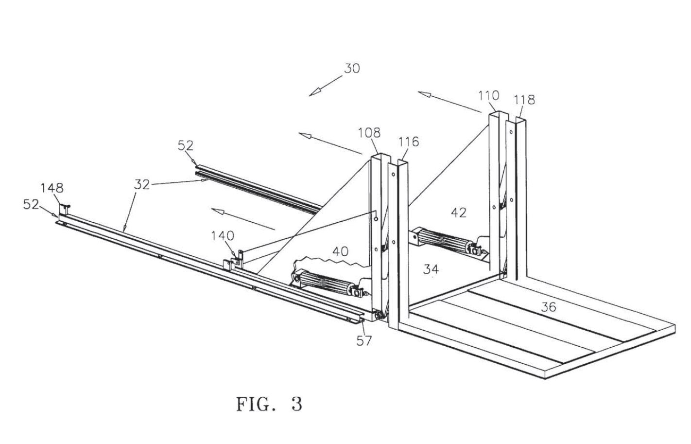
162 Contrary to the submission by MSA, it is not the case that Lutkus is a “different device” used in a “different context”. It discloses an apparatus for both lifting and enclosing loads or cargo, which is a clear and unmistakeable disclosure of an apparatus for storing one or more items. Indeed, Mr Hunter’s evidence, which I accept, is that Lutkus discloses to him that “once the item is lifted and placed on the vehicle, it is being stored in that position”.
163 Further, contrary to the submission by MSA, it is not the case that Lutkus only discloses a device for “temporary storage”, particularly in circumstances where the time period that the cargo or load is “enclosed” is not specified.
164 It follows that integer 1.1 is disclosed in Lutkus.
165 MSA submits that the mere fact that Lutkus encompasses the claimed invention in the Patent does not give rise to anticipation, citing Sanofi-Aventis Australia Pty Ltd v Apotex Pty Ltd (No 3) (2011) 196 FCR 1; [2011] FCA 846 (Jagot J) at [180] and the authorities cited therein. In that passage of her Honour’s judgment, Jagot J relevantly identified that: “[a] prior broad disclosure … may not be sufficient ‘in the absence of the skilled addressee understanding or perceiving’ the later claimed invention therein” and cited Lundbeck at [173].
166 While it is correct that Lutkus does not contain an explicit reference to “a car fridge or a tool box”, the use of the apparatus disclosed in Lutkus is not confined to any type of load or cargo and includes a load lifting system adapted for slidable mounting to the bed of a standard pickup truck (or van vehicle or other vehicle having a flatbed).
167 I consider that it is self-evident (and would be to a skilled addressee as at the priority date) that a car fridge or tool box are two examples of cargo which could be loaded into a vehicle using the Lutkus apparatus. Indeed, a skilled addressee would “add [that] missing information as a matter of course”: Lundbeck at [181].
168 The following evidence demonstrates that Dr Field understood and perceived the claimed invention in Lutkus:
(1) Dr Field gave evidence in his first affidavit that he would have regarded Lutkus as being relevant to a design brief involving developing “a system or device for lifting and storing a heavy object, like a tool box or a small fridge, in the back of a four wheel drive and/or an off-road vehicle” and would not have considered there to be any need to modify the device depicted in Lutkus to achieve that purpose. He accepted that in considering that design brief and considering Lutkus, it had disclosed to him something that could be used to store a heavy object like a tool box or a small fridge in the back of a four-wheel drive.
(2) Dr Field gave evidence in his second affidavit that, “The design of the lift platform member 36 … of Lutkus enables fridges or toolboxes (or other items) of varying widths, lengths and heights to be placed on the lift platform member…”.
169 For these reasons, I find that integer 15.1 is disclosed by Lutkus.
170 Lutkus does not use the term “offset lever” or even “lever”. It will be recalled that the term “offset lever” is not a term of art, and its meaning in the claims is a lever having a centre line that is offset (that is, spaced apart and not in line with) in the plane of operation of the mechanism from the centre line of one of the linkage arms to which it is connected.
171 In the Detailed Description of the Preferred Embodiments, at Column 5, lines 12–39, the following is stated:
Turning once again to FIGS. 2–4, the linearly movable ends 100, 102 of the pair of hydraulic cylinders 82, 84 are pivotally connected to a first end of a corresponding pair of crank arm members 104, 106 as shown. The crank arm members 104, 106 are supported for pivotal rotation by a corresponding pair of spaced apart vertically oriented support frame members 108, 110 which are fixedly attached at their lower ends to the roller platform member 34 as shown. The second ends 112, 114 of the pair of crank arm members 104, 106 are, in turn, pivotally connected to a pair of spaced apart, vertically oriented lift platform frame members 116, 118 so that movement of the linearly movable ends 100, 102 of the pair of hydraulic cylinders 82, 84 causes relative movement between the lift platform member 36 and the roller platform member 34 in a well known manner.
The second ends 112, 114 of the crank arm members 104, 106, together with a pair of idler arm members 120, 122 form the parallelogram linkage system 38 for connecting the lift platform member 36 to the roller platform member 34. As understood by those skilled in the art, the parallelogram linkage system 38 enables vertical movement of the lift platform member 36 relative to the roller platform member 34 between the raised position illustrated in FIG. 3 and the lowered position illustrated in FIG. 2, and through a continuous range of positions therebetween. The details of the parallelogram linkage system 38 and the operation thereof are well known in the art and therefore, will not be described with any more particularity herein.
(Emphasis original.)
172 Clearview submits that components 104 and 106, which are described in Lutkus as “crank arm members” in the extract above, each include an “offset lever” that is connected to an arm (which is part of the same component 104 and 106), and which include an offset portion that creates an offset between the centre line of the lever and the centre line of the arm to which it is connected in the plane of its motion. It relies upon the evidence of Mr Hunter to support this construction.
173 Below is a reproduction of part of Figure 3 from Lutkus (which is above) which has been annotated by Mr Hunter to demonstrate the portion of the crank arm member which is the arm and the portion which is the “offset lever”:
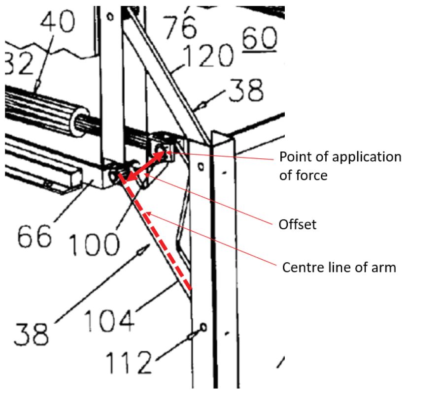
174 In Mr Hunter’s first affidavit, he explained:
As shown in Figure 2 [in the Lutkus specification], a pair of crank arm members 104, 106 (that are part of the parallelogram linkage system) are pivotally attached at the distal end 66 of the sliding mechanism. The crank arm members have an inverted T shape. The base portion of each inverted T (which runs between the sliding mechanism and the second part (as described in integer 1.7 below) form the “arms” of this integer. I will refer to this as the “arm” portion of the crank arm member. ...
The upstanding portion of the inverted T shaped crank arm member is the offset lever. I will refer to this as the “lever” portion of the crank arm member.
Force is applied at the top end of the “lever” portion (by extension or retraction of the hydraulic cylinders), at a point offset from the “arm” portion. In other words, the location where the force is applied to the lever is spaced apart from the centre line of the “arm” portion of the crank arm component, as shown in the annotated portion of Figure 2... The application of this force to the lever portion actuates the arms so as to raise or lower the second part.
175 In his third affidavit, Mr Hunter further explained, by reference to the annotated figure below (being Figure 8 of Lutkus with additional markings added by Mr Hunter), that the effective input lever arm is at an angle to the output lever arm, with the fulcrum at the intersection of the two.
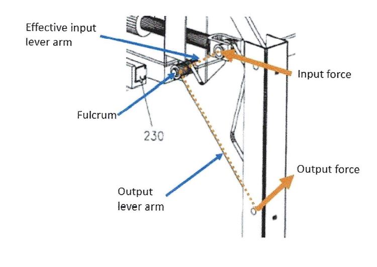
176 Mr Hunter explained during the concurrent evidence session by reference to another annotated copy of Figure 8 from Lutkus (below) that (a) the hydraulic actuator applies force to an upper portion of the lever (which is the tip of the blue-shaded portion on the diagram below); (b) that force causes the blue and green components to rotate; and (c) that rotational force is transferred to the lower linkage arm or “parallelogram linkage member (as it is labelled)” (bottom yellow component).
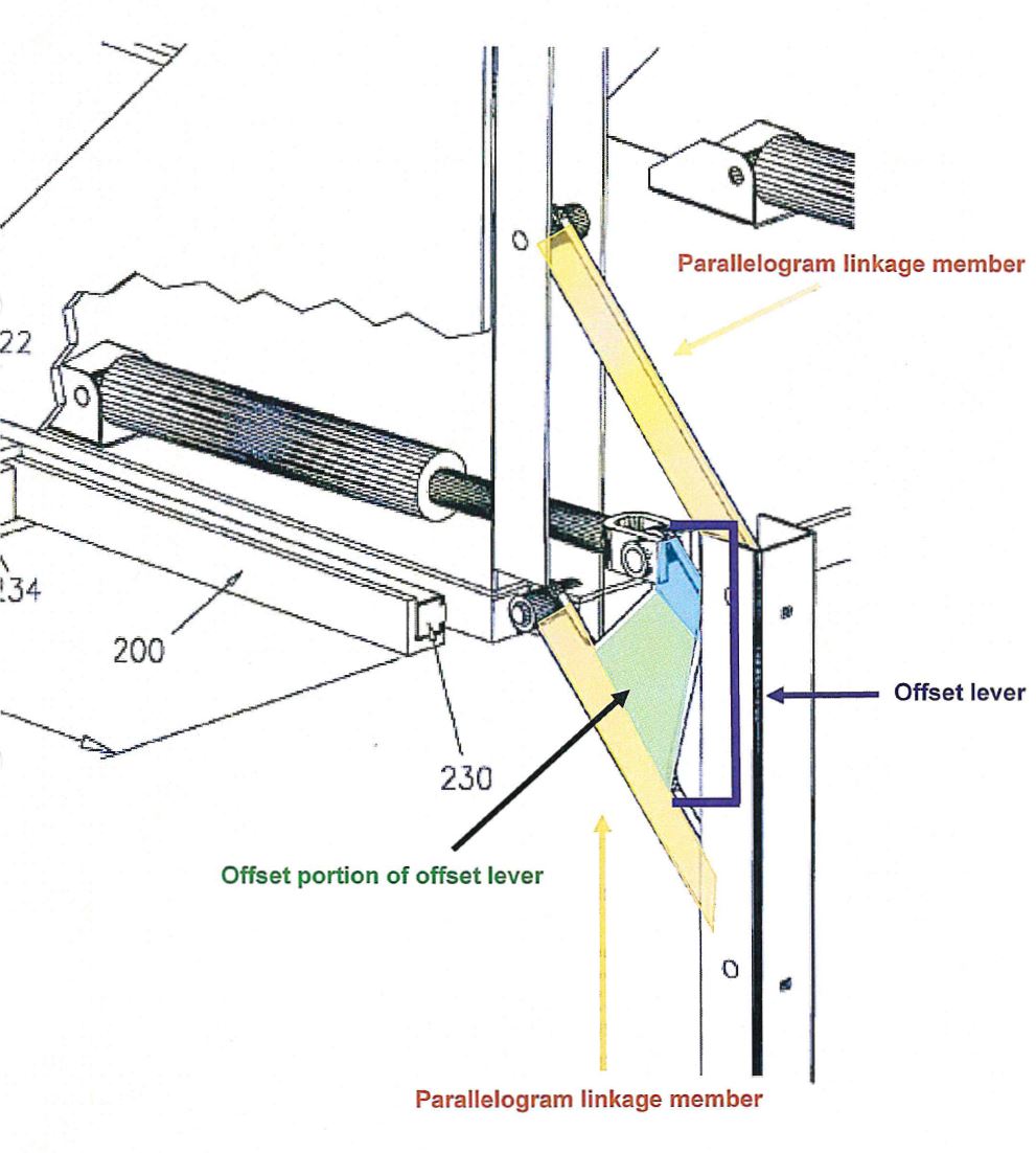
177 By contrast, Dr Field described the crank arm member 104 and 106 as a “simple bell crank that transmits motion between the linear actuator (item 40) and the lift platform member (item 36)”.
178 During his oral evidence, Dr Field (a) accepted that the “bell crank” in Lutkus was a “component that does the same thing” as the “offset lever” in the Patent; (b) accepted that it achieved the same outcome as the “offset lever” in the Patent; and (c) accepted that it was mechanically equivalent to the “offset lever” in the Patent.
179 For the following reasons, however, I am not persuaded that there is the required disclosure of an “offset lever” in Lutkus.
180 An “offset lever” within the meaning of the claims does not contemplate or encompass a single component comprised of both the arm and the “offset lever”. Further, in the Patent, the “offset lever” and the “arm” or “arms” are separate components.
181 By contrast, the crank arm member 104 and 106 in Lutkus is one component. What Mr Hunter has done is to artificially divide the crank arm member into different portions of his own devising, and then label those portions as the “offset lever” and the “arm” (being something which Lutkus does not itself do or disclose or even suggest). To explain why one portion of the crank arm member was an “offset lever” required the addition of multiple variations of highlighting and annotations to the Figures disclosed in Lutkus and detailed explanations to justify why one portion of each member was an “offset lever”. All of this only served to detract from any notion that there was a clear and unmistakable disclosure of an “offset lever” in Lutkus.
182 That the crank arm member 104 and 106 “achieves the same result” as the “offset lever” in the Patent is not enough to amount to a clear and unmistakable disclosure of an “offset lever” within the meaning of the claims: AstraZeneca FCAFC at [301], [447]. Determining lack of novelty involves considering whether the prior art discloses the integers as articulated in the claims of the Patent, not whether there is an equivalence of function.
183 As no “offset lever” is disclosed, it follows that integer 1.8/15.9 is not disclosed in Lutkus.
184 For the reasons set out above, Lutkus does not anticipate claims 1, 8 to 12 and 15 of the Patent.
185 Clearview accepts that Thomas does not disclose integers 1.6 and 1.7, nor integer 1.8 based on its construction of those integers. However, it submits that Thomas arises for consideration if the disputed terms in the claims are construed consistently with MSA’s submissions such that the Clearview Easy Slide infringes the Patent.
186 Although Clearview’s construction of the disputed terms has been accepted, I will assume that it has not for the purposes of dealing with this alternative argument.
187 MSA’s position is that Thomas does not disclose integers 1.1/15.1, 1.8/15.9, 1.11/15.10, 8.2, and 15.2/15.3. Because of the view I have reached about whether Thomas discloses an “offset lever”, it was not necessary to address all disputed integers.
6.4.2 The disclosure in Thomas
188 There are similarities between Thomas and the Clearview Easy Slide, as can be seen from Figure 2 of Thomas:
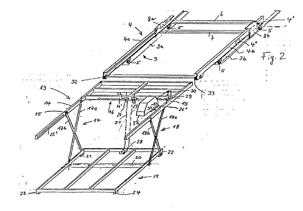
189 The invention disclosed in Thomas relates in particular, without any limitation, to a loading and unloading apparatus for heavy articles for transport in station wagon-type passenger motor vehicles and vans, without conventional tail lift devices, and vehicle trailers, minivans and similar vehicles, which are also suitable for transporting relatively heavy loads.
190 The problem that Thomas states the invention solves is described at page 2 commencing at line 19 of the English translation:
It is an object of the invention to specify a loading and unloading apparatus of the type mentioned in the introduction which can advantageously be used wherever it is the intention for loading and unloading of heavy individual articles to be easily possible, even for a person working on their own, but conventional loading systems or lifting devices and assisting persons are not available. Here, it is the intention for the loading and unloading apparatus according to the invention to be particularly suitable, without difficulties, for passenger motor vehicles and vans that are suitable for transporting heavy loads, without the need for major modification or retrofitting of said vehicles. For this purpose, it is the intention that the loading and unloading apparatus according to the invention can be used or installed easily when required and, after its use, can be just as easily removed again, such that the load compartment and in particular the associated floor of the vehicle are then freely available again substantially in the conventional form…
191 Claim 1 of Thomas (which is the only independent claim) states:
A loading and unloading apparatus for heavy articles for overcoming a loading height between a relatively low-lying ground and an elevated loading plane, in particular the floor of a passenger motor vehicle, van or the like, characterized in that a rail element for the displaceable guidance of a flat telescopic element is fixed on the loading plane, and a pull-out element is provided, which pull-out element is connected to a stability device which holds a height-adjustable loading platform in the horizontal, and which pull-out element has a lifting apparatus for lowering the loading platform out of the plane of the pull-out element or for lifting said loading platform from the ground into the plane of the pull-out element, wherein the pull-out element is configured to be displaceable, as a whole together with the lifted loading platform and the stability device, in drawer-like fashion along the telescopic element.
192 The apparatus in Thomas is actuated by hand crank 33, which is rotated (page 8, line 22) in order to lift or lower the platform to which it is attached via a cable. Other than its depiction in the drawings, hand crank 33 is only mentioned once in Thomas.
193 Clearview submits that the hand crank 33 has the shape of two parallel horizontal components, joined by a vertical component, and that this is an “offset lever” on MSA’s construction of this term, being a “lever that is modified by a geometric offset in its shape”.
194 In his first affidavit, Mr Hunter opined that the lever is “part of” hand crank 33 (without giving any reasons for this opinion), and that hand crank 33, as shown in Figure 2, is an “offset lever”. His stated reasons that it is an “offset lever” were not related to its geometric shape (which is the premise of Clearview’s novelty attack based on Thomas).
195 However, during the concurrent evidence session, Mr Hunter agreed that the hand crank is “simply a winder” and that he “could easily be convinced that” he was incorrect when he determined that the hand crank was an “offset lever”.
196 An extract of Figure 2 (which depicts hand crank 33) is below as appears in Mr Hunter’s first affidavit:
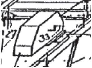
197 Dr Field explained in his second affidavit that the “hand crank” is not a lever and does not function as a lever. His reasons for saying this included that the hand crank is capable of moving through multiple revolutions, and that it does not provide any mechanical advantage.
198 However, during the concurrent evidence session, Dr Field appeared less certain about the need for the hand crank to provide a mechanical advantage for it to be a lever:
MR FOX: Now, your position is that it’s not a lever, because you say that the lever – a lever must have an arc of motion which is less than 360 degrees, and it also must provide a mechanical advantage. Correct?
DR FIELD: I’m not sure it must provide a mechanical advantage, but it does.
MR FOX: Okay. It should. Or it will.
DR FIELD: Well, it’s a number.
MR FOX: Right.
DR FIELD: Which ..... yes.
(Emphasis added.)
199 It is therefore unclear whether it would be necessary to show that the hand crank provided a mechanical advantage for it to be regarded as a lever.
200 However, Dr Field was emphatic in his disagreement with the propositions put to him during the concurrent evidence session that (a) it was not relevant how far the crank rotates and (b) the hand crank was functioning as a lever through its rotations.
201 Mr Hunter appeared less certain on this issue, saying (without much enthusiasm) that a lever “can be something that rotates 360 degrees, or even possibly more”.
202 Neither party addressed the issue as to how this expert evidence could or should be reconciled.
203 In these circumstances, and taking into account the sparsity of information about the hand crank in Thomas, the concessions made by Mr Hunter during the concurrent evidence session and the lack of reasons provided by Mr Hunter to explain his opinion that the hand crank is a lever, I am not persuaded that Thomas clearly and unmistakably discloses an “offset lever”.
204 For the reasons set out above and on the premise that MSA’s construction of “offset lever” is correct, the “offset lever” in integers 1.8/15.9 and 1.11/15.10 is not disclosed in Thomas with the consequence that Thomas does not anticipate claims 1 and 15, being the only independent claims. It therefore follows that Thomas also does not anticipate claims 8 to 12.
205 Clearview accepts that Dieter does not disclose integers 1.6 and 1.7, nor integer 1.8 based on its construction of those integers. However, it submits that Dieter arises for consideration if the disputed terms in the claims are construed consistently with MSA’s submissions such that the Clearview Easy Slide infringes the Patent.
206 Although Clearview’s construction of the disputed terms has been accepted, I will again assume that it has not for the purposes of dealing with this alternative argument.
207 MSA’s position is that Dieter does not disclose integers 1.8/15.9, 1.11/15.10, 8.2, 11.2, 15.1 and 15.2. Because of the view I have reached about whether Dieter discloses an “offset lever”, it was not necessary to address all disputed integers.
6.5.2 The disclosure in Dieter
208 In the Dieter specification, under the heading “Description” on page 1 of the English translation, it is stated that the invention relates to a lifting and loading apparatus according to the preamble of claim 1.
209 After identifying certain disadvantages with current forms of apparatus, Dieter states at page 2 lines 3–14 that:
It is therefore an object of the present invention to create a lifting and loading apparatus which can receive a payload outside the vehicle at any desired height between a roadway plane and vehicle loading floor, and can move said payload onto the vehicle loading floor or onto payload that has already been loaded there, irrespective of whether the vehicle has a luggage compartment sill or a planar loading floor edge, whether loading and unloading are to be performed at a rear end or at a longitudinal side.
Said object is achieved by means of the features of the main claim.
210 Claim 1 of Dieter provides:
A lifting and loading apparatus (1), in particular for vehicles,
– having a guide device (2) which has at least one movable support arm (3),
– having a drivable lifting device (4), which is arranged on the support arm (3) and which serves for lifting and lowering a load-receiving device (5) from, onto or to loading planes which are spaced apart in height-offset fashion, characterized
– in that the lifting device (4) has at least one lifting arm (6) which is arranged in pivotable fashion on the support arm (3), and in that the support arm (3) and the load-receiving device (5) are operatively connected such that their originally set orientation with respect to one another does not change during the lifting and lowering movement.
211 Figure 1 of Dieter is below:
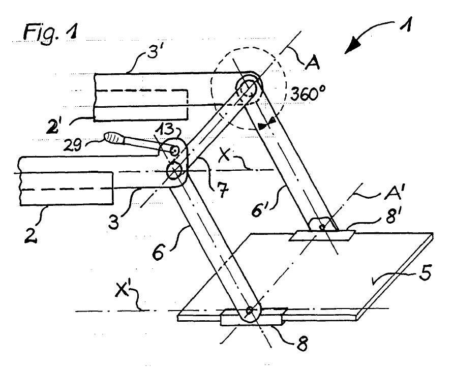
212 Figure 2 of Dieter is below:
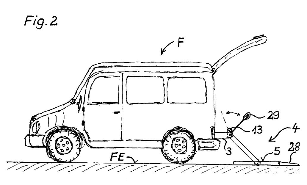
213 Figure 2 is described in these terms at page 10, lines 30–36:
Figure 2 shows a vehicle F with a partially pulled-out support arm 3 and with a lifting device 4 which has been lowered onto the roadway plane FE and the load-receiving device 5 of which has a pivotable access ramp 28. The drive apparatus 13, which is provided for being actuated by way of hand lever 29, is arranged on the support arm 3.
(Emphasis added.)
214 The reference to hand lever 29, as it appears in the above extract, is not otherwise referred to in Dieter.
215 Figure 6 of Dieter, which includes a depiction of item 29, is below:
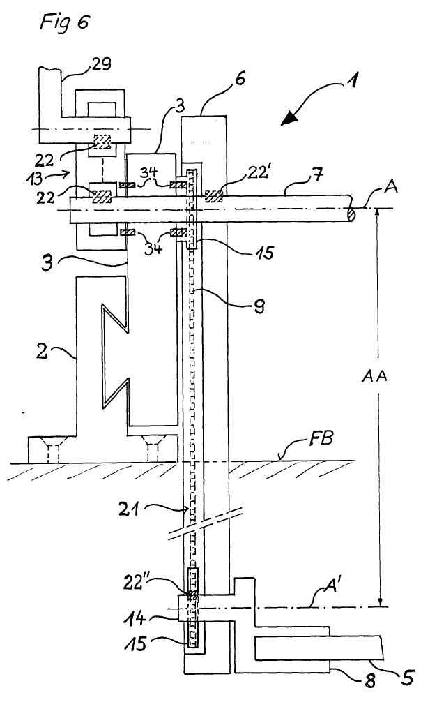
216 As already observed, item 29 is identified in Dieter as a “hand lever”.
217 To demonstrate that this is an “offset lever” within integer 1.8/15.9, Clearview points to Figure 6, an extract of which is below, to submit that item 29 is a lever with an L-shape. It submits that this figure depicts an “offset lever” on MSA’s construction of this term, being a “lever that is modified by a geometric offset in its shape”.
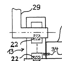
218 When shown Figure 6, Mr Hunter opined that the main arm of hand lever 29 is “L” [sic] shaped” and the “upper end of the lever [is] not shown”. Although Mr Hunter provided other reasons for concluding that item 29 was an offset lever, these reasons did not relate to its geometric shape. During the concurrent evidence session, Mr Hunter conceded that he found it difficult to interpret whether there was an offset lever in Dieter but maintained his position that the depicted item 29 was “all part of the one lever”.
219 MSA submits that item 29 is a straight object which is connected to a shaft, and that the shaft is a separate object. For these reasons, MSA submits that item 29 is not an offset lever. As to this, Dr Field stated in his second affidavit that:
The base of the L-shape in Figure 6 is the driveshaft onto which the hand lever (item 29) is directly attached. The hand lever (item 29) and the driveshaft are two separate items and their axes intersect – they are not offset…
220 During his oral evidence, Dr Field explained that, at the bottom end of the L is a “thin, discontinuous line with dots” which is indicative of it being circular and is a “shaft going across the page”. He said that this was the circle at the end of item 29 on Figure 1, just below item 13, and is the shaft to which the arm or lever is mounted.
221 Upon my review of Dieter, I am not persuaded that there is a clear and unmistakable disclosure of an “offset lever” in Dieter, adopting MSA’s construction of that term. Figures 1 and 2 of Dieter depict hand lever 29 as a solid straight component which is connected to a circular component which appears to be separate to the arm or lever itself, rather than part of the lever (as shown by the circle in Figure 1 to which the lever is connected but not part of the same item). While it is true that Figure 6 appears to depict the hand lever 29 as one component which has an L-shape, the counter argument is that the number 29 is only adjacent to and indicating the vertical component of the L-shape, rather than the entire L-shape (which it could do by, for example, indicating hand lever 29 with an arrowhead line as other broader components are indicated – such as loading apparatus 1, drive apparatus 13 and transmitting device 21). Thus, Figure 6 is ambiguous and the Dieter specification does not assist in resolving the ambiguity. Further, Dr Field’s interpretation concerning the dotted line across the base of the L-shape in Figure 6 (which is consistent with Figures 1 and 2) was not contradicted by Mr Hunter, whose explanation did not address the meaning of the dotted line at the base of the L-shape.
222 For the reasons set out above and on the premise that MSA’s construction of “offset lever” in the claims is correct, the “offset lever” in integers 1.8/15.9 and 1.11/15.10 is not disclosed in Dieter with the consequence that Dieter does not anticipate claims 1 and 15, being the only independent claims. It therefore follows that Dieter does not anticipate claims 8 to 12.
7.1 The case as advanced by Clearview
223 By its opening submissions, Clearview contended that claims 5, 6 and 7 lack an inventive step in light of the common general knowledge together with Lutkus: see, for example, [31] of its written opening submissions. This was a narrower case than that which had been articulated in the Amended Particulars of Invalidity filed on 7 February 2022.
224 By its opening submissions, Clearview also outlined the evidence on which it would rely to establish this aspect of its case, which related to claims 5, 6 and 7 only.
225 By its written closing submissions, Clearview reverted to its broader case, namely that claims 1, 5, 6, 7, 8, 9, 10, 11, 12 and 15 of the Patent lack an inventive step when compared with the prior art base, as the “idea” of the invention (that is, the “inventive concept”) would have been obvious to a person skilled in the art in light of the common general knowledge or, alternatively, the common general knowledge in combination with Lutkus.
226 This broader case was based (in part) on evidence which had emerged at trial, through answers to questions asked of (primarily) Dr Field. Those answers were then relied upon in Clearview’s closing submissions as to what was common general knowledge, none of which had been pleaded or opened as being relevant to this asserted ground of invalidity. This had the consequence that MSA appeared to have been taken by surprise as its written closing submissions only addressed the narrower case which had been opened by Clearview, and did not address the submissions concerning common general knowledge.
227 MSA did not object to the broader case being advanced by Clearview in closing submissions but sought to supplement its written submissions with oral submissions. However, because of the manner in which Clearview had revived its broader case, and the manner in which MSA sought to meet that case, the identification of the common general knowledge and the extent of the dispute concerning that common general knowledge was somewhat opaque.
228 With that background, I turn to the case advanced by Clearview in its closing submissions. As part of this case, Clearview contended (and MSA disputed) that Lutkus could be reasonably ascertained, understood and regarded as relevant by a person skilled in the art before the priority date.
229 The Patents Act deals with inventive step in ss 7(2) and 7(3). The version of s 7 of the Patents Act that applies to the Patent is that which appears in the compilation prepared on 27 March 2007. Section 7(3) was amended by the Patents Amendment Act 2001 (Cth), Sch 1, which commenced on 1 April 2002. The amendments applied to patents for which the complete application was filed on or after that date: Patents Amendment Act, Sch 1, item 13. The application for the Patent was filed on 27 March 2007. Both before and after the amendments, s 7(3) referred to information that the skilled person could, before the priority date of the relevant claim, be reasonably expected to have ascertained, understood and regarded as relevant. However, the amendments introduced by the Intellectual Property Laws Amendment (Raising the Bar) Act 2012 (Cth) do not apply.
230 Section 7(2) of the Patents Act (as in force at the time) provided that an invention is taken to involve an inventive step when compared with the prior art base:
…unless the invention would have been obvious to a person skilled in the relevant art in the light of the common general knowledge as it existed in the patent area before the priority date of the relevant claim, whether that knowledge is considered separately or together with the information mentioned in subsection (3).
231 Section 7(3)(a) of the Patents Act relevantly provides that the information for the purposes of s 7(2) is:
…any single piece of prior art information… being information that the skilled person mentioned in (2) could, before the priority date of the relevant claim, be reasonably expected to have ascertained, understood, regarded as relevant…
232 In Insta Image Pty Ltd v KD Kanopy Australasia Pty Ltd (2008) 239 FCR 117; [2008] FCAFC 139 (Lindgren, Bennett and Logan JJ) at [80], the Full Court held that in determining the issue of obviousness it is necessary to:
(a) identify the invention “so far as claimed in any claim”;
(b) identify the “person skilled in the relevant art”;
(c) identify the common general knowledge as it existed in Australia before the priority date;
(d) inquire under s 7(2) whether the invention referred to in (a) would have been obvious to the person in (b), in light of the knowledge referred to in (c); and
(e) inquire whether that invention would have been obvious to that person in the light of that knowledge, when considered together with the information in s 7(3) (being additional prior art information).
233 With respect to the “understood and regarded as relevant” component of s 7(3), in Lockwood Security Products Pty Ltd v Doric Products Pty Ltd (No 2) (2007) 235 CLR 173; [2007] HCA 21 (Gummow, Hayne, Callinan, Heydon and Crennan JJ) at [153] (Lockwood (No 2)), the High Court characterised the process of applying s 7(3) (as it then was) to the issue of inventive step as follows:
The question of what a person skilled in the relevant art would regard as relevant, when faced with the same problem as the patentee, is to be determined on the evidence. The starting point is the subject matter of the invention to be considered together with evidence in respect of prior art, common general knowledge, the way in which the invention is an advance in the art, and any related matters. …
234 As to the “ascertained” component of s 7(3), the relevant principles include the following:
(1) The issue is whether the skilled addressee “could be reasonably expected to have ascertained (etc) the information”. Ascertained means “discovered or found out”: see AstraZeneca AB v Apotex Pty Ltd (2015) 257 CLR 356; [2015] HCA 30 at [68] (Kiefel J) and [110] (Gageler and Keane JJ) (AstraZeneca HC).
(2) Section 7(3) “does not assume an ascertainability by any and all skilled persons… of all publicly available prior art documents anywhere in the world”. Further, where the prior art is a patent, the “mere fact that some participants in the field might undertake patent searches is not sufficient to establish a reasonable expectation of ascertainment”. In assessing whether the skilled addressee could be reasonably expected to have ascertained the information, it is important to consider the characteristics of the skilled addressee, the nature of the problem, and the information typically used by the skilled addressee: SNF (Australia) Pty Ltd v BASF Australia Ltd (2019) 140 IPR 276; [2019] FCA 425 (Beach J) at [1084] and [1086].
(3) Section 7(3) requires more than a possibility. It requires a prediction as to the events that would have taken place as at the priority date. The prediction must be sufficiently reliable to be regarded as reasonable: Pharmacia LLC v Juno Pharmaceuticals Pty Ltd (2022) 165 IPR 200; [2022] FCA 92 (Burley J) at [268].
(4) As Gageler and Keane JJ made plain in AstraZeneca HC at [111], nothing in s 7(3) suggests that the “notional skilled addressee may not trawl through multiple documents… as part of the ascertainment of relevant information”.
(5) The fact that there may have been a large number of publicly available patent publications at the priority date, of varying degrees of relevance, does not mean that the skilled addressee would be less likely to understand and regard as relevant any one of those publications. That is, the fact the field may be “extremely crowded” does not provide a basis for concluding that the skilled addressee would not appreciate the relevance of a particular document, if he or she could “reasonably have been expected to discover it”: Caffitaly System S.p.A v One Collective Group Pty Ltd (2020) 154 IPR 1; [2020] FCA 803 (Nicholas J) at [191].
235 In Hanwha, Burley J provided a useful summary of the legal principles concerning the assessment of inventive step at [414]–[418]:
The law concerning the requirement for an inventive step reflects a balance of policy considerations in patent law of encouraging and rewarding inventors without impeding advances and improvements by skilled, non-inventive persons: Lockwood No 2 at [48] (Gummow, Hayne, Callinan, Heydon and Crennan JJ). The cases over the years have made a number of statements as to what is required to answer the “jury question” of whether or not an invention is obvious. It is a question of fact. The question is not what is obvious to a court, but depends on analysis of the invention as claimed having regard to the state of the common general knowledge, any information relied upon for the purpose of s 7(3), and the approach taken to it by the person skilled in the art: Lockwood No 2 at [51].
As a basic premise, the question is always “is the step taken over the prior art an ‘obvious step’ or an ‘inventive step’?” This is often an issue borne out by the evidence of the experts: Lockwood No 2 [52]. Whilst the question remains one for the courts to determine, the courts do so by reference to the available evidence, including that of persons who might be representative of the skilled person in the art: AstraZeneca (HC) at [70] (Kiefel J, as her Honour then was).
Various formulations of the question have been set out in the cases. In R D Werner & Co Inc v Bailey Aluminium Products Pty Ltd [1989] FCA 57; 25 FCR 565 at 574, Lockhart J said that there must be “some difficulty overcome, some barrier crossed”.
A “scintilla of invention” is sufficient to support the validity of a patent: Aktiebolaget Hässle v Alphapharm Pty Limited [2002] HCA 59; 212 CLR 411 at [48] (per Gleeson CJ, Gaudron, Gummow and Hayne JJ), although this proposition may be seen to be somewhat circular, because the requirement of the qualitative assessment remains that the scintilla so identified must be inventive.
In Allsop Inc v Bintang Ltd [1989] FCA 428; 15 IPR 686 at 701 the Full Court (Bowen CJ, Beaumont and Burchett JJ) noted that for the invention to be inventive, it must be “beyond the skill of the calling”.
7.3 Identification of the invention
236 The first step in the process outlined by the Full Court in Insta Image is to identify the invention “so far as claimed in any claim”.
237 Clearview submits that the “idea” of the invention (that is, the “inventive concept”) resides in the specification of the Patent at page 2, lines 5–12:
In a first aspect, the present invention provides an apparatus for storing one or more items, the apparatus comprising a first part adapted to be mounted to a surface or a wall and a second part mounted to the first part, the second part adapted to store or hold one or more items, wherein the second part is movable relative to the first part such that the second part can be moved from a storage position to a first access position at which the second part is at one level, the second part being movable from the first access position to a second access position, the second access position being located at a lower level than the first access position.
238 By its closing submissions, Clearview relies upon Dr Field’s evidence to support its submission as to the “idea” or “essence” of the invention. However, it is not readily apparent that Dr Field gave the evidence attributed to him in Clearview’s submissions. Nor is it apparent that Dr Field understood what he was agreeing to in terms of identification of the “essence” of the invention or whether he understood that his agreement encompassed claims 1, 5, 6, 7, 8, 9, 10, 11, 12 and 15. Dr Field’s (somewhat confusing) evidence was this:
MR FOX: And by way of the introduction to the claimed invention, because we have the heading there, “Brief description of the invention”, that the patentee, Mr Miles, is asserting that in its basic form the invention is to be able to move the tray from a higher position to a lower position. Correct?
DR FIELD: Yes. It also is talking about moving from a storage to the .....
MR FOX: Yes. Indeed.
DR FIELD: Yes.
MR FOX: It moves from the stored position.
DR FIELD: Yes.
MR FOX: Comes out, but the essence is in the prior art we have a horizontal movement out. That’s as far as or sophisticated as the patentee says it ever was.
DR FIELD: Yes.
MR FOX: And so what he’s saying is, “I’ve invented this now means of sliding it out, but also being able to lower it to a lower level”.
DR FIELD: He’s not necessarily claiming that combination. So the separate elements were inventive.
MR FOX: That - - -
DR FIELD: It’s a machine that does both elements.
MR FOX: But the essence is, isn’t it, that we can actually move the platform from a raised position to a lower position.
DR FIELD: That’s the essence, yes.
MR FOX: That’s the essence of it.
DR FIELD: The horizontal part is not the essence.
MR FOX: Yes. The essence is being able to make that movement.
DR FIELD: Vertical movement.
MR FOX: Yes.
DR FIELD: Yes.
MR FOX: And then – that’s right. The vertical movement in the sense that, well, we are moving from one horizontal position being the first access position to a lower second access position. Correct?
DR FIELD: Yes. Although I’m not sure of the word, “Horizontal”, but yes.
MR FOX: That’s all right. Well, I’m just trying to do it for the purpose of the transcript anyway.
DR FIELD: One height to a lower height.
MR FOX: The point is we can access – sorry. Say that again.
DR FIELD: One height to a lower height.
MR FOX: One height to a lower height, and the tray’s intended to be horizontal, is it not?
DR FIELD: It doesn’t mention that at this point, but yes.
239 By its submissions and without further elaboration by reference to each of claims 1, 5, 6, 7, 8, 9, 10, 11, 12 and 15, Clearview then submits that the “idea” identified by it was “plainly” common general knowledge.
240 No evidence is cited to support that submission other than Dr Field’s experiences with other types of apparatus throughout his career (which I will address shortly), and that Dr Field “accepted as such” and that “[i]t was therefore obvious”. However, Dr Field’s evidence does not rise to the heights claimed by Clearview. For example, one passage of evidence relied upon by Clearview to support its contention that the “idea” was common general knowledge was as follows:
MR FOX: All right. And so we – going back to the questions I posed to you previously about what the patentee has anointed as the claimed invention in this case, there’s nothing – again, posing this question at the priority date, there’s nothing surprising or unexpected in the idea of the invention which was set out on page 2 at lines 5 to 12, is there?
DR FIELD: So patent – in – in – no, sorry, yes, .....
MR FOX: So the question that I have about those lines, there’s nothing – putting your October 2007 hat on, if someone described to you that idea, there would be nothing surprising or unexpected by you reading that and someone telling you that at the priority date, that idea of a device; is that right; you agree with that?
DR FIELD: The – the idea of the device in – on page 2 - - -
MR FOX: Yes, just that general description in lines 5 to 12.
DR FIELD: I – I see this is – yes, this is an idea of a device which has movement.
MR FOX: Yes.
DR FIELD: Yes.
MR FOX: Nothing surprising about that to you when you read that at October 2007?
DR FIELD: No. It – it describes many devices that existed.
241 Clearview relies upon evidence that Dr Field had direct involvement with improving the mechanism for moving parts of beds in medical treatment rooms “up and down” (which is not the same as its posited “idea” in any event). It also relies upon Dr Field’s acceptance that it was “known” that a fishing box, or tackle box, or tool box, could include a lid that opened up, with trays inside that all opened up and involved “movement from one axis position to another” and that mechanical engineers would be “well familiar with all the principles that are associated with having multiple trays that are linked in some way and able to be moved from one position to the next”.
242 However, the concept of multiple trays being linked and being able to be moved apart, exposing the contents of each tray, is not the same “idea” as that which Clearview contends is the “essence” of the invention, being to move one platform horizontally from a raised position to a lower position. It could be said to involve the same movement (if one sets to one side the absence of multiple trays) but no more than that.
243 In any event, the passage in the specification relied upon by Clearview as encompassing the invention in the claims does not (on its own) explain the improvement over, or basis for asserting a commercial alternative to, the prior art identified on page 1 of the specification, which identifies (amongst other things) the problem that “car fridges” and tool boxes typically have a lid that pivots upwardly and that, in order to obtain access, the sliding arrangement is slid outwardly and the “car fridge” or tool box extends out of the luggage compartment of the vehicle. Although not stated expressly, the skilled addressee would understand upon reading the specification as a whole (and particularly page 1) that the improvement or commercial advantage provided by the invention is to enable better access to the content of the “car fridge” or tool box once it is lowered to the second access position (that is, to provide a solution to the problem). As submitted by MSA, the whole (or part) of an inventive step may lie in “the perception of the true nature of the problem”: Wellcome Foundation Ltd v V.R. Laboratories (Aust.) Pty Ltd (1981) 148 CLR 262 (Aickin J) at 281 approved in Aktiebolaget Hässle v Alphapharm Pty Limited (2002) 212 CLR 411; [2002] HCA 59 (Gleeson CJ, Gaudron, Gummow and Hayne JJ) at [51].
244 In this case, the invention “so far as claimed in any claim” of the Patent was the inferred perception by the patentee of the problem that sliding the “car fridge” or tool box to the first access position did not provide the best means of access to the content of those items combined with the recognition of the solution that better access could be obtained through the movement of the platform to a second access position. There was no evidence that the invention, characterised in this way, was common general knowledge as at the priority date.
245 For these reasons, the invention “so far as claimed in any claim” of the Patent (and, in particular, so far as claimed in claims 1, 5, 6, 7, 8, 9, 10, 11, 12 and 15) is not confined to the “idea” of moving one platform horizontally from a raised position to a lower position as described at page 2, lines 5–12 of the specification.
7.4 Identification of the common general knowledge
246 The person skilled in the art has been identified earlier in these reasons. As to the common general knowledge, Clearview submits that “the experts agreed” that each integer of claims 1, 5, 6, 7, 8, 9, 10, 11, 12 and 15 was common general knowledge, and that the combination was also known. However, the passage in the transcript cited by Clearview as evidence of that agreement does not establish any agreement by the experts that the combination of integers in each claim was known. Further, neither Dr Field nor Mr Hunter could agree upon what an “offset lever” was within the meaning of the claims and as at the priority date, let alone that it was common general knowledge.
247 Clearview also submits that, once it is found that the integers in the dependent claims comprise common general knowledge, it is “evident that any combination of those integers is similarly obvious”. However, it is trite that a Court must be careful to avoid “the misuse of hindsight”. The dangers are “particularly acute where” – as here – “what is claimed is a new and inventive combination for the interaction of integers, some or all of which are known”: see e.g., Aktiebolaget Hässle at [21], [60], [78] and [119]; Lockwood (No 2) at [46]. As observed by Beach J in SNF at [512]:
Now impermissible hindsight should be avoided in determining whether a claimed invention lacks an inventive step. Indeed, the misuse of hindsight is most common in relation to combination claims.
(Citations omitted.)
248 In the case of a combination, the question is whether the claimed combination as a whole is obvious, not whether each integer is obvious. As Beach J helpfully observed in SNF at [513]–[517]:
For a combination invention, the question is whether the combination, not each integer, is obvious. It is simply impermissible to take any one integer or take each integer seriatim and ask whether each integer involved an inventive step. The invention is the combination. The combination is what is claimed as the monopoly. And the relevant question is whether the combination involves an inventive step. As the plurality in Aktiebolaget Hässle (at [41]) said:
… The claim is for a combination, the interaction between the integers of which is the essential requirement for the presence of an inventive step. It is the selection of the integers out of “perhaps many possibilities” which must be shown by Alphapharm to be obvious, bearing in mind that the selection of the integers in which the invention lies can be expected to be a process necessarily involving rejection of other possible integers. This expression of the issue follows what was said by Aickin J in Minnesota Mining.
(Citation omitted.)
Further, Lord Davey stated in Re Klaber’s Patent (1906) 23 RPC 461 at 469, in terms approved by Dixon J in Palmer v Dunlop Perdriau Rubber Co Ltd (1937) 59 CLR 30 at 73:
A proper combination for a patent is the union of two or more integers, every one of which elements may be perfectly old, for the production of one object which is either new, or at any rate is for effecting an old object in a more convenient, cheaper or more useful way. But the point in a combination patent must always be that the elements of which the combination is composed are combined together so as to produce one result.
More generally, in Aktiebolaget Hässle (at [21] and [78]) the importance of avoiding hindsight was reinforced in the following terms:
[T]he warnings in the authorities against the misuse of hindsight are not to be repeated as but prefatory averments and statements of trite law. The danger of such misuse will be particularly acute where what is claimed is a new and inventive combination for the interaction of integers, some or all of which are known. It is worth repeating what was said by Lord Diplock in Technograph Printed Circuits Ltd v Mills & Rockley (Electronics) Ltd:
“Once an invention has been made it is generally possible to postulate a combination of steps by which the inventor might have arrived at the invention that he claims in his specification if he started from something that was already known. But it is only because the invention has been made and has proved successful that it is possible to postulate from what starting point and by what particular combination of steps the inventor could have arrived at his invention. It may be that taken in isolation none of the steps which it is now possible to postulate, if taken in isolation, appears to call for any inventive ingenuity. It is improbable that this reconstruction a posteriori represents the mental process by which the inventor in fact arrived at his invention, but, even if it were, inventive ingenuity lay in perceiving that the final result which it was the object of the inventor to achieve was attainable from the particular starting point and in his selection of the particular combination of steps which would lead to that result.”
…After its review of the evidence, the Full Court concluded that Astra’s “development” of the formulation “was essentially an exercise in trying out various known possibilities until the correct solution emerged” (emphasis added). That view of the matter wrongly takes as the starting point the assumed result. It succumbs immediately to the seduction of hindsight. Also, the notion of trying out possibilities invites the repetition of criticisms made earlier in these reasons.
(Emphasis added, citations omitted.)
In Lockwood (No 2) (at [46]) the High Court repeated the caveat against the misuse of hindsight. Clearly, any inordinate use of hindsight is likely to conceal or gloss over all of the problems, blind alleys and choices of options encountered by the patent applicant along the path to the invention. To present its evolution as some seamless and inevitable linear progression involving no more than the application of routine steps or methods is to engage in some intellectual property lawyer’s version of a Whiggish ahistorical approach.
Further, it is self-evident that problems with hindsight are even further elevated where the claimed invention concerns the application of known principles.
(Emphasis original.)
249 Applying these principles, it follows that, even if each integer of claims 1, 5, 6, 7, 8, 9, 10, 11, 12 and 15 was common general knowledge as at the priority date, it does not follow from this alone, nor is it evident, that the combination of those integers in each of those claims is obvious.
250 This is especially having regard to the manner in which I have characterised the invention above.
7.5 Whether invention obvious in light of common general knowledge and Lutkus
251 In relation to this aspect of its case, Clearview contends that the invention is also obvious in light of the common general knowledge, together with Lutkus (which it contends is prior art information within s 7(3) of the Patents Act). Clearview submits that a skilled addressee would add any missing integers from Lutkus as a matter of course, and without the application of inventive ingenuity or undue experimentation.
252 Consistently with its opening submissions, Clearview’s closing submissions focus only upon claims 5, 6 and 7 and rely upon the evidence of Dr Field (to a limited extent) and upon the evidence of Mr Hunter, who was provided with a design brief by Clearview’s solicitors, to establish that:
(1) Lutkus discloses all of the features of claims 5, 6 and 7 other than integers 5.2 (a biasing means to assist movement), 6.2 (defining the points of connection of the biasing means), and 7.2 (requiring the biasing means to be a gas strut);
(2) the use of gas struts to assist in raising and lowering items was well known in the field well before the priority date; and
(3) confronted with a design brief aligned with the problem addressed by the Patent, it would have been obvious for a skilled person such as Mr Hunter to modify the apparatus in Lutkus to add a gas strut to assist in the manual lifting of items. If such gas struts “assist” in the sense required by claim 5, then the resulting apparatus would have all the features of claims 5, 6 (subject to design choices as to the location of the gas struts), and 7.
253 As to the “ascertained, understood, [and] regarded as relevant” requirements, Clearview relies on the evidence of Mr Hunter as to the searches he would have conducted in addressing the design brief and Mr Cruise (an experienced patent searcher) as to the expected results of those searches before the priority date. It submits that this evidence establishes the basis for the reasonable expectation required by s 7(3).
254 For the following reasons, this aspect of Clearview’s invalidity attack also fails.
7.5.1 Objection to Mr Hunter’s evidence
255 MSA objected to certain evidence of Mr Hunter given in his first affidavit in which he expressed his opinions as to the obviousness of the patented invention when compared to his “knowledge and experience” as at the priority date and the information contained in Lutkus. During the hearing, I ruled that the evidence was excluded and that reasons would be given in this judgment.
256 Relevantly, Mr Hunter had been provided with the Patent before giving that evidence. The challenge by MSA was primarily based on s 135 of the Evidence Act 1995 (Cth), which provides for this Court’s general discretion to exclude evidence, as well as relevance. MSA relied upon observations made by the Full Court of this Court in Minnesota Mining & Manufacturing Co v Tyco Electronics Pty Ltd (2002) 56 IPR 248; [2002] FCAFC 315 (Heerey, Emmett and Dowsett JJ) at [43]–[50] to the effect that expert evidence on the question of obviousness is not always likely to be helpful, particularly in circumstances where the expert is provided with a copy of the challenged patent prior to giving the evidence. It was said that this is because the issue of obviousness is a mixed question of fact and law that is ultimately for the court to determine. In Tyco, the Full Court indicated a preference for refusing to admit expert evidence as to whether a claimed invention is obvious; however, it did not state as a matter of general principle that such evidence must always be excluded.
257 In response, Clearview sought to emphasise that Tyco has not been rigidly applied and that the preferred approach, employed by other judges of this Court, is to admit the evidence subject to weight. Clearview relied on two cases where that approach was adopted: Austal Ships Pty Ltd v Stena Rederi Aktiebolag (2005) 66 IPR 420; [2005] FCA 805 (Bennett J) at [155]–[156] and Globaltech Corporation Pty Ltd v Reflex Instruments Asia Pacific Pty Ltd (2022) 167 IPR 515; [2022] FCA 797 (Jagot J) at [483]. Clearview submits that those cases identify that expert evidence should not be rejected or given negligible weight merely because he or she has the benefit of hindsight or access to the patent specification.
258 As to this, I accept that it is not a blanket rule that expert evidence should always be excluded when the expert has reviewed the patent in suit prior to giving evidence on the issue of obviousness. Rather, whether it should be excluded will depend upon the circumstances.
259 In this case, there is no evidence that Mr Hunter was instructed by Clearview’s lawyers as to what it means for an invention to be “obvious” as that term is understood in patent litigation. Further, there is insufficient evidence to demonstrate what Mr Hunter understood “obvious” to mean when he expressed his opinions. For these reasons, [149]–[153] of Mr Hunter’s first affidavit were not admitted into evidence.
260 For completeness, even if I had adopted the approach urged by MSA and admitted this evidence subject to considerations of weight, I would have attributed no weight to this evidence for the same reasons that I have excluded it and because Mr Hunter was provided with the Patent prior to giving this evidence. As observed by Beach J in SNF at [520]:
…Lesser weight is to be given to the evidence of experts asserting an invention to be obvious after they have reviewed the patent or been provided with other information concerning the state of the art. Undoubtedly, at the least there is a need for caution where an expert asserting obviousness knew both the problem and the solution.
7.5.2 Mr Hunter’s evidence generally
261 Turning to the design brief given to Mr Hunter, Mr Hunter identified the design task in his first affidavit as follows:
[I was asked] to assume that, as at 22 October 2007, I had been engaged as a consulting engineer by someone who was seeking to develop a product to address the following issue:
(a) Items such as fridges or tool boxes are stored in four wheel drives or commercial vehicles on top of storage drawers;
(b) These items are opened by a pivoting lid located on top of the item;
(c) These items are stored on sliding arrangements that allow the item to be slid in and out of the luggage compartment of the vehicle; and
(d) Even once slid out, it can be inconvenient to obtain access to the fridge or toolbox because the top of the fridge or tool box is quite high off the ground.
262 There was no evidence that the matters identified in (a), (b) and (c) of the design task were common general knowledge. That was so even though each of Mr Hunter and Dr Field addressed the topic of what was known at the priority date in relation to the storage and lifting of items in vehicles.
263 More importantly and having regard to the manner in which I have characterised the invention above, there was no evidence that the issue identified in (d) of the design task was common general knowledge. In other words, there is no evidence that the person skilled in the art would have perceived the problem identified in (d).
264 After being given the design task, Mr Hunter stated in his first affidavit that “[i]n this hypothetical engagement I consider the basic problem resides in the tool box or fridge being at too great a height once it is slid out of the vehicle”. In oral evidence, Mr Hunter accepted that he did this because of what is stated in (d).
265 As a result, the framing of the design task infected Mr Hunter’s evidence on obviousness as it impermissibly enlarged the “body of knowledge and information” against which inventive step is to be tested, which is contrary to principle, and infects his evidence.
266 In AstraZeneca FCAFC, the majority stated at [202]–[203]:
… it is apparent that the relevant provisions of the Act do not expressly or impliedly contemplate that the body of knowledge and information against which the question whether or not an invention, so far as claimed, involves an inventive step is to be determined may be enlarged by reference to the inventor’s (or patent applicant’s) description in the complete specification of the invention including, in particular, any problem that the invention is explicitly or implicitly directed at solving.
If the problem addressed by a patent specification is itself common general knowledge, or if knowledge of the problem is s 7(3) information, then such knowledge or information will be attributed to the hypothetical person skilled in the art for the purpose of assessing obviousness. But if the problem cannot be attributed to the hypothetical person skilled in the art in either of these ways then it is not permissible to attribute a knowledge of the problem on the basis of the inventor’s “starting point” such as might be gleaned from a reading of the complete specification as a whole.
267 As the content of the design task went beyond what was common general knowledge, no weight can be attached to Mr Hunter’s evidence concerning the alleged ascertainability of Lutkus, the identification of the problem by Mr Hunter and the solution devised by Mr Hunter to that problem.
268 In addition, Mr Hunter’s evidence can be given no weight because the design brief was provided by him after he had been briefed with both the Patent and with Lutkus, had opined in detail on the Patent and the relevant claims, and then opined whether Lutkus disclosed the relevant claims for the purposes of novelty. As Mr Hunter accepted in his oral evidence, when undertaking the design task, he “already had clearly in [his] mind all of the features of the invention described, illustrated and claimed in the patent”.
269 In Tyco at [45]–[46], it was observed that where, as here, an expert witness is first provided with a copy of the patent, this is:
…hardly calculated to result in objective evidence as to what the hypothetical uninventive but skilled worker would have done. To give the patent to a prospective witness is tantamount to leading the witness… where evidence is obtained in circumstances such as just described, the evidence is not likely to be helpful at all.
7.5.3 Whether Lutkus falls within s 7(3)
270 Clearview’s case is based on “the evidence of Mr Hunter as to the searches he would have conducted in addressing” the design task and the “expected results of those searches before the priority date”. As to the “results” of such (hypothetical) searches, the only database raised by the evidence is Google Patents.
271 However, for the following reasons, Lutkus does not meet the requirements of s 7(3) of the Patents Act.
272 First, Google Patents became available less than a year before the priority date, in December 2006. At the time, it was limited to granted US patents. Mr Hunter could not recall when Google Patents became available or when he started using it, and he did not think that he did in the first year that it became available, but he “may have looked at it briefly”. I therefore cannot be satisfied that even Mr Hunter would have conducted searches on Google Patents as part of any design project before the priority date, let alone the hypothetical skilled addressee.
273 Second, the search terms which Mr Hunter suggested that he would have used for a hypothetical search of Google Patents were likely influenced (even if subconsciously) by the terms of the design task, the Patent and his exposure to and analysis of Lutkus. Those terms included “slide”, “sliding”, “lifting” and “lowering”. The references to “slide” or “sliding” and “lifting” are important, including because the title of Lutkus is “Slidable load lifting system” (emphasis added).
274 Third, Clearview relied upon the evidence of Mr Cruise to the effect that his simulated searches conducted in November 2021 or May 2023 meant that he was confident that Lutkus would have appeared in the top 100 results for 25 of 48 searches for various word combinations in October 2007. However, Mr Cruise was not himself a skilled addressee, and Mr Hunter’s evidence did not provide a proper foundation for the number or structure of the searches carried out by Mr Cruise. In particular, Mr Hunter did not give evidence that he would have conducted searches using the word combinations used by Mr Cruise (i.e. which words and in what order he would search the terms, including which Boolean search terms he would use). Further, there is no evidence that Mr Hunter would have selected Lutkus had it appeared in any search results, and why he would have done so.
275 For these reasons, the evidence was insufficient to establish that, if the hypothetical uninventive but skilled addressee was given the design brief before the priority date, he or she would have undertaken the searches which Mr Cruise simulated on Google Patents and selected Lutkus from the search results.
276 For these reasons, Clearview has failed to rebut the presumption provided by s 7(2) of the Patents Act with the consequence that the invention in the Patent is to be taken to involve an inventive step.
277 Clearview relies on this ground if the disputed term “connected to” has the meaning contended for by MSA. It submits that, on that premise, the claims are not fairly based because they travel beyond the invention disclosed in the Patent.
278 Notwithstanding that I have rejected the construction of “connected to” as advanced by MSA, I will address this issue.
279 It will be recalled that the construction which MSA advanced was that “connected to” merely requires a relationship between the offset lever and at least one arm to achieve a “kinematic outcome” such that movement of one component causes movement of another, and so can encompass an indefinite number of indirect connections.
280 Clearview submits that, if MSA’s construction is correct, the Patent gives no disclosure of: (a) a device in which the offset lever is not directly connected to the linkage arm; or (b) how the offset lever in such an arrangement would co-operate with the rest of the apparatus in order for the mechanism to work.
281 In response, MSA submits that the term “connected to” in integers 1.8 and 15.9 appears in the consistory clauses for claims 1 and 15. It further submits that Clearview’s argument must fail because, insofar as Clearview argues that the consistory clause is wider than the invention, the invention is not restricted to the disclosure of the preferred embodiment.
282 Section 40(3) of the Patents Act at the effective filing date of the Patent (22 October 2007) requires a claim to be fairly based on the matter described in the specification.
283 A claimed invention is only fairly based if the specification provides a “real and reasonably clear disclosure” of what is claimed: see Lockwood Security Products Pty Limited v Doric Products Pty Limited (2004) 217 CLR 274; [2004] HCA 58 (Gleeson CJ, McHugh, Gummow, Hayne and Heydon JJ) at [69] (Lockwood (No 1)) quoting Société des Usines Chimiques Rhône-Poulenc v Commissioner of Patents (1958) 100 CLR 5 (Fullagar J) at page 11.
284 A claim may be fairly based on a consistory clause: see, e.g., Lockwood (No 1) at [92]–[93]; Globaltech Corporation Pty Ltd v Australian Mud Company Pty Ltd (2019) 145 IPR 39; [2019] FCAFC 162 (Kenny, Robertson and Moshinsky JJ) at [76], [148]. However, a claim based on what has been cast in the form of a consistory clause is not fairly based if other parts of the specification show that the invention is narrower than that consistory clause: see Lockwood (No 1) at [99]. Claims that travel beyond the disclosure of the invention in the body of the specification are not fairly based: Lockwood (No 1) at [83]; AstraZeneca FCAFC at [417]–[421].
285 There is no dispute that consistory clauses may provide fair basis for a claim that uses the same language. In this case, there are consistory clauses in the specification that use the same language as claims 1 and 15.
286 Further, the specification states in plain terms at page 11, lines 10 and 20–22 that:
The present invention may be susceptible to variations and modifications other than those specifically described.
It will be understood that other variations and modifications are also possible. It will be appreciated that the invention encompasses all such variations and modifications that fall within its spirit and scope.
287 However, the specification, when read as a whole, describes an invention consisting of an apparatus which has direct connections between the offset lever and the linkage arm as referred to in integers 1.8 and 15.9 (being a connection of the kind described by Mr Hunter).
288 The only disclosure in the specification of the positioning and relationship of the offset lever with respect to other components of the mechanism is at page 9, lines 5–7 of the specification:
The actuating means 60 comprises an offset lever 62 having an offset portion 63 that is mounted to linkage arm 24. This may be achieved, for example, by welding the end of offset portion 63 to the linkage arm 24.
289 The experts agree that the above passage describes a “direct connection” between the offset lever and linkage arm, and that there is no other description of a connection between these components in the Patent.
290 The Patent describes an apparatus that is a series of mechanical components, which work together in a particular way. The Patent explains which components are connected to which other components, and it is the particular way that these components are connected that causes the mechanism to work as described.
291 The specification does not suggest that the invention might not consist of an apparatus which has a direct connection between the offset lever and the linkage arm, or how the apparatus might be configured otherwise than by having such a direct connection.
292 For these reasons and on the assumption that MSA’s construction of the term “connected to” in integers 1.8 and 15.9 is the correct one, there is not a real and reasonably clear disclosure in the specification of an invention in which there is an indirect connection between the offset lever and the linkage arm. It follows that, if MSA’s construction of the term “connected to” in integers 1.8 and 15.9 is the correct one, the relevant claims are not fairly based, and are invalid for that reason.
293 An issue arose in this case concerning the proper construction and effect of a deed made on 9 February 2021 between Mr Miles, as Licensor, and MSA, as Licensee, and the standing of MSA to bring infringement proceedings prior to the date of the deed. Notwithstanding that I have determined below that there has been no infringement of the Patent by Clearview, I will address this issue.
294 Clause 2.1(b) of the deed relevantly provides that the Licensor grants the Licensee an exclusive, royalty-free, licence during the Term to, where the rights in the Patent are infringed by a third party, bring about a claim or infringement proceedings against that third party consistent with the rights of an exclusive licensee under s 120(1) of the Patents Act. The deed defines the “Term” as meaning the period between the “Commencement Date” (which is 1 July 2020) until the earlier of the expiry of the Patent or the date terminated in accordance with the deed.
295 Clause 2.5 of the deed provides that the Licensor assigns to the Licensee the right to sue for any infringement of the Patent by a third party which occurred before the Commencement Date.
296 This proceeding was commenced by MSA (alone) on 9 February 2021, being the date of the deed. It appeared to have done so as exclusive licensee because Mr Miles, as patentee, was joined as the second respondent (as contemplated and, indeed, required by s 120(2) of the Patents Act in circumstances where an exclusive licensee starts infringement proceedings).
297 By the initial statement of claim, MSA pleaded that it is, and has since 1 July 2020 been, an exclusive licensee of the Patent within the meaning of the Act. That plea is maintained in the Further Amended Statement of Claim which was filed on 9 May 2023. Accordingly, on its own pleaded case, it is an exclusive licensee as and from 1 July 2020 but not earlier than this.
298 Clearview accepts that MSA was an exclusive licensee from 9 February 2021 (being the date of the deed), but disputes that MSA was an exclusive licensee, or that it has any standing to bring infringement proceedings, prior to that date.
299 The weight of existing authority indicates that it is not possible to backdate the commencement date of an exclusive licence of intellectual property rights: see, in the context of copyright, Allam v Aristocrat Technologies Australia Pty Ltd (2012) 95 IPR 242; [2012] FCAFC 34 (Bennett, Middleton and Yates JJ) at [420]–[432] and Film Investment Corporation of New Zealand (rec apptd) v Golden Editions Pty Ltd (t/as Hughes Leisure Group) (1994) 28 IPR 1 (Burchett J) at page 15. The justification for this approach was articulated by Heerey J in Black and Decker Inc v GMCA Pty Ltd (No 2) (2008) 76 IPR 99; [2008] FCA 504 at [147]–[148] as being because “it is not possible for [parties] by internal arrangements to shift between themselves entitlements under statute as against strangers”: see also Film Investment at page 15.
300 MSA appeared to recognise that these authorities were problematic for it because no submission was made by it at the conclusion of the trial that it had been an exclusive licensee since 1 July 2020 in reliance on cl 2.1(b) of the deed. Its pleaded case to this effect was therefore abandoned, or at least not pressed.
301 Instead, MSA relies upon cl 2.5 as giving it the requisite standing to sue and it submits that it has standing to sue for any infringements that have occurred since 9 February 2015, which is six years before the date that the proceedings were commenced (by reference to the limitation period contained in s 120(4)(b) of the Patents Act). As part of this submission, it submits that it “had before 9 February 2015 (and continues to have) a genuine commercial interest in enforcing Mr Miles’ claims from 9 February 2015 to 9 February 2021, including because” and then a series of inclusive facts are identified which are said to be based on the evidence (emphasis added).
302 The approach taken by MSA is unsatisfactory. Had MSA intended to pursue a case of this kind, which asserted an entitlement to sue premised on cl 2.5 coupled with a claim that it had (and continues to have) a genuine commercial interest in enforcing Mr Miles’ claims from 9 February 2015 to 9 February 2021 based on particular facts, then such a case should have been pleaded and opened, and a confined series of facts identified by it.
303 Clearview did not object to the unpleaded case being advanced by MSA in closing submissions. Instead, Clearview conceded that, if it could be inferred from the facts identified in MSA’s closing submissions that MSA had a genuine commercial interest in enforcing Mr Miles’ claims, then MSA’s standing to sue since 9 February 2015 was established. Further, Clearview did not submit that the facts relied upon by MSA in its closing submissions could not give rise to the asserted genuine commercial interest.
304 In Equuscorp Pty Ltd v Haxton (2012) 246 CLR 498; [2012] HCA 7, French CJ, Crennan and Kiefel JJ stated at [50]–[53] that a right of action was assignable if it was an incident of, or subsidiary to, a right of property, or if the assignee had a genuine commercial interest in the enforcement of the claim of another citing Trendtex Trading Corporation v Credit Suisse [1982] AC 679 (Lord Roskill) at page 703: see also [79] and [156].
305 Turning to the facts relied upon by MSA in its submissions, Clearview’s case as particularised in its Defence was that MSA had been its competitor “since at least March 2015 by reason of being a competitor in the same industry”. Further, by its Cross-Claim, Clearview relied upon a press release issued by MSA on 11 February 2021 (which was admitted for all purposes) which identified that the MSA4X4 DropSlide™ came onto the market in 2007 and that it was “patented technology”. MSA was incorporated in 2011 and Mr Miles (the owner of the Patent) became its sole director in 2012, and I infer from these facts that MSA commenced to sell the MSA4X4 DropSlide™ shortly after this. In those circumstances and in the absence of any submission to the contrary by Clearview, I infer that MSA has been engaged in selling the product the subject of the invention claimed in the Patent since at least February 2015, such that it has (and has had since that date) a genuine commercial interest in the enforcement of Mr Miles’ claims of infringement of the Patent.
306 On that basis and in light of the concession by Clearview as to the correct legal position (about which I express no concluded view), MSA has standing to sue Clearview for alleged infringements from 9 February 2015 by reason of cl 2.5 of the deed and because MSA had a genuine commercial interest in enforcing Mr Miles’ claims since at least that date.
307 The principal issues in dispute are whether the Clearview Easy Slide has the following features:
(1) integers 1.6/15.7 and 1.7/15.8: one or more arms pivotally connected at or near one end to the sliding mechanism and pivotally connected at or near another end to the second part;
(2) integers 1.8 and 15.9: an offset lever connected to at least one of the one or more arms;
(3) integer 5.2: a biasing means to assist in moving the second part between the first access position and the second access position;
(4) integer 6.3: another end of the biasing means is connected to the offset lever.
308 As to integers 1.11 and 15.10 (the second part being movable from the first access position to a second access position by moving the offset lever), the presence of this integer in the Product follows from whether the lever in the Product is an “offset lever”.
10.2.1 Integers 1.6/15.7 and 1.7/15.8
309 This is a diagram of the Clearview Easy Slide which is taken from an Installation & User Guide:
310 The Clearview Easy Slide has four relevant arms (two on each side of the device).
311 As seen in the annotated photograph below (extracted from Clearview’s submissions), one end of each of the two arms is connected to the sliding mechanism and one end of each arm is connected to the second part. These linkage arms form a conventional scissor lift mechanism.
312 The “first arm” (highlighted yellow) is pivotally connected at one end to the sliding mechanism. However, on the proper construction of the claims (as I have found), the first arm is not pivotally connected to the second part, because it both rotates and slides, as depicted by the white arrow.
313 The “second arm” (highlighted pink) is pivotally connected at one end to the second part. However, on the proper construction of the claims (as I have found), the second arm is not pivotally connected to the sliding mechanism, because it both rotates and slides, as depicted by the white arrow.
314 MSA relied upon the figure below in its submissions (which originally appeared in Dr Field’s affidavit). It can be seen that “Pivot 3” is a sliding pivot (to use Dr Field’s terminology).
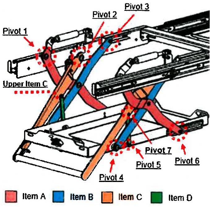
315 MSA also contends that items A and B are arms in a “linkage arrangement” within the meaning of integers 1.5 and 15.6, with pivotal connections (“Pivot 1” and “Pivot 4”) at two ends of the “linkage arrangement” with the consequence that integers 1.6/15.7 and 1.7/15.8 are taken. However, on the proper construction of integers 1.6/15.7 and 1.7/15.8, as I have found, the pivotal connections must be on the same arm. That is not the case with the Clearview Easy Slide.
316 For these reasons, the Clearview Easy Slide does not have the features of integers 1.6/ 15.7 and 1.7/15.8.
317 In his first affidavit, Dr Field stated that he considered that integer 1.8 is present in the Clearview Easy Slide. By reference to the figure directly above, he opined that the full length of Item C is a lever. He said that it is an elongated component that, by virtue of its ability to move on a pivot, provides leverage; that is, Item C rotates about Pivot 2 when force is applied to a component in a direction that is perpendicular to the centre line of the component to leverage the raising and lowering of the second part.
318 Dr Field continued by reference to photographs (below), stating that:
Item C is a lever with an offset, or an ‘offset lever’. As shown in the photographs at Figure J, Item C includes two diagonal bends in its top-most portion. These bends create an offset in the lever. Due to these bends, the top-most portion of the lever is not in line with (and is offset from) the remaining lower portion of the lever in a geometric sense, as it is positioned on a different plane from the lower portion. The physical distance of the offset enables Item C to fold into a compact storage position in which Item C and Item A are arranged in space in a way that they do not interfere with one another. The physical distance of the offset also enables Item C to move without interfering with (or touching) Item A.
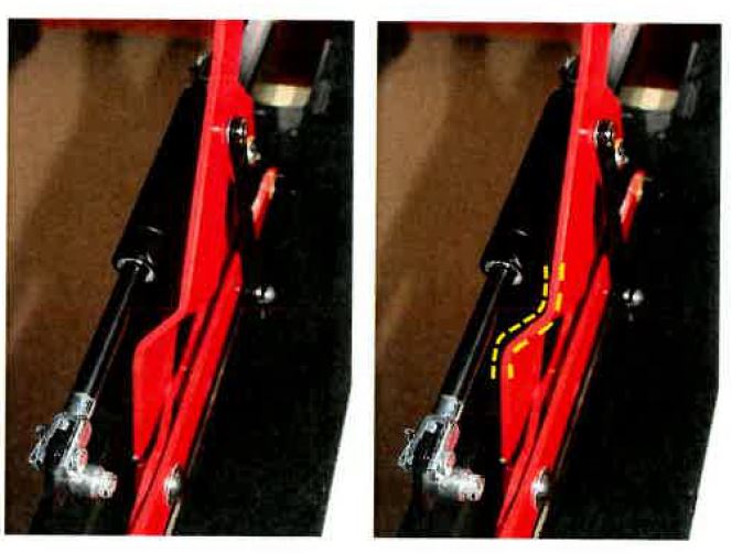
319 Dr Field continued:
Item C is also offset, or skewed from, Item D. It is neither parallel nor intersecting with Item D. Item D is mounted to the side of Item C in a manner that causes Item D to sit offset from Item C in a geometric sense (as shown in Pivot 7 of Figure I).
320 As to whether the offset lever was “connected to” at least one arm, Dr Field gave this evidence:
The offset lever (Item C) is pivotally connected to Item D (see Pivot 7 in Figure I), which is an arm forming part of a linkage arrangement.
The offset lever (Item C) is also connected to the arms (Items A and B). The connection is made by the sequence of a pivot connection between Items C and D (shown in Pivot 7 of Figure I); a pivot connection between Item D and the second part (as shown in Pivot 5 of Figure I); and pivot connections between the second part and Items A and B (respectively shown in Pivot 6 and Pivot 4 of Figure I). As a result, the application of force to move the offset lever (Item C) in an upward or downward direction necessarily causes the pivotal movement of both Items A and B. In other words, there is a dependent relationship between Item C and Items A and B.
321 In his second affidavit, Mr Hunter expressed his disagreement with Dr Field as follows:
Dr Field states that he understands the term “offset” to mean that the configuration and orientation of one thing is not in line with another thing in a geometric sense. I agree in part with this statement. However, in the context of the Patent, I understand that the “offset” refers to something that has a configuration and orientation that is not in line with another thing in the plane of motion of the device, so that it has functional significance in the way in which the device operates.
…
…I do not consider integer 1.8 to be present in the Clearview Easy Slide.
At page 31 of the Field Affidavit Dr Field identifies the “two diagonal bends” in the lever of the Clearview Easy Slide as the offset portion.
I do not agree with Dr Field. These diagonal bends do not create an offset lever as required by this integer. As set out in page 3 of Annexure WSH-9, there is no offset between the lever and the component to which it is connected, and there is no component in the lever that creates an offset between the point of application of force and the centre line of the lever arm. When viewed in the plane of motion of the device, the lever remains a straight arm.
(Emphasis added.)
322 In relation to whether the lever was “connected to at least one of the one or more arms”, Mr Hunter stated in Annexure WSH-9 to his second affidavit by reference to the annotated photograph below:
Furthermore, the lever of the Clearview Easy Slide is not connected to any of the arms of the linkage mechanism. Rather the lower end of the lever is pivotally connected to the first part, as shown in Diagram 4 of Annexure WSH-10. Also, as shown in Diagram 5 of Annexure WSH-10, the lever is connected at a point along its length to a component I have called a “lever actuation link”. The lever actuation link is connected at one end to the lever, and at its other end to the second part. As the lever is lowered, the second part is pushed downward by the lever actuation link, and as the lever is raised, the second part is lifted upward by the lever actuation link.
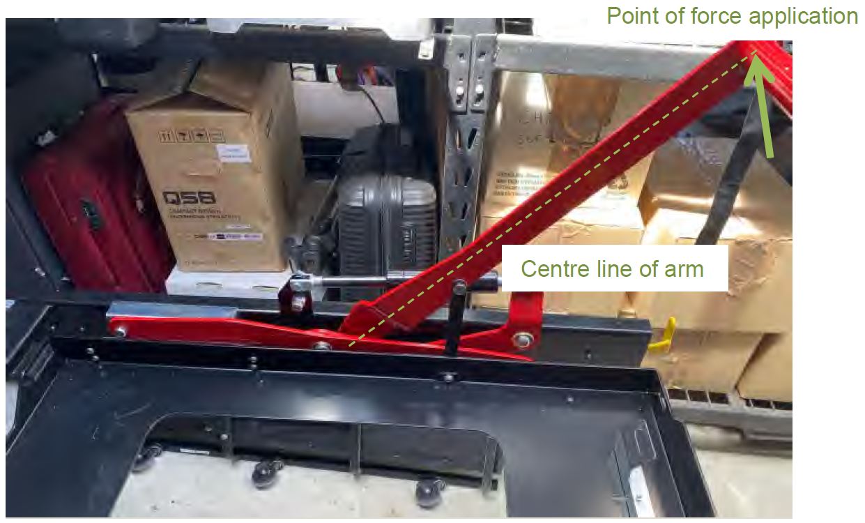
323 Each expert elaborated on their evidence in the JER.
324 By reference to the annotated photograph below, Mr Hunter stated in the JER that:
The lever is pivotally (directly) connected to a lever actuation link at a first location. The opposite end of the lever actuation link is pivotally (directly) connected to the second part (which is the lifting platform) at a second location. At a third location, an outer end of the linkage arm is pivotally (directly) connected to the second part/lifting platform. Consequently, the lever is indirectly connected to the linkage arm via the lever actuation link and then via the second part (lifting platform). However, in my view the Patent does not use the term ‘connected to’ to encompass indirect connection. Otherwise every part of the mechanism is connected to every other part, and the term has no meaning. For example, using that logic (indirect connection) the lifting platform could be said to be connected to [the] floor of the vehicle. That description is meaningless and accordingly unhelpful in terms of describing and understanding the mechanism involved.
325 Dr Field gave evidence that the offset lever in the Clearview Easy Slide is connected to one or more arms because (a) the indirect connection through linkages creates a unique kinematic relationship and/or in any case (b) the “lever actuation link” is an arm within the arrangement that is pivotally (directly) connected to the offset lever. That is, he volunteered for the first time in the JER that the “lever actuation link” is an arm within the meaning of integer 1.8/15.9.
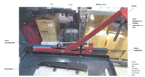
326 However, the difficulty with Dr Field’s approach to this issue, and his attempt to find a “connection” through a series of intermediate components, was identified during the demonstration of the Clearview Easy Slide. When asked about what components could be regarded as “connected,” Dr Field expressed the view that the lever in the Clearview Easy Slide was connected to the base frame, the vehicle, and indeed “everything”, by a chain of intermediary components.
327 As to Dr Field’s nomination of the “lever actuation link” as an “arm” within the meaning of these integers, the “lever actuation link” is pivotally connected at one end to the load platform (second part) and at the other end to the lever, but it is not pivotally connected to the sliding mechanism. It therefore cannot be an “arm” meeting the requirements of integers 1.6 and 1.7, and thus is not the arm to which the offset lever must be connected in integer 1.8.
328 On my construction of the term “offset lever” in the claims, the Clearview Easy Slide does not have the features of integers 1.8 and 15.9, and therefore does not have an “offset lever” within the meaning of claims 1 and 15. That is because:
(1) the diagonal bends in the lever are not offset in the way that term is used in the Patent. The bends are perpendicular to the plane of operation of the mechanism and play no functional role in assisting the operation of the mechanism;
(2) when viewed in the plane of motion of the mechanism, the lever is a straight arm.
329 Additionally, on my construction of the term “connected to” in the claims, the Clearview Easy Slide does not have the features of integers 1.8 and 15.9. Even if it is an “offset lever”, the lever in the Clearview Easy Slide is not connected to at least one of the one or more arms.
330 For these reasons, the Clearview Easy Slide does not have the features of integers 1.8 and 15.9.
10.2.3 Integers 1.11, 6.3 and 15.10
331 Based on my finding that the Clearview Easy Slide does not have an “offset lever” within the meaning of the claims, it follows that it also does not have the features of integers 1.11, 6.3 and 15.10.
332 Further, the parties agree that, as to claim 6, the dispute about whether “another end of the biasing means” is “connected to” the offset lever will turn on my construction of the term “connected to” in the claims. Based on that construction, this provides a further reason to conclude that the Clearview Easy Slide does not have the features of integer 6.3.
333 The issue in relation to integer 5.2 is whether the Clearview Easy Slide has a “biasing means to assist in moving the second part between the first access position and the second access position”.
334 It is not in dispute that the Clearview Easy Slide contains a “biasing means” in the form of a gas strut: see, for example, JER at [38]–[40]. Further, the experts agreed that the gas strut assists in raising the second part from the second access position to the first access position.
335 For these reasons, I am satisfied that the claimed feature is taken. All that is needed is assistance by a biasing means in moving the second part between (not from) the first access position and the second access position, which can be movement in either direction.
336 The Clearview Easy Slide does not infringe the relevant claims because it does not have all of the features of independent claims 1 and 15 for the reasons given above. It follows that MSA is not entitled to any relief and its claim should be dismissed.
11. UNJUSTIFIED THREATS AND CONTRAVENTION OF ACL
11.1 Overview of the allegations
337 Clearview alleges that MSA and Mr Miles have made unjustified threats of patent infringement pursuant to s 128 of the Patents Act. As to this part of its case, Clearview relies upon: (a) a letter sent on behalf of the cross-respondents by their solicitors on 23 November 2020 (KWM Letter); (b) correspondence circulated by MSA on or around 11 February 2021 (First MSA Announcement); and (c) correspondence circulated by MSA on or around 11 March 2021 (Second MSA Announcement). The sending of the communications is not in dispute.
338 With respect to the KWM Letter, Clearview alleges that this constituted threats by both cross-respondents against Clearview, and that those threats were unjustified in circumstances where the Patent is invalid and not infringed.
339 With respect to the First and Second MSA Announcements, Clearview alleges that these contained threats by MSA which were unjustified and that Mr Miles was a joint tortfeasor.
340 Clearview also alleges that MSA has engaged in misleading or deceptive conduct contrary to s 18 of the ACL in relation to the First and Second MSA Announcements, and that Mr Miles was knowingly involved in these contraventions. It is alleged that the announcements contained (inter alia) false representations as to the validity of the Patent, infringement of the Patent by manufacture and sale of the Clearview Easy Slide, and in respect of the First MSA Announcement, false representations that the Clearview Easy Slide was copied from MSA’s product. As to these allegations, MSA accepts that the announcements were sent in trade or commerce.
341 For the reasons given above, the Patent is not invalid. To the extent that Clearview’s allegations are premised upon the invalidity of the Patent, those allegations fail.
11.2 Alleged unjustified threats
11.2.1 Relevant legal principles
342 Section 128(1) of the Patents Act relevantly provides that where a person:
…threatens a person with infringement proceedings, or other similar proceedings, a person aggrieved may apply to a prescribed court…for:
(a) a declaration that the threats are unjustifiable; and
(b) an injunction against the continuance of the threats; and
(c) the recovery of any damages sustained by the applicant as a result of the threats.
343 The legal principles are not in dispute and were recently summarised by the Full Court in Rakman International Pty Limited v Boss Fire & Safety Pty Ltd [2023] FCAFC 202 (Nicholas, Burley and Rofe JJ) at [79]–[82] relying in part on the observations of Crennan J in JMVB Enterprises Pty Ltd v Camoflag Pty Ltd (2005) 67 IPR 68; [2005] FCA 1474 at [208]–[211]. Those principles relevantly include:
(1) Whether a communication amounts to a threat to commence infringement proceedings against the person said to be threatened for the purposes of s 128 is determined objectively.
(2) A threat arises where the language, by direct words or implication, conveys to a reasonable person in the position of the recipient that the author of the communication intends to bring infringement proceedings against the person said to be threatened: U & I Global Trading (Australia) Pty Ltd v Tasman-Warajay Pty Ltd (1995) 60 FCR 26 (Cooper J) at pages 31–32.
(3) The conclusion of whether a document amounts to a threat of patent infringement proceedings is essentially one of fact: Occupational and Medical Innovations Ltd v Retractable Technologies Inc (2007) 73 IPR 312; [2007] FCA 1364 (Dowsett J) at [9].
(4) A threat may arise without a direct reference to infringement proceedings: Lido Manufacturing Co Pty Ltd v Meyers & Leslie Pty Ltd (1964) 5 FLR 443; [1964–5] NSWR 889 (McLelland CJ) at pages 450–451.
(5) Once a threat has been established, it is prima facie unjustifiable unless the person making the threat establishes that it was justified. The court may grant the relief applied for unless the person threatening infringement proceedings establishes that the relevant conduct infringes or would infringe a valid claim of a patent: s 129.
(6) A threat can be made by means of a letter from a legal representative: Sydney Cellulose Pty Ltd v Ceil Comfort Home Insulation Pty Ltd (2001) 53 IPR 359; [2001] FCA 1350 (Conti J) at [36].
344 Section 129 of the Patents Act (as in force at the time) refers to the relief which may be granted:
129 Court’s power to grant relief if threats related to a standard patent or standard patent application
If an application under section 128 for relief relates to threats made in respect of a standard patent or an application for a standard patent, the court may grant the applicant the relief applied for unless the respondent satisfies the court that the acts about which the threats were made infringed, or would infringe:
(a) a claim that is not shown by the applicant to be invalid; or
(b) rights under section 57 in respect of a claim that is not shown by the applicant to be a claim that would be invalid if the patent had been granted.
345 That Clearview is an aggrieved party is common ground in this case. To succeed, it must therefore demonstrate that: (a) the relevant communications involve the making of a threat; and (b) the threat is unjustifiable.
346 The KWM Letter stated (inter alia) that:
(1) MSA and Mr Miles were “concerned that the Clearview Easy Slide product range infringes the Miles Patent and [their] exclusive rights under that patent”;
(2) the Patent is “valid and enforceable and has been successfully enforced against a number of other traders”;
(3) any “manufacture, sale or use of products falling within the scope of any of the claims…will constitute an infringement”, and will entitle MSA and Mr Miles to “several remedies, including: an injunction… [and] damages…”;
(4) the Clearview Easy Slide product includes “each and every essential element of claim 1”; and
(5) MSA and Mr Miles “reserve all rights under the Miles Patent, as well as the right to present this letter to a Court as evidence should the need arise”.
347 MSA and Mr Miles accepted that the KWM letter involved a threat of patent infringement proceedings by each of them. However, they contend that the threat was not unjustified and rely upon an observation by Middleton J in Damorgold Pty Ltd v Blindware Pty Ltd (2017) 130 IPR 1; [2017] FCA 1552 at [422] that “[j]ust because proceedings for infringement are not sustained does not necessarily mean the threats are unjustified in terms of s 128”.
348 So much may be accepted. That is, while this Court has typically taken the approach that a finding that there has been no infringement means that the threats were unjustified (see, e.g., CQMS Pty Ltd v Bradken Resources Pty Ltd (2016) 120 IPR 44; [2016] FCA 847 (Dowsett J) at [159]), it is not the case that such a finding will necessarily result in a finding that a threat was unjustified. Rather, it depends on the circumstances.
349 In Damorgold, Middleton J considered whether certain notices circulated by the applicant constituted unjustified threats in circumstances where his Honour had rejected allegations of patent infringement and invalidity. The applicant in Damorgold argued that the threats were not unjustified because it had “good legal grounds for asserting the rights that it did” (citing Telstra Corp Ltd v Phone Directories Co Pty Ltd (2014) 107 IPR 333; [2014] FCA 568 (Murphy J) at [672], [681]) and because it had previously succeeded in contested proceedings on the validity of its patent (citing JMVB at [212]–[213]): [419]. Justice Middleton concluded that the threats were not “objectively groundless or unjustifiable in light of the matters raised by Damorgold”. His Honour observed that s 128 “is not aimed at deterring infringement proceedings” and the conduct complained of by the respondent was not “the type of conduct that s 128 was aimed at covering in its operation”: [422].
350 By contrast to the facts relied upon by the applicant in Damorgold, MSA and Mr Miles submit that the threats in the KWM Letter were not unjustifiable “in light of the matters raised by [them] on infringement”. However, no further submissions were advanced by them which identify what those matters are or explain why this has the consequence that the threats were justified in circumstances where the infringement claim has failed.
351 This has the consequence that MSA and Mr Miles have not discharged their onus to establish that the threats in the KWM Letter were justified. It follows that the KWM Letter constituted an unjustified threat by them in contravention of s 128 of the Patents Act.
11.2.2.2 First MSA Announcement
352 The First MSA Announcement included the following statements:
MSA4x4 Accessories has commenced legal proceedings in the Federal Court against Clearview Towing Mirrors Pty Ltd alleging infringement of the granted Australian full patent which protects MSA 4x4’s DropSlideTM.
MSA4x4 alleges that Clearview’s Easy Slide product copies essential features of the DropSlideTM patented technology. MSA4x4 is seeking an injunction preventing Clearview from manufacturing or selling the Easy Slide, as well as damages to compensate MSA4x4 for such infringement.
The MSA4x4 DropSlideTM is an industry first product … [which] has been the benchmark in the industry since coming to the market in 2007 and continues to be to this day.
MSA4x4 has exclusive rights to an extensive patent portfolio, both in Australia and internationally, which protect the DropSlideTM and many other innovative products in MSA4x4’s range.
“We take infringement of these valuable intellectual property rights very seriously, and we will not hesitate to enforce those rights,” said Shane Miles, director of MSA4x4.
“We are always watching the market for copies. It is easier for our competitors to simply copy our successful product than to create something new. We will not stand for this. We stand up for innovators in our industry and we will do everything we can to protect our investment in innovation.”
353 That the First MSA Announcement was published to customers and prospective customers was not disputed by MSA in its closing submissions. In any event, such publication is established by the fact that it appeared on MSA’s Facebook and LinkedIn pages on 11 February 2021, being about two days after this proceeding was commenced. That such publication occurred is also apparent, and is inferred, from the following documents:
(1) In an email from Mr Miles to MSA’s Marketing Manager Mr Richard Unwin dated 25 January 2021, Mr Miles provided a list of parties (including “industry contacts”) for the announcement to be sent to. Mr Peter Hazer, identified as the General Manager of MSA in his email signature, suggested in response that the announcement be sent through other manufacturing companies, and on LinkedIn; to which Mr Miles agreed, stating “Yes good idea, can spread it with others and their media, as well as Linkedin”;
(2) The “first pass” of the distribution list contained a list of more than 1,423 names;
(3) In an email dated 11 February 2021, Mr Miles approved the sending of the announcement by Mr Unwin and, in response, Mr Unwin noted:
Email list – Mailchimp 1,304 people
Industry Email List 81 people
Social Media – 43,000+ people.
354 The First MSA Announcement referred to past events, namely Clearview’s “infringement”, that Clearview’s Easy Slide product copies essential features of the DropSlideTM patented technology, that MSA had commenced proceedings and was seeking an injunction to prevent Clearview from selling the Clearview Easy Slide. These were statements of fact but they provide the context for what follows.
355 The First MSA Announcement then referred to future matters, namely that MSA takes infringement “of these valuable intellectual property rights very seriously, and we will not hesitate to enforce those rights” (emphasis added). It also stated that MSA was “always watching the market for copies” (emphasis added), that it “is easier for our competitors to simply copy our successful product than to create something new” and that it “[would] not stand for this” including by doing “everything we can to protect our investment in innovation”.
356 The First MSA Announcement referred to the allegation that “Clearview’s Easy Slide product copies essential features of the DropSlideTM patented technology”. The reference to copy or copies is repeated in the final paragraph, including the reference to “watching the market for copies”. In this context, the reasonable recipient would construe the reference to copies in the final paragraph as referring to Clearview’s Easy Slide product.
357 For this reason, and in circumstances where the recipients of the First MSA Announcement are existing and potential customers, the First MSA Announcement would be construed by the reasonable recipient as a threat of infringement proceedings against any person exploiting the Clearview Easy Slide.
358 Contrary to the submissions of MSA and Mr Miles, the strident words used in the final paragraph of the First MSA Announcement (and, indeed, the existence of the final paragraph itself) have the consequence that this announcement would be construed as more than just a general warning of the kind found in Damorgold.
359 That the First MSA Announcement only refers to competitors expressly, and not customers, does not matter. That is because the reference to “watching the market” captures all participants in the market and would be construed by the reasonable actual or prospective customer in that market as such.
360 MSA and Mr Miles also submit that, if the First MSA Announcement was a threat, it was not unjustified for the same reason that the KWM Letter was not an unjustified threat. Accordingly, for the same reasons I gave in relation to the KWM Letter, MSA and Mr Miles have failed to establish that the threat contained in the First MSA Announcement was justified. This includes, of course, that the Clearview Easy Slide does not infringe the Patent.
361 It follows that the threat in the First MSA Announcement constituted an unjustified threat by MSA in contravention of s 128 of the Patents Act.
11.2.2.3 Second MSA Announcement
362 The Second MSA Announcement included the following statements:
There have been some comments made about legal proceedings that MSA4x4 have filed against Clearview.
MSA4X4 would like to clarify the position. MSA4X4 approached Clearview on several occasions in a genuine attempt to resolve this matter without it being necessary to commence legal proceedings, but those attempts have been unsuccessful.
As the holder of an exclusive licence of a granted patent, MSA4X4 has the legal standing to enforce its patent rights for any infringing act that occurs during the 20-year term of the patent. MSA4X4 will do so where appropriate. Further, MSA4X4 will commence legal action against any company that chooses to infringe on our intellectual property or design registration rights, during the period within each grant.
363 That the Second MSA Announcement was published to customers and prospective customers was not disputed by MSA in its closing submissions. In any event, such publication is established by the documentary evidence which indicates that the mailing list for that announcement was extensive.
364 No case was advanced by Clearview to the effect that the recipients of the Second MSA Announcement were the same recipients as the First MSA Announcement such that the two announcements should be viewed as constituting one threat, or that it may be inferred that the recipients of the Second MSA Announcement were aware of the content of the First MSA Announcement. The Second MSA Announcement must therefore be viewed on its own.
365 For the following reasons, by the Second MSA Announcement, MSA did not threaten any person exploiting the Clearview Easy Slide with proceedings for patent infringement:
(1) The Second MSA Announcement did not refer to the Clearview Easy Slide expressly, or contain any detail as to the legal proceedings commenced against Clearview;
(2) Unlike the First MSA Announcement, the third paragraph (being the one which referred to commencing legal proceedings for infringement of MSA’s intellectual property) did not contain any direct or indirect reference to any intention to bring patent infringement proceedings against any person for exploitation of the Clearview Easy Slide;
(3) Like the notice at [393] of Damorgold, which bears similarities to the Second MSA Announcement, the latter is more appropriately characterised as a general warning to the addressees against infringement: Damorgold at [409].
366 It follows that the threat in the Second MSA Announcement did not constitute an unjustified threat in contravention of s 128 of the Patents Act.
11.2.2.4 Liability of Mr Miles
367 In relation to the KWM Letter, Clearview alleges that Mr Miles engaged in unjustified threats on the same basis as alleged against MSA. That letter was written on behalf of both MSA and Mr Miles, and the content of the letter consistently refers to both cross-respondents as “our clients”, on behalf of whom the infringement action is threatened. As such, for the same reasons that MSA is liable for having made the unjustified threats, Mr Miles is liable for contravention of s 128 of the Patents Act.
368 The issue presented by the First MSA Announcement is less straightforward. That is because Clearview alleges that MSA and Mr Miles are “joint tortfeasors” in respect of the unjustified threat contained in that announcement. Clearview submits that:
…Miles was knowingly concerned in, or directed or procured the contraventions [of s 128 of the Patents Act by MSA]. At all times he was the sole director and secretary of MSA, the managing and controlling mind of MSA, and the sole person having responsibility for making decisions on behalf of MSA including decisions in relation to the management of and business conducted by MSA. He is the owner of the Patent and was also the individual responsible for approving publication of the First MSA Announcement... Further, the First MSA Announcement contains quotes directly attributed to him. Miles is therefore a joint tortfeasor with respect to the conduct.
369 No authority was cited by Clearview to support its submission that contravention of s 128 of the Patents Act is a statutory tort such that Mr Miles could be held liable as a “joint tortfeasor”, and neither party engaged in fulsome submissions on this novel issue.
370 The only authority which I have been able to locate and which arguably supports such a proposition is UbiPark Pty Ltd v TMA Capital Australia Pty Ltd (No 2) [2023] FCA 885 (Moshinsky J) at [186]–[194]. However, the issue of whether contravention of s 128 of the Patents Act is a statutory tort was not decided in that case, as it did not appear to be in dispute. Instead, Moshinsky J found that the relevant parties were not joint tortfeasors on the facts which were before his Honour: [191].
371 The Patents Act contains no provision for imposing liability upon third parties (such as directors) who authorise contravention of s 128 of the Patents Act. The characterisation of such a contravention as a tort, and the usage of the joint tortfeasor concept by reference to this statutory tort appears, therefore, to be a backdoor means of imposing liability upon third parties in circumstances where Parliament has decided not to do so.
372 The problems with such an approach were addressed in a helpful article by Christopher Wood entitled “Liability of directors as joint tortfeasors in intellectual property matters” (2010) 21 AIPJ 164 at pages 174–176. The author’s arguments against imposing liability upon directors as joint tortfeasors for the contravention by companies of intellectual property rights created by statute appear, with respect, persuasive and are difficult to overlook in the absence of submissions to the contrary.
373 For these reasons, I am not prepared to find that Mr Miles was a joint tortfeasor in relation to the First MSA Announcement, as I am not persuaded that there is a proper basis in law to do so.
11.2.3 Relief under s 129 of the Patents Act
374 It is appropriate that a declaration be granted in the terms sought by Clearview. This relief is not opposed by MSA and Mr Miles. The parties will be directed to confer and agree upon an appropriate form of wording.
375 By its closing submissions, Clearview seeks an injunction restraining the continuance of the threats. MSA and Mr Miles submit that no injunction is sought in the Amended Notice of Cross-Claim, but did not advance any other submission as to why an injunction should not be granted. While it is correct that no injunction is sought in the Amended Notice of Cross-Claim in relation to the unjustified threats, I will treat Clearview’s submissions as an application for an injunction.
376 My reasons for taking this approach are as follows:
(1) The written closing submissions of MSA and Mr Miles, delivered prior to the final day of trial, reveal that they were aware that Clearview was seeking an injunction in respect of the unjustified threats.
(2) It was apparent from the written and oral closing submissions of its counsel that Clearview understood that an injunction had been sought by it in its Amended Notice of Cross-Claim, which position was mistaken.
(3) Other than relying on its technical argument referred to above, MSA did not advance any substantive reasons why injunctive relief should not be granted in respect of the unjustified threats.
(4) There is a real prospect that third party consumers were misled by the First MSA Announcement. It is appropriate to take steps to prevent this occurring again.
(5) I am not confined by the relief formally sought in the Amended Notice of Cross-Claim and may make any order that I consider appropriate in the interests of justice: see r 1.32 of the Federal Court Rules 2011 (Cth).
377 For these same reasons, I will grant an injunction restraining MSA and Mr Miles from making any further unjustified threats as I consider it to be in the interests of justice to make such an order.
378 As to damages, by order of Greenwood J dated 5 March 2021, it was ordered by consent that:
Issues of quantum that arise on the claim, and any cross claim, in the proceeding are to be determined separately from, and following, the determination of all other issues for determination in the proceeding.
379 MSA and Mr Miles submit that there is no evidence that Clearview has suffered any loss as a result of any established breaches of s 128 of the Patents Act with the consequence that there should not be any inquiry as to damages. They submit therefore that the claim for damages, including additional damages pursuant to s 128(1A) of the Patents Act, should be dismissed.
380 However, as observed by Dowsett J in CQMS at [189], before whom a similar submission was advanced:
[Such a submission] highlights the fact that in case management, the distinction between issues of liability and issues of quantum is not always clear. When used in connection with the conduct of proceedings, the distinction is a matter of convenience rather than principle. The only real necessity is that the parties be accorded procedural fairness…
381 I will respectfully adopt the same approach in this case.
382 In any event, having regard to the extensive range and nature of the recipients of the First MSA Announcement, and the content of that announcement, damage to Clearview’s reputation can be (and is) inferred.
11.3 Alleged ACL contraventions
11.3.1 Relevant legal principles
383 Section 18 of the ACL relevantly provides:
18 Misleading or deceptive conduct
(1) A person must not, in trade or commerce, engage in conduct that is misleading or deceptive or is likely to mislead or deceive.
384 The principles in relation to s 18 of the ACL were recently summarised by the Full Court in Australian Competition and Consumer Commission v Employsure Pty Ltd (2021) 156 ACSR 1; [2021] FCAFC 142 (Rares, Murphy and Abraham JJ) as follows:
(1) the relevant context in which a statement is to be viewed in assessing whether it is misleading or deceptive, or likely to mislead or deceive, includes both internal and external factors operative at the time the representation was made: [75];
(2) the inclusion of the phrase “likely to mislead or deceive” in s 18 means that a contravention may be established if there is a real or not remote chance or possibility that a person exposed to impugned conduct would be misled. It is not necessary to demonstrate that the impugned conduct was actually misleading; it is enough if it was likely to be so: [89];
(3) the central question is whether the impugned conduct (under s 18), viewed as a whole and in context, has a sufficient tendency to lead a person exposed to the conduct into error (that is, to form an erroneous assumption or conclusion about some fact or matter): [92].
385 Where conduct is directed at consumers (or a class of consumers), the Court must consider whether the “ordinary” or “reasonable” members of the class would be misled or deceived: see Google Inc v Australian Competition and Consumer Commission (2013) 249 CLR 435; [2013] HCA 1 (French CJ, Crennan and Kiefel JJ) at [7].
386 The characterisation of whether a statement is one of belief or opinion, or as to a matter of fact, was addressed in Ireland v WG Riverview Pty Ltd (2019) 101 NSWLR 658; [2019] NSWCA 307 (Bell ACJ, Macfarlan JA and Barrett AJA). In that case, Bell ACJ observed at [30]:
The case law requires that the characterisation of a statement as to one of belief or opinion, on the one hand, or as to a matter of fact, on the other hand, is to be viewed from the perspective of the person or “ordinary” or “reasonable” audience to whom the statement or representation is directed (as opposed to from the perspective of the maker of the statement): Campomar Sociedad, Limitada v Nike International Ltd (2000) 202 CLR 45; [2000] HCA 12 at [102]. This will frequently be a critical aspect of the context as the decision in Forrest also illustrates: see at [36]–[39]; [105]. Thus, in Pyrotek Pty Ltd v Ausco Industries Pty Ltd (1992) ATPR (Digest) 46-085 at [53,323]; [1991] FCA 743 at 33, French J (as he then was) observed that:
“A statement which has the character of a statement of fact when read by an ordinary person may to another, who has relevant knowledge, be seen as an opinion involving interpretation of other data. If in the circumstances in which it is communicated, including the nature or resources of the recipient, a statement presents as a statement of opinion then it is not necessarily to be characterised as anything other than a representation that the maker of the statement holds the opinion or interpretation offered.”
11.3.2.1 Whether the alleged representations were made
387 Clearview alleges that the First and Second MSA Announcements each convey the representation that the manufacture or sale of the Clearview Easy Slide infringes the patent rights of either or both MSA and Mr Miles. Each announcement is pleaded as conveying the representation and no case is advanced by Clearview that the recipients of the Second MSA Announcement were or would have been aware of the content of the First MSA Announcement. For that reason, I will address each of the announcements separately.
388 The ordinary or reasonable members of the class of consumers to whom these alleged representations were made were persons who had acquired or might have an interest in acquiring products of the kind sold by MSA and Clearview. Such products are not especially sophisticated, being used by consumers to store and transport “car fridges” and tool boxes.
389 MSA and Mr Miles submit that the alleged representations were not made as a matter of fact and that the representation which was made in each announcement was that MSA had commenced proceedings against Clearview in which MSA alleged patent infringement.
390 While the First MSA Announcement uses the word “alleges”, it must be viewed in context and as a whole. The references to (for example) “granted Australian full patent which protects MSA 4X4’s DropSlideTM”, “MSA4X4 has exclusive rights to an extensive patent portfolio, both in Australia and internationally, which protect the DropSlideTM” and “we will not hesitate to enforce [these valuable intellectual property] rights” convey a representation of fact that there can be no doubt about the legitimacy of MSA’s assertion of its patent rights. Further, while the First MSA Announcement refers to the allegation that the Clearview Easy Slide copies essential features of the DropSlideTM patented technology, the final two paragraphs of the announcement contain a clear representation that Clearview Easy Slide in fact infringes the patent rights of MSA.
391 Contrary to the submissions of MSA and Mr Miles, the First MSA Announcement was not a statement of opinion or belief but a statement of fact when viewed from the perspective of the audience to whom the announcement was directed. There was no reference to or suggestion of any belief or opinion being held by MSA; rather, the statements were definitive.
392 However, I am unable to discern any reference to, or representation concerning, the patent rights of Mr Miles.
393 For these reasons, the First MSA Announcement conveyed the representation that the manufacture or sale of the Clearview Easy Slide infringes the patent rights of MSA, but not Mr Miles.
394 By contrast, the Second MSA Announcement does not refer to the Clearview Easy Slide, or to any patent rights of Mr Miles. For these reasons, although a representation may be inferred from the Second MSA Announcement that MSA had commenced proceedings against Clearview in which MSA alleged patent infringement (as MSA accepts), the Second MSA Announcement does not represent that the manufacture or sale of the Clearview Easy Slide infringes the patent rights of either or both MSA and Mr Miles.
395 Clearview next alleges that the First MSA Announcement conveyed the representation that the Clearview Easy Slide was copied from MSA’s product. Again, MSA and Mr Miles dispute that this representation was conveyed as a matter of fact.
396 MSA and Mr Miles submit that the First MSA Announcement relevantly states (with their emphasis added):
MSA4x4 alleges that the [Clearview Product] copies essential features of the DropSlideTM patented technology… “We are always watching the market for copies. It is easier for our competitors to simply copy our successful product than to create something new…”
397 They then submit that these statements would not be understood as a discrete representation that there was copying per se of MSA’s product independent of MSA’s patent infringement claim.
398 However, when the First MSA Announcement is read as a whole, in the manner as it appeared and without particular words emphasised (as they are in the submissions), it contains a clear and discrete representation that the Clearview Easy Slide was, in fact, copied from MSA’s product. This is especially so when one has regard to the final paragraph, which makes no mention of the patent infringement claim and conveys that Clearview took a shortcut and simply copied MSA4X4’s DropSlideTM rather than designing its own product.
399 Further, having regard to their content and contrary to the submissions of MSA and Mr Miles, this representation was not a statement of opinion or belief but was a statement of fact when viewed from the perspective of the audience to whom the announcement was directed.
400 For these reasons, the First MSA Announcement conveyed the representation that the Clearview Easy Slide was copied from MSA’s product.
11.3.2.2 Whether representations were misleading or deceptive
401 The representation conveyed in the First MSA Announcement that the manufacture or sale of the Clearview Easy Slide infringes the patent rights of MSA was false or misleading because, as I have found earlier in these reasons, the manufacture or sale of the Clearview Easy Slide does not infringe the Patent.
402 The representation conveyed in the First MSA Announcement that the Clearview Easy Slide was copied from MSA’s product was false or misleading because, based upon the uncontested and unchallenged evidence of Mr Chapman (whose evidence explained the origins of the design of the Clearview Easy Slide), there was no copying by Clearview of any kind, whether from the Patent or the MSA4X4’s DropSlideTM.
11.3.2.3 Liability of Mr Miles
403 Mr Miles was knowingly concerned in or induced or procured MSA’s contravention of s 18 of the ACL within the meaning of “involved” under s 2 of the ACL. That is because he was the sole director and secretary of MSA, and therefore the managing and controlling mind of MSA. He was also the sole person having responsibility for making decisions on behalf of MSA, which included decisions in relation to the management of and business conducted by MSA. Further, he is also the owner of the Patent and was the individual responsible for approving publication of the First MSA Announcement. Further, the First MSA Announcement contains quotes directly attributed to him.
404 For these reasons, MSA has engaged in misleading or deceptive conduct in contravention of s 18 of the ACL, and Mr Miles was knowingly concerned in or induced or procured MSA’s contravention of s 18 of the ACL. I am also satisfied that Clearview is entitled to the relief sought in paragraphs 3, 4 and 6 of the Amended Notice of Cross-Claim, with the quantum of damages to be assessed at the further hearing.
405 I will invite the parties to confer and provide an agreed form of orders having regard to the findings made, and directions as to the further conduct of this proceeding.
I certify that the preceding four hundred and five (405) numbered paragraphs are a true copy of the Reasons for Judgment of the Honourable Justice Downes. |
Associate:
QUD 32 of 2021 | |
SHANE MILES |

