FEDERAL COURT OF AUSTRALIA
Allied Pumps Pty Ltd v LAA Industries Pty Ltd [2023] FCA 1457
Table of Corrections | |
In paragraph 122, in the last sentence, the words “referred to this integer as” have been amended to “referred to this disputed term as” | |
4 December 2023 | In paragraph 178, subparagraph 2, in the last sentence, the words “against them such they were” have been amended to “against them such that they were” |
4 December 2023 | In paragraphs 577, 578, 580 and 581, the words “Southern Cross 1” have been amended to “Southern Cross” |
4 December 2023 | In paragraph 587, the words “Roy Hill Acts amount to secret use” have been amended to “Roy Hill Acts amounts to secret use” |
ORDERS
Applicant | ||
AND: | Respondent | |
AND BETWEEN: | LAA INDUSTRIES PTY LTD (and another named in the Schedule) First Cross-Claimant | |
AND: | Cross-Respondent | |
DATE OF ORDER: | 24 november 2023 |
THE COURT ORDERS THAT:
1. Pursuant to ss 37AF(1)(b) and 37AG(1)(a) of the Federal Court of Australia Act 1976 (Cth), until further order of the Court, and subject to any restrictions imposed by the Order dated 7 June 2023, access to and disclosure (by publication or otherwise) of the unredacted text of the reasons for judgment delivered today be restricted to the parties and their legal representatives, and those persons to whom access is allowed under the terms of the confidentiality regime agreed by the parties.
2. Nothing in Order 1 or any earlier order of the Court prevents any party from publishing the covering pages of these reasons for judgment up to paragraph 15 of the reasons, including these orders, along with the final paragraph of the reasons and the associate’s certificate.
3. By 4.00 pm AEDT on 4 December 2023, the legal representatives for the parties confer on redactions to be proposed, agree on the proposed redactions, and provide to the chambers of Downes J an agreed form of the reasons for judgment with the proposed redactions highlighted, together with an agreed redacted form of the reasons for judgment that is suitable for publication.
4. The parties are to otherwise confer and provide to the chambers of Downes J an agreed form of order giving effect to the reasons for judgment by 4.00 pm AEDT on 8 December 2023.
Note: Entry of orders is dealt with in Rule 39.32 of the Federal Court Rules 2011.
[1] | |
[16] | |
[16] | |
[23] | |
[28] | |
[31] | |
[43] | |
3.1 Whether known that dewatering lowers the local water table | [60] |
3.2 Whether known that pressure sensors were used to measure level | [71] |
[86] | |
[94] | |
[95] | |
[118] | |
[119] | |
[119] | |
[120] | |
[122] | |
[123] | |
[127] | |
[136] | |
[137] | |
[150] | |
[156] | |
[156] | |
[163] | |
[184] | |
[186] | |
[194] | |
[200] | |
[200] | |
[203] | |
[206] | |
[207] | |
8.3.5 Whether the Roy Hill Systems could be controlled on level | [215] |
[216] | |
[237] | |
[250] | |
[251] | |
[269] | |
[276] | |
[289] | |
[298] | |
[331] | |
[338] | |
[361] | |
[363] | |
[364] | |
[379] | |
[390] | |
[390] | |
[392] | |
[395] | |
[404] | |
[404] | |
[412] | |
[413] | |
[413] | |
[425] | |
[441] | |
[442] | |
[456] | |
[457] | |
[457] | |
[463] | |
[464] | |
[464] | |
Whether disclosure of level sensor integer in Boot and Elizondo | [474] |
[483] | |
[484] | |
[495] | |
[496] | |
[496] | |
[505] | |
[506] | |
[511] | |
[513] | |
[528] | |
[538] | |
[539] | |
[541] | |
[548] | |
[553] | |
[557] | |
[569] | |
[570] | |
[570] | |
[573] | |
[583] | |
[588] | |
[589] | |
[594] | |
[598] | |
[599] | |
[603] | |
[613] | |
[614] | |
[617] | |
[621] | |
[623] | |
[625] | |
[631] | |
[633] | |
[638] | |
[642] | |
[647] | |
[653] | |
[657] | |
[661] | |
[674] | |
13.6.8 Dewatering Generator Trailer Package Operation & Maintenance Manual | [683] |
[693] | |
[696] | |
[715] | |
[715] | |
[718] |
DOWNES J:
1 This case concerns Australian Innovation Patent No. 2020103197, which is directed to a “power and control system” for a “dewatering submersible pump”, and a means of controlling the frequency and voltage of the electricity from a generator provided to the pump based on the water level in a bore. This generator is called a variable speed generator (VSG) or variable frequency generator (VFG) and provides a variable electrical output to the pump as compared to a fixed speed generator which would generally provide a fixed electrical output.
2 The main characteristic of an electric submersible pump or “ESP” is the design of the electric motor such that it can be operated submersed in fluid without affecting its electrical integrity. ESPs are commonly placed in a borehole and used to lift water from underground.
3 The application for the Patent was a divisional application of Australian Standard Patent Application No. 2019203740 (740 Application) filed on 28 May 2019. The 740 Application is in turn a divisional application of Australian Standard Patent Application No. 2017210650 (650 Application), which claims priority from Australian Provisional Patent Application No. 2016903254 (254 Provisional) filed on 16 August 2016. The expiry date of the Patent is 5 August 2025.
4 The earliest priority date of the claims of the Patent is therefore 16 August 2016. The applicant, Allied Pumps Pty Ltd, asserts that the Patent is not entitled to a priority date that is earlier than 3 November 2020 or, alternatively, 28 May 2019 (the deferred priority dates). It is not in dispute that the Patent is invalid for lack of novelty in light of Australian Patent Application number AU 2017213531 (Taranis) if the deferred priority dates apply to the Patent claims.
5 The respondent and first cross-claimant, LAA Industries Pty Ltd, is the patentee of the Patent. LAA exclusively licences the Patent to the second cross-claimant, UON Pty Ltd, which manufactures, hires and sells its “GMC Pro Power” VSGs according to the claims of the Patent. It is generally convenient to refer to LAA and UON together as UON, unless the context requires both to be identified.
6 Allied Pumps is a competitor of UON. The device supplied by Allied Pumps is referred to by the parties as the “Allied Pumps System”, and further divided into what were described as Category A Systems and Category B Systems. The Category A Systems have two sub-categories, being those supplied to BHP Billiton Iron Ore Pty Limited (BHP Category A Systems) and those supplied to Rio Tinto (Rio Tinto Category A Systems).
7 UON asserts that Allied Pumps has infringed the Patent. Allied Pumps admits that it has manufactured, kept for the purposes of sale and supply, offered for sale, sold and supplied the Category A Systems and the Category B Systems, but generally denies infringement on the basis that the Patent is invalid.
8 Allied Pumps also denies that the BHP Category A Systems possess each of the integers of the claims of the Patent as alleged by UON; and denies that indirect infringement has been established pursuant to s 117(2)(b) and s 117(2)(c) of the Patents Act 1990 (Cth) (being the allegations pressed by UON in relation to these systems).
9 While Allied Pumps maintains that the Rio Tinto Category A Systems do not possess each of the integers of the claims of the Patent, Allied Pumps admitted, for the purposes of this proceeding only, that the alleged acts of exploitation with respect to the Rio Tinto Category A Systems constitute infringement of the Patent, if the Patent is held to be valid. Allied Pumps also admitted, for the purposes of this proceeding only, that the Category B Systems possessed each of the integers of the claims of the Patent. Allied Pumps has ceased exploiting the Category B Systems and offered an undertaking not to exploit the Category B Systems in the future, while the Patent remains enforceable in its current form.
10 As part of its invalidity case (by the conclusion of the trial), Allied Pumps alleges that:
(1) the Patent is invalid for want of novelty in light of prior public disclosure by the act of UON hiring out two of its GMC Pro Power VSGs to Roy Hill Iron Ore Pty Ltd before the earliest priority date (the Roy Hill Systems);
(2) the Patent is invalid for want of novelty in light of each of the following prior art documents: International Patent publication number WO2015/041805 (Torrey); Patent Application JP H08270594 (Komatsu); US Patent application number 2014/0209289 (Boot) in combination with US Patent number 8,347,953 (Elizondo), which is incorporated by reference in Boot; the Canadian Advanced ESP Inc. manual entitled “Variable Frequency Generator Operator’s Manual” (CA Manual, also referred to in the evidence in some instances as the VFG Operation Manual);
(3) the Patent is invalid for want of novelty because of two combinations of acts concerning Canadian Advanced’s supply of two of its VFGs to Lihir Gold Ltd for dewatering in about 2012 (CA Lihir Systems);
(4) there has been secret use of the invention (by reference to the commissioning and testing of the GMC Pro Power VSGs at Roy Hill) (in the alternative to (1));
(5) the invention does not involve an innovative step within the meaning of s 18(1A)(b)(ii) of the Patents Act.
11 UON disputes that its GMC Pro Power VSGs had capacity to control by reference to level prior to the earliest priority date but, if they were so capable, also disputed that they were configured to control by level when commissioned at Roy Hill. Finally, UON contends that, if they were so capable and were so commissioned, then that occurred in the course of a reasonable trial within the meaning of s 24(1)(a) of the Patents Act and reg 2.2B of the Patents Regulations 1991 (Cth).
12 The hearing on liability only was held over 11 days in March and April 2023, with a separate hearing to be held on the issues of election and quantification of pecuniary relief.
13 For the reasons which follow, my primary conclusion is that the Patent is invalid for want of novelty. I have also found that, in any event, there was no infringement as alleged in the cross-claim and the cross-claim should be dismissed. I will order that the parties confer with a view to drafting a form of order giving effect to the conclusions I have reached.
14 These reasons were published to the parties on 24 November 2023 in an unredacted form but, conscious that there were confidential affidavits, exhibits and submissions filed in this proceeding, only the first 15 paragraphs and the final paragraph will be publicly available. The full reasons for judgment, if necessary subject to some redactions, will be published once the parties have had an opportunity to consider whether any redaction is necessary. Accordingly, I will also order that the parties confer with a view to drafting a form of order which reflects their agreement as to any redactions to be applied to these reasons.
15 Additionally, both parties should have leave to appeal and, if necessary, leave to cross-appeal.
2. WITNESSES CALLED BY THE PARTIES
2.1 Witnesses called by Allied Pumps
16 Mr Richard Pilson is a civil/mechanical engineer with 25 years’ experience in water, wastewater, civil and mechanical engineering and project delivery. He is currently employed by Roy Hill as a Senior Engineer, in its Water Division. From 2014 to 2018, he was employed by Roy Hill as a Water Engineer and Project Manager and was responsible for procuring all of Roy Hill’s dewatering equipment. During that period, Roy Hill had approximately 90 dewatering bores in operation; and Mr Pilson was responsible for designing and supervising approximately 30–60 dewatering boreholes in the Pilbara Region. Mr Pilson affirmed four affidavits in this proceeding dated 24 February 2022, 31 October 2022, 27 January 2023 and 10 February 2023.
17 Mr Patrick Murphy is an Engineer in Water Projects at Roy Hill, a role that he has held since March 2015. This role involves supervising the installation of water infrastructure on the Roy Hill mine site. Mr Murphy swore two affidavits in this proceeding dated 27 January 2023 and 10 February 2023.
18 Professor Donald Holmes is an electrical engineer, a retired Professor of Smart Energy Systems and an Honorary Professor at RMIT University, Melbourne. Prof. Holmes has significant experience in electrical motors; the digital control of power electronic systems; and the conversion of electrical energy from one form to another using this technology. Prof. Holmes affirmed five affidavits in this proceeding dated 23 February 2022, 11 July 2022, 26 August 2022, 28 October 2022 and 31 October 2022.
19 Mr Gerard Baarslag is a dewatering engineer with 26 years’ experience in dewatering systems, including consulting, design, project management, supervision, installation and commissioning activities, including for mining and civil applications. Mr Baarslag’s experience includes six and a half years spent managing the dewatering systems at Lihir Gold’s mine, located in Papua New Guinea. Mr Baarslag affirmed two affidavits in this proceeding dated 23 February 2022 and 8 July 2022.
20 Mr Zoran Vukadin is a mechanical engineer and the Manager of Engineering and Operations at Canadian Advanced, which specialises in the manufacture of pumps and power supply equipment. Mr Vukadin’s work has focused on ESPs for 23 years and his experience includes the design, installation and commissioning of ESPs across a range of activities including mining activities. Mr Vukadin affirmed three affidavits in this proceeding dated 10 July 2022, 21 July 2022 and 30 October 2022.
21 Mr Craig Meredith is a control systems engineer with over 20 years’ experience providing control system engineering solutions to the mining industry, approximately 10 years of which have been dedicated to dewatering. Mr Meredith affirmed one affidavit in this proceeding dated 2 June 2022.
22 Mr Troy Walters is an electrician who worked for Allied Pumps between 2015 and 2021. His role included factory acceptance testing of Allied Pumps’ products, including VSGs to be supplied to BHP. Mr Walters affirmed one affidavit in this proceeding dated 30 May 2022.
23 Mr Duncan Quick is an electrical engineer, who has, for the last 36 years, worked as a consulting engineer in the engineering design and project management of automation, control and instrumentation projects in the mining, coal, power generation water and wastewater and transportation sectors. His experience includes the design and programming of power and control systems including pumps. He has experience in the oil and gas industry, having worked on oil wells (including designing power management systems for an oil rig), as well as downstream oil and gas facilities. He also has experience with emergency water supply equipment, including fire pumps. Mr Quick affirmed three affidavits in this proceeding dated 13 April 2022, 2 June 2022 and 30 September 2022.
24 Mr Jose Bernedo is a mechanical engineer with around 30 years’ experience working with pumps, around 25 years of which have been focused on ESPs. Mr Bernedo affirmed one affidavit in this proceeding dated 30 September 2022.
25 Mr Anthony Reid, a licensed electrician, is a Technical Support Technician at UON and a named co-inventor on the Patent. Mr Reid affirmed two affidavits in this proceeding dated 11 August 2022 and 19 December 2022.
26 Mr Geoffrey Smith is a Product Manager at UON, where he has worked since 2011. Mr Smith affirmed one affidavit in this proceeding dated 19 December 2022.
27 Mr Sebastianus Meys is a Project Manager – Products at UON, where he has worked in various roles since 2011. Mr Meys affirmed one affidavit in this proceeding dated 15 July 2022.
28 Two joint expert reports were prepared with the helpful assistance of a judicial registrar of this Court.
29 The first report involved three separate conclaves: (a) Mr Quick, Prof. Holmes and Mr Baarslag on questions common to electrical engineering and dewatering; (b) Mr Quick and Prof. Holmes on questions relevant to electrical engineering; and (c) Mr Quick and Mr Baarslag on questions relevant to dewatering. The first report was filed on 10 February 2023 (Electrical/Dewatering JER).
30 The second report addressed the conclave between Mr Bernedo and Mr Vukadin, and was filed on 9 February 2023.
2.4 Observations about the experts
31 For the following reasons, I do not accept Mr Quick’s evidence to the extent that it differs from any of the evidence of Mr Baarslag, Mr Vukadin and Mr Bernedo in connection with topics relating to dewatering.
32 That is because Mr Quick has no direct experience in dewatering. Indeed, the evidence advanced by UON in support of its contention that Mr Quick has the relevant expertise emphasises that Mr Quick has only ever indirectly engaged with dewatering and is only familiar with concepts related to dewatering. Relevantly, he has never been involved in the construction or maintenance of a below ground submersible pump in a borehole; never seen one removed from a borehole; never had to understand the mechanical aspects of those pumps; never had to understand the workings of ground water or the relationship between the borehole and ground water; and never seen a pressure sensor in a borehole.
33 The opinions that Mr Quick expressed were often in direct contrast to the three other experts (Messrs Baarslag, Vukadin and Bernedo) who do have direct experience in dewatering. For example, Mr Quick was adamant that an inlet/intake pressure sensor had to be positioned at the inlet of the pump (even though he had never seen one located at such a position). This was contradicted by each of Mr Vukadin, Mr Bernedo and Mr Baarslag, all of whom had direct experience with these types of sensors.
34 Mr Quick’s direct lack of experience in dewatering was also apparent from his evidence concerning the Patent itself.
35 The specification of the Patent discusses:
(1) a mode of operation described as the constant flow rate mode, as part of which a sensor measures the flow rate through the transport pipe and the controller operates a feedback loop between the engine speed and the measured water flow until a steady state is reached;
(2) a mode of operation described as the constant pressure mode, as part of which a sensor measures the pressure in the transport pipe and the controller operates a feedback loop between the engine speed and the measured water pressure until a steady state is reached.
36 In his first affidavit, Mr Quick stated that, based upon his experience and his reading of the Patent, he sees “limited use” for these modes, and that, in dewatering, “the primary objective is to remove water from the bore to maintain the level of groundwater below a certain level”. He also stated that it is not apparent why these modes would be used in dewatering operations.
37 However, the Patent specification itself explains the purposes of these modes:
(1) As to the constant flow rate mode, it is stated at [0051] that water being extracted from the bore can be used in many applications, some of which (for instance, use as process water within ore processing operations) require a constant rate of water;
(2) As to the constant pressure mode, it is stated at [0055] that water being extracted from the bore can be used in many applications, some of which (for instance, dust suppression and tank filling via a pressure valve) may require a constant water pressure.
38 Further, it is UON’s case in relation to the Roy Hill Systems supplied in 2016 for dewatering that the VSGs could control by reference to flow and pressure (but not level). That UON developed such modes of control (i.e. flow and pressure) as at 2016 illustrates the perceived utility of these modes when dewatering, being something which Mr Quick was not familiar with, either in 2016 or as at the time of preparing his first affidavit.
39 Otherwise, I generally treat the evidence of Mr Quick with significant caution to the extent that it differs from the evidence of the other experts.
40 That is because Mr Quick generally appeared intent on assisting UON when answering questions asked of him during the concurrent session (such as by, for example, giving lengthy and unresponsive answers to questions).
41 By contrast, Mr Baarslag gave careful and considered answers to questions asked of him during the hearing, appeared to be attempting to assist the Court and, by his answers and general demeanour, did not appear to be favouring any party or outcome in the dispute. Prof. Holmes, Mr Vukadin and Mr Bernedo behaved in the same manner during the hearing, and I found their evidence (and that of Mr Baarslag) to be very helpful.
42 In addition, Mr Quick was not provided with significant parts of Prof. Holmes and Mr Baarslag’s evidence (despite preparing a joint expert report with them). Relevantly, Mr Quick was not provided with and did not give written evidence in response to Mr Baarslag’s analysis of the Patent or the prior art; or the affidavits of Prof. Holmes dated 11 July 2022, 28 October 2022 and 31 October 2022 which included Prof. Holmes’ analysis of the testing data that was produced during Roy Hill’s testing of the Roy Hill Systems. This has the consequence that Mr Quick’s reasons for his opinions in relation to these issues were either set out in truncated form in the Electrical/Dewatering JER or were the subject of oral explanation during the hearing (with the attendant problems identified above). It also has the consequence that Mr Quick did not possess all relevant information about the opinions of the other experts when he expressed his own.
43 Common general knowledge is the background knowledge and experience which is available to all in the trade in considering the making of new products, or the making of improvements in old, and it must be treated as being used by an individual as a general body of knowledge. It is not limited to what is specifically memorised or in the mind of the skilled addressee but includes material which is habitually consulted as a matter of course by him, her or them as part of their role, including publications of detailed and technical information: ICI Chemicals & Polymers Ltd v Lubrizol Corporation Inc (1999) 45 IPR 577; [1999] FCA 345 (Emmett J) at [111]–[112]; Minnesota Mining and Manufacturing Co v Beiersdorf (Australia) Ltd (1980) 144 CLR 253 (Aickin J) at page 292; Aktiebolaget Hässle v Alphapharm Pty Ltd (2000) 51 IPR 375; [2000] FCA 1303 (Wilcox, Merkel and Emmett JJ) at [73].
44 The parties were not in serious dispute about the majority of what follows. To the extent that there was any controversy, I have accepted the evidence of Mr Baarslag to that of Mr Quick, for the reasons already explained, or I have addressed those matters separately.
45 Standalone generator sets (referred to as gensets) were commonly used for dewatering operations where an electrical supply grid was not available. Gensets were usually located near the system it was to supply. The standard components of a genset included a prime mover (or engine), an alternator that converts mechanical rotation to electrical power, a controller and human machine interface (HMI) (sometimes called an HMI screen), an engine control unit (ECU) to control the speed of the engine, and an automatic voltage regulator (AVR) to control the output voltage of the genset.
46 In mining operations, it was common to artificially draw down the ground water level to allow for minerals to be extracted when relatively dry. To achieve this, a borehole (or well) was drilled into the earth’s subsurface, which filled with water as a result of underground aquifers. The terms borehole and well were interchangeable (and were understood to be so) by persons skilled in the art.
47 To remove the water from a borehole, it was common to place an ESP into the borehole to lift fluid from underground (this being an example of artificially pumping fluid from a well or “artificial lift”). The ESP would typically be a component of an “artificial lift system”.
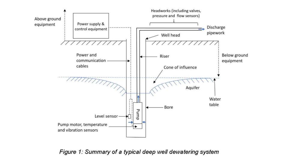
48 A typical artificial lift system, such as was used for dewatering purposes in mining applications, included “downhole equipment” and “above ground equipment” (see Figure 1 below, which was extracted from Mr Baarslag’s first affidavit). As at the earliest priority date, the “downhole equipment” typically included an ESP; power and communication cables that supplied power and instructions to the ESP; sensors that monitored the operation of the ESP and well conditions; as well as rising main pipework (known as a riser) that allowed the ESP to pump fluid out of the well.
49 The “above ground” equipment typically included a power supply system (e.g. a genset with a separate variable speed drive to allow the speed of the ESP to be controlled) and headworks, which typically included control valves and sensors to measure, for example, flow and discharge pressure of the fluid produced from the pump.
50 The speed of the ESP was automatically controlled using three main parameters: pressure, level, or flow. Automatic control of the ESP was based on information received from a pressure sensor that usually formed part of the headworks (measuring discharge pressure), a level sensor that formed part of the downhole equipment (measuring level of fluid above the ESP), or a flow sensor that typically formed part of the headworks (measuring the flow rate of fluid from the ESP).
51 There were different types of sensors that could be used to monitor the level of fluid in the well, including:
(1) capillary tubes (which expand and contract as a result of pressure in the well and provide a pressure reading in bars);
(2) floats (mechanical devices where the float rests on the fluid surface);
(3) cox whistles (which operate on air pressure);
(4) pressure sensors (which measure level by determining the pressure of fluid on the pressure sensor);
(5) vibrating wires (electric devices);
(6) ultrasonic sensors (which measure level using ultrasonic sound pulses).
52 It was industry practice to maximise production from a water well by obtaining the highest flow rate possible, whilst maintaining the water level within the recommended safe limits, just above the suction requirement.
53 It was also common to control the speed of an ESP using certain setpoints (i.e. the number in the controller which is used as a target for the closed loop control). The most common setpoints used to control the speed of the pump in a well were fluid level, flow rate of fluid from the pump and discharge pressure of the pump.
54 Whether to control the pump based on fluid level, flow rate and/or discharge pressure depended on the system components and well characteristics. For all wells, it was common to control the speed of the pump via fluid level, so that the pump could be run at high speed and produce a high output flow rate without causing damage to the pump.
55 When an automatic control mechanism was used, a proportional integral derivative (PID) control was the primary type of control used for controlling a variable to achieve a setpoint, and setpoints were typically entered via an HMI, but could also be entered remotely, hard-coded into the controller or dynamically operated by another layer of control which adjusted the setpoint for that particular controller to achieve some functional objective.
56 Submersible pumps were designed to automatically shut down in circumstances where the level, pressure, flow, temperature and/or vibration parameters fell outside of a certain range, in order to protect the pump.
57 The fluids which could be lifted from underground using an artificial lift system included, for example: salt and fresh water; water with entrained solids or sediment; oil; and mixtures of oil and water.
58 ESPs were not characterised by the application in which they were used, or the fluid that was moved by the pump. Such pumps were selected based on the characteristics of the relevant well, and were suitable for multiple applications, including in oil and gas, and mining applications. As Mr Vukadin and Mr Bernedo agreed during their concurrent evidence session:
(1) a pump is designed to displace a liquid from A to B, whatever its design;
(2) the purpose to which that pump is being put is irrelevant; and
(3) the design of the pump will not change depending on whether you are, for example, using that pump to lower the local water table or, for example, supplying water to a mining site.
59 In general terms, “dewatering” referred to removing water from solids from above or below the ground. An example of above ground removal of water from solids was the removal of water from tailings dams. An example of below ground removal of water occurred in mining applications; that is, water was commonly extracted from underground aquifers to create a dry environment to allow material to be excavated, for use as a water supply source or both of these purposes.
3.1 Whether known that dewatering lowers the local water table
60 There is a dispute between the parties as to whether below ground dewatering necessarily results in the lowering of the local water table, and whether this formed part of the common general knowledge as at the earliest priority date. Unless otherwise indicated, all further references to dewatering in these reasons is to below ground dewatering.
61 Allied Pumps submits that the level of a borehole prior to removing any ground water is more or less the level of the local water table and that, as water is removed, that level is lowered, and that this is the case irrespective of the purpose for removing the water. It submits that the water in the borehole is then replenished, at least in part, by the surrounding water table. Allied Pumps relied on the evidence of Mr Baarslag and Prof. Holmes.
62 Mr Baarslag was asked to identify the information that he knew and regarded to be well known and generally accepted by dewatering engineers by 16 August 2016. In response, he gave this evidence in his first affidavit:
Dewatering has many different meanings depending on the context in which it is used. Generally speaking, “dewatering” refers to removing water, and potentially other fluids, from solids. This can involve removing ground water to temporarily lower the ground water table or removing surface water out of the working area.
For example, in mining applications, water is commonly extracted from underground aquifers to allow for material to be excavated from areas that would otherwise be submersed in water. In civil applications, water is commonly extracted from underground reservoirs to allow for piping installations to occur in a dry environment that would otherwise be submersed in water. In construction applications, water is commonly extracted from underground reservoirs to allow for building works to take place in a dry environment that would otherwise be submersed in water. In oil and gas applications, water is commonly extracted from underground aquifers during the extraction of oil and gas from underground reservoirs. In each case, the ground water is lowered.
…
In mining projects, it was common to artificially lower the ground water table. Drawing down the ground water level, by extracting water via pump, allows for minerals to be extracted when relatively dry. Both diesel and electrical pumps are used for dewatering applications. When a diesel pump is used, it is located on the surface. When an electric pump is used, it is typically submersed in fluid. This is referred to as an electric submersible pump. For mining dewatering applications, it is most common to use an electric submersible pump.
As part of a dewatering drilling operation, a bore hole (also referred to as a well) is drilled into the earth’s subsurface. The bore hole fills with water as a result of underground aquifers. In order to remove water from the bore hole and to reduce the underground water level around the bore hole, it is common to locate an Electric Submersible Pump (Pump) into the bore hole. This is an example of “deep well artificial lift” (i.e. artificially pumping fluid from a deep well).
In deep well artificial lift applications, extracting water from below the ground causes a “cone of influence” on the underground aquifer around the well. This is shown in Figure [1]. The height and width of the cone of influence depends on many factors...
63 The “cone of influence” appears in Figure 1 above (depicted by the curved lines), being the figure which was extracted from Mr Baarslag’s first affidavit.
64 Mr Baarslag expanded upon his affidavit evidence in the concurrent evidence session:
MR BAARSLAG: It is my view that, when you’re pulling water out of a borehole, you’re dewatering. In my opinion, there is no soil that doesn’t have any hydraulic resistance. Therefore, there will always be a cone of influence of some description.
…
MR BAARSLAG: So it draws the water table down. Whether that’s a big cone or a small cone, it will draw it down somewhat and Mr Quick is right. It depends on the permeability, on how fast it gets, I guess, back to the previous level of where it was before you start[ed] pumping, but as soon as you start pumping, it will draw down.
MR BANNON: And those considerations in relation to permeability, do they apply equally to a dewatering exercise for a mining operation?
MR BAARSLAG: Yes. Yes. There – there is – there is no difference between drawing water out of a – a bore for the purpose of dewatering or for the purpose of water supply in terms of what it does in the ground.
…
MR BAARSLAG: For instance, in Mount Tamborine, Coca Cola is pulling water out of the aquifer for the supply and – and to make fizzy drinks. Mount Tamborine doesn’t have town water, and most people either rely on tank water that comes in trucks, or they have a bore. Coca Cola is not intending to lower the water table, but they are because they [dry] all these other people’s bores out because theirs is not as deep, and they simply take too much, and it’s a big dispute there, right there, at the moment, so that’s – it’s an unintended consequence.
65 Prof. Holmes gave this evidence during the same session:
PROF HOLMES: It seems to me, from just general engineering principles, if you need to get water out, you have to lower the surrounding water table from the borehole because, otherwise, you won’t get inflow because if the borehole water level is at the level of the ground table, there’s no water flow. You actually have to have a lowering of the localised water table around the borehole to let the water from the wider area flow in to where you want it to go. Now, whether it’s a minimal lowering or a significant lowering, it’s still lowering because, otherwise, you don’t get the differential pressure that will get you the flow, so the two are interrelated. If you take water out of a borehole, you – just to get a replenishment of the water, you must have a lowering in and around the hole to let the water flow in.
Now, Mr Quick says that might be minimal. It might be. If the water table is huge, it might be substantial. If the water table is not so huge – you just have to read documentaries about people draining aquifers to realise that, within Australia, with limited water, there’s constraints on how much water you can take out of a borehole for the use of taking water out so that you don’t lower the water table too much – suggest that, by definition, taking water out of a hole, for any purpose, is lowering the water table. If your intent is to lower it for the purposes of lowering it, or your intent is to take water, it’s the same engineering process. It’s the same result.
66 UON submits that the proposition that dewatering necessarily results in the lowering of the local water table is not agreed to be factually correct, and therefore disputes that it formed part of the common general knowledge. It says that that is because whether the local water table is lowered by dewatering will depend in any given case on factors including the permeability of surrounding rock, and the ability of ground water to flow into the reservoir to replace the fluid that is extracted.
67 By his second affidavit, Mr Quick gave evidence that, when oil is lifted from an oil reservoir, it will not necessarily lower the level of the surrounding ground water and that, whether it does will depend on factors including the permeability of the surrounding rock, and the ability of ground water to flow into the reservoir to replace fluid that is extracted.
68 During the hearing, Mr Quick applied the same reasoning to a dewatering operation on a mine. His evidence was somewhat confusing and illogical, and culminated in a claim that he was qualified to comment on the issue because he had been dux of earth science at high school:
MR BANNON: No, and so that – well, you would agree that, if your only purpose is to use a bore for water supply, you want that bore to be replenished from the water table as you pour water out, don’t you?
MR QUICK: Yes, that’s true.
MR BANNON: And it’s your intention that it be – when you use it for a water supply only, it’s your intention that it be replenished from the water table.
MR QUICK: Yes.
MR BANNON: And reducing – replenishing it from the water table reduces the level of the local water table, doesn’t it?
MR QUICK: Generally, it will. That’s right. It depends on the permeability and the supply of where that aquifer is being fed from.
…
MR BANNON: Well, do you understand, in mining applications – and I’ve heard your answer previously is through experience, but nevertheless, do you understand that, in mining applications, if you are dewatering in anticipation of digging, it’s a continuing continuous process? The pumps run all the time. Did you understand that?
MR QUICK: Yes, so dewatering is a different application from water supply. In dewatering, you’re deliberately attempting to lower the water table, which means you need enough withdrawal capacity to affect that water table. So you have to have enough bores to do it and big enough pumps to do it to substantially affect that water table and bring it down so that it’s clear of underground shafts or open cut pits or whatever you’re trying to remove the water – lower the water table to protect so that you don’t get ingress of water into those workings. So that’s a different purpose. If you’re intending on simply supplying water, then the last thing you want to do is drain your aquifer. So you don’t want to lower the water table. It’s a different objection.
MR BANNON: But do you understand that, in a mining application, when you are using bores for a dewatering purpose, the pumps run all the time because, if they don’t, the water table just goes back up again? Did you understand that?
MR QUICK: Yes, that’s true.
MR BANNON: So in a mining application, a dewatering purpose, the lowering of the water table is a temporary thing, isn’t it?
MR QUICK: While the pumps run, yes.
MR BANNON: Yes.
MR QUICK: That’s – yes, it is a temporary thing. If the dewatering pumps were to stop for some reason, for any period of time, then the water table will seep back up.
…
MR BANNON: But what I’m suggesting to you is you read the claims. You satisfy the claims if you’ve got one pump down one borehole which has the relevant elements. Correct? Right. So understanding that, the impact of one pump in one borehole for a dewatering purpose of lowering the water table, firstly, is only effective while the pump is running, while you’re pulling water out. You agree?
MR QUICK: Yes, that’s right. I agree on that.
MR BANNON: And it’s a lowering, a temporary lowering of the water table in the immediate vicinity of that individual borehole.
MR QUICK: That’s right. Yes.
MR BANNON: Right. Now, tell me, if you can, the difference between that circumstance and pumping water out of a well for water supply in terms of the impact on the immediately surrounding water table. Can you tell me that?
MR QUICK: Yes. The difference between a supply and a dewatering application is supply is trying not to deplete the well because, eventually, you’re going to run out of supply. So you would locate that where you have plenty of water flowing into the – from the aquifer into the well and you would draw it off at a rate that’s less than the inflow rate. Otherwise, you’re going to suck air. So it’s a different objective and you would locate it in a different place.
…
MR BANNON: With your background, your experience, you’re not in a position to actually dispute the proposition, are you, that, no matter where you put this borehole, if you’re pulling water out, it will, necessarily, lower, to some degree, the water table. You’re not qualified to resist that proposition, are you?
MR QUICK: I’m not a qualified hydrologist, but I’m a well-experienced engineer. I’ve had – worked on many different sites around this country and overseas, and several of those sites that I’ve worked on have had bore fields and dewatering systems that I’ve had to review, and, yes, I’m qualified enough to speak on - - -
MR BANNON: Sorry. When you say you’ve had to review the dewatering system, I thought you said your involvement was just in electrical componentry and that sort of thing. Are you wanting to expand on that?
MR QUICK: No. I’m not claiming to be a hydrologist or a - - -
MR BANNON: Right.
MR QUICK: Although I’m familiar with the sciences and geology. I was dux of earth science in high school. I am quite familiar with how these things work, and you do need some appreciation of the mechanics and the hydraulics in doing any kind of electrical and instrument-control design and software and – and functional arrangements. So yes, I would say I’m qualified to comment.
69 I find that dewatering necessarily results in the lowering of the local water table, and that this formed part of the common general knowledge as at the earliest priority date. If water finds its way into a borehole or well from the local water table (whether quickly or slowly, depending on the permeability of the walls of the borehole and other factors) and then that water is removed by the artificial lift system, the physical dislocation of the water from the water table into the borehole and then out of the borehole must necessarily result in a reduction of water in the local water table (and therefore a lowering of that water table), however temporary or insignificant the reduction in the level might be. That is because the water from the water table will enter the borehole and replace the water which has been removed by the artificial lift system.
70 In making this finding, I rely upon and accept the evidence of Mr Baarslag and Prof. Holmes, whose evidence I prefer over that of Mr Quick for the reasons explained above and because, as already observed, I found Mr Quick’s evidence on this issue to be confusing and illogical, and occasionally self-contradictory. For example, he appeared to conflate what could or would be done to avoid diminishing the water table substantially in a water supply situation with the physical consequences of dewatering on the water table irrespective of the purpose of the removal of the water.
3.2 Whether known that pressure sensors were used to measure level
71 There is limited divergence between the parties about whether and the extent to which it was common general knowledge that pressure sensors were used to measure the level of the fluid in the borehole or well (and how that was done) as at the earliest priority date. As this is an important issue in this case, however, I will address it separately.
72 It was common general knowledge at the earliest priority date that an artificial lift system needed to be designed and configured so as to ensure that the level of fluid did not fall below the minimum required fluid level over the pump because this would result in cavitation, which could damage the pump. This requirement was understood both in the context of water level and pressure, in which case it was referred to as the net positive suction head required (NPSHR). The NPSHR for each pump was provided by the pump manufacturer, so that users could ensure that the pump was operated within safe operating ranges so as not to damage the pump. Despite being described as a measure of pressure, NPSHR was in fact identified as a measure of the height (typically metres) of fluid required above the inlet of the pump.
73 Further, in his first affidavit, Mr Baarslag explained that, for dewatering applications, the “rule of thumb” to ensure that the pump is operating at, or close to, its best efficiency point is that the NPSHA (or net positive suction head available) is at least one metre above NPSHR. He explained that when the pump is operating within its preferred operating range, vibration is minimised, a high output flow rate is achieved, and the pump motor operates efficiently.
74 It was also common general knowledge that downhole pressure sensors (known as inlet pressure sensors or intake pressure sensors) were commonly used to measure the level of fluid in a borehole or well.
75 By his first affidavit, even Mr Quick accepted that it was common general knowledge as at the earliest priority date that, “In applications where access is difficult and an ultrasonic level sensor cannot be used (such as dewatering), a pressure-based sensor may be used to determine the water level based on the water pressure”.
76 The following passage of oral evidence is also instructive in this regard (with the reference to paragraph 19 being a reference to [0019] of Boot):
MR BANNON: So, coming back to my question, a pressure-based sensor in water will give you a reliable – or can give you a reliable sense of level in a water bore, subject to your issue with whether you put it over the inlet or in – or accounting for flow?
MR QUICK: The pressure sensor can be used to sense level in a bore, yes.
MR BANNON: Okay. And, looking at paragraph 19, would you agree, understanding that this particular can apply to a water well, that the reference to a pressure sensor is telling you that this system can be operated to vary speed based on the reading of a pressure sensor in a water well?
MR QUICK: Yes, it can be – that’s right. It could be varied – it could be using one of those operational characteristics, including pressure, to vary the speed; that’s true.
MR BANNON: Do you – do you agree with that?
MR BAARSLAG: Yes.
…
MR BANNON: And would you agree that one of the most common uses of a pressure sensor in a water bore as in 2016 was to measure level?
MR QUICK: Yes, certainly.
MR BAARSLAG: Yes.
(emphasis added.)
77 Such sensors worked by measuring the pressure exerted by the fluid on the sensor, which has a correlation (or mathematical relationship) with the fluid level. As explained by Mr Bernedo, who was called by UON:
Pressure at the pump intake is correlated with the fluid level, and because of this these terms are sometimes used interchangeably. However, the two are not identical.
In general terms, the pressure at the pump intake can be given by the equation:
Pip = ρ * g * h + Pcsg
[where Pip is pump intake pressure, ρ is the density of the fluid, g is a gravitational constant, h is the height of the fluid above the pump intake and Pcsg is the casing pressure]
As the height of the fluid above the pump increases, the pump intake pressure will increase. In this way, changes in pump intake pressure can indicate a rise or fall in the fluid level. However, pump intake pressure alone does not tell you the level of the fluid. In order to calculate the fluid level above the pump intake from the pump intake pressure you also need to know the density of the fluid, and the casing pressure.
…When pump intake pressure remains constant and there is no change in the density of the fluid or the casing pressure, it can be inferred that there has been no change in the fluid level. If the pump intake pressure changes, and there is no change in the density of the fluid or the casing pressure, then you can infer that the fluid level has changed. However, to calculate the exact amount by which it has changed you would need to carry out the calculations above.
78 In summary, then, if one takes the equation Pip = ρ * g * h + Pcsg, and assumes that each of ρ, g and Pcsg are constant, or relatively so, then an increase or decrease in Pip will typically mean that there has been a corresponding increase or decrease in h. That is (and was as at the earliest priority date) the known manner in which pressure sensors were used to measure level in the typical dewatering scenario.
79 This is because, in the case of dewatering:
(1) the density of fluid is typically relatively constant, and any changes in density because of changes in temperature, salinity or sediment are not sufficient to materially affect the accuracy of the sensor measurement for the purposes of determining level;
(2) the gravitational constant does not change;
(3) the boreholes are almost always open to the atmosphere, so there is no casing pressure. Even where there is a casing pressure (e.g. in a “closed system”), then, unless the casing pressure changes materially over time, it also will have no overall practical effect on the accuracy of the sensor measurement for the purposes of determining water level.
80 It was also common general knowledge that inlet/intake pressure sensors were positioned either above or below the pump inlet to ensure that the pressure reading was not affected by the disturbance and flow of fluid by the pump impeller at the inlet. The only expert who disputed this was Mr Quick, whose evidence was to the effect that inlet/intake pressure sensors were positioned directly at the pump intake/inlet, with the consequence that the flow at the intake/inlet prevents the sensor from accurately determining the level.
81 However, Mr Quick’s evidence was refuted by each of Mr Baarslag, Mr Vukadin and Mr Bernedo. Their evidence was that an intake/inlet pressure sensor is not placed directly at the intake, but rather either above the pump or below the motor. Indeed, neither Mr Vukadin and Mr Bernedo had ever seen an intake pressure sensor located directly at the inlet and considered that such placement would be “impractical”. Rather, the intake/inlet pressure sensor would be placed away from the inlet itself and any necessary adjustments to the calculation made by reference to the distance of the sensor from the intake.
82 At one stage, Mr Quick appeared to accept, if a pressure sensor was used to measure level, the sensor would need to be positioned away from the pump inlet. This acceptance occurred during the following exchange relating to [0058] and [0059] of the Patent specification:
MR BANNON: ...And you accept that would be a pressure sensor - - -
MR QUICK: Yes.
MR BANNON: - - - or pressure-based sensor which could measure that bore water level sufficiently above the pump; that’s right?
MR QUICK: Well, it would need to be – as Mr Baarslag and I agree, it would need to be some distance from the intake of the pump in order to accurately indicate level, but we need the level in order to produce the pressure on the intake of the pump.
(emphasis added.)
83 The evidence of Mr Baarslag, Mr Vukadin and Mr Bernedo, who were qualified to give evidence about this issue, is preferred to the evidence of Mr Quick, for the reasons already given and because Mr Quick had no direct experience with installing intake/inlet pressure sensors for submersible pumps in a borehole and had never seen a pressure sensor installed in a borehole.
84 It was also common general knowledge that electronic pressure sensors included a transmitter that communicated a signal, typically in milliamps, to a controller, which typically converted the milliamp signal and, where required, displayed some unit of measurement in pressure (e.g. kPA, head pressure) or depth (e.g. metres of fluid column) or in some instances both. If required, the system controller or the sensor device itself could convert the pressure signal to depth so that it could be displayed to the user via an HMI screen. It was, however, not necessary for the system controller to convert the milliamp signal into a unit of measurement for it to control the operation of the pump by such a signal. Instead, the system controller could be set to ensure that the ESP did not run in a manner which drew down the water level below the NPSHR.
85 Finally, in the case of dewatering, it was industry practice to maximise production from a water well by obtaining the highest flow rate possible, whilst maintaining the water level within the recommended safe limits, just above the NPSHR, and this could be done using an inlet/intake pressure sensor to control the pump. This was common ground between Mr Bernedo and Mr Vukadin through their evidence during the concurrent evidence session.
86 UON submits that the notional skilled addressee in this case is a person with practical experience in pump systems used in dewatering and the means of powering such pumps, who may be an electrician or electrical engineer. It also submits that, while there may be occasions where the person skilled in the art is a composite team, such as where no single person has the necessary range of knowledge, this is not such a case because Mr Quick has the skill and knowledge of such a person. UON also complains that Allied Pumps has provided no detail as to why a team is the necessary, or appropriate, way to characterise the relevant person skilled in the art, but, notwithstanding these submissions, did not object to the admission of the evidence of the experts called by Allied Pumps.
87 However, as French CJ explained in AstraZeneca AB v Apotex Pty Ltd (2015) 257 CLR 356; [2015] HCA 30 (AstraZeneca HC) at [23], the skilled addressee is not:
…an avatar for expert witnesses whose testimony is accepted by the court. It is a pale shadow of a real person – a tool of analysis which guides the court in determining, by reference to expert and other evidence, whether an invention as claimed does not involve an inventive step.
88 In other words, the skilled addressee is not a reference to a specific person but is a legal construct who may have an interest in using the products or methods of the invention, making the products of the invention, or making products used to carry out the methods of the invention either alone or in collaboration with others having such an interest: Aristocrat Technologies Australia Pty Ltd v Konami Australia Pty Ltd (2015) 114 IPR 28; [2015] FCA 735 (Nicholas J) at [26]; Root Quality Pty Ltd v Root Control Technologies Pty Ltd (2000) 49 IPR 225; [2000] FCA 980 (Finkelstein J) at [71]; see also AstraZeneca HC at [23].
89 As observed by Burley J in Hanwha Solutions Corporation v REC Solar Pte Ltd [2023] FCA 1017 at [86]:
Skilled addressees are those likely to have a practical interest in the subject matter of the invention: Catnic Components v Hill & Smith Ltd [1982] RPC 183 at 242 (Diplock LJ). There may be more than a single person with such an interest, and the notional skilled reader to whom the document is addressed may not be a single person but a team, whose combined skills would normally be employed in that art in interpreting and carrying into effect instructions such as those which are contained in the document to be construed: General Tire & Rubber Co v Firestone Tyre & Rubber Co Ltd [1971] 7 WLUK 130; [1972] RPC 457 at 485 (Sachs LJ). Put another way, the skilled addressee is a notional person who may have an interest in using the products or methods of the invention, making the products of the invention, or making products used to carry out the methods of the invention either alone or in collaboration with others having such an interest: Aristocrat Technologies Australia Pty Limited v Konami Australia Pty Limited [2015] FCA 735; 114 IPR 28 at [26] (Nicholas J); Pharmacia LLC v Juno Pharmaceuticals Pty Ltd [2022] FCA 92; 165 IPR 200 at [111] (Burley J).
(emphasis omitted.)
90 Evidence from multiple experts can be relied upon in identifying the background knowledge and experience of the single skilled addressee, particularly where a patent traverses multiple technical disciplines: see, for example, Aristocrat Technologies at [26]–[27]; see also Jupiters Ltd v Neurizon Pty Ltd (2005) 65 IPR 86; [2005] FCAFC 90 (Hill, Finn and Gyles JJ) at [154].
91 That the Patent traverses more than one discipline, such that evidence from multiple experts can be relied upon, accords with the practical experience of Mr Baarslag that he had resort to electrical engineers in his role as a dewatering engineer.
92 In this case, the skilled addressee is someone with expertise in and knowledge of both electrical engineering and dewatering. This may be a single person, or a team with the collective expertise and knowledge. Having regard to their qualifications and experience, the evidence of the experts called by Allied Pumps can be taken to reflect the knowledge and expertise of the skilled addressee.
93 Further, for the reasons given above relating to his lack of experience, I do not accept that Mr Quick (alone) has the skill and knowledge of the skilled addressee in this case. Thus, to the extent that UON contends that Allied Pumps has failed to explain why a team with the collective expertise and knowledge may represent the skilled addressee because a single person has the necessary range of knowledge (and that person is Mr Quick), that contention fails.
94 The Patent relates to submersible pumps used in dewatering applications, and, in particular, to the powering of such pumps when mains power supply is not available. The specification is to be understood in the light of the common general knowledge of the persons skilled in the art.
95 The title of the Patent is “Power and control of a submersible pump”.
96 The Background to the Invention in the specification includes the following statements:
Mining operations frequently occur below the local water table. In such operations, it is necessary to remove local ground water by an operation known as dewatering. Dewatering is achieved by drilling a bore; locating a submersible pump within the bore; and operating the pump to remove water from the vicinity of the pump.
Submersible pumps used in dewatering are typically driven by an electrically powered motor…
Where mains power is not available, the electrical power for the motor must be generated on the surface. This is typically achieved by use of a generator having an internal combustion engine which drives an alternator.
In a typical installation, electrical power and voltage produced by the generator is supplied to an electrical control unit [which], in turn, provides electrical power to the pump motor. Such an electrical control unit may weigh up to four tonnes, and cost up to $300,000.
In order to maintain the motor condition the pump must be operated within a range of interdependent parameters. For a given pump speed, such as 40Hz, the pump curve for that pump will show the flow rate of the pump for a given pressure head. In a downhole operation, both the pressure head and a desired flow rate are subject to change. Such changes can be accommodated by a change in the pump speed, within safe pump operating limits. This is typically achieved by the use of a variable speed drive within the electrical control unit.
The present invention seeks to avoid the use of a variable speed drive by instead providing direct control of the generator. In a preferred embodiment, this may eliminate the need for a separate electrical control unit.
97 At [0008] of the specification, the following statement is made (which paragraph received significant attention during the trial):
For the avoidance of doubt, the term ‘dewatering’ as used herein is defined as the removal of groundwater from a borehole in order to lower the level of the local water table.
98 The specification then contains a Summary of the Invention, which describes the various aspects and embodiments of the invention.
99 The specification describes one aspect of the invention as providing a power and control system for a dewatering submersible pump, the system including a generator comprising an engine and an alternator, the engine having an ECU, the alternator having a voltage regulator, the generator supplying electrical power to the pump; at least one sensor arranged to provide information regarding pump operation and/or surrounding conditions; and a system controller, the system controller being arranged to receive information from the sensor and to control the voltage regulator and the ECU, wherein the voltage regulator is an AVR. It states in relation to this aspect that the sensor may be arranged to monitor the operation of a motor controlling the pump; to monitor the operation of the pump; to monitor the condition of fluid within a system connected to the pump; or to monitor external conditions. It states that the voltage regulator preferably provides an excitation voltage to the alternator in order to regulate output voltage of the alternator; and that the excitation voltage is arranged to vary in response to a comparison of measured output voltage of the alternator and a desired output voltage indicated by the system controller. It states that the sensor may be arranged to monitor the operation of a motor controlling the pump; to monitor the operation of the pump; to monitor the condition of fluid within a system connected to the pump; or to monitor external conditions.
100 The specification then provides that, in a preferred embodiment, at least one sensor is arranged to measure borehole water level; it is also preferred that at least one sensor is arranged to measure a fluid flow rate within a pipe connected to an outlet of the pump; and it is further preferred that at least one sensor is arranged to measure fluid pressure within a pipe connected to an outlet of the pump.
101 The specification then describes a second aspect of the invention as providing a power and control system for a dewatering submersible pump, the system including a generator comprising an engine and an alternator, the engine having an ECU, the alternator having a voltage regulator, the generator supplying electrical power to the pump; at least one sensor arranged to provide information regarding pump operation and/or surrounding conditions; and a system controller, the system controller being arranged to receive information from the sensor and to control the voltage regulator and the ECU, wherein the system controller is arranged to compare the information from the sensor to an input setpoint, and to control the voltage regulator and the ECU in response to deviation of the sensed information from the setpoint.
102 The specification states that the setpoint may be one of the set of desired water level in a bore; desired fluid flow rate within a pipe connected to an outlet of the pump; and desired pressure within a pipe connected to an outlet of the pump.
103 The specification then describes a third aspect of the invention as providing a method of controlling a dewatering submersible pump, the pump being powered by a generator having an engine and an alternator, the method including monitoring at least one condition using a sensor; using a system controller to receive information from the sensor; using the system controller to control an ECU to in turn control an output frequency of the generator in response to information from the sensor; and using the “system control [sic]” to control an AVR to in turn control an output voltage of the generator in response to the sensed condition. It states that the condition(s) being monitored may be borehole water level and/or fluid conditions in a pipe connected to an outlet of the pump. These fluid conditions include fluid flow rate and fluid pressure. It states that the ECU and AVR are “preferred operated to maintain pump speed within a recommended range”.
104 The specification then discusses certain pieces of prior art. The specification states at [0020] that “[t]he applicant is not aware of similar power and control systems and methods used in dewatering” but acknowledges that other power and control systems exist “for submersible oil pumps”.
105 The specification first discusses US Patent Number 7170262 (Pettigrew) which was initially relied upon by Allied Pumps as part of its novelty case, but which was then not pressed at trial. The specification states that Pettigrew describes such a submersible oil pump, and that, rather than an AVR, Pettigrew uses an excitation controller which adjusts voltage according to the frequency of the engine-generator combination. The specification states that Pettigrew does not suggest the use of sensors in order to inform the operation of the excitation controller, or to control for a desired setpoint.
106 The specification then discusses Torrey at [0022] in these terms:
International patent publication number WO2015/051805 (Torrey) describes another submersible oil pump, with a control system arranged to regulate pump inlet pressure. Torrey also describes the use of pump sensors such as temperature and vibration. In one embodiment, Torrey describes the use of an exciter commanded by a system controller, however Torrey does not describe the use of an automatic voltage regulator. Torrey does not suggest the use of sensors monitoring either well level or conditions in connected piping, or the control for associated setpoints.
107 The specification next discusses Boot at [0023] in these terms:
US Patent application publication 2014/0209289 (Boot) describes yet another submersible oil pump. As in Torrey, Boot suggests sensing operational characteristics within the pump, but not within connected piping. There is no suggestion of monitoring well level. Boot does not suggest the maintenance of setpoints.
108 There is then a brief description of the drawings and a Detailed Description of the Preferred Embodiments of the invention by reference to Figures 1, 2 and 3. Figure 1, which is a schematic view of a power and control system for a submersible pump in accordance with the invention, is reproduced below.
109 The specification states, by reference to the figures, that:
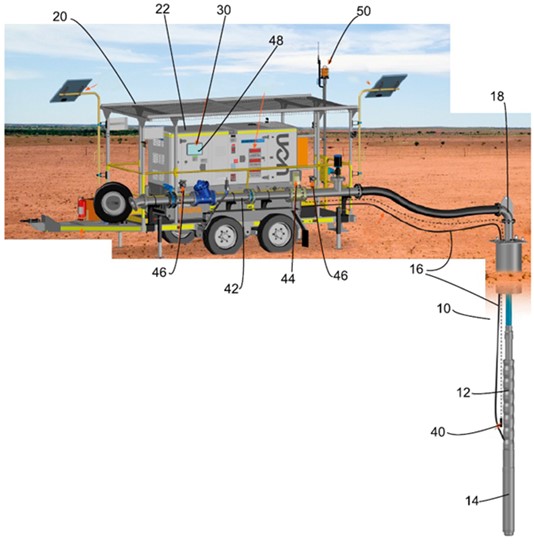
(1) there is shown a water bore 10 in which a submersible pump 12 has been lowered. The submersible pump 12 is powered by an electrical motor 14. A primary electrical cable 16 provides electrical power to the motor 14. An outlet pipe 18 carries water from the pump 12 to the surface;
(2) a power and control unit 20 is located on the surface. The power and control unit 20 includes outer casing 22 which houses a generator 24 comprising an internal combustion engine 26 and an alternator 28. The generator 24 supplies electrical power to the primary electrical cable 16;
(3) the power and control unit 20 includes a controller 30. The controller 30 is arranged to manage an ECU 32 and an AVR 34;
(4) the AVR 34 regulates the voltage supplied via the primary electrical cable 16 to the motor 14. It achieves this by applying an excitation voltage to the alternator 28, and varying the excitation voltage in response to measured output of the alternator 28. The arrangement is such that the controller 30 provides an indication of desired output voltage to the AVR 34, and the AVR 34 constantly manages the excitation voltage in order to achieve the desired output voltage by means of a feedback loop;
(5) the ECU 32 controls the speed and power of the engine 26, primarily through control of electronic fuel injectors. The controller 30 provides the ECU with a desired speed (i.e. frequency) and load for operation of the alternator 28 under the relevant conditions. The ECU 32 acts to maintain efficiency of the engine 26 through changing conditions. The ECU 32 actively controls the volume of fuel delivered per engine stroke by the fuel injectors to provide the required engine speed and torque;
(6) a circuit breaker 36 is located electrically between the generator 24 and the primary electrical cable 16;
(7) the controller 30 is connected to a plurality of sensors. A first sensor 40 is located within the bore 10, and extends down to the pump 12. The first sensor 40 is arranged to detect and monitor the level of ground water within the bore 10;
(8) the outlet pipe 18 is fluidly connected to a transport pipe 42. A second sensor 44 is mounted on the transport pipe 42. The second sensor is a flow meter, arranged to detect the flow rate of water passing through the transport pipe 42;
(9) two third sensors 46 are mounted at spaced locations along the transport pipe 42. The third sensors 46 are pressure sensors, arranged to detect pressure within the transport pipe 42;
(10) a temperature sensor (not shown) is attached to the motor 14;
(11) operation of the controller 30 may be done directly via a HMI 48, or may be done remotely via a network interface 50, arranged to communicate with an electronic network 52 and to be operated from a remote control centre 54;
(12) the present invention operates on the understanding that pump speed, flow rate, and pressure head together provide an interrelated threedimensional operation range for the pump 12.
110 At [0063] of the specification, the HMI is described in this way:
The HMI 48 is a physical interface electronically coupled to the controller 30. The HMI 48 includes output means, such as a display, speaker and/or printer; and input means, such as a keypad, keyboard, touch screen, touch pad and the like. The HMI 48 provides the ability to control the system controller 30 locally, that is, by a user physically located in the vicinity of the power and control unit 20.
111 The specification then describes three modes, being water-level maintenance mode, constant flow rate mode and constant pressure mode.
112 The water-level maintenance mode is described at [0048]–[0050]:
In this mode the key sensor is the first sensor 40, measuring the level of water in the bore 10. The level of ground water surrounding a bore 10 can be calculated using the baseline aquifer level, the porosity of the surrounding medium, the distance from the bore, and the level within the bore. As such, maintaining an appropriate level within the bore 10 provides certainty that the water level in the surrounding area will be below the required level. This appropriate level is input into the controller 30 as a setpoint.
In water-level maintenance mode, the pump 12 is operated at its full speed (e.g. 50Hz) to achieve maximum possible flow rate until the water level in the bore reaches the setpoint. Once the setpoint has been reached, the controller 30 operates a feedback loop between the engine speed governed by the ECU 32 (operated in conjunction with excitation voltage of the AVR 34) and the measured water level of the first sensor 40 until a steady state is reached. It will be appreciated that the steady state must be within the system capacity (including within safe pump speeds and system pressures) otherwise an alarm will activate and the pump 12 will be shut down. In a preferred embodiment, the feedback loop employs Proportional Integral Derivative (PID) control.
The controller 30 will continue to operate the feedback loop in the event that there is a change in surrounding conditions.
113 The constant flow rate mode is described in these terms at [0051]–[0054]:
In this mode the key sensor is the second sensor 44, measuring the flow rate through the transport pipe 42. Water being extracted from the bore 10 can be used in many applications, some of which (for instance, use as process water within ore processing operations) require a constant flow rate of water. This flow rate is input into the controller 30 as a set point.
In constant flow rate mode, the controller 30 operates a feedback loop between the engine speed governed by the ECU 32 (operated in conjunction with excitation voltage of the AVR 34) and the measured water flow past the second sensor 44 until a steady state is reached. In a preferred embodiment, the feedback loop employs PID control. It will be appreciated that the steady state must be within the system capacity (including within safe pump speeds and systems pressures temps) otherwise an alarm will activate and the pump 12 will be shut down.
The controller 30 will continue to operate the feedback loop in the event that there is a change in surrounding conditions.
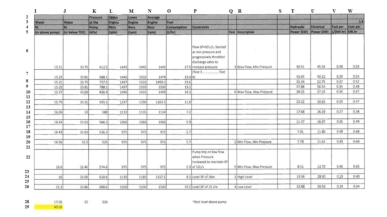
Figure 3 shows usage of the pump curve diagram in constant flowrate mode. As head pressure changes from 230m to 90m (for instance, different valves are opened or closed downstream, or in response to changes in bore water level), the pump speed is changed from 50Hz to 35Hz while maintaining a flow rate of 30I/s.
114 The constant pressure mode is described in these terms at [0055]–[0057]:
In this mode the key sensors are the third sensors 46, measuring the pressure in the transport pipe 42. Water being extracted from the bore 10 can be used in many applications, some of which (for instance, dust suppression and tank filling via a pressure valve) may require a constant water pressure. This pressure is input into the controller 30 as a set point.
In constant pressure mode, the controller 30 operates a feedback loop between the engine speed governed by the ECU 32 (operated in conjunction with excitation voltage of the AVR 34) and the measured water pressure at the third sensors 46 until a steady state is reached. In a preferred embodiment, the feedback loop employs PID control. It will be appreciated that the steady state must be within the system capacity (including within safe pump speeds) otherwise an alarm will activate and the pump 12 will be shut down.
The controller 30 will continue to operate the feedback loop in the event that there is a change in surrounding conditions.
115 There is then a description of the system operating safeguards. In particular, the specification states at [0058] and [0059] that:
The controller 30 includes a plurality of thresholds within which the system must operate, including current draw, pump speed, system pressure, bore water level, motor temperature, and minimum flow rate. The controller 30 is arranged to activate an alarm and, if necessary, shut down the system should any of the thresholds be breached.
Typical thresholds include a motor speed of 30Hz to 50Hz or 60Hz, a bore water level sufficiently above the pump 12, and a motor temperature below 65°C or 70°C. Thresholds such as minimum flow rate are specific to particular pump/motor combinations.
116 At [0066] of the specification, the following is stated:
It will be appreciated that the methods described above essentially allow the power and control unit 20 to provide the function of a variable speed drive (VSD), thereby removing the need for a dedicated VSD and hence the additional capital and operating expenditures associated with having a VSD coupled to a fixed speed generator.
117 Relevantly to the issues in this case, I observe that:
(1) The Detailed Description does not indicate that the system that is the subject of the claimed invention must be used for the express purpose of lowering the local water table.
(2) By reference to the water-level maintenance mode, the specification does not confine the “first sensor 40” to any particular type of sensor which measures the level of water in the bore; does not identify any particular unit of measurement that must be used (for example, metres); does not require any display of the measured level; does not detail where the sensor is placed in the borehole; does not identify how level is calculated or where such calculation is to take place; or stipulate against what the measurements should be made (for example, distance below ground level or level above the pump).
(3) The description of the pumping system in the Detailed Description is not limited to a pump which can only be used to pump water and it does not exclude pumps which can pump water but also other fluids, or which have other additional features.
118 Below are the claims of the invention:
1. A power and control system when used for a dewatering submersible pump, the system including:
a generator comprising an engine and an alternator, the engine having an Engine Control Unit (ECU), the alternator having a voltage regulator, the generator supplying electrical power to the pump;
at least one sensor arranged to provide information regarding pump operation and/or surrounding conditions; and
a system controller, the system controller being arranged to receive information from the sensor and to control the voltage regulator and the ECU based on the received information,
wherein the voltage regulator is an automatic voltage regulator,
wherein the ECU is controlled to govern the speed of the engine and thus the frequency of the electrical power supplied to the pump, and the voltage regulator is controlled to govern the voltage of the electrical power supplied to the pump,
and wherein the sensor is arranged to measure borehole water level.
2. A power and control system when used for a dewatering submissible pump, the system including:
a generator comprising an engine and an alternator, the engine having an ECU, the alternator having a voltage regulator, the generator supplying electrical power to the pump;
at least one sensor arranged to measure borehole water level; and
a system controller, the system controller being arranged to receive information from the sensor and to control the voltage regulator and the ECU,
wherein the system controller is arranged to compare the information from the sensor to an input setpoint, and to control the voltage regulator and the ECU in response to deviation of the sensed information from the setpoint.
3. A power and control system when used for a dewatering submersible pump as claimed in claim 3, wherein the setpoint is desired water level in a bore.
4. A method of controlling a dewatering submersible pump, the pump being powered by a generator having an engine and an alternator, the method including:
monitoring borehole water level using a sensor;
using a system controller to receive information from the sensor,
using the system controller to control an ECU to in turn control an output frequency of the generator in response to the information from the sensor; and
using the system controller to control an automatic voltage regulator to in turn control an output voltage of the generator in response to the borehole water level.
119 There are three issues on construction that arise in the present case, namely:
(1) the meaning of the term “dewatering submersible pump” in claims 1–4;
(2) the scope of “a sensor arranged to measure borehole water level” in claims 1, 2 and 3 and “monitoring borehole water level using a sensor” in claim 4;
(3) the meaning of “control” and “in response to” in claim 4.
6.2 Principles of construction
120 The principles applicable to patent claim construction are well-settled and were not in dispute. In Jupiters at [67], the Full Court summarised the principles for the construction of patents as follows:
(1) the proper construction of a patent specification is a matter of law: Décor Corporation Pty Ltd v Dart Industries Inc (1988) 13 IPR 385 (Sheppard J) at page 400;
(2) a patent specification should be given a purposive, not a purely literal, construction: Flexible Steel Lacing Company v Beltreco Ltd (2000) 49 IPR 331; [2000] FCA 890 (Hely J) at [81]; and it is not to be read in the abstract but is to be construed in the light of the common general knowledge and the art before the priority date: Kimberley-Clark Australia Pty Ltd v Arico Trading International Pty Ltd (2001) 207 CLR 1; [2001] HCA 8 (Gleeson CJ, McHugh, Gummow, Hayne and Callinan JJ) at [24];
(3) the words used in a specification are to be given the meaning which a normal person skilled in the art would attach to them, having regard to his or her own general knowledge and to what is disclosed in the body of the specification: Décor Corporation at page 391;
(4) while the claims are to be construed in the context of the specification as a whole, it is not legitimate to narrow or expand the boundaries of monopoly as fixed by the words of a claim by adding to those words glosses drawn from other parts of the specification, although terms in the claim which are unclear may be defined by reference to the body of the specification: Kimberley-Clark at [15]; Welch Perrin & Co Pty Ltd v Worrel (1961) 106 CLR 588 (Dixon CJ, Kitto and Windeyer JJ) at page 610;
(5) the body of a specification cannot be used to change a clear claim for one subject matter into a claim for another and different subject matter: Electric & Musical Industries Ltd v Lissen Ltd (1939) 56 RPC 23 at page 39;
(6) experts can give evidence on the meaning which those skilled in the art would give to technical or scientific terms and phrases and on unusual or special meanings to be given by skilled addressees to words which might otherwise bear their ordinary meaning: Sartas No 1 Pty Ltd v Koukourou & Partners Pty Ltd (1994) 30 IPR 479 (Gummow J) at pages 485–6;
(7) the Court is to place itself in the position of some person acquainted with the surrounding circumstances as to the state of the art and manufacture at the time: Kimberley-Clark at [24]; and
(8) it is for the Court, not for any witness however expert, to construe the specification: Sartas No 1 at pages 485–6.
121 This decision, and these principles, were recently cited with approval in Reflex Instruments Asia Pacific Pty Ltd v Globaltech Corporation Pty Ltd [2023] FCAFC 158 (Moshinsky, Burley and Kennett JJ) at [75].
6.3 Issue 1: meaning of “dewatering submersible pump”
122 Each of claims 1 to 3 includes within the first integer “[a] power and control system when used for a dewatering submersible pump” and claim 4 includes within the first integer “[a] method of controlling a dewatering submersible pump”. The parties referred to this disputed term as “dewatering submersible pump” and I will adopt the same approach.
6.3.1 The contentions of the parties
123 UON contends that “dewatering submersible pump” means a submersible pump used for the purpose of dewatering for the purpose of extracting ground water and lowering the water table, such as for mining applications. It also submits that the meaning to be given to the term “dewatering” depends upon the context, and that the context of the Patent is that of lowering the water table including in mining operations, and not use in oil and gas.
124 UON submits that the language of the specification supports its construction, relying in particular upon:
(1) the reference in [0001] to the Field of the Invention, being that the invention relates to “submersible pumps used in dewatering applications, such as within the Australian mining industry”;
(2) the reference in [0002] as part of the Background of the Invention as follows:
Mining operations frequently occur below the local water table. In such operations, it is necessary to remove local ground water by an operation known as dewatering. Dewatering is achieved by drilling a bore; locating a submersible pump within the bore; and operating the pump to remove water from the vicinity of the pump.
(3) the statement in [0008] as follows:
For the avoidance of doubt, the term ‘dewatering’ as used herein is defined as the removal of groundwater from a borehole in order to lower the level of the local water table.
(4) the distinction which is drawn in [0020] between power and control systems and methods used in dewatering, and power and control systems for submersible oil pumps.
125 Allied Pumps contends that “dewatering submersible pump” in the claims means any pump that is capable of being used for dewatering, and that the claims extend to the use of the claimed system with a submersible pump for the purposes of removing water from a borehole, whether that be for the purposes of lowering the local water table to create a dry environment, water supply or both. It also contends that the Patent is directed to submersible pumps used in any dewatering application, not just in the mining industry.
126 For the following reasons, I prefer the construction posited by Allied Pumps.
6.3.2 Consideration of issue 1
127 The main characteristic of a submersible pump is the design of the electrical motor such that it can be operated submersed in fluid without affecting its electrical integrity. The submersible motor coupled to a centrifugal pump is what is called an electrical submersible pump. There are numerous types of ESPs which are suited to the requirements of different applications.
128 As is apparent from the words used in the specification at [0001], the Patent is directed to submersible pumps used in any dewatering application, not just in the mining industry. The fact that the mining industry is referred to by way of example does not confine the scope of the claims to that industry, and the skilled addressee would not understand the Patent specification to be confined in that way.
129 UON’s construction is tied to the particular purpose of lowering the level of local water table. It particularly relies upon [0008] of the specification which “defines” the term dewatering as the removal of ground water from a borehole in order to lower the level of the local water table.
130 However, as already observed, the Detailed Description does not indicate that the system that is the subject of the claimed invention must be used for that purpose. Further, the Patent specification states that the “submersible pump” can be used to extract water for different applications, which are not for the purposes of lowering the local water table. At [0051], it states that, “[w]ater being extracted from the bore 10 can be used in many applications, some of which (for instance, use as process water within ore processing operations) require a constant flow rate of water” (emphasis added); and at [0052] it states that, “[w]ater being extracted from the bore 10 can be used in many applications, some of which (for instance, dust suppression and tank filling via a pressure valve) may require a constant water pressure” (emphasis added). Such applications may not be for the purpose of lowering the local water table. The skilled addressee would therefore not understand [0008] of the specification to import any purpose requirement in the claims beyond specifying, for the avoidance of doubt, that the system is to be used for below ground dewatering (as opposed to above ground dewatering).
131 UON’s construction begs the question: how does one assess the purpose?
132 If it is the purpose of the pump itself, assessed objectively by reference to its design and capabilities, one would expect that the specification would be directed to a particular type of mechanical pump design. However, the specification is not so directed; indeed, there is no disclosure in the specification that suggests that the Patent requires the pump to be designed for use as a water pump in a borehole, or that it possesses any specific characteristics, other than it be submersible and capable of removing water from a borehole.
133 If it is the subjective purpose of the user of the pump, then such a construction would be surprising and absurd because:
(1) the pump may be used for different uses over time, only one of which is for the express purpose of lowering the local water table;
(2) a purchaser may not have determined the intended use of the power and control system at the time of purchase, or they may purchase the system for multiple uses, only one of which is for the express purpose of lowering the local water table;
(3) a pump may be used for multiple purposes at the same time (such as in the case where water is extracted from the bore both to create a dry environment and for water supply purposes).
134 These matters provide strong reasons to reject UON’s construction. A further reason to reject UON’s construction is that locating a submersible pump in a borehole and extracting ground water will always lower the local water table, and a skilled addressee would know this. As Mr Baarslag explained in the concurrent evidence session:
[T]he purpose of the dewatering pump – if you use it in a bore, you’re going to dewater, whether that’s your purpose or not… You’re going to lower the watertable and… the pump doesn’t care what it does… it needs to pump the water out.
135 A skilled addressee would therefore not read the Patent as distinguishing between a circumstance of a purpose of lowering the water table and a purpose of removal of water which had the inevitable known effect of lowering the water table. This has the consequence that the words “in order to” in [0008] confirm that the Patent is directed to below ground dewatering, which necessarily has the known effect of lowering the level of the local water table (as opposed to above ground dewatering).
136 For these reasons, “dewatering submersible pump” in the claims means any pump that is capable of being used for dewatering. Thus, the claims of the Patent extend to the use of the claimed system with a submersible pump for the purposes of removing water from a bore, whether that be for the purposes of lowering the local water table to create a dry environment, water supply or both.
137 Each of claims 1 to 3 includes a “sensor [arranged] to measure borehole water level”, whereas claim 4 has the integer “monitoring borehole water level using a sensor”. As was done by Allied Pumps, I will describe these as the level sensor integers.
138 The tension between the parties is whether these claims were limited to a particular type of sensor which had certain features (being one which is configured to measure, and does measure, “borehole water level”), or whether they should be construed as referring to any sensor which is capable of being used to measure or monitor the water level in the borehole.
139 For the following reasons, I prefer the latter construction.
140 As has been addressed in detail, at the earliest priority date, it was common general knowledge that pressure sensors were commonly used as water level sensors for boreholes. Such sensors were “very well suited to measuring the level of fluid in a well”, to use the words of Mr Baarslag.
141 The measurement obtained by the pressure sensor could be converted within the system to a representation of the level, if required.
142 As to this topic, Prof. Holmes gave this evidence during the concurrent session (with which evidence Mr Quick appeared to agree):
In terms of the control of itself, it has no idea whether it’s measuring pressure, level, anything. It has an electrically measured quantity that it’s internally doing the calculations on. The translation of that internal quantity to whatever representation the operator may need or the user may need is a translation process and has no relation to the controller. Over the years, I’ve designed controllers where we operate on abstract numbers, and all of that conversion is done at the design level.
More modern systems have a HMI to make it easier for the operator to translate from that internal quantity to what’s displayed on the screen. It’s a convenience for the operator. It’s not required. I’ve built many systems where the set point is controlled by a knob, which has a scale from one to 10. It has no correlation with any quantity, but the user of that system knows that he needs to dial up to seven, for example, to get the right number. The – the relationship between the quantity and the control system is all for the human user.
143 Further, any conversions required to be performed by the pressure sensors did not have to be done by the device itself. For example, capillary tubes provided a reading in bars, which would then (if needed) be converted to metres using that reading. As to this, Mr Baarslag gave this evidence:
MR BAARSLAG: Yes, but if we – for instance, in Lihir we had a separate measuring device, which was a capillary tube, and it would register the pressure in bars related to the water level. Engineers put it in the spreadsheet for the data to be interpreted, and that would convert that straight over to metres head or water level.
MR BANNON: And from your purpose – is this right – if you got a reading in bars, that would tell you in your own head what the level was you were after or not after?
MR BAARSLAG: We had it in a spreadsheet. It was converted straight up, so we could see the numbers in metres and head because the thumb curves are all in metres and head, so we try to keep it simple.
144 Further, as Prof. Holmes explained:
I have a great deal of experience in using sensors, and it is extremely common to have to take the output of the sensor and adapt it in a variety of ways to suit the needs of the control system. It is just what you do. Whether it requires compensation from some other variable within the – the control system, whether it simply requires some form of rescaling adaptation, but it is often not done in the sensor because, particularly in the earlier days, sensors were relatively dumb and all you could get out of them was a fairly simplistic measurement, and you had to compensate. More modern sensors tend to integrate that compensation into the electronics within the sensor, but it’s the same process…
145 A type of pressure sensor called the “piezo resistant level sensors” was described by Mr Baarslag as the most common type of sensor. As to this, Mr Quick’s evidence was:
Traditionally, they were four to 20 milliamps output … Piezo is one way. There’s – for the purposes of this exercise, the actual mechanism inside the sensor doesn’t make any difference. All we’re interested in is that pressure comes in and electrical signal comes out that can be interpreted as pressure and then, under some circumstances, that can be used as a level.
(emphasis added.)
146 Importantly, neither the claims nor the specification:
(1) identify or define the sensor which measure or monitor the borehole water level;
(2) identify any specifications that such a sensor must have;
(3) stipulate how the sensor must measure borehole water level including what output it must provide or what unit the setpoint must be in; or
(4) place any limitation on the sophistication of the sensor or the accuracy of the measurement that it must achieve. The specification only requires the sensor to be “arranged to detect and monitor the level of ground water within the bore”: [0035].
147 As to this last point, UON submits that the word “arranged” in the claims means that the sensor must be appropriately located, configured to provide measurements that enable the desired water level to be achieved, and engineered or designed for that purpose and function.
148 However, in the context of the specification (which does not define or confine the sensor in any way), and in light of the common general knowledge, the level sensor integers include any sensor that is capable of measuring an input that is reflective of borehole water level. Each of Mr Baarslag, Mr Quick and Prof. Holmes agreed that this could include a pressure sensor.
149 The role of the sensor is to, amongst other things, provide information which enables the water level to be measured so that the desired water level can be achieved, with the system controller being “arranged to compare the information from the sensor to an input setpoint”. This does not exclude from the scope of the claims an adjustment (or conversion) of the information received from the sensor by the controller, or conversion of the setpoint that has been entered, when comparing the information from the sensor with that setpoint. In other words, the claims are not limited to a “direct” comparison between the output of the sensor and the setpoint, and the comparison could include a conversion from pressure to depth or vice versa.
6.5 Issue 3: meaning of “control” and “in response to”
150 Each of Allied Pumps and UON raise different issues concerning the construction of claim 4 in closing submissions and did not address the issue raised by the other. It was therefore difficult to understand what, if anything, was in dispute between them. However, I will address both arguments for completeness.
151 Addressing “control”, Allied Pumps submits that the claims do not specify the type of control that must be achieved by the system controller, nor does it require PID control. All that is required is that the system controller controls the speed of the engine via the ECU and the voltage of the electrical power supplied to the pump via the AVR based on the received information.
152 I accept this submission. Claim 4 does not specify any type of control that must be achieved by the system controller in response to the information received from the sensor. Further, while there is a disclosure of the feedback loop employing PID control in [0049] of the specification (in relation to a preferred embodiment), claim 4 does not require PID control.
153 Addressing the meaning of “in response to”, UON observed that the experts disagreed about the meaning of these words. The expert evidence was as follows:
(1) “This agreed meaning is in the context of this Patent, but not all sensors are used for control functions. In this Patent, the sensor is used by the system controller to control the generator speed and voltage” (Mr Quick);
(2) “I am of the opinion that claim 4 means that the system controller continuously adjusts the generator output based on fluid level inside the well” (Mr Baarslag);
(3) “Claim 4 requires the system controller to ‘respond’ to the monitored water level, but does not define what this response should be. The use of a PID feedback loop, which clarifies the response as ‘water level maintenance’ control, is disclosed in [0049] of the Detailed Description in the 197 Patent” (Prof. Holmes).
154 UON submits that the different approaches of the experts does not affect the clear and plain language of these words in claim 4, which is that information from the sensor is used by the system controller to control the generator speed and voltage based on borehole water level. It submits that it is in that sense that the words “in response to” are used and are applicable.
155 It is not clear how these submissions differ from the submission by Allied Pumps concerning “control”. To the extent that the submission by UON leads to a conclusion which is different to that which I have reached above in relation to the meaning of “control”, it is not accepted.
7. ADMISSIBILITY OF PLEADINGS IN OTHER PROCEEDING
156 The present proceeding was commenced by Allied Pumps on 1 July 2021 against LAA. By the statement of claim filed by Allied Pumps on that date, it was pleaded that the alleged invention was not novel as at 16 August 2016, including because of:
The hiring, supply and/or other disclosure of a power and control system for a dewatering submersible pump according to the invention as claimed in each of claims 1 to 4 of the Patent by LAA’s predecessor in title, UON Pty Ltd, to the Roy Hill mine site located in the Pilbara region of Western Australia, which occurred in or around May 2016; and the subsequent use and/or other disclosure of that system at the Roy Hill mine site from in or around May 2016.
157 In a separate proceeding in this Court which had been brought by UON (and LAA) against non-parties to this proceeding, UON (and LAA) filed an “Amended Substituted Statement of Claim” on 13 August 2021, pursuant to leave granted by McKerracher J (Amended Statement of Claim).
158 The Amended Statement of Claim included the following allegations (whether as material facts or particulars of those material facts):
(1) From 2002 until 2015, Mr Mark Keogh (a director of UON, and named co-inventor for the Patent) and Mr Reid, for and on behalf of UON, invented and developed an alternative motor starting control and power management system with specific application for dewatering remote island mine sites and generally (defined as the “Invention”).
(2) On 16 August 2016, Mr Keogh and Mr Reid, for and on behalf of UON, sought registration under the Patents Act for the grant of a patent in relation to the Invention and were granted Provisional Patent Registration Number 2016903254.
(3) UON:
(a) marketed the Invention as the Pro Power General Motor Control Generator (defined as the “Pro Power GMC Generator”);
(b) commenced marketing and offering the Pro Power GMC Generator for sale generally but specifically to parties operating in the industries of mining, oil and gas exploration and production, construction, equipment rental and agriculture; and
(c) commenced marketing and offering the Pro Power GMC Generator for sale or hire from December 2015.
(4) On 3 November 2020, LAA applied for an innovation patent under the Patents Act in respect of innovative aspects of the Invention, being Innovation Patent Application 2020103197.
(5) On 23 December 2020, the Innovation Patent Application 2020103197 was granted.
159 The Amended Statement of Claim stated that it was prepared by a lawyer (who was named). That lawyer also signed a certificate at the conclusion of the pleading, certifying that “the factual and legal material available to me at present provides a proper basis for each allegation in the pleading”.
160 On 1 July 2022, following an interlocutory hearing on 17 June 2022, Jackson J delivered a decision in that proceeding (as well as an associated proceeding): UON Pty Ltd v Hoascar [2022] FCA 769. The consequence of that decision was that UON (and LAA) were permitted to file a Further Amended Substituted Statement of Claim, which amended the earlier version of the statement of claim.
161 On 20 February 2023, the solicitors for Allied Pumps wrote to the solicitors for UON:
We refer to your letter dated 15 February 2023, regarding UON’s Amended Substituted Statement of Claim (ASSC) in the Taranis Proceeding (WAD 123/2021).
Allied Pumps maintains its intention to rely on the ASSC at trial in this proceeding, for the following reasons.
Allied Pumps does not accept that the ASSC cannot constitute admissions made against UON’s interest.
The ASSC was signed by UON’s solicitors, on UON’s behalf, on 12 August 2021 (after Allied Pumps commenced this proceeding on 1 July 2021 and shortly before your clients filed their defence in this proceeding on 1 September 2021). Those solicitors had the authority to sign on UON’s behalf, as solicitors on the record at that time. The solicitors certified that the factual and legal material available to them provided “a proper basis for each allegation in the pleading”.
Your clients have known that Allied Pumps intends to rely on the ASSC in this proceeding for 8 months, since 27 July 2022, when Allied Pumps served the eighth affidavit of Robert Cooper and its written submissions in answer to your clients’ application to vacate the trial.
Your clients could have put on evidence in this proceeding as to why the ASSC was drafted in terms that later needed to be “clarif[ied]” and “align[ed] with the more detailed facts”, to use the language of your letter, however your clients have not sought to do so.
In these circumstances, it is a matter for your clients to seek to rely on the evidence that they have filed (ie, the affidavits of Mr Reid) as establishing facts contrary to UON’s admissions in the ASSC, as your letter foreshadows.
Finally, the ASSC contains admissions in addition to UON making water level control available in the Pro Power GMC Generator (ie, UON VSG) by 2015 (paragraphs 2 and 4 of the ASSC), the example referred to in your letter as being amended in UON’s more recent pleading. As your letter notes, Allied Pumps intends to rely on paragraphs 1, 1AA, 2, 3, 4, 4A, 4B3, 10A.1.3 and 15.4 of the ASSC. In these paragraphs, UON admits that before the priority date of the Patent, UON VSGs had all of the features of the claims, including the claimed control of the Engine Control Unit of the engine and the Automatic Voltage Regulator of the alternator; control based on information from one or more sensors; and use for dewatering applications. This supports Allied Pumps case that the UON VSGs supplied to Roy Hill in 2016 had all of these features.
(original emphasis omitted.)
162 No witness was called by UON to explain the circumstances in which the Amended Statement of Claim came to be filed or to explain the reasons for the amendments which were made in the Further Amended Substituted Statement of Claim.
163 At trial, Allied Pumps tendered the Amended Statement of Claim as evidence as to the truth of its contents insofar as it contains representations of fact which were relevant to its allegations of lack of novelty in this proceeding. UON objected to the tender, and the resolution of this objection was reserved.
164 Allied Pumps accepts that the hearsay rule applies (as contained in s 59 of the Evidence Act 1995 (Cth)), but submits that the Amended Statement of Claim is admissible pursuant to ss 81, 82 and 87 and clause 6 of Part 2 of the Dictionary of the Evidence Act on the basis that it is a document in which representations adverse to the interests of UON and LAA have been made (which representations were therefore admissions within the meaning of that term in the Evidence Act); and that document was made either directly by UON and LAA as the applicants in that proceeding, or alternatively by UON and LAA’s solicitor who had the authority to make those statements on their behalf.
165 UON submits that no admissions were made “in the manner alleged” because the statements which were made were “in a rolled up and general manner”. However, to the contrary, the pleaded facts and particulars were quite precise. Further, even if any of the allegations could be said to be “rolled up and general”, that did not detract from the fact that they were representations which were adverse to the interests of UON and LAA in this proceeding, and so were admissions within the meaning of the Evidence Act.
166 UON also relies upon the fact that the pleadings were subsequently amended with the leave of the Court. It submits that, if there was an admission, it has been withdrawn and that occurred with the leave of the Court.
167 In support of this submission, UON relies upon a passage in the decision of Global Alliance Network Pty Ltd v Sensis Pty Ltd [2007] NSWCA 163. In that case, the Court of Appeal considered (among other things) whether purported admissions in a defence to a cross-claim could operate as informal admissions in the same proceeding in circumstances where the defence containing the admissions had been superseded by an amended defence. Unlike the case here, the amended defence had been filed without objection.
168 In the passage which UON relies upon, Hodgson JA expressed agreement at [11] with Tobias JA’s opinion that, if the statement in the original defence did constitute an admission, “the superseded pleading no longer operated as a formal admission, and not having been tendered, could not operate as an informal admission” (emphasis added).
169 This view was expressed by Tobias JA at [72] as follows:
The difficulty facing the appellant is that the amended defence was filed in court without objection with the result that either the appellant implicitly consented to its filing and, therefore, to the withdrawal of the admission contained in paras 5 and 6 (if such they be) or her Honour implicitly granted leave to the admission being withdrawn when she accepted the amended defence as being filed in court.
170 However, this passage was directed at whether the superseded pleading could constitute a formal admission. That characterisation is supported by the language of Hodgson JA’s concurring view, wherein his Honour observed that the superseded pleading could not operate as a formal admission but acknowledged that, if the superseded pleading had been tendered, it may have operated as an informal admission.
171 This is consistent with the primary judge’s reasons as summarised by the Court of Appeal and not disturbed on appeal, namely: “even if the original defence was superseded by the amended defence so that there was no longer any admission on the pleadings, it would have been open to the appellant to have tendered the original verified defence … as part of its evidence on the cross-claim but it failed to do so” (at [48]).
172 Further, Tobias JA (with whom Mason P and Hodgson JA agreed) viewed the more “fundamental answer” to the appellant’s challenge as being that the content of the original defence did not amount to a complete admission. Rather, the only admission that could be extracted from the impugned paragraphs of the pleading related to a smaller sum being owed than that alleged by the appellants: [73].
173 Accordingly, Global Alliance provides no assistance to UON. That is because, in this case, Allied Pumps has tendered the pleading as evidence of an informal admission which was made in different proceedings to that in which the Amended Statement of Claim was filed.
174 Although UON initially submitted that a statement in a pleading in an unrelated matter cannot constitute an admission in the context of the present proceeding, it later softened its stance by submitting that whether an admission is made in a pleading filed by a lawyer is a question of fact having regard to all of the relevant circumstances.
175 In this case, the reasons in Hoascar did not address the issue of whether leave should be granted to withdraw any admissions; rather, they addressed whether UON (and LAA) should be permitted to file a new statement of claim including because they had changed legal representation. Importantly, no evidence was adduced by UON in the trial before me as to the circumstances in which the Amended Statement of Claim came to be prepared and filed, with the content that it had, or the reasons for the changes which were made to the applicants’ case through the new pleading which was permitted to be filed by Jackson J. Contrary to the submissions of UON, it was not for Allied Pumps to cross-examine about such matters; rather, it was for UON to adduce such evidence. While it is the case that submissions were made to Jackson J about the need for clarification in the pleading (as reflected in [15] of his Honour’s decision), that does not constitute evidence of the kind which I have just described.
176 For these reasons, the fact that a subsequent pleading was filed which differed from the Amended Statement of Claim, and which removed or modified any admissions, does not, on its own, cause the informal admissions made in the earlier pleading to cease to be admissible as such. As UON submits, whether any statements in the Amended Statement of Claim constitute an admission is a question of fact having regard to all the relevant circumstances.
177 This conclusion accords with my reasons in Australian Competition and Consumer Commission v J Hutchinson Pty Ltd (2022) 404 ALR 553; [2022] FCA 98 at [97]–[101] in which I addressed two decisions from this Court:
“Previous representation” (also a defined term) [in the Evidence Act] means a representation made otherwise than in the course of giving evidence in the proceeding in which evidence of the representation is sought to be adduced. “Representation” (also a defined term) includes an express or implied representation (whether oral or in writing) and a representation to be inferred from conduct.
Having regard to these statutory definitions, a statement contained in a pleading filed by a lawyer acting for a party is prima facie capable of being a representation. Whether such a representation is in fact made is a question of fact having regard to all of the relevant circumstances. Such a conclusion is consistent with the statements of Ryan J in Australian Competition and Consumer Commission v Pratt (No 3) (2009) 175 FCR 558; [2009] FCA 407 at [70], [72] and [73] that:
…the Evidence Act has been predicated on the view that admissions (or previous representations) contained in pleadings in earlier civil litigation may be admissible in subsequent proceedings against the party on whose behalf the pleadings were filed...
I consider that… the effect of the Evidence Act is that pleadings in previous civil proceedings are not necessarily excluded for the purposes of subsequent proceedings from what may be regarded as admissions within the meaning of s 81(1). Rather, it is a question of fact in the circumstances whether the particular statement in a pleading or analogous document constitutes an admission. The relevant circumstances will include the type of pleading or other document and the terms in which the alleged admission has been expressed... That I consider to be consistent with the observations of Cockburn CJ in Richards v Morgan (1863) 4 B & S 641; 122 ER 600. In a passage, at B & S 661; ER 607, which has been cited with approval by Rares J in Hoy Mobile Pty Ltd v Allphones Retail Pty Ltd (2008) 167 FCR 314; [2008] FCA 369 at [34], his Lordship said;
It cannot be doubted that a man’s assertions are admissions, whether made in the course of a judicial proceeding or otherwise, and, in the former case, whether he was himself a party to such proceeding or not. It may be given in evidence against him in any suit or action in which the fact so asserted or admitted becomes material to the issue to be determined. And in principle, there can be no difference whether the assertion or admission be made by the party himself who is sought to be affected by it, or by someone employed, directed or invited by him to make the particular statement on his behalf. In like manner, a man who brings forward another for the purposes of asserting or proving some fact on his behalf, whether in a court of justice or elsewhere, must be taken himself to assert the fact that he thus seeks to establish.
I regard that passage as an early recognition that, to be admissible as an admission in the evidentiary sense, the statement in the pleading must, on balance, amount to a positive assertion or acknowledgement of a material fact. A statement in a defence or subsequent pleading that a party “admits” an allegation in a particular paragraph of a statement of claim or subsequent pleading may not always constitute such a positive assertion or acknowledgement. It may, in its context and other relevant circumstances, signify no more than that the party admitting the allegation is content for the litigation in which it is made to be resolved on the basis that the allegation is true or has been proved. That election may be made for a variety of forensic reasons, including a desire to avoid the costs of contesting the allegation in question or a belief that the party making the admission can succeed on some other issue without disputing the particular allegation…
(emphasis added)
In that case, a defence was filed which contained admissions which had been agreed to be included pursuant to s 191 of the Evidence Act. On the facts of that case, Ryan J concluded that the relevant paragraphs of the pleading in that case did not, as a matter of fact, embody an admission, stating at [90] that:
I have been persuaded to that finding, first, by the fact that the relevant paragraphs have been prefaced by the expression that Pratt “admits” the matters then set out. There is no unqualified assertion of any of those matters as a fact for any purpose beyond that of the proceeding in which the Further Amended Defence was filed.
The defence being considered by Ryan J included an express reference to the fact that the admissions were being made for the purposes of the proceeding only, and also referred to the statement of facts having been agreed pursuant to s 191 of the Evidence Act. Ryan J considered that this reinforced his view...
In Capic v Ford Motor Company of Australia Pty Ltd (2021) 154 ACSR 235; [2021] FCA 715, the ACCC sought to rely on the content of a Statement of Agreed Facts and Admissions tendered in a previous proceeding which had been brought by the ACCC against the same respondent. In that case, Perram J stated at [815]–[817]:
The Respondent submitted that at best this document was evidence of what matters the Australian Competition and Consumer Commission and the Respondent had agreed did not need to be proved in that proceeding. The statement was tendered in that proceeding under s 191 of the Evidence Act 1995 (Cth) and is certainly evidence of that. However, it is also evidence from which it could be inferred that statements in the paragraphs were correct. Here the thinking would be that the Respondent would be unlikely to agree as a fact something which was not a fact. Against that, it might be said that the Respondent may have taken the course in the other proceeding of agreeing facts for tactical or pragmatic reasons. Both inferences are open on the paragraphs. I think the former inference more likely than the latter. I may more confidently draw that inference where the Respondent did not produce a witness to suggest that it was the latter course which was correct: Jones v Dunkel (1959) 101 CLR 298 at 308; [1959] ALR 367 per Kitto J, CLR 312 per Menzies J and CLR 319 per Windeyer J; Manly Council v Byrne [2004] NSWCA 123 at [51] per Campbell JA, Beazley JA agreeing at [1] and Pearlman AJA agreeing at [2]. However, I would draw the inference even without resort to Jones v Dunkel. It merely makes me more confident in the correctness of the inference.
So to hold is not to regard the representations in the statement as ‘previous representations’ for the purposes of Pt 3.2 of the Evidence Act (‘Hearsay’) which, as Ryan J explained in Australian Competition and Consumer Commission v Pratt (No 3) (2009) 175 FCR 558; [2009] FCA 407 at [83]–[84], they are not. That is to say, while each representation in the statement is ‘no more than a representation by each party to the proceeding that he, she or it will not dispute the asserted fact in that proceeding’ nonetheless it is open to this Court to infer from the parties’ decision so to eschew such disputation that the asserted fact is true. As I have said, I draw that inference with greater confidence having regard to the absence of contradictory evidence which it was peculiarly within the Respondent’s power to lead.
While Ryan J also explained at [84] that the representations in such a statement are not ‘admissions’ for the purposes of s 81 of the Evidence Act, nonetheless it is noteworthy that in civil proceedings the rule has long been that ‘formal admissions made by attorneys of both sides at a first trial could be relied on at the second trial after the first verdict had been set aside’: Hoy Mobile Pty Ltd v Allphones Retail Pty Ltd (2008) 167 FCR 314; [2008] FCA 369 at [18] per Rares J, citing Doe dem Wetherell v Bird (1834) 111 ER 63; 7 Car & P 6 at 7 per Lord Denman CJ. In other words, it has never been thought that admitted facts may have vitality only within the four corners of the proceeding in connection with which they were admitted.
(emphasis original.)
178 Having regard to the reasoning of Ryan J and Perram J in the extract taken from Hutchinson, I am satisfied that the Amended Statement of Claim is admissible as an admission pursuant to ss 81(1), 82(b) and 87(1)(a) of the Evidence Act because:
(1) it is a document which contains positive assertions of fact which are adverse to UON’s (and LAA’s) interest in the outcome of this proceeding;
(2) the fact that the representations are contained in a statement of claim, rather than a defence, supports the conclusion that the representations are positive assertions of fact by UON and LAA. This is especially as it was not the first version of the statement of claim which had been filed by them; and it was filed pursuant to leave which had been sought and obtained from the Court. This was done in circumstances where the present proceeding had been commenced against them such that they were on notice of the invalidity case;
(3) no evidence was adduced by UON and LAA about the circumstances in which the Amended Statement of Claim was prepared and filed (such as, for example, that it was filed by mistake);
(4) it is reasonably open to conclude in these circumstances that the assertions of fact contained in the Amended Statement of Claim were made by UON and LAA because they were the applicants in the other proceeding, and it was their document filed in that proceeding, or it is reasonably open to find that these assertions of fact were made by their solicitor with their authority, having regard to the position held by the solicitor and the certification by the solicitor at the conclusion of the pleading: ss 87(1)(a), 88 of the Evidence Act.
179 For these reasons, the Amended Statement of Claim will be admitted into evidence.
180 However, that is not the end of the matter. UON submits that, if the Amended Statement of Claim is admitted into evidence, no weight should be attached to the admissions contained in it because:
(1) they do not say what Allied Pumps contends, as the statements were rolled up and general. However, I disagree because the pleaded facts and particulars were reasonably precise;
(2) the statements were not addressed by any of UON’s witnesses in cross-examination. However, the admissions had been made. UON had been on notice since at least August 2022 that Allied Pumps intended to tender the Amended Statement of Claim as an admission. Allied Pumps did not therefore need to put that pleading to any witness or explore its contents with any witness, especially in the absence of evidence adduced by UON about the circumstances in which the admissions came to be made. This is especially as it could not be known whether any of UON’s witnesses had been responsible for supplying instructions to the solicitor who prepared the pleading;
(3) the amendments made to the Amended Statement of Claim reflect the evidence adduced in this proceeding. However, that can have no impact on the weight to attach to the admissions contained in the Amended Statement of Claim unless the evidence adduced in this proceeding is accepted (which, as will be seen in the case of Mr Reid in particular, it was generally not accepted). Further, the Amended Statement of Claim identifies witnesses who could have, but did not, give relevant evidence concerning the circumstances around the development and marketing of the product which embodied the claimed invention.
181 UON also submits that, if the Amended Statement of Claim is admitted into evidence, then the Further Amended Substituted Statement of Claim should be admitted “on the same basis”, being without any limitation imposed pursuant to s 136 of the Evidence Act (although UON submits that it does not seek to rely upon the latter pleading for a hearsay purpose). UON submits that it should be admitted to “answer” the assertion by Allied Pumps that admissions have been made. However, if the Further Amended Substituted Statement of Claim is admitted “on the same basis”, then its admission will infringe the hearsay rule: s 59 of the Evidence Act. No exception to that rule was invoked by UON.
182 UON did not tender the Further Amended Substituted Statement of Claim subject to a limitation being imposed pursuant to s 136 of the Evidence Act. Allied Pumps suggested that this be done but then resiled from that suggestion in closing submissions. Notwithstanding this, I will admit the Further Amended Substituted Statement of Claim into evidence subject to a limitation pursuant to s 136 of the Evidence Act that it is not admitted as evidence of the truth of its contents. An order imposing that limitation should be included in the draft orders provided by the parties.
183 UON also initially sought to tender the Hoascar decision but did not press that tender in closing submissions.
8. NOVELTY – PRIOR ACTS AS DISCLOSURES
184 Allied Pumps alleges that the Patent is invalid for want of novelty in light of certain prior acts concerning the hire of the Roy Hill Systems; and, in addition to reliance on the CA Manual as a prior art document, two combinations of acts concerning Canadian Advanced’s supply of two of the CA Lihir Systems to Lihir Gold. There is no dispute that, if established, these acts occurred before the earliest priority date.
185 It is convenient to address UON’s hire of two of its VSGs to Roy Hill before turning to the balance of the allegations concerning novelty, as these events occupied a significant part of the hearing.
186 Section 18(1A)(b)(i) of the Patents Act requires, for an innovation patent, that an invention, so far as claimed in any claim and when compared with the prior art base as it existed before the priority date of the claim, be novel.
187 The starting point for determining novelty is s 7(1) of the Patents Act, which provides that an invention is taken to be novel when compared with the prior art base unless it is not novel in light of prior art information made publicly available in: a single document or through doing a single act; or in two or more related documents, or through doing two or more related acts, if the relationship between the documents or acts is such that a skilled addressee would treat them as a single source of information.
188 The test for lack of novelty is well-known and applies equally to prior acts and documents: see, for example, Australian Mud Co Pty Ltd v Globaltech Corp Pty Ltd (2018) 138 IPR 33; [2018] FCA 1839 (Besanko J) at [389]; Fieldturf Tarkett Inc v Tigerturf International Ltd (2014) 107 IPR 46; [2014] FCA 647 (Jagot J) at [34]–[36].
189 Broadly speaking, the test for lack of novelty, or anticipation, was expressed in the oft-cited passage from Hill v Evans (1862) 1A IPR 1 at pages 6–7; (1862) 31 LJ Ch 457 at page 463 as follows:
the antecedent statement [or act] must be such that a person of ordinary knowledge of the subject would at once perceive, understand, and be able practically to apply the discovery without the necessity of making further experiments and gaining further information before the invention can be made useful. …the information as to the alleged invention given by the prior publication [or act] must, for the purposes of practical utility, be equal to that given by the subsequent patent. The invention must be shewn to have been before made known. Whatever, therefore, is essential to the invention must be read out of the prior publication.
See also General Tire & Rubber Co v Firestone Tyre & Rubber Co Ltd (1971) 1A IPR 121; [1972] RPC 457 (Sachs, Buckley and Orr LJJ) at page 138.
190 The reference above to the need for the information to be “equal” is a reference to the need for the information in the prior disclosure to be both specific and complete; it must disclose with sufficient specificity all of the essential features of the claim: Mylan Health Pty Ltd v Sun Pharma ANZ Pty Ltd (2020) 279 FCR 354; [2020] FCAFC 116 (Middleton, Jagot, Yates, Beach and Moshinsky JJ) at [82]; Nicaro Holdings Pty Ltd v Martin Engineering Co (1990) 16 IPR 545 (Gummow J, with whom Jenkinson J agreed) at page 559, see also 549 (Lockhart J).
191 In the context of prior acts, the skilled addressee must at least be able to observe on inspection enough to enable them to comprehend the complete invention. This means the skilled addressee should be able to perceive, understand and be able to practically apply the discovery without the need for further experimentation: Insta Image Pty Ltd v KD Kanopy Australasia Pty Ltd (2008) 239 FCR 117; [2008] FCAFC 139 (Lindgren, Bennett and Logan JJ) at [124], [151]. Relevantly, further experimentation does not preclude experiments that formed part of a standard procedure, the common general knowledge or the ordinary means of trial and error: H Lundbeck A/S v Alphapharm Pty Ltd (2009) 177 FCR 151; [2009] FCAFC 70 (Bennett J) at [173].
192 Further, it will suffice if, through the prior act, the information was made available to at least one member of the public who was not constrained by any express or implied confidentiality obligations either in law or equity not to make use of it. Importantly, the question is not whether access to the invention was availed of, but simply whether the act made the information available to the public without restraint: Insta Image at [124].
193 It is also useful to refer to the reverse infringement test, whereby a prior disclosure will be novelty-defeating if it would constitute an infringement of the patent in question: Meyers Taylor Pty Ltd v Vicarr Industries Ltd (1977) 137 CLR 228 (Aickin J) at page 235.
194 As this is civil litigation, the standard of proof is the balance of probabilities: see s 140(2) of the Evidence Act.
195 UON submits that the prior acts relied on by Allied Pumps (including the Roy Hill conduct) must be “strictly proved”, relying on Aspirating IP Ltd v Vision Systems Ltd (2010) 88 IPR 52; [2010] FCA 1061. In that case at [199]–[202], Besanko J stated:
The applicant submits that in the case of an alleged prior use, there should be corroboration from an independent witness and, preferably, the presentation of records which corroborate the alleged prior use. It is not clear to me whether the applicant goes so far as to submit that corroboration was required as a matter of law. If it does go that far then I reject the submission.
The correct principle is that a prior public use must be strictly proved and evidence which is not corroborated must be scrutinised with care, particularly where it is evidence of events which occurred many years ago. In Commonwealth Industrial Gases Ltd v M W A Holdings Pty Ltd (1970) 180 CLR 160 at 165–6; 1A IPR 113 at 117, Menzies J said:
It is not that I dismiss the evidence as deliberately untruthful — although I am disposed to think that the evidence relating to Ex 8 and Ex 9 — which was a less than accurate representation of Ex 8 — was not wholly frank — it is rather that I cannot accept as reliable, oral evidence relating to particular pieces of equipment to which some reference has been found in the records of the defendant company, and then, as if by unaided recollection of observations made up to 28 years ago, that equipment has been identified and described by the witnesses. It is apparent that during the long period since the equipment was seen, the witnesses must have looked at hundreds, if not thousands, of unremarkable pieces of similar equipment, and I have no confidence in their stated recollections of particular pieces of equipment among those numbers.
In Nicaro Holdings Pty Ltd v Martin Engineering Co (1990) 91 ALR 513 at 524–5; 16 IPR 545 at 556–557 Gummow J said that proving an alleged anticipation by the recollection of witnesses and by drawings in catalogues and brochures is to be approached with “some caution”.
In Windsurfing International Inc v Petit (1983) 3 IPR 449, Waddell J (at 489) referred to the need to scrutinise evidence of an alleged prior public use with great care and said that such a use should be strictly proved.
196 In relation to this, UON submits that:
In advancing the notion of ‘strict proof’, Besanko J did not suggest that this involved requiring evidence to meet any Briginshaw standard. Rather, the observation of ‘strict proof’ should be understood as merely ensuring the proper application of the civil standard of proof in the adjudication of evidence which, for example, may not be corroborated or which concerns events said to have occurred many years ago.
197 In Aspirating IP, the respondent sought to prove invalidity based on prior acts, relying primarily on the uncorroborated evidence of a single witness, Mr Miles, whose evidence Besanko J found at times “unclear and to some extent confusing” with “an element of reconstruction”. The invalidating prior act was said to have occurred approximately 27 years prior to the trial. Having considered all of the circumstances, including the onus borne by the respondent and the time which had elapsed since the alleged prior acts, his Honour declined to accept the evidence of Mr Miles and on that basis rejected the respondent’s argument for invalidity due to prior acts. It is in this context that Besanko J made the statements extracted above.
198 The statements by Besanko J in Aspirating IP have been subsequently adopted in other first instance judgments of this Court: see, for example, Fieldturf at [17]–[18]; Multisteps Pty Ltd v Source and Sell Pty Ltd (2013) 214 FCR 323; [2013] FCA 743 (Yates J) at [101]–[103]; Rakman International Pty Ltd v Boss Fire & Safety Pty Ltd (2022) 166 IPR 264; [2022] FCA 464 (Yates J) at [95].
199 Consistently with the submissions of UON, it is apparent from these decisions that the reference to the prior public use being “strictly proved” refers to the need for the Court to carefully consider whether the evidence adduced by the party is sufficient to establish the occurrence of that prior use on the balance of probabilities, having regard to the nature and quality of the evidence relied upon. This will necessarily be affected by matters such as how long ago the relevant events occurred, whether the evidence depends upon the memory of witnesses alone (given the fallibility of memory and the risk of reconstruction), the credibility of the witnesses as assessed by the Court, the objective plausibility of the events having occurred as recounted by the witnesses, whether the evidence is corroborated or contradicted by other evidence (such as contemporaneous records) and whether the evidence of the prior acts relates to recollections of the features or usage of equipment which is not in evidence.
8.3.1 Case advanced by Allied Pumps
200 In 2016, UON supplied two VSGs to Roy Hill for use at boreholes described by Roy Hill as bore 64 and bore 65 and which were located at Roy Hill’s iron ore mine located in the Pilbara region of Western Australia. In these reasons, I will describe the VSG supplied for each bore as the bore 64 VSG and the bore 65 VSG, respectively. The bore 64 VSG and bore 65 VSG had the same fundamental configuration.
201 These VSGs were provided for the purposes of a trial being undertaken by Roy Hill to determine the viability of using VSGs on diesel generators providing power to submersible bore pumps (VSG trial). If the VSG trial was successful, in that the VSGs were reliable and resulted in cost savings, Roy Hill intended to “make the technology standard across all bores in the future”.
202 The relevant acts relating to the Roy Hill Systems relied upon by Allied Pumps are:
(1) UON’s commissioning of the bore 64 VSG on or about 17 and/or 18 May 2016, and the resulting system as commissioned;
(2) UON’s training as to the operation of the bore 64 VSG on or about 17 and/or 18 May 2016;
(3) Roy Hill’s testing of the bore 64 VSG performed by Mr Pilson on 3 and 4 August 2016;
(4) UON’s commissioning of the bore 65 VSG at a Roy Hill tenement for the purpose of conducting a reinjection trial in or around June 2016, and the resulting system as commissioned; and
(5) UON’s commissioning of the bore 64 VSG and the resulting system as commissioned, together with the representation to Roy Hill, by way of statement from Mr Reid of UON to Mr Pilson of Roy Hill, in or around March/April 2016, that the bore 64 VSG would be able to control on (inter alia) water level in the bore (combination allegation);
(the Roy Hill Acts).
203 Leaving aside the factual disputes, in defence of this aspect of Allied Pumps’ case, UON contends that, if any act involved the working of the claimed invention in public, then:
(1) any information made publicly available by each of the acts was made publicly available by or with the consent of UON and because the invention was worked in public;
(2) the working of the invention was for the purposes of reasonable trial;
(3) because of the nature of the invention, it was reasonably necessary for the working to be in public;
(4) a provisional application was made within 12 months of the public working of the invention, and a complete application for the invention associated with the provisional application was filed within 12 months of the provisional application; and
as a consequence, any information made publicly available by each of the relevant acts relating to the Roy Hill Systems must be disregarded for the purpose of assessing novelty pursuant to s 24(1)(a) of the Patents Act and reg 2.2B of the Regulations.
204 It was common ground that Allied Pumps bears the legal onus of establishing that the disclosure or use at Roy Hill was not for the purposes of reasonable trial but that UON may have an evidentiary onus to lead evidence which raises the point: Fuchs Lubricants (Australasia) Pty Ltd v Quaker Chemical (Australasia) Pty Ltd (2021) 284 FCR 174; [2021] FCAFC 65 (Beach, Moshinsky and Thawley JJ) at [158].
205 UON also submits that, as a matter of law, the combined acts relied upon by Allied Pumps in relation to the Roy Hill Systems were not capable of falling within the ambit of s 7(1)(b) of the Patents Act because they were significantly separated in time and location, and therefore could not be considered a “single source of information”. Because of the conclusions which I have reached, it was not necessary to address this argument.
206 The timeline of key events relevant to the supply of the Roy Hill Systems, and which events were not in contest, was as follows:
(1) On 30 March 2016, Roy Hill issued a purchase order for the hire of the bore 64 VSG which was arranged by Mr Pilson.
(2) On or by 26 April 2016, Mr Reid had configured the settings for the controller for the bore 64 VSG, before it was delivered to Roy Hill.
(3) In late April or early May 2016, the bore 64 VSG was delivered to Roy Hill.
(4) On 6 May 2016, Roy Hill issued a purchase order for the hire of the bore 65 VSG which was arranged by Mr Pilson.
(5) On or by 16 May 2016, Mr Reid had configured the settings for the controller for the bore 65 VSG, before it was delivered to Roy Hill.
(6) On 17–18 May 2016, Mr Reid attended the Roy Hill site and commissioned and provided training on the bore 64 VSG.
(7) At some time after 20 May 2016, the bore 65 VSG was delivered to Roy Hill.
(8) On 1 and 3 June 2016, Roy Hill circulated an internal Roy Hill document, which recorded the purpose, scope and method for Roy Hill’s VSG trials at bore 64 and bore 65 (VSG Trial Procedure).
(9) On 9 and 13 June 2016, Mr Reid remotely commissioned the bore 65 VSG.
(10) On 13 July 2016, Mr Pilson communicated to Mr Reid that the reinjection trial using the bore 65 VSG had concluded.
(11) On 3 and 4 August 2016, Mr Pilson conducted certain tests on the bore 64 VSG as part of the VSG trial, and recorded data about these tests.
(12) On 14 February 2017, the bore 64 VSG was returned to UON.
(13) On 28 March 2017, the bore 65 VSG was returned to UON.
8.3.4 The witnesses called by the parties
207 Relevantly to this aspect of the case, UON called Mr Smith and Mr Reid and Allied Pumps called Mr Pilson and Mr Murphy.
208 Mr Smith is a current employee of UON, who was asked to review certain emails and provide his recollection regarding the supply of the Roy Hill Systems to Roy Hill. Mr Smith’s evidence was of no assistance as he conceded that he did not recall much of the details of these projects (being the supply of the Roy Hill Systems), he was not involved in the development of the systems of the kind which had been supplied to Roy Hill, and when he was asked about the features of these systems, his answer was that, “as a rental manager, I did not have that information…”. Mr Smith’s interpretation of various emails which he had been asked to comment upon, and his “best” recollection of when the generator systems supplied by UON had certain features, must therefore be viewed through that lens.
209 As for Mr Reid, he is one of the two inventors, and he is a current employee of UON. He therefore has a vested interest in the outcome of this litigation, and his performance as a witness betrayed his partiality to that cause. This is particularly as he appeared to try to give answers to questions which best suited UON’s case, and which would save the Patent, rather than giving candid and frank evidence of his genuine recollection. This was demonstrated by Mr Reid often giving hesitant evidence under cross-examination, as he appeared to search for the “right” answer to give to the question being asked. This often occurred when he was shown documents which differed from his evidence, including evidence which he had just given. A good example of this appears at T209 to T211, when Mr Reid gave evidence about emails exchanged on 20 April 2016 (as addressed further below).
210 Further, Mr Reid was an unreliable witness. For example, Mr Reid emphatically denied certain matters in his affidavit evidence, including (for example) that he told Mr Pilson that the Roy Hill Systems could be controlled via level. He also attested that the Roy Hill Systems could not have been configured to control via level. However, during his cross-examination, it was apparent that he in fact could not recall many of the events relating to the supply of the Roy Hill Systems and UON’s dealings with its other customers relating to the GMC Pro Power VSGs. It is therefore remarkable that he was able to be so definite in his affidavit evidence.
211 Mr Pilson is a civil/mechanical engineer who was employed as a Water Engineer and Project Manager at Roy Hill during the relevant period. He advocated for the VSG trial at Roy Hill which eventually resulted in the supply by UON of the Roy Hill Systems. According to Mr Pilson, he conducted testing of control via level on the bore 64 VSG. Mr Pilson is independent of Allied Pumps and UON.
212 Mr Pilson’s unchallenged evidence was to the effect that:
(1) he did not (and does not now) understand any communications with UON about the VSG trial at bore 64 to be confidential. He did not sign any confidentiality agreement with UON or anyone else, or require that a confidentiality agreement be signed, and there was a free flow of information between Roy Hill and UON regarding this project;
(2) he openly discussed the testing on the bore 64 VSG with his colleagues and with other suppliers;
(3) the VSG trial at bore 64 was conducted for Roy Hill’s benefit – namely, for the purpose of demonstrating that the VSG concept would result in significant cost savings to Roy Hill. UON was not involved in the planning for, or conduct of, the VSG trial which he ultimately conducted with the bore 64 VSG and no member of UON was present during this trial.
213 Mr Murphy is a civil engineer who has been employed by Roy Hill as an Engineer in Water Projects since early 2015. He said that, in his role, he is responsible for overseeing the installation of dewatering equipment including electric submersible pumps in boreholes, gensets and headworks. Like Mr Pilson, he is independent of Allied Pumps.
214 Mr Murphy’s unchallenged evidence was that:
(1) third parties, including contractors and visitors (such as consultants and suppliers), were able to access the Roy Hill mine site. Once a third party was on the Roy Hill mine site, they were not restricted in where they could travel or what they could observe or record (e.g. take photos) provided that, if they were a visitor, they were escorted and, if they were to go inside the active mining area, they needed to be escorted by someone with a pit permit or have their own pit permit (which could be obtained through the induction process);
(2) the boreholes at Roy Hill were not fenced, so any individual on site could approach a bore and observe the equipment; and
(3) he was not aware of any third parties visiting the Roy Hill site being under an obligation of confidence imposed by Roy Hill.
8.3.5 Whether the Roy Hill Systems could be controlled on level
215 An overarching factual issue raised by UON was whether the bore 64 VSG and bore 65 VSG were capable of being controlled based on water level. I have already addressed why I did not regard Mr Smith’s evidence as being of any real assistance in relation to this issue. Other than Mr Reid, no other witness from UON was called (including Mr Keogh, the co-inventor). This has the consequence that UON’s case therefore rests primarily on the evidence of Mr Reid, who, for reasons already explained, I do not regard to be a reliable witness and whose evidence I treat with caution unless it is corroborated.
216 Mr Reid’s evidence on this issue can be summarised as follows:
(1) Mr Reid denied that UON was able to provide clients with VSGs that had the capacity to control by level in April 2016, and that “[n]either [the bore 64 nor bore 65 VSG] was intended for (or set up to) … control the speed of the generator based on water level”.
(2) The UON VSGs were developed with the intention of having the capacity to control by flow, pressure, and level. He said that he set up the software for the VSGs in or around October 2015 to provide for each of these inputs, but that the programming for each of these control methodologies had not yet been developed. He said that the software was programmed into a controller supplied by a company known as “ComAp” and that, in order to develop the variable speed function, Mr Reid created different control loops in the ComAp controller based on PID control, which functioned so as to control the speed of the generator based on the difference and rate of change between the input value from a sensor (i.e. the bore’s actual flow, pressure or water level, as the case may be) and a setpoint chosen by the operator. He said that the software was programmed into a ComAp control interface, which was accessible behind a door in the VSG that could be opened by an operator, and that the control interface could be navigated by using buttons on the outside of the box it was contained in.
(3) A person operating a UON VSG developed in this way would see a screen showing each of level control, pressure control and flow rate control as options; however, the VSGs were not configured to control by all of those metrics. Rather, he said that a default control loop was programmed into each of those control options in the VSGs developed by UON as a placeholder until he had developed a suitable control loop for each option.
(4) By around April 2016, he had developed the program in the controller to achieve flow control or pressure control but had yet to develop the control loop to achieve level control, and that, even if the control interface showed level control as an option to an operator, the control block for that control option was not actually configured at that time, and could not provide level control functionality until January 2017. Instead, the control block was programmed by a default control loop.
217 However, a different story emerged through the documents.
218 In an internal email to Mr Keogh, dated 20 April 2016, Mr Reid explained the four ways in which the VSGs could be operated, with the second way being:
… using an analogue input from a level transducer we can program the GMC / VSD to either maintain a level or it can run at 50Hz most of the time but reduce the frequency of the pump if the level drops to a pre set point. This will allow the bore to replenish and once the level increases again the frequency will increase to remove as much water as possible.
219 Mr Reid accepted, in cross-examination, that this was a reference to level control and that nothing in his email suggested that the level control function needed more work.
220 The email continued:
All parameters can be controlled by the client through the front face of the controller, for example, If you want to change the required flow from 35L to 42L it is just a matter of a quick set point change on the run.
No need to stop the pumping process.
Any of the Analogue inputs can be used as a warning and shutdown to protect against, low flow, High pressure and low water levels.
Practically any analogue input can be used to control the GMC / VSD unit. You could remotely monitor a tank being fed from the bore and have automatic level control, Maintaining a set level in the tank by speeding up or slowing down the GMC / VSD unit.
221 This was a reference to the control interface on the VSGs, which was also present in the bore 64 VSG and bore 65 VSG.
222 Mr Reid initially gave evidence under cross-examination that his email to Mr Keogh of 20 April 2016 was internal only, and that he did not think that Mr Keogh would tell people about the qualities or capabilities of level control of the system in the way Mr Reid had described it in that email. After giving this answer, Mr Reid was shown a later email chain in which he forwarded his email of 20 April 2016 to Allied Pumps’ business development personnel and advised them that he sent the email to Mr Keogh “to give him something to use in his meetings” and they should “[f]eel free to take bits out of it to send to [their] clients”. After he had reviewed this email, Mr Reid was again asked whether he agreed that he appreciated and understood that the capabilities set out in his email of 20 April 2016, including the ability to provide level control, would be conveyed to potential customers without any qualification as to whether or not it had truly been refined or sufficiently developed, to which Mr Reid first answered “possibly” and later “yes”. The answers given by Mr Reid during this passage of cross-examination illustrate the manner in which Mr Reid attempted to craft an answer to suit his employer’s case, but then changed his evidence when shown inconsistent documents.
223 When Mr Reid was made aware of the purchase order for the bore 64 VSG by email from UON’s Hire Projects Coordinator dated 30 March 2016, he replied saying:
…we need to get a control philosophy from the client and then work out how to do it and test it on the tank.
We need to know how they want it to work.
Do they want to be able to just manually set the speed they want or do they want the speed to be controlled by water level or pump pressure ?
(emphasis added.)
224 Mr Reid was shown this email in cross-examination, leading to the following exchange:
Why would you be even talking about control by water level if, as far as you were concerned, it was simply not on the table at this time?---Well, because if they wanted that I would have had to make it work.
…
And, certainly in this email, you don’t suggest, at all, that there would be any problem with controlling by water level, do you?---Well, I said whatever they needed we would have to set it up and test it.
(emphasis added.)
225 The eventual “control philosophies” decided upon were primarily flow control for the bore 64 VSG, and pressure control for the bore 65 VSG.
226 Following a demonstration on 22 April 2016 of the generator that became the bore 64 VSG to Mr Chris Gee from PIHA (another potential customer), on 28 April 2016, Mr Gee sent an email to UON indicating that he “would like [UON] to get the ball rolling in relation to sizing and pricing of PRO POWER GMC generators for the attached three bores for the Iron Valley BWT Project” with “VSD operation (set to maintain flow/level control set points)” to be delivered and operational by 1 July 2016. UON then subsequently sent a quotation addressed to Mr Gee which provided a quote for a VSG which could (inter alia) control via level.
227 In an internal email between Mr Reid and Mr Smith, on 10 May 2016, Mr Smith said that he had spoken with Mr Pilson and “Mark” (which is likely to be a reference to Mr Keogh, as Mr Reid acknowledged) and that Mr Pilson had expressed concern over the variable speed response time “given pressure can rise very quickly”. Mr Smith wrote that Mr Pilson:
…see’s [sic] the hierarchy of controls in terms of complexity and speed as
1) Fastest = Pressure
2) Mid speed = Flow rate
3) Slowest = Bore level
…
Please can you ensure the system is prior function tested and even a mini ITP agreed with Richard prior to him coming out to witness.
228 When cross-examined on this email, Mr Pilson was asked whether, in the conversation referred to in this email, he was “expressing … concern about pressure control”. Mr Pilson replied that he was expressing his concern about “the speed associated with pressure control” and did not make any reference to concerns about the speed associated with control by either flow or bore level.
229 Under cross-examination, Mr Reid was asked whether he could think of any reason why Mr Pilson would have mentioned “bore level” as one of the hierarchy of controls in his conversation with Mr Smith unless he expected the VSG to control for level, and why, if Mr Reid knew at the time that the VSG could not control for level, he did not correct Mr Pilson’s misunderstanding. In response, Mr Reid said that he was not concerned about the reference to level control given that the bore 65 VSG had been configured for pressure control. This culminated in the following exchange which contained answers given by Mr Reid which were implausible:
And you didn’t respond saying, “Well, he shouldn’t be talking about bore level, because the system is not set up for it and there could be problems”?---You’re right. I didn’t respond saying that.
And you never rang him to say, “You’ve got the wrong idea, Richard”?---No. This set was to be run on pressure, so I wasn’t too worried.
…
…You accept it could do damage to the reputation of the company if a client mistakenly operated the system for level control if it wasn’t truly configured for it? You understood that, didn’t you?---No. I didn’t believe it – it could possibly do any damage.
Well, if they operate it for level control, it wouldn’t – it couldn’t possibly do any damage. Is that – that’s what you understood?---Well, yes.
Because they did have – you did have settings – PID settings for level control, didn’t you?---There were copy and paste blocks in a - - -
…
Yes, and you didn’t think that those settings could possibly do any damage to a client who may choose to switch on the level control; correct?---Correct.
And that’s why you didn’t say anything?---Well, the unit – the unit was set up to work on pressure. We had concerns over pressure and we made adjustments to suit, because that’s how he wanted to operate it.
But I’m asking you why you didn’t respond to this email where the reference was to bore level, apparently, from the client. … The reason you tell the court, as I understand it, is because you didn’t think – if they did flick it onto level control, it couldn’t possibly cause the client any damage; that’s right?---The email was responded to, based on his concern of pressure rise.
230 After Mr Smith’s email of 10 May 2016, Mr Reid separately emailed Mr Pilson explaining how the VSG operated when set to pressure control and stating, “I believe there was some talk of a concern over the speed of the PID loop function” and “[t]he concern being that there was a possibility of a spike or a large rise in pressure that may not be responded to in time”. Mr Pilson did not respond to this email.
231 After the supply and commissioning of the bore 64 VSG, Mr Reid sent an email on 31 May 2016 to Mr Smith and Mr Donnelly, UON’s Hire Projects Coordinator, and copied to Mr Keogh, describing a telephone conversation with Mr Pilson on the preceding day regarding “a site visit to commission the second VSD generator” as follows:
He said they are very happy with the [bore 64 VSG] and it has been running without any problems as a VSD unit based on flow since the commissioning was done.
They may convert it to level control to test that out in the near future.
(emphasis added.)
232 Mr Keogh responded by email, “well done mate”.
233 The VSG Trial Procedure also provides insight as to what Roy Hill understood about the VSGs’ capacities in early June 2016. Page 1 of the VSG Trial Procedure states, under the heading “Purpose and Scope”:
The aim of the trial is to confirm ComAp controller technology, as proposed by UON Pty Ltd, provides reliable operation in the field and the functionality required by Water Operations.
234 One of the tests outlined in the “Testing Procedure” section described a test “designed to mimic the bore slowing down pumping to maintain a water level”. The first step in the procedure was to “[s]et ComAp to control on level”.
235 When Mr Pilson conducted the tests on the bore 64 VSG on 3 and 4 August 2016, he was able to control on water level. This is discussed in further detail below.
236 As to whether the Roy Hill Systems could be controlled by water level, they had PID setpoints for level control, and they had been tested for control via water level in a test tank using computer-simulated sensor inputs. UON had run that simulated water level test many times and knew that it operated. Such testing was sufficient to claim in the 254 Provisional (filed on 16 August 2016) that the system could control via level, and there is no suggestion in the 254 Provisional that further work (or testing) would be required or that such work would be difficult.
237 Mr Reid’s evidence on this issue and as referred to above was inconsistent with the internal communications within UON at the time, as demonstrated by the documentary evidence. This provides another reason to find that his evidence is not reliable.
238 For example, on 20 April 2016, Mr Reid stated in an email to Mr Keogh that the VSGs developed by UON could be operated “using an analogue input … to… maintain a level”, which he accepted under cross-examination was a reference to the level control function. Mr Reid’s email spoke in the present tense; it identified level control as one of four ways in which the variable speed operation “can be done…currently”, and it stated that “[a]ll parameters can be controlled by the client” (emphasis added).
239 UON did not articulate any plausible reason why Mr Reid would represent to other UON personnel that the level control function was operative if it was in fact still in the development phase or required further testing. Further, Mr Keogh, as the managing director of UON, was significantly senior to Mr Reid in the company. It would not have been in Mr Reid’s interests to misrepresent the capacity of the VSGs to Mr Keogh.
240 Under cross-examination, Mr Reid eventually conceded that he did understand that his representations about the ability of the VSG to achieve level control could be relayed to clients.
241 Of course, Mr Reid must have held this understanding, given that he forwarded his email of 20 April 2016 to members of UON’s business development team for the express purpose of that team providing the information to clients. It is also consistent with Mr Reid’s reference in his email of 20 April 2016 to “[a]ll parameters” of the VSG, including level control, being capable of being “controlled by the client”.
242 It is objectively unlikely that Mr Reid, understanding that his representations in his email to Mr Keogh might be conveyed to clients, would inform Mr Keogh that a prospective client could operate all aspects of the VSG system if level control (which was identified in the email as one of four ways the VSG could operate) was yet to be developed. That is especially unlikely in circumstances where Mr Reid is said to have had significant doubt about the capacity of the VSG to achieve level control when operated in the field by a client.
243 Mr Reid’s language in his email of 1 April 2016 to UON’s Hire Projects Coordinator regarding the bore 64 VSG also demonstrates the VSG’s capacity to control by level (and his knowledge of that fact, contrary to his affidavit evidence). In that email, when asking what control philosophy Roy Hill wished to adopt for the VSG, Mr Reid casually and without qualification asked whether, “they want[ed] the speed to be controlled by water level”.
244 When asked why he would be talking about level control if, as far as he was concerned, it was not on the table at this time, Mr Reid said “because if they wanted that I would have had to make it work”. However, Mr Reid did not explain how he would have made level control “work”, in the context of an existing purchase order from Roy Hill if the circumstances were such that UON was still in the process of developing that function. That is because he did not have one; the VSG had the capacity to control by level, Mr Reid knew it and his answer given under cross-examination was patently weak.
245 Mr Reid’s confidence, as expressed in these internal communications, about the capacity of the VSG to be operated by clients (including Roy Hill) to achieve level control must have been communicated to Roy Hill, whether by Mr Reid or someone else within UON. That is because the VSG Trial Procedure prepared by Roy Hill in June 2016 includes tests designed to test the bore 64 VSG’s ability to control by level. UON has not offered any cogent explanation for why Roy Hill would include such tests in their trial procedure for the bore 64 VSG if they had not been informed by Mr Reid or another person at UON that the bore 64 VSG would have the capacity to control by level. It is objectively unlikely that such a test would have been included unless Roy Hill had been so informed.
246 Another example of inconsistency between Mr Reid’s version and the documentary evidence appears from the content of the email exchange on 31 May 2016 between Mr Reid and Mr Keogh (and others) (which is set out above). These emails provide additional support for a conclusion that UON had developed the required technology such that the bore 64 VSG was capable of being controlled via water level. Importantly, these emails do not suggest that any such conversion by Roy Hill to level control would not be possible because the technology had not yet been developed to enable control by level to occur.
247 Further, for the reasons explained in more detail below, Mr Pilson did in fact control on water level when conducting the tests on the bore 64 VSG.
248 Finally, it was always open to UON to lead evidence of the actual work it says that it did in the development of the GMC Pro Power VSG both prior to and after 2017 to demonstrate that the Roy Hill Systems could not provide level control when they were supplied. However, UON did not lead such evidence and Mr Keogh, the co-inventor, was not called as a witness. For this reason, I infer that this evidence (including any evidence which Mr Keogh could have given) would not have assisted UON’s case on this issue: Kuhl v Zurich Financial Services Australia Ltd (2011) 243 CLR 361; [2011] HCA 11 (Heydon, Crennan and Bell JJ) at [63]–[64].
249 For these reasons, I find that, by no later than late April 2016 or early May 2016 when the bore 64 VSG was supplied to Roy Hill, UON had developed the technology required to provide clients with VSGs that had the capacity to control by level, and that the Roy Hill Systems could be so controlled. I am also satisfied, and I find, that the Roy Hill Systems had that capacity.
8.3.6 Whether the Roy Hill Systems were controlled on level
250 Another factual issue was whether the bore 64 VSG and bore 65 VSG had level sensors connected to them and, in the case of the bore 64 VSG, whether it was controlled on level.
251 It was common ground that a level sensor would need to have been installed at bore 64 for the bore 64 VSG to control by level (if it had the capacity to do so in the first place).
252 Mr Reid attended Roy Hill to commission and configure the bore 64 VSG on 17 and 18 May 2016. During the hearing, Mr Reid accepted that, once a level sensor was configured, it would measure bore level, but also gave evidence that he did not configure the bore 64 VSG to control by level. Mr Murphy, who attended the bore 64 VSG with Mr Reid on 17 May 2016, said that Mr Reid showed him the VSG’s functionality “by inserting different flow set points”, but he could not recall whether Mr Reid also told him whether it was possible to select setpoint parameters according to water level or pressure, and he said that he did not recall Mr Reid ever calibrating a level sensor at the bore 64 VSG.
253 Mr Pilson said that, as part of the commissioning process (which he did not attend), he “expected Mr Reid to test all the VSG functions, including for … control on level”. Mr Pilson also gave evidence that, prior to the installation of the bore 64 VSG, the bore used a fixed speed generator and had a level sensor installed for that purpose. Although Mr Pilson was unable to locate documentation demonstrating this, he said that he was not aware of a circumstance where a pump had been placed down a bore at Roy Hill without a level sensor, and that it was Roy Hill’s practice to always include a level sensor because it was the measure by which the success of any dewatering arrangement was assessed. Under cross-examination, Mr Pilson gave this evidence:
…We always had sensors. It’s a dewatering operation. We have to measure our level of success. So we always had level sensors down our bore holes for dewatering purposes.
254 Mr Pilson said that the level sensor at bore 64 was not removed when the UON VSG was installed, meaning that bore 64 had “all equipment necessary to control on level”.
255 Mr Reid accepted that, for Roy Hill to determine whether a VSG controlling by flow rate was lowering the water level in the bore and thereby achieving a dewatering purpose, Roy Hill would need to do so either by use of a down-hole level sensor or a “hand dipper”. Mr Reid described a hand dipper as a reel that is wound down the bore and beeps when it hits water, allowing the operator to take a measurement of the level from the top of the concrete. Mr Reid accepted that a hand dipper was not operating in the test set-up at bore 64 when he attended to commission the bore 64 VSG.
256 Mr Reid initially gave affidavit and oral evidence that he was not aware whether there was an existing level sensor at bore 64. He also said that, at the time of commissioning the bore 64 VSG, he had no recollection of having any capacity to know the bore water level.
257 However, Mr Reid changed his evidence after being shown an email chain between himself and Mr Smith dated 17 May 2016 (being the first date on which Mr Reid attended Roy Hill to commission the bore 64 VSG) discussing the set-up at bore 64. Mid-way through that email chain, at 5:38 pm on 17 May 2016, Mr Reid emailed Mr Smith as follows:
Can you discuss with Karl in the morning and come up with a plan on recommended settings ?
If we apply head pressure we will lose flow so not sure how we would get 55L.
Based on bore at 50 meters.
Water level 16m above pump.
Static level is 32m from the top of the casing .
Sent from my iPhone
(emphasis added.)
258 After reviewing this email, Mr Reid accepted that there must have been a down-hole level sensor in bore 64 which was connected, at least, to the fixed speed generator set-up which was in place prior to the commissioning and configuration of the bore 64 VSG.
259 As to whether this sensor was connected to the bore 64 VSG, Mr Reid initially said during cross-examination that it was not “equally possible” that the level sensor that he accepted was in bore 64 at the time of his email on 17 May 2016 was so connected. However, Mr Reid later changed his evidence on this issue, accepting that it was a reasonable possibility that he had connected the level sensor to the bore 64 VSG but then denying that this was a reasonable possibility:
You don’t remember … a level sensor just being left dangling down Bore 64 when you left not attached to anything. You don’t remember that, do you?---No, I didn’t see that. No.
And you don’t remember it being pulled out of a bore and taking off somewhere by Roy Hill, do you?---No.
And once the old generator had gone, and whatever else you say this flow sensor might have been plugged into, there’s really just two possibilities, isn’t there? It’s just left dangling there, not attached to anything for no purpose and not readable because it’s a digital thing, or you configured it and connected it to the new system … they’re the only two reasonable possibilities?---Yes.
Doing your best to assist the court, Mr Reid, wouldn’t you agree that the more likely thing that occurred was, for the assistance of the client, you give it back its capacity to read the bore level, which it had before, by attaching it to the new system? Isn’t that likely?---No, it wasn’t done.
Isn’t that a reasonable possibility, doing the best to explore your memory?---No.
You exclude – you exclude it as a reasonable possibility, do you?---Yes, because we didn’t - - -
(emphasis added.)
260 This passage provides another example of Mr Reid searching for the best answer for his employer’s case. His flip-flop approach to answering propositions put to him only further undermined his credibility.
261 As observed above, after the supply and commissioning of the bore 64 VSG, Mr Reid sent an email on 31 May 2016 to Mr Smith and Mr Scott Donnelly, UON’s Hire Projects Manager, and copied to Mr Keogh, describing a telephone conversation with Mr Pilson on the preceding day regarding “a site visit to commission the second VSD generator” and which included the statement:
They may convert it to level control to test that out in the near future.
262 Mr Keogh responded by email, “well done mate”.
263 This email exchange indicates that the conversion to level control was something which Roy Hill was able to do (and could choose to do) without any further involvement of UON. There was no suggestion by either Mr Reid or Mr Keogh that UON would need to conduct further configuration of the bore 64 VSG to achieve level control. As Mr Pilson stated, “I don’t recall… anybody getting hold of me and saying, ‘You can’t possibly do that. It’s not going to work. We will have to come back to site and recommission. No, no no. It’s not set up for that.’ I don’t believe any of those conversations occurred at that time”.
264 Indeed, Mr Pilson then proceeded to do what he said he would do (that is, convert the bore 64 VSG to level control and test it), which testing took place on 3 and 4 August 2016. No-one from UON (such as Mr Reid) attended to connect and configure a level sensor to the bore 64 VSG. Mr Pilson gave unchallenged evidence that, other than selecting level control on the system controller and inserting a setpoint for level, the bore 64 VSG did not require any further “work” by him (or UON) to control on level.
265 After the testing occurred, the results were recorded. As addressed in more detail below, that testing data showed that the water level in bore 64 had been measured and that the bore 64 VSG had been tested on level control.
266 Once UON received a copy of that testing data, neither Mr Reid nor any of the other recipients, such as Mr Keogh, raised any concerns or queries regarding this data (such as how level control had been achieved in the absence of a level sensor being connected and configured).
267 Taking all of this evidence into account, I find that there was a level sensor at bore 64 which was configured and connected by Mr Reid to the bore 64 VSG. This is especially because, as I have already determined, the Roy Hill Systems could be controlled by level, and it was Roy Hill’s practice to always include a level sensor in its boreholes. It is objectively unlikely in those circumstances that Mr Reid would not have connected the level sensor to the new system at bore 64 and configured the system to control by level.
268 For these reasons and having regard to my findings below concerning the testing which was performed by Mr Pilson, I also find that the bore 64 VSG was controlled on level by Roy Hill.
269 For the following reasons, the bore 65 VSG also had a level sensor which was connected and configured to it.
270 First, that there was such a level sensor in bore 65 accords with Roy Hill’s practice to always include such a sensor because it was the measure by which the success of any dewatering arrangement was assessed.
271 Second, photographs of the HMI screen for the bore 65 VSG showed that a level sensor was connected and that the reading of the water level in the bore was 11.37 metres. Mr Murphy’s evidence was that the reading of 11.37 metres was an accurate reading that accorded with his recollection of the water level in the borehole at that location. Mr Reid gave evidence that, “[w]hen there’s no sensor, it’s just four red Xs” although later said that another possibility was a “crazy reading” (but he did not suggest that 11.37 metres was such a reading). Mr Reid ultimately accepted that one possible explanation for the reading of 11.37 metres (on the assumption that it was accurate) was that he had configured a level sensor for the bore 65 VSG.
272 Third, in an email dated 9 June 2016, Mr John Howard of Roy Hill informed Mr Reid of the level sensor analogue ranges for configuration for the bore 65 VSG as follows:
Carl
Below are analogue ranges for configuration:
Flow: 4mA=0, 20mA=50l/s
Pressure: 4mA=0, 20mA= 1600kPa
Level: 4mA=0, 20mA= 100m
Regards
John Howard
273 Mr Reid responded and provided instructions for Mr Murphy to print out for the electrician. Notably, he did not respond with any statement such as (for example) that the bore 65 VSG cannot control by level and nor did he say that no level sensor is connected or configured to that system, so there is no need to configure for level control (which would have been an easy thing to write if that was the case). Instead, Mr Reid’s response included pictures and these statements (which encompassed the input for level control):
The links near the plug on the back of the controller on the right hand side need to be moved to current. I can talk them through it on the phone if required.
Inputs 1, 2 and 3 need to be on current. The fourth is fuel level which will stay on resistive.
274 Mr Reid suggested under cross-examination that he told the electrician to move all three inputs, including the level sensor input, because it was easier than pin-pointing the flow and pressure sensor inputs. However, I do not accept this explanation. Having regard to the content of these emails, it is objectively unlikely that Mr Reid would have responded to Mr Howard’s request in this way unless the bore 65 VSG was, in fact, capable of controlling by level and a level sensor had been connected and configured to that system.
275 I now turn to the particularised acts relied upon by Allied Pumps.
8.3.7 The commissioning of the bore 64 and bore 65 VSGs
276 It is convenient to address these two particularised acts together, namely the commissioning of each of the bore 64 VSG and bore 65 VSG and the resulting systems as commissioned.
277 For the reasons which follow, and taking into account my finding that the Roy Hill Systems could be controlled by level, the Roy Hill Systems that were supplied and commissioned by UON possessed each of the physical integers of the claims.
278 The Roy Hill Systems were power and control systems used for submersible pumps that each possessed a generator which included an engine having an ECU, an alternator having an AVR and a system controller. Each of those components had the interrelationship and the functionality according to the claimed invention, and this could be ascertained by the skilled addressee looking at the bore 64 VSG and bore 65 VSG (which had the same structure and components) once commissioned and left at the Roy Hill mine.
279 Mr Reid gave evidence in his first affidavit that the control software that he had loaded onto the controller of the bore 64 VSG was locked and could not be accessed and modified without a password that was only known to a few others within UON and was not known by anyone at Roy Hill. However, Mr Reid later changed his evidence, stating under cross-examination that he did not know whether there had been “level 1 password protection” in this case and accepting that, if there had been such protection, this meant that the controller could be accessed by Roy Hill, and that Roy Hill could alter the PID settings. Mr Reid therefore did not appear to have any genuine recollection of whether there was password protection on the controller of the bore 64 VSG. Taking into account the evidence of Mr Pilson as to the steps which he took to select level control on the system controller and insert a setpoint for level (as referred to above), I find that there was no such password protection.
280 In these circumstances, I am satisfied, and I find, that the skilled addressee could view the HMI screen of the Roy Hill Systems when the screen was turned on and see that the system included an option for level control; select that control; observe the facility for putting in a setpoint for level control and could put in a level control setpoint and, in addition, observe PID settings which had already been inputted for that control, even when the machine was not operating.
281 Upon viewing this, the skilled addressee would know that the system had a closed loop control system in which the system controller controlled the ECU and the AVR to vary the output of the generator and hence the speed of the pump according to information received from a water level sensor. As Mr Quick deposed, “PID control is, and was as at 2016, the primary type of control used for controlling a variable to achieve a setpoint”.
282 As already explained, it will suffice for the purposes of anticipation if the skilled addressee would, on inspection, be able to identify all of the essential features of an invention following further experiments that constitute a standard procedure, or the ordinary means of trial and error: see Lundbeck at [173]. Here, any steps which a skilled addressee would need to take to identify the integers of the claims are not inventive. In this case, the relevant experts agreed during the concurrent evidence session that, if they had access to the functioning system and could “have a play” with it, they could reverse engineer it and determine all of the features of the invention.
283 Having discerned the features of the Roy Hill Systems, the skilled addressee could produce that system as a matter of routine – the specification of the Patent does no more than identify the physical features and their working interrelationship, and the experts agreed that this was sufficient to build the system claimed.
284 The commissioning of the Roy Hill Systems and the systems as commissioned therefore provided “a clear description of, or clear instructions to do or make, something that would infringe the patentee’s claim if carried out after the grant of the patentee’s patent” in accordance with the requisite test: see AstraZeneca AB v Apotex Pty Ltd (2014) 226 FCR 324; [2014] FCAFC 99 (Besanko, Foster, Nicholas and Yates JJ) (AstraZeneca FCAFC) at [293].
285 UON parted possession with the Roy Hill Systems, and Roy Hill was given unrestricted access to the product to see and understand the essential integers of the invention; and it was possible to reverse engineer the product. Thus, the skilled addressee could, on inspection of the Roy Hill Systems, comprehend the complete invention, and make it.
286 There was also an incentive to investigate the components of the Roy Hill Systems which internal emails in February 2016 between UON and Roy Hill described as “new GMC technology”. Mr Quick had never seen a VSG before, Mr Baarslag was interested in VSGs, and the Roy Hill Systems bore signs which identified them as VSGs. In those circumstances, the skilled addressee would have been interested to see how the system operated, and its components.
287 Further, the commissioning of the Roy Hill Systems, and the systems as commissioned, comprised information that was publicly available in the requisite sense: see Insta Image at [124]. There was no dispute that Roy Hill was under no obligation of confidence with respect to the Roy Hill Systems and the commissioning of those systems, and the Roy Hill Systems were available for any employee of Roy Hill, or person attending the Roy Hill mine site, to inspect. Such persons were all free in law and equity to use the information discerned from the commissioning and inspection of the Roy Hill Systems.
288 For these reasons and subject to consideration of the reasonable trial defence, the commissioning of the bore 64 VSG and bore 65 VSG and the resulting Roy Hill Systems anticipates the claims.
8.3.8 The training provided by Mr Reid on the bore 64 VSG
289 Allied Pumps relies upon the training provided by Mr Reid to employees of Roy Hill, including Mr Murphy as rendering the claims invalid for want of novelty. It contends that, as part of the training, Mr Reid showed the attendees the HMI screen, and explained how to access those screens and adjust the setpoints onsite.
290 Mr Reid suggests that he only did this with respect to the flow control functionality. While I do not accept that Mr Reid is a reliable witness, no witness called by Allied Pumps was able to contradict his evidence. This is not surprising having regard to the passage of time since the relevant events occurred. Further, one of the attendees at the training, Mr Howard, was not called as a witness at all, although it had been suggested that he would be called. I infer that his evidence would not have assisted Allied Pumps: Kuhl at [63]–[64].
291 Notwithstanding these matters, I find that Mr Reid did identify the level control functionality by reference to the HMI screen, and demonstrated its operation, as part of the training. My reasons for reaching this conclusion are as follows.
292 First, for the reasons which are given below in relation to the combination allegation, representatives of UON had held discussions with Mr Pilson about the ability of the UON VSGs to control by level. These discussions occurred prior to the supply of the bore 64 VSG. UON therefore knew that Roy Hill was interested in level control. Mr Reid also knew that Roy Hill was trialling the bore 64 VSG to determine its suitability for their operations. That is, it was a new system that was being hired to Roy Hill in the hope that Roy Hill would continue to hire UON’s VSGs. The bore 64 VSG was capable of being controlled on level, and Mr Reid had connected it to the level sensor in the bore 64 when he commissioned it. In this context, Mr Reid is more likely than not to have explained the full functionality of the bore 64 VSG as part of the training, including the two other control options which were available and visible on the HMI screen (namely pressure and level), even if the bore 64 VSG was only initially intended to be used with flow control.
293 Second, in the 20 April 2016 email to Mr Keogh, Mr Reid referred to the fact that “[a]ll parameters can be controlled by the client through the front face of the controller, for example, If [sic] you want to change the required flow from 35L to 42L it is just a matter of a quick setpoint change on the run…”. That is, the ability to control and alter the parameters was regarded by Mr Reid as a straightforward matter, and he is likely to have regarded that as something which enhanced the attractiveness of the system to potential customers like Roy Hill. Further, it is unlikely that he would explain such a matter to Mr Keogh, but not then explain the same matter as part of the training provided to Roy Hill employees a month later.
294 Third, as already addressed, UON was promoting and offering the level control functionality to other customers prior to, and at or about the same time, as the training. In circumstances where Mr Reid regarded this feature of the UON VSG as a selling point to customers, and Roy Hill was a potential new customer, it would be passing strange if he had not referred to the system’s ability to control via level as part of the training.
295 Fourth, Mr Reid’s email of 31 May 2016 (as referred to above) addressed Roy Hill converting the bore 64 VSG “to level control to test that out in the near future”. There was no suggestion by Mr Reid that he would need to carry out further training to enable that conversion to take place.
296 The training provided by Mr Reid on the bore 64 VSG comprised information that was publicly available in the requisite sense: see Insta Image at [124]. There was no evidence or even a suggestion by Mr Reid that Roy Hill was under any obligation of confidence with respect to the information imparted by him during the training. Mr Murphy and Mr Howard (and, by them, Roy Hill) were therefore free in law and equity to use the information disclosed to them during the training.
297 It follows that, subject to consideration of the reasonable trial defence, the training provided by Mr Reid in relation to the bore 64 VSG anticipates the claims with the result that they are not novel.
8.3.9 The testing of the bore 64 VSG by Mr Pilson
298 Mr Pilson is a civil/mechanical engineer and a former employee of Roy Hill. During the period when he was so employed (being between 2014 and 2018), he was part of the dewatering team, spending most of his time in Perth but with “frequent visits to site”. Since June 2018, he has worked as a contractor for Roy Hill as well as other clients.
299 As already observed, Mr Pilson has no relationship with Allied Pumps or, indeed, with UON.
300 By his first affidavit, Mr Pilson gave a detailed explanation of his understanding of, relevantly, VSGs used in mining dewatering applications, ESPs, genset controllers, fixed speed generators connected to a VSD, level transmitters (otherwise known as level sensors) and what he means to use a level transmitter to “control on level”. Mr Pilson gave evidence that:
Where I have used a Level Transmitter to control the electrical output of the VSG, the user selects a desired water level (termed a “set-point”). If the Level Transmitter detects that the water level is above the set-point, the genset controller will increase the electrical output of the VSG (by manipulating the electronic governor and AVR, which in turn increases the volts and hertz in the same proportion) to cause the pump to pump faster until such time as the water level nears or reaches the set-point level. Conversely, if the Level Transmitter detects a water level that is approaching or below the set-point, the genset controller will decrease the electrical output of the VSG (by manipulating the electronic governor and AVR, which in turn decreases the volts and hertz in the same proportion) to cause the pump to pump slower. I refer to using a Level Transmitter in this way as “control on level”, or say that the “control philosophy” for the unit is level control.
…
The ability to control on level (or on any other parameter, such as flow rate or Pressure…) is facilitated by software installed on the genset controller. For the VSGs I have worked with, this has been implemented by “PID control” from software programmed into the genset controller. The purpose of the PID (proportional, integral, derivative) control is to manipulate the input value to the genset controller such that the output value from the genset controller is adjusted to ensure that the process value (eg the actual water level in the bore) moves towards the set-point value (eg the water level set-point).
301 On 3 August 2016, Mr Pilson undertook testing of the bore 64 VSG while a colleague, Mr Howard, was present. Mr Pilson had not attended any training on how to operate the bore 64 VSG but he said that Mr Howard (who had attended Mr Reid’s commissioning of the bore 64 VSG on 17 and 18 May 2016) “showed [him] what to do” in a period of “a couple of minutes”.
302 Mr Pilson said that he “tested the Bore 64 VSG in a dewatering application where the VSG was controlled on flow and level” by navigating to the “control on level” setting using the control interface on the VSG and inserting a level setpoint on that screen. He described it as a “simple matter”.
303 In the first test (relating to level control), Mr Pilson entered a level setpoint of 16 metres, and over a period of approximately seven minutes, the speed of the RPM on the generator ramped up and then settled down once the level of 16 metres had been obtained (down from an estimated level of 16.6 metres). Once the setpoint was reached, Mr Pilson wrote down the minimum and maximum RPM that he had observed on the HMI screen at that time, being 1,130 to 1,185 RPM, which was the range of the pump speed required to control and keep the level at 16 metres.
304 In the second test (relating to level control), Mr Pilson entered a level setpoint of 15.2 metres. Mr Pilson considered that setpoint to be a “stretch target”, and therefore let the system run overnight. Upon returning in the morning, Mr Pilson observed that the level setpoint had been reached, but that the speed of the pump was 1,500 RPM, being the speed required to control the level at 15.2 metres because, in his opinion, it was right at the cusp of maintaining the setpoint, and therefore, in order to maintain that 15.2 metres it was going “flat out” at 1,500 RPM.
305 Under sustained cross-examination to the effect that the recorded results did not reflect tests being conducted to control by level, Mr Pilson explained the process which he undertook when he recorded the data from the level tests:
When you first make a change it will ramp up significantly.
…Once you’ve given it an opportunity to stabilise, then you write the data down. We’re not interested in what it ramps up to and how it gets to the set point. We’re interested in what happens when it has reached the set point. What it does in between is of no interest to anybody, it’s just – it’s controlling, it’s doing its best to meet the set point, whether it’s a flow set point or a level set point. Or, indeed, a pressure set point. It doesn’t make any difference.
…
…This data is recorded when the system has met its set point. It’s completely silent on how it got to that set point. Yes, we can, you know, assume that it ramped up to get there and, indeed, it did. I was there. I heard it ramp up. But I’m not interested in how far it ramped up. See, that’s no consequence to me whatsoever. I want to know when it has got to its set point. And that’s when I write everything down. What happens between the time I’ve made a change and between the time it hits its set point, this is of no consequence to me at all…
…
So we shouldn’t worry about where it came from. We should worry about where it ends up. Let’s focus on where it ends up because, if you’ve got good control, the process value and the set point are basically the same.
…That’s the definition of control. And it – that’s a general principle. It can be flow level, pressure, anything you like.
…So, if I can go back up to flow here. So if you look at – can I take you to row 12? So there I’ve set a flow set point of 40 litres a second and a little bit below row 14, 30 and then 20 and then 15. So what I’m looking for here is set a new set point and see if the control system reacts. And it did in all cases. And do we meet that set point? And then I write down, “Look, it’s fluctuating a little bit,” which is why I put a low, a high and an average. And you will note that, on all of those flows, you’ve got an achieved flow that’s very similar to the set point flow. And that’s exactly the same with level. You’re comparing the set point, which is what you want it to achieve, with what it actually achieves.
306 As to whether the Roy Hill Systems could control on flow, level and pressure, Mr Pilson said:
…My test data, which we went through just a little while ago, certainly would have convinced me that it could control on flow and level. And we know that the bore 65 VSG could control on pressure; there’s plenty of evidence for that. So we’ve covered all three of them.
307 Mr Pilson recorded the results of his tests in his work book and, about a week later, transcribed the results to an excel document on which he performed further analysis (Bore 64 Test Spreadsheet).
308 An extract of the Bore 64 Test Spreadsheet is annexed to these reasons. The version of that spreadsheet which is in evidence includes additional columns with dates and times, and other information.
309 For ease of reference, the rows in the extract have been labelled in the same manner to that which appears in the full version of the spreadsheet which is in evidence.
310 Columns I and J refer to “Water RL (m above pump)” (which is a reference to Water Reduced Level or metres of water above the level sensor) and “Water RL (m below TOC)” (which is a reference to the distance between the top of the borehole or “TOC” and the water level). TOC refers to “Top of Concrete”.
311 Mr Pilson’s evidence is that he recorded the water level readings taken during his testing from the HMI screen. This evidence was not challenged, and it was not put to Mr Pilson that he used a hand dipper or other instrument to read the water level.
312 Mr Pilson said that the test results recorded at rows 24 and 26 (of the extract annexed to these reasons) were level control tests. Although not shown on the extract, the entire spreadsheet shows that the test at row 24 was over a period of seven minutes. Mr Pilson said that for the test in row 24, he entered the level setpoint of 16 metres into the control interface, and the other figures recorded in that row reflected the other data points (e.g. highest and lowest engine revs) at the time at which the bore water level stabilised at 16 metres, which may or may not have been the data points during the time period of the test. He said that he did not record the data points immediately after setting the desired water level, but only at the end of the period of time which was recorded in the spreadsheet. Similarly, the entirety of the spreadsheet shows that the test at row 26 was overnight, until 8:21 am the next morning (around 16 hours).
313 UON contends that these test results were “rife” with numerous omissions, inconsistencies, and estimations, and were therefore unreliable. It provides eight examples of error, which it asserts bear on the cogency of Mr Pilson’s evidence as to his test results. For example, the labels (in rows 2–5) for columns L and M are mislabelled – in fact, column L records the lower engine revs whilst column M records the upper engine revs (being an error which was accepted by Mr Pilson during the hearing). However, none of the identified errors are of a kind which causes me to doubt that the data recorded by Mr Pilson reflects that he conducted tests on the bore 64 VSG by reference to level (which is the relevant issue).
314 UON raises other complaints about the testing and about Mr Pilson’s test results. It complains that the testing did not accord with the VSG Trial Procedure; however, even if that is correct, it does not establish that the bore 64 VSG was not tested for level control. UON also complains that the test results do not record whether the bore 64 VSG was able to control based on water level over any particular period, such as hours or days; that is, they did not record that the system maintained a constant water level at a setpoint after reaching it. However, the effect of Mr Pilson’s evidence, and of the results which he recorded, was that he tested the system to ascertain if it could control by level by (after converting it to level control) entering a level setpoint and then seeing if the system could achieve that setpoint. Relevantly, the claimed invention says nothing about maintaining a level setpoint either at all or for any duration, and so this is another complaint without substance.
315 It was Prof. Holmes’ unchallenged opinion that the test results achieved by Mr Pilson are consistent with the opinion as expressed in his fourth affidavit that the level control function for the bore 64 VSG was programmed on or before 26 April 2016, and was fully operational. The fact that Prof. Holmes did not see the testing methodology, and that he may have even taken a different approach to that methodology, does not detract from his opinion that the data demonstrates that the system was being controlled via level.
316 The effect of Mr Reid’s evidence was that the levels recorded by Mr Pilson during the trial were likely to reflect the levels of water in the bore. That is because:
(1) Mr Reid accepted in cross-examination that if no sensor was connected to the system, the HMI screen would show four Xs or hashes (“####”) after the words “bore level” or, if there was a sensor connected but it was not configured, the HMI would show either four Xs (or hashes) or an inaccurate reading that did not change even with changes in water level. Mr Pilson’s results show that the bore 64 VSG HMI gave a bore level reading that changed over time;
(2) Mr Reid also accepted that the reading of 16 metres that he reported in his email of 17 May 2016 was an accurate reading of the water level in bore 64 at the time that he commissioned the new bore 64 VSG and that the readings recorded by Mr Pilson during his tests were in the vicinity of that 16 metre reading.
317 On 16 August 2016, Mr Pilson prepared an updated version of the VSG Trial Procedure to report on the actual results of the testing. He subsequently updated this document again about a month after the testing (VSG Trial Report). The VSG Trial Report recorded under its “Testing Procedure” the same set water levels that had been recorded in the Bore 64 Test Spreadsheet, and Mr Pilson also included, under the procedure for the high level test, an additional item which read “[o]bserve the pump backing off to allow the water level in the bore to rise”. In its conclusions, the VSG Trial Report stated:
The trail [sic] was deemed successful for the following reasons:
• The system was able to maintain flow/pressure/water level as defined
• The controller was capable of ensuring the set point was obtained within a reasonable time. The flow control PID loop settings were acceptable but the pressure control and level control loop settings will probably require adjustment during commissioning…
318 When cross-examined on this section of the VSG Trial Report, Mr Pilson candidly conceded that the first dot point was incorrect, because he had not actually tested the ability of the bore 64 VSG to control by pressure. He said that he had “copied” the first dot point from the previous version of the document and had not corrected it. This was a reasonable explanation which I accept. In this regard, I note that UON did not submit that I should not accept it.
319 Mr Pilson also said that he had either written or copied the second dot point. When asked whether, by this bullet point, he was conveying that the bore 64 VSG was not capable of level control, he denied that and said that he was “alluding to … the flow being relatively easy to control on” and “because pressure and level might change more rapidly than flow, it might be necessary going forward to spend a bit more time tuning the [control] loops”. I also accept that explanation.
320 Mr Pilson’s evidence that the bore 64 VSG was able to control on level is corroborated by the internal emails within UON.
321 Taking all of this evidence into account, I find that the bore 64 VSG was used by Roy Hill (through Mr Pilson) to control on level during the testing conducted by him on 3 and 4 August 2016.
322 A person observing that testing and inspecting the bore 64 VSG (as it was commissioned by UON) would have been able to discern all of the integers of the claims.
323 Where a machine is made available to the public to “handle measure and test”, the disclosure to the public includes information gleaned from an “appropriate test or examination”: see Lux Traffic Controls Ltd v Pike Signals Ltd [1993] RPC 107 (Aldous J).
324 In Lux, Aldous J found that a trial of traffic controllers was publicly available in circumstances where contractors were free in law and equity to examine them (regardless of whether they did so or not). Aldous J observed at page 134:
There is a difference between circumstances where the public have an article in their possession to handle, measure and test and where they can only look at it. What is made available to the public will often differ in those circumstances. In the latter case it could be nothing material; whereas in the former the public would have had the opportunity of a complete examination.
Mr Jacob, on behalf of Lux, submitted that the test is: What is made available to the public? If so, he submitted that the task of the court was to decide what actually happened during the use of the prototype and from that conclude that the skilled man would assimilate. I believe he is right as to the test but not as to the task of the Court. In the case of a written description what is made available to the public is the description and it is irrelevant whether it is read. In the case of a machine it is that machine which is made available and it is irrelevant whether it is operated in public. A machine like a book can be examined and the information can be written down. Thus what is made available to the public by a machine, such as a light control system, is that which the skilled man would, if asked to describe its construction and operation, write down having carried out an appropriate test or examination. To invalidate the patent, the description that such a man would write down must be a clear an unambiguous description of the invention claimed.
In the present case, a light system with a prototype controller was on a number of occasions made available to contractors over five months. Those contractors were free in law and equity to examine it. When doing so, they would observe the lights test the detectors and observe when detection had been made.
325 Here, the bore 64 VSG was made available to a member of the public (being a third-party customer, Roy Hill) by UON. As such, the disclosure included any information which could be gleaned by any step which Roy Hill took or could take to examine, handle, measure or test the VSG. It follows then that the disclosure to the public included the information that Mr Pilson derived from the testing that he carried out on 3 and 4 August 2016.
326 The testing was performed on a system provided by UON under no obligation of confidence by Mr Pilson, on behalf of Roy Hill, at Roy Hill’s premises and Mr Pilson considered himself free in law and equity to tell the world about what he did and observed. Mr Pilson was not bound by any confidentiality agreement or arrangement with Roy Hill (his then employer) or UON not to disclose the fact that he was able to operate the bore 64 VSG on level control, and Roy Hill was also not so bound by any agreement or arrangement with UON.
327 In these circumstances, Mr Pilson’s testing forms part of the disclosure to the public arising from UON’s commissioning of the bore 64 VSG, and the resulting system as commissioned.
328 Further, the testing of the bore 64 VSG was available for any employee of Roy Hill, or person attending the Roy Hill mine site, to inspect. Such persons were all free in law and equity to use the information discerned from an inspection of the testing.
329 It follows that the testing of the bore 64 VSG performed by Mr Pilson on 3 and 4 August 2016 was publicly available.
330 For these reasons and subject to consideration of the reasonable trial defence, the testing of the bore 64 VSG anticipates the claims with the result that they are not novel.
331 Part of the combination allegation was a statement by Mr Reid to Mr Pilson in or about March/April 2016 that the UON VSG for bore 64 would be able to control on (inter alia) water level in the bore.
332 The representation which Mr Pilson says Mr Reid made to him is set out in Mr Pilson’s first affidavit, in the following terms:
During a telephone conversation with Mr Reid prior to 1 April 2016, I said words to the effect that I wanted to be able to control the VSG on flow or level or pressure and that Mr Reid said words to the effect that he agreed that UON’s system would be able to do so.
333 However, the evidence was insufficient to establish that the representation was made by Mr Reid to Mr Pilson as alleged. That is because, under cross-examination:
(1) Mr Pilson accepted that the conversation did not necessarily take place with Mr Reid, but with somebody else at UON, which could have been Mr Tony Bogue. Later in his oral evidence, Mr Pilson conceded that the conversation could have occurred with someone other than Mr Reid or Mr Bogue; and
(2) Mr Pilson accepted that he could not be sure when the conversation (recounted in his first affidavit) took place – that is, whether the conversation took place before 1 April 2016 (or not).
334 Having regard to Mr Pilson’s oral evidence, I accept that Mr Pilson spoke to someone at UON (and likely more than one person) about the capability of the GMC Pro Power VSGs to control on level (and this did not seem to be seriously challenged by UON). By reference to an email from Mr Reid to Mr Pilson dated 1 April 2016, in which Mr Reid referred to a purchase order and stated, “[a]fter talking with you a short time ago I don’t think we had nailed down a control philosophy for this unit”, Mr Pilson gave evidence that:
…I think what that clearly shows – the email clearly shows that I think Mr Reid was probably looking for one, either flow or pressure or level. And the reality is I wanted all three. And I do understand that there would have been more work involved in…programming for all three… but that’s what I wanted.
335 Earlier in his oral evidence, Mr Pilson said:
I had several conversations, your Honour, with – with Mr Reid about this and, indeed, with Mr Smith, and I don’t recall exactly when I said, “Look, you know, we need all three of them, but let’s focus on flow. Flow is the easiest. Let’s get that right and we will worry about the other two.” I do not recall exactly when I had that conversation with these gentlemen.
…
I had several conversations with… several people about this, yes.
336 As Mr Pilson wanted to conduct tests on the UON VSG using parameters which included pressure, level or flow, these conversations most likely occurred at some time prior to the order being placed for the hire of the bore 64 VSG, and the preparation of the VSG Trial Procedure. That is because Mr Pilson would have needed to be satisfied that the UON VSG was suitable for the proposed testing.
337 However, these findings fall short of establishing the combination allegation (which identified a single conversation between Mr Reid and Mr Pilson in which certain statements were said to have been made), with the consequence that this aspect of Allied Pumps’ case fails.
8.3.11 Reasonable trial defence
338 As is apparent from the above analysis, UON mounted a significant attack on the assertion by Allied Pumps that the Roy Hill Systems could control via level, which included opposition to a finding being made that Mr Pilson had tested the bore 64 VSG for level control.
339 Nevertheless, UON contends in the alternative that, if any of the acts relied upon by Allied Pumps for the purposes of novelty are found to have occurred (in particular, that the Roy Hill Systems could control via level), then any information made publicly available by each of the relevant acts relating to the Roy Hill Systems must be disregarded for the purpose of assessing novelty pursuant to s 24(1)(a) of the Patents Act and reg 2.2B of the Regulations.
340 Section 24(1)(a) of the Patents Act relevantly provides that, for the purpose of deciding whether an invention is novel, the person making the decision must disregard any information made publicly available in the prescribed circumstances, by or with the consent of the patentee, but only if a complete application for the invention is made within the prescribed period. The “prescribed circumstances” are that the information has been made publicly available because the invention was worked in public, and the working of the invention was for the purposes of a reasonable trial of the invention, and because of the nature of the invention it was reasonably necessary for the working to be in public: reg 2.2B(2) of the Regulations. The “prescribed period” by which the patent application must be filed is within 12 months from the start of the working of the invention: reg 2.2B(3) of the Regulations.
341 As already observed, the legal onus of showing that the disclosure or use was not for the purpose of reasonable trial is on the party asserting invalidity (Allied Pumps), although the patentee may have an evidentiary onus to lead evidence which raises the point (UON).
342 For the following reasons, I am satisfied that the disclosure or use at Roy Hill was not for the purposes of reasonable trial.
343 First, for the reasonable trial defence to succeed, the working of the invention in public must have been for the purposes of a reasonable trial “of the invention”: reg 2.2B(2)(b) of the Regulations. Relevantly, it must have been a trial of the Roy Hill Systems to control via level.
344 In Fuchs at [151], the Full Court observed that:
[The word “trial”] would embrace seeing how the invention works or performs. It would embrace proof of concept. It would embrace seeing whether it could be made more efficient or whether it could be improved. It would embrace seeing whether it performed in all relevant instances or to see if any changes were needed…
345 UON submits that the evidence was “clear” that “both UON and Roy Hill considered that the purpose of hire of UON VSGs was for a trial”.
346 However, Roy Hill’s purpose in hiring the Roy Hill Systems was, in effect, to conduct certain trials to determine the suitability of these systems for its own commercial purposes and objectives. Mr Pilson’s evidence on this topic was (in summary) as follows:
(1) Commencing from early 2014, Roy Hill was investigating achieving better efficiencies around pumps.
(2) During 2014 and 2015, discussions were held concerning costs savings through the use of bore pumps which had variable speeds.
(3) Before committing to major capital expenditure for a new project, Roy Hill would often conduct what was termed a “trial” to justify the implementation of a technology on the basis of costs savings and effectiveness.
(4) Mr Pilson’s purpose in hiring and testing the bore 64 VSG was to demonstrate whether the VSG concept would result in significant fuel savings and cost savings, which purpose he conveyed to Mr Howard Doddrell, the General Manager of Engineering Services at Roy Hill. Mr Doddrell authorised Mr Pilson to proceed with the consequence that Mr Pilson arranged for the hire of the bore 64 VSG.
(5) Mr Pilson replaced the existing generator at bore 64 with a UON VSG “in order to demonstrate that VSGs would give rise to fuel savings and cost savings” for Roy Hill.
(6) Mr Pilson caused Roy Hill to hire another UON VSG to conduct a “reinjection trial” at bore 65. This trial used two separate boreholes in which water was extracted from the first and injected into the second.
347 The evidence cited by UON in its submissions supports the conclusion that Roy Hill hired the bore 64 VSG and bore 65 VSG for its own commercial purposes and objectives, as follows:
In Mr Pilson’s initial request to UON to hire the Bore 64 VSG and Bore 65 VSG he stated ‘We are interested as discussed in using some VSD units to conduct a trial…Can you please give us a cost to use the above two units in a trial.” Mr Pilson’s evidence repeatedly refers to the use of the Bore 64 VSG and Bore 65 VSGs as a “trial”. An email from Ben Ziegelaar of Roy Hill states that Roy Hill were testing a UON VSG as “proof of concept”, and that if the trial proved successful, Roy Hill would proceed to retrofit existing gensets. The Test Protocol for the tests carried out by Mr Pilson identifies their purpose as being “to determine the viability of using [the technology] on Diesel Generators providing power to submersible bore pumps”, “to confirm ComAp controller technology, as proposed by UON Pty Ltd, provides reliable operation in the field”, and to “demonstrate the…technology is capable of reducing the fuel consumption at each diesel Generator”.
(original emphasis omitted.)
348 Mr Reid accepted that Roy Hill conducted the trials for its own purposes, saying (about the bore 64 VSG) that, “[i]t was used as a test pump to see if it saved [Roy Hill] any money”. Mr Reid was also aware that the bore 65 VSG was hired by Roy Hill for a reinjection trial.
349 As to UON’s purpose, the findings already made above demonstrate that the GMC Pro Power VSGs were capable of controlling by level prior to (or no later than the date of) the commissioning of the Roy Hill Systems and that UON was already marketing these VSGs as having the capacity to control by level prior to the trials conducted by Roy Hill. For example, UON made an offer in June 2016 to supply a system controlling for level to PIHA for operation in July 2016. These events alone strongly contradict any notion that UON’s purpose in hiring the Roy Hill Systems was for a reasonable trial of those systems within the meaning of s 24(1)(a) of the Patents Act and reg 2.2B of the Regulations.
350 The following facts also demonstrate that the acts by UON of commissioning the Roy Hill Systems and the provision of training by Mr Reid of the bore 64 VSG were not done for the purpose of a reasonable trial of the invention:
(1) UON did not provide any input into the precise manner in which the Roy Hill Systems would be tested by Roy Hill, which would be likely to have occurred if UON held the relevant purpose. Indeed, Mr Reid indicated that he had no control over what Roy Hill did at their site or what it did with the equipment that Roy Hill hired from UON, and it was a matter for Roy Hill whether they provided the outcome of the trial to UON or not.
(2) There was no agreement or arrangement between Roy Hill and UON to the effect that the relevant acts at Roy Hill were for the purposes of a “trial” in the sense contemplated by s 24(1)(a) of the Patents Act and reg 2.2B of the Regulations. Rather, the Roy Hill Systems were provided pursuant to hire agreements for which UON received a commercial benefit. The hire of the VSGs on commercial terms points away from reasonable trial or experiment: see SNF (Australia) Pty Ltd v BASF Australia Ltd (2019) 140 IPR 276; [2019] FCA 425 (Beach J) at [1426].
(3) Despite the testing occurring in August 2016, it was not until October 2016 (after the earliest priority date) that Mr Reid emailed Mr Pilson asking for the testing data and the data was not supplied to UON until December 2016. Not only was Roy Hill under no obligation to provide it but, had the testing been done for the purposes of a reasonable trial by UON “of the invention”, one would have expected Mr Reid to pursue these results at an earlier date. Indeed, the 254 Provisional was filed on 16 August 2016, barely two weeks after that testing had taken place and before any results had been communicated to UON.
351 Second, in relation to the testing which was performed by Mr Pilson at Roy Hill, there was no evidence that UON consented (or was required to consent) to Roy Hill’s working of the invention, i.e. the working of the bore 64 VSG to control via water level for the purpose of trialling the system to control via level. To the contrary:
(1) it was Mr Reid’s evidence (and UON’s case which was maintained in closing submissions) that the Roy Hill Systems could not control via level;
(2) Mr Reid accepted that, when he was told that Mr Pilson “may convert [the bore 64 VSG] to level control”, he did not understand that he was required to consent or was being asked to consent to such tests, and did not proffer any such consent on behalf of UON;
(3) UON continued to advance a positive case which challenged the proposition (including by its closing submissions) that Roy Hill had in fact conducted any testing of the Roy Hill Systems to ascertain if they could control via level, which belies any notion that it consented to such testing, whether expressly or impliedly.
352 Third, the reasonable trial defence is inconsistent with the facts pleaded by UON in the Amended Statement of Claim (being the pleading filed by UON in the other proceedings), which pleading admitted that testing of the system had been done in-house and was completed by December 2015, at which time it commenced to market and offer the system for sale and hire. That pleading relevantly stated:
During the period 30 September 2015 to 10 December 2015, UON through its director Mr Keogh and employee Mr Reid, with the assistance of other employees of UON from time to time, being Mr Hoascar, Edward Lim and Mohsen Nabizadeh, as well as Phil Levins of ComAp (a former UON employee), developed by designing, experimenting and testing, the Invention.
[and]
UON marketed the Invention as the Pro Power General Motor Control Generator (“Pro Power GMC Generator”)
[and]
UON commenced marketing and offering the Pro Power GMC Generator for sale or hire from December 2015.
(emphasis original.)
353 Fourth, of the people identified in the Amended Statement of Claim as having been involved in the design, experimentation and testing of the invention, only one was called by UON as a witness (Mr Reid), while another (Mr Keogh) did not give evidence notwithstanding that he is a director of UON (and best placed to give evidence as to its purposes) and the named co-inventor. No explanation was offered by UON as to why the witnesses referred to in the Amended Statement of Claim (other than Mr Reid) were not called to give evidence in support of the reasonable trial defence. I infer that their evidence would not have assisted UON: Kuhl at [63]–[64].
354 Fifth, Mr Reid gave conflicting and sometimes counterintuitive evidence about his degree of interest in the testing being conducted at Roy Hill and in particular the Bore 64 Test Spreadsheet. Initially, Mr Reid said in cross-examination that the testing results would have been “interesting to see”. He then went on to say that he only “had a glimpse” at the Bore 64 Test Spreadsheet, “noting the fuel savings over the test, [but] that’s about as far as I took it”. He later accepted that he must have looked at the spreadsheets to see the tests that had been done but did not accept that it was apparent to him at the time of reviewing this spreadsheet in in 2016 that Roy Hill was purporting to have controlled the bore 64 VSG by level.
355 Mr Reid’s prevarication indicated that he was torn between the two conflicting (and irreconcilable) positions being taken by UON in relation to the Roy Hill Systems. In any event, his answers cut across the notion that the testing by Roy Hill (which the evidence established was for Roy Hill’s own internal purposes) was for the purposes of a reasonable trial within the meaning of s 24(1)(a) of the Patents Act and reg 2.2B of the Regulations.
356 Finally, even if the public workings of the Roy Hill Systems were trials within the sense contemplated by the Patents Act, and even if it was reasonably necessary for such a trial to be carried out on a “live operational bore” (as UON submits), it was not reasonably necessary for those workings to be in public for the following reasons.
357 In assessing what is reasonable in the context of “reasonable trial”, one needs to consider the nature of the invention, its intended use or purpose and the conditions under which it was to be used. Further, it is necessary to consider the period of use and the scale of use in determining what was reasonable: Fuchs at [149]–[150]. It will not be reasonably necessary that the workings be in public if they could have been subject to an implied or express confidentiality constraints: see Fuchs at [275], [293].
358 In this case, the length of the public “trials” was unnecessarily long. The bore 64 VSG and bore 65 VSG were installed and operating for approximately 9 months, whereas Mr Pilson did not even consider that 48 hours was necessary to test the level control mechanisms of the bore 64 VSG. Further, there was no explanation as to why the “trials” continued for months after the data had been collected and reported (and passed onto UON). This demonstrates that the length of the “trials” exceeded that which was reasonable. No evidence was adduced by UON (or even a submission made) as to why this length of time was required for the “trials” to counter this finding.
359 Further, the testing conducted at Roy Hill could have been conducted in a manner which prevented people from inspecting the systems. As to this, Mr Pilson and Mr Murphy both gave unchallenged evidence of the rules and procedures available at Roy Hill for restricting movement of individuals on site. This included, for example, the use of locked security fencing around boreholes. However, there was no evidence of any such rules or procedures being utilised in relation to the bore 64 VSG and bore 65 VSG and no attempts were made to subject the workings of the invention, or the communication of the results by Roy Hill, to confidentiality constraints (express or implied).
360 For these reasons, the disclosure or use of the invention (through the commissioning of the bore 64 VSG and bore 65 VSG, the training by UON on the bore 64 VSG and Roy Hill’s testing of the bore 64 VSG) was not for the purpose of a reasonable trial within the meaning of s 24(1)(a) of the Patents Act and reg 2.2B of the Regulations.
8.3.12 Conclusion on Roy Hill Acts
361 Each of the Roy Hill Acts (other than the combination allegation) anticipates the claims with the result that they are not novel.
362 Although I have reached this conclusion, it is necessary to address the other bases upon which Allied Pumps asserts invalidity.
8.4 CA Manual and CA Lihir Systems
363 Allied Pumps alleges that the Patent is invalid for want of novelty in light of the CA Manual issued by Canadian Advanced in relation to the CA Lihir Systems. It also relies upon the following two combinations concerning Canadian Advanced (which include the provision of the CA Manual):
(1) the act of Canadian Advanced telling Lihir Gold that the CA Lihir Systems were suitable for dewatering hot water and could be controlled by well level, together with the act of Canadian Advanced providing Lihir Gold with the CA Manual in about early 2012; and
(2) the act of Lihir Gold telling Canadian Advanced of the intended use of the CA Lihir Systems together with the act of Canadian Advanced providing Lihir Gold with the CA Manual in about early 2012.
364 It is convenient to first address whether the CA Manual alone constitutes a standalone documentary disclosure which anticipated any of the claims.
365 The copy of the CA Manual which was admitted into evidence states that it is “Software Version 3 Revision 8 – November 2011” and it bears the code “SO3008 Lihir Gold” in the footer.
366 Mr Baarslag worked at the Lihir Gold mine located in Papua New Guinea between 2007 and 2013. In his first affidavit, Mr Baarslag says that in mid-2011, he placed an order for two VSGs from Canadian Advanced, with them being delivered to the Lihir Gold mine “in early 2012”. He also said that “[w]hile I cannot recall precisely when it occurred, I also recall receiving an electronic copy of an operational manual gensets around the time they were delivered in early 2012”. He said that he received the manual electronically (that is, by email) and that he could not find the email. He also said during the hearing that he had no recollection of receiving a hard copy of the manual.
367 A copy of the CA Manual was provided to Mr Baarslag by the lawyers for Allied Pumps (being the copy which is in evidence), but there is no evidence as to how they obtained it. Mr Baarslag was asked by the lawyers for Allied Pumps whether the document he had been given was the same as that which he had received electronically in early 2012 and he answered in his first affidavit, “I believe it is”.
368 Later in his first affidavit (which was affirmed on 23 February 2022, about ten years after the events in question), Mr Baarslag said that he was asked by Allied Pumps’ lawyers how he might be able to locate the original CA Manual. Rather than identifying any potential public source of this document, this led him to recall that he had a portable hard-drive “with many thousands of old electronic documents regarding various projects that [he had] worked on over time, that might include [the CA Manual]”. He searched that hard-drive and located some documents, one of which was an electronic copy of the CA Manual (being the same as the version in evidence). He took a screenshot of the “Properties” field for the document and annexed it to his affidavit.
369 Under cross-examination, Mr Baarslag accepted that it was possible that the CA Manual that he says he received “in early 2012” was not the version with the “SO3008 Lihir Gold” code in the footer, and he agreed that he could not be sure that this was the document he received “in early 2012”. He also accepted that it would probably not have been until 26 November 2012 that he received the version of the CA Manual with the “SO3008 Lihir Gold” code.
370 In relation to the code, Mr Vukadin confirmed (based on his experience as an employee of Canadian Advanced since 2008) that “SO” was an internal code given by Canadian Advanced standing for “Sold Order number”, and that a unique code was allocated for each order. With respect to the two VSGs ordered by Mr Baarslag in mid-2011, the Canadian Advanced SO code that was allocated to that project/order was “SO3007”. That is apparent from the documentation issued by Canadian Advanced in response to the order placed by Mr Baarslag. There was no explanation in the evidence for the different SO code which appeared on the version of the CA Manual which is in evidence.
371 During his oral evidence, Mr Baarslag was taken to a different and later order proposed by the Lihir Gold mine for three VSGs and it was suggested to him that this could have been the subject of the “SO3008” code. He said, “I can’t recall that”, that he believed that was not the case, that he did not “believe we ordered them”, but said, “I can’t say it with 100 per cent certainty”. In other words, his answer left open the prospect that the CA Manual bearing the “SO3008” code (being the version which is in evidence) was unrelated to the delivery of the two VSGs to the Lihir Gold mine in early 2012 but was, instead, related to a different order.
372 Mr Baarslag left the Lihir Gold mine in 2013 (when it ceased active mining) which supports a finding that the CA Manual which was located on his hard-drive related to an order of VSGs which were delivered before his departure, but the fact that he cannot recall any further such order and that he believed that the Manual did not relate to such an order, as referred to above, only serves to muddy the waters.
373 In the circumstances, the evidence was insufficient to establish that the version of the CA Manual which is in evidence was available before the priority date. There are simply too many unanswered questions surrounding the timing of when and how it came into Mr Baarslag’s possession.
374 Even if I could be satisfied to the requisite standard that the CA Manual which is in evidence was available before the priority date, Allied Pumps must also establish that the CA Manual was publicly available before the earliest priority date.
375 As to this issue, Allied Pumps submits that, “[t]he CA Manual was not supplied to Lihir Gold under any obligation of confidence, and Lihir Gold was free in law and equity to make use of it in any way it saw fit”. However, the evidence which it cites in support of this submission relates to discussions held between Mr Baarslag and Mr Jermyn (a representative of Canadian Advanced) which did not relate to the CA Manual. There was no evidence given by Mr Baarslag concerning the circumstances in which he (or Lihir Gold) had received the CA Manual. In particular, Mr Baarslag was unable to produce the email which he says he received from Canadian Advanced attaching the CA Manual.
376 The fact that the CA Manual bears the words “Lihir Gold” on every page is equivocal; it might mean that the document was provided to Lihir Gold on an unrestricted basis (and so was publicly available) or it might mean that the document was prepared specifically for Lihir Gold and was provided to it in circumstances of confidence and for internal use at Lihir Gold only. It is impossible to say.
377 For these reasons, the evidence did not establish to the requisite standard that the version of the CA Manual which is in evidence was publicly available before the earliest priority date.
378 These findings are sufficient to lead to a conclusion that the evidence did not establish that the Patent is invalid for want of novelty in light of the CA Manual, such that this claim by Allied Pumps fails. Although UON advanced further arguments in support of this conclusion, it is unnecessary to address those arguments.
8.4.2 CA Manual in combination with certain acts
379 Common to each of the two combinations alleged by Allied Pumps is the act of providing the CA Manual in or about early 2012. However, as has already been found, the evidence did not establish to the requisite standard that the version of the CA Manual which is in evidence was publicly available before the earliest priority date.
380 Further, each of Allied Pumps’ two combinations relies upon the act of a different “telling”.
381 For the first combination, Allied Pumps says that the “telling” was by Canadian Advanced. For the second combination, the “telling” was by Mr Baarslag on behalf of Lihir Gold. In each case, what is relied upon is a relatively short oral statement – for the first combination, it is “telling Lihir [Gold] that the CA Lihir Systems were suitable for dewatering hot water and could be controlled by well level”, and for the second combination it is, “telling Canadian Advanced of the intended use of the CA Lihir Systems”.
382 Allied Pumps alleges that the first “telling” was on behalf of Canadian Advanced by a sales manager, Mr Thomas “Alan” Jermyn, during “calls” with Mr Baarslag which included one call “in late 2010 or early 2011” and subsequent calls “in early 2011”. The second “telling” concerns words said to have been spoken by Mr Baarslag to Mr Jermyn as part of those “calls”. That is, the alleged “tellings” are said to have occurred about six months before Mr Baarslag placed an order with Canadian Advanced for two VSGs “in around mid-2011”.
383 In his first affidavit, Mr Baarslag gave evidence of things which he said to Mr Jermyn, and which Mr Jermyn said to him, in the relevant calls. This evidence was admitted subject to a limitation under s 136 of the Evidence Act pursuant to orders dated 14 March 2023.
384 During these conversations, the alleged “tellings” are said to have occurred. However, under cross-examination, Mr Baarslag could not say how many calls he had with Mr Jermyn, or the dates on which they occurred, and he did not make any notes of these calls. He could not remember what was said in one conversation, as opposed to what was said in a different conversation. He could not recall with any precision the words which Mr Jermyn said to him, nor the words he said to Mr Jermyn.
385 In the same affidavit, Mr Baarslag gave evidence of a further conversation with Mr Jermyn and Mr Sid Degen in April 2012 at a meeting in Whistler. He said that he provided the same information as he had already provided in his calls with Mr Jermyn, and Mr Jermyn and Mr Degan said the same “words to the effect” as Mr Jermyn had already said to him during the earlier calls. However, under cross-examination, Mr Baarslag accepted that he could not recall the words that were spoken in Whistler; he said he remembered generally what had been discussed, stating, “I do not account it word for word but I very much remember the conversation in terms of what we spoke about, the general, I guess, gist of the conversations”. However, recollection of the “gist” of a conversation is distinctly different to recalling the conversation itself.
386 Further, that Mr Baarslag would say the same things as he had already said to Mr Jermyn, and then be told the same information by or in the presence of Mr Jermyn about the features of the Canadian Advanced VSGs (who would have known that he had already told Mr Baarslag these things), is objectively unlikely. By April 2012, the VSGs had been ordered and had arrived at the Lihir Gold mine in early 2012. There was therefore no need for Mr Baarslag to be informed of their qualities again as he had been presumably satisfied that they would meet the mine’s requirements before ordering them in mid-2011.
387 The following passage of oral evidence by Mr Baarslag also casts doubt upon the reliability of his recollection of these various conversations:
Right. So it’s fair to say that you haven’t been able to resort to any written records of the conversations you had with Mr Jermyn, as recounted in paragraph 108 and 109, nor the conversation you had with the Canadian representatives in April 2012; correct?---That is correct.
And so what you’ve endeavoured to do, in giving this affidavit, is to reconstruct your memory of those conversations, some 12 years after the event, after looking at various documents that are attached to your affidavit; correct?---Yes.
…
But you agree that what you’ve endeavoured to do is to reconstruct as best you can what you think was likely to have been said by him. Is that right?---Yes.
Right. And you do the same thing with paragraph 108, that you’ve engaged in that type of reconstruction as well. Correct?---Yes.
388 Taking into account the evidence of Mr Baarslag under cross-examination (and his candid concessions) and my assessment of the objective unlikelihood that the Whistler meeting occurred in the way that Mr Baarslag attested (which necessarily infected my assessment of his ability to recall these long past events), I do not accept that the alleged “tellings” occurred as contended by Allied Pumps.
389 These findings are sufficient to lead to a conclusion that the evidence did not establish that the Patent is invalid for want of novelty in light of the CA Manual in combination with the alleged acts, such that these claims by Allied Pumps also fail. Although UON advanced further arguments in support of this conclusion, it is unnecessary to address those arguments.
9. NOVELTY – DOCUMENTARY DISCLOSURES
390 As already observed, s 18(1A)(b)(i) of the Patents Act requires, for an innovation patent, that an invention, so far as claimed in any claim and when compared with the prior art base as it existed before the priority date of the claim, be novel.
391 The touchstone for lack of novelty is whether a prior publication anticipates a claimed invention: see Hanwha at [467]. The following statements are worth emphasis:
(1) In order for a prior art document to be anticipatory, the document must contain a clear description of, or clear instructions to do or make, something that would infringe the patentee’s claim if carried out after the grant of the relevant patent: AstraZeneca FCAFC at [301], [447]. In that case, the Full Court referred at [299]–[300] to the reverse infringement test in Meyers Taylor at page 235 and also the observations of Parker J in Flour Oxidizing Company Ltd v Carr & Co Ltd [1908] 25 RPC 428 at page 457 to the effect that it is not enough to prove that an apparatus described in an earlier specification could have been used to produce a result, it must also be shown that the specification contains clear and unmistakable directions to do so. In that regard, see also Hanwha at [468].
(2) Sufficiency of disclosure is a cardinal anterior requirement in the analysis of whether a prior art document anticipates a claimed invention. It is only after the stage of assessing the sufficiency of the disclosure – which involves a determination of whether a prior art document has “planted the flag” as opposed to having provided merely “a signpost, however clear, upon the road” or, perhaps, something less – that the notion of reverse infringement comes into play as the final and resolving step of the required analysis. It is not the first step of the required analysis; nor is it the only step: AstraZeneca FCAFC at [302].
(3) Although the prior art must clearly disclose the essential integers of the patent, an implicit disclosure may constitute a sufficient disclosure. In particular, if the prior art discloses some but not all of the integers of a claimed patent to a product, such as a combination, there will still be anticipation if the skilled addressee would add the missing information “as a matter of course”: Lundbeck at [181].
(4) The limits of implicit disclosure must always be borne in mind: AstraZeneca FCAFC at [345]. A disclosure will, relevantly, fall far short of anticipation if what is required to achieve the patent in suit is the exercise by the skilled address of inventive ingenuity and the taking of an inventive step: see Nicaro Holdings at page 563.
(5) It is also not sufficient to demonstrate that the prior publication is capable of being carried out in a manner which would “equally infringe or not infringe” the claim. If there is ambiguity in the sense that the disclosure can be read in two or more ways, such that one way would, if carried out, infringe, and one or more other ways would not, there has been no anticipation: Streetworx Pty Ltd v Artcraft Urban Group Pty Ltd (2014) 110 IPR 82; [2014] FCA 1366 (Beach J) at [160].
9.2 Overview of case advanced by Allied Pumps
392 Apart from the CA Manual which has been addressed, Allied Pumps also alleges that the Patent is invalid for want of novelty in light of each of the following prior art documents:
(1) Torrey;
(2) Boot in combination with Elizondo, which is incorporated by reference in Boot; or
(3) Komatsu.
393 There was no dispute that each of those documents was published before the earliest priority date, and that they formed part of the prior art base within the meaning of s 18(1A)(b)(i) of the Patents Act.
394 While Allied Pumps pleaded that Boot alone anticipates the claims, it only made submissions about Boot and Elizondo in combination in circumstances where UON did not dispute that the disclosures can be combined pursuant to s 7 of the Patents Act. For that reason, I will not consider whether Boot alone anticipates the claims, as that contention was not pressed by Allied Pumps in its closing submissions.
9.3 Overarching case advanced by UON
395 UON advances general arguments which are relevant to two or more of the documentary disclosures.
396 First, it submits that none of the documents expressly disclose the use of a pump for the purpose of dewatering, which the Patent defines to mean “the removal of groundwater from a borehole in order to lower the level of the local water table”. However, as already found, the claims of the Patent are not confined to the use of the claimed system for the purpose of lowering the level of the local water table. It follows therefore that no such express disclosure is required for there to be anticipation.
397 Second, it submits that “persons in the field” and “skilled workers” referred to three types of sensors (i.e. pressure, flow and level) because they each served a different purpose, and each sensor was referred to by a separate name which was referable to that purpose. However, none of the named persons identified by UON in its written closing submissions were independent experts or were proffered by UON as persons skilled in the art, and one of them was the self-interested Mr Reid. Further, this submission harms rather than helps UON because the level sensor integers in the Patent are not confined expressly to a particular type of sensor, being one which is designed to measure, and does measure, “borehole water level”. Rather, the level sensor integers include any sensor that can be arranged to measure or which is capable of measuring an input that is reflective of borehole water level (by whatever label the “persons in the field” choose to call it).
398 Third, it submits that, to the extent that any of the documents disclose the use of a pump intake pressure sensor, a pump intake pressure sensor can provide a useful approximation of intake pressure but not an accurate one. However, the claims do not require any particular degree of accuracy.
399 Fourth, it submits that pump intake pressure depends on a number of factors, of which level is only one, and that an inlet pressure sensor could not provide an accurate indication of level unless one knew the density of the fluid and the casing pressure (which were not disclosed).
400 However, it was common general knowledge at the earliest priority date that:
(1) pressure sensors were commonly used as water level sensors for downhole bores; and
(2) pressure and water level were considered interchangeable in the context of dewatering, whereby an increase in the level of the fluid above the pump correlated with an increase in the inlet pressure and vice versa (as casing pressure and variation of the density of the fluid within a borehole were usually not factors that arose in dewatering). The variables (other than level) were therefore not required to be disclosed.
401 A related submission by UON is that it would not be possible to use the output of the pump inlet pressure sensor to accurately calculate level unless one knew the temperature of the fluid (which is not constant), density of the fluid (which is not constant), and the casing pressure (which is not constant). It submits that Torrey and Boot are silent on the measurement of these variables, let alone their use in calculating a level in a well.
402 However, UON’s own expert, Mr Quick, demonstrated that disclosure of such variables to accurately calculate level is not required as a person skilled in the art would know how to make any required mathematical adjustments. In relation to a sensor “arranged to measure borehole water level” in claims 1–3 of the Patent, he stated in the Electrical/Dewatering JER at [15] that:
The accuracy of the signal provided by the sensor may be further improved by subsequent mathematical adjustments using other process variables, such as fluid density, temperature and pressure, but need not be. It depends on what the required accuracy is for the intended function.
403 Fifth, it submits that, to the extent that any of the documents disclose the use of an intake or inlet pressure sensor, there is nothing expressly disclosed in each document to indicate that the pressure sensor could be converted to measure for water level, or that the system controller (to the extent the document discloses use of a system controller) could be programmed so as to convert any pressure readings (from pressure sensors) to water level measurements. However, as already found, it was common general knowledge at the earliest priority date that, to the extent that a distance unit of measurement was required, pressure could be converted to a distance unit within the system to a representation of level, if required.
9.4.1 The disclosure of Torrey
404 Torrey is entitled, “System and method for converterless operation of motor-driven pumps”.
405 In the Background at [0001], the specification states that it relates to motor-driven pumps generally, and more particularly, to a system and method for “converterless operation of motor-driven pumps”.
406 The specification refers at [0003] to a conventional system that is known in the oil and gas industry for operating ESPs in an off-grid application and states at [0004] that there is a need in that industry to provide a system for operating ESPs that is less complex, less costly and that has a smaller footprint.
407 The Detailed Description at [0014] of the specification refers to the embodiments as being directed to control motor-driven pumps in applications that are operating independently of a utility power grid, and explains (with my added emphasis) that the embodiments are particularly useful in the oil and gas industry where the usual control objective is to regulate the pressure at the inlet of the motor driven submersible pump, although other control objectives, including without limitation, temperature, speed or vibration can be applied in like fashion.
408 At [0015], the specification refers to Figure 2 which illustrates a converterless ESP system according to one embodiment. With my emphasis added, it relevantly states that the motor-driven pump is typically located within a well for purposes of artificially lifting a fluid from the well. The fluid could be, without limitation, water, gas or oil in a well, or a combination thereof.
409 At [0016], the specification states that:
A sensor package 28 is attached to the motor-driven pump 26 that may comprise, for example, one or more temperature sensors and one or more pressure sensors to provide an indication of various pump operating temperatures and pressures. An important pressure is the inlet pressure to the pump 26, since this pressure provides a direct indication of whether the well is being operated at the proper loading for maximizing well production. The sensor package 28 may further comprise one or more vibration sensors configured to monitor various pump vibration characteristics and to provide an indication whether a predetermined vibration level is exceeded. At least one speed sensor may be included in the sensor package 28 in order to accurately monitor the rotational speed of the pump. Other types of sensors may be included in the sensor package 28 depending on the particular application requirements.
410 The following statement is included in the specification at [0020]:
The programmable system controller 36 is responsible for monitoring the pump operating conditions, including without limitation input and output pressures, pump temperature(s), pump vibration levels, and pump rotational speed, and commanding the throttle position control 38 of the prime mover 21 that will drive the pump 26 output to the desired pump operating point in response to one or more of the monitored operating conditions.
411 At [0029] of the specification, there is a further discussion about the sensor package by reference to Figure 4 comprised of “without limitation, various pressure sensors” to monitor operating conditions including “without limitation, pump inlet pressure”.
412 The dispute between the parties concerns the following integers, it being accepted that all other integers in claims 1–4 are disclosed in Torrey:
(1) dewatering submersible pump (claims 1–4);
(2) the level sensor integers (claims 1–4); and
(3) a “setpoint [of] desired water level in a bore” (claim 3).
Whether disclosure of “dewatering”
413 UON’s position is that “dewatering” is not disclosed having regard to the disclosure in the specification as a whole, which it says is of a system for use in the oil and gas industry. It submits that the word “water” appears in Torrey only once, in [0015], and that this is a reference to fluids that may be present during the oil and gas extraction process and which the pump may encounter during such use. UON submits that Torrey does not suggest that the submersible pump the subject of Torrey is being used, or is suitable, for pumping water in a dewatering operation.
414 The experts agreed that Torrey discloses a “submersible pump” but not a submersible pump “identified for the purposes of dewatering”.
415 Further, Mr Quick’s view was that Torrey disclosed a pump for use in an “oil and gas application” only.
416 However, Mr Baarslag understood the reference in Torrey to “an electric submersible pump used in the oil and gas industry” to be a reference to a pump for artificial lift applications, including for pumping oil from an oil well in an oil application and dewatering in a mining application. Mr Baarslag reaffirmed his view during the hearing that he read Torrey as referring to the oil and gas industry, but not being limited to it.
417 As UON submits, that is the “impasse between them”.
418 However, contrary to UON’s submission, I did not perceive, and therefore do not accept, that Mr Baarslag’s opinion was influenced by his experience with the CA Lihir Systems such that he was reading Torrey through the “lens of his personal experience” and “impermissibly read features into Torrey that are not present”.
419 Further, for the reasons already given, I prefer the evidence of Mr Baarslag to that of Mr Quick where their views differ.
420 Having regard to [0014] and [0015] of Torrey extracted above, including the words which I have emphasised, and to Mr Baarslag’s evidence (which I accept), Torrey includes an explicit disclosure to use the system for an ESP located within a well for the purposes of artificially lifting only water, and that is how it would be understood by a person skilled in the art of dewatering. In particular, [0015] makes plain that it is referring to the artificial lift of water on its own, as well as water with gas and/or oil. It explicitly states that the fluid could be, without limitation, water along with other types of fluid or a combination thereof.
421 No part of Torrey is confined to any specific type of fluid which is to be pumped or in which the pump is to be submerged, or to any type of well or borehole in which the fluid is located which is to be pumped by the disclosed system. Further, the terms borehole and well are interchangeable (and were understood to be so) by persons skilled in the art.
422 That Torrey discusses applications in the oil and gas industry as examples of particular embodiments of the invention does not mean that the disclosure in Torrey is limited to a fluid which is wholly or partly comprised of oil or gas, particularly when read in the context of the common general knowledge that submersible pumps are not characterised by the application in which they are used, or the fluid that is moved by the pump.
423 It follows that Torrey includes the required clear and unmistakable disclosure to use the system disclosed for an ESP located within a well for the purposes of artificially lifting water, and that is how it would be understood by a person skilled in the art of dewatering.
424 As claim 1 is not confined to the use of the claimed system for the purpose of lowering the level of the local water table, it follows that Torrey discloses a “dewatering submersible pump” within the meaning of claim 1.
Whether disclosure of level sensor integer in Torrey
425 Allied Pumps submits that the skilled addressee reading Torrey in light of the common general knowledge would understand the reference to an “inlet pressure sensor” in Torrey to be a sensor which is arranged to measure borehole water level within claim 1.
426 This submission is supported by the evidence of Mr Baarslag, who reviewed Torrey and gave evidence that:
(1) Torrey provides several examples of sensors that can be used to automatically adjust the electrical output of the VSG, including a pressure sensor to measure “pump inlet pressure” (i.e. well level);
(2) he understands that the pump inlet pressure sensor described by Torrey measures the height of the fluid above the pump in the well;
(3) [0015] of Torrey explains to him that the primary control method utilised in Torrey is well level, reasoning that:
Torrey states that in the embodiment described “the prime mover(s) 21 is/are directly controlled to regulate pump inlet pressure” and that “[s]uch embodiments are particularly useful in the oil and gas industry where the usual control objective is to regulate the pressure at the inlet of the motor driven submersible pump”. At paragraph [0016], Torrey explains that “[a]n important pressure is the inlet pressure to the pump 26, since this pressure provides a direct indication of whether the well is being operated at the proper loading for maximizing well production.” This control strategy ensures that an optimal level of fluid above the pump is maintained so that [NPSHA] is above [NPSHR]. [M]onitoring level to control the speed of a pump is a typical control methodology for artificial lift applications.
(emphasis omitted.)
(4) level and pump inlet pressure are synonymous in deep well dewatering applications. The terms are used interchangeably. Therefore, he considered a reference to pump inlet or intake pressure for the purposes of controlling the speed of a pump to be a reference to a pressure sensor located at the pump inlet, and that the output of that sensor corresponds with the level of fluid in the well.
427 In the Electrical/Dewatering JER, Mr Baarslag further explained:
Whilst several sensors are listed in Torrey, it is my interpretation that one of the primary methods utilised to ensure that yields are maximised and the pumping equipment is protected is, by adjusting pump rotational speed automatically based on readings from the inlet pressure sensor which in my opinion is directly related to the fluid level in the well.
Intake pressures [sic] sensors are essentially measuring NPSHa and its intended use is to protect the pump from low pressure caused by low fluid level. NPSHa is quoted as a Head (in feet or metres) rather than as an actual pressure (lb/in², psi or Pa) because ‘head’ is a fluid-independent property. Low fluid levels inside a well can have several causes such as a pump that pumps more fluid out of the well than the maximum yield of the well, wells often deteriorate over time due to issues such as scaling, lower hydrostatic pressures due to depletion of aquifer or reservoir due to pumping fluids out.
I believe that it is possible for the inlet pressure sensor to measure borehole fluid level especially if mathematical adjustments are used to improve the accuracy of the system.
(emphasis original.)
428 As to this last statement, UON seized upon the use by Mr Baarslag of the word “possible” as being insufficient to demonstrate the required level of disclosure of the integer; however, this statement should be read in the context of all of Mr Baarslag’s evidence.
429 UON submits that Torrey does not expressly disclose the use of a “level sensor” and that there is no clear and unmistakable direction to use a “borehole water level sensor”. It submits that there is nothing expressly disclosed in Torrey to indicate that the pressure sensor could be converted to accurately measure for water level, or that the system controller could be programmed to convert any pressure readings (from pressure sensors) to accurate water level measurements. UON ultimately submits that Torrey teaches away from the theoretical use of a pressure sensor to measure water level, whether on its own or in conjunction with other (undisclosed) sensors to provide an indication of (unmentioned) level in an (unmentioned) dewatering application.
430 UON relies upon the evidence of Mr Quick, who opined that the system disclosed in Torrey “does not have a sensor arranged to measure borehole water level. The only sensors disclosed in Torrey are pump pressure sensors, pump speed sensors, pump temperature sensors, pump vibration sensors, pump viscosity sensors, pump gas volume fraction sensors, specific gravity sensors, motor current sensors, motor temperature sensors, motor voltage sensors, and motor frequency sensors”. Mr Quick also held the view that no level sensor is disclosed because there is no concept of level in an oil and gas reservoir.
431 In the Electrical/Dewatering JER, Mr Quick stated that the pump inlet pressure sensor disclosed by Torrey cannot be used for borehole level control as it is designed and located to measure the suction pressure at the inlet of the pump. However, he also stated that he agreed with Mr Baarslag that the output from the pump inlet pressure sensor could be used by the controller to derive fluid level by applying suitable compensation but, in his opinion, this would not constitute a level sensor (within the meaning of the claims).
432 Pausing there, the use of the terminology of “level sensor” must be approached with caution as that phrase does not appear in the claims of the Patent in suit. As already explained, the claims of the Patent do not identify or define the sensor, nor identify any specifications that such a sensor must have. The level sensor integers include any sensor that can measure an input that is reflective of borehole water level.
433 UON also submits that the text of Torrey is silent on the placement and the calibration of the inlet pressure sensor, and that the drawings of Torrey (plural) indicate that the inlet pressure sensor is located between the motor and the pump (which they submit is not a suitable location for a pressure sensor to be used to measure level because it would be affected by fluid flow).
434 However, only one drawing of Torrey (being Figure 2), which illustrates the system according to one embodiment, shows the pressure sensor located between the pump and the motor. Further, as to Figure 2 of Torrey, Mr Baarslag gave evidence to the effect that he did not believe that the pressure sensor would be located in a position “that close to the inlet that it would be [affected by fluid flow]”.
435 For the reasons already explained, I prefer the evidence of Mr Baarslag to that of Mr Quick generally, and the evidence of Mr Baarslag, Mr Vukadin and Mr Bernedo to that of Mr Quick in relation to downhole pressure sensors (including their location) (which is addressed above). As to this last point, I rely upon my finding that it was common general knowledge that downhole pressure sensors were positioned either above or below the pump inlet to ensure the pressure reading was not affected by the disturbance and flow of fluid by the pump impeller at the inlet. For these reasons, a person skilled in the art would understand that the inlet pressure sensor of Torrey would be placed away from fluid flow.
436 Further, I do not accept the evidence of Mr Quick because:
(1) Torrey is not confined to a system for use in the oil and gas industry (as already found); and
(2) Mr Quick’s understanding of the level sensor integers in the claims (and UON’s posited construction of those integers) has not been accepted (as already found).
437 In my view, there is a clear and unmistakable disclosure by Torrey of a system which regulates an input, in this case pressure, by one means only, namely altering the speed of the submersible pump (and there was no dispute about this between the experts). The only way that the Torrey system can control the pressure recorded by an inlet pressure sensor (located appropriately above or below the inlet) is to alter the level of water in the well by altering the speed of the generator. The effect of that is to alter the inlet pressure because that pressure is a function of the level of water above the inlet. That is because, in the use of the Torrey system to artificially lift water alone from a well, level and inlet pressure are interchangeable, and an increase in fluid level over the pump will result in an increase in inlet pressure and vice versa (as a skilled addressee would be aware).
438 It follows that a skilled addressee would understand that Torrey discloses a system for regulating the level of water in a well. The fact that it uses an inlet pressure sensor to do so does not distinguish it from the disclosure in the Patent.
439 Thus, the skilled addressee, reading Torrey in light of the common general knowledge, would understand the reference to an inlet pressure sensor in the context of controlling the speed of the pump based on information from that sensor to be a sensor which is arranged to measure borehole water level within claim 1.
440 Accordingly, the level sensor integer in claim 1 is disclosed by Torrey.
441 For the reasons set out above, Torrey anticipates claim 1. UON accepts that such a finding would lead to a result that claims 2 and 4 are also not novel, as no separate issue arises in relation to them.
442 UON submits that:
To the extent that a “setpoint [of] desired water level in a bore” adds anything to claim 2, there is no suggestion that this is disclosed in Torrey. Prof Holmes combines Torrey’s use of setpoints with an explicit assumption that a level sensor exists to find an implied disclosure of use of water level as a setpoint. Assuming the correctness of that assumption (which UON does not), such a disclosure would fall well short of the “clear and unmistakeable directions” test.
443 However, this submission did not address all of the evidence which had been adduced by Allied Pumps about this issue or explain why it should not be accepted.
444 In his first affidavit, Mr Baarslag addressed the Patent (describing it as the 197 Patent in his affidavit) and Torrey as follows:
[In relation to the Patent]
249. Claim 3 defines that “the setpoint is desired water level in a bore”. The purpose of this setpoint is to enable the electrical output of the genset to be varied based on borehole water level. This setpoint could be in units of pressure or depth. Either will enable the system controller of the genset to vary the electrical output of the genset using borehole water level.
[In relation to Torrey]
Pump control
197. Torrey explains that the system controller 36 monitors operating conditions and controls the variable speed generator to maintain operating set points. For example, at paragraph [0020], Torrey explains that:
“The programmable system controller 36 is responsible for monitoring the pump operating conditions, including without limitation input and output pressures, pump temperature(s), pump vibration levels, and pump rotational speed, and commanding the throttle position control 38 of the prime mover 1 that will drive the pump 26 output to the desired pump operating point in response to one or more of the monitored operating conditions.”
…
227. With respect to Torrey, the 197 Patent similarly states it “describes another submersible oil pump”. For the reasons provided at paragraphs 190 to 196, I would not characterise the Pump described in Torrey as a “submersible oil pump”. As previously mentioned, Pumps are not characterised by the application in which they are used. Rather, as explained at paragraph 64, Pumps are characterised by how they move the fluid. Torrey describes to me the use of a Pump for pumping water. The 197 Patent further states that “Torrey does not suggest the use of sensors monitoring either well level or conditions in connected piping, or the control for associated setpoints.” I disagree. With respect to well level, as I explained at paragraph 202, paragraphs [0015]-[0016] of Torrey explain that the primary control method utilised in Torrey is the level of fluid in the well. With respect to conditions in connected piping and control for associated setpoints, I also disagree. Torrey refers to monitoring output pressure, which is able to be monitored in outlet piping, and must use setpoints for control purposes.
(original emphasis omitted; emphasis added.)
445 Prof. Holmes also discussed the Patent and Torrey in his first affidavit:
[In relation to the Patent]
Claim 2
…
180. Claim 2 also requires that “the system controller is arranged to compare the information from the sensor to an input setpoint, and to control the Voltage Regulator and the ECU in response to deviation of the sensed information from the setpoint.”
181. I understand that the system controller achieves this objective by comparing the received signal with a setpoint stored within the system controller and controlling the Voltage Regulator and Engine Control Unit in response to the difference between this signal and the setpoint. This is a conventional control process for this type of closed-loop control system.
Claim 3
182. There appears to be an error in claim 3, in that claim 3 describes a power and control system “as claimed in claim 3”. Given that a setpoint is first described in claim 2, I assume that the reference to claim 3 should be a reference to claim 2. On this basis, I understand that claim 3 requires that the setpoint stored in the system controller is the desired borehole water level.
…
[In relation to Torrey]
292. For the reasons provided above …, Torrey discloses a conventional closed-loop control process.
293. Torrey refers to the input setpoint for each control algorithm as a “desired pump operating point”, “desired operating point”, or “desired points” (e.g. see paragraphs [0020] and [0029]). Thus, the system controller in Torrey is arranged to compare the information from the sensor against a “desired operating point” (i.e. a setpoint input), and to control the “engine throttle device” and the “excitation controller” in response to deviation of the sensed information from the “desired operating point”.
294. Therefore, Torrey discloses integer (v) of claim 2.
Claim 3
295. Claim 3 defines that the setpoint is the desired water level in a bore.
296. In order to perform close loop control in the manner referenced at paragraph 280 above, such a setpoint is necessarily required. Torrey refers to this setpoint as a “desired pump operating point”, “desired operating point”, or “desired points” (e.g. see paragraphs [0020] and [0029]), which I consider includes setpoints for the selected control algorithm.
297. Therefore, Torrey discloses being able to operate with setpoints. Under the assumption provided to me in paragraph 231, Torrey consequently discloses the feature of being able to specify a setpoint for a desired water level in a bore.
(original emphasis omitted.)
446 The assumption which Prof. Holmes was asked to make for the last expressed opinion was that Torrey implicitly describes a pressure sensor at the pump intake that is used to determine borehole water level (which I have found to be the case).
447 In his second affidavit, Mr Quick addressed the issue in brief terms:
In my opinion, Torrey does not disclose a system or method having all the features of claims 1 – 4 of the Patent. This is because:
…
(c) Integers 2.5, 3.2 and 4.5 are not present, as the system controller of the system disclosed does not control the voltage regulator and ECU based upon deviation between the input from a water level sensor and an input water level setpoint. The only disclosure of setpoint control in Torrey is control based on pump inlet pressure. I refer to paragraphs 148 - 152 of my First Affidavit in which I set out my understanding of claims 2, 3 and 4 of the Patent.
448 Integer 3.2 is “wherein the setpoint is desired water level in a bore”.
449 By Annexure DRQ-19 to his second affidavit, Mr Quick identified that integer 3.2 was not disclosed in Torrey because integers 1.1, 1.7 and 2.5 were not disclosed. As he explained in the body of his affidavit, this was because:
(1) “[t]he system in Torrey is used in oil and gas applications”;
(2) “[t]he only disclosure of setpoint control in Torrey is control based on pump inlet pressure” with the consequence that Torrey does not “have a sensor arranged to measure borehole water level”.
450 As I have found that Torrey anticipates claims 1 and 2, the foundation of Mr Quick’s opinion concerning integer 3.2 was not established, such that it cannot be accepted.
451 Claim 2 relevantly includes the integers “at least one sensor arranged to measure borehole water level” (integer 2.3) and “wherein the system controller is arranged to compare the information from the sensor to an input setpoint, and to control the voltage regulator and the ECU in response to deviation of the sensed information from the setpoint” (integer 2.5).
452 The input setpoint in claim 2 can only be a nominated or “desired” water level (within the meaning of the words used in claim 3). That is because the sensor in integer 2.3 is arranged to measure borehole water level, and in integer 2.5, the system controller is arranged to compare the information from the sensor to an input setpoint. The reference to the sensor in integer 2.5 can only be a reference to the sensor in integer 2.3, being the sensor arranged to measure borehole water level.
453 Mr Quick agreed with this construction of claim 3, saying:
Claim 3 refers to a power control system “as claimed in claim 3”. This claim references itself, which I regard as an obvious error, and I instead read this claim as referring to claim 2. This is because claim 3 more specifically refers to “the setpoint”, which I take to be a reference to the setpoint mentioned in claim 2 since claim 1 does not mention a setpoint. Claim 3 adds that the setpoint is desired water level in a bore. It is not clear to me what this adds to claim 2. Claim 2 requires “an input setpoint”, although it does not say expressly what this setpoint is. However, since the setpoint must be compared to information from a sensor, and that sensor is arranged to measure borehole water level, I understand that “the setpoint” in claim 2 can only be desired water level in a bore.
(original emphasis omitted; emphasis added.)
454 It follows that, as claim 3 is a dependent claim on claim 2 and UON accepts that claim 2 has been anticipated based on other unrelated findings, the integer “setpoint [of] desired water level in a bore” in claim 3 is disclosed in Torrey.
455 The consequence is that Torrey anticipates claim 3.
9.4.5 Conclusion in relation to Torrey
456 For the reasons set out above, Torrey anticipates each of claims 1–4. This has the consequence that they are not novel.
9.5.1 The disclosure of Boot and Elizondo
457 The title of Boot is “Remote Power Solution”, and the Field of the Invention states:
This invention relates generally to the field of electrical generation systems, and more particularly, but not by way of limitation, to electrical generation systems adapted for providing power to electric submersible pumping systems and associated auxiliary systems installed in locations without access to an established power grid.
458 The Detailed Description of the specification of Boot commences at [0011] by reference to Figure 1. That paragraph states:
In accordance with a preferred embodiment of the present invention, FIG. 1 provides a general diagrammatic depiction of an independent power system 100. The independent power system 100 preferably includes at least one genset 102, a fuel source 104, an integrated control system 106 and one or more loads 108. The independent power system optionally includes a load bank 110.
(emphasis original.)
459 Paragraph [0012] of the specification of Boot states:
The genset 102 includes a driver 112 coupled to a generator 114. As generally known in the art and in accordance with presently preferred embodiments, the driver 112 is an engine that converts chemical energy in the fuel from the fuel source 104 into mechanical energy. The generator 114 then converts the mechanical energy from the engine 112 into electrical energy. The loads 108 are general references for devices or systems that consume electrical power during a selected operation, such as, for example, electric motors, computers, motor controllers, lighting, heating and other electrical equipment. The loads 108 may specifically include surface pumps, water processing equipment, battery pumps, waste treatment equipment, lighting and transfer pumps.
(emphasis original.)
460 At [0017], [0018] and [0019] of the specification of Boot, the following is stated:
Turning to FIG. 2, shown therein is a diagrammatic representation of a preferred embodiment of the independent power system 100 used to provide power to electric submersible pumping systems 116 deployed in wells 118. Although the application of the independent power system 100 is not so limited, it will be appreciated the that [sic] independent power system 100 will find particular utility in providing power to electric submersible pumping systems disposed in wells drilled in remote locations for the production of petroleum products.
As will be understood by those skilled in the art, the electric submersible pumping system 116 typically includes a centrifugal pump that is driven by one or more electrical motors. Electricity is provided to the electrical motors through a power cable that extends from the surface to the motor disposed within the well 118. When energized, the electric submersible pumping system 116 pushes pumped fluids out of the well 118 to surface facilities 120. The surface facilities 120 may include, for example, phase separators, storage batteries and gathering lines used to separate, store and transfer the pumped petroleum products from the well 118. Although two electric submersible pumping system [sic] 116 are depicted in FIG. 2, it will be appreciated that fewer or greater numbers of electric submersible pumping systems 116 may be connected to a single independent power system 100. It will also be appreciated that, although the present disclosure includes the prescribed use of the electric submersible pumping systems 116, preferred embodiments of the independent power system 100 will include use in connection with surface-mounted electrical pumping systems.
The electric submersible pumping system 116 further includes a series of sensors that output signals representative of various operational characteristics, including, for example, flowrate, temperature, pressure, vibration and unintended leakage within the electric submersible pumping system 116. The operation and monitoring of downhole electric submersible pumping systems is more fully described in U.S. Pat. No. 8,347,953 issued Jan. 8, 2013, entitled “Inline Monitoring Package for Electrical submersible Pump,” [i.e. Elizondo] the disclosure of which is herein incorporated by reference.
(emphasis original.)
461 The Field of the Invention in the specification of Elizondo states that it is related “generally to the field of submersible pumping systems, and more particularly, but not by way of limitation, to an improved monitoring system for downhole pumping systems”.
462 In the Detailed Description of the Preferred Embodiments in the specification of Elizondo, it is stated that:
The submersible pumping system 100 and production tubing 102 are disposed in a wellbore 104, which is drilled for the production of a fluid such as water or petroleum…Although the submersible pumping system 100 is primarily designed to pump petroleum products, it will be understood that the present invention can also be used to move other fluids…
(emphasis original.)
463 The dispute between the parties concerns the following integers, it being accepted that all other integers in claims 1–4 are disclosed in Boot and Elizondo:
(1) dewatering submersible pump (claims 1–4);
(2) level sensor integers (claims 1–4);
(3) an “input setpoint” within the meaning of claim 2;
(4) a “setpoint [of] desired water level in a bore” (claim 3).
Whether disclosure of “dewatering”
464 The tension arises from the contention by UON that Boot is confined to submersible pumping systems used to extract petroleum fluids, and that it does not disclose dewatering. UON also submits that Elizondo is only referenced to provide details of a package of sensors which can be used, not to expand the field in which Boot applies. For the reasons which follow, it is not necessary to address this latter submission by UON.
465 Mr Baarslag gave detailed evidence about the disclosure in Boot and Elizondo (which he called the 953 Patent) in his first affidavit. As part of that evidence, which I do not reproduce in these reasons but to which I have had close regard in reaching my conclusions, Mr Baarslag stated (in relation to Boot):
…It is clear to me from the reference to “water processing equipment” in Boot that one application contemplated by Boot is the use of the system to pump water, including for dewatering applications.
…
I consider that, whether I read it alone, or in combination with the 953 Patent, Boot
discloses that the variable speed generator is used to supply a variable electric output to a Pump for dewatering applications.
(emphasis omitted.)
466 Much of Mr Baarslag’s evidence was not disputed by Mr Quick.
467 As part of his reasons for reaching his opinions, Mr Baarslag also stated in his first affidavit that:
The main application of the variable speed generator described in Boot is the application of the variable speed generator to submersible pumps “positioned in a well that produced petroleum products” (Boot at [00061). However, Boot identifies that the variable speed generator also has broader application. For example, the variable speed generator supplies electrical energy to a general “load” [by reference to [0012].
468 Mr Baarslag’s first affidavit also referred to [0018] of the Boot specification, which describes that the system is for use with an “electric submersible pumping system 116 [that] pushes pumped fluids out of the well 18 to surface facilities 120” (emphasis omitted). He said that the general reference to “fluids” includes any fluid that is pumped from a well, including oil and gas, an oil water mixture, and water. He then stated that: “[i]t is clear to me from the reference to ‘water processing equipment’ in Boot that one application contemplated by Boot is the use of the system to pump water, including for dewatering applications”. I agree with and accept this analysis of the disclosure in the Boot specification.
469 UON submits that none of the listed matters in [0012] of the Boot specification are relevant to dewatering. However, by reference to the express words used in that paragraph, each of Mr Baarslag, Prof. Holmes and Mr Quick agreed that a submersible pump in a water well is a device that consumes electrical power. Mr Quick also gave evidence that a submersible pump in a well may be termed a transfer pump in particular circumstances (as referred to in [0012]). Prof. Holmes stated that this paragraph told him that the system is suitable for operating pumps, that pumps can pump fluids of various types and there was nothing that told him that a pump is restricted to any one type of fluid. Mr Baarslag agreed with this statement.
470 Each of Mr Baarslag, Prof. Holmes and Mr Quick also agreed during the concurrent evidence session that:
(1) the combination of the first sentence of [0017] and Figure 2 of the Boot specification does not indicate that the well depicted in Figure 2 is only an oil well;
(2) Boot discloses a system related to submersible pumps;
(3) submersible pumps include pumps which could be immersed in any fluid, including water;
(4) by reference to wells in the first sentence of [0017] of the Boot specification, the sorts of wells that submersible pumps could be put in would include both water wells, such as bores, and oil wells;
(5) having regard to the first two sentences of [0017] of the Boot specification, the system could be used in other wells besides wells containing petroleum products, such as water wells;
(6) the combination of [0017] and [0019] of the Boot specification indicates that the system is suitable for being put down a water well with a package of sensors which includes, as one of those sensors, a pressure sensor.
471 I agree with and accept the reasoning of the experts as referred to in the previous paragraph. I also observe that the Field of the Invention in the Boot specification make plain that the system which is disclosed is not confined to the oil and gas industry. While it is the case that the specification in Boot makes express reference to petroleum fluids (such as the statement that “[s]ubmersible pumping systems are often deployed in wells to recover petroleum fluids from subterranean reservoirs”), the disclosure in the Boot specification is not confined to the extraction of petroleum fluids. Even Mr Quick accepted that Boot was not limited to oil and gas.
472 It follows that Boot (alone) includes a clear disclosure to use the system disclosed for a submersible pump located within a well for the purposes of artificially lifting water, and that is how it would be understood by a person skilled in the art of dewatering. That is, it discloses a dewatering submersible pump within the meaning of the claim 1.
473 As the claims of the Patent are not confined to the use of the claimed system for the purpose of lowering the level of the local water table, it follows that Boot (alone) discloses a “dewatering submersible pump” within the meaning of claim 1. It therefore follows that the combination of Boot and Elizondo also make that disclosure.
Whether disclosure of level sensor integer in Boot and Elizondo
474 Like Torrey, the language of [0019] of the Boot specification discloses the use of a pressure sensor within the system. Further, Mr Baarslag and Mr Quick were able to agree during the hearing that [0019] of the Boot specification discloses that the system in Boot can be used with a pressure sensor to vary the speed of the pump based on the output of the pressure sensor in a water well. The relevant extract of the transcript of that evidence appears earlier in these reasons.
475 Further, UON accepts that Elizondo adds the specific feature of a pump inlet pressure sensor to the disclosure of Boot. That is correct as the Elizondo specification discloses at column 4 lines 35–49:
The external pressure sensor 138 [within the inline monitoring sensor package] is configured to evaluate the pressure in the wellbore adjacent the inline monitoring package 116. Because the inline monitoring package 116 is located above the motor assembly 118 and in closer proximity to the pump 108 than prior art sensor packages, the integrated external pressure sensor 138 provides a more accurate measurement of the downhole pressure near the intake of the pump 108. The intake pressure can be more closely approximated by applying corrective factors to the pressure measured by the external pressure sensor 138 in the inline monitoring package 116 based on the height of the intake above the external pressure sensor 138 and the density of the wellbore fluids.
(original emphasis omitted; emphasis added.)
476 As to this passage, Mr Quick accepted (and I agree) that Elizondo discloses that a more accurate measurement can be achieved by applying corrective factors based on the height of the intake above the pressure sensor and the density of the wellbore fluids.
477 Mr Quick also accepted that Elizondo discloses the use of a pressure sensor located at a position that would not be affected by flow, as can be seen from these exchanges (by reference to Figure 1 in Elizondo):
MR BANNON: Do you agree that located where it’s shown in figure 1, that is – and described as it is as a well bore intake pressure sensor, the readings on that pressure sensor are not going to be influenced by flow? Now, it’s a fairly simple - - -
MR QUICK: No, it’s not going to be – no.
MR BANNON: It’s a fairly simple proposition, Mr Quick.
MR QUICK: That’s right. Yes. I understand.
MR BANNON: Can you answer it or not?
MR QUICK: I can answer that a pressure sensor at that location simply senses the pressure at that location regardless of flow.
…
MR BANNON: - - - can you answer my question? It’s not going to be affected by flow down there, is it?
MR QUICK: No.
…
HER HONOUR: “No” as in you agree?
MR QUICK: No, I agree. It’s not affected by flow at that point.
478 For the reasons already explained:
(1) I prefer the evidence of Mr Baarslag to that of Mr Quick generally, and the evidence of Mr Baarslag, Mr Vukadin and Mr Bernedo to that of Mr Quick in relation to downhole pressure sensors;
(2) it was common general knowledge at the earliest priority date that pressure sensors were commonly used as water level sensors for downhole bores;
(3) it was also common general knowledge that pressure and water level were considered interchangeable in the context of dewatering, whereby there was a correlation between an increase in the level of the fluid above the pump and an increase in the inlet pressure and vice versa (as casing pressure and variation of the density of the fluid within a borehole were usually not factors that arose in dewatering). Further, it was also known that, to the extent that a distance unit of measurement was required, pressure was converted to a distance unit either in the device itself or by the system controller, and could be done with or without taking into account density and casing pressure (if relevant), depending on the accuracy required;
(4) the level sensor integers are not confined to a particular type of sensor, being one which is designed to measure, and does measure, “borehole water level”. Rather, the level sensor integers include any sensor that is capable of measuring an input that is reflective of borehole water level;
(5) Boot (and therefore the combination of Boot and Elizondo) is not confined to a system for use in the oil and gas industry.
479 For these reasons, there is a clear and unmistakable disclosure by Boot and Elizondo of a system which regulates an input, in this case pressure, by one means only, namely altering the speed of the submersible pump (and there was no dispute about this between the experts). The only way that the Boot and Elizondo system can control the pressure recorded by an inlet pressure sensor (located appropriately above or below the inlet) is to alter the level of water in the well by altering the speed of the generator. The effect of that is to alter the inlet pressure because that pressure is a function of the level of water above the inlet. That is because, in the use of the Boot and Elizondo system to artificially lift water alone from a well, level and inlet pressure are interchangeable, and an increase in fluid level over the pump will result in an increase in inlet pressure and vice versa (as a skilled addressee would be aware).
480 It follows that a skilled addressee would understand that Boot and Elizondo discloses a system for regulating the level of water in a well. The fact that it uses an inlet pressure reading to do so does not distinguish it from the disclosure in the Patent.
481 Thus, the skilled addressee, reading Boot and Elizondo in light of the common general knowledge, would understand the reference to an inlet pressure sensor, in the context of controlling the speed of the pump based on information from that sensor, to be a sensor which is arranged to measure borehole water level within claim 1.
482 Accordingly, the level sensor integer in claim 1 is disclosed by Boot and Elizondo.
483 For the reasons set out above, the combination of Boot and Elizondo anticipates claim 1. UON accepts that such a finding would lead to a result that claim 4 is also not novel on the basis that no separate issue arises in relation to it.
484 It is convenient to address claims 2 and 3 together as they both relate to the issue of the extent of any disclosure relating to input setpoint.
485 UON submits in its written closing submissions that:
Claim 2: …The notion of an “input setpoint”, or ‘setpoint control’, is not clearly described in Boot. There is no suggestion of an input setpoint related to level (or even pressure), let alone a clear and unmistakeable direction to use such a setpoint.
Claim 3: To the extent that a “setpoint [of] desired water level in a bore” adds anything to claim 2, there is no suggestion that this is disclosed in Boot.
(emphasis omitted.)
486 Prof. Holmes addressed these integers in his first affidavit as follows:
330. Boot discloses using a system controller to implement closed loop control of the electrical output of the genset based on an input received from a sensor…
331. …[T]he integrated controls module (item 106) in Boot is configured and operable to vary the speed of the engine and therefore the alternator voltage output by the generator assembly so that the speed of the electric motor is varied to maintain the operational set points.
…
337. For the reasons provided above at paragraphs 330 to 331, Boot discloses the defined conventional closed-loop control process. I also note that at paragraph [0030] Boot identifies “[c]ustomer-specific inputs ...” at paragraph [0030] which could be used, as Boot describes as an example, “to activate electric Submersible pumping systems 116 on a priority basis”. In claim 6, Boot identifies being able to select a frequency of operation. Taken together, in my opinion, it is clear that the VSG system described in Boot incorporates operator adjustment of setpoints for the system.
(emphasis omitted.)
338. Therefore, in my opinion Boot has the features of integer (v) and claim 2.
Claim 3
339. Claim 3 defines that the setpoint is desired water level in a bore.
340. In order to perform closed loop control in the manner referenced at paragraph 330 above, such a setpoint is necessarily required. Since Boot describes a closed loop control system, the system must incorporate a setpoint against which it tracks.
341. Therefore, Boot has the features of claim 3 in terms of being able to operate with setpoints. Under the assumption [that Boot implicitly describes a pressure sensor at the pump intake that is used to determine borehole water level], I consequently consider that Boot has the features of claim 3 in terms of being able to specify a setpoint for a desired water level in a bore.
487 Mr Quick referred to the disclosure in Boot in his second affidavit:
31. The system includes a series of sensors that output signals representative of various operational characteristics, including flowrate, temperature, pressure, vibration and unintended leakage within the electric submersible pumping system (see [0019]).
32. Boot does not describe how the control system responds to the output signals representative of various operational characteristics.
33. It is stated at [0015]:
For example, if the load 108 is an electrical pump, the power demand for the electrical pump can be predicted based on the flowrate of the discharge from the pump. As the flowrate increases or decreases, the integrated control system 106 can be configured to predict an upcoming change in demand for the electric motor and adjust the output of the genset 102 accordingly.
34. This is the only disclosure I see of any control strategy or philosophy in Boot.
…
39. Elizondo does not disclose the control strategy implemented by the motor control unit, which is connected to the inline monitoring package.
…
41. In my opinion, Boot does not disclose a system or method having all the features of claims 1 – 4 of the Patent. This is because:
…
(d) Integers 2.5, 3.2 and 4.5 are not present, as there is no disclosure of a setpoint in Boot or Elizondo. As stated above, neither Boot or Elizondo disclose a control strategy or philosophy or how the sensor outputs are used to control the frequency and voltage produced by the generator.
(emphasis omitted.)
488 Mr Quick was provided with a copy of the first affidavit of Prof. Holmes and was asked to read and consider it. In relation to the prior art documents addressed by Prof. Holmes (including Boot and Elizondo), Mr Quick took the approach of responding to the matters which he regarded as most important. Mr Quick did not address the specific paragraphs of Prof. Holmes’ affidavit which are set out above and which related to the disclosure in Boot concerning claims 2 and 3.
489 Prof. Holmes did, however, respond to Mr Quick’s evidence concerning the prior art (including Boot and Elizondo) in detail in his third affidavit. He described the Patent as the 197 Patent and his evidence included the following:
14. In my opinion, the VSG, or the “power and control system” claimed in the 197 Patent, is fundamentally the same as is described in the prior art documents (Pettigrew, Torrey, Boot, the VFG Manual, Komatsu). It is an electrical system that provides a variable frequency variable voltage supply to an electrical motor load by varying the speed of the prime mover (engine) and adjusting the excitation of the associated synchronous generator, to create an essentially constant Volts per Hertz supply to the motor as the speed varies. In my opinion, the load and application of the motor is relatively unimportant for the VSG operation, since it is obviously capable of being used in a wide variety of applications…
15. Given that essentially the same technology is described in the prior art documents (Pettigrew, Torrey, Boot, the VFG Manual, Komatsu), the related 650 Application, and the 197 Patent, and as is acknowledged in the comparison tables in Quick #2, the main contentious issue I can therefore see relating to the claims of the 197 Patent is whether the use of the technology to control a “dewatering submersible pump” represents a substantive difference in application. I can see no such difference.
16. As I described at paragraphs 125-130 of my First Affidavit, technologies such as the “power and control system” described in the claims of the 197 Patent, are most often controlled using an industry standard PID algorithm, whereby a measured control variable is compared against a target setpoint, and the control system responds accordingly to the difference between these two parameters. The tuning of the gain constants of a PID algorithm to suit a particular application context is a standard part of commissioning such systems. At paragraph 139 of Quick #1, Mr Quick acknowledges that PID is the “primary type of control” used for setpoint control purposes in this way which most likely, in his opinion, would be used for the control purposes of the 197 Patent.
17. Neither Mr Quick or the 197 Patent provide any information as to how the use of a PID type control algorithm in the context of control of a “dewatering submersible pump” is any different to the use of a PID type control algorithm for any other fluid pumping application.
18. Therefore, I disagree with Mr Quick’s opinion that there is a substantive difference in the use of the same technology, with an industry established PID algorithm, for control of a “dewatering submersible pump” as distinct from controlling the pumps described in the prior art documents (Pettigrew, Torrey, Boot, the VFG Manual, Komatsu).
…
21. …[I]n my opinion the 197 Patent is fundamentally directed to the use and control of a VSG for water pumping, and not to the use of any particular type of pump mechanical design. The end result is essentially the same system, the same control algorithm, and the same technology as described in the prior art documents (Pettigrew, Torrey, Boot, the VFG Operation Manual, and Komatsu). I do not see how the differences Mr Quick identifies between each such prior art and the system claimed in the 197 Patent make any substantive difference as to how that system works to provide power and control to the pump, as I explain in greater detail below.
…
39. …Mr Quick's opinion as to why integer 4.5 of claim 4 is not described in each of Pettigrew, Torrey, Boot, the VFG Operation Manual & Komatsu, seems to me to be based on his view that the control of a borehole level setpoint is not present and/or is significantly different from control based on any other setpoint.
40. As I explained above …, I see no difference in “using the system controller to control an automatic voltage regulator to in turn control an output voltage of the generator” in response to a measured borehole water level, or any other setpoint variable. The systems described in each of Pettigrew, Torrey, Boot, the VFG Operation Manual & Komatsu clearly describe using a system controller in the same way as described in integer 4.5 of claim 4 of the 197 Patent, in response to relevant setpoint variable(s). As I explained above …, I see no difference in their control methodology description and the control methodology described by integer 4.5 of claim 4 of the 197 Patent. I note also that Mr Quick makes no such distinction between the 197 Patent and Pettigrew, Torrey, Boot, the VFG Operation Manual and Komatsu with respect to integers 4.3 and 4.4 of claim 4.
490 Mr Quick was not provided with the second affidavit of Prof. Holmes, and so did not respond to it.
491 Further, Prof. Holmes and Mr Quick did not address these contested integers in their conclave.
492 By its submissions, UON relies upon the agreement by Prof. Holmes with the proposition that Boot “doesn’t tell you which inputs are used or how they’re used in order to achieve the objective of balancing the power produced by the genset” to submit that “input setpoint” or “setpoint control” is not clearly described in Boot. However, it is not apparent from this answer that Prof. Holmes was accepting that there was no implicit disclosure, or that he was resiling from the evidence given in his second affidavit. This is especially as it was later suggested to Prof. Holmes that, “we’re not told [by Boot] which input is used for closed loop control [in] this system”, to which he responded, “I wouldn’t agree with that”.
493 The analysis by Prof. Holmes of the disclosure in Boot and Elizondo, especially in his second affidavit (to which there is no responsive analysis by Mr Quick), is detailed, well-reasoned and compelling. By contrast, the evidence of Mr Quick about these contested integers is sparse and contains many assertions of opinion that do not expose his reasoning. Further, no evidence was adduced in reply to Prof. Holmes’ second affidavit. The evidence in Prof. Holmes’ second affidavit was not the subject of direct challenge during the hearing, and UON did not submit that this evidence should not be accepted, or why. For these reasons, and because I prefer the evidence of Prof. Holmes to Mr Quick generally (for the reasons already explained), I accept the evidence of Prof. Holmes as extracted above.
494 For these reasons, I am satisfied that there is a clear disclosure of the integer “wherein the system controller is arranged to compare the information from the sensor to an input setpoint, and to control the voltage regulator and the ECU in response to deviation of the sensed information from the setpoint” in claim 2 (and the dependent claim, being claim 3) in Boot and Elizondo. It follows from this conclusion that the integer of “the setpoint [being] desired water level in a bore” in claim 3 is also disclosed in Boot and Elizondo.
9.5.5 Conclusion in relation to Boot and Elizondo
495 For the reasons set out above, Boot and Elizondo anticipates each of claims 1, 2, 3 and 4. This has the consequence that they are not novel.
9.6.1 The disclosure of Komatsu
496 The version of Komatsu which was relied upon by the parties and the experts was a translation into English from Japanese.
497 The title of Komatsu is “Control device for an engine driving a liquid pumping device”.
498 The stated purpose in the specification is to provide a control device for an engine driving a liquid pumping device, such as emergency water supply equipment comprising an engine driving an underwater pump. It is described by reference to an adjacent figure as:
A control device for an engine driving a liquid pumping device. For the liquid pumping device comprising an underwater pump 12 for pumping liquid installed in a lower position, an engine 1 installed in an upper position, and means of power transmission 4, 11, 31 enabling engine 1 to drive pump 12, as well as means of detecting hydraulic pressure 14 for detecting hydraulic pressure in pump discharge pipe 13 installed in the vicinity of the aforementioned upper position, this control device controls the rotation speed of engine 1 in order to maintain a predetermined hydraulic pressure in pump discharge pipe 13, in accordance with the values detected by the means of detecting hydraulic pressure 14.
499 The figure is reproduced here:
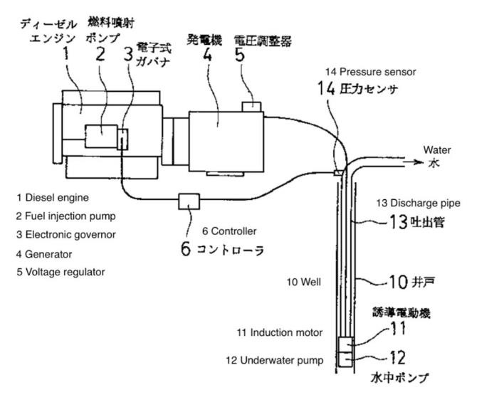
500 The claims are then stated, including claim 8:
The control device for an engine driving a liquid pumping device as per Claim 1 is characterised by having means of detecting liquid level at the aforesaid lower position, and reducing engine rotation speed in response to a decrease in the value detected by the means of detecting liquid level.
501 The Industrial Field of Application is stated at [0001] of the specification in similar terms to the purpose:
This invention relates to a control device for an engine driving a liquid pumping device, such as emergency water supply equipment comprising an engine driving an underwater pump.
(emphasis added.)
502 Certain problems are identified in the specification, and the proposed solution is stated at [0006]–[0008] to be as follows:
…the liquid pumping device relating to the present invention includes an underwater pump for pumping liquid installed in a lower position, an engine installed in an upper position, and means of power transmission enabling the engine to drive the pump, as well as means of detecting hydraulic pressure in a pump discharge pipe installed in the vicinity of the aforementioned upper position. It is characterised by controlling the rotation speed of the engine in order to maintain a predetermined hydraulic pressure in the pump discharge pipe, in accordance with the values detected by the means of detecting hydraulic pressure…
The predetermined pressure of the pump discharge pipe can be kept constant, as the means of hydraulic pressure detection detects the hydraulic pressure in the discharge pipe using an electric signal, outputting this hydraulic pressure signal to a controller, which compares this hydraulic pressure signal against a set hydraulic pressure signal and is then able to output a control signal to the governor that regulates the engine in order to bring the hydraulic pressure signal closer to the set hydraulic pressure signal. Preferably, the means of hydraulic pressure detection is a diaphragm, enabling the governor that regulates the engine to be controlled by the action of the hydraulic pressure detected by the diaphragm, and the engine governor is an all-speed governor. The means of power transmission may comprise a generator and an electric motor, with the generator equipped with a voltage regulator having a positive increasing function between the output voltage of the generator and the rotation speed (frequency) of the engine. The means of power transmission may also comprise a flexible shaft. The engine rotation speed can be reduced in response to a decrease in the value detected by the means of detecting liquid level installed at the lower position…
Due to this configuration, since the rotation speed of the engine can be controlled such that the hydraulic pressure of the pump discharge pipe in the vicinity of the upper position is consistent with a predetermined constant pressure, the discharge pressure can be maintained at a predetermined pressure even if the load changes. This makes it possible to achieve a simple, inexpensive control device for an engine driving a liquid pumping device capable of maintaining the discharge pressure of the liquid pumping device at a predetermined level without wasteful consumption of fuel.
503 At the conclusion of [0009], it is stated that:
Further, if the engine rotation speed is reduced in response to a decrease in the liquid level at the lower position, temporary water shortfalls can be avoided – for example, in the case of pumping well water for firefighting activities – thus preventing any interruption of firefighting activities or burnout of the electric motor driving the pump.
504 By reference to practical examples of the invention, the following is stated at [0013] of the specification:
Additionally, when the water level of the well rises and the required pump head decreases, as shown in Fig. 9 the water pressure rises such that the rotation speed of the engine is reduced, the discharge flow rate of the water pump is decreased, and the water discharge pressure is kept constant. Further, if a water level sensor (not shown) is installed in the well, engine rotation speed will be reduced when the water level drops to an abnormal level, and the quantity discharged will be reduced to avoid temporary water shortfalls, thus preventing any interruption of firefighting activities or burnout of the electric motor driving the pump.
505 The dispute between the parties concerns the following integers, it being accepted that all other integers in claims 1–4 are disclosed in Komatsu:
(1) dewatering submersible pump (claims 1–4);
(2) a “sensor [which] is arranged to measure borehole water level” (claims 1–3);
(3) a “system controller [which] is arranged to compare the information from the sensor to an input setpoint, and to control the voltage regulator and the ECU in response to deviation of the sensed information from the setpoint” (claims 2 and 3) and “using the system controller to control an automatic voltage regulator to in turn control an output voltage of the generator in response to the borehole water level” (claim 4).
506 UON submits that, while Komatsu discloses a “liquid pumping device”, it is one which is used for water supply and that the specific application of the device given in Komatsu is firefighting. UON also submits that such uses are not the removal of ground water to lower the level of the water table and are therefore not dewatering within the meaning of the claims.
507 UON relies upon Mr Quick’s view that Komatsu discloses a device which is used for water supply and, more specifically, firefighting. He said that such a device would not be suitable for dewatering because the type of water level control used (threshold control) is specific to firefighting, where constant flow is required. He considered that this is distinct from dewatering where continuous flow is not needed, as the overriding factor is avoiding damage to the pump. However, the term “dewatering” encompasses the removal of water from a borehole, including for the purpose of water supply. This has the consequence that I do not accept Mr Quick’s opinion as to the disclosure in Komatsu.
508 In my view, Komatsu contains a clear and unmistakable disclosure of the use of a system for an ESP located within a well for the purposes of artificially lifting water from the well, such as (but which is not limited to) the purpose of emergency water supply. Such disclosure is made plain by, for example, the stated purpose (as identified above) which appears next to a figure (as extracted above) which depicts the underwater pump (12) which is located at the bottom of a well (10). The figure also refers to a pressure sensor (14), and depicts water being discharged from a discharge pipe (13). The Industrial Field of Application is stated in similar terms to the purpose.
509 As claim 1 is not confined to the use of the claimed system for the purpose of lowering the level of the local water table, it follows that Komatsu discloses a “dewatering submersible pump” within the meaning of claim 1. It follows that it also discloses a “dewatering submersible pump” within the meaning of claims 2–4.
510 While UON also challenges whether Komatsu discloses a “sensor [which] is arranged to measure borehole water level” within the meaning of claims 1–3, it accepts that Komatsu discloses a sensor. Further, the experts agreed that Komatsu discloses a sensor arranged to measure borehole water level. UON’s dispute with respect to this integer is therefore confined to whether the sensor is of the kind contemplated by the Patent. This dispute is comprehensively addressed in relation to claims 2 and 3 below. As such, subject to my findings below in respect of the type of sensor described by Komatsu, I conclude that Komatsu anticipates claim 1 of the Patent and is not novel.
511 As UON submits, the question as to claims 2–4 is whether Komatsu discloses the requirement of “control” by reference to a setpoint using the sensor. It is therefore convenient to address claims 2–4 together.
512 The dispute lies in whether:
(1) the “sensor” in Komatsu is an analogue sensor, or could be understood to be either an analogue sensor or a float switch; and
(2) Komatsu discloses a system controller arranged to compare the information from the borehole water level sensor to an input setpoint, and to control electrical output of the VSG in response to deviation of the sensed information from the setpoint.
513 Prof. Holmes and Mr Quick (being the relevant experts) agreed that Komatsu discloses a sensor arranged to measure borehole water level. However, they did not agree whether the sensor described is an analogue water level sensor (as would be required for closed loop level control) or a threshold level switch.
514 Mr Quick did not read Komatsu as disclosing a system that would speed up the engine to reduce the water level nor a system that could be controlled to maintain a pre-determined water level. As such, Mr Quick understood the water level sensor in Komatsu to be a digital sensor (or level switch) which simply sends a signal to indicate whether the water level is above or below a predetermined level. He said that, therefore, it could be, but is not necessarily, the type of level sensor identified in the Patent which must continuously monitor the water level to maintain the setpoint.
515 By contrast, Prof. Holmes reviewed Komatsu and gave the following evidence:
(1) Komatsu explains at [0013] that the electronic generator and the pump are not shut down when water level is low but, rather, the speed of the pump motor is decreased by the controller by slowing down the generator engine such that less water is pumped from the well. Specifically, an “abnormal level” of water in the bore results in a decrease in the engine rotation speed.
(2) Komatsu explains a system which has two sensors for the purpose of controlling the speed of the pump in this way: one is a pressure sensor which detects the discharge pressure of the pump; the other is a level sensor that detects water level in the well within which the pump is located. That sensor is disclosed in [0013] of Komatsu.
(3) Komatsu clearly discloses a mode change, in that it describes changing from pressure control to a different operational mode when the water level “drops to an abnormal level”. Prof. Holmes expected that the device in Komatsu would increase the engine speed after the water level in the bore increased, and that the system was one which could also revert from level control back to pressure control once the water level rose above its “abnormal level”.
(4) Komatsu discloses the use of a closed loop control system for pressure control. Because changing the entire control strategy from closed loop to a digital threshold response is difficult and complicated, Prof. Holmes expected that Komatsu was designed to provide closed loop level control during the mode change from pressure to level control (rather than transitioning to a level switch).
516 Prof. Holmes therefore considered that the words used in Komatsu were more likely to be describing an analogue water sensor than a threshold level switch, which was proposed by Mr Quick as an equally available interpretation of Komatsu.
517 I accept the evidence of Prof. Holmes, and agree with his opinions, for the following reasons.
518 First, by its terms, Komatsu refers to a “water level sensor”, not a “switch”. Had Komatsu intended to refer to a “switch” rather than a “water level sensor”, it would have done so (as those terms have different meanings). Notably, Komatsu also refers to a “pressure sensor”. While this is a reference to a different type of sensor to what is referred to as the water level sensor, this common terminology supports a construction that the disputed reference is to a “sensor”.
519 Second, Mr Quick accepted in the concurrent evidence session that he had concerns about the accuracy of the translation of Komatsu, which made him “hesitant to accept that it must be an analogue water level sensor”. Such concerns were also expressed in the Electrical/Dewatering JER, which concerns appear to have infected Mr Quick’s opinions. However, in this proceeding, UON accepted the accuracy of the translation of Komatsu into English.
520 Third, using a switch rather than a level sensor would not achieve the objectives of Komatsu and therefore does not support reading the reference to “sensor” in Komatsu as anything other than an analogue sensor. That is shown by the following extracts from Komatsu which point to a reduction in, not cessation of, engine rotation speed.
521 At [0013] of the Komatsu specification, the following is stated:
… if a water level sensor (not shown) is installed in the well, engine rotation speed will be reduced when the water level drops to an abnormal level, and the quantity discharged will be reduced to avoid temporary water shortfalls, thus preventing any interruption of firefighting activities or burnout of the electric motor driving the pump.
(emphasis added.)
522 Claim 8 of Komatsu states:
The control device for an engine driving a liquid pumping device as per Claim 1 is characterised by having a means of detecting liquid level at the aforesaid lower position, and reducing engine rotation speed in response to a decrease in the value detected by the means of detecting liquid level.
(emphasis added.)
523 Prof. Holmes expressed the view that the water level sensor in Komatsu was an analogue sensor that was capable of continuous measurement, and not a switch. The following evidence by Prof. Holmes provides ample (and logical) justification for this view:
PROF HOLMES: My inference is because, unless you stop the motor when you hit that protective threshold, you can’t just reduce the speed and satisfactorily achieve the protective function. It’s not a satisfactory solution to protection to reduce the speed.
MR CAINE: You say that when the water drops to an abnormal level, the system could not cause engine speed to reduce to a desired level and operate that way.
PROF HOLMES: Unless you had a continuing measurement of level.
MR CAINE: Can you explain why that’s so.
PROF HOLMES: When you hit the protective level and you reduce the engine speed, if you do not reduce it enough, you will continue to over-pump out of the well, and the level will continue to go lower. But since you’ve already gone past the threshold, you don’t know that’s happening, so you will continue to suck the well dry, because you have reduced the speed, but not enough.
MR CAINE: Do you say that when the trigger operates, as it were, when the abnormal level is reached, that the system can’t restore it to a safe level above the abnormal level, save by stopping the pump?
PROF HOLMES: That would not be a safe operating procedure for a different reason. If you stop the pump when you hit the trigger level, which of course would then let the well start to fill up again, and then you came back past the trigger level and automatically started as you came back past the trigger level, the operators on the surface would not know that was about to happen. And that would be an unsafe operating condition.
…
MR CAINE: …I will just identify the scope of the dispute Professor, if I might. You say there should be an analogue sensor because that’s the only way, I assume, that the way you interpret what Komatsu has said can be put into practice. Is that right?
PROF HOLMES: If you are only reducing the speed when you reach the threshold as distinct from stopping the pump, yes. In my opinion that’s the only safe way it can be done.
MR CAINE: So that your view about the appropriate form of sensor follows on the heels of – or is predicated on your view about the way you say the system controls?
PROF HOLMES: It’s predicated on the words that Komatsu used, “reduce the engine speed”.
…if you look at claim 8, claim 8 describes reducing engine rotation speed in response to a decrease in the value detected by the means of detecting the liquid level. Now, a threshold switch is not a decrease in value. It’s an on/off. So if you have a decrease in value, it’s part of my – the background that’s leading me to the opinion that it’s an analogue sensor. You can’t get a decrease in a value determined from a switch.
524 Following this evidence being given by Prof. Holmes, Mr Quick conceded that Prof. Holmes “may be right” but that “there’s no guarantee that’s the only way this was ever intended”. Mr Quick then gave this evidence:
MR BANNON: Would you agree that if you look at the words in paragraph 13, which finish there, the water level – sorry:
…speed will be reduced –
then dropping out some words, it says:
…thus preventing any interruption of firefighting activities or burnout of the motor.
MR QUICK: Yes.
MR BANNON: Leaving aside burnout, if the – if you have a shut-off switch, there’s no more pumping; correct?
MR QUICK: No. That’s not correct at all. What we’re talking about here is a generator that’s a variable speed within an upper and lower limit, maybe 30 to 50 hertz if it was here in Australia. All this says is that when that switch is hit, it reduces the speed down, and I would expect to a minimum, where it sits, and then, as Professor Holmes says, if that minimum is still set too far for the inflow to the bore, then it may well suck dry. But because this is a fire pumping application, we don’t mind burning motors out. We make controls as simple as possible, so that it’s as reliable as possible. There’s no point protecting a motor in a firefighting application, which is why they’re generally designed without thermal overload protection or motor thermistors or anything – any kind of protection. A fire pump is designed to run to destruction, so it’s a very different design from normal pumps, where the pump has some value to you.
(emphasis added.)
525 By giving such evidence, Mr Quick ignored the teaching of Komatsu, which was to reduce the speed of the pump to prevent burnout of the electric motor driving the pump.
526 Fourth, as already explained, I considered that Mr Quick generally sought to advance the interests of UON in this case, whereas I considered that Prof. Holmes remained independent throughout the hearing, including by making appropriate concessions in relation to topics which were outside of his area of expertise.
527 It follows that, for these reasons, the skilled addressee reading Komatsu would understand the sensor to be an analogue sensor that measures water level. As this sensor is one which is contemplated by the Patent, it follows that the remaining contested integer in respect of claim 1 (regarding the nature of the sensor) is also resolved.
528 Prof. Holmes and Mr Quick agreed that:
…Komatsu discloses a system controller that operates to compare information from a sensor, and to control the voltage regulator and the ECU in response to deviation of the sensed information from the setpoint.
It is also agreed that Komatsu discloses information taken from a [borehole water level] sensor.
529 The relevant experts only differed in their view of whether Komatsu uses the information taken from the borehole water level sensor to control the system voltage regulator and ECU in response to a deviation of the sensed water level from a setpoint.
530 Mr Quick’s view was that Komatsu does not disclose closed loop borehole level control and only discloses closed loop delivery pressure control. His view as expressed in the Electrical/Dewatering JER was that:
There are various protection and control functions that could be programmed using a borehole level sensor, but the fitment of such as [sic] sensor does not automatically define any of those functions. Komatsu does not disclose any other than “reducing engine speed when the water drops to an abnormal level”.
531 Prof. Holmes expressed the view in the Electrical/Dewatering JER that:
Claim [8] of Komatsu discloses a means of detecting a liquid level in a well, and “reducing the engine rotation speed in response to a decrease in the [level] value detected”. In my opinion, this claim discloses a transition from the constant pressure control strategy disclosed in Claim [1] of Komatsu, to a “reducing engine rotation speed” strategy that will reduce output pressure as the well water level decreases below an identified (abnormally low) level setpoint.
For me, this discloses a strategy of a system response to a deviation of sensed [measured] information [away] from a setpoint. Hence, while the Komatsu patent is not directed to the concept of a “dewatering” application, in my opinion this disclosure meets (claims 1-3).
(emphasis omitted.)
532 In my view and having regard to claim 8 and the extracts from [0009] and [0013] above, Komatsu discloses the use of a water level sensor to reduce engine rotation speed in response to a decrease in water level to avoid temporary water shortfalls, thus preventing any interruption to (for example) firefighting activities or burnout of the electric motor driving the pump.
533 Further, to avoid interruption to water supply, the system disclosed in Komatsu must increase the speed of the pump back to full capacity once the level in the borehole returns to a safe level. That is, it uses the information taken from the borehole water level sensor to control the system voltage regulator and ECU in response to a deviation of the sensed water level from a setpoint.
534 In making these findings, I rely upon and accept the evidence of Prof. Holmes during the concurrent expert session, which is extracted above.
535 I also rely upon and accept further evidence given by Prof. Holmes under sustained cross-examination:
MR CAINE: Thank you. So if we go back to JER112, you recite the fact that you consider that there is a transition from a constant pressure control strategy disclosed in claim 1, that is, the control strategy that’s predicated on maintaining a discharge pressure.
PROF HOLMES: Yes.
MR CAINE: Yes. And then you say that reducing engine speed rotation is a separate strategy that you draw from paragraph 13 in claim 8; is that right?
PROF HOLMES: It represents a change in the control objective.
MR CAINE: Yes. And you recite, in 112, that the strategy will reduce output pressure as the well water level decreases below an identified abnormally low-level set point.
PROF HOLMES: It following that, if you reduce the engine speed below what is commanded by the constant pressure controller, you must have a reduction in pressure.
MR CAINE: And if I can just ask you to focus on the language that you’ve extracted in JER112, you rely on claim 8 to say that Komatsu discloses a strategy that reduces output pressure as the well water level decreases. That’s what you’ve got in 112, isn’t it?
PROF HOLMES: As I said, it’s the inevitable consequence of reducing the engine speed.
MR CAINE: Yes.
PROF HOLMES: That’s what I meant by those words.
MR CAINE: Yes. That – first of all, can we go to claim 8. That is not the language of claim 8, is it? Claim 8 refers to a response by the engine to a decrease in the value detected by the detection means.
PROF HOLMES: I will say it again: if you change to reducing the engine rotation speed, you can no longer be operating in a constant pressure mode and therefore, by definition, you have reduced the output pressure. The claim does not say we have given up pressure control because it’s implicit; there’s no other way to do it.
MR CAINE: Yes. Is your interpretation of what – or is what you read Komatsu as saying that the sensor not only signals when an abnormal level has been reached, it also continues to measure water level as it decreases and the controller compares that continually measured decrease against the abnormal level?
PROF HOLMES: That’s how I read the words, yes.
MR CAINE: Yes. Well, I put it to you, first of all, that that’s inconsistent with the language of 8 but it’s also inconsistent with the language that we saw in – at the tail end of paragraph 7, 9 and in paragraph 6, that is, what is disclosed is a system which – in which engine speed reduces at the point in time when the water level drops to a single level which is described as abnormal.
PROF HOLMES: I’m not sure what the word “inconsistent” means. If you did not continue to monitor the water level as you went below the point – the point at which the level detector picks it, you potentially would put yourself into a hazardous operating condition. And I don’t think that’s what Komatsu intends to do.
MR CAINE: Could you go back to paragraph 13?
PROF HOLMES: Yes.
MR CAINE: That tells you that the – there is a water level sensor which will respond in circumstances where – when the water level drops to an abnormal level. So what I’m putting to you is that it says that there – the system operates such that, at the point in time when the water level drops to that abnormal level, the system will then respond by reducing the engine speed and therefore the pump speed.
PROF HOLMES: I can only repeat what I said: if you did not continue to monitor the water level as it has gone passed that level and you have reduced the pump speed, you would continue to run the risk of interrupting firefighting activities and burning out the electrical motor, depending on how much you reduced the speed. It would be an unsafe operating continue.
MR CAINE: The system could respond at the point in time in which the water level drops to the abnormally low level and take action at that stage, on that event, to control the speed, to reduce the speed of the pump so that the flow of water, as it were, is reduced.
PROF HOLMES: As I said, if you don’t continue to monitor the water level, the only safe action you can take at that point is to turn the pump off. You can’t just reduce the speed and assume that is a continuing safe operating condition.
536 It follows that the skilled addressee would understand Komatsu to disclose closed loop control based on water level.
537 In any event, as I have found above, the claims do not specify any specific type of control which must be achieved by the system controller in response to the information received from the sensor arranged to measure borehole water level. As Komatsu discloses a system that reduces the speed of the pump in response to a decrease in water level as detected by a water level sensor, it discloses a system which uses the information taken from the borehole water level sensor to control the system voltage regulator and ECU in response to a deviation of the sensed water level from a setpoint within the meaning of claims 2, 3 and 4.
9.6.5 Conclusion in relation to Komatsu
538 For the reasons set out above, Komatsu anticipates each of claims 1, 2, 3 and 4. This has the consequence that they are not novel.
10. DEFERRAL OF PRIORITY DATE AND NOVELTY
539 Allied Pumps advances an alternative contention that the priority date of the claims of the Patent should be deferred if its construction of “dewatering submersible pump” was not accepted. Although its construction of “dewatering submersible pump” has been accepted, I will assume that it has not for the purposes of dealing with this alternative argument.
540 That is, I am proceeding in this section of the reasons on the premise that, as UON submits, the specific purpose of dewatering which is part of the definition of “dewatering” namely, “to lower the level of the local water table”, is a matter to be imported into the claims of the Patent. That premise would require acceptance of the proposition that below ground dewatering does not necessarily result in the lowering of the local water table. It will be recalled that UON’s submissions on construction were that, whether dewatering necessarily results in the lowering of the local water table will depend on factors such as the permeability of surrounding rock and the ability of ground water to replace the fluid that is extracted.
541 Sections 43(2) and (2A) of the Patents Act provide:
(2) The priority date of a claim is:
(a) if subsection (2A) applies to the claim—the date determined under the regulations; or
(b) otherwise—the date of the filing of the specification.
(2A) This subsection applies to a claim if:
(a) prescribed circumstances apply in relation to the invention defined in the claim; and
(b) a prescribed document discloses, or a prescribed set of prescribed documents considered together disclose, the invention in the claim in a manner that is clear enough and complete enough for the invention to be performed by a person skilled in the relevant art.
542 Where the application for a patent was a divisional application of an earlier filed “parent application” (reg 3.13D of the Regulations) or where it arises from a provisional patent application (reg 3.13C of the Regulations), the priority date of the claims may be the filing date of such an earlier filed document (a priority document), so long as the priority document, or combination of priority documents, “clearly disclose[s] the invention in the claim”.
543 As to this, reg 3.12(4) of the Regulations provides that “in this Division, a document … clearly discloses an invention if the document, or set of documents, discloses the invention in a manner that is clear enough, and complete enough, for the invention to be performed by a person skilled in the relevant art” (emphasis original).
544 There is no additional requirement imposed by the words “clearly discloses” in reg 3.13A(1)(b)(i).
545 In ToolGen Incorporated v Fisher (No 2) [2023] FCA 794, Nicholas J observed at [166] by reference to the interaction between ss 40(2)(a) and 43(2A) of the Patents Act that:
Section [40(2)(a)] requires that the complete specification make the necessary disclosure. Since the claims form part of the complete specification they may contribute to the disclosure. However, for the purposes of s 43(2A), the claims in the complete specification, although defining the invention, do not contribute to the disclosure. They serve only to define the invention which must be disclosed in the priority document “… in a manner that is clear enough and complete for the invention to be performed by a person skilled in the relevant [art]”. That said, the language used in s 40(2)(a) and s 43(2A)(b) is essentially the same: in both cases the invention must be disclosed in a manner that is clear enough and complete enough for the invention to be performed by a person skilled in the relevant art. Section 43(2A)(b) expresses the disclosure obligation by reference to the invention “in the claim”. In my view, nothing turns on the absence of the words “in the claims” in s 40(2)(a). The disclosure obligation imposed by s 40(2)(a) of the Act relates to the invention as claimed.
546 The test to be applied for the purposes of determining whether the priority document clearly discloses the invention in the claims was articulated by his Honour in the following terms at [181] (and repeated at [183] in the final sentence):
For the purposes of s 40(2)(a) it is necessary to identify the invention in the relevant claim of the complete specification and then ask whether there is a disclosure that is clear enough and complete enough for the invention to be performed by a person skilled in the art. Where the requirement of s 40(2)(a) is in issue, the claim and any related disclosure will be found within the one document (ie. the complete specification). However, where the requirement of s 43(2A)(b) is in issue, the sufficiency of the disclosure of the priority document will be assessed against the invention of the claim in the complete specification. Since that claim may not be reproduced in the priority document … it is necessary to determine whether there is any disclosure of the invention in the claim in the priority document and, if so, whether it is clear enough and complete enough for it to be performed by the person skilled in the art.
(emphasis added.)
547 At [193] of ToolGen, Nicholas J continued:
Although neither s 43(2A) nor reg 3.13A(2) [which was the relevant regulation in that case] requires that the invention as claimed be “in respect of the same invention”, it does not follow that the priority document need not disclose the invention claimed. The invention claimed must be disclosed in the priority document if priority is to be obtained. It is not sufficient for the priority document to provide a starting point from which the person skilled in the art may transition from one invention to another by the use of the common general knowledge. The mere fact that it would be obvious to the person skilled in the art to use the disclosure in the priority document to produce what is claimed is not enough to obtain priority if, properly characterised, the priority document and the claim are for different inventions. In this respect, and notwithstanding differences between statutory language in the relevant UK and EPC provisions and s 40(2)(a) of the Act, I consider the position under Australian law is not materially different from the UK law as explained in the English authorities to which I have referred. The question is not what is made obvious to the person skilled in the art from the disclosure of the priority document but what it explicitly or implicitly discloses to that person. The distinction is important even though it is often not easily drawn.
(emphasis added.)
10.2 Overview of relevant facts
548 As addressed earlier, the application for the Patent was a divisional application of the 740 Application filed on 28 May 2019, which in turn was a divisional application of the 650 Application filed on 5 August 2017 (and amended on 11 February 2019), which in turn asserts priority from the 254 Provisional filed on 16 August 2016, which is the earliest priority date.
549 The Taranis patent application was published on 21 December 2017.
550 The word “dewatering” first appeared in the 740 Application, but it did not mention a local water table. This was also the first time a mine site was mentioned in the asserted priority documents.
551 The definition of dewatering as meaning, for “the avoidance of doubt … the removal of groundwater from a borehole in order to lower the level of the local water table” was introduced by amendment to the Patent on 15 March 2021.
552 UON accepts (for the purposes of this proceeding only) that if the deferred priority dates apply (which is denied by it), Taranis discloses the claimed invention.
10.3 254 Provisional Application
553 The focus of UON’s submissions, and the evidence of Mr Quick in his first affidavit, was upon the 254 Provisional.
554 The invention described in the 254 Provisional is said to relate to a system for starting and controlling a motor solely via an optimally sized generator connected directly to an electric motor, eliminating the need for external conventional current-limiting motor starting and control devices such as variable speed drives, soft-starters, auto-transformers and wound-rotor motors.
555 The description of the system includes these statements (with [27] receiving particular attention by Mr Quick and by UON):
[26] A motor starting and control system 100 according to the present invention is described with reference to Fig. 1. The motor starting and control system 100 includes a generator assembly 10, an automatic voltage regulator (AVR) 12, an engine control unit 14, a system controller 16, a circuit breaker 18, human machine interface (HMI) 18, and a network interface 22. The generator assembly 10 comprises an engine 9 coupled to an alternator 11.
[27] The motor starting and control system 100 is electrically connected to a motor 24, which is part of a load system 200. The motor 24 operates, for example, a pump (not shown) or other equipment/load of the load system 200. The load system 200 is, for example, a borehole and pump in which or on which the motor 24 operates, a conveyor system driven by the motor 24, or any other motor driven application. The load system 200 includes one or more load environment sensors 26, such as a borehole water level sensor, which provides an output to the system controller 16. The motor 24 is connected to the motor starting system 100 such that the motor 24 can be started by the generator assembly 10 of the motor starting and control system 100.
556 As part of the description of the method, it is stated at [47]:
The method 500 may commence in response to the receipt by the system controller 16 of a signal from one or more of the load environment sensors 26 and/or periphery system sensors 28, 30. The load environment sensor 26 may, for example, detect and signal an increase in borehole water level above a predetermined threshold which then necessitates an increase in the speed of a pump operated by the motor 24. Alternatively, method 500 may commence in response instructions provided to the system controller 16 via the HMI 20 and/or control centre 34. At step 3-10, therefore, the system controller 16 receives a signal and/or instruction indicating that a change in motor speed is required. For the purposes of the following description, it is assumed that an increase in motor speed is required.
557 UON relies on the evidence of Mr Quick to support its submission that the 254 Provisional clearly discloses the invention in the claims and seeks a finding that such disclosure includes “dewatering” as defined in [0008] of the Patent.
558 Mr Quick read and considered the 254 Provisional prior to reading the Patent. His evidence was:
[123] The Provisional Application describes the system and method being used in exactly this type of application, namely for a borehole pump [and then quoted from [27] and [47] of the 254 Provisional].
[124] A borehole is a hole in the ground, into which water seeps from the surrounding strata. This results in water collecting at the bottom of the borehole. A borehole pump is a type of submersible pump (i.e. a pump that is placed under the water level), which is used to pump water from the bore.
[125] In my experience, borehole pumps are frequently used in remote mining operations to pump water from a borehole (and were so used as at 2016)...
[126] The general purpose of a borehole pump is to extract water from the borehole. I am aware of two reasons for using a borehole pump:
(a) Dewatering: which is a process where unwanted water is removed from an underground body of water, referred to as an aquifer. Dewatering is commonly undertaken around mines, where underground water interferes with the mining operations, and therefore needs to be removed; and
(b) Water supply: where water from underground aquifer is brought to the surface to supply water to remote areas without access to other water supplies.
[127] Based on my experience, the ability to vary the speed of a motor (and a pump), in particular in response to changes in water level as described in paragraphs 27 and 47 of the Provisional Application, is more applicable to dewatering operations than to water supply operations. In dewatering operations, the principal concern is to keep the water level in the borehole below a certain level, so that ground water does not interfere with mining operations. If the water rises above this level, it is desirable for the pump to then operate faster to reduce the water level below its desired level.
[128] In water supply operations, there is no such imperative to keep water in the borehole below a particular level. Water level is still important, as the pump may be damaged if it operates when the water is below a certain level…
(original emphasis omitted; emphasis added.)
559 It can immediately be observed that, although Mr Quick describes the process of dewatering using the disclosed borehole pump as removing unwanted water from an aquifer (or local water table), he identifies the “principal concern” in dewatering operations as keeping the level of the water in the borehole below a certain level and that there is no such concern in a water supply operation. Nowhere does he identify that the purpose of using the invention disclosed in the 254 Provisional is the lowering of the local water table. It is therefore apparent that this was not something which he considered as being disclosed to him by that document, whether explicitly or implicitly.
560 Adopting the arguments by UON in support of their construction of the claims, identifying that one, but not the sole, purpose of the disclosed invention is keeping the level of the water in the borehole below a certain level is a different proposition to the disclosed invention being limited to use for the sole purpose of lowering the local water table. That is because UON’s position was that below ground dewatering does not necessarily result in the lowering of the local water table.
561 After Mr Quick was provided with the Patent, he was asked whether the 254 Provisional “clearly disclosed to [him] a system or method comprising a submersible pump used to remove groundwater from a borehole in order to lower the level of the local water table”. No detail appears to have been provided to Mr Quick as to the meaning of “clearly disclosed”.
562 Notwithstanding that he did not volunteer that there was any such disclosure when first asked to review the 254 Provisional, Mr Quick answered at [155] of his first affidavit:
In my opinion, it does. The Provisional Application sets out several applications for the invention it describes. The claims appearing in the Provisional Application do not specify a particular application. However, as set out [above], the description of the invention makes it clear to me that one of the applications for the invention is powering a submersible pump to remove groundwater from a borehole for the purpose of dewatering (i.e lowering the level of the local water table).
563 Contrary to UON’s submission, I do not accept that Mr Quick’s evidence demonstrates that the 254 Provisional “clearly discloses” the invention within the meaning of reg 3.12(4) of the Regulations because the statements made by Mr Quick about the 254 Provisional before he saw the Patent did not volunteer the fact of any disclosure of the purpose of lowering the local water table. Further, the opinion expressed in [155] of his first affidavit is not (in fact) supported or explained by the earlier paragraphs of his affidavit, which paragraphs make no reference to the lowering of the local water table. It follows that, in addition to my views as to Mr Quick’s tendency to seek to assist UON which reduces the weight I attach to any opinion expressed by him, I do not accept the opinion expressed in [155] of Mr Quick’s first affidavit because of the lack of reasons for that opinion.
564 Indeed, I regard Mr Quick’s evidence as providing support for the position advanced by Allied Pumps that the 254 Provisional does not disclose the invention claimed in the Patent. That is because Mr Quick did not identify the disclosure of the invention in the claims (which includes the purpose) until he had read the Patent and was prompted by the question asked of UON’s solicitors.
565 This is especially as, during the trial, Mr Quick was asked about [0008] of the Patent specification, and it became apparent that, unlike his analysis of the 254 Provisional which made no mention of it, he regarded the purpose of lowering the water table as a significant (if not the most significant) feature of the invention in the claims because of the words used in [0008]. His evidence during the concurrent evidence session was as follows:
MR QUICK: …The paragraph 8 defines the entire function of the patent, which is level controls of a water table. That’s a different function from – and – and in designing any kind of system to support that, we start with a functional specification and a purpose, and that is the purpose of this, to lower the level, so the level is critically important.
MR BANNON: I will ask you my question again. Looking at paragraph 8, do you agree that if you were to assume, contrary to, I think, your view, that the removal of groundwater from a borehole will always, necessarily, have the object of lowering the level of the local water table – on that assumption, do you agree the words “in order to lower the level of the local water table” add nothing to the earlier part of the sentence?
MR QUICK: No. They define the function of the system, so even if I accepted that you will always lower the water table, these words define the function of the entire patent, and they’re critically important, and I would not write them off as having no consequence.
(emphasis added.)
566 On the assumption (for the purposes of this analysis) that below ground dewatering does not necessarily result in the lowering of the local water table, as UON maintains even in its closing submissions, then, because the words in [0008] of the Patent specification are absent from the 254 Provisional, there was not any disclosure of the invention in the claims in that priority document.
567 It follows that, properly characterised, the 254 Provisional and the Patent are for different inventions.
568 Given the Taranis patent application was published on 21 December 2017, it is enough for Allied Pumps to establish that the claims of the Patent cannot derive priority from any document earlier than the 740 Application filed on 28 May 2019. That is so given that the word “dewatering”, let alone the definition at [0008] of the Patent specification, did not appear in the priority documents prior to that date and nor was that purpose implicitly disclosed, for the reasons given above. I am satisfied that Allied Pumps has established this.
569 On the assumption that the specific purpose of dewatering which is part of the definition of “dewatering” namely, “to lower the level of the local water table”, is a matter to be imported into the claims, I find that, prior to the filing of the 740 Application on 28 May 2019, there was no clear disclosure (within the meaning of the Regulations) that the power and control system in the claims must be used for the purpose of lowering the level of the local water table. It follows that the claims are invalid for lack of novelty in light of Taranis.
570 Allied Pumps contends that the invention was secretly used within the meaning of s 18(1A)(d) of the Patents Act as an alternative to lack of novelty with respect to the commissioning of the Roy Hill Systems, the resulting systems as commissioned and the training that Mr Reid provided in relation to the bore 64 VSG (being the first and second Roy Hill Acts).
571 Allied Pumps disavowed reliance upon the testing of the bore 64 VSG performed by Mr Pilson for its secret use case.
572 This section of the reasons proceeds on the premise that, contrary to my findings, the first and second Roy Hill Acts did not anticipate the claims because those acts were not publicly available in the requisite sense, or it was not possible to discern from those acts a particular integer of the claims.
11.2 Relevant legal principles
573 Pursuant to s 18(1A)(d) of the Patents Act, an invention is not patentable if it was secretly used in the patent area before the priority date of that claim by, or on behalf of, or with the authority of, the patentee or nominated person or the patentee’s or nominated person’s predecessor in title to the invention.
574 There is no statutory definition of “secret use” in the Patents Act. However, pursuant to s 9 of the Patents Act, a use of an invention will not be “secret use” if it was (relevantly to the matters pleaded and relied upon by UON in its closing submissions) for the purpose of reasonable trial or experiment only: s 9(a).
575 In Encompass Corporation Pty Ltd v InfoTrack Pty Ltd (2018) 130 IPR 387; [2018] FCA 421 at [203]–[206], Perram J articulated the following legal principles:
First, secret use is concerned with a patentee reaping a commercial benefit and enjoying a period of de facto monopoly through secret use before the priority date: Bristol-Myers Co v Beecham Group Ltd [1974] AC 646 at 680–1 per Lord Diplock; [1974] 1 All ER 333; [1974] 2 WLR 79. This involves a practical test: ‘has what occurred amounted to a de facto extension of the patent term? The answer to this will usually depend upon whether the patentee reaped commercial benefit from what was done before the priority date’: Azuko Pty Ltd v Old Digger Pty Ltd (formerly SDS Digger Tools Pty Ltd) (2001) 52 IPR 75; [2001] FCA 1079 at [181] per Gyles J, Beaumont J agreeing on this issue at [72].
Secondly, the onus of proof in relation to s 9 lies upon the would-be revoker including the onus of excluding reasonable trial and experiment: Coretell Pty Ltd v Australian Mud Company Pty Ltd (2017) 250 FCR 155; [2017] FCAFC 54 at [227] per Burley J (Jagot and Nicholas JJ concurring); Grove Hill Pty Ltd v Great Western Corporation Pty Ltd (2002) 55 IPR 257; [2002] FCAFC 183 (Grove Hill) at [221] per Dowsett J (French and Gyles JJ agreeing).
Thirdly, a use may be a reasonable trial or experiment within s 9(a) if the purpose was to prove the concept, to see if the invention performed appropriately or to see if any changes were needed: Grove Hill at [226], [231] and [233].
Fourthly, if the true purpose of a prior use is trial or experimentation and that use is reasonable, any collateral commercial advantage to the inventor is irrelevant: Grove Hill at [229].
576 To this exposition of the principles I would respectfully add that the exception in s 9(a), which is invoked by UON, will arise if the use is for the purpose of reasonable trial and experiment only. That will be satisfied if the true purpose of the use is for reasonable trial or experiment, even if there is a collateral commercial advantage that accrues to the inventor. The question of what is the “true purpose” is a question of fact, to be determined by the Court on the basis of the evidence before it, and the operation of s 9(a) calls for consideration of what use is reasonable trial and experimentation: Coretell Pty Ltd v Australian Mud Company Pty Ltd (2017) 250 FCR 155; [2017] FCAFC 54 (Burley J; Jagot and Nicholas JJ concurring) at [222]– [226]. As to this, UON submits that it did not derive any commercial benefit arising from the offer or supply of its invention.
577 UON further submits that, to establish secret use, the concealment must be deliberate. Its closing submissions cite the decision of Southern Cross Mining Services Pty Ltd v Mickala Mining Maintenance Pty Ltd [2020] FCA 1064 (Greenwood J) at [102]–[103] (Southern Cross) (and Bristol-Myers Co v Beecham Group Ltd [1974] AC 646 at pages 684–5) as authority for this submission. As it transpired, the issue of whether the concealment must be deliberate for secret use to be established was the primary battleground on which secret use was fought between the parties.
578 In Mickala Mining Maintenance Pty Ltd v Southern Cross Mining Services Pty Ltd [2020] FCA 1635, Besanko J heard an application for leave to appeal from Southern Cross. As to the issue of whether deliberate concealment was required to establish secret use, his Honour said the following at [11]–[17]:
As I have said, there is no plea of deliberate concealment. Mickala Mining’s case is that such a plea is not necessary because deliberate concealment is not an essential element of a successful plea of secret use within s 18(1A)(d) of the Act. As I have said, his Honour held otherwise and this holding was a ground upon which the application to amend should be refused.
It should be noted that his Honour, in refusing the application to amend, did not rely on other matters commonly raised on applications for leave to amend such as delay, the adequacy of the explanation for the amendment coming forward at the time it is advanced and general prejudice to the opposing party.
The leading case on whether deliberate concealment is a necessary element of secret use is the English case of Bristol-Myers Co v Beecham Group Ltd [1974] AC 646 (Bristol-Myers) in which, by a majority of three to two, the House of Lords held that, in the absence of deliberate concealment by the prior user, the prior use was not a secret use and, therefore, that prior use was taken into account and led to successful opposition proceedings under s 14 of the Patents Act 1949 (UK). The leading speech was delivered by Lord Diplock with whom Lord Kilbrandon agreed and Lord Cross agreeing with the result, albeit on different grounds (688H–689A), Lords Reid and Morris dissented holding that deliberate concealment was not a necessary element of a secret use. Lord Diplock said (at 685D–F and 686B–C):
My Lords, in its ordinary connotation, particularly as descriptive of actions, I agree with the Court of Appeal and the Shorter Oxford Dictionary (1933), vol. 2, p. 1826, that “secret” means: “Done with the intention of being concealed; clandestine”. To ascribe to it a meaning wide enough to include actions done “unwittingly,” a state of mind which is incompatible with any intention to conceal is, in my view, a misuse of the adjective “secret” or, as Edmund Davies L.J. points out in his judgment, even more so of the adverb “secretly” which is the form in which it would have to be read into section 14 (l) (d) where it would qualify the verb “was used”. To sell something to the public unconditionally and thereby to put it out of one’s power to stop them finding out anything that can be found out about it is, in my view, the very opposite of “secret” use of the thing that is sold.
…
So neither in the terms of sections 14 and 32 nor in the policy of the Act is there anything that requires one to give to “secret use” a meaning other than its primary one of a use which is intentionally concealed by the user. I, therefore, agree with the Court of Appeal that the sale of ampicillin trihydrate by Beechams was not a secret use. They did not know the chemical composition of what it was that they were selling. They could not have formed any intention of concealing something they did not know. I would dismiss this appeal.
Lord Reid said (at 665D–F):
The other matter is the meaning of “secret” in the Act. I agree that it must have the same meaning in each section when the word is used. But I cannot agree that it means “deliberately concealed”. No doubt that is the normal meaning of the word, but I think that in such a phrase as “the secrets of nature” it merely means something undiscovered without any implication of deliberate concealment. So one is entitled to ask whether giving to the word its most usual meaning leads to an unreasonable result which would be avoided by taking the less usual meaning
I think that here the result would be unreasonable. I can see nothing in the Act or its apparent policy to justify what seems to me to be a strange result: If one man, he who makes the concealment, alone knows the truth it is secret, but if no one at all knows the truth it is not secret.
This aspect of Bristol-Myers was followed by Jenkinson J in Melbourne v Terry Fluid Controls Pty Ltd (1993) 26 IPR 292 and is said in a leading Australian text to represent the law in this country (Bodkin C, Patent Law in Australia, 3rd ed, Lawbook Co, 2019 at pp 238–239).
The primary judge analysed the authorities carefully and he made the point at the outset that “the authorities are not as clear on the topic as they might be” (at [83]). He concluded that deliberate concealment is a necessary element of secret use.
There is no Australian appellate authority addressing the point and that is a matter of significance. In my opinion, the point is capable of reasonable argument on either side. Had this been the only issue on the application for leave to appeal, I would have been disposed to grant leave to appeal.
(emphasis added.)
579 Bensanko J further stated at [26]:
The primary judge noted that there was no plea of deliberate concealment and held that deliberate concealment was an essential element of a case of secret use within s 18(1A)(d) of the Act. Whilst the primary judge may or may not be right about that, in my opinion, for the reasons I have given, if this was the only point there is sufficient doubt about it to warrant a grant of leave to appeal …
(emphasis added.)
580 Having regard to the observations of Besanko J, I respectfully decline to follow Southern Cross as I do not consider the question of law to be a settled one.
581 A further reason that I respectfully decline to follow Southern Cross is that I do not agree that, in the absence of deliberate concealment by the prior user, the prior use cannot be a secret use within the meaning of s 18(1A)(d) of the Patents Act. That is for the following reasons:
(1) Although secret use has been addressed by the Full Court previously, no decision has stated that there is any requirement for the concealment to be deliberate. In particular, I refer to Coretell, Grove Hill Pty Ltd v Great Western Corporation Pty Ltd (2002) 55 IPR 257; [2002] FCAFC 183 and Azuko Pty Ltd v Old Digger Pty Ltd (formerly SDS Digger Tools Pty Ltd) (2001) 52 IPR 75; [2001] FCA 1079. If it was an essential element of secret use within s 18(1A)(d) of the Patents Act, one would have expected it to be referred to in these decisions (or at least one of them). It was also not referred to by Perram J in his Honour’s summary of the legal principles in Encompass or by Yates J in DSI Australia (Holdings) Pty Ltd v Garford Pty Ltd (2013) 100 IPR 19; [2013] FCA 132. In the latter case, his Honour decided that certain claims were invalid on that basis that there had been a secret use at [166]–[167]. On appeal, the Full Court decided that additional claims were also invalid for secret use (with no mention made of the need to demonstrate deliberate concealment or criticism of any failure by Yates J to make such a finding): Garford Pty Ltd v Dywidag Systems International Pty Ltd (2015) 110 IPR 30; [2015] FCAFC 6 (Dowsett, McKerracher and Nicholas JJ) at [141].
(2) It was observed by Dowsett J that secret use and public use are “mutually exclusive”: Grove Hill at [212], with no mention of state of mind being relevant. That statement was cited with approval in Coretell at [221].
(3) The plain words of the legislation do not support a requirement that there be deliberate concealment, which construction is consistent with the ordinary meaning of “secret” as provided in the Macquarie Dictionary:
adjective - 1. done, made, or conducted without the knowledge of others: secret negotiations…
– noun 8. something secret, hidden or concealed…
10. the reason or explanation, not immediately or generally apparent: the secret of his success
11. a method or art known only to the initiated or the few: the secret of happiness
(emphasis added.)
(4) The object of s 18(1A)(d) of the Patents Act is to ensure that the patentee does not receive a de facto extension of the patent term unless one of the exceptions in s 9 applies: Coretell at [242]. A patentee will derive such an extension regardless of whether they have deliberately concealed the whole or part of the invention, or simply used it in a manner that means it cannot be discerned.
582 For these reasons, Allied Pumps did not need to prove deliberate concealment by UON to establish secret use.
583 Each of the first and second Roy Hill Acts comprised an act either of UON or an act done with UON’s authority (and this was not disputed by UON), which, for the following reasons, constituted a “commercial use” of the claimed invention:
(1) The acts of commissioning and training involved a “use” of the claimed invention within the meaning of s 18(1A)(d) because those acts were part of, and necessary for, the hire of the Roy Hill Systems to Roy Hill.
(2) UON received a commercial benefit from the commissioning of, and training on, the Roy Hill Systems (the training being for the bore 64 VSG). That is because UON was paid a fee for the hire of these systems, which hire entailed the commissioning and training on the first system (being the bore 64 VSG). The rate of hire was on commercial terms, being higher than the rate for the fixed speed generator that UON had previously hired to Roy Hill.
584 Further, for the reasons already articulated above:
(1) the Roy Hill Systems could control on level;
(2) each integer of the invention was in fact used when the first and second Roy Hill Acts were carried out;
(3) UON derived a commercial benefit arising from the supply of a system having level control; and
(4) the use of the invention, in the course of the first and second Roy Hill Acts, was not for the purpose of reasonable trial and experiment within the meaning of s 9(a) of the Patents Act (and therefore s 9(a) does not apply).
585 Relevantly to this last point, I rely upon the findings concerning whether there was a reasonable trial under s 24(1)(a) of the Patents Act.
586 The answer to the question “has what occurred amounted to a de facto extension of the patent term?” is therefore “yes”: Azuko at [181].
587 For these reasons and on the assumption that the first and second Roy Hill Acts did not anticipate the claims because those acts were not publicly available in the requisite sense, or it was not possible to discern from those acts a particular integer of the claims, it follows, and I find, that each of the first and second Roy Hill Acts amounts to secret use of the invention in the patent area before the earliest priority date by, or on behalf of, or with the authority of the patentee within the meaning of s 18(1A)(d) of the Patents Act.
588 The primary position advanced by Allied Pumps at trial was that each of the prior acts and prior art documents relied upon by it anticipated the claims. In the alternative, it contends that, to the extent that those prior acts and documents did not anticipate the claims, the differences in the disclosures do not make a substantial contribution to the working of the invention as claimed such that the invention did not involve an innovative step within the meaning of s 18(1A)(b)(ii).
12.1 Relevant legal principles
589 Section 18(1A)(b)(ii) of the Patents Act stipulates that an invention for the purposes of an innovation patent involves an innovative step when compared with the prior art base as it existed before the priority date.
590 Pursuant to s 7(4) of the Patents Act, an invention is taken to involve an innovative step when compared to the prior art base unless the invention would, to a person skilled in the art, in light of the common general knowledge as it existed before the priority date of the claim, only vary from the kinds of information set out in s 7(5) in ways that make no substantial contribution to the working of the invention.
591 Determination of innovative step requires the following: (a) compare the invention as claimed with the relevant prior art information; (b) identify the difference or differences between that which is claimed in the patent and that which is disclosed in the relevant prior art information; and (c) determine whether the difference or differences make a substantial contribution to the working of the invention as claimed: Product Management Group Pty Ltd v Blue Gentian LLC (2015) 240 FCR 85; [2015] FCAFC 179 (Kenny and Beach JJ, with whom Nicholas J agreed) at [174].
592 The comparison must be between the invention as claimed and the prior art information: Blue Gentian at [174(a)]. The provision requires a claim-by-claim analysis, having regard to the features of each claim: Dura-Post (Aust) Pty Ltd v Delnorth Pty Ltd (2009) 177 FCR 239; [2009] FCAFC 81 (Kenny and Stone JJ) at [72].
593 As observed by Yates J in Rakman at [337]:
…It is the task of the party relying on a lack of innovative step to identify each and every variance between the prior art information and the invention as claimed, and to articulate, by reference to the evidence, why that variance does not make a substantial contribution to the working of the invention as claimed. This is the task imposed by s 7(4) of the Patents Act.
594 After an exposition of the applicable legal principles, the closing submissions by Allied Pumps total 7 paragraphs insofar as it seeks to advance this part of its case.
595 Relevantly, Allied Pumps submits that:
…the dispute on novelty with respect to each of the prior acts and prior art documents relied upon comes down to whether the acts or documents disclose: (a) the use of the system as claimed for the purposes of dewatering; and (b) a sensor that falls within the scope of the Level Sensor Integers.
[and]
If, contrary to Allied Pumps’ submissions above, the claims should be construed narrowly as being limited to the use of the system for the deliberate purpose of lowering the local water table; and the prior acts and prior art documents do not disclose the use for that purpose, then that is not a difference which substantially affects the working of the claimed invention.
[and]
If, contrary to Allied Pumps’ submissions above, the Court finds that the references to pressure sensors and intake pressure sensors in the prior art are not sensors within the meaning of the Level Sensor Integers, any difference between those prior art sensors and the Level Sensor Integers of the claims is not a difference which substantially affects the working of the claimed invention.
596 By these scant submissions, Allied Pumps did not undertake the task identified by Yates J in Rakman which is imposed by s 7(4) of the Patents Act, and which task should not be undertaken by the Court in the absence of hearing from both parties about the various issues which are likely to arise.
597 The consequence is that Allied Pumps has failed to demonstrate that the invention did not involve an innovative step within the meaning of s 18(1A)(b)(ii) of the Patents Act.
598 It is necessary to address the allegations of infringement which continued to be pressed by UON at the conclusion of the trial on the premise that my conclusions as to invalidity are incorrect. Before addressing the allegations, I will address the issue of the characterisation of claims 1 to 3.
13.1 Characterisation of claims 1 to 3
599 By their opening submissions, there was a desultory dispute between the parties about the proper characterisation of claims 1 to 3. Allied Pumps submitted that claims 1 to 3 are method or process claims, whereas UON submitted that those claims are product claims.
600 Allied Pumps also submitted that there was no practical difference in the outcome of the case whether claims 1 to 3 were construed as product or method claims. UON appeared to agree, submitting that its infringement case is established regardless of how claims 1 to 3 are characterised.
601 The characterisation dispute continued into the written closing submissions but petered out during oral closing submissions. Specifically, after referring to UON’s arguments regarding the nature of the claims, Senior Counsel for Allied Pumps stated:
… we say the claims in this case are product claims. They’re limited to a product which is used for dewatering ..... therefore, the patent describes a product suitable for use for the dewatering submersible pump. And then quoting from [Garford Pty Ltd v Dywidag Systems International Pty Ltd (2015) 110 IPR 30; [2015] FCAFC 6] again, my learned friend quoted:
To establish infringement of such a claim it is not necessary for the patentee to establish that the apparatus is intended to be used for that purpose.
And we agree. In other words, what appeared to be a division of the parties, there is not issue between us. We say it refers to a system which is capable of being used or suitable of being used for dewatering. [UON] says exactly the same thing, and if it’s a product claim, as I say, there is no scope for a subjective intention or any sort of intention about dewatering or lowering a water table or anything like that. It just does not exist. It cannot exist if it’s a product claim, and we’re happy to accept it as a product claim. The same outcome would be as a – even if it’s described as a process claim, the same logic would inform that integer…
(emphasis added.)
602 As the parties agree that claims 1 to 3 are product claims and, in any event, contend that the outcome of this case is not affected by the resolution of this issue, no further analysis is required.
603 UON does not press its direct infringement case or its authorisation of infringement case.
604 Otherwise, UON maintained its pleaded indirect infringement case with respect to the Allied Pumps System.
605 As part of the particulars to its infringement case, UON asserted there had been supply “from at least 20 November 2020” of the Allied Pumps System to BHP “for use at its Mount Whaleback operation site in Newman, Western Australia”. However, by its oral opening submissions, UON accepted that, in accordance with the Full Court’s decision in Coretell at [68], any acts of exploitation of the Allied Pumps System prior to 23 December 2020 (being the date of grant of the Patent) are not acts of infringement.
606 As already described, Allied Pumps pleaded that there are two categories of this system:
(1) Category A Systems (which fell into two subcategories: Rio Tinto Category A Systems and BHP Category A Systems); and
(2) Category B Systems.
607 Allied Pumps admitted that each system: (a) is to be used in conjunction with dewatering submersible pumps; (b) includes a generator and a generator controller (known as a “ComAp” controller); and (c) has been used to power and control submersible pumps.
608 Further, Allied Pumps admitted that the Category B Systems had software installed on the ComAp controller which enabled those systems to be used in the manner claimed in the Patent. That is, Allied Pumps admitted that the Category B Systems directly infringed the Patent.
609 Allied Pumps offered an undertaking in relation to the infringing Category B Systems. UON submits that regardless of that undertaking, the Court should make the declarations and orders sought by it in the cross-claim with respect to the Category B Systems (including the injunctive order). As I have determined that the Patent is invalid, I decline to grant the relief sought by UON with respect to the Category B Systems. Had I not concluded that the Patent was invalid, I would have invited further submissions from the parties about whether an injunction was warranted (and the terms of any such injunction) having regard to the undertaking.
610 Allied Pumps also admitted that, without limiting the denials of patent infringement pleaded in the Third Amended Defence to Cross-claim dated 8 February 2023 with respect to the Category A Systems supplied to BHP and on the basis that any claim of the Patent is found to be valid, its exploitation of the VSGs supplied to Robe River Mining Co. Pty Ltd as part of Allied Pumps’ Req 88273 was an infringement of the Patent by way of direct and indirect infringement pursuant to ss 13 and 117 of the Patents Act. This admission concerned the Rio Tinto Category A Systems. As I have determined that the Patent is invalid, UON is not entitled to any relief in connection with this admitted infringement.
611 Allied Pumps otherwise denied infringement with respect to the BHP Category A Systems. As to this, UON’s case for indirect infringement was ultimately only pressed in relation to the BHP Category A Systems. As I have found that the Patent is invalid, that case must fail with the consequence that the cross-claim will be dismissed.
612 However, I will proceed to determine the infringement case in any event and on the premise that the Patent is valid, on the assumption that this might be found to be the case in any appeal.
613 By the time of closing submissions, UON submitted that “only ss 117(2)(b) and (c) [of the Patents Act] are in play” and contended that the principal issues in dispute were:
(1) whether, at the time Allied Pumps supplied the BHP Category A Systems to BHP, Allied Pumps had “reason to believe” that the systems would be put to an infringing use, within the meaning of s 117(2)(b);
(2) whether Allied Pumps provided instructions to BHP concerning the use of the BHP Category A Systems within the meaning of s 117(2)(c).
13.4 Relevant legal principles
614 Section 117(1) of the Patents Act imposes liability on the supplier of a product where the use of the product by the receiver would infringe the patent: Northern Territory v Collins (2008) 235 CLR 619; [2008] HCA 49 (Hayne J) at [42].
615 Whether the supply of a product amounts to an infringement under s 117 depends on the nature of the product and the use or uses to which it is put: Apotex Pty Ltd v Sanofi-Aventis Australia Pty Ltd (2013) 103 IPR 217; [2013] HCA 50 (Crennan and Kiefel JJ) at [300].
616 Relevantly, s 117 states:
(1) If the use of a product by a person would infringe a patent, the supply of that product by one person to another is an infringement of the patent by the supplier unless the supplier is the patentee or licensee of the patent.
(2) A reference in subsection (1) to the use of a product by a person is a reference to:
…
(b) if the product is not a staple commercial product—any use of the product, if the supplier had reason to believe that the person would put it to that use; or
(c) in any case—the use of the product in accordance with any instructions for the use of the product, or any inducement to use the product, given to the person by the supplier or contained in an advertisement published by or with the authority of the supplier.
13.4.1 Section 117(2)(b) of the Patents Act
617 A person (the supplier) will infringe a claim of a patent within the meaning of s 117(2)(b) of the Patents Act if: (a) that person has “reason to believe” that the receiver of the product would put the product to a particular use; (b) that use of the product would infringe the patent; and (c) the supplied product is not a “staple commercial product”: see Generic Health Pty Ltd v Otsuka Pharmaceutical Co Ltd (2013) 100 IPR 240; [2013] FCAFC 17 (Emmett J) at [2].
618 As to this last element, Allied Pumps did not dispute (for the purposes of this proceeding only) that the BHP Category A Systems were not a “staple commercial product”.
619 A supplier need not have an actual belief that the product would be put to an infringing use. The test is an objective one, such that it does not matter whether Allied Pumps actually held the belief: Fuchs at [340]–[346].
620 The question is whether there are factual matters known to the supplier that would lead a reasonable person to believe that the product will be put to an infringing use: Generic Health at [35] and [61]. The relevant “use” is the actual or intended use by the third party of the product being supplied: see Northern Territory at [128]–[132].
13.4.2 Section 117(2)(c) of the Patents Act
621 Section 117(2)(c) of the Patents Act requires that there be an instruction or inducement: Generic Health at [22]. For Allied Pumps to be liable pursuant to s 117(2)(c), it must be established that BHP’s use of the BHP Category A Systems, undertaken in accordance with any instructions or inducement given by Allied Pumps, would infringe the Patent.
622 Where instructions for use are given that instruct the user to add a missing integer to the patented product, thereby causing the product to gain a missing integer and become infringing, it has been held that s 117(2)(c) applies: see, for example, Beadcrete Pty Ltd v Fei Yu (t/as Jewels 4 Pools) (No 2) (2013) 100 IPR 188; [2013] FCA 187 (Jagot J) at [123], [126]–[127]; Fei Yu (t/as Jewels 4 Pools) v Beadcrete Pty Ltd (2014) 107 IPR 516; [2014] FCAFC 117 (Dowsett, Middleton and Robertson JJ) at [83]–[86]. However, s 117(2)(c) requires the use to be “in accordance with” any instructions or inducement. It follows that, if the instructions do not instruct the user to add the missing integer to the patented product or modify the product in order to achieve the missing integer, there will be no infringement.
623 Allied Pumps resists a finding of infringement on the basis that the system controller of the BHP Category A Systems only controls or governs the frequency and voltage of the electrical power supplied to a pump based on the information provided by a sensor that is arranged to measure a flow rate of water pumped from the pump (i.e. a flow sensor). It also contends that BHP did not and do not implement level control for their VSGs; and, therefore, did not have (at any relevant time) any desire to change the BHP Category A Systems in a manner that controlled via water level.
624 Allied Pumps called two witnesses in relation to the infringement case, namely Mr Meredith and Mr Walters.
625 Mr Meredith has no affiliation with either party in this proceeding.
626 Mr Meredith commenced work with BHP as an embedded contractor through his company MineData Pty Ltd in 2000. From 2000 to the mid-2010s, Mr Meredith provided general control systems support for BHP across several BHP mines in Western Australia. From the mid-2010s, he began to provide control systems support for equipment used in dewatering applications across several BHP mines in Western Australia. By around 2017, Mr Meredith had become a specialist with such systems.
627 Mr Meredith’s evidence was that:
(1) by around 2018, each of BHP’s Western Australian Iron Ore (WAIO) mine sites utilised VSGs for dewatering application;
(2) with one exception, each VSG on a BHP WAIO mine site is remotely monitored and controlled by way of a WAIO control panel. The exception is BHP’s Yandi mine site, which is to be decommissioned and which has dewatering equipment supplied by UON;
(3) a WAIO control panel includes a PLC (or programmable logic controller) that meets BHP’s WAIO standards;
(4) one WAIO requirement is that all PLCs for mining equipment must be Allen-Bradley PLCs (a particular brand of PLC) which must be able to communicate with BHP’s CITECT system (a centralised SCADA control system, with SCADA being an acronym for supervisory control and data acquisition);
(5) BHP requires that its VSGs used for dewatering applications have a master PLC. To date, this master PLC has always been configured by Mr Meredith;
(6) the master PLC is an Allen-Bradley branded PLC which instructs a ComAp branded generator controller for the VSG. The ComAp generator controller controls the operation of the generator upon receipt of instructions from the Allen-Bradley PLC. The Allen-Bradley PLC is connected to sensors including a level sensor, and most of the Allen-Bradley PLCs have a HMI.
628 Mr Meredith explained the usage of the VSGs at the WAIO mine sites in these terms:
BHP controls the speed of every pump used for dewatering applications across all of the WAIO mine sites using a flow sensor (Flow Control). To facilitate Flow Control of the Allied Pumps supplied VSGs for WAIO mine sites, I programmed the Allen-Bradley PLC to include closed loop control that utilises the information received by the Allen-Bradley PLC from a flow sensor…
…
As BHP has only ever required of me, and still only requires of me, Flow Control (other than as I describe … below), I have not programmed any PLCs used for dewatering applications to include any other type of control. This includes every VSG I have programmed for Allied Pumps.
While BHP only utilises Flow Control for dewatering applications, the VSG supplier, UON, provides additional control capability for the VSGs it has supplied to BHP. UON incorporates the logic for Level Control (control of the pump speed using a level sensor) and Flow Control in its ComAp generator controller. Therefore, at UONs request, I have programmed the Allen-Bradley PLC differently from what I have that [sic] described above … to facilitate this. For UON’s VSGs, I do not include Flow Control capability in the Allen-Bradley PLC. Rather, I provide a bridge between the Allen-Bradley PLC and the ComAp generator controller, so the Allen-Bradley PLC is able to instruct the ComAp generator controller to perform Level or Flow Control, as selected by an operator via CITECT.
…
To my knowledge, BHP only uses Flow Control on the UON VSGs, regardless of the fact that another type of control is provided by UONs VSGs, because BHP does not implement Level Control for its VSGs.
(original emphasis omitted; emphasis added.)
629 The underlined sentences in Mr Meredith’s evidence as extracted above were subject to an order made by consent on 14 March 2023 pursuant to s 136 of the Evidence Act limiting those passages to his understanding. However, even so limited, Mr Meredith’s understanding is cogent evidence of BHP’s processes having regard to the nature of the work which he performed for BHP through his company.
630 In relation to the HMI display for the Allied Pumps System, Mr Meredith attested that:
First, I have never included the ability to select Level Control or Pressure Control on the Allen-Bradley HMI for Allied Pumps’ dewatering trailers. While these options are displayed on the screen, there have never been boxes around “Pressure Control Selected” or “Level Control Selected” (i.e. they are not buttons that can be operated by a user). Second, for the Allen-Bradley HMI for Allied Pumps’ dewatering trailers, I have included the words “not enabled” next to “Level Control Selected” and “Pressure Control Selected”…
Therefore, the HMIs for Allied Pumps’ VSGs include inactive text (i.e. text that is not selectable by the user), including text saying “Level Control Selected (not enabled)” and “Pressure Control Selected (not enabled)”. To the best of my recollection, the HMIs for Allied Pumps’ VSGs have included this inactive text since I started working on them in mid-2018 until now. Because the underlying Allen-Bradley PLC for Allied Pumps’ VSGs does not include the logic to facilitate Pressure or Level Control, the inactive text does not enable the VSGs supplied by Allied Pumps to be controlled on Pressure or Level Control. What appears on the HMI screen is simply text read from a Secure Digital (SD) memory card onto the HMI display. In other words, it is not possible to change the control of the Allied Pumps VSGs from Flow Control to Level or Pressure Control, because Allied Pumps does not have this logic in its PLCs.
(emphasis added.)
631 Mr Walters is a former employee of Allied Pumps, who had been engaged in factory acceptance testing of Allied Pumps products, which included BHP Category A Systems. He ceased to work for Allied Pumps in April 2021.
632 Under cross-examination, Mr Walters maintained a consistent and steadfast position in relation to the BHP Category A Systems, stating that:
(1) “these things did not run on pressure” and “[i]t couldn’t run on pressure mode” but “runs off flow”;
(2) “it’s impossible to test it on pressure or level. They didn’t operate that way”;
(3) “They only operated in speed and flow. You couldn’t make it do pressure or level at all”;
(4) “They could not run at all on level or pressure”.
633 UON relies on a series of documents discovered by Allied Pumps which it says disclose that the BHP Category A Systems do in fact have level control, as well as the evidence of its expert, Mr Quick, who reviewed those documents and expressed opinions based on those documents that (relevantly) the BHP Category A System:
(1) is a system that has sensors for measuring water level;
(2) has a PLC which takes water level as an input and outputs a reference signal being the desired pump speed to the separate generator controller which controls the generator to achieve that speed;
(3) has an HMI which allows the user to program setpoints for water level and shows PID control (being control based upon the deviation from a setpoint);
(4) has trip points (i.e. points at which the pump will be stopped) when thresholds or limits for water level are reached; and
(5) is tested during factory acceptance and confirmed to be able to control the speed of the pump to maintain a desired water level.
634 UON also called Mr Meys, who is an employee of UON (having held the role of Project Manager since 2011). Mr Meys gave evidence about a site meeting with BHP representatives in January 2018 held at a BHP site known as “Area C” (located in Western Australia). According to the minutes of that meeting, its purpose was the “Inspection and review of the new as-built in-field 300kVA GMC Trailer with folding platforms with the purpose of suggesting improvement possibilities to finalize the BHP Standard Requirement”. Mr Meys also annexed copies of email exchanges to his affidavit, including with Mr Meredith, in January and February 2018. It is self-evident from those exchanges that BHP (with Mr Meredith) was exploring the idea of having level control on the GMC Pro Power VSGs then being supplied by UON. In this regard, insofar as the evidence was read by UON, I place no weight on Mr Meys’ “understanding” of these exchanges as the documents speak for themselves. The final email in the chain (dated 2 February 2018) was from Mr Meredith to Mr Meys and Mr Reid which referred to potential selections on the HMI for the GMC Pro Power VSGs; and raised a further query and concern. There the story came to an abrupt halt.
635 Since at least 2016, Mr Meys’ role has focused on delivering dewatering and power generation projects to BHP, and Mr Meys has attended informal on-site meetings with representatives of BHP “around six times a year on average since 2016”. Notwithstanding this, Mr Meys did not give evidence about BHP’s requirements (as was finally determined post the site meeting or the email exchanges in early 2018), or whether level control had been (in fact) implemented on the GMC Pro Power VSGs at the site in question and in the manner which had been canvassed in January and February 2018. It would be expected that he would be aware of this, having regard to his ongoing role and his regular site visits. As the evidence shows that UON supplied GMC Pro Power VSGs to BHP after 2018, I infer that his evidence about such matters would not have assisted UON: see Kuhl at [63]–[64].
636 Neither party called any evidence of an expert who had inspected a BHP Category A System and nor was any person who works within BHP called as a witness.
637 Each document relied upon by UON will now be considered.
638 This is a document dated 29 April 2018 entitled “BHP Billiton Auxiliary Maintenance Dewatering Trailer Controls Requirement Specification” (MineData Specification). It was prepared by Mr Meredith (through his company) and contained what was, in effect, his recommendation to BHP about the features of what he described as the “preferred design” of a control system for dewatering trailers that were to be supplied to BHP.
639 Section 1.1 of the MineData Specification relevantly stated:
In general, the current generation of variable speed generators provide the ability to control speed based on flow, pressure or level if the process variables are connected directly to the generator controller. The controller provides built-in PID [closed loop] control and, by correctly configuring the generator’s HMI, an operator can select different control modes (flow/pressure/level) and adjust set-points.
640 Under cross-examination, Mr Meredith gave this evidence, which was not challenged:
(1) The document was “capturing the precedents [that] were already … on site and putting them on paper somewhere”.
(2) The document was informing BHP that there were VSGs in the marketplace which could control pump speed based on the three control modes mentioned in section 1.1, and was “written around the UON trial sets that [BHP] already had on site”.
(3) Section 1.1 did not specify UON, but “we only had the UON trailers at the time”. It was “really just talking about UON trailers that we had”.
(4) Section 1.1 was a description by Mr Meredith of the way UON’s VSGs operated at that time (although it should not have included a reference to pressure, because, as Mr Meredith later explained, no UON trailer supplied to BHP could control by pressure)
(5) The document was written by Mr Meredith to effectively describe the current UON trailers and “what we saw as the changes we would like”. It was not “driven by a requirement spec from BHP. Nor was it known “whether BHP want[ed] flow level or pressure control”. The document “was really just a description [of] what we had, and how what we already had could be made more in line with BHP standards”.
(6) “[T]hen we went into the requirements with BHP, there was no requirement for level or pressure control, so I just never programmed it”.
641 Having regard to the timing of the document and its purpose, and the evidence of Mr Meredith (which I accept), this document does not provide cogent support for a finding that BHP wanted to, and did, implement level control on its VSGs in and from 2020, or that the Allied Pumps System had level control as at April 2018. Rather, it is no more than a continuation of the timeline of events referred to by Mr Meys which involved the initial exploration by BHP of the implementation of level control on VSGs in the first half of 2018.
642 This is an unsigned BHP document which states that it was “issued for review” on 27 September 2019 (Scope of Work). There is no evidence that it was ever issued to third parties in this form, and its precise status is not known because no witness from BHP was called. Mr Meredith was not the author of it. It states that it was authored by Mr Jarred Yow (who was not called as a witness). The Scope of Work cross-references other documents which are not in evidence.
643 A document of this type is not uncommon in both construction and mining projects. According to its content, the Scope of Work contains the scope of work for, in this case, a proposed contract for certain works including the supply of 13 dewatering trailers, bore pump control panels and associated electrical infrastructure to the “OB24” mine site in the Pilbara region, Western Australia which is part of BHP’s Eastern Ridge Operations. It stipulates, amongst other things, that the equipment “shall be capable of being programmed to control on either flow, pressure or bore water level”.
644 Under cross-examination, Mr Meredith accepted that the document says that the system could be controlled by any of those control modes and accepted that the requirement was that the supplier provide equipment that was capable of being programmed to control on all three methodologies, as selected by the operator. However, Mr Meredith did not resile from his evidence that in practice, BHP has never asked him to program the PLCs for VSGs on their mine sites for anything other than flow control. Under cross-examination, he gave this evidence:
And what I’m putting to you is that BHP requires that the supplier provide equipment that’s capable of being programmed to control on flow, pressure or bore water as the operator selects?---And it is – well, yes. But it hasn’t been programmed to do – it has only been programmed for flow. So it is capable of being programmed to control flow, pressure or level, but it has only ever been programmed to control flow.
What’s it, Mr Meredith?---The PLC.
This is a requirement document. We’re not talking about a specific system, are we? It’s telling - - -?---I’m reading the requirement. It says it’s capable of being programmed, which it is, but it has never been programmed to do the other modes. Programmed is something that would – you do in the PLC. I would program the PLC to do level or pressure control. I never have.
645 In this regard, it is noteworthy that the Scope of Work states within section 3.3.4 that:
PLC programming shall be undertaken by a BHP nominated Controls Contractor at the Contractors [sic] premises prior to transport of the trailer packages.
646 Mr Meredith also observed that the UON systems are only “flow and level, they don’t do pressure so that doesn’t comply with all three”. Yet it was common ground that UON supplied its systems to BHP, which fact supports Mr Meredith’s evidence and tells against the conclusion that BHP would only accept equipment that was capable of being programmed to control on all three modes.
647 This is an unsigned document which states that it is Rev. 0 and was “issued for use” by BHP on 26 March 2018 (Specification). There is no evidence that this document was ever issued to third parties in this form, and its precise status is not known because no witness from BHP was called. It states that it was written by Jebbin Valakkattil on 15 January 2018. It bears document number SPEC-000-G-12059/0.
648 A later version of the Specification (Rev. 1) dated 21 November 2018 was circulated from a BHP employee to several employees of Allied Pumps on 7 October 2021.
649 Later versions of the Specification, namely Rev. 2 and Rev. 5, are also in evidence.
650 Each version of the Specification states within section 4.7.1:
The design of the control panel shall demonstrate the use of latest pump starting technologies(s) [sic] which can optimise Generator sizing. Variable speed functionality (VSG) is also required to control on either flow, pressure or bore water level. The overall design shall demonstrate Capex & Opex through the life of the Dewatering solution.
651 Under cross-examination about the Specification, Mr Meredith gave this evidence:
And it’s also required to control on the three control modes that we saw before, flow pressure and bore water level?---Well, I still read that as either flow pressure or bore water level, and we control inflow.
Sorry?---Well, I read – when I says either flow pressure or level, we control inflow. We’ve only tested flow with Allied Pumps, for example. It still meets that. It’s still either flow pressure or level.
Yes. And what I put to you before and I will put again is that the requirement that is set out there is that the device or the system will be capable of controlling on any one of those three control modes and the operator can select which one he or she wishes to use as the method of control?---Well, if you read it that, none of the UON ones are compliant.
I’m sorry?---If you want to read it that way, none of the UON trailers are compliant. None of the UON trailers can be switched to – none of the UON trailers have pressure control. So if you want to read it that way, the UON trailers are not compliant either.
…To be frank, I don’t take a lot of notice of these documents. If I wanted to know whether a trailer needed level control, I would just talk to the people on site, and I’ve never been asked to put level control in a trailer. So it’s as simple as that. These are a broad overview of what they’re looking for. The specs mainly are aimed at ensuring that the hardware supplied by the vendor meets the requirements. As far as the programming, because that can be done anytime, effectively.
So first of all, you’re suggesting that because your experience has been that UON doesn’t control on three parameters, that BHP does not wish that to happen. And you read the specifications narrowly, based on the fact that the ones that you have programmed only control on-flow?---I work with the dewatering personnel on a daily basis. I’m their first line of support for, you know, for all support; I’m 24/7 basically. I work with the – the site people. And no one on site has ever asked me to put a trailer into level control.
…
So do you read the passage in 4.7.1 that we’ve been discussing on the footing that a supplier can decide which, amongst the required control modes in that document it chooses to include in the system that it supplies to BHP?---It’s – it’s more by convention. Every trailer has flow control. So regardless of this document, because I’m working with the vendors as well, they all know that it has to provide a flow control. In the case of Allied Pumps, that’s all they have. There has never been a PLC programmed with a level controlled PID loop in a dewatering trailer.
652 Contrary to UON’s submission and in the absence of any evidence from a witness within BHP who could explain the content of the different versions of the Specification, I did not regard Mr Meredith’s evidence as “far-fetched”. It was Mr Meredith’s position, from which he did not resile under cross-examination, that BHP has never asked him to program the PLCs for VSGs on their mine sites for anything other than flow control. Having regard to his extensive experience with BHP, and his evidence about the Allied Pumps System, his evidence about the content of these documents was not implausible.
13.6.4 BHP Installation Scope of Work
653 This is a document which appears to bear the signature of a Chris Ye, who is stated to be the author of the document which is dated 10 April 2017 (and who was not called to give evidence). This document is Rev. G and states that it was “issued for tender”. However, there is no direct evidence that it was, in fact, issued for tender.
654 This document specifies how the dewatering trailers which are supplied pursuant to the BHP Scope of Work are to be installed at their destination site, referred to as Mining Area C (which is described as being located approximately 100 kilometres north-west of Newman in the Pilbara region of Western Australia).
655 Part B of Appendix 2 titled “Design and Installation of Trailer Mounted Dewatering Units” states that, among other things:
The generator shall be used to directly control the pump motors in variable speed mode.
The technology shall be capable of being programmed to vary the frequency to maintain a set flow rate, headworks pressure, or bore water level.
An Allen Bradley Compact Logix L2 PLC shall be fitted. The PLC shall be used to perform all logic control functions as well as interface control and monitoring signals through to an existing site Citect SCADA control system via the wireless Ethernet radio communications network.
656 Assuming that this document was issued for tender, it relates to one mining site in Western Australia and was issued in 2017, some three years prior to the date on which it is alleged that Allied Pumps engaged in the conduct said to constitute indirect infringement. For these reasons, it does not undermine the evidence of Mr Meredith that in practice, BHP never asked him to program the PLCs for VSGs on their mine sites for anything other than flow control, and nor does it establish that the Category A Systems supplied by Allied Pumps were able to control by level.
13.6.5 BHP’s Manufacturer Data Records
657 BHP’s Manufacturer Data Records is a collection of engineering and other project-related documents compiled by BHP in relation to a particular project, in this case the provision of equipment and a GMC dewatering trailer to the Eastern Ridge Orebody 24.
658 UON relies upon certain schematic electrical drawings which form part of these records, and somewhat qualified evidence by Mr Quick about these drawings, in the sense that he had made certain assumptions about the operation of the system.
659 Mr Meredith, who is familiar with these types of records and the operation of the system, gave the following unchallenged and uncontradicted evidence, which I therefore accept:
Page 300 of the BHP MDR is a schematic electrical drawing dated 6 August 2019. It depicts the inputs and outputs of the PLC for an Allied Pumps VSG. The electrical drawing refers to a “PRESSURE TRANSDUCER (WATER LEVEL SENSOR)”. This sensor is connected to the PLC via several wires and provides information to the PLC. Amongst other information, the sensor provides information representative of the level of water in the bore to the PLC.
[The] Allen-Bradley PLC utilised by BHP on VSGs for dewatering is connected to a level sensor to monitor the level of water in the borehole from which water is being extracted during the dewatering process ... Accordingly, …the connection between this level sensor and the Allen-Bradley PLC enables level to be read and displayed on the HMI for monitoring purposes. For as long as I can remember, BHP has monitored level in a bore used for dewatering purposes.
(emphasis added.)
660 It follows that these drawings do not support a conclusion that BHP was supplied with a system with a dewatering trailer with VSGs that were capable of being programmed so that the system can control pump or engine speed by reference to level control. That is because the system as depicted in the drawings only displays the level for monitoring purposes.
13.6.6 Allied Factory Acceptance Procedure documents
661 These documents record the results of factory acceptance testing of dewatering trailers (or VSGs) supplied by Allied Pumps to BHP, such testing having taken place between January 2020 (being the date of the first document) and April 2021 (when Mr Walters, an employee who undertook most of the factory acceptance testing, ceased to work for Allied Pumps). During this period, there was a range of products offered by Allied Pumps which were also subject to factory testing such as pressure systems, fire pumps, mining equipment and control panels.
662 The first document is an Allied Pumps document entitled “BHP Dewatering Trailers Packaged Headworks Trailer Factory Acceptance Procedure” that Mr Walters filled out and signed while conducting factory acceptance testing of a particular BHP Category A System, being requisition number 83020. The cover page of the document states that it is dated January 2020. No date appears next to Mr Walters’ signature.
663 Mr Walters gave oral and written evidence to the effect that, when he filled out the Factory Acceptance Procedure document, he had mistakenly ticked off having completed level control testing when he did not in fact do so, because the system did not have level control capability. He gave evidence to the same effect in relation to pressure control testing.
664 The second document relied upon by UON is another Factory Acceptance Procedure document filled out by Mr Walters. The notation next to Mr Walters’ signature states: “Factory Acceptance Procedure completed by Troy Walters 16/1/2020”.
665 In that document, Mr Walters did not insert a tick next to the words: “Verify that Pump runs and varies speed to maintained set Level”. Instead, he wrote the words: “* Flow or Hz%”. Under cross-examination, he rejected a suggestion that this annotation indicated that the “desired water level is being maintained” and said that “I have put that asterisk and the flow or hertz to indicate that it only works off flow or hertz in a percentage”. That is, the control could only work by reference to flow or a speed setting in hertz, not by way of level control.
666 This evidence is supported by the annotation made in section 6.6.2.2 as follows:
Press Pump Start Button (Any mode; pressure. flow or level).
667 Mr Walters crossed out the words “or level” and then inserted a tick.
668 Under cross-examination, Mr Walters indicated that the checklist was incorrect in that it indicated that he had tested the system on pressure control, which was not possible. The checklist also indicated that he had been able to “select water”, which he said was also not correct.
669 Mr Walters gave an emphatic denial to the proposition that he in fact tested the BHP Category A Systems described in these two Factory Acceptance Procedure documents on pressure and water level.
670 Mr Walters is no longer an employee of Allied Pumps and had no reason to lie (and nor was it suggested that he did lie). He appeared to have a definite recollection of the functionality of the BHP Category A Systems in that his evidence about this was given with frankness and without hesitation. The annotation on the second form (in that he drew a line through the words “or level”) supports the case advanced by Allied Pumps, rather than UON. Taking these matters into account and that his evidence corresponds with that of Mr Meredith in terms of the functionality of these systems, I accept the evidence given by Mr Walters in relation to the first and second Allied Factory Acceptance Procedure documents.
671 The third document relied upon by UON was another Factory Acceptance Procedure document discovered by Allied Pumps, but this time one that appeared to have been filled out by a different Allied Pumps employee, Mr Nat Hanson and dated 8 July 2020. UON had not previously identified its intention to rely on this document, and so I draw no inference from the failure of Allied Pumps to call Mr Hanson.
672 There are features of this document which supports each side’s case.
(1) The first 10 stated steps in section 6.6.2.1 which relate to the system being tested for pressure control (which included the selection of pressure as a target parameter (step 4), and verifying that the pump runs and varies speed to maintain set pressure (step 7)) were initially ticked, but then crossed out, with the words “N/A FLOW” and “FLOW” written next to steps 4 and 7. These matters support Mr Walters’ evidence that the systems did not control on flow. They also appear to show that initially these steps were ticked by mistake. Finally, they indicate that, as the system was controlled on flow only, pressure control was not applicable. Notably, the word “Level” was not inserted next to steps 4 and 7 nor were the words “N/A Flow and Level” inserted next to step 4, for example. These matters tend to support the case advanced by Allied Pumps.
(2) Steps 18 to 24 in section 6.6.2.1 were ticked, and related to level control including verifying that the pump runs and varies speed to maintain “set Level”. These steps were ticked, and not marked N/A as steps 1 to 10 were. This supports the case advanced by UON in that it indicates that the system was controlled on level. However, steps 18 to 24 might have been ticked off in error (as was the case with Mr Walters).
673 Without evidence from Mr Hanson which explains his annotations and ticks, it is difficult to determine the meaning to ascribe to the content of this document. For this reason and having regard to its internal inconsistences, as identified above, I am therefore unable to place any weight on it.
13.6.7 Quick Start Operation document
674 This is a document entitled “Allied Pumps Variable Speed Generator Quick Start Operation”. In this document, there is a screenshot of the HMI of the BHP Category A System. This document is undated but was provided by Allied Pumps to BHP by at least 1 June 2021.
675 The screenshot as taken from the document, which was annexed to Mr Meredith’s affidavit, is below:
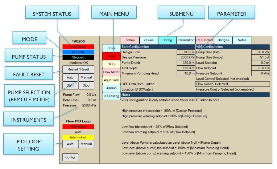
676 It can be seen on the right-hand side of the screen that there are three setpoints: namely level, flow and pressure. There are also three types of control, with the words “not enabled” appearing in brackets after “Level Control Selected” and “Pressure Control Selected”.
677 Mr Quick’s evidence was that the references to Level Control, Flow Control and Pressure Control indicate to him that the HMI has been configured to allow a user to select control based upon either level, flow or pressure, and that the words “(not enabled)” simply show that only one control variable has been selected and enabled. However, this evidence was contradicted by Mr Meredith who created this HMI display and gave evidence that he expected that it had been annotated by Allied Pumps. His evidence was that:
[T]he “Level Control Selected (not enabled)” and “Pressure Control Selected (not enabled)” text depicted at section 1.2 of the Quick Start Operation are not selectable by an operator (which is apparent from the fact that they do not appear in a box). That is, they are not buttons. Rather, they are inactive text. The underlying logic for the Allen-Bradley PLC for Allied Pumps’ VSG does not include (and has never included) any programmed logic to facilitate Level or Pressure Control functionality. Regarding “Level Setpoint” and “Pressure Setpoint”, although a value could be entered into the “Level Setpoint” and “Pressure Setpoint” positions on the screen, entering such a value has no effect what so ever [sic] as it is not possible for an operator to select Pressure or Level Control for the Allen-Bradley PLC for Allied Pumps’ VSGs.
678 Under cross-examination, Mr Meredith said that the HMI (or user interface) is standard across all VSGs used by BHP regardless of the supplier; BHP had not reviewed and approved what was displayed on the HMI; the layout was his concept; it was not a requirement of BHP; and when he designed it, he tried to duplicate what was on the SCADA control system.
679 UON did not address this evidence in its submissions or explain why it should not be accepted.
680 UON did, however, submit that the inclusion of the three options featured on the HMI, whether enabled or otherwise, indicates to a viewer of the screenshot of the HMI that there is level, pressure and flow control. It also submits that, as the HMI includes lines to enter level setpoint and an option for level control, this reveals (and would have revealed to a reasonable person in the position of Allied Pumps) that BHP wished to avail itself of this functionality. It submits that the fact that level control is “not enabled” would convey to a reasonable supplier in Allied Pumps’ position that the programming for level control was present but not currently usable.
681 However, the words “not enabled” rather than, for example, “not selected” are ambiguous; they are equivalent to “not applicable” and, as such, they could equally convey to a reasonable supplier in Allied Pumps’ position that the programming for level control was not present, and that BHP did not wish to avail itself of this functionality.
682 Further, having regard to the unchallenged evidence of Mr Meredith about the HMI display for the Allied Pumps System (which is cited earlier in these reasons) and his evidence about the lack of involvement of BHP in the design of the HMI, its design (including the reference to the three types of control) is insufficient to establish the separate proposition that BHP in fact implemented level control for its VSGs, or that it in fact required its VSGs to have that capability.
13.6.8 Dewatering Generator Trailer Package Operation & Maintenance Manual
683 This is an Allied Pumps document entitled “Dewatering Generator Trailer Package Operation & Maintenance Manual”. It is marked “Revision B” and dated 3 March 2021, although an earlier version of the document was issued for review in March 2020. The Manual was provided by Allied Pumps to BHP by at least 1 June 2021, apparently in response to certain issues which BHP was having with trailers supplied for Mining Area C. There is no direct evidence that the Manual was provided to BHP when the BHP Category A Systems were first supplied.
684 In section 5.3.1 of the Manual (which is contained within the overarching section entitled “Maintenance”), there is a picture of the screen of a ComAp controller. It is reproduced below:

685 Above this image, it is stated that:
The generator mode in the Genvar unit are by default in VSG Mode which means that the generator varies voltage and frequency to meet optimum operating parameters.
686 Mr Quick deposed that the “operating parameters” referred to above are those contained on the right-hand side of the ComAp screen, namely “Pressure”, “Flw rate” (being a reference to flow rate) and “Bore lvl” (being a reference to bore water level). Mr Quick concluded that the system depicted in the Manual is operating in pressure control mode. This was an inference based on an unverified assumption that the PID setpoint was set for pressure, and the fact that “0” appears above the “Mode” button and also next to “pressure” in the list of variables appearing on the screen.
687 UON submits that this Manual makes clear that: (a) the features of the product include a HMI controller being the Allen-Bradley and a ComAp; and (b) the device depicted in the Manual is in VSG mode, controlling for certain operating parameters. It was submitted that the Manual explicitly refers to water level as being one of the control modes.
688 When taken to the Manual in cross-examination, Mr Meredith stated that he had never seen the document before. Mr Meredith accepted that the Manual describes how an Allied Pumps VSG system operated in March 2021, but said that he was not familiar with an Allied Pumps System which has both a PLC and a ComAp controller. He stated that it was unlikely that such a system had ever come to a BHP iron ore site.
689 Mr Meredith was insistent that every Allied Pumps trailer that has gone to any of the iron ore sites he deals with do not have the level, flow or pressure readings in the ComAp. That was said to be because, in the wiring, there is no signal for the flow to get to the ComAp and so, if there is a PID loop, it does not work.
690 That is, Mr Meredith’s evidence was that the controller depicted in the Manual did not reflect the controllers present in any of the BHP Category A Systems. This is in circumstances where Mr Meredith was familiar with the screens depicted in the Quick Start Operation document and gave evidence about the HMI display present in the Allied Pumps System (which is reproduced above).
691 Notably, Mr Walters, who was involved in the factory acceptance testing of the BHP Category A Systems, was not taken in cross-examination to this part of the Manual, nor asked whether he had ever seen such a screen on the BHP Category A Systems tested by him.
692 Taking into account these matters and the absence of evidence of any persons (other than Mr Meredith and Mr Walters) who had direct involvement with the BHP Category A Systems, I am unable to place any weight on the Manual. In particular, the evidence is insufficient to conclude to the requisite standard that the screen depicted in the Manual is one that is or was available on the BHP Category A Systems. Therefore, to the extent that UON suggests that the Manual demonstrates that the BHP Category A Systems were capable of controlling via level, this submission is not accepted.
13.6.9 Submissions by UON about effect of documentation
693 This section of the reasons relates to UON’s submission about the documents referred to above other than the Allied Factory Acceptance Procedure documents and the Quick Start Operation document.
694 UON’s submission was that these documents, read separately and together, demonstrate that BHP required a supplier to provide it with a system capable of being programmed to control pump or engine speed by reference to any of flow, level or pressure control, and that Allied Pumps was aware of this.
695 However, that submission is rejected. The evidence of Mr Meredith, who is independent of the parties, was emphatic and generally consistent. His evidence about the requirements of BHP concerning the VSGs supplied to it, even if that evidence was limited to his understanding, carries more weight than the documents relied upon by UON, having regard to his role and the fact that he would likely be made aware of these requirements by BHP. This is especially as no witness was called from BHP to either explain the documents or contradict the evidence of Mr Meredith. Further, Mr Meredith’s evidence was supported by Mr Walters, and was not contradicted by Mr Meys (who could have given evidence about BHP’s requirements post-February 2018 but, without explanation, did not do so). Further, the documentary evidence had various deficiencies, which are identified above. Finally, UON’s GMC Pro Power VSGs were supplied to BHP and were not capable of controlling by reference to all three modes. This latter fact demonstrates that, irrespective of the content of these documents and how they might be construed, BHP did not, in practice, have the requirement which UON submits that it had.
13.6.10 Submissions by UON about absence of evidence
696 UON submits that it was “telling” that no evidence was given by any person from Allied Pumps about communications with Mr Meredith or BHP concerning BHP’s intention to use the BHP Category A Systems.
697 However, there are inherent difficulties with this submission.
698 The burden of proof is on UON, not Allied Pumps. Allied Pumps is only required to meet the case which is put against it, which was, in essence, a circumstantial case premised upon a limited assortment of documents with input by Mr Quick (but no-one from BHP) as to their interpretation or usage, as well as evidence of Mr Meys concerning a period in early 2018 when BHP was exploring level control (and absent evidence as to BHP’s requirements as actually implemented post-February 2018). While this evidence was sufficient to shift the evidentiary onus to Allied Pumps, Allied Pumps discharged that onus by calling Mr Meredith and Mr Walters, whose evidence I have accepted for the reasons already explained. There was therefore no necessity for further witnesses to be called from within Allied Pumps.
13.7 Whether infringement within the meaning of s 117(2)(b)
699 UON submits that the above documentation provides ample support for a finding that Allied Pumps had reason to believe for the purposes of s 117(2)(b).
700 However, the evidence did not establish that a reasonable person in the position of Allied Pumps would have believed that the BHP Category A Systems would be put to an infringing use by BHP. That is because those systems did not have the capacity to do so (and a reasonable person in the position of Allied Pumps would be familiar with the manner in which the systems operated and would therefore know this).
701 In making this finding, I rely upon and accept the evidence of Mr Meredith, who had direct involvement with the BHP Category A Systems and whose evidence was not contradicted by any other witness. His evidence was that the underlying Allen-Bradley PLC for these systems did not include the logic to facilitate pressure or level control, and that (regardless of what appears on the HMI display) it was and is not possible to change the control of the systems from flow control to pressure or level control. For the reasons explained above, the documentation relied upon by UON was insufficient to cause me to doubt or reject the evidence of Mr Meredith concerning the BHP Category A Systems. Further, Mr Meredith’s evidence as to the capacity of the systems to control on pressure or level was corroborated by Mr Walters, who engaged in factory acceptance testing of the BHP Category A Systems and whose evidence I have also accepted for the reasons explained above.
702 In further support of its case under s 117(2)(b), UON referred to the fact that the Category B Systems supplied by Allied Pumps allowed for level control by way of the ComAp. This was said to demonstrate that “there are systems which have been supplied by Allied [Pumps] to customers other than BHP that have the inherent capability to allow for Level Control and could be configured to allow for Level Control were the controller programmed to do so”. However, this submission does not impact my findings above as the Category B Systems are distinct from the Category A Systems.
703 It follows that UON failed to establish infringement by Allied Pumps within the meaning of s 117(2)(b) of the Patents Act.
13.8 Whether infringement within the meaning of s 117(2)(c)
704 UON’s pleaded case was that infringement under s 117(2)(c) was established on the basis that certain documents provided by Allied Pumps to BHP contained the necessary instructions to BHP to use the BHP Category A Systems in an infringing manner. Although there was passing reference to inducement in UON’s closing written submissions (at [123]), its oral and written closing submissions focussed upon whether there were instructions within the meaning of s 117(2)(c), and not inducement.
705 In its opening submissions, UON asserted that each of the following documents constituted instructions given by Allied Pumps to BHP: (1) the Manual; (2) the Factory Acceptance Procedure documents; and (3) the Quick Start Operation document. However, by its closing written submissions, UON did not press reliance upon the Quick Start Operation document. In closing oral submissions, Senior Counsel for UON confirmed that “[t]here are two documents we rely upon which constitute relevant instructions”. I will therefore only consider the Manual and the Factory Acceptance Procedure documents for the purposes of UON’s case brought under s 117(2)(c).
706 Dealing first with the Manual (the details of which are set out above), UON submits that the references in section 5.3.1 to pressure, flow rate and water level in the image of the ComAp controller were instructions issued to BHP to use the BHP Category A Systems to control by reference to those control modes including, relevantly, level.
707 However, Mr Quick only gave limited evidence (a total of three paragraphs) about the image in section 5.3.1 of the Manual. As discussed above, this included an inference drawn by him that the system depicted in the image is operating in pressure control mode based on (inter alia) an assumption made by him (which assumption was not established having regard to my acceptance of the evidence of Mr Meredith). Mr Quick also expressed an opinion that “the use of the [BHP Category A System], in accordance with any instructions given in those documents [which included the Manual], would result in use of a method having each integer of claim 4 of the Patent” (emphasis added). Notably, Mr Quick did not identify what those instructions were (in any of the documents, including the Manual) and he did not give reasons for his opinion. While the Manual contains general instructions for use of the BHP Category A Systems, there is not a single instruction or statement in the Manual about how to put the BHP Category A System into a mode which would allow it to be controlled by reference to level. I place no weight on Mr Quick’s evidence for these reasons.
708 Although Mr Meredith gave evidence under cross-examination which suggested that it would not be difficult to reprogram the BHP Category A Systems to achieve control via level, he stated that it would have been time consuming for a skilled person such as himself to change the software of the system. The Manual did not contain any directions to BHP as to how to reprogram the software in the BHP Category A Systems so as to achieve control via level (which reprogramming was necessary). It was not suggested that this was something that BHP could have done itself. Therefore, at best for UON, there is a suggestion of control by level through the image depicted in the Manual, but no directions as to how to achieve that control.
709 That is not enough to constitute “instructions for use” within the meaning of s 117(2)(c) of the Patents Act. That is because there is a distinction between a document specifying a use and the provision of instructions for that use: see, for example, Hood v Bush Pharmacy Pty Ltd (2020) 158 IPR 229; [2020] FCA 1686 (Nicholas J) at [257]–[269] (appeal dismissed: Hood v Down Under Enterprises International Pty Ltd (2022) 166 IPR 436; [2022] FCAFC 69 (Yates, Moshinsky and Rofe JJ)).
710 Therefore, contrary to UON’s submissions, the Manual, if supplied to BHP with the BHP Category A Systems, did not contain instructions within the meaning of s 117(2)(c).
711 Turning then to the three Factory Acceptance Procedure documents (which are discussed in detail above), UON submits that section 6.6.2.1 of the documents constitutes instructions from Allied Pumps to BHP that the BHP Category A Systems function using “Level as a target parameter” and can vary the speed of the VSG to “maint[ain] set Level”. Section 6.6.2.1 of each document relevantly states:
The following functions of the system shall be tested.
…
18. Select Level as target parameter on Ext. Control Panel HMI
19. Press Pump Start Button.
20. Verify that Generator Starts
21. Verify that Pump runs and varies speed to maintained set Level.
22. Press Stop Button
…
712 As discussed above, the first Factory Acceptance Procedure document (completed by Mr Walters) contained ticks next to these steps (although Mr Walters gave evidence, which I accepted, that those ticks were placed in error).
713 This document contained instructions to a person who is required to carry out tests on a dewatering trailer. That person was an employee of Allied Pumps, not BHP. Like the Manual, this document does not contain “instructions for use” which explain to BHP how it might put the BHP Category A Systems into a mode which achieves control by level. At most, the document (taken with the ticks contained next to the relevant steps) suggests to BHP that the BHP Category A Systems could be controlled by level but, as already explained, that is not enough: Hood at [257]–[269].
714 By contrast, the second and third Factory Acceptance Procedure documents had differing annotations next to the steps concerning the testing of control by level. In light of the conclusion reached above, it is not necessary to explore the inferences which might have been drawn by BHP from these annotations. If anything, the annotations contained in these documents made the meaning of the steps in section 6.6.2.1 more ambiguous, thereby making it less likely that they could amount to an instruction for BHP to use the BHP Category A Systems in an infringing manner.
715 Therefore, contrary to UON’s submissions, the Factory Acceptance Procedure documents, if supplied with the BHP Category A Systems to BHP, did not contain instructions within the meaning of s 117(2)(c).
716 It follows that UON failed to establish infringement by Allied Pumps within the meaning of s 117(2)(c) of the Patents Act.
717 For these reasons, the cross-claim should be dismissed.
718 I will direct the legal representatives for the parties to confer on the redactions to these reasons, and to provide to chambers an agreed form of the reasons for judgment with the proposed redactions highlighted, together with an agreed redacted form of the reasons for judgment that is suitable for publication. I will also invite the parties to confer and provide an agreed form of orders having regard to the findings made.
I certify that the preceding seven hundred and eighteen (718) numbered paragraphs are a true copy of the Reasons for Judgment of the Honourable Justice Downes. |
Associate:
NSD639 of 2021 | |
UON PTY LTD |
|