
FEDERAL COURT OF AUSTRALIA
MMD Design and Consultancy Limited v Camco Engineering Pty Ltd [2023] FCA 827
ORDERS
DATE OF ORDER: |
THE COURT ORDERS THAT:
1. The parties confer and, within 21 days of these orders, submit to the Associate to Justice Rofe an agreed minute of orders giving effect to these reasons, alternatively if no agreement each party submit a proposed minute of order.
2. Orders 1 and 2 made 14 September 2022 be extended until further order of the Court.
Note: Entry of orders is dealt with in Rule 39.32 of the Federal Court Rules 2011.
[1] | |
[6] | |
[31] | |
[33] | |
[49] | |
[69] | |
[70] | |
[75] | |
[86] | |
[87] | |
[92] | |
[98] | |
[108] | |
[110] | |
[115] | |
[120] | |
[132] | |
7.5.1 Weldingly secured to and seated in face to face contact with the front face (or rear face) of the support body | [133] |
[141] | |
[153] | |
[160] | |
[167] | |
[179] | |
[182] | |
[185] | |
[188] | |
[190] | |
[199] | |
[204] | |
[206] | |
[206] | |
[208] | |
[216] | |
9.4 Parties’ submissions on terms where there was no expert agreement | [218] |
[239] | |
[281] | |
[282] | |
[287] | |
[296] | |
[299] | |
10.3 Front/rear cover in face to face contact with the front/rear face of the support body | [301] |
[303] | |
[307] | |
[308] | |
[330] | |
[336] | |
[338] | |
[341] | |
[354] | |
[367] | |
[381] | |
[384] | |
[389] | |
[395] | |
[396] | |
[397] | |
[408] | |
[427] | |
[440] | |
[444] | |
[460] | |
[466] | |
[486] | |
[496] | |
[498] | |
[502] | |
[513] | |
[514] | |
[526] | |
[538] | |
[550] | |
15.5 Dr Huggett’s evidence as to methods of protection of sizer teeth | [555] |
[559] | |
[560] | |
[564] | |
[594] | |
[606] | |
[607] | |
[613] | |
[624] | |
[624] | |
[639] | |
[653] | |
[665] | |
[669] | |
[672] | |
[678] | |
[686] | |
ROFE J:
1 MMD Design and Consultancy Limited is the patentee of Australian Patent No. 2004289510 entitled “A tooth construction for a mineral breaker” (the Patent). MMD and MMD Australia Pty Ltd (together are referred to as MMD) contend that Camco Engineering Pty Ltd has infringed claims 1, 2, 3, 4, 7, 8, 9, 10 and 17 of the Patent (the Asserted Claims) by the unauthorised supply of five tooth constructions for mineral sizers (Camco Constructions) to particular mine sites in Western Australia.
2 MMD seeks injunctive, declaratory and monetary relief (including additional damages) against Camco for infringement of the Asserted Claims.
3 Camco denies infringement of the Asserted Claims and cross-claims for revocation of those claims. Camco denies that its sizers take all the integers of the Asserted Claims and also contends that the Camco Constructions are used to repair MMD sizers and thus do not constitute infringement. Camco’s cross-claim raises four grounds of invalidity: manner of manufacture, novelty, inventive step and s 40 issues (fair basis and clarity).
4 MMD also contends that Camco has engaged in misleading and deceptive conduct under s 18(1) of the Australian Consumer Law in Sch 2 to the Competition and Consumer Act 2010 (Cth) (ACL) by failing to warn its customers of the existence of the Patent, that the exploitation of the respective Camco Constructions infringed the relevant claims of the Patent, and that Camco is not entitled without the authority or consent of MMD to supply the Camco Constructions. MMD alleges that Camco’s failure to warn of these matters occurred in circumstances where each of Camco’s customers reasonably expected Camco to provide each of these warnings.
5 For the reasons set out below, I consider that the Camco Constructions do not infringe the Asserted Claims, and that the Patent is valid.
6 The Patent was filed on 5 November 2004 and claims a priority date of 8 November 2003. The priority date is not in dispute in these proceedings. The Patent is due to expire on 5 November 2024.
7 The Patent concerns a tooth construction for a mineral breaker. Mineral breakers are also known as mineral sizers. As “mineral sizers” was the description used by the parties throughout the trial and in their submissions, I will use that term.
8 Mineral sizers are large pieces of equipment used predominantly on mine sites to break mineral ore into smaller sizes so that the rocks are a suitable size for processing. Mineral sizers typically comprise two counter-rotating parallel shafts, with each shaft having a series of adjacent drums with radially projecting teeth, the teeth from each shaft being offset so as to be interlaced.
9 The Patent states that the present invention is primarily concerned, but not exclusively, with the type of mineral breaker disclosed in an earlier MMD European patent 0167178. The illustration below is Figure 1 from that European patent:
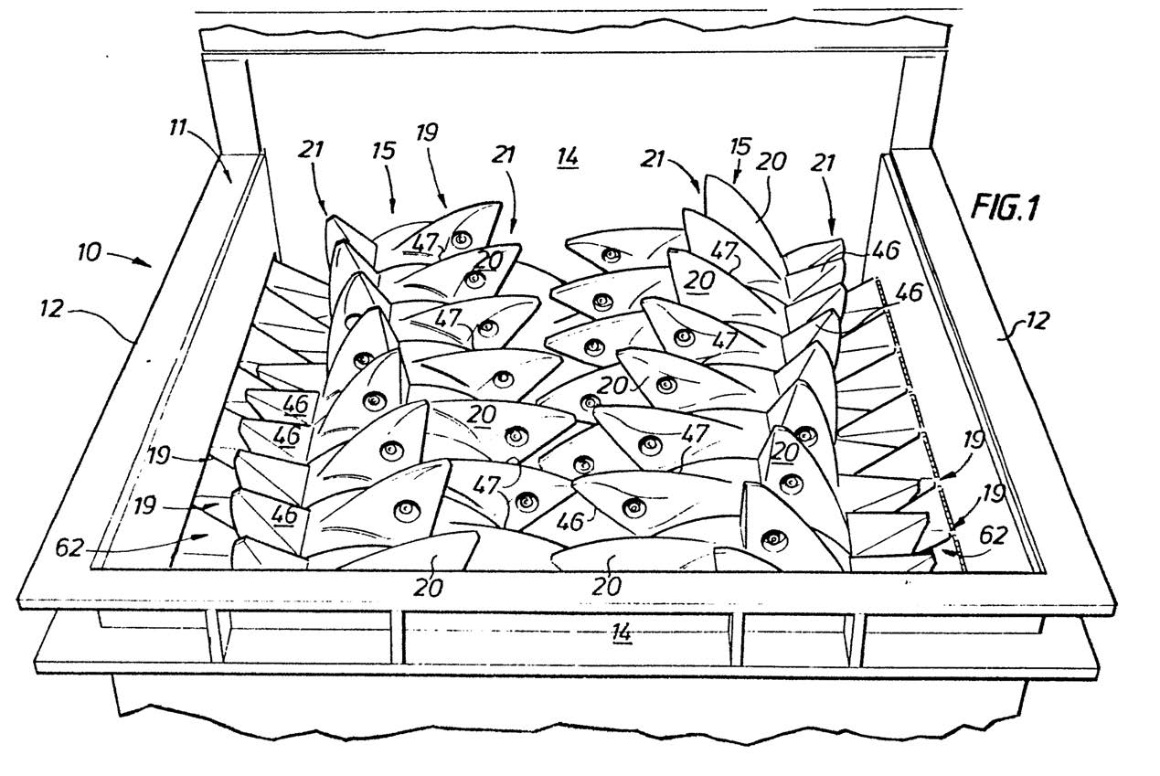
10 With a sizer of the kind depicted above, mineral lumps are broken down by gripping the lumps and applying tensile forces to cause the lump to break by a snapping action. Each tooth is exposed to large breaking forces applied, on the one hand, onto the front of the tooth and then, on the other hand, onto the rear of the tooth.
11 A tooth construction is the combination of a support body (also known as a “horn”) covered by a shell so as to protect the horn.
12 The Patent sets out the purpose of the invention on page 1, lines 19–27:
In order to enable each tooth to withstand the breaking forces without snapping it is desirable to construct each tooth so as to have a core formed of ductile metal which is covered with a tooth shell of a wear resistant material, which in itself can be relatively brittle. In order to be capable of breaking particularly hard minerals, such as for example granite, it is necessary to be able to transmit, from the drive shaft, relatively large forces. These large forces, in turn, exacerbate the securance of a tooth shell on the tooth core or horn and also require the core or horn construction to be robust enough to transmit the relatively high forces required.
13 At the foot of the first page, the Patent sets out the first consistory clause in language which mirrors claim 1:
According to one aspect of the present invention there is provided a tooth construction for a mineral breaker, the tooth construction including a tooth shaped support body covered by a shell which defines the outer shape of the tooth construction, the shell being composed of a plurality of covers which are fixedly secured to one another and/or to the support body by welding to define a unitary tooth construction the support body having a front face and an opposed rear face and the plurality of covers including at least a front cover weldingly secured to and seated in face to face contact with the front face of the support body and a separate rear cover weldingly secured to and seated in face to face contact with the rear face of the support body.
14 The second consistory clause which commences at page 2, line 10, is to a “drum construction for a mineral breaker”, and mirrors claim 12, which is not one of the Asserted Claims.
15 The Patent includes 12 figures which relate to two embodiments of the invention. Various aspects of the invention are described in the following section of the Patent by reference to the figures:
Figure 1 is a part perspective view of a drum annulus according to an embodiment of the present invention;
Figures 2 to 6 illustrate a sequence of construction steps, according to a first embodiment, for creating a toothed annulus for a mineral breaker using the drum annulus of Figure 1;
Figures 7 to 11 illustrate a sequence of construction steps, according to a second embodiment, for creating a tooth annulus for a mineral breaker using the drum annulus of Figure 1; and
Figure 12 is a part side view of a tooth construction according to a further embodiment of the invention.
(Emphasis added.)
16 Figures 2 to 6 are said to illustrate the method of construction to produce a breaker tooth of a given height (the first embodiment). The method of construction of a breaker tooth illustrated in figures 7 to 11 enable a breaker tooth of a height greater than that of the first embodiment to be produced whilst using the same size of drum annulus (the second embodiment).
17 The “two methods of construction” are said to be illustrative of the principle that the same drum annulus may be used to produce breaker teeth of different heights. The Patent notes that this is particularly advantageous since it enables the same size of drive shaft and drum annulus to be used for the construction of mineral breakers having different sizes of teeth. The Patent also notes that “these two methods of construction” are also illustrative of different ways of securing covers to each horn to define the outer, exposed faces of breaker teeth.
18 The Patent describes a series of steps (or method of construction) to assemble two embodiments of a tooth construction of the invention.
19 The method of construction according to the first embodiment is described at pages 4 to 6 (inclusive) as follows:
As shown in Figure 2, the axial side faces 33, 34 of the horn 12 are partially covered by a pair of side covers 36, 37.
Each side cover 36, 37 include a plate-like body 38 and an arcuate flange 39 located at the lower edge of body 38.
Preferably the side faces 33, 34 are planar and bodies 38 are preferably formed from a metal plate which is also planar.
The front and rear edges 40, 41 of body 38 are preferably co-planar with the front and rear faces 44, 45 respectively of the horn 12. The upper edge 47 of each body 38 is preferably rectilinear and extends from the upper part of the front face 33 to the upper part of the rear face 34 of the horn 12. Accordingly the upper portions of side faces 33, 34 are left exposed to define a crown portion 50.
The side covers 36, 37 are secured to the horn 12 preferably by welding. Preferably this is achieved by providing welding along the front, upper and rear edges 40, 47, 41 respectively to produce a welded seam 55. Accordingly the side covers 36, 37 are securely bonded to the horn 12.
The arcuate flange 39 is seated upon a portion of the annular shoulder 20 and serves to cover that part of the shoulder 20.
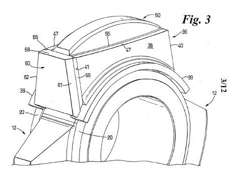
As shown in Figure 3, a rear cover 60 is then provided which is seated in face to face contact with the rear face 31 of horn 12. The cover 60 has side edges 61, 62 which are co-planar with the outer face of bodies 38 and so covers the rear edges 41 of both side covers 36, 37. The rear cover 60 is preferably formed from a metal plate.
The rear cover 60 is secured to the horn 12 and side covers 36, 37 preferably by welding. Preferably this is achieved by welding along the side edges 61, 62 to produce welded seams 65. Whilst it is preferred that the cover 60 is directly welded to the horn 12 it is envisaged that it may be indirectly welded to the horn 12 by being welded to side covers 36, 37 only (which in tum are weldingly connected to the horn).
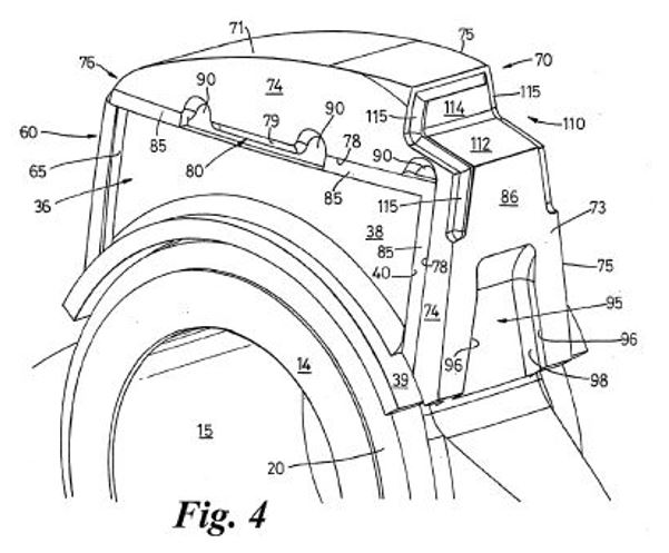
As shown in Figure 4, the horn 12 is then provided with a front and top cover 70.
Cover 70 includes a top portion 71 which has an inner groove (not shown) of complementary shape and size to the exposed crown 50 of the horn 12 which is left exposed after securance of side covers 36, 37 and rear cover 60. Cover 70 further includes a depending front wall portion 73 which has an internal face (not shown) which is seated in face to face contact with the front face 32 of the horn 12. The front wall portion 73 has an upper front face 86 which is preferably planar. The lower portion 87 of the front wall portion 73 preferably includes a window 95. Side walls 96 of the window 95 are preferably secured to the exposed front face of the horn 12 by welded seams 98 in order to directly weldingly secure the front wall portion 73 to the horn 12.
The cover 70 has outer side faces 74, 75 which lie in the same plane as the outer face of side plates 38 and so have inner faces 78, 79 respectively which face and overlie edges 40, 47 of the side plates 38. Preferably a rear end portion 76 of the cover 70 overlies the upper edge 68 of cover 60.
Preferably the side edges of top portion 71 which define faces 78 are spaced from opposed edges 47 to form a gap 80 extending along the edge 47 (only a portion of gap 80 is shown). This enables the inner surface of the top portion 71 to seat upon the upper portion of crown 50.
The cover 70 is then secured to the horn 12 preferably by welding so as to join the opposed faces between cover 70 and plates 38 to one another via a welded seam 85.
A further welded seam 86 is preferably provided to weldingly join the upper edge 68 of cover 60 to the end portion 76.
The weld seam 85, where it extends along the upper edge 47 of each plate 38, also fills the gap 80 and so is weldingly joined to that part of the horn 12 which is exposed by gap 80. Preferably recess windows 90 are provided to enable a gouging tool to be inserted for removal of the weld seam 85 to thereby enable the cover 70 to be removed in the event of a replacement cover 70 being necessary due to wear.
(Emphasis added.)
20 Figures 3, 4 and 5 of the Patent are as follows:
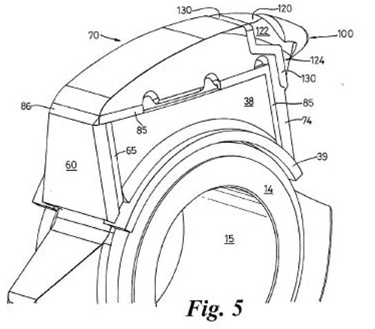
21 There is a description of the mounting of the breaking tip member at page 7, lines 13–19:
The tip member 100 preferably has a mounting body 120 in which is secured a pick-like tip 121. The mounting body 120 has an upper part 122 which seats in rebate 110 and a lower depending part 124 which has an inner face which lies in face to face contact with the upper front face 86 of wall portion 73. The body 120 has outer edges which overlie the peripheral groove 115 and is preferably secured to the cover 70 by a welded seam 130 extending along groove 115.
(Emphasis added.)
22 The Patent notes at page 7, line 20 to page 8 line 12, that:
The above arrangement produces a breaker tooth in which a horn 12 is provided which is completely enclosed by a fabricated shell-like tooth cap defined by covers 36, 37, 60 and 70. The tooth cap is fabricated in-situ on the horn 12, preferably by welding covers 36, 37, 60, 70 to one another and/or the horn 12. This provides a very strong tooth construction having a shell-like construction which is securely fixed to the horn 12.
In this construction, the front of the tooth is fully seated on the horn front face 32 at the time of assembly and so is highly resistant to loosening during operation by being exposed to impacts on the front of the tooth. Similarly, the rear of the tooth shell (as defined by plate 60) is fully seated on the rear face 31 of the horn during assembly and is fixed in position independently of the front of the tooth. This means that the rear plate 60 of the shell is highly resistant to loosening by impacts on the rear of the tooth. It follows therefore that the fabricated shell is highly resistant to loosening by repeated alternate impacts to the front and rear of the tooth.
As wear takes place, in use, replacement covers can be simply installed by removal of the worn cover and insertion of a new one. Removal is easily achieved by first removing the relevant welded seam.
(Emphasis added.)
23 The second embodiment which is illustrated in figures 7 to 11 is said to be an example of a tooth construction which uses the same sized horn as the first embodiment but has a tooth height greater than that of the first embodiment as depicted in figure 6. This is achieved primarily by the provision of an intermediate cover.
24 The second embodiment is described on pages 8 to 9.
In embodiment 200, the horn 12 is first covered with a cover 210 which is preferably cast from a suitable metal. The cover 210 has a pair of opposed sides 212, 214, a front wall 216 and a top 215. The cover 210 has an open back (not shown).
The cover 210 defines an internal pocket which has faces which seat in face to face contact with faces 32, 33, 34 and 50 of the horn 12.
The side walls 212, 214 include at least one window or aperture 218 which exposes a portion of the underlying face 33 or 34 of the horn 12. The aperture 218 has side walls 219 which are secured to the exposed face 33 or 34 of the horn 12 by welding. Preferably the entire aperture 218 is filled with weld.
Similarly, the front wall 216 is provided with at least one window or aperture 225 which exposes a portion of face 32.
The aperture 225 has side walls 226 which are secured to the exposed portion of face 32 by welding.
The rear end faces 219 of the cover 210 are preferably co-planar with the rear face 31 of horn 12 and are secured to the horn 12 by a welded seam extending between the internal edges of faces 219 and the horn 12.
Accordingly the cover 210 is securely fixed to the horn 12 by welding located at the front, both sides and rear of the cover 210.
The top 215 of cover 210 defines an upper crown 250 of similar shape to crown 50.
As shown in Figure 8, a rear cover 60 is provided which overlies the rear face 31 and end faces 219 of the cover 210. The cover 60 is formed of a metal plate and is located in face to face contact with rear face 31. It is secured to the cover 210 and horn by a seam of weld 65 which extends along both sides of plate 60.
As shown in Figure 9, a cover 270 similar to cover 70 is located on the crown 250 and is secured in place by welded seams 85.
(Emphasis added.)
25 At page 10, the Patent notes that the construction of the breaker tooth, as exemplified in the two embodiments, provides a very strong breaker tooth since welding of the covers to the horn in effect adds strength to the horn. This means that the tooth construction of the invention can transmit relative high forces for breakage of very hard minerals with a reduced risk of snapping and in addition without a risk of the tooth shell or cover working loose.
26 The Patent notes that the strength of the tooth construction according to the invention is also enhanced by the fact that the horn is solid, eg does not contain through bores as is commonly required with prior art constructions.
27 The Patent has 19 claims.
28 Claim 1 claims:
A tooth construction for a mineral breaker, the tooth construction including a tooth shaped support body covered by a shell which defines the outer shape of the tooth construction, the shell being composed of a plurality of covers which are fixedly secured to one another and/or to the support body by welding to define a unitary tooth construction the support body having a front face and an opposed rear face and the plurality of covers including at least a front cover which is weldingly secured to and seated in face to face contact with the front face of the support body and a separate rear cover which is weldingly secured to and seated in face to face contact with the rear face of the support body.
(Emphasis added.)
29 The highlighted integers are where the primary dispute lies in construction of the claim and infringement.
30 Claims 2 to 9 are dependent on claim 1. Claims 10 and 17 are omnibus claims.
31 Much of the infringement evidence was the subject of claims to confidentiality. In particular, the drawings of the Camco Constructions at each of the mine sites at which MMD contends there is infringement of the Asserted Claims.
32 References to certain confidential manufacturing tolerances and evidence that is confidential to MMD are redacted in the public version of these reasons.
33 Before going further, it is necessary to address what I term “the ore fines issue”.
34 At trial MMD opened its case on the construction of a critical claim integer: “in face to face contact”, orally and in writing by reference to ore fines and corrosion.
35 At [32] of its written opening submissions on the construction of the “in face to face contact” integer, MMD submitted:
… seated in face to face contact with the front face of the support body: Consistent with Mr De Vos’ evidence, MMD submits that this integer requires that the front cover is positioned (whether when fitted or during use)71 so that the forces are transmitted from the front cover to the front face of the Support Body (horn), whether by the front cover directly touching the Support Body (horn), or indirectly through an intermediate component (such as an Intermediate Cover) or ore fines and/or corrosion present in the clearance between the cover and the Support Body (horn).72 In order for forces to be transmitted between two components, there must be a physical connection between them.73 “Seated in face to face contact” does not require that forces are transmitted across the entire face of the front cover.74
(Original emphasis, with bold emphasis added.)
36 Footnotes 71, 72, 73 and 74 are to Mr de Vos’ first affidavit. Footnote 72 additionally refers to the joint expert report.
37 Camco denied that the Camco Constructions infringed principally on the basis that there were gaps between the face of the horn and the cover, such that they were not in face to face contact.
38 As will be discussed further later, Mr de Vos considered that the invention described in the Patent is concerned with efficiently transmitting the large forces applied to the tooth construction in operation to the horn, because the covers may fall off the support body if those forces are not efficiently transmitted.
39 The ingress of ore fines into tooth constructions and their compaction (together with any corrosion) during operation to fill any gaps and thus provide an efficient transmission of force from the covers to the horn was a central part of Mr de Vos’ construction of the “in face to face contact” integer in his first affidavit. Interestingly, Mr de Vos had no prior experience with or knowledge of the ingress of ore fines and their compaction during operation until he was instructed to accept that ore fines would infiltrate into the tooth construction during operation and compact in any gaps, and asked how that would affect the transfer of forces.
40 Once instructed to accept the ingress of ore fines to fill gaps or clearances, Mr de Vos included ore fines as part of his consideration of the construction of the “in face to face contact” integer, and in his infringement analysis.
41 I note that Dr Huggett did not accept the compaction of ore fines as a solid intermediary component through which forces could be effectively transmitted. In his opinion the transfer of forces in a tooth construction that contained clearances would occur exclusively through the weld.
42 On day seven of the trial MMD informed the Court that “its position on ore fines is no longer pressed”. MMD’s fourth amended position statement on infringement was marked up to remove references to ore fines, however no mark up of the evidence was provided to show which parts, if any, were no longer relied on.
43 By closing, the MMD infringement argument had evolved to no longer rely on ore fines and corrosion filling the gaps during operation to enable efficient transmission of the forces. Instead, where the faces of the relevant covers were not in physical contact with the support body (eg there were gaps) MMD now relied on the presence of weld at the edges of the front or rear face for the transmission of force from the cover to the support body. The extreme point of this argument is illustrated by diagram 3 (discussed in detail below) where the weld is the sole means by which force can be transferred from the front/rear cover to the support body. Diagram 3 appeared for the first time in the joint expert session.
44 For reasons which I set out below, I do not consider that a tooth construction in which the transfer of force from the front/rear covers is solely via the weld connecting the edge of the front/rear covers to the ends of the side covers (as depicted in diagram 3) falls within claim 1 of the Patent.
45 Mr de Vos’ extensive written evidence on construction placed emphasis on the transmission of compressive force as the most efficient and effective means for the transfer of force from the faces of the front/rear covers to the front/rear faces of the support body. He observed that once the clearances are filled with ore fines or corrosion, forces are able to be transmitted to the support body in the same manner as occurs with front and rear covers that are placed against the front and rear faces of the support body, respectively.
46 Mr de Vos’ evidence in the joint expert report also referred to the transmission of force indirectly through ore fines and/or corrosion present in the clearance between the covers and the support body.
47 Despite abandoning the ore fines argument on day seven of the trial, MMD’s written closing submissions still contained a submission that the forces could be transmitted from the covers of the Camco Constructions to the support body via ore fines and/or corrosion present in the clearance between the covers and the support body. Whilst this reference may have been a relict from the opening submissions, overlooked in the preparation of a very extensive submissions document in a short space of time, it serves to illustrate the centrality of this argument to MMD’s infringement argument in opening, and to Mr de Vos’ reasoning in his evidence, and just how difficult it is to simply excise ore fines from the infringement case, where they had previously played a central role.
48 It is because I consider that the ore fines issue was integral to Mr de Vos’ reasoning on construction and infringement in his affidavit evidence such that it cannot be simply surgically excised, that I have discussed his written evidence at length in a following section.
49 MMD led evidence from three non-expert witnesses employed by MMD, and Andrew Mullane, one of MMD’s solicitors. Each of the MMD non-expert witnesses, other than Mr Mullane was cross-examined.
50 Darren Balmer, Production Director at MMD Australia, made five affidavits dated 27 January 2022, 2 February 2022, 11 May 2022, 10 June 2022 and 24 June 2022. Mr Balmer commenced with MMD Mineral Sizing (Europe) Ltd in 1993, and has been employed by various MMD companies since then, moving to MMD Australia’s Brisbane office in 2009.
51 Starting in about 1995, Mr Balmer began assisting in MMD Mineral Sizing’s service department in the United Kingdom and was involved in the installation of new equipment and the repair and changing of worn components for bolted tooth constructions.
52 According to Mr Balmer, MMD Australia has supplied mineral sizers to mine sites in Australia since the late 1980’s. For the majority of MMD Australia’s mineral sizers, the teeth are composed of a support body clad with covers. The covers are wear parts.
53 In a confidential annexure to his first affidavit, Mr Balmer gave post priority date evidence about the MMD tooth constructions at each of the Yandi, Solomon and Worsley Alumina sites at which MMD contends that Camco supplies infringing tooth constructions. According to Mr Balmer, the MMD intermediate, rear and top covers are made by casting which he describes as a “relatively imprecise fabrication technique”. He observes that there are manufacturing tolerances associated with the cast covers depending on the length of the component. MMD’s cast covers have a manufacturing tolerance of approximately [REDACTED].
54 The MMD covers also undulate across their inner and outer surfaces (another product of the casting process). As a result, the faces of the covers (both inner and outer) are not perfectly flat.
55 According to Mr Balmer, when fitting the intermediate cover of the MMD tooth construction to the support body [REDACTED] [REDACTED] [REDACTED] [REDACTED] [REDACTED] [REDACTED] [REDACTED] [REDACTED] [REDACTED] [REDACTED] [REDACTED] [REDACTED] [REDACTED] [REDACTED] [REDACTED] [REDACTED] [REDACTED] [REDACTED] [REDACTED] [REDACTED] [REDACTED] [REDACTED] [REDACTED] [REDACTED] [REDACTED].
56 Mr Balmer gave extensive evidence relating to the ore fines issue. For example:
[REDACTED] [REDACTED] [REDACTED] [REDACTED] [REDACTED] [REDACTED] [REDACTED] [REDACTED] [REDACTED] [REDACTED] [REDACTED] [REDACTED] [REDACTED] [REDACTED] [REDACTED] [REDACTED] [REDACTED] [REDACTED] [REDACTED] [REDACTED] [REDACTED] [REDACTED] [REDACTED] [REDACTED] [REDACTED]. [REDACTED] [REDACTED] [REDACTED] [REDACTED] [REDACTED] [REDACTED] [REDACTED] [REDACTED] [REDACTED] [REDACTED] [REDACTED] [REDACTED] [REDACTED] [REDACTED] [REDACTED] [REDACTED] [REDACTED] [REDACTED] [REDACTED] [REDACTED] [REDACTED] [REDACTED]
(Emphasis added.)
57 The majority of the evidence in Mr Balmer’s affidavits was devoted to the ore fines argument. In a confidential section of his first affidavit Mr Balmer describes how he has observed ore fines and corrosion filling clearances in the MMD tooth constructions when they are being removed from a support body. He exhibits various photographs of MMD tooth construction components with corrosion or ore fines on their faces. Mr Balmer opines that the rotation of the tooth construction about the shaft generates centrifugal force that causes the ore fines to compact toward the outer portions of the covers and become solid. Once solid, the compacted ore fines are able to efficiently transmit forces.
58 Scott Harvey is employed as Service Manager at MMD Australia. Mr Harvey made two affidavits dated 19 July 2022 and 21 July 2022 in which he gave evidence as to the provenance of certain photographs (annexed to Mr Balmer’s first affidavit) of tooth constructions at sequential stages of removal during the MMD refurbishment process. Mr Harvey’s evidence was entirely relevant to the ore fines issue.
59 David Waring, the Operations Director of MMD, made one affidavit dated 18 July 2022. Mr Waring gave evidence as to MMD Australia’s exclusive licence to exploit the Patent. Mr Waring appeared by video from the United Kingdom.
60 Mr Mullane annexed to his two affidavits an extensive collection of correspondence between his firm, Wrays Lawyers, and Camco’s lawyers, Griffith Hack.
61 Camco led evidence from its director, Frank Fusco. Mr Fusco made two affidavits, dated 13 May 2022 and 10 June 2022. Mr Fusco’s current role at Camco is Executive Director of Operations and he oversees operational activities at Camco. He agreed in cross-examination that his original claim that he oversaw “all” operational activities was an overstatement. This includes overseeing the workshop repairs conducted by Camco for its customers. Mr Fusco did not have any engineering qualifications and was unable to comment on engineering issues such as the transmission of forces between covers.
62 Camco was incorporated on 4 November 1994 and commenced trading in June 1995 as a start-up business by Bruce Cameron, Victor Fusco, Alan Leese and Mr Fusco. Mr Fusco has been a part owner of Camco since it commenced trading. Mr Fusco and Mr Cameron are responsible for the day-to-day operation of the Camco business and both take a very “hands on” role in all aspects of the business. Mr Cameron, a mechanical engineer, took the lead in relation to negotiating supply contracts and attending meetings, and giving instructions (together with Mr Prasad, a Camco project engineer) including deciding which diagrams to provide to the expert, Dr Paul Huggett, in the course of the MMD litigation. Mr Fusco was generally aware of the negotiations and litigation but was more involved in overseeing the refurbishment operations of the business. Camco currently has over 300 full time equivalent employees.
63 Mr Fusco gave evidence as to Camco and MMD’s business history and he described the nature of Camco’s business as follows:
Camco is not an original equipment manufacturer (OEM) supplier. That is, Camco does not design and supply capital equipment and machinery to resource sector companies when those companies are expanding or developing a new mine site. Rather, Camco provides an after-market repair service (what I described above as ‘operational support’) to those companies. With particular reference to the current proceedings, Camco has repaired parts of mineral breakers (sizers) owned by mining companies and in particular Camco has repaired the breaker shaft assemblies which generally consist of a pair of shafts with drum annuli and wear covers welded around the horns of the drum annuli. Repair of mineral breaker teeth is required because the components forming the teeth are consumable parts worn away by the mineral breaking process and need replacing after a period of time in use. Over the years, Camco has repaired tooth structures as part of the overall repair of breaker shaft assemblies by using OEM parts provided by the mining companies, purchasing parts directly from the OEM, or by Camco manufacturing parts of its own, or by Camco using welding and other hard facing techniques that do not require spare parts.
64 Mr Fusco gave evidence as to the creation of various confidential Camco Fitment and Welding drawings for each of the Camco Constructions at the relevant mine sites alleged to infringe and which were the subject of discussion by the expert witnesses (Camco Drawings). According to Mr Fusco he gave instructions for the preparation of the drawings and supervised their creation. The Fitment and Welding drawings were created to depict the construction method but most importantly to emphasise to workshop staff the importance of particular aspects such as clearances or where welding should be minimised.
65 Mr Fusco said that he sometimes gave verbal variations to the instructions in the Fitment and Welding drawings directly to the workshop staff, and that not all these variations were recorded in the drawings. Modifications to the drawings might also arise during the casting process. The foundry might be asked to make a small modification to the initial casting and to do this they would make a relevant modification to the pattern. Mr Fusco said that these types of modifications, often as a result of verbal discussions, were not always reflected by a revision to the 3D model and creation of revised 2D drawings because he considered them to be so minor that he did not consider it necessary for revised modelling or drawings to be created.
66 Mr Fusco outlined the process by which Camco carried out the refurbishment of mineral sizers. Camco undertakes mineral sizer refurbishment projects in its workshops. The sizer shaft assemblies typically arrive at the Camco workshop by truck on transport frames and are delivered back to the mine site for reinstallation in the mineral sizer following refurbishment.
67 Mr Fusco also gave evidence on the ore fines issue. Mr Fusco’s second affidavit was primarily directed to responding to Mr Balmer’s evidence on the ore fines issue.
68 As a witness, Mr Fusco was at times pugnacious and combative, particularly when presented with a proposition he disliked. He was unable to recall whether he had seen certain emails relating to Camco’s tender negotiations to which he was copied, at the time they were sent. Mr Fusco also had memory lapses in relation to whether he had attended important meetings such as meetings with Watermark, or the 18 December 2018 meeting with MMD.
69 MMD and Camco each called an expert witness. Mr Jurrien de Vos was called by MMD and Dr Paul Huggett was called by Camco. Mr de Vos and Dr Huggett prepared a joint expert report (JER) prior to the hearing, and gave evidence at the hearing in a joint session.
70 Dr Huggett graduated with a Bachelor of Applied Science with honours in Materials Science from the NSW Institute of Technology in 1986. He obtained a Masters in Materials Science from the University of Technology Sydney in 1992. His PhD was conferred by the University of Technology Sydney in 2008 for his research on a novel manufacturing process for a composite wear material. He has been a certified Materials Professional with Materials Australia since about 2004. Dr Huggett is listed as an inventor on four Australian patents.
71 Dr Huggett has worked as a materials scientist in the manufacturing and mining industry for the past 30 years. He started his career as a materials scientist in the manufacturing of pumps, and then moved to earthmoving and mining equipment. From about 1998 Dr Huggett worked with mineral sizers and wear components for mineral sizers, amongst other mineral processing equipment such as crushers, mills, chutes, conveyors, screens and flotation units.
72 As at the priority date, Dr Huggett had worked for mining companies to prolong the life of various equipment including mineral sizers through making changes to their design and materials. His experience included materials failure analysis, wear materials, material testing, research and development, open cut and underground mining, construction, slurry and water pipeline design, project engineering and project management with the mining, manufacturing and oil and gas industries.
73 Dr Huggett had post priority date experience of working with mineral sizers, including MMD sizers for Fortescue Metals Group Ltd’s Solomon In-Pit crushing projects and at Rio Tinto’s Mesa A mine site, and failure analysis of sizer teeth.
74 As at the priority date, Dr Huggett’s evidence was that he stayed informed about mineral sizer design and materials by:
(a) maintaining close relationships with manufacturers;
(b) conducting his own research through internet searches;
(c) reading scientific journals and papers, such as Wear, Minerals Engineering, conference papers and patents, trade publications in the metallurgical field, and textbooks; and
(d) attending and presenting at conferences, including Materials Innovations in Surface Engineering conferences, and educational and networking events through Materials Australia and Australian Corrosion Association.
75 Jurrien de Vos is a mechanical engineer, who graduated with First Class Honours from Curtin University in 1989. Since then he has gained significant experience with respect to the general principles and process of engineering design, particularly in relation to equipment for the mining and heavy industries.
76 Mr de Vos had two periods of employment at Hofmann Engineering (1990–1993 and 1996–1998). During his second period of employment at Hofmann Engineering, as a Design Manager, he designed and improved a variety of different pieces of mining equipment, including the gearbox of an MMD mineral sizer and an ABON-designed mineral sizer, jaw crushers and cone crushers.
77 The ABON mineral sizer had a shaft with teeth that were an all-in-one casting (with no separate covers). Due to a combination of the heavy loading and abrasive ore applied to the mineral sizer during its use, the teeth had worn down significantly. Hofmann Engineering cast new tooth constructions for ABON’s mineral sizer using a harder material to increase their wear life. Mr de Vos, in collaboration with another employee of Hofmann, made the decision as to the materials from which the new tooth constructions would be cast. The ABON sizer did not include covers. The entire tooth was removed and replaced with a new tooth when it became too worn to perform its function.
78 In 2006, Mr de Vos started deVos Chater & Associates (dVCA) with another engineer. He was Director and Principal Design Engineer of dVCA. In 2009 dVCA was dissolved, and Mr de Vos started Deacon Engineers. Since 2009, Mr de Vos has been the Managing Director and Principal Design Engineer of Deacon Engineers.
79 As at the priority date, Mr de Vos had supervised the design of mechanical power transmissions, process equipment and ore crushing equipment. This included the design for a rock breaker for a jaw crusher, to improve the installation of a cone crusher, the investigation and redesign of a rolls crusher, and the design of a new tooth removal machine for mineral sizers.
80 Mr de Vos had not seen a mineral sizer in operation before the priority date.
81 Mr de Vos gave evidence as to his construction of the terms used in the Patent claims, his analysis of whether the Camco Constructions infringed the claims of the Patent and on invalidity.
82 When undertaking a new design task at the priority date, Mr de Vos’ approach was to rely substantially on his own experience gained through designing equipment. He also consulted formally and informally with colleagues, metallurgists and suppliers that he worked with to ask them about their experiences and new developments. He conducted internet searches to see the designs of similar equipment being manufactured and supplied to the market, and the materials available. At the priority date the information on the internet was more limited than it is today.
83 Mr de Vos also referred to textbooks, including the Machinery Handbook, Fundamentals of Machine Component Design, Applied Mechanical Design and the Procedure Handbook of Arc Welding and Design with Weldox and Hardox. He relied more on textbooks at the priority date than now because in his experience there is more, and more up to date, information available on the internet now.
84 Mr de Vos never undertook a patent search before beginning a new design task. It was his view that many patented designs were good ideas but which did not work in practice. In order to produce a design that he would be confident would work, he preferred to use designs and components that were commercially available as it was more likely that they would be useful.
85 Mr de Vos also referred to engineering design standards, such as the Australian Standards and British Standards and to supplier design handbooks and catalogues, such the Ajax Fastener Handbook and bearing catalogues, to obtain information about components that were commercially available.
86 The following background information is taken from Mr de Vos’ first, third and fourth affidavits.
87 Mineral sizers typically consist of two shafts housed within a rectangular enclosure with an open top side and open bottom side. The shafts have rows of teeth affixed to them that rotate in opposite directions to one another. The teeth are designed to crush rocks.
88 The teeth of the mineral sizer do the majority of the work reducing the size of rocks. The teeth break the rocks against other teeth. The teeth are typically shaped to have a pointed front (eg a pick or breaking tip) that allow the teeth to grip the rocks. Depending on the design of the mineral sizer, the teeth may have sacrificial covers.
89 Where a tooth consists of a tooth core (which Mr de Vos described as a “support body”) and sacrificial covers, the covers protect the support body from becoming damaged by the rocks. The covers wear during use and are replaced periodically. The support body may need to be replaced on occasion, but less frequently than the covers. Where a tooth does not include covers, the tooth itself is a sacrificial part, and will be replaced periodically due to wear from the rocks.
90 As a result of the action of the teeth, significant forces are imparted during use to the front, top and rear faces of the teeth. Smaller forces are imparted on the sides of the teeth. The front face of each tooth is subject to the greatest number of forces, though the magnitude of the forces imparted on the front and rear faces of the teeth is similar.
91 Tooth constructions are typically made from steel. Steels tend to be relatively malleable, meaning that it tends to deform, rather than fracture, when force is applied to it. Steel can be hardened to reduce its malleability, making it resistant to plastic deformation when a force is applied to it. Steel is an alloy of iron with a small amount of carbon. A common way of hardening steel is to create an alloy by introducing other elements (such as other metals). For example, manganese steel is a hardened form of steel. The inclusion of manganese makes the steel more resistant to plastic deformation when forces are applied to it.
92 According to Mr de Vos, the well-known principle: for every action, there is an equal and opposite reaction, is critical to the operation of a mineral sizer tooth construction.
93 In a mineral sizer, there must be a physical connection between two components (according to Mr de Vos this can be directly or through an intermediary) in order for forces to be transferred between them. When a force is applied to Component A, that force can be transmitted to other components that are physically connected to Component A.
94 Mr de Vos described the transmission of forces between two components through a third, intermediate component. He referred to a situation where Component A touches Component B, and Component B touches Component C, but Component A does not touch Component C. A force applied to Component A may be transmitted to Component B, and then may be transmitted from Component B to Component C. In this way, the force is transmitted from Component A to Component C, even though Component A and Component C do not touch one another directly, because there is a physical connection between them.
95 Forces may be transmitted between components in several different ways. The most efficient way of transmitting force is a “compressive force”. Compressive forces involve pushing into, or compressing, a component. A compressive force occurs where, for example, Component A and Component B are touching and a force is imparted on Component A in the direction of Component B. The force is transmitted from Component A to Component B in a way that compresses Component B.
96 A “tensile force” relies on a fastening medium to transmit the force between components. Tensile forces involve pulling away from, or stretching, a component. A tensile force occurs where, for example, Component A and Component B are secured to one another (for example by a weld), and a force is imparted on Component A in the direction away from Component B. The tensile force will be transmitted from Component A to Component B in a way that stretches Component B and the bond between the two components. A tensile force can only be transmitted in this manner if the two components are secured to one another. If the two components are not secured to one another, a force that is applied to Component A in the direction away from Component B will not be transmitted to Component B.
97 “Shear forces” are another way that forces may be transmitted between components. A shear force is a transverse force, not an axial force. In comparison, compression and tensile forces are generally axial. A shear force relies on either a fastening medium or friction in order to transmit the force between two components.
98 There are different methods for manufacturing components made from steel, including forging, casting and machining.
99 Forging involves creating a desired shape through compressive forces that are applied to the metal whilst it is in a semi-solid state to plastically deform the metal. The semi-solid state is achieved through an elevated temperature. There are several different types of forging, including hammering, pressing and rolling.
100 Casting involves melting the metal, pouring the molten metal into a mould and allowing it to cool. Once the metal is cooled it is removed from the mould and keeps the shape of the mould.
101 There are different types of casting. There are advantages and disadvantages associated with each, including with respect to the precision (manufacturing tolerances), the size and complexity of the components that can be manufactured, the ability to re-use the die and cost. Three common forms of casting are: sand, die and investment casting.
102 Sand casting uses silica-based materials that are tightly packed together into a smooth moulding surface. The silica-casting reduces the potential for tearing or cracking by allowing some flexibility and shrinkage during the cooling phase of the process. The main advantages to sand casting include:
(a) relatively low production costs, particularly where a relatively small number of components are being produced; and
(b) the ability to cast large components.
103 Sand casting is not a high-precision production method. Sand casting involves relatively high manufacturing tolerances. Components that are produced using sand casting have relatively large manufacturing tolerances and relatively rough surfaces. The product from sand casting requires thicker walls than die and investment casting (discussed below), because the method relies on gravity, not pressure, to push the molten metal into the mould. In sand casting there is significant distortion because there is movement and cracking in the sand cast mould as the cast metal cools.
104 The various parts of the sand cast component will shrink to different degrees across the component and between different moulds, leading to differences in the dimensions of the manufactured component. The size of the manufacturing tolerances for a particular cast component depends on the quality and process of the casting.
105 Die casting involves injecting molten metal into a steel die under high pressure. The die is often coated with a lubricant to regulate the temperature of the die and assist with ejecting the cast metal part once it has cooled. Die casting provides greater precision but it is more expensive than sand casting.
106 Investment casting uses a disposable wax pattern for each cast part. The wax is injected into a die having the desired shape of the component. The wax pattern is removed from the die before the wax pattern is surrounded by a ceramic compound to create a mould (the “investment process”). The wax is then removed from the mould by heating it up. Molten metal is injected into the mould. Once the metal has cooled, the mould is broken to release the cast metal. Investment casting provides significantly greater precision and lower manufacturing tolerances than sand casting, and allows more complex geometrical shapes to be created. However, investment casting is more expensive than sand casting (unless the sand cast part is machined to increase its precision, as machining increases costs).
107 Machining involves cutting the part into the desired shape using a variety of different tools, and can produce a high degree of precision. It is possible to increase the precision of a cast component by machining it after it has been cast. Machining is a labour-intense process, and therefore adds substantially to the cost of producing the part, and so is usually only used when a high degree of precision is required.
7.4 The invention described in the Patent
108 Mr de Vos considered that the invention described in the Patent is concerned with efficiently transmitting the forces to the horn, because the covers may fall off the support body if those forces are not efficiently transmitted.
109 Dr Huggett considered that the essence of the patentee’s invention appeared to be to make discrete cover plates that are welded to the horn in face to face contact at assembly, thereby to allow the maximum amount of load to be transmitted to the horn without compromising the fatigue strength and subsequent breaking of (i) the cover plates which can otherwise occur when there are gaps between a plate and the underlying substrate (horn), and (ii) the horn which would otherwise occur where cover plates are not used.
110 Mr de Vos considered that it is important that tooth constructions have the properties of both malleable and hardened steel. This is consistent with the statement in the Patent at page 1, lines 19–22 that, “[i]n order to enable each tooth to withstand the breaking forces without snapping it is desirable to construct each tooth so as to have a core formed of a ductile metal which is covered with a tooth shell of a wear resistant material, which in itself can be relatively brittle”.
111 Mr de Vos explained that “ductility” describes the ability of a metal to be drawn into a thin wire. In the context of the Patent, Mr de Vos understood the reference to ductility as a reference to the core being formed of a “malleable” material.
112 According to Mr de Vos, if a tooth construction is made entirely from material that is too hard, it may be too brittle to withstand the forces imparted during use. It will have an increased likelihood of snapping at the juncture of the support body and shaft as large forces are imparted onto the tooth construction. This is because hardened steel will fracture more readily than malleable steel (which will more readily plastically deform) when large forces are applied to it. In comparison, a malleable metal will tend to plastically deform, rather than snap, when forces greater than its yield strength are applied to it.
113 If a tooth construction is too malleable, it may not be able to transmit the amount of force required to snap or crush the rocks. Instead, the tooth construction may deform and experience accelerated rates of wear. The tooth construction may quickly become so deformed or worn that it loses the shape required to reduce the size of rocks to the desired extent.
114 According to Mr de Vos, the Patent explains that it is possible to obtain the desirable properties of both malleable and hardened steel by using a malleable support body clad in hardened covers. This arrangement will only work if the forces applied to the tooth construction can be efficiently transmitted between the covers and support body. The transmission of those forces prevents the covers from deforming to the point where they fracture.
7.4.2 Efficient transmission of force
115 Mr de Vos considered that a critical element of a tooth construction is its capacity to transmit forces from the covers to the support body. According to Mr de Vos, the use of the word “contact” in the claims to imports the critical concept of the efficient transfer of forces into the claims.
116 According to Mr de Vos, a robust tooth construction that includes sacrificial covers to protect the support body must be capable of efficiently and effectively transmitting the forces imparted by the teeth breaking the rocks:
(a) from the rocks to the covers;
(b) from the covers to the support body; and
(c) from the support body to the shaft;
and back in the opposite direction.
117 As a result of the large forces that are imparted on the teeth, it is necessary for those forces to be efficiently transmitted to the support body and the shaft in order for the teeth to be sufficiently robust. Mr de Vos observed that this concept was described on page 1, lines 22–27 of the Patent:
In order to be capable of breaking particularly hard minerals, such as for example granite, it is necessary to be able to transmit, from the drive shaft, relatively large forces. These large forces, in turn, exacerbate the securance of a tooth shell on the tooth core or horn and also require the core of horn construction to be robust enough to transmit the relatively high forces required.
118 Tooth constructions are commonly composed of covers that are secured to a support body. As compressive forces do not rely on a fastening medium unlike tensile and shear forces, according to Mr de Vos it is preferable for the forces imparted on the covers during use to be transmitted to the support body through compressive forces.
119 Mr de Vos explained that where a tooth construction does not efficiently transmit forces from the covers to the support body, this places strain on the means of securing the covers to the support body. The large forces that are imparted onto the teeth during operation (particularly in hard rock mining) can cause the means of securing the covers to fail if those forces are not efficiently transmitted to the support body.
120 The ingress and compaction of the ore fines and corrosion was first raised by Mr de Vos in his discussion of the use of sand cast covers on mineral sizers.
121 In Mr de Vos’ experience, the covers of tooth constructions are most commonly sand cast. As the covers are sacrificial parts, and designed to be replaced periodically, there is an imperative to minimise manufacturing costs. The covers do not have a particularly intricate design, which in Mr de Vos’ opinion makes them suitable for sand casting.
122 Although sand cast parts have relatively large manufacturing tolerances, Mr de Vos considers that those tolerances are not functionally significant to the performance of the covers. This is because, in practice, the covers are secured in place (meaning that a perfectly neat fit is not required) and any gaps that are left between components as a result of the manufacturing tolerances will be filled with ore fines and corrosion once the tooth constructions are in use. In use, sand cast covers which have not been machined therefore effectively provide the same efficient and effective transmission of force between components as covers which had been machined to create a perfect fit from the outset.
123 Mr de Vos also considered ore fines and corrosion in the context of fitting an intermediate cover of the kind described as the second embodiment in the Patent, with a separate rear cover to the support body.
124 Due to the manufacturing tolerances associated with sand casting, it is common for a sand-cast component that will be installed over a second component, such as an intermediate cover with welded or integral front and rear covers over a support body, to be manufactured so that there are slight clearances between the two components. These clearances allow for an easier fitment.
125 If the intermediate cover is cast to the precise dimensions of the support body, with no clearances, the imprecision of the casting process will mean that the intermediate cover will likely not fit well to the support body at various places. The intermediate cover will need to be ground or machined at each place there is poor fit in order for the two components to fit together. This is a time-consuming and costly exercise.
126 A fitment clearance is of less importance if the rear cover is welded to the intermediate cover after the intermediate cover is installed on the support body. The front cover can be pressed up against the front face of the support body. Once the front cover is in position, the rear cover can be placed against the rear face of the support body (provided that the side covers of the intermediate cover do not extend beyond the rear face of the support body).
127 It was Mr de Vos’ evidence that in practice, there will still be some clearances between (a) the support body and (b) the front and/or rear covers due to the imprecision involved with sand casting. The front and/or rear covers will undulate across their surface, meaning part of the face will touch the support body and part will not. Mr de Vos observed that the clearances arising from the surface undulations of the cast cover will be smaller than those required to fit an intermediate cover with welded or integral front and rear covers.
128 In Mr de Vos’ opinion, the small clearances required for an intermediate cover with welded or integral front and rear covers are immaterial to the function of the tooth constructions. Mr de Vos’ evidence was that in use, these small clearances typically fill with ore fines and corrosion. Once the clearances are filled, forces are able to be transmitted to the support body in the same manner as occurs with front and rear covers that are placed against the front and rear faces of the support body, respectively. I understand Mr de Vos to be describing the transmission of compressive force.
129 Mr de Vos considered that there may be some advantages with effectively transmitting forces to the front and rear faces of the support body from the moment that the mineral sizer is first used, rather than waiting for the clearances to fill over time. However, in practice, Mr de Vos expected the welds to be strong enough to hold the tooth construction together until any clearances have been filled with weld. In his experience, weld may fail over time due to fatigue cracking resulting from repeated cycles (unless the tooth construction has been designed in such a way that the welds can transmit and withstand the forces over an extended period of time). Accordingly, in practice, having clearances that fill over time is unlikely to affect the longevity of the tooth construction, and fabricating a tooth construction with no clearances will be of marginal benefit.
130 Mr de Vos’ evidence as to the infiltration of ores and fines was based entirely on information provided to him from Mr Balmer’s affidavits. Mr de Vos accepted in cross-examination that he did not know about the possibility of an ingress of “ore fines and/or corrosion” until he was given instructions to consider them in them as part of his consideration of claim construction:
MR DE VOS: … The information that was provided to me from Mr Balmer’s affidavit related to the compaction of ore fines because I had no experience with that and that was a point of consideration: could that be possible. And I still – I don’t know. And that was the purpose of that affidavit – the disclosure of that affidavit was to confirm for me that ore fines would, in fact, make their way in between the covers and compact, and could that, in fact, be a way of transmission of force.
COUNSEL: And that information from Balmer was conveyed to you before you completed your construction exercise in section C. Correct?
MR DE VOS: I couldn’t say exact dates, but I do know that I was – I was instructed to accept that ore fines would get their way in there, and then I was asked, “If ore fines did get their way in there, would they affect ..... transfer?” And I said yes. …
131 Mr de Vos’ evidence was that forces can be transmitted between two components with a clearance between them (Component A and Component C) through ore fines and/or corrosion that are present within that clearance, provided that the ore fines and/or corrosion are sufficiently compacted between Component A and Component C to allow for the transmission of that force. In this situation, the ore fines and/or corrosion act as an intermediate component that provides a physical connection between Component A and Component C, allowing forces to be transmitted between them.
7.5 Experts’ evidence as to the construction of claim terms
132 Dr Huggett provided his understanding as at the priority date of the construction of the claim terms in his first affidavit. Mr de Vos gave evidence as to his construction of the terms of the claims of the Patent in his first, third and fourth affidavits. Dr Huggett and Mr de Vos agreed in the JER on the construction of a number of terms. The terms on which the construction was agreed are discussed separately in the JER section below.
7.5.1 Weldingly secured to and seated in face to face contact with the front face (or rear face) of the support body
133 Both Mr de Vos and Dr Huggett considered the “weldingly secured to …support body” integer to have the same meaning for the front and rear covers.
134 Mr de Vos understood the phrase “weldingly secured to and seated in face to face contact with the front face of the support body” to require that:
the front cover is:
(i) weldingly secured to; and
(ii) seated in face to face contact with the front face of;
the support body.
135 In other words, Mr de Vos understands that the front and rear covers must be welded to the support body. They may, but need not, be welded to the front and rear faces of the support body (respectively). They also may, but do not necessarily have to, be welded directly to the support body. They may instead be welded indirectly to the support body through an intermediary component, such as the side covers.
136 Dr Huggett considered that there were two equally possible ways to construe the “weldingly secured …support body” integer. The first, which he termed Meaning A, required that (taking the front cover as the example) the front cover be directly welded to the front face of the support body:
the front cover is:
(i) weldingly secured to; and
(ii) seated in face to face contact with,
the front face of the support body.
137 The second, which he termed Meaning B, accorded with Mr de Vos’ construction above.
138 Mr de Vos considered that passages from the specification, such as the one at page 5 lines 16–21, showed that the Patent contemplated indirect welding to the support body via an intermediate component, such as the side covers, which are themselves secured to the horn, preferably by welding (see page 5, lines 1–5 and fig 2 and page 9, lines 1–4). In addition, the front wall of the top cover of the second embodiment is welded to the support body indirectly through the intermediate cover. Mr de Vos expected that if it were a feature of the invention that the rear cover must be welded (directly or indirectly) to the rear face of the support body, was that the Patent would have said so. The Patent states only that the rear cover and side covers are welded to the side faces of the support body and to the “horn” (eg the support body).
139 Mr de Vos considered that a first cover can be indirectly welded to the support body if there is weld connecting the first cover to a second cover (an intermediary cover), and weld connecting that second cover to the support body. Mr de Vos considers that claim 1 requires an unbroken chain of welding between the front (or rear cover) and the support body. For example if a first cover is welded to a second cover but the second cover is bolted to the support body, Mr de Vos would not consider either cover to be weldingly secured to the support body.
140 Dr Huggett disagreed with Mr de Vos’ inclusion of indirect welding in the construction of “weldingly secured”. The disagreement was explored in the joint session.
7.5.2 Seated in face to face contact
141 Dr Huggett considered that the requirement that the front cover be “seated in face to face contact with the front face” means that the front cover and the front face are flush, in intimate contact across their surfaces, without any gaps.
142 Dr Huggett considered the language “seated in face to face contact”, in relation to a tooth construction for a mineral sizer, was not surprising because in his view mineral sizers have always been designed for the horn to take the loads rather than the covers and shells. Intimate contact and in a fixed (seated) position across the surface gives the maximum amount of strength to the horn for power transmission or loads and to minimise the risk of fatigue, movement or cracking in the shell. The large forces mean the tooth shell on the horn needs to be secured to withstand and transmit the high forces required.
143 Mr de Vos disagreed with Dr Huggett’s construction of the “seated in face to face contact” integer as meaning (in the context of the front cover) that the front cover and the front face are flush, in intimate contact across their surfaces without any gaps.
144 Mr de Vos did not see a practical reason why there was a need for the components to directly touch one another to satisfy the “contact” requirement. As noted earlier, Mr de Vos considered that the use of the word “contact” imports in the claim the critical concept of the efficient transfer of forces. Provided forces can be transmitted from one component to another, he considered they will obtain the benefit of being in “contact”, even if there is an intermediate component between them.
145 Mr de Vos considered that, if the claims were intended to be limited to front and rear covers that directly touch the support body (as is the case with the first embodiment), the claims would have used a phrase equivalent to “seated on the horn (or support body)”, as the Patent does at page 7, line 27 to page 8, line 2. In his opinion, if one component is “seated on” a second component, the two components are touching one another. In comparison, a component that is seated in “face-to-face contact” with a second component does not, in Mr de Vos’ opinion, need to touch the second component provided that forces can be transmitted between the two components including through an intermediary component.
146 Mr de Vos also noted that due to the manufacturing tolerances associated with sand casting, the covers described in the Patent (with the exception of the covers made from steel plate (the side covers of the tooth constructions described in the Patent and the rear cover)) would not be “flush, in intimate contact across their surfaces, [with the support body] without any gaps”.
147 In the course of explaining why the cover did not need to be in intimate contact with the horn across the entire surface without any gaps, Mr de Vos discussed further the transmission of force between two components. He observed that the same total force will be transmitted between two components, irrespective of whether they are “flush, in intimate contact across their surfaces, without any gaps” or there are some gaps between them.
148 Provided that the front or rear cover is seated in face to face contact with the support body, Mr de Vos considered that the forces imparted on those covers during use will be transmitted efficiently to the support body. Mr de Vos discussed as an example where the rear cover is welded to the sides of the support body. According to Mr de Vos the forces will predominantly be transmitted through the face to face contact between the rear cover and the rear face of the support body. In this configuration, (which I consider to be as depicted in diagram 2 below) the weld is required primarily to secure the rear cover to the support body. Mr de Vos considered that a tooth construction in which the rear cover is in face to face contact with the rear face of the support body, and welded to a part of the support body that is not the rear face, is still a robust design within the principles described in the Patent.
149 Mr de Vos understands the phrase “face to face contact” to require that the forces are able to be transmitted from the face of one component to the face of a second component. A front cover will be seated in face to face contact with the front face of the support body if forces can be transmitted from the face of the front cover to the front face of the support body.
150 Mr de Vos saw no reason why a cover would not be seated in face to face contact with the support body if there is a clearance between the cover and the support body and that clearance is bridged by, for example:
(a) weld between the cover and the support body;
(b) an intermediary cover between the first cover and the support body; or
(c) ore fines and corrosion between the cover and the support body.
151 Mr de Vos explained further that where there is a clearance between a cover and a support body at the time of installation:
(a) those clearances may close as the cover deforms because of the forces imparted on it during use. The clearances may be permanently closed (plastic deformation), or closed only while the force is applied to the cover (elastic deformation); and
(b) clearances between two components can fill with ore fines and/or corrosion, allowing forces to be transmitted through the ore fines and/or corrosion.
152 In either case, as forces will be transmitted to between the cover and the support body, the cover and the weld are unlikely to fail. Mr de Vos considered that the weld securing the cover to the support body may crack over time if there was a permanent gap between the cover and support body.
153 According to Dr Huggett, the term “seated” when used in engineering applications, in particular in relation to valves, refers to two parts which have been wholly matched in shape so that the surface of one part is in intimate contact with the surface of the other part. Dr Huggett referred to the example of a valve, if the respective parts of a valve were not in intimate contact across their surfaces, the valves would leak.
154 Mr de Vos understands “seated” in the phrase “seated in face to face contact” to mean “positioned” or “in the position of”. He considers that claim 1 can be understood as requiring that the front cover is “positioned”, or “in the position of being”, in face to face contact with the front face of the support body. The requirement that the rear cover is seated in face to face contact with the rear face of the support body has an equivalent meaning. The front cover will be seated in face to face contact with the front face of the support body at any time that it is in face to face contact, irrespective of whether it was placed in face to face contact by the fitter at the time of assembly, or it came to be in face to face contact over time during use through the ingress and compaction of ore fines or corrosion. Mr de Vos did not consider that the claims were limited to tooth constructions in which the front and rear of the tooth shell touch the front and rear faces of the support body at the time of assembly.
155 Mr de Vos discussed further his understanding of the meaning of “seated” in his third affidavit. He said that his use of the term seated in contexts like a tooth construction is consistent with a Macquarie Dictionary definition of the term: “to fix firmly or accurately in a particular place”. In Mr de Vos’ experience, a component of an assembly or construction can “fix firmly or accurately in a particular place” without being “flush, in intimate contact across the surface, without any gaps”.
156 According to Mr de Vos, the Macquarie definition is consistent with the use of covers that have been manufactured via sand casting. As above, the surface of a cover that has been sand cast will not be perfectly flat; there will be gaps between the face of the cover and the corresponding face of the support body. These components will not be “flush, in intimate contact across their surfaces, without any gaps”.
157 Mr de Vos observed that aside from the broadest statement of the invention on pages 1–2, and claim 3, the Patent uses the phrase “face to face contact” on five occasions.
(a) Page 5, lines 10–11: “As shown in Figure 3, a rear cover 60 is then provided which is seated in face to face contact with the rear face 31 of horn 12”.
(b) Page 5, line 29 to page 6, line 1: “Cover 70 further includes a depending front wall portion 73 which has an internal face (not shown) which is seated in face to face contact with the front face 32 of the horn 12”.
(c) Page 7, lines 13–16: “The mounting body 120 has an upper part 122 which seats in rebate 110 and a lower depending part 124 which has an inner face which lies in face to face contact with the upper front face 86 of wall portion 73”.
(d) Page 8, lines 27–28: “The cover 210 defines an internal pocket which has faces which seat in face to face contact with faces 32, 33, 34 and 50 of the horn 12”.
(e) Page 9, lines 24–25: “The cover 60 is formed of a metal plate and is located in face to face contact with rear face 31”.
158 Mr de Vos observed that in each of the instances listed above, the two components that are described as being in face to face contact are also directly touching one another. Two components that are directly touching are in contact with one another because forces can be transmitted between them. They are therefore in “direct contact”. However, his observations did not cause Mr de Vos to consider that two components can only be in “contact” if they are directly touching one another. He considered that “contact” is a broad term that encompasses both direct and indirect transmission of force.
159 According to Mr de Vos, the phrase “face to face contact” does not require that forces can be transmitted across the entire faces of each component. In his opinion this is because the Figures of the Patent depict multiple covers that are said to be in face to face contact with the support body, yet the cover or support body remains partially exposed once the cover is secured to the support body.
160 Mr de Vos discussed weld failure in his third affidavit. He explained that weld is well suited to withstanding compression forces and is generally assumed as having similar strength to the components being joined together (eg the parent metal). However, when used in an application where forces are applied cyclically, resulting in fatigue (as is the case with tooth constructions in a mineral sizer), the welds have less fatigue strength than the parent metal. According to Mr de Vos weld failure would commonly occur where large shear forces or tensile forces are repetitively imparted on the weld.
161 Mr de Vos then explained by reference to the diagram below, that on a welded tooth construction, even if there are clearances between a cover and the support body, there are limited circumstances in which shear and tensile forces imparted on the welds are large enough to cause the welds to fail.
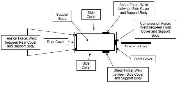
162 Mr de Vos’ diagram illustrates the situation where there is weld between the front cover of the tooth construction and the front face of the support body. In that case, the majority of force imparted at the front of the tooth construction will be transmitted directly to the front face of the support body as a compression force. The same principle applies to the rear face of the tooth construction.
163 Mr de Vos identifies the force on the weld between:
(a) the side cover and the support body as a shear force; and
(b) the rear cover and the support body as tension force.
164 According to Mr de Vos in his third affidavit, in practice, it is possible to create a tooth construction with clearances between the covers and support body provided that:
(a) at the time of installation the cover touches the support body (whether directly or through weld) across enough of its face to transmit the forces without the cover deforming;
(b) clearances between the covers and the support body will fill with ore fines and/or corrosion during use, so that forces can be transmitted through the ore fines and/or corrosion;
(c) during use the cover is able to deform (plastically or elastically) to close the clearances between the cover and the support body, so that the cover is in contact with the support body during use;
(d) the cover is made with thick steel, and the weld is thick enough, that is able to withstand the forces even if there is a gap between the cover, or part of the cover, and the support body; and/or
(e) the way the forces are transmitted to the support body do not place the welds under too much stress.
165 Mr de Vos agreed that Dr Huggett was correct when he said that intimate contact between the front and rear covers and the respective front and rear faces of the support body will give the maximum amount of strength to the horn and minimise the risk of fatigue, movement or cracking in the shell, but Mr de Vos considered that in practice there is minimal risk of the cover or weld failing as a result of clearances between the cover and the support body in (a) to (e) above.
166 Dr Huggett observed that the Patent did not provide any details of any additional design elements to prevent damage occurring in a tooth construction from the application of the large breaking forces during operation of the mineral sizer where the shell was not in intimate contact with the support body.
8. JOINT EXPERT REPORT AND JOINT SESSION
167 The following summary includes key aspects only of the JER prepared by Dr Huggett and Mr de Vos.
168 Dr Huggett and Mr de Vos agreed that:
(a) the “support body” is a tooth shaped projection on the sizer ring that transmits the driving force from the support body through the shell connected to the support body to the actual ore;
(b) the “shell” is the outer covering that protects the support body; and
(c) the “tooth construction” is the assembly of all those components together.
169 The experts also agreed that:
(a) the “front cover” is any cover that lies in front of the front face of the support body. Dr Huggett added that in his view the front cover is the outermost cover;
(b) a “rear cover” is a separate cover located at the rear face of the support body and protects the support body;
(c) a “plurality” of covers means more than one; and
(d) a “unitary” tooth construction requires the covers and support body to work together to act as one complete body rather than individual components.
170 The experts disagreed as to their construction of the “weldingly secured…” integer. Both experts’ rationale for their positions is set out earlier.
171 In summary, Mr de Vos considered that the integer would be satisfied by the cover being directly or indirectly welded to the support body: “an unbroken chain of welding between the front or rear cover and the support body”. In support he cited the passage on page 5, lines 18–21 of the Patent which states:
Whilst it is preferred that the cover 60 is directly welded to the horn 12 it is envisaged that it may be indirectly welded to the horn 12 by being welded to side covers 36, 37 only (which in turn are weldingly connected to the horn).
172 Dr Huggett considered that the integer required that the cover be welded directly to the support body.
173 The experts also disagreed as to the construction of the term “seated in face to face contact with the front face of the support body”.
174 In summary, Dr Huggett ultimately landed at this integer requiring that the two matching faces of the cover and support body are in contact (physically touching) across the majority of their faces without any gaps. On the other hand Mr de Vos considered that the integer encompassed a tooth construction where the faces of the cover and support body did not touch at all, but in which the forces were indirectly transmitted from the cover to the support body via an intermediate component (in the JER that component was ore fines and/or corrosion). In the joint session, according to Mr de Vos the intermediate component could be the weld or an intermediate cover.
175 The experts agreed that whatever the construction of “seated in face to face contact”, there was no difference with the construction in the context of whether the front or rear face was being considered.
176 Discussion about this integer occupied extensive time in the joint session, and by the time the joint session was completed, I consider that both witnesses’ construction had evolved from what it was when first stated in their affidavits. I will summarise the key points of that discussion, and the evolution of the experts’ construction a little later.
177 Dr Huggett and Mr de Vos agreed that:
(a) the “breaking tip member” is a component added to the front face of the tooth assembly for gripping the rocks and effecting the initial breakage of the rocks; and
(b) the “juncture” is the location where the top and front walls of the top cover meet. Mr de Vos would include the rebate in this location also.
178 As both experts agreed that there was no difference in how the face to face integer was construed with respect to whether it was the front or rear cover, the following discussion concerns the rear cover, but would also be equally applicable to the front cover.
8.1 Seated in face to face contact
179 As noted above, Dr Huggett initially construed this integer as requiring the front cover and the front face of the support body to be flush, eg they are in intimate contact across the majority of the surfaces of their faces without any gaps.
180 In the JER, Dr Huggett had refined his construction:
The use of the words “in face to face” requires the matching faces of the cover and support body to be aligned such that the faces are parallel, with the addition of the term “contact” requiring these parallel faces to be physically touching across the parallel faces. Reading as a complete phrase the cover is fitted firmly or accurately such that the parallel faces are in physical and direct contact with each other. The emphasis provided by using the term “seated” to me implies the majority of the face is in physical contact between the cover and support body. As de Vos has described, the positioning of the faces in this manner will permit the forces to be transferred between the support body and the covers.
Had the intention of the invention been to merely ‘position’ the cover onto the support body as suggested by de Vos, the terms “in face to face” and “contact” would not be required. The use of all three terms collectively to me reinforces the intent of the phrase to mean the cover and the support body must be physically touching across the majority of the contact face, rather than just being positioned close to each other.
181 In his response in the JER, Mr de Vos said that he understood the phrase “seated in face to face contact” to mean that the covers are positioned so that the forces are transmitted from the covers to the support body (referring to his evidence in his first affidavit). The transmission of force may be achieved by the covers directly contacting the support body, or indirectly through an intermediate component or ore fines and/or corrosion present in the clearance between the covers and the support body. In the joint session, his response had evolved to: there must be some level of connection between the covers and the support body to enable the transmission of force from one face to another, either through the faces physically touching, or through a weld where the faces may be welded to one another, or through an intermediate component, whether that be another cover or ore fines or corrosion.
8.2 Preferably co-planar – Diagrams 1 to 3
182 During the joint session senior counsel for MMD put three diagrams to the experts. None of the diagrams had been discussed by the experts in their evidence or in the JER.
183 The diagrams were said by MMD to illustrate the three possible ways in which the side covers and rear cover could be assembled whilst being “preferably co-planar”. That expression was used for example at page 4, lines 25 of the Patent where the front and rear edges of the side cover are described being “preferably co-planar” with the front and rear faces of the horn. It was contended by MMD that each of the configurations depicted in the three diagrams fell within the claims of the Patent.
184 In each of the diagrams the direction of the force is vertically down the page.
185 In this first diagram:
(a) The rear edges of the side covers are co-planar (finish level with) with the rear face of the support body or horn.
(b) The rear cover is touching/in contact with the rear face of the horn across the full face of the cover.
(c) The rear cover is welded to the rear edges of the side cover (the black triangles).
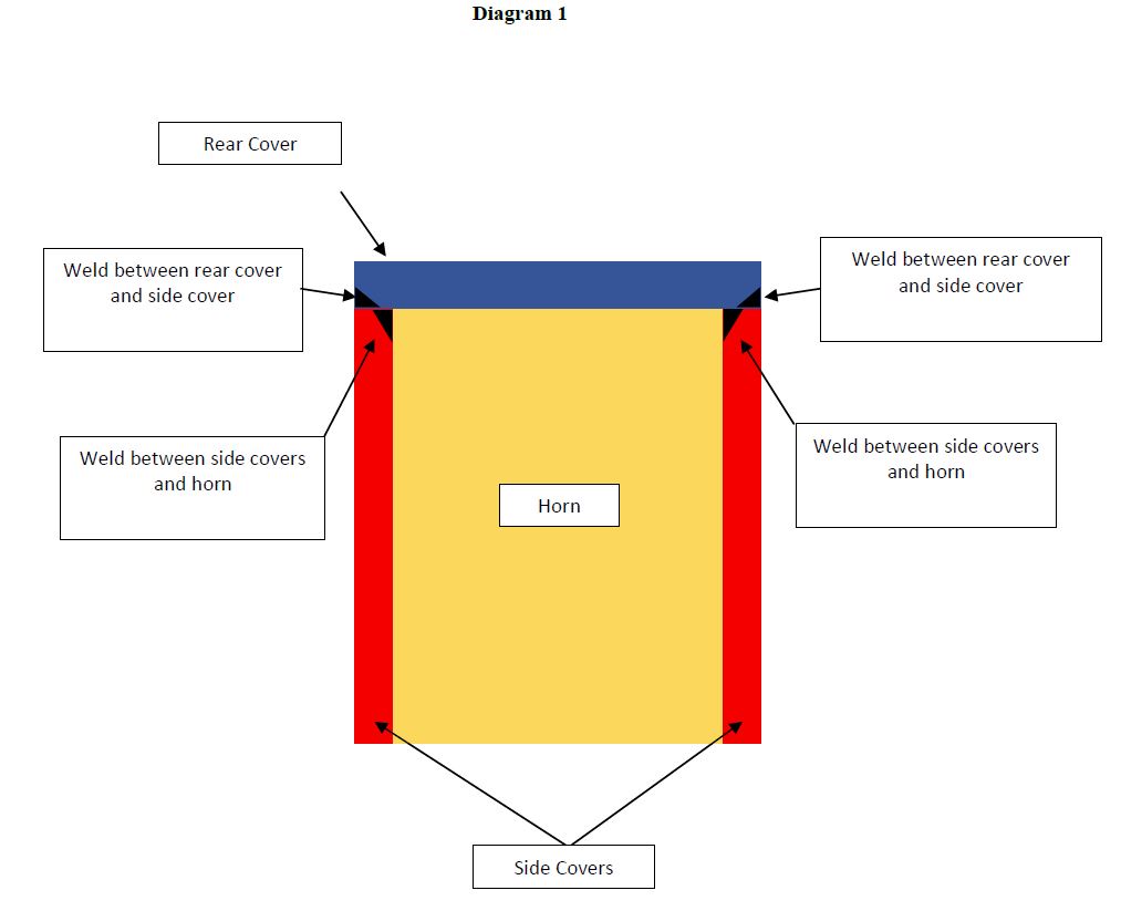
186 The configuration depicted in diagram 1 is described as a preferred embodiment at page 4, lines 25–27 of the Patent, and pictured in figures 2 and 3.
187 In the diagram 1 configuration, the rear cover is indirectly welded to the rear and side faces of the horn. Also in this configuration, compressive force will be transmitted directly from the rear cover to the rear of the horn as they are in contact across their faces.
188 In the second diagram:
(a) The rear edges of the side covers stop short of the rear face of the horn.
(b) The side covers are welded to the side face of the horn.
(c) The rear cover is touching/in contact with the rear face of the horn across the full face of the cover.
(d) The rear cover is welded to the rear edges of the side covers.
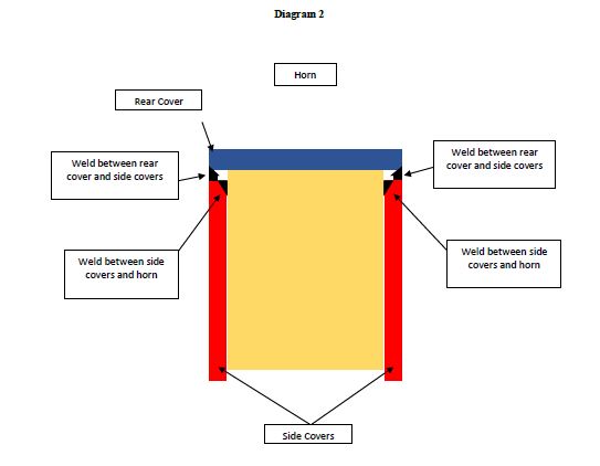
189 In the diagram 2 configuration, the rear cover is indirectly welded to the side faces of the support body. Also in this configuration, compressive force will be transmitted directly from the rear cover to the rear of the horn as they are in contact across their faces.
190 In the third diagram:
(a) The rear edges of the side covers extend beyond the rear face of the horn.
(b) The rear cover does not directly touch the rear face of the support body.
(c) The rear cover is welded to the rear edges of the side covers.
(d) The side covers are welded to the rear and side faces of the support body.
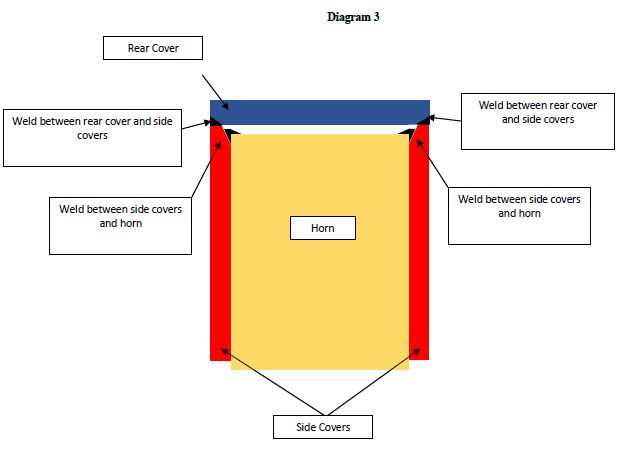
191 MMD submits that the configuration depicted in diagram 3 is an arrangement of side covers and rear cover in accordance with the description in the Patent at page 4, line 25 to page 5, line 21 and depicted in figure 3.
192 In this configuration, MMD submits that the rear cover is indirectly welded to the rear and side faces of the horn. MMD also submitted that in this configuration, the rear cover is seated in face to face contact with the rear face of the support body (even though it is not in physical contact) because forces can nonetheless be transmitted between the rear cover to the rear face of the support body via:
(a) the weld between the rear cover and the rear edges of the side covers; and
(b) the weld between the side covers and the edge of the rear face of the support body.
193 Camco contends that MMD impermissibly had recourse to Mr Balmer’s evidence about MMD’s commercial embodiment of the invention and the evidence as to the CamcoConstructions, to support its construction by showing that diagram 3 was not a “mere theoretical possibility”. Camco submits that the fact that tooth constructions may be constructed in the form depicted in diagram 3, either by design or accident, does not mean that such constructions fall within the claims of the Patent.
194 When diagram 3 was put to Dr Huggett in the joint session, he accepted that the diagram was a tooth construction as described in the Patent, if MMD’s construction of face to face contact was used, but not on his understanding of the phrase.
195 MMD submits that in the arrangement depicted in diagram 3 the rear cover is seated in face to face contact with the rear face of the support body, even though the rear cover and rear face of the support body are not in physical contact. MMD submits that four matters follow from its characterisation:
(a) The forces are transmitted from the rear cover to the rear face of the support body via the side covers. Accordingly, a cover can be “seated face to face contact” with the support body even if the forces must be transmitted through a second, intermediary cover.
(b) The forces are transmitted through the weld between the rear cover and the side covers, and between the side covers and the support body. Accordingly, a cover can be “seated in face to face contact” with the support body even if the forces are transmitted through weld.
(c) Not all of the forces imparted on the rear cover will be transmitted to the rear face of the support body. The proportion of the force imparted on the rear cover will depend on, inter alia, the thickness of the rear cover and the amount of weld applied between the rear cover, the side covers and the support body. The Patent does not specify any of these parameters. Accordingly, “face to face contact” does not require all or even most of the forces to be transmitted to the rear face of the support body.
(d) The forces are imparted from the rear cover to the peripheral edges of the rear face of the support body. As the rear cover is nonetheless described (by MMD) as being “seated in face to face contact with the rear face of the support body”, those peripheral edges must be a relevant part of the “rear face of the support body” for the purposes of claim 1.
196 Mr de Vos understood the phrase “fully seated on the horn” (eg the support body) which appeared in the passage at page 7, line 27 to page 8, line 5 to mean that the front and the rear of the tooth shell (eg cover) touch the front and rear faces of the support body, respectively.
197 Mr de Vos understood the phrase “highly resistant to loosening” to mean that the welds are less likely to fail because the front and rear of the tooth shell touch the front and rear faces of the support body such that the forces imparted on the tooth shell can be transmitted to the front and rear faces of the support body.
198 The first paragraph of the passage at page 10, lines 11–18 refers to the welding between the covers and support body adding to the strength of the support body. Mr de Vos understood “strength” here to refer to the fact that the covers and support body form a unified (or unitary) body. The second paragraph explains that welding the covers to the support body allows the tooth construction to transmit forces to the support body with a reduced risk of the support body snapping or the covers working loose. Mr de Vos considered that these sections of the Patent emphasise the importance of the ability of the tooth construction to transmit forces from the covers to the support body to ensure that the welds securing the covers to the support body do not fail as a result of the forces imparted on them during use.
8.3 Intermediate cover/front cover
199 Mr de Vos considered that a cover could be a front cover or rear cover even if there was another (intermediate) cover between it and the front or rear face of the support body (respectively). He gave four reasons to support his understanding.
200 First, where two components cover the front or rear face of the support body, both components protect that face of the support body and thus act as a front or rear cover.
201 Second, the Patent does not call the front wall of the intermediate cover of the second embodiment (73 in figure 4) a “front cover”. If the only front cover was the component that immediately touches the front face of the support body, Mr de Vos would expect the Patent to describe the front wall of the intermediate cover as the “front cover” of the second embodiment. By not stipulating which of the intermediate cover and top cover provide a front cover, he understood the Patent to mean that each cover is a front cover.
202 Third, page 7, line 27 to page 8, line 5 refers to the “front of the tooth” and “rear of the tooth shell” being “fully seated on” (eg touching) the front and rear faces of the support body, respectively. It does not refer to these components as the “front and rear cover”, which suggested to Mr de Vos that the front and rear cover are not made up only of the covers that touch the front and rear faces of the support body.
203 Fourth, claim 7 which is dependent on claim 1 via claim 2, requires the tooth construction to include an intermediate cover with a front wall (that forms the front cover of the tooth construction), opposed side walls, a top wall and “an open rear wall”. If claim 1 required both the front and rear covers to be the covers immediately touching the front and rear faces of the support body, there would be no need for claim 7 to specify that the intermediate cover includes an open rear wall, because an open rear wall would already be a necessary feature of the intermediate cover. Where a tooth construction includes an intermediate cover with integral front and rear walls, the covers immediately touching the front and rear faces of the support body will be integral parts of the same component.
204 The experts did not agree on the proper understanding of the term “juncture” as it appears in claim 9:
A tooth construction according to Claim 4 or 8 wherein a breaking tip member is mounted at the juncture of the top and front walls of the top cover, the breaking tip member being secured thereto by welding.
205 In the JER, Mr de Vos and Dr Huggett agreed “the juncture is the location where the top and front walls of the top cover meet”, however, they disagreed as to the “location where the top and front walls meet”.
206 The principles governing patent construction are well established and were not in dispute. The principles have been summarised in many Full Federal Court cases, as to which, see for example Jupiters Ltd v Neurizon Pty Ltd (2005) 65 IPR 86 at [67], ESCO Corporation v Ronneby Road Pty Ltd (2018) 131 IPR 1 at [144] and GlaxoSmithKline Consumer Healthcare Investments (Ireland) (No 2) Limited v Generic Partners Pty Limited (2018) 264 FCR 474 per Middleton, Nicholas and Burley JJ at [102].
207 The following principles are of particular relevance in the present case.
(a) In construing the claims, a generous measure of common sense should be used: Product Management Group Pty Ltd v Blue Gentian LLC (2015) 240 FCR 85 at [36].
(b) A construction according to which the invention will work is to be preferred to one in which it may not: Pfizer Overseas Pharmaceuticals v Eli Lilly and Company (2005) 68 IPR 1 at [250]; Blue Gentian at [39].
(c) Third, a patent specification should be given a purposive, not a purely literal, construction.
(d) A patent specification is not to be read in the abstract but is to be construed through the eyes of the person skilled in the art in the light of the common general knowledge and the art before the priority date: Jupiters at [67(ii)].
(e) The claims are to be construed in light of the specification as a whole, but the plain and unambiguous meaning of a claim cannot be varied or qualified by reference to the body of the specification: Welch Perrin & Co Pty Ltd v Worrel (1961) 106 CLR 588 at 610 per Dixon CJ, Kitto and Windeyer JJ.
(f) Claims in a patent are not to be narrowed by reference to the preferred embodiment: Rehm Pty Ltd v Websters Security Systems (International) Pty Ltd (1988) 11 IPR 289 at 299.
(g) The preferred embodiment cannot be used to introduce into the definite words of a claim an additional definition or qualification of the patentee’s invention: Erickson’s Patent (1923) 40 RPC 477 at 491; Globaltech Corporation Pty Ltd v Australian Mud Company Pty Ltd (2019) 145 IPR 39 at [111]; Welch Perrin at 612.
208 A person skilled in the art is a person of the kind to whom a patent specification is addressed: General Tire & Rubber Co v Firestone Tyre & Rubber Co Ltd [1972] RPC 457 at 485 (English Court of Appeal), cited with approval in Nicaro Holdings Pty Ltd v Martin Engineering Co (1990) 16 IPR 545 per Gummow J.
209 Justice Beach summarised the relevant principles relating to the hypothetical skilled person in Meat and Livestock Australia Ltd v Cargill, Inc (2018) 129 IPR 278 at [219]. The person skilled in the art is not a reference to a specific person but is a legal construct: Root Quality Pty Ltd v Root Control Technologies Pty Ltd (2000) 49 IPR 225 per Finkelstein J at [71]. The notional person is not an avatar for expert witnesses whose testimony is accepted by the Court. As French CJ observed in AstraZeneca AB v Apotex Pty Ltd (2015) 257 CLR 356 at [23], the notional person is a pale shadow of a real person – a tool of analysis. It is a legal construct drawn by reference to the available evidence.
210 In the JER the experts agreed that the Patent is addressed to an engineer, technologist or designer involved in the manufacture of mineral processing equipment in the mining industry. The experts agreed that such a person would have knowledge of how mineral sizers are used and maintained within the mining industry, that mineral sizers had been used in the mining industry for some time (particularly with coal) and would also have knowledge of materials and manufacturing methods, including castings and the applications of tolerances to the assembly of cast components.
211 The experts agreed that the person skilled in the art would have kept up to date with what was known or used in Australia relating to the design and manufacture of mineral processing equipment in the mining industry by consulting industry journals and magazines and attending conferences, seminars and workshops.
212 Dr Huggett noted in the JER that “occasionally” he was informed of patents through the issue of Government Gazettes. Mr de Vos’ evidence was that he did not read patent documents.
213 If asked to improve on existing equipment as at the priority date, Mr de Vos’ evidence was that he would conduct an internet search to find designs of similar equipment being manufactured and supplied to the market. He noted that the information on the internet at the priority date was more limited than it is now. Mr de Vos said at the priority date he would also have consulted textbooks, supplier design handbooks and catalogues and engineering design standards such as the Australian or British Standards. He would not conduct a patent search.
214 I do not consider that the person skilled in the art of the design and manufacture of mineral processing equipment in the Australian mining industry routinely read patent documents.
215 The common general knowledge of the person skilled in the art is discussed below.
9.3 Terms on which there was expert agreement
216 Both experts agreed, and I adopt, that a “separate” rear cover means that the rear cover must be separate from the front cover, in the sense that they are not integral parts of the same component. I consider that a rear cover would still be separate if it were welded to the front cover before being installed on the support body.
217 I also adopt the agreed construction of the experts of the following terms:
(a) The support body is a tooth shaped projection on the sizer ring that transmits the driving force from the support body through the shell connected to the support body to the actual ore.
(b) The shell is the outer covering that protects the support body.
(c) The tooth construction is the assembly of all those components together.
(d) A rear cover is a separate cover located at the rear face of the support body and protects the support body.
(e) A plurality of covers means more than one.
(f) A unitary tooth construction requires the covers and support body to work together to act as one complete body rather than individual components.
9.4 Parties’ submissions on terms where there was no expert agreement
218 As set out above, Mr de Vos and Dr Huggett did not agree on the construction of the following integer: “front cover which is weldingly secured to and seated in face to face contact with the front face of the support body”.
219 MMD submits that the phrase “face to face contact” requires that the covers are positioned such that forces are able to be transmitted between the face of one component (eg the front or rear cover) and the face of a second component (eg the front or rear faces of the support body). It says there are a “myriad” of reasons to support this construction.
220 MMD submits that Dr Huggett failed to consider the importance of transmitting forces within a tooth construction when interpreting the phrase “face to face contact”.
221 MMD submits that the Patent explains that in order to create a robust tooth construction, forces must be transmitted from the covers to the support body. The term “contact” is apt to import this critical concept into the claim.
222 The transmission of force from one face to another requires a physical connection between components. MMD submits the physical connections include where the components are:
(a) directly touching each other;
(b) touching indirectly through an intermediate component (such as an intermediate cover); and
(c) joined by a weld.
223 MMD submits that the requirement for face to face contact is met where the front cover is positioned so that the forces are transmitted from the front cover to the front face of the support body (horn), whether by the front cover directly touching the support body (horn), or indirectly through an intermediate component (such as an intermediate cover). In order for forces to be transmitted between two components, there must be a physical connection between them. “Seated in face to face contact” does not require that forces are transmitted across the entire face of the front (or rear) cover.
224 MMD submits that when the side covers are welded to the edges of the rear face of the support body (in diagram 3), the weld melts, and penetrates the edge and a further part of the rear face of the support body. The rear face of the support body is melted to form a single component with the molten weld deposit. The weld also becomes part of the rear face of the support body, and extends the rear face of the support body. According to MMD there can be no doubt that forces are transmitted to the rear face of the support body.
225 MMD submits that diagram 3 shows that the Patent describes a method of assembling both the first and second embodiments in such a way that forces are transmitted from the rear cover to the peripheral sides of the rear face of the support body. Although the forces may only be transmitted to the outer few millimetres of the rear face of the support body, they are still transmitted to the rear face of the support body, and MMD contends that is sufficient for the claims of the Patent.
226 According to MMD, the evidence establishes that, provided forces can be transmitted from the front and rear covers to the front and rear faces, respectively, of the support body, a robust tooth construction can be created.
227 MMD refers to one of the many Macquarie Dictionary definitions for “contact” that require two components to touch (“the state or fact of touching; a touching or meeting of bodies”), and a definition that does not require them to touch (“immediate proximity or association”). Accordingly, MMD submits that one should look beyond the ordinary English definition of “contact” to the specification of the Patent when interpreting the phrase “face to face contact” as it is used in claim 1.
228 MMD submits that the Patent discriminates between circumstances where two components must directly touch, (by using “seated upon” and cognate expressions such as “seated on”) and circumstances where it is not necessarily possible or not practical for two components to directly touch one another (by using the expression “seated in face to face” contact). MMD submits that if the patentee had intended claim 1 to require that the front and rear covers must touch the front and rear faces of the support body, respectively, they would have used the phrase “seated on” (or cognate expressions) instead of the broader phrase “seated in face to face contact”.
229 Camco submits that all of the words in the phrase “seated in face to face contact” have a role to play when it comes to claim construction. The words “face to face” are important because they contemplate much more than simply “opposing” or “opposite”. The “face” of the front cover refers to the whole of the side that faces the “front face” of the support body. The words “face to face” act as an adverb to “contact”. The whole of the phrase contemplates much more than being “in contact”, which would permit the claim to be met by the front cover and the support body touching at a few points only. Camco submits that such a construction is akin to that which is advanced by MMD – as demonstrated at the extreme by diagram 3, and ignores the actual language of the claim.
230 Camco points to the word “seated” which it says also plays a role in the phrase, which is not to be diminished. The patentee chose this word deliberately, and it is apparent why – because it is a word which properly picks up, and embraces, the requirements of the words that follow, being “face to face contact”. When the front cover is “seated” it is positioned in the way contemplated by the words that follow, being that there is contact across the majority of the faces of the front cover and the support body.
231 Camco submits that there are distinct advantages to having front and rear covers being fully abutted with the support body. That is obvious with respect to the transmission of forces. Mr de Vos accepted the benefits of full abutment of the covers with the support body. If the “connection” is only point to point in a few places, then that has the consequence that significant stress will arise at those points, which will need to be factored into the overall design for the construction. There are disadvantages to point to point contact. Camco’s point is that the patentee is disclosing how to make a particular tooth construction. The Patent is not teaching the skilled reader how to make a tooth construction of a different design such as one involving point to point contact between the front/rear covers and the support body.
232 As to the “weldingly secured” integer, Camco contends that the difference between the two meanings is that Meaning A requires the front cover to be weldingly secured to the front face of the support body, whereas Meaning B requires the front cover to be weldingly secured to the support body – which could be anywhere on the support body, not just the front face. Meaning B contemplates, for example, that if the front cover is welded to the side covers, and the side covers are welded to the support body, then it could be said that although the front cover is not directly welded to the front face of the support body it is indirectly welded to the support body by reason that it is welded to the side covers, which are welded to the support body.
233 Camco contends that Meaning A should be preferred as it reflects the natural reading of the words and phrases appearing in the integer. Camco submitted that Meaning A is consistent with Mr de Vos’ natural reading of the phrase in the joint session, which was to insert pauses (notional commas) in accordance with Meaning A.
234 Camco contends that the claim language is consistent with the description of the invention in the body of the specification where the inventor describes a series of steps in preparing the claimed tooth construction, including the sequence of seating and welding steps to be undertaken (see eg page 4, lines 13–15; page 5, lines 10–21; page 5, line 29 to page 6, line 6; page 6, lines 13–20; page 7, lines 13–19; page 8, line 13 to page 9, line 8; page 9, lines 23–27). The specification describes that each relevant component in the tooth construction (eg side covers) is first “seated in face to face contact with” the relevant face of the horn and then “weldingly secured” in that position. Following that, “a separate rear cover” is then “seated” in the position described and is “weldingly secured” in that position. Distinct components are identified. The sequence of construction steps utilising these components informs an understanding of the claimed monopoly.
235 Camco submits that the weld used to join the various components of the tooth construction (eg front cover, rear cover) is separate to those components. The weld is not described, in the claimed monopoly, as forming any part of each component. The weld is referred to in the specification as a means for securing the components, in the manner claimed. Mr de Vos agreed that the weld filled chamfer was separate to the rear face of the horn or the side face of the horn in the tooth construction described in the claims.
236 MMD contended for Meaning B in relation to the “weldingly secured” integer, for the reasons that construction was preferred by Mr de Vos.
237 MMD noted that the passages (at page 5, lines 18–21 and page 5, line 29 to page 6, line 6) refer to the front and rear covers being “directly weldingly secure[d]” or “directly welded” to the support body. MMD submits that in contrast to the wording of those passages, the language of claim 1 is “weldingly secured to”. MMD submits that the claim does not use the word “direct” and is thus perfectly apt to encompass indirect, as well as direct, welding.
238 MMD contends that the purpose of the front face of the tooth construction is to protect the front face of the support body. According to MMD’s construction of the embodiment which has a top cover over the intermediate cover, the front wall of a top cover is a front cover, as is also the front wall of the intermediate cover.
239 It was not suggested that any of the terms of the claims were technical terms, or anything other than ordinary English words. The construction of the terms is a matter for the Court: Airco Fasteners Pty Ltd v Illinois Tool Works Inc [2023] FCAFC 7 at [59].
240 The experts were in agreement as to how certain terms should be construed. Where that has occurred, I agree with and adopt the experts’ construction of those terms as set out below.
241 The invention described in the specification and around which the claims are drawn is concerned with a particular arrangement of the sacrificial covers of a tooth construction for a mineral sizer, wherein the covers are welded to each other and to the support body indirectly, or are welded to the support body directly, so as to provide a robust tooth construction which will efficiently transmit the large forces generated during operation of the sizer by breaking particularly hard mineral, from the covers to the support body. Without the efficient transmission of the large forces generated, the covers may fall off the support body.
242 The invention is not a robust tooth construction however constructed. At times MMD’s submissions and Mr de Vos’ evidence in the joint session came very close to suggesting that any way of achieving a robust tooth construction would fall within the claims of the Patent. An example being the tooth construction depicted in diagram 3 which involved the transmission of force via weld between the very edges of the covers and (at best) the outer few millimetres of the front/rear face of the support body.
243 Both Dr Huggett and Mr de Vos agree that:
(a) The support body is a tooth shaped projection on the sizer ring that transmits the driving force from the support body through the shell connected to the support body to the actual ore. The shell is the outer covering that protects the support body. The tooth construction is the assembly of all those components together.
(b) A “plurality” of covers means more than one cover.
(c) The unitary construction requires the covers and support body to work together to act as one complete body rather than as individual components.
(d) The front cover is any cover that lies in front of the front face of the support body.
(e) A rear cover is a separate cover located at the rear face of the support body and protects the rear face of the support body.
(f) A “breaking tip member” is a component added to the front face of the tooth assembly for gripping the rocks and effecting the initial breakage of the rocks.
(g) The “juncture” is the location where the top and front walls of the top cover meet.
244 I consider that:
(a) the “shell” is composed of the covers covering the support body; and
(b) “tooth shaped” means that the support body is shaped like a tooth, in that it is symmetrical, smooth and rounded, without sharp corners.
245 The “separate” rear cover is separate from the front cover. If the rear cover is welded to the rest of the tooth construction shell, it does not become integral with the front cover. It remains a separate rear cover. However, if the rear cover is integral with the intermediate cover such that they are part of the same component, the rear cover will not be a separate rear cover. Mr de Vos agreed that a benefit of a separate rear cover was that it was easier to install the tooth construction and to position the front and rear faces as close as possible to the horn. The first cover can be placed on and then the separate rear cover can be placed on and pressed up against the horn. It is much harder to install a one piece tooth construction. That benefit is lost when the rear cover is an integral part of the intermediate cover, not a separate cover.
246 I do not consider that a rear cover which is an integral part of the intermediate cover can become a “separate” rear cover in the situation where a top cover is added over the intermediate cover, merely by being separate to the top cover, in particular the front face of the top cover.
247 Regarding the “unitary tooth construction” integer, I do not consider that welding the toe of one tooth construction to the heel of the next tooth construction around the circumference of the drum annulus results in the individual tooth constructions no longer being “unitary” tooth constructions. The plurality of covers come together to form the one complete tooth construction, that is not altered by that tooth construction being attached by a strip of weld to the next one situated on the annulus.
248 The major construction dispute between the parties arises in relation to two aspects of the following integer:
… a front cover which is weldingly secured to and seated in face to face contact with the front face of the support body …
249 For the reasons which I will explain shortly, I consider that the phrase “weldingly secured to and seated in face to face contact with the front face of the support body” requires that:
the front cover is:
(i) weldingly secured to; and
(ii) seated in face to face contact with the front face of;
the support body (Dr Huggett’s Meaning B).
250 This construction also applies to the equivalent rear cover integer.
251 Meaning A may at first glance seem to be the more natural reading outside the context of the Patent, but to my mind Meaning B is consistent with the use of the phrases in the specification.
252 It is necessary to construe the phrases “weldingly secured” and “seated in face to face contact” within the context of the larger phrase.
253 Before continuing, I return to the ore fines issue that was introduced early in these reasons. The extensive recitation of Mr de Vos’ evidence directed towards construction of the terms of the claims of the Patent demonstrates that the ingress and compression of ore fines (and corrosion) into the gaps and clearances in the tooth constructions was a significant element of Mr de Vos’ reasoning processes in arriving at his preferred construction in his first affidavit, and was relied upon by MMD in its written opening submissions. As noted previously, considerable evidence was devoted to the issue of ore fines and corrosion.
254 The Court is left to attempt to reconcile MMD’s case in closing absent the ore fines, with the evidence of Mr de Vos in which the ore fines play a significant part in his reasoning and consideration to reach the construction in his first affidavit, and to that extent cannot simply be set to one side. It was not practical or possible to just read out any reference to ore fines (and corrosion) from Mr de Vos’ affidavits and leave his reasoning intact. Accordingly I cannot ignore the impact of ore fines on Mr de Vos’ reasoning as set out in his five affidavits.
255 Equally, I cannot accept those of MMD’s submissions which appear to have their origin in the ore fines infected reasoning, but which ignore the role of ore fines in the reasoning process. This is particularly applicable to MMD's submissions as to diagram 3. As I foreshadowed and will now explain, I do not consider that a tooth construction with the configuration depicted in diagram 3 falls within claim 1.
256 According to Mr de Vos the word “contact” imports into the claims the critical concept of the efficient transfer of forces. A robust tooth construction must be capable of efficiently and effectively transmitting forces from the covers to the support body.
257 As a result of the large forces that are imparted on the teeth, it is necessary for those forces to be efficiently transmitted to the support body and the shaft in order for the teeth to be sufficiently robust. Otherwise, the large forces that are imparted onto the teeth during operation (particularly in hard rock mining) can cause the means of securing the covers to fail if those forces are not efficiently transmitted to the support body. Failure of tooth covers in between scheduled maintenance breaks is very undesirable.
258 According to Mr de Vos, the most efficient way of transmitting force is a “compressive force”, which involves “pushing into, or compressing, a component”. In his first affidavit, Mr de Vos observed that “as compressive forces do not rely on a fastening medium unlike tensile and shear forces, it is preferable for the forces imparted on the covers during use to be transmitted to the support body through compressive forces”.
259 In his first affidavit, Mr de Vos observed that the Patent emphasises the importance of the ability of the tooth construction to transmit forces from the covers to the support body to ensure that the welds securing the covers do not fail as a result of the forces imparted on them during use. I consider that the emphasis on the effective transmission of force is inconsistent with the welds being the means for the transmission of the majority of the force as shear force as per diagram 3. In the configuration as depicted in diagram 3, the majority of the forces are being transmitted through the welds, thereby placing the weld under stress which may cause them to crack and fail early. According to Mr de Vos weld will most commonly fail where large shear forces or tensile forces are repetitively imparted on the weld.
260 The person skilled in the art would be aware that mineral sizers undergo regular maintenance. The tooth construction must be robust enough to break the ore and remain intact for the duration of the maintenance period. The welds must secure the covers of the tooth construction for the entire maintenance period. As the tooth constructions are replaced at regular intervals, there is no need for the tooth constructions to be made to last as long as possible.
261 All of the words in the phrase “seated in face to face contact” have a role to play.
262 MMD focusses on the face of the support body as the face of interest. Its submissions speak of methods to ensure the requisite transmission of force “from the covers” to the support body not the faces of the covers or the faces of the support body (as the claims require). Diagram 3 depicts an arrangement where the “rear cover … does not directly touch the rear face of the support body”. I consider that the words “face to face” contemplate the existence of two faces: the face of the front/rear cover, and the front/rear face of the support body, and that being in face to face contact requires the two faces to be in physical contact.
263 That face to face contact requires the physical contact of the two faces: the face of the front or rear cover and the corresponding face of the horn, is consistent with the usage of the phrases in the description of the two embodiments of the invention described in the specification. Each time the phrase “face to face contact” is used, it is in the context of a description of the placement of two faces: the front or rear cover, and the front or rear face of the horn. In contrast, the discussion of welding in the specification directs welding “to the horn”, not to specifically the front or rear faces of the horn.
264 The phrase “face to face contact” first appears at page 5, line 11, in the description of the placement of the rear cover in the first embodiment. The rear cover is described as being seated in face to face contact with the rear face of the horn. There is no mention of how the rear cover is held in place until the next paragraph in which the rear cover is said to be preferably secured to “the horn”, not the rear face of the horn, by welding. It is also noted that the rear cover may be “indirectly welded to the horn” by being welded to the side covers.
265 Later on page 5, line 30, the internal face of the top cover is said to be seated in “face to face contact” with the front face of the horn. The top cover is then said at page 6, line 18, to be “secured to the horn 12, preferably by welding”. There is no reference to a particular face of the horn. The welding direction is to join the opposed faces between the top cover and the plate-like body of the side cover to one another.
266 I consider that “seated” in the phrase “seated in face to face contact” means positioned. The front cover is the front cover which is in physical contact with the front face of the horn.
267 The specification describes a method or sequence of the construction of the tooth construction – the cover is described as being “seated in face to face contact” with the relevant face of the horn, well before any discussion of how it is secured to the horn.
268 Sand casting is relatively imprecise. Components that are produced using sand casting have relatively rough surfaces. In practice, there will still be some clearances between (a) the face of the support body and (b) the front and/or rear covers due to the imprecision involved with sand casting. The front and/or rear covers will undulate across their surface, meaning part of the face of the covers will touch the support body and part will not.
269 I disagree that the two faces must be “flush” to the extent that “flush” requires intimate contact across all surface of the faces. Dr Huggett agreed in the joint session that he contemplated that the majority of the surfaces would be in contact, rather than a perfect 100%.
270 According to Mr de Vos the surface of the covers are unlikely to be smooth, even with the best manufacturing tolerances, as cast surface are likely to have undulations. Over a lifetime of use and refurbishment, including gouging off old welded-on covers, the surfaces of the horn are unlikely to be entirely smooth or identical to each other.
271 Thus a common sense construction of “face to face contact” in the context of front and rear covers which are likely to be sand cast, means physically touching across most of the faces of the cover and the support body (allowing for undulations inherent in the casting process). The same total force will be transmitted between two components, irrespective of whether they are “flush, in intimate contact across their surfaces, without any gaps” or there are some gaps between them.
272 Weld is discussed in the specification merely as the way to secure components, not as the primary conduit of force from the covers to the support body. In the method of construction outlined for the first embodiment, the side covers are said to be secured to the horn, preferably by welding. The specification states that preferably this is to be achieved by “welding along the front, upper and read edges” respectively to produce a welded seam. Similarly, the rear cover is secured to the horn and side covers preferably by welding. This is achieved “welding along the side edges” to produce “welded seams”. There is no discussion in the specification of adjusting the weld to bear the transmission of the majority of the force as shear forces if there is no physical contact across the faces of the covers and the support body.
273 As I noted above, MMD’s construction of claim 1 reached the point where it became almost a claim by result—anything which achieves the functionality of, or results in, a robust tooth construction falls within claim 1—whether it be an embodiment of the kind in diagram 1 or at the other extreme with only point to point contact with the side cover such as diagram 3. This is illustrated by MMD’s submission that a robust tooth construction can be created that is designed to transmit forces between the covers and the support body entirely through weld (diagram 3). I consider that such a construction ignores the references to face to face contact in the specification and gives “contact” no work to do. It also ignores the notion of efficient transmission of compressive force said by Mr de Vos to be imported by the word “contact”.
274 I consider that a tooth construction of a kind depicted in diagram 2, in which the face of the rear cover is in physical face to face contact with the rear face of the support body, but which is welded to a part of the support body that is not the rear face (eg indirectly welded), is still a robust design within claim 1 of the Patent.
275 Provided that the rear cover is seated in face to face contact (touching across most of the two faces) with the rear of the support body, the forces imparted on those covers during use will be transmitted efficiently via compressive force to the support body. Even if, for instance, the rear cover is welded to the sides of the support body, most of the force will not be transmitted through those welds. The forces will predominantly be transmitted through the face to face contact between the rear cover and the rear face of the support body. In this configuration, the role of the weld is primarily to secure the rear cover to the support body.
276 Where there is a permanent gap between a cover and a support body, the cover or weld could break during use. Mr de Vos considered that the weld securing the cover to the support body may crack over time if there is a permanent gap between the cover and support body. In his experience, weld will most commonly fail where large shear forces or tensile forces are repetitively imparted on the weld.
277 In the tooth construction depicted in diagrams 1 and 2, the majority of force imparted at the rear of the tooth construction will be transmitted directly to the front face of the support body as a compression force transmitted via the physical contact of the faces of the rear cover and the support body. Mr de Vos agreed that where the rear cover and the rear face of the support body are “flush” (in contact across the majority of their faces), then the transfer of forces “would be much more effective”, than when there is a gap such as that depicted in diagram 3.
278 MMD submits that diagram 3 shows that forces are transmitted from the rear cover to the peripheral sides of the rear face of the support body. Although forces may only be transmitted to the outer few millimetres of the rear face of the support body, they are still transmitted to the rear face of the support body and MMD submits that is sufficient for the claims of the Patent.
279 On MMD’s case, the size of the weld is important, because (in the diagram 3 scenario) if the weld is only a few millimetres and is required to take a high amount of shear force, this renders it prone to cracking (or failure), with the consequence that the cover is likely to fall off during operation.
280 The Patent speaks of weld as a preferable way to secure the covers of the tooth construction. It says nothing about the transmission of forces through welds or the adjustment of the welds to bear transmission of the majority of the force as shear forces. If welds were contemplated by the inventor as components through which large forces were intended to be transmitted efficiently to the horn and thereby effect face to face contact, it would be expected the patentee would have said something about that topic, including on the importance and the nature of the welds required to effect the invention (including the size of the welds). Further, the sequence of construction described in the specification would not describe components as seated in face to face contact before welding had taken place; welding is said only to secure them after they are seated in face to face contact (page 5, line 10–16; page 5, line 29 to page 6, line 5; page 8, line 27 to page 9, line 4).
281 Claim 3 concerns the addition of first and second side covers to the tooth construction of claim 2, which, in each case, must also meet the requirement of “face to face contact” with the “respective side faces of the support body” as seen for the front and rear covers in claim 1. The first and second side covers are described as “overlying respective side faces of the support body”. There is no reason why the two side covers must be two separate covers to the tooth construction, not part of one component with two sides. Claim 1 refers to a separate rear cover, if the patentee had intended the side covers to be separate covers, then there would be an express reference to their being separate.
282 Claims 10 and 17 are omnibus claims. Claim 10 is directed to “a tooth construction substantially as described herein with reference to and as illustrated in any of the accompanying drawings”. Claim 17 is directed to a “tooth construction substantially as herein described with reference to the accompanying figures”.
283 The general principles to be applied in construing an omnibus claim were set out by Middleton J in Britax Childcare Pty Ltd v Infa-Secure Pty Ltd (No 3) [2012] FCA 1019 at [27]–[33]. His Honour said at [28]–[32]:
28 As is the case with regular patent claims, the scope of omnibus claims will largely be determined by the precise language used therein, “the context of the specification in which the clause appears”, and “the nature of the descriptions or drawings” to which that clause refers: see Memcor Australia Pty Ltd (ACN 003 581 566) v GE Betzdearborn Canada Company (2009) 81 IPR 315 at 323; [2009] FCA 507; citing Lewis v Hall (2005) 68 IPR 89; [2005] FCAFC 251 with approval; Deere & Co v Harrison McGregor & Guest Ltd [1965] 82 RPC 461 at 465.
29 Without more and in the absence of evidence to the contrary, references in an omnibus claim to claims as “substantially as described herein” are typically construed as being more or less limited to the preferred embodiment described in the specification: see Townsend Controls Pty Ltd v Gilead (1989) 16 IPR 469 at 489; Rescare Ltd v Anaesthetic Supplies Pty Ltd (1992) 111 ALR 205 at 241. …
30 “Substantially” in this context simply means ‘in substance’: see Deere & Co 82 RPC 461 at 463; Townsend Controls 16 IPR 469 at 489. …
32 If an omnibus claim also refers to specific drawings or examples, this will typically be construed to narrow the scope of such claims, substantially confining them to the particular embodiments shown in those drawings or examples, subject to those variations that the skilled addressee would regard as minor: see Emperor Sports Pty Ltd v Commissioner of Patents (2005) 146 FCR 159 at 181 citing PhotoCure ASA 216 ALR 41 and Raleigh Cycle Co 65 RPC 141 with approval; General Steel Industries Inc v State of New South Wales (1967) 40 ALJR 464 at 467; Deere & Co 82 RPC 461 at 477-478. Lord Morton commented in Raleigh Cycle Co 65 RPC 141 at 158 that this type of claim is “directed to saving the patent from revocation, if all wider claims are held to be bad”: see also Lewis 68 IPR 89 at 96; [2005] FCAFC 251.
284 The Full Court (Allsop CJ, Yates and Robertson JJ) considered the construction of the omnibus claims in suit in GlaxoSmithKline Australia Pty Ltd v Reckitt Benckiser Healthcare (UK) Ltd (2016) 120 IPR 406 at [69] to [80]. At [79] and [80] the Full Court stated the following in respect of the effect of the word “substantially” in the omnibus claims:
79 In our opinion, contrary to the conclusion of the primary judge, the use of the word “substantially” in claim 9 in the expression “substantially as described with reference to the drawings and/or examples” does not extend the definition of the invention to “the substantial idea” disclosed by the specification and shown in the drawings.
80 The word “substantially” provides no warrant for departing from what the specification itself mandates to be the essential features of the invention. A flat-nosed syringe dimensioned as described in the consistory statement is one of the essential features of the invention. Thus, whatever work the word “substantially” is to perform in claim 9, it cannot transform a feature made essential by the description of the invention into one that is now inessential. Put another way, an embodiment that does not possess the essential features of the invention as described, cannot be one that is “substantially as described”. Thus, the word “substantially” in claim 9 does not do the work which the primary judge held that it did.
285 MMD submits that claim 10 and claim 17 have a different scope because claim 17 encompasses embodiments of the invention that are described, but not illustrated in the figures/drawings themselves. By way of example, the Patent discusses both direct and indirect welding of the rear cover to the rear face of the support body in the context of the first embodiment, but illustrates only one option. According to MMD both options are captured by claim 17, and only the illustrated option is captured by claim 10.
286 I consider that the reference to “drawings” in claim 10 is a reference to figures 1 to 12 of the Patent. Claim 17 claims an invention substantially as described in the Patent with reference to the figures, whereas claim 10 is limited to an invention which is both described in the specification and illustrated in the figures.
287 MMD complains of Camco’s unauthorised supply of five welded tooth constructions (the Camco Constructions) for mineral breakers used:
(a) at the Yandi iron ore mine site operated by BHP Group Ltd in the Pilbara region of Western Australia, some of which were supplied from about 9 May 2016 to about 6 December 2018 (the First Yandi Constructions), which MMD alleges either directly or indirectly infringe all the Asserted Claims. MMD dropped its claim as to infringement by a Second Yandi Construction on the seventh day of the trial;
(b) at the Solomon Hub iron ore mine site operated by Fortescue Metals Group Ltd (FMG) in the Pilbara region of Western Australia from about 1 June 2016 to about 6 March 2020 (Solomon Constructions). MMD alleges that Camco’s supply of the Solomon Constructions either directly or indirectly infringe claims 1, 2, 3, 4, 7, 8 and 9 of the Patent.
(c) at the Worsley Alumina mine site operated by South 32 Ltd in the Peel Region in Western Australia, some of which were supplied from about:
(i) 1 January 2017 to about 25 February 2019 (First Worsley Alumina Constructions), which MMD alleges either directly or indirectly infringe claims 1, 2, 3, 4 and 9 of the Patent;
(ii) 20 March 2019 to about 28 February 2020 (Second Worsley Alumina Constructions), which MMD alleges either directly or indirectly infringe claims 1, 2, 3, 4 and 9 of the Patent; and
(iii) 23 December 2021 to about 4 February 2022 (Third Worsley Alumina Constructions), which MMD alleges either directly or indirectly infringe claims 1, 2, 3, 4 and 9 of the Patent.
288 Confidential Annexure A depicts each of the Camco Constructions in suit using images taken from drawings discovered by Camco (the Camco Drawings).
289 Although there are five Camco Constructions in suit, Camco submits that there are similarities between a number of aspects of the designs. Each design comprises components which Camco calls the top cap (including a pick feature), bottom cap and back plate (or rear cover or rear cap).
290 Camco contends that the Camco Constructions do not infringe the Asserted Claims. First, it submits that each of the Camco Constructions do not take all of the integers of the Asserted Claims. Second, Camco characterises its refurbishment of the MMD mineral sizers as repair of the mineral sizers, and that as its repair of a patented article does not result in a new product being made, its conduct does not infringe. Camco’s repair defence is discussed later.
291 Claim 1 is the only independent claim. If any of the integers of claim 1 are not present, then the dependent claims will not be infringed.
292 Claims 10 and 17 are omnibus claims to a tooth construction substantially as described in the Patent with reference to the accompanying drawings (claim 10) or figures (claim 17). Neither party suggested that the scope of the omnibus claims exceeded the scope of claim 1.
293 The integers in dispute on infringement in relation to claim 1 are:
(a) unitary tooth construction;
(b) front/rear cover weldingly secured to the support body;
(c) front/rear cover in face to face contact with the front/rear face of the support body; and
(d) separate rear cover.
294 As the experts agreed that there was no difference between the front and rear covers in terms of the corresponding integers, I have grouped them together as one integer (see (b) and (c) above). Unless it is necessary to discuss some particular aspect related to the front or back cover, I will only discuss the integer in relation to one of the front or rear cover.
295 Before considering each of the Camco Constructions separately, I briefly summarise the parties’ contentions as to the four integers in dispute, and my construction for each.
10.1 Unitary tooth construction
296 Camco contends that none of the Camco Constructions is a “unitary tooth construction”. According to Camco its “repair” work results in a series of teeth that are all joined to each other at the rear of one tooth to the front of the adjacent tooth by being welded “heel to toe” to the next tooth construction on the sizer ring, and in some designs by circumferential welding to the tooth construction on the adjoining sizer ring. That is, each tooth construction is welded to the next tooth construction around each drum annulus. Camco submits that the Camco Constructions operate as a collective group of tooth constructions, hence they do not satisfy the “unitary tooth construction” integer.
297 As I have construed the integer above, the act of welding the base of one tooth construction to the base of the next tooth construction on the sizer ring does not stop the tooth construction from being a unitary tooth construction. Each of the individual tooth constructions work together with the other tooth constructions on the mineral sizer ring to crush rocks. Each constitutes a unitary tooth construction whether or not it is joined by welding to the next tooth construction on the sizer ring.
298 I consider that each of the Camco Constructions is a unitary tooth construction.
10.2 Front/rear cover weldingly secured to the support body
299 Camco contends that to be “weldingly secured” to the support body, the cover (be it front or rear) must be directly welded to the support body (Meaning A above in the Construction section).
300 I have construed “weldingly secured” to encompass indirect welding of the rear cover to the rear face of the support body (as per Meaning B). The welding of the rear cover to the side covers which are themselves welded to the support body (such as depicted in diagram 2) would satisfy the requirement that the rear cover be “weldingly secured” to the support body. If the side covers were bolted to the support body, there would be no continued weld connection to the support body and the integer would not be satisfied.
10.3 Front/rear cover in face to face contact with the front/rear face of the support body
301 MMD contends that for each of the Camco Constructions there is a physical connection between the front cover and the front face of the support body, and the front cover is positioned so that, during use, the forces are transmitted from the covers to the support body, whether by the majority of the forces being transmitted via the weld where the covers do not touch the support body (for example, as depicted in diagram 3), or indirectly through an intermediate component (such as an intermediate cover, but no longer ore fines).
302 I construed this integer to require (in the case of the rear cover) the face of the rear cover and the rear face the support body to be in physical contact (or touching) over most of their faces (such as depicted in diagrams 1 and 2), so that the majority of force imparted at the rear of the tooth construction will be transmitted efficiently from the rear cover to the rear face of the support body as a compression force transmitted via the physical contact of the faces. The integer is not satisfied where there is at best a point to point contact at the edge of the rear cover via weld to the end of the side cover and ultimately to the support body (such as diagram 3).
303 MMD contends that each Camco Construction has a rear cover which is separate from the front cover. Camco rejects that characterisation.
304 Camco submits that a “separate rear cover” means a cover that protectively covers the rear face of the support body and which is separate to (eg being a distinct component, not integral with) the front cover. Camco submits that welding the separate rear cover to the front cover does not make it an integral part of the front cover, it remains a separate part.
305 I consider that a “separate” rear cover is separate from the front cover. If the rear cover is welded to the same component which forms the front cover it does not become integral with the front cover, it remains a separate rear cover. If the rear cover is an integral part of the same component which forms the front cover, it is not a separate rear cover.
306 In two of the Camco Constructions the rear cover is an integral part of the intermediate cover component. For those constructions MMD contends that the front cover of the top cover is the relevant front cover for the purposes of claim 1. In the other constructions, where the rear cover is not an integral part of the intermediate cover, MMD contends that the front face of the top cover and the front face of the intermediate cover are both front covers.
307 MMD’s closing infringement submissions were made by reference to block diagrams depicting each of the Camco Constructions. These diagrams, in the style of diagrams 1 to 3 above, do not include details such as dimensions and clearances. Camco did not criticise the block diagram representations of each of the Camco Constructions and I have adopted them in the following infringement section. Where I refer to gaps below, the measurement will be redacted in the public version of the reasons.
308 The First Yandi Construction includes the following components:
(a) a support body;
(b) an intermediate cover (which Camco calls the bottom cap) which has a front wall, two side walls, a top wall and an open rear;
(c) the front wall of the intermediate cover has a welding aperture;
(d) each of the side walls has two welding apertures, and a chamfer at the edge of the support body side of their rear end;
(e) a rear cover or back plate;
(f) a top cover (which Camco calls the top cap) which has a front wall and top wall; and
(g) a breaking tip attached to the top cover.
309 The intermediate cover of the First Yandi Construction is installed over the support body. When installed there is a gap of approximately 2 mm between the front wall of the intermediate cover and the front face of the support body, and a similar gap between the side faces of the intermediate cover and the side faces of the support body.
310 The intermediate cover is welded to the support body as follows.
(a) The front wall of the intermediate cover is welded to the front face of the support body through the aperture in the front wall.
(b) The side walls of the intermediate cover are welded to the side faces of the support body through the two apertures in each side wall.
(c) The rear ends of the side walls of the intermediate cover are welded to the side and rear faces of the support body.
311 The rear cover is then fitted and welded to the support body. There is a gap (of approximately 5 mm) between the rear ends of the side walls and the face of the rear cover. The gap between the rear end of the side walls and the rear cover is then filled with weld. A gap or clearance remains between the rear face of the support body and the rear cover. Mr de Vos drew the following diagram to demonstrate how the intermediate cover and rear cover are welded to the support body on the First Yandi Construction:
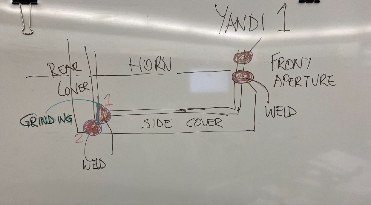
312 Mr de Vos’ evidence was that he considered that the welds between the rear edges of the side walls of the intermediate cover and the support body spreads over the rear edge of the side walls of the intermediate cover, over the rear face of the support body and also penetrates the cavity between the side walls of the intermediate cover and the side faces of the support body. Mr de Vos agreed that the Patent did not describe a chamfer filled with weld as being part of either the rear face of the horn or the side face of the horn.
313 Dr Huggett estimated that the spread of weld onto the rear face of the support body would be in the order of one or two millimetres.
314 Mr de Vos acknowledged that in the configuration depicted above, the force is transmitted via the welds and the forces down the side cover were going to be much greater than the forces into the rear face of the horn. Mr de Vos also acknowledged that the transfer of forces between the rear cover and the rear face of the support body would be much more effective if the two faces were flush, than if there was a gap of the kind depicted above.
315 MMD submits that the manner in which the rear cover is welded to the rear end of the side walls of the intermediate cover is very similar to that depicted in diagram 3 (which it alleges falls within the claims of the Patent), the main difference being that the ends of the side walls are co-planar with the rear face of the support body, rather than overhanging. Instead of the extended side walls, the gap is filled by weld.
316 The top cover with its front wall is positioned on and welded to the front wall of the intermediate cover. The top cover only touches the front wall of the intermediate cover along its side edges.
317 A breaking tip is welded to the front of the top cover.
318 Diagram 12 is a stylised representation of the First Yandi Construction with a cross section taken at approximately the mid-point of the support body. I have adopted the diagram numbering used in MMD’s submissions. I will discuss whether the First Yandi Construction infringes the Patent by reference to this diagram:
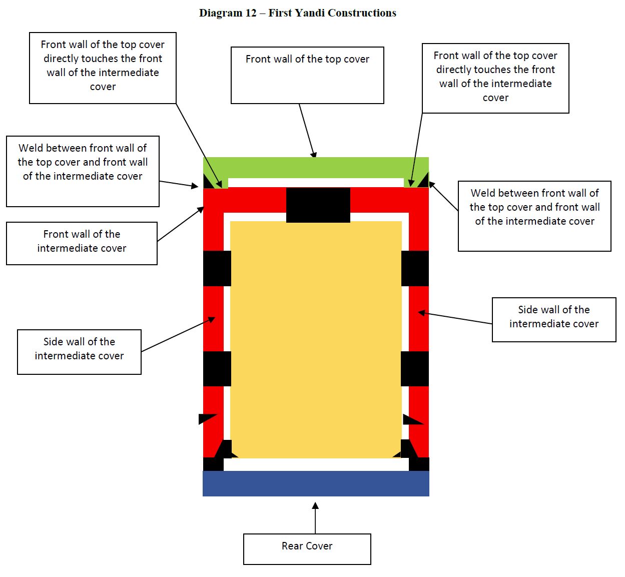
319 MMD submits that the First Yandi Constructions have two front covers; the first, the front wall of the intermediate cover and the second, the front wall of the top cover.
320 MMD submits that both the front covers are “weldingly secured to and seated in face to face contact with the front face of the support body”. Both are seated in face to face contact because forces can be transmitted from the front wall of the top cover to the front wall of the intermediate cover and then from there to the face of the support body through the weld that secures the front wall of the intermediate cover to the front face of the support body.
321 MMD submits that the front wall of the intermediate cover is directly weldingly secured to the front face of the support body, and indirectly weldingly secured to the side and rear faces of the support body because:
(a) the front wall of the intermediate cover is welded to the front face of the support body through the aperture of the front of the intermediate cover; and
(b) the side walls of the intermediate cover are welded to the side and rear faces of the support body.
322 MMD submits that the front wall of the top cover is indirectly weldingly secured to the support body because the outer edges of the front wall of the top cover are welded to the front wall of the intermediate cover which is directly weldingly secured to the front face of the support body, and indirectly weldingly secured to the side and rear faces of the support body as above.
323 MMD submits that the force will be transmitted from the front wall of the top cover to the front wall of the intermediate cover where they touch at the periphery, and the force will then be transmitted from the front wall of the intermediate cover to the front face of the support body via the weld in the weld aperture. Force is transmitted from the rear cover to the weld at the rear edges of the side walls and through them to the rear corner edge of the support body.
324 MMD acknowledged in its written submissions that the force being transmitted to the side face of the support body may be greater than the force going into the rear face of the support body, depending on the geometry and size of the covers and the way that the side walls of the intermediate cover are attached to the support body. The force that is transmitted to the rear face of the support body will be transmitted to the peripheral edges of the rear face of the support body.
325 Camco contends that the front of the intermediate cover is the relevant front cover for the purpose of claim 1. It refers to claims 7 and 8 of the Patent to support its contention that there is only one front cover: the front wall of the intermediate cover is the front cover for the purposes of the claims.
326 Claim 7 claims a tooth construction according to claim 2, which in turn claims a tooth construction according to claim 1. In claim 7, the front cover is described as forming “the front wall of an intermediate cover”. Claim 7 contemplates an additional cover added over the intermediate cover, and in that configuration it is the front wall of the intermediate cover that forms the “front cover” for the purposes of the claim. Claim 7 does not, however, derogate from the requirement in claim 1 that the “front cover” must be “seated in face to face contact with the front face of the support body.” Camco submits that claim 7 makes it clear that the addition of a top cover does not change the identity of “the” front cover of the claims; it remains the front wall of the (now) intermediate cover. It is from this cover that the rear cover needs to be separate.
327 Claim 8 claims a tooth construction according to claim 7 wherein a “top cover is mounted on the intermediate cover”. Camco submits that claim 8 contemplates two separate and distinguishable covers, but does not derogate from the front wall of the intermediate cover (in claims 7 and 8) being the “front cover” in claim 1. Claims 7 and 8 confirm that the “front cover” in claim 1 is a cover that is immediately adjacent to the support body – in the language of the claim, it is a cover that is “seated in face to face contact” with the front face of the support body. Camco submits that its construction is supported by the lack of any description in the specification of any part of the top cover as being a “front cover”.
328 Mr de Vos agreed in the joint session that in the case of the second embodiment where there is an intermediate cover and a top cover, the patentee is telling the reader that the front cover is not the front wall of the top cover, but rather the front wall of the intermediate cover. That the front wall of the intermediate cover is the front cover for the purposes of the claims is also consistent with my construction of the “seated in face to face contact” integer.
329 There is no direct physical contact between the inner face of the front wall of the top cover and the front face of the support body.
330 The front cover of the First Yandi Construction’s intermediate cover is “weldingly secured” to the front face of the support body. Dr Huggett agreed that the welding through the aperture of the front cover met this integer.
331 Camco conceded that if (as I have found) indirect welding was sufficient to satisfy “weldingly secured” then the rear cover of the First Yandi Construction is “weldingly secured” to the rear face of the support body.
332 I do not consider that either the front cover or the rear cover are “seated in face to face contact with the [front/rear] face of the support body” as I have construed that phrase. Neither the inner face of the front cover nor the inner face of the rear cover are in physical contact across most of their faces with the respective front and rear faces of the support body.
333 Even if the weld through the aperture of the front face of the intermediate cover spread across the majority of the two surfaces it is connecting: the front face of the support body and the inner face of the intermediate cover, and was considered to become part of those surfaces so as they might be considered to be physically touching across the majority of their surfaces such as to be in face to face contact, the rear cover is not in face to face contact with the rear face of the support body.
334 When questioned as to the configuration depicted in diagram 3, Mr de Vos acknowledged that, in terms of force, the forces down the side cover were going to be much greater than the forces into the rear face of the horn. Mr de Vos said the forces would, after exiting the weld between the rear cover and the side cover, take a 90-degree turn through the weld between the side cover and the rear face of the horn. As Camco submitted, no experiments were conducted by MMD which might have established the extent to which forces are efficiently transferred through to the support body, in accordance with Mr de Vos’ construction.
335 The First Yandi Construction does not infringe claim 1 of the Patent.
336 The First Yandi Construction has two side covers, which form part of the intermediate (or bottom) cover. Claim 3 does not require the side covers to be “separate”. The side covers both “overlie” the respective side faces of the support body, and they are secured to the support body by welding.
337 Like the front and rear covers, the First Yandi Constructions have a gap between the inner face of each of the side covers and their respective side of the support body. There is no physical contact between most of the face of the side covers and the corresponding side face of the support body.
338 Claim 9 of the Patent refers to a “tooth construction according to Claim 4 or 8 wherein a breaking tip member is mounted at the juncture of the top and front walls of the top cover, the breaking tip member being secured thereto by welding”.
339 Dr Huggett and Mr de Vos agreed in the JER that the “juncture” is the location where the top and front walls of the top cover meet. Mr de Vos highlights that the rebate also present on the top cover is included in this location.
340 Dr Huggett’s evidence was that the breaking tip on the First Yandi Construction is located and welded on the front face of the overlying top cover and is positioned with the uppermost region at the juncture of the top and front walls of the top cover. According to Dr Huggett the front face of the top cover is not technically the juncture, hence in his view this integer is not found in the First Yandi Construction. I disagree. I consider that the breaking tip of the First Yandi Construction is mounted at the juncture of the top and front walls of the top cover.
341 The Solomon Construction has the following components:
(a) a support body;
(b) an intermediate cover with a front wall, two side walls, a top wall, a rear projection and an open rear wall;
(c) the front wall and the side walls of the intermediate cover each has an aperture;
(d) a rear cover;
(e) a top cover with a front wall, a top wall and a rear projection; and
(f) a breaking tip.
342 When the intermediate cover is installed on the support body, there is a clearance of at least approximately 2 mm between:
(a) the front wall of the intermediate cover and the front face of the support body; and
(b) the side walls of the intermediate cover and the side faces of the support body.
343 The cavity between the front wall and rear projection of the intermediate cover is 2 mm longer than the support body.
344 The rear projection of the intermediate cover is in physical contact with the rear face of the support body.
345 The intermediate cover is welded to the support body in the following ways:
(a) The front wall of the intermediate cover is welded to the front face of the support body through the aperture in the front wall.
(b) The side walls of the intermediate cover are welded to the side faces of the support body through the aperture of each side wall.
(c) The rear projection of the intermediate cover is welded along its underside directly to the rear face of the support body.
(d) The rear ends of the side walls of the intermediate cover are welded to the side and rear faces of the support body (in the same manner as for First Yandi).
346 Once the intermediate cover is welded to the support body, the rear cover is fitted and welded to the rear ends of the side walls of the intermediate cover. The rear cover is U-shaped. The arms of the “U” create a clearance of approximately 90 mm between the inner face of the rear wall of the rear cover and the rear face of the support body.
347 When assembled, the rear cover is comprised of three pieces:
(a) the rear projection of the intermediate cover;
(b) the rear projection of the top cover; and
(c) the rear cover.
348 The rear projection of the intermediate cover, which covers only a very small portion of the rear face of the support body, is in contact with that small portion of the rear face of the support body.
349 The rear projection of the intermediate cover is welded to the rear projection of the top cover.
350 Diagram 13 is a stylised representation of the Solomon Construction:
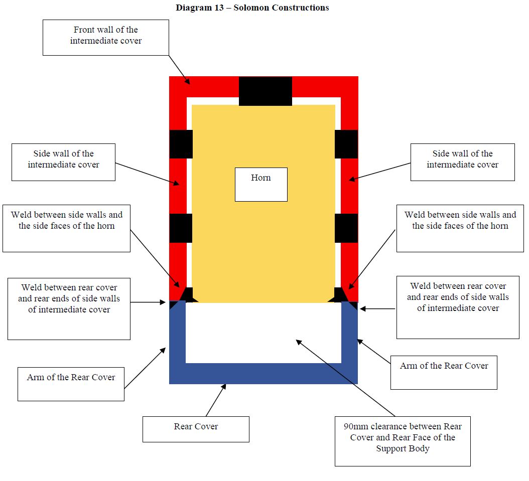
351 When the configuration depicted in diagram 13 is compared with the equivalent diagram for the First Yandi Constructions (diagram 12), it can be seen that arms of the rear cover for the Solomon Constructions take the place of the 5 mm root gap between the rear cover and the rear ends of the side walls of the intermediate cover. Although in the Solomon Constructions the arms of the rear cover are longer than the 5 mm root gap and create a larger clearance between the rear cover and the rear face of the support body, MMD submits that forces are transmitted from the rear cover to the side walls of the intermediate cover, and then to the rear face of the support body, in the same way.
352 After the rear cover is welded to the intermediate cover, a top cover with depending front wall and rear projection is welded to the intermediate cover.
353 The breaking tip is welded to the top cover.
354 For the same reasons as discussed for the First Yandi Construction, I do not consider the front wall of the top cover to constitute a “front cover” for the purposes of claim 1.
355 For the same reasons as discussed for the First Yandi Construction, I consider that the front and side covers of the intermediate cover are “weldingly secured” to the respective faces of the support body.
356 MMD submits that the Solomon Construction has three rear covers:
(a) the rear projection of the intermediate cover;
(b) the rear projection of the top cover; and
(c) the rear cover.
357 MMD submits that all three of these “rear cover” components are located at, and protect, the rear face of the support body and are each therefore rear covers. MMD then considers each component on its own, to submit that it is separate to the top cover or the intermediate cover as needed to make its case. For example, the rear projection of the intermediate cover is said to be separate to the front wall of the top cover, and the rear projection of the top cover is separate to the front cover of the intermediate cover, as in neither case are they integral parts of the same component. Finally, the rear cover is said to be separate because it is not an integral part of the intermediate or top covers.
358 MMD submits that each “rear cover” component separately satisfies the “a separate rear cover” integer for the purposes of claim 1.
359 MMD relies on its transmission of forces argument to contend that each of the rear covers is seated in face to face contact with the rear face of the support body. In the case of the rear projection of the intermediate cover, forces can be transmitted directly as the rear projection touches the rear face of the support body, as well as indirectly via the welds. For the other rear covers the forces are transmitted indirectly through the welds.
360 Mr de Vos accepted that if the front cover in the Solomon Construction is the front wall of the intermediate cover then the rear projection is not separate from the intermediate cover. MMD’s written submissions describe the rear projection of the intermediate cover as “part” of the intermediate cover.
361 Dr Huggett did not consider the rear projection of the intermediate cover on its own was the rear cover. His evidence was that the rear projection only formed a very small portion of the rear surface, “it certainly doesn’t cover the majority of that rear [f]ace”.
362 I do not consider that the rear projection of the intermediate cover constitutes “a separate rear cover” for claim 1. As Mr de Vos accepted, the rear projection is an integral part of the intermediate cover and cannot be considered to be “separate” to the intermediate cover. MMD’s submissions accept it is a part of the intermediate cover.
363 As the rear projection of the intermediate cover covers only a very small portion of the rear face of the support body, even if it were a separate rear cover, it could not be considered to be in “face to face” contact with the rear face of the support body, as the majority of the rear face of the support body is not covered by the rear projection of the intermediate cover.
364 If the rear cover is considered as the rear cover, then it is a separate rear cover. However, I do not consider that the rear cover is in face to face contact with the rear face of the support body on the Solomon Construction for the same reasons that the rear cover of the First Yandi Construction depicted in diagram 12 is not in face to face contact with the rear face of the support body.
365 For the same reasons as discussed for the First Yandi Construction, I reject MMD’s submission that the front wall of the intermediate cover is seated in face to face contact with the front face of the support body because forces can be transmitted between these components through the weld that secures the front wall of the intermediate cover to the front face of the support body.
366 The Solomon Construction does not infringe claim 1 of the Patent.
10.8 First Worsley Construction
367 The First Worsley Construction has the following components:
(a) a support body;
(b) an intermediate cover with a front wall, two side walls, an open top wall and an open rear wall;
(c) a rear cover;
(d) a top cover with a front wall and top wall; and
(e) a breaking tip.
368 An 80 mm wide aperture is machined out of the top wall of the intermediate cover, spanning all the way from the inside face of the front wall of the intermediate cover to its open rear wall, to leave the top wall of the intermediate cover open. Apertures in the front and side walls are filled in with weld which is ground to be flush with the relevant surfaces of the intermediate cover.
369 Before installation the rear cover is welded to the intermediate cover.
370 The intermediate cover (with welded rear cover) is installed on the support body so that there is:
(a) a clearance of 3.5–5 mm between the front wall of the intermediate cover and the front face of the support body;
(b) a clearance of 3.5 mm between the rear cover and the rear face of the support body; and
(c) a clearance of 3 mm between each side wall of the intermediate cover and the respective face of the support body.
371 The intermediate cover and rear cover are welded to the top face of the support body through the opening cut in the top wall of the intermediate cover. There is no other welding to the support body or the sizer ring
372 When installed, the front wall of the top cover extends down in front of the front wall of the intermediate cover. The top of the top cover covers the opening cut in the top wall of the intermediate cover.
373 Mr de Vos considered that the front wall of the intermediate cover was welded to the front face of the support body along the chamfers between the top face and the front face of the support body. He considered the chamfers to be part of the front and rear face of the support body. Mr de Vos drew the below diagram in the joint session to explain how the front cover and rear cover of the intermediate cover were welded to the respective faces of the support body in the First Worsley Construction.
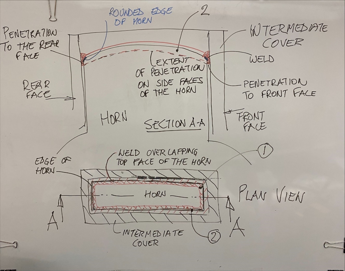
374 Mr de Vos explained that the weld would penetrate down to the broken line – as shown in the above diagram so that there would be weld on the front, side and rear faces of the support body. Dr Huggett considered that “the penetration is going to be – probably a minimal amount through the faces”. Mr de Vos quantified the extent to which the weld would penetrate in cross-examination as being in the order of a few millimetres, saying that it:
[d]epend[s] on the gap. The gap is quite wide, You could expect a fair amount of penetration. But if the gap was two millimetres, yes, I would say three millimeters or so.
375 MMD speculates that as the First Worsley Construction gap is 3.5–5 mm, the penetration will be more than 3 mm. There was no evidence as to what the penetration would be. On the basis of Mr De Vos’ evidence that the extent of weld penetration seemed to be in the same order as the gap, I consider that the weld penetration would be less than 7 mm.
376 Diagram 14 is a stylised representation of the First Worsley Construction:
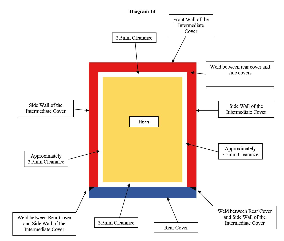
377 Camco submits that the welding of the rear cover to the intermediate cover before installation means that the rear cover is not a separate rear cover. Camco submits that because the rear cover is welded to the intermediate cover before installation, the First Worsley Construction is not taking the assembly as described in the Patent, which involves a sequence of particular steps. Not being separate at the point of assembly robs the rear cover of one of the advantages of the invention, namely, being able to be pushed right up against the rear face of the horn.
378 I consider that the rear cover is a separate rear cover for the purposes of claim 1, as it is welded to the intermediate cover. It is not an integral part of the intermediate cover.
379 I do not consider that the front/rear faces of the intermediate cover are in face to face contact with the front/rear faces of the support body. There is no aperture in the front face of the intermediate cover as this is filled prior to installation. To the extent that there is any spill over penetration of the weld on to the front, side and rear faces, that is a minimal amount which does not result in the majority of the faces being in physical contact. Nor do I consider that the chamfers constitute more than a minimal part of the front or rear faces of the support body.
380 The First Worsley Construction does not infringe claim 1 of the Patent.
10.9 Second Worsley Construction
381 The Second Worsley Constructions have a similar design to the First Worsley Constructions except for the following differences in the intermediate cover:
(a) the intermediate cover is cast with an integral rear wall, whereas the First Worsley rear cover is welded to the intermediate cover prior to installation;
(b) the intermediate cover has an aperture in the front wall which is not filled with weld prior to installation; and
(c) the inner cavity of the intermediate cover is 2 mm longer than the First Worsley.
382 Like the First Worsley Constructions, the intermediate cover of the Second Worsley Constructions includes a 80 mm wide slot in its top wall which extends from its front wall to its rear wall.
383 In addition to being welded through the slot cut in the top wall of the intermediate cover to the top face of the support body, the front wall of the intermediate cover is welded through the aperture to the front face of the support body.
384 MMD accepts that if the front wall of the intermediate cover is a “front cover” (in that it lies in front of, and protects, the front face of the support body), it is not “separate” to the rear wall of the intermediate cover. Only the front wall of the top cover is “separate” to the rear cover. For the reasons discussed above in relation to the First Yandi Construction I do not consider that the front wall of the top cover is the “front cover” for the purposes of claim 1.
385 As the rear cover is integral with the intermediate cover, there is no separate rear cover, and that integer is absent.
386 MMD contends that the front wall of the top cover forms the relevant front cover for the purposes of claim 1. MMD further contends that the front wall of the top cover is seated in face to face contact with the front face of the support body because forces can be transmitted between these components
387 MMD speculates that as the Second Worsley Construction has larger clearances than the First Worsley Construction the weld will penetrate further down the front and rear faces of the support body. There was no evidence as to the amount of weld penetration expected by the experts. Without evidence, the contention rises no higher than conjecture that the weld would penetrate further than it does for the First Worsley Construction. I do not consider that it would cover the majority of the front or rear face of the support body. The front and rear faces of the support body are not in face to face contact with the respective faces of the front and rear covers of the intermediate cover.
388 As such, I find the Second Worsley Construction does not infringe claim 1 of the Patent.
10.10 Third Worsley Construction
389 The Third Worsley Construction is very similar to the Second Worsley Construction. Like the Second, it also has an intermediate cover with an integral rear cover. There is no aperture in the front wall of the Third Worsley intermediate cover.
390 The cavity of the intermediate cover is 5 mm longer than that of the Second Worsley. The clearances between the front and rear faces of the intermediate cover and the front and rear chamfers of the support body are 7–8.5 mm.
391 The intermediate cover and integral rear cover are welded to the top face of the support body through the opening cut in the top wall of the intermediate cover. There is no other welding to the support body or the sizer ring.
392 MMD contends that the front wall of the top cover is the front cover for the purposes of claim 1, and as a result the rear cover is a separate rear cover.
393 MMD speculates that as the Third Worsley Construction has larger clearances than the First Worsley Construction the weld will penetrate further down the front and rear faces of the support body.
394 For the same reasons that I found the First Worsley Construction not to infringe, I do not consider that the Third Worsley Construction infringes claim 1 of the Patent.
395 I do not consider that the specification describes or illustrates an invention otherwise than in accordance with my construction of the terms of claim 1. For the reasons discussed above, I do not consider that a tooth construction as depicted in diagram 3 is described or illustrated in the Patent.
10.12 Conclusion on infringement
396 For the above reasons, Camco’s supply of each of the five welded tooth constructions do not infringe the relevant Asserted Claims of the Patent.
397 Given my findings on infringement, it is not strictly necessary to consider Camco’s second defence to infringement.
398 For the purposes of considering the repair defence, it is necessary to assume (contrary to my findings) that the Camco Constructions infringe at least one of the claims of the Patent.
399 Camco’s second defence to the allegations of patent infringement is that the owners of the MMD mineral sizers (being certain mining companies) have a contractual right of repair and Camco has undertaken the repair work as the owners’ agent.
400 Camco was previously MMD’s repairer of its mineral sizers supplied in Australia. The parties’ commercial relationship ended in late 2015. Since then, MMD has provided repair services for MMD mineral sizers in competition with Camco.
401 After the termination of their commercial relationship, Camco continued to provide repair services to mining companies for MMD’s mineral sizers, but using different repair designs to those used during its commercial relationship with MMD. Camco submits that the Camco Constructions were designed following receipt of legal advice as to how to avoid infringement.
402 The exclusive statutory rights of a patentee to exploit an invention which is a product include the rights to “make, hire, sell or otherwise dispose of the product” and to “use” it: s 13(1), Sch 1 of the Patents Act 1990 (Cth) (definition of “exploit”).
403 As to the rights between the patentee and the owner of a product, the majority in Calidad Pty Ltd v Seiko Epson Corporation (2020) 272 CLR 351 upheld the exhaustion doctrine, but regarding the issue of repair or further manufacture of a product observed at [45]:
Regardless of whether the exhaustion doctrine or the implied licence doctrine is to be preferred, neither doctrine has any part to play in determining whether there has been an infringement of a patent by reason that a new product embodying the claimed invention has been made. The sale of a patented product cannot confer an implied licence to make another and it cannot exhaust the right of a patentee to prevent others from being made.
404 The question then is whether a party has engaged in a permissible repair or an impermissible manufacture. The majority in Calidad relevantly observed:
49 That answer directs attention to the real issue in relation to infringement, namely whether the modifications resulted in a new product being made. …
…
53 Lord Hoffmann [in United Wire Ltd v Screen Repair Services (Scotland) Ltd [2001] RPC 24 at 458-459 [70]-[71]] viewed an owner’s right to repair a patented article not as an independent right conferred by licence, but as a residual right forming part of the right to do whatever does not amount to making the product. There are two matters to which his Lordship referred in part of his speech which might imply acceptance of a wider notion of “repair” in this context. “Repair”, he said, “is one of the concepts (like modifying or adapting) which shares a boundary with ‘making’ but does not trespass upon its territory.” His Lordship also approved the statement attributed to Lord Halsbury, in a case decided not long before the Menck decisions [citing Sirdar Rubber Co v Wallington Weston & Co (1907) 24 RPC 539 at 543], that “you may prolong the life of a licensed article but you must not make a new one under the cover of repair”.
(Emphasis added.)
405 The majority held that the modifications made by Calidad to used printer cartridges was not an infringement of the relevant patent, and explained the question of whether there had been an infringing act of manufacture by reference to the facts in United Wire.
406 Where a “mere component” of the patented article remains from which a new product is made, there will be a making, not a repair. Relevantly, the majority (Kiefel CJ, Bell and Keane JJ) summarised, at [51] of Calidad, the patent and infringing conduct in United Wire:
… The patent there in question concerned improvements to sifting screens used to recycle drilling fluid in the offshore oil-drilling industry. The screen was described in the first claim of the patent as a sifting screen assembly, comprising a frame to which mesh screens were secured, for use in a vibratory sifting machine. The defendants stripped down the screen to its frame and then secured new mesh screens to it. This was regarded by Aldous LJ, in the Court of Appeal, as equivalent to purchasing the frames on the open market and then using them to produce an assembly. The House of Lords held that the Court of Appeal was entitled to conclude that the totality of the work amounted to "making" a new article because the removal of the meshes and the stripping down and repairing of the frame resulted in a mere component of the patented article remaining "from which a new screen could be [and was] made".
407 At [66]–[69] of Calidad, the majority observed:
66 …The question of infringement under the Patents Act 1990 is not addressed to the nature of the article but rather to the invention described by the integers of the claim. Where what has been done does not involve the replication of the combination of integers that describe the invention it cannot be said that what has been done is the making of it.
67 When a small hole was made in the printing material container of the original Epson cartridge to enable it to be refilled with ink, the cartridge did not cease to exist, and it was not made anew when the two holes were sealed. The product did not cease to exist when the memory chip was substituted. An argument that an article has been “unmade” and then “remade” might have some weight in a circumstance such as United Wire. However, it is somewhat artificial in cases where parts are changed so as to permit continuation of use. In Wilson v Simpson, referred to with approval in Aro Manufacturing, the Court refused to accept that a tangible machine could be said to have ceased to have a material existence because a part that had become inoperative was repaired or replaced.
…
69 When all of Ninestar’s modifications to each of the categories of cartridges were completed what remained were the original Epson cartridges with some modifications which enabled their re-use. The modifications did not involve the replication of parts and features of the invention claimed. There was no true manufacture or construction of a cartridge which embodied the features of the patent claim.
(Emphasis added.)
408 Again, I note that this consideration of the repair defence assumes that the Camco Constructions infringe the claims of the Patent.
409 The question is whether Camco’s conduct constitutes repair or manufacture of a new product. Where an alleged infringer’s act falls on the continuum between repair and manufacture is a question of fact and degree to be decided according to the nature of the article defined by the integers of the claim. Each case is dependent upon its own facts.
410 Camco submits that they have done no more than repair mineral sizers and that its conduct does not result in the making of new tooth constructions. Camco submits that it replaced individual unpatented parts.
411 MMD submits the facts of this case are closely analogous to United Wire and relies on the majority’s reasoning in Calidad to demonstrate the tooth construction was “made anew” by Camco’s actions. As Lord Hoffman found at [73] of United Wire, MMD submits that the modification or refurbishment was so extensive that it only left a mere component of the original patented article remaining:
It is quite true that the defendants have prolonged the useful life of the frame. It would otherwise presumably have been scrapped. But the screen was the combination of the frame and meshes pretensioned by attachment with adhesive according to the invention. That product ceased to exist when the meshes were removed and the frame was stripped down to the bare metal. What remained at that stage was merely an important component, a skeleton or chassis from which a new screen could be made.
412 Counsel for Camco submits United Wire should be distinguished and noted that the argument that a product has been unmade and then remade “is somewhat artificial where parts are changed so as to permit continuation of use”. Camco refers to [54] and [55] of Calidad in particular:
54 In Schütz, Lord Neuberger appears to have accepted that, whilst the focus should be on the question whether the article is made, a consideration of whether an alleged infringer is repairing rather than making an article may sometimes be useful. It is reflected in the approach, his Lordship observed, which is taken by the German courts to infringement. His Lordship gave as an example the mere replacement of a part of an article, which does not necessarily mean a making is involved.
55 The jurisprudence of the courts of the United States has employed the dichotomy of permissible repair and impermissible reconstruction to resolve questions of infringement by making a new article having the features of the claimed invention. It has consistently been held that for an infringement to be established, there must be a true reconstruction so as to in fact make a new article. The replacement of individual unpatented parts may involve a right of repair where what is done bears on the usefulness of the old combination of the product. Modifications of this kind tend to be characterised in the spectrum closer to repair than to reconstruction or making.
(Emphasis added.)
413 I am not persuaded by Camco’s arguments that the analogy to the United Wire case should be distinguished here.
414 As I discuss further below, the only part of the claimed invention which is not replaced by Camco when undertaking a refurbishment is the tooth-shaped support body.
415 In oral closing submissions, counsel for Camco accepted the evidence of Mr Fusco and Mr Balmer that the sizer rings with their integral support bodies were not replaced. Once the covers of the tooth construction are removed via arc gouging of the weld, all that remains is the naked support body attached to the sizer ring. The shell of the tooth construction has ceased to exist at this point.
416 Camco submits that Mr Fusco’s evidence on this topic, including his characterisation of Camco’s work as “repairs” to mineral sizers (and tooth constructions), was not challenged in cross-examination. Camco refers to the observation in Wilson v Simpson (1850) 50 US 109, cited in Calidad, at 123:
When the wearing or injury is partial, then repair is restoration, and not reconstruction.
417 I consider that in this case the wearing or injury is not partial. It is clear from Mr Fusco’s evidence describing the repair of the sizer, that the each of the covers that form the shell was removed and replaced with new covers, rather than the cover being repaired and re-used. Camco’s conduct demonstrates the un-making and re-making of the tooth construction the subject of the claims.
418 Camco further sought to distinguish United Wire on the basis that the screens were purchased on the open market. I agree with the submissions made by MMD that this does not affect the proposition that the owners of a chattel have the right to repair.
419 Lastly, Camco submits that MMD has not led any evidence that suggests any restrictions or conditions which impose limitations as to the use of its patented product after the sale to a mining company. Accordingly, MMD exhausted its patent rights in that mineral sizer and its components. On Camco’s case, it is then entitled to do what it wishes by extending the life of the sizer by repair and refurbishment, but cannot make a new mineral sizer which would fall within the patent claim.
420 MMD submits that such limitations as to the use are irrelevant given that Camco has made the product, and not used it. This is made plain by the majority at [45] of Calidad (extracted above).
421 Camco removes the plurality of covers, including the front cover and the rear cover, and removes the weld. When Camco has removed the covers and the welds, there is no unitary tooth construction. Camco then attaches new covers, including a front cover and separate rear cover to form a new shell. Camco welds the new covers to the support body so that they are weldingly secured to the support body and in face to face contact with the front and rear surfaces of the support body respectively. That is, Camco replicates the integers of the claim which relate to the welding connection between the covers and the horn.
422 The only component of the patented article that remains after Camco refurbishes the sizer shaft is the support body. A new tooth construction is made from this single support body. Like the frame in United Wire, the fact that this “skeleton or chassis” remains does not derogate from the conclusion that Camco has unmade the patented tooth construction and made a new tooth construction.
423 The claim is to a tooth construction for a mineral breaker, it is not a claim to a mineral breaker (sizer) including, amongst other things, tooth constructions. Camco’s repair argument strayed close to suggesting that the repair question should be answered by reference to repair to the mineral sizer, rather than the individual tooth constructions as claimed. From that viewpoint, the replacement of the covers of some or all of the support bodies arranged along the shafts of the sizer might be said to be a repair of the sizer, as the shafts and integral support bodies are not being replaced. However, the claims define an article which is a tooth construction, and it is that article which must be the focus of the consideration.
424 I find that Camco replicates the integers of the claim which relate to the welding connection between the covers and horn, and when Camco completes its work, there is a new unitary tooth construction which is comprised of the old support body and the new covers, which are welded to the support body and in face to face contact with the support body because of the new welded connections.
425 In the course of its work Camco disassembles the old tooth construction. It then assembles new covers to make a new product, the tooth construction, the subject of the claims. On that basis, the repair defence must fail.
426 In the event that the Camco Constructions were held to infringe a claim of the Patent, Camco’s conduct would constitute the assembly of a new product which would infringe the claims of the Patent.
12. AUSTRALIAN CONSUMER LAW CLAIM
427 MMD contends that Camco failed to warn each of its customers (BHP, FMG and South 32):
(a) of the existence of the Patent;
(b) that the exploitation of the Camco Constructions infringed particular claims of the Patent;
(c) that Camco is not entitled without the authority or consent of MMD to exploit the Camco Constructions; and
(d) that each of Camco’s customers are not entitled without the authority or consent of MMD to exploit the relevant tooth constructions.
428 MMD says that this failure to warn occurred in circumstances where each of the identified customers reasonably expected Camco to provide each of the above warnings.
429 Further or in the alternative, MMD contends that Camco represented to each of FMG, BHP and South 32 that it had obtained any necessary licences or authorisations from third parties in relation to the relevant tooth constructions and that the supply of the Camco Constructions did not infringe the rights of any third parties.
430 MMD alleges by reason of the above representations, that Camco has made the following representations to each of the mining companies:
(a) that Camco is lawfully entitled, without the authority or consent of MMD, to exploit the Camco Constructions;
(b) that each relevant mining company is lawfully entitled, without the authority or consent of MMD, to exploit each of the relevant tooth constructions; and
(c) that the exploitation of the Camco Constructions will not infringe the Patent.
431 MMD says in each case that the representations were made in trade and commerce and that each of the representations were false, and that Camco has engaged in conduct which is misleading or deceptive, or likely to mislead or deceive, in contravention of s 18 of the ACL.
432 MMD alleges it has suffered loss and damage as a result of Camco’s misleading and deceptive conduct as the Camco Constructions are sold and supplied in direct competition with tooth constructions sold and supplied by MMD. MMD did not provide evidence or particulars of any loss and damage alleged to be suffered by reason of Camco’s conduct, as MMD submits that in a split trial such as this, it is not necessary to establish loss and damage until the quantum hearing. MMD seeks declaratory relief, injunctive relief, damages under s 236 of the ACL and compensation under s 237 of the ACL.
433 MMD submits that it has long been recognised that such a failure to warn may constitute misleading or deceptive conduct, citing Advanced Building Systems Pty Ltd v Ramset Fasteners (Aust) Pty Ltd [1995] FCA 236; AIPC 91-129 at 38; Ramset Fasteners (Aust) Pty Ltd v Advanced Building Systems Pty Ltd (1999) 44 IPR 481 at [66]–[68]; Sanofi-Aventis Australia Pty Ltd v Apotex Pty Ltd (No 3) (2011) 196 FCR 1 at [275]–[282], Apotex Pty Ltd v Sanofi-Aventis Australia Pty Ltd (No 2) (2012) 204 FCR 494 at [91]; Sandvik Intellectual Property AB v Quarry Mining & Construction Equipment Pty Ltd (2016) 118 IPR 421 at [272]–[277].
434 Camco submits that given the infringement case concerning the Second Yandi Construction has been abandoned, MMD cannot succeed in its ACL claim in relation to Camco’s conduct concerning that construction.
435 Camco submits that a failure to warn is akin to an allegation of misleading or deceptive conduct by silence. Unless the circumstances give rise to a reasonable expectation that, if some relevant fact existed, it would be disclosed, the Courts have observed that it is difficult to see how silence could be misleading or deceptive: French J (as he then was) in Kimberley NZI Finance Ltd v Torero Pty Ltd [1989] FCA 400; ATPR (Digest) 46-054 at 53, 193, cited and followed in Demagogue Pty Ltd v Ramensky (1992) 39 FCR 31 per Gummow J at 41, see also Black CJ at 32.
436 Camco submits that as a matter of general principle, s 18 does not require a party to commercial negotiations (or commercial dealings) to volunteer information which will, or might, assist the decision-making of the other party: Demagogue at 40.
437 Camco contends that at the time it conducted the repair work for each of the five Camco Constructions, it had an honest belief that it did not infringe the Patent and it believed the different repair designs it employed (compared to the designs it previously performed as MMD’s chosen repairer) were innovative advancements. Camco contends that it had an honest belief that it did not infringe at the time that it made any representation.
438 MMD rejects that submission and says that the evidence does not support the conclusion that Camco had an honest belief that it did not infringe. MMD disputes that Camco had obtained legal advice that the Camco Constructions did not infringe the Patent at the time Camco was first asked by BHP about infringement of third party rights. MMD also disputes that the Camco legal advice related to a Camco Construction actually supplied by Camco.
439 MMD contends that the design of the First Yandi Construction in respect of which Camco sought legal advice was quite different to the designs of the other Camco Constructions, and differed from the actual First Yandi Construction in the placement of two welds. According to MMD, at the time it provided each Camco Construction, Camco was well aware of the risk of infringement.
440 As the High Court recently observed in Self Care IP Holdings Pty Ltd v Allergan Australia Pty Ltd (2023) 171 IPR 120 per Kiefel CJ, Gagler, Gordon, Edelman and Gleeson JJ at [80], determining whether there has been a breach of s 18 of the ACL involves four steps:
[F]irst, identifying with precision the “conduct” said to contravene s 18; second, considering whether the identified conduct was conduct “in trade or commerce”; third, considering what meaning that conduct conveyed; and fourth, determining whether that conduct in light of that meaning was “misleading or deceptive or ... likely to mislead or deceive”.
441 As the High Court explained at [81] and [82]:
81 The first step requires asking: “what is the alleged conduct?” and “does the evidence establish that the person engaged in the conduct?”. The third step considers what meaning that conduct conveyed to its intended audience. As in this case, where the pleaded conduct is said to amount to a representation, it is necessary to determine whether the alleged representation is established by the evidence. The fourth step is to ask whether the conduct in light of that meaning meets the statutory description of “misleading or deceptive or ... likely to mislead or deceive”; that is, whether it has the tendency to lead into error. Each of those steps involves “quintessential question[s] of fact”.
82 The third and fourth steps require the court to characterise, as an objective matter, the conduct viewed as a whole and its notional effects, judged by reference to its context, on the state of mind of the relevant person or class of persons. That context includes the immediate context – relevantly, all the words in the document or other communication and the manner in which those words are conveyed, not just a word or phrase in isolation – and the broader context of the relevant surrounding facts and circumstances. It has been said that “[m]uch more often than not, the simpler the description of the conduct that is said to be misleading or deceptive or likely to be so, the easier it will be to focus upon whether that conduct has the requisite character”. That said, the description of the conduct alleged and identified at the first step should be sufficiently comprehensive to expose the complaint, because it is that conduct that will ultimately, as a whole, be determined to be or not to be misleading or deceptive.
(Citations omitted.)
442 In Sandvik, Jessup J observed that failure to warn may amount to misleading conduct under s 18 of the ACL. At [273], his Honour noted in the context of a patent case, the Full Court in Ramset said (at [67]):
… Whether or not Ramset’s conduct should be analysed as conveying an implicit misrepresentation, it acted misleadingly when it promoted and sold face-lift tilt-up equipment in the way that it did, without informing its customers of the liability it was inducing them to incur. This was conduct calculated to cause a mistaken impression about a significant consequence of the transaction proposed to those customers. In our opinion, in such a case, it is unnecessary, and may be artificial, to speak of a representation. The orthodox theory would find one, but it is more realistic to see the conduct as misleading, without resorting to a sophisticated analysis in which no one would have engaged at the time.
443 In response to the respondent’s submission in Sandvik that “[n]o representation of any kind was made that use of the Quarry Drill Rods or the Quarry Adaptors would not infringe Sandvik’s patent”, at [276] Jessup J observed that the submission misunderstood the applicant’s case, stating:
[The] case was based not upon the presence of a positive representation, but upon the absence of a warning in circumstances where the purchaser of rods and/or adaptors would have no reason to be alert to the prospect that the use of what he or she had purchased would, or might, expose him or her to allegations of patent infringement.
444 Camco entered into an agreement with BHP for the refurbishment of mineral sizers located at its Yandi site in December 2015. Camco entered into an agreement with FMG in January 2016 to refurbish mineral sizers at the sites in the Pilbara region.
445 Camco did not have a refurbishment agreement with South 32, rather it supplied South 32 with covers as required on an order by order basis.
446 Both of the agreements and the correspondence produced by Camco demonstrate that, each of BHP and FMG had raised the issue of potential infringement of third party intellectual property rights prior to their entry into their respective refurbishment agreements with Camco.
447 BHP raised the issue of the potential infringement of third party intellectual property rights in correspondence during the process of tender negotiation with Camco. In an email dated 29 September 2015, the BHP supply category manager wrote that BHP was keen to understand in detail Camco’s “non-OEM parts proposition”. In the email BHP wrote:
How would you seek to
a) protect yourself from breaching any other 3rd party IP?
b) avoid a challenge / injunction by the OEM on your development of parts due to breach of OEM IP?
c) avoid a situation where we need to interrupt operations to swap out the Camco parts, and replace with OEM parts?
This will give us better insight into your plan to deploy nonOEM parts, and how Camco would manage/avoid some key risks.
448 Camco’s agreement with BHP to refurbish the MMD sizers in operation at Yandi contains an express contractual obligation on Camco to notify BHP as soon as Camco became aware of any suspected, threatened or actual infringement of any intellectual property rights arising by reason of the contract or use of the goods (which included the Camco Constructions).
449 In the agreement with FMG, Camco warranted that the supply of the covers would not infringe the intellectual property rights of any third party. Camco also agreed to:
notify [FMG] as soon as it becomes aware of any suspected, threatened or actual infringement of any Intellectual Property Rights in the Project IP and/or [FMG]'s Background IP[.]
450 In the course of correspondence with BHP, Camco informed BHP that it was obtaining legal advice on the use of non-OEM parts.
451 Mr Fusco’s evidence was that he had nothing to do with the tenders and was not a party to the negotiations with BHP or FMG. According to Mr Fusco, the other director of Camco, Bruce Cameron, and Camco’s project manager, now sizer repair manager, Mr Prasad (a mechanical engineer) handled the negotiations and responded to queries in the course of the negotiations.
452 Mr Fusco agreed in cross-examination that he was copied in on email correspondence relating to the tender negotiations and that he was aware that BHP had raised the issue of infringement with Camco in the course of negotiations. Mr Fusco was also aware that under its contract, BHP required Camco to notify it of any suspected, threatened or actual infringement of intellectual property rights; and that FMG imposed a similar obligation on Camco. In cross-examination Mr Fusco agreed that an important part of the negotiations with BHP was BHP’s requirement that Camco advise BHP of any potential intellectual property infringement issues in relation to the supply of non-OEM parts.
453 Mr Fusco conceded in cross-examination that his evidence in his affidavit, that he had never experienced a situation where a customer had asked Camco, or required Camco to advise, of any potential intellectual property infringement issues, was false.
454 Mr Fusco believed that the Camco Constructions were different to the MMD tooth constructions and that they constituted “innovative concepts” over the MMD tooth covers.
455 According to Mr Fusco, in September and October 2015, Camco sought and obtained legal advice to ensure the First Yandi Construction did not infringe. Mr Fusco’s evidence was that Mr Prasad and Mr Cameron briefed Mr Provan of Watermark for the purpose of obtaining legal advice as to whether the First Yandi Construction infringed the claims of the Patent. Mr Cameron and Mr Prasad selected the drawings and photographs that were to be given to Camco’s lawyer and also to Dr Huggett, Camco’s expert witness. Neither Mr Cameron nor Mr Prasad, both of whom still work for Camco, were called as witnesses by Camco.
456 Camco received the written Watermark legal advice dated 15 October 2015, prior to the execution of the BHP and FMG agreements. The legal advice addressed whether the proposed Camco Construction for First Yandi infringed the Patent. No further written legal advice was produced in response to a call for production of such advice to Camco in addition to the 15 October 2015 legal advice.
457 Mr Fusco agreed that Camco’s First Yandi Construction was based on MMD’s Yandi design. He rejected the suggestion that he had copied the MMD design, explaining that in making a replacement tooth construction, Camco was “constrained” in the design of the First Yandi Construction by reason of the shape and configuration of the support body and the shafts of the MMD mineral sizer which were being refurbished. The MMD sizer needed to be able to rotate and crush the ore as required using Camco’s First Yandi Construction.
458 There were some differences between photographs supplied to Watermark by Camco for the purposes of preparing the advice and the Camco Construction supplied to BHP’s First Yandi site. Mr Fusco’s evidence was that diameter of the pick, and the internal dimensions of the First Yandi Construction were different to the MMD design and that he considered that the Camco Constructions did not take the “face to face” integer.
459 As can be seen from the infringement analysis above, each of the Camco Constructions supplied to Solomon and First, Second and Third Worsely differed to that supplied to First Yandi.
460 In the circumstances described above, both BHP and FMG were concerned about the potential for infringement of third party intellectual property rights by Camco’s use of non-OEM parts. Both had raised the issue with Camco in the course of tender negotiations, either specifically in correspondence, or by the inclusion of provisions in the proposed refurbishment agreements directing notification of any potential infringement of third party intellectual property rights. Both would have a reasonable expectation that Camco would inform them if the Camco Constructions infringed the patent rights of a third party.
461 I am prepared to infer from the evidence that large mining companies preparing to enter long term refurbishment contracts involving large sums of money are concerned about the potential for infringement of third party intellectual property rights by the use of non-OEM parts. However, I am not able to make the same inference in relation to mining companies that purchase tooth constructions on an as required basis with no long-term refurbishment agreement, as there was no evidence to support such an inference.
462 BHP was aware prior to executing the BHP refurbishment agreement that Camco had legal advice that the proposed First Yandi Construction did not infringe the Patent.
463 Whilst the photographs supplied to Watermark for the purposes of preparing the legal advice differed in some respects from the actual Camco Construction provided to the First Yandi site, I consider it unlikely that those differences would have changed the advice. The Watermark advice of 15 October 2015 was that the proposed Camco Constructions did not infringe the Patent and I have found that the First Yandi Construction does not infringe the Patent.
464 On the basis of the Watermark advice of 15 October 2015, Mr Fusco and Camco held an honest belief that the Camco Constructions did not infringe the Patent. Based on my findings as to infringement, that belief was correct.
465 As I have found none of the Camco Constructions infringes the Patent, none of the alleged representations, if made, were false. MMD’s ACL case must fail.
13. STANDING TO SUE / EXCLUSIVE LICENCE
466 MMD Design is the registered proprietor of the Patent. MMD Australia contends that it has been the exclusive licensee of the Patent at all material times. MMD alleges Camco’s conduct has infringed the Patent from about 9 May 2016, thus in order for MMD Australia to be entitled to damages for any infringement from that date, it must have been the exclusive licensee from at least May 2016.
467 Camco contends that prior to 21 May 2020, MMD Australia was not the exclusive licensee of the Patent in Australia.
468 Mr Waring, Operations Director at MMD Design, and an employee of MMD Design since about April 2016, annexed two deeds to his affidavit (served on the eve of trial) which MMD relies upon to establish that MMD Australia is an exclusive licensee of the Patent, and has been since May 2016. The first deed is dated 20 February 2019 (First Deed), and the second is dated 21 May 2020 (Second Deed). MMD Australia and MMD UK are the parties to both deeds.
469 Mr Waring gave evidence based on his direct knowledge and experience working as Operations Director (including as acting Operations Director between April 2016 and 7 July 2016) that from at least 1 May 2016:
(a) MMD Australia is, and has been since at least 1995, a fully owned subsidiary of the MMD Group;
(b) MMD Design is, and has been since the early 1980’s, a fully owned subsidiary of the MMD Group;
(c) MMD Australia has had the right to (a) make, hire, sell or otherwise dispose of, (b) offer to make, sell, hire or otherwise dispose of, (c) use in or import into Australia and (d) keep the subject matter claimed in the Patent in Australia (the Rights); and
(d) MMD Design has not granted its licence, authority or consent to the Rights in Australia to any party except MMD Australia.
470 Mr Waring signed the First Deed and Second Deed on behalf of MMD Design. According to Mr Waring the Second Deed made “certain variations” to the First Deed.
471 Mr Waring’s evidence was that prior to the execution of the First Deed, the exclusive licence was not recorded in writing; it was a gentleman’s agreement, an internal understanding within the MMD Group.
472 The purpose of the First Deed is expressed in recital D as being to formalise the existing (implied) licence on the terms and conditions set out in the deed. The First Deed is retrospective. It is expressed to commence on 5 November 2004, over 14 years prior to the execution of the First Deed.
473 The stated purpose of the Second Deed was to define the scope of the First Deed to confirm MMD Design and MMD Australia’s intention that MMD Australia has always held an exclusive licence (within the meaning of the Patents Act) to MMD Design’s intellectual property rights.
474 Camco accepts that the Second Deed establishes that MMD Australia has been the exclusive licensee of the Patent since 21 May 2020. Camco says, however, the evidence does not establish MMD Australia was the exclusive licensee before that date.
475 Camco submits that even on the assumption the First Deed is capable of operating retrospectively, the insurmountable difficulty for MMD is that the First Deed does not meet the requirements for an exclusive licence as discussed by Yates J in Bristol-Myers Squibb Company v Apotex Pty Ltd (No 5) (2013) 104 IPR 23 at [434]–[440]. Camco submits that the licence arrangement cannot reserve to the patentee any territory of the right to “exploit” the Patent. If any part of that territory is maintained by the patentee, then the licence is not an exclusive licence within the meaning of s 120(1) of the Patents Act.
476 The term “exploit” is defined in the Dictionary to the Patents Act as follows:
exploit, in relation to an invention, includes:
(a) where the invention is a product—make, hire, sell or otherwise dispose of the product, offer to make, sell, hire or otherwise dispose of it, use or import it, or keep it for the purpose of doing any of those things; or
(b) where the invention is a method or process—use the method or process or do any act mentioned in paragraph (a) in respect of a product resulting from such use.
477 In the present case, clause 2.1 of the First Deed provides that the licence granted is:
an exclusive, irrevocable, royalty-free licence for the Term to use the Licensor’s Intellectual Property Rights to import, manufacture, advertise, sell and distribute the Products and the Parts and provide the Services in the Territory;
(Emphasis added.)
478 The term “Services” is defined in clause 1.1 in the First Deed as meaning “services associated with the repair and maintenance of the Products”. “Products” means products incorporating the patented technology (which includes the Patent).
479 Camco submits that from a comparison between the acts (or conduct) provided in the definition of “exploit” (with respect to product claims) and the emphasised part of clause 2.1 of the First Deed above, clause 2.1 reserves to the Patentee at least the rights to “hire”, “use”, “keep” and “otherwise dispose of”, as well as the corresponding rights to “offer” each of them. Accordingly, the First Deed does not meet the requirements for an exclusive licence because it reserves certain rights to the patentee.
480 As Justice Yates explained in Bristol-Myers (No 5) at [434] to [436]:
434 Section 13(1) of the Act provides that a patent gives the patentee the exclusive rights to exploit the invention (which can only mean the invention as claimed) and to authorise another person to exploit the invention. The definition of “exclusive licensee” recognises these twin rights. The licence referred to in the definition might confer on the licensee the patentee’s exclusive right to exploit the patented invention throughout the patent area. Alternatively, the licence might confer that right on the licensee and persons authorised by the licensee. In either case, the legal effect of the licence must be that “the patentee and all other persons” are excluded from exercising the right to exploit the patent. It follows that the legal effect of the licence must also be to exclude the patentee from exercising the exclusive right under s 13(1) of the Act to authorise another person to exploit the invention.
435 In this way, it can be seen that the definition of “exclusive licensee” operates in harmony with the rights conferred by the Act on the patentee. The licence under which the licensee derives the status of “exclusive” licensee is one that excludes the patentee, and others deriving authority from the patentee, from exercising the rights conferred by the patent with respect to the invention during the term of the licence. An exclusive licence cannot be one that reserves to the patentee or any other person any residual right with respect to the exploitation of the invention. It follows that there can only be one exclusive licensee.
436 In my view, the Act speaks of “the right to exploit” the invention as a single, indivisible right. The word “exploit” is used in the Act as a hypernym to cover a range of activities. The inclusive nature of the definition employed by the Act, and the exemplification of particular activities to elucidate the meaning of the word, signify that a broad range of activities is intended to be covered. However, s 13(1) of the Act recognises that only two rights are conferred by the patent: the right to exploit the invention and the right to authorise others to exploit the invention. The use of disjunctive language in the definition of “exploit” to identify particular activities falling within the scope of the term does not create separate rights with respect to those activities. It merely recognises that the right to exploit covers a range of activities, any one of which, if undertaken, would amount to the exercise of the right to exploit.
481 Recital C of the First Deed says that:
[MMD Design] grants other members of the MMD group of companies the right to use its intellectual property rights and has granted [MMD Australia] the right to use those rights in Australia, New Zealand and New Caledonia in relation to the importing, manufacturing, advertising, distribution, sale, repair and maintenance of MMD products subject to the terms of an implied licence.
482 As noted above, clause 2.1(a) of the First Deed grants a licence to MMD Australia in similar terms to recital C, namely the exclusive right to import, manufacture, advertise and distribute the Products and the Parts. By clause 2.2 of the First Deed MMD Design agrees that it will not grant any other licences in Australia, New Zealand or New Caledonia.
483 The definition of “exclusive licensee” in the Patents Act refers to the conferral by the patentee of a single licence that precludes the patentee, and any person deriving authority from the patentee, from exercising the rights granted by the patent. Whilst MMD Design agrees in the First Deed to not grant any other licences in Australia, it, as the Patentee, still retains the rights in Australia to “hire”, “use”, “keep” and “otherwise dispose of”, as well as the corresponding rights to “offer” each of them. There is nothing in the First Deed that precludes MMD Design from exercising the retained rights. Accordingly, I do not consider that the licence granted to MMD Australia pursuant to the First Deed is an exclusive licence.
484 The First Deed is intended to formalise the implied “gentleman’s agreement” in operation prior to the execution of the First Deed. I consider that the terms of the implied licence are not broader than the terms of the First Deed which is expressly intended to formalise the existing licence. Contrary to Mr Waring’s evidence, I do not consider that MMD Australia has had the exclusive right to (a) make, hire, sell or otherwise dispose of, (b) offer to make, sell, hire or otherwise dispose of, (c) use in or import into Australia and (d) keep the subject matter claimed in the Patent in Australia since 1 May 2016.
485 My conclusion is supported by the existence of the Second Deed, which purports to rectify the deficiencies of the First Deed by inserting a definition of “utilise” at clause 2.2(a), which picks up the definition of “exploit” in the Patents Act. As accepted by Camco, the Second Deed grants an exclusive licence to MMD Australia to exploit the Patent in Australia as from 21 May 2020.
486 MMD seeks orders for additional damages from Camco in the event that MMD succeeds on its infringement case and makes an election for damages. Camco denies that claim. The trial having been split as between liability and quantum, the only point to be determined at the liability stage is whether MMD has enlivened an entitlement to an order for additional damages, not the quantum of any award.
487 Section 122(1A) of the Patents Act provides as follows:
(1A) A court may include an additional amount in an assessment of damages for an infringement of a patent, if the court considers it appropriate to do so having regard to:
(a) the flagrancy of the infringement; and
(b) the need to deter similar infringements of patents; and
(c) the conduct of the party that infringed the patent that occurred:
(i) after the act constituting the infringement; or
(ii) after that party was informed that it had allegedly infringed the patent; and
(d) any benefit shown to have accrued to that party because of the infringement; and
(e) all other relevant matters.
488 Section 122(1A) sets out five relevant matters to which the Court must have regard in determining whether to award additional damages. Those matters, to which the Court must have regard, are not in the nature of preconditions which must be satisfied in order to make the award: Futuretronics.com.au Pty Limited v Graphix Labels Pty Ltd (No 2) (2008) 76 IPR 763 per Besanko J at [17] in the context of the equivalent section in the Copyright Act 1968 (Cth). The statutory factors set out in the section do not exhaust all relevant matters for consideration, but they do indicate the considerations to which Parliament turned its attention.
489 The Court has a broad discretion to award additional damages. Justice Perram observed in relation to the equivalent section in the Trade Marks Act 1995 (Cth) (s 126(2)) that it is not a general grant of a power to award any damages the court thinks fit. Instead, the power is circumscribed by the concept of deterrence; that is to say, additional damages are awarded, not to compensate loss, but to make infringement unattractive: Halal Certification Authority Pty Ltd v Scadilone Pty Ltd (2014) 107 IPR 23 at [99]. The concept of deterrence encompasses both specific deterrence of repetition of the conduct by the infringer and, by their example, general deterrence of other would-be infringers.
490 In addition to flagrancy, the relevant matters include the conduct of the infringer after the acts of infringement (including after the infringer has been informed that it has infringed the rights in question), the benefits accruing to the infringer by reason of the infringements that are found, and all other relevant matters: Hytera Communications Corporation Ltd v Motorola Solutions, Inc [2019] FCAFC 210 (per Jagot, Yates and Stewart JJ) at [25]. The Full Court in Hytera at [25] observed that “all other relevant matters” meant “all other matters that can be seen, rationally, to bear on an assessment of the conduct that is found to be infringing and the context in which that conduct takes place”.
491 More than copying is required to enliven the application of s 122(1A). The Full Court in Oxworks Trading Pty Ltd v Gram Engineering Pty Ltd (2019) 154 IPR 215 observed at [72] that “[i]t is not illegitimate, or flagrant, for a competitor to examine the disclosure of a patent and to attempt to work around the monopoly claimed in the claims”. Nor is flagrancy a prerequisite for an award of additional damages: MJA Scientifics International Pty Ltd v SC Johnson & Son Pty Ltd (1998) 43 IPR 275 per Sundberg J at 282.
492 Speaking in the copyright context, Lander and Gordon JJ observed in Facton Ltd v Rifai Fashions Pty Ltd (2012) 95 IPR 95 at [32] that in order to enliven an entitlement to additional damages, the court must first order that compensatory damages are payable, as opposed to an account of profits. At [33], they noted that the damages contemplated under s 115(4) of the Copyright Act 1968 (Cth) were of a punitive kind. At [36], they observed that additional damages will be awarded under s 115(4) when the conduct of the defendant is such that an award of punitive damages should be made to mark the court’s recognition of the opprobrium attached to the defendant’s conduct.
493 Additional damages may be awarded even if the rights owner is only entitled to nominal compensatory damages: Dynamic Supplies Pty Ltd v Tonnex International Pty Ltd (No 3) (2014) 107 IPR 548 at [52].
494 MMD submits that the following matters support its claim for additional damages:
(a) Camco was aware of the Patent at all times;
(b) Camco copied MMD’s First Yandi design;
(c) Camco’s conduct prior to commencement of proceedings and after the commencement of proceedings; and
(d) The false evidence given by Mr Fusco in relation to never having had a situation where a customer had asked or required Camco to advise of any potential intellectual property infringement issues.
495 Camco complains that many of the matters on which MMD’s case for additional damages relies were not particularised in detail. The precise details of MMD’s case only emerged through its cross-examination of Mr Fusco. Camco submits that MMD in conducting its case in this way, has essentially engaged in trial by ambush. To the extent MMD makes criticisms of Mr Fusco, and also Camco, because Mr Fusco could not answer questions put to him in cross-examination (because he did not know), Camco submits that reflects the very generalised way that MMD put its flagrancy case in its pleadings. Camco submits that it may have adduced evidence responsive to MMD’s assertions had it been given proper notice of those assertions.
496 Camco does not dispute that it was aware of the Patent before it commenced the refurbishment work. However, it submits that mere awareness of the Patent is not a sufficient basis upon which to award additional damages. Camco points to the evidence of Mr Fusco in relation to the three integers of the claims that he said were sought to be avoided in the Camco Constructions.
497 Camco also refers to the 19 October 2015 legal advice it received from Watermark that Camco’s proposed repair designs would not infringe the Patent. According to Mr Fusco, the advice was sought from Watermark in September and October 2015, and the Camco Constructions designs were implemented after receiving that advice. Camco submits that it had a belief at all material times that it had a reasonably arguable basis upon which to defend any allegation of patent infringement.
498 MMD submits that Mr Fusco ultimately accepted that the design for Camco’s First Yandi Construction was based on the MMD First Yandi tooth construction, and that Camco’s design reflects substantially the same features as MMD’s First Yandi designs, save for minor changes to the size of the chamfers on the top cap, the radius where the pick attaches to the top cap, the pick diameter, and the internal dimensions of the intermediate cover.
499 Camco submits that there is no evidence that Camco engaged in any acts of copying of MMD’s design at the time Camco’s First Yandi design was devised, such as by copying MMD’s design drawings. Camco notes that MMD’s Patent was publicly available at that time, and contained drawings of the tooth constructions the subject of the claimed invention. Those Patent drawings show tooth constructions of a similar overall shape to Camco’s First Yandi Construction.
500 Camco submits that it is unsurprising that the First Yandi Construction adopted a general shape which had an affinity with the MMD First Yandi design. Mr Fusco’s evidence was that Camco was “constrained” in the design of the Camco Construction by reason of the shape and configuration of the support body and the shafts of the MMD mineral sizer which was being refurbished. The MMD sizer needed to be able to operate and crush the ore as required using the Camco First Yandi Construction.
501 Camco submits that the evidence shows that Camco developed its own repair designs, which differed from the MMD First Yandi design, after its commercial relationship with MMD ceased. Camco submits that its designs embodied certain features which sought to address issues which Camco had encountered with the MMD design. In particular, Camco noticed that the MMD design “used to clash all the time”, and so addressed this issue by incorporating a steeper angle for the portion of the top cap where the pick is secured. Consequently, the sweep angle is reduced and the First Yandi Construction is less prone to clashing.
502 MMD accepts that disputing infringement of itself is not sufficient to trigger an award of additional damages. However, MMD submits that Camco knowingly misled MMD by reference to fabricated drawings and a model that did not reflect the design of any actual Camco Construction that it used.
503 MMD relies on a meeting, attended by Mr Fusco, between MMD and Camco on 18 December 2018 to discuss the issue of infringement. Camco put forward, for the purposes of convincing MMD that it did not infringe the Patent, a drawing of a tooth construction said to be an accurate representation of the features of the Camco Construction being supplied to FMG for use at the Solomon mine site.
504 Mr Fusco accepted that there was an element of the drawing that was incorrect which he described as a “drawing error”.
505 MMD submits that the drawing was advanced to deliberately mislead MMD into the false belief that Camco’s tooth constructions did not infringe the Patent because force was directed into the sizer ring and not the horn. MMD submits that Camco sought to rely on the drawing to convince MMD that Camco covers were not relevantly in face to face contact with the horn. MMD submits that Camco did not raise the error in the 18 December 2018 meeting (or in an affidavit about the meeting from Mr Cameron made on 16 August 2019).
506 MMD submits that subsequent letters sent to MMD by Camco’s solicitors confirm that Camco deliberately sought to mislead MMD. In each of these letters Camco’s solicitors draw a distinction between the design philosophies of MMD and Camco. For example, in a letter of 30 January 2019, Watermark writes:
• MMD uses ‘face-to-face’ contact and welding of components of the MMD tooth with the horn faces to transfer loading forces into the horn.
• Camco spaces components of the Camco tooth from the horn i.e. no ‘face-to-face’ contact, with loading forces directed into the annulus on the breaker shaft and/or to adjacent teeth.
507 In cross-examination Mr Fusco explained (in relation to Camco’s assembly drawings) that he wanted to conceal the way in which Camco was welding to the rear face of the horn, because:
I elected to protect some of my methodologies and methods of ensuring that the construction withstood the force of the clearances […] Now that … that was intentional, because I didn’t want that information getting out into the public arena.
508 Mr Fusco described the “differences” identified by MMD as “insignificant” and did not accept that they were materially different. In re-examination Mr Fusco noted that it would not matter if the skirt of the intermediate cap sat on the annulus of the horn or if it was spaced a millimetre or two above. He was not qualified to respond as to consequence of the “differences” on whether the forces would be directed into the horn or the sizer ring.
509 Camco responds to the assertion that MMD was misled at the 18 December 2018 meeting by observing that no evidence was led from anyone at MMD that either the “differences”, or the drafting error in the Camco drawings which Mr Fusco picked up in cross-examination, obstructed or impeded MMD’s decision to sue Camco for infringement, which they subsequently did based on other information (and documents) provided by Camco.
510 Camco accepts that it experienced difficulties in complying with the discovery orders made by the Court on 26 November 2020 and 15 December 2020 and was granted an extension of time to comply. However, Camco submits that neither those difficulties, nor any other aspect of its conduct in the course of the proceedings, provide any potential basis for an award of additional damages.
511 I have found that in the Camco Constructions there is no face to face contact of the type described and claimed in the claims of the Patent. On that basis, Camco was not misleading MMD when it stated that the Camco Constructions did not have “face to face contact”. The differences in the drawings identified by MMD did not amount to the difference between infringement and non- infringement. There was no evidence as to whether the Camco Constructions direct the forces into the annulus on the breaker shaft or the horn.
512 Taking all the considerations above into account, I am not satisfied that MMD would be entitled, upon a finding of infringement, to an award of additional damages.
513 Camco contends that the Patent is invalid and relies on four grounds of invalidity: manner of manufacture, novelty, inventive step, and s 40 issues (fair basis and lack of clarity). For the reasons below, I do not find that any of these grounds of invalidity are established.
514 At the priority date, the notional skilled addressee in Australia would have been aware of a number of matters that were common general knowledge. The following list of matters is not intended to be (and is obviously not) exhaustive, but consists of matters that are of particular relevance to the skilled addressee’s understanding of the Patent specification including the invention described and claimed.
515 In addition to the matters the subject of Mr de Vos’ evidence above, the following matters taken from the evidence of Mr de Vos and Dr Huggett formed part of the common general knowledge of the person skilled in the art as at the priority date.
516 Before the priority date, mineral sizers had been in use for many years in soft rock (such as coal) mining in Australia. According to Mr de Vos, mineral sizers were not widely used in Australia in hard rock mining at the priority date.
517 Dr Huggett agreed that mineral sizers were not typically used in nickel, gold or copper mines because those mines require fine particles or ore to allow the valuable mineral to be liberated. Mineral sizers do not create fine particles. The purpose of a mineral sizer is to create smaller lumps of ore from larger lumps whereas the other types of crushers are used to break down ore into fine particles. According to Dr Huggett, mineral sizers were in use for hard rock ores including hematite and iron ore at the priority date.
518 Mr de Vos was aware of two manufacturers of mineral sizers at the priority date: ABON and MMD.
519 Mining companies often have a target size distribution for their crushed ore. The crushing equipment used at a mine site must be designed to produce the size distribution required by the mining company.
520 Where a mine site utilises primary and secondary crushing stages (as is most common), the primary crusher or mineral sizer must produce rocks of an appropriate size for the secondary crusher or mineral sizer. The secondary crusher or mineral sizer must produce rocks of the desired size distribution from the rocks that leave the primary crusher or mineral sizer.
521 The size distribution of the ore produced at the end of the crushing process can affect downstream handling of the ore (eg transport and further processing), as well as the ore’s final sale price.
522 The size distribution of rocks produced by a mineral sizer are primarily determined by the size distribution and hardness of the rocks fed into the mineral sizer, the size and shape of the teeth and breaker bars of a mineral sizer, and the gaps between these components.
523 A mineral sizer must also produce the desired amount of crushed rocks each hour (referred to as “throughput”). A mineral sizer that produces rocks of the desired size distribution too slowly is a poor design. The throughput of mineral sizers used on a large mining site is typically hundreds or thousands of tonnes per hour.
524 The throughput of a mineral sizer is primarily determined by the factors that affect size distribution, along with:
(a) the electrical power available to the mineral sizer; and
(b) the mineral sizer’s ability to use that power to rotate the shafts.
Rotating the shafts faster, and generating more torque through the shafts, will usually increase the throughput of a mineral sizer.
525 As a mineral sizer is used, any surfaces that are exposed to the ore, including the teeth, will wear. Wear can change the size and/or shape of the teeth, which may increase the size distribution of the rocks processed by, and the throughput of, the mineral sizer. Accordingly, the crushing performance and throughput of a mineral sizer may change over time.
15.2 Maintenance of Crushing Equipment
526 Mine sites typically operate 24 hours per day, seven days per week in order to produce as much saleable ore as possible and maximise profits.
527 Mining companies require consistent results from their mineral sizers. It is important that the size of the rocks produced by, and the throughput of, the mineral sizer does not change significantly over time. Inconsistency in size can create issues with downstream handling and screening of the ore. If the ore is not crushed small enough, it may be necessary to pass it through the mineral sizer a second time.
528 Virtually all equipment on a mine site is subject to wear, and needs to be maintained to continue to operate. Every mine site has regular maintenance cycles for the equipment, including crushing equipment and mineral sizers. These maintenance cycles are planned and occur at regular intervals. Mining equipment is designed to be maintained at regular intervals. If mining equipment is not properly maintained, it will likely lead to unplanned maintenance disruptions on site.
529 During scheduled maintenance periods (often called “shutdowns”), some or many operations and equipment at the mine site are shut down (either completely or partially) to allow the maintenance to be carried out. The shutdowns are planned carefully in advance to minimise the disruption to the mine site (and particularly to minimise the effect on the production of saleable ore).
530 Maintenance work carried out on mining equipment can be conducted in situ (where the equipment is situated in its location of operation at the mine), in a workshop on the mine site, in a workshop off-site, or a combination of all three. There are often significant time and cost advantages to maintaining a mineral sizer in situ, as opposed to having to remove the shaft from the mineral sizer before maintenance can be undertaken. This is particularly the case where only a small number of teeth require maintenance (as can occur with unscheduled maintenance).
531 There are also significant time and cost advantages to maintaining a mineral sizer on site, as opposed to having to transport it or the shaft off-site for maintenance:
(a) There are significant delays associated with undertaking maintenance at a workshop off-site, particularly if, as is often the case, the mine site is located a significant distance from the workshop. For example, there is a significant distance between the location of many iron ore mines in the Pilbara region of Western Australia and the location of most Western Australian engineering workshops which are in Perth.
(b) Given the time involved with transporting a shaft of a mineral sizer from the mine site to the workshop and back, if a worn shaft is to be restored off-site the mining company will generally require at least one spare shaft they can use while the worn shaft is being restored. This increases costs and requires space for the spare shaft to be stored whilst it is not being used.
(c) If one or more teeth require replacement, but cannot be replaced without removing the entire shaft from the mineral sizer (eg they cannot be replaced in situ), and the spare shaft is off-site for maintenance, there may be a significant period of time before the teeth are replaced and the mineral sizer can be used at full capacity.
532 It is difficult, and sometimes impractical or impossible, to carry out some types of work on the shafts while they are in a mineral sizer (eg in situ). There is little space within a mineral sizer, and accordingly there are significant occupational health and safety risks in carrying out work in situ. This limits the equipment that can be safely used within the mineral sizer during maintenance.
533 It was Mr de Vos’ experience at the priority date, that where it was possible and cost-effective to restore equipment in situ, mining companies preferred to do so. Dr Huggett agreed. Mining companies did not want to incur the time and expense of removing equipment from site to fix defects that had arisen during a period of unscheduled maintenance. Even in the case of scheduled maintenance, it was Mr de Vos’ experience that mining companies preferred to carry out the work in situ due to the time and cost advantages. More work at mine sites was carried out in situ at the priority date compared to today. Dr Huggett noted that safety concerns were not as well developed at the priority date as they are now.
534 Mining companies seek to reduce the costs of running their mines by finding ways to efficiently maintain their equipment. Mining companies are able to take steps to limit the disruption to the production of ore during scheduled maintenance. For example, mining companies may have spares of critical components such as shafts, so that when a critical component is taken out for refurbishment, another can be installed immediately. Mining companies may also build up a stockpile of crushed ore ready for transport away from the mine site which can create a buffer, limiting the effect that shutting down a mineral sizer for maintenance has on the amount of saleable ore the mine can produce. A mining company can also minimise the time required to complete the maintenance by ensuring that all personnel, equipment and consumable materials required to complete a scheduled maintenance are ready.
535 In addition to being easy to maintain, it is important for mineral sizers (like all mining equipment) to be reliable, in the sense that they do not break or wear out too often in between maintenance cycles. Unscheduled maintenance if a mineral sizer fails unexpectedly, for example, if one or more teeth break, can have significant financial consequences for mining companies, particularly if the required shutdown outlasts the accumulated stockpile of crushed ore and production stops.
536 At the priority date it was (and still is) important for mining equipment, including the teeth in a mineral sizer, to be easily and quickly replaceable in situ to minimise the length of time that the equipment is shut down during any planned and unplanned maintenance periods. It was also important that it be safe for workers to be able to carry out replacement work in situ.
537 According to Mr de Vos (with Dr Huggett in agreement), when it comes to designing any piece of equipment for the mining industry, including crushing equipment, there are three considerations to take into account:
(a) The equipment must perform the desired function adequately. For example, a mineral sizer must be capable of processing the desired amount of ore with the desired size distribution for the desired length of time. This may involve consideration of wear (for example, as the teeth of a mineral sizer become worn, the mineral sizer may become less effective at reducing the size of ore).
(b) The equipment must be reliable, in that it does not wear too quickly or break too frequently between maintenance cycles.
(c) The equipment must be easy to maintain during scheduled maintenance cycles and easy to restore between maintenance cycles in the event that the equipment breaks.
15.3 Mineral sizers at the priority date
538 Before the priority date, both Mr de Vos and Dr Huggett had been involved in work to improve mineral sizer teeth.
539 Mr de Vos had assisted with improving the wear life of the shaft and teeth of an ABON mineral sizer. The ABON mineral sizer had two shafts with integral teeth with no covers. When the teeth became too worn down to function, the entire tooth was removed and replaced. Mr de Vos was asked to improve the design of the teeth to reduce their wear and extend their life. Mr de Vos came up with an improved design by using an alternative material for the casting, improved materials for the shaft and a change in machining details.
540 In 1998, Dr Huggett was asked by one of the Rio Tinto iron ore mine sites (he could not recall which one) to improve the wear life of MMD sizer teeth being used at the site. The MMD sizer consisted of two rows of counter rotating elements with each element carrying three teeth projecting radially and each element indexed in position to the next such that the teeth formed a helical pattern along the length of each row of rotating elements, and the teeth were experiencing a wear rate that necessitated replacement before the scheduled maintenance period for the unit. What Dr Huggett describes as “teeth”, I understand from his discussion in the joint session, to be equivalent to the horn or support bodies rotating around the shaft.
541 Dr Huggett annexed to his affidavit the article ‘Mechanistic modelling of mineral sizers’ written by R Heng et al on 4 March 2003 published in Minerals Engineering 16 (2003) 807–813, which he said described the wear associated with the teeth on the sizers due to hard particle abrasion and gouging abrasion. The MMD sizer discussed in the article had two crushing rolls with 48 segments on each roll, each of which had five teeth (pictured below). It was not described or shown as having covers on the teeth.
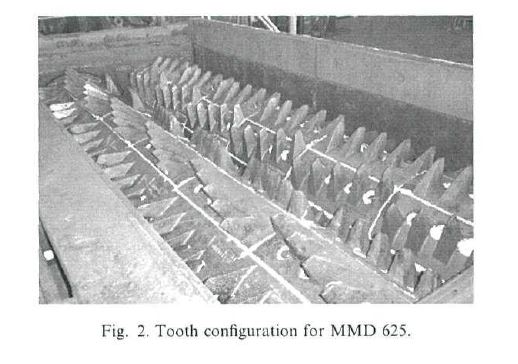
542 Dr Huggett did not attend the mine site, but was provided with a worn sizer tooth for analysis. He examined the wear profile and found that the wear material of the MMD sizer tooth was wearing from the top of the tooth construction profile. Dr Huggett included a drawing of the worn sizer tooth from the Rio Tinto site in his first affidavit. 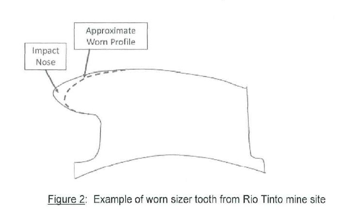
543 In the joint session, Dr Huggett explained that the teeth were experiencing a wear rate that necessitated replacement before the scheduled maintenance period of the unit and that Rio Tinto was looking for an extension to the wear life of four to five weeks.
544 As a result of his examination of the worn tooth, Dr Huggett considered the following options to extend the wear life:
(a) change to the materials used;
(b) change to profile shape;
(c) addition of wear plates/cast shells; and/or
(d) welding and hard facing to build up the worn sections of the tooth.
545 According to Dr Huggett, whilst the addition of wear plates and cast shells can extend the wear life of a sizer tooth, he decided that it was not the longer term solution he was after. Instead, Dr Huggett designed a new profile shape and produced a pattern to allow some trial castings to be manufactured. He redesigned the tooth construction by changing its shape, to extend the breaker tip and position it higher. The new tooth was trialled and Dr Huggett “believed they actually went quite okay” although he did not “know what the follow up for that particular project was”.
546 In the joint session Dr Huggett provided further details about the MMD sizer at the Rio Tinto site, including observing for the first time that the support bodies were covered with a shell formed from two covers secured by a bolt. The front and rear covers were held together with a high tensile bolt that ran along the support body in the circumferential direction; “it ran effectively through one face of the horn on one side to the rear face on the other side”. There were no intermediate or top covers. The covers had “chocky bars” (plates, which are different to covers; being items that are welded to covers not the support body) welded to them because they were wearing too quickly, and a Domite style wear button on the front in lieu of the pick.
547 Dr Huggett gave no evidence, written or oral, that the problem that was experienced at the Rio Tinto mine was that the bolts on the MMD sizer were failing prematurely. The problem that Dr Huggett was asked to assist with was unrelated to bolt failure. Dr Huggett’s evidence did not suggest that there was any issue concerning the adequacy of the bolted connection between the covers and the horn. Dr Huggett’s evidence in the joint session was that Rio Tinto did not want to move away from a bolted construction.
548 Mr de Vos who had worked in the field of mining technology since the early 1990s, was not aware of any tooth constructions in which covers were bolted or welded to a support body before the priority date.
549 Dr Huggett’s evidence as to other mineral sizers in use in Australia at the priority date was general and non specific and ultimately it was apparent that these other sizers did not have teeth with covers: there was hard facing on the tooth itself, and the tooth itself was built up with weld, as a band-aid solution in the short term.
15.4 Tooth construction covers not common general knowledge
550 There was no publication in evidence as to the availability in Australia of mineral sizers with covers at the priority date.
551 Mr de Vos’ evidence was that at the priority date he was unaware of any tooth constructions in which covers were bolted or welded to a support body.
552 Dr Huggett’s evidence about the covers on the Rio Tinto mineral sizer was the only evidence of a mineral sizer in Australia utilising tooth covers before the priority date.
553 The MMD sizer with bolted tooth constructions used by Rio Tinto at the priority date does not form part of the common general knowledge. Mr de Vos was unaware that Rio Tinto used MMD sizers, and Dr Huggett only knew of them because he was involved in a project relating to them. There was no evidence that the mineral sizers located at the Rio Tinto site would be available to the public to inspect. Rather, it would be expected for reasons of safety and confidentiality that access to the site would be controlled and not open to the public.
554 Tooth covers for mineral sizers were not part of the common general knowledge at the priority date. Since there were no covers, the question of how the covers were attached to the tooth constructions of mineral sizers did not arise.
15.5 Dr Huggett’s evidence as to methods of protection of sizer teeth
555 In his first affidavit, Dr Huggett’s evidence was that typical construction or assembly methods for attaching teeth to the rotating element included “bolting or welding the components”. In the joint session, Dr Huggett was unable to produce any pre-priority date examples of teeth or covers being welded to the support body of a mineral sizer. His only example of covers was the bolted covers on the Rio Tinto MMD sizer.
556 In his first affidavit Dr Huggett also gave evidence that welding plates in face to face contact onto various faces of teeth was something that was commonly done by mining companies and equipment manufacturers before the priority date.
557 Dr Huggett also gave evidence that some of the mid- to long-term solutions that were commonly used to prolong the life of teeth were:
(a) applying weld or hard facing directly on to the high wear surfaces in a “XXXX” pattern, or in parallel lines, or so as to cover the whole surface, by the component supplier or as part of the scheduled maintenance of the sizer; and
(b) affixing wear plates/shells of steel or composites onto the teeth by bolting or welding into place, again by the component supplier or as part of the scheduled maintenance of the sizer. With the bolting method, the bolts needed to be hidden (eg by welding over the bolt) so that there was no exposure of the bolt itself to the wearing face of the tooth. The wear plates were either cast or fabricated plates/shells.
558 Dr Huggett’s evidence as to the “commonly” used methods was not corroborated by Mr de Vos, or by any documentary source such as photographs, textbooks, diagrams or sketches. Dr Huggett did not give further details as to the suppliers, manufacturers or mining companies that were “commonly” using the methods, or the mineral sizers that they were being used on, when they were being used, or whether they could be considered to be publicly available.
15.6 Covers on other machinery
559 Dr Huggett gave some evidence in the joint session as to his experience before the priority date with covers on other non-sizer machinery. He referred to sacrificial liners used on ore bins and buckets, and a “wet plant” tank. The evidence did not establish when those uses occurred. Nor how they were relevant to tooth constructions.
560 Camco relies on two pieces of prior art. The first, PCT application WO 98/58739 entitled “Mineral Breaker” published on 30 December 1998 (the 739 Patent) and the second, PCT Application WO 03/006165 entitled “A Tooth Cap Assembly” published on 23 January 2003 (the 165 Patent).
561 To anticipate, the prior publication must contain clear and unmistakable directions to do what the patentee claims to have invented: General Tire at 485–6.
562 The plurality in AstraZeneca AB v Apotex Pty Ltd (2014) 107 IPR 177 at [293] described General Tire as the “touchstone” for determining whether a prior documentary publication anticipates a claimed invention. In order to be novelty-destroying, a prior documentary disclosure must provide information that is equal to the invention that is claimed: Hill v Evans (1862) 1A IPR 1 at 7; Samsung Electronics Co Ltd v Apple Inc (2011) 217 FCR 238 at [127].
563 The Full Court in Mylan Health Pty Ltd v Sun Pharma ANZ Pty Ltd (2020) 153 IPR 199 at [82]–[83] further observes:
82 …[E]quality in this context refers to both the specificity of the information and its completeness. Unless these twin qualities are present, the prior disclosure will not be sufficient to deprive the invention of novelty.
83 Thus, a prior documentary disclosure will not be anticipatory if it merely provides information at a level of generality which, while encompassing that which is claimed as the invention, nevertheless fails to identify the invention with sufficient specificity. …
(Original emphasis.)
564 Camco contends that the first tooth construction in the 739 Patent anticipates claims 1, 2, 3, 7, 8, 9, 10 and 17 of the Patent, but not claim 4.
565 The 739 Patent describes tooth constructions for use in a mineral breaker, or sizer.
566 The 739 Patent states that the tooth constructions include a tooth core (support body) and a sheath or tooth cap (shell) that covers the support body (page 1, paragraph 4). The support body is made from an impact resistant cast metal, and the shell is made of a wear resistant material such as a high manganese content steel or a suitable steel alloy depending on the mineral to be broken (page 1, paragraph 5; page 4, paragraph 4). The specification notes that when the shell has worn it is necessary to replace the entire shell, which can be time consuming, particularly with large mineral breakers (page 1, paragraph 6).
567 At page 2, the specification states that, in use, a shell will be exposed to repetitive impacts and high loads, so any movement between the shell and the support body will quickly lead to failure of the tooth construction.
568 The general aim of the invention described in the 739 Patent is said to be to provide a tooth construction for such mineral sizers wherein a tooth sheath is securely held in place and yet wherein worn breaker teeth can easily be renewed.
569 The 739 Patent describes two tooth constructions. The first is described on pages 6 to 13 and depicted in figures 1 to 14. The second is described on pages 14 to 16 in figures 15 to 19.
570 Reproduced below is figure 1 of the 739 Patent and additionally a coloured version of the same figure.
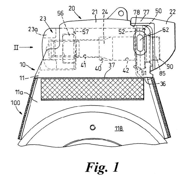
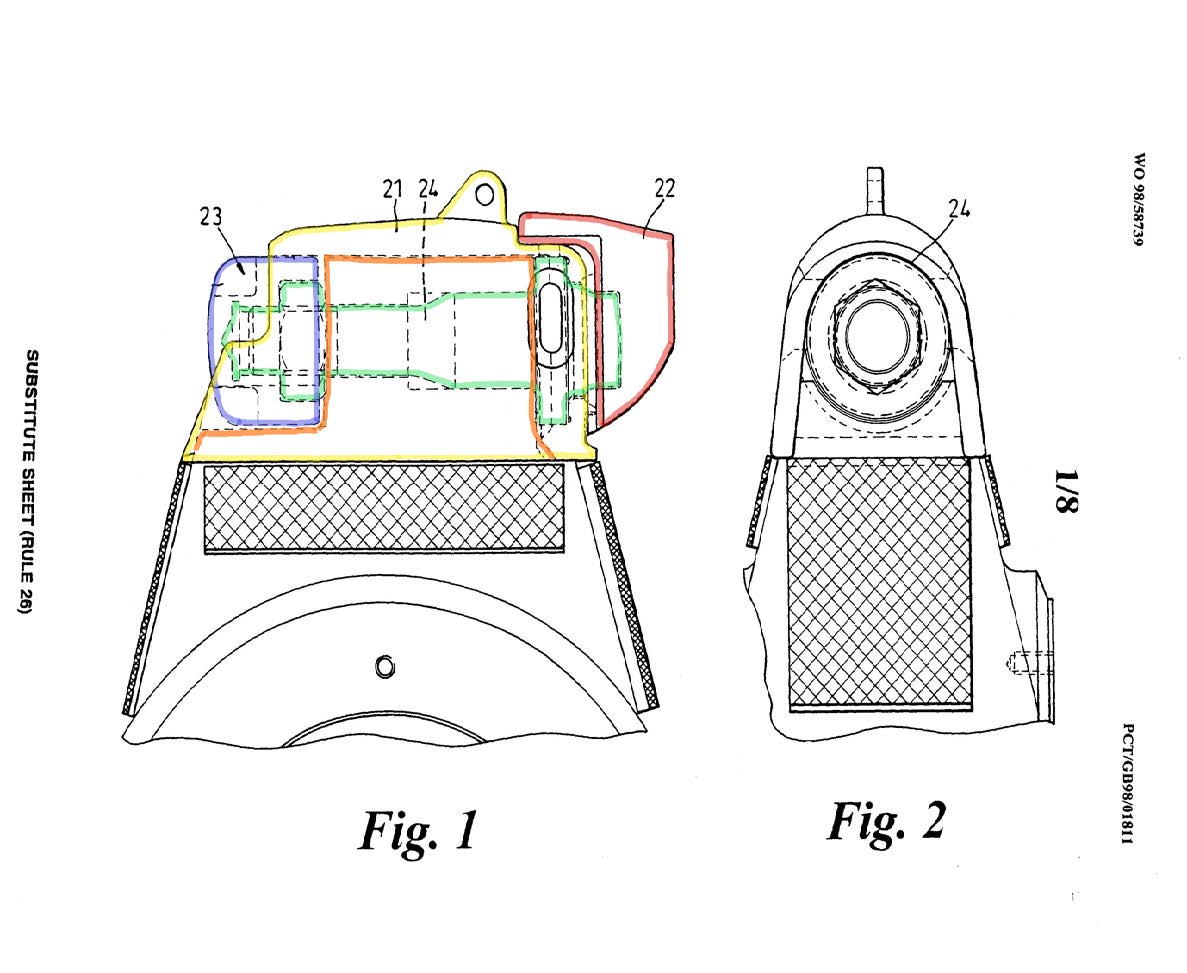
571 The tooth construction has a bore hole extending between the front and rear faces.
572 A tooth cap assembly (which does not completely enclose the horn) is mounted on the tooth core. The tooth core is outlined in orange in above. The tooth cap assembly consists of:
(a) a main cover 21 (outlined in yellow above) (which is said by Camco to be the front cover and side covers), which has:
(i) opposed side walls, a top wall, a front wall and an open rear wall; and
(ii) a “central elongate channel shaped recess” which allows the main cover to seat on the tooth core;
(b) a tip 22 (outlined in red above) (which is said by Camco to be both the top cover and the tip) that is welded to the front wall of the main cover;
(c) a rear cover 23 (outlined in blue above) (which is said by Camco to be the separate rear cover); and
(d) an anchor 24 (outlined in green above) (which is said by Camco to form part of the horn).
573 The anchor extends through the bore hole in the tooth core and is immovably clamped to the front and rear faces of the tooth core (the vertical orange lines). The anchor is a bolt which has a collar, a shank and a screw thread at the opposite end to the collar. A nut 56 is screwed onto thread at the end of the anchor. When the nut is tightened, the rear face of the collar abuts the front face of the tooth core and the nut abuts the rear face of the tooth core.
574 The main cover 21 (front cover and side covers) is welded to the collar of the anchor through a series of openings in the side and top walls of the main cover.
575 The rear cover 23 (outlined in blue above) is located on the screw thread of the shank of the anchor. The rear cover is tightened on the screw thread of the anchor to tightly abut the nut, and functions as a lock nut to resist the nut from loosening on the anchor shank. The rear cover is secured to the main cover by suitable fixing techniques, such as welding, to prevent it from loosening on the screw thread of the anchor and immovably connects the rear of the main cover to the anchor.
576 In the JER the experts agreed that the 739 Patent disclosed the following integers:
(a) a support body (tooth core);
(b) a plurality of covers, with at least a main cover and a rear cover;
(c) the main cover is keyed and bolted to the support body, and the rear cover screws to the bolt and is welded to the main cover; and
(d) the main cover is also welded through a slot to the bolt which extends through the support body.
577 Dr Huggett considered that both the tooth constructions described in the 739 Patent disclosed all the integers of the Asserted Claims of the Patent. Mr de Vos disagreed. He did not consider the anchor to form part of the support body, nor did he agree that the covers were welded to the support body (tooth core).
578 MMD submitted that there were two critical differences between the 739 Patent and the Patent. These were the differences identified by Mr de Vos: the presence of the bolt (anchor) through the tooth core, and that the main cover of the 739 Patent is secured to the tooth core by the anchor (and the use of flanges and grooves), not welded to the tooth core.
579 MMD referred to Dr Huggett’s explanation of what was disclosed in the 739 Patent:
COUNSEL: So the question is what does the 739 patent disclose. Dr Huggett, first of all, what does this patent disclose to you, in broad terms?
DR HUGGETT: Effectively, it shows an arrangement of shells which are clamped onto the support body using a bolted system. The bolt has a collar where part of the actual cover is welded to the bolt… The rear cover is located over the thread to protect the rear thread of the bold so that you can take that off later without any issues there. And I’ve also noted on the patent there’s some plates shown on the lower portion of the support body which appear to be also some sort of a shell but aren’t actually described in the patent.
(Emphasis added.)
580 Camco submits, consistent with Dr Huggett’s evidence, that the support body is constituted by the combination of the tooth core and the anchor. In Dr Huggett’s view, in the absence of the anchor, “the cover wouldn’t stay on there, therefore it is a support”. Dr Huggett considered that the anchor only has one function – to connect the cover to the support body, and thereby together the anchor and the tooth core fit the description “a tooth shaped support body”. Camco contends that there is no requirement in the 739 Patent that the support body must be a single piece construction.
581 MMD submits that Dr Huggett’s evidence on this issue was not consistent. In his first affidavit Dr Huggett stated that the combination of the tooth core and the anchor is the substrate, being a tooth shaped support body. However, in the JER the experts’ agreed response to JER Q22 appears to regard the support body and the bolt as separate components: “[t]he bolt extends through the support body and is clamped to the support body”. Likewise, when asked to identify what component(s) comprised the support body in the JER, Dr Huggett and Mr de Vos agreed that “Patent 739 calls the support body a ‘tooth core’ which is considered to being described as similar to the support body in Patent ‘510”. In the joint session, Dr Huggett returned to his view that the bolt formed part of the support body.
582 Mr de Vos did not consider the anchor to be part of the support body in the 739 Patent as it was designed to be removed and replaced. When asked if it was reasonable to assume that the anchor was part of the support body Mr de Vos responded:
No. I’ve given thought to your assumption that the anchor forms part of the support body, and if we consider when the covers are removed, that anchor is removed and disposed of as well, so it no longer remains part of the support body. You need to have a new anchor to reconfigure a new support body in your description. So for that reason, I would not consider the anchor to be part of the support body. If anything, the anchor would be part of the cover for the purpose of securing the cover to the support body.
583 I do not consider that the anchor plus tooth core combine to form the support body for the purposes of satisfying the “support body” integer of claim 1.
584 No part of the cap assembly of the 739 Patent is welded directly or indirectly to the support body, as required by claim 1 of the Patent. Thus, no part of the cap assembly is a “front cover which is weldingly secured to and seated in face to face contact with the front face of the support body” or a “separate rear cover which is weldingly secured to and seated in face to face contact with the rear face of the support body” as required by claim 1 of the Patent.
585 The 739 Patent describes the anchor and tooth core as being separate components, not one combined component. The anchor is described as forming part of the “tooth cap assembly” which is said to be mounted upon the tooth core.
586 That the support body is not intended to be replaced each time the covers are replaced is consistent with the description of the invention in the specification of the Patent.
587 The strength of the horn or support body is said to be a key aim of the invention described and claimed in the Patent. Strength is said to be due to the horn being solid and not containing any through bores, as is commonly required with prior art constructions (Patent at page 10, lines 20–23):
The strength of the tooth construction according to the invention is also enhanced by the fact that the horn is solid, i.e. does not contain through bores as is commonly required with prior art constructions.
588 The invention described and claimed in the Patent is expressly stated to be an improvement over prior art which involves bolts through the horn. This is inconsistent with the support body having a bolt lengthwise through it.
589 Further, if the combination of the anchor or bolt with the tooth core were considered to be the support body, then the support body would not be “tooth shaped” as required by claim 1.
590 Exhibit #A17 (reproduced below) was put to Dr Huggett during cross-examination. It was derived from figure 1 of the 739 Patent, with a pink outline tracing the profile of the component which Camco asserts comprise the support body of the 739 Patent (eg the horn (11) and the bolt (24)).
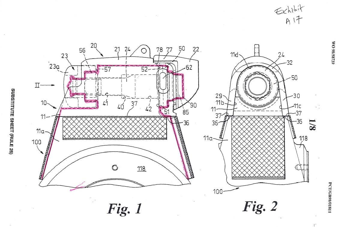
591 Dr Huggett acknowledged that the profile of the tooth core and the bolt together, which Dr Huggett then relied upon to form his opinion that the profile of the tooth core and bolt together formed the support body, bore “no resemblance to”, and indeed it was “substantially different” from, the examples of “tooth shaped” tooth constructions in the other prior art to which he had been taken.
592 I do not consider that claim 1 of the Patent, and the claims dependent upon it, are anticipated by the disclosure in the 739 Patent.
593 For the same reasons that I do not consider claim 1 of the Patent to be anticipated, I do not consider that the omnibus claims, claims 10 and 17, are anticipated.
594 The 165 Patent describes a tooth cap assembly for use in a “mineral processing machine” (or mineral sizer) that includes a tip (pick) that is capable of being rigidly held in a cover (a “supporting cap body”) without movement and is easy to replace. Two different embodiments for the tooth construction are disclosed.
595 The experts agreed that the tooth cap assembly described in the 165 Patent has a removable tip which is bolted to a removable main cover bolted on a support body. Wear plates are attached to the outside surfaces of the main cover (preferably by welding), principally to prevent damage to the bolts, and minimise ingress of ore fines into the bolt cavities. The wear plates are located on the front, rear and top sections of the main cover. The second embodiment of the main cover has side walls which include T slots, the purpose of which is to allow easier fitment of the main cover to the support body and allows the bolts to better secure the cover to the support body. The tip has an elongated tail, with a tapered portion that allows the tip to lock into the tapered bore of the main cover and is secured with a nut at the end of the tail.
596 Dr Huggett prepared the below diagram showing the attachment of the multiple covers to the support body in the 165 Patent, and the location of the bolts.
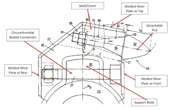
597 The experts agreed that the 165 Patent discloses:
(a) the support body as the component the pick is seated into, as well as the support body that is attached to the sizer ring;
(b) the “support body” and “supporting cap body” are all covers;
(c) although the terminology in the 165 Patent suggests that there are multiple support bodies for each tooth cap assembly, it is considered that there is only one support body with multiple covers;
(d) the covers include “the cap body”, “cap”, “support”, “supporting body”, “support body”, “supporting cap body”, depending on which embodiment is being described; and
(e) the primary connection of the covers to the support body is via a bolted connection.
598 Dr Huggett agreed that there is no disclosure of direct welding between the front cover and the front face, and no welding through the bolt hole to the support body.
599 However, Dr Huggett considered that the external plates are weldingly secured “in principle” and that the 165 Patent disclosed all the integers of claim 1 of the Patent. Dr Huggett considered that the “weldingly secured” integer was present in the 165 Patent in two ways. First, it was sufficient to satisfy Dr Huggett’s definition of “indirect” welding if only one part of a “chain of securance” involved welding. Dr Huggett’s definition was sufficiently broad to embrace where the wear plate was welded to the cap which was itself bolted to the support body.
600 Alternatively, Dr Huggett observed in the integer chart in his affidavit that “it would have been a routine design choice to either directly or indirectly weld the front cover to the front face by running a fillet weld around the plate, or to the support body by indirect welding the front face to the sides of the cap”.
601 Mr de Vos did not consider the “weldingly secured” integer to be disclosed by the 165 Patent. His evidence was that there was no front or rear cover “weldingly secured” (either directly or indirectly) to the support body, as the covers in the 165 Patent are bolted to the support body. The outer protection wear plates are welded to the outside of the tooth cap, but the tooth cap is secured to the mounting boss or support body by a bolt which passes through the support body, so that there is no unbroken chain or “direct line” of weld securing the wear plates to the support body. The prime connection of the cap to the support body is a bolted connection.
602 Camco relied on Dr Huggett’s weldingly secured “in principle” to submit that the 165 Patent disclosed all the integers of claim 1 of the Patent.
603 According to my construction of the “weldingly secured” integer it would be satisfied if there was an unbroken chain of weld joining, for example, the rear cover to the side cover to the support body. The phrase does not include the situation where one component is welded to another which is then bolted to the support body.
604 There is no implicit or explicit disclosure of welding the cap to the support body in the 165 Patent: AstraZeneca at [347] to [350]. Camco’s attempt to fill the gap in the disclosure with what it submits is part of the common general knowledge is impermissible. As the Full Court explained at [352] of AstraZeneca:
Although the common general knowledge can be used in a limited way to construe a prior art document, s 7(1) does not permit the common general knowledge to be used as a resource that can be deployed complementarily to arrive at a disclosure which the document alone, properly construed, does not make. If it were otherwise, the separate requirement of an inventive step to support a patentable invention (see s 18(1)(b)(ii) of the Act) would be otiose.
(Emphasis added.)
605 Claim 1 of the Patent is not anticipated by the disclosure in the 165 Patent.
606 Camco contends the invention disclosed in the Patent was obvious at the priority date in light of the common general knowledge alone, and in combination with each of the 739 Patent and the 165 Patent made publicly available before the priority date.
607 The requirement for an invention to involve an inventive step is set out in s 7 of the Patents Act. The applicable version of ss 7(2) and 7(3) provides:
(2) For the purposes of this Act, an invention is to be taken to involve an inventive step when compared with the prior art base unless the invention would have been obvious to a person skilled in the relevant art in the light of the common general knowledge as it existed in the patent area before the priority date of the relevant claim, whether that knowledge is considered separately or together with the information mentioned in subsection (3).
(3) The information for the purposes of subsection (2) is:
(a) any single piece of prior art information; or
(b) a combination of any 2 or more pieces of prior art information;
being information that the skilled person mentioned in subsection (2) could, before the priority date of the relevant claim, be reasonably expected to have ascertained, understood, regarded as relevant and, in the case of information mentioned in paragraph (b), combined as mentioned in that paragraph.
608 Section 7(2) of the Patents Act is a deeming provision. Its legal effect is that the invention claimed in each asserted claim is “deemed to involve an inventive step when compared with the prior art base” unless Camco establishes that the invention, as claimed, would have been obvious to the person skilled in the art, having regard to the common general knowledge and any available s 7(3) information: AstraZeneca at [200].
609 An inventive step only requires a “scintilla of invention”: Meyers Taylor Pty Ltd v Vicarr Industries Ltd (1977) 137 CLR 228 at 249 (Aickin J). The combination defined by the claimed invention must always be something that would have been “very plain” to the person skilled in the art: Aktiebolaget Hassle v Alphapharm Pty Ltd (2002) 212 CLR 411 at [34].
610 The modified Cripps question as endorsed by the High Court in Aktiebolaget Hassle at [53] is often posed:
Would the notional research group at the relevant date, in all the circumstances, which include a knowledge of all the relevant prior art and of the facts of the nature and success of chlorpromazine, directly be led as a matter of course to try the -CF3 substitution in the '2' position in place of the -C1 atom in chlorpromazine or in any other body which, apart from the -CF3 substitution, has the other characteristics of the formula of claim 1, in the expectation that it might well produce a useful alternative to or better drug than chlorpromazine or a body useful for any other purpose?
(Original emphasis.)
611 The test has been alternatively expressed as inviting consideration of whether the steps that would have been taken by the skilled person were of a “routine” character to be tried as a matter of course. However, it remains necessary to consider whether or not the person skilled in the art would have reasonably expected to have arrived at the claimed invention from the starting point of the common general knowledge and s 7(3) information alone: Generic Health Pty Ltd v Bayer Pharma Aktiengesellschaft (2014) 106 IPR 381 at [71].
612 The approach of assessing obviousness by asking whether it would have been “worthwhile” or “obvious to try” the claimed invention has firmly been rejected: Aktiebolaget Hassle at [34] and [66] to [76].
613 Camco submits that none of the claims of the Patent involve an inventive step over the common general knowledge.
614 Camco submits that the problem addressed in the Patent is the need for a robust tooth construction to withstand the large forces applied to break hard materials. The need for tooth constructions to be robust and withstand large forces was a known problem, and mining companies desired robust tooth constructions to increase their lifespan before repair was needed.
615 Camco relied upon Dr Huggett’s conclusion in his first affidavit:
I cannot find anything new in the combination of features in the Claims that I did not know before the Priority Date. The Claims cover welding plates in face to face contact onto various faces of teeth which is what was commonly done by mining companies and OEMs before the Priority Date. Cast and fabricated wear components were known and welding those fabricated wear components was known. The patentee has described what was already being done by mining companies at the Priority Date to increase the life of mineral sizer teeth and similar teeth in other mining applications, such as rolls crushers.
As I discussed earlier in this affidavit, if I was tasked with designing a robust tooth construction, I would have inevitably tried one or a combination of applying cover plates to wear faces, using different materials, or changing the shape of the tooth. Where cover plates are used, it was a well known engineering principle that spreading the load by seating a plate in face to face contact allows greater forces to be applied than a point load or having gaps between surfaces. Welding cover plates was also widely used at the Priority Date.
616 Camco submits that the response of Mr de Vos in the joint session also shows that the invention does not involve an inventive step over the common general knowledge. Mr de Vos was asked to assume that he had been given the task of making a robust tooth construction for a mineral sizer at November 2003 and that he knew of mineral sizer horns and covers being applied to horns. Camco submitted that after making those assumptions, Mr de Vos:
[A]cknowledged that he knew he would plainly want to get the cover in contact with the front of the horn. He knew that this would permit the transmission of forces. He agreed this was an obvious path to take, and did not require anything beyond the ordinary application of his skill. He agreed that the same would apply for the rear cover. He agreed that the first option was to get the cover and the front of the horn together. Then it was necessary to secure that cover to the horn. His view was that back in November 2003 he would have opted to secure that cover to the horn by bolting. But he agreed he would have known that the other option, or that one of the other options then available, was welding. He agreed that welding and bolting each have their advantages, and disadvantages. He agreed that each of them however was an obvious path to take and that neither required anything beyond the ordinary application of his skills. He would have followed the same process for the rear cover and any top and side covers.
617 Camco contends that there is no inventive step involved in choosing one of two obvious paths: in this case, the obvious path of welding over the equally obvious path of bolting.
618 MMD submits that the application of covers to mineral sizer horns was not part of the common general knowledge and that the relevant design process does not simply reduce to the choice between two obvious alternative methods of attaching covers to the horn: welding versus bolting.
619 As to the choice between bolting and welding, MMD relies on Mr de Vos’ response in the joint session to submit that it is not a choice between two obvious methods of attachment. When he was asked whether he would have tried welding, Mr de Vos explained that he would not have done so, due to the significant time, expense and difficulty associated with removing the worn covers from the support body during maintenance and the significant time, expense and difficulty associated with welding the replacement covers to the support body.
620 MMD observes that both Mr de Vos and Dr Huggett were tasked with designing “a robust tooth construction” for use in hard rock mining before the priority date. MMD says that what Mr de Vos did when he worked on a tooth construction at ABON and what Dr Huggett did when he worked on a bolted MMD tooth construction for Rio Tinto is powerful evidence of non-obviousness.
621 MMD submits that Dr Huggett’s evidence as to the design of a robust tooth construction is contaminated with hindsight. MMD submits that Dr Huggett began his design process with full knowledge of the claimed invention and the problem to be solved as described in the Patent, and the five prior art patents initially asserted. According to MMD, Dr Huggett’s reasoning involves an ex post facto analysis, based on knowing the claimed solution. Dr Huggett knew the end result, the claimed invention, and reverse engineered a design process that inevitably ended up at the destination of the invention described in the Patent.
622 MMD submits that many of Dr Huggett’s assertions as to what was commonly done, used or known by equipment manufacturers or operators at the priority date were not borne out when they came under scrutiny in the joint session.
623 MMD submits that an examination of how Dr Huggett arrived at his inevitable conclusion reveals that his reasoning was irretrievably contaminated by hindsight.
624 Dr Huggett was shown the Patent before he was provided with the prior art. He was not asked to carry out any literature searches or give evidence as to what he would have done in light of the common general knowledge alone or the common general knowledge and the prior art before he saw the Patent.
625 The plurality in Aktiebolaget Hassle warn against the dangers of hindsight at [21]:
The defendant to an infringement action who cross-claims for revocation on the ground of obviousness bears the onus of establishing that case. This obliges the defendant to lead evidence looking back to the priority date, sometimes, as here, many years before trial. In those circumstances, the warnings in the authorities against the misuse of hindsight are not to be repeated as but prefatory averments and statements of trite law. The danger of such misuse will be particularly acute where what is claimed is a new and inventive combination for the interaction of integers, some or all of which are known. It is worth repeating what was said by Lord Diplock in Technograph Printed Circuits Ltd v Mills & Rockley (Electronics) Ltd [1972] RPC 346 at 362. See also Olin Corporation v Super Cartridge Co Pty Ltd (1977) 180 CLR 236 at 262-263:
“Once an invention has been made it is generally possible to postulate a combination of steps by which the inventor might have arrived at the invention that he claims in his specification if he started from something that was already known. But it is only because the invention has been made and has proved successful that it is possible to postulate from what starting point and by what particular combination of steps the inventor could have arrived at his invention. It may be that taken in isolation none of the steps which it is now possible to postulate, if taken in isolation, appears to call for any inventive ingenuity. It is improbable that this reconstruction a posteriori represents the mental process by which the inventor in fact arrived at his invention, but, even if it were, inventive ingenuity lay in perceiving that the final result which it was the object of the inventor to achieve was attainable from the particular starting point and in his selection of the particular combination of steps which would lead to that result.”
626 Dr Huggett did not approach the task of “designing a robust tooth construction” that would be secured to the horn armed only with matters which formed common general knowledge or common general knowledge as extended by s 7(3). He came to that task having undertaken a detailed comparison of the Patent and the prior art, and with his own personal experience of the Rio Tinto tooth construction.
627 Dr Huggett was given the Patent and copies of five prior art patents for the purposes of preparing his evidence on invalidity. Of the prior art patents, only the 739 and 165 Patents (discussed above) were relied on by Camco for its s 7(3) case at the hearing, and were the subject of cross-examination. Dr Huggett’s evidence was that he was not familiar with any of the prior art patents before he was provided with them. None of the five prior art patents formed part of the common general knowledge of the person skilled in the art.
628 When explaining why he considered that the invention disclosed in the Patent was obvious, Dr Huggett conceded that when he explained the way he could design a tooth construction at the priority date, he started with the solution presented in the Patent which he described as “face to face contact from a load sharing perspective”.
629 Dr Huggett was not aware of problems with bolted tooth constructions at the priority date, and only became aware of problems from reading the prior art. Dr Huggett did not recall reading the 739 and 165 Patents before they were provided to him and agreed he was unaware of their contents prior to preparing his evidence in this case. Nor was he familiar with the mineral sizers discussed in the prior art documents at the priority date.
COUNSEL: Yes. Am I right in thinking – sorry. Am I right in understanding your evidence that you suggest that you would have pursued welding as an option for joining the covers to the horn at the priority date despite the fact it was impractical and involved a significant cost?
DR HUGGETT: In the context of what I believe the patent to try and achieve, which is giving that ..... face-to-face contact from a load sharing perspective, yes, I would have considered it. There’s only a limited number of options in what you can do to join these components together, and it was – in the prior art they were saying that one of the issues was that the parts become loose and they – with a bolted option. So surely you would look – I would look at a welded process as minimising that movement.
COUNSEL: And the reason that you referred there to the face-to-face contact was because that was the problem that you had – sorry, that was the solution that was presented in the 510 patent?
DR HUGGETT: That’s what I believe it is. Yes, correct.
COUNSEL: Yes. And you started with that in your mind when you explained the way you would go about bringing into existence a tooth construction in November 2003?
DR HUGGETT: Correct.
630 To the extent that the 739 and 165 Patents mention the performance of bolts in bolted tooth constructions, it is not to suggest that there are problems with the bolts. Rather the prior art patents convey that the bolts perform well in tooth constructions. The 739 Patent describes that “the spigot” (bolt) is “immovably anchored to the tooth core” and that it will remain so during use when the tooth construction will be “exposed to repeated high impact forces”. The 165 Patent suggests that it provides a means of anchoring a pick (with a bolt) in which the pick is capable of being rigidly held in a supporting cap body without movement and yet, after use, is easy to replace.
631 As a result, I consider that Dr Huggett’s evidence as to the design of a robust tooth construction was impermissibly assisted by hindsight.
632 Both Camco and MMD approach the problem to be addressed as being the design of a robust mineral sizer tooth construction (or “an improved mineral sizer tooth/horn”) to withstand the large forces applied to break hard minerals (the design task). The person skilled in the art looking to carry out the design task at the priority date is equipped with the common general knowledge in the field at that time.
633 Tooth/horn covers for protecting the support bodies of mineral sizers were not part of the common general knowledge at the priority date. Nor were methods for attaching tooth covers to mineral sizer support bodies. Whilst bolting and welding may have been examples of well-known methods for attaching components to equipment in the mining industry at the priority date, the use of bolts or welding to attach covers to mineral sizer teeth/horns, particularly for use in hard rock crushing was not part of the common general knowledge
634 Bolted covers existed in the prior art patents and Dr Huggett’s evidence in the joint session was that he had seen covers on the Rio Tinto sizer before the priority date. However, bolted covers, and the problems (if any) associated with them, were not part of the common general knowledge of the person skilled in the art.
635 Dr Huggett did not approach the task of “designing a robust tooth construction” that would be secured to the horn armed only with matters which formed common general knowledge or common general knowledge as extended by s 7(3). As I observed earlier, Dr Huggett came to that task having undertaken a detailed consideration of the Patent and the non-common general knowledge prior art, including his knowledge of the Rio Tinto mineral sizer tooth covers.
636 Dr Huggett moved straight to adopting covers, rather than any of the other possibilities he considered when confronting a similar design task for the Rio Tinto sizer, and from there to choosing welding over bolting as the connection method.
637 Dr Huggett sought to assert in the joint session that “the issue, from what I’ve looked at with some of the bolted connections, is the risk of fatigue through the bolt arrangement. So one of the things you would look at would be to eliminate that bolt because you’re going to eliminate that fatigue process”. This suggestion was not made in Dr Huggett’s written evidence, and it did not arise in the context of his only experience about a bolted cover, given in the joint session, being that of the Rio Tinto MMD sizer. The only other bolted sizer covers were to be found in the five prior art documents, the two of which remaining in the invalidity case did not mention problems with the bolts.
638 Dr Huggett’s evidence as to the use of welding to prolong the life of mineral sizer teeth was not supported by Mr de Vos, or corroborated by any contemporaneous documents. Having read the Patent before giving his evidence it is not surprising that Dr Huggett chose the welding route rather than bolts.
639 The design task is set in circumstances where covers of mineral sizer horns were not part of the common general knowledge.
640 A skilled person who was undertaking the design task at the priority date would be aware of the following:
(a) The front and rear faces of mineral sizer horns are subject to very large cyclical forces during rock crushing/snapping operation.
(b) Mining equipment had to perform the desired function adequately, be reliable, and be easy to maintain and restore, with easily replaceable parts.
(c) Mining companies have maintenance schedules, and wearable parts need to last at least the length of the maintenance cycle.
(d) Mining companies desire to minimise the shutdown time required for maintenance to be carried out.
(e) There are significant time and cost savings to maintaining a mineral sizer on site, and that if work was done off-site, there were potential delays in getting a refurbished device back into the sizer.
(f) Mining companies prefer work to be done on site and in situ where it is possible and that they are conscious of worker safety.
(g) Machinery or equipment failure between scheduled maintenance cycles can be very costly in terms of both time and mine profitability.
641 There are a variety of techniques available to the person skilled in the art looking to design a robust tooth construction. Examples include those considered by Dr Huggett when he was retained to extend the wear life of the Rio Tinto sizer teeth:
(a) change the materials used to cast the horn;
(b) change the profile shape of the horn;
(c) addition of wear plates to the horn;
(d) addition of covers – front and rear – to the horn;
(e) plurality of covers covering the horn; and/or
(f) welding and hard facing to build up the worn sections of the horn.
642 When each expert was actually faced with the design task at the priority date, neither Mr de Vos nor Dr Huggett considered attaching a plurality of covers to the horn. Instead, Mr de Vos chose to change the materials used to cast the horn and Dr Huggett chose to change the profile of the horn.
643 If the person skilled in the art chose to select the plurality of covers from the range of options available to pursue, there were at least three different methods of attaching the covers to the horn and to each other: bolting, clipping or welding.
644 There were no known problems with bolts as a means of connection of covers to mineral sizer horns in the common general knowledge. Both experts agreed that it was easier to remove and replace bolted components than welded components.
645 The person skilled in the art considering attachment methods would appreciate that the removal and welding of replaceable covers to mineral sizer support bodies would be difficult, time consuming, costly, impractical and dangerous. Replacement of welded covers requires:
(a) removing worn covers with an air arc gouger, which heats up metal until it is molten and then blows it away with high velocity air jets;
(b) undertaking a magnetic particle inspection to identify gouge marks and cracking;
(c) digging around gouge marks and cracks and filling the cavities with weld;
(d) grinding the new welds; and
(e) preheating the surfaces to which the weld is to be applied.
646 Even if safety standards were more relaxed at the priority date, it would still be dangerous for the arc gouging and welding to be undertaken by workers on the mineral sizer shafts in situ, so the maintenance work involving arc gouging and welding would be carried out in a workshop, rather than in situ. Removal of the sizer shafts and transport to a workshop would add to the time taken for refurbishment.
647 Welding of high tensile materials results in a reduced fatigue capacity of the welded area. Repeated welding and arc gouging will increase the incidence of cracking over time because of the repeated application of heat to the horn. The horn may eventually reach a stage where there are so many cracks it is not economical to keep building it up. The existence of cracks increases the risk of catastrophic failure, in which the horn breaks off the sizer ring.
648 The skilled person selecting an attachment method would not select welding as a matter of course, due to the significant time, expense and difficulty associated with removing the worn covers from the support body during maintenance and the significant time, expense and difficulty associated with welding the replacement covers to the support body. That work is significantly more difficult, and not possible to carry out in situ, than removing a bolted tooth construction.
649 If tasked with the design task, the person skilled in the art at the priority date would not be led as a matter of course to try attaching a plurality of covers to a mineral sizer horn and attaching the covers to the horn and each other by welding. The design process to reach the robust tooth construction is more complex than selecting a method by which to attach covers to a mineral sizer horn from two equally obvious options. Even if that were the correct analysis, I do not consider, for the reasons just outlined, that in the context of mineral sizer refurbishment, welding was in essence interchangeable with bolting as a method for attaching covers to mineral sizer horns.
650 The person skilled in the art equipped with the common general knowledge would not inevitably be led to the invention as claimed in each Asserted Claim.
651 Camco’s inventive step argument based on Mr de Vos’ responses in the joint session does not assist. It takes as the analytical starting point the last step in the design process that I have just outlined. Mr de Vos was asked to assume, contrary to my finding, that mineral sizer horn covers were known. Mr de Vos was asked about welding in general. Mr de Vos’ agreement with the proposition that “at the priority date, people did in fact weld components of covers to tooth horns” was clearly based on the existence of prior art showing welding had been done on covers and wear plates had been welded to support bodies. That prior art was not part of the common general knowledge.
652 Camco’s submission that welding and bolting were the two obvious alternatives ignores Mr de Vos’ qualifications as to why welding would not be an obvious choice to him, and relies on his responses to welding generally as a well-known method of attachment, rather than in the specific context of mineral sizer refurbishment.
653 Camco submits that each of the s 7(3) documents discloses a tooth construction in a form which would inevitably lead the skilled worker to the invention as claimed in each of the Asserted Claims.
654 MMD submits that neither the 739 or 165 Patents would satisfy the requirements of s 7(3) as neither of them would be ascertained, understood and regarded as relevant by the person skilled in the art. MMD contends that the person skilled in the art would not conduct a patent search.
655 Dr Huggett was not familiar with either of the 739 or 165 Patents before he was provided with copies of them.
656 Dr Huggett gave general evidence as to how he “regularly searched for and read patents” prior to the priority date. His evidence was that he searched for patents by:
checking gazetted information I received from the patent offices, eg the Australian Official Journal of Patents, undertaking library searches from the University of Western Australia which often resulted in references to patents, reading of trade journals which referred to patents and receiving copies of patents that I requested from my own patent attorneys at the time.
657 Dr Huggett’s evidence was that when he read the patent office gazettes, he looked for patent titles that he thought were relevant to the field he was interested in and looked for patentees that he knew operated in that field. Dr Huggett would then try to obtain a copy of the patent. Once the patent databases became readily searchable online, he was able to search for and locate patents himself online by entering keywords about the technology field of interest, or the names of patentees or companies in the relevant technology field.
658 Dr Huggett gave general evidence in his affidavit that he would have used “mineral breaker”, “tooth”, “tooth construction”, “teeth” as keywords. In the joint session that he added that he would put in keywords related to a sizer. In each case in his affidavit, the keywords selected by Dr Huggett were selected with the full glare of hindsight with the particular prior art patent in front of him. For example:
The 739 Patent is titled “Mineral Breaker” and the patentee is again MMD Design & Consultancy Limited. I would have ascertained a copy of this patent if I was solving the problem contemplated in the MMD Patent because the title of “mineral breaker” would have jumped out at me in a gazette search or in an online search as being in the same technology area, and I knew at the Priority Date that MMD was one of the major suppliers of mineral sizers so its patents would have been of interest to me. The Abstract of the 739 Patent refers in the first line to “a mineral breaker” and “tooth construction”, which are both keywords I would have searched for in this technology area, or would have instructed my patent attorneys to search for in conducting a search for me.
659 Dr Huggett gave no evidence as to what a gazette search would entail, whether it involved physically or electronically looking at each gazette, or whether they were electronically searchable. There was no evidence as to keywords that he would have chosen without the benefit of knowing what prior art needed to be found. There was no evidence as to how many results would be returned in his online searches, with his proposed keywords and why he would have selected the 739 and 165 Patents from the other potentially relevant search results. Dr Huggett accepted that he did not know what volume of information he would find if he had done a search, nor whether he would have found the prior art patents.
660 Mr de Vos’s evidence was that he did not read patents and would not have conducted a patent search if tasked with the design task.
661 I do not consider that the person skilled in the art would regularly read and search for patents. Even if they did, the evidence does not establish that the person skilled in the art would ascertain the 739 and 165 Patents. The s 7(3) inventive step case fails at this point.
662 Camco contends that both the 739 and 165 Patents disclose a tooth construction in a form which would inevitably lead the skilled worker to the invention. Whilst welding of parts may not be disclosed in the 739 and 165 Patents to the extent of the claim language, Camco contends that does not result in the claims lacking obviousness. According to Camco, welding was well-known as another way of joining components, and was in essence interchangeable with processes such as bolting.
663 MMD submits that Camco’s submission entirely overlooks the detailed and considered evidence of Mr de Vos that welding was not only not interchangeable with processes such as bolting, but also, significantly more difficult, expensive and inconvenient.
664 For the reasons I discussed above, I do not consider that welding was in essence interchangeable with bolting for the purposes of attaching covers to mineral sizer horns.
665 Mr de Vos explained that he would expect the tooth constructions described in the 739 Patent to be suitable for use, reliable and easy to maintain. He observed that the aim of the invention described in the 739 Patent is to hold the shell securely in place and allow worn tooth constructions to be easily removed. The movement of the covers is prevented by the use of the bolt. Mr de Vos identified the key benefit of the 739 Patent to be the bolting of the covers which enables their ready removal, meaning no repair would be required to the support bodies to allow new covers to be installed.
666 Dr Huggett accepted that the general aim of the 739 Patent was to provide a tooth construction where the covers are securely held in place but could be easily removed and renewed, and that the ease of removal and replacement is an important design consideration. Dr Huggett agreed that there was nothing on the face of the 739 Patent to suggest that it would not be easy to maintain, or that would cause him to think it would not work efficiently.
667 In the joint session, Dr Huggett agreed that if the constructions of the 739 Patent were found to wear, or to wear too quickly, the skilled person had a variety of options: they could increase the thickness of the covers, manufacture the covers from different hardened materials, apply hard facing or carbide studs or wear plates, seek to improve the reliability of the bolt, or seek to use a fastener or keyed system to hold the covers to the support body.
668 Both experts agreed that it was easier to remove and replace bolted components than welded components. The skilled person would not select welding as a matter of course, due to the significant time, expense and difficulty associated with removing the worn covers from the support body during maintenance and the significant time, expense and difficulty associated with welding the replacement covers to the support body. That work is significantly more difficult, and not possible to carry out in situ, than removing a bolted tooth construction.
669 Mr de Vos explained that he would expect the tooth constructions described in the 165 Patent to be suitable for use, reliable and easy to maintain. If (against his expectation) the tooth constructions described did require modification, depending on the problem he encountered, he would try one of the following options:
(a) increase the thickness of the covers, manufacture the covers from different material, or apply hard facing;
(b) increase the hardness of the tip; or
(c) consider the use of wear plates over the recesses around the nut and bolt head.
670 If contrary to his expectation the bolts failed after testing, Mr de Vos would aim to improve the reliability of the bolts. For the reasons set out above, Mr de Vos would not use welding to attach the covers to the support body.
671 Camco has not established that the person skilled in the art equipped with the common general knowledge and one of the 739 or 165 Patents would inevitably be led to try as a matter of routine the invention as claimed in the Asserted Claims.
18. SECTION 40: CLARITY AND FAIR BASIS
672 The test for fair basis is the test of whether there is a “real and reasonably clear disclosure” in the specification of what is claimed: Lockwood Security Products v Doric Products Pty Ltd (2004) 217 CLR 274 at [69].
673 Camco’s fair basis case is based on a construction of the “face to face contact” integer which does not require the cover and the corresponding face of the support body to be in physical contact. Camco says that, properly construed, the claim language requires that the two relevant components be in direct physical contact with each other across the entirety of each component (in other words, minor or fleeting instances of direct physical contact do not meet the requirements of the claim). Camco draws attention to the embodiments of the invention which are disclosed in the specification, all of which disclose components that are in direct physical contact with each other, consistent with Camco’s construction of the “face to face contact” integer. Camco contends that the Patent does not contemplate, by way of disclosure of embodiments of the invention, any other way of performing or meeting that claim language than the components being in direct physical contact.
674 I have rejected MMD’s construction of the “face to face contact” integer. In those circumstances, Camco makes no fair basis challenge to the claims of the Patent on the basis of the construction of the “face to face contact” integer.
675 Camco propounded a clarity challenge based on the use of “and/or” in the phrase “fixedly secured to one another and/or to the support body” in claim 1. According to Camco, the “and/or” term in the phrase “fixedly secured to one another and/or to the support body” means that each of the covers is fixedly secured to:
(a) one another and not the support body; or
(b) one another and the support body; or
(c) the support body but not one another.
676 I consider that a person skilled in the art reading the claim in a common sense manner, in the context of the specification, and with an eye to making the invention work, would not construe the claim in accordance with option (a). Option (a) makes no sense as none of the covers forming the shell would be attached to the support body and would be likely to fall off. This is consistent with Dr Huggett’s view that option (a) would not be practical because the shell would be loose from the support body and therefore fall off during use.
677 Camco’s other fair basis challenge is based on the absence of any disclosure in the Patent of option (a). MMD submits that Camco’s option (a) is not open, and that each of options (b) and (c) (that the plurality of covers are fixedly secured to either the horn or to the horn and to each other) are disclosed. On the basis of my construction, Camco’s other fair basis challenge must fail.
678 Camco contends that no patentable invention is disclosed in the Patent because the combination of integers is a mere collocation, which is unpatentable.
679 The law in relation to mere collocation is conveniently summarised by the Full Court in Smith & Nephew Pty Ltd v Wake Forest University Health Sciences (2009) 82 IPR 467 at [16]–[24]. It may be accepted that, in a combination patent, the elements of the claimed combination must work together to produce one result. The integers must interact to bring about the desired result.
680 Where a claimed “combination” consists only of integers which do not interact with each other to produce a new result or product it is not a manner of manufacture. Rather, it is a “mere collocation of separate parts”, each performing its own separate function, which is unpatentable: Firebelt Pty Ltd v Brambles Australia Ltd (2002) 54 IPR 449 at [21]; Wake Forest at [16].
681 The horn, the covers, and the welding which secures the covers to the horn and the face to face contact between covers and the horn interact to bring the desired result; the robust tooth construction capable of efficiently transmitting large forces.
682 It is apparent from the specification that the use of a support body clad in covers is an arrangement which works because the forces applied to the tooth construction can be efficiently transmitted between the covers and the horn, which are seated in a face to face contact. The covers are welded to the horn, which adds strength. The covers do not deform to the point where they fracture and the ability to construct the horn from malleable material reduces the risk it will snap. Further, the horn is solid because it has no bolt holes.
683 When the experts were asked to identify the meaning of the expression of the term “unitary tooth construction”, they agreed that “the unitary construction requires the covers and support body to work together as one complete body rather than individual components”. I consider that the elements of the tooth construction work together to produce one result, the claimed invention is a manner of manufacture.
684 Camco also submits that all the features of the Asserted Claims were known at the priority date, including in combination. Camco says that no patentable invention is disclosed because the combination of features does not bring about a new working inter-relationship between the features.
685 As Camco appeared to concede in its written submissions, this manner of manufacture argument has an affinity with its novelty and obviousness cases and I consider that it is best dealt with under those grounds of invalidity. As I have found there, certain of the integers of claim 1 of the Patent were not known by persons skilled in the art at the priority date, this aspect of Camco’s manner of manufacture argument cannot succeed.
686 For these reasons, I find the Camco Constructions do not infringe the Asserted Claims. By their supply of the Camco Constructions, Camco has not engaged in conduct that contravenes s 18 of the ACL. I also find the Asserted Claims of the Patent are, and at all material times have been, valid.
I certify that the preceding six hundred and eighty-six (686) numbered paragraph is a true copy of the Reasons for Judgment of the Honourable Justice Rofe. |
[REDACTED].
VID 340 of 2020 | |
MMD AUSTRALIA PTY LTD ACN 002 446 835 |

