
FEDERAL COURT OF AUSTRALIA
Vehicle Monitoring Systems Pty Limited v SARB Management Group Pty Ltd trading as Database Consultants Australia (No 8) [2023] FCA 182
ORDERS
DATE OF ORDER: |
THE COURT ORDERS THAT:
1. The applicant bring in draft minutes of order reflecting the conclusions in these reasons and the parties will be heard as to the terms of the orders.
Note: Entry of orders is dealt with in Rule 39.32 of the Federal Court Rules 2011.
BESANKO J:
Introduction
1 Vehicle Monitoring Systems Pty Limited (VMS) is the registered owner of two patents. The first patent is Australian Patent No. 2005243110 and bears the title “Method, apparatus and system for parking overstay detection” (the First Patent). The second patent is Australian Patent No. 2011204924 (the Second Patent) and has the same title. The invention is for identifying the overstay of a vehicle in a parking space and involves a battery-powered subterraneous detection apparatus (DA) to detect the presence of a vehicle in a parking space, the storage of data in that apparatus and the wireless transmission of that data to a data collection apparatus (DCA) and the indication by that device to an operator of identified instances of vehicle overstay in a parking space. The DCA may be portable and may retrieve data from the DA whilst the DCA is located in a moving vehicle. The wireless retrieval of data from the DA may be performed in response to receipt of a wireless wake-up signal from a DCA.
2 In earlier periods of time, the DA was referred to as a vehicle detection unit (VDU) or an in-ground unit (IGU). In earlier periods of time, the DCA was referred to as a drive-by enforcement vehicle (DEV) or the in-vehicle unit (IVU) and may consist of a handheld unit (HHU) and a transient middle tier (TMT) which is a belt-worn device which communicates with the HHU by Bluetooth.
3 VMS has brought a proceeding in this Court against SARB Management Group Pty Ltd (t/a Database Consultants Australia) (SARB) and the City of Melbourne (CoM) for relief in relation to alleged infringements of the patents.
4 The claim by VMS against SARB is that it has directly and indirectly infringed claims in the First Patent and claims in the Second Patent by its conduct in connection with vehicle detection sensors, systems and methods known as PinForce. There are three versions of SARB’s PinForce Sensors, PinForce Systems and PinForce Methods. The First PinForce Sensor and First PinForce System was made, sold, used and kept by SARB and the subject of authorisation by SARB to local government councils to use, between approximately October 2007 and December 2016 (PinForce Version 1). Between approximately January 2016 and December 2016, PinForce Version 1 was progressively upgraded to the Third PinForce Sensor and Third PinForce System.
5 The Second PinForce Sensor and Second PinForce System was made, sold, used and kept by SARB and the subject of authorisation by SARB to local government councils to use, between approximately November 2014 and December 2016 (PinForce Version 2). Between approximately November and December 2016, PinForce Version 2 was progressively upgraded to the Third PinForce Sensor and Third PinForce System.
6 The Third PinForce Sensor and Third PinForce System was made, sold, used and kept by SARB and the subject of authorisation by SARB to local government councils to use from approximately December 2014 (PinForce Version 3).
7 VMS seeks declarations, injunctions, orders for delivery up, damages or an account of profits and additional damages under s 122(1A) of the Patents Act 1990 (Cth) (the Act) against SARB.
8 The relief which VMS seeks against CoM is similar, although the relief is based on claims of direct infringement by CoM.
9 On 6 April 2020, the Court made the following orders in this proceeding:
1. Pursuant to r 30.01 of the Federal Court Rules 2011 (Cth), the quantum of any pecuniary relief be heard and determined separately from, and after, the determination of all issues of liability for infringement and patent validity.
2. For the avoidance of doubt:
(a) the issues of liability for infringement include all questions of liability for authorisation of any infringement, of liability for additional damages and any question of innocent infringement under s 123 of the Patents Act 1990 (Cth);
(b) the issues of quantum include the quantum of any additional damages and the allegations of double-recovery that are pleaded in paragraphs 10(b) and 11(b) of the First Respondent’s Defence filed 28 February 2020 and paragraphs 18(d) and 19(e) of the Second Respondent’s Defence filed 28 February 2020.
10 With respect to paragraph 2(a) of the orders, the following matters should be noted. The authorisation of infringements are actionable by reason of s 13 of the Act and VMS’s case is that SARB has authorised local government councils to use the PinForce Sensors and the PinForce Systems and that SARB has, in Australia, authorised other persons to use the PinForce Sensors and the PinForce Systems in one or more methods for identifying overstay of a vehicle in a parking space. As I have said, the claim for additional damages is made under s 122(1A) of the Act and is made against both respondents and under the orders, the Court is to determine liability for additional damages at this stage, but the quantum thereof (assuming liability for additional damages is established) is to be determined at a later stage. With respect to innocent infringement under s 123 of the Act, that is a basis upon which a Court may refuse relief by way of damages or an account of profits. The defence was raised by CoM in its Amended Defence, but it was not pursued by CoM in closing submissions and need not be considered any further.
11 With respect to paragraph 2(b) of the orders, the following matters should be noted. The allegations of double recovery are made by both SARB and CoM. The allegations are based on a Deed of Release dated 18 June 2014. SARB alleges in its Further Amended Defence that in relation to the PinForce Sensors and PinForce Systems, VMS has already been compensated under the Deed of Release for loss and damage alleged to arise from the supply or use of the PinForce Sensors and PinForce Systems which were sold or supplied by SARB prior to 9 May 2013, “including in respect of allegations arising from the use of those PinForce Sensors and PinForce Systems after that date”. SARB advances a similar plea in response to the alleged infringement of PinForce Methods. CoM advances equivalent pleas in its Amended Defence. The issue of double recovery is, like the quantum of additional damages (assuming liability for additional damages is established), to be determined at a later stage.
12 SARB has filed a Notice of Cross-Claim in which it seeks orders from the Court under s 138(3) of the Act revoking the First Patent and the Second Patent. SARB did not press in its closing submissions all of its pleaded grounds of invalidity.
13 The infringement issues of which there were four include issues of construction.
14 The first issue raises the meaning of “wake-up signal” in certain claims in the patents and whether PinForce Version 1 and PinForce Version 2 used a wake-up signal.
15 The second issue raises the construction of certain claims in the First Patent and whether the claims include a method or system where the determination of vehicle overstay is made by the DCA instead of the DA, it being accepted that in the case of PinForce Version 3, all capability of determining vehicle overstay in the DA has been removed and vehicle overstay is determined by the DCA.
16 The third issue raises a question as to the infringing acts for which SARB is liable because it has authorised those acts, or because it is a joint tortfeasor in relation to these acts. It is also necessary to consider in this context the construction of the Deed of Release dated 18 June 2014.
17 The final issue is whether SARB and CoM are liable for additional damages under s 122(1A) of the Act.
18 The grounds of invalidity which were pursued by SARB in its closing submissions are as follows:
(1) In relation to both patents, a failure to describe in the complete specification the best method known to VMS of performing the invention (s 40(2)(a));
(2) In relation to both patents, a failure by VMS to describe the invention fully (s 40(2)(a));
(3) In relation to both patents, a claim that VMS was not the inventor, or the sole inventor, of the invention and did not derive title from the inventor under s 15 of the Act and is not entitled to the First Patent or the Second Patent and it is just and equitable that the patents be revoked under s 138(3) of the Act;
(4) In relation to both patents, and in respect of those claims that do not involve the use of wake-up signals (i.e., claims 1 and 6–10 (to the extent they depend on claim 1) and 30–32 of the First Patent and claims 1–25 and 27–29 of the Second Patent), the claims are not fairly based on the matter described in the specification (s 40(3));
(5) In relation to both patents, the “invention” lacks an inventive step having regard to common general knowledge as it existed in the patent area before the earliest priority date of the claims (s 18(1)(b)(ii)). In relation to this ground, SARB relies only on common general knowledge and does not rely on any information of the kind identified in s 7(3) of the Act;
(6) In relation to the First Patent and if, contrary to earlier contentions made by SARB, claims 21–23 and 28–32 encompass a system in which the DCA determines vehicle overstay, then the First Patent, or at least those claims in the First Patent, should be revoked because:
(a) the Patent or those claims were obtained by false suggestion or misrepresentation (s 138(3)(d)); and
(b) they lack clarity and therefore do not comply with s 40(3); and
(c) they lack definition and therefore do not comply with s 40(2)(b).
19 CoM adopted SARB’s submissions in relation to infringement and invalidity. CoM confined its closing submissions (written and oral) to the reasons it contends an award of additional damages should not be made against it.
20 The relevant version of the Act and Regulations for the purpose of this proceeding is that in force prior to the amendments made to the Act by the Intellectual Property Laws Amendment (Raising the Bar) Act 2012 (Cth) (the Raising the Bar Act) and the Intellectual Property Legislation Amendment (Raising the Bar) Regulations 2013 (No 1) (Cth).
The First Patent
21 The complete specification of the First Patent was published and became open for public inspection on 24 November 2005. The application for the First Patent was made on 9 May 2005 and the patent was sealed on 13 March 2008. The priority date for the claims in the First Patent is 17 May 2004. The inventor named in the First Patent is Mr Fraser John Welch.
22 The First Patent identifies the field of the invention as relating to parking violations and, more particularly, to the detection of vehicles that overstay a defined time interval in parking spaces.
23 In the section in the specification entitled “Background”, the traditional methods of detecting vehicles that have exceeded the time limit of a parking space are described. A traditional method of placing a chalk mark on the tyre of a vehicle in a parking space and then returning at a later time to check if any of the vehicles with “chalked” tyres are still parked is described. The inefficiencies and disadvantages said to be associated with that method are identified and then a statement is made that a need thus exists for a method, an apparatus and a system that overcomes, or at least ameliorates, one or more of the described disadvantages.
24 In the “Summary” section in the specification, three aspects of the invention are described. Those descriptions of aspects of the invention correspond with claims 1, 11 and 21 respectively.
25 The first aspect is the provision of a method performed by a subterraneous DA for identifying overstay of a vehicle in a parking space. The method comprises the steps of detecting the presence of a vehicle in the parking space, processing and storing data relating to the presence of the vehicle in the parking space, determining whether the vehicle has overstayed a defined duration in the parking space, and wirelessly transmitting data relating to identified instances of overstay of the vehicle in the parking space.
26 The second aspect is the provision of a battery-powered apparatus for subterraneous installation for identifying overstay of a vehicle in a parking space. The apparatus comprises a detector adapted to detect the presence of a vehicle in the parking space, a processor coupled to the detector for processing and storing data received from the detector, and determining whether the vehicle has overstayed a defined duration in the parking space, a radio receiver coupled to the processor for receiving wake-up signals, and a radio transmitter coupled to the processor for transmitting data relating to identified instances of overstay of the vehicle in the parking space.
27 The third aspect is the provision of a system for identifying overstay of vehicles in parking spaces. The system comprises a plurality of battery-powered DAs for identifying overstay of vehicles in respective parking spaces when subterraneously installed, and a DCA for wirelessly retrieving data from the plurality of battery-powered detecting apparatuses. The DCA comprises a radio transmitter for transmitting wake-up signals to ones of the plurality of battery-powered DAs, a radio receiver for receiving data from woken-up ones of the plurality of battery-powered DAs, a memory unit for storing data and instructions to be performed by a processing unit, and a processing unit coupled to the radio transmitter, the radio receiver and the memory unit. The processing unit is programmed to process data received via the radio receiver and to indicate instances of vehicle overstay to an operator. The data relates to identified instances of vehicle overstay in the respective parking space.
28 The specification then contains the following passages (on p 3) which were the subject of expert evidence and of submissions by the parties:
Repeated wireless wake-up of a detection apparatus is typically performed irregularly with respect to time depending on the presence of a data collection device. Wireless retrieval of data may be performed in response to wireless wake-up of a detection apparatus. Overstay of a vehicle in a parking space may be determined at the detection apparatus by processing data received from the detector.
The data collection apparatus may be portable and may retrieve the data from the detection apparatus whilst the data collection apparatus is located in a moving vehicle. Data relating to presence of a vehicle may comprise presence duration of the vehicle in the parking space, movements of the vehicle in and out of the parking space with corresponding time-stamp information, and/or an indication of overstay of the vehicle in the parking space. Vehicle presence detection may be performed by a magnetometer that detects changes in the earth’s magnetic field caused by presence or absence of a vehicle in the parking space. The detection apparatus may be encased in a self-contained, sealed housing for subterraneous installation in a parking space. The radio transmitter and/or radio receiver may operate in the ultra-high frequency (UHF) band and may jointly be practised as a transceiver.
29 The specification contains nine drawings, diagrams or figures which are described in the specification.
30 The body of the specification states that a “small number of embodiments are described hereinafter, by way of example only, with reference to the accompanying drawings” and contains the following brief description of the drawings, diagrams or figures:
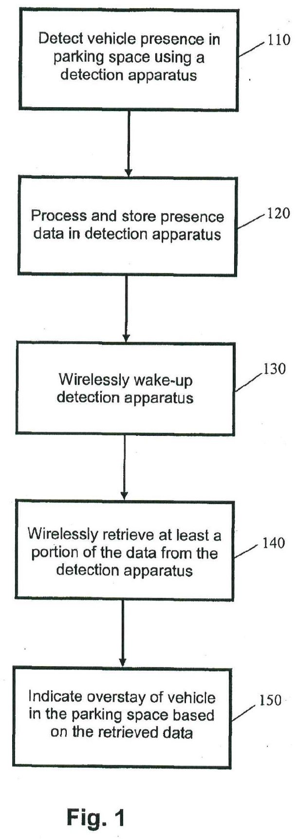
Fig. 1 is a flow diagram of a method for identifying overstay of a vehicle in a parking space;
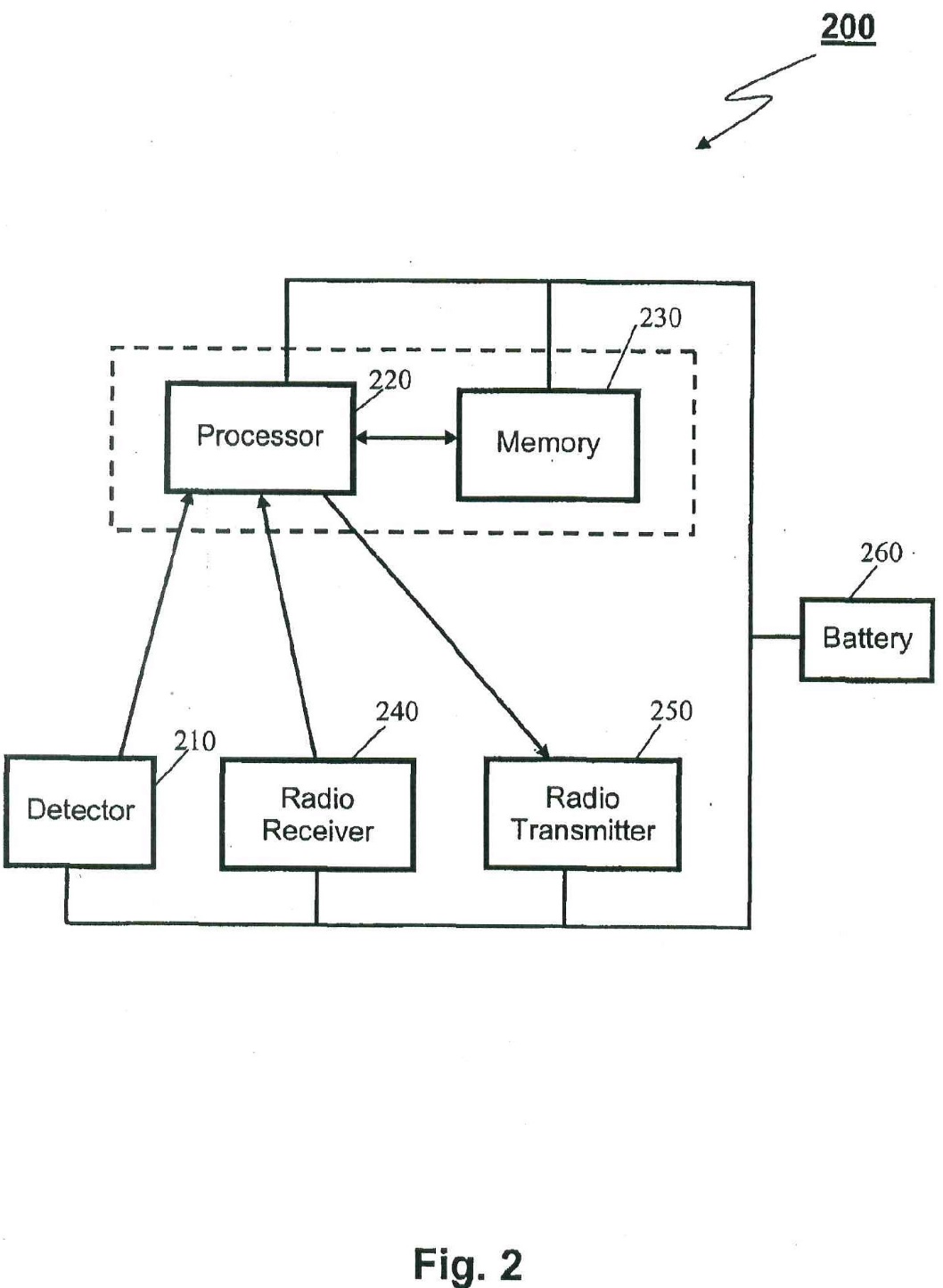
Fig. 2 is a block diagram of a detection apparatus for monitoring presence of a vehicle in a parking space;
Fig. 3 is a block diagram of a data collection apparatus for retrieving data from one or more detection apparatuses;
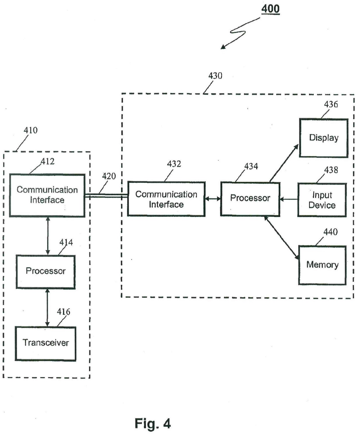
Fig. 4 is block diagram of another data collection apparatus for retrieving data from one or more detection apparatuses;
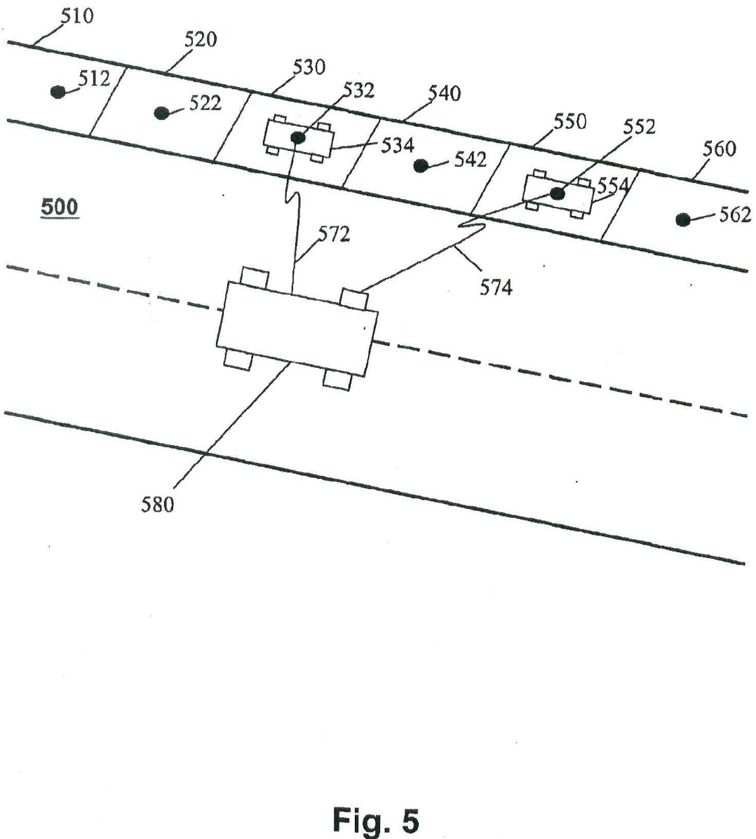
Fig. 5 is a schematic diagram of a system for identifying overstay of vehicles in parking spaces;
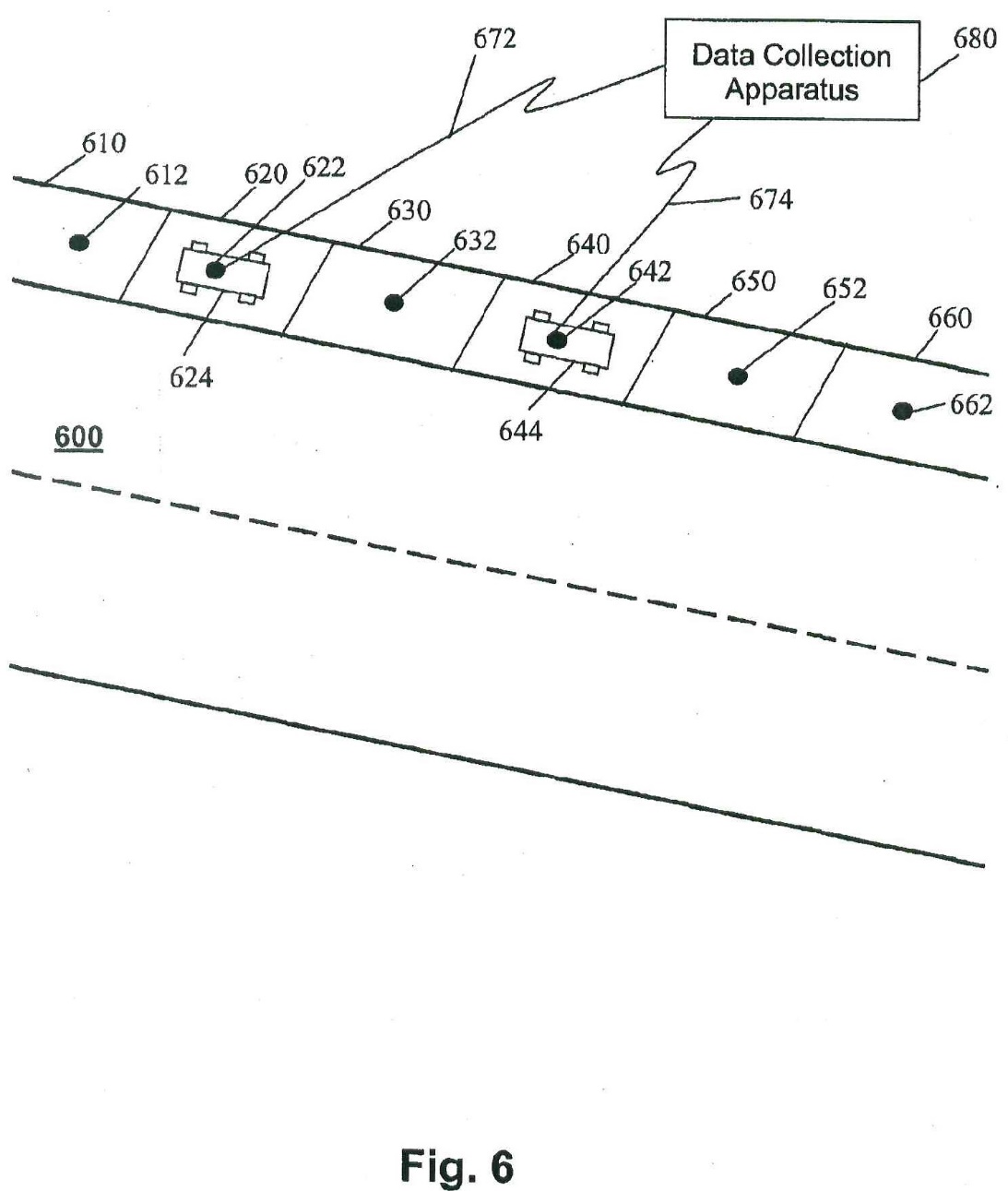
Fig. 6 is a schematic diagram of another system for identifying overstay of vehicles in parking spaces;
Fig. 7 is a schematic diagram of a further system for identifying overstay of vehicles in parking spaces;
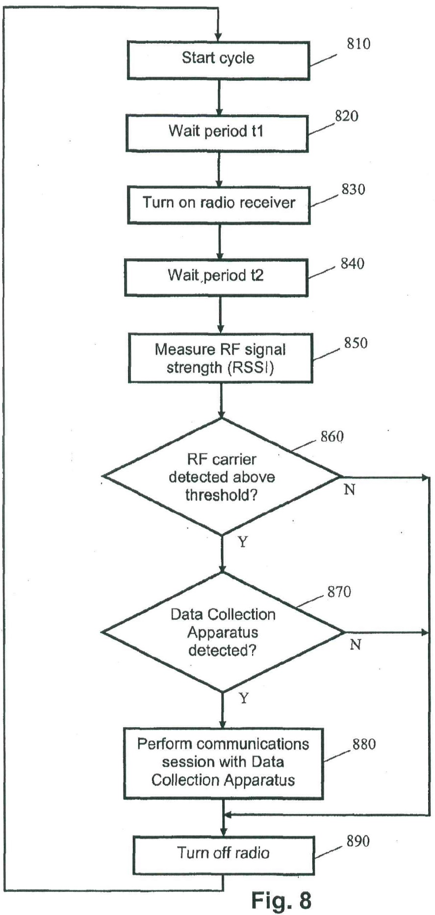
Fig. 8 is a flow diagram of a method of operating a detection apparatus according to an embodiment of the present invention; and
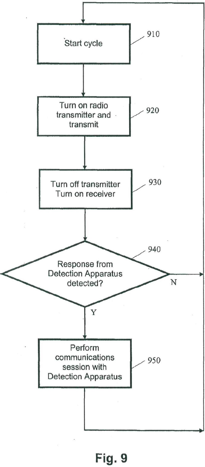
Fig. 9 is a flow diagram of a method of operating a collection apparatus according to an embodiment of the present invention.
31 Figures 1, 2, 4, 5, 6, 8 and 9 are as follows:
32 A detailed description of the methods, apparatuses and systems largely by reference to the figures, extends over approximately 10 pages in the specification. In light of the issues between the parties, it is necessary to set out the following passages:
In relation to Figure 1
Page 4
Fig. 1 is a flow diagram of a method for identifying overstay of a vehicle in a parking space. Presence of a vehicle in the parking space is detected using a detection apparatus in step 110. Data relating to presence of the vehicle is processed and stored in the detection apparatus at step 120. The detection apparatus is wirelessly woken-up at step 130 and at least a portion of the data is retrieved from the detection apparatus at step 140. Overstay of the vehicle in the parking space is indicated based on the retrieved data at step 150.
In relation to Figure 2
Fig. 2 is a block diagram of an apparatus 200 for monitoring presence of a vehicle in a parking space. ….
Page 5
The radio receiver 240 and radio transmitter 250 are practised as a 433 MHz ultra-high frequency (UHF) radio transceiver for transmitting and receiving radio signals to and from a data collection apparatus, respectively. Various UHF transceivers may be practised such as the Micrel MICRF501 transceiver, which requires to be turned on for approximately 1ms before RF carrier energy can be detected. However, persons skilled in the art would readily understand that other types of transmitters, receivers or transceivers may be practised such as low frequency (LF) transceivers. Other UHF frequencies may also be practised such as in frequency bands commonly used for low powered devices, including 868 MHz, 915 MHz and 2.4 GHz.
The battery 260 comprises a lithium manganese dioxide (LiMnO2) battery, which may be capable of providing the apparatus 200 with 5 to 10 years of continuous operation. Again, persons skilled in the art would readily understand that various other battery types may be practised in place of a LiMnO2 battery.
Page 6
The apparatus 200 generally operates in a low-power mode while detecting vehicle movements and presence in a corresponding parking space, which may be practised on a continuous or periodic (e.g., interrupt driven) basis to conserve battery life. Although the radio receiver 240 of the apparatus 200 consumes a small amount of power (relative to other radio receivers), the radio receiver 240 is only turned on for the shortest possible time duration at regular intervals to detect the presence of a data collection apparatus. At other times, the radio receiver 240 is turned off to conserve battery life.
…
In one embodiment, the apparatus 200 determines and maintains three primary types of information:
• Current Status
The current status of the parking space in terms of vehicle presence (i.e., present or not present) and the amount of time the space has remained in the present state.
• Historical Vehicle Movements
Page 7
A record of each vehicle movement in the parking space including the date and time of the movement.
• Overstay Situation
Detected when a vehicle remains in said parking space for a duration longer than a defined time interval.
The apparatus 200 may optionally be programmed with information relating to the hours of operation and parking time limits that apply to an associated parking space based on the time of day and day of week. Decisions concerning overstay can thus be made by the apparatus 200 based on different time limits that may apply to the parking space at different times.
Information may also be downloaded to the apparatus 200 using a radio receiver in the apparatus 200. The same radio receiver as used for receiving wake-up signals or a separate radio receiver may be used for this purpose. The downloaded information may comprise, but is not limited to:
• application firmware for the apparatus 200,
• a table of operating hours and time limits (time of day and day of week) applicable to an associated parking space,
• operating parameters for the apparatus 200, and
• information for updating or synchronising the real-time clock with a more accurate real-time source.
Alternatively, decisions relating to vehicle overstay can be made by a data collection apparatus that collects data from the apparatus 200 via a radio communication link rather than by the apparatus 200.
…
In relation to Figure 4
Page 9
A data collection apparatus transmits a wake-up signal (e.g., RF carrier followed by a defined message) and listens for valid responses from detection apparatuses. If no response is received from a detection apparatus, the data collection apparatus repeatedly transmits the wake-up signal.
…
In relation to Figure 6
Page 10
Fig. 6 is a schematic diagram of another system for identifying overstay of vehicles in parking spaces. Fig. 6 shows detection apparatuses 612, 622, … 662 installed in parking spaces 610, 620, …, 660, respectively. Vehicles 624 and 644 are parked in parking spaces 620 and 640, respectively. Detection apparatuses 622 and 642 are shown in radio communication with a data collection device 680 by means of jagged lines 672 and 674, respectively. The data collection device 680 may be of fixed location remote from the parking spaces 610 620, …, 660 or may comprise a hand-held portable apparatus carried by a pedestrian enforcement officer.
…
In relation to Figure 8
Page 11
Fig. 8 is a flow diagram of a method of operating a detection apparatus such the apparatus 200 in Fig. 2. A cycle of operation begins at step 810. After a wait period of duration t1 at step 820, the radio receiver is turned on at step 830. After a further wait period of duration t2 at step 840, for the radio receiver to stabilise, the received radio frequency signal strength (RSSI) is measured at step 850. At step 860, a determination is made whether the signal strength of a detected RF carrier is larger than a defined threshold. If an RF carrier of sufficient signal strength is detected (Y), a determination is made at step 870 whether the RF carrier relates to a data collection apparatus. If a data collection apparatus is detected (Y), a communications session between the detector apparatus and the data collection apparatus occurs at step 880. Such a session typically involves transmission and reception by both the detector apparatus and the data collection apparatus. The radio receiver and transmitter are turned off at step 890 and a new operation cycle begins at step 810.
If an RF carrier of sufficient signal strength is not detected (N), at step 860, the radio receiver is turned off at step 890 and a new operation cycle begins at step 810.
If a data collection apparatus is not detected (N), at step 870, the radio receiver is turned off at step 890 and a new operation cycle begins at step 810.
The duration t2 is determined according to the type of radio receiver used and is typically of the order of 1 millisecond. Setting the duration t1 to 250 milliseconds implies an on:off duty cycle of 1:250. A typical low-power receiver may consume 5 to 10mA in receiver mode and the average power consumption of the data collection apparatus detection process is thus 20 to 40 µA.
33 Again, in light of the issues between the parties, it is necessary to set out the following claims in the First Patent:
1. A method performed by a subterraneous detection apparatus for identifying overstay of a vehicle in a parking space, said method comprising the steps of:
detecting presence of a vehicle in said parking space;
processing and storing data relating to presence of said vehicle in said parking space;
determining whether said vehicle has overstayed a defined time duration in said parking space; and
wirelessly transmitting data relating to identified instances of overstay of said vehicle in said parking space.
2. The method of claim 1, wherein said step of wirelessly transmitting is performed in response to receipt of a wireless wake-up signal.
3. The method of claim 2, wherein wireless wake-up signals are received irregularly with respect to time.
…
8. The method of claim 1 or claim 2, comprising the further step of determining an overstay duration of the vehicle in said parking space and storing a record thereof.
…
11. A battery-powered apparatus for subterraneous installation for identifying overstay of a vehicle in a parking space, said apparatus comprising:
a detector adapted to detect presence of a vehicle in the parking space;
a processor coupled to said detector, said processor adapted to process and store data received from said detector and to determine whether said vehicle has overstayed a defined time duration in said parking space;
a radio receiver coupled to said processor for receiving wake-up signals; and
a radio transmitter coupled to said processor for transmitting data relating to identified instances of overstay of said vehicle in said parking space.
…
21. A system for identifying overstay of vehicles in parking spaces, said system comprising:
a plurality of battery-powered detection apparatuses for identifying overstay of vehicles in respective parking spaces when subterraneously installed; and
a data collection apparatus for wirelessly retrieving data from said plurality of battery-powered detection apparatuses, said data collection apparatus comprising:
a radio transmitter for transmitting wake-up signals to ones of said plurality of battery-powered detection apparatuses;
a radio receiver for receiving data from woken-up ones of said plurality of battery-powered detection apparatuses;
a memory unit for storing data and instructions to be performed by a processing unit; and
a processing unit coupled to said radio transmitter, said radio receiver and said memory unit;
said processing unit programmed to process said data received via said radio receiver and to indicate incidences of vehicle overstay to an operator;
said data relates to identified instances of vehicle overstay in a respective parking space.
22. The system of claim 21, wherein said data is received from one of said battery-powered detection apparatuses in response to receipt of a wake-up signal transmitted from said data collection apparatus.
23. The system of claim 22, wherein said data collection apparatus is portable.
…
28. The battery-powered apparatus of claim 11, wherein said radio receiver is only turned on to receive said wake-up signals for short durations to conserve power in said battery-powered detection apparatus.
29. The method claim 1, comprising the further step of selectively enabling receipt of said wake-up signal for short durations to conserve power in said subterraneous detection apparatus.
30. A method performed by a subterraneous detection apparatus for identifying overstay of a vehicle in a parking space, said method substantially as herein described with reference to an embodiment shown in the accompanying drawings.
31. A battery-powered apparatus for subterraneous installation for identifying overstay of a vehicle in a parking space, said apparatus substantially as herein described with reference to an embodiment shown in the accompanying drawings.
32. A system for identifying overstay of vehicles in parking spaces, said system substantially as herein described with reference to an embodiment shown in the accompanying drawings.
The Second Patent
34 The complete specification for the Second Patent was published and became open to the public for inspection on 11 August 2011. The application for the patent was made on 21 July 2011 and the patent was sealed on 4 February 2016. The priority date for the claims in the Second Patent is (as with the claims in the First Patent) 17 May 2004. The inventor named in the Second Patent is Mr Fraser John Welch.
35 The Second Patent describes the invention in very similar terms to the description of the invention in the First Patent. The different consistory clauses in the Second Patent reflect the different language of the claims. The nine drawings, diagrams or figures in the Second Patent are identical to the nine drawings or figures in the First Patent.
36 Again, in light of the issues between the parties, it is necessary to set out the following claims in the Second Patent:
1. A method for identifying vehicles that overstay a parking time limit associated with a parking space, said method comprising the steps of:
detecting presence of a vehicle in said parking space using a battery-powered apparatus encased in a self-contained, sealed housing;
processing and storing, in said battery-powered apparatus encased in a self-contained, sealed housing, data relating to presence of said vehicle in said parking space;
determining from said stored data by said battery-powered apparatus encased in a self-contained, sealed housing and independently of any parking payment system, whether said vehicle has overstayed said parking time limit associated with said parking space;
detecting presence of a data collection apparatus within wireless communication range of said detection apparatus; and
when presence of said data collection apparatus is detected, wirelessly transmitting from said battery-powered apparatus encased in a self-contained, sealed housing, data relating to an identified instance of said vehicle overstaying said parking time limit associated with said parking space.
…
10. A battery-powered apparatus for identifying vehicles that overstay a parking time limit associated with a parking space, said apparatus comprising:
a detector adapted to detect presence of a vehicle in said parking space;
a processor coupled to said detector, said processor adapted to process and store data received from said detector and to determine from said data and independently of any parking payment system whether said vehicle has overstayed a parking time limit associated with said parking space;
a radio receiver coupled to said processor for receiving radio signals from a data collection apparatus; and
a radio transmitter coupled to said processor for transmitting data relating to identified instances of said vehicles overstaying said parking time limit associated with said parking space;
wherein said battery powered apparatus is encased in a self-contained, sealed housing.
…
25. A method for identifying overstay of a vehicle in a parking space, said method comprising the steps of:
detecting presence of a vehicle in said parking space using a battery-powered apparatus encased in a self-contained, sealed housing;
processing and storing, in said battery-powered apparatus encased in a self-contained, sealed housing, data relating to presence of said vehicle in said parking space;
determining from said stored data by said battery-powered apparatus encased in a self-contained, sealed housing and independently of any parking payment system, whether said vehicle has overstayed a defined time duration in said parking space; and
wirelessly transmitting, from said battery-powered apparatus encased in a self-contained, sealed housing, data relating to an identified instance of overstay of said vehicle in said parking space.
26. An apparatus for identifying overstay of a vehicle in a parking space, said apparatus comprising:
a detector adapted to detect presence of a vehicle in the parking space;
a processor coupled to said detector, said processor adapted to process and store data received from said detector and to determine from said data and independently of any parking payment system whether said vehicle has overstayed a defined time duration in said parking space;
a radio receiver coupled to said processor for receiving wake-up signals; and
a radio transmitter coupled to said processor for transmitting data relating to identified instances of overstay of said vehicle in said parking space; and
a battery for providing power to said detector, processor, radio receiver, and radio transmitter;
wherein said apparatus is encased in a self-contained, sealed housing.
27. A method for identifying overstay of a vehicle in a parking space, said method comprising the steps of:
detecting presence of a vehicle in said parking space using a battery-powered apparatus;
processing and storing, in said battery-powered apparatus, data relating to presence of said vehicle in said parking space;
determining from said stored data by said battery-powered apparatus and independently of any parking payment system, whether said vehicle has overstayed a defined time duration in said parking space; and
wirelessly transmitting, from said battery-powered apparatus, data relating to an identified instance of overstay of said vehicle in said parking space.
28. An apparatus for identifying overstay of a vehicle in a parking space, said apparatus comprising:
a detector adapted to detect presence of a vehicle in the parking space;
a processor coupled to said detector, said processor adapted to process and store data received from said detector and to determine from said data and independently of any parking payment system whether said vehicle has overstayed a defined time duration in said parking space;
a radio transmitter coupled to said processor for transmitting data relating to identified instances of overstay of said vehicle in said parking space; and
a battery for providing power to said detector, processor, and radio transmitter;
The Decision of this Court in 2013
37 VMS was the registered owner of Innovation Patent No 2010101354 which bears the title “Method, apparatus and system for parking overstay detection”. The Innovation Patent was certified on 14 January 2011. The complete application for the patent was filed on 2 December 2010 as a divisional application of Patent Application No. 2008200089 (the Parent Application). The Parent Application was filed on 8 January 2008 as a divisional application of the First Patent. The Innovation Patent expired on 9 May 2013.
38 VMS instituted a proceeding in this Court against SARB alleging that the supply of SARB’s VDU known as the PinForce Sentinel VDU which was used in a method for detecting the overstay of a vehicle in a parking space, infringed the claims in the Innovation Patent. The Court upheld the validity of the Innovation Patent and found that the claims had been infringed by SARB (Vehicle Monitoring Systems Pty Limited v SARB Management Group Pty Ltd (trading as Database Consultants Australia) (No 2) [2013] FCA 395; (2013) 101 IPR 496 (VMS 2013)).
39 A construction issue resolved by the Court in VMS 2013 was whether the PinForce Sentinel VDU had a radio receiver for receiving wake-up signals within claim 2 of the Innovation Patent. Claim 2 of the Innovation Patent and claim 26 of the Second Patent are in identical terms. The Court described the PinForce Sentinel VDU in detail. The Court found that it infringed claim 2 of the Innovation Patent.
40 As I have said, an issue arises in this proceeding as to the meaning of “wake-up signal” in claims in the First Patent and the Second Patent and whether PinForce Version 1 and PinForce Version 2 wirelessly transmits data in response to receipt of a wireless wake-up signal. VMS filed a Reply in this proceeding in which it alleged that by reason of the findings in VMS 2013, an estoppel in relation to that issue arose against SARB. The plea of issue estoppel is no longer pressed by VMS. VMS now submits that the findings in VMS 2013 are highly persuasive.
41 The decision in VMS 2013 is relevant in another respect. In this proceeding, SARB contends that for the purposes of claims 1, 6–10 (insofar as they depend on claim 1) and 30–32 of the First Patent and claims 1–25 and 27–29 of the Second Patent, there is no real and reasonably clear disclosure of a system/apparatus/method in which the DA communicates with the DCA without the aid of wake-up signals and, in those circumstances, those claims are not fairly based. VMS contends that a “materially identical argument” was put to this Court in VMS 2013 and rejected by the Court.
42 There was an appeal to the Full Court of this Court against the orders made in VMS 2013 and the appeal was heard. However, the proceeding was resolved before judgment was delivered when VMS and SARB entered into the Deed of Release dated 18 June 2014.
The Infringement Issues
43 The infringement issues raise issues as to the proper construction of claims in the patents. The principles of claim construction are well established and are not in dispute in this case. In the circumstances, it is sufficient to set out the statement of those principles by the Full Court of this Court in Jupiters Ltd v Neurizon Pty Ltd [2005] FCAFC 90; (2005) 222 ALR 155; (2005) 65 IPR 86 (at [67]):
(i) the proper construction of a specification is a matter of law: Décor Corp Pty Ltd v Dart Industries Inc (1988) 13 IPR 385 at 400;
(ii) a patent specification should be given a purposive, not a purely literal, construction: Flexible Steel Lacing Company v Beltreco Ltd (2000) 49 IPR 331 at [81]; and it is not to be read in the abstract but is to be construed in the light of the common general knowledge and the art before the priority date: Kimberley-Clark Australia Pty Ltd v Arico Trading International Pty Ltd (2001) 207 CLR 1 at [24];
(iii) the words used in a specification are to be given the meaning which the normal person skilled in the art would attach to them, having regard to his or her own general knowledge and to what is disclosed in the body of the specification: Décor Corp Pty Ltd at 391;
(iv) while the claims are to be construed in the context of the specification as a whole, it is not legitimate to narrow or expand the boundaries of monopoly as fixed by the words of a claim by adding to those words glosses drawn from other parts of the specification, although terms in the claim which are unclear may be defined by reference to the body of the specification: Kimberley-Clark v Arico at [15]; Welch Perrin & Co Pty Ltd v Worrel (1961) 106 CLR 588 at 610; Interlego AG v Toltoys Pty Ltd (1973) 130 CLR 461 at 478; the body of a specification cannot be used to change a clear claim for one subject matter into a claim for another and different subject matter: Electric & Musical Industries Ltd v Lissen Ltd [1938] 56 RPC 23 at 39;
(v) experts can give evidence on the meaning which those skilled in the art would give to technical or scientific terms and phrases and on unusual or special meanings to be given by skilled addressees to words which might otherwise bear their ordinary meaning: Sartas No 1 Pty Ltd v Koukourou & Partners Pty Ltd (1994) 30 IPR 479 at 485-486; the Court is to place itself in the position of some person acquainted with the surrounding circumstances as to the state of the art and manufacture at the time (Kimberley-Clark v Arico at [24]); and
(vi) it is for the Court, not for any witness however expert, to construe the specification; Sartas No 1 Pty Ltd, at 485–486.
Issue 1
44 The first issue raises the meaning of “wake-up signal” in certain claims in the patents and whether PinForce Version 1 and PinForce Version 2 used a wake-up signal.
45 A wake-up signal is referred to in two contexts in the First Patent. First, it is referred to in the context of a step being performed in response to receipt of a wireless wake-up signal, that step being the wireless transmission of data relating to identified instances of overstay of a vehicle in a parking space as in claim 2 of the First Patent. The second is as an integer of the DA being a radio receiver coupled to the processor (previously identified) for receiving wake-up signals as in claim 11 in the First Patent and claim 26 in the Second Patent.
46 VMS adduced evidence from Mr Tony Spirovski. Mr Spirovski is an electrical engineer. He is the sole employee or consultant of a consulting company that specialises in electronics design. He is a qualified electrical engineer who has specialised in working with sensing devices, RF (radio frequency) communications and communication devices concerned with the generation, transmission, processing, exchange and storage of data. He has had a long involvement as an independent expert witness in disputes between VMS and SARB.
47 SARB adduced evidence from Mr Jefferson Harcourt. Mr Harcourt has an Associate Diploma of Mechanical Engineering (Manufacturing) and a Bachelor of Engineering (Honours) in Electronics and Communication Engineering. He sets out his work history in his affidavit at considerable length. It is not necessary for me to repeat it. I accept that he has specialised knowledge in the field of electronics and communications engineering technologies.
48 Each expert provided lengthy affidavits dealing with the issues of infringement and invalidity. They then participated in a conference of experts in which they addressed a number of agreed questions. A joint experts’ report (JER) was prepared. The experts then gave evidence in this proceeding in a joint session of evidence over a period of three days. There was no challenge to the expertise of either witness, although SARB made a general challenge to Mr Spirovski’s evidence which I will address later in these reasons.
49 The experts were asked in the conference of experts to identify any points of agreement or disagreement between them regarding their understanding of the term “wake-up signal” in the claims in the First Patent and the Second Patent (being claims 2, 3, 4, 5, 11, 12, 13, 21, 22, 28 and 29 in the First Patent and claim 26 in the Second Patent) in light of the specifications of the First Patent and the Second Patent respectively.
50 In the JER, the experts indicated that they agreed that the term “wake-up signal” is somewhat confusing in that the processor and receiver in the DA are active in order to receive the wake-up signal. They agreed that rather, the wake-up signal acts as a keep awake signal to alert the DA to the presence of the DCA within radio communications range and that when the wake-up signal is received, the DA and the DCA engage in a communications session.
51 In addition to the joint observations, Mr Spirovski made the following observations. A wake-up signal within the meaning of the claims in the First Patent is a wireless radio signal that is transmitted by a transient DCA to notify a data detection apparatus that it is within radio communications range. The effect of the wake-up signal is to halt the data detection apparatus’ power-saving operating cycle which involves the processor and transceiver being in various states of activity and inactivity, and to keep the processor and radio receiver in an active state, once the DCA is within range, in order to have a communications session with the DCA.
52 In addition to the joint observations, Mr Harcourt made the following observations. A wake-up signal initiates change in a system’s power state from a sleep state to a run or active state. In a sleep state, the device is in, or close to, hibernation. The device may “wake” to perform certain routine tasks, and return to sleep. In the case of both patents, the “wake-up signal” is not waking the device from a typical sleep state, but rather initiates a communications session between the IGU and the HHU (TMT and HHU). The IGU is already awake as it must be awake to receive and process messages from the HHU. The wake-up signal would have been better labelled as an “initiate communications request” or “HHU beacon”, as it is not technically waking the IGU (DA) up.
53 The experts were also asked to address in the conference of experts any points of agreement or disagreement between them regarding whether PinForce Version 1 uses a wake-up signal as claimed in claims 2, 3, 4, 11, 12, 21, 22, 28 and 29 of the First Patent and claim 26 of the Second Patent.
54 In the JER, the experts indicated that they disagreed as to the signal which acts as the “wake-up signal” within the meaning of the claims in the First Patent. It followed that they disagreed as to which device is sending the wake-up signal.
55 Mr Spirovski expressed the opinion that the [REDACTED] informs the IGU that the TMT is within radio communications range. The effect of receiving the [REDACTED] causes the processor and transceiver in the IGU to [REDACTED]. The [REDACTED] is synonymous with the wake-up signal in the First Patent. The use of a wake-up signal in the form of a [REDACTED].
56 Mr Harcourt expressed the view that claim 2 of the First Patent discloses that the IGU will wirelessly transmit data in response to a wake-up signal sent by the DCA. The transfer of data is thus initiated by the DCA which sends the so-called “wake-up signal”. [REDACTED]
57 It is convenient to note at this point that the notion of performing a communications session is identified in Fig 8 (at step 880) and in Fig 9 (at step 950). It should also be noted that in VMS 2013 (at [79]), Yates J considered the meaning of wake-up signals within claim 2 of the Innovation Patent and said that they are:
signals that are sent wirelessly by a data collection apparatus to a detection apparatus that, upon receipt by the detection apparatus, activate it to engage in a communications session with the data collection apparatus, in which the detection apparatus wirelessly transmits data relating to identified instances of overstay of a vehicle in a parking space.
58 VMS submits that the following matters are common ground between it and SARB as to the operation of PinForce Version 1. First, PinForce Version 1 has a battery-powered DA that identifies overstay, by the use of a magnetic sensor, the readings of which are used to detect vehicle presence and which is coupled to a microprocessor in a module that includes, inter alia, a radio transceiver. [REDACTED].
59 In VMS 2013, the Court set out the process in the case of the PinForce Sentinel VDU which takes place when the DA attempts to communicate with a TMT. The Court’s description was relied on by VMS in this case although, at the same time, I did not understand VMS to dispute the description contained in SARB’s outline of closing written submissions which is set out below (at [63]). The description of the process given by the Court in VMS 2013 (at [90]) is as follows:
[REDACTED]
[REDACTED]
[REDACTED]
[REDACTED]
[REDACTED]
[REDACTED]
[REDACTED]
60 [REDACTED].
61 In VMS 2013, the Court held that SARB’s PinForce Sentinel VDU possessed all of the essential features of claim 2 in the Innovation Patent.
62 Mr Stephen Toal is the Director of Development at SARB and he is one of three main shareholders in the company, including as he put it, through entities controlled by him. He has approximately 37 years’ experience in software development, “working primarily for system vendors developing and supplying off-the-shelf systems and consulting to large corporate clients”. His work history includes leading SARB’s design team in developing the “PinForce Sentinel” vehicle detection and parking management system from 2006 to 2012. Mr Toal gave evidence in this case as he had in VMS 2013.
63 SARB set out a description of the process in its outline of closing written submissions on infringement. That description is based on the evidence of Mr Toal and various documents. It is an accurate description of the process and, as I have said, I did not understand VMS to dispute that that is the case. It is as follows:
[REDACTED]
[REDACTED]
REDACTED]
[REDACTED]
[REDACTED]
[REDACTED]
[REDACTED]
[REDACTED]
[REDACTED]
(Footnotes omitted.)
64 VMS submits in this case that while Mr Toal provides additional evidence of the information contained in the [REDACTED] and how the communications session is established between the DA and the DCA when there is a violation or pending violation, neither of those matters should lead to a different conclusion in this case from the conclusion reached by the Court in VMS 2013. VMS makes the point that the information provided in the [REDACTED] from the DA was not identified with any precision in VMS 2013. In his evidence in re-examination in VMS 2013, Mr Toal said that the key piece of information was the reason for connecting. He said that there was also other information about how much parking event data has been collected, and other fields. He said:
I don’t recall all of them off the top of my head.
65 Mr Toal said he believed it was the information set out in the VDU functional specification.
66 In his evidence before this Court, Mr Harcourt agreed that the [REDACTED]. He agreed that while some information was included in the [REDACTED].
67 Mr Spirovski did not consider that the [REDACTED].
68 Mr Harcourt expressed the opinion that Mr Spirovski’s opinion was incorrect and that it was flawed by reason of his consideration of the Zigbee protocol. In response, Mr Spirovski said the following:
This has nothing to do with the Zigbee protocol. [REDACTED]
69 Mr Spirovski was cross-examined at some length about the extent to which he had relied on his knowledge of the Zigbee protocol in formulating his opinion. The Zigbee protocol is a global standard that relates to wireless networking and it relates to the products which have a similar functionality to SARB’s products. Mr Spirovski described the Zigbee protocol as a framework that specifically relates to the construction of mesh networks and low power devices and it is targeted towards a particular class of device. He agreed that a fair way to describe it was that it provides the “broad communications architecture”. Mr Spirovski was taken through paragraphs in his affidavit which referred to the Zigbee protocol. He expressed a number of opinions in para 125 of his first affidavit based on his knowledge of the Zigbee protocol and two product specifications, specification 1.0 and specification 2.0. He was taken to Mr Toal’s evidence about the communications protocol actually adopted by SARB. He was asked to assume that Mr Toal’s evidence is correct. He was also taken to the Verified Product and Method Description verified on 24 April 2020 (VPMD). He agreed that some of the opinions he expressed were incorrect on the assumption that Mr Toal’s description of how the process worked was correct. For example, he gave the following evidence:
MR CAINE: So that lays to rest, does it not, the evidence you give about what might be a logical design choice in 127. It’s simply not a feature of the version 1 SARB product.
MR SPIROVSKI: Yes. It’s – the logic aspect of it has to do with needlessly sending additional data. But that’s – that’s a logical perspective based on how I would design a system. If Mr Toal’s evidence says it’s done otherwise, then it’s done otherwise.
70 The criticism of Mr Spirovski’s approach went further than this and I deal with the additional criticisms of Mr Spirovski’s approach below. VMS submits that SARB’s criticism of Mr Spirovski in terms of his reliance on the Zigbee protocol and the functional specifications “goes nowhere” because Mr Spirovski has based his opinions, or has also based his opinions, on more fundamental considerations.
71 VMS submits that the [REDACTED]. VMS submits that I should reach the same conclusions as the Court did in VMS 2013.
72 As I have already said, the Court in VMS 2013 noted that [REDACTED]
[REDACTED].
73 The Court then noted that the evidence before the Court was unclear as to precisely what part of the overstay information was included in the [REDACTED]
[REDACTED]
74 The key point put by SARB in response to VMS’s submissions was expressed by it in various ways. It submits that it is the [REDACTED] containing the connection information which initiates the communications between the DCA and the DA. It submits that the DA initiates communications with the DCA. It submits that the [REDACTED] is in and of itself a communication that contains useful data, including overstay information and it is the initial transmission in the sequence of transmissions and responses. SARB submits that the DA and the DCA have already engaged in a communications session before the DCA sends its response.
75 SARB submits that the decision in VMS 2013 should not be followed because the Court in that case did not have the benefit of Mr Toal’s evidence about the connection information contained in the [REDACTED] and details of how the communications session is established between the DA and the DCA and details of how the PinForce Version 1 departed from the [REDACTED]. SARB submits that a proper understanding of these matters is essential to the correct conclusion that the PinForce Version 1 did not use a wake-up signal as claimed. SARB refers to Fig 8 and the significance of performing a communications session and submits that the crucial point is, in effect, which of the two devices initiates the communications session. SARB submits that that is the [REDACTED] containing the connection information which initiates the communications session.
76 SARB submits that the wake-up scheme of the invention as revealed in the claims is that it is the DCA which initiates the communications session and that that is not the case with the PinForce Version 1. SARB refers to the significance of the communications session to the decision in VMS 2013. It submits that this Court has fresh evidence from Mr Toal and, furthermore, that the opinions of Mr Spirovski have been shown to be flawed.
77 In my opinion, the essence of the Court’s reasoning in VMS 2013 applies having regard to the evidence advanced in this case and, with respect, that reasoning is correct. The notion of which device initiates the communications session was a matter raised before the Court in VMS 2013. For example, in paras 45 and 46 in confidential exhibit STO1 referred to in the affidavit of Mr Toal affirmed on 22 December 2011, the following appears:
45 In [13(c)] Mr Spirovski also states:
[REDACTED];
46 This is also incorrect. The VDU [REDACTED].
78 In my opinion, as VMS submits, reference to “initial communication” or “initiating the communications session” is irrelevant because neither of those matters is referred to in the claims and it is not the communications session that is the subject of the claims. The communications session which is the subject of the claims is that which follows the wake-up signal. Furthermore, data related to identified instances of overstay of a vehicle, in that magnetic data is undoubtedly data that relates to identified instances of overstay of the vehicle, is transmitted in response to receipt of a wireless wake-up signal.
79 In my opinion, the PinForce Version 1 (and the PinForce Version 2) infringes claims 2, 3, 4, 5, 11, 12, 13, 21, 22, 28 and 29 of the First Patent and claim 26 of the Second Patent and the contention by SARB that PinForce Version 1 does not involve the use of a wake-up signal or provide for data to be transmitted when a DCA is detected, should be rejected.
80 SARB raised a separate point which appears to be correct and that is that PinForce Version 1 and PinForce Version 2 do not infringe claim 8 in the First Patent because the DA does not involve the further step of determining an overstay duration of the vehicle in the said parking space (emphasis added).
81 Before leaving this section of the reasons, I will address by way of a summary a submission made by SARB that seems to bear upon Mr Spirovski’s approach to giving evidence in relation to this issue and, as I would apprehend it, other issues in the case. SARB submits that Mr Spirovski speculated on the basis that SARB had used the Zigbee protocol in circumstances where he knew when he made his affidavit that Mr Toal had given evidence in 2011 that SARB’s DAs only utilised a subset of the Zigbee protocol. Furthermore, SARB submits that Mr Spirovski’s evidence did not reflect the VPMD or Mr Toal’s 2011 evidence, both of which Mr Spirovski had to hand when he made his affidavit. SARB submits that Mr Spirovski was aware from Mr Toal’s 2011 evidence that the SARB functional specifications did not accurately describe PinForce Version 1. The submission seemed to be that Mr Spirovski proceeded on a basis he knew to be incorrect. I reject that submission.
82 SARB referred to the fact that in Mr Spirovski’s first affidavit in this proceeding, he said that he was provided with, and had read, affidavits sworn in the VMS 2013 proceedings. One of those affidavits was an affidavit of Mr Spirovski himself sworn on 27 February 2012 in which he said:
Zigbee standard
22. In paragraphs 31 to 33 of Confidential Exhibit ST02, Mr Toal states that I may have assumed that [REDACTED]
83 Counsel for VMS took me through the history of the matter. He started with a redacted document dated 22 December 2009 and a second redacted document dated on various dates in 2009 (VDU Technical Specification). Counsel submits that that was all Mr Spirovski had at the beginning of 2020. VMS was then given an unverified VPMD and then a verified VPMD which contained marked up a number of additions. VMS asked to look at the underlying documents and received the various functional specifications and specifications set out in a table in para 100 of Mr Spirovski’s first affidavit.
84 Counsel took me to para 115 and following of Mr Spirovski’s affidavit where he sets out his instructions which were to consider the function and specifications of 1.0 to 3.1 and to describe the process by which the IGU and the TMT establish a communications session. Mr Spirovski was asked to assume that the documents relate to the PinForce Version 1. There are a number of references to the Zigbee protocol in the documents. VMS prepared a 24 page document which, among other things, linked paragraphs in Mr Spirovski’s affidavit with paragraphs in the Sentinel Functional specifications. I do not propose to go through this document in detail. It is sufficient that I do not consider that Mr Spirovski prepared his evidence on a basis which he knew to be wrong (see transcript pp 758–761, 779–781).
Issue 2
85 The second issue raises the construction of certain claims in the First Patent and whether the claims include a method or system where the determination of vehicle overstay is made by the DCA instead of the DA.
86 It is agreed between the experts that in the case of PinForce Version 3, all capability of determining overstay in the DA has been removed. Vehicle overstay is determined by the HHU. The issue is whether, on the correct construction of claims 21–23 and 28–32 of the First Patent, either the DA or the DCA can make the determination that a vehicle has overstayed. VMS’s case is that on the correct construction of those claims, either the DA or the DCA can make the determination that a vehicle has overstayed. SARB’s case is that those claims are restricted to systems or methods in which the DA, and only the DA, makes the determination that a vehicle has overstayed.
87 In the joint conference of experts, the experts addressed this issue as an issue involving proper construction of the claims and an issue as to whether PinForce Version 3 fell within the terms of the claims as so construed. As there is no dispute about how the PinForce Version 3 operates in this respect, the issue is, in essence, one of construction.
88 With respect to the construction of the claims, the experts were asked to identify any points of agreement or disagreement between them regarding their understanding of which component(s) of the system or method claimed are responsible for determining overstay of vehicles in parking spaces within claims 21–23 and 28–32 of the First Patent.
89 The experts agreed that the system as disclosed in the First Patent is capable of determining overstay in the DCA. However, they disagree as to whether claims 21–23 and 28–32 of the First Patent indicate that the DCA performs the overstay determination.
90 In addition to the joint observations, Mr Spirovski made the following observations. He said that in order to determine overstay, the system needs to have the following information: (1) the arrival time of the vehicle; (2) the identification of the parking space; (3) the parking time rules associated with that parking space; and (4) the current time. The First Patent discloses a DCA that has all of the means necessary for determining overstay within the apparatus. The First Patent also discloses a system where the DA is operated in a reduced capacity that transmits a subset of the necessary information to the DCA and the DCA is used to determine overstay of the vehicle as part of the system. In this context, Mr Spirovski referred to p 7 lines 21–23 of the First Patent, which is set out above, but which I repeat here for convenience:
Alternatively, decisions relating to vehicle overstay can be made by a data collection apparatus that collects data from the apparatus 200 via a radio communication link rather than by the apparatus 200.
91 In addition to the joint observations, Mr Harcourt made the following observations. He said that claim 21 of the First Patent states that the vehicle detector (i.e., the DA) determines overstay. The passage on p 7 lines 21–23 of the First Patent states that decisions relating to overstay can be made by a HHU. The meaning which Mr Harcourt gives to this passage is that overstay is still determined in the IGU (DA), but decisions relating to the information can be made in the DCA or HHU. Mr Harcourt’s opinion is that the system could theoretically support the determination of overstay outside the DA, but the First Patent clearly states that the DA determines overstay. Mr Harcourt expresses the opinion that “considerable thought” is required in order to decide how overstay could be determined in the DCA or HHU and the First Patent is silent on that matter.
92 The experts were also asked to address in the joint conference of experts any points of agreement or disagreement between them regarding their understanding of Figs 1 to 9 of the First Patent, including by reference to the description of those figures in the specification.
93 The experts agreed that, in the case of Fig 1, the DCA indicates overstay based on retrieved data stored in the DA. However, they disagree as to whether the retrieved data already contains a determination of overstay made by the DA. They agree on the meaning and description of the other figures.
94 In addition to the joint observations, Mr Spirovski made the following observations. Fig 1 is a general system overview of overstay determination and the figure discloses that at least the vehicle presence data is stored in the DA and later retrieved by the DCA. The figure allows for an overstay determination to be made by either the DA or the DCA.
95 In addition to the joint observations, Mr Harcourt made the following observations. In the case of the method shown in Fig 1, overstay is determined by the DA and this information is then retrieved by the DCA and indicated on the HHU based on the retrieved data (Mr Harcourt’s emphasis). There is no reference in the figure to other data sources and Mr Harcourt states that he can only infer that all data relating to overstay is retrieved from the DA. Mr Harcourt expresses the opinion that the word “indicated” means to “pass through information” and display it to a user. There is no mention of further processing or calculation with respect to the data, which Mr Harcourt believes would have been described in the First Patent if that was a feature of the system.
96 The experts were asked to identify in the joint conference of experts any points of agreement or disagreement between them as to whether the PinForce Version 3 is, in substance, the same as, or different to, the embodiments shown in Figs 1, 2, 4, 5, 6, 8 and 9 in the First Patent. They agreed in regards to the embodiments in Figs 2, 4, 5, 6, 8 and 9 in the First Patent, that the PinForce Version 3 is substantially the same as the system in the First Patent. They disagree that PinForce Version 3 in regards to the embodiment shown in Fig 1 in the First Patent is substantially the same as the system of the First Patent.
97 In addition to the joint observations, Mr Spirovski made the following observations. PinForce Version 3 is the same in substance as the system of the First Patent operating in the configuration where the DCA determines overstay. Mr Spirovski refers to and relies upon his comments with respect to the construction of claims 21–23 and 28–32 of the First Patent (see [90] above). Mr Spirovski agrees that the DA in the PinForce Version 3 cannot determine overstay.
98 In addition to the joint observations, Mr Harcourt made the following observations. Step 150 in Fig 1 reads as overstay indicated based on the retrieved data from the DA (IGU). There is no reference to retrieving data from anywhere else so the retrieved data must therefore include overstay information. It follows, according to Mr Harcourt, that Fig 1 does not match in substance the PinForce Version 3.
99 Finally, the experts were asked to identify in the joint conference of experts any points of agreement or disagreement between them with respect to the related question of whether PinForce Version 3 has all of the features of the system claimed in claim 21 of the First Patent. The experts referred to their previous comments. In addition, they noted that they agree that the system as disclosed in the First Patent is capable of determining overstay in the DCA. However, they disagree as to whether claim 21 of the First Patent discloses that the DCA performs the overstay determination.
100 Before turning to consider first, the proper construction of claim 21 and whether it includes a system in which vehicle overstay is determined in the DCA and then, if not, the same question in relation to the omnibus claims (claims 30–32), it is necessary to highlight certain evidence given by the experts.
101 The third aspect of the invention is the consistory clauses for claim 21 and is described above (at [27]).
102 Mr Spirovski was cross-examined by counsel for SARB about the scope of the third aspect of the invention. He gave the following evidence:
MR CAINE: And just by way of broad overview, you will see that set out on page 2 are three aspects of the invention. The first one is a method, the second one in the middle paragraph is an apparatus, and the third one is a system. Do you see that?
MR SPIROVSKI: Looking. So method, apparatus and the system. Yes.
MR CAINE: Okay. And is it your understanding that the invention has those three aspects as described on pages 2 and 3?
MR SPIROVSKI: Yes.
103 Mr Spirovski then agreed that, in the case of the first aspect (method) and the second aspect (apparatus), the determination of vehicle overstay takes place in the DA.
104 Mr Spirovski was then taken through the elements of the third aspect and he gave the following evidence:
MR CAINE: So what is being described there is that the data apparatuses have determined or calculated that there have been identified instances of vehicle overstay.
MR SPIROVSKI: Yes, in that summary.
MR CAINE: Yes. And the processing unit in the data-collection apparatus is programmed to process those instances of vehicle overstay - - -
MR SPIROVSKI: Yes.
MR CAINE: - - - and to indicate those instances to an operator – an end user such as a parking officer.
MR SPIROVSKI: Yes.
MR CAINE: And that means that the data-collection apparatus will pass on the information from the – sorry – it will pass on the information to the end user that it has received from the detection apparatus.
MR SPIROVSKI: It – it says to process. It doesn’t indicate what processing is done and exactly what is passed on or – or determined from – from the received data.
MR CAINE: So let’s just take that step by step. It’s telling you that the data received is data from the detection apparatus which has previously determined whether there is vehicle overstay.
MR SPIROVSKI: Yes.
MR CAINE: And then what the data-collection apparatus is doing is to pass on, that is, to indicate instances of vehicle overstay that it has received from the detection apparatus.
MR SPIROVSKI: That’s some of the data, yes, but as a summary it doesn’t include any detail as to what is being processed.
MR CAINE: No. But what’s it not saying is that the data-collection apparatus is itself calculating or determining vehicle overstay.
MR SPIROVSKI: Not there it isn’t, no.
105 Counsel for SARB returned to the topic the next day in order to clarify one of Mr Spirovski’s answers. Mr Spirovski gave the following evidence:
MR CAINE: Thank you. All I wish to do, Mr Spirovski, is just clarify one question and answer between you and I. At transcript page 403, towards the bottom of the page at about line 42, I asked you a question about the data-collection apparatus and some of its features, and then at the top of page 404 I said:
The processing unit is programmed to process the data it receives from the detection apparatus –
and at this stage I’m walking through the third aspect of the invention. I refer there to the data that’s received from the detection apparatus and you say “yes”. And then I say:
And that data provided by the detection apparatuses is data that relates to identified instances of overstay –
and you say “yes”. And then the question I put to you is:
So what is being described there is that the data apparatuses have determined or calculated that there have been identified instances of vehicle overstay.
Now, what I wanted to ask you was did you – and you say:
Yes, in that summary.
First of all, that summary was the third aspect that we were talking about – third aspect of the invention?
MR SPIROVSKI: .....
MR CAINE: And did you understand my question when I referred to data apparatuses to mean the detection apparatuses had determined or calculated identified instances of vehicle overstay or would your answer be the same had I referred to detection apparatuses rather than data apparatuses, which was inelegant?
MR SPIROVSKI: Detection apparatuses.
106 SARB submits that it is significant in terms of the proper construction of claim 21 that Mr Spirovski agreed that in the system described in the consistory clause for claim 21, the determination of vehicle overstay is made in the DA.
107 Mr Spirovski did make it clear on a number of occasions that his opinion was that the description of the third aspect of the invention was only a summary and a description of one embodiment of the invention. He did not resile from his opinion that the relevant claims in the First Patent included a system or method in which vehicle overstay was determined by the DCA. He made it clear that his opinion was based on the specification as a whole.
108 Mr Spirovski referred to a number of passages in the specification of the First Patent in support of his opinion that a product, system and method wherein the determination of vehicle overstay is made in the DCA is within the terms of claim 21 or the omnibus claims.
109 First, he referred to the passage on p 3 of the First Patent which is set out above (at [28]) and which I repeat here for convenience:
Overstay of a vehicle in a parking space may be determined at the detection apparatus by processing data received from the detector.
Mr Spirovski relies on the fact that the word may has been used in this passage and the use of that word carries the implication that overstay of a vehicle may not be determined in the DA.
110 Secondly, Mr Spirovski referred to the passage on p 3 of the First Patent which again, is set out above (at [28]) and which I repeat here for convenience:
The data collection apparatus may be portable and may retrieve the data from the detection apparatus whilst the data collection apparatus is located in a moving vehicle. Data relating to presence of a vehicle may comprise presence duration of the vehicle in the parking space, movements of the vehicle in and out of the parking space with corresponding time-stamp information, and/or an indication of overstay of the vehicle in the parking space.
Mr Spirovski placed emphasis on the use of and/or in the above passage. He interprets the passage to mean that the DA may, for example, send data relating to the presence duration of the vehicle in the parking space and movements of the vehicle in and out of the parking space with corresponding time-stamp information, but not data which includes an indication of overstay of the vehicle in the parking space. In those circumstances, the DCA would have to determine the overstay of the vehicle.
111 SARB submits in response to this interpretation of the passage that the passage can be read in a way which gives it work to do, but is quite neutral with respect to the present issue. The DA may send only an indication of the overstay of the vehicle in the parking space and not the other information or it may send the first two types of information, but not the third because there is no overstay of the vehicle in the parking space.
112 Thirdly, Mr Spirovski places great reliance on the passage at p 7 lines 21–23 of the First Patent which is set out above (at [90]) in support of his opinion. This passage appears in the detailed description of Fig 2 which is a block diagram of a DA (or IGU) designated 200. The figure does not show or refer to the DCA.
113 Mr Spirovski expresses the opinion that there is nothing in claim 21 or Fig 1 which precludes the determination of vehicle overstay by the DCA. There is no statement that the determination of vehicle overstay can only be made by the DA. Step 150 in Fig 1 refers to “[i]ndicate overstay of vehicle in the parking space based on the retrieved data”. The ordinary mean of “indicate” is to show or to make known. Step 140 in Fig 1 is described as the wireless retrieval of at least portion of the data from the DA and that accommodates the determination of vehicle overstay by the DCA. The argument, as I understand it, is that if the receiving device is receiving only portion of the data, it then is doing something with the data and not simply receiving it. Mr Spirovski said that, in his opinion, there is nothing in Fig 1 to indicate where vehicle overstay is determined. Mr Spirovski said that there would be no difficulty with the DCA determining vehicle overstay. The hardware of the DA and the DCA is the same irrespective of where vehicle overstay is determined and the software programming necessary to implement either option would be “straightforward and routine”. He said in his oral evidence that the decision made by the DCA would be made in the same way as the DA, “using the same equations”.
114 Mr Harcourt does not consider the passage relied on by Mr Spirovski on p 7 lines 21–23 of the First Patent has the significance to the present issue that Mr Spirovski attributes to it. He expresses the opinion that the reference in the passage to “decisions relating to vehicle overstay” does not mean determinations of vehicle overstay, but rather, decisions made subsequent to determinations of vehicle overstay. It became apparent in Mr Harcourt’s cross-examination that he had in mind, at least in part, decisions made not by the DCA, but by the parking officer. As I understand it, Mr Harcourt’s opinion is that the passage deals with decisions made by the DA “being overruled or perhaps upheld”. He gave the following example:
… even if the device is broken and the operator – the parking officer is confident that the vehicle has, indeed, been there for a long time and overstayed, may issue the fine regardless of what the VDU tells him or her.
115 Mr Harcourt points to what he says is a further difficulty with Mr Spirovski’s construction of the passage on p 7 lines 21–23 of the specification and that is there is no indication anywhere in the specification as to how the DCA would make determinations of vehicle overstay. Mr Harcourt disagrees with the suggestion by VMS that it can be readily concluded that vehicle overstay would be determined by the DCA in the same way it would be determined by the DA. Mr Harcourt also disagreed with the suggestion by VMS that there was nothing sophisticated about the programming of the DCA. This point is linked to Mr Harcourt’s opinion that the system disclosed in the First Patent is capable of determining vehicle overstay in the DCA. Mr Harcourt explained that this was theoretically the case, but not practically the case because, as he explained in his oral evidence, there is no information in the specification as to how that could be done in circumstances in which there are many indications in the specification that vehicle overstay is determined by the DA.
116 In forming his opinion that the passage relied on by Mr Spirovski is not dealing with determinations of vehicle overstay, Mr Harcourt also relies on the fact that Fig 2 in the detailed description of which the passage appears, does not show the determination of vehicle overstay by a DCA. That is true as Fig 2 is a representation of the DA.
117 Mr Harcourt agreed in cross-examination that there is nothing in Fig 1 that “explicitly confines the determination of overstay to the detection apparatus” and that vehicle overstay could be determined in the DCA.
118 As I understand it, the experts agreed that none of the other figures provide any indication of where vehicle overstay is determined. Mr Harcourt made it clear that his agreement is simply having regard to “the elements described in each figure”.
119 Finally, Mr Harcourt agreed that, unlike the first and second aspects and claims 1 and 11, the words “determining whether said vehicle has overstayed” do not appear in the third aspect or claim 21 and he agreed that the third aspect and claim 21 had in contemplation that data received from the DA will be processed in some way by the processing unit inside the DCA.
120 I turn now to the issue of whether a system which has the integers of claims 21–23 of the First Patent, but in which the determination of vehicle overstay is made by the DCA rather than the DA, falls within the claims.
121 The experts expressed opposing views and that remained the position after they had given their oral evidence.
122 The starting point is the text of claim 21.
123 The chapeau in claim 21 provides that the claim is for a system for identifying overstay of vehicles in parking spaces. That is the purpose of the system. All other things being equal, a system in which vehicle overstay is determined by the DA and a system in which vehicle overstay is determined by the DCA both have that purpose. Relatedly, I reject the suggestion that where vehicle overstay is determined by the DCA, there is no longer a DA which has the purpose of identifying the overstay of vehicles. The DA would still be performing a key role in the objective or purpose of the system.
124 The system comprises a plurality of DAs and a DCA. The DCA comprises a number of pieces of hardware for various purposes and it includes a processing unit programmed to process data received by the radio receiver of the DCA from the DA and to indicate incidences of vehicle overstay to an operator. In this particular context, “indicate” means to “show or make known” (Macquarie Dictionary (6th ed), 2013). To provide an indication of incidences of vehicle overstay is a function of the DCA.
125 The “said data”, that is, the data received by the DCA from the DA is data that “relates to” identified instances of vehicle overstay in a respective parking space. In ordinary usage, “relates to” is a broad phrase which indicates an association or a connection between two or more things. In this case, the connection must be between the data received by the DCA from the DA and identified instances of vehicle overstay in a respective parking space. Data falling short of a vehicle overstay determination such as vehicle presence data and a record of vehicle movement in the parking space, including the date and time of movement, is data relating to vehicle overstay, but is it data relating to “identified” incidences of vehicle overstay? In my opinion, there is an ambiguity in the phrase between data which includes the identified instances of vehicle overstay, that is, the determination of vehicle overstay and data which may lead to the identification of instances of vehicle overstay. In those circumstances, it is appropriate to consider the rest of the specification in order to resolve the ambiguity.
126 The Summary of the Invention includes the consistory clauses of the three principal claims in the First Patent, being claims 1, 11 and 21. The first aspect of the invention is a method performed by the DA and the description identifies the steps in claim 1 and one of those steps is determining whether a vehicle has overstayed a defined duration in a parking space. The second aspect of the invention is an apparatus, being the DA, and the description identifies the composition of the DA in claim 11 and one of those components is a processor coupled to the detector for, among other things, determining whether the vehicle has overstayed a defined time duration in the parking space. Clearly, in the case of the first and second aspects of the invention, vehicle overstay is determined by the DA. Mr Spirovski agreed with this conclusion and with the obvious fact that there is no reference to the DCA in either the first or second aspect of the invention. The third aspect of the invention is a system and the description mirrors the terms of claim 21. Mr Spirovski was cross-examined about the description of the third aspect of the invention and he agreed that in the description of the third aspect of the invention, “in that summary”, as he put it, the DA was determining vehicle overstay. SARB submits that considerable weight should be placed on this evidence. VMS submits that the cross-examination was confusing in its sequence and that Mr Spirovski was frequently interrupted. In my opinion, whatever confusion there might have been when Mr Spirovski was first cross-examined about the topic, was removed when counsel for SARB returned to the topic on the following day. There is more force in VMS’s second point that whatever view Mr Spirovski might have expressed about the description of the third aspect considered in isolation, he certainly did not resile from his view that considering the specification as a whole, a system in which vehicle overstay is determined by the DCA falls within the relevant claims in the First Patent. In any event, the question of construction is ultimately one for the Court and I consider the same ambiguity arises in the description of the third aspect of the invention as arises in claim 21.
127 VMS (and Mr Spirovski) relied on two other passages in the Summary of the Invention in support of its argument that the relevant claims encompass a system in which vehicle overstay is determined by the DCA.
128 First, VMS and Mr Spirovski rely on the first paragraph in the passage set out above at [28].
129 VMS places emphasis on the word “may” and suggests that it allowed of the possibility that the DCA determined vehicle overstay. That is true, but it seems to me to be a fairly weak point, bearing in mind that the passage is directed to the DA and says nothing expressly about the DCA.
130 Secondly, VMS and Mr Spirovski rely on the second paragraph in the passage set out above at [28].
131 VMS places emphasis on the “and/or” in this passage. The “and” means that all three pieces of information may be part of the data and the “or” means that only one or two pieces of information may be part of the data. If it was only the first two pieces of information, the determination of vehicle overstay would have to be made by the DCA.
132 The three pieces of information identified in the above passage correspond with the description of the three primary types of information determined and maintained by the DA in the embodiment described in the detailed descriptions of Fig 2 (p 6 line 28–p 7 line 5) (see [32] above).
133 As set out above, SARB submits that the second passage relied on by VMS and Mr Spirovski is neutral as far as the present question is concerned because it has work to do where vehicle overstay is determined, and only determined, by the DA and it provided two examples of where that is the case (at [111]).
134 Mr Spirovski was cross-examined about this second possibility and, in that context, he agreed that the “and/or” does not mean that the DCA is determining overstay, “it just means there’s no overstay for the detection apparatus to report”. In my opinion, the “and/or” does cover that case. However, it is not restricted to that case and the question of construction is ultimately one for the Court. At the same time, there is nothing in the passage which expressly indicates that vehicle overstay may be determined by the DCA.
135 The next passage is the key passage relied on by VMS in support of its argument that the relevant claims include a system in which the DCA determines vehicle overstay. That is the passage which is set out on p 7 of the specification (see [32] above).
136 The passage appears in the detailed description of Fig 2 and Fig 2 is a block diagram of a DA for monitoring the presence of a vehicle in a parking space.
137 The context of the passage is provided by the passage which immediately precedes it rather than the passage which follows it.
138 After describing the various components of the DA and how it may be installed in or on the parking space, there is a description of one embodiment of the DA in which the three pieces of data or information are referred to and in this embodiment, it is clear that the DA determines vehicle overstay. Instruction is given as to the determination of overstay where different time limits apply to a parking space based on the time of day and day of week and as to the information which may be downloaded to the DA.
139 The relevant passage then appears. I will come to the construction of the passage shortly, but first I make clear the reason(s) why regard can be had to it in the proper construction of claim 21.
140 Claim 21 refers to DAs and that permits reference to the description of a DA in the detailed description of a DA in connection with Fig 2. Further, or in the alternative, reference to the detailed description of a DA is permitted by Fig 1 which is a flow diagram of a method for identifying overstay of a vehicle in a parking space and which refers to a DA.
141 As to the construction of the passage, I consider that “decisions relating to vehicle overstay” means, in context, determinations of vehicle overstay. That, to my mind, is the natural reading of the passage in context, including the reference in an earlier passage to “In one embodiment” and the use of “alternatively” and “rather than”. It follows that I reject Mr Harcourt’s interpretation of the passage which, with respect, I consider somewhat artificial and strained.
142 The second problem with the passage raised by Mr Harcourt was that there is no indication in the passage, or indeed in any other part of the specification, as to how the DCA would go about determining vehicle overstay. In those circumstances, the First Patent should not be construed to include what would be essentially a different system in which the DCA determines vehicle overstay. As I have said, this lack of information seems to be what lay behind his distinction between his statement that it was theoretically possible for vehicle overstay to be determined by the DCA, but in the absence of further information, it was not provided for in the First Patent. As the problem identified by Mr Harcourt was “teased out” in cross-examination, it became clear that the uncertainty was not in not knowing that the parking rules would have to be programmed into the DCA because that was clear. The problem was with other issues and the example Mr Harcourt gave was in identifying the parking space. I prefer the evidence of Mr Spirovski on this issue, both at a general level — the software programming necessary to implement the option would be straightforward and routine — and at the specific level that the sensor itself transmits the information as to which parking space is being dealt with. The other point to note is that in the context of other issues in the case, Mr Harcourt was asked to address how he would have designed and made a system for detecting unauthorised vehicles as at May 2004. As to the option he put forward of mobile data terminals, he said that either the sensors themselves or the personal digital assistant (PDA) could determine vehicle overstay and that the system would work using either option, “so the decision of which to implement is a matter of design choice, personal preference and the requirements of the client”.
143 As to Fig 1, there was not a significant difference between the experts with Mr Spirovski saying that under the method identified in Fig 1, either the DA or the DCA could determine vehicle overstay and Mr Harcourt saying that, in the case of the method shown in Fig 1, there was no requirement that vehicle overstay be determined by the DA and determination of vehicle overstay by the DCA is not explicitly ruled out.
144 In my opinion, the ambiguity in claim 21 should be resolved in holding that it includes a system in which vehicle overstay is determined by the DCA having regard to the passage on p 7 and, to a lesser extent, the other passages relied on by VMS and Mr Spirovski.
145 I turn now to VMS’s alternative argument to the effect the SARB’s PinForce Version 3 falls within the omnibus claims. Claims 30, 31 and 32 are set out above. The claims include a method performed by a subterraneous DA, a battery-powered apparatus for subterraneous installation and a system for identifying overstay of a vehicle(s) in a parking space(s), said method, apparatus or system “substantially as herein described with reference to an embodiment shown in the accompanying drawings”.
146 In view of my conclusions with respect to claim 21, it is not strictly necessary for me to decide whether PinForce Version 3 falls within one of the omnibus claims. VMS submitted that it would be relevant to do so if the Court was against it “on the grammatical structure of claim 21”.
147 In Raleigh Cycle Co Ltd v H Miller & Co Ltd [1948] 1 All ER 308; (1948) 65 RPC 141, Lord Morton of Henryton discussed omnibus claims and, in the course of his discussion, said the following (at 157 and 159–160):
For many years it has been a common practice to insert, as the last claim in a patent specification, a claim on the same lines as Claim 5 in the present case. I think that the reason why such a claim has been inserted, in the present case and in countless other cases, is as follows. The patentee fears that his earlier claims may be held invalid, because they cover too wide an area or fail sufficiently and clearly to ascertain the scope of the monopoly claimed. He reasons as follows: “If I have made a patentable invention and have described the preferred embodiment of my invention clearly and accurately, and without any insufficiency in the directions given, I must surely be entitled to protection for that preferred embodiment, and that protection may fairly extend to cover anything which is substantially the same as the preferred embodiment.”
…
The word [substantially] merely indicates that the patentees are not limiting their monopoly to an electric generator which corresponds in every detail with the generator shown in the drawings, but claim the right to object to the manufacture or sale of an electric generator which is in substance the same as the generator so shown. It may be said with some force that the rights of the patentees would have been the same if the word “substantially” had been omitted from the claim. Even so, its presence cannot render the claim invalid. It may be a matter of some difficulty, in some cases, for the Court to decide whether an alleged infringement is or is not substantially the same as the electric generator shown in the drawings, but the Court does not shrink from such a task.
(See also Britax Childcare Pty Ltd v Infa-Secure Pty Ltd (No 3) [2012] FCA 1019 (Britax Childcare v Infa-Secure) at [23]–[30] per Middleton J; Rescare Ltd v Anaesthetic Supplies Pty Ltd (1992) 25 IPR 119; (1992) 111 ALR 205 at 241 per Gummow J.)
148 GlaxoSmithKline Australia Pty Ltd v Reckitt Benckiser Healthcare (UK) Ltd [2016] FCAFC 90; (2016) 120 IPR 406 (GlaxoSmithKline) provides an example of the construction process in relation to an omnibus claim and the limits depending on the terms of the specification of the expression “substantially as herein described”. An issue in that case was the construction of an omnibus claim which related to a liquid dispensing apparatus, “substantially as described with reference to the drawings and/or examples” (claim 9) and whether an alternative syringe fell within the terms of the claim. The Full Court said that when an omnibus claim is in issue, greater emphasis is generally placed by the words of the claim on the body of the specification to provide the necessary definition of the invention as required by s 40(2)(b) of the Act. In GlaxoSmithKline, the consistory statement for the first aspect of the invention found expression in an earlier claim (claim 1) and given that the specification made it clear that the example is of the first aspect of the invention, then it followed that the invention defined in claim 9 cannot be wider in scope than the invention defined in claim 1. The Court said in that case that the use of the word “substantially” in claim 9 in the expression “substantially as described with reference to the drawings and/or examples” does not extend the definition of the invention to the “substantial idea” disclosed by the specification and shown in the drawings.
149 Blanco White TA, Patents for Inventions (5th ed, Stevens & Sons, London, 1983) at 2–113 states that claims which are framed by reference to words, such as described or substantially as described, are construed by reference to the exact wording of the claim and the remainder of the specification, but there are a number of rules which are normally applicable. Those rules include the following: (1) the word “substantially” means “in substance” and for the most part is without effect. It does not broaden a claim such that an essential feature of the invention is replaced by something else. This means that as the essential features of the invention are identified by reference to the specification, the word “substantially” “can only rarely broaden the claim beyond what the consistory clause and the main claims specify”; (2) where claims of this type follow after broad claims, they are taken as attempts to claim the features of the (or a) preferred embodiment; and (3) the position is different where claims of this type are used, not merely to wind up after the broad claims, but among the broad claims and, in such cases, it cannot be presumed that the invention is meant to confine the invention to the features of the preferred embodiment.
150 VMS’s argument that the omnibus claims included a method, apparatus or system in which vehicle overstay was determined by the DCA is along similar lines to its argument that claim 21 included a system in which vehicle overstay was determined by the DCA. The focus of its argument was claim 32. It submitted that it is clear from Fig 1 and step 150 that at that point, the DCA is determining vehicle overstay. From there, one goes to Fig 2 and the description associated with that figure as to what constitutes a DA. Within that description is the reference to the alternative location of decisions or determinations as to vehicle overstay and the alternative location is the DCA. It submits that the experts agreed that in the system disclosed in the First Patent, vehicle overstay is capable of being determined by the DCA. It submits that in the case of an omnibus claim, greater attention is placed by the words of the claim on the body of the specification and the essential features of the invention as described therein.
151 Attention is not focused on the consistory statements. There is no difficulty with insufficient information to indicate how vehicle overstay is determined by the DCA as the same method can be used as is described in relation to the DA. VMS relies on the same passages in the description of Fig 2 as it identified in its submissions in relation to claim 21. There is no indication in any of the figures in the First Patent that vehicle overstay is to be determined in the DA. As to Fig 1, there is no step in the method that refers to the DA determining vehicle overstay. The reference in step 140 to at least portion of the data being retrieved from the DA indicates that Fig 1 and not necessarily a determination of vehicle overstay means that Fig 1 allows for the DA or the DCA to determine vehicle overstay. In other words, the figure does not indicate which device determines overstay, thus allowing for both.
152 SARB submits that the omnibus claims do not extend to a case where vehicle overstay is not determined in the DA. Claim 30 is a method claim which reflects the first aspect of the invention, claim 1 (where the DA determines vehicle overstay) and Fig 1 and claim 31 is an apparatus claim which reflects the second aspect of the invention, claim 11 (where the DA determines vehicle overstay) and Fig 2 and claim 32 is a system claim which reflects the third aspect of the invention, claim 21 and Figs 5, 6 and 7.
153 SARB submits that with respect to Fig 2, the passage relied on by VMS on p 7 does not describe an embodiment, method or system of the invention and Fig 2 itself does not even show the DCA and there is no drawing or diagram showing an alternative system where vehicle overstay is determined by the DCA. Fig 1 does not assist VMS for the reasons SARB advanced in relation to claim 21. It neither shows the DCA determining vehicle overstay or contains a reference to that in the description. Nor does any of the figures of a system indicate vehicle overstay being determined in the DCA.
154 In light of the relevant principles and the evidence, I am unable to see how VMS can succeed on the omnibus claims as an alternative argument. If it is correct about the construction of claim 21, then it is also correct about the omnibus claims. If VMS is not correct about claim 21, then the arguments which defeat its submission with respect to claim 21 also defeat its submission with respect to the omnibus claims.
Issue 3
155 The third issue raises a question as to the infringing acts for which SARB is liable because it has authorised those acts, or because it is a joint tortfeasor in relation to those acts, and includes the construction of the Deed of Release dated 18 June 2014.
156 In its Amended Statement of Claim (ASOC), VMS pleads that from a date not known to it, but at least since October 2007, SARB has made, offered to make, sold or otherwise disposed of, offered to sell or otherwise dispose of, supplied, used, offered to use, kept for the purpose of doing the acts described aforesaid and authorised local government councils to use one or more vehicle detection sensor units and one or more vehicle detection systems. In response to that plea, SARB pleads as follows:
10 As to paragraph 10, the First Respondent:
(a) says that, pursuant to section 120(4) of the Patents Act 1990 (Cth), the Applicant is statute-barred from pursuing any claim for the alleged infringement of the First Patent or the Second Patent arising from the supply or use of the PinForce Sensors and Systems which were sold or supplied by the First Respondent in Australia prior to 15 February 2013 (including in respect of allegations arising from the use of those PinForce Sensors and Systems after that date);
(b) says that the Applicant has already been compensated under the Deed of Release between the Applicant and the First Respondent dated 18 June 2014 (Deed) for loss and damage alleged to arise from the supply or use of the PinForce Sensors and Systems which were sold or supplied by the First Respondent prior to 9 May 2013 (including in respect of allegations arising from the use of those PinForce Sensors and Systems after that date);
Particulars
The Deed is in the possession of the solicitors for the First Respondent and may be inspected at their office by appointment.
(c) says further that the Applicant authorised the First Respondent to use, and authorised local government councils to use, the PinForce Sensors and Systems referred to in paragraph 10(b) above pursuant to the Deed;
Particulars
The First Respondent refers to and repeats the particulars to paragraph 10(b), above.
(d) admits that since approximately October 2007, the First Respondent has made, sold or otherwise disposed of, offered to sell or otherwise dispose of, supplied, used, kept and authorised local government councils to use PinForce Sensors and PinForce Systems in Australia;
…
157 In para 11 of the ASOC, VMS pleads that from a date not known to it, but at least since 2009, SARB has, in Australia, offered to use, used, and authorised other persons to use, the PinForce Sensors and the PinForce Systems in one or more methods for identifying overstay of a vehicle in a parking space. In response to that plea, SARB pleads in its Further Amended Defence as follows:
11 As to paragraph 11, the First Respondent:
(a) says that, pursuant to section 120(4) of the Patents Act 1990 (Cth), the Applicant is statute-barred from pursuing any claim for the alleged infringement of the First Patent or the Second Patent in respect of PinForce Sensors and PinForce Systems which were sold or supplied by the First Respondent in Australia prior to 15 February 2013 (including in respect of allegations arising from the use of those PinForce Sensors and Systems after that date);
(b) says that the Applicant has already been compensated for loss and damage alleged to arise from PinForce Sensors and Systems sold or supplied by the First Respondent prior to 9 May 2013, pursuant to the Deed (including in respect of allegations arising from the use of those PinForce Sensors and Systems after that date).
Particulars
The Deed is in the possession of the solicitors for the First Respondent and may be inspected at their office by appointment.
(c) says further that the Applicant authorised the First Respondent to use, and authorise local government councils to use, the PinForce Sensors and Systems referred to in paragraph 11(b) above in PinForce Methods, pursuant to the Deed.
Particulars
The First Respondent refers to and repeats the particulars to paragraph 11(b), above.
(d) admits that since approximately October 2007, the First Respondent has used, and authorised local government councils to use, the PinForce Sensors and PinForce Systems in PinForce Methods in Australia.
…
158 I will refer to the matter raised in paras 10(a) and 11(a) of SARB’s Further Amended Defence as the limitation issue; the matter raised in paras 10(b) and 11(b) as the double recovery issue; and the matter raised in paras 10(c) and 11(c) as the authorisation issue.
159 The allegation by SARB that VMS is precluded from recovering damages or loss of profits for infringements after 9 May 2013 in respect of sensors or systems sold or supplied prior to that date because it has already been compensated for that loss under the Deed of Release, that is, the double recovery issue, is part of the issues of quantum referred to in the orders made on 6 April 2020. It is not to be determined at this stage (see the orders set out in [9] above).
160 I turn to consider the limitation issue.
161 This proceeding was commenced on 14 February 2019. Section 120(4) of the Act provides as follows:
(4) Infringement proceedings must be started within:
(a) 3 years from the day on which the relevant patent is granted; or
(b) 6 years from the day on which the infringing act was done;
whichever period ends later.
162 The relevant paragraph for the purposes of the issues in this case is s 120(4)(b) and the effect of that paragraph is that VMS is precluded from recovering damages or loss of profits in respect of infringing acts by SARB prior to 15 February 2013. That matter is not in dispute.
163 For reasons it is not necessary to relate, it has been agreed between the parties that VMS will not seek to recover damages or loss of profits in respect of conduct by SARB between 15 February 2013 and 9 May 2013. The latter date is the date VMS’s Innovation Patent expired. It follows, as I understand the concession, that VMS will not seek to recover damages or an account of profits in respect of infringing acts by SARB prior to 9 May 2013.
164 The limitation issue is whether VMS is able to recover damages or loss of profits against SARB in relation to uses by SARB’s clients after 9 May 2013, that is, within the agreed limitation period, in respect of sensors and systems supplied by SARB to those clients prior to that date, that is, outside the agreed limitation period. VMS contends that it is able to do so and, in support of that contention, it relies on two bases of liability: authorisation by SARB under s 13 of the Act of its (SARB’s) clients to exploit the invention; and liability with its clients as joint tortfeasors.
165 There is a Position Statement and Response Position Statement on Infringement filed pursuant to the Practice Directions of the Court for each version of the sensor, system and method of SARB. It is sufficient for present purposes to quote from that Position Statement and Response on Infringement applicable to PinForce Version 1. It provides:
5. There is a dispute between the parties as to whether:
a. any acts of exploitation occurring after 15 February 2013 are statute-barred, where the First PinForce Sensor or First PinForce System being used or otherwise exploited was supplied before 15 February 2013. This dispute extends to whether SARB is liable for authorising the allegedly infringing uses by local councils after 15 February 2013, where the First PinForce Sensor or First PinForce System was supplied before 15 February 2013. VMS will contend, and SARB will dispute, that each alleged act of authorisation is a separate act of infringement and a separate statutory tort; and
(b) VMS authorised SARB to use, and authorised local government councils to use the First PinForce Sensor or First PinForce System which were sold or supplied by SARB prior to 9 May 2013 pursuant to the Deed of Release between VMS and SARB dated 18 June 2014. This dispute extends to whether SARB is liable for authorising the allegedly infringing uses by local councils after 9 May 2013, where the First PinForce Sensor or First PinForce System was supplied before 9 May 2013. VMS will contend, and SARB will dispute, that each alleged act of authorisation is a separate act of infringement and a separate statutory tort.
6. Relevantly to [5] above, VMS will contend and SARB will dispute, that each use by a local council of a sensor or system on or after 15 February 2013 or 9 May 2013 is an act of infringement that was authorised by SARB on the date of the use, and that SARB is liable for each such infringing use as a joint tortfeasor, having regard to the ongoing relationship between SARB and each of its local council clients under contracts requiring SARB to provide the relevant local council with service, maintenance, firmware upgrades and/or other assistance. Further or alternatively, VMS contends, and SARB disputes, that each act of service, maintenance, firmware upgrade and/or other assistance provided by SARB after 15 February 2013 is an act of authorisation to use the claimed sensors, systems and methods. In this regard, it is noted that page 2 of the PSPMD states that the firmware used in the First PinForce Sensor, First PinForce System and First PinForce Sensor [sic] was upgraded over time from version 1.0 to version 3.0. However, PSPMD does not identify when each firmware upgrade occurred, or what changes it involved. VMS is seeking further information from SARB in this regard. Given the lack of clarity in SARB’s defence, it is necessary for SARB to respond to the issues identified in [5] and [6] of this position statement when filing and serving its responsive position statement on infringement.
7. SARB says that SARB’s Verified PinForce Sentinel Product and Method Description dated 24 April 2020 (VPSPMD) explains the upgrades to the firmware used in the First PinForce Sensor, First PinForce System and First PinForce Method and the dates of these upgrades. SARB says further that these upgrades do not affect SARB’s position on why each of the claim integers set out below is absent in the First PinForce Sensor, First PinForce System and First PinForce Method. …
166 The following matters should be noted about the terms of this Position Statement and Response Position Statement on Infringement. First, the PSPMD (PinForce Sentinel Product and Method Description) served on 28 February 2020 was replaced by the Verified Product and Method Description dated 24 April 2020. Secondly, as I have already said, the relevant date is 9 May 2013, not 15 February 2013. Finally, the acts of authorisation or joint tortfeasance are said to be acts of service, maintenance, firmware upgrade and/or other assistance under contracts.
167 SARB submits (as I understood it) that VMS’s argument fails at the first hurdle because it has led no evidence as to the nature and timing of these acts as would enable the Court to conclude that SARB was a joint tortfeasor in any case, let alone in every case.
168 This argument must be rejected because the point has effectively been decided against SARB in a previous decision in this proceeding.
169 In Vehicle Monitoring Systems Pty Limited v SARB Management Group Pty Ltd trading as Database Consultants Australia (No 4) [2020] FCA 819, the Court addressed an application by VMS for discovery of documents by SARB. One of the categories of documents sought by VMS from SARB was as follows:
All contracts in relation to sensors and/or systems supplied or sold by [SARB] before 9 May 2013, including for the provision of any servicing, maintenance, upgrades or other services/assistance provided on or after that date, in respect of any sensors and/or systems supplied or sold beforehand.
170 The basis upon which VMS sought discovery of these documents by SARB is that SARB pleaded that all claims against it relating to the use of sensors after 15 February 2013 are statute-barred if the sensor being used was supplied before that date. In addition, SARB contended that, under a Deed of Settlement entered into by VMS on 9 May 2013, VMS authorised all future uses of sensors supplied before 9 May 2013.
171 The Court noted that VMS’s case is that each use of the sensors or systems by a local council on or after 15 February 2013 or 9 May 2013 is an act of infringement that was authorised by SARB on the date of the use, and that SARB is liable for each such infringing use as a joint tortfeasor on the date of the use. VMS relied on the ongoing relationship between SARB and each of its local council clients under contracts requiring SARB to provide service, maintenance, firmware upgrades and assistance after 15 February 2013 and 9 May 2013 in respect of sensors/systems supplied beforehand.
172 The Court noted SARB’s submission that the information in Annexure A, which is an annexure to the VPMD, is sufficient to identify the dates on which SARB first supplied its sensors to each client council and the length of this supply. It submitted that, to the extent that VMS required further clarity on whether any sensors were supplied after 9 May 2013 pursuant to contracts entered into before that date, SARB will amend the annexure to identify any such sensors.
173 The Court described the information in Annexure A as “information in relation to SARB’s supply of PinForce Sensors and Systems, including the clients to whom PinForce Sensors and Systems were supplied, the date of use of those sensors and systems, and the number of sensors supplied and in operation”.
174 The Court refused VMS’s application for discovery in respect of the category of documents identified above. The Court said (at [24]–[25]):
24 As to the question of any ongoing relationship between SARB and its local council clients under contracts requiring SARB to provide service, maintenance, firmware upgrades and assistance, SARB admits that it provides such service, maintenance, upgrades and assistance, where necessary, during the course of its contracts.
25 I am not persuaded that discovery of these documents is required. The question whether VMS’s claims of infringement are statute-barred or whether, by the deed of settlement entered into on 9 May 2013, VMS authorised all future uses of sensors, supplied before 9 May 2013, can be determined as a matter of principle, on the information presently at VMS’s disposal, without the need for the documents it seeks in this category. Moreover, in its amended defence filed on 24 April 2020 in response to VMS’s amended statement of claim, SARB admits the acts of authorisation that have been pleaded. As to its allegations of joint tortfeasance, this issue can be determined having regard to SARB’s admission that it provides service, maintenance, upgrades and assistance, where necessary, during the course of its contracts. VMS does not need access to the contracts themselves in order to litigate those allegations.
175 This Court has already decided that the issue can be decided on SARB’s admission that it provides service, maintenance, upgrades and assistance where necessary during the course of its contracts.
176 Next, SARB submits that on the evidence before the Court, VMS is not entitled to relief in respect of any alleged infringing uses of the First and Second Versions where the alleged act of infringement by SARB (whether direct or indirect) occurred prior to 9 May 2013, even where the use by SARB’s clients occurred after that date. It submits that the infringing act of authorisation was given to each client only once and that was when it supplied the relevant products. It submits that its actions after 9 May 2013 do not constitute fresh torts and it refers in this context to Blueport Nominees Pty Ltd v Sewerage Management Services Pty Ltd [2015] FCA 631; (2015) 251 FCR 127 (Blueport Nominees) at [93]–[96].
177 VMS submits that based on authorisation under s 13 of the Act and/or the doctrine of joint tortfeasance, every use by SARB’s clients after 9 May 2013 constitutes a separate infringement which was authorised by SARB as at the date of the primary alleged infringement and that SARB is liable for each infringing use. The acts of authorisation and/or joint tortfeasance are the acts involved in the ongoing relationship between SARB and each of its local council clients under contracts requiring SARB to provide the relevant local government council with service, maintenance, firmware upgrades and/or other assistance.
178 SARB accepts that if it is otherwise unsuccessful, it will be liable in respect of products sold or supplied after 9 May 2013 because that is fresh conduct not covered by the terms of the Deed of Release between SARB and VMS dated 18 June 2014.
179 As far as the meaning of the word “authorise” in s 13 of the Act is concerned, assistance may be gained by the authorities which have considered the meaning of the word “authorizes” in s 36(1) of the Copyright Act 1968 (Cth). In University of New South Wales v Moorhouse [1975] HCA 26; (1975) 133 CLR 1, Gibbs J (as his Honour then was) said (at 12):
The word “authorize”, in legislation of similar intendment to s 36 of the Act, has been held judicially to have its dictionary meaning of “sanction, approve, countenance”: Falcon v Famous Players Film Co; Adelaide Corporation v Australasian Performing Right Association Ltd. It can also mean “permit”, and in Adelaide Corporation v Australasian Performing Right Association Ltd. “authorize” and “permit” appear to have been treated as synonymous.
(Citations omitted.)
180 Justice Jacobs said (at 20–21):
It is established that the word is not limited to the authorizing of an agent by a principal. Where there is such an authority the act of the agent is the act of the principal and thus the principal himself may be said to do the act comprised in the copyright. But authorization is wider than authority. It has, in relation to a similar use in previous copyright legislation, been given the meaning, taken from the Oxford Dictionary, of “sanction, approve, countenance”. See Falcon v Famous Players Film Co. which was approved in Adelaide Corporation v Australasian Performing Right Association Ltd. I have no doubt that the word is used in the same sense in s 36(1). It is a wide meaning which in cases of permission or invitation is apt to apply both where an express permission or invitation is extended to do the act comprised in the copyright and where such a permission or invitation may be implied. Where a general permission or invitation may be implied it is clearly unnecessary that the authorizing party have knowledge that a particular act comprised in the copyright will be done.
The acts and omissions of the alleged authorizing party must be looked at in the circumstances in which the act comprised in the copyright is done. The circumstances will include the likelihood that such an act will be done. “… [t]he Court may infer an authorization or permission from acts which fall short of being direct and positive; … indifference, exhibited by acts of commission or omission, may reach a degree from which authorization or permission may be inferred. It is a question of fact in each case what is the true inference to be drawn from the conduct of the person who is said to have authorized …” (per Bankes L.J. in Performing Right Society Ltd. v. Ciryl Theatrical Syndicate Ltd.).
(Citations omitted.)
181 In my opinion, VMS’s claim based on authorisation within s 13 of the Act fails. First, I reject VMS’s submission that the admission by SARB in its Further Amended Defence that it authorised local government councils to use sensors, systems and methods in Australia means that with respect to sensors and systems sold or supplied by SARB to local government councils outside the limitation period, that is, in this case before 9 May 2013, SARB is to be taken as authorising infringing uses by the local government councils within the limitation period. The issue was not the subject of detailed submissions and, insofar as it is dealt with by authority to which I was referred, the authority is in favour of SARB’s submission that it is not liable (Blueport Nominees at [91]–[92]; see also Bodkin C, Patent Law in Australia (3rd ed, Lawbook Co, 2019) at [41830]).
182 Secondly, there does not appear to be any scope to argue that there is authorisation by reason of a mere failure to act within the limitation period. In Adelaide Corporation v Australasian Performing Right Association Limited [1928] HCA 10; (1928) 40 CLR 481, Knox CJ said (at 487):
I agree with the learned Judges of the Supreme Court in thinking that indifference or omission is “permission” within the plain meaning of that word where the party charged (1) knows or has reason to anticipate or suspect that the particular act is to be or is likely to be done, (2) has the power to prevent it, (3) makes default in some duty of control or interference arising under the circumstances of the case, and (4) thereby fails to prevent it. This statement of the legal position was not challenged in argument before this court.
Justice Isaacs (as his Honour then was) said (at 490–491):
As an illustration, a person “permits” his hall to be used for the public performance of a play or a song, if he knows or has reason to know or believe that the particular play or song (Performing Right Society Ltd v Ciryl Theatrical Syndicate Ltd) will or may be performed, and having the legal power to prevent it, nevertheless disregards that power and allows his property to be used for the purpose.
(Citation omitted; see also Apotex Pty Ltd v Les Laboratoires Servier (No 2) [2012] FCA 748; (2012) 293 ALR 272 (Apotex v Servier (No 2)) at [27]–[30] per Bennett J.)
183 In this case, SARB has sold or otherwise disposed of PinForce Sensors and Systems and at the time of sale or disposal, has authorised local councils to use PinForce Sensors, Systems and Methods. Subject to the third argument, SARB has had no power to prevent local councils from using the PinForce Sensors, Systems and Methods.
184 Thirdly, VMS submits that the acts SARB performed within the limitation period with respect to PinForce Sensors and Systems supplied outside the limitation period and those acts were “provided to local government councils, under contracts requiring SARB to provide the relevant local council with service, maintenance, firmware upgrade and/or other assistance”, was authorisation within s 13 of the Act and/or were sufficient acts to constitute SARB as a joint tortfeasor with the users of the PinForce Sensors, Systems and Methods.
185 I do not propose to discuss the principles of liability based on an allegation that the parties are joint tortfeasors. They are dealt with in the standard texts (Bodkin C, Patent Law in Australia (3rd ed, Lawbook Co, 2019) at [42180]–[42220] and Birss C, Terrell on the Law of Patents (19th ed, Sweet & Maxwell, 2020) at 14-198–14-226) and are, with respect, clearly stated in cases such as Bayer Pharma Aktiengesellschaft v Genentech, Inc [2012] FCA 1467; (2012) 98 IPR 424 at [27]; Apotex v Servier (No 2) at [22]–[26] per Bennett J; Morton-Norwich Products Inc v Intercen Ltd [1978] RPC 501).
186 In my opinion, the acts of service, maintenance, firmware upgrade and/or other assistance do not give rise to liability, assuming as I take it to be the case those acts were performed pursuant to lawfully binding contracts entered into before the beginning of the limitation period, because there would be no power to prevent the use and no procuring, inducing or acting in concert in the relevant sense.
187 One final issue needs to be addressed before I leave the limitation issue and that concerns liability under s 117 of the Act. It is that it is no longer in dispute between the parties that “supply” within s 117(1) of the Act encompasses “a permission to take possession or physical control of something” (Collins v Northern Territory [2007] FCAFC 152; (2007) 161 FCR 549 at [74] per French J; and Northern Territory v Collins [2008] HCA 49; (2008) 235 CLR 619 at [55] per Hayne J).
188 The next argument relates to the Deed of Release and is a defence raised by SARB. As I have said, the Deed of Release was entered into in respect of the proceedings concerning the Innovation Patent and the alleged infringement of that Patent by SARB in its conduct in respect of PinForce Version 1. As I have said, SARB’s contention is that VMS is not entitled to relief in respect of any infringing uses where the products were sold or supplied by SARB prior to 9 May 2013, even where the use by SARB’s clients continued after that date. An alternative basis to that already put upon which SARB seeks to support that proposition is that VMS is precluded from claiming such relief because of an implied authorisation given by VMS under the Deed of Release.
189 The Deed of Release provides for SARB to pay an amount defined as the settlement amount to VMS within 21 days of the date of the Deed. It provides for the resolution of the trial proceeding and the appeal in VMS 2013. Clause 6 provides for a release. It is in the following terms:
6.1 On and from the date of receipt of payment of the Settlement Amount under clause 3, VMS releases and discharges SARB from all Claims for any infringements or exploitations of the VMS Innovation Patent that happened prior to its expiry.
6.2 VMS will not threaten or commence any action, proceeding or suit against any third party to whom SARB has supplied the SARB Product, for any Claims for infringements or exploitations of the VMS Innovation Patent that happened prior to its expiry, in respect of the SARB Product.
6.3 The parties acknowledge and agree that VMS does not by this Deed release, discharge or covenant not to sue SARB or any third party from any Claims for infringement and/or exploitation of any other patents or patent applications, including any patents or patent applications that may be related to the VMS Innovation Patent.
190 Clause 1 includes a definition of “Claim” as follows:
(2) Claim means any present or future, actual or contingent, claim, cause of action, complaint, liability, cost or expense that any person (whether or not a Party to the Proceeding) has or might have in respect of the alleged infringements and exploitations of the VMS Innovation Patent that are the subject of the Proceedings, whether or not the facts, matters or circumstances giving rise to that Claim are known to that person or to any other person at the date of this Deed;
191 SARB submits that by cl 6.1 of the Deed, VMS acknowledged that on and from the date of the receipt of the settlement amount under cl 3, VMS released and discharged SARB from all claims for any infringements or exploitations of the Innovation Patent that happened prior to its expiry on 9 May 2013. SARB submits that VMS was aware when it signed the Deed, that SARB was likely to have supply obligations to existing clients. By entering into the Deed and accepting the substantial settlement amount, without requiring SARB to remove all existing PinForce products then in use, SARB contends that VMS impliedly authorised the ongoing use of those products that were supplied prior to 9 May 2013. Clauses 6.1 and 6.2 of the Deed released SARB from suit for acts of supply prior to 9 May 2013. Clause 6.3 placed SARB at risk of suit for acts of supply after 9 May 2013. SARB submits that, in accordance with settled principles of contract construction, the Deed must be interpreted in this manner in order to give it a sensible business interpretation. SARB submits that if VMS is correct that SARB continued to authorise the ongoing use of its products by its clients, then the fact is that by entering into the Deed of Release, VMS itself authorised that use.
192 The issue concisely expressed is whether the Deed of Release releases SARB from liability for infringements by the use of PinForce Sensors, Systems and Methods after 9 May 2013 in cases where the sensors and systems were supplied before that date. If, contrary to my view, there is liability in those circumstances, it is because acts of SARB after 9 May 2013 give rise to liability under the doctrines of authorisation or joint tortfeasorship. On that assumption, it seems to me that the Deed of Release does not release SARB in relation to such claims. That is evident on the plain wording of cl 6. Under cl 6.1, VMS releases and discharges SARB from all claims for any infringements or exploitations of the VMS Innovation Patent that happened prior to its expiry. Similar wording appears in cl 6.2. The liability being considered under the assumption identified is for infringements or exploitations after the expiration of the Innovation Patent on 9 May 2013 and, therefore, they are not the subject of the release in cll 6.1 and 6.2.
Issue 4
The Claim for Additional Damages
193 The final infringement issue is whether SARB and CoM are liable for additional damages under s 122(1A) of the Act. Section 122(1A) of the Act is in the following terms:
A court may include an additional amount in an assessment of damages for an infringement of a patent, if the court considers it appropriate to do so having regard to:
(a) the flagrancy of the infringement; and
(b) the need to deter similar infringements of patents; and
(c) the conduct of the party that infringed the patent that occurred:
(i) after the act constituting the infringement; or
(ii) after that party was informed that it had allegedly infringed the patent; and
(d) any benefit shown to have accrued to that party because of the infringement; and
(e) all other relevant matters.
Relevant Principles
194 The leading authority on the award of additional damages under s 122(1A) of the Act is Oxworks Trading Pty Ltd v Gram Engineering Pty Ltd [2019] FCAFC 240; (2019) 154 IPR 215 (Oxworks). The Full Court in that case said that the proper approach to the application of s 122(1A) is to consider all the matters identified in the subsection. Whilst one of the matters may by itself justify an award of additional damages, all matters must first be considered by the Court. For example, the flagrancy of the infringer’s conduct may be sufficient to justify an award of additional damages, but that conclusion cannot be reached before all the other matters in the subsection are considered. Explicit findings need not necessarily be made as to each of the matters as a particular matter may not be raised on the facts or is, on the facts, trivial or insignificant. Ultimately, the statutory task is and remains a matter of considering whether it is appropriate to award additional damages, having regard to the matters identified in the subsection (Oxworks at [78]).
195 The Court in Oxworks said the following as to the meaning of the “flagrancy” of the infringement in s 122(1A) of the Act (at [69]):
The authorities show that the reasonableness of arguments as to why there was no infringement is a relevant factor to take into account in considering whether the infringement was “flagrant” in the sense that word is used in s 122(1A) of the Patents Act. “Flagrant” in ordinary usage connotes conduct which could be described as “glaring, notorious, scandalous” (Oxford English Dictionary); to this the Full Court in Raben Footware v Polygram Records Inc (1997) 75 FCR 88 added: “or blatant” (at 103). The word derives from the Latin flagrans meaning “blazing, burning”.
The Court also noted that it was not illegitimate or flagrant for a competitor to examine the specification of a patent and attempt to work around the monopoly claimed therein (at [72]). The Court went on to say (at [73]):
A competitor may take the patent, examine the scope of the claims, and endeavour to produce something that does not fall within them. Often, infringement cases are determined by having regard to contestable constructions of the claims. The fact that an alleged infringer fails to defend its reasonably arguable view as to the correct construction of the claim, and continues to produce infringing products in the face of that view, may result in an award for damages, but would not of itself trigger an entitlement to additional damages within s 122(1A) of the Patents Act.
196 In the particular case before it, the Court said in Oxworks that the infringer’s non-infringement contention, although ultimately unsuccessful, was reasonably arguable and, in the circumstances of the case, that weighed “heavily” against an award of additional damages (at [77]).
197 A reasonably arguable defence to an infringement claim based on the construction of claims in the patent or other circumstances (Oxworks at [66]), or a reasonably arguable ground in a cross-claim alleging invalidity is a relevant matter (Zetco Pty Ltd v Austworld Commodities Pty Ltd (No 2) [2011] FCA 848 at [267]–[268] per Bennett J; Industrial Galvanizers Corporation Pty Ltd v Safe Direction Pty Ltd [2018] FCA 1192; (2018) 135 IPR 220 at [132]–[133] per Burley J) and may be of particular significance depending on all the circumstances of the case.
198 In conclusion, flagrancy may be established by conduct which might otherwise be described as glaring, notorious or scandalous. The cases which have considered s 115(4) of the Copyright Act 1968 (Cth) provide guidance as to the circumstances in which an award of additional damages may be made (see for example, Dynamic Supplies Pty Ltd v Tonnex International Pty Limited (No 3) [2014] FCA 909; (2014) 312 ALR 705; (2014) 107 IPR 548; Futuretronics.com.au Pty Limited v Graphix Labels Pty Ltd (No 2) [2008] FCA 746; (2008) 76 IPR 763).
The Claim Against SARB
199 VMS seeks additional damages against SARB should VMS make an election to claim damages.
200 VMS claims that SARB’s infringements have been flagrant. It claims that SARB knew of the existence of the patents and it knew (or was recklessly indifferent to the fact) that its conduct gave rise to infringements of the patents. Finally, VMS claims that SARB intended that a substantial benefit would accrue to it by virtue of its conduct. The particulars provided by VMS in the ASOC focus on SARB’s knowledge of the patents, the fact that it has acted in direct competition with VMS and the fact that since VMS 2013, it has known that its conduct infringes the patents or has been recklessly indifferent to that possibility or risk. The ASOC stated that further particulars would be provided after discovery. That did not occur and the particulars, in effect, appeared in VMS’s Closing Submissions on Construction and Infringement, which included an “Additional Damages Chronology — SARB”. The chronology was, for the most part, based on the evidence of Mr Saxon Hill who is the managing director of VMS. Mr Hill gave his evidence-in-chief by way of affidavit. He was cross-examined by counsel for SARB, but not on any aspect of his evidence which bears on the accuracy of the chronology. In those circumstances, I set out the relevant aspects of the chronology:
Date | Event |
22–24 November 2006 | Mr Del Papa of SARB told of existence of 110 Patent. Mr Welch’s presentation which concluded with a demonstration of PODs. |
4 January 2010 | Mr Hill wrote to Mr Ryan, CEO of SARB, notifying existence of the 110 Patent. |
24 March 2010 | VMS caused its solicitors to write to the APO requesting re-examination of SARB innovation patent; in support of the application for re-examination VMS drew the APO’s attention to similarities between the 110 Patent and SARB’s innovation patent. |
21 June 2010 | APO examiner’s re-examination report on SARB’s innovation patent referred to the 110 Patent. |
5 May 2011 | VMS proceedings against SARB for infringement of its innovation patent (Innovation Patent Proceedings). |
1 June 2011 | SARB sent Mr Schwarz of CoM a letter confirming that VMS had commenced proceedings against SARB and indicating SARB’s intention and resolve etc. |
3 May 2013 | Judgment in the Innovation Patent Proceedings. |
29 November 2013 | SARB’s notice of opposition to the grant of the 924 Patent (924 Opposition Proceedings). |
4 June 2014 | Mr Ryan emailed Mr Lawler of CoM setting out details of the IP dispute between VMS and SARB. |
18 June 2014 | VMS and SARB entered into a settlement deed in respect of the Innovation Patent Proceedings. |
28 October 2015 | Delegate dismisses the 924 Opposition Proceedings. |
12 November 2018 | VMS (Johnson Winter & Slattery) letter of demand to SARB (Letter of Demand). |
28 November 2018 | NRFA responded to the Letter of Demand. |
201 VMS relies on the following matters in support of its claim for additional damages.
202 SARB was aware of VMS’s patents and claims to patentability since well before SARB decided to develop a system that included an underground battery-powered sensor communicating with a device above the ground and adopting a magnetometer.
203 It is not in dispute that VMS and SARB have competed with each other in the market of the provision of automated systems that detect vehicle overstay to local councils. They have each responded to requests for tenders or expressions of interest by local councils with their respective products and systems. They did for a time in 2006 explore co-operation with each other on the basis of SARB acting as distributor of the period overstay detection system (POD System) and SARB’s software being used in the POD System. These negotiations came to nothing and SARB proceeded to develop its PinForce brand. Mr Hill produced two documents prepared during the negotiations both of which contained a provision stating that VMS is the owner of the hardware, software and intellectual property of and in the POD System.
204 As the chronology shows, in November 2006 Mr Welch advised Mr Del Papa of SARB of the existence of the First Patent and, on 4 January 2010, Mr Hill of VMS did so again when he wrote to the chief executive officer of SARB (Mr Declan Ryan).
205 VMS submits then that SARB has repeated its infringing conduct “without restraint”. Its infringing conduct had been pointed out to it and yet it has continued. By its conduct, SARB has gained substantial profits, although the quantum of those profits is yet to be determined.
206 SARB’s submissions in response were brief. In essence, it submits that all that has been shown in this case (assuming its other defences and claims do not succeed) is exploitation by it of the patented invention in circumstances of allegations of infringement that objectively could be considered to be defensible. An attempt to work around a monopoly is not conduct which can be described as “flagrant” within s 122(1A) of the Act. VMS has not identified any conduct by SARB which can be properly described as reprehensible, scandalous, glaring or notorious.
207 I turn to apply the matters in s 122(1A) to the circumstances of this case. I will come back to the issue of flagrancy after I have considered the other matters in the subsection. Neither party pointed to anything in particular in relation to the need to deter similar infringements of the patents. At a general level, it can be said that there is a need to deter similar infringements of patents. It may be assumed that this case will receive some publicity within the parking enforcement industry, although such publicity is unlikely to extend far beyond that industry. In terms of the conduct of the party that infringed the patents that occurred after the act constituting the infringement, this is a case in which the infringement has been ongoing over a number of years. That is also the position in terms of SARB’s conduct after it was informed that it had allegedly infringed the patents and SARB’s conduct continued even after the decision of this Court in VMS 2013. At the same time, the PinForce method, apparatus and system was modified to remove the vehicle overstay determination facility from the DA, a matter to which I will return. In terms of any benefit shown to have accrued to SARB by reason of the infringement(s), there is no evidence before the Court at this point which would enable me to quantify the benefit. I am prepared to infer from the longstanding nature of the dispute between the parties, the fact that the relevant methods, apparatuses and systems appear to have been successful in attracting a substantial number of local government clients to both businesses and the advantages of the methods, apparatuses and systems over existing methods that the PinForce methods, apparatuses and systems have resulted in not insubstantial benefits to SARB.
208 I come then to the relevance of reasonably arguable defences or reasonably arguable grounds raised in a cross-claim alleging invalidity. As I have said, such defences or grounds are relevant matters whether they fall within the rubric of whether an infringement is flagrant in the sense of glaring, notorious or blatant or within “other relevant matters” in s 122(1A)(e).
209 I have reached the conclusion that insofar as SARB has infringed by the use or supply of PinForce Version 3, the infringements are not flagrant and the other matters are not sufficient to support an award of additional damages. The submission that the claims did not include a method, apparatus or system wherein the determination of vehicle overstay was made in the DCA rather than the DA was certainly reasonably arguable.
210 The aspect of SARB’s conduct where the argument in favour of an award of additional damages is at its strongest is its conduct after the delivery of judgment in VMS 2013 and with respect to PinForce Versions 1 and 2. Even though that decision dealt with a different patent, there were sufficient similarities for it to be inferred that SARB must have known that to continue to deal in PinForce Versions 1 and 2 involved a very substantial risk of infringement. In my opinion, an award of additional damages is appropriate with respect to infringements after the decision in VMS 2013, but only insofar as the infringements involve PinForce Versions 1 and 2.
CoM
211 I turn now to VMS’s claim that it is entitled to an award of additional damages against CoM should VMS make an election to claim damages. VMS’s claim as pleaded is that CoM engaged and continues to engage in infringing conduct flagrantly, knowing the two patents subsist and knowing that its conduct constitutes an infringement of the patents, or being recklessly indifferent as to whether its conduct constitutes an infringement of the patents. In addition, CoM has intended to obtain a substantial benefit by its conduct. VMS’s particulars contain no more detail than an assertion that CoM has continued its infringing conduct despite notice from VMS that its conduct infringes the patents.
212 VMS put forward a chronology of events in relation to its claim for additional damages against CoM consisting of 26 items commencing in early 2010 and ending on 12 November 2018. I will not set out that chronology. My findings as to the relevant events over the period are set out below.
213 The key points that VMS relies on in support of its claim for additional damages are as follows: (1) CoM proceeded with its use of SARB’s PinForce Sensors and Systems knowing of the risk that the sensors and systems infringed the First Patent since 2010 and “a fortiori” since 2015 when it was advised by VMS that SARB’s PinForce Sensors and Systems infringed the First Patent; and (2) CoM has benefited from its infringements, including by way of the receipt of fines paid by motorists for parking offences.
214 VMS relied on the evidence of Mr Hill in support of its claim for additional damages against CoM. I have already referred to Mr Hill in the context of VMS’s claim for additional damages against SARB.
215 CoM relied on the evidence of Dr Kathy Alexander, Mr Samuel Schwarz, Mr Dean Robertson, Mr Geoff Robinson and Mr Geoffrey Lawler in defence of the claim for additional damages.
216 Dr Alexander was the chief executive officer of CoM from 10 April 2008 to 3 December 2014. She affirmed an affidavit on 26 October 2020, in which she states that as chief executive officer, she was responsible for overseeing all divisions of CoM, establishing and maintaining organisational arrangements to implement the decisions of council members, ensuring council decisions were successfully implemented, managing the day to day operations of CoM and providing advice to the council. Dr Alexander says that during her time as chief executive officer, CoM implemented a system to automate some of its parking functions. Dr Alexander was not required for cross-examination.
217 Mr Schwarz affirmed an affidavit on 26 October 2020 and in his affidavit, he states that from about January 2010 to about May 2012, he was the branch manager, parking and traffic at CoM. He states that in his role, he reported to Mr Lawler (see below) and his general duties pertained to anything that would affect any of the parking and traffic and some local laws in the municipality of CoM, for example, responsibility for the governance of parking and traffic inspectors. Mr Schwarz was not required for cross-examination.
218 Mr Robinson is the director of his own business, Geoff Robinson Consulting, and he has held this role since November 2017. Prior to November 2017, he was the head of engineering services at CoM and he was in this position from 1 December 2003 until 21 October 2017. Mr Robinson affirmed an affidavit on 29 October 2020 and he was cross-examined by counsel for VMS.
219 In his affidavit, Mr Robinson states that in his position at CoM, he had the following responsibilities:
(a) managing all aspects of the engineering services group to ensure the provision of traffic engineering, infrastructure development, primary municipal services and environmental engineering services to the Municipality of Melbourne.
(b) managing and ensuring the professional development of approximately 102 staff (being approximately three executive managers and 99 professional engineers and technical officers).
(c) managing the annual group budget for both revenue and expenditure.
(d) acting in other roles from time to time, such as that of acting director city planning and infrastructure.
220 During his employment with CoM and as part of his role in engineering services, Mr Robinson was involved in overseeing:
(a) the early-2010 and early-2011 trials of the in-ground parking overstay sensor units conducted by DCA (which is the “name” by which he knew SARB), insofar as engineering services assisted in nominating the car parking bays where the sensors would be trialled;
(b) the preparation of the technical specification for the New Technologies for Parking Enforcement in CoM, contract no. 3435 (the 2011 Contract);
(c) the tender held for the 2011 Contract (the 2011 Tender); and
(d) the tender held in 2015 for the Parking Enforcement Technologies Service Contract (contract no. 3534 (the 2016 Contract)) (the 2015 Tender).
221 Mr Lawler affirmed two affidavits, the first on 27 October 2020 and the second on 16 March 2021 and he was cross-examined by counsel for VMS. Mr Lawler worked in management of local government for the latter half of his career. He retired in 2020. From October 1996 to December 2017, Mr Lawler held the following positions at CoM:
(a) October 1996 – June 2000, manager capital city planning / economic and strategic planning;
(b) 2000 – 2016, director (a variety of portfolios);
(c) December 2007 – April 2008, acting chief executive officer; and
(d) July 2016 – December 2017, senior strategic advisor (part time) leading special projects involving multiple stakeholders.
222 One of the positions Mr Lawler held in the period between 2010 and December 2016 was director of city planning and infrastructure and in this position, he was responsible for the general management of that division of CoM, which sometimes involved making decisions to appoint relevant providers to CoM depending on whether those decisions were within the scope of his authority. The city planning and infrastructure division included, amongst other functions, the engineering services branch and the parking and traffic branch.
223 Mr Robertson is the director of on-street support and compliance at CoM and he has held this position since July 2017. Mr Robertson affirmed an affidavit on 27 October 2020. He was not required for cross-examination.
224 Mr Robertson states that on-street support and compliance services is a branch of approximately 250 people and is responsible for parking, local laws and animal management compliance, school crossing monitoring, issuing permits and the back office of the infringement life cycle from payments to infringement review and prosecutions. He states that in his current role, he is responsible for overseeing the operations of the on-street support and compliance services branch, including the use of parking enforcement technologies by CoM. Part of his role involves ensuring that the technology is functioning as intended (so that parking infringements are enforceable in Court if they are challenged). He has dealt with SARB (which he knows as DCA) and was a member of the tender evaluation panel for the 2015 Tender.
225 I turn to describe the events that occurred over the relevant period.
2010
226 On 13 July 2010, Mr Hill attended the Victorian Parking Steering Group Workshop and that included a presentation given by Mr Schwarz, who was then CoM branch manager for parking and traffic. During the presentation, Mr Schwarz announced that CoM was engaged in a trial of new technology for automated parking overstay detection. As he knew that VMS was not conducting this trial, Mr Hill assumed that the trial was being conducted with technology supplied by SARB or potentially another supplier of subterraneous parking detection systems. Mr Hill was aware by this time that SARB was marketing the PinForce Sentinel product.
227 Following the presentation, Mr Hill decided to send a letter to CoM notifying it of the First Patent. He gave evidence that on or about 20 July 2010, he sent such a letter to Dr Alexander, the then chief executive officer of CoM. The copy of the letter which is in evidence is dated 20 July 2010, but it is unsigned for reasons Mr Hill gives in his affidavit. Although I did not understand there to be any dispute between VMS and CoM as to whether or not the letter was actually sent by Mr Hill to CoM, to the extent that Dr Alexander’s evidence that she could not remember receiving the letter suggests a negative answer, I accept the evidence of Mr Robinson and of Mr Lawler that they saw the letter. In the case of Mr Lawler, that is supported by his evidence that he asked his assistant to arrange a meeting in response and that he recalls a meeting with a representative of VMS, whom he believes was Mr Hill, after he returned from long service leave in early October 2010.
228 In the letter to Dr Alexander, Mr Hill states that he wishes to inform her of the existence of an Australian standard patent titled “Method, apparatus and system for parking overstay detection” (Patent Application No. 2005243110). Mr Hill states that a copy of this patent can be obtained from IP Australia and he gives details of where it can be inspected online. Mr Hill states that he is notifying Dr Alexander of the existence of this patent in light of the address given by Mr Schwarz at the Victorian Parking Steering Group Workshop and the fact that in his address, Mr Schwarz announced that CoM was engaged in a trial of new technology for parking overstay detection.
229 There is a dispute between VMS and CoM as to the purport of the letter and the state of mind of Mr Robinson and Mr Lawler after reading it.
230 As I have said, Mr Robinson in his position at CoM had the responsibility of acting in other positions from time to time, such as that of acting director of city planning and infrastructure and in July 2010, he was acting in that position because Mr Lawler was on long service leave between June and October 2010. Mr Robinson states in his affidavit that he recalls seeing the unsigned letter and he recalls thinking at the time he saw it that given it was unsigned, it was “sabre rattling” by VMS in an attempt to secure the position of supplier of in-ground sensors. He did not consider that there was anything to discuss with VMS as the letter appeared to him to be advertising for their equipment. In cross-examination, Mr Robinson agreed that he understood at that time that the letter was informing CoM of the existence of a patent and that VMS considered that the patent was relevant to Mr Schwarz’s trial of new technology for parking overstay detection. Mr Robinson said that he did not look up the patent at the time.
231 Mr Lawler states in his second affidavit that he has a recollection of seeing the letter after he returned to work in October 2010. He was cross-examined by VMS about his actions in relation to the letter. Mr Lawler agreed that he read the letter carefully at the time and carefully enough to organise a meeting with Mr Hill after reading it. Mr Lawler accepted that he understood at the time that the letter was informing CoM of the existence of a patent and that VMS considered that its patent was relevant to Mr Schwarz’s trial of new technology for parking overstay detection. He said that he did not recall looking up the patent at the time.
232 VMS relies on the content of the letter and the fact that Mr Robinson and Mr Lawler took no action in response to it in support of its claim for additional damages. I am not prepared to place any significance on the letter in that respect. I consider it was open to Mr Robinson and Mr Lawler to respond in the way they did to a letter which made no demand against CoM, and for Mr Robinson to regard the letter as being directed towards VMS’s participation in CoM’s trial of new technology for parking overstay detection. To the extent Mr Robinson’s recollection of the letter being unsigned was one of the reasons for the evidence he gave, whereas it was Mr Hill’s evidence that the copy of the letter he sent was signed, I consider it is unnecessary to make any finding on that matter because the terms of the letter itself are sufficient to lead to the conclusion I have expressed.
233 As I have said, Mr Lawler recalled a meeting with a representative of VMS, whom he believes was Mr Hill, after he returned from long service leave in early October 2010. Mr Hill states in his affidavit that within a few weeks of sending the letter around 20 July 2010, he was invited to attend a meeting with CoM in its offices. Mr Hill accepted under cross-examination that if Mr Lawler was on leave until at least 1 October 2010, any such meeting could not have happened until after that time.
234 Mr Hill said that during this discussion at the offices of CoM, although he cannot now recall the exact words used, he said to Mr Lawler words to the effect that “VMS is the holder of a patent in relation to PODS” and that “given that [CoM] is starting to trial in-ground parking detection technology we felt it important that you be made aware of this fact”. He said that he also said to Mr Lawler words to the effect that “VMS is willing to undertake a trial of its PODS for [CoM]” and he said that in response, Mr Lawler said words to the effect that he “would look into it”. Mr Lawler in his affidavit said that he does not recall Mr Hill saying that VMS is the holder of a patent, but that it is possible he did and that the words about participation in CoM’s trial are consistent with his recollection of the meeting. Mr Lawler said that his recollection is that Mr Hill said that he wanted VMS to be able to participate in CoM’s trial of parking bays.
235 To the extent there is a contest between the parties in relation to the content of the discussion between Mr Hill and Mr Lawler, I am not prepared to draw any inference against CoM on that basis, even accepting that Mr Hill said words to the effect that VMS is the holder of a patent in relation to the POD System and that Mr Lawler said words to the effect that he would look into it. As I have said, it was open to CoM employees to regard VMS’s approach as being directed to the possibility of participation in CoM’s trial and again, no demand against CoM was made at that time.
236 For the same reasons, I am not prepared to draw any inference against CoM on the basis of the following circumstances which occurred in the period from mid to late 2010:
(1) From 29 September to 1 October 2010, Mr Hill attended the Australian National Parking Steering Group Conference in Hobart and in his affidavit, he states he was introduced to Mr Schwarz and he had a conversation with him. Mr Hill states that Mr Schwarz said to him words to the effect that “I understand you have an in-ground sensor system that several councils are using. We have been trialling the DCA sensor and I am not happy with its performance, particularly in parking spaces affected by trams. Would you be prepared to move fast to conduct a trial of your technology in Melbourne CBD?” Mr Hill states that in response, he said words to the effect that he had a strong interest in conducting such a trial with CoM. I note that Mr Schwarz in his affidavit disputes that he said he was not happy with a third party’s technology that CoM was trialling and that was put to Mr Hill in cross-examination.
(2) On 4 October 2010, Mr Hill sent an email to Mr Schwarz proposing a three month pilot of the POD System. The cover letter of the proposal attached to the email stated that VMS is the inventor and market leader in in-ground electronic sensing for parking enforcement and referred to VMS’s “patented technology”.
(3) Mr Hill and Mr Welch were invited to meet with Mr Schwarz in Melbourne to discuss the proposal and this meeting took place on 13 October 2010.
(4) After this meeting, Mr Hill states that he had various conversations with Mr Schwarz and Mr Alan Grant regarding pricing and installation and traffic management and that around this time, he also learned that Mr Schwarz and Mr Grant had conducted an inspection of VMS’s POD System in Maribyrnong in October 2010. I note that Mr Schwarz in his affidavit states that he does not recall these matters.
(5) On 4 November 2010, Mr Hill received a copy of the pilot proposal countersigned by Mr Schwarz and from the end of November 2010, VMS supplied and installed 100 in-ground sensors under the pilot program with Mr Robinson’s involvement, albeit limited to advising on the location and installation requirements of VMS’s sensors.
(6) On 13 December 2010, Mr Hill sent an email to Mr Schwarz and Mr Grant attaching a presentation and the second slide in the presentation made reference to the POD System being a patented alerting and information system. Both Mr Schwarz and Mr Grant replied to the email on 13 and 14 December 2010, respectively.
2011
237 On 2 February 2011, Mr Hill received an email from Mr Schwarz announcing the 2011 Tender and on or around 17 February 2011, a briefing session occurred with representatives from all of the tenderers, including Mr Hill, and CoM. As the tender for the 2011 Contract involved a range of technologies and service offerings, VMS joined the “Future Parking” consortium of seven companies to bid for the tender. The consortium was led by Tenix Solutions (Tenix) and the other members of the consortium were VMS, Schweers Australia, SenSen Networks, Citywide, PaybyPhone (Verrus) and CellOPark Australia. The consortium’s bid for the 2011 Tender was submitted to CoM in March 2011. The bid documents contained statements that VMS’s POD System were patented and references to the First Patent. The bid documents did not state that SARB’s technology infringed any VMS patent or that CoM’s use of that technology would infringe VMS’s rights.
238 An internal memorandum dated 21 March 2011 records that following CoM’s tender evaluation, it was agreed that only one of the tenderers, SARB, would proceed to the interview stage.
239 As I have said, on 5 May 2011, VMS commenced proceedings in this Court (NSD 395 of 2011) against SARB for infringement of an Innovation Patent (the 2011 Proceedings). These proceedings resulted in the judgment, VMS 2013. CoM was not named as a respondent in the 2011 Proceedings.
240 On 1 June 2011, SARB sent a letter to CoM, attention to Mr Schwarz. The letter is signed by Ms Tasneem Allie. In cross-examination, Mr Lawler said that he recalled being shown the letter by Mr Schwarz. There is a contest between the parties as to the effect of this letter and as to Mr Lawler’s state of mind after reading it. The terms of the letter are as follows:
Dear Sam,
Further to your request to Sandy Del Papa (of Database Consultants Australia), I confirm that Vehicle Monitoring Systems Pty Ltd (“VMS”) has filed proceedings in the Federal Court of Australia alleging that Database Consultants Australia (“DCA”) are infringing the VMS innovation patent, AU 2010101354 which was only applied for in December 2010 and certified in January 2011. This claim is being vigorously defended by DCA and, among other things, DCA will be seeking revocation of VMS’ patent. The matter is currently being managed by Norton Rose Australia solicitors, who are engaged by DCA to respond to the claim.
As proceedings are current, we are not able to provide any further detail in relation to the claim. However I offer the following information for your consideration.
DCA currently holds a patent (Australian Innovation Patent No 2008100796) for a system that includes the transfer and integration of data recorded by a vehicle detection sensor to a handheld unit for the purposes of infringement issuance. VMS unsuccessfully made several attempts to have DCA’s patent revoked by requesting re-examination of DCA’s patent in the Australian Patents Office. Their challenges have been dismissed.
VMS’s claim against DCA has been filed only after:
1) VMS’s failed attempts to revoke DCA’s patent for an integrated sensor and infringement issuing system; and
2) DCA’s current market success through the award of a number of notable commercial contracts for its integrated sensor/infringement issuing system.
As previously stated, DCA is defending the claim filed by VMS and will continue to provide its superior comprehensive system and service to the market.
With regards
241 Mr Schwarz states in his affidavit that at this time, he was acting in Mr Lawler’s position as Mr Lawler was on leave. Mr Schwarz said that at the time, he sought advice from the internal legal team in CoM on whether this was something that CoM needed to be concerned about and he says that he does not recall what, if any, further steps were taken to address the matters in the letter. In addition, he said that he recalls having a telephone call with Mr Del Papa in which the dispute, that is to say, the 2011 Proceedings, was discussed.
242 As I have said, Mr Lawler gave evidence that he recalled reading the letter from SARB to CoM dated 1 June 2011. He recalled being shown the letter by Mr Schwarz and although he could not recall the actual date, he agreed that it would have been some time around the date of the letter. Mr Lawler agreed with the following propositions put to him by counsel for VMS: (1) when he read the letter in 2011, he understood that VMS was alleging that SARB’s integrated sensor system infringed VMS’s patent; (2) he understood at the time that it was a significant matter for VMS to be alleging that SARB’s sensor system infringed VMS’s patent rights; and (3) he understood at the time that SARB’s sensor system was being used by CoM. Mr Lawler recalled that the letter was provided to the legal services branch of CoM. However, he disagreed with the proposition put to him that he understood at the time that if SARB’s sensor system infringed VMS’s patent rights, CoM might also infringe the same patent by its use of SARB’s system.
243 VMS relies on the fact that the letter states that VMS has filed proceedings alleging that SARB is infringing its Innovation Patent, that the claim is being vigorously defended by SARB and that SARB will continue to provide its system and service to the market, i.e., to CoM. On the other hand, CoM draws attention to other aspects of the letter, including that it refers to VMS alleging infringement of VMS’s Innovation Patent, which, the letter states, was only applied for in December 2010 and certified in January 2011. The letter also states that SARB currently holds its own Innovation Patent which VMS has made several unsuccessful attempts to have revoked and it is in that context, that SARB states that it will continue to provide its products and services to the market.
244 In my opinion, CoM’s construction of the letter is correct and I accept Mr Lawler’s disagreement with the suggestion that he (and therefore CoM) understood at the time that CoM might also infringe the same patent by its use of SARB’s system. I agree that the interposition of the statement that SARB has its own Innovation Patent which VMS had unsuccessfully challenged, in between the two aspects of the letter relied on by VMS means that the letter does not have the significance VMS seeks to place on it. With respect to Mr Schwarz’s evidence that at the time he sought advice from the internal legal team on whether CoM needed to be concerned about the letter and that he does not recall what, if any, further steps were taken to address these matters, I note that Mr Schwarz was not required for cross-examination. In any event, in light of my conclusion as to the effect of the letter, I infer that it was considered by CoM that no further steps needed to be taken by it.
2012
245 On 13 March 2012, a Subpoena to produce documents addressed to CoM was issued in the 2011 Proceedings at the request of VMS. The Subpoena sought documents relating to the 2011 Tender. A chain of email correspondence within CoM is in evidence and two emails, both dated 19 March 2012, are addressed first, to Mr Schwarz and second, to Mr Lawler and Dr Alexander.
246 Mr Schwarz states in his affidavit that he has no independent recollection of the Subpoena and reviewing the documents has not refreshed his memory. Mr Lawler remembers reading the email chain and he said that it was a fairly frequent occurrence for his division within the council to receive requests for documents and his primary responsibility was to be aware of the request and to ensure that the documents requested were provided as quickly as possible. Dr Alexander says she does not have any recollection of being aware of the Subpoena and considering the emails has not refreshed her memory.
247 VMS contends that it is significant that the Subpoena was brought to the attention of Mr Lawler and Dr Alexander.
248 Mr Lawler was cross-examined about the email dated 19 March 2012 and he agreed that at the time he read the email correspondence, he understood that the Subpoena related to the 2011 Tender and that SARB had been selected to provide its sensor system. Mr Lawler agreed that at the time he read the email, he understood, or, as he put it, “presumed so”, that it related to Court proceedings between VMS and SARB. However, Mr Lawler did not immediately accept the proposition that the email was forwarded to him and to Dr Alexander because the subject matter was a matter of significance for CoM. Mr Lawler said that there were often requests for documents from courts of various kinds and that those requests were managed and handled by the government services branch of CoM, but the provision of documents relied on the operating branches. Nevertheless, he accepted that the subject matter was considered important enough to draw to his attention and to the attention of Dr Alexander.
249 I do not consider that the fact that a Subpoena to produce documents was issued to CoM is a matter that, without more, should be given the significance VMS sought to attach to it. I accept the evidence given by Mr Lawler that CoM often received requests for documents. The fact that the Subpoena was brought to the attention of Mr Schwarz and Mr Lawler may be explained, as Mr Lawler did in his evidence, by the circumstance that the Subpoena called for documents in relation to the 2011 Tender, which Mr Schwarz in his role as branch manager, parking and traffic was responsible for and Mr Schwarz reported to Mr Lawler. I am prepared to accept that the fact that Dr Alexander was sent the email correspondence on 19 March 2012, indicates the matter was considered to be of significance within CoM. However, such significance seems to reside in the circumstance that the 2011 Proceedings had some link to the 2011 Tender.
2014
250 The next relevant event in the chronology is an email from Mr Declan Ryan of SARB to Mr Lawler on 4 June 2014. The email refers to a conversation between the two men the previous week and Mr Ryan states that he is seeking information regarding the policy, process or other governance that was used by CoM in the 2011 Tender. Mr Ryan goes on to say the following “by way of full disclosure”:
On 3rd May 2013, Justice Yates of the Federal Court of NSW handed down his judgment on the proceedings brought by VMS against DCA which alleged that DCA had breached VMS innovation patent for its inground sensor. In that 63 page judgment, which Justice Yates had taken more than six months to consider, it was determined that DCA’s product was in breach of the VMS patent. It is to be noted that the VMS patent expired on the 9th May 2013. It is also to be noted that the final outcome is not yet determined as the matter is before the Court of Appeals currently.
Also, to be noted here, there are current proceedings by DCA against VMS (in the Federal Court of Victoria) pertaining to a breach of DCA’s patent which provides DCA with exclusive rights in Australia to the provision of an integrated sensor-infringement issuing enforcement solution through the pre-population of data from the sensor to the infringement issuing device. DCA’s patent is current until 22nd August 2016.
DCA and VMS are currently in mediation discussions surrounding both matters and appear to be close to a resolution. …
251 Mr Lawler responded to the email on 4 June 2014 and he forwarded the correspondence to other representatives of CoM including Mr Robinson.
252 In his first affidavit, Mr Lawler refers to the email dated 4 June 2014 and he states that he does not recall the conversation with Mr Ryan referred to in the email or the precise words of the conversation, but he has a recollection of being assured by someone from SARB to the effect that SARB was confident of its position and could continue to provide services to CoM. Under cross-examination, Mr Lawler accepted as a possibility that during the conversation, Mr Ryan had advised him that VMS and SARB were in dispute in relation to intellectual property rights. Mr Lawler agreed that he understood at the time he read the email that there had been a determination by this Court that SARB’s in-ground sensor product was in breach of VMS’s patent. Mr Lawler said he did not recall taking any other steps after having been advised of the matters set out in Mr Ryan’s email.
253 Mr Lawler was asked in cross-examination about the assurance he said he was given by a representative of SARB and he said he could not recall precisely who gave him that assurance. Mr Lawler said that the email from Mr Ryan refers to SARB and VMS being currently in mediation discussions surrounding the legal matters and that they appeared to be close to a resolution and he said that he took that as having the same effect as the matter referred to in his affidavit, that is to say, the assurance. Mr Lawler agreed that there is no explicit statement in the email that SARB was confident of its position.
254 Mr Robinson said in cross-examination that he read Mr Ryan’s email dated 2 June 2014 carefully when it came in after Mr Lawler had forwarded it to him. Mr Robinson accepted that it would be his understanding that the email was saying that this Court had determined that SARB’s sensor product had infringed VMS’s patent and he was aware at that time that CoM was using SARB’s sensor product. Mr Robinson agreed that after reading the email, he took no further action himself.
255 VMS relies on the terms of Mr Ryan’s email dated 2 June 2014 and submits that it is significant that having read the email, neither Mr Lawler nor Mr Robinson took any steps or action in response.
256 CoM submits that read in its context, the email conveyed the following information: (1) that VMS’s patent had expired; (2) that the dispute between VMS and SARB had not been finally determined by the Court; (3) that SARB had its own patent and was suing VMS for infringement of it; and (4) that the parties appeared to be close to resolving their dispute. CoM also relies on the evidence of Mr Lawler that he was given an assurance by a representative of SARB that SARB was confident of its position and it submits that it is significant that it was not put to Mr Lawler or Mr Robinson in cross-examination that after reading this email, either of them understood that by using SARB’s technology, CoM was infringing VMS’s patent.
257 In relation to the latter submission, I am prepared to proceed on the basis that both Mr Lawler and Mr Robinson were on notice that it was VMS’s case that CoM was aware of a risk that it was using a product which infringed VMS’s patents. So much was put to Mr Lawler with respect to other events in the chronology, such as the letter dated 1 June 2011, and was an implied or inevitable aspect of the cross-examination of Mr Robinson. However, I note that as CoM submits and as recorded above, Mr Lawler disagreed with such a proposition in relation to the letter dated 1 June 2011.
258 The starting point in assessing the significance of the email dated 4 June 2014, is the evidence of Mr Lawler and Mr Robinson in cross-examination that they understood at the time they read the email that this Court had determined that SARB’s product infringed VMS’s patent. In the case of Mr Robinson, it was also put to him, and he agreed, that he understood at the time that CoM was using SARB’s product. The same was put to Mr Lawler when he was cross-examined about the letter dated 1 June 2011.
259 This knowledge of Mr Lawler is significant and places this point in the chronology on a different footing from the earlier events to which I have referred. However, it is still necessary to consider CoM’s submission that reading the email in context, it conveyed other matters such that the issue of infringement by CoM does not have the significance VMS seeks to attribute to it, and Mr Lawler’s evidence of being given an assurance by a representative of SARB.
260 In relation to the first matter, it is not surprising that in an email from a party to its commercial partner conveying advice of an adverse Court determination, the party would seek to highlight other matters favourable to the party and its position. However, that is not the end of the matter and I accept CoM’s submission that in this case, the other matters identified rose higher than mere puffery and, in particular, CoM was informed that the patent it was determined SARB’s product infringed had expired, that an appeal was on foot, that SARB had instituted proceedings against VMS alleging infringement of its own patent and that the parties were in mediation discussions surrounding both matters and appeared to be close to a resolution.
261 Although I have no reason to doubt Mr Lawler’s honesty, I do not consider that there is sufficient evidence to support a finding that Mr Lawler had a conversation with a representative of SARB wherein he was assured of SARB’s confidence in its position. I infer from Mr Lawler’s evidence that the content of the conversation was to the same effect as the statement in Mr Ryan’s email that the parties were in mediation discussions and that he would have regarded the latter as an assurance that the matter was not finalised. This is to be taken into account in the consideration of VMS’s claim for additional damages together with the fact that CoM was made aware of a determination by this Court that SARB’s product infringed VMS’s Innovation Patent.
2015
262 In approximately the middle of 2015, CoM advertised the 2015 Tender for the procurement of parking enforcement technologies and services as its contract with SARB was due to expire. Mr Robertson was one of the four full voting members on the CoM tender evaluation panel for the 2015 Tender and in his affidavit, he states that CoM received tender responses from SARB and Tenix, among others. Tenix’s tender response is dated 22 September 2015 and in that document, it is recorded that VMS is one of Tenix’s partners in relation to the 2015 Tender. Mr Robertson describes the tender evaluation process and he states that, as far as he can recall, no patents or patent-related issues were raised or discussed at any meetings of the evaluation panel throughout the 2015 Tender process as far as he can recall, including during the presentation given by Mr Welch on behalf of VMS. Mr Robertson states that eventually, the panel created and signed the tender evaluation report recommending a successful tenderer and that the report ultimately recommended SARB. The report is annexed to Mr Robertson’s affidavit and it is marked to the attention of Mr Robinson and dated 30 October 2015.
263 Mr Robinson states in his affidavit that it was his responsibility to prepare the confidential management report to the board of council members on the outcome of the 2015 Tender and the report, dated 15 December 2015, is annexed to Mr Robinson’s affidavit.
264 On 16 December 2015, Mr Hill sent a letter to Mr Ben Rimmer, who at that time was chief executive officer of CoM. The letter refers to the First Patent, a copy of which was enclosed with the letter, and notes that SARB was awarded CoM’s 2011 Tender under which it supplied its PinForce Sentinel system to CoM which was utilised by the in-ground sensors installed or procured by SARB under the 2011 Contract. In the letter it is alleged that SARB’s system includes methods and apparatus falling within the scope of claims in the First Patent and the letter continues as follows, relevantly:
5. In short the City of Melbourne has, since approximately July 2011, infringed the Patent by using the DCA System because that system falls within the scope of the Patent claims identified above.
6. As a result of this activity, VMS is entitled to be compensated for Council’s use of the DCA System until such time as the in-ground sensors are removed or no longer in use. We understand that this will occur from some time in 2016, consistent with the Invitation to Tender under Contract No. 3534.
…
8. Notwithstanding the above, VMS is conscious of the significant costs and management time involved in pursuing patent infringement claims in the Federal Court, its business relationships and its obligations to resolve disputes, where possible, before commencing proceedings.
9. With this in mind, it seems to us that a commercial resolution with the City of Melbourne in relation to past and present infringement of the Patent should be actively considered in the interests of all parties. In this regard, we understand that in the 15 December 2015 council meeting a recommendation was made to award the Tender for Contract No. 3534 to a party other than our partner Tenix Solutions Pty Ltd. Further we assume that no letter of acceptance has yet been issued to the recommended successful tenderer. Accordingly we view this as a good opportunity for the City of Melbourne to engage in an expeditious settlement negotiation with VMS of the City of Melbourne’s patent infringement claim as set out above, as the current tender could be factored into the negotiations, for example, by part compensating VMS for the unauthorised use of its intellectual property since 2011.
265 The 2015 Contract was ultimately awarded by CoM to SARB and the contract was signed in 2016.
266 In his affidavit, Mr Hill states that he sent the letter dated 16 December 2015 because he had become aware that the 2011 Contract was due for renewal and the purpose of the letter was to remind CoM of VMS’s patents. Mr Hill states that in the letter, he set out the reasons why SARB’s system infringed the First Patent and he requested a meeting to discuss the issue.
267 Mr Hill was cross-examined at length about his state of mind at the time of this letter and his purpose in sending it. He agreed that by 15 December 2015, he knew that Tenix had not been successful in the 2015 Tender and he accepted that that was the reason he sent the letter he did on 16 December 2015. It was put to Mr Hill that the references in para 9 of the letter to the 2015 Tender were intended by him as a final effort to secure the tender. He said that he did not agree with that suggestion and it was a proposal to factor into a potential settlement and something that could have been considered, but not the objective. Mr Hill said it was not the sole objective of the letter to win the tender but that “would have been nice”. Mr Hill agreed that the letter was the first occasion on which he made a demand of CoM and he said it was a “reasonable statement” that the reason why he had not previously made a demand of CoM was because he did not want to put it “offside” while there was still a possibility of VMS securing a contract.
268 Mr Robinson states that he must have read the letter because it is likely it was the letter which prompted his call to Mr Hill on 18 December 2015 which he describes in his affidavit. He refers to an internal email to Mr Rimmer’s executive assistant dated 18 December 2015, containing a file note of a conversation he had with Mr Hill over the telephone on that day, at the request of Mr Rimmer. Mr Robinson states he recalls making this file note and while he does not remember the precise words used in the conversation, he can recall that Mr Hill said words to the effect that SARB was “using our technology” and Mr Robinson states he replied with words to the effect that he “did not believe this to be true”. He states he also said words to the effect that Mr Hill “should communicate his concerns to [SARB]”. The file note prepared by Mr Robinson records that Mr Hill indicated he wanted to discuss the possibility of CoM coming to a commercial arrangement with VMS as it had, in his view, breached IP protocols in using the in-ground sensors and that Mr Robinson advised Mr Hill that CoM had not “in any way breached” IP protocols and that he rejected Mr Hill’s claim and frankly was outraged that Mr Hill would think that CoM would do such a thing. The file note further records that Mr Robinson advised Mr Hill that CoM had received an unqualified offer from SARB which had been accepted by it and that he needed to convey his concerns to SARB.
269 Mr Hill also refers to the telephone conversation with Mr Robinson in his affidavit and he says that after sending the letter dated 16 December 2015, he received a telephone call from Mr Robinson, rejecting VMS’s claims set out in the letter.
270 The file note prepared by Mr Robinson in relation to his telephone conversation with Mr Hill also refers to a telephone conversation Mr Robinson had with SARB shortly afterwards. Mr Robinson gives evidence about that conversation in his affidavit. Mr Robinson states that after the call with Mr Hill, he spoke with SARB’s director, Mr Del Papa, and that while he does not recall the precise words used during the conversation, he sought confirmation from Mr Del Papa by asking with words to the effect of, “does [SARB] have legal rights to use the equipment” to which Mr Del Papa responded with words to the effect that “it did”. Mr Robinson states that he also recalls asking for further confirmation from Mr Del Papa with words to the effect of “are there appropriate indemnification provisions in the submission from [SARB] and does [SARB] have the necessary approvals to supply all the nominated products?”. Mr Robinson states that he also sought confirmation of CoM’s position by asking Mr Del Papa with words to the effect of “would [CoM] be in breach of IP rights as a consequence of the contract?”. Mr Robinson states that he recalls Mr Del Papa replied with words to the effect that “yes [SARB] has provided indemnification and has the approvals” and “no, [CoM] would not breach IP rights”. Mr Robinson states that he recalls forming the view that the dispute was over VMS being unsuccessful in relation to the 2015 Tender and as a consequence it did not concern CoM.
271 By letter dated 21 December 2015, Mr Robinson responded to Mr Hill’s letter dated 16 December 2015. In that letter, Mr Robinson notes that, as discussed by telephone, CoM rejected the claim that it had infringed VMS’s patent by entering into a contract with SARB and consequently, it saw no reason to meet to discuss the matter further. Mr Robinson noted that SARB was contracted by CoM to supply parking technologies and suggested that Mr Hill contact SARB directly to discuss his concerns.
272 Finally, Mr Robertson gave evidence of a telephone conversation he had with Mr Del Papa in 2015 or 2016. He received a telephone call from Mr Del Papa, the director at SARB, in relation to a patent dispute between VMS and SARB and this telephone call was the first time he had heard about such dispute between VMS and SARB. Mr Robertson states that during the telephone call, Mr Del Papa said words to the effect of, “I’m just letting you know, there may be a case that hits the media tomorrow, in relation to the sensors that are used by [CoM] and patents owned by VMS. It has nothing to do with the City of Melbourne, I’m just letting you know.” Mr Robertson states that he asked Mr Del Papa, “is there anything that [CoM] needs to do?” and Mr Del Papa responded “no, this is between VMS and [SARB]”. Mr Robertson states that as a result of this conversation with Mr Del Papa, he formed the view that there was nothing required on the part of CoM. He states that he did not specifically recall discussing this telephone call with any members of his team, although he probably did.
273 VMS relies on the terms of the letter dated 16 December 2015 from Mr Hill to CoM in full. In relation to Mr Robinson’s conversation with Mr Del Papa, VMS submits that the confirmation sought and obtained by Mr Robinson that SARB had legal rights to use the equipment was no more than a bare assertion and, in relation to Mr Del Papa’s assurance that SARB had provided indemnification and that CoM would not breach IP rights, no details or explanations were provided. VMS submits that having been told that SARB was indemnifying it, CoM clearly decided it could simply continue to use SARB’s sensors regardless of them being found to infringe VMS’s patent rights. VMS relies on the file note prepared by Mr Robinson in relation to his conversation with Mr Hill and submits that its dismissive tone takes CoM “across the additional damages threshold”.
274 CoM relies on Mr Hill’s acceptance under cross-examination that he sent the letter dated 16 December 2015 because Tenix had been unsuccessful in the 2015 Tender and his agreement with the proposition that VMS had not previously made a demand against CoM because it did not want to put CoM “offside” while there was still a chance of VMS securing a contract with CoM. In that respect, CoM relies on para 9 of the letter dated 16 December 2015. In response, VMS submits that such reliance is misplaced because it is the conduct of CoM, not VMS, which is relevant for the purposes of the claim for additional damages.
275 In relation to Mr Robinson’s conversations with Mr Hill and Mr Del Papa and his file note with respect to those conversations, CoM submits that the striking thing about those communications is not that CoM is dismissive of VMS and its claims, but rather that Mr Robinson’s state of mind at the time was that he believed that CoM was not infringing VMS’s rights. CoM points to the fact that Mr Robinson was not cross-examined about the letter dated 16 December 2015 or these conversations. CoM submits that from December 2015, it was faced with competing positions of VMS on the one hand, and SARB on the other and, in the circumstances, it was not unreasonable for it to rely on the latter’s assurances.
2018/2019
276 The last event in the chronology before VMS’s letter of demand on 12 November 2018 was Mr Robinson’s letter to VMS on 21 December 2015. There was a period of almost three years between these two events.
277 On 12 November 2018, VMS through its solicitors, sent a letter of demand to CoM. The letter enclosed a draft statement of claim and it stated that unless CoM confirmed in writing, within 14 days, that it intended to fully compensate VMS for CoM’s infringing conduct and to otherwise agree to appropriate restraints or measures in respect of ongoing infringement, VMS intended to file proceedings without further notice.
278 On 14 February 2019, VMS commenced these proceedings.
279 Before addressing the merits of VMS’s claim against CoM for additional damages, it is necessary to address a submission by CoM about how VMS has pleaded its claim for additional damages. CoM submits that the relevant paragraph in VMS’s ASOC, para 134, contains a number of matters that are pleaded conjunctively and therefore, VMS’s case must be that an award of additional damages against CoM is warranted because of their combined effect. CoM submits that despite the pleading, VMS’s closing submissions proceed seemingly unconstrained by the pleadings and on a disjunctive basis.
280 I do not need to determine whether CoM’s characterisation of VMS’s closing submissions is correct. The decision in Oxworks makes it clear that all the matters in s 122(1A) must be considered and taken into account, even though one matter may ultimately make the critical difference in terms of whether there is an award of additional damages.
281 In considering the matters in s 122(1A), it is convenient to divide the period of alleged infringement into three periods.
282 First, there is the period from about the middle of 2010 to March 2012. CoM knew in the middle of 2010 that it was involved in trials of SARB’s PinForce product and system and that it was a product and system for detecting vehicle overstay and that it involved in-ground sensors. CoM knew that another supplier in the field, VMS, had heard of these trials and that this had prompted VMS to notify CoM that VMS held a patent in relation to a parking overstay detection apparatus/method/system. VMS met with CoM in late 2010. VMS indicated that it had a patent with respect to its POD System or in-ground sensor system and wished to participate in CoM’s new technology trials. In late 2010, VMS and CoM were involved in a trial by CoM of VMS’s POD System or in-ground sensor system. CoM was aware that VMS claimed it had rights under a patent in respect to the POD System or in-ground senor system. CoM was aware that VMS, as part of a consortium, had made a bid for a contract with CoM to begin in 2011 to supply its POD System or in-ground sensor system. The bid by the consortium was unsuccessful. SARB was successful in securing the contract and commenced supplying its PinForce product and system to CoM. By mid-2011, CoM was aware of the following matters: (1) VMS had instituted legal proceedings against SARB for patent infringement in relation to SARB’s PinForce product and system. CoM was then using SARB’s PinForce product and system; (2) the legal proceedings were being defended by SARB; (3) SARB held its own patent in relation to its own system, or aspects of its own system, and was advised by SARB that attempts by VMS to have that patent revoked had been unsuccessful; (4) SARB asserted that VMS’s actions were motivated, or partly motivated, by SARB’s success in the market; and (5) SARB would continue to provide its product and system.
283 CoM knew in March 2012 that the legal proceedings between VMS and SARB included a subpoena issued by VMS to CoM in order to obtain documents it held in relation to the 2011 Tender.
284 There is nothing to this point which would provide a basis for an award of additional damages. I am assuming, for present purposes, that conduct outside the limitation period identified in the Act (see s 120(4)) might form the basis, or part of the basis, for an award of additional damages. CoM is the customer. It is aware that its supplier is involved in a dispute with a third party and that the dispute has not been finally resolved. As at March 2012, there had been no assertion by VMS to CoM that the latter had allegedly infringed the patents. I will deal with the issue of benefit shown to have accrued to CoM because of the infringement in the context of the next period of time.
285 Secondly, there is the period between March 2012 and 15 December 2015.
286 CoM knew in the middle of 2014 that SARB had lost its patent dispute with VMS. The latter had established a breach by SARB in relation to SARB’s product and system of VMS’s Innovation Patent for its in-ground sensor. CoM knew that VMS’s Innovation Patent expired on 9 May 2013 and it knew that SARB was appealing against the decision of the Court. It also knew that SARB had brought legal proceedings against VMS for breach of its patent and that that patent was said by SARB to be current to 22 August 2016. CoM was told by SARB that the parties were engaged in mediation and that the matters appeared close to a resolution.
287 Again, I do not consider that there is anything to this point that supports an award of additional damages against CoM. Similar factors are relevant as were relevant in relation to the first period. There is still no allegation by VMS against CoM that the latter is infringing its patents. In terms of benefit accrued to CoM because of the infringement, CoM points to evidence from Mr Robertson that the number of vehicles overstaying parking limits had decreased since the introduction of the PinForce product and system. I note this submission, but I am not inclined to place a great deal of weight on it in the absence of a detailed costings analysis.
288 The third period is from 16 December 2015 to the commencement of the proceedings on 19 February 2019. CoM was aware from 16 December 2015 that VMS was asserting the following: (1) CoM had since approximately July 2011 infringed the First Patent by using SARB’s system and product which fell within the claims in the First Patent; (2) VMS was entitled to compensation; and (3) VMS took the view that commercial negotiations to resolve the dispute between it and CoM could factor in the tender that was then being considered by CoM.
289 VMS had made no previous demand of CoM in relation to its use of the PinForce product and system. In response, CoM asserted to VMS that it was not in breach of any of VMS’s patent rights. At or about this time, CoM was given assurances by SARB, including as to appropriate indemnification provisions, that SARB had all the necessary legal rights to the SARB product and system.
290 From December 2015, CoM was on notice from VMS that VMS claimed that CoM was in breach of its patent rights by its use of the PinForce product and system. It decided to proceed and took no action on the basis, in whole or in part, of assurances from the supplier of the alleged infringing product and system. There is no evidence of any other advice it received at the time, either expert advice or legal advice.
291 I do not consider that the circumstances relating to the third period support an award of additional damages against CoM. Whilst it is true that from 16 December 2015, CoM was aware that VMS was claiming that CoM was in breach of VMS’s patent rights, that assertion had, if I may put it this way, been a long time coming, was made in the context of a request for CoM to revisit the decision made with respect to the 2015 Tender and then was not the subject of any further action or communication by VMS until nearly three years later when a letter of demand was sent. I am not suggesting that VMS’s inaction is decisive; rather it is a matter of considering CoM’s conduct in all the circumstances.
292 In my opinion, VMS is not entitled to an award of additional damages against CoM. I should say that even if I had reached a contrary conclusion, that conclusion would not extend to the use by CoM of PinForce Version 3 to the extent that that occurred. I have held that the provider of PinForce Version 3 is not liable for additional damages in relation to the use or supply of that product. The customer, CoM, relied on assurances from the provider and I do not think it can be liable for additional damages in relation to the same method, apparatus or system.
The Invalidity Issues
Lack of Best Method, Insufficiency and Lack of Entitlement (Both Patents)
The evidence relevant to the first three grounds of alleged invalidity
293 A summary of the first three grounds of alleged invalidity is as follows. SARB’s case with respect to VMS’s failure to describe the best method known to it of performing the invention is based on the failure to describe in the patents the ASTRX2/AMIS 52000 transceiver (the ASTRX2 transceiver) and an antenna. SARB’s case with respect to VMS’s failure to describe the invention fully is based on the same matters, although it emphasises in this context the failure to describe in the patents any details of the antenna scheme used by VMS and the failure to provide adequate details of the wake-up signal adopted by it. SARB’s case with respect to lack of entitlement is based on the contribution of Mr Peter Crowhurst in relation to the antenna and his own work in testing various transceivers identified by Mr Welch and in developing a functioning system.
294 There is one body of evidence which is relevant to the first three grounds of alleged invalidity raised by SARB and it is convenient to describe that body of evidence before addressing each individual ground. There are some aspects of the evidence which I will need to describe in more detail when I come to consider the particular issues raised on the facts.
295 The body of evidence consists of the evidence of Mr Crowhurst and Mr Harcourt on behalf of SARB and the evidence of Mr Welch and Mr Spirovski on behalf of VMS. In addition, a number of documents were tendered by the parties.
296 It is convenient to start with the evidence of Mr Welch who is the executive director of VMS and the named inventor in both patents. His evidence was clear and provides a convenient framework in terms of the chronology of events. He was a straightforward witness and I accept his evidence. In cases of conflict, I prefer his evidence to that of Mr Crowhurst for reasons I will give.
297 Mr Welch established Focus International Pty Ltd (Focus) in 1993 and, from 1993 to 2019, Focus carried on the business of designing and manufacturing parking meters and paid parking ticket machines primarily for local councils and, in some cases, for private car park operators. Focus was involved in other projects as well. Mr Welch is the managing director of Focus.
298 In approximately 2000, Mr Welch started to give consideration to how local councils could improve the enforcement of time-limited parking. A couple of years later, Mr Welch started to develop a system called the period overstay detection system or POD System or the period longer detection system.
299 By approximately August 2003, the major components and sub-systems to be implemented in the POD System had been identified by Mr Welch and it was at that point that he decided that the development of the POD System was at the stage at which it was advantageous to build a prototype VDU and DEV components and sub-systems. An element of the POD System was the wireless communication of data from the VDU to the DEV and Mr Welch identified a transceiver for the POD System which was manufactured by a company called RF Waves. Mr Welch explained his reasons for selecting that transceiver which I do not need to repeat. The use of that transceiver did not proceed because Mr Welch considered that it did not operate well in wet conditions.
300 In or about July or August 2003, Mr Welch identified another transceiver for the VDU. This transceiver was the ASTRX2 transceiver and it was a product manufactured by a company known as AMI Semiconductor (AMIS). Mr Welch was particularly interested in the ASTRX2 transceiver because it used power saving mechanisms such as a “sniff mode” and a “quick start” oscillator. The ASTRX2 transceiver was an ultra-high frequency (UHF) transceiver.
301 The ASTRX2 transceiver was not available through AMIS’s Australian distributor, Arrow Australia, and in those circumstances, Mr Welch contacted AMIS directly for information about the product. On 13 August 2003, he was advised by AMIS that because the ASTRX2 transceiver had been developed in co-operation with a particular customer, it could only be supplied to “non-competitors”.
302 Mr Welch said that in order to conserve the battery life of the VDU, the VDU was to operate in a low power mode or “sleep” mode until a DEV came within wireless communication range and sent a RF signal to the VDU communicating with the VDU to “wake up” and transmit data. This mode of operation was adopted to prevent the VDU from remaining active to “listen” for a DEV or to unnecessarily transmit data when there is no DEV in range to receive that data. Mr Welch said that he had not, at that point, decided whether the “wake up” signal was to be transmitted on a low frequency (LF) or an UHF.
303 In or about July 2003, Mr Welch started making inquiries with Braemac about a low-power LF receiver manufactured by ATMEL. Braemac supplied electronics components to Focus. The ATMEL receiver was called an ATA5283.
304 In or about mid-2003, Mr Welch was seeking an electronics engineer with expertise in RF communications to work on the POD System and another project (Smart Card Reader Projects) that Focus was developing and, with that in mind, he approached Mr David Murrell who was a field application engineer at Braemac. The Smart Card Reader Projects involved a RF integrated circuit. Mr Welch said in evidence that Focus was a small company with approximately four or five employees at the time and it did not have an electronics engineer with expertise in RF communications within the company. Mr Murrell recommended Mr Crowhurst to Mr Welch and provided him with Mr Crowhurst’s contact details.
305 Mr Welch contacted Mr Crowhurst by telephone after 11 August 2003. He has no recollection of the contents of his conversation with Mr Crowhurst. Mr Welch met with Mr Crowhurst on 9 October 2003. His recollection of what they discussed at that meeting is limited to the fact that they discussed the RF communication requirements for the POD System and the Smart Card Reader Projects and Mr Crowhurst’s background and experience in RF engineering and antenna design. Mr Welch recalls being particularly interested in Mr Crowhurst’s work on keyless entry and tyre pressure monitoring systems that used LF wake-up schemes.
306 At some point during or after his meeting with Mr Crowhurst on 9 October 2003, Mr Welch engaged Mr Crowhurst on behalf of Focus as an independent contractor to undertake tasks in relation to both the POD System and the Smart Card Reader Projects. He said that he initially engaged Mr Crowhurst to design and match an antenna for the VDU that could operate underground, communicate with a DEV in a car travelling past at over 60 kilometres per hour, have an LF or UHF wake-up scheme and that could fit into a small cylindrical canister containing the VDU. In order to choose between the LF or UHF wake-up scheme, Mr Welch asked Mr Crowhurst to demonstrate the range that could be achieved using the LF receiver. He also engaged him to create the schematic and layout for the printed circuit board (PCB) for the VDU. Mr Welch explained that the PCB was to be installed in the sealed housing of the VDU. The schematic for the PCB was required to show the components of the PCB and the interconnections between them, including the circuitry for the transceiver, microcontroller, magnetometer and battery. Mr Welch explained that laying out the PCB involved determining the physical placement of the components and their interconnections. He said that at that time he was aware that there was a specific electronics engineering design software program called “Protel” which was used to prepare the types of schematics and layouts which were required.
307 In or about March 2004, Mr Welch engaged Mr Crowhurst to design and build a test jig and test specification for the manufacture of the VDU and in or about April 2004, he engaged Mr Crowhurst to match and tune the antenna in the DEV and prepare the PCB for the DEV.
308 Mr Welch is unable to recall the precise date Mr Crowhurst commenced work on the POD System, but said that it was at some point after his meeting with Mr Crowhurst on 9 October 2003.
309 VMS was incorporated on 15 December 2003 for the purpose of commercialising the POD System. Mr Crowhurst was issued shares in VMS as compensation for his services to VMS and Focus for his work on the POD System and he was paid a lump sum of approximately $20,000. In or around 2004, Mr Crowhurst was separately remunerated for his work on the Smart Card Reader Projects.
310 On or around 23 December 2003, Mr Crowhurst was provided with a Share Subscription Agreement, a Confidential Disclosure Deed and an Application Form for the issue of the shares.
311 The Share Subscription Agreement is dated 23 December 2003 and the parties to the agreement are VMS, Mr Welch, Mr Crowhurst, Mr Saxon John Hill and a company called Tencap Pty Ltd. The Agreement has a number of schedules, including a Confidential Disclosure Deed. Mr Crowhurst was to receive nine shares in the company for $0 per share with a note to the effect that the consideration for the issue of the shares was the “technical design, documentation and development services Mr Crowhurst has provided and will continue to provide to VMS”. The Share Subscription Agreement contains a statement that Mr Welch is the first and true inventor of the technology being the parking restriction enforcement invention known as the Period Longer Detection System “invented solely by Welch”. At or about this time, Focus entered into a Development, Commercialisation and Supply Agreement with VMS for the further development, testing and documentation of the POD System.
312 Mr Welch sets out in his affidavit his best recollection of the work done by Mr Crowhurst in the period from December 2003 to July 2004. For present purposes, it is sufficient to refer to the following matters.
313 Mr Crowhurst performed some work on preparing a technical description of the POD System for a patent application.
314 On 19 December 2003, Mr Welch provided to Mr Crowhurst a number of manufacturer’s (i.e., AMIS’s) information sheets about the ASTRX2 transceiver. A good deal of evidence in this case was directed to the information contained in these information sheets. For convenience, I will call them the Data Sheets, although at the same time I note that in the industry, some of them are described in other ways such as Application Notes. They are documents produced by the manufacturer of the transceiver, in this case, AMIS.
315 Between December 2003 and January 2004, Mr Crowhurst, among other tasks, prepared schematics and layouts of the PCB for the VDU. Mr Welch explained in his evidence that Mr Crowhurst was only working on the RF communications component of the PCB for the VDU and that meant that Mr Crowhurst prepared the schematics and layouts of the other components of the PCB from information provided by Mr Welch and other individuals at Focus who were working on other elements of the POD System.
316 Mr Welch said that the PCB schematics he received from Mr Crowhurst in January 2004 showed the following matters in relation to the RF components of the PCB:
(a) PCB 1 and PCB 2 incorporated the ATMEL ATA5283 LF receiver. The LF receiver was for an LF wake up scheme (which was abandoned).
(b) PCB 1 and PCB 3 included the AMIS ASTRX2 transceiver (433 MHz) and two separate antennas. The AMIS ASTRX2 transceiver was a UHF transceiver, for the transmission of data from the VDU to the DEV. The AMIS ASTRX2 required two separate antennas, one to transmit data and one to receive data.
(c) In PCB 1, the passive components in the voltage controlled oscillator (“VCO1” and “VCO2”), the Loop Filter (“LP Filter”), the current bias resistor (“CREF”) and the crystal oscillator (“X1” and “X2”) circuits, elements of the RF communications circuit, were as specified in the ASTRX2 Data Sheet. Capacitors, resistors and inductors are commonly referred to as “passive components”. The values assigned to each of these components were also the same as (in some instances), or very similar to (in others), the values specified in the ASTRX2 Data Sheet.
(d) PCB 2 incorporated the ATMEL U2741B transceiver (433 MHz) and a single antenna. The ATMEL U2741B transceiver was an alternative UHF transceiver, for the transmission of data from the VDU to the DEV. The ATMEL U2741B transceiver required only a single antenna, which was used both to transmit and receive data.
(e) PCB 3 was the same as PCB 1, except that the LF receiver had been removed from PCB 3, there were two capacitors in the voltage controlled oscillator circuit (“VC01” and “VC02”) in PCB 3 (C1a and C1) as opposed to only one capacitor in PCB 1 (C14) and a capacitor (C15) had been added to PCB 3.
(para 44 of Mr Welch’s affidavit dated 12 March 2021.)
In summary, these subparagraphs refer to one ATMEL receiver, the ASTRX2 transceiver and an ATMEL transceiver. ATMEL is a different supplier from AMIS. In para 44(c), Mr Welch identifies components in PCB 1 where the components and the values assigned to them are the same or very similar to the Data Sheets.
317 Mr Welch outlined the work carried out by Mr Crowhurst in the course of February 2004 and the PCB schematics he received from Mr Crowhurst in that month. Mr Crowhurst’s work included bringing a network analyser and a spectrum analyser to the workshop and using it to test the operation and performance of the RF network (transmitting and receiving data) and to tune and match the antenna to the transceiver. Mr Welch said that he understood that the tuning and matching of the antenna is reflected by changes to the values assigned to certain passive components of the transceiver circuits. With respect to the PCB schematics, Mr Welch noted that PCB 3 and PCB 4 were identical and with respect to PCB 5, he said the following:
The PCB schematics I received from Mr Crowhurst in February 2004 show the following in relation to the RF components of the PCB:
(a) …
(b) In PCB 5 the passive components in the RF receive (“RX1”) and RF transmit (“RFOUT” and “REF PWR”) circuits now reflected those specified in the ASTRX2 Data Sheet. The values assigned to these components were also the same (in some instances), or very similar to (in others), those specified in the ASTRX2 Data Sheet. Test points were also added at various points on PCB 5 (royal blue dots labelled “TP”). These test points were used to test the operation of certain components on the PCB.
(para 47 of Mr Welch’s affidavit.)
318 Mr Welch said that after PCB 5 in February 2004, very little changed in the RF components of the PCB schematics. He described in a general way the changes which were made. First, there were no changes to the passive components in the transmit, receive and oscillator circuits of the PCB and only a handful of changes to their component values. Secondly, there were some minor adjustments to the layout of the PCB which Mr Welch described as design choices required for manufacture that he directed Mr Crowhurst to make. Mr Welch explained that from PCB 7 to PCB 8, some of the values in the RF related circuits changed, “mostly as a result of further tuning and matching of the antenna by Mr Crowhurst”.
319 Mr Welch also outlined the work carried out by Mr Crowhurst in March 2004 to June 2004. It is not necessary for me to set out the details.
320 Mr Welch said that the provisional patent application relating to the POD System was filed in May 2004. In that same month, the VDU prototype, including the PCB for the VDU, was also completed. He said that from around May 2004, the focus of Mr Crowhurst’s work on the POD System was the manufacture of the PCB for the VDU. Mr Crowhurst also worked on the Smart Card Reader Projects between December 2003 and June 2004.
321 Mr Crowhurst continued to work periodically on other projects for Focus from June 2004 to approximately March 2008.
322 Mr Welch said that in February 2005 when the PCBs in the first manufacturing batch of the IGU were being tested and calibrated, there was 40–50% failure rate in relation to the ASTRX2 transceiver and that, as a result, the ASTRX2 transceiver had to be replaced in all 500 units. Mr Welch expressed the opinion in his evidence that the failures appeared to be a fault in the particular batch of the ASTRX2 transceiver. It appears from the evidence that there were no problems with the replacement devices and later batches.
323 On 22 November 2004, Mr Crowhurst sent to Mr Welch the final PCB schematic and layout for the manufacture of the VDUs. Mr Welch said that the Production PCB was a “tidied up” version of the PCB that Mr Crowhurst produced at or around the time of the first manufacturing run of the circuit board for the VDU. The Production PCB was very similar to PCB 8.
324 For the purposes of his evidence in the case, Mr Welch prepared an annotated version of the Production PCB. In that document, he identified and labelled the main components of the PCB, being the circuitry for the battery, magnetometer, microcontroller, reset generator, the ASTRX2 transceiver and the antennas. He also prepared another annotated version of the Production PCB in which he highlighted the components that Mr Crowhurst worked on in blue, yellow, green and pink, and the layout and components specified in the Data Sheets highlighted in blue, yellow and green. He identified the following aspects of the Production PCB which were specified in the Data Sheets: (1) the voltage controlled oscillator circuit; (2) the loop filter design; (3) the crystal oscillator circuit; (4) the resistor; (5) the RF receiver circuit; and (6) the RF transmit circuit.
325 As I have said, Mr Crowhurst’s work for Focus and VMS ceased in approximately March 2008. Mr Welch said that he stayed in touch with Mr Crowhurst until approximately late 2010, speaking on the telephone and occasionally meeting him for a drink. From in or around early 2011, he did not hear from Mr Crowhurst and was unaware of what he was doing or where he was working. Mr Crowhurst sold all of his shares in VMS in two tranches in 2009 and 2012 respectively. Mr Welch said that at no time since 2003, has Mr Crowhurst raised with him, or, so far as he is aware, anyone else from VMS that he (Mr Crowhurst) should be named as the inventor of the First Patent or of the Second Patent, or that he had some entitlement to the First Patent or the Second Patent. Furthermore, at no time between December 2003 and late 2020, has Mr Crowhurst raised with Mr Welch, or as far as Mr Welch is aware, with anyone else from VMS that he considered himself an inventor, or the inventor, of the POD System. Mr Welch’s recollection is that Mr Crowhurst acknowledged Mr Welch as the inventor of the POD System at all relevant times during that period.
326 Mr Welch said that prior to the engagement of Mr Crowhurst, neither he nor Focus were seeking assistance from Mr Crowhurst to fix any problem or failure with the in-ground parking overstay detection system. Mr Welch explained that Focus did not have an engineer with RF communications expertise and that he needed someone with this expertise to “build the RF communications component of the system using components that had already been identified, to test the viability of an LF wake up system and to create the PCB schematic and layout”. He said that at the time he first contacted Mr Crowhurst, he had already identified a number of components and concepts that were ready to be implemented and built into prototypes and an LF frequency was only being considered for the wake-up scheme. He said that he had identified the ASTRX2 transceiver from AMIS before he first contacted Mr Crowhurst.
327 The following matters emerged from Mr Welch’s cross-examination. In August 2003, Focus had decided to build a prototype of two components of the POD System, being the VDU and the DEV. The intention was that the VDU was to communicate wirelessly with the DEV. For that to occur, it was necessary to build the RF communications component of the system. Mr Welch said that Focus required the skills and experience to tune the RF frontend of the two devices. Mr Welch confirmed that the component he identifies in para 44(a) of his affidavit is the ATMEL LF receiver, the component he identifies in paras 44(b) and (c) is the ASTRX2 transceiver and the component he identifies in para 44(d) is an ATMEL UHF transceiver. Mr Welch’s understanding is that prior to the engagement of Mr Crowhurst, nobody at Focus had tested the two transceivers and one receiver referred to in para 44 of his affidavit or prepared PCB schematics or layouts in relation to the RF components of the PCBs. He could not recall anybody at Focus testing any transceiver other than those referred to in para 44 of his affidavit. He could not recall Mr Crowhurst testing any transceivers, creating a PCB schematic or layout which included any transceiver other than those referred to in para 44 of his affidavit. He did not believe that Mr Crowhurst did any work to design and match an antenna for the VDU in relation to any transceiver or receiver other than the three components referred to in para 44. He does not recall Mr Crowhurst testing any transceiver or receiver other than those referred to in para 44. Mr Welch could not identify any other devices being considered other than those identified in para 44 of his affidavit after Mr Crowhurst had been engaged.
328 Mr Welch acknowledged that prior to Mr Crowhurst’s engagement, no-one at Focus had sufficient RF communications expertise to design the RF communications component of the VDU. He agreed that Focus needed an electronics engineer with RF communications expertise to build the RF communications component responsible for RF communication in the POD System and that Focus needed a person with Mr Crowhurst’s experience to design and match an antenna that went with the transceiver that ultimately formed part of the POD System. He agreed that initially Mr Crowhurst was engaged by Focus to design the antenna for the VDU and to create the schematics and layouts for the PCB for use in the VDU.
329 Mr Welch agreed that the ASTRX2 transceiver and the AMIS 52000 transceiver are, for all intents and purposes, the same product or device, save and except that there is a difference in size and, therefore, the footprint is slightly different.
330 Mr Welch was asked about Mr Crowhurst’s work to design an antenna for the VDU that tuned and matched the antenna to the ASTRX2 transceiver. He agreed with the proposition that in order for the RF network to transmit and receive data effectively, the antenna associated with the transceiver had to be designed and adapted so that it could effectively communicate with the DEV in circumstances where the transceiver was located underground and the DEV was in a car that might be travelling past at more than 60 kilometres per hour.
331 Mr Welch was asked a number of questions concerning his opinion as to the advantages of the ASTRX2 transceiver. He agreed that the ASTRX2 transceiver had the advantage that the receiver could turn itself on, rather than utilise an external device such as the microcontroller to turn the receiver on. That was because it had its own internal timer that was used to determine the wake-up period and those periods were predetermined. It did not require the external processor to do that and, as the external processor used more power, that meant that there is a power saving. Furthermore, Mr Welch agreed that one of the advantages of the ASTRX2 transceiver was that the period that it is awake and seeking to detect a signal is brief and that has the effect of saving power.
332 Mr Welch was asked about the manufacturer’s assertion that the ASTRX2 transceiver has a unique quick start component. He agreed that the manufacturer was asserting that there is a time saving and, therefore, a power saving, in that the transmitter and the receiver can both be powered up quickly. He agreed that the manufacturer was asserting that the oscillator used in the transceiver resulted in a meaningful saving in power. He agreed that the quick start oscillator contributes to the power saving capacity of the device.
333 In broad terms, Mr Welch agreed that two advantages of the ASTRX2 transceiver were that it did not stay awake for very long because it did not need to and it did not transmit data when it was unnecessary to do so.
334 Mr Welch agreed that the ASTRX2 transceiver met his objectives and he was particularly interested in it. He agreed that the power saving mechanisms were desirable features of the ASTRX2 transceiver and those features included the “sniff mode” and the “quick start oscillator”. He agreed that he and Mr Crowhurst were ultimately satisfied that the ASTRX2 transceiver “ticked all the boxes as far as a transceiver component in the system was concerned”.
335 Mr Welch was unable to say whether a member of the public prepared to satisfy the manufacturer’s commercial terms could obtain the documents relating to the ASTRX2 transceiver from the manufacturer or an evaluation kit with samples.
336 Mr Welch agreed that he would have taken any concern raised by Mr Crowhurst with respect to the use of the ASTRX2 transceiver very seriously. As it happened, Mr Crowhurst did not raise any concern.
337 Mr Welch agreed that the ASTRX2 transceiver was the lead candidate in the project as far as transceivers were concerned if it did what the manufacturer asserted.
338 Mr Welch agreed that properly considered, there were two candidates for the transceiver — the ASTRX2 transceiver and the ATMEL U2741B transceiver — and that the ASTRX2 transceiver was the better candidate.
339 Mr Welch agreed that the ASTRX2 transceiver was used in almost all of the test PCBs and was used in the production PCB. He agreed that the ASTRX2 transceiver was used in the Maribyrnong field trials in March 2005 and in relation to the tender to Maribyrnong after the field trials.
340 Mr Welch agreed that the ASTRX2 transceiver was the best transceiver known to him and VMS for use in the communications component of the POD System.
341 I turn now to the evidence of Mr Crowhurst. The circumstances in which Mr Crowhurst came to give his evidence-in-chief were unusual. They are identified in my reasons in Vehicle Monitoring Systems Pty Limited v SARB Management Group Pty Ltd trading as Database Consultants Australia (No 6) [2020] FCA 1866. In the course of those reasons, I said the following (at [47] and [48]):
47 Mr Crowhurst was examined by SARB on 25 November 2020. That came about in the following circumstances. SARB claimed that Mr Crowhurst had information relevant to their existing pleas of insufficiency and lack of best method. He would not speak to SARB because of the confidentiality obligations he owed to VMS. He could be subpoenaed to attend at trial, but that had the potential to disrupt the trial because the parties will not have advance notice of what he is going to say as it will be the case with other witnesses who have either provided affidavits or will do so.
48 On 13 November 2020, the Court made the following orders, relevantly:
1 Pursuant to sections 23, 37P(2) and (3) of the Federal Court of Australia Act 1976 (Cth) (the Act) Mr Peter Crowhurst be deposed on oath or affirmation by counsel for the First Respondent before Justice Besanko on 25 November 2020 at 10.30 am (AEDT) (Oral Examination).
2 The First Respondent be granted leave to, and must, issue to Mr Crowhurst a subpoena to attend to give evidence for the purposes of Order 1 above, returnable on the date specified in Order 1 above.
3 At the Oral Examination, there be no cross-examination.
4 The evidence at the Oral Examination be recorded in a transcript in accordance with the usual processes of the Federal Court of Australia.
5 Objections to evidence be permitted to be made by the Applicant and recorded on the transcript, and determined by the Court as it deems fit.
6 The transcript of the Oral Examination may be tendered at the hearing in this proceeding in March 2021, subject to:
(a) Mr Crowhurst being available for cross-examination if required by the Applicant;
(b) any rulings as to objections made by Justice Besanko; and
(c) appropriate confidentiality orders being made over information contained in the transcript.
342 The material which was produced at or following Mr Crowhurst’s examination on 25 November 2020 was a transcript of his evidence and a small number of documents, the most significant of which were as follows: (1) Mr Crowhurst’s handwritten notes of tests carried out by him and calculations he made (Mr Crowhurst’s handwritten notes); (2) Data Sheets for “AMIS-53000 Frequency Agile Transceiver” dated February 2006; and (3) Mr Crowhurst’s curriculum vitae.
343 The transcript of Mr Crowhurst’s examination was intended to serve the same purpose as an affidavit before trial.
344 VMS raised a general objection to the tender of the transcript and other documents by SARB at the trial. The basis of the objection was that the transcript of Mr Crowhurst’s evidence and the other documents were so confusing and unclear, that it would create substantial prejudice to VMS if they were admitted. The transcript and other documents were said to fall a long way short of the equivalent of an affidavit before trial.
345 I heard submissions on the objection and overruled it. Having said that, there was a good deal of force in the objection. VMS identified three areas in which Mr Crowhurst’s evidence was confusing and unclear and they are as follows: (1) Mr Crowhurst’s evidence about when various events occurred; (2) Mr Crowhurst’s identification of what he states are relevant documents; and (3) the tests and calculations in Mr Crowhurst’s handwritten notes. As I will make clear, a number of these problems endure and affect the weight I am prepared to put on Mr Crowhurst’s evidence. Nevertheless, I was not satisfied the problems were of such magnitude that I should rule that the whole of Mr Crowhurst’s evidence was inadmissible, particularly having regard to the circumstances in which it was adduced by SARB. It is worth recording at this point, for reasons which will become clear, that SARB’s counsel said in the course of submissions with respect to the objection that Mr Crowhurst’s evidence was important with respect to two issues and counsel identified those issues as his work in relation to the antenna and his work in relation to identifying the appropriate transceiver.
346 VMS submitted, in the alternative to its general objection, that various parts of the transcript and accompanying documents were inadmissible or should be the subject of limitations as to use under s 136 of the Evidence Act 1995 (Cth). My rulings as to those matters are set out in the transcript.
347 I am not prepared to place any significant weight on Mr Crowhurst’s evidence. I do not suggest any dishonesty on his part, but his recollection of events was generally poor and unreliable and his evidence of what he did relevant to the invalidity grounds was vague and non-specific and, therefore, difficult to follow. His self-assessment of the importance and value of his work was unreliable. His combativeness on the first day he was cross-examined was puzzling.
348 Mr Crowhurst dealt with one additional topic in examination-in-chief at the trial. He conceded that his reference at his examination on 25 November 2020 to the AMIS 53000 frequency agile transceiver was a mistake and the reference should have been to the AMIS 52000 or the ASTRX2 transceiver. He said that, in his opinion, the ASTRX2 transceiver and the AMIS 52000 transceiver are essentially the same device. It would seem that the AMIS 53000 transceiver was a later device manufactured and supplied by AMIS.
349 Mr Crowhurst gave evidence of the work he did in relation to the antenna for the transceiver. His evidence of the work and his assessment of its nature and value included the following:
(1) the antenna was his design and it was innovative;
(2) the purpose of the antenna is, among other things, to receive all signals which are transmitted;
(3) using equipment such as sophisticated spectrum analysers, network analysers and a numerical package, he was able to “conformally map” the performance of the antenna which he explained as a matching process between the performance of an antenna out of the ground with an antenna in the ground. He said that he took a series of measurements, processed them and then translated them to component values into a printed circuit. That resulted in an indication of performance. The conformal mapping exercise was carried out over three to four months;
(4) the antenna was substantially smaller than would normally be used and so it was necessary to apply “certain principles” to make it “behave as a larger geometry”. He referred to a “very specific method or engineering approach to create what appears as a larger geometry”. In cross-examination, Mr Crowhurst appeared to describe a two stage process of reduction from one metre to 25 centimetres and then a further reduction from that size to the size of the antenna on the PCB;
(5) he designed, he said, the electronic hardware, the RF components and “all of those parts that went into the board”.
(6) the work he performed was innovative and he explained that assertion in the following way:
So the antenna design was innovative, and I will say that on the basis that the ground needed to be matched. So there were aspects of the antenna designed where I used sophisticated spectrum analysers, network analysers and what is known as a numerical package to simulate the design and self-serenade. Using these tools, I was able to conformally map – ie – the performance of the antenna out of the ground to match what was required in ground. So the surroundings – as a child, you go up onto the roof and dad adjusts the TV antenna. And as he adjusts it, it’s perfect. He lets it go; the signal varies. It’s the same thing for the in-ground transmitter antenna. It needed to be matched so that it was perfectly in tune with its environment. I did this by taking a series of measurements, mathematically processing them and then translating them to component values onto the printed circuit board, which gave us the performance.
This evidence was received as evidence of what was done, not as evidence that it was innovative.
A little later, Mr Crowhurst returned to conformal mapping and why he described his work as innovative:
And why did you regard it as innovative?---Because it called upon some work that I had gained understanding in from Bosch. And that is to conformally map a particular type of area to another area. So it called upon me to translate things from air to things in the bitumen. So the bitumen surrounding has specific artefacts that will shift the frequency of the antenna. And in order to adjust for that shift, you have to compensate for it. There is this compensation that is – I would describe – quite innovative.
(7) work was performed with a block of tar or road material with a hole in it. Mr Welch had removed a portion of the road surface and provided it to Mr Crowhurst so that he could match the antenna; and
(8) in explaining what he meant by tuning the geometry within the AMIS range, Mr Crowhurst said that he would be looking for a centred or slightly offset tuning range, so that he could actually make sure the AMIS has the ability to fully compensate for temperature and antenna variations.
350 Two matters involving what were said to be techniques applied by Mr Crowhurst were emphasised by SARB. They involve the conformal mapping referred to by Mr Crowhurst and the process whereby the size of the antenna is reduced so that it fits on the PCB. Some details of the technique Mr Crowhurst described as “conformal mapping” were explained by Mr Crowhurst, but just how it was innovative or involved complexity was never explained. No details of the “technique” used to make the final reduction in the size of the antenna so that it fitted onto a PCB were provided. I will return to this evidence, and the observations I have made with respect to it, later in these reasons.
351 Page 36 of Mr Crowhurst’s handwritten notes, among others, was said by Mr Crowhurst to show the transponder and the tar block. There is a spectrum analyser with an antenna approximately one metre from the transponder in the ground and Mr Crowhurst said:
… we were able to measure the transmitted hour [sic] by changing the antenna components.
352 Mr Crowhurst described the work which is shown on p 38 of the handwritten notes and then on pp 35, 36 and 40 as follows:
Now in order to make those measurements the same, I – I had to perform some – the idea is to create the antenna that behaves the same or has the same performance in the tar block as it does in air. So, in order to use that I had to use a calibrated cable from my network analyser and measure the impedance of the antenna in the ground. And that final circuit value or one of the final circuit values is reflected on page 40.
And the circuit values – is this right – reflect what – a specification for the circuit which will produce the required outcome for the antenna?---Correct. That’s right. There’s one other component to consider with this and that is these components have a tolerance. You will have one value and it will have a variation of that value. That variation is seen in production in high volume. So there – I would have actually looked for other values but that – that – to the best of my recollection, that was the antenna geometry and values of capacitors that I remember having.
And so you’ve referred us to pages, I think, 35, 36, 38 and 40?---Yes.
The balance of the pages consist of what as a general description?---Further refinement of the testing and analysis. So there’s an aspect for component variations and there’s an aspect to evaluate what those variations will look like over a production.
353 Mr Crowhurst said the Data Sheets which he produced for AMIS 53000 frequency agile transceiver described the transceiver which was used in the installation for the Maribyrnong Council and that it was the “Holy Grail” for Mr Welch’s parking overstay system and that it met all of his requirements. As I have previously said, that reference is not a reference to the correct component. Mr Crowhurst described the ASTRX2 transceiver as an “incredible part” and a “good find” because it included sniffing or polling and waking up on received strength indicator. Mr Crowhurst said that he provided information to Mr Welch as to the requirements of a desirable part and Mr Welch went off and found the part that matched the requirements, “that we had identified”.
354 A number of issues were clarified in Mr Crowhurst’s cross-examination.
355 First, Mr Crowhurst was asked about his view concerning the identity of the inventor of the invention. In the Share Subscription Agreement which Mr Crowhurst executed, it is made clear that Mr Welch is the first and true inventor of the technology and that he is the sole inventor of the technology. The technology is described as the parking restriction enforcement invention known as the period longer detection system. Mr Crowhurst was asked about inventorship in the context of questions he was asked in cross-examination which suggested to him that he was giving evidence in order to advance his own claims. Mr Crowhurst was asked the questions in the context of the annotated schematic of the PCB prepared by Mr Welch and attached to Mr Welch’s affidavit. This is the schematic which has been annotated by Mr Welch by reference to the Data Sheets. In the context of that schematic, Mr Crowhurst said that this was his work and that he claimed his work. He did not deny Mr Welch’s claim to be the true inventor of the period longer detection system. He drew upon an analogy of the wheel not being the car. Later in his cross-examination, he agreed that Mr Welch was the one true inventor of the parking overstay detector system as was specified in the agreement and that there was no argument from him that it was a novel and inventive concept. He said that he was not arguing about the identity of the inventor.
356 Secondly, Mr Crowhurst was asked about Mr Welch’s opinion as to the schematic of the PCB which he (Mr Welch) had annotated. Mr Crowhurst was asked whether he agreed that the components in boxes outlined in red were derived directly from the ASTRX2 Data Sheets. He said that the topologies were very similar. He was asked whether he would be surprised if they were identical. In answer, he said that it is the component values that are salient in this regard. Mr Crowhurst was asked to elaborate on this comment in re-examination. As far as his evidence may be understood, his elaboration was that the manufacturer’s specifications were only a starting point and the tolerance of the capacitors and the technology of the capacitors and the possibility of stray capacitants is critical. He said that topology is what the circuit needs to see and the values are what must be selected for a particular application.
357 Thirdly, Mr Crowhurst was asked about the work he did on the antenna. Mr Crowhurst agreed that the idea of having an antenna on a PCB was well known in the industry in late 2003 and early 2004. Mr Crowhurst did not agree with the proposition that, as a general rule in the case of antennas, “bigger is better”. He said that antennas operate at a specific wavelength proportional to the frequency of transmission. Mr Crowhurst referred to specific techniques for reducing antenna size. Mr Crowhurst said in answer to a question as to whether it was a routine decision to use a printed antenna on a PCB of small dimensions that is going to be placed into a self-contained underground unit, that in fact it was a compelled decision. It was put to him that it was also a matter of compulsion to use two antennas. He did not agree with this suggestion and he referred to an in-vehicle D unit where only one antenna was used because there was an RF switch which enabled the operator to switch between transmit and receive. He agreed that if not compelled, then the use of two antennas is entirely in accordance with the ASTRX2 transceiver. Mr Crowhurst was asked in re-examination about the technique for reducing antenna size. His answer did not seem to address that topic, but related to the “technique” of conformal mapping. He said that this technique was designed to compensate for, by way of example, the artefact of the tar seal, in the case of an in-ground unit. He said the technique was conformal mapping and that it was not a standard technique and it is not documented in any of the documents produced in evidence. He said that free space is measured. Then, the impact of the in-ground unit is measured, and
… we compensate or we map the complex impedance from free space to ground through adjustment of the component values.
358 He referred to the technique as a very specific one and he referred to it in the context of the test he performed with the piece of tar or road material. He then said this:
… So we would tune it for one frequency, knowing that it would be out, and then by the time we had inserted the key fob into the tar seal, it would be on channel.
359 Fourthly, and related to the third matter, Mr Crowhurst was asked about the work he did on the piece of tar seal. He said that he took a piece of tar seal, analysed the influence of the tar seal which is capacitive and then matched the antenna and tuned it for the tar seal and the correct frequency. He said that he believed that while the patent claims the parking overstay detection system is new and novel, so too are the antennas that were developed to put a sensor in the ground. Mr Crowhurst undertook testing of a circuit board, both in the air and under tar. He said that Mr Welch had gone out and cut up a piece of road so that he had a block of equivalent material to road tar that was available to him in which to place the unit. Mr Crowhurst said that he asked Mr Welch to obtain a piece of road that was at least quarter wavelength square. Some tests were done on the benchtop and others were done in the tar block. Mr Crowhurst said that he used a network analyser and a spectrum analyser. As I have said, in re-examination Mr Crowhurst again explained the technique which he adopted. He said that he had developed it at Robert Bosch Australia Pty Ltd (Robert Bosch) and that it involved taking the piece of tar seal provided to him by Mr Welch and analysing the influence of the tar seal which was capacitive. He then matched the antenna and tuned it. He said that what he was examining was the influence of the tar seal on the tuned resonant circuit. He calculated the amount of pull or shift the tar seal had had on the frequency and then he adjusted in the complex plane with his simulator doing some sums. He then adjusted that value, compensating for the tar seal back to the resonant circuit values.
360 Finally, Mr Crowhurst was asked about the features capacity of the Protel software. Mr Crowhurst described the benefit of Protel software as allowing an integrated electrical design at schematic capture to be “completely validated”. He said that this meant that designers could set up a series of electrical rules that validate inputs to outputs and outputs to inputs and passive components. He did not agree that the Protel software enabled the designer to drag and drop components from a library of components into a schematic and that the software resulted in significant automation of a total map of circuit layout. He said that in sensitive layouts, all components are placed by hand. He said that in terms of layout for digital techniques, there is a lot of technology associated with the collection of transmission lines, the distance of the PCB, the substrates used, the dielectric constants and it is not the case that it is an automatic process of “just shaking a box and hoping the bits will fall into place”. He did not agree with the proposition that with the use of the Protel software, the designer dragged and dropped the components into place using Protel and that that was an automated process thereafter. Mr Crowhurst had Protel software on his computer when he was working with Mr Welch.
361 As I have said, I found Mr Crowhurst’s recollection of events to be generally poor and unreliable. The following are examples of this, although clearly they are not all of equal significance.
362 First, Mr Crowhurst’s initial recollection of when he first did work for Mr Welch was “Circa 2001” when, in fact, it was in the second half of 2003.
363 Secondly, Mr Crowhurst initially produced the Data Sheets for the wrong AMIS device.
364 Thirdly, it became clear in cross-examination that Mr Crowhurst made a number of errors in the curriculum vitae he produced in connection with his examination on 25 November 2020. It quickly became apparent that that document contained numerous errors in terms of the periods of his employment with various employers. One error as to the dates of his employment by a particular employer was substantially wrong in circumstances in which he had used the location of that employment to identify the place where he had dinner with Mr Welch. In fairness, he did correct that evidence later. I will not describe further these aspects of his cross-examination. It is sufficient for me to record that Mr Crowhurst was unable to explain the reasons for the errors in his curriculum vitae other than by conduct which can only be characterised as careless. Furthermore, I found that even some of his evidence correcting the dates was initially confusing.
365 Fourthly, and it seems to me that this is a significant error, Mr Crowhurst’s evidence is wrong when he said he had a conversation with Mr Welch and Mr Welch went off and found the ASTRX2 transceiver. Mr Crowhurst said, or at least implied, that he specified a number of requirements and Mr Welch went off with those requirements in mind and found the ASTRX2 transceiver. Mr Welch found the ASTRX2 transceiver before he met Mr Crowhurst and SARB did not suggest the contrary in its closing submissions.
366 Fifthly, the most benevolent construction of Mr Crowhurst’s evidence on the first day he was cross-examined about his recollection of the contents of his first telephone conversation with Mr Welch was that it proceeded the way it did because he recognised he had no genuine recollection of that conversation.
367 As I have said, I find it difficult on the evidence Mr Crowhurst gave to assess the nature and extent of the work he did in fixing the values for the antenna system and in reducing the size of the antenna so that it fitted on the PCB.
368 Other aspects of Mr Crowhurst’s evidence that I take into account are the fact that he fenced with the cross-examiner as to whether he knew a Mr “Jeff” Harcourt and that he did, from time to time, provide lengthy and apparently unresponsive answers. The answer he gave in re-examination when asked about techniques for reducing antenna size is as good an example of this as any other example.
369 I turn now to the evidence of Mr Spirovski and Mr Harcourt. Mr Spirovski and Mr Harcourt were asked to identify in the joint conference of experts any points of agreement or disagreement between them regarding whether further information is required for the skilled person reading the First Patent and the Second Patent to understand or address certain matters.
370 The first matter is the identification of the appropriate antenna and any other hardware or software to communicate data from the subterraneous DA. The experts agreed that the development of an antenna can be complex. They disagreed as to whether the level of information disclosed in the Patent is sufficient for someone skilled in the art to implement an antenna suitable for the application. Mr Spirovski said that compact antenna designs for operating at the disclosed frequencies were well known and reliably used in a number of applications in 2004. Many of these applications would require radio operation across solid barriers such as walls. A thin layer of road material would present a similar design challenge to transmitting radio signals through such solid barriers.
371 Mr Harcourt, on the other hand, said that some research was required to confirm the best antenna type, configuration, power level and mechanical mounting e.g., plastic lid with antenna underneath. In his opinion, a poorly considered approach may waste significant battery power or have poor operating characteristics in terms of range or blackspots or both. Weather such as water on the ground and snow can cause problems and considerable variation in performance. A robust design would not simply fall into place based on the information in the First Patent, even for a typically skilled person.
372 Mr Harcourt said in his oral evidence that in 2004, there would have been 20 to 30 options in terms of available transceivers. In relation to transceiver chips in 2004 available for any purpose, such transceivers would have a connection either for an antenna circuit which terminates in an antenna, or connections for an antenna. There would be provision for two antennas, one to receive and one to transmit, although sometimes they would be combined into a single antenna and that was an option in 2004. He said that there would either be a single antenna which both transmits and receives, or a separate antenna for each process. The manufacturers of chips would leave it up to the purchasers to select an appropriate antenna and typically, they would provide some recommendations as well. Mr Harcourt agreed that in 2004, one well-known solution, if a designer was working with a transceiver on a circuit board, was to have a loop antenna printed on the circuit board. Such configurations were in widespread use in 2004.
373 Mr Spirovski agreed that as at the relevant date, his choice of a suitable antenna for implementing the invention would be a compact antenna, that is, either a helical or loop antenna. In the case of a small self-contained unit, a circuit board with a printed antenna was a very common solution. Mr Harcourt said: “Not exclusively, but yes. A common solution”. He agreed that within limits in the case of the printed antenna solution, a general rule of thumb that could be followed was that the area enclosed by the antenna loop would be as large as possible. He added the caveat that he is not an antenna designer. He agreed that in the case of a printed loop antenna on a circuit board, it would need to be matched to the antenna circuit that was part of the transceiver chip. Manufacturers would provide information that would enable the matching process to be “kicked off”. Mr Harcourt explained in his oral evidence the matters that would need to be taken into account in order for two devices to communicate with each other. In the case of a device one centimetre below the road surface, it would be necessary to conduct tests which mimic the circumstances as far as possible. One approach was to use a tar block with a hole in it, although Mr Harcourt did not accept that that approach appropriately mimicked the circumstances. Mr Harcourt agreed that if that was an approach adopted, then it would be a process of trial and error to find the proper setting.
374 Mr Spirovski said in his oral evidence in the context of a discussion about barriers between an antenna and the air, that, in his opinion, there was always a solution for this application. He said:
MR SPIROVSKI: It’s – it’s difficult to go back to 2004. In 2004, myself, I was actively involved in – in creating small handheld devices for communicating – keyless entry systems, garage door openers, collision-avoidance systems – and we used for those a range of antennas. Sometimes it’s just a single piece of wire of a certain length. Sometimes it was loop antenna, sometimes it was little – just a coiled piece of wire, but in all cases there was no difficulty creating the circuit and/or tuning the circuit.
375 The key point Mr Spirovski made was that in 2004, the interference caused by the fact the unit was buried in the road presented a challenge no different from other commercial applications operating at the relevant frequencies and he gave the examples of keyless entry systems for cars and buildings, including garage doors, remote alarm system activation devices, Wi-Fi and Bluetooth.
376 Mr Spirovski referred to Mr Harcourt’s evidence that the patents do not mention the type of antenna which is used and that antenna design is a complex area that is typically solved through a process of experimentation to design the optimal system and said that he did not agree that the choice or design of a suitable antenna to implement the invention disclosed in the patents would be complex. In his evidence, he said the following:
As at May 2004, if I was choosing a suitable antenna to implement the invention disclosed in the patents, I would have chosen a “compact antenna”, either a helical antenna or loop antenna. The antenna must match the driver of the transceiver. Information on how to match an antenna to a particular transceiver is typically provided by the manufacturer of the transceiver. Therefore, once I had selected the antenna type and transceiver for the detection apparatus, I would have known that the manufacturer would provide the information I needed to match the antenna to the transceiver. This would have been a straightforward and routine process.
377 This was a point upon which Mr Spirovski and Mr Harcourt disagreed. It was put to Mr Harcourt that in terms of testing, he would put his device in something that approximated the conditions of being on the road and take the device through various settings and see which one was the best. Mr Harcourt agreed that that is how one would proceed, but went on to say:
… And to your point of approximating or mimicking the environment, you could imagine the variables involved with different road surfaces and materials, it can be quite an elaborate exercise.
378 Mr Spirovski was taken to the Data Sheets and taken through the Key Features and Product Description. He was asked about the quick start oscillator. Mr Spirovski agreed that if the receiver is on for 2.5 milliseconds and off for 2.5 milliseconds, the start-up time for the ASTRX2 receiver, its 50 microseconds would be 0.05 milliseconds. Mr Spirovski agreed that in the example given, there is a meaningful saving in power. He agreed that the manufacturer was asserting in the Data Sheets that there is a meaningful saving in power in using the quick start oscillator in comparison with other devices.
379 Mr Spirovski agreed that the receiver in the ASTRX2 transceiver is woken up by its own internal timer which turns the receiver on at predetermined intervals. Mr Spirovski characterised the transceiver as semi-intelligent. He would characterise a Bluetooth receiver as super-intelligent. He agreed the ASTRX2 transceiver is not a simple transceiver. He agreed that because the ASTRX2 transceiver is able to wake itself up using its own internal timer, it does not require an external microcontroller or microprocessor to wake up the receiver and that this gives rise to a saving in power because the microcontroller consumes more power than the component in the receiver which is waking it up. He did say that a proper comparison could only be made if it is known what microprocessor is being used because, he observed, there are some extremely low power microprocessors. He said that one needed to look at the system as a whole to make such comparisons.
380 Mr Spirovski agreed that one of the attractive features of the ASTRX2 transceiver is that the transceiver could wake the receiver up to listen for incoming signals and it did not unnecessarily use extra power that would otherwise be required if the microcontroller woke the receiver up. He agreed that if the receiver can be woken up more quickly and it is able to turn itself off and wait for another predetermined signal, there is a saving in power consumption.
381 Mr Spirovski agreed that in addition to selecting a transceiver, it would be necessary for the designer to design an antenna that matched the transceiver. He agreed that there were no statements in the patents describing a particular antenna type, or a particular antenna configuration, or a particular power level that might apply to the antenna.
382 Mr Spirovski agreed that it is important to match the outputting impedance of the transceiver chip with the impedance of the transmit antenna and associated networks. Mr Spirovski described “impedance” in its simplest terms to mean resistance to the flow of electricity. He agreed that if there is a proper matching, the maximum level of the RF signal output by the transceiver is transmitted out of the antenna. If there is not a proper match, a portion of the transmitted signal does not go to the antenna. The same need to match applies to the input impedance of the transceiver chip and the impedance of the receive antenna and its associated network of components. If that is not done, then the received signal strength indicator (RSSI) threshold of the sniff mode in the ASTRX2 transceiver will not function effectively.
383 Mr Spirovski agreed that the designer of the system trying to match the output and input impedances of the transceiver with the impedance of the transmit and receive antennas must take account of manufacturing and temperature tolerances. There may be a variance between theoretical and actual impedances.
384 The trim function of the ASTRX2 transceiver which is designed to account for any variations due to manufacturing tolerances is an important feature of the device. It means that the designer can optimally match the circuitry of the transceiver with the antenna circuitry. Mr Spirovski said that optimal matching of the circuitry and the antenna is not one value and that is shown by the fact that most transceivers do not have or use a trim function. Mr Spirovski considered that the trim function was an advantageous feature, but not an absolutely necessary feature of transceiver chips. The trim function allows the designer to use components of a wider tolerance and possibly cheaper components and then fine tune the system at the end. Mr Spirovski said that in an ideal world, the designer would not need the trim function.
385 Mr Harcourt considered the following features to be advantages of the ASTRX2 device:
(1) the ASTRX2 transceiver wakes itself up independently of the external microcontroller and that leads to a very low power mode of operation;
(2) the ASTRX2 transceiver’s utilisation of the RSSI threshold is advantageous because it means that it is not woken up repeatedly from very low signals and again, this means that it uses less power;
(3) the quick start oscillator of the ASTRX2 transceiver is an advantageous feature because the faster the radio stabilisers, the faster the RSSI can be measured and the radio put back to sleep. This results in a reduction in the use of power; and
(4) the trim function of the ASTRX2 transceiver is advantageous because you can use cheaper products and adjust and trim to suit the circumstances.
386 Mr Spirovski was taken to the Micrel data sheet for the MICRF501 device (the Micrel transceiver). This is the device referred to by way of example in the specification of both patents. The Data Sheet is dated March 2003 and it describes a transceiver. Mr Spirovski agreed that the ASTRX2 transceiver had a much shorter start up time than the Micrel transceiver. He agreed that the Micrel transceiver relies on the microprocessor to wake up. He agreed that the Micrel transceiver does not operate its receiver in sniff mode and that it does not have an RSSI threshold which operates in the same way as the ASTRX2 transceiver. The ASTRX2 transceiver has a better start up oscillator. The Micrel transceiver does not have the trim function.
387 Mr Spirovski agreed that as a component, the ASTRX2 transceiver is a better transceiver in working the invention than the Micrel transceiver on the basis of power. However, Mr Spirovski considered that there are other considerations, such as cost, availability and lead times etc. Mr Spirovski considered that the trim function was a bonus and not absolutely necessary.
388 Mr Harcourt considered that the ASTRX2 transceiver is clearly the better transceiver. He identified the quick start feature, the sniff mode, the ability to wake itself up without involving the microcontroller as all leading to a significantly better power performance. He also considered the trim function to be advantageous as it means “we can use a wider component tolerance with greater flexibility with production variations and, therefore, its advantageous for that reason as well”.
389 The evidence of the experts is to the effect that a number of the parameters for the ASTRX2 transceiver are programmable. That is a matter that is made clear in the Data Sheets for the ASTRX2 transceiver and I refer, for example, to Data Sheets numbered 100, 101 and 106. In addition, factors which can affect at least some of the parameters include environment, temperature, component tolerance and physical circuits.
390 The next matter the experts were asked to identify in the joint conference of experts was any points of agreement or disagreement about whether further information is required for the skilled person reading the First Patent or the Second Patent to understand or address the communication of data from the DA using a functioning wake-up scheme.
391 The experts agreed that the First Patent discloses a wake-up scheme. They disagreed on the specific nature and the level of detail required in the wake-up scheme as disclosed in the First Patent.
392 Mr Spirovski considered that the wake-up scheme as disclosed in the patents is about alerting the DA to the presence of a transient DCA within radio communication range and this is disclosed in the patents in Figs 8 and 9 and in the description of these figures in the specification.
393 By contrast, Mr Harcourt expressed the following view:
A skilled person would implement a wireless communication network, however it is my opinion that there will be hidden complexity in the implementation. In my experience the detail in the minutia is critical, and can create significant project risk in the implementation. It is my opinion that a patent describing a novel communication and wake-up scheme would have significant detail describing the current methods, the improvement, and detail in implementing those improvements. The 110 Patent does not do this, but rather simply describes a wake-up signal at a conceptual level. Wake-up signals are commonplace and not novel. The 110 Patent affords the skilled reader no advantage or improvement, and leaves it to the reader to implement in-line with their own understanding of wake up schemes.
394 The First Patent contains a description of the flow diagram of a method of operating a DA (Fig 8), such as the apparatus shown in Fig 2. That description is set out above (at [32]). There is a similar description of Fig 8 in the Second Patent (p 11 lines 10–132).
395 The wake-up scheme of the patents is disclosed in Figs 8 and 9 and the descriptions thereof. Mr Spirovski said, and I accept, that the scheme shown in Fig 8 may be performed in a number of ways. In the case of the use of a simple receiver, the steps 850, 860 and 870 may be performed by the processor, whereas in the case of an intelligent receiver (which may have an internal processor) those steps could be performed by the receiver. The term “wake-up” signal is not defined in the patents, save and except for a reference to what Mr Spirovski called the second aspect of a wake-up scheme, being the detection of an external apparatus for the purpose of communication. The reference is to a wake-up signal “(e.g., RF carrier followed by a defined message)” (First Patent p 9 lines 21–23). The first aspect of a wake-up scheme (according to Mr Spirovski) is a device which goes to sleep periodically. The ASTRX2 transceiver has the following features: (1) performs steps 810 to 860 shown in Fig 8; (2) can be programmed so that t2 (i.e., the wait period between turning on the receiver and the measurement of the RF signal strength (RSSI)) is consistent with the example value referred to in the patents; and (3) can be programmed so that t1 (the sniff interval) is consistent with the example value referred to in the patents.
396 In the context of questions about Fig 8, Mr Spirovski agreed that one implication of the wake-up signal is that there is a power-saving wake-up scheme which is part of the method, apparatus and system of the invention. He said that the second implication is that one is dealing with transient communications in the context of the First Patent. He agreed with the proposition that it is a very important feature of the invention in all its manifestations that power savings are achieved. He agreed that power saving is a critical consideration in the context of an in-ground unit that is powered by a battery.
397 Before leaving this section of the reasons, I note that the following facts are admitted.
398 In around November 2004, VMS submitted a proposal to Maribyrnong Council to supply its POD System for evaluation and trial and that proposal included POD System IGUs, IVUs and a back-office system. Between around November 2004 and March 2005, Maribyrnong Council accepted VMS’s proposal. In March 2005, VMS installed approximately 500 POD System IGUs in parking bays in Maribyrnong Council and at about the same time, VMS supplied the Council with IVUs and personal digital assistants for use in conjunction with the POD System IGUs.
399 On 31 March 2005, Maribyrnong Council issued its first infringement notice using the POD System and by the end of October 2005, the Council had issued over approximately 4,000 parking infringements using the POD System.
Lack of Best Method
400 The version of s 40 of the Act which is relevant in the case of both patents is the version in force before the Raising the Bar Act. The section was in the following terms:
40 Specifications
(1) A provisional specification must describe the invention.
(2) A complete specification must:
(a) describe the invention fully, including the best method known to the applicant of performing the invention; and
(b) where it relates to an application for a standard patent—end with a claim or claims defining the invention; and
(c) where it relates to an application for an innovation patent—end with at least one and no more than 5 claims defining the invention.
(3) The claim or claims must be clear and succinct and fairly based on the matter described in the specification.
(4) The claim or claims must relate to one invention only.
401 The relevant date for the purposes of determining whether the requirement on the patentee that he or she disclose the best method known to them of performing the invention is the date of the filing of the application which in the case of the First Patent is 9 May 2005 and in the case of the Second Patent is 21 July 2011. The obligation on the applicant for the patent is to describe the best method known to the applicant of performing the invention as at those dates.
402 The particulars of this ground as pleaded and pressed in closing submissions are as follows:
The specification does not include the best method known to VMS of communicating data from the subterraneous DA using a functioning wake-up scheme because they do not describe the ASTRX2.
The specification does not include the best method known to VMS of designing or adjusting an antenna (and any other necessary hardware or software) to reliably communicate data from the subterraneous DA because they do not describe an antenna.
403 The Full Court of this Court considered the best method requirement in s 40(2)(a) of the Act as applicable in this case in Les Laboratoires Servier v Apotex Pty Ltd [2016] FCAFC 27; (2016) 247 FCR 61. The Court considered the relationship between the best method requirement and the requirement to describe the invention fully or the sufficiency requirement. The Court rejected a submission that the best method requirement is a subset of sufficiency and enablement, or that there is no separate, additional or “residual” best method requirement. After reviewing a number of authorities, the Court said (at [108]):
From the above authorities the following principles may be gleaned:
• Different policy reasons support the obligation to describe the invention fully and the obligation to provide the best method known to the patentee of performing the invention. The purpose of the former obligation is to circumscribe the monopoly granted to the patentee; the purpose of the latter is to allow the public the full benefit of that invention when the monopoly expires.
• Although a patentee might not be explicitly required to act in good faith, principles of good faith underlie the best method requirement.
• Even where legislation has not included an explicit “best method” requirement, courts have considered it to be a separate and additional requirement to the obligation to provide a sufficient description of the invention.
• The nature and extent of the disclosure required to satisfy the best method requirement will depend on the nature of the invention itself. Accordingly, a distinction between products and processes that ignores the specific features of the invention claimed is unhelpful.
404 Later in its reasons, the Court said (at [123]–[126], [129]–[130]):
123 Section 40(2)(a) requires that the best method of performing the invention be provided. Perform is relevantly defined in the Macquarie Dictionary to include: “to carry out; execute, do”; and “to carry into effect; fulfil”. The meanings of “perform” in the Shorter Oxford English Dictionary are relevantly “execute, accomplish, do, (any action, operation or process undertaken or ordered)” and “make or construct (an object)”.
124 The key to understanding the obligation of the patentee is to understand that the section is directed to the method of performance of the invention. The monopoly is circumscribed by the claims but the nature of the invention is as described in the whole of the specification. This approach accords with that adopted by Lord Nicholls in Van Der Lely and by the Full Court in Firebelt.
125 Section 40(2)(a) expressly uses the word “method”. Method is relevantly defined in the Macquarie Dictionary as: “a mode of procedure” and “a way of doing something”.
126 There is no distinction drawn in the language of the statute between a product and a process in providing for the obligation to provide the best method of performing the invention.
…
129 It can be accepted that there are cases where the claim is to a product or class of products and the best method requirement is satisfied by a description of the best embodiment known to the patentee at the relevant time. It can also be accepted that there are cases where the claim is to a product and there is no requirement to provide a method of using that product. It is also the case that there is no requirement actually to have carried out the best method and that a prediction will suffice (New England Biolabs Inc v Hoffmann-La Roche AG (2004) 63 IPR 524; [2004] FCA 1651 at [33]). However, it is necessary to understand the invention itself (Expo-Net). As was succinctly stated by Lord Hoffman in Kirin-Amgen Inc v Hoechst Marion Roussel Ltd (2004) 64 IPR 444 at [104]:
in order to decide whether the invention has been fully enabled, you first have to decide what the invention is.
Lord Hoffman was there addressing the sufficiency requirement, but the observation applies equally to the best method requirement. The nature of the invention will determine what is “best” in the circumstances.
130 The centrality of the invention is also emphasised in the approach that has been adopted in Australia, for example in Lockwood Security.
405 In Firebelt Pty Ltd v Brambles Australia Ltd [2000] FCA 1689; (2000) 51 IPR 531 (Firebelt v Brambles Australia), the Full Court of this Court considered the best method requirement in s 40(2)(a) as applicable in this case. The Full Court set out the consistory clause of the claimed invention in that case (at [18]):
The consistory clause of the invention is as follows:
“In one aspect, the present invention resides in a side loading refuse vehicle having a cab, the combination of an elongate refuse storage tank divided into longitudinally extending tank sections, a loading mechanism adjacent a side of the refuse vehicle and a refuse transfer mechanism for delivering refuse or other material emptied into the vehicle by the loading mechanism to the respective tank sections, the loading mechanism having a lid opening device and the loading mechanism being adapted to engage a bin of the type having a pivoting lid by remote control from the cab, raise the lid and empty the bin into the vehicle, the bin holding recyclable waste separately from other waste in the bin and upon being emptied into the vehicle, the recyclable waste and the other waste are separately delivered by the transfer mechanism to respective ones of the said tank sections.”
Annexed to his Honour’s judgment was a list indicating the essential features of the combination patent:
“(a) In a side loading refuse vehicle
(b) having a cab
(c) the combination of an elongate refuse storage tank divided into longitudinally extending tank sections
(d) a loading mechanism adjacent to the side of the refuse vehicle and
(e) a refuse transfer mechanism for delivering refuse or other material emptied into the vehicle by the loading mechanism to the respective tanks
(f) the loading mechanism having a lid opening device and
(g) the loading mechanism being adapted to engage a bin of the type having a pivoting lid by remote control from the cab
(h) raise the lid and
(i) empty the bin into the vehicle
(j) the bin holding recyclable waste separately from other waste in the bin, and
(k) upon being emptied into the vehicle, the recyclable waste and other waste are separately delivered by the transfer mechanism to the respective ones of the tank sections.
(l) the combination in claim 1 wherein the tank sections are located one above the other.
(m) The combination of claim 1 or claim 2 wherein the transfer mechanism is an active transfer mechanism.”
It should be said that features (f), (g) and (h) identify three features of the loading mechanism.
406 The claimed invention in Firebelt v Brambles Australia was a combination of features. Although a lid opening device was an essential feature of the invention, no particular type of lid opening device was claimed. That fact was crucial in the reasoning of the Full Court because the Court reasoned that the obligation was to describe the best method of performing the invention and that obligation was not breached even if the applicant for the patent knew of, but did not disclose, a better lid opening device in circumstances where the invention claimed was not of a particular lid opening device operating at any particular time. The Full Court said (at [52]–[53]):
52 The invention claimed is not of a particular type of lid opening device operating at any particular time. There is therefore no statutory obligation to describe which of the contemplated lid opening devices was considered to be the best, nor the preferred timing, contrary to his Honour’s understanding of the section.
53 The requirement of s 40(2) of the Act is that the patentee is required to give the best information in his power as to how to carry out the invention. That requirement is ordinarily satisfied by including in the specification a detailed description of one or more preferred embodiments of the invention offered, with reference to drawings of specific mechanisms or structures or examples of specific process conditions or chemical formulations, depending on the field of the invention and the nature of the instruction to be conveyed. It is necessary to have regard to what is the invention claimed in the petty patent. The invention here claimed is not a particular type of lid opening device operating at any particular time. It is only if it were such a claim that there might be a failure such as the primary judge found.
407 In Sandvik Intellectual Property AB v Quarry Mining & Construction Equipment Pty Ltd [2016] FCA 236; (2016) 118 IPR 421 (Sandvik), the invention which was the subject of the patent was for an extension drilling system used in subterranean mining operations such as coal mining used to install bolts to secure the structure of roof tunnels. Justice Jessup held that the applicant for the patent had not described the best method known to it of performing the invention because it knew of a better sealing member than that described in the specification. His Honour referred to the following passage from the reasons of Fletcher-Moulton LJ in Vidal Dyes Syndicate Ltd v Levinstein Ltd (1912) 29 RPC 245 (Vidal Dyes Syndicate v Levinstein) (at 269):
It is settled law that a patentee must act towards the public uberrima fide, and must give the best information in his power as to how to carry out the invention. He is therefore bound to tell the public all the steps that can advantageously be taken in carrying out the invention. But he is not limited to claiming only the best way of carrying it out.
408 His Honour said that the best method of carrying out the invention need not be claimed, but it must be described. He went on to say (at [224]–[226]):
224 … In the present case, the inventors did claim what was, ostensibly at least, the best way of carrying out the invention claimed in Claims 1-5: the use of the device set out in Fig 3 was incorporated into Claim 6. Importantly, the inventors made it clear in the specification that this was the “drive chuck preferred”: a formula, I take it, intended to equate to what was the best known method.
225 The difficulty was (and is), of course, that what was thereby described was not the best method known to the inventors. When the complete specification was filed in May 1998, the applicants had developed, to the detailed technical drawing stage, a sealing member that was better than any described in the specification.
226 For the above reasons, I accept the respondent’s case that the complete specification for the Patent did not describe the best method known to the inventors for performing the invention, as required by s 40(2)(a) of the Act.
409 There is perhaps a fine line between the decision in Sandvik at first instance and the decision in Firebelt v Brambles Australia. On appeal in Sandvik, the Full Court upheld the decision at first instance (Sandvik Intellectual Property AB v Quarry Mining & Construction Equipment Pty Ltd [2017] FCAFC 138; (2017) 348 ALR 156; (2017) 126 IPR 427). After referring to the authorities, the Court identified the relevant principles as follows (at [115]):
For present purposes, the following key principles may be stated on the basis of the authorities set out above:
(a) The purpose of the requirement in s 40(2)(a) to disclose the best method known to the applicant of performing the invention is to allow the public the full benefit of the invention when the monopoly expires: Servier at [108].
(b) Although a patentee might not be explicitly required to act in good faith, principles of good faith underlie the best method requirement: Servier at [108].
(c) The nature and extent of the disclosure required to satisfy the best method requirement will depend on the nature of the invention itself: Firebelt at [52]-[53]; Servier at [108].
(d) The key to understanding the obligation of the patentee is to understand that the section is directed to the method of performance of the invention. The monopoly is circumscribed by the claims, but the nature of the invention is as described in the whole of the specification: Servier at [124].
(e) The requirement to describe the best method of performing the invention is ordinarily satisfied by including in the specification a detailed description of one or more preferred embodiments of the invention: Firebelt at [53]; Servier at [104]. See also Blanco White (5th ed) at [4-516]; Bodkin C, Patent Law in Australia (2nd ed, Thomson Reuters, 2014) at [5280].
410 The Full Court distinguished the decision in Firebelt v Brambles Australia by saying that in the case before it, even accepting that the water seal was not part of the invention, it was necessary and important to perform the invention or carry it into effect and there was a real issue that needed to be overcome in designing an effective water seal (at [125] and see also [118] and [121]). The Court also made the point that there is a limit to “what can usefully be drawn from the factual outcome of another case on an issue such as this” (at [126]).
411 Finally for present purposes, I refer to the decision of the Full Court of this Court in GlaxoSmithKline Consumer Healthcare Investments (Ireland) (No 2) Ltd v Generic Partners Pty Ltd [2018] FCAFC 71; (2018) 264 FCR 474. The Court said that whether the necessary disclosure (i.e., of the best method) is made is essentially a question of fact. The Court should approach the matter in a practical and common sense manner and should have regard to the following matters: (1) the nature of the invention; (2) the significance of what is and what is not disclosed; (3) the public policy rationale which lies behind the best method requirement as explained by, among others, Fletcher-Moulten LJ in Vidal Dyes Syndicate v Levinstein referred to above; and (4) the need to bear in mind that merely showing that a skilled addressee could ascertain by routine experiment the best method actually known to the applicant for the patent is not an answer to an allegation of a breach of the best method requirement.
412 With respect to the fourth point, the Full Court said (at [192]):
Whether or not it will be open to the patent applicant to not disclose relevant information on the basis that it is available to the skilled addressee by routine experimentation will depend on the importance of the information in question, the practicality of disclosing it, and the extent of the burden imposed on the skilled addressee who is left to rely upon routine experimentation. That question is, as we have already mentioned, to be addressed in a practical and common sense manner.
The ASTRX2 transceiver
413 SARB’s case is that VMS failed to comply with the best method requirement by failing to describe the ASTRX2 transceiver in the specifications of the patents.
414 Figure 2 of both patents is a block diagram of the IGU or DA. It identifies, among other devices, a radio receiver (240) and a radio transceiver (250). The description of these devices in the specifications states that these devices are practised as a 433 MHz UHF radio receiver for transmitting and receiving radio signals to and from a DCA, respectively. The description states that various UHF transceivers may be practised “such as the Micrel MICRF501 transceiver, which requires to be turned on for approximately 1ms before RF carrier energy can be detected”. The description goes on to state:
However, persons skilled in the art would readily understand that other types of transmitters, receivers or transceivers may be practised such as low frequency (LF) transceivers. Other UHF frequencies may also be practised …
415 Figure 8 of both patents is a flow diagram of a method of operating a DA such as the apparatus in Fig 2. The operation at each step from 810 to 890 is described in the specifications. A wait period described as “t1” (820) is identified and it relates to start of the cycle (810) and the turning on of the radio receiver (830). There is a second wait period identified as “t2” (840) and it relates to the stabilisation of the radio receiver between it being turned on and the received RF signal strength (RSSI) being measured (850). The description further provides that the duration of t2 is determined according to the type of radio receiver and “is typically of the order of 1 millisecond” and that setting the duration of t1 “implies an on:off duty cycle of 1:250”. The description also provides an indication of power consumption of a typical low-power radio receiver and the average power consumption of the DCA detection process (20 to 40 microamperes).
416 The starting point in SARB’s submissions is the undoubtedly correct proposition that the transceiver is a vital part of the RF communications component and that the component would not function without it.
417 As set out above, Mr Welch found the ASTRX2 transceiver in July or August 2003 and he was particularly interested in it because of certain power-saving mechanisms it used (at [300]). Mr Welch considered other transceivers such as the one manufactured by RF Waves, but that was discarded (at [299]). The transceivers or receivers tested other than the ASTRX2 transceiver are identified above (at [316] and [327]). They were either abandoned or not taken into production. No other transceivers or receivers were tested other than those identified (see [327]). The only transceivers incorporated into a developed PCB or tested by Mr Crowhurst were the ATMEL U2741B and the ASTRX2 and Mr Welch could not recall any other transceiver or device being evaluated. Mr Welch agreed that of the two transceivers, the ASTRX2 transceiver was the better candidate (at [338]). It was used in almost all the test PCBs and was used in the production PCB. It was used in the Maribyrnong field trials in March 2005 and in relation to the tender to Maribyrnong after the field trials (at [339]). Mr Welch considered that the ASTRX2 transceiver “ticked all of the boxes” as the transceiver component in the POD System and he agreed that it was the best transceiver known to him and VMS for use in the RF communications component in the POD System (at [340]).
418 The evidence is that the ASTRX2 transceiver had various features that contributed to power savings. I will not repeat the evidence described above of Mr Welch (at [331]–[334]), Mr Spirovski (at [378]–[380]) and Mr Harcourt (at [385] and [388]).
419 The ASTRX2 transceiver also had a trim function which is a function used to fine tune the input and output impedances of the transceiver to the actual impedances of the antennas and their networks as manufactured and produced to account for variances in manufacturing tolerances. This was an advantage primarily because more widely “tolerated” components could be used and they are cheaper. Mr Spirovski said, and I accept, that the trim function is a bonus, but not absolutely necessary and that he rarely needed to use such a feature.
420 The patents identify the Micrel transceiver as suitable for working the invention. The times and estimated power consumption in the specifications are consistent with the use of the Micrel transceiver. The stabilisation period for the radio receiver i.e., t2 in the specifications, is 1 millisecond which is the start-up time of the Micrel transceiver compared with the much shorter start-up time of the ASTRX2 transceiver of 50–55 microseconds or 0.05 milliseconds.
421 The Micrel transceiver compares unfavourably with the ASTRX2 transceiver in that: (1) it cannot wake itself up and it relies on the microprocessor to wake it up; (2) it involved the use of the microcontroller to receive and transmit data; (3) it had a considerably longer start-up time of at least one millisecond; (4) it did not have a sniff mode; (5) it did not have an RSSI threshold which operated in the same way as the ASTRX2 transceiver; and (6) it has an inferior start-up oscillator to that of the ASTRX2 transceiver.
422 The Micrel transceiver does not have a trim function.
423 At the same time, the Data Sheets for the Micrel transceiver indicate that the circuit is designed so that other parts of the device are not turned on during start-up so as to save on power consumption.
424 Mr Harcourt, when asked which of the ASTRX2 transceiver and the Micrel transceiver is the better transceiver for working the invention, said that it is clear that the ASTRX2 transceiver is the better device. He explained that was because of the features which all lead to significantly better power performance. Mr Spirovski, when asked to focus on the transceiver, said that on the basis of power, the ASTRX2 transceiver is a better transceiver for working the invention than the Micrel transceiver. He said that as a component, the ASTRX2 transceiver appeared to be the better device, but it is also necessary to take into account the whole device and other factors “such as cost, availability, lead times, etcetera”.
425 SARB submitted that not only has VMS not disclosed the best transceiver known to it, but it has failed to disclose fully the wake-up scheme used by it in that had it disclosed the ASTRX2 transceiver and how it worked, it would have been clear that the wake-up scheme shown in Fig 8 could be implemented as a wake-up scheme in which the radio signal was responsible for the external microcontroller waking up. Mr Spirovski agreed that steps 850, 860 and 870 could be performed by an intelligent transceiver and the first time the external microprocessor became involved was at step 880 with the qualification the intelligent transceiver was likely to have some form of processor built into it. It would be possible with a “less intelligent” transceiver for the transceiver to carry out steps 850 and 860 and it would not be necessary to wake-up the external microprocessor until step 870.
426 VMS submitted that SARB bears the onus of proof and that when the facts are carefully considered, the correct conclusion is that it has not failed to comply with the best method requirement. It complied with that requirement by its description of the wake-up system in the specifications by reference to Fig 8 and it was not required to identify a transceiver component. VMS relies heavily on the absence of evidence as to the following matters:
(1) The operational parameters, including t1 and t2 in the patents, are identified in the specifications at p 11 lines 10–31 and there is no evidence that they did not reflect the best method known to VMS of performing a functioning wake-up scheme;
(2) The operational parameters implemented by VMS in the POD System, that is to say, there is no evidence that VMS did not implement the operational parameters in the patents;
(3) That the use of the ASTRX2 transceiver in a wake-up scheme is a different way of making a wake-up scheme to that described in the patents; and
(4) That performing the wake-up scheme with the ASTRX2 transceiver rather than other transceivers avoids any particular pitfalls or difficulties in performing the communication of data from the subterraneous DA.
427 The starting point is the wake-up scheme described in the patents. The wake-up scheme is described in Figs 8 and 9 and the descriptions of those figures. The scheme shown in Fig 8 may be implemented in a number of ways in the sense of the functions performed by the receiver and those performed by the microprocessor. As already mentioned, example values for the operation of the scheme are provided. “Wake-up signal” is not defined in the specifications, although there is reference to a DCA transmitting a wake-up signal, for example, an RF carrier followed by a defined message and listening for valid responses from DAs.
428 The evidence revealed the links between the steps in Fig 8 with the features of the ASTRX2 transceiver as follows:
(1) The ASTRX2 transceiver periodically waking up and detecting RSSI signal strength functions (i.e., steps 810 to 860) is performed by the transceiver and the quick start feature relates to the wait period, t2, for the radio receiver to stabilise or settle. Mr Harcourt agreed that if this period is too short that can lead to false positives. The period can be affected by the environment, including the temperature, component tolerances and the physical circuits. In the ASTRX2 transceiver, the length of this period may be programmed within specified parameters by reference to an Offset Durell Timer, an RSSI Delay or a Data Filter Delay; and
(2) The sniff mode feature in the ASTRX2 transceiver relates to the t1 period. As Mr Spirovski said, a sniff interval of 255 milliseconds can be programmed. In fact, the programmable range is 0.5 microseconds to 16.32 seconds.
429 There is no dispute that the ASTRX2 transceiver can be programmed within certain ranges and the selection of the specific values in those ranges depends on the specific application. The programmable ranges are consistent with the parameters for the transceiver in the patents.
430 VMS submits, correctly in my opinion, that it was not put to Mr Welch that the parameters in the patents did not reflect the best method of a wake-up scheme. It is also true that Mr Welch was not asked about the parameters actually used in the POD System.
431 Mr Harcourt considered that if the system described in the patents had been successfully commercialised, it is likely a more sophisticated and efficient wake-up scheme would have been implemented and he gave as an example, the possibility of addressing the issue by utilising an interrupt-driver wake-up scheme which is more complex than the simple polling scheme described in the patents. However, I am persuaded by the evidence of Mr Spirovski that the wake-up scheme described in the patents is an efficient and adequate wake-up scheme and there is no reason to think on the evidence that Mr Welch knew of a more sophisticated wake-up scheme.
432 VMS’s responses to various submissions made by SARB are as follows.
433 First, the power saving advantages of the ASTRX2 transceiver are based on the Data Sheets and an assertion that the ASTRX2 transceiver operates at very low power is made in a context in which no specific transceiver is identified as a comparator. The patents refer to the Micrel transceiver and states that other transceivers may be practised. There were a number of transceivers available at the relevant date.
434 Secondly, whilst the operational parameters in the patents are consistent with the use of the Micrel transceiver, the said parameters are also consistent with the programmable ranges of the relevant parameters in the ASTRX2 transceiver. It is true that the Data Sheets for the ASTRX2 transceiver referred to potential power savings, but Mr Welch’s evidence went no further than saying that he was interested in the ASTRX2 transceiver because it might achieve power savings and it was the lead candidate if it did what the brochure said. The power savings were never quantified in the evidence and, as Mr Spirovski said, there are other considerations such as “cost, availability, lead times, etcetera”.
435 I do not consider the trim function standing alone to be of significance in light of Mr Spirovski’s evidence.
436 In my opinion, the patents provide for a wake-up scheme and describe certain parameters within which the scheme may operate. The wake-up scheme operating within those parameters is efficient and adequate. The inventor, Mr Welch, agreed that the ASTRX2 transceiver was the best transceiver known to him and VMS for use in the RF communications component of the POD System. However, there is nothing to indicate that Mr Welch knew of a better method of performing the wake-up scheme than that described in the patents or that the ASTRX2 transceiver used in the POD System were programmed other than in accordance with the parameters. In those circumstances, VMS did not fail to describe in the specifications of the patents the best method known to it of performing the invention.
437 VMS advanced two further independent grounds for rejecting the lack of best method ground. In view of the conclusions I have already expressed, it is not strictly necessary for me to consider these grounds. However, I do so for the sake of completeness. The independent grounds advanced by VMS must be rejected.
438 VMS advanced as an independent ground for rejecting SARB’s submission that it failed to describe the best method known to it of performing the invention, the problems experienced by VMS with a batch of ASTRX2 transceivers in February 2005. This was close to the date upon which the application was made. Mr Harcourt agreed that a device which had a failure rate of 40 to 50% could not be endorsed unreservedly and he said that he would “have to disclose the failure rate as well”.
439 Mr Welch referred to the failure rate with a particular batch of units, but he does not suggest, at least in express terms, that this is the reason, or a reason, the ASTRX2 transceiver is not referred to in the specifications. In fact, he does not address the topic of the reasons why the ASTRX2 transceiver was not referred to in the specifications and he was not asked about it by either party.
440 VMS relies on the onus of proof and submits that the onus is on SARB to establish that VMS has failed to describe the best method known to it of performing the invention. If an equally probable inference is that the failure of the ASTRX2 transceivers was the reason the transceiver was not disclosed in the specifications, then SARB would have failed to discharges its onus.
441 Mr Welch’s evidence is that the failure of the ASTRX2 transceivers was in “February 2005” and that these failures appeared to be a failure in a particular batch of the ASTRX2 transceivers. It transpired that that was the case, that is, there was a failure in a particular batch of transceivers. The email exchange between Mr Welch and AMIS produced by Mr Welch dealing with the failure of the batch of ASTRX2 transceivers range in date from 9 February 2005 to 7 April 2005. On 7 April 2005, Mr Welch wrote to AMIS referring to the failure of the first batch and he said “[s]o far, devices from later batches seem OK”. In my opinion, that does not suggest that by the application date of 9 May 2005, the failure of the first batch was still operative with respect to the ASTRX2 transceiver.
442 VMS also advanced as an independent ground for rejecting SARB’s submission that it failed to describe the best method known to it of performing the invention, the circumstance that (so it contends) the ASTRX2 transceiver was not publicly or generally available. I have already referred to the fact that the ASTRX2 transceiver was not available through AMIS’s Australian distributor, Arrow Australia, and the circumstances under which Mr Welch obtained the ASTRX2 transceivers from AMIS (at [301]). Mr Welch produced the email he received from AMIS on 13 August 2003. It was in the following terms:
Hello Fraser,
thank you for contacting AMIS about the ASTRX2 part and please, accept my apology for the delay of the reply. I am currently travelling in Europe.
Anyway, in order to receive more information about the ASTRX2 as well as samples, we will need approval from our US business unit. ASTRX2 was developed in cooperation with a customer. We have permission of the customer to market the device to non-competitors. The typical ASTRX2 customer we would like to service is:
1) Not involved in Home or Building Fire and Security products – what is your application?
2) A well-known company with existing and historic successful product sales.
3) Possesses a sophisticated technical staff capable of designing their product around the ASTRX2 data sheet and application notes.
4) Is interested in at least 25,000 units per year as a minimum.
5) Preferably the customer would represent the Automotive, Medical, or Industrial marketplace.
Could you please, comment on the above points and then register at the MyAMIS web site (can be reached through www.amis.com) to request the full datasheet? Please, provide a company overview for your company and some information about the end customers (if the design is done on behalf of somebody else).
Best regards,
Olaf Gresens
443 The fact is that VMS was able to obtain sufficient quantities of the ASTRX2 transceiver for its purposes prior to 9 May 2005 and I do not consider that such limitations on supply as there were constitute a reason VMS was not required (assuming there was otherwise an obligation to describe the ASTRX2 transceiver) to describe it.
444 For the reasons I have given earlier, the lack of best method ground of invalidity, insofar as it involved the ASTRX2 transceiver, is rejected.
The antennas
445 For the reasons which follow, SARB has not established that by not referring to the antennas at all in the specifications of the patents, VMS has failed to describe the best method known to it of performing the invention.
446 It is not disputed that the method and system would not work at all without an antenna. I will refer to antenna, while noting that the POD System developed by VMS used two antennas, one for receiving signals and the other for sending them. As Mr Harcourt explained, radio transmissions are always sent via an antenna in the transmitting device. Antennas convert the electrical current flowing through the wires in the device into an electromagnetic wave form carrying that energy through free space so that it can be wirelessly transmitted to remote locations. Mr Harcourt explained difficulties which may arise in the transmission of radio signals:
It is difficult to transmit radio signals from devices in which the antenna is buried, because most of the energy being transmitted is absorbed by the ground, and only a small amount escapes into the air. Different materials have different levels of conductivity, and additional difficulties arise in certain environmental conditions, for example when the ground is wet. Further, objects between the transmitter and the receiver (such as the vehicle parked on top of the Detector Unit), and radio frequency noise from other transmissions in the vicinity can also interfere with transmissions.
447 SARB’s case is that the patents do not describe the following:
(1) the antenna type, configuration or power level;
(2) how the output impedance of the transceiver is best matched to the impedance of the transmit antenna and its associated network of components. This matching is necessary to ensure maximum power is transmitted from the transceiver to the antenna, avoiding a reduction in the range of the resulting signal and ensuring that transmission is on the chosen frequency;
(3) how the input impedance of the transceiver chip is best matched to the impedance of the receive antenna and its associated network of components. This matching ensures the transceiver is able to detect RF signals;
(4) the additional impedance matching necessary to account for changes to impedance arising because the device was located below the road surface;
(5) Mr Crowhurst’s conformal mapping technique used to compensate for the effect of tar seal;
(6) the technique Mr Crowhurst used for reducing the antenna to less than a quarter of a wavelength (that is, the resonance circuit);
(7) that the best transceiver was the ASTRX2 transceiver; and
(8) that the RF communications component of the IGU or DA was operable over varying temperatures.
448 SARB relies on Mr Harcourt’s evidence that he would have expected the patents to include details on the type of antenna because antenna design is a complex area that is typically solved through a process of experimentation to design the optimal system and involves input from a specialist with experience in antenna design. It also relies on Mr Welch’s evidence that in order for the RF network to transmit and receive data effectively, the antenna associated with the transceiver had to be designed and adapted so that it communicated effectively with the IVU in circumstances in which the transceiver was located underground and the IVU was in a motor vehicle that might be travelling past at more than 60 kilometres per hour.
449 I have already referred to Mr Crowhurst’s evidence. Nevertheless, it is helpful to identify the precise detail of that evidence. Mr Crowhurst said in his evidence-in-chief the following:
(1) His assessment of his antenna design was that it was innovative based on the fact that “the ground needed to be matched”;
(2) Aspects of his antenna design involved the use of “sophisticated spectrum analysers, network analysers” and a numerical package to simulate the design and self-serenade. These tools were used to conformally map, that is, the performance of the antenna out of the ground to match what is required in ground. Mr Crowhurst did this by taking a series of measurements, “mathematically processing them” and then translating them to component values into the PCB which gave the performance;
(3) The application required antennas of a particular size which are less than a quarter of a wavelength and that means they are electrostatic problem antennas and they are smaller than Mr Crowhurst would normally use; and
(4) Antennas of such small size require very specific and technical treatment to allow them to perform as “larger-style geometries”. The specific or technical treatments or principles are applied so that in compressing a quarter wavelength part down to a fraction of what a wavelength should be allows the antenna to behave as a larger geometry.
There was some further explanation of conformal mapping and reference to the process of reducing the size of the antenna to several centimetres by Mr Crowhurst in cross-examination.
(5) Conformal mapping designed to compensate for the artefact of the tar seal is not standard and it is not referred to in any documents produced to Mr Crowhurst. It involves measuring the free space change and then measuring the difference of the impact of the IGU. An exercise is carried out of compensating or mapping the complex impedance from free space to ground through adjustment of the component values.
(6) The tar seal acts like the addition of a capacitor to the tuned component of the antenna. Capacitors change the centre frequency of operation which means insufficient power is transmitted out of the ground;
(7) Mr Crowhurst considered that influence of the tar seal on a tuned resonant circuit. A calculation of the amount of pull or shift the tar seal has had on frequency is performed. An adjustment is made in the complex plane with a simulator “doing some sums”. An adjustment is then made of that value compensating for the tar seal back to the resonant circuit values. The antenna would shift in frequency when placed in the road. The channel of the antenna can be shifted by up to 40dB, “so just by pulling the antenna away, I can reduce the range profoundly, so this is quite key in [ensuring] that the radio, one, remains on channel, and two, has appropriate range”;
(8) According to Mr Crowhurst, conformal mapping was a technique he developed during his employment at Robert Bosch when he took a piece of tar seal, analysed the influence of the tar seal which was capacitive and matched the antenna and tuned it for the tar seal and the correct frequency. He said, as I understood him, that the technique was not an established one; and
(9) The reduction of the antenna size involves a specific technique and the antenna is reduced to substantially less than a quarter wavelength.
450 Finally, SARB relies on the importance of the particular transceiver to the task of tuning the antenna. The ASTRX2 transceiver provides tuning ranges for the antenna which Mr Crowhurst said would be selected for the antenna geometry. The ASTRX2 transceiver has a tuning range because of small differences in capacitors. The antenna geometry is tuned to be within the centre tuning range of the ASTRX2 transceiver. Mr Crowhurst explained that part of the reason for this is to compensate for temperature variations. Mr Spirovski also referred to the need to take into account temperature variations in the matching or tuning process. The manufacturers of transceivers provided information to purchasers to assist in the process of matching the antenna to the antenna circuit of the transceiver. In short, SARB submits that absent a reference to the ASTRX2 transceiver, the skilled addressee would not be led to the Data Sheets and evaluation kit. It points to Mr Spirovski’s evidence that he only learnt of the existence of the ASTRX2 transceiver when preparing to give oral evidence in the proceeding.
451 On the one hand, SARB submits that at the time VMS filed the patent applications, it knew of better ways of working the invention than those described in the specifications because it had developed a functioning antenna.
452 On the other hand, VMS submits that there is nothing new or radical about the use of an antenna to wirelessly transmit data. That proposition is correct. VMS further submits that SARB has not shown that VMS considered at the filing date that the antenna it used was essential to the best method of performing the reliable communication of data from the subterraneous DA. The best method of performing the invention is not a description of a particular antenna, but rather a description of wirelessly communicating data.
453 Mr Harcourt said in evidence that standard terminology and common sense is to the effect that a wake-up event means a system which moves from a sleep or low-powered state to an awake mode. This is a “very, very, very common feature of most systems in the world” and there is a standard nomenclature and understanding about what constitutes “sleep”, “wake” and a “wake-up signal”. VMS points to Mr Harcourt’s evidence that in 2004, there were 20 to 30 options in transceivers and separate receivers and transmitters. Mr Spirovski’s evidence was to similar effect. The reference in the specifications to the Micrel transceiver would indicate to the person skilled in the art that he or she may opt, from hundreds of options, for a similar device or they may opt for a smarter transceiver. There was certainly a choice in terms of the number of transceivers, receivers and processors that could be used to implement the wake-up scheme described in the patents.
454 I accept Mr Spirovski’s evidence that the antenna used must match what he called the “driver” of the transceiver. Manufacturers of transceivers typically provide information about how to match an antenna to the particular transceiver. Mr Harcourt agreed that manufacturers provide information to purchasers to get the process of matching the antenna to the antenna circuit of the transceiver, “kicked off”. Mr Harcourt said in terms of antenna it is necessary to have something that meets the product’s (i.e., the transceiver) requirements. VMS submits, in my view correctly, that, in those circumstances, it is unsurprising that the patents do not mention an antenna and do not describe how to design or adjust an antenna to reliably communicate data from the subterraneous DA.
455 The type of antenna used by VMS in its POD System was a printed loop antenna on a circuit board. Mr Harcourt said in 2004 in the case of selecting an antenna to work with a transceiver which was on a circuit board, the use of a loop antenna which was printed on the circuit board was widespread and that an antenna printed on a circuit board was a very common solution in the case of a small self-contained unit the size of a USB key or a piece of soap. In addition to this, there is the evidence of Mr Spirovski previously referred to that if in May 2004 he was selecting an antenna to implement the invention, he would have chosen a “compact antenna”, either a helical antenna or loop antenna. As I have already said, once the transceiver and the type of antenna have been selected, the person skilled in the art in 2004 would know that the manufacturers of the transceiver would provide information as to how the antenna and the transceiver are to be matched. I accept Mr Spirovski’s evidence that this matching process would have been straightforward and routine and the disclosure of the transceiver to be used provides sufficient information to the person skilled in the art to develop a suitable antenna.
456 The evidence of Mr Harcourt and Mr Crowhurst does not persuade me otherwise.
457 It is true that Mr Harcourt said that the development of an antenna can be complex and that it may involve a significant testing program. I have already referred to Mr Harcourt’s evidence about the difficulties of transmitting radio signals from devices buried in the ground (at [446]). Mr Spirovski disagreed; he did not consider that the choice or design of a suitable antenna to implement the invention would be complex. Mr Spirovski said, and I accept, that the optimisation of the fine tuning of the input and output impedances of the transceiver with the actual impedances of the antenna to account for manufacturing tolerances and operating conditions is not necessary in the sense that it is not one value, but rather a range of values or a “curve”. The trim function which assists in the fine tuning process is a bonus and it is not absolutely necessary. The fact that the DA is buried and is to transmit signals from that position raises issues routinely encountered as at 2004. It is easy to determine the rate of absorption of energy by the material the signal is to penetrate. A radio signal must penetrate solid material in the case of garage entry. The barrier will reduce signal strength, but as Mr Spirovski said, there is always a solution in this application. Mr Harcourt agreed it would be a matter of running tests to make sure the device and the antenna were working correctly. I do not consider that Mr Harcourt’s evidence establishes that any challenges to the functioning of antennas in the DA underground could not be routinely solved in 2004.
458 I have already referred to the reasons I am not prepared to place any significant weight on Mr Crowhurst’s evidence. Mr Crowhurst’s description of his work, particularly his description of what he called conformal mapping and the reduction of the antenna size lacked a clear and, importantly, comprehensible description of the work he carried out such that a logical and balanced assessment of the nature of that work and its complexity can be made. I have already referred to his evidence about conformal mapping which was based, he said, on an undocumented understanding gained while working at Robert Bosch between 1995 and 2001. The technique Mr Crowhurst said that he used to reduce the antenna size was never properly explained.
459 Mr Crowhurst said in cross-examination that in the case of a PCB of small dimensions which was to be placed in a self-contained underground unit, the use of a printed antenna was a “compelled decision” and he agreed that the use of two antennas was entirely in accordance with the requirements of the ASTRX2 transceiver. He agreed that the idea of having an antenna on a PCB was well known in late 2003 and early 2004. He said that the loop antenna was substantially smaller than a wavelength and that it was based on the application of a known technique he had applied in previous work. The manufacturer, AMIS, specified the topology and component values for the RF communications component of the PCB except for the antenna circuit and he agreed that the topologies he used were very similar.
460 The evidence of Mr Welch and Mr Crowhurst establishes that Mr Crowhurst commenced work on the PCB schematics and layouts in approximately December 2003. The PCB schematics and layouts produced by Mr Welch show that Mr Crowhurst only ever considered the option of a printed antenna which is entirely consistent with his evidence that a printed antenna was a compelled decision. Furthermore, other than making the antenna larger when the footprint of the ASTRX2 transceiver reduced in size, the PCB schematics and layouts show that the design of the antenna did not change after January 2004.
461 Mr Crowhurst’s handwritten notes of his work on the antenna in the IGU and the other evidence in the case provide a reasonably accurate indication of the time he spent working on the antenna and those aspects he was working on.
462 As Mr Crowhurst put it, the handwritten notes “covers off” his work on the design of the antenna in the IGU. The work recorded in Mr Crowhurst’s notebook could not have been started prior to 17 February 2004. There are two antenna circuits, a receive antenna circuit and a transmit antenna circuit and, as I understand Mr Crowhurst’s evidence, from the beginning of March to mid to late April 2004, the only adjustments he made to the receive antenna circuit were to two component values at the far end of the receive antenna circuit and for the transmit antenna circuit, to the three component values at the far end of the circuit. Mr Crowhurst agreed that there was no change in the antenna circuit topology after early April 2004. The values for the production unit or version were settled upon by mid to late April 2004, according to the evidence of Mr Crowhurst, and it follows that the values were determined within a period of four to eight weeks. Mr Crowhurst seemed to suggest in his evidence-in-chief that the “mapping of the system” exercise took in the order of three to four months, but I do not consider this to be a reliable estimate.
463 I have already indicated that I have a number of reservations about Mr Crowhurst’s evidence. I place no weight on his own description of his work as innovative and complex or involving complexity.
464 Mr Crowhurst conducted his tests in relation to the impedance of the antenna with units in the tar block or on the bench. The numbers produced are displayed on the screen of the testing device. He agreed that it is a matter of ordinary practice to set the antenna up in the circumstances in which it is to operate and then conduct the tests in the manner he indicated. In my opinion, the testing in the tar block and in the air was routine.
465 VMS pointed out correctly, that there is no evidence Mr Crowhurst was involved in or undertook any field testing. Mr Harcourt was asked about the tests which should be carried out to ensure the transceiver and the antenna were working correctly. He seemed to suggest that mimicking the environment e.g., water, ice and snow and different road surfaces and materials would be “quite an elaborate exercise”. VMS’s response to this evidence is two-fold. First, it submits that such testing would, in any event, be routine. Secondly, and more to the point in my view, is that Mr Crowhurst did not carry out any such testing.
466 In my opinion, VMS has not failed to describe the best method of performing the invention by not describing the matters relating to the antenna identified by SARB. The work required for the antenna was routine work for the person skilled in the art. Approaching the matter in a practical and common sense manner, there is, in my view, nothing about the importance of the information or the practicality of disclosing it or the extent of the burden imposed on the person skilled in the art who is left to rely on routine experimentation that brings this case within a case where disclosure should made.
467 The lack of best method ground of invalidity is rejected.
Lack of Sufficiency
468 The particulars of this ground as settled upon by SARB in its closing submissions were as follows:
1. The specification does not provide sufficient information to enable the person skilled in the relevant art to communicate data from the subterraneous DA using a functioning wake-up scheme, without new inventions or additions or prolonged study of matters presenting initial difficulty in that VMS did not provide details of the wake-up signal adopted by it, that is to say, details of the particular intelligent transceiver it used and its features, including the transceiver’s ability to wake itself up and use a low power sniff mode and RSSI threshold to minimise power usage.
2. The specification does not provide sufficient information to enable the person skilled in the relevant art to identify or design an appropriate antenna (and any necessary hardware or software) to reliably communicate data from the subterraneous DA without new inventions or additions or prolonged study of matters presenting initial difficulty, that is to say, details as follows: (1) the use of two antennas and the reasons for that; (2) the need to reduce the antenna size by using a resonance circuit; (3) the use of conformal mapping to account for the effect of the road surface on the antenna signal — a process which utilised new techniques developed by Mr Crowhurst when he worked for Bosch which Mr Crowhurst asserted were not known in the field; and (4) the tuning of the antenna.
469 Both SARB and VMS relied on their written submissions in relation to the lack of sufficiency ground. VMS said in its oral submissions that it had dealt with the issue when it set out its criticisms of Mr Crowhurst’s evidence.
470 The Australian leading authority on the meaning of s 40(2)(a) of the Act as applicable in this case is Kimberly-Clark Australia Pty Ltd v Arico Trading International Pty Ltd [2001] HCA 8; (2001) 207 CLR 1 (Kimberly-Clark) at [14], [24]–[25]. The High Court in that case emphasised three matters. First, in considering whether the complete specification describes the invention fully, it is necessary to consider not only the body of the specification, but also the claims. Secondly, the complete specification is not to be read in the abstract, but is to be construed by the person skilled in the art in light of the common general knowledge at the priority date. Thirdly, the question is whether the disclosure enables the addressee of the specification to produce something within each claim without new inventions or additions or prolonged study of matters presenting additional difficulty. The High Court in Kimberly-Clark endorsed the following passage in Blanco White TA, Patents for Inventions (5th ed, Stevens & Sons, London 1983) at §4-502:
To be proper and sufficient, the complete specification as a whole (that is, read together with the claims, and in light of the drawings, if any) must in the first place contain such instructions as will enable all those to whom the specification is addressed to produce something within each claim “by following the directions of the specification, without any new inventions or additions of their own” and without “prolonged study of matters which present some initial difficulty”.
(Footnotes omitted; see also Pfizer Overseas Pharmaceuticals v Eli Lilly & Co [2005] FCAFC 224; (2005) 225 ALR 416; (2005) 68 IPR 1 (Pfizer Overseas Pharmaceuticals v Eli Lilly) at [325]–[330] and Warner Lambert Co LLC v Apotex Pty Limited (No 2) [2018] FCAFC 26; (2018) 355 ALR 44 at [99]–[120].)
471 The following additional matters are also important. The fact that testing is necessary and the fact that the steps in the testing call for skill does not establish insufficiency where the steps are essentially routine for the skilled addressee. Routine is not used as a synonym for simple and easy. The skilled addressee may be highly qualified, both academically and in terms of practical experience. As Heerey J said in Eli Lilly & Co v Pfizer Overseas Pharmaceuticals [2005] FCA 67; (2005) 64 IPR 506 (at [193]):
… It would not be necessary to employ such persons unless the task they had to perform was a difficult one.
472 In Apotex Pty Ltd v Warner-Lambert Co LLC (No 2) [2016] FCA 1238; (2016) 122 IPR 17 (Apotex v Warner-Lambert (No 2)), Nicholas J said (at [259]):
The description of the invention will not be insufficient merely because the skilled addressee is expected to apply considerable skill, effort and resources to make it work. If the steps required to be taken to work the invention are readily apparent to the notional skilled addressee, and they are standard or routine steps within the competence of the notional skilled addressee, then the test for sufficiency will be satisfied.
473 As to the first matter concerning a functioning wake-up scheme, SARB, in its opening submissions summarised its submission as a failure to provide in the patents adequate details of the wake-up signal and, in particular, details of the transceiver and its features.
474 As to the second matter concerning an antenna, SARB, in its opening submissions, summarised its submission as a failure to provide any details of an antenna.
475 In addition to repeating the submissions it made in support of its case with respect to the best method requirement, SARB submitted that it was significant that Mr Spirovski, who had used many devices where the transceiver is intelligent and some of the functionality is performed by the transceiver, only learned about the ASTRX transceiver in the course of preparing to give oral evidence in the proceeding. Furthermore, Mr Harcourt said that, although he was aware of the fact that there were radio receivers that could wake themselves up and then wake up the main microcontroller only upon receipt of a valid signal from that HHU at the time he prepared his evidence, he was not aware of whether or not they were available in May 2004. Mr Harcourt’s evidence was that the lack of disclosure in the specification meant that to make something within the scope of the claims, a skilled addressee would be required to make new inventions or additions, or engage in prolonged study of matters presenting initial difficulty.
476 VMS’s submissions were as follows.
477 There are two aspects to SARB’s lack of sufficiency argument and they are that the specification does not provide sufficient information to perform the claimed methods and systems in terms of communicating data from the DA using a functioning wake-up scheme and of the design of an appropriate antenna to reliably communicate from the DA.
478 In addition to the High Court’s decision in Kimberly-Clark, VMS referred to Eli Lilly & Co v Pfizer Overseas Pharmaceuticals [2005] FCA 67; (2005) 218 ALR 408; (2005) 64 IPR 506 at [193], Pfizer Overseas Pharmaceuticals v Eli Lilly at [324]; Apotex v Warner-Lambert (No 2) at [236]; and Warner-Lambert Co LLC v Apotex Pty Limited (No 2) [2018] FCAFC 26; (2018) 355 ALR 44; (2018) 129 IPR 205 at [114]–[134].
479 With respect to the adequacy of the disclosure of a method, system or apparatus which involves communicating data from the DA using a functioning wake-up scheme, VMS submitted, correctly in my view, that the starting point is the disclosure in the specifications and not the ASTRX transceiver. VMS referred to Figs 8 and 9 and, in particular, steps 850, 860 and 870 and the accompanying description in the specification of those steps.
480 The detailed description in relation to Fig 8 includes the following:
(a) step 830 when the radio receiver was turned on;
(b) step 840 which involves a wait period for the radio receiver to stabilise;
(c) step 850 at which point the received RF signal strength (RSSI) is measured;
(d) step 860 which involves a determination as to whether the signal strength of a detected RF carrier is larger than a defined threshold;
(e) step 870 if an RF carrier of sufficient signal strength is detected, a determination is made as to whether the RF carrier relates to a DCA.
481 Mr Spirovski said that each of the steps between (and including) 810 to 850 of Fig 8 do not involve wake-up signals. Step 860 involves the detection of a radio signal which could be a wake-up signal or some other kind of radio signal. It is at step 870 that the radio signal is decoded and determined to be a wake-up signal.
482 Mr Spirovski expressed the opinion that the step of determining whether the detected RF carrier is a wake-up signal from the DCA at step 870 requires the DA to process the radio signal carried by the RF carrier and make determinations as follows: (1) whether the radio signal conforms to the relevant communications protocol for the system; (2) whether the radio signal is valid, that is to say, not corrupted; (3) whether the DA is identified as the destination of the radio signal; and (4) whether the radio signal is a wake-up signal or some other kind of communication.
483 Mr Spirovski said that he knew that the step of determining whether the received RF signal is a wake-up signal from a DCA, that is say, step 870 involves the underlying steps previously referred to above out of necessity.
484 Although Mr Harcourt was critical of the way in which wake-up signal was referred to in the specifications, he had no difficulty in understanding the specific sense in which it was used in the patent. He had no difficulty in understanding the wake-up scheme of the patents.
485 With respect to the claim of a lack of sufficiency in relation to the appropriate antenna to reliably communicate data from the DA, Mr Spirovski said that he did not expect to see information about antenna design in the patents because he did not understand them to be describing any advance or invention in radio or antenna technology. In Mr Spirovski’s opinion, the disclosure of the transceiver used provides sufficient information for a person in his position to develop the product with an appropriate antenna. Furthermore, VMS submitted that even if the Court were to accept that hypothetical difficulties in a subterraneous environment were established on Mr Harcourt’s evidence, the description in the specification will not be insufficient where the specification does not demonstrate that what it claims actually satisfies the object of the invention. Those particular matters go to utility which is not pleaded.
486 With respect to the first particular of insufficiency concerning a functioning wake-up scheme, Mr Harcourt in his evidence identified two main types of wake-up schemes used for the purpose of initiating communications between devices.
487 The first type is a polling scheme where the transceiver in the device to be “woken-up” simply “polls” or listens at regular intervals for a signal at a particular, predetermined frequency. If no signal is received at that frequency, the transceiver takes no action until the next interval. If a signal is received at the correct frequency, the microcontroller “wakes up” to determine if the signal is coming from a relevant device and, if so, responds by sending back a packet of data.
488 Mr Harcourt expresses the opinion that broadly speaking, this is how communications occur in the system described in the patents, save and except that the microcontroller in the IGU wakes itself up at regular intervals, instructs the radio receiver to listen for signals from the HHU and responds if it receives such a signal.
489 The second type is an externally triggered interrupt-driven scheme. In an interrupt-driven scheme, there is often an additional specific piece of hardware integrated into the radio receiver in the device to be “woken-up”, called a received RF signal strength (RSSI) detection block. This is a separate component which runs constantly, but has an extremely low power budget, as its sole purpose is to listen for signals at the relevant frequency. If the RSSI detection block detects the relevant signal, it instructs the microcontroller to “wake-up” to determine if it is coming from the transmitting device. This allows the microcontroller to remain in sleep mode for long stretches of time, conserving its power. Mr Harcourt expresses the opinion that the system block diagram in Fig 2 in the patents supports his understanding that the system in the patents uses a polling scheme, not an interrupt-driven scheme by reason of the fact that it does not include an RSSI detection block, which is a necessary component of an interrupt-driven scheme.
490 Mr Harcourt expresses the opinion that the use of a polling scheme is an inefficient and impractical choice, particularly where the HHU is located in a quickly moving vehicle. Mr Harcourt considers that this is because there is only a small window within which to communicate with the HHU. This, in turn, means that the IGU is constantly “polling” which uses a lot of power and will affect battery life. Mr Harcourt considers that a polling scheme is also impractical and unnecessary in circumstances where, for the vast majority of the time, there would not be a HHU within communications range.
491 As I have said, Mr Harcourt considers that if the system described in the patents had been “successfully commercialised”, it is likely a more sophisticated and efficient wake-up scheme would have been implemented. In the JER, Mr Harcourt expresses the opinion that there would be hidden complexity in implementation of the functioning wake-up scheme and that the detail in the minutia is “critical” and can create significant project risk in the implementation. In his evidence at the trial, Mr Harcourt agreed that he had no difficulty in understanding the term “wake-up signal” as used in the specifications and that he believed it was a label for the radio signal sent from the HHU to the detector unit. He agreed that the skilled addressee would understand that the term “wake-up signal” was used to indicate the presence of a DCA. Mr Harcourt said that in designing and making a system for detecting unauthorised vehicles as at May 2004, he would have employed an interrupt-driven wake-up scheme in which case he would have needed to include an RSSI detection block as an additional component of the radio receiver in the sensor. This would have allowed these sensors to remain in “sleep mode” for the majority of the time and only wake-up when a PDA came into range with the advantage in decrease in their power consumption and increasing their battery life. It seems to me, however, that the critical point is that Mr Harcourt had no difficulty in understanding the wake-up scheme described in the patents.
492 I accept the opinion of Mr Spirovski that Figs 8 and 9 of the patents and the accompanying discussion of those figures disclose the details of the wake-up scheme and, in particular, steps 850 (measure RF signal strength (RSSI)), 860 (RF carrier detected above threshold?) and 870 (data collection apparatus detected?). Mr Spirovski said that each of the steps at 810 to 850 of Fig 8 do not involve wake-up signals. Step 860 deals with the detection of a radio signal which could be a wake-up signal or other kind of radio signal. It is at 870 that the radio signal is decoded and determined to be a wake-up signal.
493 With respect to the second particular of insufficiency, for the reasons previously given in relation to the best method requirement, the evidence does not establish that the absence of a description of an antenna meant that the skilled addressee could not identify or design an appropriate antenna to reliably communicate from the subterraneous DA without new inventions or additions or prolonged study of matters presenting additional difficulty. The evidence of the experts establishes that the skilled addressee would know how to implement the invention described in the patents with a subterraneous DA using an antenna. As Mr Spirovski said, he would not expect to see information about antenna design in the patents because he did not understand the patents to be describing any advance or invention in radio or antenna technology. The disclosure of the transceiver used provides sufficient information for the development of a product with an appropriate antenna.
494 VMS makes a further submission if, contrary to their previous submissions, the Court was to accept that hypothetical difficulties in a subterraneous environment were established on Mr Harcourt’s evidence. The submission is that the description in the specification will not be insufficient where the specification does not demonstrate that what it claims actually satisfies the object(s) of the invention, such as the detection of vehicle presence with a particular level of accuracy or efficiency. Those matters would go to utility which is not pleaded (see Aktiebolaget Hässle v Alphapharm Pty Ltd [2002] HCA 59; (2002) 212 CLR 411 (Alphapharm) at [208]). Dr Bodkin puts the matter thus in Patent Law in Australia (3rd ed, Lawbook Co, 2019) at [26360]:
Nevertheless, the position appears to be that insufficiency will arise if there is a failure of the specification to instruct the skilled reader, equipped with the relevant common general knowledge, how to make anything that falls within the claim in question, whereas inutility may only arise as a live issue if there is no insufficiency. In other words, the question of inutility does not arise unless the patent is otherwise valid.
In the circumstances, I do not need to address this submission.
495 The lack of sufficiency ground of invalidity is rejected.
Lack of Entitlement
496 The starting point is s 15 of the Act which is in the following terms:
15 Who may be granted a patent?
(1) Subject to this Act, a patent for an invention may only be granted to a person who:
(a) is the inventor; or
(b) would, on the grant of a patent for the invention, be entitled to have the patent assigned to the person; or
(c) derives title to the invention from the inventor or a person mentioned in paragraph (b); or
(d) is the legal representative of a deceased person mentioned in paragraph (a), (b) or (c).
(2) A patent may be granted to a person whether or not he or she is an Australian citizen.
The concept of “the inventor” is not defined in the Act.
497 A patent may be revoked on the ground that the patentee is not entitled to the patent (s 138(3)(a)).
498 The Raising the Bar Act amended the Act to include s 22A and s 138(4). Those sections are as follows:
22A A patent is not invalid merely because:
(a) a patent, or a share in the patent, was granted to a person who was not entitled to it; or
(b) the patent, or a share in the patent, was not granted to a person who was entitled to it.
138 …
(4) A court must not make an order under subsection (3) on the ground that the patentee is not entitled to the patent unless the court is satisfied that, in all the circumstances, it is just and equitable to do so.
499 It is accepted by the parties that the operation of the transitional provisions mean in this case that s 138(4) and an order for revocation on the ground of lack of entitlement will not be made unless, in addition, the Court is satisfied that, in all the circumstances, it is just and equitable to do so (see AstraZeneca AB v Apotex Pty Ltd [2014] FCAFC 99; (2014) 226 FCR 324 (AstraZeneca v Apotex) at [182]–[183]).
500 The leading authority on the issue of whether there are joint inventors of an invention is Polwood Pty Ltd v Foxworth Pty Ltd [2008] FCAFC 9; (2008) 165 FCR 527 (Polwood). In that case, the Full Court said (at [33]–[35]):
33 The entitlement to the grant of a patent as the inventor is not determined by quantitative contribution. The role of joint inventors does not have to have been equal; it is qualitative rather than quantitative. It may involve joint contribution or independent contributions. The issue is whether the contribution was to the invention. What constitutes the invention can be determined from the particular patent specification which includes the claims. In some cases, evidence can assist. In some cases, the reduction of a concept to a working apparatus by a person may not be part of the invention, in other cases it may be. For example, the construction of an apparatus may involve no more than carrying out the instructions in the specification. This would not normally entitle that person to joint inventorship. On the other hand joint inventorship may arise where the invention is in the apparatus itself, or where the person constructing the apparatus contributed to a different or better working of it which is then described and claimed.
34 One criterion for inventorship may be to determine whether the person’s contribution had a material effect on the final invention. It may be that an invention is made as part of a collaborative effort. In those circumstances, it would ordinarily follow that the collaborators are joint inventors of the product of the collaboration. In the present case, the subject of the patent application was not part of a continuing collaboration recognised as such by the parties.
35 To ascertain the inventor for the purposes of entitlement to the grant of the patent it is therefore necessary to determine the contributions to the invention described in the patent application. The claims may assist in that determination, bearing in mind that the claims may be to less than the totality of the invention. It may also be appropriate to investigate the contributions to the inventive steps giving rise to the invention.
501 Although there was a plea that Mr Crowhurst was the sole inventor, that case was not pursued in closing submissions. SARB’s case was that Mr Welch and Mr Crowhurst were joint inventors of the invention.
502 The Full Court in Polwood (at [53]) approved the observations of Crennan J in JMVB Enterprises Pty Ltd v Camoflag Pty Ltd [2005] FCA 1474; (2005) 67 IPR 68 as follows (at [132]):
Rights in an invention are determined by objectively assessing contributions to the invention, rather than an assessment of the inventiveness of respective contributions. If the final concept of the invention would not have come about without a particular person’s involvement, then that person has entitlement to the invention. One must have regard to the invention as a whole, as well as the component parts and the relationship between the participants. The fact that the parties were in collaboration can be a major consideration: see Illuka Midwest Ltd v Wimmera Industrial Minerals Pty Ltd (2001) 55 IPR 140; Re Upham and Commissioner of Patents (1998) 28 AAR 276; Re Applications by CSIRO and Gilbert (1995) 31 IPR 67; Row Weeder Pty Ltd v Nielsen (1997) 39 IPR 400; Sunstrum & Payette v Boland (2003) 59 IPR 146.
503 SARB’s case is that Mr Crowhurst’s input in relation to the antenna and his work in testing the transceivers identified by Mr Welch and in developing a functioning system made a material contribution to the claimed invention. SARB submits that without Mr Crowhurst’s work, the POD System would not have worked at all because the DA would have had no ability to communicate with the DCA. SARB put its entitlement case in terms of Mr Crowhurst transforming Mr Welch’s concept into a working apparatus.
504 As I have said earlier, Mr Welch gave evidence that in or around the middle of 2003, he approached a Mr David Murrell at Braemac as he was seeking an electronics engineer with expertise in RF communications to work on, inter alia, the POD System. Mr Welch said that Focus was a small company with approximately four or five employees at the time and did not have the required expertise in-house. Mr Murrell was a field application engineer at Braemac. He recommended to Mr Welch Mr Crowhurst. Mr Murrell provided Mr Crowhurst’s contact details to Mr Welch.
505 In May 2004, Mr Welch did not have any tertiary qualifications in electronic engineering or the design of RF communications. Nor did he have any experience or expertise in the design of RF communications. Mr Welch agreed that he needed an electronics engineer with RF communications expertise to build the RF communications components responsible for RF communication in the POD System and that he needed someone with Mr Crowhurst’s experience to design and match an antenna that went with the transceiver that ultimately formed part of the POD System.
506 Mr Welch and Mr Crowhurst agreed the terms of the latter’s engagement in terms of a shareholding in VMS and cash in December 2003.
507 Mr Crowhurst said that he worked on the entire design and not just the RF section. In other words, that also included all the other circuitry. He laid out all of the board and he said that he did not send in any instance any incomplete circuit boards. To the best of his recollection, in or about mid-February 2004, nobody else was working on schematics for this system for Mr Welch and all of the designs came from him. Mr Crowhurst designed and constructed the RF communications component without which the DA could not effectively communicate with the DCA. His work in designing and matching the antennae to the ASTRX transceiver enabled the DA to wirelessly communicate with the DCA. In his evidence on 25 November 2020, he claimed that the antenna was his design.
508 Mr Crowhurst drew a distinction between the POD System which was Mr Crowhurst’s work. In terms of his work, Mr Crowhurst identified his work on the PCBs and the antenna design. The following passage appears in his cross-examination:
So you are – accept that you would describe what you’re doing here as being in support of your claims?---No. I haven’t made any claims, Mr Cobden.
So is it your evidence you’ve never described what you’re doing here as being in support of your claims? Mr Cobden, this is my work, absolutely. Mr Welch may claim to period longer detection systems. This is quite different to that. The wheel is not a car.
Is it your evidence that you have not described your participation in this court as being in support of your claims; is that your evidence?---I claim this is my work, Mr Cobden.
So you are here in support of your claims. You agree with that?---Insofar as this is my work, absolutely. But in regards to this schematic, I don’t know that it’s the final one or the production …
509 SARB submits that there is no evidence that Mr Crowhurst assigned his rights to VMS. Mr Crowhurst claims ownership in the PCBs he developed. He recognises Mr Welch as the inventor of the concept of the POD System. The fact that he recognised Mr Welch as the inventor in the Shares Subscription Agreement is not to the point. The acknowledgement that Mr Welch came up with the concept of the “period long detection system” in December 2003 was not an assignment in respect of work done by Mr Crowhurst throughout 2004. It matters not if Mr Crowhurst is an inventor of the claimed invention that he may have once signed a document which described the situation differently. SARB submits that VMS has not identified any basis on which it would not be just and equitable to revoke the patents.
510 SARB has not established that Mr Crowhurst was an inventor of the invention disclosed in the patents for the reasons which follow.
511 The following three matters, although not conclusive, suggest that Mr Crowhurst was not an inventor of the invention.
512 First, until the trial in this proceeding, Mr Crowhurst has not claimed to be an inventor of the invention. On 23 December 2003, he signed an agreement, the Share Subscription Agreement, which contained an acknowledgment that the Period Longer Detection System, or POD System, was solely invented by Mr Welch. Mr Welch said, and I accept, that at no time since 2003 has Mr Crowhurst claimed to Mr Welch or, to Mr Welch’s knowledge, any other person at VMS, that he is an inventor or had some entitlement to the patents or should have been named as an inventor in the patents.
513 Secondly, it is not entirely clear whether Mr Crowhurst is claiming to be an inventor of the invention in the patents. In cross-examination in response to a suggestion that he was giving evidence to advance his claims, he said he has no claims and he had not made any claims. He then seemed to draw a distinction between the POD System which he acknowledged was Mr Welch’s work and the PCB. In the context of the annotated circuit board, he said that this was “his work” and “I claim my work”. It may be that this factor is more relevant to the stage, if it be reached, of considering whether it is just and equitable to revoke the patents.
514 Thirdly, SARB’s case as to what it alleges to be Mr Crowhurst’s contribution which had a material effect on the final invention has changed from the point in time of its pleaded case to the point in time of its closing submissions. The pleaded case was in very general terms and did not expressly identify his contribution as relating to the features of the desired transceiver, the testing and design of the antenna, the making of the PCB and the testing of various transceivers identified by Mr Welch and in developing a functioning system. At the beginning of the trial, SARB’s emphasis was on Mr Crowhurst’s contribution in terms of the features of the desired transceiver and the testing and design of the antenna. In closing submissions, the case that Mr Crowhurst had made a material contribution to the invention by identifying the desired features of the transceiver and following that, Mr Welch had subsequently found the ASTRX2 transceiver was abandoned in the face of clear evidence from Mr Welch that he found the ASTRX2 transceiver before he had any contact with Mr Crowhurst. I have already referred to the significant effect this circumstance has on the weight I am prepared to place on Mr Crowhurst’s evidence. VMS submitted that SARB’s case on entitlement in closing submissions is that Mr Crowhurst made a material contribution to the claimed invention by reason his “input in relation to the antenna, and his work in testing the various transceivers identified by Mr Welch and in developing a functioning system” is outside SARB’s pleaded case on entitlement. These matters are not expressly referred to in SARB’s pleadings. However, I consider that the pleadings are wide enough to include them. In my opinion, the references in the pleadings in relation to both patents to Mr Welch not developing a radio transmitter which was capable of transmitting data relating to identified instances of overstay is wide enough to cover the matters SARB now advances.
515 A starting point which provides support for SARB’s entitlement case is that Mr Welch and Focus/VMS needed an electronics engineer with RF communications expertise to build the RF communications component responsible for RF communication in the POD System and to design and match an antenna that went with the transceiver to be used in the POD System. Mr Welch agreed that Mr Crowhurst was engaged to design the antenna for the VDU and to create the schematics and layouts for the PCB for the VDU. However, that is only a starting point and it is necessary to go on to consider the nature of the work Mr Crowhurst actually carried out.
516 With respect to the design and matching of the antenna, for the reasons already given, that involved no more than the application of common general knowledge. Mr Crowhurst’s handwritten notes show by reference also to the documents produced by Mr Welch that Mr Crowhurst’s work with respect to the antenna commenced on 17 February 2004 and concluded in approximately April 2004. There was no change in the antenna circuit topology after early April 2004 and what was changing in March and April 2004 were the two component values at the far end of the receive antenna circuit and the three at the far end of the transmit antenna. The testing to obtain those values was carried out in accordance with ordinary practice and involved processes known to any competent RF engineer. It seems that Mr Crowhurst’s work in this respect took in the order of four to eight weeks.
517 With respect to the PCB, the following should be noted. The components of the PCB, including the battery, magnetometer, microcontroller and transceiver and their interconnections, including circuitry, must be physically placed on the board. As Mr Welch said, at the time there was a specific electronics engineering design software program called “Protel” which was used to prepare “these types of schematics and layouts” and Mr Crowhurst used this software. The evidence establishes that Mr Crowhurst commenced work on the preparation and layouts of the PCB for the VDU in December 2003 and January 2004. Again, as Mr Welch said and I accept, Mr Crowhurst was only working on the RF communications component of the PCB for the VDU so he prepared the schematics and layouts of the other components of the PCB from information provided by Mr Welch and other individuals at Focus working on the other elements of the POD System.
518 Mr Welch produced the schematics and layouts for the VUD sent to him by Mr Crowhurst in 2004. It is apparent from those documents that there was little change in the RF components of the PCB schematics after 17 February 2004. In my opinion, Mr Crowhurst’s work on the RF communications component of the PCB, which was completed within a relatively short period of time, was routine.
519 Mr Crowhurst made reference to preparing specifications for the in-ground functional testing which specified performance characteristics of the system. These specifications were written in 2005 so that “we could actually functionally test and deploy the units in a production capacity”. As VMS submitted, this work has no bearing on the invention as all such products need to be tested. As Mr Crowhurst acknowledged, the matters listed in the specification are functions of the ASTRX2 transceiver and are to be found in the manufacturer’s documentation (i.e., AMIS documentation).
520 As Polwood makes clear, the contribution of the claimed inventor must be to the invention and the notion of “but for” the contribution relates to the final concept of the invention. As VMS pointed out, a prototype will not work unless those working on it do their part, but that does not answer the entitlement issue. I do not consider that Mr Crowhurst by his work in relation to the antenna, testing in late 2003 early 2004 and in relation to the RF communications component of the PCB, made a material contribution to the invention or the inventive concept. His contribution was based on common general knowledge or was routine.
521 In the circumstances, it is unnecessary to consider whether it is just and equitable to revoke the patents. Other than asserting that Mr Crowhurst had not seen the later patents which set out the invention over which Mr Welch ultimately claimed ownership, SARB contented itself with a submission that VMS had not shown that it would not be just and equitable to revoke the patents. That is not sufficient to shift the onus, even the evidentiary onus, to VMS. The evidence from Mr Crowhurst is not clear. He knew that VMS in early May 2004 was filing an application for a provisional patent. In fact, he was involved in drafting it. He said he never saw the patent that was filed “so I never had opportunity to really inform him that it might be challenged”. He then went on to say that Mr Welch was the one true inventor of the POD System as articulated in the agreement and that there is no argument “about who the inventor is”. The fact is Mr Crowhurst made no claim to be an inventor for over 15 years and it has not been established by SARB that it would be just and equitable to revoke the patents even if an entitlement in Mr Crowhurst had been otherwise established.
522 The lack of entitlement ground of invalidity is rejected.
Lack of Fair Basis (Both Patents)
523 SARB alleges that claims 1, 6–10 (to the extent they depend on claim 1) and claims 30–32 of the First Patent, and claims 1–25 and 27–29 of the Second Patent, are not fairly based on the matter in the specification in that in each case there is no real and reasonably clear disclosure in the specification of an invention which does not involve the use of wake-up signals. Section 40(3) of the Act is set out above. It provides, inter alia, that the claim or claims must be fairly based on the matter described in the specification.
524 The test for internal fair basis is whether there is a real and reasonably clear disclosure in the body of the specification of what is then claimed. In Lockwood Security Products Pty Ltd v Doric Products Pty Ltd [2004] HCA 58; (2004) 217 CLR 274 (Lockwood Security v Doric), the High Court said (at [69]):
“Real and reasonably clear disclosure”. Section 40(3) requires, in Fullagar J’s words, “a real and reasonably clear disclosure.” But those words, when used in connection with s 40(3), do not limit disclosures to preferred embodiments.
“The circumstance that something is a requirement for the best method of performing an invention does not make it necessarily a requirement for all claims; likewise, the circumstance that material is part of the description of the invention does not mean that it must be included as an integer of each claim. Rather, the question is whether there is a real and reasonably clear disclosure in the body of the specification of what is then claimed, so that the alleged invention as claimed is broadly, that is to say in a general sense, described in the body of the specification.”
Fullagar J’s phrase serves the function of compelling attention to the construction of the specification as a whole, putting aside particular parts which, although in isolation they might appear to point against the “real” disclosure, are in truth only loose or stray remarks.
(Citations omitted.)
525 The other point made by the High Court in Lockwood Security v Doric, which is of present relevance, relates to the relevance of a consistory clause. A mere assertion in a consistory clause will not satisfy s 40(3) and that subsection will only be satisfied if the specification read as a whole corresponds with the consistory clause (Lockwood Security v Doric at [83] and [87]; see also AstraZeneca v Apotex at [417]–[419] per Besanko, Foster, Nicholas and Yates JJ).
526 SARB submits that the specification in the case of the First Patent when read as a whole does not disclose a vehicle detection system, method or apparatus in which the DA communicates with the DCA without the aid of wake-up signals and, in those circumstances, claims 1, 6–10 (to the extent they depend on claim 1) and claims 30–32 of the First Patent are not fairly based. In a similar vein, SARB submits that claims 1–25 and 27–29 of the Second Patent lack a fair basis, because there is no real and reasonably clear disclosure in the specification of an invention which does not use wake-up signals. SARB has not otherwise particularised this alleged ground of invalidity.
527 In my opinion, this ground of alleged invalidity must be rejected. My reasons for reaching that conclusion largely reflect an acceptance of the submissions made by VMS.
528 First, in VMS 2013, Yates J considered a materially similar ground in relation to claims 1, 3, 4 and 5 of the Innovation Patent. He rejected the ground for reasons which, in my respectful opinion, are cogent and correct. The passages in the Innovation Patent quoted at [38] and [39] of VMS 2013 appear, in substance, in the specification of both the First Patent and the Second Patent. The reasons his Honour rejected the ground of alleged invalidity were as follows (at [142]–[143]):
142 I do not accept the respondent’s submission that claims 1, 3, 4 and 5 of the patent are not fairly based on the matter described in the complete specification because they are not limited to a method or apparatus using wake-up signals. There is no necessity, arising by dint of s 40(3) of the Act, for the claims to be so limited. I have identified a number of passages in the parent, grandparent and provisional specifications that describe the operation of detection apparatuses that do not require a wake-up signal for their operation. I have also identified the passages in those specifications which describe the particular significance of wake-up signals where the data collection apparatus is portable or mobile and not at a fixed location. All of these passages find corresponding expression in the complete specification. In this connection, I also refer to my summary of the invention described in the specification in [9] to [42] above. Additionally, the complete specification contains consistory statements supporting each of claims 1, 3 and 4.
143 The respondent sought to treat all these disclosures, individually and cumulatively, as mere stray phrases that do not truly describe the invention. I do not accept that contention. It is true that the complete specification refers on many occasions to the use of wake-up signals. However, on a fair reading of the specification, those references are directed principally to embodiments where a portable or mobile data collection apparatus is employed. This is not to say that wake-up signals cannot be used where the data collection apparatus is at a fixed location. But there is no need for wake-up signals when a data collection apparatus is at a fixed location. In my view, this is made clear by the complete specification itself, especially (but not exclusively) in the passages I have quoted in [38] and [39] above. The specification makes plain that the invention it describes is not one limited to embodiments involving a portable or mobile data collection apparatus. It also makes plain that the invention it describes includes embodiments that employ a persistent wide area network. The recognition in the specification that some embodiments of the invention have advantages that others do not – because, advantageously a portable or mobile data collection device can be used – does not mean that the other described embodiments cannot be claimed validly.
529 Secondly, the specification in the case of each patent contains disclosure of an invention that does not involve the use of wake-up signals by way of a consistory clause for each of the independent claims and there is nothing elsewhere in the specification that means the specification read as a whole does not correspond with the consistory clause (Lockwood Security v Doric at [91]; Bitech Engineering v Garth Living Pty Ltd [2010] FCAFC 75; (2010) 86 IPR 468 at [48]).
530 Thirdly, there are clearly embodiments of the invention which do not use wake-up signals. The embodiments shown in Figs 6 and 7 and the descriptions of those figures in the body of specification may not involve wake-up signals. Furthermore, one means of carrying out the invention which would not involve a wake-up signal is identified on p 13 of each patent as follows:
A further advantage of inter-detection apparatus communications is that messages such as a parking overstay alert may be forwarded from parking space to parking space, for example, to a transmitter, repeater or data collection apparatus at the end of a street.
531 Finally, it is a relevant matter that the specification of each patent uses inclusive language. An example is found on p 13 of the specification as follows:
Embodiments described include detection or monitoring apparatuses that can be woken-up repeatedly, but at irregular time intervals, depending on when a data collection apparatus is present.
532 Having regard to these matters, the lack of fair basis ground of invalidity is rejected.
Lack of Inventive Step (Both Patents)
533 The relevant principles are not in dispute.
534 In order for a claimed invention to be a patentable invention it must involve an inventive step. There is a presumption of inventiveness unless the contrary is shown. Section 7(2) of the Act is in the following terms:
For the purposes of this Act, an invention is to be taken to involve an inventive step when compared with the prior art base unless the invention would have been obvious to a person skilled in the relevant art in the light of the common general knowledge as it existed in the patent area before the priority date of the relevant claim, whether that knowledge is considered separately or together with the information mentioned in subsection (3).
535 In this case, the relevant information is common general knowledge and SARB does not rely on any prior art information of the type identified in s 7(3) of the Act. The priority date is 17 May 2004 (PD).
536 “Obvious” has been said to mean very plain and a “scintilla of invention” is sufficient to support the validity of a patent. An invention will involve an inventive step unless it is established that the person skilled in the art would have been led to the invention directly or as a matter of course. At the same time, the High Court has approved the observations of Lockhart J in RD Werner & Co Inc v Bailey Aluminium Products Pty Ltd (1989) 25 FCR 565; (1989) 13 IPR 513 that an invention involves “some difficulty overcome, some barrier crossed” (Lockwood Security Products Pty Ltd v Doric Products Pty Ltd [No 2] [2007] HCA 21; (2007) 235 CLR 173 (Lockwood (No 2) at [51]–[52]). The onus is on the party challenging validity to establish a lack of inventive step (Firebelt Pty Ltd v Brambles Australia Ltd [2002] HCA 21; (2002) 76 ALJR 816; (2002) 188 ALR 280 at [31]; AstraZeneca AB v Apotex Pty Ltd [2015] HCA 30; (2015) 257 CLR 356 at [18] per French CJ).
537 In the case of a combination patent, it is the inventiveness of the combination as a whole which must be examined and it is not permissible to determine inventiveness by a piecemeal examination integer by integer (Minnesota Mining and Manufacturing Co v Beiersdorf (Australia) Ltd [1980] HCA 9; (1980) 144 CLR 253; Alphapharm at [41] per Gleeson CJ, Gaudron, Gummow and Hayne JJ; Elconnex Pty Ltd v Gerard Industries Pty Ltd (1992) 25 IPR 173 per Lockhart J).
538 The Court must be alert to avoid the use of hindsight in assessing inventive step, particularly in the case of a claim for a combination involving an interaction of integers, some or all of which are well known (Alphapharm at [21]).
539 Secondary evidence such as the commercial success of the invention, the fact that the invention satisfied a long-felt want or need, the fact that others have tried to find a solution, but have failed, and the copying of the invention by commercial competitors may all be relevant to the Court’s determination of whether the claimed invention involves an inventive step. As the High Court said in Lockwood (No 2) (at [116]), the importance of secondary evidence and its weight will vary from case to case and it will not necessarily be determinative.
540 The skills of the person skilled in the art (skilled addressee) will depend on the relevant art, in other words, the field of the invention. It is well established that the skilled addressee for the purposes of determining the inventive step issue may be a team of persons (ICI Chemicals & Polymers Ltd v Lubrizol Corp Inc [1999] FCA 345; (1999) 45 IPR 577 at [100] per Emmett J; Alphapharm at [30] per Gleeson CJ, Gaudron, Gummow and Hayne JJ; at [153] per Kirby J). There is a dispute in this case about the identity of the skilled addressee.
541 Common general knowledge is a narrower conception than public knowledge. The fact that information is publicly available and even widely circulated and widely read is not enough to make it common general knowledge. As Luxmoore J said in British Acoustic Films Ltd v Nettlefold Productions (1936) 53 RPC 221 (at 250):
Such a piece of knowledge only becomes general knowledge when it is generally known and accepted without question by the bulk of those who are engaged in the particular art; in other words, when it becomes part of their common stock of knowledge relating to the art.
542 In Graham Hart (1971) Pty Ltd v SW Hart & Co Pty Ltd [1978] HCA 61; (1978) 141 CLR 305, Aickin J (with whom Barwick CJ agreed) said (at 329) that common general knowledge was:
… part of the ordinary equipment of all persons engaged in the relevant art, i.e. part of their general background knowledge which they put to use in the exercise of that branch of industry or manufacture.
543 SARB adduced evidence from three witnesses in support of its lack of inventive step case. Mr Harcourt gave evidence on the topic and, as I have previously said, he has expertise in the field of electronics and communications engineering technologies. Mr Craig Hawkings has expertise in the field of parking enforcement obtained from working in the local government area for a number of years. Mr Thomas Stamp has expertise in the field of electronics and communications engineering technologies.
544 The fields of expertise of the witnesses may be divided into two broad categories. The first category consists of those witnesses who have expertise in the field of the existing methods of parking enforcement as at the PD and developments in the area of parking enforcement prior to that date. The second category consists of those witnesses who had various forms of expertise in the field of electronic engineering.
545 VMS adduced evidence from four witnesses in answer to SARB’s lack of inventive step case. Mr Spirovski gave evidence on the issue and, as I have previously said, he has expertise in electrical engineering specialising in electronics design. Mr Jason Pieloor is a computer systems and software engineer. At the time he swore a statutory declaration in 2014, he had had approximately 18 years’ experience in the field of product development and technology solutions for embedded platforms, primarily in the subscription and pay-per-view television industry. Mr Larry Schneider has expertise in parking management, operations, planning and technology. Mr Thomas Gladwin has expertise in parking enforcement obtained from working in the local government field for a number of years.
546 In its closing submissions, SARB referred to Mr Stamp as its lead witness in support of its lack of inventive step case. It submits that Mr Harcourt’s evidence supports Mr Stamp’s evidence. In closing submissions, counsel for SARB referred to Mr Harcourt’s evidence “as supporting evidence rather than the primary evidence”. I will approach SARB’s inventive step case in that way and I will, in due course, explain why Mr Harcourt’s evidence provides little or no support for SARB’s case.
547 VMS submitted that there had been a shift in SARB’s case with respect to the skills and expertise of the skilled addressee from a case of the skilled addressee having skills and expertise in parking enforcement as it was before and at the PD and parking enforcement technology to a case where the skilled addressee has expertise in parking enforcement technology. Whether that be so or not, it is clear that SARB advances a case of the skilled addressee having expertise in parking enforcement technology and does not include a skilled addressee with skills and expertise in parking enforcement before and at the PD other than, in the case of the latter, by way of providing background information about the nature of the problem to be solved. I will return to this issue later in these reasons.
548 The problems with existing methods of enforcing time limits in vehicle parking spaces were well known and part of the common general knowledge in the parking enforcement field before and at the PD. They are described in the background section of the specifications in each patent (see at [23] above). The witnesses with experience in parking enforcement before and at the PD gave evidence of the problems.
549 Mr Schneider is a self-employed consultant. Prior to 20 December 2019, he was employed by the Australian Road Research Board Group Limited (ARRB). He described ARRB as a leading provider of advisory and consultancy services to road agencies and public and private organisations, including local councils, state governments, airports, hospitals, shopping centres and universities. Mr Schneider made a statutory declaration on 11 September 2014 which was used by VMS in the opposition proceedings in the Australian Patents Office in 2014 brought by SARB. He was also engaged by VMS in 2018 to provide expert evidence in patent proceedings in this Court involving SARB and VMS (NSD 75 of 2018).
550 In his statutory declaration in 2014, Mr Schneider said that he was, at the time of the declaration, president of Parking Australia and a manager and principal consultant of ARRB. He had worked in the fields of private and public management and equipment in Australia, New Zealand and South Africa for about 28 years. He held Bachelor degrees in Commerce, Arts and Law. In January 2004, he began working as a senior business manager at ARRB and, in January 2008, he was promoted to the role of manager and principal consultant of Luxmoore, which was a wholly owned division of ARRB specialising in the provision of consultancy services to the parking industry. He described his role at ARRB since January 2004 as one of providing advisory and consultancy services in parking management, operations, planning and technology.
551 Mr Schneider commenced work for Wilson Parking in 1985 and he was a director from 1992. He said that after January 2004, when he started with the ARRB, he provided consultancy services to local councils. Mr Schneider said that chalking was the typical method of detecting overstay in unpaid parking spaces before May 2004. Chalking required officers to go twice to every parking space to detect an infringement and where chalking was used, drivers of the vehicles could avoid infringement by rubbing chalk marks off their tyres, or by rolling their car back or forwards to hide the chalk marks. These actions by vehicle owners meant that parking officers were not able to detect all infringements. Mr Schneider said that chalking was not a very efficient system and there was room for improvement in the enforcement of time limits for unpaid parking systems in May 2004. Mr Schneider considered that that view was widely appreciated by others in the parking industry.
552 Mr Tom Gladwin was, from early 2014 to 15 January 2021, the Local Laws Supervisor at Boroondara Council in the inner-eastern suburbs of Melbourne. Between May 1996 and October 2011, Mr Gladwin was the manager of Parking and Local Laws at the Maribyrnong City Council in the inner-western suburbs of Melbourne. The responsibilities of that position included the overall responsibility for managing council’s parking operations and enforcement. Mr Gladwin swore an affidavit in the VMS 2013 proceedings on behalf of VMS and he made a statutory declaration on 9 September 2014 in the opposition proceedings in the Australian Patents Office. In his oral evidence, Mr Gladwin said that before his employment by the City of Maribyrnong and since 1974, he had worked for the City of Brunswick, the City of St Kilda and the Stonnington Council.
553 Mr Gladwin said that chalking was the primary means of enforcing time-limited unpaid parking before May 2004 and that he considered chalking as at May 2004, to be “cumbersome, inefficient, slow and expensive”. He identified the disadvantages of chalking as follows: (1) the markings could be rubbed out; (2) the parking officer needed to visit parking spaces twice for each offence; and (3) there was a risk of accidents in the course of checking chalking marks and relatedly, there were occupational, health and safety risks and a risk of injuries to parking officers. Mr Gladwin agreed that by reason of these disadvantages, only a very small percentage of overstaying vehicles could be identified by using the chalking method. Mr Gladwin said that he was sufficiently frustrated with the difficulties that he spoke to parking technology service providers before May 2004. Mr Gladwin identified his view to those providers to the effect that “it must be possible to do something better than chalking”. He spoke to Mr Welch. Mr Gladwin said that his view was widely shared amongst those persons he spoke to, that is to say, that there must be a better way to identify overstay and to enforce time-limited parking. A better way would enable councils to collect and store data that could be used for planning and management and would increase revenue.
554 Mr Hawkings was, at the time he gave evidence, a rugby operations manager. However, he had worked in local government for approximately 18 years between 1988 and 2006. He was employed by the Sutherland Shire Council between August 1999 and March 2002 as Manager – Community Law Enforcement Officer and by the Adelaide City Council between March 2002 and December 2006 as Manager – Parking and Information Officer. In his affidavit, he described his position at the Adelaide City Council as Team Leader, Regulatory Services. In this role, he was responsible for:
(a) managing over 60 officers who enforced local government legislation and regulations, primarily relating to parking enforcement. I did not personally carry out parking enforcement duties in the field in my role;
(b) directing public relations and crisis communications campaigns, including drafting press releases, primarily aimed at improving the perception of parking officers within the community, and so reducing instances of officers being abused and assaulted during the course of their duties;
(c) devising short- and long-term action plans to address a range of municipal needs (some examples of which are discussed in paragraph 19 below);
(d) preparing memos and reports to ACC on issues such as policing strategies, dealing with complaints, recommendations for enforcement and methods for increasing efficiencies, and statistical analyses on revenue versus expenditure; and
(e) negotiating contractual agreements for projects on behalf of ACC (including contracts for software, hardware and other equipment for parking enforcement) and preparing budget documents for these projects to present to Council for their approval. These projects included the introduction of PDAs for parking officers, discussed further in paragraphs 102 to 109 below.
555 Mr Hawkings gave similar evidence to the other parking experts about the use of chalking in the period prior to May 2004 as a means of parking enforcement for timed on-street parking. He also identified the disadvantages of chalking in similar terms to the other witnesses. Mr Hawkings said that he considered it “inevitable” that all stages of the parking enforcement cycle would eventually become fully automated. He did not know how long it would be before that was the case. As I understood his evidence, the concept of fully automated in his mind did not exclude humans altogether and, in fact, he said that, in his view, a human should be involved at all times in the issuing of an infringement notice.
556 I turn now to summarise the common general knowledge as at the PD. The evidence establishes that before and at the PD, enforcement of unpaid but time-limited parking was primarily carried out using manual methods such as chalking. The enforcement of parking restrictions by chalking was not a very efficient system because officers needed to go twice to every parking space to detect an infringement and where chalking was used, drivers of the vehicles could avoid infringement by rubbing chalk mark off their tyres or by rolling their car back or forwards to hide chalk marks. In addition, an infringement may be missed by a parking officer because he or she did not return to the vehicle before it was driven away. There was room for improvement in the enforcement of time limits for unpaid parking systems in May 2004 and that that was widely appreciated by others in the industry.
557 One person in the field (Mr Gladwin) was so frustrated by the difficulties caused by chalking that he discussed them with a parking technology service provider in the early 2000’s and before May 2004. He had a discussion with Mr Welch before May 2004. The view that it should be possible to come up with something better than chalking was a widely held view. However, there is no evidence that any person in the parking enforcement field knew what the solution might be or that before and at the PD any local council had engaged an engineer to design or create a product to address or overcome the inefficiencies of the chalking method. I note that in this context, Mr Gladwin said that he had regular interactions with representatives from other local councils and that he expected he would have become aware of the fact if a local council had engaged an engineer to design such a product.
558 Other methods of enforcing time limits in parking spaces before and at the PD were parking meters and there were three types of parking meter systems in use in user pay parking areas, being single space coin and multi-space “pay and display” and “multi-bay” systems. “Pay and display” parking ticket machines were typically installed on the side of the street and members of the public were required, upon parking their vehicle, to walk up to the ticket machine, pay a fee, obtain a ticket from the machine and display it on the dashboard of their vehicle. “Multi-bay” parking systems were also used for on-street parking. An electronic parking meter similar to a pay and display meter was installed for a series of numbered parking bays. Members of the public were required upon parking their vehicle, to walk up to the parking meter and pay a fee corresponding to the length of time they wished to park. The equipment used in this method was similar to the equipment for “pay and display” parking, save and except that the person parking their vehicle did not need to display a ticket. These conclusions as to the state of common general knowledge are based on the evidence of Messrs Schneider and Gladwin.
559 The evidence as to trends towards the use of technology and automation in the parking enforcement industry, by May 2004 was as follows. First, personal digital assistants, or PDAs, were competing with the Autocite handheld computer and replacing handwriting in carbon copy books for the issuing of parking infringement notices. Secondly, parking meter technology was improving and those improvements included the introduction of multi-bay machines, networked meters and payment by credit card. Thirdly, the integration of infringement data with council’s back-office systems was becoming more streamlined. There were no sensors used in parking enforcement before and at the PD. Nor is there any evidence that any person working in the parking enforcement field knew or considered that sensors could be used as an alternative to chalking. Mr Gladwin said that it never occurred to him before Mr Welch approached the City of Maribyrnong and proposed the trial of the POD System that a sensor detection system could be used as an alternative to chalking. Mr Gladwin said that, to his knowledge, such a proposal in parking enforcement had not previously been put forward. Mr Schneider said that, to the best of his recollection, the earliest date upon which he became aware that companies or persons were using or investigating or developing the use of sensor devices in parking enforcement was in about late 2005 or 2006 when he heard about a system called “METERI” which was subject to trials in New Zealand. Mr Hawkings did not give evidence that he was aware of sensors before and at the PD or that sensors could be used in parking enforcement or in vehicle overstay detection.
560 There was evidence about the extent of automation in the parking enforcement field before and at the PD and the extent to which those with the common general knowledge in the field anticipated that that process would continue. I do not think at the end of the evidence that any clear picture emerged.
561 Mr Gladwin did not consider it inevitable that the identification of parked vehicles which had overstayed would eventually become fully automated.
562 By contrast, Mr Hawkings considered that it was inevitable that all stages of the parking enforcement cycle would eventually become fully automated. He did not know the timeframe over which this automation would occur. He was of this view because of the rapid rate of technological development, the uptake of technology in the second and third stages of parking enforcement, and the increased efficiency and cost savings from the use of technology in those stages. He also considered that councils were keen to introduce technology that functioned as a “one stop shop” combining multiple stages of a process into a single, streamlined process. Mr Hawkings expanded on these views in his oral evidence. He referred to the following: (1) the transition from written to typed infringement notices; (2) improvements in user interface and keyboard layout in the PDA over the Autocite device; and (3) the transition from manual parking meters with a dial to electronic parking meters with digital screens.
563 However, as VMS correctly pointed out, Mr Hawkings’ examples were tied to improved efficiency, rather than the level of human intervention in the process of parking enforcement because in each case, a parking officer had to observe the vehicle or read the expiry sign on the meter to determine vehicle overstay. Mr Hawkings gave the following evidence:
What did you mean by “fully automated”?---What I meant by “automated” there was it was a more efficient way of issued a parking infringement notice to an illegally parked motor vehicle. By moving away from the first stage of handwritten and the second stage of the Autocite to a technologically advanced device which would help the officer be a little bit more efficient, it would streamline the process and, in my opinion, become a fully automated system.
I see. And so in your interpretation – to your understanding of automated and fully automated, is that a human is involved with the process. Is that correct?---That’s correct. And it is my view in parking that a – that a human should be involved at all times in the issuing of an infringement notice.
564 I turn now to address the common general knowledge of sensors as at the PD.
565 Mr Pieloor, whose qualifications are described below (at [594]–[596]), said that, while he was aware that technologies such as sensors, timers, cameras and image processing software existed before May 2004, he was not aware that any of these technologies were used in Australia or elsewhere to enforce time restrictions in parking spaces. Any solution based on sensors, timers, cameras or image processing technologies would, to Mr Pieloor’s knowledge, be a new enforcement method. More generally, he said that as at May 2004, he was aware of a broad range of sensing devices and of the principles of electrical engineering that governed their operation, including inductive sensors, capacitive sensors, infrared sensors (both time of flight and interruption), pressure sensors, video cameras, radar and ultrasonic sensors. Mr Pieloor referred to seeking to improve existing systems and methods in free or paid parking and, as an alternative, investigating different technologies, including the use of “sensors, timers, signalling and/or image processing and associated reporting and enforcement mechanisms”. Mr Pieloor said that one of the sensors it may be possible to investigate was the use of an inductive loop sensor.
566 Mr Spirovski gave evidence of his knowledge of sensing transducer technology as at May 2004. In his experience, sensing transducers, like most technological components, generally became progressively cheaper, smaller, more accurate and reliable and more energy efficient over time as the technology improved. He said that that was the case well before 2004 and remained the case today. The components have been integrated or packaged into single chips or modules. Mr Spirovski was, in addition to the sensing transducers identified by Mr Harcourt (i.e., light/optical transducers, sound transducers, magnetic field transducers, accelerometers, temperature transducers and capacitive sensors), aware of hydrophones, electro-magnetic sensors (for example, pulse induction devices, as opposed to inductive loops) and thermal transducers. He was also aware of “light or optical transducers”: cameras and other image sensors. As at May 2004, Mr Spirovski was aware of different types of magnetometers, for example, flux-gate magnetometers and Hall-effect sensors. The magnetometers of which Mr Spirovski was aware in May 2004 were “large and inefficient devices as compared to magneto resistive magnetometers”. In Mr Spirovski’s opinion, Hall-effect sensors were smaller, but not suitable to measure the earth’s magnetic fields. As at May 2004, Mr Spirovski was not aware of compact low power magnetometers of the type used in the patents. Mr Spirovski said that he noted that a magnetometer measures magnetic fields and that some magnetometers can measure only a changing magnetic field (to be distinguished from a change in the magnetic field). Other magnetometers can measure both static and changing magnetic fields, for example, Hall-effect sensors, flux-gate magnetometers and magneto-resistive magnetometers. Mr Spirovski said that as at May 2004, he was aware that magnetic sensors could detect the magnetic field of an object, such as a ship. He first became aware of compact low power magnetometers in around 2006. He had not turned his mind, and he was not aware of the use of magnetometers to detect the presence of vehicles such as cars. He said that using a magnetometer in this way is an indirect way of sensing, in that it involves sensing a vehicle’s disturbance of the earth’s magnetic field as opposed to any measurement of the magnetic field of the vehicle. Mr Spirovski first became aware of compact magnetometers to detect the presence of vehicles like motor vehicles when he was engaged in the VMS 2013 proceeding.
567 Mr Spirovski explained in his oral evidence that as at May 2004, he was aware that magnetometers measure magnetic field, but he was not aware that a magnetometer could detect metal objects or that they were used to detect objects that influence magnetic fields. Mr Harcourt on the other hand, said that he agreed with Mr Spirovski that magnetometers are really detecting or measuring the earth’s magnetic field, but the fact that the field would be distorted by pieces of metal, and particularly a large piece of metal like a vehicle, was obvious to him.
568 Mr Spirovski said that he was aware at the time he gave evidence that magnetometers of the type disclosed and claimed in the patents had been available since 1996. He said that if he had a design project in May 2004, it was his practice to consider new technologies and that one source of informing himself would be to explore existing products made by well-established manufacturers. Mr Spirovski would have considered a sensor-based solution to the problem in May 2004, but he would choose an RF mixing device or a pulse indicator device over other sensors.
569 Mr Stamp said that he was aware of magnetometers in 2004. However, his experience of them to that date was large scale, that is, around one metre in width or larger, devices for use in measuring variances in the earth’s magnetic field in relation to geodetic events. He only became aware that magnetometers were available in a smaller size suitable for deployment in a system such as a parking overstay detection system as a result of his involvement in the opposition in the Patents Office.
570 Mr Harcourt was the only electronic engineer who was aware of smaller magnetometers at the PD. He had used a type of magnetometer called Hall-effect sensors before May 2004. He said that the Hall-effect sensor was installed next to a motor as part of a feedback loop. When the motor was moving, the sensor counted the pulses in the magnetic field lines of the motor to ensure it was moving as instructed and had not stalled. That did not relate to a project involving parking enforcement. Mr Harcourt gave the following evidence (at T636):
MR COBDEN: And I just want to suggest to you that you didn’t know of a magnetometer as at May 2004 that had been used to do the following things or recommended to do the following things: measure presence or absence of a vehicle from underground and small enough to be housed in a self-contained unit with battery power.
MR HARCOURT: Look, I — I knew of them. I had not used them, but — but I had some — I had some knowledge.
MR COBDEN: Thanks.
MR HARCOURT: Just not detailed knowledge.
571 Mr Spirovski said that Hall-effect sensors not only do not measure the earth’s magnetic field, they are typically designed to measure static fields and that they would not be suitable in any way in this application. Mr Harcourt said that Hall-effect sensors could well be suitable, but it would not be his preference although it could work.
572 With respect to magnetic sensors and inductive loop sensors, inductive proximity sensors and magnetometers were part of the common general knowledge before and at the PD. However, inductive loop sensors were not suitable for the type of application involved in the invention. As to inductive proximity sensors, I deal with the knowledge as to availability of these devices in connection with Mr Stamp’s evidence. As to magnetometers, although an appropriate magnetometer in terms of size and suitability was available, I am not satisfied on the evidence that that availability was part of the common general knowledge.
573 I turn now to address the evidence of Mr Stamp who was, as I have said, SARB’s lead witness on lack of inventive step.
574 Mr Stamp is a director of Blue Curve Group Pty Limited (Blue Curve) which he described as “a systems engineering and project management consulting company specialising in medical device and diagnostic device product development”.
575 As I have said, Mr Stamp has specialised knowledge in the field of electronics and communications engineering technologies. He made two statutory declarations in 2014 in the opposition proceedings in the Australian Patents Office, one on 28 May 2014 and the other on 5 June 2014. The second statutory declaration was not read in this proceeding and I will refer to the first statutory declaration as simply “the statutory declaration”. Mr Stamp prepared a 23 page report as part of his engagement in the opposition proceedings and that report was tendered in this proceeding.
576 Mr Stamp holds a Bachelor of Engineering (Electronic and Communications Engineering) with Honours from the Royal Melbourne Institute of Technology which he obtained in 1992. In the course of his undergraduate degree, he specialised in RF design, satellite communications and network engineering technologies. Mr Stamp has carried on business through Blue Curve since 2010. From July 2005 to August 2010, he was involved in projects relating to the design of diagnostic medical devices. As Mr Stamp himself says in his statutory declaration, since 2005 he has worked exclusively in the field of medical devices.
577 Mr Stamp described his employment from 1992 to 2005 in detail. Of relevance for present purposes, is that between April 2004 and July 2005, Mr Stamp was employed by Transol as a hardware manager. Transol was an Australian-based company which developed red light camera systems for detecting and issuing tickets for traffic violations with systems deployed mainly in the United States of America. As a hardware manager at Transol, Mr Stamp managed the manufacturing, testing and roll out of red light camera systems. He worked closely with a team of engineers and designers. Mr Stamp said that a company called Redflex was at the technological forefront in the field of red light detection systems.
578 The Transol system detected traffic violations using a video camera. The Redflex system was based on the use of inductive loop technology, which Mr Stamp described as using “a magnetic field to detect the presence of cars over a crossing and correlated that data with data relating to the status of the lights (that is, whether it was red or not)”. Mr Stamp said that the inductive loops used by Redflex were placed in the surface of the road.
579 It is to be noted that Mr Stamp had one month’s experience with Transol before the PD.
580 In 2014, Mr Stamp was asked by Monks IP to address a particular problem. The background to the problem is taken from the First Patent and is as follows:
Demand for on-street parking spaces in today’s modern cities often exceeds supply, which necessitates rationing of the parking resource by implementation of time restrictions. Parking time restrictions typically vary according to the competing needs and demands of a given area. Time restricted public parking spaces may require the payment of a fee or be free of charge. Parking meters or similar devices may be installed to collect fees. In any case, time limits are applied to parking spaces to ensure equitable sharing of access to a limited public resource to promote the interests of the community.
Enforcement of time restrictions in public parking spaces is a central element of any effective parking management program. Effective parking management requires regular and consistent enforcement. However, existing methods for identifying vehicles that have exceeded a parking space’s time limit are inefficient. For example, a traditional method of detecting vehicles that have exceeded a parking space’s time limit is to manually place a chalk mark on a tyre of each of the vehicles parked in a specific zone and then return at an appropriate time to check if any of the vehicles with “chalked” tyres are still parked. Some of the disadvantages associated with this method are:
• each parking space must be visited at least twice (usually on foot),
• the two visits must be timed to match the time restriction plus any grace period allowed by the enforcement authority,
• parking spaces within the same general area that have different time limits (e.g., 1-hour & 2-hour) must be enforced separately, and
• The system can be defeated simply by either by rubbing off the chalk mark or moving a vehicle to a different parking space after a parking officer has “chalked” types of cars in a particular area.
581 The question Mr Stamp was asked to address was as follows:
Assume you are provided with this background in May 2004. Using only the background knowledge you had at that date, and having regard only to the information you would regularly have considered at that date, can you think of a solution that would overcome or at least ameliorate the foregoing disadvantages?
582 Mr Stamp’s report addresses that question.
583 Mr Stamp said that there were four options and each of them involved the use of sensors. He described the options in the following way:
• A system where the parking space sensors are wired to a local site controller, and then potential violation information is transmitted to a central dispatch location, which communicates with a parking officer in the field and co-ordinates the enforcement response.
• A system where the parking space sensors are wired to a local site controller, and then potential violation information is transmitted directly to a parking officer in the field who initiates the enforcement response.
• A system where the parking space sensors are wirelessly connected to each other in a “daisy chain” and then wirelessly to a local site controller, which transmits potential violation information is [sic] directly to a parking officer in the field who initiates the enforcement response.
• A system where the parking space sensors are wirelessly connected to each other in a “daisy chain” and there is no local site controller. Potential violations are determined within the sensor chain network itself and communicated directly to a parking officer in the field who initiates the enforcement response.
584 Mr Stamp favoured the last option because it involved the quickest, lowest cost installation in part because of the reduction or even elimination of the need to cable between sensors, and the lowest operating costs.
585 In para 11.2 of his report, Mr Stamp set out what he described as a general high-level solution architecture. He states that this provided an overview or summary of all the solutions considered possible. He said that the solution components shown in the Solution Diagram (para 11.3) may be included or excluded and combined in a number of ways to create “a specific parking detection and enforcement response architecture”.
586 In terms of detectors or sensors, Mr Stamp identified five possibilities and they are as follows: (1) inductive loop sensor; (2) inductive proximity sensor; (3) ultrasound sensor; (4) optical/infrared detector; and (5) video or time-lapse camera.
587 Mr Stamp said that any of the sensors could be used in any number of combinations to detect the presence of vehicles in a particular set of parking spaces. He considered the inductive loop sensor and the inductive proximity sensor to be the most viable in terms of cost, ease of installation and specificity in detecting vehicles. As to the advantages and disadvantages of those two types of sensors, he said the following:
[C] Inductive Loop – traditional road loop, as used for traffic light systems, cut into the surface of the parking spot. Uses an oscillating electromagnetic field to detect when large metallic body place above it – vehicle presence detection. Detects one vehicle space per sensor.
Pros: Reasonable selectivity – not susceptible to false triggering.
Cons: Large install cost – cutting in the loops to the road surface.
[D] Inductive proximity sensor – detects presence of vehicle using an oscillating electromagnetic field. This is similar in principle to the inductive loop, but smaller to implement and potentially easier to install. Detects one vehicle space per sensor.
Pros: Reasonable selectivity – not susceptible to false triggering. Low-Medium install cost – could be cut into the surface minimally, or even glued on top. Better install costs than inductive loops.
Cons: May require specific implementation or tuning for this application to ensure adequate sensitivity – not considered a major issue.
588 Furthermore, Mr Stamp said that of these two sensors, the inductive proximity sensor would be the easiest to install and was most likely to involve lower costs. This means that it was the preferred sensor for most parking detection applications outlined in his report.
589 Mr Stamp then turned to consider transmission solutions and his solutions are set out in three figures which I reproduce below:
11.7. Localised Reporting Network – wired with central controller
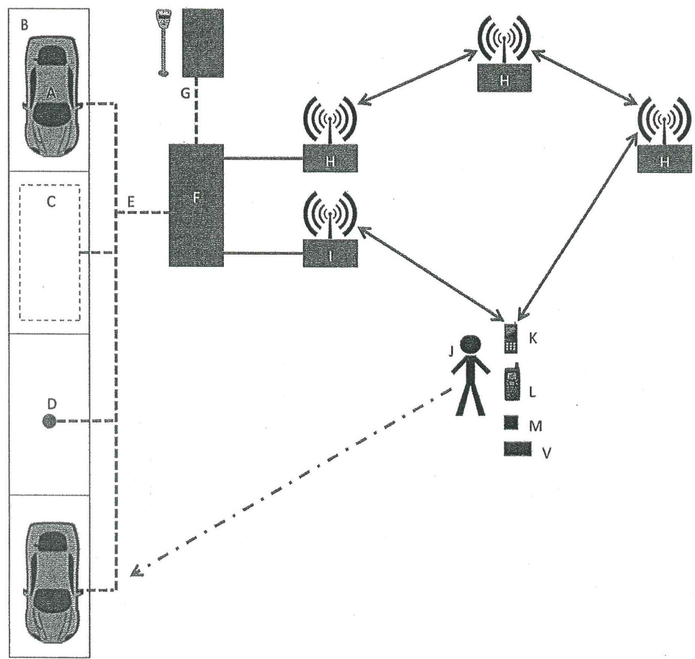
11.8. Localised Reporting Network – wireless with central controller
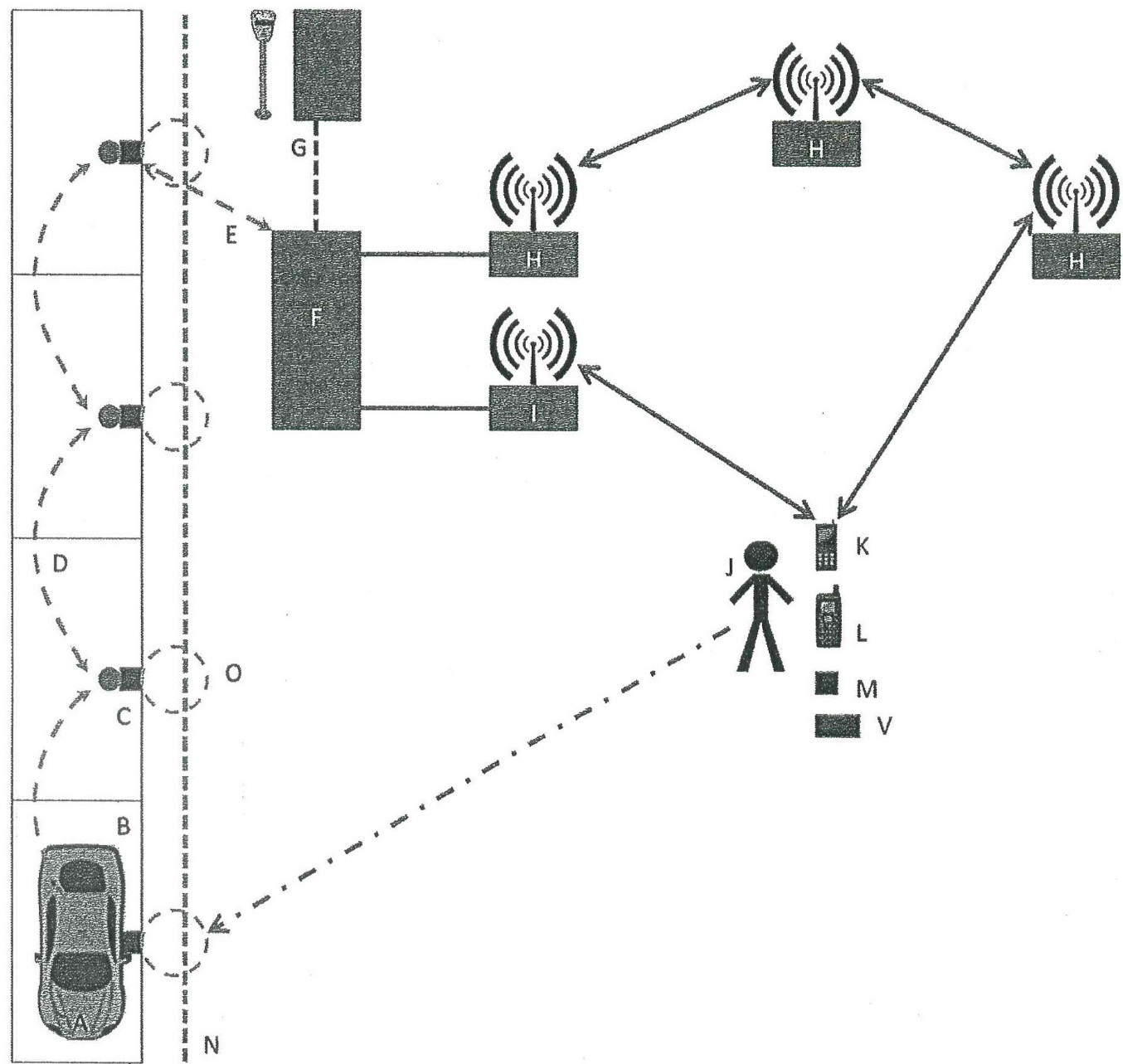
11.9. Localised Reporting Network – wireless with no central controller
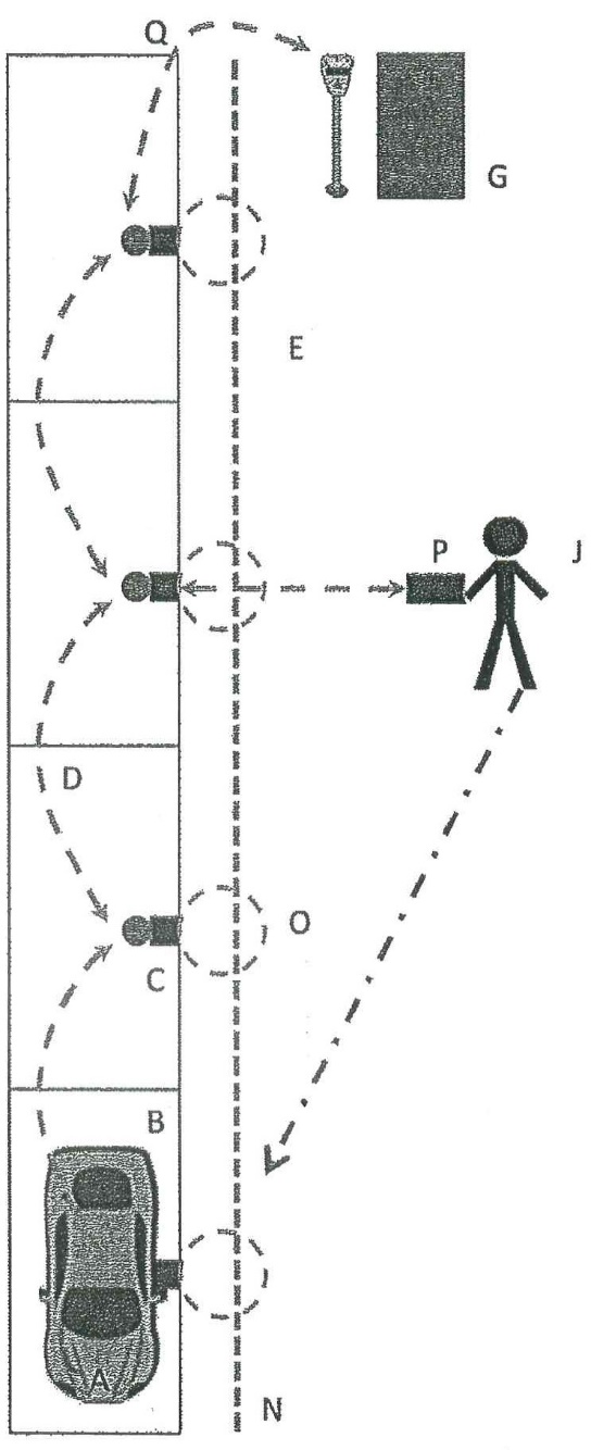
590 Mr Stamp identified the third transmission solution shown in para 11.9 as involving the quickest installation and at the lowest cost.
591 Mr Stamp addressed the power for the transmission solutions and, in relation to the solution shown in para 11.9, he states that the power for the sensor chain would be provided from inbuilt solar chargers in the sensors, or an inductive charging cable.
592 In response to a question from counsel for VMS suggesting that his report was influenced by knowledge he acquired after May 2004, Mr Stamp said the following:
… my frame of mind coming into this was very much one of an engineering solution framework. So … I started by imagining a range of possible solutions and then classifying those into groups and then basically trying to explain how they might be realised in the real world as particular architectures. The efficiencies and drivers around each of those choices was mine to make and was based on my general knowledge of the – particularly based on my knowledge of designing and installing red light camera systems and having some sense, I think, of the economics related to installation and operation of systems in general. …
593 I have reached the conclusion that Mr Stamp’s opinions do not establish that the invention described in the patents were obvious or very plain. Those opinions do not establish that the skilled addressee would be led directly or as a matter of course to the invention. Before setting out my reasons for reaching that conclusion, it is necessary to refer to evidence given by Mr Pieloor, Mr Harcourt and Mr Spirovski.
594 Mr Pieloor is employed at Sonartech ATLAS as a senior software engineer and that position involves providing leadership and technical expertise for embedded hardware and software development for sonar signal processing related products used in the defence sector.
595 Mr Pieloor was engaged by VMS in 2014 in the opposition proceeding before the Australian Patents Office. He made a statutory declaration in that proceeding on 11 September 2014.
596 In 2014, Mr Pieloor had had approximately 18 years’ experience in the field of product development and technology solutions for embedded platforms, primarily in the subscription and pay-per-view television industry. At that time, he was employed as a solutions architect at Pace Australia, a business involved in the design and building of embedded hardware systems, including set top boxes and modem and router components. Mr Pieloor holds a Bachelor of Engineering majoring in Computer Systems from the University of Tasmania, a Doctor of Philosophy involving a thesis in the field of computer engineering, specifically in the area of performance analysis of queuing systems for telecommunications networks. Mr Pieloor completed a Master of Engineering Studies between January 2011 (part-time) and 2014. He described in his affidavit his employment between October 2005 and September 2014, including as a consultant software engineer, a software architect, a senior software engineer and a solutions architect. He also described his employment from 2016 in a contract role as a senior software engineer.
597 In his statutory declaration, Mr Pieloor addressed the problem which had been presented to Mr Stamp and he addressed Mr Stamp’s response to the problem. He took a very different approach to that taken by Mr Stamp.
598 Mr Pieloor expresses the opinion that he would not have been directly led by the problem statement alone before May 2004 to try any particular approach as a matter of course and, in his opinion, nor would any other suitably qualified engineer. The decision to pursue any particular approach would have been heavily influenced by the parameters fixed by the client, a matter which is not addressed in the identification of the problem. Mr Pieloor said that in the context of a client seeking to improve the efficiency of its parking enforcement practices and, in particular, to overcome one or more disadvantages associated with chalking, the first step he would have taken would be to consult with the client to understand the problem from their perspective and to identify the specific goals and boundaries or limitations that apply to any solution. He identified the following questions as critical questions that he would ask: (1) how does the client measure efficiency in parking enforcement? (2) what level of improvement in efficiency is the client seeking? and (3) what cost is the client prepared to incur to achieve the desired level of improvement? Mr Pieloor considered that these questions would, in turn, require consideration of the following seven matters: (1) what are the client’s budget constraints for capital costs and applicable operational and maintenance costs? (2) what are the client’s personnel requirements and resources? (3) does the client have any other commercial requirements? (4) does the client have any governance, audit or reporting requirements? (5) what are the applicable regulatory limitations? (6) what are the scalability requirements, that is, the number and kind of parking spaces, the ease of adding more parking spaces, etc.? and (7) what level of accuracy of vehicle identification is required, that is, is a reduction in the number of false positives and false negatives desired and, if so, what level of reduction would be acceptable?
599 In considering possible solutions, Mr Pieloor said that in seeking to improve existing systems and methods in free or paid parking, a variety of different technologies could have been investigated to try and come up with new methods of enforcing time-limited parking. The technologies included the use of sensors, timers, signalling and/or image processing and associated reporting and enforcement mechanisms. He gave the following example:
… it may have been possible to investigate the use of an inductive loop sensor together with a mechanical, electrical or digital timer and an indicator (such as a light or mechanical flag installed at the parking space, or an adjacent display board) to detect vehicle presence and indicate when a vehicle has been present for longer than the permitted duration. An inductive loop sensor uses a loop of wire or similar conductive material to generate a magnetic field and to measure how this field changes over time (such as when a vehicle enters or exits the sensing range of the loop). …
600 Mr Pieloor said that he was aware before May 2004 that inductive loop sensors were used for traffic light control. In Mr Pieloor’s opinion, the costs involved in the research and development work needed to implement a sensor-based technology of this kind for the purpose of parking enforcement were likely to have been significant.
601 Mr Pieloor does not agree with Mr Stamp that he would have been directly led as a matter of course before May 2004 to try any of the solutions proposed in Mr Stamp’s report. He provides a number of reasons in support of that opinion. The problems Mr Pieloor identifies mean that he would not have investigated any system of the kind proposed by Mr Stamp before May 2004 without first gaining a better understanding of a client’s specific needs and constraints or limitations, and without giving appropriate consideration to whether a client’s desired efficiency of improvement could be achieved by improving existing enforcement methods at substantially less cost and complexity. He said, by way of example, that he would conduct an analysis of whether providing patrollers with mopeds, electric bikes, golf carts or similar powered transport would be likely to increase the time efficiency of the chalking method by overcoming the disadvantage of officers having to visit each parking space “on foot”. The provision of powered transport to officers would have had little associated research and development or infrastructure costs, given mopeds etc., were readily available commercially before May 2004. However, such equipment would have had additional capital and operational costs. Mr Pieloor said whether this approach would have improved efficiency to the required level at an acceptable cost, would again require investigation and consultation with the client.
602 Mr Pieloor has never worked in traffic enforcement and he did not know much about cost or time-efficient methods of parking enforcement. He has never considered work to improve parking efficiencies. He made it clear that, as far as the problem is concerned, the solution he would adopt would depend on the level of efficiency the enforcement authority wanted to achieve and at what cost.
603 SARB is correct to point out that despite Mr Pieloor’s opinions as described above, he immediately identified that it would be possible to use sensors, timers, signalling and/or image processing and associated reporting and enforcement mechanisms. Mr Pieloor agreed in cross-examination that whether the use of an inductive loop sensor was an appropriate solution was, like the other solutions he proposes, dependent on the results required and the client’s budget. Mr Pieloor acknowledged that he was and is not an expert in sensors. He was aware that inductive sensors were installed in groups in the ground, that is, subterraneously. He agreed that if he were to be engaged to undertake a task of determining appropriate sensors, he would have undertaken research to find the best sensor available in terms of costs and efficiency. That research would involve:
Either calling vendors or doing some sort of trade study, or finding a suitably qualified expert and asking them directly.
604 He would be concerned about battery life and would direct his attention to efficient power operations for sensors.
605 Mr Pieloor said that a counter could be used instead of a time of day clock for a car space with a fixed one hour limit. Nevertheless, he accepted in cross-examination that a time of day clock may be required for circumstances where the parking limits change over time and possibly for enforcement purposes to issue an infringement notice. He was clear that a time of day clock would work. Mr Pieloor agreed that as an alternative to indicators to a parking officer that there has been an overstay of a vehicle by way of a light or a mechanical flag or a display board, another way of doing the same thing is by sending a message to a parking officer. He agreed and he said that he would have known that as at May 2004. In other words, he agreed that a digital means would work.
606 Mr Harcourt was asked to provide his opinion as to how he would have designed and made a system for detecting unauthorised vehicles as at May 2004. He first addressed the design of the sensor. He said that he would have chosen a sensor which had the following features: a magnetometer as the sensor transducer, an off-the-shelf processor, an off-the-shelf radio receiver and an antenna, and a non-rechargeable battery and a power supply block. With respect to his choice of a magnetometer, Mr Harcourt said that he would have chosen this as the sensor because magnetometers are effective at detecting large metal objects such as vehicles and that as at May 2004, they were relatively cheap, could be purchased off-the-shelf and were very small so they could be installed cheaply and easily without significantly disrupting the road surface. They are able to be fully buried protecting them from vandalism and general wear and tear whilst at the same time maintaining their functionality.
607 Mr Harcourt addressed the communications platform and said that he would have experimented with Bluetooth. If this was not successful, he would have attempted to develop a proprietary communications platform on another unlicensed UHF band and, if this also was not successful, he would have chosen a licensed UHF band. The communications platform would have been bi-directional for the reasons Mr Harcourt gave in his affidavit and which it is unnecessary for me to set out. The sensor would have been embedded in the ground. It would have been sealed in a rigid plastic enclosure to protect it during transportation and from the elements, including ground water, once installed.
608 With respect to the rest of the system, Mr Harcourt would have considered two different configurations as a matter of course, in the expectation that he would be able to develop a system using either configuration. He said that the choice of which option to implement would be a matter of design choice based on personal preference and the requirements of the client, particularly in relation to the client’s appetite for risk and costs considerations.
609 The first option was one of fixed gateways (Option 1). Option 1 involved wire gateways fixed in place in permanent range of the various sensors they service. These gateways would be constantly awake and ready to receive wireless radio signals. The sensors would wake themselves up when they wanted to send a communication to the gateways. The base stations would either be wired to mains power or have a solar panel and a large enough battery that they could be constantly “awake” and ready to receive messages from the sensors. Communications would travel from the gateways to a back office system located on a server, either in a data centre or in the facilities of the company providing the service, using either the cellular network or a wired internet connection. The back office system would make determinations about various matters, including whether the vehicle had overstayed the allowable parking time limit for the relevant parking space. The back office system and parking officers on the street could interact with the latter using an off-the-shelf PDA, and the system could send notifications to alert the parking officers to overstaying vehicles through a beep or alarm.
610 Mr Harcourt said that the system comprising Option 1 is the system he would implement in the first instance because of the benefits he could see to using this approach. He identified some disadvantages with Option 1. He recognised the option would require the installation of substantial infrastructure and, therefore, it would involve significant costs. Mr Harcourt said that whilst he was of the view that Option 1 is likely to represent a better long term solution, he accepted that in practice, clients such as local councils would prefer to take an incremental approach to the adoption of new technology.
611 Mr Harcourt’s second option involved mobile data terminals (Option 2). Parking officers would carry a PDA or similar type of device around with them as they walked or drove around the streets. The PDA would communicate with the sensors when it came within range of them and Mr Harcourt said he would employ an interrupt-driven “wake-up” scheme. This would allow the sensors to remain in “sleep mode” for the majority of the time and only wake up when a PDA came into range, thus decreasing their power consumption and increasing battery life. The sensors would send data to the PDA relating to vehicle presence or vehicle overstay and the PDA would be loaded with a custom application allowing the parking officer to view information received from the sensors on the screen of the PDA and decide what action to take. If the parking officer decided to issue a fine based on information received from the sensors, they would already be in place to do so.
612 Mr Harcourt outlined the advantages of Option 2 which included significantly fewer upfront installation costs than Option 1. He also identified the disadvantages of Option 2 which included the need to update multiple devices — either the PDA or the sensors — if the council changed the applicable parking time limits.
613 Mr Harcourt said that in the case of Option 2, either the sensors themselves or the PDA could determine vehicle overstay. The system would work using either option, so the decision of which of the options to implement is a matter of “design choice based on personal preference and the requirements of the client”. In the case of his Option 2(a), the sensors determined vehicle overstay and in the case of his Option 2(b), the PDAs determined vehicle overstay.
614 Like Mr Stamp, Mr Harcourt performed an exercise whereby he compared the integers of the method, system and apparatus he described and the integers of a number of claims in the First Patent and a number of claims in the Second Patent. He did not address all the claims in the two patents.
615 I do not consider that I can place any significant weight on the evidence of Mr Harcourt for the reasons which follow.
616 First, in Mr Harcourt’s case, there is a substantial risk of hindsight bias. Mr Harcourt was given the patents before he designed and made his system for detecting unauthorised vehicles as at May 2004. Furthermore, he was familiar with SARB’s apparatus which is alleged to infringe the patents. In December 2010, Mr Harcourt commenced doing work for SARB for an initial period of nine months and then for a further three months. He provided advice to SARB in relation to the design of the hardware and firmware components of SARB’s vehicle detection product. He was not involved in providing advice on all aspects of the system, but he knew that SARB’s in-ground sensor unit was self-contained, battery operated and equipped with RF and antenna circuitry. He was aware that it was installed subterraneously and that the overall purpose of the product or system was the detection of vehicle overstay in car parking spaces.
617 Secondly, Mr Harcourt preferred Option 1 and said that this is the system he would seek to implement in the first instance. This was a matter upon which the experts were agreed. Mr Spirovski agreed that Mr Harcourt’s Option 1 had the benefits that Mr Harcourt identified and that he would also choose to implement a centralised system in the first instance. Mr Spirovski identified what he considered to be the advantages of a centralised system.
618 The significance of Mr Harcourt’s preference for Option 1 and Mr Spirovski’s agreement with that opinion is that, as Mr Spirovski said, the design which Mr Harcourt develops as a result of his design process is different from the methods, systems and apparatus described and claimed in the patents, both in terms of the particular set of systems, functions to be supported and how the components are organised to support their functions. Although Mr Harcourt said that his Option 2 involved “significantly fewer upfront installation costs than Option 1”, and was “more compatible with existing practices for determining vehicle overstay”, he agreed that he was no more familiar with the issues facing councils in operating parking enforcement systems than the ordinary motorist or pedestrian.
619 Thirdly, there is force in Mr Spirovski’s evidence questioning assumptions made by Mr Harcourt in addressing the problem put before him. As Mr Spirovski states, Mr Harcourt assumed that an “unauthorised vehicle” is a vehicle which has overstayed and that the system is for on-street parking. As Mr Spirovski said, those assumptions affect the range of options to be considered in designing and making a system for detecting unauthorised vehicles.
620 Mr Harcourt goes straight to a sensor-based solution and, in particular, a magnetometer. He described a magnetometer as a device which detects static magnetic fields and typically the earth’s magnetic fields. It is to be contrasted with inductive loops which only measure changes in magnetic fields. Mr Harcourt expresses the opinion that magnetometers are commonly used to detect objects which influence magnetic fields, such as coils and large metal objects such as vehicles. Mr Harcourt used a type of magnetometer called Hall-effect sensors before May 2004, including in a project he worked on at Robert Bosch while he was a student. The project involved a Hall-effect sensor being installed next to a motor as part of a feedback loop. When the motor was moving, the sensor counted the pulses in the magnetic field lines of the motor to ensure it was moving as instructed and had not stalled. In his oral evidence, Mr Harcourt agreed that Hall-effect sensors were not suitable to measure the earth’s magnetic field. Mr Spirovski agreed with this opinion and said that Hall-effect sensors would not be suitable in any way for “this application”.
621 Mr Spirovski expressed the opinion that, as at May 2004, there were many alternative approaches which could have been investigated by someone designing a system for detecting unauthorised vehicles. He would not have immediately opted for a sensor-based solution. He considers that the installation of multiple sensors would be a more expensive choice than the option of improving or adapting existing systems involving the manual chalking method and PDAs. Mr Spirovski said that he would consider a sensor-based solution as one possible approach, but would not have considered a sensor-based solution as the only approach. A factor which would affect whether he would pursue a sensor-based solution would be the particular requirements of the system to be designed. Furthermore, he would not have immediately opted for any particular type of sensor and would not have immediately opted for a subterraneously installed device or sensor. Mr Spirovski also pointed out that there were other choices as at May 2004 to the use of UHF radio communications to communicate data from the sensors. He refers to infrared communications as another option available for wireless communications. Mr Spirovski comments that Mr Harcourt does not provide any reasons for selecting UHF radio communications over other forms of wireless communications available as at May 2004.
622 Mr Harcourt favoured a non-rechargeable battery, but as VMS pointed out, whilst that may be a sensible and logical choice to employ in the case of a sensor-based solution buried underground, there are other solutions to a sensor-based solution.
623 As I have said, Mr Harcourt performed a similar exercise to Mr Stamp in identifying the features of his system and comparing them to the integers in claims in the patents. As with Mr Stamp, that does not advance SARB’s case unless his underlying opinions are accepted. It may also be noted, as VMS pointed out, that Mr Harcourt does not address claims 5, 9, 20, 25 or 27 of the First Patent and claims 5 and 21 of the Second Patent. In addition, in his claims charts, he relies on features in Option 2 of his design solution even though he expressed a preference for Option 1 and would have implemented that option first.
624 In my opinion, Mr Stamp’s evidence does not establish that the invention lacked an inventive step for the following reasons considered as a whole.
625 First, it is necessary to consider Mr Stamp’s skills and experience. Mr Stamp has skills and experience in wireless sensor networks, but he has never worked in designing a parking infringement system and he did not know what technology was used in that field. Whether it is correct to characterise Mr Stamp’s work with red light camera systems for approximately one month before the PD as a related field and to recognise some knowledge he had of the Redflex system, Mr Stamp himself nevertheless accepts that he has had no experience in the field of parking enforcement technology. These matters are relevant to the weight to be given to Mr Stamp’s evidence (E I Du Pont de Nemours & Co v ICI Chemicals & Polymers Limited [2005] FCA 892; (2005) 66 IPR 462 at [130] per Emmett J).
626 Secondly, Mr Stamp makes no reference is his report to common general knowledge in the field of parking enforcement. As I understand it, he is not put forward by SARB as part of a team with a member who has direct knowledge of parking enforcement methods and of the common general knowledge operating in that field before and at the PD. His expertise relevant to the problem is in wireless sensor networks and, although the problem did not direct him to a sensor-based solution, it is unsurprising, as VMS put it, that, in view of his expertise, he is led directly to a sensor-based solution. He gives no consideration, for example, to the other non sensor-based solutions or improvements to the existing methods identified by Mr Pieloor. None of the persons directly involved in the field of parking enforcement who gave evidence before me — Mr Schneider, Mr Gladwin and Mr Hawkings — gave evidence that as at the PD, they considered a sensor-based solution to overcome the existing problems.
627 Thirdly, it is unclear whether Mr Stamp limited his analysis to common general knowledge. His instructions invited him to have regard to (and only to have regard to) information he would have regularly considered (emphasis added) at the PD and in his evidence he said he had regard to his knowledge as a citizen and observations as a parking officer. Furthermore, his report indicates that he had some regard to material on the internet and it is unclear whether that material is part of the common general knowledge.
628 Fourthly, Mr Stamp’s report is 23 pages in length and must have taken some time to prepare. Although the report identifies one architecture or solution to the problem as the quickest in installation time and, therefore, the lowest in terms of cost, and as involving the lowest operating costs, the report does present four architectures or solutions. In the case of the four architectures each involving a number of components, Mr Stamp advises that for some of these components, a number of interchangeable solutions are possible. The solution components for detection, transmission and response are variations and “may be included or excluded or combined in a number of ways to create a specific parking detection and enforcement response architecture”. Mr Stamp advances five options for sensor devices which “could be used in any number of combinations to detect the presence of vehicles in any particular set of parking spaces” and he identifies two as the most viable in terms of cost, ease of installation and specificity in terms of detecting vehicles. Mr Stamp’s inductive loops were large inductive loops cut into the road surface. As VMS pointed out, it is not clear to what extent the practice of covering the cut or hole with a bitumen or adhesive solution was a practice Mr Stamp observed in Australia as distinct from the United States. Mr Stamp had not considered whether the inductive loop might be contained in housing along with other elements of his system. An optical or infrared detection requires an optical path to a vehicle in order to work and, therefore, cannot be subterraneous. A video or time lapse camera could not be subterraneous and would need to be either beside the vehicle or have an overhead view of the vehicle. Mr Stamp’s preferred option was of an inductive proximity sensor because of, inter alia, lower installation costs and the fact that it could be placed in a hardened, plastic dome enclosure and glued to the top of the road. In this context, it is worth noting the evidence of Mr Harcourt that he did not know of any person as at May 2004 using inductive loops of the type used to detect vehicles at traffic lights in a self-contained battery-powered unit and that was because, for mechanical and costs reasons, it was easier to follow the existing practice of burying the wire in the ground.
629 Fifthly, it is relevant to consider the process Mr Stamp went through before he reached his preferred solution. He identified four solutions and in his oral evidence, he said that as he worked through his report, it became apparent to him that there would be significant costs associated with the roadside installation of roadside controllers and it might be advantageous to have a system where there was no roadside controller required. Ultimately, he reached his preferred solution, having regard to low installation costs and low operating costs, but as Mr Pieloor pointed out, there are other relevant considerations for an electronics engineer such as the desired level of efficiency of parking enforcement to be achieved by the solution, the client’s budget for installation costs and ongoing maintenance costs, the number and skill level of the client’s personnel and resources, sealability requirements, whether the client has any governance or audit and reporting requirements and the level of accuracy in vehicle identification required. As Mr Pieloor said in cross-examination when it was put to him that cutting into the road was a “very expensive solution”, the notion of very expensive certainly means non-trivial costs, but beyond that one would consider economies of scale and that cost as against the cost and value of the entire system.
630 The different perspectives of costs savings which may be taken by an electronics engineer in approaching the choice of a preferred system is illustrated by Mr Pieloor’s evidence. He said that if he had been tasked with implementing one of Mr Stamp’s solutions, he would have been led away from the fourth solution because he would have preferred centralising common hardware and logic at a local site controller and thereby minimising the amount of hardware at each sensor. He went on to express the opinion that installation and maintenance costs and the physical space requirements for the overall system could be reduced by co-locating common sensor hardware with other system components such as display boards, wireless transceivers and power supplies.
631 Sixthly, there are difficulties and uncertainties with Mr Stamp’s solutions. For example, he said that in the case of battery-powered sensors, it may be necessary to conserve battery power by periodically operating the sensors, for example, for a short period once per minute. That particular example would not produce a reliable indicator of infringement because one vehicle may leave the parking space and another enter it in the intervening period. Another example is the provision of power to one of his two preferred sensors, the inductive loop sensor. These are large items which, when used in traffic light applications, cannot be powered by batteries. That is likely to be the case also in vehicle overstay detection and, as Mr Pieloor said if he was implementing Mr Stamp’s solutions, he would examine whether or not a fixed or permanent power source could be used to provide power to the sensors. Finally and significantly, Mr Stamp’s preferred sensor is the inductive proximity sensor and he said that they had been in place for many years in the industrial automation and control arena. He said that there were some longer range sensors that can detect at or beyond a distance of 100 mm. He did not know whether such sensors were available “off the shelf”, but he expressed the view that if not, it would have been quite possible (to use his words) to take an inductive proximity sensor to detect something as large as a car at a range of 300–400 mm from the sensor. He explained in cross-examination that, although he did not know whether that was possible, “there were quite likely parts that could have done that but it would have required further research and selection to identify that”.
632 Seventhly, Mr Stamp referred to his report as a report done at a concept design level and he identified the further research he would have carried out, including those with respect to sensors. He believes that he would have identified the magnetometer. I agree with VMS’s submission that the evidence as a whole indicates that Mr Stamp’s solutions required substantial further thought and experimentation and that gives rise to the possibility of trial and error, dead ends and the retracing of steps referred to by the High Court in Alphapharm at [58].
633 Finally, there is a matter for noting. I say that because if Mr Stamp’s earlier opinions do not carry the day, the exercise he carried out in 2014 of comparing his solution with the integers in the Second Patent and the similar exercise in 2020 in relation to the First Patent do not advance SARB’s case. VMS pointed out certain difficulties with his analysis in any event. There is nothing in that part of his report describing the fourth solution which sets out Mr Stamp’s opinion as to the preferred sensor. One has to go back earlier in the report to identify this and the earlier solution contains a statement that any of the sensors described could be used in any number of combinations to detect the presence of vehicles in a particular set of parking spaces. It also emerged from cross-examination that Mr Stamp did not state expressly in his report matters he assumed based on his knowledge. Furthermore, Mr Stamp admitted in cross-examination that there was no single place in his report where all of the integers in claim 1 of the Second Patent (a method claim) are set out.
634 Taking all of these matters into account, I am not satisfied that SARB has established that the invention disclosed lacks an inventive step.
635 The skilled addressee would include both an electronics engineer and a person with expertise and experience in the field of parking enforcement before and at the PD. The skilled addressee would consider a range of options in addressing the problem, including but not limited to, a sensor-based solution. The option chosen would involve a range of considerations, including costs (installation and operation), the degree of accuracy required and available alternatives. Even if the skilled addressee was led directly as a matter of course to a sensor-based solution, I am not satisfied that that would have led to the invention. I have set out my reasons for concluding that Mr Stamp’s evidence does not establish that conclusion. I am not satisfied that the skilled addressee would have been led directly as a matter of course to a magnetometer or an inductive proximity sensor for the reasons I have given in the section dealing with common general knowledge and I am not satisfied that the skilled addressee would be led directly as a matter of course to the system which is the invention.
636 In addition to these matters, this is a case in which secondary considerations are significant.
637 The invention disclosed and claimed represented a solution to a long-felt want of overcoming the drawbacks of chalking which had existed since at least the mid-1970’s and which involved missed enforcement opportunities, revenue opportunities and a reduction in the availability of on-street parking for the general public.
638 The introduction of VMS’s POD System in 2005, which is an embodiment of the patents, resulted in a paradigm shift. As Mr Gladwin said, the POD System was so effective at the City of Maribyrnong that the workers’ union for parking officers regarded it as a threat to the workforce. At the time the system was introduced to the City of Maribyrnong, it generated a great deal of interest from local councils. Since the POD System was introduced in the City of Maribyrnong, Wilson Parking Technologies and SARB have also released sensor detection systems on the market and market their systems in competition with VMS as an alternative to chalking. Mr Hawkings said that he reported back to the Adelaide City Council on the POD System because it struck him as new technology at the time. He considered it to be innovative. He did not pursue it because of his policy at the time of waiting to see whether new developments were accepted.
639 The lack of inventive step ground of invalidity is rejected.
False Suggestion and Misrepresentation (Both Patents)
640 A patent, or claims in a patent, may be revoked if the patent, or the claims in the patent, were obtained by fraud, false suggestion or misrepresentation. Fraud is not alleged by SARB in this case and this ground of invalidity is based on false suggestion or misrepresentation.
641 I have held that claims 21–23 and 28–29 and the omnibus claims (30–32) of the First Patent extend to methods, apparatuses and systems whereby vehicle overstay is determined either in the DA or the DCA. In the event that the Court reaches that conclusion, SARB contends that those claims were obtained by false suggestion or misrepresentation.
642 There is no evidence that the Commissioner of Patents has complained or complains of the conduct identified by SARB and neither the Commissioner nor her delegate gave evidence in this proceeding.
643 SARB’s case is that the alleged false suggestion or misrepresentation was made in 2007 by VMS’s Patent Attorneys, Spruson & Ferguson, in connection with the process of examination by IP Australia of application no 2005243110 and in response to novelty and inventive step objections raised by IP Australia, having regard to WO 2002/06,3570 A2 (VEHICLESENSE, INC.) (D1).
644 The following background is relevant to this ground. US Patent Application No 10/072,808 (Howard 1) published on 15 August 2002 and D1 are based on the same US provisional application 60/267,059 filed on 7 February 2001 and contain the same disclosure.
645 Howard 1 was part of SARB’s pleaded lack of novelty case in this proceeding and was also advanced as part of (either common general knowledge or information failing within s 7(3) of the Act) SARB’s pleaded lack of inventive step case in this proceeding. SARB has abandoned its novelty case and did not place any reliance on Howard 1 in its inventive step case. As I understand one submission made by VMS, it is that SARB must be taken to have accepted that by abandoning reliance on Howard 1 and, therefore, D1 which contains the same disclosure, there was and is no lawful objection to the First Patent on the basis of D1 and that, in those circumstances, whatever its Patent Attorneys said to IP Australia was and is immaterial. The submission is that it cannot be shown as a matter of fact that anything said by VMS’s Patent Attorneys to IP Australia was a material inducing factor in the obtaining of the patent by VMS. Another way the submission was put was to say that if there was a representation, it was that the claimed invention was novel and involved an inventive step compared with D1 and that bearing in mind D1 and Howard involve the same disclosure and reliance on Howard 1 has been abandoned, the representation has not been shown to be false. For reasons which follow, I do not need to decide if this submission is correct.
646 The relevant communications between Spruson & Ferguson and IP Australia during the examination process were as follows.
647 On 16 February 2007, IP Australia advised Spruson & Ferguson in writing that the application had been examined and it had been determined that there were lawful grounds for objection to the application. Those grounds included a ground that claims 1, 2, 7, 9, 11, 12, 14–16, 19–22 and 24–27 were not novel and did not involve an inventive step, having regard to the prior art document which was D1.
648 On 24 May 2007, Spruson & Ferguson responded to IP Australia by claiming that the claimed invention was novel and involved an inventive step when compared to D1 because in the case of D1, parking violations are identified by wireless sensors in conjunction with a central computer, server or network whereas in the case of the claimed invention:
… instances of overstay violation are determined solely by the subterraneous detection apparatus. That is, no central computer, service, network or any above-ground apparatus is needed to identify violations as instances of overstay.
649 On 7 June 2007, IP Australia provided a second examination report to Spruson & Ferguson with respect to the application. The report stated that the invention defined in claims 1, 2, 7, 9, 11, 12, 14, 19֪–22 and 24–27 was not novel and lacks an inventive step compared with the prior art document D1 “for the same reasons as given in the first report”.
650 On 2 October 2007, Spruson & Ferguson responded to the second examination report and asserted that the claimed invention was novel and involved an inventive step and asserted that “the subterraneous detection apparatus of the claimed invention is battery-powered and wirelessly transmits data relating to identified instances of parking overstay” and the cited reference fails to disclose, or even suggest, that an overstay duration of a vehicle in a parking space is determined and stored by a subterraneous DA.
651 On 8 November 2007, IP Australia provided a third examination report in which it no longer advanced an objection to the application on the basis of a lack of novelty or inventive step.
652 On 16 November 2007, IP Australia advised Spruson & Ferguson that the application and complete specification were accepted and, on 13 March 2008, IP Australia advised Spruson & Ferguson that a patent had been granted in respect of the application.
653 SARB contends that but for the representations made by Spruson & Ferguson in their responses to IP Australia dated 24 May 2007 and 2 October 2007 respectively, IP Australia would not have accepted application no 2005243110.
654 The authorities which deal with the ground that a patent or claims in a patent have been obtained by false suggestion or misrepresentation include Re Alsop’s Patent [1907] 24 RPC 733; Prestige Group (Aust) Pty Ltd v Dart Industries Inc (1990) 26 FCR 197; Ranbaxy Australia Pty Ltd v Warner-Lambert Co LLC [2008] FCAFC 82; (2008) 77 IPR 449 (Ranbaxy); ICI Chemicals & Polymers Ltd v Lubrizol Corporation Inc [2000] FCA 1349; (2000) 106 FCR 214 (ICI Chemicals); and Apotex Pty Ltd v ICOS Corporation (No 3) [2018] FCA 1204; (2018) 135 IPR 13. It will be sufficient for me to refer to Ranbaxy and ICI Chemicals.
655 The “but for” test is not the test of causation in this area of the law. It is sufficient if the suggestion or representation materially contributed to the Commissioner’s decision to grant the patent, or was a material inducing factor leading to the grant (Ranbaxy at [82]).
656 The position taken by the Commissioner is relevant in considering this ground of invalidity. In Ranbaxy, the Court said (at [83]):
Bearing in mind that the grant of a patent is a right in rem, the Commissioner could be expected to take a position if a misrepresentation did in fact play a part in the decision to grant a patent and it is a relevant factor that the Commissioner chooses not to give evidence (ICI Chemicals & Polymers Limited v The Lubrizol Corporation Inc (2000) 106 FCR 214 at 244-245). In the absence of such evidence, it is for the Court to make a finding, based on the evidence before it. In the absence of explicit evidence that the Commissioner, or the Commissioner’s delegate, was in fact misled, it may nevertheless be inferred that a representation in fact contributed to the decision to grant a patent, if the representation was objectively likely to contribute to such a decision and the patent was in fact granted (see Synthetic Turf Development Pty Limited v Sports Technology International Pty Limited [2004] FCA 1179 at [2], and WM Wrigley Jr Co v Cadbury Schweppes Pty Limited (2005) 66 IPR 298 at 321).
657 Assuming fraud is not present and, as I have said, fraud is not alleged in this case, it is not sufficient to make out the ground of false suggestion or misrepresentation to prove simply that a false suggestion or misleading statement was made and nothing else. The Full Court made this clear in Ranbaxy in the following passages (at [135]–[137]):
135 The ground of false suggestion or misrepresentation must involve some misleading or deception of the Commissioner or the Commissioner’s delegate, being the person who makes the grant. To establish the ground, there must be a finding that the Commissioner or the Commissioner’s delegate was in some way misled or deceived by the suggestion or representation in question and that being so misled or deceived contributed to or caused the decision to grant the patent.
136 The Commissioner was a party to the proceeding but took no substantive part in the proceeding. The Commissioner may have taken the view that Ranbaxy was prosecuting the alleged grounds of invalidity with sufficient vigour for the Commissioner not to be involved. Ranbaxy adduced no evidence as to the way in which the alleged false suggestions or misrepresentations operated on the decision making process of the Commissioner. Where it is alleged that a patent was obtained on or by false suggestion or misrepresentation, it is relevant, although not decisive, that the Commissioner has made no complaint about being misled or deceived.
137 In the absence of an allegation of fraud, which involves an examination of the state of mind of the patent applicant, it is not sufficient to make out the ground of false suggestion or misrepresentation to prove simply that a false or misleading statement was made and nothing else. That is to say, even if a suggestion or representation is shown to be false or misleading, that, of itself, is not sufficient reason to draw an inference that the suggestion or representation contributed to the decision to grant the patent.
658 A submission about the meaning and effect of a piece of prior art will not necessarily involve a false suggestion or misrepresentation even where it transpires that it was wrong unless, it seems, it can be said that there was no basis for the submission (ICI Chemicals at [91]).
659 The Court in ICI Chemicals made it clear that where good faith is not in issue, it is inappropriate to apply a presumption that the misrepresentation actually misled. The Court said (at [92]):
… We think it is relevant also to bear in mind that the examiner must be taken to have become thoroughly familiar with the specification and claims the subject of Lubrizol’s application; the examiner should also be taken to have become familiar with at least the abstract but, we should think, more likely the complete specification, of the Japanese patent. A reaction more likely, we should think, than immediate acceptance of what was said on Lubrizol's behalf was a further consideration, by the examiner, of both. After all, where good faith is not in issue it is inappropriate to apply any presumption that the misrepresentation actually misled. …
660 The onus is on SARB to establish this ground of invalidity. Even if it be assumed that there was a false suggestion or misrepresentation, there is no presumption that the Commissioner was misled. It is true that a sufficient causal link may be inferred if the representation was objectively likely to contribute to the grant of the patent and the patent was, in fact, granted. However, I am not satisfied that in this case an inference of a sufficient causal link should be drawn, having regard to the course of the correspondence. For example, as VMS pointed out in its written submissions, there were a number of bases upon which the objections to the First Patent did not succeed, not just the scope of claims 21–23 and 28–32. The Spruson & Ferguson letter of 24 May 2007 focussed primarily on claims 1, 5, 10, 11, 15, 16 and 26 and the letter of 2 October 2007 focused primarily on claims 1, 10 and 11.
661 The false suggestion and misrepresentation ground of invalidity is rejected.
Claims 21–23 and 28–32 of the First Patent lack clarity and fail to define the invention
662 SARB’s case is that if claims 21–23 and 28–32 in the First Patent encompass a system, apparatus or method which does not require the DA to make the overstay determination, then the claims are not clear and do not define the invention because they do not set out how the identification of overstay is to be determined. Section 40(3) provides, inter alia, that claims in a complete specification must be clear and s 40(2)(b) provides that the claim or claims must define the invention.
663 SARB pleaded an additional ground of lack of clarity in relation to claim 29 and that related to the reference in the claim to a wake-up signal, but that ground was not pursued in closing submissions.
664 SARB submits that it is common ground between the experts that the specification provides no information about how the identification of overstay is to be determined. For example, Mr Harcourt said that the difficulty with overstay being determined by or in the DCA is that this possibility “is not discussed or described anywhere else, and there is insufficient information about how a system configured in this way works”. For his part, although Mr Spirovski stated in his oral evidence that the DCA would make the decisions in exactly the same way as the DA using the same equations, he agreed that there was “no discursive account of how that might be done using the data collection apparatus”.
665 SARB submits that insofar as VMS relies on the omnibus claims which use the words “substantially as herein described”, they will generally be restricted to the preferred embodiment or an embodiment substantially the same as the preferred embodiment and that difficulties in meeting the requirement of clarity may arise where more than one preferred embodiment is described in the specification (Britax Childcare v Infa-Secure at [29] and [31]).
666 It is important to remember that a lack of clarity is concerned with the certainty surrounding the scope of the monopoly claimed. A skilled addressee must be able to ascertain whether what he or she proposes to do falls within the ambit of the relevant claim. There is a further relevant point and that is that a claim will not fail for lack of clarity if it identifies a workable standard suitable to the intended use. I am unable to see how it can be said the claims lack clarity. Once construed in the manner I have described, there would be no difficulty for the skilled addressee to understand the boundaries of the claims.
667 A similar conclusion follows in the case of the ground of alleged invalidity that the claims do not define the invention. In General Tire & Rubber Co v Firestone Tyre & Rubber Co Ltd [1972] RPC 457, the Court of Appeal said (at 515–516):
It is clear in our judgment that the question whether the patentee has sufficiently defined the scope of his claims is to be considered in relation to the facts of each case, that allowance is to be made for any difficulties to which the circumstances give rise, and that all that is required of the patentee is to give as clear a definition as the subject matter admits of. It is also clear in our judgment that, while the court is to have regard to all the relevant facts, the issue of definition is to be considered as a practical matter and little weight is to be given to puzzles set out at the edge of the claim which would not as a practical matter cause difficulty to a manufacturer wishing to satisfy himself that he is not infringing the patent. We accept also that definition of the scope of a claim is not necessarily insufficient because cases may arise in which it is difficult to decide whether there has been infringement or not provided the question can be formulated which the court has to answer in deciding the issue of infringement.
668 A lack of definition will not be established unless a claim is “incapable of resolution by a skilled addressee by the application of common sense and common knowledge” (Innovative Agriculture Products Pty Ltd v Cranshaw (1996) 35 IPR 643 at 666; PhotoCure ASA v Queen’s University at Kingston [2005] FCA 344; (2005) 216 ALR 41; (2005) 64 IPR 314 at [117] per Merkel J). In my opinion, that cannot be said of the claims in this case.
669 The lack of clarity and lack of definition grounds of invalidity are rejected.
Conclusions
670 The principal conclusions with respect to the infringement issues in this case are as follows:
(1) The PinForce Version 1 (and PinForce Version 2) infringes claims 2, 3, 4, 5, 11, 12, 13, 21, 22, 28 and 29 of the First Patent and claim 26 of the Second Patent and the contention by the first respondent that PinForce Version 1 does not involve the use of a wake-up signal or provide for data to be transmitted when a DCA is detected is rejected;
(2) Claim 21 of the First Patent includes a system in which vehicle overstay is determined by the DCA;
(3) The acts of service, maintenance, firmware upgrade and/or other assistance do not give rise to liability, assuming as I take to be the case, those acts were performed pursuant to lawfully binding contracts entered into before the beginning of the limitation period because there would be no power to prevent the use and no procuring, inducing or acting in concert in the relevant sense;
(4) (a) With respect to the applicant’s claim for additional damages against the first respondent, an award of additional damages is justified with respect to infringements after the decision in VMS 2013, but only insofar as the infringements involve PinForce Version 1 and PinForce Version 2; and
(b) With respect to the applicant’s claim for additional damages against the second respondent, the claim is dismissed.
These conclusions must be read in the context of these reasons and be reflected in the orders to be made.
671 The first respondent/cross-claimant’s cross-claim is to be dismissed.
672 The applicant is to bring in draft minutes of order reflecting the conclusions in these reasons. I will then hear from the parties as to the terms of the orders.
I certify that the preceding six hundred and seventy-two (672) numbered paragraphs are a true copy of the Reasons for Judgment of the Honourable Justice Besanko. |

