
Federal Court of Australia
TCT Group Pty Ltd v Polaris IP Pty Ltd [2022] FCA 1493
ORDERS
DATE OF ORDER: |
THE COURT ORDERS THAT:
1. The parties confer and supply to the chambers of Justice Burley by 4pm on 1 February 2023 draft short minutes of order giving effect to these reasons and a timetable for further steps in the proceedings.
2. Insofar as the parties are unable to agree to the terms of the draft short minutes of order referred to in order 1, the areas of disagreement should be set out in mark-up.
3. The proceedings be listed for a case management hearing at 9.30am on 2 February 2023.
Note: Entry of orders is dealt with in Rule 39.32 of the Federal Court Rules 2011.
BURLEY J:
1 These proceedings concern innovation patent No AU 2020100485 (485 patent) entitled “Hinge” and innovation patent No AU 2020102918 (918 patent) also entitled “Hinge” (together, patents). Both claim 17 February 2016 as their priority date. Both patents concern hinges used for softly closing glass-panelled doors of the type typically used to access swimming pools. The patentee is Polaris IP Pty Ltd and the exclusive licensee is Glass Hardware Australia Pty Ltd.
2 The applicants are TCT Group Pty Ltd and Astral Hardware Pty Ltd (collectively, TCT). They contend that the patents should be revoked pursuant to the terms of s 138 of the Patents Act 1990 (Cth) and that Polaris IP and Glass Hardware (collectively, Polaris) have made unjustified threats of patent infringement against them and their customers arising from their distribution and sale of hinges under the “Orion” brand (Orion hinges). The alleged threats are said by TCT to give rise to contraventions of s 128 of the Patents Act and ss 18 and 21 of Schedule 2 of the Competition and Consumer Act 2010 (Cth) (ACL).
3 Polaris denies that the patents are invalid and denies making any unjustified threats.
4 Glass Hardware, as exclusive licensee of the patents, advances a cross-claim alleging that TCT Group and Astral are liable for patent infringement on the basis that the Orion hinges infringe the claims of the patents. More specifically, it alleges that the Orion glass-to-glass hinge (GTG hinge) infringes each of claims 1, 2 and 3 of the 485 patent and the 918 patent and that the Orion glass-to-wall (GTW hinge) infringes each of claims 4 and 5 of the 485 patent and the 918 patent. Polaris IP is not an applicant in the infringement cross-claim, but has been joined as a respondent to the cross-claim pursuant to s 120(2) of the Patents Act. Even so, whilst recognising this distinction, it is convenient to refer below to the cross-claimant as Polaris.
5 Polaris also pleads in its cross-claim that two individuals are liable for patent infringement being Liang Xue, who is a director and shareholder of TCT Group and a shareholder of Astral; and Xingying Chen, who is a director and the majority shareholder in Astral. In closing submissions, Glass Hardware abandoned its claim against Ms Chen.
6 By orders made on 25 May 2021, issues of liability were to be heard separately and before issues concerning the quantum of any pecuniary relief. Accordingly, this judgment addresses only questions of liability.
7 The parties agree that the version of the Patents Act that is applicable to the present dispute may be found in compilation no. 49 dated 26 August 2021. This has the consequence that the Intellectual Property Laws Amendment (Raising the Bar) Act 2012 (Cth) (RTB Act) amendments apply to these proceedings.
1.2 Background information about the patents
8 The 485 patent was filed on 30 March 2020 and claims a priority date of 17 February 2016 from corresponding provisional application No 2016900547. It was certified on 19 June 2020.
9 The 918 patent was filed on 21 October 2020, amended on 23 December 2020 and certified on 28 January 2021. It also claims a priority date of 17 February 2016 from the provisional application.
10 The 918 patent lapsed on 31 August 2021 because of a failure to pay the renewal fee. Steps are apparently being made by Polaris to reinstate it to the Register, but nothing turns on that for the purpose of the present proceedings because the question of liability for infringement before 31 August 2021 remains for determination.
11 Each of the patents is a divisional of patent application No 2017201858 filed on 16 February 2017 (parent).
12 TCT advances the following five substantive grounds of invalidity in respect of each of the patents.
13 First, lack of novelty pursuant to s 7(1) of the Patents Act. It is not in dispute that TCT commenced selling the Orion hinges in January 2020. TCT contends that by operation of the Patents Act and the Patents Regulations 1990 (Cth) the priority date of the claims cannot be based on the filing date of either the provisional application or the parent, with the consequence that the priority dates for the 485 and 918 patents must be their dates of filing, which were 30 March 2020 and 21 October 2020 respectively. It is not in dispute that if this is so, the claims are anticipated by the earlier sale of Orion hinges.
14 Secondly, lack of full description because of a failure to comply with s 40(2)(a) of the Patents Act.
15 Thirdly, lack of support because of a failure to comply with s 40(3) of the Patents Act.
16 Fourthly, if the priority date is not deferred, lack of novelty in the light of four prior art documents, being:
(a) international patent application No WO 2011/035499 A1 (WO499 patent);
(b) United States patent application No US 2012/0279015 (A1) (US015 patent);
(c) Chinese Utility Model No 203755860 (CN860 patent); and
(d) innovation patent No AU 2011101327 (AU327 patent).
17 Fifthly, lack of innovative step having regard to the common general knowledge and each of the prior art documents.
1.4 TCT’s unjustified threats and ACL claims
18 TCT contends that Polaris unjustifiably threatened in correspondence to bring an action against it, as well as its distributors and persons who are involved in the supply or promotion of the Orion hinges, in breach of s 128 of the Patents Act. It also contends, on the basis of the same correspondence, that Polaris engaged in misleading and deceptive conduct in breach of ss 18 and 21 of the ACL.
1.5 The infringement cross-claim
19 In its amended cross-claim Glass Hardware contends that each of TCT Group, Astral and Mr Xue have infringed the patents in suit. In particular, it alleges that since 11 October 2019, the corporate cross-respondents (whom I shall continue to refer to collectively as TCT) manufactured or imported into Australia, and sold and supplied the Orion hinges in Australia.
20 The case against Mr Xue is based on the fact that he is the sole director and majority shareholder of TCT Group and also a director and shareholder of Astral. Polaris’ pleaded case alleges that Mr Xue is liable for authorising the infringing conduct of TCT Group and Astral and also as a joint tortfeasor with those companies. During the course of its closing written submissions TCT accepted that if the sale of the Orion hinges by either TCT Group or Astral is held to infringe, then it is open to the Court to find that Mr Xue authorised those infringements. In light of that concession, in its oral submissions Glass Hardware properly accepted that there was no utility in pressing its alternative claim against Mr Xue on the basis that he might also be a joint tortfeasor. The consequence is that if the Orion hinges are found to infringe a valid claim of the patents then it follows that Mr Xue will be found to have authorised that infringement.
21 Glass Hardware seeks additional damages in the event that infringement of the 485 patent is established.
22 Polaris submits that each of TCT Group, Glass Hardware and Mr Xue has engaged in misleading and deceptive conduct in breach of s 18 of the ACL as a result of the form of the packaging of the Orion hinges. Specifically, it contends that the packaging incorrectly contends that the hinges are the subject of particular patent and design rights in Australia.
23 This aspect of the case has been resolved by agreement and is not addressed further in these reasons.
24 For the reasons set out in more detail below, I have found that:
(1) the Orion hinges fall within the scope of the claims of each of the patents;
(2) the claims of neither the 485 patent nor the 918 patent are entitled to claim their priority date from the date of filing of the parent or the provisional application;
(3) by reason of the finding in (2), and the use and sale of the Orion hinges before the priority dates of 30 March 2020 and 21 October 2020, the claims of the 485 patent and the 918 lack novelty;
(4) the specifications of the 485 patent and the 918 patent also do not disclose the invention in a manner which is clear enough and complete enough for the invention to be performed by a person skilled in the art within s 40(2)(a) of the Patents Act;
(5) the claims of the 485 patent and the 918 patent are also not supported by matter disclosed in the specification within s 40(3) of the Patents Act;
(6) claims 1 and 4 of the 485 patent lack novelty in light of the disclosure of the US015 and CN860 patents;
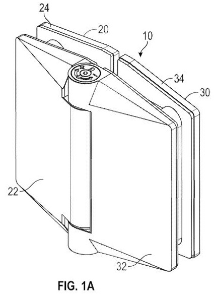
(7) all of the claims of the 485 patent lack an innovative step over the disclosure of the US015 patent;
(8) otherwise the challenge to the validity of the 485 patent and the 918 patent on the basis of lack of novelty in the light of the WO499, US015, CN860 and AU327 patents and lack of innovative step on the basis of those prior art documents fails; and
(9) TCT succeeds in its claim for unjustified threats on the basis of the correspondence sent by the solicitors for Polaris to TCT and also to Glass Pro, but fails in its claim based on the same correspondence under s 18 of the ACL.
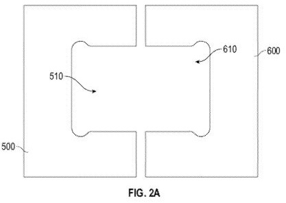
25 The result is that the claim for revocation of the patents must be allowed and that the cross-claim for patent infringement be dismissed. The matter will be relisted for the purpose of making final orders after allowing the parties time to confer and reach agreement as to the form of those orders, including as to costs.
26 William Hunter is a mechanical engineer. From 1986 until 1993 he held positions in companies engaged in the design of products that utilised hinges. From 1994 until 2001 he worked in his own product development company and designed many products and machines including hinges. Since then he has worked as an independent design consultant engaged in mechanical engineering design.
27 Mr Hunter was provided by the solicitors for TCT with copies of the parent, the provisional application, the 485 patent and the 918 patent. In his first affidavit he sets out what he understands to be the main concepts behind the hinge described in the parent, including the dampener feature. He then describes what he considers to be the disclosures of the 485 patent and the meaning of the claims, before comparing what he considers to be claimed in the 485 patent with the disclosure of the parent and the provisional application. He does the same exercise with the 918 patent. He then provides a review of what he considers to be the disclosure of (inter alia) the prior art documents and provides detailed claim charts that set out his view of the disclosure of the prior art documents when compared with the specific integers in the claims of the 485 and 918 patents. He then gives his opinion, relevant to the question of innovative step, as to whether or not the claims of the 485 and 918 patents vary from the information set out in the claim charts in ways “that make no substantial contribution to the working” of the inventions claimed.
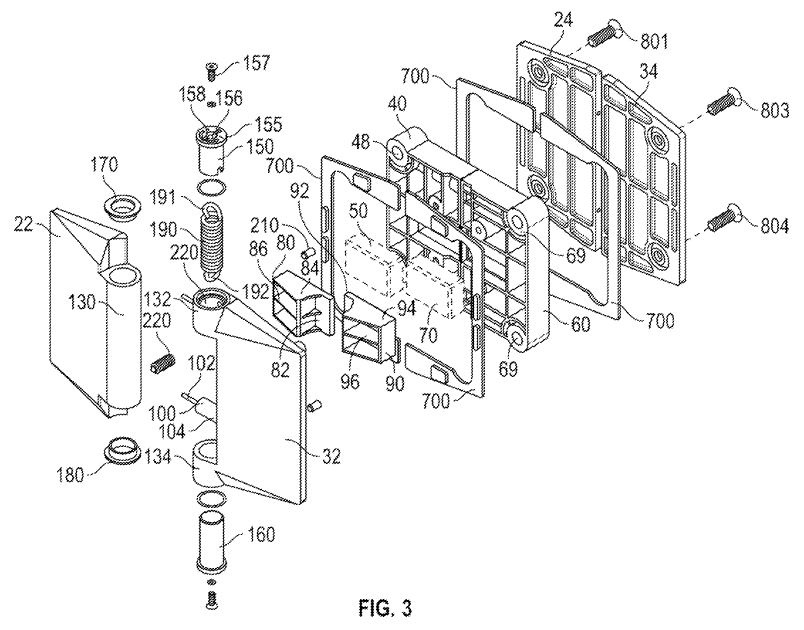
28 In his second affidavit Mr Hunter responds to the evidence of Mr Richardson, differing as to his understanding of the meaning of a number of the integers of the claims of the patents in suit for the purposes of infringement.
29 Mr Hunter joined with Mr Richardson in the preparation of a detailed joint expert report and participated in a concurrent evidence session with him, during which he was cross-examined.
30 Min Yee Won is the sales manager of Glass Pro Australia Pty Ltd, which he established with a business partner in 2018. He has been working in the glass industry since 2008. In his affidavit he gives evidence about his experience in the industry, his familiarity with the Polaris soft close hinges since 2013 and his company’s sales of Orion hinges. He also gives evidence about his reaction to receiving cease and desist letters from the solicitors acting for Polaris, Spruson & Ferguson Lawyers. He was cross-examined.
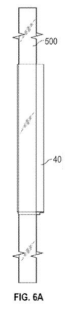
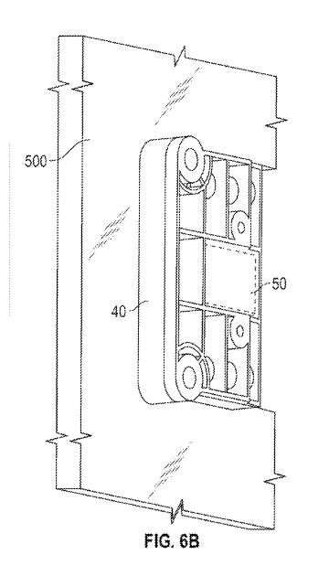
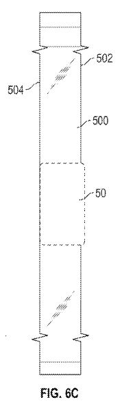
31 Weizhong Chen provides an English translation from Chinese of the CN860 and WO499 patents. He was not cross-examined.
32 Timothy Francis is a solicitor at Wrays Lawyers, who act for TCT. He affirmed an affidavit annexing a copy of Australian Standard AS 1926.1–2012 and related correspondence. He was not cross-examined.
33 Francis Bindschedler has been the general manager of Glass Hardware since November 2017 and prior to then held positions as sales executive from 2009 until 2014 and finance and operations manager from 2014 until 2017. He gives evidence about the operations of Glass Hardware and its dealings with TCT since 2012. He explains that in March 2012 Glass Hardware started purchasing glass products from TCT Group and how, after an approach from TCT Group in 2016, the two companies entered into negotiations for TCT Group to manufacture the Polaris 120 Series Hinges. He gives evidence that on 23 January 2018 Glass Hardware entered into a manufacturing agreement with TCT Group, which concluded in May 2019 with a final delivery of Polaris 120 Series Hinges. He explains that he regularly monitored the activities of Glass Hardware’s competitors which led him in October 2019 to learn that Glass Pro was promoting an Orion soft close hinge for sale. Mr Bindschedler gave one affidavit and was cross-examined.
34 Jacqueline Chelebian is a solicitor at Spruson & Ferguson Lawyers. She annexes various documents and was not cross-examined.
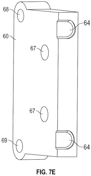
35 Alexander Richardson is an industrial designer and engineer who has been the managing director of Design Edge, an industrial design consultancy firm that he founded, since 1988. He has provided industrial design research and development, concept design, engineering detailing and manufacturing consultancy services to a wide range of industries. His work has involved the design of numerous types of hinges. He holds degrees in Mining Engineering and Arts (Industrial Design).
36 In his first affidavit, Mr Richardson provides his comments on his understanding of various phrases used in the 485 and 918 patents and gives his opinion that the features of the claims of those patents are embodied in the Orion hinges. In his second affidavit Mr Richardson notes that he has been provided with the parent, the provisional application and the 485 and 918 patents. He responds to certain questions asked of him in relation to the disclosure in those patents relevant to the s 40 case advanced by TCT. He also gives his opinion as to whether particular integers in the claims of 485 and 918 patents are present in the prior art documents.
37 Mr Richardson joined with Mr Hunter in the preparation of the joint expert report and also in a concurrent evidence session, during which he was cross-examined.
38 The body of the specification of each of the 485 and 918 patents is substantially the same, save for their claims and the consistory clauses contained in the summaries of the invention. It is convenient to describe their disclosure by reference to the specification of the 485 patent.
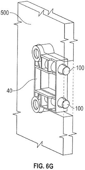
3.2 Disclosure of the 485 patent specification
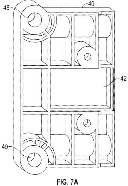
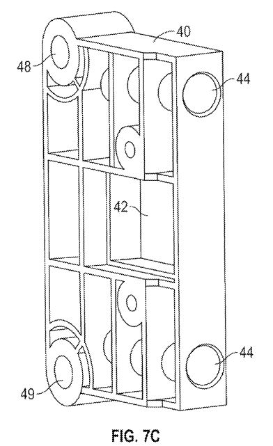
39 The specification commences by noting that it is a divisional application of the parent filed on 16 February 2017, and claims priority from the provisional application, which was filed on 17 February 2016. The contents of both related patents are incorporated in the specification.
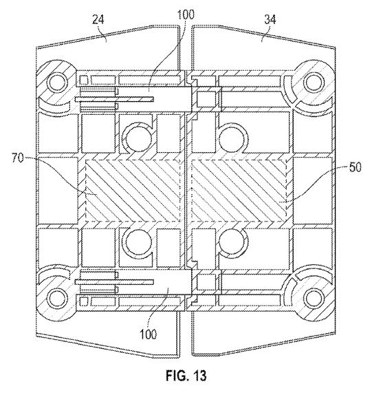
40 The technical field of the invention is said to relate to a hinge.
41 The “Background” refers to WO 2009/018615 (615 patent) as describing a hinge including a mechanical biasing element, for example a spring, and a plurality of magnetic elements which bias and retain hinge members in a retained (for example, closed) position. The magnetic elements of that hinge were configured to have an overlapping arrangement in the closed position. The hinge was primarily designed for gates and showers which have a relatively significant weight and so the first and second magnetic elements were required to provide sufficient magnetic strength to bias the hinge toward the closed position, particularly when the spring may have suffered from mechanical wear. Dampeners were introduced into the hinge to control its closing action. These were orientated orthogonally (that is, perpendicular) relative to the plane of the hinge members such that the overlapping portion of the hinge would contact a protruding portion of the dampener when the hinge had nearly progressed to the closed position and would slowly retreat until the hinge progressed to the closed position. The specification says:
[0005] …However, despite the introduction of dampeners, structures such as glass panels of gates and shower doors could undergo significant vibration once the hinge progressed to the closed position. In particular, the structure would vibrate in a direction orthogonal to the plane of the glass panel of the structure. Over time, the vibration could lead to mechanical wear of the structure.
[0006] Furthermore, due to the dampeners being orientated orthogonally, the overall thickness of the hinge was relatively large to accommodate the dampeners which led to high manufacturing costs.
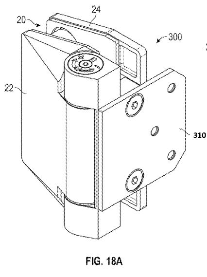
42 The specification notes that the requirement for magnets of sufficient strength led to the magnetic elements requiring a relatively large amount of space to be located within the hinge. The front hinge plate was designed to be relatively thick to accommodate the first magnetic element and, because of that element being located adjacent an outer face of the panel, the thickness of the first hinge member was accentuated. The front hinge plate of the second hinge member had the same thickness in order to be flush in the closed position. The specification goes on to say:
[0008] Whilst the hinge worked well to overcome problems associated with mechanical wear experienced by torsional springs in self closing hinges, new problems arose in relation to the panels of the hinged structure undergoing vibration after closing and the physical spatial constraints dictated by the size of the overlapping magnetic elements resulting in high manufacturing costs due to the amount of steel that was required to construct the hinge.
[0009] Therefore, there is a need to overcome or alleviate one or more of the above-mentioned problems or provide a useful alternative.
43 It may be seen that the specification discloses three identified difficulties with the prior art, the first being the vibration problem caused by vibration in a direction orthogonal to the plane of the glass panel, the second being the thickness problem caused by the orthogonal orientation of the dampeners relative to the plane of glass and also the thickness of the magnets, and the third being the manufacturing problem caused by the amount of steel used in the hinge.
44 Under the heading “Summary” the specification at [0011] sets out aspects and embodiments of the invention that are later reproduced in the claims. The first aspect of the invention is set out in [0011] and reproduces claim 1, which is set out in section 3.3 below.
45 Other embodiments are described in [0012]-[0016].
46 There follows a brief description of the figures which are provided “by way of example only” of embodiments of the invention, which are described by reference to 45 drawings.
47 The section entitled “Detailed Description of the Embodiments” commences by referring to an example of a hinge 10 in the glass-to-glass configuration in isometric drawing fig 1A:
48 The hinge 10 includes a first leaf assembly 20 hingedly coupled to a second leaf assembly 30, one or more biasing components 190 (shown in later figures as a spring, see [53] below) which bias the hinge toward a closed position, and one or more dampeners 100 (shown in fig 3 below) to slow movement of the first and second leaf assemblies 20, 30 to the closed position.
49 The specification says (emphasis added):
[0066] The first leaf assembly 20 includes a first front leaf component 22 coupled to a first rear leaf component 24 for accommodating therebetween a portion of a first panel 500 having a first cut-out section 510 as shown in Figure 2A. The first leaf assembly 20 further includes a first insert component 40 which is tight fittingly receivable within the first cut-out section 510 of the first panel 500.
50 The first insert component 40 is described in the specification to have “mouse ears” to fit within the cut-out part of the first panel 500, as shown in fig 2A. Figure 2A depicts the cut-outs which are respectively for the first insert 510 and second insert 610 as follows:
51 The second leaf assembly 30, which comprises part of the glass-to-glass embodiment, is described to have a similar arrangement.
52 The specification describes a dampener in more detail:
[0069] A first portion 102 of each dampener 100 is secured or fixed within the first insert component 40 and a second portion 104 is configured to at least partially retract within the first insert component 40 when coming into contact with the second leaf assembly 30 during hinged movement toward the closed position under bias from the one or more biasing components 190. The second portion 104 of the dampener 100 extends and retracts along a longitudinal axis which is coplanar with the first panel 500.
53 An exploded isometric view of hinge 10 in fig 1A is depicted in fig 3. It is quite complicated, but it may be seen that dampener 100 has a narrow, pin-like portion 102 and a larger cylindrical portion 104. Biasing spring 190 may be noted, and also the insert components 40 and 60 that have protrusions to match the mouse ears in the cut-out part of the panel:
54 The specification identifies advantages said to arise from the arrangement described:
[0070] Due to the longitudinal axis of the one or more dampeners 100 being coplanar with the first panel 500, any vibratory force is transferred in a direction parallel to the plane of the first panel 500. Due to the force being transferred along the plane of the first panel 500, the first panel 500 undergoes substantially little vibration resulting in a reduction in mechanical wear.
55 At [0071] the specification says that a first magnetic element 50 can be located in the first insert component 40 and a second magnetic element 70 can be located in the second insert component 60, being potential inclusions to provide an additional biasing component to the spring 190. The magnetic elements described in the specification are not referred to in the claims and played no significant part in the dispute between the parties.
56 The specification says:
[0072] As shown in Figures 6A, 6B and 6C, a majority of the first insert component 40 is tight fittingly receivable by the first cut-out section 510 of the first panel 500 such that only a minority portion of the insert portion protrudes from the face of the first panel. …
57 Figures 6A, 6B and 6C are as follows:
|
|
|
58 The reference to “tight fittingly receivable” emphasises the fact that only a minority portion of the first insert component 40 protrudes from the face of the first panel.
59 The second leaf assembly has the same general arrangements, which are described at [0073]. It is to be noted that it is the first leaf assembly that has within the insert component dampeners located within hollows 44. In operation, in the open position those dampeners extend towards the second leaf assembly.
60 The specification states:
[0073] …As shown in Figure 7E, one or more striking surfaces 64 are provided by the second insert component 60, which the dampeners 100 strike when moving to the closed position, are located between opposing planes of the faces of the second panel 600 in order to achieve packing advantages….
61 The specification refers at [0075] to advantages said to arise from the design:
[0075] Due to the dampeners 100 being located between the planes of the opposing faces 502, 504 of the first panel 500, and optionally the first magnetic element 50 and the second magnetic element 70 being substantially located between opposing faces 502, 504, 602, 604, of the first and second panels 500, 600 respectively, the first leaf assembly 20 and the second leaf assembly 30 can be manufactured with a thinner profile meaning that the hinge 20 can be manufactured using less material…
62 The reference to the “thinner profile” is to be understood to be a comparison with the thicker profile used in the hinge arrangement of the prior art 615 patent, where the dampeners and magnetic elements were described as orientated orthogonally to the plane of the panels. By putting those elements between the planes of the opposing faces (that is, coplanar or parallel to the plane of the panel), the manufacturing problem of the prior art is said to be addressed.
63 The specification then refers again to fig 3 and notes:
[0077] …The first insert component 40 and second insert component 60 have a mouse ear shaped profile that corresponds to the mouse ear cut-out sections 510, 610 provided in the panels 500, 600 shown in Figure 2A. The mouse ear shaped corners of the first and second insert component 40, 60 contribute toward restricting rotational movement between the hinge 10 and the panels 500, 600. …
64 Figure 6G provides a perspective front view of the first insert component within the first cut-out section of the first panel, where it may be seen that dampener 100 is longitudinally aligned through hollows in the first insert component. The face of dampener 100, when in the extended position, meets with the chamfered face 64 of the second insert component as the hinge moves into the closed position, as shown in fig 7E, which is also depicted below:
|
|
65 Figures 7A and 7C are as follows:
|
|
66 Figure 13 is as follows:
67 The description of the arrangement of the first insert component depicted in the above drawings was referred to at length in the evidence and the submissions and is reproduced in full below (this is [099] in the parent):
[0078] As shown in Figure 7A, 7B and 7C, the first insert component 40 includes a plurality of hollows 44 which have a longitudinal axis which is orthogonal to the hinge axis 290 and coplanar with the plane of the first panel 500. The hollows 44 are located along adjacent longitudinal edges of the cavity 42 for housing the first magnetic element 50. Each hollow 44 is configured to house at least a portion of a dampener 100 as shown in Figures 3 and 13 for reducing the speed which the hinge approaches the retained position. As shown in Figure 13, at least a portion 102 of each dampener 100 is located within a respective hollow 44 of the first insert component 40 and a second portion 104 of the dampener 100 at least partially retracts within the respective hollow 44 of the first insert component 40 when the second portion 104 of the dampener 100 comes into contact with the second insert component 60 during hinged movement towards the retained position. The second portion 104 of the dampener 100 extends and retracts along an axis which is coplanar with the first panel 500. The first portion 102 of the dampener 100 is a dampener pin which is coupled within a respective hollow 44 of the first insert component 40. Furthermore, the second portion 104 of the dampener 100 is a dampener body which at least partially extends from and at least partially retracts within the respective hollow 44 of the first insert component 40. As shown in Figure 13, the dampener pin 102 is substantially thinner than the dampener body 104. Due to the dampener pin 102 being secured within the respective hollow 44 and the dampener body 104 having a cross sectional profile which substantially corresponds to the cross-sectional profile of the respective hollow 44, the dampener pin 102 is less likely to deflect and bend during hinge movement toward the retained position. The substantially similar cross-sectional profiles between each dampener body 104 and the hollow 44 effectively acts as a guide such that each dampener body 104 receives therein the dampener pin 102 along the longitudinal axis of the respective hollow 44. As the orientation of the longitudinal axis of the one or more dampeners 100 is substantially coplanar with the first panel 500, the overall thickness of the hinge leaf component 20 can be reduced thereby providing material efficiencies in relation to manufacture of the hinge. Additionally, due to the orientation of the dampeners 100, a majority of the vibrational force experienced by the hinge 100 when approaching the retained position is transferred in a direction substantially parallel to the planes of the faces 502, 504, 602, 604 of the panels 500, 600 thereby reducing the stress on the panels when moving toward the retained position.
68 It may be noted from this passage that, first, the embodiment includes a description of the dampener arrangement that emphasises the steps taken in the design to ensure that the dampener pin is less likely to deflect and bend during closing. The evidence demonstrated that one concern for the person skilled in the art in developing such a hinge is to ensure that the dampener is not subject to undue lateral forces. Secondly, that the embodiment has an orientation of the longitudinal axis that is “substantially” rather than precisely coplanar with the first panel. Thirdly, the passage emphasises that “due to the orientation of the dampeners 100, a majority of the vibrational force experienced by the hinge 100 [sic, 10] when approaching the retained position is transferred in a direction substantially parallel to the planes…”.
69 There is no dispute that the orientation of the dampener 100 throughout this part of the specification is depicted and described as being orthogonal or substantially orthogonal to the hinge axis (orthogonal hinge arrangement).
70 The specification then describes how the various components are fitted together, with additional detail provided of certain aspects of the embodiments described before addressing in some detail a glass-to-wall embodiment of the invention. It then describes the glass-to-wall embodiment of the invention by reference to hinge 300 in fig 18A:
71 The description explains the features of this embodiment, which does not involve a second leaf assembly, because the hinge is affixed to a mounting assembly 310 which is “hingedly coupled to the leaf assembly”. The specification provides in relation to the dampener of this arrangement:
[0093] The hinge 300 includes a dampener 100 to slow movement of the hinge 300 toward the retained position. The dampener 100 includes a first portion located within the insert component 40A and a second portion which at least partially retracts within the insert component 40A when coming into contact with the mounting assembly 310 during movement toward the retained position. The second portion of the dampener 100 extends and retracts along an axis which is parallel and coplanar with the panel 500. The first portion of the dampener 100 is a dampener pin which is coupled within a hollow 44 of the insert component 40A, and the second portion 394 of the dampener 390 is a dampener body which at least partially extends from and at least partially retracts within the hollow 44 of the insert component 40A.
72 The specification concludes by noting that the example hinges disclosed can be used for many applications, that modifications will be apparent to those skilled in the art without departing from the scope of the invention, and that, unless the context otherwise requires, the word “comprise” should be understood in its inclusive sense.
3.3 The claims of the 485 patent
73 The 485 patent has five claims. These are set out below with the integer numbers added.
74 Claim 1 encompasses a hinge with a glass-to-glass configuration and provides:
1.1 A hinge including:
1.2 a first leaf assembly including a first front leaf component coupled to a first rear leaf component for accommodating therebetween a portion of a first panel having a first cut-out, 1.3 wherein the first leaf assembly further includes a first insert component located between the first front and rear leaf components, 1.4 wherein a portion of the first insert component is adapted to locate within the first cut-out;
1.5 a second leaf assembly hingedly connected to the first leaf assembly about a hinge axis, 1.6 said second leaf assembly including a second front leaf component coupled to a second rear leaf component for accommodating therebetween a portion of a second panel having a second cut-out, 1.7 wherein the second leaf assembly further includes a second insert component located between the second front and rear leaf components, 1.8 wherein a portion of the second insert component is adapted to be located within the second cut-out;
1.9 a spring operatively coupled to the first and second leaf assemblies to bias the hinge to move from an open position to a closed position; and
1.10 a dampener, having a longitudinal dampener axis, said dampener at least partially housed within the first insert component and adapted to dampen movement of the hinge from the open position to the closed position, 1.11 wherein said longitudinal dampener axis is disposed between and substantially parallel with planes defined by respective opposing faces of the first panel.
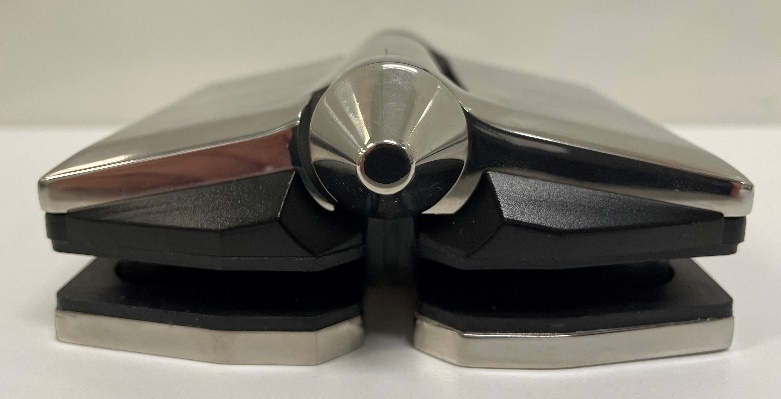
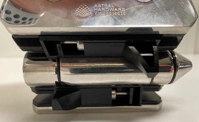
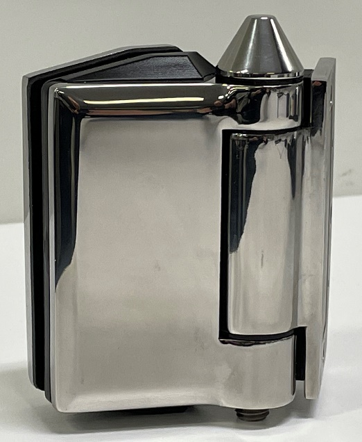
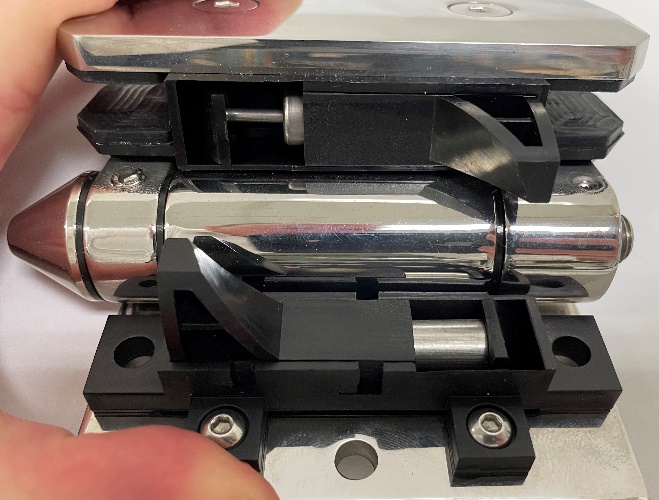
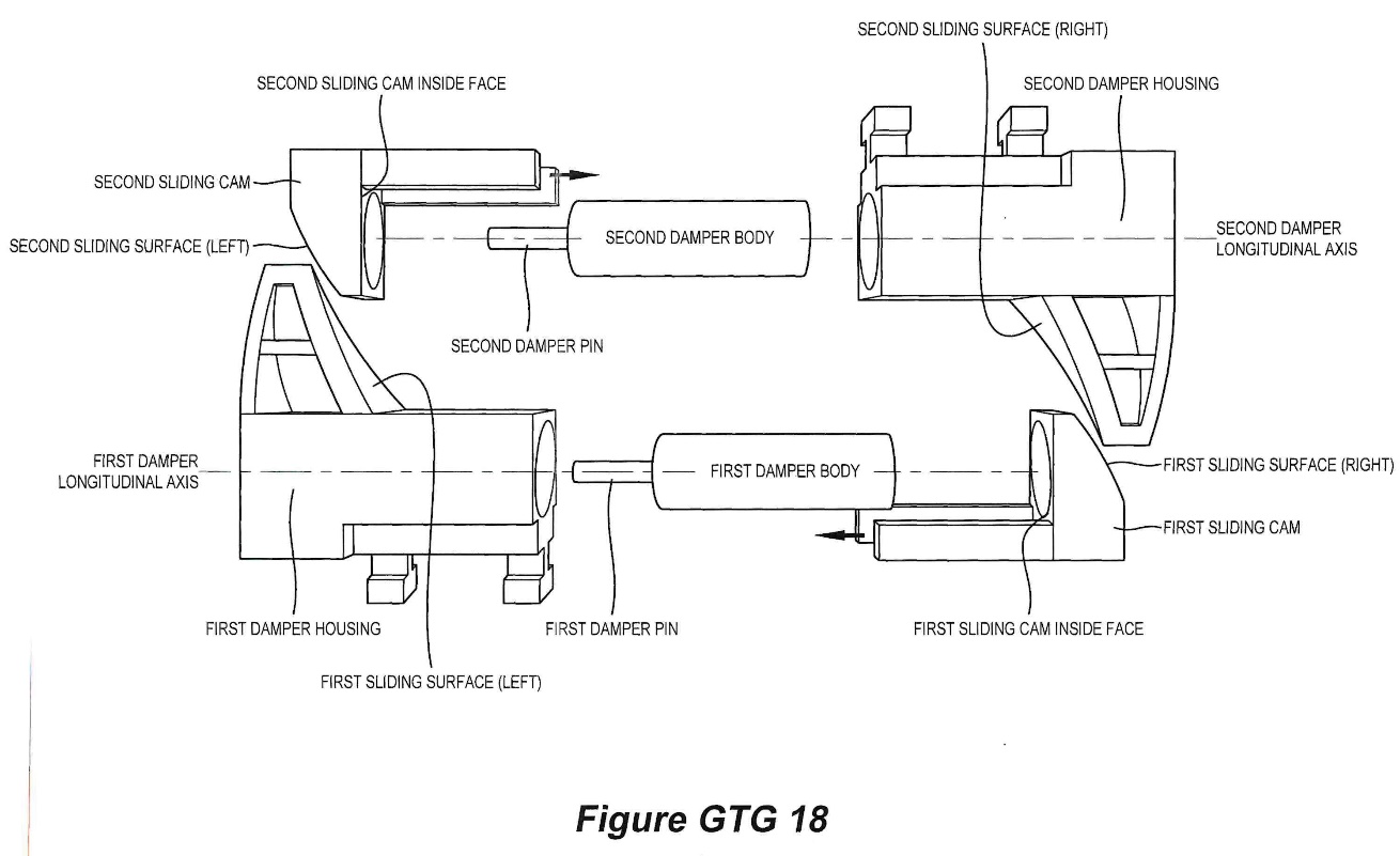
75 Claim 2 is for:
2.1 The hinge according to claim 1, 2.2 wherein the first insert component includes a first and second hole adapted to receive a first and second threaded stem of the first front leaf component, 2.3 wherein a first and second fastener are receivable through corresponding holes of the first rear leaf component and fasten with the first and second threaded stems respectively to secure the first front leaf component to the first rear leaf component.
76 Claim 3 is for:
3.1 The hinge according to claim 1, 3.2 wherein the hinge further includes an end cap coupled to an upper end of a barrel of the hinge, said end cap having an upper surface acutely angled relative to the hinge axis to prevent the end cap being used as a stepping surface.
77 Claim 4 is for:
4.1 A hinge including:
4.2 a leaf assembly including a front leaf component coupled to a rear leaf component for accommodating therebetween a portion of a panel having a cut-out, 4.3 wherein the leaf assembly further includes an insert component located between the front and rear leaf components, 4.4 wherein a portion of the insert component is adapted to locate within the cut-out;
4.5 a mounting component for mounting said hinge, said mounting component hingedly connected to the leaf assembly about a hinge axis;
4.6 a spring operatively coupled to the leaf assembly and mounting component to bias the hinge to move from an open position to a closed position;
4.7 a dampener, having a longitudinal dampener axis, said dampener at least partially housed within the insert component and adapted to dampen movement of the hinge from the open position to the closed position, wherein said longitudinal dampener axis is disposed between and substantially parallel with planes defined by respective opposing faces of the panel.
78 Claim 5 is for:
5.1 The hinge according to claim 4, 5.2 wherein the insert component includes a first and second hole adapted to receive a first and second threaded stem of the front leaf component, 5.3 wherein a first and second fastener are receivable through corresponding holes of the rear leaf component and fasten with the first and second threaded stems respectively to secure the front leaf component to the rear leaf component.
3.4 The claims of the 918 patent
79 As noted, the specification of the 918 patent is not materially different to that of the 485 patent, save that the summary of the invention and the claims differ.
80 It is not necessary for present purposes to address the summary of the invention. The claims are set out below with the relevant integers added.
81 Claim 1 provides:
1.1 A hinge including:
1.2 a first leaf assembly including a first front leaf component coupled to a first rear leaf component for accommodating therebetween a portion of a first panel having a first cut-out, 1.3 wherein the first leaf assembly further includes a first insert component located between the first front and rear leaf components, 1.4 wherein a portion of the first insert component is adapted to locate within the first cut-out;
1.5 a second leaf assembly hingedly connected to the first leaf assembly about a hinge axis, 1.6 said second leaf assembly including a second front leaf component coupled to a second rear leaf component for accommodating therebetween a portion of a second panel having a second cut-out, 1.7 wherein the second leaf assembly further includes a second insert component located between the second front and rear leaf components, 1.8 wherein a portion of the second insert component is adapted to be located within the second cut-out;
1.9 a spring operatively coupled to the first and second leaf assemblies to bias the hinge to move from an open position to a closed position, 1.10 wherein the spring has a longitudinal spring axis which is parallel with the hinge axis to operate as a torsion spring; and
1.11 a dampener, having a longitudinal dampener axis along which a portion of the dampener retracts during dampening, said dampener at least partially housed by the first insert component, 1.12 and wherein said longitudinal dampener axis is disposed between and orientated substantially parallel with planes defined by respective opposing faces of the first panel;
1.13 wherein the second leaf assembly includes a striking surface to cooperate with the dampener to dampen spring induced movement of the hinge from the open position to the closed position.
82 Claims 2 is for:
2.1 The hinge according to claim 1, 2.2 wherein the first insert component includes a first and second hole adapted to receive a first and second threaded stem of the first front leaf component, 2.3 wherein a first and second fastener are receivable through corresponding holes of the first rear leaf component and fasten with the first and second threaded stems respectively to secure the first front leaf component to the first rear leaf component.
83 Claim 3 is for:
3.1 The hinge according to claim 1, 3.2 wherein the hinge further includes an end cap coupled to an upper end of a barrel of the hinge, said end cap having an upper surface acutely angled relative to the hinge axis to prevent the end cap being used as a stepping surface.
84 Claim 4 is for:
4.1 A hinge including:
4.2 a leaf assembly including a front leaf component coupled to a rear leaf component for accommodating therebetween a portion of a panel having a cut-out, 4.3 wherein the leaf assembly further includes an insert component located between the front and rear leaf components, 4.4 wherein a portion of the insert component is adapted to locate within the cut-out;
4.5 a mounting component for mounting said hinge, said mounting component hingedly connected to the leaf assembly about a hinge axis;
4.6 a spring operatively coupled to the leaf assembly and mounting component to bias the hinge to move from an open position to a closed position, 4.7 wherein the spring has a longitudinal spring axis which is parallel with the hinge axis to operate as a torsion spring; and
4.8 a dampener, having a longitudinal dampener axis along which a portion of the dampener retracts during dampening, said dampener at least partially housed by the insert component, 4.9 wherein said longitudinal dampener axis is disposed between and substantially parallel with planes defined by respective opposing faces of the panel;
4.10 wherein the mounting component includes a striking surface to cooperate with the dampener to dampen spring induced movement of the hinge from the open position to the closed position.
85 Claim 5 is for:
5.1 The hinge according to claim 4, 5.2 wherein the insert component includes a first and second hole adapted to receive a first and second threaded stem of the front leaf component, 5.3 wherein a first and second fastener are receivable through corresponding holes of the rear leaf component and fasten with the first and second threaded stems respectively to secure the front leaf component to the rear leaf component.
86 There was no dispute that the skilled addressee of the patents in suit is a person engaged in, or who has experience in, the design of mechanical devices and, in particular, in respect of hinges used in domestic and commercial applications. Nor is there any dispute that Mr Hunter and Mr Richardson fall within that description.
87 The following questions of claim construction, which are relevant to a number of issues, require determination, namely the meaning of:
(a) “insert component” as it appears in integer 1.3 of claim 1 of each of the patents and subsidiary claims;
(b) “adapted to locate” as it appears in integers 1.4 and 4.4 of each of the patents; and
(c) “striking surface to cooperate with the dampener” as it appears in integers 1.13 and 4.10 of the 918 patent.
88 The principles of claim construction are not in dispute. They are conveniently set out in Jupiters v Neurizon [2005] FCAFC 90; 65 IPR 86 at [67] (Hill, Finn and Gyles JJ) as follows:
(i) the proper construction of a specification is a matter of law: Décor Corp Pty Ltd v Dart Industries Inc (1988) 13 IPR 385 at 400;
(ii) a patent specification should be given a purposive, not a purely literal, construction: Flexible Steel Lacing Company v Beltreco Ltd (2000) 49 IPR 331 at [81]; and it is not to be read in the abstract but is to be construed in the light of the common general knowledge and the art before the priority date: Kimberley-Clark Australia Pty Ltd v Arico Trading International Pty Ltd (2001) 207 CLR 1 at [24];
(iii) the words used in a specification are to be given the meaning which the normal person skilled in the art would attach to them, having regard to his or her own general knowledge and to what is disclosed in the body of the specification: Décor Corp Pty Ltd at 391;
(iv) while the claims are to be construed in the context of the specification as a whole, it is not legitimate to narrow or expand the boundaries of monopoly as fixed by the words of a claim by adding to those words glosses drawn from other parts of the specification, although terms in the claim which are unclear may be defined by reference to the body of the specification: Kimberley-Clark v Arico at [15]; Welch Perrin & Co Pty Ltd v Worrel (1961) 106 CLR 588 at 610; Interlego AG v Toltoys Pty Ltd (1973) 130 CLR 461 at 478; the body of a specification cannot be used to change a clear claim for one subject matter into a claim for another and different subject matter: Electric & Musical Industries Ltd v Lissen Ltd [1938] 56 RPC 23 at 39;
(v) experts can give evidence on the meaning which those skilled in the art would give to technical or scientific terms and phrases and on unusual or special meanings to be given by skilled addressees to words which might otherwise bear their ordinary meaning: Sartas No 1 Pty Ltd v Koukourou & Partners Pty Ltd (1994) 30 IPR 479 at 485-486; the Court is to place itself in the position of some person acquainted with the surrounding circumstances as to the state of the art and manufacture at the time (Kimberley-Clark v Arico at [24]); and
(vi) it is for the Court, not for any witness however expert, to construe the specification; Sartas No 1 Pty Ltd, at 485–486.
4.2 The “insert component” integer
89 Claim 1 of each of the 485 and 918 patents provides as part of integer 1.3 that “the first leaf assembly further includes a first insert component located between the first front and rear leaf components” (emphasis added).
90 An “insert component” is also referred to in integers 1.4, 1.7, 1.8, 4.3 and 4.4 of the patents.
91 Polaris contends that the words “insert component” refer to a separately identifiable part that is assembled within the first and second leaf assemblies, and that when the hinge is assembled the “insert component” is a separate component located between the respective front and rear leaf components. It submits, based on Mr Richardson’s evidence, that the word “component” means “constituent part” and that the word “insert” is used as an adjective to describe a component that is being inserted between the front and rear leaf components.
92 TCT contends that the approach of Polaris involves impermissibly reading the word “separate” into the claim. Whilst the specification does envisage that in the preferred embodiment the insert component can be made of different material, TCT submits that the claim includes no language limiting the component to a separate entity. It submits that in engineering usage an “insert” can be a separate component, but it can also be a child component part of a parent component that is integral with one another. This was the view of Mr Hunter.
93 Claim 1 of the 485 patent provides suitable context for consideration of the words “insert component”. No party suggested that the words would have a different meaning in any other claim.
94 That claim describes the relationship between features in the hinge of the invention for a glass-to-glass embodiment. The constituent parts are to include a first leaf assembly, a second leaf assembly, a spring and a dampener.
95 The first leaf assembly includes a front leaf component coupled to a rear leaf component for accommodating between the two a portion of a panel, which has a cut-out (integer 1.2), and includes a “first insert component” which is located between the front and rear leaf components (integer 1.3) and a portion of that insert component is adapted to locate within the cut-out (integer 1.4).
96 The second leaf assembly is hingedly connected to the first leaf assembly and includes a front leaf component coupled to a rear leaf component for accommodating between the two a portion of a second panel, which has a cut-out (integer 1.6), and includes a “second insert component” which is “located between the front and rear components” (integer 1.7) a portion of which is adapted to locate within the cut-out (integer 1.8).
97 The spring is “operatively coupled” to the two leaf assemblies to bias the hinge to move from an open to a closed position (integer 1.9).
98 The dampener is described as having a longitudinal axis and being at least partially housed within the first insert component and adapted to dampen movement of the hinge from the open position to the closed position (integer 1.10) “wherein said longitudinal dampener axis is disposed between and substantially parallel with planes defined by respective opposing faces of the first panel” (integer 1.11).
99 There was no suggestion in the evidence that the language of this claim had any technical meaning that could not be understood by reference to ordinary English usage.
100 The claim describes these four parts by reference to their relationship to each other and their functions, which together combine to result in a hinge. It does not purport to define how the hinge is to be manufactured or the materials from which it is to be made.
101 The word “component” in the claim is to be understood in its ordinary sense as being to describe a constituent part of the hinge. Such a component may be made up of multiple other parts and several components may make up a larger part of the hinge as a whole.
102 The words “insert component” in the claim serve to identify a part of the leaf assembly described, which is to be positioned between the front and rear leaves of the assembly. In that context, the word “insert” is not in my view to be understood as an adjective, as if it were a magazine inserted into a newspaper that is able to be separated from the whole or separately placed in (“inserted”) or removed. Rather, it identifies the part that is positioned between the front and rear leaves and in that sense is “inserted” or “sandwiched” between the two. The language of the claim does not specify one way or the other how this aspect of the leaf assembly is manufactured, but where the component is located. It may be a discrete part that is made and placed into the hinge, or it may in the final product be integral to either or both of the front and rear leaf components. When the hinge is assembled the insert component is physically located “between” the front and rear leaves regardless of whether it is a discrete part or integral to another. The requirement of the claim is that the insert component be situated between the two leaves and adapted to locate within the cut-out.
103 In my view the body of the specification supports this construction. The invention disclosed is directed to a hinge that addresses the prior art problems identified. Whilst it is true that the only embodiment described and depicted in the specification identifies that the insert component is a discrete part (see for example, fig 7C item 40), the specification makes clear that this is only one embodiment and that the person skilled in the art may work the invention in other ways.
104 Furthermore, at [0080] of the specification the patent states that “[p]referably the insert components 40, 60 are injection moulded components in order to further reduce the manufacturing costs of the hinge” (emphasis added). It is telling that where a component is to be manufactured in a particular way, the specification specifies as such. Whilst the outcome of that preference is that items 40 and 60 will be able to be separate “inserts”, the language of the claim does not require it.
4.3 “adapted to locate” integer
105 The words “adapted to locate” or “adapted to be located” are present in integers 1.4, 1.8 and 4.4 of each of the patents. The parties accept that the words will have the same meaning in all of the claims, and so their construction can be considered by reference to the language of claim 1 of the 485 patent.
106 Polaris contends that the words mean “formed to fit”, namely, that the insert component must have some correspondence or consistency of shape between it and the cut-out portion in the panel, while allowing for a degree of tolerance or leeway. This, it submits, is broadly equivalent to the expression “tight fittingly receivable”, which is used in the specification. It submits that the word “adapted” must be given work to do, and in the context of the specification as a whole it means “adapted” by reason of a correspondence or consistency of shape. It relies on the evidence of Mr Richardson.
107 TCT adopts the evidence of Mr Hunter to support a submission that the words “adapted to locate” encompass any relationship that allows a portion of the insert component to fit within the cavity formed by the cut-out. It notes that the words of the claim do not correlate with any language in the body of the specification, which refers to “tight fittingly receivable” only, and submits that where the patentee chooses to use different language in respect of the same integer, it should be understood that the patentee intended to refer to a different thing. Whilst the drawings in the patent depict the existence of small gaps between the insert component and the cut-out (e.g. fig 6G), this should not distract from the language of the claim. It submits that the word “adapted” must be given work to do, which “tight fittingly receivable” does not.
108 The word “adapted” in the phrase “adapted to locate within the first cut-out” in integer 1.4 is a relative term, “adapt” meaning, according to its ordinary usage, “to make suitable to requirements; adjust or modify fittingly”: Macquarie Dictionary (6th ed, 2013). The scope of the phrase “adapted to locate” is to be understood by reference to the role of the first insert component and the purpose that its location in the cut-out is to serve.
109 In that context, it is to be recalled that the insert component is part of a hinge mechanism that is fixed to a panel, typically of glass. When in the closed position, the hinge panel (or door) will align with another panel that will have a latch or similar arrangement to secure it. As Mr Richardson observed in his evidence, the first hinge leaf assembly must be adapted to locate “in order for the panel not to be loose in the first hinge leaf assembly to help prevent the panel from misaligning, moving, coming free or rotating for the invention to function successfully” and later “…[G]iven the context of mounting a hinge in a panel material, in my opinion, it would be obvious to anyone skilled in the art that ‘any shape or size’ is not preferable as the panel could misalign, move, come free or rotate relative to the hinge”. This view was shared by Mr Hunter.
110 This relationship is explained in the 485 patent, which says at [0077] by reference to fig 3 (emphasis added):
… The mouse ear shaped corners of the first and second insert components 40, 60 contribute toward restricting rotational movement between the hinge 10 and the panels 500, 600.
111 Whilst this description is provided in the context of a preferred embodiment, the experts’ evidence indicates that the need to avoid misalignment between the panels is applicable more generally. As Mr Richardson explained in his oral evidence, there were two aspects to the restriction of rotational movement. One is the hinge itself in relation to the panel. The other is the reality of an installed situation, being that there will be two hinges installed on a panel and accordingly the rotational movement will be significantly restricted. He noted that it is important for there to be some allowance for movement or adjustment in order to avoid misalignment and to ensure that the panel (such as a gate or glass door for a pool) is level with the rest of the fence and with the latch. Mr Richardson’s evidence was:
… there needs to be an allowance for an amount of adjustment, not a – a large amount. And that relationship, it’s – the tolerance relationship is compounded by the dimensional variation between the two cut-outs. So the formation of the cut-out in relation to the shape of the insert component, there’s an adapted to locate relationship that the insert component has a offset shape relative to the shape of the cut-out in the glass.
112 Furthermore, the experts agreed that the process of cutting glass panels needs to allow some variation, because there is necessarily a degree of variation in the dimensions of a cut-out, which is typically produced using a diamond tipped grinder wheel to score the glass and then snap it.
113 In my view the requirement in integers 1.4 and 4.4. that a portion of the first insert component be “adapted to locate within the first cut-out” cannot sensibly mean, as Mr Hunter contends, that it permits any relationship that allows a portion of the insert component merely to fit within the cavity formed by the cut-out. It has a more confined meaning which the skilled addressee would understand enabled the fitment to be suitable for purpose.
114 On the other hand, I do not consider the phrase to be synonymous with “tight fittingly receivable”, which is too narrow and necessitates a closer correlation between the insert component and the cut-out than its function would require. As Mr Richardson observed in his oral evidence, the relationships between a screw and a hole drilled for purpose or a piston in a cylinder in a car will be “tight fitting”, while the relationship between a house door and its frame will be relatively tight-fitting.
115 In my view the skilled reader would understand the phrase “adapted to locate” within the claim to mean that the insert component was sized to have a shape relationship between it and the cut-out for the purpose of enabling the hinge to be located or fitted in position. I do not understand it to mean that the insert must fit tightly within the cut-out such that there is little or no room for movement. That would be an impractical construction not required by the language of the claim.
4.4 “striking surface to cooperate with the dampener” integer
116 The following integers describe the operation of the dampener in claim 1 of the 918 patent (integers and emphasis added):
…[1.11] a dampener, having a longitudinal dampener axis along which a portion of the dampener retracts during dampening, said dampener at least partially housed by the first insert component, [1.12] and wherein said longitudinal dampener axis is disposed between and orientated substantially parallel with planes defined by respective opposing faces of the first panel; [1.13] wherein the second leaf assembly includes a striking surface to cooperate with the dampener to dampen spring induced movement of the hinge from the open position to the closed position.
117 A similarly worded integer appears in claim 4 at integer 4.10. The parties agree that the emphasised words will have the same meaning in both claims.
118 Two points arise, the first concerns the meaning of “striking surface” and the second the meaning of “to cooperate with the dampener”.
119 Polaris contends first, that the words “to cooperate with the dampener” in integer 1.13 include indirect action such as via an intermediate component and secondly, that the “striking surface” is something that must be “struck” by operation of something else in the hinge. It relies on the evidence of Mr Richardson to support the proposition that the hitting action of the “striking surface” in integer 1.13 may operate cooperatively on the dampener directly or alternatively through indirect contact via intermediate components operating between the dampener and the striking surface. Secondly, it submits that the definition of “strike” and “striking” means that a striking surface is a surface that is subject to impact from another object. The requirement that the striking surface “cooperate” with the dampener includes arrangements other than those with direct contact, including by an intermediate component.
120 TCT submits that the phrase requires that the dampener and the striking surface be in direct contact with each other. Whilst Mr Hunter agrees in his evidence that, considered in isolation, the words “to cooperate with the dampener” might be sufficiently broad to include the presence of intermediary components between the striking surface and the dampener, TCT contends that the 918 patent specification teaches that direct contact is required.
121 In answer to the second point, TCT contends that a “striking surface” describes a necessary feature of every hinge with a dampener. It contends that the language of the integer does not require the “striking surface” to be “hit” or “struck”. It relies on the evidence of Mr Hunter that “striking surface” is not a term of art and must be understood from the specification. He considers that the integer only requires that direct contact be made between the dampener and the striking surface and that accordingly the dampener and striking surface could be in contact throughout the door closure; no “striking” action is necessary.
122 In my view the words “to cooperate with the dampener” in integer 1.13 indicate that the striking surface does not need to be in direct contact with the dampener, but may interact indirectly with it, in order to achieve the effect of dampening the spring induced movement of the hinge. That is the plain meaning of the phrase “to cooperate with the dampener”. Whilst I accept that, leaving aside the consistory clause at [0011], there is no description of such an arrangement, the approach taken by TCT tends to read down the language of the claim by reference to the preferred embodiments. Nowhere does the specification purport to limit the word “cooperate” which, in its ordinary meaning, refers to a “joint operation or action”: Macquarie Dictionary (6th ed, 2013). Accordingly, in my view integer 1.13 is not to be understood to be confined to a direct interaction.
123 In my view, the approach taken by TCT in relation to “striking surface” deprives the word “striking” of content. Such approach is not to be preferred as a matter of construction. The consequence is that a dampener that is in continuous contact with the surface will not be in contact with a striking surface within the claim.
124 Glass Hardware contends that the GTG hinge infringes claims 1, 2 and 3 of each of the 485 and 918 patents and that the GTW hinge infringes claims 4 and 5 of each of those patents.
125 TCT’s position in relation to infringement changed during the course of the hearing, but ultimately the only issue between the parties in relation to infringement concerned whether integer 1.4 of claim 1 was present in the GTG hinge and whether integer 4.4 was present in the GTW hinge for both of the patents. Otherwise, TCT accepted that all of the integers of the claims of the patents are present in the Orion hinges.
126 Despite the narrowness of the dispute, it is convenient to commence with a full description of the Orion hinges.
127 The impugned products were tendered in evidence. Images of the GTG and GTW products are set out below:
GTG | |
|
|
GTW | |
|
|
128 Exhibit C is a drawing of the dampening mechanism of the Orion GTG hinges:
129 Mr Hunter provided the following description of the apparatus:
21. … the dampeners in each of the Orion Hinges are actuated by a combination of interactions between several sliding surfaces external to the dampeners themselves … . That is, there is no direct contact between the dampener pin or body with a sliding surface provided by an opposite mounting assembly or second leaf assembly. Rather, each dampener is held within a dampener housing which slidingly locates within its respective insert. The insert contains a rectangular channel which houses the dampener in its dampener housing. A further component, which is a sliding cam, also slides in this same rectangular channel. The inside face of the sliding cam contacts the dampener (either the pin or the body) and causes the dampener to retract at approximately 35 degrees from the hinge’s fully closed position as the hinge is closing under spring bias …. The outside face of the sliding cam is actuated by an angled surface protruding from the dampener housing located in either the opposing leaf assembly (in the case of the GTG Hinge) or the mounting component (in the case of the GTW Hinge). Consequently, actuation of each dampener occurs via one intermediate sliding cam making contact with a sliding surface, which then in turn causes the dampener to retract. This arrangement ensures that only axial forces are transmitted to the dampener and the dampener pin does not receive any lateral forces.
5.3 Consideration of the adapted to locate issue
130 The first part of claim 1 of the 485 patent provides (integers and emphasis added):
1.1 A hinge including:
1.2 a first leaf assembly including a first front leaf component coupled to a first rear leaf component for accommodating therebetween a portion of a first panel having a first cut-out, 1.3 wherein the first leaf assembly further includes a first insert component located between the first front and rear leaf components, 1.4 wherein a portion of the first insert component is adapted to locate within the first cut-out;
131 I have in section 4.3 determined that within the emphasised phrase the words “adapted to locate” should be understood to mean that the insert component is sized to have a shape relationship between it and the cut-out for the purpose of enabling the hinge to be located or fitted in position. I do not consider that the phrase requires that the insert must be “tight fittingly receivable”.
132 Having reached this conclusion, I do not understand TCT to dispute that the insert component in the Orion hinges satisfies this integer. If I am wrong about that then, having regard to the analysis conducted by Mr Richardson of the Orion hinges, I am independently satisfied that the insert component of the Orion hinges falls within the scope of integer 1.4 (or 4.4) of both of the patents in suit. Accordingly, subject to the question of validity, the infringement case advanced by Polaris succeeds.
6. INTRODUCTION TO THE REVOCATION CASE
133 In its third further amended statement of claim, TCT contends that the patents are invalid for lack of sufficiency, lack of support, lack of novelty and lack of innovative step.
134 Part of the lack of novelty ground depends upon the contention that the claims are not entitled to a priority date earlier than the filing date of the patents. If that contention is correct, then as a result of my findings of infringement, the patents are anticipated by the Orion hinges and accordingly are invalid. It is convenient to first address the question of priority date before turning to the remaining grounds of invalidity advanced.
135 TCT pleads that the 485 patent and the 918 patent were both filed as divisional applications of the parent on 16 February 2017 and claim priority from the provisional application which was filed on 17 February 2016. Nothing turns on the difference in date between the parent and the provisional application as the disclosure of the two is essentially the same. Accordingly, in the reasons that follow I refer for convenience to the parent only.
136 TCT submits that by operation of s 43 of the Patents Act and the Regulations, the disclosure of the parent does not provide an adequate basis upon which to claim the earlier priority date, with the consequence that the priority date for the 485 patent will be deferred to the date that it was filed, being 30 March 2020, and the priority date for the 918 patent will be deferred until the date of its filing, being 21 October 2020.
137 In its statement of claim, TCT contends that the glass-to-glass and glass-to-wall hinges claimed in the 485 patent extend beyond that disclosed in the parent for several reasons. First, because the broadest disclosure of the parent describes a dampener feature of a specific operation in which the dampener is arranged to come into contact with the second leaf assembly during hinged movement towards the closed position (the coming into contact requirement). Secondly, because the parent discloses only an invention where the dampener partially extends from and retracts within a first insert component. Thirdly, because the orientation of the dampener feature is described in the parent to be orthogonal to the hinge axis, as set out in [0099] of that document (the orthogonal dampener requirement). Fourthly, because the broadest disclosure of the invention is that the first insert component is “tight fittingly receivable within the first cut-out section” of the first panel (the tight fitting requirement).
138 TCT contends that the claims of the 485 patent do not include any of these limitations. In closing submissions only the first, third and fourth reasons were pressed.
139 During closing submissions TCT abandoned a pleaded contention that amendments made to the 485 patent were not allowable.
140 TCT contends that the glass-to-glass and glass-to-wall hinges claimed in the 918 patent extend beyond the disclosure of the parent for the same reasons as those described for the 485 claims, with the additional contention that the parent discloses only a “striking surface” in the hinge located in the second insert component for an end of the dampener body to strike when moving toward the closed position with the dampener at least partially extending from and retracting within the hollow of the first insert component. It contends that the claims of the 918 patent do not possess that limitation (the striking surface requirement).
141 Polaris submits that the scope of the claims of each of the patents is sufficiently disclosed in the parent.
142 Section 43(1) of the Patents Act provides that each claim of a specification must have a priority date. If s 43(2A) applies to a claim, the priority date is the date determined under the Regulations: s 43(2)(a). Otherwise the priority date of a claim is the date of the filing of the specification: s 43(2)(b).
143 Section 43(2A) provides for a presently relevant exception:
(2A) This subsection applies to a claim if:
(a) prescribed circumstances apply in relation to the invention defined in the claim; and
(b) a prescribed document discloses, or a prescribed set of prescribed documents considered together disclose, the invention in the claim in a manner that is clear enough and complete enough for the invention to be performed by a person skilled in the relevant art.
144 Chapter 3, Pt 1, Div 2 of the Regulations determines the priority date of a claim for s 43(2)(a) of the Patents Act: reg 3.12(1). Regulation 3.13D(4)(a), which falls within this part of the Regulations, provides that a prescribed circumstance within s 43(2A) of the Patents Act includes where the “specification containing the claim that defines the invention was filed for (i) a divisional application under s 79B”.
145 By reg 3.13D(4)(b), “the document mentioned in paragraph 1(b) is a prescribed document”. Paragraph (1)(b) says “the specification mentioned in subsection 79B(1) of the Act (the earlier specification) clearly discloses the invention in the claim”.
146 It follows that to be a prescribed document, the earlier specification (here, the parent) must (a) be an earlier specification mentioned in s 79B(1) of the Patents Act; and (b) “clearly disclose” the invention in the claim.
147 Regulation 3.12(4) provides:
In this Division, a document, or a set of documents considered together, clearly discloses an invention if the document, or set of documents, discloses the invention in a manner that is clear enough, and complete enough, for the invention to be performed by a person skilled in the relevant art.
148 The requirement that a priority document clearly discloses an invention the subject of later claims is the same as that set out in s 40(2)(a) of the Patents Act which provides:
40 Specifications
…
(2) A complete specification must:
(a) disclose the invention in a manner which is clear enough and complete enough for the invention to be performed by a person skilled in the relevant art
149 The Explanatory Memorandum to the Intellectual Property Laws Amendment (Raising the Bar) Bill 2011 [2012] (Cth) (RTB Bill) sets out the purpose for changes made to s 43 of the Patents Act. The prior test for determining the priority date was whether the claim was fairly based on the disclosure of the priority document. It says (at p 49):
The item amends paragraph 43(2)(b) to provide that, if prescribed circumstances apply in relation to the claim and the prescribed document discloses the invention claimed in that claim in a manner that is clear and compete enough for the claimed invention to be performed by a person skilled in the art, the priority date of the claim will be the date that is determined under the Regulations.…
150 The Explanatory Memorandum identifies two objectives for the change. The first is to maintain consistency between the requirement of s 40(2) and the requirement for priority. The second is to increase the transparency of the Patents Act.
151 The legislative language indicates the disclosure requirements under s 43 and the Regulations are the same as that under s 40(2)(a) of the Patents Act.
152 In Merck Sharpe & Dohme Corporation v Wyeth LLC (No 3) [2020] FCA 1477; 155 IPR 1 at [511]-[514] and [523]-[526], I addressed the introduction of the current form of s 40(2)(a) into the Patents Act (by way of the RTB Act), the relevant secondary materials and the relationship that it bears to equivalent provisions in European and United Kingdom law. I said the following in relation to the manner in which the requirement under s 40(2)(a) has been applied in the United Kingdom by reference to “classical sufficiency”:
[524] In Mentor Corp v Hollister Inc (No 2) [1992] 7 WLUK 465; [1993] RPC 7 at 14, the Court of Appeal (per Lloyd LJ, with whom Stuart-Smith and Scott LJJ agreed) endorsed a passage from Aldous J at first instance (Mentor Corp v Hollister Inc [1991] 3 WLUK 167; FSR 557 at 562) who said:
The section requires the skilled man to be able to perform the invention, but does not lay down the limits as to the time and energy that the skilled man must spend seeking to perform the invention before it is insufficient. Clearly there must be a limit. The subsection, by using the words “clearly enough and completely enough”, contemplates that patent specifications need not set out every detail necessary for performance, but can leave the skilled man to use his skill to perform the invention. In so doing he must seek success. He should not be required to carry out any prolonged research, enquiry or experiment. He may need to carry out the ordinary methods of trial and error, which involve no inventive step and generally are necessary in applying the particular discovery to produce a practical result. In each case, it is a question of fact, depending on the nature of the invention, as to whether the steps needed to perform the invention are ordinary steps of trial and error which a skilled man would realise would be necessary and normal to produce a practical result.
[525] In Novartis AG v Johns & Johnson Medical Ltd [2010] EWCA Civ 1039; [2011] E.C.C. 10, Jacob LJ said at [74]:
The heart of the test is: “Can the skilled person readily perform the invention over the whole area claimed without undue burden and without needing inventive skill?”
[526] In Terrell on the Law of Patents (19th ed, Sweet & Maxwell, London, 2020), at page 404 the learned editors (Sir Colin Birss et al) propose as a convenient summary of the elements of this aspect of classical insufficiency the following passage provided by Kitchin J (as his Lordship then was) in Eli Lilly v Human Genome Sciences [2008] 7 WLUK 978; RPC 29 at [239]:
The specification must disclose the invention clearly and completely enough for it to be performed by a person skilled in the art. The key elements of this requirement which bear on the present case are these:
(i) the first step is to identify the invention and that is to be done by reading and construing the claims;
(ii) in the case of a product claim that means making or otherwise obtaining the product;
(iii) in the case of a process claim, it means working the process;
(iv) sufficiency of the disclosure must be assessed on the basis of the specification as a whole including the description and the claims;
(v) the disclosure is aimed at the skilled person who may use his common general knowledge to supplement the information contained in the specification;
(vi) the specification must be sufficient to allow the invention to be performed over the whole scope of the claim;
(vii) the specification must be sufficient to allow the invention to be so performed without undue burden.
153 The contrast between previous law applicable in the pre-RTB Act version of s 40(2)(a) of the Patents Act and the present may be seen by reference to the decision of the Full Court in Warner-Lambert Company LLC v Apotex Pty Limited (No 2) [2018] FCAFC 26; 129 IPR 205 (Jagot, Yates, Burley JJ) at [99]-[113].
154 In considering the disclosure obligation, the first step is to construe the claims of the patent to determine the scope of the invention, the next is to construe the description (here, the content of the parent, and in the case of s 40(2)(a), the specification in suit) through the eyes of the person skilled in the art who is in possession of the common general knowledge. The final step is to consider whether the parent provides an enabling disclosure of all the things that fall within the scope of the claims: Cytec Industries Inc v Nalco Company [2021] FCA 970; 162 IPR 202 at [143]. The reference to “all things” that fall within the scope of the claims is to be understood by reference to a materiality consideration, having regard to the nature of the invention disclosed and described: Regeneron Pharmaceuticals Inc v Kymab Ltd [2020] UKSC 27; RPC 22 at [56].
155 In Regeneron, the United Kingdom Supreme Court (Reed P, Hodge, Black, Briggs and Sales LJJ) considered the authorities relevant to the concepts of an enabling disclosure. Briggs LJ concluded as follows at [56] (Reed, Hodge and Sales LJJ agreeing):
Reflection upon those European and UK authorities yields the following principles:
(i) The requirement of sufficiency imposed by article 83 of the EPC exists to ensure that the extent of the monopoly conferred by the patent corresponds with the extent of the contribution which it makes to the art.
(ii) In the case of a product claim, the contribution to the art is the ability of the skilled person to make the product itself, rather than (if different) the invention.
(iii) Patentees are free to choose how widely to frame the range of products for which they claim protection. But they need to ensure that they make no broader claim than is enabled by their disclosure.
(iv) The disclosure required of the patentee is such as will, coupled with the common general knowledge existing as at the priority date, be sufficient to enable the skilled person to make substantially all the types or embodiments of products within the scope of the claim. That is what, in the context of a product claim, enablement means.
(v) A claim which seeks to protect products which cannot be made by the skilled person using the disclosure in the patent will, subject to de minimis or wholly irrelevant exceptions, be bound to exceed the contribution to the art made by the patent, measured as it must be at the priority date.
(vi) This does not mean that the patentee has to demonstrate in the disclosure that every embodiment within the scope of the claim has been tried, tested and proved to have been enabled to be made. Patentees may rely, if they can, upon a principle of general application if it would appear reasonably likely to enable the whole range of products within the scope of the claim to be made. But they take the risk, if challenged, that the supposed general principle will be proved at trial not in fact to enable a significant, relevant, part of the claimed range to be made, as at the priority date.
(vii) Nor will a claim which in substance passes the sufficiency test be defeated by dividing the product claim into a range denominated by some wholly irrelevant factor, such as the length of a mouse’s tail. The requirement to show enablement across the whole scope of the claim applies only across a relevant range. Put broadly, the range will be relevant if it is denominated by reference to a variable which significantly affects the value or utility of the product in achieving the purpose for which it is to be made.
(viii) Enablement across the scope of a product claim is not established merely by showing that all products within the relevant range will, if and when they can be made, deliver the same general benefit intended to be generated by the invention, regardless how valuable and ground-breaking that invention may prove to be.
156 In Illumina Cambridge Ltd v Latvia MGI Tech [2021] EWHC 57; RPC 12 Birss J explained aspects of the passage cited above. He noted by reference to (ii) and (viii), that in the case where the contribution to the art provided by the patent is the ability of the skilled person to make the product itself, then enablement across the scope of the product claim will not be established merely by showing that all products within the relevant claim range will, if and when they are made, deliver the same general benefit intended by the invention, regardless how ground breaking the invention may be. It will be necessary for the whole of the range of the products within the claim to be made: Illumina Cambridge at [255]; Regeneron [56(ii), (viii)].
157 Principles (v), (vi) and (vii) provide a different example of considerations of what it is within the scope of the claim that has to be enabled. It was in the context of these that Lord Briggs distinguished between “principles of general application” and a “relevant range”. Birss J explains at [259] of Illumina Cambridge that the delimitation between a relevant range and one of no relevance is to be determined as a matter of construction of the specification through the eyes of the skilled person possessing the common general knowledge. A claim that is in descriptive or functional language may well cover a variety of things that could be described as a “range”. But it is only if the range is “relevant” that it will be required to be enabled across its breadth. The example given at [277] of Illumina Cambridge is a specification describing a new non-drip spout for a teapot which is shaped in a special way. The claim may not say anything about the material from which the pot itself is to be made. As a matter of theory, it could perhaps be made from vitreous China, or a new substance not known to the art or a range of other materials. However, even though a product within the scope of the claim could be infringed by anyone making a pot with the designated spout, regardless of the material from which it was made (even one not yet invented), the material from which the pot itself is made is not relevant to the invention claimed – which is the spout. Accordingly, the absence of a functional limitation on the material from which the pot is to be made would not be a relevant range in the Regeneron sense.
158 With the exception of the “Summary” of the invention and the claims, the content of the parent is relevantly the same as each of the 485 and 918 patents.
159 The introductory parts of the parent match those in the 485 patent and are as set out in section 3.2 above. They refer to certain prior art hinges and identify the vibration problem caused by vibration in a direction orthogonal to the plane of the glass, the thickness problem caused by the orthogonal orientation of the dampeners relative to the plane of glass and also the thickness of the magnets and the manufacturing problem caused by the amount of steel used in the hinge.
160 The Summary in the parent differs from that in the patents and describes the invention by reference to two aspects, one being a GTG hinge and the other being the GTG hinge. The GTG arrangement is as follows (with integer numbers added):
[011] (1) In a first aspect of the invention there is a hinge including:
(2) a first leaf assembly including a first front leaf component coupled to a first rear leaf component for accommodating therebetween a portion of a first panel having a first cut-out section, wherein the first leaf assembly further includes a first insert component, wherein the first insert component is tight fittingly receivable within the first cut-out section;
(3) a second leaf assembly, hingedly coupled to the first leaf assembly, including a second front leaf component coupled to a second rear leaf component for accommodating therebetween a portion of a second panel having a second cut-out section;
(4) one or more biasing components to bias the hinge toward a closed position; and
(5) a dampener to slow movement of the first and second leaf assemblies to the closed position, wherein at least a first portion of the dampener is located within the first insert component and a second portion is configured to at least partially retract within the first insert component when coming into contact with the second leaf assembly during hinged movement toward the closed position under bias from the one or more biasing components, (6) wherein the second portion of the dampener extends and retracts along an axis which is coplanar with the first panel.
161 The specification next refers to embodiments where the insert components house magnetic elements. It then discloses embodiments of the dampener:
[016] In certain embodiments, the first portion of the dampener is a dampener pin which is coupled within a hollow of the first insert component, and the second portion of the dampener is a dampener body which at least partially extends from and at least partially retracts within the hollow of the first insert component.
162 In [017] the specification says that in certain embodiments the second insert component includes a chamfered striking surface for an end of the dampener body to strike when moving toward the closed position. In [018] it notes that in certain embodiments the first insert component and the second insert component have a mouse ear shaped profile.
163 The parent includes a second aspect at [024] that describes an arrangement of the GTW hinge that utilises broadly the same arrangement of dampener as that which is described in relation to the GTG hinge of the first aspect.
164 The parent then has the same figures and description of the embodiments as set out in section 3.2 above.
165 The parent has 28 claims, which for the purposes of the priority debate form part of the disclosure of the parent.
166 TCT submits that the claim sets in each of the 485 patent and the 918 patent extend beyond the disclosure in the parent. It submits that the claims of the 485 patent simply require the dampener to be “…adapted to dampen movement of the hinge from the open position to the closed position” and do not require any contact between the dampener and the second leaf assembly. Nor do they contain any limitation as to the orientation of the longitudinal axis of the dampener, which for integer 1.11 of the 485 patent must simply be “disposed between and substantially parallel with planes defined by respective opposing faces of the first panel”, thereby leaving it open for the longitudinal axis to be at any angle from 0 to 360 degrees from the hinge axis.
167 TCT submits that the disclosure of the parent is narrower, as set out in the Summary of the invention at [011], which requires a second portion of the dampener “coming into contact with the second leaf assembly during hinged movement toward the closed position”. It submits that this description of the dampener is critical, and describes the means by which the improved dampener mechanism of the parent addresses the problems of the prior art. TCT submits that the disclosure of the parent more generally makes clear that the axis of the dampener identified in [011] is coplanar with the panels because the dampener described is always oriented orthogonally to the hinge axis, as set out in the embodiments, relying also on [090], [091], [096] and [099] of the parent (being, [0069], [0070], [0075] and [0078] of the 485 patent). In this way, it submits, the requirements of direct contact and orthogonal angle of the dampener are interdependent and complementary throughout the description, such that there is no disclosure of a broader description of the invention claimed in the patents in suit in the parent.
168 TCT relies on Regeneron at [56] in support of the proposition that the requirement of sufficiency is to ensure that the extent of the monopoly conferred by the patent corresponds with the extent of the contribution that it makes to the art. In the case of a product, subject to de minimus exceptions, a claim which seeks to protect products which cannot be made by the person skilled in the art will exceed the contribution to the art. Where a patentee relies upon the contention that the specification discloses a “principle of general application” that is reasonably likely to enable a whole range of products, then the disclosure, without more, may be enough to justify the monopoly. However, the patentee takes the risk, if challenged, that the supposed general principle will be proved at trial not in fact to enable a significant relevant part of the claimed range to be made as at the priority date. TCT contends that the “coplanar” aspect of the invention disclosed in the parent is not a principle of general application, because the disclosure of the specification does not enable the skilled person to make available all variants within the range of the claims citing, amongst other authority, Merck at [532]-[543]. It submits that the only invention disclosed in the parent is one where the dampener retracts within the first insert component when coming into contact with the second leaf assembly along an axis which is coplanar with the first panel and where the dampener axis is orthogonal to the hinge axis.
169 TCT submits that the person skilled in the art could not make a product within the whole scope of the claims of the 485 patent based on the teaching of the parent without undue burden or the exercise of inventive skill. In this regard, it relies on the evidence of the experts and placed emphasis on the Orion hinges as representing an embodiment of a product that falls within the scope of the claims which is not enabled by the parent.
170 Polaris accepts that the relevant legal tests are identified in Cytec and Merck. It submits that the heart of consideration of the requirement of disclosure is “can the skilled person readily perform the invention over the whole of the area claimed without undue burden and without needing inventive skill”, citing Merck at [526]. It emphases that the onus lies upon TCT.
171 Polaris submits that the invention claimed in the patents is of a product framed by its physical characteristics using descriptive and functional language. The skilled reader would understand upon reading the specification that it is plausible to make a reasonable prediction that the invention will work with substantially everything falling within the scope of the claim.
172 Turning to the disclosure of the parent, in relation to the dampener integer Polaris submits that the second portion of the dampener disclosed at [011(5)] of the parent is configured to at least partially retract within the first component “when coming into contact with the second leaf assembly”. This, it submits, does not require that there is “direct” contact between any particular part of the dampener mechanism and the second leaf assembly, and contact may occur through another component. It submits that there is no reason why a feature such as a sliding cam that is engaged and moves with the dampener pin to provide the dampening effect cannot be considered to be part of the “dampener” as disclosed in [011]. It submits that the term “dampener” is not a term of art, and may be understood to mean the same thing as “dampener mechanism”.
173 Polaris disputes that the parent discloses any limitation that would serve to confine the disclosure of the dampener of the invention to any particular angle relative to the hinge axis. It submits that the only requirement disclosed in the parent is that the longitudinal axis be coplanar with the panel. In this regard it contends that the detailed description in the parent identifies each of the components of the invention that is consistent with the breadth of the claims of the patents in suit. It emphasises that the detailed description of the embodiments is expressly said to be given by way of example only (at [085] of parent and [064] of the 485 patent) and that it is apparent that the general disclosure emphasises the coplanar aspect of the longitudinal axis at [090] and [093] (485 patent at [0069] and [0072]), which is explained in the parent at [091] and [096] (485 patent at [0070] and [0075]) as being responsible for addressing the prior art vibration problem, the manufacturing problem and the thickness problem. Contrary to TCT’s submissions, Polaris submits it is apparent from the parent that it does not matter what angle the longitudinal axis takes, so long as the coplanar requirement is maintained.
174 Polaris submits that the United Kingdom cases disclose that, for product claims, the nature of the sufficiency requirement and the extent of the disclosure will depend on whether the patent claims a “relevant range” of products (in which case detailed embodiments may need to be disclosed across the breadth of that range) or whether the claims simply identify the product using descriptive or functional language which necessarily covers a variety of arrangements (in which case the disclosure of a single embodiment may suffice). Polaris disputes that the claims of the patents in suit purport to describe a “relevant range” within Regeneron, submitting that no significance is given to the particular orientation of the dampener either in the parent or the patents, other than that it be coplanar relative to the panel. Further, it contends that this is a case in which descriptive, functional or structural language is used to describe the features of the product.
175 Polaris relies on the explanation of Regeneron given by Birss J in Illumina Cambridge to distinguish a “relevant range” from descriptive or functional language. It submits that the invention of the patents in suit is of a type that is appropriately enabled (and supported) by a general disclosure of the invention in terms commensurate with the claims along with a more detailed description of a single preferred embodiment.
176 Polaris submits that whilst it does not need to put its case in this way, the coplanar aspect of the disclosure can be understood to be a principle of general application, as that term was used in Regeneron.
177 Finally, Polaris submits that TCT has failed to establish that a person skilled in the art, using the teaching of the parent and the ordinary skill as a designer in the light of the common general knowledge, would not be able to perform the invention across the scope of the claims of the patent. It submits that the evidence demonstrates that the work required would be essentially routine. Polaris submits that TCT has not established its case going to burden for the following reasons. First, a skilled person would understand that other arrangements could be employed to meet the requirements of the claims. Secondly, if a skilled addressee wished to make an embodiment with the dampener orientated at an angle other than orthogonal to the hinge axis, they could do so, as Mr Hunter and Mr Richardson discussed by reference to exhibit D. Thirdly, Mr Hunter’s evidence of how long it would take to develop an alternative hinge concerned the process of taking a product to market, which was irrelevant, and the evidence established that even making the preferred embodiment would take considerable time. Fourthly, Mr Richardson’s agreement that his Exhibit D design involved “imaginative faculty” can be of no assistance, because it was not explored what he meant by it. Fifthly, the reliance by TCT on the Orion hinges as an exemplar of the burden of work required and the use of inventive faculty to create a hinge with dampeners located at an angle other than orthogonal is also of no assistance because TCT adduced no evidence going to the process of making those hinges. The unexplained failure of TCT to call a designer is such that the Court may infer that the evidence would be of no assistance TCT, citing Jones v Dunkel [1959] HCA 8; 101 CLR 298.
7.5 Review of the submissions and the expert evidence
178 In considering whether the invention claimed in the 485 patent is disclosed in a manner that is clear enough and complete enough for the invention claimed to be performed by a person skilled in the art it is first necessary to consider the scope of the claims. The parties addressed this question by reference to claim 1 of the 485 patent and in particular by reference to two parts of the combination identified in it. The first concerns the “adapted to locate” integer which I have construed in section 4.3 above. TCT submits that this is much broader in concept than the disclosure of the parent, which refers to “tight fittingly receivable” in the description. I return to this at the conclusion of this part of my reasons.
179 The second concerns the “dampener” integers in claim 1, which I repeat for convenience:
1.10 a dampener, having a longitudinal dampener axis, said dampener at least partially housed within the first insert component and adapted to dampen movement of the hinge from the open position to the closed position, 1.11 wherein said longitudinal dampener axis is disposed between and substantially parallel with planes defined by respective opposing faces of the first panel.
180 It is apparent that the dampener of the claim must have a longitudinal dampener axis, be at least partially housed within the first insert component and be “adapted to dampen movement” of the hinge when under bias it moves from the open to the closed position. The claim is agnostic as to the arrangement of the dampener relative to the second leaf assembly. It is this aspect of the claim upon which TCT’s submissions focussed. Otherwise, the claim requires in integer 1.11 that the longitudinal axis of the dampener be disposed between and substantially parallel with planes defined by the opposing faces of the first panel. This means that the dampener must be co-planar or parallel with the panel in which it sits.
181 The parties are at issue as to whether the parent discloses a dampener arrangement as claimed in claim 1 of the 485 patent, and whether a person skilled in the art is adequately enabled to make a hinge within the breadth of the claim.
182 More specifically, TCT contends that the disclosure of the parent does not sufficiently describe a hinge which deviates from an arrangement whereby the longitudinal axis of the dampener is aligned to be orthogonal to the hinge axis. It contends that the summary of the invention at [011] of the parent, and the disclosure of the balance of the specification is confined to a mechanism whereby a portion of the dampener retracts within the first insert component “when coming into contact with the second leaf assembly” during closing of the hinge under the influence of a biasing component. The only manner in which this occurs is when the dampener is arranged to be orthogonal to the hinge axis.
183 Polaris first disputes that the parent requires that there be an orthogonal arrangement. It submits that [011] does not require it, because the reference in [011(5)] does not require that the dampener come into “direct contact” with the second leaf assembly. Alternatively, it submits that the word “dampener” in [011] should be understood to refer to a “dampener mechanism” rather than a particular part, which may include a sliding cam which cooperates with the dampener.
184 In my view the disclosure of the parent as a whole, when considered in conjunction with the expert evidence, supports the contentions advanced by TCT.
185 The passage at [011] is set out immediately after the Background and supplies a Summary of the invention. It relevantly provides in relation to the dampener:
(5) a dampener to slow movement of the first and second leaf assemblies to the closed position, wherein at least a first portion of the dampener is located within the first insert component and a second portion is configured to at least partially retract within the first insert component when coming into contact with the second leaf assembly during hinged movement toward the closed position under bias from the one or more biasing components, (6) wherein the second portion of the dampener extends and retracts along an axis which is coplanar with the first panel.
186 In my view the reference to the dampener “coming into contact” with the second leaf assembly is unambiguous. It requires that the dampener make contact or touch the second leaf assembly. The language does not admit for a construction that would permit an intermediate part or indirect contact to be made.
187 Nor, in my view can “dampener” be read down to mean “dampener mechanism” such that not only may a dampener contact the second leaf assembly, but also a part attached to it may, such as a sliding cam. In this regard three points may be made.
188 First, a “dampener” is a component recognised in the field. In his evidence, Mr Hunter describes a dampener as a part where a piston moves inside a cylinder and the motion of the piston is restricted in some way, such as by friction or by pressure resistance by the working fluid. Mr Richardson similarly observes that a dampener with a longitudinal dampener axis operates to dampen in a linear direction. By contrast, there are other commercially available dampeners that operate to dampen rotationally which are not the subject of the claims because they do not have a longitudinal axis.
189 Secondly, the balance of the body of the specification supports the view that the skilled reader would understand the reference to a dampener to be to a particular component. The only description of a dampener in the parent is of the embodiment referred to in the figures. In those, dampener 100 is described and depicted as an individual part, having dampener body 104 and dampener pin 102 (see fig 3 of the parent and also the 485 patent). If the broader definition proposed by Polaris were adopted, the “dampener” would include other parts of the hinge that are not a dampener, but which cooperate with it to achieve that function such as the separately described striking surface 64. There is no suggestion that this was intended, and I reject the contention that the skilled addressee would read the reference in [011] or the specification of the parent as a whole in that way.
190 Furthermore, the Background refers to prior art dampeners that were orientated orthogonally relative to the plane of the hinge members, with the overlapping portion of the hinge contacting “a protruding portion of the dampener when the hinge had nearly progressed to the closed position”. This suggests that the dampener referred to is not a broad “mechanism” but rather a part, which has a particular orientation and protrusion. Leaving aside the context of the language of the [011] of the parent as a whole, perhaps the clearest reason for this view is that the patentee has chosen to use the word “dampener” and not “dampener mechanism” in that paragraph and elsewhere in the parent.
191 Thirdly, the expert evidence further supports this distinction. In cross-examination during the course of the concurrent evidence session Mr Hunter was asked to agree that the second dampener in the Orion hinge included the parts identified in the drawing (depicted in section 5.2 above), being jointly the second damper body, second dampener pin and also the second sliding cam. Mr Hunter resisted that proposition. It was then suggested that the second sliding cam could be regarded as part of the “dampener mechanism” to which he responded:
MR DIMITRIADIS: And I suggest to you that that is fairly – you’re fairly able to regard that [being the sliding cam] as part of the dampener mechanism in this product for that reason?
MR HUNTER: I think it’s a fair – it’s fair to say that it’s a component of the overall dampening mechanism, because a mechanism can obviously be comprised of many different components that work together to achieve a functional outcome, but you were saying something different before, which was that the sliding cam was part of the dampener, which is not something I would agree with.
192 I accept Mr Hunter’s description.
193 In my view it is not only [011] of the specification that confines the scope of the invention disclosed and described to one where the dampener is aligned to be orthogonal to the axis of the hinge. In the balance of the specification of the parent this is the only arrangement described. The description of the preferred embodiments specifically emphasises that the dampener makes (direct) contact with the second leaf assembly, thereby ensuring the orthogonal arrangement: see, for example, [090] (485 patent at [68]), [114] ([093] of the 485 patent) and also [99] ([078] of the 485 patent), which relevantly provides:
[099] As shown in Figure 7A, 7B and 7C, the first insert component 40 includes a plurality of hollows 44 which have a longitudinal axis which is orthogonal to the hinge axis 290 and coplanar with the plane of the first panel 500. … Due to the dampener pin 102 being secured within the respective hollow 44 and the dampener body 104 having a cross sectional profile which substantially corresponds to the cross-sectional profile of the respective hollow 44, the dampener pin 102 is less likely to deflect and bend during hinge movement toward the retained position. … As the orientation of the longitudinal axis of the one or more dampeners 100 is substantially coplanar with the first panel 500, the overall thickness of the hinge leaf component 20 can be reduced thereby providing material efficiencies in relation to manufacture of the hinge. Additionally, due to the orientation of the dampeners 100, a majority of the vibrational force experienced by the hinge 100 when approaching the retained position is transferred in a direction substantially parallel to the planes of the faces 502, 504, 602, 604 of the panels 500, 600 thereby reducing the stress on the panels when moving toward the retained position.
194 The teaching in this passage is not only of the advantages of the coplanar aspect of the hinge arrangement, namely that the overall thickness of the hinge may be reduced thereby addressing the manufacturing problem and the alignment of the majority of the vibrational force to reduce stress on the panels. It is also of the arrangement of the dampener pin which is less likely to deflect and bend during hinge movement.
195 The expert evidence indicates that the person skilled in the art reading the parent would understand that the advantage of the orthogonal arrangement of the dampener relative to the hinge axis is that it addresses a problem that would otherwise arise in dealing with lateral forces that would be applied to the dampener at other angles.
196 Mr Hunter’s evidence was that to make a hinge with dampeners that had a damped closing function and that addressed the problems identified in the parent without the dampeners coming into direct contact with the second leaf assembly would require new concepts to be developed for a completely new hinge design compared with that described in the parent.
197 Mr Richardson gave evidence in answer that in his view it would be apparent to anyone skilled in the art that there are other embodiments beyond those described in the specification of the parent where the dampener comes into contact with the second leaf assembly without necessarily coming in contact with the second insert component. However, in this context his evidence was that:
…for anyone skilled in the art of using dampeners in product design it would be known that other arrangements can be employed that include a dampener with a longitudinal axis… For example, an intermediate sliding component could be used between the dampener and the second insert component that would not require the dampener to come in direct contact with the second insert component as in hinge 10 (emphasis added).
198 Significantly, Mr Richardson went on to say that an intermediate sliding component “could also mitigate the effect of force that is not co-axial with the dampener axis as the angle changes between the dampener axis and the striking surface of the second insert component … as the hinge rotational movement approaches the closed position”.
199 Mr Richardson gave evidence that by using an intermediate component between the dampener and the second leaf assembly “it would be possible to have a dampener in orientations different to orthogonal to the hinge axis”. Yet no intermediate components are described or disclosed in the parent. It is apparent that Mr Richardson was deviating from the disclosure in this evidence.
200 Mr Hunter cogently explains the mechanical consequences of moving away from the coming into contact requirement and the orthogonal dampener requirement in his evidence in chief. He says that adopting orientations that significantly vary from one that is orthogonal to the hinge axis and, when the hinge is fully closed, the striking surface of the second leaf assembly would produce the negative effects of asymmetrical forces on the dampener. As he explains, it is a matter of simple geometry that, if the dampener is used on an angle rather than having its longitudinal axis being orientated orthogonally to the striking surface when the hinge is fully closed, its stroke will need to be longer in order to provide the same dampening effect. It will in turn need to have a deeper hollow within which to be retained, which will be less compact.
201 He further explains, again as a matter of simple geometry, that dampeners that are subject to asymmetric loads are more likely to jam or fail. If a dampener is used on an angle rather than having its longitudinal axis orthogonal to the striking surface when fully closed the striking surface will “load” the dampener asymmetrically by exposing it to side or “lateral” loads. It will increase the tendency of the dampener to jam and could lead to premature failure, particularly for piston dampeners featuring a dampener pin. He notes in this regard that fig 6H of the parent shows that, in keeping with one of the objectives of the specification, the dampener itself is quite thin, with the pin being even thinner. Accordingly, the dampener pin depicted will be quite prone to failure if loaded in a non-axial direction. As a result of these matters, an engineer would seek to avoid putting the dampener at a different angle.
202 Mr Hunter gives evidence going to the challenges facing the person skilled in the art seeking to design a hinge with a dampener that did not meet the orthogonal dampener requirement. He notes that there is no disclosure as to how to implement such a device. If he were trying to do so, he considered that he would need to re-design the insert components, the hollows to house the dampener and the shape of the striking surface, identify whether the same or a different type of dampener should be used, and then develop a testing protocol for ascertaining whether the other orientation could work.
203 He further explained that this would involve identifying or building a test rig to run tests on the hinge’s durability and testing the effect of asymmetric loading on the dampener pin, body and piston seals and on the hollow to take into account the effects of the lateral loading described above. This would, he considered, take a lot of time and skill and substantial design and experimentation work.
204 In his oral evidence, Mr Hunter emphasised that the step of changing the dampener angle involved a fundamental redesign of parts and the possible introduction of new parts which, he said “is pretty much like starting all over again”. In this context, a variation of angle orientation of ten degrees would likely require fundamental changes, because by that point one begins to put “considerable lateral loads” on the dampener and it is necessary to take steps to protect it. As he explained, by reference to [0078] of the 485 patent (which is [099] of the parent):
MR DIMITRIADIS: What I’m suggesting to you is that the reason you’re not motivated to make – to look at making another embodiment - is because, provided you get the result of a hinge that has acceptable dampening, it doesn’t matter to you what axis the dampener lies in and what plane it lies in as long as it gives you the result.
MR HUNTER: No, that’s not true because if the – the reason why the embodiment in the patent is attractive is that, and it obviously goes to some length to describe this as we’ve – we’ve been through before in paragraph 78, it describes a particular arrangement of the dampener where the pin is captured inside the insert. The dampener body is sliding in and out in a hollow. It’s oriented orthogonally to the hinge, and as a result of that arrangement, one of the most important things we can do with this hinge is to protect the dampener from failure and prevent the dampener from locking up by protecting it from lateral loading. So the patent seems to me to be, and as described in 78, a good solution to that problem. So once you start saying, well, then, I can just choose any dampener orientation angle, that whole benefit of paragraph 78 goes away, so I’m not inclined to think that another dampener on angle is axiomatic from there.
205 As noted above, Mr Richardson’s evidence demonstrated that he was also concerned about the effects of lateral loading on the dampener if the angle was changed. He agreed, in discussion with Mr Hunter during concurrent evidence, that if he were to change the angle of the dampener from orthogonal to the hinge, it would make the lateral load problem worse than in the embodiment described in the patent. He then proposed that in order to address that problem it would be necessary to add an intermediate component, which he then depicted in a hand-drawn sketch, which became exhibit D, as follows, where the dampener is (1), the intermediate component is (2), the striking surface of the second leaf assembly is (3) and the dampener cylinder recess is (4):
206 He explained that if the dampener axis was at 45 degrees (as depicted) and also within the coplanar relationship described, then the intermediate component (2) could be positioned on the end of the dampener, with a twisted, angled face which sits out towards the second leaf assembly (3). When the hinge operates to close, as the second leaf assembly comes closer to the first leaf assembly housing the dampener (1), the intermediate component (2) slides progressively over the angled surface on the second leaf assembly so that it compresses the intermediate component in the same direction as the dampener axis.
207 Mr Richardson explained that he would start the design process with hand sketches and move to computer aided design drawings, using software to create the forms of the parts and the relationship between the parts. He gave evidence that the difficult aspect to design is the shape of the surfaces that are coming together and how they would interact. He gave evidence that there are different ways to go about it, the easiest being to define a start position when the surfaces contact, the final position and some intermediary points. This, he said, “would start to indicate to you a shape for a lofted surface which would be on each part, because what you’re trying to do is to maximise the contact area so that you don’t have a high wear area in one location as those surfaces come together”. He said that one could do it mathematically, but that would be “very difficult”. He would instead design a prototype, and then build that and test it and then tune the design from there.
208 It is apparent from his evidence that he would not know whether the problem of the lateral loading had been solved until the prototype was built and tested.
209 After a leading question from counsel for Polaris, Mr Dimitriadis SC, Mr Richardson agreed that the process that he had described was the sort of process that he adopted in his practice as a designer. However, leaving aside that he was led to that point, it is apparent from the context of his explanation that Mr Richardson was explaining the process of a new product design.
210 Indeed, Mr Richardson accepted that the process of arriving at a design such as depicted in exhibit D involved a new design using his own “imaginative faculty”. In my view this observation provides a degree of insight into the task facing the skilled addressee who wishes to design a device within the scope of claim 1 of the 485 patent. It points to the fact that the parent leaves gaps in its teaching that must be filled by imaginative design work. An example of a gap, as I have found, is that the parent does not disclose the use of an intermediary component.
211 I accept, as Mr Hunter explained, that the step of changing the dampener angle involved a fundamental redesign of parts. By this, I understand his evidence to mean that the parent specification does not disclose to him how to address the problem of moving away from the orthogonal arrangement.
212 Separately from the example given by reference to his sketch (exhibit D), Mr Richardson agreed that if one were to change the orientation of the dampener from orthogonal to the hinge axis, the person skilled in the art would need to make a number of decisions, none of which is guided by the patent beyond a requirement that the angle of orientation be in the same plane as the panel. Those decisions would include which angle of orientation to choose; what arrangement to design for any intermediate sliding component or components; what arrangement to choose for any cooperating elements; the rearranged design of an insert component; and how those components are to fit together. He agreed that whilst with the benefit of the parent he would be able to keep the outside features of the hinge (being the broad arrangement of the first leaf assembly, the hinge knuckle and the second leaf assembly), the interaction between the dampener and the second leaf assembly and the internal components of the insert would need to be altered.
213 In his oral evidence, Mr Richardson agreed that the Orion hinges provide an example of a design that falls within the scope of claim 1 of the 485 patent. It will be observed that those hinges possess dampeners that are not orthogonal to the hinge axis but parallel to it. Nor do the dampeners come into contact with the second leaf assembly. Rather, the addition of intermediate sliding cam surfaces ensure that the dampener performs its function.
214 The statutory test under s 43(2A) and reg 3.12(4) is whether the parent clearly discloses the invention in the claim of the 485 patent. It will do so if the parent discloses the invention in a way that is clear enough and complete enough for the invention to be performed by a person skilled in the art. The requirement of “clear enough and complete enough” leaves room for persons in the art to use their ordinary skills to perform the invention claimed, assisted by the specification (here, of the parent) and their common general knowledge: Mentor Corp v Hollister Inc (No 2) [1992] 7 WLUK 465; [1993] RPC 7 at p 14.
215 For the reasons set out in more detail above, claim 1 of the 485 patent is for an invention that is broader in terms than the invention disclosed in the parent. Claim 1 contains no limitation as to the orientation of the dampener or the means by which it effects dampening upon the closing of the hinge. By contrast, the disclosure of the parent describes the invention by reference not only to the co-planarity feature, but also by reference to limitation that the dampener come into contact with the second leaf assembly, being arranged such that it is orthogonal to the hinge axis. The person skilled in the art would understand that limitation to be the means by which the inventor has resolved the problem of constructing a hinge with a dampener which will be subject to lateral forces when closing.
216 The expert evidence discloses that when the orientation of the dampener is changed from orthogonal to the hinge, lateral forces quickly become a problem. As Mr Hunter said, when deviating from the orthogonal by only ten degrees, those forces could cause the dampener to fail. Indeed, Mr Richardson considered that the lateral forces applied to the dampener even in its orthogonal arrangement would give him cause for concern. For that reason he proposed the addition of an intermediate component for a non-orthogonal arrangement, one example of which he depicted in exhibit D.
217 These matters serve to elucidate that the invention as disclosed in the parent is not as broad as Polaris contends. The parent does not disclose a hinge mechanism whereby the axis of the dampener is simply coplanar with the first panel. Although it may be accepted that the disclosure of the parent in a number of parts serves to emphasise the importance of the longitudinal axis of the dampener being coplanar with the panel in order for vibratory force to be transferred in a direction parallel to the plane of the panel (see, for instance, parent at [090], [091], [099], respectively [0069], [0070] and [0078] of the 485 patent), the parent also emphasises that the dampener comes into direct contact with the second leaf assembly. That requirement limits the scope of the invention as disclosed and described to a particular hinge mechanism in which the longitudinal dampener axis is more or less orthogonal to the hinge axis. I say “more or less” because plainly there will be scope for some variance from the perpendicular. However, the range will be modest, having regard to the lateral forces.
218 Polaris submits that claim 1 of the 485 patent simply identifies a product using descriptive or functional language that necessarily covers a variety of arrangements. It cites Illumina Cambridge in support of the proposition that, in such a context, a general disclosure of the invention in terms commensurate with the claims accompanied by a more detailed description of a single preferred embodiment will suffice.
219 However, in my view the invention disclosed and described in the parent is limited to the ability to make the product itself as contemplated in Illumina at [255] and Regeneron at [56(ii) and (viii)]. Although other hinges that have a dampener with a longitudinal axis that is coplanar with the panel may achieve the benefits described in overcoming the vibration, manufacturing and thickness problems, the contribution to the art in the patent application is the ability of the skilled person to make the product itself. Enablement across the scope of the claim will not be established merely by showing that all products within the claim range will, if and when they are made, deliver the general benefit concerning the vibration, manufacturing and thickness problems. It will be necessary for the whole range of the products within the range to be made.
220 For the reasons developed in section 7.5 and above in this section, I am persuaded that, in order to adjust the axis of the dampener to an angle that is materially beyond one that is orthogonal to the hinge axis, significant research and development would be needed. I consider that the evidence of the steps required as set out by both of the experts demonstrates that the exercise would involve the development of an intermediate component, additional to the dampener, and the design of the interacting surfaces to meet it. Even with a plan in mind to place the dampener axis at a different angle (contrary to the evidence of Mr Richardson, I do not accept that the parent suggests or teaches one), the person skilled in the art would be required to ascertain what that angle should be, itself no easy task, and then use computer-aided design techniques to develop a prototype and develop a test rig. The evidence reveals that even were that to be done, the skilled addressee would not be sure that the result would be a design with a dampener that could withstand the lateral forces involved. The exercise might have to be repeated with alternative designs and angles. The insert components would require redesign to accommodate the configuration.
221 The evidence volunteered by Mr Richardson in relation to exhibit D was, in my view, an indication of the task required.
222 Polaris submitted that the work required by the skilled person was within the day-to-day work of engineers with the skill of the experts. It relied on oral evidence given by the experts to the effect that all of that work was “normal practice in developing many products, including complex products”. However, the evidence upon which Polaris relies in this respect is in my view unpersuasive. Mr Hunter’s acceptance was more limited that Polaris’ submissions suggest. As he said:
MR HUNTER: Because – I will just re-emphasise what I just said – that when we’re – when we’re changing the fundamental characteristics of a design in the way– some of the ways in which we’ve just described – for instance, what we talking about – of a fundamental redesign of parts, possibly the introduction of new parts, and it’s pretty much like starting all over again.
MR DIMITRIADIS: And what you’ve just referred to, that would apply, would it to changing the angle of the dampeners from the preferred embodiment by, say, 10 degrees?
MR HUNTER: Possibly. Yes. Because then you’re starting to put some considerable lateral loads on the dampener. So how are you going to protect the dampener from – from that? Are you then going to have to introduce bearings into the hollows where the dampener runs to protect it from side loads, or is that not necessary? I don’t know the answer to those sorts of questions, so, you know, again, a lot of it is like starting again.
MR DIMITRIADIS: And that process of designing something, a variation like that, is the sort of thing that you do in your trade as a designer on a day-to-day basis when you’re designing products, isn’t it?
MR HUNTER: That’s true. Yes.
MR DIMITRIADIS: Mr Richardson, do you agree with that?
MR RICHARDSON: Yes. That’s right.
223 The concession obtained is of limited value. On its face, it asks about the task when the engineer is designing a new product. This does not equate to the task presently under consideration, which is not a question of new product design, but the enablement of an invention said to have been disclosed in a patent specification. Furthermore, conclusionary statements by experts do not in any event go very far. The process of considering sufficiency of disclosure involves an evaluation of the disclosure, in the context of the art and consideration of whether implementing the invention across its scope falls on the wrong side of the line. In my view in the present case it does.
224 For similar reasons I reject the submission advanced by Polaris to the effect that it was not put to Mr Richardson that the steps required to be taken, as explained in his evidence, required “undue effort”. Such evidence could only be of limited weight in circumstances where the test requires more substantive evaluation of the task involved.
225 In my view the evidence demonstrates that the parent does not disclose the invention claimed in claim 1 of the 485 patent clearly enough or completely enough for the invention to be performed by a person skilled in the art.
226 Finally, I note that Polaris submits that, “stepping back from the detail of the evidence”, at its heart the case advanced by TCT is that the description of a single embodiment does not provide a disclosure that is clear enough and complete enough to perform a broader invention as claimed. It submits that TCT seeks to limit the disclosure of the parent to its preferred embodiment. I accept that the description of a single embodiment may in any given case be enough to satisfy the disclosure requirement across a range. This will depend, however, upon the disclosure of the specification, the common general knowledge and the skills of the relevant addressee. The decision in this case establishes no principle to any different effect. On its face, the disclosure of the parent is not sufficiently clear and complete for the invention disclosed in the claims of the 485 patent to be performed.
7.7 Conclusion in relation to deferred priority date
227 I have found above that the requirements set out in s 43(2A) of the Patents Act and the Regulations are not met, with the consequence that claim 1 of the 485 patent is not disclosed in a manner that is clear enough and complete enough for the invention to be performed by a person skilled in the relevant art. The same conclusion necessarily applies to dependent claims 2 and 3 of that patent, which involve no narrowing of the scope of integers 1.10 and 1.11 of claim 1. The GTW hinge of claim 4 includes a dampener having materially the same scope as the dampener identified in integers 1.10 and 1.11 of claim 1. Claim 5 is dependent on claim 4 and includes the same dampener mechanism. Accordingly, my conclusion in relation to claim 1 applies to all of the claims of the 485 patent.
228 The same conclusion equally applies to the claims of the 918 patent, as Polaris accepts in its closing submissions.
229 The consequence is that the priority date is deferred to the date the patents were each filed. Having regard to my findings that the Orion hinges fall within the scope of the claims of the patents, there is no dispute that in light of the deferred priority date they anticipate the claims of both patents, with the result that the claims are invalid.
230 Having regard to my conclusions above, it is not necessary to consider the further point made by TCT in relation to “tight fittingly receivable” or a submission made by TCT in relation to the claims of the 918 patent to the effect that they are for an invention that is broader in scope than the disclosure of the parent by the introduction of integer 1.12, which includes a “striking surface”. However, in short ofrm, in my view the evidence does not demonstrate that the person skilled in the art in possession of the specification of the parent would not be in a position to design a hinge within claim 1 of the 485 patent or the 918 patent without undue burden notwithstanding these differences.
8. SUFFICIENCY OF DISCLOSURE – s 40(2)(a)
231 Section 40(2)(a) provides:
A complete specification must:
(a) disclose the invention in a manner which is clear enough and complete enough for the invention to be performed by a person skilled in the relevant art.
232 As noted in section 7.2 above, the statutory test under s 40(2)(a) for internal sufficiency of description aligns with the equivalent test for determining whether the claims of a patent are entitled to claim priority from an earlier filed document pursuant to s 43(2A) of the Patents Act (that is, external sufficiency).
233 TCT pleads that the complete specification of the 485 patent does not provide a sufficiently clear disclosure of the hinge as it lacks each of the requirements defined in section 7.1 above, being the coming into contact requirement, the orthogonal dampener requirement and the tight fitting requirement. It pleads the same matters in relation to the 918 patent.
234 TCT submits that the conclusion reached by the Court in relation to internal sufficiency should be the same as for external sufficiency, having regard to the fact that the disclosure of the patents and the parent is materially the same. It submits that the fact that the Summary of the invention in the 485 and 918 patents each matches the language of the claims would not alter the outcome of the analysis. It contends that the consistory clauses in the patents do not supply any additional information to enable a person skilled in the art to perform an invention, in particular, where the alignment of the dampener deviates materially beyond an angle that is orthogonal to the hinge axis.
235 Polaris repeats and relies upon its submissions in relation to deferral of the priority date for the purpose of the internal sufficiency debate.
236 Whilst the Summary of the invention in each of the 485 and 918 patents aligns with the claims now asserted, for the reasons substantially given in section 7 above, I agree with the parties that the outcome of the external sufficiency question in this case leads to the same conclusion for the present ground. The assertions in the consistory clauses provide no additional information to enable the invention that, as a matter of substance, is disclosed in each specification. The consequence is that by operation of s 138(3)(f), all of the claims of the 485 and 918 patents are invalid and must be revoked for failure to satisfy the requirements of s 40(2)(a) of the Patents Act.
237 Section 40(3) of the Patents Act provides:
The claim or claim must be clear and succinct and supported by matter disclosed in the specification.
238 TCT pleads that the claims of each of the patents are not supported by matter disclosed in the specification, for substantially the same reasons that they lack internal and external sufficiency. That is, it pleads in relation to the 485 patent that there is no support for its claims insofar as they are not limited to a hinge mechanism which contains each of the orthogonal dampener requirement and the tight fitting requirement. It pleads that the claims of the 918 patent are not supported because they are not limited to a hinge mechanism that contains the orthogonal dampener requirement, the tight fitting requirement or the striking surface requirement.
239 Polaris submits that the breadth of the two patents is justified by the technical contribution to the art, which is the product itself, being a hinge in the arrangement claimed in which the axis of a longitudinal dampener is coplanar with the panel. It contends that the submissions advanced by TCT tend incorrectly to fuse the requirements of sufficiency with the requirements of support by incorporating into support concepts of enablement.
240 As noted in Merck, the claim support obligation was introduced as a replacement for the former requirement of fair basis. The purpose of this change is explained in the Explanatory Memorandum to the RTB Bill:
Overseas law generally requires there to be a relationship between the claims and the description, and between the claims and any document from which priority is being claimed. This is expressed by the requirement that a claim be ‘supported by’ or ‘fully supported by’ the description. Broadly speaking, the terms ‘support’ and ‘full support’ pick up two concepts:
• there must be a basis in the description for each claim; and
• the scope of the claims must not be broader than is justified by the extent of the description, drawings and contribution to the art.
...
This item is intended to align the Australian requirement with overseas jurisdictions’ requirements (such as the UK). Overseas case law and administrative decisions in respect of the ‘support’ requirement will be available to Australian courts and administrative decision-makers to assist in interpreting the new provision.
241 The parties accept that the following passages in Merck summarise the requirements of s 40(3):
545 The theme common to each ground, however, reflects what the Minister described in his Second Reading Speech as the cornerstone of the patent system, namely that in exchange for a monopoly on commercialisation, the patentee must tell the public how their idea works. As said in the Explanatory Memorandum, in exchange for the exclusive rights given to the patentee, the patentee must share with the public the information necessary to make and use the invention. This is the essential exchange between inventors and the public which has long been a feature of patent law in Australia: see Lockwood No 1 at [57].
546 In CSR Building Products Ltd v United States Gypsum Company [2015] APO 72, Dr S D Barker adopted the summary provided by Aldous J in Schering Biotech at 252 – 253, which has been often followed in the United Kingdom (emphasis added):
…to decide whether the claims are supported by the description it is necessary to ascertain what is the invention which is specified in the claims and then compare that with the invention which has been described in the specification. Thereafter the court’s task is to decide whether the invention in the claims is supported by the description. I do not believe that the mere mention in the specification of features appearing in the claim will necessarily be a sufficient support. The word “support” means more than that and requires the description to be the base which can fairly entitle the patentee to a monopoly of the width claimed.
547 That approach encapsulates broadly the claim support obligation under s 40(3). To it may be added the requirement that the technical contribution to the art must be ascertained. Where it is a product, it is that which must be supported in the sense that the technical contribution to the art disclosed by the specification must justify the breath of the monopoly claimed.
242 This statement of the position has been adopted without criticism by other judges of this Court: Rakman International Pty Ltd v Trafalgar Group Pty Ltd [2022] FCA 464; 166 IPR 264 at [120] (Yates J); Jusand Nominees Pty Ltd v Rattlejack Innovations Pty Ltd [2022] FCA 540; 167 IPR 1 at [370]-[372], [481] (Rofe J).
243 In Fuel Oils/Exxon, (T409/91) [1994] OJ EPO 653 the EPO Boards of Appeal said, in a passage at 3.3 that has been often cited, including by Lord Neuberger in Generics UK at [97], that: (emphasis added):
…[there is a] general legal principle that the extent of the patent monopoly, as defined by the claims, should correspond to the technical contribution to the art in order for it to be supported, or justified… This means that the definitions in the claims should essentially correspond to the scope of the invention as disclosed in the description. In other words,... the claims should not extend to subject-matter which, after reading the description, would still not be at the disposal of the person skilled in the art.
244 The language of “at the disposal of the person skilled in the art” should be understood to mean that the patent must enable the invention to be performed by such a person.
245 In Jusand, Rofe J observed that one way for the claim impermissibly to exceed the technical contribution to the art is for the claim to cover ways of achieving the desired result which owe nothing to the patent or any principle that it discloses: at [483].
246 For the reasons set out in more detail in section 7 above, in my view it cannot be said that the invention so asserted is supported by matter disclosed in the specification. As explained, the technical contribution made by the disclosure is limited to the form where the longitudinal dampener is orientated orthogonal to the axis of the hinge, failing which the person skilled in the art would be left to design a hinge with a dampener afresh, including potentially with the use of intermediate parts (such as cams and sliders) to attempt to overcome problems of lateral load, none of which was disclosed in the specification. The breadth of the claim exceeds the technical contribution of the specification because the claim covers ways of achieving a result which owe nothing to the disclosure of the specification.
247 Polaris submits that adopting this approach to the disclosure of the specification involves reading down the scope of the invention by reference to the preferred embodiments, which are expressly identified as provided by way of example only. It contends that the 485 patent attributes no particular significance to the orthogonal orientation of the axis of the dampener and that all that is required is that the dampener be “coplanar” with the first panel. However, in my view this submission downplays the absence of any disclosure in the specification of how a hinge with a non-orthogonal dampener axis might be made by persons skilled in the art. Whilst the person skilled in the art may understand what is asserted to be the contribution, they would not be assisted by the specification as to how to achieve implementation of it. The invention is more limited than simply the coplanar idea and, in my view, extends to the orthogonal arrangement of the dampener relative to the hinge axis. Nor is the coplanar idea a principle of general application. Indeed the expert evidence supports the conclusion that the person skilled in the art is not able to make anything within that general idea without the use of undue effort or ingenuity: cf Biogen Inc v Medeva Plc [1997] RPC 1 at 50-51; and Jusand at [497].
248 Accordingly, in my view the claims of the 485 patent lacks support.
249 Polaris accepts that there is no relevant difference in the support arguments between that patent and the 918 patent, with the consequence that those claims also lack support.
10. NOVELTY AND INNOVATIVE STEP
250 TCT pleads that the claims of the patents lack novelty pursuant to ss 18(1A)(b)(i) and 138(3)(b) of the Patents Act by reason of the public availability from at least 28 January 2020 of the Orion hinges. This allegation is advanced on the basis that the claims of neither of the patents are entitled to a priority date before the date of their filing, which, as I have noted in section 7 above, was 30 March 2020 for the 485 patent and 21 October 2020 for the 918 patent.
251 Polaris accepts that the Orion hinges were made publically available before the deferred priority date of the patents. It also accepts that a necessary consequence of findings that:
(a) the priority date of the patents is deferred until their respective dates of filing; and
(b) a finding that the Orion hinges fall within the claims of the patents;
will be that the Orion hinges anticipate both patents and accordingly the patents are invalid, which I so find.
252 Given that I have also found that the patents should be revoked for failure to satisfy the requirements of s 40(2)(a) and s 40(3) of the Patents Act, it might perhaps be thought that further examination of the validity of the patents to see whether they might be revoked for other reasons is unwarranted. Nevertheless, against the prospect that I am incorrect in my earlier findings, I now turn to address the remaining grounds advanced.
253 TCT pleads that the following claims of the 485 patent also lack novelty by reason of the prior publication of the:
(a) The WO499 patent – claims 1 and 4;
(b) The US015 patent – claims 1 and 4;
(c) The CN860 patent – claims 1 and 4; and
(d) The AU327 patent – claims 4 and 5.
254 In its statement in response to TCT’s novelty table, Polaris made admissions as to the presence of various integers of the claims of the 485 patent by reference to the prior art pleaded. The issues were thereafter refined further in the evidence of the experts where Mr Hunter provided a claim chart indicating his views as to why integers of the claims are present in the prior art, and Mr Richardson indicated his response. They concluded their debate in writing in their extensive joint expert report, which further narrowed the issues in dispute. A number of the remaining issues were the subject of discussion in concurrent evidence.
255 TCT submits that, to the extent that the invention disclosed in each of the prior art documents does not anticipate the claims of the 485 patent in accordance with s 7(1) of the Patents Act, the claims are nonetheless invalid because they lack an innovative step over the prior art documents within ss 7(4), (5) and (6) of the Patents Act. TCT does not argue that the claims of the 918 patent lack novelty over the pleaded prior art documents, but does contend that those claims lack an innovative step over those documents.
256 There was little time at trial devoted to the lack of innovative step case. In my view this problem tends to arise when a party seeking revocation is less than discerning in selecting the number and quality of its grounds of invalidity. Nevertheless, in abbreviated form TCT cantered through each of many permutation of its case, asserting that if it failed on lack of novelty, it should nonetheless succeed on the ground of lack of innovative step. As will be seen, there was little to commend this approach, the fault lying in a failure to discriminate between and abandon repetitive grounds of invalidity.
257 I address the novelty and innovative step challenges in relation to each item of prior art in the sections that follow.
10.2 Novelty of the 485 patent over the WO499 patent
258 The WO499 patent is entitled “glass clamp”. The experts agree that all elements of claims 1 and 4 of the 485 patent are disclosed in the WO499 patent, with the exception of the phrase wherein a portion of the second insert component is adapted to locate within the second cut-out, which appears in materially the same form in claim 1 (integers 1.4 and 1.8) and claim 4 (integer 4.4). I have referred to this in section 4.3 as the “adapted to locate” integer.
10.2.2 The description and drawings
259 The WO499 patent is for a “glass clamp” which has a baseplate 2 that is hinged on a fixing base 1, used to clamp a glass door that can be rotated relative to the fixing base.
260 Set out below is fig 1 of the WO499 patent, with the hatching and coloured markings added in the evidence of Mr Hunter:
261 The specification states that fixing base 1 is used to fix the glass clamp on the wall or the fixing glass, thereby defining a glass-to-glass and glass-to-wall configuration of a hinge. It identifies that baseplate 2 can be rotated relative to the fixing base. The sliding block 3, spring 4 and buffer cylinder 5 are all described in such a way that a person skilled in the art, with the assistance of the drawings, will identify the components of a hinge with the features of the claims of the 485 and 918 patents, with the possible exception of the disputed integer.
262 The description provides at [45]:
The beneficial effects of the invention are: the glass clamp of the invention will provide sufficient rebound force with the combination of the buffer cylinder and the return spring, ensuring the automatic rebound of the glass door after it is opened; due to the buffer of the buffer cylinder, the door will spring back in a smooth and steady manner, and finally returns to the closed position accurately without occurrence of impact and vibration. It is extremely practical. The floor spring is hence omitted, and the work of installation and adjusting the glass door is reduced; the door will not unexpectedly rebound and injure the users; in addition, since the glass clamp of the invention is provided with fine-tuning screw at the guide plate, the angle of the spring holder and the fixing plate can be adjusted; it is suitable for use when there is a misalignment between the door and the fixing glass; it is making the door opening and closing much easier.
263 The invention is further described by reference to a preferred embodiment which identifies a fixing plate 11 used to fix the glass clamp to a wall or fixing glass (depicted as a glass-to-glass embodiment in figs 6 and 7). In the course of describing this, the specification says:
[55] As a preferred embodiment, an anti-collision rubber strip 21 is disposed on the outer circumference of the baseplate 2 to ease the impact on it.
264 Figures 5, 6 and 7 are set out below:
|
|
|
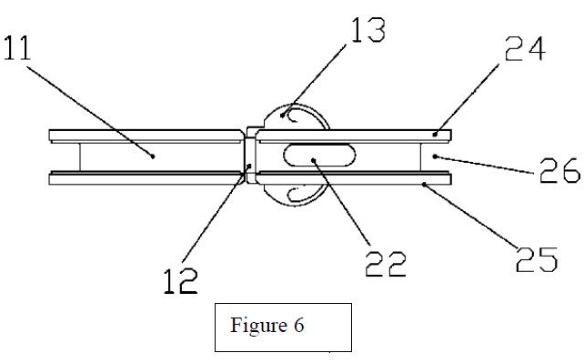
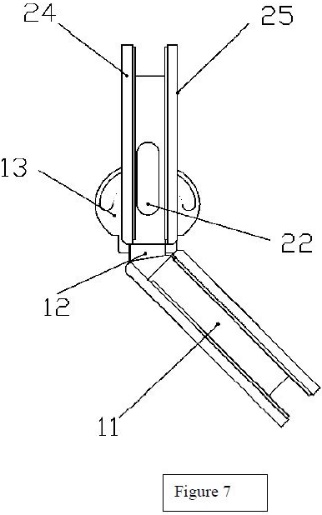
265 The adapted to locate integers in the 485 patent require a portion of the insert component to be “adapted to be located with the second cut-out”. There is no dispute that the first insert component disclosed in the WO499 patent is the baseplate 2. The dispute between the parties concerns whether there is disclosed any shape of a cut-out which is adapted to locate the insert within as required by the integer.
266 Mr Hunter (taking integer 1.8 as the example) expresses the view that the integer is present because the insert of the invention disclosed is within the second cut-out. He explains this by reference to his mark-up of figure 1, reproduced at [260] above. The outer thick solid line around the circumference (purple) is the outer boundary of one of the clamps. The inner thick solid line (red) is the outer boundary of the insert component. In Mr Hunter’s view, to enable the glass door to be clamped, the boundary of the cut-out in the glass panel must be located between the outer purple boundary of the clamp, and the red boundary of the insert component. He says that the glass panel cut-out cannot logically be located outside the purple hatched area, because otherwise the clamp would not meet the glass and no clamping could occur. It cannot be inside the red hatched area (inside the red inner boundary) because the insert component would interfere with the glass and the glass panel would not fit between the clamps. The result is that there must be a cut-out in the glass somewhere between the red and purple lines, in the purple hatched area. Otherwise the WO499 invention could not work. The insert must, in Mr Hunter’s view, be “adapted to locate within the second cut-out”.
267 Mr Richardson’s view is that there is no definition of a cut-out in the WO499 patent to enable him to assess whether it is “adapted to locate within the second cut-out”. He considers that there is no teaching in the WO499 patent of the shape of the cut-out.
268 The parties’ submissions adopted the evidence of their respective experts.
269 The WO499 patent teaches that the insert is to be located in the place identified by Mr Hunter, between the red and purple lines in his drawing.
270 In one preferred embodiment, an anti-collision rubber strip 21 is disposed on the outer circumference of the baseplate 2 (that is, the insert) “to ease the impact upon it”. In his oral evidence, Mr Richardson accepted that this indicated that he expected that the rubber strip would be in contact “somewhere with the glass of the panel or the gate”. However, he was concerned that the WO499 patent did not tell him the shape of the cut-out. Whilst he agreed with Mr Hunter that it is necessary that there must be a cut-out that accommodates the insert component and that the (purple) outer hatched area must fit over the top of the surface of the glass, he said:
… because there is no actual definition or description of the cut-out itself, I can’t tell whether that’s a very short distance from the outside edge, whether the cut-out has any ear shapes at all…but to me, the wording “adapt to locate” requires some sort of relationship between the cut-out and the insert component, and as I’m not told what the cut-out shape is, I can’t adjudicate as to whether it meets the wording “adapted to locate”.
271 I have in section 4.3 found that the adapted to be located integer should be understood to mean that the insert component was sized to have a shape relationship between it and the cut-out for the purpose of enabling the hinge to be located or fitted in position. I do not understand it to mean that the insert must fit tightly within the cut-out such that there is little or no room for movement.
272 In Merck I said the following in relation to the test for a novelty disclosure in the context of drawings:
224 In C. Van der Lely N.V. v Bamfords Ltd [1963] RPC 61 Lord Reid considered whether a skilled reader would infer from photographs of a machine in magazine articles that the rake wheels of the alleged anticipating machine were ground driven rather than gear driven. He said at 72 (emphasis added):
The appellants’ first argument is that it is not enough that the photograph should disclose a probability that the wheels were ground driven. There cannot be anticipation, they say, unless this is shown clearly and unmistakably. I cannot accept that argument. I would agree that the anticipating material must be as good for practical purposes as the material in the appellants’ specification. But I can see no practical difference between a definite statement of fact and material from which the skilled man would clearly infer its existence.
So the question is whether the typical skilled man would infer ground drive from the photograph. It would not be enough that a quick-witted man would guess that. But in this case I think that it is proved that the ordinary skilled man would have had good grounds for reaching the conclusion that these wheels were ground driven. He could not have been certain, but practical men act on something less than absolute certainty.
225 The Full Court in AstraZeneca (FC) at [293] noted that the touchstone for determining whether a prior publication anticipates a claimed invention is stated in General Tire & Rubber Co Ltd v Firestone Tyre & Rubber Co Ltd [1971] 7 WLUK 130; [1972] RPC 457 at 485 – 486 (Sachs, Buckley and Orr LJJ) as follows:
When the prior inventor’s publication and the patentee’s claim have respectively been construed by the court in the light of all properly admissible evidence…the question whether the patentee’s claim is new…falls to be decided as a question of fact. If the prior inventor’s publication contains a clear description of, or clear instructions to do or make, something that would infringe the patentee’s claim if carried out after the grant of the patentee’s patent, the patentee’s claim will have been shown to lack the necessary novelty, that is to say, it will have been anticipated. The prior inventor, however, and the patentee may have approached the same device from different starting points and may for this reason, or it may be for other reasons, have so described their devices that it cannot be immediately discerned from a reading of the language which they have respectively used that they have discovered in truth the same device; but if carrying out the directions contained in the prior inventor’s publication will inevitably result in something being made or done which, if the patentee’s patent were valid, would constitute an infringement of the patentee’s claim, this circumstance demonstrates that the patentee’s claim has in fact been anticipated.
If, on the other hand, the prior publication contains a direction which is capable of being carried out in a manner which would infringe the patentee’s claim, but would be at least as likely to be carried out in a way which would not do so, the patentee’s claim will not have been anticipated, although it may fail on the ground of obviousness. To anticipate the patentee’s claim the prior publication must contain clear and unmistakable directions to do what the patentee claims to have invented…A signpost, however clear, upon the road to the patentee’s invention will not suffice. The prior inventor must be clearly shown to have planted his flag at the precise destination before the patentees.
273 In the present case, it is apparent from Mr Hunter’s diagram of figure 1 that there may be a shape relationship between the insert and the cut-out, but it is not apparent how that relationship is defined. Having regard to the function of the insert component, the cut-out of the invention in the WO499 patent must permit the insert component to be included within the hinge arrangement, and also enable the hinge to be affixed to the glass panel. But does this conform with the requirement of the claim that the cut-out is sized to have a shape relationship between it and the insert component for the purpose of enabling the hinge to be located or fitted in position? It is true that the space between the exterior of the insert component (red border) and the outer boundary of the clamp (purple) provides limited space for a cut-out. Even so, I am not persuaded that the person skilled in the art would consider that the WO499 patent discloses the relevant shape relationship. Even accepting that the rubber anti-collision strip (21) on the baseplate (2) is present because there would likely be some contact between the cut-out in the panel of the door or wall and the insert, I am not satisfied that the WO499 patent identifies the presence of the integer with sufficient clarity to disclose this feature.
274 In this regard, I reject the proposition that Mr Richardson’s evidence, where he declined to accept that he could deduce a shape relationship, was “idiosyncratic”. Rather, I understand his evidence to be directed to the disclosure of the WO499 patent. The fact is that TCT’s case relies on the experts inferring the presence of the integer. Mr Richardson’s view, with which I agree, is that whilst the WO499 patent contains a direction which is perhaps capable of being carried out in a manner which would infringe the patentee’s claim, it would be at least as likely to be carried out in a way which would not do so. That is not sufficient disclosure for the purposes of a novelty challenge.
275 Accordingly, in my view, integers 1.4, 1.8 and 4.4 are not disclosed in the WO499 patent.
276 TCT does not contend that the remaining claims of the 485 patent lack novelty over the WO499 patent.
10.3 Do the patents lack an innovative step in light of the WO499 patent?
277 I turn to consider whether or not the invention claimed in each of the 485 and 918 patents involves an innovative step over the disclosure of the WO499 patent.
278 TCT contends that, regardless of the conclusions reached in relation to novelty, the claims of neither the 485 patent nor the 918 patent involve an innovative step over the disclosure of the WO499 patent.
10.3.2 The law concerning lack of innovative step
279 Pursuant to s 18(1A)(b)(ii), an invention claimed in an innovation patent must involve an innovative step. Section 7(4) of the Patents Act provides:
(4) For the purposes of this Act, an invention is to be taken to involve an innovative step when compared with the prior art base unless the invention would, to a person skilled in the relevant art, in the light of the common general knowledge as it existed (whether in or out of the patent area) before the priority date of the relevant claim, only vary from the kinds of information set out in subsection (5) in ways that make no substantial contribution to the working of the invention.
280 The language of s 7(4) makes plain that an innovation patent is assumed to possess an innovative step, with the onus being upon the party challenging the patent to establish otherwise.
281 The essential task is to compare the invention as claimed with the relevant prior art information, as set out in s 7(5). It is to identify the difference or differences between that which is claimed in the patent and that which is disclosed in the relevant prior art information and to determine whether the difference or differences make a substantial contribution to the working of the invention as claimed. Each comparison is to be made from the perspective of the person skilled in the art, whose task is to identify and assess the variations between the invention as claimed in each claim and the prior disclosure and determine whether they make a substantial contribution to the working of the invention as claimed in each claim. The word “substantial” in this context means “real” or “of substance”. See generally Dura-Post (Aust) Pty Ltd v Delnorth Pty Ltd [2009] FCAFC 81; 177 FCR 239 (Kenny and Stone JJ) at [73]-[74].
282 In the case of a product claim, one means of assessing whether or not there has been a substantial contribution is to consider whether any variation from the prior art to the claimed invention “contributes substantially to the way in which the [product] functions as such”: Dura-Post at [80].
283 In Product Management Group Pty Ltd v Blue Gentian LLC [2015] FCAFC 179; 240 FCR 85 the majority (Kenny and Beach JJ) expanded on an aspect of the test:
176 What is meant by the concept of “working of the invention”? Assume that the invention as claimed varies in a particular respect from the relevant prior art information and the question is whether this variation does or does not make a substantial contribution to the working of the invention. The question is not whether, absent the variation, the invention could still work effectively or whether, by other means, it could be adapted to so work. The question is whether the variation makes a substantial contribution to the working of the invention as claimed (Vehicle Monitoring Systems Pty Ltd v Sarb Management Group Pty Ltd (No 2) (2013) 101 IPR 496 (Vehicle Monitoring Systems) at [226] and [227] per Yates J). Moreover, the substantial contribution to the working of the invention must be across the full scope of the claim (see Multisteps Pty Ltd v Source and Sell Pty Ltd (2013) 214 FCR 323 at [285] per Yates J).
177 Further, the specification does not need to expressly identify or set out the substantial contribution that any particular integer of a claim might make to the working of the invention. That is to be ascertained by the Court with or without expert assistance.
284 TCT tentatively submitted that the proper test for innovative step requires that any asserted contribution to the working of the invention “be a positive one”, in the sense of conferring an advantage over the prior disclosure. In this regard it noted that the objects of the Patents Act as set out in s 2A involve the provision of a patent system in Australia that promotes economic wellbeing through technological innovation, and that such wellbeing would not be promoted by permitting a patent to remain on the register where it confers no such advantage. TCT accepted that a single judge could not accept this submission in light of the reasoning of the majority in Blue Gentian at [178], which found in terms that nowhere in the test for “substantial contribution” is there to be found reference to “advantage”, and that one may still have a substantial contribution even if the overall effect could be characterised in evaluative terms as neutral from a particular perspective. In this regard, TCT submitted that the reasoning of Nicholas J at [284], which cast doubt on that interpretation and suggested that it is strongly arguable that the contribution must be a positive contribution to the working of the invention, is to be preferred.
285 Whilst there may be force in the argument advanced by TCT, it is not a matter for debate in the present case, and there was no occasion for Polaris to respond to it. I am plainly bound by the decision of the majority in Blue Gentian.
286 In relation to the 485 patent TCT first submits that for claims 1 and 4, the absence of an “adapted to locate” integer in the disclosure of the WO499 patent should not be taken to mean that those claims involve an innovative step. It submits that the WO499 patent clearly discloses a hinge in which the leaves are clamped onto glass door 103 and a glass panel 102, as depicted in fig 8:
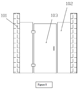
287 It is TCT’s position that as the WO499 hinge clamps on each side to a glass door and glass panel, it achieves “precisely the same functional outcome as the ‘adapted to locate’ feature of the claim”.
288 TCT secondly submits for claims 2 and 5, that the “key question” is whether the specific arrangement used to tighten the front and rear leaves with the insert component – in substance a conventional combination of screws and threaded bosses (“fasteners” and “threaded stems”) – makes a substantial contribution to the working of the claimed hinge when compared to the fastening arrangements disclosed in the WO499 patent. It submits that having regard to the essentially identical functional outcomes that are delivered, and the need to assess any variations from the perspective of the skilled addressee and the common general knowledge, the conclusion must be that no substantial contribution is made.
289 TCT finally contends that claim 3 is for an end cap having an acutely angled upper surface to prevent it from being used as a stepping surface. It submits that this is merely a feature that is mandated by section 2.4.3 of the current Australian Standard AS 1926.1 – 2012 Swimming pool safety. It submits that there is no innovative step in claiming a feature that the skilled addressee would, as a practical matter, be compelled to introduce. It submits that this is not purely hypothetical, as Mr Bindschedler’s cross examination revealed that the Polaris products also have this feature.
290 In response, Polaris first submits in relation to claim 1 that the 485 patent includes a fitment relationship between the hinge and the cut-out to prevent rotation, misalignment or movement of the panel on the hinge leaf assemblies, relying on the evidence of Mr Richardson. It contends that that feature is absent from the WO499 patent, in that it does not describe or depict that relationship. It submits that it is not to the point, and reflects an incorrect approach to the test under s 7(4), for TCT to merely assert that the disclosure of the WO499 patent produces the same “functional outcome”.
291 In relation to claims 2 and 5, Polaris notes the agreement of the experts that integer 2.2 (and 5.2) is not present in the WO499 patent. It submits that the insert component of the 485 patent includes at least two holes formed to fit with and accept at least two threaded stems. By contrast, the WO499 patent has visible screw heads and screws have limited strength of retention, which according to Mr Richardson amounts to a “functional difference”.
292 In relation to claim 3, Polaris notes the agreement of the experts that integer 3.2 (end cap) is not present in the WO499 patent. It relies on the evidence of Mr Richardson whose opinion is that the angled upper surface on the end cap makes a substantial contribution to the working of the invention and confers a functional advantage in that it prevents the end cap being used as a stepping surface. His evidence was, in Polaris’ submission, not substantially challenged. Nor, it submits, is it to the point that an angled end point either forms part of the common general knowledge or is identified in the Australian standard.
293 In relation to the 918 patent, TCT acknowledges the presence of additional features of claims 1 and 5 that mean that the disclosure of the WO499 patent cannot be novelty defeating. In relation to the differences it:
(1) submits that the same arguments apply as when comparing claims 1 and 4 of the 485 patent concerning the adapted to locate integer.
(2) contends that the requirement in integers 1.10 and 4.7 of the 918 patent (“wherein the spring has a longitudinal spring axis which is parallel with the hinge axis to operate as a torsion spring”) adds no substantial contribution to the disclosure of the WO499 patent, which is of a compression spring. It relies on the evidence of Mr Hunter to the effect that both achieve the same functional purpose of giving closing bias.
(3) submits that the difference between integers 1.11 and 4.8 of the 918 patent, which require the dampener to retract during dampening, and the disclosure in the WO499 patent, which expands during dampening is of no moment.
(4) notes that integers 1.13 and 4.10 require that the second leaf assembly or mounting component include an “impacted” striking surface to cooperate with the dampener. It submits that the experts’ disagreement arises from a construction argument as to whether or not striking in the sense of “hitting” is required.
(5) contends that claims 2 and 5 of the 918 patent (fasteners and threaded stems) lack an innovative step over the disclosure of the WO499 patent because, even though it is not clear from reading the WO499 patent precisely how the moveable plates were to be secured to the baseplate, the arrangement would involve the use of screws and holes to secure them and the hinge in the WO499 patent delivered the same functional outcome as the combination in the 485 and 918 patents.
294 In response to the points made by TCT, Polaris:
(1) disputes that the adapted to be located integer can be characterised as TCT contends.
(2) relies on the evidence of Mr Richardson, who explains the difference between the torsion spring arrangement of the 918 patent and the compression spring.
(3) submits that the evidence of Mr Richardson demonstrates that the difference in the dampener indicates that there is a functional difference and an advantage in the mechanism of the 918 patent.
(4) submits that the existence of a striking surface is material to the invention.
(5) repeats its earlier submissions as to the material differences that arise in relation to the fasteners and threaded stems components of claims 2 and 5.
10.3.4 Consideration of innovative step of the 485 patent over the WO499 patent
295 I commence with consideration of whether TCT has established that no innovative step resides in the claims of the 485 patent having regard to the disclosure of the WO499 patent.
296 In relation to claims 1 and 4, I have found that there is no disclosure in the WO499 patent of the adapted to locate integer. As Mr Richardson says in his evidence, by including this integer, the person skilled in the art is informed of the relationship between the cut-out and the insert component. In my view this space relationship addresses and resolves difficulties that may arise in relation to the fitment of the hinge to a panel or door. The relationship is not disclosed in the WO499 patent. I am not satisfied that TCT has established that this difference between the disclosure of the WO499 patent and claims 1 and 4 of the 485 patent does not amount to a substantial contribution to the working of the invention of the 485 patent. Plainly, the way the hinge of the invention fits to the panel or door is integral to the operation of the invention disclosed.
297 This conclusion is sufficient to determine the lack of innovative step case adversely to TCT insofar as it concerns all of the claims of the 485 patent, as each of claims 2, 3 and 5 are dependent on either claim 1 or claim 4. Nevertheless, I proceed.
298 Claim 2 provides as follows (integers added):
2.1 The hinge according to claim 1, 2.2 wherein the first insert component includes a first and second hole adapted to receive a first and second threaded stem of the first front leaf component, 2.3 wherein a first and second fastener are receivable through corresponding holes of the first rear leaf component and fasten with the first and second threaded stems respectively to secure the first front leaf component to the first rear leaf component.
299 Claim 5 includes the equivalent integers for the glass-to-wall embodiment of claim 4.
300 There is no dispute that integer 2.2 is not present in the disclosure of the WO499 patent.
301 The WO499 patent discloses an insert component (baseplate 2) with two integral bosses. The description at [59] discloses that the baseplate 2 comprises an inner shell 23 and moveable plates 24, 25 fixed on both sides of the inner shell 23. It says that a fixing groove 26 is formed between the moveable plates and is used to clamp the glass door 103. Mr Hunter considered that, whilst it was not clear from reading the WO499 patent how the moveable plates 24, 25 were to be secured to the baseplate, the arrangement would involve the use of threaded screws and holes to secure them together in order to clamp the panel with the insert component sandwiched into the cut-out. He considered that it is possible that the WO499 patent uses less thread depth than the stems referred to in claim 2, but considered that clamping force is not an attribute of the claims of the 485 patent.
302 Mr Richardson agreed that the WO499 patent disclosed a functioning door hinge, and interpreted fig 1 as indicating that baseplate 2 would be secured together with the moveable plates 25, 26 by using, for each hole, two screws inserted from opposite sides of the assembly, meeting halfway in the holes. He considered that this would be aesthetically different to the 485 patent and result in the screw threaded engagement having lesser strength.
303 Integer 2.2 requires at least two holes formed to fit with and receive at least two threaded stems or protrusions. The WO499 patent has visible screw heads which may have limited strength of retention. In my assessment, neither difference represents a substantial contribution to the working of the invention disclosed and claimed in the 485 patent. The fact is that there is no dispute that the baseplate arrangement in the WO499 patent is sufficiently secured for the hinge so described to operate on a closing door. Had I concluded differently in relation to claims 1 and 4, I would have concluded that claims 2 and 5 involved no innovative step.
304 Claim 3 of the 485 patent is:
The hinge according to claim 1, wherein the hinge further includes an end cap coupled to an upper end of a barrel of the hinge, said end cap having an upper surface acutely angled relative to the hinge axis to prevent the end cap being used as a stepping surface.
305 The experts agree that integer 3.2 is not present in the WO499 patent, which includes no angled upper surface on the end cap. The WO499 patent does not locate the hinge in a position where such a cap may be necessary. The experts agreed that when considering or designing any hinge for use in a poolside application they must apply the relevant Australian Standard in developing their design. Mr Richardson gives evidence that, in his view, the disclosure of the angled surface in the 485 patent makes a substantial contribution to the working of the invention “for safety and to meet [the relevant Australian Standard]”. Whilst I accept that there is a functional difference between the two, I do not consider that the addition of the angled end cap which, in practice conforms only to a mandatory requirement for pool applications, will of itself amount to a substantial contribution to the working of the invention. Accordingly, had I concluded differently in relation to claims 1 and 4, I would have concluded that claims 3 and 5 involved no innovative step.
10.3.5 Consideration of the innovative step of the 918 patent over the WO499 patent
306 I now turn to consider whether TCT has established that no innovative step resides in the claims of the 918 patent having regard to the disclosure of the WO499 patent.
307 In this regard, my findings in relation to the adapted to locate integers are the same as for the 485 patent, with the consequence that the challenge advanced by TCT in relation to lack of innovative step must fail.
308 There is no dispute that the following integers of independent claims 1 and 4 are not disclosed in the WO499 patent:
(a) 1.10, wherein the spring has a longitudinal spring axis which is parallel with the hinge axis to operate as a torsion spring (and 4.7);
(b) 1.11, a dampener, having a longitudinal dampener axis along which a portion of the dampener retracts during dampening, said dampener at least partially housed by the first insert component (and integer 4.8); and
(c) 1.13, wherein the second leaf assembly includes a striking surface to cooperate with the dampener to dampen spring induced movement of the hinge from the open position to the closed position (and integer 4.10).
309 I have reviewed each of these differences in the context of the disclosure of the US015 patent in section 10.5.3 below. For substantially the reasons given in that section, I find that the differences identified in (a), (b) and (c) above have also not been shown by TCT to lack an innovative step over the disclosure of the WO499 patent. Taking these differences individually and collectively, the innovative step challenge to the 918 patent must accordingly fail.
10.4 Novelty of the 485 patent over the US015 patent
310 Two issues have been raised in relation to the novelty of claims 1 and 4 of the 485 patent in relation to the US015 patent. The first concerns the “insert component” integer identified in section 4.2 above, the second concerns the adapted to locate integer.
10.4.2 The disclosure of the US015 patent
311 The US015 patent is entitled “Damped hinge and control device thereof”.
312 The hinge described in the US015 patent may be identified by reference to figs 1, 2 and 4 which are set out below, where the contested insert component may be seen at 81 and 91 in fig 1 with mouse ear shaped protrusions and is moulded with the first connecting member 8.
|
|
|
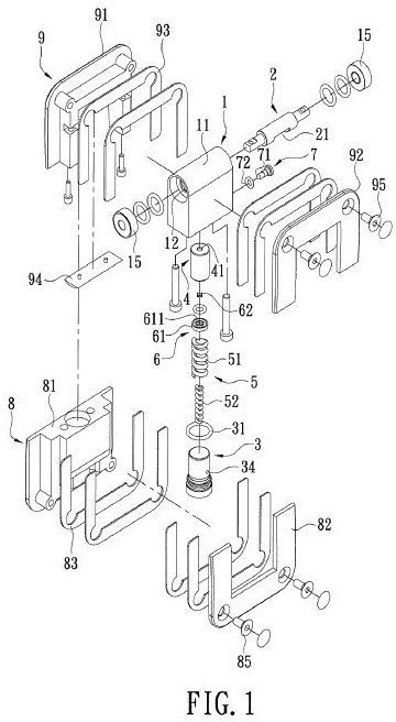
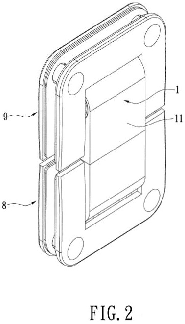
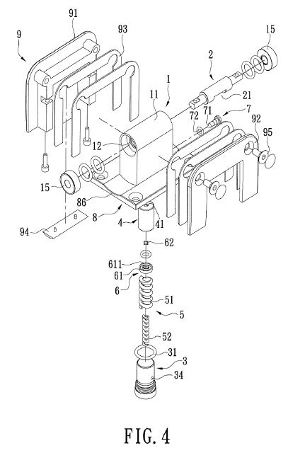
313 Mr Hunter gave evidence, which I accept, that the lower leaves 81 and 82 in fig 1 form part of the “leaf assembly” as do the upper leaves 91 and 92. He contends that the “insert components” are the mouse ear shaped part of leaf 81 and leaf 91, which parts are adapted to locate within the respective cut-outs. The “mounting component” is the upper leaf assembly comprising sleeves 91, 92 and spindle 2. The springs 51 and 52 are operatively coupled to both the “leaf assembly” and “mounting component” in order to bias the hinge to move from an open position to the closed position. The dampener is made up of parts 3, 4 and 5 (identified in the US015 patent specification respectively as the sleeve, which can be filled with hydraulic oil; the sliding member 4 slidably disposed in the sleeve 3; and the elastic unit including a first spring 51 and a second spring 52).
314 Mr Hunter explains in the joint expert report that the dampener is adapted to dampen movement of the hinge from the open position to the closed position, because components 41 (a through hole in sliding member 4), 61 (valve seat in a non-returning valve 6) and 34 (an opening in sleeve 3) work together by permitting hydraulic oil to flow out of the oil reservoir 42 through the through hole 41 freely when the dampener is contracting.
10.4.3 Consideration of novelty
315 As noted above, two issues have been raised in relation to the novelty of claims 1 and 4 of the 485 patent. The first concerns the “insert component” integer.
316 The experts agree that all of the features in claims 1 and 4 of the 485 patent are disclosed in the US015 patent, with the exception of the integers in claim 1 (being integers 1.3 and 1.7) and claim 4 (being integer 4.3) which have a requirement that the first leaf assembly include a “first insert component”. The parties agree that the dispute between the experts in this regard will be resolved by my determination of the construction issue identified in section 4.2 above. They agree that in the event that I determine (as I have) that those claims encompass an insert component which is integral with the front leaf component, then those claims lack novelty.
317 The second issue concerns the disclosure of the “adapted to locate” aspect of integers 1.4 and 4.4, which I have addressed in detail in relation to the WO499 patent. In the course of his oral evidence Mr Richardson accepted that this integer was present. In my view that concession was properly made. Accordingly all of the integers of claims 1 and 4 of the 485 patent are disclosed in the US015 patent.
318 No other claims in the 485 patent or the 918 patent are said by TCT to lack novelty over the disclosure of the US015 patent.
319 Accordingly, I find that claims 1 and 4 of the 485 patent lack novelty over the disclosure of the US015 patent.
320 TCT does not contend that the 918 patent lacks novelty over the disclosure of the US015 patent
10.5 Innovative step of the patents over the US015 patent
321 In relation to the 485 patent TCT contends that in the event that it fails in its construction argument concerning the “insert component” then nonetheless claims 1 and 4 of the 485 patent do not involve an innovative step over the US015 patent. It relies on the evidence of Mr Hunter to support the submission that whether or not the insert component is separated from or integrated with the front or rear leaves of the hinge makes no difference in terms of how the invention would work, and there would be no functional advantage because in both configurations the insert would fulfil the same function of being “adapted to locate” in the cut-out and at least partially housing the dampener.
322 Polaris submits that the separate insert component provides a substantial contribution to the working of the invention claimed in the 485 patent. It relies on the evidence of Mr Richardson to the effect that the difference provides, for the 485 patent, manufacturing cost advantages, material options for each part, inclusion of complex details for mounting dampeners and magnets and easier servicing of the hinge. It points out that the background of the invention of the 485 patent draws attention to manufacturing advantages.
323 In relation to the 918 patent TCT submits that:
(1) the same arguments apply in relation to the “insert component” integers (being integers 1.3, 1.7 and 4.3) and “adapted to locate” integers (being integers 1.4, 1.8 and 4.4) as for the equivalent in the 485 patent.
(2) the requirement in integers 1.10 and 4.7 of the 918 patent (“wherein the spring has a longitudinal spring axis which is parallel with the hinge axis to operate as a torsion spring”) adds no substantial contribution to the disclosure of the US015 patent, which is of a compression spring. It relies on the evidence of Mr Hunter to the effect that both achieve the same functional purpose of giving closing bias.
(3) the difference between integers 1.11 and 4.8 of the 918 patent, which require the dampener to retract during dampening and the disclosure in the US015 patent, where the dampener expands during dampening is of no moment.
(4) integers 1.13 and 4.10 require the second leaf assembly or mounting component to include an “impacted” striking surface to cooperate with the dampener. It submits that the experts’ disagreement arises from a construction argument as to whether or not striking in the sense of “hitting” is required.
(5) claims 2 and 5 of the 918 patent (fasteners and threaded stems) lack an innovative step over the disclosure of the US015 patent because the arrangement of stems and bosses in the US015 patent achieve the same function as the combination in the 485 and 918 patents, being to secure the leaves together and ensure a tight clamp onto the glass panel.
324 In response to the points made by TCT, Polaris first accepts that the “insert component” and “adapted to locate” arguments will apply equally to the 918 patent as they do to the result in the 485 patent. Secondly, it relies on the evidence of Mr Richardson, who explains the difference between the torsion spring arrangement of the 918 patent and the compression spring. Thirdly, it submits that the evidence of Mr Richardson establishes that the difference in the dampener mechanism demonstrates an advantage in the retracting mechanism of the 918 patent. Fourthly, Polaris submits that the existence of a striking surface is material to the invention. Finally, Polaris repeats its earlier submissions made for the 485 patent as to the material differences that arise in relation to the fasteners and threaded stems components of claims 2 and 5 of the 918 patent.
10.5.2 Consideration of the innovative step of the 485 patent over the US015 patent
325 In the event that I am incorrect as to my conclusion that the “insert component” of the claims of the 485 patent is not a feature that may be either integral with the front leaf component or separate from it, it is necessary to consider whether or not claims 1 and 4 lack an innovative step.
326 In this regard I am unpersuaded by the arguments advanced by Polaris. I accept the evidence of Mr Hunter to the effect that whether or not the insert component is integrated with the front or rear leaf makes no difference to the manner in which the invention would function and provides no functional advantage over or indeed difference to the operation of the invention. In my view the other advantages cited, including the material options available, the potential for easier servicing and the details for mounting of magnets, are peripheral or irrelevant to the invention disclosed and claimed and do not in my evaluation make a substantial contribution to the working of the invention.
327 The consequence of this finding is that, if I am incorrect as to the construction of this integer, claims 1 and 4 of the 485 patent would in any event be invalid for want of innovative step.
328 Turning to claims 2 and 5, the undisclosed integer in the US015 patent concerning these claims is that the first insert component includes a first and second hole adapted to receive a first and second threaded stem of the first front leaf component. Mr Richardson’s evidence addressing this aspect of the case concerned the advantages of a separate insert component as opposed to an integral one. Mr Hunter pointed out that the threaded stems in the US015 patent allow for the insert to be aligned with the front and rear leaves in the same way as those disclosed in the 918 patent. The difference has no effect on how the invention claimed works or how it overcomes the problems of thickness or vibration disclosed in the specification. I accept the explanation given by Mr Hunter. I do not consider that the variance makes a substantial contribution to the working of the invention.
329 Polaris made no separate submissions in relation to claim 3 to those advanced in response to the equivalent arguments that I addressed above in relation to the WO499 patent (section 10.3.4 above). In my view the same result applies for that claim.
330 Accordingly, all of the claims of the 485 patent are also invalid for want of innovative step over the disclosure of the US015 patent.
10.5.3 Consideration of the innovative step of the 918 patent over the US015 patent
331 There is no dispute that the following integers of independent claims 1 and 4 are not disclosed:
(a) 1.10, wherein the spring has a longitudinal spring axis which is parallel with the hinge axis to operate as a torsion spring (and 4.7);
(b) 1.11, a dampener, having a longitudinal dampener axis along which a portion of the dampener retracts during dampening, said dampener at least partially housed by the first insert component (and integer 4.8); and
(c) 1.13, wherein the second leaf assembly includes a striking surface to cooperate with the dampener to dampen spring induced movement of the hinge from the open position to the closed position (and integer 4.10).
332 In this regard, the five separate points that TCT refers to in its arguments (set out at [323] above) reflect the hurdles that it must overcome. In relation to these, my findings in relation to the insert component integer serve to overcome the first argument.
333 The second argument concerns integer 1.10 (and 4.7) which provides “wherein the spring has a longitudinal spring axis which is parallel with the hinge axis to operate as a torsion spring”. There is no dispute that the spring of the US015 patent has the orientation required by this integer.
334 In his evidence, Mr Richardson says of the disclosure in the US015 patent:
… compression springs 51 & 52 push against shaft 2 via other parts including sliding member 4. Shaft 2 has a flat surface 21 that is perpendicular to the axis of the springs accepting the springs’ force when the door is closed. As the door is opened, the end surface of sliding member 4 changes to being at an angle to surface 21. The contact area between surface 21 and end surface of sliding member 4 becomes much smaller. The edge of surface 21 moves across the end surface of sliding member 4 and when the door is substantially near to being at 90 degrees open, the end surface of sliding member 4 presses against the outer cylindrical surface of shaft 2. When this occurs, there ceases to be any spring force pushing the door closed. This is likely a good feature in shops and other locations where the door can be left open, but not for the purposes of a pool gate. The 918 patent discloses a hinge for use in situations where the spring force is required to return the gate or door automatically from the full range of operating angles up to the door being fully open…
335 Mr Hunter gives evidence that in both the US015 patent and the 918 patent the spring has one purpose, which is to give closing bias. Whether that is achieved by a compression or torsion spring, these achieve the same outcome.
336 As I have noted, there is no dispute that the operation of the embodiment of the US015 patent, which as described by Mr Richardson in the passage quoted, is of the compression mechanism cooperating with other parts in a manner that is accordance with the requirements of claim 1 of the 918 patent with the exception that a compression spring is utilised rather than a torsion spring. Mr Richardson otherwise describes an arrangement that falls within the claim in terms of its orientation and operation (I leave to one side for the present the dampener mechanism and striking surface debates which are addressed below). Nowhere does he point to any intrinsic difference between the use of a torsion spring and a compression spring that makes any difference to the operation of the embodiment. The evidence of Mr Hunter reveals that they are interchangeable. I do not consider that in this respect the 918 patent contains an innovative step because in my view the difference makes no substantial contribution to the working of the invention.
337 The third argument concerns the expanding dampener integer 1.11. Mr Richardson explains that the dampening mechanism of the US015 patent lies in the extended position as compression springs 51 and 52 cause the sliding member 4 to abut to the surface 21 of shaft 2, as seen in the figures at [312] above. The opening of the door causes the shaft to turn relative to the sliding member 4, causing 4 to retract into sleeve 3. During retraction, the components allow the oil to flow in the direction from the valve seat 61 to the through hole 41 during retraction of the dampener component. Closing of member 2 blocks the hydraulic flow in the reverse direction. The integral hydraulic dampener device provides dampening by expansion rather than retraction as included within integers 1.11 and 4.8 of the claims of the 918 patent.
338 Mr Richardson identifies what he considers to be a substantial functional catch in this arrangement. This is that the dampening action occurs over the whole range of angular movement of the door, which allows for a gradual closing over the entire range of the closing. This, he considers, makes the mechanism more suitable for a shop door closing where there is a need for a door to slowly come shut over the entire arc of the closing. It is less suitable for pool situations than the mechanism of the 918 claims where the dampener retracts during opening. In those circumstances it is desirable to have the gate close more quickly initially and then slowing movement in the final stage of angular rotation to minimise the time that the gate is open to reduce the risk for toddlers to pass through the gate without being noticed. He considers that the US015 patent’s integrated hydraulic mechanism would not be an appropriate pool safety option.
339 Mr Hunter considers that it makes no material difference whether during dampening the dampener components retract or expand. In both, a dampening effect is delivered.
340 I accept Mr Richardson’s evidence that this distinction is of significance. The US015 patent describes a hinge that dampens by expansion over the whole range of movement of the door. Integers 1.11 and 4.8 require that the dampener simply retracts during dampening with no limitation as to the point along the range of movement whereby dampening commences. In so doing, it leaves it open the point in the arc of closing at which the dampening will begin. This provides for a functionally different mechanism between the two which is material to the operation of the hinge. I consider that in this regard the 918 patent represents an innovative step over the disclosure of the US015 patent.
341 In relation to the fourth argument, integer 1.13 (and 4.10) requires that the second leaf assembly includes a striking surface to cooperate with the dampener to dampen spring induced movement of the hinge from the open position to the closed position.
342 Mr Richardson observes that the US015 patent discloses the dampener sliding member 4 continuously pushing against a surface 21 on shaft 2 and adjacent external surface of shaft 2. At no time does the dampener cease to be in contact, nor does it then come into contact with, surface 21 in a “striking action”. He considers that “striking” means “hitting one thing against another” and that the advantages of the use of a striking surface as claimed in the 918 patent are first, to reduce rubbing wear of the shaft 2 on the end of the sliding member 4 and the striking surface 21, and secondly to reduce wear on the sliding member against the inner surface of sleeve 3.
343 Mr Hunter disputes that there is any difference between the disclosure of the US015 patent and this integer. That dispute arises from Mr Hunter’s construction of “striking surface”, which is that the integer only requires that direct contact be made between the dampener and the striking surface and that accordingly the dampener and striking surface could be in contact throughout the door closure; no “striking” action is necessary. I have in section 4.4 above rejected that construction.
344 Mr Hunter further disputes that there would be an issue about the wear and tear on the parts as a result of any continual interaction between the sliding member and the striking surface. However, there is plainly a difference in the operation of the two hinges. In the 918 patent the dampener is not in continual contact with the striking surface. In the US015 patent it is. Whether or not one is advantageous over the other may be debatable (and the experts did debate it, but is not to the point: see Blue Gentian at [178]. There is a material difference in the design of the two hinges. In my view TCT has not established that this difference does not reflect, on the part of the 918 patent, a substantial contribution to the working of the invention.
345 Having regard to my findings in relation to the third and fourth arguments, taken individually and also collectively, in my view the independent claims 1 and 4 of the 918 patent do not lack in innovative step over the disclosure of the US015 patent.
346 Accordingly, the claims of the 918 patent are not invalid for want of innovative step over the disclosure of the US015 patent.
10.6 Novelty of the 485 patent over the CN860 patent
347 Similar issues arise in relation to the disclosure of the CN860 patent as arise in relation to the US015 patent. The parties agree that the determination of the “insert component” issue will resolve the question of the novelty of claims 1 and 4 of the 485 patent.
10.6.2 The disclosure of the CN860 patent
348 CN860 is a utility model patent entitled “A new type of hinge with buffer function for glass doors”.
349 Figures 1, 3 and 5 are as follows:
|
|
|
350 The specification provides that the utility model is for a new type of glass door hinge with buffer function, which comprises a first door clamp 1 and a second door clamp 2. The first door clamp 1 is firmly connected to the hinge base 3, and the second door clamp 2 is rotatably mounted on the hinge base 3 by a door shaft 4, characterised in that the door shaft 4 is provided with a cam 41, which is mounted in the limit zone 31 on the hinge base 3. The side wall of the limit zone 31 is also provided with a buffer hydraulic cylinder 5 which is pressed against the cam 41 when the door shaft 4 rotates, the cam 41 is driven to rotate in the limit zone 31.
351 The specification provides as follows:
[0023] Working principle: in the process of opening or closing the door, the glass door drives the door shaft to rotate with the door clamp. When the door shaft rotates, it will inevitably drive the cam to rotate. When the door is closed, the apex of the cam is at the farthest end, compressing the buffer cylinder to the closest point. When the glass door is opened, the cam is driven to rotate, so that the apex of the cam deviates from the buffer cylinder, and the buffer cylinder extends outward under the action of the spring to return to its original position. When the glass door is opened at its maximum angle, the buffer cylinder is fully extended.
[0024] When the door is closed, the cam turns and compresses the apex of the buffer cylinder. The buffer cylinder slowly retracts after being compressed, thereby slowing down the rotation speed of the door shaft and slowing down the returning glass door. As the buffer cylinder is continuously compressed, the vertex of the cam gradually deviates from its center, and finally the buffer cylinder is completely compressed. At this time, the glass door is in a completely closed position, preparing for the next buffered returning; the process will be repeated this way and I will not go into details.
352 The expert evidence indicates that the two leaves of the first door clamp 1 make up the “first leaf assembly”. The two leaves of the second door clamp 2 make up the “second leaf assembly”. The raised rib sections on the right and left lower leaves in fig 3 are the (controversial) first and second insert components respectively, which rib sections are adapted to locate within glass panel cut-outs. The spring 62 is operatively coupled to the first and second leaf assemblies that biases the hinge to move from an open position to a closed position. The dampener in the CN860 patent is the buffer hydraulic cylinder 5, which compresses upon the door closing, thereby slowing down the speed of the door.
353 The disputed first and second “insert components” are to be seen in fig 3 as the raised rib section to the right of hinge base 3 and the raised rib section surrounding hinge base 3.
354 The experts agree that all of the features in claims 1 and 4 of the 485 patent are disclosed in the CN860 patent, with the exception of the integers in claim 1 (being integers 1.3 and 1.7) and claim 4 (being integer 4.4), which have a requirement that the first and second leaf assemblies each include an “insert component”. The parties agree that the dispute between the experts in this regard will be resolved by my determination of the construction issue identified in section 4.2 above. They agree that in the event that I determine (as I have) that those claims encompass an insert component which is integral with the front leaf component, then those claims lack novelty.
355 The consequence is that claims 1 and 4 of the 485 patent lack novelty in light of this disclosure.
10.7 Innovative step of the patents over the CN860 patent
356 In relation to the 485 patent, TCT makes the following submissions, that:
(a) That if it is incorrect in its construction of the “insert component” integer, then there is no innovative step to be found in the difference between a separate or an integrated insert; and
(b) That although there is no clear disclosure of the adapted to be located integer in CN860, no innovative step lies in the difference.
357 In relation to the 918 patent, TCT accepts that the following additional differences are apparent between the claims and the disclosure in CN860 but submits that none disclose an innovative step because:
(a) the requirement in integers 1.10 and 4.7 of the 918 patent (“wherein the spring has a longitudinal spring axis which is parallel with the hinge axis to operate as a torsion spring”) adds no substantial contribution to the disclosure of the CN860 patent, which is of a compression spring. It relies on the evidence of Mr Hunter to the effect that both achieve the same functional purpose of giving closing bias.
(b) the difference between integers 1.11 and 4.8 of the 918 patent, which require the dampener to retract during dampening and the disclosure in the CN860 patent, which expands during dampening is of no moment.
(c) although integers 1.13 and 4.10 require that the second leaf assembly or mounting component include an “impacted” striking surface to cooperate with the dampener, the experts’ disagreement arises from a construction argument as to whether or not striking in the sense of “hitting” is required.
(d) contends that claims 2 and 5 of the 918 patent (fasteners and threaded stems) lack an innovative step over the disclosure of the CN860 patent because the arrangement of stems and bosses in the CN860 patent achieve the same function as the combination in the 485 and 918 patents.
358 Polaris submits, for substantially the same reasons advanced in relation to the cognate arguments set out in answer in relation to the disclosure of the US015 patent, that TCT’s innovative step case in relation to both the 485 and 918 patents must fail.
10.7.2 Consideration of the innovative step of the 485 patent over the CN860 patent
359 I have concluded earlier that the failure to disclose the adapted to be located integer in relation to each of the WO499 patent and the US015 patent is a difference that has not been demonstrated by TCT to lack an innovative step. I reach the same conclusion in relation to the CN860 patent. Accordingly, the claims of the 485 patent have not been shown to lack an innovative step over this disclosure.
10.7.3 Consideration of the innovative step of the 918 patent over the CN860 patent
360 The conclusion reached in relation to the adapted to be located integer is sufficient to resolve TCT’s challenge to the 918 patent also. In addition, for the reasons given earlier, the conclusion that I have reached in relation to the dampener retracting integer, the striking surface integer and the torsion spring lead to the same conclusion.
10.8 Novelty of the 485 patent over the AU327 patent
361 TCT relies on the hinge depicted in figs 16 and 17 and described in the specification of the AU327 patent as an anticipating disclosure of claims 4 and 5 of the 485 patent. The integers in dispute are:
(a) 4.3, wherein the leaf assembly further includes an insert component located between the front and rear leaf components (also in integer 4.7);
(b) 4.4, wherein a portion of the insert component is adapted to locate within the cut-out; and
(c) all of the features of claim 5.
10.8.2 The disclosure of the AU327 patent
362 The AU327 patent is an innovation patent entitled “Hinge having self-centering means”.
363 The embodiment upon which TCT relies may be explained by reference to figs 16 and 17, which are set out below:
|
|
364 I summarise the differences between the parties as to the disclosure by reference to the joint expert report.
365 Mr Hunter describes the first front leaf component coupled to the rear leaf component as being component 100 and its counterpart on the opposite side to 103 (together, clamps). In figs 16 and 17 the whole of the insert component 103 within integer 4.3 is located between clamps 100, and the shape of the channel 104 indicates that there is a cut-out in the glass that is a rectangular shape in which the internal corner is rounded.
366 He refers to a passage in the specification at page 25 that says:
Figure 16 shows a perspective view of an alternative hinge in accordance with this invention. A pair of clamps (101) mounted on housing (103) form a channel (104) within which a glass door panel (not shown) may be engaged.
367 Mr Hunter considers that integer 4.4 (wherein a portion of the insert component is adapted to locate within the cut-out) is indicated by reference to the shape of the channel 104. He considers that the “pair of clamps (101)” is misnamed in the text and should refer to “100”, and that the shape of the channel 104 indicates that there is a cut-out in the glass that is a rectangular shape, with the internal corner rounded, and the insert component 103 is shaped to locate within it.
368 Mr Richardson considers that there is no clear disclosure of any insert component in fig 16, because the text at page 25 does not identify with any clarity that the mounting of clamps defines 103 “housing” as an insert component. Furthermore, as previously noted, he considers that an “insert component” must be a separate component to the other parts of the leaf assembly.
369 In relation to the adapted to be located argument, Mr Richardson notes that fig 17 shows a protrusion at the top with an adjustable screw 140, but notes that there is no corresponding detail in fig 16 showing how this is adapted to locate within the cut-out.
370 The dispute in relation to integer 4.3 comes down to whether or not the housing 103 in figs 16 and 17 can be understood to be the insert component. Mr Richardson’s difficulty in his written evidence distils to uncertainty on his part as to whether the housing is separate from the clamps. That is because of his view that an “insert component” within integer 4.3 must be separate to the balance of the parts of the hinge. However, I have found at 4.2 above that this is not a requirement of the claim. Accordingly, the insert may either be a separate part or made as a unit within the hinge. In addition, I agree with the submission advanced by TCT that the description of the clamps being “mounted” onto the housing indicates that the insert is a separate component. This is supported by the cross hatching in fig 17 which depicts the separate housing that is attached as a separate component to the clamps (or leaves).
371 Furthermore, I consider that the doubt harboured by Mr Richardson as to the clarity of the disclosure is not well founded. The passage in the AU327 patent at page 25 (set out above) refers to clamps (101) plural. Figure 16 identifies no item (101) at all, however, a line (100) points to one of the two identical clamps. In my view a person skilled in the art would understand, as did Mr Hunter, that the clamps (plural) are mounted on housing 103 and designation (101) in the text is a typographical error that should be understood to mean (100). This has the result that the proper interpretation is that clamps (100) are on either side of housing (103).
372 Accordingly I find that integer 4.3 is present in the AU327 patent.
373 However, I am not persuaded that the “adapted to locate” feature of integer 4.4 is sufficiently clearly disclosed. The shape of the cut-out is nowhere described in the disclosure of the AU327 patent, but has been deduced by Mr Hunter. It may be that one practical implementation of the disclosure would involve the cut-out in the glass shaped in accordance with the integer, but absent specific disclosure this is a matter for conjecture. In this regard I prefer the evidence of Mr Richardson.
374 The consequence is that all of the integers of claim 4 are not disclosed in the AU327 patent. The same must apply to claim 5, which is dependent on claim 4. This novelty challenge accordingly fails.
10.9 Innovative step of the patents over the AU327 patent
375 In relation to the 485 patent, TCT has succeeded in its argument that the AU327 patent discloses an “insert component” within integer 4.3 and 4.7 but failed in its argument that it discloses that the insert component is adapted to be located within the glass panel cut-out within integer 4.4. For substantially the reasons given in section 10.3.4 above, the lack of innovative step can no more succeed in relation to the AU327 patent than it did for the disclosure of the WO499 patent.
376 In relation to the 918 patent, in addition to this hurdle, the same two further hurdles lie in the way for TCT’s arguments as for each of the US015 patent, the WO499 patent and the CN860 patent, namely the failure of the AU327 patent to disclose integers:
(a) 4.8, a dampener, having a longitudinal dampener axis along which a portion of the dampener retracts during dampening, said dampener at least partially housed by the first insert component; and
(b) 4.10, wherein the second leaf assembly includes a striking surface to cooperate with the dampener to dampen spring induced movement of the hinge from the open position to the closed position.
377 For substantially the reasons set out in section 10.5.3 above, the arguments advanced by TCT in relation to these missing integers must also fail.
10.10 Conclusion in relation to novelty and innovative step
378 For the reasons set out in more detail above, claims 1 and 4 of the 485 patent lack novelty over the disclosure of each of the US015 and CN860 patents. All of the claims of the 485 patent lack an innovative step over the disclosure of the US015 patent.
11. UNJUSTIFIED THREATS AND BREACH OF THE ACL
379 TCT pleads in its statement of claim that by reason of four letters sent by Polaris’ solicitors to it and two letters sent to its customer Glass Pro Australia Pty Ltd, Polaris has made wrongful threats of patent infringement in breach of s 128 of the Patents Act. TCT also pleads that by reason of two letters sent from Polaris’ solicitors to Glass Pro, Polaris engaged in conduct in breach of ss 18 and 21 of the ACL.
380 TCT seeks declarations of breach of the ACL, injunctive orders, orders for corrective statements, damages pursuant to the Patents Act and damages pursuant to the ACL.
381 In its submissions TCT contends that in two letters dated 1 July 2020 Polaris threatened each of TCT Group and Astral with proceedings for patent infringement and by correspondence on the same date it also made threats to Glass Pro. It contends that the letters conveyed the representation that the Orion hinges infringe claims 1 to 5 of the 485 patent and demanded that sales in Australia cease. It contends that as the claims of the 485 patent are invalid, the threats are wrongful in breach of s 128 of the Patents Act and that the letter sent to Glass Pro amounts to a contravention of s 18 of the ACL, citing BLH Engineering and Construction Pty Ltd v Pro 3 Products Pty Ltd [2015] FCA 833; 114 IPR 105 (Jessup J) at [104].
382 TCT’s case under the ACL is confined to the correspondence from Polaris’ solicitors to Glass Pro which is said to amount to misleading or deceptive conduct in contravention of s 18 of the ACL on the basis that they convey the representation that “the Orion hinges infringe claims 1 to 5 of the [485 patent] and require the immediate and permanent cessation of their sale in Australia”.
383 Polaris accepts that TCT is a person aggrieved within s 128 of the Patents Act and does not dispute that the impugned letters were sent. It contends, however, that even if patent infringement is not established, none of the letters relied upon by TCT constitutes an unjustified threat principally because there is no evidence of any recipient regarding each letter to be a threat. Only Mr Won of Glass Pro gave evidence on this point. Polaris submits that he took no steps in response to the letters. He passed the letters on to Mr Xue of TCT, but otherwise ignored them. It submits that there is no evidence of any loss occasioned by the receipt of each letter and accordingly, it submits, there should be no inquiry into damages.
384 In relation to the claim under the ACL, Polaris submits first that the letters do not make the pleaded representations but rather amount to a statement of opinion, not of fact. Secondly, if the pleaded representations were made, that there was no evidence that the recipient of the letter was misled or deceived or relied on the representation. In its closing submissions TCT did not press its case under s 21 of the ACL.
385 Section 128(1) of the Patents Act provides:
128 Application for relief from unjustified threats
(1) Where a person, by means of circulars, advertisements or otherwise, threatens a person with infringement proceedings, or other similar proceedings, a person aggrieved may apply to a prescribed court, or to another court having jurisdiction to hear and determine the application, for:
(a) a declaration that the threats are unjustifiable; and
(b) an injunction against the continuance of the threats; and
(c) the recovery of any damages sustained by the applicant as a result of the threats.
386 Section 129A(3) of the Patents Act provides:
If an application under s 128 for relief relates to threats made in respect of a certified innovation patent, the court may grant the applicant the relief applied for unless the respondent satisfies the court that the acts about which the threats were made infringed, or would infringe, a claim that is not shown by the applicant to be invalid.
387 In their letter to TCT Group of 1 July 2020, the solicitors for Polaris IP and Glass Hardware referred to the 485 patent, drew attention to TCT Group’s conduct in selling the Orion hinges, demanded that TCT Group provide undertakings and made various other demands including that it immediately cease the promotion sale and keeping of the Orion hinges, recall its products from sale, provide the names and addresses of its suppliers and customers and provide details of products sold. The letter concluded with the statement that its clients reserved the right to commence proceedings against TCT Group and its directors without further notice. Polaris’ solicitor’s letter of 1 July 2020 to Astral was in substantially the same terms.
388 In their letter to Glass Pro, the solicitors for Polaris IP and Glass Hardware referred to the 485 patent and noted that it had come to their clients’ attention that Glass Pro was promoting and selling the Orion hinges and that it was their clients’ position that the products infringe claims 1 to 5 of that patent. It contended that it was entitled to injunctive relief, damages and delivery up of stock and demanded, amongst other things, that Glass Pro cease its activities, remove all reference to the Orion hinges from its promotional activities, return all stock to Polaris and provide details of sales and profits made from the sales. The letter concluded with the statement that in the absence of resolution of the demands Polaris reserved the right to commence proceedings. By letter dated 22 July 2020, the solicitors for Polaris wrote again to Glass Pro, referring to their earlier letter of 1 July, noting that they had received no reply and reiterating their demands.
389 A threat arises where the language, by direct words or implication, conveys to a reasonable person in the position of the recipient that the author of the letter intends to bring infringement proceedings against the person said to be threatened. It may arise without a direct reference to infringement proceedings: see JMVB Enterprises Pty Ltd v Camoflag Pty Ltd [2005] FCA 1474; 67 IPR 68 at [209] (Crennan J). Once a threat has been established, it is prima facie unjustifiable unless the person making the threat establishes that it was justified: JMVB Enterprises at [210].
390 No evidence was given by a representative of TCT Group or Astral in relation to the receipt of the letters. Mr Won gave evidence on behalf of Glass Pro to the effect that after receiving the first letter from Polaris he contacted Mr Xue at Astral who said that he should “just wait”. Mr Won received messages from a customer of Glass Pro saying that he had also received a call regarding the Orion hinges whereupon Mr Won ceased supplying Orion hinges. One or two weeks after receiving the first letter, Mr Won made the decision to resume making sales. He passed the second letter from Polaris’ solicitors (of 22 July 2020) on to Mr Xue, but nonetheless continued to sell the Orion hinges.
391 I am satisfied that the three letters of 1 July 2020 amount to threats within s 128 of the Patents Act. They plainly convey to the reader the view of Polaris that the Orion hinges infringe the 485 patent and that unless the recipient complies with the demands made, Polaris will commence proceedings for patent infringement. That view is to some extent supported by the evidence of Mr Won. Upon receipt of the letter of 1 July 2020 Mr Won was concerned, passed it on to Mr Xue, and ceased selling. He resumed sales shortly afterwards after receiving assurances from Mr Xue that he would “sort things out”.
392 I have found that although the Orion hinges fall within the scope of the claims of the 485 patent, those claims are not valid for a variety of reasons. In the circumstances I am also satisfied that the threats made to TCT Group and Astral and also to Glass Pro were unjustifiable within the meaning attributed to that term in s 128 of the Patents Act. Subject to any submissions that Polaris may make in relation to the form of relief to be ordered, it would seem that the appropriate order is for a declaration that Polaris IP and Glass Hardware have engaged in conduct in breach of s 128 Patents Act. It is to be doubted that orders warranting that an account of damage suffered should be made, having regard to Mr Won’s evidence of a cessation in sales of only one or two weeks, but I will consider submissions on this subject and also as to the utility, if any, of ordering injunctive relief.
393 In relation to the claim under s 18 of the ACL, it may be noted that this traverses similar ground to that addressed in the more specific relief under s 128 of the Patents Act. Section 18(1) of the ACL provides that a person must not, in trade or commerce, engage in conduct that is misleading or deceptive or is likely to mislead or deceive. In my view, a cause of action under s 128 of the Patents Act is the appropriate proceeding arising from the making of threats of patent infringement. The poor fit with the ACL claim is perhaps demonstrated by the fact that the assertion of rights in impugned letter of 1 July 2020 to Glass Pro may properly be understood to amount to an assertion of opinion on the part of the solicitors, on behalf of their clients, that the Orion hinges infringe the 485 patent. It is in terms a letter before action alleging infringement on the part of Glass Pro. When one trader causes its professional advisers to make an accusation of infringement in formal correspondence, it should not be regarded as misleading merely because it turns out that the allegation made was wrong on the law or the facts. Nor is it consonant with the terms and policy underlying s 18 of the ACL that letters of demand should generally be inhibited on the basis that such errors are, after the event of litigation, actionable if, in the result, the opinion proved to be incorrect. In this regard the reasoning in BLH Engineering at [103] and GM Global Technology Operations LLC v S.S.S. Auto Parts Pty Ltd [2019] FCA 97; 139 IPR 199 (Burley J) at [592] applies.
394 Accordingly, the claim under s 128 Patents Act is allowed but the ACL claim must be dismissed.
395 For the reasons set out in more detail above I have found that the Orion hinges fall within the scope of the claims of each of the 485 patent and the 918 patent. However, I have found that the patents are invalid on several bases, and accordingly the infringement case must be dismissed. I will make orders for the revocation of each of the patents in suit. I will hear argument from the parties addressing the relief to be provided in respect of the wrongful threats claim under s 128 of the Patents Act, but dismiss the claim advanced by TCT under s 18 of the ACL.
396 Quantum and liability have been separated and so it will be necessary for any party wishing to appeal to seek leave. Having regard to the nature of the proceedings I will grant such leave, if sought.
397 No doubt the parties will wish to argue the question of costs. My first impression is that TCT should have its costs of the cross-claim and the bulk of its costs in its claim insofar as they concern the invalidity of the patents. However, although TCT succeeded in its invalidity case on a number of grounds, it advanced a number of unnecessarily repetitive grounds, particularly in the challenges it brought to the patents for lack of novelty and lack of innovative step. In my preliminary view, allowance should be made, possibly on an indemnity basis, for the unnecessary costs spent in relation to two of the four prior art documents ultimately relied upon. Parties should be discouraged from bringing unnecessary claims.
398 I will direct that the parties confer, with a view to agreeing the form of final orders to be made including (to the extent that they disagree with my first impression) as to costs.
I certify that the preceding three hundred and ninety-eight (398) numbered paragraphs are a true copy of the Reasons for Judgment of the Honourable Justice Burley. |
Associate:
NSD 1013 of 2020 | |
ASTRAL HARDWARE PTY LTD | |
Third Cross-Respondent | LIANG XUE |
Fourth Cross-Respondent | XINGYING CHEN |
Fifth Cross-Respondent | POLARIS IP PTY LTD |

