
Federal Court of Australia
Globaltech Corporation Pty Ltd v Reflex Instruments Asia Pacific Pty Ltd [2022] FCA 797
Table of Corrections: | |
Second sentence of [292] amended to remove reference in parentheses to patent area. | |
18 July 2022 | Second sentence of [311] amended to remove repeated reference to “armed with the common general knowledge” in parentheses. |
ORDERS
DATE OF ORDER: |
THE COURT ORDERS THAT:
1. The cross-claim be dismissed.
2. The cross-claimant pay the cross-respondent’s costs of and in connection with the cross-claim as agreed or taxed.
3. Within 14 days of today’s date, the parties confer and submit agreed or competing orders finalising the matter including as to costs.
Note: Entry of orders is dealt with in Rule 39.32 of the Federal Court Rules 2011.
JAGOT J:
[1] | |
[3] | |
[25] | |
[35] | |
[35] | |
[36] | |
[40] | |
[41] | |
[41] | |
4.1.3.2 Wired systems for communicating and/or transmitting data downhole | [45] |
[46] | |
[47] | |
[50] | |
[52] | |
[69] | |
[71] | |
[81] | |
[82] | |
[88] | |
[95] | |
[101] | |
[103] | |
[123] | |
[124] | |
[127] | |
[128] | |
[131] | |
[135] | |
[140] | |
[142] | |
[146] | |
[147] | |
[148] | |
[149] | |
[150] | |
[153] | |
4.2.2.12 Wired systems for communicating and/or transmitting data downhole | [158] |
4.2.2.13 Unwired systems for communicating and/or transmitting data downhole | [160] |
[169] | |
[176] | |
[176] | |
[179] | |
[180] | |
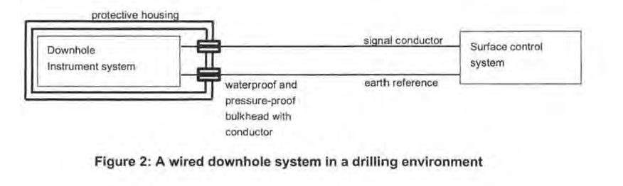
[184] | |
[185] | |
[193] | |
[194] | |
[196] | |
[198] | |
[200] | |
[205] | |
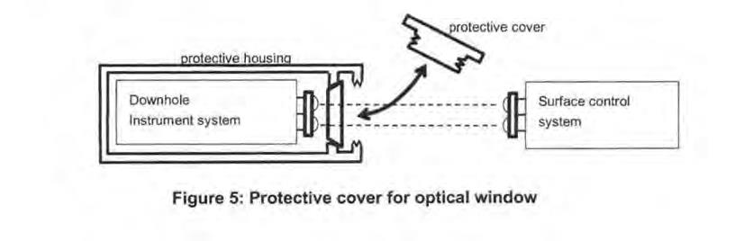
[207] | |
[208] | |
[212] | |
[216] | |
[219] | |
[221] | |
[224] | |
[228] | |
[230] | |
[237] | |
[238] | |
[241] | |
[263] | |
[270] | |
[270] | |
[270] | |
[287] | |
[293] | |
[307] | |
[337] | |
[343] | |
[356] | |
[368] | |
[374] | |
[391] | |
[404] | |
[411] | |
[415] | |
[415] | |
[420] | |
[424] | |
[427] | |
[431] | |
[435] | |
[437] | |
[438] | |
[440] | |
[441] | |
[455] | |
[471] | |
[472] | |
[472] | |
[476] | |
[516] | |
[520] |
1 Globaltech Corporation Pty Ltd contends that Reflex Instruments Asia Pacific Pty Ltd has infringed Globaltech’s Australian Standard Patent No 2012297564 for the invention titled “Optical device for use with downhole equipment” (the patent). Reflex admits that it has infringed the patent by supplying in Australia downhole survey instruments under the brand names “EZ-GYRO” and “EZ-TRAC”, when such instruments are supplied with optical devices as claimed in claim 1 of the patent and described by Reflex as the “IRDA Device” and the “IR Coupling” (“IR” meaning infrared, and “IRDA” referring to the Infrared Data Association Standard). However, Reflex also contends by its cross-claim that the patent is invalid for lack of novelty and lack of inventive step.
2 I consider that Reflex has not established that the invention as claimed in the patent is invalid for lack of novelty or lack of inventive step. In summary:
(1) the three prior art documents (referred to as Iizuka, Bergren, and Sun) do not anticipate the invention as claimed in the patent for numerous reasons in each case and, accordingly, do not deprive the claimed invention of novelty; and
(1) the inventive step in the present case was the perception and the related idea at the priority date that existing downhole tools could be improved by an arrangement that enabled the light signal within the optical device to be reflected to an infrared communication port on the side of the instrument housing, which would mean that when the instrument was brought to the surface for data communication, the end of the housing did not need to be uncoupled to enable access to the infrared port for the data to be obtained, as it could be communicated from the side port to a hand-held communication device. This perceived capacity for a material improvement to existing devices was not obvious at the priority date. While the method chosen to effect this improvement would have been obvious to a person skilled in the art who had been asked to make that particular improvement at the priority date, there was no such problem perceived with the existing designs and no need felt to improve the designs in this or any similar manner. The inventiveness of the perception and related idea to improve the existing designs in this or some similar manner is sufficient to sustain the inventive step of the invention as claimed.
3 The claimed priority date of the patent is 15 August 2011.
4 The inventors are Gordon Stewart and Michael Klass, both current directors of Globaltech.
5 The field of the invention relates to “devices enabling data to be transmitted to and from downhole equipment, such as core orientation units and borehole telemetry probes”: p 1 [0001].
6 The background to the invention at pp 1–2 explains that:
[0002] Core orientation is the process of obtaining and marking the orientation of a core sample from a drilling operation.
[0003] The orientation of the sample is determined with regard to its original position in a body of material, such as rock or ore deposits underground.
[0004] Core orientation is recorded during drilling, and analysis is undertaken during core logging. The core logging process requires the use of systems to measure the angles of the geological features, such as an integrated core logging system.
[0005] Whilst depth and azimuth are used as important indicators of core position, they are generally inadequate on their own to determine the original position and attitude of subsurface geological features. Core orientation i.e. which side of the core was facing the bottom (or top) of a borehole and rotational orientation compared to surrounding material, enables such details to be determined.
[0006] Through core orientation, it is possible to understand the geology of a subsurface region and from that make strategic decisions on future mining or drilling operations, such as economic feasibility, predicted ore body volume, and layout planning.
[0007] In the construction industry, core orientation can reveal geological features that may affect siting or structural foundations for buildings. Core samples are cylindrical in shape, typically around 3 metres long, and are obtained by drilling with an annular hollow core drill into subsurface material, such as sediment and rock, and recoverying [sic] the core sample.
[0008] A diamond tipped dril [sic] bit is used at the end of the hollow drill string. As the drill progresses deeper, more sections of hollow steel drill tube are added to extend the drill string. An inner tube assembly captures the core sample. This inner tube assembly remains stationary while the outer tubes rotate with the drill bit. Thus, the core sample is pushed into the inner tube.
[0009] A ‘back end’ assembly connects to a greaser. This greaser lubricates the back end assembly which rotates with the outer casing while the greaser remains stationary with the inner tubing.
[0010] Once a core sample is cut, the inner tube assembly is recovered by winching to the surface. After removal of the back end assembly from the inner tube assembly, the core sample is recovered and catalogued for analysis.
[0011] Various core orientation systems have previously been used or proposed. Traditional systems use a spear and clay impression arrangement where a spear is thrown down the drill string and makes an impression in clay material at an upper end of the core sample. This impression can be used to vindicate the orientation of the core at the time and position the spear impacted the clay.
7 The patent explains that prior art devices have limitations, including that (at p 3 [0015]):
…The orientation unit is connected to the greaser by a screw thread and o-ring seal arrangement. In the harsh down hole environment within the drill string, it has been realised that the o-ring seals are not always effective and can let fluid into the space between the orientation unit and the greaser.
8 Further, “the orientation unit must be disassembled from the greaser unit before the display and orientation unit can be viewed, rotated and the required core orientation displayed”: p 4 [0015]. It then states (p 4):
[0016] Similar issues arise with downhole probes that are used to obtain borehole telemetry data to determine drilling progress, such as depth and direction of the borehole and change in surrounding magnetic field.
9 At p 4 [0017] the patent records that:
Typically the downhole equipment is brought to the surface once sufficient data is gathered or task completed, such as obtaining a core sample. It is common practice to manually have to separate the backend assembly from an electronics package used for gathering downhole data. This task involves unscrewing the backend assembly from the electronics package, which takes time and risks thread damage as well as resulting in risk of ingress of dirt and water into the thread. Also, o-ring seals protecting the electronics unit may be compromised through separation and refitting of the backend assembly and electronics unit. Similar issues exist with separating the electronics unit of a downhole probe from its backend assembly.
10 Page 4 [0018] says:
It has been found desirable to provide means of obtaining signals/data from or providing signals/data to downhole equipment electronics units, such as used in core sample orientation units or downhole probes.
11 The background to the invention section ends with this statement (p 5 [0020]):
With this in mind, it has been found desirable to provide improved means for obtaining signals/data from or providing signals/data to an electronics unit of downhole equipment.
12 The summary of the invention in the patent includes at p 5 [0021]:
With the aforementioned in mind, in one aspect the present invention provides a device that transfers at least one electromagnetic signal to or from an electronics unit of downhole equipment, the device including a body and an electromagnetic signal direction altering means, the body having a light path arranged to allow the electromagnetic signal from an electromagnetic wave source associated with the electronics unit to pass to the electromagnetic signal direction altering means, the electromagnetic signal direction altering means causing the electromagnetic signal to change direction of travel, the device, in use, configured to transmit or receive the electromagnetic signal through at least one aperture through a side wall of a component of downhole equipment.
13 At pp 7–9 the summary records that:
[0037] An advantage of the present invention is that the greaser or other equipment to which the electronics unit attaches does not need to be separated from the electronics unit in order to obtain access and communicate with the device to obtain data. This avoids needing to unscrew components of the downhole equipment and risk ingress of dirt/water or damaged threads, as well as reduces time taken to obtain data.
[0038] In addition, the electronics unit can be started or stopped remotely and at the most opportune time. For example, in known devices an operator usually delays turning on the electronics unit until the last minute in order to conserve the unit's onboard battery power. The operator then starts the electronics unit and assembles the unit to the other equipment, such as a greaser or probe assembly.
[0039] The present invention avoids the need for such urgent activity by allowing an operator to switch the unit on or off by sending an optical signal from a hand held device to the optical device through an overlying aperture, the device then transmitting the optical signal to the electronics unit to activate/deactivate the unit. Data to/from the unit can also be sent/received utilising the same optical device.
…
[0042] A further aspect of the present invention provides downhole equipment having an electronics unit configured to obtain data relating to a borehole into which the electronics unit is inserted or to obtain data relating to equipment used within the borehole system, and an optical device associated with the electronics unit, and an optical device according to any one of the preceding claims configured to enable optical signals to be transmitted to or received from the electronics unit whilst the electronics unit is connected to the downhole equipment.
14 At p 9 [0044] the summary records:
A still further aspect of the present invention provides a downhole data gathering system, including a communication device arranged to communicate wirelessly with an electronics unit of downhole equipment, the downhole equipment including an electronics unit configured to obtain data relating to a borehole into which the electronics unit is inserted or to obtain data relating to equipment used within the borehole system, and a device that transfers electromagnetic signals to or from the electronics unit of the downhole equipment, the device including a body and an electromagnetic signal direction altering means, the body having a light path arranged to allow the electromagnetic signals from an electromagnetic wave source associated with the electronics unit to pass to the electromagnetic signal direction altering means, the electromagnetic signal direction altering means causing the electromagnetic signal to change direction of travel and wherein the device is configured to enable the electromagnetic signals to be transmitted to or received from the electronics unit whilst the electronics unit is connected to the downhole equipment, the device enabling transmission of the electromagnetic signals from the electronics unit to the wireless communication device, or from the wireless communication device to the electronics unit, through at least one aperture in a side wall of the downhole equipment.
15 The patent includes the following figures described in a section entitled “Description of the preferred embodiment” (p 10):
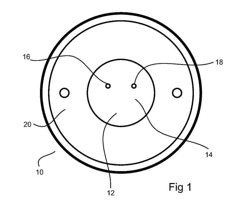
16 Figure 1 shows an end on view of a core sample orientation device or downhole probe having an indicator window whereby indicator lights provide optical signals to an optical device according to an embodiment of the present invention: p 10 [0047]. In figure 1, the indicator window end 12 of an electronics unit of a core sample orientation data gathering device 10 includes a window 14. Indicator lights 16, 18 can be seen through this window at least when illuminated. The window end is sealed by a retaining plate 20: p 10 [0051].
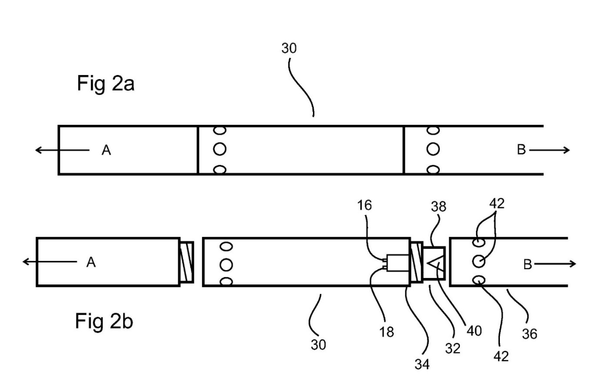
17 Figures 2a and 2b below show an electronics unit 30 for gathering data downhole which houses the light emitters 16, 18. Light from these emitters (eg, LEDs,or light emitting devices) passes through the window 14 (shown in figure 1). Reference arrow A refers to the drill bit end direction, and reference arrow B refers to the backend assembly direction. An optical device 32 according to an embodiment of the present invention is provided at the end 34 of the electronics unit 30 and which device extends into the greaser unit 36 of the backend assembly when connected thereto. The optical device has a body 38 and a light path altering means 40. The body also defines a light path therethrough (see figure 3 below) arranged to allow the optical signal from a light source(s) 16,18 associated with the electronics unit to pass to the light path altering means. The light path altering means 40 can be arranged to cause the optical signal from/to the electronics unit to change direction of travel and emit out of the body/into the body of the optical device. The greaser unit 36 has apertures 42 that allow light therethrough. Light from the emitters is directed onto at least one light path altering means of the device. The emitted light can be observed through the apertures 42 in the greaser: pp 11–12 [0058]–[0064].
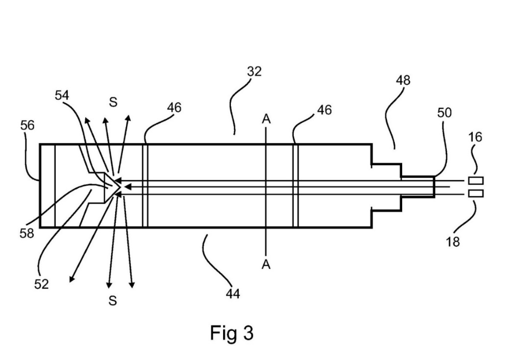
18 Figure 3 below shows a particular embodiment of an optical device 32 for use with a downhole electronics unit. The optical device is shown in side, profile view. In practice, the device is cylindrical in cross section A–A. The optical device has a body 44 of a transparent machined plastics material, such as polycarbonate, acrylic, nylon etc. Glass may also be used, though a plastic material is preferred. The body has annular grooves 46 therearound to receive o-rings for sealing the device within a housing or casing of a downhole unit, such as an electronics unit. In this embodiment, the transparent material of the body allows light to pass therethrough. At least a portion of the body is shaped to fit within a housing or casing of a component of downhole equipment, such as an electronics unit or a greaser unit or extension piece etc. A first end 48 of the body is shaped so that an end surface 50, in use, faces the light emitters 16, 18 or other light emitters depending on the equipment used and required application. Light from one or more such emitters is transmitted by the light path through the body to impinge on a light path altering means 52. In this embodiment, the light path altering means includes a reflector 54. The reflector reflects some or a majority of the light impinging upon it, and said reflected light is re-directed sideways (S) with respect to a longitudinal direction (L) of the device. The light path altering means may be provided, as in this embodiment, by forming a recess in its second end 56. The recess may form a conical surface 58 to which a reflective material is applied, such as a silvery coating: pp 14–15 [0071]–[0077].
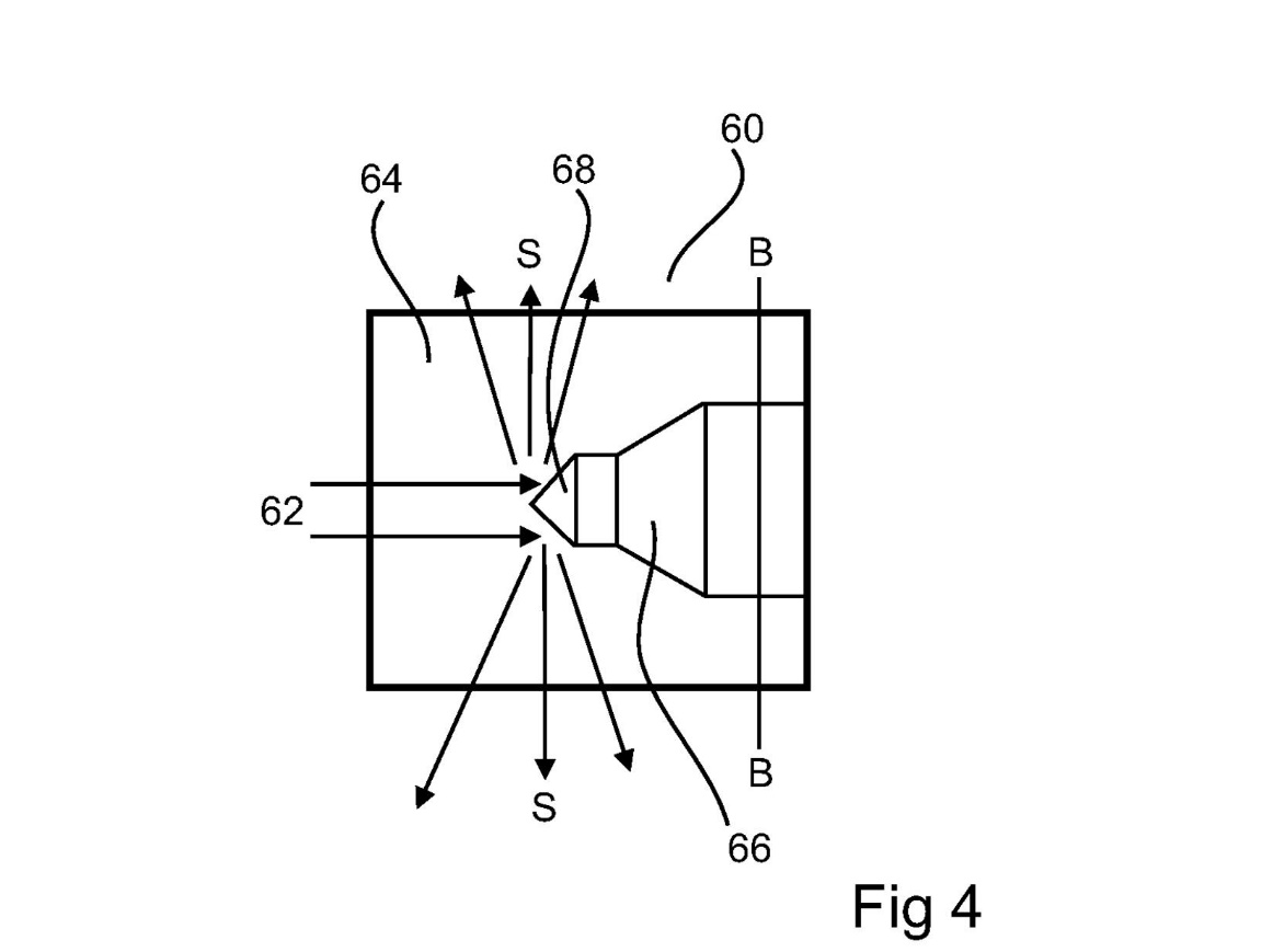
19 Figure 4 below shows an alternative embodiment of the present invention which works in the same manner as that of figure 3. This alternative form of optical device 60 is provided as an insert for use with a downhole probe. Again, this device as the one above in figure 3, is shown in side view but is a cylinder with a circular cross section B–B. Light 62 entering the device 60 passes through the body 64 material and reflects off of a protrusion 66 into the envelope of the cylinder. The protrusion is a machined surface coated from the exterior with a reflective material. A conical surface 68 assists in diffracting light sideways (S). The light path altering means may be a dished or domed end to the device and which is coated or covered in a reflective material. The optical device can be inserted into a downhole component and removed from replacement or access to an end of the electronics unit as required. Otherwise, the optical device can be left in situ to transmit light from/to the electronics unit. This can avoid the need to disassemble the electronics unit from the backend assembly, greaser unit or probe etc to which it is connected. The electronics unit can be switched on or off by sending a controlling optical signal to the electronics unit through the optical device. The optical device may be formed of one or multiple parts. For example, the optical device may be machined as a monolithic component or may be formed of multiple sub-components brought together, which may be bonded together or simply abutting in use. Light impinging on the light path altering means can be emitted sideways omni-directionally. Thus, and of great benefit to an operator, the optical device needs no alignment with the at least one aperture of the downhole assembly through which the light is to be transmitted: pp 15–16 [0078]–[0085].
20 The claims in contest are claims 1, 5, 7, 8, 9, 10, 12, 17, 21, 22, 24, 25, 26, 27 and 29.
21 Claim 1 in the patent is to:
A device that transfers at least one electromagnetic signal to or from an electronics unit of downhole equipment, the optical device including a body and an electromagnetic signal direction altering means, the body having a light path arranged to allow the electromagnetic signal from an electromagnetic wave source associated with the electronics unit to pass to the electromagnetic signal direction altering means, the electromagnetic signal direction altering means causing the electromagnetic signal to change direction of travel, the device, in use, configured to transmit or receive the electromagnetic signal through at least one aperture through a side wall of a component of downhole equipment.
22 Contested claims 5, 7, 8, 9, 10, 12, and 17 are dependent on claim 1.
23 Claim 21 is to:
A downhole data gathering system, including a communication device arranged to communicate wirelessly with an electronics unit of downhole equipment, the downhole equipment including an electronics unit configured to obtain data relating to a borehole into which the electronics unit is inserted or to obtain data relating to equipment used within the borehole system, and device-that [sic] transfers electromagnetic signals to or from the electronics unit of the downhole equipment, the device including a body and an electromagnetic signal direction altering means, the body having a light path arranged to allow the electromagnetic signals from an electromagnetic wave source associated with the electronics unit to pass to the electromagnetic signal direction altering means, the electromagnetic signal direction altering means causing the electromagnetic signal to change direction of travel and wherein the device is configured to enable the electromagnetic signals to be transmitted to or received from the electronics unit whilst the electronics unit is connected to the downhole equipment, the device enabling transmission of the electromagnetic signals from the electronics unit to the wireless communication device, or from the wireless communication device to the electronics unit, through at least one aperture in a side wall of the downhole equipment.
24 Contested claims 22, 24, 25, 26, 27, 28 and 29 are dependent on claim 21.
25 Kelvin Brown is the Global Lead (Directional Drilling) of Reflex. Reflex is a wholly owned subsidiary of Imdex Ltd (Imdex). He has over 20 years’ experience in mineral exploration drilling. He has acquired knowledge and experience in all major aspects of exploration drilling, including auger drilling, rotary-percussion drilling and diamond core drilling, and the downhole equipment and instruments used in those drilling programmes. He regularly observed competitors’ products being used on Reflex customers’ sites and was given an opportunity to operate them. He also maintained a familiarity with competitors’ products by attending mining events, doing online research on competitors’ websites, LinkedIn and social media accounts, via customer contacts who would inform him of competitors’ products, through marketing collateral including mining and geology publications and by way of membership with the Deep Exploration Technologies Cooperative Research Centre (DETCRC).
26 Mr Brown said that downhole equipment refers to equipment used down boreholes, which includes core orientation tools and survey tools.
27 Mr Brown identified that the Imdex range of instruments being manufactured in Western Australia as at 30 June 2011 comprised: (a) ACT II RD – rapid descent core orientation instrument, (b) EZ-SHOT – single shot magnetic survey instrument, (c) EZ-AQ – magnetic survey instrument specifically designed for AQ sized boreholes, (d) EZ-TRAC – multi shot magnetic survey instrument, (e) MAXIBOR II – optical non-magnetic survey instrument, (f) Reflex Gyro – gyroscopic survey instrument, and (g) customised directional motors.
28 Mr Brown said that with the exception of the EZ-SHOT and the customised directional motors, each of the above instruments used wireless handsets for communication and data transmission. The ACT II RD, EZ-AQ, EZ-TRAC and MAXIBOR II used wireless infrared communication. The Reflex Gyro used Bluetooth communication.
29 According to Mr Brown, core orientation tools and survey tools are complementary products. The borehole used in the core orientation process is required to be surveyed at some point in order to determine the geospatial position of the oriented core. The survey process is undertaken either before or after the process of orientating the core. Core orientation tools are used to indicate the orientation of a core sample in its original underground location and provide that orientation data to the operator. Survey tools are primarily used to measure changes in inclination and azimuth (deviation) along a drill hole. It is typical for drilling rig operators to require supply of both core orientation tools and survey tools before commencing drilling operations.
30 Core sample orientation is the process of obtaining and marking the orientation of a core sample from a drilling operation, which is typically an approximately three metre length of solid cylindrical core. Core orientation procedures are required to be carried out because, once detached from its parent rock and retrieved to the surface, the recovered sample will not reflect its original orientation underground. In order to re-orientate the sample, it is typically necessary to include an orientation tool in the drilling assembly unit between the greaser unit and inner core tube holding the core sample. The purpose of the orientation tool is to indicate the orientation of the core sample in its original underground location and provide that orientation data to the operator.
31 The process of orientating drill samples allows geologists to correlate recovered samples with one another to reveal trends in rock strata and predict whether resource mining is worthwhile, and if so, where, in what direction, and how deep below the surface. Core orientation is an important process as it allows geologists to build a three-dimensional profile of subsurface resource deposits, such as iron ore or diamonds. As metal-bearing deposits are often determined by the structural compositions of their enclosing rocks, it is important for the geologist to understand these structural elements in order to estimate the likely location of mineral bearing ore deposits, and once located, determine the likely position, size and composition of the deposit. If a valuable ore seam is found, it is vital that the core has been orientated properly so that a true picture of the ore body can be investigated, located and estimated.
32 Prior to and/or during any drilling operation, there is often a need to obtain more information from the borehole being drilled, as boreholes frequently deviate from the projected path. As such, there is a need to know in which direction the hole is on/off track and by how much, and if the course should be re-routed. A downhole or borehole survey is therefore a geophysical survey carried out by a specialised technician which involves putting digital geophysical equipment down exploration drill holes to gather magnetic, radiometric or electrical information from the rocks adjacent to the hole.
33 The geologist will have plotted the desired trajectory of the drill path before the coring operation begins. After the drill hole has sufficiently advanced, the geologist will direct the drilling crew to lower a survey instrument into a desired location of the borehole to ensure that the drill path has not deviated from its planned trajectory.
34 Downhole survey data provides geospatial data, namely the dip and azimuth of the axis of the core, which can then be used by a driller. However, downhole survey data does not provide orientation information to fully orientate the cylindrical sample of the core.
35 The following sections primarily consist of extracts from Professor Tapson’s affidavit evidence, relied on by Reflex.
36 Jonathan Tapson is an electrical and electronic engineer. He was a Professor of Electrical and Electronic Engineering at Western Sydney University and became Visiting Professor of Electronics and Information Technology at the University of Technology, Sydney. He has worked as the Chief Scientific Officer for GrAI Matter Labs in San Jose, California. He holds a PhD in Engineering from the University of Cape Town, obtained in 1994. He has 32 years of experience in electrical and electronic engineering, primarily in the field of sensors and instrumentation. This includes designing and building orientation systems for the mining and resources industry, including in drilling applications.
37 Professor Tapson has previously been engaged on behalf of Reflex in the following proceedings: Australian Mud Company Pty Ltd v Coretel1 Pty Ltd (No 4) [2015] FCA 1372, Australian Mud Company Pty Ltd v Coretell Pty Ltd (No 2) [2018] FCA 1109; (2019) 134 IPR 359, Australian Mud Company Pty Ltd v Globaltech Corporation Pty Ltd [2018] FCA 1839; (2018) 138 IPR 33, Reflex Instruments Asia Pacific Pty Ltd v Borecam Asia Pte Ltd [2017] APO 51, Reflex Instruments Asia Pacific Pty Ltd v Minnovare Pty Ltd [2018] APO 70, and Reflex Instruments Asia Pacific Pty Ltd v Minnovare Pty Ltd [2018] APO 71. He has also been engaged by the respondent in two ongoing matters, one in the United States (by a related Imdex subsidiary) and one in Australia in this Court.
38 Professor Tapson is a named inventor of a number of patents including two patent applications filed by the respondent, being: (a) Australian provisional application 2016905363 (363 application) in the name of Imdex Global BV filed on 23 December 2016, and (b) Australian standard patent application 2017381411 (411 application) in the name of Reflex Instruments Asia Pacific Pty Ltd (formerly Imdex Global BV) filed on 22 December 2017 which claims priority from the 363 application. Professor Tapson was not aware of these applications before they were filed and was first informed about them in around August 2017. He has no contractual or financial connection with Reflex or its related companies other than his remuneration to act as an expert in the various proceedings identified and has not been remunerated for his inventive contribution to the 363 and 411 applications.
39 Before being provided with the patent, Professor Tapson was informed that the patent in dispute related to downhole instrumentation used in the mining industry, including techniques for data transmission. He was asked to complete a design task based on only the common general knowledge in the field described as “the methods for communicating and transmitting data in devices which are designed to operate in a geological drilling environment” at the priority date of August 2011. After completing the design task he was provided with the patent.
40 Professor Tapson referred to the resources relevant to the identified field that he and colleagues would have had access to, and consulted as at the priority date. He and colleagues in the field regularly attended instrument, measurement and position-sensing conferences. They also read and referred to papers delivered at these conferences. They regularly read and referred to other papers in peer-reviewed journals, trade journals and industry-specific journals. He has also reviewed patents since the early 2000s. He considered it common for people working in the field to use patent databases and specifications as a resource to assess technology and the commercial risks associated with particular designs. He and his colleagues engaged with industry representatives including geophysicists and drilling operators in relation to the design of mining instrumentation. They also regularly reviewed information about sensors, downhole instruments and componentry (including specifications, data sheets, user guides and operational manuals) published by suppliers of such products and componentry. They monitored internet forums provided by product and componentry suppliers, on which instrumentation systems and componentry information and knowledge were disseminated and exchanged.
4.1.3 Common general knowledge
41 Professor Tapson said that the common general knowledge (as he was instructed, the background knowledge and experience which is available to all in the field) at the priority date included that downhole instruments are tools that are used down boreholes. These tools include survey tools, core orientation tools, drilling tools, geophysical probes and gyroscopes. Survey tools and core orientation tools are usually both present at drilling sites and are often used in tandem in drilling operations.
42 A core orientation tool is one that provides information as to the orientation of a core sample drilled from a borehole. Core orientation does not generally require a measurement of azimuth or direction.
43 A survey tool is a tool that provides information to plot a borehole trajectory and path, usually including azimuth and direction and usually using a compass or a gyroscope or other deviation methods.
44 Since the 1990s, there has been a continuing evolution towards digitisation of these tools. By the 2000s, the use of electronic tools downhole started to overtake the use of pre-existing mechanical methods. This development was accompanied by the use of new methods of communication to extract data obtained by these tools downhole once back at the surface. This was a trend not only in downhole tools but in all areas of industrial automation around this time.
4.1.3.2 Wired systems for communicating and/or transmitting data downhole
45 The available options included:
(1) Electrical port on the instrument housing: this option involved placing a sealed waterproof and pressure-proof electrical port on the external housing of the downhole instrument. In particular, the instrument would be sealed at the surface in an external housing and sent downhole to gather data. The data could then be read after the downhole instrument had returned to the surface or alternatively, the instrument could be removed or partially unsealed from the housing. This method had two disadvantages. The first is that waterproof and pressure-proof electrical ports were not particularly reliable in the drilling environment. The second is that unsealing and re-sealing a port or housing seal introduced a delicate and potentially unreliable action into a busy and robust workflow. Introducing such a step in a drilling workflow created a likely point of failure, which could be expensive should the instrument be flooded after seal failure.
(2) Electrical conductor on the drill string: this option involved placing a conductor in the metal drill string or using the metal of the drill itself as an electrical conductor. There were a number of so called single-wire techniques for using a single conductor to transmit data. He was aware of a number of efforts to use this method as at the priority date, but not aware of any that was particularly reliable or allowed a high data rate.
(3) Permanent cable integrated into an instrument: this option involved integrating a permanent connection between the instrument and drill string. In such a design the instrument and drill string would have a permanent multi-wire communications cable integrated into it. While electronically satisfactory, this was unlikely to prove viable for reasons of cost, complexity and reliability in geological drilling.
46 The available options included:
(1) Acoustic systems: acoustic systems cover a wide range of possibilities, including transmission by pulses in liquid, and acoustic and ultrasonic transmission in air and water. The early reliable logging while drilling (LWD) devices created pulses in the drilling fluid (mud) being pumped from the surface. These pulses were readable at the surface as pressure pulses at the mud pump. This method is called mud-pulse telemetry.
(2) Ultrasonic transducers: a second acoustic possibility is to use ultrasonic transducers to communicate from within the housing to the exterior (at the surface). Ultrasonic communication was well established as a method for underwater communication between sealed vessels at least 50 years ago. Each device in the transmission will have a small ultrasonic transceiver (which can be thought of as a combination of speaker and microphone, operating at inaudible frequencies). The transmitter will broadcast the data as modulated sounds, and the receiver will receive the data as a sound stream and decode it. An advantage of ultrasonic links is that ultrasound in sufficient volume penetrates through most solids and liquids for a moderate distance, and hence can be transmitted from inside a housing without breaking the seal. There were many variations on these methods.
(3) Optical devices: the use of optical systems to bridge gaps which are not tractable with electrical conductors is a mature art, with optocouplers, photocouplers and opto-isolators being commonplace in electronics since the semiconductor boom of the 1970s. While much of the technology focuses on guided optical transmission (eg, through optic fibres) there is an entire field of electronics that focuses on unguided transmissions (ie, where there is no bespoke optical system connecting the transmitter and receiver, and transmissions take place through whatever natural medium lies between the two systems). This is called optical wireless communication. It was largely a fringe technology until the invention of the IRDA standard in the early 1990s, at which point it became commonplace – including use in television remote controls and similar devices for short range communication. The advantage of optical wireless communication is that the electro-optical devices that transmit and receive light can be placed behind a clear pressure-proof window, which will not significantly distort or disrupt short range communications.
4.1.3.4 Magnetic Communication
47 Magnetic communication or strictly, near-field magnetic induction communication, makes it possible to transmit information by means of a modulated magnetic field. This is quite straightforward and is not very different from wireless communication.
48 Magnetic communication has the advantage that magnetic fields are not significantly attenuated in water or soil or other dielectric media, so has often been used as a means of underwater communication (to submarines, for example). It is possible to fabricate magnetic antennas which are robust enough to be integrated into the exterior of a pressure housing, as they consist of coils of wire which can be deeply embedded in a protective epoxy, for example.
49 The disadvantage for all magnetic communication and instruments is that they are each susceptible to interference from man-made or natural magnetism which will interfere with the communication and result in incorrect measurements. Additionally, magnetic communication has the disadvantage that unless a very high-power signal is transmitted, it is only effective over short range, and because of the intrinsic inductance of magnetic antennas, it is not possible to sustain a high data rate with magnetic communication.
4.1.3.5 Handsets or hand-held devices
50 A wireless communication system would typically use an interface such as a handset or hand-held device to communicate with the downhole instrument. The use of hand-held devices to display orientation information or measurements from sensors and instruments was increasingly common amongst mining engineers and surveyors before the priority date particularly with the introduction of the Apple iPhone in 2007.
51 The Apple iPhone was increasingly used as a hand-held human-machine interface (HMI). HMIs include the keyboard, or mouse, and display which are used to interact with any given machine. Mining survey instruments started to include a remote display (via HMI) for various reasons including (a) safety: often the sensor or instrument must be placed in a position, such as closely adjacent to a rotating machine shaft, that would be hazardous for a human operator. Under these circumstances, the use of a remote display makes the instrument safe to use. Also, in hazardous environments where the presence of flammable gas or powders create a risk of explosion, it is often safer to keep electronic instruments within their sealed explosion-proof housings and interrogate them wirelessly with a remote display, (b) accommodation: the volume of space available to house the instrument may not be sufficient for a human operator, or access may not be possible (for example, the interior of a drill pipe), (c) ergonomics: in some cases, the instrument may be placed in a position which is either uncomfortable for the operator, or does not allow them to access the controls which they require to make use of the instrument information, and (d) workflow: a wireless remote enables the operator to work more quickly because there is no need to remove or access the instrument, which might cause lost drilling through downtime.
4.1.4 Designing a downhole instrument for transferring data
52 Professor Tapson described the steps he would have taken to design a downhole instrument for transferring data based on the common general knowledge at the priority date.
53 Professor Tapson identified the factors that had to be considered in the design as being the hostile borehole environment from liquid and very high pressure. Accordingly, the downhole instrument must be waterproof at the depth to which it is anticipated the drill will go. Other design issues include: (a) at drilling depths, the ambient temperature can be extremely high, which can affect the performance of polymer seals as well as electronics, (b) the drilling environment is extremely harsh physically (ie, involving being dropped onto hard surfaces from a significant height), and (c) if the instrument is to be integrated into the drill string for any kind of operation during or concurrent with borehole drilling, it will be physically isolated from the outside by the metal structure of the drill string into which it is integrated.
54 For these reasons, downhole instruments are generally placed in housing designed to protect the instrument while still allowing it access to the external environment for communications and sensing purposes. Communicating between an instrument in a sealed housing and an external device was well-known before the priority date. These methods included either use of wired devices or systems (meaning there is at least one physical electrical conductor connecting the instrument and the external device) or wireless devices or systems (which are similarly divided into multiple classes according to the medium of communication).
55 There are two possible requirements (purposes) of downhole instruments intended for communicating or transmitting data to and from the surface: (a) first, to communicate from the instrument to the surface while drilling (measurement while drilling (MWD) or LWD), and (b) secondly, to communicate between a housed instrument and another device at the surface.
56 Professor Tapson would have preferred a wireless communication method over a wired communication method. A wired downhole system has many disadvantages. Even with good conductors (a drill string and the rock body are not good conductors) the transmission rate is low, because data going in both directions must share the same signal line. This is called half-duplex communication and is not efficient. The signal lines must somehow be connected to the downhole instrument system while that system is protected from the drilling environment. A protective housing for the downhole instrument system is therefore required. If a waterproof and pressure-proof bulkhead with a conductor is provided, the bulkhead represents a point of probable failure in circumstances of robust handling, and the permanent wired connection is inconvenient in drilling operations if the system is integrated into a drill string. This is shown in figure 2 below:
57 Where LWD is not required, but data can be retrieved at the surface at a later time, an option is to disconnect the wires and fully protect the instrument. As shown in figure 3 below, the instrument is fully enclosed in the housing, with a removable port cover that can be opened to expose an electrical connector on the housing.
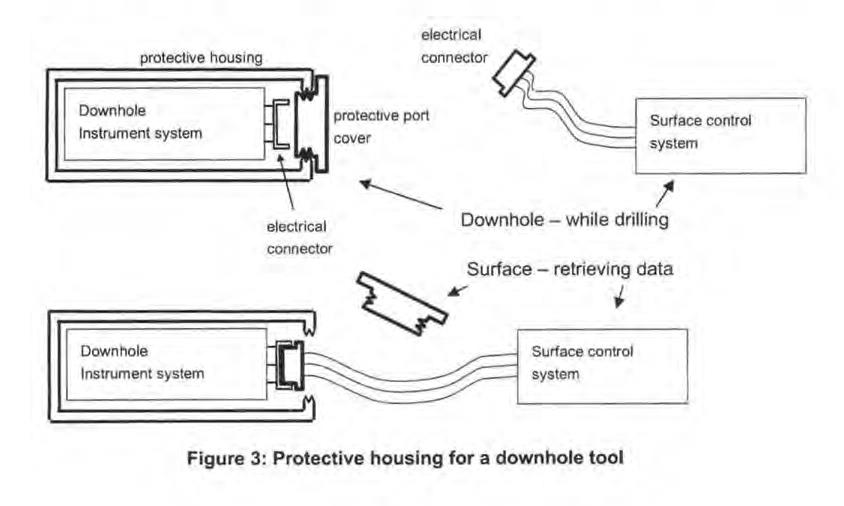
58 The main drawbacks of the figure 3 design are: (a) when the housing is opened at the surface, the instrument is exposed to dirt and liquid and other physical damage which may be unavoidable in the drilling environment, (b) opening and closing the port, and plugging and unplugging the connector add steps to the drilling workflow that will slow the operation down, and (c) the electrical connector and the port are inevitable points of failure, given that dirt may get into the joint faces of either, and any misalignment in insertion will also cause failure.
59 Abandoning the permanent wired connection makes it possible to use a multi-wire communications system, allowing full duplex (simultaneous bidirectional) data communication. The disadvantages above suggest the use of a wireless communications method is more appropriate for downhole environments. Given that the housing is metal, electromagnetic (radio) transmission from inside to out is not possible (the housing is a so-called Faraday cage, fully shielding the circuit inside from any radio signals produced outside, and vice-versa).
60 The most easy and straightforward communication method is to use optical wireless communication. The most suitable form of optical communication would be infrared radiation. Infrared radiation is a type of optical signal or light wave. Infrared light has good transmission through humid temperatures and many instrument components can transfer or transmit infrared signals. There is no need to use optical (visible) light unless a human is required to see the light (eg, an entry light or a flashing light).
61 The optical wireless communication method is illustrated in figure 4 below. It requires including a transparent window in the protective housing, so that the light signals can be transmitted.
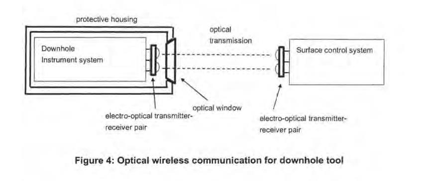
62 This system (in figure 4) is excellent from a workflow point of view because it does not require any fine manipulation of connectors. There are also no connectors to be removed, which would have been a point of vulnerability. The system at figure 4 also allows for very quick transfer of data because all that is required for communication is for the user to bring the downhole instrument system and surface control system into optical alignment. This way, there is very little wait time involved whilst downloading the data from the downhole instrument system.
63 However, any time there is a sealed lid or cap that has to be unscrewed or unfastened, the design introduces a point of vulnerability which means that dirt can be introduced into the seal and there is always a risk that the seal will fail as a result. Professor Tapson’s design in figure 4 is also consistent with the well-established principle that a designer does not want to introduce dirt into sealed instruments. This is especially the case in a drilling environment, where it is always very dirty, and the drilling crew are in a hurry to continue with the drilling operation.
64 Professor Tapson considered that the only remaining point of mechanical failure is that the optical window (which may be waterproof and pressure-proof) is necessarily made from a material such as glass or acrylic plastic, which is not as strong as the metal housing, and susceptible to abrasion and fracture. As a further improvement, it could therefore be covered with a protective metal cover, as indicated in figure 5 below, when communication is not required. The protective metal cover in figure 5 can then be removed manually when communication with the surface control system is required. This protective cover does not need to be water or pressure tight, as it is only protecting the window from mechanical damage.
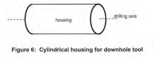
65 In all of these figures, the downhole tool is shown as a rectangle with the long side being conceptually the axis of drilling, as illustrated in figure 6 below, consistent with using a cylindrical housing which is either integrated into the drill string, or freely lowered into the borehole.
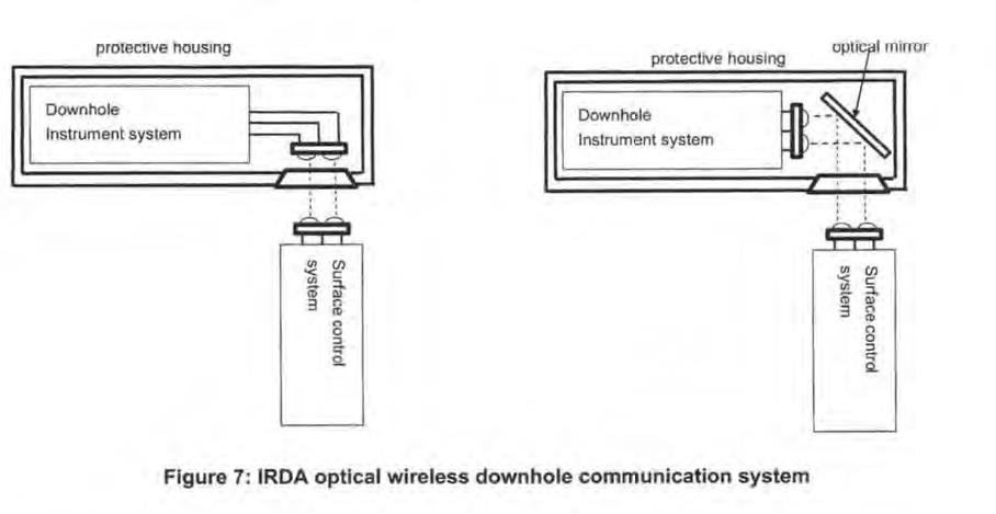
66 Professor Tapson said that while it may make sense for the communication access to be placed at the end of the housing in cases where there is a semi-permanent connection, as in MWD or LWD or post-drilling logging, it does not make sense where the isolated instrument is enclosed within the drill structure. This is because the ends of the cylinder are the easiest (and often, only practical) places to couple the housing to the rest of the system, and also because the ends are likely to receive more mechanical abuse in general handling. It would be preferable not to uncouple or otherwise interfere with the coupling of the housing in order to communicate with the instrument. It would therefore be advantageous to access the instrument through the side wall rather than the ends of the housing. With optical wireless communications, this is easily achieved either by rotating the transmitter-receiver pair through 90 degrees, or simply bending the optical axis 90 degrees by means of a mirror, as shown in figure 7 below. The latter method has the advantage that the basic instrument board does not need to be modified from the above system and can be used in both cases. In typical IRDA-type optical wireless communication, the transmitted optical beam is quite wide, perhaps 20–30 degrees, so some misalignment from the direct optical axis is tolerable.
67 Professor Tapson said that after he provided the above evidence, Reflex’s lawyers asked him to describe in further detail the nature and function of the optical mirror.
68 In response to this request, Professor Tapson said that if the optical signal path is short so that the surface control system is close to the instrument (eg, 10cm or 20cm), a high-quality mirror is not required because there is enough light bouncing around inside the instrument. If the optical signals need to be transmitted over a longer distance (eg, 5m) then a high-quality mirror is required. If a mirror is not available, other reflective surfaces which could be used are polished metal, acrylic, or aluminium foil over plastic. The result from each of these alternatives should not be dramatically different.
69 Although Professor Tapson had the Reflex EZ-TRAC Manual before undertaking his design, he did not read it until after completing his design task. The EZ-TRAC instrument had the following features as at 2009: (a) optical wireless (infrared) communication which was used to communicate and transfer data to and from the downhole instrument (see 8.1.3 of the EZ-TRAC Manual), (b) a handset, “EZ-COM” which had an integrated infrared port on the top of handset for wireless communication with the downhole instrument (see 7.2 and 8.1 of the EZ-TRAC Manual), and (c) the infrared port on the EZ-COM needed to be directed to a corresponding infrared port on the downhole instrument for communication and data transfer (see 8.1.3 of the EZ-TRAC Manual).
70 The EZ-TRAC instrument did not have: (a) a window in the side wall, which Professor Tapson considers to be a rudimentary improvement in his preferred designs over the EZ-TRAC instrument, or (b) a mirror, which as shown in Professor Tapson’s second alternative design at figure 7 he considered is a routine improvement over the EZ-TRAC instrument.
71 Professor Tapson’s understanding of terms used in the patent as at the priority date follows.
72 Azimuth is the angle with respect to magnetic north or geographic north.
73 Backend assembly is a component of the core drill. The backend assembly connects the inner and outer tubes, and incorporates a bearing or other mechanism for restricting relational movement and allows retrieval of the inner tube following breaking off of the bottom, namely, the detachment of the core from the body or parent rock.
74 Bore hole or borehole is any hole drilled into the earth using a drilling machine for the purposes of geological investigation, petrochemical investigation or resource extraction.
75 Core drill refers to the conventional core drilling assembly used in mineral exploration for drilling a core sample, which includes, among other things, a backend assembly, an inner tube, a core lifter, an outer tube and a drilling bit.
76 Core sample, or simply core is a cylindrical core of rock drilled using a core drill from the ground. Geologists can analyse the core sample to determine the composition and other attributes of rock under the ground.
77 Depth is the distance from the surface to a position either along or at the bottom of a borehole.
78 Drill bit or cutting head is an annular, diamond-impregnated cutting tool (known as a “bit”) mounted on the end of a turning string of drill rods that forms part of the outer tube.
79 Inner tube assembly or inner tube, also known as a “core tube”, “sample tube” or “core barrel”, is a tube which sits inside the outer tube and progressively receives the core sample as drilling advances into the rock.
80 Outer tube, also known as the “outer barrel”, is the assembly into which the inner tube fits during core drilling.
81 Professor Tapson then considered the following patents:
(1) US Patent No 4899277 “Bore hole scanner with position detecting device and light polarizers” granted 6 February 1990 (Iizuka);
(2) US Patent No 5729013 “Wellbore infrared detection device and method” granted 17 March 1998 (Bergren); and
(3) US Patent No 7777643 “Optical communications with a bottom hole assembly” granted 17 August 2010 (Sun).
82 The Iizuka patent says that:
This invention relates to a bore hole scanner (an apparatus for observing the wall of a bore hole which, in the present invention, refers to boring holes and pipe holes and the like) for being raised, lowered and moved within a bore hole to observe the wall of the bore hole by means of a scanner incorporated in a sonde.
83 The summary in the Iizuka patent says:
An object of the present invention is to provide a bore hole scanner in which movable portions in the bore hole observing section are eliminated to do away with wearing components and facilitate maintenance.
Another object of the present invention is to provide a bore hole scanner with which a bore hole can be scanned at high speed.
In accordance with the present invention, the foregoing objects are attained by providing a bore hole scanner comprising a light projecting device for projecting a light beam toward the bore hole wall, a conical mirror arranged coaxially with respect to a sonde for condensing light reflected from the bore hole wall, image forming device arranged in front of the conical mirror, photoelectric transducing device for converting a light signal into an electric signal, optical fibers for introducing an image, which is formed on concentric circles by the image forming device, to the photoelectric transducing device, data processing device for scanning and extracting signals from the photoelectric transducing device, and for generating and processing image data indicative of the hole wall surface, and sonde position detecting device for detecting orientation and position of the sonde.
84 Figure 3 in Iizuka is:
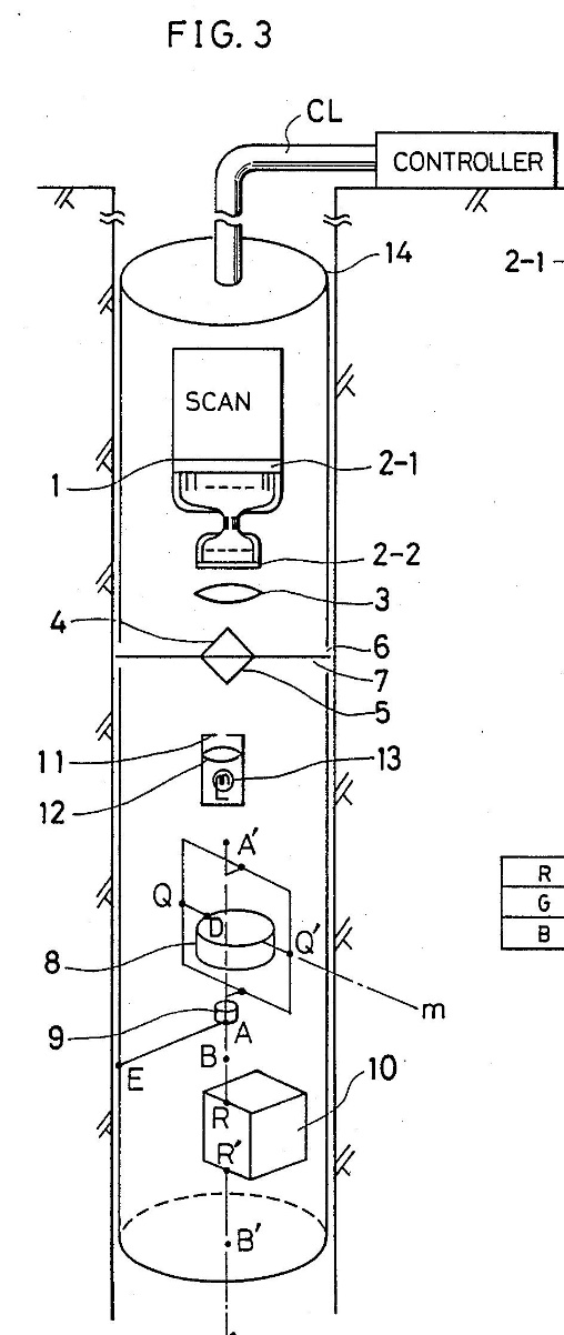
85 Professor Tapson said that Iizuka discloses a downhole survey tool and system being a borehole scanner, which uses light to scan or probe the wall of the borehole optically to establish an optical survey of the borehole. Iizuka’s borehole scanner uses a sonde as an optical device whereby light is projected onto a borehole wall using a conical mirror. The sonde detects the light reflected from the borehole using a further conical mirror. This reflected light is condensed using a lens before travelling through optic fibres to a photoelectric transducer whereby the light signals are converted to electric signals corresponding to the intensity of the reflected beam. A data processing unit then detects and processes the electric signals to generate image and positional data indicative of the borehole wall surface. The sonde is raised and lowered in the borehole to produce a continuous image of the borehole wall surface.
86 According to Professor Tapson, the borehole scanner disclosed by Iizuka is not confined to any particular field and is appropriate for use in any borehole as the description of the invention refers extensively to a borehole but does not describe what kind of borehole. There is nothing in the technical description in Iizuka which makes Professor Tapson believe that this invention is limited to work in any kind of borehole.
87 Professor Tapson considered that asserted claim 1 and dependent claims 5, 7, 8, 9, 10, 12 and 17 of the patent are disclosed in Iizuka.
88 The Bergren patent says:
This invention relates to an infrared detection device for determining sources and concentrations of oil and water flow in cased and uncased wellbores; and more particularly to an infrared detection device insertable into a wellbore without interrupting the flowing fluid production; and more particularly to an infrared detection device which is insertable into an inclined or horizontal wellbore casing, to provide a plurality of radially-spaced detection zones across the wellbore cross section, so that two-phase and three-phase fluid flow patterns may be detected and logged along the length of the wellbore casing.
89 The background in the Bergren patent explains that:
Water production from hydrocarbon fluid production wells has been a longstanding problem. Mature oil fields which are being waterflooded to stimulate oil production may experience water flows from production wells which exceed ninety percent (90%) of total fluid production from such wells…
…
Detection of a source or sources of water downhole is considered difficult with existing technology. It is particularly difficult to determine the sources of water in inclined wellbores or in horizontal wellbores…
…
90 The summary of the invention in Bergren is:
An infrared source and detector disposed downhole is provided which is capable of determining whether the fluid flowing past the detector is water or oil. It has been found that the optical densities of water and crude oil with respect to the transmission of infrared radiation are particularly distinct… By a particular arrangement of a downhole logging device having a tool body carrying an infrared radiation source and a detector onboard, longitudinally spaced sections of a perforated wellbore casing can be identified which are producing excessive amounts of water. Particular areas, zones or radial locations about the wellbore radius within a given longitudinal section which are the source of excess water production can also be identified. Based upon a plurality of discrete infrared detection zones around the tool body, the flow pattern or flow regime of production fluid flow can be determined without interrupting production to take samples.
Advantages of the device described and shown in the diagrams are that the device may be traversed through the well without interrupting fluid production during the analysis procedure. The device is capable of analyzing all fluid flow on an average or selective basis at any longitudinal location along the wellbore and the device may be continuously traversed through the wellbore to minimize analysis time and to accurately locate sources of excessive water into the well and/or desirable quantities of oil production into a well.
91 Figure 2 in Bergren is:

92 Professor Tapson said that Bergren discloses a downhole survey tool and system, being an infrared detection device or a logging device composed of an infrared source, transmitter and detector that is inserted into a borehole to optically survey the borehole and determine the source and concentration of oil and water flow. The Bergren infrared detection device uses an infrared transmitter as an optical device to transfer infrared radiation from an infrared source through production fluid flowing in a borehole. The infrared transmitter uses infrared signals travelling through optical fibres bent at a 45 degree angle to redirect infrared signals into the flowing production fluid. Infrared signals flowing through the production fluid are subsequently detected by mirrors located on the infrared receptors located around the infrared transmitter. Once the infrared signals are detected, the infrared detector logs and analyses the data in order to determine whether the fluid flowing past the infrared detector is water or oil. As such, this infrared detection device is able to provide information regarding the geology of the borehole.
93 The Bergren infrared detection device is an oil and gas instrument as it is intended for determining the concentration of hydrocarbon fluids and describes how transmitted light can be used to establish such concentrations. Nonetheless, Professor Tapson still considered the Bergren infrared detection device to be a device which transferred infrared signals to and from downhole equipment, particularly as the asserted claims of the patent are not limited in their application or to any field.
94 Professor Tapson considered that asserted claim 1 and dependent claims 5, 7, 8, 10, 12 and 17 of the patent are disclosed in Bergren.
95 The Sun patent says in its background section that:
Monitoring of various parameters and conditions downhole during drilling operations is important in locating and retrieving hydrocarbons, such as oil and gas, there from. Such monitoring of the parameters and conditions downhole is commonly defined as “logging”.
96 Sun explains:
Typically, such data may initially be stored in various components downhole. The data is then downloaded from these components to a computing device on the surface for analysis and possible modifications to the current drilling operations. A current approach for downloading and downloading of this data includes the use of low data rate electrical connections after the downhole drilling tools are pulled out of the borehole.
97 The detailed description of the invention in Sun includes figure 3A as follows:

98 Professor Tapson said Sun describes a system for drilling operations consisting of a downhole tool with an optical communications device, computing device or portable handset with storage, interface, hybrid cable and a power source. While Sun’s optical communications device is related to the field of oil and gas, Professor Tapson considered that the Sun optical communications device is capable of equal application and use in mining, where maintaining the physical integrity of downhole electronics and seals is still a problem. In particular, Sun discloses an optical communications device whereby borehole data obtained from sensors in the downhole tool can be transmitted to a computing device or portable handset located on the surface. Sun envisages communicating with the downhole tool when it is at or near the surface to a computing device or portable handset. Sun discloses that optical data communication and transmission of data between the downhole tool and the computing or hand-held device located at the surface occurs via a hybrid cable. A hybrid cable is a form of wireless communication. The reason for this is that, where the hybrid cable uses an optical fibre for optical data communication external to the downhole tool this is not a wired connection, but a form of “wireless communication”. Wireless communication in the context of the patent means, as Professor Tapson understood it, that the electromagnetic transfer of information between two or more points are not connected by an electrical conductor.
99 According to Professor Tapson, Sun’s optical communications device is therefore highly similar to the claimed invention in the patent as it:
(1) focuses on solving the same problem as the patent, namely, communicating with the downhole tool whilst maintaining the physical integrity of downhole electronics, eg, maintaining the integrity of the seals in the body of the downhole tool and still being able to communicate with the surface unit;
(2) transfers borehole data in the form of electromagnetic signals to and from downhole equipment to an external computing device or portable handset located at the surface using wireless communication;
(3) envisages the use of optical communication in a downhole tool, and/or as part of a system for drilling operations; and
(4) comprises of the same components and equipment as the patent, including:
(a) using optical fibres together with routing fixtures and a spindle to change the direction of optical signals travelling within so they can be emitted through an aperture by the sidewall hybrid connector and continue optical communications external to the downhole tool to the surface; and
(b) a portable handset with memory instead of a computing device to communicate with the optical communications device downhole and/or analyse the borehole data at the surface.
100 Accordingly, Professor Tapson considered that the invention claimed in the patent is anticipated by the Sun optical communications device. He considered that asserted claim 1 and dependent claims 5, 7, 8, 10, 12, 17, 21, 22, 24, 25, 27 and 29 of the patent are disclosed in Sun.
101 Professor Tapson considered the issue of inventive step having reviewed the three prior art documents, Iizuka, Bergren and Sun on two bases: (a) in light of the common general knowledge alone, and (b) in light of the common general knowledge together with the information disclosed in each of the prior art documents.
102 As to the common general knowledge alone, Professor Tapson considered his design exercise demonstrated that the invention in the patent would have been obvious at the priority date. Asserted claims 1, 5, 7, 8, 9, 10, 12, 17, 21, 22, 24, 25, 26, 27 and 29 of the patent are disclosed in Professor Tapson’s design exercise. According to Professor Tapson, claim 28 is not disclosed but is obvious. Claim 28 claims “the device including a recessed end portion including an internally projecting conical, domed, facetted and/or tapered end surface of the body”. Professor Tapson said that anyone who has worked with optics would know how a “front-surface” or “rear-surface” mirror works and/or can be created. Front-surface mirrors create less distortion of the image because the light is reflected directly, whereas in a rear-surface mirror some of the light reflects off the first surface of the mirror substrate when the light path enters it; some optical distortion takes place in the mirror substrate; and some light is reflected off the substrate surface as the light path exits it.
4.1.9 Professor Tapson’s response to Professor Dupuis
103 Professor Dupuis’ evidence is discussed below.
104 In response to Professor Dupuis’ evidence, Professor Tapson disagreed that “downhole equipment” in the context of the patent is limited to equipment used by a driller to gather data during drilling operations.
105 Professor Tapson disagreed that the term “borehole” is not used in the field of oil and gas. In the field of oil and gas, a hole is generally called a borehole during the exploration phase and becomes a well once it is producing.
106 Professor Tapson disagreed that the optical device in the patent must be a singular object and not a structure or a system, as the patent says the optical device may be formed of one or multiple parts.
107 Professor Tapson disagreed that air or gas like air cannot be part of the body of the optical device as air and gas are optical media of different refractive index than solids or liquids, but can be used to create directional change via refraction and reflection in the same way as solid or liquid media and an optical device can include air or gas like air as part of the optical (light) path.
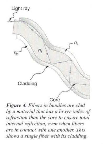
108 Professor Tapson disagreed that optical fibres do not alter the direction of light since its direction of propagation remains in the axial direction of the optical core of the fibre. Optical fibres are generally constructed by drawing or extruding a fibre from glass or plastic. They are constructed to comprise a core material and a cladding material, where the core usually has a higher refractive index than the cladding. Light which is propagating from a high refractive index material to one of low refractive index will usually reflect, if it meets the interface at a low angle.
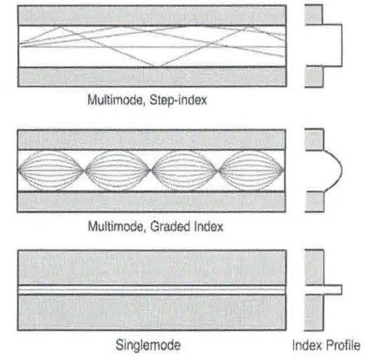
109 Professor Tapson explained that there are broadly two categories of optical fibres, being single mode and multimode optical fibres. Within these categories, optical fibres may be subcategorised by the composition of their core. The below figures, extracted from the optical fibre page from the Fiber Optic Association, Inc, Reference Guide to Fiber Optics (available at the following link: https://www.thefoa.org/tech/ref/basic/fiber.html), illustrate a multimode fibre, graded-index multimode fibre and a single mode fibre, with their associated refractive index profiles shown on the right. The paths of typical light rays propagating through the fibres are shown in the interior of the fibres.
110 Single mode optical fibres are a special type of optical fibre that are so narrow only a single wave of light can travel through them. That single wave cannot bounce from one core-cladding “wall” to the other, and instead must propagate down the middle of the fibre. They are generally only used for telecommunication and a few, very specialised, other applications (eg, fibreoptical gyroscopes).
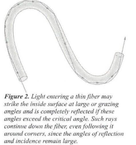
111 In contrast, multimode optical fibres are wider and allow several waves of light to propagate simultaneously. These light waves travel through the fibre by way of “total internal reflection”. The structure of these optical fibres creates a reflective interface between the core and the cladding, so that when light is injected into the core from one end of the fibre, it reflects off the internal interface. The light therefore propagates down the length of the fibre and emerges at the other end. The figure below, extracted from section 10.4: “Total Internal Reflection” in the Douglas College Physics 1207 Winter 2020 custom textbook adapted from Open Stax College Physics by the Department of Physics and Astronomy at Douglas College (Douglas College Physics), illustrates light propagating through a thin (multimode) optical fibre, including around corners:
112 Total internal reflection is illustrated in the figure below, extracted from the same Douglas College Physics source:
113 Professor Tapson said that, as can be seen from the above, by means of total internal reflection, light propagating through the (multimode) fibre core reflects off the core-to-cladding interface, and in this way is confined inside the fibre. The light waves bounce from wall to wall inside the fibre and thus propagate down its length and can change direction if the walls of the fibre are bent to change the angle of reflection. The action is no different than if the fibre was a hollow cylinder with a reflective mirror inner surface. By this means, light signals can be communicated over distances and around bends and underwater and underground, in ways that would not be possible if the light beam had to be shone directly through a homogenous optical medium such as air or water.
114 Professor Tapson said that, generally, when optical fibres are used in or with downhole equipment, multimode fibres are used, unless the unique properties of single-mode fibres are specifically required. Multimode fibres are generally more robust, being made of plastic rather than glass. Multimode fibres are more easily cut, joined and repaired. Multimode fibres have large core diameters (typically 0.5–1mm) and large acceptance angles (typically up to 15 degrees off-axis) which makes it easy to launch light into the core. Single mode fibres have extremely narrow cores, typically 5–10um (micrometres) or a hundred times smaller than a multimode fibre, and the acceptance angles are extremely small (typically less than 1 degree), so it requires specialized interface optics and laser sources to launch a signal into a single mode fibre.
115 Accordingly, at the priority date Professor Tapson understood that: (a) optical fibres do alter the direction of light, (b) the direction of the propagation of light in the fibre is not the same as the “axial direction of the optical core of the fibre”, and (c) optical fibres are a “signal direction altering means” within the meaning of the patent. Professor Tapson said that this is also supported by the following in the patent:
(1) [0034] of the patent says “…Alternatively the light path may be provided by a light transmitting conduit within the body”. This indicates to Professor Tapson that the patent contemplates the use of optical fibres or light-pipes, being a kind of rudimentary optical fibre used when a light beam must be redirected over a short-range or in a tight space;
(2) claim 6 relates to the device of any preceding claim, “wherein the electromagnetic signal direction altering means includes a boundary at a change of material or edge of a portion of the device”. This indicates to Professor Tapson that the signal direction alteration should be by means of reflection or refraction, as these are optical effects that occur at a change of material; and
(3) claim 7 relates to the device of any preceding claim, “including a reflector to reflect at least a portion of the electromagnetic signal”, which makes it clear to Professor Tapson that reflection at an interface (like in an optical fibre) is an embodiment within the scope of the patent.
116 Professor Tapson also said that even if light did propagate along the core of a fibre (which might happen in a single mode optical fibre) if the fibre was bent: (a) the axial direction of the core at one end of the fibre would not be the axial direction of the core at the other end of the fibre, (b) light entering the fibre along the optical axis at one end, would exit in the different direction in which the optical axis was projecting at the other end, (c) the optical device would therefore still alter the direction of the light, and (d) the optical device would be a “signal direction altering means” within the meaning of the patent.
117 Professor Tapson disagreed that the entirety of the system must be downhole. He said that there is nothing in the patent that restricts the data gathering system to being down the hole. The adjective “downhole” modifies or describes the data, that is, it is a system for gathering data pertaining to the downhole environment.
118 Professor Tapson disagreed that the electronics unit must consist of one circuit board as there is nothing in the patent that restricts the electronics unit to one circuit board and many electronics units contain multiple circuit boards.
119 In response to Professor Dupuis’ comments on his analysis of the prior art documents, Professor Tapson said the patent is not limited to mineral mining, excluding oil and gas and therefore “downhole equipment” within the meaning of the patent does not exclude equipment used in the oil and gas industry.
120 As to Iizuka, Professor Tapson said:
(1) wireline tools are “downhole equipment” within the meaning of the patent;
(2) the optical device in Iizuka transfers an electromagnetic signal to or from an electronics unit of downhole equipment. The patent does not require restricting or constraining the signal to an application (eg, communication but not sensing);
(3) the optical components do not exclude optical fibres;
(4) the light path in the patent cannot be understood to be constrained to the body of the optical device. The light path in the patent must extend outside the body of the optical device, otherwise the electromagnetic signal would be unable to be transmitted to or received from the external receiver or transmitter. In Iizuka the light path reflects off the conical mirrors in the same fashion as in the patent;
(5) the patent allows for part of the light path within the body, however, the patent does not describe the light path as being formed of a specific type of optical material. It could be air, or liquid, or a transparent solid and the invention claimed in the patent would work (though liquid is less practical). The patent does not state that the body of the optical device is a waveguide, and it is not necessary for the operation of the invention claimed in the patent. Professor Dupuis appears to have restricted the patent to one embodiment in which there is a mirror embedded within a solid optical material (with the added feature of the body being a waveguide, which is not described in the patent);
(6) in claim 1 of the patent, there is no requirement that the electronics unit must receive and send an electromagnetic signal. Rather, claim 1 says that the electromagnetic signal can be transferred to or from the electronics unit and claim 5 says wherein the electromagnetic signals may be incoming to or outgoing from the electronics unit. This is reinforced by [0018] and [0025] of the patent. Accordingly, “associated with” in the context of claim 1 means that the signals communicate in some way with the electronics unit. The signals may be generated by or received by the electronics unit. There is no restriction that the signals originate in or from the electronics unit. Furthermore, the signals may be processed in the electronics unit, or processing may take place prior to or after the electronics unit in the signal processing chain; and
(7) in relation to claim 8 “the reflector including a reflective material applied to, mounted to, or formed on or within the body”, Professor Dupuis has introduced multiple additional features for the invention in Iizuka not mentioned in that patent.
121 As to Bergren, Professor Tapson said:
(1) workovers (maintenance or specialised interventions required for an oil or gas well to be put in service or remain in service for the purpose of producing hydrocarbons) represent “downhole equipment”;
(2) he did not suggest that optical fibres are waveguides; and
(3) insofar as Professor Dupuis asserts that claim 22 of the patent requires the electromagnetic signal direction altering means to redirect signals incoming to the electronics unit, the integer specifically says “and/or” and cannot be limited in this way.
122 As to Sun, Professor Tapson said:
(1) there is no reference to a protective face cap, cover or protective face seal for the sidewall hybrid connector in Sun, and he did not see why one would be required; and
(2) “hermetically sealed” in Sun at column 4 line 48 refers to the connector sealing in an airtight or watertight fashion to the housing wall and is not the protective cap referred to by Professor Dupuis. Sun says that the sidewall hybrid connector can be exposed to the full pressure of the fluid environment at the bottom of the borehole. That is, the connector can be exposed to the full pressure of the fluid environment at a depth of 3,330m. It is therefore not sensible to suggest that the instrument in Sun requires an additional “protective face seal” or “protective cap”.
123 The following sections primarily consist of extracts from Professor Dupuis’ affidavit evidence.
124 J Christian Dupuis is an Associate Professor at the Université Laval, Québec, Canada. He graduated with a Bachelor of Electrical Engineering in 2001. He received a Masters in Electrical Engineering in 2003. He completed doctoral studies in geology in 2009. He has over twelve years of experience working with the mineral exploration industry. Borehole and core orientation devices are not the focus of his academic research (his focus is measuring the physical properties of boreholes, not the direction of boreholes or cores), but he has been involved in the development of such devices for his research and seen them used in the field. He began developing knowledge and expertise in this instrumentation from 2006.
125 Since 2008, Professor Dupuis has been part of teams tasked with the development of borehole instruments and measurement systems to facilitate borehole geophysics and improve mineral exploration efficiency. In 2008, he was appointed as a research fellow at Curtin University in Perth for the Centre for High Definition Geophysics (CHDG) in the Department of Exploration Geophysics. As part of his affiliation with CHDG, he has developed expertise in acoustic borehole measurements (sonic and ultrasonic) for the mineral industry. These measurements are used to calibrate seismic images. Seismic energy travels as a wave in the earth until it reaches heterogeneity in acoustic impedance. At these boundaries, a portion of the energy comes back to the receivers on the surface. The arrivals of these reflected waves allow a geophysicist to form an image of these heterogeneities. This expertise was necessary to support CHDG’s research projects in 3D seismic for mineral exploration. During these projects Professor Dupuis worked with borehole orientation data including around many drill sites. He became familiar with the then current tools used in the field in Australia. The tools used were a combination of hydrophone arrays, full-waveform sonic, electromagnetic induction, natural gamma and temperature borehole tools.
126 From 2010 to 2013 Professor Dupuis was also a researcher affiliated with the Deep Exploration Technologies Cooperative Research Center (DET CRC). The objective of the DET CRC was to find technological solutions to decrease the cost of mineral discoveries in Australia and in the rest of the world. He worked in and became the project leader of the Logging and Sensing Program of DET CRC and was involved in: (a) the development of field experiments and instruments for enabling imaging in front of the drill-bit, (b) the development of an autonomous sonde and an autonomous shuttle for the measurement of physical properties by drillers, and (c) the development of economical tools for vertical seismic profiling for mineral exploration.
4.2.2 Basic information in the field of mineral exploration
127 Professor Dupuis gave evidence about this information and his opinions relevant to the priority date of the patent in 2011. It is apparent that Professor Dupuis treated this basic information as common general knowledge available to those in the field.
4.2.2.1 The mineral industry and drilling
128 Professor Dupuis explained that the mineral industry uses boreholes to gain a better understanding of geological and geotechnical aspects of a rock mass.
129 Diamond drilling is widely considered the gold standard in the mineral industry because it allows the geologists and engineers to recover cylindrical rock samples called cores. Other drilling technologies only provide drill cuttings (also called rock chips). Drill cuttings are useful for chemical analysis but cannot be used to understand the geometry of a mineral deposit.
130 The cores are cut with a drill bit. This drill bit is placed at the bottom of a drill rod. Modern drill rods are usually hollow cylindrical metal rods that transfer rotational power from the drill rig to the drill bit. Like the drill rods, the drill bit is hollow in the middle. In modern diamond-drilling operations, the core is received in an assembly called the core barrel. In early drilling systems, this core barrel was simply the last section of the drill rods. Once the core barrel was filled, the driller would have to pull out all of the drill rods in order to recover the core. This became impractical once the depth of investigation increased. The modern core barrel was introduced to solve this problem. It sits at the bottom of the drill string, inside the drill rods. Once filled with the core, it is brought back to surface using a strong metal cable called a wireline.
4.2.2.2 Borehole orientation devices
131 The wireline introduced new issues. The first problem encountered was the elastic deformation of the drill rods. This deformation can cause the drill bit to drift away from the intended target. As the number of drill rods increases, the drill string is more susceptible to be deviated by a rock mass with higher rock strength. Borehole orientation devices were largely introduced to solve this issue. They allow the drillers to determine the trajectory of the borehole and adjust it when required in order to reach a given target. The wireline also has inherent strains that are stored within the cable. They are caused by the weaving of the cable and the spooling on the winch. These strains cause the core barrel to spin onto itself as is it brought back to surface. Since the rotation is not controlled, it becomes impossible to ascertain the original orientation of the core if it is not recorded prior to breaking it. This is also why core orientation devices were developed.
132 Boreholes drilled in the mineral industry are often angled. This means that they are not vertical or perpendicular to the surface of the soil. This is a fundamental attribute that allowed for the original core orientation systems to work. The angles given to the boreholes in the mineral industry are a function of the structures that geologists and engineers aim to characterise. These structures are most often sub-vertical. Since the geologists and engineers want to characterise the true thickness of each structure, they will angle the boreholes such that they intersect the structures perpendicularly.
133 The original core orientation devices used in the mineral industry exploited these drill angles by using an eccentric device where the weight was concentrated on one edge of the tool. Gravity naturally forced this weighted edge to follow the bottom of the angled borehole. The marking devices differed somewhat (hard metal spike, wax crayons, etc) but they all allowed the drillers to identify the bottom edge of the core before bringing it back to surface.
134 In addition to the mechanical devices, there were optical televiewers which used accelerometers and magnetic compasses to orient the images that were recorded using a wire line. The use of accelerometers was growing in popularity from around 2011.
4.2.2.3 The invention in the patent
135 According to Professor Dupuis, the essence of the invention disclosed in the patent is to offer a means of obtaining signals/data from, or providing to, electronic units of downhole equipment without having to disassemble the downhole equipment to gather that data from the electronics unit. This is achieved by an optical device that is capable of altering the direction of signals travelling to or coming from an electronics unit of the downhole equipment when the device is at the surface. The optical device is capable of effecting this transfer of data even when it is located inside of a part of downhole equipment through apertures which maintain a line of sight to the optical device, and thereby one of the advantages of the invention is that the downhole equipment does not have to be taken apart to get access to a data transferral port to effect the data transfer, making for a much quicker data retrieval process.
136 Professor Dupuis understood that when the downhole tool in the patent is deployed in the borehole it operates as a standalone tool that does not receive or transmit data to the driller or any other surface equipment while it is deployed. This differentiates this type of borehole equipment from other equipment called wireline tools.
137 Wireline tools are tools used by geophysicists and geotechnical engineers to measure petrophysical and geotechnical properties of the rock mass. Wireline tools are more fragile and are usually deployed by specialised crews. The wireline operator interacts with the wireline tools through the electrical conductors or optical fibres that are housed in an armoured cable. Wireline logging can be performed at different stages during the drilling process, but it requires the drill rig to standby. Most tools will require an open hole, which means that the borehole will have no casing or drill rods when the data is acquired. This also means that the bottom hole assembly will have been removed from the borehole so that the wireline tool can engage beyond the drill bit. This is also an important point of differentiation between downhole equipment and wireline tools.
138 It is conceptually possible to acquire wireline data throughout the drilling process, but it is not usually done in the mining industry. This is because it is significantly more expensive than logging the borehole once the drillers have moved on. Wireline logging during drilling requires two crews which means that one crew is always standing by. This means that when wireline data are acquired, the mining company pays for the wireline crew and drill rig standby fees. Since wireline logs can take several hours to acquire, the rig standby fees quickly become a significant cost. It is also important to note that wireline data will generally be analysed off-site by geophysicists and engineers to plan future exploration and development work. They will not usually be used by drillers or site geologists.
139 Conversely, downhole equipment such as core orientation devices are deployed by the driller at the bottom of the drill string as part of the downhole assembly. The data recovered from downhole equipment are used by the driller to steer the borehole in the correct direction, monitor the condition of mechanical implements like downhole motors and/or provide the information required to orient the core recovered. Downhole probes that are used by the drillers to obtain data that relate to the drilling progress and the depth and trajectory of the borehole relative to a North reference also constitute downhole equipment.
4.2.2.4 Downhole equipment/downhole probes
140 Professor Dupuis understands the reference to “downhole equipment” in the patent to refer to any equipment that is used by a driller to gather data during drilling operations. “Downhole equipment” includes a core orientation device that is deployed along with other downhole equipment at the bottom of the drill string as part of the inner-tube assembly. During the drilling process, the core orientation device is autonomous and does not communicate with any form of surface equipment. Once the core tube is filled, the inner-tube assembly and the core orientation device are recovered by the driller and brought back to surface.
141 The patent also refers to “downhole probes”, Professor Dupuis’ understanding of which is summarised above.
142 Professor Dupuis noted that according to Professor Tapson, “borehole” as referred to in the patent is “any hole drilled into the earth using a drilling machine for the purposes of geological investigation, petrochemical investigation or resource extraction”. Professor Dupuis disagreed. Professor Dupuis said that a borehole is a hole that is driven into the ground to obtain geological information, or release water, and is not defined by the specific drilling apparatus that is used to create the borehole. Professor Dupuis said that the Macquarie Dictionary 2020 defines boreholes to be “a hole bored into the surface of the earth, as for obtaining geological information, releasing oil, water, etc” but, in practice, “borehole” is not used to refer to the extraction of oil.
143 Professor Dupuis said that Professor Tapson described the intent of a borehole as to perform “petrochemical investigation or resource extraction”, however Professor Dupuis considered the reference to “petrochemical” confusing because petrochemicals are refined versions of petroleum products or natural gas, and they are not expected to be naturally occurring compounds in the environment.
144 According to Professor Dupuis, a hole that is drilled for oil and gas exploration and production is not a “borehole”, but a “well”. The Macquarie Dictionary 2020 defines “well” as “a hole drilled into the earth, generally by boring, for the production of water, petroleum, natural gas, brine, or sulphur”.
145 Professor Dupuis said that the intended use of these two hole types is very different. A borehole aims to obtain geological information (that is, as I understand it, it is exploratory) while a well is meant to tap a supply of, for example, water, oil, or gas (that is, as I understand it, it is exploratory but critically must also be productive, acting as the source of the extracted materials). Accordingly, a successful well is a production asset that can be used for resource extraction. A borehole, even if it intersects valuable resources, is an exploration expense. The resource extraction will be done through other means of excavation, but not using the borehole. Boreholes are therefore generally smaller in diameter than wells and are drilled using different equipment. In Professor Dupuis’ experience, the tools and methods used to characterise wells are not all applicable to boreholes.
146 Professor Dupuis said that Professor Tapson described an “azimuth” as “the angle with respect to magnetic north or geographic north”. Professor Dupuis disagreed, but this disagreement is not material to the issues in this case.
147 Professor Dupuis agreed with Professor Tapson that a “core” is a cylindrical core of rock drilled using a core drill from the ground. However, Professor Tapson defined “core drill” as the “conventional core drilling assembly used in mineral exploration for drilling a core sample which includes, among other things, a backend assembly, an inner tube, a core lifter, an outer tube and a drilling bit”. Professor Dupuis considered this too restrictive. As at the priority date, a “core drill” could refer to any apparatus that enables the user to recover a core. Original core drills did not include the equipment Professor Tapson mentions. Nor do sonic drills. But both produce cores. Again, this disagreement is not material to the issues in this case.
148 Professor Tapson defined “depth” as “the distance from the surface to a position either along or at the bottom of a borehole”. Professor Dupuis noted that when measuring the vertical position of a sample, relative to a given reference point, there is both a “measured depth” and a “true vertical depth”. Again, this disagreement is not material to the issues in this case.
4.2.2.9 Drill bit or cutting head
149 Professor Tapson defined “drill bit” or “cutting head” in the patent as “an annular, diamond-impregnated cutting tool (known as a “bit”) mounted on the end of a turning string of rods that forms the part of the outer tube”. Professor Dupuis considered this to be too limited. Again, this disagreement is not material to the issues in this case.
4.2.2.10 The patent – tube/barrel
150 Professor Tapson defined the “inner tube assembly” or “inner tube”, also known as a core tube, sample tube, or core barrel as “a tube which sits inside the outer tube and progressively receives the core samples as drilling advances into the rock”. Contrary to Professor Tapson, Professor Dupuis considered these terms were not all equivalent and interchangeable. Rather, the core barrel is composed of a cylindrical tube in which the rock core is received as the coring activity proceeds. Such a core tube or a sample tube can describe the cylindrical shape of the recipient that is a part of a core barrel, but it does not need to be restricted only to this form of drilling. Before the advent of wireline drilling, conventional core drilling required that core samples be recovered by disassembling the entire drill string composed of the coring bit, a core lifter, an outer tube and drill rods. The outer tube is the section of drill string that is immediately behind the drill bit. It is generally fabricated from thicker material and may be specially hardened to accommodate the increased stresses imposed by the coring bit. It houses the landing ring and the reaming shell that accommodate the inner tube of the core barrel.
151 This means that the core barrel used to recover the sample in diamond core drilling is composed of several parts that include, but is not limited to, a cylindrical tube to house the rock core retrieved by the driller. When Professor Dupuis uses the term inner tube, he means the cylindrical recipient that houses the rock core inside the core barrel. Since the core barrel sits inside the outer tube, some people in this field of technology may choose to refer to the core barrel as an inner tube assembly. While this name may help provide a general nomenclature for tools that could be found inside the outer tube, it does not mean that an inner tube assembly needs to be limited to a core barrel. The term could also be used for any other device that sits inside the outer tube behind the drill bit. Such devices could include, for example, sensors to measure drill bit performance such as temperature, pressure and torque. The backend assembly is the portion of the core barrel that makes it possible to decouple the rotation between the outer tube and the inner tube. It is also the portion of the core barrel that makes it possible to recover the rock core without having to disassemble the entire drill string.
152 While this dispute about meaning is not material, the above information assists in understanding the way in which a core orientation device forms part of a drill string.
4.2.2.11 Tools and instruments
153 Professor Tapson uses “tools” and “instruments” interchangeably. Professor Dupuis said that a tool is a device that is meant to do some form of work, whereas an instrument is used to perform precision work or take a measurement. Instruments will usually require calibration to traceable standards while tools will require regular maintenance but will not require calibration. “Instruments” include survey equipment, core orientation devices and geophysical logging equipment. Only drilling tools truly fall under the definition of tools. Further, a gyroscope is not a tool or an instrument. It is a sensor that can be included in survey instruments.
154 Professor Tapson said that “survey tools and core orientation tools are usually both present at drilling sites and are often used in tandem in drilling operations”. Professor Dupuis said that, in the field of geological drilling, there are circumstances where the presence of these tools would be an oddity. It is more accurate to say that core orientation and survey instruments are often found at diamond drill sites where the drill-targets are deeply seated and require these instruments to improve the odds of intersecting the target. However, this statement would remain slightly misleading as it establishes a connection between two related ideas that need not exist in all circumstances.
155 Professor Tapson defined a “survey tool” as a tool that “provides information to plot borehole trajectory and path, usually including azimuth and direction and usually using a compass or a gyroscope or other deviation methods”. Professor Dupuis would call this a “borehole survey instrument”. Borehole survey instruments will house sensors, such as a magnetic compass and gyroscopes. They also include accelerometers that allow the user to determine the tilt, pitch and roll of the sensor package.
156 Professor Dupuis agreed with Professor Tapson that downhole equipment has seen an evolution towards digitisation. This is because of the ever increasing depth of boreholes, and a need for technologies that were efficient and robust in these deeper environments.
157 While these disputes about meaning are not material, they too assist in understanding the technology.
4.2.2.12 Wired systems for communicating and/or transmitting data downhole
158 Professor Tapson referred to use of electrical conductors as a means to transfer data. Professor Dupuis agreed these methods of data transfer systems were known at the priority date but said they were not applicable to all situations. In relation to instruments deployed by drillers, wired communication is only applicable as a temporary means to exchange data when the borehole survey instrument is at the surface. Logistically, the use of electrical conductors (ie, an electrical wireline) with a borehole survey instrument is only possible when the top drive of the diamond drill rig is decoupled from the drill string and thus when drilling is stopped. This is because even if a suitable aperture can be present through the top drive to allow the communication wire to be fed through, the logistical complexity of threading the electrical conductor through each drill rod and preventing entanglement downhole when the rods are spun makes this communication channel perilous at best for drillers.
159 Further, with respect to a “sealed waterproof and pressure proof electrical port”, Professor Dupuis said that it is not an electrical port (connector) that allows the instrument to operate at any appreciable depth below the water table without the external pressure vessel. It is the sealing mechanism of the external pressure vessel that is the most important. It maintains the integrity of the instrument when deployed in a borehole. If the pressure vessel seal fails, the electrical port on the instrument will not protect the circuits and sensors in the instrument. As Professor Tapson said, repeated manipulation of this sealing mechanism under adverse and dusty conditions can increase chances of failure. Thus, while being electrically straightforward to implement in a design, mechanical limitations would motivate people working in the field to explore other methods of communicating with borehole instruments.
4.2.2.13 Unwired systems for communicating and/or transmitting data downhole
160 According to Professor Dupuis, the acoustic system described by Professor Tapson, a mud pulse modem which is used in LWD is a good example of a communication channel that is used to exchange limited information between surface and downhole instrument while it is deployed inside of a well. This technology was in common use in the oil and gas industry, but to the best of Professor Dupuis’ knowledge, mud-pulse telemetry was not yet implemented in the mineral industry before the priority date. Given the nature of the mechanisms involved for modulation of the signal onto the mud pulses, this mode of communication provides very limited bandwidth for information exchange between downhole and surface instruments.
161 Professor Dupuis said that ultrasonic transducers are a reasonable means to exchange information when the transmitting and receiving instruments are proximal to each other. The physical dimensions of piezoelectric devices used to generate the ultrasonic vibrations determine the amplitude of the signal and the bandwidth that can be achieved. Given a suitable transmission media, as proposed by Professor Tapson, information can be exchanged between transmitter and receiver. The only caveat to this scheme is that this suitable coupling media must be present between the two devices. Given the acoustically noisy environment encountered in drilling, if this technology were deployed at great depth, it would be severally impeded by attenuation and acoustic noise. Multi-mode echoes and guided waves would add to the woes and provide poor data transfer rates, if any. This means that this communication channel, to be used efficiently to transfer data from a borehole instrument, must be used when the tool is at surface. Providing adequate coupling between the instruments when they are in air is not trivial. In Professor Dupuis’ laboratory, they often use silicone gels to couple ultrasonic transducers to rock samples. In his experience, the signal can be compromised if too little gel is used and if insufficient pressure is applied between the transducer and the sample. Too much pressure damages the transducers. The lower data rates achieved with this communication channel and the coupling difficulty likely to be encountered by the users make this technology marginal in this context.
162 Professor Dupuis agreed with Professor Tapson that the use of opto-electronics was well-established before the priority date. Optocouplers, photocouplers and opto-isolators are primarily used to provide electrical isolation between circuits. Fundamentally, these modules are fabricated with a light emitting diode, energised by one circuit which is coupled to a photo-sensor that is on the second circuit. The information exchanged between the two circuits can be digital, that is, a series of light pulses are transmitted, or analogue where the intensity of the light is used to determine the amplitude of the electrical signal on the first circuit. If these devices are to be considered as communication channels (which Professor Dupuis is of the opinion they are not in the context of the patent), they are very short ones. In reality, the light emitting diode, the photosensor and biasing electronic required for their operation are all built into the same integrated circuit. Optical communication channels can be constructed from similar parts (ie, light emitting diodes and photo sensors) but their characteristics will be different than the ones that were optimised for use in these optical isolation devices.
163 Professor Dupuis said that Professor Tapson’s example of use of a television remote as an example for the use of IRDA technologies is incorrect. Television sets used the RC-5 protocol that was established by Philips in the late 1980s, which predates the creation of the IRDA in 1993. The use of the television remote control is not a good example of the contributions of the IRDA on the proliferation of infrared data networking infrastructure. IRDA networking ports appeared on laptops and computing devices in the 1990s largely to provide an alternative to wired serial ports. The use of IRDA ports on computers and consumer electronics have largely been replaced by wired and wireless alternatives such as USB and electromagnetic data transmission such as WiFi and Bluetooth.
164 Professor Tapson also described magnetic communication. Professor Dupuis calls this “near-field electromagnetic induction communication” because the modulated magnetic field proposed by Professor Tapson is achieved through current variations in a circuit. In this type of technology, both instruments must be proximal to each other. This is because the modulated electromagnetic signal sensed in the receiver is caused by variations in the near-field of the circuit that generates it. Contrary to Professor Tapson’s view, Professor Dupuis said that this type of communication is different from wireless communication as electromagnetic energy used in this scheme does not propagate through space but rather diffuses through it. The near-field electromagnetic induction system that Professor Tapson describes is based on Faraday’s law of induction. This means that a time-varying magnetic flux will induce a rotational electric field. For physical reasons, the rotational axis of this field will be in opposition to the direction of the exciting flux. The field strength of the rotational field increases as a function of the rate of change. This means that, everything being equal, as the frequency of the exciting field increases, the rotational electrical field will be stronger. As near-field electromagnetic induction communication relies on the fact that the transmitter and the receiver are in close proximity, the properties of the media between the two can be neglected at low frequencies. As frequencies increase, however, the conductivity of the media will start to play a role and attenuate the signal through another electromagnetic mechanism. As the magnetic flux density changes in a conductive material it will create eddy currents that will oppose the change in magnetic flux. The equation that describes this phenomenon is known as the Ampere-Maxwell equation. The current density in the conductive material will determine the strength of the opposing field that is created. The currents that are created in this scenario are called galvanic currents or conduction currents. As frequency increases, a second phenomenon is observed. The electrical permittivity of the media allows time-varying electrical fields to generate rotational magnetic flux density. The currents generated at these higher frequencies are known as displacement currents. They are the basis of what makes radio-wave telecommunication possible.
165 Professor Dupuis agreed with Professor Tapson that near-field electromagnetic inductive devices are more prone to interference and can therefore be considered as a less robust means to establish a communication channel between two devices, and that because of the inductive nature of these devices, data rates that can be achieved are significantly limited.
166 Professor Dupuis noted that Professor Tapson had only mentioned in passing methods based on radiofrequency transmission. These would require the pressure vessel to be constructed of non-conductive materials. Amongst the technologies that could be used within a composite barrel are data encoding schemes that sit on top of UHF, VHF and the ISM bands. Protocols such as WiFi, Bluetooth and Zigbee, just to name a few, could all be implemented provided a suitable non-conductive pressure housing could be engineered to sustain the mechanical abuse at the intended depth. These protocols, especially WiFi and Bluetooth, are readily available on consumer electronic computing devices and therefore could easily be interfaced with borehole instruments.
167 Professor Dupuis agreed with Professor Tapson that for tools equipped with wireless means of communication, hand-held computing devices were used to interact with the instruments. However, to use an iPhone as an interface, the people in the field would have two options. The first would be to use WiFi or Bluetooth protocols that were built into the iPhone but would require non-conductive pressure housings to be engineered. The second option would be to construct the equivalent of a “dongle” to enable the communication technologies to be interfaced to those available from the iPhone. In practice, given the harsh environmental conditions encountered at a drill site, the hand-held computing devices used with downhole instruments were, as at the priority date, and are currently, “ruggedised” field personal computers.
168 While much discussed above is not directly relevant to the issues in dispute in this case, it exposes the high level of academic, research and detailed knowledge at which Professor Dupuis and Professor Tapson both operate. This is relevant to the assessment of other aspects of their evidence, particularly the common general knowledge of the person skilled in the art at the priority date, to which I return below.
4.2.3 Designing a downhole instrument for transferring data
169 Professor Dupuis noted that Professor Tapson described how he would design a downhole instrument for transmitting data to the surface as at the priority date. While Professor Tapson described his design as “transferring or communicating data downhole”, this is not the case. Professor Tapson’s figure 7 (reproduced above) shows two devices consisting of two components that are in close proximity and orthogonal to each other. This configuration could not be deployed inside the confines of a borehole. Thus, Professor Dupuis understands Professor Tapson’s design exercise is to design a means for a HMI (that is, as I understand it, the surface control system shown in the two alternatives in figure 7) to interact with a borehole instrument.
170 Professor Tapson said the most suitable form of communication “would be infrared radiation”. Professor Dupuis agreed that the choice of an optical communication link makes sense, but it may not have been implemented if IRDA ports were not readily available on the field personal computers at the priority date.
171 Professor Dupuis considered that engineers in the field would have been satisfied with the communication system that is proposed by Professor Tapson in figures 4 and 5. The instruments available as at the priority date, for the most part, were what is proposed by Professor Tapson in figure 5.
172 Professor Dupuis noted that Professor Tapson then said that it would be preferable not to uncouple or otherwise interfere with the coupling of the housing in order to communicate with the instrument, but did not explain this view. Professor Dupuis described Professor Tapson’s design exercise as fundamentally flawed because it was intended to reach a specific design goal (not explicitly disclosed), being to design a communication solution that provides the benefits of a wireless HMI which Professor Tapson said was already implemented prior to the priority date. If the wireless means of communication between a borehole instrument and a HMI were well-established before the priority date then Professor Tapson’s design exercise would not be required since examples of pre-existing technologies could easily be cited.
173 If Professor Tapson was not aware of the EZ-TRAC, Professor Dupuis would anticipate that his design exercise would have ceased at the embodiment proposed in figures 4 or 5. Axially mounted communication ports are easily machined and easy to integrate in the design of a pressure housing. Since this is the easiest implementation of a communication system that meets the original design specification and the geometry of the instrument, in Professor Dupuis’s view, engineers in the field would not implement other features to this design unless they were prompted to do so as part of an evolutive design process. The final designs in Professor Tapson’s figure 7 appear to Professor Dupuis to emerge from a need not initially disclosed in the design exercise for the user to be able to interact with a borehole instrument that is housed in a pressure housing (that is, the unexplained proposition that it would be preferable not to uncouple or otherwise interfere with the coupling of the housing in order to communicate with the instrument).
174 Professor Dupuis noted that Professor Tapson provides two alternative means to fulfil this new requirement of not uncoupling. In the first design in figure 7, the circuit board is modified to allow the IRDA port to face sideways and point out the window. The modification of a circuit board is trivial and would require far less design resources than the second alternative in figure 7. The second solution uses an optical mirror to bend the optical axis. This is much more complex and expensive to implement than modifying the circuit board to allow the IRDA port to face sideways. This is because additional parts are required in the design. In Professor Dupuis’ experience, engineers usually pursue solutions that are as simple as possible, and easy to implement. Complexity is only introduced in a design when it can provide other benefits. Professor Tapson provides no explanation as to why he would be motivated to use a side window and mirror in the second alternative in figure 7, in view of his designs in figures 4 and 5. In Professor Dupuis’ view, the inclusion of the additional optical device in the second alternative in figure 7 is motivated by another engineering requirement that is implied but not disclosed. It allows the circuit board with the IRDA port to be located at an arbitrary distance from the aperture in the sidewall of the housing.
175 Professor Dupuis noted that Professor Tapson said that the inclusion of a side window in his design would be a rudimentary improvement over the EZ-TRAC instrument. Professor Dupuis does not understand from Professor Tapson’s overall design process why he would be motivated to include a side window from the design that he sets out in figure 5. Professor Tapson also said that the second alternative design at figure 7 is a routine improvement over the EZ-TRAC instrument. Again, Professor Dupuis does not understand from Professor Tapson’s overall design process why he would be motivated to use a mirror to bend the optical access out of a side window, in view of the design that he sets out in figure 5.
176 Based on his review, Professor Dupuis concluded that Iizuka did not disclose any of the asserted claims of the patent.
177 Professor Dupuis said that Iizuka’s borehole scanner is not intended to be used in the same circumstances as the borehole instruments described in the patent. This is clear from the summary of the invention where the invention is described in part as a borehole scanner with which a borehole can be scanned at high speed (at column 2 lines 2–28). According to Professor Dupuis what is described in Iizuka is a “wireline instrument”. Wireline instruments are deployed by specialised crews when normal drilling operations are halted. The wireline instrument described by Iizuka has a telemetry link, being the cable (labelled “CL” in Iizuka figure 3, reproduced above). This cable is used to communicate with a surface instrument while the device is in the borehole, not at the surface like the invention disclosed in the patent. Conversely, the invention disclosed in the patent enables communication of information between a downhole instrument and a user or an external data storage device at the surface. As such, the optical systems described by Iizuka, composed of lenses, conical mirrors, slits and optical fibres serve a completely different purpose (in facilitating scanning of the interior of the borehole) to the device that is described in the patent to enable surface level communication.
178 While not limited to any given borehole or well of sufficient diameter, the turbidity of the fluid within the annular space will significantly limit the deployment of the invention described in Iizuka. Thus, the use of Iizuka’s invention does not fit either the intended use of the invention described in the patent or the chronology of its use at the drill site. In the context of diamond drilling at a mineral exploration site, the invention disclosed in the patent will be used by drillers to help them interact with the borehole instrument during the drilling of the borehole. Iizuka’s invention will be deployed by technicians, geotechnical engineers or geophysicists after the borehole has been sufficiently washed and flushed from contaminants or left to decant. Given the long period of time required to achieve suitable optical conditions, the drill crew will not usually be on-site for this imaging exercise.
179 Professor Tapson said that he considers that the device described in Bergren “to be an oil and gas instrument” as it is intended for determining the concentration of hydrocarbon fluids and describes how transmitted light can be used to establish such concentrations. Professor Dupuis agreed with Professor Tapson that the tool described in Bergren is a specialised instrument that pertains to the oil and gas industry. As such, he did not understand the device described in Bergren to be “downhole equipment” within the meaning of the claims of the patent.
180 Professor Tapson said that “Sun’s optical communications device is related to the field of oil and gas”. Professor Dupuis agreed that Sun describes a device that pertains to oil and gas exploration. He did not agree with Professor Tapson that the device is “of equal application and use in mining” such that it is “downhole equipment” within the meaning of the claims of the patent. In Professor Dupuis’ opinion, what is described in Sun is not “downhole equipment” within the meaning of the claims of the patent. This is because the hybrid cable introduced by Sun is designed to provide an intrinsically safe high bandwidth communication channel. The data collected by downhole equipment are not sufficiently voluminous to justify the added complexity and expense of this type of communication channel. Optical fibres are more fragile than electrical conductors and are difficult to repair in the field. Also, since the downhole equipment within the meaning of the claims of the patent is not usually used in explosive environments it is not useful to engineer an intrinsically safe cable.
181 Professor Dupuis also disagreed with Professor Tapson that optical fibres are “reflectors” within the meaning of the claims of the patent. Professor Dupuis said that in optical fibres the general direction of the electromagnetic signal remains axial to the core of the fibre. The signal direction is not “altered”, such that there is a change in the direction of travel.
182 Further, the transfer of data in Sun is by way of the optical fibre found in the sidewall hybrid connector (212 in Sun figure 3A reproduced above). Professor Tapson said that the hybrid cable is a form of wireless communication. However, the communication that is described in Sun is wired.
183 Professor Tapson says that the optical communication device described is “highly similar” to the invention claimed in the patent. However, Professor Dupuis disagreed as what is described in Sun is communication using an optical fibre. This is not similar in any way to the invention disclosed in the patent.
184 Professor Dupuis reiterated his view that at the priority date a skilled designer would be expected to have stopped at the embodiment proposed in figure 4 or figure 5 of Professor Tapson’s design exercise, as this would have fulfilled the design task. Further, Professor Dupuis said that Iizuka, Bergren, and Sun disclose inventions different from the invention claimed in the patent. He noted that Professor Tapson did not explain why a skilled designer would have selected these patents in developing and then devising the device described in the patent. The equipment in those patents is not “downhole equipment”. Even if the skilled designer would have selected those patents, combining them with the common general knowledge would not have led to the invention disclosed by the patent. Specifically:
(1) in the case of Iizuka, the invention that is disclosed is a borehole scanner. Further, Iizuka requires a plurality of electronics unit and optical devices that are arranged into an optical system to function. Professor Dupuis therefore did not regard this type of invention as likely to offer any assistance to the skilled designer when seeking to devise a new device of the kind described in the patent;
(2) in the case of Bergren, Professor Dupuis would expect that a designer inspired by having read it would incorporate optical fibres in the design but this is not the case in the patent; and
(3) in the case of Sun, in combination with the common general knowledge, Professor Dupuis would expect a type of cable in the ultimate design but the cable is not an aspect of the invention the subject of the patent.
185 Professor Dupuis agreed that the invention in the patent relates to transmission of data and downhole equipment used in mining, but disagreed that the field of the invention was the “resource industry” as opposed to the “mining and mineral resources industry”. Professor Dupuis also disagreed that the invention is restricted to data transmission inside of downhole equipment. Rather, the patent discloses not only a means to transmit an electromagnetic signal within the downhole equipment but also a means to redirect this electromagnetic signal towards at least one side aperture. The essence of the invention disclosed is that this signal redirection makes it possible to establish, for the user of external electronic devices, a means to interact with the downhole equipment while the integrity of the pressure housing where it resides remains intact. This was new because most downhole equipment at the priority date required that their communication port be protected and sealed with a protective cap which completed the pressure housing. The patent proposes a way to improve the reliability of downhole equipment and increase productivity of drill crews by doing away with the protective cap and seal.
186 Professor Dupuis said that the invention is not limited to an electronic core orientation tool of the type that Imdex first released to the market in 2004 as the “Ace Core Tool” or ACT. This is an illustrative example only of how the invention could be used. The invention disclosed in the patent could be used with any downhole equipment that is configured appropriately.
187 Further, the original ACT differs from the invention disclosed in the patent because it sits inside a pressure housing that must be disassembled before the user can interact with the downhole equipment. It differs also in that the interaction with the user is achieved through the LCD display that is mounted axially and not through indicator lights. It is also important to note that the data acquired by the ACT are not downloaded to an external electronic device. They are simply used to reach the appropriate orientation of the core barrel. The user guide does not discuss any means to retrieve any digital data from the ACT.
188 Professor Dupuis said that the ACT II separates the interface mechanism from the measurement instrument. The interaction between the user and the borehole equipment is still achieved through the LCD panel that is now found on the hand-held controller. Notably different from the invention disclosed in the patent is that the ACT II requires that the optical port be exposed by removing a portion of the pressure housing and the handset is coupled to the borehole equipment axially. User interaction with the downhole equipment is still only possible via the LCD display and cannot be achieved via indicator lights inside the borehole equipment. Thus, while an infrared communication port is found on the ACT II, Professor Dupuis considered that it does not afford the benefits provided by the invention disclosed in the patent, that are to be able to communicate information to the user at all times without the need for an external electronic device and remain accessible without altering the pressure housing of the downhole equipment.
189 Professor Dupuis said that core orientation and borehole survey instruments are complementary but are not always used together. Rather, core orientation and survey instruments are often used together at diamond drill sites where the drill-targets are deeply seated and require these instruments to improve the odds of intersecting the target. This statement remains slightly misleading, however, as it establishes a connection between two related ideas that need not exist in all circumstances. Borehole survey information can exist in the absence of any core orientation data and it does for many sites across the world where there is not a tradition of orienting cores. Core orientation data, however, cannot exist in a meaningful way without the spatial information provided by the borehole survey.
190 Geological models can be built without the use of oriented core. In Professor Dupuis’ experience, the structural information obtained from oriented core allows structural geologists to understand the mechanisms that have shaped the rock mass and understand how these mechanisms may have offset some of the mineralisation. The composition of the host-rock and the mineralisation is defined by chemistry, not structural features. The metal content of deposits is generally associated with mineralisation events, not with the chemical composition of the host rock. The structural features pre-, syn- and post-mineralisation can provide clues as to the structural constraints of a given deposit.
191 Professor Dupuis agreed with Mr Brown that deviation instruments can be deployed by specialised wireline crews but said this is not often the case in the mining industry because it requires the mobilization of an extra crew and the drill-rig to standby. Magnetic susceptibility, radiometric methods and electrical resistivity are examples of volume measurements of the rock mass that is proximal to the borehole instrument. These data do not contain any orientation information and will require borehole survey data to be properly spatialised and included into the geophysical model. Optical and acoustic televiewers are examples of wireline tools that include a means to acquire borehole orientation information because this information is used to orient the images that are recovered from the borehole. Note that televiewers are different from borehole cameras because they offer a side view of the borehole wall and produce oriented images, which is not generally the case for instruments that are called borehole cameras. The exploration team will usually have determined the drill-target and a notional trajectory for the borehole. The exploration team will track the progress and trajectory of the borehole using a survey instrument that is usually deployed by the drilling crew. In Professor Dupuis’ experience, under normal conditions, these driller operated survey instruments provide adequate data quality for the exploration team to verify that the borehole is following the intended trajectory. The survey instruments provide geospatial data such as dip and azimuth that are used to determine the trajectory of a borehole and this information cannot be used to orient a core sample.
192 Otherwise, Professor Dupuis gave this evidence:
(1) if caps or other devices are required to ensure the integrity of the pressure housing of the MAXIBOR II (as Professor Dupuis believes from the brochure for the MAXIBOR II – that the port is axially configured and is protected by a cap that completes the pressure housing like the ACT II), the infrared communication port of the MAXIBOR II does not afford the benefits provided by the invention disclosed in the patent. Those benefits are to provide a way for the user to communicate with the borehole equipment at all times without the need for an external electronic device and to remain accessible without altering the pressure housing of the downhole equipment;
(2) the Reflex EZ-AQ communicated via IR sideways with the EZ-AQ instrument. Professor Dupuis notes however that the infrared port, the eight character starburst LCD and the multifunction control switch for the EZ-AQ are housed under a protective cap that ensures the integrity of the pressure housing. This is evident from the dual-seals (o-rings) that are included in the figure at the top of page 18 of Mr Brown’s affidavit (depicting an IR port in the side of the tool). As such, the infrared communication port of the EZ-AQ and its eight character display do not afford the benefits provided by the invention disclosed in the patent;
(3) the Ranger Survey System (Ranger Explorer) is comprised of an electronic measuring and memory system that is encased in a pressurised instrument barrel. A synthetic IRDA window on the end of the tool provides a means to communicate with the Ranger Explorer controller via the coupling cable. This cable is used to set the survey instrument and to download the survey data. The survey instrument is housed in a brass survey barrel that is sealed with o-rings that are on the top sub-assembly and the bottom sub and shock assembly. Since the survey instrument is housed in an opaque brass pressure housing, the infrared communication port of the Ranger Explorer, either in its original form, where the port is axially mounted, or its later form disclosed by Mr Brown where it is radially mounted, do not afford the benefits provided by the invention disclosed in the patent (ie, to provide a way for the user to communicate with the borehole equipment at all times without the need for an external electronic device);
(4) Globaltech Pathfinder is a downhole survey instrument that was housed inside of the pressure housing, like the Ranger Explorer. The infrared communication port, as explained by Mr Brown, was on the side of the instrument and was only available when the instrument was removed from the protective housing. From Professor Dupuis’ understanding of the Pathfinder, the infrared communication port included on this survey equipment does not afford the benefits provided by the invention disclosed in the patent;
(5) the communication port of the EZ-TRAC, like the ACT II, is housed under a protective cover. The top coupling of the EZ-TRAC protects and seals the upper end of the instrument. Since this top coupling must be removed to access the infrared port, this port does not afford the benefits provided by the invention disclosed in the patent; and
(6) Mr Brown provided examples of tools wirelessly communicating with external devices by other means, such as a PC or tablet, using other communication technologies, such as the Flexit SmartTool System, which used a 433 MHZ fast link and the Flexit GyroSmart that communicates via Bluetooth on recovery to the surface. This mode of wireless communication was only possible for the Flexit SmartTool and the Flexit GyroSmart once they were removed from their respective brass pressure housing and, as such, Professor Dupuis considered that the wireless communication ports included on the Flexit SmartTool system and the Flexit GyroSmart do not afford the benefits provided by the invention disclosed in the patent.
193 Professor Tapson and Professor Dupuis prepared a joint expert report. The following summary includes key aspects only from that report.
194 Professor Tapson confirmed his view that the field of the invention is oil and gas drilling and mining, including basically all exploration drilling. The patent uses just one sentence in describing the field, and it includes “core orientation” and “borehole telemetry”, suggesting that both hard rock (mineral) exploration, and oil or gas extraction (in which borehole telemetry is a more commonplace activity) were intended as fields of the invention.
195 Professor Dupuis confirmed his view that as the patent is presented in the context of diamond core drilling and is designed specifically with the drilling infrastructure afforded by this drilling system (eg, core barrel, greaser unit), and there is no reference to any oil and gas drilling technologies in the patent, it is clear that the field of the invention described in the patent is mining, mineral exploration, and geotechnical drilling. In this regard: (a) it is important to understand the motivations of a given drilling activity to understand the engineering choices that are made, (b) wells drilled by the oil and gas industry represent potential production assets while boreholes drilled in the mining industry are exploration expenses, (c) accordingly, wells are far more expensive to drill than boreholes, and (d) technologies developed to solve problems encountered in the oil and gas industry are not usually transferable to the mineral industry.
196 Professor Tapson considered a “device” in the patent to mean a unit of physical equipment that performs some function.
197 Professor Dupuis agreed generally but said in claim 1 of the patent the device describes a unit of physical equipment that transfers at least one electromagnetic signal to or from an electronics unit of downhole equipment. As such, the device in claim 1 includes an optical device and an electronics unit that is associated with an electromagnetic wave source.
198 Professor Tapson considered downhole equipment to be any equipment that goes down the hole during the process of drilling or during surveying or analysis or extraction after the hole is drilled. He noted that the specific inclusion of “wireline telemetry” in the field of the invention (patent [0001]) makes it clear that wireline instruments were specifically intended by the authors to fall within the field of the invention, and hence within this definition of “downhole equipment”.
199 Professor Dupuis considered that within the field of the invention, at the priority date, downhole equipment includes equipment that is used by a driller during normal drilling operations. Wireline instruments that are deployed by specialised crews are not downhole equipment because they are not intended to be deployed during drilling. During deployment, wireline instruments are permanently tethered to a specialised cable called a wireline that provides a telemetry link between the operator and the instrument. For this wireline to move freely in the borehole and reduce the risks of tangling, the drilling operations must be halted while the wireline instrument is deployed. With very few exceptions (eg, density logging), the portion of the borehole over which the wireline operator seeks to acquire data will be required to be free of downhole equipment to measure the true characteristics of the rock mass. Professor Dupuis noted the author’s field of invention (patent [0001]) discloses “borehole telemetry probes’’ and not “wireline telemetry’’. Professor Dupuis considered that the authors erroneously used the word telemetry because patent [0016] specifies that the authors consider telemetry data to be used to “… determine drilling processes, such as depth and direction of the borehole and change in surrounding magnetic field’’. For Professor Dupuis, it was clear that the manipulations of the driller to interact with the device described in the patent occur at the surface and thus the patent does not disclose a mean to provide in-hole telemetry. Professor Dupuis also noted that he did not find the word “wireline’’ in the patent.
200 Professor Tapson agreed with Professor Dupuis that an electronics unit is likely to be physically singular. Professor Tapson considered that this is a physical unit of electronic equipment that carries out a function or functions in the downhole instrument. The function in the embodiment described in the patent is the measurement and storage of orientation data, but other functions are possible. Professor Tapson noted that “electronics unit” and “electronics package” are used synonymously in the patent – see for example patent [0017] – and as such it very likely was intended to mean the whole of the electronics in the downhole equipment; the use of “electronics package” in [0017] suggests that the authors thought of the entire tool as an electronics payload in the drill assembly, so “electronics unit” may refer to the entire unit.
201 Professor Dupuis considered that the use of the term electronics unit means that it is singular and is embodied by a printed circuit-board. Professor Dupuis considered that while an electronic system can be constructed of a plurality of electronics units where individual electronics units are assigned specific tasks, the patent only discloses a singular electronics unit. Professor Dupuis disagreed that the “electronics package’’ and “electronics unit’’ are synonymous in the patent. In patent [0017] Professor Dupuis considered that the electronics package is the name for the whole apparatus (mechanical and electrical) that couples to the backend assembly. This was clear for Professor Dupuis because the patent reveals that “[t]his task involves unscrewing the backend assembly from the electronics package, which takes time and risks thread damage as well as resulting in risk of ingress of dirt and water in the thread’’.
202 That the patent is concerned about the effects on the threads and not on the electronics unit reveals that this unit is otherwise safe from water ingress. Professor Dupuis considered that the last part of [0017] makes it clear that the electronics unit is found inside of the electronics package and protected by o-ring seals. Thus, while the electronics unit is protected by o-rings and the electronics package is not, they are two different entities. For Professor Dupuis the electronics unit is found inside of the electronics package. Professor Dupuis also noted that electronics package only appears twice in the patent (all in [0017]) and that electronics unit appears 172 times. Consequently, Professor Dupuis did not consider that these terms are used synonymously or interchangeably in the context of the patent.
203 Professor Tapson disagreed with the interpretation of [0017] as implying that the electronics unit is inside the electronics package and separately protected from water ingress. The paragraph states:
[t]his task involves unscrewing the backend assembly from the electronics package, which takes time and risks thread damage as well as resulting in risk of ingress of dirt and water into the thread. Also, o-ring seals protecting the electronics unit may be compromised through separation and refitting of the backend assembly and electronics unit.
204 Professor Tapson said that the second sentence refers to the seals between the backend assembly and electronics unit, making it clear that the electronics unit is not separately contained inside an electronics package, but is directly connected to the backend assembly, and so the simplest explanation – that the electronics unit and the electronics package are the same – is confirmed.
205 Professors Dupuis and Tapson considered that, in general terms, an optical device is an apparatus that allows light to be transported or altered. An optical device can be, for instance, a lens, a mirror, or a prism. According to Professor Dupuis, however, the optical device in the patent is more specific. The optical device appears in figures 2b, 3 and 4 of the patent. From the description in the claims and the figures included in the patent, Professor Dupuis considered that the patent discloses the use of either a conical mirror (figures 3 and 4) or a prism (figure 2b) to redirect light. Professor Dupuis considered that the optical device in the patent is singular. For Professor Dupuis, within the context of the patent, the test to determine if an apparatus is an optical device or an optical system is to determine if the apparatus can be broken down into elementary parts that would still be a useful optical device on their own. If the answer is no, then it is an optical device. If the answer is yes, then Professor Dupuis considered it to be an optical system.
206 Professor Tapson did not agree with this device/system distinction. He did not agree with Professor Dupuis’ test to determine whether an apparatus is a system or a device, largely because it is arbitrary – for example, a single lens in any optical system can be replaced by a pair or more of lenses, or a compound lens, achieving the same optical outcome, but this substitution would turn a device into a system (according to the test) without any change in function, or probably even change in appearance, to an examiner.
207 Professors Dupuis and Tapson considered that, in general terms, the light path is the path followed by light. They also agreed that light can propagate through a vacuum and that it does not have to be contained, although it can be.
4.3.7 Electromagnetic signal direction altering means
208 Professors Dupuis and Tapson agreed that the use of the term “electromagnetic signal”, while it keeps the options open for the patent, is neither practical nor relevant for the implementation envisaged by the inventors. It is clear to the experts that the portion of the electromagnetic spectrum in question in this patent is associated with light.
209 Professor Dupuis considered that the direction of an electromagnetic signal is altered if the direction of propagation of the electromagnetic wave is altered. The direction of propagation of an electromagnetic wave is usually considered to be perpendicular to the direction in which it oscillates. An optical fibre does not modify the direction of propagation of the light. The light that enters the fibre through its admittance angle has a direction of propagation that is aligned with the axis of the fibre. This direction of propagation for the light inside of the fibre remains unchanged as it always remains aligned with the axis of the fibre. Thus, while the axis of the optical fibre may be flexible and can be bent to guide light to a different position in space, it does not alter the direction of the light within. Optical fibres and other waveguides are therefore not an electromagnetic signal direction altering means.
210 Professor Tapson considered an optical fibre to be an electromagnetic signal direction altering means. If an optical fibre is bent through an angle of 90 degrees (in a suitably gentle curve) between the light entry and exit, then the light exiting the fibre will come out at the same angle of 90 degrees to that at which it entered, according to the bend in the fibre – because the direction of the axis of the fibre has changed between the entry and exit. Therefore, the direction of propagation of the light changed within the fibre.
211 Professor Dupuis responded that it is the direction of light within the frame of reference of the optical device which is relevant, so that if the direction does not change in terms of the optical device frame of reference, it has not changed. Professor Tapson considered that if the direction of light exiting the device is different to that at which it entered (in terms of the instrument as a whole, or the external world), then its direction of propagation has changed.
4.3.8 Downhole data gathering system
212 For Professor Dupuis, a downhole data gathering system involves a form of accumulation of downhole data for storage and later retrieval. Professor Dupuis noted that the invention disclosed in the patent does not communicate with the surface and is a standalone tool. This is clear to him since the patent states at [0017] that the “… downhole equipment is brought to the surface once sufficient data is gathered or task completed…’’. Professor Dupuis also noted that all the interactions described in the patent between the driller and the invention imply that the aperture is accessible and visible to the driller. This means that the invention must be at surface and therefore that the data was gathered downhole but only retrievable once the invention is back at surface. For Professor Dupuis this is an important point of differentiation between the invention disclosed in the patent and wireline tools.
213 Professor Tapson noted that this term defines a system which is designed to gather data about the downhole environment or the downhole tools. It could be continuously transmitting data or it could accumulate and store the data until downloading is possible. Professor Tapson considered that the word “gathering” is synonymous in this case with “acquiring” – more so than “accumulating” – and so would cover the immediate acquisition and transmission of data to the surface. Professor Tapson noted again the specific reference to “borehole telemetry” in the first sentence of the patent (and elsewhere, eg, patent [0016]) as making it clear that the authors intended their patent to include devices which used telemetry links.
214 Professor Dupuis believed the word telemetry is misused in the patent and refers to the acquisition of downhole data (patent [0016]) and not to a communication link established with the surface for real-time communication of these results.
215 In essence, Professors Dupuis and Tapson differed in opinion that a telemetry link to the surface constitutes a downhole data gathering system in the context of the patent. Professor Dupuis considered that it is outside the scope of the present patent since communication with the invention while it is downhole is never disclosed in any of the preferred embodiments or in the claims. Professor Tapson thought that telemetry links should be considered as downhole gathering systems because there is nothing that limits their use within the scope of the invention and the explicit references by the authors to “borehole telemetry” make it clear that including this possibility was their intention. Professor Dupuis considered that the communication link disclosed in the patent could not work when the downhole equipment is deployed in the borehole. He therefore did not agree with Professor Tapson that it is useful or constructive to the discussion to infer that this could be otherwise, and this, despite the use of the word telemetry in the patent.
216 For Professor Dupuis, the communication device in the patent allows for the exchange of information between two different entities described in the patent at [0039]. The communication device allows:
the operator to switch the unit on or off by sending an optical signal from a hand-held device to the optical device through an overlying aperture, the device then transmitting the optical signal to the electronics unit to activate/deactivate the unit. Data to/from the unit can also be sent/received utilising the same optical device.
217 In the context of the patent, Professor Dupuis therefore considered that the communication device is a means to transfer data between the unit and the hand-held device. It is also clear for him that the communication device in the patent is intended to be a bi-directional device that can send and receive data. Professor Dupuis considered that the encoding of the information and the higher levels of the communication protocol stack that are used to communicate information are not relevant to the definition of what is a communication device. For Professor Dupuis the communication device in the patent is the infrared transceiver and the electronics required to establish the communication link in the unit and the hand-held device.
218 Professor Tapson considered this to be a device that passes information – it could be a transmitter or receiver or both (Professor Dupuis agrees with this feature). For Professor Tapson the information could be coded digitally or in analogue form or it could be uncoded, in the form of a raw signal (for example, a light signal may contain information in terms of its spectral content).
4.3.10 Wireless communication or communicate wirelessly
219 Professor Dupuis considered that “wireless communication” means to communicate without wires.
220 Professor Tapson considered this to mean communication which takes place without a physical electronic conductor connecting the two systems.
221 Professor Dupuis considered that the invention disclosed in Iizuka is a wireline tool, deployed by specialized crews that are independent of drillers and occurs when drilling operations are halted or have ceased. The invention disclosed by Iizuka is therefore not “downhole equipment’’ within the meaning of the patent for Professor Dupuis. He also considered that Iizuka’s invention discloses an optical system composed of multiple optical devices such as the light source 13, the slits 6, 11, the lenses 3, 12 and the conical mirrors 4, 5. In contrast, the optical device in the patent is singular. Further, for Professor Dupuis, the light path in the patent is understood to be within the body of the optical device. In the case of Iizuka, the light is transmitted between optical devices in the optical system. The slit and the lens used in Iizuka’s design serve to focus the optical signal towards the next optical device in the system.
222 In respect of the issue as to whether the inventor would consider the Iizuka invention to be “downhole equipment”, Professor Tapson once again referred to the reference to “borehole telemetry” in the patent at [0001] and [0016] and noted that Iizuka’s invention is described in its title, and the first sentence of the abstract as a “borehole scanner”, and therefore would be considered by any literature-searching inventor to be a relevant invention in the context of borehole telemetry equipment. Also, the structures labelled 4 and 5 in Iizuka figure 3 (reproduced above) are conical mirrors which redirect the light out of the aperture 6, and in his opinion this constitutes the device within the meaning of claim 1 of the patent. Professor Tapson did not agree that it is necessary in the patent for the light path to be contained entirely within the optical devices; it is not so contained in the embodiment described in the patent.
223 Professor Dupuis also noted that “electromagnetic signal from an electromagnetic wave source associated with the electronics unit” (emphasis added by experts) means that the source of the electromagnetic signal is from a singular electronics unit. Iizuka’s electronics unit, the linear CCD (charge coupled device) sensor, does not transfer an electromagnetic signal (and so, has no signal associated with it) since the source of illumination 13 is separate and not a part of the electronics unit. Since the electronics unit of the patent in claim 1 must have a wave source associated with it so that it can receive and send an electromagnetic signal, it is not the equivalent to the electronics unit described by Iizuka. Professor Tapson disagreed on the basis that the electronics unit in Iizuka is comprised of the scanner 1, photoelectric transducer (optical receiver) 2–1 and light source 13. While these components are physically separated in the sonde, Professor Tapson considered they must have a common source of power and would be connected by wires. As such, the electronics unit including the light source 13 is the source of the light signal in Iizuka.
224 Professor Tapson noted that the optic fibres shown in Bergren (figure 2, items 40 and 48) are the device in the meaning of claim 1 of the patent, and they transfer the signal to the electronics unit (figure 2, items 52, 59, 56 and 57), so this is disclosed. Bergren is described in the first sentence of the summary as an “infrared source and detector disposed downhole” and (taken together with the rest of the description) is clearly downhole equipment and a “borehole telemetry” system within the meaning of the patent. Professor Tapson also noted that the class of devices covered in Bergren is referred to as “downhole tools” (Bergren 1:53) and hence Bergren can clearly be considered to be downhole equipment. Bergren also refers to “other downhole logging instruments” (Bergren 14:14) and a “prior downhole tool” (Bergren 1:59) which makes it clear to Professor Tapson that the Bergren device is downhole equipment in the meaning of claim 1 of the patent. Professor Tapson noted that the optical fibres can clearly be seen to change the direction of propagation of the electromagnetic signal, through 45 degrees in both the upper and lower sections of the tool, as shown at items 40 and 48 in figure 2 of Bergren.
225 Professor Dupuis considered that the invention disclosed by Bergren is a specialised type of equipment used in the oil and gas industry to complete work that falls into the category of workovers, being maintenance or specialised interventions that are required for a well to be put in service or remain in service (for the purpose of producing hydrocarbons). Since these workover instruments are not used by the mining industry and are not deployed during drilling, they do not represent, in Professor Dupuis’ view, downhole equipment. Professor Dupuis also considers that the invention disclosed by Bergren has a plurality of electronics units and optical devices which, used in combination, form an optical system. Professor Dupuis considered that it is impossible for Bergren’s invention to achieve the acquisition goal, that is, to determine the sources and concentrations of oil and water flow in cased and uncased wellbores with a singular device and electronics unit. The “optical device” and “electronics unit” being singular in the claim, Professor Dupuis did not consider Bergren’s invention to disclose this integer of claim 1 within the meaning of the patent.
226 Professor Dupuis considered that the mirrors 74 in figure 5 of Bergren, which are electromagnetic signal alteration means, are external to the optical device and thus are not within the meaning of claim 1 of the patent. In figure 2, the wellbore casing 12 could be considered as an electromagnetic signal alteration means but it is also external to the optical device. Given that neither of these electromagnetic signal alteration means are part of the “optical device”, Professor Dupuis said that this element is not disclosed by Bergren.
227 Professors Tapson and Dupuis continued to disagree about optical fibres changing the direction of propagation of the signal. Professor Dupuis said that the optical wave is always in the axis of the fibre. Professor Tapson said that this is not the case, especially with multimode fibres where there is a refractive change of direction at the boundary between core and cladding, but even if it were, a change in the direction of the fibre causes the emitted light to be emitted in a different direction to that at which it started, so the direction of propagation of the electromagnetic signal is altered.
228 Professor Tapson considered that the optic fibre 314 in Sun figures 3A and 3B is a device that transfers the electromagnetic signal from the electronics unit 214, within the meaning of claim 1 of the patent. He noted that the whole device is labelled “downhole tool” (figure 2A item 124) and is repeatedly described, including in the title, as a “bottom hole assembly” which seems as synonymous with “downhole equipment” as it is possible to get without using the same words. He noted that the unit 214 carries out the same functions as the electronics unit in the embodiment described in the patent – recording of sensor data, data storage, control logic, and communication – and therefore considers that there is no difference between the electronics unit described in the patent and the unit 214 in Sun.
229 Professor Dupuis considered that the invention disclosed by Sun is used in oil and gas exploration. In this regard, Professor Dupuis considered that this is clear because Sun specifies that the drill rods pass through a Kelly 116, and are rotated by a rotary table 110. Sun also explains that the bottomhole assembly 120 can be rotated independently by an additional downhole motor. The drill bit 126 is drawn as a familiar tricone bit which is used in sedimentary environments. Sun does not disclose that the invention is intended to be deployed on a diamond coring rig. Professor Dupuis considered that the invention disclosed by Sun is not “downhole equipment”.
230 Professors Tapson and Dupuis agreed that the use of a mirror to redirect a signal out of the side wall of an instrument is a logical and obvious conclusion to the problem (as I understand it, of managing the sealing of the ends of the instrument housing). They agreed that the use of a fibre optic cable to redirect a signal out of the side wall of an instrument is not a logical and obvious conclusion for reasons of fragility and the necessity for careful alignment. However, they also disagreed on the feature of the design exercise in which the light is redirected out of the side of the tool. They said that the key is whether the utility of not having to decouple the device from the drill string is an obvious design criteria or not. Professor Dupuis considered that it was not an obvious design criteria. Professor Tapson considered that it would clearly give an advantage in drilling practice and was a well-known requirement.
231 They disagreed on the commonality between wireline logging and drilling activities. Professor Dupuis was of the opinion that the tools that are presented as prior art are from a technology standpoint and use case that is not encountered in mineral drilling. Professor Tapson was of the opinion that a good designer would be aware of the existence of wireline tools and would include their technology in any scan of the literature, particularly if their titles and abstracts included relevant terms such as “Optical communications with a Bottom Hole Assembly” or “Bore Hole Scanner”.
232 Professor Dupuis continued to consider that engineers with common general knowledge in the field of instrumentation in the mining and resource industry would have stopped the design exercise once they reached figures 4 and 5 in Professor Tapson’s design exercise for the reasons already given.
233 Further, Professor Dupuis continued to consider that the use of an optical mirror to bend the optical axis is more complex and expensive to implement because additional parts are required and would not be justified, for the reasons already given.
234 Professor Tapson noted that it is extremely well-known in the design of any instrumentation for a harsh or robust environment, such as drilling, that any opening, closing, coupling or decoupling of a housing introduces the possibility of damage to that equipment, and so designing to minimise these operations is an obvious requirement. This is particularly so where the personnel carrying out the operations are either unskilled in the handling of instrumentation, or operating under a sense of urgency – both of which conditions obtain in borehole drilling.
235 Professor Tapson considered that the utility of redirecting the signal through the side wall of the instrument was a logical engineering response to the issue of managing the sealing of the ends of the instrument housing, requiring no inventive step, and that the use of a mirror to reflect an electromagnetic signal perpendicular to the drilling axis was known to him since the early 1990s. He noted that the utility of redirecting the signal through the side wall of the downhole equipment was obvious, given the necessity to keep the ends of the tool sealed and preferably coupled to the rest of the drill string.
236 Professor Tapson noted that the problems associated with mounting an IRDA port sideways, as suggested by Professor Dupuis, are that it allows emitting of light from the housing in only one direction, and that it requires the housing and electronics unit to be designed so that the IRDA port lines up exactly with the port in the housing, and that this alignment is not disturbed mechanically during drilling. Both of these problems are avoided by Professor Tapson’s design.
237 The following summary focuses only on evidence to the extent that it is significant and further clarifies or is different from, or additional to, the written evidence of the experts.
4.4.1 Expertise and related matters
238 Professor Dupuis said that he focused on borehole research but not core orientation research. His research focus is measuring the physical properties of boreholes, not the direction of boreholes or cores. To do so he needed to be and was familiar with borehole/core orientation devices which he and his team had adapted to measure the physical properties of boreholes. He also has expertise in the oil and gas industry as he has worked in carbon dioxide sequestration in depleted oil and gas reservoirs. Also, while he has not worked in the oil and gas industry he has extensively taught at university level about that industry.
239 Professor Dupuis agreed he was an expert in hard rock mining, but said he also had experience in groundwater, which is a sedimentary environment.
240 Professor Dupuis confirmed that he was a co-inventor of a number of patents and co-author of some articles with directors of Globaltech. This occurred while he was a researcher at DET CRC and Globaltech was one of many involved in some of the research projects of DET CRC. He had no ongoing connections with Globaltech after he ceased work at DET CRC. Imdex and Reflex were also involved in the work at DET CRC and he knew people from Imdex as well as Globaltech.
241 Professor Tapson agreed that “borehole telemetry” is used in both mineral drilling and oil and gas extraction wells, but said it is more important in the oil and gas extraction industry than the mining industry. This is because in the oil and gas industry, the well or borehole is used to extract the oil and gas, whereas in mining the borehole is to indicate where to mine. As a result, the quality of the borehole itself is much less important in mining than in oil and gas extraction.
242 Professor Tapson agreed that the references to rock and ore in the patent suggest it is concerned with hard rock mining, but said that the reference to sediment suggests oil and gas extraction.
243 Professor Dupuis agreed that telemetry is normally employed more in the oil and gas field than in the mineral industry as the oil and gas industry “are drilling because they’re actually trying to navigate towards their reservoir that they will produce once they reach it”. Direct telemetry to the surface is not deployed very widely as a standard offering in the mineral industry.
244 Professor Dupuis agreed that Sun used the word “borehole” and related to the oil and gas industry. He agreed that one of the patents for which he was a co-inventor referred to borehole logging in a context including the oil and gas industry. He said that a well was a borehole, but a borehole was not necessarily a well. Boreholes that are drilled in the mining industry and boreholes that are drilled in the oil and gas industry are different. The equipment used is different. The object is different. The footprint is different and the depth of penetration is different: “there’s a lot of different technology that you would find on an oil and gas borehole or well that you wouldn’t encounter in mineral drilling”.
245 Professor Dupuis accepted that he considered it important that the patent refers to diamond drilling as a preferred embodiment but explained that he could not “understand why an oil and gas inventor would try to use some of this technology in their devices”, as “the oil and gas industry doesn’t usually use tools that do not communicate with the surface”.
246 Professor Tapson said there is a difference between wireline equipment which is used downhole for dropping and retrieving items down the borehole, and wireline telemetry which involves a communication link between the downhole and the surface. Professor Tapson understood the references in the patent to borehole telemetry to include wireline telemetry. By contrast, Professor Dupuis said that the patent does not refer to any communication from downhole to the surface using wireline telemetry.
247 Professor Dupuis said he read the patent as disclosing an invention that is for diamond drilling which is used in the mineral industry. As such, the downhole equipment is downhole equipment used by a driller during a normal drilling process. The equipment must then come back to the surface to be interrogated.
248 Professor Tapson explained that in single mode optic fibres the light travels down the central axis of the fibre. But the optic fibres that are used in instrumentation are the multimode fibres which can have a large internal diameter where the light is bouncing back and forth. In multimode optic fibres the light travels in “a series of straight lines and each time the light array meets the interface it reflects and eventually comes out of the pipe as a result of being directed by a series of reflections”. “[T]o suggest that the light is in some mysterious way following the centre axis of the fibre without in any way being refracted by the boundaries of the fibre is wrong”. He further explained:
…standing wave requires coherence … You don’t get resonance without coherence.
…
…in a multimode optic fibre, you get phase dispersion, so you lose coherence and you can’t build a standing wave in a short – in anything except an exceptionally short length of multimode optic fibre. I agree 100 per cent with you in the case of single mode optic fibres. You can – you get the reflection and you get – you get resonance. But it doesn’t occur in multimode fibres because the rays can travel by multiple paths and so the phase disperses because of these multiple paths. And as a result you cannot build a standing wave with it in a multimode fibre.
249 Professor Dupuis responded that this involved “a highly simplistic way of looking at optical signals” by using ray optics. An optical fibre is a wave guide and so has a transmission frequency enabling transmission of optical energy. Accordingly:
if we actually write the equations for this waveguide we see that the pointing vector, which actually determines the direction of the electromagnetic wave, actually is always orthogonal to the electric field of the light that’s travelling with it. And so I think if we look at the physics and the equations of what’s happening inside of the fibre, we see that there is always the direction – the direction remains unchanged.
The light follows the light path, which is in the middle of the core of the fibre. Professor Dupuis agreed that multimode fibres would be used more frequently in instrumentation as they have a larger diameter which relaxes the alignment requirements.
250 Professor Dupuis accepted that the patent did not expressly say that the downhole gathering system could not communicate with the surface while down the hole. Rather, he considered that the entire spirit of the patent, and the concept of “gathering” data downhole, disclosed that the patent was dealing with a system for collecting data downhole and bringing the equipment back to the surface for the communication of the data. He considered that in using the concept of “telemetry” the patent meant sensing down the hole, not communicating data from downhole to the surface. A telemetry link enabling communication with the surface would “get tangled when you’re spinning your rods” so the reference in the patent at [0016] to “borehole telemetry data to determine drilling progress” is in error or a misuse of the word “telemetry”. This is reinforced by the fact that the patent is concerned with a single optical path which will not communicate from down the borehole to the surface. While Professor Dupuis agreed that downhole telemetry was used in the oil and gas industry, he did not accept it could be used in the context of the optical link the subject of the patent in mineral drilling. He said:
I would like Professor Tapson to demonstrate how you may couple the rods of a diamond drilling device, send those rods and not get the fibre completely mangled. Because in my experience, this is impossible to do. And so logging while drilling and – and measurement while drilling I agree are technologies that have been developed in the oil and gas industry, and they use mud pulse motors to actually bring this information to the surface. And so this is not the same – it’s not our optical link as it’s described in the patent.
251 Professor Tapson disagreed. Professor Tapson said telemetry while drilling was well-established using both electrical wires and optical fibres. Professor Tapson asserted that his drilling experience was wider than that of Professor Dupuis. He had been involved in a marine drill, saying:
And in this case, there was an air line run down the outside of the drill string to take air to the drill head in order to lift material from – from the seabed by using a well-known principle called an – an – an air lift. So for example, in this case, we had a – literally a pipe full of air running from the surface down to the drill head and we, in that case, ran an electromagnetic link down that air pipe, just as – as this patent describes.
I will say that – that – that I don’t claim that as a piece of prior art that disproves this patent, but simply to say that there are many circumstances in which you can run a – a link down the side of the drill string without it being an issue. And – and once again, Professor Dupuis is confining to this very narrow drilling in rock in a certain way with a diamond drill head situation and – and there are complications. But – but I will say, once again, that wireline drilling – wireline telemetry while drilling is – is available.
252 Professor Dupuis said:
I would like to actually understand where from the claims we actually see that there’s – there is a link from surface that is accessible – so that the device is accessible when it’s inside of the borehole. Because we – we learn in the patent that we wait until sufficient data is acquired and then the – the device is brought to surface. And so if – if this link existed and you could communicate with it, there – there would be no reason to actually wait until sufficient data is acquired or to bring the device up to the surface; we could just interrogate it while it’s down in the borehole.
253 Professor Dupuis (and not Professor Tapson, as indicated in the transcript) reiterated that, in mineral drilling, there was “no way” that there would be available the room in the borehole (which would be occupied by the drill string) for any communication link radial to the tool.
254 Professor Tapson responded:
I agree with Professor Dupuis about the exemplars in the – in the patent don’t – don’t have this facility, but it’s very clear to me that the patentee wanted to leave the door open to this – to this use of the patent because they – they make these references to borehole telemetry… borehole telemetry is the business of communicating data from the tool while it’s down the hole to the surface. And the specific reference to that as part of the field of invention, and specifically here in paragraph 16, suggests to me that the patentee considered that their patent would solve this problem – or would provide utility in solving this problem.
255 Professor Tapson explained that Professor Dupuis was thinking of a typical hard rock drill which has a narrow diameter but in a marine drill the “drill head is substantially larger than the – than the drill string and the drill rods”. This would enable an imaginative engineer to run a communication link down the outside or inside of the drill string. Professor Tapson agreed, however, that all telemetry is difficult and this additional telemetric link may not be necessary as the tool could be brought to the surface for communication of the data. Nevertheless, he considered this an option that was being preserved in the patent as having utility and was sure that, even in the more difficult mineral context, telemetry could be made to work with the invention in the patent.
256 Professor Dupuis responded:
… one of the things that I do a lot of is optical televiewer. So I actually acquire images down boreholes with optical cameras and light sources that we bring. And one of the biggest problems we have is actually that the holes are never clean. So there’s grease, there’s mud, there’s particulates in suspension. So an optical system, while we’re drilling, would actually be the least workable solution of all means of telemetry. It would be trying to see a light in a sandstorm or in a snowstorm. It makes no – I don’t see it as making any technical sense to try to see an optical system while we’re drilling.
257 Professor Tapson said:
What Professor Dupuis says it correct: if one is trying to look through the fluid that’s always present in boreholes in one way or another. But it would be possible to put an optical coupling right against the window of this device and, in fact, very straightforward to do so so that none of that fluid would get into that interface or, if it did, it would be a micron or two of fluid that wouldn’t make any difference at all…. I would have a lens of some kind which would be placed in one of those apertured 42 I see in the patent which I think you will agree with me gives it a very good alignment and a very concentric alignment to the device 38. And then I would use that lens to focus the light onto a photo detector or something like that. I have no requirement to use a fibre at that point. As I said, we could take a fibre to the surface. We could take – we could do the communication of over fibre or over wire. But we could certainly extract the signal.
258 Professor Dupuis said:
From all of the experience of measuring things down the hole, and I’ve got several thousands of kilometres of logging to back me up, I think that this would be a very sophisticated mousetrap to accomplish and something that I can’t see as serving any purpose. I think it’s – it’s just a way of complexifying the issue. I would agree with Professor Tapson if you wanted to use an ultrasonic module to communicate with the device and then I accept the fact that you can actually have a transducer that changes things back to electrical. But I would venture to say that there’s no really reason to – to go from anything else but electrical in that – in that manner. There would be I [sic] way of engineering inductive pick up or whatever. There’s all kinds or other ways that are much simpler that an engineer would pursue. Trying to do optical, sort of, wizardry down the hole I don’t see serving any purpose.
259 Professor Dupuis repeated that he read the patent on the basis that “all of the manipulation of the device as it is being presented is when the instrument is at surface” which indicates the focus on diamond drilling in the context of mineral exploration. The patent deals with the risk of water ingress because “water ingress will happen when you place the instrument down the hole because of the high pressure… So the device – the electronics need to be protected from this high-pressure water”. Professor Tapson agreed with this latter point.
260 Professor Tapson did not accept that he word “remote” in the patent suggested that the two devices were untethered. He considered that “remote” in the patent meant nothing more than physically separate whether or not tethered. He also considered that “remote” in the patent was not synonymous with “wireless”.
261 Professor Dupuis explained that the important point about the wireless aspect of the patent was to ensure that there was no water ingress. He explained that if there was a tethering system “then you have to actually put some sort of connector that either will protrude or will have to be recessed in the instrument and so would nullify the point of the invention, which is to protect the instrument from water ingress”. As such, there was no sense in including any form of tether in a wireless system. He did not see the concept of “remote” in the patent as central. He accepted that a wireless system for communication focuses on the communication itself being wireless.
262 Professor Tapson said he could not “100 per cent agree” with this proposition. The invention has two benefits: preserving the sealing and accessing the device without disassembling the entire drill string. Both can be obtained “if you had some kind of a recess in the device that your – that your remote abutted to”.
263 Professor Tapson agreed that he had not identified in his affidavit any “uncoupling problem” (that is, the need to uncouple the end of the housing to access to the axially aligned infrared communication port) as part of the common general knowledge as at the priority date. He said he had not identified in his affidavit everything well-known in the field. He had said in his affidavit that unsealing and re-sealing a port or housing seal introduced a delicate and potentially unreliable action into a busy and robust workflow, and would create a likely point of failure.
264 Professor Tapson agreed that before he carried out his hypothetical design exercise he had been informed by the lawyers for Reflex that in January 2009 Reflex sold the EZ-TRAC tool which was a downhole survey instrument used to measure borehole paths. The information included that in the upper end of the EZ-TRAC probe is an infrared port sealed by a top coupling which is used for communication with the EZ-COM handset once the tool is retrieved to the surface. Further, that the EZ-COM communicates with the instrument via an IR communication connection. The infrared port of the EZ-COM is placed in the top of the unit and it has to be directed towards the infrared port of the instrument for communication. This process required the “the removal of the top coupling from the instrument and the separation of the tool from its running gear”. The lawyers for Reflex asked Professor Tapson if he could “consider whether there are any other means for transferring data or signals between the EZ-TRAC and the EZ-COM or similar that would have been considered common knowledge by those in the field as at August 2011”.
265 Professor Tapson did not agree that from this information he knew that there was a patent case between the parties. He agreed, however, that there was “always a patent case between Reflex and Globaltech of one kind or another” and he had been involved for Reflex or Imdex in eight such cases. He accepted also that the information made him expect a patents case existed between the parties. He also knew that it was relevant to that case that in order for communication to occur between a product called the EZ-TRAC and the EZ-COM, one required uncoupling of the EZ-TRAC in order to expose the infrared port for communication with the EZ-COM, and he was being asked to consider an alternative way for transferring data between the EZ-COM and the EZ-TRAC. Professor Tapson did not read the EZ-TRAC design manual before he undertook his hypothetical design exercise.
266 However, Professor Tapson agreed that he could not have put the information provided to him, as described above, out of his mind when undertaking his design exercise. He agreed that this information included a downhole tool that communicated by infrared communication (ie, wirelessly) between the infrared port on the downhole device and a hand-held communication device. He agreed that the information included that for the communication to occur you had to remove the top coupling from the downhole instrument and separate the tool from its running gear.
267 Professor Tapson denied that when he said in his hypothetical design exercise that it would be preferable not to uncouple or otherwise interfere with the coupling of the housing in order to communicate with the instrument and therefore advantageous to access the instrument through the side wall rather than the ends of the housing he was relying on the information Reflex’s lawyers had provided to him. He said everyone in the industry knew “one doesn’t want to uncouple and recouple devices unnecessarily because it introduces a ... failure and it interferes with the drilling work”.
268 Professor Tapson agreed that he was retained as an expert by a company related to Reflex in 2016 concerning the Globaltech Orifinder tool (which, I note, is an embodiment of the invention claimed in the patent). For that proceeding he had read a product description, the “User Guide for the Orifinder Integrated Core Orientation system”, and the related patent. He also used an Orifinder V5 tool and related Oripad wireless communication device, in which the infrared communication was delivered wirelessly by the Oripad, which sent and received infrared signals to the Orifinder tool through an aperture in the side wall of the Orifinder tool.
269 Professor Tapson did not agree that the Globaltech Orifinder tool was precisely the same as figure 7 in his hypothetical design exercise. He said he had never opened an Orifinder tool, but agreed that there was communication laterally out of the Orifinder tool, as opposed to axially out of and/or into the tool. He agreed that the Globaltech Orifinder tool would have been in his mind when carrying out the hypothetical design exercise but said everything he used in that exercise was common general knowledge. He agreed, however, that he had never read the User Guide for the Orifinder Integrated Core Orientation system or used an Orifinder tool before 2016. He was also not aware of the EZ-TRAC probe before the priority date.
270 The relevant principles of construction were not in dispute, but some are worth repeating for the purposes of this case.
271 As Lord Diplock said in Catnic Components Ltd v Hill & Smith Ltd [1982] RPC 183 at 242–243:
...a patent specification is a unilateral statement by the patentee, in words of his own choosing, addressed to those likely to have a practical interest in the subject matter of his invention (i.e. “skilled in the art”) by which he informs them what he claims to be the essential features of the new product or process for which the letters patent grant him a monopoly..... A patent specification should be given a purposive construction rather than a purely literal one derived from applying to it the kind of meticulous verbal analysis in which lawyers are too often tempted by their training to indulge ...
272 The patent is to be construed through the eyes of the skilled addressee armed with the common general knowledge: General Tire and Rubber Co v Firestone Tyre and Rubber Co Ltd [1972] RPC 457 at 485; Nicaro Holdings Pty Ltd v Martin Engineering Co [1990] FCA 37; (1990) 91 ALR 513 at 523–524.
273 “The question is always what the person skilled in the art would have understood the patentee to be using the language of the claim to mean. And for this purpose, the language he has chosen is usually of critical importance”: Kirin-Amgen Inc v Hoechst Marion Roussel Ltd [2004] UKHL 46; [2005] 1 All ER 667 at [34].
274 In Stanway Oyster Cylinders Pty Ltd v Marks [1996] FCA 527; (1996) 66 FCR 577 at 582–583 Drummond J stated:
…a claim is a description of an invention which it is intended to be put to practical use and which is addressed to non-inventive readers who are nevertheless skilled in the relevant art. It will therefore be proper and necessary to read down the wide and unqualified words of a claim, if they would otherwise encompass methods or products or devices that cannot be regarded as practical and commonsense embodiments or results of the claimed invention.
275 Further, at page 585 Drummond J stated:
[A] fairly fine, although still clear distinction can … be drawn between, on the one hand, reading down the unqualified words of a patent claim to reflect how a person skilled in the relevant art would understand it in a practical and commonsense way and, on the other hand, impermissibly limiting the clear words of a claim because a reader skilled in the art would be likely to apply those wide words only in a limited range of all the situations they describe.
276 As explained in Root Quality Pty Ltd v Root Control Technologies Pty Ltd [2000] FCA 980; (2000) 177 ALR 231 at [70], the person skilled in the art is a hypothetical construct, possibly a team of people:
The skilled addressee, or the judge adopting the mantle of the skilled addressee, is relevant for a variety of purposes in patent law. He is the person to whom the patent is addressed and who must construe it. He is the person whose knowledge will determine whether a patent is novel. He is the person who will judge whether a patent is obvious. The skilled addressee has been given various descriptions. Sometimes he is the “notional skilled addressee” (Electricity Trust of South Australia v Zellweger Uster Pty Ltd (1986) 7 IPR 491 at 500), sometimes the “uninventive skilled worker in the particular field” (Leonardis v Sartas No 1 Pty Ltd (1996) 67 FCR 126 at 146), sometimes the “non-inventive worker in the field” (The Wellcome Foundation Ltd v V R Laboratories (Aust) Pty Ltd (1981) 148 CLR 262 at 270; Minnesota Mining and Manufacturing Company v Beiersdorf (Australia) Ltd (1980) 144 CLR 253 at 293), sometimes the “person skilled in the art” (Genentech Inc v The Wellcome Foundation Ltd (1989) 15 IPR 423 at 545; Tetra Molectric Ltd v Japan Imports Ltd [1976] RPC 547 at 583) and sometimes the “non-inventive hypothetical skilled addressee” (Innovative Agricultural Products Pty Ltd v Crawshaw (unreported, Federal Court of Australia, Lee J, 19 August 1996 at para 90)).
277 In JMVB Enterprises Pty Ltd v Camoflag Pty Ltd [2005] FCA 1474; (2005) 67 IPR 68 at [91] Crennan J quoted Lahore’s Patents, Trade Marks and Related Rights (vol 1, Butterworths, Australia, 2001) at 12,892 as follows:
The importance of evidence on the state of knowledge of a skilled addressee at the priority date and his understanding of the available evidence cannot be over-emphasised. It is equally important that the evidence should be directed to showing what the “notional skilled worker” would have known, not what a leading expert in the field would have known. There are numerous decisions in which evidence has been discounted because the expert witness knew too much. An expert witness should have no “excess of any peculiar or special knowledge”, he should not be over-qualified and, most importantly, he should be able to depose to the state of the common general knowledge in Australia at the priority date.
278 This does not mean that the evidence of an inventive person skilled in the art is inadmissible or should be given no weight: Britax Childcare Pty Ltd v Infa-Secure Pty Ltd (No 4) [2015] FCA 651; (2015) 113 IPR 280 at [223]–[230]. The inventive person may be giving evidence not based on any “peculiar or special knowledge” or may be giving evidence about the approach of the non-inventive person skilled in the art: Firebelt Pty Ltd v Brambles Australia Ltd [2002] HCA 21; (2002) 188 ALR 280 at [44]. It is for the court to assess the whole of the evidence on the basis that, as was said in Jupiters Ltd v Neurizon Pty Ltd [2005] FCAFC 90; (2005) 222 ALR 155 at [154]:
[The person skilled in the art] is wholly hypothetical. Much evidence is admissible from persons none of whom would precisely answer the statutory description. Some may be more skilled in the relevant art than others. Some may be skilled and inventive; some may be brilliant; some may be plodders; some may be aware of particular pieces of art claimed to be part of the common general knowledge and others not. It is for the court, having admitted relevant evidence, to come to a conclusion as to the application of the section. It appears that the view was taken that Gregory and Krimmer were not skilled or knowledgeable enough. That would not be a ground for rejecting the relevance of their evidence. Indeed, it may make their evidence very powerful if it were accepted that they did or would have come across the invention. The usual problem in cases of this sort is the over-qualified expert.
279 The person skilled in the art is not to be attributed with qualities such as “constitutional idleness” or “perception beyond the knowledge and skill” in the relevant field: Windsurfing International Inc v Tabur Marine (Great Britain) Ltd [1985] RPC 59 at 71.
280 The common general knowledge which is attributed to the person skilled in the art is the “background knowledge and experience which is available to all in the trade”: Minnesota Mining & Manufacturing Co v Beiersdorf (Australia) Ltd [1980] HCA 9; (1980) 144 CLR 253 at 292.
281 Common general knowledge is the knowledge which has been assimilated and accepted by the bulk of those in the relevant field: Aktiebolaget Hässle v Alphapharm Pty Limited [2002] HCA 59; (2002) 212 CLR 411 (Alphapharm HCA) at [31], [173].
282 The common general knowledge is not limited to that which the person skilled in the art has memorised and includes the material to which that person would have regard as a matter of course: Re Raychem Corp’s Patents [1997] EWHC 372; [1998] RPC 31 at [40].
283 In Pharmacia Italia SPA v Mayne Pharma Pty Ltd [2005] FCA 1078; (2005) 222 ALR 552 at [57] citing Attorney‑General v Prince Ernest Augustus of Hanover [1957] AC 436 at 461 and 463, Crennan J said:
[W]ords, and particularly general words, cannot be read in isolation: their colour and context are derived from context … The elementary rule must be observed that no one should profess to understand any part of a statute or of any other document before he has read the whole of it. Until he has done so he is not entitled to say that it or any part of it is clear and unambiguous.
284 “A patent is to be construed as if the infringer had never been born”: Convatec Ltd v Smith & Nephew Healthcare Ltd [2011] EWHC 2039 (Pat); [2012] 129 RPC 182 at [68], see also CCOM Pty Ltd v Jeijing Pty Ltd [1994] FCA 396; (1994) 51 FCR 260 at 267–268.
285 In Interlego AG v Toltoys Pty Ltd (1973) 130 CLR 461 at 479 (see also the cases there cited), Barwick CJ and Mason J stated that:
If the expression [in a claim] is not clear then it is permissible to resort to the body of the specification to define or clarify the meaning of the word without infringing the rule that clear and unambiguous words in the claim cannot be varied or qualified by reference to the body of the specification.
See also Decor Corporation Pty Ltd v Dart Industries Inc [1988] FCA 682; (1988) 13 IPR 385 per Lockhart J at 391 and Sheppard J at 398–399 and NV Philips Gloeilampenfabrieken v Mirabella International Pty Limited [1993] FCA 583; (1993) 44 FCR 239 at 257–258.
286 As summarised in Nichia Corporation v Arrow Electronics Australia Pty Ltd [2019] FCAFC 2 at [53]:
(1) when construing claims, “a generous measure of common sense should be used”: Product Management Group Pty Ltd v Blue Gentian LLC [2015] FCAFC 179; (2015) 240 FCR 85 at [36];
(2) a too technical or narrow construction should be avoided: Product Management at [39];
(3) claims should not be construed by applying “the kind of meticulous verbal analysis in which lawyers are too often tempted by their training to indulge”: Kirin-Amgen at [32], quoted with approval in Artcraft Urban Group Pty Ltd v Streetworx Pty Ltd [2016] FCAFC 29; (2016) 245 FCR 485 at [79];
(4) a construction that would lead to an absurd result is to be avoided: Philips at 287; and
(5) “it is not legitimate to narrow or expand the boundaries of monopoly as fixed by the words of a claim by adding to those words glosses drawn from other parts of the specification”: Welch Perrin & Co Pty Ltd v Worrel [1961] HCA 91; (1961) 106 CLR 588 at 610.
5.1.2 Some observations about ss 7(1)–(3)
287 The concept of the person skilled in the art has multiple functions in patent law. As discussed above, the patent is to be construed through the eyes of the person skilled in the art. This is a notional construct taken to have the common general knowledge in the relevant field of the invention as at the priority date. This approach to the construction of the patent in suit remains unaffected by the amendments made to the Patents Act 1990 (Cth) (Patents Act) by the Intellectual Property Laws Amendment (Raising the Bar) Act 2012 (Cth).
288 As a result of the 2012 amendments, the test for novelty focuses on the public availability of the prior art documents: s 7(1) of the Patents Act. For the purposes of assessing novelty, those prior art documents are still to be construed through the eyes of the person skilled in the art who is taken to have the common general knowledge in the relevant field of the invention as at the priority date. Further, information from separate prior art documents is only to be combined if the relationship between the documents “is such that a person skilled in the relevant art would treat them as a single source of that information”: s 7(1)(b) of the Patents Act.
289 For the purposes of inventive step, s 7(2) provides that:
an invention is to be taken to involve an inventive step when compared with the prior art base unless the invention would have been obvious to a person skilled in the relevant art in the light of the common general knowledge as it existed (whether in or out of the patent area) before the priority date of the relevant claim, whether that knowledge is considered separately or together with the information mentioned in subsection (3).
290 Accordingly, in the context of inventive step, the concept of the common general knowledge is expanded to include common general knowledge both in and out of the patent area.
291 In other words, for the purposes of assessing inventive step, the notional construct of the person skilled in the art is different because that construct is taken to have the common general knowledge as it existed (whether in or out of the patent area) before the priority date. In both cases, however, the common general knowledge must be proved. It is not to be assumed.
292 In the present case, to the extent the common general knowledge was proved, it was proved only in the context of the hard rock exploration for mining and, to a limited extent, in the field of drilling holes for exploring and producing hydrocarbons. One of the issues in the case was whether the field of the invention was confined to boreholes for exploration of minerals and siting buildings for construction in a hard rock environment or extended to boreholes or wells for the exploration and production of hydrocarbons. This issue is relevant (as discussed above), but when dealing with inventive step it is important to recognise that the common general knowledge is not confined to the patent area given the terms of s 7(2) of the Patents Act.
5.2 Some observations about the experts
293 To the extent the parties suggested that either expert was doing other than giving their honest opinions based on their expertise, I disagree. Having seen and heard Professors Tapson and Dupuis give evidence, I am satisfied that both did so honestly and consistently with their obligations as an expert witness.
294 To the extent it was suggested that Professor Tapson’s relevant expertise materially exceeded that of Professor Dupuis in a manner that undermined the cogency of Professor Dupuis’ evidence, I also disagree. I do not accept Reflex’s characterisation of Professor Dupuis as an “academic electrical engineer” with expertise limited to mining, mineral exploration and geotechnical drilling. Professor Dupuis’ expertise was more broad-ranging than this characterisation. Professor Dupuis had significant expertise, including in respect of carbon sequestration using depleted oil and gas reservoirs which gave him knowledge in respect of the oil and gas industries. While he did not work in the oil and gas industries, he also taught at university level about those industries. The fact that Professor Dupuis did not consider that the relevant field of the patent included the oil and gas industries does not mean that he lacked knowledge about those industries. Professor Dupuis also had substantial practical field experience. This experience includes core orientation devices. Reflex has misunderstood his evidence that his research focus was boreholes and not core orientation. To focus on boreholes, he needed to be and was familiar with core orientation devices.
295 The fact that Professor Dupuis said “I don’t do borehole orientation and I don’t do core orientation” must not be taken out of context. As he said, what he does is “measure physical properties in boreholes”, that borehole research forms part of this, and that to do this he had to have (and did have) knowledge of core orientation devices, despite his focus of research not being core orientation.
296 I also do not accept, to the extent it was suggested, that Professor Dupuis was not able to bring to bear his expertise at the priority date, in August 2011. Professor Dupuis started to become familiar with borehole and core orientation devices from 2006. He has been developing borehole instruments since 2008. By (and before) 2011 Professor Dupuis was an expert in the field.
297 I do not accept that Professor Dupuis brought to bear only his experience in hard rock drilling to his evidence about the construction of the patent and the prior art documents. As he said, he understood he had been retained because of this area of his expertise, but noted that he also worked in sedimentary environments and understands drilling in the oil and gas industries. It is clear that he did not approach the patent or prior art documents, or any part of his evidence, pre-supposing that the relevant field of the invention was hard rock drilling. Rather, he concluded from his reading of the patent as a whole that the relevant field of the invention was mineral exploration, and not oil and gas exploration.
298 While Professor Tapson may fairly be described as an electrical engineer who has worked for a longer period of time than Professor Dupuis, this does not mean that his evidence is inherently more persuasive or cogent.
299 Nor is it helpful for Reflex to seek to boost its case and Professor Tapson’s evidence by reference to:
(1) expert evidence that was not tendered (a report of a Mr Perkin): seeking to do so is illogical, as nothing is known of the quality of Mr Perkin’s work; or
(2) the fact that in another case, Australian Mud Company Pty Ltd v Coretell Pty Ltd (No 4) [2015] FCA 137, Professor Tapson was described as an “impressive witness” whose expert evidence was preferred over that of some other expert: seeking to do so is illogical, as nothing is known of the other experts in that case and, in any event, each case turns on its own facts.
300 I do not accept that Professor Dupuis was subject to any form of influence, subconscious or otherwise, by reason of his previous dealings with Globaltech and its directors.
301 I also do not accept that Professor Tapson was subject to any form of influence, subconscious or otherwise, by reason of his previous dealings with Reflex.
302 One material difference between Professor Tapson and Professor Dupuis was that Professor Tapson has been involved in much more patent litigation than Professor Dupuis and much of that has been on behalf of Reflex or related companies. As a result, Professor Tapson was more familiar than Professor Dupuis with concepts relevant to patent law and had certain knowledge of other devices which had been subject to patents disputation between these parties or other related companies. Leaving aside the latter fact, which is relevant to certain issues in the case, Professor Tapson’s greater familiarity with patent law does not mean his evidence is inherently more persuasive or cogent than the evidence of Professor Dupuis.
303 It is also apparent that both experts possessed far more expertise than the common general knowledge attributed to the person skilled in the art. Both experts are high-level research scientists at the top of their fields who are inventive. I need to return to this fact below in more detail.
304 As discussed, this does not mean that their evidence is inadmissible or unhelpful. It does mean that it is necessary to scrutinise their evidence to ascertain what aspects of it represent the approach the skilled addressee would take and what aspects of it represent the approach of the inventive research scientist. In this regard, it is important that, whatever the scope of the field of the invention, we are in a field of resolutely practical application. This is not an invention concerning rarefied and abstruse scientific concepts. It is about a piece of equipment which goes down a hole and an improved means of obtaining data from that equipment by use of an optical device. The person skilled in the art is a person with a practical interest in that kind of equipment. Such a person, to be a person skilled in the art and no more, should not be attributed with the kind of knowledge, expertise and inventiveness of Professors Tapson and Dupuis.
305 As will be apparent from the above, while the initial affidavit evidence of the Professors focused on knowledge that they said would have been common general knowledge, their responsive affidavits, joint report and oral evidence were not so confined. I return to the significance of this below.
306 One other general observation should be made. I am not bound to accept and apply the whole or any particular part of the evidence of the experts. In a case such as the present, the evidence of the experts is to assist in the resolution of the issues, but not to determine their resolution. The fact that I may accept or reject one or other part of their evidence is a result of the cogency or otherwise of that part alone. This is not a case in which one expert is more persuasive than another overall. Contrary to the submissions for the parties, there is no sound reason to apply any predisposition to favour the whole of one expert’s evidence over the whole of the other expert’s evidence. As will become apparent, I have found parts of the evidence of each expert helpful and other parts not so helpful. As to the latter, there was a superfluity of expert evidence which was immaterial or of marginal materiality to the issues which must be resolved. This tended to distract from the real issues in dispute.
5.3 Mining and oil and gas exploration
307 I infer from the whole of the evidence that drilling for minerals is a different field (or patent area) from drilling for oil and gas.
308 This is most apparent from the evidence of Kelvin Brown, Reflex’s Global Lead (Directional Drilling). All of Mr Brown’s experience relates to subterranean rock drilling for minerals (in the sense of crystalline structures or rocks of some kind, consistent with the Online Macquarie Dictionary definition of a “mineral”). He described his roles for Reflex in terms disclosing that all of Reflex’s instruments for which he is responsible concern mining. He described the “mining market”, “mining events”, “mine sites”, “mineral exploration drilling” and the “Minerals division” of Imdex. He described his knowledge concerning “data transmission in downhole equipment used in the mining and resources industry” in terms disclosing that the only relevant resources are minerals. He referred to core sample orientation as the “the process of obtaining and marking the orientation of a core sample from a drilling operation, which is typically an approximately 3 metre length of solid cylindrical core” (that is, a rock or rock-like structure). He referred to the object of the process as being to allow geologists to “correlate recovered samples with one another to reveal trends in rock strata and predict whether resource mining is worthwhile”, the relevant resource being “mineral bearing ore deposits”. He annexed a copy of Imdex’s 2011 Annual Report which disclosed that Imdex has a minerals division and an entirely separate oil and gas industry division. Reflex is part of the minerals division. Reflex provides instruments and equipment to the “global mining and mineral exploration industries”. The oil and gas division provides instruments and equipment to the niche onshore oil and gas industry and the offshore oil and gas industry. Mr Brown described the field of the patent as downhole equipment “used in the mining and resources industry”.
309 Professor Dupuis also explained that the purpose of a borehole in mining was different from a well in the oil and gas industry. In mining, a borehole is used for exploration only. The resource is not obtained through the borehole. In the oil and gas industry, the well is used to obtain the oil and gas and is an ongoing productive asset. As such, the two drilling processes use different equipment, have different dimensions and depths, perform different functions, and involve different capital expenditure (wells being far more capital intensive). Professor Dupuis also indicated that while all wells are a form of borehole, not all boreholes are wells. By this I understood him to mean that wells are a kind of borehole specific to the oil and gas industry.
310 Professor Tapson was instructed that the patent “relates to downhole instrumentation used in the mining industry”. Professor Tapson’s early experience related to “measuring the constituents and flow rates of materials in drill pipes and slurry pipelines”. All of his earlier experience appears to relate to the mining industry, even if part of that experience concerned marine drilling. His later experience included the oil and gas industry when he worked for a company based in Florida in the United States which had an oil and gas industry component to its downhole tool sensing business. It is also apparent that Professor Tapson’s academic, research and development focus has been measurement and sensing instruments.
311 Having regard to this evidence, I consider that a person skilled in the art of drilling for mineral exploration should not be hypothesised to be a person skilled in the art in the field of drilling for oil and gas exploration and production. In this regard, while Professor Tapson is a person skilled in the art in both fields and more (in that I infer from his academic, research and development expertise and experience that he possesses far more than the common general knowledge of the person skilled in the art) and Professor Dupuis has knowledge of the oil and gas industry by reason of his work in the minerals industry, I consider that this range of experience would not be typical of a person skilled in the art of the drilling of boreholes for mineral exploration, such as Mr Brown.
312 In particular, Professor Tapson has extraordinarily wide expertise ranging from instrumentation and measurement to “Machine Learning, Biomedical Engineering, Bio-Inspired Systems, Neuromorphic Engineering”. He is a prolific author in peer-reviewed journals over numerous fields, including neuroscience and biomedical instruments, tomography and spectroscopy, underwater transducers, machine learning, animal pregnancy detection, and more. He has supervised over 40 Research Masters and Doctoral students supervised to graduation. He has been involved in:
(1) a start-up company designing and producing a new type of silicon chip for AI hardware;
(2) multidisciplinary research into the human brain, with an emphasis on cognitive, neuromorphic and biomedical engineering, and human-machine interfaces;
(3) leadership of a large software development team;
(4) founding a technology company which builds processing machinery for the platinum and precious metals industry;
(5) founding a university spin-off that does web-based condition monitoring of industrial machinery and infrastructure; and
(6) co-founding a not-for-profit organisation that builds cellphone-based support infrastructure for the HIV/Aids epidemic in developing societies.
313 It is apparent from his curriculum vitae that Professor Tapson is a scientific polymath. He is obviously imaginative and inventive across numerous fields of scientific endeavour. Whatever the field of the invention, Professor Tapson is not representative of the person skilled in the art armed with the common general knowledge. He is far more knowledgeable, imaginative and inventive than the hypothetical person skilled in the art of drilling in either the mining or the oil and gas industries. For a person with Professor Tapson’s kind of expertise, imagination and inventiveness across numerous fields it is particularly important that the common general knowledge in the field (or fields) be identified and that the expert is able to and does distinguish the expert’s expertise over and above the common general knowledge.
314 The question then arises – who is the person skilled in the art who is likely to have a practical interest in this patent? This is to be derived from the terms of the patent as a whole. It must be accepted that there is apparent circularity involved in this exercise. The patent is to be construed through the eyes of the skilled addressee in the field, but the field is to be identified from the terms of the patent. This is why it is important to identify whether the evidence discloses a single field or two separate fields. For the reasons given above, I consider that there are two separate fields and that the hypothetical person skilled in the art should not be attributed with the common general knowledge in both fields (apart from as required by s 7(2) of the Patents Act, when dealing with the issue of inventive step).
315 If the patent is construed though the eyes of a person skilled in the art in either field I do not accept that the two references to “telemetry” in the patent (at [0001] and [0016]) would be taken to be an indicator that the person skilled in the art who is likely to have a practical interest in the patent would be concerned with drilling for oil and gas exploration and production. This is because those references have to be read in the context of the patent as a whole. While the field of the invention in [0001] is expressed in general terms, the background to the invention discloses that the primary field is exploration for mining as that term is conventionally understood (that is, mining for minerals). This is apparent from patent [0006]:
Through core orientation, it is possible to understand the geology of a subsurface region and from that make strategic decisions on future mining or drilling operations, such as economic feasibility, predicted ore body volume, and layout planning.
316 While this passage refers to “future mining or drilling operations”, the context is drilling for mining to predict (not extract via the drilling process) ore. An “ore” is “a metal-bearing mineral or rock, or a native metal, especially when valuable enough to be mined” (Online Macquarie Dictionary, 2022). Oils and gases are not within the ordinary meaning of “ore”.
317 The patent at [0003] and [0007] also says:
The orientation of the sample is determined with regard to its original position in a body of material, such as rock or ore deposits underground.
…
Core samples are cylindrical in shape, typically around 3 metres long, and are obtained by drilling with an annular hollow core drill into subsurface material, such as sediment and rock, and recoverying [sic] the core sample.
318 While the references are to “material, such as rock or ore deposits” and to “subsurface material, such as sediment and rock”, it is relevant that the examples given are apt to describe drilling to explore mineral deposits or hard rock qualities. At [0007] the patent contains the reference to “sediments and rock” in the context of the use of core orientation in the construction industry to site buildings (a secondary field of the patent). The examples do not relate to drilling to explore and recover gas and oil deposits through the drilled hole.
319 Further, Professor Dupuis confirmed that the technology described in the patent (ie, annular hollow core drill, diamond tipped drill bit, core barrel, greaser) are all associated with drilling for mineral exploration, not drilling for gas and oil exploration and production. Professor Tapson did not disagree in this regard. Rather, Professor Tapson’s point was that the references in the patent to borehole telemetry, which is common in the oil and gas industry (and not so common in the mining industry), indicated that the fields of the invention also included the oil and gas industry. Further, this was supported by the reference to “sediment” which Professor Tapson took to imply a reference to the oil and gas industry. Professor Tapson said that while the references to rock and ore in the patent suggest it is concerned with hard rock mining, these other references disclosed that the patentee wanted to “leave the door open” to the patent concerning the use of telemetry as in the oil and gas industry, and an “imaginative engineer” would be able to run a communication link down with the drilling equipment in the more difficult context of mineral exploration.
320 I consider this exposes that Professor Tapson’s approach to the characterisation of the field of the patent reflects his own expertise in the two separate fields, which would not be attributed to the person skilled in either field. Rather, I consider that a person skilled in the art of oil and gas drilling would recognise from the terms of the patent as a whole that the field of the patent is not oil and gas drilling, but drilling for mineral exploration. Similarly, the person skilled in the art of drilling for mineral exploration would not read the references to “telemetry” or “sediment” as indicating that the field of the invention extends to oil and gas drilling.
321 Telemetry (meaning wired communication) is not unknown in the mining industry, even if it is uncommon. It is uncommon because the boreholes in mining are for exploration purposes only. The qualities of the borehole are not as important as the qualities of a well which will be the ongoing means of the production of oil and gases. In mining, however, the borehole is merely exploratory and the minerals will not be recovered through the borehole. As such, the borehole will be much narrower than a well for oil and gas extraction and its qualities are less important. Accordingly, a mere reference to “telemetry” does not necessarily mean that the oil and gas industry must have been in contemplation.
322 Further, “sediment” is used in [0007] of the patent in the specific context of the construction industry and the use of core orientation to assist in the siting of buildings. The fact there is an express reference to the construction industry confirms that the invention is concerned with the exploration of hard rock environments (which may also include sedimentary layers) and not the exploration and subsequent extraction through the drilled hole of oil or gas. It is clear that [0007] of the patent has nothing to do with the oil and gas industries, so the reference there to “sediment” also cannot be taken as an indicator that the field of the patent extends to drilling for oil and gas exploration and extraction. This is reinforced by the fact that the context of the patent as a whole discloses: (a) no references to oils and gases, (b) no references to the kind of equipment typically seen in oil and gas drilling, (c) references to rocks and ores, and (d) references to equipment typically used in drilling boreholes for mineral exploration.
323 In this context, I do not consider it would have occurred to a person skilled in either field at the priority date that the patent involved drilling for oil and gas exploration and production. I do not accept Reflex’s submission that the wording of the patent supports a characterisation of the relevant field as including drilling for oil and gas exploration and production. As explained, the fact that telemetry is common in oil and gas drilling and uncommon and difficult in mineral drilling does not mean that the field includes drilling for oil and gas exploration and production.
324 Rather, the fact that telemetry may be physically impossible in the mining context under consideration by the patent (as Professor Dupuis said) or require imaginative engineering to be workable in that context (as Professor Tapson said) tends to suggest that Professor Dupuis is right and the patent is using “telemetry” not to describe a wireline communications link between the surface and the equipment down the hole to allow data transmission from the equipment down the hole, but sensing down the hole for subsequent acquisition at the surface. This is also supported by the following:
(1) the Online Macquarie Dictionary 2022 defines “telemetry” as “the science and technology of the automatic transmission and measurement of data conveyed by wire, radio, or other means, from remote sources”. Accordingly, the concept of measurement is part of the ordinary meaning of “telemetry”;
(2) the patent does not refer to wireline telemetry as commonly used in oil and gas drilling. It refers to “borehole telemetry probes” and “downhole probes that are used to obtain borehole telemetry data to determine drilling progress”. A “probe”, in the context of an instrument or tool, is an instrument or tool permitting an examination (derived from the Online Macquarie Dictionary 2022). This does not necessarily involve data transmission to the surface;
(3) [0016] says “[s]imilar issues arise with downhole probes that are used to obtain borehole telemetry data to determine drilling progress…”. The “similar issues” are those identified in [0015]. These issues all concern the problems associated with manual manipulation of the device at the surface to obtain data. This indicates that by “borehole telemetry data to determine drilling progress” the patent does not mean that data is communicated from downhole to the surface by telemetry link. If that were so, the “similar problems” arising at the surface with manual manipulation of the device to obtain data would not arise. In turn, and in association with the word “probes”, this suggests that the patent uses “borehole telemetry” to mean use of a probe to obtain data about the borehole by sensing/measuring, which is part of the data brought to the surface in the device rather than communicated to the surface by wireline telemetry; and
(4) immediately after the reference in [0016] to “downhole probes that are used to obtain borehole telemetry data to determine drilling progress”, [0017] in the patent, in the context of the prior art, says that “[t]ypically the downhole equipment is brought to the surface once sufficient data is gathered”. All other relevant references in the patent also disclose that the equipment is brought to the surface to obtain the data. Specifically:
(a) in the background to the invention at [0010], the specification says that “[o]nce a core sample is cut, the inner tube assembly is recovered by winching to the surface…the core sample is recovered and catalogued for analysis”;
(b) in the background to the invention at [0014], the specification refers to the prior art as including a device where “[a]t the surface before removing the core sample from the inner tube assembly, the operator views the display fitted on the system… The core sample is marked (usually by pencil) before being removed from the core for future analysis”;
(c) the specification at [0015] says that this same device requires “manual manipulation before any reading can be viewed on the display”, which is a disadvantage. This manual manipulation must be occurring at the surface;
(d) the specification at [0053] describes the preferred embodiment as involving the obtaining of a core sample which is “recovered back to the surface” and [0057] says that the “required orientation of the core sample is then marked and the core sample can be stored and used for future analysis. The received data can be transferred to a computer for analysis”;
(e) the specification at [0066] says that “advantageously, when the unit is recovered from down the hole, the unit need not be separated from the rest of the downhole equipment in order to determine required information”; and
(f) the specification at [0070] says that “[w]ithout having to separate the unit from the inner tube and/or backend, the orientation of the core sample can be determined and the gathered information retrieved with less drilling delay and risk of equipment damage/failure”. It is apparent that this separation must occur at the surface to obtain the information.
325 I do not find Reflex’s submissions to the contrary persuasive. Reflex’s submissions assume that in a choice between: (a) treating the reference to borehole telemetry probes at [0001] and “borehole telemetry data” at [0016] as meaning either measurement of some kind down the hole or communication, and (b) treating the field of the patent as including oil and gas drilling, the latter choice should be made in each case given Professor Tapson’s evidence. The cogency of this submission is undermined by a consideration of the patent as a whole. The fact that the patent refers to telemetry probes and telemetry data, which are not common in the mining industry for numerous reasons, indicates not that the field includes oil and gas drilling, but rather, that the patent uses the concept of telemetry probes and telemetry data in a manner different from how it would ordinarily be understood by an expert such as Professor Tapson (and, for that matter, Professor Dupuis who has expertise in oil and gas drilling based on study and not experience).
326 Reflex also submitted:
In his affidavit evidence, Professor Dupuis asserted that the word “borehole” referred to mineral mining and did not include holes drilled for oil and gas extraction. In cross-examination, however, Professor Dupuis accepted that the ordinary meaning of ‘borehole’ includes ‘well’, ‘wellbore’ and a hole drilled in the course of oil and gas activities. He accepted that his affidavit evidence to the contrary was wrong.
327 The position is not that simple. Professor Dupuis explained in his affidavit that while “borehole” was defined in the Macquarie Dictionary 2020 to mean “a hole bored into the surface of the earth, as for obtaining geological information, releasing oil, water, etc”, in practice the word was not used to refer to the extraction of oil. In practice, a hole for the extraction of oil and gas is referred to as a well, which the Macquarie Dictionary 2020 defines as “a hole drilled into the earth, generally by boring, for the production of water, petroleum, natural gas, brine, or sulphur”. Professor Dupuis explained that:
The intended use of these two hole types is very different. The borehole aims to obtain geological information while a well is meant to tap a supply of, for example, water. Oil, or gas. A successful well is a production asset that can be used for resource extraction. A borehole, even if it intersects valuable resources, is an exploration expense. Resource extraction will be done through other means of excavation.
Boreholes are therefore generally smaller in diameter than wells and are drilled using different equipment. In my experience, the tools and methods used to characterize wells are not all applicable to boreholes.
328 The oral evidence he gave was:
… a well is something that is used in oil and gas, yes, and that a borehole most commonly refers to things that are drilled in minerals…
…
…a well is usually something that you’re going to extract something from. And so I don’t think that anybody could argue that you drill wells in mining because you don’t extract material from them. But I do concede that sometimes the terms can be used interchangeably.
…
… if we use “wellbore” as synonymous with “borehole” then it is the same thing, yes…
…
[a drill hole] can be a – a similar name, yes, a synonym [for a borehole].
…
I accept that a well can be a borehole… [and that a borehole “can be” a hole drilled in the course of oil and gas activities].
…
…it’s true that boreholes can be used in different ways. Many words can be used synonymously, not always the same way. As I was saying, a well can be a borehole, but a borehole is not necessarily a well.
…
So for me, a well – when I speak of a well, it’s because we have groundwater in it or we have other products that are liquid that we intend to actually produce. When I talk about a borehole, it’s usually because we’re using it in a – in a mining environment or for geotechnical applications.
…
In the light of the document I’ve seen, I accept that we can use the term “borehole” in the oil and gas industry to extract oil.
329 Professor Dupuis’ acceptance that “we can use the term “borehole” in the oil and gas industry to extract oil” does correct his evidence that in practice holes to extract oil (and gas) are not referred to as boreholes. But the effect of his evidence as a whole on this issue remains this: (a) while all wells are boreholes, not all boreholes are wells, (b) the term borehole can be used to describe a well (I infer because it is the broader class of which a well is a specific example) but, in his experience, boreholes describe exploratory mining holes and wells describe holes to extract oil and gas, and (c) the holes used for mining exploration are different from the holes used for oil and gas extraction in the numerous respects he described (dimensions, depth, equipment used, purpose, and capital investment required).
330 On this basis, and contrary to Reflex’s submissions, the “explicit reference to “borehole telemetry probes”” does not clearly establish “that the field of invention includes oil and gas”. For the reasons already given, the fact that telemetry is more important and common in the oil and gas industry does not lead to the conclusion that the field of the invention is the oil and gas industry.
331 For the same reasons, I do not accept that the patent’s focus on “core orientation” leads to the conclusion that the field of the invention is drilling in the oil and gas industry. Professor Dupuis explained that while core cutting started in the oil and gas industry, it was now much more common in mining. Further, while “core cutting now still exists in oil and gas, …it’s much different compared to what we do in mining” and uses different equipment such as the equipment referred to in the prior art documents (drill rigs, kelly bushing, rotary tables, tricone bits – “those are all indicators that they’re actually for a particular type of drilling activity, which is not mineral drilling”). Professor Dupuis also said “the fact that there is a core barrel in the invention that we’re discussing actually allows us to believe that it’s for mineral drilling”.
332 Professor Tapson said:
I disagree somewhat with my colleague that core orientation is purely carried out in mineral exploration because it’s carried out in a great many fields of underground exploration. It’s very important in oil and gas in terms of understanding the structure from which oil is going to be extracted, and it has been used, for example, in Antarctica to drill through ice and take cores of ice. So it’s absolutely not a mineral extraction exclusive process. And, in fact, the patent also describes its use in the construction industry. It suggests that this patent could be of use in – if I can give you the – paragraph 7, it says that this tool could be used in the construction industry.
So it seems clear to me that the drafters of the patent had think [sic] very broad view of the field of the invention. And they also refer – field of the invention – to borehole telemetry, which is the business of sending a system down a borehole and sending back the information to the surface concerning some feature of the hole, using something to do with the physics or the geological features of the hole. So … to me, the reference to core orientation doesn’t restrict this invention to the mineral industries.
333 As noted, the patent at [0007] does refer to the construction industry on the basis that “core orientation can reveal geological features that may affect siting or structural foundations for buildings”. The kind of core orientation activity that would be used in construction would be obtaining a rock core to determine the stability and other qualities of the ground for the placement of a building. While this is different from mineral exploration, the patent recognises expressly that the invention is capable of being used in that hard rock environment, not to identify ore for subsequent extraction by another method, but to identify the suitability of the ground for a building. The important point, however, is that they both involve extraction of a core of rock for exploratory (not resource productive) purposes. The evidence establishes, however, that the context of drilling holes in the oil and gas industry is different in many fundamental respects including the dimensions, depth and function of the hole as the means of extraction of the resource (that is, the hole is itself a long-term, capital intensive, productive asset). As such, the equipment used for drilling holes in the oil and gas industry is also different.
334 As a result, I do not accept that the patent involves a “very broad view of the field of the invention”, as Professor Tapson would have it. The specific reference to the construction industry in [0007] of the patent, if anything, reinforces that the field of the invention is a device to improve an aspect of borehole drilling for mineral exploration, which is also capable of use in the construction industry to assist in the siting of buildings by performing the same function. Further, nothing in the patent suggests that this invention has anything to do with other forms of core orientation such as obtaining ice cores in Antarctica. Accordingly, while core orientation may be used in a range of industries (and Professor Dupuis did not say otherwise), the context of the patent as a whole indicates that the field of this invention is an aspect of drilling boreholes for mineral exploration – albeit that the patent recognises that this invention can also be used to assist in siting buildings in the construction industry which involves the same hard rock environments as the minerals industry.
335 Professor Dupuis did not incorrectly rely on a mere embodiment of the invention to support his view of the field of the invention. As discussed, the background to the invention is also important in establishing the field of the invention. The background refers to numerous features indicating that the field is hard rock drilling for mineral exploration including “rock or ore deposits underground”, “strategic decisions on future mining or drilling operations, such as economic feasibility, predicted ore body volume, and layout planning”, “such as sediment and rock, and recoverying [sic] the core sample”, “diamond tipped dril [sic] bit”, “[o]nce a core sample is cut, the inner tube assembly is recovered by winching to the surface”, and“[t]ypically the downhole equipment is brought to the surface once sufficient data is gathered or task completed” (given the evidence that the oil and gas industry uses downhole to surface communication commonly). Reflex’s submission that the background to the invention reveals “nothing as to the scope of the field” is contrary to the principle that the patent must be read as a whole and wrong in fact.
336 The meaning of terms in the patent should be approached in this context, that the field of the invention is drilling for mineral exploration, that the person skilled in the art (like Mr Brown) is a person with a practical interest in that field, and that this person possesses the common general knowledge in the field, but not the high level academic, research and development expertise and inventiveness of a person like Professor Tapson or Professor Dupuis.
5.4 The common general knowledge
337 Globaltech submitted that “Reflex has not established a sufficient evidentiary framework for the common general knowledge”.
338 Reflex’s closing submissions in respect of the common general knowledge are confined. Reflex submitted that:
…Professor Tapson describes the common general knowledge described for his design task in Tapson 1 at [48]–[62]. In particular, Professor Tapson describes the handsets at Tapson 1 [60]–[62], [164]–[168] which were available before the PD. The handsets described at Tapson 1 [166]–[177] are corroborated by Brown at Brown 1 at [107], [154] and [176]–[177]. It is clear that Professor Tapson, and Professor Dupuis agrees, that his design task uses known components (eg mirror and side window) and methods (optical infrared wireless communication), all of which were readily available/established before the PD [priority date] (see Tapson 1 at [55(c)], [60]–[62]) whilst overcoming known challenges of using electronic equipment in a geological borehole…
…
Professor Tapson, being representative of the hypothetical non-inventive skilled addressee before the PD, was instructed to describe the steps he would have taken and the factors he would have considered in designing a downhole instrument for transferring data as at the PD of 15 August 2011 based on the common general knowledge in the Field…
339 Professor Tapson said in his affidavit that:
I have been asked by Gilbert+ Tobin to identify resources that I and, in my opinion, other persons working in the field of instrumentation in the mining and resources industry, and in particular, the methods for communicating and transmitting data in devices which are designed to operate in a geological drilling environment (Field) would have had access to, and regularly consulted, before the Priority Date.
340 As discussed, the test for common general knowledge requires that the knowledge be background information assimilated and accepted by the bulk of those in the relevant field(s) and includes the material to which that person would have regard as a matter of course (even if not specifically recollected). This is not the same as the information that a person in the field would have had access to and regularly consulted. Such information might include disputed and controversial propositions which had not been accepted by the bulk of persons skilled in the field(s). Therefore, Professor Tapson’s description of the sources of information such as conferences, publications, patents, industry representatives, and products and componentry information, does not establish that any such information would be part of the common general knowledge at the priority date.
341 Professor Tapson also said that “Gilbert+Tobin explained to me that “common general knowledge” refers to the background knowledge and experience which is available to all in the trade in considering the making of new products, or the making of improvements in old, and it must be treated as being used by an individual as a general body of knowledge”. This too is not quite right, in the sense that the information must not merely be available to all in the trade but assimilated and accepted by the bulk of those people. This is not a great concern, however, as Professor Tapson then identified information he said was “well understood by those working in the Field before the Priority Date”, which is near enough to the concept of common general knowledge. What is apparent is that the information Professor Tapson provided thereafter in his first affidavit (before he saw the patent and the prior art) is far more confined than the evidence Professor Tapson has otherwise given.
342 As explained, given Professor Tapson’s broad expertise and imaginative and inventive scientific mind, this case called for great care in the identification and application of the common general knowledge. This needs to be kept in mind in the assessment of numerous issues in the case.
343 The patent is for an optical device for use with “downhole equipment”.
344 One issue is the meaning of the “hole” in downhole equipment. That is, is “downhole equipment” confined to equipment for use in a hole which is drilled for mineral exploration or subsurface exploration for construction of buildings or does it extend to equipment for use in a hole for the exploration and production of oil and gas?
345 As discussed above, I consider that the field of the patent is not holes for oil and gas exploration and production, but holes for mineral and construction exploration.
346 As the person skilled in the art would have regard to the specification to construe the meaning of “downhole equipment”, they would give a meaning to “hole” consistent with the terms of the patent as a whole. On this basis, they would construe the “downhole” part of “downhole equipment” as meaning a hole for mineral and construction exploration, not a hole for oil and gas exploration and production. This reflects an aspect of Professor Dupuis’ evidence which I accept, that while every well is a borehole, not every borehole is a well. Accordingly, while a well might be, and is called, a borehole, the borehole with which the patent is concerned is not a well for oil and gas production, but a borehole for mineral and construction exploration.
347 Another issue between the experts in respect of “downhole equipment” is whether it includes wireline telemetry. The reason this is relevant is that wireline telemetry is common in the oil and gas industry and uncommon and very difficult in the mining industry because of the different dimensions and functions of the holes.
348 I have explained above that I do not accept that the patent has anything to do with wireline telemetry. It never mentions a “wireline” at all. It does not mention telemetric communication with the surface from down the hole. It refers to “borehole telemetry probes” and “borehole telemetry data”. As explained, in the context of the patent overall I consider the references to probes mean a sensing/measuring instrument, not an instrument to communicate to the surface. I also consider that the patent consistently teaches away from wireline telemetry. The patent concerns a device which is manipulable at the surface to obtain data with the advantages described of avoiding damage and ingress of foreign substances from the manipulation. The patent says that the invention “improves on” the prior art. The improvement (the side infrared communication port rather than the infrared communication port being at the top of the device) is all about ease of access to the infrared communication port at the surface without the associated time and risk associated with having to uncouple the top of the device to obtain access to the communication port. If the device included communication from downhole to the surface via wireline telemetry, the benefit of the improvement would be immaterial. Accordingly, this invention is not concerned with the uncommon and difficult (even physically impossible, according to Professor Dupuis) feat of enabling wireline telemetry in mineral exploration drilling while drilling is occurring.
349 Reflex also placed too much emphasis on the word “typically” in [0017] of the patent (“[t]ypically the downhole equipment is brought to the surface once sufficient data is gathered or task completed”). This is a description of the prior art, not the invention. The patent as a whole discloses that the improvement concerns the operation of the side communication at the port so as to avoid uncoupling the top of the device from the rest of the device and the rig to access the top axially aligned communication port. This improvement is focused on events at the surface enabling communication from the device. It is not concerned at all with communication to the surface from down the hole.
350 For these reasons, the downhole equipment in the patent would not be understood by the person skilled in the art as including wireline telemetry. The person skilled in the art would know that wireline telemetry is not used in most mineral exploration borehole drilling for good practical reasons and that this patent is not saying anything about making such use practical or worthwhile. The concept of wireline telemetry, in the sense of communication via wire to and from the surface while drilling, would not occur to the person skilled in the art as contemplated by the patent.
351 Further, it should be noted that the “downhole equipment” is not the optical device. The optical device is a device that goes down the hole as a component of the downhole equipment and which transmits or receives the signal through at least one aperture on the side of a component of the downhole equipment. The downhole equipment the patent contemplates clearly includes core orientation units (see [0001], [0002], [0004], [0007], [0011], [0012], [0014], and [0015]). Core orientation units function while the drilling of the borehole is taking place, as these references also disclose and as the person skilled in the art would understand.
352 Would the person skilled in the art understand “downhole equipment” to include a probe for sensing or measuring down the borehole as a separate activity from the drilling of the borehole? Professor Dupuis said not. He considered that the patent concerned only core orientation and a probe for sensing data gathering while drilling was occurring. He said that sensing/data gathering in boreholes for mineral exploration outside of the drilling process involved a wireline instrument providing a telemetry link for communication from down the hole to the surface. He said that in the context of mineral exploration (as opposed to oil and gas exploration where telemetry while drilling was common as already explained), drilling operations must be halted while the wireline instrument is deployed and, with very few exceptions, the borehole must be free of downhole equipment to enable the data acquisition about the rock mass. Professor Tapson disagreed for the same reasons identified above about the use of wireline telemetry in the mineral exploration industry.
353 To answer this question, the person skilled in the art would refer to all references to probe or probes in the patent. References to “probe” or “probes” appear at [0001], [0016], [0017], [0018], [0032], [0036], [0038], [0040], [0047], [0065], [0079] and [0082]. The patent at [0001] indicates that the patent includes such probes as downhole equipment but does not deal with the drilling issue. [0016] contemplates measuring and sensing by a probe while or as part of the drilling. [0017] contemplates the use of a probe while drilling, with the downhole equipment brought to the surface once the data is obtained or task completed. [0018], like [0001], says nothing about drilling. [0032] contemplates the probe at the surface so the signal can be seen through the aperture. [0036] contemplates that the downhole probe may be part of downhole equipment. [0038] concerns the operator of the downhole equipment. [0040], like [0036] contemplates that the downhole probe may be part of downhole equipment. [0047], [0065], [0079] and [0082] are like [0001] and [0018] and say nothing about drilling.
354 Ultimately, I can see no reason from the specification why the person skilled in the art would confine the “downhole equipment” to a core orientation device or other device that only goes down the hole as part of a drilling operation with drilling equipment. That is, I do not accept that the person skilled in the art would read the patent as confining “downhole equipment” to equipment involved in or attached to the activity of drilling the hole. The references to “probe” in the patent indicate that it contemplates that the hole may be drilled in whole or part and the downhole equipment may include a downhole probe including the optical device. The downhole probe does not operate via wireline telemetry, for the reason already given. It is brought to the surface for the acquisition of the data. However, the probe may be part of a drilling operation or it may not, according to the patent.
355 In summary, I consider that to the person skilled in the art at the priority date “downhole equipment” in the patent means equipment that goes down a hole used for mineral or construction exploration, but not equipment that goes down a hole used for oil and gas exploration and extraction, excluding wireline telemetry equipment for the purpose of communication from down the hole to the surface, but including equipment used down the hole for mineral or construction exploration while drilling is not occurring.
356 It is important not to conflate the optical device with the body of the optical device, which would be inconsistent with the clear directions in the patent. For example:
(1) claim 1 refers to the optical device including “a body and an electromagnetic signal direction altering means” where the body has a light path arranged to allow the signal to pass from a source to the electromagnetic signal direction altering means;
(2) claims 2 and 3 refer to the optical device of claim 1, including a body of a specified kind;
(3) claim 8 refers to the optical device with a reflector applied to, mounted to or formed on or within the body;
(4) claims 9 and 10 claim the optical device of claim 8 where the reflector is the end portion of the optical device or is embedded within or attached to the optical device (in other words, an end of the optical device can be part of the body);
(5) [0021] refers to the “the device including a body and an electromagnetic signal direction altering means, the body having a light path…”;
(6) [0026] and [0027] refer to the optical signal direction means potentially including a boundary of or within the body of the optical device. See also [0030] which refers to the reflective surface being the end of the body;
(7) [0033] refers to the optical device including a one piece body;
(8) [0034] explains the body is preferably transparent to form the light path or that the light path may be via a light transmitting conduit within the body;
(9) [0041] explains that the signal direction altering means may be within the body or at the surface of the body or both combined;
(10) all other references in the patent are consistent with the optical device including the body having the light path, even if an end or edge or surface of the optical device form parts of the body; and
(11) as an example, figure 2B shows the optical device having a body 38 and a signal direction altering means 40 included in the optical device 32 as shown below:
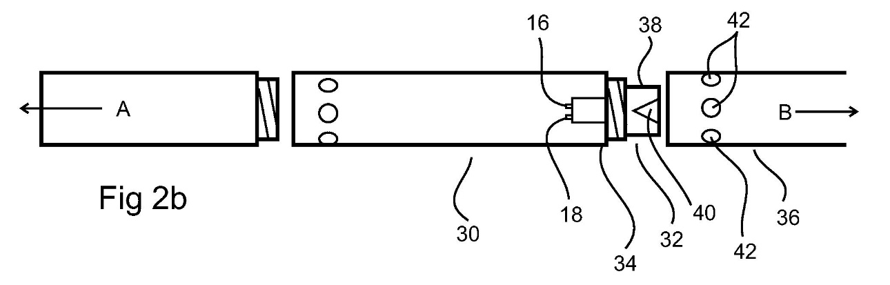
357 In this example, the optical device is the whole of 32 which includes the body shown at 38 and the signal direction (ie, light path) altering means 40. In this example, the signal direction altering means is formed within the body, but the patent discloses the signal direction altering means may be formed by the end, boundary, surface or edge of the device.
358 As to the electromagnetic signal/light path/light direction altering means, the patent discloses:
(1) the optical device includes the electromagnetic signal/light path/light direction altering means: [0021];
(2) the body passes the signal/light to the electromagnetic signal/light path/light direction altering means: [0021];
(3) the electromagnetic signal/light path/light direction altering means can act on optical signals/light to or from the electronics unit: [0025] and [0061], [0062];
(4) the electromagnetic signal/light path/light direction altering means can be the end of the optical device which is recessed ([0077], dished or domed (0081]); and
(5) consistent claims in, for example, claims 1, 5, 6, 7, 8, 9, 10, and 11.
359 Accordingly, the optical device must have both a body and the electromagnetic signal/light path/light direction altering means. That signal direction altering means may be within or at the surface, edge or boundary of the body and that surface, edge or boundary of the body may be the surface, edge or boundary of the optical device.
360 Reflex contended that the issue is whether the optical device can be comprised of multiple parts that are not abutting or bonded. According to Reflex, the optical device can be comprised of multiple parts that are not abutting or bonded as the patent expressly provides for this at [0024] and [0084].
361 At [0024] the patent says that “the [optical] device may be formed of multiple parts, which may be bonded together or otherwise held together”. At [0084] the patent says that “the optical device may be formed of one or multiple parts. For example, the optical device may be machined as a monolithic component or may be formed of multiple sub-components brought together, which may be bonded together or simply abutting in use”.
362 Claim 2 refers to the device of claim 1, including a unitary or monolithic body. Claim 3 refers to the device of claim 1, including a multi-component body. Claim 4 refers to the device of claim 3, wherein the multiple components of the body are bonded together. [0024] says the device “may be formed of multiple parts, which may be bonded together or otherwise held together”.
363 The question which arises from these claims is whether claim 2 (read with claim 3) means that the body may be a multi-component body which is not bonded together, held together, or abutting. Alternatively, does the reference to “multi component body” in claim 2 mean: (a) a body which is held together or abutting, or (b) multiple bodies whether or not held together or abutting or bonded together?
364 These questions engage the principle that it is impermissible to confine the clear meaning of a claim using unambiguous words, but it is permissible to have regard to the specification to define the meaning of an unclear or ambiguous word in the claim. I consider the references to the “body” in claims 1 to 3 to be ambiguous. The person skilled in the art would have to consider the specification to give meaning to the concept of the “body” in the claims.
365 Given the terms of claims 1, 2, 3, 4 and [0024], the person skilled in the art would understand that while the optical device is a single device it may be formed of one or multiple parts. Those parts may (but need not be) bonded or held together or abutting in use. This follows from the fact that claim 2 expressly contemplates a body in multiple parts not bonded or held together or abutting in use, whereas claim 4 and [0024] expressly contemplate such a body where the parts are bonded or held together. Further, the specification does not, in terms, require the patents of the body to be bonded or held together or abutting in use. It does require that the optical device includes (in the sense of has) a body and that the signal direction altering means be within or at the boundary, surface, or edge of the body.
366 Professor Dupuis distinguished between an optical device and an optical system. Professor Tapson disagreed with this distinction. I agree that the patent does not draw any distinction between an optical device and an optical system. There is no basis to conclude that the person skilled in the art would construe the patent on the basis that the device must not constitute an optical system. Provided the body is or forms part of an optical device including (in the physical sense described of within, or at the boundary, surface, or edge of) the signal direction altering means, the distinction between a system and a device is not material to the patent.
367 Professor Tapson said that “a compound lens might be formed of multiple (e.g. 8 or 9) pieces of glass with air between, but it would still be referred to as a lens, singular”. I agree. The lenses would be the electromagnetic signal direction altering means included in the optical device, but as I have said it is important to recognise that the optical device still requires a body having a light path that allows the signal to pass to the electromagnetic signal direction altering means.
368 It is clear that the downhole equipment includes an electronics unit that transfers or receives an electromagnetic signal (claim 1).
369 One issue between the experts is whether the “electromagnetic signal from an electromagnetic wave source associated with the electronics unit” as referred to in claim 1 means that, as Professor Dupuis said, the electronics unit has to be the source of the signal. Professor Tapson disagreed with this on the basis that the specification and claims contemplate that the electronics unit may send or receive signals and does not need to do both (see claims 1 and 5 and the patent at [0018] and [0025]). As such, for the signal from the wave source to be “associated with” the electronics unit, it is sufficient for Professor Tapson if the:
signals communicate in some way with the electronics unit. The signals may be generated by or received by the electronics unit. There is no restriction that the signals originate in or from the electronics unit. Furthermore, the signals may be processed in the electronics unit, or processing may take place prior to or after the electronics unit in the signal processing chain.
370 I accept that the electronics unit may send or receive the electromagnetic signal. But it is also clear that where there is an electromagnetic signal from the electromagnetic wave source that source must be “associated with the electronics unit”: patent [0021], [0042], [0044], [0061], and claims 1 and 21. In the context of an electromagnetic signal from the electromagnetic wave source, I consider that it is clear that the envisaged “association” is that the electronics unit powers the wave source (ie, the light source).
371 Another issue between the experts is whether the electronics unit is a single physical unit within the electronics package or a single functional unit which is or may be the electronics package.
372 The claims do not use the words “electronics package” which is found only in [0017] of the patent. The claims use “electronics unit”. It may be accepted that the “electronics unit” in the optical device is singular, but that does not mean that it must consist of one single physical unit. In claim 1 (and otherwise) the electronics unit is functionally described. It is the thing which can send or receive a signal. As discussed above, if sending a signal it does so via the wave source.
373 Beyond this, the patent contemplates a number of options relating to the electronics unit. It is not apparent how any of the issues which otherwise concerned the experts (a need for the electronics unit to be on a single printed circuit board, the possible difference between electronics package as used in the patent and electronics unit, a need for printed circuit boards to be in close proximity to each other) materially contributed to the resolution of any relevant issue.
5.8 Electromagnetic signal direction altering means
374 The experts agreed that the electromagnetic signal direction altering means must alter the direction of propagation of an electromagnetic wave (in practice, light), which can be achieved by reflection (eg, a mirror) or refraction (eg, dense glass) or diffraction (eg, through an aperture or slit). They disagreed about whether an electromagnetic signal direction altering means included an optical fibre which can be bent so that the light which enters the fibre in one direction can exit the bent fibre in another direction.
375 This is an issue about which I consider it is particularly important to recall that it is the understanding of the skilled addressee possessing the common general knowledge which is important. The skilled addressee is a person with a practical interest in the invention. The skilled addressee, as I have said, is not a scientific polymath like Professor Tapson. Nor is the skilled addressee someone who is to be attributed with the knowledge of Professor Tapson or, for that matter, Professor Dupuis. I have identified aspects of Professor Tapson’s extraordinarily broad range of scientific expertise and inventiveness above. Professor Dupuis is also no slouch. He has been awarded numerous academic excellence awards through to post-doctoral level. His research fields include mine exploration technologies, instruments, imagery, ground water and water tables, mining and petroleum contamination. He has been involved in numerous research projects. He has supervised numerous doctoral candidates. He is a prolific author.
376 As discussed above, Professor Tapson and Professor Dupuis engaged in a fascinating discussion about the behaviour of light in single and multimode optical fibres.
377 However, an anterior issue is whether the patent contemplates that the electromagnetic signal direction altering means might be an optical fibre.
378 The patent does not mention optical fibres. It describes the ways in which the optical device may operate to change the direction of light. At [0026] it says that refraction may occur at a surface edge of the optical device. At [0027] it says that refraction may occur at a change of material or material density within the body of the optical device. At [0028] it says that the optical device may include a reflector, which may be a silvered or polished coating provided on an end portion of the optical device. At [0029] it says that the reflector may be embedded within or attached to the optical device. At [0034] it says that preferably the material of the body is substantially transparent to the light travelling through it or the light path may be provided by a light transmitting conduit within the body. The body is the body of the optical device. As noted above, in the patent the light path is not the electromagnetic signal direction altering means. They are two separate things. The body has a light path allowing the light signal to pass to the electromagnetic signal direction altering means. It is that light path which might be provided by a light transmitting conduit within the body. The patent does not say that the electromagnetic signal direction altering means may be a light path with a bend in it. At [0041] it says that “the direction of the light signal may be altered within the body of the optical device or a surface of the device, or a combination of both”.
379 Given this context, it is not apparent that the patent contemplates that the optical device including an electromagnetic signal direction altering means will use a bent optical fibre to achieve the change in direction of the light. The patent contemplates that the optical device will include the electromagnetic signal direction altering means and that the direction altering means may be within the body of the optical device or a surface of that device (that is, the surface of the optical device may act to change the direction of the light). On this basis I am unable to accept that the person skilled in the art would understand that the electromagnetic signal direction altering means within the meaning of the patent might be an optical fibre.
380 I also consider that the patent requires the alteration of the direction of the light to occur within (in the sense of inside or at the boundary, surface, or edge of) the optical device. This is because claim 1 says that the optical device includes the electromagnetic signal direction altering means. I do not see how the optical device includes the electromagnetic signal direction altering means if the means is not inside or at the edge or surface of the body of the device. From [0026] it is apparent that a boundary of or within the body of the optical device or surface edge of the optical device may be used to refract the light and therefore alter its direction. That does not mean that the light can change direction outside (in the sense of a place apart from) of the optical device. The boundary or surface edge of the optical device is still part of the optical device. This explains the statement at [0041] that the direction of the light signal may be altered within the body of the optical device or a surface of the device, or a combination of both. This also does not indicate use of an optical fibre or that the electromagnetic signal direction altering means can occur at a location physically separate from the optical device.
381 Professor Tapson considered that an optical fibre is an electromagnetic signal direction altering means within the meaning of the patent for four main reasons. I do not accept these reasons, as explained below.
382 First, and as discussed, [0034] of the patent must be read in the context of the patent as a whole. In particular [0033] and [0034] say:
[0033] The optical device may be formed of a glass and/or plastics material. In at least one preferred form of the present invention the optical device may include one piece body, such as a moulded and/or machined plastics or glass material.
[0034] Preferably the material of the body is substantially transparent to the light travelling through it. For example, the light path may be formed by the body of the optical device being transparent to the optical signal passing through the material of the body. Alternatively the light path may be provided by a light transmitting conduit within the body.
383 Accordingly, the “body” referred to in [0034] is the body of the optical device. That body may be transparent so that the light path travels though that transparent body. The alternative is a light transmitting conduit within the body. These paragraphs are dealing with the body of the optical device, not the electromagnetic signal direction altering means. The paragraphs dealing with the electromagnetic signal direction altering means are [0021], [0025]–[0031], [0044], [0061]–[0063], [0076], [0077], [0081] and [0085]. From these paragraphs it is apparent that the body provides a light path to the electromagnetic signal direction altering means and that means may include a boundary of or within the body of or a surface edge of the body of the optical device. The light transmitting conduit within the body (which would include an optical fibre), within the patent, is a means of transporting the light and not a means of altering the direction of the light. See, in particular:
(1) [0021]: “…the body having a light path arranged to allow the electromagnetic signal from an electromagnetic wave source associated with the electronics unit to pass to the electromagnetic signal direction altering means, the electromagnetic signal direction altering means causing the electromagnetic signal to change direction of travel”;
(4) [0044]: “…the device including a body and an electromagnetic signal direction altering means, the body having a light path arranged to allow the electromagnetic signals from an electromagnetic wave source associated with the electronics unit to pass to the electromagnetic signal direction altering means, the electromagnetic signal direction altering means causing the electromagnetic signal to change direction”;
(5) [0061]: “[t]he optical device has a body 38 and a light path altering means 40. The body also defines a light path therethrough (see figure 3) arranged to allow the optical signal from a light source(s) 16, 18 associated with the electronics unit to pass to the light path altering means”; and
(6) [0076]: “[l]ight from one or more such emitters is transmitted by the light path through the body to impinge on a light path altering means 52”.
384 Second, Professor Tapson said that [0026] says the change of direction can occur at the surface edge of the optical device which means it can occur “on the exterior of the device”. I agree, provided the focus is on the word “on” the exterior of the device, as opposed to beyond the exterior of the device. However, it is not apparent that this means that the change in direction can occur by means of an optical fibre exiting the optical device in a different direction from that which it entered the optical device. Rather, from the context of the patent as a whole, what is contemplated is that the reflection or refraction may occur by or from the internal or external surface of the optical device, including by means of a “reflector embedded within or attached to the optical device”: [0029].
385 Third, claim 6 claims “the device of any one of the preceding claims, wherein the electromagnetic signal direction altering means includes a boundary at a change of material or edge of a portion of the device”. This means that the electromagnetic signal direction altering means, as the specification discloses, can be or include a boundary or surface edge of the optical device which is of a different material from the rest of the optical device to enable refraction, reflection, or diffusion. It does not have anything to do with the means being a bent optical fibre.
386 Fourth, claim 7 claims “[t]he device of any one of the preceding claims, including a reflector to reflect at least a portion of the electromagnetic signal”. This too means only that the means can include a reflector within or on the boundary or surface edge of the optical device. This does not, as Professor Tapson claims, make “it clear that reflection at an interface (like in an optical fibre) is an embodiment within the scope of the Patent”. To the contrary, the patent assumes that an optical fibre might be a light transmitting conduit within the body to the electromagnetic signal direction altering means but clearly does not contemplate that the light transmitting conduit will be the electromagnetic signal direction altering means.
387 I also consider that the analysis by the experts about the way in which different optical fibres (that is, single mode and multimode optical fibres) propagate light is outside the scope of this patent and outside the common general knowledge of the person skilled in the art. Neither expert suggested this kind of knowledge would be part of the common general knowledge of the skilled addressee of the patent.
388 It is apparent from the experts’ evidence that the dispute between them related to the characterisation of light. Professor Dupuis described Professor Tapson’s characterisation of light within a multimode fibre as over-simplified “ray optics”. However, neither expert explained the nature of light. They assumed knowledge about the nature of light which would have to be proved by evidence. If it were necessary to resolve this issue, Reflex would fail on the onus of proof as the party asserting invalidity of the patent. Professor Dupuis’ evidence, insofar it went about the nature of light in a multimode fibre, would not be discounted. It would prevent the acceptance of Professor Tapson’s evidence about this issue being accepted as having been proved on the balance of probabilities.
389 However, the salient fact remains that they did not assert, and I am not persuaded that, this knowledge would have been common general knowledge of the person skilled in the art at the priority date.
390 In any event, as I have said, the person skilled in the art would not read the patent as contemplating an optical fibre as an electromagnetic signal direction altering means. It seems even more unlikely that the person skilled in the art would read the patent on the basis that in a multimode (as opposed to a single) optical fibre there is “total internal reflection” in which the light wave bounces from wall to wall inside the fibre and thus changes direction if the fibre is bent as shown in publications by the Department of Physics and Astronomy at Douglas College. It is equally unlikely that the person skilled in the art would read the patent on the basis that to work out if the integer of an electromagnetic signal direction altering means existed or not they would have to write the equations Professor Dupuis mentioned in passing in his oral evidence to ascertain how the light propagates through the optical fibre as a waveguide. I consider that all of this reinforces that the person skilled in the art would not read the patent as contemplating that an electromagnetic signal direction altering means might be an optical fibre, bent or otherwise.
5.9 Downhole data gathering system
391 For the reasons already given, this patent has nothing to do with wireline telemetry or holes for oil and gas exploration and production.
392 To the extent it is appropriate to deal with Reflex’s criticisms of Professor Dupuis’s evidence about this issue, I respond as follows.
393 Professor Dupuis did not accept that “there is no language in the claims of the Patent, or anywhere in the Patent, that expressly or impliedly excludes the possibility of communicating data at the same time the device [is] downhole” and did not rely “only on the absence of an example about communicating with the device when it is downhole in the body of the specification”. His evidence was to this effect:
… if you read the patent, you can actually see it in the text of the patent that there is no mention about communicating with the device while it’s down in the borehole…
…
…I cannot agree that you could actually put this tool at 800 metres depth or at any metres depth in a borehole and still be able communicate with the handheld device that it’s intended to communicate with…
…
There is nothing that says, “You may not use it when the device is in the hole.” But I think that a reasonable person would actually understand that it can’t be the case.
…
… because you would actually look at the word “telemetry” and understand that what the people in the patent wanted to say was sensing down the hole.
394 In the joint report Professor Dupuis said:
Professor Dupuis noted that the invention disclosed in the patent does not communicate with the surface and is a standalone tool (Dupuis affidavit P3, paragraph 9). This is clear to him since the patent states at paragraph [0017] that the “… downhole equipment is brought to the surface once sufficient data is gathered or task completed…’’. Professor Dupuis also notes that all the interactions described in the patent between the driller and the invention imply that the aperture is accessible and visible to the driller. This means that the invention must be at surface and therefore that the data was gathered downhole but only retrievable once the invention is back at surface. For Professor Dupuis this is an important point of differentiation between the invention disclosed in the Patent and wireline tools see Dupuis affidavit (P3, paragraphs 9 to 11, P12 paragraphs 60 to 63).
395 It is true that [0017] of the patent says “[t]ypically the downhole equipment is brought to the surface once sufficient data is gathered or task completed”. As noted, this is a discussion of the prior art. And [0017] is not to be read in isolation. The whole purpose of the invention is to improve on the existing systems in which the tool is brought to the surface for analysis of data. This is clear from:
(1) [0014]: “[a]t the surface before removing the core sample from the inner tube assembly, the operator views the display fitted on the system”; and
(2) [0037]: “[a]n advantage of the present invention is that the greaser or other equipment to which the electronics unit attaches does not need to be separated from the electronics unit in order to obtain access and communicate with the device to obtain data”.
396 As noted in respect of [0016] of the patent, if the device includes wireline telemetry in which data is communicated from downhole to the surface, it is not the case that “similar issues” (ie, associated with manual manipulation of the instrument on the surface to obtain the data) “arise with downhole probes that are used to obtain borehole telemetry data to determine drilling progress”. The issues associated with manual manipulation obviously do not arise if the tool includes wireline telemetry in which data is communicated from down the hole to the surface. This is one reason why “borehole telemetry” in [0016] cannot mean wireline telemetry involving downhole communication to the surface, but must mean borehole sensing/measuring (as discussed above). Accordingly, [0016] involves a use of “borehole telemetry data” different from the ordinary meaning of telemetry.
397 The words “task completed” in [0017] of the patent do not assist Reflex. They do not contemplate “something other than sufficient data being gathered and would naturally include the completion of the communication of data from downhole to the surface”. They mean simply the completion of a downhole task such as the express example given of “obtaining a core sample”. The express reference to sufficient data being gathered and the device then being brought to the surface is inconsistent with the proposition that the completed task might be the sending of data from downhole to the surface as in wireline telemetry.
398 The final sentence of [0017] also does not assist Reflex. The sentence is “[s]imilar issues exist with separating the electronics unit of a downhole probe from its backend assembly”. This is consistent with the use of “probes” in [0016]. Again, there would not be similar issues (that is, issues associated with manual manipulation at the surface) if the “probes” were for the purposes of downhole communication to the surface via wireline telemetry.
399 The fact that [0017] is discussing the prior art does not mean it is immaterial. It is the prior art on which this invention improves, as [0020] discloses (by its reference to “with this in mind”).
400 Professor Tapson’s examples of wireline telemetry being used in contexts other than hard rock drilling disclosed that: (a) one example he gave was a marine drill using a larger drill than an oil and gas drill (and therefore much larger than mineral drilling), which is wholly foreign to the field of the patent, (b) nothing suggests Professor Tapson’s experience with a marine drill formed part of the common general knowledge of the person skilled in the art for the purpose of this patent, (c) Professor Tapson considered that the patentee was “leaving the door open” to wireline telemetry because of references to “telemetry” which have to be read in context, (d) Professor Tapson accepted that telemetry is never easy and is always a problem, and would be more difficult in hard rock mineral drilling, but said he was “sure it could be made to work”, and “an imaginative engineer could run a signal line down the outside of the drill string or down the inside of the drill string” in that circumstance.
401 This is not compelling evidence that the patent includes wireline telemetry. To the contrary, properly understood, it confirms that the person skilled in the art would not understand the patent’s references to probes for borehole telemetry (involving “similar issues” to core orientation units requiring manual manipulation at the surface for data retrieval) to mean wireline telemetry for downhole to surface communication. It is not so much that the references to “telemetry” involve an error (as Professor Dupuis suggested), but that in the context of this patent, probes for borehole telemetry refer to borehole sensing and measuring and not downhole to surface data communication.
402 The fact that Professor Dupuis accepted that “borehole telemetry” ordinarily means communicating data from the tool while it is down the hole to the surface does not make it highly improbable that the patent uses the words in a different way. As noted above, this is principally because: (a) the words used are not “borehole telemetry”. They are “borehole telemetry probes” at [0001] and “downhole probes that are used to obtain borehole telemetry data…” at [0016], (b) the problems with such probes are identified as being similar to the problem for core orientation units, being associated with manual manipulation to obtain data at the surface (eg, water ingress, dirt ingress, and failure of the o-ring seals) at [0016] and [0017], (c) all references to obtaining data from the device in the patent involve an act at the surface, not downhole communication of data to the surface, and (d) it was common ground that telemetry, in accordance with its meaning of remote communication from down the hole to the surface, is uncommon in mineral exploration.
403 Consistent with these reasons, the “downhole data gathering system” referred to in claim 21 does not include wireline telemetry in the sense of the gathering of data downhole which is communicated from down the hole to the surface. It means a system for gathering data down the hole which is then acquired once the device is brought to the surface.
5.10 Communicate wirelessly and wireless communication
404 Claim 21 of the patent refers to a “downhole data gathering system, including a communication device arranged to communicate wirelessly with an electronics unit of down hole equipment”.
405 The debate between the experts is that Professor Tapson considered that the communication device could be tethered to the electronics unit of downhole equipment but could not be connected by a wire enabling communication between the two. Professor Dupuis considered that this integer involved the communication device not being physically connected by a wire of any kind to the electronics unit of the downhole equipment.
406 Reflex said that the two issues of construction were: (a) whether the communication itself must be wireless (or whether the device must be untethered by wire), and (b) the meaning of “wireless”, and relatedly, “wire”.
407 I find this an odd approach. The relevant phrase is “communicate wirelessly” and “wireless communication device”. The communication is between a communication device and an electronics unit of downhole equipment. The same terms are used at patent [0044], [0054] (“[u]sing an infrared link or other wireless link, the electronics unit is put into orientation indicating mode by the remote communication device”), and [0055] (“[t]he remote communication device is then used to communicate with the electronics unit to obtain core sample orientation data from the electronics unit”. The fact that the communication device is “remote” (see for example, [0038]) need not detain us long. It means only that the communication device is not down the hole with the electronics unit – it is on the surface with the operator.
408 It is clear that the communications device remains on the surface and communicates wirelessly with the electronics unit of the downhole equipment. Once this is accepted, the notion that the communication device would otherwise be tethered by some wire not performing a downhole to surface communications function is nonsensical. There would be no purpose to a “wireless communication device”, which “communicate[s] wirelessly” if the communication device were otherwise physically tethered to the electronics unit while it is down the hole. It is also obvious that the concept of “wireless” is about a physical communications link. Anything constituting a physical communications link would not be “wireless”. The idea that the patent contemplates that, in this context, “wireless” means not connected by a “wire” which in turn means “a metal, electrical conductor”, so that a communication device which communicates to an electronics unit down the hole by optical fibre (which is not a metal conductor), is untenable. This proposition discloses how far from the required task of reading the patent through the eyes of the skilled addressee we have strayed. In context, “wireless” communication, means without a physical link of any kind which permits communication. It does not matter if the physical link is metallic or an optical fibre. Once the task of communication is achieved through a physical link between the communication device and the electronics unit, the communication is not “wireless”.
409 The evidence of the experts that “wire” means a metal conductor is beside the point. We are not dealing with the concept of a “wire”, but of “wireless communication”. The two are not synonymous. Nor are dictionary definitions particularly helpful.
410 There is no basis in the text or context of the patent for concluding that it contemplates such distinctions as wires being metallic and optical fibres being non-metallic when referring to wireless communication. It is obviously contemplating a form of communicating with the electronics unit without any physical link between the communication device and that unit. To this extent, Professor Dupuis was right when he said that “wireless communication” means no physical link for communication purposes – be it a wire, cable or ultrasonic wave guide. He was also right when he said, in context, there was no reason for physically tethering the communications device and electronics unit for non-communications purposes.
5.11 Professor Tapson’s design exercise
411 I discuss below a number of problems with Professor Tapson’s design exercise. For present purposes, what is relevant is that Professor Tapson’s design exercise tends to support the conclusions reached above about the understanding of the person skilled in the art armed with the common general knowledge in the field. Notably, in his design exercise for a downhole instrument for transferring data as at the priority date of August 2011 based on the common general knowledge in the field:
(1) Professor Tapson rejected wired communication and pursued a wireless communication method because the pass-through bulkhead shown in his figure 2 represents a point of probable failure in circumstances of robust handling, and the permanent wired connection is inconvenient in drilling operations if the system is integrated into a drill string;
(2) the rejection of wired communication enabled the instrument to be fully enclosed in the housing (see Professor Tapson’s figure 3); and
(3) the redirection of the signal through the side wall of the instrument in both alternatives is not achieved through bent optical fibres. It is achieved through the rotation of the transmitter-receiver pair through 90 degrees or bending the optical axis 90 degrees by means of a mirror as shown in figure 7 of the design exercise.
412 Further, the optical wireless transmission as shown in figures 4 and 5 of Professor Tapson’s design exercise involves the downhole tool being brought to the surface for communication. This is evident from the addition in figure 5 of the protective cover which a human is required to remove to enable the optical communication. While Professor Tapson gave evidence that the protective cover itself might be several metres long enabling the optical communication to occur while the instrument was some way down the hole, I found all of this evidence, and Reflex’s submissions about it being possible for the instrument to communicate optically from down the hole, unconvincing. That this is also not what Professor Tapson designed is apparent from his affidavit evidence that:
(1) “[t]he system at Figure 4 also allows for very quick transfer of data because all that is required for communication is for the user to bring the downhole instrument system and surface control system into optical alignment”; and
(2) “[t]he protective metal cover in Figure 5 can then be removed manually when communication with the surface control system is required”.
413 Further again, Professor Tapson only suggested a possibility of optical communication over a longer distance from the side port to the surface communication device after he was asked by the lawyers for Reflex to “describe in further detail the nature and function of the optical mirror”. Even then, he did not explain why the instrument he designed would need to enable transmission of the optical signal over longer distances than would be anticipated if the instrument was brought to the surface for data communication. If the implicit reason is to enable optical communication while the optical device is down the hole or some way down the hole then, as Professor Dupuis said:
(1) he understood Professor Tapson’s design in figure 4 and 5 (and therefore also figure 7 in my view) to involve the transmission of data over a short distance at the surface as “the surface control system must be in view of the downhole instrument system to be able to actually communicate”;
(2) for the notion of communication while the instrument was down the hole to work “you would have either a very short borehole for it to be able to actually be accessible or you would have a borehole that is completely empty of other fluid” as otherwise the communication could not work; and
(3) the idea of a third possibility of the device being close to the surface was untenable as then “you would have to actually get rid of gravity for this to succeed because you would have to hold your downhole instruments in place”. As such, the device would be resting on the bottom of the hole and a person could not then reach down and manually remove the protective cover as figures 5 and 7 contemplate.
414 It is also apparent from this that the entire purpose of Professor Tapson’s alternative designs in figure 7 would be undermined by the notion of wired telemetry. It is the unwired nature of the instrument which drives the design as Professor Tapson’s design exercise makes clear.
415 Section 7(1) of the Patents Act provides that:
(1) For the purposes of this Act, an invention is to be taken to be novel when compared with the prior art base unless it is not novel in the light of any one of the following kinds of information, each of which must be considered separately:
(a) prior art information (other than that mentioned in paragraph (c)) made publicly available in a single document or through doing a single act;
(b) prior art information (other than that mentioned in paragraph (c)) made publicly available in 2 or more related documents, or through doing 2 or more related acts, if the relationship between the documents or acts is such that a person skilled in the relevant art would treat them as a single source of that information;
(c) prior art information contained in a single specification of the kind mentioned in subparagraph (b)(ii) of the definition of prior art base in Schedule 1.
416 The prior art base is defined in Schedule 1 to mean:
(a) in relation to deciding whether an invention does or does not involve an inventive step or an innovative step:
(i) information in a document that is publicly available, whether in or out of the patent area; and
(ii) information made publicly available through doing an act, whether in or out of the patent area.
(b) in relation to deciding whether an invention is or is not novel:
(i) information of a kind mentioned in paragraph (a); and
(ii) information contained in a published specification filed in respect of a complete application where:
(A) if the information is, or were to be, the subject of a claim of the specification, the claim has, or would have, a priority date earlier than that of the claim under consideration; and
(B) the specification was published on or after the priority date of the claim under consideration; and
(C) the information was contained in the specification on its filing date.
417 The undisputed principles are:
(1) “…if carrying out the directions contained in the prior inventor’s publication will inevitably result in something being made or done which, if the patentee’s patent were valid, would constitute an infringement of the patentee’s claim, this circumstance demonstrates that the patentee’s claim has in fact been anticipated”, but this is not so if “the prior publication contains a direction which is capable of being carried out in a manner which would infringe the patentee’s claim, but would be at least as likely to be carried out in a way which would not do so”, as what is required are “clear and unmistakeable directions to do what the patentee claims to have invented”, a mere “signpost” “upon the road to the patentee’s invention will not suffice”, and the prior publication must have “planted his flag” at the “precise destination” of the invention: General Tire at 483–486; and
(2) “[a]nticipation is deadly but requires the accuracy of a sniper, not the firing of a 12 gauge shotgun”: Apotex Pty Ltd v Sanofi-Aventis [2008] FCA 1194; (2008) 78 IPR 485 at [91].
418 Globaltech submitted that the comments of the Full Court in AstraZeneca AB v Apotex Pty Ltd [2014] FCAFC 99; (2014) 226 FCR 324 at [335] to [354] might undermine Nicaro at 529 and Lundbeck A/S v Alphapharm Pty Ltd [2009] FCAFC 70; (2009) 177 FCR 151. In Lundbeck, Bennett J (with whom Middleton J agreed) said, in a summary of principles at [173], that:
• The disclosure is assessed by reference to the skilled addressee, a person of ordinary skill in the art.
• The question is whether the prior publication is sufficient to make the claimed invention apparent to the skilled addressee (Nicaro Holdings Pty Ltd v Martin Engineering Co (1990) 91 ALR 513 at 529).
• A prior publication does not invalidate a patent unless it supplies sufficient information to enable a person of ordinary skill to produce the product subsequently claimed (Acme Bedstead Company Limited v Newlands Brothers Limited (1937) 58 CLR 689 at 707). A specification is not to be read as in a vacuum but by the reader having at least the common knowledge of the art (Acme Bedstead at 701; Nicaro at 530).
• The requirement is that a person of ordinary knowledge of the relevant subject would be able practically to apply the prior published discovery without the necessity of making further experiments (Hill v Evans [(1862) 1A IPR 1] at 6–7).
419 I do not understand AstraZeneca at [335] to [354] to be suggesting that the earlier authorities are wrong. The point being made in AstraZeneca at [335] to [354] is that the principle that the prior art is to be read through the eyes of the skilled addressee can be taken so far only. The requirement remains that the prior art explicitly or implicitly (to the skilled person possessing the common general knowledge in the art) discloses the relevant feature. Accordingly, in AstraZeneca at [352] the Full Court said:
Although the common general knowledge can be used in a limited way to construe a prior art document, s 7(1) does not permit the common general knowledge to be used as a resource that can be deployed complementarily to arrive at a disclosure which the document alone, properly construed, does not make. If it were otherwise, the separate requirement of an inventive step to support a patentable invention (see s 18(1)(b)(ii) of the Act) would be otiose. The test of novelty would encompass the test for inventive step, without the need to satisfy the threshold requirements of s 7(3) (as it then stood) that the information in the document be information that the person skilled in the art could, before the priority date of the relevant claim, be reasonably expected to have ascertained, understood and regarded as relevant to work in the relevant art in the patent area. All that would be required is that the information in the prior art document be publicly available.
420 Reflex contended that claims 1, 5, 7, 8, 9, 10, 12 and 17 of the patent are not novel by reason of the prior art base as disclosed in Iizuka, Bergren, and/or Sun.
421 Reflex submitted that Professor Dupuis erred in his approach to novelty by comparing the prior art to the “essence of the invention” and not each claim of the patent.
422 This criticism of Professor Dupuis is not well-founded. In his second affidavit at [8] he was not dealing with novelty. He was merely describing what he understood to be the essence of the invention. At [156] of his second affidavit he was dealing with the issue of inventive step, not novelty. When dealing with novelty, Professor Dupuis focuses on the asserted claims of the patent.
423 In the discussion below I focus on the issues which I consider material to the resolution of the required issues only. In particular, I focus primarily on the integers of the claims in the patent which are not disclosed in the prior art.
424 Reflex acknowledged that Iizuka does not disclose claim 21 or its dependent claims 22, 24, 25, 26, 27, 28, and 29 because Iizuka’s borehole scanner does not have a communications device arranged to communicate wirelessly with the sonde. Reflex contended that Iizuka disclosed claim 1 and dependent claims 5, 7, 8, 9, 10, 12 and 17 of the patent.
425 For ease of understanding figure 3 in Iizuka is again reproduced below:
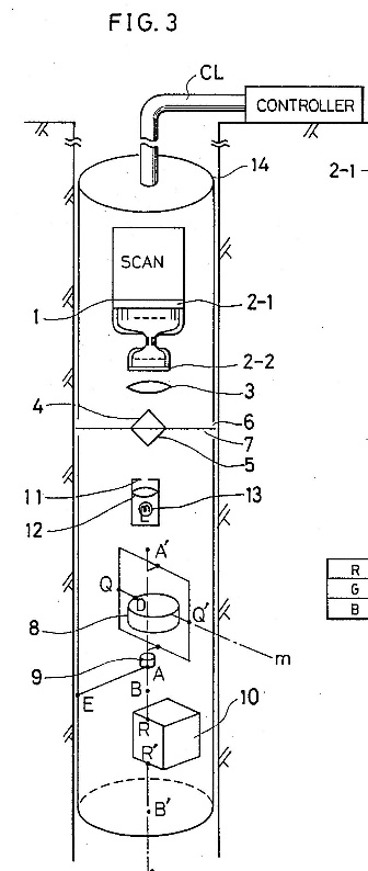
426 Figure 5 in Iizuka is:
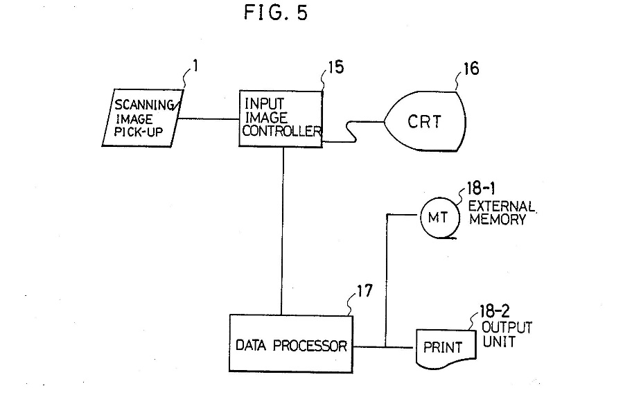
427 Iizuka involves wireline telemetry as shown by the item “CL” which is a cable telemetry link. Further, the specification describes the invention as involving a process in which:
… the signals from the photoelectric transducing device are scanned, and image data relating to the borehole wall surface is generated and processed, by the data processing device while the sonde is raised and lowered, thereby providing a continuous image of the wall surface. Moreover, observation of the wall surface based on accurate position information is made possible by correlating the image data and sonde position by the sonde position detecting device.
428 That is, the sonde 14 (see figure 3) acquires images of the borehole and sends those images to the surface via the input image controller 15 (see figure 5) where it can be viewed on a monitor 16 (see figure 5) and processed by a data processor 17 (see figure 5). Within the sonde 14 the specification explains that the image pick-up device in the upper part irradiates the wall of a borehole with light from a light source 13 via the lens 12 and through a slit 11 to the conical mirror 5 and the lower side of the light shielding plate 7 to the lower side of the slit 6 and the light signal as modulated by the side of the borehole then re-enters the sonde via the upper side of the slit 6. The modulated light signal from the borehole wall is projected to the upper side of the light shielding plate 7 and to the conical mirror 4. The lens 3 forms the light from the conical mirror 4 on one end of the optical fibres 2–2 which are connected to the photoelectric transducer 2–1. The photoelectric transducer 2–1 converts the optical light signals into electrical signals. The electrical signals are scanned by the scanning section 1 to read the observation data and as “the sonde 14 is raised and lowered while this operation is being repeated, a continuous image of the bore hole wall is obtained”.
429 Accordingly, the continuous image of the borehole wall is obtained at the surface while the sonde is down the hole. As discussed above, I do not accept that the person skilled in the art would construe “downhole equipment” as meaning or including wireline telemetry, as the patent consistently teaches away from wireline telemetry. It follows that Iizuka does not disclose “a device that transfers at least one electromagnetic signal to or from an electronics unit of downhole equipment…” in accordance with claim 1 of the patent (and dependent claims).
430 Professor Dupuis considered that the Iizuka patent also does not disclose “downhole equipment” within the meaning of the patent, but is a “wireline tool” because it does not involve equipment used by a driller to gather data during drilling operations. I have rejected this construction of “downhole equipment” in the patent above.
431 It is also apparent that claim 1 of the patent requires an optical device including a body and an electromagnetic signal direction altering means, the body having a light path to allow the signal from the electronics unit to pass to the electromagnetic signal direction altering means. As discussed, the optical device must include a body and an electromagnetic signal direction altering means which alters the direction of travel of the signal. While this electromagnetic signal direction altering means may be or be at the boundary or surface edge of the body of the optical device, including the outside surface edge, the light signal has to change direction within or at the outer edge of the optical device.
432 Reflex summarised its case in respect of the optical device in Iizuka as follows:
Conical mirrors 4, 5 make use of light.
Body of optical device is the light shielding plate 7.
Conical mirrors 4, 5 and 7 are a monolithic structure, being part of the same physical structure which forms the optical device.
Professor Dupuis accepts that if optical device can be multiple components, then optical device disclosed in Iizuka are the conical mirrors 4, 5.
433 However, the light shielding plate 7 cannot be the body of the optical device as contemplated by the patent. The light shielding plate 7 is not a body at all and does not have a light path to allow the signal from the electronics unit to pass to the electromagnetic signal direction altering means. The light reflects off the mirror 5 out of the slit 6 because the light shielding plate 7 prevents the light from being otherwise dispersed. There is no light path within the light shielding plate 7. Further, the direction of the light signal is altered by the mirror 5 before it reaches the light shielding plate 7 and changes directions again after it reflects back off the borehole wall through the upper part of slit 6 to the mirror 4 where it again changes direction.
434 In contrast to Reflex’s submission above, Professor Tapson identified the whole sonde 14 as the optical device, with the whole sonde, particularly 4, 5 and 7 being the body, and the sonde, in effect, having a light path from 13, 12 and 11 to 5, 6 and 7, and then to 4, 3, 2–2 and 2–1. This characterisation of Iizuka makes sense. On this basis, the optical device has a body (the body of the sonde) and an electromagnetic signal direction altering means both within the body at 5, 4, 3 and 2–2 (and at the edge of the body, being the slit 6). This also gets around the problem that the body must have a light path, as the sonde does have a light path.
6.3.3 Electromagnetic signal direction altering means
435 In Iizuka the electromagnetic signal direction altering means includes the optical fibres 2–2. As discussed, I do not accept that the patent contemplates an electromagnetic signal direction altering means comprising optical fibres, bent or otherwise. While the patent in suit contemplates that the light path might be via a conduit (which could be an optical fibre) to enable the light to pass from the wave source to the electromagnetic signal direction altering means, it does not contemplate that such a conduit will itself be an electromagnetic signal direction altering means.
436 Otherwise, I do not accept that because it has multiple electromagnetic signal direction altering means which are not abutting each other, the invention in Iizuka does not involve an optical device including a body and an electromagnetic signal direction altering means. The different signal altering means in Iizuka are part of the one single optical device (the sonde). Nor do I accept that Iizuka does not have a signal from a wave source associated with an electronics unit. The electronic components of the sonde (1, 2–1 and 13) are part of the electronics unit of the sonde enabling the propagation and redirection of the light signal for imaging purposes.
437 I see no reason to confine the “electronics unit” in Iizuka to the linear CCD sensor which can be used as the photoelectric transducer 2–1, as suggested by Professor Dupuis. If, as I consider, the electronics unit is a function rather than a physical unit, it includes the light source 13 in Iizuka. As such, there is an electromagnetic wave source associated with an electronics unit disclosed in Iizuka.
438 The dependent claims are not disclosed for the reasons given above, in summary that:
(1) the invention in Iizuka is not downhole equipment within the meaning of the patent as it is a wireline telemetry tool; and
(2) the invention in Iizuka does not alter the direction of the signal by an electromagnetic signal direction altering means within the meaning of the patent as one of the electromagnetic signal direction altering means involves optical fibres 2–2.
439 Subject to these matters, there is a reflector in Iizuka 3 and 4 as referred to in claims 7, 8, 9, and 10 of the patent. There is an aperture (slit) through a side wall configured to redirect the electromagnetic signal through a side of the device 6 as referred to in claim 12. The direction of the signal is altered within the body of the device (the sonde) as referred to in claim 18. Iizuka is not a “downhole data gathering system” as referred to in claim 21 as it involves a wireline telemetry system in which the data is communicated from downhole to the surface. As noted, Reflex acknowledged that Iizuka does not disclose claim 21 or its dependent claims 22, 24, 25, 26, 27, 28 and 29 because Iizuka’s borehole scanner does not have a communications device arranged to communicate wirelessly with the sonde.
440 Section 7(1) of the Patents Act does not operate so that the invention in the patent is taken not to be novel in light of Iizuka.
441 Figure 2 in Bergren is reproduced again for convenience below:
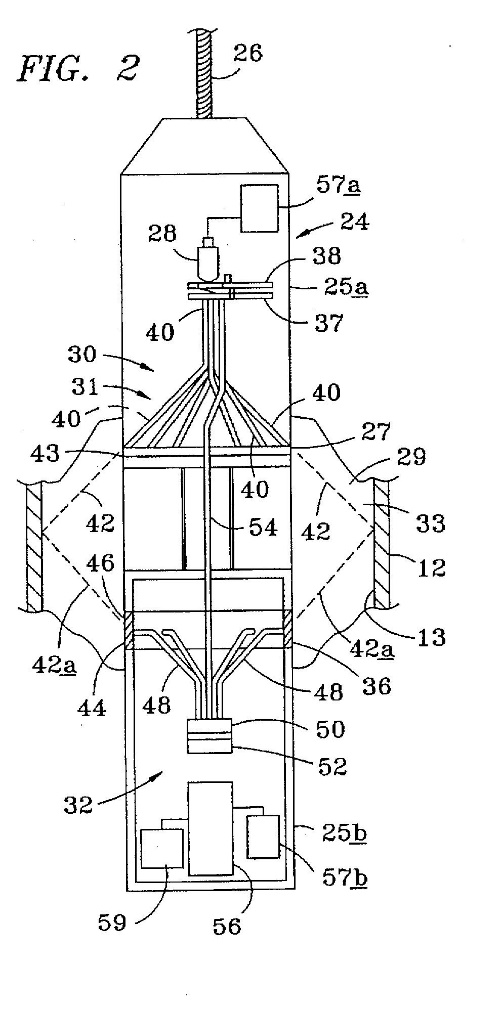
442 Figure 5 in Bergren is this:
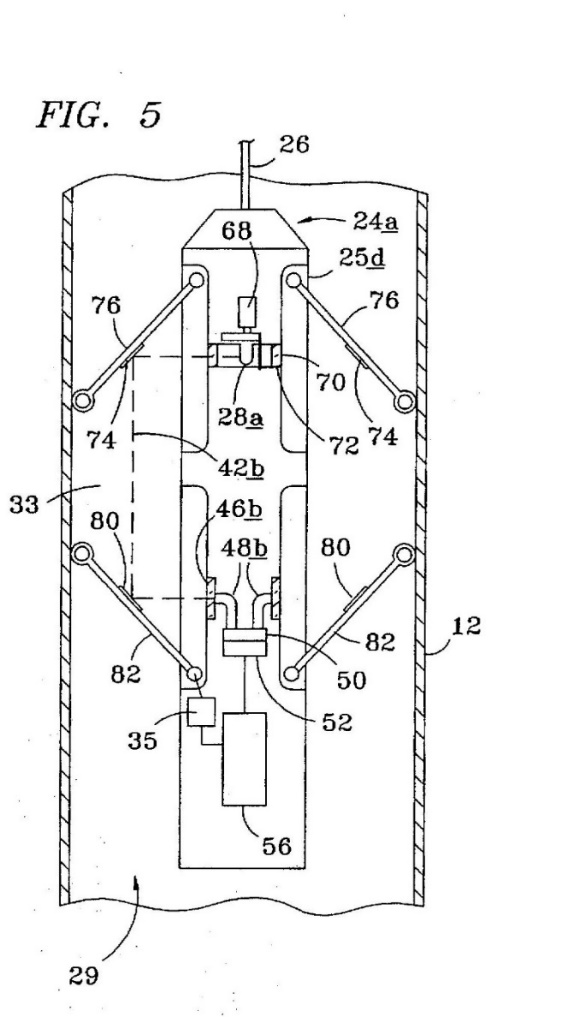
443 Bergren does not anticipate the invention in the patent.
444 The invention in Bergren does not involve “downhole equipment” within the meaning of claim 1 of the patent because it involves equipment that goes down a hole for producing oil and not down a borehole as that term is used in the patent (that is, an exploration hole used for mineral exploration and in the construction industry). The hole in Bergren is a well that is producing oil. This is clear from numerous references including:
(1) “[t]his invention relates to an infrared detection device for determining sources and concentrations of oil and water flow in cased and uncased wellbores; and more particularly to an infrared detection device insertable into a wellbore without interrupting the flowing fluid production…”: 1.5–10;
(2) “[w]ater production from hydrocarbon fluid production wells has been a longstanding problem”: 1.19–20;
(3) “[a]n infrared source and detector disposed downhole is provided which is capable of determining whether the fluid flowing past the detector is water or oil”: 2.1–5; and
(4) “[a]dvantages of the device described and shown in the diagrams are that the device may be traversed through the well without interrupting fluid production during the analysis procedure”: 2.23–25.
445 The invention in Bergren also does not involve an “electromagnetic signal direction altering means” within the meaning of the patent because the means to alter the light signal in the body of the device in Bergren are or include the optical fibres 40 in the infrared transmitter 30. As discussed, the patent does not include optical fibres as an “electromagnetic signal direction altering means”.
446 Further, the wellbore casing 12 in Bergren acts as an “electromagnetic signal direction altering means” but unlike the patent, the wellbore casing is not included in the body (in the sense of within, or at the boundary, surface, or edge of the body) of the optical device. The wellbore casing 12 is wholly external to the optical device.
447 Further again, the electromagnetic wave source in Bergren is the infrared light 28 but this does not pass via a light path to the (alleged) electromagnetic signal direction altering means (said to be the optical fibres) as required by claim 1 of the patent. Rather, the light signal passes through the rotary chopper 38 and a shutter 37. The rotary chopper 38 permits timed pulses of infrared radiation: 5.21–25. The rotary shutter 37 causes selective transmission of the infrared signal to selected detection zones: 6.40–43.
448 Insofar as the embodiment in figure 5 of Bergren is concerned, the infrared lamp 28a transmits an infrared signal through a circumferential window 70 formed in housing 25d. The signal is directed to the reflector mirrors 74 supported on support arms 76 which direct the signal through the production fluid in the annulus 29 back to receptor windows 44b on the tool body. The received radiation is carried by receptor elements 46b through a filter 50 to detector 52 and analyser 56: 7.35–60.
449 In this figure 5 embodiment, the reflector mirrors 74 are an “electromagnetic signal direction altering means”, but these means are not included in the body of the optical device as required by claim 1 (and dependent claims) of the patent. Rather, the reflector mirrors are on arms 76 extending outside the body of the optical device (noting that the exterior 12 is the wellbore casing). As a result, the body of the optical device in this embodiment also does not have a light path arranged as required by claim 1 of the patent as the light path is exterior to the body before it passes to the “electromagnetic signal direction altering means”.
450 Subject to these observations, in the embodiment in figure 5 there are reflectors as referred to in claims 7, 8 and 10 of the patent. There is not a reflector on an end portion of the device as referred to in claim 9. The device also includes the required aperture with “transmitter windows” in the side wall 43 as referred to in claim 12. However, in this embodiment, the direction of the signal is not altered within the body of the device as required by claim 17.
451 Bergren also discloses a data gathering system but, for the reasons given, it is not a downhole data gathering system and is not downhole equipment as referred to in claim 21 (as the hole is a wellbore for oil or other fluid production, not a borehole as referred to in the patent).
452 Bergren also does not disclose a wireless communications device as referred to in claim 21.
453 Bergren does not disclose a reflector on an end portion of the device as referred to in claim 26 or a recessed end portion/surface as referred to in claim 28.
454 For these reasons, s 7(1) of the Patents Act does not operate so that the invention in the patent is taken not to be novel in light of Bergren.
455 Figure 1 in Sun is this:
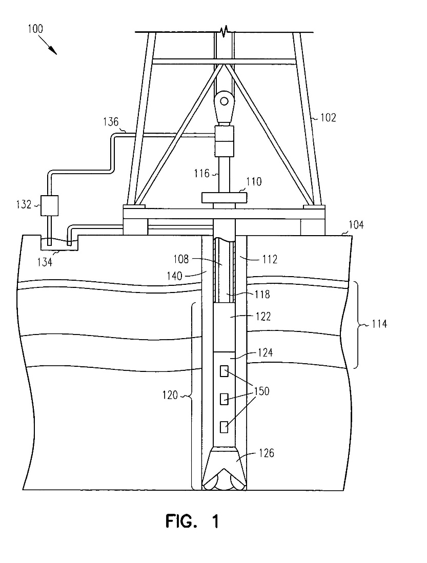
456 Figure 3A in Sun is reproduced again below for convenience:
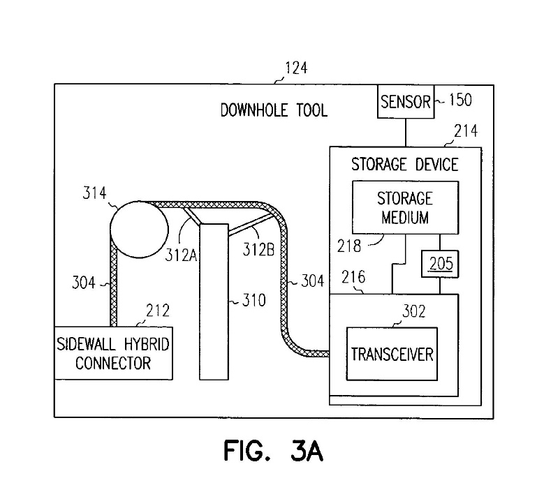
457 Sun does not anticipate the invention in the patent.
458 The invention in Sun does not involve “downhole equipment” within the meaning of claim 1 of the patent because it involves optical communications equipment that goes down a borehole which is a well, because it is for the production of hydrocarbons. As discussed, the “hole” in “downhole equipment” in claim 1 of the patent is a borehole for mineral exploration and subsurface exploration in the construction industry, and is not a hole for the exploration and production of hydrocarbons. As such, equipment designed to go down a hole for the exploration and production of hydrocarbons or other fluids is not “downhole equipment” within the meaning of claim 1 (or elsewhere in the patent).
459 Sun discloses that it is to be used in holes for the exploration and production of hydrocarbons as follows:
(1) the background explains that “[m]onitoring of various parameters and conditions downhole during drilling operations is important in locating and retrieving hydrocarbons, such as oil and gas, there from” and “[b]oreholes are drilled through various formations at different levels of temperature/pressure to locate and retrieve these hydrocarbons”: 1.10–18; and
(2) Professor Dupuis said Sun refers to specific equipment used in oil and gas exploration and production drilling, not mineral exploration drilling. At 3.10–17, Sun refers to:
a drilling rig 102 located at a surface 104 of a well. The drilling rig 102 provides support for a drill string 108. The drill string 108 penetrates a rotary table 110 for drilling a borehole 112 through subsurface formations 114. The drill string 108 includes a Kelly 116 (in the upper portion), a drill pipe 118 and a bottom hole assembly 120 (located at the lower portion of the drill pipe 118).
460 Sun does not involve an “electromagnetic signal direction altering means” within the meaning of claim 1 of the patent (or as elsewhere used in the patent) as the signal in Sun is transmitted and has its direction change via an optical signal carrier such as a fibre optic cable 304. As explained above, while I accept that an optical fibre can be used to pass the light signal through the body of the optical device to the “electromagnetic signal direction altering means” within the meaning of the patent, I do not accept that the “electromagnetic signal direction altering means” itself can be an optical fibre. As Sun states (for example):
(1) “[t]he sidewall hybrid connector 212 is coupled to the transceiver 302 of the storage device 214 through an optical signal carrier 304. The optical signal carrier 304 may be different types of optical mediums including different types of fiber optic cables. As shown, the optical signal carrier 304 may be wrapped around the spindle 314”: 8.11–16;
(2) “[a]s shown, the routing fixtures 312A–312B are coupled to the component 310 and are affixed to the optical signal carrier 304 to assist in the routing from the sidewall hybrid connector 212 to the storage device 214 around the component 310. The routing fixtures 312A-312B may be composed of different flexible high temperature material that would be formed to a specific radius (for satisfying the bend radius requirement for the optical signal carrier 304)”; 8.20–27;
(3) “[t]he optical signal carrier 304 may be a multi-mode fiber …However, embodiments of the invention are not so limited, as the optical signal carrier 304 may be a single mode fiber, etc.”: 8.30–39; and
(4) “[t]he component 310 is shown in the FIG. 3A to illustrate the different bends in the optical signal carrier 304 that may be needed in order to couple the sidewall hybrid connector 212 to the interface 216”: 9.4–7.
461 Accordingly, the body does not have a light path arranged to allow the signal to pass to the “electromagnetic signal direction altering means” as claim 1 of the patent requires, as the optical fibre is not an “electromagnetic signal direction altering means”. Rather, the optical fibre ends at the sidewall hybrid connector 212. The sidewall hybrid connector 212 is also not an “electromagnetic signal direction altering means”. As Sun explains:
(1) “[t]he sidewall hybrid connector 212 is coupled to the interface 216 of the storage device 214”: 4.45–47;
(2) “[t]he sidewall hybrid connector 212 may have an optical interface and an electrical interface. The face of the sidewall hybrid connector 212 may be hermetically sealed. Additionally, the side of the sidewall hybrid connector 212 may include an O-ring seal…The sidewall hybrid connector 212 may also include expanded beam connectors for the optical connections”: 4.47–55; and
(3) “[t]he sidewall hybrid connector 212 includes the transceiver 302. Accordingly, the optical to electrical conversion is still performed internal to the downhole tool 124, but within the sidewall hybrid connector 212. Because the transceiver 302 is within the sidewall hybrid connector 212, the sidewall hybrid connector 212 is coupled to the storage device 214 through electrical signal carriers”: 10.8–16.
462 Professor Dupuis explained that the sidewall hybrid connector 212, when connected, enables the optical signal to pass to the hybrid cable and from there to the storage medium 254. This is illustrated in figure 2B below:
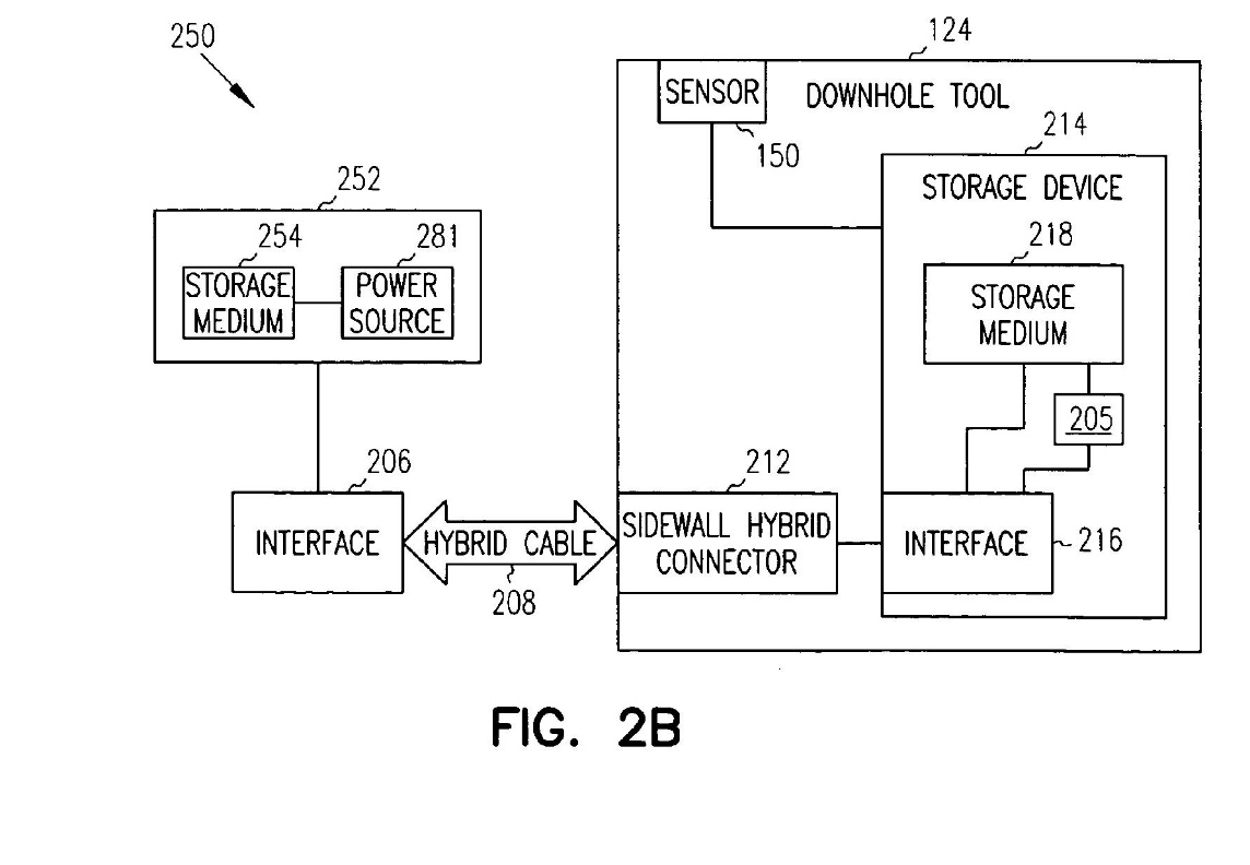
463 The hybrid cable 208 includes an optical fibre to carry the signal and therefore is also not an “electromagnetic signal direction altering means” within the meaning of the patent. At 3.65–4.10 Sun says:
…a cable that may includes [sic] optical signal carrier(s) (e.g., fiber optic cable) and electrical signal carrier(s) ( e.g., electrical wire). A cable that includes both fiber and wire is referred to as a hybrid cable. While described with reference to a hybrid cable, embodiments of the invention are not so limited. The electrical signal carrier(s) therein may be used to provide low-voltage power ( e.g., less than about 12 volts and may be intrinsically barriered) to the electronics within the downhole tool 124 to power electronics necessary for the download or upload of data. The electrical signal carrier(s) may also be used as a slow speed communication media. The optical signal carrier(s) is used to provide the communication medium for the downloading and uploading of the data.
464 For the same reason Sun does not disclose an “electromagnetic signal direction altering means causing the electromagnetic signal to change direction of travel” within the meaning of the patent.
465 Further, as Globaltech submitted, even if the optical fibre could be a potential “electromagnetic signal direction altering means”, Sun does not disclose that the means is to alter the direction of travel of the light signal. The alteration of the direction of travel in Sun (assuming also that a multimode optical fibre changes the direction of the propagation of light as Professor Tapson proposed) is optional. At 8.15–20 Sun says:
As shown, the optical signal carrier 304 may be wrapped around the spindle 314. The downhole tool 124 also may include routing fixtures 312A–312B to help route the optical signal carrier 304, while satisfying the requirements for the given optical signal carrier 304 ( e.g., the bend radius, etc.)
466 At 9.4–10 Sun says:
The component 310 is shown at figure 3A to illustrate the different bends in the optical signal carrier 304 that may be needed in order to couple the sidewall hybrid connector 212 to the interface 216. The component 310 may be any of a different types of components (electrical, mechanical, electromechanical) used within the downhole tool 124.
467 Consistent with the reasoning above, the optical fibre is also not a “reflector” within the meaning of the patent (specifically, claim 7 and dependent claims). The evidence discloses that a multimode optical fibre is a waveguide that transmits light by total internal reflection. However, as discussed above, the evidence does not establish that the common general knowledge of the person skilled in the art includes the way in which light propagates through a multimode (as opposed to a single) optical fibre by total internal reflection or what exactly total internal reflection means in the context of the nature and theories of light. The person skilled in the art would look to the specification to understand the meaning of “reflector” in the claims. On reading the patent, that person would understand a reflector to mean a device or part of the body having a reflective coating: see the patent at [0028]–[0030], [0043], [0076]–[0077]. That person would not consider a multimode optical fibre to be a reflector by reference to the theory or actuality of total internal reflection as the means by which light is propagated down a multimode optical fibre (in contrast, for example, to its mode of propagation down a single mode optical fibre).
468 Sun does not disclose a “downhole data gathering system” as referred to in claim 1 of the patent because of the meaning of “downhole” in the patent which does not include a hole for the exploration and production of hydrocarbons.
469 Sun also does not disclose a “communication device arranged to communicate wirelessly” (the wireless communication device) as referred to in claim 21 of the patent. This is because an essential part of the communication in Sun involves the hybrid cable 208. Professor Tapson said that because the hybrid cable 208 can communicate via the optical fibre within the hybrid cable 208, and the optical fibre is not a wire, the communication via the hybrid cable 208 is wireless. In Professor Tapson’s view, for the communication not to be wireless, the communication would have to be via the metallic wires in the hybrid cable 208 which transmit power – ie, where there is electromagnetic transfer of information between two points “not connected by an electrical conductor”. I have already rejected this characterisation of the meaning of a “wireless” communication device in the patent. Communication via an optical fibre is not “wireless” within the meaning of the patent.
470 For these reasons, s 7(1) of the Patents Act does not operate so that the invention in the patent is taken not to be novel in light of Sun.
471 The evidence does not establish that the invention claimed in the patent is not novel in light of the prior art.
472 Sections 7(2) and (3) of the Patents Act provide that:
(2) For the purposes of this Act, an invention is to be taken to involve an inventive step when compared with the prior art base unless the invention would have been obvious to a person skilled in the relevant art in the light of the common general knowledge as it existed (whether in or out of the patent area) before the priority date of the relevant claim, whether that knowledge is considered separately or together with the information mentioned in subsection (3).
(3) The information for the purposes of subsection (2) is:
(a) any single piece of prior art information; or
(b) a combination of any 2 or more pieces of prior art information that the skilled person mentioned in subsection (2) could, before the priority date of the relevant claim, be reasonably expected to have combined.
473 There was no dispute between the parties that:
(1) a “scintilla of invention” is sufficient, but there must be “some difficulty overcome, some barrier crossed”: Lockwood Security Products Pty Ltd v Doric Products Pty Ltd (No 2) [2007] HCA 21; (2007) 235 CLR 173 at [52] citing Woolworths Ltd v W B Davis and Son Ltd Inc (1942) 16 ALJ 57 at 59 and R D Werner & Co Inc v Bailey Aluminium Products Pty Ltd [1989] FCA 57; (1989) 25 FCR 565 at 574;
(2) the question whether the notional person(s) would directly be led as a matter of course to try the invention in the expectation that it might well produce a useful alternative to or better device than the common general knowledge or prior art devices is relevant: Alphapharm HCA at [52]–[53]; and
(3) so too it may be asked if the notional person(s) would have reached the invention by experiments of “routine character to be tried as a matter of course”: Generic Health Pty Ltd v Bayer Pharma Aktiengesellschaft [2014] FCAFC 73; (2014) 222 FCR 336 at [71] citing The Wellcome Foundation Limited v VR Laboratories (Aust) Proprietary Limited [1981] HCA 12; (1981) 148 CLR 262, at 280–281, 286.
474 The parties also agreed with Vehicle Monitoring Systems Pty Ltd v Sarb Management Group Pty Ltd [2020] FCA 408; (2020) 150 IPR 216 at [96] about the applicable versions of ss 7(2) and (3) of the Patents Act, that all that is required is the prior art information be publicly available.
475 Reflex contended that the invention described and claimed in claims 1, 5, 7, 8, 9, 10, 12, 17, 21, 22, 24, 25, 26, 27 and 29 of the patent did not involve an inventive step in the light of the common general knowledge considered alone and/or also together with each of Iizuka, Bergren, and Sun.
7.2 Common general knowledge alone
476 For the reasons already given, I do not accept Reflex’s submission that Professor Tapson is “representative of the hypothetical non-inventive skilled addressee before the” priority date.
477 Professor Tapson also approached the task armed with the knowledge he held:
(1) from the information provided to him by Reflex’s lawyers that in January 2009 that (a) Reflex sold the EZ-TRAC tool which was a downhole survey instrument used to measure borehole paths, (b) the upper end of the EZ-TRAC probe is an infrared port sealed by a top coupling which is used for communication with the EZ-COM hand-held control once the tool is retrieved to the surface, (c) the EZ-COM communicates with the downhole instrument via an infrared communication connection, (d) the infrared port of the EZ-COM is placed in the top of the unit and it has to be directed towards the corresponding infrared port of the instrument for communication. This process required “the removal of the top coupling from the instrument and the separation of the tool from its running gear”, and (e) he was asked if he could “consider whether there are any other means for transferring data or signals between the EZ-TRAC and the EZ-COM or similar that would have been considered common knowledge by those in the field as at August 2011”; and
(2) from having been retained by Reflex in 2016 concerning the Globaltech Orifinder tool (an embodiment of the invention claimed in the patent) which involved: (a) communication laterally out of the Orifinder tool, as opposed to axially out of and/or into the tool, and (b) the related Oripad wireless communication device, in which the infrared communication was delivered wirelessly by the Oripad, which sent and received infrared signals to the Orifinder tool through an aperture in the side wall of the Orifinder tool.
478 The evidence of Mr Brown is not sufficient to establish that the EZ-TRAC tool was part of the common general knowledge of a person skilled in the relevant art in the light of the common general knowledge as it existed (whether in or out of the patent area) before the priority date.
479 The Globaltech Orifinder tool could not have been part of the common general knowledge of a person skilled in the relevant art in the light of the common general knowledge as it existed (whether in or out of the patent area) before the priority date, as it did not exist at that time.
480 I do not accept Reflex’s submission that these circumstances have no material effect on Professor Tapson’s evidence.
481 Professor Tapson accepted that he had the information above “in my mind” at the time he did the design exercise but not “the top of [his] mind” and, in any event, noted that he had been instructed to use the common general knowledge only. He did not agree it was impossible for him to do so. He also considered that there was nothing inventive about lateral communication as there were many such instruments using this, including a common submarine periscope. He said “everything in this design exercise is part of the common general knowledge”.
482 In response to certain submissions of Reflex in this regard:
(1) the fact that it was a “generic feature” of these kinds of tools at the priority date that “you had to remove the top coupling from the downhole instrument and separate the tool from its running gear to allow the IR data communication” does not assist Reflex. It indicates that those skilled in the art did not perceive a need to change this generic feature. The invention in the patent is different in that it removes the need for this uncoupling;
(2) the instructions from Reflex’s lawyer focused specifically on a design that did not involve this uncoupling;
(3) the purpose of the instructions was not to “introduce a document (the manual) that Professor Tapson was instructed not to read and did not read”. The instructions said that it was hoped Professor Tapson had some “thinking time”, and what he was asked to think about was “whether there may have been other means for transferring data or signals between the EZ-TRAC and EZ-COM (or a similar display/hand-held device) that would have been considered common general knowledge by those in the field as at August 2011”. “Other means” is means other than what was described as the fact that because the EZ-TRAC has an infrared port at the top of the unit which has to be directed towards the infrared port on the EZ-COM handheld control unit thereby requiring “the removal of the top coupling from the instrument and the separation of the [EZ-TRAC] tool from its running gear to allow IR data communication”;
(4) Professor Tapson said “everyone who works in the industry knows, that this [avoiding uncoupling] was a preferable thing”, as these are known failure points, as he had pointed out in his affidavit. However, there is a difference between a general recognition that seals and ports are failure points in downhole instruments and the specific perception that the need for the operator of a downhole instrument to uncouple the top of the device at the surface could be avoided by altering the axial alignment of the light signal to a side communication port. In support of the non-obviousness of the idea of the invention, there is no evidence of a need felt within the industry at the priority date to effect such an improvement over the prior art; and
(5) Professor Tapson’s evidence that the Orifinder tool involved “fairly commonplace ways” of tools working does not suggest that the way in which that tool worked (via lateral communication) was common general knowledge at the priority date. There is no evidence suggesting that this aspect of the Orifinder tool was commonplace at the priority date. Rather, I understand Professor Tapson’s evidence to be to the effect that because reflection is commonplace in many instruments (submarine periscopes being his example) it is also common place and obvious in the context of downhole instruments within the meaning of the patent. This, however, is belied by the facts that:
(a) the evidence establishes that at the priority date existing downhole instruments did not have this feature for the purpose of avoiding the uncoupling of the top part of the device;
(b) the evidence establishes a lack of a common perception at the priority date that there was a known problem calling for a solution; and
(c) Mr Brown’s evidence indicates that he and his customers did not recognise the unfelt need for such an improvement on downhole instruments until years after the priority date.
483 Whether the “insidious influence of hindsight has been avoided” is a question of fact in each case: Merck Sharp & Dohme Corporation v Wyeth LLC (No 3) [2020] FCA 1477; (2020) 155 IPR 1 at [831]. Even if evidence about inventive step is affected by hindsight, it does not mean the evidence is necessarily inadmissible or not entitled to material weight. I also do not accept that, as a matter of inevitable fact, an expert who possesses knowledge is incapable of putting that knowledge to one side for the purpose of giving an expert opinion.
484 The problem in this case includes the combination of the information that had been provided to Professor Tapson, together with the substance of his evidence. He had already seen the Globaltech Orifinder tool (with its lateral communication) before he was asked to consider, in the context of this patent dispute, if “there are any other means for transferring data or signals between the EZ-TRAC and the EZ-COM or similar that would have been considered common knowledge by those in the field as at August 2011” in circumstances where he was told that the infrared port of the EZ-COM is placed in the top of the unit and has to be directed towards the infrared port of the instrument for communication, which requires “the removal of the top coupling from the instrument and the separation of the tool from its running gear”. By this means, Professor Tapson was informed about the perceived problem that the invention in the patent addresses and the solution to that problem the patent involves.
485 To this must be added the fact that Professor Tapson is very familiar with patents and patent litigation. I infer that he knows the context of patents litigation including the relevance of the concepts of anticipation by prior art (for lack of novelty) and obviousness (for lack of inventive step), and the common general knowledge of the person skilled in the art. This knowledge base would have alerted Professor Tapson, on receipt of the instructions, that the problem was the top uncoupling requirement to enable the infrared communication from the port in the instrument to the hand-held communication device at the surface.
486 Further, in this case the evidence of the common general knowledge of the person skilled in the art (whether in or out of the patent area) for the purposes of s 7(2) of the Patents Act is sketchy. The evidence elicited from the experts failed to ensure the maintenance of the necessary distinction between the common general knowledge and the expert’s own knowledge. As noted, Professor Tapson is an inventive and imaginative scientific polymath and Professor Dupuis is an inventive and imaginative expert working at the highest research levels. Their evidence did not consistently distinguish between their own knowledge from their own experiences, such as Professor Tapson dealing with marine drilling which I infer is highly specialised and both experts dealing with the propagation of light within single and multimode optic fibres. As discussed, while Professor Tapson identified the common general knowledge in his first affidavit, he did so in generalised terms. He did not identify that any particular tool or kind of tool that was common general knowledge at the priority date. He did not identify a commonly felt need for further development in response to any particular problem.
487 Professor Dupuis agreed that the design exercise that led Professor Tapson to figures 4 and 5 involved a “logical progression”. I am prepared to accept that, by this, Professor Dupuis meant that all design steps to figure 5 would have been obvious to the person skilled in the art at the priority date. I do so on the basis that Professor Dupuis said that figures 4 and 5 represented the kind of instruments available in the field at the priority date. However, Professor Dupuis did not agree that the location of the communication port at the end of the housing was an “inconvenience”, on the basis that this was how most devices in the field were designed at the priority date. He said: “I’m not sure that I would have actually foreseen that somebody would want to resolve this problem. It’s not obvious to me that they would”.
488 Professor Dupuis subsequently said that the fact the communication port in figures 4 and 5 was completely enclosed within the drill structure and the housing would have to be uncoupled in order to communicate with the instrument was an inconvenience.
489 This evidence might appear to be inconsistent, but I do not consider it is. In the first question, Professor Dupuis was dealing with what was in fact perceived at the priority date. This is clear from the context he gave about instruments at the priority date. In the second question, Professor Dupuis is dealing with his own current perception. While (as discussed) I infer that if someone had asked Professor Dupuis to design an improved downhole instrument removing the need for top uncoupling at the priority date he would have thought of the side port and an internal means to redirect the light signal (as would Professor Tapson) what is material is that no-one but Globaltech perceived the room for improvement at the priority date.
490 In other words, the second answer assumes away the perception of the room for improvement and the idea to make the improvement – but that is where the inventive step lies in the present case.
491 Professor Dupuis also did not accept that “use of a mirror to redirect a signal out of the sidewall of an instrument was a logical and obvious choice”. He said it was a logical choice but not an obvious choice. This is because if he had been undertaking the design task at the priority date he would have located the transceiver so it could align with the sidewall rather than adding another component, a mirror, that could vibrate out of place or be broken. This is the design solution disclosed in figure 7 on the left-hand side (in the design exercise). This exchange then occurred:
MR HENNESSY: You’ve – you’ve just described the design you’ve mentioned as the obvious choice. My questions [sic] was whether the mirror to redirect a signal out of the sidewall of an instrument was an obvious choice. Are you disputing that it was an obvious choice?
ASSOC PROF DUPUIS: No. It’s an obvious choice. Yes.
MR HENNESSY: And that’s – but I want to suggest to you that’s particularly so if a designer needed a radial communication port. Correct.
ASSOC PROF DUPUIS: I think – as I’ve alluded before, I think that if I wanted a radial communication port, I could attain it with the – the system that’s in the left-hand side of figure 7.
MR HENNESSY: You agree that in figures 4 and 5 the system has within it an axial communication port. Correct.
ASSOC PROF DUPUIS: I agree.
MR HENNESSY: Right. And do you accept that no downhole data gathering device was commercially available as at the priority date to people skilled in the art that incorporate – incorporated the feature of a mirror redirecting light?
ASSOC PROF DUPUIS: To the best of my knowledge, that’s the case. There was nothing like this on the market.
MR HENNESSY: And do you accept that a person skilled in the art would have been motivated to choose the figure 7 solution over the solutions in figures 4 and 5?
ASSOC PROF DUPUIS: I don’t believe so, and that’s for the purpose that I’ve pointed in my affidavit which is that machining of sides wall connectors or side wall apertures and waterproofing, those are much harder to achieve in the way that Professor Tapson has drawn them, so we – you would have to actually have significant, call it, market pull to want to achieve this because it’s a more costly arrangement and I suspect that it’s more fragile also.
492 Professor Dupuis also accepted that it would be preferable not to have to uncouple or interfere with the coupling of the housing to access the communication port.
493 Professor Dupuis subsequently said: (a) it is a simple matter to add the mirror, but it is an expense and it is difficult to keep the mirror aligned in a high vibration environment, (b) “including a mirror is not necessarily the way I would pursue a new design”, (c) he could see the advantages of putting a window in the side wall, and (d) the EZ-TRAC tool had the features of Professor Tapson’s figures 4 and 5, not figure 7. In the context of the issue of inventive step it is proposition (c) which is important.
494 Reflex submitted that this evidence exposed that “Professor Dupuis accepted that there were advantages in the steps from Figure 5 to Figure 7 and that those steps were logical and obvious choices”. Further, that the device in figure 7 (the right hand side) using an optical mirror was “a readily available solution for transferring data to and from a downhole instrument to the surface which used components and technology established well-before the [priority date], and addressed well-known concerns”.
495 Again, context is all. Once the idea of the potential improvement exists then it is clear that people such as Professors Tapson and Dupuis could come up with the means to effect the improvement. They could also see that the improvement would in fact be an improvement. The essential difference between Professors Tapson and Dupuis is that Professor Tapson considered that:
not having to disassemble and reassemble the system gives significant utility, and I think that the instrument designers would be looking for that utility and they would see that the instrument in figure 7 would give them that utility.
496 Professor Dupuis considered that at the priority date designers did not in fact perceive that the axial communication port involved any disadvantage or that the design of downhole instruments could be improved by a side communication port. He did not accept that it was obvious to seek to effect such an improvement to the existing designs. I agree; on this key issue, the evidence supports the position of Professor Dupuis.
497 Professor Dupuis also considered that if a person had the idea at the priority date, the means to effect the improvement he would have chosen is the first alternative in figure 7 (the left hand side using the rotated transmitter-receiver pair) and not the second alternative (using a reflector/mirror). What is critical, however, is that his acceptance that both alternatives to effect the improvement were logical and obvious, pre-supposed that the idea for the improvement existed. This is clear from the way in which the questions were put to Professor Dupuis which assumed that the goal was to redirect the signal out of the side wall of the instrument and the designer needed a radial communication port (see above). Professor Dupuis’ unchanged view was that at the priority date the scope for the improvement or the need or the goal that Reflex assumed in its questions of him was not obvious. I agree.
498 Professor Dupuis’ evidence that “[f]rom what we’ve discussed up to now, I can see the advantages of putting a window in the side wall” also does not suggest that it was obvious to the person skilled in the art at the priority date that downhole instruments could be improved by a side communication port.
499 Globaltech submitted that this case was analogous to Zetco Pty Ltd v Austworld Commodities Pty Ltd (No 2) [2011] FCA 848 in which Bennett J said that the invention (a plumbing valve) was simple and may have “come easily” to the inventor, but the inventive step lay in “the idea of the combination in a single valve” in order to satisfy an “unfelt want”: [229]. Globaltech relied on the evidence of Mr Brown as disclosing the position of the person skilled in the art at the priority date. Mr Brown said:
(1) Reflex’s development design team involved all different disciplines as required;
(2) Reflex’s most successful device at the time was the ACT device which was updated from ACT I, to ACT II, to ACT III (the latter being released in Australia after the priority date in 2014);
(3) design development is all market driven;
(4) Reflex did not release the EZ-TRAC with the IR coupling and the EZ-GYRO with the rota-lock with the side IR window (which Reflex accepts infringe the patent, if the patent is valid) until 2016, five years after the priority date; and
(5) this was because “having a feature of side communication in a survey tool [eg, the EZ-TRAC and the EZ-GYRO] is natural and obvious and makes much more sense as opposed to a core tool [eg, the ACT tools]”. He did not see any competitive advantage in having the side communication feature in the ACT tools. Given that Reflex was “enjoying 100 per cent market share. It tells you that it’s not broken. Don’t fix it”.
500 This supports the conclusions I have reached above.
501 Globaltech submitted that Reflex had not proved the tools which were part of the common general knowledge as at the priority date other than the ACT I. I agree.
502 Globaltech submitted that Mr Brown’s evidence revealed that no new devices entered the Australian marketplace between 2009 and the priority date. This, said Globaltech, supported an inference that “device designers were content to rely on their existing product offerings”. I agree.
503 Globaltech said that Reflex:
… has not established a sufficient evidentiary framework for the common general knowledge for the purposes of its s 7(2) case. That evidentiary hiatus ought be a sufficient basis upon which to reject the obviousness case so far as it relies upon the common general knowledge alone.
504 I have not proceeded on this basis (as apparent from the discussion above). I agree that the evidence of the common general knowledge is far from ideal. Caution is required in respect of the evidence of Professor Tapson and Professor Dupuis, for the reasons already given. But the issue of inventive step is to be determined on the whole of the evidence.
505 Reflex submitted that:
There is no evidence that Reflex tried and failed to solve the Problem before the PD. Reflex was not attempting to solve the Problem in its development update of the ACT. When Reflex did seek to address the Problem [in effect, the uncoupling requirement], and ‘improve robustness and save workflow’ in its survey tools, the modification to the couplings for its survey tools to create a side IR window was ‘natural and obvious’ in a survey tool in that context.
506 The fact that there is no evidence that Reflex tried to solve the uncoupling problem confirms that there was no perceived problem at the priority date. There was no perception that there was scope or a need for such an improvement. The fact that there is no hint in the evidence that Reflex perceived the ACT could be improved in any way similar to the invention at the priority date, despite the ACT being under design consideration and re-design throughout the period before and after the priority date, also indicates that there was no perceived problem at the priority date. If there was no such problem or room for improvement perceived (as I consider to be the case), then the perception or idea of the problem or scope for the improvement may well be inventive. That is the case here.
507 I did not find one part of Mr Brown’s evidence persuasive. He said that there was a material difference of some kind between modifying the EZ-TRAC tools to include the integers of the claimed invention because they were survey and not core orientation tools (in contrast to the ACT tools) and that the modification to the EZ-TRAC tools was “natural and obvious” because it was a survey and not a core orientation tool. His evidence was that it was not natural and obvious (and, indeed, made no sense) to modify the ACT tool to incorporate a side port and avoid the decoupling of the end of the instrument housing. I consider that:
(1) it is clear from the evidence that Mr Brown (and thus Reflex) knew about Globaltech’s Orifinder tool which embodied the invention before Reflex modified the EZ-TRAC tool;
(2) while it may be accepted that it cannot be found that Reflex copied Globaltech’s Orifinder tool, Reflex could not have missed seeing the side communication port and the fact it removed the need to uncouple the top section of the device;
(3) accordingly, the fact that Reflex found it “natural and obvious” to modify the EZ-TRAC tool does not support the conclusion that the invention was obvious at the priority date, as the inventive step lies in the idea that such tools could be improved in the particular manner embodied in the invention; and
(4) I do not accept Mr Brown’s evidence of some meaningful difference between a survey tool and a core orientation device in this context.
508 Reflex submitted that the person skilled in the art must be taken to be:
motivated to improve on existing devices or systems for obtaining or providing data to and from downhole equipment. It is with this in mind that the skilled team considers the disclosure of each of the prior art patents: see AstraZeneca HC at [18] (French CJ) and [69]–[70] (Kiefel J): Vehicle Monitoring Systems Pty Ltd v SARB Management Group Pty Ltd [2020] FCA 408 at [196].
509 However, in AstraZeneca AB v Apotex Pty Ltd [2015] HCA 30; (2015) 257 CLR 356 at [18] French CJ did not suggest that the person skilled in the art is taken to be motivated to improve the existing technology in cases where there is no evidence to support any perceived need for improvement. Nor did Kiefel J (as her Honour then was) at [69]–[70]. At [69], Kiefel J said that the prior art base and the common general knowledge are used to “look forward from the prior art base to see what the skilled person is likely to have done when faced with a problem similar to that which the patentee claims to have solved with the claimed invention”. This is necessarily so if the common general knowledge includes the existence of the problem (as the emphasis on “when faced with a problem” in this passage reinforces). But the High Court did not suggest that invention might not lie in the identification of a problem or of something only seen to be a problem in hindsight. To the contrary:
(1) in Lockwood Security Products at [59], Gummow, Hayne, Callinan, Heydon and Crennan JJ cited with approval Fletcher Moulton LJ in Hickton’s Patent Syndicate v Patents and Machine Improvements Company Ltd (1909) 26 RPC 339 at 348 that “invention may lie in the idea, and it may lie in the way in which it is carried out, and it may lie in the combination of the two”;
(2) in Lockwood Security Products at [85], their Honours said that as the problem in that case was well-known, the perception of the problem was not inventive and inventiveness, if anywhere, must be found in the solution to the problem; and
(3) in Alphapharm HCA at [51] Gleeson CJ and Gaudron, Gummow and Hayne JJ cited with approval Aickin J in Wellcome Foundation at 280–281 including that “[i]t may be that the perception of the true nature of the problem was the inventive step which, once taken, revealed that straightforward experiments will provide the solution”.
510 Ultimately, the motivation of the person skilled in the art to improve existing technology and the direction such improvement might take are matters for evidence. It may be accepted that, “when faced with a problem”, the person skilled in the art is not to be assumed to be indifferent or idle. It should not be accepted that, if the evidence indicates that the person skilled in the art saw no problem, that the identification of the problem and an idea for fixing it is obvious (even if the means chosen to fix the problem are themselves obvious). That would be to assume away the invention itself. In the present case, the weight of the evidence is against any inference that the perceived problem or need for improvement was itself part of the common general knowledge or would itself have been obvious to the person skilled in the art at the priority date.
511 Accordingly, and in summary having regard to the whole of the evidence, I consider that:
(1) it was common general knowledge at the priority date that the instrumentation in the housing of downhole instruments had to be protected from water and dirt ingress in the harsh downhole environment;
(2) it was common general knowledge at the priority date that seals and other points of detachment were potential vulnerable points in the design of the external housing protecting the instrumentation;
(3) there is a material difference between the general recognition of the issues referred to in (1) and (2) above and the drawing of an inference that it was common general knowledge that existing designs could be improved by re-aligning the light signal within the housing so that it existed through a side port and that this would remove the need for uncoupling the end of the instrument to obtain access to the communication port. To the contrary, there is no evidence suggesting that it was common general knowledge that there was any such problem or even a hint of a need for this improvement over existing designs at the priority date;
(4) specifically, there was no perceived need at the priority date to improve the existing designs of downhole instruments by arranging the instrumentation, either by reflecting mirror or transceiver placement and design, to carry the light signal to a port on the side of the device so as to avoid the need to uncouple the end of the housing to access the communication port;
(5) if asked to improve existing designs to avoid the need for the uncoupling of the top of the housing, Professor Tapson and Professor Dupuis both knew or would have known at the priority date that a design solution generally as shown in the two options in figure 7 (in the design exercise) would have advantages and be preferable in design terms. Further, to them these design solutions would have been logical and obvious had they been tasked with improving the existing designs for such equipment to avoid the need for the top uncoupling at the priority date;
(6) however, there is no persuasive evidence (apart from the invention itself) that at the priority date the person skilled in the art perceived any need or particular advantage in giving a person such as Professor Tapson and Professor Dupuis such a design task; and
(7) Reflex itself (with its overwhelmingly dominant market share) did not perceive the invention as meeting an unfelt need or as having any worthwhile commercial advantage to it until it adopted the integers of the invention in two of its products in 2016.
512 In circumstances where a “scintilla of invention” is sufficient to defeat a claim of lack of inventive step I am not persuaded that the invention claimed in the patent (which includes the idea that existing designs of downhole instruments could be improved by a side communication port and includes a means to achieve the redirection of the light signal to that side communication port) would have been obvious to the person skilled in the art (whether inside or outside of the patent area) at the priority date. This is because, as in Zetco, it was inventive simply to have the idea that the existing designs could be improved by re-aligning the light signal to exit the device via a side port so there was no need to uncouple the end of the housing to access the side communication port. That is, the idea of the potential improvement was not obvious at the priority date.
513 I accept, however, that once the relevant idea had been conceived that an improvement could be effected by a side communications port, the methods to achieve the improvement by either design in figure 7 (rotating the transmitter-receiver pair through 90 degrees or bending the optical axis 90 degrees by means of a mirror) would have been obvious at the priority date. That is, once the person skilled in the art had the idea that the side communication port would be an improvement as it would avoid the need for uncoupling the top of the device, both designs in figure 7 involve routine steps that the person would have been directly led as a matter of course to try in the expectation that it might well produce a useful alternative to or better device than the existing devices.
514 The fact that I cannot infer that the embodiment of the invention, when released onto the market in 2016 (the Globaltech Orifinder tool), materially diminished the market share of Reflex’s ACT tool does not undermine the conclusions reached above. Commercial success may be an indicator of the meeting of an unfelt need, but lack of commercial success does not prove lack of inventive step. Further, Reflex ultimately reached the view that the development of a side port was useful in respect of its survey tools in 2016, which Reflex admits infringes the patent. It is not to the point that I cannot infer that Reflex copied the Orifinder device. The relevant point is that Reflex ultimately perceived that there was a genuine improvement that could be made to these kinds of devices. Reflex may have reached this perception independently, but this does not mean Globaltech’s perception five years earlier was not inventive.
515 For these reasons, Reflex’s s 7(2) case fails. This is a case in which the inventive step was the perception that an improvement on existing devices could be achieved by simple means.
7.3 Common general knowledge and prior art
516 To the extent it was suggested (which is not apparent), I would not accept that the person skilled in the art could reasonably be expected to have combined information in the three prior art documents, Iizuka, Bergren, and Sun as referred to in s 7(3)(b) of the Patents Act. Even if this could be reasonably expected, I do not accept that the invention claimed in the patent lacks an inventive step by reason of being obvious when considered in the light of the common general knowledge and the combined information in Iizuka, Bergren, and Sun.
517 Of the three prior art documents two manifestly involve a different field (Bergren and Sun), and all teach away from the invention in the patent. Iizuka is a wireline telemetry tool. The tool provides a continuous image from down the borehole via wireline telemetry. It has nothing to do with improving a tool that must be brought to the surface to obtain data and therefore nothing to do with improving such a tool by moving the infrared communication port to the side and to avoid the need to uncouple the end of the device for access to the port. Bergren and Sun also bear no resemblance to the invention claimed in the patent. This is not just because they are for use in the exploration and extraction of hydrocarbons. Figure 5 in Bergren, representing the embodiment including reflectors, has nothing to do with a reflector inside or at the edge or surface of the body of the device. The reflectors are on arms extending from the sides of the device. Their purpose is to enable the signal to travel through the surrounding fluid in the hole to determine the concentrations of oil and water in the surrounding fluid. Similarly, Sun has no “electromagnetic signal direction altering means” within the meaning of the patent.
518 I do not see how the person skilled in the art would combine anything from the three prior art documents with the common general knowledge and, on that basis, reach the invention claimed in the patent as an obvious step.
519 For these reasons, Reflex’s s 7(3) case also fails.
520 Reflex has not established that the invention claimed in the patent is not novel or lacks an inventive step. Accordingly, the cross-claim should be dismissed with costs. The parties will be given an opportunity to submit agreed or competing orders in respect of Globaltech’s claims for infringement.
I certify that the preceding five hundred and twenty (520) numbered paragraphs are a true copy of the Reasons for Judgment of the Honourable Justice Jagot. |
Associate:

