
FEDERAL COURT OF AUSTRALIA
Jusand Nominees Pty Ltd v Rattlejack Innovations Pty Ltd [2022] FCA 540
ORDERS
DATE OF ORDER: | 16 May 2022 |
THE COURT DECLARES THAT:
1. The following claims are, and have at all material times been, invalid:
(a) claims 1, 2 and 5 of Australian Innovation Patent No. 2019100556;
(b) claims 1 and 2 of Australian Innovation Patent No. 2020100163; and
(c) claims 1, 4 and 5 of Australian Innovation Patent No. 2020103956.
(the Claims)
THE COURT ORDERS THAT:
1. The application be dismissed.
2. Pursuant to section 138 of the Patents Act 1990 (Cth), each of the Claims be revoked.
3. The applicant/cross-respondent pay the costs of the respondents/cross-claimants.
4. Order 2 be stayed for a period of 28 days from the date of this order.
5. If any appeal is lodged within 28 days, order 2 be stayed until the determination of that appeal.
6. If any party seeks a variation of the costs orders in paragraph 3 above, it may, within seven days, file and serve a written submission (of no more than two pages) and any affidavit in support. In that event, the other party may file and serve a responding written submission (of no more than two pages) and any affidavit in support within a further seven days, and the issue of costs will be determined on the papers.
Note: Entry of orders is dealt with in Rule 39.32 of the Federal Court Rules 2011.
ROFE J:
1 The applicant, Jusand Nominees Pty Ltd (Jusand), claims that the first respondent/cross-claimant, Rattlejack Innovations Pty Ltd (Rattlejack), the second respondent, Pan Australis Pty Ltd (Pan Australis), the third respondent, Murray Engineering Pty Ltd (Murray) and the Fourth respondent, Mr Leigh Sutton (Mr Sutton), have each infringed three Australian Innovation Patents (the Patents), each entitled “Safety System and Method for Protecting Against a Hazard of Drill Rod Failure in a Drilled Rock Bore”, being Australian patent numbers:
(a) 2019100556 (556 Patent);
(b) 2020100163 (163 Patent); and
(c) 2020103956 (956 Patent).
2 The Patents are related and each claims an earliest priority date of 12 November 2015.
3 The applicable form of the Patents Act 1990 (Cth) (the Act) is the form that it took following the Intellectual Property Laws Amendment (Raising the Bar) Act 2012 (Cth).
4 The respondents’ product is a known as the SafetySpear.
5 Jusand alleges that the respondents have infringed the 556 Patent and the 163 Patent by offering to sell, supply, or otherwise dispose of the SafetySpear; and that they have infringed the 956 Patent by supplying the SafetySpear together with instructions, by reason of s 117(2) of the Act.
6 By way of cross-claim, Rattlejack seeks revocation of all the asserted claims on the basis that each is invalid for lack of sufficient description (s 40(2)(a) of the Act) and lack of support (s 40(3) of the Act), and that some of the claims are invalid for lack of clarity (s 40(3) of the Act).
7 Rattlejack alleges that a finding of lack of sufficient description necessarily means each of the asserted claims is not entitled to a priority date earlier than the filing date of its specification (s 43(2A) of the Act), which means that each of the claims of each of the Patents lacks novelty over the Patents’ own priority documents.
8 The issues of infringement and validity were ordered to be heard and determined separately prior to any questions of quantum or pecuniary relief.
9 The claims of the 556 Patent and the 163 Patent are product claims. The claims of the 956 Patent are method claims. Most of the integers of those method claims define the relevant “safety system” product.
10 The parties agreed that whether Jusand is entitled to the relief that it seeks in its amended originating application can be determined by reference to the following more confined claim set:
(a) claims 1, 2 and 5 of the 556 Patent;
(b) claims 1 and 2 of the 163 Patent; and
(c) claims 1, 4 (read with claim 1) and 5 (read with claims 1 and/or 4) of the 956 Patent
(the Asserted Claims).
11 The respondents confined their invalidity case to the Asserted Claims.
12 Pan Australis admits that it has offered to sell, supply or otherwise dispose of the SafetySpear product. Rattlejack admits that it authorised that conduct of Pan Australis. Mr Sutton, the developer of the SafetySpear, owns one of the two shares in Harvest Home Enterprise Pty Ltd which is the sole shareholder of both Rattlejack and Pan Australis.
13 Issues relating to whether Mr Sutton has authorised the conduct of the Rattlejack and Pan Australis, or is a joint tortfeasor, have been deferred for consideration together with any issues of quantum.
14 Murray admits that it has supplied the SafetySpear product, but it asserts an “experimental use” exemption under s 119C of the Act applies. It is the only respondent to rely on that exemption.
15 Rattlejack made submissions on behalf of the respondents on all aspects of the infringement claim and validity cross-claim other than the s 119C exemption. Murray addressed the Court in relation to that claim. In these reasons I refer to the respondents as Rattlejack, unless it is necessary to refer to one of the respondents in particular.
16 On the first day of the trial Jusand offered an undertaking to the Court not to assert the balance of the claims of the three Patents in respect of Rattlejack’s SafetySpear product. This undertaking would be relevant in the event that Jusand was unsuccessful in its infringement case based on the confined claim set.
17 The parties are to be commended for their efforts in narrowing the issues for trial.
18 For the reasons set out below I find that:
(a) The SafetySpear does not infringe the Asserted Claims;
(b) The Asserted Claims do not lack clarity;
(c) The Asserted Claims are invalid as they do not meet the requirements of ss 40(2)(a) and 40(3) of the Act; and
(d) The Byrnecut “trials” of the 200 SafetySpears do not constitute experimental use for the purposes of s 119C of the Act.
19 Jusand and Rattlejack led evidence from expert witnesses.
20 Jusand’s expert witness was Mr Davison, a mining engineer. Mr Davison graduated with a Diploma in Engineering (Mining) from RMIT in 1978 and obtained a Masters in Mineral and Energy Economics from Macquarie University in 1997. He holds a Manager’s Certificate in several states, including Victoria and Western Australia, which enables him to be registered as a mine manager in each of those states. Mr Davison is a Fellow of the Australasian Institute of Mining & Metallurgy.
21 Mr Davison is the Managing Director and Principal Mining Engineer at Mining One, a consultancy company providing services to mine operators in Australia and overseas. He has more than 42 years’ experience working in the mining industry in Australia.
22 Mr Davison has substantial experience in relation to long-hole drilling which he describes as the drilling of holes using more than one connecting drill rod. This experience includes being mine manager for a number of long-hole drilling mines and being responsible for all aspects of safety and maintenance for those sites. He has experience in the use and performance of a wide variety of rock bolts and other fixings used in a variety of underground mining operations.
23 Mr Davison regarded himself as innovative and his affidavit dated 6 August 2021 set out a number of patents and patent applications for which he was listed as the inventor. These include a granted patent for an invention related to the anchoring of rock bolts, and a grouted friction stabiliser to improve the frictional performance of split-set anchors for use in mines. His curriculum vitae describes Mr Davison in the following terms:
Gary is highly innovative in many areas and has developed unique mine designs and infrastructure for difficult mining situations. He has a particular passion for innovative ground support methods that improve the safety and efficiency of underground mining. Gary has successfully patented a variety of rock bolts, many of which are commercially available selling over 3 million units worldwide. He also has a number of other patents pending.
24 Rattlejack accepted that Mr Davison has the skills of someone relevant to the skilled team.
25 In cross-examination Mr Davison evinced a preparedness to consider matters and materials with which he was not necessarily immediately familiar, and he explained that in practice he consulted and worked with others in developing solutions for problems where he was not immediately aware of a solution himself. Mr Davison also expressed a preparedness to try different materials or combinations of materials, even if he initially thought those materials may not be suitable. His approach involved almost an expectation of being surprised, based on his past experience which had shown that combinations of materials could yield surprising results.
26 It would be fair to say that Mr Davison had an element of the inventor about him. He was reluctant to concede that something couldn’t be done, instead regarding difficulties as a challenge to be overcome. At one point during the joint session he illustrated his point by stating that he “could construct a shield to go around that impact reduction member before the end of proceedings this afternoon” and would then “try an experiment to see how that works”.
27 Rattlejack’s expert witness was Dr Peter Fuller, a geotechnical engineer with more than 47 years’ experience relating to underground and open-cut coal and metalliferous mining. Dr Fuller graduated with a Bachelor of Engineering (Chemical) from the University of Adelaide in 1967. He noted that at that time there was no formal Geotechnical Engineering course offered. Dr Fuller was awarded a PhD in Materials Engineering by the University of Adelaide in 1971.
28 After completion of his PhD, Dr Fuller spent a year in the Department of Metallurgy at the University of Manchester Science and Technology Institute in the UK working on the strengthening properties of aluminium silicon alloys. Dr Fuller is also a Fellow of the Australasian Institute of Mining & Metallurgy.
29 Early in his career, Dr Fuller conducted applied research into mine stabilisation and ground/strata control. He was project leader for the development of rock stabilisation devices such as rock bolts and cable bolts which are anchored in bored holes to stabilise rock around mine tunnels. As part of that work Dr Fuller became familiar with how access tunnels and mine openings are created by drilling blast holes, blasting the rock, removing the broken rock and installing rock stabilisation devices.
30 Since 1980 Dr Fuller has provided consultancy services to Australian and overseas mining companies including inspections of underground mine operations, assessments of rock quality in terms of condition, variability and competence, design of mine openings within orebodies to minimise the risk of collapse and the design of rock stabilisation measures to ensure rock walls and roof remain stable. Dr Fuller’s work has included analysis of rock failures and their cause.
31 Dr Fuller’s experience in relation to long-hole drilling in mining operations includes the creation of geotechnical designs for long-hole drilling, assessing appropriate stable stope spans, stope size and stope sequencing, hazard management and stability assessment.
32 Dr Fuller also had relevant experience as a materials engineer. However, his specialisation did not extend to plastics beyond those involved in anchoring rock bolts which concerned a combination of the frictional interconnection between the plastics and steel and the plastics and rock. He had performed some detailed calculations and provided informed views on materials and their potential performance, and Jusand accepted that he had expertise in that area.
33 Both Dr Fuller and Mr Davison had lengthy experience in the mining industry. Both also had relevant experience with long-hole mining. They each originated from different undergraduate engineering backgrounds, mining and chemical; but their extensive mining experience meant that their knowledge and experience overlapped in areas relevant to long-hole mining.
34 Both experts had a familiarity with steel and its properties as it is commonly used in mining equipment and components. Mr Davison confirmed in oral evidence that he had experience designing products using steel.
35 Dr Fuller had a greater familiarity with mechanical engineering principles than Mr Davison and more experience with the properties of materials other than steel.
36 Dr Fuller and Mr Davison prepared a joint expert report. Their oral evidence was given by way of an extended joint session over Microsoft Teams wherein each was cross-examined and also able to make comments on the other’s evidence.
37 The third respondent, Murray, led evidence in relation to the s 119C experimental use exemption from three lay witnesses, each of whom was cross-examined:
(a) Leon Spencer, the Project Manager at Deep South Gold Mine for Byrnecut Australia Pty Ltd (Byrnecut), an associated entity of Murray;
(b) Keith Law, an area manager for Byrnecut; and
(c) Mark Coughlan, the Chief Executive Officer of Murray.
38 The content of each of the specifications of the Patents is very similar. These reasons focus, as did the evidence and the parties’ submissions, on the 556 Patent. Where there are differences of relevance as between the 556 Patent specification and the other specifications I will discuss them separately.
39 The specifications of the Patents commence by identifying that the field of the invention relates to a safety system, or, in the case of the 956 Patent, a method using a safety system, for protecting against a hazard of drill rod failure in a drilled rock bore extending above the horizontal, and especially a hazard posed by a broken drill rod section lodged within the bore.
40 The background of the invention notes that in underground mines, the material to be extracted (ore) is often accessed by excavating cavities into the rock strata below the ore and then working towards the ore deposit from below. The technique commonly involves drilling bores upwards from the cavity into the rock strata towards the ore deposit above. Explosive charges are then set in the bores to blast away the intervening rock and to access the ore deposit directly.
41 The specification notes that a significant problem associated with this mining technique concerns drill rod failure when drilling the multiple bores extending upwards into the rock strata towards the ore body. The bores drilled can be tens of metres long (for example, in the range of 20 to 60 m) and the drill rods which extend over that length that are used to drill the bores are quite slim: for example, they may have a diameter of only about 80 mm.
42 The composition and properties of the rock strata typically vary throughout its depth, and during drilling it is not uncommon for the drill rod to break somewhere along its length and for the upper broken part of drill rod to become stuck in the bore, often some distance from the rock-face. Broken drill rod sections lodged in the bore can be very long (for example 15 to 20m) and heavy (in the range of 100 to 500 kg). The broken drill rods can unexpectedly become dislodged and fall down the bore and then into the main cavity below where miners are working, potentially causing serious physical injury to mine workers and/or damaging mine equipment. The specification describes this hazard as extreme.
43 The specification explains that in the absence of a tailored solution to the problem to date, miners have had to improvise with very provisional and suboptimal measures. These measures are not only time consuming and lead to long delays in the further progress of the mining, but the actual safety benefits provided by these provisional methods has at times also been questionable.
44 It is said to be an object of the present invention to provide a new and improved safety system and an associated method for protecting against a hazard of drill rod failure in a drilled rock bore extending above horizontal, especially for protecting against the hazard of a broken drill rod section falling out of the bore into an excavated area.
45 The specification then describes a new and improved “safety system” product and associated method for protecting against such hazards, which involve a product comprising two “members”:
An anchor member configured to be fixed in a proximal end region of the drilled bore adjacent a rock-face; and
An impact reduction member for reducing an impact of a broken drill rod section striking the anchor member in the proximal end region of the drilled bore, wherein the impact reduction member is configured to be located within the proximal end region of the bore and to extend within the bore above the anchor member to be impacted or struck directly by the broken drill rod section falling within the bore.
46 Thus the safety system of the invention is configured and arranged to be fixed at the proximal end region of the bore adjacent the rock-face and to absorb the force or impact of a broken drill rod section falling within the bore towards the opening in the rock-face.
47 The specification discusses a number of embodiments of the safety system of the invention. In one embodiment of the safety system, the anchor member is said to be configured to plug or to be inserted into the drilled bore and to at least partially block or obscure the bore.
48 In another embodiment of the safety system, the anchor member or plug member is said to be configured to be fixed within the proximal end region of the drilled bore in a friction fit or interference fit. In this regard the anchor member or plug member may, for example, comprise a split tube having a longitudinal slit or gap and an outer diameter sized larger than an inner diameter of the drilled bore. The split tube is configured to be driven into the proximal end region of the drilled bore and the longitudinal slit or gap is thus configured to allow the other diameter of the split tube (ie the anchor member or plug member) to be compressed or to reduce when it is driven into the drilled bore of smaller diameter. In this way, the anchor member or plug member comprising the split tube can be fixed in the proximal end region of the bore adjacent the rock-face in a friction fit or an interference fit, in a manner similar to that known for a “split-set” type of rock member.
49 In another embodiment of the safety system, the impact reduction member comprises an impact dampening material which may, for example, comprise a polymer foam material.
50 The specification has five drawings.
Figure 1 is a schematic cross-sectional view of an excavated cavity in a mine environment illustrating bores drilled in rock strata extending towards an ore deposit.
Figure 2 (extracted below) is a schematic cross-sectional side view of a safety system to protect against the hazard of a broken drill rod section in a drilled rock bore according to an embodiment of the invention.
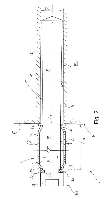
Figure 3 (extracted below) is a schematic partial perspective view of the safety system of Figure 2 shown in an installed state in a proximal end region of a bore.
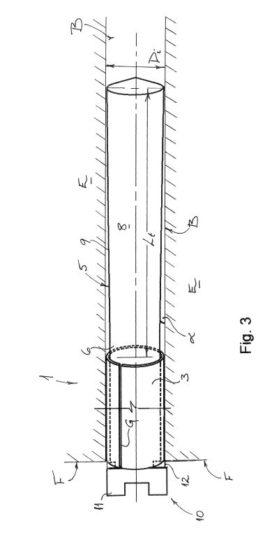
Figure 4 (extracted below) is a schematic cross-sectional side view of a safety system to protect against the hazard of a broken drill rod section in a drilled rock bore according to another embodiment of the invention.
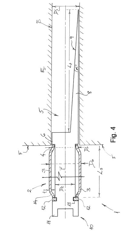
Figure 5 is a flow diagram which schematically represents a method according to an embodiment of the invention.
51 There follows a detailed description of the embodiments by reference to the drawings:
With reference now to Figs. 2 and 3 of the drawings, a safety system 1 according to a preferred embodiment for protecting against just such a hazard posed by the broken drill rod section S in the drilled bore B is shown schematically. The safety system 1 comprises an anchor member 2, which is configured to be inserted and fixed in a proximal end region E of the bore B adjacent or close to a rock-face F of the cavity C at which the drilling takes place. The anchor member 2 is provided in the form of a plug member which is configured to be driven into and fixed within the proximal end region E of the drilled bore B in a friction fit or interference fit. In this regard, the plug member 2 comprises a split tube 3 formed from a round steel tube or pipe having an outer diameter Do sized larger than an inner diameter Di of the bore B. For example, if the bore B has an inner diameter Di of 89 mm, the split tube 3 may have an outer diameter Do of about 100 mm and a wall thickness t of about 6 mm to 9 mm, e.g. about 8 mm in this case. Furthermore, the split tube 3 has a longitudinally extending slit or gap G formed or cut in the wall (as seen in Fig. 3) which allows the outer diameter Do of the split tube 3 (i.e. plug member 2) to be compressed or to reduce when the plug member 2 is driven into the drilled bore B of smaller diameter Di. A front or leading end region 4 of the split tube 3 also has a reduced diameter Dr that is smaller than an inner diameter Di of the drilled bore B to assist the initial introduction or insertion of the plug member 2 into the proximal end region E of the bore B. In this way, the plug member 2 comprised of the split tube 3 can be fixed in the proximal end region E of the bore B adjacent the rock-face F in a friction fit, in a manner similar to that known for a "split-set" type of rock anchor. As with the other dimensions of the split tube 3, the length Ls of the split tube 3 may be selected as appropriate to the rock-strata R, but it is preferably in the range of about 400 mm to 800 mm; e.g. 600 mm in this case.
The safety system 1 further comprises an impact reduction member 5 for reducing an impact of the broken drill rod section S in the event that it falls and strikes the anchor member or plug member 2 in the proximal end region E of the bore B. The impact reduction member 5 is also arranged in the proximal end region E of the bore B and extends within the bore B above the anchor or plug member 2. In this N embodiment, the impact reduction member 5 comprises an elongate body 6 which is arranged centrally of the plug member 2 and which is configured and arranged to be impacted or struck directly by the broken drill rod section S, in the event that the broken drill rod section S falls within the bore B. The elongate body 6 may be formed of steel (e.g. mild steel) and may be machined from bar stock with a round cross-section. A portion 7 of the elongate body 6 within the split tube 3 preferably has a substantially constant diameter De and a portion 8 of the elongate body 6 extending above the split tube 3 is tapered, i.e. an outer surface 9 of the elongate body 6 in the tapered portion 8 tapers outwardly at an angle a of about 1° to 3°; e.g. about 1° in this case. The length Lt of the tapered portion 8 may be selected as appropriate to the safety system, but this length is preferably in the range of about 200 mm to 400 mm; e.g. 290 mm in this case, with the tapered portion 8 tapering from a maximum diameter of about 80 mm at its distal end to a diameter of about 70 mm at the constant diameter portion 7 within the split tube 3.
In this embodiment, the impact reduction member 5 is configured for movement relative to the plug member 2 upon impact by the falling broken drill rod section S. That is, the body 6 of the impact reduction member 5 is configured for movement into an interior of the plug member 2 if impacted or struck by the drill rod section S. In this way, the outer surface 9 of the tapered portion 8 of the body 6 contacts and bears against an inner surface of the split tube 3. As an initial impact by the broken drill rod section S drives the elongate body 6 downwards into the split tube 3, the slight taper of the tapered portion 8 exerts an outward force on the split tube 3 and thus enhances or increases engagement between the bore B and the tube 3. The tapered portion 8 thereby acts to effect a gradual or extended transfer of impact loading from the broken drill rod section S to the plug member 2. In particular, by extending the stopping distance for the falling drill rod section S (i.e. the distance travelled by the drill rod section S after initial impact) via the tapered portion 8, the impact force is reduced significantly, such that the friction fit or interference fit of the anchor member or plug member 2 within the bore B can readily withstand the impact loading. In this way, the safety system 1 of this embodiment can effectively and reliably protect workers and/or equipment in the cavity C from the hazard of broken drill rod sections S falling from a bore B drilled above horizontal.
52 The 556 Patent has five claims. Claim 1 claims:
A safety system for protecting against a hazard of drill rod failure in a drilled rock bore above horizontal, and especially a hazard posed by a broken drill rod section within the bore, comprising:
an anchor member configured to be fixed in a proximal end region of the bore adjacent to a rock-face; and
an impact reduction member for reducing an impact of the broken drill rod section striking the anchor member in the proximal end region of the bore, wherein the impact reduction member is configured to be located in the proximal end region of the drilled bore and to extend within the bore above the anchor member to be impacted or struck directly by the broken drill rod section falling within the bore.
53 The Patents do not differ in the substantive disclosure of the invention described in each.
54 The 163 Patent also claims a safety system for protecting against a hazard posed by a drill rod section as a result of drill rod failure in a drilled rock bore above horizontal. The 163 Patent has five claims. Jusand relies on claims 1 and 2 of the 163 Patent.
55 The safety system claimed in claim 1 is as follows:
A safety system for protecting against a hazard of drill rod failure in a drilled rock bore that extends above horizontal, and especially a hazard posed by a broken drill rod section within the bore, comprising:
an anchor member configured to be fixed in a proximal end region of the bore adjacent or proximate to a rock-face, wherein the anchor member is configured to at least partially block or obscure the drilled bore; and
an impact reduction member configured for reducing an impact of the broken drill rod section striking the anchor member in the proximal end region of the bore, wherein the impact reduction member is configured to be located in the proximal end region of the bore and to extend within the bore above the anchor member;
wherein the impact reduction member is configured and arranged to be impacted or struck directly by the broken drill rod section falling within the bore, and comprises a tapered portion which is configured to allow movement of the drill rod section relative to the anchor member to effect a gradual or extended transfer of the impact loading from the broken drill rod section to the anchor member; and
wherein the safety system is configured for connection with a rock drilling apparatus for driving the anchor member and the impact reduction member into the proximal end region of the bore to deploy the safety system in the bore.
56 Claim 2 claims:
A safety system according to claim 1, wherein the anchor member forms a plug member and is configured to be driven or forced into the proximal end region of the bore by the rock drilling apparatus, and wherein the tapered portion of the impact reduction member is configured to allow movement of the impact reduction member relative to the anchor member to effect the gradual or extended transfer of the impact loading from the drill rod section to the anchor member.
57 The 956 Patent shares the specification of the 556 and 163 Patents, aside from the claim set.
58 The 956 Patent claims a method of protecting against a hazard posed by a drill rod section as a result of drill rod failure in a drilled rock bore above horizontal. Jusand relies on claim 1 of the 956 Patent which reads:
A method of protecting against a hazard posed by a drill rod section as a result of drill rod failure in a drilled rock bore above horizontal, the method comprising deploying a safety system into the bore in response to drill rod failure, the safety system comprising:
an anchor member configured to be fixed in a proximal end region of the bore adjacent to a rock-face; and
an impact reduction member for reducing an impact of the drill rod section on the anchor member in the proximal end region of the bore, wherein the impact reduction member is configured to be located in the proximal end region of the drilled bore and to extend within the bore above the anchor member;
wherein the step of deploying the safety system comprises fixing the anchor member in the proximal end region of the bore.
59 Jusand also relies on claim 4 (read with claim 1):
A method according to [claim 1], wherein the anchor member comprises a plug type anchor member that is configured to plug into the proximal end region of the bore in a friction fit or an interference fit
and claim 5 (read with claims 1 and/or 4):
A method according to [claim 1 or claim 4], wherein the impact reduction member is, upon installation of the safety system, configured and arranged to be impacted or struck directly by the drill rod section, the impact reduction member preferably comprising an elongate body arranged substantially centrally of the anchor member and configured to move relative to the anchor member when impacted or struck by the drill rod section.
60 The Patents provide a safety system to avoid the hazard of falling drills during long-hole underground mining.
61 The following background to long-hole underground mining is taken from the expert evidence and would form part of the common general knowledge of a person with experience in long-hole drilling as at the priority date.
62 Long-hole underground mining generally uses a process of drilling bore holes upward into the ore, and then using explosives that are inserted into the bore holes to break up the ore and the surrounding rock, which is then removed via access tunnels.
63 The progress of the tunnel through rock that does not contain ore is referred to as “waste development”. If a tunnel is then progressed through ore-containing rock, that is referred to as “ore development”. Where a section of an ore body is worked or connected to development tunnels so as to create an open space, that space is commonly referred to as a “stope”. “Stoping” describes the process of removing the ore, which results in a stope, and “overhand stoping” refers to the process of removing ore from above.
64 The roof of the mine chamber is usually covered in a layer of “shotcrete” (sprayed concrete) which is then covered in steel mesh.
65 The bore holes are drilled using a long-hole drilling rig which allows the drilling of holes anywhere from 51 to approximately 125 mm in diameter, using a range of standard drill bit sizes. The drill diameters commonly used for blasting bore holes are 64, 76, 89, 102 and 125 mm. The bore holes may be drilled upward at angles from near horizontal to almost vertical.
66 The drilling rig uses a process that involves coupling a series of individual drill rods together as the bore progresses in length. The drill rods are normally about 1.5 to 4 m long. They are usually made from high-strength steel and are very heavy, generally weighing between 20 to 40 kg each.
67 The bore may be drilled for lengths usually in the range or 10 to 25 m but the bore may be longer, up to about 50 or 60 m for services/utilities holes. When the bore length gets beyond about 25 m, hole deviation may become a problem. The upper length of long hole drilling is around 60 m as beyond that length drilling is impractical as the hole deviation becomes uncontrollable.
68 The ring of the bore hole at the rock-face is called the “collar”. The top of the bore hole is called the “toe”. The first 10 to 15 cm of rock in the bore (ie, the rock that constitutes the collar and the initial short length of the bore) can be damaged during the process of blasting to create the tunnel. That area is called the “blast damage zone”.
69 The drill rods are hollow so as to allow for water to be passed through the drill rod to assist with washing the cuttings out of the bore hole as it progresses. The couplings between the drill rods allow water to pass through them to lubricate the drilling.
70 The diameter of the cutting head of the drill is wider than the diameter of the drill rods as the cuttings need to be able to fall down, or be washed down, the bore within the annular space between the bore hole walls and the outside of the drill rods.
71 The problem with overhand stoping is that the drill rod can fail. The cutting end of a drill rod can get caught up in the cuttings within the bore hole, or in poor ground in the bore hole. If this happens it is referred to as “bogging”. The drill rod then becomes “bogged” in the hole, and is not able to continue drilling to progress in the bore hole. If the cutting head of the drill rod becomes bogged, that can lead to breakage of the drill rod, either as a direct result of the forces being applied by the drilling rig, or when the operator then tries to remove the drilling rod from the hole. Sometimes drill rods can break without bogging.
72 Drill rods are particularly likely to break in percussion drilling because the forces applied are aggressive. A break in a drill rod can occur anywhere along the length of any rod in a drill string, including at a coupling, resulting in disconnection with any rods, or part thereof, above the break. A broken section of a drill rod is heavy and often has a jagged and potentially sharp edge.
73 Often the broken section of the drill rod is not retrievable from the bore. The broken part may dislodge later and fall into the mine tunnel or chamber potentially causing serious personal injury or death to mine workers, or damage to mine equipment. The hazard is increased as the angle of inclination of the bore increases towards vertical. At horizontal there will be little to no hazard as gravity would not act on the broken drill bit to cause it to fall down the bore hole.
74 A patent specification is to be construed through the lens of a hypothetical person skilled in the art, or the skilled addressee. The Court is to place itself in the position of a person acquainted with the surrounding circumstances of the state of the art and manufacture at the relevant time. The skilled addressee is likely to have a “practical interest in the subject matter of the invention” and may often work in the art with which the invention is connected: KD Kanopy Australasia Pty Ltd v Insta Image Pty Ltd (2007) 71 IPR 615 at [16], approved by the Full Court in Insta Image Pty Ltd v KD Kanopy Australasia Pty Ltd (2008) 78 IPR 20 at [94]-[96].
75 As French CJ said in AstraZeneca AB v Apotex Pty Ltd (2015) 257 CLR 356 at [23], the skilled addressee is not a manifestation of, or “avatar” for the expert witness whose testimony is accepted by the court. Rather, the notion of the skilled addressee is a tool of analysis that is given form and content by the testimony of the expert and other evidence.
76 Such a hypothetical person may be a team, and it is the collective knowledge of such a team that must be considered where applicable: Minnesota Mining & Manufacturing Co v Tyco Electronics Pty Ltd (2002) 56 IPR 248 at [40]; General Tire & Rubber Company v Firestone Tyre & Rubber Company Ltd [1972] RPC 457 (UK) at 483.
77 The skilled addressee is taken to be a person of ordinary skill in the field to which the invention relates, as opposed to a leading expert, and is equipped with the relevant common general knowledge before the priority date. The skilled addressee is not particularly imaginative or inventive.
78 Different aspects of that hypothetical person construct may be relevant for different enquiries. Such as different claims or different grounds of invalidity: Axent Holdings Pty Ltd t/a Axent Global v Compusign Australia Pty Ltd (2020) 154 IPR 431 at [251].
79 The Patents are addressed to someone with an engineering qualification, preferably in mining or geotechnical engineering, who has experience in underground mining including long-bore drilling, and experience in designing devices to interact with rock masses in underground mining. The skilled person would also have a knowledge of basic mechanical engineering principles relating to impact forces and the redirection of such forces, the absorption of energy from such impact forces, principles relating to deceleration over a distance, the role of frictional resistance and a general understanding of how these forces will be affected by the properties of different materials.
80 Experience in materials engineering would be beneficial to the skilled person but not required, as detailed questions about materials and their mechanical properties would be referred to a materials engineer.
81 Both experts had relevant engineering qualifications and experience in underground mining and were each well equipped to give evidence on matters relating to underground mining. Where they differed was in their knowledge and experience of the properties of materials other than steel. Dr Fuller had qualifications in materials science and was able to provide useful and considered evidence on this topic. Mr Davison did not have qualifications in materials science. This difference in the experts was relevant to the validity issues and is discussed further in that section.
82 The principles governing claim construction are well understood and were not in dispute. The parties referred to the principles as set out by Full Court in Jupiters Ltd v Neurizon Pty Ltd (2005) 65 IPR 86 (Jupiters) at [67] and Product Management Group Pty Ltd v Blue Gentian LLC (2015) 116 IPR 54 at [34]-[42] (Kenny and Beach JJ) (Blue Gentian). Jusand and Rattlejack placed particular emphasis on different principles to suit their cases. For present purposes it is sufficient to highlight the following points.
83 The proper construction of a claim is a question of law.
84 A claim is to be construed through the lens of the hypothetical skilled person. The words in the specification and claims are to be given the meaning which the normal skilled person would attach to them, having regard to their own general knowledge and to what is disclosed in the specification: Jupiters at [67].
85 Ordinary words which are used in a patent claim should be given their ordinary meaning unless the skilled addressee would give them a different meaning: Kimberly-Clark Australia Pty Ltd v Multigate Medical Products Pty Ltd (2011) 92 IPR 21 at [39] (Greenwood and Nicholas JJ).
86 The integers of a claim should not be considered individually and in isolation: Blue Gentian at [39]. Furthermore, a claim should be given a “purposive” construction, not a “purely literal” or a “too technical or narrow” construction: Jupiters at [67]; Blue Gentian at [39].
87 It is not the province of an expert to give evidence of the meaning of words or phrases used in a claim if those words or phrases bear their ordinary English meanings and are not suggested to have a technical or special meaning: Multigate Medical Devices Pty Ltd v B Braun Melsungen AG (2016) 117 IPR 1 at [26].
88 To apply a “purposive” construction does not justify extending the patentee’s monopoly to the “ideas” disclosed in the specification (Blue Gentian at [40]). Instead, its application should be guided by considerations including those addressed by Hoffman LJ when he explained “purposive construction” in Kirin-Amgen Inc v Hoechst Marion Roussel Ltd (2004) 64 IPR 444 (Kirin-Amgen) at [33] and [34], a passage which has been endorsed by the Full Court including in Blue Gentian at [41] and Tramanco Pty Ltd v BPW Transpec Pty Ltd (2014) 105 IPR 18 at [174] (Nicholas J):
[33] In the case of a patent specification, the notional addressee is the person skilled in the art. He (or, I say once and for all, she) comes to a reading of the specification with common general knowledge of the art. And he reads the specification on the assumption that its purpose is both to describe and to demarcate an invention — a practical idea which the patentee has had for a new product or process — and not to be a textbook in mathematics or chemistry or a shopping list of chemicals or hardware. It is this insight which lies at the heart of “purposive construction”…
[34] “Purposive construction” does not mean that one is extending or going beyond the definition of the technical matter for which the patentee seeks protection in the claims. The question is always what the person skilled in the art would have understood the patentee to be using the language of the claim to mean. And for this purpose, the language he has chosen is usually of critical importance. The conventions of word meaning and syntax enable us to express our meanings with great accuracy and subtlety and the skilled man will ordinarily assume that the patentee has chosen his language accordingly. As a number of judges have pointed out, the specification is a unilateral document in words of the patentee’s own choosing. Furthermore, the words will usually have been chosen upon skilled advice. The specification is not a document inter rusticos for which broad allowances must be made. On the other hand, it must be recognised that the patentee is trying to describe something which, at any rate in his opinion, is new; which has not existed before and of which there may be no generally accepted definition. There will be occasions upon which it will be obvious to the skilled man that the patentee must in some respect have departed from conventional use of language or included in his description of the invention some element which he did not mean to be essential. But one would not expect that to happen very often.
89 When seeking to give a claim a purposive construction, care must be taken to avoid imposing an impermissible gloss on the claim language based on material found in the body of the specification: Blue Gentian at [37]; Jupiters at [67].
90 A construction according to which the invention will work is to be preferred to one according to which it will not work: Blue Gentian at [39].
91 In approaching the construction of a claim, a court should apply a “generous measure of common sense”: Blue Gentian at [36]; see also Ranbaxy Laboratories Ltd v AstraZeneca AB (2013) 101 IPR 11 at [108] (Middleton J).
92 Rattlejack contends that the SafetySpear (and the method involving the installation of the SafetySpear) does not have the following integers of the claims of the Patents:
(a) an “anchor member”;
(b) the anchor member (and the impact reduction member) “configured to be fixed [or located] … in the proximal end region of the bore”; and
(c) the anchor member “configured to be fixed … adjacent to a rock-face” or “adjacent or proximate to a rock-face”.
93 Accordingly, it is sufficient for present purposes to concentrate on those integers of the claims of the Patents. Having said that, it is necessary to consider those integers in the context of the claims of each Patent, and the body of each specification as a whole, without an eye to infringement.
94 Jusand contends that:
(a) the “anchor member” fixes the safety system in place until such time that the safety system is struck by a falling drill rod and then checks the downward movement of that falling drill rod. Jusand’s construction contemplates that the anchor member can move substantially down the bore hole whilst checking the downward movement of the falling drill rod; and
(b) the claim language of the second integer in dispute requires that the anchor member be “configured to be” or be suitable to be inserted into a lower end region of the bore hole.
95 Rattlejack contends that:
(a) the “anchor member” cannot move down the bore hole (other than a de minimis amount) when struck by a falling drill rod section: the anchor is fixed in place before, during and after the safety system is struck by a falling drill rod; and
(b) the words “adjacent to” as used in the claims means that the lowest end of the “anchor member” must be positioned at the lowest extremity of the bore, flush with the rock-face.
96 The Patent is to be construed by the person skilled in the art equipped with the common general knowledge as at the priority date as set out above.
97 The disclosed object of the invention described and claimed in the Patents is to protect against the hazard of a broken drill rod falling out of the bore into an excavated area. The safety system of the invention is said to desirably prevent such a broken drill rod section from falling out into the space or area in which miners are working.
98 In the context of the Patent, the person skilled in the art at the priority date would understand:
The hazard posed by the falling broken drill rod is extreme and potentially fatal;
The only way identified in the Patents to protect against the hazard is to stop the broken drill rod section from leaving the bore hole;
The safety system of the Patents must stop the drill rod section falling from the bore each time;
The impact force from a falling drill rod section, which is primarily a function of drill rod section size, weight, drop length and bore angle, is substantial, in the order of up to possibly hundreds of tonnes;
A different safety system may be required for bores of different diameters;
Stopping the falling drill rod section will involve absorbing the energy of and decelerating the falling drill rod section; and
The one safety system will need to work for the all the potential forces up to the maximum possible impact force potentially experienced in a bore hole; i.e. whether the drill rod falls from a short distance or from the far end of the bore hole.
99 The evidence was that the term “anchor” is not a term of art in the mining industry.
100 The parties agree that the question of construction is a matter for the Court and since there are no technical terms or particular terms of art (within any relevant discipline), used in the Patents, the Court can decide the question of construction of the claims without regard to the views of the experts. However, there was extensive expert evidence directed to construction which was admitted without objection.
101 The word “anchor” is used as part of the descriptor of a component in the claimed safety system: an “anchor member”.
102 Jusand contends that the anchor member is a lower component of the safety system of the invention (when installed) which has the role of fixing the safety system product in place within the bore, until such time as it may be struck by a falling drill rod section and which then resists and checks downward movement of that product. Jusand’s construction contemplates an anchor member (and safety system) which can move substantially down the bore hole after being struck before coming to a stop.
103 According to Jusand, a skilled person would recognise that the safety system product of the invention achieves the object of the Patent by bringing the falling drill rods to a stop before the safety system product is pushed out of the bore. The skilled person would understand that some movement of the anchor member down the bore hole would be an effective way in which residual energy from a falling drill rod section, not absorbed by the impact reduction member, could be absorbed.
104 Jusand contends that its construction is consistent with the broader context provided by the claims and with an ordinary English meaning of the word “anchor” considered within that context. Jusand also states its construction of the term is capable of practical application towards assessing whether an allegedly infringing product has that feature or not.
105 In contrast, Rattlejack contends that an “anchor member” in the context of the Patents is an element that once fixed in the bore hole, acts as an anchor to stop the movement of the safety system relative to the rock when impacted by a falling broken drill rod section. On the construction propounded by Rattlejack, the claims encompass a de minimis movement of the anchor member in the order of a few millimetres (no more than 5 mm) but do not encompass a safety system that moves substantially (centimetres rather than millimetres) down the bore hole.
106 Rattlejack submits that such a construction is consistent with the definition of “anchor” in the current version of the Macquarie Dictionary, in which the primary non-specialist definitions of “anchor” as a noun and a verb are:
anchor
noun 1. a device for holding boats, vessels, floating bridges, etc., in place.
2. any similar device for holding fast or checking motion.
…
–verb (t) 11. to hold fast by an anchor.
12. to fix or fasten; affix firmly.
…
–verb (i) …
16. to keep hold or be firmly fixed.
107 Jusand relied on the reference in the definition above to the words “any…device…for checking motion”. According to Jusand, one of the meanings of “check” in the Merriam-Webster Dictionary is “to slow or bring to a stop”, and in the Oxford Languages dictionary through the Google platform is “stop or slow the progress of”.
108 Rattlejack disagreed that “check” meant to slow something down. Rattlejack relied upon the definition of “check” from the current version of the Macquarie Dictionary, in particular, the first three definitions, none of which it submitted meant “to slow”:
check
verb (t) 1. to stop or arrest the motion of suddenly or forcibly.
2. to restrain; hold in restraint or control.
3. to investigate or verify as to correctness.
109 In any event, Rattlejack submitted that something which is “fixed” can slow down something else in the manner precisely, and expressly, contemplated by the Patents; namely, the impact reduction member sliding with significant friction against the anchor member.
110 Jusand described the construction propounded by Rattlejack as being “practically unworkable” and submitted that it should be rejected for the following reasons.
111 First, there is no express statement anywhere in the Patents that shows that the patentee clearly intended to limit the scope of the disclosure to exclude from the scope of the Patents a safety system product with a friction-type anchor member that moved down the bore to a limited degree, but still operated with the impact reduction member to effectively bring a falling drill rod to a stop within the bore.
112 By introducing the practical acknowledgment of a de minimis movement, Jusand submits that Rattlejack is already accepting that the word “anchor” cannot have been intended as imposing a strict requirement of no movement. In practical terms it also follows that if the patentee were intending the word “anchor” to have the specific meaning that Rattlejack contends for, then it is odd that the patentee has not taken the care to explain in the specification that movement of at least a few millimetres still amounts to anchoring, otherwise the patentee would be taking the risk that “anchor” would be read more strictly, thereby leaving the claims with no practical scope.
113 Second, Jusand criticised Dr Fuller’s reasoning which it said was based on the particular embodiment shown in Figure 2. According to Jusand, Dr Fuller read down the disclosure in the Patents to fit with his assumed meaning of the word “anchor”. Jusand submitted that Dr Fuller read the Patents with an assumption that the patentee intended to exclude from the scope of its monopoly embodiments that Dr Fuller recognised in cross-examination would feasibly work so as to achieve the object of the Patents.
114 In cross-examination Dr Fuller agreed that down-hole movement of an anchor member would absorb energy. When Dr Fuller was asked to consider the embodiment shown in Figure 4, he understood that it did not rely on the same principle shown in the Figure 2 embodiment, and that it relied solely on its frictional engagement with the bore walls. It would therefore have a more constant capacity to resist downward movement.
115 Jusand also criticised the two additional reasons Dr Fuller gave in support of his construction of “anchor” in the joint expert report:
If it is assumed that the lowest extremity of the anchor member must be flush with the rock-face, then it is not desirable for the anchor member to move downwards as in doing so it will lose surface area contact with the bore wall.
If there is movement of the anchor member, the kinetic coefficient of friction comes into play. His statement was:
[O]nce the anchor member starts to move, it is easier for it to keep moving due to the kinetic (moving) friction coefficient being about 20% less than the static friction coefficient.
116 As to the first of Dr Fuller’s reasons, Jusand submitted that even if it is assumed that the extremity of the anchor member must be flush with the rock-face, then depending on the relative degree of down-hole movement, and the relative length of the anchor member, an anchor that moved more than a few millimetres may still be effective.
117 As to the second, Jusand noted that the frictional coefficient (the proportion of force resisting movement as a function of the normal force between the two surfaces) is reduced by about 20% once movement occurs. If there is a constant force being applied to an object, once movement begins, it will be easier to keep that object moving as the resistant frictional force has decreased. In cross-examination, Dr Fuller accepted that where the anchor member is moving even a few millimetres, then the kinetic coefficient of friction is involved. Jusand contends the kinetic coefficient of friction is therefore involved even for Dr Fuller’s preferred narrow construction.
118 Third, Jusand submits that a powerful reason against concluding that the construction for which Rattlejack contends was the intended meaning of “anchor member”, is that it is one that would not be suited for defining the boundaries of a patent monopoly. Jusand submitted that its construction is readily capable of being assessed by reference to a potentially infringing product. A skilled person can consider whether a relevant feature of a safety system product is suitable for fixing the product in place within a bore until such time as it may be struck by a falling drill rod, and in considering whether that feature will check down-hole movement.
119 In contrast, Jusand submitted that Rattlejack’s proposed meaning raised practical issues for assessing whether a product has an “anchor member” within the meaning of the claims, such as: what amount of down-hole movement results in it still being an “anchor member”, and under what conditions should infringement be assessed?
Consideration
120 For the reasons that follow, I reject the construction of “anchor member” propounded by Jusand.
121 I consider that the skilled addressee would understand “anchor member” in the claim to mean a component of the safety system that once fixed in the bore hole, acts as an anchor to stop the movement of the safety system relative to the rock when impacted by a falling broken drill rod section. I consider that the claims encompass a de minimis movement of the anchor member in the order of a few millimetres (1–5 mm) but do not encompass a safety system that moves substantially (centimetres rather than millimetres) down the bore hole before coming to a stop.
122 A construction of “anchor” which contemplates no movement, other than de minimis movement, is consistent with the description of the invention in the specification of the Patents. It is also consistent with the evidence of both experts and the Macquarie Dictionary definition of “anchor”.
123 To adopt an absolute requirement of no movement whatsoever of the anchor member would be to adopt an overly literal meaning at odds with practical reality and the experts’ understanding. Common sense also suggests that movement of up to 5 mm in the context of a bore length of 10 to 60 m or an impact force of up to hundreds of tonnes is negligible or de minimis. It is unsurprising that the specification did not expressly mention the possibility of de minimis movement. Such a construction is much like that in Catnic Components Ltd v Hill & Smith Ltd [1982] RPC 183 in which the specification did not expressly describe that “extending vertically” included 6 to 8 degrees off true vertical, but which term Diplock LJ (at 224, the other members of the House of Lords agreeing) construed as meaning “near enough to the exact geometrical vertical to enable it in actual use to perform satisfactorily all the function it could perform if it were precisely vertical”.
124 It is useful to begin with some observations concerning the Patent specifications as this provides the context for the use of the term “anchor member” in the claims.
Specification
125 As Jusand submitted, there is no express direction that the anchor member should not move. Nor, however, is there any express direction that the anchor member should move, or any reference to, or description of the anchor moving during the impact of the falling drill bit. None of the descriptions of the anchor member or of the working of the safety system after insertion into the bore describes any movement of the anchor member. No movement of the anchor member relative to the rock-face or the bore is described in the context of the functioning of the embodiments in Figures 3 and 4. In contrast, the specification includes many references to the movement of the impact reduction member in the specification.
126 Movement of the impact reduction member is contemplated by the specification. At page 4, lines 15 to 18, the specification notes that the tapered portion of the impact reduction member is “configured to allow movement of the impact reduction member relative to the anchor member” for gradual or extended transfer of the impact loading from the drill rod section to the anchor member (emphasis added). Also on page 4, at lines 24 to 27, the tapered portion of the impact reduction member is said to be desirably configured to provide for movement of the falling drill rod section relative to the anchor member (see also page 10, line 27).
127 The falling drill rod section is said to “drive” the elongated body of the impact reduction member downwards into the split tube (page 11, lines 1 to 2). By the tapered portion of the impact reduction member extending the stopping distance for the falling drill rod section, the impact force is said (at page 11, lines 5 to 10) to be reduced significantly, such that the friction fit or interference fit of the anchor member within the bore can readily withstand the impact loading.
128 At page 12, line 30 to page 13, line 9, in the context of the description of the embodiment in Figure 4, the Patent states that for this embodiment the impact reduction member is not configured for any significant movement relative to the plug member upon impact by the falling drill rod section. Rather, the falling drill rod section is gradually deflected towards and into contact with the opposite inner wall which generates friction which acts to brake the falling object and dissipate the impact. The tapered portion is again said to act to cause gradual or extended transfer of impact loading from the drill rod section to the anchor member. The impact force is again reduced significantly such that the friction fit or interference fit of the anchor member within the bore can readily withstand the impact loading.
129 Further the anchor member is said to “readily withstand” the impact loading after the impact force is significantly reduced by the tapered portion of the impact reduction member. Withstanding does not connote substantial movement. The following references from the specification also support a construction where the anchor member does not move substantially.
(a) At page 4, lines 2 to 5, the Patent compares the manner of fixing the anchor member in the bore to the manner of fixing another “anchor” known in mining: a “split-set” rock anchor:
In this way, the anchor member or plug member comprising the split tube can be fixed in the proximal end region of the bore adjacent the rock-face in a friction fit or an interference fit, in a manner similar to that known for a “split-set” type of rock anchor.
(b) At page 11, lines 8 to 10:
[T]he impact force is reduced significantly, such that the friction fit or interference fit of the anchor member or plug member 2 within the bore B can readily withstand the impact loading.
130 In the context of a specification which describes the movement of the impact reduction member, silence as to any movement of the anchor member supports a construction that does not countenance movement of the anchor member beyond a de minimis amount.
131 The embodiment of the invention shown installed in Figure 3 needs to work while flush with the rock-face, even if it is not required to be installed there. If there was any more than de minimis movement in that example, it is possible that the safety system would fall from the bore hole.
Experts’ construction
132 The experts agreed that the term “anchor” did not have a technical or special meaning in mining. The evidence showed that the term “anchor” is one that is known and used in the mining industry, in particular in relation to a type of fixing known as “rock anchors”.
133 The experts in their joint report and joint session agreed that an anchor member in the context of the Patents is an element that acts as an anchor, to stop movement of the safety system relative to the rock when impacted by a broken drill rod section. Both experts considered that the claims would encompass a safety system which moved a de minimis amount. Dr Fuller contemplated movement of a few millimetres down the bore. Mr Davison accepted that once installed the anchor member would not move “more than a few” millimetres down the bore, which seemed to be about 5 mm. De minimis movement in the context of the invention described in the Patents entailed movement of the anchor member of 5 mm or less.
134 Neither expert considered that the claims contemplated a safety system that slides substantially down the bore.
135 Dr Fuller’s view was that the claims would encompass a safety system that moves a de minimis amount, such as a few millimetres, but that they do not encompass a safety system that slides substantially (i.e., more than a few millimetres) down the bore. Mr Davison accepted that an anchor, once installed, is fixed in place and does not move more than a de minimis amount, which he put at 1 to 5 mm.
136 Initially, Mr Davison said he understood that the anchor member must locate and hold the safety system in position in the bore “until such time as it may be struck by a falling drill rod section”. It must then “resist downward movement of the safety system in the bore if the safety system is struck by a broken drill rod section”.
137 Mr Davison’s initial construction would have the anchor member functioning as an anchor only until it is hit by falling drill rods, at which point it could cease to operate as an anchor and instead slide down the bore. There is nothing in the Patents to support that construction.
138 However, in the joint report, Mr Davison clarified his position. He did not mean that the anchor member held the safety system in place only until such time as it may be struck. He agreed that the anchor member may move by “a few millimetres or more”.
139 In the joint session, Mr Davison accepted that the word “anchor”, generally speaking, means something which is “a device for holding something fast or checking its motion”. He used the example of anchoring a boat: he said such an anchor “moves to – to check the motion to fix, eventually, in one spot”. He accepted that once the anchor is pushed into the mud, it is “fixed in place”, which he equated with “it checks the – the motion”.
140 “Fixed” in place accords with the role of the anchor in the “split-set anchor” product discussed by Mr Davison in his affidavit. It would also accord with the requirement in the claim that the anchor member be “configured to be fixed”.
141 Mr Davison had in mind a very small amount of movement, some 3 to 4 mm. That is not substantially different from Dr Fuller’s estimate of a few millimetres.
142 The Patent at page 4, line 5 (and again at page 10, lines 1 to 3) states that the anchor member can be fixed in the bore in a friction fit or an interference fit, in a manner similar to that known “for a ‘split-set’ type rock anchor”.
143 Mr Davison referred to “split-set anchors” and “a split-set (rock anchor) product” in his written evidence. The term “anchor” is also used by Mr Davison in the specifications of the patents and patent applications for his inventions relating to rock bolts.
144 One example of Mr Davison’s “developments and innovations” relates to a grouted friction stabiliser which uses grout to improve the frictional performance of “split-set anchors” by a factor of about four. That invention is the subject of Australian Patent no. 2014295889 which is entitled “A grouted friction bolt”.
145 The Macquarie Dictionary definitions are consistent with a construction where the anchor member is fixed or held fast in place and acts to stop the movement of the safety system relative to the rock when the safety system is hit by a falling broken drill rod.
146 As Hoffman LJ observed in Kirin-Amgen at [34], the specification is a unilateral document in words of the patentee’s own choosing. Furthermore, the words will usually have been chosen upon skilled advice. There may be good reason why the patentee chooses certain words over others, such as the avoidance of prior art, but the skilled addressee is not privy to the reasons for that choice.
147 Jusand urged me to accept that the invention the subject of the Patents was an invention of the kind contemplated by Hoffman LJ in Kirin-Amgen when he said at [34]:
On the other hand, it must be recognised that the patentee is trying to describe something which, at any rate in his opinion, is new; which has not existed before and of which there may be no generally accepted definition.
148 Whilst the safety system described and claimed in the Patents is taken to be new and innovative, it is not a new invention of the kind where the patentee is struggling to find the words to adequately describe the concepts involved. The term “anchor” is known and used in the mining industry in the context of fixings. The specification itself makes reference to the friction fit of the anchor member or plug member in the bore being in a manner similar to that known for a “split-set” type rock anchor. In choosing to describe the safety system, the patentee chose to describe the lower member as an “anchor member”, not a braking or checking or restraining member. If the patentee intended to claim a safety system that was held in place until it was struck by a falling drill rod and then moved down the bore hole to eventually stop the broken drill rod from falling out of the hole, there were more apt words available than “anchor”.
149 The well accepted authorities on construction counsel against construing the claims with an eye to infringement. This warning is apposite in most patent cases, where the claims are being construed as part of an infringement action and there is an allegedly infringing product in existence. It seems appropriate that this warning also extend to construing claims with an eye to the ease of establishing infringement. Such a consideration is an extraneous one that has no part to play in the construction of patent claims.
150 The claims are to be construed in the context of the specification as a whole, through the lens of the hypothetical skilled addressee equipped with the common general knowledge as at the priority date: Blue Gentian at [35]. The ease with which the patentee is able to establish infringement may play a part as to why the patentee chose the particular words of the claim in the first place, but it, like a motivation to avoid prior art to preserve validity, is a reason not known to the skilled reader and not relevant to the construction of the claims.
A proximal end region of the bore adjacent to a rock-face
151 The second construction issue that arises relates to the meaning of the words:
Anchor member configured to be fixed in a proximal end region of the bore adjacent to a rock-face.
(Emphasis added.)
152 The parties split this integer into different elements.
153 Jusand focussed on the word “adjacent” and noted that it could be read on to “end region of the bore” which was its contention, or potentially on to “fixed” which it said was Rattlejack’s contention: anchor member to be fixed in a proximal end region of the bore [and] adjacent to a rock-face.
154 Rattlejack broke the phrase into two parts, the first “configured to be fixed in a proximal end region of the bore”, and the second “configured to be fixed … adjacent to a rock-face”. Rattlejack noted that each of the Asserted Claims requires that the anchor member and the impact reduction member be “configured to be fixed in” or “configured to be located in” a “proximal end region of the bore…”.
155 Neither party contended that the phrase was a term of art, or contained terms of art.
156 Claim 1 of the 956 Patent also requires that the step of deploying the safety system “comprises fixing the anchor member in the proximal end region of the bore…”. Claim 4 of that Patent requires that the anchor member is “is configured to plug into the proximal end region of the bore …”.
157 There was no dispute between the parties about the slight differences in phrasing of this integer: it means that the anchor member and the impact reduction member must be configured to be fixed or located in the “proximal end region of the bore”, and, for the Asserted Claims of the 956 Patent, that in carrying out the claimed method, the anchor member must be fixed in the “proximal end region of the bore”.
158 Jusand contended consistently with Mr Davison’s evidence that the word “proximal” states that the relevant end region is the closer end region of the bore, rather than the farthest end region (or “distal” end region) and the words “adjacent to” then communicate and clarify that that “proximal” end region is near to the rock-face.
159 Jusand conceded that there was some redundancy on its construction, but submitted there was more redundancy on Rattlejack’s construction.
160 Jusand submitted that the claim language more clearly and simply requires that the anchor member be “configured to be”, that is, be suitable to be, inserted into a lower end region of the bore hole. It need not be “configured to be” driven the entire way up to the distal or far end of the bore hole, if that was the location of an issue in a particular bore. Jusand’s construction gives no meaning to “fixed”.
161 Rattlejack referred to the definitions of “proximal”, “end” and “region” from the current version of the Macquarie Dictionary which included:
proximal
adjective situated towards the point of origin or attachment…
end
noun 1. an extremity of anything that is longer than it is broad…
2. an extreme or farthermost part of anything extended in space.
3. Anything that bounds an object at one of its extremities; a limit.
region
noun 1. Any more or less extensive, continuous part of a surface or space.
162 Rattlejack contended that in the context of a bore, the plain English meaning of the phrase “proximal end region of the bore” means the region situated at the end (extremity) of the bore at its point of origin or opening.
163 The body of the Patents does not give any specific definition of the phrase, but does identify the “proximal end region of bore”, E, in Figures 2 and 3, as being the area at the very end of the bore closest to the opening of the bore hole, consistent with its ordinary English meaning. In the depiction of the installed embodiment in Figure 3, the region E is depicted as extending beyond the anchor member and alongside the impact reduction member.
164 Jusand listed the references in the Patent regarding the proximal end region that do not use the word “adjacent” and which it suggested provide some relevant broader context including:
• In an embodiment of the safety system, the anchor member or plug member is configured to be fixed within the proximal end region of the drilled bore in a friction fit or interference fit (page 3, lines 26 to 28);
• The split tube is configured to be driven into the proximal end region of the drilled bore (page 3, lines 30 to 31);
• In an embodiment, the safety system further comprises an adapter member which is configured for connection to a rock drilling apparatus for driving or inserting the safety system, especially the anchor member and the impact reduction member, into the proximal end region of the drilled bore (page 6, lines 5 to 8);
• This thereby enables the safety system to be placed in and held by the drill rod carousel and then be introduced or inserted (e.g. driven or forced) into the proximal end region of the bore by the rock drilling apparatus (page 6, lines 19 to 21);
• Fixing an anchor member in or at a proximal end region of the drilled bore to at least partially plug or obscure the proximal end region of the bore adjacent to or in the vicinity of a rock-face (page 6, lines 27 to 29);
• Figure 3 is a schematic partial perspective view of the safety system of Figure 2 shown in an installed state in a proximal end region of a bore (page 7, lines 23 to 24);
• The safety system 1 comprises an anchor member 2, which is configured to be inserted and fixed in a proximal end region E of the bore B adjacent or close to a rock-face F of the cavity C at which the drilling takes place (page 9, lines 15 to 18);
• The anchor member 2 is provided in the form of a plug member which is configured to be driven into and fixed within the proximal end region E of the drilled bore B in a friction fit or interference fit (page 9, lines 18 to 20);
• This enables the safety system 1 to be placed in and held by the drill rod carousel and then introduced or inserted (e.g. hydraulically driven or forced) into the proximal end region E of the bore B by the rock drilling apparatus (page 11, lines 19 to 21);
• The split tube 3 of the plug member 2 seats against the collar 12, such that the collar 12 imparts an axial force to the plug member 2 to drive the plug member 2 (together with impact reduction member 5) into the proximal end E of the drilled bore B in a friction fit (page 11, lines 26 to 29);
• In this embodiment, the safety system 1 again includes a plug type anchor member 2 comprising a split tube 3 having longitudinally extending slit or gap (not shown) and a front or leading end region 4 of reduced diameter Dr to assist driven or forced insertion into a proximal end region E of a bore B in an interference fit or a friction fit (page 12, lines 10 to 14); and
• As before, the safety system 1 of Figure 4 includes an adapter member configured to cooperate with a rock drilling apparatus (not shown) for deploying the plug-like anchor member 2 and the impact reduction member 5 into the proximal end E of the bore B (page 13, lines 11 to 15).
165 None of these references is inconsistent with the proximal end region of the bore being the region beginning at the bore hole entry and extending into the bore hole. Some are supportive of such a construction, in particular the description of Figures 2, 3 and 4.
166 The question is, how far up the bore does the proximal region extend?
167 Mr Davison understood the proximal end region of the bore to extend for the first few meters of the hole above the development drive, or more in the case of a longer bore. He understood the words “adjacent to the rock-face” to reinforce the meaning of proximal in identifying the relevant end of the bore hole. In the joint report Mr Davison understood the phrase “proximal end region of the bore” to be read together with “adjacent to the rock-face” and to describe the lower end of the bore hole away from the end region at the distal or toe end.
168 Dr Fuller understood the proximal end region of the bore to be the region of the bore located at and near the collar (the ring of the hole at the rock-face). In his first affidavit, Dr Fuller estimated that the proximal end region extended from the collar about 20 or 30 cm into the bore. At the start of the joint session, Dr Fuller revised his estimate of the length of the proximal end region to extend from the collar to about a metre. This was, he explained, to include the impact reduction member, which he noted was also required by the claim to be configured to be located in the proximal end region of the bore.
169 Dr Fuller’s evidence was that the first 10 to 15 cm of rock in the bore (ie the rock that constitutes the collar and the initial short length of the bore) can be damaged during the process of blasting to create the tunnel. The strength of that rock can be reduced, so in order to act as an anchor, Dr Fuller considered that the anchor member of this system would need to be at least partly in rock above the blast damage zone.
170 Mr Davison’s evidence was to similar effect: that the quality of the rock at the lowest end of the bore hole may be compromised and unstable because of the blasting to create the stope, the natural quality or stability of the rock and/or the stresses and strains at the rock-face. Furthermore, in the joint report Mr Davison agreed that there might be bad ground conditions at the “rock-face/mine opening interface”. I assume from his earlier evidence and the context of his comment in the joint report that Mr Davison’s reference to “mine” opening meant the opening of the bore hole at the rock-face. Mr Davison did not give an estimate of the length that the damaged rock might extend up the bore hole.
171 Mr Davison also gave evidence that the rock-face at the roof of the mine chamber is usually covered in a layer of “shotcrete” which is sprayed concrete covered by steel mesh. The layer of shotcrete and steel mesh needs to be drilled through to create the bore.
172 Consistent with the experts’ evidence as to the quality of the rock at the entry to the bore hole, the Patent at page 12, lines 4 to 6 describes that the rock at the rock-face may be friable or crumbling, and that in that situation, the safety system of the invention can be driven deeper into the bore beyond the rock-face to where it can be soundly founded in competent rock.
173 Rattlejack contends that “configured to be fixed in the proximal end region of the bore” tells the skilled addressee where the entire device is to be inserted — ie that no part of the device is to extend out of the bore. That would not be conveyed by the words “adjacent [or proximate] to a rock-face” on their own because, whatever the configuration, not all of the device can be adjacent or proximate to a rock-face (it cannot be inserted sideways) but without the words “in the proximal end region of the bore” the anchor could be fixed partially in and partially out of the bore and still be “adjacent to a rock-face”.
174 Rattlejack sought to rely on the construction of “configured” in B Braun Melsungen AG v Multigate Medical Devices Pty Ltd [2014] FCA 1110 (Multigate) to import into the claim, by the use of that word, a requirement that the safety system of the invention will work.
175 “Configured” as used in this claim means that the anchor member is put together, arranged or constructed so it is suitable for the purpose of being fixed in the proximal end of the bore.
176 Each depiction of the embodiments of the invention in the figures indicate the location of the rock-face. The description of the method in Figure 5 describes the step of fixing an anchor member of the safety system within the proximal end region of the bore, to at least partially plug or block the end region of the bore “adjacent or near” an outer rock-face.
177 “Adjacent or near” the rock-face could also be used to differentiate the start of the bore hole in the rock from the shotcrete/steel mesh layer, to ensure that the safety system is installed fully in the rock part of the bore, rather than partially in the shotcrete.
178 Figure 3 of the Patent shows the installation of an embodiment of the safety system with its base at the rock-face. I agree with Rattlejack that the safety system of the invention as illustrated in Figure 3 is installed “flush” with the rock-face. I also agree that the safety system of the invention must work in the installed position illustrated in Figure 3. However, the claims are not limited to the embodiments and the specification describes friable rock at the bore entry point and the need to insert the safety system into more competent rock. In that situation the base of the safety system will not be, and nor do the claims require it to be, flush or substantially flush with the rock-face.
179 Dr Fuller understood the words “adjacent [or proximate] to a rock-face” to have the effect of further limiting the area within which the anchor member must be fixed, and mean that the anchor member must be fixed not only in the proximal end region of the bore, but also adjacent to a rock-face, so that the lower edge of the anchor member is flush or substantially flush (or, in the case of “proximate to the rock-face”, near to flush) with the rock-face. Jusand submitted that “flush” is not a natural meaning of the word “adjacent”.
180 Rattlejack contends that “adjacent to a rock-face” means “flush” or substantially flush with the rock-face. I disagree that the claims are so limited.
181 I consider that the skilled reader would understand the totality of the phrase to mean that the anchor member is configured to be fixed at the collar end of the bore, at or near the rock-face. The safety system would be located entirely within the rock part of the bore, with no part extending out into the shotcrete or mine chamber. This would encompass the anchor member being placed a short distance into the bore to be situated beyond the friable rock (if any) so as to be fixed in the competent rock.
182 The SafetySpear, is a long plastic device that looks somewhat like a spear. It is attached to the end of a drilling rig and then pushed up into the bore, where it is intended to stop falling drill rods from falling out of the bores.
183 The SafetySpear has two overlapping parts. The top part is referred to by Rattlejack as the “braking system”. It overlaps the bottom part, which is referred to by Rattlejack as the “triggering system”.
– Triggering system – – Braking system –
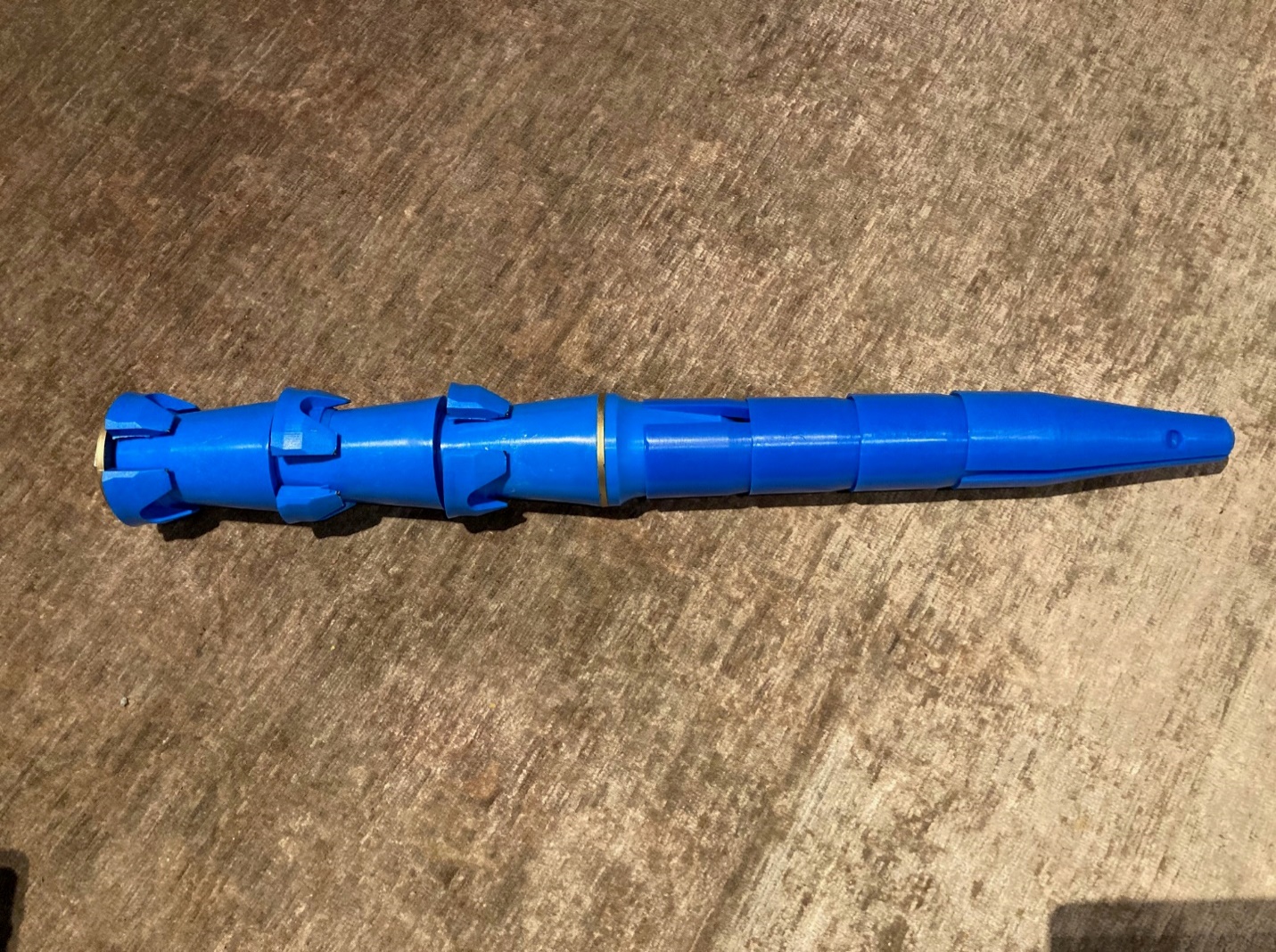
184 The braking system is made up of a series of soft polyurethane wedges that are seated over each other with a split from the top to the bottom of each wedge. The first wedge is seated over the “head piece” made of hard nylon, which runs from the metallic ring in the middle of the SafetySpear up under the first wedge, and to which the first wedge is connected.
185 The triggering system comprises:
(a) three tapered sections made of a hard nylon that sit below the head piece and are joined solidly together with the head piece;
(b) a retaining plate, lock nut, and internal pipe, which holds the headpiece and three tapered sections together; and
(c) three expansion rings also made of hard nylon, each with a small outwardly-flared lip at the bottom. Prior to use, each expansion ring is seated separately over the narrowest section of a tapered section. These rings can be squeezed by hand to reduce their circumference and diameter by a small amount, and can be forced by hand some distance up each tapered section.
186 The SafetySpear is supplied with instructions printed on the side of the box in which the SafetySpear is packaged. It is also supplied with a more detailed set of instructions inside the box.
187 There are two versions of the SafetySpear, each suited for a particular bore diameter (namely, 89 mm and 102 mm bores), with all elements of the SafetySpear other than the expansion rings slightly narrower than the respective bore size. According to both sets of instructions, the SafetySpear is inserted into the bore using a drilling machine, braking system first. It is pushed into place rather than requiring percussive force.
188 When each expansion ring reaches the collar of the bore, the ring is elastically compressed slightly by the wall of the bore so that it can fit in and slide up the bore while exerting a small force against the bore wall. According to the instructions the SafetySpear must be “installed at least 1.5 m into competent rock”, or pushed up into the bore hole at least 1.5 m or until competent rock is found.
189 When the drilling machine pulls back, the SafetySpear remains seated in the bore, where it is left under its own weight. The pressure of the expansion rings against the bore wall holds the SafetySpear in place.
Testing of prototype SafetySpears
190 Mr Sutton is the designer of the Safety Spear. He initially tested the Safety Spear successfully in a goldmine in Fosterville, Victoria.
191 Murray is a mechanical and electrical maintenance service provider for equipment used in underground mining operations. Murray supplies mechanical and electrical mining equipment and machinery to mining operators such as BHP Billiton, Goldfields Australia and Northern Star, and to contract miners such as Byrnecut.
192 Murray and Byrnecut are associated corporate entities that have the same shareholders and a similarly comprised board. Byrnecut is the largest underground mining contractor in Australia. It carries out underground mine feasibility, mine development, mine production and mine engineering consultancy services (including establishing underground mines and extracting ore). Byrnecut is currently involved in 15 underground mining projects, including Northern Star’s Carosue Dam Gold Mine (Carosue Dam) in Western Australia.
193 A prototype SafetySpear was tested by Byrnecut using two drop tests at Carosue Dam in March 2020. The testing involved drilling an 89 mm diameter bore hole between two underground mine tunnels, one of which was above the other. A SafetySpear prototype was installed in the lower end of the bore, in accordance with the supplied instructions. A number of linked drill rods were hung from a tripod above the bore hole and then dropped approximately 20 m into the bore hole onto the installed SafetySpear to simulate the impact of falling drill rods.
194 The prototype failed the March 2020 drop tests as the prototype SafetySpear was ejected from the bore hole by the falling drill rods. Mr Sutton wrote to Mr Spencer of Byrnecut on 30 March 2020 and stated:
It seems the … SafetySpear spiral base was just not hard enough for your rock over there, luckily the 86-30 alloy we make the bases out [of] can be easily hardened … In the meantime I am redoing tests on the weight-bearing capabilities of the SafetySpear when it is driven into the back of the rods.
195 Changes were made to the prototype SafetySpear to harden the spiral base and the new prototype SafetySpear was subjected to further drop tests in May 2020 which also failed. Mr Sutton summarised the May 2020 tests, and their implications in a report:
A. Driving Test Spiral Bases Only.
Two separate driving tests with spiral bases only (no wedges) to ascertain the correct hardness of the spiral base and its interaction with the surrounding rock and the installation dolly.
450 Brinell hardness and 370 Brinell hardness. Both spiral bases were driven approximately 20 metres between levels. Both spiral bases were damaged significantly due to the high energy and heat created when driving them through.
The wear rate on the spirals themselves was substantial which would unfortunately not allow the SafetySpear to be used as a “drive into the back of the rods” plugging system. The heat generated out of this frictional drive burnt all the paint to black. This indicates that the amount of heat would melt the polyurethane wedges and render the SafetySpear unserviceable.
The damage done to the end of the installation dolly that contacts the spiral base was significant. This has occurred because when two metals of similar hardness are impacted together, both share the damage load. In the original softer spiral base, it was the sacrificial element and therefore no damage was done to the installation dolly.
B. High impact drill string drop test.
This test was carried out on the 26th May, 2020. The tubes (5 x ST58s) were dropped approximately 20 metres onto the installed SafetySpear with the hardened 370 Brinell spiral base. The SafetySpear was unable to prevent the escape of the tubes. The cause appears to be the inability of the spiral base to jam itself into the rock strata due to the ground hardness.
It appears that while the spiral base works well in softer ground such as that at the Fosterville Gold Mine in Victoria and the 24MPA concrete blocks in our above ground test rig, it is unable to initiate the wedges into action, as it does not hold well enough to trigger the wedges into their engaged position. This is due to the ground being so hard (even with the hardened spiral bases) that it wears the spiral fins from the front edge back, exacerbating the tapered shape over its length. Therefore, it makes the spiral base easier to knock out as the required jamming effect does not come into effect.
CONCLUSION
The short answer is that the spiral base design to initiate the wedge expansion action is not good enough for the Western Australian hard rock ground. While it will work in the softer rock ground such as the Fosterville Gold Mine, this does not have the broad-based, one-size-fits-all product requirement. Therefore, the options open to us are: re-design the base and re-test with a view to moving towards a design that doesn’t require high impact driving installation (and no heat generation), rather move to a push in interference fit where the hardness of the ground is not a significant factor, or abandon the idea and not pursue the market space.
196 After the May 2020 test failures, Mr Sutton redesigned the prototype SafetySpear with a lighter plastic or polyurethane base. In an email to Mr Spencer dated 21 July 2020 (21 July 2020 email), Mr Sutton wrote:
…
The new high impact plastic bases for the SafetySpear have done 22 drops through the test rig but there is only one test that matters, which is the one that your team will do.
…
I need you and your team to do two main tests, which will require two separate 89mm holes to be drilled.
Please do the drop test first.
First Test:
Drop test from one level to another, 20 m + if possible, using ST-58 tubes on one SafetySpear installed to 1.5 m.
Second Test:
Wear Test from one level to another. Need approx. 3 passes.
Pushing the SafetySpear (just the base without the wedges on the front) up through the same hole repeated multiple times to prove it's resistance to wear against the rock. Measure the outside diameter of the expansion ring after each push through to monitor the wear rate.
197 On 18 and 19 August 2020, the redesigned prototype SafetySpear was tested in multiple drop tests and a wear test at Carosue Dam (August 2020 drop tests). This time the redesigned prototype passed. The drop tests involved the use of a long hole drill rig positioned above the hole to drop the string of rods (five 1.8 m tubes), rather than the tripod of the earlier tests. The SafetySpear was installed 1.8m up the bore hole into competent ground.
198 In his report of the August 2020 drop tests Mr Spencer wrote:
The first trial was conducted on Monday night, drilling a 19.5m hole (89mm) on a 17.9 degree angle.
Unfortunately the hole was making water after it was drilled and when the Safety Spear was installed it actually plugged the hole causing it to fill with water.
We carried on with the drop test, dropping five ST58 tubes but with the hydraulic pressure in the hole we were unable to get the acceleration required.
However, the plug caught the tubes and they were not ejected from the hole.
The second trial was conducted Tuesday night, drilling a 19.7m hole on a 17.9 degree angle with a brand new 89mm drill bit. Two holes were drilled this time in order to get a dry one.
After completion of the hole we installed the Safety Spear at 1.8m (One tube length) into competent ground.
We confirmed this using a paint stick to measure the installation depth, the pink mark on the paint stick below is at 2m.
The tubes were then dropped and successfully caught by the Safety Spear.
A second measurement was taken using the paint stick and as you can see from the picture below (sort of) it has not budged the plug from its original position, if it has then very marginally.
…
199 On 19 August 2020, Mr Spencer wrote in an email to Mr Coughlan, copied to others including Mr Sutton and Mr Law:
The latest trial of the Safety Spear was conducted over the past couple of nights with successful results.
We installed the Spear @ 1.8m up the 19.7m hole and dropped 5 x 1.8m ST58 Tubes down from the level above.
The rods were successfully caught by the Safety Spear without budging from its original position.
The latest version of the Spear is obviously a lot lighter than the original and is very easy to handle and install.
200 The prototype SafetySpear the subject of the August 2020 drop tests was a handmade prototype, not a commercial production model of the SafetySpear.
201 In January 2021, Murray, Rattlejack and Pan Australis entered into a “Partnering Agreement” which provided for the sale on consignment, to Byrnecut, of an initial delivery of 200 SafetySpears. Murray submits that the supply was for experimental purposes and as such does not infringe the Patents as the exemption under s 119C of the Act is enlivened. The experimental use exemption is considered later in these reasons.
202 Following the supply of the 200 SafetySpears to Byrnecut in April 2021, the SafetySpear was to be trialled by Byrnecut at multiple Byrnecut mine sites and operations in Western Australia and Queensland.
203 Of the initial 200 SafetySpear products, there were approximately 50 remaining in Murray’s warehouse by the time the trials were halted in September 2021.
Infringement by the SafetySpear
204 Jusand’s case is that Rattlejack has infringed the 556 Patent and the 163 Patent by offering to sell, supply, or otherwise dispose of the SafetySpear; and that it has infringed the 956 Patent by supplying the SafetySpear together with instructions, by reason of s 117(2) of the Act.
205 Jusand seeks relief only in respect of the current version of the SafetySpear, 200 of which were supplied to Byrnecut. Jusand does not allege that the earlier SafetySpear prototypes that were tested in August 2020 (or the failed earlier tests) infringe the Patents.
206 Jusand bears the onus of establishing that the SafetySpear has each and every essential integer of at least one valid claim of the Patents.
207 As noted above, the only integers remaining in dispute are:
(a) “Anchor member”; and
(b) “A proximal end region of the bore adjacent to a rock-face”.
Anchor member
208 Jusand contends that the SafetySpear has an anchor member on either construction of that term. Jusand submits that there is “no issue” that each of the three split plastic rings of the SafetySpear operates as an anchor member on its construction, in that they fix the SafetySpear in place within a bore until such time as it may be struck by a falling drill rod section and then resist and check down hole movement of the SafetySpear.
209 On the construction that I have found, the anchor member does not move when hit by a falling drill rod section other than a de minimis amount (less than 5 mm).
210 Jusand relies on the results of the August 2020 drop tests conducted at the Carosue Dam mine to establish that the SafetySpear has an anchor member that does not move when hit by falling drill rods. The evidence about the August 2020 drop tests comprised two blurry photos from Mr Spencer’s report (one of the photos is reproduced above). These showed a long stick with a pink circle painted 2 m from the end poked into the bore hole before and after the drop test, and Mr Spencer’s statements in his report and email of 19 August 2020 to the effect that the SafetySpear had not moved during the trial. This approach suffers from a number of flaws.
211 First, Jusand relies on the 200 current model SafetySpears for its infringement case. It does not allege that the SafetySpear prototypes used in the August 2020 drop tests infringe the Patents.
212 The evidence was that the SafetySpears used in the August 2020 drop tests were handmade prototypes. In an email to Mr Spencer of 21 July 2020, Mr Sutton wrote:
I’ve sent you two handmade SafetySpears, one is assembled, the other is the base on it’s [sic] own and some spare top wedges should you need them. See photo attached of the foam insert under the expansion rings (please leave it there), this is in there while we do these tests to keep it clean, the production model will have a thin ‘skirt’ that will both hold the rings firm and keep dirt out (not that it is a major problem).
213 Importantly, there is no evidence that the handmade prototypes used in the August 2020 drop tests were the same as the 200 SafetySpears supplied to Byrnecut which are the subject of the proceeding. The photographs of the prototype Mr Spencer was given for testing in the August tests shows that the prototype was different to the SafetySpear the subject of the proceeding. The black prototype in the reproduced photograph below was missing the “lip” on the base of the expansion ring of the SafetySpears alleged to infringe. The lip can be seen on the expansion ring in the picture of the blue SafetySpear in the previous section.
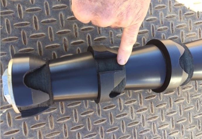
214 Dr Fuller explained that the existence of the lip reduces the surface area of the SafetySpear that comes into contact with the bore, reducing friction between the device and the hole, and thus making it more likely that the production version of the SafetySpear will slide down the bore when it is struck.
215 Second, Mr Spencer’s statement in an email of his opinion that the prototype had not moved substantially or budged during the drop test was only a rough estimation, made from where he stood below the bore hole watching the test without the benefit of any measurements other than comparing the approximate distance of a painted line on a stick from the shotcrete covered ceiling of the mine. The use of a painted line on a long stick is an imprecise and inaccurate method by which to measure whether there has been movement of greater than the order of 5 mm. Whilst such a method might be sufficient to demonstrate substantial movement in the order of half a metre or so, it is not adequate to establish whether there has been movement of 5 mm. There are many sources of potential error, not limited to the angle of the stick, whether the end of the stick is touching the edge or the centre of the SafetySpear (or the same point as the first “measurement”) and the position of the observer in the mine, so as to render it impossible to determine on the basis of one pair of blurry photos whether the SafetySpear has moved more than a de minimis amount.
216 Even then, on close inspection of the blurry enlarged photos taken of the August 2020 drop test, there appears to be movement of the SafetySpear of more than a few millimetres (ie there is a detectable difference in the position of the pink circle).
217 I also note that no leave was sought from the Court by Jusand to rely on the drop tests as experimental proof of a fact pursuant to r 34.50(2)(b) of the Federal Court Rules 2011 (Cth). Neither expert was present to observe the August 2020 drop tests. Nor were they able to provide input into the design of the tests.
218 For these reasons, the August 2020 drop tests do not establish that the SafetySpear has an “anchor member”. Nor do they establish how the SafetySpear, the subject of this proceeding, works in operation, and whether there is any movement of the SafetySpear down the bore hole (de minimis or substantial) following it being hit with a falling drill rod.
219 Mr Davison and Dr Fuller were both provided with a SafetySpear for use in 89mm bore holes, the instructions on the side of the SafetySpear box, and a copy of the SafetySpear instruction sheet.
220 Neither of the experts had seen the SafetySpear in operation. Mr Davison’s evidence was that it was difficult to understand how the SafetySpear functions even if he was to see it in operation in a mine site. Dr Fuller agreed, and said that experiments would be required to be undertaken to determine what forces were required to move the SafetySpear down a bore. No such experiments were in evidence.
221 Dr Fuller’s second letter of instruction set out a series of steps describing the working of the SafetySpear in operation being hit with a falling drill rod section, culminating with:
When a broken drill rod section hits the SafetySpear, the whole SafetySpear slides back down the bore as it “catches” the broken drill rod section. The average distance that the SafetySpear slides is between about 200mm and 700mm, depending on momentum of the falling rods and the ground conditions.
222 Dr Fuller was asked in the first letter of instruction to provide his answer to the question whether each and every integer of claims 1 and 4 of the Patents was present in the SafetySpear product when it was used in accordance with the instruction sheet having regard to the instructions in the letter as to the operation of the SafetySpear. Dr Fuller was also provided with a document entitled “Operational description of the SafetySpear” by Rattlejack’s legal advisers, but which he was later asked to disregard.
223 On the basis of his instructions Dr Fuller prepared an integer table considering whether any integers of the relevant claims of the Patents were found in the SafetySpear.
224 No evidence was led by Rattlejack to support the assumptions made as to the operation of the SafetySpear in Dr Fuller’s second letter of instruction.
225 Dr Fuller agreed in cross-examination that his view as expressed in his integer table was that the triggering system of the SafetySpear was not an anchor member, because it, together with the braking system, moved down the bore until the SafetySpear eventually stopped. This view was based on the description of the operation of the SafetySpear in his second letter of instruction and also in part on the document he was asked to disregard.
226 Both experts thought it possible that the SafetySpear might move in operation when hit by a falling drill rod section. There was disagreement as to how much movement there might be.
227 Mr Davison agreed in his affidavit dated 6 August 2021 that it was “possible, even likely, for some movement [of the SafetySpear] to occur, depending on the magnitude of the impact and the properties of the rock in the bore hole”. In the joint report he said on the basis of the photos (which Dr Fuller had been instructed to ignore), he believed the movement would be minor, but gave no indication of what “minor” might be.
228 In cross-examination, Mr Davison referred to some “experimentation” by him, the details of which were not revealed, but which appeared to involve only one expansion ring, as the basis for his view that he would not expect the SafetySpear to move very much if at all, if hit by 500kg of falling rods.
229 In the joint session, Dr Fuller referred to the three split or expansion rings, in particular their very small contact area and their overall small dimensions, as a reason why he expected the SafetySpear to move down the bore in operation. When it was put to Dr Fuller that the split rings of the SafetySpear might stop movement down the bore of more than a few millimetres, Dr Fuller said he “would doubt that very much”. He based his response on a calculation of the forces involved, in which he assumed that the split ring would act as two separate elements. Dr Fuller described the two-dimensional calculation of wedge forces as relatively straightforward; the lateral force is a ratio of the downward force which is a function of the α angle on the cones and the coefficient of friction between the two sliding materials. Assuming that the material was Nylon 66, and a 6.5 degree α angle on the cones, on Dr Fuller’s calculation, the horizontal forces would be expected to be less than the vertical impact force.
230 Mr Davison said that in his understanding of wedges, the lateral force is usually higher than the downward force. However, he conceded that he had not measured the α angle of the cones, or done any calculations. Mr Davison said that he did not carry out any calculations as there were quite complicated shapes involved and he was not a mechanical engineer.
231 Ultimately, neither expert could say definitively if, or how far the SafetySpear would move in the bore under any impact loading. In the absence of any experiment to establish whether the SafetySpear moves down the bore hole in operation, and if so, how far, or probative expert evidence on this subject, Jusand has failed to discharge its onus and thus the infringement case must fail.
Proximal end region of the bore adjacent to a rock-face
232 Jusand contended that there was no issue that the anchor member of the SafetySpear was able to be located anywhere in the proximal end region of the bore, including with its base flush with the rock-face, as well as inserted further into the bore.
233 To support its contention, Jusand relied on Mr Spencer’s report of the August 2020 drop tests at the Carosue Dam mine in which he said that the SafetySpear did not budge. For the reasons set out above in relation to the anchor member, the August 2020 drop tests of the prototype cannot assist Jusand.
234 There was disagreement between the experts as to whether if the SafetySpear was located with its base flush with the collar of the bore at the rock-face it would function to stop falling drill rod sections in that position.
235 Dr Fuller’s evidence was that if the SafetySpear was installed with its base flush with the collar of the bore, “there would be a significant risk of the whole lot moving right out of the bore – being pushed out by the falling drilling rods”. Mr Davison’s view was that if the operation of the SafetySpear depended on whether or not one ring was exposed from the collar of the bore then the device wouldn’t work in any circumstances.
236 The SafetySpear instructions (both those on the box and the instruction sheet included with the product) make it clear that the SafetySpear should be pushed into the bore hole at a minimum of at least 1.5 m into competent rock. The diagram on the instruction sheet indicates that the 1.5 m is to be measured from the base of the SafetySpear. The instructions say that the SafetySpear can be used for a hole drilled up to 25 m in depth, or it can be used in holes up to 40 m if it is driven until it “self-engages into the bogged rods”. If the instructions are followed, the SafetySpear will always be installed so that the base of the SafetySpear is at least 1.5 m into the bore from the collar.
237 The instruction sheet notes that the reflective base of the SafetySpear helps in-hole inspection, as a person shining a torch up the bore hole can see the reflective base of the SafetySpear. Dr Fuller considered the reflective base would not be necessary if the SafetySpear was intended to be installed with its base at or near the collar of the bore.
238 The Asserted Claims require the safety system of the invention to be inserted so that the impact reduction member sits above the anchor member in the bore. Thus, if the anchor member of the SafetySpear is located higher in the bore than the proximal end region, so must the impact reduction member.
239 Jusand has not established that the SafetySpear is installed contrary to the instructions with which it is supplied. Given that the lives of those working in the mine are at stake it would be expected that those inserting the SafetySpear would follow the instructions provided, rather than disregard them.
240 If the SafetySpear is installed according to its instructions the anchor member would be installed in the outer limits of the proximal end region. At that point, no part of the SafetySpear would be adjacent or near a rock-face.
241 Jusand has failed to establish that the SafetySpear has this integer.
242 Both these integers are in each of the independent claims of all the Patents. The evidence does not establish that the SafetySpear has either of the integers in dispute. There is no infringement of any of the Asserted Claims.
SECTION 119C “EXPERIMENTAL PURPOSES” EXEMPTION
243 I have found that the SafetySpear does not infringe the Asserted Claims of the Patents. For completeness, I will consider whether the s 119C exemption raised by Murray would apply if my finding on infringement was different.
244 As noted earlier, Jusand seeks relief only in respect of the current version of the SafetySpear, 200 of which were supplied to Byrnecut by Murray. Jusand does not seek relief in respect of the SafetySpear prototypes that were the subject of the failed drop tests in March and May 2020, or the successful August 2020 drop test.
245 Murray denies any infringement of the Patents. It says that its provision of 200 SafetySpear products to Byrnecut was done for experimental purposes, and that by reason of the operation of s 119C of the Act, that supply does not constitute infringement. Murray is the only respondent to rely on the s 119C exemption.
246 Section 119C provides that:
119C Infringement exemptions: acts for experimental purposes
(1) A person may, without infringing a patent for an invention, do an act that would infringe the patent apart from this subsection, if the act is done for experimental purposes relating to the subject matter of the invention.
(2) For the purposes of this section, experimental purposes relating to the subject matter of the invention include, but are not limited to, the following:
(a) determining the properties of the invention;
(b) determining the scope of a claim relating to the invention;
(c) improving or modifying the invention;
(d) determining the validity of the patent or of a claim relating to the invention;
(e) determining whether the patent for the invention would be, or has been, infringed by the doing of an act.
247 The Oxford Dictionary defines “experiment” as:
3. An action or operation undertaken in order to discover something unknown, to test a hypothesis, or establish or illustrate some known truth.
a. in science.
248 Section 119C was introduced into the Act by the Intellectual Property Laws Amendment (Raising the Bar) Act 2012 (Cth) (Raising the Bar Act).
249 Prior to the introduction of the experimental use exemption the Advisory Council on Intellectual Property (ACIP) and the Australian Law Reform Commission (ALRC) both recognised that there was significant uncertainty as to the existence and scope of any implied experimental use defence to patent infringement in Australia.
250 Both the ALRC and ACIP considered it desirable to remove the uncertainty and recommended the introduction of an experimental use exemption into the Act.
251 The Explanatory Memorandum accompanying the Intellectual Property Laws Amendment (Raising the Bar) Bill 2011 (Cth) and the introduction of s 119C (Explanatory Memorandum) recognised that the patent system exists to encourage innovation and promote the dissemination of technical knowledge:
It rewards the innovator who has invented a new and useful product with a time-limited exclusive right to exploit their invention. In exchange the inventor must disclose their invention to the public. In this way innovators gain a competitive advantage to commercialise their inventions, while the public and the research community gain access to information about new technology. Researchers can then study, test and improve on the new technology for the benefit of society as a whole.
252 It noted that concerns had been raised that the lack of a statutory exemption from infringement for research and experimental activities in Australia was causing uncertainty and disincentives in the research community, and for follow-on inventors:
Uncertainty discourages researchers from working in areas where there are patents, and where they may be at risk of being sued for infringement. It also leads to researchers expending effort and expense on obtaining advice, where they have concerns about how the experiments intersect with the patent system. These inefficiencies detract from the system.
253 The Explanatory Memorandum stated in relation to the introduction of s 119C:
The item implements these recommendations by introducing a statutory exemption from infringement for research and experimental activities.
It is intended that “experimental” be given its ordinary English meaning. The exemption should apply to tests, trials and procedures that a researcher or follow-on inventor undertakes as part of discovering new information testing a principal or supposition.
To provide certainty and clarity for researchers, an additional inclusive list of activities that are deemed to be experimental has been included. This list is not intended to be exhaustive and a court may find that other activities also fall within the meaning of “experimental”.
The exemption is not intended to apply only to circumstances where activities are undertaken solely for experimental purposes. This would ignore the reality of the current research environment, where research is frequently undertaken mixed purposes.
For example:
• a researcher may be contracted and paid to undertake experiments;
• research may be conducted with a view to ultimately commercialising the end-product of the experimentation; and
• research may be undertaken with, and partially funded by, a commercial partner.
In each of these circumstances the exemption should apply as long as the specific acts are undertaken for the predominant purpose of gaining new knowledge, or testing a principle or supposition about the invention. Thus if an activity is conducted primarily for the purpose of improving a patented invention, the activity would still be exempt, even if the person also had in mind commercialising the improvement in the future.
However, the exemption is not intended to apply where the main purpose of the act is to commercialise the invention, or to manufacture it for the purpose of sale or use for commercial purposes. Additionally, market research on a patented invention (eg making and using the invention to test the likely commercial demand for a product) is not intended to be exempt. This too has a predominantly commercial purpose
254 The ALRC considered the issue of experimental use in chapter 13 of its Report entitled “Genes and Ingenuity: Gene Patenting and Human Health” published in 2004. It noted that ACIP was also undertaking a review of patents and experimental use at the same time.
255 As part of its consideration the ALRC reviewed the position in other jurisdictions including New Zealand (which had no express exemption), the United States and the United Kingdom. The United States case law recognised a limited experimental use defence.
256 In Roche Products Inc v Bolar Pharmaceutical Co 733 F 2d 858 (Fed Cir, 1984), the United States Court of Appeals for the Federal Circuit found that the defence was dependent on the experiments involved being for “amusement, to satisfy idle curiosity, or for strictly philosophical inquiry” and not for business reasons. In Embrex Inc v Service Engineering Corp 216 F 3d 1343 (Fed Cir, 2000) at 1353, the Court of Appeals confirmed that the exemption should be interpreted narrowly and that a use is disqualified from the defence if it has even the “slightest commercial implication”. The “very narrow and strictly limited” nature of the experimental use defence was upheld in Madey v Duke University 307 F 3d 1351 (Fed Cir, 2002).
257 The ALRC reported that Canadian case law established an experimental use defence which was available when experimentation is “not for profit”.
258 The ALRC reported that the United Kingdom enacted an experimental use defence in s 60(5) of the Patents Act 1977 (UK) (the UK Act). The UK Act provision states that:
(5) An act which, apart from this subsection, would constitute an infringement of a patent for an invention shall not do so if –
…
(b) it is done for experimental purposes relating to the subject-matter of the invention.
259 The ALRC report referred to the consideration by Dillon LJ of the United Kingdom’s s 60(5) “experimental purposes” exemption in Monsanto Co v Stauffer Chemical Co [1985] RPC 515 (Monsanto). I consider this decision below.
260 ACIP also looked at what exemptions, if any, were available in other jurisdictions including the United States, Europe, Canada, Germany, New Zealand and the United Kingdom in its report entitled “Patents and Experimental Use” (2005).
261 ACIP noted that:
The objective of patent rights is to encourage and diffuse industrial innovation in a manner that benefits society as a whole. In general, the more innovation that occurs, the greater the potential gains to society. The state encourages innovative activity through awarding people the exclusive rights to new, useful products or processes they have created, in return for their full disclosure.
262 ACIP also noted that the use for experimental purposes shouldn’t unreasonably conflict with the normal exploitation of a patent.
263 ACIP noted that the courts in the United Kingdom have provided some guidance on what is meant by “experiment/experimental”. ACIP also referred to Dillon LJ in Monsanto as drawing a line according to whether an experiment sought to generate genuinely new information, or if it merely sought to verify existing knowledge.
Secret use — “reasonable trial or experiment only”
264 Both parties also looked to the authorities relating to secret use for guidance as to what might constitute “experimental purposes” for the purposes of s 119C.
265 Section 18(1)(d) of the Act provides that an invention is a patentable invention for the purposes of a standard patent if the invention, so far as claimed in any claim:
was not secretly used in the patent area before the priority date of that claim by, or on behalf of, or with the authority of, the patentee or nominated person or the patentee’s or nominated person’s predecessor in title to the invention.
266 Section 9 of the Act provides that for the purposes of the Act, the following acts are not to be taken to be secret use of an invention in the patent area:
(a) any use of the invention by or on behalf of, or with authority of, the patentee or nominated person, or his or her predecessor in title to the invention, for the purpose of reasonable trial or experiment only; …
(Emphasis added.)
267 In Azuko Pty Ltd v Old Digger Pty Ltd (2001) 52 IPR 75 at [181] (Azuko), Gyles J referred to a passage from the decision of Lord Diplock in Bristol-Myers Co v Beecham Group Ltd [1974] AC 646 at 680–1 where he explained that the UK equivalent secret use provisions were directed towards the “mischief” of a patentee reaping a commercial benefit from their invention from a de facto extension of their patent term before the priority date. The inventor should not, by using the invention for a period of time prior to disclosing it, derive greater advantage from it than is contemplated by the Act. Gyles J said that Dillon LJ’s passage suggests a practical test: has what occurred amounted to a de facto extension of the patent term? His Honour noted that the answer will usually depend upon whether the patentee reaped commercial benefit from what was done before the priority date.
268 Ultimately Gyles J held at [183] and [187] that the manufacturing of the hammers with which the Court was concerned was not commercial use, and thus there was no relevant “use” within the meaning of s 18(1)(d), and no need to consider whether ss 9(a) or (b) might have any application (Beaumont J agreeing at [72]).
269 Justice Heerey, in dissent in Azuko, considered the history of secret use as a ground of invalidity from [111] to [144]. After finding there had been use, Heerey J then considered whether the “reasonable trial and experiment” exemption of s 9(a) applied. He found at [147] that production of 15 or 20 hammers in a condition ready for commercial sale, an order having been received for five or six, could not be considered a matter of trial and experiment, let alone only trial and experiment. The production of 15 to 20 hammers of a “commercial quality” indicated that any trial and experiment had concluded. His Honour observed in relation to s 9(a) that:
The provision is limited to trial or experiment to see how the product of an invention performs and whether any improvements are needed, as distinct from commercial or marketing assessments.
270 Section 124 of the Patents Act 1903 (Cth) (the 1903 Act) provided a defence to otherwise invalidating public use of an invention before a patent application was filed, if the use was for “experimental purposes”; a narrower exemption than the one found in s 9 of the Act (where use must have purpose of reasonable trial or experiment only).
271 The High Court in Longworth v Emmerton (1951) 83 CLR 539 (Longworth), considered the nature of “experimental use” in the context of s 124 of the 1903 Act. In that case the invention was a machine for collecting seed, especially seed of paspalum grass. The priority date of the claimed invention was 4 October 1935. In 1934 the patentee constructed a machine along the general lines of the invention on the verandah of his home. The patentee and his brother tested the first machine at the brother’s farm in April 1934. Considerable modifications and improvements were made to the machine after the testing. The patentee built a second machine. In December 1934, one of the machines was used for a day on the farm of another. In between December 1934 and February 1935, the machines were used to harvest on three or four other farms, sometimes operating simultaneously. The owners of the paddocks which were worked were paid a royalty on the seed collected and the inventor sold the harvested seed profitably. The inventor’s evidence was that he wanted to see if the machine would be a commercial success. “I knew it would harvest some seed, but the work I had done in 1934 would not have been on a profit basis. As I went along I tried improvements and alterations”.
272 The High Court held that the patentee’s field trials did not constitute “experimental use” for the purposes of s 124. At 550, Dixon, McTiernan and Kitto JJ stated:
On the facts of the present case it appears to be reasonably plain that the appellant used his invention freely in the district in which he and his brother and brother-in-law lived, taking no precautions to keep its character secret or to confine its use to those who were in confidential relations with him, and that he did so, without any view to definite improvement or experiment of a specific character and not for the purpose of developing the actual invention applied for. The use was not experimental except in the possible but vague sense that the appellant might not have been quite satisfied that the qualities of the machine had been fully tested and might have remained uncertain whether some further improvements might not be affected to make it more efficient. This, in our opinion, was not enough to protect the disclosure which he made in the course of the use of the machine. The use seems to have been wide and unguarded and it could not be considered as reasonably necessary in order to bring the invention to such a condition that he might apply for a patent and described his invention in the specification.
(Emphasis added.)
273 The scope of “reasonable trial and experiment” for the purposes of s 9 of the Act was most recently considered by Burley J (Jagot and Nicholas JJ agreeing) in Coretell Pty Ltd v Australian Mud Company Pty Ltd (2017) 124 IPR 210, in an appeal from a decision that particular testing of the prototype ACT Tool was for the purpose of a reasonable trial and did not constitute secret use.
274 At [205], his Honour set out the relevant findings of the primary judge, including:
The relevant findings of the primary judge are:
[753] …
As I have already found, the prototype had to be trialled in real world conditions and it was reasonable to do so in different locations, having regard to the different conditions experienced in those locations which could affect the nature of the apparatus and the claimed invention.
…
[755] …
The whole exercise of trialling the ACT Tool prototype was occurring in conjunction with preparations for filing a provisional patent and in conjunction with negotiating and arriving at terms on the distributorship agreement. All of these things had to come together. Unless the tool worked in the trials, either modified or unmodified (and the evidence is clear that modifications were made following the trials), clearly the parties would not have reached the ultimate distributorship agreement, nor would there have been any purpose in filing a provisional patent
275 At [206] his Honour noted the primary judge’s finding that:
Field testing involved different types of locations because, his Honour found, the technical team considered that conducting laboratory testing was less appropriate because of the harsh onerous environment that a tool of the type being developed would encounter.
276 At [222] Burley J noted that:
[T]he exception in s 9(a) of the Act will arise if the use is for the purpose of reasonable trial and experiment only. That will be satisfied if the true purpose of the use is for reasonable trial or experiment, even if there is a collateral commercial advantage that accrues to the inventor.
(Emphasis in original.)
277 At [223] his Honour noted that this was explained in Grove Hill Pty Ltd v Great Western Corporation Pty Ltd (2002) 55 IPR 257 (Grove Hill):
In that case, the inventor had used the invention (a row cultivator for crop cultivation) on his farm from September 1992 until December 1993, which included two growing seasons. The purpose of using the equipment was to prove the concept and test the equipment, the subject of a proposed patent, in different conditions. The inventor had already satisfied himself that he knew by that stage that he had an invention that would work. Justice Dowsett explained at [229] (French and Gyles JJ agreeing at [125], [349]):
The [party seeking revocation] also pointed out that the use was in connection with the cultivation of commercial crops. This was no doubt true, but it is difficult to conceive of any field trial of the invention which would not involve such use. If the true purpose of the use is for trial, and the trial is reasonable, any collateral commercial advantage to the inventor is irrelevant. As to the question of reasonableness, Mr Mansur’s explanation of his objectives must be a relevant consideration. It was said that there was no evidence that his trials addressed the problems identified in the patent and that there were no experimental notebooks or other records. While all this may be true, it does not necessarily follow that the trials were unreasonable….
278 At [234] Burley J upheld the primary judge’s finding that the purpose of the trials was to use the ACT Tool prototype in real world conditions, and that the trials were reasonable.
279 The secret use cases are of limited assistance in considering the scope of the infringement exemption in s 119C of the Act.
280 First, the s 119C exemption is directed to acts for “experimental purposes”, whereas the exception in s 9(a) is directed to use for the purposes of “reasonable trial and experiment only”. The scope of the exemption provided by s 119C must be narrower than the s 9(a) exception as s 119C makes no reference to trials, reasonable or otherwise.
281 Justice Dowsett recognised the distinction between trials and experiments in Grove Hill. At [231] his Honour noted that in Longworth, the High Court was considering only the question of experiment whereas s 9(a) speaks of both trial and experiment:
The structured and specific research processes often adopted in experimentation will not necessarily be relevant in trials. The latter process may simply involve “seeing how it goes”, when the invention is employed in the field. In such a situation adjustment and fine tuning may not be recorded as would be the results of laboratory experiments.
282 In each of Coretell and Grove Hill the Full Court was concerned with considering whether the particular uses were for the purposes of reasonable trial. Neither appeal focussed on what constituted the “experimental” part of the exception.
283 Justice Heerey, in dissent in Azuko, was the only judge on the appeal to consider whether the secret use exception applied. It was not necessary for his Honour to differentiate between trials and experiments as he found on the evidence the use was for commercial purposes, not for trial or experiment.
284 Second, whilst both the secret use exception and the experimental purposes exemption affect the rights of the patentee, the former is focussed on the conduct of the patentee (or nominated person) and the latter on the conduct of a potential patent infringer. The rationale for the existence of each is different.
285 In the secret use exception in s 9(a), the focus is on the use of an invention by the patentee of a potential patent before the filing of a patent application. The secret use provision recognises the tension between a patentee obtaining a de facto extension of the patent term, with no accompanying disclosure to the public, and the patentee’s need to perfect and fine tune an invention prior to filing a patent application in order to obtain the best protection possible. Kekewich J explained the balance in the prior use case, Hudson, Scott & Sons Ltd v Barringer, Wallis and Manners Ltd (1906) 23 RPC 79 (Hudson):
No man can draw up a specification, which will have the slightest chance of holding water, without testing the results which he is going to state in that specification, …
But he is not entitled to put [the invention] on the market… he is not entitled to go to persons who are likely to be customers and say: “If I bring this out, will you order so many? Here is a sample, perhaps not complete – more or less in the rough – but with regard to which you, who know these things can tell exactly what will be forthcoming”… He is not entitled to insure himself against failure, and still more to ensure success, by obtaining orders in advance, and then, having done that, to patent and obtain protection for what he has really used in that way.
286 Section 119C, on the other hand, provides a limited exemption from patent infringement. The confined reference in that section to only acts for “experimental purposes”, rather than reasonable trial or experiment, evinces a legislative intent to include a narrower scope of acts within the exemption than the secret use exception of s 9(a). The balance to be struck in s 119C is, on the one hand, the right of the patentee to be rewarded for disclosing their invention (with a statutory monopoly), and on the other, the ability of members of the public to study, test and improve upon the invention, to determine the properties of the invention or to modify the invention, or evaluate the likelihood or risk of their conduct infringing the claims by determining the scope of the monopoly relating to the invention and the validity of the claims.
287 Section 119C must also be read consistently with the object in s 2A of the Act:
To provide a patent system in Australia that promotes economic wellbeing through technological innovation and the transfer and dissemination of technology. In doing so, the patent system balances over time the interests of producers, owners, and users of technology and the public.
288 As submitted by Jusand, it would not be consistent with the object as set out in s 2A of the Act for any element of experimental purpose, no matter how inconsequential, to bring the relevant exploitation within s 119C.
289 Applying s 119C to ordinary commercial activities with minimal, or, in reality, no actual experimental purposes, would be contrary to the object of the Act. Falconer J reached a similar conclusion in Monsanto at 522:
I feel it cannot have been the intention of the legislature to include in the exemptions from infringement of paragraph (b) of section 60(5) tests or trials intended, as their purpose, to promote, ex hypothesi an infringing product with a view to its wider or better marketing by the infringer when he should be free to market it, as, for instance, when the patent expires.
290 The Explanatory Memorandum makes plain that the exemption is not intended to only apply to activities solely undertaken for experimental purposes. There may be a commercial aspect or ultimate aim to the experimentation. However, the experiments should be undertaken for the predominant purposes of gaining new knowledge or testing a principal supposition about the invention. Such activities are to be contrasted with the “see how it goes” trialling of an invention of the kind contemplated by Dowsett J in Grove Hill.
291 As noted in the ALRC report, the UK’s experimental purposes exemption (s 60(5) of the UK Act) was considered by Dillon LJ in Monsanto. Monsanto was an appeal from the decision of Justice Falconer refusing an application by the defendants to modify an injunction to allow them to carry out “experiments relating to the subject matter of the invention”. The defendants argued that the object of the injunction was to restrain infringement and that their intended experiments using their herbicide “TOUCHDOWN” would not be infringing acts by reason of the experimental exemption in section 60(5) of the UK Act.
292 The defendants, sought to conduct three categories of field trial of their herbicide. The trials sought to be carried out were:
(1) by the defendants on their own research farm;
(2) by the defendants’ personnel on rented farms; and
(3) for the defendant by third parties such as the Forestry Commission and certain Water Authorities.
293 At first instance Falconer J accepted the first category of trial as being for experimental purposes, but did not accept that the second and third categories of trial were for experimental purposes:
It seems to me that the limitation would exclude tests or trials having as their purpose achieving or extending the commercial acceptance of some commercial embodiment of the patented invention – such tests or trials would not, it seems to me, as a matter of language, the for purposes related to the subject matter of the patented invention.
(Emphasis in original.)
294 Falconer J considered it a sensible assumption that the Parliament in using “experimental” was using it in a sense that reflected how it had been used in patent jurisprudence, not some new or different sense. In determining the matter, therefore, he turned to the UK authorities as to the meaning of “experiment”, beginning with the cases on prior use, including Hudson, and then infringement.
295 On appeal, Dillon LJ (with whom Denys Buckley J and Watkins LJ agreed) began by observing that “experiment” is an ordinary word in the English language that has never been a term of art in UK patent law. He also noted that s 60 was enacted to bring UK patent law into line with the corresponding provisions of the Community Patent Convention and there was no reason to suppose that the Convention signatories concerned themselves with the minutiae of earlier UK patent law. On that basis Dillon LJ ignored the earlier UK authorities as to the meaning of “experiment” that had been considered by Falconer J.
296 Lord Justice Dillon rejected the plaintiff’s submission that the words “for experimental purposes” are limited to experiments in the privacy of a laboratory or glasshouses. At 538 he stated:
What may legitimately be the subject of experiment may perhaps depend upon the nature of the product but, with herbicides or compositions to stimulate plant growth, it must surely be a legitimate area for experiment to see if results obtained in the laboratory or glasshouse can also be achieved in natural conditions in the open air where a product is to be used.
297 Lord Justice Dillon refused to draw a line excluding experiments directed to the commercial exploitation of the invention. He referred to the sort of experimental activity considered by the Canadian Supreme Court in Micro-Chemicals Ltd v Smith Kline and French Inter-American Ltd [1972] SCR 506 at 513 which was “a limited experiment to establish whether the experimenter could manufacture a quality product commercially in accordance with the specification of the patent, as being covered by the words for ‘experimental purposes relating to the subject-matter of the invention’”.
298 Lord Justice Dillon modified the injunction to allow acts done for experimental purposes in the first category field trial: in laboratories and glasshouses or on the defendants’ research farm. He refused to modify the injunction to cover the second or third category of field trials.
299 The second category covered activity in which the defendants wanted to use their herbicide on different crops, at different stages of the year, at different concentrations, on small areas (of perhaps a couple of acres each), on some 20 to 25 farms across the United Kingdom, and to tabulate the results. The defendant submitted that it was necessary to see if what is successful in the laboratory or glasshouse works successfully out of doors, and it is necessary that the experiments should be carried out in different soil conditions and in different climate conditions. They argued that what works in California will not necessarily work in England, and what works on their farm in Essex may not necessarily work in Wales or Cumbria.
300 Lord Justice Dillon considered that the problem was whether in light of all that the defendants had already done culminating in the commercial launch of TOUCHDOWN in August 1983, what they wanted to do by the field trials could fairly be classified as experimental, or was in truth merely a matter of amassing statistics to further the commercial exploitation.
301 The evidence was that the defendants’ field trials were directed towards achieving full commercial clearance from the UK Pesticides Safety Precautions Scheme (PSPS) and the Agricultural Chemicals Approval Scheme (ACAS). There were four stages to full clearance under the schemes and the defendants had provisional commercial clearance and were seeking to satisfy the fourth stage for full commercial clearance. At 542, Dillon LJ stated:
Trials carried out in order to discover something unknown or to test a hypothesis or even in order to find out whether something which is known to work in specific conditions, e.g. of soil or weather, will work in different conditions can fairly, in my judgement, be regarded as experiments. But trials carried out in order to demonstrate to a third party that a product works or, in order to amass information to satisfy a third party, whether a customer or a body such as the PSPS or ACAS, that the product works as its maker claims are not, in my judgement, to be regarded as acts done “for experimental purposes”. The purposes for which test trials are carried out may in some cases be mixed and may in some cases be difficult to discern; indeed, in the present case, if fuller evidence is given at trial, a different result may then be reached. On the affidavit evidence before this court, it is not clear to me what the defendants are still wanting to find out about TOUCHDOWN. On that evidence, if I ask, in relation to the defendants’ proposed field trials of category (2) to be carried out by the second defendant’s personnel on land rented on other farms, the broader question whether those trials would be carried out, or done, for experimental purposes, my answer is that they would not; they would be carried out in order to obtain the approval of the PSPS and ACAS.
302 By the same reasoning, Dillon LJ held that the injunction should not be modified to permit the third category of field trials. He said, at 542, that these trials faced additional difficulties:
The Forestry Commission and the Water Authorities are customers of the plaintiffs for ROUNDUP and are potential customers of the defendants for TOUCHDOWN if the marketing of TOUCHDOWN becomes permissible. Beyond that the field trials would be carried out by the Forestry Commission and the Water Authorities and not by the defendants and, even though they would be carried out for the defendants in the sense that full data of the trials would be supplied to the defendants, they would be carried out for the purposes of the Forestry Commission and the Water Authorities in eradicating weeds at the discretion of the Forestry Commission or the Water Authorities on Forestry Commission or Water Authorities’ land.
The present matter
303 I now move to the facts in this dispute relevant to the discussion on experimental purposes.
304 After the successful August 2020 drop test of the prototype SafetySpear at the Carosue Dam, Murray submits that it supplied the 200 SafetySpears to Byrnecut so that Murray could establish the properties of the SafetySpear (in particular, its usefulness as a safety system and ease of installation) in a real world environment in various hard rock geological conditions at underground mining operations around Australia over an extended period of time. Murray submits that if the SafetySpear infringes the Patents this use falls within the s 119C experimental use exemption.
305 At the time that the proceeding was commenced, Byrnecut had installed 26 of the SafetySpears. It stopped installing the SafetySpears in September 2021 when Murray was joined as a respondent to these proceedings. Fifty or so remain in Murray’s warehouse premises in Pinjarra.
306 As noted earlier, in January 2021, Murray entered into a “Partnering Agreement” with Rattlejack and Pan Australis. The Partnering Agreement made no mention of any “trials” of any kind of the SafetySpear. Rather, it referred to the manufacturing, sales, marketing and distribution of SafetySpears.
307 The recitals to the Partnering Agreement included:
B. The Parties have agreed to engage in the planning, tooling, setup, manufacture and “Sales” of two hundred (200) 89mm Safetyspears to MEPL group customer “Byrnecut”.
…
D. Subject to the success of the initial sale the Parties agree to take all steps necessary and make their best efforts to furthering the partnership to develop an exclusive licensing agreement; not limited to Marketing, Sales, Training, Manufacturing and Distribution in the agreed Territories.
308 The Partnering Agreement defined “Buyer” as meaning Byrnecut, and “Sale or Sales” as meaning “securing a sale of Safetyspears to Byrnecut that may involve tooling, setup, manufacture, supply, onsite training and vendor support”.
309 The stated objectives of the Partnering Agreement were:
2.1 Identify and Exploit Sales
The Partners shall endeavour to identify and exploit for their mutual benefit, Sales that involve but shall not be limited to Marketing, Sales, Planning, Joint Presentations and Training.
2.2 Conduct Sales in the spirit of the Partnering Proposal
The Partners shall endeavour to conduct Sales in accordance with the spirit set out in this Partnering Agreement.
310 As per the extracts below, the Partnering Agreement provided that:
• The cost of manufacturing the tooling for the 89mm Safetyspears was to be borne by Murray.
• Pan Australis would appoint the manufacturer and coordinate the manufacture of the 200 89mm Safetyspears in accordance with the specification and quality requirements.
• The unit cost of manufacturing, packaging, freight and Insurance and any variable costs + - was to be borne by Pan Australis.
• The Buyer (Byrnecut) required that the Partners supply and deliver 200 89 mm Safetyspears on a consignment basis to the Buyer’s store in Pinjarra, WA.
• The term of the consignment period shall be inclusive of this Agreement and in any event will not exceed the six-month term. Any remaining consignment stock in store at the conclusion of the Agreement, the cost of which will be Invoiced to the Buyers account.
• As consignment stock is drawn from stores by the Buyer a monthly reconciliation will occur with the Buyer, whereupon the consignment stock consumed within that period shall be invoiced to the Buyer’s account on a monthly and progressive basis with payment occurring 30 days from Invoice date.
• A sales margin would be calculated upon the agreed unit cost of the manufactured Safetyspear.
• Fees for all Sales were to be shared between the Partners and calculated as follows:
o Murray forty percent of the agreed gross sales margin; with
o Pan Australis receiving the balance of the agreed gross sales margin.
311 The Partnering Agreement recorded that the Partners agreed that:
The Partnering Agreement shall be conducted as a partnering venture in accordance with prudent commercial practices;
The relationship between the Partners was that of Sales Partners, and was limited to carrying out the Sales and associated services…
312 Murray’s CEO, Mr Coughlan’s oral evidence in relation to the Partnering Agreement was that:
Mr Coughlan: We just thought it was the right commercial document to cover, you know, a six-month – six-month period where we’re allowed to go out and – and – and yes, I’m, continuing to use the word trial, but effectively – effectively, see how the product performs in a lot of – in all of Byrnecut’s mine sites.
[Counsel]: Well, you didn’t, for example, seek discount pricing for the purposes of assessing the product, did you? ---
Mr Coughlan: No, but basically, we could have, if – if – if Pan Australis or Rattlejack were to invest in the tooling, then we would have – we would have had no issue with discounting or providing some sort of discount to Byrnecut on – on the per unit sale price of the product, but we had to invest around $60,000 in the initial tooling and – and really, all we wanted to do over that – over the batch of 200 was to recover our tooling costs, which the 40 per cent – you know, I did the mathematics and, basically, it – it covered that. So we had a sale price of $950, doing the maths, investing in tooling. We were going to recover. We just – we were going to just recover that – that investment in the tooling for the initial batch of 200.
[Counsel]: So you misunderstand me, though. Murray Engineering was not seeking a discount from Pan Australis so that it could cover any trial by Murray Engineering; correct?
Mr Coughlan: No. We weren’t seeking a discount, no.
[Counsel]: And on the contrary, as you pointed out Murray Engineering was, in fact, investing in this product in at least in the form of paying for the tooling, correct?
Mr Coughlan: That’s correct, yes.
313 Jusand rejects the proposition that the supply to and use of the SafetySpears by Byrnecut was for experimental purposes so as to fall within s 119C of the Act.
314 Jusand submits that the Partnering Agreement provides contemporaneous evidence of an intention on the part of Murray to supply the 200 SafetySpear products for profit. The Partnering Agreement makes no reference to any trial or experiment, and identifies no parameters by which such a trial would take place. Murray’s interest in the supply of the 200 SafetySpear products to its customer, Byrnecut, was a commercial one. Murray, and the other members of the Partnering Agreement, had an interest in Byrnecut placing more orders for the SafetySpear products.
315 The Murray witnesses (Mr Law, Mr Coughlan and Mr Spencer) agreed that Murray was safety conscious: the safety of mine workers was a critical consideration, the risk of a broken drill rod was a serious (potentially fatal) safety issue, and that they and the company wouldn’t knowingly put workers at risk of injury or death.
316 Mr Coughlan agreed that the SafetySpear was a product that was addressing a potentially fatal hazard.
317 The evidence of Mr Spencer as to the SafetySpear was that:
[I]t was a product that was on the market and it was a product that, you know, sort of we were looking for. So I, yes, was just trying to see if it worked or not.
318 Mr Spencer’s email correspondence with Mr Sutton after Mr Spencer’s initial enquiry did not contemplate extensive trialling across all mine sites lasting for a year. On 12 November 2019, Mr Sutton wrote:
I'll bring over a few SafetySpears to play with and a couple to leave in your and Gary's offices. I have one in the Super's office in Fosterville and number of staff that come to inspect it is amazing.
All this is as a courtesy to get us started.
The price per SafetySpear is $950 each plus GST ex Victoria (same price for the 76mm and 89mm). Freight is through StarTrack Express so they can be tracked and we can accurately price the freight.
We have a ‘Starter Pack’ of 7 SafetySpears and 1 installation dolly which is proving popular, as it allows a few ‘user cycles’ to turn so different operators can use them.
The cost of the Start Pack is $7,600 plus GST ex Victoria.
319 On 13 November 2019, Mr Spencer emailed Mr Sutton:
As discussed, let me know when you are available to come across and I will organise everything to get you on site.
There will be some site access paperwork that you will have to fill out.
From my end, we would have to do the demo and get the product approved before we could add you as a supplier.
320 On 20 November 2019, Mr Sutton emailed Mr Spencer:
Fly to Kalgoorlie on the 9th (Monday), grab some wheels and l’ll pick up my pallet from StarTrack in Kal. Then drive out to the Mine. Assume it’s a normal WA Mine road. Camp Monday night, for an early start Tuesday 10th, leave that afternoon back to Kal. I’ll leave one extra day in there before l fly back to Vic. Thursday too. As l can fill that with a few meetings in Perth if we don’t need on the Mine site.
321 The Murray witnesses agreed that drop tests were a reasonable test for demonstrating the safety of the SafetySpear for use in Byrnecut’s mines. Critically, after the successful August 2020 drop tests, no drop tests were conducted in any of the other mines before the SafetySpears were deployed, despite “every mine being different”, and the acknowledged risk of the SafetySpear not functioning being potentially fatal.
322 At that time, Murray and Byrnecut considered the SafetySpear safe to install across the other Byrnecut mine sites. Mr Coughlan, Murray’s CEO, confirmed as such in cross-examination:
[Counsel]: And so you understood, didn’t you, in supplying this product to Byrnecut, that it was a product that would be addressing a potentially fatal hazard; correct?
Mr Coughlan: Yes, we did.
[Counsel]: And you understood that – and in those circumstances where you – Murray Engineering was supplying these products to Byrnecut for it to use in active mines, you did that because at that time you considered the products were fit for purpose, didn’t you?
Mr Coughlan: Not necessarily. Not necessarily.
[Counsel]: Murray Engineering would not supply a product with such serious safety implications in circumstances where it was knowingly taking risks with the lives of mine workers, surely?
Mr Coughlan: As I said, we – we were comfortable that [Mr Law] and the Byrnecut safety team had conducted their own risk assessments, change management procedures, and the information from Byrnecut was that, yes, it was safe to use for the application.
…
[Counsel]: So your state of mind this point in time was that you understood that it was a product that had achieved sufficient safety that Byrnecut was prepared to use it in a mine and that insurance had been obtained in support of the effectiveness of its operation?
Mr Coughlan: We were comfortable, given the work that [Mr Law] and the Byrnecut safety team had – had told us they had conducted, and we were also confident that it was – it was more fit for purpose than the traditional method of plugging up – plugging of broken rods, which was the old grou[t] and plate method. We were confident in that, and that’s what they were telling us.
[Counsel]: So you understood at that time that by supplying this product to Byrnecut, you weren’t supplying a product that was exposing mine workers to any increased level of risk of injury or death? ---
Mr Coughlan: We didn’t believe it was an increased level of risk, this is the traditional method.
[Counsel]: And, in fact, you understood it to be better than the traditional method, didn’t you? ---
Mr Coughlan: Based on those-based on conversations with [Mr Law], yes.
323 By May 2021, after the 200 SafetySpears had arrived, Mr Law had formed the view that the product was easy to use. He explained that to “determine if a new safety product like the SafetySpear is suitable for long term use by Byrnecut at its mine sites, the product must undergo a trial to determine whether the new product has any durability, performance or safety issues”. These trials consist of “real world testing and of a larger scale than initial simulated testing”.
324 Mr Law sought to suggest that “every mine is different” as the reason for the 12 month trial of the SafetySpears across Byrnecut’s other mines:
We still had to check – check that by trialling it in each mine. Although because the ground changes everywhere you go, it changes in each min[e].
325 Murray had no input into the trial design. Decisions as to the parameters to measure, if any, where and how the trial was to be conducted, and what constituted success of the SafetySpear product, was entirely up to Byrnecut. Mr Coughlan’s evidence on the role of Murray in the trial was:
[Counsel]: And am I correct in understanding that you didn’t have any understanding as to the – what the design of the trial was?
Mr Coughlan: No input. No. No. Effectively, we just – we based our assessment, you know, to prove up the product, that you know, 200 was big enough of a sample and then it was up to [Mr Law] to really distribute that to the mine sites he thought that – he thought it was applicable. Certainly, they could obviously plug the 89-millimetre holes because the only – obviously, the only size SafetySpear we manufacture – or the initial 200 batches was all the same size.
…
But, really, 200, we thought, was as much as you would possibly need. It might have been less than that.
[Counsel]: So you and [Mr Law] reached a decision that 200 would be the number of SafetySpears required to conduct an adequate trial of the product. Is that what you are saying? ---
Mr Coughlan: Yes. That is what I’m saying. Subject to 200, you know, subject to no incidences or no failures, 200 would have satisfied the two of us. Yes.
[Counsel]: … but from your perspective, what assessment went into the calculation of that 200 as being the required or adequate number of products? ---
Mr Coughlan: I don’t think any real detailed evidence or documentation to be honest. I think it was just, you know, talking about 12 different mine sites, roughly. 16 to 20 successful installations we thought would have been satisfactory. So no real documentation.
326 Mr Law gave the following written evidence as to why 200 SafetySpears were ordered:
[T]he initial order of 200 units was based on an estimate of how many SafetySpears would be required for six months before the Trial Mine Sites and Operations after consultation with various Byrnecut mine site Project Managers.
But for this litigation, I expect that Byrnecut would have made the additional order of 200 units… to ensure there was enough stock to continue the trial.
…
To date, the trial of the SafetySpear has been successful. The feedback has been that the product is easy to install and no one has reported a failure. That is, there have been no failures/safety incidents involving drill rods falling into the underground mine tunnel below a bore where a SafetySpear product has been inserted into the bore hole.
327 There was no formality to the alleged experiment in the sense of identified variables to be monitored. The only monitoring, and I use that term loosely, was whether the SafetySpear functioned as expected (whether it fell out of the bore hole) and how many had been installed. Mr Law gave evidence as to the parameters for the trial and the data collected:
[Counsel] What were the design parameters for the trial?
Mr Law: Basically, it was – I wanted to send it [to] sites and get them to pop them in holes and if one fell out, it’s hard to say whether they’ve worked or not, because you’re only going to know if they don’t work.
…
[Counsel]: So and what data did you collect in relation to the trial?
Mr Law: Only usage, and we hadn’t had any fall out of the hole yet.
328 There was no experimental protocol, proposal or design process for conducting the trial across all Byrnecut mines before the SafetySpears were rolled out. There was no trial design documentation. No formal instructions were given to anyone at the other mines about the trials, other than that the SafetySpears were for use in 89mm diameter bore holes and that Mr Law would “like to use them everywhere”.
329 There was no methodology (calculations or assumptions) by which the duration of 12 months, or number of SafetySpears was chosen, other than “we put in quite a few hundred by then and … we haven’t had a failure, I would say that would be working”.
330 The reporting on the trial to Murray was limited to the number of SafetySpears installed each month, and some informal positive feedback from the operators that they were happy with the product.
331 Murray did not expect the SafetySpear to fail the trial. Mr Law agreed, that at its highest, the position was that if there was some unexpected failure of the SafetySpear product, he would reassess at that time whether to make ongoing use of the product or not. Mr Coughlan’s evidence was to the same effect:
[Counsel]: This is a product you’re expecting is going to withstand a massive blow from all falling drill rod. Surely, you didn’t have any serious expectation they were simply going to drop out under their own weight?
Mr Coughlan: No. We certainly didn’t. You know, and – look, we were confident of the product, having gone through the testing at Carosue Dam, the redesign, that it was going to be okay. But, really, you can’t be 100 per cent confident. Sure. So it’s not just the success of the product and – yes. The rods shouldn’t protrude or shouldn’t fall but there are a lot of factors, not just the safety factor as well.
332 The assessment of the SafetySpear and what would be considered success was all up to Byrnecut, not Murray, the entity seeking to rely on the exemption.
333 At the time the 200 SafetySpears were rolled out for trial in the Byrnecut mines Mr Coughlan “was comfortable that [Mr Law] and the Byrnecut safety team had conducted their own risk assessments, change management procedures, and the information from Byrnecut was that, yes it was safe to use the application”:
Mr Coughlan: We were comfortable, given the work that [Mr Law] and the Byrnecut safety team had – had told us they had conducted, and we were also confident that it was – it was more fit for purpose than the traditional method of plugging up – plugging up broken rods, which was the old grout and plate method. We were confident in that, and that’s what they were telling us.
[Counsel]: So you understood at that time that by supplying this product to Byrnecut, you weren’t supplying a product that was exposing mine workers to any increased level of risk of injury or death?
Mr Coughlan: We didn’t believe it was an increased level of risk, this versus the traditional method.
[Counsel]: And in fact, you understood it to be better than the traditional method, didn’t you? --- Based on those – based on the conversations with [Mr Law], yes.
334 Murray submits that the trial of the SafetySpears at the Carosue Dam mine was for an experimental purpose: to prove that the product which worked in the specific conditions at Carosue Dam would also work in a range of other geological conditions around Australia. Furthermore, Murray submits that its supply of the SafetySpears to Byrnecut for the purposes of the trial was for an experimental purpose.
335 Murray submits the need for a year long field trial reflected the fact that the SafetySpear had failed on three occasions during drop tests in the hard rock at Carosue Dam (despite passing tests in softer rock elsewhere). A lengthy field trial was prudent, given the challenging nature of the design task of building a safety system out of plastic componentry, and the safety risks to miners. Murray submits that the field trials represented the first opportunity to test a production model rather than a handmade prototype.
336 Murray further submits that the trial was not commercial use by stealth and that it is not to the point that Murray carried out the trial with a view to eventually commercialising the SafetySpear. Commercial intention does not disqualify the use as experimental use. Murray states that it has not supplied the SafetySpear on a commercial basis, including to Byrnecut, and that it does not intend to do so unless the SafetySpear is found not to infringe the Patents.
Consideration
337 The Explanatory Memorandum makes it clear that “experimental” is to be given its ordinary English meaning. The discussion in the Explanatory Memorandum is heavily focussed on “researchers” or follow-on inventors and their freedom to study, test and improve upon new technology. The Explanatory Memorandum states that the exemption should apply to tests, trials and procedures that a researcher or follow-on innovator undertakes as part of discovering new information or testing a principle or supposition.
338 The reference to “trial” in the Explanatory Memorandum in this context must be to the kind of small scale trial undertaken in an experimental context, such as the first category of limited trials in the Monsanto case. By the reference to “tests, trials and procedures” it is apparent that “experimental” should be understood to have a broader application than just applying only to the limited context of work undertaken in laboratories.
339 However, the different wording used in the secret use exception suggests that “experimental purposes” are to be distinguished from “for the purposes of reasonable trial”, as the latter, present in the secret use exception, has been intentionally excluded from the infringement exemption in s 119C.
340 Section 119C also gives guidance as to the nature of the acts which fall within the exemption: acts done for determining the properties of the invention, or for improving or modifying the invention, as well as acts done to determine patent claim scope, validity or infringement.
341 To my mind, the reference to “experimental purposes” connotes at least some application of scientific method to the discovering of new information or testing a principle or supposition, the testing of a hypothesis, the existence of a protocol or methodology documentation of some kind setting out the purpose of the experiment and the variables to be measured or observed, the recording of results or observations, and the reporting of the results or observations.
342 I accept that the drop tests of the SafetySpear up to and including the successful August 2020 tests fall within the experimental purposes exemption. Those tests which involved a limited number of prototype SafetySpears were conducted for the purposes of determining whether the prototype SafetySpears worked, and when they failed, for testing the redesigned prototypes. Mr Sutton prepared reports on the failed tests which included his speculation as to the cause of the failures, and what changes were required.
343 I do not consider that Byrnecut’s 12 month “testing” of the 200 production model SafetySpears at its mines falls within the experimental use exemption.
344 The successful August 2020 drop tests established that the SafetySpear was as safe as or better than the existing grouting method of blocking bores containing broken drill bits. No further drop tests were carried out at any of the other mines at which the SafetySpear was “tested”. Despite the suggestion that “every mine is different”, Murray did not consider it necessary to conduct a drop test at each of the mines at which the SafetySpear was to be deployed.
345 Furthermore, the Partnering Agreement does not support Murray’s characterisation of the use of the 200 SafetySpears by Byrnecut as being for experimental purposes. The Agreement is entirely silent as to any experimental use or trial by Byrnecut, and the express object of the Agreement was to identify and exploit sales. The SafetySpears were supplied to Byrnecut at a commercial (not discounted) price that included a sales margin. Finally, the term of the Agreement was six months, half the life of the purported trials.
346 There was no scientific method associated with the trial of the 200 SafetySpears and no documentation recording the details of the trial existed. No formal instructions about the trial were given to anyone at the Byrnecut mines where the SafetySpears were to be used and the only monitoring of the product was whether any of the installed SafetySpears fell out of the bore hole during the 12 months.
347 Murray suggests that in order for it to be satisfied that the SafetySpear worked, it was necessary to test the product in its mines over 12 months to see if any fell out during use. Byrnecut also uses Jusand’s MESAFE product at some of its mines. There was no suggestion that there was or had been any extended field trial prior to the MESAFE products being used in the Byrnecut mines.
348 Any “experimentation” involved nothing more than an ongoing monitoring program, although Jusand submits that the evidence did not establish that there was even any formalised monitoring program.
349 In my view the trials are akin to the second category of trials in Monsanto, in relation to which Dillon LJ said at 542:
But trials carried out in order to demonstrate to a third party that a product works or, in order to amass information to satisfy a third party, whether a customer or a body such as the PSPS or ACAS, that the product works as its maker claims are not, in my judgment, to be regarded as acts done for “experimental purposes”.
350 Byrnecut’s 12 month “real world testing” of the SafetySpear was nothing more than use in the ordinary course of mine operations. Such use does not constitute use for experimental purposes so as to fall within the s 119C exemption.
351 It is unnecessary to reach a conclusion on whether the supply of the SafetySpears to Byrnecut for Byrnecut to carry out trials would be sufficient for Murray’s supply to fall within s 119C.
LACK OF SUPPORT AND SUFFICIENT DESCRIPTION
352 As Jusand correctly points out there is no challenge to validity of the Patents on the basis of innovative step, novelty or inutility for the purposes of the s 40 considerations. What is claimed in the Patents must therefore be assumed to be novel, useful and to comprise an innovative step.
353 Rattlejack contends that each of the asserted claims does not comply with sections 40(2)(a) and 40(3) of the Act.
354 Justice Burley recently comprehensively considered the background to the introduction of the amendments to ss 40(2)(a) and 40(3) of the Act, introduced by the Raising the Bar Act, in Merck Sharp & Dohme Corporation v Wyeth LLC (No 3) [2020] FCA 1477 (Merck).
355 Section 40(2)(a) requires that the complete specification disclose the invention in a manner which is clear enough and complete enough for the invention to be performed by a person skilled in the relevant art. This replaced the pre-Raising the Bar Act “sufficiency” requirement that the complete specification must describe the invention fully. Justice Burley in Merck referred to the requirement under s 40(2)(a) as the “disclosure obligation” (at [505]).
356 Section 40(3) requires that the claims be clear and succinct and supported by the matter disclosed in the specification. This replaced the pre-Raising the Bar Act “fair basis” requirement that the claims be fairly based on the matter disclosed in the specification. Justice Burley in Merck referred to the requirement under s 40(3) as the “claim support obligation” (at [503]).
357 Justice Burley also discussed the secondary materials accompanying the introduction of these provisions in Merck at [511]–[513]. Three themes are evident in the secondary materials. The themes are linked by their emphasis on the disclosure of the invention.
358 First, it is plain that the intention of the changes was to raise the standard of granted patents by bringing the requirements into conformity with the requirements of Australia’s major trading partners.
359 Second, the secondary materials place a heavy emphasis on disclosure as being the cornerstone of the patent system. The Parliament intended to increase the standard of disclosure so that the public would receive sufficient disclosure of the invention in return for the 20 year monopoly granted to the patentee.
360 Third, the intention of Parliament in amending ss 40(2)(a) and 40(3) of the Act was to align the law in relation to these requirements with that of the United Kingdom and Europe. It is also apparent from the language adopted in the sections and also the secondary materials that there can be little doubt that Parliament considered that it is appropriate for the Court to have regard to the law in the European Union and the United Kingdom in considering their scope: Merck at [544].
361 Before considering the UK authorities, it is useful to examine the emphasis placed on the obligation on a patentee to disclose their invention fully in the secondary materials in more detail.
362 The Explanatory Memorandum states the object of amending the support and disclosure requirements:
[T]he Bill raises the standards set for disclosure of an invention. A patent is a compact between an inventor and the state: in exchange for a time-limited exclusive right to exploit an invention, a patentee must give the public sufficient information to make and use the invention. In this way the patentee is rewarded for what they have done and the public has access to the information necessary to conduct follow-on innovation and to make and use the invention once the patent has expired. The amendments address circumstances where the information disclosed in a patent specification, although sufficient to make one thing within the scope of each claim, is not sufficient to make the invention across the full scope of each claim. The changes ensure that granted patents are no broader than the invention which has been disclosed.
363 The Explanatory Memorandum referred to the state of the disclosure requirement before the amendment, as confirmed by the High Court in Kimberly-Clark Australia Pty Ltd v Arico Trading International Pty Ltd (2001) 207 CLR 1 at 17 (Kimberly-Clark) as being satisfied by the patentee disclosing enough to enable the skilled reader to produce something within each claim without new inventions or additions or prolonged study of matters presenting initial difficulties. Disclosure of one thing within the claim would suffice for sufficiency prior to the Raising the Bar Act amendments. The Explanatory Memorandum noted that such narrow disclosure was not consistent with the fundamental nature of the patent bargain, and would be inadequate to support a broad claim following the amendments.
364 In relation to the amendments to s 40(2)(a), the Explanatory Memorandum stated:
This item amends paragraph 40(2)(a) by imposing the requirement that a patent specification must disclose the invention in a manner which is clear enough and complete enough for the invention to be performed by a person skilled in the relevant art. This is intended to align the disclosure requirement with that applying in other jurisdictions with the effect that sufficient information must be provided to enable the whole width of the claimed invention to be performed by the skilled person without undue burden, or the need for further invention. This more clearly reflects a fundamental principle of the patent system: in exchange for the exclusive rights given to the patentee, the patentee must share with the public the information necessary to make and use the invention.
365 As to the new support requirement in s 40(3), the Explanatory Memorandum continued:
Overseas law generally requires there to be a relationship between the claims and the description, and between the claims and any document from which priority is being claimed. This is expressed by the requirement that a claim be ‘supported by’ or ‘fully supported by’ the description. Broadly speaking, the terms ‘support’ and ‘full support’ pick up two concepts:
• there must be a basis in the description for each claim; and
• the scope of the claims must not be broader than is justified by the extent of the description, drawings and contribution to the art.
…
This item is intended to align the Australian requirement with overseas jurisdictions’ requirements (such as the UK). Overseas case law and administrative decisions in respect of the ‘support’ requirement will be available to Australian courts and administrative decision-makers to assist in interpreting the new provision.
366 In Merck, Burley J reviewed the UK authorities on the equivalent UK Act requirements: s 14(3), the disclosure obligation, or “classical insufficiency” (at [521] and [523]–[526]) and s 14(5)(c), the claim support obligation or “Biogen insufficiency” (at [519]–[521] and [530]–[543]). His Honour explained the origin of Biogen insufficiency as being a “logical gap” in the UK Act arising from its drafting, in that whilst s 14(5)(c) of the UK Act imposes the claim support obligation as a statutory requirement for the grant of a patent, there is no concomitant provision whereby a granted patent that fails to satisfy the claim support obligation may be revoked. As Burley J noted at [527], that gap was plugged when the House of Lords resolved that the claim support obligation fell under the umbrella of the requirement that the patent specification contain an enabling disclosure in Biogen Inc v Medeva Plc [1997] RPC 1 at 47 (Biogen).
367 At [528] Burley J noted that the main difference between the two types of UK insufficiency is that the disclosure obligation under s 14(3) relates to the specification as a whole whereas the claim support obligation under s 14(5)(c) relates to the claims which define the invention. At [529] he also cited the learned editors of Terrell on the Law of Patents (19th ed, Sweet & Maxwell, London, 2020) (Terrell), at p 403 where they summarised the distinction:
The self-standing objection that a claim is broader than the technical contribution of the patent, even when it can be performed, is sometimes referred to as “Biogen insufficiency”. It is to be contrasted with “classical insufficiency” which is concerned with whether or not embodiments within the claim can be performed.
368 Classical insufficiency and Biogen insufficiency are two sides of the same coin. As Burley J noted at [543] both concern the essential patent bargain, and both require consideration, as a matter of substance, of the scope of the disclosure of the specification when read against the scope of the claims
369 At [544] Burley J noted that there is no gap in the Act akin to that in the UK Act, and in Australia each ground is to be considered separately. He concluded that, nevertheless, the law as it has developed in the United Kingdom and Europe in relation to the support obligation, when disentangled from classical insufficiency, provides guidance as to how s 40(3) should be approached.
Claim support obligation in Australia (s 40(3))
370 From [544] Burley J considered the law of claim support in Australia. At [546] his Honour referred to the decision CSR Building Products Ltd v United States Gypsum Company [2015] APO 72 (CSR Building Products), in which Dr Barker adopted the summary provided by Aldous J in Schering Biotech Corp’s Application [1993] RPC 249 (Schering Biotech) at 252–253, which has often been followed in the United Kingdom:
[T]o decide whether the claims are supported by the description it is necessary to ascertain what is the invention which is specified in the claims and then compare that with the invention which has been described in the specification. Thereafter the court’s task is to decide whether the invention in the claims is supported by description. I do not believe that the mere mention in the specification of features appearing in the claim will necessarily be a sufficient support. The word “support” means more than that and requires the description to be the base which can fairly entitle the patentee to the monopoly of the width claimed.
371 Justice Burley noted at [547] that the approach outlined by Aldous J broadly encapsulated the claim support obligation under s 40(3). He also added to Aldous J’s approach the requirement that the technical contribution to the art must be obtained. Where it is a product, it is that which must be supported in the sense that the technical contribution to the art disclosed by the specification must justify the breadth of the monopoly claimed.
372 In Cytec Industries Inc. v Nalco Company [2021] FCA 970 at [120] (Cytec), Burley J referred to what he had said at [547] in Merck, and noted that the parties in Cytec accepted that approach as the appropriate way to proceed in relation to the support requirement. Neither party in this case disagreed with that approach being the appropriate way to proceed in relation to the support requirement in Australia, the disagreement lay in how the approach is applied to the facts of this case.
Disclosure obligation in Australia (s 40(2)(a))
373 Justice Burley then considered the disclosure obligation pursuant to s 40(2)(a) in Cytec at [140]–[148]. At [142] his Honour referred to the section in Merck (at [511]–[514] and [523]–[526]) where he addressed the introduction into the Act of the current form of s 40(2)(a) and also discussed the manner in which that requirement had been applied in the United Kingdom under the name “classical insufficiency”.
374 At [524] in Merck, Burley J quoted from Aldous J at first instance wherein he discussed the extent of the disclosure obligation in Mentor Corp v Hollister Inc [1991] FSR 557 at 562. The passage was endorsed by the Court of Appeal in Mentor Corp v Hollister Inc (No 2) [1993] RPC 7 at 14:
The section requires the skilled man to be able to perform the invention, but does not lay down the limits as to the time and energy that the skilled man must spend seeking to perform the invention before it is sufficient The subsection, by using the words “clearly enough and completely enough”, contemplates that patent specifications need not set out every detail necessary for performance, but can leave the skilled man to use his skill to perform the invention. In so doing he must seek success. He should not be required to carry out any prolonged research, enquiry or experiment. He may need to carry out the ordinary methods of trial and error, which involve no inventive step and generally are necessary in applying the particular discovery to produce a practical result. In each case, it is a question of fact, depending on the nature of the invention, as to whether the steps needed to perform the invention are ordinary steps of trial and error which a skilled man would realise would be necessary and normal to produce a practical result.
375 His Honour then referred to what he said in [526] of Merck, wherein he quoted the convenient summary by the learned editors of Terrell of the passage provided by Kitchin J (as his Lordship then was) in Eli Lily v Human Genome Sciences [2008] RPC 29 at [239]:
The specification must disclose the invention clearly and completely enough for it to be performed by a person skilled in the art. The key elements of this requirement which bear on the present case are these:
(i) the first step is to identify the invention and that is to be done by reading and construing the claims;
(ii) in the case of a product claim that means making or otherwise obtaining the product;
(iii) in the case of a process claim, it means working the process;
(iv) sufficiency of the disclosure must be assessed on the basis of the specification as a whole including the description and the claims;
(v) the disclosure is aimed at the skilled person who may use his common general knowledge to supplement the information contained in the specification;
(vi) the specification must be sufficient to allow the invention to be performed over the whole scope of the claim;
(vii) the specification must be sufficient to allow the invention to be so performed without undue burden.
376 At [143] in Cytec Burley J referred to CSR Building Products in which Dr Barker considered at [95] that assessing whether the disclosure requirement was satisfied involved the following steps:
(1) construe the claims to determine the scope of the invention claimed;
(2) construe the description to determine what it discloses to the person skilled in the art; and
(3) decide whether the specification provides an enabling disclosure of all the things that fall within the scope of the claims.
377 At [144] his Honour also added two further steps from Evolva SA [2017] APO 57 at [45]:
(1) Is it plausible that the invention can be worked across the full scope of the invention?
(2) Can the invention be performed across the full scope of the claims without undue experimentation?
378 The last step aligns with what Jacob LJ described in Novartis AG v Johnson & Johnson Medical Ltd [2010] EWCA Civ 1039 (Novartis) as the heart of the disclosure test:
Can the skilled person readily perform the invention over the whole area claimed without undue burden and without needing inventive skill?
379 Justice Burley observed at [145] that the steps proposed in the Terrell summary (as set out above) do not differ materially from those set out in the decisions of the Commissioner of Patents. His Honour recognised that the question of whether the invention can be performed across the full scope of the claims without undue experimentation represents a significant shift from the previous law, as set out by the High Court in Kimberly-Clark at [25]. At [146] Burley J considered that the language of s 40(2)(a) indicates that this is the correct approach in Australia.
380 Jusand submits that the nature of the relevant invention is critical to determining whether the claims exceed the technical contribution disclosed in the Patents.
381 Jusand disavowed at the outset any contention that special principles regarding disclosure or support applied to patents for mechanical inventions. However, it noted that patents for mechanical inventions did not necessarily raise the same issues that have arisen in some of the chemical and biotechnological cases in which statements of principle have been made.
382 Jusand contends that it has developed a new and innovative product to address a long-standing problem in the mining industry. The invention is disclosed in the Patents as being an improvement upon a prior art position that is stated to have involved covering bores containing stuck drill rods using methods that were time-consuming and of questionable effectiveness. The Patents involve a completely new approach to addressing this problem, by disclosing as the invention a new two component product presented in broad terms that can be inserted into the bore, with one component (the impact reduction member) performing the role of reducing the magnitude of the impact forces imparted by a falling drill rod section. The other component (the anchor member) locates the product in position within the bore and resists downward movement out of the bore so that the product operates to bring the falling drill rod section to a stop within the bore.
383 The relevant “scope” of the invention is said by Jusand to be the production of a safety system product for use in bores. According to Jusand the invention disclosed in the Patents is a new mechanical product for protecting against the hazard of stuck or “bogged” broken drill rods. Any question of scope would instead need to address the nature of that invention. For example, an issue of sufficiency or support might arise if the range of types of bore holes that it could be used in was limited in some way, such that it was not plausible that it would work for some of the bores covered by the claims without further invention. Jusand notes that Rattlejack does not contend that the skilled person could not produce a product that is effective across the range of such bores (being a relevant consideration of claim scope).
384 Jusand’s response to Rattlejack’s support and sufficiency attacks is that the mode of action of the invention is an application of a common principle of general application. Any safety system that falls within the claims, whether or not it is produced following an application of inventive ingenuity or undue burden, will be a use of the same invention as disclosed in the Patents.
385 Jusand contends that a principle of general application is involved in relation to the mode of action of the impact reduction member decelerating the falling drill rods, and combining with the frictional resistance contribution from the anchor member to bring the drill rods to a stop within the bore.
386 If different materials are used to make the claimed safety system product of the Patents, that still involves using the same invention. In other words, Jusand states that the use of a product comprising an anchor member and an impact reduction member that operate together to protect against the hazard of falling drill bits uses the invention.
387 Jusand submits that the applicable “principle”, insofar as it justifies claims that are not limited in terms of materials, is trivial, and it is simply that all materials have mechanical properties that allow them to be assessed for their utility in making a physical product of the type described in the patent. And if they are suitable, Jusand submits the resulting product involves practising the same general invention that is disclosed in the Patents, whatever those materials may be.
388 There is no express reference to materials in the claims of the Patents (other than claim 5 of the 556 Patent, insofar as it refers to an “impact dampening material”). However, the safety system product needs to be constructed from one or more materials — the description of the components of the safety system provides a relevant functional limitation that must be met by materials having suitable properties.
389 Since different materials will relevantly vary only in their mechanical properties, Jusand submits that it is self-evidently “plausible” that a range of materials may prove to have mechanical properties that enable their use in making one or more components of a safety system product as claimed. Any such product will work in the same way, and will involve practising the same disclosed invention.
390 According to Jusand, a skilled person could make a selection of likely candidate materials, and determine whether their selection worked or not as part of their overall design in achieving a suitable safety system product within each of the claims. If some inventive development resulted in the ability to use an existing material for making the claimed safety system product, the skilled person could incorporate that material in the context of using the same invention.
391 Finally, Jusand submits that in the case of an innovation patent, the nature of the “technical contribution” can, if anything, be construed more broadly than for a standard patent, since less of an advance is required over the prior art for a valid patent.
392 Rattlejack submits that the scope of the claims of the Patents is a safety system or use of a safety system that comprises an anchor and impact reduction member. The safety system's ability to absorb the potentially huge impact force of a falling drill rod section and bring it to a stand-still safely within the bore is crucial to how the safety system works. The physical relationships between the anchor and impact reduction member comprising the safety system; the impact reduction member and the falling drill rods; and the anchor and the bore wall, determine that ability. Both the properties of the materials (anchor, impact reduction member, drill rod and bore) and the design of the anchor and impact reduction member necessarily affect the nature of those physical relationships and thereby the ability of the safety system to achieve the desired outcome of stopping falling drill rods from exiting the bore. The claims are not limited to particular materials or properties of materials, and (putting aside the reference to polymer foam) there is no disclosure in the Patent of the use of any material other than steel to make the safety system.
393 Rattlejack’s complaint is that the Patents are directed to making a safety system out of any material, including plastics, but the disclosure does not teach the skilled reader how that can be done for all materials (or even for any material other than steel). The Patents do not give the skilled reader any assistance as to the desirable properties (other than suggesting steel is suitable), nor how to change the design of the embodiments to make the device work when made from materials with different properties. Similarly, the claims include all taper angles, but the disclosure in the Patents is limited to a narrow range of angles.
394 Rattlejack submits that the evidence shows that the skilled reader can only work the invention over the breadth of the claims if they exercise undue effort and ingenuity.
395 Rattlejack’s approach to the disclosure requirements reflects the fact that the Patents are directed to devices (and methods) for protecting against the hazard of a falling drill rod section. Rattlejack requires that the extent of the monopoly conferred by the Patents corresponds with the extent of the technical contribution each Patent makes to the art. In the case of the product claims, that technical contribution must enable the skilled person to make the product itself, across the scope of the claim. Rattlejack referred to the following extract from Regeneron Pharmaceuticals Inc v Kymab Ltd [2020] UKSC 27 (Regeneron) at [56] in support of that contention:
Reflection upon those European and UK authorities yields the following principles:
i) The requirement of sufficiency imposed by article 83 of the EPC exists to ensure that the extent of the monopoly conferred by the patent corresponds with the extent of the contribution which it makes to the art.
ii) In the case of a product claim, the contribution to the art is the ability of the skilled person to make the product itself, rather than (if different) the invention.
iii) Patentees are free to choose how widely to frame the range of products for which they claim protection. But they need to ensure that they make no broader claim than is enabled by their disclosure.
iv) The disclosure required of the patentee is such as will, coupled with the common general knowledge existing as at the priority date, be sufficient to enable the skilled person to make substantially all the types or embodiments of products within the scope of the claim. That is what, in the context of a product claim, enablement means.
v) A claim which seeks to protect products which cannot be made by the skilled person using the disclosure in the patent will, subject to de minimis or wholly irrelevant exceptions, be bound to exceed the contribution to the art made by the patent, measured as it must be at the priority date.
vi) This does not mean that the patentee has to demonstrate in the disclosure that every embodiment within the scope of the claim has been tried, tested and proved to have been enabled to be made. patentees may rely, if they can, upon a principle of general application if it would appear reasonably likely to enable the whole range of products within the scope of the claim to be made. But they take the risk, if challenged, that the supposed general principle will be proved at trial not in fact to enable a significant, relevant, part of the claimed range to be made, as at the priority date.
vii) Nor will a claim which in substance passes the sufficiency test be defeated by dividing the product claim into a range denominated by some wholly irrelevant factor, such as the length of a mouse’s tail. The requirement to show enablement across the whole scope of the claim applies only across a relevant range. Put broadly, the range will be relevant if it is denominated by reference to a variable which significantly affects the value or utility of the product in achieving the purpose for which it is to be made.
viii) Enablement across the scope of a product claim is not established merely by showing that all products within the relevant range will, if and when they can be made, deliver the same general benefit intended to be generated by the invention, regardless how valuable and ground-breaking that invention may prove to be.
396 Rattlejack submits that the goal of the claimed invention is to provide a safety system that will, when deployed, stop a falling drill rod. The claimed invention can be understood, as a matter of substance, to encompass various “ways” that result can be achieved using an anchor member and an impact reduction member.
397 Rattlejack notes that whilst the disclosure in the Patent of the safety system made of steel with particular ranges of taper angles for the impact reduction member (ie the enablement of one embodiment within the claims) would have satisfied the sufficiency requirement as it was before the Raising the Bar Act amendments came into effect, it is not sufficient to meet the post-Raising the Bar Act disclosure requirements.
398 Rattlejack further submits that the evidence shows that for a skilled addressee to make a safety system out of plastic (or with a taper angle other than the specified angles) undue work and ingenuity would be involved given the lack of any assistance given in the Patent. Hence the post-Raising the Bar Act disclosure requirements are not satisfied.
399 Rattlejack challenges what it says is Jusand’s circular reasoning: that anything made (no matter how much invention or ingenuity it takes) that falls within the claimed invention makes use of the same invention and is thus enabled. Rattlejack submits that Jusand’s “use of the same invention” approach falls into the same error as the Court of Appeal in Regeneron Pharmaceuticals, Inc v Kymab Ltd [2018] EWCA Civ 671 (Regeneron CoA), in relying on a principle of general application in circumstances where the claim encompasses things that could not be made without undue work or ingenuity. According to Rattlejack, submitting that using different materials would still be a use of the same invention is not an answer to their disclosure and support challenge. If any inventive work or ingenuity is required to be done by the skilled reader, the disclosure is inadequate.
400 Finally, Rattlejack submits that the Patents could have provided sufficient disclosure by disclosing the properties that would make materials suitable to make the safety system of the invention. Armed with the relevant properties, a person skilled in the art would be able to identify a suitable material and to make something within the claims without undue skill and effort. Alternatively, the claims could have been limited to materials that had been demonstrated to work.
401 Both Dr Fuller and Mr Davison had a good understanding of the properties of steel, its interaction with rock in underground mining, and its use in components and equipment used in underground mining. Both also had experience in methods for stabilising rock.
402 As discussed earlier, Dr Fuller had materials engineering qualifications and experience. His PhD was in materials engineering and he spent a year working in the Department of Metallurgy at the University of Manchester Science and Technology Institute on the strengthening properties of aluminium silicon alloys.
403 Mr Davison agreed that he was not a materials scientist and he did not have materials engineering qualifications. He did, however, have experience working with fibreglass in the course of designing his patented rock bolt anchors. Mr Davison said that he would go to a plastic supplier for information about the properties of plastic or consult industry catalogues or textbooks for information about the properties of plastic.
404 On matters going to the properties of various materials and how those properties affect the suitability of materials for constructing the SafetySpear, I prefer the evidence of Dr Fuller. Dr Fuller has materials science qualifications and is able to carry out calculations to demonstrate whether a safety system made from particular materials might withstand the potential impact forces of falling drill bits. Mr Davison was not a materials scientist and admitted that he would seek assistance from others qualified in that area as to the properties and behaviours of materials with which he was not familiar.
405 Both experts agreed that the safety system of the Patents could be made out of steel, in particular mild steel. Dr Fuller’s evidence was:
The device needs to be very strong, to withstand the impact of falling drill rods. It also needs to develop substantial friction force between the device and the bore hole, to prevent the device from slipping down the hole (or, in a worst case scenario, out of the hole); and between the anchor member and the impact reduction member, so that the impact reduction member can do its job of slowing the fall of the drill rods before they hit the anchor member.
406 Dr Fuller said he knew that steel on hard rock, and steel on steel, are combinations with relatively high friction coefficients: that is, high friction is likely to exist between those two surfaces when the anchor member is installed with an interference fit.
407 The particular type of steel used to make the example in Figures 2 and 3 could be selected from a large number of suitable grades of steel. Decisions would also need to be made about the thickness of the steel to be used for the various components. The experts disagreed as to whether there were “many” or “only a few” grades of steel that could be selected for use as the split tube component and to form an effective anchor member that operates as shown in Figures 2 and 3 of the 556 Patent. Similarly, a number of grades of steel could be selected for the other main component, the impact reduction member shown in Figures 2 and 3, having a downward taper that acts as a wedge that is driven into the split tube upon impact by a falling drill rod section.
408 Mild steel which is expressly mentioned in the Patents is a more ductile, and therefore more malleable, form of steel. Dr Fuller says it makes sense to him that the impact reduction member would be made out of mild steel because it is designed to cushion the fall of the broken drill rod section.
409 In Dr Fuller's opinion it would take some effort to make the safety system the subject of the claims in the Patents out of steel, but that such work would be within the skill and experience of the ordinary geotechnical engineer and should not require any ingenuity. Mr Davison did not disagree.
Materials other than steel
410 Both experts agreed that the claims are not limited to a safety system made from steel, they recognised that a range of materials could potentially be used to make the safety system of the Patents.
411 At the start of the joint session it seemed there was consensus between the experts that there were some materials, such as paper or glass, that would not be considered suitable to make the safety system of the invention no matter how the system was designed. However, as the session progressed, it became apparent that Mr Davison was reluctant to concede that any material was potentially unsuitable.
Her Honour: Okay. And then, just to backtrack a bit, then, so you say that you wouldn’t necessarily discard something like glass or papier-mâché; it conceivably could be done, if you’re being ---
Mr Davison: It does sound ridiculous to say things like glass or papier-mâché. You know, then you get into, well, what – you know, what is glass? Is fibreglass glass? Could that work? You know, some products – they’re surprising – how some products work. But I don’t disagree with you that they sound like crazy ideas. But sometimes crazy ideas work. …
412 All materials have a number of important mechanical properties (discussed further below) that affect how those materials behave under impact, including how they interact with other materials including rock. The expert evidence was that each of these mechanical properties will dictate the suitability of a particular material for use in the safety system of the invention.
413 The potential material would need to have sufficient strength and other mechanical properties to resist or absorb the downward impact of a falling drill rod (hundreds of kilograms of falling weight), but the strength requirements or mechanical properties of the material will also depend on the particular product design that is selected. For example, the rigidity of any components of the product will depend on the stiffness of the material, as well as how thick the components are, their cross-sectional profile, and how those components connect with each other.
414 Both experts considered the following mechanical properties of materials to be relevant to the selection of a suitable material for constructing a safety system of the invention:
modulus;
compressive strength;
coefficient of friction; and
shearing/galling.
415 Dr Fuller considered two further mechanical properties to also be relevant to material suitability.
ductility; and
melting point.
416 In the joint report the experts referred to one example of a design for the safety system product being that shown in Figures 2 and 3 of each of the Patents. For such a product design, the materials used would need to be capable of remaining largely intact upon being impacted by a falling drill rod section. The split tube that is used as part of the split-set component (item “3” in the Figures) would need to have a degree of elasticity in order to allow the product to be driven into the bore, hold itself in place until such time as it may be impacted by a falling drill rod section, and remain in place after impact, preventing the broken drill rod from falling out of the bore.
417 The experts recognised that a range of different materials other than steel could potentially be used to make the safety system of the invention, including other metals, plastics, and fibre-reinforced polymer materials such as fibreglass or carbon fibre materials. Plastics became the focus of the experts’ discussions of potential materials other than mild steel. Mr Davison commented in his affidavit:
…I was not surprised when I saw that the respondents’ SafetySpear product, which I addressed in my First Affidavit, was largely made from plastic – it appeared to me that it was likely made from high-density polyethylene (HDPE).
There is a large range of different types of plastic, having a wide range of properties. Plastics can be used in a wide range of applications, including structural applications. Some common types of plastic that I am aware of that can be used to make relatively rigid components include HDPE, polyvinyl chloride (PVC), acrylonitrile butadiene styrene (ABS), polylactic acid (PLA), polypropylene, nylon and polycarbonate. I am also aware that for each type of plastic there is typically a large range of different grades, each having different properties.
I expect that various types of plastic could be used to make an effective safety system product, including one using the design that is shown in Figures 2 and 3 of the Patents, for example. In particular, I am familiar with HDPE as being a type of plastic that can be injection moulded, which is relatively cheap, and for which there are different grades available, including grades that would have the rigidity required for the downward tapering member, and sufficient elasticity to operate as part of a split-set design.
418 The use of plastic in underground mining is rare. Dr Fuller observed the following in the joint expert report about the use of plastic to make the impact reduction member:
The safety system described in the Patent includes an impact reduction member to be subjected to impact loading of potentially substantial magnitude and I am not aware of plastics being used for such loading.
Rigidity or stiffness is a requirement for the axial stability of the impact reduction member and compared to mild steel, plastics rigidity ranges from 0.5% to about 4% that of steel depending on the plastic type and operating temperature.
419 The impact load that plastics can bear is much lower than the impact load that steel can bear. Dr Fuller provided some calculations in the joint expert report regarding the use of plastics for the impact reduction member, which showed that depending on the plastic used, the impact reduction member would buckle once an impact load exceeded 1.3 to 7 tonnes. In contrast, the figure for mild steel was around 275 tonnes. I note here that I adopt in these reasons Dr Fuller’s use of tonnes to express amounts of load or force, rather than the more usual units of force: kilo Newtons (1000kg or 1 tonne of mass equating to a 10kN force):
As a geotechnical engineer with experience with materials, I have recognized that the impact reduction member as disclosed in the Patent must maintain its axial shape during the impact loading so it can slide through the anchor member and radially expand the top portion of that member and develop additional friction at the top of the anchor. That requires it not to buckle (bend near the mid-point of its length above the anchor member) under impact. Calculations I have made of critical buckling loads of the top portion (300mm long) of the impact reduction member indicate the once impact loads exceed between 1.3 tonnes and about 7 tonnes depending on the choice of plastic, the impact reduction member will buckle. That compares with mild steel which would not buckle at impact loads less than 275 tonnes. The critical impact loads for plastics are much lower than the potential impact loads from falling drill rods and I therefore do not believe that a safety system as described in the Patent would work as described, if it were made from plastic.
Modulus
420 The experts agreed that the modulus of elasticity of a material (its stiffness) would be relevant to how the impact reduction member in Figures 2 and 3 would buckle under the impact of a falling drill rod.
421 Dr Fuller, drawing on his materials knowledge, sought to demonstrate through some example calculations that no plastic of any kind would be suitable for constructing the impact reduction member of the safety system that would withstand the impact of a falling drill rod.
422 The average impact load from the vertical drop (assuming no friction) of a falling drill rod is calculated by multiplying the weight (mass) of the falling object (in this case the drill rod) in kilograms, by the height of the drop in metres, divided by the stopping distance, giving a force in tonnes (each tonne equates to 1,000 kg of force being applied to the top of the impact reduction member). Accordingly, as the stopping distance decreases, there is a corresponding increase in the impact force on the system.
423 Dr Fuller calculated the likely impact force of a broken drill rod falling on the safety system depicted in Figure 2. He assumed the maximum stopping distance of the impact reduction member in Figures 2 and 3 is 290 mm (being the length of the impact reduction member above the anchor). If a 500 kg broken drill rod section, which would be approximately 20 m long, was dropped from the top of a 60 m long bore (the practical upper limit of a bore), and fell onto the device which is 890 mm above the rock-patentface (600 mm anchor member plus 290 mm of impact reduction member sitting above it), the impact load in tonnes would be: 500 kg x 39.10 m / 290 mm, giving a result of just over 67 t (or 67,000 kg). Reducing the stopping distance to 100 mm gives an average impact load of 195 t. These approximate impact loads are relevant to later considerations of the maximum impact load that an impact reduction member of the safety system made from plastic could withstand.
424 Dr Fuller used the Euler equation to calculate the critical axial load at which the impact reduction member, as described in the Patents, would buckle if it were made from plastics (the maximum load it could bear before buckling). His calculations assumed an effective length of the impact reduction member length above the anchor member rounded up to 300 mm and used the modulus for HDPE (1 GPa, or 109 pascals) and what he considered to be the upper limit modulus for plastic materials (5.5 GPa). Dr Fuller obtained the modulus values from a table in the Properties of Polymers textbook he referenced in the joint expert report (Van Kevelen DW and Te Nijenhuis K, Properties of Polymers: Their Correlation with Chemical Structure; their Numerical Estimation and Prediction from Additive Group Contributions (4th ed, Elsevier, 2009)). His upper limit for plastics was based on the modulus for polymer resin, the highest modulus value for a plastic in the table, at 5.0 GPa.
425 On Dr Fuller’s analysis, if the impact reduction member of the safety system depicted in Figures 2 and 3 were made out of mild steel (which has a modulus of 220 GPa), it would resist up to 855 tonnes of impact force before buckling, but if it were made from HDPE it would resist only up to 4.1 tonnes before buckling. Even a plastic with the highest modulus for plastics materials identified by Dr Fuller would resist only up to 22 tonnes of impact load before buckling. The critical impact loads calculated by Dr Fuller for both plastics are much lower than the potential impact loads from falling drill rods (the 67 tonnes to 195 tonnes calculated above). If the impact reduction member of the safety system depicted in Figures 2 and 3 were made from plastics, on these calculations it would not be expected to survive the likely impact loads of a falling drill bit and the safety system would fail.
426 Modulus was also considered by the experts to be relevant to the propensity of the chosen material to fail in its role as an anchor member. This is especially in the case where compressive strength fails (another relevant materials property discussed below), in which case the modulus of the material will reduce dramatically — it would lose its stiffness and be able to squeeze out of shape, upwards and downwards. If that occurs, the system is not operating as intended and is more likely to fail.
427 Accordingly, the modulus not only of HDPE, but all plastics, means that they would not be suitable for the anchor member (especially if their compressive strength is reached) or impact reduction member as depicted in Figures 2 and 3, requiring the skilled addressee to redesign the system. The difficulty of redesigning the system is discussed later.
Compressive strength
428 The experts agreed that the compressive strength of the material is a critical factor. The compressive strength of a material identifies when the material will suffer a significant loss of strength under compression. The compressive strength of the chosen material would be very important to the design of the anchor member and impact reduction member.
429 A loss of compressive strength for the anchor member would mean its modulus would decrease dramatically, and the upper part would squeeze upwards into the borehole and the lower part would squeeze downward into the free space beneath. Dr Fuller’s view was that a plastic would deform in this manner. His view reflected his understanding of the likely impact forces involved (for example 50 or 80 tonnes) The plastic with the highest unconfined compressive strength discussed by the experts was Nylon 6/10, which had a compressive strength of 170 MPa (or 180 MPa). That is to be contrasted with the compressive strength of mild steel which is 500 MPa, and the plastic initially suggested by Mr Davison, HDPE which is 20 MPa.
430 The evidence supports the conclusion that for a safety system of the kind depicted in Figures 2 and 3, the compressive strength of plastics would not meet the challenge of a 50 tonne impact force without significant invention or undue experimental effort.
431 A loss of compressive strength would also cause a dramatic reduction in the frictional coefficient between the bore wall and the anchor, and the impact reduction member and the anchor, leading to failure of the safety system and the whole device falling out of the bore.
432 In the examples described in the Patents, the safety system product also relies on there being frictional engagement between the safety system product and the rock walls of the bore, so the frictional coefficient of the material would be another relevant consideration for material selection.
Coefficient of friction
433 The experts agreed that the frictional coefficient between the rock and the anchor member and the anchor member and the impact reduction member is very important to the working of the safety system of the invention. The less friction between the bore and anchor, the more likely the anchor is to slip down the bore upon being hit. The frictional coefficient of a material can drop dramatically if the compressive strength or ductility of the material is exceeded, leaving either the contact between the anchor and the bore or the impact reduction member and the anchor to not act as required. Too much friction can also be a bad thing, leading to the creation of too much heat, which, depending upon the melting point of the material may lead to other problems.
434 The frictional coefficient between the anchor and impact reduction members would also be a relevant consideration to the extent that they move relative to one another. It may also be possible to modify the surface texture of the material to affect its frictional properties.
435 Nylon 66 has a friction coefficient virtually identical to that of mild steel. However, that is not the case for all plastics; HDPE has a much lower friction coefficient than Nylon 66.
Ductility
436 The ductility of materials, especially polymers, is another mechanical property of concern to the skilled addressee seeking to make the safety system of the invention, in particular the design depicted in Figures 2 and 3 of the Patents.
437 Dr Fuller’s evidence was that the anchor member needed to be sufficiently ductile so as to move outwards against the rock and increase the friction between its outer surface and the bore without cracking. If, due to prior deformation, the anchor member became too brittle, then it would be potentially at risk of developing a crack. Mr Davison agreed that “you wouldn’t want the device to crack because if it — and I agree that if it cracked, it had potential to lose — to reduce its friction”. The key to the anchor member working is maintaining high friction with the bore wall, without which it is likely to fall out of the bore hole.
Galling/shearing
438 Dr Fuller explained that galling and shearing are essentially the same things. Galling is a tearing away of the surface. That tearing action is a result of shear failure. Galling normally leaves a residue of material which Dr Fuller stated, in this case, would be in front of the sliding members. Thus, the resistance can change due to debris which would be ahead of that shearing surface.
439 The shear strength of a material is normally about 60% of its compressive strength. Shearing becomes a more significant factor as the compressive strength of the materials used decreases. Dr Fuller considered shearing to be an important consideration where plastics rather than steel was contemplated for the impact reduction member in the case of the embodiment in Figures 2 and 3 of the Patents, where the impact reduction member moves relative to the anchor member, particularly if the anchor member was made from steel.
440 The compressive strength of steel, as noted above, is in the order of 500 MPa. Shearing will become a relevant consideration when plastics are contemplated to construct the safety system as the compressive strength of plastics is at least an order of magnitude less than that of mild steel, ranging from 20 MPa (for HDPE) to about 50 MPa.
Melting point
441 Dr Fuller considered that the melting point of a potential material other than steel was another relevant matter to be considered. In the case of steel, the melting point is around 1400˚ Celsius, whereas the melting point of plastics is much lower. Mr Davison disagreed that the melting point of a material was a relevant consideration in whether to use it to construct the safety system of the invention. This was based on his view that the time of impacting would be so short that there would be no sufficient build-up of heat.
442 The evidence of Mr Sutton’s experience in designing and testing the prototype SafetySpears, shows that the melting point of the material used was relevant, not just at the time of stopping the impact of a falling drill bit, but also during the installation of the safety system into the bore. The report of the unsuccessful May 2020 testing stated:
Two separate driving tests with spiral bases only (no wedges) to ascertain the correct hardness of the spiral base and its interaction with the surrounding rock and the installation dolly.
450 Brinell hardness and 370 Brinell hardness. Both spiral bases were driven approximately 20 metres between levels. Both spiral bases were damaged significantly due to the high energy and heat created when driving them through.
The wear rate on the spirals themselves was substantial which would unfortunately not allow the SafetySpear to be used as a “drive into the back of the rods” plugging system. The heat generated out of this frictional drive burnt all the paint to black. This indicates that the amount of heat would melt the polyurethane wedges and render the SafetySpear unserviceable.
(Emphasis added.)
443 Each of the mechanical properties discussed above would affect the suitability of a potential material for constructing the anchor member and the impact reduction member of the safety system of the invention. The skilled person would need to consider each of these relevant properties and their interactions in seeking to identify a suitable material
Re-design of the safety system
444 The specifications of the Patents fail to give any indication as to what materials other than steel, including plastics, might be suitable for making the system, or disclose what properties or characteristics such other materials would desirably have in order to be suitable. In circumstances where neither expert gave any examples of plastics being used to resist high-impact strikes of the nature that occur with falling broken drill rods, a skilled person seeking to make the safety system out of plastics would start their investigative work in the dark.
445 Even assuming the skilled person was able, without undue work or ingenuity, to identify a suitable plastic (an assumption which is not supported by Dr Fuller’s calculations), making the safety system would not be a matter of simply making the designs shown in the figures of the Patents out of plastic. Rather, the skilled person would need to consider how to design the system so that it would work when it was made out of the particular plastic selected, given its mechanical properties, which would be very different in many respects from steel or mild steel.
446 As the evidence above shows, there are a number of different mechanical properties for each potential material. The person skilled in the art would need to take each of these mechanical properties and how the parts of the safety system would interact with each other and how the material would interact with the rock in a dynamic way as contemplated by the claimed invention. This includes:
how to stop the system from crumpling or being damaged during installation or upon impact from falling drill rods;
how to stop it from falling down the bore hole;
how to make sure that it developed the necessary friction without melting or burning;
the appropriate length and shape of the anchor and impact reduction members, whether the members should be joined together, and if so, how; and
how the impact reduction member and anchor member should interact.
Each change of a material or change to the shape and dimensions of the anchor and impact members brings with it further problems that must be addressed.
447 Each time the skilled person tried a new material, they would need to work out a design they thought might work with the properties of that material, test the design, and then evaluate the results and try to understand whether the results (if, as Dr Fuller expected for materials other than steel, were poor) were due to the design or the characteristics of the selected material, or a combination of both.
448 Mr Davison, drawing on his past innovative experiences, suggested the possibility, not stated in the Patents, of using a combination of materials or a steel shield to cover an HDPE anchor or impact reduction member to overcome some of the problems discussed above:
MR DAVISON: No. That – as I said before, I’ve been surprised with – with, you know, constructing patents and constructing the elements that can be commercialised from the patents – how materials work. I don’t necessarily let some of the notions that sometimes are quite esoteric guide me. I – I – this is what I’ve done in the past and I can only speak from my experience. Certainly, you can be guided, but I – I have regularly been surprised how materials behave in these environments, especially where there’s high forces and quickly applied – quickly applied forces. So saying, “Let’s make it out of HDPE totally”, I wouldn’t necessarily discount, but as I said before, I could – I could see a combination of materials being quite – quite a probable method of construction and I would test those to see how well they worked.
449 Mr Davison also referred to finite element analysis, which he said could “quickly and efficiently explore” the effect of design adjustments before a project moves to the prototypes stage. Finite element analysis can allow a designer to make adjustments virtually rather than in physical prototypes, but that does not avoid the bulk of the work and ingenuity that would be involved in this project — the selection of a plastic or plastics that might work and the work involved in designing a device with that plastic or those plastics to input into the finite element analysis software.
Consideration
Disclosure obligation (s 40(2)(a))
450 Starting with the disclosure obligation, and adopting the approach set out by Burley J in Cytec at [143]–[144], the first step is to construe the claims to determine the scope of the claims.
451 I find that the claims of the Patents are to a product, a safety system (or use of a safety system) that comprises an anchor member and an impact reduction member for stopping broken drill bits falling out of a bore. The claims of the Patents (other than claim 5 of the 556 Patent) are not limited to the safety system being made of any particular material. Claim 5 of the 556 Patent requires the impact reduction member to be made of an “impact dampening material”. With that exception, the claims of the Patents encompass a safety system made out of any material.
452 Both the experts agreed that the claims were not limited to a safety system made from steel and that a range of different materials could potentially be used to make the safety system of the Patents.
453 The description of the invention in the specifications of the Patents is focused on steel. In the 556 Patent it notes at page 9, line 21:
“…the plug member 2 comprises a split tube 3 formed from a round steel tube or pipe…”
At page 10, line 15:
“The elongate body 6 may be formed of steel (e.g. mild steel)…”
And at page 12, line 16:
“The body 6 may again be formed of steel (e.g. mild steel)”
454 The Patents’ focus on steel in the specification is unsurprising. It is consistent with the experts’ experience of the widespread use of steel in the manufacture of equipment and components for use in underground mining.
455 The Patents do not refer to any material other than steel or mild steel except in respect of the “impact dampening material”, which is said might comprise “a polymer foam material”. There is no description or suggestion as to materials other than steel that could potentially be used to make the safety system of the invention. Nor is there a description of the mechanical properties of potential materials that would make them suitable to use to make the safety system of the invention.
456 The specifications of the 556 Patent and the 956 Patent say that in one embodiment, the impact reduction member comprises an impact dampening material, which may, for example, comprise a polymer foam material. There is no mention of any other material that might be used as the impact dampening material in the impact reduction member.
457 A polymer foam is a polymer with void cells within it. Polymer foam is a sub-set of plastics, but it is still a large field. The specifications of the 556 and 956 Patents give no guidance about what polymer foams might be suitable, or even what characteristics such foams would desirably have other than being "dampening"; and they do not tell the skilled person how to design the system so that it would work if the impact reduction member were made, or partially made, out of polymer foam.
458 There is no disclosure anywhere in the Patents that the anchor member of the safety system, or the system as a whole, can be made of any material other than steel, such as plastic. The Patents give no guidance as to what material other than steel might be suitable to make the safety system, or what properties of a material might make it a suitable candidate. There is no enabling disclosure of anything that falls within the claims other than a safety system made from steel (mild steel).
459 One of the possible materials other than steel is plastic. There is a large range of different types of plastic, and each typically has a large range of different grades, each having different properties. In order to consider whether plastics would be suitable, the person skilled in the art would need to consider at least the above discussed properties for each plastic in contention in order to determine whether the system could be made from that plastic, and whether, if made, it would work in the way promised by the Patents.
460 The critical question is whether the non-inventive person skilled in the art could perform the invention across the full scope of the claims without undue experimentation and without needing inventive skill or ingenuity? For the reasons set out below, the answer is no.
461 The experts’ considerations and the cross-examination was focussed on making a safety system of the invention from plastic given the alleged infringing product, the SafetySpear, was made from plastic. There was no evidence as to whether the person skilled in the art could make a safety system of the invention from a material other than steel or plastic, such as aluminium.
462 The two experts adopted quite different approaches to the task of producing something within the claims made from a material other than steel, ie plastic.
463 Dr Fuller drew upon his materials and engineering background to engage in a methodical consideration of each of the mechanical properties of potential materials (as discussed above) and their interactions to consider whether any might be suitable to use to make the safety system of the invention. Dr Fuller described a process of prolonged research, enquiry and experiment with a need for ingenuity, to get anything made from plastic to work, without any assistance from the Patents.
464 As Dr Fuller explained, the work of selecting the plastic, and the work of designing the system so that it would work if it were made out of plastic, are intertwined. Every time the skilled person tried a new plastic, they would need to amend the design to take into account its different properties. The skilled person would need to hypothesise a design that might work with a particular plastic, test the design, then evaluate the results and try to understand whether the results stem from the design, or the characteristics of the plastic, or (likely) both. Dr Fuller gave the example that if the taper angle of the impact reduction member in the Figures 2 and 3 were increased, that would reduce the amount of movement of the impact reduction member and result in more force acting on the anchor member. Dr Fuller described trying to solve the follow on effects of a change to the design to accommodate different material properties as “kind of a catch-22”.
465 Dr Fuller concluded that the work required to find out which plastics would be suitable, and how to design the safety system so that it would work if it were made out of plastic, would be significant. It would not be the ordinary work of a non-inventive person skilled in the art. Rather, it would require the skilled person to exercise inventive skill to come up with ingenious ways to address the difficulties in both choosing the right plastic(s) and arriving at a suitable design, without any guarantee of success.
466 In contrast to Dr Fuller, Mr Davisons’s approach drew upon his background as an inventor. He approached the task of making the claimed safety system out of plastics as an inventor, confident in his ability to be innovative and to think outside the square; hoping and expecting to be surprised.
467 In the joint session Mr Davison appeared extremely reluctant to admit that there might be a challenge or problem that he could not solve in making the safety system. When asked about what materials might be excluded from consideration on the basis that they would not work (for example glass or paper), he said:
Mr Davison: I’m always astounded by innovation, your Honour. I have seen – and again, I have seen things that I think would not work, and work, and I see people creating new substances – and I’m aware of, in history, new substances being created through innovation, and I have also experienced myself where people have stood up, person after person after person after person, saying, “This won’t work,” and then, when you make it work, they say, “Well, that was too obvious, wasn’t it.” So I don’t – and that specifically happened with, you know, some of my patents. …
So, to that end, I’m saying you’re probably right, there’s a whole bunch of things that wouldn’t work, but sometimes you’re surprised, and sometimes it’s good to think – in my experience – outside the square, so to speak, about different products, because people have set views of the world.
(Emphasis added.)
468 Mr Davison was confident in his inventive abilities. During the joint session he suggested the possibility of a two-part impact reduction member: a plastic internal section with an external shield made from steel; offering to make a shield to go around the plastic section “before the end of proceedings this afternoon”.
469 Mr Davison’s approach would have the person skilled in the art embark on a potentially lengthy voyage of discovery with no set course, and plenty of potential for shipwreck, but which might unexpectedly be cut short by arriving at a surprising destination. In Mr Davison’s words: “I don’t disagree with you that they sound like crazy ideas. But sometimes crazy ideas work. …” (emphasis added).
470 I also consider that Mr Davison’s confidence in his ability to make something within the claims from plastic without undue effort or ingenuity was influenced at least to some extent by his knowledge that the SafetySpear (alleged to fall within the scope of the claims) which he had inspected for the purpose of giving evidence on infringement, was made from plastic.
471 Of the other possible non-steel materials contemplated by Mr Davison for making something falling within the claims, he initially focussed on HDPE and its rigidity and elasticity properties, without giving any specifics as to HDPE’s rigidity and elasticity compared to, for example, steel, or explaining how those characteristics would make HDPE suitable instead of steel. At the time of giving that evidence Mr Davison had seen the SafetySpear and considered that it was made from HDPE. Mr Davison did not say whether he would know how to come up with a suitable design for the safety system if it were made out of HDPE, in the absence of seeing the SafetySpear product. For the reasons discussed above, the properties of HDPE do not make it suitable for making a safety system of the invention as depicted in Figures 2 and 3.
472 As it turned out, the SafetySpear was not made from HDPE, but Nylon 6/6, 6/10 and polyurethane. Once he came to understand the SafetySpear was made out of that plastic Mr Davison’s material of choice then became Nylons 6/6 and 6/10.
473 Mr Davison's evidence was that if he used a particular plastic for the design in Figures 2 and 3, and it didn't work, he would just go and find a plastic with a different compressive strength. There was no evidence that there exists a plastic with a greater compressive strength than Nylon 6/10, and certainly nothing getting close to the compressive strength of mild steel.
474 The approach outlined by Dr Fuller is much closer to the approach that I consider would be adopted by the non-inventive person skilled in the art when trying to make something within the scope of the claims from a material other than steel, rather than the inventive journey of Mr Davison.
475 The steps the skilled person would need to take in following the teaching of the specification in order to make a system out of plastic, or even a mixture of steel and plastic, would go well beyond the ordinary steps of trial and error which a skilled person would realise would be necessary and normal to produce a practical result.
476 There are a plethora of potential polymers, and other non-steel materials that could be explored. The person skilled in the art would need to engage in undue effort and invention to first identify a suitable material and then get to work to produce a safety system within the scope of the claims. The skilled person would need to take many factors into account in light of the properties of the materials identified above and how they would work with each other and the rock in a dynamic way as contemplated by the claimed invention. This includes how to stop the system from crumpling or being damaged during installation or upon impact from falling drill rods; how to stop it from falling down the bore hole; how to make sure that it developed the necessary friction without melting or burning; the appropriate length and shape of the anchor member and impact reduction member; whether the anchor member and the impact reduction member should be joined together and, if so, how; and how the anchor member and the impact reduction member should interact. None of that information in relation to plastics, or any material other than steel, is disclosed in the Patents.
477 Aides such as materials handbooks or finite element analysis might shorten the process of narrowing the field of potential materials but they do not provide the solution. As discussed above, a change in one property of a material or aspect of the product design may very likely affect other properties. Furthermore, even after finding a material with potentially suitable mechanical properties, the person skilled in the art would need to consider whether it was necessary to redesign the system from that depicted in the Figures of the Patents to take into account the variation of the properties of the material from those of steel.
478 I consider that it is plausible that the invention can be worked across the full scope of the invention — that a safety system of the invention could be made from a material or materials other than steel. I put to one side materials such as glass or paper, which might fall within the broad claims, but which, despite Mr Davison’s reluctance to abandon, I consider are not materials that the person skilled in the art would seriously consider as potential materials from which to construct a safety system to stop falling drill bits. There are still many materials, such as plastic, which potentially would be suitable to make a safety system that would fall within the claims and which would not be peremptorily disregarded by a skilled addressee looking to make the safety system of the invention.
479 However, the Patents provide no guidance to the person skilled in the art seeking to perform the invention by making a safety system out of a material other than steel. In order to make a safety system out of plastic (or another material other than steel) the skilled person would need to undertake a process of prolonged research, enquiry and experiment. It would not be the work of a non-inventive skilled person, requiring an exercise of inventive skill or ingenuity or undue effort.
Claim support obligation (s 40(3))
480 As to lack of support, the evidence makes plain that what is included within the scope of the claimed invention — a safety system made out of plastic (or a method using such a system) — far exceeds the technical contribution the Patents make to the art, which is (at best) a safety system made out of steel, alternatively with the impact reduction member made out of an unspecified polymer foam. The Patents simply give no support for the invention as claimed without limit as to materials.
481 In both Merck and Cytec Burley J said that the appropriate way to approach the s 40(3) requirement was that derived from the summary provided by Aldous J in Schering Biotech at 72 (and adopted by Dr Barker in CSR Building Products at [95]) with the addition of the requirement that the technical contribution to the art must be ascertained:
what is the invention which is specified in the claims;
compare that with the invention which has been described in the specification; and
the technical contribution to the art of the patent.
482 For claim breadth to be supported it must correspond to the “technical contribution to the art”: Merck at [531]. Does what is claimed impermissibly exceed the technical contribution to the art provided by the patentee?
483 The breadth of the claim will exceed the technical contribution if the claim covers ways of achieving the desired result which owe nothing to the patent or any principle it discloses. Two classes of this are where the patent claims results which it does not enable, such as making a wider class of products when it enables only one and discloses no principle to enable the others to be made, and where the patent claims every way of achieving a result when it enables only one way and it is possible to envisage other ways of achieving that result which make no use of the invention: Arnold J in Sandvik Intellectual Property AB v Kennametal UK Ltd [2012] RPC 23 summarising at [122] the main points that he drew from Hoffmann LJ’s opinion in Biogen.
484 In order to determine whether the Patents lack support, the Court must consider what is the invention that is claimed, examine the description in the specifications to ascertain the technical contribution the Patents make to the art, and then compare the two, to make sure that the technical contribution entitles Jusand to a monopoly of the width that it claims.
485 Section 40(3) does not use the word “invention”. In Kimberly-Clark at [21] and Lockwood Security Products Pty Ltd v Doric Products Pty Ltd (No 2) (2007) 235 CLR 173 (Lockwood) at [53], the High Court held that in the pre-Raising the Bar Act s 40(2) “invention” means the embodiment which is described, and around which the claims are drawn. I do not understand the Raising the Bar Act amendments to have changed the meaning of “invention” to another of the four possible meanings identified by Fletcher-Moulton LJ in British Untied Shoe Machinery Co Ltd v A Fussell & Sons Ltd (1908) 25 RPC 631 at 651.
486 Jusand contends for a broad articulation of the nature of the invention: a new product for protecting against the hazard of drill rod failure in a drilled rock bore, being an improvement upon the prior art position that involved covering bores containing struck drill rods using time consuming methods of questionable effectiveness. Jusand submits that under European law, considerations of “technical contribution” and claim scope are often addressed by reference to article 56 of the European Patent Convention (Convention on the Grant of European Patents. Opened for signature 5 October 1973. 1065 UNTS 199 art 56 (entered into force 7 October 1977) (European Patent Convention)) which relates to inventive step.
487 Jusand’s suggestion, that the technical contribution to the art made by the Patents was the step of moving from covering bores to using the claimed anchor and impact reduction member combination, should be rejected.
488 The Patents’ technical contribution to the art is disclosing the anchor member and impact reduction member combination made from steel (and polymer foam for the impact reduction member) to achieve the goal of making a safety system to prevent falling drill rods exiting a bore.
489 The “technical contribution to the art” is not to be confused with the concept of inventive (or innovative) step. In H Lundbeck A/S v Generics (UK) Ltd [2008] RPC 19, a case involving a claim to a single product, being an isolated enantiomer, Hoffman LJ observed at [36] that it is a mistake to treat the relevant “technical contribution to the art” as being the inventive step. His Honour continued at [41]:
[T]here is nothing in s 72(1)(c) which connects the requirements of sufficiency to the inventive step. What needs to be disclosed is the invention as defined in the claim. That remains the same, whatever may have been the inventive step.
490 Lord Walker upholding Hoffmann LJ’s decision in Generics (UK) Ltd v H Lundbeck A/S [2009] RPC 13 explained the difference between the inventive concept and the technical contribution to the art at [30]:
“[I]nventive concept” is concerned with the identification of the core (or kernel, or essence) of the invention – the idea or principle, of more or less general application (see Kiren-Amgen [2005] R.P.C. 9 paras. 112-3) which entitles the inventor’s achievement to be called inventive. The invention’s technical contribution to the art is concerned with the evaluation of its inventive concept – how far forward has it carried the state of the art?
(Emphasis in original.)
491 Justice Burley in Merck at [540] referred to Hoffmann LJ’s distinction between technical contribution to the art and inventive step:
Lord Hoffmann in Generics UK (CoA) considered the finding of the trial judge that the claim in suit lacked Biogen insufficiency because the relevant “technical contribution” to the art was the inventive step. Lord Hoffmann found that to be the incorrect approach. The technical contribution to the art for a product claim is the product, and not the process by which it was made (at [30]).
492 The separation of inventive step from considerations of support is also consistent with the High Court’s observation at [46] in Lockwood that the grounds of patent invalidity are, and must be kept, conceptually distinct.
493 The absence of any concept of inventive (or innovative) step from considerations of support also precludes any possibility of there being a different test for support in the case of innovation patents by reason of the lesser requirement of innovative step.
494 Jusand further submits that the breadth of the Patents’ claims is supported by the disclosure of a principle of general application: the mode of action of the impact reduction member decelerating the falling drill rods and combining with the frictional resistance contribution from the anchor member to bring the drill rods to a stop within the bore. Anything made by the skilled reader (no matter the effort required) that falls within the scope of the claims will use the invention. As such only one embodiment needs to be enabled.
495 The UK Supreme Court in Regeneron makes clear that the disclosure requirement is not satisfied simply because all embodiments that fall within the claimed range make use of the invention.
496 Moreover, the expert evidence in the present case does not support the disclosure of a general principle, such that anything falling within the scope of the claim can be made by the person skilled in the art without undue effort or ingenuity.
497 Lord Hoffman in Biogen said that in assessing whether the claims exceed the technical contribution disclosed in the patent it is relevant to consider “whether the claims cover other ways in which they might be delivered: ways which owe nothing to the teaching of the patent or any principle which it disclosed”. That is a sufficient but not necessary test for lack of support. Lord Hoffmann went on to observe at [71] that:
[I]n Genentech I/Polypeptide expression the Technical Board spoke of the need for the patent to give protection against other ways of achieving the same effect “in a manner which could not have been envisaged without the invention”. This shows that there is more than one way in which the breadth of a claim may exceed the technical contribution to the art embodied in the invention. The patent may claim results which it does not enable, such as making a wide class of products when it enables only one of those products and discloses no principle which would enable others to be made. Or it may claim every way of achieving a result when it enables only one way and it is possible to envisage other ways of achieving that result which make no use of the invention.
(Emphasis added.)
498 In Kirin-Amgen Hoffmann LJ explained at [112] what he meant by a “principle of general application” in Biogen:
This gave rise to a good deal of argument about what amounted to a “principle of general application”. In my opinion there is nothing difficult or mysterious about it. It simply means an element of the claim which is stated in general terms. Such a claim is sufficiently enabled if one can reasonably expect the invention to work with anything which falls within the general term. For example, in Genentech/Polypeptide expression Decision T0292/85 [1989] OJ EPO 275, the patentee claimed in general terms a plasmid suitable for transforming a bacterial host which included an expression control sequence to enable the expression of exogenous DNA as a recoverable polypeptide. The patentee had obviously not tried the invention on every plasmid, every bacterial host or every sequence of exogenous DNA. But the Technical Board of Appeal found that the invention was fully enabled because it could reasonably be expected to work with any of them.
499 At [534]–[536] of Merck, Burley J referred to Regeneron. In Regeneron, an appeal from the Court of Appeal, the Supreme Court considered two patents which sought to confer a monopoly over the creation of a range of types of transgenic mice. The relevant claim was for a range of transgenic mice (referred to as “products”) answering a certain description. The Court of Appeal held that the teaching in the patent coupled with the available common general knowledge as at the priority date enabled some, but not all, types of mice within the claimed range to be made. Nonetheless, the Court of Appeal found the claim support obligation was met, as the invention claimed was for an inventive, ground-breaking principle, such that every type of mouse within the specified range that could now be made or would in future be made, would display the benefits which the invention was designed to achieve (Regeneron at [4]).
500 Justice Burley noted at [536] of Merck that the central issue before the UK Supreme Court arose because although the beneficial effects of the principle disclosed in the patent would apply to every mouse within the range claimed, the specification did not disclose how to make every mouse in the range. The formidable difficulties in producing some of the mice in the range could not be surmounted by the combination of the existing general knowledge and disclosure in the patents. The UK Supreme Court noted that the previously unachievable mice in the range had subsequently been made, but only with the benefit of further inventive processes, not forming part of the disclosure of the patents or the prior art (Regeneron at [11]).
501 The UK Supreme Court in Regeneron made it clear that the notional skilled person or team must be enabled by a combination of the teaching in the patent, the general technical knowledge available at the priority date, and a reasonable (not burdensome) element of experimentation. But the skilled person is not expected to be inventive, or even imaginative: Regeneron at [24].
502 After reflecting on the European and UK authorities, the Supreme Court in Regeneron set out at [56] the following eight principles relevant to the claim support obligation:
(i) The requirement of sufficiency imposed by article 83 of the EPC exists to ensure that the extent of the monopoly conferred by the patent corresponds with the extent of the contribution which it makes to the art.
(ii) In the case of a product claim, the contribution to the art is the ability of the skilled person to make the product itself, rather than (if different) the invention.
(iii) Patentees are free to choose how widely to frame the range of products for which they claim protection. But they need to ensure that they make no broader claim than is enabled by their disclosure.
(iv) The disclosure required of the patentee is such as will, coupled with the common general knowledge existing as at the priority date, be sufficient to enable the skilled person to make substantially all the types or embodiments of products within the scope of the claim. That is what, in the context of a product claim, enablement means.
(v) A claim which seeks to protect products which cannot be made by the skilled person using the disclosure in the patent will, subject to de minimis or wholly irrelevant exceptions, be bound to exceed the contribution to the art made by the patent, measured as it must be at the priority date.
(vi) This does not mean that the patentee has to demonstrate in the disclosure that every embodiment within the scope of the claim has been tried, tested and proved to have been enabled to be made. Patentees may rely, if they can, upon a principle of general application if it would appear reasonably likely to enable the whole range of products within the scope of the claim to be made. But they take the risk, if challenged, that the supposed general principle will be proved at trial not in fact to enable a significant, relevant, part of the claimed range to be made, as at the priority date.
(vii) Nor will a claim which in substance passes the sufficiency test be defeated by dividing the product claim into a range denominated by some wholly irrelevant factor, such as the length of a mouse's tail. The requirement to show enablement across the whole scope of the claim applies only across a relevant range. Put broadly, the range will be relevant if it is denominated by reference to a variable which significantly affects the value or utility of the product in achieving the purpose for which it is to be made.
503 Lord Justice Briggs expanded upon the second point at [58]. In the case of a product, the contribution to the art is the product which is enabled to be made by the disclosure. Sufficiency requires substantially the whole range of products within the scope of the claim to be enabled to be made by means of the disclosure in the patent, and this both reflects and applies the principle that the contribution to the art is to be measured by the products which can thereby be made as at the priority date, not by the contribution which the invention may make to the value and utility of the products, the ability to make which, if at all, lies in the future.
504 Enablement across the scope of a product claim is not established merely by showing that all products within the relevant range will, if and when they can be made, no matter how much ingenuity is required, deliver the same general benefit intended to be generated by the invention.
505 The claims of the Patents are not limited to any particular material. The broad scope of the claims covers a safety system with an anchor member and impact reduction member made from any material. Neither the Patents, nor the common general knowledge provide guidance as to how to make the safety system of the invention out of a material other than steel, such as plastic.
506 The evidence does not support the existence of a general principle to support the broad scope of the claims of the Patents. The evidence, as discussed above, establishes that the person skilled in the art, armed with the disclosure in the Patents and the common general knowledge, is not able to make, for example, an embodiment of the claimed safety system entirely out plastic without undue burden or the application of inventive skill or ingenuity. The claims of the Patents extend far beyond the technical contribution of the Patents and are not supported by the disclosure in the specifications.
507 The task is more than the selection of a “suitable” material or materials. The properties of the materials considered may interact with the properties of the rock or other materials chosen, these are intertwined with the design of the safety system which will need to be re-designed for many materials.
508 For embodiments other than those made out of steel, the Patents invite the skilled reader to undertake an extensive research and development program requiring undue effort or ingenuity, which if successful, the patentee claims the fruits of the program.
509 The experts agreed that for each potential material, there were a number of mechanical properties such as modulus and compressive strength that would affect whether the potential material was suitable for use to make the safety system of the invention. The Patents give no guidance as to what mechanical properties might make a material suitable. Unlike the example of the irrelevant mouse tail length given in Regeneron (at [56](vii)), each of the mechanical properties discussed above will affect whether a particular material is suitable for making a safety system that will operate to stop a falling drill bit from falling out of a drill hole. The mechanical properties of the potentially suitable material are variables which significantly affect the value or utility of the safety system in achieving the purpose for which it is made.
510 Even if Mr Davison was correct in nominating one type of plastic that might work (after a research and development program), that does not mean the Patents' technical contribution to the art is commensurate with the scope of the claims, which cover all materials.
511 The claimed invention exceeds the technical contribution the Patents make to the art, which is (at best) a safety system made out of steel, alternatively with the impact reduction member made out of an unspecified polymer foam. The Patents simply give no support for the invention as claimed without limit as to materials.
Taper angles
512 The other contention that Rattlejack advances in relation to its sufficiency and support grounds relates to the range of angles that may be used for the relevant “tapered portion” of the impact reduction member.
513 Rattlejack submits that the Patents disclose two types of tapered portion. In Figures 2 and 3, a tapered portion is depicted which tapers outwards on both sides (it becomes thicker near the top of the safety system and narrower where it meets the anchor member). In Figure 4, a tapered portion is depicted that is tapered to a tip on one side only, and the other side sits close to the side of the bore.
514 Claim 2 of the 556 Patent and claims 1 and 2 of the 163 Patent expressly include a “tapered portion” integer. However, Rattlejack submits that all of the asserted claims of the Patents encompass a safety system (or method for its use) that has an impact reduction member that comprises a "tapered portion" (that is, none of the claims have language which exclude that possibility). None of the asserted claims are limited to any particular angle of taper on the impact reduction member. Thus, the claims encompass a system with an impact reduction member that comprises a tapered portion with any angle of taper.
515 Jusand submits that a skilled person will be able to determine whether a particular angle will be suitable to use for a particular embodiment of the invention without invention or ingenuity. Jusand also submits that there is no suggestion in the Patents that all angles will be suitable.
516 Rattlejack observes that its support and disclosure case is not that the patentee needed to specify every material that would work and the taper angles that would work for each material. It is that the patentee needed to give the skilled person enough information to work out how to make the claimed inventions work across their scope without undue effort or inventiveness. In particular, if the patentee had specified the range of properties that suitable materials should have, that would have allowed the skilled person to identify materials with those properties, and that would have made it a manageable task to determine what taper angles would work.
517 For the reasons I have outlined above, I consider that the claims are invalid as they do not satisfy the requirements of ss 40(2)(a) or 40(3) as they give no guidance as to what might be a suitable material other than steel, and provide no details of the properties that would make potential materials other than steel suitable for use to construct a safety system of the invention.
518 However, I consider the taper angles to be a different case to the lack of guidance as to suitable materials (or specification of what properties make materials suitable) for constructing the safety system. Once the skilled person has found a suitable material and designed a safety system using that material, I consider that ascertaining the taper angles that would work would form part of the routine work of optimising the design of the safety system for that material.
519 Dr Fuller’s evidence was that it would be “of great assistance” in determining the taper angle if the patentee had specified the materials, because “once the materials are specified, that — that locks us into the mechanical properties — compressive strength, friction coefficient”.
520 I consider that once the person skilled in the art had undertaken the inventive journey described above to arrive at a suitable material and re-design for the safety system, the optimisation of the taper angles for that particular safety system would be a matter of routine trial and error testing for the skilled worker.
Clarity
521 If a claim is not clear, then it is invalid and liable to be revoked: ss 40(3) and 138(3)(f) of the Act. To meet the requirements of s 40(3), a claim must define the scope of a monopoly with sufficient clarity.
522 Rattlejack submits that the claims that use the term “plug” are bad because the skilled reader will not understand the meaning of that term, and will therefore not be able to understand the scope of the monopoly claimed by those claims. Claim 5 of the 556 Patent, claim 2 of the 163 Patent, and claim 4 of the 956 Patent are unclear and therefore invalid.
523 Claim 5 of the 556 Patent includes these words:
…
an anchor member configured to be fixed in a proximal end region of the bore adjacent or proximate to a rock-face, wherein the anchor member is configured to plug into the drilled bore and to at least partially block or obscure the drilled bore, …
(Emphasis added.)
524 Claim 2 of the 163 Patent includes these words:
…wherein the anchor member forms a plug member and is configured to be driven or forced into the proximal end region of the bore…
(Emphasis added.)
525 Claim 4 of the 956 Patent includes these words:
…wherein the anchor member comprises a plug type anchor member that is configured to plug into the proximal end region of the bore in a friction fit or an interference fit…
(Emphasis added.)
526 A claim, to be valid, needs to “define a monopoly in such a way that it is not reasonably capable of being misunderstood”: Welch Perrin & Co Pty Ltd v Worrel (1961) 106 CLR 588 (Welch Perrin) at 610.
527 In Welch Perrin at 610, the High Court said:
If it is impossible to ascertain what the invention is from a fair reading of the specification as a whole, that, of course, is an end of the matter. ... we are not construing a written instrument operating inter partes, but a public instrument which must, if it is to be valid, define a monopoly in such a way that it is not reasonably capable of being misunderstood.
528 Justice Jessup (with whom Greenwood J agreed) summarised these principles as follows in Novozymes A/S v Danisco A/S (2013) 99 IPR 417 at [95]:
[A] conclusion that a claim lacks clarity is proper to be made only if the court, using all the properly available aids and looking at the matter through the eyes of the skilled addressee, is unable to give a clear meaning to the claim.
529 While lack of precise definition will not be fatal to the validity of a claim as long as it provides a workable standard suitable to the intended use, a claim will be bad if no reasonably certain construction can be given to it or the claim is fairly and equally open to diverse meanings: GlaxoSmithKline Consumer Healthcare Investments (Ireland) (No 2) Limited v Apotex Pty Ltd (2016) 119 IPR 1 at [723].
530 Rattlejack asserts that the meaning of “plug” in claims 2 and 4 of the 163 Patent and claim 4 of the 956 Patent is unclear.
531 Rattlejack also contended that claim 5 of the 556 Patent was also unclear due to the reference to “configured to plug”. The challenge to claim 5 of the 556 Patent was not pleaded in Rattlejack’s Second Amended Statement of Cross-claim dated and filed on 17 September 2021.
532 Rattlejack submitted that a construction of “plug” that could encompass a thing or action that obscures only such a small proportion of the bore would give the term no meaning in the context of the claims. That is because an anchor member must already block some part of the bore. If that is all that “plug” means, then describing the anchor member as a “plug member”, or using the term “plug” in the ways the other claims do, adds nothing to the claims. Rattlejack submitted that such a construction that would render it otiose.
533 Jusand responded that plainly the word “plug” is not being used in the Patents in the sense of any of the ordinary English meanings for the word “plug” as a noun. However, Jusand submitted that the use of the word “plug” in the Patents does, however, correspond to the meaning in the Macquarie Dictionary, “to insert or drive a plug into”.
534 Dr Fuller’s evidence was that “plug” is not a term of art in the relevant field. Rattlejack provided definitions from the Macquarie Dictionary 2021 edition for ‘plug’. These included:
plug
noun 1. a piece of rubber or plastic for stopping the flow of water from a basin, bath (def. 3) or sink (def. 30).
2. a piece of wood, cork, plastic, etc., used to stop up a hole or aperture, to fill a gap, etc.
3.Electricity
a. a tapering piece of conducting material designed to be inserted between contact surfaces and so establish connection between elements of an electric current connected to the respective surfaces.
…
verb (t) 16. to stop or fill with or as with a plug.
17. to insert or drive a plug into: to plug a wall for the hanging of a picture.
18. to secure by a plug.
19. to insert (something) as a plug.
535 The first use of the word “plug” in the specification at page 3, explains that the anchor member is configured to “plug or to be inserted into the drilled bore and to at least partially block or obscure the bore”. The specification then describes an embodiment in which the anchor member or plug member is configured to be fixed within the proximal end region of the drilled bore in a friction or interference fit. As an example of that embodiment, the anchor member or plug member may comprise a split tube which is configured to be driven into the proximal end region of the drilled bore. The anchor member or plug member of that embodiment is said to be fixed in the proximal end of the bore in a friction fit or an interference fit, in a manner similar to that known for a “split-set” type of rock anchor.
536 Mr Davison understood the word “plug” to relate to the nature of the fit within the bore – meaning that the anchor member is designed so as to fit within the corresponding bore in a compression or interference fit, resulting from it being forced into the hole such that it is held in place by frictional forces. He did not consider that use of “plug” meant that the plug anchor member must completely obscure the bore hole.
537 Dr Fuller, in his first affidavit, after reviewing various uses of the word “plug” in the specification, considered that the word “plug” as used in the Patents most likely meant an anchor member that is configured to be inserted or to plug into the drilled bore and which may only partially block or obscure the hole. He also accepted in cross-examination that, by reference to the use of the word “plug” in the specification, its meaning related to achieving a friction or interference fit.
538 I consider that within the context of each of the Patents, the terms “plug”, “plug member” and “plug type anchor member” each has a sufficiently clear meaning: a member that is forced or driven into a correspondingly sized bore so as to be held in place by friction. There is no requirement that the plug, plug member or plug type anchor member block the bore hole completely.
539 This meaning is consistent with meaning number 17 in the Macquarie Dictionary, “to insert or drive a plug into”, and 19, “to insert (something) as a plug”.
540 I am fortified in this construction by the fact that each Murray’s witnesses, Mr Spencer, Mr Law and Mr Coughlan used and understood the word “plug” in a manner consistent with the meaning above in the context of underground mining. Each used the word to describe the operation of the SafetySpear product in their written evidence.
541 Mr Spencer’s evidence was that he had been looking for a product like the SafetySpear to deal with the problem in underground mines with plugging production holes when broken drill rods could not be retrieved from production holes. Mr Law referred to the one of the SafetySpear induction documents: “TRM Byrnecut procedure - SafetySpear production hole plugging”. Mr Coughlan described a requirement that the product must keep the bore hole “plugged” so that the broken rods do not fall out of the hole and potentially kill someone.
CONCLUSION
542 For the reasons set out above, I find that the SafetySpear does not infringe the Asserted Claims. I also find that the Asserted Claims are invalid as they fail the disclosure and support obligations of sections 40(2)(a) and 40(3) of the Act.
I certify that the preceding five hundred and forty-two (542) numbered paragraphs are a true copy of the Reasons for Judgment of the Honourable Justice Rofe. |
Associate:

