
Federal Court of Australia
Vector Corrosion Technologies Limited v E-Chem Technologies Ltd [2022] FCA 188
ORDERS
VECTOR CORROSION TECHNOLOGIES LIMITED Applicant | ||
AND: | First Respondent NIGEL DAVISON Second Respondent ADRIAN CHARLES ROBERTS (and others named in the Schedule) Third Respondent | |
DATE OF ORDER: |
THE COURT ORDERS THAT:
1. The amended originating application be dismissed.
2. Subject to orders 3 and 4, the applicant pay the respondents’ costs of the proceeding as agreed or taxed.
3. If a party wishes to vary order 2 the party may file and serve notice of the proposed varied order and a written submission in support, together with any affidavit required, as well as consent to the issue of costs being determined on the papers or a request for a further hearing, within 14 days.
4. Any party served with documents under order 3 may, within a further 14 days, file and serve notice of any proposed varied order sought and a written submission in support, together with any affidavit required, as well as consent to the issue of costs being determined on the papers or a request for a further hearing.
5. Pending further order and pursuant to s 37AF of the Federal Court of Australia Act 1976 (Cth), publication of the reasons for judgment be restricted to the respondents and their legal representatives and the applicant’s external lawyers and Australian barristers retained by or on behalf of the applicant’s external lawyers to act for the applicant in this proceeding who have signed and provided to the respondents’ lawyers a confidentiality undertaking in the form agreed between the respondents and the applicant (the applicant’s external lawyers).
6. Within 7 days, the respondents are to notify the associate to Jagot J and the applicant’s external lawyers of any proposed permanent redactions to the reasons for judgment.
7. Within a further 7 days, the applicant’s external lawyers are to notify the associate to Jagot J and the respondents whether they wish to be heard in respect of the proposed permanent redactions.
Note: Entry of orders is dealt with in Rule 39.32 of the Federal Court Rules 2011.
JAGOT J:
1. The application
1 Vector Corrosion Technologies Limited claims that it is solely or jointly with others entitled to Australian patent No 2006224340 B2 (the E-Chem patent) entitled “Treatment process for concrete”.
2 E-Chem Technologies Limited is the registered patentee of the E-Chem patent. Dr Nigel Davison, Mr Adrian Roberts and Dr Gareth Glass are the inventors named in the E-Chem patent. They are also the directors and shareholders of E-Chem. Before February 2019 Dr Davison, Mr Roberts and Dr Glass were the registered patentees of the E-Chem patent. They transferred their rights to E-Chem in respect of the E-Chem patent on 25 January 2019.
3 Where it is not necessary to distinguish between E-Chem and the individual respondents, I refer to the respondents together as E-Chem.
4 The E-Chem patent was granted on 18 November 2010. It claims priority from documents filed in the United Kingdom in March and October 2005 and January 2006.
5 Vector contends that it is solely or jointly entitled to the E-Chem patent as a result of its purchase of a corrosion business from Fosroc International Limited (and Fosroc’s related companies) in January 2009.
6 Between 2002 and 2004 Dr Glass, Dr Davison and Mr Roberts were employees of Fosroc. Dr Glass ceased to be an employee of Fosroc on 8 March 2004. Dr Davison ceased to be an employee of Fosroc on 14 July 2004. Mr Roberts ceased to be an employee of Fosroc on 13 May 2004.
7 According to Vector, the inventive concept the subject of the E-Chem patent was conceived of by Dr Glass, Dr Davison and Mr Roberts while they were employed by Fosroc. The consequence is that by operation of s 39 of the Patents Act 1977 (UK) the invention would belong to Fosroc. Vector purchased Fosroc’s corrosion business on 29 January 2009 pursuant to contracts including a deed of assignment and a sale and purchase agreement. Vector contends that it purchased from Fosroc the rights in the invention claimed in the E-Chem patent under these contracts. Vector also contends that if this is not so, it purchased those rights from Fosroc under two subsequent contracts, a first addendum dated 9 July 2019 and a second addendum dated 16 September 2019. It follows, on Vector’s case, that it is the “eligible person” to whom a patent for the E-Chem invention may be granted under s 15(1)(c) of the Patents Act 1990 (Cth) (Patents Act) and a declaration to that effect should be made under s 34(1) of that Act.
8 Vector claims, in the alternative, that to the extent that any of Dr Davison, Mr Roberts and Dr Glass made a relevant inventive contribution to the inventive concept the subject of the E-Chem patent after they ceased to be employed by Fosroc, Vector is jointly entitled to the E-Chem patent with that person. Further or in the alternative, the Register should be rectified under s 192(2) of the Patents Act to record Vector as either the registered sole or joint owner of the E-Chem patent.
9 In the further alternative, Vector claims revocation of the E-Chem patent on the basis that E-Chem is not entitled to the E-Chem patent.
10 According to E-Chem, Dr Davison, Mr Roberts and Dr Glass conceived of the inventive concept the subject of the E-Chem patent after they had ceased to be employed by Fosroc and while they were working for their new company, E-Chem. It follows that Fosroc had no rights in respect of the invention and Vector could not purchase any such rights from Fosroc. E-Chem always had those rights.
11 Vector’s claims must be rejected in their entirety for the following reasons.
2. Statutory provisions
12 Under s 15(1) of the Patents Act a patent for an invention may only be granted to a person, relevantly, who is the inventor or derives title to the invention from the inventor.
13 Schedule 1 to the Patents Act provides that an “eligible person”, in relation to an invention, means a person to whom a patent for the invention may be granted under s 15.
14 Under s 34(1) of the Patents Act, if the Court is satisfied either that “one or more persons are eligible persons in relation to an invention so far as claimed in any claim of the patent (the original claim) but that the patentee is not an eligible person” or that “the patentee and another person or persons are eligible persons in relation to an invention so far as claimed in any claim of the first patent (the original claim)” then the court may declare that “the persons who it is satisfied are eligible persons are eligible persons in relation to that invention so far as so claimed”.
15 Under s 192(1) of the Patents Act a person aggrieved by, relevantly, an error or defect in an entry in the Register may apply to a prescribed court for an order to rectify the Register. Section 192(2) provides that on hearing an application, the court may make any order it thinks fit for the rectification of the Register. The Commissioner of Patents must be given notice of the application for rectification of the Register under s 192(3) and may appear at the hearing. By s 192(4) a copy of any order must be served on the Commissioner by the Registrar or other appropriate officer of the court. By s 192(5) on receiving a copy of the order the Commissioner must rectify the Register accordingly.
16 Section 138(1) of the Patents Act provides that a person may apply to a prescribed court for an order revoking a patent. By s 138(3) the court may revoke a patent on grounds including that the patentee is not entitled to the patent. However, s 138(4) provides that a court must not make such an order on the ground that the patentee is not entitled to the patent unless the court is satisfied that, in all the circumstances, it is just and equitable to do so.
3. Principles
17 In respect of entitlement to a patent in Australian law:
(1) there is a distinction in the authorities between a discovery or an idea (an inventive concept) and the reduction of that inventive concept to practice: University of Western Australia v Gray (No 20) [2008] FCA 498; (2008) 76 IPR 222 (Gray FC) at [1419]–[1443];
(2) “an invention is essentially described by the inventive concept, albeit it may be manifested in the invention as variously claimed”: Gray FC at [1424];
(3) the “inventive concept marks a boundary between invention and verification”: Gray FC at [1426];
(4) “what constitutes the invention can be determined from the particular patent specification including the claims”: Gray FC at [1439];
(5) “[t]he time at which the invention was developed and the person by which it was developed is to be ascertained by reference to the inventive concept of the invention so described. The time of invention, and the identity of the inventor will not be affected by the subsequent process of reduction to practice some elements of which may have found their way into the claims in the application”, albeit recognising that “there may be more than one contributor to the inventive concept and perhaps more than one inventive concept”: Gray FC at [1443], [1442];
(6) the invention or inventive concept of a patent or patent application should be discerned from the whole of the specification including the claims: citing Polwood Pty Ltd v Foxworth Pty Ltd [2008] FCAFC 9; (2008) 165 FCR 527 at [60], affirmed in University of Western Australia v Gray [2009] FCAFC 116; (2009) 179 FCR 346 (Gray FFC) at [222];
(7) “[r]ights in an invention are determined by objectively assessing contributions to the invention, rather than an assessment of the inventiveness of respective contributions. If the final concept of the invention would not have come about without a particular person’s involvement, then that person has entitlement to the invention. One must have regard to the invention as a whole, as well as the component parts and the relationship between the participants”: JMVB Enterprises Pty Ltd v Camoflag Pty Ltd [2005] FCA 1474; (2005) 67 IPR 68 at [132] cited with approval in Polwood at [53];
(8) “…determining inventorship involves a two part inquiry. The starting point is to analyse the inventive concept of the patent applications. The next step is to consider whether …the alleged co-inventor, made contributions that had a material effect on the inventive concept”: Kafataris v Davis [2016] FCAFC 134; (2016) 120 IPR 206 at [62];
(9) entitlement is not determined by reference to the inventiveness of the invention claimed in the patent. It is determined by reference to the history of the inventive concept in the minds of the inventors: Stack v Davies Shephard Pty Ltd [2001] FCA 501; (2001) 108 FCR 422 at [19], Vehicle Monitoring Systems Pty Ltd v SARB Management Group Pty Ltd [2021] FCAFC 224 at [68];
(10) “…a person may be considered a joint inventor where they had a general idea of what was required, but someone else was required to put the ideas into effect and did so (Costa v G R & I E Daking Pty Ltd (1994) 29 IPR 241)”; the “key question is whether the person’s contribution had a material effect on the final invention”: Neobev Pty Ltd v Bacchus Distillery Pty Ltd (Administrators Appointed) (No 3) [2014] FCA 4; (2014) 104 IPR 249 at [108];
(11) “[c]urrent Australian case law takes the “inventor”, for the purposes of s 15(1)(a) of the Act, to be the person who is responsible for– in the sense of the person (there may be more than one) who materially contributes to – the “inventive concept””: Vehicle Monitoring Systems at [52];
(12) as to identifying the inventive concept, “[i]t is not possible to be very specific about how this is to be done. But as a general rule one will start with the specific disclosure of the patent and ask whether that involves the use of information which is really that of the applicant, wholly or in part or as a joint owner. … What one is normally looking for is “the heart” of the invention. There may be more than one “heart” but each claim is not to be considered as a separate “heart” on its own”: Vehicle Monitoring Systems at [63] citing Markem Corp v Zipher Ltd [2005] EWCA Civ 267; [2005] RPC 31 at [102];
(13) “…invention may reside in the conception of an idea, without the need for reduction to practice”: Vehicle Monitoring Systems at [73]; or “the inventive concept, derived from the specification as a whole, may be, or include, the manner in which an idea is carried out”: Vehicle Monitoring Systems at [76] citing Polwood at [60]–[61]; and
(14) “[t]he present state of Australian law on entitlement is declared in Polwood…Polwood adopted, without qualification, Crennan J’s observation in JMVB that rights in an invention are determined by objectively assessing contributions to the invention rather than assessing the inventiveness of respective contributions. That approach conforms to principle. The invention or the inventive concept (in Polwood the Full Court appears to have used these terms synonymously) is discerned from the whole of the specification, not just the claims. However, the requirements of s 18 of the Act, dealing with the characteristics of a patentable invention, including (in the case of a standard patent) the need for an inventive step, are directed specifically to the invention as claimed (i.e., as defined by the claims). The question of entitlement is separate to, and distinct from, the question of patentability assessed by reference to the patent claims. It involves a broader inquiry. It stands to reason, therefore, that consideration of the requirements of patentability under s 18 of the Act, including the existence of an inventive step within the meaning of s 7(2) of the Act, is not part of the entitlement calculus”: Vehicle Monitoring Systems at [104].
18 Contrary to the submissions for E-Chem, it is not the case that an inventive concept necessarily involves the “formation in the mind of the inventor of a definite and permanent idea of the complete and operative invention as it is hereafter to be applied in practice” if, by this, E-Chem intends to suggest that the inventive concept must in fact work or be capable of being reduced to practice. This formulation was cited in Gray FC at [1426] and Polwood at [47]–[50] (citing Shum v Intel Corporation 499 F.3d 1272 (2007) at [6]). However, it is apparent that the characterisation of the inventive concept in Australian law depends on how the specification as a whole identifies the inventive concept, which may or may not include the manner in which an idea is carried out or the reduction of the idea to practice. Gray FFC at [256] does not suggest otherwise. Nor does Sigma Pharmaceuticals (Australia) Pty Ltd v Wyeth [2010] FCA 1211; (2010) 88 IPR 459.
19 Vector is not correct that the manner in which an idea is carried out or its reduction to practice is necessarily irrelevant to the identification of the inventive concept. As the parties otherwise accepted, it is the inventive concept as identified in and by the whole of the specification which is determinative. In Australia, for the purpose of ascertaining entitlement to the patent, this is so whether or not the inventive concept involves a patentable invention (which is a separate and distinct inquiry).
20 For the same reasons, care is required in respect of E-Chem’s submission that an inventive concept:
…is complete only when the idea is so clearly defined in the inventor’s mind that only ordinary skill would be necessary to reduce the invention to practice without extensive research or experimentation. That is, there can be no invention where a person “comes up with a vague idea … saying “wouldn’t it be nice if we could do such and such””.
21 This submission elides inventiveness (as essential for patentability) and identification of the inventive concept (relevant to entitlement) when, in Australian law, the two are distinct. The issue is that which the whole specification identifies as the inventive concept. The point in Polwood at [45], that “conception is complete when one of ordinary skill in the art could construct the apparatus without unduly extensive research or experimentation”, again, depends on the nature of what is said by the whole specification to be the inventive concept. This is why the Full Court also said in Polwood at [45] that “[i]t is clear that, in working out the inventive concept in a patent, each patent will be different and it will be necessary to ascertain the inventive concept from the whole of the specification”. What is clear from Polwood at [45], however, is that mere “general goals or a research plan to be pursued are not sufficient” to constitute the inventive concept. This is consistent with the proposition in Gray FC at [1433] that a vague idea (““wouldn’t it be nice if we could do such and such” – but without any idea as to whether “such and such” can in fact be done or how it might be done”, citing Stanelco Fibre Optics Ltd’s Application (No 2) [2005] RPC 16) is not an inventive concept but that an inventive concept may consist of an idea.
22 This also explains why E-Chem’s reliance on Yeda Research & Development Co Ltd v Rhone-Poulenc Rorer International Holdings Inc [2007] UKHL 43; [2008] RPC 1 requires some caution. It may be accepted that, as Lord Hoffman said in Yeda at [20], the key question to the identification of an inventor is the development of the inventive concept. It must also be the case that, as the whole specification is relevant to identifying the inventive concept, the common general knowledge in the art is relevant as the specification is to be construed through the eyes of the person skilled in the art. More problematic is Lord Hoffman’s observation, also at [20], that “the inventive concept is a relationship of discontinuity between the claimed invention and the prior art”, because this too elides the distinction between inventiveness and entitlement. Again, in Australian law, it is what the whole specification, construed through the eyes of the person skilled in the art who possesses the common general knowledge in that field, identifies as the inventive concept which is determinative.
23 Otherwise:
(1) as noted, E-Chem contended that Dr Davison, Mr Roberts and Dr Glass conceived of the inventive concept of the E-Chem patent after they had ceased to be employed by Fosroc and while they were employed by E-Chem so that their rights in respect of the patent vested in E-Chem under ss 7 and 39–42 of the Patents Act 1977 (UK). There was no dispute between the parties about the operation of these provisions, the dispute being focused on the time at and by which Dr Davison, Mr Roberts and Dr Glass conceived of the inventive concept of the patent;
(2) E-Chem accepted that if, contrary to its case, Dr Davison, Mr Roberts and Dr Glass had conceived of the inventive concept in whole or in part while they were working for Fosroc, then their rights in respect of the patent vested in Fosroc pursuant to the same provisions of the Patents Act 1977 (UK);
(3) however, E-Chem did not accept that Vector had acquired the rights from Fosroc that would exist in accordance with (2) from Fosroc; and
(4) E-Chem also contended that if, contrary to its case, Vector had acquired those rights from Fosroc, the Court should refuse to grant the relief Vector seeks in the exercise of a discretion under ss 34(1) and 192(2) of the Patents Act given Vector’s inordinate and unjustified delay in seeking such relief; Vector’s other unreasonable conduct; prejudice to E-Chem by reason of Vector’s delay; and the unfair advantage Vector would receive by reason of its delay. Vector denies the existence of any such discretion and disputes E-Chem’s characterisation of the facts.
24 It was common ground that any rights of Vector obtained through the acquisition of Fosroc’s corrosion business depended on s 39 of the Patents Act 1977 (UK). Section 39 provides that “an invention made by an employee” belongs to an employer in the specified circumstances. It was a common assumption of the parties that an invention is “made by an employee” within the meaning of s 39 once the employee has conceived of the inventive concept of the invention. There was no expert evidence about the content of the law of the United Kingdom in respect of the meaning and operation of s 39 the Patents Act 1977 (UK). Accordingly, the common assumption of the parties, that an invention is “made” for the purposes of determining entitlement once the inventive concept exists in the mind(s) of the inventors (in accordance with Australian law), is appropriate.
25 As a result, the principal issue between the parties is one of timing, that is, whether Dr Glass, Dr Davison and Mr Roberts conceived of the inventive concept of the E-Chem patent while employed by Fosroc, or whether they did so after they had ceased to be employed by Fosroc and while they were employed by E-Chem. As noted, this issue is not answered by whether the invention the subject of the E-Chem patent is novel or obvious. It is also not answered by whether the E-Chem patent could have been anticipated by an amended version of any earlier patent including patents owned by Fosroc or whether it lacks an inventive step when compared to the prior art. The law of novelty and obviousness are conceptually distinct from the law of entitlement.
26 I should also record that E-Chem did not plead any potential limitation period issue (and by this I do not suggest E-Chem could have done so).
4. Common general knowledge – technical primer
27 The parties agreed the terms of a technical primer which they accepted formed part of the common general knowledge of those skilled in the art as at April 2004 (by which time Dr Glass had ceased to be an employee of Fosroc).
28 The summary below contains extracts from the technical primer.
4.1 The field
29 The field is products and systems for the electrochemical protection of steel and/or prevention of corrosion in reinforced concrete structures.
4.2 Steel reinforced concrete
30 Reinforced concrete is concrete in which steel has been embedded in such a manner that the high tensile strength of the steel and the high compressive strength of the concrete work together to allow the structure to sustain stress. The embedded steel is referred to variously as steel reinforcement, reinforcing steel or (steel) “rebar”.
31 Concrete is formed by mixing cement, aggregate and water. When the cement in a concrete mixture cures, high concentrations of hydroxide (or hydroxyl) ions (OH-) are generated. This causes the concrete, specifically the retained water in capillary pores in the concrete, to become highly alkaline, with a pH typically in the range of 12 or 12.5 to 14.
32 Steel is intrinsically unstable in that it wants to return to its natural state (commonly iron oxide). The very high alkalinity of the concrete causes a stable iron oxide film to form on the surface of the reinforcing steel. This iron oxide film is referred to as a “passive film” and this condition is referred to as “passivity”.
33 Whilst the passive film is present, it protects the reinforcing steel from corrosion (more specifically, it slows the corrosion process to a negligible rate). However, when the passive film breaks down, the rate of corrosion will increase. The breakdown of the passive film is typically due to: (a) carbonation, which is the loss of alkalinity (i.e., the reduction of pH) due to reactions with atmospheric carbon dioxide, and/or (b) chloride induced corrosion, which occurs due to the presence of chloride ions in, or introduction of chloride ions into, the concrete structure.
34 The volume occupied by the products of corrosion can be several times greater than that of the steel they replace. This expansion places significant tensile stress on the cover concrete, leading initially to cracking of the concrete followed by delamination (fracturing of the concrete into layers) and, eventually, spalling (layers or fragments of concrete breaking off).
35 Corrosion therefore causes the combined failure of the concrete and loss in the cross-section of the reinforcing steel bars. The loss of concrete cover increases the rate of access to the reinforcing steel by aggressive species such as chloride ions, and the loss of steel section reduces the structural strength and load carrying capacity of the structure.
4.3 Corrosion of steel in concrete
36 Corrosion will normally only occur when the passive conditions within the concrete are lost.
37 A schematic representation of a “corrosion cell” for reinforcing steel in concrete is shown in the figure below (reproduced from J Broomfield, Corrosion of Steel in Concrete (CRC Press, 1998) page 7, figure 2.1):
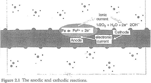
38 A corrosion cell comprises:
(1) an “anode”: This is the site on the reinforcing steel at which metal loss occurs. The typical anodic reaction is the oxidation of iron (Fe) to iron ions (Fe2+). This results in metallic ions entering the electrolyte (i.e., the concrete – see sub-paragraph (3) below) and excess electrons (e-) being produced at the steel. The chemical equation for this reaction shown in the figure above is Fe  Fe2+ + 2e-;
(2) a “cathode”: This is the site on the reinforcing steel at which the excess electrons produced at the anode can be consumed to conserve charge. The typical cathodic reaction, in neutral and high pH environments, is the reduction of dissolved oxygen (O2) in water (H2O) to produce hydroxide ions (OH-). The chemical equation for this reaction shown in the figure above is ½O2 + H2O + 2e-  2OH-;
2OH-;
(3) an “electrolyte” (i.e., the water and ions in the capillary pores of the concrete) through which current is carried by ions such as chloride ions (Cl-), hydroxide ions (OH-) and other ions (Na+, H+, Ca2+ etc); and
(4) a metallic path (i.e., the reinforcing steel) connecting the anode and the cathode through which the electrons travel.
39 By convention, current flows in the direction of movement of positive charge carriers (e.g., positive ions); that is, in the opposite direction to the movement of negative charge carriers (e.g., electrons). Thus, in a corrosion cell: (a) current flows from the anode to the cathode via the electrolyte (i.e., ionic current); and (b) current flows from the cathode to the anode via the metallic path (i.e., electronic current).
40 The reactions involved in the process of corrosion are, therefore, both chemical and electrical, and the process is referred to as an electrochemical process.
4.4 Carbonation
41 Carbonation is a process by which the alkaline conditions within the concrete are lost due to reaction with atmospheric carbon dioxide.
42 Carbon dioxide reacts with water in the pores of the concrete to produce carbonic acid, which in turn reacts with calcium hydroxide within the cement paste to produce calcium carbonate. When all the locally available calcium hydroxide (which contributes to the high pH of the concrete) is consumed, hydroxide ions are removed from solution, causing the pH to decrease. At this lower pH, the passive film surrounding the reinforcing steel breaks down, reducing its corrosion resistance.
43 Since water is essential for carbonation to occur, the reaction of carbon dioxide and calcium hydroxide only occurs in solution. Therefore, in very dry concrete, carbonation will be slow. Similarly, in saturated concrete, the moisture presents a barrier to the penetration of carbon dioxide, resulting in a slow rate of carbonation.
4.5 Chloride ingress
44 Chloride ingress describes the introduction of chloride ions into the concrete structure where they may break down the passive film at the steel surface.
45 Unlike carbonation, where the pH decreases, in the chloride attack mechanism, the chloride ions attack the passive layer by acting as a catalyst to corrosion reactions, allowing the corrosion process to proceed quickly. In this process, the surface of the steel acts as an anode and the passive surface layer acts as the cathode. If chloride ions penetrate the concrete to the steel reinforcement and accumulate to a sufficient concentration, and water and oxygen are present, then corrosion of the steel reinforcement will occur.
46 The presence of chloride ions at the steel surface can result in localised high-rate corrosion. As with carbonation, the rate of corrosion caused by chloride ingress is dependent on time, depth and concrete quality (durability). That is, the rate of increase in chloride concentration through the concrete to the embedded steel reinforcement slows with depth and increases with reduced concrete quality.
47 Any significant corrosion of the steel surface can create a significant volume of expansive corrosion product, which can create a bursting force inside the concrete.
4.6 Repair of reinforced concrete
48 Options for the remediation of concrete damaged by reinforcement corrosion include concrete repair and the application of an electrochemical repair technique.
49 With patch repairs, chlorides will remain in concrete surrounding the repair and, once repairs have been carried out, the reinforcement in surrounding areas can quickly corrode and cause further deterioration.
50 Removing chloride-contaminated concrete and replacing it with fresh concrete is more likely to succeed than simply patching visual defects, but this may result in the removal of large quantities of concrete which are contaminated but otherwise sound and, where the repair is extensive, the need for temporary structural support. As such, the cost of this approach may be prohibitive or impractical.
51 There is a period before extensive damage occurs on a structure where intervention (such as an electrochemical treatment) can be applied to arrest or reduce ongoing corrosion without major repair works.
4.7 Electrochemical repair techniques
4.7.1 Overview
52 Electrochemical treatments are intended to suppress corrosion across the entire treated structure.
53 Four different kinds of electrochemical treatments were in common use:
(1) impressed current cathodic protection (ICCP);
(2) sacrificial anode cathodic protection (SACP);
(3) chloride extraction; and
(4) realkalisation.
54 All electrochemical treatments rely upon the same basic electrochemical principle of using an anode to apply a current to the steel reinforcement to cause a cathodic reaction at the steel. Each approach applies this principle in a different way to achieve a different objective.
55 Cathodic protection (ICCP and SACP): this involves or commonly involves the application of a small current (conventionally at a current density of between about 2 to 20 mA/m2 steel surface area) via an anode to shift the steel potential for the lifetime of the structure, e.g., 100 years. While the only reaction on the steel surface is the cathodic reaction, corrosion is suppressed and the steel is said to be under “cathodic protection”. The cathodic reaction also produces hydroxide ions (OH-) at the steel, which over time increases the pH near the steel and assists to restore and maintain the stable iron oxide film layer at the steel.
56 The same principles apply to new structures (i.e., those not undergoing corrosion conditions) where the application of cathodic protection was sometimes referred to as “cathodic prevention”. In this case, a lower current density (conventionally of about 0.2 to 2 mA/m2 steel surface area) is intended to maintain passive conditions and, hence, prevent corrosion.
57 ICCP and SACP systems are intended to provide corrosion protection for as long as the systems remain functioning and in place, which may be measured in decades.
58 Chloride extraction and realkalisation: these treatments involve the application of significantly higher current density (conventionally between about 500 and 1000 mA/m2 steel surface area or more) than ICCP or SACP over a period of days (for realkalisation) or weeks (for chloride extraction). The treatment is then stopped and the system is entirely removed from the structure. These temporary electrochemical treatments aim to alter the chemical make-up of the concrete to return it to a state in which the conditions around the steel restore passivity (i.e., lower chloride concentration (for chloride extraction) or higher pH (for realkalisation)).
59 After chloride extraction or realkalisation treatments have been performed, chloride ions can migrate back to the steel over time and the pH can fall again over time due to ongoing carbonation.
4.7.2 Impressed current cathodic protection (ICCP)
60 In ICCP, an external direct current (DC) power source is used to apply a small current to the steel via an anode. Typically, an impressed current anode is made from an essentially inert material that can pass charge over a long period of time without losing significant mass (i.e., corroding), such as a mixed metal oxide (MMO)-coated titanium anode.
61 The impressed current anode is either in contact with, or embedded in, the concrete. Two diagrammatic representations of an ICCP system are shown below (reproduced from Broomfield, page 108, figure 6.1 (top); and Paul M Chess (ed), Cathodic Protection of Steel in Concrete (E & FN SPON, 1998) page 115, figure 6.2(b)):
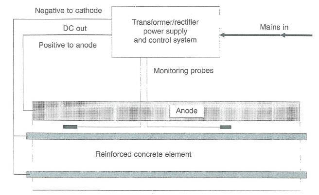
62 The power supply passes enough current from the anode to the reinforcing steel to force the anodic reaction at the steel to stop (or reduce it to negligible levels) and make the cathodic reaction the only significant reaction occurring on the steel surface. The production of hydroxide ions increases the pH and assists to restore the passive layer at the steel. For as long as current is supplied to the steel reinforcement in this way, the steel reinforcement is maintained in a cathodic state and corrosion is suppressed.
63 Normally, the DC source for an ICCP system is provided by mains (AC) power with a transformer-rectifier and other control and monitoring systems. Rechargeable batteries (e.g., charged by solar cells) were also used as a source of DC power in ICCP systems.
64 ICCP systems require a constant and reliable power source and regular monitoring and maintenance to ensure that the system is applying the required current density to the steel reinforcement. If the required current density is not being achieved, the amount of current could be increased by using a higher operational voltage. ICCP systems, therefore, can be used where the conductivity of the concrete is low (i.e., concrete resistivity is high).
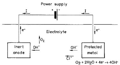
4.7.3 Sacrificial anode cathodic protection (SACP)
65 SACP works by coupling to the steel a galvanic (or sacrificial) anode, which is a metal that is more electrochemically active than steel (such as zinc, aluminium or magnesium or an alloy of these metals). A diagrammatic representation of an SACP system is shown below (Chess, page 115, figure 6.2(a)):
66 The sacrificial anode is electrically connected to the steel (e.g., via a wire) and is attached to the surface of the concrete or embedded in the concrete. This forms an electrochemical cell and the potential difference between the sacrificial anode and the steel causes a current to flow. The anodic reaction results in positively charged metal ions (e.g., zinc (Zn) to zinc ions (Zn2+)), which travel through the concrete to the steel, and negatively charged electrons, which travel through the electrical connection to the steel, to be taken up in the cathodic reaction. The cathodic reaction yields hydroxide ions, which increases the local alkalinity at the steel and, hence, strengthens the passive layer.
67 In this process, the anode is consumed (i.e., it corrodes, thereby “sacrificing” itself to protect the steel), hence the term “sacrificial anode”.
68 In comparison to ICCP systems, SACP systems (dependent on the type) can be much easier and cheaper to install. SACP systems do not require a source of DC power, or any external wiring or monitoring system.
69 The principal operating disadvantage of SACP systems is the relatively low driving voltage between the sacrificial anode and the steel, which is fixed and cannot be regulated. The current from the anode is dependent on the driving voltage and the anode resistance (which is dependent on anode shape and the concrete resistivity). The application of SACP, therefore, is limited by the resistivity of the concrete (which can be relatively high in normal, dry environments) and the size of the anode that can be used.
4.7.4 Chloride extraction
70 Chloride extraction is a temporary electrochemical treatment designed to extract chloride ions from the concrete, thus reducing the concentration of chloride ions at the surface of the steel. Chloride extraction, therefore, is an option for use on reinforced concrete structures which have been contaminated with chlorides.
71 Chloride extraction treatments require different equipment to cathodic protection systems. In particular, an electrolyte-containing medium (typically a tank, a felt mat or sprayed cellulose fibre) is mounted on the surface of the concrete structure. The anode is located in the electrolyte-containing medium.
72 During the treatment, the very high current density (between about 500 and 1000 mA/m2 steel surface area or more) applied to the steel increases the negative charge on the steel, essentially repelling negatively charged chloride ions, which migrate toward the anode and, thus, are removed at the surface of the structure into the electrolyte solution.
73 At the end of the treatment (typically up to four to six weeks or so), the power supply, the anode and electrolyte-containing medium are removed.
4.7.5 Realkalisation
74 Realkalisation is a temporary electrochemical treatment designed to generate an excess of hydroxide ions at the steel, thus re-establishing the alkalinity (high pH) at the surface of the steel. Realkalisation, therefore, is used on reinforced concrete structures in which the pH has been reduced, typically by carbonation (which results in the generation of acid and, hence, reduction in pH).
75 In realkalisation, a similar setup to that in chloride extraction is utilised, with the anode located in an electrolyte-containing medium mounted on the surface of the concrete structure (again, typically a tank, a felt mat or sprayed cellulose fibre). A difference is that, in realkalisation, the electrolyte may contain sodium or lithium carbonate which diffuses into the concrete structure and aids in restoring the high pH and in making the structure more resistant to further carbonation.
76 At the end of the treatment (typically around four to eight days), the power supply, the anode and electrolyte-containing medium are removed.
4.8 Applicable standards
77 Detailed requirements for the design and implementation, commissioning, control and monitoring of impressed current cathodic protection and prevention systems for reinforced concrete structures were described in: Australian Standard AS 2832.5-2002 “Cathodic protection of metals – Part 5: Steel in concrete structures”; National Association of Corrosion Engineers (NACE) Standard Recommended Practice RP0290-2000 “Impressed Current Cathodic Protection of Reinforcing Steel in Atmospherically Exposed Concrete Structures”; and European Standard EN 12696:2000 “Cathodic protection of steel in concrete”.
78 Detailed requirements for the design and implementation, commissioning, control and monitoring of chloride extraction and realkalisation for reinforced concrete structures were described in: NACE International Technical Committee Report “Electrochemical Chloride Extraction from Steel Reinforced Concrete – A State of the Art Report” published by NACE International in May 2001 and NACE International Technical Committee Report “Electrochemical Realkalization of Steel Reinforced Concrete – A State of the Art Report” published by NACE International in April 2004.
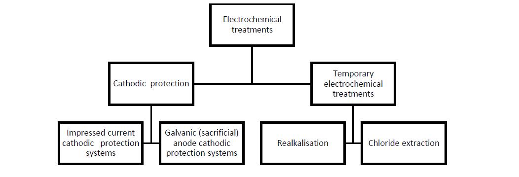
4.9 Further observations about the common general knowledge
79 Vector stressed that while there are four commonly used categories of electrochemical treatment: (a) they are all based on the same basic electrochemical principle of using an anode to apply a current to the steel reinforcement to cause a cathodic reaction at the steel, (b) they all cause the same chemical processes and changes to occur on and around the surface of the steel reinforcing, and (c) the changes (the reactions and movement of ions) that occur do not depend on the type of DC power source that is used. Vector referred in this regard to expert witness Dr David John’s evidence that “the steel itself doesn’t know where the current is coming from … it just knows how much current it is receiving”.
80 All this may be accepted at one level of generality. However, it would be wrong not to recognise that it was common general knowledge of the person skilled in the art that electrochemical techniques for corrosion treatment fell into two distinct groups: (a) cathodic protection comprising ICCP and SACP, and (b) temporary electrochemical treatments comprising realkalisation and chloride extraction. It would also be wrong not to recognise that each approach applies the principle of using an anode to apply a current to the steel reinforcement to cause a cathodic reaction at the steel “in a different way to achieve a different objective” (to use the words of the agreed technical primer).
81 E-Chem is thus correct that the mental landscape of the person skilled in the art, as a result of the common general knowledge, involved two distinct classes of electrochemical treatment which may be represented as follows (figure extracted from the affidavit of Dr John affirmed on 29 October 2019):
82 E-Chem is also correct that the common general knowledge included that cathodic protection was a permanent (so far as possible) treatment with a continuous low current (a current density of between about 2 to 20 mA per m2 of steel surface area), the current being either: (a) supplied by an external power source via an impressed current anode in ICCP; or (b) caused by coupling of a galvanic (sacrificial) anode to the steel in SACP.
83 It follows that while the “the steel itself doesn’t know where the current is coming from … it just knows how much current it is receiving”, the person skilled in the art had to know where the current was coming from in order to decide on the appropriate system of treatment for the reinforced concrete in question.
84 The expert evidence supports these propositions.
85 Dr Bruce Ackland is a corrosion engineer and consultant with over 37 years’ experience, holding a Bachelor of Science with Honours in Physics (1979) and a PhD in Materials Engineering (1984), and has conducted continuous work in the field since 1982.
86 Dr John is a corrosion engineer and consultant with over 40 years’ experience in the field in the United Kingdom and elsewhere holding a Bachelor of Science with Honours (1975) and a PhD concerning corrosion science (1979), and has conducted continuous work in the field since 1978.
87 Dr Ackland explained that an impressed current anode as used in ICCP necessarily involved an external power supply. As he put it (emphasis added):
As at 2004 we had a definition in our Australian standards of a – what an impressed current is, and that definition is you’re supplying direct current by means of an external power supply, and my understanding in 2004 of an external power supply was a power supply such as ..... transformer required to plug into mains power. If you’re in a remote location where you haven’t got AC power readily available it might be a solar powered, multicell, rechargeable battery system. Whatever it ..... be quite a substantial power supply delivering current to, usually, multiple anodes, and, in accordance with our definition, located external to the concrete.
88 Dr John said:
The majority of DC power supplies used for impressed current cathodic protection systems, whether for steel and concrete or elsewhere, would have been either traditional transformer rectifiers, which do as it says – they transform AC voltage from hundreds of volts down to typically 20 or 30-odd volts – and then also rectify it from AC to DC, and those are typical systems which could either be single phase or three phase, depending upon the power. At the time of the low-2000s, the traditional TRs were being replaced by solid state devices, but the majority of them would be that way.
There were cases, of course, even at that time where in remote areas, where AC mains is not available, people were looking at alternative power supplies, either solar or wind, typically using that to charge a battery to power the power supply, and in one particular project I was working on in Israel, we did initially use that, which was solar panels to trickle charge a battery to then power the system, but that had to be replaced after a year because people kept stealing the solar panels. So in those cases, we then just left with a very large rechargeable battery, which was replaced every three months… it’s what’s called a tractor battery, which is about the size of 50 car batteries. You know, big.
89 Understanding this for the person skilled in the art would have been essential common general knowledge, as would have been the consequence that ICCP treatment requires a constant and reliable power source and regular monitoring and maintenance over the life of the structure to ensure that the system is applying the required current density to the steel reinforcement.
90 In contrast, in SACP treatment, the current arises from the fact that a galvanic (or “sacrificial”) anode is more electrochemically active than the steel reinforcement it is being used to protect, so that the sacrificial anode preferentially undergoes the anodic reaction, resulting in the cathodic reaction at the steel, with the sacrificial anode connected to the steel via a steel wire, cable or strap. The person skilled in the art would know as a matter of common general knowledge that SACP does not require a source of DC power or any external wiring, control or monitoring system. As such, without the control, monitoring and maintenance of ICCP, sacrificial anodes could be much cheaper and easier to install, and have lower ongoing costs as there is no need for periodic maintenance.
91 Further, it was part of the common general knowledge that because the current potential of SACP depends on the operating potential of the anode, the potential of the embedded steel, and the resistivity of the concrete, the current output cannot be regulated. The result was that SACP was rarely used in normal dry (or inland) environments due to the high resistivity of concrete under these conditions. Also, and accordingly, ICCP and SACP were not interchangeable and equally available treatment alternatives.
92 The mental landscape of the person skilled in the art also included the common general knowledge that chloride extraction and realkalisation are temporary electrochemical treatments which do not provide ongoing electrochemical protection against corrosion. They aim to alter the chemical make-up of the concrete to return it to a state in which the conditions around the steel rapidly restore passivity (i.e., lower chloride concentration (for chloride extraction) or higher pH (for realkalisation)).
93 Dr John explained it this way:
… it is fully accepted that the fundamental electrochemical reactions occurring in all these four systems – Galvanic, CP, impressed current CP, electrochemical chloride removal, electrochemical realkalisation – the fundamental reactions are the same. The biggest difference, as I have just stated, is the impact of the magnitude of those reactions, which is very much dependent upon which way you’re coming from… the cathodic protection system, you are basically aiming to provide a continuous power or electricity to suppress the corrosion reaction occurring on the steel… you’re applying that literally for the life of this system, 25-50 years or above…
94 Cathodic protection systems also involve a “completely different engineering requirement, both in terms of how you physically apply the system, how you operate the system, the amount of power you have to supply over that period of time, and so on” if compared to the temporary protection systems. Further, in Dr John’s words:
…once you stop applying the temporary protection system, whilst you will have changed the conditions significantly ..... corrosion will have stopped, that is not in itself a permanent solution because with time the natural environment can re-establish itself, chlorides can migrate back, carbonation can re-proceed, etcetera, so that therefore corrosion be expected to reoccur at some point in the future.
95 As E-Chem noted by reference to the joint expert evidence, for cathodic protection, AS 2832.5-2002 specifies a current density of 2 to 20 mA/m2 of steel surface area, although the “typical range of operation” for ICCP is 10 mA/m2 of steel surface area. This could then be reduced in time or if the structure is new and not corroding, in which case “the current densities we used might be less than [1 mA/m2]”. The temporary electrochemical treatments, on the other hand, require “hundreds or even thousands of [mA/m2]. It’s many orders of magnitude greater”.
96 Dr Ackland said that for cathodic protection there are minimum current densities so that the “moderation of chlorides away from the steel will exceed in normal diffusion of chlorides towards the steel, and you get a net migration” whereas the “impact of the tremendously high current density that is used for chloride extraction and realkalisation, the processes that are occurring – the electrochemical processes that are occurring in the steel are substantially different to what would initially occur for a regular cathodic protection system”. He explained:
Well, the normal current densities that we would use for a permanent, fulltime cathodic protection system would be in the range – the upper level would be – in terms of actual operation – would be maybe 10 milliamps per square metre, reducing to, for a system applied to a structure that’s not corroding yet, that’s passive, would be, you know, maybe one milliamp per square metre or less. Plus or minus. So that sort of one to 10 milliamp per square metre range is our typical range of operation. In these temporary treatments it’s hundreds or even thousands of milliamps per square metre. It’s many orders of magnitude greater.
And the effect of that is totally different to the effect of the smaller current densities that we apply for fulltime cathodic protection. …but…there are issues with applying these very, very high current densities. You can get hydrogen embrittlement in susceptible steels. You can lose bond between the bar and the concrete. And those detrimental effects don’t occur with cathodic protection. So not only are the beneficial effects the same, but all these detrimental effects are totally different. That’s what I meant by totally or particularly different.
97 Dr John also explained that while the fundamental electrochemical reactions are essentially the same for all four systems, the magnitude of reactions differs for each approach and it is the “magnitude of the difference which is one of the factors which differentiates the different approaches”.
98 For these reasons, all of the expert evidence establishes that in the mind of the person skilled in the art there was a conceptual, purposive, practical and regulatory divide between cathodic protection systems and temporary protection systems.
99 This part of the mental landscape of the person skilled in the art is also reflected in the fact that the standards applying to the approaches are themselves divided into two separate categories – those relating to cathodic protection (which exclude the temporary treatments) and those relating to chloride extraction and realkalisation (the temporary treatments).
5. The inventive concept of the E-Chem patent
100 As noted, the E-Chem patent is to be construed through the eyes of the person skilled in the art and in light of the common general knowledge.
101 The specification identifies the technical field as “the electrochemical treatment of reinforced concrete to protect it from deterioration arising from corrosion of the steel” and that the invention is concerned with “a hybrid electrochemical treatment to arrest steel reinforcement corrosion and subsequently prevent corrosion initiation”.
102 The specification identifies the background art in terms which reflect the common general knowledge as described above. Accordingly, the background art is said to include that:
(1) both sustained and temporary electrochemical treatments have been used to arrest corrosion of steel in reinforced concrete;
(2) sustained or long-term electrochemical treatments are installed with the intention of maintaining the treatment for the foreseeable future and a well-known family of sustained or long-term techniques is cathodic protection which includes impressed current cathodic protection and sacrificial cathodic protection. In these techniques a long-term or permanent anode delivers a small current to the steel reinforcement. Average current densities expressed per unit area of steel surface typically range from 2 to 20 mA/m2 to arrest existing deterioration and 0.2 to 2 mA/m2 to prevent the initiation of deterioration;
(3) temporary or short term electrochemical treatments are installed with the intention of discontinuing the treatment in the foreseeable future. The electrochemical treatment period would typically be measured in days, weeks or months. These techniques include chloride extraction and realkalisation. In these systems a temporarily installed anode system is used in conjunction with a temporary DC power supply to deliver a large current of the order of 1000 mA/m2 expressed per unit area of steel surface for a short period (typically less than three months) to the steel reinforcement;
(4) anodes for concrete structures may be divided into inert anodes or sacrificial anodes;
(5) a widely used inert anode system is a MMO-coated titanium mesh embedded in a cementitious overlay on the concrete surface;
(6) sacrificial anodes are consumed in the process of delivering the protection current. The main anodic reaction is the dissolution of the sacrificial metal. As a result, the life of sacrificial anodes is limited. The use of sacrificial anodes in an impressed current role is deterred by the more rapid consumption of the anode in this role;
(7) temporary anode systems are usually attached to the concrete surface to deliver short term high current temporary electrochemical treatments and are removed at the end of the treatment period that is typically less than three months. Temporary anodes are surrounded by a temporary electrolyte, such as a liquid contained in a tank or an electrolytic material such as saturated cellulose fibre, that is easily removed at the end of the treatment process. A high drive voltage together with a high volume of electrolyte is generally needed to support the high current output; and
(8) by contrast, long-term anode systems, intended to deliver a protection current over several years, are strongly attached to the concrete and may be embedded in cavities in the concrete to improve anode attachment.
103 The specification provides a disclosure of the invention starting with a description of the “technical problem”. This section says:
(1) impressed current cathodic protection is the most proven of the existing methods of arresting chloride induced corrosion of steel in concrete. However it requires a high level of maintenance when compared with other inspection or maintenance requirements of reinforced concrete structures and while the low current densities used in impressed current cathodic protection eventually arrest corrosion, corrosion-induced damage continues to occur until the corrosion process is arrested;
(2) temporary electrochemical treatments rapidly arrest the corrosion process and have no maintenance requirements after the initial treatment but a substantial level of chloride sometimes remains, there are concerns regarding the durability of such treatments in chloride containing environments, and the duration of the treatment may last several months and access to the treated surface is restricted during this time;
(3) sacrificial cathodic protection is not always considered to be powerful enough to arrest corrosion. However it is a low maintenance, reliable process that can be used in a preventative role; and
(4) the problem solved by this invention is the efficient delivery of powerful electrochemical protection treatments to corroding steel in concrete to arrest corrosion and to achieve long-term durability of the protective effects with minimal maintenance requirements and minimal disruption during system installation.
104 The next section in the disclosure of the invention concerns the “technical solution”. This section says:
(1) existing electrochemical treatments may be improved by splitting the treatment into two phases; namely, a brief initial high current treatment to rapidly arrest corrosion minimising further damage, and a subsequent long-term preventative treatment with low maintenance requirements to sustain passivity and ensure durability;
(2) a single multiple treatment anode that is capable of delivering both the initial high current, short term electrochemical treatment to arrest corrosion and subsequently the long-term, low current treatment to prevent subsequent corrosion initiation is disclosed;
(3) to deliver the initial high current treatment, the multiple treatment anode is capable of delivering very high current densities off the anode surface at low safe DC voltages. To achieve a durable long-term preventative treatment the multiple treatment anode is used in a cathodic prevention role, preferably connected to the steel as a sacrificial anode;
(4) the multiple treatment anode is based on the use of a sacrificial anode metal in a temporary high impressed current role. One observation leading to the development of the multiple treatment anode was that an aluminium alloy sacrificial anode metal can deliver current densities in excess of 10,000 mA/m2 (expressed per unit of anode area) off the anode surface at very low safe DC voltages that are not sufficiently positive to induce gas evolution even when the sacrificial anode is embedded in a porous material in a cavity formed in reinforced concrete. This is possible because the anodic reactions occur easily on sacrificial anode metals when compared with the anodic reactions occurring on inert impressed current anodes. Very high current density compact discrete anodes may therefore be embedded in the concrete to limit the disruption caused during the brief high impressed current treatment. A brief high impressed current treatment moves corroding sites from locations on the reinforcing steel to installed sacrificial anodes because hydroxide is produced at the steel causing the pH to rise and aggressive ions like chloride and sulphate are drawn from the concrete to the sacrificial anode. The anode may be subsequently used as an activated sacrificial anode to maintain steel passivity;
(5) accordingly, the present invention provides in a first aspect, a method of protecting steel in concrete that comprises using an anode and a source of DC power and a temporary impressed current treatment, and a low current preventative treatment wherein the temporary impressed current treatment is a high current treatment using the source of DC power to drive current off the anode to the steel to improve the environment at the steel and the low current preventative treatment is applied to inhibit steel corrosion initiation after the application of the temporary impressed current treatment and the same anode is used in both treatments and the anode comprises a sacrificial metal element that undergoes sacrificial metal dissolution as its main anodic reaction;
(6) another observation leading to the development of multiple treatment technology was the high charge density of aluminium alloy anodes. Four aluminium alloy anodes 100mm long and 15mm in diameter have sufficient charge to deliver approximately 500 mA for one week and 1 mA for 50 years in their impressed current and sacrificial anode functions. The high charge density of some sacrificial anodes means that long lives are achievable from small sacrificial anodes embedded in concrete. This alleviates the concerns regarding the costs of replacing the anodes embedded in porous materials at the end of their service lives; and
(7) the inclusion of an impressed current anode connection detail on a compact discrete sacrificial anode alleviates the risk of corroding the connection when the discrete sacrificial anode is used as an impressed current anode. Forming the sacrificial anode metal around an impressed current anode that may be used in an impressed current cathodic prevention role after the sacrificial metal has been consumed may also be used to extend the life of the treatment.
105 The specification then describes the advantageous effects of the invention. These are that:
The anodic reactions occurring on a sacrificial metal occur more easily than the anodic reactions occurring on an inert anode and require less driving voltage and generate less acid and less gas. This enables a brief high current electrochemical treatment to be delivered more easily. The application of a high current to a steel cathode of an electrochemical cell rapidly arrests corrosion of the steel minimising further corrosion damage. Aggressive ions in the concrete are drawn to the anode by the impressed current treatment. The combination of these aggressive ions and the sacrificial metal forms a sacrificial anode that is activated without the addition of other activating chemicals to the concrete. Connecting this sacrificial anode directly to the steel provides a simple method of applying a continuous, preventative treatment to inhibit future corrosion initiation. The corroding areas are effectively moved from the steel to the installed anode during the initial treatment. Embedding an anode system within the concrete allows the concrete surface to be used while the high impressed current electrochemical treatment is applied.
106 A section called “Mode for Invention” follows the drawings (see below). The section says, under the sub-heading “Mechanism of Electrochemical Protection”:
(1) the traditional understanding of reinforced concrete electrochemical treatments is that different treatments rely on different protective effects induced by a negative driven potential shift that inhibits the dissolution of steel to form positive iron ions (corrosion), the removal of chloride ions from the steel surface that renders the environment less aggressive to passive films on steel, and the generation of hydroxyl ions at the steel surface that stabilises the formation of passive films on steel;
(2) the collation and analysis of the available evidence suggests that one protective effect is likely to have a dominant effect on the success of all electrochemical treatments applied to steel in atmospherically exposed concrete. This dominant protective effect is the increase in pH at the steel/concrete interface;
(3) the importance of the generation of hydroxyl ions at the steel is supported by a number of observations including the surprising observation that induction of open circuit steel passivity is achieved using cathodic protection current densities that are substantially lower than the localised steel corrosion rates; and
(4) analysis suggests that the range of charge densities applied to reinforcing steel in concrete to induce open circuit steel passivity may be an order of magnitude below that previously postulated to be necessary.
107 The next sub-section concerns “Improving the Electro-chemical Treatment Process”. This says that:
(1) it has been noted above that relatively low charge densities may be used to restore steel passivity. A temporary electrochemical treatment process to arrest corrosion may therefore be substantially less intensive than the very intense temporary electrochemical treatments sometimes applied. In particular, the period of a temporary electrochemical treatment may be reduced. Thus a temporary electrochemical treatment may be applied for less than three months and preferably less than three weeks. However, the durability of a short term treatment will be questioned despite the immediate reduction in corrosion rate. Such a brief initial treatment would be more acceptable if a supplementary long-term corrosion prevention treatment was applied;
(2) an improved treatment process would therefore be a hybrid electrochemical treatment in which an initial charge density that is sufficient to arrest corrosion and induce open circuit steel passivity was applied and followed by a low maintenance cathodic prevention treatment to prevent any subsequent corrosion initiation. It would be advantageous to use the same anode system in both the powerful impressed current treatment to arrest corrosion and in the subsequent low maintenance treatment to maintain steel passivity; and
(3) average current applied during the initial impressed current electrochemical treatment will typically be at least an order of magnitude greater than the average current subsequently applied during the low current preventative treatment. The low current preventative treatment will usually involve the delivery of an average current density of less than 5 mA/m2 and more than 0.2 mA/m2 to the steel surface.
108 The next sub-section, “Treatment Technology”, describes aspects of the invention and preferred embodiments and examples, which are all encompassed by the first aspect of the invention which is described as follows:
… a method of protecting steel in concrete that comprises using an anode and a source of DC power and a temporary impressed current treatment and a low current preventative treatment wherein the temporary impressed current treatment is a high current treatment using the source of DC power to drive current off the anode to the steel to improve the environment at the steel and the low current preventative treatment is applied to inhibit steel corrosion initiation after the application of the temporary impressed current treatment and the same anode is used in both treatments and the anode comprises a sacrificial metal element that undergoes sacrificial metal dissolution as its main anodic reaction.
109 The next section in the specification concerns industrial applicability. This section notes that standards applicable to the invention include BS EN 12696: 2000 (Cathodic protection of steel in concrete) and prCEN/TS 14038-1 (Electrochemical realkalisation and chloride extraction treatments for reinforced concrete).
110 The claims of the E-Chem patent include claim 1 as follows:
Use of an anode and a source of DC power to protect steel in concrete construction which use comprises driving a current off the anode to the steel using the source of DC power to deliver a temporary impressed current treatment adapted to improve the environment at the steel to arrest steel corrosion and subsequently delivering from the same anode to the steel a low current preventative treatment adapted to inhibit steel corrosion initiation wherein the temporary impressed current treatment is a high current treatment relative to the low current preventative treatment and the anode comprises a sacrificial metal element that undergoes sacrificial metal dissolution as its main anodic reaction.
111 Figure 1 below shows a schematic diagram of the use of an anode in a hybrid impressed current sacrificial electrochemical treatment, as it appears in the patent claims:
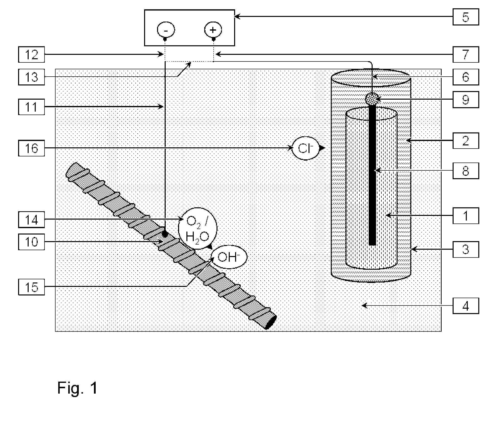
112 In this figure a sacrificial metal element [1] is embedded in a porous material [2] containing an electrolyte in a cavity [3] formed in concrete [4]. The sacrificial metal element is connected to the positive terminal of a source of DC power [5] using an electrical conductor [6] and electrical connection [7]. An impressed current anode connection detail is used to connect the sacrificial metal element [1] to the electrical conductor [6].
113 This preferably involves forming the sacrificial metal element around a portion of a conductor [8] that remains passive during the impressed current treatment. The conductor [8] provides a convenient connection point [9] away from the sacrificial metal to facilitate a connection to another electrical conductor. The negative terminal of the power source [5] is connected to the steel [10] using an electrical conductor [11] and connection [12]. While the power supply is connected to the anode and the steel, electrical connection [13] is not made. The description in the specification continues:
Initially a large, short term impressed current is driven from the anode assembly [1, 8] to the steel [10] for a brief period using the source of DC power [5]. In the process oxygen and water [14] are converted into hydroxyl ions [15] on the steel. This neutralises the acidic corrosion sites and promotes the repair of the protective passive film on the steel. In addition, aggressive ions such as chloride ions [16] are drawn from the concrete into the porous material [2] around the anode. The local environments around the embedded steel and around the embedded anode are modified by this brief impressed current treatment. The changes mean that the local environment at the steel supports steel passivation while the environment at the anode maintains sacrificial anode activity. The corroding sites are effectively moved from locations on the steel reinforcement to the installed sacrificial anode. At the end of the impressed current treatment, a long term low power cathodic prevention treatment may then be applied using the same anode.
It is preferable to disconnect the power supply [5] at electrical connections [7] and [12] and to connect remaining sacrificial anode metal directly to the steel through electrical connection [13]. The activated discrete sacrificial anode formed by the temporary impressed current treatment is then used in a long term sacrificial cathodic prevention role to maintain steel passivity. This is preferable because the current output of sacrificial anodes is more reliable than that of a DC power supply and is to some extent self adjusting with more aggressive environments leading to higher sacrificial anode current outputs. Furthermore, monitoring is not critical to sacrificial anode system function and can be tailored to compliment end user requirements for the protected structure. A simple method of monitoring performance uses non destructive potential mapping techniques to determine whether the only areas of anodic activity are located at the sites where the discrete sacrificial anodes are embedded.
The connections [7, 9, 12, 13] and conductors [6, 8, 11] are all electron conducting connections or conductors in that they provide a path for electrons to move. They may be referred to as electronic connections or electronic conductors. The conductors would typically be wires or electrical cables. These conductors and connections differ from ionic conductors or ionic connections. The electrolyte in the concrete [4] provides an example of an ionic connection between the sacrificial metal element [1] and the steel [10]. To achieve sacrificial cathodic protection or prevention, both an electronic connection and an ionic connection between the sacrificial metal element and the steel are required.
The sources of DC power [5] for the brief high current treatment include a mains powered DC power supply or a battery. It is an advantage if the connection between the anode and the positive terminal of the power supply is kept as short as possible to minimize the corrosion risk to this connection.
114 The inventive concept of the E-Chem patent was described as follows by Dr Ackland and Dr John:
… the E-Chem Patent describes a method of providing corrosion protection to steel reinforcement utilizing:
• Use of multiple-treatment anodes, which are discrete, embedded, sacrificial (galvanic) anodes.
• A first, temporary, treatment whereby the discrete anodes are operated in an impressed current manner, to provide a high current (from an external power supply) to the steel reinforcement to restore passivity on the steel.
• A second, long-term treatment, whereby the power supply has been removed and the discrete sacrificial (galvanic) anodes are then connected directly to the steel reinforcement to provide a lower current to maintain the passive conditions.
The overall Inventive Concept is the combination of these the two treatments to form a Hybrid system.
115 This characterisation of the inventive concept of the E-Chem patent reflects the terms of the E-Chem patent and the common general knowledge. Importantly, the heart of the invention described in the specification and claims is the use of the same anode in two modes – in the first phase, for a short period, using a high impressed current (but not as high as the current densities of existing temporary treatments) supplied through an external power source to the anode and, in the second phase, using the same anode as a sacrificial anode to generate a continuous low galvanic current to maintain the passive conditions induced by the first treatment phase.
116 While the issue is not whether the inventive concept of the E-Chem patent is inventive, it is apparent from the evidence that Dr Ackland and Dr John considered the concept to be inventive.
117 Dr John explained the inventive concept of the E-Chem patent in oral evidence in a consistent manner. He said:
…the inventive concept is not the fact that you could apply a DC – an external DC supply to get more current out of the anode. It is - the fact is that you… need to get the extra current in the initial stage to achieve the effect you need of significantly reducing the overall corrosivity of the environment or suppressing the corrosion so that the second stage, when you are now solely reliant on galvanic anodes, that they are able to operate successfully. It’s not the – the issue is the combination of those two features, not the fact that those two features can exist in isolation.
118 Vector’s two “preliminary observations” about the inventive concept require caution. Vector submitted that:
(a) the invention as described, and as claimed, … is not limited to any specific current density levels at the steel – instead it expressly teaches that the required improvement in the environmental conditions around the steel can be achieved using a wide range of current densities; and
(b) similarly, the invention is not prescriptive as to how the end of the first phase is to be identified. The specification proceeds on the basis that a sufficient degree of improvement in the environment around the steel would involve practising the invention.
119 The required caution is that the issue is the identification of the inventive concept (not the invention as claimed). Current densities at the steel are crucial to the inventive concept. In the first phase the current density is to be high and over a short period “to rapidly arrest corrosion minimising further damage” and in the second phase the current density is to be low and long-term to “sustain passivity and ensure durability”.
120 As such, it is inaccurate to say, as Vector does, that the E-Chem patent expressly teaches that the required improvement in the environmental conditions around the steel can be achieved using a wide range of current densities. To the contrary, the E-Chem patent teaches that the low current densities used in existing long-term cathodic protection systems enable corrosion-induced damage to continue until the corrosion process is ultimately arrested, while the high current densities used in temporary treatment methods (chloride extraction and realkalisation) rapidly arrest the corrosion process. The inventive concept includes combining aspects of the existing treatment systems using a single anode which functions as both a high current density inert anode (sourced by an external DC power supply) to rapidly arrest corrosion and then a low current density galvanic sacrificial anode to achieve long-term durability of the protective effects with minimal maintenance requirements.
121 It is fundamental to this inventive concept that the anode be capable of delivering both high current densities temporarily when in impressed current mode and low current densities when in sacrificial anode mode. While these high and low current densities are not prescribed in the claims, the specification discloses that: (a) the high impressed current density is to be sufficient to arrest corrosion, but this can be substantially less intensive than the very intense temporary electrochemical treatments applied in chloride extraction and realkalisation, (b) average current applied during the initial impressed current electrochemical treatment will typically be at least an order of magnitude greater than the average current subsequently applied during the low current preventative treatment, and (c) the low current preventative treatment will usually involve the delivery of an average current density of less than 5 mA/m2 and more than 0.2 mA/m2 to the steel surface.
122 Given this, I do not accept that the E-Chem patent teaches that the required improvement in the environmental conditions around the steel can be achieved using a wide range of current densities.
123 I accept that the E-Chem patent does not prescribe how the end of the first phase of treatment is to be identified. This said, the patent does explain that: (a) the first phase is temporary and intended to be “brief” and the second phase is ongoing for the lifetime of the structure, and (b) electrochemical treatment in the first temporary phase may be applied for less than three months and preferably less than three weeks.
124 While the claims are relevant to identifying the inventive concept, it is the heart of the invention which is the required focus, not the specific limits on the scope of the invention as claimed. On this basis, it would be to denude the inventive concept of its essential content not to accept that it involves a short high impressed current phase for one purpose (to rapidly arrest corrosion) and a permanent low (relative to the first phase) galvanic current phase for another purpose (to continue steel passivity) using the same anode. Further, these requirements are informed by the information in the E-Chem patent about the current densities in each phase by reference to details of existing techniques, up to date analysis, and the common general knowledge of the person skilled in the art about these matters.
125 For these reasons Vector’s submission that nothing in the specification suggests that the “high current” density used for the initial phase must be at some minimum level is inapt. It is apparent that the inventive concept includes that in the first phase the high current density is to be: (a) high relative to the second phase (not merely higher than the density in the second phase by any amount), (b) typically at least an order of magnitude greater than the average current applied in the second phase, and (c) the low current in the second phase is usually less than 5 mA/m2 and more than 0.2 mA/m2. Moreover, these requirements are informed by the fact that the current in the first phase is impressed from an external power source and the current in the second phase is galvanic and generated by the sacrificial anode. This is in a context where the essence of the invention also includes that a sacrificial anode can be used to provide both a high current density temporarily and a low current density thereafter for the life of the structure.
126 Further, Vector’s focus on phrases in the specification out of context is unhelpful. The “relatively small amount of charge’” in paragraph 14 of the specification is in the context of describing the restoration of alkalinity at corroding sites. The theory underlying the inventive concept is the recognition that if, as posited in the specification, the dominant protective effect is achieved by an increase in pH at the steel/concrete interface, then the temporary impressed current first phase to arrest corrosion can involve substantially less current density than the very intense temporary electrochemical treatments (that is, in chloride extraction and realkalisation). These current densities for chloride extraction and realkalisation, however, would be understood by the person skilled in the art to be many orders of magnitude greater than those used in cathodic prevention techniques (“hundreds or even thousands of [mA/m2]” as Dr Ackland said). The fact that the current density in the first phase may be substantially less than these current densities for chloride extraction and realkalisation does not mean that the current densities in the first phase are not “high”.
127 Further again, as the specification discloses, this first phase alone would not provide the required durability of protection which is why the inventive concept also includes the second phase of continuous low current density provided by the same anode in galvanic sacrificial mode. It is also clear from the specification as a whole that the inventive concept is not merely that the density in the first impressed current phase be higher than the second galvanic current phase. The current density in the first phase is to be high, as described in:
(1) paragraph 14: “a brief initial high current treatment to rapidly arrest corrosion”, “both the initial high current, short term electrochemical treatment to arrest corrosion and subsequently the long-term, low current treatment to prevent subsequent corrosion initiation is disclosed. To deliver the initial high current treatment, the multiple treatment anode is capable of delivering very high current densities off the anode surface”;
(2) paragraph 15: “the use of a sacrificial anode metal in a temporary high impressed current role”, “[a] brief high impressed current treatment moves corroding sites from locations on the reinforcing steel to installed sacrificial anodes”;
(3) paragraph 16: “wherein the temporary impressed current treatment is a high current treatment”;
(4) paragraph 17: “[a]nother observation leading to the development of multiple treatment technology was the high charge density of aluminium alloy anodes”, “[t]he high charge density of some sacrificial anodes means that long lives are achievable from small sacrificial anodes embedded in concrete”;
(5) paragraph 19: “[t]his enables a brief high current electrochemical treatment to be delivered more easily. The application of a high current to a steel cathode of an electrochemical cell rapidly arrests corrosion”, “[e]mbedding an anode system within the concrete allows the concrete surface to be used while the high impressed current electrochemical treatment is applied”;
(6) paragraph 48: the initial current density is to be “sufficient to arrest corrosion and induce open circuit steel passivity”;
(7) paragraph 50: examples include “briefly driving a high current off a sacrificial anode to passivate the steel”;
(8) paragraph 60: in the example “[i]nitially a large, short term impressed current is driven from the anode assembly”;
(9) paragraph 63: “the brief high current treatment include a mains powered DC power supply or a battery”;
(10) paragraph 75: “[o]ne advantage of using an embedded sacrificial metal anode is the high impressed current density that may be delivered of [sic] the anode”; and
(11) paragraph 84: “use of a sacrificial metal embedded in a porous material in a hole in reinforced concrete allows anode impressed current densities to be achieved that are substantially greater than any of those achieved using existing impressed current anode technology at the same driving voltage”.
128 It follows that I do not accept Vector’s submission that:
The E-Chem Patent explains that passivation can be effectively achieved by delivering a sufficient amount of charge to the steel, which only requires the use of intermediate current density levels that are higher than the current density that is delivered by a long-term galvanic only anode, but do not need to be anything like as high as the current densities used for temporary chloride extraction or realkalisation methods.
129 While the E-Chem patent does explain that the high impressed current in the first temporary phase of treatment may be substantially less intensive than the very intensive current densities used in existing temporary treatments (chloride extraction and realkalisation), it does not teach that the current density in the first phase need only be an intermediate current density level higher than the current density level in the second phase. It teaches that the current density in the first phase must be a high current density to rapidly arrest corrosion (albeit substantially less than the very intensive current densities used in existing temporary treatments) which will typically be at least an order of magnitude greater than the average current subsequently applied during the second phase of the low current preventative treatment. Within these parameters it may be accepted that the inventive concept permits that the current densities and duration of the first phase may vary depending on the structure sought to be treated, but the high temporary/low permanent current density phasing using the same anode remain at the heart of the inventive concept, as does the outcome of rapidly arresting corrosion in phase 1 and continuing steel passivity in phase 2.
130 Given these matters it is not apparent that anything depends on Vector’s observations that claim 1 of the E-Chem patent requires the temporary impressed current treatment to be “adapted to improve the environment at the steel to arrest steel corrosion” and that “[c]laim 1 does not require that corrosion be arrested in fact, nor define how that is to be assessed”. Suffice to say that if the impressed current treatment improves the environment at the steel but does not arrest steel corrosion then the impressed current treatment will not be “adapted” as required by claim 1.
131 The sacrificial anode capable of functioning in the two different modes for two different purposes is a critical part of the inventive concept.
132 Vector submitted that:
The potential of a sacrificial anode relative to the steel is therefore an inherent property of the sacrificial anode. That is, the sacrificial anodes are being used for the purpose of achieving low-maintenance ongoing protection in the later phase where current is naturally provided to the steel without the need for a source of DC power and it is also the case that during the initial phase a reduced amount of additional voltage would be needed because they have a galvanic potential that supports the delivery of charge to the steel (compared with inert anodes, which have an opposite galvanic potential).
133 The inventive concept of the E-Chem patent is not about reducing the voltage needed in the initial phase of treatment because of the capacity of the sacrificial anode to function galvanically after the connection to the external DC power source is removed. The inventive concept involves a sacrificial anode capable of functioning in a high impressed current mode temporarily.
134 I do not accept Vector’s submission that the recognition of the different types of electrochemical treatment or their different purposes goes beyond reading a patent in the light of common general knowledge. As noted, the common general knowledge included that the different types of treatment had different purposes and involved different advantages and disadvantages. This is why, although the steel is indifferent to the source of the current, the nature of the source of the current and the nature of the current itself are fundamental aspects of the common general knowledge of the person skilled in the art.
135 Importantly, it is not the case that the higher the voltage of the power source, the higher current density at the steel, and the better the outcome in terms of corrosion. This assumption would be contrary to the common general knowledge of the person skilled in the art.
136 Nor would the person skilled in the art applying the common general knowledge to the E-Chem patent understand it to be saying that any current higher than the low current in the second phase of the treatment would suffice in the first phase of the treatment. As Dr John said, to “deliver a temporary impressed current treatment adapted to improve the environment at the steel to arrest steel corrosion” in the temporary “high current treatment relative to the low current preventative treatment” as identified in claim 1 of the E-Chem patent “the amount of current you need … is significant. It’s not just an extra 10 per cent; it is orders of magnitude”. Dr John said that for the first stage current to be “adapted to improve the environment at the steel to arrest steel corrosion” “means I know I’m going to have to be outputting something of the order of hundreds of milliamps per square metre to the steel”. In contrast, for the second stage current to be “a low current preventative treatment adapted to inhibit steel corrosion initiation” (as identified in claim 1 of the E-Chem patent): “I only need to provide a milliamp or so per square metre of steel, which is two orders of magnitude up”. Dr Ackland agreed, observing that “anyone who was experienced in this field back then would have seen these [the first stage current densities] as being extremely high current densities compared to anything that we would use in normal cathodic protection”.
137 The fact that the E-Chem patent does not specify the use of an external power supply as the source of the high impressed current is immaterial. The evidence is clear. It was part of the common general knowledge at the time that an impressed current involved an external power source. Consistent with this, the meaning of “impressed current”, as defined in AS 2832.5-2002, is “[d]irect current supplied by an external power source to cathodically protect a structure”. In the E-Chem patent that external power source is to be disconnected and removed from the structure after completion of the first phase of treatment to enable the sacrificial anode to be directly connected to the steel for the second phase of the treatment. As E-Chem submitted, the person skilled in the art would understand from the specification of the E-Chem patent that without the manual intervention to conclude the first phase of treatment, disconnect the power supply and reconnect the anodes to the steel reinforcement, the anodes could not operate in a galvanic manner because there would be no circuit with the steel reinforcement.
6. Dr Glass, Dr Davison, Mr Roberts – the E-Chem inventive concept
6.1 Vector’s criticisms of Dr Glass’s evidence
138 Vector accepted that the inventors of the E-Chem patent are Dr Glass, Dr Davison, and Mr Roberts. Vector did not suggest that some other person who was or is employed by Fosroc is an inventor.
139 I accept that Dr Glass, Dr Davison, and Mr Roberts have an interest in the outcome of the proceeding. So too does Mr David Whitmore, the President of Vector, who gave evidence for Vector. The evidence of Dr Glass, Dr Davison, and Mr Roberts also relates to events and circumstances from many years ago. It is unsurprising that they each had to refresh their memories from documents before they prepared affidavits. They are not to be criticised for this necessity. Nor did their evidence disclose any sign of expedient reconstruction of events and circumstances to suit their interests. To the contrary, I found their evidence direct, cogent and persuasive.
140 Dr Glass, who might fairly be described as the principal inventor of the invention the subject of the E-Chem patent, came in for particular criticisms from Vector. I do not accept those criticisms to be justified. Dr Glass was extensively cross-examined over video-link for three days. The time difference between Sydney and the United Kingdom (where Dr Glass resides) meant that he was being cross-examined from 4.30 or 5.00am in the morning over many hours by reference to numerous electronic and hard copy documents. Dr Glass’s evidence was not evasive or unnecessarily discursive in these circumstances. It is apparent he was trying to ensure he understood the questions being asked and gave accurate answers.
141 The proceeding was commenced in February 2019. Vector’s case narrowed significantly over the course of the proceeding to its ultimate claims for entitlement. This proceeding is also not the first legal dispute between Vector and E-Chem about the invention the subject of the E-Chem patent. As far as Dr Glass is concerned, in 2004 Fosroc made his continued research untenable so he left Fosroc and took the risk of establishing E-Chem. While at E-Chem he (in the main) conceived of the invention the subject of the E-Chem patent. Dr Glass, Dr Davison, and Mr Roberts took all of the risk in developing and commercialising the invention. Fifteen years after the conception and ten years after its acquisition of Fosroc, Vector claims entitlement to the E-Chem patent. Given this perspective (whether it be right or wrong) and the circumstances under which he gave evidence, Dr Glass is not to be criticised for the occasional signs of exasperation and exhaustion which he manifested during his evidence.
142 The specific criticisms Vector made of Dr Glass are also not justified.
143 Dr Glass was criticised for saying in his first affidavit that he understood an email from Mr Robert Viles (intellectual property manager at Fosroc) to him of 8 April 2003 which referred to an anode “connected, at least temporarily, to a DC source” meant “connected until the battery runs flat”. I do not find this evidence implausible or self-serving in the least given that:
(1) the issue is Dr Glass’s understanding in 2003;
(2) the immediate context was Dr Glass’s email of 8 April 2003 referring to a battery powered zinc anode;
(3) in the same email of 8 April 2003 Dr Glass referred to including “an electronic gizmo that will connect the zinc directly to the steel when the battery runs flat”;
(4) Dr Glass was responding to an email from Mr Viles of 7 April 2003 referring to a “battery anode”, being a “galvanic anode connected in series with a battery to boost its potential”;
(5) these were the points Dr Glass was trying to make when he said “– if you look at those words today in – in – from 2021 and looking at those words, there’s no words of a battery going flat. The mention of a battery going flat is in my email from the previous day, or whenever it was, or from earlier this day. I can’t remember … my email from two hours before. Just two hours before we were mentioning the battery going flat”; and
(6) what Dr Glass could not remember was if his email was from two hours before or the previous day. He was not suggesting that he could not recall his own understanding from 2003. Given the number of documents in evidence and the number to which he was taken in cross-examination, it is not surprising that Dr Glass could not recall the time his earlier email had been sent, but he certainly had a firm grasp of the context and his own understanding from that time.
144 Dr Glass’s understanding to this effect does not conflict with “the very concept that he had sent to Mr Viles in his email earlier that day, which directly raised the concept of there being a temporary connection between a battery and the zinc anode”. The point Dr Glass had made to Mr Viles was that a battery powered zinc anode would be unlikely to be patentable given the disclosed art. Dr Glass’s email included a form of ‘musing out loud’ when he said that to be patentable there would need to be a further “innovative” step and listed possibilities including “an electronic gizmo that will connect the zinc directly to the steel when the battery runs flat”.
145 Far from Dr Glass’s contemporaneous evidence about his then state of mind being inconsistent with his email, it is entirely consistent with his email – that the temporary power source was a battery which would run flat and then there might be other possible steps including “an electronic gizmo that will connect the zinc directly to the steel”.
146 A musing in an email, about a possibility (unexplored) of an “an electronic gizmo that will connect the zinc directly to the steel when the battery runs flat” is not an inventive concept (let alone the invention or the inventive concept of the E-Chem patent). A “gizmo” is an undefined or unidentified “gadget” (Macquarie Dictionary Online) or a “gadget, gimmick, ‘thingumajig’” (Oxford Dictionary Online). The essence of a “gizmo” is its lack of definition or identification. Dr Glass said by “gizmo” he meant a “device to be invented”. It is not that an inventive concept cannot include a “gizmo” in the sense of an undefined or unidentified “gadget”, as the creation of the “gizmo” may involve nothing more than a reduction to practice of a known product, process or method. As will be discussed further, that is not the case here, however.
147 For present purposes, what is relevant is Dr Glass’s evidence that he understood Mr Viles’s reference to a temporary connection between a battery and the zinc anode as meaning that the battery would run flat. This evidence is entirely consistent with the context and content of the surrounding contemporaneous evidence. It casts no doubt upon the credibility of Dr Glass.
148 Nor is it the case that Dr Glass and Mr Roberts understood in 2003 “that a practical workaround for his gizmo idea was that if a wire was connected to each of the zinc anode and the steel and each wire projected out of the concrete, then that would facilitate the relevant direct connection being made when the battery ran low”. To the contrary, and for good reasons, that formed no part of Dr Glass’s thinking at the time. Dr Glass said (emphasis added):
If the entire assembly was buried in concrete, it would have been… ridiculous to try and connect a sacrificial anode assembly. This was a fit and forget unit. We would be trying – ridiculous to try and connect the sacrificial anode of the assembly to the steel. There was no suitable connector you could use, there was – everything was buried in concrete. You would have to break the concrete and the sacrificial anode to get to the – and the assembly – to get to the sacrificial anode of the assembly.
…
So if I assume there was a wire from the sacrificial anode of the assembly that was extending from the sacrificial anode of that assembly outside the concrete to form a second connection – second lead, as it were, into the sacrificial anode – so now we have two leads. And if I assume that the concrete had a lead connected to it, then it would be a simple matter – well, it would be useful to have connected the sacrificial anode to the steel if there was enough sacrificial anode material left to connect to the steel.
…
… you’re asking me about a hypothetical scenario which starts with an assumption, and you’re asking me when I already have the knowledge of all the 20 years after the event, or whatever it is. That could be an alternative means to achieving the effect of the gizmo I describe, but the problem with that kind of a means is that it now involves monitoring and maintenance, and that just removes completely the – would have removed completely the advantage of the fit and forget assembly, which was no maintenance, and – you know, only monitoring, sort of, in the circumstances that you really need monitoring – and so, those – the fit and forget assembly had that – that was a selling point. Its selling point wasn’t 25 to 50 years of anode life. That was 10 years. Its selling point was no maintenance, no monitoring, so you would be required to assume a construction that we are dealing with here which isn’t a real one. You would be producing something that would be taking away the very benefit of the fit and forget assembly.
…
And can I ask you, please, if the battery was external to the concrete – outside it – the connection of the zinc to the steel could be done easily, couldn’t it? It could have been done easily. In fact, it could have been done easily in the ENSA pattern. So there, they had a zinc anode in concrete and a battery on the outside. But if you look at the prior art, the teaching at the time was teaching away from doing that sort of stuff. It would have been – if you were going to have a battery external to the concrete and you were going to add the monitoring and maintenance to your system, you are now talking about something completely different. You are talking about an impressed current system, and if your battery is outside the concrete and it ran flat, you wouldn’t choose to connect the anode up to the steel to continue providing cathodic protection. Your system would be designed to be an impressed current system, and you would just simply replace the battery – that is, that’s what you would choose to do in those scenarios. So we are talking now – in a sense, we are talking about a very hypothetical, “can we construct a new invention”, but we have no benefit. We have no – what is the problem we are solving, or what are the things we are doing, here? We are in fact removing the known benefits of what we already did. So they sound daft. That’s what I’m saying.
149 Mr Roberts gave this evidence to the same effect (emphasis added):
…assume the scenario for me where there’s no difficulty accessing your anode at all. If you want to take advantage of the part of the anode that hasn’t been consumed when the battery was still running, and you want it – and therefore you need to connect that anode to the steel so that you can take advantage of its galvanic – its sole galvanic operation, it’s straightforward to connect those two wires, isn’t it? I don’t think it’s straightforward at all, in practice, because there would have to be wires sticking out of the concrete structure, and for every anode, there would be a wire sticking out to make the connection. I just don’t think that was it’s – it’s not straightforward at all and
Well, going back to 2002, as a matter of principle, in order to take advantage of the balance of the anode that hasn’t been consumed, as a matter of principle, all that needs to be done is to connect the wire between and the steel and the zinc? I don’t think that was ever entered anyone’s head at the time then – it’s – it’s a ridiculous thing to do back then.
150 What is apparent is that the evidence of Dr Glass and Mr Roberts is reflecting their states of mind in 2002/2003 whereas the questions to them assume a different conceptual landscape – a conceptual landscape that (anachronistically) includes the inventive concept of the E-Chem patent.
151 Dr Glass’s evidence otherwise was not of the character proposed in Vector’s submissions. He was careful, but not argumentative. I did not form any impression that Dr Glass was tailoring his evidence to suit his case. The examples on which Vector relied do not support any such suggestion. Dr Glass was frank that he had to do “a lot of memory-jogging”, which is unsurprising given the level of detail he provided in his affidavit. That does not mean he did not recall the material circumstances. Conceiving of the E-Chem inventive concept involved “eureka” moments for Dr Glass which he clearly recalled. He had good reason to recall it – it was a form of culmination of his life’s work.
152 Dr Glass also explained that the Bell Street carpark project, identified by Dr Glass, Dr Davison and Mr Roberts as involving circumstances critical to the formulation of the inventive concept, was a project run by Faber Maunsell (to whom Dr Glass was contracted to do the work) so Faber Maunsell held the relevant documents in relation to the project. I do not find it surprising that E-Chem did not hold documents relating to the Bell Street carpark project. The lack of documents does not undermine the credibility or cogency of the evidence of Dr Glass, Dr Davison and Mr Roberts. Given the importance of the Bell Street carpark project to the formulation of the inventive concept in Dr Glass’s mind it is not surprising that he recalled “quite a bit” about the project despite the lack of documents held by E-Chem.
153 Dr Glass’s evidence supported this characterisation of his recall. He said:
I recall we took a photograph, at that time, showing, like, potholes in the car deck where you could drive up to the car park, you could park your car, and you didn’t have to take your handbrake off, because you could just drive into the potholes where the car tyres stood on the car park, because that’s where all the salt drained off the car wheels onto the deck, and – and your car was now sitting in a pothole. You didn’t need a handbrake to stay in the parking bay, and it was very, very badly damaged…
… the car park led up to another car park on top of a building next door, and this gave particular access problems for the client, because that was – that access to the car park next door was like a right of way, and so we – there was a lot of problems and – and in – in the context of chloride extraction on that car park, six weeks was simply too long a time for such a temporary ... treatment. It wasn’t short enough…
154 Faber Maunsell had contracted Dr Glass (not E-Chem) to assist on the Bell Street carpark, but according to Dr Glass was fully aware of Dr Glass’s involvement in E-Chem. There is no reason to doubt this evidence. Because of the difficulties presented by the client’s needs for the Bell Street carpark project (for continued access), Dr Glass took Dr Davison to see the site for assistance. According to Dr Glass they initially considered using Galvashield (a range of Fosroc products comprising a form of sacrificial anode) but rejected it as the corrosion damage was too bad. They then decided that they needed to stop the corrosion first and thought of using a temporary impressed current before using Galvashield, musing together at the site as follows:
… the way it came it came up was, “I wonder if we could do a temporary impressed current treatment with Galvashield?” You know, drive – drive a huge current of Galvashield, and we said – and – and we – and what triggered in our mind and triggered that we had an invention wasn’t the fact I wondered whether we could do a temporary impressed current treatment with Galvashield, but if we did that we would corrode through all the Galvashield connectors – connections, but the trigger that led to the – to the what was for me, my eureka moment was we would corrode away all our connections if we tried to do that … we thought we can’t do it with any of the anodes that are on the – on the market, essentially.
155 It is also apparent that Dr Glass, Dr Davison and Mr Roberts understood in the context of the proceeding that it was important they not collaborate about their evidence; Dr Glass noting that when he did ultimately scan (albeit not in detail) Dr Davison’s affidavit after the affidavits had been filed he was surprised by the very different perspective he had on some events. However, none of these different perspectives relate to the timing or circumstances of the formulation of the E-Chem inventive concept. As Dr Glass put it, “I think – even our – our – as it were, our recognition of the invention in the E-Chem patent came to each of us, I think, in different ways”. That is so, but one clear consistency in their evidence is that the inventive concept was conceived of in the context of their work leading up to and including the Bell Street carpark between October 2004 and March 2005, after they had left Fosroc.
156 The fact that Dr Glass identified the invention as “my invention” is no cause for criticism of him. It is clear he was the principal inventor. It is not that Dr Glass’s subjective state of mind as to when he conceived of the inventive concept is determinative. It is that there is no doubt that it is the process or act of conception of, principally, Dr Glass with which we are concerned. To explain further: (a) the process or act of conception of the inventive concept (what it is and when it came into existence) is critical, (b) those issues are to be determined objectively on the basis of the whole of the evidence, and (c) Dr Glass’s subjective views about the inventive concept (what it is and when it came into existence) are not determinative, but nor are they irrelevant.
157 Dr Glass is entitled to his own view about what he invented and when he invented it. He should not be expected to be a neutral observer about his own invention or his own thought processes. His thought processes were what they were and are what they are. Nor is he to be expected to know the law about the distinction between an invention which is patentable and an inventive concept. None of this is cause for criticism. Far from being a rigid and compartmentalised thinker, it is apparent that Dr Glass is highly inventive and creative – his mind appears to have been constantly drawing connections and working for solutions.
158 Dr Glass is also not to be criticised for saying that one “eureka” moment for him was realising that the connector of all sacrificial anodes on the market would corrode if a high (or “huge”) temporary impressed current was applied to them. Nor is he to be criticised for saying he had multiple “eureka” moments. He said there were multiple such moments because the E-Chem hybrid process (that is, the two stage process) was “so different to anything that we had previously seen”.
159 Dr Glass’s recognition about the connectors was important because it meant that there was a commercial opportunity to make a sacrificial anode capable of operating in the two phases envisaged by the E-Chem hybrid process: high impressed current (far higher than conventional cathodic protection but lower than for temporary protection treatments) and then low galvanic current. It is not the case that this suggests that Dr Glass did not see the inventive concept of the E-Chem patent as involving the two stage hybrid process using the same anode. Dr Glass also did not say that the inventive concept was the connectors which would not corrode. None of his evidence, fairly read, supports the submission that “Dr Glass appreciated that the other aspects of the E-Chem hybrid process [that is, other than the connectors] had already been conceived of at Fosroc”. That submission is untenable given the evidence.
160 Nor is it fair to say that Dr Glass acknowledged that he “withheld ideas that he had developed while at Fosroc because of his falling out with the new owners”. It would be unrealistic to expect Dr Glass to look kindly upon those whom he considered had effectively made him redundant from Fosroc. He clearly recalled that this period at Fosroc involved an “emotional rollercoaster”. But he did not say he withheld ideas from Fosroc while still employed by it. To the contrary, the reason he would “not be developing anything for Fosroc any more” was because “[p]roduct development in the UK was hit by a sledgehammer from our new company owners in Dubai”. In hindsight, he also considered a proposed new employment contract from those new owners to be “completely unlawful”. His evidence that he “didn’t, at the time, want to give everything that was in my head or all my new ideas to this new owner any more because there was no reward” does not mean he withheld any idea – it means from his perspective the new owners had effectively discontinued his research and the research of the other scientists so he had no incentive to develop further ideas.
161 I do not accept that Dr Glass’s filing of a patent for the E-Chem hybrid process in the United States in December 2009, which claimed priority from the Fosroc 2004 application, involved Dr Glass in giving “spurious” explanations seeking to avoid damage to E-Chem’s case. I will return to the Fosroc 2004 application below. For present purposes what is relevant is that:
(1) Dr Glass is an inventor of the invention claimed in the Fosroc 2004 application (the so-called high voltage anode invention and the associated Fosroc patents for this invention);
(2) by October 2009, Dr Glass was aware of what he perceived to be illegitimate attempts by Vector to claim priority over the E-Chem patent priority documents by amending the claims of the Fosroc 2004 application patents;
(3) Dr Glass did not have the benefit of a patent attorney in the United States. E-Chem was a small company with limited resources financed by Dr Glass, Dr Davison and Mr Roberts initially; and
(4) Dr Glass claimed priority from the Fosroc 2004 application in the US patent application in December 2009 in this context.
162 These circumstances do not support any inference about Dr Glass’s subjective state of mind in 2009 being that he conceived of the inventive concept in the E-Chem patent while working at Fosroc, let alone that, objectively determined, he in fact conceived of the inventive concept in the E-Chem patent while working at Fosroc up to 8 March 2004. Accordingly, the December 2009 patent application in the United States is not “powerful evidence that Dr Glass conceived the E-Chem hybrid process when he was at Fosroc”.
163 Just as Dr Glass’s evidence about a battery providing a “temporary” power source made sense in context, equally his evidence about the meaning of “passivity” was no cause for criticism of him. His evidence merely recognised that the word could take different meanings depending on the context. Characterising his evidence as involving some form of “push back” against the cross-examiner is unfairly pejorative. Similarly, he is not to be criticised for making it clear that in 2003 “we” (meaning he and others with whom he was working at Fosroc) were focused on currents and current densities, and not charge. The point Dr Glass was making, as I understand it, is that it was common knowledge or assumed or unquestioned in 2003 that a high charge to a sacrificial anode could cause the anode to fail. Dr Glass said:
In 2003, we understood that applying a high voltage to a sacrificial anode could have caused a lot of problems with the sacrificial anode and could have caused it to fail prematurely.
164 This is why (or one reason why), as Dr Glass put it, it never crossed “our minds” (meaning he and others with whom he was working at Fosroc), that “if you applied a source of DC power in series with a sacrificial anode, the resulting current density was the result of the voltage from the source of power and the voltage from the galvanic potential between the anode and the steel”. The focus in 2003 at Fosroc was a “set and forget” sacrificial anode solution.
165 There is also a difference between the current density, which is the rate of charge measured at the steel, and the charge from the power source which is necessary to achieve the desired current density at the steel. While the current density is a product of the charge per unit area, Dr Glass’s evidence exposes that the conceptual landscape of the relevant person(s) at the time is critical. As he put it in response to a question about the work he and his team at Fosroc were doing in 2003, “the problem you have there is me talking about current density and the other one is you talking about charge”. He explained that “[w]e had not, at this point at all, attempted to determine how much charge we needed to do this” (that is, arrest corrosion), which was analysis that was started “after the first priority document” (for the E-Chem patent) and presented in 2006.
166 As Dr Glass also explained, in 2003 at Fosroc he was not considering the same problem as he was considering in 2005 in respect of the Bell Street carpark and thereafter. He said:
…the thing is, I just didn’t do the calculations in that way at that time because I was not considering the same problem. So after we got – after we started on the concept of press [impressed?] supply chloride extraction and then move it to galvanic protection. Now we were addressing the problem, can we actually get the charge in for chloride extraction. Now we start thinking about charge. Chloride extraction, for us, was the charging to equivalent about to 3600 kilocoulombs. And re-alkalisation was equivalent to a charge of about 600 kilocoulombs. And we had started to realise – just knowing from, I think, that we were going to struggle to get these ..... chargers [charges?] delivered with our discrete – with our multi-treatment anodes. And that was the development that took place between March 2005 and March 2006 or about, really, I think, October 2005…So we were working on two things at that time. One was, can we get more charge. And the other one is, can we get more current in steel for anodes.
167 These distinctions being drawn by Dr Glass are not quibbles. They reflect the changes in his conceptual landscape between 2003 and late 2004/2005. They also reflect the different focus of the work done for Fosroc in 2003 and the work prompted by the challenge by the Bell Street carpark in 2005.
168 Dr Glass’s point that he knew in 2003 that a high current applied to a sacrificial anode would have caused the anode to fail is not inconsistent with the terms of the Fosroc 2004 application. The Fosroc 2004 application identified that impressed current cathodic protection needs an external power supply whereas in sacrificial anode cathodic protection it is the voltage between the sacrificial anode and the metal that drives current through the electrolyte between these components and the voltage is limited by the natural potential difference between the metal and the sacrificial anode. The Fosroc 2004 application said that, as a result, there is a need for a sacrificial anode assembly that can give rise to a voltage greater than the natural potential difference between the metal and the sacrificial anode. The invention, by the particular configuration of the assembly, enabled this to occur by ensuring the anode and cathode (a cell) are not in electronic contact but are in ionic contact so that current can flow between the anode and cathode, with the anode electrically connected to the metal (for cathodic protection) and the cathode electrically connected in series to the sacrificial anode, the cell otherwise being isolated so that current can only flow into and out of the cell via the sacrificial anode and the connector. This assembly enabled greater current because the current was not being impeded by the resistance of a material (such as an electrolyte) through which it had to flow between the sacrificial anode and the cathode.
169 The inventive concept of the Fosroc 2004 application is thus an improved sacrificial anode assembly. The improvement allowed greater current to be delivered to the steel. It has nothing to do with the kind of high charges used in temporary electrochemical protection treatments (chloride extraction or realkalisation).
170 There is no inconsistency in Dr Glass’s thinking processes or his evidence once the different contexts in 2003 and 2005 are recognised.
171 Dr Glass did not avoid answering a question that he knew in October 2003 that once you had achieved passivation of the steel, connecting a sacrificial anode in the galvanic-only mode would be likely to protect that steel from actively corroding again. He answered “no” to this question on the basis that what he knew in 2003 was that if you applied a high charge to a sacrificial anode it would fail.
172 There was also no “ready acceptance” by Mr Roberts that in 2003 he knew that once you had achieved passivation of the steel, connecting a sacrificial anode in the galvanic-only mode would be likely to protect that steel from actively corroding again. The context was a paper prepared by Dr Glass, Dr Davison and Mr Roberts in 2007. Mr Roberts agreed that he knew that once the environment around the steel was improved a lower current density would provide ongoing protection and then this exchange occurred:
And for example, you could use a galvanic-only protection?---That would work, yes.
Thank you, Mr Roberts. No further - - -?---This is back in 2003, isn’t it. So it’s difficult to remember everything.
173 The answer “that would work”, even if referring to 2003, does not mean that in 2003 Mr Roberts conceived of any treatment involving first improving the environment around the steel by a high charge to a sacrificial anode and then providing continuing protection by a galvanic charge from the sacrificial anode.
174 For these reasons I conclude that Vector’s criticisms of the evidence of Dr Glass as variously defensive, argumentative, or implausible are unfounded. There is no doubt that Dr Glass feels vexed by this proceeding and, indeed, more generally over many years by Vector. But nothing in Dr Glass’s evidence suggested to me that he was other than frank, direct, careful and truthful. I formed the same impressions about the evidence of Dr Davison and Mr Roberts.
6.2 Dr Glass’s evidence
175 Dr Glass (who ceased working for Fosroc and established E-Chem in March 2004) said the first invention he conceived of at E-Chem involved the development of a sacrificial anode with an improved means of connection to enable the attachment of sacrificial anodes to exposed steel reinforcement with a wide range of steel bar geometries. This work involved Mr Roberts developing a prototype sacrificial anode with the improved means of connection and Dr Glass conducting a series of experiments on the prototype. This led to UK patent application GB2425778 filed 6 July 2004.
176 The second invention Dr Glass conceived of at E-Chem focused on an ‘activated’ sacrificial anode. This involved Mr Roberts in building new prototypes of the aluminium sacrificial anodes cast in a gypsum mortar surround which were the subject of further experiments yielding an anode current density greater than any result Dr Glass had previously seen for a sacrificial anode. More than 5000 mA/m2 was delivered off the aluminium surface at aluminium potentials between -800 and -200 mV relative to a saturated calomel electrode (or SCE), which is a reference electrode. Dr Glass and Mr Roberts decided to test another prototype in a concrete block at a reduced rate at which the potential was changed because Dr Glass thought the high current was due to the low resistivity of the environment and the rate at which the potential was changed. Further experiments were conducted comparing the prototype to a Galvashield CC65 sacrificial anode assembly. The results showed that while the output from the Galvashield CC65 sacrificial anode assembly plateaued at around 200 to 250 mA/m2, at IR (a product of current and resistance) free anode potentials of between around -400 to -600mV, the output obtained from E-Chem’s prototype aluminium/gypsum sacrificial anode assembly was around 7000 mA/m2. This work led to UK patent application GB2427618 filed on 20 October 2004.
177 Dr Glass then realised that the fact that no plateau in current density was observed, and that current densities of over 5000 mA/m2 of anode surface area could be obtained at relatively low (and, therefore, safe) driving voltages using E-Chem’s prototype sacrificial anodes gave him the idea that E-Chem’s prototype sacrificial anodes could be used not only for cathodic protection as discrete embedded galvanic anodes, but potentially in temporary impressed current treatments such as chloride extraction, by inserting them into liquid filled cavities. This is a critical first conceptual step on the way to the inventive concept of the E-Chem patent. It is not yet the inventive concept, however. The idea of the potential for use of the one anode in a temporary impressed current treatment closer to the kind of current densities used in chloride extraction was a mere potential and remained inchoate in October 2004.
178 Dr Glass then researched chloride extraction and realkalisation techniques including reviewing the anode materials used in these systems. To his knowledge at the time, no temporary impressed current systems on the market had used sacrificial metals as anodes. He understood the reason for this was that during the temporary high current application, the anode material would be consumed, generating expansive corrosion products, and losing contact with the concrete surface. In addition, if the anodes were significantly consumed they could not be re-used, involving higher costs than re-usable inert anode systems.
179 Dr Glass said that when he became involved with Faber Maunsell in the Bell Street carpark project in December 2004, the client’s requirements would not permit chloride extraction as that would prevent access to the carpark for around six weeks. Dr Glass and Dr Davison began considering using discrete sacrificial anodes in a chloride extraction system. They then discussed moving to a temporary impressed current treatment without a chloride extraction system for the Bell Street carpark delivering a high current through their prototype sacrificial anodes over a period of only a few weeks. Dr Glass reasoned that a high current (but not as high as used in chloride extraction systems), such as 5000 mA/m2, which they had shown in September and October of 2004 could be delivered from E-Chem’s prototype sacrificial anodes, over a period of a few weeks, could be used to draw chloride ions from the steel surface and restore the passive layer at the steel. The installed anodes could then be left in place, the power supply removed, and the anodes connected directly to the steel to be left permanently to operate to provide long-term sacrificial cathodic protection. Because the discrete anodes would be installed in the surface of the carpark ramps, and connected together with wires located in slots between the installed anodes, the surface would be useable for vehicle access during the temporary impressed current phase. While the chloride ions would not be extracted from the concrete, they would be moved away from the steel reinforcement to the installed anodes, and their presence in the concrete could actually reduce the resistance to current flow from the installed anodes operating in galvanic mode in the second phase.
180 This conception, of a high (but not as high as used in chloride extraction systems) temporary impressed current being applied via a sacrificial anode for a short period followed by the same anode being connected to operate thereafter in galvanic mode, is the inventive concept of the E-Chem patent.
181 One problem with this conception, however, was that all existing discrete sacrificial anode products, including E-Chem’s prototype aluminium/sulphate activated anodes, would fail in such a role because they had connectors that would corrode under the application of high impressed current. While existing connectors would have performed well under the cathodic conditions that existed when the anodes were used to deliver sacrificial cathodic protection, Dr Glass understood that they would fail under the anodic conditions imposed on the connectors and anodes in impressed current systems. Dr Glass considered various alternatives and was confident that with further research a solution would be found. The fact that Dr Glass was confident that he could work out a solution to the connection problem indicates that this aspect of the invention involves a mere reduction to practice.
182 Dr Glass emailed Mr Roberts on 8 February 2005 (before he had solved the connection problem) saying:
I want to patent the hybrid CP [cathodic protection] of steel in concrete market (anodes that you can run as impressed current anodes at start up to arrest corrosion and then run as galvanic anodes to maintain passivity). The use of discrete sacrificial anode in chloride extraction is a subset of this.
183 Accordingly, the effect of Dr Glass’s evidence is that the first time he conceived of the inventive concept was after his October 2004 realisation (that is, the realisation that E-Chem’s prototype sacrificial anodes could be used in temporary impressed current treatments such as chloride extraction which then caused Dr Glass to research chloride extraction and realkalisation techniques) and during his work with Dr Davison on the Bell Street carpark from December 2004 to February 2005 (when Dr Glass conceptualised his invention as a form of hybrid treatment using a temporary impressed current via the anode to arrest corrosion followed by use of the same anode in galvanic mode to maintain passivity).
184 Between 8 and 11 February 2005 Dr Glass prepared a draft patent application describing his concept for this new hybrid method, for initial discussion with Dr Davison and Mr Roberts. The draft prepared by Dr Glass said “this invention is concerned with the use of discrete anodes made from sacrificial metals in the electrochemical treatments of concrete that require high protection currents for a short duration” and that “[o]n completion of the temporary electrochemical treatment, the remaining sacrificial anode material my [sic] be directly connected to the steel reinforcement to give long term form [sic] sacrificial cathodic protection to the steel”.
185 Dr Glass and Mr Roberts performed an extensive amount of experimental work in the following weeks involving driving the potential of E-Chem’s prototype anode to more positive values than they had previously undertaken and measuring the anode current density. This yielded a data set on 8 March 2005 showing that as the anode potential was raised, the current increased to more than 15,000 mA/m2 off E-Chem’s sacrificial anode constructed of aluminium formed around an MMO-coated titanium connector, compared to about 3000 mA/m2 off an inert impressed current anode which was then in common use in impressed current systems. Dr Glass included this data in UK patent application GB0505353.3 filed on 16 March 2005 relating to the E-Chem hybrid process invention.
186 Over the next six months Dr Glass, Dr Davison and Mr Roberts conducted further work on what Dr Glass referred to as the E-Chem hybrid process invention. This included work to develop a theoretical basis for the effectiveness of the temporary impressed current treatment they had developed using E-Chem’s prototype sacrificial anodes. In the course of this work Dr Glass realised that the theoretical charge required to achieve conditions leading to steel passivity during the first temporary electrochemical treatment could be reduced somewhat because raising the pH at the steel in order for effective pit realkalisation (I infer, a pit in the steel caused by corrosion) was theoretically less onerous than extracting chloride from a corroding section of steel. From Mr Roberts’s further experiments, they also decided to use titanium for both anode and steel connections in practice. Work continued, enabling the filing of UK patent application GB0520112.4 on 4 October 2005 and UK patent application GB 0600661.3 on 13 January 2006, all relating to the E-Chem hybrid process invention. UK patent application numbers GB0505353.3, GB0520112.4 and GB 0600661.3 constituted the three E-Chem hybrid process priority documents.
6.3 Dr Davison’s evidence
187 Dr Davison (who ceased working for Fosroc in July 2004 and became a director of and began working for E-Chem in October 2004) said that when he joined E-Chem Dr Glass and Mr Roberts were working on a sulphate-activated sacrificial anode assembly. Mr Roberts had created prototype sacrificial anodes, testing of which showed that current densities of over 5000 mA/m2 of anode surface area could be obtained at relatively low driving voltages, which was superior to the current densities of the Galvashield CC65 product.
188 Dr Davison said that in December 2004 he and Dr Glass were asked to inspect the Bell Street carpark and provide advice regarding corrosion solutions. The prospective client said that he did not want to install an impressed current system; rather, he wanted a short-term solution. Dr Glass and Dr Davison discussed the use of sacrificial anodes but Dr Davison did not think that these would be powerful enough given the extensive corrosion damage to the structure. In about February 2005 Dr Davison and Dr Glass discussed the prospect of using chloride extraction on the structure. The client, however, did not want to adopt this approach because it would require a chloride extraction removal system to be applied to the surfaces of the structure, including the ramps, which would prevent access to the carpark for the duration of the treatment (around six weeks).
189 Dr Davison and Dr Glass then discussed the prospect of conducting a temporary impressed current system using E-Chem’s prototype sacrificial anodes, without the chloride extraction system. The reasoning behind this approach was that a current density could be delivered off the prototype sacrificial anodes E-Chem had developed using a power supply for a few weeks and this should draw chloride ions away from the steel surface and restore the passive layer at the steel and by using these discrete anodes (that is, embedding the anodes in holes and placing the connecting wiring in chases), and by not using a chloride extraction system, the structure (including the ramps) could still be used during the temporary impressed current treatment. The installed sacrificial anodes could then remain in the structure and, by removing the power supply and connecting the anodes to the steel, provide long-term sacrificial cathodic protection. A further reason was that the chloride ions drawn away from the steel surface to the anode surface may reduce the local anode resistance, which would improve the operation of the sacrificial anodes in long-term sacrificial cathodic protection.
190 This is the inventive concept of the E-Chem patent. Accordingly, Dr Davison’s evidence is that he and Dr Glass first conceived of the inventive concept from December 2004 to February 2005. Dr Davison said he had reservations about this approach as he knew that sacrificial anodes, through which current could theoretically be passed, were on the market and had been for some years but, as far as he was aware, no one had used those anodes in this approach before. He, Dr Glass and Mr Roberts also knew that the connectors of E-Chem’s prototype sacrificial anodes would corrode during the application of high impressed current (as would the connectors of all commercially available discrete sacrificial anode products at that time, which were made of steel or galvanised steel). It was, therefore, necessary to consider an appropriate connector for the sacrificial anodes that would operate under impressed current conditions without dissolution (for which they proposed an aluminium sacrificial anode with an MMO-coated titanium wire connector). They coined this approach using the same anode as a “hybrid” process.
191 Dr Davison considered the hybrid process to be an excellent commercial opportunity as there were clear issues with impressed current systems (such as the need for a permanent power supply to be installed, maintained and monitored, and the potential for power failure) and galvanic anodes alone were not powerful enough to stop ongoing corrosion of steel in concrete. He was even more impressed with the concept when he read the draft patent application Dr Glass had prepared. Dr Glass, Dr Davison and Mr Roberts continued work on the hybrid process in the following months including about:
(1) how much charge was necessary to deliver for the temporary impressed current treatment in the hybrid process to be effective, and how much of the anode material would be consumed in that treatment;
(2) the behaviour of titanium under cathodic conditions; and
(3) identifying a suitable material to be the backfill for the sacrificial anodes, in particular a material that could overcome the issues associated with the continuous production of resistive corrosion product (as the sacrificial metal is consumed) and/or accommodate the space of the corrosion products (which are more voluminous than the corresponding anode material).
192 According to Dr Davison, in September 2005 Mr Roberts embedded an aluminium sacrificial anode (encased around a titanium connector) in lime putty in a concrete block and delivered current off it using a 12 volt power supply over a 13 day period. He then removed the power supply and connected the anode to the steel and continued to measure the current over time.
193 In November 2005 Dr Glass, Dr Davison and Mr Roberts arranged a confidential, small-scale (25 anodes) trial of the E-Chem hybrid process in a carpark.
6.4 Mr Roberts’s evidence
194 Mr Roberts (who ceased working for Fosroc in May 2004 and started working for E-Chem in about June 2004) said the first project he worked on at E-Chem was under the direction of Dr Glass and involved an alternative means of connecting a sacrificial anode to steel reinforcement by attaching a fixing point to the side of a block of sacrificial metal, which could be connected to the steel reinforcement with a conductive tie to enable a more flexible and adaptable means of attaching sacrificial anodes to exposed steel reinforcement.
195 In September 2004, after a patent application for the alternative connection means invention had been filed by Dr Glass, he and Dr Glass discussed the development of an activated sacrificial anode, specifically an aluminium anode with a gypsum activator, with Mr Roberts’s role being to build the prototype anodes and to test the prototype. This included testing against the Fosroc Galvashield CC65 product and the results showed the prototype gave a higher current output than the Galvashield CC65 product. Further, more refined testing designed to avoid interference with the test data, ensued. This demonstrated that more than 5000 mA/m2 was delivered off the aluminium surface at aluminium potentials between -800 and -200 mV relative to a SCE. The results showed that the prototype Al/Gyp anode assembly was providing at least 0.4 volts of additional driving voltage over the Galvashield CC65. Whilst this was a very high current output, it was achieved in a low resistivity environment of a plaster solution. It needed to be tested in concrete.
196 Mr Roberts conducted the third and fourth round of experiments using the prototype Al/Gyp anode assembly in concrete from around September 2004. The data obtained by 28 September 2004 showed that the E-Chem prototype provided a current density substantially higher than that of the Fosroc Galvashield product.
197 These results were the subject of a further E-Chem patent application filed by Dr Glass. The results of Mr Roberts’s latest round of experiments gave rise to the possibility of using the prototype Al/Gyp anode assembly in a temporary impressed current treatment which would draw chloride ions away from the steel surface and towards the anode. Mr Roberts was not aware of any chloride extraction treatment which used anodes installed within the structure, as opposed to those applied to the surface of the structure. An advantage of this approach is that the surface could be used during the treatment.
198 From around December 2004 to February 2005 Mr Roberts was involved in discussions with Dr Glass and Dr Davison about the Bell Street carpark. They discussed using the Al/Gyp sacrificial anodes they had developed to deliver a high current (which they had shown the anodes were capable of doing) over a period of a few weeks to restore the passive layer and draw chloride ions to the installed anodes. They could then disconnect and remove the power supply and directly connect the anodes to the steel to provide long-term sacrificial anode protection. They called this a hybrid treatment concept. Mr Roberts was not aware of this being done before, thought it was a great new concept, and was excited to find a way to see if it could work in practice. They knew and discussed the fact that the connectors of E-Chem’s anodes would fail during the period of high impressed current.
199 Again, and despite the knowledge of the inventors that the inventive concept could not work unless they developed a connection system which would not fail during the temporary period of high impressed current, this is the inventive concept of the E-Chem patent. On Mr Roberts’s evidence this inventive concept came into existence between October 2004 and February 2005.
200 Dr Glass then developed a prototype anode product with an MMO-coated titanium wire as the connector. Mr Roberts believed this could solve the problem and could also behave as an impressed current anode when the sacrificial metal had been consumed.
201 Dr Glass also prepared the E-Chem patent application for the hybrid treatment concept. On reading the draft application, Mr Roberts “realised that we had a potentially revolutionary product”. On 24 February 2005 Mr Roberts sent Dr Glass an email saying:
I really like this concept and can’t believe that nobody has yet protected it (or have they?).
202 Mr Roberts then performed several further experiments on the prototype anode. In the early experiments, the current density off the prototype anode went so high it was out of range of the measuring equipment. Mr Roberts then created a new smaller prototype anode assembly with a significantly reduced anode surface area and repeated the experiment in order to generate a polarisation graph. He also tested a commercially available MMO-coated titanium ribbon. He found during these experiments that as the anode potential was raised, the current increased to more than 15,000 mA/m2 off E-Chem’s prototype sacrificial anode (Al/Ti) compared to about 3000 mA/m2 off the MMO-coated titanium ribbon.
203 Mr Roberts said that development work continued for the next six months. Mr Roberts focused on investigating the behaviour of titanium under reducing (cathodic) conditions, in particular the extent of any corrosion risk for the titanium connectors under these conditions. This work was completed empirically using numerous concrete test blocks designed to replicate different site conditions around the world. As a result, he and Dr Glass decided to use titanium for both the anode and steel connections. Mr Roberts also conducted a series of experiments on the use of putty as a backfill for the anode cavities. In one such experiment, he embedded an aluminium sacrificial anode (cast around a titanium connector) in lime putty in a 25 mm diameter by 130 mm deep cavity in a concrete block containing approximately 0.125 m2 of steel. He used a 12 volt DC power supply (with the positive terminal connected to the anode and the negative terminal connected to the steel) to deliver charge of 65 kC to the steel over a period of 13 days. He then disconnected the wires from the DC power supply and connected the two wires together, so that the anode was connected to the steel (with a 1 Ohm resistor in place to assist current measurements with a data logger). They then performed a confidential trial of the E-Chem hybrid process in a carpark using about 25 anodes.
6.5 Overview
204 This evidence supports the conclusion that Dr Glass, Dr Davison and Mr Roberts developed (in the sense of intellectually conceived of) the inventive concept of the E-Chem patent starting in October 2004 and until February 2005 by which time Dr Glass knew the inventive concept and was confident it could be made to work. The substantial work thereafter was necessary but I consider it clear that Dr Glass, Dr Davison and Mr Roberts had conceived of the inventive concept by 8 February 2005.
205 While, as I have said, the subjective states of mind of Dr Glass, Dr Davison and Mr Roberts do not determine either the inventive concept or the time by which they possessed the inventive concept in their minds, it is relevant that they are each inventive persons skilled in the art. They possessed the common general knowledge in the field before and after October 2004. They were directly involved in the work they undertook for Fosroc and others. None of them considered any part of the inventive concept to have existed in their minds or the minds of others (to their knowledge) before the period of October 2004 until February 2005. They did not, at that time or thereafter, consider that the ideas they had formulated while working for Fosroc were material to the inventive concept of the E-Chem hybrid process.
7. Vector – the conception of the inventive concept
7.1 Dr Glass’s March 2003 inventive concept
206 In this section I consider Vector’s case about the conception of the inventive concept of the E-Chem patent. This must start with Dr Glass’s earlier invention of the so-called high voltage sacrificial anode while he worked at Fosroc in March 2003.
207 In the context of Dr Glass’s earlier invention from March 2003, Vector submitted that: (a) with one immaterial exception, sacrificial (galvanic) anodes were not used for impressed current electrochemical treatment, because the anodes would be consumed, and impressed current treatments were intended for long-term operation which required the use of inert anodes, (b) the Chess textbook puts this succinctly in a statement also quoted by Dr Glass in his affidavit: “For permanent embedment in concrete, only relatively non-consumable anodes are of practical use”, and (c) the idea of applying additional voltage to an embedded sacrificial anode was a significant one, and was a departure from what had gone before.
208 Vector submitted that while Dr Glass, Dr Davison and Mr Roberts were at Fosroc they, together with Mr Viles, worked on a concept that Dr Glass had originally developed while he was at a NACE conference on 18 and 19 March 2003. When Dr Glass returned, he immediately started drafting a description of that concept for the purpose of Fosroc filing a patent application.
209 In this regard it should be noted that Mr Viles was a chartered chemist and Fosroc’s Technology Manager (between 1998 and 2003) and then Technical Services Manager (between 2004 and 2007). In the former role Mr Viles gave intellectual property advice in relation to cement, cement additives, cementitious and corrosion product development. In the latter role Mr Viles was responsible for intellectual property management and technical support, including for the corrosion and cathodic protection teams in the United Kingdom. Fosroc’s corrosion protection team between 2002 and 2004 consisted of Dr Glass, Dr Davison, Mr Roberts and a Mr John Taylor. Mr Viles was initially in charge of supervising the corrosion protection team but Dr Davison took on this role from 2002/2003. Mr Viles continued to have responsibility for patent issues for the corrosion and cathodic protection teams in the United Kingdom (including the corrosion protection team). Fosroc’s patent attorneys from around 2003 were Barker Brettell.
210 As noted, Fosroc had a commercially available galvanic anode known as Galvashield. The corrosion protection team at Fosroc was tasked with developing an electrochemical way of improving the protection for steel reinforcement in concrete, including by the use of galvanic anodes.
211 Dr Glass explained that Dr Davison had asked that he present a paper at the NACE 56th annual corrosion conference which was scheduled to take place in March 2003. Dr Glass re-purposed work he had carried out previously while at Imperial College, London, to present a paper (co-authored by Mr Taylor, Mr Roberts and Dr Davison) entitled “The protective effects of electrochemical treatment in reinforced concrete”. The abstract identified that available evidence suggests that, on balance, the principal protective effect of a cathodic current applied to steel in atmospherically exposed concrete is to improve the environment at the steel which promotes the formation of a stable passive film on the steel that polarises the anodic dissolution reaction. The abstract continues:
…it can be shown that the protective effects of a negative potential shift may be negligible compared to the protective effects of improving the environment at a steel cathode in atmospherically exposed concrete where oxygen access is not restricted. Electrochemical treatment may also modify the solid phases present at the steel surface, which in turn results in a persistent increase in the tolerance to the presence of chloride ions. The effect of generating a protective environment at the steel has been observed in both galvanic and impressed current electrochemical protection systems applied to reinforced concrete.
212 Dr Glass’s evidence was that while he was at the NACE conference on about 18 or 19 March 2003 he came up with the idea of taking a standard single cell, disposable Duracell battery and inserting it into a solid zinc element shaped like the zinc can of a standard zinc carbon cell so that the cathode of the cell contacted the zinc can, attaching a steel wire to the anode of the cell and covering the lid of the can with silicone to isolate the battery inside the can from the external environment. He reasoned that if such an assembly were attached to the steel reinforcement and embedded in the concrete in the same way as a Galvashield XP sacrificial anode product, then the (galvanic) voltage of the cell inside the assembly would be added to the galvanic voltage between the outer sacrificial anode and the steel reinforcement. Dr Glass believed that such an assembly would be a simple, elegant sacrificial anode product which would produce a higher driving voltage and therefore pass more charge to the steel when used in the same method as Example 9 of the Imperial College patents (explained below).
213 Dr Glass had previously worked at Imperial College on the Archimedes project (a research program concerning electrochemical protection systems), resulting in patent applications filed in 2000 and 2001. Example 9 involved the use of zinc as a sacrificial anode. Dr Glass also reasoned that because it would be an integrated assembly it would avoid the problems of external wiring between a sacrificial anode and a power supply of an impressed current system, and would, therefore, be suitable for use in new concrete construction (i.e., it could be attached to the reinforcing steel and embedded in the new concrete as it was poured).
214 Dr Glass was concerned that he might have revealed too much about his concept in discussions at the NACE conference so wished to obtain any patent protection for it as quickly as possible. On returning to the United Kingdom he built a prototype anode assembly on 24 March 2003 and wrote a draft description of the battery anode assembly. In so doing he understood that the cell in the assembly had to be isolated so that current could only flow into and out of the cell via the steel wire connector and the sacrificial anode or else the assembly would fail as: (a) current may flow directly from the can-shaped zinc sacrificial anode to the cell cathode, consuming the sacrificial anode and cell cathode and lowering the cell voltage but not generating any useful effect, (b) the external casing of a battery would be driven by the cell to act as an anode and would corrode, destroying the cell, and (c) the cell anode would deliver current to the steel, bypassing the cell cathode causing premature consumption of the cell anode and lowering the cell voltage.
215 On 26 and 27 March 2003 Dr Glass sent his initial description of this concept to Barker Brettell. Following further amendments as a result of discussions with Mr Viles over the next few months, Dr Glass sent an updated version to Mr Viles on 29 July 2003, which Mr Viles forwarded to Barker Brettell on 1 August 2003. This description is entitled “high voltage sacrificial anode”. After describing the background to the invention the description identifies the “problem to be solved by the invention” in these terms:
The voltage between the sacrificial anode and the steel drives the current through the electrolyte between these components. This voltage is limited by the natural potential difference that exists between the steel and the sacrificial anode. When the electrolyte has a high resistance, the application of sacrificial cathodic protection is restricted. This problem is solved by coupling a sacrificial anode to the cathode of an isolated anode-cathode cell. In this way the voltage of the cell is added to that of the sacrificial anode-steel couple to increase the voltage driving the current through the electrolyte.
216 The description contains a summary of the invention including the following:
The invention contains an anode-electrolyte-cathode combination that forms a cell with a natural voltage with the cathode of the cell in contact with a sacrificial anode and a conductor is connected to the anode of this cell. The cell in the assembly is isolated from the electrolyte in the environment with part of this isolation being achieved by the sacrificial anode is [sic] in contact with this electrolyte. The conductor facilitates the connection to the steel in contact with the electrolyte that is to be protected.
217 The description includes draft claims in these terms:
…
2 A sacrificial anode assembly consisting of an anode-electrolyte-cathode cell with the anode of the cell being connected to a conductor and the cathode is connected to an outer anode that partially shields the cathode from the external environment. Both the cathode and the anode of the cell are isolated from the external environment.
3 A method of applying cathodic protection to steel in concrete that utilises the above assembly.
218 The following observations about the high voltage sacrificial anode assembly are apt:
(1) the invention and inventive concept from March 2003 is a sacrificial anode assembly;
(2) the improvement achieved over existing sacrificial anodes was that the assembly, by the coupling of the sacrificial anode to the cathode of an isolated anode-cathode cell, added the voltage from the isolated cell to the voltage from the sacrificial anode and removed the loss of current from the resistivity of the electrolyte;
(3) the outcome was a sacrificial anode assembly with a capacity to provide a higher voltage than a conventional sacrificial anode assembly;
(4) the method is confined to applying cathodic protection to steel in concrete that utilises the assembly; and
(5) the title “high voltage sacrificial anode assembly” reflects that the inventive concept is a particular assembly of a sacrificial anode and that the voltage it generates is higher than the voltage able to be generated by a conventional sacrificial anode assembly.
219 As the additional voltage is from the isolated anode-cathode cell forming part of a single assembly, the person skilled in the art would understand that the inventive concept involved an improved sacrificial anode for providing cathodic protection. That is, the person skilled in the art would understand from their common general knowledge that the assembly was to be used in the same manner as existing sacrificial anodes. Importantly, the person skilled in the art would understand that:
(1) the advantage of the invention over conventional sacrificial anode cathodic protection is that a greater current can be applied to the steel but the current would still be the kind of low current associated with cathodic protection (in contrast to the high current temporary treatments available, being chloride extraction and realkalisation); and
(2) the invention would retain the benefits of sacrificial anode protection, by being relatively cheap, easy to install, and without any need for ongoing monitoring or external power supply. Dr Glass described it as a “fit and forget” sacrificial anode assembly to deliver sacrificial cathodic protection; but
(3) the assembly depended on an isolated anode-cathode cell (the battery) and when the battery ran flat the anode would cease to work. In respect of the last element, as Mr Roberts explained, the operation of the new assembly as a whole was galvanic “because the battery inside is galvanic as well” and it operated until the battery went flat.
220 Vector submitted that the idea of applying additional voltage to an embedded sacrificial anode was significant and new. Again, the generality of Vector’s descriptions call for caution. It is not in dispute that Dr Glass’s March 2003 assembly was new. What is important to recognise, however, is that it is the assembly itself which was new. The assembly was to be used as a traditional sacrificial anode. The assembly and resulting additional voltage from the cell was to overcome resistivity of the electrolyte. The current to be applied to the steel was that used for cathodic protection, a small galvanic current (conventionally at a current density of between about 2 to 20 mA/m2 steel surface area) intended to continue for the life of the battery.
221 However, it is not the case that trying to increase the current at the steel delivered by a sacrificial anode was new – given that cathodic protection involves a current range of between 2 to 20 mA/m2 of steel surface area it must always have been useful to have a sacrificial anode capable of delivering current continuously at the higher end of that range. As Dr Glass said, the invention from March 2003 was not about adding voltage to a sacrificial anode which had been, and could easily be, done by known means. His invention involved replacing the outer casing of a Duracell battery with zinc to make an isolated cell which would provide voltage for the sacrificial anode to overcome resistive environments. The entire assembly was to be embedded in the concrete and would not require monitoring or maintenance. When the battery ran flat the device would simply cease operating. The very advantages of the high voltage sacrificial anode assembly inventive concept – no maintenance, no monitoring – would be lost if instead the sacrificial anode could continue to operate by connection to the steel after the battery went flat by means of some external wiring.
222 Nor was Dr Ackland suggesting the concept of a sacrificial anode capable of delivering this kind of increased current was new. His evidence was that this particular assembly, using a cell connected to the galvanic anode to deliver the additional voltage, was new. Dr Ackland said:
The clever bit of this, of the inventive concept that set this apart is arranging the assembly of these conventional materials – you know, a sacrificial anode and a single cell. Arranging those as an assembly to give you more voltage than the sacrificial anode alone. That is the thing that is part of that – or that’s the inventive concept.
223 In the subsequent series of emails between Dr Glass and Mr Viles, Mr Viles agreed that Fosroc should file a patent application in the near future given the discussions Dr Glass was concerned about at the NACE conference. In his email of 7 April 2003 Mr Viles suggested it would be “useful to brainstorm the options” and get some more data as that would improve the Fosroc patent application as Dr Glass’s description was “high on concept but low on results”. He noted that Mr Roberts had a view of the invention – a galvanic anode connected in series with a battery to boost its potential – and Mr Viles thought this broader than Dr Glass’s description.
224 As the person responsible for Fosroc’s patents, Mr Viles would have had an interest in describing Dr Glass’s invention in the broadest possible terms consistent with obtaining a patent.
225 Dr Glass’s response of 8 April 2003 was that “[b]attery powered cathodic protection of concrete is disclosed art”. Vector submitted that in his affidavit, in which he said that a galvanic anode connected in series with a battery to boost its potential was well known at the time, Dr Glass was seeking to “diminish the significance of this aspect of his” inventive concept of March 2003 by failing to acknowledge that his invention was to be embedded in the concrete. I disagree. Dr Glass’s point both in April 2003 and presently is sound. His March 2003 invention was a particular form of assembly of a sacrificial anode (it being known that such anodes are frequently embedded in concrete). It was not a galvanic anode connected in series with a battery to boost its potential. In observing in his 8 April 2003 email that powered “zinc anodes placed on the concrete surface with the power source being a remote sacrificial anode (very battery like) are disclosed art” Dr Glass was not suggesting his invention was to be placed on the surface of the concrete. He was saying that describing the inventive concept as “a galvanic anode connected in series with a battery to boost its potential” was inapt.
226 Dr Glass, in the same email, also said that:
To make battery powered zinc patentable we would probably need a further innovative step.
Possibilities include
Partially encasing the battery in the zinc to make an item
Activating the zinc with additional hydroxide and other ions
Embedding the zinc in the concrete
Including an electronic gizmo that will connect the zinc directly to the steel when the battery runs flat.
227 As discussed, the second and fourth possibilities have nothing to do with what Dr Glass had invented in March 2003. They are musings about something Dr Glass had not invented or even considered beyond the musing in the email in April 2003 in response to Mr Viles’s suggested inaccurate description of what Dr Glass had invented. As Dr Glass also said in his affidavit, in terms which are consistent with the contemporaneous evidence, when he referred to including an electronic gizmo that will connect the zinc directly to the steel when the battery runs flat he had not worked out any way of doing so. He had no idea how it might be done. Dr Glass considered that a limitation inherent in his invention of March 2003 was that when the battery ran flat, the device would cease to work.
228 Mr Viles’s response, also on 8 April 2003, was that the difference from prior art was that Dr Glass’s invention involved:
… a sacrificial anode element embedded in concrete or mortar and is connected, at least temporarily, to a DC source to reduce its electrode potential, thus increasing the driving potential difference between the sacrificial metal and the concrete reinforcement.
The DC source could then be external or internally coupled to the sacrificial anode.
I would be fairly confident that the internal device is novel.
External means may require some greater definition in just how it is done to get the effect we are seeking.
229 Mr Viles continued in his email:
Your “gizzmo” ideas do not have to be revealed at this stage, although they also may be patentable.
230 The disjunct between what Dr Glass had invented and the email from Mr Viles is obvious:
(1) Dr Glass’s inventive concept was an integrated sacrificial anode assembly which could be attached to the reinforcing steel and embedded in the new concrete as it was poured avoiding the problems of external wiring and capable of providing the higher current generated by the assembly until the battery expired, thereby having the “fit and forget” advantage associated with sacrificial anodes;
(2) Mr Viles (who is not suggested by Vector to be the inventor of any relevant invention) was referring to a sacrificial anode connected to a battery either externally or internally. The external connection was not part of Dr Glass’s invention for the reasons he gave. Indeed, it was the antithesis of his inventive concept which involved a single integrated assembly;
(3) Mr Viles recognised that greater definition of any proposed external coupling would be required “to get the effect we are seeking” but, in fact, external coupling would have been contrary to the effect being sought which was a “fit and forget” solution; and
(4) apart from this, there is no rational basis in the contemporaneous material to infer that in referring to a connection to a DC source “at least temporarily”, Mr Viles was referring to something other than Dr Glass’s assembly involving the integrated and isolated anode-cathode cell.
231 The further work then undertaken by Dr Glass and others within Fosroc related to Dr Glass’s invention as conceived of by Dr Glass. Dr Glass, Dr Davison and Mr Roberts tested the prototype Dr Glass had made. There is no suggestion of any further consideration or work within Fosroc relating to any external coupling means or “gizmo” or how that could form part of the inventive concept. As noted, these possibilities, in fact, are antithetical to the inventive concept of Dr Glass’s high voltage anode which was to be a “fit and forget” solution.
232 As noted, on 1 August 2003 Mr Viles sent a full draft description of the invention to Barker Brettell, copied to Dr Glass, Dr Davison and Mr Roberts. Mr Viles’s covering email said it attached Dr Glass’s description of the invention of a “new anode”. The solution identified to two problems in the email (said to be that ICCP requires an external power supply and SACP limits the driving voltage available) is described as integrating “the sacrificial metal with a battery to form a discrete unit for placement within concrete or possibly within a mortar or conductive material placed upon concrete”. The attached description prepared by Dr Glass (entitled “High Voltage Sacrificial Anode Assembly”) includes in the background to the invention that:
… the power supply, cables and connections…also present problems in an impressed current system…
Problems associated with both a potentially unreliable power supply and the cables and connections from the power supply to the anode, which are prone to failure, may be solved using a sacrificial cathodic protection system…
233 The problem to be solved by the invention is described in these terms:
The voltage between the sacrificial anode and the steel drives the current through the electrolyte between these components. This voltage is limited by the natural potential difference that exists between the steel and the sacrificial anode. When the electrolyte has a high resistance, the application of sacrificial cathodic protection is restricted. This problem is solved by coupling a sacrificial anode to the cathode of an isolated anode-cathode cell. In this way the voltage of the cell is added to that of the sacrificial anode-steel couple to increase the voltage driving the current through the electrolyte.
234 The summary of the invention followed in these terms:
The invention contains an anode-electrolyte-cathode combination that forms a cell with a natural voltage with the cathode of the cell in contact with a sacrificial anode and a conductor is connected to the anode of this cell. The cell in the assembly is isolated from the electrolyte in the environment with part of this isolation being achieved by the sacrificial anode is in contact with this electrolyte. The conductor facilitates the connection to the steel in contact with the electrolyte that is to be protected…
235 Five examples are then provided. In all examples the sacrificial anode assembly is shown as embedded in the concrete. In example five, items 38 and 39 on the surface of the concrete are not the sacrificial anode assembly (which is item 31). Items 38 and 39 are merely a saturated calomel reference electrode installed to facilitate the independent determination of the steel potential across monitoring points. That is, they are part of the experimental equipment to enable measurement, not part of the inventive concept.
236 The possible claims (said to still require drafting) are:
1 A powered sacrificial anode assembly.
2 A sacrificial anode assembly consisting of an anode-electrolyte-cathode cell with the anode of the cell being connected to a conductor and the cathode is connected to an outer anode that partially shields the cathode from the external environment. Both the cathode and the anode of the cell are isolated from the external environment.
3 A method of applying cathodic protection to steel in concrete that utilises the above assembly.
237 This description accords with Dr Glass’s contemporaneous identification of his invention and his evidence in this proceeding.
238 Dr Glass rejected the proposition that any battery (such as a lithium battery) could have been used in the invention, noting that this was an invention from 2003 and a lithium battery would not then have crossed his mind. Dr Glass noted that the assembly was to be buried in concrete and there would be problems if the voltage was too high, involving breaching standards on cathodic protection and causing hydrogen bubbles at the surface of the steel. That is, the invention was not about simply increasing voltage. It was about a sacrificial anode assembly that could overcome resistive environments. Dr Glass did understand, however, that the invention was not confined to use in new concrete.
239 The fact that Mr Viles forwarded this description of the invention to Barker Brettell indicates that, at that time, Mr Viles accepted that the invention was as so described. This inventive concept did not include a DC power source (battery or otherwise) outside of the concrete or wires from the battery and anode within the concrete outside of the concrete enabling connection and disconnection to an external power source. It did not include any “gizmo” to enable connection of the anode to the steel after the battery had run flat.
7.2 Fosroc 2004 application
240 The Fosroc patent application went through further iterations in 2003 and 2004 culminating in a patent application in the United Kingdom filed on 29 April 2004 (after Dr Glass had left Fosroc). The related PCT application became open for public inspection on 10 November 2005. This version is referred to as the Fosroc 2004 application (in contrast to the Fosroc 2003 application which Dr Glass had reviewed while at Fosroc). When I refer to the Fosroc 2004 application below I intend to include the earlier manifestations of that application.
241 The Fosroc 2004 application is entitled “Sacrificial Anode Assembly”. It said that:
The present invention relates to sacrificial anode assemblies suitable for use in the sacrificial cathodic protection of steel reinforcements in concrete, to methods of sacrificial cathodic protection and to reinforced concrete structures wherein the reinforcement is protected by sacrificial cathodic protection.
242 Consistent with the earlier versions of the Fosroc 2003 application the application referred to ICCP using an impressed current from an external power supply (requiring complex circuits and control systems, and external structures) and SACP in which the voltage is limited by the natural potential difference that exists between the metal section and the sacrificial anode.
243 The Fosroc 2004 application continued observing that:
Accordingly, there is a need for a sacrificial anode assembly that can give rise to a voltage between itself and the metal section greater than the natural potential difference that exists between the metal section and the material of the sacrificial anode.
244 The invention is said to provide, in a first aspect, a sacrificial anode assembly for cathodically protecting and/or passivating a metal section, comprising a cell, which has an anode and a cathode arranged so as to not be in electronic contact with each other but so as to be in ionic contact with each other such that current can flow between the anode and the cathode and where the cell is otherwise isolated from the environment such that current can only flow into and out of the cell via the sacrificial anode and the connector. This assembly means that the potential difference between the metal section and the sacrificial anode is greater than the natural potential difference between the metal section and the sacrificial anode, and therefore a useful level of current flow can be achieved even in circuits with high resistance.
245 The Fosroc 2004 application continued:
In addition, the assembly of the present invention produces a high initial current. This is in particular useful as it allows the assembly to be used to passivate metals, such as steel, which metals may be in an active corrosion state or may be in new concrete.
246 The Fosroc 2004 application also said that:
When the cell of the assembly of the present invention ultimately becomes depleted, the sacrificial element may still remain active and thus continue to provide cathodic protection.
247 Further, the Fosroc 2004 application said:
The cell may be any conventional electrochemical cell.
248 The Fosroc 2004 application also said that, in a second aspect, the invention provides a method of cathodically protecting metal in which a sacrificial anode assembly in accordance with the first aspect of the present invention is cathodically attached to the metal via the connector of the assembly.
249 The Fosroc 2004 application includes 22 claims which all relate to the assembly described in claim 1 involving:
A sacrificial anode assembly for cathodically protecting and/or passivating a metal section, comprising:
a cell, which has an anode and a cathode arranged so as to not be in electronic contact with each other but so as to be in ionic contact with each other such that current can flow between the anode and the cathode;
a connector attached to the anode of the cell for electrically connecting the anode to the metal section to be cathodically protected; and
a sacrificial anode electrically connected in series with the cathode of the cell;
wherein the cell is otherwise isolated from the environment such that current can only flow into and out of the cell via the sacrificial anode and the connector.
250 As noted, Dr Glass said in respect of his March 2003 invention that he gave no thought to whether the sacrificial anode could be directly connected to the steel by some external mechanism after the battery went flat to enable continued galvanic operation of the sacrificial anode. He did not do so for good reason as the very point of the March 2003 inventive concept was a “fit and forget” solution, albeit limited by the life of the battery, developed in response, at least in part, to problems from external wiring. Dr Glass thought it “daft” and “ridiculous” to suggest this direct connection possibility occurred to him in 2003.
251 Mr Roberts’s evidence in this regard is consistent with that of Dr Glass. Mr Roberts said that in 2002 he never conceived of a sacrificial anode driven by an external power supply as he knew external power supplies for impressed current cathodic protection were big and bulky. Mr Roberts did not accept that if you wanted the sacrificial anode to continue to operate galvanically after the battery ran flat it would be “an easy thing” to achieve via direct connection of the anode to the steel. Mr Roberts explained that: (a) the sacrificial anode is connected to the steel in the March 2003 invention (and Fosroc 2004 application) via the isolated battery, (b) as it is to be buried in concrete the battery cannot be changed once it runs flat and nor can new connections be made once it has been installed, (c) in 2002 and 2003 the focus was on fit and forget anodes, but now much more monitoring is done, (d) it is not straightforward at all to envisage in 2002 wires external to the concrete to enable direct connection of the sacrificial anode to the steel once the battery had run flat as “there would have to be wires sticking out of the concrete structure…for every anode”, which would have been a “ridiculous thing” to have done in 2002.
252 Dr John described the same concept (the Fosroc 2004 application invention but re-conceived with external wires enabling connection of each sacrificial anode directly to the steel after the battery ran flat) as involving a “hedgehog with all these wires sticking out” when, in fact, the inventive concept was
a modified classic sacrificial anode install and forget setup in that you have a system of, in this case, an augmented galvanic anode – sacrificial anode, which is the anode assembly as described in the application, which is installed in the situation where you do have to drill a hole in the concrete to install the anode embed it, and then run a wire to the steel and make electrical contact to that point. You would then make good and go away. There’s no requirement for any further action, because you are leaving the – a electrochemical cell permanently connected to the anode to form the anode assembly.
Dr John accepted that “in a pure thought experiment, you could actually have it so that the anode was inside and the electrochemical cell was outside”, but that was not the inventive concept.
253 In the face of this evidence, Vector’s submission that the “concept of adding a source of DC power to an embedded sacrificial anode was a substantial and inventive one, which lay at the core of each of the 2003 Fosroc Application, and the E-Chem Patent” is untenable. Contrary to the implicit assumption in this submission, there is nothing about the March 2003 invention as conceptualised and as taken forward by Fosroc to patent in the Fosroc 2004 application suggestive of the hybrid process which is at the heart of the E-Chem patent. The March 2003 invention as conceptualised and as taken forward by Fosroc to patent in the Fosroc 2004 application was not “adding a source of DC power to an embedded sacrificial anode”. It was a particular sacrificial anode assembly which included as a part of a single integrated unit a battery which provided cumulative current output from the integrated unit. The method involved was confined to the use of that assembly. The suggestion that Dr Glass likely recognised in April 2003 that the concept of adding a source of DC power to an embedded sacrificial anode was a substantial and inventive one and that this is evidenced by his suggestion to “make the concept patentable” by embedding the zinc in the concrete is untenable. The whole of the contemporaneous and current evidence is to the contrary.
254 Vector’s further thesis is that the concept of applying current to an embedded sacrificial anode results in the potential use of that anode in two different phases involving an earlier phase during which a higher effective current is delivered to the steel which has the effect of more quickly improving the environment around the steel and a subsequent phase, during which a lower current is delivered to the steel, as the result of the galvanic potential only. This, however, is a hindsight construct. These potential uses are not inherent in the inventive concept of the Fosroc 2004 application. The Fosroc 2004 application does not involve: (a) use of a sacrificial anode in two phases, (b) production of a higher current in the first phase mode of use of the anode, or (c) production of a lower current in the second phase mode of use of the anode. The potential use inherent in the Fosroc 2004 application is simply a sacrificial anode used only as a sacrificial anode which provides a higher current than available from other sacrificial anodes because of the particular assembly and which, thereby and as of course, provides a higher initial current which decreases over time as the galvanic material is consumed in common with all other sacrificial anodes.
255 The statements in the Fosroc 2004 application that “the assembly of the present invention produces a high initial current” and “[w]hen the cell of the assembly of the present invention ultimately becomes depleted, the sacrificial element may still remain active and thus continue to provide cathodic protection” do not support these propositions.
256 Mr Viles included these statements in the draft specification for the Fosroc 2004 application after Dr Glass had ceased working for Fosroc.
257 These statements have to be read through the eyes of the skilled addressee as at April 2004 and in the context of the Fosroc 2004 application as a whole.
258 First, the person skilled in the art would understand from the common general knowledge that the invention involves a sacrificial anode. Accordingly, they would know that the high initial current is still a current suitable for cathodic protection in the range of between 2 and 20 mA/m2.
259 Vector submitted that neither Dr John nor Dr Ackland advanced any specific reasoning for their view that the inventive concept in the Fosroc 2004 application would deliver a current density at the steel of between 2 and 20 mA/m2. This overlooks the fact that the Fosroc 2004 application is a sacrificial anode assembly. Of necessity, a sacrificial anode is a form of cathodic protection which had to comply with cathodic protection standards. Those standards reflected the conventional understanding of the person skilled in the art and involved a current density of between about 2 to 20 mA/m2 steel surface area for cathodic protection.
260 Dr John and Dr Ackland also gave evidence that if the current densities at the steel achieved in the tests referred to in the Fosroc 2004 application (between 25 and 30 mA/m2) were translated to a real life circumstance then the current density at the steel would be between 2.5–3 mA/m2 as, under normal operating conditions, there would be probably about 10 times the amount of surface area of steel compared to the anode.
261 Vector submitted that this evidence disregarded the inclusion in example 2 of the Fosroc 2004 application of a 10,000 Ohm resistor which would not be present in a real life situation and but for which the current density in example 2 in the Fosroc 2004 application would increase potentially significantly. However, as Dr John also said, “there are other resistances which take place and become effective in a real structure” and he had also not taken into account those resistances. Dr John was unable to estimate any potential increase that may result. The relevant point remains that such a potential increase is theoretical, as in real life other resistances would operate as well.
262 While the concrete structure might (and no doubt would) contain more than one of these sacrificial anode assemblies, as Dr John and Dr Ackland also explained, the Fosroc 2004 application, consistent with the understanding of Dr Glass, involves an anode assembly consisting of a single isolated cell which produced a higher driving voltage than the natural potential difference between the anode and the cathode in the cell. Dr Ackland said:
…the Fosroc 2004 application requires a single cell. Throughout the whole document it’s very specific about a single cell. And if you had a single cell lithium ion battery – I would have to check what the voltage is, but it’s not going to be three-point whatever it was that you say. 3.2 or whatever. It will be less…
… All these cells, when you’re talking about a single cell, you’re talking about the potential difference between two metals or a metal and an oxide, and if you look at the – all of these are positioned ... galvanic series from more noble to more active metals or materials, and about the maximum range you can have from top to bottom is – well, it’s probably only around about one and a half volts, maybe two.
…
…it was clear that they’re describing a battery. A single cell. And much like that AA battery.
263 Dr Ackland did not accept that there was no reason in principle that the Fosroc 2004 application could not involve something other than a single cell. Dr Ackland said:
Yes, there are plenty of reasons why you wouldn’t. For a start, the size. You’re very restricted in what you can install under these conditions. Outside of this specification, if you wanted to put in something larger embedded in the concrete, you would need large holes. They’re more expensive to dig and drill and form a larger hole, to the extent that it would probably be a cost impediment to the project and, you know, no one would use it. But certainly the dimension – the physical dimensions and the way that you operate these would be an impediment to it.
264 Vector submitted that the Fosroc 2004 application did not prescribe what voltage the cell should have and higher voltages than the 1.5 volt AA battery used in example 2 would deliver proportionately higher current densities to the steel. As Dr Ackland explained, however, cathodic protection is about the long-term use of a low current density. High current densities at the steel cause their own set of problems including hydrogen embrittlement and loss of the bond between the steel and the concrete which do not occur at the current densities traditionally used in cathodic protection. Dr Glass’s evidence was to the same effect – too high a voltage (and thus current density) and the standards for cathodic protection would be breached and hydrogen bubbles may form at the surface of the steel. The person skilled in the art may not have been aware of these specific issues but they knew that cathodic protection involved a particular low current range for good reasons, which is sufficient to reject Vector’s submission.
265 Second, the person skilled in the art would understand from the common general knowledge that as a sacrificial anode, the invention the subject of the Fosroc 2004 application had to be capable of being embedded in concrete and thus was limited by size considerations.
266 Vector submitted, however, that the Fosroc 2004 application contemplated that an “increase in the size of the anode, and hence its surface area, would also decrease its resistance, and therefore contribute to an increase in current density”. Given the common general knowledge of the person skilled in the art, I disagree. That concept is not to be found in the Fosroc 2004 application and forms no part of its underlying inventive concept. Dr Ackland explained that the larger the sacrificial anode the less the resistance. Dr John explained that the actual resistance is inversely proportional to the surface area of the element, whether it be the rebar or the anode. But the problem with Vector’s submission is that it overlooks the fundamental requirement that the Fosroc 2004 application’s sacrificial anode is to be capable of being embedded in concrete so the size of the assembly was confined by the circumstances of its proposed use.
267 Dr Ackland accepted that 9 voltage smoke alarm batteries are compact but said “[t]hey’re multi-celled devices, and they just wouldn’t have the capacity that you require to deliver the current for the period of time that you need”.
268 Third, Vector submitted that “there was flexibility in the choice and specification of an external ‘DC source’ for temporary connection to the embedded zinc anode”. This too is incorrect. The Fosroc 2004 application involves an integrated sacrificial anode assembly involving a single cell. It does not involve an “added” or external DC power source merely because a battery (the single cell) provides direct current. The cell is part of the integrated sacrificial anode.
269 Dr Ackland also reiterated that these concepts underlying Vector’s case are divorced from the Fosroc 2004 application which is “limited to a single cell, but it’s also limited to a sacrificial anode system” and “specifically not an impressed current system which requires an external power supply”. This is because:
In regards to cathodic protection – and if we’re talking about cathodic protection, impressed current has a very definite meaning and it’s in the standards. …the impressed current is the direct current delivered or supplied by an external power supply, and the understanding of the external power supply is something that is totally different to a AA or a nine-volt battery or any such little or small compact device. I would never have considered it in 2004 that they would be sources of power or power supplies for impressed current systems.
270 Accordingly, while a battery is a source of DC power it is not a source of impressed current. In the Fosroc 2004 application the battery is an integral part of the sacrificial anode assembly. Dr Ackland thus did not accept that “where you’ve got a battery that’s attached or connected to a zinc anode, it’s impressing current onto the anode” because in cathodic protection impressed current has to have an external power supply and:
… in our industry, even though we’re talking outside of cathodic protection, it has very, very specific meanings. And we never, ever use the word “impressed” when we’re talking about sacrificial anodes. And that’s the situation in 2003, 2004 and now. There’s a clear distinction between the two.
271 Further, the inventors named in the Fosroc 2004 application are Dr Glass, Dr Davison and Mr Roberts. There is no evidence that they understood that “[w]hen the cell of the assembly of the present invention ultimately becomes depleted, the sacrificial element may still remain active and thus continue to provide cathodic protection”. To the contrary, they understood that when the cell became depleted, the assembly would stop working. It is also not apparent from the Fosroc 2004 application how the sacrificial element may still remain active and thus continue to provide cathodic protection after the cell is depleted. The Fosroc 2004 application states that:
It is preferred that the quantities of the anode and cathode materials utilised in the assembly are such that they will each deliver the same quantity of charge during the life of the assembly, as this clearly maximises the efficiency of this system.
272 This accords with the understanding of Dr Glass, Dr Davison and Mr Roberts that the invention ceased to work when the cell was depleted. It is not apparent that this statement (albeit a preference) is reconcilable with the statement that after the cell is depleted the sacrificial anode may still remain active and thus continue to provide cathodic protection. This is because the sacrificial anode is connected to the metal via the cell only. Notably, Mr David Simpson of Fosroc (who worked on the Fosroc 2004 application invention after the departure of Dr Glass) must be inferred to have had the same understanding given his email to Mr Roberts on 14 October 2004 which said that:
Good patent by the way. I was very impressed when i read it. The only concern i have is the resistance inside the battery once it has died as the zinc and the battery both share the same negative connection and rely on the ionic resistance in the battery to complete the circuit. Everyone seems to have forgotten about this patent for some reason, but i see it as great potential.
273 Dr Glass did not see the statement that “[w]hen the cell of the assembly of the present invention ultimately becomes depleted, the sacrificial element may still remain active and thus continue to provide cathodic protection” in the Fosroc 2004 application until around the end of 2008 or beginning of 2009. If read literally, the statement does not accord with the invention or inventive concept in the Fosroc 2004 application. Dr John and Dr Ackland described this statement in the Fosroc 2004 application as a description of an “unsubstantiated situation”. Dr John said:
… when the electrochemical cell is fully depleted in the configuration (i.e. when the anode within the cell is fully consumed), it is my view that this would then prevent any current flow though the assembly.
As such it would then mean that the remaining sacrificial (galvanic) anode would NOT be able to pass any current between the sacrificial anode and the steel reinforcement (as the depleted cell would, essentially, disconnect the sacrificial (galvanic) anode from the circuit). Which is contrary to the proposed condition in the Application.
274 Dr Ackland said:
In my opinion the Cell Depletion Statement is incorrect. The cell becomes depleted when there is no longer any anode material remaining inside the cell to provide additional voltage or current from the cell… once the cell anode material is all gone, the resistance of the anode becomes very high because the dimensions become vanishingly small. This reduction in dimensions must result in a rise in resistance and fall in current down to small or negligible values incapable of providing cathodic protection.
Even if there is a small but finite current still flowing due to the sacrificial anode surrounding the depleted cell, such current will rapidly corrode any remaining supporting material (stud, pin or otherwise that was required to support the previous anode material inside the cell) and the connection within the cell will be completely lost and the cell resistance will effectively become infinite. This will cause complete cessation of the operation of the assembly and so it will not be able to provide cathodic protection or any cathodic current at all.
275 There is no contrary expert evidence.
276 It is also relevant that the statement is that “the sacrificial element may still remain active”, not that the sacrificial element remains active. Understood by the person skilled in the art in April 2004, the statement means only that the current produced by the assembly would naturally and gradually decline over time as the material within the cell is consumed. For so long as the cell is not fully depleted, some small current will continue to flow. In other words, from the perspective of the person skilled in the art, the Fosroc 2004 application read as a whole would be understood as involving a new kind of assembly which gave a better voltage than a conventional sacrificial anode but which operated in a wholly conventional manner for a sacrificial anode – that is, the voltage would be higher at the initiation of the galvanic connection, and then gradually decline as the anode-cathode material in the cell is consumed until, on ultimate consumption of all material in the cell, the cell would be inert and the assembly would cease operating.
277 Accordingly, the statement in the Fosroc 2004 application cannot be inferred to be evidence that Mr Viles (not one of the inventors named in the Fosroc 2004 application) had developed another inventive concept from that conceived of by Dr Glass, Dr Davison and Mr Roberts, being an augmented sacrificial anode where the anode provides a higher current from the dual action of the isolated cell in combination with the anode and a lower current once the cell is fully depleted. If understood in that way (as involving another inventive concept), the statement is: (a) wholly speculative in the Fosroc 2004 application (it “may” occur), (b) inconsistent with the obvious fact from the Fosroc 2004 application that the anode is connected to the steel via the cell only, (c) inconsistent with the understanding of the inventors at the time and presently, and (d) wrong according to all of the expert evidence in this proceeding.
278 Mr Viles’s affidavits were admitted into evidence but he was not cross-examined given his death before the hearing. Mr Viles said that he included the statements in the specification that “the assembly produces a high initial current. That is particularly useful to passivate steel” and “when the cell component is depleted the sacrificial element may still remain active” because that is what he understood from discussions with Dr Glass. If Dr Glass said those things they could have meant only that: (a) the high initial current is the result of the better galvanic output of the particular assembly, and (b) as the cell depleted, current would continue to flow at decreased levels until the cell became inert. Mr Viles did not suggest in giving this evidence that he had conceived of another inventive concept apart from that conceived of by Dr Glass, Dr Davison and Mr Roberts.
279 Even if the statements are understood as involving this other putative inventive concept, the concept does not involve the use of a sacrificial anode in two different phases, the first temporary phase involving a high impressed current and the second continuous phase involving a low galvanic current. Nor is that two phase notion inherent within this other putative inventive concept. This is because:
(1) the putative inventive concept remains a particular sacrificial anode assembly and the use of that assembly;
(2) the higher current generated by the assembly initially is a result of the galvanic operation of the assembly as a whole. It is not the result of an impressed current which, on the evidence, necessarily involves an external power source;
(3) the higher current generated by the assembly initially reflects the operation of any sacrificial anode in which the anode will have its greatest output initially that declines over time as the material causing the galvanic reaction is consumed. It does not reflect the application of an impressed current source to the sacrificial anode for a period and cessation of that impressed current by removal of the external power source; and
(4) accordingly, in the putative inventive concept the assembly is being used in one mode only, as a sacrificial anode operating galvanically.
280 There is no legitimate basis upon which the two phase notion or an impressed current can be grafted onto the Fosroc 2004 application as properly understood (that is, as not involving the other putative inventive concept) or as improperly understood (that is, as involving the other putative inventive concept). The attempt to do so by Vector is a result of hindsight.
7.3 Sagues emails
281 A distraction raised by Vector involves the so-called Sagues emails. Shortly after he left Fosroc Dr Glass sent emails to Professor Alberto Sagues. Professor Sagues was a professional colleague well-known to Dr Glass. Professor Sagues was conducting a long-term evaluation of commercially available embedded sacrificial anodes. He described his proposed testing approach to Dr Glass at a conference in early 2004 (before Dr Glass left Fosroc). Dr Glass was concerned the methodology proposed by Professor Sagues would not result in a representative characterisation of the performance of Fosroc’s Galvashield product, and proposed potentiodynamic testing methods he (Dr Glass) had used. On his return from the conference Dr Glass raised these concerns with Fosroc including a Mr Steve Dyball and Dr Davison. Dr Glass understood Fosroc wished him to “continue to persuade Professor Sagues of the merits of potentiodynamic testing of sacrificial anodes for Fosroc’s benefit”. He continued to be of this understanding after he left Fosroc. He sent the emails in this context. Dr Glass also said the information was the kind he would have been able to publish at the conference but had not done so.
282 Dr Glass sent an email to his professional contacts on 10 March 2004 letting them know he had left Fosroc. The email involves humour. Professor Sagues responded by email of the same day asking if Dr Glass would continue working on anodes and noting some test results asking if Dr Glass had noticed anything similar. Dr Glass responded on 11 March 2004 providing a graph which he said should be treated as “confidential Fosroc information”. On 16 March 2004 Dr Glass sent another email to Professor Sagues. This contained a graph sent to Dr Glass by Dr Davison.
283 The suggestions to Dr Glass in cross-examination that he had acted improperly by sending Professor Sagues the emails go nowhere. Vector abandoned its claims of theft, destruction and breach of Fosroc confidential information against Dr Glass, Dr Davison and Mr Roberts. Having done so Vector should not have pursued the issues, even half-heartedly, in cross-examination.
284 The emails do not support any aspect of Vector’s case. The proposition that the use of a potentiostat (a device that controls the potential of an electrode (e.g., an anode) relative to an external reference cell by adjusting the current flowing to or from the electrode), which is used in testing, constitutes a form of external DC power source in this context is without merit. The graphs relate to another form of sacrificial anode Dr Glass had explored with an increased sacrificial anode area to generate more current without generating hydrogen. This exchange occurred in Dr Glass’s evidence:
And when you referred to the potentiostat that you have used in these experiments, that’s a source of DC power? ---Well, your interpretation of a source of DC power is now getting immensely broad, okay? If you consider a little multimeter you go and buy in a hardware store to measure resistance through your fuse on your plug to check whether it’s still continuous, that applies a voltage to your DC plug and it looks at the current response and gives you a resistance measurement. Is that a source of DC power? …
Well, you would describe it as an external power supply, wouldn’t you? Absolutely not, in terms of cathodic protection.
285 Dr Glass did not suggest to the contrary in his first affidavit. He said there that in another experiment involving an impressed current anode (not a sacrificial anode) the “charge passed using an impressed current anode (titanium mesh) driven by a potentiostat acting as an external power supply”. As he explained, the comparison between the two experiments involves “chalk and cheese”. The impressed current anode experiment involved a laboratory test in which Dr Glass was trying to use laboratory testing kit to simulate an external power supply as part of his work on the Archimedes project which, at its inception, was considering using impressed current via a source of DC power (not sacrificial anodes). This is a reference to the work undertaken while Dr Glass was at Imperial College. Fosroc provided Imperial College with funding for some of this work. As Dr Glass explained, the Archimedes project subsequently focused on sacrificial anodes.
7.4 Fosroc’s 2003 two stage anode specification
286 Vector also pleaded reliance on a draft specification prepared in 2003 for a so-called Fosroc two stage anode. Vector submitted that the zinc anode with a powdered zinc component was developed so as to generate a “high initial current output” which was said to be “beneficial because it causes the galvanically protected metal, e.g., steel, to become passive and less current is then needed to maintain the metal in this state, keeping it protected”.
287 It is clear from the description in the draft specification of this invention that the sacrificial anode is one in which there are two materials, the first being powdered or particulate metal or metal alloy and the second being metal or metal alloy in a form having a density of 90 per cent or more of the corresponding solid metal or metal alloy. The anode achieved a high initial current because the inclusion of powdered or particulate metal or metal alloy provided a high available surface area due to its porous and permeable structure and the inclusion of the second material enabled the anode to continue to function after the first material had been consumed.
288 Mr Roberts gave evidence that: (a) the two materials operated galvanically concurrently, (b) the current outputs being discussed in the context of this anode are in the micro amp range, meaning I can infer these differences are minuscule compared to even the Fosroc 2004 application, (c) the assembly was intended to be used in passivated steel after a patch repair to maintain passivity, (d) the anode was produced in two stages in that the zinc had to be cast and the powder then pressed into it and “that’s where the two stages come from on multi-density pressed powdered anodes”, and (e) the project never made it to the production line.
289 This inventive concept, of a sacrificial anode giving a higher initial current by galvanic operation due to the use of powdered metal in its formation and a continuing lower current due to the use of solid metal in its formation (an anode which had to be made in two stages), has nothing to do with the Fosroc 2004 inventive concept or the E-Chem hybrid process in which a sacrificial anode is operating under impressed current first and then galvanically.
290 Vector is also speculating when it suggested that the work done on this invention “appears to have motivated Drs Glass and Davison and Mr Roberts to conduct the ongoing experiment with the battery anode prototype, including testing of the steel potential up to 47 days”. The evidence does not support any such inference. Dr Glass had been considering what actually occurs at the steel under cathodic protection for years before he had any involvement with Fosroc.
291 Vector referred in this context to evidence of Mr Roberts as follows:
[Y]ou knew that once there was such an improvement in the environment around the steel, once you achieved that, then you only needed the lower current density to provide ongoing protection of the steel?---That’s correct.
292 The context of this evidence was not the two stage anode, however. It was the work done in October 2003 by Dr Glass and Mr Roberts using the sacrificial anode prototype that Dr Glass had built which produced a higher galvanic current than other conventional sacrificial anodes but operated in one phase only with a reducing current as the galvanic material was consumed.
293 Vector also referred in this context to Dr Glass’s evidence that:
[Galvashield XP anodes] may be useful to maintain steel passivity. …
I discussed with Mr Viles the benefits of a galvanic anode in providing a higher initial current output which improves the effectiveness of its later, lower current output.
294 Galvashield XP anodes are sacrificial anodes. The discussion to which Dr Glass is referring occurred in 1999. The issue Fosroc was then confronting was that its Galvashield XP sacrificial galvanic anodes experienced a reduced current output after some time which was below the required criterion for effective cathodic protection. Dr Glass’s point was that the higher initial current which then fell dramatically may still be useful in maintaining steel passivity even if not powerful enough to arrest corrosion.
295 There is no possible basis upon which to infer that the fact that a sacrificial anode can be designed to yield a higher initial current density than would otherwise be the case which (as with all sacrificial anodes) reduces over time until the galvanic material is consumed (or so much of it is consumed to render it incapable of overcoming resistance), has anything to do with a sacrificial anode operating in two separate phases – first by impressed current and thereafter galvanically.
7.5 Mr Viles’s evidence
296 In his second affidavit Mr Viles said that he became aware of the E-Chem priority documents and patent applications in late 2006. In fact, on 10 May 2005, after learning that Fosroc would be closing down the relevant research, Dr Glass sent Mr Viles an email saying:
What is happening at Fosroc is sad, but I would like to let you know that I do value the time I spent working with yourself and others…
The enforced move away from Fosroc has also been of some benefit - there are loads of possibilities outside of the galvashield technology that could offer substantial improvements over galvashield. If the only construction chemicals company with a serious interest in echem would not behave so badly I would be much more inclined to talk to you about these things but trust in Fosroc’s new owners is really low.
297 By 30 June 2005 Dr Glass was told by another Fosroc employee that Mr Viles had been tasked by Fosroc with “seeing whether Fosroc can make a case against you over Fosroc IP”.
298 On 22 September 2005 Dr Glass emailed Mr Viles again saying that:
It is very sad that we have not spoken for a while. I would love to be able to discuss my recent inventions with you - I think they are fantastic and we have some really amazing data. It would have been really good if I could have felt confident about approaching Fosroc as a possible client but the company will probably have to be sold before that confidence returns. I’m sorry if my activities have damaged the prospects of a rapid sale of Fosroc to someone like Sika.
299 Mr Viles emailed back on the same day saying that he understood why Dr Glass did not want to talk to Fosroc and that it was fine for them to meet “but I won’t tell you much about developments and I would not expect you to either”. Mr Viles noted in the email that E-Chem’s patent “would be published in spring”. From this it is apparent that Mr Viles was monitoring E-Chem’s patent applications. This is to be expected. Mr Viles was still responsible for Fosroc’s patents and intellectual property.
300 Dr Glass responded “[y]es, very sadly it would not be sensible for me to disclose such developments to yourself or to approach Fosroc with my inventions”. This too is not unexpected. Dr Glass is first and foremost a scientist. He has a scientist’s enthusiasm for his discipline. He is highly inventive. But by 2005 he understood that it was not in his interest to disclose too much about his inventions outside of E-Chem until he had patent protection for them.
301 Nevertheless, Dr Glass, Dr Davison and Mr Roberts met with Mr Viles and Mr Simpson of Fosroc on 4 November 2005. In a follow-up email on 7 November 2005 Dr Glass informed Mr Viles that:
The title and application number of our best invention by far will be appearing in this weeks or next weeks UK Patents and Design Journal. I think it is a substantial and timely improvement to all our previous work, ... and data sheets and product will probably be in the public domain before the text of the patent application.
302 Mr Viles responded on the same day saying that he was sure Dr Glass would create something valuable and that “it could be possible to do business with Fosroc. They are prepared to buy in technology if that will make money”.
303 On 11 November 2005 Mr Viles emailed to Dr Glass an image taken from the United Kingdom Patents and Designs Journal No. 6077 which was published on 11 November 2005 and listed the filing details of the E-Chem patent application filed on 4 October 2005. Dr Glass responded on 14 November 2005, saying “[t]hat’s the big one – two filings to date and possibly one more before the end of the year…”.
304 On 13 January 2006 Dr Glass met Mr Viles and other Fosroc employees. He gave them a copy of a paper he had prepared with Dr Davison and Mr Roberts to be presented at a conference in February 2006 and the then published PCT application PCT/GB2005/050100 for the connection detail invention entitled “Protection of reinforcing steel” (UK patent application GB2425778 filed by Dr Glass on 6 July 2004). Dr Glass offered Mr Simpson a job at E-Chem saying that “[w]e have a fantastic product that will launch soon, and we would love your technical services for it going forward”. On 30 January 2006 Dr Glass called Mr Viles and asked if Mr Viles could consult to E-Chem as an intellectual property consultant. Mr Viles said he could not do any work which would compete with Fosroc.
305 In the interim Mr Viles and others at Fosroc reviewed Dr Glass’s paper. Mr Viles sent an email to Dr George Sergi, Mr Simpson and others within Fosroc on 17 January 2006 which said:
With Nigel Davison, I can recall many times talking about my idea of using anodes in conjunction with impressed current. The concept initially was to use Norcure using either a roll on overlay (on a deck) or discrete anodes (more complex reinforcement) to give a quick burst (24 - 48 hr) so as to passify steel. The impressed anode would then be replaced with Galvashields. What we may be looking at is a clever combination where the Al anode is both used to distribute impressed current (passivation) and then to act as a galvanic (prevention).
306 As E-Chem submitted, Mr Viles does not suggest that he or anyone else at Fosroc had conceived of the “clever combination” of using the one sacrificial anode in two modes – impressed current (passivation) and then to act as a galvanic (prevention). Rather, Mr Viles said he had suggested to Dr Davison using a quick burst of current (Norcure or discrete anodes) which would then be replaced by Fosroc’s sacrificial anode, Galvashield. Norcure was a temporary chloride extraction and realkalisation treatment system owned by Fosroc.
307 In other words, Mr Viles never suggested a hybrid process where an embedded sacrificial anode was used to convey first impressed current and then galvanic current. Rather, Mr Viles said in the email that he suggested to Dr Davison using a conventional and commercially available form of temporary treatment involving an impressed current to an inert anode, Norcure, and then replacing the inert anode with the conventional and commercially available sacrificial anode, Galvashield. This bears no resemblance to the inventive concept of the E-Chem patent, the essence of which is using the same sacrificial anode in a two phase treatment.
308 I am recording these events because they show that:
(1) Mr Viles knew what E-Chem was doing;
(2) despite having been told that Fosroc was seeing if it could take a case against him and E-Chem, Dr Glass had no concern that any such case could be of substance. Although an enthusiast for his work, by this time, Dr Glass could not have been naïve. He must have been willing to keep in communication with Mr Viles because he genuinely had no concern that his work with E-Chem could give rise to any legitimate claim by Fosroc; and
(3) Mr Viles’s contemporaneous communications on becoming aware of the likely inventive concept did not include that he had previously suggested anything similar to the likely inventive concept to anyone, or that the invention was covered by the Fosroc 2004 application, or that Fosroc was entitled to the invention as the inventive concept had been created while Dr Glass, Dr Davison and Mr Roberts had been employed by Fosroc. Rather, Mr Viles’s immediate reaction was that:
(a) his previous suggestion to Dr Davison was only that Fosroc could use two of its commercially available products sequentially (a conventional temporary treatment followed by a conventional long-term treatment); and
(b) the likely inventive concept was “a clever combination where the Al anode is both used to distribute impressed current (passivation) and then to act as a galvanic (prevention)”, meaning that this combination was not one previously conceived of to Mr Viles’s knowledge; and
(4) despite having talked to Dr Davison many times about his idea, Mr Viles had never considered that his idea involved any form of invention. If he had done so, there is no doubt that Mr Viles would have sought to obtain patent protection for his idea. It may be inferred that this was because Mr Viles knew that his idea of using two known conventional and commercially available products/systems in sequence was not inventive.
309 Dr Glass presented the paper at the conference in February 2006. The paper included reference to a “solution” to cathodic protection issues involved using a sacrificial metal anode in an impressed current role to rapidly deliver protection. Dr Glass had a discussion with Mr Simpson at the conference in which Dr Glass said that E-Chem was “very close to launching a galvanic anode product we have developed over the last two years”.
310 Dr Davison gave a presentation in March 2006 about the E-Chem hybrid process. Mr Whitmore of Vector was at this conference and discussed with Dr Davison the possibility of Vector distributing E-Chem’s product.
311 An E-Chem related company (Concrete Preservation Technologies Ltd or CPT) launched the Duoguard 500 product involving the hybrid anode in March 2006. Dr Glass, Dr Davison and Mr Roberts continued to present at conferences thereafter speaking about the E-Chem hybrid process and its associated products, the Duoguard 500 hybrid anode system.
312 On 21 September 2006 the E-Chem hybrid process PCT Application was published as WO 2006/097770 A2.
313 On 15 November 2006 the E-Chem UK patent priority document GB0520112.4 filed on 4 October 2005 was published as UK patent application GB 2 426 008 A.
314 On 3 January 2007 Mr Viles sent an email to Barker Brettell about the Fosroc 2004 application. This email said (emphasis added):
There is one additional claim that we would like to have, but it would depend on how we can justify it on the basis of the specification.
The teaching of the patent [the Fosroc 2004 application] is that we can improve the effectiveness of a galvanic anode by adding the means - specifically a chemical cell - to increase the initial voltage.
This we do preferentially by an integral device that can be enclosed in the concrete.
Now there is another way of achieving the objective.
a) By using an external battery (eg a car battery @ 12 V)
b) By using an external power supply and transfomer to give a similar low voltage DC. Even less desirable logistically.
Now the inventors of the HV anode [the Fosroc 2004 application] have devised a system that uses route a).
They have also filed a patent - written by Gareth Glass and not an attorney.
Hence we would like a claim that gave us better position versus GB2426008A - ideally the specific inclusion of an external power source.
On P1 of our Specification there is clear teaching away from an external power source but it is not precluded.
At the bottom of P2 and on to P3 we have the phrases that lead to Claim 1. That could arguably anticipate GB2426008A.
Is there anything stronger or clearer that we could add that would work against GB2426008A?
Our interest would not be just to defeat GB2426008A but to catch workings of type a) above
I cannot see that we have stated - other than by inference - that the cell could be external in the working of CBP335.
…
315 In an email of 11 January 2007 Barker Brettell raised the question of ownership of the E-Chem hybrid invention with Mr Viles. Fosroc decided to obtain advice about this issue. The advice is not in evidence. Suffice to say and as explained below, Fosroc never asserted ownership of the E-Chem hybrid process invention but instead sought to amend the Fosroc 2004 application in a manner that would capture the E-Chem hybrid process invention (and thereby defeat the novelty of the E-Chem hybrid process patents). The necessary inference is that Fosroc obtained the legal advice it said it would obtain and then made a deliberate decision not to claim that it owned the E-Chem hybrid process invention on the ground now asserted by Vector – that Dr Glass, Dr Davison and Mr Roberts conceived of the inventive concept of the E-Chem patent in the course of their employment by Fosroc.
316 As noted, Mr Viles’s affidavits were admitted into evidence but he died before the hearing. The fact that Mr Viles was not able to be cross-examined (in contrast to the extensive cross-examination of Dr Glass, Mr Roberts and Dr Davison) needs to be considered in the weighing of the evidence. Even without cross-examination of Mr Viles, the contemporaneous documents would support a number of inferences:
(1) Mr Viles was a canny protector of, and advocate for, an expansive approach to Fosroc’s intellectual property rights;
(2) on first becoming aware of the likely inventive concept of the E-Chem patent Mr Viles did not say that he had previously suggested anything similar to the likely inventive concept to anyone, or that the invention was covered by the Fosroc 2004 application, or that Fosroc was entitled to the invention as the inventive concept had been created while Dr Glass, Dr Davison and Mr Roberts had been employed by Fosroc. Rather, Mr Viles recognised that the inventive concept was a clever combination and new;
(3) Mr Viles obtained legal advice and, on the basis of that advice, Fosroc decided not to claim any entitlement to the E-Chem hybrid process invention;
(4) if Mr Viles believed that Fosroc had owned the E-Chem hybrid process invention, he would have sought to pursue that ownership claim on behalf of Fosroc;
(5) Mr Viles had real doubts about Fosroc’s capacity to legitimately amend the claims of the Fosroc 2004 application in an attempt to obtain priority over the E-Chem hybrid process invention patents, but saw an opportunity for Fosroc to improve its commercial and legal position against E-Chem by trying to amend the claims of the Fosroc 2004 application;
(6) in seeking to amend the Fosroc 2004 application to include the E-Chem hybrid process invention, Mr Viles recognised that the Fosroc 2004 application contained a clear teaching away from use of an external power source, but was willing to see what could be done to enhance Fosroc’s interests; and
(7) Mr Viles’s strategy of trying to amend the Fosroc 2004 application, if it succeeded, would improve Fosroc’s commercial negotiating position substantially if it wished to acquire E-Chem’s technology.
317 In early January 2007 Dr Glass heard that Fosroc had asserted that E-Chem’s Duoguard 500 hybrid anode system may infringe Fosroc’s patents. Dr Glass called Mr Viles on 10 January 2007 and had this conversation:
Dr Glass said: I have been told that Fosroc people in France are saying our Duoguard product may infringe Fosroc’s patents. What patents do we infringe?
Mr Viles said: We have looked at your Duoguard product and your patent application and we believe we can get claims in the High Voltage Anode patent to cover the combination of your Duoguard product with a battery. If you use a battery to supply power to a zinc anode we think your product will fall within these claims in the High Voltage Anode patent.
Dr Glass said: That is ridiculous. The High Voltage Anode relates to an assembly and sacrificial cathodic protection. It does not relate to impressed current. It has nothing to do with our hybrid system.
318 Dr Glass said that Mr Viles did not suggest in this conversation that “he, or anyone else at Fosroc, believed that the E-Chem Hybrid Process or the Duoguard product was invented at Fosroc, was owned by Fosroc, or was the same invention as the High Voltage Anode Assembly invention” or that “the High Voltage Anode Assembly invention involved two steps, two stages or two phases”.
319 Dr Glass then discovered that Fosroc had applied to amend the Fosroc 2004 application European national phase application by changing claims 7 and 8 so that they read, respectively, “[a]n assembly according to claim 1, wherein the sacrificial anode and the cell are connected together so as to not form a single unit” and “[a]n assembly according to claim 1, which is not a single unit”. Dr Glass sent an email to Mr Viles on 25 January 2007 which said:
I recall our initial concept of the invention being that of a battery anode, an integrated unit, in which we coupled an alkaline cell (or battery) to a casing made from a base metal like zinc, and while we may have desired to broaden this, we also needed to distinguish a broader independent claim from the above prior art.
I would also like to point out that the concept of a remote anode-cathode assembly to form a cell to power an anode delivering electrochemical treatment to steel in concrete, which was called the remote sacrificial anode, was introduced to us (Fosroc) by David Farrell, Rowan Technologies Ltd in 2002. However we discontinued development on this technology at least in part because we believed it to be disclosed by JP9031675 and US6346188… It is my view that David Farrell should be added to the list of inventors of this technology if his remote sacrificial anode-cathode assembly is to be covered by our broadest claim because all we would have done then is taken his broad concept and refined the anode on the concrete.
It may also be noted that in the introduction to PCT/GB2005/001651 we indicate that installing a battery remote from the anode on a concrete structure is not preferable, so I am not sure why we are trying to include something like this in our broadest claim.
320 Mr Viles forwarded this email on to Barker Brettell on 26 January 2007 saying:
I have had the following communication from Gareth Glass.
I would ask that you consider these remarks in the context of the strength of their application GB 2 426 008 against ours.
There are some prior art issues but I think we were aware of those before we filed.
Finally he maintains that there may be another inventor in our case, Dave Farrell. I am not at all sure about that since my recollection was that he simply had an external galvanic anode.
I will not respond to this other than to thank him very much for his observations.
321 In September 2007 Dr Glass, Dr Davison and Mr Roberts refused to sign an assignment of rights to Fosroc in relation to the Fosroc 2004 application as they considered Fosroc was trying to illegitimately broaden the claims of the Fosroc 2004 application to capture the E-Chem hybrid process.
322 On 23 October 2007, UK patent application GB0520112.4, which is the United Kingdom national phase patent application for the E-Chem hybrid process, was granted as UK patent GB2426008 B.
323 From about January 2008, the Duoguard 500 Data Sheet was uploaded to, and accessible to the public from, CPT’s United Kingdom website.
324 Discussions also continued between E-Chem and Vector.
325 As noted, Vector purchased Fosroc’s corrosion business in January 2009.
326 To return to Mr Viles’s evidence, it is apparent that Mr Viles does not assert in his affidavits that: (a) Dr Glass, Dr Davison and Mr Roberts conceived of the inventive concept of the E-Chem hybrid process while at, and in the course of, their employment by Fosroc, or (b) Mr Viles himself conceived of the inventive concept of the E-Chem hybrid process while at and in the course of his employment by Fosroc, or (c) some person other than Dr Glass, Dr Davison and Mr Roberts conceived of the inventive concept of the E-Chem hybrid process while at, and in the course of, their employment by Fosroc.
327 Mr Viles said that he understood an email from Dr Glass to him of 28 June 2000, while Dr Glass was working at Imperial College, to indicate “that it may be possible to apply a temporary impressed current treatment to the steel which passivates the steel, arrests corrosion, and allows temporary impressed current treatment to be discontinued in some circumstances”. However, the email from Dr Glass of 28 June 2000 is indicating only that two possible causes of reduction in current output of Fosroc’s sacrificial anodes are that the cathodic reaction at the cathode is being polarised or the anodic reaction at the anodes (including the installed zinc anode) is being polarised. Dr Glass said he suspected both phenomena were “dominant in many impressed current reinforced concrete CP systems” and suggested that it “may be possible to discontinue the cathodic protection current once passivity has been restored without risking subsequent corrosion initiation in some circumstances”. It is apparent that there is no connection in Dr Glass’s email between his suggestions about Fosroc’s sacrificial anodes and the impressed current cathodic protection. They are separate and distinct strands of thought.
328 Mr Viles’s email in response reflects this conceptual distinction in dealing first with the galvanic anodes and second with impressed current. In the latter regard Mr Viles said that he thought Dr Glass was right that “after a period impressed current CP can be switched off without hazard, at least temporarily” and said how this would be used “is the basis of an interesting argument”, suggesting that money was made out of the ongoing maintenance requirements of impressed current cathodic protection.
329 Mr Viles said that he thought Dr Glass’s reference to an “electronic gizmo” in the email of 8 April 2003 was to a switching device between the first and second stage. As discussed, however, this “electronic gizmo” was not part of the inventive concept of the Fosroc 2004 application as the contemporaneous documents disclose. Further, as Dr Glass said:
At no time whilst I was employed at Fosroc, or indeed at any time thereafter before these proceedings were brought by VCT, did Mr Viles make any statement or suggestion to me to the effect that he understood the High Voltage Anode Assembly involved two steps, two stages or two phases. At no time did I describe to Mr Viles the High Voltage Anode Assembly as involving two steps, two stages or two phases. As far as I was concerned, it did not. The only use I envisaged for the High Voltage Anode Assembly invention was to connect the entire assembly to the steel via the connector, and embed it in the concrete.
330 Mr Viles said in his second affidavit that:
Even though one important aspect of the invention was embedding a single integrated anode assembly in concrete, I understood and appreciated other aspects of the invention included where the battery was external to the concrete as I stated at paragraph 29 of my First Affidavit. I also appreciated at the time that the “gizmo” idea would likely to be useful at a later time, when embedding a single integrated assembly in concrete, as the higher resistance of the battery as it went flat would reduce the current flowing in the galvanic mode of operation (when the initial impressed current from the battery was spent). I understood at the time that it was a simple matter to connect the wiring from a sacrificial anode to the steel reinforcement to connect the circuit and make an embedded sacrificial anode operate galvanically without any impedance from the higher resistance of the spent battery. There was no reason to include the “gizmo” idea at that stage, since the ways of working with that had yet to be determined.
331 I do not accept this evidence. Mr Viles was not an inventor of the inventive concept that culminated in the Fosroc 2004 application. He dealt with all of Fosroc’s patent issues in his area of responsibility. Unlike Dr Glass, in particular, Mr Viles had no reason to recall the essence of the inventive concept that culminated in the Fosroc 2004 application. Unlike Dr Glass, who had been vexed by Fosroc and then Vector since 2007, Mr Viles had no continuing involvement in the topic after Fosroc sold the business to Vector in January 2009. Mr Viles continued to work for Fosroc until he retired in 2013. After 2013 he worked occasionally as a consultant. Mr Viles would have had no reason to think about the Fosroc 2004 application between 2009 and 2019 when he prepared his first affidavit. Mr Viles’s evidence from 2019 is not readily reconcilable with the contemporaneous documents including those Mr Viles created. Specifically:
(1) in his 1 August 2003 instruction to Barker Brettell Mr Viles said the “solution” presented by the invention of the Fosroc 2004 application was to “integrate the sacrificial metal with a battery to form a discrete unit for placement within concrete or possibly within a mortar or conductive material placed upon concrete”. This is inconsistent with a connection to an external power source;
(2) in his 3 January 2007 email to Barker Brettell about the likely E-Chem hybrid process invention Mr Viles said that (emphasis added) “[n]ow there is another way…” by using an external power source and said that “[n]ow the inventors of the HV anode have devised a system that uses” an external battery. The implication is obvious – there was no other way of using an external power source before the inventors (Dr Glass, Dr Davison and Mr Roberts) invented the E-Chem hybrid process. This explains the repeated use of the word “now’. That is, before “now” there was no such way;
(3) this means that Mr Viles could not have understood at an earlier time that the Fosroc 2004 inventive concept could include an external power source. It is not that an inventive concept must be reducible to practice. That is not required. But the essence of the Fosroc 2004 application inventive concept not only did not include an external power source but, as Mr Viles also acknowledged in the 3 January 2007 email, it contained a clear teaching away from an external power source; and
(4) Mr Viles’s further observation in that email that an external power source is not “precluded” in the Fosroc 2004 application are the words of a canny man looking to obtain an advantage for Fosroc by any lawful means. The fact is, as Dr Glass said, an external power source would have been fundamentally antithetical to the inventive concept of the Fosroc 2004 application.
332 It is not that Mr Viles is being deliberately untruthful. It is that the contemporaneous evidence leads to the inference that Mr Viles’s evidence in this case has been affected by hindsight and wishful thinking. And his communications from 2007 onwards are the result of legitimate commercial expedience, rather than a legitimate claim by Fosroc to novelty defeating priority of the Fosroc 2004 application over the E-Chem hybrid process invention patents.
333 The same conclusions apply to Mr Viles’s evidence about the “gizmo”. The idea that the battery going flat would merely “reduce the current flowing in the galvanic mode of operation” is a form of wishful thinking inconsistent with the terms of the Fosroc 2004 application which contain nothing more than a speculation that the assembly may continue producing current. So too Mr Viles’s statement that he “understood at the time that it was a simple matter to connect the wiring from a sacrificial anode to the steel reinforcement to connect the circuit and make an embedded sacrificial anode operate galvanically without any impedance from the higher resistance of the spent battery” stretches the boundaries of credulity. If he had understood that at the time, the obvious question would have been why Mr Viles did not disclose that “simple matter” to anyone including Dr Glass. The inescapable conclusion is that the “electronic gizmo” was not part of the Fosroc 2004 application because it was no part of the underlying inventive concept of that application.
334 Mr Viles said that during a conversation with Dr Glass on 28 April 2019 Mr Viles said he “would not make a statement saying that he, Nigel and Adrian had made the DuoGuard hybrid treatment invention at Fosroc, as I was not aware of any evidence to that effect and had not observed evidence of such a prototype whilst I was at Fosroc”. Mr Viles also agreed that in another conversation with Dr Glass and Mr Roberts on 19 June 2019 Mr Viles said:
…words to the effect that I was not aware that Fosroc had any claim to the DuoGuard hybrid treatment invention, as I was not aware of any evidence to that effect at the time. I also said words to the effect that I thought that the DuoGuard hybrid treatment invention was owned by Gareth and his company. I also said words to the effect that one of the important focus areas of the High Voltage Anode Project was for embedding a single integrated assembly in concrete…I also advised Gareth that I thought some of the inventions in their patent applications were anticipated by the Fosroc 2004 Application.
335 Mr Viles also sent an email to Dr Glass on 25 July 2019 which said:
It is true to say that the HVA that you developed at Fosroc I considered to be a two stage process in that the high voltage part would dissipate leaving the galvanic action at lower voltage. I also regarded the development at that time to be an integral unit for the insertion into concrete.
I also regarded your subsequent patent applications after you left Fosroc as being inventive over your work with Fosroc but obviously drawing on your experience. I did of course question if some of the work was anticipated by the Fosroc patent.
336 As Mr Viles said in his second affidavit, when he became aware of the E-Chem hybrid process patents, he “wanted Fosroc to maintain a competitive position if it was possible under the applicable patent laws”. Attempting to gain novelty defeating priority over another patent, with the benefit of knowledge of the other patent, is part and parcel of the maintenance of a competitive position.
337 In summary, I do not accept material aspects of Mr Viles’s evidence and do not consider his evidence to support Vector’s claim to entitlement to the E-Chem patent. To the contrary, properly assessed, Mr Viles’s evidence supports the conclusion that Fosroc never had any legitimate claim of entitlement to the E-Chem hybrid process invention.
7.6 Vector’s further dealings with E-Chem
338 In October 2009 Vector filed a request to amend the Fosroc 2004 application equivalent in the United States which included reference to a “first protection step” involving connection to a power supply and a second protection step involving galvanic current from the sacrificial anode. The request included a signature as follows:
339 Dr Glass was displeased (not unreasonably). Amongst other things, he thought the amendments involved an illegitimate attempt to claim the E-Chem hybrid process invention and that the use of his name in the manner set out above falsely represented that he had authorised the amendment request.
340 Relations between E-Chem and Vector deteriorated. Fosroc, for its part, wanted nothing to do with the dispute between E-Chem and Vector. Mr Viles said to Dr Glass that the issue was of no interest to Fosroc and Dr Glass had to deal with Vector. This supports my view that Mr Viles had no reason to keep these matters in his mind between 2009 and 2019.
341 I have referred above to Dr Glass’s filing of a patent for the E-Chem hybrid process invention in the United States in December 2009. In so doing I rejected Vector’s submission that this document evidenced a belief on the part of Dr Glass that he had invented the E-Chem hybrid process while at Fosroc as part of what became the Fosroc 2004 application. Vector said that the:
…US patent application copied all of the Figures in the Fosroc 2004 application. It also copied slabs of text. Most importantly, as Dr Glass had to accept, Example 5 was substantially the same as Example 2 in Fosroc 2004.
The only plausible explanation is that Dr Glass included this material from Fosroc 2004 because he understood that the E-Chem hybrid process encompassed the invention described in Fosroc 2004.
342 Vector’s “only plausible explanation”, when the context is understood, is profoundly implausible. If Dr Glass believed that “the E-Chem hybrid process encompassed the invention described in Fosroc 2004”, it is clear that he never believed that the Fosroc 2004 application encompassed the E-Chem hybrid process. Further, it is not apparent what “encompassed” means in this context. From the point of view of Dr Glass, Dr Davison and Mr Roberts as the inventors of the E-Chem hybrid process, the Fosroc 2004 application was prior art since its publication in 2005. Claiming priority from the Fosroc 2004 application was misconceived but explicable given that: (a) Dr Glass is not a patent attorney, and (b) Dr Glass, Dr Davison and Mr Roberts are the inventors of the Fosroc 2004 application. At worst, the terms of the application Dr Glass filed in December 2009 are a misguided retaliation for what he perceived to be Fosroc and Vector illegitimately trying to claim the E-Chem hybrid process invention. In this context, Vector’s submissions in this regard go nowhere.
343 In January 2011 Dr Glass received a call from Mr Whitmore in which Mr Whitmore said “that he believed the DuoGuard Hybrid Anode System infringed VCT’s [Vector’s] patents and that CPT should consider paying VCT money to “avoid the high costs of litigation in faraway places like Australia””. Dr Glass then discovered that on 27 May 2010 Vector had been granted an amendment of Vector’s Australian high voltage anode patent claiming priority from the Fosroc 2004 application to claim a “two step” process.
344 Vector also continued to express interest around this time in licensing E-Chem’s technology.
345 Several years of discussions and negotiations between Vector and E-Chem followed, as did litigation including:
(1) Vector suing Dr Glass, Dr Davison and Mr Roberts in Canada over the 2009 patent application filed by Dr Glass in the United States. This patent application was later amended to remove a priority claim based on the Fosroc 2004 application and the patent was granted on 13 June 2012. Vector then discontinued the proceedings;
(2) CPT opposing Vector amending Vector’s Australian high voltage anode patent claiming priority from the Fosroc 2004 application, resulting in the decision in Concrete Preservation Technologies v Vector Corrosion Technologies [2013] APO 71 refusing the amendments;
(3) Dr Glass, Dr Davison and Mr Roberts successfully opposing amendments to Vector’s European patent for the high voltage anode claiming priority from the Fosroc 2004 application, with the patent granted without any claims to a “two step” method;
(4) a subsidiary company of E-Chem unsuccessfully opposing amendments to Vector’s Australian high voltage anode patent claiming priority from the Fosroc 2004 application, as described in Duoguard Australia Pty Ltd v Vector Corrosion Technologies Ltd [2015] APO 86; (2015) 118 IPR 612;
(5) Vector commencing proceeding QUD649/2018 against CPT, Duogard Australia Pty Ltd and the individual respondents in this proceeding alleging infringement of Vector’s Australian high voltage anode patent;
(6) those respondents cross-claiming in proceeding QUD649/2018 for revocation of the asserted claims of Vector’s Australian high voltage anode patent;
(7) Vector filing this proceeding claiming entitlement to the E-Chem patent; and
(8) the making of consent orders in proceeding QUD649/2018 revoking the asserted claims of Vector’s Australian high voltage anode patent and dismissing Vector’s infringement case against the respondents to that proceeding.
346 This course of events does not lend weight to any inference in favour of Vector that at the time it acquired the relevant part of the Fosroc business it also believed it acquired rights to the E-Chem hybrid process.
7.7 Other observations
347 I do not accept Vector’s submission that “three important developments took place and were conceived of at Fosroc” as follows:
(a) a new idea was formed of connecting a source of DC power in series with a sacrificial anode that was embedded in concrete – that had not been done before;
(b) recognising that the increased current density that would result at the steel could achieve a substantial improvement in the environment around the steel, including so as to passivate the steel, within a reasonable time frame – the experiment that was conducted showed that this was achieved within 47 days using those experimental conditions; and
(c) recognising that the embedded galvanic anode could have an ongoing galvanic-only operation if the anode were connected to the steel following a period during which the higher current density was delivered, and recognising that the rate of corrosion had been slowed, meaning that the steel required lower current density levels to protect it.
348 In response to proposition (a), the conception at Fosroc was an integrated sacrificial anode assembly which included a battery. The integrated assembly was to be used in the conventional manner for a sacrificial anode with the battery operating galvanically. The integrated assembly was to have the conventional advantages of a sacrificial anode in that it was to be embedded in concrete and did not require any ongoing monitoring. The benefit it provided was to enable an initial increased current as part of the orthodox cathodic prevention. The inventive concept concerned the individual integrated assembly involving one battery (a single cell) for each assembly, not the “connection of a source of DC power in series”.
349 In response to proposition (b), the idea of obtaining a greater current from a sacrificial anode at the steel was not part of the inventive concept of the Fosroc 2004 application. The inventive concept was the assembly by which this greater current was obtained. The greater current remained a form of orthodox sacrificial anode cathodic protection, that is a small galvanic current of a current density of between about 2 to 20 mA/m2 steel surface area. The assembly enabled the problem of resistive environments to be overcome.
350 The inventive concept of the Fosroc 2004 application was not that the increased current density resulting from the assembly could “achieve a substantial improvement in the environment around the steel, including so as to passivate the steel, within a reasonable time frame”. While the Fosroc 2004 application refers to a sacrificial anode for “cathodically protecting and/or passivating a metal section” and that the high initial current is useful as “it allows the assembly to be used to passivate metals” it does not refer to improving the environment around the steel. Nor does it refer to any experiment in which steel corrosion was passivated in 47 days. This is a reference to experiments undertaken by Dr Glass and others at Fosroc in October 2003 using the prototype sacrificial anode assembly Dr Glass had built in March 2003 which showed that the galvanic protection supplied by the prototype sacrificial anode, under the test conditions, achieved passivation of the steel after 47 days. Any suggestion that Dr Glass withheld this information from Barker Brettell is untenable.
351 It was common general knowledge that a better sacrificial anode would be one that provided a greater current in the conventional range for cathodic protection for a longer period whilst retaining the advantages of sacrificial anodes, including the fact they were embedded in concrete and required no maintenance or monitoring. Dr Glass’s inventive concept from March 2003 and as the subject of the Fosroc 2004 application provided a greater current in the conventional range for cathodic protection whilst retaining these advantages of sacrificial anodes. It did so as a result of its integrated assembly of a single cell with the sacrificial anode. The reduction of this inventive concept to practice subsequently showed that the assembly could passivate steel within a period of 47 days.
352 In response to proposition (c), it was not part of Dr Glass’s inventive concept from March 2003 or as the subject of the Fosroc 2004 application that “the embedded galvanic anode could have an ongoing galvanic-only operation if the anode were connected to the steel following a period during which the higher current density was delivered, and recognising that the rate of corrosion had been slowed, meaning that the steel required lower current density levels to protect it”. This is inaccurate in numerous respects. Specifically:
(1) at no time did any of the inventors of the Fosroc 2004 application, Dr Glass, Dr Davison or Mr Roberts, recognise that “the embedded galvanic anode could have an ongoing galvanic-only operation if the anode were connected to the steel following a period during which the higher current density was delivered”. To the contrary, they considered that the anode would operate conventionally – with a higher initial current, reducing over time as the galvanic material became depleted. Once all of the galvanic material in the cell had been consumed, the anode would stop operating as it was connected to the steel via the cell;
(2) at no time did any of the inventors of the Fosroc 2004 application, Dr Glass, Dr Davison or Mr Roberts, consider that the anode could be connected to the steel by some method other than the isolated cell – it was that connection which gave the advantage of the greater current;
(3) at no time did any of the inventors of the Fosroc 2004 application, Dr Glass, Dr Davison or Mr Roberts, consider that the integrated assembly had anything other than a galvanic operation for the life of the assembly;
(4) at no time did any of the inventors of the Fosroc 2004 application, Dr Glass, Dr Davison or Mr Roberts, consider that the integrated assembly would provide one kind of non-galvanic operation while the assembly produced a higher current followed by a lower current density galvanic current. The invention was a new assembly for a sacrificial anode which would operate in one mode only, galvanically, in a conventional manner, which involves a higher initial current reducing over time until the cell is depleted. The advantage of the assembly was that the current density would be relatively higher compared to other sacrificial anodes, not that the current density would be high initially due to the cell and then reduce to a low galvanic current when the cell was depleted;
(5) at no time did any of the inventors of the Fosroc 2004 application, Dr Glass, Dr Davison or Mr Roberts, consider that the integrated assembly would deliver a high current density to slow the rate of corrosion at the steel followed by delivery of a lower density galvanic current to continue to protect the steel;
(6) the Fosroc 2004 application contained a statement that the assembly produces a high initial current which is useful as it allows the assembly to be used to passivate metals. The application does not suggest that this passivation is achieved by the high initial current on its own. It is produced by the operation of the assembly. This statement was inserted by Mr Viles who was not an inventor of the invention; and
(7) the Fosroc 2004 application contained a statement that “[w]hen the cell of the assembly of the present invention ultimately becomes depleted, the sacrificial element may still remain active and thus continue to provide cathodic protection”. This statement, in terms, is mere speculation. The inventors, as at the date of the Fosroc 2004 application and today, consider the statement is incorrect. The expert evidence supports the conclusion the statement was and is incorrect. The statement was inserted by Mr Viles who was not an inventor of the invention.
353 It is apparent that Vector’s submissions are infused with hindsight in respect of the inventive concept of the Fosroc 2004 application. The submissions anachronistically suggest that it was part of the inventive concept of the Fosroc 2004 application, as conceived by Mr Viles at least, that:
(1) a separate temporary source of DC power could be embedded with a sacrificial anode in concrete. In fact, the assembly consisted of an integrated unit;
(2) the source of DC power was to be in series. In fact, the integrated unit consisted of a single cell (a battery) which formed part of the one unit with the sacrificial anode;
(3) the separate source of DC power provided an increased current density at the steel compared to the current density produced by the sacrificial anode. In fact, the current density which the integrated assembly produced was always the result of the operation of the sacrificial anode connected to the steel via the single cell;
(4) the separate source of DC power provided an increased current density at the steel so as to passivate the steel. In fact, the increased current density was the result of the operation of the assembly as a whole integrated unit and was not the result of the operation of the DC power source. That increased density output of the whole integrated unit could operate to passivate the steel; and
(5) after the separate source of DC power was consumed, the sacrificial anode could continue operating galvanically at a lower current density to continue to protect the steel. In fact, once the galvanic operation of the single cell ceased, there was no means proposed to connect the sacrificial anode to the steel by some other method (that is, other than via the cell) and the integrated assembly would cease working.
354 As I have said I consider Mr Viles’s evidence, used by Vector to support these propositions, does not do so when properly understood in context and/or, to the extent it does do so, reflects the effect of hindsight on Mr Viles from the time he became aware of the inventive concept of the E-Chem patent family and decided that Fosroc may be able to formulate a case to amend the Fosroc 2004 application to achieve novelty defeating priority over the E-Chem patent family. This effect of hindsight on Mr Viles’s evidence is impermissible but unsurprising. Mr Viles had a responsibility to expand Fosroc’s intellectual property claims to the extent legitimately arguable. Mr Viles understood how patent processes could be used to obtain commercial advantages. Mr Viles recognised the commercial value of the E-Chem hybrid process invention and the related patents. Mr Viles wanted Fosroc to explore every avenue to see if Fosroc could obtain a commercial benefit from the E-Chem hybrid process invention. Having worked on this basis between 2004 and 2009, when the Fosroc business was sold to Vector, Mr Viles was not in a position to strip hindsight from the evidence he gave by affidavit in this proceeding.
355 Vector submitted that Dr Ackland and Dr John “agreed that what was missing from Fosroc 2004 was information that was in the Viles emails (which they had not seen)”. This is incorrect. It is an inference illegitimately drawn by Vector from evidence of Dr Ackland and Dr John. The proposition, in these terms, was never put to Dr Ackland or Dr John. Their evidence cannot be understood as involving any agreement that “what was missing from Fosroc 2004 was information that was in the Viles emails”. In particular, it is clear that Dr Ackland and Dr John recognised the inventive concept of the E-Chem patent to be or include the hybrid two stage process involving the single anode which formed no part of the inventive concept of the Fosroc 2004 application. They also plainly did not agree that the inventive concept of the Fosroc 2004 application included an external power source or the application of impressed current to the sacrificial anode or any connection between the sacrificial anode and the metal other than via the isolated cell which together with the sacrificial anode formed part of the integrated assembly of the inventive concept of the Fosroc 2004 application.
356 Vector submitted that:
Even the embodiment that is directly described in the 2003 Fosroc Application of a battery anode assembly being encased in concrete with no gizmo is closely related to a two-phase use of the zinc anode, because the voltage supplied by the battery reduces over time, and approaches the voltage that would be supplied by the galvanic anode alone (at least until the battery is depleted). So there is an initial period of operation with substantially increased current density being delivered to the steel, followed by a period of operation during which the current density approaches one that is closer to that attributable to the galvanic potential only.
357 This is incorrect. As discussed, the Fosroc 2004 application (including all of its earlier manifestations) involves an integrated sacrificial anode assembly which operates in one mode only, galvanically. The single cell operates galvanically connecting the sacrificial anode to the steel, with the combined operation involving a conventional galvanic output of current density (albeit at a higher current density of other sacrificial anodes) which is higher initially and reduces over time as the electrode material in the battery is consumed. There is no “initial period of operation with substantially increased current density being delivered to the steel, followed by a period of operation during which the current density approaches one that is closer to that attributable to the galvanic potential only”. There is one assembly which operates in one manner, galvanically, starting out producing a higher current density and reducing over time as the battery is depleted. Further, and contrary to Vector’s submissions, there is no “later phase [in the Fosroc 2004 application] ... functionally close to the galvanic-only phase in the E-Chem Patent”. There is one galvanic phase only in which the integrated assembly in the Fosroc 2004 application operates which, as with all sacrificial anodes, produces reducing current density over time.
358 For these reasons I do not accept that the inventive concept of the E-Chem patent was conceived of by Dr Glass, Dr Davison and Mr Roberts while they worked at, or in the course of their employment, at Fosroc. Nor do I accept that “key developments” conceived of by Dr Glass, Dr Davison and Mr Roberts while they worked at Fosroc make Vector an “eligible person” together with E-Chem in respect of the E-Chem patent. No part of the inventive concept of the E-Chem patent was conceived of by Dr Glass, Dr Davison and Mr Roberts while they worked at Fosroc. In answer to Vector’s specific submissions in this regard:
(1) Vector’s reference to “the concept of applying DC power to an embedded sacrificial anode” involves a mistaken focus redolent of hindsight. What Dr Glass conceived of at Fosroc, culminating in the Fosroc 2004 application, was not applying DC power to an embedded sacrificial anode, but was a specific assembly for a sacrificial anode involving a single isolated cell;
(2) Vector’s reference to “the concept of using the embedded sacrificial anode for a longer-term low-current treatment whether by reason of the proposal by Mr Viles around the temporary connection, or the same conception via the description of the ‘gizmo’” involves a mistaken focus redolent of hindsight. All sacrificial anodes involve long-term treatment. All sacrificial anodes produce a reduced current density over time. All sacrificial anodes involve cathodic protection which is a low density current treatment;
(3) Vector’s submission that the battery anode without a “gizmo” operating longer term approached a galvanic-only operation is misconceived. The Fosroc 2004 application did not include any form of “gizmo” as part of its inventive concept. The sacrificial anode of the Fosroc 2004 application only operated galvanically; and
(4) Vector’s reference to “the concept of achieving substantial improvement of the environment around the steel by using an enhanced sacrificial anode, to which DC power was connected in series” is wrong. There was no such concept at Fosroc. The enhancement of the sacrificial anode was the fact it was integrated into a unit with a single cell. There was no “enhanced sacrificial anode, to which DC power was connected” (emphasis added). Nor was the single cell connected in series to the enhanced sacrificial anode.
359 No material contribution to the inventive concept of the E-Chem patent occurred while Dr Glass, Dr Davison or Mr Roberts worked at Fosroc. Mr Viles did not make any material contribution to the E-Chem patent or, indeed, to the inventive concept culminating in the Fosroc 2004 application.
360 It is not necessary to dwell on E-Chem’s submission that the fact that three people, Mr Simpson, Mr Wayne Zakers and Dr Sergi, were employed by Fosroc, involved in relevant events and two of whom remain employed by Vector but were not called to give evidence, should lead to an inference that their evidence would not have assisted Vector. Suffice to say that all three were involved in relevant events at Fosroc. All three provided affidavits. Vector decided not to rely on their affidavits. That was a forensic decision Vector was entitled to make. To the extent that Mr Simpson, Mr Zakers and Dr Sergi could have given relevant evidence (which is unclear) it may be inferred that their evidence would not have assisted Vector. But that conclusion remains at an unhelpful level of generality as it is not apparent what relevant evidence they could have given which would have been material to any conclusion I have drawn.
361 More important is the fact that while Mr Viles’s affidavits are admissible and not excluded by the hearsay rule by operation of s 63 of the Evidence Act 1995 (Cth) this does not mean that his affidavits must be accepted at face value. They are statements made in 2019 and 2020 about events in 2003–2007, for the most part. As noted, unlike Dr Glass, Dr Davison and Mr Roberts, Mr Viles had no cause to think about these events after January 2009 and the sale of the Fosroc business to Vector. At the time, Mr Viles had a vested interest in taking an expansive view of Fosroc’s patent rights. It may be inferred that this expansive view has coloured Mr Viles’s perceptions both at the time and thereafter. The contemporaneous documents provide the best guide to the weighing of the evidence including that of Mr Viles, Dr Glass, Dr Davison and Mr Roberts. Those contemporaneous documents invariably support the evidence of Dr Glass, Dr Davison and Mr Roberts.
8. The assignment issue
362 Given the conclusions above, the assignment issue does not arise.
363 I will confine myself to the following observations.
364 But for the subsequent addenda executed in 2019 the deed of assignment dated 29 January 2009 is immaterial because the assignment is of all rights attaching to the “Patents” which are listed in a schedule. The schedule does not include any patent within the E-Chem hybrid process patent family.
365 Fosroc and Vector also executed a sale and purchase agreement on 29 January 2009. The Purchased Assets are defined to mean “all of the assets and property … owned and used by the Sellers or held by the Sellers for use in, or in respect of the operation of the Business by the Sellers including, without limitation, the following…”: cl 1.1. The “Sellers” are defined to include Fosroc International Ltd, the employer of Dr Glass, Dr Davison and Mr Roberts: cl 1.1. The “business” is defined to mean “the research, development … of electrochemical corrosion mitigation products, services and systems, including the … but excluding the Excluded Business”: cl 1.1. While cl 3.1 provides that the Purchase Price shall be payable to the Sellers for the Purchased Assets, the operative provision, cl 2.1 does not refer to the Purchased Assets. Instead cl 2.1 refers to other defined assets which are themselves defined by reference to assets listed in various parts of sch 1 to the agreement. To take the “FIL Assets” as an example, that term is defined to mean “the assets listed in part 2 (paragraph 1) of schedule 1”. That part of sch 1 includes reference to various versions of the Fosroc 2004 application patent family but not the E-Chem patent.
366 As noted, the operative answer to Vector’s claim is that Fosroc had no entitlement of any kind (sole or joint) to the E-Chem patent and thus could not purport to sell any such rights to Vector. E-Chem’s alternative argument is that Vector could not have purchased any rights in the E-Chem patent from Fosroc under the agreement because the E-Chem patent or rights in respect of it were not “used by the Sellers or held by the Sellers for use in, or in respect of the operation of the Business by the Sellers” as required by the definition of Purchased Assets. E-Chem observed in support that it is apparent that Fosroc did not consider that it owned any entitlement to the E-Chem patent, and consequently it did not make any use of such a right as part of the operation of its Business, or hold it for that purpose. This is supported by the fact that the agreement incorporates the Warranties in sch 3 (see cl 5) which refers to a disclosure letter dated 29 January 2009. The disclosure letter refers to the E-Chem hybrid process patent PCT application number WO2006/097770 and records that it is arguable that Fosroc’s pending PCT application PCT/GB2005/001651 (a version of the Fosroc 2004 application) anticipates all of the claims of the E-Chem hybrid process patent. In other words, the common contractual intention of Fosroc and Vector was not that Fosroc had any entitlement to the E-Chem hybrid process patent, but that it might have an argument to priority.
367 This submission of E-Chem must be correct. Under the agreement, rights in respect of the E-Chem patent do not form part of the FIL Assets or the Purchased Assets. If Fosroc held any rights to the E-Chem hybrid process patent it did not transfer those rights to Vector by the agreement. Rather, it transferred to Vector the Fosroc 2004 application patent family and that transfer necessarily carried with it whatever rights Fosroc had to claim priority over the E-Chem hybrid process patent and thereby defeat the novelty of that patent.
368 There is no need to deal with the addendum dated 9 July 2019 as a further addendum dated 16 September 2019 was executed in additional terms. By the operative provision, cl 2, Fosroc assigned to Vector “all rights, title and interest to all inventions and improvements and other technologies owned by the Assignor in connection with the Purchased Assets, including … the rights to pursue, obtain and/or claim entitlement from relevant governmental authorities to patents, designs or other similar industrial property rights” but cl 2(a)(iii) provided that cl 2 does not extend to “any inventions and improvements and other technologies created after the date of the Original Agreement”. The Original Agreement is the sale and purchase agreement dated 29 January 2009.
369 As E-Chem submitted the problems are that: (a) the assigned rights are only in connection with the Purchased Assets which, given the definition of that term, cannot include any rights in the E-Chem hybrid process patent, and (b) to the extent that the Purchased Assets include the FIL Assets which includes the Fosroc 2004 application, there is no right in connection with that patent family which involves a right to claim entitlement to (as opposed to priority over) the E-Chem hybrid process patent.
370 In short, any rights that Fosroc had to entitlement to the E-Chem hybrid process patent would be derived from the employment relationship between Fosroc and Dr Glass, Dr Davison and Mr Roberts and the consequential operation of s 39 of the Patents Act 1977 (UK). Section 39 is to the effect that “an invention made by an employee shall, as between him and his employer, be taken to belong to his employer for the purposes of this Act and all other purposes if”, amongst other things, the invention was made in the course of the normal duties of the employee or, if outside that scope, in the course of duties specifically assigned to the employee and “the circumstances in either case were such that an invention might reasonably be expected to result from the carrying out of his duties”.
371 The rights which could have arisen in Fosroc by reason of the employment relationship and under s 39 (if, contrary to my conclusions, Dr Glass, Dr Davison and Mr Roberts conceived of the inventive concept while employed by Fosroc) are not “in connection with the Purchased Assets” or “in connection with the FIL assets” as provided for in the contracts.
372 It is not necessary to refer to any pre-contractual communications between Vector and Fosroc about the addenda to conclude that the addenda do not transfer to Vector any of Fosroc’s rights arising from Fosroc’s employment of Dr Glass, Dr Davison and Mr Roberts and the making of the invention the subject of the E-Chem patent in the course of their duties as employees of Fosroc.
373 It follows that if my principal conclusions are incorrect and Fosroc had some right to the invention the subject of the E-Chem patent by operation of s 39 of the Patents Act 1977 (UK), then Vector did not obtain any such rights by its contracts with Fosroc.
9. The discretion issue
374 Given the conclusions above, the discretion issue does not arise.
375 I will confine myself to the following observations.
376 E-Chem submitted that if Vector had any entitlement to the E-Chem patent I should decline to make any order under ss 34(1) and 192(2) of the Patents Act in Vector’s favour in the exercise of discretion given: (a) Vector’s inordinate and unjustified delay in bringing its entitlement claim between 2009 and 2019, (b) the exacerbation of the delay by Vector threatening claims of infringement against E-Chem based on amended claims of the Fosroc 2004 application patent later the subject of consent orders revoking the amended claims, (c) prejudice to the respondents caused by the delay given the substantial investments made by them in the business in Australia over the years, and (d) the unfair advantage Vector would obtain “being future license fees from a fully established Australian business, and a business established at the Respondents’ expense” rather than at the expense of Vector.
377 Vector submitted that ss 34(1) and 192 of the Patents Act do not vest any discretion in the Court. Rather, the references in ss 34(1) and 192(2)(b) to “may” (in s 34(1) that the Court “may, by order, declare that the persons who it is satisfied are eligible persons are eligible persons in relation to that invention so far as so claimed” and in s 192(2) that the Court “may… make any order it thinks fit for the rectification of the Register”) are facultative only and operate to permit the making of an order if the pre-conditions to doing so are satisfied.
378 The issue about the meaning of “may” in ss 34(1) and 192(2) of the Patents Act is important. I prefer not to express a concluded view about the issue in circumstances where, on my reasoning, it is hypothetical. If those sections vest a discretion in the Court then I would accept that the considerations on which E-Chem relied against the exercise of the discretion would be relevant to the decision whether or not to make an order. I would also conclude that the essence of E-Chem’s complaints of unreasonable delay by Vector in bringing its claims for entitlement to the E-Chem patent and resulting serious prejudice to E-Chem are substantiated on the evidence.
379 Mr Whitmore gave evidence. As noted, he is the President of Vector. He is an engineer and a certified cathodic protection specialist. It is sufficient to say that it is clear from Mr Whitmore’s evidence as a whole that he is a sophisticated businessperson with a clear understanding of how patent rights can operate to Vector’s advantage. It is obvious from the whole of the evidence that Mr Whitmore well understood from the time Vector purchased Fosroc in 2009 that as a result Vector might be able to amend the Fosroc 2004 application patents to try to obtain novelty defeating priority over the E-Chem hybrid process patents (and, indeed, Vector did so from October 2009 onwards). Even giving Mr Whitmore the benefit of the doubt, he was aware of sufficient information to decide whether or not Vector should claim entitlement to the E-Chem hybrid process patents from no later than 2011. The inference which must be drawn is that Vector did not do so for so long as Mr Whitmore held out hope that the ongoing disputes between Vector and E-Chem about amended claims and priority might yield a commercial solution acceptable to Vector. When that commercial solution did not emerge, Mr Whitmore decided to make the entitlement claim. To the extent Mr Whitmore’s evidence and Vector’s submissions propose to the contrary, I reject both the evidence and the submissions.
380 I also reject Vector’s submission that Vector “originally prosecuted an entitlement to what was covered by the E-Chem Patent through its patent claim amendments and infringement allegations and then infringement proceeding”. As noted, there are material differences between attempting to obtain novelty defeating priority by amending the claims of a patent and asserting entitlement to the patent over which priority is sought.
381 Mr Whitmore said that although he had copies of the emails from Mr Viles to Barker Brettell of 3 and 26 January 2007 as part of the sale and purchase negotiations with Fosroc he did not then consider from the emails that “any of the individual respondents had wrongfully taken inventions they had made whilst at Fosroc, or information and records owned by Fosroc, and filed various patent applications in their own names and the names of others for their own benefit”. He also said that while cl 1.2(3) of the disclosure letter referred to in the sale and purchase agreement said that Fosroc “has not, so far, sought to comment or contest the Employee’s application W02006/97770 but has sought legal advice on the matter” he did not see any such advice.
382 Further, Mr Whitmore said that he first considered the issue of the position “when ex-employees subsequently filed a patent application in respect of inventions made as a result of work conducted on behalf of the employer before departure (i.e. the Fosroc 2004 Application and any other research work conducted at Fosroc)” in 2011 after he learned that Dr Glass, Dr Davison and Mr Roberts had filed the patent application in the US claiming priority from the Fosroc 2004 application. Mr Whitmore emailed Mr Zakers at Fosroc for information (including the employment contracts of Dr Glass, Dr Davison and Mr Roberts) and Mr Zakers said in response on 1 July 2011:
Of course if a new patent is filed in the UK after the employee’s departure date then that patent is owned by the inventor. There would be some argument if it could be shown that the patent included work that was conducted on behalf of the employer before departure… In respect of the High Voltage Anode patent, we did not file a new patent to clarify the point about having considered an external power source (and therefore creating prior art in respect of the Davison, Glass, Roberts Duoguard), we submitted an amendment to the original claim to clarify this.
383 Mr Whitmore’s oral evidence, however, was that he did not know in 2011 about the “Viles emails” (that is, the emails involving Mr Viles and Dr Glass of 7 and 8 April 2003), as if these emails were of significance to his decision to cause Vector to bring this proceeding.
384 But as E-Chem observed, when Vector first asserted an entitlement to the E-Chem patent on 17 January 2019 it made no reference to the Viles emails and instead referred to information Vector had in its possession since it purchased Fosroc in 2009. Further, Vector did not rely on the Viles emails as part of its entitlement claim until it filed its second further amended statement of claim. Knowledge of the Viles emails was not necessary to enable Vector to bring an entitlement claim if it wished to do so at any time from 2009 or 2011 when it had possession of the contracts of employment of Dr Glass, Dr Davison and Mr Roberts. The necessary inference is that Vector did not do so at that time because it assessed that it was not in its overall commercial interests to do so.
385 If ss 34(1) and 192(2) of the Patents Act provide the Court with a discretion then I would have exercised the discretion against Vector and declined to make any order. Vector’s delay in bringing its claims has been extreme and unreasonable. In seeking to obtain the most commercial advantage it could between 2009 (or, at the latest, 2011) as against E-Chem Vector sat on its hands in respect of its entitlement claim for 10 (or 8) years while the respondents invested an enormous amount of time, money and effort in developing and commercialising the E-Chem hybrid process invention including in Australia. By its unreasonable and inordinate delay Vector would obtain a substantial and unjustified windfall benefiting from the time, money and effort of the respondents (at no charge to Vector). The resulting prejudice to the respondents borders on the incalculable. It is 10 (or 8) years of their working lives. Not only would they lose (or have to share, if joint entitlement was found) the fruits of their time, money and effort over that entire period, but they would also bear the lost opportunity burden. They could have been focusing on other inventions and commercial opportunities to their benefit during those 8 or 10 years but did not do so as no-one had ever asserted entitlement to the E-Chem hybrid process patents before. Dealing with amended claims as part of a battle for priority is one thing. Dealing with a claim for entitlement is another. Dr Glass’s evidence to the effect that he was annoyed and distressed by the priority/infringement battles with Fosroc and Vector but “absolutely surprised” by the entitlement claim when it was ultimately brought is readily understandable.
386 The only considerations put against such an exercise of discretion (assuming it exists) related to the “public interest in the integrity of the Register, as well as in patent rights not being held by a person who is not entitled to them”. The public interest in the integrity of the Register is underpinned by the need for certainty and transparency about patent entitlement. That interest would not be undermined by rejecting Vector’s claims to entitlement on a discretionary basis if such a discretion exists. Nor would any public interest consideration be undermined. There is an equal if not more important public interest in ensuring that people in Vector’s position do not unreasonably delay the commencement of entitlement proceedings to the serious prejudice of those whose entitlement has otherwise been registered.
10. Conclusions
387 For these reasons, Vector’s claim must fail in its entirety. Vector is not an “eligible person” in respect of the E-Chem patent either solely, or in the alternative, together with E-Chem. Vector could not have acquired from Fosroc any rights in respect of the E-Chem patent as Fosroc possessed no such rights at any time. There is also no basis upon which the E-Chem patent would be revoked.
388 Orders will be made accordingly. Directions will be made in relation to the issue of costs to enable any claim for indemnity costs, as foreshadowed by E-Chem, to be made.
I certify that the preceding three hundred and eighty-eight (388) numbered paragraphs are a true copy of the Reasons for Judgment of the Honourable Justice Jagot. |
Associate:
QUD 117 of 2019 | |
GARETH KEVIN GLASS | |
Fifth Respondent: | VECTOR CORROSION HOLDINGS LTD |
Sixth Respondent: | VECTOR MANAGEMENT LTD |

