FEDERAL COURT OF AUSTRALIA
Caffitaly System S.p.A v One Collective Group Pty Ltd [2020] FCA 803
ORDERS
DATE OF ORDER: |
THE COURT ORDERS THAT:
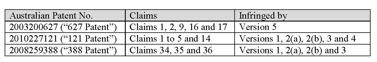
1. Claims 1, 2, 9, 16 and 17 of Australian Patent No. 2003200627 be revoked.
2. Claims 1, 2, 3, 4, 5 and 14 of Australian Patent No. 2010227121 be revoked.
3. Claims 34, 35 and 36 of Australian Patent No. 2008259388 be revoked.
4. The amended originating application be dismissed.
5. Within 14 days, the parties file and serve (by way of exchange) written submissions (limited to 3 pages in length) on the question of costs.
6. Within 21 days, the parties file and serve (by way of exchange) any written submissions in reply (limited to 2 pages in length) on the question of costs.
7. Upon the applicant, by its counsel, undertaking to the Court during the period of the stay:
A. to prosecute any appeal expeditiously;
B. forthwith to serve on the Commissioner of Patents copies of these orders pursuant to s 140 of the Patents Act 1990 (Cth) with a request that particulars of Orders 1, 2 and 3 (“the Revocation Orders”) be registered in accordance with s 187 of the Patents Act 1990 (Cth); and
C. not to commence any proceeding (apart from any appeal) or make any threat to do so in respect of any alleged infringement of any one or more of the claims the subject of the Revocation Orders,
the Revocation Orders be stayed:
(a) initially for a period of 21 days from today; and
(b) if an appeal from any of the Revocation Orders is lodged within that period, until the final determination of that appeal or further order.
Note: Entry of orders is dealt with in Rule 39.32 of the Federal Court Rules 2011.
[1] | |
[3] | |
[3] | |
[13] | |
[14] | |
[14] | |
[27] | |
[28] | |
[47] | |
[54] | |
[137] | |
[137] | |
[145] | |
[163] | |
[166] | |
[221] | |
[221] | |
[229] | |
[238] | |
[265] | |
[297] |
NICHOLAS J:
1 In this proceeding the applicant claims injunctive and pecuniary relief against the three respondents for patent infringement. The applicant is the patentee of the three patents in suit, each of which relates to coffee capsule technology. The first respondent imports and sells coffee capsules that are alleged by the applicant to infringe one or more of the claims of the patents. The third respondent (“Ms Tink”) is the sole director and shareholder of the first respondent. The second respondent (“Mr Knox”) is her husband. Both are sued for authorisation and also for having induced or procured the first respondent’s infringements. Each of the respondents denies infringement. The first respondent also contends that each of the relevant claims is invalid and has brought a cross-claim seeking orders for their revocation.
2 The proceeding is complicated by the number of patents in suit, the number of asserted claims, and the number of different coffee capsules that are alleged to infringe one or more of the applicant’s patents. Details of the three patents, the asserted claims, and the different versions of the first respondent’s coffee capsules that are alleged to infringe those claims are as follows:
3 The applicant called two expert witnesses, Mr William Hunter and Dr Frederick Davis.
4 Mr Hunter is a mechanical design engineer based in Australia with experience in packaging and product design. He provides consultancy services in the areas of engineering design and product development. In his first affidavit he gave evidence on his understanding of the integers within each claim in suit in the 388 patent and the 121 patent and described the nature of the inventions disclosed in both specifications. He also gave evidence directed to whether the integers of the asserted claims of the 388 patent and the 121 patent are present in the first respondent’s capsules. In his second affidavit, he gave evidence relevant to the sufficiency issue in relation to the 388 patent.
5 Dr Davis is an engineer based in Australia with experience in mechanical engineering. He has completed courses in plastic materials and manufacturing processes. He was not involved with coffee capsule design at any of the relevant priority dates. However, he has held various roles in a professional services firm that specialises in product design, development and contract manufacturing. He made two affidavits in the proceeding. In his first affidavit Dr Davis addressed the validity issues in relation to all of the patents. In his second affidavit he gave evidence directed to his understanding of the integers within each of the asserted claims of the 627 patent and whether those integers are present in the first respondent’s capsules.
6 The respondents called two expert witnesses, Mr Karl Winkler and Professor Gianluca D’Urso.
7 Mr Winkler is a mechanical engineer based in the United States with experience in consumer and commercial product development. From 2000 to 2003 he was employed as a Principal Engineer and Senior Product Development Engineer at Keurig Inc (“Keurig”). Keurig was a commercial coffee machine manufacturer and distributor. During his time at Keurig he was the principal engineer of the division which developed a single serve consumer coffee machine for use in the home. He made one affidavit in the proceeding in which he gave evidence relevant to the validity issues in relation to all three patents.
8 Professor D’Urso is a management engineer and Associate Professor in Technologies and Manufacturing Systems at the University of Bergamo, Italy. He has experience in mechanical and manufacturing engineering. He has consulted with Gruppo Gimoka s.r.l. (“Gimoka”) in relation to the design of its coffee capsules. Gimoka is the manufacturer of the first respondent’s coffee capsules. He made two affidavits and gave evidence relevant to the infringement issues in relation to all three patents. He also gave evidence on the issue of sufficiency in relation to the 388 patent.
9 The evidence given by the four witnesses to whom I have referred was given in a number of concurrent sessions and was the subject of three joint expert reports that were also admitted into evidence. Their evidence was admitted generally (ie. not the subject of any particular limitations) which means that although some of their evidence was given in relation to particular issues, it had sometimes broader relevance.
10 I formed a favourable impression of all four experts. However, I also formed the impression that Professor D’Urso and Mr Winkler were more familiar with the state of the art with respect to coffee machines at relevant times. I should also add that English is Professor D’Urso’s second language. This contributed to him taking what I would regard as an excessively literal interpretation of one particular aspect of one claim.
11 A considerable amount of the expert evidence related to experiments conducted by Mr Hunter that were relied on by the applicant in support of its infringement case. For reasons that I will later explain, I did not find the experimental evidence relied on by the applicant persuasive. My criticisms of the experimental evidence should not be taken as reflecting on Mr Hunter as a witness. I found much of his evidence helpful particularly in elucidating the relevant issues. I believe the difficulties associated with the experimental evidence are largely the result of difficulties with the way in which the relevant claims are drawn.
12 Evidence was also given for the respondents by Ms Susan Hantos, who is a patent attorney specialising in searching and analysing patent and other technical information. Her evidence related to patent searches she conducted relating to patent publications relied on by the respondents as s 7(3) information. Ms Hantos was not cross-examined.
13 There were three lay witnesses who were called and cross-examined. The first was Ms Tink. She was cross-examined at length in relation to matters that were relied upon by the applicant in support of a claim for additional damages and also the claim against her husband, Mr Knox. Mr Knox also gave evidence and he was also cross-examined at length on the same issues that were canvassed in the cross-examination of Ms Tink. There was also cross-examination of Ms Nicole Reynolds in relation to Mr Knox’s involvement in the first respondent’s business. Given that I have found that the asserted claims of each of the three patents is invalid, it is unnecessary to make any further reference to the evidence given by the lay witnesses in these reasons.
14 The 627 patent is entitled “Cartridge containing a single serving of a particulate substance for preparing a beverage”. It is common ground that the priority date of each of the asserted claims is 14 March 2002.
15 The specification begins with a general description of the invention. The specification states at page 1A, lines 1-9:
The present invention refers to a cartridge adapted to contain a single serving of a particulate substance, extractable by means of water for preparing a beverage, preferably an espresso coffee beverage, comprising an essentially cup- or bucket-shaped main body portion having a bottom portion and an open end opposite to the bottom portion, and a cover member adapted to be sealingly attached to the open end of the main body portion.
16 There follows a discussion of prior art cartridges and the manner in which they work. The specification states at page 1A, line 10 – page 2, line 13:
Such cartridges are well known in the art in a variety of different embodiments, whereby particularly [sic] cartridges containing a single serving of coffee powder for preparing an espresso coffee are in widespread use. One of the fundamental advantages of such cartridges may be seen in the fact that they are gas tight, thus keeping the ground coffee contained therein fresh over an extended period of time. For brewing the coffee powder received in the cartridge, predominantly semi-automatic espresso coffee machines are in use whereby the cartridge is inserted into a cartridge holder of the machine, with its cover facing downwards. Then, the cartridge holder is inserted manually into the coffee machine. The coffee machine is provided, in the region of the area where the cartridge holder is to be inserted into the machine, with a so-called brewing spike, i.e. a hollow piercing member comprising radial outlet openings for feeding the brewing water into the interior of the cartridge, once the bottom of the cartridge has been pierced upon insertion of the cartridge holder into the coffee machine. The bottom of the cartridge holder itself is provided with a plurality of projections located on a collecting tray. These projections penetrate the cover of the cartridge and provide a plurality of openings in the cover as soon as pressurized brewing water is fed into the cartridge and the cover thereof is pressed against the projections due to the hydraulic overpressure in the interior of the cartridge. During the subsequent brewing operation, the brewing water is fed into the interior of the cartridge through the brewing spike, with the result that it flows under pressure through the coffee powder in the cartridge, finally leaving the cartridge as coffee beverage through the openings in the cover. The freshly brewed coffee is collected in the collecting tray and flows through a beverage outlet out of the machine. A coffee machine comprising such a setup for the extraction of the coffee powder contained in a cartridge is disclosed, for instance, in the document EP 0,512,470.
17 There is then some discussion of certain disadvantages of the prior art. The specification continues at page 4, line 22 – page 5, line 10:
Embodiments of the invention provide a cartridge adapted to contain a single serving of a particulate substance, extractable by means of water for preparing a beverage, preferably an espresso coffee beverage, in which the brewing water flows through the extractable substance contained therein as uniformly as possible to thereby extract the substance as fully as possible.
Embodiments of the invention provide a cartridge adapted to contain a single serving of a particulate substance, extractable by means of water for preparing a beverage, preferably an espresso coffee beverage, in which the associated coffee machine can be kept as simple as possible, removing the need to provide the machine with means for distributing and/or collection [sic] the brewing water and the beverage, respectively, with regard to the cartridge.
Embodiments of the invention provide a cartridge adapted to contain a single serving of a particulate substance, extractable by means of water for preparing a beverage, preferably an espresso coffee beverage, in which the brewing water can flow through the cartridge from cover to bottom or vice versa, without the need to provide substantial structural modifications to the cartridge.
18 This is followed by the first of six consistory statements which states at page 5, lines 11-26:
According to a first aspect of the invention, there is provided a cartridge adapted to contain a single serving of a particulate substance, extractable by means of water for preparing a beverage, comprising an essentially cup- or bucket-shaped main body portion having a bottom portion and an open end opposite to said bottom portion, and a cover member adapted to be sealingly attached to the open end of the main body portion wherein at least one fluid director member having essentially disc-shaped configuration with a central longitudinal axis and a dimension essentially corresponding to the interior cross sectional dimension of the main body portion, the fluid director member adapted to be received in the interior of the main body portion whereby each fluid director member is provided with a plurality of openings and a plurality of embossings, each of the embossings having a raised portion, whereby a plurality of communicating fluid channels is created between the raised portions of the embossings.
19 The specification then states at page 5, lines 28 – page 6, line 3:
By providing at least one fluid director member of the kind explained herein above, for example, at the inlet side of the cartridge above the particular substance, a uniform distribution of the water fed into the cartridge for extracting the particulate substance can be ensured, independent of the number and the size of the inlet perforations.
20 Some preferred embodiments are then described. This is followed by further consistory statements describing the other four aspects of the invention.
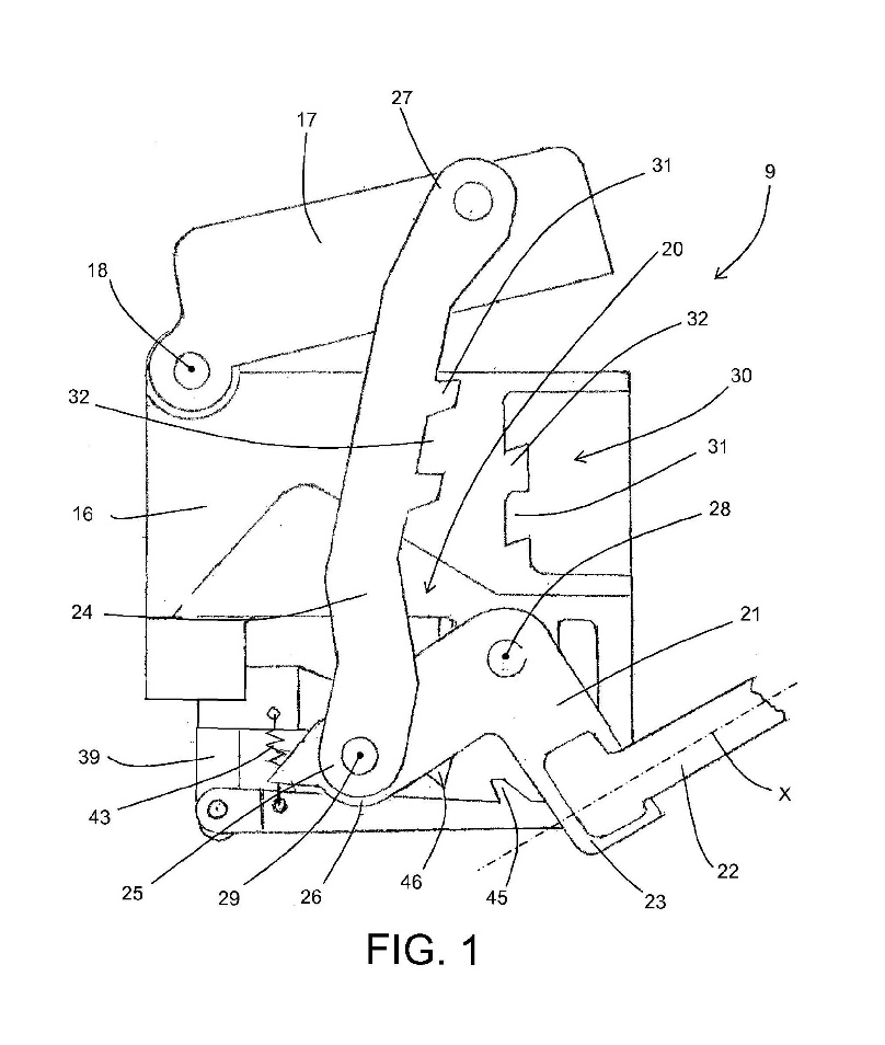
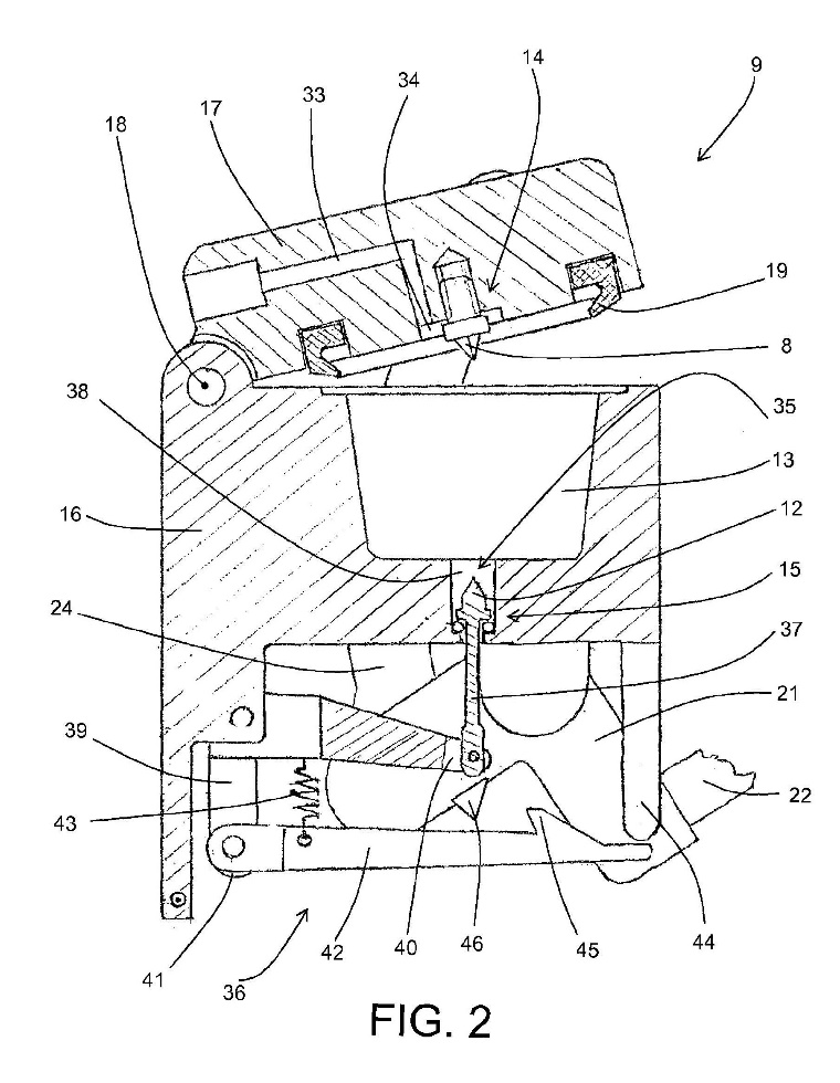
21 The specification includes a detailed description of the invention by reference to seven drawings. The most significant of these for present purposes are Figs 1 and 2 which are as follows:
|
|
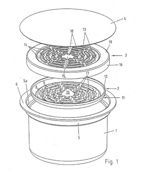
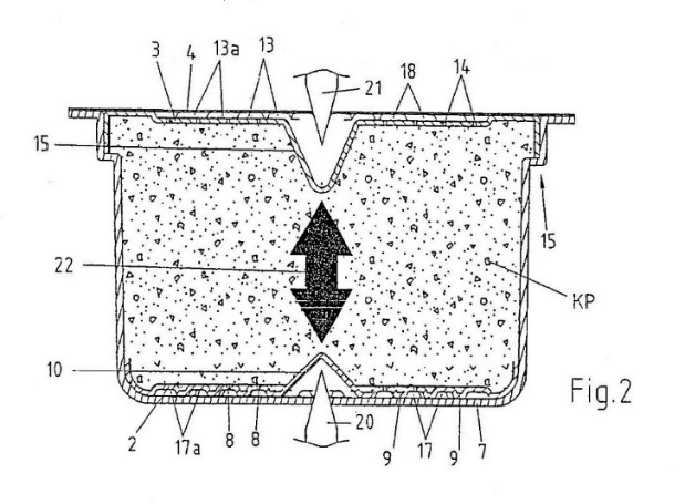
22 Figure 1 is an exploded view of a cartridge adapted to receive a single serving of a particulate substance used in the preparation of a beverage. Figure 2 shows a longitudinal sectional view of an assembled cartridge containing a single serve of coffee powder. The coffee powder is enclosed between the lower collection member (2) and the upper distribution member (3).
23 Figure 1 shows a cartridge with a main housing portion (1), a lower fluid collection member (2), an upper fluid distribution member (3) and a cover (4). Coffee powder is stored in the main housing portion (1) between the fluid collection member (2) and the fluid distribution member (3). The main housing portion (1) and the cover (4) consist of a gas-tight multi-layer composite foil material. The specification states at page 8, lines 18-21:
The fluid collection member 2 and the fluid distribution member 3 both are generally disc-shaped and are manufactured preferably by deep drawing.
24 The specification continues at page 9, lines 1-13:
The collection member 2 is provided with a plurality of embossings having the shape of annular segments; these embossings show as raised portions 9 protruding from the bottom surface of the lower collection member 2. Once the collection member 2 having been inserted into the main portion 1 of the cartridge, the raised portions 9 rest on the flat bottom surface of the main portion 1, with the result that a plurality of fluid channels 17 are created, running from the central longitudinal axis of the collection member 2 radially outwards and concentrically around the central longitudinal axis of the collection member 2. Beside the raised portions 9, i.e. in the region of the thus created fluid channels 17, the collection member 2 is provided with a plurality of openings 8.
25 The specification also states at page 9, line 21 – page 10, line 3:
As far as the design is concerned, the upper distribution member 3 is essentially a mirror image of the lower collection member 2. Again, the distribution member 3 comprises a plurality of embossings having the shape of annular segments; these embossings show as raised portions 13 protruding from the top surface of the upper distribution member 3. By means of these raised portions 13, a plurality of fluid channels 18 are created at the top surface of the upper distribution member 3, these fluid channels 18 running from the central longitudinal axis of the distribution member 3 radially outwards and concentrically around the central longitudinal axis of the distribution member 3. Beside the raised portions 18, i.e. in the region of the thus created fluid channels 18, the distribution member 3 is provided with a plurality of openings 14.
26 The specification also states at page 10, line 31 – page 11, line 6:
Moreover, it can be clearly seen that fluid channels 17 are created by the raised portions 9 of the lower collection member 2 resting on the bottom of the main cup- or bucket-shaped main portion 1 of the cartridge. Similarly, fluid channels 18 are created by the raised portions 9 of the upper distribution member 3 resting on the bottom surface of the cover 4 of the main portion 1 of the cartridge.
27 Claims 1, 2, 9, 16 and 17 are as follows:
1. A cartridge adapted to contain a single serving of a particulate substance, extractable by means of water, extractable by means of water for preparing a beverage comprising an essentially cup- or bucket-shaped main body portion having a bottom portion and an open end opposite to said bottom portion, and a cover member adapted to be sealingly attached to said open end of said main body portion, wherein there is provided at least one fluid director member having essentially disc-shaped configuration with a central longitudinal axis and a dimension essentially corresponding to the interior, cross sectional dimension of said main body portion, said fluid director member adapted to be received in the interior of said main body portion, whereby said fluid director member has a plurality of openings and a plurality of embossings, each of said embossings having a raised portion, whereby a plurality of communicating fluid channels is created between said raised portions of said embossings.
2. A cartridge containing a single serving of a particulate substance, extractable by means of water for preparing a beverage, comprising:
an essentially cup- or bucket-shaped main body portion having a bottom portion and an open end opposite to said bottom portion;
a cover member sealingly attached to said open end of said main body portion;
a fluid director member having essentially disc-shaped configuration with a central longitudinal axis and a dimension essentially corresponding to the interior cross sectional dimension of said main body portion;
said fluid director member having a plurality of openings and a plurality of embossings, each of said embossings having a raised portion, whereby a plurality of communicating fluid channels is created between said raised portions of said embossings, and;
said fluid director member located in the interior of said cartridge between said particulate substance and said bottom portion of said main body portion, thereby constituting a collection member for the water flowing through said particulate substance.
…
9. Cartridge according to any one of ·the claims 1, 2, 4 or 7, wherein said openings are located in said fluid channels created between said raised portions of said embossings.
…
16. Cartridge according to claim 1 or 12, wherein said fluid director member is located in the interior of said cartridge with a certain distance from the bottom of said main body portion or from said cover member.
17. Cartridge according to any one of the claims 1, 2, 4 or 7, wherein said openings have a size that is less than the statistical mean value of the diameter of one particule of said particulate substance
28 There was no dispute between the parties as to the relevant principles of construction. These were summarised by the Full Court (Hill, Finn and Gyles JJ) in Jupiters Ltd and Ors v Neurizon Pty Ltd (2005) 222 ALR 155 at 168-169 [67]:
…
(i) the proper construction of a specification is a matter of law: Décor Corporation Pty Ltd v Dart Industries Inc (1988) 13 IPR 385 at 400;
(ii) a patent specification should be given a purposive, not a purely literal, construction: Flexible Steel Lacing Co v Beltreco Ltd (2000) 49 IPR 331; [2000] FCA 890 at [81] (Flexible Steel Lacing); and it is not to be read in the abstract but is to be construed in the light of the common general knowledge and the art before the priority date: Kimberley-Clark Australia Pty Ltd v Arico Trading International Pty Ltd (2001) 207 CLR 1; 177 ALR 460; 50 IPR 513; [2001] HCA 8 at [24];
(iii) the words used in a specification are to be given the meaning which the normal person skilled in the art would attach to them, having regard to his or her own general knowledge and to what is disclosed in the body of the specification: Décor Corporation Pty Ltd at 391;
(iv) while the claims are to be construed in the context of the specification as a whole, it is not legitimate to narrow or expand the boundaries of monopoly as fixed by the words of a claim by adding to those words glosses drawn from other parts of the specification, although terms in the claim which are unclear may be defined by reference to the body of the specification: Kimberley-Clark v Arico at [15]; Welch Perrin & Co Pty Ltd v Worrel (1961) 106 CLR 588 at 610; Interlego AG v Toltoys Pty Ltd (1973) 130 CLR 461 at 478; the body of a specification cannot be used to change a clear claim for one subject matter into a claim for another and different subject matter: Electric & Musical Industries Ltd v Lissen Ltd [1938] 4 All ER 221 at 224–5; (1938) 56 RPC 23 at 39;
(v) experts can give evidence on the meaning which those skilled in the art would give to technical or scientific terms and phrases and on unusual or special meanings to be given by skilled addressees to words which might otherwise bear their ordinary meaning: Sartas No 1 Pty Ltd v Koukourou & Partners Pty Ltd (1994) 30 IPR 479 at 485–6 (Sartas No 1 Pty Ltd); the court is to place itself in the position of some person acquainted with the surrounding circumstances as to the state of the art and manufacture at the time (Kimberley-Clark v Arico at [24]); and
(vi) it is for the court, not for any witness however expert, to construe the specification; Sartas No 1 Pty Ltd at 485–6.
29 Plain language must be given its plain meaning, and clear words in a claim must not be given an unnatural meaning by imposing glosses drawn from the body of the specification. However, the context in which the relevant language is used is of crucial significance to the ascertainment of its meaning. When construing a patent specification the Court seeks to give the document a purposive construction by reading the document as it would be understood by a person skilled in the art and without engaging in overly meticulous verbal analysis. As Lord Hoffman said on the topic of purposive construction in Kirin-Amgen Inc and Others v Hoechst Marion Roussel Ltd and Others (2004) 64 IPR 444 at 454-455 [34]:
“Purposive construction” does not mean that one is extending or going beyond the definition of the technical matter for which the patentee seeks protection in the claims. The question is always what the person skilled in the art would have understood the patentee to be using the language of the claim to mean. And for this purpose, the language he has chosen is usually of critical importance. The conventions of word meaning and syntax enable us to express our meanings with great accuracy and subtlety and the skilled man will ordinarily assume that the patentee has chosen his language accordingly. As a number of judges have pointed out, the specification is a unilateral document in words of the patentee’s own choosing. Furthermore, the words will usually have been chosen upon skilled advice. The specification is not a document inter rusticos for which broad allowances must be made. On the other hand, it must be recognised that the patentee is trying to describe something which, at any rate in his opinion, is new; which has not existed before and of which there may be no generally accepted definition. There will be occasions upon which it will be obvious to the skilled man that the patentee must in some respect have departed from conventional use of language or included in his description of the invention some element which he did not mean to be essential. But one would not expect that to happen very often.
30 There is a danger that in seeking to give a claim a purposive construction, or in seeking to read it in context, an impermissible gloss might be imposed upon the language used based on material found in the body of the specification: see Sachtler GmbH & Co KG v RE Miller Pty Ltd (2005) 65 IPR 605 at 613-614 [42], Tramanco Pty Ltd v BPW Transpec Pty Ltd (2014) 105 IPR 18 at 48-49 [175]. Purposive construction does not justify departing from clear and unambiguous language used in the claim.
31 The principal issue of construction concerns the following words of claim 1 (referred to in the evidence variously as integers 1.5 and/or 1.6) and similar wording in claim 2:
… whereby said fluid director member has a plurality of openings and a plurality of embossings, each of said embossings having a raised portion, whereby a plurality of communicating fluid channels is created between said raised portions of said embossings.
32 There are two aspects to the construction issue. The first concerns the meaning of the term “embossings” which is not defined in the specification. The second concerns the meaning of the words “communicating fluid channels”. As the claim states, the cartridge includes a fluid director member that has a plurality of embossings, each of which has a raised portion, creating a plurality of communicating fluid channels between them.
33 The meaning of the term “embossings” and the words “communicating fluid channels” are closely related. This is because the claim requires that “a plurality of embossings, each … having a raised portion” create between those raised portions “a plurality of communicating fluid channels”. The function that is performed by the raised portions of the embossings is relevant to understanding what the word embossings means as used in the claim.
34 The respondents submitted that the term “embossings” has a technical meaning that refers to a type of manufacturing process that introduces a shape or geometry into a flat surface. In support of this submission they relied on evidence given by Professor D’Urso. He understood the term to refer to shapes produced using processes such as stamping, pressing and deep drawing which result in a raised area above the top plane of the material matched by a cavity on the lower plane. According to the respondents, the raised areas created through such processes are what are described as the “raised portions” in the claims.
35 The applicant submitted that the respondents’ interpretation of the word “embossings” is too narrow and does not reflect the wide meaning that the word “embossings” naturally bears. It submitted that the respondents’ interpretation is arrived at from an impermissible reading down of the wide language of the claim by reference to the preferred embodiments described in the specification.
36 The applicant relied on expert evidence given by Dr Davis to the effect that an “embossing” is a geometry of any shape that is raised off a surface. According to the applicant, Dr Davis’ understanding of the term embossing is consistent with the following definition of “emboss” in the Macquarie Dictionary (“Macquarie”) upon which the applicant also relied:
emboss / verb (t) 1. to raise or represent surface designs in relief. 2. to cause to bulge out; make protuberant; make umbonate. 3. to raise a design on a fabric by pressing. 4. to cover or ornament with bosses or studs.
In its submissions the applicant placed particular reliance on meanings 1, 2 and 4. The Macquarie does not include any definition of the word “embossing”.
37 The Oxford English Dictionary (“OED”) defines the verb “emboss”, the noun “embossing” and the adjective “embossed” as follows:
Emboss, v. 1. a. To cause to bulge or swell out, make convex or protuberant; to cover with protuberances…b. To emboss (out): to inflate (style), render tumid; to give exaggerated prominence to. c. To bulge, be convex. 2. a. To carve or mould in relief; to cause (figures, parts of a wrought surface) to stand out, project or protrude… b. To adorn with figures or other ornamentation in relief; to represent (a subject) in relief. (Sometimes with reference to embroidery.) Also of the figures, etc.: To stand out as an ornament upon. 3. To ornament with or as with bosses or studs. Hence, To adorn or decorate sumptuously.
Embossing, n. a. The action of emboss (verb). b. Embossed ornamentation; formerly in wider sense, swelling, protuberance.
Embossed, adj. 1. Carved or moulded in relief; ornamented with figures in relief; (of figures or ornament) raised, standing out in relief. 2. Covered with ornamental bosses or studs; richly or sumptuously decorated. 3. Humpbacked. 4. Bulging, convex, swollen, tumid. 5. Projecting in the centre like the boss of the shield.
38 Dr Davis drew some support for his understanding of the word “embossing” from the word “boss”, which is a term that is used in the field of engineering. According to the Macquarie, when used in relation to machinery, a “boss” is:
a. an enlarged, usually strengthened section of a shaft, wheel hub, etc. b. a raised circular pad on a machine part, which surrounds an attachment hole …
That meaning is narrower than the meaning given to the word by Dr Davis. In any event, the word with which I am directly concerned is “embossing” and there is nothing in either the OED or the Macquarie to indicate the two words have the same meaning.
39 The applicant also relied on the evidence of Mr Winkler in relation to the meaning of the word “embossing”. In his oral evidence Mr Winkler indicated that he agreed with Dr Davis’ understanding of the word embossing. I found that evidence difficult to reconcile with the statement made in his affidavit indicating that “embossing” refers to a particular type of geometry in which there is a raised area above the plane of the material which is matched by a cavity on the underside of the plane. The apparent inconsistency in Mr Winkler’s evidence was not taken up in cross-examination.
40 I did not find the evidence of Dr Davis or Mr Winkler in relation to the meaning of the word embossing of assistance. It seems to me that Dr Davis wrongly equated the word embossing with the word boss and gave insufficient attention to the context in which the word appears in the relevant claims when read in light of the specification as a whole. I think this is also true of the oral evidence to which I have referred given by Mr Winkler.
41 It seems to me that the word embossings is intended to convey more about the configuration of the shape and structure of the relevant integer than the applicant’s interpretation allows. In particular, in my view the word refers to the bulging or convex nature of the shape. Contrary to the applicant’s submission, it is not referring to a geometry of any shape that is raised off a surface. The meaning of the word embossings, when read in the context of the claims and the specification as a whole, has a more nuanced meaning.
42 The word “embossings” does not have a technical or special meaning in the sense discussed in the authorities. In particular, the evidence does not establish that it is a word that would ordinarily be used by a person skilled in the art to describe a feature of a coffee capsule. The word must be given an ordinary and natural meaning best suited to the context in which it is used in the specification as a whole. I think in context it is used to describe a surface of the fluid director member that has been “embossed”. This implies that the surface is bulging or convex. The words bulging and convex both feature in the OED definitions of emboss and embossed.
43 When regard is had to the detailed description of the preferred embodiments, it is clear that the raised portions (9, 13) of the embossings protrude from the top surface of the upper distribution member (3) and the bottom surface of the lower collection member (2). They are bulging and convex in shape. They create the fluid channels referred to in the claim.
44 Embossings, in the sense that word is used in the claims, may be stamped, pressed or deep drawn into the surface on which they reside. That is not to say that they must be made by any particular manufacturing process. Provided they exhibit the bulging and convex appearance that can be achieved using those processes, it does not matter how they are manufactured. There is no reason why the relevant effect might not be achieved by a process of injection moulding. It is the bulging and convex shape of the relevant feature in the finished componentry that will determine whether the requirement that there be a plurality of embossings is satisfied.
45 The next question that arises concerns the meaning of the words “communicating fluid channels”. Here the applicant again relied on the evidence of Dr Davis who it said suggested that a “communicating fluid channel” is a path or flow of fluid itself rather than a physical feature of the fluid director member. The evidence given by Dr Davis to which I was referred by the applicant in support of its submission does not say this. What it says is that the term “channels” does not necessarily require that there be a long or thin-shaped fluid passage. Rather, Dr Davis said that the fluid channels were created by “… raised solid geometries that act to create channels which divide beverage fluid flows …”.
46 The relevant words of the claim define a physical feature of the fluid director member. This requirement of the claim will be satisfied regardless of whether or not fluid is present. I accept the respondents’ submission that what is referred to is not an actual flow of liquid, but a shape or geometry that can contain and direct such a flow during use. It is the raised portions of the embossings that will contain and direct the flow of liquid when the coffee capsule is in use.
47 The applicant alleges that the first respondent’s version 5 coffee capsule includes a lower fluid director member that meets the requirements of claims 1, 2, 9, 16 and 17. Whether or not that is so depends on whether the version 5 capsule has “a plurality of embossings” and “a plurality of communicating fluid channels … created between [the] raised portions of said embossings”.
48 Dr Davis produced the following annotated photograph of the version 5 capsule fluid director member that indicates where each of the relevant integers is alleged by the applicant to be found:
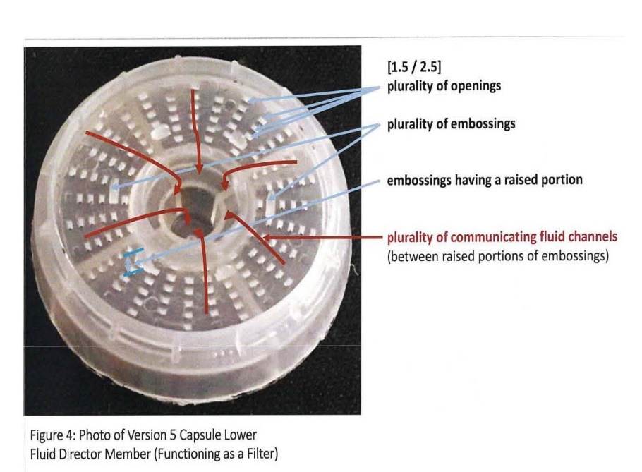
49 Towards the centre of the fluid director member is what was described in the evidence as an inner castellated ring. In his oral evidence Dr Davis accepted that his annotated photograph depicted fluid flow over the top of the raised portions of the inner castellated ring. But he went on to state that he believed the way in which he had drawn the fluid flow in the photograph was in error. He said that the dominant flow would be in the “notches” by which I understood him to mean the “plurality of openings” shown in the photograph.
50 The applicant made clear in its closing submissions that it does not contend that the castellated ring, or the castellations themselves, are embossings within the meaning of the relevant claims. The applicant identified the six piercers or ribs on the underside of the fluid distribution member in the version 5 capsule as the plurality of embossings. It was submitted that these six piercers or ribs are:
… “embossings” as they are raised portions which stand the filter off the base of the capsule. They allow fluid to flow from the apertures and between the six ribs or piercers to the central region, where the flows merge, and to the exit holes, and thereby create a plurality of communicating fluid channels.
51 I think the words piercers or ribs accurately describe what the applicant called embossings. However, in my view these piercers or ribs do not constitute embossings within the meaning of the claims. They are not bulging or convex in shape and they do not control or direct fluid flow in any meaningful sense.
52 In his written evidence Dr Davis suggested that in the version 5 capsule the piercers or ribs create communicating fluid channels in which liquid will flow towards the centre of the fluid director member as depicted in his photograph. He later qualified this evidence as I have previously discussed. I am satisfied that the function of the piercers is not to create fluid channels or to direct fluid flow. That is not their purpose and that is not what they do when the version 5 capsule is in use. In his oral evidence Dr Davis accepted when pressed that the purpose of the piercers was to pierce and provide structural support and that they were not intended to create fluid channels.
53 In the result, I am not satisfied that the first respondent’s version 5 capsule includes a plurality of embossings with raised portions that create a plurality of communicating fluid channels. I am therefore not satisfied that the version 5 capsule infringes any of the asserted claims.
54 The respondents allege that claims 1, 2, 9 and 16 of the 627 patent are invalid for lack of novelty. They contend that each of those claims is anticipated by US patent 4,921,712 (“the 712 patent”). There is no issue as to the relevant legal principles, or the date of publication of the 712 patent. The question is whether the 712 patent provides a clear disclosure of the invention as claimed. In my opinion it does not.
55 The 712 patent includes a detailed description of a coffee brewing system comprising an automatic drip coffee brewing machine and a disposable coffee cartridge. The cartridge is made from a disposable material. It consists of a first cup, having an open first end and a substantially closed second end, a filter member that has an open end and a closed end, and a closure member having an open end and a substantially closed end. The closed end of the closure member includes a plurality of holes. A sealing sheet is provided at the top to keep the coffee fresh and to stop it from leaking out through the holes.
56 The coffee cartridge design is depicted in various drawings including Fig 1 which is as follows:
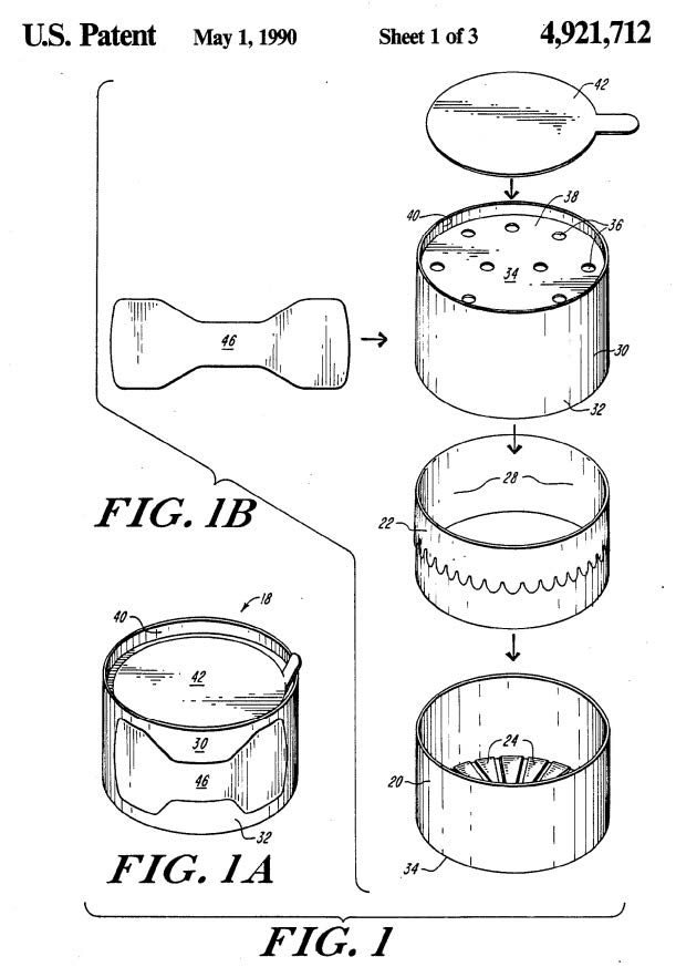
57 Figure 1A depicts an assembled coffee cartridge. Figure 1B shows an exploded view of the elements of the cartridge which consists of the following four parts: a lower cup (20), a filter element (22), an upper closure member (30) (also referred to as the upper closure cup or upper cup) and a sealing sheet (42). Coffee is stored in the filter element (22). The sealing sheet is adhesively sealed to the upper closure member (34).
58 When the capsule is ready to be used, the sealing sheet (42) is removed. The capsule is then inserted into the machine. Water drips from a water spout located above the capsule. The water drips through the holes (36) of the upper closure member (30), then through the filter element (22) and into the lower cup (20). The bottom of the lower cup includes exit ports (not shown in Fig 1) through which the brewed coffee flows from the lower cup into a serving cup or mug.
59 The critical question is whether the 712 patent clearly discloses a main body portion having a bottom portion and an open end opposite to said bottom portion, and a cover member adapted to be sealingly attached to the said open end of said main body portion as required by claim 1. The corresponding language of claim 2 is slightly but not materially different. Claims 9 and 16 are dependent on either claims 1 or 2.
60 The respondents submitted that the sealing sheet (42) and the upper closure member (30) together form a cover member which is adapted to be sealingly attached to the main body portion of the cartridge, being the lower cup (20). There are two difficulties with this submission.
61 The 712 patent clearly discloses a cover member (ie. the sealing sheet). However, the sealing sheet is not “adapted to be sealingly attached” to the main body portion of the cartridge. According to the respondents, the main body portion of the cartridge as shown in Fig 1 of the 712 patent is the lower cup (2). Assuming that to be correct, the sealing sheet disclosed in the 712 patent is not adapted to be sealingly attached to the lower cup. According to the 712 patent at column 4, lines 8-10:
The lower cup 20 is dimensioned slightly smaller in diameter than the upper cup, so that the upper closure cup can slip over it.
There is nothing in the description to suggest that the upper closure cup (or member) and the lower cup are adapted to be “sealingly attached” to each other.
62 The upper closure member (30) is not a “cover member”. Nor do I accept that the sealing sheet (42) and the upper closure member (30) shown in Fig 1 of the 712 patent together form a cover member. The purpose of the upper closure member is to receive and distribute water through the holes onto the coffee in the filter element. Mr Winkler was asked whether he contended that the upper closure member (30) shown in Fig 1 was a cover member. It is apparent from his answer that he did not consider that it was.
63 I am not satisfied that the 712 patent contains a clear disclosure of the invention defined by any of the relevant claims.
64 The respondents also allege that each of claims 1, 2, 9, 16 and 17 of the 627 patent is invalid for lack of inventive step.
65 Section 18(1)(b)(ii) of the Patents Act 1990 (Cth) (“the Act”) provides that an invention is a patentable invention for the purposes of a standard patent if the invention, so far as claimed in any claim, involves an inventive step when compared with the prior art base as it existed before the priority date of that claim. At the relevant times subs 7(2) and (3) of the Act provided:
(2) For the purposes of this Act, an invention is to be taken to involve an inventive step when compared with the prior art base unless the invention would have been obvious to a person skilled in the relevant art in the light of the common general knowledge as it existed in the patent area before the priority date of the relevant claim, whether that knowledge is considered separately or together with the information mentioned in subsection (3).
(3) The information for the purposes of subsection (2) is:
(a) any single piece of prior art information; or
(b) a combination of any 2 or more pieces of prior art information;
being information that the skilled person mentioned in subsection (2) could, before the priority date of the relevant claim, be reasonably expected to have ascertained, understood, regarded as relevant and, in the case of information mentioned in paragraph (b), combined as mentioned in that paragraph.
66 As to the operation of subs 7(3) of the Act, see AstraZeneca AB v Apotex Pty Ltd (2015) 257 CLR 356 (“AstraZeneca”) at [18]-[19] per French CJ, at [68] per Kiefel J (as her Honour then was), at [111] and [115] per Gageler and Keane JJ.
67 The expression “patent area” is relevantly defined in Sch 1 to mean Australia. The expression “prior art information” is relevantly defined to mean information that is part of the prior art base for the purposes of subs 7(3) in relation to deciding whether an invention does or does not involve an inventive step. At the relevant times the expression “prior art base” was defined in para (a) of the definition as:
in relation to deciding whether an invention does or does not involve an inventive step or an innovative step:
(i) information in a document that is publicly available, whether in or out of the patent area; and
(ii) information made publicly available through doing an act, whether in or out of the patent area.
68 There is no dispute that the priority date of the relevant claims is 14 March 2002. Nor is there any dispute that the person skilled in the relevant art is an engineer working in the field of developing coffee machines and capsules as at the priority date or a team comprising an engineer with more general product development experience working with another person with knowledge in relation to coffee, coffee machines and capsules (such as a food technologist and/or a barista).
69 The respondents’ inventive step case was put on the basis of first, the common general knowledge as it existed in Australia at the priority date, and secondly, the common general knowledge together with the information disclosed in the 712 patent which was said to satisfy the requirements of s 7(3) of the Act.
70 Neither party made any detailed submissions in relation to the content of the common general knowledge. The focus of the respondents’ attention was on a hypothetical design task undertaken by Mr Winkler for the purposes of this proceeding that was said by the respondents to provide evidence that the claimed invention was obvious. The applicant also focused its attention on Mr Winkler’s hypothetical design task and the reasons why, according to the applicant, it did not provide any reliable evidence from which to conclude that the claimed invention did not involve an inventive step.
71 Each of the claims that is alleged to be invalid for lack of inventive step is to a combination. In Garford Pty Ltd v Dywidag Systems International Pty Ltd (2015) 110 IPR 30 (“Garford”) the Full Court said at 43 [54]-[55]:
[54] … the question to be addressed in relation to inventive step is directed to the combination. The combination will be taken to involve an inventive step unless it is established that it would be obvious to the notional person skilled in the art in light of the common general knowledge considered separately from, or together with, any available s 7(3) information. As Aickin J observed in 3M at CLR 293:
In the case of a combination patent the invention will lie in the selection of integers, a process which will necessarily involve rejection of other possible integers… It is the selection of the integers out, of perhaps many possibilities, which must be shown to be obvious.
[55] In Elconnex Pty Ltd v Gerard Industries Pty Ltd (1992) 25 IPR 173 (Elconnex FC) Lockhart J (with whom Sheppard and Wilcox JJ agreed) referred to this observation of Aickin J and added (at 184) that in the case of a combination “it is impermissible to determine inventiveness by a piecemeal examination integer by integer”.
72 As to whether a combination is obvious, it will often be appropriate to adopt a problem and solution analysis which involves asking whether the hypothetical person skilled in the relevant art, if faced with the same problem to which the invention is directed, would have taken as a matter of routine whatever steps might have led from the prior art to the invention, whether they be the steps of the inventor or not, if the person skilled in the art would be directly led as a matter of course to take such steps in the expectation that doing so might well produce a useful or better alternative to the prior art: Wellcome Foundation Ltd v VR Laboratories (Aust) Pty Ltd (1981) 148 CLR 262 at 286, Aktiebolaget Hässle v Alphapharm Pty Limited (2002) 212 CLR 411 (“Alphapharm”) at [50]-[53], Garford at 39-40 [41]-[43], Becton Dickinson Pty Ltd v B. Braun Melsungen AG [2018] FCA 1692 at [303]. Of course, in this context, prior art refers to information that formed part of the common general knowledge at the relevant priority date together with any other information to which regard may be had in accordance with s 7(3) of the Act.
73 The hypothetical person skilled in the art is assumed to possess the common general knowledge in the relevant field in so far as it is relevant to the subject matter of the patent in suit. This will include the background knowledge and experience available to all persons engaged in the relevant field within the patent area and includes publications to which they would refer as a matter of course: Minnesota Mining and Manufacturing Company v Beiersdorf (Australia) Ltd (1980) 144 CLR 253 (“3M”) at 292 per Aickin J, ICI Chemicals & Polymers Ltd v Lubrizole Corporation Inc (1999) 45 IPR 577 at 599 [11] per Emmett J.
74 Although it is correct to say that the hypothetical person skilled in the art is assumed to lack any capacity for invention, it does not follow that this person is taken to be incapable of finding a solution to a known problem that does not require inventive ingenuity. As the Full Court in Garford observed at [44], “[t]he inventiveness required to sustain a patent for a claimed invention is quite small. A “scintilla” of inventiveness is all that is required …”. But there must still be “some difficulty overcome, some barrier crossed” per Lockhart J, RD Werner & Co Inc v Bailey Aluminium Products Pty Ltd (1989) 85 ALR 679 at 689, or some contribution to the art “beyond the skill of the calling” per Bowen CJ, Beaumont and Burchett JJ, Allsop Inc v Bintang Ltd (1989) 15 IPR 686 at 701. Both of these formulations were referred to with apparent approval by the High Court in Lockwood Security Products Pty Ltd v Doric Products Pty Ltd (No 2) (2007) 235 CLR 173 at 195-196 [52] per Gummow, Hayne, Callinan, Heydon and Crennan JJ.
75 Also relevant is the use that may be made of hindsight or ex post facto analysis in deciding whether an invention lacks an inventive step. Many inventions may seem obvious with the benefit of hindsight. An ex post facto analysis of an invention can be particularly unfair to the inventor of a new combination which involves selecting a number of known integers from a large range of possible alternatives: see the observations of Aickin J in 3M at 293-294.
76 It is necessary to make findings in relation to the common general knowledge as at the priority date. Mr Winkler gave evidence that the field of consumer and commercial product development engineering, including in respect of single serve coffee machines and capsules, was an international field as at the priority date. Mr Winkler also gave evidence as to the different type of machines that were well-known as at the priority date which was unchallenged and which I accept.
77 The following description of single serve coffee machines, traditional espresso machines, and drip coffee machines is based on Mr Winkler’s evidence and is consistent with statements appearing in the body of the specification which describe single serve coffee cartridges for preparing espresso coffee in a coffee machine as well-known and in widespread use.
78 A single serve coffee machine is a machine that utilises a capsule containing a predetermined amount of coffee grounds to make a standardised cup of coffee. The single serve coffee machine delivers an amount of water heated to a particular temperature under pressure into the capsule to extract certain flavours from the coffee grounds. The coffee beverage then passes through a filter and exits the machine into a receptacle for drinking.
79 In traditional espresso machines, a portafilter is utilised rather than a capsule. A portafilter has a handle and a filter basket for holding the coffee grounds. Coffee grounds are manually placed into the filter basket by the operator. The operator then uses a tamp to manually compact the coffee grounds in the filter basket. The portafilter is then attached to the espresso machine. The espresso machine then delivers heated water under pressure through the coffee grounds through a shower head mechanism. The shower head provides an even coverage of water over the coffee grounds to ensure that the coffee grounds are fully extracted. The coffee beverage then passes through the filter in the bottom of the filter basket and exits the machine into a receptacle for drinking. The operator then removes the portafilter from the espresso machine and removes the used coffee grounds. Espresso machines are generally considered to produce good quality espresso coffee. However, the manual handling of the coffee grounds can be messy and the process of preparing the coffee beverage can be time consuming.
80 Dr Davis agreed in his oral evidence with Mr Winkler’s explanation of the portafilter system. Dr Davis was shown a photograph of a traditional espresso machine portafilter which was admitted into evidence. He agreed that it showed three components of a portafilter. The three components are the exterior part of the portafilter with the handle and two cups (or baskets). He agreed that in use, either one of the two cups (one is larger than the other) is filled with compacted coffee and is then placed inside the main part of the portafilter with the handle.
81 In drip coffee machines, the coffee grounds are held in a large conical paper filter in a brewing basket. Heated water is then fed onto the coffee grounds through a shower head mechanism and the flavours of the coffee are extracted from the grounds. However, unlike in an espresso machine, the extraction does not occur under pressure. Drip coffee machines usually create between 8 to 12 cups of coffee at a time and, therefore, are not suitable for making a single serving of coffee.
82 Drip coffee is made by pouring hot water over the top of coffee grounds, which are held in a filter, and letting the water slowly pass through the coffee grounds and the filter by the force of gravity. In contrast, an espresso coffee is made by pressing hot water at a high pressure through compacted coffee grounds. Drip coffee has a different flavour profile to espresso coffee. Espresso coffee is generally made using darker roast coffee beans which give it a stronger flavour. Drip coffee is made with a lighter roast and has a lighter, more nuanced flavour. The grind profile of an espresso coffee is generally finer than for drip coffee. The finer particles allow for a more compacted coffee bed which increases the resistance of water passing through the coffee bed. This extracts soluble compounds from the coffee grinds, which have a different flavour profile from the coffee grinds used in drip coffee which are generally considered to be sharper and have a different mouth feel. In drip coffee, the heavier grind and larger particles facilitate the passage of the water through the coffee bed under the force of gravity alone.
83 Mr Winkler was asked by the solicitors for the respondents to describe the features that he would have adopted if he was developing a single serve espresso coffee capsule as at the priority date in light of information that he knew and regarded as well-known and generally accepted by engineers working in the field of developing single serve coffee machines and capsules as at that date. He said that he would have included a number of standard features in his design.
84 According to Mr Winkler’s evidence, as at the priority date, it was well-known and generally accepted by engineers working in the field of developing single serve coffee machines and capsules that single serve coffee capsules had at least the following features (“the standard features”):
(a) an enclosure for storing the coffee grounds;
(b) an entrance means for the water to enter the enclosure;
(c) an exit means for the water to exit the enclosure;
(d) at least one filter inside the enclosure between the coffee grounds and the exit means to prevent the coffee grounds from exiting the capsule with an open area beneath the filter for the water to flow and exit the enclosure; and
(e) a hermetical seal.
85 Dr Davis accepted that he had no experience in the design of coffee capsules as at 2002. With reference to the paragraph in Mr Winkler’s affidavit in which he identifies the standard features, Dr Davis was asked:
May we take it that if you had been asked to develop a coffee machine for use with … single serve coffee capsules at that time you would have familiarised yourself with the products on the market and become aware that these were the standard sorts of features of those capsules at that time.
Dr Davis’ response to this question was:
Yes. I agree I would have.
86 Although I can accept that (a), (b), (c) and (e) were standard features as at the priority date, I am not persuaded that there was any coffee capsule shown to be common general knowledge as at the priority date which included feature (d). The Keurig K-Cup included an open area below the filter but it was not shown to have been common general knowledge as at the priority date. Although I accept that the Nespresso capsule was likely to have been well-known as at the priority date, it did not include any open area below the filter.
87 Mr Winkler said that a cup shape is particularly relevant for an espresso coffee capsule because cup-shaped capsules replicate the shape of the portafilter of traditional espresso machines. He said that he would have made a capsule from materials which were able to withstand the pressures required to make an espresso coffee, were impermeable to oxygen, and would be capable of being hermetically sealed. He said that he would have also included an optional second filter between the coffee grounds and the entrance means to act like a shower head to evenly disperse the water across the coffee grounds. This second filter would replicate the shower head of a standard espresso machine.
88 In response to a request from the solicitors for the respondents, Mr Winkler produced three designs using those features on a design software program that he used as at the priority date. He said that the impetus for these designs was to, as much as possible, replicate the features of a portafilter from a traditional espresso machine in the coffee capsule.
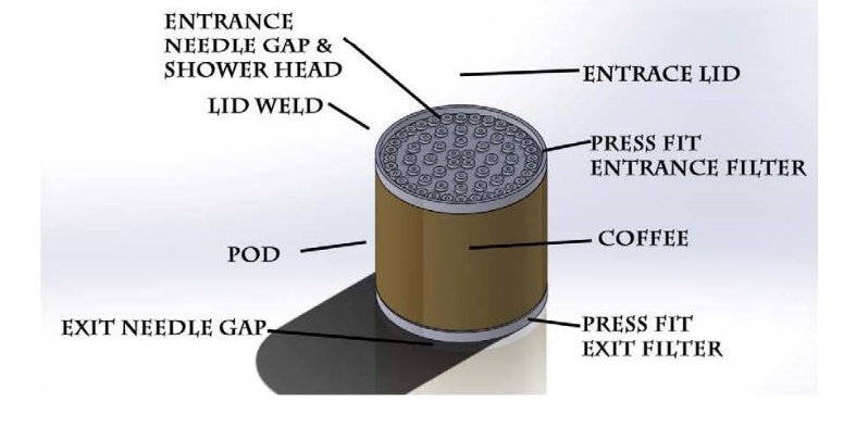
89 The first design (Fig 1) was a one piece pod housing design as follows:
Figure 1
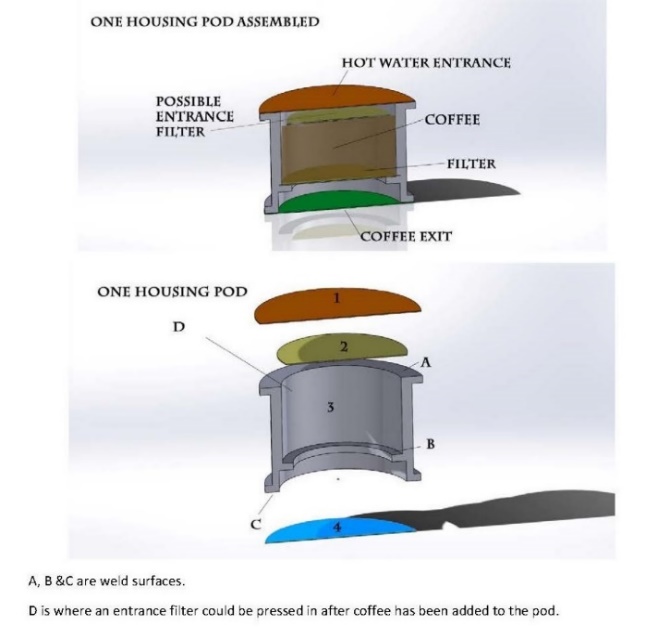
90 Both images are cross-sections of the cup-shaped coffee pod design by Mr Winkler. The exploded image shows an upper cover member (1), an upper filter (2), a main body (3) in which coffee is stored and a lower filter (4) which is welded to a lip at the bottom of the main body. The upper filter is described as a “possible entrance filter” which is not essential. The lower filter is essential. It is designed to prevent particulate exiting the main housing into the coffee cup.
91 Mr Winkler also produced what he referred to as a two piece pod housing design as follows:
Figure 2
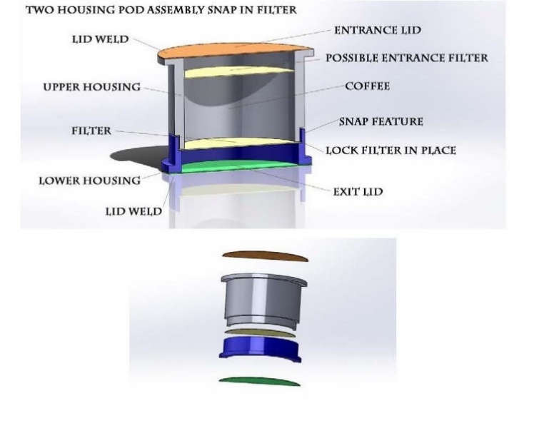
92 In his second design (Fig 2) Mr Winkler used a two piece housing pod. The two pieces could be either welded or “snap fit” together with a filter made of woven polymer, an injection moulded filter or a plastic sheet material with filter holes punched or sliced into it. The two piece pod design also included provisions for the inclusion of an optional upper filter.
93 In his third design (Fig 3) Mr Winkler incorporated upper and lower exit filters as shown below:
Figure 3
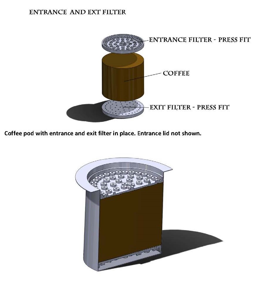
94 There are a couple of points to note about the entrance and exit filter designs. The entrance filter resembles an inverted shower head with cylindrical bosses facing upwards. The exit filter is facing in the opposite direction so that the cylindrical bosses face downwards. The bosses on the exit filter create a space between the base of the filter and the exit lid. According to Mr Winkler’s description of his design, this allows the filter to stand off the bottom of the cartridge, allowing coffee to collect and pass to the exit.
95 Both filters were designed by Mr Winkler to be made of injection moulded material. But he said that a simple punched filter made of mylar, polyethylene or other food safe flexible plastic could also be used.
96 None of the asserted claims require that the cartridge include more than one filter. For present purposes, I think the presence of the upper filter in Mr Winkler’s design can be disregarded. It is apparent that Mr Winkler’s design has all of the features of the cartridges described in claims 1 and 2 subject to the requirement that the fluid director member (ie. the exit filter in his design) have “… a plurality of openings and plurality of embossings, each of said embossings have a raised portion, whereby a plurality of communicating fluid channels is created between said raised portions of said embossings”.
97 In his evidence Mr Winkler explained that the main difference between the three designs is the method by which the exit filter is attached. In the first design, the filter is welded to a preformed inner ring inside the capsule. Mr Winkler said that welding a filter in this manner was well-known prior to March 2002. However, he did not point to any specific examples where the filter was welded to a preformed inner ring inside the capsule (as opposed to the base of the capsule) in the prior art capsules described in the evidence.
98 In his second design, the filter is locked into place between the two housings. The filter is made of woven polymer, injection moulded material or plastic sheet material with a filter hole punched or sliced into it.
99 In the third design, the filter is press fit into the capsule and is spaced away from the bottom of the capsule by what he referred to as “stand offs” which form part of the filter. He said that this feature was known more broadly in product development engineering. According to Mr Winkler:
I considered that the third design (the Press-Fit Design) was superior to the others because it provides more versatility as to how to execute the design. The exterior housing for the capsule can be chosen without being limited by the filter material because the filter is press fit into the housing. By contrast, if the filter is welded to the interior of the housing, the housing would need to be made of a material which is compatible with the filter material. Further, if the filter was snapped between upper and lower segments of the capsule, the capsule might be susceptible to leakage, i.e. oxygen might permeate the capsule through leaks in the snapping mechanism.
100 The applicant made a number of criticisms of Mr Winkler’s evidence.
101 First, it was suggested that Mr Winkler’s design task was artificial in that it would be unusual for a product engineer to be requested to design a coffee cartridge without also being told exactly what type of machine it was to be used in. Whether that is true or not is neither here nor there. The patent specification does not describe the coffee machine in which the cartridge is to be used except in the most general terms. Mr Winkler has approached the design task in much the same way as the specification proceeds, that is to say, he has designed a cartridge for use in a single serve machine adapted to use such a cartridge.
102 Secondly, it was submitted that rather than attempting to design a cartridge for use in a single serve espresso coffee machine, Mr Winkler instead sought to design a cartridge that could be used in a portafilter in a traditional espresso machine. I do not think that is an accurate characterisation of his evidence. Mr Winkler agreed that he took the portafilter of a traditional espresso machine as his starting point and it provided the inspiration for his design. He was seeking to replicate some of the design characteristics of a traditional espresso machine in his cartridge design. Dr Davis agrees that if he was asked to develop a single serve espresso coffee cartridge then that would be a reasonable approach and “one of [his] approaches”.
103 Thirdly, it was submitted by the applicant that:
… the key difficulty with Mr Winkler’s design task is that there is no satisfactory explanation as to why the non-inventive worker would have included, as he did, (a) a filter element which is solid rather than fabric, and which also acts as a fluid collection member, by incorporating features which stand it off from the base of the capsule so that the beverage can flow beneath it; and (b) a similar solid filter element, constituting a distribution member, inserted at the top of the body of the capsule, when neither feature, or anything like them, existed at all in the prior art …
104 As to the first point, there is nothing in claims 1 or 2 that requires that the distribution member (the exit filter in Mr Winkler’s design) be made of any particular material. Mr Winkler said that the filter could be made from an injection moulded material or a simple food safe flexible plastic. Nor is there anything in claims 1 or 2 which requires that the fluid collection member incorporate features which stand it off from the base of the capsule. Although dependent claim 16 requires that the fluid member “… is located in the interior of the cartridge with a certain distance from the bottom of said main body portion or from said cover member” there is no requirement that the “raised portions” stand the filter member off the base of the capsule so that beverage may flow beneath it. That is no doubt a feature of a preferred embodiment (see page 9, lines 1-10 of the specification) but it is not a feature that is carried through into any of the asserted claims.
105 As to the second point, none of the asserted claims require that the cartridge include a filter at the top above the store of coffee. As I have mentioned, Mr Winkler’s designs included a “possible entrance filter”. The fact that he included an entrance filter is perhaps not surprising if he was trying to, as much as possible, replicate the features of a portafilter from a traditional espresso machine in a coffee capsule. It would seem logical to include in the design a shower head mechanism similar to that found in a traditional espresso machine. Mr Winkler stipulated that the upper filter in his design was optional only. It is not apparent to me why he decided to make this element of his design optional. Curiously, claims 1 and 2 also allow for the cartridge to have only one fluid director member (ie. a second fluid director member is optional).
106 Mr Winkler referred in his evidence to a number of coffee capsules that were, as at the priority date, relevant prior art. These were:
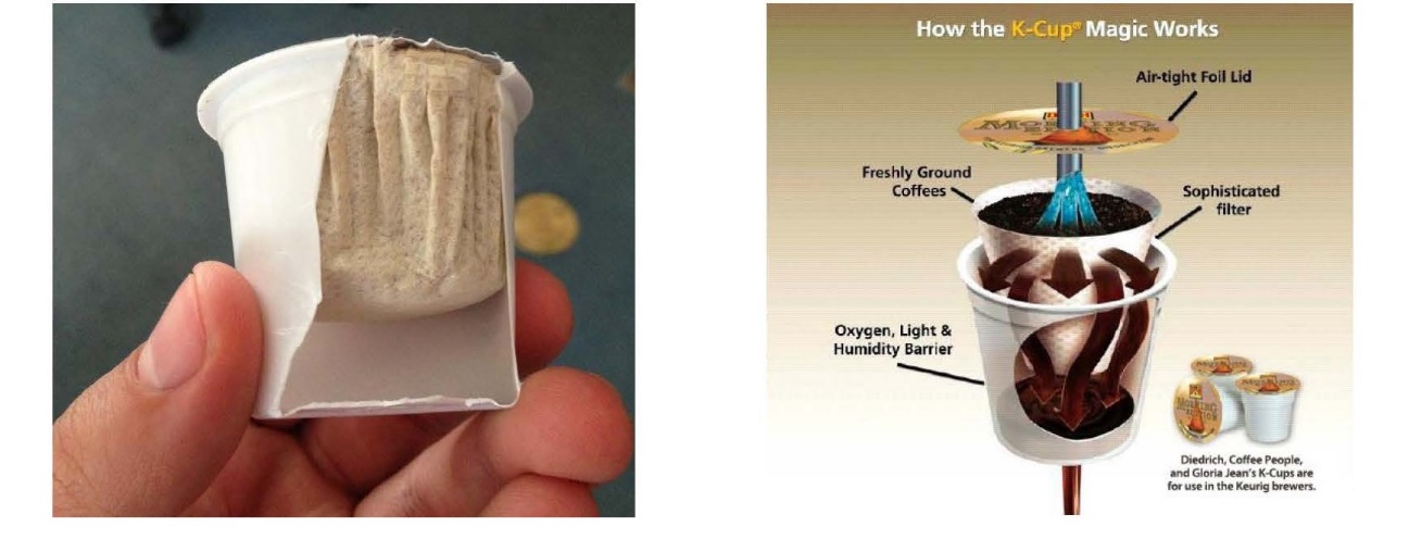
Keurig K-Cup. The K-Cup was a pour-over coffee machine capsule which had a paper polymer filter held within it. The filter was welded directly to the side wall of the pod. Entry and exit was via a cannula. The K-Cup as at 2001 is depicted in the images below (the exit cannula is not shown). The capsule and the Keurig B-100 machine were designed as a system.
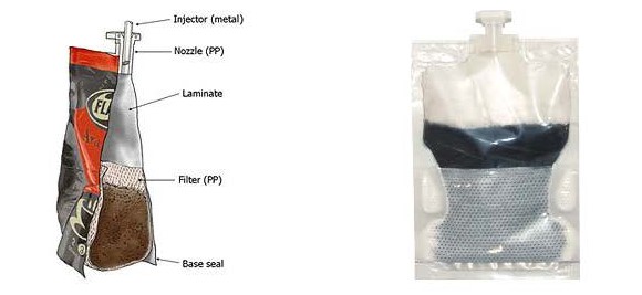
Flavia by Mars. The Flavia pack was a foil sealed pack containing coffee with an enclosing made of flexible laminate. Entry was by an injector and nozzle. The filter was a satchel or bag and was contained inside the pack. Exit was by a weakened seal at the bottom, whereby the filter would drop down and liquid would pass through the filter and into the cup. The Flavia pack as at 2001 is shown in the images below.
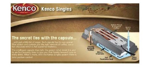
Kenco Cappio. The Kenco Cappio was a rectangular plastic cartridge that looked similar to an eight-track tape. That cartridge is shown in the image below (save that the exit was not by a nozzle but some form of puncture). Entry was via a nozzle (indicated by the words “Water Flow”). There was a filter in the cartridge made of cloth. Exit was via some form of exit puncture at the location with the words “Freshly Brewed Coffee”.
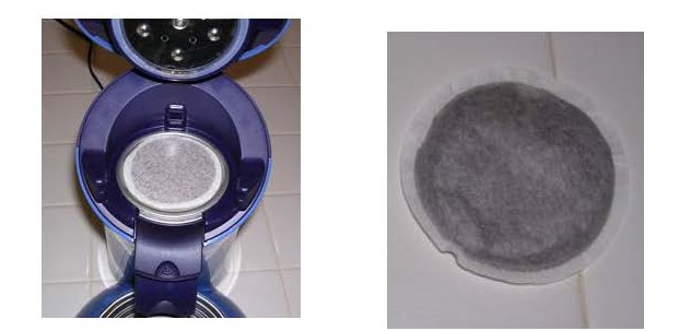
Philips Senseo. The Senseo coffee pod was a soft satchel or bag containing coffee. The coffee was held between two disc-shaped filters made of paper polymer. Water entered through the filter on the top of the pod. Water exited through the underside of the pod into a collection means which had a decelerating feature. The coffee then went through a spout to an exit. The Senseo machine as at 2001 is shown in the images below.
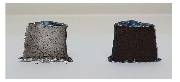
Nespresso. The Nespresso capsule as at 2001 was a cup-shaped capsule containing coffee. Entry was via a canula that entered the pod. It did not have a solid filter inserted in the body of the capsule. The Nespresso machine had plates with pyramid-shaped geometries that pressed onto the lid of the capsule to create openings that allowed the coffee beverage to exit but retain the coffee grounds. The following image is indicative of a Nespresso capsule as at 2001, at least with respect to the exit means.
107 Mr Winkler’s evidence as to when the Nespresso system first entered the market is unclear. He said that he first inspected a Nespresso machine at a tradeshow in Chicago in 2001. However, the specification of the 627 patent describes at page 1A, line 10 – page 2, line 13 a system that is the same or very similar to the Nespresso system. Cartridges used in the system described are said to be “well known” in the art. In light of that statement and, in the absence of evidence to the contrary, I am satisfied that the Nespresso system as described by Mr Winkler was common general knowledge as at the priority date.
108 The Nespresso capsules were cup-shaped and made of aluminium. They did not contain a separate internal filter. Rather, once pierced by the machine, the cover of the capsule functioned as a filter through which brewed coffee could exit.
109 At this point it is useful to consider what the applicant says the inventive step is. Although it did not identify the inventive step in terms, it referred in its written submissions to a number of features which were said to distinguish the inventive cartridges described in the specification from the prior art. The following four features were identified by the applicant as distinguishing the cartridge described in the specification from the prior art:
(a) the use of a filter element at the bottom of the body of the capsule made of solid material rather than paper or fabric;
(b) the use of a filter element that acts as a fluid collection member by incorporating features which stand it off from the base of the cartridge so that the beverage can flow beneath it;
(c) a distribution member located at the top of the cartridge that simplifies the coffee machine by removing the need for a distribution mechanism in the machine, providing for a more uniform flow of liquid through the capsule;
(d) the ability to reverse the flow.
110 It is important to note that these are features of various preferred embodiments but are not requirements of claims 1 or 2. The question whether an invention involves an inventive step is to be answered by reference to the invention as claimed. None of the distinguishing features identified by the applicant are requirements of claims 1 and 2.
111 As to the use of a filter element which is solid rather than paper or fabric, this reflects an obvious design choice. If the filter is to be used in a pressurised system it would be both natural and logical to select a material capable of withstanding the pressure. There is nothing in Dr Davis’ evidence to suggest that the use of a filter made from a solid material (eg. aluminium or plastic) would be anything other than an obvious design choice. Mr Winkler said that a capsule used to make espresso coffee would need to be able to withstand the pressures used to make espresso coffee. Dr Davis disagreed because, in his opinion:
… many Australian mechanical engineers specialising in product design … would readily recognise both the capsule and the cavity of the coffee machine (in which the capsule is inserted into) must be able to withstand internal pressures in the capsule. In other words, the material used to manufacture the coffee capsule would not need to be able to withstand the pressure in question on a standalone basis as the cavity of the machine needs to provide support to assist the capsule in withstanding internal pressure.
112 While it may be accepted that both the machine and the capsule must be able to withstand the pressures within the system, and that the cartridge would not be required to withstand pressure on a “stand alone” basis, I did not understand Dr Davis to suggest that a product design engineer designing a coffee capsule for use in a pressurised system that was intended to be used to brew espresso coffee would be likely to opt for a capsule made of paper, fabric or some similar material in preference to something more rigid such as lightweight polypropylene or aluminium. But if that is what Dr Davis was suggesting then I prefer the evidence of Mr Winkler on this point.
113 I have already referred to criticisms made by the applicant of Mr Winkler’s design task. In my view Mr Winkler’s evidence as to how he would have gone about designing an espresso coffee cartridge was helpful and, generally speaking, persuasive. Dr Davis accepted that the approach taken by Mr Winkler was reasonable. He did not suggest that Mr Winkler’s approach would be unlikely to be followed by other persons skilled in the art who were seeking to design a new or improved espresso coffee cartridge. In my view, the design pathway followed by Mr Winkler (including its starting point) would have been obvious to a person skilled in the relevant art at the priority date and was one that would have directly led to an espresso coffee cartridge within claims 1 and 2 of the 627 patent subject only to the requirement that the fluid director member have a plurality of embossings (as I have interpreted that word) and fluid channels.
114 The applicant did not suggest that there was anything unusual about the shape or configuration of the embossings in the lower distribution member of the invention claimed in claims 1 and 2. That is hardly surprising in circumstances where the applicant has always contended that the word “embossing” refers to no more than the geometry of any shape that is raised off a surface. That said, it is still necessary to ask whether the shape or configuration of the embossings referred to in the claims, as I have construed them, might somehow involve an inventive step.
115 Whether or not the bosses on the underside of the exit filter in Mr Winkler’s third design (Fig 3) are embossings in the sense that word is used in the claim is doubtful. I would not describe their shape as bulging or convex. But on the issue of inventive step I do not regard that as a matter of any real significance. If similar shapes were to be created using well-known manufacturing techniques such as pressing or deep drawing, then they would be likely to exhibit the bulging or convex shapes that would also create fluid channels as described in the claims. The difference between what Mr Winkler produced and what is claimed seems to me to reflect small differences in detail that are of no importance to the inventive step analysis. The fact that Mr Winkler’s designs may not in all respects have met the exact requirements of the claims does not diminish the value of his evidence.
116 The applicant submitted that Mr Winkler’s evidence must be approached with some caution given that he is a highly experienced and inventive design engineer. The submission was, in effect, that he was not a good proxy for the hypothetical person skilled in the art who lacks any capacity for invention. I do not accept that submission. I found the evidence of Mr Winkler’s design task and his explanation for it helpful in understanding the way in which a person skilled in the art would be likely to go about designing a single serve coffee cartridge suitable for making espresso coffee in a pressurised coffee machine as at the priority date.
117 In my opinion the design of an espresso coffee cartridge for use in an espresso machine having the features of the combination defined by claims 1 and 2 would be obvious to a non-inventive product design engineer equipped with the common general knowledge at the priority date. It would not require inventive ingenuity or any contribution to the art that was “beyond the skill of the calling” to design a coffee cartridge within each of those claims as at the priority date: Allsop Inc v Bintang Ltd (1989) 15 IPR 686 at 701.
118 None of the dependent claims that are asserted against the respondents add any additional feature to the combination described in claims 1 or 2 that could render it inventive.
119 Claim 9 requires that the exit holes be located in the fluid channels created between the raised portions of the embossings. In circumstances where the function of the fluid channels is to direct brewed coffee out of the cartridge, there cannot be any inventive step arising out of the addition of this requirement. The use of exit holes and channels in the surface of the exit filter reflects a simple design choice that would be well within the capabilities of a non-inventive product design engineer who was tasked with designing aa single serve coffee cartridge suitable for making espresso coffee in a pressurised coffee machine as at the priority date.
120 Claim 16 imposes the additional requirement that the fluid director member be spaced a certain distance from the bottom of the main body portion of the cartridge or from the cover member. Incorporating some form of support (eg. a step in the interior of the main body of the cartridge) to enable the filter to stand off the base of the cartridge would, as Mr Winkler explained, be a means of enabling the beverage to flow out of the exit holes. Given the need for such a spacing, there is nothing inventive about the combination that includes this additional integer.
121 Claim 17 merely specifies the size of the exit holes. There is no suggestion in the specification or the expert evidence that there is anything inventive about the size of the exit holes described which would need to be smaller than the average size of the coffee particles that will be included in the capsule to prevent most of them flowing into the cup in which the brewed coffee will be dispensed.
122 None of what I have said is to be taken to suggest that there are not claims that were not asserted against the respondents that may well involve an inventive step. These include various claims to cartridges that incorporate both a first fluid director member and a second fluid director member as essential features of the defined invention.
123 I should add that the applicant did not call any evidence of any long felt want or need or commercial success with respect to the invention either as claimed or as more specifically described in the body of the specification: see Garford at [91]-[92]. There are no secondary evidence of inventiveness upon which the applicant can rely.
124 In the result, I conclude that each of the asserted claims is invalid for lack of inventive step.
125 As I have mentioned, the respondents’ inventive step case was also put on the basis of the common general knowledge together with the information disclosed in the 712 patent which was said to satisfy the requirements of s 7(3) of the Act. Given my conclusion that the asserted claims are invalid for lack of inventive step based on the common general knowledge alone, it is not necessary for me to consider the respondents’ alternative case.
126 The respondents alleged that each of claims 1, 2, 9, 16 and 17 of the 627 patent is invalid on the ground that it is not fairly based. At relevant times s 40(3) of the Act provided that “[t]he claim or claims must be clear and succinct and fairly based on the matter described in the specification”.
127 In essence, the respondents contended the specification describes an invention that has both an upper fluid collection member and a lower fluid collection member whereas each of the relevant claims requires only that there be “at least one fluid director member”.
128 The respondents submitted, correctly, that a claim based on what has been cast in the form of a consistory clause is not fairly based, if other parts of the specification show that the invention is narrower than that consistory clause: Lockwood Security Products Pty Ltd v Doric Products Pty Ltd (2004) 217 CLR 274 at [68]-[69], [83], [99].
129 The difficulty with the respondents’ submission on this topic is that the disclosure in the body of the specification relied upon by the applicant as providing a fair basis for each of the relevant claims extends beyond the consistory clause.
130 The relevant consistory statement, which mirrors the language of claim 1, appears at page 5, lines 11-26. However, that statement is immediately followed by the following at page 5, line 28 – page 6, line 3:
By providing at least one fluid director member of the kind explained herein above, for example at the inlet side of the cartridge above the particular substance, a uniform distribution of the water fed into the cartridge for extracting the particulate substance can be ensured, independent of the number and the size of the inlet perforations.
Preferably, two fluid director members are provided …
131 The respondents also relied on the following passage in the specification at page 5, lines 4-10:
Embodiments of the invention provide a cartridge adapted to contain a single serving of a particulate substance, extractable by means of water for preparing a beverage, preferably an espresso coffee beverage, in which the brewing water can flow through the cartridge either from cover to bottom or vice versa, without the need to provide substantial structural modifications to the cartridge.
132 The person skilled in the art, reading the 627 patent specification as a whole, would understand that part of the specification to be referring to an advantage provided only by those embodiments of the invention that include two fluid director members as in the preferred embodiment described by reference to the drawings in Fig 1.
133 In my view the body of the specification contains a real and reasonably clear disclosure of a cartridge that provides one fluid director member.
134 Whether or not the claimed invention is useful depends on whether, by following the directions provided in the patent, the result which the claimed invention is said to produce, can in fact be produced: Lane-Fox v Kensington and Knightsbridge Electric Lighting Co (Ltd) [1892] 3 Ch 424 at 430-431, Advanced Building Systems Pty Ltd v Ramset Fasteners (Aust) Pty Ltd (1998) 194 CLR 171 at 187. In considering this ground of alleged invalidity, it is necessary to determine, first, what the relevant promise is and, secondly, whether that promise is fulfilled by the claimed invention. The second of these matters is to be determined across the full scope of the claim, but recognising that the claim is not to be read through the eyes of a skilled addressee purposively seeking to perform the claimed invention in a manner that would not provide a useful result: see Washex Machinery Corporation v Roy Burton & Co Pty Ltd (1975) 49 ALJR 12 at 19, WM Wrigley Jr Co v Cadbury Schweppes Pty Ltd (2005) 66 IPR 298 at 323 [138].
135 The respondents contended that the 627 patent promises that all embodiments of the invention will achieve the following three objectives:
(a) uniform distribution of liquid so as to obtain uniform extraction;
(b) keeping the coffee machine as simple as possible; and
(c) allowing liquid to flow in either direction through the cartridge without substantial structural modifications.
136 In support of its submission that the 627 patent conveys these promises the respondents relied on the passages in the specification at page 4, line 22 – page 5, line 10 to which I have previously referred which identify attributes of “[e]mbodiments of the invention”. The premise of the respondents’ challenge to the validity of the asserted claims for lack of utility is that every embodiment of the invention described in the specification will possess all three of the attributes identified in those passages. For the reasons previously stated I do not accept that is a correct interpretation of the specification when read as a whole.
The Specification
137 The 121 patent is entitled “Cartridge containing one serving of coffee powder for preparing a coffee beverage”. It is common ground that the priority date of each of the asserted claims is 13 January 2004.
138 The specification includes a description of prior art coffee makers and coffee cartridges. The specification states at page 2, line 25 – page 3, line 14:
All these above mentioned species of coffee maker usually comprise a hollow so-called brewing spike provided with radial outlet openings for injecting brewing water into the cartridge that is also adapted to punch the bottom and the cover, respectively, of the cartridge. Also known are manually operated coffee makers in which the cartridge retainer is provided with a plurality of embossments located on an outlet grate; these embossments break open the cover of the cartridge as soon as brewing water is injected into the cartridge from the opposite side thereof and the cartridge is pressed against the embossments under the influence of the hydraulic overpressure created by the pressurized brewing water. During the subsequent brewing operation, the brewing water is injected into the cartridge by means of the brewing spike, with the result that [it] flows under pressure through the coffee powder contained in the cartridge and escapes from the cartridge through the opening created by the embossments. Independent of the fact whether it is a manually operated coffee maker or a semi-automatic or a fully automatic machine, the coffee maker is designed and adapted to the cartridge so as to produce a coffee beverage having froth on its surface; that froth usually is considered as a characteristic of a good coffee beverage. Even if great efforts have been taken to ensure that the prepared coffee beverage has durable froth on its surface, in certain countries the desire arises to prepare also conventional coffee in the sense of a filter coffee by means of these coffee makers. In place of the expression “filter coffee”, also the expression “gentle coffee” is used.
139 That passage is followed by a discussion of a cartridge of the kind disclosed in US Patent Document 2003/172813 which appears to (based on the description in the 121 patent) correspond to the invention disclosed in the 627 patent. The specification continues at page 3, line 15 – page 4, line 2:
The U.S. Patent document 2003/172813 discloses a cartridge of the kind referred to herein. It contains a substance extractable by means of water for preparing a beverage, preferably an espresso coffee. Thereby, a sieve-like member is disposed between the bottom of the cartridge and the substance and/or between the cover of the cartridge and the substance, provided with a plurality of axial apertures. The sieve-like member is provided with stampings directed towards the bottom of the cartridge and the cover of the cartridge, respectively, such that fluid channels are formed between the sieve-like member and the bottom of the cartridge, and the sieve-like member and the cover of the cartridge, respectively. In these channels, the brewing water can be distributed over the cross sectional area of the cartridge, and the prepared beverage can be collected in these channels, respectively. In order to prevent that the sieve-like member is punched upon piercing the cartridge, the sieve-like member comprises a central recess directed towards the interior of the cartridge into which the piercing member can extend once the cover or the bottom of the cartridge have been pierced. Even if such a cartridge is well suitable for preparing espresso coffee, it can hardly be used for preparing normal filter coffee, since the cartridge presents a high flow resistance to the brewing water flowing therethrough; the result is a formation of froth. In such a cartridge, moreover, the sieve-like member can move with regard to the bottom of the cartridge.
140 The specification also states at page 4, lines 15-18:
Embodiments of the present invention to provide a cartridge containing one serving of coffee powder for preparing a coffee beverage of the kind disclosed in patent US 2003/172813 in which the sieve-like member is fixed with respect to the bottom of the cartridge.
141 There is then a consistory statement that mirrors claim 1. The specification then states at page 4, line 29 – page 5, line 16:
As described herein, the cartridge may be capable of being used in a conventional espresso machine to prepare a normal coffee beverage not having froth on its surface and corresponding in taste to a normal filter coffee. In this last case, by providing at least the bottom portion of the cartridge with a passage constituted by an aperture, adapted to avoid a hydraulic pressure build-up in the interior of the cartridge during brewing and extracting the coffee powder, the fundamental prerequisite is realized to use such a cartridge in a conventional espresso machine for preparing a coffee beverage corresponding in appearance and taste to a normal filter coffee. The passage ensures that the pressurized brewing water fed into the cartridge cannot create a substantial pressure build-up in the interior of the cartridge. Thus, the brewing water can flow through the cartridge and, thereby, through the coffee powder contained therein without any substantial resistance, thereby avoiding the formation of froth. In order to prevent the coffee powder contained in the cartridge from escaping the cartridge through the aforementioned passage and from being flushed out by the brewing water, a filter element is arranged between the passage and the coffee powder contained in the cartridge. In order to ensure that the coffee powder contained in the cartridge keeps well during an extended period of time in spite of the passage provided in the cartridge, the passage is covered by a gas-tight foil. The latter one is either manually removable or designed such that it can be easily pierced by a punching member.
142 The specification includes a detailed description of the invention written around four drawings (Fig 1 – Fig 4). Figure 1 shows the elements of a coffee powder cartridge which is said not to incorporate the subject of the present invention. The cartridge depicted in Fig 1 is essentially the same as that depicted in Fig 1 of the 627 patent. Figure 2 shows a longitudinal sectional view of the same cartridge which is also said not to incorporate the subject of the present invention.
143 Figure 3 shows a longitudinal section of an embodiment of a cartridge of the invention. Figure 4 shows an enlarged portion of the circled section shown in Fig 3. Figures 3 and 4 are as follows:
|
|
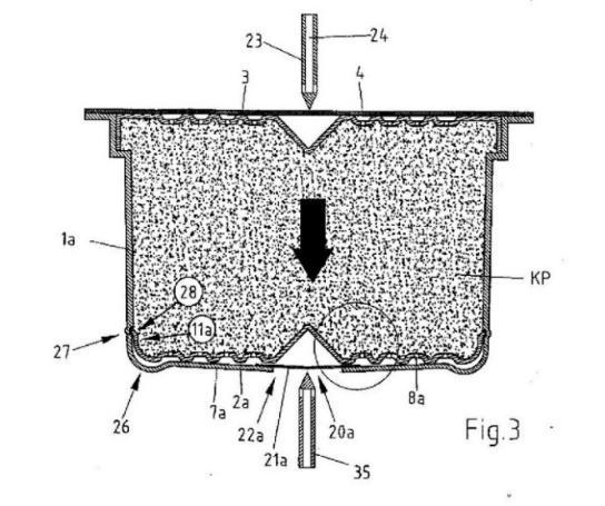
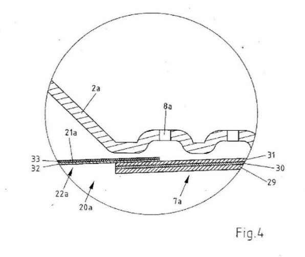
144 In the embodiment of the invention depicted in Fig 3 the cup-like shaped lower portion (1a) of the cartridge includes a circumferential groove (27) located inside the lower portion (1a), while the edge (11a) of the filter element (2a) is provided with a circumferential annular projection (28) which engages with the groove (27) to clampingly fix the filter element (2a) in the interior of the cartridge. Figure 4, which is an enlargement of the circled section in Fig 3, shows a portion of the bottom (7a) of the cartridge, the aperture (20a) and the foil (21a) covering the aperture, but does not show either the groove (27) or the annual projection (28). What is depicted in Fig 4 is in fact of no direct relevance to the fixing means constituted by the groove (27) and the annual projection (28) shown in Fig 3.
The Claims
145 The 121 patent includes 15 claims. The claims asserted against the respondents are:
1. Cartridge containing one serving of coffee powder for preparing a coffee beverage, comprising a cup-like shaped lower portion and a cover portion attached to said lower portion, and a filter element located inside said cartridge lower portion between said coffee powder and a bottom portion of said cartridge lower portion, wherein the interior of said cup-like shaped lower portion of said cartridge is provided with an annular groove, whereby said filter element is provided with a peripheral edge portion engaging said groove for fixing said filter element to said lower portion of said cartridge wherein the peripheral edge portion engages said groove for clampingly fixing said filter element to said lower portion of said cartridge.
2. Cartridge according to claim 1 wherein the groove is located at the inside of the lower portion.
3. Cartridge according to claim 1 or claim 2 wherein the cover portion is sealingly attached to said lower portion.
4. Cartridge according to any one of the previous claims, wherein said cup-like shaped lower portion of the cartridge is dimensionally stable.
5. Cartridge according to any one of the previous claims, wherein said filter element is dimensionally stable and comprises a plurality of apertures.
…
14. Cartridge according to any one of the previous claims, wherein said filter element comprises at least one central recess directed towards the interior of the cartridge.
146 There are two issues that arise in relation to the alleged infringement of claims 1-5 of the 121 patent. The first is whether any of the first respondent’s cartridges that are alleged to infringe the 121 patent include the following features of claim 1:
whereby said filter element is provided with a peripheral edge portion engaging said groove for fixing said filter element to said lower portion of said cartridge wherein the peripheral edge portion engages said groove for clampingly fixing said filter element to said lower portion of said cartridge.
147 Another issue that arises in relation to infringement concerns the additional requirement in dependent claim 4 that the “said cup-like shaped lower portion of the cartridge is dimensionally stable”. There is an issue between the parties as to what “dimensionally stable” means in this context. The same issue would appear to arise in relation to claim 5 but no separate arguments were made in relation to the requirements of that claim which concern the filter rather than the cup shape.
148 It is accepted by the respondents that the first respondent’s cartridges referred to as versions 1, 2a, 2b, 3 and 4 (“version 1-4”) are relevantly the same and it is therefore not necessary to distinguish between them.
149 The respondents’ submissions in relation to the construction of claim 1 focused on the words “engaging” and “engages”. It was submitted that the engagement between the peripheral edge portion of the filter element and the annular groove referred to in the claim must be one in which the entire geometry of the peripheral edge portion of the filter element is engaged with the entire geometry of the annular groove. In support of that submission the respondents point to the detailed description of the preferred embodiment.
150 I do not accept the respondents’ submission.
151 The respondents’ construction of the claim imposes a gloss on what in my view is clear language. The language used does not, either expressly or by implication, require that the engagement referred to occur along the entire circumference of the peripheral edge portion of the filter element.
152 It is true that the preferred embodiment described in the specification shows the annular groove and the peripheral edge portion of the filter element engaged along the entire circumference of each of those elements. However, the language used in the claim is not limited to that specific configuration.
153 As to the second issue, the respondents submitted that the expression “clampingly fixing”, when read in context, refers to an arrangement which creates a clamping action that fixes the filter element in place by constraining its movement in both the horizontal and vertical directions. They submitted that the fixing of the filter element in the lower portion of the cartridge must be achieved by the clamping of the peripheral edge portion of the filter element by the annular groove.
154 The applicant submitted that it was not a requirement of claim 1 that the fixing of the filter element be achieved solely by the engagement between the peripheral edge portion and the groove. It submitted that the word “for” as used in claim 1 means that the engagement between the peripheral edge portion and the groove is made for the purpose of producing the result of clampingly fixing the filter element. It submitted that this does not mean that it must be the only element which contributes to that result. In support of its submission the applicant points to the embodiment depicted in Fig 3 which shows that the base of the capsule abuts the base of the filter element, which also contributes to holding the filter element in place.
155 The applicant relied on evidence given by Mr Winkler who accepted in cross-examination that in the embodiment depicted in Fig 3, where the filter engages with the groove, the base is also playing a role in preventing the movement of the filter. That answer was given in the context of a broader exchange as follows:
MR LANG: You see the peripheral edge of the lower filter element there in the annular groove at item 27?
MR WINKLER: Yes.
MR LANG: And so you understand this to be a feature which addresses the disadvantage of the risk that the filter element of the prior art cartridge could move?
MR WINKLER: Yes.
MR LANG: And just considering the embodiment depicted there in figure 3, the filter engages with the groove as indicated there at point 27?
MR WINKLER: Yes.
MR LANG: And it also engages with the base of the capsule as you see there, for example, at items 2A or 7A?
MR WINKLER: Yes.
MR LANG: And so the base is also playing a role in preventing movement of the filter?
MR WINKLER: Yes.
MR LANG: And turning to claim 1, do you see there … [a]t line 5:
wherein in the interior of said cup like shape lower portion of said cartridges provided with an annular groove whereby said filter element is provided with a peripheral edge portion engaging said groove for fixing filter element to said lower portion of said cartridge wherein the peripheral edge portion engages said groove for clampingly fixing said filter element to said lower portion of said cartridge.
Do you see that?
MR WINKLER: Yes.
MR LANG: And so the aspect which has been picked out to be the subject of this claim corresponds to that feature of the second embodiment that we saw?
MR WINKLER: Yes.
MR LANG: And that’s directed to solving the problem that the filter element may move?
MR WINKLER: Yes.
156 It is true that the cartridge depicted in Fig 3 shows that the downward annular segments of the filter element are in contact with the base of the cartridge. However, the specification does not suggest that it is the function of the base of the cartridge to fix the filter in position or that the base acts as a clamping means. The specification makes clear at page 10, line 29 – page 11, line 2 that the embodiment depicted in Fig 3 is one in which the circumferential annular projection (28) of the filter element (2a) engages the groove (27) to clampingly fix the filter element (2a) in the interior of the cartridge so as to prevent movement in either a horizontal or vertical direction. It is apparent from a reading of the specification as a whole that the particular embodiment around which claim 1 has been drawn provides for the filter element to be fixed in position by the clamping action of the groove on the edge of the filter element with which it engages.
157 In my opinion claim 1 requires that the groove clampingly fix the filter element into position so as to prevent both horizontal and vertical movement relative to the main body of the cartridge by the engagement of the annular groove of the main body and the peripheral edge portion of the filter element.
158 With regard to claim 4, the question is what the words “dimensionally stable” mean. The respondents referred to the description at page 5, line 29 of the specification which states that the filter element (2) and the distribution member (3) are “dimensionally stable” and at page 6, lines 12-13 which describes the cup-shaped portion (1) of the cartridge as “relatively stiff, dimensionally stable, elastic and ductile”. It is clear from the passage at page 6, lines 12-13 that the specification is describing the physical properties of the cup-shaped portion of the cartridge relative to the cover (4) and the foil (21).
159 The experts were in general agreement that the requirement that the cartridge be dimensionally stable means that the cartridge will maintain its shape. However, the respondents submitted that the requirement of “dimensional stability” represents an “in use” requirement of claim 4 which requires that the cartridge exhibit “dimensional stability” when used in a coffee making machine.
160 I do not accept the respondents’ submission. It seems to me that the claim is referring to the physical characteristics of a cartridge suitable for use in a coffee machine. There is nothing in the specification or the claims to suggest that dimensional stability is a physical characteristic of a cartridge when in use.
161 Whether or not a cartridge maintains its physical dimensions when used will necessarily depend on the forces that are applied to it by the coffee machine in which it is used. However, the specification provides very little information in relation to the design of the coffee machine in which the capsule is to be used.
162 Even if it there was an expectation on the part of the person skilled in the art that the coffee cartridge would maintain its shape when in use, this is not sufficient to construe claim 4 as imposing a requirement to that effect. In my view the language of the claims does not support the respondents’ construction.
Infringement
163 It is convenient to identify the key infringement issue by reference to the following annotated photograph of one of the first respondent’s cartridges that was taken by Mr Hunter:
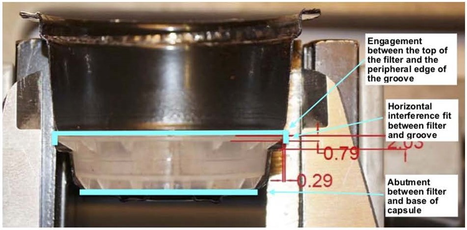
164 What is described by Mr Hunter as a “horizontal interference fit” between the peripheral edge portion of the filter element and the annular groove prevents the filter from moving in a vertical direction towards the upper end of the main body of the cartridge. However, vertical movement in the opposite direction is prevented not by the engagement of the annular groove and the peripheral edge of the filter element, but by the engagement of the base of the filter and the base of the cartridge. This is not a configuration that meets the requirement of the claim.
165 In my opinion none of the version 1-4 cartridges infringe the 121 patent.
Validity
Novelty
166 The respondents contend that the asserted claims of the 121 patent are anticipated by the application for the 627 patent (“the 627 application”) published on 2 October 2003. The respondents also contend that the asserted claims of the 121 patent are anticipated by the application for a European patent (“EPA605”) published on 26 November 2003.
167 There is an issue as to whether either the 627 application or the EPA605 disclose the following integers:
wherein the interior of said cup-like shaped lower portion of said cartridge is provided with an annular groove;
[the peripheral edge portion of said filter element] engaging said groove for fixing said filter element to said lower portion of said cartridge;
wherein the peripheral edge portion engages said groove for clampingly fixing said filter element to said lower portion of said cartridge.
168 The respondents contend that Fig 2 of the 627 application (which is identical to Fig 2 in the 627 patent) discloses a cartridge which, if inverted, has an annular groove formed by the annular shoulder (15) and the lid (4).
169 Figure 2 shows a conical shaped recess (15) and what I would call an outwardly projecting step in the wall of the main body of the cartridge (15). The second reference (15) appears to be an error in that the outwardly projecting step (15) is not expressly identified in the detailed description of the invention. The respondents referred to this outwardly projecting step as an “annular shoulder”. That description reflects their choice of words and not the words used in the specification to describe this feature.
170 A groove is a “… channel or hollow, cut by artificial means, in metal, wood, etc” (OED online) or “… a rut, furrow, or channel formed by any agency” (Macquarie online). Dr Davis said an annular groove requires “a recess or depression”. Whichever of these definitions is adopted, I do not think that what the respondents call an annular shoulder (15) in Fig 2 is, or forms part of, an annular groove. There is no clear disclosure in the 627 application of an annular groove at or in the vicinity of the step (15).
171 Nor do I think there is any clear disclosure of a distribution member (which will be the collection member if the cartridge shown in Fig 2 is inverted) that is clampingly fixed to the lower portion of the cartridge. The means by which the peripheral edge portion of the relevant member is fixed to the lower portion of the cartridge does not involve any clamping action but instead rests on the cover.
172 EPA605 relates to a cartridge or capsule containing coffee or soluble products for the preparation of drinks made of coffee and other products that are soluble in hot pressurised water.
173 Figure 1 of EPA605 shows an exploded view of a cartridge according the invention. Figure 1 is as follows:
|
|
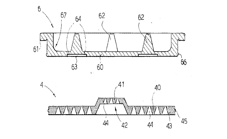
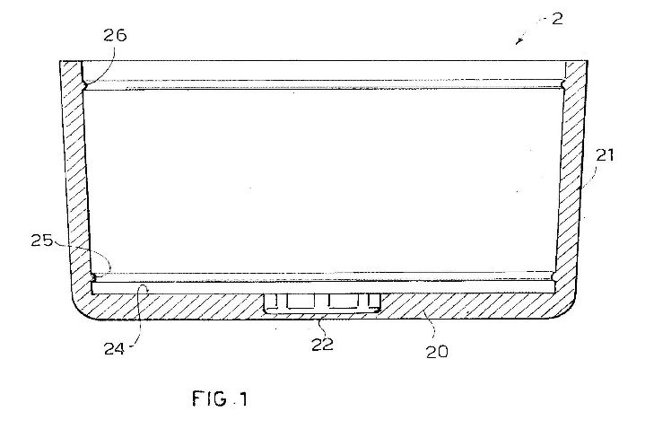
174 The cartridge (1) comprises a cup-shaped container to contain coffee (2), a filter (4) and a lid (6). On the inner surface of the side wall (21) there is a first protruding ring or collar (25) set near the base (20) that protrudes radially towards the inside. There are raised radial ribs (24) at the bottom of the container that are more clearly shown in Fig 2.
175 According to the respondents, Fig 1 clearly discloses a groove whereby the top of the groove is formed by the annular collar (25) and the bottom of the groove is formed by the inside surface of the base (20) of the cartridge. The respondents submitted that the fact that the top of what it calls the groove is created by a small inward protrusion does not mean that it is not a groove.
176 Neither Dr Davis nor Mr Winkler considered that Fig 1 disclosed what they would refer to as a groove. I doubt Fig 1 discloses what a person skilled the art would describe as a groove. In any event, Fig 1 does not disclose any arrangement in which what the respondents call a groove engages with the peripheral edge of the filter to clamp the filter to the lower portion of the cartridge. The filter is not clampingly fixed to the cartridge as required by the claims.
177 None of the asserted claims is anticipated by either the 627 application or EPA605.
Inventive step
178 The respondents contend that none of the asserted claims involves an inventive step. They submitted that the invention, as claimed, would have been obvious to a person skilled in the art in light of the common general knowledge as at the priority date whether considered separately or together with the information disclosed in either EPA605 or the 627 application. It was not suggested that those disclosures could be combined. Each of them must be considered separately together with the common general knowledge.
179 For the purpose of considering inventive step, it is necessary to say a little more about the problem to which the 121 patent is said to provide a solution. So far as claim 1 is concerned, the applicant’s case is that the problem addressed by the specification and to which the invention defined by claim 1 is directed consists of a means of fixing the filter to the body of the cartridge.
180 There is very little discussion of the problem in the specification. All that appears is a statement at page 4, lines 1-2 suggesting that in a cartridge of the kind described at page 3, lines 15-28 “… the sieve-like member can move with regard to the bottom of the cartridge”. On the applicant’s case, the invention defined by claim 1 is directed to providing a cartridge in which the filter member does not move relative to the bottom of the cartridge in which it is housed.
181 There was no evidence to indicate that this was a known problem in the art. Be that as it may, that is the problem which the applicant, supported by the sentence in the specification to which I have referred, says that the invention defined in claim 1 is said to provide a solution. This is a matter of some importance when it comes to assessing whether the information defined by claim 1 provided a solution to a known problem that required inventive ingenuity or, put another way, some contribution to the art that was “beyond the skill of the calling”.
182 Evidence given by both Mr Winkler and Dr Davis shows that a person skilled in the art would be likely to engage a patent attorney in the course of the design task for the purpose of obtaining information relevant to “freedom to operate” issues and as a source of inspiration for product design. As Dr Davis explained:
… recognising that my core business was the development of innovative products, I would recommend that the client engage patent attorneys to undertake a patent search and advise on freedom to operate issues for the presented concepts. This process may also involve drawing on patents as a source of inspiration for concept generation, assisting the client's patent attorneys with their investigations, briefing patent attorneys on potential changes to concepts that could avoid freedom to operate issues and providing briefing materials that may be helpful to patent attorneys if the client should choose to file patent applications …
183 In the case of the design task performed by Mr Winkler for the purposes of this proceeding, there was no patent search undertaken until he had completed his designs. Some of the search parameters used by Ms Hantos were informed by elements of Mr Winkler’s designs.
184 The applicant made a number of criticisms of the quality of the evidence relied upon by the respondents to show that EPA605 was s 7(3) information to which regard may be had when determining the issue of inventive step. I will say more about those criticisms shortly. In the meantime, it is necessary to make a few general observations in relation to both the significance of the evidence relied upon by the respondents to show that EPA605 qualifies as s 7(3) information and other general matters concerning the nature and content of the document itself.
185 It was not disputed that EPA605 was able to be sourced online by a patent attorney at the priority date. Ms Hantos’ evidence included some qualifications that recognised that there had been changes to the database used by her for the purpose of conducting the patent publication searches the subject of her evidence compared to the databases that were in use around the time of the priority date. But there was no suggestion in her evidence that she might not have been able to access a recently published European patent application using search facilities available to patent attorneys as at the priority date. Ms Hantos was not cross-examined and there was no evidence called by the applicant in answer to the evidence she gave.
186 The real question is whether the person skilled in the art who engaged a patent attorney to undertake a patent publication search could reasonably be expected to have engaged the patent attorney to conduct a search the results of which would be likely to include EPA605. In reality, the nature of the search that would be undertaken by the patent attorney would be heavily influenced by the nature of the design that the person skilled in the art was interested in developing.
187 In the present case it may be assumed that at the priority date a person skilled in the art would be interested in designing a coffee cartridge that could be used to prepare espresso coffee in a pressurised coffee machine. This interest would extend to the means by which the filter could be attached to the cartridge. That seems to me to provide the starting point for the design task that is likely to inform the patent publication searches that would be undertaken by a patent attorney at the request of the person skilled in the art.
188 EAP605 is entitled “Cartridge for coffee and soluble products, device for the extraction of drinks from said cartridge and relevant drink production method”. The abstract describes the relevant cartridge as follows:
A cartridge (1) for coffee and soluble products, comprises a container (2) designed to contain coffee or soluble product, a lid (6) placed on top of the container so as to provide an upper wall (60), designed to be perforated for the introduction of hot water under pressure into the container (2) for the production of the drink; a filter (4) designed to be positioned inside the container (2) above a base (20) of the container, which is designed to be perforated for the drink to be able to flow out. The cartridge is made of a hard plastic material with an airtight seal so that the coffee or soluble product contained therein does not come into contact with the air outside, at the same time allowing the inside of the cartridge to be pressurised for a long enough time to release the aromas and fragrances of the coffee or soluble product into the drink.
The abstract also includes Fig 1.
189 EPA605 was discovered by Ms Hantos in the second of the patent publication searches she undertook for the purpose of this proceeding. The search parameters used by her limited the results to specifications that had been published prior to 14 January 2004. Her search terms included the words “cartridge”, “coffee” and “filter”. The search results she obtained occupy 226 printed pages. They disclose a large number of devices that the skilled addressee would quickly dismiss as having little relevance to the design task. Many of Ms Hantos’ results relate to coffee machines, filters for use in coffee machines and devices used to prepare drip filter coffee. The skilled addressee could work through the search results obtained by her and quickly identify those patent publications of most relevance to the design task.
190 Ms Hantos’ search results include both the abstract and Fig 1 to EPA605. These would disclose to the person skilled in the art that the coffee cartridge described in EPA605 comprises an airtight cartridge that is made of plastic, fitted with an internal filter inside the cartridge, and designed to be used in a pressurised coffee making system. I do not think there could be any doubt that the information disclosed in the abstract and Fig 1 would be understood and regarded as relevant by a person skilled in the art engaged in the design task to which I have referred. It would be a routine step for the patent attorney to obtain a complete copy of EPA605.
191 The fact that there may have been a large number of publicly available patent publications at the priority date of varying degrees of relevance does not mean that the skilled addressee would be less likely to understand and regard as relevant any one of those publications. The existence of a large body of such material may indicate that the field of the invention is extremely crowded but that does not provide a basis for concluding that a person skilled in the art would not appreciate the relevance of a particular document if he or she could reasonably have been expected to discover it.
192 That EPA605 would have been ascertained by a person skilled in the art may be readily accepted given the design task that I have identified and the fact that it was a European patent application of recent origin that was identified by a routine patent search. In the present case, once it is accepted that a person skilled in the art would undertake patent searches (using the services of a registered patent attorney) to undertake a search for relevant prior art, it should be concluded that such a search would have provided the skilled addressee with EPA605.
193 One of the criticisms that the applicant made of the respondents’ evidence on inventive step was that the search terms used by Ms Hantos included various words that the applicant suggested would not have been used by a patent attorney undertaking patent publication searches for a skilled addressee. I do not accept that criticism. In any event, it is apparent having regard to the terminology used in the abstract of EPA605 (eg. coffee, cartridge, filter, pressure) that EPA605 would have been disclosed even if some of the other terminology to which the applicant’s submission was directed (eg. groove, snap, projection, ledge) had not been used. Accordingly, while the search conducted by Ms Hantos may have been extensive in terms of the search terms used, it is clear that EPA605 would have been discovered even if fewer search terms had been adopted.
194 The applicant sought to make something of the fact that Mr Winkler did not review all of the patent attorney’s search results and select the patents of most interest himself. Ms Hantos’ search results were instead reviewed by her to produce a shortlist which then led to Mr Winkler being provided with a copy of EPA605 by the respondents’ solicitors. Having reviewed the search results myself, it is clear that many of the documents obtained as a result of the patent attorney’s search could be put aside on the basis that they had little relevance to the design task. Whether or not that exercise was undertaken by Mr Winkler or by Ms Hantos is in my view not a matter of any real significance.
195 The evidence establishes that EPA605 constitutes information that the person skilled in the art could be reasonably expected to have ascertained, understood and regarded as relevant to a design task of the kind previously identified. I am satisfied that EPA605 constitutes s 7(3) information for the purpose of determining whether the invention as claimed involves an inventive step.
196 The next question is whether the asserted claims of the 121 patent would be obvious to the person skilled in the art as at the priority date having regard to the common general knowledge and the information disclosed in EPA605.
197 The fixing means described in the detailed description of the invention of the 121 patent consists of an annular groove that extends along the inside wall of the cartridge which is adapted to receive the circumferential edge of the filter element. This fixing means was variously described in the evidence as a “snap fit” arrangement that could be used as an alternative to the fixing means used in the preferred embodiment of the 121 patent.
198 Dr Davis described the “snap fit” method as an economical, fast and popular assembly method that could be used to join dissimilar plastics. This type of assembly is particularly desirable if different plastics are used to make the housing of the cartridge and the filter element, and welding is not an option. It is clear that a snap fit arrangement of the kind described in the 121 patent constituted a well-known method of attaching components as at the priority date. Snap fit arrangements, including those that include a recessed groove, were common general knowledge at the priority date.
199 The applicant submitted that Mr Winkler acknowledged in his oral evidence that the use of a groove for clampingly fixing the filter element to the cartridge (ie. the snap fit arrangement) provided a “huge” benefit and, implicitly, that this acknowledgement supported a finding that the invention disclosed in the 121 patent (at least that defined by claim 1) involved an inventive step. I think this submission is based on a misunderstanding of Mr Winkler’s evidence.
200 The relevant passage in his cross-examination began with a question by Mr Lang which suggested that it might be possible to include in a cartridge more than one groove. The relevant exchange was as follows:
MR LANG: And would it be possible to have, say, two, grooves for different positions of the filer [sic] or, perhaps, for different size filters?
MR WINKLER: Correct. I would like to explain that a little further?
MR LANG: Sure.
MR WINKLER: So if you’re building 14 billion of these a year to have as many components as possible be the same part would be huge.
MR LANG: Yes.
MR WINKLER: So instead of having the – the ring around – the protrusion ring around the perimeter of different lengths meaning you would have to have three or four different lengths to accompany all of these different beverages you now could just buy – that the machine that inserts these into the – into the pod could actually lock them in at different heights specific to get that volume of – of coffee or whatever the beverage is out of the same component.
MR LANG: Yes.
MR WINKLER: So you would be using the same component multiple times.
MR LANG: So that’s an advantage which you get – which a groove has over a protrusion?
MR WINKLER: Well, you could have multiple protrusions doing the same thing.
MR LANG: I see.
201 The idea of using multiple grooves was first raised by Mr Winkler in his affidavit evidence. In any event, the 121 patent does not describe a coffee cartridge which has multiple grooves so as to enable the filter element to be located in different positions. The advantage referred to in this passage of the cross-examination is not one provided by any embodiment of the invention described in the 121 patent.
202 A little further into the cross-examination the following exchange occurred:
MR LANG: Is it your view that the solution of the 121 patent which uses a groove in the side wall to engage a peripheral edge of the filter for clampingly fixing it to the lower cartridge was one which represented a significant advantage over a cartridge which did not include such additional fixing means?
MR WINKLER: Yes.
Mr Winkler’s affirmative answer to that question is hardly surprising given his earlier evidence. He accepted that the snap fit arrangement constituted by the groove and the peripheral edge provided an advantage in that it permitted the use of more than one groove in the manner discussed. In my opinion this evidence shows that Mr Winkler believed that the use of a groove and the peripheral edge of the filter in a snap fit arrangement was one that provided a significant advantage over a cartridge that did not include that type of fixing means. But that does not assist me in determining whether there was an inventive step involved in introducing a snap fit arrangement of that kind into the cartridge described in EPA605.
203 Mr Lang returned to the topic of multiple grooves when questioning Dr Davis as follows:
DR DAVIS: So I understanding [sic] you’re asking me if I thought that having two grooves in the body so that the filter could be inserted at different heights would be advantageous?
MR LANG: Yes.
DR DAVIS: Yes. And I agree with Mr Winkler. I believe that would be advantages [sic]. And I believe I could design the geometry that would deliver that advantage.
The question addressed by Dr Davis in this passage of evidence related to a feature not described in the 121 patent.
204 EPA605 does not disclose a means for fixing the filter to the lower portion of the cartridge of the kind required by claim 1. The fixing means disclosed by EPA605 consists of a protruding circumferential collar that extends inwards from the inside wall of the lower portion of the cartridge which prevents the filter from moving away from the base. But it would be obvious to a person skilled in the art equipped with the common general knowledge and EPA605 that he or she could take a cartridge of the type depicted in that document and include a different fixing means to prevent the filter from moving away from the base. One means of preventing the filter from moving is to incorporate a groove moulded or cut into the side wall of the cartridge into which the peripheral edge of the filter element could then be snap fit so that the filter did not move relative to the base of the cartridge. A design modification of this kind to the cartridge disclosed in EPA605 is something that could be achieved by the person skilled in the art with ease through the routine use of a well-known design feature and without any element of ingenuity.
205 It was also submitted by the applicant that there were reasons why a skilled addressee might choose not to use a groove in place of the collar as the fixing means in the cartridge of the kind shown in EPA605. In particular, it was submitted by the applicant that the 121 patent discloses for the first time in the art the “counterintuitive possibility” of using a groove in the side wall for clampingly fixing the filter.
206 The evidence does not support the proposition that use of a groove to clampingly fix the filter to the cartridge was a counterintuitive possibility. In my view, the use of a groove in the wall of a coffee cartridge of the kind shown in EPA605 to clampingly fix the filter to the cartridge reflects no more than the application of well-known design principles. A person skilled in the art would be directly led to try such an arrangement in the expectation that it would provide a useful way in which to prevent the filter moving relative to the base of the cartridge.
207 The applicant also submitted that there were advantages to using the collar arrangements shown in EPA605 in preference to a groove as the fixing means. That may well be so. But it does not follow that the use of a groove as a fixing means in a cartridge of the kind shown in EPA605 would not provide an obvious alternative to the use of the collar. Moreover, as Dr Davis’ evidence makes clear, the use of a groove would have a clear advantage in circumstances where it was not practical to weld the filter element to the cover. It follows that I do not accept the suggestion that a person skilled in the art would not wish to use a groove in place of a collar in a cartridge of the kind shown in EPA605 or that the making of such a design modification would require any element of inventiveness.
208 Ms Hantos’ first patent publication search also included within its results the abstract of the application for the 627 patent which was filed on 21 February 2003 and first published on 2 October 2003. Her search results reproduced the abstract of the application (which is in identical terms to the abstract associated with the 627 patent as granted) together with the exploded view of the cartridge shown in Fig 1 which includes the lower distribution member (ie. the filter element) standing off the base of the cartridge. The search terms used by Ms Hantos which led her to identify the 627 application included the words “cartridge”, “espresso” and “coffee” reflecting the routine nature of the kind of search that would have led the person skilled in the art to ascertain the 627 application. It would also have been a matter of routine for the patent attorney to obtain a copy of the 627 application.
209 The 627 application does not disclose a fixing means joining the fluid collection member to the inside wall of the cartridge. In the case of the embodiment depicted in Fig 2, the fluid collection member (2) appears to sit on the bottom of the cartridge and is held in that position by the coffee particulate compacted above it. But there are other embodiments shown (eg. the fifth embodiment shown in Fig 6) in which the lower collection member (36) is supported on the bottom (7) of the cartridge by means of what is referred to as a pressure resistant rigid frame (35). Figure 6 is as follows:
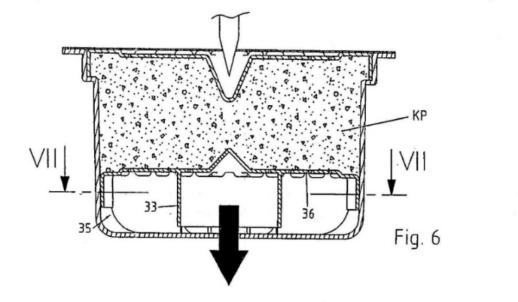
210 It was submitted by the applicant that the skilled addressee would have no reason to incorporate a groove into which the peripheral edge of the filter could snap fit into a cartridge of the kind described in the 627 application. The suggestion seem to be that there was nothing in the 627 application that would directly lead the person skilled in the art to adopt such an arrangement. I do not accept that submission because it reflects a misunderstanding of the relevant test. The question is whether it would be obvious to the person skilled in the art equipped with the common general knowledge and the 627 application to use a groove as part of a snap fit arrangement to prevent the filter element in a cartridge of the kind shown in the 627 application from moving relative to the base. The person skilled in the art would understand that there are a number of different methods of fixing the filter to the wall of the cartridge. The fact that Fig 6 may disclose one means of fixing the filter element relative to the base does not mean that the skilled addressee would not be directly led to try other fixing arrangements if these were well-known and also capable of preventing movement.
211 In my view all of the asserted claims of the 121 patent are invalid for lack of inventive step over the common general knowledge combined with either EPA605 or the 627 application.
Lack of Utility
212 To be useful, an invention, as claimed, must deliver the result promised by the patentee: see the previous discussion of the principles relevant to utility.
213 What the patentee has promised is to be ascertained from the specification. In the present case, the respondents contend that the 121 patent promises that the invention provides a cartridge which can be used in a conventional espresso machine to prepare a normal coffee beverage, not having froth on its surface, and corresponding in taste to a normal filter coffee. They submitted that the 121 patent teaches that froth may be avoided where the cartridge has the following features:
a passage constituted by an aperture in the bottom of the cartridge to avoid a hydraulic pressure build up in the interior of the cartridge during brewing and extracting coffee powder (specification page 4, line 32 – page 5, line 2);
an upper distribution member with an entire summed cross sectional surface area of the apertures provided in the distribution member amounting to at least 3% of the total cartridge cross sectional area (specification page 7, lines 27-30); and
a lower filter with an entire summed cross sectional surface area of the apertures provided in the filter member amounting to at least 3% of the total cartridge cross sectional area (specification at page 7, lines 27-30).
214 Although it may be accepted that the specification teaches that froth may be avoided by including these features in the cartridge, the question is whether the specification promises that the invention, as claimed, will avoid froth. Since neither claim 1 nor any other asserted claim includes any of the three integers referred to in the specification (as set out) that are said to result in the avoidance of froth, it may be inferred that, if such a promise is made, then the invention defined by those claims does not fulfil that promise. The applicant did not make any submission to the contrary.
215 I do not think the specification promises that all embodiments of the invention will eliminate or reduce froth.
216 As previously explained, the specification makes clear that one of the problems with the prior art cartridges described in the specification is that the filter element can move with respect to the bottom of the cartridge (specification page 4, lines 1-2).
217 The specification also states at page 4, lines 15-18:
Embodiments of the present invention to [sic] provide a cartridge containing one serving of coffee powder for preparing a coffee beverage of the kind disclosed in patent US 2003/172813 in which the sieve-like member is fixed with respect to the bottom of the cartridge.
218 That statement is followed by a consistory clause that describes a first aspect of the invention in terms that mirror claim 1 (specification page 4, lines 19-28). The specification then continues at page 4, line 29 – page 5, line 9:
As described herein, the cartridge may be capable of being used in a conventional espresso machine to prepare a normal coffee beverage not having froth on its surface and corresponding in taste to a normal filter coffee. In this last case, by providing at least the bottom portion of the cartridge with a passage constituted by an aperture, adapted to avoid a hydraulic pressure build-up in the interior of the cartridge during brewing and extracting the coffee powder, the fundamental prerequisite is realized to use such a cartridge in a conventional espresso machine for preparing a coffee beverage corresponding in appearance and taste to a normal filter coffee. The passage ensures that the pressurized brewing water fed into the cartridge cannot create a substantial pressure build-up in the interior of the cartridge. Thus, the brewing water can flow through the cartridge and, thereby, through the coffee powder contained therein without any substantial resistance, thereby avoiding the formation of froth.
(emphasis added).
The use of the words “may” in the first line of that passage is significant as are the highlighted words in the next sentence. What this passage shows is that if the cartridge is to produce a coffee beverage corresponding in appearance and taste to a normal filtered coffee (ie. without froth) then it will include an aperture of the kind described to allow the brewing water to flow through the cartridge without substantial resistance.
219 On my reading of the specification as a whole what is described as the first aspect of the invention is directed to the specified problem said to exist in the prior art (ie. movement of the filter element relative to the bottom of the cartridge). The first aspect of the invention provides a solution to that problem. There is no representation that the cartridge described at page 4, lines 19-28 will eliminate or reduce froth.
220 The challenge to the validity of the asserted claims of the 121 patent on the ground that the claimed invention is not useful fails.
The Specification
221 The 388 patent is entitled “Method for preparing a drink and apparatus and capsule for application of this method” and was published on 11 December 2008. The specification states that the invention relates to a method for preparing a drink by passing pressurised hot water through a sealed capsule, and to an apparatus and a capsule which allows the method to be implemented. The invention is said to be intended to prepare any beverage including, in particular, coffee.
222 The specification states at page 1, line 15 – page 3, line 18:
The use of disposable capsules for preparing coffee has been known for many years. They are usually sealed capsules, which may have filters, through which hot water, under pressure if necessary, is injected, to extract the coffee from the powder or grains contained in the capsule. The outflow of the drink is guaranteed by an opening made through the second wall of the capsule.
Since the quality of the drink obtained is very much dependent on the methods with which the water is passed through the capsule, with the passage of time many processes and apparatuses intended for preparing such drinks have been developed. For example, a capsule containing a mixture of powdered coffee can be used to obtain a simple infusion by slowly percolating low pressure hot water through it, or the so-called "espresso" (that is to say, a drink with significantly different organoleptic properties) if pressurised hot water is percolated through it. The quality of the espresso may be further improved by forced pre-infusion before starting to dispense the drink from the capsule, then maintaining a predetermined pressure in the capsule during the entire dispensing period.
Usually, the times, temperatures and pressures during the pre-infusion and dispensing steps, the intergranular flow speed and therefore the micro-turbulences generated are essential for obtaining a good organoleptic result. Since not all soluble substances contained in coffee are useful for an optimum result, attempts must be made to optimise the extraction cycle so that the appearance, smell and taste confirm the positive outcome of the process. Up to now, these empirical means have been the only ones considered really reliable to define the quality of the coffee.
Thus, the main technique for making a good quality espresso is broadly speaking widely known. However, in practice achieving a good level of quality and maintaining it constant with the passage of time are not certain and not easy. This is because there are many factors which contribute to the success of the operation, difficult to quantify and sometimes not even clearly identifiable, since even minimal changes in operating circumstances may produce considerably different effects. Moreover, when selecting production methods, preference should be given to simple, reliable methods with low industrial cost, but which guarantee a good end result. It is not commercially feasible to use methods that are too complex and therefore too expensive in order to achieve an optimum result.
As already indicated, one of the techniques recognised as being able to improve the result in terms of the quality of espresso coffee is preinfusion. This consists of introducing hot water into the capsule, preventing it from flowing out until the internal pressure has reached a predetermined value (and if necessary this has been maintained for a predetermined time). This operation should allow the water to deeply penetrate the micro-pores of the coffee granules/powder, thanks to its own pressure compressing and therefore reducing the volume of the gaseous substances present in said pores. This deep penetration on one hand would allow the water to strike a significantly larger surface than that formed exclusively by the granule outer covering, and on the other would allow extraction of the aromas and essential oils found in the granule which represent most of those possessed by the coffee. Therefore, in this way, a significantly improved coffee flavour and aroma could be extracted.
223 There are a number of points that emerge from this passage of the specification which should be emphasised.
224 The quality of the drink obtained using disposable coffee capsules is very much dependent on the methods with which the water is passed through the capsule. Espresso coffee is made using pressurised hot water that is percolated through the coffee. The quality of espresso may be improved by forced pre-infusion before the drink starts to dispense from the capsule and then by maintaining a predetermined pressure in the capsule during the dispensing period. Usually, whether or not a good organoleptic result (ie. good flavour and aroma) is obtained will depend on the time, temperature and pressure applied to the capsule during the pre-infusion and dispensing steps.
225 Pre-infusion consists of introducing hot water into the capsule and preventing it from flowing out until the internal pressure has reached a predetermined value which has, if necessary, been maintained for a predetermined time. This will allow the water to deeply penetrate the coffee granules. Deep penetration of the micro-pores of the coffee granules can significantly improve the flavour and aroma of the drink.
226 The specification includes a discussion of various prior art capsules and problems said to be associated with them. The specification then refers to what are said to be the technical purposes of the invention at page 7, lines 25-38:
… to provide a method for preparing a drink and a relative capsule and apparatus able to allow the preparation of drinks with optimum organoleptic properties. Another technical purpose of the present invention is to provide a method for preparing a drink and a relative capsule and apparatus which guarantee a result which can be repeated and remains constant with the passage of time.
227 The specification asserts that the technical purpose is substantially achieved by a method for preparing a drink, the relative apparatus and the capsule described in the claims. The specification includes a number of consistory clauses which mirror various claims followed by a detailed description of the invention. The detailed description of the invention includes Figs 1-8, which are reproduced in the Schedule to these reasons.
228 Figure 1 includes a partial schematic side view of what is said to be an apparatus (9) made in accordance with the present invention. Such an apparatus is described in the specification and claimed in claim 24 and dependent claims 25-33. Figure 2 shows a sectional view of the apparatus which comprises a housing (13) in which the capsule (1) containing coffee (5) is inserted. The cutting means shown in Fig 2 used to penetrate the second wall of the capsule is a blade (12). The blade is activated by a movement means (20) comprising a rocker arm (21), an actuator element (22), a pivoting bar (24) and a rod (37).
The Claims
229 Claim 34 and dependent claims 35 and 36 are as follows:
34. A capsule for preparing drinks containing a substance to be extracted and comprising at least a first wall designed to form an inlet wall for water to be injected into the capsule, and a second wall designed to form an outlet wall for a drink obtained by the interaction between the water and the substance to be extracted, the second wall having at least one cut extending in a linear fashion, substantially made without removing material from the second wall, and delimited by two adjacent portions of the second wall drawn near one another, the cut having a size and/or shape such that, after the adjacent portions delimiting the cut have drawn near one another again substantially, directly or indirectly, the cut prevents the passage of liquid, the capsule being characterized in that the cut has a transversal size and/or a shape such that, after the adjacent portions delimiting the cut have drawn near one another again, and at least when a minimal overpressure is created in the capsule, the cut allows the passage of air while substantially preventing, directly or indirectly, the passage of liquid; and in that said adjacent portions are also deformable towards the outside of the capsule in such a way to form an opening for the beverage flowing out.
35. The capsule according to claim 34, wherein the distance between two non-adjacent points of the cut is always greater than the reciprocal distance between all of the points in between the first two.
36. The capsule according to claim 34 or claim 35, wherein the cut has a size and/or shape such that, after the adjacent portions delimiting the cut have drawn near one another again, the cut substantially prevents the passage of particles of the substance contained in the capsule, the particles and the cut operating in conjunction with one another to prevent the passage of the liquid.
230 Claim 34 requires:
(a) a capsule for preparing drinks containing a substance to be extracted;
(b) comprising at least a first wall designed to form an inlet wall for water to be injected into the capsule;
(c) a second wall designed to form an outlet wall for a drink obtained by the interaction between the water and the substance to be extracted;
(d) the second wall having at least one cut extending in a linear fashion, substantially made without removing material from the second wall;
(e) delimited by two adjacent portions of the second wall drawn near one another;
(f) the cut has a size and/or shape such that, after the adjacent portions delimiting the cut have drawn near one another again substantially, directly or indirectly, the cut prevents the passage of liquid;
(g) the capsule being characterised in that the cut has a transversal size and/or shape such that, after the adjacent portions delimiting the cut have drawn near one another again, and at least when a minimal overpressure is created in the capsule, the cut allows the passage of air while substantially preventing, directly or indirectly, the passage of liquid;
(h) said adjacent portions are also deformable towards the outside of the capsule in such a way to form an opening for the beverage flowing out.
I will refer to these as integers (a) – (h) of claim 34.
231 The passages in the specification most directly relevant to claim 34 describe the cut in the second wall by reference to Figs 5-7 which are described as “schematic illustrations of several steps of the method in accordance with the present invention”. Figure 3 shows a schematic view of the capsule and the capsule cutting means. Figure 4 shows a sectional view of the capsule and cutting means of Fig 3 which includes a blade (12) used to penetrate the second wall (3) of the capsule (1).
232 To better understand claim 34 and the characteristics of the cut in the second wall of the capsule referred to in the claim, it is necessary to refer in greater detail to the detailed description of the capsule used to perform the invention. The following passages from the detailed description are most relevant:
Page 9, line 17 – page 10, line 10:
… according to the present invention, the step of creating the second opening 7 through with [sic] the drink must be able to flow out, comprises a plurality of steps. First, there is an operating step in which at least one cut 10 extending in a linear fashion is made through the second wall 3 of the capsule 1. Said cut 10, preferably made before the injection step, is advantageously substantially made without removing material from the capsule 1 wall, so that it is delimited by two adjacent portions 11 of the second wall 3. The cut 10 is preferably obtained using a blade 12. Moreover, it may be made both extending in a straight fashion, and extending in a curved fashion, although it is preferably made in such a way that it does not delimit lobed portions, that is to say, so that the distance between two non-adjacent points of the cut 10 is always greater than the reciprocal distance between all of the points in between the first two.
In addition, the step for creating the cut 10 is preferably carried out without affecting what is contained in the capsule 1 (in particular, the filter 6 which may separate the base of the capsule from the coffee powder). Finally, in the most common embodiments, the cut 10 is normally made so that it has a length of between 2 and 6 mm.
Page 10, line 15 – page 12, line 25:
It should also be emphasised that the step of making the cut 10 may be carried out at a different moment to that of preparing the drink. The cut may already be made at the moment the capsule 1 is produced. In such a case, however, the cut 10 is preferably covered to preserve the organoleptic properties of the substance contained in the capsule. For example, each capsule may be individually packaged in a hermetically sealed wrapper, or the cut may be covered with an adhesive protective film which must be removed before using the capsule.
After the cut 10 has been made, there follows a step during which the adjacent portions 11 of the second wall 3, which delimit the cut 10, may draw near one another again, to substantially prevent, directly or indirectly, as described below, the drink from flowing out through the cut. This entails, firstly, removal if necessary, from the cut 10, of the cutting means 35 used (blade 12 or other). Only at this point are the adjacent portions 11 which delimit the cut 10 free to draw near one another again, if necessary returning to their starting position. In particular, when the operating [sic] to create the cut 10 has moved (by elastic deformation) the adjacent portions 11 from their original position (typically a movement towards the inside of the capsule 1 ), the actual drawing near again of the adjacent portions may take place both before the subsequent injection step (for example thanks to the elasticity of the adjacent portions 11) or after the injection step due to the increase in pressure generated inside the capsule 1. Moreover, the expulsion of the cutting means 35 from the cut 10 may be caused by the increase in pressure inside the capsule 1 due to the injection step.
In any event, according to the present invention the step of drawing near again is performed in such a way that after said step the cut 10 has a transversal size and/or a shape such that it substantially prevents the passage of liquid through it, but it does allow the passage of air. As described below, in this way the cut 10 allows air to be emptied out of the capsule 1 and, at the same time, optimum pre-infusion of the drink. If this were not possible, after the step of drawing near again the cut 10 would still preferably have a transversal size and/or a shape such that it substantially prevents the passage through it of particles of the substance 5 to be extracted (coffee) which are normally removed by the first drops of water passing through the substance. Therefore, in this case, another operating step may be identified, of blocking the cut 10 by means of said particles carried close to the cut 10 by the water injected into the capsule 1. As may easily be inferred, during this blocking step some drops of liquid exit the second opening 7 until the latter is completely blocked. However, in this case it is not possible to refer to drink dispensing.
Therefore, when the cut 10 is made in such a way that it has a transversal size such that it satisfies one of the two above-mentioned requirements, following injection of the water into the capsule 1 at least part of the air contained in it is expelled, after which several drops of liquid may be dispensed, but this is followed by a period in which drink dispensing is substantially inhibited.
In other words, at the moment when the water enters the capsule 1, the cut 10 made through the second wall 3 acts as a valve, practically open for the air or the gases contained in the capsule 1 but closed for the very first drops of liquid arriving which are dense with solid particles.
This is also the case when the transversal size of the cut 10 is too small to allow the passage of air. In that case, the edges delimiting the cut 10 are substantially coplanar and butted together but without being integral with one another. However, a minimal overpressure in the capsule 1 (for example around 0.1 bar) is sufficient for the two edges delimiting the cut 10 to move away from one another, bending slightly in such a way as to create a gap sufficient for the passage of a gas. However, in this patent, said minimal bending is not considered a deformation of the second wall 3, since that definition is reserved for deformations which allow the passage of the drink.
Page 13, line 1 – page 14, line 18:
As already indicated, at this point of the method disclosed, the drink is still unable to exit the capsule 1, since the second opening 7 can still not be considered completely formed.
Consequently, in the subsequent step of the method disclosed, after the above-mentioned air expulsion, by continuing the step of injecting hot water into the capsule 1, the internal pressure in the capsule 1 is further increased to produce a substantial deformation (elastic or permanent) of the second wall 3, and a consequent movement away from one another of the adjacent portions 11 delimiting the cut 10, so that the drink can pass. Moreover, depending on requirements, the deformation of the second wall 3 may affect only part of the second wall (as in the case of the apparatus illustrated in the accompanying drawings), or the whole of the second wall 3.
Therefore, advantageously the injection step is in turn divided into a first sub-step during which the internal pressure in the capsule 1 increases without deforming the second wall 3 but expelling the air, and a second sub-step during which the pressure is further increased and instead deforms the second wall 3 (advantageously an elastic deformation). In practice, the passage from the first to the second sub-step corresponds with exceeding a threshold pressure to overcome the structural resistance of the second wall 3 of the capsule 1 and/or allow the expulsion of any particles blocking the cut 10.
It is immediately clear that the force necessary for the step of substantially deforming the second wall 3 must be much greater than that needed to allow the edges to move away from one another so that the air can flow out if the cut 10 has a very limited transversal size. This circumstance is accentuated by the fact that the microscopic particles accumulated at the cut 10 have a blocking action on the [sic] 10 which helps to keep it substantially hermetically sealed, preventing the passage of liquid through it. It should be noticed that, approximately and schematically, it is possible to imagine the micro-particles having a spherical shape with an average diameter of around 0.1 - 0.2 mm, so that, to allow them to pass through the cut 10 and consequently unblock the cut 10 and allow the liquid to flow out, the deformation required is much greater than that sufficient to allow the passage of air or liquid only. From this it may be inferred that the pressure must rise significantly before the cut 10 actually opens and allows the passage of the drink. Approximately, the overpressure must be at least 20-30 times that which allows the simple passage of air. However, it should be noticed that all of the values supplied here are given by way of example only and in no way limit the scope of the invention, since in practice they are inseparably linked to the shape and size of the cut 10 and to the thickness and type of the material used to make the second wall 3 of the capsule 1.
233 The detailed description of the capsule that is defined in claim 34 is inextricably connected to the method by which it is used. For example, whether or not the step of “substantially deforming the second wall” is achieved will depend not only on the characteristics of the cut but also on the force that is required to overcome any resistance when the capsule is in use. The focus of the detailed description is on the method in which the capsule shown in Figs 3-4 is used including, in particular, the making of the cut and the transformation that it undergoes when in use in response to the actions of the blade and the pressure generated by the coffee machine.
234 The method described in the specification involves the following three essential steps:
Step 1 – Make a cut using a blade or other cutting means which is substantially made without removing material from the second wall (see Fig 5).
Step 2 – After the cut is made the adjacent portions of the cut draw near one another (ie. returning to or close to their original position) following withdrawal of the cutting means. By drawing together in this way, the adjacent portions may substantially prevent the flow of liquid through the cut, but still allow the passage of air. This allows air to be emptied out of the capsule and for optimum pre-infusion of the drink to occur (see Fig 6).
Step 3 – At the point at which the liquid is still unable to flow through the cut, the increase in pressure achieved by continuing to inject hot water into the capsule will produce a substantial deformation of the wall that produces an opening through which the drink can then pass (see Fig 7).
235 The specification also discusses the possibility of a variation in the method at step 3 whereby the pressure in the capsule is increased (presumably by increasing the pressure at which the water is injected into the capsule) to enable deformation to occur after pre-infusion has occurred.
236 Importantly, the specification makes clear that the pressure required to achieve pre-infusion followed by passage of the drink will depend on the type and thickness of the material used in the construction of the second wall of the capsule and the length, thickness and shape of the cut that is made. Of course, the amount of pressure that is generated in the capsule will depend on a variety of factors including the rate and temperature at which hot water is injected by the apparatus into the capsule, the size and shape of the cut, the density of the coffee granules, and the viscosity of the liquid.
237 The capsule of the preferred embodiment described in the specification has an unbroken wall that is cut by the blade of the apparatus in which the capsule is deployed. However, the cut can also be made at the time the capsule is manufactured. So much is made clear from the first paragraph of the passage in the specification beginning at page 10, line 15 extracted above. That said, claim 34 still requires that the two adjacent portions of the wall “draw near to one another again” (so that they return to, or close to, their original position) after the cutting means (eg. the blade) is withdrawn. This requires a consideration of the size and shape of the cut when first made and the size and shape of the cut after the movement referred to in the claim (ie. the drawing near again, etc) has occurred. In the preferred embodiment the movement described is achieved by elastic deformation (see page 11, lines 2-12).
Validity
238 The respondents contend that claims 34, 35 and 36 are invalid on the ground that the invention defined by each of those claims is not fully described in the specification as required by s 40(2)(a) of the Act. There was no dispute between the parties as to the relevant principles which were considered by the High Court in Kimberly Clark Australia Pty Ltd v Arico Trading International Pty Ltd (2001) 207 CLR 1 (“Kimberly-Clark”). As French and Lindgren JJ explained in Pfizer Overseas Pharmaceuticals v Eli Lilly & Co (2005) 68 IPR 1 at [325]-[328]:
[325] Section 40(2)(a) of the Act requires that a complete specification “describe the invention fully including the best method known to the applicant of performing the invention”. The first limb of that requirement, namely, that the invention be described “fully” imports the requirement of sufficiency of description.
[326] The complete specification referred to in s 40(2)(a) is the whole document inclusive of the claims: Kimberly-Clark at [31]. The court there said (at [16]):
[16] The question then is whether the invention has been fully described in the complete specification. The text speaks here of the complete specification, not any one part thereof. From the distinction drawn in s 40(2) between describing the invention in the complete specification and defining the invention in any claims with which the complete specification ends, it does not follow that the description is to be gleaned solely from one part (the body) and that it is forbidden to obtain any assistance by regard to the remainder (the claims) of the complete specification. Rather, the text indicates that the specification must be read as a whole and that reference to the claims may dispel ambiguity or uncertainty from the body of the specification concerning the description of the invention.
[327] The requirement of full description of the invention depends for its content, in part, upon the meaning of the word “invention” as used in s 40(2)(a). The relevant meaning was stated by McTiernan J in respect of s 40(1) of the 1952 Act in AMP Inc v Utilux Pty Ltd [1971] ALR 495 at 499; 45 ALJR 123 at 127:
I take it to mean “the embodiment which is described, and around which the claims are drawn”.
The High Court in Kimberly-Clark approved that formulation and its application to s 40(2)(a) of the 1990 Act.
[328] For the purpose of assessing sufficiency the complete specification is to be read in the light of the common general knowledge and the art before the priority date. The court is required to place itself “in the position of some person acquainted with the surrounding circumstances as to the state of [the] art and manufacture at the time”: Kimberly-Clark at [24] citing British Dynamite Co v Krebs [1879] 13 RPC 190 at 192. The relevant question formulated by the High Court in Kimberly-Clark (at [25]) is:
[25] … will the disclosure enable the addressee of the specification to produce something within each claim without new inventions or additions or prolonged study of matters presenting initial difficulty?
In the present case the question is whether the specification provides sufficient information to enable the skilled addressee to perform the invention “without new inventions or additions or prolonged study of matters presenting initial difficulty”. For convenience I will refer to the measures of difficulty encompassed by that formulation of words as “undue difficulty”.
239 The different grounds of invalidity which, if established, will result in the revocation of a claim are often said to be separate and distinct. However, there are some grounds of invalidity that can overlap. As Mr Blanco White QC said in relation to insufficiency:
The distinction between inutility and insufficiency is in principle clear: insufficiency is when you cannot make the thing inutility when you can but it doesn’t work when you have. The distinction is often less clear in practice: the specification may be so framed, that an attempt to make the patented thing cannot be said to be successful until the thing does work.
(TA Blanco White, Patents for Inventions, 5th ed. Stevens & Sons, London, 1983 (“Blanco White”) at para 4-404).
There may be some cases in which the person skilled in the art may faithfully follow the directions for making a claimed invention only to find that what is produced will simply not work. The fact that what is produced will not work may be due to a deficiency in the directions or some inherent deficiency in the claimed invention that prevents it from working. Sometimes it may not be possible to determine whether the deficiency resides in the directions or the invention itself or some combination of both.
240 What constitutes undue difficulty will usually depend on the evidence of expert witnesses as to the common general knowledge and what may need to be done to fill in gaps in the teaching of the specification. The question whether the specification presents the person skilled in the art with undue difficulty in performing the invention must be addressed in a practical and common sense way. The specification need not provide the person skilled in the art with the manufacturing directions, drawings and specifications that would enable production of the preferred embodiment without any further design work. The person skilled in the art may be required to carry out further research, study or experimentation of a standard or routine kind in order to produce a working embodiment of the invention. As I said in Apotex Pty Ltd v Warner-Lambert Company LLC (No 2) (2016) 122 IPR 17 at 71 [259]:
The description of the invention will not be insufficient merely because the skilled addressee is expected to apply considerable skill, effort and resources to make it work. If the steps required to be taken to work the invention are readily apparent to the notional skilled addressee, and they are standard or routine steps within the competence of the notional skilled addressee, then the test for sufficiency will be satisfied.
This statement of principle was approved by the Full Court on appeal: Warner-Lambert Co LLC v Apotex Pty Ltd (No 2) (2018) 129 IPR 205 at 228 [132].
241 The detailed description of the invention includes a description of a capsule with reference to Figs 1, 2 and 8. Figures 1 and 2 show a type of machine in which the capsule can be used which includes the cutting means used to make a cut in the second wall of the capsule.
242 The difficulties with the sufficiency of the description of the capsule defined by claim 34 emerge when one comes to the requirement that the adjacent portions delimiting the cut draw near one another again to substantially prevent the passage of liquid; the further requirement that after the adjacent portions have drawn near one another again, and when a minimal overpressure is created in the capsule, the cut allows the passage of air, while substantially preventing the passage of liquid; and the final requirement that the adjacent portions be deformable towards the outside of the capsule to form an opening for the beverage to exit.
243 The meaning of these requirements is best illustrated by a simple example. If the second wall is made of an elastic material (eg. rubber) and a blade having a length (eg. 6.0 mm) and width (eg. 0.2 mm) is used to cut an opening (eg. a slit) into that material, there will be what the claim refers to as two adjacent portions, one on either side of the blade. When the blade is withdrawn, the elasticity of the rubber will cause the adjacent portions to return to their original position, or close to it. At that point, the adjacent portions will have drawn near one another.
244 I do not think the word “again” (which is used twice in the claim) adds to what is being described. It merely conveys that two adjacent portions of the wall that were separated by the cutting means are once more drawn near to one another after removal of the cutting means.
245 So understood, claim 34 is describing a cut that will, in the first place, allow the passage of air but substantially prevent the passage of liquid, and in the second place, allow the formation of an opening which will thereafter allow the beverage to flow out of the capsule. The person skilled in the art would understand from the specification that the invention is intended to facilitate pre-infusion of the coffee granules and, when that has occurred, to provide a means for allowing the water that passes through the pre-infused coffee granules, to exit the capsule as liquid coffee. The specification does not provide any indication of the length of time during which pre-infusion should occur even though it states that the organoleptic result will depend on the time, temperature and pressure applied to the capsule during the pre-infusion and dispensing steps.
246 It is useful at this point to consider some of the information that is provided to the person skilled in the art by the specification concerning the blade, the cut, materials and pressure. In this regard the specification discloses:
Blade: In preferred embodiments the cut is made by a blade which has a thickness that is “preferably limited”.
Cut: In the “most common embodiments” the cut is normally made so that it has a length of between 2 mm and 6 mm. The cut “has a very limited transversal size”.
Materials: The second wall of the capsule is made from a material that has elasticity.
Pressure: A minimal overpressure in the capsule is sufficient for the two edges delimiting the cut to move away from one another, and to create a gap for the passage of a gas but not liquid. Overpressure of 0.1 bar is given as an example. The deformation of the wall necessary to permit exit of the drink occurs at a significantly higher pressure before the cut actually opens to allow the passage of the drink. This overpressure should be approximately 20 to 30 times that which allows passage of the air.
247 The term “overpressure” refers to a condition in which the internal pressure of the vessel (eg. the capsule) exceeds its ambient pressure. Some of the questions asked of the expert witnesses suggested that overpressure was referring to some measure of pressure in excess of atmospheric pressure. I do not think that is correct. The better view is that overpressure refers to a condition in which pressure exceeds the pressure inside the vessel when not pressurised.
248 Importantly, the specification also states that:
… all of the values supplied here are given by way of example only and in no way limit the scope of the invention, since in practice they are inseparably linked to the shape and size of the cut 10 and to the thickness and type of the material used to make the second wall 3 of the capsule 1.
249 No more specific information as to the size and width of the cut, the material from which the second wall of the capsule is made, or the temperatures and pressures at which water is injected into the capsule in any preferred embodiment is disclosed. Nor does a person skilled in the art find any more specific information as to the pressure at which pre-infusion should occur or for how long pre-infusion should occur before the second wall deforms to allow passage of the drink.
250 In order to make a capsule that meets the requirements of claim 34, it would be necessary for the person skilled in the art to do so by reference to a particular coffee making machine. The specification discloses a machine with which a capsule can be used including a suitable cutting means which would not be suitable if the second wall of the capsule had been “pre-cut”. The detailed description the machine does not include any information in relation to its operating temperatures or pressures. Nor is there any disclosure as to the period of time during which pre-infusion occurs before liquid is allowed to exit the capsule.
251 Whether or not the capsule would exhibit the characteristics described in claim 34 would necessarily depend on a range of factors including the temperature and pressure at which water is introduced into the capsule, the pressure within the capsule, and the pressure on the second wall. Pressure within the capsule would in turn be influenced by the density of the coffee granules in the capsule, the size and shape of the water inlet, the size and shape of the cut made in the second wall of the capsule, and the strength and elasticity of the material used to make the second wall.
252 Professor D’Urso’s evidence was that a system in which the capsule will be used necessarily involves many different variables that will affect the behaviour of the capsule. It was put to him that to make the relevant capsule using the specification he would proceed by way of trial and error. He did not accept that proposition. His evidence indicates that he would not follow a trial and error approach because it would be too difficult and it would be unlikely to produce the desired result. He did not believe the necessary parameters could be established by trial and error due to the complex interactions involved.
253 A similar point was made by Mr Winkler in his evidence. In his written evidence, when referring to the amount of overpressure needed to facilitate deformation of the cut that will enable the beverage to exit the capsule, Mr Winkler said that such deformation could happen very quickly depending on the level of pressure inside the capsule and the compliance (ie. the tendency to yield) of the capsule material, and that if deformation happened quickly, then pre-infusion would not be achieved. In cross-examination, with reference to that part of his written evidence, Mr Winkler gave the following evidence:
MR LANG: … You’re not saying there in that paragraph that if you follow the instructions in the patent that we have just been discussing that you think that the distortion would be likely to happen very quickly so that the liquid immediately flows out?
MR WINKLER: - - - pre-infusion will not take place because it will already start to deform and drain the cartridge.
MR LANG: And that’s based on your view, is it, that at the .1 bar the liquid is likely to seep out?
MR WINKLER: It’s a plus .1 bar. It’s above . It’s above the .1 bar.
MR LANG: Yes. But it’s a question of degree, isn’t it. So you have that first step at the .1 bar.
MR WINKLER: Yes.
MR LANG: And there the liquid may not pass out; is that right?
MR WINKLER: I’m having difficulty talking about this.
MR LANG: Is this this confidentiality concern that you have?
MR WINKLER: Yes, it is.
MR LANG: All right. Well, just looking there in the third line down, you say:
Such distortion could happen very quickly, depending on the level of pressure.
MR WINKLER: Correct.
MR LANG: You don’t say there that you expect that it would likely happen?
MR WINKLER: It – to get the pre-infusion I think it would be very likely to happen.
MR LANG: Sorry. What do you mean by “to get the pre-infusion”?
MR WINKLER: So you need to be able to – you don’t just wet the grounds. You have to actually have them wet under pressure before you start flowing water through them. And that’s it. I can’t say any more.
MR LANG: All right. Well – and – now – but just looking at the instructions in this patent, as you’ve seen them and as we’ve discussed them, if you were developing a capsule in accordance with those instructions and you discovered that the capsule collapsed immediately, in the manner that you’ve suggested there in paragraph 202, you wouldn’t finalise your design at that point but you would adjust it, for example, by increasing the thickness of the material?
MR WINKLER: I mean, there would be a bunch of things that you could attempt to do but you’re limited, because you’re also dealing with oxygen barrier properties; things that have – that you can purchase that have the ability to block oxygen. So it’s not like you can just thicken something. You can’t just add a thicker piece of aluminium foil to it. There’s a number of different things that would be an issue that you would have to deal with.
MR LANG: I see. And by “oxygen barrier” there, were you talking about covering up the cut?
MR WINKLER: No. I’m talking about the material that the cut is made into, so it would have a barrier property to it.
MR LANG: Yes.
MR WINKLER: Once you’ve penetrated that – so you’re dealing with two very different variables there.
…
MR LANG: Is it your view that if you had a capsule which had a pre-cut in it of the kind we’ve been discussing, then such a capsule would not be effective because of the oxygen issue with
MR WINKLER: Because of the oxygen issue? No.
MR LANG: I see.
MR WINKLER: What I’m – yes. No, that’s not what I’m saying is about the oxygen issue. What I’m talking about is the ability to vary the variables you’re describing
MR LANG: Yes.
MR WINKLER: - - - in a way to compensate for what you’re looking to do in a two-stage system.
MR LANG: … And just looking at this question of whether the capsule deforms too quickly, if you found that your capsule was doing that, what you would do would be adjust it in certain ways, including you could adjust the length of the cut or you could adjust the thickness of the material.
MR WINKLER: So this is a – this is a system. This is not as simple as just the valve.
MR LANG: Yes.
MR WINKLER: You then have to deal with the back end of this, so once you’ve pressured it, if you overpressure it, you alter the extraction process on the beverage. You change what you pull from the actual coffee.
MR LANG: Yes.
MR WINKLER: Then you will run into the issue of you will be pulling materials you don’t want to be drinking out of that coffee. All right?
MR LANG: Yes.
MR WINKLER: So you never want to overpressure coffee beans.
MR LANG: Yes.
MR WINKLER: You will be extracting solubles that you do not want to drink ever.
MR LANG: Yes.
MR WINKLER: So in that case of compensating it to work on one end, you would have the issue at the other end.
MR LANG: I see. And perhaps take a scenario where you have an existing machine with certain pressure specifications. If that was a given, and you found that the capsule was collapsing too quickly in that case, then what you could do is adjust the size of the cut and the materials in the capsule.
MR WINKLER: No, that’s not what I would do.
MR LANG: And what would you do?
MR WINKLER: I would put that valve outside of the capsule, keep it simple, and have that be the part that’s repeatable.
Mr Winkler’s evidence is consistent with that given by Professor D’Urso. Neither of them would attempt to adjust the variables (eg. size of the cut or the thickness of the wall) for the purposes of creating a system in which the capsule met the requirements of claim 34.
254 Claim 34 does not expressly stipulate that pre-infusion occur nor for how long. However, the person skilled in the art reading the claim in light of the specification as a whole would understand that the whole purpose of creating a capsule with the particular design characteristics referred to in claim 34 is to enable the coffee granules to be pre-infused before the beverage is produced.
255 What the claim makes clear, as Mr Winkler’s evidence confirms, is that the capsule must be capable of first allowing the passage of air but not liquid through the cut so that pre-infusion may occur, before the beverage is permitted to exit the capsule. This is what Mr Winkler was referring to when he spoke of a two stage system.
256 The problem identified in Mr Winkler’s evidence is that deformation may take place too quickly with the consequence that the beverage exits the capsule before pre-infusion has occurred. Whether or not this will occur will depend upon more variables relevant to the operation of the system than the length of the cut or the thickness of the second wall. As Mr Winkler’s and Professor D’Urso’s evidence makes clear, the cut and its adjoining portion are part of a complex system with a number of variables which affect their ability to behave in the manner required by the claim. Apart from the length of the cut and the thickness of the wall, it would be necessary to determine what material would be used in the construction of the wall. Although the specification indicates that the second wall should be made from an elastic material (a relative term) it provides no more specific indication as to what material would be suitable for use in the construction of the second wall which is critical to the two-step process.
257 In the course of the cross-examination to which I have referred Mr Winkler was ultimately asked to assume that he was working with an existing machine with certain pressure specifications. It was then put to him that if he found the capsule was collapsing too quickly, adjustments could be made to the size of the cut and the material used. However, there is nothing in the claims that requires that the capsule described be used on a certain machine. This is significant because, as I think Mr Hunter correctly accepted, whether or not a particular capsule was within the scope of claim 34 would depend on the characteristics of the machine in which it was used. In any event, even if the capsule was designed to operate with a particular coffee machine, Mr Winkler’s opinion was that the two-step process in which pre-infusion is achieved before the beverage exits the capsule is unlikely to occur. His evidence indicates that the adjacent portions of the cut would collapse before pre-infusion was achieved. It follows that the specification does not provide the person skilled in the art with the information needed to create, at least not without undue difficulty, a capsule with a cut that allows for the passage of air (but not liquid) before forming an opening through which the beverage may later exit.
258 I found Professor D’Urso’s and Mr Winkler’s evidence persuasive. Even if it is accepted that by a process of trial and error a person skilled in the art would be able to devise a capsule meeting the requirements of claim 34, I find that this exercise would extend well beyond what might reasonably be characterised as standard or routine work in the field. I find that the steps that the person skilled in the art would be required to take in order to make a capsule meeting the requirements of claim 34, would be neither readily apparent nor standard or routine in character. The problems that would be likely to arise would require that person to engage in a prolonged and difficult exercise in problem solving with an uncertain outcome.
259 In my opinion each of claims 34, 35 and 36 is invalid for insufficiency.
Lack of Utility
260 The respondents contend that claims 34, 35 and 36 are invalid for lack of utility.
261 I have previously referred to the passage in the specification identifying “the technical purpose” of the invention which is to provide a method for preparing a drink which overcomes disadvantages of capsules of the prior art which did not permit pre-infusion of the coffee granules before dispensing the drink from the capsule. According to the specification, this technical purpose is substantially achieved “… by a method for preparing a drink, the relative apparatus and capsule as described in the claims herein”. The result promised is, in my view, an improvement in the flavour or aroma of coffee by the pre-infusing of the coffee granules used in the preparation of the beverage. Pre-infusion of the coffee granules is an essential element of that promise.
262 It is necessary at this point to say a little more concerning the proper construction of claim 34. As I have previously mentioned, the person skilled in the art would understand that the purpose of the capsule defined by claim 34 is to facilitate pre-infusion of the coffee granules before the beverage is produced. It follows that the manner in which the two-step process is executed must permit pre-infusion to occur. As Mr Winkler’s evidence makes clear, pre-infusing the coffee granules involves more than simply wetting them: “[y]ou have to actually have them wet under pressure before you start flowing water through them”. If the water passes through the coffee granules and out of the exit before pre-infusion has occurred then the promise of the invention will not have been fulfilled.
263 Claim 34 should not be construed in a manner that the skilled addressee would appreciate would lead to unworkability if there is another construction that is equally open that avoids that result: Electric and Musical Industries Ltd v Lissen Ltd (1938) 56 RPC 23 at 39; Rehm Pty Ltd v Websters Security Systems (International) Pty Ltd (1988) 81 ALR 79 at 99. For that reason, I think that claim 34 should be construed as requiring that the capsule behave in accordance with what must be a clearly defined two-step process that first allows for pre-infusion of the coffee granules and, when this has occurred, for production of the beverage through the exit. A capsule which simply directed liquid through the coffee beans and straight out of the exit without allowing any time for pre-infusion to occur before the beverage was produced, would be outside of the claim as it would be understood by the person skilled in the art.
264 If I am wrong in my construction of claim 34, then it would follow that a capsule the working of which did not provide any opportunity for pre-infusion, would be within the scope of the claim. Such a capsule would not fulfil the promise of the invention with the consequence that claim 34 (and dependent claims 35 and 36) would be invalid for lack of utility.
Infringement
265 The applicant relies on a number of tests carried out by Mr Hunter in support of its case that versions 1, 2a, 2b and 3 (“version 1-3”) infringe claims 34, 35 and 36.
266 The respondents say that the applicant’s infringement case fails at the threshold because Mr Hunter did not test the version 1-3 capsules in a coffee machine. This was said to amount to a fatal flaw in the infringement case because, according to the respondents, the behaviour of a coffee capsule depends upon the behaviour of the machine in which it is intended to be used.
267 The dispute in relation to infringement primarily concerns the physical characteristics of the cut in the second wall and its adjoining portions. It is not disputed that the respondents’ capsules have a first and second wall as required by claim 34. However, there is an issue as to whether the evidence establishes that there is a cut in a second wall with adjoining portions that meets the requirements of the claim.
268 The applicant’s case on infringement was primarily based on experiments conducted by Mr Hunter. Mr Hunter conducted these experiments on the respondents’ version 1, 2a and 3 capsules. It is accepted by the respondents that versions 2b and 3 are not materially different.
269 As Mr Hunter explained in his written evidence, he first took a version 1 capsule and removed the top cover, the perforated member that sits immediately below the top cover, and the coffee granules from the capsule. He then pushed the base portion of the capsule upwards in order to break the lower portion foil cover so that what he characterised as “the cut” in the base of the capsule (an opening made in the base of the capsule at the time of its production) was exposed.
270 Mr Hunter then filled the modified version 1 capsule with 6 ml of inky blue fluid to a point just above where the perforated member had been located. He then placed the capsule onto a white paper towel and left it there for one minute. At the end of this time, he observed that no inky blue fluid passed through to the paper towel, which indicated to Mr Hunter that the cut prevented the passage of liquid, thereby meeting the requirements of integer (f).
271 According to Mr Hunter’s evidence, the nature of integer (g) means its presence or absence can only be determined by specifically testing for it and it is not possible to determine by a simple observation in the course of the normal use of a capsule. Mr Hunter formulated a test protocol “… bearing in mind cost and time constraints”. His test protocol included the following sketch of a test rig that he designed and built in order to test for the presence of integer (g) in the version 1-3 capsules:
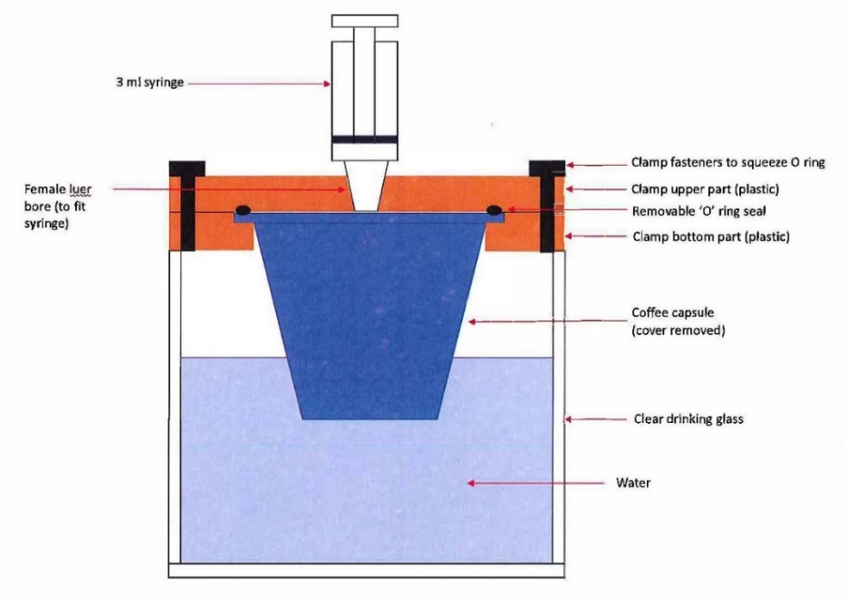
272 According to Mr Hunter, he designed his test rig to be low cost and of simple design. He said that it deliberately does not have a precise pressure control or pressure transducers incorporated into it as these were likely to be relatively high cost items to both purchase and set up. In his written evidence he suggested that a test rig with a precise controllable pressure source and pressure transducers could be designed if the respondents’ expert deemed it necessary.
273 The test rig included upper and lower clamping parts to hold the capsule in position. The top flange of the open capsule was sealed by the underside of the top part of the upper clamp. The test rig sat on top of a clear drinking glass, and the bottom portion of the capsule sat beneath the water in the glass. The test rig was fitted with a syringe as shown in the sketch. According to Mr Hunter’s calculations, the syringe used in the test rig could be used to inject air into the capsule body at “minimal overpressure” (ie. approximately 0.1 bar overpressure in the capsule).
274 Using the test rig, Mr Hunter tested two samples of each of version 1, 2a and 3 capsules by (i) pushing the base of the capsules against a firm horizontal surface to break the inside foil seal across the cut in the base of the capsule that allows the cut at the base of the capsule to be used to dispense the beverage when the capsule is being processed in a machine; (ii) removing the top cover from the capsule, and the top perforated film member, and the coffee stored inside; (iii) using the syringe to inject 3 ml of blue-dyed water into the bottom of the capsule; (iv) loading the empty capsule into the clamp fixture; (v) tightening the clamp fixture without the O-ring present until both faces of the clamp fixture are in contact; (vi) introducing a 3 ml syringe into the female luer bore, with the syringe plunger set to 2.5 ml; (vii) loading the assembled fixture into a partially filled drinking glass so that the bottom of the capsule sits under water; and (viii) slowly depressing the syringe plunger so that it moves from 2.5 ml to O ml.
275 According to Mr Hunter, in the event that integer (g) is present, air bubbles will be observed in the water in the glass streaming from the area of the capsule where the cut is present together with a minimal amount of blue dyed water.
276 On the basis of these tests, Mr Hunter concluded that some (though not all) of the capsules tested by him met the requirements of claim 34. With regard to both the version 1 and version 2a capsules, his tests on the two samples produced inconsistent results which led him to conclude that, while one sample possessed the relevant integers, he was unable to draw the same conclusion in relation to the other sample.
277 There are a number of points to make in relation the testing conducted by Mr Hunter.
278 It is common ground that the respondents’ version 1-3 capsules are intended for use in the applicant’s Caffitaly coffee machines. Mr Hunter was provided with an example of a Caffitaly coffee machine but he did not carry out any tests using it. Nor is there any evidence that he conducted any rigorous inspection of the Caffitaly machine with a view to understanding its operating characteristics including the temperatures and pressures at which it injects water into the capsule. The respondents’ principal submission in relation to Mr Hunter’s experimental evidence is that whether or not the respondents’ capsules exhibit the physical properties and behavioural characteristics defined by claim 34 will depend on how they are used and that the only way to test whether or not the respondents’ capsules meet the requirements of claim 34 is to test them in a compatible machine.
279 The specification does not prescribe any tests that may be conducted to determine whether or not a capsule has the integers of claim 34: cf Blanco White at para 4-703. The specification describes in detail a machine with which the capsule described in claim 34 can be used. However, that machine is one which, amongst other things, makes the cut in the second wall of the capsule. It would not be suitable for use with a capsule in which the cut had already been made at the time of manufacture. So there is little to be gained by looking to the machine described in the specification for guidance as to the conditions under which a capsule alleged to be within claim 34 would be used.
280 This highlights one of the difficulties with the claim. If the relevant behavioural characteristics of the capsule are influenced by the design and operating characteristics of the coffee machine in which it is to be used, how is infringement to be assessed? The obvious place to start in this case is with the Caffitaly coffee machine in which the first respondent’s capsules are intended to be used. One might then formulate for a test which sought to reproduce, as far as is reasonably possible, the conditions to which a capsule would be subjected when used in that particular machine. That would involve studying the geometry, temperatures and pressures within such a machine and then seeking to replicate them in test conditions.
281 The machine in which the capsule is used will most likely affect the size and shape of the cut in the second wall of the capsule. As Mr Hunter frankly acknowledged, he does not know what happens to the shape of the cut when the capsule was in the Caffitaly machine; that was not something that he tested, and it is not something about which he was willing to speculate. In my opinion this points to a fundamental problem with Mr Hunter’s experimental evidence.
282 I asked some questions of Mr Hunter concerning the extent to which the design of the machine in which the capsule was used would affect the behaviour of the capsule and its ability to meet the requirements of the claim. Mr Hunter’s reply was that the “the claim is independent of what type of machine … you’re using to process the cartridge”.
283 It is true that claim 34 makes no direct reference to any particular type of machine. But at least some of the characteristics of the capsule, as defined by the claim, must depend on the conditions to which it is exposed in use; for example, whether or not the cut is capable of allowing air but not any substantial quantity of liquid to pass will depend not just on physical characteristics of the cut but also on the pressure at which water is injected into the capsule and if and when the pressure changes during the brewing process. The manual for the Caffitaly machine suggests that it has a maximum operating pressure of 15 bar. However, there is nothing in the manual to indicate at what pressure the machine ordinarily operates and whether different pressure is applied during different stages of the brewing process.
284 Likewise, the geometry of a coffee machine and the compressive and other forces imposed by it on the capsule may have a direct bearing on the shape and configuration of the cut. Even in the case of a capsule in which the cut is made at the time of manufacture, the shape of the cut may change in use due to the geometry of the machine and the various forces and pressures applied to the capsule.
285 Mr Hunter’s approach to the experimental evidence seemed to assume that the physical characteristics of the capsule in question could be determined without regard to the design of the machine in which they were intended to be used. When asked what affect a machine operating at a higher temperature than another machine might have on the ability of the cut to substantially prevent the passage of liquid, Mr Hunter replied:
Well, I suppose I can only give you my view of that, your Honour, which is that if you were to try to interpret that integer in terms of what all coffee machines that processed espresso capsules in the world could do, then I don’t know what that variation would be or how you could sort of police the claim, if you like. It would just become … an almost impossible exercise to do.
286 The difficulty with Mr Hunter’s approach is that it ignores the fact that the behavioural characteristics of the capsule defined by claim 34 must depend, at least to some extent, on the machine in which the capsule is used. This is because the claim does not define the relevant properties of the capsule by reference to discernible physical properties or characteristics that can be measured without also knowing something about the conditions to which it will be exposed in use. Rather, the claim defines characteristics of the capsule by reference to the way in which it behaves in use. In my opinion it is not possible to determine whether the capsule is within the claim without knowing how its behaviour will be affected by the machine in which it is used including, for example, by the forces applied to the capsule when locked into position in the machine and their effect on the size or shape of the cut.
287 Mr Hunter agreed that claim 34 describes a capsule which would, if used, exhibit particular characteristics. However, his position was that it was impossible, or practically impossible, except at considerable expense, to replicate in experimental conditions the behaviour of a capsule in a given coffee machine. This point was further explored with Mr Hunter as follows:
MR HUNTER: - - - there’s an integer there that says, “Adjacent portions” – this is of the cut, “are also deformable towards the outside of the capsule in such a way to form an opening for the beverage flowing out”. Now, again, the Caffitaly machine, your Honour, this capsule is ..... in a hidden area in between two capsules and I’m being asked to find out whether the adjacent portions of the cut are deforming by fractions of a millimetre towards the outside when the beverage flows out. There just simply is no way of determining that experimentally.
HIS HONOUR: Well – and it may – the result may vary from one machine to another.
MR HUNTER: Precisely. It might – you might spend $500,000 on a testing program for the Caffitaly machine and then find that there are others that you had to do. So this is the difficulty, that trying to test - - -
HIS HONOUR: Well … meaning, though, that the same capsule may be within the claim when used in one machine and outside the claim when used in another.
MR HUNTER: Indeed. I can’t - - -
HIS HONOUR: Yes. I’m not talking about problems with testing.
MR HUNTER: Yes.
HIS HONOUR: Just leaving – putting all that aside, it’s really coming back to the issue that has been explored by Mr Cooke; the question of whether or not … the capsule is within the claim. And it really … will depend on what machine [it] is put in, possibly.
MR HUNTER: Possibly.
HIS HONOUR: That’s what I’m asking.
MR HUNTER: It possibly could, your Honour. You’re right. Yes. If you read it in such a way that the machine comes into claim 34, which, I think, is – as I’ve said, is problematic for me.
288 I am not sure why Mr Hunter regarded this as problematic in circumstances where he accepted that whether or not a capsule exhibited the behavioural characteristics described in claim 34 may well depend on what machine the capsule was used in. The fact that it may be difficult for the patentee to prove infringement of claim 34 is not a matter that bears on the proper construction of the claim or the need for there to be some evidence as to precisely how the capsule is likely to behave in use.
289 There are two other matters that I will refer that relate to Mr Hunter’s testing.
290 In order to test for the presence of integer (h), Mr Hunter conducted an experiment using computer simulation and a technique called finite element analysis (“FEA”). This is a technique in which a three-dimensional computer model can be created of a part or a portion of a part. The computer model can be used to simulate material characteristics which are synonymous with those from which the part is made. Simulated loads may then be applied to the part, and the results of those loads on the part may be estimated.
291 In this experiment Mr Hunter created three different computer models of the central boss portion of the inside of the version 1-3 capsules which incorporated the cut. Using the computer models Mr Hunter simulated a downward pressure load of 3 bar which was at the uppermost end of the range that he said most coffee machines would generate when they are building up pressure to process the coffee beverage. He then analysed the deflections which the modelling indicated would result from the application of the pressure load and, in particular, the deformation which it suggested would occur at adjacent portions of the cut. As to the results of this modelling, Mr Hunter said:
Note that the results of this analysis should be considered as broadly indicative only. The behaviour of the boss portion (and the cut) when pressure is applied is complex, and there are many factors which would affect the deformation of the boss and the cut, which were not possible to include in this analysis.
292 There are various difficulties with Mr Hunter’s computer modelling but two of them stand out. First, the modelling occurs in circumstances which take no account of the effect of the geometry of the coffee machine on the shape and configuration of the cut. This is a problem that affects all of Mr Hunter’s experiments, including the computer modelling. Secondly, the analysis is based on a pressure load of 3 bar applied to the top of the boss. According to Mr Hunter’s analysis, the application of that amount of pressure will cause the cut to deform towards the outside of the capsule allowing the beverage to flow out.
293 In the case of the version 1 capsule, Mr Hunter’s modelling showed that the application of 3 bars of pressure to the top of the boss would cause a cut that was 0 mm in width to expand to 0.18 mm in width. His evidence was that a gap of 0.18 mm was large enough for the beverage to flow out. However, Mr Hunter’s other testing indicated that a capsule with a cut between 0 mm and 0.2 mm in width was “liquid-tight”. In his oral evidence Mr Hunter acknowledged that there was a discrepancy between these test results. He also acknowledged that he did not know at what pressure liquid starts to flow using a version 1 capsule in a Caffitaly machine. I think it is clear from Mr Hunter’s evidence that he does not know at what pressure liquid starts to flow using any of the respondents’ capsules in any compatible coffee machine. In these circumstances, I have very little confidence in the reliability of Mr Hunter’s experiments as a means of testing for the presence of integers of the asserted claims. Unexplained variability in test results raises serious doubts as to their overall reliability. Of no less concern is the fact that, in the case of versions 1 and 2a, inconsistent test results were achieved as between two samples of the same capsule. Given that only two samples of versions 1 and 2a were tested, it is impossible to exclude the possibility that the positive results obtained in those cases were anything other than chance results.
294 The applicant’s submissions in relation to infringement do not engage in any convincing way with the problems with the experimental evidence. Nor do they come to grips with the fact that one cannot determine whether or not the capsules will behave in the particular way required by claim 34 without assessing the impact that the particular machine in which they are used will have on such behaviour.
295 When dealing with various points raised by Professor D’Urso in relation to the activation of the bellows of the respondents’ capsules when used in a Caffitaly coffee machine (but which are not activated under Mr Hunter’s test conditions), the applicant made the point in its closing submissions that:
… there is certainly no requirement in the claim that the features must be present when the capsule is used in a Caffitaly coffee machine, as Mr Hunter pointed out.
That statement is correct so far as it goes. And it may be correct to say, as the applicant also points out, that the first respondent’s capsules are indicated as compatible with both Caffitlay and “K-Fee” coffee machines. But there was no evidence led as to the design of either the Caffitaly or the K-Fee coffee machine and the effect that each machine may have on the behaviour of the cut. Mr Hunter’s experiments were not designed to simulate the operation of either of those machines. Rather than address the question of how the first respondent’s capsules would behave in a compatible coffee machine, his evidence sought to deal with the infringement issues at a level of abstraction that ignores the effect that the operation of the coffee machine in which the capsule is used will have on the behaviour of the capsule including, in particular, the cut.
296 I am not persuaded that Mr Hunter’s experimental evidence provides a reliable basis for drawing any conclusions as to the likelihood that any of the first respondent’s capsules will, if used in a compatible machine, meet the requirements of any of integers (f), (g) and (h) of claim 34. On that basis, even if I was to have found that claim 34 was valid, neither it nor dependent claims 35 or 36 is shown on the balance of probabilities to be infringed by sale, use or otherwise.
297 There are a number of issues that I have not decided in light of my other findings in relation to validity. They include whether dependent claim 35 of the 388 patent was invalid for lack of clarity. They also include the issue of Mr Knox’s liability for authorisation of alleged acts of infringement.
298 In the result, there will be orders revoking each of the claims that the respondents are alleged to have infringed. There will also be an order dismissing the application. The parties will be given an opportunity to make submissions on costs in writing.
299 There will be orders accordingly.
I certify that the preceding two hundred and ninety-nine (299) numbered paragraphs are a true copy of the Reasons for Judgment herein of the Honourable Justice Nicholas. |
Associate:
Schedule