
FEDERAL COURT OF AUSTRALIA
BlueScope Steel Limited v Dongkuk Steel Mill Co., Ltd (No 2) [2019] FCA 2117
ORDERS
BLUESCOPE STEEL LIMITED (ACN 000 011 058) Applicant | ||
AND: | Respondent | |
AND BETWEEN: | Cross-Claimant | |
AND: | BLUESCOPE STEEL LIMITED (ACN 000 011 058) Cross-Respondent | |
DATE OF ORDER: |
THE COURT ORDERS THAT:
1. Each of the parties file and serve by 3 February 2020 minutes of orders and short submissions (limited to 3 pages) to give effect to these reasons.
2. Costs reserved.
3. Liberty to apply.
Note: Entry of orders is dealt with in Rule 39.32 of the Federal Court Rules 2011.
BEACH J:
1 BlueScope Steel Limited (BlueScope) contends that Dongkuk Steel Mill Co Ltd (Dongkuk) has infringed various claims of Australian Patent No. 2009225257 (the 257 Patent) and Australian Patent No. 2009225258 (the 258 Patent). BlueScope is the registered proprietor of both Patents, the applications for which were filed on 13 March 2009.
2 BlueScope carries on business, inter-alia, as a manufacturer and supplier of alloy-coated steel strip products which are sold in Australia and elsewhere. Dongkuk carries on business outside Australia, inter-alia, as a manufacturer and supplier of alloy-coated steel strip products which are sold by third parties in Australia and elsewhere.
3 The invention the subject of the 257 Patent relates to a hot dip coating method for coating steel strips with an alloy coating of aluminium, zinc, silicon and magnesium (Al-Zn-Si-Mg) where variations in the thickness of the coating are controlled such that there is only a small proportion of Mg2Si particles or substantially no Mg2Si particles in the surface of the coating. The invention also relates to a coated steel strip formed by that method.
4 The invention the subject of the 258 Patent relates to an Al-Zn-Si-Mg alloy-coated steel strip where the distribution of Mg2Si particles is such that there is no more than 10% by weight of Mg2Si particles in a surface region of the coating. The invention also relates to a hot dip coating method for forming such a coated steel strip.
5 BlueScope says that Dongkuk without the licence or authority of BlueScope has imported and authorised other persons to offer for sale, sell and supply in Australia an Al-Zn-Si-Mg alloy-coated steel strip product (the GLX product) that infringes both Patents because it is a product which:
(a) results from the use of the method claimed in claims 1, 3, 4, 5, 6, 8, 9, 11, 12 and 13 of the 257 Patent;
(b) falls within the scope of claims 14 and 15 of the 257 Patent; and
(c) falls within the scope of claims 2, 5, 6, 11 and 12 of the 258 Patent.
6 Now although BlueScope originally pleaded infringement of claim 7 of the 257 Patent, it does not now press that claim. Further, although it originally pleaded infringement of claims 1 and 17 to 25 of the 258 Patent, it no longer presses those claims.
7 Dongkuk has denied infringement and has alleged that BlueScope has made unjustified threats in respect of the alleged infringing conduct asserted by BlueScope. Dongkuk has also cross-claimed seeking orders revoking both the 257 Patent and the 258 Patent in so far as they relate to various claims.
8 Dongkuk has alleged that claims 1, 3 to 6, 8, 9 and 11 to 15 of the 257 Patent are invalid upon the grounds that:
(a) the invention is not novel;
(b) the invention does not involve an inventive step;
(c) the specification does not disclose the best method of performing the invention;
(d) the specification does not describe the invention fully;
(e) the claims do not define the invention or are not clear;
(f) the claims are not fairly based; and
(g) the Patent was obtained by false suggestion or misrepresentation.
9 Further, Dongkuk has alleged that claims 1, 2, 5, 6, 11, 12, 17, 18 and 20 to 25 of the 258 Patent are invalid upon similar grounds.
10 Now as I have said, the applications for the Patents were filed on 13 March 2009. But although ss 7 and 40 of the Patents Act 1990 (Cth) (the Act) were amended by the Intellectual Property Laws Amendment (Raising the Bar) Act 2012 (Cth) (the Raising the Bar Act), the amendments brought about do not affect the present case.
11 Further, each of the 257 Patent and the 258 Patent claim priority from two convention applications being AU2008901223 and AU2008901224 filed on 13 March 2008 (the priority date). There is no issue concerning the priority date.
12 I should note one other preliminary matter. By an interlocutory application dated 13 April 2017, BlueScope has applied to amend the 257 Patent. The amendments sought relate to the description in the body of the 257 Patent, but not the claims.
13 In summary and for the reasons that I have explained in more detail later, I have rejected BlueScope’s infringement case even assuming the asserted claims of the 257 Patent and the 258 Patent to be valid. But in any event, the asserted claims of the 257 Patent and some of the asserted claims of the 258 Patent are invalid by reason of the specifications failing to disclose the best method known to BlueScope at the relevant time. Further, I have rejected BlueScope’s amendment application relating to the 257 Patent.
14 It is convenient to divide my reasons into the following sections:
(a) The 257 Patent – [17] to [81].
(b) The 258 Patent – [82] to [120].
(c) The measurement protocol – [121] to [134].
(d) BlueScope’s application of the protocol – [135] to [232].
(e) Deficiencies in the experimental evidence – [233] to [415].
(f) Infringement of the 257 Patent – [416] to [602].
(g) Infringement of the 258 Patent – [603] to [679].
(h) Invalidity – general – [680] to [702].
(i) Lack of clarity and lack of definition – [703] to [747].
(j) Lack of fair basis – [748] to [799].
(k) Lack of sufficiency – [800] to [826].
(l) Lack of disclosure of best method – [827] to [960].
(m) False suggestion – [961] to [1013].
(n) Lack of novelty – [1014] to [1219].
(o) Lack of inventive step – [1220] to [1323].
(p) Amendment application – [1324] to [1513].
(q) Conclusion – [1514] to [1517].
15 I should say at the outset that I have been much assisted by the technical presentations of all counsel. Their cases were presented with notable efficiency.
16 Let me begin with identifying and describing some of the key features of the 257 Patent and the 258 Patent. I will then turn to questions of infringement before dealing with questions of invalidity. It is convenient to take this course, albeit that this may seem counter-intuitive, in order to achieve some comprehensible flow to the technical issues.
THE 257 PATENT
17 The Patents relate to the field of alloy-coated steel strips, where the alloy coating provides corrosion resistance. The work in this field was undertaken by materials scientists and engineers with a focus on corrosion resistance. In the present case, the person skilled in the art is a team of materials scientists and engineers working in the coatings field, with a particular interest in Al-Zn coatings, who were involved in a research project to identify an improved coating at the priority date. The team would have expertise in hot dip coatings, including galvalume, that is, alloy coatings having 55 wt. % aluminium, 43 wt. % zinc and approximately 1.5 to 2 wt. % silicon. They would have a practical interest in the subject matter of the invention but be presumed to be unimaginative and non-inventive.
18 The invention the subject of the specification of the 257 Patent is described in the following terms (p 1 lines 3 to 36):
The present invention relates to strip, typically steel strip, which has a corrosion-resistant metal alloy coating.
The present invention relates particularly to a corrosion-resistant metal alloy coating that contains aluminium-zinc-silicon-magnesium as the main elements in the alloy, and is hereinafter referred to as an “Al-Zn-Si-Mg alloy” on this basis. The alloy coating may contain other elements that are present as deliberate alloying additions or as unavoidable impurities. Hence, the phrase “Al-Zn-Si-Mg alloy” is understood to cover alloys that contain such other elements and the other elements may be deliberate alloying additions or as unavoidable impurities.
The present invention relates particularly but not exclusively to steel strip that is coated with the above-described Al-Zn-Si-Mg alloy and can be cold formed (e.g. by roll forming) into an end-use product, such as roofing products.
Typically, the Al-Zn-Si-Mg alloy comprises the following ranges in % by weight of the elements aluminium, zinc, silicon, and magnesium:
Aluminium: 40 to 60 %
Zinc: 40 to 60 %
Silicon: 0.3 to 3%
Magnesium 0.3 to 10 %
Typically, the corrosion-resistant metal alloy coating is formed on steel strip by a hot dip coating method.
19 In terms of the addition of silicon and magnesium, the following was said (p 3 line 4 to p 4 line 7):
It is known to add silicon to the coating alloy composition to prevent excessive alloying between the steel substrate and the molten coating in the hot-dip coating method. A portion of the silicon takes part in a quaternary alloy layer formation but the majority of the silicon precipitates as needle-like, pure silicon particles during solidification. These needle-like silicon particles are also present in the inter-dendritic regions of the coating.
It has been found by the applicant that when Mg is included in a 55%Al-Zn-Si alloy coating composition, Mg brings about certain beneficial effects on product performance, such as improved cut-edge protection, by changing the nature of corrosion products formed.
However, it has also been found by the applicant that Mg reacts with Si to form a Mg2Si phase and that the formation of the Mg2Si phase compromises the above-mentioned beneficial effects of Mg in a number of ways.
One particular way, which is the focus of the present invention is a surface defect called “mottling”. The applicant has found that mottling can occur in Al-Zn-Si-Mg alloy coatings under certain solidification conditions. Mottling is related to the presence of the Mg2Si phase on the coating surface.
More particularly, mottling is a defect where a large number of coarse Mg2Si particles cluster together on the surface of the coating, resulting in a blotchy surface appearance that is not acceptable from an aesthetic viewpoint. More particularly, the clustered Mg2Si particles form darker regions approximately 1-5 mm in size and introduce non-uniformity in the appearance of the coating which makes the coated product unsuitable for applications where a uniform appearance is important.
The above description is not to be taken as an admission of the common general knowledge in Australia or elsewhere.
20 Then there is a statement of the invention as follows (p 4 lines 9 to 14):
The present invention is an Al-Zn-Si-Mg alloy coated strip that has Mg2Si particles in the coating with the distribution of Mg2Si particles being such that a surface of the coating has only a small proportion of Mg2Si particles or is at least substantially free of any Mg2Si particles.
21 As to this statement, what does “small proportion” mean? Almost nothing? And does the phrase “only a small proportion” mean the same thing as “at least substantially free”? And does the latter phrase mean immaterially small?
22 Further, it was then explained (p 4 lines 16 to 27):
The applicant has found that the above-described distribution of Mg2Si particles in the coating microstructure provides significant advantages and can be achieved by any one or more of:
(a) strontium additions in the coating alloy,
(b) selection of the cooling rate during solidification of coated strip for a given coating mass (i.e. coating thickness) exiting a coating bath; and
(c) minimising variations in coating thickness.
23 There are two issues to note concerning this passage. Does “can” in the phrase “can be achieved” mean may or must? Further, what is the significance of “any one or more of”? Does this mean that the promise can be achieved with one only?
24 The addition of strontium (Sr) is then explained (p 4 line 29 to p 5 line 12):
The applicant has found that Sr additions described in more detail below control the distribution characteristics of the Mg2Si phase in the thickness direction of an Al-Zn-Si-Mg alloy coating so that the surface of the coating has only a small proportion of Mg2Si particles or is at least substantially free of Mg2Si particles, whereby there is a considerably lower risk of Mg2Si mottling.
The applicant has found that when at least 250 ppm Sr, preferably 250-3000 ppm Sr, is added to a coating bath containing an Al-Zn-Si-Mg alloy the distribution characteristics of the Mg2Si phase in the coating thickness direction are completely changed by this addition of Sr from the distribution that is present when there is no Sr in the coating bath. Specifically, the applicant has found that these additions of Sr promote the formation of a surface of the coating that has only a small proportion of Mg2Si particles or is free of any Mg2Si particles and consequently a considerably lower risk of mottling on the surface.
25 The reference to “below” (p 4 line 30) appears to be a reference to p 7. Further, are these passages saying that Sr is the cause (i.e. on its own)?
26 In an apparently self-contained passage referring to the subject matter in (b) (p 4 line 23), the following is said (p 5 lines 14 to 23):
The applicant has also found that selecting the cooling rate during solidification of a coated strip exiting a coating bath to be below a [threshold] cooling rate, typically below 80℃/sec for coating masses less than 100 grams per square metre of strip surface per side, controls the distribution characteristics of the Mg2Si phase so that the surface has only a small proportion of Mg2Si particles or is at least substantially free of Mg2Si particles, whereby there is a considerably lower risk of Mg2Si mottling.
27 In a yet further apparently self-contained passage referring to the subject matter in (c) (p 4 line 27), the following is said (p 5 lines 25 to 34):
The applicant has also found that minimising coating thickness variations controls the distribution characteristics of the Mg2Si phase so that the surface has only a small proportion of Mg2Si particles or is at least substantially free of Mg2Si particles, whereby there is a considerably lower risk of Mg2Si mottling. As is the case with Sr addition and selection of cooling rate during solidification, the resultant coating microstructure is advantageous in terms of appearance, enhanced corrosion resistance and improved coating ductility.
28 Then the invention is described (p 5 line 36 to p 6 line 4):
The claims define the invention in terms of minimising coating thickness variations to control the distribution characteristics of the Mg2Si phase so that the surface has only a small proportion of Mg2Si particles or is at least substantially free of Mg2Si particles, whereby there is a considerably lower risk of Mg2Si mottling.
29 Then there are listed consistory clauses (p 6 line 6 to p 9 line 5).
30 The advantages are then described as follows (p 9 lines 6 to 21):
The advantages of the invention include the following advantages.
• Elimination of mottling defect and improved first-time-prime production rate. The risk of the mottling defect is at least substantially eliminated and the surface of the resultant coating maintains a beautiful, silvery metallic appearance. As a result, first-time-prime production rate is improved and profitability is boosted.
• Prevention of mottling defect by the addition of Sr allows the use of higher cooling rates, reducing the length of cooling equipment required after the pot.
31 In terms of line trials the following was said (p 11 line 3 to p 13 line 25):
The applicant has also carried out line trials on 55%Al-Zn-1.5%Si-2.0%Mg alloy composition (not containing Sr) coated on steel substrates.
The purpose of these trials was to investigate the impact of cooling rates and coating masses on mottling in the surface of the coatings.
The trials covered a range of coating masses from 60 to 100 grams per square metre surface per side of strip, with cooling rates up to 90℃/sec.
The applicant found two factors that affected the coating microstructure, particularly the distribution of Mg2Si particles in the coatings, in the trials.
The first factor is the effect of the cooling rate of the strip exiting the coating bath before completing the coating solidification. The applicant found that controlling the cooling rate makes it possible to avoid mottling.
By way of example, the applicant found that for a AZ150 class coating (or 75 grams of coating per square 25 metre surface per side of strip – refer to Australia Standard AS1397-2001), if the cooling rate is greater than 80℃/sec, Mg2Si particles formed on the surface of the coating. In particular, when the cooling rate was greater than 100℃/sec, mottling occurred.
The applicant also found that for the same coating it is not desirable that the cooling rate be too low, particularly below 11℃/sec, as in this case the coating develops a defective “bamboo” structure, whereby the zinc-rich phases forms a vertically straight corrosion path from the coating surface to the steel interface, which compromises the corrosion performance of the coating.
Therefore, for a AZ150 class coating, under the experimental conditions tested, the cooling rate should be controlled to be in a range of 11-80℃/sec to avoid mottling on the surface.
On the other hand, the applicant also found that for a AZ200 class coating, if the cooling rate was greater than 50℃/sec, Mg2Si particles formed on the surface of the coating and mottling occurred.
Therefore, for a AZ200 class coating, under the experimental conditions tested, a cooling rate in a range of 11-50℃/sec is desirable.
The second important factor found by the applicant is the uniformness of coating thickness across the strip surface.
The applicant found that the coating on the strip surface normally had thickness variations that are (a) long range (across the entire strip width, measured by the “weight-strip-weight” method on a 50mm diameter disc) and (b) short range (across every 25 mm length in the strip width direction, measured in the cross-section of the coating under a microscope with 500x magnification). In a production situation, the long range thickness variation is normally regulated to meet the minimum coating mass requirements as defined in relevant national standards. In a production situation, as far is the applicant is aware, there is no regulation for short range thickness variation, as long as the minimum coating mass requirements as defined in relevant national standards are met.
However, the applicant found that short range coating thickness variations could be very high, and special operational measures had to be applied to keep the variations under control. It was not uncommon in the experimental work for the coating thickness to change by a factor of two or more over a distance as short as 5 mm, even when the product perfectly met the minimum coating mass requirements as defined in relevant national standards. This short range coating thickness variation had a pronounced impact on the Mg2Si particles in the surface of coatings.
By way of example, the applicant found that for a AZ150 class coating even in the desirable cooling rate ranges as described above, if the short range coating thickness variation was greater than 40% above the nominal coating thickness within a distance of 5 mm across the strip surface, Mg2Si particles formed on the surface of the coating and thereby increased the risk of mottling.
Therefore, under the experimental conditions tested, the short range coating thickness variation should be controlled to no greater than 40% above the nominal coating thickness within a distance of 5mm across the strip surface to avoid mottling.
32 I will return later to the significance of the phrase “special operational measures” (p 13 line 3).
33 I should also set out some other passages (p 16 line 23 to p 18 line 3):
Practically, the applicant has found that, to achieve the distribution of Mg2Si particles of the present invention, i.e. to avoid mottling defect on the surface of a coated strip, the cooling rate for coated strip exiting the coating bath has to be in a range of 11-80℃/sec for coating masses up to 75 grams per square metre of strip surface per side and in a range 11-50℃/sec for coating masses of 75-100 grams per square metre of strip surface per side. The short range coating thickness variation also has to be controlled to be no greater than 40% above the nominal coating thickness within a distance of 5 mm across the strip surface to achieve the distribution of Mg2Si particles of the present invention.
The applicant has also found that, when Sr is present in a coating bath, the above described kinetics of Mg2Si nucleation can be significantly influenced. At certain Sr concentration levels, Sr strongly segregates into the quaternary alloy layer (i.e. changes the chemistry of the quaternary alloy phase). Sr also changes the characteristics of surface oxidation of the molten coating, resulting in a thinner surface oxide on the coating surface. Such changes alter significantly the preferential nucleation sites for the Mg2Si phase and, as a result, the distribution pattern of the Mg2Si phase in the coating thickness direction. In particular, the applicant has found that, Sr at concentrations 250-3000ppm in the coating bath makes it virtually impossible for the Mg2Si phase to nucleate on the quaternary alloy layer or on the surface oxide, presumably due to the very high level of increase in system free energy would otherwise be generated. Instead, the Mg2Si phase can only nucleate at the central region of the coating in the thickness direction, resulting in a coating structure that is substantially free of Mg2Si at both the coating outer surface region and the region near the steel surface. Therefore, Sr additions in the range 250-3000ppm are proposed as one of the effective means to achieve a desired distribution of Mg2Si particles in a coating.
Many modifications may be made to the present invention as described above without departing from the spirit and scope of the invention.
In this context, whilst the above description of the present invention focuses on (a) the addition of Sr to Al-Zn-Si-Mg coating alloys, (b) cooling rates (for a given coating mass) and (c) control of short range coating thickness variation as means for achieving a desired distribution of Mg2Si particles in coatings, i.e. at least substantially no Mg2Si particles in the surface of a coating, the present invention is not so limited and extends to the use of any suitable means to achieve the desired distribution of Mg2Si particles in the coating.
34 The following claims, inter-alia, are then made (pp 19 to 21):
1. A hot-dip coating method for forming a coating of a corrosion-resistant Al-Zn-Si-Mg alloy on a steel strip comprising passing the steel strip through a hot dip coating bath that contains Al, Zn, Si, and Mg and optionally other elements and forming an alloy coating on the strip with a variation in thickness of the coating of no more than 40% in any given 5 mm diameter section so that the distribution of Mg2Si particles in the coating microstructure is such that there is only a small proportion of Mg2Si particles or substantially no Mg2Si particles in the surface of the coating.
…
3. The method defined in any one of the preceding claims wherein the small proportion of Mg2Si particles in the surface of the coating is no more than 10wt.% of the Mg2Si particles.
4. The method defined in any one of the preceding claims wherein the coating thickness variation is no more than 30% in any given 5 mm diameter section of the coating.
5. The method defined in any one of the preceding claims wherein, for a coating thickness of 22μm, the maximum thickness in any region of the coating greater than 1mm in diameter is 27μm.
6. The method defined in any one of the preceding claims comprising selecting the cooling rate during solidification of coated strip exiting the coating bath to be less than a threshold cooling rate.
…
8. The method defined any one of claims 1 to 6 comprising selecting the cooling rate for coated strip exiting the coating bath to be less than 50℃/sec for coating masses of 75-100 grams per square metre of strip surface per side.
9. The method defined in any one of the preceding claims wherein the coating comprises the following ranges in % by weight of the elements aluminium, zinc, silicon, and magnesium:
Aluminium: 40 to 60 %
Zinc: 40 to 60 %
Silicon: 0.3 to 3%
Magnesium 0.3 to 10 %.
…
11. The method defined in any one of the preceding claims wherein the coating contains less than 3000 ppm Sr.
12. The method defined in any one of the preceding claims comprising forming the coating to have a thickness of less than 30μm.
13. The method defined in any one of the preceding claims comprising forming the coating to have a thickness 35 of greater than 7μm.
14. A steel strip having a coating of a corrosion-resistant Al-Zn-Si-Mg alloy formed by the method defined in any one of the preceding claims.
15. An Al-Zn-Si-Mg alloy coated strip that has Mg2Si particles in the coating with the distribution of Mg2Si particles being such that a surface of the coating has only a small proportion of Mg2Si particles or is at least substantially free of any Mg2Si particles formed by the method defined in any one of the preceding claims.
35 It will be apparent that claim 1 is the only truly independent claim.
36 Let me summarise some of the aspects of the specification.
37 The specification explains that the invention relates to strip, typically steel strip, which has a corrosion-resistant metal alloy coating and more particularly a corrosion-resistant metal alloy coating that contains as its main elements aluminium, zinc, silicon and magnesium being an Al-Zn-Si-Mg alloy.
38 The specification observes that the alloy coating may contain other elements that are present as deliberate alloying additions or unavoidable impurities. The specification explains that the expression “an Al-Zn-Si-Mg alloy” is to be understood as covering an Al-Zn-Si-Mg alloy which also includes other elements.
39 The specification explains that the present invention relates to steel strip that is coated with the Al-Zn-Si-Mg alloy and can be cold formed into an end-use product such as roofing products.
40 The specification explains that typically the Al-Zn-Si-Mg alloy comprises 40 to 60% weight of Al, 40 to 60% weight Zn, 0.3 to 3% Si and 0.3 to 10% Mg and that typically the metal alloy coating is formed by a hot dip coating method.
41 After explaining the conventional hot dip coating method, the specification explains that a 55%Al-Zn alloy coating that is sold under the name “galvalume” is a well known metal alloy coating for steel strip, and that after solidification, such a coating normally consists of Al dendrites that are a characteristic tree-like structure of Al crystals, and a Zn phase in the inter-dendritic regions that is the region or space between the Al dendrites. The specification explains that it is known to add Si to prevent excessive alloying between the steel substrate and the molten coating. But only a portion of Si takes part in the quaternary alloy layer formation. The majority of Si precipitates as needle-like pure Si particles. The needle-like Si particles are also present in the inter-dendritic regions of the coating.
42 At this point I note that a 55% Al-Zn alloy coating was a coating originally developed by Bethlehem Steel in the United States in the 1960s and known there as “galvalume” and in Australia as “galvalume” or “zincalume”. BlueScope and its predecessors produced that product in Australia under licence for many years before the priority date.
43 As I have already indicated, the specification states that the applicant has found that when Mg is included in a 55%Al-Zn-Si alloy coating composition, it brings about certain beneficial effects on product performance, such as improved cut-edge protection, by changing the nature of the corrosion products formed. However, it was also found that the Mg reacts with Si to form an Mg2Si phase which compromises the beneficial effects of Mg in a number of ways.
44 One of the consequences of the Mg2Si phase being formed is a surface defect called “mottling”. This can occur in Al-Zn-Si-Mg alloy coatings under certain solidification conditions and is related to the presence of an Mg2Si phase on the surface of the coating. The specification explains that mottling occurs where a large number of coarse Mg2Si particles cluster together on the surface of the coating, resulting in a blotchy and aesthetically unacceptable surface. The clustered Mg2Si particles form darker regions from 1 to 5 mm in size and introduce non-uniformity in the appearance of the coating.
45 The specification identifies the present invention as an Al-Zn-Si-Mg alloy coated strip that has Mg2Si particles in the coating with the distribution of Mg2Si particles being such that a surface of the coating has only a small proportion of Mg2Si or is at least substantially free of Mg2Si particles.
46 The specification explains that the applicant has found that such a distribution of Mg2Si particles in the coating microstructure provides significant advantages in terms of appearance, enhanced corrosion resistance and improved coating ductility (p 5 lines 33 to 34). As I have indicated, it states (p 4 lines 16 to 28) that those advantages can be achieved by any one or more of:
(a) adding Sr in the coating alloy;
(b) selection of the cooling rate for the coated strip for a given coating mass as it exits the coating bath; and
(c) minimising variations in coating thickness.
47 BlueScope submits that the use of the word “can” is permissive, when read in context. So, it means “may” rather than “will”. I agree.
48 Further, BlueScope says that the proper construction of the phrase “any one or more” does not mean that if a skilled addressee practices one of the trilogy of matters set out in (a), (b) or (c) above in isolation, it will inevitably give rise to the requisite distribution of Mg2Si. It says that the specification makes it plain that where the claimed cooling rate is used, it is also necessary to control coating thickness variation. Generally speaking I agree with BlueScope’s construction. Its construction is supported by various passages of the specification some of which I have set out earlier. It is convenient to identify them as follows:
By way of example, the applicant found that for a AZ150 class coating even in the desirable cooling rate ranges as described above, if the short range coating thickness variation was greater than 40% above the nominal coating thickness within a distance of 5mm across the strip surface, Mg2Si particles formed on the surface of the coating and thereby increased the risk of mottling. (page 13 lines 13 to 19)
…
In particular, the applicant has found that for a set coating thickness, the cooling rate should be regulated to a particular range, and more particularly not to exceed a threshold temperature, to avoid the risk for the Mg2Si phase to nucleate in region A. (page 16 lines 1 to 5)
…
Practically, the applicant has found that, to achieve the distribution of Mg2Si particles of the present invention, i.e. to avoid mottling defect on the surface of a coated strip, the cooling rate for coated strip exiting the coating bath has to be in a range of 11-80°C/sec for coating masses up to 75 grams per square metre of strip surface per side and in a range 11-50°C/sec for coating masses of 75-100 grams per square metre of strip surface per side. The short range coating thickness variation also has to be controlled to be no greater than 40% above the nominal coating thickness within a distance of 5mm across the strip surface to achieve the distribution of Mg2Si particles of the present invention. (page 16 lines 23 to 35)
49 In relation to the addition of Sr, BlueScope refers to p 17 lines 1 to 17 of the specification and says that this passage says that Sr can also have an effect, but not that it can occur in isolation. Again, generally speaking I agree with BlueScope’s construction.
50 Further, it seems to me that the relevant passages indicate that it may be necessary to combine the trilogy to achieve the desired distribution of Mg2Si particles resulting in a product that is mottle-defect free.
51 It seems to me, as BlueScope correctly submitted, that the three methods referred to above control the distribution characteristics of the Mg2Si phase so that the surface has only a small proportion of Mg2Si particles or is at least substantially free of Mg2Si particles, resulting in a considerably lower risk of Mg2Si mottling.
52 Let me proceed further with the specification. As I have set out earlier, the specification goes on (at p 5 lines 1 to 3) to describe the addition of Sr and notes that the applicant has found that the desired distribution of Mg2Si is obtained when at least 250 ppm Sr is added to the coating bath.
53 The specification then explains how keeping the cooling rate below a certain threshold for a given coating mass can control the Mg2Si distribution.
54 The specification then describes that the applicant has found that minimising coating thickness variations also controls the distribution characteristics of the Mg2Si phase.
55 As I have indicated earlier, the specification then states (at p 5 lines 36 to 37 and p 6 lines 1 to 4) that “[t]he claims define the invention in terms of minimising coating thickness variations” to obtain the desired distribution of Mg2Si. Then there is a consistory clause corresponding to claim 1 followed by consistory clauses broadly corresponding to dependent claims. All of the claims involve minimising coating thickness variations and certain of the dependent claims also involve either Sr additions or selection of cooling rate.
56 The specification then recites the aspect of the invention which is the subject of claim 1 (p 6 lines 6 to 17). The specification then recites preferred aspects of the method which are reflected in dependent claims 2 to 14 (p 6 line 19 to p 8 line 25). The specification goes on to explain that the invention also relates to a steel strip which is formed by the earlier described method of the invention.
57 The specification then outlines the advantages of the invention, which include the following as I have already indicated (p 9 lines 9 to 22).
58 First, it is said that one advantage is that the risk of the mottling defect is at least substantially eliminated and the surface of the coating retains a beautiful, silvery metallic appearance, improving first-time-prime production rate and profitability.
59 Second, it is said that another advantage is that the addition of Sr to prevent mottling allows the use of higher cooling rates, reducing the length of cooling equipment required after the pot.
60 The specification then discloses laboratory experiments on a series of 55% Al, 1.5% Si, 2.0% Mg with the remainder Zn alloy compositions, being an alloy composition including 41.5% Zn, having up to 3000 ppm Sr. The purpose of the experiments was to investigate the impact of Sr on mottling (p 9 lines 30 to 32). The specification states that alloys without Sr have Mg2Si particles distributed throughout, whereas alloys with 250 ppm to 3000 ppm Sr have upper and lower regions at the coating surface and at the interface of the steel substrate that are free of Mg2Si (p 9 line 25 to p 10 line 35).
61 Reference is also made to figure 1 which shows photomicrographs of a coating without Sr and a coating with Sr and it is noted that the alloy to which 500 ppm of Sr was added demonstrates “[a] complete absence of mottling”.
62 At p 10 lines 32 to 35 it is said:
The laboratory experiments found that the microstructure shown in the right hand side of the Figure were formed with Sr additions in the range of 250-3000 ppm.
63 Dongkuk notes that there is no suggestion that Sr additions below 250 ppm had any beneficial effect on Mg2Si distribution.
64 As I have indicated earlier, the specification describes line trials of 55% Al, 1.5% Si, 2.0% Mg with the remainder Zn alloy compositions that did not contain Sr. The specification reports that the applicant found there to be two factors that particularly affected the distribution of Mg2Si (p 11 lines 1 to 15). The first factor is cooling rate (p 11 lines 16 to 21). The second factor is the uniformity of the coating thickness across the surface of the strip (p 12 lines 18 to 20).
65 Dongkuk says that this first factor is consistent with the three alternative methods of achieving the desired distribution of Mg2Si set out at p 4 lines 16 to 27 and set out above.
66 According to Dongkuk, the specification then goes on to say, at p 11 lines 23 to 36 and p 12 lines 1 to 2, which I have set out earlier:
By way of example, the applicant found that for a AZ150 class coating (or 75 grams of coating per square metre surface per side of strip – refer to Australia Standard AS1397-2001), if the cooling rate is greater than 80°C/sec, Mg2Si particles formed on the surface of the coating. In particular, when the cooling rate was greater than 100°C/sec, mottling occurred.
The applicant also found that for the same coating it is not desirable that the cooling rate be too low, particularly below 11°C/sec, as in this case the coating develops a defective “bamboo” structure, whereby the zinc-rich phases forms a vertically straight corrosion path from the coating surface to the steel interface, which compromises the corrosion performance of the coating.
67 The patentee is telling the person skilled in the art that for an AZ150 class coating (i.e. up to 75 grams per square metre of strip surface per side) if the cooling rate is kept at a rate below 80°C per second, Mg2Si particles will not form on the surface of the coating. The patentee is also telling the person skilled in the art not to use a cooling rate below 11°C per second for different reasons.
68 The specification then goes on at p 12 to make similar observations in respect of AZ200 class coating, that is, 100 grams per square metre of strip surface per side, and indicates that the cooling rate should be kept at a rate between 11 to 50°C per second. So, the thicker the coating the lower the cooling rate.
69 The specification then describes the second factor affecting Mg2Si distribution (at p 12 lines 18 to 20):
The second important factor found by the applicant is the uniformness of coating thickness across the strip surface.
70 The specification describes the uniformity of the coating thickness across the strip surface. The specification explains that the coating had long range thickness variations across the entire strip width and short range thickness variations (p 12 lines 22 to 28). The specification explains that in a production situation short range thickness variation was not regulated so long as minimum coating mass requirements were met as defined in national standards (p 12 lines 32 to 36). However, short range coating thickness variations could be very high (p 13 lines 1 to 2). It was not uncommon in the experimental work for the coating thickness to change by a factor of two or more over a distance as short as 5 mm, even where it met minimum coating mass requirements (p 13 lines 4 to 9). This variation had a pronounced impact on Mg2Si particles (p 13 lines 9 and 10). But unlike short range thickness variations, long range thickness variations were measured by the weigh-strip-weigh method (p 12 lines 24 and 25); I will use “weigh-strip-weigh” rather than “weight-strip-weight”. The specification explains (p 13 lines 13 to 25):
By way of example, the applicant found that for a AZ150 class coating even in the desirable cooling rate ranges as described above, if the short range coating thickness variation was greater than 40% above the nominal coating thickness within a distance of 5 mm across the strip surface, Mg2Si particles formed on the surface of the coating and thereby increased the risk of mottling.
Therefore, under the experimental conditions tested, the short range coating thickness variation should be controlled to no greater than 40% above the nominal coating thickness within a distance of 5mm across the strip surface to avoid mottling.
71 The specification says that it was found that short range coating thickness variations could be very high and special operational measures had to be applied to keep the variations under control. It is said (at p 13 lines 1 to 11):
However, the applicant found that short range coating thickness variations could be very high, and special operational measures had to be applied to keep the variations under control. It was not uncommon in the experimental work for the coating thickness to change by a factor of two or more over a distance as short as 5 mm, even when the product perfectly met the minimum coating mass requirements as defined in relevant national standards. This short range coating thickness variation had a pronounced impact on the Mg2Si particles in the surface of coatings.
72 It is then said (at p 13 lines 13 to 19):
By way of example, the applicant found that for a AZ150 class coating even in the desirable cooling rate ranges as described above, if short range coating thickness variation was greater than 40% above the nominal coating thickness within a distance of 5 mm across the strip surface, Mg2Si particles formed on the surface of the coating and thereby increased the risk of mottling.
73 Dongkuk says that there is an inconsistency between the above paragraph and the assertion that is made on p 4 line 23 that “selection of the cooling rate during solidification of coated strip for a given coating mass (i.e. coating thickness) exiting a coating bath” alone can achieve the desired distribution of Mg2Si particles. One way to resolve this inconsistency is to understand the expression “even in the desirable cooling rate ranges as described above” not to mean the whole extent of the ranges described above, but, rather, the end of those ranges. Thus, for an AZ150 class coating, if the cooling rate approaches the 80°C per second point, there may be a need to control thickness variation.
74 Dongkuk says that the specification then advances a theory as to why cooling rates for certain thicknesses can influence the distribution of Mg2Si. In substance the theory is that Mg2Si particles tend to move from the surface of the alloy coating to the centre of the alloy coating before they begin to solidify, but if the cooling rate is too high for the distance which needs to be travelled, those particles will solidify at or near the surface before they can reach the centre.
75 The specification then says at p 16 lines 23 to 35:
Practically, the applicant has found that, to achieve the distribution of Mg2Si particles of the present invention, i.e. to avoid mottling defect on the surface of a coated strip, the cooling rate for coated strip exiting the coating bath has to be in a range of 11-80°C/sec for coating masses up to 75 grams per square metre of strip surface per side and in a range 11-50°C/sec for coating masses of 75-100 grams per square metre of strip surface per side. The short range coating thickness variation also has to be controlled to be no greater than 40% above the nominal coating thickness within a distance of 5 mm across the strip surface to achieve the distribution of Mg2Si particles of the present invention.
76 Again Dongkuk says that there is an inconsistency between this passage and the passage at p 4 lines 16 to 27.
77 The specification then goes on to describe how Sr achieves the desired Mg2Si distribution. In substance Sr brings about a chemical effect which makes it less desirable for Mg2Si to nucleate at the surface of the alloy coating.
78 In summary, the specification explains that it has been found that to achieve a distribution of Mg2Si particles that substantially eliminates mottling, various things are important.
79 First, the cooling rate for the coated strip exiting the coating bath has to be in the range of 11 to 80°C/sec for coating masses up to 75 grams per square metre of strip surface per side. Further, the cooling rate has to be in the range of 11 to 50°C/sec for coating masses of 75 to 100 grams per square metre of strip surface per side.
80 Second, the short range coating thickness variation has to be controlled so that it is no greater than 40% above the nominal coating thickness within a distance of 5 mm across the strip surface to achieve the distribution of Mg2Si particles of the present invention. The specification describes minimising coating thickness variations. Specifically, the specification describes a variation in thickness of the coating of no more than 40% in any given 5mm diameter section or no more than 30% in any given 5mm diameter section. In any given situation the selection of an appropriate thickness variation will be related to the coating thickness or coating mass.
81 Third, as to the addition of Sr, the specification describes the addition of 250 to 3000 ppm of Sr. The specification explains that the inclusion of Sr in the coating bath can affect the kinetics of Mg2Si nucleation because Sr changes the chemistry of the quaternary alloy layer and the characteristics of surface oxidation. But the specification does not suggest that the inclusion of Sr affects coating thickness variation.
THE 258 PATENT
82 The 258 Patent deals with both product claims (claims 1 to 12) and method claims (claims 13 to 25). The first two and a half pages of the specification are similar to the 257 Patent specification, but then there are some differences.
83 The specification does not address mottling. Rather, it is said (p 3 line 25 to p 14 line 15):
By way of example, the Mg2Si phase forms as large particles in relation to typical coating thicknesses and can provide a path for rapid corrosion where particles extend from a coating surface to an alloy layer adjacent the steel strip.
By way of further example, the Mg2Si particles tend to be brittle and sharp particles and provide both an initiation and propagation path for cracks that form on bending of coated products formed from coated strip. Increased cracking compared to Mg-free coatings can result in more rapid corrosion of the coatings.
The above description is not to be taken as an admission of the common general knowledge in Australia or elsewhere.
The present invention is an Al-Zn-Si-Mg alloy coated strip that has Mg2Si particles in the coating microstructure with the distribution of Mg2Si particles being such that a surface region of the coating has only a small proportion of Mg2Si particles or is at least substantially free of any Mg2Si particles.
The term “surface region” is understood herein to mean a region that extends inwardly from the exposed surface of a coating.
84 So, ductility rather than the problem with mottling seems to be the issue.
85 The statement of the invention (at p 4 line 5) is also slightly different to that of the 257 Patent. It is said:
The present invention is an Al-Zn-Si-Mg alloy coated strip that has Mg2Si particles in the coating microstructure with the distribution of Mg2Si particles being such that a surface region of the coating has only a small proportion of Mg2Si particles or is at least substantially free of any Mg2Si particles.
86 The specification goes on:
The term “surface region” is understood herein to mean a region that extends inwardly from the exposed surface of a coating.
87 The specification then repeats the passage of the 257 Patent set out earlier (p 4 lines 16 to 27). It says that the desired distribution of Mg2Si can be achieved by Sr additions, selection of cooling rate, and minimising variations in coating thickness.
88 The specification then provides a consistory clause in the terms of claim 1. It says:
According to the present invention there is provided an Al-Zn-Si-Mg alloy coated steel strip that comprises a coating of an Al-Zn-Si-Mg alloy on a steel strip with the alloy comprising in % by weight 40 to 60% Al, 40 to 60% Zn, 0.3 to 3% Si, and 0.3 to 10% Mg and unavoidable impurities, with the microstructure of the coating comprising Mg2Si particles, and with the distribution of the Mg2Si particles being such that there is no more than 10% by weight of Mg2Si particles in a surface region of the coating that has a thickness that is less than 30% of the total thickness of the coating.
89 So, the invention is said to be a coated steel strip with an alloy coating having the same components in the same ranges as claim 9 of the 257 Patent but the difference is that the distribution of Mg2Si particles is such that the surface region, that is the region below the surface itself, is “substantially free” of Mg2Si particles.
90 Consistently with the above there are also separate consistory clauses for each means whereby the desired distribution of Mg2Si particles is achieved.
91 The specification sets out the advantages of the invention (p 9 line 16 to p 10 line 23). The first advantage is said to be:
Enhanced corrosion resistance. The Mg2Si distribution of the present invention eliminates direct corrosion channels from the coating surface to steel strip that occurs with a conventional Mg2Si distribution. As a result, the corrosion resistance of the coating is markedly enhanced.
92 The next advantage is said to be improved coating ductility.
93 The third advantage is said to be as follows:
The addition of Sr allows the use of higher cooling rates, reducing the length of cooling equipment required after the pot.
94 The Sr addition experiments are identical to those described in the 257 Patent. They illustrate the effect on Mg2Si distribution with the addition of Sr.
95 Further, there is a discussion of line trials. So at p 12 lines 1 to 27 the following was said:
The applicant has also carried out line trials on 55%Al-Zn-1.5%Si-2.0%Mg alloy composition (not containing Sr) coated on steel strip.
The purpose of these trials was to investigate the impact of cooling rates and coating masses on the distribution of Mg2Si particles in the coatings.
The experiments covered a range of coating masses from 60 to 100 grams per square metre surface per side of strip, with cooling rates up to 90℃/sec.
The applicant found two factors that affected the coating microstructure, particularly the distribution of Mg2Si particles in the coatings.
The first factor is the effect of the cooling rate of the strip exiting the coating bath before completing the coating solidification. The applicant found that controlling the cooling rate is important.
By way of example, the applicant found that for a AZ150 class coating (or 75 grams of coating per square metre surface per side of strip – refer to Australia Standard AS1397-2001), if the cooling rate is greater than 80℃/sec, Mg2Si particles formed in the surface region of the coating.
96 There is no reference to mottling.
97 It is also said:
The applicant also found that for the same coating it is not desirable that the cooling rate be too low, particularly below 11°C/sec, as in this case the coating develops a defective “bamboo” structure, whereby the zinc-rich phases forms a vertically straight corrosion path from the coating surface to the steel interface, which compromises the corrosion performance of the coating.
98 The specification is saying that for an AZ150 class coating, that is, up to 75 grams per square metre of strip surface per side, if the cooling rate is kept at a rate below 80°C per second, Mg2Si particles will not form in the surface region. The specification is saying not to use a cooling rate below 11°C per second for different reasons. The specification then goes on to make similar observations in respect of AZ200 class coating (i.e. 75 to 100 grams per square metre of strip surface per side), and indicates that the cooling rate should be kept at a rate between 11 and 50°C per second.
99 Page 12 and the first half of p 13 are relevantly the same as for the 257 Patent, but p 13, line 15 of the 258 Patent does not discuss “the second factor”, thickness variation, as the 257 Patent does. Rather, at this point it discusses the BlueScope research work in substantially the same terms as the 257 Patent.
100 Later it is said (p 16 line 8 to p 17 line 24):
Practically, the applicant has found that, to achieve the distribution of Mg2Si particles of the present invention, i.e. to avoid nucleation of the Mg2Si phase in region A, the cooling rate for coated strip exiting the coating bath has to be in a range of 11-80℃/sec for coating masses up to 75 grams per square metre of strip surface per side and in a range 11-50℃/sec for coating masses of 75-100 grams per square metre of strip surface per side. The short range coating thickness variation also has to be controlled to be no greater than 40% above the nominal coating thickness within a distance of 5 mm across the strip surface to achieve the distribution of Mg2Si particles of the present invention.
The applicant has also found that, when Sr is present in a coating bath, the above described kinetics of Mg2Si nucleation can be significantly influenced. At certain Sr concentration levels, Sr strongly segregates into the quaternary alloy layer (i.e. changes the chemistry of the quaternary alloy phase). Sr also changes the characteristics of surface oxidation of the molten coating, resulting in a thinner surface oxide on the coating surface. Such changes alter significantly the preferential nucleation sites for the Mg2Si phase and, as a result, the distribution pattern of the Mg2Si phase in the coating thickness direction. In particular, the applicant has found that, Sr at concentrations 250-3000ppm in the coating bath makes it virtually impossible for the Mg2Si phase to nucleate on the quaternary alloy layer or on the surface oxide, presumably due to the very high level of increase in system free energy would otherwise be generated. Instead, the Mg2Si phase can only nucleate at the central region of the coating in the thickness direction, resulting in a coating structure that is substantially free of Mg2Si at both the coating outer surface region and the region near the steel surface. Therefore, Sr additions in the range 250-3000ppm are proposed as one of the effective means to achieve a desired distribution of Mg2Si particles in a coating.
Many modifications may be made to the present invention as described above without departing from the spirit and scope of the invention.
In this context, whilst the above description of the present invention focuses on (a) the addition of Sr to Al-Zn-Si-Mg coating alloys, (b) regulating cooling rates (for a given coating mass) and (c) minimising variations in coating thickness as means for achieving a desired distribution of Mg2Si particles in coatings, i.e. at least substantially no Mg2Si particles in the surface of a coating, the present invention is not so limited and extends to the use of any suitable means to achieve the desired distribution of Mg2Si particles in the coating.
101 The passage at p 16 lines 8 to 20 is equivalent to that set out earlier for the 257 Patent (p 16 lines 23 to 35).
102 The specification ends with 25 claims. All claims are dependent upon claim 1. Claims 1 to 12 are product claims and claims 13 to 25 are method claims.
103 I should set out some of the claims:
1. An Al-Zn-Si-Mg alloy coated steel strip that comprises a coating of an Al-Zn-Si-Mg alloy on a steel strip with the alloy comprising in % by weight 40 to 60% Al, 40 to 60% Zn, 0.3 to 3% Si, and 0.3 to 10% Mg and unavoidable impurities, with the microstructure of the coating comprising Mg2Si particles, and with the distribution of the Mg2Si particles being such that there is no more than 10% by weight of Mg2Si particles in a surface region of the coating that has a thickness that is less than 30% of the total thickness of the coating.
2. The alloy coated steel strip defined in claim 1 wherein the surface region has a thickness that is at least 5% of the total thickness of the coating.
…
5. The alloy coated steel strip defined in any one of the preceding claims wherein the coating thickness is less than 30μm.
6. The alloy coated steel strip defined in any one of the preceding claims wherein the coating thickness is greater than 7μm.
…
11. The alloy coated steel strip defined in any one of the preceding claims wherein the coating contains less than 3000 ppm Sr.
12. The alloy coated steel strip defined in any one of the preceding claims wherein there are minimal coating thickness variations.
…
17. A hot-dip coating method for forming a coating of a corrosion-resistant Al-Zn-Si-Mg alloy on a steel strip as defined in any one of claims 1 to 12 that is characterised by passing the steel strip through a hot dip coating bath that contains Al, Zn, Si, and Mg and optionally other elements and forming an alloy coating on the strip, and cooling coated strip exiting the coating bath during solidification of the coating at a rate that is controlled so that the distribution of Mg2Si particles in the coating microstructure is such that there is no more than 10% by weight of Mg2Si particles in a surface region of the coating that has a thickness that is less than 30% of the total thickness of the coating.
18. The method defined in claim 17 comprises selecting the cooling rate for coated strip exiting the coating bath to be at less than a threshold cooling rate.
…
20. The method defined in any one of claims 17 to 19 comprises selecting the cooling rate for coated strip exiting the coating bath to be less than 50℃/sec for coating masses 75-100 grams per square metre of strip surface per side.
21. The method defined in any one of claims 17 to 20 comprises selecting the cooling rate for coated strip exiting the coating bath to at least 11℃/sec.
22. A hot-dip coating method for forming a coating of a corrosion-resistant Al-Zn-Si-Mg alloy on a steel strip as defined in any one of claims 1 to 12 that is characterised by passing the steel strip through a hot dip coating bath that contains Al, Zn, Si, and Mg and optionally other elements and forming an alloy coating on the strip with minimal variation in the thickness of the coating so that the distribution of Mg2Si particles in the coating microstructure is such that there is no more than 10% by weight of Mg2Si particles in a surface region of the coating that has a thickness that is less than 30% of the total thickness of the coating.
23. The method defined in claim 22 wherein the coating thickness variation is no more than 40% in any given 5 mm diameter section of the coating.
24. The method defined in claim 22 or claim 23 wherein the coating thickness variation is no more than 30% in any given 5 mm diameter section of the coating.
25. The method defined in any one of claims 22 to 24 comprises selecting the cooling rate during solidification of coated strip exiting the coating bath to be less than a threshold cooling rate.
104 Again, let me summarise some key themes.
105 The field of technology to which the specification relates is also a strip, typically steel strip, which has a corrosion-resistant metal alloy coating, and particularly a corrosion-resistant metal alloy coating that contains Al, Zn, Si and Mg as its main elements being an Al-Zn-Si-Mg alloy.
106 The specification describes the background to the invention in the same terms as the 257 Patent specification. But whereas the 257 Patent specification focuses on the surface defect “mottling”, the 258 Patent specification focuses on improved corrosion resistance performance and overcoming formability problems.
107 The specification is directed to keeping Mg2Si particles away from a “surface region” of the coating and within the central part of the coating. It explains the detrimental effects of Mg2Si particles on the corrosion resistance and formability of coated strip products.
108 The specification explains that with typical coating thicknesses, the Mg2Si phase forms as large particles which can provide a path for rapid corrosion where the particles extend from the surface of the coating to an alloy layer adjacent the steel strip. Further, the Mg2Si particles tend to be brittle and sharp particles, and provide both an initiation site and propagation path for cracks that form on the bending of coated products formed from coated strip. Moreover, increased cracking compared to Mg-free coatings can result in more rapid corrosion of the coatings.
109 The specification explains that the invention is an Al-Zn-Si-Mg alloy coated strip that has Mg2Si particles in the coating microstructure with the distribution of Mg2Si particles being such that a surface region of the coating has only a small proportion of Mg2Si particles or is at least substantially free of any Mg2Si particles. It explains that the term “surface region” should be understood to mean a region that extends inwardly from the exposed surface of a coating.
110 The specification states that the coated steel strip of the invention has a distribution of Mg2Si particles such that there is no more than 10% by weight of Mg2Si particles in the surface region of the coating. The surface region of the coating is to have a thickness which is at least 5% and less than 30% of the total thickness of the coating.
111 The specification explains that the applicant has found that such a distribution of Mg2Si particles in the coating microstructure provides significant advantages. Further, those advantages can be achieved by the three techniques described.
112 The specification lists other preferred aspects of the invention.
113 The specification states that there is also provided a hot dip coating method for forming a coating of a corrosion-resistant Al-Zn-Si-Mg alloy on a steel strip as defined in any one of claims 1 to 12 that is characterised by passing the steel strip through a hot dip coating bath that contains Al, Zn, Si, Mg, and more than 250 ppm Sr and optionally other elements, and forming an alloy coating on the strip that has Mg2Si particles in the coating microstructure with the distribution of the Mg2Si particles being such that there is no more than 10% by weight of Mg2Si particles in a surface region of the coating that has a thickness that is less than 30% of the total thickness of the coating.
114 Further, after listing other preferred aspects of the invention, the specification states that the Al-Zn-Si-Mg-Sr alloy coating may contain other elements as deliberate additions or as unavoidable impurities.
115 Further, after detailing possible coating thickness variations, the specification explains that in any given situation, the selection of an appropriate thickness variation is related to the coating thickness or coating mass.
116 The specification identifies various advantages (p 10 lines 1 to 23) as I have indicated earlier.
117 The specification describes laboratory experiments which showed that the addition of 500 ppm Sr to the alloy had the result that Mg2Si was confined to a central band of the coating. The specification later explains that Sr at concentrations in the range 250 to 3000ppm in the coating bath significantly influences nucleation of Mg2Si and makes it “virtually impossible” for the Mg2Si phase to nucleate on the quaternary alloy layer or on the surface oxide.
118 The specification also details the same line trials as described in the 257 Patent specification, which showed that the cooling rate of the strip, which should be from 11 to 80°C/sec for AZ150 class coatings and 11 to 50°C/sec for AZ200 class coatings, affects the microstructure.
119 The specification concludes by saying that to achieve the distribution of Mg2Si particles of the invention, specified cooling rates must be used and the short range coating thickness variation must be controlled to be no greater than 40% above the nominal coating thickness within a distance of 5 mm across the strip surface. Moreover, the specification states that the inclusion of Sr can influence the kinetics of Mg2Si by changing the chemistry of the quaternary alloy layer and characteristics of surface oxidation, and thereby the distribution pattern of the Mg2Si phase, particularly at concentrations of 250 ppm to 3000 ppm.
120 Let me now turn to the infringement question. As I have said, it is convenient to deal with this before invalidity questions.
MEASUREMENT PROTOCOL
121 It is appropriate to set out as the starting point for the analysis concerning infringement the measurement protocol used by BlueScope which was applied to the GLX product. Parts of two A4 size samples of the GLX product which had been provided to BlueScope by Dongkuk in March 2016 were used.
122 The facts that were sought to be proved by applying the protocol to parts of the March 2016 samples were:
(a) the proportion of the surface area of the March 2016 samples that comprised exposed Mg2Si particles;
(b) the proportion by weight of Mg2Si particles in the coating microstructure of the March 2016 samples that were exposed at the surface of the coating;
(c) the proportion by weight of Mg2Si particles in the coating microstructure of the March 2016 samples that were present in the top 5% of the thickness of the coating;
(d) the average, minimum and maximum coating thickness of the March 2016 samples; and
(e) the average, minimum and maximum coating thickness of 5mm diameter sections of the March 2016 samples.
123 The protocol reproduced images of portions of the March 2016 samples that remained following other testing that BlueScope had conducted on the samples as set out in Figure 1. The discs and cross-sections which are noted in red in Figure 1 are the approximate locations of where the discs were to be punched and the cross-sections sheared in accordance with the protocol.
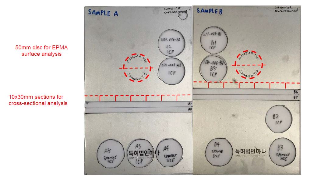
Figure 1: Location of discs and cross sections from the March 2016 samples.
124 The protocol used the notation of “sample A” and “sample B” to refer to the samples of the March 2016 samples marked as such in Figure 1.
125 Stage 1 being sample preparation involved the following steps:
(a) Using a scribe, a 50mm diameter circle was to be marked near the centre of samples A and B as depicted in Figure 1 being the intended punch locations.
(b) Using a scribe, each 50mm diameter circle was to be marked with the sample name (either sample A or sample B) and the side (either top or reverse), as depicted in Figure 1.
(c) After the samples had been labelled, the labelled 50mm diameter circles were to be punched from each sample.
(d) Each disc was to be sheared in half as indicated by the red, dotted, horizontal line in Figure 1, maintaining the labels on each half. The sample was to be trimmed, if necessary, to ensure the sample was properly located on the Electron Probe Microanalyzer (EPMA) to be used at the relevant stage. All burs were to be removed.
(e) One 10mm slice was to be sheared across the full strip width of samples A and B, and cut into 30mm lengths (for 40mm diameter mounts) as indicated in Figure 1 in preparation for metallographic mounting and polishing of the 30mm long edge.
(f) Each 30×10mm section was to be placed into a separate contamination free plastic bag and the section location was to be recorded on each bag.
126 Stage 2 being to assess the Mg2Si surface presence or elemental surface mapping involved the following steps:
(a) A Jeol JXA-8530FPlus HyperProbe Electron Probe Microanalyzer (FE-EPMA) was to be used.
(b) For each half (top and reverse) of the two 50mm diameter discs, four separate areas were to be mapped, selected randomly but spaced at least 10mm apart.
(c) Each area mapped was to be 500x500µm, at a resolution of 1µm per pixel, using a beam dwell time of 50 milliseconds [the original protocol incorrectly referred to mm rather than µm].
(d) The maps were to be generated using electron beam settings of 5kV for the accelerating voltage and a beam current setting of 50 nanoAmps. This accelerating voltage and beam current setting were to be used throughout the experiment for all FE-EPMA analysis to ensure that the FE-EPMA analysis was not affected by using different parameters. The parameters used for each FE-EPMA analysis were to be recorded.
(e) The elemental maps for Mg, Si, Zn were to be measured by wavelength dispersive spectroscopy and captured as separate grey scale images.
(f) The characteristic x-rays and spectrometer crystals to be used for each element were: Mg: Kα on TAPH crystal, Zn: Lα on TAPH crystal and Si: Kα on TAP crystal.
(g) A professional grade photo editing software tool, such as COREL Paint Shop Pro, was to be used to convert each grey scale elemental map to a colour and each map was to be saved as a separate file.
(h) The following colours and settings were to be applied to the individual elemental x-ray map of the specified element:
(i) Mg x-ray map = Red (gamma setting: 4, grey scale offset: -4).
(ii) Si x-ray map = Green (gamma setting: 4, grey scale offset: -4).
(iii) Zn x-ray map = Blue (gamma setting: 3, grey scale offset: -0).
(i) To identify Mg2Si particles on the surface, a professional grade photo editing software tool, such as COREL Paint Shop Pro, was to be used to create a composite image of the red, green and blue coloured elemental x-ray maps. Mg2Si particles would appear as a yellow/orange coloured particles in the composite image.
(j) The surface area fraction of all identified Mg2Si was to be measured using standard image analysis software and techniques. The surface area of the Mg2Si was to be reported as a % of the total surface area imaged.
127 Stage 3 being the coating thickness measurement involved the following steps.
128 As to the sample preparation steps:
(a) Each 10mmx30mm length of samples A and B was to be mounted in a cold mount resin (such as Epofix) to allow preparation and viewing of the cross-section of the 30mm edge of each length. A 30mm length would be chosen by example as being appropriate for a 40mm diameter mount, where three to four lengths could be put into each mount.
(b) The strip was to be polished to a 1-3μm diamond finish using standard metallographic grinding and polishing techniques, specifically avoiding edge rounding or staining/corrosion of the Mg2Si or the metal coating. An alcohol based diamond polishing lubricant such as Struers “DP-Lubricant Yellow” and absolute ethanol for cleaning would be used for the final stages of polishing to assist with the prevention of corrosion and staining.
129 As to the image capture methodology:
(a) The metal coating thickness of one side of the strip would be measured at intervals of 0.5mm along each 30mm (a total of 60 measurements per 30mm cross-section) polished metallographic cross-section using an optical microscope at a magnification of 1000x, and the results recorded.
(b) The metal coating thickness measurement would be repeated on the reverse side of each cross-section.
(c) Cross-section images of the coating at 1000x magnification would be captured and saved for each side of each cross-section.
(d) The microscope images would be calibrated using a certified calibration slide.
130 As to calculating average metal coating thickness, for each cross-section image, the average metal coating thickness (AMCT) would be calculated as follows:
(a) One would threshold each image to highlight the area from the steel/alloy layer interface to the external metal coating surface.
(b) One would measure the highlighted area in square microns.
(c) One would measure the width of the image in microns.
(d) One would calculate the AMCT by dividing the highlighted area by the width of the image.
131 As to the metal coating thickness variation measurement:
(a) A 5mm width of cross-section (10 consecutive images long) would be randomly selected (see Figure 2 below).
(b) The maximum AMCT measurement from the 10 consecutive image measurements, denoted as AMCTmax, would be identified and recorded. The minimum AMCT measurement from the 10 consecutive image measurements, denoted as AMCTmin, would be identified and recorded.
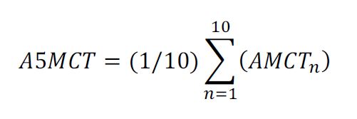
(c) The average 5mm width metal coating thickness (A5MCT) would be calculated using the following formula:
(d) Thickness variation would be calculated according to the following formula:
Thickness Variation = (AMCTmax – AMCTmin) / A5MCT
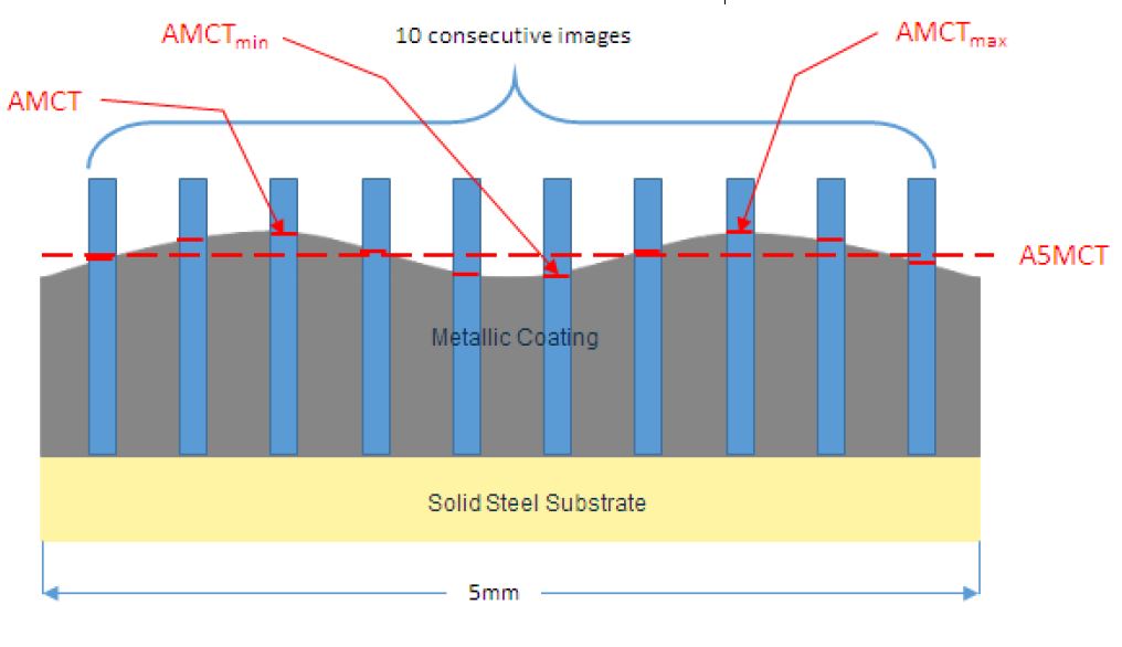
Figure 2: 5mm width cross-sections (10 consecutive images long)
132 As to the full width metal coating thickness measurement, one would separately calculate the top and reverse full width average metal coating thickness (FWAMCT) according to the following formula:
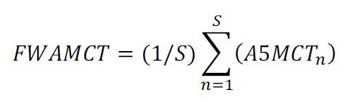
Where S = Total number of consecutive 30mm mounted sections covering full width of strip.
133 Stage 4 being an assessment of the proportion of Mg2Si in the cross-sections involved the following steps:
(a) The metallographic cross-sections previously prepared for optical thickness measurements were to be used for this stage.
(b) The first and last cross-sections from each of samples A and B (four cross-sections in total) would be selected for analysis.
(c) FE-EPMA would be used to create elemental maps.
(d) Elemental maps for Mg, Si, Zn of the top and bottom metallic coated surfaces of the four selected cross-sections would be measured by FE-EPMA/WDS.
(e) Two 150μm wide areas, five millimetres apart, on each selected metallic coated cross-section would be mapped (see Figure 3), at a resolution of 0.2µm per pixel, using a beam dwell time of 50 milliseconds. Each cross-section map would include the full thickness of the coating.
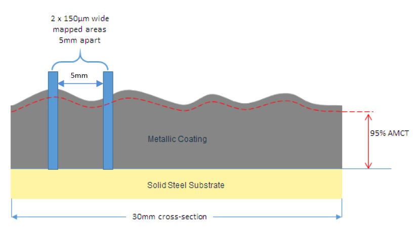
Figure 3: Image of one selected 30mm cross-sections showing the two 150μm wide mapped areas
(f) The maps would be generated using electron beam settings of 5kV for the accelerating voltage and a beam current setting of 50 nanoAmps (i.e., the same parameters used in Stage 2, step (d) that I have set out earlier).
(g) The elemental maps for Mg, Si, Zn would be measured by WDS and captured as separate grey scale images.
(h) The characteristic x-rays and spectrometer crystals to be used for each element were: Mg: Kα on TAPH crystal, Zn: Lα on TAPH crystal and Si: Kα on TAP crystal.
(i) A professional grade photo editing software tool, such as COREL Paint Shop Pro, would be used to convert each grey scale elemental map to a colour and each map would be saved as a separate file.
(j) The following colours and settings would be applied to the individual elemental x-ray map of the specified element:
(i) Mg x-ray map = Red (gamma setting: 4, grey scale offset: -4).
(ii) Si x-ray map = Green (gamma setting: 4, grey scale offset: -4).
(iii) Zn x-ray map = Blue (gamma setting: 3, grey scale offset: -0).
(k) To identify Mg2Si particles on the surface and in the cross-section, a professional grade photo editing software tool, such as COREL Paint Shop Pro, would be used to create a composite image of the red, green and blue coloured elemental x-ray maps. Mg2Si particles would appear as a yellow/orange coloured particles in the composite image.
(l) The cross-sectional area of all identified Mg2Si particles within each 150μm wide mapped area would be measured using standard image analysis techniques available in proprietary image analysis software tools, such as Olympus’ analySIS Pro.
(m) The cross-sectional area of all identified Mg2Si particles within each 150μm wide mapped area that were in contact with the external surface of the metal coating would be isolated and measured as depicted in Figure 4 below.
(n) To calculate the proportion of Mg2Si particles in the surface in respect of each mapped area, the cross-sectional area of the Mg2Si particles determined to be in the surface would be divided by the cross-sectional area of all Mg2Si particles.
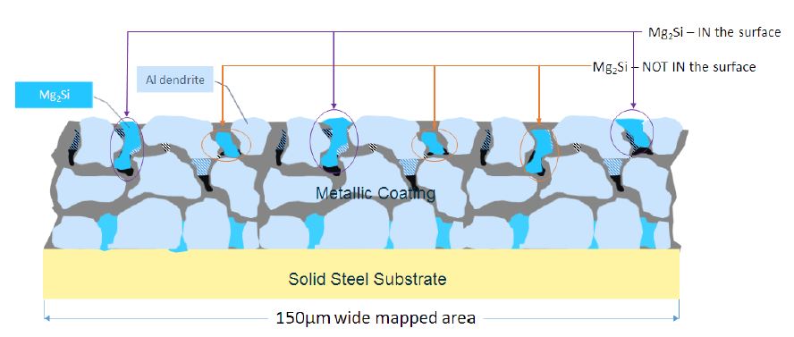
Figure 4: 150μm wide mapped area identifying the Mg2Si particles in the surface and not in the surface
(o) To calculate the proportion of Mg2Si particles in the top 5% of the AMCT (258 Patent, claim 2):
(i) one would, using the steel substrate/alloy layer interface as the reference line, measure the cross-sectional area of Mg2Si that resided above 95% of the AMCT (see Figure 5 below);
(ii) one would calculate the proportion of Mg2Si in the 5% thickness surface region by dividing the cross-sectional area of Mg2Si residing above 95% of the AMCT by the total cross-sectional area of Mg2Si in the mapped area.
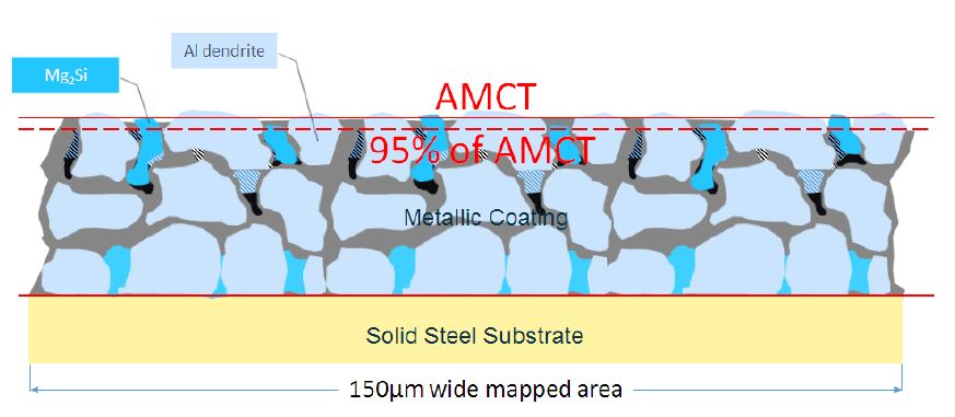
Figure 5: 150μm wide mapped area identifying Mg2Si particles residing above 95% of the AMCT
(p) All measurements and calculations were to be recorded.
134 At the conclusion of the experiments and measurements, the remainder of the March 2016 samples together with the discs and strips used for the measurements were to be securely stored in the same plastic sleeve packaging the March 2016 samples were supplied to BlueScope in. The remainder of the March 2016 samples together with the discs and strips were to be accessible to Dongkuk on request.
BLUESCOPE’S APPLICATION OF THE PROTOCOL
135 The experiments necessary to apply the protocol were conducted by Dr Stewart Ford, metal coating and characterisation specialist, Ms Louise Hodges, metallographer and coating analyst, and Mr Leslie Moore, metallurgist of BlueScope.
136 The experiments produced the following images:
(a) Cross-sectional images (side view): A1 – A8, and B1 – B8 (16 cross-sections in total).
(b) Surface images (top view): A Top, A Rev, B Top and B Rev (4 half discs in total).
137 The experiments produced measurements of:
(a) coating thickness measurements (cross-section), which were relevant to all claims;
(b) the proportion of Mg2Si in the surface of the coating (cross-section), which was relevant to all asserted claims of the 257 Patent except claim 15;
(c) the amount of Mg2Si at the surface of the coating (surface), which was relevant to claim 15 of the 257 Patent;
(d) the proportion of Mg2Si in a surface region of the coating that had a thickness that was less than 30% of the total thickness of the coating (cross section), which was relevant to claim 1 of the 258 Patent and dependent claims, although I note that BlueScope does not now press its allegation of infringement concerning claim 1; and
(e) the proportion of Mg2Si in a surface region of the coating that had a thickness that was at least 5% of the total thickness of the coating (cross-section), which was relevant to claim 2 of the 258 Patent.
(a) The conduct of the experiments
Calculation of the AMCT
138 The AMCT calculated for each optical image is a measurement of the area of the coating from the interface of the steel substrate and alloy layer to the external metal coating surface (in μm2) divided by the frame width of the image (in μm).
139 BlueScope measured eight 25mm x 7.5 mm cross sections from each of sample A and sample B. The protocol specified that the samples should be 30 mm x 10 mm. The reasons for diverging from the protocol were explained in the evidence of Dr Ford and Ms Hodges. In summary, the height of the material available was not 10 mm across the full strip, and as the mounts were 40 mm long, 30 mm sections would have been too long. These samples were sheared, creating sixteen cross sections (A1 – A8 and B1 – B8). Each cross section was placed into separate contamination free bags for cross sectional analysis.
140 The sixteen cross sections were divided into groups of four (A1 to A4, A5 to A8, B1 to B4 and B5 to B8). Each cross section was attached to a mounting clip and placed into a container and mounted in Epofix, a cold mounting resin. After the resin had cured, the cross sections were polished to a 3 μm diamond finish (or 1 μm, where required).
141 Using an optical microscope, BlueScope took 125μm wide images of the cross section of the coating, across the entire 25mm length, on both the top and reverse side of each cross section. Each cross sectional image for all but one sample was spaced at intervals of 0.5mm (four x 125μm) from centre to centre. One sample was measured at intervals of 0.52 mm, but was an error. On ten occasions of the 1579 images taken, the image location was varied by up to 50 μm due to unevenness in the intermetallic layer.
142 BlueScope took a total of 47 to 50 optical images per cross section.
143 To define the interface of the steel substrate and alloy layer and to ensure that the interface was horizontal, BlueScope rotated the images of the cross sections, when required, using the line of best fit approach to ensure that the area of alloy layer above and below the line was equal.
144 BlueScope adjusted the frame area of the cross section images to 122μm wide to exclude alterations to the border of the cross section image which result from the rotation and set the colour thresholds on the image analysis software program to include the metal coating and interface but to exclude the mounting resin.
145 The area of the coating was then measured in terms of square microns (μm2), and the AMCT was calculated by dividing the coating area (in μm2) by the frame width (in μm).
146 BlueScope repeated this process and measured the AMCT for each of the optical images, on both the top and reverse side for each of the sixteen cross sections. BlueScope took a total of 1579 AMCT measurements across each of the top and reverse side of the sixteen cross sections.
147 BlueScope recorded the raw data for each of the AMCT measurements in an Excel spreadsheet titled “171130 Thick Measurement Data and Summary”.
148 One of BlueScope’s experts Dr Tomáš Prošek, a materials engineer, considered that the interface of the steel substrate and alloy layer should be set at a different point and undertook his own measurements of the AMCT using the optical images taken by BlueScope.
149 But although Dr Prošek’s measurements of the AMCT varied slightly from BlueScope’s by between 3 and 5%, the difference was so small that it did not affect his calculations. Dr Prošek used BlueScope’s measurements to undertake his analysis.
150 Dr Prošek applied Chauvenet’s criterion, being a statistical theory that identifies data points from a set of data that are outliers, and concluded that the AMCT results for samples B7 Top 25, B7 Top 26, B6 Top 20, B7 Top 27, B7 Top 24, A5 Rev 34 and B5 Rev 29 were outliers. I will return to the question and treatment of outliers later.
151 Dr Prošek determined that the coating thickness of the GLX product was 17 μm or greater but less than 27 μm.
Calculation of the AMCTmin & AMCTmax
152 The evidence establishes that the distance between ten contiguous images from centre to centre was at least 5mm in diameter.
153 Given that Ms Hodges took approximately 47 to 50 images across the 25 mm diameter length of each cross-section sample, the results for 10 contiguous images had to be identified from the total of 47 to 50 images for that cross section to generate a 5mm diameter section.
154 On this basis, Dr Prošek first satisfied himself that the thickness calculations across a random sample of 10 contiguous images, which represented a 5mm diameter section, was representative of the thickness calculation across any random 5mm diameter section.
155 To identify a “representative” 5mm diameter section for testing, BlueScope prepopulated a formula into its thickness measurement spreadsheet. The formula randomly selected the results from ten consecutive AMCT measurements and identified the AMCTmax and the AMCTmin for that sample of ten AMCT measurements.
156 BlueScope also prepopulated the following formulas, which I have set out earlier, in its thickness measurement spreadsheet:
(a) The formula to calculate A5MCT:
(b) the thickness variation across a 5mm diameter section being:
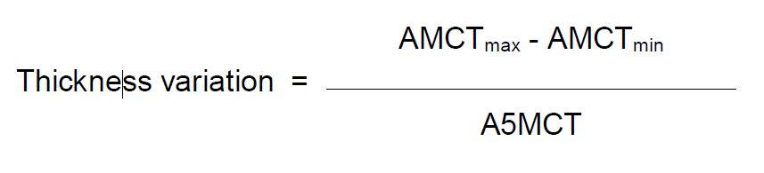
(c) the formula for FWAMCT being:
157 I would note that for the last formula “S” is equal to 8, the total number of cross sections across the full width of each of samples A and B.
158 BlueScope’s thickness measurement spreadsheet was used to randomly select ten contiguous AMCT results representing a 5 mm diameter section, and to calculate the A5MCT, and the thickness variation for the 5 mm diameter section based on the above formulas.
159 The thickness measurement spreadsheet recorded an A5MCT measurement and thickness variation measurement for each side (top and reverse) for each of the sixteen cross sections (A1 to A8 and B1 to B8).
160 The thickness measurement spreadsheet randomly generated different A5MCT and thickness variations for a 5mm diameter section contained within the same cross section sample by randomly selecting a new starting point measurement for each A5MCT measurement.
Calculation of the FWAMCT
161 The thickness measurement spreadsheet used the eight A5MCT results from each side (top and reverse) for each of the eight cross sections (A1 to A8 or B1 to B8) to calculate the FWAMCT of the sample for both the top and reverse side of sample A and sample B.
162 Dr Prošek confirmed that the thickness variation calculation across a random sample of ten AMCT measurements was representative of the thickness variation across any ten AMCT measurements.
163 To undertake his analysis, Dr Prošek selected a random sample of ten images for each of the sixteen cross sections (both for the top and reverse side).
164 Dr Prošek concluded that for sample A, the thickness variation across a 5mm diameter section varied between 8% and 26%, and for sample B varied between 6% and 51%.
165 I would note that Dr Prošek did not identify thickness variations of between 39.8% and 112.3% for sample B7 as identified by Professor Michael Cortie, a physical metallurgist and one of Dongkuk’s experts, because the ten images Dr Prošek randomly chose from the total of 50 images for cross-section sample B7 Top did not include samples B7-Top-25 and B7-Top-26.
166 Using statistical principles, Dr Prošek concluded that for cross section B6 Top, the thickness variation calculation of 51% was as a result of an outlying thickness measurement B6 Top 20, being the twentieth AMCT measurement for cross section B6 on the top side, which was an exception and should be excluded.
167 Dr Prošek concluded that the thickness variations (excluding B-Top-6), were significantly lower than 40% and 30%.
(b) Calculating the amount of Mg2Si particles at the surface of the sample
168 Before getting into the detail, let me note some aspects of metallurgy that were not controversial.
169 The metallurgy of Al-Zn-Si-Mg coatings is dependent upon the formation of the coating microstructure and the intermetallic phases formed within the coating microstructure.
170 The initial phase to form when the coated steel strip is solidifying is the intermetallic layer or “alloy layer”. The intermetallic layer forms at the interface between the steel substrate and the metallic coating, and it begins to form as the steel strip is submerged into the coating bath. In general, the intermetallic layer consists of Fe-Al-Si intermetallic compounds.
171 The metallic coating primarily consists of the Al-dendrites, which is the second phase that begins to form. Zn and Mg are soluble in Al, so the Al-dendrites will contain significant concentrations of Zn and a small amount of Mg. On the other hand, Si is relatively insoluble in Al, so the Al-dendrites will only contain insignificant amounts of dissolved Si.
172 Most of the Zn, Mg and Si is rejected from the growing Al dendrites, resulting in a liquid enriched in Zn, Mg and Si. As the coating is cooled, most of the Si and some of the remaining Mg, being from the Zn, Mg and Si rich liquid, forms Mg2Si, meaning that the remaining liquid is enriched with Zn and Mg. Some Si precipitates as metallic Si. The remaining Zn and Mg enriched liquid forms MgZn2.
173 The final liquid of the metallic coating to solidify results in a complex eutectic mixture of Al, Zn and Mg rich phases, including MgZn2, Mg2Si, Zn-MgZn2-Al, Zn-5%Al and metallic Si.
174 The formation of the coating microstructure is complex, and requires the right chemistry, solidification path and thermal processing.
175 To determine the location and amount of the Mg2Si phase in the coating, it is necessary to devise a process to detect and identify the Mg2Si phase of interest in analytical samples of the coating. This process is generally known as thresholding.
176 As I have referred to earlier, BlueScope measured and sheared one 50 mm disc from each of sample A and sample B. Each 50 mm disc was sheared in half creating four half discs (A Top, A Rev, B Top and B Rev) and placed into separate, labelled, contamination free bags for EPMA surface analysis. The samples were cleaned with ethanol and compressed air, and carbon coated to a thickness of approximately 15 nm to prevent the samples from becoming electrically charged by the electron beam.
177 An FE-EPMA was used to ascertain the microstructure of the GLX product. Separate areas for each half disc were mapped. The areas were mapped at a resolution of 1 μm per pixel. An accelerating voltage of 5 kV and a beam current setting of 50 nanoAmps was used. The areas mapped were randomly selected.
178 The FE-EPMA scanned each 1 μm pixel within each of the mapped areas of each half disc to identify the elements present in the pixel. Using wavelength dispersive spectrometry and characteristic x-rays and spectrometer crystals, spectrometers within the FE-EPMA captured the X-rays of the elements of interest (Mg, Si and Zn) that were diffracted, creating elemental maps for each of Mg, Si and Zn for each mapped area. Each elemental map was a spreadsheet containing a number of X-ray counts for each pixel mapped.
179 Mr Moore recorded the minimum and maximum X-ray count values for each of the Mg, Si and Zn maps from each mapped area of sample A, and entered these values into an in-house purpose built program to convert each elemental map from its original 4 byte integer csv file format into a 1 byte grey scale, bitmap image.
180 Although there is no real top limit to the value of the X-ray counts, the average maximum and minimum values ranged from:
(a) 12 to 578 for Mg;
(b) 6 to 690 for Si; and
(c) 22 to 464 for Zn.
(c) Creation of the RGB (red, green, blue) map
181 Mr Moore produced a colour map that identified the location of the Mg2Si particles (as yellow phases), so that he could find the corresponding area of the Si map corresponding to the Mg2Si phase.
182 A professional grade photo editing software tool, COREL Paint Shop Pro, was used to convert each of the X-ray grey scale elemental maps to a colour map by applying specified colours and gamma and offset value settings to the individual elemental X-ray map of each element by attributing red to the Mg X-ray map, green to the Si X-ray map and blue to the Zn X-ray map. The gamma setting and grey scale offset values were applied to improve the visual delineation of the boundary of the Mg2Si phase, to compensate for any effect of ZAF factors, which I will explain in a moment. Mr Moore explained that the gamma correction enhanced the separation between the metallic Si and Mg2Si, the MgZn2 and the Mg2Si, and the Zn rich interdendritic regions and the Al-dendrites, to discriminate between the Mg2Si from the surrounding matrix.
183 Each of the gamma corrected Si, Mg and Zn elemental maps were combined to create a composite red, green, blue (RGB) image, where the Mg was depicted as red, Si as green and Zn as blue, where Mg and Si together was depicted as yellow, and where Mg and Zn was depicted together as purple.
184 Once an RGB map was generated, Mg2Si regions were identified by their yellow colouration.
185 According to Mr Moore, the above process took into account any ZAF factors because the gamma correction minimised any variations in the Mg:Si ratio, enhanced the yellow pixels and created a clear boundary of the Mg2Si evidence in the RGB map.
186 As Mr Moore explained it, ZAF factors refers to the factors that affect electron microscopy, namely atomic number (Z), absorption (A) and secondary fluorescence (F). Let me set out his description which I did not understand to be controversial.
187 “Z” refers to the atomic number (Z) factor, being of course the number of protons in the nucleus of an atom, which also characterises where an element appears on the periodic table. The Z factor describes how the atomic number of the element contributes to the resulting X-ray yield result. As the electron beam hits the sample, the electrons spread within the sample and may generate X-rays that are detected by the EPMA. When the electrons collide with the atoms in the sample, the electrons begin to lose energy. The rate of energy loss depends on the elements present in the sample. Part of the electrons will backscatter and will not penetrate the sample, which is also dependent on the elements in the sample. These two factors are mainly dependent on the atomic number of the sample. The X-ray yield for widely varying atomic numbers, i.e. elements that are far apart from each other on the periodic table, can result in quite a large difference in X-ray yield and therefore any effect of Z factors must be corrected.
188 “A” refers to the absorption of the X-rays as they exit the sample, being the portion of the generated X-rays that are absorbed by the atoms in the specimen, and not released from the sample, and therefore not detected by the detector. The amount of absorption of the X-ray is also dependent on the atomic number because different elements absorb X-rays from other elements to different extents. If the energy of the X-ray is above the absorption edge energy of the atoms in the material it is exiting through, it may be absorbed. By absorption edge energy is meant the energy at which there is a sharp rise in the absorption coefficient of X-rays by an element.
189 “F” refers to the secondary fluorescence of X-rays by other X-rays, where the other X-rays can be from the background spectrum or from other elements. By this is meant that there may be instances where the electron collides with element Z and generates an X-ray. But such an X-ray, rather than being detected by the detector, may be absorbed by element Y, and that absorption may then give rise to the generation of an X-ray from element Y which is then detected. In such circumstances the detector will detect an X-ray from element Y, rather than from element Z.
190 In the Al-Zn-Si-Mg coating system, Mg, Al and Si are consecutive elements in the periodic table. Therefore the effect of atomic number on the Z factor is relatively minor. But the effect of absorption of the X-rays (the A factor) and the secondary fluorescence of X-rays (the F factor) is significant because of the Al present. This is because Al Kα X-rays have a higher energy line than the Mg Kα absorption edge, meaning Al X-rays can be absorbed by Mg, resulting in the fluorescence of Mg X-rays rather than Al X-rays. This erroneously increases the yield of the Mg X-rays generated and subsequently detected by the FE-EPMA. The effect of Al X-rays on the Mg yield is greater than Si X-rays, because Al is closer to the Mg Kα absorption edge.
191 In the course of Mr Moore’s work with Al-Zn-Si-Mg coatings, he undertook extensive modelling to investigate geometry and spatial resolution issues in microanalysis. As part of his work, he investigated the quantitative microanalysis of Mg2Si entities within an Al matrix at different accelerating voltages of 5kV, 7kV, 10kV and 15kV.
192 The modelling showed that a presence of 5% Al in the interaction volume would result in an error of more than 1 % in the wt% of Si and Mg measured in the final analysis of Mg2Si. For this reason, according to Mr Moore, the contribution of Al X-rays from the dendrites immediately underneath the Mg2Si had to be kept to a minimum. This required fine spot sizes and low kV to minimise the depth of penetration. The effect of Al on the Mg:Si ratio for various kV and phase sizes depicted as ɸ (in μm) is shown in Figure 6 below.
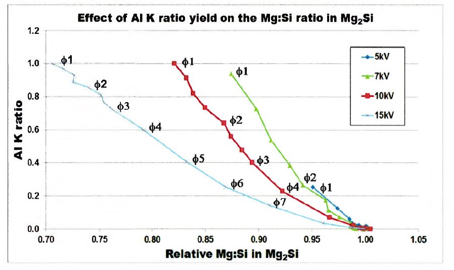
Figure 6: Effect of Al Ka presence (expressed as a K ratio) on the Mg:Si ratio for various kV and phase sizes (ɸ)
193 In Mr Moore’s view, the thresholding procedure he established was sound and comprehensively took into account any ZAF factor effect of the Al in the substrate to mitigate these effects. This was because of the use of the gamma transformation of the RGB images, and the use of a statistically based thresholding technique.
(d) Silicon map
194 Using the RGB map as a visual guide to identify the location of the Mg2Si phases, BlueScope reviewed the data from five of the Si elemental maps, being the raw data produced from the EPMA machine without any gamma correction applied, and identified the Si X-ray counts that were associated with Mg2Si regions. Mr Moore chose the Si X-ray counts from pixels that were wholly contained within the Mg2Si particle, avoiding the boundaries, to avoid including a Si X-ray count that related to a different phase.
195 BlueScope extracted, culled and assembled the Si X-ray counts from the five separate Mg2Si regions, and calculated the Si X-ray count lower threshold associated with the Mg2Si data array, by subtracting three standard deviations from the average Si X-ray count. According to Mr Moore, each of the Si X-ray counts was a Poisson variant, such that he could be confident that the average of a normal distribution was also normal.
196 Mr Moore obtained a Si X-ray count value that he was confident was the minimum value to represent a Mg2Si X-ray count, and that any value below the threshold value would not represent an Mg2Si phase. The threshold X-ray count value for Si that was determined by Mr Moore was 101, where the minimum Si X-ray count was 6.
197 Because the image analysis software Mr Moore used worked within a range of zero to 255, the threshold value was converted to a 0-255 grey scale value. The grey scale threshold value for Si was 35.
198 Using COREL Paint Shop Pro, BlueScope applied this grey scale value to each Si X-ray map to generate a binary image in which only the Si pixels, that is, those pixels containing an X-ray count higher than the Si X-ray count threshold of 35, were highlighted white; the balance of the image representing other elements was black.
199 This process removed (by blacking out) those pixels in the binary map that contained an X-ray count value below the threshold value. The resulting binary Si map only identified pixels as white pixels containing both metallic Si and Mg2Si.
200 To exclude the metallic Si, and to create a map that contained only Mg2Si, Mr Moore combined the Si map together with the Mg map. But in some specific cases this method did not exclude all of the metallic Si.
(e) Magnesium map
201 BlueScope then manually thresholded the Mg elemental maps by visually comparing the Mg2Si phases present in the Mg grey scale map with the Mg2Si present in the RGB maps.
202 Because of the innate statistical variations for Mg and this manual thresholding procedure, the Mg threshold image could be smaller than the Si threshold image. According to BlueScope the binary image of Mg and Si could under-represent the number of pixels associated with Mg2Si.
203 To overcome this problem and avoid improperly culling Mg2Si pixels, BlueScope dilated the Mg thresholded map by a factor of two pixels. But in some cases the dilation operating inflated the size of the Mg2Si.
204 BlueScope then used the COREL Paint Shop Program to create a binary map of Mg2Si, and used the measure function on the image analysis program ImageJ to measure the surface area percentage of Mg2Si as a percentage of the total image area.
205 The average area fraction for sample A was 0.15%, with the individual measurements varying between 0.07% and 0.23%.
206 The average area fraction for sample B was 0.23%, with the individual measurements varying between 0.08% and 0.38%.
207 Now because this calculation compared the proportion of Mg2Si particles to all phases of the coating rather than comparing the Mg2Si particles to Mg2Si particles in the entire microstructure, the area fraction did not equal the weight fraction or weight percent.
208 But Dr Prošek explained that the average area fraction corresponded to the average volume fraction, and the average weight fraction (or wt.%) could be calculated as follows:
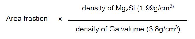
209 Galvalume was used as a proxy because the presence of Mg would have an insignificant effect on the overall density of the Al-Zn-Si-Mg product. Since the density of Mg2Si is 1.99 g/cm3 and the density of galvalume is 3.8 g/cm3, the weight fraction of Mg2Si particles could be estimated from the area fraction by multiplying the area fraction with a coefficient of 0.52 (1.99/3.8).
210 So adjusting, for sample A the relevant proportion was 0.08%, and for sample B the relevant proportion was 0.12%.
(f) Calculating the proportion of Mg2Si particles in the surface of the coating (cross section)
211 BlueScope cleaned the first and last cross sectional samples of samples A and B (A1, A8, B1 and B8) with ethanol and compressed air, and carbon coated the cross sections to a thickness of approximately 25 nm. BlueScope used FE-EPMA to map two 150 μm x 32 μm (or 40 μm depending on the sample) areas for each of the four cross sections, at a resolution of 0.2 μm, resulting in elemental maps for Mg, Si and Zn for each mapped area.
212 BlueScope thresholded each of the Si and Mg maps (and then dilated the Mg map by two pixels) and created a binary map of Mg2Si for each mapped area.
213 BlueScope identified all of the Mg2Si particles in the surface of each mapped area, and using ImageJ, measured the cross sectional area of all the Mg2Si particles in the surface, divided by the cross sectional area of all Mg2Si particles present in the total image.
214 As Dr Prošek explained, since this proportion compared the distribution of Mg2Si particles only, the area fraction was equal to the weight fraction or weight percent. For sample A, this proportion was 0.42% and for sample B, 0.40%.
(g) Calculating the proportion of Mg2Si particles in the top 5% of the thickness of the coating of the samples
215 Let me deal with the top 5% aspect. Mr Moore explained the matter in the following terms.
216 Stage 4 of the protocol identified that the steel substrate / alloy layer interface would be used as the reference line to delineate between the top 5% of the AMCT and the bottom 95% of the AMCT. But during the conduct of the experiments it became apparent to Mr Moore that the unevenness and angle of the interface affected the estimation of the top 5% of the AMCT. Mr Moore chose to use a line of best fit approach to locate this boundary, which allowed for angle and irregularities in the interface.
217 Using the Back Scattered Electron (BSE) images, Mr Moore recorded the number of pixels in the X- and Y-axis in an Excel spreadsheet entitled “Mg2Si In top 5% Area Calculation”. This spreadsheet automatically calculated the number of pixels in the whole image by multiplying the number of pixels in the X-axis by the number of pixels in the Y-axis.
218 From Mr Moore’s experience he understood that the average grey level on a 0-255 scale for a thresholded black and white image would be a rough estimate of the area of the image coloured in white, when divided by the upper limit of the grey scale, being 255. Given that each of the BSE images were black and white images, where the coating was coloured in white, he understood that he could use the average grey level to calculate the area of the coating as a percent of the whole image.
219 Using the histogram palette on COREL Paint Shop Pro, he obtained the average grayscale for each of the BSE images and calculated the area of the coating as a percentage of the area mapped by dividing the average grey scale by 255 and multiplying by 100. He recorded the coating area percent for each mapped area into his spreadsheet, which automatically calculated:
(a) the number of the pixels in the coating, by multiplying the number of pixels in the whole image by the coating area percent divided by 100; and
(b) the 95% average thickness coating Y-axis coordinate (95% Avg Coating Thick Y-Axis) by dividing the number of pixels in the coating by the number of pixels in the X-axis (which in all cases was 750 pixels), multiplied by 95%.
220 Using the line of best fit model, he established the left (bottom) and right (top) Y-axis coordinates of the steel substrate / alloy layer interface (respectively, the Y-Axis Left and Y-Axis Right). According to Mr Moore, the line of best fit took into account any slope in the image and that the black pixels above the line balanced out with the white pixels below the line shown in Figure 7 below.
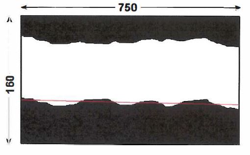
Figure 7: Image showing the line of best fit
221 He then subtracted each of the Y-Axis Left and Y-Axis Right from the 95% Avg Coating Thick Y-Axis to predict the left and right y-axis coordinates in the top 5% of the AMCT, shown by the blue line in the Figure 8 below.
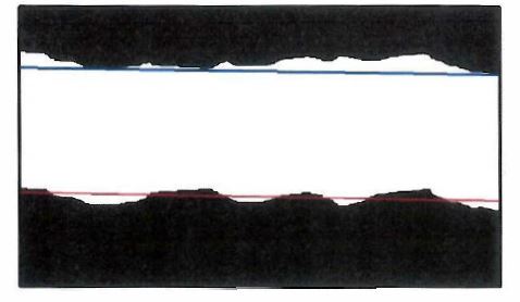
Figure 8: Image showing the line of best fit and the line estimating the top 5%
222 Using COREL Paint Shop Pro, he drew a 1 pixel wide black line on the image, which is shown by the blue line in the Figure above. He then deleted all of the pixels below the blue line, leaving just the top 5% of the AMCT in white, which is shown in Figure 9 below. Using ImageJ, he measured the area of the estimated top 5% of the AMCT, calculated as a percentage of the whole coating.
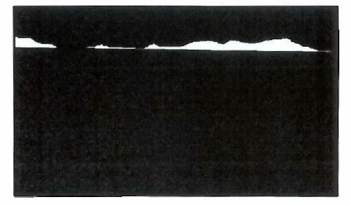
Figure 9: Image showing the top 5% of AMCT
223 If the area of the top 5% of the AMCT was greater than 5%, he moved the estimated top 5% line (as shown by the blue line in Figure 8) up, one pixel. Using ImageJ, he remeasured the area. He repeated this process until he had established the left (bottom) and right (top) y-axis pixel that corresponded to one pixel below the top 5%, and one pixel above the top 5%, of the AMCT, respectively, with the “true” 5% boundary falling somewhere between these two pixels. These steps deviated from the protocol which stated that the area above the 95% of the AMCT would be measured. Instead he measured the area falling one pixel above the 95% AMCT and one pixel below the 95% of the AMCT. He recorded the area of the boundary >5% and <5% in his top 5% area calculation spreadsheet.
224 Using ImageJ, he calculated the proportion of Mg2Si particles in the area one pixel above the top 5%, and the area one pixel below the top 5%. He recorded the results in that spreadsheet.
225 Let me summarise the above.
226 Using the total number of pixels in the coating, BlueScope calculated the y-axis coordinate that represented 95% of the average thickness of the coating. BlueScope then used the line of best fit approach to establish the left and right y-axis coordinates of the steel substrate/alloy interface, and then subtracted the 95% y-axis coordinate from each of the left and right y-axis interface coordinates to identify the left and right y-axis coordinates representing the top 5% of the coating.
227 BlueScope then drew a line from the y-axis 5% coordinate to the right y-axis 5% coordinate to mark off the area of the coating in the top 5% of the coating, and then measured the area of the coating. Because of the unevenness and angle of the steel substrate/ alloy layer interface, BlueScope identified that this process sometimes over or underestimated the top 5% of the coating. BlueScope then shifted the left and right y-axis coordinates one pixel up or down depending on whether the line of best fit approach over or under estimated the top 5% of the coating respectively, until the left and right y-axis coordinates that were one pixel above and one pixel below the true 5% boundary of the coating had been identified. BlueScope measured the total area of the coating falling one pixel above the 95% of the coating and the area falling one pixel below the 95% of the coating, and calculated the proportion of Mg2Si particles in each area. The “true” 5% boundary fell somewhere between these two pixels.
228 Since this proportion compared the distribution of Mg2Si particles, the area fraction was equal to the weight fraction or weight percent. Dr Prošek used the average of these assessments to calculate the amount of Mg2Si in the top 5% of the surface coating. He concluded that for sample A, the average total weight proportion of Mg2Si as a proportion of the overall weight percent of Mg2Si particles in the total coating microstructure in 5.06% of the total thickness of the coating was 1.22%. For sample B, the average total weight proportion of Mg2Si in 5.09% of the total thickness of the coating was 0.99%.
229 Let me just say something about Professor Cortie’s approach at this point.
230 According to BlueScope, based on Professor Cortie’s approach to delineating the surface region, he concluded that for sample A, the fraction of Mg2Si in at least 5% of the coating was 4.06%, and for sample B, the fraction of Mg2Si in at least 5% of the coating was 3.51%.
231 In the joint expert report, Professor Cortie said that if the data was aggregated for samples A and B, then the average weight proportion of Mg2Si in the top 5% of the coating was 1.1% ± 4.1% based on Mr Moore’s results, and 3.8% ± 3.6% based on Professor Cortie’s results.
232 Finally, given concessions made by BlueScope, it is not necessary to discuss the “top 30%” aspect further in the infringement context concerning claim 1 and some dependent claims of the 258 Patent.
DEFICIENCIES IN THE EXPERIMENTAL EVIDENCE
233 Before turning directly to the question of infringement I should first address another matter. Dongkuk’s experts made various criticisms of BlueScope’s experimental evidence. These criticisms and the response to them by BlueScope’s experts are set out below.
(a) Was the sample size sufficient?
234 BlueScope’s infringement evidence is based upon a single coil of the GLX product. More particularly, the experimental evidence is based on two A4 samples taken from a coil of the GLX product which were provided to BlueScope by Dongkuk on 16 March 2016.
235 Dongkuk’s experts, Professor Arnold Marder, a materials scientist and engineer, and Professor Cortie, have criticised BlueScope’s experimental evidence on the basis that the sample size tested by BlueScope was too small to conclude that the results were representative of the whole of the GLX product. But BlueScope says that the samples were representative, and the number of measurements taken was sufficient to characterise the whole of the GLX product. It says that I should find that the samples are representative, for the following reasons.
236 First, it is said that Dongkuk represented that the samples were representative of the GLX product. It is said that BlueScope relied upon the correctness of that representation in providing admissions of non-infringement sought by Dongkuk and in preparing the experimental protocol and its evidence on infringement in this proceeding. Accordingly it says that Dongkuk should not be allowed to resile from its representation.
237 Second, it is said that no expert has definitively concluded that the samples are not representative.
238 Third, it is said that Dongkuk has not led any evidence about the GLX product or the process by which it was made which would support the conclusion that the samples are not representative. Further and to the contrary, it is said that Mr Byoung Sun Moon, one of Dongkuk’s research engineers, was the witness best placed to comment on the issue and he gave evidence that the samples were representative of the coil from which they were taken.
239 Fourth, samples A and B were not materially different and samples A and B were the best evidence that was available to BlueScope.
240 Let me elaborate on BlueScope’s first assertion that Dongkuk represented that the samples were representative of the GLX product. It is said that Dongkuk consistently represented over the course of correspondence between 2014 and 2017 that the samples it provided to BlueScope were representative of the GLX product. It says that Dongkuk was aware when it made these representations that the samples it provided to BlueScope would be used by BlueScope to determine whether the GLX product infringed patents held by BlueScope. This occurred in two contexts. First, it occurred in the context of BlueScope considering whether to sue for infringement or provide Dongkuk with admissions of non-infringement in respect of various BlueScope patents including the 257 and 258 Patents. Second, it occurred in the context of BlueScope using the samples to prepare the experimental protocol and prove infringement of the 257 and 258 Patents.
241 Let me detail the relevant chronology, most of which was not contentious.
242 On 17 October 2014, Dongkuk’s solicitors offered to provide samples which would be representative of the product imported into Australia.
243 On 13 August 2015, Dongkuk’s solicitors wrote to BlueScope’s solicitors seeking a written admission of non-infringement in relation to four patents, although not the patents in suit. Dongkuk offered to provide samples of the GLX product for inspection, collection and testing subject to BlueScope providing a confidentiality undertaking.
244 On 2 September 2015, BlueScope’s solicitors wrote to Dongkuk’s solicitors accepting the offer to provide a sample for testing and asked for the sample to be sent to Dr Ford of BlueScope.
245 On 18 September 2015, Dongkuk’s solicitors confirmed that Dongkuk would provide a sample of its GLX product to BlueScope’s solicitors upon receipt of a confidentiality undertaking.
246 On 23 November 2015 BlueScope’s solicitors wrote to Dongkuk’s solicitors and attached copies of the 257 Patent and 258 Patent. BlueScope’s solicitors observed that BlueScope believed that it might have the right to obtain relief for the infringement or threatened infringement of those Patents.
247 In the letter of 23 November 2015, BlueScope’s solicitors also said:
Our client is concerned to ensure that the samples provided by your client for our client’s analysis are of a sufficient size and are identical to, and in all respects representative of, the “GLX Product” which your client has stated it has manufactured in Korea and is continuing to export to Australia, and intends selling or supplying in Australia or for distribution in Australia. While this may be implicit in your letter dated 13 August 2015 we have amended the undertaking to make clear our client’s reliance on this fact.
248 The amended confidentiality undertaking was attached. The recital read:
I, Dr Stewart Ford, being an authorised representative of BlueScope, of 120 Collins Street, Melbourne, Victoria 3000 undertake to Union Steel, and, in the event of any Proceeding, undertake to the Court, as follows, in consideration of the stipulation by Union Steel that the Materials [2 samples of Union Steel Products] are identical to, and in all respects representative of, the Union Steel Products.
249 This proposed undertaking dealt with a number of BlueScope patents including the 257 Patent and 258 Patent.
250 On 4 March 2016, Dongkuk’s solicitors wrote back and confirmed that it was agreeable to the form of the confidentiality undertaking, including the addition of the 257 and 258 Patents. The letter read:
Please provide us with the executed confidentiality undertakings, at which time we will forward 2 30 cm x 20 cm samples of the GLX Product, as well information in relation to the concentration of magnesium in the GLX Product to your office.
251 On 9 March 2016, BlueScope’s solicitors forwarded the executed confidentiality undertaking. The executed confidentiality undertaking was in the same terms as the proposed confidentiality undertaking. The Union Steel products referred to in the proposed undertaking and the executed undertaking referred to GLX product made on the same continuous coating line as the March 2016 samples.
252 On 16 March 2016, Dongkuk’s solicitors forwarded the two A4 samples to Dr Ford under cover of a letter which referred to the confidentiality undertaking. I have referred to these earlier as the March 2016 samples.
253 On 6 June 2016, BlueScope’s solicitors requested six additional sheets of the GLX product, 850 mm long in coating direction at strip width 900 – 1000 mm and strip thickness min 0.42 mm and a maximum of 0.7 mm, taken from coils produced in different weeks, so that it could conduct further tests.
254 On 6 June 2016, BlueScope provided a written admission that the GLX product did not infringe claims of four BlueScope patents, including claim 10 of the 257 Patent and claims 8, 9 and 10 the 258 Patent.
255 On 22 June 2016, Dongkuk’s solicitors refused the request for further samples on the basis that it was a fishing expedition.
256 On 13 July 2016, BlueScope’s solicitors wrote to Dongkuk’s solicitors and observed that BlueScope had experienced difficulty identifying samples of the GLX product in the market and required six samples of the GLX product from different runs to ensure the samples were representative. BlueScope’s solicitors asked Dongkuk either to provide samples or identify a supplier who would do so.
257 On 5 August 2016, Dongkuk refused to provide further samples.
258 On 18 August 2016, BlueScope’s solicitors re-agitated the request for the name of a supplier from whom BlueScope could obtain samples.
259 On 14 September 2016, Dongkuk’s solicitors identified a supplier.
260 On 24 November 2016, BlueScope ordered a further coil from a supplier.
261 On 14 December 2016, BlueScope commenced the present proceedings.
262 On 27 March 2017, BlueScope informed Dongkuk that its infringement case would be supported by testing to be undertaken on a coil of product to be acquired by BlueScope as an alternative to Dongkuk providing samples as requested (the May 2017 coil).
263 On 26 May 2017, BlueScope solicitors wrote to Dongkuk’s solicitors observing that the March 2016 samples had been provided on the basis they were representative but that its tests of the May 2017 coil which it had acquired raised serious concerns in relation to the identity of the products. BlueScope’s solicitors asked Dongkuk to explain the differences and confirm which of the products was representative of the product sold in Australia. BlueScope noted that until the issue was resolved, it was not in a position to propose an experimental protocol.
264 On 2 June 2017, Dongkuk’s solicitors wrote to BlueScope’s solicitors indicating that the March 2016 samples were production samples used for marketing and promotional purposes and produced as part of a trial product on a different manufacturing line from the line currently in use to manufacture the GLX product.
265 On 5 June 2017, BlueScope’s solicitors wrote to Dongkuk to confirm that it required further time to consider whether to pursue a case in respect of the GLX product which had been made prior to the changes identified by Dongkuk, that is, the change of line. The letter asked when the changes to the GLX product had been made and the volume of the old product which had been imported, supported or supplied, and stated that it was premature to develop an experimental protocol before this information was provided.
266 On 6 June 2017, the previous docket judge made orders for the provision by Dongkuk of the information sought. The order provided as follows:
By 20 June 2017, the Respondent provide in writing the following information:
(a) the date on which the changes to the production process for the GLX Product, identified in paragraph 6 of the letter from the Respondent’s solicitors to the Applicant’s solicitors dated 2 June 2017 (GLX Production Process Changes), were implemented; and
(b) the amount of the GLX Product, produced before the GLX Production Process Changes were implemented, which has been imported, sold or supplied in Australia, with the relevant summary financial reports of the Respondent being annexed to the affidavit.
267 On 20 June 2017, Dongkuk advised that it had used two different manufacturing lines to make the two GLX products tested, that is, the March 2016 samples and the May 2017 coil, that the line used was dependent on the quantity to be manufactured, and that there had been one sale of the GLX product made on the line which produced the March 2016 sample. That sale was approximately 52 tonnes being other than the supply of the two A4 samples to BlueScope’s former solicitors, which had been imported and sold in Australia. The letter confirmed that the use of that line ceased insofar as production for Australia was concerned after that supply. Dongkuk confirmed it was not using the line for the production of GLX product, and would not recommence use of that line for production of product for supply to Australia.
268 On 19 July 2017, BlueScope’s solicitors sent Dongkuk the proposed experimental protocol in support of its claim of infringement. The proposed protocol referred to the March 2016 samples, defined as the two A4 size samples which were provided to BlueScope by Dongkuk in March 2016. The facts to be proved were all referable to the March 2016 samples.
269 On 7 August 2017, Dongkuk’s solicitors responded. In the response, Dongkuk noted that the experiment was to be carried out on the two A4 size samples provided in March 2016 and that BlueScope had already undertaken at least one set of testing. Dongkuk noted it had not been provided with any information about the storage or treatment of the samples, and asked for information about these matters. Dongkuk raised the issue that the selection of samples did not cater for the possibility of the different spread of Mg2Si in the coating in other regions of the sample and asked BlueScope to consider an alternative approach to sample selection to accommodate this concern.
270 On 18 August 2017, BlueScope amended its statement of claim to limit its claim to the GLX product, representative samples of which were the March 2016 samples. BlueScope’s particulars recited that the March 2016 samples had been provided by Dongkuk’s solicitors purportedly on the basis they were representative of the GLX product.
271 By a letter dated 5 September 2017, BlueScope’s solicitors confirmed that testing of the March 2016 samples to date had been undertaken by punching discs from the samples or shearing strips from near the centre of the samples, and that the sheets had been stored inside the HANA Intellectual Property Law A4 plastic sleeves in which they were provided by Dongkuk. Those plastic sleeves were in turn placed inside another plastic sleeve and securely stored in an air conditioned environment at BlueScope’s facilities. The letter attached a revised experimental protocol which included images of the samples, showing the sections that had already been taken for testing and the sections that were to be taken. BlueScope’s solicitors confirmed that the remainder of the sample would be stored and would be available to Dongkuk on request. The letter said:
Our client has considered your client’s request for an alternative approach to sample selection to accommodate your client’s concern that the sample selection does not cater for the possibility of a different spread of Mg2Si in the coating in other regions of the sample. As the protocol indicates, our client intends to take samples from both A4 sheets provided by your client. Since your client has indicated that the samples are representative of the GLX Product, our client considers it reasonable to take a sample from anywhere on the A4 sheet as being representative of the GLX Product. If your client considers that two 50mm samples are insufficient and wishes us to adopt an alternative approach to sample selection, please propose an approach for our client’s consideration. Our client wishes to avoid any later argument that the samples tested were not representative whilst being realistic about the time and cost involved in repeating the experimental work across even more samples.
272 BlueScope confirmed that the May 2017 coil which it had acquired did not infringe the 257 Patent or the 258 Patent.
273 On 10 October 2017, Dongkuk responded to BlueScope’s letter of 5 September 2017 and the revised protocol which was enclosed. Dongkuk asked BlueScope to provide a copy of the thresholding protocol. BlueScope sent the thresholding procedure to Dongkuk by letter of 14 November 2017. Dongkuk said:
Other than this issue, and our client’s maintenance of its position as to the desirability of conducting LA-ICP/XRD testing as explained below, Dongkuk has no further comments on the substance of your client’s proposed experimental protocol.
274 BlueScope says that the correspondence as a whole shows that Dongkuk, through its solicitors, represented that the March 2016 samples were in all respects representative of the GLX product.
275 BlueScope says that Dongkuk should not now be permitted to resile from the representation that the samples were representative of the GLX product. Further, it says that Dongkuk should not be permitted to argue that the testing undertaken under the experimental protocol was not adequate, given that it did not raise this objection following receipt of BlueScope’s letter of 5 September 2016.
276 Let me now elaborate on BlueScope’s second point. It says that no expert has definitively concluded that the samples are not representative.
277 It says that Mr Moore was not asked, and did not give evidence, that samples A and B were not capable of being representative.
278 The substance of Mr Moore’s evidence was that he did not know whether the samples were in fact representative. He explained that although “notionally”, there might be different variability from one area to another arising from Dongkuk’s process, this was a point of speculation, and that he could not address Dongkuk’s process.
279 Further, whilst Mr Moore gave evidence that he would prefer to take three samples (quarter, centre, quarter), this did not mean that samples A and B were not representative.
280 Further, BlueScope says that Professor Marder did not positively assert that the data was not representative. He merely said:
And right now I would be perfectly happy to say that the BlueScope protocol was the correct protocol for analysing a coil or establishing whether a coil is good or not. But I have not seen the data that says that their small specimen of 2.5 millimetres squared is equivalent to a ten tonne coil. If they had done that, then that would be fine and we would not have a disagreement. But right now there is nothing that tells me that there is a characterisation of the entire coil based on 2.5 millimetres squared.
281 Moreover, according to BlueScope, the evidence given by Professor Cortie was also speculative. He provided no substantive basis for his view that “you would need to sample lots and lots of places in that coil”.
282 Let me elaborate on BlueScope’s arguments concerning its third point, which is related to the second point. It says that Dongkuk has not led any evidence about the GLX product which supports the conclusion that the samples are not representative. It says that Dongkuk has advanced no positive evidence that the samples tested by BlueScope were not representative of the characteristics of the Dongkuk coil from which they were taken. It says that Dongkuk could have advanced experimental evidence of its own to make good its contention that samples A and B were not representative. In this respect it could have conducted its own tests, either on samples A and B or on the same line.
283 BlueScope submits that given that Dongkuk could have led evidence that the samples tested were atypical of the GLX product in suit, and deliberately chose not do so, I should conclude that the samples were representative.
284 Further, BlueScope says that Mr Moon’s evidence was that the samples were representative. Mr Moon is a research engineer. He was employed from 2007 to 2015 as a research engineer at Union Steel Co. Ltd, and from January 2015 to the present as a research engineer at Dongkuk. He was involved in the development of the GLX product and the equipment used to make that product. He was familiar with the production process used to make the GLX product. Mr Moon supervised the preparation of the samples which were used by BlueScope for testing. The samples were taken from a single coil of GLX product manufactured on a particular coating line, CGL2. His evidence was that he was aware of the requirement that the samples be representative of the GLX product and that he considered that the samples were representative of the coil from which they were taken.
285 Let me elaborate on another point made by BlueScope that samples A and B were not materially different.
286 Although Mr Moore suggested that three samples might be necessary because the hot dip coating process may have resulted in variability between one area of the coil and another, Dr Prošek found similar results for sample A compared to sample B. In this respect, the thickness variations for sample A varied between 8% and 26% and sample B varied between 6 and 30% (excluding the 51% outlier). Further, the full width average metal coating thickness for the top and reverse side of sample A was 22.2 μm and 21.7 μm respectively and for the top and reverse side of sample B was 22.7 μm and 22.9 μm respectively. Further, on average, the cross sectional surface of sample A had 0.42% Mg2Si compared to 0.40% for sample B.
287 Dr Prošek’s analysis accords with Professor Cortie’s view, which he expressed in the following terms:
I agree with Mr Moore we were never officially informed that A and B were drawn from the same population … That information was not disclosed to us. … Your Honour, it’s not in the email or anything, but, pretty soon, we realised A and B were the same.
288 Let me at this point record some other points made by BlueScope.
289 BlueScope says that it could not have obtained further samples. In June 2017 Dongkuk advised BlueScope that it had used two different manufacturing lines to make the two GLX products tested, that is, the March 2016 samples and the May 2017 coil, that the line used was dependent on the quantity to be manufactured, and that there had been one sale of the GLX product made on the line which produced the March 2016 samples which had been imported and sold in Australia of approximately 52 tonnes, other than the supply of the two A4 samples to Ashurst, BlueScope’s former solicitors. Dongkuk said that the use of that line ceased insofar as production for Australia was concerned after that supply. Dongkuk confirmed it was not using the line for the production of GLX product, and would not recommence use of that line for production of product for supply to Australia. These statements were supported by the evidence of Mr Moon, who explained that CGL No 2 was no longer in use for the production of the GLX product, and had not been used to make GLX product since March 2016. Further, in evidence was an invoice showing that the sale of products made on the relevant line which were imported in Australia took place in April 2015 and that the product was exported from South Korea in June 2015. Mr Moon’s evidence was that the remainder of the coil from which the samples were taken had either been used by Dongkuk for promotional purposes or sold by Dongkuk. Dongkuk did not have any of the coil left. The coil had been disposed of by about February or March 2016, before the present proceedings were commenced in December 2016 and before the pleadings were narrowed in August 2017. Therefore, after February or March 2016, BlueScope could not have obtained further samples of the GLX product which were sold into Australia and from which samples A and B were taken.
290 In summary, according to BlueScope, it is apparent from the above evidence and matters that BlueScope’s experimental evidence based on samples A and B is the least speculative and most current admissible evidence available.
291 Further, BlueScope says that the sample size is very large.
292 Now although Professor Marder compared the sample sizes used in the weigh-strip-weigh method, according to BlueScope this comparison ignored the fact that the purpose of the weigh-strip-weigh method is different to the method used in the BlueScope protocol, and was undertaken for a different purpose.
293 Further, Professor Marder accepted that there was no standard for the measurement of the amount of Mg2Si in the surface region of the coating or for the measurement of variations in short range coating thickness.
294 Further, according to BlueScope, it appeared that Professor Marder’s primary concern was the size of the samples taken, rather than the number of data points used. But the BlueScope data involved 16 samples of 7.5 mm x 2.5 mm, not 8 samples of 2.5 mm2 as Professor Marder suggested.
295 Further, although Professor Marder suggested that the weigh-strip-weigh method involved three spots of approximately 15,000mm2, Dr Prošek’s evidence was that the spots ranged from 2500 mm2 (i.e. 5 cm x 5 cm samples) to 15000 mm2 (i.e. 10 cm x 15 cm samples), and were typically 2500 mm2.
296 Further, Professor Marder suggested that the weigh-strip-weigh method, which takes three samples across the width of a coil, is sufficient to characterise the thickness of a product, but that the samples taken by BlueScope were not capable of providing information as to the whole of the coil.
297 But Dr Prošek explained that when the weigh-strip-weigh method is used, this method involved taking a single thickness measurement from each of three samples and averaging to arrive at a single thickness measurement which is taken to be representative of the coating mass for the entire coil. This single figure is taken as representative of the coating mass for the entire coil. Mr Moore explained that the average provides no information on the spread of data. As Mr Moore further explained, determining local thickness variations required small scale measurements from a sample rather than a single aggregated measurement of the kind in the weigh-strip-weigh method.
298 Further, Dr Prošek explained that the coating thickness measurements undertaken by BlueScope included a “much, much higher set of data” than the weigh-strip-weigh method, namely, 1579 data points. Dr Prošek’s evidence was that the number of measurements was higher than would be standard for many decisions on processes. Mr Moore’s evidence was that in statistical terms, 400 measurements or more are equivalent to infinite measurements.
299 Further, BlueScope says that although Professor Cortie suggested that it would have been desirable to take more samples, he described the number of measurements taken from the samples as relatively large and more rigorous than normal.
300 Therefore, so BlueScope submits, if it is accepted that the samples are representative, then there is sufficient data available to conclude that the relevant claims of the 257 and 258 Patents have been infringed.
301 I agree with Dongkuk that given the nature of the exercise, the sample size tested by BlueScope was insufficient. But I should be clear about what is being referred to here. Dongkuk accepts that samples A and B are representative of the GLX product. Indeed they both show a non-uniform distribution of Mg2Si. But Dongkuk’s point is that the cross-sectional samples taken from samples A and B do not adequately cater for the non-uniform distribution of Mg2Si, with the problem exacerbated by corrosion troughs and voids in the cross-sectional samples. I agree with Dongkuk.
302 The testing conducted by Mr Moore in respect of tiny fractions of samples A and B could not on the balance of probabilities establish the presence of the claimed distribution of Mg2Si. What may have been required was to slice along the whole length and breadth of the strip or at least sample A and sample B at a depth of at least 5% of the total depth of the coating and then to compare the Mg2Si particles in that slice with the Mg2Si particles in the remainder of the coating.
303 Professor Marder showed that schematically, the Mg2Si distribution is not uniform. This non-uniformity is also illustrated in Professor Cortie’s analysis. Those results show huge fluctuations in the amounts of Mg2Si over a small area.
304 Professor Marder said that the following technical issues were relevant to the coating morphology, and indicated that the data relied upon by BlueScope was not likely to be representative of the entire coating in the way that Dr Prošek asserted.
305 Mg2Si can form during the solidification of the Al-Zn-Si-Mg coating. It has been shown that these particles form similarly to the Si particles found in Al-Zn-Si zincalume coatings. The Si particles in zincalume take the shape of “tree-like” particles nucleating from the surface of the alloy layer/liquid interface. Nolan et al (Proc. of Microscopy: Materials and Techniques, Inst. of Metals and Materials, Australia, September, 1993, 85) reported a morphological similarity between the Mg2Si particle formation in Al-Zn-Si-Mg coatings and the Si particle formation in zincalume.
306 Professor Marder said that it is imperative to consider the chemical distribution of Mg and Si in the liquid prior to solidification. On the outer surface, it is possible to nucleate Al dendrites that reject Mg and Si into the coating towards the alloy interface. Also, since it was shown that Mg2Si nucleates at the alloy layer first, the amount of Mg and Si will decrease as the Mg2Si grows towards the surface of the coating as is apparent from the following image in evidence:
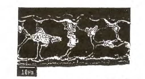
307 So, when conducting quantitative metallographic measurements, Professor Marder said that it was important to consider the three dimensional morphology of the Mg2Si particles. A single two dimensional metallographic sample will not fully characterize the shape of the Mg2Si particle. Through serial sectioning, being a series of polished surfaces through the sample, of the specimen, the size and shape of the phases such as Mg2Si particles can be appreciated. For example, if a phase is tree like with a large trunk that grows upwards from the ground with different branches of decreasing diameter as the tree grows skyward. At the middle section of the tree, there will be a number of larger branches, however, at the very top of the tree there only a few smaller branches or twigs present:

308 A planar horizontal section at the top of the tree will show very few twigs. In comparison, a planar vertical section through various parts of the tree may show the large trunk, a great deal of branches in the middle of the section and a few fine twigs at the very top of the section.
309 Now Dr Prošek attempted to support the sample size tested by BlueScope by analogy with sampling he used when testing for corrosion or for long term thickness variation by the weigh-strip-weigh method. But ultimately he appeared to accept that such testing was not analogous to the testing required to be conducted in the present context, which was for testing Mg2Si distribution.
310 Now in relation to sample size, BlueScope has asserted that although the size of a standard coil of coated steel is 1.2m x 3000m, it is standard practice to ascertain properties of a coil using very small samples. But the examples that BlueScope referred to are standards for testing thickness and corrosion resistance. These are not relevant to the matters in question before me. Standards may assist buyers and sellers of products to have a certain pragmatic confidence in particular qualities of a product and its suitability for particular commercial purposes by taking small samples without destroying the remainder of the product. But this involves an element of compromise.
311 Now BlueScope says that Dongkuk consistently represented over the course of correspondence that the samples provided by it to BlueScope were representative of its product.
312 But it was BlueScope who demanded samples each of 210mm x 300mm when it was threatening infringement proceedings in respect of five other patents. It was up to BlueScope to request a larger sample if it needed one. It is not correct that BlueScope requested 6 sheets of the GLX product by its 6 June 2016 correspondence to establish that the samples were “representative” in the manner that it now seeks to claim. The further samples were requested in both the 6 June 2016 and 13 July 2016 letters in order for BlueScope “to identify the rate at which the GLX Product corrodes”, to support its threat of proceedings in relation to contraventions of the Australian Consumer Law made in that letter. It would seem that BlueScope was satisfied by 6 June 2016 that the GLX product infringed the claims of the 257 and 258 Patents based on samples A and B that had been provided.
313 Indeed in respect of the later 2017 GLX product, which BlueScope now accepts is not infringing, Dongkuk sold to BlueScope an entire coil of that product for BlueScope to carry out such testing as it wished.
314 Accordingly, I agree with Dongkuk that BlueScope could have done one or more of the following things.
315 First, it could have engaged in more testing of samples A and B.
316 Second, it could have purchased a coil of the 2016 GLX product.
317 Third, it could have requested further samples prior to asserting its claim of infringement, or proposing the BlueScope protocol, instead of seeking only samples A and B and relying on those as sufficient to allege and prove infringement.
318 In any case, I agree with Dongkuk that samples A and B are representative of the Dongkuk 2016 GLX product so far as it is possible in relation to non-uniformly distributed phases. They show, as is the fact, that the Mg2Si distribution is not uniform.
319 Further, I agree with Dongkuk that it is not to the point whether the samples are “representative” or not. The real issue is whether BlueScope has established the facts that it has sought to prove. In my view the BlueScope protocol and the results produced pursuant to the protocol do not establish the relevant facts, because the sample size used is not sufficient to adequately cater for the non-uniform distribution of Mg2Si as I have earlier said. Further, Dongkuk was not obliged by any direction or order to agree to the BlueScope protocol, and it is not now prevented from asserting that the protocol, including by way of the use of an unsatisfactory sample size, did not prove the facts the experiments sought to establish.
(b) Did the preparation of the samples affect the results?
320 Let me at this point deal with various matters concerning the preparation of the samples.
321 Professor Marder was critical of BlueScope’s sample preparation technique. However, he was not able to conclude what effect, if any, the sample preparation techniques had on the reliability of the Mg2Si measurements. BlueScope says it had no effect.
322 First, BlueScope says that the grinding and polishing did not affect the result.
323 Professor Marder asserted that the preparation of the samples involved grinding and polishing and the use of alcohol, which because it is hygroscopic may have absorbed water. This could have dissolved the Mg2Si on the surface of the coating. Accordingly, the Mg2Si data may not be reliable.
324 But BlueScope submitted that Ms Hodges was experienced in sample preparation, and appreciated the risks associated. Ms Hodges had undertaken this polishing before and knew how to polish the results to produce a good finish without etching the surface of the samples. Mr Moore’s evidence was that Ms Hodges had been preparing samples for years, and that BlueScope used her samples to diagnose production problems.
325 BlueScope pointed out that as Ms Hodges explained, it was necessary to initially grind the cross-sectional face of the samples of the cross sections because they have been deformed mechanically through the cutting process. The material which was removed by grinding and polishing was not removed from either the top or bottom of the sample, that is, the surfaces of the coating, but from the cross sectional face of the samples; that is, material was equally removed from the entire cross sectional face consisting of the top coating layer, the steel substrate layer and the bottom coating layer.
326 According to BlueScope, the use of water, as was standard practice, during the initial grinding phase had no bearing on the amount of Mg2Si present in the final polished surface of the sample because the effects of grinding were removed in the polishing stage, and the polishing process used an alcohol rather than water as the polishing lubricant. The polishing stage was the critical stage for exposing the surface. The ground surface was not the same as the polished surface, because the polishing process removed an additional amount of material from the cross sectional surface.
327 Polishing was undertaken after the samples were cleaned with ethanol, using a polishing machine and Struers DP Lubricant Yellow.
328 Professor Marder gave evidence that the Struers DP Lubricant Yellow contained a large amount of ethanol which was hygroscopic. He stated that “because Mg2Si is water soluble, then it seems to me that we can expect the smallest particles which reside on the surface will be dissolved irrespective of any galvanic protection at all”.
329 But Mr Moore’s evidence was that Mg2Si was not the first phase to be etched. He said that the Zn rich eutectics would be etched first. Further, where Mg2Si was exposed to water, it would turn a distinct blue colour. But Mr Moore did not observe much of this colouration in the optical micrographs. Similarly, where the coating absorbed alcohol, the effect would be visible on the samples. Mr Moore saw no such effect in the samples he was provided with.
330 Dr Prošek considered that any corrosion present on the samples was not the result of the sample preparation. He did not believe that any Mg2Si had been removed in the preparation of samples.
331 Accordingly, BlueScope says on the basis of this evidence that the coating was not affected by the sample preparation process.
332 Second, BlueScope says that its approach to voids and anomalies did not affect the result.
333 Professor Marder asserted that BlueScope’s treatment of voids and anomalies affected the amount of Mg2Si measured. Professor Marder identified “holes” in the optical micrographs of the samples which he identified as corrosion products. He suggested that it was necessary to take account of these defects, how they formed and what they contributed to the total volume of Mg2Si. Professor Marder referred to certain aspects of the coating and during the trial Dongkuk’s counsel identified other aspects that were said to be voids in the coating.
334 Professor Marder suggested that “holes” and corrosion products evident in the samples had to be accounted for. He said:
I’m merely pointing out that all of these potential defects – you’re not seeing the actual coating, and you need to see the actual coating before you can draw any conclusions about the distribution of Mg2Si.
335 But Professor Marder was not able to explain why these “holes” were present. He agreed that they could have been present on the surface of the samples when BlueScope received them. Moreover, Professor Marder was not able to conclude with certainty whether any Mg2Si had been dissolved when the “holes” were created.
336 Professor Marder suggested that there was no way to adjust for the corrosion products on the surface, because he considered that Mg2Si was randomly distributed, meaning that it was not possible to extrapolate using data from unaffected areas.
337 It appeared that Professor Marder was not able to draw conclusions about what each of the regions represented:
The material – this is there. You can’t wish it away, but the point is that there was something there. There was – it could have been corrosion that existed because of sitting on a dock somewhere or it could be because of preparation, but the fact is that there – and there’s a way of showing that, and that is to make sure that your mounting material gets into – into these holes so we can say that it happened before.
But the fact is that if you’re going to count any of the material here and you are going to count something as sensitive as small little particles of Mg2Si, you better have an understanding of what was there to begin with. And if – and by carefully selecting a typical photomicrograph and excluding something like that is against anything that you might do an analysis of coatings or any materials, for that matter. It’s done all the time, but let’s be honest here, what are we looking for? We’re looking for what is occurring in the surface and, in this case, we don’t know.
338 Dr Prošek gave evidence that some defects in the samples were inevitable, and that the defects in the samples which were tested were immaterial. He characterised the samples as being of very good quality.
339 Dr Prošek agreed that there were depressions evident in some of the cross-section images. He did not consider that all of the examples identified by Professor Marder were instances of corrosion, since in some cases there were no visible corrosion products.
340 Professor Marder accepted that normal industrial applications of coating might have non-uniform surfaces, although he expressed the view that it would be necessary to look at many more samples to characterise the surface contour.
341 Dr Prošek observed that where corrosion occurs, it is usually non-uniform, and would be shown by the colouring in the optical micrograph.
342 Mr Moore and Professor Cortie considered that some of the other instances of “voids” identified by Professor Marder were actually debris on the surface remaining from the sample preparation.
343 Now BlueScope accepts that there were some voids present in the samples. Mr Moore’s evidence was that there were voids in a small subset of the images. Professor Cortie’s evidence was that it was likely that at least some of the voids resulted from corrosion which had occurred before the samples were prepared. Dr Prošek reached a similar conclusion.
344 BlueScope says that the existence of voids does not support an inference that some Mg2Si had been removed, either in the course of sample preparation, or as a result of corrosion. Indeed, it says that the evidence was to the contrary.
345 Mr Moore explained that the nature of an Al-Zn-Si-Mg alloy is that the zinc rich eutectics will corrode first, and that the Mg2Si will be galvanically protected by the aluminium either side of it. Mr Moore explained that even where corrosion occurred on the surface, Mg2Si would be preserved in the corrosion product. Mr Moore suggested that in those circumstances, the Mg2Si would be retained. Mr Moore explained that Mg2Si is one of the last parts of the Al-Zn-Si-Mg alloy to corrode.
346 Professor Cortie’s evidence was that BlueScope’s documentation and the academic literature supported Mr Moore’s evidence.
347 Further, the images showed Mg2Si present in the corrosion products.
348 Now although Professor Marder said that the fact that some Mg2Si was visible in the corrosion product did not negate the fact that some Mg2Si might be disappearing, his evidence was that he did not know how the laws of thermodynamics or electrochemistry worked for this alloy.
349 BlueScope says that Mr Moore’s evidence, which should be accepted, is that any corrosion would preferentially corrode the rest of the coating, leaving the Mg2Si intact. And it is apparent that the effect of corrosion of surrounding material makes it more likely that there will be Mg2Si close to the surface.
350 But I agree with Dongkuk that there are deficiencies in BlueScope’s evidence relating to the preparation of the samples.
351 BlueScope prepared 16 cross-sectional samples from samples A and B which were used to investigate whether the GLX products have the claimed distribution of the Mg2Si in the top 5% of the surface of the coating. But it is clearly apparent from the images that were taken of these cross-sectional samples that they had corrosion troughs and voids in the coating. These were created by BlueScope in grinding and polishing the samples. Further, BlueScope did not store samples A and B in a corrosion free environment for the period of 20 months from receipt of the samples until the experiments were conducted.
352 Now Mg2Si particles do not exist uniformly in the coating. Smaller Mg2Si particles exist in the top 5% of the coating surface as opposed to lower in the coating surface. But smaller particles are more easily dissolved in water. Indeed, the measurements as to the distribution of Mg2Si in the top 5% are very sensitive such that if a small amount of Mg2Si that was originally present in the samples was not counted in the top 5%, then this has a substantial effect on the percentage of Mg2Si calculated. I tend to agree with Dongkuk that the consequence of BlueScope’s grinding and polishing techniques and the corrosion troughs and the voids being present in the cross-sectional samples is that they cannot be used to confidently determine distribution of Mg2Si in the top 5% of the coating surface. Accordingly, in my view both Professor Cortie’s and Mr Moore’s respective calculations of the distribution of Mg2Si in the top 5% are flawed.
353 Let me deal with various aspects of these deficiencies.
354 BlueScope received samples A and B in March 2016. During the period March 2016 to November 2017 being some 20 months, BlueScope stored samples A and B in their original packaging in Mr Andrew Morton’s air-conditioned office; he was BlueScope’s Corporate IP Manager. The original packaging comprised two plastic sleeves that were not air-tight and had no desiccant. That is, no measures were taken by BlueScope to ensure that samples A and B were kept in a non-corrosive environment for the 20 months that they were stored before testing.
355 The cross-sectional samples were prepared as follows. Mr Ford sheared a 7.5mm wide strip across the full width of each of samples A and B. Ms Hodges then sheared each strip into 8 lengths of 25mm, creating 16 rectangular cross-sectional samples. Ms Hodges then dripped Epofix cold mounting resin under vacuum onto the samples and left them to harden over the weekend.
356 There were four rectangular samples in each mount.
357 Ms Hodges selected one 25mm side of each of the cross-sectional samples for grinding and polishing and analysis. Ms Hodges ground the samples using grinding machines with different grades of silicon carbide paper, being 80, 180, 320 and 1200 grit, with 80 being the most abrasive and 1200 being the least. In respect of each of the grinding machines, water was used as the lubricant in the grinding process. For each set of four of the cross-sectional samples, Ms Hodges used approximately six to eight sheets of sandpaper. As each sheet of sandpaper was replaced, Ms Hodges wiped down the samples with water and before moving onto a finer stage grit she would rinse off the sample with water. She did this multiple times.
358 Ms Hodges then used a water based diamond lubricant with a nine diamond and three diamond abrasive disc for fine grinding.
359 Ms Hodges then polished the samples using a one micron diamond finish on some of the samples and three diamond finish on all of the samples and at all times using Struer’s DP Lubricant yellow in a non-air tight container, which contained a high proportion of hygroscopic alcohol. Ms Hodges and Mr Moore confirmed that one micron diamond finish is more likely to etch away some of the coating.
360 Approximately, three or four times during the polishing process Ms Hodges cleaned the samples with a tissue and ethanol.
361 The grinding and polishing techniques were not described in the BlueScope protocol. Moreover, I agree with Dongkuk that they are problematic considering the context of the particular measurements sought to be taken, namely, to determine the distribution of Mg2Si in the surface of the coating.
362 It seems well apparent that the cross-sectional samples were not ground and polished uniformly. This is significant in the context of measuring the distribution of Mg2Si in the top 5% of the coating where the distribution of Mg2Si is non-uniform. The problem is also compounded by the fact that an insufficient sample size of the GLX product was tested by BlueScope.
363 As Ms Hodges explained:
MR COOKE: And it goes without saying, when you polish a metallic surface, that, of course, some of the surface will be removed?
MS HODGES: The purpose of grinding and polishing is to remove material from the surface to create a nice surface to look at down a microscope or electron microscope.
MR COOKE: Yes?
MS HODGES: That is the intent of preparing a cross-section.
364 Further, the shearing of the strips meant that each side of each rectangular cross-sectional sample had been sheared. Therefore, they were deformed by shearing. Even at the first stage of grinding using the 80 grit, Ms Hodges was grinding below the deformation zone created by the shearing into the actual coating. Accordingly, all steps thereafter also removed actual coating.
365 Further, Ms Hodges also explained that the level of grinding and polishing was in one sense subjective albeit based upon experience, and was not uniform in any one sample let alone across different samples. They were not ground and polished to the same depth. As Dongkuk rightly contended, this matters in the context of measuring the distribution of Mg2Si in the top 5% of the coating and is again compounded by the fact that the distribution of Mg2Si was non-uniform.
366 Further, it is not in dispute that Mg2Si is soluble in water. And as discussed above, Ms Hodges used significant amounts of water in the grinding process and significant amounts of hygroscopic alcohol in the polishing process. And it is not in dispute that hygroscopic alcohol attracts water.
367 In my view, water and hygroscopic alcohol were inappropriate lubricants in the context of preparing the samples for measuring the distribution of Mg2Si particles in the cross- sectional samples. As Professor Marder explained, lubricants in which Mg2Si is not soluble, such as methanol, could and should have been used.
368 Let me say something about the corrosion and voids present in the cross-sectional samples.
369 Corrosion troughs and voids could be seen in the images of the cross-sectional samples. Professor Marder gave the following evidence:
PROF MARDER: … Turn to - just as an example of the material, turn to [Exhibit 3] page 9, and if you look at the centre photograph - there are two factors that I would like to talk about. One is on very right side, and it looks like the specimen has been completely or slightly corroded below the surface line. That - so right away there’s a corrosion in the piece before we even have a chance to look at it. And then I would like to look at the - just about the central region, where there's a big hole sitting in the material.
Now, first question that I would have - if I was looking at specimens and somebody presented this specimen to me, I would say “What happened here? Was there any material that was pertinent to the count of Mg2Si in both regions?”. And the fact that no accounting has been done as far as that is concerned - then I would say that you have to go back and make sure that we understand that we’re not putting these defects into the material. So we’re faced with two factors, one - that the material itself had these holes in it before we even started. That would be good, because then there would be no infringement at all. On the other hand, we’ve induced those in the preparation of the material, and we have to take an account of that, and we have to go back and develop our technique for polishing so that this induced defect would not exist. So I question at this point the fact that we have these defects and we have not taken account for how they form and what they contributed to the total volume of the Mg2Si. Now - - -
HIS HONOUR: Is this just one example of many or - from what you’ve seen of these micrographs or whatever you call them?
…
PROF MARDER: … they exist everywhere.
370 There was also other evidence of corrosion troughs and voids which were identified in the evidence.
371 In my view it is likely that a significant number at the least of the corrosion troughs and voids were created by BlueScope’s grinding and polishing of the cross-sectional samples including by using significant amounts of water and hygroscopic alcohol as well as one diamond micron polish on some of the samples.
372 Indeed, Ms Hodges repeatedly ground and polished below the deformation zone. In essence, she kept removing parts of the coating to create a surface for analysis. Accordingly, any pre-existing corrosion troughs and voids would have been ground away.
373 Further, there is other evidence supporting the conclusion that the corrosion troughs and the voids did not exist before the samples were ground and polished. Professor Marder explained a technique for identifying existing holes in the samples as follows:
One of the techniques that we’ve used in the past is that - when we use the epoxy resin, we put it into a - and I’m not sure whether BlueScope has done this; you put it into a vacuum, when you mount it, and that sucks in - all of the epoxy into these existing holes, if they were there to begin with.
374 Now apparently Ms Hodges used a vacuum with the epoxy resin. If the corrosion troughs or voids already existed in the samples before they were ground and polished, then they would have been filled with the epoxy resin under vacuum. If this had occurred then the images would show remnants of epoxy in the corrosion troughs and voids after grinding and polishing; the epoxy would have seeped into those crevices. But no epoxy was evident in the corrosion troughs or voids in the cross-sectional images.
375 Further, I agree with Dongkuk that if there is a doubt as to the cause of the corrosion troughs and voids and more particularly whether they were somehow formed in the manufacturing of the GLX product, in the storage of samples A and B by BlueScope or in sample preparation, then BlueScope carried the onus of establishing that they formed part of the GLX product as manufactured. It failed to so establish. Mr Moore’s evidence was that he did not know for sure whether the corrosion troughs and voids were created by BlueScope’s preparation of the cross-sectional samples or whether they already existed in the GLX product. Now BlueScope could have created other cross-sections of samples A and B without using the same grinding and polishing processes. And it had plenty of material left to do so, but it chose not to do so.
(c) Other problems
376 Generally, the BlueScope protocol sought to prove by experiment:
(a) the proportion of the surface area of the samples that comprised exposed Mg2Si particles;
(b) the proportion by weight of Mg2Si particles in the coating microstructure of the samples that were exposed at the surface of the coating;
(c) the proportion by weight of Mg2Si particles in the coating microstructure of the samples that were present in the top 5% of the thickness of the coating;
(d) the average, minimum and maximum coating thickness of the samples; and
(e) the average, minimum and maximum coating thickness of 5 mm diameter sections of the samples.
377 The protocol provided for the mapping and analysis of randomly selected parts of the surface in a two dimensional sense and cross-sections of the samples to prove or disprove these facts.
378 Professor Cortie, whose evidence I accept, addressed other problems concerning the experiments and measurements.
379 Although even putting to one side these problems, in summary his review of the data indicated that:
(a) there were 5mm diameter regions with a thickness variation greater than 40%; Dr Prošek identified one “outlier” at 51%, but Professor Cortie’s analysis indicated more than one 5 mm region with a thickness variation greater than 40%;
(b) there were measurements of coating thickness that exceeded 30 μm, being B6-Top-20 (at 30.4 μm), B7-Top-25 and 26 (at 35.9 μm and 46.4 μm);
(c) compared to BlueScope’s 2 areas with a proportion of Mg2Si in the “surface region … that has a thickness that is less than 30% of the total thickness of the coating” being greater than 10% by weight of total Mg2Si, Professor Cortie found 5 areas; and
(d) compared to BlueScope finding no area with the proportion of Mg2Si in the “surface region [having] a thickness that is at least 5% of the total thickness” being greater than 10% by weight of total Mg2Si”, Professor Cortie found one (B1 Top2 contained 11.6%).
380 Let me now address some additional matters. In Professor Cortie’s opinion, a precise determination of the amount of Mg2Si present in the Dongkuk samples by weight was beyond the reach of current analytical technologies. This was because the volume percentage of Mg2Si in the coatings was very small. At best only an estimate of the amount present and its distribution could be made.
381 Further, the problem of making an accurate measurement was compounded by using small sample sizes as BlueScope had done, namely, eight cross-sections each for samples A and B, coming to less than 1 mm2 of the surface area of a steel strip that was originally many hundreds of square meters in size when manufactured.
382 Professor Cortie investigated whether state-of-the-art synchrotron X-ray diffraction would be able to achieve a sufficient level of accuracy in relation to the phase (microstructural) makeup of the coating, but he concluded that not even this technique was capable of producing data with the level of detail required to determine accurately the amount of Mg2Si in the GLX product. In his opinion, quantitative metallography as applied to compositional maps of polished cross-sections was the only viable option to determine the amount and distribution of Mg2Si in the coating in the individual samples tested.
383 He noted that a low accelerating voltage of 5 kV was used in the EPMA analysis by BlueScope. But in his experience, voltages used in electron-beam analyses were typically higher and in the range 8 to 20 kV. Nevertheless, 5 kV would excite the necessary elemental emissions and had the advantage of lower penetration relative to higher voltage. This was useful in the case of the surface measurements in which a low penetration was required to isolate only those Mg2Si precipitates that were at or near to the surface. A relatively high beam current was selected by BlueScope to compensate for lower yield of emission at the lower accelerating voltage. For the surface measurements, each volume analysed was about a micron in diameter and about half a micron deep. But on balance, he believed that the aforementioned parameters were suitable to map the composition of “the surface”.
384 In relation to the use of EPMA generally, he noted that EPMA was normally performed on highly polished surfaces. But in his observation of the BlueScope experiments, it became apparent to him that the “top surface” samples were quite rough, with raised and depressed surface regions.
385 In his opinion, the impact of the rough surface regions on the data obtained could be cross-checked by examining the results of those cross-sectional EPMA measurements that were taken just below the surface and comparing them to the “surface” analyses. This was because as the cross-sectional samples were polished, there should have been no error due to surface roughness. In this regard, the average amount of Mg2Si in the cross-sectional EPMA analyses taken immediately below the surface must, in principle, be about the same as the average amount of Mg2Si found in the “surface” measurements. In other words, the same proportion of Mg2Si should be found, on average, in the uppermost part of the coating irrespective of whether the coating surface was analysed from above or from the side. By taking an average of a sufficiently large set of samples, the influence of individual inhomogeneities within the different sets of samples should be removed. But in fact the alignment between the average of the BlueScope results on the amount of Mg2Si on the cross-sectional EPMA analyses and the average amount of Mg2Si found in the “surface” measurements was relatively poor. In his opinion, this meant either that there was so much statistical scatter in the BlueScope results that the averaging process could not suppress it given the small sample size used by BlueScope or that surface roughness influenced the amount of Mg2Si detected. For this reason, in his opinion, the effect of the surface roughness on the EMPA results could not be neglected in considering the BlueScope data obtained in relation to the top “surface” analysis.
386 Further Mr Moore noted that the bottom interface and the top surface of the coating were uneven. In an attempt to define an upper “5% region” a series of image processing actions or measurements were performed. To carry these out, some simplifying approximations were made by Mr Moore including the demarcation of the bottom of the coating as a straight line and the use of a straight line to demarcate the lower limit of the “top 5%” layer. But in Professor Cortie’s opinion, whilst Mr Moore’s procedure was rigorously specified, it did not truly identify the “top 5%” or “top 30%” of the coating.
387 Now another issue of concern to Professor Cortie regarding the protocol was the process by which the boundaries of the Mg2Si precipitates would be delineated to provide the results.
388 The exercise conducted by BlueScope provided a considerable number of spatially located analyses in order to isolate the Mg2Si phase present. But this thresholding process by which a particular part of an image, the Mg2Si in the present case, is able to be identified as the phase of interest is not an exact science.
389 Now in this respect the protocol did not provide the means by which the boundary between the Mg2Si and the surrounding phases was to be determined. It merely said that “The surface area fraction of all identified Mg2Si is measured using the standard image analysis software and techniques”. A thresholding procedure was later provided by BlueScope, which provided a specific sequence of steps (i.e. “thresholding”) to identify which regions were the Mg2Si phase and which were not.
390 Now in this regard Dr Prošek said that “there [was] no generally accepted thresholding procedure used in the field of corrosion research and different approaches can lead to slightly different results”. In Professor Cortie’s opinion, which I accept, this was a considerable understatement of the difficulties inherent in the thresholding process. Significantly different results could be obtained depending upon the choice of thresholding parameters.
391 It is not in doubt that any final thresholding approach adopted is subjective in the sense that the boundaries determined to be part of a particular phase of interest is based on a decision made by the operator of the equipment. Moreover, differences in thresholding can influence the results delivered in significant ways. Now as explained in the evidence, differences in thresholding will affect the amount of precipitate identified. But in the present context, it is the proportion of particles in different parts of the coating that is the issue, not the actual amount. Accordingly, provided that the thresholding does not introduce spatial bias, that is, thresholding results that vary inconsistently from one part of the coating to another, then different thresholding approaches should not matter. Nevertheless, as explained in the evidence, if there were to be some systematic variation in the proportion of small to large particles through the thickness of the coating so that smaller particles formed a greater proportion of the whole in the lower half of the coating than in the upper half, then a thresholding method that exaggerated smaller particles would erroneously bias the outcome towards a higher volume fraction in the lower half of the coating.
392 In Professor Cortie’s opinion, which I accept, the thresholding procedure used by BlueScope had influenced the relative proportions of Mg2Si precipitates quite strongly. According to Professor Cortie, the subjectivity of the thresholding procedure adopted by BlueScope was evident in a number of the procedures adopted by Mr Moore.
393 First, the thresholding process took place within the RGB colour space of an image processing program with red, green and blue channels allocated respectively to Mg, Si and Zn. In order to convert the raw X-ray counts (ranging from about 0 to 1000 in the present measurements) to the colour channel values (with a range only from 0 to 255), decisions had to be made by Mr Moore concerning the minimum and maximum values by which Mg, Si and Zn would be delineated, an offset value of arbitrary magnitude, and the parameters for a colour gamma transformation. Now the initial choice of parameters for each of these steps was a judgment that had to be made by Mr Moore with unknown effects on the final analysis. But in Professor Cortie’s opinion, the colour adjustments were unnecessary complicating factors. And the use of the two-pixel dilation operation on the Mg image could have, depending on limits used for Si and Mg in their respective images, inflated the size of any very small Mg2Si particles and bias the results.
394 Second, the conversion of a high precision X-ray count value (about 0 to 1000 in the case of the present measurements) to a greyscale value (0 to 255) necessarily involved a loss of precision. Greater precision in thresholding was obtainable by using the raw data as in Professor Cortie’s method.
395 But nevertheless on the evidence, the identification and delineation of large Mg2Si precipitates in the course of a thresholding procedure was uncontroversial. Professor Cortie was of the view that the thresholding procedure adopted and described by Mr Moore was appropriate to identify the presence of such large precipitates.
396 But Professor Cortie observed that in the experimental work carried out by Mr Moore, pixels suggesting the presence of smaller, secondary Mg2Si, of the order of a micron or so in diameter, were only visible if a sufficiently low cut-off threshold value for Si was used. The protocol specified that the lowest Si content that could mark the presence of a Mg2Si precipitate should be 3 standard deviations below the mean value that had been determined by Mr Moore for these precipitates. Professor Cortie observed that the same precipitates were not detected if a cut-off of 2 standard deviations was used. According to him this was an example of how a subjective choice of thresholding parameters could influence the outcome in respect of the smaller particles especially.
397 Professor Cortie noted that Liu W et al, “Influence of alloyed magnesium on the microstructure and long-term corrosion behavior of hot-dip Al-Zn-Si coating in NaCl solution” (2016) 104 Corrosion Science 217-226 (Liu et al 2016) reported the presence of Mg2Si precipitates in the 2 to 8 μm size range within the Zn-rich interdendritic regions. This paper showed that alloys of the present type might contain a profusion of very small Mg2Si precipitates, as well as larger, more easily identified, ones. Now given that the claims of the 257 Patent and 258 Patent required a measurement of the amount of Mg2Si in the alloy, in Professor Cortie’s opinion it was important to include all precipitates, including the smaller precipitates in the analysis.
398 Further, in Professor Cortie’s opinion there was a risk that the dilation of the Mg-rich areas would exaggerate the area fraction of smaller Mg2Si precipitates. Now provided these small particles were evenly distributed through the coating, this exaggeration would not influence the final ratio of Mg2Si within the upper layers relative to the whole coating, since all parts of the coating should be equally affected. But should smaller particles be preferentially located in a region of the coating, then the distribution would become biased as a result. If, for example, the smaller particles formed a larger proportion of the total in the lower half of the coating, then exaggerating their presence by a two pixel dilation would result in the upper half of the coating seeming to contain a lesser proportion of the total Mg2Si.
399 Now in order to eliminate some of the subjectivity attached to thresholding of the BlueScope experiments, Professor Cortie used a software program that he wrote (“ChemImage”) to process in an alternative manner the data obtained from the electron microprobe.
400 His analysis used the raw elemental analysis provided by the electron microprobe, in combination with certain peak ratios, to determine what constituted a Mg2Si region.
401 He also used a different method of determining the top and bottom limits of the coating.
402 In summary, thresholding by him was established by defining a set of “post-acquisition analysis rules” based on elemental counts in each pixel. He did this by varying lower and upper limits for the Mg, Al, Si and Zn counts in the ChemImage program until only the Mg2Si precipitates were highlighted in the chemical images.
403 He noted that taken over all samples the same average area fraction of Mg2Si was found by his method as was found by Mr Moore, that is, they both found 0.28% as the average area of all 16 cross-sections through samples A and B of Mg2Si in the whole coating, and 0.18% vs 0.19 % respectively for the surface measurements. But this was deliberate on his part so that as a result of this standardization he could focus on questions relating to the distribution of the Mg2Si. Once the set of rules had been defined, it was fixed for all the cross-sectional samples, so that all samples could be processed in an unbiased fashion. A slightly modified set of rules was required for the surface analyses as their analytical conditions were different to those of the cross-sections. I will return to aspects of this later.
404 The top and bottom of the coatings was found by an edge detection algorithm which he coded. Essentially, a minimum sum of the counts for Mg, Si, Zn and Al was used to define the beginning and end of the Al-Zn-Mg coating.
405 In some cases, stray pixels were manually edited by him on the images using a paintbrush tool coded in ChemImage to remove obvious glitches or porosity, which would otherwise have been detected as an edge by the algorithm. In general, delineation of the top surface required more editing of stray pixels. Following this calibration exercise, the images were analysed by the ChemImage software line by line, bottom-of -coating to top-of-coating, and from left to right. All pixels identified as Mg2Si by the software were counted by the software and binned according to their relative position (in %) between detected bottom (0%) and detected top (100%). Whilst based on the same raw elemental analysis provided by the electron microprobe, this analysis was otherwise independent of the BlueScope analysis since it used an independent definition of what constituted the top and bottom of the coating and an independent thresholding rule. His method provided for a “top 5%” or “top X%” layer that was approximately conformal with the upper region of the coating.
406 In Professor Cortie’s opinion, the technique that he coded into the ChemImages computer program was an independent and unbiased estimator for both the distribution of Mg2Si and for determining the bottom and top limits of the coating in the cross-sections. In regard to the total amount of Mg2Si present in the coating, it provided a very similar estimate to that made by BlueScope. But it produced a more accurate result for the distribution than the BlueScope analysis.
407 As an example, the BlueScope and Cortie data for sample A1 Top1 is compared in Figure 10 below.
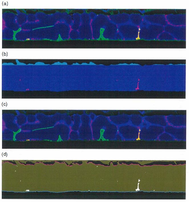
Figure 10: Sample A1 Top 1. (a) BlueScope data for composite image- Mg2Si is yellow - and (b) for just Mg2Si (purple) and top 5% (cyan layer) as per BlueScope protocol, (c) Cortie composite image produced with ChemImage program, (d) Cortie data for Mg2Si with auto-detected limits of the coating shown in cyan and magenta. The material above the magenta dots is corrosion product and/or oxide.
408 I will return to some of these matters later. For the moment it is sufficient to say that I preferred Professor Cortie’s method.
(d) Summary
409 Given the considerable problems with the experiments in the context of what was sought to be proved, including the deficiencies, sensitivities and in some respects relevant subjectivities, I had little confidence in some of the conclusions that BlueScope sought to draw from the experiments.
410 Let me make some further observations.
411 First, as between the evidence of Mr Moore and Professor Cortie, I preferred the evidence of Professor Cortie where there were differences. Professor Cortie was more objective and independent. Further, his methodology required less need for subjective choices. Further, he seemed to better appreciate that there were significant limitations on the whole exercise in terms of the realistic precision that could be achieved.
412 Second, although BlueScope continually and heavily emphasised that Dongkuk had represented to it the representative nature of the samples, the fact is that the samples and the coil from which they were taken always had inherent variability in terms of Mg2Si distribution. The samples were representative of each other and the coil accepting that inherent variability. But it was that inherent variability which was a problem for BlueScope in its forensic proofs, which problem it never really overcame.
413 As Dongkuk made plain, for example, through its solicitors on 7 August 2017:
At Stage 1 point 4, it seems to us that the choice of sample selection does not cater for possibility of different spread of Mg2Si in the coating in other regions of the sample. We ask you to consider an alternative approach to sample selection to accommodate this concern.
414 The simple fact is that the cross-sectional samples taken from samples A and B did not adequately cater for the non-uniform distribution of Mg2Si. This problem and any analysis was further made problematic by corrosion troughs and voids.
415 Let me now turn to address the infringement issues more directly.
INFRINGEMENT OF THE 257 PATENT
Claim 1
416 The following integer is conceded by Dongkuk:
A hot-dip coating method for forming a coating of a corrosion-resistant Al-Zn-Si-Mg alloy on a steel strip comprising passing the steel strip through a hot dip coating bath that contains Al, Zn, Si, and Mg and optionally other elements and forming an alloy coating on the strip…
417 But Dongkuk denies that the following integer has been established:
…with a variation in thickness of the coating of no more than 40% in any given 5 mm diameter section…
418 BlueScope relies on the evidence of Dr Prošek that an assessment of whether there is a variation in thickness of the coating of no more than 40% in any given 5mm diameter section requires a comparison between the AMCT in a representative 5mm diameter section against the difference in thickness between the thickest and thinnest points in that 5mm diameter sections.
419 BlueScope says that evidence in relation to the coating thickness of “representative” sections of samples A and B proves on the balance of probabilities that the entire coil of GLX product has the claimed feature when outliers are removed from the data taken from the samples tested.
420 Dr Prošek used the thickness measurement data from the cross sectional measurements taken by BlueScope for samples A and B. Dr Prošek calculated the thickness variation for a representative 5 mm diameter section of the 25mm in length cross-section for each of the sixteen cross-sections for sample A (top and reverse side) and for each of the sixteen cross-sections (top and reverse side) for sample B. To undertake his analysis, Dr Prošek selected a random sample of ten images for each of the sixteen cross sections (both for the top and reverse side).
421 Now in my view there is a problem concerning the word “any”.
422 Dr Prošek said of that word:
DR PROSEK: I would say this is strange wording for a patent. Really if you read it literally that says in any given and that’s technically nonsense because there is no industrial product that would be able to really have that uniform distribution of whatever parameter. So in my understanding, this is - this should read like in any typical or any normal or any average five millimetre diameter section and so on. That’s my understanding based on knowledge of industrial processes. It’s - there is all the time a variation in real production as we’ve seen before.
MR RYAN: Without stating the obvious, Doctor, those additional words just don’t appear in the claim, do they?
DR PROSEK: No, they do not appear there.
MR RYAN: No. And they don’t appear in the body of the specification either, do they?
DR PROSEK: I don’t think so, no.
423 It is not for me to rewrite the claim language so as to give effect to what the patentee may now wish he had said. One reason for this is that the patentee may express the monopoly in ways which may be important for distinguishing prior art, but one could never know what the motivation was for particular forms of wording. But in any event, as Dongkuk points out, Mr Renshaw, one of the inventors, at least must have intended that any thickness variation of 40% or more should be avoided.
424 Further, the claim is not concerned with variation in thickness from an average. By calculating thickness variation from an average thickness over a 5mm diameter area rather than the absolute thickness variation over that area BlueScope has understated the variation in thickness by ensuring that the denominator in the equation was higher than it should have been.
425 In my view, BlueScope has not shown that the GLX product was made by the method claimed in claim 1.
426 First, the results of the experiments demonstrate that the GLX product does not have a surface thickness variation of “no more than 40% in any given 5mm diameter section”. There are results outside this range and such results cannot be dismissed as outliers.
427 Second, BlueScope has not shown that GLX product has “only a small proportion of Mg2Si particles or substantially no Mg2Si particles in the surface of the coating”.
428 These non-infringement points apply to all of the asserted claims, as they are all dependent upon claim 1, that is, claims 3, 4, 5, 6, 8, 9, 11, 12, 13, 14 and 15.
429 Let me elaborate on some of these topics.
Outliers
430 Let me begin with BlueScope’s submissions and the evidence it pointed to concerning outliers.
431 Dr Prošek found that the thickness variations for sample A varied between 8% and 26%. For sample B the thickness variations were between 6% and 51%.
432 Dr Prošek considered that the thickness variation measurement of 51% should be excluded as an “outlier”. The maximum value in B6-Top (B6-Top-20) was 30.4 μm. This is the measurement of B6-Top-20, which was the highest single value amongst the values that make up B6-Top. This single value gave rise to a thickness variation of 51%. Dr Prošek describes the thickness variation result of 51% (from B6-Top) as “an exception” and “an outlier”. Once the measurement of 30.4 μm was excluded, thickness variations for sample B varied between 6% and 30%.
433 In addition, Dr Prošek accepted that there were two further thickness measurements amongst the 1579 measurements taken which were above 30 μm, namely, B7-Top-25 (46.4μm) and B7-Top-26 (35.9μm). The experts agreed that if B7-Top-25 and B7-Top-26 were included in the thickness variation calculations, variations of between 39.8% and 112.3% were obtained depending on the start and end points.
434 Dr Prošek considered those two thickness measurements should also be excluded as “outliers”. These measurements were not included in the representative sections considered by Dr Prošek in his first affidavit. On this basis, Dr Prošek concluded that the thickness variation of samples A and B were significantly less than 40%. Dr Prošek’s evidence was that once the three “outlier” thickness measurements (30.4 μm, 46.4μm and 35.9μm) were excluded, claims 1 and 4 were infringed.
435 Professor Marder’s evidence was that the claim language “in any given 5mm diameter” requires that there must be no thickness variation measurement which is above the claimed 40% variation over the whole of the product. Accordingly, Professor Marder asserted that the GLX product did not satisfy this coating thickness variation integer, because there were three thickness variation measurements above 40%.
436 Dr Prošek prepared a graph that he said identified the coating thickness measurement distribution relating to the GLX product. Dr Prošek explained that this graph showed that the data was a normal distribution (I might say an assertion that is contestable) and therefore that a statistical theory, Chauvenet’s criterion, could be applied to the data set to exclude outliers. Chauvenet’s criterion identifies data points that lie outside the probability band centred on the mean of normal distribution.
437 The usual technique associated with Chauvenet’s criterion defines an acceptable scatter, in a statistical sense, around the mean value from a given sample of N measurements. The criterion usually states that all data points should be retained that fall within a band around the mean that corresponds to a probability of 1–1/(2N). In other words, data points can be considered for rejection only if the probability of obtaining their deviation from the mean is less than 1/(2N). This is illustrated below.
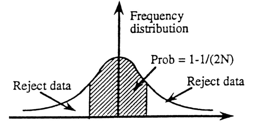
438 The probability 1–1/(2N) for retention of data distributed about the mean can be related to a maximum deviation dmax away from the mean by using Gaussian probabilities. For the given probability, the nondimensional maximum deviation τmax can be determined from the table where
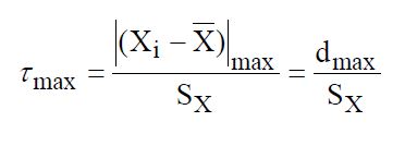
and SX is the precision index of the sample. Therefore, all measurements that deviate from the mean by more than τmaxSX can be rejected. A new mean value and a new precision index can then be calculated from the remaining measurements. No further application of the criterion to the sample is allowed. Usually Chauvenet’s criterion may be applied only once to a given sample of readings.
439 Dr Prošek explained Chauvenet’s criterion and his application thereof in the following terms.
440 Chauvenet’s criterion is a statistical theory that is routinely applied as a means of assessing whether a data point that appears to be an outlier is likely to be spurious, and not a true reflection of the set of data.
441 The application of Chauvenet’s criterion to a data set results in identifying the data points from a sample that lie outside a probability band, centred on the mean (μ) of a normal distribution, and can be excluded from the data set as outliers.
442 According to Chauvenet’s criterion, the identification of the outliers is achieved by finding the number of standard deviations that correspond to the bounds of the probability band around the mean (Dmax) and comparing that value to the absolute value of the difference (D) between the suspected outlier (x) and the mean (μ) divided by the sample standard deviation (σ) according to the following formula:
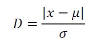
443 To identify the outliers in BlueScope’s AMCT measurements, Dr Prošek first ordered all of the thickness measurements for each of the 1579 AMCT measurements from highest to lowest. He calculated the mean AMCT of 22.4 μm (μ) and the standard deviation of 1.5 μm (σ). Then he calculated how far the highest AMCT measurement (x), being 46.4 μm from sample B7-Top-25, is from the mean using the formula referred to above.
444 He compared the result (D) to the Dmax calculated in Excel according to the following formula:
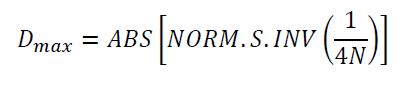
where N is the number of data points.
445 He excluded the result if the distance D was greater than the probability band Dmax, where Dmax was calculated to be 3.6. He repeated this procedure for each and every data point, calculating a new μ, σ, D and Dmax for each data set until he had identified all outliers and no further outliers were detected. According to Dr Prošek the results indicated that the following samples were outliers:
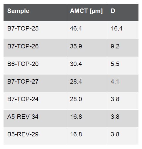
446 He also plotted the thickness measurements for each of the 1579 AMCT measurements to create a chart showing the thickness measurement distribution of the GLX product.
447 It is apparent from the results he obtained by applying Chauvenet’s criterion that there were seven data points that fall within extreme values, five of which fall within the high range having thicknesses of 28μm or greater, that is, outliers.
448 In the joint expert report, Professor Cortie disagreed that the application of Chauvenet’s criterion was relevant because the data in Dr Prošek’s graph represented a long tail distribution rather than a normal distribution. Professor Marder yielded to Professor Cortie’s expertise regarding statistical principles.
449 Mr Moore considered that Dr Prošek’s graph looked like a normal or Gaussian distribution with the mean value equivalent to the mode, although Mr Moore could not discount that the data might contain two distributions. Mr Moore’s evidence was that the outlying data points could be excluded from the data set if there was sufficient cause to suggest that they were not representative of the underlying distribution.
450 Professor Cortie explained that an “outlier” must be analysed to assess the reason for the outlier and determine whether there is a valid reason to exclude the data point, for example, that the sample was defective. In the context of the GLX product, Professor Cortie’s view was that, regardless of the underlying explanation, the outlying thickness measurements were a characteristic of the coil, which were likely to be replicated across the coil as a whole. Professor Marder agreed. I must say that I have accepted Professor Cortie’s evidence on these aspects, including the inapplicability of Chauvenet’s criterion to the present context.
451 It was common ground that the “outlying” measurements were accurate. BlueScope did not contend that they were false readings, or that they were not genuine data points. However, BlueScope said that once the data points were identified as outliers, they could be excluded if there was a valid reason to exclude them.
452 BlueScope submitted that there was a valid reason to exclude the outlying measurements, namely, the presence of dross particles which were not part of “the coating” as claimed.
453 Mr Moore gave evidence that dross particles can locally change the coating thickness and the presence of such particles is not representative of the rest of the coating.
454 Mr George Rommal, a materials science engineer and one of Dongkuk’s experts, explained that “dross is basically a small rock and it’s – you know, it would be embedded in the coating”. He also explained that dross particles are not precipitated from the coating, that is, dross is foreign matter.
455 Dross can be top dross, which is an oxide which floats on the top of the bath and then is pulled out on the coating, or bottom dross, which is a kind of intermetallic compound of iron and other elements. Mr Moore explained that dross particles have a very high surface energy and tend to minimise their surface energy by sticking together, leading to large particles.
456 Dr Prošek explained that the dross particle appears as dark spots on the coated surface where a dross particle or oxide particle is withdrawn from the coating bath. As the strip passes through the top turn-around roller the dross particle becomes embedded into the coating. The dross forms a bump on the surface, which is then burnished or polished as the strip passes through the rolling process. Dr Prošek explained that the dross particle will increase the local thickness of the coating by as much as 200 per cent, and by an amount that may be much more significant than the size of the dross particle. Mr Rommal agreed that large particles would influence the flow of molten liquid, and therefore thickness.
457 BlueScope took images of the surface of eight cross-sectional samples of the top side of sheet B. BlueScope submits that the evidence in relation to samples B6 and B7 establishes that the three outlying thickness measurements referred to above were due to the presence of dross particles.
458 At trial this evidence was admitted on a provisional basis, subject to a determination of relevance. I will admit it absolutely. The evidence is relevant and should be admitted as it is probative of a matter in issue, namely, whether the measurements which give rise to coating thickness variations greater than 40% are outliers, which do not represent the thickness of the coating.
459 Dr Prošek identified a dross particle or metal spot on the surface of each of the cross section samples of B6 and B7. Mr Rommal could also identify the dark spot in B6, although Professor Cortie could not. Professor Cortie agreed that there was a dark spot in B7, as did Mr Rommal.
460 The thickness measurements of the cross-sectional samples B6 and B7 which correspond to the three outlying measurements in Dr Prošek’s graph are as follows:
B7-Top-25 (46.4 μm)
B7-Top-26 (35.9 μm)
B6-Top-20 (30.4 μm).
461 In relation to B7-Top-25, BlueScope said the following.
462 The dross particle identified by Dr Prošek in sample B7 was in the middle of that strip. The image which is B7-Top-25 is also in the middle of the strip.
463 The dross particle is evident in the cross sectional image of B7-Top-25, which shows the dross particles in a lighter colour than the surrounding coating. Dr Prošek explained that the image shows only a very small part of the cross-section of the dross particle. Dr Prošek considered that this dross particle caused the increased thickness measurement of 46.4 μm for B7-Top-25, and the higher thickness measurements around that dross particle.
464 Professor Cortie agreed that there was a burnished surface reflecting an area over the normal thickness, but he considered that there was no compelling evidence the localised thickness was caused by dross.
465 In relation to B7-Top-26, BlueScope said the following.
466 The image which is B7-Top-26 lies adjacent to the image which is B7-Top-25. The distance between the image B7-Top-25 and the image B7-Top-26 is at its closest point 225 microns and at its furthest point 375 microns. Although Dr Prošek could not see a dross particle in the image for B7-Top-26, he considered that the thickness of B7-Top-26 was influenced by the dross particle visible in the image for B7-Top-25.
467 In relation to B6-Top-20, BlueScope said the following.
468 Dr Prošek was not able to identify a dross particle in the image for B6-Top-20. However, he considered it was likely that there was a dross particle sufficiently close to the point of measurement, which caused the increase in thickness. Dr Prošek explained that his conclusion was supported by the increase in thickness between the measurements at B6-Top-18 and the measurement at B6-Top-22. Those increases in the thickness of the coating corresponded to the position with a black spot on the image for B6.
469 Those thickness increases could be seen in one of the exhibits tendered before me which exhibited the thickness measurements for sample B top side, and showed the three outliers B7-Top-25, B7-Top-26 and B6-Top-20 and the fluctuation in thickness in the images around them.
470 Professor Cortie considered that the particle in B7-Top-25 was silicon. Professor Marder also expressed the view that the particle was a silicon particle which had grown in the liquid.
471 Dr Prošek’s evidence was that the particle was a dross particle from the top of the bath. Although he accepted that the particle might contain silicon, he considered it was more likely to be silicon oxide, aluminium oxide or a mixed oxide.
472 Mr Rommal and Professor Marder suggested that if the particle was dross, it would not be homogenous. Mr Moore gave evidence that the dross particles exist as aggregates. Dr Prošek explained that the image only showed a very small part of the dross, and that the specific part shown might be a single phase, or of quite simple chemical composition.
473 Professor Marder did not understand how a dross particle would necessarily cause an increase in the coating thickness. Mr Rommal explained that dross might make the coating thicker or thinner or stay the same. Dr Prošek’s evidence was that whilst he could not explain the mechanism, it was quite typical that the incorporation of dross particles into a coating would result in a bump or increase in thickness. Mr Moore explained the mechanism. His evidence was the dross was in the form of an aggregate of dross particles with liquid around it. This would locally affect viscosity, because the particles are more viscous than the surrounding coating and would stay thicker. His evidence was that the dross particles were slightly more viscous and the coating would stay slightly thicker, perhaps as thick as the coating as it came out of the bath.
474 BlueScope says that the evidence provides a rational basis for concluding, on the balance of probabilities, that the thickness measurements for B6-Top-20, B7-Top-25 and B7-Top-26 are caused by the effects of dross particles which are foreign to the coating.
475 According to BlueScope, it is apparent from the evidence that dross is basically a small rock that is embedded in the coating. It is pulled out of the coating when the strip exits the bath according to Mr Rommal. It is not precipitated from the coating. Dross is (undesirable) foreign matter. BlueScope accepts that a dross particle is incorporated within the product as sold. However, the fact that the particle is entrained in the coating does not make it part of “the coating” as claimed.
476 A central aspect of the invention is directed to minimising thickness variations in the coating in order to control the distribution of Mg2Si at the surface of the coating to reduce the risk of mottling. Controlling coating thickness in the manner claimed is a key feature of the invention. It is the relationship between the thickness of the (liquid) alloy coating and the consequent behaviour of the coating and its constituent elements that is important to the distribution of Mg2Si. Solid particles which are not part of the liquid coating are not representative of the thickness of the coating as claimed.
477 I accept that a claim is to be construed from the perspective of how a person skilled in the art would have understood the patentee to be using the words. Importantly, I should approach the task of patent construction with a measure of common sense.
478 BlueScope says that it would be an extraordinary outcome if infringement could be avoided because of the presence of only a few dross particles in “any 5mm diameter” section of a coil which could be three kilometres in length. It says that the patentee could not be taken to have intended such a construction and it would be a departure from common sense.
479 BlueScope says that the thickness variations of samples A and B, after the outliers are excluded, are significantly less than 40%.
480 Generally speaking I would reject BlueScope’s contentions.
481 The results of BlueScope’s testing show that the Dongkuk strip has a variation in thickness of the coating of 40% or more in various 5mm diameter sections. At least three measurements show this variation. Indeed on Professor Cortie’s analysis the thickness variation could be as high as 112.3%. There is no basis to dismiss these results as “outliers”. It is not suggested that the results were erroneous. If the measurements were taken again, the same results would be found. The words “in any given 5mm diameter section” are what they are. They must be applied. Moreover, if the measurements were taken elsewhere the same results would be expected across the strip.
482 In the joint report in respect of infringement Professor Cortie said:
Next I consider the question of the so called outliers. In data analysis an unexpected value (an ‘outlier’) is not necessarily a false value. It might indicate some interesting underlying factor that occasionally produces an especially high-valued measurement, winning the big prize in the lottery for example. To avoid confirmation bias or other errors in analysis, an 'outlier' can only be discarded if one has a valid reason to do so. Valid reasons include a scenario where it has been discovered that the equipment used to take the measurement failed or was improperly used, or that the sample was defective due to some unforeseen but identifiable factor. None of those factors appear to apply to the measurements made in this case. Therefore, the present measurements are all equally valid and none can be discarded.
483 Mr Moore gave evidence on this point:
HIS HONOUR: Well, it does, but I suppose it really depends upon what your definition is for an outlier. You’re not saying that these outliers are false readings or an artefact of the experiment. So you’re accepting that they’re accurate measurements of the thickness.
MR MOORE: Absolutely.
484 Dr Prošek gave the following evidence:
MR RYAN: Now, look, you said a short time ago in respect of TP14 you, at least at that stage, called it “a nice normal distribution and some figures to the right”. The question you then said was, “Are we able to exclude those figures?” And then you answered your own question by saying, “Not without any good reason.” Now, just to be clear, you didn’t put forward any good reason to exclude those figures either in your affidavit or in your joint report, did you?
DR PROSEK: No.
485 BlueScope belatedly adduced oral evidence from Dr Prošek to the effect that the so-called outliers should be excluded because they were thickness variations resulting from the presence of “dross” particles. But it was not clear whether the thickness variations were the result of dross particles. Professor Cortie thought they could be silicon. Mr Rommal could not say confidently but said one could find out by microanalysis. Professor Marder also accepted that one would perform microanalysis. Nevertheless, in respect of some of the images said to be the cause of thickness variations, he said they were probably due to silicon. But whatever was the cause of those variations, I agree with Dongkuk that they could not be put to one side. They were part of the coating.
486 Professor Cortie said:
Well, whatever that is, it’s incorporated in the coating. It’s intrinsically [part] of the coating.
487 Mr Rommal said:
It’s incorporated in – it’s incorporated within the coating. I would use the language that it is certainly part of the coating. If it were so extraordinarily unusual that it’s the only example like that in the entire coil, then I might say this is something, you know, weird and unusual and different. But if there are other examples in the coil that have similar structure to them, then I would say it’s part of the coating. I mean, having certain kinds of defects, certain kinds of inclusions are just a natural course of hot dip coating. It’s not a product that's made in a clean room where they make integrated circuits or anything like that. So having material in the coating is a normal - a normal thing to happen, at least some of the time. It’s not a strange and unusual thing.
488 Professor Marder said:
But it’s incorporated in a coating is what I would maintain. And since it’s incorporated in the coating it is the coating and it happens to be a measurement, if you are going to measure the thickness of the coating, that has to be incorporated in it. You can’t go about plucking out the defect or what you think is the defect and then measure the coating because nobody is going to - nobody is going to be interested in that thickness that you - you know, the thickness that you measure, it’s not going to meet specifications. You have to make that measurement and that measurement will incorporate whatever is in there. We could say the same thing about all the other particles that are there. If we want the real coating width, do we pluck out all these other particles and then we get the real coating width. The real coating is all these products that are within the coating.
489 Professor Cortie said:
Absolutely, your Honour. It is just something that’s characteristic of this product. Several hundred examples or thousands or millions will be found in a whole coil statistically speaking. It has to be treated as part of the product when negotiating a commercial agreement or something. It is the product.
490 Other evidence concerning dross was given to the following effect:
MR ROMMAL: There are a couple of things I have heard the word dross used for. I have heard the term top dross which is an oxide. It’s called top dross because it floats on the top of the molten metal bath and then it’s pulled out on the coating when the strip exits the bath. I’ve heard of things call bottom dross, especially in the context of a Galvalume bath or similar coating so that bottom dross is an intermetallic compound of iron and other elements that are in the bath, the particles that get kind of stirred around in the, you know, in the bath during the process. And they also can be pulled out in the coating and become part of the coating, basically incorporated in the coating as well. So I can’t tell just kind of looking at the this kind of image whether this is an oxide dross or a bottom dross or something else like a silicon particle or whatever. I really can’t tell that.
MR RYAN: How frequently in your experience is dross encountered in the course of a coating – hot-dip coating process?
MR ROMMAL: I’ve seen a lot of cross-sections with small particles entrained in there that are not precipitated from the coating during – during solidification. I don’t have data that would allow me to say, you know, what fraction of cross-section images like this or anything like that. But it’s a not extraordinarily rare.
MR RYAN: Professor Marder, do you have any comment on the last piece of evidence by Mr Rommal?
PROF MARDER: Usually, if it were dross you would have several different compounds incorporated together and I wouldn’t – I would then expect to see different – the resolution, I don’t know what the resolution is here, but you would see this particle not be as homogenous as it looks. It could be still dross but I would expect to see other compounds and then as it has been treated, which is difficult to tell how it has been treated, it has not been polished very well, but we would – we would see different sections. I’ve seen some of this dross in micrographs and it’s not so homogenous.
MR RYAN: Thank you. Now, gentlemen, Dr Prošek drew on the whiteboard a schematic diagram. If you turn around you can see it. And the diagonally hatched thing there is meant to be dross and on top of it and below it is meant to be the coating – all this is schematic of course – but you see how the representation illustrates that the coating is raised above what might be described as the normal thickness, both on top of and before and after the dross. What do you say about the accuracy of that representation of how the coating process would proceed, including through the air knives if there were dross present in the coating? Perhaps Dr Cortie.
PROF CORTIE: So at the moment I’ve got no basis for supposing that the coating should be increased, decreased or stay the same. All three possibilities seem equally probable to me as I sit here.
MR RYAN: Mr Rommal.
MR ROMMAL: So if I am going to assume that that particle in the drawing there is dross and hence was solid in the molten metal bath, pulled out in the molten coating, the particle would have to be quite large, a substantial fraction of the thickness of the molten coating that you are applying in order for it to influence the flow of the molten metal around it in order to get a thicker, thinner, whatever, spot there. If it’s – you know, as it’s drawn there, that particle may not even be big enough to really affect the thickness of the molten coating you would get because it would flow around that particle during the wiping unless that particle is large enough that it is going to interrupt the smoothness of the airflow locally right in that place.
MR RYAN: Professor Marder.
PROF MARDER: I would agree. If it was on the surface, I might expect that the thickness would change. But this is, obviously, within the coating, so it’s still floating in the liquid to begin with and therefore the air knives should just come along and keep it at the distance that it was. So I don’t think I would – most times when you see these kinds of inclusions – we will call them inclusions or whatever, dross – they would be sitting – they would be sitting on the surface and then may – may or may not affect the flow of the liquid around it.
491 Further, statistical theory does not assist BlueScope.
492 As Professor Cortie explained:
So in these histograms we have three or four measurements that lie well away from the mean of that distribution. Now, given the small size of the sample then, there’s the statistical argument that we can expect many millions more of such outliers when you extrapolate to the whole coil. That’s just application of the expectation argument. We have a one in 2000 chance or two in 2000 chance of one of these outliers. Multiplied by the size of the coil we have several million maybe. Therefore, those are characteristics of the coil. It doesn’t really matter to me what the explanation was; they are part and parcel of that product, statistically speaking, as manufactured and delivered.
493 Further, although Dr Prošek suggested that Chauvenet’s criterion or the Grubbs’ test, which I will refrain from elaborating on, could be applied to the data set to identify and exclude outliers, the idea behind Chauvenet’s criterion is to find a probability band, centred on the mean of a normal distribution, that should reasonably contain all data points of a data set. By doing this, any data points from any sample that lie outside this probability band can be considered to be outliers. The Grubbs’ test similarly depends upon a normal distribution to identify outliers. But the data set depicted in Dr Prošek’s graph does not have normal (Gaussian) distribution. Rather, the distribution is either long tailed or bimodal. Professor Cortie was of the view that the distribution was long tailed, whereas Mr Moore was of the view that the distribution was bimodal. Professor Cortie indicated that more data would be required to determine which of the two distributions applied. Nevertheless, on either view the data set is not normally distributed. As Professor Cortie explained:
PROF CORTIE: … The probability that those red numbers came from that normal - a normal distribution, as indicated in the histogram, are one in a trillion or something. Mr Moore proposes that, in fact, perhaps there are two distributions simultaneously. Well, no, there are never two distributions technically. What there can be is one distribution which has two components to it, a component A and a component B. That’s not a normal distribution. So Mr Moore either way has agreed that’s not a normal distribution.
MR COOKE: And what’s the probability, Professor Cortie, in your view, of it being a normal distribution?
PROF CORTIE: Zero. Or close as it needs to be to zero.
MR COOKE: And why is that?
PROF CORTIE: Because we have data which we agree are all legitimate data points, the probability of those red data points being drawn from that - a normal distribution - because there’s only one distribution in truth from a sample. It might be made of different components. But there’s only that one distribution, technically. That is not a normal distribution.
494 Mr Moore did not disagree with this. Dr Prošek indicated that he did not have the expertise in statistics to comment. Contrastingly, Professor Cortie had the most expertise in statistics. As Professor Cortie said:
So I have an engineering degree and I’ve gone on to physics. I teach some aspects of statistics in my materials course, particularly the comparison of one set of data to another or one mean to another. It’s an important aspect of material science. I teach that. I’m also an active researcher and I use statistics very frequently in my own work to place confidence intervals on any parameters that I measure. So I’m familiar with that aspect of statistics.
495 Professor Cortie explained that neither Chauvenet’s criterion nor the Grubbs’ test can be applied to a data set which does not have a normal (Gaussian) distribution:
MR COOKE: And, Professor Cortie, what do you say in relation to the assumption - if you were to assume that it does not have a normal distribution, what would you then say in respect of the applicability of the Chauvenet’s criteria and/or the Grubbs’ test.
PROF CORTIE: So allowing, for example, that it’s two distributions added together, that’s a bimodal distribution, Chauvenet’s criteria and Grubbs’ test totally inapplicable. Totally inapplicable.
496 In the circumstances, BlueScope has not established that the data set contained outliers. That being the case, the evidence shows that for the samples the results show that the product has a variation in thickness of the coating of 40% or more in various 5mm diameter sections.
Other matters
497 Let me deal with the following integer:
…so that the distribution of Mg2Si particles in the coating microstructure is such that there is only a small proportion of Mg2Si particles or substantially no Mg2Si particles in the surface of the coating.
498 Dongkuk says that BlueScope has not shown that the alleged lack of thickness variation in the samples is the cause of the alleged paucity of Mg2Si particles in the surface of the coating. That paucity of Mg2Si may have been caused by cooling rate or the presence of Sr, or by some other factor such as the nature and quantities of the elements in the coating (Mg, Zn, Si, Al).
499 Dongkuk says that the evidence permits the conclusion that Mg2Si forms on the surface of the coating at high cooling rates and that coating thickness variation is not the cause, or even a significant cause, of that microstructure. Mg2Si does not form on the surface of the coating at conventional cooling rates. The GLX product was made at a stepped cooling rate of, first, 20 to 30°C per second and, second, 15 to 20°C per second.
500 Relevantly, mottling did not occur in the BlueScope trial until the cooling rate reached at least 65°C per second. Accordingly, Dongkuk says that the relevant cooling rates would be the most likely candidate for the alleged Mg2Si distribution. On the other hand it may be Sr.
501 According to the specification, Sr does not have effect below 250ppm. Nevertheless, BlueScope sues in respect of claim 11 and does not accept that that claim is invalid by reason of it not being confined to an Sr content above 250ppm. Dongkuk’s product has Sr present as an impurity in the range of 0.8 to 3.9ppm.
502 Dongkuk says that it is not required to speculate. The claim requires that the lack of thickness variation should be, if not the sole cause, then the dominant cause or at least a causa sine qua non of the outcome. Proof would require in the present case at least taking the known parameters and then varying the thickness by more than 40% in one case and by, say, 35% in another, noting the amount of Mg2Si on the surface, and then characterising it as a small proportion in the first case but not the second case. Dongkuk says that BlueScope did not bother, not because of oversight, but because at low cooling rates it would make no difference.
503 I reject these submissions.
504 In my view the words “so that” mean that if the thickness is controlled so that there is no more than a 40% variation in any given 5 mm diameter section, the resulting coating microstructure will contain only a small proportion of Mg2Si particles or substantially no Mg2Si particles in the surface of the coating.
505 It is apparent from the discussion of the specification that controlling coating thickness variation alone will not control Mg2Si distribution. Moreover, controlling cooling rate alone will not control Mg2Si distribution.
506 Now Dongkuk sought to impugn the causative link between coating thickness variation and Mg2Si distribution by pointing to the fact that mottle was not seen where the cooling rate was below 65ºC/sec in some of the trials that led to the patented invention. But the absence of mottle does not prove Dongkuk’s thesis, because it is not clear whether there was coating thickness variation above 40% in the relevant trials. No direct measurement of coating thickness was taken in those trials where the cooling rate was under 65ºC/sec, and short range coating thickness variation was not seen.
507 Mr Wayne Renshaw, one of the inventors of the 257 and 258 Patents, said that it was possible that mottle would not be seen at 30ºC/sec. However, Mr Renshaw was familiar with the results of co-inventor Dr Qiyang Liu’s laboratory experiments, where Dr Liu had found that in the laboratory, mottling had been seen at a cooling rate of 30 – 40ºC/sec, where the coating thickness was at or above 30 microns.
508 Mr Renshaw’s evidence, based on his own observations and his experience, was that mottle was correlated with “thick spots”, being coating thickness variations, as well as with temperature. He explained the link in a discussion with me:
HIS HONOUR: I can understand the 40 per cent variation in thickness is not a one-off. It’s going to occur - - -?
MR RENSHAW: It’s going to repeat. Yes.
HIS HONOUR: But how do you know it’s just not a random effect that on particular occasion it showed that it – it would have had an effect on mottle or no mottle without taking your 40 per cent variation, for want of a better expression, and doing it 10 times to see whether it correlates with your - - -?
MR RENSHAW: Yes, yes. So - - -
HIS HONOUR: - - - yes or no mottle? Do you follow what I mean?
MR RENSHAW: I guess I will term it this way – is that the other thing is that if you had a 40 per cent variation or a much lower thickness - - -
HIS HONOUR: Yes?
MR RENSHAW: - - - at these cooling rates, you might have – you might have got away with it.
HIS HONOUR: Yes?
MR RENSHAW: The other – that’s the other – that’s the other side of it. So this was for – this is the typical variation of a – a – of a 150 coating class sample.
HIS HONOUR: Well, I understand that but it’s more the correlation. Is it typical that it’s correlated with the effect of mottle?
MR RENSHAW: Yes, okay.
HIS HONOUR: Do you follow what I mean? I’m just asking you, you’ve got one measurement out of a whole stack of them?
MR RENSHAW: Yes.
HIS HONOUR: So how can you be confident that it’s correlated with mottle or no mottle?
MR RENSHAW: Okay. Well, the variation is going to give you a thick spot.
HIS HONOUR: Yes?
MR RENSHAW: Right?
HIS HONOUR: Said that. Understand?
MR RENSHAW: And that – and that’s the key. So the the thick […] spot is what will give you mottle. So if you get a variation like 40 per cent, you will end up with a thick spot which will give you mottle.
HIS HONOUR: Well, I understand that from all of the other science, but I’m just going on this table. You couldn’t say that just looking at this table alone, could you? Just from one measurement of a variation of 40 per cent?
MR RENSHAW: Yes.
HIS HONOUR: That’s what I am saying?
MR RENSHAW: I guess I’m basing it on both the table - - -
HIS HONOUR: Yes?
MR RENSHAW: - - - and my experience as well.
509 Mr Renshaw rebutted the proposition that mottle was caused by high cooling rates rather than thickness variation:
MR RYAN: Yes. Now, doesn’t that suggest that the cause of the mottle on these August 2007 samples was the high cooling rate at that trial, rather than the thickness variation?
MR RENSHAW: I don’t think it’s that simple; it’s a combination of the two. For example, if you look at many of the mottled areas – they are ..... areas of thicker coating. That thicker coating can arise from long-range variation and short-range variation. So for example – the – some of the points on the other surface – so if we go to page 94 – there are a batch of points around the 5 55 through to 5 75, where the coating is 27.6 to 3.4 micrometres thick, and that – those points were consistently mottled. So really it’s the – they are the sort of the thickest areas of the coating, and that’s where we expect to see mottle. So it’s the combination of the two.
510 Mr Renshaw explained that cooling rate would affect mottle, in that at a higher cooling rate, mottle would be seen at thinner regions and at a lower cooling rate, less mottle would be seen in thicker regions.
511 Mr Renshaw’s understanding of the relationship between cooling rate and coating thickness is consistent with the evidence of Mr Rommal, the only other witness who had worked on Al-Zn-Si-Mg alloys.
512 As Mr Rommal explained:
Minimizing local coating thickness variations cannot produce the claimed gradient of Mg2Si distribution. Rather, since both patents discuss the need to have the proper cooling rate as a function of coating thickness, the importance of not having excessive coating thickness variation is so that a single cooling rate will be appropriate for all areas of the coating. Depending on the cooling rate used, if the coating thickness variation is too great, a situation could arise where the cooling rate is too high for the thick areas, but appropriate for the thin areas, leading to more Mg2Si on the surface of the thick areas, and the non-uniform appearance of “mottle”. However, even with perfect coating thickness uniformity, it is certainly possible to have a cooling rate that does not produce the distribution of Mg2Si desired by the patents.
513 The effect of this evidence is that control of coating thickness variation is necessary in controlling Mg2Si distribution, although it may not be sufficient if cooling rate is uncontrolled. That evidence is consistent with the disclosure in the specification.
514 In the present case, I am prepared to infer that Dongkuk’s control of coating thickness variation was a necessary contributor to the distribution of Mg2Si in its product.
515 Finally, let me deal with another aspect concerning the phrase:
…only a small proportion of Mg2Si particles or substantially no Mg2Si particles in the surface of the coating.
516 Dr Prošek’s evidence is that “substantially no” means that the number of Mg2Si particles present in the surface of the coating is immaterially small, having regard to the purpose of the invention which is to lower the risk of mottling caused by the presence of such particles in the surface.
517 Dr Prošek’s evidence is that a “small proportion” is up to 10wt.% of Mg2Si particles exposed at the surface. This is consistent with the statement on page 6 lines 23 to 25 of the 257 Patent that “the small proportion of Mg2Si particles in the surface of the coating is no more than 10 wt.% of the Mg2Si particles”.
518 Both Mr Rommal and Professor Marder assert that the meaning of “small proportion of Mg2Si particles or substantially no Mg2Si particles” is unclear.
519 Professor Marder did not initially express any difficulty with the expression “small proportion”. It was only in his second affidavit that he contended that the expression was unclear. His view was advanced in the context of considering the meaning of claim 3. Professor Marder’s view is that the expression “small proportion” in claim 1 cannot carry the same meaning as “small proportion” in claim 3.
520 In my view the phrase “small proportion” carries the same meaning in both claim 1 and claim 3, and means less than 10 wt%.
521 The expression “in surface of the coating” as used in claim 1 is at least a reference to the Mg2Si particles which are present at the surface of the coating, that is, in contact with, or exposed at, the external surface of the metal coating.
522 The evidence of Dr Prošek was that Mg2Si particles which are exposed at the coating surface are “in the surface of the coating”. It is those particles that communicate with the surface of the coating so as to be exposed and therefore visible to the eye that will give rise to mottle. For the purposes of claim 1, where a particle communicates with the surface of the coating, the area fraction for that particle is measured. Mr Rommal asserted that the meaning of “in the surface” is unclear.
523 Professor Marder asserted that the claim is unclear because it might refer to the top of the coating (the part visible to the eye) or might include some depth.
524 But ultimately it did not appear that the meaning of this expression was genuinely controversial at least so far as the experts were concerned. The phrase would encompass Mg2Si particles which were in contact with or exposed to the coating surface.
525 Dr Prošek used the data from the cross-sectional measurements taken by BlueScope for samples A and B to calculate the weight fraction of Mg2Si in the surface compared to the overall Mg2Si particles in the coating microstructure.
526 Dr Prošek found that the cross sectional surfaces of sample A had, on average, 0.42% Mg2Si in the surface (with measurements for the cross-sectional samples ranging between 0% and 2.38%) and that the cross sectional surfaces of sample B had, on average, 0.40% Mg2Si in the surface (with measurements for the cross sectional samples ranging between 0.40% and 1.90%).
527 On this basis, Dr Prošek concluded, having regard to the purpose of the invention, which is to lower the risk of mottling caused by the presence of Mg2Si particles in the surface, that there was only a small proportion of Mg2Si particles in the surface of the coating of each of samples A and B.
528 Professor Cortie’s analysis of the amount of Mg2Si present in the “in the surface” of the coating, is similar to BlueScope’s analysis.
529 Now although a substantial part of the conclave involving Mr Moore and Professor Cortie focused on the differences between the threshold approach adopted by Mr Moore and Professor Cortie, the differences only had a significant effect on the amount of Mg2Si present in the top 30% surface region (relevant to claim 1 of the 258 Patent) and did not affect the relevant integer of claim 1 of the 257 Patent.
530 In my view, BlueScope has established this integer.
531 In summary, BlueScope has not established infringement of claim 1 as it has failed to establish the integer:
… with a variation in thickness of the coating of no more than 40% in any given 5mm diameter section…
Claim 3
532 As I say, BlueScope has not established that claim 1 is infringed. But let me say something about the following additional integer:
… wherein the small proportion of Mg2Si particles in the surface of the coating is no more than 10wt.% of the Mg2Si particles.
533 Dr Prošek concluded that the small proportion of Mg2Si particles in the surface of the coating for samples A and B is no more than 10 wt% of the Mg2Si particles.
534 Accordingly, BlueScope contends that the GLX product is formed by the method of claim 3.
535 But I would reject this assertion.
536 The measurements obtained by BlueScope’s experiments do not establish only a small proportion of Mg2Si particles or substantially no Mg2Si particles in the surface of the coating or no more than 10 wt. % (claim 3). The methodology in taking those measurements was flawed for the following reasons.
537 First, the discs were rubbed with hygroscopic alcohol which would have dissolved the small particles of Mg2Si on the surface.
538 Second, despite what was sought to be measured as required by the claims of the 257 Patent, that is, the “proportion of Mg2Si in the surface”, the BlueScope protocol failed to take into account the limitations of pixels being able to account for small Mg2Si particles. This has particular consequences when one considers the fact that there are a greater number of smaller Mg2Si particles towards the very upper surface of the coating and that the measurements are highly sensitive.
539 Mr Moore confirmed that on his approach he would not recognise any Mg2Si particles smaller than 1 micron in the surface maps used for the purpose of calculating the amount of Mg2Si “in the surface of the coating” for the 257 Patent. Professor Cortie’s approach also had limitations in this regard, however, BlueScope carried the onus of establishing that the GLX product fell within the asserted clams. Professor Cortie confirmed that he would not recognise any Mg2Si particles smaller than 0.5 micron in the surface maps.
Claim 4
540 As I say, BlueScope has not shown infringement of claims 1 and 3. But let me say something about the following additional integer:
…wherein the coating thickness variation is no more than 30% in any given 5 mm diameter section of the coating.
541 Dr Prošek concluded that the thickness variations for samples A and B are lower than 30%. Accordingly, BlueScope contends that the GLX product is formed by the method of claim 4.
542 But I would reject this assertion. The relevant results in evidence demonstrate coating thickness variation of more than 30% in any given 5mm diameter section.
Claim 5
543 As I say, BlueScope has not established infringement of claims 1, 3 and 4. Let me say something about the following additional integer:
…wherein, for a coating thickness of 22μm, the maximum thickness in any region of the coating greater than 1mm in diameter is 27μm.
544 BlueScope took images at intervals of 0.5 mm along each cross sectional sample, except for one side of one sample where the internal was 0.52 mm, and took thickness measurements for each image. Dr Prošek combined the thickness measurements for every three consecutive images to create regions of the coating “greater than 1 mm” in size, each region being at least 1.5 mm. This gave thickness measurements at 1531 such regions. Of the 1531 regions greater than 1.5 mm, four (0.03%) had a thickness greater than 27 μm. Dr Prošek’s evidence is that the four measurements were outliers.
545 But Professor Marder did not accept that the four measurements were outliers. He relied on the fact that there was no evidence or data establishing that the four regions were outliers in respect of the whole of the coating. Moreover, he said that claim 5 required “the maximum thickness in any region of the coating greater than 1mm in diameter is 27 μm … whether or not that includes ‘outliers’”.
546 Dr Prošek explained that the four coating thickness measurements greater than 27μm (28.4 μm, 30.4 μm, 35.9 μm, and 46.4 μm) were included in the seven values which were identified as anomalous by applying Chauvenet’s criterion. Once these four values were excluded, there were no regions greater than 1mm in size where the coating thickness exceeded 27μm.
547 Dr Prošek maintained that the four outliers were properly excluded and the GLX product had a maximum thickness in any region of the coating greater than 1mm in diameter of 27μm.
548 On this basis, Dr Prošek concluded that the maximum thickness in any region of the coating greater than 1 mm in diameter for samples A and B was 27 μm.
549 BlueScope said that there was a rational basis to infer that the few measurements over 27 μm were caused by the presence of dross particles embedded in the coating thickness, and were not measures of the coating thickness itself. Accordingly, BlueScope contended that the GLX product was formed by the method of claim 5.
550 But I would reject these submissions.
551 As BlueScope accepted, its testing found four regions of the samples tested where the maximum thickness was greater than 27µm. Again, BlueScope’s only response was to dismiss these results as outliers. But as I have said earlier, there is no basis for doing so. BlueScope ignores the words “any region …”. Further, the GLX product is not one with a coating thickness of 22 µm. The thickness varies considerably above and below 22 µm.
Claim 6
552 As I say, BlueScope has not established that Dongkuk used the method of each of claims 1, 3, 4 and 5. Let me say something about the following additional integer:
…comprising selecting the cooling rate during solidification of coated strip exiting the coating bath to be less than a threshold cooling rate.
553 There is a dispute between the parties arising out of the expression “threshold cooling rate”. Two issues arise. First, what is the meaning of the term “threshold”? Second, does the expression “threshold cooling rate” mean there must be a single cooling rate?
554 BlueScope contends that this integer is directed to a method of controlling the cooling rate to be less than a selected maximum value. The maximum value will depend on a number of factors including, for instance the coating mass of the product.
555 The specification explains that the applicant found that for a coating mass up to 75 grams per square metre of strip surface per side the “threshold” cooling rate is less than 80°C/sec. (p 7 lines 36 and 37, p 11 line 24 to p 12 line 7), and that for a coating mass between 75-100 grams per square metre of strip surface per side the “threshold” cooling rate is less than 50°C/sec (p 8 lines 4 to 7, p 12 lines 9 to 16).
556 Mr Rommal suggested that this integer is unclear because it is not clear what “threshold cooling rate” means, particularly in circumstances that are not typical or for coating masses greater than 100 grams (per square metre of strip surface per side).
557 Professor Marder said that the phrase has no meaning and is not defined, although he accepted that the specification provided guidance as to its meaning.
558 BlueScope submits that claim 6 does not require the use of a single cooling rate across the entire continuous hot dip metal coating line. Although there is only one threshold (maximum) cooling rate, the actual rates used may vary.
559 Dr Prošek’s evidence is that it is and was before the priority date routine for hot dip metal coating lines to apply multiple cooling rates during the cooling section. Different cooling rates are applied depending on the temperature range of the molten metal coating and the desired microstructural formation. Dr Prošek’s evidence is that the claim is directing the skilled addressee to ensure that the cooling rates during solidification of the coated strip stay below a maximum or “threshold” cooling rate. The example on page 8 lines 12 to 21 of the specification supports this. The example recites multiple cooling rates that may be used during solidification of a coating which has an average thickness of 22 μm.
560 Contrastingly, Professor Marder contended that a single cooling rate must be used. He sought to distinguish a “stepped” cooling rate, which covered the “pre-cooling” phase and “after–cooling” phase process used by Dongkuk, from a “cooling rate”. Professor Marder explained that a method of manufacture that employs a “pre-cooling” phase and an “after-cooling” phase is a stepped cooling rate.
561 In my view, when the specification is read as a whole, it is plain that a process which uses multiple cooling rates in a “stepped” fashion, where each of the rates used is below a threshold, is included within the scope of claim 6.
562 Dr Prošek calculated the coating mass of the GLX product using the galvalume density as a proxy. He explained that the presence of Mg in the coating would have an insignificant effect on the overall density of an Al-Zn-Si-Mg coated product and that even if the alloy changed within the claimed ranges, the weight fraction would not be significantly affected. The weight fraction would vary from 0.06% to 0.07% for sample A and 0.09% to 0.10% for sample B. Based on the density of galvalume (3.8 g/cm3), he estimated the coating mass of the GLX product to be approximately 84g/m2 per side, that is, 3.8g/cm3 x 22µm being the average coating thickness of the GLX product. He therefore concluded that the GLX product had a coating mass greater than 75 grams per square metre of strip surface per side. At page 8 lines 4 to 9 the specification describes the threshold cooling rate for a coated strip with a mass between 75-100 grams per square meter to be less than 50°C/sec.
563 Mr Moon’s evidence is that the GLX product from which the samples were taken was subject to two cooling phases: a “pre-cooling” rate of 20-30°C/sec and an “after-cooling” rate of 15-20°C/sec. Both are under the threshold cooling rate of 50°C/sec.
564 Accordingly, the GLX product is formed by a method which satisfies the additional integer of claim 6.
Claim 7
565 BlueScope did not press its allegation of infringement of claim 7 at trial.
Claim 8
566 Let me say something about the following additional integer:
…comprising selecting the cooling rate for coated strip exiting the coating bath to be less than 50°C/sec for coating masses of 75-100 grams per square metre of strip surface per side.
567 In relation to claim 6, the coating mass of the GLX product is greater than 75 g/m2 (approximately 84g/m2) and the cooling rate used by Dongkuk is always under 50°C/sec.
568 Accordingly, this additional integer is satisfied.
Claim 9
569 Let me say something about the following additional integer:
…wherein the coating comprises the following ranges in % by weight of the elements aluminium, zinc, silicon, and magnesium:
Aluminium: 40 to 60%
Zinc: 40 to 60%
Silicon: 0.3 to 3%
Magnesium: 0.3 to 10%
570 Dongkuk admits this integer.
Claim 11
571 Let me say something about the following integer:
…wherein the coating contains less than 3000ppm Sr.
572 Dongkuk admits this integer.
Claim 12
573 As I say, BlueScope has not established that the GLX product is made using the methods claimed in claims 1, 3, 4, 5, 6, 8, 9 and 11. Let me say something about the following integer:
…comprising forming the coating to have a thickness of less than 30μm.
574 Dongkuk originally admitted that its products have a maximum coating thickness of less than 30 μm. But Professor Marder and Professor Cortie disputed this fact. I will give leave to Dongkuk to withdraw this admission as no relevant forensic prejudice is caused to BlueScope by the withdrawal.
575 Dr Prošek was originally asked to assume this fact. But in his reply evidence, Dr Prošek said that the data established that the coating thickness of samples A and B was less than 30 μm.
576 Professor Marder asserted that there was no data to support an analysis that the coating thickness was less than 30 μm, and said that he could not accept that this integer was present. Professor Cortie identified three coating thickness measurements (out of 1579) that exceeded 30 μm, namely B6-Top-20 (30.4 μm), B7 Top-25 (46.4 μm) and B7-Top-26 (35.9 μm).
577 Dr Prošek’s view was that in determining whether the coating thickness of the samples was less than 30μm did not require that every part of the coating thickness be under 30 μm. Dr Prošek used an average value, based on the relevant full width average metal coating thickness. Dr Prošek agreed that three out of the 1579 thickness measurements were greater than 30 μm. But he explained that it was usual to exclude anomalous results from data analysis. Applying Chauvenet’s criterion, Dr Prošek identified seven outlying thickness measurements. Three measurements of 1579 were above 30 μm, which were the three measurements identified by Professor Cortie.
578 I will not repeat what I have already said. I would not exclude the outliers.
579 Accordingly, the analysis of Professor Cortie shows that the coating thickness is not less than 30 µm. BlueScope has not established this additional integer.
Claim 13
580 Let me say something about the following integer:
…comprising forming the coating to have a thickness of greater than 7μm.
581 Dongkuk admits this integer.
Claim 14
582 This claim contains the integer:
A steel strip having a coating of a corrosion-resistant Al-Zn-Si-Mg alloy…
583 Dongkuk admits that the GLX product is a steel strip having a coating of corrosion resistant Al-Zn-Si-Mg alloy.
Claim 15
584 Dongkuk admits the integer:
An Al-Zn-Si-Mg alloy coated strip…
585 Let me say something about the following integer:
…that has Mg2Si particles in the coating with the distribution of Mg2Si particles being such that a surface of the coating has only a small proportion of Mg2Si particles or is at least substantially free of any Mg2Si particles…
586 BlueScope contended that claim 15 refers to the proportion of Mg2Si particles that are exposed at the surface of the coating, compared to the particles at the surface that are not Mg2Si. This required a measurement of those Mg2Si particles which were visible using EPMA analysis when the coating was viewed from the top, looking down onto the surface.
587 In order to determine if there was a small proportion of Mg2Si particles at the surface of the coating of samples A and B, Dr Prošek used the BlueScope experimental surface mapping results which measured the Mg2Si particles at the surface of the coating as a proportion of all phases at the surface of the coating. The experimental results were presented as an area fraction of the surface. Dr Prošek used galvalume as a proxy. Even if the alloy changed within the claimed ranges, the weight fraction would not be significantly affected. The weight fraction would vary from 0.06% to 0.07% for sample A and 0.09% to 0.10% for sample B.
588 Dr Prošek calculated the weight fraction as the average of the samples tested. Dr Prošek concluded that the average weight fraction of Mg2Si in a surface of sample A was 0.08% (the average area fraction of Mg2Si is 0.15%) and that the average weight fraction of Mg2Si in a surface of sample B was 0.12% (the average area fraction is 0.23%).
589 On this basis, Dr Prošek concluded that the surface of the coating for each of samples A and B only had a small proportion of Mg2Si particles.
590 Professor Cortie concluded that his analysis for the total area fraction of Mg2Si in the surface of coating compared with the other constituents in the surface of the coating was comparable to BlueScope’s analysis.
591 Professor Cortie suggested that a calculation of particles in the surface of the coating should use an area fraction, not a weight fraction, because a surface has no mass and is two dimensional.
592 In the joint expert report, Mr Moore and Professor Cortie agreed on the average Mg2Si area fractions of all the Mg2Si present in both cross-section and surface samples, as a proportion of all the other phases present in the samples. They concluded that the average area fraction of Mg2Si in the surface view was about 0.19% with standard deviation of the order of 0.10%.
593 Even if Professor Cortie’s approach of using an area fraction and not a weight fraction was adopted, it can be appreciated from the agreed figures that the GLX product satisfies the integer under discussion.
594 Now Professor Cortie said that the surface samples were quite rough, and that surface roughness (or statistical scatter) influenced the amount of Mg2Si detected. Professor Cortie relied on a perceived discrepancy between his cross-sectional data and his surface data in support of his conclusion that the Mg2Si measurements for the surface samples were affected by surface roughness. In his opinion, “the same proportion of Mg2Si should be found, on average, in the uppermost part of the coating irrespective of whether the coating surface was analysed from above [surface samples], or from the side [cross section samples]”.
595 The evidence of Dr Prošek and Mr Moore was that surface roughness did not affect the EPMA analysis of the surface samples.
596 Mr Moore explained that because there is a very small difference in the atomic number of the elements, any surface roughness will affect Mg and Si to the same extent.
597 Mr Moore explained that although surface roughness may affect the yield of X-ray intensity, he considered that it did not affect the amount of Mg2Si detected in the samples tested. Mr Moore also explained that during the mapping set up, he determined that there was insufficient surface variation on the surface of the sample to significantly defocus the spectrometers and cause a differential effect on X-ray yield. Mr Moore explained that the position of the spectrometers used to measure Mg and Si means that where there is a change in the X-ray yield caused by surface roughness, distinct enrichment areas or sharp peaks (“Batman ears”) are evident on one side of the Mg2Si entity if there has been an enrichment of Mg and the other side of the Mg2Si entity if there has been an enrichment of Si. Mr Moore investigated whether there were absorption peaks which indicated that surface roughness had affected the differential yield (absorption). He found no enriched Mg or Si “Batman ears”. In his opinion this “strongly” indicated that surface roughness was not having a differential yield effect.
598 Mr Moore also undertook other modelling, which indicated that the effect of surface roughness is accounted for within the inherent variation of Si Kα X-ray counts. For these reasons, Mr Moore concluded that surface roughness did not affect the amount of Mg2Si detected in the samples tested.
599 Dr Prošek explained in his evidence that the top surface samples that were analysed were typical of samples taken and used in the industry. Dr Prošek explained that surface roughness may affect the relative elemental intensities measured by EPMA if the elements have a large difference in photon energies. However, such an effect is not evident in the BlueScope results because the elements measured had similar photon energies.
600 In the joint expert report Professor Cortie reconsidered his position and stated that he was satisfied with the agreement between his cross section analyses of the region closest to the surface and his surface analyses. He agreed that surface roughness should not have affected the measure of the Mg2Si in the surface of the samples.
601 In my view, the relevant integer under discussion was established by BlueScope.
Summary
602 As a result of my conclusions and notwithstanding that BlueScope has established some integers, it has not established infringement of the said claims (assuming them to be valid).
INFRINGEMENT OF THE 258 PATENT
603 BlueScope does not press its allegation of infringement in relation to claim 1 of the 258 Patent. Accordingly I need say nothing further about it in this context at least.
Claim 2
604 Let me turn to claim 2 and say something about the following integer:
The alloy coated steel strip defined in claim 1 wherein the surface region has a thickness that is at least 5% of the total thickness of the coating.
605 This claim requires that there be less than 10% Mg2Si in the top 5% of the coating.
606 Mr Moore determined the top 5% of the AMCT of the cross sectional measurements for samples A and B using cross-sectional samples. Mr Moore then calculated the number of Mg2Si particles in the area of the coating which was just less than 5% and in an area that was just greater than 5%.
607 The measurements for the proportion of Mg2Si particles just inside and just outside the boundary that was established by Mr Moore for sample A were adopted by Dr Prošek. Using these measurements, Dr Prošek calculated that the average total weight percent proportion of Mg2Si particles in 5.06% of the total thickness of the coating of sample A was 1.22%.
608 The measurements for the proportion of Mg2Si particles just inside and just outside the boundary that was established by Mr Moore for sample B were also adopted by Dr Prošek. Using these measurements, Dr Prošek calculated that the average total weight percent proportion of Mg2Si particles in 5.09% of the total thickness of the coating of sample B was 0.99%.
609 Accordingly, Dr Prošek concluded that for samples A and B, there was no more than 10% by weight of Mg2Si particles in a surface region of the coating that had a thickness that was at least 5% of the total thickness of the coating.
610 In the joint expert report, Professor Cortie and Mr Moore agreed that it was appropriate to calculate Mg2Si as an average for the samples. For the surface region that was at least 5%, Professor Cortie’s and Mr Moore’s analyses could not be differentiated at the 99% confidence level.
611 BlueScope asserted that the evidence demonstrated that the GLX product had a surface region which was less than 30% of the total thickness of the coating and the distribution of Mg2Si particles was such that there was no more than 10% by weight of Mg2Si particles in a surface region of the coating which had a thickness of at least 5% of the total thickness of the coating.
612 Accordingly, BlueScope said that the GLX product had every integer of claim 2.
613 But in my view BlueScope has not discharged its onus of establishing that the GLX product had no more than 10% by weight of Mg2Si in the top 5% of the surface of the coating as required by each of the asserted claims, that is, claims 2, 5, 6, 11 and 12. As I have referred to earlier, this is because of:
(a) the grinding and polishing techniques it used in the experiments;
(b) the existence of corrosion troughs and voids in the samples; and
(c) the insufficient sample size tested.
614 These deficiencies and the fact that the measurements were very sensitive meant that both Professor Cortie’s and Mr Moore’s calculations of the distribution of Mg2Si in the top 5% were flawed. Those calculations were likely to have significantly underestimated the amounts of Mg2Si in the top 5%.
615 Let me say something further about Professor Cortie’s evidence.
616 As I have said, Professor Cortie took a different approach in order to remove the bias that he saw as inherent in the thresholding procedure adopted by BlueScope. Moreover, Professor Cortie’s methodology was based on the Standard Test Methods for Rating and Classifying Inclusions in Steel Using the Scanning Electron Microscope, E2142-08 (the Standard).
617 For completeness, I should add to what I have already said concerning Professor Cortie’s method.
618 The basic principle he followed was to set a ‘window’ of lower and upper counts on the available pixel-by-pixel data for each of Mg, Si, Zn and Al. The ‘window’ was chosen to highlight the precipitates only. This ‘window’ of compositional counts (called the ‘post acquisition analysis rules’ in the Standard or ‘PAAR’) was set up to highlight only the Mg2Si. Once a PAAR was chosen, it had to be used unchanged for all samples of the same type to avoid bias. The PAAR for the cross-section samples was adjusted so that, on average, it gave the same area fraction (0.28%, average of 16 cross-sections through samples A and B) as that provided by the BlueScope protocol. This ensured that the delineation was also, on average, equivalent to that used by Mr Moore even if it varied slightly for a few specific precipitates. This facilitated a comparison of the distribution of Mg2Si, which was the issue in the present context, rather than the absolute amount, which was not the issue for present purposes. However, the rough nature of the surface required slight adjustment of the PAAR and the same adjusted PAAR was then used for all the surface samples.
619 An important deviation from the Standard was that the total sample area analysed in the present exercise was much smaller than that recommended in the Standard. This had the effect of increasing the uncertainty on the averages of the measured values. The effect could be quantified using statistics though, so its magnitude of the possible uncertainty could be calculated using statistical tables.
620 Further, in order to allocate measurements to some position in the coating, the top and bottom of the coatings had to be defined. Here they were found by an automatic edge detection algorithm. This method produced boundaries for the zones that were conformal with the actual coating top and bottom, that is, they followed the undulations of the interfaces and were more accurate than using a straight line across the image frame. In some cases stray pixels were edited to remove obvious glitches or porosity, which would otherwise have been detected as an edge. In general, delineation of the top surface required more editing of stray pixels due to the presence of layers of corrosion product that had separated from the bulk of the coating.
621 Once the PAARs (one each for cross-section and surface analysis) had been established, the images were analysed, line by line, bottom-of-coating to top-of-coating, and from left to right. All pixels identified as Mg2Si were counted and binned according to their relative position (in %) between bottom (0%) and top (100%). Whilst based on the same elemental analysis data provided by the electron microprobe that were used by Mr Moore, this analysis was otherwise independent of Mr Moore’s analysis. It used an independent definition of what constituted a Mg2Si region and a different method of determining the positions of top and bottom. It also provided the full picture for distribution of Mg2Si as a function of relative depth through the coating.
622 Professor Cortie explained that the area fractions of Mg2Si for the whole coating, “surface region…that has a thickness that is less than 30% of the total thickness of the coating” and “surface region [that] has a thickness that is at least 5% of the total thickness” as obtained by him using his analysis, and as obtained by BlueScope using its thresholding procedure, were compared in the following table.
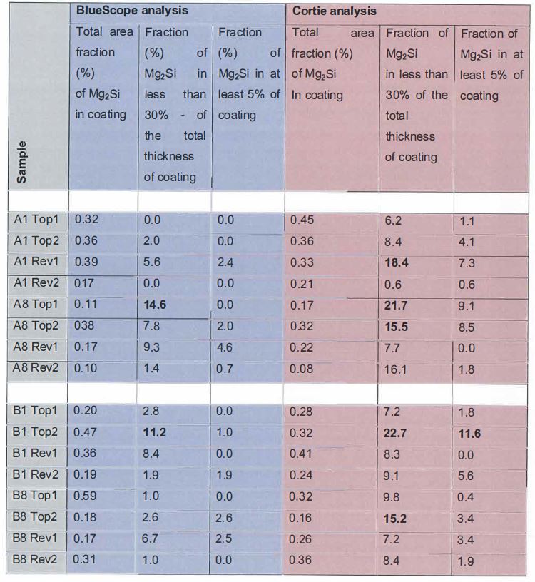
623 In this regard, the post-acquisition analysis rule that he used to identify the Mg2Si on the polished cross-sections was that a pixel was counted as Mg2Si if (34<Mg<600) AND (60<Si<350) AND (0<Zn<400) AND (0<Al<400) AND (0.1 < Mg:Si < 3.0) AND (is NOT counted as coating if [Mg+Si+Zn+Al]<50), where the terms ‘Si’, ‘Zn’, ‘Mg’ and ‘Al’ are the numerical values of the raw X-ray counts measured by EPMA.
624 In general, he said that the Cortie algorithm gave higher proportions of Mg2Si in “surface region…that has a thickness that is less than 30% of the total thickness of the coating” and “surface region [that] has a thickness that is at least 5% of the total thickness”, including B1 Top2 containing more than 10% by weight of Mg2Si particles (11.6%) in the surface region that is at least 5% of the total thickness. The Cortie algorithm also identified five areas (compared to BlueScope’s two) that contained more than 10% in the surface region that had a thickness that was less than 30% of the total thickness of the coating. In respect of sample A, these are A1 Rev 1 (18.4%), A8 Top 1 (21.7%) and A8 Top 2 (15.5%), and for sample B, these are B1 Top 2 (22.7%) and B8 Top 2 (15.2%).
625 He considered why there was this variation in results from the Cortie method and the BlueScope method. In his opinion, it was probably due to the absence of a dilation operation on the Mg pixels in the Cortie method. That is, it was possible that there were slightly more “small” Mg2Si precipitates in the lower half of the coating of the GLX product, which were exaggerated by the BlueScope dilation operation. There were also small differences in terms of the delineation of the top and bottom surfaces, especially as the BlueScope method just used a straight line to mark the bottom edges of the coating base and the “5% top layer base”. In any event, both procedures could only provide an estimate of the Mg2Si, both because there was statistical scatter in the data anyway and because thresholding the Mg2Si from an EPMA or EDS map was not an exact process.
626 Since the Cortie method provided the complete distribution of Mg2Si as a function of depth through the coating, the distribution could be visualized as in Figures 11 and 12 below.
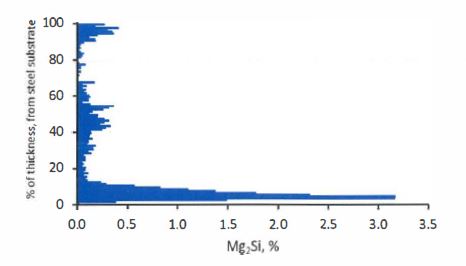
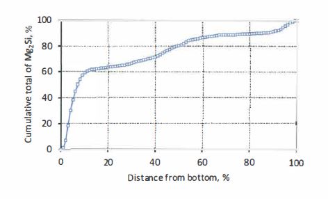
Figure 11: Average distribution of Mg2Si in sample A, according to Cortie analysis using custom-written ChemImage program.
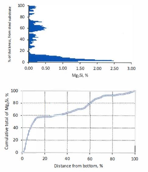
Figure 12: Average distribution of Mg2Si in sample B, according to Cortie analysis using custom-written ChemImage program.
627 In relation to analysing Mg2Si particles “in the surface” of the coating, Professor Cortie said the following. In analysing the data taken by Mr Moore, he noted that the set of rules that he used for the cross-sectional analyses gave inconsistent results for the surface analyses. This was no doubt due to the combined effect of surface roughness and the presence of corrosion products. He then modified the rules slightly by varying the lower and upper limits for the four elements until a satisfactory delineation of the Mg2Si precipitates was obtained. The post-acquisition analysis rules were that the pixel was identified as Mg2Si if (50<Mg<500) AND (70<Si<350) AND (0<Zn<200) AND (0<Al<200) AND (0.5 < Mg:Si < 3.0) AND (is NOT counted as coating if [Mg+Si+Zn+Al]<50).
628 His analysis of the data yielded comparable area fraction results to the BlueScope analysis for the total area fraction of Mg2Si “in the surface”, if this was to include the amount of Mg2Si that extended out of the top most surface region. The results of his analyses, together with the BlueScope results, are set out below. There is some statistical scatter in the individual measurements resulting, in his opinion, from the different thresholding rules used. In particular, the reverse side of sample B appeared to contain an unusual number of very small Mg2Si precipitates that had been exaggerated in area by BlueScope’s two pixel dilation process. He was not able to say whether it was due to some different treatment that the surfaces had received or not. But overall the differences were not statistically important in his opinion. Both his analyses and that of BlueScope showed that there were Mg2Si particles exposed on the surface. Due to the rough and non-polished nature of the surfaces, however, the area fractions as set out in the following table were only indicative.
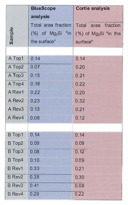
629 He agreed with Dr Prošek that by using a conversion factor the weight fraction of Mg2Si could be estimated. However, this pre-supposed an agreed standard density for the coating. However, he noted that a surface itself cannot contain a weight percent as it has no mass, so it was nonsensical to him to talk about the weight percent “in the surface of the coating” (on a 2D plane). In this regard, “in the surface of the coating” is an inexact concept, because the surface being two-dimensional can only possess an area fraction of precipitates and not a weight fraction since to have mass the particles must necessarily extend out of the 2D plane. He noted that the BlueScope protocol considered the “exposed” particles as being the area fraction of those particles of Mg2Si that broke through to the surface of the coating, divided by the total area fraction of Mg2Si particles throughout the coating thickness.
630 In my view BlueScope has not shown that there is no more than 10% by weight of Mg2Si particles in a surface region of the coating that has a thickness that is less than 30% of the total thickness of the coating and at least 5% of the total thickness of the coating. The testing conducted by Mr Moore in respect of tiny fractions of samples A and B did not persuasively establish the presence of this feature. This is because the Mg2Si distribution was not uniform. The relevant results showed significant fluctuations in the amounts of Mg2Si over a small area.
631 Further, Professor Cortie’s analysis shows more than 10% Mg2Si in a tested surface region having a thickness between 5% and 30% of the thickness of the coating. Further, if it is appropriate to calculate an average weight proportion, the average is greater than 10% in any event based on Professor Cortie’s analysis.
632 Let me deal with some other matters.
633 BlueScope submits that the existence of voids does not support the inference that some Mg2Si has been removed because the nature of an Al-Zn-Si-Mg alloy is that the zinc eutectics will corrode first and the aluminium will protect the Mg2Si. But I reject this argument.
634 Mr Moore’s evidence inconsistently oscillated between Zn protecting the Mg2Si and the Al protecting the Mg2Si, although on this issue the former was given primacy by him. He had no documents to corroborate either theory. Professor Cortie said he did not know whether Zn would protect the Mg2Si.
635 Further, even if Mr Moore’s Zn or Al protection theory had any substance, most of the corrosion troughs and voids were devoid of any material. That is, even if Zn and/or Al had acted as a first line trip before the Mg2Si was dissolved in these instances, all the material had dissolved including the Mg2Si. As Mr Moore volunteered water “dissolve[s] everything”. The following exchange illustrated the point:
HIS HONOUR: But that trough – assume, as you say, the zinc is the first line trip that sacrifices itself. There may have been magnesium silicide in there.
MR MOORE: There could have been.
HIS HONOUR: We just don’t know.
636 Further, in the few places where there was any Mg2Si remaining in a corrosion trough, the evidence suggests that there was a greater amount of Mg2Si before the corrosion had occurred. Professor Marder explained this in the following exchange:
HIS HONOUR: You would say if there had been Mg2Si there and you would still see it there at the bottom of that hole.
MR MOORE: Yes, it’s the eutectic that has been chewed out.
HIS HONOUR: Yes.
MR MOORE: So it’s – it’s very – it’s a complicated mixture of phases there, and all I’m drawing the attention to, that there is a whitish-yellowy phase there that Dr Cortie has – that Dr Cortie has called an Mg2Si and I’ve called an Mg2Si. We differ in size, of course, but that’s part of the issue, but it is definitely located in what would be called the void.
HIS HONOUR: So I was going back to page 9 of exhibit R3.
MR MOORE: Yes.
HIS HONOUR: Yes.
MR RYAN: Professor Marder, do you have a comment on that last answer?
PROF MARDER: Something is missing there. There’s a hole.
MR MOORE: There’s a hole.
PROF MARDER: And corrosion product is there. How much of the Mg2Si - original Mg2Si and the size that was there when it was first corroded, if that was corrosion, is maybe different than what we have right now. I don’t know if that Mg2Si is the same size as we started, but it certainly can be - you can certainly speculate that the size of the Mg2Si has dissolved a bit. So it would be a smaller particle than the original …
637 Further, Mr Moore’s evidence was that “zinc-rich areas corrode dramatically fast”. So even if his theory was accepted, Zn would not be much of a first line trip before Mg2Si was corroded by the water.
638 Further, irrespective of any galvanic protection, the small particles of Mg2Si existing near the surface of the coating would dissolve.
639 The experts agreed that smaller particles of Mg2Si existed closer to the surface of the coating. The smaller the Mg2Si particles, the easier it was to dissolve them in water:
MR COOKE: Thank you. And the effect that water has on magnesium silicide particles will vary depending on the size of the particle? By which, I mean, the smaller the particle, the easier it is to dissolve that particle.
MR MOORE: Yes.
MR COOKE: Thank you.
MR MOORE: I would make the point, however, it is galvanically protected in an aqueous environment by the zinc around it. Zinc will throw millimetres to protect steel. It will similarly throw millimetres 5 to protect Mg2Si.
MR RYAN: Professor Marder, do you have any comment on that last answer from Dr Moore in relation to the - - -
PROF MARDER: Of course. The smaller the particle, the easier it will be to dissolve. So any kind of a particle that has been subjected to water, because Mg2Si is water soluble, then it seems to me that we can expect the smallest particles which reside on the surface will be dissolved irrespective of any galvanic protection at all.
640 It is likely based upon BlueScope’s protocol, that Mg2Si particles that existed in the top 5% of the coating as made were dissolved by the grinding and polishing techniques used by BlueScope. The fact that smaller particles of Mg2Si existed very close to the surface and the fact that they were more susceptible to dissolving in water was material to calculating the distribution of Mg2Si in the top 5% of the coating. The measurements were very sensitive, including the distribution of Mg2Si in the top 5%. Mr Moore confirmed that the measurements as to the distribution of Mg2Si in the top 5% were very sensitive:
MR MOORE: … the nuance effects are the tiny particles, and when I say tiny if you look at the [Liu] paper which you reference, these are in order of magnitude less than what the literature talks about. These are so small that the literature isn’t even considering them. They’re double, if not tripled. If you do a quick back of envelope calculation, you only need next to three pixels or so - two pixels, actually, to increase the percentage by one. So you only need to switch on an extra five, 10 pixels in that top surface and you’ve doubled my numbers. There’s very little in the surface and most of them are these extremely small particles that are, shall we say, nuanced in terms every how we detect them.
…
HIS HONOUR: This context is different. And I think we’ve – everybody seems to be in heated agreement; you could get very small crystals, particles, whatever you want to talk about, of magnesium silicide very close to the surface. So what might be immaterial in terms of a defect in another context may become material in this context.
MR MOORE: Okay.
HIS HONOUR: So I would be interested in what Professor Marder has said and by reference to the image that we’re looking at on page 9.
MR MOORE: Yes; yes, your Honour. I neglected to address that point that he made. That particular sample or rather – when we looked at these samples in the surface work – there were areas where there have been corrosion. These samples were provided to us, and they were immediately put in a plastic bag. So we do not know the heritage or the – what are they called? What’s that word?
PROF CORTIE: Provenance.
MR MOORE: Provenance. We don’t know the provenance of the samples before they arrived.
HIS HONOUR: So you’re saying these defects existed and had nothing to do with your isopropanol or whatever you were – used for cleaning the - - -
MR MOORE: I’m saying I don’t know for sure.
…
HIS HONOUR: I could just – I mean – I’ve been sitting here – you know – listening for the last couple of days, and perhaps this is just my intuition, and you will have to forgive me, but you’re looking at magnesium silicide close to the surface, and there’s not very much of it, and we’re trying to work out the distribution close to the surface: top five per cent, top 30 per cent as compared with the balance. And smaller changes seem to have substantial effects - - -
MR MOORE: Yes.
HIS HONOUR: - - - in terms of the different approaches between yourself and Professor Cortie in terms of the numerator and denominator depending upon the approach. You know, some small changes in the number of pixels in the numerator less than the denominator, will skew the results substantially in terms of working out percentages of magnesium silicide close to the surface or in the relevant layer that we’re looking at, five per cent or 30 per cent.
So it just seems to me all of what you’ve done is very, very sensitive and, in some respects, it’s subjective, and if that’s appreciated, then these sorts of issues about potential corrosion of the samples are just going to be much more material than otherwise, aren’t they? If all of these results are very driven by very small amounts and the calculations of the percentages are very sensitive to very small changes, it just strikes me intuitively that if you pick up something that’s wrong with the sample such as corrosion, however it occurred, you would be concerned about that. Is that a wrong intuition or not?
MR MOORE: I think it boils down to how many of these interdendritic channels have actually corroded, and we’ve got evidence of a few, but not all of them show corrosion. It’s one of those things, once you have a corrosion pit, it changes the environment. You get what’s call acidification. You get diffusion of chlorides and other species into it. It creates its own microenvironment and off it goes. The initiation – it’s a bit like fatigue, roughly two-thirds of the life of the problem, be it fatigue, cracks or corrosion or whatever is just getting started, and the last third is it progressing through the material.
So you can see a lot of these images have but one entity in it. If you go back to image 1, there’s possibly none. Image 2 has one significant one. Image 3 has got one significant one. Image 4 has one significant one and, in that particular field, there’s one, two, three, four, five, six, seven, eight, nine interdendritic surface intersecting channels. So whether or not it’s significant enough to compromise the integrity of the work done, I can’t comment, but I will just draw attention to the fact it is not the average thing going on and - - -
HIS HONOUR: No, but then, as I understood it, there’s nothing average going on about the presence or the distribution of magnesium silicide particles - - -
MR MOORE: Yes.
HIS HONOUR: - - - whether along the surface or at depth. So I’m just wondering what might not be a problem with a little bit of ad hoc corrosion here and there, you might say, “No, well, that’s not - - -
MR MOORE: Yes.
HIS HONOUR: - - - “sensitive – our results are not going to be affected by that.” But where you’ve got results that are highly sensitive and, perhaps, in one view, highly subjective as to how you’re looking at pixels and the like, wouldn’t these sorts of problems be considered to be more material, or is that wrong?
MR MOORE: Without putting an arrow in Mr Cooke’s quiver, if that particular corroded part had more Mg2Si and, as a result of the corrosion product, they were lost, the answer to your Honour’s question would be yes. However, are they significantly different to the other eutectic regions? I don’t think so, but I cannot answer that question with a categorical yes or no.
641 Professor Marder’s evidence was to similar effect:
PROF MARDER: I agree with the judge in that what - what bothers me is a statement by Mr Moore that, well, we will just move onto another section that doesn’t have it. That doesn’t characterise the material. The material - this is there. You can’t wish it away, but the point is that there was something there. There was - it could have been corrosion that existed because of sitting on a dock somewhere or it could be because of preparation, but the fact is that there - and there's a way of showing that, and that is to make sure that your mounting material gets into - into these holes so we can say that it happened before.
But the fact is that if you’re going to count any of the material here and you are going to count something as sensitive as small little particles of Mg2Si, you better have an understanding of what was there to begin with. And if - and by carefully selecting a typical photomicrograph and excluding something like that is against anything that you might do an analysis of coatings or any materials, for that matter. It’s done all the time, but let’s be honest here, what are we looking for? We’re looking for what is occurring in the surface and, in this case, we don’t know.
642 Further, the measurements taken of the cross-sectional samples were flawed. As Professor Marder explained, the fact that the cross-sectional samples had corrosion defects and voids meant that the measurements taken by both Professor Cortie and Mr Moore were flawed:
… I don’t know the reason why we got these holes. I don’t know the reason why we had corrosion on the surface. But obviously - we are not looking at the complete specimen, and if we’re not looking at the complete specimen, then we have a problem with all of the measurements that have been done.
…
There is the specimens are faulty in that respect, and because of that, no matter what we do, and all the counting that we do, will not really define how much Mg2Si will exist in the surface.
643 As the cross-sectional images contained voids and corrosion troughs, this meant that Mg2Si was not accounted for. If the Mg2Si distribution were to be calculated correctly, the voids and corrosion troughs could not be avoided.
644 Further, and as Professor Marder explained to me, statistical averages could not be used to account for the voids and corrosion troughs because the presence of Mg2Si was non-uniform:
PROF MARDER: But you know - I don’t know how to make an adjustment to say, well, I can adjust this error and then add to it or subtract from it.
HIS HONOUR: I suppose if you have a frequency of magnesium silicide in some other area and that was a good statistical average, you could just apply it to the area that’s missing or something as a rough rule of thumb.
PROF MARDER: That could be true, if the Mg2Si was periodic.
HIS HONOUR: Yes.
PROF MARDER: But it’s not.
HIS HONOUR: No. It’s not.
PROF MARDER: It’s random.
HIS HONOUR: Yes.
PROF MARDER: So how can you make that kind of an adjustment.
645 In the circumstances, in my view BlueScope has not discharged its onus of proving that at least the top 5% of the surface of the coating of the GLX product had no more than 10% by weight of Mg2Si particles. It follows that BlueScope has not established that the GLX product falls within the scope of any of the asserted 258 Patent claims, that is, claims 2, 5, 6, 11 and 12.
646 Further, as I have indicated above, both Mr Moore’s and Professor Cortie’s respective calculations in respect of the distribution of Mg2Si in the top 5% were flawed. But BlueScope’s approach was also defective for additional reasons.
647 First, pixels were unable to account for small particles of Mg2Si. Despite what was sought to be measured as required by the claims of the 258 Patent, that is, the distribution of the Mg2Si in the top 5% of the coating, the BlueScope protocol additionally failed to take into account the limitations of pixels being able to account for small Mg2Si particles. This had particular consequences when considering the fact that there were a greater number of smaller Mg2Si particles towards the very upper surface of the coating and that the measurements were highly sensitive.
648 It would appear that in designing the protocol, BlueScope gave little consideration to these limitations and sensitivities. As Mr Moore said “…the way I set out to do it was based on the large ones and the standards, not to identify the tiniest ones possible”. During the conduct of the experiment he said to Professor Cortie words to the effect: “I knew that small magnesium silicide particles are there. I just didn’t think they were relevant” and “You are only interested in the big ones. The small bits are going to happen because of the solidification process of the coating. I didn’t realise that we’re interested in the little fellows”. Mr Moore also confirmed that his approach would not recognise any Mg2Si particles smaller than 0.2 microns in the rectangular cross-sectional samples for the purpose of calculating the distribution of Mg2Si.
649 Now Professor Cortie’s approach also had limitations in this regard. But BlueScope carried the onus of establishing that the GLX product fell within the asserted claims.
650 It is appropriate to set out the following exchange:
MR COOKE: …Now, you’d also agree, Mr Moore, that the pixel size you used is one micron; correct?
MR MOORE: On the surface maps, it is one micron. On the cross-section, it’s .2 micron.
MR COOKE: Yes, and so the size of the pixel will mean that, in respect of very small magnesium silicide particles, you wouldn’t have identified them; correct?
MR MOORE: The one micron size - - -
MR COOKE: Less.
MR MOORE: Sorry, let me get this right. You’re saying in the one-micron size pixels, I wouldn’t identify the ones that I’d identified on the .2-micron pixel size?
MR COOKE: No, that’s my unclear question. I apologise for that. Now, in respect of magnesium silicide particles which were, say, less than 0.5 microns.
MR MOORE: Yes.
MR COOKE: Your pixels wouldn’t identify that, would they?
MR MOORE: The surface ones wouldn’t, but the cross-section would.
MR COOKE: So what size – what’s the lower limit that – what’s the lower limit of the size of a magnesium silicide particle that your one pixel would identify?
MR MOORE: Approximately one micron.
MR COOKE: So, below that, your methodology wouldn’t identify it?
MR MOORE: No,
MR COOKE: And - - -
MR MOORE: On the surface maps.
MR COOKE: Yes. So on the discs, your methodology wouldn’t identify the magnesium silicide particles less than one micron?
MR MOORE: On the discs, yes. There was the surface maps; correct.
MR COOKE: Yes, and I think the evidence you’ve given is that the majority of the small magnesium silicide particles will exist on the surface of the coating.
MR MOORE: In the eutectic troughs.
MR COOKE: Yes.
MR MOORE: And in the case of mottle where the interdendritic liquid has been squished on to the top – this occurs from early on in the process, your Honour. Early on in the process, you squish a large amount of magnesium rich liquid onto the surface, you get large fan shaped Mg2Si that are amply resolved at this one micron.
MR COOKE: Yes, and you would also understand that Professor Cortie’s methodology wouldn’t detect magnesium silicide particles which were less than one micron on the surface?
MR MOORE: Yes.
MR COOKE: And that’s because he has used your data.
MR MOORE: He may be able to adjust and get a few more to show up, rather than I have, by the nature of his slider bars, and, by the way, Dr Cortie’s does use different slider bar settings for the surface. I use the same calibration approach for surface and cross-section. Dr Cortie uses, I believe, two different sets of settings.
MR COOKE: So, Professor Cortie, would you like to comment on the lower limit of the size of the magnesium silicide particle that your methodology would detect?
PROF CORTIE: So, your Honour, it goes to what I was asked before by the other counsel. So we have a one-micron block and, within it, all these different particles which we can’t see. My methodology would give a reasonable probability of finding a small magnesium silicide within the one-micron block. Because of the proposition put to me by Mr Caine – so, yes, I will find more because my methodology works differently to Mr Moore’s one.
MR COOKE: Yes, and what’s the answer to my question, what’s the lower limit of the size of the magnesium silicide particle that your methodology would pick up?
PROF CORTIE: I can’t size it. I just know it’s less than one micron.
MR COOKE: Right. And would it pick up a 0.5 micron?
PROF CORTIE: I believe so.
MR COOKE: Less than?
PROF CORTIE: No.
651 Professor Cortie confirmed that his approach would not recognise any Mg2Si particles smaller than 0.1 microns in the rectangular cross-sectional samples for the purpose of calculating the distribution of Mg2Si.
652 It is also appropriate to set out the following exchange:
MR COOKE: Professor Cortie, what’s the lower limit of the size of magnesium silicide particle that your methodology would detect?
PROF CORTIE: Based on the answer I gave for the surface roughness, about half of the pixel size, so maybe .1.
MR COOKE: And, Mr Moore, you would agree that there’s more smaller magnesium silicide particles in the top 30 per cent of the coating than the bottom?
MR MOORE: There are more smaller pixels in the interdendritic regions in the final quaternary eutectic because there’s more of that up the top of the coating.
MR COOKE: So is the answer to my question yes?
MR MOORE: A nuanced yes.
MR COOKE: And would you agree that the size of the magnesium particles in the top five per cent are, typically, even smaller than what occurs in the top 30 per cent of the coating?
MR MOORE: I am torn between saying “absolutely” and “I don’t know”. However, to detect a .1 micron particle and inflate it to a whole pixel is a four times inflation. A four times overestimate of its size – at least four.
MR COOKE: Professor Cortie, do you have any comments in relation to what I’ve just discussed with Mr Moore in terms of the relative size of the magnesium silicide particles?
PROF CORTIE: Yes,…so I claim that, probably, the lower limit was .1. So they are probably one or two that got inflated to one pixel so four times their size. That’s the extreme. That is the absolute limit of my detection. Almost all of the ones that were readily detected would have been bigger than that. Who knows what proportion – 99 per cent?
653 Second, there was a problem in the use of horizontal straight lines. As I have previously indicated in calculating the top 5% of the coating, BlueScope used a horizontal straight line rather than a line following the contour of the coating at its surface.
654 The process that Mr Moore undertook to draw the 5% horizontal line appears to have been the following. He drew a straight horizontal line to represent the intermetallic layer. He established that line by counting the number of pixels above and below and ensuring that they were equal to each other. He then calculated approximately 95% of the surface area of the coating using the horizontal bottom line by counting pixels to establish his “5 % line”. Mr Moore agreed that he was “measuring the surface area, not the thickness from the surface.” He said “that’s the whole purpose of the protocol”.
655 But as I have indicated elsewhere, there were difficulties with BlueScope’s approach. Mr Moore appeared to accept that at some places the “5 % line” was at the very surface of the coating (i.e. at 0% thickness) and at other places it was at a depth greater than 5% thickness from the surface of the coating.
656 Contrastingly, Professor Cortie calculated boundaries conformal with the actual outer surface and the interface with the steel substrate albeit after the cross-sectional samples had undergone grinding and polishing. He worked from the surface to establish the top 5% thickness. Professor Cortie applied his rules to the entire coating, which meant that the pixels were analysed conformal with the actual contours of the coating surface and base.
657 As a result of the contrasting approaches, there were a number of instances where Mr Moore’s 5% line did not count Mg2Si particles whereas Professor Cortie’s line did.
658 In evidence was a histogram of Professor Cortie’s aggregated data for samples A and B as %Mg2Si area fraction as a function of depth within coating for aggregated data. Although the consequence of BlueScope’s preparation of the cross-sectional samples meant that Professor Cortie had undercounted the distribution of Mg2Si in the top 5%, what his results do nonetheless show is that there was a “flourish” of Mg2Si around the 5% mark. As Mr Moore agreed, this meant that where you drew the 5% line had a significant effect on the results:
MR COOKE: And if you - because there is a flourish of magnesium silicide particles around that five per cent mark, where you place the five per cent boundary would matter, wouldn’t it?
MR MOORE: Yes.
MR COOKE: Because you’re more susceptible to missing out on magnesium silicide particles if you don’t measure the five per cent from the thickness from the surface.
MR MOORE: That sounds reasonable, yes. I will agree with that, yes.
659 Third, let me say something about the pixel dilation error. The “pixel dilation operation” in the thresholding procedure used by BlueScope artificially inflated the amount of Mg2Si towards the bottom of the coating which meant that BlueScope underestimated the proportion of Mg2Si in the top 5% of the coating compared with the proportion of Mg2Si in the rest of the coating. Mr Moore appeared to agree that the pixel dilation step in some cases rather than excluding silicon counted that as Mg2Si when it was embedded in or adjacent to silicon. Mr Moore appeared to agree that in those instances it overinflated the Mg2Si compared to what was actually there. Now it also appeared to be agreed that the majority of the silicon existed towards the lower half of the coating. So, as a corollary, the following was confirmed:
MR COOKE: Yes, thank you. But the over-inflation of magnesium silicide down the bottom of the coating logically means that the percentage of magnesium silicide calculated in the top of the coating is underestimated.
MR MOORE: Yes.
660 Mr Moore confirmed such an inflation of the Mg2Si in the lower portions of the coating as compared with Professor Cortie’s approach. He agreed that in some instances they were inflated by at least a factor of two. Mr Moore also agreed that because the distribution of Mg2Si was being measured, it was important that the thresholding did not bias the results:
MR COOKE: What matters, Mr Moore, is making sure that how you treat the magnesium silicide from the top to the intermetallic layer down the bottom is uniform, because we’re interested in the distribution of magnesium silicide. That’s correct; isn’t it.
MR MOORE: Correct; yes.
661 So, BlueScope’s approach undercounted the Mg2Si in the top 5%. Mr Moore conceded that his dilation procedure and the horizontal line meant that he undercounted the Mg2Si in the top 5%:
MR COOKE: And you would accept, Mr Moore, that because you’ve used the horizontal line approach, that you’ve undercounted the magnesium silicide in the top five per cent.
MR MOORE: I would word it this way. I have undercounted Mg2Si in the surface as a result of (a) the difference in the thresholding and (b) the difference in the approaches that we use from the bottom up and the top down. I would say there’s - the differences can be related to those two issues.
662 Finally and generally, as I have already indicated, in my view Professor Cortie’s methodology should be preferred over Mr Moore’s methodology.
663 Now Mr Moore was critical of the final check in Professor Cortie’s algorithm. But it would seem that Mr Moore’s methodology had no such check and that had he had one then he would have detected his dilation error.
664 Further, and in contrast as Professor Cortie explained, his thresholding methodology did not have the dilation error:
PROF CORTIE: Yes, the one to the left of it is a bit bigger. So this is statistics in action. There’s just little bit of variation, but, on average, I think that if mine are slightly bigger than Mr Moore’s outside of the red circles, that’s just a choice of different thresholding, but there’s no bias in mine. It doesn’t matter if it’s top or bottom, my method treats it the same. Doesn’t matter if it’s next to silicon or not.
MR COOKE: So can you explain to his Honour how, if at all, that affects the distribution of magnesium silicide particles.
PROF CORTIE: Well, it doesn’t affect the distribution because the same - - -
HIS HONOUR: You’re saying your method is bias free; whereas Mr Moore’s dilation method - - -
PROF CORTIE: Well, it’s certainly - - -
HIS HONOUR: - - - were biased to the extent that it enlarges these particles?
PROF CORTIE: Yes, your Honour. I don’t have that particular issue. That significant bias is absent in my method.
HIS HONOUR: Yes.
665 Further, Mr Moore’s criticism that Professor Cortie’s methodology was adversely affected by ZAF factors was not made good. As Professor Cortie explained, the ZAF effect applies equally from top to bottom of the coating such that it can cause no bias in calculating the distribution of Mg2Si.
666 In summary, BlueScope has not discharged its onus of establishing that the GLX product fell within claim 2. This is because of the grinding and polishing techniques it used in the experiments, the existence of corrosion troughs and voids in the samples and the insufficient sample size tested. As a consequence of the polishing and grinding techniques used by BlueScope, voids and corrosion troughs were present in the cross-section samples prepared by BlueScope. Further, an insufficient sample size was tested by BlueScope. These deficiencies and the fact that the measurements were very sensitive meant that both Professor Cortie’s and Mr Moore’s calculations of the distribution of Mg2Si in the top 5% were flawed. Had BlueScope not created or had addressed these deficiencies, then Professor Cortie’s methodology would have established the amount of Mg2Si in the top 5% of the surface coating.
667 Further, in any event Professor Cortie’s analysis shows more than 10% Mg2Si in a tested surface region having a thickness between 5% and 30% of the thickness of the coating.
668 Further, Professor Cortie’s evidence is to be preferred. The “pixel dilation operation” in the thresholding procedure used by BlueScope artificially inflated the amount of Mg2Si towards the bottom of the coating which meant that BlueScope underestimated the proportion of Mg2Si in the top 5% and 30% of the coating compared with the proportion of Mg2Si in the rest of the coating. Further, in calculating the top 5% and 30% of the coating, BlueScope used horizontal straight lines rather than lines following the contour of the coating at its surface and at its interface with the steel substrate.
669 Further, as Professor Marder pointed out the preparation of the samples by BlueScope involved grinding and polishing with the use of hygroscopic alcohol including ethanol which would have introduced water and dissolved Mg2Si.
670 Further, in relation to sample size, BlueScope asserted that although the size of a standard coil of coated steel is 1.2m x 3000m, it is standard practice to ascertain properties of a coil using very small samples. But the examples provided are standards for testing thickness and corrosion resistance. These are not relevant to the matters in question in this case. Standards may assist buyers and sellers of products to have a certain pragmatic confidence in particular qualities of a product and its suitability for particular commercial purposes by taking small samples without destroying the remainder of the product. But this involves an element of compromise. But there is no reason why it was necessary to preserve any part of the samples in question in this proceeding. There was no reason to take any short cuts. In any event, as Professor Marder points out the sample size for thickness testing is normally 1000 times the size of the samples taken in this case.
671 The above points apply to all the asserted claims, as they are all dependent upon claim 2, that is, claims 5, 6, 11 and 12. The following are additional non-infringement points for certain claims.
Claim 5
672 Let me deal with the following additional integer:
…wherein the coating thickness is less than 30μm.
673 Dongkuk originally admitted that its products had a maximum coating thickness of less than 30 μm, but for reasons given elsewhere I will allow it to withdraw its admission. The analysis of Professor Cortie shows that the coating thickness was not less than 30 µm.
Claim 6
674 The following additional integer is admitted by Dongkuk:
…wherein the coating thickness is greater than 7μm.
Claim 11
675 The following additional integer is admitted by Dongkuk:
…wherein the coating contains less than 3000 ppm Sr.
Claim 12
676 Let me say something about the following additional integer:
…wherein there are minimal coating thickness variations.
677 In my view, the evidence establishes that the relevant thickness variations are more than minimal coating thickness variations in the GLX product.
Claims 17 to 25
678 BlueScope does not press its allegations of infringement in relation to claims 17 to 25 of the 258 Patent.
Summary
679 For the above reasons, BlueScope has not proved infringement of relevant claims of the 258 Patent (assuming them to be valid). Let me now turn to the relevant invalidity questions.
INVALIDITY – GENERAL
680 Each of the Patents has a priority date of 13 March 2008 flowing from the filing of a provisional patent specification. The complete specification in each case was filed on 13 March 2009. The Patents were accepted on 25 September 2014.
681 Dongkuk says that claims 1, 3, 4, 5, 6, 8, 9, 11, 12, 13, 14 and 15 of the 257 Patent are invalid. Further, it says that claims 1, 2, 5, 6, 11, 12, 17, 18, 20, 21, 22, 23, 24 and 25 of the 258 Patent are invalid.
(a) The expert evidence
682 Dongkuk has relied on the testimony of four expert witnesses being Professor Marder, Mr Rommal, Professor Cortie and Mr Michael Salon.
683 Professor Marder is the R.D. Stout Distinguished Emeritus Professor of Material Science and Engineering at Lehigh University, Bethlehem, Pennsylvania. He has a PhD in Materials Science and Metallurgy from Lehigh University. During the period 1965 through to 1987 he held various roles in the Research Department of Bethlehem Steel. Bethlehem Steel invented galvalume. Professor Marder’s roles at Bethlehem Steel included Supervisor of the Phase Transformations Research Group and Senior Scientist. During the period 1982 to 1991, Professor Marder was an adjunct Professor of Materials Science and Engineering at Lehigh University. In 1991, he was appointed a full Professor of Materials Science and Engineering, teaching undergraduate and graduate courses on processing and properties of metals and phase transformations, failure analysis, introductory lab techniques, coatings and corrosion and advanced physical metallurgy until he retired in 2007. Professor Marder has substantial knowledge of and experience in the structure and qualities of galvalume, and the methods for manufacture of galvalume. He is the author or co-author of more than 200 articles and seven book chapters in the metals and materials technology field, and the editor of the text, The Physical Metallurgy of Zinc Coated Products, as well as two chapters of the ASM Handbook. Professor Marder is also a fellow of ASM International, the global association of metal and materials engineers and scientists that publishes reference materials like the ASM Handbook.
684 Mr Rommal is a materials science engineer with a Bachelor of Engineering Science and a Masters of Science in Engineering from John Hopkins University. He was employed for 14 years at Bethlehem Steel in senior research and development roles. Mr Rommal has substantial knowledge and experience in Zn-Al coatings and in the development of hot dip alloy coatings for steel sheet. His work at Bethlehem Steel included studies of the effects of variations to the composition of galvalume coating including the addition of Mg. This work was part of “Project 4 Star”, based on the work of Bethlehem Steel research engineer, Neal Berke, one of the inventors of what I have elsewhere described as the Berke patent (US patent no. 4,401,727 “Ferrous product having an alloy coating thereon of Al-Zn-Mg-Si alloy, and method”).
685 Professor Cortie is a physical metallurgist, currently holding the position of Discipline Leader: Physics at the University of Technology Sydney. From 2002 until 2017 he was Professor of Nanotechnology and Director of the Institute for Nanoscale Technology, UTS. He has more than 30 years’ experience in the field of metallurgy, and in the use of optical microscopes, scanning electron microscopes and electron microprobe microanalysers.
686 Mr Salon has 32 years’ experience in the operation of alloy coating lines used in the application of alloy coatings to steel strip. In 1976, Mr Salon was employed by John Lysaght Australia (JLA), which became a wholly owned subsidiary of BHP. BHP Steel was later spun off from BHP to become BlueScope. Mr Salon was involved in the establishment of the first commercial production line for galvalume product produced in Australia by JLA under licence from Bethlehem Steel. In 1987, Mr Salon became the Manager, Metallic Coatings R&D at JLA, which was responsible for developing new or improved coating compositions. During the period 1998 to 2001, Mr Salon was the General Manager Steel Research Laboratories, with the Managers of Polymer Coating R&D, Metallic Coating R&D, Hot & Cold Rolling R&D, Steelmaking R&D and Ironmaking R&D reporting to him. After he retired in 2002 and during the period 2002 to 2010, Mr Salon consulted for BlueScope on four or five occasions, two of which were in respect of problem solving projects with galvalume licensees in the United States and China.
687 BlueScope has relied upon two expert witnesses, being Dr Prošek and Mr Ronald Dutton.
688 Dr Prošek is a materials engineer and the Head of Department of Metallic Construction Materials at the Technopark Kralupy of the University of Chemistry and Technology (UCT) in Prague, Czech Republic. He has 20 years’ experience in corrosion engineering and has undertaken research into corrosion resistance of steel products. Dr Prošek holds a Masters of Science from the Department of Metals and Corrosion Engineering at the UCT and a PhD from the same university on the “Influence of heat transfer on localized corrosion of stainless steel”. Between 2001 and 2003, Dr Prošek worked in a number of research capacities until joining the French Corrosion Institute in Brest, France, as a Senior Researcher and Project Leader in 2004. As part of his role as Project Leader, he led a team of researchers and investigated inter-alia the corrosion protection of coil-coated materials, the development of novel zinc-based protective coatings and accelerated and natural corrosion on metallic coatings. In 2007, Dr Prošek was promoted to Research and Development Leader, Building and Infrastructure at the same institute. He was responsible for research projects relating to atmospheric corrosion of metallic building materials and was the Secretary of the Member Research Consortium “Corrosion properties of coil-coated steel products”, a grouping of 15 international steel producers and their suppliers, including Swedish Steel, Tata Steel, ArcelorMittal, and BlueScope. In 2015, he returned to the UCT to set up and head the Metallic Construction Materials department. Dr Prošek holds a number of professional appointments including being President of The Czech Association of Corrosion Engineers.
689 Mr Dutton is a product applications and customer engineering professional and is the President of Ron Dutton Consulting Services LLC, which provides consulting services in the area of hot dip metallic coated steel products. He has over 40 years’ experience in the field of metallic-coated and pre-painted steel products, with a strong emphasis on 55%Al-Zn alloy coated sheet (galvalume). He graduated from Drexel University, Philadelphia, with a Bachelor of Science in Metallurgical Engineering in 1971 and completed a Masters in Metallurgy and Materials Science through Lehigh University in 1977. Between 1971 and 2003, Mr Dutton worked for Bethlehem Steel in a variety of different roles including in research engineering positions in hot dip and tin mill coatings, in a customer engineering function in the sales department and in product applications. In 1993, he moved to Bethlehem Steel’s Sparrows Point plant and held various positions in customer technical services, supporting the marketing of Bethlehem Steel’s galvalume product and the operation of the Sparrows Point plant. From 2003 to 2009 he held quality assurance and customer technical services positions at Sparrows Point for successor companies to Bethlehem Steel, namely International Steel Group, Mittal Steel Company and Severstal. From 1984 to 2009 Mr Dutton was a member of the North American Zinc Aluminium Coaters Association and from 2011 onwards he has been a member of the American Society for Testing and Materials. He has presented papers at a number of conferences, has authored or co-authored 10 publications in the field of hot dip coated steel and is a named inventor on two US patents on the manufacturing of faux stainless finishes on coated sheet.
690 I found all expert evidence to be of considerable assistance. But where there were differences between the experts on some topics I have had to select between them. Where I have done so I have explained my choice of preference at the relevant parts of my reasons.
(b) Construction principles
691 Before proceeding further I should say something about the principles of construction as they are relevant to some of the invalidity questions. As I said in Meat & Livestock Australia Ltd v Cargill, Inc (2018) 354 ALR 95; [2018] FCA 51 (MLA (No 1)) at [213] to [221], the principles governing the construction of patent specifications, including claims, are well established. A claim is construed from the perspective of a person skilled in the relevant art as to how such a person would have understood the patentee to be using the words of the claim in the context of the specification as a whole. Further, a claim is to be construed in the light of the common general knowledge including the art before the priority date.
692 A measure of common sense should be used. And ordinary words should be given their ordinary meaning unless a person skilled in the art would give them a technical meaning or the specification ascribes a special meaning.
693 In terms of how the body of the specification may be used in construing a claim, the claim should be construed in the context of the specification as a whole even if there is no apparent ambiguity in the claim. Nevertheless, it is not legitimate to narrow or expand the boundaries of the monopoly as fixed by the words of a claim by adding to these words glosses drawn from other parts of the specification. More particularly, if a claim is clear and unambiguous, to say that it is to be read in the context of the specification as a whole does not justify it being varied or made obscure by statements found in other parts of the specification.
694 Now the specification may stipulate the problem in the art before the priority date and the objects of the invention that are designed to address or ameliorate this. Accordingly, the specified objects may be useful in construing a claim in context. Nevertheless, the specified objects are not controlling in terms of construing a claim; glosses cannot be drawn from the objects.
695 A claim should be given a purposive construction. Words should be read in their proper context and a too technical or narrow construction should be avoided. Further, the integers of a claim should not be considered individually and in isolation. Further, a construction according to which the invention will work is to be preferred to one in which it may not. But to give a claim a purposive construction “does not involve extending or going beyond the definition of the technical matter for which the patentee seeks protection in the claims” (Sachtler GmbH and Co KG (formerly Sachtler AG) v RE Miller Pty Ltd (2005) 221 ALR 373 at [42] per Bennett J). To apply a purposive construction does not justify extending the patentee's monopoly to the ideas disclosed in the specification.
696 In terms of the skilled addressee, one is using a hypothetical construct. The following principles are applicable.
697 First, to identify the characteristics of the skilled addressee, the field to which the invention relates must be identified.
698 Second, the skilled addressee is taken to be a person of ordinary skill (as opposed to a leading expert) in that field and equipped with the relevant common general knowledge including the art before the priority date.
699 Third, the qualifications and experience of the skilled addressee will depend on the particular case, having regard to the nature of the invention and the relevant industry. Formal qualifications are not essential. Practical skill and experience in the field may suffice. A patent specification is addressed to those having a practical interest in the subject matter of the invention; such persons are those with practical knowledge and experience of the kind of work in which the invention is intended to be used.
700 Fourth, the hypothetical person skilled in the art may possess an amalgam of attributes drawn from a team of persons whose combined skills, even if disparate, would normally be employed in interpreting and carrying into effect instructions such as those contained in the specification.
701 Fifth, as the skilled addressee comes to a reading of the specification with the common general knowledge of persons skilled in the relevant art, they read it knowing that its purpose is to describe and demarcate an invention. But the person skilled in the art is not particularly imaginative or inventive.
702 Sixth, the skilled addressee does not come to reading the specification seeking failure.
LACK OF CLARITY AND LACK OF DEFINITION
703 Let me begin with the asserted invalidity ground concerning lack of clarity and lack of definition. For this purpose, in terms of the relevant principles I repeat what I said in MLA (No 1) at [932] to [940].
704 The requirements that a claim be clear (s 40(3)) and define the invention (s 40(2)(b)) are separate requirements under the Act, but it is convenient to deal with them together.
705 A valid claim is required to define with sufficient certainty the scope of the monopoly being claimed. Given that a patent is a public instrument, the claim must be defined in such a way that it is not reasonably capable of being misunderstood so that others know the “exact boundaries of the area within which they will be trespassers”: Electric & Musical Industries Ld v Lissen Ld (1939) 56 RPC 23 at 39 per Lord Russell of Killowen. A claim will lack clarity if a person skilled in the relevant art cannot ascertain whether what he proposes to do falls within the claim’s ambit.
706 In Norton and Gregory Ld v Jacobs (1937) 54 RPC 271, Lord Greene MR said at 276:
…The duty of a patentee is to formulate his claim in such a way as to define with clarity the area of his monopoly; the claim is the solemn operative part of the Specification in which the patentee sets himself to achieve that purpose, and in construing it, it is of great importance not to lose sight of that fact. It is illegitimate to whittle away clear worlds in a claim by reading into them glosses and limitations extracted from the body of the Specification whose function is in its essence different from that of the claim. Each part of the document must be construed in the light of the function which is peculiarly its own. In the same way it is in our opinion illegitimate to whittle away the clear words of the claim – selected, as they must be taken to be, with the peculiar function of the claim in mind – by writing into them glosses and limitations based on the fact that a skilled chemist would avoid working in part of the area which the words in their ordinary meaning are wide enough to include.
707 In Welch Perrin & Co Pty Ltd v Worrel (1961) 106 CLR 588, Dixon CJ, Kitto and Windeyer JJ said (at 610):
…It is, however, fitting that we remind ourselves of the criterion to be applied when it is said that a specification is ambiguous. For, as the Chief Justice pointed out in Martin v. Scribal, referring to Lord Parker’s remarks in National Colour Kinematograph Co. Ltd. v. Bioschemes Ltd, we are not construing a written instrument operating inter partes, but a public instrument which must, if it is to be valid, define a monopoly in such a way that it is not reasonably capable of being misunderstood. … Courts have often insisted that it is not legitimate to narrow or expand the boundaries of monopoly as fixed by the words of a claim by adding to those words glosses drawn from other parts of the specification…
(Citations omitted.)
708 In Martin v Scribal Pty Ltd (1954) 92 CLR 17 (Scribal), Dixon CJ said at 59:
The following passage, however, in the judgment of Lord Parker (Natural Colour Kinematograph Co. Ltd. (In liquidation) v. Bioschemes Ltd.) describes what is the duty of the court and provides the test of ambiguity:- “Further, though it may be true that in construing an instrument inter partes the Court is bound to make up its mind as to the true meaning, this is far from being the case with a Specification. It is open to the Court to conclude that the terms of a Specification are so ambiguous that its proper construction must always remain a matter of doubt, and in such a case, even if the Specification had been prepared in perfect good faith, the duty of the Court would be to declare the Patent void. Once again, though the Court may consider that the meaning of the Specification is reasonably clear, yet if the Specification contain statements calculated to mislead the persons to whom it is addressed, and render it difficult for them without trial and experiment to comprehend in what manner the patentee intends his invention to be performed, these statements may avoid the Patent…”
(Citation omitted.)
709 But lack of precise definition will not be fatal to the validity of a claim as long as it provides a workable standard suitable to the intended use. But as stated in Kauzal v Lee (1936) 58 CLR 670 at 685 per Dixon and McTiernan JJ:
[v]agueness of description, want of particularity and evident indistinctiveness of thought may be the source of so much uncertainty as to the scope of the monopoly that the claim fails to fulfil the requirement of stating with definiteness to what the patentee is exclusively entitled.
710 Thus, the requirement for clarity is not satisfied where a person cannot objectively ascertain whether or not what he proposes to do falls within the ambit of the claim. Therefore, the foundational requirement that a patent makes objectively clear to the public the actions that will infringe the claim is the price the patent owner pays to enjoy its monopoly rights. If the claims do not make this clear, the patent cannot fulfil this fundamental purpose, and is invalid.
711 A patentee should be assumed to have chosen the words of the claims carefully, and it is not my role to re-write a claim in an effort to save it from a lack of clarity.
712 A claim is clear if either there is no ambiguity or any ambiguity is resolvable by properly construing the claim applying the principles that I have set out previously. But I accept that a claim is bad if no reasonably certain construction can be given to it. And I also accept that I am not bound to find a meaning for a claim nor to approach a claim with the conviction that its language is capable of a reasonable construction when carefully examined.
713 Finally, if a claim is clear, it is not to be made obscure or treated as obscure by taking elements of a preferred embodiment not referred to in the claim and artificially creating obscurity.
714 Let me turn to the question of definition.
715 Section 40(2)(b) requires the complete specification “to end with a claim or claims defining the invention”. In General Tire & Rubber Co v Firestone Tyre and Rubber Co Ltd (1971) 1A IPR 121, the Court stated at 167 that “the issue of definition is to be considered as a practical matter and little weight is to be given to puzzles set out at the edge of the claim which would not as a practical matter cause difficulty to a manufacturer wishing to satisfy himself that he is not infringing the patent”. The Court also observed that allowances should be made for any difficulties of the case, so that an alleged issue of want of definition should always be considered in relation to the particular facts. It concluded (at 167 and 168):
It is clear in our judgment that the question whether the patentee has sufficiently defined the scope of his claims is to be considered in relation to the facts of each case, that allowance is to be made for any difficulties to which the circumstances give rise, and that all that is required of the patentee is to give as clear a definition as the subject matter admits of. It is also clear in our judgment that, while the court is to have regard to all the relevant facts, the issue of definition is to be considered as a practical matter and little weight is to be given to puzzles set out at the edge of the claim which would not as a practical matter cause difficulty to a manufacturer wishing to satisfy himself that he is not infringing the patent. We accept also that definition of the scope of a claim is not necessarily insufficient because cases may arise in which it is difficult to decide whether there has been infringement or not provided the question can be formulated which the court has to answer in the issue of infringement.
716 A claim will be bad if it fails to define the monopoly claimed so that the skilled addressee of the patent can know the exact boundaries of the area within which they will be trespassers.
717 A claim must also clearly define the invention, so far as it relates to the matter claimed. As observed by Jessup J in Albany Molecular Research Inc v Alphapharm Pty Ltd (2011) 90 IPR 457 at [174]: “[a] claim which is a model of verbal or grammatical clarity may none the less fail the test of this requirement if it leaves the definition of the boundaries of the invention uncertain or variable”. In that case, Jessup J held at [174] to [175] that “a substantially pure piperidine derivative compound” did not lack clarity, however, lacked definition because the boundaries of the invention were uncertain or variable.
718 Let me say something about claims by result. It is permissible to define either a feature in a claim or a whole combination claimed by defining the result in the claim. However, particular care needs to be taken in drafting such claims. In Patents for Inventions and the protection of industrial designs (5th ed, The Law Book Company, 1983), Mr Blanco White QC said at para 4-413:
To amount to a limitation by result, what is in the claim must at least be a limitation: something that draws a line between two classes of things that would otherwise fall within the claim: with the implication that conditions of the manufacture can be adjusted, by the reader of the specification, to secure the specified result. It is, of course, a matter of construction to determine whether words in the claim effect a limitation or merely assert that complying with the claim will secure a certain result, and this like other questions of construction affecting validity is likely in present-day conditions to be decided in favour of an otherwise meritorious patentee.
719 He further said at para 4-703:
….particular care must be taken when claims of this sort are adopted to give in the specification all possible assistance in determining what does, and what does not, give the useful result concerned: clarity of claim and sufficiency of description go together here. Thus a claim limited by result has been held bad for ambiguity where the instructions for attaining the result were meaningless to those in the art. In addition, it must not be forgotten that there is no authority for putting upon the reader of the specification the burden of making any but “simple” experiments…
(a) The 257 Patent
720 The following issues of definition and clarity arise on claim 1 and relevant dependent claims of the 257 Patent.
721 First, Dongkuk says that the expression “a small proportion of Mg2Si particles” is entirely unclear. It says that a person seeking to avoid this claim has no notion at all of what proportion of Mg2Si in the surface would avoid infringement. The same issue applies to the expression “substantially no Mg2Si particles”.
722 Second, Dongkuk says that the expression “in the surface of the coating” is unclear. It says that perhaps one reading of that expression would contemplate Mg2Si particles lying on the surface of the coating in much the same way as a swimmer lies on the surface of the water in a pool. However, Figure 1, which is said to illustrate the invention, identifies by a perforated line beneath the surface of the coating a region that is said to be free of Mg2Si. Dongkuk says that it is therefore unclear whether “in the surface of the coating” means on the surface or at some depth near the surface.
723 Third, Dongkuk says that claim 6 is unclear in so far as it uses the expression “less than a threshold cooling rate”. It says that a person seeking to avoid that claim would have no idea what cooling rate would be outside the claim. Dr Prošek’s evidence was that all he learns from the expression “less than a threshold cooling rate” is that there is “a maximum cooling rate I am not allowed to exceed, even if it is not specified in the patent by number”.
724 Fourth, Dongkuk says that claim 15 is unclear in so far as it uses the expression “a surface of the coating”, there being only one surface of the coating. It says that that claim is also unclear in so far as it refers to the surface being “substantially free of any Mg2Si particles” or “has only a small proportion of Mg2Si particles”. It asks rhetorically: How is the putative infringer to test this?
725 So, Dongkuk alleges that each of claims 1, 6 and 15 do not comply with s 40(2)(b) in that they fail to define the invention, and fail to comply with s 40(3) of the Act, in that they are not clear or succinct.
726 Now I reject Dongkuk’s assertions and largely for the reasons given by BlueScope.
727 First, a “small proportion of Mg2Si particles” (claim 1) means no more than 10 wt.% in light of the definition in the specification at p 6 lines 23 to 25. Further, the phrase “small proportion of Mg2Si particles” carries the same meaning in both claim 1 and claim 3. Moreover, the claims of a specification are not rendered invalid on account of there being a redundancy in the claims. As noted in David Kahn Inc v Conway Stewart & Co Ltd (1974) 91 RPC 279 at 308, there “is no absolute or invariable rule that different claims should be construed as of different scope”.
728 Second, the expressions “a small proportion” and “substantially no” with reference to Mg2Si particles (claim 1) do not carry the same meaning. The phrase “substantially no” means an immaterially small amount. The same point can be made about the expression “substantially free” in claim 15.
729 Third, Mg2Si particles which are in contact with or exposed to the coating surface are “in the surface of the coating” (claim 1). It is only those particles that communicate with the surface of the coating that will give rise to mottle. In this regard, Figure 1 does not purport to define the surface of the coating. It summarises the results of one set of experiments that illustrate the invention, that is, a preferred embodiment.
730 Fourth, the integer “less than a threshold cooling rate” (claim 6) is directed to a method of controlling the cooling rate to be less than a selected maximum value. The maximum value will depend on a number of factors including the coating mass of the product. In this regard, Dr Prošek’s evidence was not simply that all he learns from the expression is that there is a maximum cooling rate he is not allowed to exceed which is not specified in the Patent by number. As Dr Prošek explained:
I think that it’s very clearly specified in the body of the patent what values apply for whatever given coating thickness range. … They are two specific ranges, one for coating methods up to 75 grams and second one for ranges of range of 75 to 100 grams per square metre of strip. … if I’m producing coating at different coating thickness outside of this ranges …Then what I learn from the claim is that there is a maximum cooling rate that I am not allowed to exceed, even if it is not specified in the patent by number.
731 Fifth, as to the integer “a surface of the coating” (claim 15), a coated steel strip has two surfaces, namely, the top surface and the bottom surface. This integer requires a measurement of those Mg2Si particles which are visible when the coating surface is viewed from above, looking down onto the surface.
732 In summary, there is nothing in Dongkuk’s criticisms on this ground concerning the 257 Patent.
(b) The 258 Patent
733 Dongkuk says that claim 12 is unclear in so far as it uses the expression “minimal coating thickness variations”. It says that under cross-examination, Dr Prošek accepted that this was a “nonsense term”.
734 Further, Dongkuk says that claims 17 and 18 are unclear in so far as they refer to a cooling rate that is controlled but the rate is not identified.
735 Further, Dongkuk says that claims 18 and 25 are unclear in so far as they refer to the expression “a threshold cooling rate” without identifying that rate.
736 Further, Dongkuk says that claim 22 is unclear in so far as it refers to “minimal variation in the thickness of the coating” without quantifying that variation.
737 In summary, Dongkuk says that these claims do not comply with s 40(2)(b) in that they fail to define the invention and fail to comply with s 40(3) in that they are not clear or succinct. But I reject these complaints.
738 First, let me address the question of “minimal coating thickness variations” and “minimal variation in the thickness of the coating” (claims 12 and 22).
739 Dongkuk asserts that the expression “minimal coating thickness variations” is unclear. But it is clear from the 258 Patent read as a whole, and particularly p 16 lines 16 to 20, that “minimal coating thickness variations” means variations no greater than 40%. That passage reads:
The short range coating thickness variation also has to be controlled to be no greater than 40% above the nominal coating thickness within a distance of 5 mm across the strip surface to achieve the distribution of Mg2Si particles of the present invention.
740 The same is true for the expression “minimal variation in the thickness of the coating” in claim 22.
741 Second, as to the integer “cooling coated strip … at a rate that is controlled” (claims 17 and 18), Dongkuk asserts that the expression “cooling coated strip exiting the coating bath during solidification of the coating at a rate which is controlled” is not clear. But the expression means that steps have been taken to control the cooling rate.
742 Third, as to the integer “threshold cooling rate” (claims 18 and 25), Dongkuk asserts that the phrase “threshold cooling rate” is unclear. But in light of the passage from p 12 line 16 to p 13 line 14, the expression is clear for the same reasons that the same expression in the 257 Patent is clear. This integer is directed to a method of controlling the cooling rate to be less than a selected maximum value. The maximum value will depend on a number of factors including for instance the coating mass of the product.
743 In summary, there is nothing in Dongkuk’s criticisms on this ground concerning the 258 Patent.
(c) Other matters
744 At this point it is convenient to say something about three other questions of construction that I have already touched on in the infringement section.
745 First, let me say something about causation. In claim 1 of the 257 Patent, the words “…so that the distribution of Mg2Si particles in the coating microstructure is such that…” are used. In one sense this is the language of causation. But in my view proof of causation is not required. What is apparent is that the language is saying that if the condition is met, the effect will follow without further proof. There is no separate integer as such to be separately forensically established.
746 Second, contrary to BlueScope’s case thesis concerning excluding outliers and the like, I have read the word “any” in the phrase “in any given 5 mm diameter section” in claim 1 of the 257 Patent in accordance with its plain meaning and consistently with how a person skilled in the art would read it. The patentee chose the word “any”. The patentee chose this level of precision. It does not permit the flexibility as BlueScope would have it.
747 Third, much was made by Dongkuk in relation to the language of some of the claims concerning whether a single cooling rate or multiple cooling rates were being referred to. These criticisms lacked substance. Single or multiple cooling rates could be used across products, for the same product on different occasions or the same product on the same occasion, for example, the cooling rate might not be uniform for the one occasion but might change.
LACK OF FAIR BASIS
748 Section 40(3) at the relevant time provided that the claims must be “fairly based on the matter described in the specification”. Section 40(3) requires a real and reasonably clear disclosure in the body of the specification of what is claimed. The language of s 40(3) points to a comparison between the claims and what is described in the body of the specification only. As stated by Barwick CJ in Olin Corporation v Super Cartridge Co Pty Ltd (1977) 180 CLR 236 at 240:
the question is a narrow one, namely whether the claim to the product being new, useful and inventive, that is to say, the claim as expressed, travels beyond the matter disclosed in the specification.
749 In Lockwood Security Products Pty Ltd v Doric Products Pty Ltd (2004) 217 CLR 274 (Lockwood (No 1)) at [69] the High Court said that a claim would be fairly based only if the specification provides a “real and reasonably clear disclosure” of what has been claimed. Lockwood (No 1) further explained at [99] and [100] that such an assessment must be made as a matter of substance. It said at [99]:
… the correct position is that a claim based on what has been cast in the form of a consistory clause is not fairly based if other parts of the matter in the specification show that the invention is narrower than that consistory clause. The inquiry is into what the body of the specification read as a whole discloses as the invention. An assertion by the inventor in a consistory clause of that of which the invention consists does not compel the conclusion by the court that the claims are fairly based nor is the assertion determinative of the identity of the invention. The consistory clause is to be considered by the court with the rest of the specification.
(Citations omitted.)
750 Section 40(3) does not use the word “invention”, but it requires that the claims “be fairly based on the matter in it that discusses the ‘invention’”; Lockwood (No 1) at [53]. This is the embodiment(s) which is described and around which the claims are drawn, but it does not mean the inventive step taken by the inventor or the advance in the art made by the inventor. Lockwood (No 1) described the relevant test in the following terms (at [68] and [69]):
Erroneous principles. The comparison which s 40(3) calls for is not analogous to that between a claim and an alleged anticipation or infringement. It is wrong to employ “an over meticulous verbal analysis”. It is wrong to seek to isolate in the body of the specification “essential integers” or “essential features” of an alleged invention and to ask whether they correspond with the essential integers of the claim in question.
“Real and reasonably clear disclosure”. Section 40(3) requires, in Fullagar J’s words, “a real and reasonably clear disclosure”. But those words, when used in connection with s 40(3), do not limit disclosures to preferred embodiments.
The circumstance that something is a requirement for the best method of performing an invention does not make it necessarily a requirement for all claims; likewise, the circumstance that material is part of the description of the invention does not mean that it must be included as an integer of each claim. Rather, the question is whether there is a real and reasonably clear disclosure in the body of the specification of what is then claimed, so that the alleged invention as claimed is broadly, that is to say in a general sense, described in the body of the specification.
Fullagar J’s phrase serves the function of compelling attention to the construction of the specification as a whole, putting aside particular parts which, although in isolation they might appear to point against the “real” disclosure, are in truth only loose or stray remarks.
(Footnotes omitted, save that the italicised phrase is drawn from Rehm Pty Ltd v Websters Security Systems (International) Pty Ltd (1988) 81 ALR 79 at 95 per Gummow J.)
751 So, one should not use an over meticulous verbal analysis. Further, the focus is not on an identity of language between the claims and the disclosure in the body of the specification. Rather, one is looking for a generalised disclosure in the body that provides support for the claims in substance. Moreover, it is inappropriate to isolate in the body of the specification essential integers or features of an alleged invention and to ask whether they correspond with the essential integers of the claim.
752 A claim will lack fair basis if it describes matters that travel beyond the invention disclosed in the body of the specification read as a whole.
753 Now fair basis can be established by a comparison with the consistory clause(s). But even if a claim is based on and mirrors the form of the consistory clause(s), it will not be fairly based if other parts of the specification show that the invention is narrower than the consistory clause(s). What has been described as a coincidence of language between a claim and part of the body of a specification does not per se establish fair basing if that part of the language of the specification does not reflect the description of the invention in the light of the specification as a whole.
754 Further, where a feature included in a claim is a limiting feature, there is no need for it to be the subject of an explicit disclosure in the body of the specification, if the subject matter of the claim falls within the scope of what is more broadly described in the specification. As explained in DSI Australia (Holdings) Pty Ltd v Garford Pty Ltd (2013) 100 IPR 19; [2013] FCA 132 at [240] per Yates J:
… the inquiry as to fair basis is directed to the question of claim width: see, for example, Olin Corporation at CLR 240 ... A claim may be fairly based for the purposes of s 40(3) of the Act where it adds a feature to a combination otherwise described in the specification and, by that addition, limits the described invention, as a matter of definition, to a more restrictive form than that to which the patentee might otherwise be entitled. In short, a claim may be fairly based for the purposes of s 40(3) of the Act even when all the characteristics by which the invention is defined in the claim are not described in the body of the specification itself, provided those characteristics are truly limiting ones in the sense that I have described.
755 Relatedly, the claims need not be restricted to precise embodiments described in the specification. As Gummow J said in Sartas No 1 Pty Ltd v Koukourou & Partners Pty Ltd (1994) 30 IPR 479; [1994] FCA 936 at 497:
it is no objection to any particular claim that it claims a monopoly for less than every feature described in the body of the specification. It cannot be the case that, for example, a claim is restricted to the precise embodiment which is depicted in the body of the specification.
(a) The 257 Patent
756 Let me now deal with this invalidity ground in the context of the 257 Patent.
757 Page 4 lines 9 to 14 of the specification contains a statement of the invention in the following terms:
The present invention is an Al-Zn-Si-Mg alloy coated strip that has Mg2Si particles in the coating with the distribution of Mg2Si particles being such that a surface of the coating has only a small proportion of Mg2Si particles or is at least substantially free of any Mg2Si particles.
758 Dongkuk says that that statement of the invention is consistent with the obvious purpose of the invention, which is to avoid mottling by preventing Mg2Si particles from forming on the surface of the alloy coating. But it says that claims 1 and 3 are inconsistent with the invention as stated and its purpose because they allow 10% (claim 3) or more (claim 1 when read with claim 3) by weight of Mg2Si particles in the surface. It says that it is difficult to see how mottling would be avoided where the Si and Mg quantities are high and when there is 10% of the Mg2Si particles in the surface of the coating. It says that the 10% figure seems to be arbitrary. It contends that there is no data supporting it in the specification. It says that it does not assist the patentee to say that as a matter of English a small proportion may be 10% because in the context of the passage on p 4 “a small proportion” and “substantially free” must mean the same thing. It says that the patentee is expressing the point in alternative ways that there is effectively no Mg2Si on the surface. It says that if those expressions were construed to mean different amounts, then “substantially free” would have no work to do at all, since it would always be less than “a small proportion”.
759 Claim 6 claims “[t]he method defined in any one of the preceding claims comprising selecting the cooling rate during solidification of coated strip exiting the coating bath to be less than a threshold cooling rate”. But Dongkuk says that this claim would encompass “threshold cooling rates” beyond those disclosed in the specification, for example, outside the range 11 to 80°C per second for an AZ150 class coating and outside the range 11 to 50°C per second for an AZ200 class coating. In the circumstances, it says that claim 6 is not fairly based.
760 Further, Dongkuk says that whilst claims 7 and 8 claim the upper limits of the temperature per second ranges of 80°C per second and 50°C per second respectively, they do not define the lower limit of 11°C per second. So, to the extent that the claims 7 and 8 are not confined by that lower figure, they say that they are not fairly based.
761 Further, claim 11 claims “[t]he method defined in any one of the preceding claims wherein the coating contains less than 3000 ppm Sr”. But Dongkuk says that the only disclosure of quantities of Sr in the body of the specification is the disclosure of at least 250 ppm. But there is no disclosure of Sr as part of the invention in an amount less than 250 ppm. So to the extent that claim 11 is not confined by that lower figure, it says that it is not fairly based. The same reasoning applies to the other asserted claims in so far as the “other elements” may include Sr.
762 Let me deal with each of these aspects in turn.
763 First, Dongkuk asserts that each of claims 1 and 3 lack fair basis because they are inconsistent with the invention as stated and its purpose because they allow 10 wt.% or more by weight of Mg2Si particles in the surface. It says that it is difficult to see how mottling would be avoided where the Si and Mg quantities are high and when there is 10% of the Mg2Si particles in the surface of the coating.
764 But Dongkuk has adduced no experimental evidence that the risk of mottling would not be lowered with high levels of Si and Mg and where there is 10% Mg2Si in the surface.
765 Further, the statement at p 4 lines 9 to 14 describes the surface of the coating as containing “a small proportion” or being “at least substantially free” of any Mg2Si particles.
766 Further, at p 6 lines 6 to 17 there is a consistory clause for claim 1. That provides that there is only a small proportion of Mg2Si particles or substantially no Mg2Si in the surface of the coating.
767 Further, at p 6 lines 23 to 25 there is a consistory clause for claim 3. That describes that the “small proportion” of Mg2Si particles in the surface of the coating is no more than 10wt.% of Mg2Si particles.
768 Further, there is nothing in the specification as a whole which would teach that coatings with 10% Mg2Si in the surface will have mottle.
769 Second, Dongkuk asserts that each of claims 6, 7 and 8 lack fair basis because claim 6 would encompass threshold cooling rates beyond those disclosed in the specification and because claims 7 and 8 do not define a lower limit of 11ºC/sec. But the specification observes that the cooling rates which are stated are for the experimental conditions tested, and are not parameters of universal application. And each of BlueScope’s experts gave evidence that the cooling rates to be used would depend on the particular line set up. Both Dr Prošek and Mr Dutton explained that there is an interplay between a number of production parameters, and that all these parameters need to be set separately for each coating line.
770 Third, as to the question of the inclusion of Sr, Dongkuk asserts that claim 11 is not fairly based. Now p 7 of the specification, which deals with the addition of elements including Sr, specifies in a series of alternative but not cumulative preferments that the coating may contain more than 250 ppm Sr and may contain less than 3000 ppm. The description at p 17 lines 1 to 25 disclosed generally that Sr is useful. The description at p 17 lines 12 to 18 discloses that the use of Sr from 250 to 3000 ppm is particularly desirable. So, there is nothing in the specification as a whole which would teach that Sr should not be added in amounts below 250 ppm.
(b) The 258 Patent
771 Dongkuk says that the following claims of the 258 Patent lack fair basis for the following reasons.
772 It says that claims 1, 2, 5 and 6 are not fairly based on the alleged invention described in the specification because the claimed Mg2Si particle distribution is not restricted to being achieved by one or more of the three means of achieving the invention referred to in the specification. The statement in the specification on p 17, lines 22 to 24 that “…the present invention is not so limited and extends to the use of any suitable means to achieve the desired distribution of Mg2Si particles in the coating” does not alter that conclusion. There is no real and reasonably clear disclosure of any other means in the specification.
773 Further, it says that claim 1 is also not fairly based for a different reason. It refers to “the distribution of the Mg2Si particles being such that there is no more than 10% by weight of Mg2Si particles in a surface region of the coating that has a thickness that is less than 30% of the total thickness of the coating”.
774 It says that that integer would allow 10% by weight of the Mg2Si particles in a surface region of the coating that had, for example, a thickness which was 1% of the total thickness of the coating. It says that such a large amount of Mg2Si at the top of the coating is inconsistent with the statement on p 4 lines 5 to 10 that:
The present invention is an Al-Zn-Si-Mg alloy coated strip that has Mg2Si particles in the coating microstructure with the distribution of Mg2Si particles being such that a surface region of the coating has only a small proportion of Mg2Si particles or is at least substantially free of any Mg2Si particles.
775 Similarly, it says that one could select a surface region of the coating with a thickness that is, say, 2% of the total thickness of the coating, identify zero Mg2Si particles in that region, and so satisfy the claim, but yet have 100% of the Mg2Si particles in the next 2 to 4% of the thickness of the coating.
776 Alternatively, it says that the purposes of the invention stated in the specification would not be achieved if, for example, there was a very large amount of Mg2Si particles in the coating such that 10% by weight of that amount was in itself a large amount.
777 It also says that the same objections apply to claim 2. It would be inconsistent with the statement of the invention for there to be 10% by weight of Mg2Si particles in, say, the top 6% of the thickness of the coating, and yet that result would fall within claim 2.
778 Further, it says that claim 11 is not fairly based for the same reason as claim 11 of the 257 Patent, namely, it is not confined by a lower limit of 250ppm Sr where the only disclosure of quantities of Sr in the body of the specification having any useful effect are disclosures of Sr in an amount of at least 250 ppm.
779 Further, claim 12 claims “[t]he alloy coated steel strip defined in any one of the preceding claims wherein there are minimal coating thickness variations”. Dongkuk says that claim 12 does not restrict the coating thickness variation to be “no greater than 40% above the nominal coating thickness within a distance of 5 mm across the strip surface” yet the specification states that this is necessary in order to achieve the claimed Mg2Si particle distribution. In the circumstances, it says that claim 12 is not fairly based. For the same reason it says that claim 22 (and claim 25 dependent on claim 22) is not fairly based.
780 Further, in relation to claims 17, 18 and 21 to 25, it says that if it is said that the “other elements” referred to therein may include Sr, those claims are not fairly based if they include Sr at a level of less than 250 ppm.
781 Further, claim 17 claims a method for forming a coating as defined in any one of claims 1 to 12 in which the claimed Mg2Si particle distribution is achieved by “cooling [the] coated strip exiting the coating bath during solidification of the coating at a rate that is controlled.” Claim 18 claims the “method defined in claim 17 comprises selecting the cooling rate for coated strip exiting the coating bath to be less than a threshold cooling rate”. Dongkuk says that both claims 17 and 18 would encompass cooling rates beyond those disclosed in the specification, for example, outside the range 11 to 80°C per second for an AZ150 class coating and outside the range 11 to 50°C per second for an AZ200 class coating. In the circumstances, it says that neither of claims 17 or 18 is fairly based. Further, it says that claim 25 also claims “less than a threshold cooling rate” and therefore lacks fair basis.
782 Further, whilst claims 19 and 20 claim the upper limits of the cooling rate ranges of 80°C per second and 50°C per second respectively, they do not claim the lower limit of 11°C per second. So it says that to the extent that claims 19 and 20 are not confined by that lower figure, they are not fairly based.
783 Let me address the above arguments.
784 First, let me say something about the means by which Mg2Si distribution is achieved.
785 Dongkuk asserts that claims 1, 2, 5, and 6 are not fairly based on the invention described in the specification because the claimed distribution of Mg2Si particles is not restricted to being achieved by one or more of the three means of achieving the invention referred to in the specification, namely, the selection of a cooling rate, minimising coating thickness variations and the addition of Sr.
786 The passage on p 17 lines 15 to 24 of the specification provides:
In this context, whilst the above description of the present invention focuses on (a) the addition of Sr to Al-Zn-Si-Mg coating alloys, (b) regulating cooling rates (for a given coating mass) and (c) minimising variations in coating thickness as means for achieving a desired distribution of Mg2Si particles in coatings, i.e. at least substantially no Mg2Si particles in the surface of a coating, the present invention is not so limited and extends to the use of any suitable means to achieve the desired distribution of Mg2Si particles in the coating.
787 There is nothing in the specification as a whole which teaches that the Mg2Si distribution as claimed must be achieved solely by one or more of the three means of achieving the invention referred to in the specification.
788 It is apparent that claims 1, 2, 5 and 6 are fairly based in light of this disclosure.
789 Second, Dongkuk says that claims 1 and 2 are not fairly based because they would allow a large amount of Mg2Si at the top of the coating. Dongkuk asserts that this would be plainly inconsistent with the statement on p 4 of the specification that the coating has only a “small proportion” of Mg2Si particles or is “at least substantially free” of any Mg2Si particles. Further, Dongkuk asserts that this would not achieve “the purposes” of the invention.
790 Dongkuk asserts that claim 1 would allow 10% by weight of the Mg2Si particles in a surface region of the coating that had, for example, a thickness which was 1% of the total thickness of the coating or no Mg2Si particles in the top 2% of the coating yet have 100% by weight of Mg2Si particles in the top 2 to 4% of the coating.
791 Dongkuk advances the same objections against claim 2 where 10% by weight of Mg2Si particles are in the top 6% of the coating.
792 But I agree with BlueScope that there is fair basis for claims 1 and 2 in the specification.
793 The statement at p 4 lines 5 to 10 describes the surface region as containing “a small proportion” or being “at least substantially free” of any Mg2Si particles. At p 7 lines 21 to 23 the specification recites that:
The small proportion of Mg2Si particles in the surface region of the coating may be no more than 10 wt.% of the Mg2Si particles.
794 Further, at p 4 line 29 to p 5 line 2 there is a consistory clause for claim 1. That provides that the proportion of Mg2Si particles in the surface region of the coating be no more than 10 wt.% of the Mg2Si particles. The surface region of the coating has a thickness that is less than 30% of the total thickness of the coating.
795 Further, at p 5 lines 8 to 9 there is a consistory clause for claim 2. That describes that the surface region may have a thickness that is at least 5% of the total thickness of the coating.
796 Third, Dongkuk says that claim 11 is not fairly based because there is no lower limit of Sr. But this point fails for reasons I have given earlier when discussing the Sr question. The same point applies to Dongkuk’s attack on claims 17 to 25.
797 Fourth, Dongkuk says that claims 12, 22 and 25 (insofar as it depends on claim 22) are not fairly based insofar as they include coating thickness variations of more than 40% in any given 5 mm diameter section. But this point goes nowhere when the terms “minimal coating thickness variations” and “minimal variation in the thickness of the coating” are properly construed in light of the invention described in the specification as a whole. In each case, the phrase imports a limitation of 40% as I have discussed above.
798 Finally, Dongkuk asserts that claims 17, 18 and 25 are not fairly based because they encompass cooling rates beyond those disclosed in the specification. But as with the 257 Patent, the specification of the 258 Patent explains that the given cooling rates apply in the experimental conditions tested and are set out by way of example.
799 Let me turn to the next ground of asserted invalidity.
LACK OF SUFFICIENCY
800 At the relevant time, s 40(2)(a) of the Act provided:
(2) A complete specification must:
(a) describe the invention fully, including the best method known to the applicant of performing the invention …
801 On the question of this ground, let me repeat what I said in MLA (No 1) at [883] to [888].
802 The “invention” for the purposes of s 40(2)(a) is the embodiment(s) which is described and around which the claims are drawn. Kimberly-Clark Australia Pty Ltd v Arico Trading International Pty Ltd (2001) 207 CLR 1 at [19] and [21] approved that formulation and its application to s 40(2)(a).
803 Only one embodiment within each claim need be enabled for sufficiency purposes. An invention is sufficiently disclosed if a skilled person could make a single embodiment of the invention which falls within the scope of the claims. The following test for sufficiency was formulated in Kimberly-Clark at [25]:
The question is, will the disclosure enable the addressee of the specification to produce something within each claim without new inventions or additions or prolonged study of matters presenting initial difficulty?
(Footnote omitted.)
804 This test was stated in the context of whether the addressee of the specification, being a person skilled in the art, would be capable of producing something within each claim at the priority date of the claim or at least by the date of filing of the patent. The Full Court in Idenix Pharmaceuticals LLC v Gilead Sciences Pty Ltd (2017) 134 IPR 1; [2017] FCAFC 196 at [132] to [238] appeared to proceed on the basis that sufficiency should be tested at the priority date of the claim in question. Dongkuk has proceeded on the assumption of the Full Court in Idenix, but says that the claims lacked sufficiency even at the filing dates of the Patents.
805 In Lockwood (No 1) the High Court said at [60]:
For the purposes of s 40(2)(a), it is not necessary for the inventor to disclose all the alternative means; it is enough that there is disclosure in the sense of enabling the addressee of the specification to produce something within each claim without new inventions or additions or prolonged study of matters presenting additional difficulty.
(Footnote omitted.)
806 In SNF (Australia) Pty Ltd v Ciba Speciality Chemicals Water Treatments Ltd at [234], Kenny J explained:
A specification is not insufficient merely because some experiment of a routine character (as distinct from prolonged study of matters presenting initial difficulty) is necessary in the particular case … Nor is a specification insufficient because it fails to give detailed instructions as to matters which a “practical person … would naturally settle, and expect to have to settle … himself”, provided he “would find no difficulty in so doing”.
(Citations omitted.)
807 Further, the plurality in AstraZeneca AB v Apotex Pty Ltd (2014) 226 FCR 324 observed (at [205]):
[A]lthough the complete specification must describe the invention fully, including the best method known to the inventor of performing the invention, it does not follow that the inventor must explain how he or she arrived at the invention. It is the invention itself that must be fully described, not the route that was travelled by the inventor to arrive at it. Again, the way in which the inventor came to the invention described and claimed may also have an evidentiary significance. However, an invention may be the result of chance or luck as much as long experiment and the question whether an invention, or an alleged invention, involves an inventive step is an objective one.
(Citation omitted.)
(a) The 257 Patent
808 Dongkuk says that there is a lack of sufficiency such as to impugn the validity of claims 1, 3 to 9, and 11 to 15.
809 Dongkuk points out that the specification states at p 5 line 36 to p 6 line 4 that “[t]he claims define the invention in terms of minimising coating thickness variations” to obtain the desired distribution of Mg2Si. This is also reflected in the wording of claim 1.
810 But it says that it was common ground amongst the experts that minimising coating thickness variations alone is not capable of achieving the desired distribution of Mg2Si.
811 Dr Prošek’s evidence was that you need to control variation in thickness as part of a set of conditions that together are all necessary conditions to bring about the desired microstructure, and that each of these is important and not independent. Dongkuk says that if Dr Prošek’s evidence is accepted, then there is insufficient description in the specification as to how the claimed resultant distribution of Mg2Si is to be achieved.
812 Further, Dongkuk says that the patentee does not describe any method for controlling such thickness variations, save for the reference at p 2 lines 18 to 22 to thickness control as part of the generic description of a typical hot dip coating method. The specification at p 13 lines 2 to 3 refers to the patentee finding that “special operational measures had to be applied to keep the variations under control” but does not indicate what those special operational measures were.
813 Dongkuk therefore says that if ordinary good manufacturing practice would not achieve a coating within the claimed ranges of thickness variation, then the disclosure in the specification is insufficient. In those circumstances, each of the asserted claims is invalid for lack of sufficiency.
814 Now BlueScope says that the description of the invention will not be insufficient merely because the skilled addressee is expected to apply considerable skill, effort and resources to make it work.
815 In Warner-Lambert Co LLC v Apotex Pty Ltd (No 2) (2018) 355 ALR 44, the Full Court at [132] found that if the steps required to be taken to work the invention are apparent to the skilled addressee, and they are standard or routine steps within the competence of that person, then the test for sufficiency will be satisfied.
816 Further, Heerey J in Eli Lilly and Co v Pfizer Overseas Pharmaceuticals (2005) 218 ALR 408 at [193] explained the concept of “routine” in the following terms:
It would be necessary to test for oral bioavailability, toxicity and effectiveness, but the evidence shows that while these steps call for skill, they are essentially routine for those skilled in this area. The term routine here (and in other contexts in this case) is not used as a synonym for simple and easy. In the present case the hypothetical skilled workers at the hypothetical workbench are persons holding academic qualifications at the PhD level together with practical experience. It would not be necessary to employ such persons unless the task they had to perform was a difficult one. Yet this does not of itself mean that the patent could not be worked without further invention.
817 Now control of coating thickness variation alone will not achieve the claimed Mg2Si distribution, and that is plain from the specification.
818 But the evidence does not support Dongkuk’s contention that the skilled addressee, armed with the disclosure in the 257 Patent, would not be able to work the claimed invention achieving the claimed distribution of Mg2Si.
819 The other production parameters needed to achieve the desired microstructure could be arrived at by routine trials conducted by experienced operators. As Dr Prošek explained:
For me, what’s really at core of the patent is that I need to get such a distribution of Mg2Si that it’s away from the surface because of the reason that are explained there. And then as – well, how I set up my coating line, it’s really up on experience of the operators there. It would need to be tested. It’s not a simple task. It’s not a single number that you can obtain or write somewhere down. It has to be tested. It has to be set up, and to get, really, the right microstructure.
…
In any case, I would need to set up my galvanising line, so I would need to find out these – these parameters in some way.
…
[T]hese are production parameters ... It’s something that you have to set up for every single galvanising line.
…
So I would start – there some established ranges of, let’s say, temperature of the galvanising put of the line speed of the temperature of the strip at the – at the entry of the – into the galvanising bath. So I would play within the ranges that are available for each line because they are specific. Then obtain certain range of products, and then I would analyse them looking – trying to identify those parameters that would lead to the desirable product.
…
It’s a question of days.
820 Mr Dutton’s evidence was to the same effect:
And so until you try it, until you also do the same thing with the strontium levels, until you try them all together and put together the right combination to balance what’s going on, microstructurally, to develop this microstructural distribution, you don’t know. You’ve got to [do] the work; you’ve got to do the testing; you’ve got to do the research. And so I think taking, you know, a cooling rate that Kurosaki may have done or that Nisshin may have done and say, “Okay. It falls in this, yes. It’s less than 80, that” – but maybe it’s not the one that has to be right for that particular galvanising or Galvaluming line with the coating going – with the strip going through at a certain dimension, certain speed, bath temperature certain amount of flutter or no flutter, do you have good combination of control so that you’re not vibrating the strip as it goes through – those are the things, to me, that are different in this whole affair. It’s not the same to me.
…
[I]t’s all these factors, in my view, that need to be put together in the right combination for the right product line or coating line that you’re using in order to achieve, and that’s what they – I believe they’ve done in putting together these patents, that these are the components that need to be right in order for you to get the distribution and the resulting properties whether it’s freedom from mottle or corrosion resistance and ductility.
…
[Y]ou would have to be looking at the specifics of the line you are running, the bath temperature, the height to the tower, the amount of cooling that you can achieve in that amount of time, the speed of the strip, the coating thickness – all of those go into factoring in what you need to do to make this work and I think that’s what – that’s what I’m reading into it; that that it’s not taking a slice out of Nisshin or a slice out of Kurosaki and saying, “Well, it must have developed all those same characteristics.
821 The skilled addressee armed with the specification would be able to produce something within each claim by taking standard or routine steps within their technical competence without new inventions or additions or prolonged study of matters presenting initial difficulty.
(b) The 258 Patent
822 Dongkuk says that claims 12, 22, 23, 24 and their dependent claims refer to minimising coating thickness variations in the manner of the 257 Patent. Claims 22, 23, 24 and 25 expressly require that the minimal variation in thickness of the coating should bring about the required distribution of Mg2Si particles in the coating microstructure. But the specification does not describe any method for controlling such variations, save for the reference at p 2 lines 18 to 23 to thickness control as part of the generic description of a typical hot dip coating method.
823 Dongkuk submits that insofar as ordinary manufacturing practice would not achieve a coating within the claimed ranges of thickness variation, then the disclosure in the specification is insufficient. In those circumstances, claims 12, 22, 23, 24 and their dependent claims are invalid for lack of sufficiency.
824 Further, Dongkuk says that it was common ground amongst the experts that minimising coating thickness variations alone is not capable of achieving the desired distribution of Mg2Si. As I have already said, Dr Prošek’s evidence was that you need variation in thickness as part of a set of conditions that together are sufficient conditions to bring about the desired microstructure, and that each of these are important and not independent.
825 But in my view for the reasons set out above in relation to the 257 Patent, it is apparent that the skilled addressee armed with the specification would be able to produce something within each claim without new inventions or additions or prolonged study of matters presenting initial difficulty.
826 This ground of challenge fails.
LACK OF DISCLOSURE OF BEST METHOD
827 Dongkuk submits that BlueScope failed to disclose in the specification for the 257 Patent the best method known to it at the filing date of performing the invention because it had not disclosed the “special operational measures” to be applied to keep the short range coating thickness variation under control. It says that BlueScope was obliged to disclose such special operational measures as consideration for the grant and its failure to do so invalidates all of the asserted claims of the 257 Patent. A separate point is made concerning some of the asserted claims of the 258 Patent, notwithstanding the absence of that phrase.
828 Let me begin by discussing some principles. In GlaxoSmithKline Consumer Healthcare Investments (Ireland) (No 2) Ltd v Apotex Pty Ltd (2016) 119 IPR 1; [2016] FCA 608 at [753] to [759], [765], [767] and [842] to [844] I said the following on this aspect.
829 Section 40(2)(a) at the relevant time required that a patent applicant describe the invention fully, including the best method known to it of performing the invention. This second element is separate to sufficiency. On the question of the requirement to disclose the best method, I am bound to follow what the Full Court (Bennett, Besanko and Beach JJ) said in Les Laboratoires Servier v Apotex Pty Ltd (2016) 247 FCR 61; [2016] FCAFC 27 (Servier 2016). In particular, at [108] and [109] the Court said:
From the above authorities the following principles may be gleaned:
• Different policy reasons support the obligation to describe the invention fully and the obligation to provide the best method known to the patentee of performing the invention. The purpose of the former obligation is to circumscribe the monopoly granted to the patentee; the purpose of the latter is to allow the public the full benefit of that invention when the monopoly expires.
• Although a patentee might not be explicitly required to act in good faith, principles of good faith underlie the best method requirement.
• Even where legislation has not included an explicit “best method” requirement, courts have considered it to be a separate and additional requirement to the obligation to provide a sufficient description of the invention.
• The nature and extent of the disclosure required to satisfy the best method requirement will depend on the nature of the invention itself. Accordingly, a distinction between products and processes that ignores the specific features of the invention claimed is unhelpful.
It follows that the courts have recognised the necessity for a patentee to include in the specification not only sufficient instruction to work the invention but also the best method of performing the invention known to him, her or it. This requirement has been developed by the courts over time and has been reflected in statutory provisions, such as in s 40(2)(a). Where the best method question has been addressed by the courts, the separate or additional nature of the requirement has been confirmed, including by the Full Court. We see no reason to depart from this view.
830 By way of context, the Court also said at [103] to [106]:
The authorities that have dealt with s 40(2)(a), its precedents and equivalents, must be understood in context. The first, and most important, factor is the nature of the invention being described and claimed. Servier divides this simply into products and processes but that is not sufficient. It is necessary to understand the invention itself in order to appreciate what is required of an inventor by way of disclosure in the specification in order to secure a monopoly from the public. In some cases, the claim to a product will require no description of the method of obtaining it and it can be left to the skilled worker (as in AMP v Utilux). In other cases, the product claim, properly understood, will require sufficient directions in order to obtain the monopoly.
The Full Court in Firebelt observed that the statutory obligation was an obligation to disclose the best method of performing the invention. Their Honours also said (at [53]), referring to the requirement of s 40(2) of the Act (in its totality), that the patentee is required to give the best information in his (or now her) power as to how to carry out the invention (emphasis in the original). The Full Court was of the view that the requirement is ordinarily satisfied by including a detailed description of one or more preferred embodiments of the invention and concluded in that case that, by taking account of the rest of the specification together with the figures, an embodiment was depicted of the claimed device.
In Patent Law in Australia Dr Bodkin says (at [5270]) that the requirement to describe the best method known to the Patentee:
“is to supplement the necessity for a full description by requiring the patentee to disclose additional information which, if not available to potential users of the invention, could place the patentee in a stronger competitive position even though no patent protection existed [i.e. when the patent ceases to be in force]. It is included to help ensure good faith on behalf of the patentee”.
Citing Firebelt (at [48]), the author continues (at [5280]) to give the opinion that the patentee must disclose what it, subjectively, perceives to be the best embodiment of the invention known to it at the relevant time, whether or not a different embodiment is later shown to be better. Further, what must be disclosed is the best practical method of carrying out the invention as distinct from the best method in theory (citing Van Der Lely at 56). That is, the requirement is to disclose the most effective means of carrying out the invention known to the patentee at the relevant time. The view is also expressed that it appears not to be necessary to describe the best method for making an apparatus or the best method of using an apparatus (citing Illinois Tool Works and Van Der Lely).
831 Further, the best method was required to be disclosed in the complete specification at the time of filing, being the best method then known to the patent applicant. It appears that there are differences in the authorities concerning the date for disclosure and the date for when knowledge is to be assessed. But in my view, the date of filing of the complete specification is the date on which disclosure must be made. Further, it is the patent applicant’s knowledge of the best method as at that date which must be disclosed.
832 As to the question of what must be disclosed, the Court’s observations at [123] to [126] are worth noting:
Section 40(2)(a) requires that the best method of performing the invention be provided. Perform is relevantly defined in the Macquarie Dictionary to include: “to carry out; execute, do”; and “to carry into effect; fulfil”. The meanings of “perform” in the Shorter Oxford English Dictionary are relevantly “execute, accomplish, do, (any action, operation or process undertaken or ordered)” and “make or construct (an object)”.
The key to understanding the obligation of the patentee is to understand that the section is directed to the method of performance of the invention. The monopoly is circumscribed by the claims but the nature of the invention is as described in the whole of the specification. This approach accords with that adopted by Lord Nicholls in Van Der Lely and by the Full Court in Firebelt.
Section 40(2)(a) expressly uses the word “method”. Method is relevantly defined in the Macquarie Dictionary as: “a mode of procedure” and “a way of doing something”.
There is no distinction drawn in the language of the statute between a product and a process in providing for the obligation to provide the best method of performing the invention.
(Original emphasis.)
833 Further, it was said at [135]:
Accepting that there was no lack of sufficiency, the mere fact that a complete specification described a method which conveyed sufficient information to a skilled addressee to enable him or her to work the invention does not necessarily satisfy the Patentee’s additional obligation to describe the best method. The patentee has an obligation to include aspects of the method of manufacture that are material to the advantages it is claimed the invention brings.
834 I should make two other observations at this point. First, in terms of knowledge, it is the patent applicant’s relevant subjective state of mind that must be proved by the party seeking revocation. Second, the best method known to the patent applicant need not be expressly identified as such in the complete specification.
835 An assessment of best method starts with the proper identification of the invention described in the patent.
836 A patent will satisfy the best method requirement if the skilled addressee can arrive at the best method known to the patent applicant of performing the invention by some routine experimentation, but without ingenuity or undue experimentation. A patent applicant does not need to disclose details of the method which would be well-known and understood by the skilled addressee such as well-known analytical agents, commonly used methods, well-known terms of art, or a description of machinery in standard use. But a complete specification must disclose each essential element or feature for performing the invention, even if a skilled addressee would know or could readily ascertain that element. Where the best performance of the invention requires a step that is omitted by the complete specification, even if it could be readily ascertained by a skilled addressee, that will not meet the best method requirement.
837 Further, if the skilled addressee is left to make a choice as to what analytical agent to use, what commonly used method to use or what machinery to use or is left in doubt as to what a term means, the best method will not have been described if that choice or uncertainty affects the performance of that method.
838 Further, as I have already indicated, in my view the best method requirement is assessed on the basis of the applicant’s knowledge at the time of filing the complete specification, being 13 March 2009.
839 Further, and as I have already indicated by reference to Servier 2016, as the requirements for sufficiency and best method are coordinate requirements, the requirement to disclose the best method known to the patentee of performing the invention is not met simply by satisfying the sufficiency requirement.
840 In Norton and Gregory Ld v Jacobs (1937) 54 RPC 271 the English Court of Appeal rejected an appeal against the revocation of a patent, finding that the patent lacked utility and did not disclose the best method. The patent related to a type of printing, and it did not disclose that to prevent discolouration of the print, at the end of the process the print had to be acidic or neutral. The Court held that the fact that “a skilled chemist would know or could readily ascertain the necessity of leaving the print acid or neutral does not in our opinion afford any justification for omitting so essential a matter from the Specification” (at 277). The patentee was not entitled to leave the public with the risk of the non-ascertainment of this step, since it had practical relevance to whether the benefit of the invention was obtained.
841 In GlaxoSmithKline Consumer Healthcare Investments (Ireland) (No 2) Ltd v Generic Partners Pty Ltd (2018) 131 IPR 384 (Glaxo FC) the Full Court said (at [191] and [192]):
We do not think the patent applicant is entitled to withhold information that is necessary to enable the skilled addressee to perform the invention in accordance with the best method merely because the skilled addressee could ascertain such information by routine experiment. There is a great deal of experimentation performed in the field of drug development and formulation which, although routine and not requiring the application of any ingenuity, may be, time consuming and expensive. For the patent applicant to withhold information which it knows is necessary to perform the invention in accordance with the best method merely because the information could be obtained by routine experimentation is in our view inconsistent with what Fletcher Moulton LJ described as the settled law that required the patentee to give the best information in its power as to how to carry out the invention.
Whether or not it will be open to the patent applicant to not disclose relevant information on the basis that it is available to the skilled addressee by routine experimentation will depend on the importance of the information in question, the practicality of disclosing it, and the extent of the burden imposed on the skilled addressee who is left to rely upon routine experimentation. That question is, as we have already mentioned, to be addressed in a practical and common sense manner.
842 Unlike in Glaxo FC, Dongkuk says that on the facts of the present case there can be no question that BlueScope thought at the filing date that “special operating measures” were essential to the best method of performing the alleged invention. I agree with Dongkuk’s contention.
843 Further, the nature and extent of the disclosure required to satisfy the best method requirement will depend on the nature of the invention itself. In Servier 2016, the Full Court said that when considering the best method requirement “[t]he first, and most important, factor is the nature of the invention being described and claimed” (at [103]). The Full Court said (at [124]) that:
The key to understanding the obligation of the patentee is to understand that the section is directed to the method of performance of the invention. The monopoly is circumscribed by the claims but the nature of the invention is as described in the whole of the specification.
(Original emphasis.)
844 Further, the Full Court said (at [134]):
Perindopril arginine is generally a more stable product than perindopril erbumine and the claim is not to a specific form of the arginine salt. If Servier knew of a method that provides a form of the salt with the characteristics exemplified in the Patent, which characteristics provided the stated advantages of the invention over the prior art, it was incumbent on it to provide that method. This would relieve the skilled worker from making the choices within those necessarily made or available in a classical salification. The disclosure of the method known to Servier would not only have relieved the skilled addressee of confronting blind alleys and pitfalls which may not be uncommon in a general sense but also, and importantly, would tell the skilled addressee the methodology to achieve the form that obtains the result which constitutes the invention, that is increased stability and storage length. While claim 1 does not refer to any particular form of perindopril arginine, crystalline or otherwise, if Servier had a method that produced a product that was at least sufficiently crystalline or in a sufficiently good form so that it could be used in the API for the tablets used in the stability study described in the specification, that is precisely what should have been disclosed.
(a) Some technical matters
845 Before getting into the detail it is convenient to first say something about some technical matters which have relevance to this part and later parts of my reasons.
846 Professor Marder explained the metallurgy of galvalume/zincalume coatings, and in particular the microstructure of those coatings as known generally to him and other metallurgists or material scientists working in the field of corrosion resistant Zn coatings before March 2008. He explained the following matters, which I accept.
847 Zn and Al coatings are commonly used for surface protection against environmental degradation of steel products, in particular coated sheet steel. The application of a coating by hot dip processing produces steel products that are protected from environmental corrosion such as automobile sheet and structural components as well as roofing and construction applications. One such commercially important coating is galvalume, which is also known as zincalume, a 55% aluminium-zinc alloy with additions of Si in the range of 1.0 to 3.0%.
848 The surface of the galvalume coating contains characteristic spangles. The spangles, which can be seen in Figure 13(a) below, consist of aluminium dendrites with a clearly measureable dendrite arm spacing (DAS) (Figure 13(b) below).
849 In cross-section (Figure 13(c) below), three features of the overlay or solidified bath are shown. The coating contains aluminium dendrites (marked ‘A’), Zn-rich interdentritic regions (marked ‘B’), and a fine dispersion of Si particles (marked ‘C’).
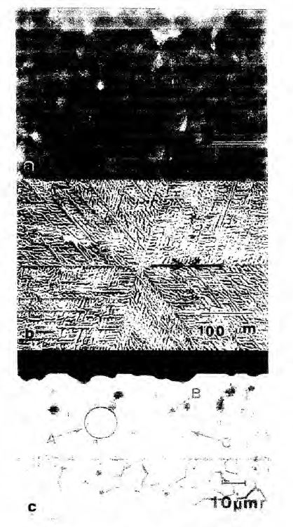
Fig. 13 Microstructure of galvalume coating: (a) spangle finish, (b) dendrite arm spacing, (c) cross-section view.
850 Selective etching of the overlay alloy coating of galvalume, removing the Al dendrites and the Zn interdentritic region, produces a forest of tree like Si particles with many branches, all connected to the alloy layer. From this process, Si particles appear to nucleate at the alloy layer/bath interface and grow into the bath, acting as either nuclei for Al dendrite growth or by constraining the growth of the Al dendrites. However, others have reported that Si particles precipitate within the coating and are not nucleated at the interfacial alloy layer, based on thermodynamic studies using computer generated equilibrium diagrams. However, according to Professor Marder, this approach may not be relevant to micron thick Al-Zn coatings produced in a dynamic, non-equilibrium solidification environment in which the kinetics of phase formation would be controlling. Professor Marder noted that computer generated equilibrium diagrams have no relationship to the three dimensional aspects of a microstructure and for this reason such diagrams may not accurately explain the actual solidification environment.
851 Figure 14 below is a schematic of the growth sequence of the galvalume solidification. At t2, the Si particles nucleate at the alloy layer and grow into the molten Al-Zn bath. At t3, the Si particles act as nucleation sites for Al rich dendrites. At t4, the Zn interdentritic region forms containing various types of precipitates in a eutectic Al-Zn matrix.
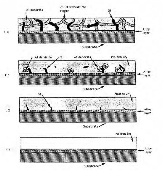
Fig. 14 Schematic of the solidification of galvalume (t1<t2<t3<t4)
852 For high Al-Zn bath compositions the reaction of an iron sheet placed in the bath is very rapid and strongly exothermic and the iron panel is consumed within two minutes of insertion in the bath. By high Al-Zn compositions, one is referring to bath compositions of 45%Al-55%Zn, 55%Al-45%Zn, and 75%Al-25%Zn. Galvalume is a high Al-Zn composition being a 55% aluminium-zinc alloy.
853 The presence of Si is required to prevent the exothermic reaction and promote the formation of an adherent coating. Si suppresses the formation of an iron-bearing alloy layer at the interface between the strip and the coating and assures that the alloy layer which is formed is thin and uniform. In relation to the effect on alloy layer thickness, for a range of immersion times a minimum in total alloy layer thickness exists around 3wt% silicon in the coating bath.
854 During the coating process of galvalume, an interfacial layer of Fe-Al-Zn intermetallic alloy layer forms at the interface between the steel substrate and the overlay coating. In general, the intermetallic alloy layer consists of a Fe2Al5 layer adjacent to the steel substrate, and mixed Fe5Si2Al20 and FeAl3 layers, depending upon processing conditions, within the intermetallic layer in contact with the Al-Zn alloy outer layer overlay coating.
855 The microstructure of the coating is controlled by the many processing variables encountered in the hot dip process. Other than the composition of the bath which determines the type of coating formed, for example, galvanize, galfan, and galvalume, some of the various processing variables are: (a) bath temperature; (b) substrate time in the bath, which is dictated by the line speed; and (c) air or nitrogen knives that control the thickness of the coating and the cooling rate.
856 All of these processing variables are interrelated, such as line speed, bath temperature and the resultant cooling rate at the air knives, which also controls the coating thickness. These variables will, in turn, control the microstructure of the coating. From the two relationships of cooling rate and DAS and coating thickness and DAS, according to Professor Marder it was generally understood by researchers in the field at the relevant time that cooling rate and coating thickness are related. Borzillo & Horton (US Patent No. 3,343,930, “Ferrous Metal Article Coated with an Aluminum Zinc Alloy”, 26 September 1967) noted that galvalume coating exhibited a small spangle size and Selverian, Notis and Marder showed that spangle size decreased with coating thickness, and by inference, cooling rate (“The microstructure of 55 w/o Al-Zn-Si (Galvalume) hot dip coatings” (1987) 9(2) J. Materials Engineering 133-140).
857 Zn coatings, and in particular galvalume, add corrosion resistance to steel in several ways. The interfacial alloy layer at the steel/coating interface acts as a barrier layer preventing the attack of the underlying steel component by any corrosive elements. Similarly, the coating itself also acts as a barrier layer separating the substrate steel from the corrosion environment. The Zn or Zn compounds add galvanic protection to the coating as a sacrificial anode to protect the underlying steel at voids, scratches and cut edges of the coating. Oxides of Al can form on the surface of the coating providing an additional barrier coating and porous oxides of Zn can lead to preferential circuitous corrosion pathways across high porosity areas slowing down the corrosion rate. Other corrosion products at intermetallic interfaces in galvalume, for example, oxides of Si or Mg, can also add to complex corrosion pathways, preventing the corrosion environment from attacking the underlying steel. Accordingly, multiple mechanisms are active in the improved corrosion resistance of galvalume coated steel product.
858 Further, according to Professor Marder the addition of Mg to alloy coatings has been done since at least the 1960s. He observed that the use of Mg to enhance corrosion resistance was discussed by Heath JA in 1961 (“A New Frontier in Hot-Dip Galvanizing: A Magnesium Containing Coating” (Paper presented to American Hot Dip Galvanizers Association Meeting, 24 March 1961)). It was reported that Mg was found to have a beneficial effect on the general corrosion resistance or weight loss of Al free Zn coatings. Mg was added to a galvanizing bath to reduce oxides of Zn on the bath surface and a method for introducing Mg in a galvanizing bath was patented in 1965. Mg in the range of 0.01% to 0.10% was shown to improve the corrosion resistance of Zn coatings with small additions of Al in the range of 0.04% to 0.35%. Sievert, et.al. reported that the level of Mg addition could be extended to 5% in the Zn bath to produce a coating with improved corrosion resistance, good ductility and adherence properties (US Patent No 3,505,042, “Method of hot dip coating with a zinc base alloy containing magnesium and the resulting product”, 7 April 1970). Further, according to Professor Marder, Mg has also been known at least since the early 1980s to improve corrosion resistance of Al-Zn-Si alloys.
(b) The 257 Patent
859 Dongkuk asserts that the complete specification does not describe the best method known to BlueScope of minimising short range coating thickness variations at 13 March 2009, being the date of filing.
860 Dongkuk says that BlueScope knew at the filing date the “special operational measures” and therefore the best method of performing the invention. The question that arises is whether or not the reference to “special operational measures” in the context of the specification was sufficient to disclose the best method of performing the invention known to BlueScope at the filing date to the person skilled in the art construing the specification at that date or the priority date; I should say for completeness that the evidence does not suggest that the common general knowledge changed between these dates.
861 Dongkuk points out that the person skilled in the art is assumed to be a skilled but unimaginative and non-inventive worker in the field of the invention. He has no private idiosyncratic preferences or dislikes and never thinks laterally. In construing the specification, he is assumed to possess the common general knowledge of those in the field at the priority date. The person skilled in the art in the present case is a member of a team having knowledge of steel-making and metallurgy and would be familiar with the basic features of the galvalume/zincalume coated product and the process for making it at the priority date.
862 Let me begin with BlueScope’s position.
863 BlueScope accepts that the common general knowledge was relevantly the same between the priority date and the filing date, but says that the common general knowledge had changed between 2002 (when Mr Salon retired) and 2009. It had also changed from 2003 (when Mr Rommal moved out of the coating industry) and 2009.
864 BlueScope accepts that by the filing date, BlueScope knew that short range coating thickness variations had to be controlled and that they should be controlled to a maximum variation of 40% in any 5mm diameter. But it says that it was not until after the filing date that BlueScope had actually taken steps to control short range coating thickness variation. It says that at the filing date it knew what a skilled addressee knew, namely, that short range coating thickness variations could be controlled by adjusting the jet stripping apparatus by reducing the height of the wiping gas outlets of the jet stripping apparatus above the coating bath so that these outlets were closer to the coating bath, adjusting the jet stripping apparatus by reducing the distance between the wiping gas outlets and a coated strip whilst reducing the pressure of the wiping gas and using a stabiliser to control the lateral movement of the strip between the jets.
865 Mr Renshaw, one of the inventors as I have said, explained that he understood that the expression “special operational measures” was a reference to these known means of controlling thickness variations. This evidence was challenged in cross-examination. Further, Mr Gregory Munt, one of BlueScope’s external patent attorneys, explained that the term had been inserted by the co-inventors, who had not raised a difficulty with it.
866 BlueScope says that the evidence does not support the contention that the skilled addressee was at risk of not ascertaining the invention because the special operational measures were not spelt out. Further, it says that even if the theoretical knowledge that BlueScope possessed was disclosed in the specification, a skilled addressee would nonetheless need to undertake routine experiments in order to apply the invention to any particular production line.
867 BlueScope submits that a skilled addressee would know what special operational measures meant. It says that it was understood that short range coating thickness variation could be controlled by changing the position of the jets. Each of Mr Salon and Mr Dutton identified adjustment of the jets when they were asked to identify possible special operational measures.
868 It says that Mr Salon appreciated that the jets would need to be closer together for an Mg containing alloy. Mr Salon knew that bringing the air knives together was not straightforward because the strip could not touch the air knife, and any wobbles in the strip might lead to the strip touching the air knives. Mr Salon was aware that the fluttering of the strip between two knives was associated with long range coating thickness variation, where the strip becomes closer to one knife. It says that it is apparent that Mr Salon appreciated that the strip would need to be stabilised.
869 Further, it says that Mr Dutton considered that strip stabilisers may have assisted in minimising short range coating thickness variations. It says that Mr Dutton was aware that stabilisers could be used to suppress vibration and to stabilise the strip, and considered that such stabilisers may have assisted in controlling short range coating thickness variations.
870 Further, it says that by 2009, the skilled addressee would have been aware that stabilisers (air flotation and electromagnetic) were being promoted for use in alloy coating lines, and were suitable for use in galvalume lines. Mr Michael Lopez, chief mechanical engineer of BlueScope, explained that references to hot dip galvanising lines simply referred to galvanising processes, which could relate to a multitude of alloys. Mr Renshaw explained that since the stabilisers had been used on Al or Zn, they were suitable for use on an alloy of the two.
871 BlueScope used a stabiliser on a galvalume line from 1992. Jindal (JWS in India) had installed them for use on its galvalume lines by 2008.
872 Further, stabilisers had been promoted as being suitable for use on alloy coating lines, including galvalume, in conferences and newsletters.
873 It says that although stabilisers were not used to control short range coating thickness variation, stabilisers were used to control long range coating thickness variation, which was well known. Stabilisation of the strip was necessary when the jets were moved closer to ensure the jets did not touch the air knives. Mr Salon appreciated the need to stabilise the strip to accommodate the closer position of the knives.
874 BlueScope says that Mr Salon’s evidence that he did not consider “special operational measures” to include stabilisers should be given little weight as he retired in 2002 and did not attend conferences after that date. It also says that Mr Rommal’s evidence should be given little weight, since he left the field in 2003.
875 It says that it is apparent from the evidence of Mr Lopez that most of the promotion of stabilisers occurred after 2005. The events to which Mr Lopez referred were an announcement by ABB in 2005 and associated presentations in 2006, newsletters and visits from EMG in 2006 and 2007, meetings with Spooner in 2006 to 2007, an Iron and Steel Technology Conference and Exposition in 2006, a presentation by ABB at the Galvanizers Association in 2006, meetings with Spooner in 2007, an SMS newsletter in 2007, an EMG newsletter in 2007 and an EMG newsletter in 2008. It says that the only promotion of stabilisers which took place before Mr Rommal and Mr Salon left the field was a presentation in 2001.
876 BlueScope submits that I should find that the skilled addressee working in the field at the priority date would have understood the phrase “special operational measures” to include the use of a stabiliser.
877 Further, it says that when BlueScope and Hatch Engineering decided to use a stabiliser on galvalume in 2007, it was confident that it would be successful in stabilising galvalume strip. Mr Renshaw explained:
I don’t think there was any question that they would work; they would work. It’s a matter of what difficulty we – we might have putting them on our lines and retrofitting them.
878 It says that although BlueScope experienced minor difficulties in implementing the stabiliser, these difficulties were not because it was unclear whether the stabiliser technology was suited to the relevant alloy. Rather, they related to the practical difficulties of fitting equipment on lines that were very old. But even these difficulties were overcome. Further, it says that as Mr Salon and Mr Renshaw explained, the design for the system was largely finalised by 2009, but put on hold following the global financial crisis.
879 Generally it says that as was observed in Glaxo FC, the requirements of best method in any case will depend on the circumstances. It was said at [192]:
Whether or not it will be open to the patent applicant to not disclose relevant information on the basis that it is available to the skilled addressee by routine experimentation will depend on the importance of the information in question, the practicality of disclosing it, and the extent of the burden imposed on the skilled addressee who is left to rely upon routine experimentation. That question is, as we have already mentioned, to be addressed in a practical and common sense manner.
880 It says that it is apparent that the means of controlling coating thickness variations were known to those skilled in the manufacture of metal coatings. It says that the means of doing so involved no more than routine adjustment of jet stripping apparatus and the introduction of stabilisers. Whilst the adjustments required may vary from one coating line to the next, it says that these adjustments could be implemented by trial and error without undue burden. It says that BlueScope disclosed the best method known to it of performing the invention.
881 In my view BlueScope did not disclose the best method known to it at the filing date.
882 BlueScope conceded that it knew at the filing date that the operating measures to control short range coating thickness variation were:
(a) adjusting the jet stripping apparatus by reducing the height of the wiping gas outlets of the jet stripping apparatus above the coating bath so that these outlets were closer to the coating bath;
(b) adjusting the jet stripping apparatus by reducing the distance between the wiping gas outlets and a coated strip whilst reducing the pressure of the wiping gas; and
(c) using a stabiliser to control the lateral movement of the strip between the jets.
883 Mr Renshaw’s evidence made clear that such a stabiliser as known to BlueScope was either an electromagnetic (EM) stabiliser or an air flotation stabiliser.
884 Accordingly, there is no dispute that the best method known to BlueScope at the filing date for controlling short range coating thickness variation to achieve the alleged invention was the use of four operating measures together, namely: (a) reducing the height of the wiping gas outlets; (b) reducing the distance between the wiping gas outlets; (c) reducing the pressure of the wiping gas; and (d) using an EM stabiliser or air flotation stabiliser.
885 Let me say something about the specification.
886 The specification states at p 5 line 36 and following:
The claims define the invention in terms of minimising coating thickness variations to control the distribution characteristics of the Mg2Si phase so that the surface has only a small proportion of Mg2Si particles or is a least substantially free of Mg2Si particles, whereby there is a considerably lower risk of Mg2Si mottling.
Accordingly, the invention provides a hot-dip coating method for forming a coating of a corrosion-resistant Al-Zn-Si-Mg alloy on a steel strip comprising passing the steel strip through a hot dip coating bath that contains Al, Zn, Si, and Mg and optionally other elements and forming an alloy coating on the strip with a variation in thickness of the coating of no more than 40% in any given 5 mm diameter section so that the distribution of Mg2Si particles in the coating microstructure is such that there is only a small proportion of Mg2Si particles or substantially no Mg2Si particles in the surface of the coating.
887 Further, the specification states at p 11 line 1 and following:
The applicant has also carried out line trials on 55%Al-Zn-1.5%Si-2.0%Mg alloy composition (not containing Sr) coated on steel substrates.
The purpose of these trials was to investigate the impact of cooling rates and coating masses on mottling in the surface of the coatings.
The trials covered a range of coating masses from 60 to 100 grams per square metre surface per side of strip, with cooling rates up to 90℃/sec.
The applicant found two factors that affected the coating microstructure, particularly the distribution of Mg2Si particles in the coatings, in the trials.
…
The second important factor found by the applicant is the uniformness of coating thickness across the strip surface.
The applicant found that the coating on the strip surface normally had thickness variations that are (a) long range (across the entire strip width, measured by the “weight-strip-weight” method on a 50mm diameter disc) and (b) short range (across every 25 mm length in the strip width direction, measured in the cross-section of the coating under a microscope with 500x magnification). In a production situation, the long range thickness variation is normally regulated to meet the minimum coating mass requirements as defined in relevant national standards. In a production situation, as far is the applicant is aware, there is no regulation for short range thickness variation, as long as the minimum coating mass requirements as defined in relevant national standards are met.
However, the applicant found that short range coating thickness variations could be very high, and special operational measures had to be applied to keep the variations under control. It was not uncommon in the experimental work for the coating thickness to change by a factor of two or more over a distance as short as 5 mm, even when the product perfectly met the minimum coating mass requirements as defined in relevant national standards. This short range coating thickness variation had a pronounced impact on the Mg2Si particles in the surface of coatings.
…
Therefore, under the experimental conditions tested, the short range coating thickness variation should be controlled to no greater than 40% above the nominal coating thickness within a distance of 5mm across the strip surface to avoid mottling.
888 The nature of the invention described and claimed in the specification is to ensure that the short range coating thickness variations had to be controlled to a maximum variation of 40% in any 5 mm diameter so that the desired distribution of Mg2Si could be obtained and, thereby, lower the risk of mottling. As stated in the specification, in order for that to be achieved “special operational measures” had to be applied. Accordingly, disclosure of these “special operational measures” had importance. In my view BlueScope was under an obligation to disclose the “special operational measures” known to it at the filing date to control short term coating variation.
889 Further, I agree with Dongkuk that, in summary, there are four reasons demonstrating that the specification failed to disclose the best method known to BlueScope.
890 First, a person skilled in the art would not understand what was meant by “special operational measures” in the context of the specification.
891 Second, even if the best operating measures formed part of the common general knowledge, a person skilled in the art would not understand that those measures were being referred to. This is because of the use of the word “special” in the phrase “special operational measures”. Further, it is because of the distinction the patentee sought to make in the specification between operating measures used to control long range thickness variation, which were known, and short range thickness variation.
892 Third, although as at the filing date the skilled addressee would have been aware of a number of different operating measures that could be used to control variation in coating thickness, he would not have understood “special operational measures” to be referring to the particular four operating measures known by BlueScope to be the best method of performing the invention.
893 Fourth, neither EM stabilisers nor air flotation stabilisers formed part of the common general knowledge in galvalume production at the filing date. A person skilled in the art would not understand the phrase “special operational measures” to be referring to the use of an EM stabiliser or air flotation stabiliser and, therefore, would not understand the best method known to BlueScope at the filing date of performing the invention. Whilst air flotation stabilisers and EM stabilisers were emerging technologies at the filing date in galvanising/galvannealing, even in those contexts they were not being used to control short range coating thickness variations.
894 Let me elaborate on some of these matters.
895 A person skilled in the art at the filing date would not understand what “special operational measures” were being referred to in the specification. Further, that person would reasonably understand from the relevant passages of the specification that the special operational measures were different to the ordinary operational measures including those known to regulate long range thickness variation.
896 First, the patentee sought to distinguish between long range thickness variation, which is “normally regulated to meet the minimum coating mass requirements as defined in relevant national standards”, and short range thickness variation, for which it said there is “no regulation”.
897 Second, the specification stated that “short range coating thickness variations could be very high… even when the product perfectly met the minimum coating mass requirements as defined in relevant national standards” which were met by controlling long range coating thickness variation.
898 Third, and following from these two points, the specification indicated that operational measures used to control long range thickness variation were different to short range thickness variation.
899 Further, even if it were to be assumed that the said adjustments to the gas wiping apparatus and/or the introduction of an EM or air flotation stabiliser to stabilise the coated strip between the jets of wiping gas were known by the skilled person in the context of galvalume production at the filing date, the skilled person would not understand special operational measures in the context of the specification to refer to either of these measures. By the use of the word “special”, the skilled person would think that the expression “special operational measures” was referring to operating measures beyond those known to him.
900 Mr Salon’s evidence was that by the filing date the adjustments to the gas wiping apparatus at a coating thickness control above the coating line was a typical adjustment to control thickness and would be known to the skilled person. But in his experience the adjustment of air knife settings was an activity that would be described as routine operational measures, rather than as special operational measures.
901 Further, as the evidence before me demonstrated, there were many different operating measures known by the skilled person at the filing date to control variations in coating thickness. Even if the skilled addressee was to construe “special operational measures” as “ordinary operational measures” he would still not know which of those operating measures were the best operating measures to perform the invention.
902 As I have said, the best method involved the use of four operating measures together, namely:
(a) reducing the height of the wiping gas outlets;
(b) reducing the distance between the wiping gas outlets;
(c) reducing the pressure of the wiping gas; and
(d) using an EM stabiliser or air flotation stabiliser.
903 Now it is clear that none of the independent experts in this proceeding would have applied these four operating measures.
904 Professor Marder was aware of the following techniques before the filing date to control thickness variation being:
(a) gas wiping dies (steam, air or nitrogen);
(b) geometry of the wipers;
(c) the velocity of the wiping gas; and
(d) the distance between the wiping dies and the steel strip.
905 Mr Rommal was aware of the following processing variables to control coating thickness variations in galvalume at the filing date being:
(a) the air pressure delivered to the air knives;
(b) the gap between the air knives; and
(c) line speed.
906 In addition, Mr Rommal was aware of the use of “edge baffles” to remove excess molten coating at the side of the strip.
907 Mr Salon was aware of the following variables which affected coating thickness variation of galvalume before the filing date, namely:
(a) line speed;
(b) air pressure;
(c) the distance between the two air knives;
(d) the height of the air knives above the pot;
(e) the fluttering of the strip between the two knives which was usually managed by a stabiliser roll (one or several) just beneath the surface of the bath; and
(f) the bad shape of the strip arising from the cold rolling process which was remedied by improving the quality of the feed from the rolling mill.
908 Further, although Mr Salon did not understand what the specification meant by “special operational measures” he would, in the first instance, have considered the pressure of and spacing between the air knives. He said:
my approach would be to lower the air pressure and (to compensate and produce the same average coating thickness) bring the knives closer together. I would take this approach, because this [was the] way in which one avoids “ripple patterns” on traditional Galvalume compared to zinc coating…
909 When Mr Salon was shown BlueScope’s proposed amendments to the specification that referred to the “special operational measures” as including the use of an EM stabiliser or an air flotation stabiliser, he said that the use of either air or electromagnetic non-touch stabilisers travelled well beyond his understanding of what special operational measures meant. He was not aware of such stabilisers being used in galvalume lines before his retirement in 2002 or throughout his consultancy work during 2002 to 2010.
910 Now Mr Dutton initially understood “special operational measures” to mean “the set of adjustments that can be made to a line to stabilise the strip, reduce flutter and otherwise provide a highly uniform coating” and that this would likely involve one or more of the following:
(a) controlling the edges;
(b) altering aspects of the air knives (e.g. the size and shape of the air knife aperture);
(c) changing the distance between the air knives and the coated strip;
(d) changing the angle of the air knife;
(e) changing the distance between the air knives and the molten bath;
(f) changing the cooling device; and
(g) tension between the points (i.e. the tension between the molten bath stabilizer roll and the top turnaround roll).
911 But Mr Dutton did not volunteer the use of an EM or air flotation stabiliser in answer to the question put to him by BlueScope’s solicitors as to what he understood by “special operational measures”. Rather, after providing this response, he was specifically asked by BlueScope’s solicitors whether, as at March 2008, he was aware of an EM stabiliser or air flotation stabiliser being used to control the lateral movement of a coated steel strip. But the question was not limited to galvalume. Mr Dutton recalled a presentation and a paper by Spooner Industries Ltd presented at the 2004 InterZAC conference. But this paper only referred to air flotation stabilisers being used in galvanising and galvannealing, and not galvalume production. Further, it did not refer to an air flotation stabiliser being used in any context to control sub 5mm variations in coating thickness.
912 In the circumstances, I do not accept BlueScope’s submission that a skilled addressee would understand that “special operational measures” meant the particular four operating measures known by BlueScope to be the best method of performing the invention as at the filing date.
913 Let me deal further with some of the evidence.
914 First, neither EM stabilisers nor air flotation stabilisers formed part of the common general knowledge in galvalume production at the filing date. In the circumstances, the skilled addressee would not reasonably understand the reference to “special operational measures” to include the use of an EM stabiliser or air flotation stabiliser.
915 I agree with Dongkuk that BlueScope’s trial of an air floater stabiliser pad device in galvalume production on metallic coating line MCL 4 at the Western Port Plant in 1992 appears to have been a coincidence.
916 BlueScope had originally installed the device on MCL 4 in or around 1991. At that time, MCL 4 was used for the production of galvanised and galvannealed coatings. The device comprised stripping jets with an in-built stabilising pad achieved by the addition of another nozzle to direct gas into the space between the metallic coated strip and the stripping jets themselves. The air floater stabiliser pad device was new technology at the time and BlueScope applied for a patent over the technology.
917 Galvanising is the process of applying a protective zinc coating to prevent rusting. Hot dip galvanising uses a hot dip coating method where parts are submerged in a bath of molten zinc. Galvannealing begins with the hot dip galvanising process and then after the sheet has passed through the galvanising zinc bath and through the air knives to remove the excess zinc, it is then heated again with an annealing furnace for several seconds, whereby another reaction then takes place.
918 BlueScope was using MCL 4 in 1991/1992 to produce “thin, fully alloyed” galvannealed products for car parts and steel furniture. Mr Lopez agreed that “the market requiring galvanneal required a better surface finish than standard galvanised products, and that’s in part why we started developing the stabiliser that we did in 1991.” For example, galvannealed automotive sheeting is mirror like, which is unlike galvalume building sheet products.
919 Mr Lopez also confirmed that MCL 4 produced strip of a larger width than what was typical for galvalume lines at the time because it was designed for the production of galvanised and galvannealed products. Mr Lopez agreed that as a “general trend” it is more difficult to keep coating uniform across wider strips than narrower strips. Hence, there was a greater need to stabilise the strip for the production of galvanised and galvannealed products compared with galvalume.
920 Mr Lopez also confirmed that at the time the galvannealed coatings BlueScope were producing were thinner (approximately 10 microns thick) compared with galvalume coatings BlueScope was producing (which for average building applications were approximately 20 microns). This was another reason why there was a greater need to stabilise the strip for the production of galvanneal coatings compared with galvalume coatings.
921 In 1993 MCL 4 was converted to a galvalume coating line only. By this stage, however, MCL 4 already had the air floater stabiliser pad device installed for use in galvannealing. BlueScope trialled the use of that device in producing galvalume for a couple of weeks in 1993. Mr Renshaw confirmed that the use of an air flotation stabiliser in respect of galvalume was not a routine thing to do. He also confirmed that although it worked for galvanising, it did not work very well for galvalume production. That is consistent with BlueScope having ceased using the air floater stabiliser pad device for galvalume after the trials in 1993.
922 Further, there is no evidence that anyone other than BlueScope and JWS in India used an air flotation stabiliser in galvalume production before March 2009. Nor is there any evidence that anyone other than BlueScope had the knowledge before (or after) March 2009 that an air flotation stabilizer was suitable for use for controlling sub 5mm coating thickness variation.
923 The 2001 publication of Spooner Industries Ltd only refers to the use of an air flotation stabiliser in galvanising/galvannealing lines, particularly the automotive market which required wider and mirror like sheets compared with galvalume sheets at the time (George S and Scott L, “New Technologies for Post-Pot Cooling Equipment” 5th International Conference on Zinc and Zinc Alloy Coated Steel Sheet (Galvatech ’2001, Brussels, Belgium, 26-28 June, 2001) pp 461-468). It does not refer to the use of an air flotation stabiliser in producing galvalume. Mr Lopez appeared to confirm that the paper did not concern the use of air flotation stabilisers to control sub 5mm variations in thickness. Rather, the paper discussed the advantages of using air flotation stabilisers in galvanising/galvannealing lines to prevent striping, which occurs when the strip comes into contact with an air knife, achieving minimum coating thickness to save on the costs of zinc. It is described in the paper as a “new type of stabilising unit that eliminates strip contact”.
924 Further, as to Mr Lopez’s evidence about Spooner supplying “stabilisers in the after pot cooling section of [JWS] facilities in India” before 2009, Mr Lopez did not give any indication that it was used for controlling sub 5mm coating thickness variation. In any event, even if it was to be assumed that another company was using an air flotation stabiliser to control sub 5mm thickness variation in respect of galvalume coating, it did not make that practice routine or part of the hypothetical skilled addressee’s common general knowledge as at March 2009. A hypothetical skilled addressee reading the specification as at March 2009 would not understand that an air flotation device was being referred to as one of the “special operational measures”.
925 Further, there is no evidence as to the use by anyone of an EM stabiliser in galvalume production before the filing date. Further, there is no evidence of anyone using an EM stabilizer in any context before the filing date for controlling sub 5mm coating thickness variations.
926 None of the papers annexed to Mr Lopez’s affidavits referred to the use of EM stabilisers in galvalume lines. Rather they only referred to the use of EM stabilisers in galvanising/galvannealing lines. But in any event, none of the papers described the use of EM stabilisers to control sub 5mm variations in coating thickness.
927 The 2006 paper “ABB Electromagnetic Strip Stabilizer” described the “first EM Stabilizer for a modern high speed galvanizing line [being] installed and tested at galvanising line #4 Thyssen Krupp Stahl in Germany in 2006” (Löfgren P et al, “ABB Electromagnetic Strip Stabilizer” (Paper presented to the Galvanizers Association 98th Meeting, Columbus, Ohio, 22 to 25 October, 2006) p 3). This paper also referred to the use of the EM stabiliser in the context of automotive applications. At this time the use of EM stabilisers even on galvanising lines was very new technology. The paper described one of the motivations for using an EM stabiliser was for cost savings by reducing over coating of zinc. As Mr Lopez explained, the price of zinc was increasing and it became important in galvanising and galvannealing to reduce production costs.
928 The coating thickness variations referred to in the ABB paper were not sub-5mm variations but rather much larger. The paper described that in galvanising lines the typical strip vibrations were in the range of 1 to 10 Hz. The EM stabiliser discussed in that paper sought to control thickness variations created by those vibration frequencies. Mr Lopez agreed that sub 5mm thickness variation would be caused by considerably higher vibration frequencies, that is, by at least two orders of magnitude than what is described in the paper. Mr Lopez agreed that to create a sub-5mm variation in a typical light galvalume line running at a speed of around 200 metres a minute, then the frequency needed would be no less than 667 Hz. He gave the following evidence:
MR COOKE: Okay. Well, let’s do some maths together. I think we could probably resolve it between us. But if you have a short range coating thickness variation and we assume for the sake of this calculation that it’s measured within – within a five-millimetre area. Right? So that means, doesn’t it, that there must be at least one peak and one trough of – within that five-millimetre area. Correct?
MR LOPEZ: Something like that you would expect, yes.
MR COOKE: So it’s like a sine wave. Right? All right. Now, if the variation is a result of vibration, then the vibration frequency must be high enough that at least one full oscillation occurs as a five-millimetre length of strip passes through the air knives; correct?
MR LOPEZ: I’m not going to say I agree, but I will say that simplifying the problem, you might consider it that way. There are other courses that if need be I will come back to.
MR COOKE: You agree with what I’ve just said?
MR LOPEZ: No, I don’t agree. I think you’re assuming that that source of vibration alone will contribute to the short-range variation when I’m aware of other reasons why the short-term variation might occur that don’t emanate at the frequencies that ABB are reporting, specifically on this ThyssenKrupp line running at low speeds, producing galvanneal.
MR COOKE: Well, I will tell you where I’m going with this, that if you consider a sub-five-millimetre strip and that’s running on a – say, a typical light gauge Galvalume line at a speed of around 200 metres a minute, then the frequency that you would need is no less than 667 hertz. That’s correct, isn’t it?
MR LOPEZ: Yes. And how do we know that it won’t occur at that frequency?
MR COOKE: Yes, but this article is talking about variations within the one to 10 hertz; correct?
MR LOPEZ: It is, but that’s only based on their particular tests on a particular line.
MR COOKE: That’s right. Now, you can work out the reason why you agreed with my question that it was no less than 667 hertz is because you did the maths that that means that the five-millimetre of strip must pass through the air knives in 0.0015 seconds at that speed, and doing that calculation is how you worked out the frequency of at least 667 hertz. Correct? That’s 30 seconds?
MR LOPEZ: It will certainly be a higher frequency than what is described as an example only in that paper.
MR COOKE: Yes. Well, annexure LM3 is referring to vibration frequencies that are 67 to – 667 times larger than the five-millimetre scale under discussion. That’s correct, isn’t it?
MR LOPEZ: It would be a higher frequency than what they’re reporting here.
MR COOKE: Yes?
MR LOPEZ: That’s just simply a trial report.
HIS HONOUR: But you agree generally that it would be, what, two orders of magnitude?
MR LOPEZ: I do.
HIS HONOUR: Yes?
MR LOPEZ: I do agree with that.
HIS HONOUR: About that. Yes. Sorry?
MR LOPEZ: Inherently, there may be some limitations with electronic magnetic stabilisers responding to vibrations, but the air flotation stabilisers are not susceptible to those limitations.
MR COOKE: Sorry, your Honour, did you say – I missed that. Did you say in the order of two?
HIS HONOUR: Two orders of magnitude - - -
MR COOKE: Two orders of magnitude, yes.
929 Further, the paper published by SMS Group “Contactless, electromagnetic strip stabilization during galvanizing”, described the use of an EM stabiliser on a galvanising line for the purpose of saving costs in respect of zinc consumption (SMS Group, “Contactless, electromagnetic strip stabilization during galvanizing” (Newsletter No. 3, 2007) pp 56-57). The last paragraph referred to the use of an EM stabiliser in the annealing galvanising line of Hysco in Korea which Mr Lopez confirmed was Hyundai Motor Corporation. Now the automotive market required wider sheets than galvalume sheets. For wider sheets it was more difficult to keep coating uniform. And there was also a need to make automotive sheeting mirror like, unlike building sheet products. Mr Lopez confirmed that there was nothing specifically in this paper to indicate to him that the EM stabiliser was being used to control short range thickness coating variations.
930 Further, a newsletter in evidence “EMG Newsletter” June 2007 referred to “[f]our leading international steel producers install new system for ensuring homogenous zinc layer thickness”. But there is no indication that the EM stabilisers were used in galvalume lines. Nor is there any reference to the use of the eMASS EM stabiliser to control short range thickness variations in any context.
931 A further newsletter in evidence “EMG Newsletter” April 2008 referred to the use of the eMASS EM stabiliser in the context of galvannealing and galvanising, but not galvalume. Mr Lopez agreed that there was no indication that the EM stabiliser had been used to control short range thickness variations. Mr Lopez conceded that he did not think that EMG had sold an EM stabiliser for galvalume production by this date.
932 Further, an EMG white paper also described the eMASS System only being used in the context of galvannealing and galvanising, but not galvalume (EMG Automation GmbH, “The time is ripe: EMG eMass® – the leading electro MAgnetic Strip Stabilisation” (White Paper, January 2008)). It referred to its use in the automotive industry and aspects concerning minimising zinc consumption. It also included a list of 50 customers since August 2007, none of which referred to its use on a galvalume line. Mr Lopez conceded that he was not aware of any EM stabiliser being used on a galvalume line to date let alone before the filing date. Further, this paper did not refer to the use of EM stabilisers to control short range coating thickness variation.
933 Let me make another point. BlueScope’s idea to use an air flotation stabiliser in 2007/2008 was not routine.
934 In late 2007, BlueScope and Hatch Engineering came up with the idea of a new generation of air flotation stabilisers that could be used on a galvalume line. Mr Lopez confirmed that Hatch Engineering was in the business of developing new technology solutions for clients in the steel industry. The idea to use an air flotation stabiliser on a galvalume line was in some respects a novel idea developed from a desire to increase efficiencies in low mass galvalume products. As Mr Lopez explained:
MR COOKE: Yes, but as you just indicated, the start of the project the motivation for the project at the very beginning was to – it was to use a stabiliser for the Galvalume line, correct, an air flotation stabiliser for the Galvalume line?
MR LOPEZ: The – we had started to work when I was working for Hatch with BlueScope Steel recognising the limitations in the production of Galvalume around the world. So this is before the magnesium-containing coating, that we needed to stabilise the strip and we needed to run with the jet-wiping nozzles closer to the strip surface. So that is how the idea of a new generation of air-based flotation stabiliser started.
MR COOKE: Yes. So this was – just to date stamp it again so this was later in 2007, Hatch, whilst you were employed, was retained to assist in the way you’ve indicated. Now, before then, apart from the trial on MCL4 in 1993 BlueScope had not used an air flotation stabiliser on a Galvalume line, correct?
MR LOPEZ: That is not correct. Prior to that we had trialled a test AFS unit on MCL3 at Port Kembla on Galvalume production.
MR COOKE: And when was that?
MR LOPEZ: I can’t recollect the date. I will have to look at that. But that was well before – sorry, you’re referring to when we used it on MCL4 originally?
MR COOKE: Yes?
MR LOPEZ: 1993 is the year that you said?
MR COOKE: Yes?
MR LOPEZ: Sorry. Sorry. There was another trial on MCL4 which came much later which is the one I thought you were talking about. So prior to 1993 and the long campaigns we ran to test the benefit of an air flotation stabiliser on MCL4 we had not trialled a air stabilisation system with Zincalume production prior to that date.
MR COOKE: Yes. And then in 1993 you trialled it on MCL4 in respect of Zincalume and then you stopped using the air flotation stabiliser after that trial finished in 1993, correct?
MR LOPEZ: That is correct.
MR COOKE: And then the next time that BlueScope Steel started trialling an air flotation stabiliser in the context of Zincalume was in 2007?
MR LOPEZ: Correct.
MR COOKE: Yes. Now, before that date BlueScope had been adjusting the air knives without the use of a stabiliser, an air flotation stabiliser, to achieve the uniform coating thickness?
MR LOPEZ: We were not entirely happy with the performance of the standard air knife. It restricted our line speed versus the product quality we needed to achieve. It also limited our operation window in such a way we couldn’t produce the low coating mass Zincalume we wanted to produce.
935 But by virtue of the costs, risks and difficulties involved, it was not a routine decision. Minutes of a BlueScope meeting to discuss the possible implementation of air flotation strip stabilisers on MCL1 or 3 at Springhill works held on 10 October 2008 described the “budgetary cost estimate for the implementation for a single set of posed floater pads over the existing air knives as being in the range of ~$310-760,000 depending on the final scope…”. Mr Lopez agreed that it was a significant investment. Further, numerous risks were identified as being involved in choosing to implement an air flotation stabiliser in galvalume production. These included the following:
(a) the scratching of product;
(b) the edge baffles may not be capable;
(c) the pad could be damaged on installation/routing;
(d) the operating window may not be as beneficial as expected and would affect the business case;
(e) there may be longitudinal/herringbone creases without front stabiliser roll;
(f) there could be ZnO deposition;
(g) there could be the intermittent use of slab roll – problem e.g. “cease”;
(h) there could be high noise levels resulting in operator issues;
(i) there could be more clutter in the pot area for Ops/Maint;
(j) total project costs may be too high;
(k) there could be no cross-bow correction;
(l) the operator’s view and access to the pot could be reduced; and
(m) other problems.
936 Further, an attachment to the minutes titled “MCL1 Upgrade Proposal UpLeg – Air Knife – Stabiliser” dated August 2008 described the motivations for BlueScope wanting to use air flotation technology on a galvalume line as follows:
MCL1 has line speed limitations on product >=1050mm wide due to strip flutter through the jets and upleg cooling. Air flotation is an emerging technology in galvanising lines, which can reduce/eliminate strip stability issues at the pot. It is proposed that installation of the BSL floater pad air jets, in combination with the Hatch or Spooner Air Stabilizer above the jets will allow speed increases on wide product on MCL1. The potential flow on process benefits from installation of this air flotation technology include better coating mass distribution, and improved cooling prior to the after pot turn roll. Deflector rolls may be disengaged for light gauge strip production, eliminating deflector roll chatter defects and reducing delays and maintenance costs.
937 But none of these considerations related to controlling sub 5mm coating thickness variations.
938 It would seem that BlueScope was the first company in the world to transfer the concept of using air flotation stabiliser technology from galvanising/galvanneal production to galvalume production. But the hypothetical skilled addressee reading the specification at the filing date is non-inventive and not taken to think laterally. And nor does he possess knowledge of emerging technologies in galvanising and galvannealing.
939 Further, as Dongkuk submitted, it appears likely that the origin for BlueScope’s idea was idiosyncratic. It first trialled, although unsuccessfully, its air flotation stabiliser pad technology in galvalume production when MCL 4 was repurposed from galvanising/galvannealing to galvalume. This is referred to in the attachment to the said minutes:
Floater pad air knife technology was developed by BSR, and has successfully been implemented on MCL6 for galvanised steel and galvanneal. The floater pads have been trialled on MCL4 for an extended period for Zincalume® Steel production.
…
While the BSR floater pad will supress vibrations at the air knife from the pot rolls, large string type vibrations between the sink roll and after pot turn roll will have a high moment at the air knife. Further stabilisation above the air knife is proposed to eliminate these vibrations.
Spooner Industries supply a stabiliser that can be installed directly above the air knife. The illustrated 1100mm long stabiliser could be installed in the existing air knife frame, which is roughly the same dimension from the top of the hanger frame to the air jet. Spooner Industries claim 20 air flotation installations on galvanising lines. BSR-Hatch have also trialled an air flotation system on MCL3. This is still in the prototype stage and limited trials have been conducted to date, but the results have been promising.
940 A further attachment to the minutes included a list of references from Spooner Industries Ltd. But it did not refer to the use of an air flotation stabiliser in galvalume production.
941 Further, a “Briefing Note – Air Floater Stabiliser Pad Trial” dated 12 June 2008 by Mr Garry Peterson, Mr Darren Thompson and Mr Lopez also supports the fact that the idea of implementing an air flotation stabiliser was not routine. This document reported on a May 2008 trial of an air flotation stabiliser by Hatch Engineering on a galvalume line. Now this document noted that “it appears this technology has the potential to provide [a number of] business benefits” including its viability of manufacturing the new EDGE product. But there were a number of problems, namely:
(a) “the test floater pad arrangement was not optimal in terms of relative position to the air knives, strip to floater pad distance or maximum operating pressure hence gains could potentially be higher under the same operating as the trial”;
(b) “[o]ne other factor to note is that the condition of the front stabiliser roll & [its] bushes at the start of the trial generated a high degree of vibration which approached the acceptable limits of operation prior to a rig change”; and
(c) “[n]oise levels in the pot area were noticeably increased by the operation of the floater pad in combination with the standard air jet”.
942 It was stated:
The coating mass variation was reduced substantially (from Standard Deviation of 8.1g/m2 to 2.7g/m2 – refer to Graph#4) and improved surface finishes apparent during the trial. The best results were obtained with the front stabiliser roll disengaged and the floater pad applied with a plenum pressure of approx. 3kPa (maximum possible with test arrangement). It should also be noted that the test floater pad arrangement was not optimal in terms of relative position to the air knives, strip to floater pad distance or maximum operating pressure hence gains could potentially be higher under the same operating as the trial.
One other factor to note is that the condition of the front stabiliser roll & [its] bushes at the start of the trial generated a high degree of vibration which approached the acceptable limits of operation prior to a rig change. Whilst this may affect the relative change in results, it represented a near extreme test for the stabilising effect of the floater pads.
Noise levels in the pot area were noticeably increased by the operation of the floater pad in combination with the standard air jets. However, a more permanent installation would incorporate an edge baffle system into the stabilisers to reduce the turbulence near the strip edges.
As a result of the above & the fact that no new defects were introduced by the floater pad during the albeit limited trial, it appears this technology has the potential to provide the following business benefits:
• Improved strip stability and consequently coating uniformity in longitudinal & transverse directions. This may also enable a tightening of the target coating masses to save on excess coating metal.
• Enabler to run significantly closer jet to strip distances providing a fundamental shift in current operating windows for jet strip[p]ing with implications on:
• Low Coating classes (AZ70 > 130mpm) to be produced at higher speeds without defects such as “Pock Marks” etc.
• Zincalume to be produced at over 200 mpm.
• Viability of manufacturing new EDGE product.
• Potential to run without a front stabiliser roll on light gauge lines (to be confirmed) with associated reductions in maintenance & downtime costs.
• Reduced stabiliser roll “shadow” marks hence improved quality & appearance of bare metallic coated products.
943 Mr Lopez agreed that at this stage further work needed to be done. This document also referred to the fact that one of BlueScope’s motivations for using an air flotation stabiliser was to produce lower coating classes at greater line speeds, which had little to do with controlling sub 5mm coating thickness variations. Mr Lopez confirmed that controlling sub 5mm coating thickness variation was not one of the motivations for using air flotation stabilisers on galvalume. In the circumstances, a person skilled in the art would not understand that the “special operational measures” used to control the sub 5mm coating thickness variation referred to in the specification included the use of such a stabiliser.
944 Mr Lopez also confirmed that after the May 2008 trial, considerably more work was done by BlueScope and Hatch Engineering in experimenting, developing and trialling the air flotation stabiliser with galvalume. Those trials included at least trials in 2009, 2010, and in 2012.
945 It is clear that at least as at November/December 2009 that BlueScope was having considerable difficulties with using an air flotation stabiliser with the EDGE (MAZ) coating. These difficulties were reported in an email chain ending in an email from Mr Lopez to Mr Thompson copied to Mr Renshaw and others reporting on outcomes of the first EDGE stripping DOE dated 20 November 2009. In an email of 19 November 2009 from Mr Renshaw to Mr Lopez, Mr Thompson and others, Mr Renshaw stated:
The first in a series of 8 designed jet stripping experiments (DOEs) was conducted last night on MCL 4. These experiments were designed to provide answers to some fundamental questions about the jet stripping behaviour of the Edge (MAZ) coating. The key questions are:
• What is the benefit of very low jet-strip distances (<10 mm) on achieving MAZ100 at high speed?
• What is the maximum speed for production of defect free MAZ100 at jet-strip distances from 10 to 5 mm?
• What is the minimum defect free coating mass achievable at 200 m/min with jet/strip distances from 10 to 5 mm?
• What is the effect of the Air Floatation Stabiliser (AFS) on the MAZ coating?
• Do various trace levels of Ca (90 – 450 ppm) have a beneficial effect on the on the jet stripping behaviour of MAZ coatings?
• What is the benefit of using floater pad jets?
The first DOE last night was designed to provide calibration data to set up the following trials, check the effect of 1% Mg on jet stripping defects and to test the capability of the AFS to achieve 5mm jet-strip distances. The status of the trial results is as follows:
• All trial settings were achieved and samples obtained.
• The AFS was able to flatten and stabilise the strip and jet-strip distances <10 mm were achieved without strip contacting the jets. There is some evidence of the strip rubbing against the AFS and further inspection of the trial samples is taking place to determine when this occurred.
• The AFS had a significant negative impact on the coating quality. This manifest[s] as a disturbance in the skin of the coating resulting in an unacceptable coating appearance. This defect was not seen on previous AFS trials on AZ coatings and may be a characteristic of the MAZ coating. More analysis of this defect will commence after the overall trial completion.
946 Mr Renshaw stated “[t]he AFS had a significant negative impact on the coating quality. This manifest[s] as a disturbance in the skin of the coating resulting in an unacceptable coating appearance. This defect was not seen on previous AFS trials on AZ coatings and may be a characteristic of the MAZ coating”. In an email on 20 November 2009 from Mr Thompson to Mr Lopez, Mr Thompson described it as “[n]ot a minor defect more on the “absolute disaster” scale on 1% Mg”.
947 BlueScope presentations titled “Project EDGE MCL4 Trial Interim Summary” dated 4 December 2009 and “Effect of AFS on Strip Position and Stability Results from MCL 4 Edge Trial DOE’s” dated 24 December 2009 also described detrimental conditions in using the air flotation stabiliser with the EDGE coating which were being experienced. The 4 December 2009 presentation stated “[a] review of the AFS design is underway to ensure the coating is not disturbed”. It was stated:
Calcium Additions proves positive
• Ca proven to reduce dross make
• Ca in conjunction with Snout pump shown to reduce/eliminate dross streaks
• Probable that 450ppm Ca not required – initial indications suggest something around 150ppm
Air Floatation Stabiliser (AFS) – mixed results
• The AFS allowed successful jet stripping at 15mm jet to jet distance.
• Initial indications suggest the AFS reduces strip vibration by a factor of 4.
• At high pressure the AFS was detrimental to EDGE coating – Ca additions were an improvement over straight Mg but still not acceptable at high pressure.
• A review of the AFS design is underway to ensure the coating is not disturbed
New Upleg Cooling Strip measurement successful
• New pyrometer configuration provided accurate strip temperature at cooling tower deflector roll
• Inadvertently, one product run faster than spec. provided data to confirm max. strip temperature at cooling roll before pick off is 300deg.
948 BlueScope was not measuring sub-5mm thickness variations.
949 I am only using any post-filing date conduct to infer that these difficulties and the fact that further work needed to be undertaken in respect of the air flotation stabiliser design suggests that a skilled addressee would not think of using an air flotation stabiliser as an available operating measure to control short range coating thickness variations in this context as at the filing date.
950 Mr Renshaw described further trials that were conducted with the air flotation stabiliser in 2011 to 2013.
951 In 2012, BlueScope and Hatch Engineering entered into an “Intellectual Property and Commercialisation” agreement for the use of air flotation stabiliser technology. Mr Lopez confirmed that both parties thought the technology was worth protecting and that “we certainly wanted to keep it as confidential knowhow between the two parties at that stage.” This again supports the proposition that using an air flotation stabiliser to control short range thickness variations was not part of the common general knowledge as at March 2009. If that were otherwise then BlueScope and Hatch Engineering would not have regarded the technology as confidential know-how.
952 Mr Renshaw’s evidence is that he did not complete the task of optimising the precise parameters for controlling short range thickness variations including in respect of the stabiliser on all metal coating lines until February 2012, with further adjustments continuing to be made later in 2012 and 2013 prior to the commercial launch of the MAZ coating product.
953 On 8 March 2012 Hatch Engineering provided the first proposal for the detailed engineering for the air flotation stabiliser to work under operational conditions. It offered its services for AUD 350,000. That order was accepted by purchase order dated 23 July 2012 with a delivery date of 28 November 2012. Mr Lopez confirmed that the air flotation stabiliser was delivered on time.
954 Again I am only using this post-filing date conduct to infer that the timing and costs involved suggest that a skilled addressee equipped with nothing more than the common general knowledge reading the specification at the filing date would not understand that the operating measures referred to included the use of such a stabiliser.
955 As Mr Salon explained:
In my opinion, in my experience in alloy coating lines, the installation of either air or electromagnetic non-touch stabilisers near the air knives is a significant modification to hot dip coating apparatus requiring repeated cycles of research, engineering, manufacture, installation and commissioning. It is the sort of development that specialist coating pot equipment engineers (like Kohler and Fontaine mentioned above) might undertake as well as BlueScope Steel’s own research and engineering resources. In my opinion, the use of either air or electromagnetic non-touch stabilisers travels well beyond my understanding of what “special operational measures” may mean.
Conclusion
956 Notwithstanding that BlueScope knew of the best method of performing the alleged invention as at March 2009, it did not disclose it in the specification as at the date. Rather, it confidentially used the best method commercially from 2013 whilst simultaneously benefiting from the statutory monopoly. In the circumstances, all of the asserted claims of the 257 Patent are invalid. Further, as I have explained later, BlueScope’s application to amend the specification should be dismissed.
(c) The 258 Patent
957 Dongkuk says that the nature of the invention described and claimed in claims 12, 22, 23, 24 and their dependent claims of the 258 Patent concern minimising thickness variation.
958 Dongkuk says that for the reasons it has advanced concerning the 257 Patent, the specification of the 258 Patent does not describe the best method known to the patentee of controlling coating thickness variations. Therefore its failure to do so invalidates claims 12, 22, 23, 24 and their dependent claims.
959 For the reasons that I have explained above, I agree with these contentions. And this is irrespective of the fact that the specification of the 258 Patent does not use the expression “special operational measures”.
960 Let me turn to the last ground of asserted invalidity.
FALSE SUGGESTION
961 Pursuant to s 138(3)(d) of the Act, a patent may be revoked, wholly or in part, if “the patent was obtained by fraud, false suggestion or misrepresentation”. It is necessary to demonstrate that a suggestion in the application was in fact false and that the suggestion materially contributed to the Commissioner’s decision to grant the patent.
962 The assessment as to the falsity of the suggestion is an objective one. So, it is not necessary to establish that there was any intention on the part of the patentee to deceive. The relevant false suggestion may consist of statements contained in the specification which misrepresent the nature or utility of the claimed invention. Moreover, the false suggestion or representation may be made implicitly rather than expressly in the specification.
963 In Sequenom Inc v Ariosa Diagnostics Inc (2019) 143 IPR 24; [2019] FCA 1011 at [1077] to [1102], I said the following.
964 Section 138 explicitly contemplates revocation claim by claim (Apotex Pty Ltd (formerly GenRx Pty Ltd) v Sanofi-Aventis (2008) 78 IPR 485 at [125]). So, as explained by Emmett J in ICI Chemicals & Polymers Ltd v Lubrizol Corp Inc (1999) 45 IPR 577 at [179]:
I do not consider that a representation or suggestion which was not material to the grant of particular claims, could constitute a basis for revocation of those claims, even if the representation or suggestion may have been material to the grant of other claims.
965 In Prestige Group (Australia) Pty Ltd v Dart Industries Inc (1990) 26 FCR 197 both Gummow J and Lockhart J discussed the expression “false suggestion or representation” as used in s 100(1)(k) of the Patents Act 1952 (Cth). They identified two instances of conduct that could fall within that provision, namely, first, statements in the patent itself and, second, conduct of the patentee during the process of application for grant.
966 A claim may be said to have been obtained by false suggestion if the suggestion can be inferred to be so material as to have actually misled or deceived the Crown into making the grant. But it is not sufficient that the representations were merely likely to mislead or deceive the Commissioner. In Gilead Sciences Pty Ltd v Idenix Pharmaceuticals LLC (2016) 117 IPR 252 Jagot J said at [683]:
it is clear that the question is whether it can be inferred that the Commissioner was actually misled by the representations and not whether the representations were merely likely to mislead or deceive the Commissioner.
967 The alleged suggestion must have been a material inducing factor. As explained by Emmett, Weinberg and Bennett JJ in Ranbaxy Australia Pty Ltd v Warner-Lambert Co LLC (2008) 77 IPR 449 at [137] to [138]:
In the absence of an allegation of fraud, which involves an examination of the state of mind of the patent applicant, it is not sufficient to make out the ground of false suggestion or misrepresentation to prove simply that a false or misleading statement was made and nothing else. That is to say, even if a suggestion or representation is shown to be false or misleading, that, of itself, is not sufficient reason to draw an inference that the suggestion or representation contributed to the decision to grant the patent.
In the present case, there was no explicit evidence to the effect that, if there had been no assertion that the effectiveness of the relevant compounds was surprising and unexpected, the enantiomer patent would not have been granted. While inferences can be drawn, in the absence of any evidence concerning the commissioner’s decision making process, the inferences must be reasonably cogent.
968 But it is not necessary to prove that but for the representation, the patent would not have proceeded to grant. Nicholas J in Apotex Pty Ltd v Warner-Lambert Company LLC (No 2) (2016) 122 IPR 17 held that whilst a person seeking revocation on this ground “must establish that the Commissioner was deceived or misled in a manner that caused or contributed to the grant of the patent” it is not necessary to “establish that the patent would not have been granted were it not for the false suggestion or misrepresentation relied upon” (at [151]).
969 Further, as explained by Kenny J in Foster’s Australia Ltd v Cash’s (Australia) Pty Ltd (2013) 219 FCR 529 (at [107]):
In order to establish that the false suggestion or misrepresentation was material, it is unnecessary to show that, without it, the Patents would not have proceeded to grant. Rather, whether or not a false suggestion or misrepresentation is a material inducing factor depends on the circumstances of the case. The inquiry is an objective one as to whether or not it is objectively likely that the false suggestion or misrepresentation materially contributed to the decision to grant the Patents.
970 The parties before me submitted, which I accept, that factors relevant to an assessment of the objective materiality of a statement contained in a patent or in correspondence with the Commissioner include the following.
971 First, is the statement significant to the invention or an essential feature of any asserted claims? If so, it is more likely to be material.
972 Second, does the statement relate to a result claimed to be produced by the invention or to a useful purpose to which the result produced by the invention may be applied? Statements in the latter category are unlikely to be material, provided that there are other purposes for which the result is useful. On this issue, Lockhart J in Prestige cited (at 200) the following section of Blanco White TA, Patents for Inventions and the Protection of Industrial Designs (5th ed, Stevens & Sons, 1983) at 4-405:
It is not easy to distinguish between the sort of failure to fulfil a promise of results made in the specification that will amount to lack of utility and the sort that merely amounts to a false representation and accordingly will invalidate only if the patent has been “obtained” upon it. The distinction has been phrased as one between a promise of results and a mere wrong statement of the purposes for which that which is attained can be used; also as one between a promise of results and a “mere puff”, or between a false representation of the attributes of the product claimed and an accurate representation as to its attributes coupled with an expression of an “over-sanguine and erroneous view of its character”. The drawing of this distinction in particular cases is by no means easy, unless some result to be attained is set out in the claim; if this is so, it will normally negative any implication that some different result, set out in the body of the specification, is to be attained by the invention.
973 Third, does the statement closely relate to the invention described and claimed?
974 Fourth, was the statement made to support a claim to novelty or to overcome another ground of invalidity? A statement in this category is more likely to be material.
975 Fifth, has the Commissioner chosen to give evidence? As said in Ranbaxy at [83]:
Bearing in mind that the grant of a patent is a right in rem, the commissioner could be expected to take a position if a misrepresentation did in fact play a part in the decision to grant a patent and it is a relevant factor that the commissioner chooses not to give evidence. In the absence of such evidence, it is for the court to make a finding, based on the evidence before it. In the absence of explicit evidence that the commissioner, or the commissioner’s delegate, was in fact misled, it may nevertheless be inferred that a representation in fact contributed to the decision to grant a patent, if the representation was objectively likely to contribute to such a decision and the patent was in fact granted.
(Citations omitted.)
976 But it is not necessary to call the Commissioner as a witness or refer to any communication from the Commissioner in order to establish that a false suggestion was material to grant. Materiality can be inferred.
977 Sixth, does the statement simply constitute a genuinely held opinion? As said by Bennett J in Sigma Pharmaceuticals (Australia) Pty Ltd v Wyeth (2011) 119 IPR 194 at [113]:
…a statement in a patent that a step was impossible does not amount to a false suggestion simply because it can later be demonstrated that it was not impossible. A statement that a course of inquiry or experimentation was fruitless does not amount to a false suggestion just because it can later be shown that the course of inquiry or experimentation would bear fruit. If the specification stated that it was impossible to formulate venlafaxine hydrochloride using hydrogel technology, the fact that it was later shown to be possible does not demonstrate false suggestion. There is no suggestion that the statement was false to the knowledge of the inventors or of Wyeth prior to grant.
978 Now it might be said that Bennett J’s statement in Sigma supports that the test was a subjective one. But her Honour’s observations were in relation to a representation that achieving a particular formulation was “impossible”. The trial judge had found that that was not a literal representation, and Bennett J’s comments on appeal should be understood in that light. Her Honour’s final observation as to the patentee’s knowledge would also have been relevant to the “fraud” component of s 138(3)(d), had the trial judge been wrong about the nature of the representation that was made.
979 Seventh, does the statement constitute an opinion based upon reasonable scientific logic and data upon which reasonable minds may differ? As observed in Apotex v Sanofi-Aventis at [124] and Arrow Pharmaceuticals Ltd v Merck & Co Inc (2004) 213 ALR 182 at [120], false suggestion:
…is a difficult ground to establish where the statement that is attacked purports to be a conclusion drawn from a published article. The patent office and others with an interest are all able to read the article and form independent judgments. Establishment of the ground would at least require a conclusion that the representation was deliberately false and intended to mislead.
980 Further, the materiality of a false suggestion or misrepresentation to the grant of a patent can be inferred from the circumstances, including the nature of the suggestion or statement made.
(a) The 257 Patent
981 Dongkuk put the following arguments concerning claims 1, 3 to 9 and 11 to 15.
982 The specification states (p 13 lines 13 to 19) that:
By way of example, the applicant found that for a AZ150 class coating even in the desirable cooling rate ranges as described above, if the short range coating thickness variation was greater than 40% above the nominal coating thickness within a distance of 5 mm across the strip surface, Mg2Si particles formed on the surface of the coating and thereby increased the risk of mottling.
983 A similar statement is made at p 16 lines 31 to 35.
984 Dongkuk says that the work done by BlueScope in relation to investigating coating thickness variation and its relationship with mottle demonstrates that consideration had been given in early 2007 to what generally had to be done to use the existing galvalume coating lines for a new galvalume product containing Mg and, inter-alia, mottling was observed. A trial was conducted in August 2007 which is reported in a presentation titled “Project Edge: Trial Results” dated September 2007 and which observed, inter-alia, mottling on certain samples. In a TechNote titled “Investigation of Mottle on Project Edge Production Trial Coatings” by Dr Joe Williams (a co-inventor of the 257 and 258 Patents) and Mr Renshaw dated 19 November 2007 there is discussion about the mottling on these samples and about calculations of thickness of the samples. Further, there were February 2008 calculations concerning one of the samples. This shows the thickness of the sample at certain points and identifies those points which have mottle and those which do not.
985 But Dongkuk says that the relevant figures do not support the representation at p 13 line 13 to 19 that:
…the applicant found that for a AZ150 class coating even in the desirable cooling rate ranges as described above, if the short range coating thickness variation was greater than 40% above the nominal coating thickness within a distance of 5 mm across the strip surface, Mg2Si particles formed on the surface of the coating and thereby increased the risk of mottling.
986 Further, Dongkuk says that they are contrary to the representation at p 16 lines 31 to 35 that:
…The short range coating thickness variation also has to be controlled to be no greater than 40% above the nominal coating thickness within a distance of 5 mm across the strip surface to achieve the distribution of Mg2Si particles of the present invention.
987 Dongkuk says that the clear suggestion of the specification is that at a cooling rate between 11 and 80°C/sec for an AZ150 class coating one will have Mg2Si and hence likely mottle on the surface if there is short range coating thickness variation of 40%, and that this is what the applicant found. But Mr Renshaw found only one single 40% variation between position 320 and 325. Mottling was observed at point 325 but also at many points of the sample where the variation in coating thickness was far less than 40%, and indeed was down to single figures. Further, it was not seen in some places where the variation was higher than in areas where it was seen. Indeed, the mottling was not seen until the cooling rate was between 65 and about 82°C/sec, and no mottling was seen in the subsequent trials where the cooling rate was more conventional.
988 Therefore, Dongkuk says that the evidence allows the conclusion that Mg2Si forms on the surface of the coating at high cooling rates and that coating thickness variation is not the cause, or even a significant cause, of that microstructure. Mg2Si does not form on the surface of the coating at conventional cooling rates.
989 Now Dongkuk says that these matters are significant, first, because the representations appeared in the body of the specification and implicitly in claim 1 during examination and, second, because the alleged benefits of controlling thickness variation and the “extensive scientific study” upon which the invention was based, were urged successfully at that time on the Australian Patent Office to gain acceptance of the application.
990 Further, Dongkuk says that it appears from the above documents that all BlueScope had done was to identify the mottling problem and speculate as to its cause or causes. It had not in fact applied any special operational measures to keep coating thickness variation under control and thereby avoid mottle, contrary to the representation at p 13 lines 1 to 4 of the specification. This matter was also emphasised to the examiner.
991 In the circumstances, Dongkuk says that each of the asserted claims is invalid for false suggestion.
992 Let me address these arguments. There are two aspects to this ground. Let me deal with the coating thickness variation aspect first.
993 Dongkuk submits that each of the asserted claims is invalid for false suggestion or misrepresentation insofar as minimising the variation in thickness of the coating to no more than 40% in any given 5 mm diameter does not cause a distribution of Mg2Si particles in the coating microstructure such that there is only a small proportion of Mg2Si particles or substantially no Mg2Si particles in the surface of the coating.
994 By early 2007, BlueScope had already undertaken significant research into the mottling defect, and had associated coating thickness with mottle. A 2007 technical note authored by Dr Williams and Dr Liu and refereed by Mr Renshaw had reported that severe mottling was associated with coating thicknesses over 30 μm, and that mottling corresponded with areas of high coating mass.
995 Earlier laboratory work had also observed that mottle could occur at 30ºC/sec.
996 In June 2006, BlueScope confirmed that mottle was not seen at a coating thickness of 17.2 μm but was seen at over 30 μm. This finding was consistent with BlueScope’s laboratory work.
997 By November 2007, BlueScope had published another technical note linking mottle with high coating mass (over 30 μm) and linking strip instability and associated coating thickness variation to mottle.
998 That technical note gave the average coating thickness for mottled and non mottled regions for each sample, presented as a chart showing the frequency of thickness measurements. The table showed that the average thickness of mottled regions was greater than the thickness of non mottled regions. Since the measurements were taken from four samples, it was apparent that there was considerable coating thickness variability within a sample with measurements ranging from around 18 μm to over 30 μm.
999 The technical note theorised that unstable coating weight control was a contributing factor, and that good control of coating mass would be necessary to prevent mottling.
1000 Further, from the results based on Mr Renshaw’s observations of mottle in a single sample, Mr Renshaw concluded that thickness variations of more than 40% were apparent in mottled regions. Mr Renshaw also concluded that restricting the short range coating thickness variations would avoid mottle. These results, which related to coated strip where there was no control over coating thickness variations, supported the hypothesis which had been developed in BlueScope’s earlier work that coating thickness variation was associated with mottle.
1001 It is apparent from this body of research that mottle was associated with areas of high coating thickness variation. It is also apparent that Mg2Si could form at cooling rates as low as 30℃/sec, and that control of coating thickness variation was identified as a significant factor affecting the distribution of Mg2Si particles in the coating microstructure.
1002 In my view the evidence is consistent with the disclosure that it is necessary to control coating thickness variation and cooling rate to obtain the desired microstructure and that BlueScope had so found.
1003 Let me deal with the other aspect.
1004 Dongkuk asserts that BlueScope has engaged in false suggestion or misrepresentation in that page 13 lines 1 to 5 of the specification falsely represented that BlueScope had in fact applied “special operational measures” when it had applied no such measures.
1005 But on a reasonable reading although not without some hesitation on my part, the passage does not assert that BlueScope had in fact implemented special operational measures. Rather, it conveys to the reader that it was necessary to do so.
1006 In summary the 257 Patent was not obtained by false suggestion or misrepresentation.
(b) The 258 Patent
1007 Dongkuk alleges that claims 12 and 22 to 25 are invalid for false suggestion or misrepresentation insofar as minimal variation in the thickness of the coating does not cause the claimed distribution of Mg2Si particles.
1008 The specification states at p 16 lines 8 to 20 that:
Practically, the applicant has found that, to achieve the distribution of Mg2Si particles of the present invention, i.e. to avoid nucleation of the Mg2Si phase in region A, the cooling rate for coated strip exiting the coating bath has to be in a range of 11-80℃/sec for coating masses up to 75 grams per square metre of strip surface per side and in a range 11-50℃/sec for coating masses of 75-100 grams per square metre of strip surface per side. The short range coating thickness variation also has to be controlled to be no greater than 40% above the nominal coating thickness within a distance of 5 mm across the strip surface to achieve the distribution of Mg2Si particles of the present invention.
1009 Dongkuk says that contrary to this representation, the desired distribution of Mg2Si is not dependent on such control of thickness variation.
1010 Dongkuk says that this matter is significant, first, because the representation appeared in the body of the specification and implicitly in claims 12, 22, 23 and 24 during examination and, second, because the alleged importance of controlling thickness variation to achieve the required Mg2Si distribution was urged at that time on the Australian Patent Office to gain acceptance of the application. In the circumstances, Dongkuk says that claims 12, 22, 23, 24 and their dependent claims are invalid for false suggestion.
1011 But this allegation is in substance the same as the allegation made in relation to the 257 Patent. BlueScope’s research provided sufficient support for the conclusion that coating thickness variation affects coating microstructure.
1012 In my view the 258 Patent was not obtained by false suggestion or misrepresentation.
1013 Let me now turn to the final question concerning BlueScope’s amendment application.
LACK OF NOVELTY
1014 Dongkuk asserts that the inventions claimed in the 257 Patent and the 258 Patent are not novel in light of the following pieces of prior art.
1015 First, reliance is placed on US Patent no. 6,635,359, titled “Zn-Al-Mg-Si alloy plated steel product having excellent corrosion resistance and method for preparing the same”, published (PCT application) on 15 February 2001 (Kurosaki).
1016 Second, reliance is placed on Japanese Patent no. 2000-328214, titled “Mg-containing hot-dip Zn-Al alloy plated steel sheet having high corrosion resistance and good surface appearance” published 28 November 2000 (Nisshin).
1017 Third, reliance is placed on an article by Nolan DJ, Kennon NF and Mercer PD, “The Effects of Magnesium Additions on the Microstructure of Zn-55%Al-1.6%Si Galvanizing Alloys and Coatings” Microscopy: Materials & Techniques (Institute of Metals and Materials Australasia Ltd, New South Wales, 21 and 22 September, 1993) pp 85-90 (the Nolan article).
1018 Fourth, reliance is placed on a Masters of Engineering (Hons.) thesis by Nolan DJ titled “The effects of alloying additions on the microstructure and corrosion properties of an Al-Zn galvanizing alloy” (MEng thesis, University of Wollongong, 1993) (the Nolan thesis).
1019 As to the last two pieces of prior art it is said that the Nolan thesis and the Nolan article should be taken together on the basis that the person skilled in the relevant art in Australia would treat them as a single source of information. I tend to agree.
1020 Dongkuk alleges that claims 1, 3 to 9 and 11 to 15 of the 257 Patent and claims 1, 2, 5, 6, 11, 12 and 17 to 25 of the 258 Patent are anticipated by each of these pieces of prior art.
1021 Section 18(1)(b)(i) of the Act requires that an invention so far as claimed in any claim be novel when compared with the prior art base as it existed before the priority date of the relevant claim. For the purposes of novelty in the present case, the prior art base included (s 7(1) and definition of “prior art base” in Sch 1 as in force at the relevant time) information contained in a single document made publicly available anywhere within or outside the patent area and prior art information made publicly available in two or more related documents if the relationship between the documents is such that a person skilled in the relevant art would treat them as a single source of that information.
1022 The legal principles are not in doubt. The reverse infringement test is the basic test. Let me repeat what I said in MLA (No 1) at [517] to [520] and [552].
1023 For there to be anticipation, the prior art, whether it is a prior publication or prior use of a product must constitute a clear and unmistakable disclosure of each and every integer of the relevant claim the subject of the challenge. If the prior art is a document, it should be read through the eyes of the skilled addressee; terms in the prior art are to be given the meaning which the person skilled in the art would attach to them having regard to relevant common general knowledge. It is a question of the disclosure to the skilled reader. Such a disclosure may be explicit or in certain circumstances implicit. This may occur where the prior art information is a publication which does not specify an integer but the skilled reader would understand that integer to be present. If the prior art does not expressly specify each and every essential integer of the claimed invention, the evidence must clearly establish that to the skilled reader each and every essential integer is included.
1024 Where the prior art is a document, to constitute anticipation the skilled addressee must be given clear and unmistakeable directions to make or perform the invention. More colloquially expressed, “the prior inventor must clearly be shown to have planted his flag at the precise destination” (General Tire & Rubber Co v The Firestone Tyre & Rubber Co Ltd (1971) 1A IPR 121 at 137 and 138 (General Tire)). Even more colourfully expressed, “anticipation is deadly but requires the accuracy of a sniper, not the firing of a 12 gauge shotgun” (Apotex v Sanofi-Aventis at [91]; H Lundbeck A/S v Alphapharm Pty Ltd (2009) 177 FCR 151 at [170]).
1025 It is not sufficient to demonstrate that a prior publication is capable of being carried out in a manner which would equally infringe or not infringe the particular claim. In such a case there would not be the relevant anticipation. To elaborate, if the prior art is a document and there is ambiguity in the sense that the disclosure can be read in two or more ways, such that one way would, if carried out, infringe, and one or more other ways would not, then there has been no anticipation. Anticipation must not merely be a possibility or even a likely consequence of performing the invention disclosed by the prior art, but it must necessarily be entailed in or an inevitable result of carrying out the disclosure.
1026 An invention can be patentable even if it was only conceived in the mind (it can be “remembered from a dream” (Wellcome Foundation Ltd v VR Laboratories (Aust) Pty Ltd (1981) 148 CLR 262 at 286)), if it otherwise satisfies the requirements of the Act. Likewise, a publication can anticipate even if it is purely theoretical. In Merck & Co Inc v Arrow Pharmaceuticals Ltd (2006) 154 FCR 31, the Full Court upheld the primary judge's decision that Lunar News anticipated the claims of a patent to a method of treatment despite the fact that the article said that the proposed new dosing regimen needed to be tested (at [104]). The Court rejected the notion that the need for routine testing and experimentation meant that a prior suggestion could not be novelty defeating (at [104] to [112]).
1027 The test for novelty was set out in General Tire where the Court of Appeal said, at 138:
…If the prior inventor’s publication contains a clear description of, or clear instructions to do or make, something that would infringe the patentee’s claim if carried out after the grant of the patentee’s patent, the patentee’s claim will have been shown to lack the necessary novelty, that is to say, it will have been anticipated. The prior inventor, however, and the patentee may have approached the same device from different starting points and may for this reason, or it may be for other reasons, have so described their devices that it cannot be immediately discerned from a reading of the language which they have respectively used that they have discovered in truth the same device; but if carrying out the directions contained in the prior inventor’s publication will inevitably result in something being made or done which, if the patentee’s patent were valid, would constitute an infringement of the patentee’s claim, this circumstance demonstrates that the patentee’s claim has in fact been anticipated.
If, on the other hand, the prior publication contains a direction which is capable of being carried out in a manner which would infringe the patentee’s claim, but would be at least as likely to be carried out in a way which would not do so, the patentee’s claim will not have been anticipated, although it may fail on the ground of obviousness. To anticipate the patentee’s claim the prior publication must contain clear and unmistakable directions to do what the patentee claims to have invented: Flour Oxidising Co Ltd v Carr & Co Ltd ((1908) 25 RPC 428 at 457, line 34, approved in BTH Co Ltd v Metropolitan Vickers Electrical Co Ltd (1928) 45 RPC 1 at 24, line 1.) A signpost, however clear, upon the road to the patentee’s invention will not suffice. The prior inventor must be clearly shown to have planted his flag at the precise destination before the patentee.
1028 The effect of the principle stated in General Tire is that a claim will lack novelty if a direction, recommendation or suggestion in a prior publication discloses either expressly or implicitly to a skilled addressee what is claimed or the inevitable result of following a direction, recommendation or suggestion in the prior publication is to arrive at the claimed invention.
1029 The disclosure is assessed by reference to the skilled addressee, a person of ordinary skill in the art. The question is whether the prior publication is sufficient to make the claimed invention apparent to the skilled addressee. Although it is impermissible to add common general knowledge to fill the gap between what is disclosed in the prior publication and the claimed invention, a skilled addressee must construe a prior publication in the light of common general knowledge.
1030 In respect of implicit disclosures, it was said in Bristol-Myers Squibb Co v F H Faulding & Co Ltd (2000) 97 FCR 524 at [67] that:
…a prior publication, if it is to destroy novelty, must give a direction or make a recommendation or suggestion which will result, if the skilled reader follows it, in the claimed invention. A direction, recommendation or suggestion may often, of course, be implicit in what is described and commonly the only question may be whether the publication describes with sufficient clarity the claimed invention or, in the case of a combination, each integer of it…
1031 In relation to implicit disclosure, in AstraZeneca AB v Apotex Pty Ltd (2014) 226 FCR 324, the Full Court found that a prior publication that disclosed a method for treating high cholesterol using rosuvastatin at doses anywhere in the range of 1 to 100 mg per day did not anticipate a claim in a patent for a method for treating high cholesterol using rosuvastatin at a dose of 5 to 10 mg per day. The Full Court concluded that it was just as likely that following the general direction in the prior publication, the skilled addressee would adopt a dosage that was not within the dosage regime claimed in the patent the subject of the proceeding. In reaching this conclusion, the Full Court explained the following. First, the specificity of the content of a prior publication will determine whether it anticipates a claimed invention (at [293], [294]). Second, the sufficiency of disclosure given by a prior art document can be assessed by considering whether, in following that disclosure, the relevant claims would inevitably be infringed (at [296]). Third, sufficiency of disclosure is a cardinal anterior requirement in the analysis of whether a prior art document anticipates a claimed invention. It is only after the stage of assessing the sufficiency of disclosure, which involves a determination about whether a prior document has “planted the flag” as opposed to having provided merely “a signpost, however clear, upon the road” or, perhaps, something less, that the notion of reverse infringement comes into play as the final and resolving step of the required analysis. It is not the first step of the required analysis, and nor is it the only step (at [302], quoting General Tire). And fourth, although an implicit disclosure may constitute a sufficient disclosure for finding that information in a prior art document anticipates a claimed invention, the limits of implicit disclosure must be borne in mind. Implicit disclosure is confined to what is in fact disclosed by the prior art document. Section 7(1) does not permit the common general knowledge to be used as a resource that can be deployed complementarily to arrive at a disclosure which the document alone, properly construed, does not make (at [345], [350] and [352]).
1032 Further, a feature in a claim that provides more information about an old use or merely explaining the mechanism which underlies a use already described in the prior art is not of itself sufficient to give rise to novelty; see Otsuka Pharmaceutical Co Ltd v Generic Health Pty Ltd (No 2) (2016) 120 IPR 431 at [71], [98], [108], [109], [112], [176] and [177]. Rather, it is a descriptive feature (per Besanko and Nicholas JJ at [98]) or “a variant form of parameteritis” (per Beach J at [177]). As I explained at [115] “[t]his affliction involves an attempt to re-patent the prior art by limiting claims by reference to a series of parameters not mentioned in the prior art (Raychem Corp’s Patents [1998] RPC 31 at 37 per Laddie J)”.
1033 Finally, in the later Apotex Pty Ltd v Sanofi-Aventis (2009) 82 IPR 416 at 433 Bennett and Middleton JJ observed:
… From the consideration in Lundbeck, the following is apposite to the consideration of anticipation by the prior art patents in this case:
• Where the prior publication discloses exactly what is claimed, there is anticipation (Lundbeck at [180]).
• There is anticipation if the skilled addressee would add missing information to what is disclosed in the prior art as a matter of course and without the application of inventive ingenuity or undue experimentation: at [181]. A disclosure is sufficient if it enables the skilled addressee, in the ordinary course and without invention, to add what is missing in the prior publication to obtain the claimed invention: at [183].
• If the prior art discloses the very subject matter of the invention, the person skilled in the art is assumed to be willing to make trial and error experiments to get it to work: at [189]. If the disclosure is of an invention which, if performed, would infringe the patent, there is anticipation.
• The question is whether the disclosure is sufficient to enable the skilled addressee to perceive, understand and, where appropriate, apply the prior disclosure necessarily, but within the ordinary limits of trial and error, to obtain the invention: at [190].
(a) General
1034 Before proceeding further, let me make some general observations particularly as they concern the claims of the 257 Patent.
1035 As BlueScope pointed out, Dongkuk led no experimental evidence to support its case for want of novelty. It did not adduce any evidence of an attempt by a skilled person to put into practice the disclosures of any of the prior art publications it relies upon. Dongkuk did not attempt to show that if the prior art disclosures worked as directed, it would inevitably have resulted in a coated product or a method for making a coated product as claimed. Rather, Dongkuk invited me to draw inferences. But I agree with BlueScope that those inferences are based on two erroneous assumptions.
1036 The first assumption is that each of the “prior art documents” had the claimed distribution of Mg2Si particles, because each had cooling rates lower than the maximum rates taught in the 257 Patent and lower than the rates which presented a problem for BlueScope in its line trials.
1037 The second assumption is that each of the “prior art documents” had the claimed thickness variation, because ordinary good manufacturing practice to minimise long range thickness variation would ensure control of coating thickness.
1038 But it cannot be assumed that a skilled person producing a product selected from those described in the prior art publications would inevitably produce a coated product or a method for making a coated product as claimed. Indeed, as BlueScope points out, none of the prior art publications alert the skilled person to the following matters.
1039 First, the person skilled in the art is not alerted to the beneficial effects of producing a coating surface which is free from mottle. Second, he is not alerted to controlling the distribution of Mg2Si so that there is only a small proportion or substantially no Mg2Si particles in the surface of the coating so as to considerably reduce the risk of Mg2Si causing mottling. Third, he is not alerted to the importance of controlling coating thickness variation. Fourth, he is not alerted to the role of Sr in reducing mottle or improving ductility.
1040 Further, an important step in producing a coated product or a method for making a coated product as claimed is the knowledge that it is necessary to obtain a distribution of Mg2Si that locates it away from the surface. But that knowledge is not found in any of the prior art publications.
1041 Let me make another point. It cannot be assumed that the use of the same cooling rates would produce the claimed microstructure or the absence of mottle. Indeed the Patents do not represent that controlling cooling rate alone is sufficient to achieve the desired microstructure. Each Patent says that controlling the cooling rate is important. But each Patent explains that practically it is necessary to control cooling rate and short range coating thickness variations. Mr Dutton considered that the process conditions described in the prior art were not the same as the process described and claimed in the Patents. He explained:
When you look at the BlueScope patents, they talk about three factor[s]. They talk about the importance of minimised coating thickness variations, and then they talk about cooling rates, and there is a threshold cooling rate involved …. And so until you try it, until you also do the same thing with the strontium levels, until you try them all together and put together the right combination to balance what’s going on, microstructurally, to develop this microstructural distribution, you don’t know. You’ve got to [do] the work; you’ve got to do the testing; you’ve got to do the research. And so I think taking, you know, a cooling rate that Kurosaki may have done or that Nisshin may have done and say: “Okay. It falls in this, yes. It’s less than 80, that” – but maybe it’s not the one that has to be right for that particular galvanising or Galvaluming line with the coating going – with the strip going through at a certain dimension, certain speed, bath temperature, certain amount of flutter or no flutter, do you have good combination of control so that you’re not vibrating the strip as it goes through – those are the things, to me, that are different in this whole affair.
1042 Mr Dutton further explained:
…it’s all these factors, in my view, that need to be put together in the right combination for the right product line or coating line that you’re using in order to achieve, and that’s what they – I believe they’ve done in putting together these patents, that these are the components that need to be right in order for you to get the distribution and the resulting properties whether it’s freedom from mottle or corrosion resistance and ductility.
1043 Mr Dutton considered that the line, the bath temperature, the height to the tower, the amount of cooling, the speed of the strip and coating thickness could all affect the measures that would need to be taken. For that reason, he did not accept that following Nisshin, Kurosaki, the Nolan article or the Nolan thesis would produce a coated steel strip with the relevant characteristics. I accept his evidence on this aspect.
1044 Dr Prošek also gave evidence that the coating thickness variation, cooling rate and Sr were necessary but not sufficient to produce the claimed coating microstructure. They were only part of a set of process parameters that it would be necessary to control in order to achieve the claimed microstructure.
1045 Further, Mr Rommal’s experience at Bethlehem Steel demonstrated that BlueScope’s experience in its line trials concerning the cooling rate at which mottle occurred could not necessarily be generalised.
1046 Mr Rommal explained that Mg2Si forms preferentially on the surface of Al-Zn-Si-Mg coatings. He then explained that he would expect some Mg2Si to solidify on the surface of the coating because its high melting point means it is one of the first phases to solidify out of the coating, and that Mg2Si will form slightly preferentially at the surface, as well as slightly preferentially at the interface of the coating overlay and intermetallic layer. Later he explained that the order of phase formation depends on the amount of Mg and Si relative to Al, and that with high levels of Mg and Si, Mg2Si forms first. But with lower levels of Mg and Si, Al dendrites start the solidification process. Mr Rommal’s evidence was that he worked with compositions of under 10 wt.% Mg and 5 wt.% Si.
1047 It is apparent from Mr Rommal’s evidence that Mg2Si does not always form at the interface of the coating overlay and the intermetallic layer and grow towards the surface. The location of the Mg2Si will depend on the amount of Mg2Si in the coating. Where Mg and Si are present at high levels, Mg2Si will preferentially form at the surface.
1048 Mr Rommal also explained that in some compositions, mottle resulted when very low cooling rates (20°C/sec) were used. He explained that these same products also had poor coating thickness consistency. So in some respects Mr Rommal’s evidence was supportive of the proposition that mottle can occur even at very low cooling rates where coating thickness variation is not well-controlled.
1049 Further, Mr Rommal explained that coating thickness variation can affect Mg2Si distribution and the appearance of mottle even where an appropriate cooling rate is used, because a single cooling rate may not be appropriate for all areas of an uneven coating. In such cases, more Mg2Si may form on the surface of the thick areas.
1050 Let me make another point. I agree with BlueScope that it cannot be assumed that good manufacturing practice would control short range coating thickness variation below 40%. It seems that Dongkuk’s assumption that good manufacturing practice to minimise long range coating thickness variation would ensure control of short range coating thickness variation appears to rest on Mr Rommal’s evidence.
1051 But the evidence of Dr Prošek and Mr Dutton does not support a finding that good manufacturing practice would inevitably ensure that short range coating thickness variation was kept below 40%.
1052 Indeed, in the joint expert report, Mr Rommal explained that he considered that “the amount of [coating thickness variation] … [is] not at all remarkable and would not necessitate operating measures beyond what was existing best practice”. But this does not support an inference that a skilled addressee working the invention would inevitably achieve a short range coating thickness variation of less than 40%.
1053 And in any event, it is apparent from Mr Salon’s evidence that best practice was not always realised. Mr Salon explained that poor coating control was a problem which was experienced by many licensees, which manifested in ripple patterns caused by short range coating thickness variation.
1054 Further, Dr Prošek’s evidence based on many years’ relevant experience was that he had very often observed very large short range variations, even where long range variations were controlled. Further, Dr Prošek provided images of coatings demonstrating coating thickness variation from 40 to 70%. Although these images were predominantly of galvanised coatings, with one example containing 96 wt.% Zn, 2 wt.% Al and 2 wt.% Mg, he explained that he would expect similar variations in galvalume products.
1055 Further, it must be noted that Mr Dutton had seen larger than 40% thickness variations in galvalume coatings over larger areas or the coated sheet edges. Moreover, he had not evaluated uniformity on a sub-5mm scale.
1056 In my view the evidence does not support a conclusion that good manufacturing practice would ensure that short range coating thickness variation was kept below 40%.
1057 Let me make one other point at this stage. In the context of Nisshin, Dongkuk also asserts that the addition of Sr inevitably brings about the claimed distribution of Mg2Si. But Mr Dutton’s view was that Sr, by itself, could not bring about the claimed microstructure. He understood the 257 Patent to disclose that Sr operated in conjunction with other factors.
1058 In my view it cannot be assumed that the use of Sr alone without suitable control of coating thickness variations would bring about the claimed Mg2Si distribution.
1059 Dr Prošek considered that other processing conditions would affect the distribution. In considering Nisshin, Dr Prošek’s evidence was that despite the presence of Sr there was a lot of Mg2Si at the top of the coating. Professor Marder considered that Sr would not affect the distribution of Mg2Si. Now Mr Renshaw’s evidence was that it was possible to restrict the formation of Mg2Si to the central portion of the coating if Sr was added in an amount which was not less than 250ppm. But his evidence was not that the addition of Sr would inevitably achieve the desired Mg2Si distribution.
1060 Let me now turn and discuss each piece of prior art.
(b) Kurosaki – the 257 Patent
1061 Kurosaki stands in the name of Nippon Steel Corporation and was published on 15 February 2001. As I have said, it is entitled “Zn-Al-Mg-Si-alloy plated steel product having excellent corrosion resistance and method for preparing the same”. It is concerned with a hot-dip coating method. As the title suggests, it is concerned with forming a corrosion resistant Al-Zn-Mg-Si alloy on a steel strip. It involves passing the steel strip through a hot-dip coating bath containing various elements in relevant ranges. Accordingly, the technical field to which Kurosaki relates is a highly corrosion resistant Al-Zn-Mg-Si alloy-plated steel material and a process for its production. The invention is described as an Zn-Al-Si-Mg alloy-plated steel material with excellent corrosion resistance, comprising by weight either:
(a) 45-70 wt.% Al, 3-10 wt.% Mg, 3-10 wt% Si; or
(b) 45-70 wt.%, Al, 1-5 wt.% Mg, 0.5-3 wt% Si,
and the remainder Zn, where the Al to Zn ratio is 0.89 to 2.75.
1062 Kurosaki states that if the content of the deposited Mg2Si phase is kept above a certain value, there exists a range in which the corrosion resistance is vastly improved compared to conventional Al-Zn plated steel sheet.
1063 Kurosaki discloses:
(a) prior art that has an alloy which has Mg in the range 0.01 to 1%; and
(b) prior art which discloses Mg in the range of 3 to 20% and silicon at 3 to 15%.
1064 There is no express disclosure of a variation in thickness of the coating of no more than 40% in any given 5mm diameter section so that the distribution of Mg2Si particles is such that there is only a small proportion or substantially no Mg2Si particles in the surface of the coating.
1065 Although Dongkuk denies as a matter of fact that minimising coating thickness variation as claimed will cause the claimed distribution of Mg2Si particles, Dongkuk says that if one were to assume that this causal relationship is correct, then the evidence is that ordinary good manufacturing practice means that if one followed the directions in Kurosaki, one would be seeking to make a product with little thickness variation.
1066 Let me make some other preliminary observations concerning Kurosaki. First, its title is “Zn-Al-Mg-Si alloy plated steel product having excellent corrosion resistance and method for preparing the same”. So it is concerned with improving corrosion resistance. Second, it does not prescribe or suggest anything concerning reducing the percentage of Mg2Si. If anything it might suggest that you want more Mg2Si in the range of 10 to 30%. Third, it is not concerned with mottling. Fourth, it says nothing express concerning thickness. Fifth, there is no reference to the addition of Sr as being necessary.
1067 Let me now address some specific topics.
Mg2Si
1068 Kurosaki states that if the content of Mg2Si is kept above a certain value outside the range of the compositions disclosed in the prior art, there exists a range in which corrosion resistance is vastly improved compared to conventional Zn-Al plated sheets. That is, Kurosaki discloses that if the level of Mg2Si is elevated at or about the levels in the prior art, vastly improved corrosion resistance will be achieved. Kurosaki distinguishes the prior art on the basis that in the prior art the Mg2Si phase is not utilised as the means for improving corrosion resistance.
1069 Kurosaki explains that the invention is to provide a highly corrosion-resistant alloy and to control the amount and the deposition form of the Mg2Si phase so as to give an improved corrosion resistance.
1070 Kurosaki describes that the improved corrosion resistance is the effect of controlling:
(a) the content of Mg and Si;
(b) the deposition amount of Mg2Si; and
(c) the deposition form of the Mg2Si.
1071 Kurosaki describes two ranges of Mg and Si content. It refers to a bulky phase which is deposited when Mg and Si are added in higher amounts, where Mg is included between 3 and 10% and Si is included between 3 and 10%. And it refers to a scaly phase where Mg is included between 1 and 5% and Si between 0.5 and 3%. Kurosaki explains that when the amounts of Mg and Si are low, Mg2Si is deposited in a scaly form. Further, when the amounts of Mg and Si exceed 3 wt.%, a bulky Mg2Si phase results as well as the scaly phase.
Bulky and scaly Mg2Si is preferred
1072 Kurosaki teaches that a composition having a bulky and a scaly Mg2Si phase is preferable to a composition without a bulky Mg2Si phase, because a bulky Mg2Si phase is more satisfactory from the standpoint of corrosion resistance. When Mg and Si exceed 3%, bulky and scaly Mg2Si are simultaneously produced.
1073 Kurosaki teaches that a scaly and bulky Mg2Si phase will be produced using Mg in the range of 3 to 10 wt.% and Si in the range of 3 to 10 wt% and that the important property of corrosion resistance is particularly satisfactory when Mg and Si are at the higher end of their appropriate ranges. Kurosaki also explains that adding Mg and Si in an appropriate range will provide an alloy with good corrosion resistance and good edge creep resistance.
1074 Kurosaki suggests that where the composition includes 5% Mg, it is necessary to include at least 3% Si. It also states that the bulky Mg2Si phase only occurs where Mg is present in an amount exceeding 3%, and that corrosion resistance improves where Mg is added above 3%. However, where the amount of Mg exceeds 10%, the bulky phase will be too large.
1075 Kurosaki explains that the preferred amount of Mg is 1 to 5%, where Si is present at less than 3%, and 3 to 10% where Si is above 3%. Kurosaki states that where Mg is increased above 3%, increasing Si will give greater deposition of the bulky phase and improve corrosion resistance. The disclosure suggests that where Mg is present over 3%, more Si can be added of up to 10% depending on the level of Mg.
1076 Kurosaki states that the bulky and scaly phase occurs where the bulky and scaly Mg2Si phases are 10 to 30 per cent as an area ratio. That is, for desirable corrosion resistance properties, the bulky and scaly phase should occupy an area ratio from 10 to 30%.
1077 The focus of the invention is preferring bulky and scaly phases to be formed in the coating microstructure.
1078 Kurosaki explains that the bulky Mg2Si phase is deposited in the state of polygonal plates spreading in the horizontal direction of the plating. Only a very small portion thereof can be observed when cutting is in the perpendicular direction by perpendicular polishing. In some cases, the size that can be confirmed with polishing at a five-degree angle reaches 10 or more times the size that can be confirmed with perpendicular polishing.
1079 Kurosaki states that as a result of much research on the polishing angle by the present inventors, it was found that if an angle of five degrees is maintained with respect to horizontal direction, the size of the deposits that can be confirmed is roughly the same as by horizontal polishing, and that the size can be confirmed continuously from the plating surface layer to the base iron section.
1080 The microstructure of the invention is illustrated in Figures 1 to 4. Figures 1 and 2 are images of plated steel sheet polished at a 5° inclination. Figures 3 and 4 are images of a perpendicular polished cross-sectional structure.
The figures
1081 Kurosaki sets out various figures that I have set out below using Kurosaki’s numbering.
1082 Figures 1 and 3 identify both the scaly (marked “5”) and bulky (marked “3”) Mg2Si phase. Figures 2 and 4 show only scaly Mg2Si. Figures 1 and 2 show images of plated steel polished at a five degree inclination (column 5 line 4). It would seem that Figures 1 and 2 are to scale, but not Figures 3 and 4.
1083 Figure 1 shows a bulky and scaly coating at a top view and at a 5 degree inclination. Figure 1 shows two large bulky Mg2Si particles (shaded yellow), numbered 3, and scaly Mg2Si particles scattered throughout, numbered 5 (shaded pink); the shading was done by one of the experts. Mg2Si is shown from left to right of Figure 1, and from top to bottom, indicating that Mg2Si appears laterally throughout the coating structure. Mr Dutton considered that there was continuous Mg2Si from the surface to the base substrate, although it may not have been the same size throughout. Professor Marder thought that the angled view of the figures made it difficult to discern the size of the particle.
1084 Figure 2 shows a scaly coating at a top view and a 5 degree inclination. Figure 2 only shows scaly Mg2Si.
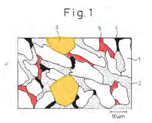
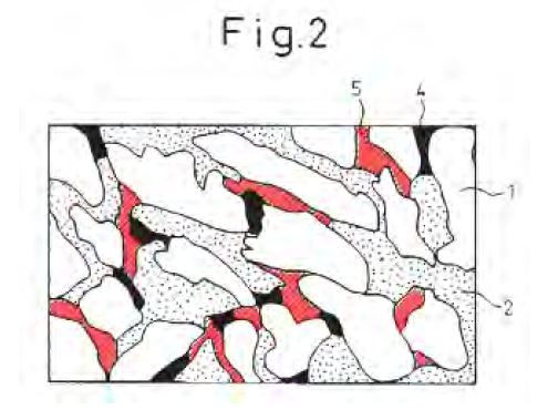
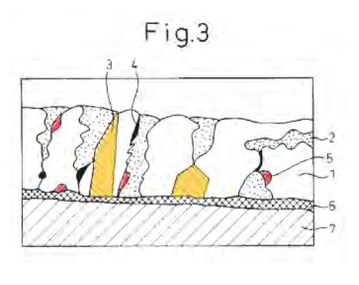
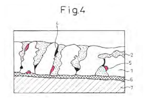
1085 The layout of Figure 1 and Figure 2 are identical but for the bulky Mg2Si particles.
1086 Figures 3 and 4 show images of a structure polished perpendicular to the surface.
1087 Figure 3 shows two bulky Mg2Si particles (numbered 3 and shaded yellow), one of which spans the coating from substrate to surface, and scaly Mg2Si (numbered 5). Figure 3 shows bulky Mg2Si from the substrate to the coating surface. There are many Mg2Si particles close to the surface. There is bulky and scaly Mg2Si in the top third of the coating. Dr Prošek considered that it appeared from the schematic that there is between about 22% and 24% Mg2Si. Dr Prošek expressed the view that the weight percent of Mg2Si would be similar to the area per cent. Mr Rommal expressed the view that it was not possible to compare the two measurements.
1088 Figure 4 appears to be identical to Figure 3, save for the bulky particles missing from Figure 4.
1089 It is apparent from the similarities between Figures 1 and 2 on the one hand and Figures 3 and 4 on the other hand that the figures are schematic illustrations. It is hard to discern a scale for Figures 3 and 4, because the examples had coating thicknesses ranging from 30 to 70 g/m2 per side.
Cooling rates
1090 Kurosaki discloses the use of cooling rates between 10 and 50ºC/sec.
1091 Kurosaki describes experiments that were conducted in order to test the corrosion resistance, workability and weldability of various compositions of the invention. Results are given for corrosion resistance (including salt corrosion, painted corrosion and outdoor exposure), workability and weldability in Table 1 which I will set out in a moment.
The Tables
1092 Table 1 relating to Example 1 and Comparative Example 1 evaluates thirty samples which were produced in a laboratory using steel strips as the base material. Samples 1 to 9 relate to samples which have the preferred form of scaly and bulky Mg2Si, and samples 10 to 14 relate to samples which have scaly Mg2Si alone. Samples 1 to 9 have Mg from 3 to 9.5 wt.% and Si from 3 to 9.3 wt.%, and Al from 46 to 68 wt.% and Zn from 25 to 45.4 wt.%.
1093 Before proceeding further, let me set out some relevant extracts.
EXAMPLES
Example 1 and Comparative Example 1
A cold-rolled steel sheet (sheet thickness: 0.8 mm) subjected to ordinary hot rolling and cold rolling was used as the material for hot-dip Zn-Al-Mg-Si plating. The plating was accomplished using a non-oxidizing furnace/reducing furnace type line, and plating coverage adjustment by gas wiping after plating was followed by cooling and zero spangle treatment. The composition of the plating bath was varied to produce test materials, and their properties were investigated. Fe was present in the bath at about 1-2% as an unavoidable impurity supplied from the plating machine and strips in the bath. The bath temperature was 600-650℃. The obtained plated steel sheet was provided for stripping and plating composition and coverage measurement by chemical analysis methods, and the plating structure was observed with an optical microscope after 5° inclination polishing. The corrosion resistance, workability, and weldability were simultaneously evaluated by the following methods. The results are shown in Table 1.
(1) Corrosion Resistance Evaluation
i) Salt Corrosion Resistance
A test sample with dimensions of 70x150 mm was subjected to a salt spray test according to JIS Z2371 for 30 days, and after stripping off the corrosion product, the corrosion loss was measured. The corrosion loss values shown are for one plated side.
Evaluation Scale
⦾: Corrosion loss of ≦5 g/m2
○: Corrosion loss of <10 g/m2
∆: Corrosion loss of 10-25 g/m2
X: Corrosion loss of >25 g/m2
ii) Painted Corrosion Resistance
First, one side was subjected to chromic acid-silica based treatment to 20 mg/m2 based on metallic Cr, as chemical treatment. Next, a test sample with dimensions of 70x150 mm was subjected to 20 μm melamine-based black painting, and baked at 140℃. for 20 minutes. A crosscut was then formed and the sample was provided for a salt spray test. The outer appearance after 60 days was visually observed.
Evaluation Scale
⦾: No red rust
○: No red rust outside of crosscut
∆: Red rust ratio ≦5%
X: Red rust ratio >5%
iii) Outdoor Exposure Test
The sample was painted after the chemical treatment described in ii) above. The painting was carried out with two types of paints, a polyethylene wax-containing acrylic-based resin (clear: 5 μm) and an epoxy-based resin (20 μm). After shearing to dimensions of 50x200 mm, the sample was subjected to an outdoor exposure test. The red rust ratio and surface coloration condition were observed from the edge after a period of 3 months.
Evaluation Scale
⦾: Red rust ratio from edge <30%
∆A: Red rust ratio from edge 30-80%
X: Red rust ratio from edge >80%
(2) Weldability
After the chemical treatment described in ii) above, spot welding was conducted under the welding conditions shown below, and the number of continuous spots until the nugget diameter reduced to below 4√t (t: sheet thickness) was evaluated.
Welding Conditions
Welding current: 10 kA, Pressure force: 220 kg, welding time: 12 cycles, Electrode diameter: 6 mm, Electrode shape: dome-shape, Tip: 6ɸ-40R
Evaluation Scale
⦾: Number of continuous spots >700
∆: Number of continuous spots 400-700
○: Number of continuous spots <400
(3) Workability
A cylindrical punch with a 50 mm diameter was used in a hydraulic molding tester for cup molding at a draw ratio of 2.25. The test was carried out with application of oil, and the flattening force was 500 kg. The workability was evaluated on the following scale.
Evaluation Scale
○: No defects
∆: Cracks in plating
X: Peeling of plating
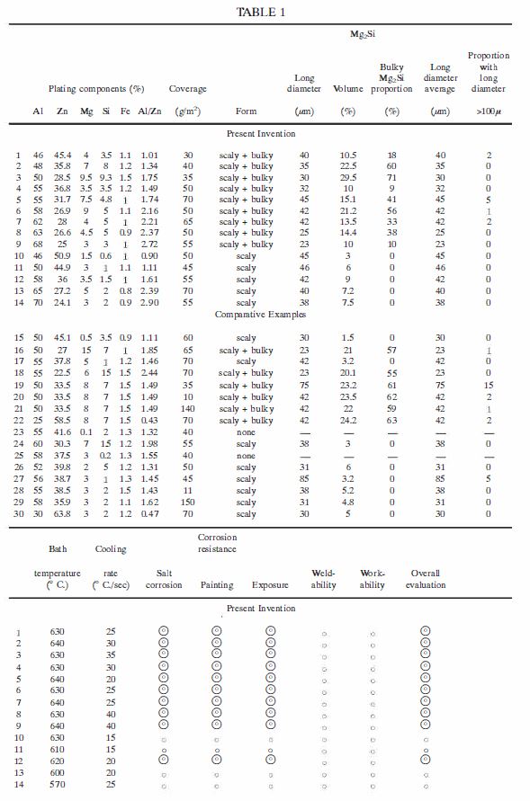
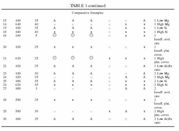
As comparative examples there are shown materials with slight addition of Mg (Sample Nos. 15 and 23), but both of these exhibited insufficient corrosion resistance in the severe corrosion environments described above. With addition of excess amounts of Mg as with Sample Nos. 16 and 24, the workability was impaired and the corrosion resistance was consequently insufficient. On the other hand, Sample Nos. 17 and 25 which had insufficient amounts of Si addition had thicker alloy layers and exhibited inferior workability as well as insufficient corrosion resistance, while conversely, Sample Nos. 18 and 26 which had excessive amounts of addition of Si exhibited inferior workability and corrosion resistance due to the effect of Si being deposited in the plating layer.
From the standpoint of the production conditions, Sample Nos. 19 and 27 which were cooled at insufficient cooling rates after plating had enlarged deposited Mg2Si phases and inferior workability. Sample Nos. 20 and 28 which had inadequate plating coverage exhibited insufficient corrosion resistance, while Sample Nos. 21 and 29 which had excessive coverage exhibited inadequate workability and weldability.
Sample Nos. 22 and 30 which had low Al/Zn ratios did not exhibit an adequate effect by the Mg2Si phase, and the resulting corrosion resistance was inferior.
On the other hand, the invention example as represented by all of Sample Nos. 1-14 exhibited excellent properties for all of the evaluated parameters. The important property of corrosion resistance was particularly satisfactory when Mg and Si were higher within their appropriate ranges.
Samples 1 to 9
1094 Kurosaki describes that the important property of corrosion resistance is particularly satisfactory when Mg and Si were higher within their appropriate ranges. Mr Rommal understood that passage to mean that, generally speaking, the examples with higher Si and Mg had better corrosion resistance. That attribute separates samples 1 to 9 from samples 10, 11, 13 and 14.
1095 Mr Rommal explained that samples 1 to 9 have good results for salt corrosion, painting and exposure, as does sample 12.
1096 Similarly, Dr Prošek understood that samples 1 to 9 give the best results for corrosion performance.
Samples 10 to 14
1097 Samples 10 and 11 are not the best samples. They have inferior corrosion resistance to samples 1 to 9.
1098 Samples 10 to 14 set out the results for coatings containing only scaly Mg2Si. The coating content of Mg in those samples ranges between 1.5 to 5 wt.%. The coating content of Si ranges between 0.6 to 2 wt.%. The amount of Al ranges from 46 to 70%. The amount of Zn varies from 24.1 to 50.9%. With the exception of sample 12, these coatings performed less well in corrosion tests.
Strontium
1099 At this point let me set out Table 2 relating to Example 2 and Comparative Example 2 with some preamble.
Examples 2 and Comparative Example 2
A cold-rolled steel sheet with a thickness of 0.8 mm was used as the material for hot-dip plating by immersion for 3 seconds in a Zn-Al-Mg-Si alloy plating bath at a bath temperature of 630℃. The plating coverage was adjusted to 90 g/m2 by gas wiping after plating, and then cooling was effected at a rate of 30℃./sec.
The compositions of the plating layers of each of the obtained Zn-Al-Mg-Si based steel sheets were as shown in Tables 2 and 3. The corrosion resistance was also evaluated by the methods described below. The results are shown in Tables 2 and 3. The structures of these platings as observed after 5° inclination polishing, at least in the case of Example 2 (Sample Nos. 31-43) as in Example 1, were structures comprising a bulky and scaly Mg2Si phase as defined according to the invention.
(1) Corrosion Resistance Evaluation
i) Salt Corrosion Resistance
A test sample with dimensions of 70x150 mm was subjected to a salt spray test according to JIS Z2371 for 30 days, and after stripping off the corrosion product, the corrosion loss was measured. The corrosion loss values shown are for one plated side.
Evaluation scale
⦾: Corrosion loss of ≦5 g/m2
○: Corrosion loss of <10 g/m2
∆: Corrosion loss of 10-25 g/m2
X: Corrosion loss of >25 g/m2
ii) Painted Corrosion Resistance
First, one side was subjected to chromic acid-silica based treatment to 20 mg/m2 based on metallic Cr, as chemical treatment. Next, a test sample with dimensions of 70x150 mm was subjected to 20 μm melamine-based black painting, and baked at 140℃. for 20 minutes. A crosscut was then formed and the sample was provided for a salt spray test. The outer appearance after 60 days was visually observed.
Evaluation Scale
⦾: No red rust
○: No red rust outside of crosscut
∆: Red rust ratio ≦5%
X: Red rust ratio >5%
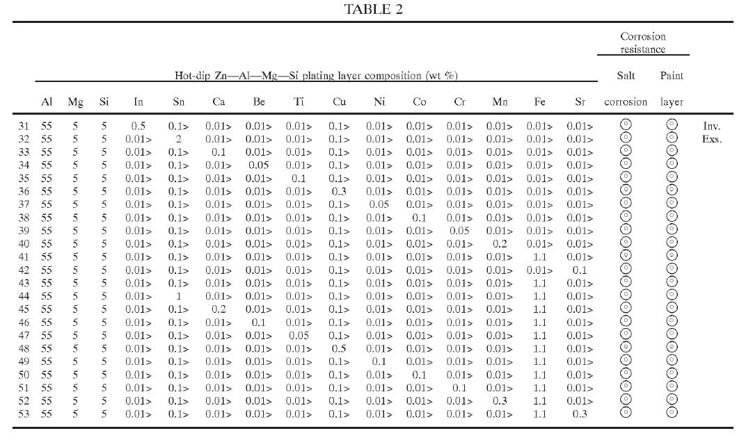
1100 Kurosaki discloses the use of a number of additional elements, the last of which is Sr, which are said to improve corrosion resistance when added in small amounts. Sr is only one of many listed elements. There is no direction or statement which would direct the user to use Sr in preference to any of the additional elements.
1101 Kurosaki reports on the performance of these additional elements in Table 2, as part of a composition of 55 wt.% Al, 5 wt.% Mg and 5 wt.% Si (and 35 wt.% Zn).
1102 It would seem that the list of elements in Table 2 and at the bottom of column 6 is there because they are elements which can be added to achieve improved corrosion resistance. Table 2 does not allow the reader to identify the contribution made by Sr to corrosion resistance in relation to any of the other elements, since Sr is not reported as being better than any of the other elements. Professor Marder concluded from Kurosaki that Sr does not affect Mg2Si in the coating or change corrosion performance. He said that the only contribution it might make is to passivation. Dr Prošek said that if there was an effect on passivation, it would be seen in the corrosion results.
Mottle/ visual defects
1103 Kurosaki is not concerned with providing a surface which is free of visual defects such as mottle. The only reference to the appearance of the product is in the context of identifying that a coating with a bulky Mg2Si phase will experience a loss of spangle. Further, there is no suggestion, direction or recommendation in Kurosaki that the addition of Sr would alter the distribution of the Mg2Si phase or resolve any visual defect.
Coating thickness variations
1104 Kurosaki does not include any discussion relating to thickness uniformity or the importance of controlling short range coating thickness variations. Further, it is not possible to predict the coating thickness variation for any composition including low Mg2Si compositions from Kurosaki.
Distribution of Mg2Si
1105 Dongkuk has done no experiments which would allow me to ascertain the microstructure of the coating used or described in Kurosaki. Instead, it relies on inferences sought to be drawn from Figures 3 and 4. But it appears to have been ultimately accepted that Figures 3 and 4 of Kurosaki, which are of a perpendicular view rather than a horizontal one, are not an accurate guide to the amount of Mg2Si at particular locations. Further, nothing about the microstructure of any of the examples is disclosed.
1106 Further, there are no measurements or calibration that would enable the surface region of the coating depicted in Figures 3 and 4 to be determined. There is no comment on the proportion of Mg2Si that would be in the surface or the surface region.
1107 Further, Kurosaki does not disclose that there are detrimental effects of having Mg2Si particles in the surface of the coating. Kurosaki does not suggest controlling the distribution of the Mg2Si particles. It focuses on controlling their size and shape. It suggests that a coating which has bulky Mg2Si particles forming up to 30% of the coating layer will provide excellent corrosion resistance. More particularly, Kurosaki does not disclose a coating having a distribution of Mg2Si particles in the coating microstructure where there is only a small proportion of Mg2Si particles or substantially no Mg2Si particles in the surface of the coating.
1108 Now I accept that Dr Prošek gave evidence that he believed that following the disclosure of Kurosaki would result in an even distribution of Mg2Si throughout the coating. But it is apparent from his evidence elsewhere that he did not consider this to be an inevitable result because Dr Prošek accepted that other processing parameters could affect the microstructure. And in any event, the effect of Dr Prošek’s evidence was that a skilled addressee would aim to achieve an even distribution. But even if that goal were achieved that would not amount to anticipation.
1109 Further, Mr Dutton’s evidence was that it was not possible to know without trying the samples in Kurosaki what microstructure would be produced.
1110 Further, Mr Rommal’s evidence was that it he did not know what the specific microstructure of any of the examples in Kurosaki would be.
1111 In my view Kurosaki does not anticipate claims 1, 3 to 9 or 11 to 15 of the 257 Patent.
(c) Nisshin – the 257 Patent
1112 Nisshin was published on 28 November 2000 and stands in the name of Nisshin Steel Co Ltd. Nisshin claimed the following:
[Claim 1]
An Mg-containing hot-dip Zn-Al alloy plated steel sheet having high corrosion resistance and good surface appearance, the Mg-containing hot-dip Zn-Al alloy plated steel sheet comprising: a plating layer formed on a surface of a steel sheet, wherein the plating layer contains, by mass%, Al: 25 to 70%, Mg: 1.5 to 5.0%, Sr: 0.01 to 1.0%, and contains Si in a range satisfying the following Equation (1) and the balance being Zn and unavoidable impurities:
Al (mass%)x0.005□Si (mass%)□10 · · ·(1) [sic].
[Claim 2]
An Mg-containing hot-dip Zn-Al alloy plated steel sheet having high corrosion resistance and good surface appearance, the Mg-containing hot-dip Zn-Al alloy plated steel sheet comprising: a plating layer formed on a surface of a steel sheet, wherein the plating layer contains, by mass%, Al: 25 to 70%, Mg: more than 5.0 to 6.0%, Sr: 0.07 to 1.0%, and contains Si in a range satisfying the following Equation (1) and the balance being Zn and unavoidable impurities:
Al (mass%)x0.005□Si (mass%)□10 · · ·(1) [sic].
[Claim 3]
The Mg-containing hot-dip Zn-Al alloy plated steel sheet of claim 1 or 2, wherein Si is contained in a range satisfying the following Equation (1)':
Al (mass%)x0.03□Si (mass%)□10 · · ·(1)' [sic].
[Claim 4]
The Mg-containing hot-dip Zn-Al alloy plated steel sheet of any one of claims 1 to 3, wherein a plating amount per one surface of the steel sheet is 40 to 120 (g/m2).
1113 The discussion of the background was as follows:
[0002] A hot-dip Al plated steel sheet has an advantage in that corrosion resistance of a plated surface is excellent as compared to a hot-dip Zn plated steel sheet. However, since Al does not have a sacrificial protection effect on Fe, unlike Zn, the Al plated steel sheet is inferior to the Zn plated steel sheet in that red rust may easily occur in an exposed portion of base steel such as a damaged portion of a plated surface, a cut cross section of the steel sheet, or the like.
[0003] As a steel sheet in which the advantage of the Al steel sheet, that is, excellent corrosion resistance of the plated surface, and the advantage of the Zn plated steel sheet, that is, the sacrificial protection effect are balanced and introduced, a hot-dip Zn-Al alloy plated steel sheet containing 25 to 70 mass% of Al is disclosed in Japanese Patent Laid-Open Publication No. S46-7161, and as the hot-dip Zn-Al alloy plated steel sheet described above, for example, a Zn-Al (55 mass%) – Si (1.6 mass%) alloy plated steel sheet has been put to practical use.
1114 So, the context concerned the question of corrosion resistance rather than mottling. Nevertheless the body of the specification discussed the question of a wrinkle like defect.
1115 A brief summary of the invention stated the following:
[0005] However, generally, a plated steel sheet in which Mg is added to hot-dip Zn-Al alloy plating (hereinafter, referred to as Mg-containing hot-dip Zn-Al alloy plated steel sheet) has not yet been widely used in spite of an excellent effect of improving characteristics as described above. Particularly, a hot-dip Zn-Al alloy plated steel sheet containing Mg in a large amount (at least several % order) in a plating layer has not yet been commercialized as an industrial product in spite of significantly excellent corrosion resistance.
[0006] The main reason for the delay in industrial distribution of the Mg-containing hot-dip Zn-Al alloy plated steel sheet is that a technology of manufacturing a Mg-containing hot-dip Zn-Al alloy plated steel sheet having good surface appearance using a general hot-dip plating line is not established.
[0007] FIG. 1 is three photographs illustrating surface appearance of a hot-dip Zn-Al alloy plated steel sheet having a plate width of 60 mm, manufactured using a continuous hot-dip plating simulator (test line). Here, in all of the photographs, left and right end portions correspond to edges of the steel sheet, and a plate passing direction in each of the photographs is a direction from the bottom to the top.
[0008] A photograph in the upper part of FIG. 1 illustrates an example of a hot-dip Zn-Al alloy plated steel sheet that does not contain Mg. The Mg-free hot-dip Zn-Al alloy plated steel sheet has almost smooth and good surface appearance. Further, white parts seen as a spangle shape (some of them are seen as a stem shape) in the photograph in the upper part, which reflect crystal grains in the plating layer, are not defects. A photograph in the middle part of FIG. 1 illustrates an example of a hot-dip Zn-Al alloy plated steel sheet containing about 1% of Mg. A white stem extended from both edge portions to a lower portion of an oblique line is observed. This stem is a portion having a wrinkle-like uneven surface. In the case of adding Mg to a hot-dip Zn-Al alloy plating bath, the above-mentioned wrinkle-like unevenness (hereinafter, referred to as a wrinkle-like defect, or wrinkle-like unevenness defect) is generally formed in a plated surface, which deteriorates surface appearance of a product, thereby deteriorating a value of the product. A photograph in the lower part of FIG. 1 illustrates an example of a hot-dip Zn-Al alloy plated steel sheet containing about 6% of Mg. When a large amount of Mg is contained as described above, the wrinkle-like defect is formed in the vicinity of a central portion of the plate in a width direction as well as edge portions thereof, such that surface appearance is significantly deteriorated.
[0009] An object of the present invention is to provide an Mg-containing hot-dip Zn-Al alloy plated steel sheet having high corrosion resistance and good surface appearance in which a wrinkle-like defect is suppressed, capable of being manufactured using a general hot-dip plating line in which a surface of a plating bath is under air atmosphere.
[0010] The wrinkle-like defect is significantly prevented by allowing an Mg-containing hot-dip Zn-Al alloy plating layer to contain a trace amount of Sr. That is, according to claim 1 of the present invention, there is provided an Mg-containing hot-dip Zn-Al alloy plated steel sheet having high corrosion resistance and good surface appearance, including: a plating layer formed on a surface of a steel sheet, wherein the plating layer contains, by mass%, Al: 25 to 70%, Mg: 1.5 to 5.0%, Sr: 0.01 to 1.0%, and contains Si in a range satisfying the following Equation (1) and the balance being Zn and unavoidable impurities:
Al (mass%) x0.005□Si (mass%)□10 · · ·(1) [sic].
[0011] Here, a chemical composition of a hot-dip plating layer may be specified by dissolving the plating layer in a solution such as an HCl solution, or the like, and analyzing the solution using inductively coupled plasma (ICP) atomic emission spectrometry. Since in manufacturing of a hot-dip plated steel sheet, a surface of the steel sheet generally reacts with a plating metal to thereby be slightly dissolved, elements (iron, and the like) derived from the steel sheet are slightly contained in the plating layer. In the present invention, these elements are also considered as the unavoidable impurities. An Si content in the plating layer may be specified by Equation (1). More specifically, for example, in the case in which an Al content in the plating layer is 25 mass%, the Si content may be specified in a range of 0.125 to 10 mass%, and in the case in which the Al content in the plating layer is 70 mass%, the Si content may be specified in a range of 0.35 to 10 mass%.
1116 In a detailed description of the illustrated embodiments the following was said:
[0016] Mg serves to cover a surface of a plating layer and an exposed portion of base steel with a corrosion product when a hot-dip Zn-Al alloy plated steel sheet is under a corrosion environment, thereby further improving original corrosion resistance of the hot-dip Zn-Al alloy plated steel sheet. That is, Mg in the plating layer serves to form intermetallic compounds with Zn and Si, that is, MgZn2 and Mg2Si, and these intermetallic compounds serve as Mg sources promoting formation of stable protective corrosion products in the corrosion environment. Therefore, the surface of the plating layer is rapidly covered with uniform corrosion products, and these corrosion products are stably present and exhibit their protective film functions, such that corrosion resistance of a plated surface is improved. Further, since the exposed portion such as a cut cross section, or the like, of the base steel is also covered with these corrosion products, early disappearance of the plating layer caused by a galvanic effect between Zn in the plating layer and Fe in a plating back plate may also be suppressed. That is, Mg serves to maintain the sacrificial protection effect while improving corrosion resistance of the plated surface.
[0017] When the Mg content in a Zn-Al alloy plating layer is less than 1.5 mass%, this corrosion resistance improvement effect is not sufficiently obtained. Further, when the Mg content is more than 6 mass%, it is difficult to sufficiently suppress a wrinkle-like unevenness defect in the surface of the plating layer even in the case of adding Sr to be described below. Therefore, the present invention relates to an Mg-containing hot-dip Zn-Al alloy plated steel sheet in which the Mg content in the plating layer is in the range of 1.5 to 6.0 mass%.
[0018] At the time of manufacturing the hot-dip Zn-Al alloy plated steel sheet containing a large amount of Mg as described above, generally, the wrinkle-like unevenness defect may occur as described above, thereby significantly deteriorating surface appearance of the hot-dip Zn-Al alloy plated steel sheet. The reason is that growth of an oxide film on a surface of a molten metal is significantly promoted by adding Mg to the plating bath, and thus the oxide film inhibits a uniform flow of a plating metal in a molten state.
[0019] The present inventors found that when a suitable amount of Sr is contained in a plating layer, a wrinkle-like defect problem as described above may be solved. The reason may be that in a non-solidified surface of the plating layer picked out from the plating bath, Sr is preferentially oxidized than Mg, and thus oxidation of Mg is suppressed.
[0020] It is preferable that a Sr content in the plating layer is 0.01 to 1.0 mass% when the Mg content is 1.5 to 5.0 mass%. When the Sr content is less than 0.01 mass%, an effect of suppressing the wrinkle-like defect is hardly exhibited. However, when the Sr content is more than 1.0 mass%, spot-like unevenness caused by an Al-Si-Sr based intermetallic compound may occur, thereby deteriorating surface appearance of the plating layer . In the case in which the Mg content is high (more than 5.0 to 6.0 mass%), it is preferable that a lower limit of the Sr content is increased to 0.07 to 1.0 mass%. When the Si content is less than 0.07 mass%, the wrinkle-like defect may not be sufficiently suppressed.
…
[0024] The Mg-containing hot-dip Zn-Al alloy plated steel sheet according to the present invention may be manufactured using a general continuous hot-dip plating line. The present inventors confirmed through a separate experiment that in the Mg- containing hot-dip Zn-Al alloy plating, a composition of the plating bath is almost reflected as it is in a composition of the plating layer in the plated steel sheet. Therefore, at the time of manufacturing the Mg-containing hot-dip Zn-Al alloy plated steel sheet according to the present invention, there is a need only to adjust the Al content, the Si content, the Mg content, and the Sr content in the plating bath so as to coincide with the composition of the plating layer to be desired.
1117 Importantly, Table 1 reported on the following results:

1118 I will discuss Table 1 and some of the entries in more detail later. But I should make some observations at this point in terms of what Table 1 displays. The description for Example 1 gives the following explanation:
[0025] Hot-dip Zn-Al alloy plated steel sheets in which Mg and Sr contents were variously changed were manufactured using a continuous hot-dip plating simulator (continuous hot-dip plating test line). Plating conditions were as follows.
• Base steel sheet: cold-rolled Al killed steel (thickness: 0.8 mm, width: 60 mm)
• Maximum Temperature Reached by Sheet in Reduction Furnace: 700°C , Dew point: -35°C
• Sheet passing rate: 50 m/min
• Composition (mass%) of plating bath: Al:55%, Si:1.6%, Mg:0-7%, Sr:0-1.5%, and the balance being Zn and avoidable impurities
• Temperature of plating bath: 605°C
• Immersion time : 3 seconds
• Cooling after plating: air cooling (cooling rate: 20°C/s)
[0026] Surface appearance of the manufactured hot-dip plated steel sheets was observed by the naked eyes, and an occurrence degree of a wrinkle-like defect was ranked into four levels (⦾, ⚪, △, and x) As an evaluation standard, the surface appearance was ranked as follows using samples illustrated in the photographs in FIG. 1.
• ⦾: The hot-dip plated steel sheet had good surface appearance equivalent to or more excellent than that of a sample at the top in FIG. 1.
• ⚪: The hot-dip plated steel sheet had surface appearance worse than that of the sample at the top but equivalent to or more excellent than that of a sample in the middle in FIG. 1.
• △: The hot-dip plated steel sheet had surface appearance worse than that of the sample in the middle but more excellent than that of a sample at the bottom in FIG. 1.
• x: The hot-dip plated steel sheet had surface appearance equivalent to or worse than that of the sample at the bottom in FIG. 1.
[0027] A case in which the wrinkle-like defect occurred was also evaluated as “⚪”. However, even in this case, surface appearance was significantly improved as compared to a material according to the related art, and it is considered that a product value of the hot-dip plated steel sheet was sufficient depending on the uses. Therefore, in the present invention, when the surface appearance was evaluated as “⦾” or “⚪”, it was determined that surface appearance was good. However, since a case in which spot-like unevenness attributed to an Al-Si-Sr based intermetallic compound was formed means that even though occurrence of the wrinkle-like defect was sufficiently suppressed, a novel defect that did not occur in the material according to the related art occurred, this case was evaluated as unevenness exists.
[0028] Further, after each of the plated steel sheets was exposed in a coastal industrial belt in Sakai City, Osaka Prefecture for 3 months in a state in which a 2t bending processing part and a cross-cut part (a portion at which an X-shaped scratch was formed on a surface of the plating layer) were formed in each of the plated steel sheets, and at the same time, the base steel was exposed in a cut cross section thereof, a degree of inconspicuousness of red rust was evaluated. A commercial Zn-Al (55 mass%)-Si (1.6 mass%) alloy plated steel sheet that did not contain Mg was used as a standard sample, and the degree of inconspicuousness of red rust was observed by the naked eyes and was ranked into four levels (⦾, ⚪, △, and x) as follows.
• ⦾: Red rust was hardly seen.
• ⚪: Red rust was more inconspicuous than that of the standard sample.
• △: Red rust was inconspicuous similarly to that of the standard sample.
• x: Red rust was more conspicuous than that of the standard sample.
[0029] Further, a composite cyclic corrosion test (CCT) was performed on each of the plated steel sheets. CCT conditions were determined according to Japan Automobile Standards Organization (JASO) M609-91 standardized by the Society of Automotive Engineers of Japan, and one cycle was composed of salt water spray (5% normal saline) at 35°C for 2 hours → drying at 60°C and relative humidity 30% for 4 hours → wetting at 50°C and relative humidity 95% for 2 hours. A cross section and an entire inner surface of the test sample were sealed with an insulating tape and used in the test. After completing CCT 200 cycles, corrosion products were removed by a 10% ammonium chloride aqueous solution (solution temperature: 60°C), and a corrosion mass loss (g/m2) was calculated from a mass difference before and after the test, thereby evaluating corrosion resistance of the plated surface. These results were illustrated in Table 1.
1119 I will return to this later, but samples 27 to 30 are shown as the optimum samples in terms of good surface appearance and more modest corrosion mass loss. I should also note that sample 1 is galvalume. It would also seem from these results that surface appearance deteriorates as Mg increases. So it might be said that Nisshin teaches away from the 257 Patent and the 258 Patent.
1120 Now Dongkuk points out that Nisshin concerns a hot-dip coating method for coating a steel strip, with the method having Al-Zn-Si-Mg in the coating in the ranges claimed in claim 9 of the 257 Patent; see especially Example 1 Table 1 samples 20 to 22 and 27 to 29. Mg2Si is formed in the coating alloy. Dongkuk says that the distribution of Mg2Si would fall within claims 1, 3 and 15 of the 257 Patent in accordance with each or all of the methods set out in the 257 Patent. Dongkuk says this for the following reasons.
1121 First, the thickness of the Nisshin product would be controlled by ordinary good practice.
1122 Second, the cooling rate in Nisshin is only 20°C/sec.
1123 Third, the samples include Sr in the range 0.05-0.3% by wt (500-3000ppm).
1124 Now Nisshin is directed towards an Mg-containing hot-dip Zn-Al alloy plated steel sheet having high corrosion resistance and good surface appearance.
1125 Nisshin discloses that a plated steel sheet in which Mg has been added to hot dip zinc and alloy had not yet been widely used in spite of its excellent effect in improving characteristics, which relates to corrosion resistance. Nisshin explains that the product has not been commercialised because it has not been possible to produce a sheet having a good surface appearance.
1126 Nisshin is particularly directed towards suppressing a “wrinkle-like” defect associated with the addition of Mg to Al-Zn alloy coatings.
1127 Nisshin discloses an Mg-containing hot-dip Zn-Al alloy plated steel sheet where the plating layer contains, by mass %:
(a) 25 to 70 wt.% Al;
(b) 1.5% to 5 wt.% Mg;
(c) 0.01 to 1.0 wt.% Sr;
(d) Si according to the following formula:
Al (mass%) x 0.005 ≤ Si (mass%) ≤ 10%,
and the balance being Zn and unavoidable impurities.
1128 Figure 1 of Nisshin contains three images illustrating the surface appearance of three Zn-Al alloy plated steel sheets. In my view the images are of such poor quality that they provide little assistance with understanding the nature of the defect.
1129 The “wrinkle-like” defect is described as a defect which arises when Mg oxidises with O2. This forms Mg-oxides that grow as an oxide film on the surface of the molten bath. As the metal strip is drawn out of the molten bath, the Mg-oxides inhibit the uniform flow of the molten metal onto the strip.
1130 The “wrinkle-like” defect is associated with oxide drag out which causes the Mg-oxide film to adhere to the coated surface of the strip as it exits the molten bath, or to form on the molten metal after the strip exits the bath. The following evidence was given:
MR CAINE: Thank you. Then if we come across to paragraph 18 on page 13, they refer again to the wrinkle-like unevenness defect, and then at about 5 line 18 they say the reason is that the growth of an oxide film on the surface of the molten metal is significantly promoted by adding magnesium to the plating bath and thus the oxide film inhibits a uniform flow of a plating metal in a molten state. So that that’s telling us that there’s an oxide film that forms on the surface of the molten bath; that’s right, isn’t it?
MR ROMMAL: It’s telling us that there is an oxide film that forms on the molten coating metal that could be on the surface of the bath or it could be on the surface of the molten metal after the strip exits the bath.
MR CAINE: As the metal strip is drawn out of the bath, I wanted to put to you the magnesium oxides inhibit the uniform flow of the molten metal on to the strip.
MR ROMMAL: It says inhibits the uniform flow of a plating metal. It doesn’t say flow of the metal from the bath to the strip. It could be flow of the metal once it’s on the surface of the strip in terms of its motion in response to gravity or other airflow in the vicinity above the bath.
MR CAINE: So the description of the wrinkle defect is one that’s not clear to you?
MR ROMMAL: It’s not clear to me whether the wrinkle defect is magnesium oxide patches pulled out on the surface of the coating or whether it’s non-uniform coating thickness on a small scale caused by magnesium oxide getting in the way of the molten metal flowing freely somewhere either on the bath or once it’s applied to the – to the coated strip.
1131 This causes the surface appearance to deteriorate, resulting in a “wrinkle-like” surface defect.
1132 Nisshin indicates that additions of Sr to the molten bath may solve the “wrinkle-like” defect. Nisshin suggests that because Sr is more favourably oxidised than Mg, the oxidation of Mg is suppressed. This reduces the amount of Mg-oxide film available for drag out onto the coated surface, suppressing the “wrinkle-like” defect.
1133 The specification explains that the wrinkle-like defect is significantly prevented by allowing the coating to contain Sr, in an amount from 0.1 to 1%.
1134 Nisshin refers to an upper limit for Sr of 1 wt.% (10,000 ppm). This is to ensure that another defect, described as “a spot-like unevenness” caused by Al-Si-Sr, does not occur. The lower limit for Sr is dependent on the amount of Mg. A lower limit for Sr of 0.01 wt.% is described where the Mg content is 1.5 to 5 wt.%. A lower limit for Sr of 0.07 wt.% is described where the Mg content is 5 to 6 wt.%.
1135 Now it would seem that the “wrinkle-like” defect described in Nisshin is a surface defect. But as Mr Dutton observed, the defect is not the surface defect mottle to which the 257 Patent is addressed. The “wrinkle-like” defect is a defect resulting from the formation of Mg-oxides on the molten bath which inhibit the uniform flow of the molten metal onto the strip. In contrast, mottle is a defect resulting from the formation of a non-uniform distribution of Mg2Si particles in the surface of the coating microstructure.
1136 Nisshin provides three examples of the Mg-Al-Zn alloy coating of the invention. The examples are assessed by reference to the naked eye. Table 1, which contains the results of 49 different samples, relates to compositions with 55 wt.% Al, 1.6 wt.% Si, Mg from 0 to 7wt. %, and Sr from 0 to 1.5 wt.%. Table 2 relates to compositions with 25 wt.% Al. And Table 3 relates to compositions with 70 wt.% Al.
1137 Let me say something about Table 1.
1138 Sample 1 of Table 1 is the composition equivalent to galvalume, which is used as a comparator. The results for samples 1, 2 and 3 showed that as Mg was increased (from 0 wt.% to 1.0 wt.%), corrosion resistance improved, that is, mass loss reduced. However, at Mg levels of 5 wt.% and above, surface appearance issues started to arise. Samples 27 to 30 appear to have been the “best”. They have the optimal balance of surface appearance, minimal red rust and corrosion resistance. Those samples contain Al in the amount of 55 wt.%, Si in the amount of 1.6 wt.%, Mg in the amount of 4 wt.%, Sr in amounts up to 1 wt.% (that is, up to 10 000ppm), and Zn in the amount of up to 39.4 wt.%. No coating mass for the samples is given.
1139 In my view it seems reasonably clear that insofar as the results in Table 1 direct the reader to any particular samples, they are samples 27 to 30. This is fatal to Dongkuk’s assertion of anticipation.
1140 Now Dongkuk relies on samples 20 to 22 as anticipatory, but I disagree as I will explain shortly.
1141 Let me say something about the other Tables. Mr Rommal’s earlier evidence was that “the results set out in Table 1 in terms of surface appearance and red rust are superior to those set out in Table 2 and Table 3”, but Dr Prošek did not agree. In my view, the results set out in Tables 1, 2 and 3, in relation to surface appearance and red rust are consistent and do not vary despite the change in Al and Si composition. I accept that Mr Rommal later corrected his early statement stating that his “intention was to say that the results set out in Table 1 are nearly identical in terms of surface appearance and red rust compared to Table 2 and Table 3, but the corrosion mass loss results in Table 1 are superior to those set out in Tables 2 and 3”.
1142 Let me now deal with a number of points.
1143 First, Nisshin does not focus on developing a specific coating microstructure. Rather, Nisshin focuses on controlling a production issue that causes oxide to build up, giving rise to the “wrinkle-like” defect. The “wrinkle-like” defect is not the result of microstructural issues.
1144 Second, Nisshin refers only briefly to Mg2Si. The context of this brief discussion is that Mg2Si is said to promote the formation of a stable product with improved corrosion resistance. Mr Rommal explained that Nisshin is talking about products of oxidation of magnesium spreading across the surface of the coating. If those corrosion products are not easily redissolved, because they are stable, then they can serve as a barrier to further corrosion. Mg2Si is a source of the magnesium which forms the barrier. At least some must be present at the surface of the coating to provide corrosion protection. Further, both Dr Prošek and Mr Dutton understood from the brief reference to Mg2Si that it was desirable to have Mg2Si at the surface of the coating in order to improve corrosion resistance.
1145 Third, Nisshin does not identify where the Mg2Si particles are located in the coating microstructure.
1146 Fourth, Nisshin is not concerned with providing a surface which is free of visual defects such as mottle. The only reference to the appearance of the product is to a wrinkle-like defect, which is not mottle.
1147 Fifth, Nisshin makes no reference to controlling coating thickness variations. In terms of coating thickness, Nisshin claims a coating mass in the range of 40 to 120g/m2, but otherwise does not refer to coating mass. The coating mass used in the tabulated results is not known.
1148 Sixth, Nisshin does not suggest that controlling the cooling rate will impact upon the distribution of Mg2Si particles. Further, it does not describe that the cooling rate will affect the appearance of the coated strip. Similarly, Nisshin does not describe the effect of cooling rate on corrosion resistance and the resulting microstructure. The same bath temperature (605°C) is used throughout. The same cooling rate of 20°C/sec is used in all the samples, despite different coating bath compositions.
1149 Seventh, although Nisshin describes that Sr assists with the appearance of the coating, Nisshin does not describe what effect the addition of Sr has on the diffusion of the Mg2Si particles. Dr Prošek concludes that Sr has no effect on the microstructure. This is because if it did, there would be a change in the corrosion resistance results. But as was pointed out in the evidence, the samples in Nisshin do not show that there was any improvement to the corrosion resistance properties across a range of 0 to 1.5 wt.% Sr (15,000 parts per million) when the amount of Al, Si and Mg remained constant.
1150 Further, samples 27 to 30, which performed best against the criteria tested, namely surface appearance evaluation, red rust test and corrosion mass loss test, had less than 40 wt.% Zn and were therefore outside the scope of claim 9 of the 257 Patent.
1151 Now as Dongkuk pointed out, samples 20 to 22 had alloy ranges which corresponded with the alloy ranges set out in claim 9 of the 257 Patent. But although Dongkuk relies upon samples 20 to 22 as anticipatory, Dr Prošek would not have made those samples. Moreover, he did not accept that if he made samples 20, 21 and 22 and exercised ordinary good manufacturing practice, he would have arrived at the claimed Mg2Si distribution.
1152 Further, although Dr Prošek accepted that the addition of Sr would affect Mg2Si distribution, he considered that the structure disclosed in Nisshin clearly had large amounts of Mg2Si at the surface. This was necessary for the protection mechanism that was claimed, being a stable corrosion product. That protection mechanism would not work without Mg-rich phases exposed at the surface, including not only Mg2Si, but also MgZn2.
1153 Further, Mr Dutton also understood that there would be Mg2Si close to the surface, if not in the surface.
1154 Further, Mr Rommal considered that there would have been some Mg2Si or MgZn2 at the surface, but that the amount would depend on the dissolution rate in the corrosive environment and how much corrosion product was required to provide protection. He explained:
Nisshin is specifically calling out the two intermetallic compounds Mg2Si and MgZn2 as potential sources of the magnesium. In order for the stable magnesium corrosion product to cover the surface of the plating layer providing additional corrosion protection, you would have to have some source of magnesium present at the surface or close enough to the surface that when the corrosion of the coating begins – the very beginning of corrosion you’ve down to it and now you’ve got some magnesium available at the new surface. … So it has to be either at the surface or close to the surface in some quantity to be able to make that corrosion product.
1155 Now although Professor Marder observed that Nisshin does not say how much Mg2Si is present at the surface, and he speculated that MgZn2 could be the source of Mg, I agree with BlueScope that that observation does not assist Dongkuk. Nisshin does not clearly disclose a coating which contains only a small proportion of Mg2Si in or near the surface of the coating.
1156 In summary, Nisshin does not anticipate claims 1, 3 to 9 and 11 to 15 of the 257 Patent.
(d) The Nolan article & the Nolan thesis – the 257 Patent
1157 Dongkuk has submitted the following.
1158 Dongkuk relies on the Nolan article and the Nolan thesis taken together on the basis that they are related documents that a person skilled in the relevant art in Australia would treat as a single source of information pursuant to s 7(1)(b) of the Act.
1159 Nolan was variously funded, employed and contracted by BlueScope (and its predecessor, BHP Steel). The Nolan article and the Nolan thesis were published in 1993 and both are by the same author. The Nolan thesis is referred to in the Nolan article. In particular, the Nolan article states “[c]oatings were produced using a controlled hot-dip galvanizing cycle” (at p 86), referencing the Nolan thesis. Dongkuk says that it is axiomatic that in producing a coating in accordance with the teachings in the Nolan article, the skilled addressee would refer to the Nolan thesis. I agree.
1160 In the Nolan article, under the sub-heading “Experimental”, Nolan explains that he obtained a Zn-Al-Si alloy by melting commercial grade zincalume. Mg was added to the liquid zincalume alloy mixture at different percentages to examine the effect of the addition of Mg to zincalume. At p 86 it is said that coatings were produced using a controlled hot-dip galvanising cycle and reference is then made to the Nolan thesis. In the Nolan thesis it is said that:
The base material for the present work was commercially produced and chromate passivated ZINCALUME in sheet form, with base thickness of 1.0 mm and coating mass of 150 g/m2. The base steel was an aluminium-killed, fully recrystallised low alloy steel. The sheets were marked and sheared into coupons 110 mm by 350 mm with the long direction in the rolling direction of the steel coil.
1161 Nolan explains his use of the so called “double-dipping” method to coat the steel with the alloy. He says that:
In this method, a sample of ZINCALUME was cleaned and preheated before being immersed in a liquid ZINCALUME alloy. While immersed in the liquid, the coating on the sample dissolved and when the sample was removed from the liquid, a new ZINCALUME coating was substituted in place of the original coating. This new coating, with the composition of the liquid alloy [including Mg], was subjected to the similar principles of coating thickness control and accelerated cooling as the original coating. Trials using the Double-Dipping method showed that it was possible to consistently produce high quality coatings…
1162 It is not expressed in either the Nolan thesis or the Nolan article that the variation in thickness of the coating was no more than 40% in any given 5mm diameter section and that that “limitation” on thickness variation caused the distribution of Mg2Si particles to be such that there was only a small proportion or substantially no Mg2Si particles in the surface of the coating. But Dongkuk says, based on the teaching of the 257 Patent, that distribution of Mg2Si would be the outcome of Nolan’s method because his cooling rate was only 12.3°C per second. Further, Dongkuk says that it is clear that Nolan was in any case also concerned with ensuring coating thickness uniformity. Further, Dongkuk says that as a matter of fact, the majority of Mg2Si was in the bottom two thirds of the coating.
1163 As to the first of these matters, Dongkuk points to various passages in the Nolan article.
1164 As to the second matter, Dongkuk says that the photomicrographs presented by Nolan in the Nolan thesis demonstrate the Mg2Si phase growing from the intermetallic alloy layer, and not from nor reaching the surface of the coating.
1165 Dongkuk says that I should reject BlueScope’s submission that neither the Nolan article nor the Nolan thesis are novelty defeating disclosures because the Nolan article does not relate to coated steel strip made by a hot dip coating process because it is a laboratory sample. It says that the samples created were created on a simulated production environment which involved hot dip coating using zincalume samples obtained from BlueScope’s predecessor. It says that this method is valid and the results can be accepted within the bounds of commercial sheet production. Further, the point of Nolan is to report the addition of Mg to zincalume for the purpose of coating steel sheet products.
1166 Further, Dongkuk says that BlueScope’s rejection of the Nolan article on the basis that the amount of zinc was not 40 to 60% is not a legitimate rejection. It says that the results relied upon by BlueScope reflect the coating composition dissolved with additional Fe from the intermetallic layer and so it is the alloy’s composition that is relevant in the Nolan thesis and not the coating composition figures.
1167 Let me analyse each piece of prior art in turn.
The Nolan article
1168 The Nolan article reports on the effects of adding magnesium on the coating microstructure. It reports on the addition of Mg to zincalume in the amounts of 0.1, 0.5, 1 and 2.5 wt.%.
1169 The Nolan article does not describe the process by which the product was made.
1170 At this point, let me set out some extracts.
1171 At pp 86 to 87 the following is said:
EXPERIMENTAL
Liquid Zn-55%Al-1.6%Si alloy was prepared by melting ingots of commercial grade ZINCALUME alloy in a graphite crucible. The ZINCALUME was obtained from the No.l Galvanizing Line at the Springhill Works of BHP Steel - Sheet and Coil Products Division at Port Kembla. Magnesium was added to the liquid ZINCALUME using pure metal in ingot form with 99% purity. Nominal concentrations of the magnesium-additions were 0.1, 0.5, 1.0 and 2.5 weight percent.
Alloy samples were taken in the form of air-cooled ingots (10mm x 10mm x 80mm) and water quenched beads (for chemical analysis). Coatings were produced using a controlled hot-dip galvanizing cycle (12). Alloy compositions were determined by dissolving samples in hydrochloric acid and analysing the solutions, using Atomic Absorption Spectroscopy for zinc, iron and magnesium, photometric analysis for silicon and the aluminium content was calculated by difference. Coating compositions (including alloy layers) were determined by dissolving coatings in a rhodine inhibited hydrochloric acid solution and analysing the solutions using Inductive Coupled Plasma Spectroscopy.
Alloy samples and coating cross-sections were mounted in low curing temperature epoxy resin, thus avoiding any possible heat treatment associated with thermosetting mounts. The mounted specimens were ground on progressively finer abrasive paper and then polished using 4-8μm, 1-3μm and 0-1μm Buehler diamond paste on motorized polishing wheels. After each polishing stage the mounts were placed in ethanol in an ultrasonic unit before being washed in a stream of ethanol and blown dry with forced air. Difficulties were encountered during polishing due to the undesirable etching of the zinc-rich regions, and great care had to be taken to achieve a satisfactory surface finish with minimum polishing time.
The polished specimens were then carbon coated in the unetched condition and examined using a JEOL JSM-840 Scanning Electron Microscope (SEM) in secondary electron imaging mode at 15kV. Images were recorded on Ilford HP5 film using an attached auto-exposure unit. The EDS spectra for compositional analysis of phases were taken using 25% dead time. The “volume of influence” of the incident electron beam, when generating x-rays for EDS analyses, was considered to be approximately 1μm3.
RESULTS AND DISCUSSION
Alloy and Coating Compositions
Alloy and coating compositions are provided in Table 1. These show that the nominal addition concentrations were very closely approximated in the ZINCALUME alloys and coatings. The absence of results for the 0.5%Mg coating is due to experimental error is coating dissolution for analysis. The high iron concentrations in the coatings are expected as a result of the dissolution of the intermetallic alloy layer along with the coating overlay in the chemical analysis. The slightly lower addition concentrations in the coatings is a consequence of the high iron content and, if the compositions were to be normalized with the iron content set to approximately 0.4%, the addition concentrations would be closer to those of the alloys.
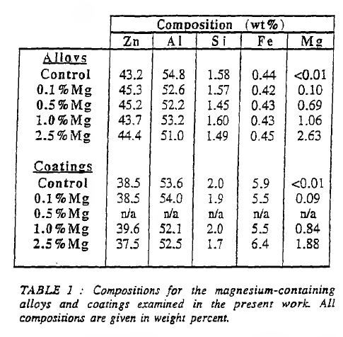
1172 I should note that end note (12) that is referred to on p 86 refers to the Nolan thesis.
1173 Then at pp 89 and 90, the following is set out:
Effects of Magnesium Additions on Coating Microstructure
With the addition of 0.1 %Mg, there were no obvious changes to the microstructure of the ZINCALUME control coating, shown in Fig.1. However, magnesium was detected in the most central zinc-rich region (shown at A in Fig.8) where the composition was found to be 94%Zn-3%Al-3%Mg. The corresponding phase region in the alloy microstructure (shown at A in Fig.4) had the composition 90%Zn-6%Al-4%Mg and was designated the V-phase. It is therefore proposed that the phase in the centre of the interdendritic regions in the coating is also the V-phase.
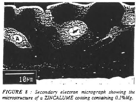
With the addition of 0.5%Mg, there were two significant changes to the microstructure. The first of these was the Mg-Si phase growing from the intermetallic alloy layer, as shown at A in Fig.9(a). The composition of this phase was found to be 61%Mg-39%Si and is consistent with that of the phase, Mg2Si, which appeared at the magnesium concentration of 0.5% in the alloy microstructure. It should be noted that the occurrence of this phase was not common in the 0.5%Mg coatings, and the predominant silicon-bearing phase was the III-phase.
The second of the changes was the presence of a homogeneous phase in the most central regions of the zinc-rich interdendritic regions, as shown at B in Fig.9(b). This phase was found to have the composition 82%Zn-16%Mg-2%Al. It is therefore proposed that this phase is MgZn2, which was observed at the same magnesium concentration in the alloy sample. Magnesium was also occasionally detected in small amounts in the II-phase regions (the fine zinc-rich interdendritic regions).
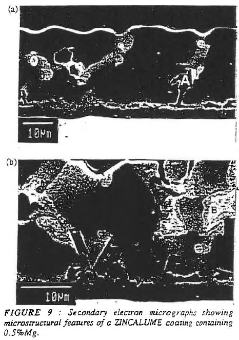
The microstructure of the coatings containing 1.0%Mg was very similar to that of the coatings containing 0.5%Mg. Perhaps the only notable difference was the greater volume fraction of MgZn2, though no attempt was made to quantify this. It was also noted that there appeared to be clearer definition between the zinc-rich interdendritic regions and the aluminium-rich denrites, as shown in Fig.10. This confirmed the observations made on alloy samples, where the same effect was noted with a 1.0%Mg addition. Some magnesium was detected in the fine zinc-rich eutectic (the composition at A in Fig.10 was 80%Zn-15%Al-5%Mg). However, this result was not consistent, and at some II-phase regions no magnesium was detected.
With 2.5%Mg, the most significant change related to an increase in the volume fraction of the Mg2Si phase. Figure 11 is an example of a typical ZINCALUME + 2.5%Mg coating structure, showing Mg2Si existing mostly in contact with the quaternary intermetallic alloy layer. Compositional analyses showed that all of these silicon-rich particles were Mg2Si. It is considered possible that
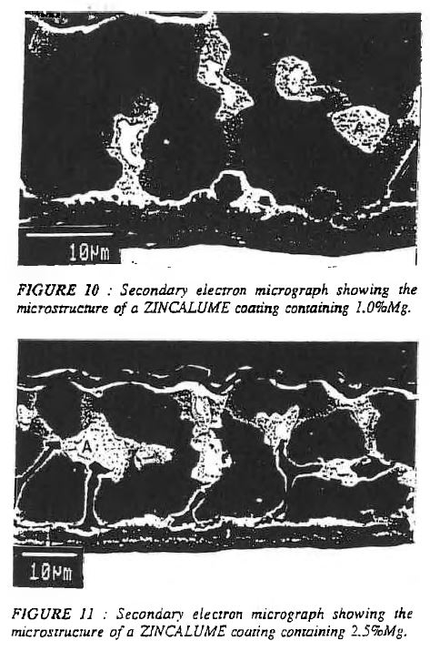
these large and numerous panicles of Mg2Si might be responsible for an observed grain refinement in these coatings (12), as Marder has suggested that silicon particles at the alloy/overlay interface act as sites for dendrite nucleation.
It is also possible to distinguish the coarse Zn-Mg eutectic, shown at A in Fig.11, which had the composition of 95%Zn-5%Mg. It is proposed that this is the Zn-MgZn2 eutectic referred to in the discussion of the alloy samples. It was noted that magnesium was not detected in the fine zinc-rich regions, the aluminium-rich dendrites, or the quaternary intermetallic alloy layer.
1174 Let me say something about Figure 9(a) of the Nolan article.
1175 The Nolan article discloses that when 0.5 wt.% Mg was added, the Mg2Si phase started to grow from the intermetallic layer, as shown in Figure 9(a). Region A of Figure 9(a) shows the Mg2Si phase, but the Nolan article does not describe in quantitative terms the proportion of Mg2Si in any part of the microstructure.
1176 Let me say something about Figure 11 of the Nolan article.
1177 The Nolan article discloses that when Mg2Si was added in the amount of 2.5 wt.%, the most significant change related to an increase in the volume fraction of Mg2Si, as shown in Figure 11. The Nolan article discloses that Mg2Si is mostly in contact with the quaternary intermetallic layer, but does not otherwise describe the location of the particles.
1178 Otherwise, the Nolan article does not expressly refer to the proportion of Mg2Si in any part of the coating, or provide any quantitative reference to the amount of Mg2Si referable to the surface region. Although the photomicrograph is unclear, Figure 9(a) shows that Mg2Si extends from the intermetallic layer and Figure 11 may show Mg2Si at the surface.
1179 Professor Marder’s evidence was that the photomicrographs were of poor resolution, and might not be able to discern fine particles. Professor Marder accepted that whilst Mg2Si was apparent at the interface:
We don’t know how [Mg2Si] has manifested in the coating at the surface because we can’t resolve that in the magnifications or the photomicrographs that we see here … we don’t see the top of the tree, but we don’t know if it isn’t there.
1180 The Nolan article discloses that above 0.5 wt.%, Mg was present as Mg2Si particles and as the Mg content increased, the quantity and size of the Mg2Si particles changed. The Nolan article suggests that the Mg2Si particles formed preferentially at the interface between the coating overlay and the intermetallic layer at 0.5 wt.%, where Mg was at higher levels (2.5 wt.%), Mg2Si appears throughout the coating thickness.
1181 Let me say something about short range coating thickness variation. The Nolan article does not disclose short range coating thickness variations, or any means taken to control them. Moreover, good manufacturing practice cannot be used to supplement the disclosure.
1182 Let me say something about the distribution of Mg2Si.
1183 It is not possible to conclude from the Nolan article that there is a small proportion of Mg2Si particles or a distribution of Mg2Si which has no more than 10 wt.% in the surface region of the coating that has a thickness of less than 30%. Neither the description nor the images clearly identify which particles are Mg2Si.
1184 Let me say something about cooling rate. The cooling rate does not provide an answer to the absence of disclosure, because the evidence does not support the proposition that cooling rate alone will achieve the claimed microstructure.
1185 Further, the Nolan article did not produce a coating with 40-60 wt.% zinc as claimed in claim 9 of the 257 Patent and claim 1 of the 258 Patent. The double dipping process used by Dr Nolan differs from a commercial product in the thickness of the quaternary intermetallic layer and in the coating composition.
1186 Further, Table 1 of the Nolan article shows that the amount of Zn in the coating compositions varied from 38.5 to 39.6 wt.%. Moreover, Mr Rommal did not suggest that Nolan had 40 to 60 wt.% Zn in the coating. His evidence is that the coating could be normalised in order to make a comparison of the coating composition with the bath composition.
1187 In my view the Nolan article does not anticipate whether standing alone or when read with the Nolan thesis.
The Nolan thesis
1188 The Nolan thesis does not anticipate the relevant claims of the 257 Patent.
1189 The Nolan thesis describes the double dipping method, which used zincalume as a base material. The zincalume samples were cleaned and preheated, and then immersed back into the bath, which dissolves the coating, and as the zincalume sample is withdrawn from the bath a new substitute coating forms on the sample.
1190 The Nolan thesis describes the processing steps for each sample and the equipment used, being a furnace, an air stripping knife and a supporting bar which sought to replicate the tension of a commercial line. The Nolan thesis describes that oxide was cleared from the surface of the bath using a scraper. The Nolan thesis discloses that the sample was withdrawn at a rate of a metre per second, and that the coating mass is only controlled on one side by the air knife. The sample was held horizontally by bulldog clips.
1191 Let me say something about short range coating thickness variations. Nolan did not take any steps to control short range coating thickness variation. He rejected samples that did not meet the desirable coating thickness range. Nolan used Fischer Deltascope to take measurements of the coating thickness. However, the intervals at which measurements were taken are not identified. The Nolan thesis does not describe how many measurements were taken, or describe steps to control coating thickness variations over 5 mm increments.
1192 Now Mr Rommal asserted that the Nolan thesis discloses the control of short range coating thickness variations, because a Fischer Deltascope was used. But Nolan was not controlling coating thickness variations. Rather he was discarding unacceptable samples.
1193 Let me say something about the distribution of Mg2Si.
1194 One cannot ascertain from the Nolan thesis how much Mg2Si is in the surface of the coating or in the surface region. The Nolan thesis reports the formation of large particles of Mg2Si above 0.5 wt.% Mg, which become more prominent with increasing Mg. Professor Marder concluded that above 0.5 wt.%, Mg2Si was present, which was coming out of the intermetallic layer. But there may be some Mg2Si at the surface region at 0.5 wt.% Mg.
1195 The aims of the project were to produce a product which did not have compromised formability or corrosion performance. It concludes that the only promising results were obtained with Mg additions, which showed significant improvement to the salt spray corrosion resistance of unpainted coatings and edge undercutting. Those improvements were more marked at higher Mg additions. The Nolan thesis concludes that although the salt spray resistance and edge undercutting of zincalume is increased by adding Mg, most markedly at 2.5 wt.% Mg, processing problems occur at 1 wt.% Mg.
1196 The Nolan thesis concludes that the addition of magnesium did not result in benefits which outweighed the detriments relating to coating ductility. The benefits were insufficient to warrant further investigation as a modifying element capable of improving the mechanical or corrosion properties of zincalume. It stated that whilst there were improvements to performance, there were associated detrimental effects that negated the benefits.
1197 In summary, neither the Nolan article nor the Nolan thesis:
(a) relate to the use of the hot dip coating method of the kind disclosed in the claims of the 257 Patent;
(b) deals with mottle or other surface defects;
(c) disclose the control of short range coating thickness variation;
(d) disclose that Mg2Si distribution should be controlled;
(e) disclose any Mg2Si distribution; or
(f) disclose coatings with the claimed alloy compositions.
1198 Neither the Nolan thesis nor the Nolan article nor the combination of both anticipate claims 1, 3 to 9 and 11 to 15 of the 257 Patent.
(e) Conclusion – the 257 Patent
1199 In summary, none of the prior art or the prior art products anticipate. I disagree with Dongkuk who contends that if the person skilled in the art followed the directions in the prior art documents then ordinary good manufacturing practice would mean that the claimed ranges of thickness variation would be achieved. I reject its contention that the patentee has simply claimed features possessed by the prior art products but which are not expressed in terms in the prior art documents.
(f) The 258 Patent
1200 Dongkuk says that each of claims 1, 2, 5, 6, 11, 12 and 17 to 25 of the 258 Patent has been anticipated.
1201 Dongkuk says that each of the prior art documents that I have just discussed above discloses the making of an Al-Zn-Si-Mg alloy coated steel strip wherein those elements are in the claimed ranges of the 258 Patent and involve the use of cooling rates well below the maximum cooling rates identified in the 258 Patent. Further, it is said that Nisshin discloses the use of Sr additions within the range identified in the 258 Patent. Dongkuk says that on the teaching of the 258 Patent, that is, that those matters would give rise to the claimed distribution of Mg2Si, then Nisshin, the Nolan article and/or Nolan thesis and Kurosaki must anticipate claim 1 of the 258 Patent. It says that to the extent the other asserted claims contain additional features, they are also disclosed in or would be the inevitable result of following a suggestion in Nisshin, the Nolan article and/or Nolan thesis and Kurosaki.
1202 Dongkuk pointed to the following evidence.
1203 It was noted in a 2007 BlueScope TechNote by Blanksby T et al titled “Cracking in 1.8-2% Magnesium-Containing 55%Al-Zn Coatings – Mechanisms and Strategies to Minimise” that ordinarily “[in] conventionally solidified coatings … the Mg2Si is located predominantly in the bottom half of the coating, probably due to nucleation at the alloy layer and solidification from the substrate outwards” (citations omitted).
1204 It says that this is consistent with the figures in the Nolan thesis and the Nolan article which demonstrate the Mg2Si phase growing from the intermetallic alloy layer, and not from nor apparently reaching the surface of the coating.
1205 Dongkuk says that this is also consistent with the evidence of Professor Marder that Mg2Si effectively nucleates from the alloy layer like a tree, with the bulk of the Mg2Si located in the “trunk” and lesser amounts in the “leaves and branches” at the top of the tree.
1206 This conventional position changes with high cooling rates. BlueScope’s August 2007 trial reported in a presentation titled “Project Edge: Trial Results” dated September 2007 that the AM150 product (75gms per m2 per side) displayed mottling, but not until the cooling rate had reached 65°C per second.
1207 Consistently with the above, in the next BlueScope trial in March 2009 at low cooling rates no mottle was seen. This indicated a more conventional distribution of Mg2Si. In relation to this trial, Mr Renshaw gave the following evidence:
MR RYAN: …I don’t see any reference to mottle here at all, Mr Renshaw?
MR RENSHAW: No.
MR RYAN: Why would that be?
MR RENSHAW: The upleg cooler on MCL5 is not capable of much more than 30 degrees C per second.
MR RYAN: Yes?
MR RENSHAW: And so we didn’t expect to see mottle. So there was no active trial or experiment - - -
MR RYAN: Yes?
MR RENSHAW: - - - that we would conduct on that line at that time. The – however, that’s not to say that we weren’t on the lookout for it if it happened.
MR RYAN: And in fact at 30 degrees Celsius per second you didn’t see it, did you?
MR RENSHAW: No, we wouldn’t expect it.
MR RYAN: Thanks. And is that – is that because you – you had realised from the August trial that we looked at, that you didn’t really have a problem with mottle until you got to a temperature above 65 degrees Celsius?
MR RENSHAW: Yes, that’s right.
1208 The next trial was in November 2009. In respect of this trial Mr Renshaw gave the following evidence:
MR RYAN: And once again there’s no mention of mottle here. Is that because at the temperatures you had in mind for cooling – rather, the cooling rates that you had in mind for this trial, it was unlikely to be a problem?
MR RENSHAW: That’s partly, although we could push MCL4 to those sorts of cooling rates if we had to. However, there were other limitations on the line that prevented us from running at full speed, and we – the other – the other focus of this was the coating thickness for this trial going to be low. We were talking at – we were looking AM100 and 125 coatings primarily and the vast bulk was going to be AM100.
1209 So, according to Dongkuk, it must follow that a product made in accordance with samples 10 and 11 of Kurosaki, with coating masses of 50gms per m2 per side and 45gms per m2 per side respectively and made at cooling rates of only 15°C per second, would have the claimed distribution of Mg2Si.
1210 Dongkuk says that the same conclusion must follow in respect of a product made according to Nisshin where the coating mass is 40 to 120gms per m2 per side and the cooling rate is only 20°C per second. Dongkuk submits that if there be any doubt, in respect of a product made according to Nisshin with a mass of between 100 to 120gms per m2 per side that doubt must evaporate because of the presence of Sr in the Nisshin alloy which “makes it virtually impossible for the Mg2Si phase to nucleate on the quaternary alloy layer or on the surface oxide” (see p 16 lines 35 to 37 of the specification for the 258 Patent).
1211 In relation to the Nolan article and Nolan thesis, in addition to the evidence of the micrographs Dongkuk submits that the same result must in principle follow for products made according to Nolan because they had an average thickness of 25 micrometers and a cooling rate of only 12.3°C per second; 25 micrometers equates to an AZ150 product or a product having a coating mass of nominally 75 but up to 85gms per m2 per side coating thickness (see Australian Standard 1397-2001 “Steel sheet and strip – Hot dip zinc-coated or aluminium/zinc-coated”).
1212 Now Dr Prošek’s resistance to Dongkuk’s conclusions was based upon the absence of mention in the prior art documents of certain production parameters. He identified two examples, namely, temperature of the steel strip at the moment it enters the galvanising bath and temperature of the galvanising bath itself.
1213 But Dongkuk submits that these processing parameters are matters about which the person skilled in the art does not need to be told. It says that it is enough to know that the hot dip coating method is to be used. It says that the 258 Patent at p 2 lines 1 to 16 treats those matters as conventional. Similarly it says that the Berke patent (US patent no. 4,401,727 “Ferrous product having an alloy coating thereon of Al-Zn-Mg-Si alloy, and method”) says that:
The products of this invention can be prepared on a commercial scale employing a conventional continuous hot-dip coating line, as known in the art…
1214 Berke then goes on to give a very broad range of temperatures for the steel strip as it enters the bath and a very rough temperature for the bath itself:
The actual temperature of the molten alloy bath for a commercial hot-dip coating line is maintained at about 50°F (22°C) above the melting point for the alloy composition of the bath…
1215 Further, Dongkuk says that Mr Renshaw did not indicate that any of Dr Prošek’s parameters came into play in his expectation of mottle occurring or otherwise in the March and November 2009 trials.
1216 Dongkuk submits that the person skilled in the art following the directions in the prior art would not need to be expressly informed of these parameters but would adopt any available parameters within the broad range available in the hot dip metal coating method.
1217 Further, it says that to the extent that the 258 Patent teaches that minimising variations in coating thickness gives rise to the claimed distribution of Mg2Si particles then the exercise of ordinary care in working Kurosaki, the Nolan article and/or Nolan thesis and Nisshin would result in the claimed distribution of Mg2Si.
1218 I would reject Dongkuk’s arguments. Dongkuk asks me to draw inferences. But those inferences are based on the erroneous assumption that each of the “prior art products” had the claimed distribution of Mg2Si particles, because each had cooling rates lower than the maximum rates taught in the 258 Patent and lower than the rates which presented a problem for BlueScope in its line trials. But the assumption is not made good.
1219 So for the reasons set out above, Kurosaki does not anticipate claims 1, 2, 5, 6, 11, 12 or 17 to 25 of the 258 Patent, Nisshin does not anticipate claims 1, 2, 5, 6, 11, 12 or 17 to 25 of the 258 Patent and the Nolan article and the Nolan thesis do not anticipate claims 1, 2, 5, 6, 11, 12 or 17 to 25 of the 258 Patent.
LACK OF INVENTIVE STEP
1220 Dongkuk asserts a lack of inventive step concerning claims 1, 3 to 9 and 11 to 15 of the 257 Patent and claims 1, 2, 5, 6, 11, 12 and 17 to 25 of the 258 Patent.
1221 For the purposes of this proceeding, the applicable version of ss 7(2) and (3) are:
(2) For the purposes of this Act, an invention is to be taken to involve an inventive step when compared with the prior art base unless the invention would have been obvious to a person skilled in the relevant art in the light of the common general knowledge as it existed in the patent area before the priority date of the relevant claim, whether that knowledge is considered separately or together with the information mentioned in subsection (3).
(3) The information for the purposes of subsection (2) is:
(a) any single piece of prior art information; or
(b) a combination of any 2 or more pieces of prior art information;
being information that the skilled person mentioned in subsection (2) could, before the priority date of the relevant claim, be reasonably expected to have ascertained, understood, regarded as relevant and, in the case of information mentioned in paragraph (b), combined as mentioned in that paragraph.
1222 An invention is taken to involve an inventive step when compared to the prior art base unless it would have been obvious to a person skilled in the relevant art in light of common general knowledge as described in Minnesota Mining and Manufacturing Co v Beiersdorf (Australia) Ltd (1980) 144 CLR 253 at 292 per Aickin J as it existed in the patent area (the then s 7(2) of the Act) before the priority date, whether that knowledge is considered separately or together with information of the kind described in the then s 7(3).
1223 The term “obvious” means “very plain”; see Aktiebolaget Hässle v Alphapharm Pty Ltd (2002) 212 CLR 411 at [34] per Gleeson CJ, Gaudron, Gummow and Hayne JJ and Lockwood Security Products Pty Ltd v Doric Products Pty Ltd (No 2) (2007) 235 CLR 173 at [51]. The inventive element needed to sustain a patent can be small. A “scintilla of inventiveness” will be sufficient and “no smallness or simplicity will prevent a patent being good” (Meyers Taylor Pty Ltd v Vicarr Industries Ltd (1977) 137 CLR 228 at 249 per Aickin J).
1224 Relevant further content has been given to determining obviousness in The Wellcome Foundation Ltd v VR Laboratories (Aust) Pty Ltd (1981) 148 CLR 262 at 286 per Aickin J in stating:
whether the hypothetical addressee faced with the same problem would have taken as a matter of routine whatever steps might have led from the prior art to the invention, whether they be the steps of the inventor or not.
1225 Further, in relation to experiments, his Honour said (at 280 and 281):
In the present case it was admitted by the respondent that the test of obviousness was an objective one, but it was argued that evidence of a subjective character was admissible. That is no doubt true in some cases because expert witnesses are often properly asked whether they found a particular invention “surprising” to them. That however does not answer the question whether evidence of the steps which the patentee took is relevant and therefore admissible. Evidence of what was in the patentee’s mind may be admissible as evidence of the state of the art, but could seldom be otherwise admissible. Evidence of what he did by way of experiment may be another matter. It might show that the experiments devised for the purpose were part of an inventive step. Alternatively it might show that the experiments were of a routine character which the uninventive worker in the field would try as a matter of course. The latter could be relevant though not decisive in every case. It may be that the perception of the true nature of the problem was the inventive step which, once taken, revealed that straightforward experiments will provide the solution. It will always be necessary to distinguish between experiments leading to an invention and subsequent experiments for checking and testing the product or process the subject of the invention. The latter would not be material to obviousness but might be material to the question of utility.
1226 So, would the addressee faced with the same problem have taken, as a matter of routine, whatever steps might have led from the prior art to the invention? That question has an affinity with the Cripps question posed in Olin Mathieson Chemical Corporation v Biorex Laboratories Ltd [1970] RPC 157 and paraphrased by French CJ in AstraZeneca AB v Apotex Pty Ltd (2015) 257 CLR 356 at [15] in the following terms:
Would the notional research group at the relevant date, in all the circumstances, which include a knowledge of all the relevant prior art and of the facts of the nature and success of [the existing compound], directly be led as a matter of course to try [the claimed inventive step] in the expectation that it might well produce a useful alternative to or better drug than [the existing compound]?
1227 Further, the plurality said in Aktiebolaget Hässle (at [58]) that:
The tracing of a course of action which was complex and detailed, as well as laborious, with a good deal of trial and error, with dead ends and the retracing of steps is not the taking of routine steps…
1228 Further, it is erroneous to characterise as obvious the variation of all parameters or the trying of all choices until one proves successful, where the prior art did not point to it. Similarly, it is erroneous to characterise as obvious the exploration of a new technology or a promising field of experimentation, where the prior art gave no more than general guidance.
1229 Impermissible hindsight should be avoided in determining whether a claimed invention lacks an inventive step. In Aktiebolaget Hässle (at [21] and [78]) the importance of avoiding hindsight was reinforced in the following terms:
[T]he warnings in the authorities against the misuse of hindsight are not to be repeated as but prefatory averments and statements of trite law. The danger of such misuse will be particularly acute where what is claimed is a new and inventive combination for the interaction of integers, some or all of which are known. It is worth repeating what was said by Lord Diplock in Technograph Printed Circuits Ltd v Mills & Rockley (Electronics) Ltd:
“Once an invention has been made it is generally possible to postulate a combination of steps by which the inventor might have arrived at the invention that he claims in his specification if he started from something that was already known. But it is only because the invention has been made and has proved successful that it is possible to postulate from what starting point and by what particular combination of steps the inventor could have arrived at his invention. It may be that taken in isolation none of the steps which it is now possible to postulate, if taken in isolation, appears to call for any inventive ingenuity. It is improbable that this reconstruction a posteriori represents the mental process by which the inventor in fact arrived at his invention, but, even if it were, inventive ingenuity lay in perceiving that the final result which it was the object of the inventor to achieve was attainable from the particular starting point and in his selection of the particular combination of steps which would lead to that result.”
… After its review of the evidence, the Full Court concluded that Astra's “development” of the formulation “was essentially an exercise in trying out various known possibilities until the correct solution emerged” (emphasis added). That view of the matter wrongly takes as the starting point the assumed result. It succumbs immediately to the seduction of hindsight. Also, the notion of trying out possibilities invites the repetition of criticisms made earlier in these reasons.
(Citations omitted.)
1230 In Lockwood (No 2) (at [46]) the High Court repeated the caveat against the misuse of hindsight. Clearly, any inordinate use of hindsight is likely to conceal or gloss over all of the problems, blind alleys and choices of options encountered by the patent applicant along the path to the invention.
1231 Further, it is self-evident that problems with hindsight are even further elevated where the claimed invention concerns the application of known principles.
1232 Further, little weight should be given to expert evidence that a claimed invention was obvious if the expert was provided with a copy of the patent or other relevant information before giving their evidence. At the least lesser weight is to be given to the evidence of experts asserting an invention to be obvious after they have reviewed the patent or been provided with other information concerning the state of the art. Undoubtedly, there is a need for caution where an expert asserting obviousness knew both the problem and the solution.
1233 Let me say something further about common general knowledge. Section 7(2) first requires consideration of what would have been obvious to a person skilled in the relevant art in the light of the common general knowledge as it existed before the priority date, putting to one side for the moment s 7(3) information. Common general knowledge is knowledge “generally known and accepted without question by the bulk of those who are engaged in the particular art” (British Acoustic Films Ld v Nettlefold Productions (1936) 53 RPC 221 at 250 per Luxmoore J). Information cannot be treated as part of the common general knowledge unless there is evidence of its general acceptance and assimilation by persons skilled in the art. And information does not constitute common general knowledge merely because it might be found for example in a journal, even if widely read by such persons. Further, as Luxmoore J said at 250:
In my judgment it is not sufficient to prove common general knowledge that a particular disclosure is made in an article, or series of articles, in a scientific journal, no matter how wide the circulation of that journal may be, in the absence of any evidence that the disclosure is accepted generally by those who are engaged in the art to which the disclosure relates. A piece of particular knowledge as disclosed in a scientific paper does not become common general knowledge merely because it is widely read, and still less because it is widely circulated. Such a piece of knowledge only becomes general knowledge when it is generally known and accepted without question by the bulk of those who are engaged in the particular art; in other words, when it becomes part of their common stock of knowledge relating to the art. Whatever else common general knowledge may be, it has never in my judgment included public knowledge of particular documents reports or scientific papers and the like. The knowledge of a number of individuals that a particular suggestion or particular suggestions has or have been made for the use of biasing in a particular apparatus, or a number of particular apparatus, cannot be held to be common general knowledge. It is certainly difficult to appreciate how the use of something which has in fact never been used in a particular art can ever be held to be common general knowledge in the art.
1234 Further, as stated in Minnesota Mining by Aickin J (at 292), the notion of common general knowledge:
involves the use of that which is known or used by those in the relevant trade. It forms the background knowledge and experience which is available to all in the trade in considering the making of new products, or the making of improvements in old, and it must be treated as being used by an individual as a general body of knowledge.
1235 So it must be knowledge that is known and available to all in the trade or at least the bulk of those who are engaged in the relevant art. Accordingly, information ascertainable by a routine literature search is not of itself taken to be common general knowledge. And patent specifications do not form part of common general knowledge without evidence that they have been absorbed into common general knowledge.
1236 Further, and as elucidated by Jagot J in Gilead Sciences Pty Ltd v Idenix Pharmaceuticals LLC (2016) 117 IPR 252 at [216] (affirmed in Idenix Pharmaceuticals LLC v Gilead Sciences Pty Ltd (2017) 134 IPR 1 per Nicholas, Beach and Burley JJ), it is erroneous to treat a document as being part of common general knowledge simply because skilled persons could readily locate and assimilate its contents. Her Honour went on to explain (at [217]):
It may be accepted that instant recall of an article is not required. This does not mean, however, that documents found by searching for a subject-matter, rather than by some form of recall or reminder of what is already known to exist, are common general knowledge. This is so irrespective of the fact that experts in the field read widely. Further, it is not the case that mere publication and republication proves that a document and its contents have entered the common general knowledge. Nor is it the fact that a document and its contents necessarily form part of the common general knowledge merely because one expert knows or has managed to locate it and assimilate its contents. Such a document may or may not form part of the common general knowledge. The relevant inferences are to be drawn on the basis of the whole of the evidence.
1237 Let me say something at this point on s 7(3) albeit briefly. In addition to using common general knowledge on a stand-alone basis, common general knowledge can be aggregated with s 7(3) information. That part of the prior art base which is common general knowledge and the information referred to in s 7(3) are considered for the purpose of looking forward from the prior art base to see what the skilled person is likely to have done when faced with a particular problem. Now in a case where the problem is known and is part of the common general knowledge, the problem may be similar to that which the patentee claims to have solved with the claimed invention. But where the problem addressed by the patentee does not form part of common general knowledge, the relevant starting point is the prior art base, but not including the problem as identified in the patent specification. As was noted in AstraZeneca AB v Apotex Pty Ltd (2014) 226 FCR 324 by the plurality (at [203]):
If the problem addressed by a patent specification is itself common general knowledge, or if knowledge of the problem is s 7(3) information, then such knowledge or information will be attributed to the hypothetical person skilled in the art for the purpose of assessing obviousness. But if the problem cannot be attributed to the hypothetical person skilled in the art in either of these ways then it is not permissible to attribute a knowledge of the problem on the basis of the inventor’s “starting point” such as might be gleaned from a reading of the complete specification as a whole.
1238 The purpose of the inquiry is to determine whether the invention is obvious to solve the perceived problem, looking forward from the prior art base. But of course this may not have been the patentee’s starting point.
1239 Let me now refer to what I said on reasonable ascertainability in SNF (Australia) Pty Ltd v BASF Australia Ltd (2019) 140 IPR 276; [2019] FCA 425 at [1082] to [1089]. As at the priority date, in order for information in addition to common general knowledge to be able to be taken into account in assessing inventive step, it was a requirement pursuant to s 7(3) (in its then terms) that a person skilled in the art could, before the priority date, be reasonably expected to have ascertained, understood, and regarded as relevant that information.
1240 The word “ascertained” means “discovered or found out”. The fact that a document has been published does not mean that a person skilled in the art could be reasonably expected to have ascertained that information. The relevant question is whether the document was published in such a manner or form that it could reasonably have been expected to be found by a person skilled in the art.
1241 In assessing whether a person skilled in the art could be reasonably expected to have ascertained the information, it is important to consider the characteristics of the person skilled in the art, the nature of the problem, and the information typically used by the persons skilled in the art. Section 7(3) does not assume an ascertainability by any and all skilled persons, of whatever description, of all publicly available prior art documents anywhere in the world.
1242 Let me say something specifically about patent searches.
1243 There may be situations where it would not be reasonable to have an expectation that a person skilled in the relevant art would conduct a search of the patent literature (Commissioner of Patents v Emperor Sports Pty Ltd (2006) 149 FCR 386 at [34]).
1244 Further, the mere fact that some participants in the field might undertake patent searches is not sufficient to establish a reasonable expectation of ascertainment. In Delnorth Pty Ltd v Commissioner of Patents (2013) 100 IPR 175, Nicholas J refused to find that a person skilled in the art could be reasonably expected to have ascertained the relevant patents, even though there was evidence of patent searching and substantial R&D expenditure, because inter-alia (at [53]):
Mr Turner’s evidence was vague as to the nature of the patent searches undertaken by or on behalf of his company during and after the mid-1980s, and the circumstances in which they were undertaken. In particular, it said nothing about the scope of such searches including how they were targeted or how far back in time they extended.
1245 Further, it is important to have regard to the jurisdiction in which any prior patents, asserted to constitute s 7(3) information, were filed. For example, in JMVB Enterprises Pty Ltd v Camoflag Pty Ltd (2006) 154 FCR 348 (at [77]), the Full Court held that it could not, on the facts of that case, be reasonably expected that a person skilled in the art in Australia would have ascertained patents filed in New Zealand:
[T]hose contentions ignore the distinction between what might reasonably be expected of a prospective seller of caravans in New Zealand, on the one hand, and the notional person skilled in the field of campervan design in Australia. There was no evidence that any designer would actually contemplate conducting a patent search in New Zealand.
1246 Further, it is important to consider the age of the asserted s 7(3) information. It is conceivable that searches undertaken might extend to patents granted many years before the priority date of the patent in suit. But this may not be sufficient to establish a reasonable expectation that a person skilled in the art would search such old patents for the purpose of solving the problem to which the patent in suit was directed (Delnorth at [54]).
1247 Further, it is not sufficient for a party seeking to rely upon a prior patent as s 7(3) information to establish that a person skilled in the art “had some familiarity with the patent literature as at the priority date” (Delnorth at [55]). The question is whether it could be reasonably expected that a person skilled in the art would have ascertained the specific patents which were asserted to constitute s 7(3) information. Accordingly, if it is asserted that a person skilled in the art would have ascertained a prior patent by undertaking a routine search, then unless an inference could be drawn, evidence would generally be required that the person skilled in the art may reasonably be expected to have done such a search.
1248 Further, on the question of reasonable ascertainability, the requirement of “reasonableness” is applied to each of the “ascertained”, “understood” and “regarded as relevant” limbs of the s 7(3) test.
1249 In Aspirating IP Ltd v Vision Systems Limited (2010) 88 IPR 52, it was explained at [457] to [458] that whether something could be reasonably expected requires a prediction and that in the context of s 7(3) the question is whether, having regard to the evidence, it may be reasonably predicted that the hypothetical non-inventive skilled worker faced with the relevant problem before the priority date would have ascertained, understood and regarded as relevant the particular s 7(3) information in question.
1250 Further, the Full Court in Commissioner of Patents v Emperor Sports Pty Ltd (2006) 149 FCR 386 in considering the “ascertained” limb of s 7(3), noted at [31]:
Section 7(3) does not assume an ascertainability by any and all skilled persons, of whatever description, of all publicly available prior art documents anywhere in the world. Nor does it assume that the skilled person has found the document in question, so that the only question is whether he or she has understood it and regarded it as relevant. Such a construction ignores the elements of expectation and reasonableness, as applied to the particular skilled person.
1251 In Emperor Sports, the Full Court concluded that the asserted prior art documents in that case, being seven United States patents, were not part of the prior art base as extended by s 7(3). This was because the relevant skilled person could not reasonably have been expected to have ascertained the patents. In that case, the person skilled in the art was a Rugby League or Australian Rules Football coach, referee, umpire or administrator. The Full Court held at [35]:
Simply stated, we think it self-evident that it could not be reasonably expected that a Rugby League or Australian Rules coach, referee, umpire or administrator would conduct a search in the United States Patent Office. Such an expectation would be fanciful rather than reasonable.
1252 The Full Court in Emperor Sports held that “ascertained” in s 7(3) is used in the sense of “[t]o find out or learn for a certainty by experiment, examination, or investigation; to make sure of, to get to know” (at [29]). The Court observed that this interpretation was consistent with the word “find” as suggested by the IPAC Committee in its recommendation for what became s 7(3). The IPAC Committee used the expression “reasonably have been expected to find, understand and regard as relevant” (at [30]). The Court noted that the Commissioner accepted that the change from “find” to “ascertained” appeared to be no more than a matter of drafting stylistic preference (at [30]).
1253 Further, a mere “possibility” of an alleged s 7(3) document being ascertained or treated as relevant is not sufficient for the purposes of s 7(3). The relevant question is to be posed in terms of “would find” rather than “could find”.
(a) Dongkuk’s arguments
1254 Dongkuk has submitted that it is open to combine common general knowledge with either Kurosaki or Nisshin to arrive at the invention claimed in either the 257 Patent or the 258 Patent. It says that it is open to do so since the evidence shows that each piece of prior art is a document which the person skilled in the art could reasonably be expected to have ascertained, understood and regarded as relevant. Dongkuk says that the first search of Mr Gregory McKenzie, a patent attorney for Dongkuk, turned up the Berke patent. He then conducted a citation search of Berke and turned up multiple copies of Kurosaki. He then conducted a classification search based on the citation search and turned up Nisshin and Kurosaki. Dongkuk says that the Berke patent was well known in the field and that a patent citation search from a well-known publication was a reasonable search strategy as was a consequent classification search. In any event it says that it is clear that in this field dominated by large industrial enterprises, each player keeps a close eye on the patenting activity of competitors and has dedicated patent groups or experienced librarians to do so. It says that BlueScope was aware of Kurosaki. And it points out that the person skilled in the art in the present case is a member of a team that would have knowledge of steelmaking and metallurgy and would be familiar with the basic features of the galvalume/zincalume coated product and the process for making it at the priority date.
1255 Accordingly, it says that common general knowledge may be combined with either of Kurosaki or Nisshin, considered separately. And it says that Mr Rommal’s evidence shows that by combining either Kurosaki with common general knowledge or Nisshin with common general knowledge, one would as a matter of routine perform the invention as claimed in each of the 257 and 258 Patents if the promised outcome of the processing conditions and Sr additions were accurate.
1256 It says that Mr Rommal was the only expert witness who provided an opinion on inventive step without being tainted by hindsight. Bluescope’s witnesses had each seen the 257 and 258 Patents. Now much of Mr Rommal’s cross examination was directed to undermining his selection of specific examples in Kurosaki and Nisshin, especially samples 10 and 11 of Table 1 of Kurosaki. But Dongkuk submits that it is not to the point that Mr Rommal would have selected those compositions together with other compositions in Kurosaki. It says that each one of samples 1 to 14 of Kurosaki is expressly an example of Kurosaki’s “present invention”. It says that each one is, therefore, recommended over the comparative samples 15 to 30. It says that each one is an obvious choice for a useful alternative to galvalume.
1257 Further, Dongkuk says that none of the subsidiary claims is saved from the conclusion of obviousness by the addition of well-known integers which may not be expressed in Kurosaki or Nisshin. Thus, for example, claim 5 of the 257 Patent claims a coating thickness of 22 micrometres and a thickness variation of no more than 5 micrometres above that stated 22 micrometre coating thickness. But Dongkuk says that is simply to state a particular thickness variation within the range of claim 1. Claim 8 of the 257 Patent claims “[t]he method defined in any one of claims 1 to 6 comprising selecting the cooling rate for coated strip exiting the coating bath to be less than 50°C/sec for coating masses of 75-100 grams per square metre of strip surface per side”. Dongkuk says that samples 10 and 11 of Kurosaki are cooled at less than 50°C per second but they do not involve coating masses of 75 to 100gms per m2 of strip surface per side. Further, the question arises whether there would be any difficulty overcome or barrier crossed in making sample 10 or 11 of Kurosaki with a coating coverage of 75 to 100gms per m2. But Dongkuk says that there would not be.
1258 In summary, Dongkuk submits that each of the asserted claims is invalid for obviousness.
(b) Analysis
1259 Let me analyse these arguments.
1260 Now Dongkuk originally pleaded that the invention(s) was obvious in light of common general knowledge alone, in light of common general knowledge and Kurosaki or in light of common general knowledge and Nisshin. But at trial, Dongkuk did not press its case for obviousness based on common general knowledge alone.
1261 Let me turn first to Kurosaki and say something about reasonable ascertainability.
1262 I do not accept that a skilled addressee could reasonably be expected to have ascertained Kurosaki.
1263 BlueScope’s witness Mr George Mokdsi, a patent researcher who followed the instructions from Dr Prošek and Mr Dutton, did not find the Kurosaki patent in his searches. And although Dongkuk’s witness, Mr McKenzie did find the Kurosaki patent, he did not do so using search terms or strategies identified by the skilled addressee.
1264 Mr Rommal’s evidence in relation to the search terms was as follows:
The search would have looked for combinations of terms like corrosion, coating, ductility or formability, Al or Aluminum or Aluminium, Zn or Zinc, Mg or Magnesium, but the librarian would have structured the query based on her experience with similar searches. It may also have been possible to search for publications that referenced the Berke patent, though again, what was possible and the mechanism for doing it was the purview of the librarian.
1265 Further, Mr McKenzie did not search for the terms identified by Mr Rommal. Rather, he searched for terms which he had himself identified as relevant based on his own review of Berke, and the documents identified in a citation search for Berke. He explained his approach in the following exchange:
MR McKENZIE: [F]rom my reading of – after doing the literature survey and reading through the other patents and what they were targeting, what appeared to be the core inventive concept from looking at, first of all, the literature search and then looking at the other results, it appeared that MT – Mg2Si was the invention.
MS CUNLIFFE: But as you say, that’s your opinion based on all of the patent literature you reviewed?
MR McKENZIE: Yes, as I was - - -
MS CUNLIFFE: It wasn’t input from the expert witness?
MR McKENZIE: Yes. Yes, as I started reading literature, that came to the front as what this was about.
1266 Now Mr McKenzie accepted that usually he would undertake a search in conjunction with the person providing instructions, so that the subject matter expert could provide feedback. But in the present case he had received no feedback. Accordingly, he substituted his own judgment for relevance for that of Mr Rommal, the subject matter expert.
1267 Moreover, Mr McKenzie did not simply conduct a citation search of Berke. Rather, he searched for all patents which cited Berke, all patents which were cited by patents which cited Berke, and all patents which cited patents which cited Berke. The results took up more than 100 pages in one of his appendices.
1268 Further, although Mr McKenzie found Kurosaki, there is no evidence that Mr Rommal would have selected Kurosaki from the more than 100 pages of results.
1269 Further, Dongkuk’s contention that the evidence indicated that each player keeps a close eye on the patenting activity of competitors is overstated. Mr Dutton’s evidence was that he did not know what the patent group did because he did not have personal experience. Mr Rommal says that he reviewed patents, but not how the patents he reviewed were identified.
1270 Further, none of the experts had seen Kurosaki before the commencement of these proceedings.
1271 In my view the evidence does not demonstrate on the balance of probabilities that the skilled addressee would have ascertained Kurosaki.
1272 Let me now say something about the Berke patent which I accept was common general knowledge.
1273 Berke disclosed that Mg could be added to the galvalume coating, together with high levels of Si. The broadest disclosure was that one would add Mg between 3 and 20 wt.% and Si between 3 and 15 wt.%. The preferred ranges are 5 to 15 wt.% of each of Mg and Si. That range was based on accelerated corrosion testing, salt spray testing and another test.
1274 The most preferred composition included Mg and Si each in the amount of 10 wt.%. Panels of the invention were listed in Table 1. Sample 3 contained 18 wt.% Mg and 6 wt.% Si and sample 4 contained 7.4 wt.% Mg and 8 wt.% Si. Berke disclosed that to achieve improved corrosion, which was tested in a sulphur dioxide test, there should be more than 5 wt.% Si and more than 4 wt.% Mg.
1275 Berke identified visual features including colour, texture, reflectivity, discolouring, roughness, satin shine finish and spangle. But Berke made no reference to mottle. Berke taught that where there was more Si in the composition, corrosion resistance and salt spray resistance would improve by a factor of two over galvalume.
1276 Now assume that the skilled addressee was set the task of developing an Al-Zn-Si-Mg alloy coated strip with good corrosion resistance, good coating ductility and minimal surface defects. The skilled addressee would understand from Berke that the optimum composition for each of magnesium and silicon was 10wt.%. Although the skilled addressee might be uncertain of the optimal composition pending field trials, he would approach the task in the expectation that the Mg and Si content would be high. But the skilled addressee could not predict what would be the best composition in any particular outdoor corrosion environment. A skilled addressee who was set the task of arriving at an improved Al-Zn-Si-Mg coated strip would come to the task seized with the knowledge in Berke and conclude that a suitable composition would include 10 wt.% Mg and 10 wt.% Si.
1277 Let me now deal with Mr Rommal’s knowledge.
1278 Mr Rommal’s evidence is that while he was employed at Bethlehem Steel he worked on Project Four Star from 1986 to 1991. He studied a variety of compositions and other process parameters and their effect on structural appearance, formability and corrosion performance to try and find an optimum combination that would be an improvement over galvalume.
1279 Project Four Star started with the Berke patent. After many years of work including work undertaken before Mr Rommal joined the team, the Project Four Star team formed the view that it should move away from the Berke patent to reach the Project Four Star composition. Mr Rommal confirmed that this work was confidential to Bethlehem Steel.
1280 The composition that emerged from the work in Project Four Star was Al from 50 to 55%, Mg 5%, Si 3% and the balance Zn. Mr Rommal conceded that the details of individual results in Project Four Star were not widely known because it was a proprietary development, and that it was his practice not to answer any specific questions from the galvalume producing community at large about Project Four Star.
1281 Now Dongkuk’s inventive step case principally focuses on Mr Rommal’s evidence. He was given the task by Dongkuk’s solicitors of developing an Al-Zn-Si-Mg coated strip with good corrosion resistance, good coating ductility and minimal surface defects.
1282 But unfortunately Mr Rommal’s evidence on inventive step took account of the idiosyncratic knowledge he had acquired whilst working on Project Four Star.
1283 When Mr Rommal initially responded to the task without regard to any prior art, he proposed a composition of Al 50 to 55 wt.%, Mg 5 wt.%, Si 3 wt.%, the remainder Zn and no Sr. This was the best of the many Project Four Star compositions which had been trialled. Mr Rommal explained that because of his knowledge of Project Four Star, he shied away from the higher end of Mg and Si, because he knew that those compositions did not provide good outdoor corrosion test results. But Mr Rommal accepted that a skilled addressee without his idiosyncratic knowledge would not shy away from the top end of the Si and Mg ranges. Mr Rommal’s evidence was that a person without his knowledge from Project Four Star, and approaching the same task without undertaking experiments, would expect the amount of Si in the composition to be 10% and the amount of Mg in the composition to be 10%, although this would be a risky proposition without further experimentation. Such a person would not be able to predict what the best composition in any particular outdoor exposure environment would be or to predict an optimal composition based on Berke.
1284 Now when Mr Rommal first considered Kurosaki in response to the task, which was before he had seen the 257 and 258 Patents, he proposed a composition of 50 to 55 wt.% Al, 37 to 45.5 wt.% Zn, 3 to 5 wt.% Mg, 1.5 to 3 wt.% Si, and no Sr.
1285 When he first considered Nisshin in response to the task, he proposed a composition of 50 to 55 wt.% Al, 3 to 4 wt.% Mg, 1.6 wt.% Si, 0.01 to 1 wt.% Sr, and the balance Zn.
1286 Subsequently and after reading the 257 and 258 Patents, Mr Rommal gave evidence that he would also develop compositions based on samples 10 and 11 of Kurosaki. Sample 10 had 46% Al, 50.9 wt.% Zn, 1.5 wt.% Mg, 0.6 wt.% Si and no Sr. Sample 11 had 50 wt.% Al, 44.9 wt.% Zn, 3 wt.% Mg, 1 wt.% Si and no Sr.
1287 Now as is clear, Mr Rommal did not mention samples 10 and 11 of Kurosaki in his earlier evidence. And each of samples 10 and 11 falls outside the ranges of the composition Mr Rommal had initially selected. But some of samples 1 to 9 fell within this range.
1288 Ultimately Mr Rommal’s evidence was that he would consider samples 1 to 9 and 12 but would also pursue samples 10 and 11. He would not prioritise a particular sample over another one. He would not discount samples 10 and 11. But by the time that Mr Rommal nominated samples 10 and 11, Mr Rommal had read the 257 and 258 Patents and commented on them.
1289 Further, after reading the 257 and 258 Patents, Mr Rommal gave evidence that he would develop a different composition based on Nisshin with 50 to 55 wt.% Al, 3 to 4 wt.% Mg, 1.6 wt.% Si, 0.1 wt.% Sr and Zn making up the balance.
1290 Further, Mr Rommal explained and conceded that the composition he initially selected without regard to the prior art and the compositions he initially based on Kurosaki and Nisshin took into account his experience gained whilst working on Project Four Star:
So the composition in paragraph 19 of my second affidavit – it was “What I would develop after a consideration of the literature?” The question was not, “What would I develop, forgetting about Project Four Star and adding consideration of literature?” So this is a combination - 19 is a combination of what I knew from my own experience in Project Four Star, tempered by what is in the literature that I was provided at the time. Whereas the question that was put to me in the fourth affidavit was not around my internal knowledge from Project Four Star. Those questions were more around what I would do based on what I’m reading in the literature.
…
The questions put to me in these documents in paragraph 19 – that’s Project Four Star knowledge plus reading the prior art documents. Because of my Project Four Star knowledge I am going to shy away from the higher magnesium and silicon compositions in the Berke patent and, in fact, in the Kurosaki work I’m going to shy away from the higher end because, with extended outdoor exposure tests, my knowledge from Project Four Star I know that those higher magnesium and silicon compositions did not produce good outdoor corrosion test results.
…
So hence my lower magnesium and silicon compositions that are –that are there.
1291 Indeed, Mr Rommal agreed that moving away from the top end of the Mg and Si ranges was not something that a person without his idiosyncratic knowledge would do.
1292 Further, Mr Rommal’s experience of trying to develop a composition based on Berke is revealing in that Project Four Star trialled a very large number of Al-Zn-Si-Mg compositions, with the preferred composition including 5 wt.% Mg and 3 wt.% Si.
1293 Moreover, the matters which were not considered as part of Project Four Star were explained by Mr Rommal as follows:
In my time on Project 4 Star, we did no experimentation on high Mg and Si formulations at higher cooling rates … We also did not explore the relationship between the distribution of Mg2Si and cooling rates/thickness variations at Bethlehem Steel because we never had the inclination of trying for a gradient in distribution of Mg2Si. … We did not experiment with Sr additions.
1294 I agree with BlueScope that Mr Rommal’s evidence as to inventive step is not based on common general knowledge. Rather, the compositions he selected without regard to prior art and the compositions he initially selected based on Kurosaki and Nisshin, were based on idiosyncratic knowledge that he had acquired from his involvement in Project Four Star.
1295 Further, the second and third Kurosaki compositions that he selected and the second Nisshin composition also took into account his idiosyncratic knowledge, as is apparent from the low levels of Mg. And I also agree with BlueScope that these selections were additionally infected by hindsight. Mr Rommal by then had the 257 and 258 Patents.
1296 In my view, Mr Rommal’s evidence must be given little weight on the inventive step question.
1297 Let me now draw some principal conclusions. In summary in my view the invention claimed in the 257 Patent or the 258 Patent is not obvious in the light of Kurosaki. I say this for the following reasons.
1298 Kurosaki discloses to the skilled addressee that bulky and scaly Mg2Si is preferred to improve corrosion resistance. The teaching of Kurosaki was that the important property of corrosion resistance was particularly significant when Mg and Si were high within their appropriate ranges. That teaching was consistent with the disclosure in Table 1. Further, the authors disclosed that the preferred range of Mg was 3 to 10 wt.% and of Si was 3 to 10 wt.%, and that bulky and scaly Mg2Si produced more satisfactory results from a corrosion resistance standpoint. The skilled addressee would therefore understand that it was desirable to have more Mg2Si particles.
1299 In my view samples 1 to 9 were consistent with that teaching, and the skilled addressee would select samples 1 to 9.
1300 Now although sample 12 (with only scaly Mg2Si) also performed well, it was the exception. The skilled addressee would appreciate, given that a wide scale for evaluating corrosion resistance was adopted, that sample 12 may have performed less well than samples 1 to 9.
1301 Further, samples 10, 11 and 12 were also inconsistent with Berke, because the level of Si in each was outside the level in Berke.
1302 In my view a skilled addressee reading Kurosaki in light of his common general knowledge, including Berke, would look to samples 1 to 9 as the preferred examples. He would appreciate that samples 1 to 9 were consistent with the teaching in Kurosaki that Si should be at least 3 and up to 10 wt.%. The Kurosaki specification informs the reader that samples 1 to 9 disclosed the best form of Mg2Si according to Kurosaki (bulky-scaly). That disclosure would be reinforced by the skilled addressee’s knowledge of Berke.
1303 Further, the skilled addressee would try to adopt an Al:Zn ratio close to 1:1.25. And the skilled addressee would appreciate that samples 1, 2 and 4 fell within Berke’s recommended ratio of Al:Zn of 1:1.5.
1304 Further, a skilled addressee would follow the teachings of Kurosaki and develop a product with high proportions of Mg2Si which would form in products where Mg was 3 to 10 wt.% and Si was 3 to 10 wt.%.
1305 Further, samples 10 and 11 did not include bulky and scaly Mg2Si. Moreover, samples 10 and 11 were inferior in relation to corrosion resistance against each of the parameters of salt corrosion resistance, painted corrosion resistance and outdoor exposure tests. Further, as BlueScope submitted, there was a disconnect between sample 10 and column 4, which disclosed that it was desirable to use Mg in the amount of 3 to 10 wt.%. Sample 10 also fell outside Berke’s claimed ratio of Al:Zn.
1306 Now I note that Mr Rommal also relied on sample 23 to provide support for his selection of samples 10 and 11. He did so because he considered sample 23 to be the closest material in the study to galvalume. Mr Rommal considered samples 10 and 11 to have better corrosion performance than sample 23. But it appears that sample 23 was not the galvalume composition, because the coating mass of sample 23 was much thinner than the mass used on galvalume. Mr Dutton explained that the coating of sample 23 was roughly half of the galvalume coating, and that Bethlehem Steel had found that coating thicknesses below that level would not produce the desired dendrite arm spacing or circuitous microstructure and would fail early. Now Mr Rommal accepted that sample 23 was thinner than any galvalume product which had been commercialised, and that coatings of the thickness of sample 23 had experienced this problem at a cooling rate of 20ºC/sec. In any event, Mr Rommal accepted that samples 1 to 9 performed better than sample 23. In summary, Mr Rommal’s reliance on sample 23 went nowhere.
1307 Further, although Mr Rommal gave evidence that he would pursue sample 10 (46 wt.% Al, Zn 50.9 wt.%, Mg 1.5 wt.% and Si 0.6 wt.%) and sample 11 (50 wt.% Al, 44.9 wt.% Zn, 3 wt.% Mg, Si 1 wt.% and Sr nil), he accepted that those approaches would be inconsistent with the teaching of Kurosaki as a whole concerning the compositions which provided the best corrosion resistance, and were outside the range of Berke.
1308 I agree with BlueScope that in light of the fact that samples 10 and 11 were inconsistent with Berke and the teaching of Kurosaki, the skilled addressee without Mr Rommal’s idiosyncratic knowledge base would not choose them for development.
1309 Further, Mr Rommal, who knew a considerable amount about Al-Zn-Mg-Si alloys, did not have the requisite expectation of success in relation to these samples. His evidence was that it was obvious to try these compositions. Mr Rommal was aware from his experience with trying to make a successful product based on Berke that accelerated corrosion tests were not necessarily reliable. Mr Rommal explained that he would not know until he tested the compositions whether he would get a product that met his objective of being an improvement or a useful alternative to galvalume. Mr Rommal’s evidence was that the data in Kurosaki did not convince him that he would be able to produce a commercially viable product. It only led him to some potentially interesting compositions that might be worthy of additional experimentation. But although these were worth exploring, he could not confidently expect that they would work.
1310 Dr Prošek’s evidence is that he understood from Kurosaki that the best results would be obtained using Mg and Si in the amount of 3 to 10 wt.% and that Mg2Si could be present at the surface. Dr Prošek would not work at the lower ranges of Mg and Si because Kurosaki disclosed that bulky-scaly Mg2Si was preferable. Accordingly, Dr Prošek explained that he would have chosen to develop samples 1 to 9.
1311 Mr Dutton’s evidence was that he would consider samples 1 to 9, and particularly samples 2, 3 and 5, which had the most bulky Mg2Si without reducing Zn and therefore reducing sacrificial protection. Mr Dutton considered that if the aim of the project was to develop a product with improved corrosion resistance, in a program with limited funds he would follow the disclosure of Kurosaki, and develop samples 1 to 9, which have bulky and scaly Mg2Si.
1312 In summary, in my view the skilled addressee, armed with Kurosaki, would not have appreciated that the inclusion of Mg2Si in the surface of the coating increased mottling and reduced ductility. The skilled addressee would not have had the knowledge that it was necessary to obtain a distribution of Mg2Si that located it away from the surface, and much less appreciated how this could be achieved. Moreover, the skilled addressee would have sought to make samples 1 to 9 of Kurosaki, each of which were compositions containing more bulky and scaly Mg2Si, including at the surface.
1313 Therefore it would not have been obvious to arrive at the invention(s) claimed in light of Kurosaki.
1314 Let me finally dispose of Nisshin. In my view, the invention claimed in the 257 Patent or the 258 Patent is not obvious in the light of Nisshin. Let me briefly explain my reasons.
1315 Nisshin discloses a solution to a wrinkle-like defect. The skilled addressee would not consider adding Sr to deal with any surface defect except the wrinkle-like defect, because Nisshin suggested that an Al-Zn-Mg-Si alloy would work well except for the wrinkle-like defect.
1316 Now notwithstanding Mr Rommal’s lack of exposure to the wrinkle-like defect and lack of experience with Sr, Mr Rommal’s first response to the task he was set after reading Nisshin was to prepare a composition in which he would decrease the amount of Mg from 5 wt.% to 3-4 wt.%, decrease the amount of Si from 3 wt.% to 1.6 wt.% and introduce Sr from 0.01 wt.% to 1 wt%. But after reading the 257 and 258 Patents and the evidence, Mr Rommal changed this composition to specify the inclusion of Sr in the amount of 0.1%.
1317 Mr Rommal’s evidence was that he would trial an alloy coating without Sr and a coating with Sr to see if it was worth the expense of adding it. He explained:
…if I took it as face value that the wrinkle-like defect is going to happen, then I would only use strontium and not even bother trialling it out, so I’m trying both. I would try both with and without strontium. If the strontium made the product look – look better and it’s worth the cost? Great. We will use it. If the product looks the same with and without, then we would decide not to use it.
1318 But it is apparent from this evidence that Mr Rommal had no particular expectation of success in relation to the product. Mr Rommal’s lack of confidence is unsurprising. He had reduced Mg from 5 wt.% to 3 to 4 wt.%, reduced Si from 3 wt.% to 1.6 wt.% and added Sr. Mr Rommal also accepted that if he did trial a coating with Sr, he would trial each of samples 27 to 30, which did not fall within the scope of the range claimed in claim 9 of the 257 Patent or claim 1 of the 258 Patent, as well as samples 20 to 22. It would seem that the effect of Mr Rommal’s evidence is that, at best, samples 20 to 22 were worth trying, along with other options with and without Sr. But it is well apparent from his evidence that at the time he selected the candidate composition for trial he could not predict or reasonably expect that the trial was likely to result in a useful coating.
1319 In my view the skilled addressee reading Nisshin would understand the limited role Nisshin describes for Sr. In particular, the skilled addressee would understand that if they experienced a problem with Mg oxidation, which manifested as a wrinkle-like surface defect, Sr could be used to fix it in an amount up to 10,000 ppm. But the skilled addressee would not use Sr to control corrosion resistance, mottle in the case of the 257 Patent or ductility in the case of the 258 Patent. Moreover, Nisshin teaches that it was desirable to produce a microstructure with Mg2Si at the surface. The skilled addressee would adjust the processing parameters to achieve that end.
1320 Moreover, if the skilled addressee decided to trial any of the examples of Nisshin, which is unlikely in the absence of any wrinkle-like defect, they would trial samples 27 to 30.
1321 Further, even if the skilled addressee trialled samples 20 to 22 using the cooling rates specified, the skilled addressee would not achieve control of short range coating thickness variation or the claimed Mg2Si distribution. In any case, the skilled addressee would not undertake those trials with the requisite expectation of success.
1322 The claimed inventions are not obvious in light of Nisshin.
1323 In summary, Dongkuk’s overall case on lack of inventive step must be rejected.
AMENDMENT APPLICATION
1324 BlueScope has applied to amend the 257 Patent to introduce into the body of the specification additional detail concerning the “special operational measures” used to control short range thickness variations in the coating. The proposed amendment does not affect the scope of the claims which are not sought to be amended.
1325 In support of the amendment application, BlueScope has relied upon evidence from:
(a) Mr Renshaw, who as I have said was one of the inventors;
(b) Mr Munt, a partner of Griffith Hack and BlueScope’s external patent attorney responsible for prosecution of the 257 Patent and corresponding patents in other jurisdictions;
(c) Mr Darren Mackenzie, General Counsel Australia & New Zealand for BlueScope; and
(d) Mr Lopez, manager of Engineering Technology Mills & Coatings and chief mechanical engineer of BlueScope.
1326 The amendment application has been advertised in accordance with rule 34.41 of the Federal Court Rules 2011 (Cth). The Commissioner has not sought to be heard in relation to it. The amendment application has only been opposed by Dongkuk who has relied, inter-alia, on the evidence of Mr Salon.
1327 The proposed amendment introduces the following description into the body of the specification:
In the context of the conventional hot-dip metal coating method and coating line described generally above on page 2 line 1 to page 3 line 12 of the specification, the gas wiping apparatus directs jets of wiping gas towards a coated steel strip with a molten alloy coating on the strip immediately after the coated strip leaves the coating bath. The jets of wiping gas control the thickness of the coating on the strip.
A conventional coating line was used for the above-described line trials. In the case of the coating line used for the above-described line trials, the jets were situated approximately 350mm above the coating bath, approximately 14mm from the coated steel strip and applied a pressure of approximately 7 kPa.
The special operational measures that may be used to keep the short range coating thickness variations under control include adjustments to the gas wiping apparatus at a coating thickness control station above the coating bath of the coating line, and/or the introduction of a stabiliser to stabilise the coated strip between the jets of wiping gas.
The adjustment options for the gas wiping apparatus are known to the skilled person and include, by way of example, (a) adjusting by reducing the height of the wiping gas outlets of the gas wiping apparatus above the coating bath so that it is closer to the coating bath and/or (b) adjusting by reducing the distance between the wiping gas outlets and the coated strip whilst reducing the pressure of the wiping gas.
A stabiliser (such as an electromagnetic strip stabiliser or an air flotation stabiliser) is known to the skilled person and stabilises the coated strip between the jets of wiping gas such that the distance between the jets of wiping gas and the coated strip remains constant.
1328 The proposed amendment provides more detail in relation to the special operational measures that may be adopted to control the short range coating thickness variations and thereby limit the risk of mottle. The proposed amended specification explains that these measures include adjustments to the gas wiping apparatus at a coating thickness control station above the coating bath of the coating line and the introduction of a stabiliser to stabilise the coated strip between the jets of wiping gas. The adjustment options for the gas wiping apparatus include reducing the height of the wiping gas outlets of the gas wiping apparatus above the coating bath so that the outlets are closer to the coating bath and reducing the distance between the wiping gas outlets and the coated strip whilst reducing the pressure of the wiping gas. The proposed amendment states that a stabiliser, such as an electromagnetic strip stabiliser or an air flotation stabiliser, is known to the skilled person and serves to stabilise the coated strip between the jets of wiping gas so that the distance between the jets and the coated strip remains constant.
1329 It would seem that the purpose of the amendment is to guard against the perceived risk that I might hold that the specification in its unamended form may not adequately disclose the best method known to BlueScope of performing the invention. As appears from other parts of my reasons, BlueScope was correct to perceive that risk, which has now eventuated.
1330 In my view the proposed amendments are allowable under s 102 (see s 105(4)) as in force at 13 March 2009, being the filing date of the 257 Patent; the current form of s 102(1) does not apply to the present case by reason of the transitional provision in Item 55(9)(b) of Schedule 1 of the Raising the Bar Act. The principal issue between the parties is whether as an exercise of discretion I should allow the present amendments.
1331 Dongkuk says that I should exercise my discretion pursuant to s 105(1) to refuse the amendments. Dongkuk has advanced four reasons.
1332 First, it says that the proposed amendments are futile because they cannot cure a failure to disclose the best method of performing the invention which was required to be disclosed at the filing date, or alternatively the date of grant.
1333 Second, it says that BlueScope has failed to provide full and frank disclosure.
1334 Third, it says that BlueScope has unreasonably delayed in making the amendment application.
1335 Fourth, it says that BlueScope has obtained an unfair advantage by failing to disclose the best method of performing the invention to the disadvantage to the public.
1336 Now BlueScope seeks to amend the specification by introducing new text to describe the “special operational measures”.
1337 In order to understand the significance and effect of the proposed text, the unamended specification of the patent as it existed at the filing date of the specification needs to be considered. The unamended text which immediately precedes the proposed inserted text as it existed at the filing date is as follows:
The applicant has also carried out line trials on 55%Al-Zn-1.5%Si-2.0%Mg alloy composition (not containing Sr) coated on steel substrates.
The purpose of these trials was to investigate the impact of cooling rates and coating masses on mottling in the surface of the coatings.
The trials covered a range of coating masses from 60 to 100 grams per square metre surface per side of strip, with cooling rates up to 90℃/sec.
The applicant found two factors that affected the coating microstructure, particularly the distribution of Mg2Si particles in the coatings, in the trials.
…
The second important factor found by the applicant is the uniformness of coating thickness across the strip surface.
The applicant found that the coating on the strip surface normally had thickness variations that are (a) long range (across the entire strip width, measured by the “weight-strip-weight” method on a 50mm diameter disc) and (b) short range (across every 25 mm length in the strip width direction, measured in the cross-section of the coating under a microscope with 500x magnification). In a production situation, the long range thickness variation is normally regulated to meet the minimum coating mass requirements as defined in relevant national standards. In a production situation, as far is the applicant is aware, there is no regulation for short range thickness variation, as long as the minimum coating mass requirements as defined in relevant national standards are met.
However, the applicant found that short range coating thickness variations could be very high, and special operational measures had to be applied to keep the variations under control. It was not uncommon in the experimental work for the coating thickness to change by a factor of two or more over a distance as short as 5 mm, even when the product perfectly met the minimum coating mass requirements as defined in relevant national standards. This short range coating thickness variation had a pronounced impact on the Mg2Si particles in the surface of coatings.
…
Therefore, under the experimental conditions tested, the short range coating thickness variation should be controlled to no greater than 40% above the nominal coating thickness within a distance of 5mm across the strip surface to avoid mottling.
[Text proposed to be inserted]
1338 I agree with Dongkuk that the following is self-evident from the unamended specification at the filing date.
1339 First, BlueScope sought to distinguish between long range thickness variation, which is “normally regulated to meet the minimum coating mass requirements as defined in relevant national standards”, and short range thickness variation for which it said that there is “no regulation”.
1340 Second, the specification stated that:
short range coating thickness variations could be very high, and special operational measures had to be applied to keep the variations under control. It was not uncommon in the experimental work for the coating thickness to change by a factor of two or more over a distance as short as 5 mm, even when the product perfectly met the minimum coating mass requirements as defined in relevant national standards.
1341 I note that the relevant standards were met by controlling long range coating thickness variation.
1342 Third, it would seem to follow from the two points just made that BlueScope was saying that operating measures used to control long range thickness variation were different to short range thickness variation.
1343 In the circumstances I agree with Dongkuk that a person skilled in the art at the filing date would not understand what “special operational measures” were being referred to in the unamended specification, save that such a person would reasonably infer that the “special operational measures” were different to the operating measures known to regulate long range thickness variation.
1344 Indeed, by the proposed added text, BlueScope now years after the filing date seeks to say that the “special operational measures” to control short range coating thickness variation were not “special” but rather were known to skilled persons at the filing date.
1345 For the reasons discussed below, I refuse the amendment application.
(a) Statutory power and discretion
1346 Section 105 relevantly provides:
(1) In any relevant proceedings in relation to a patent, the court may, on the application of the patentee, by order direct the amendment of the patent, the patent request or the complete specification in the manner specified in the order.
(2) An order may be made subject to such terms (if any) as to costs, advertisements or otherwise, as the court thinks fit.
(3) The patentee must give notice of an application for an order to the Commissioner, who is entitled to appear and be heard, and must appear if the court directs.
(4) A court is not to direct an amendment that is not allowable under section 102.
(5) The patentee must file a copy of an order within the prescribed period.
(6) On the filing of a copy of an order, the patent, patent request or complete specification is to be taken to have been amended in the manner specified in the order.
1347 Let me repeat what I said in Meat & Livestock Australia Limited v Cargill, Inc (No 2) (2019) 139 IPR 47; [2019] FCA 33 at [343] to [353], [358] and [413].
1348 It is convenient to first refer to a few cases dealing with the exercise of discretion under s 105(1). In Servier 2016 the relevant factors were conveniently summarised at [242] to [245] by Bennett, Besanko and Beach JJ in the following terms:
While the power to amend should in appropriate circumstances be exercised in favour of the patentee, it bears mentioning that it will not always be possible to overcome a ground of revocation by an amendment. Accordingly, the ground of revocation sought to be overcome is also relevant to the way in which the discretion should be exercised. In the case of a failure to comply with the best method requirement, it would be necessary to take into account, in the exercise of the discretion, the reason for that obligation and the time at which it is meant to be fulfilled.
A number of principles have been established and discussed in detail in the authorities in the United Kingdom and in this Court with respect to amendment of granted patents, relevantly and in summary:
• The discretion exists for the benefit of the patentee.
• The onus to establish that amendment should be allowed is on the patentee.
• Generally, a permissible amendment (i.e. one which is permitted under the Act) will be allowed unless there are circumstances which would lead the court to refuse amendment.
• The patentee must make full disclosure of all relevant matters.
• The Court’s focus is on a patentee’s conduct, not the merit of an invention.
• Amendment should be sought promptly and where a patentee delays for an unreasonable period, the patentee has the onus of showing that it delayed on reasonable grounds, such as a belief, on reasonable grounds, that an amendment was not necessary.
• Unreasonable delay is a circumstance likely to lead to refusal of the amendment.
• In assessing delay, the time when the patentee was unaware and reasonably did not know of the need for amendment is not taken into account. The relevant delay is from when the patentee knows of the likely invalidity, or has its attention drawn to a defect in the patent, or is advised to strengthen the patent by amendment. That is, amendment will not be permitted in cases where a patentee knows or ought to know that amendment should be sought and fails to do so for a substantial period of time. Thus the reasonableness of the conduct of the patentee is a relevant consideration when assessing delay.
• Mere delay is not, of itself, sufficient to refuse to exercise the discretion to amend. The fact of delay is, however, relevant to whether the respondent or the general public have suffered detriment.
• If a patentee seeks to take unfair advantage of the unamended patent, knowing that it requires amendment, then refusal of the amendment is likely.
• The proportionality of the asserted culpability of the patentee as compared with the effect of loss of protection for the invention should be considered.
These principles have been applied to amendments generally and operate as factors relevant to the exercise of the discretion to grant or refuse amendments. There may be other factors that are relevant in a particular case.
We would add that the nature of the amendment and the ground of invalidity sought to be overcome by it are important matters to be taken into consideration when exercising the discretion.
1349 Further, in an earlier decision between the same parties but concerning a different patent, namely, Les Laboratoires Servier v Apotex Pty Ltd (2010) 273 ALR 630, Kenny and Stone JJ (at [92]) observed that it was not necessary for the patentee to know that the unamended claims were invalid for delay to be a relevant factor in the exercise of the discretion. It was enough that the patentee knew of significant invalidity risks yet delayed in seeking amendment.
1350 Further, a failure by the patentee to provide a full and frank disclosure of the reasons for seeking amendment is also a relevant factor in the exercise of the discretion. Further, where the patentee fails to voluntarily disclose an aspect of the reasons for seeking amendment until compelled to do so, that is also a relevant factor. Further, whilst obfuscation in the patentee’s explanation “may have been attributable in part to a desire to avoid waiver of client legal privilege, that possibility does not affect the fact that it was open to the primary judge to conclude that [the patentee] failed properly to disclose its reasons …” ([83]). Moreover, even if it is not possible for the patentee to disclose relevant facts without waiving privilege, that does not “transform [the patentee’s] obligation into something less than full and frank disclosure” (at [83]).
1351 In Novartis AG v Bausch & Lomb (Australia) Pty Ltd (2004) 62 IPR 71 Merkel J, after allowing the deletion and consolidation of certain dependent claims, considered whether to allow an amendment to the original form of claim 1 to remove a typographical error and to add a limitation to make the claim conform with data that indicated the limits at which the invention would work dealing with ion permeability values. The invention that his Honour was concerned with was contact lenses involving a discovery concerning the correlation between ion permeability and “on eye” movement. There were two sets of values involved, one calculated by the ionoton measurement and the other calculated by the ionoflux measurement. The amendments were not disallowable under s 102. Accordingly his Honour considered the exercise of discretion. His Honour observed that the courts had identified a distinction between validating amendments that cure otherwise invalid claims (in substance the case before me) and other amendments such as deletion amendments involving deleting invalid claims. At [66] his Honour said by reference to this distinction that:
… As explained above, the issue of whether the amendments are validating arguments can be relevant to the amendment application. The issue is not relevant because any higher standard of proof or higher standard of conduct is required to be established in respect of such amendments. Rather, the relevance relates to whether the more lenient approach that might be applied to deleting amendments, or amendments that merely seek to correct errors or mistakes or remove ambiguities might be applicable. The reason for the leniency was explained by Pearson LJ in Van der Lely at 74-5 where his Lordship observed that a court is prima facie disposed to the deletion of invalid claims because if such claims were to remain in the patent they would constitute a potential “nuisance to industry”. A similar observation can be made in respect of the mere correction of errors or mistakes which are not sought to cure any actual or potential invalidity.
(Original emphasis.)
1352 His Honour concluded that the patentee had not made a full and accurate disclosure of all relevant matters “as it had not candidly disclosed the ‘whole story of how it was that amendment had come to be sought’” (at [130]).
1353 His Honour then dealt with the question of delay. His Honour pointed out that amendment may be denied where the delay has caused detriment to a particular party or the general public. Moreover, where a lengthy delay has occurred, a reasonable explanation is required even if no public detriment is apparent (at [135]). In the case before him his Honour found that the patentee had been made aware of substantive errors in the claims six years before amendment was sought, but concluded that no proper explanation was given of the consideration given to the errors and why it was decided that no amendment was necessary.
1354 In rejecting the amendments, his Honour observed at [161] to [162]:
The factors that militate against the granting of Novartis’ application to amend can be summarised as follows:
(i) the history of the patent’s drafting indicates that the ion permeability values contained in it were chosen not as a matter of scientific judgment but, rather, as part of a policy of claiming as broadly as possible, even if this meant overstating the patent’s claims without having reasonable grounds to do so;
(ii) when problems with the ion permeability values were revealed, no steps were taken to correct those values by the amendment of the patent until more than six years after the patentees were aware or ought to have been aware of the problems, and no reasonable or satisfactory explanation for that delay has been provided;
(iii) notwithstanding the problems concerning the ion permeability values, including the overstating of those values, there is no evidence that Novartis considered, or consulted its Australian legal advisers about, whether the patent should be amended until after the commencement of this proceeding and until after Bausch & Lomb had raised the issue of invalidity by reason of those ion permeability values;
(iv) the patentees have not made a full and candid disclosure to the court of all the circumstances relevant to the amendment application.
In summary, the present case is one in which the patentees knew or ought to have known that the substantive amendments they now seek to make should have been sought long ago, but have failed to provide a reasonable or satisfactory explanation for their delay, which can fairly be characterised as culpable delay. Further, the errors and other matters now sought to be corrected came about as part of a policy of overstating claims without having reasonable grounds for doing so.
1355 Further, under s 105(1), the Court may reject an amendment where the patentee seeks to take advantage of patent claims that it knows or ought to know should be amended.
1356 But on the question of knowledge of risk of potential difficulties, the prosecution of patent applications is jurisdiction specific given the different laws and procedures that apply (Neurim Pharmaceuticals (1991) Ltd v Generic Partners Pty Ltd [2018] FCA 1082 at [46] to [48] and [52] per Nicholas J and Bayer Pharma Aktiengesellschaft v Generic Health Pty Ltd (2012) 99 IPR 59 at [210] and [213] per Yates J). Now it may be problematic to glean too much from the patent applicants’ overseas experience to determine whether as an exercise of discretion I should refuse the amendment application. Of course a patent applicant’s knowledge of risk that is relevant to an assessment of the amendment application may be informed by its overseas experiences. But the relevant lens for the inquiry is knowledge of risk under Australian law, not foreign law.
1357 Let me make some other points.
1358 In Pfizer Overseas Pharmaceuticals v Eli Lilly & Co (2005) 225 ALR 416 (Pfizer) French and Lindgren JJ explained that (at [374]):
…The requirement that an applicant disclose the best method known to the applicant of performing the invention safeguards against an applicant’s holding back with a view to getting the benefit of the patent monopoly without conferring on the public the full consideration for the grant of that monopoly ….
1359 In Pfizer, French and Lindgren JJ noted that the date at which the best method known to the applicant is to be assessed is the date of filing (at [366] and [379]). But they did not accept the contention that a failure at the time of filing to disclose the best method known to the applicant at the time cannot in any circumstances be overcome by later amendment ([380] to [391]).
1360 As Pfizer makes clear, there are two questions of timing.
1361 First, as to the date at which the best method known to the applicant is to be identified, this is the date of filing of the complete specification.
1362 Second, as to the date by which that method must be disclosed in the complete specification in satisfaction of s 40(2)(a), this is also the date of filing of the complete specification.
1363 But in my view a failure so to disclose at that date can, theoretically, be cured by later amendment whether before or after grant.
1364 Further, Servier 2016 said that (at [239]):
In Les Laboratoires Servier v Apotex Pty Ltd (2010) 273 ALR 630 at [60], Emmett J (Kenny and Stone JJ agreeing) observed that there is no limitation in s 105 of the Act on the purpose for which an amendment may be directed, noting that s 104 provides that a patentee might ask the Commissioner for leave to amend for any purpose, including, but not limited to, removing a lawful ground of objection to a request or specification. However, as Kenny and Stone JJ said at [76], guidelines have been developed in the authorities to assist in the exercise of the discretion.
1365 Servier 2016 also found that provided that amendments are allowable under s 102, amendments may be made to overcome invalidity, saying (at [240]):
A number of matters may be accepted for the purposes of this appeal:
• The discretion in s 105(1) to direct the amendment of a patent in relevant proceedings is unfettered.
• Relevant proceedings include proceedings for revocation of the patent.
• Section 102 provides for amendments that are not allowable. The proposed amendments do not fall into any such category and are thereby not precluded by reason of s 102.
• In principle, amendments may be made to overcome invalidity.
• Failure to comply with s 40(2) is a ground of revocation for which a patent may be revoked.
(b) Some relevant background
1366 Let me set out some relevant background.
1367 Between late 2005 and July 2006, BlueScope undertook a project investigating an improved form of galvalume. By the end of that project, BlueScope decided that the most attractive option for a differentiated product was based on an Al-Zn-Mg coating, because of its improved corrosion resistance. But during the project BlueScope had identified the problem of mottle. This was the result of the different physical characteristics of the Al-Zn-Mg coating as it transformed from a molten to solid state during the hot dipping process.
1368 Between August 2006 and 2013, BlueScope undertook the project which resulted in the claimed inventions, which was described as Project Edge.
1369 By February 2008, based on samples from an August 2007 line trial which were tested by the inventors, one of the inventors, Mr Renshaw, appreciated that the mottle defect was associated with the new Al-Zn-Mg coating’s increased sensitivity to thickness variation. Apparently Mr Renshaw’s observations were consistent with earlier work undertaken by the inventors.
1370 Dr Williams and Dr Liu had previously found that mottling corresponded with areas of high coating mass, where the overlay thickness was greater than 30 microns. They had hypothesised that Mg2Si nucleates first at the alloy layer, then at the free surface, but not in the middle. Dr Williams and Dr Liu had also hypothesised that Mg alters the viscosity of the molten alloy, which leads to thicker coatings.
1371 Mr Renshaw and Dr Williams had undertaken work on samples which had shown a strong correlation between mottle and high coating thickness on individual samples, and which had indicated that unstable coating weight was a contributing factor to mottle. Mr Renshaw concluded that restricting coating thickness variation to less than 40% over 5 mm increments would substantially eliminate mottle. But in evidence before me his conclusions seemed to be problematic in some respects as exemplified by the following discussion:
MR RYAN: Thanks. And just to be clear – what you did at 320 was – you took four measurements at position 320, and you took an average of them?
MR RENSHAW: That’s – it’s actually five measurements, but – yes.
MR RYAN: Five measurements; thank you?
MR RENSHAW: Yes.
MR RYAN: And an average of them. And position – and that was over a distance of five millimetres?
MR RENSHAW: Yes; those spots – so just to explain what the measurement is – the device is a probe about one millimetre in diameter. So – yes; you would measure five – that location five times with that probe.
MR RYAN: Yes?
MR RENSHAW: And those locations were five millimetres apart.
MR RYAN: Okay. So the position 320 is perhaps better described as location 320, which is five millimetres long?
MR RENSHAW: No. I wouldn’t say the actual location is five millimetres; it’s a one-millimetre spot that is five millimetres away from another one-millimetre spot.
MR RYAN: Yes. Okay. So is the first spot - - -
HIS HONOUR: Can you just draw that on the diagram?
MR RENSHAW: Certainly.
HIS HONOUR: So you got five measurements at 320 and five measurements at 325; so can you show us on a diagram?
MR RENSHAW: Yes. Certainly.
HIS HONOUR: Thanks?
MR RENSHAW: So if we have something like that in that region – there would be five measurements in this region here, which is about one millimetre in diameter, and five measurements – repeated measurements on the same spot.
HIS HONOUR: Repeated measurements on the one millimetre?
MR RENSHAW: Yes. That’s correct. Yes.
HIS HONOUR: Well, that’s - - -?
MR RENSHAW: And the centres of those are five millimetres apart.
HIS HONOUR: Yes. That’s fine. Think that’s a bit clearer, Mr Ryan.
MR RYAN: Yes. Thank you.
HIS HONOUR: You were thinking of one millimetre in a linear sequence, but it seems to be five measurements of that same one-millimetre spot; is that right?
MR RYAN: Yes.
MR RENSHAW: Yes. So the probe is like that.
HIS HONOUR: Yes.
MR RENSHAW: So it measures an average of that millimetre.
HIS HONOUR: Yes. Thank you.
MR RYAN: Thank you. We, probably, should take a picture of that. The court photographer, Mr Swinn, will do that.
And, Mr Renshaw, in every other area in WAR8 where there is mottle – if one takes the average figure that you’ve identified and compared it with the one next-door – so to speak – the variation is far less than 40 - - -?
MR RENSHAW: In many cases it is. In some cases it gets up to about 30 per cent.
MR RYAN: That would be the max; wouldn’t it?
MR RENSHAW: Without having done all of them in front of me, I can’t say what the maximum would be, but there are a few others that are around 30 per cent.
MR RYAN: In most cases the variation is in single figures; isn’t it?
MR RENSHAW: In many cases it is; yes.
MR RYAN: Yes. Now, doesn’t that suggest that the cause of the mottle on these August 2007 samples was the high cooling rate at that trial, rather than the thickness variation?
MR RENSHAW: I don’t think it’s that simple; it’s a combination of the two. For example, if you look at many of the mottled areas – they are ..... areas of thicker coating. That thicker coating can arise from long-range variation and short-range variation. So for example – the – some of the points on the other surface – so if we go to page 94 – there are a batch of points around the 555 through to 575, where the coating is 27.6 to 3.4 micrometres thick, and that – those points were consistently mottled. So really it’s the – they are the sort of the thickest areas of the coating, and that’s where we expect to see mottle. So it’s the combination of the two.
HIS HONOUR: Is that right – but if I look down that diagram – there’s no consistency necessarily between thickness and mottling; is there. All right. So if you look down that column – sometimes you’ve got no mottling. 27.1 – so that’s thicker; that’s at the 550, whereas if you’ve got – you do have mottling at 26.6, which is at 515; so do you follow that, that sometimes you’ve got a - - -?
MR RENSHAW: Yes, I do follow that. The answer I had for that - - -
HIS HONOUR: It’s less thick, and it’s showing mottling; so there’s no consistent pattern there necessarily between - - -?
MR RENSHAW: There’s not a – it’s not a sharply defined pattern.
HIS HONOUR: No?
MR RENSHAW: I will put it that way.
HIS HONOUR: Yes?
MR RENSHAW: If you go back to page 83 and 84 of the confidential evidence, which is the tech note that Joe – Dr Williams and I wrote, you will see that there’s a distribution for thicknesses for mottled and non-mottled regions, and those distributions overlap, and that’s what we’re seeing in a point-by-point measurement.
HIS HONOUR: Yes?
MR RENSHAW: In the case of these graphs on 83 and 84 – those points weren’t five millimetres apart; they were just randomly selected from mottled and non-mottled regions. So what you see there is that – what I’ve done differently to this work with marking out is try to understand the spatial variation, not just the variation in thickness as a statistical whole. So you would expect, considering what we’ve seen in pages 83 and 84, the overlap between the thickness of mottled and non-mottled regions – you would expect to see some inconsistency, but on average the mottled regions are thicker than the non-mottled regions.
MR RYAN: Mr - - -
HIS HONOUR: And that’s – sorry.
MR RYAN: Pardon me, your Honour.
HIS HONOUR: But the other potential variable is the cooling rate, which of course is not shown on these figures?
MR RENSHAW: Indeed it is [not]. Yes; that’s correct.
HIS HONOUR: So how do we know that, if we factored out any change in the cooling rate, you would show this pattern of more mottling, the thicker - - -?
MR RENSHAW: That’s right. The actual – the impact of a cooling rate would be to shift these curves right and left.
HIS HONOUR: Right?
MR RENSHAW: Right? So a higher cooling rate would shift the curves to the left; so you would have mottle in – start to see mottle in thinner regions. The lower cooling rates would shift the curves to the right.
HIS HONOUR: Yes?
MR RENSHAW: And you would see less mottle in the thicker – in a given thickness region.
HIS HONOUR: Thank you.
MR RYAN: And to perhaps put it another way, Mr Renshaw – as your thickness of your coating increases, you would wish your cooling rate to come down?
MR RENSHAW: Indeed; yes. That’s correct.
MR RYAN: And does it follow, that in that August 2007 trial, where you had cooling rates that we saw on that graph going up above 65 degrees Celsius – that if those cooling rates hadn’t been so high, if they had come down to, say, 30, like you used in the 2009 trials, we wouldn’t have seen mottle on those samples at all?
MR RENSHAW: That’s a possibility; yes. That’s right.
HIS HONOUR: In fact, from recollection – that graph first started to show mottling at around the – was it 65-degrees-per-second cooling rate? I think - - -?
MR RENSHAW: Yes. That’s right.
HIS HONOUR: Yes. Yes.
MR RYAN: Yes. We can go back to it, but that’s correct, your Honour.
HIS HONOUR: Yes. That’s right; yes.
1372 BlueScope had not previously controlled short range coating thickness variation through the use of air knives and a stabiliser. Apparently, this was not something that was necessary for galvalume. Apparently, another visual defect, which did not involve the presence of Mg2Si at the surface, was controlled in galvalume by controlling the composition of the bath.
1373 Now it was evident to Mr Renshaw that standard air jet settings used for the production of galvalume were unsuitable for the production of the new Al-Zn-Mg coating.
1374 Apparently Mr Renshaw knew that short range coating thickness variations could be controlled by adjusting the jet stripping apparatus by reducing the height of the wiping gas outlets of the jet stripping apparatus above the coating bath so that these outlets were closer to the coating bath, adjusting the jet stripping apparatus by reducing the distance between the wiping gas outlets and the coated strip whilst reducing the pressure of the wiping gas and using a stabiliser to control the lateral movement of the strip between the jets.
1375 Mr Renshaw explained that for the production of galvalume, the distance between jets was typically 12 to 14 mm and the height of the jets was typically 200 to 350 mm. But to reduce short range coating thickness variation, it was necessary to reduce the turbulence of the jets by moving the jets closer. But there was a limit to how close the jets could be positioned in relation to the strip, because it was necessary to ensure that the strip did not touch the jet.
1376 Mr Renshaw did not know what the short range coating thickness variation of galvalume coatings were as it had not been measured, although he suspected that the problem was worse on Al-Zn-Mg-Si coatings. There was some short range variation on galvalume coatings, but mottle on galvalume coatings was not the same problem. For the Al-Sn-Mg-Si alloy, the long range variation was the same as for galvalume, but the short range coating thickness variation gave rise to mottle.
1377 Apparently Mr Renshaw appreciated that the lateral movement of the strip imposed a practical limit on the ability to reduce the distance between jets, but considered that this lateral movement could be reduced by a stabiliser. A stabiliser, for example, an electromagnetic strip stabiliser or an air flotation stabiliser, stabilises the coated strip between the jets of the jet stripping apparatus so that the distance between the jet stripping apparatus and the coated strip remains constant.
1378 Now once the link between short range coating thickness variation and mottle had been drawn, the inventors knew that it was necessary to move the jets closer together and closer to the strip to minimise short range coating thickness variation. But to move the jets closer and lower, it was also necessary to stabilise the strip so that the strip would not touch the jets.
1379 It was apparent to BlueScope from the middle of 2008 that it might be necessary to optimise the jet stripping conditions, including by introducing stabilisers. But at this time this was a low priority for BlueScope until a commercially viable coated steel product could be developed. Following the 2007 trial, and up to the end of 2009, further line trials were put on hold.
1380 On 15 February 2008, Mr Munt circulated the first draft of the provisional application.
1381 On 19 February 2008, one of the inventors, Dr Liu, proposed the language “special operational measures” in a second draft of a provisional application, although the inventors did not discuss the expression at that stage. The first draft had been created by BlueScope’s patent attorneys. The proposed language used was:
However, the applicant found that, short range coating thickness variation could be very high, and special operational measures have to be applied to kee[p] it under control…
1382 Mr Munt amended the passage to read:
However, the applicant found that, short range coating thickness variation could be very high, and special operational measures had to be applied to kee[p] it under control…
1383 Mr Munt said that he made this amendment for reasons of grammatical consistency, but without intending to make substantive changes. Mr Munt made the change as the other references to the findings of the inventors in the relevant passage used “had” and not “have”. At the time Mr Munt made this amendment, he had no knowledge of whether special operational measures had been used.
1384 Further, in late February 2008, BlueScope’s Mr Fellows and one of the inventors, Dr Liu, apparently did not know the precise mechanisms to introduce to control short range coating thickness variations. Apparently they advised Mr Munt of this, according to Mr Munt’s file note in evidence dated 29 February 2008.
1385 In March 2008, one of the inventors, Mr Renshaw reviewed the most recent draft specification and provided feedback at the invitation of the other inventors. Mr Renshaw thought the expression “special operational measures” was sufficiently clear, and did not change the expression. Further, he may not have noticed the change made by Mr Munt from “have” to “had”. The expression was retained in later drafts without further discussion. The provisional application was filed on 13 March 2008 with the word “had”.
1386 On 13 March 2009 the PCT application was filed and was closely based on the provisional application. In this respect BlueScope did not provide any additional data to Mr Munt. The expression “special operational measures” was retained. For completeness I note that on 25 June 2010 it was requested that the PCT application proceed as an application for an Australian standard patent. On 5 July 2010 notification was given by IP Australia that the PCT application had been designated as No. 2009225257.
1387 A line trial was conducted in March 2009. The March 2009 trial was conducted at speeds and cooling rates that were not suitable for commercial production. The Project Edge team did not expect that mottle would result and none was observed. As a result, no measures were implemented to address mottle, including arrangements to reduce short range coating thickness variations. There was no alteration to the arrangement of the jets or the introduction of the stabiliser. Before that time, BlueScope typically situated the jet approximately 350 mm above the coating bath and 14 mm from the coated steel strip and applied a pressure of 7 kPa.
1388 In November 2009, a further line trial was conducted on MCL4. In the November 2009 trial a temporary air jet configuration was tested in which the air jets were moved closer to the strip and an air floatation stabiliser device was used. In December 2009, BlueScope produced a manufacturing update which said that the best product had been produced when a prototype air flotation stabiliser allowed jet stripping at a particular jet to jet distance. This work continued until February 2012; apparently BlueScope first used a commercial air flotation stabiliser in 2011. Further adjustments continued to be made later in 2012 and in 2013 prior to the commercial launch of BlueScope’s product.
1389 In 2013 a final line trial was conducted on MCL4 to confirm the production capability of BlueScope’s coated steel product. This included final modifications to the upleg cooler and modified jet stripping conditions. Following the successful completion of the 2013 line trial, BlueScope launched its coated steel product.
(c) Prosecution in Australia
1390 On 7 December 2012, during the prosecution of the application, the Australian Patent Office (APO) issued its first examination report. The report raised an objection to the application on the basis that the claimed invention lacked novelty and an inventive step and that no notice of entitlement had been filed. The first examination report did not raise any issue concerning the expression “special operational measures”.
1391 On 3 September 2014, Mr Munt sent a response to the first examination report enclosing a first statement of proposed amendments, marked up specification pages and a notice of entitlement. It stated the following:
We request leave to amend the complete specification in accordance with the First Statement of Proposed Amendments.
We request the withdrawal of the postponement of acceptance of this application.
We are proposing to amend the original claims to base the claims on original independent method claim 22 with amendments to that claim.
Amended claim 1 defines the invention as follows:
A hot-dip coating method for forming a coating of a corrosion-resistant Al-Zn-Si-Mg alloy on a steel strip comprising passing the steel strip through a hot dip coating bath that contains Al, Zn, Si, and Mg and optionally other elements and forming an alloy coating on the strip with a variation in thickness of the coating of no more than 40% in any given 5 mm diameter section so that the distribution of Mg2Si particles in the coating microstructure is such that there is only a small proportion of Mg2Si particles or substantially no Mg2Si particles in the surface of the coating.
The invention is concerned with Al-Zn-Si-Mg alloy coatings on steel strip and, in particular with a surface defect called “mottling”.
Page 3, lines 20-30 of the subject specification describe that a problem of known Al-Zn-Si-Mg alloy coatings is a tendency to form the mottling surface defect. The present invention is concerned with minimising the occurrence of the Mg2Si mottling surface defect.
1392 The response further noted that the applicant had carried out line trials, which were described as “an important step in the development of an invention to a commercial stage”. It also referred to one of the two factors affecting the coating microstructure in the trials as coating thickness variation.
1393 On 4 September 2014, the APO issued its second examination report. In that examination report, the APO raised an objection to the application on the grounds that claims 1 to 15 lacked full description, and did not provide the best method of performing the invention known to the applicant. At item 3, “Section 40 (Fair Basis, Full Description, Clarity, Lack of Unity”, it noted the following passage of the specification:
…
However, the applicant found that short range coating thickness variations could be very high, and special operational measures had to be applied to keep the variations under control. It was not uncommon in the experimental work for the coating thickness to change by a factor of two or more over a distance as short as 5mm, even when the product perfectly met the minimum coating mass requirements as defined in relevant national standards. This short range coating thickness variation had a pronounced impact on the Mg2Si particles in the surface of the coatings.
…
1394 The APO then said:
Reviewing the specification as a whole, I can find no disclosure of what those special conditions are so as to provide the defined thickness variation. Do the special operational measures relate to the pot? to use of a gas knife? or to another element of the process? Given the measures are considered “special” and, according to the applicant’s recent response involved extensive research work and line trials, I am not presently satisfied they would be immediately recognisable to the person skilled in the art as part of the common general knowledge or as matter uncoverable by routine trial and error. As such I am not satisfied the subject matter claimed is enabled.
Further, I am not satisfied the subject matter claimed is provided with a best method of performance. Referring to 2.11.3.17 of the IP Australia Patent Examiners’ Manual (emphasis added):
The specification, in addition to fully describing the invention, must include ‘the best method of performing’ the invention. In American Cyanamid Company v Ethicon Limited (1979) RPC 215 at page 269, it was stated:
‘The Act is intending to protect the public against a patentee who deliberately keeps to himself something novel and not previously published which he knows of or has found out gives the best results, with a view to getting the benefit of a monopoly without giving to the public the corresponding consideration of knowledge of the best method of performing the invention.’
Consequently, even if a manner of performing an invention is self-evident, applicants are nevertheless required to set out the best method of performing the invention known to them.”
(Original emphasis.)
1395 On 4 September 2014, Mr Munt spoke with the examiner regarding the second examination report.
1396 On 5 September 2014, Mr Munt responded to the second examination report by explaining that:
With regard to item 3 of the second patent examination report, we submit that a skilled person in the field of forming metal alloy coatings on steel strip, on reading the specification and finding that the invention is concerned with minimising coating thickness variations of Al-Zn-Si-Mg alloy coatings on steel strip to control the distribution characteristics of a Mg2Si phase in the coating so that the surface has only a small proportion of Mg2Si particles or is at least substantially free of Mg2Si particles, could determine by non-inventive trial and experimentation the required operational measures to achieve this outcome on a metal alloy coating line.
The specification discusses the impact of such short range thickness variations, i.e. variations “of no more than 40% in any given 5 mm diameter section” as defined in claim 1 on a metal alloy coating line. In particular, as noted by us in our response to the first patent examination report and by the examiner in the second patent examination report, the impact of such short range thickness variations is described in the following passage on page 13, lines 1-11 of the specification:
“However, the applicant found that short range coating thickness variations could be very high, and special operational measures had to be applied to keep the variations under control. It was not uncommon in the experimental work for the coating thickness to change by a factor of two or more over a distance as short as 5 mm, even when the product perfectly met the minimum coating mass requirements as defined in relevant national standards. This short range coating thickness variation had a pronounced impact on the Mg2Si particles in the surface of coatings.”
The skilled person in the field is a person who has experience in operating metal alloy coating lines and therefore understands the parameters that can be varied to control the line and, in particular, would understand the “special operational measures” mentioned in the above-quoted passage in the specification that could be applied to achieve the necessary control. The term “special” is intended to be understood in this context that they are not the usual measures employed to control a metal alloy coating line. As described on page 12, lines 22-36 of the specification, in “a production situation, the long range thickness variation is normally regulated to meet the minimum coating mass requirements as defined in relevant national standards” and “as far as the applicant is aware, there is no regulation for short range thickness variation, as long as the minimum coating mass requirements as defined in relevant national standards are met.”
By way of example, the skilled person would understand that control of the gas stripping equipment that controls coating thickness is one of a number of measures that have an impact on controlling short range thickness variations of coatings. One particular control measure for the skilled person is to adjust the height of the stripping knife above the coating bath.
1397 Apparently, Mr Munt’s response was based on a discussion with Mr Renshaw. Mr Munt explained that he understood that the measures taken were “special” because the positions or settings to be selected were not those usually selected for conventional Al-Zn-Si coatings.
1398 Mr Munt considered that his response dealt with the objections raised by the APO. Further, apparently he made a judgment call that it was not necessary to amend the specification to state the special operational measures required, and that he made that judgment call without discussing the possibility of amendment with BlueScope.
1399 The APO accepted the application on 8 September 2014 and granted the 257 Patent on 8 January 2015.
1400 On 5 October 2016 BlueScope was alerted to the prospect that it might be necessary to amend the 257 Patent when BlueScope’s counsel and solicitors raised the issue at a meeting on that day. BlueScope was advised that it may be desirable to amend the specification of the 257 Patent to include details of the “special operational measures” known to BlueScope so as to guard against the risk that the specification may not adequately disclose the best method known to BlueScope at the filing date of performing the invention.
1401 On 23 November 2016, King & Wood Mallesons informed Mr Mackenzie of BlueScope that in order to determine whether an amendment should be sought and, if so, the appropriate form of any such amendment, consideration would need to be given to what BlueScope understood to be the best method for controlling short range thickness variations at the date on which the patent was filed. This would involve collecting and reviewing documents and interviewing those involved with the technology to identify the state of BlueScope’s knowledge. In December 2016, Mr Renshaw provided King & Wood Mallesons with documents relating to Project Edge.
1402 On 13 December 2016 the present proceedings were commenced and allocated to another docket judge. The case was transferred to my docket just over a year later on 22 December 2017.
1403 On 24 January 2017, King &Wood Mallesons advised Mr Mackenzie that BlueScope would need to apply to amend the 257 Patent. But apparently, until King & Wood Mallesons had completed its investigations, BlueScope was not in a position to form a concluded view as to what form the proposed amendments should take.
1404 On 25 January 2017, BlueScope gave instructions to seek consent orders in this Court making provision for the filing of an amendment application by 13 April 2017.
1405 On 21 February 2017, Mr Renshaw met with King & Wood Mallesons and explained, consistent with his understanding, the ways in which short range coating thickness variations could be controlled. He explained that special operational measures was a reference to:
(a) reducing the height of the stripping jets;
(b) moving the stripping jets closer to the strip whilst reducing the pressure; and
(c) stabilising the coated strip.
1406 At the end of March 2017, King & Wood Mallesons provided a proposed form of amendment to BlueScope.
1407 On 3 April 2017, BlueScope instructed King & Wood Mallesons to notify the Commissioner of Patents and make an application to this Court to amend the 257 Patent. On 13 April 2017 the application to amend was filed in this Court.
(d) Prosecution abroad of corresponding patent applications
1408 Let me say something separately about the prosecution of corresponding patent applications in each relevant foreign jurisdiction.
Chinese patent application
1409 In December 2012, the Chinese Patent Office objected to BlueScope’s application for a corresponding Chinese patent. On 11 December 2012, Mr Munt received an English summary of the Office Action from his Chinese associates, Beijing Sunhope Intellectual Property Ltd. The basis of the objection was that the Chinese specification did not explain how to control coating thickness variation. Under section II “Summary of the OA3” (p 1), it stated:
1. Claim 1 is rejected under Rule 20 of the Implementing Regulations of the Chinese Patent Law as lacking essential technical features for solving the aimed technical problem.
In order to achieve that no more than 10 wt% of Mg2Si particles exist in the surface of the coating, the following technical mean was used: the coating thickness variation is no more than 40% in any given 5 mm diameter section of the coating. In fact, this technical means is just a “result”, the technical means and technological parameters used for controlling the coating thickness variation are the indispensable technical features to arrive at this “result”, that is to say, claim 1 lacks the essential technical features to achieve the objectives of the present invention.
1410 On 30 January 2013 BlueScope was notified of this objection when Mr Munt sent an email attaching the summary to Mr Gennaro Simonetta, a patent attorney seconded to BlueScope, one paragraph of which stated:
I am surprised to receive the office action since I had expected that the response to the previous office action would place the application in order for grant. In the circumstances, and given that the objections relate to the scope and clarity of the claims rather than patentability issues, I have asked my associate to provide comments in relation to the objections.
1411 On 31 January 2013, Mr Munt received a further email from his Chinese associates attaching the pending claims and their comments on the Office Action. In relation to the objection, they commented:
1. As for claim 1 lacking essential technical features for solving the aimed technical problem
After studying the Description of the present invention, we have found the following contents in Lines 18-22 of Page 2 in the PCT International Publication:
After leaving the coating bath the metal alloy coated strip passes through a coating thickness control station, such as a gas knife or gas wiping station, at which its coated surfaces are subjected to jets of wiping gas to control the thickness of the coating.
Thus, based on the above records, the applicant can attempt to argue with the Examiner from the following points of view: just as disclosed in the Description of the present invention, the technical means and technological parameters used for controlling the coating thickness variation are routine means (such as gas knife or gas wiping station) which is well known by the skilled in the art, in this case, it is not necessary to incorporate the specific means used for controlling the coating thickness variation into claim 1.
However, we have not found the corresponding records, that the reasons why no more than 10 wt.% of Mg2Si particles or no Mg2Si particles in the surface of the coating can be achieved by controlling the coating thickness variation no more than 40% in any given 5 mm diameter section of the coating, in the Description of the present invention. If possible, please kindly provide us with some detailed technical explanation in this regard.
Moreover, based on the records of Pages 13-14 in the Description of the present invention, we consider that both of controlling the cooling rate and the uniformness of coating thickness are possible to affect the distribution of Mg2Si particles in the coatings. Please confirm whether the cooling rate controlling is also an essential technical feature for solving the aimed technical problem.
1412 Mr Munt’s Chinese associates asked for an explanation of the special operational measures.
1413 On 2 April 2013 he sent an email asking his Chinese associates to write to the Chinese Patent Office and to draw their attention to parts of the specification, including the passage about special operational measures. Apparently on 7 April 2013, the Chinese associates filed a response with the Chinese patent office.
1414 The objection appears to have been overcome and the patent was granted on 4 September 2013.
South Korean patent application
1415 On 20 June 2014, the South Korean Intellectual Patent Office objected to BlueScope’s South Korean 576 application for a corresponding South Korean patent issuing a Notification of the Reasons for Rejection. The basis of the objection was that the specification did not explain how to control coating thickness variation. Section 4 stated:
4. Description of the Specification of this application is considered defective in view of the grounds set forth below, thereby failing to meet the requirements under Article 42, Paragraph 3 of the previous version of the Korean Patent Law (before amended on 24 May 2011 by Act No. 10716).
The present invention of claims 22-26 is directed to a hot-dip coating method for forming an alloy coating with minimal variation in the thickness of the coating. However, the Description of the Specification (paragraphs [0097-0101]) does not disclose how the alloy coating with minimal variation in the thickness of the coating is formed and what kind of conditions of the hot-dip coating method should be controlled to obtain such results. Further, it is considered to be difficult for one skilled in the art to find suitable conditions of the hot-dip coating method through the repetition of experiments, even if they consider the disclosure of the specification and common knowledge in the field. Therefore, for the reasons given above, the specification of the present application is not deemed clear enough to allow one skilled in the art to implement the invention.
1416 On 29 July 2014, Mr Munt was notified of this objection by his South Korean associates, KJ Lee Patent & Trademark Law Firm.
1417 On 20 August 2014, Mr Munt notified BlueScope of the South Korean objection.
1418 Now Mr Munt was asked in cross-examination whether he could have responded to the complaint by fleshing out what special operational measures meant. But he explained that this was one of numerous objections raised, and that if he accepted every objection on face value, he would not have any patents. It is apparent that Mr Munt did not perceive the objection as having particular force. He gave the following evidence:
MR RYAN: Well, one answer to that – to that complaint would be to flesh out what might be meant by the special operational methods, wouldn’t it?
MR MUNT: Not the only response. I mean, your Honour, if I just may make the point here that this is one objection amongst numerous objections raised by the Korean patent office. If I was to accept on face value every objection raised by every patent office, we wouldn’t have any patents. The patent offices are charged to raise objections and they do, and there are numerous objections here.
MR RYAN: And, yes, Mr Munt, you in fact responded to this objection, didn’t you, in the same – essentially the same terms as you responded to the corresponding objection which was made by the Australian patent office, which we saw - - -?
MR MUNT: Yes.
MR RYAN: - - - a little while ago?
MR MUNT: Yes.
MR RYAN: So if you go over to page 550 - - -?
MR MUNT: Yes.
MR RYAN: - - - the second-last paragraph:
A skilled person on reading would have no difficulty –
etcetera. The next person:
The skilled person is a person who has experience –
etcetera, and your response to the Korean patent office is in virtually the same terms as you responded to the Australian patent office; correct?
MR MUNT: Correct.
MR RYAN: Correct?
MR MUNT: Yes.
MR RYAN: Well, didn’t the penny drop that there was a problem with the expression “special operational measures” that ought to be fixed by amendment of the specification so as to flesh them out for people to read and try and understand?
MR MUNT: No, the objection raised by the Korean patent office doesn’t refer to special operational measures as a term that’s not understood. The objection was responded to and the objection was overcome. So, again, it’s one of a number of objections. It was considered. Instructions were provided. A response was lodged and the objection was overcome. As I said – as I said to you, because an objection is raised does not mean it is correct, and the laws of different countries are – are quite wide and varied. Sure, there’s novelty inventive step basic laws but the practices of the patent offices are quite different.
MR RYAN: Sure. You had two choices here, didn’t you? You could argue the toss with the examiner and try and maintain the form of your specification, or you could propose an amendment to include a description of the special operational measures, couldn’t you?
MR MUNT: I had choices and I chose the submission route first. That’s the route that we followed in Australia. It was successful. We took that as the first option, and it was successful in Korea.
1419 On 20 November 2014, Mr Munt gave his South Korean associates instructions to respond in essentially the same terms as he had responded to the APO. He asked his South Korean associates to respond using, inter-alia, the following comments as a basis:
The skilled person, on reading the specification as a whole, would have no difficulty putting the invention into effect. Specifically, the skilled person could determine by non-inventive trial and experimentation the required operational measures to achieve this outcome on a metal alloy coating line.
The skilled person is a person who has experience in operating metal alloy coating lines and therefore understands the parameters that can be varied to control the line and, in particular, would understand the “special operational measures” mentioned in the page 14, line 27 in the specification that could be applied to achieve the necessary control. The term “special” is intended to be understood in this context that they are not the usual measures employed to control a metal alloy coating line.
1420 Although Mr Munt discussed his response with BlueScope, he did not raise the possibility of amendment with BlueScope.
1421 In December 2014, BlueScope’s South Korean associates responded to the South Korean Intellectual Property Office. Although the examination remains subject to an appeal, the objection relating to this issue has apparently not been maintained.
Japanese 619 patent
1422 On 29 July 2016, BlueScope’s corresponding Japanese 619 patent, which had been examined by the Japanese Patent Office and granted, was opposed by an individual. On 29 August 2016, Mr Munt was made aware of this by his associate firm in Japan, Aoyama & Partners. However, Mr Munt was not made aware of the nature of the objection until 3 October 2016.
1423 On 3 October 2016, Mr Munt received a translation of a notice of reasons for revocation dated 29 September 2016 from his associate firm in Japan. The covering letter from Aoyama & Partners noted that:
The examiner rejects this patent on the grounds of lack of novelty based on D1, lack of inventive step based on D1, lack of enablement and lack of clarity of claims as the result of a panel of three Appeal Examiners. You can submit a response within 90 days from issuance of the Office Action. The response may include an argument and a request for correction including a claim amendment.
1424 The notice stated the grounds of revocation including:
This patent should be revoked on the grounds as set forth below as the result of a panel of Appeal Examiners. If the Patentee has any opinion thereon, an argument response should be submitted with two copies within 90 days from the issuance of this Office Action.
…
3-1. In the invention, the statement of the specification does not comply with the description requirements under Article 36, paragraph 4(1) of the Japanese Patent Law on the points mentioned below. (Lack of enablement)
1425 On 7 October 2016, Mr Munt received a further letter from Aoyama & Partners enclosing a translation of the opposition to grant of patent. The opposition noted that “special operational measures” were not described. The notice of reasons for revocation asserted lack of enablement. The opposition noted:
Sum and substance of the ground
Article 36(4)(i) of Patent Law
It is recognized from the description of paragraph [0082] of the detailed description of the invention (specification) (page 14, lines 25 to 28) that special operational measures have to be applied to keep coating thickness variations under control, but the special operational measures are neither described nor suggested in the detailed description of the invention. Therefore, the detailed description of the invention is not described in a manner sufficiently clear and complete for the invention described in Claims to be carried out by a person with ordinary skill in the art.
1426 On 18 October 2016, Mr Munt received a further letter from Aoyama & Partners enclosing their comments on the notice of reasons for revocation and the opposition. The comments noted in relation to lack of enablement:
We understand that the special operational measures include adjusting a variation in thickness of the coating in any given 5 mm diameter section of the coating to no more than 40%; and factors for reducing the variation include the cooling rate for coated strip exiting the coating bath, concentrations of Sr in the coating bath and the like, as described in pages 15 to 19, particularly page 18, line 10 to page 19, line 11 of the specification.
…
We would like to receive your technical comment thereon.
1427 On 22 December 2016, Mr Munt responded to Aoyama & Partners based on his response to the second examination report provided to the APO. His response included the following:
1. Enablement
A skilled person in the field of forming metal alloy coatings on steel strip, on reading the specification and finding that the invention is concerned with minimising short term coating thickness variations of Al-Zn-Si-Mg alloy coatings on steel strip to control the distribution characteristics of a Mg2Si phase in the coating so that there is no more than 10 wt.% of the Mg2Si particles in the surface of the coating, could determine by non-inventive trial and experimentation the required operational measures to achieve this outcome on a metal alloy coating line.
The specification discusses the impact of such short range thickness variations, i.e. variations “of no more than 40% in any given 5 mm diameter section” as defined in claim 1 on a metal alloy coating line. In particular, as noted above, the impact of such short range thickness variations is described in the following passage on page 13, lines 1-11 of the specification:
“However, the applicant found that short range coating thickness variations could be very high, and special operational measures had to be applied to keep the variations under control. It was not uncommon in the experimental work for the coating thickness to change by a factor of two or more over a distance as short as 5 mm, even when the product perfectly met the minimum coating mass requirements as defined in relevant national standards. This short range coating thickness variation had a pronounced impact on the Mg2Si particles in the surface of coatings.”
The skilled person in the field is a person who has experience in operating metal alloy coating lines and therefore understands the parameters that can be varied to control the line and, in particular, would understand the “special operational measures” mentioned in the above-quoted passage in the specification that could be applied to achieve the necessary control. The term “special” is intended to be understood in this context that they are not the usual measures employed to control a metal alloy coating line. As described on page 12, lines 22-36 of the specification, in “a production situation, the long range thickness variation is normally regulated to meet the minimum coating mass requirements as defined in relevant national standards” and “as far is the applicant is aware, there is no regulation for short range thickness variation, as long as the minimum coating mass requirements as defined in relevant national standards are met.”
By way of example, the skilled person would understand that control of the gas stripping equipment that controls coating thickness is one of a number of measures that have an impact on controlling short range thickness variations of coatings. One particular control measure for the skilled person is to adjust the height of the stripping knife above the coating bath.
In this context, it is relevant to note that the “conventional” metal coating method (and line) described on pages 2 and 3 of the specification is the conventional method (and line) used by most companies that produce metal alloy coatings on steel strip. The method (and the line) would be very familiar to skilled persons in metal coating technology in Japan and elsewhere. The skilled person would understand straight away what factors to consider when told that it is important to control short term thickness variations, i.e. “a variation in thickness of the coating of no more than 40% in any given 5 mm diameter section of the coating so that the distribution of Mg2Si particles in the coating” as defined in claim 1.
1428 The Japanese Patent Office pressed other objections, but not the ground of lack of enablement.
1429 In evidence before me Mr Munt explained that he did not consider there to be a need to consider the position in Australia based on the Japanese Patent Office action, because the position had been evaluated in Australia. Mr Munt discussed the Japanese Patent Office action with BlueScope, but he did not raise the possibility of amendment with BlueScope.
1430 Let me deal with one other matter concerning the Japanese position.
1431 On 21 June 2016 a Japanese divisional 551 application, which was a divisional of the Japanese 619 patent, was also the subject of an office action. One of the objections was lack of enablement on the basis that the specification did not explain how to control short range coating thickness variations. On 4 August 2016, Mr Munt sent details of this objection to BlueScope. On 21 December 2016, Mr Munt instructed BlueScope’s Japanese attorney to respond. On the same day, BlueScope’s Japanese attorneys responded to the Japanese Patent Office. The Japanese divisional application was refused on 6 June 2017, being after Mr Munt had made his affidavit in the present proceeding. Mr Munt was unable to recall why the application was refused.
US patent application
1432 Let me say something about the US application No 12/811,213, although little was said about this in Mr Munt’s written evidence.
1433 The US Patent and Trademark Office had rejected certain claims of the application on the basis that they were anticipated by Kurosaki.
1434 On 16 February 2015, Mr Munt’s US associate Michael Best & Friedrich LLP responded to the office action. The US associate’s response was to submit that the key inventive step was the control of distribution of Mg2Si particles in the coating, and referred to the passage in the application on special operational measures. The US associate stated, inter-alia, the following:
b. Patentability Remarks
At page 7 of the Office action, the Examiner rejects claims 22 and 24-28 under 35 U.S.C. § 102(b) as allegedly being anticipated by U.S. Patent No. 6,635,359 to Kurosaki et al. (“Kurosaki”). At page 8 of the Office action, the Examiner rejects claims 22, 24-28 and 30-32 under 35 U.S.C. § 103(a) as allegedly being obvious over Kurosaki alone or with U.S. Patent No. 5,571,327 to Ookouchi et al. (“Ookouchi”). At page 11 of the Office action, the Examiner rejects claims 22, 24-28 and 30-32 under 35 U.S.C. § 103(a) as allegedly being obvious over Kurosaki in view of WO 2006/105593 (“WO 593”), JP 06-279889 (“JP 889), or in further view of JP 2001-316791 (“JP 791”). Applicant respectfully disagrees with the Examiner’s arguments and traverses the rejections for at least the reasons that follow.
Applicants submit that the key inventive concept of the subject invention is to control the distribution of Mg2Si particles in coatings by minimising short range coating thickness variations. Amended independent claims 22 and 32 include further method steps of the hot-dip coating method of the invention. In particular, the steps of “passing the coated steel strip from the coating bath through a coating thickness control station, and passing the coated steel strip through a cooling section and cooling the coated steel strip” provide context for the additional method step of amended claims 22 and 32 of “controlling the method to form an alloy coating on the strip with a variation in thickness of the coating …”. More particularly, the amended independent claims now include an explicit control step to ensure the formation of the required short range coating thickness variations defined in the claim.
Page 14, line 5 to page 15, line 13 of the subject specification describes that:
The second important factor found by the applicant is the uniformness of coating thickness across the strip surface (emphasis added).
The applicant found that the coating on the strip surface normally had thickness variations that are (a) long range (across the entire strip width, measured by the “weight-strip-weight” method on a 50mm diameter disc) and (b) short range (across every 25 mm length in the strip width direction, measured in the cross-section of the coating under a microscope with 500 magnification). In a production situation, the long range thickness variation is normally regulated to meet the minimum coating mass requirements as defined in relevant national standards. In a production situation, as far is the applicant is aware, there is no regulation for short range thickness variation, as long as the minimum coating mass requirements as defined in relevant national standards are met.
However, the applicant found that short range coating thickness variations could be very high, and special operational measures had to be applied to keep the variations under control. It was not uncommon in the experimental work for the coating thickness to change by a factor of two or more over a distance as short as 5 mm, even when the product perfectly met the minimum coating mass requirements as defined in relevant national standards. This short range coating thickness variation had a pronounced impact on the Mg2Si particles in the surface of coatings.
By way of example, the applicant found that for a AZ150 class coating even in the desirable cooling rate ranges as described above, if the short range coating thickness variation was greater than 40% above the nominal coating thickness within a distance of 5 mm across the strip surface, Mg2Si particles formed on the surface of the coating and thereby increased the risk of mottling.
Therefore, under the experimental conditions tested, the short range coating thickness variation should be controlled to no greater than 40% above the nominal coating thickness within a distance of 5mm across the strip surface to avoid mottling.
The above passage describes that “special operational measures had to be applied to keep the variations under control.” In other words, the above passage describes the control step defined in amended claims 22 and 32.
Applicants submit that the skilled person in the field is a person who has experience in operating metal alloy coating lines and therefore understands the parameters that can be varied to control the line and, in particular, would understand the “special operational measures” mentioned in the above-quoted passage in the specification that could be applied to achieve the necessary control. The term “special” is intended to be understood in this context that they are not the usual measures employed to control a metal alloy coating line. As described on page 14, lines 15-23 of the specification, in “a production situation, the long range thickness variation is normally regulated to meet the minimum coating mass requirements as defined in relevant national standards” and “as far is the applicant is aware, there is no regulation for short range thickness variation, as long as the minimum coating mass requirements as defined in relevant national standards are met.” There is no disclosure in Kurosaki that contradicts this statement in the subject specification…
1435 On 3 March 2015, the US Examiner responded by rejecting the arguments, on the basis that BlueScope had failed to establish the special measures that were controlled with specificity. The following was said:
Response to Arguments
3. Applicant’s arguments filed 2/16/2015 have been fully considered but they are not persuasive.
Applicant argues essentially that the thickness uniformity or variation as claimed is unexpected result, a benefit of detailed line trials and testing. The examiner notes that initially, the claims as drafted are substantially broader than the factual evidence supports. Since the factual evidence provided by the applicant is clearly insufficient to support the entire range and breadth of the claim, the examiner finds this evidence moot and unpersuasive.
Applicant argues continually that extensive line trials and research was undertaken, but this is not persuasive because it doesn’t indicate or provide factual evidence that the alleged unexpected results cover the entire range of the claims as drafted (i.e. all substrates, all coating process parameters). Additionally, the thickness variation would be expected to be reduced due to the reduction of size of the Mg2Si attributed to the cooling rate.
Applicant cites Page 14-Page 15 of the specification, arguing that the “special operational measures had to be applied to keep variation under control” and that one skilled in the art understands that parameters can be varied to control the line and these special operational measures are not the usual measures employed to control a metal alloy line. This is not persuasive because the claims are substantially broader then argued and the applicant has failed to establish with specificity the special measures that are controlled for the entire breadth of the claim.
1436 Mr Munt’s evidence was that the rejection of the US application occurred because BlueScope had responded to the US Examiner by attorney submissions rather than expert evidence from declarants. Such evidence is normally provided in the form of an inventor declaration.
1437 On the advice of its US lawyers, BlueScope abandoned the US application and proceeded by way of a divisional application.
1438 Let me make some other observations.
1439 Mr Munt accepted that it would have been preferable to mention the US application in his affidavit. But he thought that it had probably been omitted because the objection was based around patentability concerning prior art based objections and not objections around sufficiency or enablement.
1440 Further, Mr Munt rejected the proposition that he should have suggested to BlueScope, based on the exchange with the US Patent Office, that it was necessary to amend the specification. He considered that the objection related to patentability over Kurosaki, and that the attempt to provide context for the invention was neither here nor there. Mr Munt explained that it had been difficult to obtain a patent in the United States largely because BlueScope had relied upon attorney submissions rather than an inventor declaration.
Summary
1441 In no case has BlueScope amended the patent specifications which correspond to the 257 Patent in any other jurisdiction before or after grant to clarify the meaning of the phrase “special operational measures”.
1442 Let me now turn more directly to the exercise of my discretion.
(e) The exercise of discretion
1443 It is convenient to address five themes.
1444 First, Dongkuk says that the amendment is futile because BlueScope has not complied with the requirements of s 40(2)(a). But BlueScope says that this ground of opposition is not open to Dongkuk in these proceedings, in light of the Full Court’s decision in Pfizer and the Full Court’s decision in Servier 2016.
1445 Now it is well established that I should not order an amendment of an invalid patent where that patent would still remain invalid despite the amendment. But that is not the present case. I reject Dongkuk’s futility argument largely based upon the themes discussed in Pfizer, although I accept that French and Lindgren JJ’s views on this aspect were obiter.
1446 Second, in the present case the ground of invalidity sought to be overcome is highly significant. Any amendment to the specification of the 257 Patent, if permitted, would be made almost 10 years after the filing date, some four years after the date of grant and some two years after the commencement of an infringement and invalidity proceeding. Moreover, BlueScope has been using the best method commercially since 2013.
1447 Third, in my view there has not been full and frank disclosure.
1448 BlueScope says that it has provided full and frank disclosure of all relevant matters in support of its application to amend the 257 Patent. It says that the only possible matter which it has failed to disclose is the US prosecution file, which relates to an objection based on novelty and inventive step, and not any ground related to best method. It says that it is apparent from the evidence of Mr Munt that the non-disclosure of the US prosecution history was not deliberate. Further, BlueScope says that it has also provided extensive discovery of all documents it believes are relevant to the question of the best method known to it as at the filing date of performing the invention the subject of the 257 Patent.
1449 Now in making an application to amend a patent, the patentee has a duty to make full and frank disclosure of all relevant matters because the Court must, in the public interest, be satisfied that the amendment is properly allowable before exercising its discretion. This is particularly so because many of the matters which need to be considered on an amendment application are exclusively within the knowledge of the patentee. In particular, the patentee has an obligation to put forward correct reasons for the amendment and there is a corresponding obligation of disclosure of documents explaining those reasons.
1450 I agree with Dongkuk that BlueScope has failed to provide full and frank disclosure for at least the following reasons.
1451 The witnesses relied upon by BlueScope in support of the amendment application have not fully and frankly disclosed all matters in their affidavits relevant to the proposed amendments. Mr Munt failed to disclose that the US Patent Office had rejected the corresponding US application for reasons including that:
Applicant cites Page 14-Page 15 of the specification, arguing that “the special operational measures had to be applied to keep variation under control” and that one skilled in the art understands that parameters can be varied to control the line and these special operational measures are not the usual measures employed to control a metal alloy line. This is not persuasive because the claims are substantially broader then argued and the applicant has failed to establish with specificity the special measures that are controlled for the entire breadth of the claim.
1452 This is one of the matters which put BlueScope on constructive notice of the need to amend. The failure to refer to the US application significantly tells against the exercise of the discretion in BlueScope’s favour, albeit that in the US context different aspects of invalidity were being addressed.
1453 Now BlueScope does not accept that the reason for the proposed amendment is that the 257 Patent is invalid because it failed to disclose the best method known to it of performing the invention. Rather it puts it no higher than there being a risk that it has not satisfied s 40(2)(a). BlueScope’s primary position is that the unamended specification satisfies the obligation required by s 40(2)(a). But on no reasonable view would a person skilled in the art at the filing date understand that the reference in the unamended specification to using “special operational measures” to control short range thickness variation be taken to mean what is expressed in the proposed new text.
1454 Fourth, in my view there has been an unfair advantage to BlueScope by the non-disclosure.
1455 Now BlueScope says that there is no evidence of it having obtained or having sought to obtain an unfair advantage by reason of the fact that the 257 Patent stood unamended. Moreover, it says that there is no basis for concluding that Dongkuk or any person has been disadvantaged by the 257 Patent in its unamended form. Further, BlueScope notes that the proposed amendment does not affect the scope of the claims of the 257 Patent and it does not seek to amend the claims of the 257 Patent.
1456 Further, although Dongkuk asserts that BlueScope has obtained an unfair advantage by seeking to constrain its commercial activity and commencing proceedings for infringement, BlueScope says that it is not apparent how it is said that any disadvantage arises from the failure to include the amendments in the original text.
1457 BlueScope has pointed to the following matters.
1458 It is apparent from the evidence of Mr Lopez (and also Mr Salon) that adjustments to the air knives were well known considerably before the filing date. Let me elaborate on stabilisers.
1459 Mr Lopez worked for BlueScope and its predecessors from 1974 to November 1999. He recommenced employment with BlueScope in June 2008. His evidence is that stabilisers were used on coating lines to produce galvannealed and galvanised steel from 1991. Stabilisers were used in conjunction with wiping jets. The main variables that affected coating weight and consequently coating thickness were the air pressure within the wiping jets and the distance between these jets and the coated strip. BlueScope’s predecessor, BHP Steel patented such stabilisers in the early 1990s. More stabilisers were installed in 1993 or 1994. Mr Lopez was aware that stabilisers were also in use on painting lines. Stabilisers were trialled on galvalume in 1993 to 1994. The galvalume manufactured during these extended trials was sold commercially.
1460 Mr Lopez knew that if the stripping jets were moved closer to the metallic coated steel strip, more coating would be stripped-off resulting in a thinner coating. However, operating the stripping jets closer to the metallic coated strip surface increased the likelihood of the molten metallic coating touching the stripping jets and thereby blocking the apertures because of the undesired lateral movement of the coated steel strip. It was therefore important to stabilise the movement of the strip through the jets to reduce the likelihood of the molten metallic coating coming into contact with the stripping jets.
1461 Before the end of 2005, which was after Mr Salon had retired but before the filing date, major global engineering firm ABB announced the development of an electromagnetic stabiliser for application in close proximity to jet wipers on metallic coating lines. ABB also presented at the Galvanizers Association 98th meeting in 2006. It was apparent from this presentation that the strip had been tested on a galvanising line in 2004 to 2005.
1462 Between 2000 and 2007, Mr Lopez was aware of the air flotation stabiliser of Spooner Industries Ltd. In 2001, Spooner presented at the Galvatech conference in relation to its stabiliser. It was apparent from this presentation that Corus UK had installed the stabiliser.
1463 During 2006 to 2007, Mr Lopez became aware of another electromagnetic stabiliser by EMG, a German company who developed a form of electromagnetic stabiliser. EMG gave a presentation on its stabiliser to the Iron and Steel Technology Conference in about 2006. EMG gave a presentation on field tests conducted on ThyssenKrupp Steel’s galvanising lines in March 2005. In June 2007, EMG circulated a newspaper indicating that four leading steel producers had installed EMG’s electromagnetic strip stabiliser on galvanising lines to ensure uniform coating thickness. EMG circulated a similar newsletter in April 2008.
1464 During 2007, Hatch Engineering worked with JWS of India to assist them with the conversion of two of their galvanising lines to galvalume, and with Spooner who designed and supplied air flotation coolers.
1465 In 2007, SMS reported on its contactless electromagnetic strip stabiliser, which was installed on Hysco’s galvanising lines in South Korea in April 2007.
1466 Prior to 2008, Mr Lopez had meetings with Spooner based in the United Kingdom, who was aiming to sell BlueScope equipment and promoted the equipment as suitable for use in BlueScope’s facilities, including galvalume facilities.
1467 Also prior to 2008, Mr Lopez had meetings with EMG. EMG offered to loan BlueScope equipment for tests. BlueScope asked EMG if the equipment was suitable for galvalume, given the bath temperature, and EMG said they did not believe there would be a problem in using the equipment for galvalume.
1468 In evidence before me Mr Lopez and Mr Renshaw explained that stabilisers were suitable for use in any hot dip coating line. Mr Lopez explained that references to hot dip galvanising lines simply referred to galvanising processes that could relate to a multitude of alloys. He considered that by 2008, persons skilled in the field of coating had a general understanding of the principles involved in strip stabilisation, irrespective of the alloy coating.
1469 Mr Renshaw explained that since stabilisers had been used on zinc lines and on aluminium lines, it was apparent that they were suitable for use on an Al-Zn-Si based alloy provided a cost-benefit analysis supported their use. Mr Renshaw explained that galvanising was part of the same field as galvalume, that is, metal coating, and that the differences between the coatings were not significant in relation to the issue of whether a stabiliser would work. Mr Renshaw explained:
I don’t think there was any question that they would work; they would work. It’s a matter of what difficulty we – we might have putting them on our lines and retrofitting them…
1470 According to BlueScope, Mr Lopez’s evidence was that the stabilisers had been promoted for use with galvalume. It is said that he explained that although manufacturers may not have sold stabilisers for use with galvalume, they had thought through the principles and promoted the product for different coatings. I would note that his precise evidence was as follows:
MR COOKE: Now, if I could ask you now to turn to the next annexure in tab 102. This is annexure ML5. It is a June 2007 publication. This refers to the EMG eMASS electro – sorry electromagnetic stabiliser, correct?
MR LOPEZ: Yes, the eMASS system I think they call it.
MR COOKE: Yes?
MR LOPEZ: Yes.
MR COOKE: And you can see at the bottom of page E1566 it says:
Four leading international steel producer[s] installed a new system for ensuring homogeneous zinc layer thickness.
Do you see that?
MR LOPEZ: I do.
MR COOKE: And that’s a reference to it being used in the galvanising and galvannealing context; correct?
MR LOPEZ: It doesn’t necessarily mean that. Zincalume, Galvalume and similar-type products also have a significant proportion of zinc.
MR COOKE: There is nothing in this article- on the face of this article that refers to its use in Galvalume, is there?
MR LOPEZ: It doesn’t particularly cite that. But my understanding, when I received this newsletter it didn’t exclude it either.
MR COOKE: And there is no reference in this article to the use of this machine to control short-term thickness variation, is there?
MR LOPEZ: Not specifically in a general newsletter publication indicating the development of their technology. But this is also the company that we met with on quite a regular basis and they were even offering to loan us a system to try with Zincalume. So they were very confident that it would work on Zincalume.
1471 Although Mr Lopez was not aware of any electromagnetic strip stabiliser having been used in the galvalume context either before 2010 or between 2010 or 2018, he thought that such stabilisers could be used. Mr Lopez was aware of two examples where an air flotation stabiliser was in use on galvalume lines in India.
1472 Mr Lopez was also cross examined in relation to the issue of whether stabilisers had been promoted for the control of short range coating thickness variations. Mr Lopez’s evidence was that BlueScope had had discussions with manufacturers indicating stabilisers were suitable for that purpose. He explained:
MR COOKE: In this trial you did not examine sub-five millimetre - - -?
MR LOPEZ: We didn’t. You’re correct.
MR COOKE: Yes. That wasn’t one of the motivations for putting the air flotation system on MCL1, was it?
MR LOPEZ: No, not over standard Galvalume.
MR COOKE: No?
MR LOPEZ: With different defects we didn’t seem to require that capability at that stage, but I think one factor is the strip stabilisation, the movement between the air knives that we’ve talked quite a lot about yesterday and today. The other one is moving the nozzles closer to the strip means we can run them at a lower pressure and right within that wiping zone, the whole wiping condition improves in terms of stability because the jet stream is at a lower velocity so we have less disturbance right at the wiping point, and that’s not measured by any of the documents we’ve referred to. So we knew that would be the case and it would overcome many other potential defects.
…
MR COOKE: Yes. And, again, this document indicates that by December 2009 you’re still experiencing some detrimental conditions by using the air flotation stabiliser with the Edge coating?
MR LOPEZ: Yes, with the – with the particular settings that were used during the trial. I think another important point under that air flotation stabiliser – it talks about reducing vibration but also talks about moving the jets closer. As I mentioned earlier, macrovibrations in the strip are one thing, but we know that operating with the jets closer at a lower pressure and lower gas velocity reduced the vibration and the wiping effects right at the nozzle itself. So we were trying to tackle both.
1473 Mr Dutton gave evidence that the use of stabilisers had been promoted at the 2004 InterZAC Association conference, being a conference for licensees of galvalume, by Spooner in relation to stabilising the coated strip.
1474 Mr Salon says that he was not aware of the commercial use of stabilisers on galvalume coatings. Now BlueScope does not contend that stabilisers were widely used for galvalume. It is apparent from the evidence of Mr Renshaw and Mr Salon that they were not. But stabilisers were promoted for use on galvalume lines from at least about 2007, and skilled addressees were aware that they were suitable for use for that purpose in 2008 and 2009.
1475 BlueScope says that it is apparent that Mr Salon was aware stabilisers could be used on galvalume lines because he was aware that they were under development on alloy coating lines.
1476 Mr Salon retired from full time employment in 2002, some seven years before the filing date. He explained that he had undertaken two months’ work for BlueScope since February 2002 including two weeks’ employment with Steel Dynamics Inc in 2007, and one month’s employment with BlueScope Steel China with troubleshooting on their zincalume line in Suzhou. He did not attend any conferences after February 2002. BlueScope says that it is unsurprising that he was unaware that manufacturers of stabilising equipment were promoting their equipment for use on galvalume lines in 2005 and afterwards.
1477 BlueScope says that it is apparent from the evidence that the skilled addressee in 2008 was aware of air flotation or floater jet stabilisers and electromagnetic stabilisers. By 2007, several major steel companies had installed stabilisers on metallic coating lines.
1478 Further, BlueScope trialled an air flotation stabiliser with galvalume in 2007 because it was not happy with the performance of the standard air knife, which meant that line speed needed to be restricted to achieve product quality. As a result, low coating mass galvalume could not be produced. In particular, when BlueScope ran MCL1, which produced galvalume sheets greater than 1050 mm wide, the after pot system had to run at a pressure which generated instability in the strip causing fluttering. Lighter gauge steel used by BlueScope was more susceptible to vibration. These limitations meant that when BlueScope produced AZ70, it could not run the lines faster than 130 m per minute. BlueScope wanted to move the jets of its air knives closer. But without stabilisers, it was not practical to do so.
1479 Now although Dongkuk attempted to demonstrate that the implementation of air flotation stabilisers was a process attended with difficulty, BlueScope says that the evidence does not support that proposition.
1480 Mr Lopez explained that BlueScope’s research and development between 2008 and 2012 was largely driven by the practical constraints associated with a difficult working environment above a molten metal bath, rather than the principles involved in implementing wiping jets in conjunction with a stabiliser. Mr Lopez explained that although it was necessary to learn how to operate the stabiliser with the new coating, the relevant difficulties were able to be overcome without changing the design markedly.
1481 Mr Renshaw explained that some of the trial and error resulted from the fact that BlueScope made its own product, rather than buying from a supplier. Mr Renshaw explained that BlueScope knew that the stabilisers would work, but that it was more a matter of the difficulty BlueScope would have in retrofitting. He explained that BlueScope decided not to purchase from an external supplier for cost reasons and because it had the internal know-how. But it needed to fit the stabiliser into the existing (decades old) line, which required careful consideration.
1482 Mr Lopez’s evidence was that the air flotation stabiliser was settled around the end of 2008 or 2009, but that the project was put on hold in the wake of the global financial crisis until 2012. Mr Renshaw also gave evidence that the design of the air flotation stabiliser had been settled by November 2009, but that the global financial crisis delayed the project.
1483 In relation to the system that was built in 2012, Mr Lopez explained to me the following:
HIS HONOUR: Sorry, just before you go on, Mr Lopez. Am I to understand this was the first proposal for the detailed engineering as opposed to what I would describe as a concept? Is this the first work for this type of air flotation stabiliser that could be described as something more than just a concept?
MR LOPEZ: Your Honour, you could describe it that way, but previously we had fully detailed earlier versions of the [Air Flotation Stabiliser] that had to be engineered with compromises to fit the existing equipment. So we weren’t replacing the air knives. We knew there were limitations there like the distance above the air knife was too great – a number of different things. So we had fully designed the system before but under specific or within specific constraints. This was now reflecting on everything we had learned and not only adding AFS but re-engineering that whole system with the air knife and AFS built in to give us more optimal geometry.
1484 I accept much of BlueScope’s evidence as to the above matters. But the fact is that BlueScope’s failure to disclose in the unamended specification the best method known to it of performing the invention at the filing date has meant that it has obtained an unfair advantage to the detriment of the public such that I ought to exercise my discretion to refuse the amendment application.
1485 An unfair advantage that BlueScope obtained was the inability for others to experiment or improve on the invention. It has sought to protect its invalid monopoly. The public has been disadvantaged by BlueScope’s conduct because for the last 10 years it has been deprived of the knowledge of what is the best method of performing the invention. A failure to disclose the best method of performing an invention impedes persons from lawfully exploiting a patent during its term such as acts for experimental purposes (s 119C). The failure also impedes persons from conducting research in other ways that do not constitute exploitation of the invention. It also impedes persons from legitimately seeking to exploit commercially what the patentee has learned whilst avoiding the forbidden territory of the claims. Further, I agree with Dongkuk that it does not have to demonstrate that a member of the public has in fact suffered detriment by BlueScope’s failure to disclose the best method. This can be inferred from its failure to comply with its obligations under s 40(2)(a) and the consequential loss of rights available to persons under s 119C. In any event, BlueScope carries the onus of establishing why I should exercise my discretion to allow the proposed amendments.
1486 Further, another unfair advantage that BlueScope obtained was the secret use of the invention. The necessity for BlueScope to elect between preservation of its trade secrets and obtaining patent protection with its disclosure obligations was thereby avoided. It would seem that whilst withholding information from the public, BlueScope applied and optimised the best method known to it of performing the invention during the period 2009 to 2013. And it used that best method commercially from 2013. Mr Renshaw gave the following evidence:
Business conditions between the end of 2007 and March 2009 meant that further line trials for Project EDGE were put on hold. This meant that I did not complete the task of optimising the precise parameters for adjusting stripping jets to control short range coating thickness variations and introducing a stabiliser, as I had originally planned. [This] task was not completed on all metal coating lines until February 2012, with further adjustments continuing to be made later in 2012 and 2013 prior to commercial launch of BlueScope’s AM product.
On 30 June 2008, the Project EDGE Manufacturing Team circulated a process development forward work plan (Work Plan). The Work Plan stated that the next line trials would take place on MCL5 (metal coating line 5) and MCL4 (metal coating line 4) in March and June 2009 (under “Potential Future Trials”). The Work Plan also stated the relationship between cooling rate, coating thickness, impact pressure and mottle had been determined (under the heading After Pot Cooling (Mottle)).
The Work Plan also noted an issue in relation to jet stripping equipment and conditions. Namely, that the addition of magnesium may change jet stripping conditions to a set of new, unfamiliar operating conditions (under the heading Issue: Jet Stripping Equipment and Conditions). It was apparent from the work we had already done (and our conclusion that the jet stripping distances would need to be smaller) that it might be necessary to optimise the jet stripping equipment for AM coating lines, including by introducing stabilisers. However, this work did not need to be done until all of the other manufacturing issues identified in the Work Plan had been resolved. The task of optimising jet stripping conditions was therefore a low priority unless a commercially viable AM coated steel could be developed.
The Work Plan identified the next steps to be taken by the Project EDGE team, including monitoring the steel strips for mottle in the next line trials (under the heading After Pot Cooling (Mottle). However, we did not propose to take any active steps to reduce mottle in these next trials, given the more significant issues identified in the Work Plan that needed to be solved.
…
The need to modify coating air knives (jet stripping apparatus) was reflected in the Project EDGE – PSDG (Product Steering and Development Group) Update dated December 2008, which was created by Project EDGE team leader Rob Scott (under the heading “Manufacturing areas of focus”). The jet stripping apparatus used for AZ coating lines was in any event old and would need to be replaced. The update also noted that manufacturing changes, including the coating mass control project, were subject to capital review (under the heading “Project Interaction – Updates in Orange”).
…
A further line trial was conducted in March 2009 on MCL5 (the March 2009 Trial). The purpose of this trial was to conduct an extended production run of approximately two weeks duration in order to test potential process capability solutions and confirm line upgrade requirements, and to identify if there were any additional manufacturing issues, which were not apparent in the shorter, line trials. Although the task brief identified the need to examine jet stripping parameters, the focus was on reducing pock marks (a different surface defect), by observing the effect of jet stripping parameters on pock marks…
The March 2009 Trial was conducted at speeds and cooling rates that would not be suitable for commercial production. Due to the configuration of the line and the lower solidification temperature of the AM coating, unless slower speeds were used the coating would not have solidified by the time it reached the Turn-Around Roll.
At the cooling rates which were used, the Project EDGE team did not expect that mottle would result (since, as set out above, the appearance of mottle results in part from the use of higher cooling rates), and we did not observe mottle. Therefore, we did not introduce any measures to address mottle including arrangements to reduce short range coating thickness variations (that is, we did not alter the arrangements of the jets or introduce a stabiliser)…
No stabiliser was used in the March 2009 Trial.
No further line trial was conducted until November 2009 on MCL4 (the November 2009 Trial). The November 2009 Trial addressed manufacturing issues associated with the manufacture of low coating mass and to diagnose and design a solution for a surface defect, streaking. In this line trial the jets were moved closer to the metal strip for the first time, on an experimental basis, and an air flotation stabiliser was used…One of the aims of the trial was to assess the effectiveness of “Air Floatation Stabilisers” in minimising the jet to strip distance in the jet stripping zone…
Like the March 2009 Trial, the November 2009 Trial was run at reduced production speeds (of 175 metres per minute) due to equipment limitations. Therefore, the Project EDGE team did not expect that the process conditions would produce mottle. Consistent with this prediction, no mottle was observed. However, it was not possible to produce a commercially viable product using the reduced production speeds, because production volume was significantly reduced.
…
Following the November 2009 Trial, the Project EDGE team produced a Project EDGE Manufacturing Update in December 2009. That update said that the best AM product to date had been produced when the line was stabilised with an Air Floatation Stabiliser (AFS) allowed successful jet stripping at 15mm jet to jet distance (which is a jet to strip distance of 7.5mm), and that initial indications suggested the AFS reduced strip vibration by a factor of 4. The update focused on other defects. It did not mention mottle…
On 24 December 2009, I created a document analysing the effect of the AFS on strip position and stability, based on the results of the November 2009. I concluded that the effect of the AFS on strip stability is significant even at pressures of approximately 2 kPa. The magnitude of the improvement seemed dependant on the level of instability with the AFS off.
…
In 2011 the Project EDGE team ran an eight week line trial on MCL4 at speeds between 80% and 100% of normal commercial speeds, depending on the thickness of the strip. In this trial the first commercial air flotation stabiliser was used and the position of the jets were modified…
It was still necessary to modify the upleg cooling equipment (to allow production of the full range of strip thicknesses at commercial speeds) and arrive at the commercial specifications for the jet equipment (to prevent excessive short range coating thickness variations). These modifications were made in 2012…
In 2012 the Project EDGE team ran two further line trials on MCL1. The first line trial in February 2012 was to test the implementation of the solution to surface streaks and to confirm successful operation of the final jet modifications. These modifications consisted of an air floatation stabiliser that was integrated with the jet support system and a new narrow bodied jet barrel design. These jet modifications enabled a reduction in the jet height above the bath and a reduction in the jet to strip distance. The updated jet stripping equipment was designed and constructed by Hatch Engineering to BlueScope specifications.
In October 2012, further modifications to MCL1 were made. These modifications included an extra cooling zone in the upleg cooling section to increase the overall cooling capacity and redesign of the cooling control system to allow for the restrictions in cooling rate identified in the earlier work on mottle. The modifications to the upleg cooler design and control systems were undertaken by BlueScope engineering personnel.
The second line trial in December 2012 related to issues with chemical passivation and was to confirm successful operation of the upleg cooler modifications which had been made in October 2012. In both of these trials an integrated air flotation stabiliser was used (which was an updated version of the air flotation stabiliser used in the 2011 trial on MCL4) and the position of the jets were further modified…
In 2013 the Project EDGE team conducted a final line trial on MCL4 to confirm production capability for AM coated steel. This included use of final modifications to the upleg cooler and modified jet stripping conditions…
Following the successful completion of the 2013 line trial, AM coated steel was launched by BlueScope in 2013.
1487 Finally, I agree with Dongkuk that BlueScope sought to obtain an unfair advantage by threatening Dongkuk during the period June to December 2016 with infringement proceedings on the unamended 257 Patent. At that time, BlueScope knew or ought to have known that it had not disclosed the best method and that for at least that reason the 257 Patent was invalid. BlueScope sought to obtain a further unfair advantage by commencing infringement proceedings on the unamended 257 Patent some four months before it filed the amendment application.
1488 Fifth, in my view there has been unreasonable delay in seeking the amendment.
1489 BlueScope says that it has moved expeditiously in making its application to amend the 257 Patent and that there has been no unreasonable delay. Let me elaborate on its submissions.
1490 BlueScope says that it acted expeditiously to include what it considered to be the best method known to it of performing the invention as soon as it was alerted by its solicitors and counsel to the prospect that it might be necessary to amend the 257 Patent.
1491 Further, it says that it was reasonable for it not to amend the 257 Patent despite the fact that the APO raised the issue of best method in its Second Examination Report in September 2014. In light of Mr Munt’s response, no amendment was required by the APO. Mr Munt considered that the issue had been dealt with and therefore did not recommend amendment. And the 257 Patent proceeded to grant.
1492 Further, it says that it was also reasonable for it not to amend the 257 Patent despite the adverse reports in China, South Korea, Japan and the United States. Following BlueScope’s responses to the adverse reports in China, South Korea and the first office action in Japan the objections were resolved. No Patent Office required an amendment to be made. Further, although BlueScope did not press its divisional application in Japan, it had filed another patent. Further, it says that the adverse report from the United States Patent Office related to whether the claimed invention was anticipated, not sufficiency or enablement.
1493 Further, it says that when it was first alerted by its solicitors and counsel on 5 October 2016 that it might be necessary to amend the 257 Patent, it undertook extensive investigations to identify the state of BlueScope’s knowledge at the date of filing, whether amendment was necessary, and ultimately the appropriate form of the amendment required.
1494 Now unreasonable delay is a compelling reason for refusing an application to amend a patent. In Smith Kline & French Laboratories Ltd v Evans Medical Limited [1989] 1 FSR 561, Aldous J stated at 568:
[I]n a case where a patentee who is aware of the facts and either decides not to amend or takes no action, but later changes his mind, the court will refuse to exercise its discretion in his favour unless there is a good and proper reason for his failure to seek amendment promptly.
1495 This encompasses a situation where a patentee is aware that there is a significant risk of invalidity if it maintains the patent in its unamended form. Constructive knowledge of the patentee may also be relevant. Indeed, the Full Court in Servier 2016 also held that constructive knowledge of the need to amend the patent is sufficient for establishing unreasonable delay. In particular, the Full Court at [243] held that:
…
• Unreasonable delay is a circumstance likely to lead to refusal of the amendment.
…
• In assessing delay, the time when the patentee was unaware and reasonably did not know of the need for amendment is not taken into account. The relevant delay is from when the patentee knows of the likely invalidity, or has its attention drawn to a defect in the patent, or is advised to strengthen the patent by amendment. That is, amendment will not be permitted in cases where a patentee knows or ought to know that amendment should be sought and fails to do so for a substantial period of time. Thus the reasonableness of the conduct of the patentee is a relevant consideration when assessing delay.
1496 In my view BlueScope has unreasonably delayed in seeking amendments to the 257 Patent.
1497 It is not in dispute that BlueScope knew of the best method of performing the alleged invention before the filing date notwithstanding that it had not in fact applied those “special operational measures”.
1498 Further, BlueScope applied and optimised the best method known to it of performing the alleged invention during the period 2009 to 2013 and used that best method commercially from 2013.
1499 Further, during at least the period 2012 to 2014, through the prosecution of foreign equivalent patents to the 257 Patent in at least China, the United States and South Korea, BlueScope was made aware or ought reasonably to have been aware that the specification of the 257 Patent did not disclose any method, let alone the best method known to BlueScope, of achieving minimal variation in the short range coating thickness to achieve the described distribution of Mg2Si particles in the surface of the coating. This is evident from various documented comments made to BlueScope by the Patent Offices in those jurisdictions. I have set some of these out earlier.
1500 Further, on 4 September 2014, in the second examination report in respect of the 257 Patent, the examiner expressly raised a failure to disclose the best method. The examiner said:
I am not currently satisfied that the present specification provides an enabling disclosure of how to provide a strip with a variation in thickness of the coating of now [sic] more than 40% in any 5 mm diameter section and / or a best method of achieving this particular result…
Reviewing the specification as a whole, I can find no disclosure of what those special conditions are so as to provide the defined thickness variation…I am not satisfied that the subject matter claimed is provided with a best method of performance… even if a manner of performing the invention is self-evident, applicants are nevertheless required to set out the best method of performing the invention known to them.
1501 Notwithstanding that express notification, BlueScope did not amend the 257 Patent specification. Instead on 5 September 2014 it advocated a position to the office in the following terms:
The skilled person in the field is a person who has experience in operating metal alloy coating lines and therefore understands the parameters that can be varied to control the line and, in particular, would understand the “special operational measures” mentioned in the…specification that could be applied to achieve the necessary control. The term “special” is intended to be understood in this context that they are not the usual measures employed to control a metal alloy coating line…
By way of example, the skilled person would understand that control of the gas stripping equipment that controls coating thickness is one of a number of measures that have an impact on controlling short range thickness variations of coatings. One particular control measure for the skilled person is to adjust the height of the stripping knife above the coating bath…
1502 Further, on 8 January 2015, the 257 Patent in its unamended form was granted.
1503 Further, on 16 February 2015, in response to a US office action, BlueScope referred to the special operational measures that had to be applied to keep the variation under control as a basis for an amendment to one of the claims.
1504 Further, on 3 March 2015, the US Patent Office responded in relation to application no. 12/811,213:
Applicant cites Page 14-Page 15 of the specification, arguing that the [“]special operational measures had to be applied to keep variation under control” and that one skilled in the art understands that parameters can be varied to control the line and these special operational measures are not the usual measures employed to control a metal alloy line. This is not persuasive because the claims are substantially broader then argued and the applicant has failed to establish with specificity the special measures that are controlled for the entire breadth of the claim.
1505 Further, on 18 March 2016, in response to US Patent Office action #6, BlueScope said:
…The specification makes it clear that the key findings of the line trials led to the subject invention. The purpose of the line trials was to investigate the impact of cooling rates and coating masses on mottling in the surface of coatings… In fact, whilst not described explicitly in the specification, the production line included gas wiping technology to control the thickness of coatings on steel strip emerging from the coating bath of the production line…
1506 Further, on 6 June 2016, BlueScope sent a letter of demand to Dongkuk threatening infringement proceedings in relation to the unamended 257 Patent.
1507 Further, on 21 June 2016, the Japanese Patent Office notified BlueScope in relation to a divisional patent based on JP application no. 5850619 that:
…it is not categorically described in the specification what conditions may be adjusted in the hot-dip coating method in order to satisfy the feature that “an alloy coating is formed on the strip with a variation no more than 40% in any given 5 mm diameter section of the coating”. Therefore, a large amount of trials and errors are needed to find the specific condition of the hot-dip coating method from all adjustable experimental conditions even if considering common general technical knowledge at the time of filing the present application, and it is not recognized that a person with ordinary skill in the art can carry out the inventions of Claims even if considering common general technical knowledge at the time of filing the present application in the whole specification.
1508 Further, on 29 July 2016, a third party filed an opposition in respect of Japanese patent no. 5850619 alleging that the “special operational measures” are neither described nor suggested in the detailed description of the invention.
1509 Further, on 13 December 2016 BlueScope commenced infringement proceedings against Dongkuk in relation to the unamended 257 Patent.
1510 Finally, and belatedly, BlueScope filed the amendment application on 13 April 2017.
1511 In summary, it would seem from the evidence that BlueScope’s lawyers and attorneys had to explain, by reference to matters beyond what was apparent from the specification, to Patent Offices in Australia, South Korea, Japan and the US, what was meant by “special operational measures” in order to try to overcome objections to applications for patents in those countries for the invention in suit. Clearly, BlueScope was on notice of the need to explain that expression in the specification. As Jessup J explained in CSL Ltd v Novo Nordisk Pharmaceuticals Pty Ltd (No 2) (2010) 190 FCR 522 at [76] with his customary pellucidity:
…a patentee who has been exposed to facts from which it was, or reasonably ought to have been, apparent to him or her that a claim might well be invalid unless amended, and who later seeks the favourable exercise of the Court’s discretion under s 105 is, in my opinion, in no position to say that there was, on the earlier occasion, no “need” to amend simply because it had not then been conclusively established that the claim was in fact invalid…
1512 At the least BlueScope had constructive knowledge of the need to amend the specification well before it did so and simply made a calculated decision to take its chances with the disclosure it had made, whilst simultaneously benefiting commercially from the best method to the detriment of the public. I agree with Dongkuk that BlueScope should be held to that choice by my refusing the amendment.
(f) Summary
1513 Taking into account the foregoing matters and also the other considerations raised in the parties’ submissions, in the exercise of my discretion I would refuse the amendment.
CONCLUSION
1514 BlueScope has failed on its infringement case.
1515 Dongkuk has partly succeeded on its invalidity case concerning the failure by BlueScope to disclose the best method known to it at the relevant time. Otherwise its invalidity case has failed on all other grounds.
1516 BlueScope has failed on its amendment application.
1517 I will hear further from the parties concerning the orders to give effect to these reasons, the resolution of any outstanding issues, and on costs.
I certify that the preceding one thousand, five hundred and seventeen (1517) numbered paragraphs are a true copy of the Reasons for Judgment herein of the Honourable Justice Beach. |
Associate:

