
FEDERAL COURT OF AUSTRALIA
Liberation Developments Pty Ltd v Lomax Group Pty Ltd [2019] FCA 1180
File number(s): | QUD 117 of 2018 |
Judge(s): | GREENWOOD J |
Date of judgment: | |
Catchwords: | PATENTS – consideration of questions of construction of the many integers of the principal claim and the claim as a whole – consideration of “purposive construction” – consideration of the application of the construed claims to the impugned hoarding system – consideration of whether the applicants threatened a person with infringement proceedings for the purposes of ss 128 and 129A of the Patents Act 1990 (Cth) |
Legislation: | Patents Act 1990 (Cth), ss 3, 13, 40, 122, 128, 129A, 131 Competition and Consumer Act 2010 (Cth), Schedule 2, s 18 |
Cases cited: | Australian Steel Co (Operations) Pty Ltd v Steel Foundations Ltd (2003) 58 IPR 69 BLH Engineering and Construction Pty Ltd v Pro 3 Products Pty Ltd (2015) 114 IPR 105 Brian v Ingledew Brown Bennison & Garrett (a firm) [1996] FSR 341 Catnic Components Ltd v Hill & Smith Ltd [1982] RPC 183 CQMS Pty Ltd v Bradken Resources Pty Limited (2016) 120 IPR 44 C & P Development Coy (London) Ltd v Sisabro Novelty Coy Ltd (1953) 70 RPC 277 Damorgold Pty Ltd v Blindware Pty Ltd (2017) 354 ALR 1 JMVB Enterprises Pty Ltd v Camoflag Pty Ltd (2005) 67 IPR 68 Kimberly-Clark Australia Pty Limited v Arico Trading International Pty Limited (2001) 207 CLR 1 Kirin-Amgen Inc v Hoechst Marion Roussel Ltd (2004) 64 IPR 444 Lido Manufacturing Co Pty Ltd v Meyers & Leslie Pty Ltd (1964) 5 FLR 443 Luna Advertising Company Ltd v Burnham & Company (1928) 45 RPC 258 Occupational and Medical Innovations Ltd v Retractable Technologies Inc (2007) 73 IPR 312 U & I Global Trading (Australia) Pty Ltd v Tasman-Warajay Pty Ltd (1995) 60 FCR 26 Willis & Bates Ltd v Tilley Lamp Coy (1943) 61 RPC 8 |
11, 12, 13 June 2018 | |
Date of last submissions: | 13 June 2018 |
Registry: | Queensland |
Division: | General Division |
National Practice Area: | Intellectual Property |
Sub-area: | Patents and Associates Statutes |
Category: | Catchwords |
Number of paragraphs: | 173 |
Solicitor for the Applicants: | Bennett & Philp Lawyers |
Counsel for the Respondents: | Mr T Cordiner QC with Mr B Gardiner |
Solicitor for the Respondents: | Interface Legal Pty Ltd |
ORDERS
LIBERATION DEVELOPMENTS PTY LTD ACN 127 681 118 (and another named in the Schedule) First Applicant | ||
AND: | LOMAX GROUP PTY LTD ACN 615 835 848 (and others named in the Schedule) First Respondent | |
DATE OF ORDER: |
THE COURT ORDERS THAT:
1. That part of the originating application filed by the applicants related to proceedings for relief against all respondents for contended infringement or authorisation of infringement of Australian Innovation Patent 2013100057, is dismissed.
2. The cross-claim of the respondent cross-claimants is dismissed.
3. The costs of and incidental to that part of the proceedings the subject of Order 1 are reserved for later determination.
4. The costs of and incidental to the cross-claim are reserved for later determination.
5. The parties are directed to file and serve submissions in relation to all questions of costs, within three weeks.
6. The costs reserved by these orders will be determined on the papers unless a party wishes to be heard on any question of costs.
Note: Entry of orders is dealt with in Rule 39.32 of the Federal Court Rules 2011.
GREENWOOD J:
Background
1 The first applicant, Liberation Developments Pty Ltd (“Liberation”), is the patentee of Australian Innovation Patent 2013100057 entitled A Weighted Support Assembly (the “patent”). The patent was certified by the Commissioner on 1 August 2013; has an earliest priority date of 25 May 2011; and has been granted a term of eight years.
2 The second applicant, Titan Hoarding Systems Australia Pty Ltd (“Titan”), is Liberation’s exclusive licensee of the patent. The applicants say that Titan is, and has been, Liberation’s exclusive licensee since at least 6 April 2018 by reason of an amendment made on that date to an earlier non-exclusive licence between those parties dated 26 March 2014. The respondents contest that position as a matter of construction of the amended arrangement but accept that as from 9 May 2018 by reason of a Deed between Liberation and Titan, Titan, at least from that date, is and has been Liberation’s exclusive licensee of the patent.
3 The first respondent, Lomax Group Pty Ltd (“Lomax”), was incorporated on 10 November 2016. At all times, Mr Mark Lomax has been the “managing director” of Lomax and, in his affidavit material, he says that Lomax was incorporated by him and his wife with the intention of creating a manufacturing business undertaking the manufacture of a “hoarding system” he says he invented on behalf of Lomax.
4 Mr Lomax says that he and his wife are joint directors of, and shareholders in, Lomax. However, the Australian Securities and Investments Commission (“ASIC”) searches show that Mr Lomax is the sole director and only shareholder in Lomax. Mr Lomax is the fourth respondent.
5 The third respondent is Mr Lomax’s wife, Mrs Maria Lomax. Mrs Lomax is the sole director and secretary and the only shareholder in the second respondent, Hoarding Ideas Pty Ltd (“Hoarding Ideas”). That company was incorporated on 13 February 2015. Mr Lomax says in his affidavit evidence that Hoarding Ideas was established by Mrs Lomax, with his encouragement, “to operate a hoarding installation business”. Mr Lomax says that at all times he has been the “manager” of Hoarding Ideas.
6 In this proceeding, Liberation and Titan seek a declaration that each of the respondents has infringed claims 1, 2 and 4 of the patent. The applicants contend that Lomax and Hoarding Ideas have infringed the exclusive rights conferred on the patentee by s 13 of the Patents Act 1990 (Cth) (the “Act”) to “exploit the invention and to authorise [others] to exploit the invention” the subject of Liberation’s patent. They say that Lomax and Hoarding Ideas have done so by manufacturing, promoting, selling, erecting, renting and supplying the “Lomax Hoarding System” (fitted with an object called the “Lomax Support Post”). That system is said to engage each of the integers of claims 1, 2 and 4 of the patent. Mr and Mrs Lomax are said to have infringed the exclusive grant by authorising others to use the Lomax Hoarding System (fitted with the Lomax Support Post), and erect hoardings using the method the subject of the relevant claim.
7 The applicants seek an injunction restraining the respondents from exploiting and thus infringing the exclusive rights conferred on Liberation by the Act (Titan in its capacity as exclusive licensee). They seek delivery up of the components of the “Lomax Supported Hoarding” and related materials. They seek pecuniary remedies in the form of damages or on account of profits and additional damages under s 122(1A) of the Act. They seek interest and costs. The pecuniary claims have been separated out for later determination subject to the determination of the infringement claims.
8 The respondents deny the infringement claims.
9 The respondents contest the construction of the claims adopted by the applicants. They say that the Lomax Hoarding System does not exhibit the essential integers of the claims in suit. They cross-claim and contend that if the construction adopted by the applicants is found to be correct and if the Lomax Hoarding System embodies each of the integers of the claims in suit, those claims are not fairly based on disclosures contained in the specification.
10 The parties have each called and adduced expert evidence in aid of their contentions on construction of the claims and whether the essential integers of the claims in suit, so construed, can be seen in the Lomax Hoarding System. The parties agree that the claims do not (and for that matter the discussion in the specification does not) use or adopt technical terms or particular terms of art which require characterisation or elucidation from experts in any relevant field. Nevertheless, each expert called to submit reports exhibited to affidavits and give evidence in cross-examination, has sought to attribute meaning to the language of the claims. Each expert has proffered a view about a preferred construction of the ordinary language of the claims. The parties agree that the question of construction is, of course, a matter for the Court and since there are no technical terms or particular terms of art (within any relevant discipline), used in the patent by the author, the Court can decide the question of construction of the claims without regard to the views of the experts. The evidence, however, was admitted without objection.
11 In these reasons, I will examine the language of the claims defining the invention (as contemplated by s 40(2)(c) of the Act) assisted by appropriate references to the particular paragraphs of the specification. I will identify the essential integers of each claim and construe the meaning to be attributed to those integers. I will then examine the elements of the Lomax Hoarding System (including that system fitted with the Lomax Support Post) and determine whether that system embodies the essential integers as construed with respect to the relevant claim. I will have regard to the views of the experts to the extent to which I find those views useful. I will then consider the content of the cross-claim made by the respondents.
The patent in suit
12 The language of the claims defines the scope of the monopoly. The question of construction of the claims involves attributing meaning to the language of those claims and, relevantly here, the claims in suit. Without derogating from that task, I propose to first examine some of the things the author has said about the invention. Under the heading “Field of the Invention”, the specification recites that the invention “relates to a weighted support assembly”. In particular, although not exclusively, the invention relates to a weighted support assembly “for supporting structural components such as hoardings”. The invention “also relates to a structural assembly and to a method of erecting a structural assembly”: para 2.
13 Under the heading “Background to the Invention”, the specification says this at paras 3 and 4:
[0003] Most developments in areas involving human traffic require some form of structure either to protect the public or to screen developments or both. Such a structure can be temporary and in the form of hoardings, barriers or the like.
[0004] Hoardings, in particular, usually include panels or pre-fabricated walls which need to be fastened to some form of support structure. The support structure usually needs to be temporary in nature. At the same time, however, the structure needs to be stable and secure to meet safety standards that may be in place in the public area.
14 Under the heading “Summary of the Invention”, the author says this at para 5:
[0005] According to a first aspect of the invention, there is provided a weighted support assembly which comprises
a base;
an elongate support member fixed to the base;
a number of weights that can be placed on the base and which are configured to be stacked one on top of the other; and
a locking arrangement attached to the base and configured to permit the weights to be locked to at least one of the base and the support member.
[emphasis added]
15 At para 6, the author explains that “currently”, weights or counterweights are used in some applications to “secure temporary structures”. The author then says this at para 6:
[0006] For example, with hoardings and similar structures, this [securing temporary structures] can be achieved by placing counterweights on a base. A post extends vertically from the base. Once panels are fastened to the post, the counterweights secure the structure against being blown over by the wind or knocked over. It will be appreciated that where the structure is used as hoardings, a significant amount of activity can take place behind the hoardings. The weights secure the hoardings against being knocked over.
16 The problem inherent in the circumstances described in para 6 by the author, are explained in para 7 in this way:
[0007] However, hoardings and other temporary structures can become unstable and prone to being knocked over if weights are removed from the base or even knocked off the base. If the weights are accidentally knocked over, they could cause injury, for example, by being a trip hazard or landing on a person’s foot. Furthermore, it has been found by the inventor that weights of existing arrangements are removed and used for other purposes. Where a stack of similar weights are provided, a temptation can exist to remove a weight under the mistaken impression that the use of that weight elsewhere will not be overly detrimental to the stability of the structure as a whole. As a result, not only does the temporary structure become unstable, but the weight can become misplaced. In a large project, this can result in significant financial loss and extremely dangerous working conditions, both for site workers and members of the public.
[emphasis added]
17 At para 8, the author says that the “locking arrangement of this aspect of the invention” [emphasis added] (which is necessarily a reference to the “first aspect of the invention” described by the author at para 5):
… serves to inhibit the removal, accidental or otherwise, of the weights.
[emphasis added]
18 The applicants in this proceeding describe the statement at para 8 as the object of the invention.
19 In para 6, the author refers to securing “temporary structures” and counterweights securing “the structure” and in para 7 the term “structure” is used in three phrases: “hoardings or other temporary structures”; “the stability of the structure as a whole”; and “the temporary structure”. In para 9, the author places particular emphasis upon the word “structure” as appears in the quote below. In para 9, the author also begins using the phrase “support assembly” which seems to be a shorthand phrase for “weighted support assembly”. At para 9, the author says this:
[0009] The inventor envisages a number of uses for the support assembly. It follows that “structure” should be regarded in a broad sense, including such structures as billboards, sign posts, barriers, screens etc. Furthermore, the inventor envisages that the support assembly may, where necessary, be used together with permanent or temporary structures, such as any of those listed above that are intended to be located permanently or temporarily in a particular position. It follows that this and other aspects of the invention are not to be limited by application of the support assembly, unless clearly stated otherwise.
20 At para 10, the author gives one example of the suitability of use of the support assembly so described, in these terms:
[0010] In one example, the support assembly is suited for supporting panels or walls for hoardings, such as that used for screening off areas in a shopping centre or complex which are undergoing renovation or extension. In such an application, hoarding boards or panels are made fast with support posts of a number of support assemblies of the invention arranged about such an area. The fact that the weights can be stacked one on top of each other means that the assembly can readily be assembled or disassembled on-site. This can significantly reduce the amount of time taken to erect or remove hoardings.
21 At para 11, the author says some things about the base in these terms:
[0011] The base may be in the form of an elongate foot with the support member extending substantially orthogonally from the foot.
22 As to the phrase “substantially orthogonally”, the support member is thus extending substantially at right angles from (and to) the elongate foot.
23 As to the support member which, in the first aspect of the invention is described as “an elongate support member”, the author says this at para 12:
[0012] The support member may include a post retainer for retaining a post in an upright orientation. The post may be a post to which a panel is secured. Thus, the post retainer may define at least a partially enclosed profile so that the post can be located and retained in the post retainer. The post retainer may define a partially enclosed rectangular profile so that the post can be inserted into the post retainer. It is to be appreciated that the profile of the post retainer need not be partially enclosed. For example, the post retainer could be a tubular element. However, in those applications where a minimal amount of interference with a panel is required, the post retainer may define the partially enclosed profile. The post retainer may be dimensioned so that the post can be inserted into the post retainer to be a snug fit therein. For example, the post retainer may be dimensioned so that a timber post of standard dimensions can be inserted into the post retainer. Structural components such as panels, can then be fastened to the timber post.
[emphasis added]
24 In that description, the support member is the elongate support member of the first aspect of the invention. That support member might be shaped in such a way as to operate as a retainer of a post. The post contemplated by that description is a post to which a panel might be secured and thus the post is the post of the hoarding, otherwise described as a “hoarding post” and sometimes described as the “stud”. The shape of the post retainer may reflect a partially enclosed profile so that the hoarding post can be inserted in such a way that it is a “snug fit” within the post retainer so as, typically, to retain a standard timber post used for supporting hoardings.
25 At para 13, the author says that the post retainer can be used with a fastening arrangement to fasten the post to the post retainer.
26 At para 14, the author says that in one application, a number of the support assemblies can be arranged in a side-by-side manner so that when panels are attached to the timber posts, a panelled wall can be created. This is said to be particularly useful for hoardings.
27 As to the weights, the author says at para 15 that each weight “may be shaped to define a bearing surface that nests with the foot”. At para 15, the author also says this:
The bearing surface of each foot may also be shaped so that the bearing surface of a lowermost weight can bear against a substrate while accommodating the foot. For that purpose, the bearing surface of each weight may define a bearing portion that is spaced from a nesting position such that the foot can be received in a foot zone defined by the nesting and bearing portions.
[emphasis added]
28 At para 16, the author says that each weight may be “rectangular in plan view with opposed ends, sides, the bearing surface and the opposed carrier surface”.
29 At para 17, the author says that the bearing and nesting portions of each weight may be configured so that the “foot zone extends from one end to the other and is offset to one of the sides”. In relation to the foot, foot zone and the notion of removal, the author says this at para 17:
The bearing portion may be defined by a planar bearing portion on one side of the foot zone and a bearing formation on an opposite side of the foot zone so that the foot can be received between the bearing portion and the bearing formations. The foot may define engaging formations that are configured to engage the planar bearing portion and the bearing formation to inhibit the weight from being slid off the foot. Thus, the weight may be required to be lifted from the foot to be removed.
30 At para 18, the author further defines the bearing formation. At para 19, the author describes the carrier surface of each weight. At para 20, the author says this:
[0020] Two opposed slots may extend into respective ends of the weight along the foot zone. Each slot may define an entry portion with generally flat sides that opens into a generally cylindrical portion.
[emphasis added]
31 As to the locking arrangement, the author says this at para 21:
[0021] The locking arrangement may include an elongate locking formation that extends from the foot. The locking formation may have a profile that corresponds with that of at least one of the slots. Thus, the locking formation may define a generally cylindrical portion that corresponds with the cylindrical portion of the slot and a generally flat portion that corresponds with the entry portion of the slot.
[emphasis added]
32 At para 22, the author says this:
[0022] The slots may be substantially the same so that the locking formation can engage with either of the slots, depending on the required orientation of the weight/s.
33 Having regard to paras 20 to 22, the author identifies that which follows, in this way, at para 23:
[0023] It follows that the weight can be lifted and positioned so that the slot aligns with the locking formation and then lowered into position on the foot. It will be appreciated that in that position, the weight is inhibited from being slid from the foot or from a weight on which it may be positioned.
[emphasis added]
34 At para 24, the author introduces the phrase “a locking device”, in this way:
[0024] The flat portion of the locking formation may define a series of openings. The openings may be dimensioned and positioned so that a locking device can be received through any of the openings to lock the weight or weights in position.
35 At para 26, the author introduces the notion of a “locking handle”, in this way:
[0026] The locking arrangement may include a locking handle. The locking handle may include a locking post and a handle extending from one end of the locking post. The locking post may be dimensioned to be received in either of the cylindrical formations of the slots. …
36 The author then identifies further aspects of the locking handle.
37 At para 27, the author identifies a second aspect of the invention in these terms:
[0027] According to a second aspect of the invention, there is provided a method of erecting a temporary structure which includes the steps of:
positioning at least one support assembly in a desired location;
securing the support posts to the post retainers; and
fastening structural components to the support posts.
38 At paras 28 and 29, the author says this:
[0028] According to a third aspect of the invention, there is provided a temporary structure that includes at least one support assembly of the first aspect of the invention.
[0029] The invention extends to a weight, as described above.
The claims
39 The claims of the inventions are these:
1. A weighted support assembly which comprises
a base;
an elongate support member fixed to the base for supporting a post of a hoarding in an upright orientation;
a number of weights that can be placed on the base and which are configured to be stacked one on top of the other in a nested configuration each weight being rectangular in plan view with opposed ends, sides, a bearing surface and an opposed carrier surface, the carrier surface of each weight defining a locating projection that is received in a complementary locating recess defined in the bearing surface; and
a locking arrangement that is configured to permit the weights to be locked to at least one of the base and the support member each weight including a pair of opposed slots and the locking arrangement including a locking post that is dimensioned to be received in either of the slots.
2. A weighted support assembly as claimed in claim 1, in which the base is a foot, the elongate support member extending generally orthogonally with respect to the foot, the bearing surface of each weight being configured to nest with the foot so that the bearing surface of a lowermost weight can accommodate the foot.
3. A method of erecting a hoarding which includes the steps of:
positioning at least one weighted support assembly as claimed in any one of the preceding claims in a desired location;
securing support posts of the hoarding to the elongate support members; and
fastening structural components to the support posts.
4. A hoarding erected according to the method of claim 3.
40 Before returning to a consideration of aspects of the specification and particularly paragraphs addressing the various figures attached to the specification (recognising, of course, that those paragraphs and the relevant figures simply represent particular embodiments rather than limitations upon the scope of the claims), I propose to identify the essential integers of claim 1. In doing so, I put to one side for the moment a central proposition on the part of the applicants that the “hoarding post”, which might fit snugly into the elongate support member (appropriately configured to receive it), is itself an integer of claim 1. The respondents contest that proposition. I also put to one side for the moment the contention of the respondents about the “lock and key” element of any “locking arrangement”. The integers of claim 1, all of which are essential, are these:
(1) A weighted support assembly which comprises …
(2) A base
(3) An elongate support member
(4) An elongate support member fixed to the base for supporting a post of a hoarding in an upright orientation
(5) A number of weights that can be placed
(6) On the base and which are configured to be stacked one on top of the other in a nested configuration
(7) Each weight being rectangular in plan view with opposed ends, sides, a bearing surface and an opposed carrier surface
(8) The carrier surface of each weight defining a location projection that is received in a complementary locating recess defined in the bearing surface
(9) A locking arrangement
(10) A locking arrangement configured to permit the weights to be locked
(11) A locking arrangement that is configured to permit the weights to be locked to at least one of the base and the support member
(12) Each weight including a pair of opposed slots
(13) And the locking arrangement including a locking post that is dimensioned to be received in either of the slots
41 I will return to claims 2, 3 and 4 later in these reasons.
42 The words in bold in [40] of these reasons in each integer reflect the focus of discussion in the course of the opening and closing submissions of the parties and require consideration in attaching meaning to each integer and, more importantly, in attributing meaning to claim 1 overall as an integrated whole.
43 Before turning to other aspects of the specification and the contentions of the applicants on construction, the first thing to note about the language of claim 1 is that the author has not said, expressly, that the weighted support assembly of claim 1 comprises (among other things) a post of a hoarding (or other “structure”). An essential integer of claim 1 is an elongate support member fixed to the base “for supporting” a post of a hoarding in an upright orientation. The stated purpose of the elongate “support member”, fixed to the base, is “for supporting” the post of the hoarding but the author does not go on to recite as something comprising the claimed assembly words to the effect (without seeking to be precise): a post of a hoarding retained in an upright orientation by an elongate support member fixed to the base the said elongate support member configured to include a post retainer to retain the post within the post retainer in an upright orientation.
44 As I have already mentioned, the scope of claim 1 (and the other claims in suit, claims 3 and 4, recognising, of course, that claim 2 remains relevant to the question of construction of claim 1) is not read down by, or made subject to limitations reflected in, particular examples of embodiments of the invention. However, paying attention to some of the Figures and aspects of the embodiments provides an illustration of some selected features. So long as the principle of construction of the claims just mentioned is kept firmly in mind, examining aspects of the examples, Figures and the particular embodiments they reflect, does not prejudice or foreclose the proper construction of the scope of the claims. They are only particular illustrations or examples.
45 It is also necessary to direct particular attention to paras 65 to 71 of the specification which, by reference to the particular examples embodied in the Figures, address an example of the “locking arrangement” identifying how, in that example, the locking arrangement “locks the weights in position as shown in Figures 4 to 7”. That matter and those paragraphs have relevance for propositions said to derive from para 71 of the specification which addresses “one possible example of a locking device”. These paragraphs (65 to 71) are said to assist the task of construction and were the subject of argument and the cross-examination of the respondents’ expert.
46 Figures 1, 2, 3, 4 and 8 to 15 are attached to these reasons as Schedule 1.
47 Figures 1 and 2 are said to show examples of “a structure, in accordance with the invention, including support assemblies, also in accordance with the invention”: paras 31 and 32.
48 In Figs 1 and 2, numerals (“N”) 10 and 11, respectively, generally indicate a structure, temporary in nature, such as a hoarding. The support assembly N12 includes a base in the form of a foot (shown as N14 in Fig 3): para 51. An elongate support member is shown in Fig 1, 2, 3 (and more obviously in Fig 9 and 12) as N16. In these examples, the elongate support member (N16) of the assembly is fixed to the foot (N14) at one end and extends orthogonally from the foot: para 51. The elongate support member (N16) at Figs 1, 2, 3, (also shown in 4 and 5 but not marked), 9 and 12 includes “a post retainer” (N20) depicting a partially enclosed rectangular profile so that a post (a hoarding post or stud) can be located and retained in the post retainer. Figures 3, 4, 9 and 12 show clearly the partially enclosed profile of the post retainer. Figures 1 and 2 show that same profile supporting a post (N22) located within the post retainer in an upright orientation. The post (N22) is shown as “a timber post” to which a wall (Fig 1, N92) or panels (Fig 2, N24) of hoardings can be fastened. The timber post used in such an example may be “a standard sized timber post” and thus the post retainer (N20) is dimensioned to accommodate such a post. It may be dimensioned such that the post is a “snug fit”: para 54.
49 The fact that the post retainer (N20) is partially enclosed means that it is possible to fasten a structural component to the timber post so located in the retainer, without having to fasten it directly to the retainer: para 55.
50 None of the other figures, relevantly Figs 3 to 12 (and particularly Figs 3, 4 and 5) show a timber post located within the post retainer.
51 Figures 1 and 2 show a number of weights of the support assembly (N18) placed on the foot (N14). The weights are configured so as to be stacked one on top of the other: para 52. Those weights, so stacked, can be seen more clearly in Fig 4 and incremental stacking at Fig 3. Figures 13, 14 and 15 show respectively: a three-dimensional view from above a weight of the support assembly; a side view of such a weight; and a three-dimensional view from below such a weight: paras 43-45.
52 As to the weights of the support assembly, Fig 8 shows “a bottom plan view of the support assembly”. Figures 3, 8, 9, 11 and 12 show details of the foot (N14) and Fig 8 shows how the foot engages the weight: para 56. Each weight is shaped to define a bearing surface that nests with the foot. The bearing surface (Figs 8, 14 and 15 at N26) is shaped so that the bearing surface of the lowermost weight can “bear against a substrate while accommodating the foot”: para 57. The bearing surface (N26) defines a “bearing portion” (Figs 8, 14 and 15 at N28) spaced such that the foot can be received in a foot zone (Fig 8, N32) defined by the bearing and nesting positions: para 57.
53 Each weight (N18) is said to be “generally rectangular in plan view” with ends (N34), sides (N36), a bearing surface (N26) and a carrier surface (N38): para 58; see Figs 13 and 15.
54 The relationship between the foot and a weight, leading to the effect achieved as described at para 61, is described at para 60. In the configuration described at para 60, it is said to follow that once the weight is placed on the foot, “sliding the weight [N18] off the foot [N14] is inhibited”: para 61.
55 Each weight of the support assembly as shown in Figs 13 and 15 (and also Figs 3, 4 and 5) is shaped such that “[t]wo opposed slots [N56] extend into respective ends [N34] of the weight [N18] along the foot zone [N32]”. Each slot “defines an entry portion” (N62) with generally flat sides opening into “a cylindrical portion” (N64).
56 Figures 1 and 2 show a “locking arrangement” (N19) configured “to permit” the weights (N18) to be “locked” to at least one of the foot (N14) and the elongate support member (N16): para 53.
57 The locking arrangement (N19) as shown in the particular example includes an “elongate locking formation” (Figs 3, 9 and 12 at N66) that extends from the foot. The locking formation of this locking arrangement has a profile that corresponds with the profile of the two opposed slots (N56) in each weight: para 65. In this example, the locking formation (N66) defines a cylindrical portion in the form of a “rod” (Figs 4, 9 and 12 at N68) that corresponds with the cylindrical portion (Fig 13, N64) of each slot (Fig 13, N56) and a “generally flat portion in the form of a web” (Figs 4, 9 and 12 at N70) that interconnects the rod (N68) and the post retainer (Figs 3, 4, 5, 9 and 12, N20). The web (N70) is shaped to correspond with the entry portion of each slot (Fig 13, N62): para 65.
58 What follows from all that is said of this example at para 65, is set out at para 66 in this way:
[0066] It follows that the weight [N18] can be lifted and positioned so that the slot [Fig 13, N56] aligns with the locking formation [Figs 3 and 4, N66] and is then lowered into position on to the foot [N14] or a preceding weight. It will be appreciated that, in that position, the weight [N18] is inhibited from sliding off the other weights [N18] or the foot [N14].
[emphasis added]
59 Paragraph 65 talks about a “locking arrangement” that includes a “locking formation”. Paragraph 66 describes the effect of inhibiting weights from sliding off either the foot or the other weights. Paragraph 67 explains that the web (Figs 4 and 9, N70) defines a number of openings (Fig 3 at N72) and those openings can be dimensioned so that a “locking device” can be received through any of those openings “to lock the weights in position”. Paragraph 68 contemplates that the locking arrangement (Figs 3, 4 and 5, N19) includes a locking handle (Figs 3, 4 and 5, N74) and the locking handle includes a “locking post” (Figs 3, 4 and 5, N76) and a “handle” (Figs 3, 4 and 5, N78). The locking post is dimensioned to be received in either of the cylindrical portions (Fig 13, N64) of the slots (Fig 13, N56): para 68. The locking post is received in the cylindrical portion (Fig 13, N64) of at least an uppermost weight “thus locking the weights in position as shown in Figures 4 to 7”: para 69.
60 The applicants say that paras 65 to 69 make it clear that in these examples, as described, the weights are locked in position thus demonstrating a locking function without the need “to lock” the weights in a nested position by a device such as a “lock and key”. As to a “locking device” capable of being received through the openings (Fig 4, N72) referred to in para 67, Fig 3 shows “one possible example of a locking device in the form of a pin [N82] bent so as to permit insertion of the pin [N82] through the corresponding openings [Fig 3, N72 and N80]”. The pin (N82) “defines a locking aperture [Fig 3, N84] so that a padlock or the like can be used to lock the pin [Fig 3, N82] to the web [Figs 3 and 4, N70] and the handle [Figs 3 and 4, N78]”.
61 The respondents say, supported by their expert, that the locking arrangement of claim 1 must be configured to permit the weights “to be locked” to at least one of the base and the support member with the locking arrangement including a “locking post”. The respondents turn to paras 65 to 69 and particularly the last sentence of para 69 which contemplates a locking arrangement as described thus locking the weights in position “as shown in Figures 4 to 7”, and contend that since those figures show a locking device engaging a pin defining an aperture so that a padlock or the like can be used to lock the pin to the web and the handle, the locking arrangement of claim 1, with its locking post, does not “permit the weights to be locked” unless a padlock or the like is used.
62 I will return to that matter later in these reasons.
The contentions of the applicants on construction of the integers of the patent
63 Having regard to the number of integers comprising the claims and the questions in issue, I propose to address the contentions of the applicants in some detail. In identifying the various contentions, the words in quotes (apart from quoted parts of paragraphs of the specification and the claims) are drawn from oral submissions of the applicants in support of the written submissions. The propositions they contend for are these.
64 The background discussion and summary (paras 3, 4 and 5 of the specification) concerning the invention reveals the function of the weighted support assembly of claim 1. Its function is to operate as a “support structure” to which panels or pre-fabricated walls are fastened. Because this is the function to be served by the weighted support assembly, the applicants say that the claims, when read sensibly in the context of the body of the specification, ought to be construed such that the weighted support assembly includes the “hoarding post” and thus the “timber post” or “stud” is a “component” of the weighted support assembly for the purposes of the claims.
65 Paragraph 7 of the specification identifies two problems to be solved by the invention.
66 The first is “removal” of weights, that is, deliberate removal of weights by being picked up or taken for other uses or otherwise, from hoardings or other temporary structures rendering them unstable.
67 The second is weights being “accidentally knocked off the base” also rendering the relevant structure unstable.
68 Because claim 1 (and by reason of claim 1, also the other claims) refers to a support member fixed to the base “for supporting a post of a hoarding …” the claims, are directed to a hoarding and not other possible uses of the invention. The use of that phrase, coupled with the function of the assembly as a support structure for panels or pre-fabricated walls (hoardings), is re-affirmed, it is said, by para 10 of the specification. It says that in one example, the weighted support assembly is suited for supporting panels or walls of hoardings screening off areas in a shopping centre or complex undergoing renovation and, in such an application, hoarding boards or panels “are made fast with support posts of a number of [weighted] support assemblies of the invention arranged about such an area”. These references are said to be relevant to a “contextual construction of claim 1” and indicate that the support post of the hoarding board or panel is “part of the weighted support assembly”: that is, an integer of claim 1, so construed.
69 The applicants say that the “object” of the invention is found in para 8 in that the “locking arrangement” of the first aspect of the invention serves to inhibit the removal, accidental or otherwise, of the weights, which is a referral back to para 7.
70 The applicants say that the term “inhibit” should not be understood as “complete prevention”. Inhibit means, they say, a number of things including “restrain, check, hinder, prevent, stop”. Inhibit does not mean, “make it impossible to remove”, accidentally or otherwise, the weights.
71 The applicants say that if that was the intended meaning of the patentee, the author would have said so expressly.
72 As to the “base”, the applicants say that it is “quite clear” that an essential integer of claim 1 is “the base”. However, they say that there is “no indication in the specification” that the base of claim 1 cannot be “a weight”. The applicants say that the word “base” in claim 1 simply means the “lowermost or supporting part” of the assembly of claim 1. Paragraph 11 of the specification introduces the option that one particular configuration of a base may be an elongate foot with the elongate support member extending substantially orthogonally from the foot. The applicants say, however, that claim 1 claims a base “generally”. They say that when claim 2 is taken into account, it can be seen that it claims an assembly in which the base “is a foot” with the elongate support member extending generally orthogonally “with respect to the foot”. The particular form of the base selected by the author as “a foot” in claim 2 suggests, it is said, that the term “base” in claim 1 is a broader notion conveying something which is the “lowermost supporting part of the assembly”. That part can, it is said, be a weight, not necessarily a “foot” or some “component” separate and distinct from a weight.
73 Thus, the “bottom weight” as the “lowermost supporting part of the structure”, can be a base for the purposes of claim 1.
74 The applicants say that to the extent that the specification identifies possibilities or options where the base may be a foot or a particular component and that component is claimed as a specific integer of a claim, it is essential to that claim. They say that where the specification identifies examples or options prefaced by the word “may”, the claims should not be limited to, or read down by, references to particular possible embodiments.
75 The applicants say that para 12 describes a “post retainer” (see [23] of these reasons) and a post held in an upright orientation to which a panel is secured. Paragraph 12 concludes with the words: “Structural components, such as panels, can then be fastened to the timber post”. These observations are said to provide “some support” for the primary contention that the hoarding post or stud is “part of the claimed weighted support assembly” of claim 1.
76 Paragraph 14 is said to be a “clear indication” that the timber post is part of the weighted support assembly and that the “weighted support assembly, including the timber post”, supports the panel of hoarding. Paragraph 14 says that in one application “a number of the support assemblies can be arranged in a side-by-side manner so that, when panels are attached to the timber posts, a paneled wall can be created” and this is “particularly useful for hoardings, for example”. This paragraph is also said to support the notion that the hoarding post or stud is part of the claimed weighted support assembly.
77 As to the matters the subject of paras 15 to 19 of the specification which describe the “nesting arrangement” of the weights, there is no dispute between the parties about the construction of the bearing and nesting portions of the weights. There is, however, a dispute about the meaning to be attributed to the words “each weight including a pair of opposed slots” [emphasis added] having regard to the matters at integers (9) to (13) as set out at [40] of these reasons. There is, at least, a question concerning the bearing surface and what exactly it can or might bear upon. I will return to that issue later in these reasons.
78 As to the phrase “two opposed slots”, the applicants say that para 20 identifies one option for the positioning of the slots in that they may extend into the respective ends of the weight along the foot zone with an entry portion which has generally flat sides opening into a generally cylindrical portion.
79 Paragraphs 21, 22 and 23 address the locking arrangement which may include a locking formation that extends from the foot. As to the phrase “locking arrangement”, the applicants say that it involves a combination of the verb “locking” with a noun “arrangement”. The noun “arrangement” is said to mean, relevantly, a “structural combination of things arranged in a particular way for the particular purpose”. They say that the verb “lock” is context dependent and in the context of the invention, the verb “to lock” means “to make or become joined or fixed” or “to hold or trap in a particular position”. The applicants also say that the meaning to be given to the term “locking arrangement” is a function of the task the locking arrangement is to perform which claim 1 spells out as a locking arrangement configured to “permit the weights to be locked to at least one of the base and the support member”, and in attributing meaning to that phrase, the applicants say that the object of the locking arrangement needs to be kept in mind which is an object of inhibiting the removal, accidental or otherwise, of the weights: para 8. Returning to paras 21, 22 and 23 of the specification, the applicants note that the locking formation may have a profile corresponding with at least one of the slots. The locking formation may define a generally cylindrical portion corresponding with the cylindrical portion of the slot and a flat portion corresponding with the entry portion of the slot. The two opposed slots may be substantially the same so that the locking formation can engage with either of the slots depending upon the required orientation of the weights. The applicants note that para 23 says that the weights can be lifted and positioned so that the slot aligns with the locking formation and then the weights can be lowered into position on the foot. Paragraph 23 says that in that position, “the weight is inhibited from being slid from the foot or from a weight on which it may be positioned”. The applicants emphasise that the locking arrangement itself does not necessarily have to perform the “locking” in the weighted support assembly of claim 1. The locking arrangement has to be configured “to permit” the weights to be locked to at least one of the base and support member.
80 The applicants say that having regard to the object of the invention at para 8, the locking arrangement is performing its function of permitting the weights to be locked because it permits, by reason of the locking formation, the weights to be held “fast, firm or stable”, that is, “to be locked” and in doing so, the locking arrangement “inhibits the removal, accidental or otherwise, of the weights”. That construction is said to derive from paras 8 and 21 to 23 in conjunction with the language of the locking arrangement in claim 1.
81 The applicants say that this notion of held “fast, firm or stable” is relevant to both the locking arrangement and the “concept of fixed to the base”. The applicants say that the integers relating to the locking arrangement as explained by, particularly, paras 21 to 23 (having regard to para 8) and the integer of “an elongate support member fixed to the base” is satisfied if the locking arrangement and locking formation or the fixing inhibits “lateral movement of the weights” in the sense, at least, that it “inhibits them being knocked off”. The applicants contend that even if “vertical movement” of the weights is not prevented (which they contest), vertical movement is “inhibited” in the sense contemplated by para 8 of the specification.
82 Paragraph 24 focuses upon the flat portion of the elongate locking formation (an example of which can be seen in Figs 3 and 4 at N66) which may define a series of openings which may be dimensioned and positioned so that a “locking device” can be received through any of the openings “to lock the weight or weights in position”. The applicants say that a “locking device” is simply not an essential integer of the claims.
83 Paragraph 26 provides that the locking arrangement may include a “locking handle” and the “locking handle” may include a “locking post” dimensioned to be received in either of the cylindrical formations of the slots. As to examples of such a locking post, see Figs 4 and 5 at N76; as to examples of the cylindrical formations, see Figs 13 and 15 at N64. The applicants say that the “locking post” is an essential integer because claim 1 claims a locking arrangement “including a locking post dimensioned to be received in either of the [opposed] slots”. The applicants say that although the specification at para 26 talks about a “locking handle”, no claim is made for a locking handle in claim 1 or otherwise.
84 As to the figures and drawings and examples of embodiments, the applicants emphasise paras 51 to 54 of the specification and, particularly, para 54 which refers to a “support member” which includes a “post retainer” for supporting a post in an upright orientation. The applicants emphasise these paragraphs and again make the point that because the post is a timber post to which a wall or panels of a hoarding can be fastened, the weighted support assembly is said to include “the whole assembly, that is, the base, the weights, the locking arrangement and the timber posts which support the panels of the hoarding” but not the panels themselves, of the hoarding.
85 As to the shape of the weights, claim 1 says, apart from other features of the weights, this: “each weight being rectangular in plan view with opposed ends” [emphasis added]. Figures 13 and 15 are not “in plan view”. The applicants say that the Dictionary definition of the adjective “rectangular”, is, “shaped like a rectangle”, and therefore the weight does not have to be a “perfect rectangle”.
86 As to the “two opposed slots” (or to use the language of the claim, “a pair of opposed slots”), the applicants say that the relevant meaning of “a slot” is simply “an elongated aperture for the purpose of receiving something”. They say that a slot can be a “vertical slot”. The vertical (or depth dimension) of a cylindrical opening (that is, a vertically elongated aperture) is capable of “receiving something” and although the surface opening of the slot may be, for example, circular, it is nevertheless a slot because it exhibits the characteristics of an elongated aperture for the purpose of receiving something. The applicants take issue with the respondents’ contention that “a slot” is something that can only receive that which is placed into the slot in a “single orientation”. The applicants say that that is not the correct meaning of the term “a slot” and they say that Fig 3 at N76 is an example of a cylindrical “locking post” that can be inserted into the “cylindrical portion” of “a slot” (Figs 13 and 15 at N64) in any rotation or orientation and then be rotated to the “desired orientation”.
87 As to the locking arrangement, the applicants turn to paras 65 and 66 of the specification (as to which see [57] and [58] of these reasons) and contend that “quite clearly” in the context of those paragraphs the “locking arrangement of the patent” inhibits the weights from sliding off either the foot or other weights. The applicants say that it is true that there is some inhibition by virtue of the nesting arrangement of the weights but the nesting arrangement alone will not inhibit the weights from being knocked off, or over, if the force applied is sufficient to dislodge the weights. The applicants say that the locking arrangement of the preferred embodiment has a cylindrical rod that extends through the cylindrical portion of the slots and in that configuration it is said to inhibit the weights from sliding off other weights or the foot. The applicants say that, going no further, the locking arrangement of the preferred embodiment is “doing its work”. It is “addressing the object of the invention by inhibiting [the occurrence of] one of the problems described in paragraph 7 of the fit specification” of the weights being “knocked off [the base]”.
88 The applicants note that para 67 (as to which see [59] and [60] of these reasons) refers to a “locking device” and para 68 (as to which also see [59] and [60] of these reasons) addresses a locking arrangement which includes a locking handle which, in turn, includes a locking post (Figs 3, 4 and 5, N76) dimensioned to be received in either of the cylindrical portions (Fig 13, N64) of the slots: see [59] to [61] of these reasons. The applicants say that the specification tells the reader that when the locking post is inserted, without more, the weights are locked into position. At this point, the locking arrangement is performing its function of locking the weights in the position shown in Figs 4 to 7. The applicants say it is not necessary to import into claim 1 use of a “lock and key” to bring about the function of locking the weights in the position shown in Figs 4 to 7 as the respondents (by adopting the views of their expert), contend. The applicants say that reference to a lock and key comes from para 71 of the specification and the respondents are relying upon a very particular embodiment described in para 71 (by reference to a lock and key) as importing “an essential limitation of the claim” by construing claim 1 as “requiring” the presence of a lock and key “to absolutely prevent removal of the weights”. The applicants say that para 71 is simply one possible example of a “locking device” and it is heretical to construe claim 1 by reference to the “particular limitation” contained in that embodiment (described essentially at the end of the patent specification). The applicants say that recourse to a pin is “just one possible example of a locking device in the form of a pin, so as to permit the insertion of the pin through the corresponding openings”, shown in Figs 3, 9 and 12 as N72. The applicants say that this reference to a pin together with a lock and key arrangement “is not an essential feature of the invention”. It is “clearly an option that is not claimed”.
89 So, as to claim 1, the applicants say that it is a weighted support assembly that comprises (in the sense of “includes”) a base, as earlier described; an elongate support member fixed to the base in the sense in which lateral movement is inhibited (and so too is vertical movement said to be inhibited); for supporting a post of a hoarding in an upright orientation which, in the context of the specification, suggests that the weighted support assembly includes the hoarding post or stud as part of the claimed assembly (although the applicants also say that infringement has occurred even if the hoarding post is not part of the assembly); a nesting configuration of weights each weight being rectangular in plan view in the sense in which the term “rectangular” is used as earlier described; a locking arrangement configured to permit the weights to be locked to at least one of the base (as earlier understood) or the elongate support member without the need for a lock and key device, in which the locking arrangement configured to permit the weights to be locked simply need to “hold each weight firmly into position”; each weight including a slot as earlier described; each weight including a pair of “opposed slots” in which the slots (as earlier described) need not be at “opposite ends” of the weight as the slots are “equally opposed if they are across the sides of the weights or if they are across the ends of the weights” as the notion of “opposed” simply means “in opposition to each other”; the locking arrangement including a “locking post” dimensioned to be received in “either of the [opposed] slots” which “simply suggests that there has to be one [locking] post” dimensioned to be received and if there are two locking posts so dimensioned to be received, there nevertheless remains, necessarily, “one post” so dimensioned.
90 It should also be noted that the applicants say that the integer of an elongate support member “fixed to the base” must be read in conjunction with the words “for supporting a post of a hoarding in an upright orientation” because the purpose to be served of supporting a post of a hoarding in an upright orientation “conditions the standard of fixation” required of the member to the base. The “standard” or “degree” of fixation is that necessary for supporting a post of a hoarding in an upright orientation, and no more. The standard of fixation required by claim 1 is “to fix” the elongate support member to the base, that is, to hold it “fast, firm or stable”, for supporting the hoarding post.
91 As to claim 3, it is a method claim of “erecting a hoarding” which includes the steps of positioning at least one weighted support assembly as claimed in either or both of claims 1 and 2 (which, on the applicant’s contention, includes as an integer of the assembly, the hoarding post or stud) in a desired location; “securing support posts of the hoarding” to the elongate support members; and “fastening structural components to the support posts [that is, the support posts of the hoarding]”.
92 The applicants say that all that need be demonstrated as an integer of claim 3 (apart from the presence of an assembly “as claimed in any one of the preceding claims”) is that the “support post of the hoarding, … the timber stud, needs to be secured to the elongate support member”.
93 Claim 4 claims a hoarding erected according to the method of claim 3.
The Lomax Hoarding System (and the Lomax Support Post)
94 Having regard to the contentions of the applicants as to the construction of the essential integers of claim 1 (and the contention as to the hoarding post or stud said to be a claimed element of the assembly), the applicants then turn to the Lomax Hoarding System (the “Lomax HS”) when assembled with the Lomax Support Post (the “Lomax SP”), and contend that it infringes claims 1, 3 and 4 of the patent. Information about the Lomax HS (with its Lomax SP) is drawn for the purposes of these proceedings from the affidavit material of Mr Lomax; a “Lomax Product Information Brochure” (the “Brochure”); and a Lomax Installation and Technical Guide (the “Guide”).
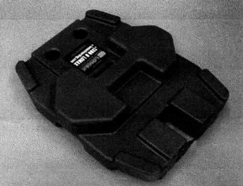
95 As to the integers of claim 1 said to be reflected in the Lomax HS (with the Lomax SP), the applicants make these contentions:
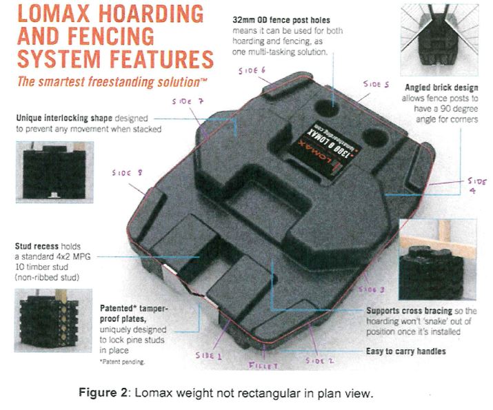
(1) The “bottom weight” of the Lomax HS is said to be the “base”. The bottom weight of the Lomax HS (and thus the base on this proposition) rests or sits or bears upon the ground. One or more other weights can nest upon any other weight. Two images of the weight(s) of the Lomax HS are depicted below. As to the second image under the heading “Lomax Hoarding and Fencing System Features”, the weight is surrounded by some text about the features. The image is reproduced simply for the purpose of identifying the shape and appearance of the weight itself.
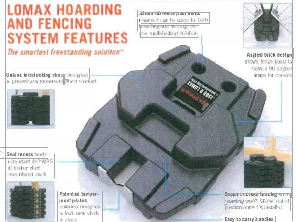
(2) The applicants observe that at one end of the Lomax weight there is a recess (a “stud recess”) for receiving a “standard 4 x 2” timber stud (described as “non-ribbed”). At the other end there are two cylindrical holes described in the Lomax Brochure as “fence post holes”. Those holes are said by the applicants to be “slots” for the purposes of claim 1 and also they are said to be “opposed” slots as contemplated by claim 1.
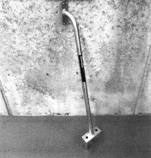
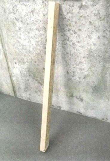
(3) The elongate support member is the Lomax SP. It is depicted below. It has two prongs at one end. Those two prongs are dimensioned to be inserted into, and received by, the two cylindrical holes depicted in the Lomax weight. These prongs are said to be the “locking posts” contemplated by claim 1. At the other end of the elongate support member is a vertical plate with four holes evident. The elongate support member is said to “support a post of a hoarding in an upright orientation” and an example of such a post is a timber stud of “MPG 10 graded timber”, depicted below the elongate support member.
(4) The elongate support member is “fixed to the base”, that is to say, fixed to the bottom weight of the Lomax HS which is said to be the “base”. The elongate support member of the Lomax HS is said to be fixed to the base because it is “made fast, firm or stable” to the base (that is, the bottom weight). The applicants say that this is said to occur in at least two ways, as follows (paras 82 and 83, applicants’ written submissions):
First, the insertion of the prongs (locking posts) into the opposed slots of the stacked weights (the two vertical cylindrical holes) and the stacking of the weights, which operate together as a nested unit, mean that there is lateral fixation – the post cannot be moved laterally relative to the base. In that configuration the Lomax Support Post (even if it can be lifted vertically) is made fast, firm or stable for the purpose of supporting the post of a hoarding in an upright orientation.
Secondly, the Lomax Support Post is fixed to the base through its connection with the Stud, which extends down to the bottom weight through the stud recess. In other words, the Stud operates so as to fix the Lomax Support Post to the base weight. The Studs, to which the Lomax Support Post is fixed, are held in a recess (in all the stacked weights, including the base). In the Respondents’ own words, the stud recess to which the Lomax Support is fixed has plates “uniquely designed to lock the pine studs in place” [Murdoch affidavit, Court Book Tab 19, Annexure NLM-7 at p 127].
[emphasis added]
(5) The applicants contend, for the reasons already identified, that the weighted support assembly of claim 1 includes the post of the hoarding. They say that in the absence of any “deliberate exclusion” by the author of the patent, of the hoarding post from the assembly of claim 1, the fact that, in the Lomax HS, the stud is “involved” in the fixation of the elongate support member to the base is not something which tells against infringement. The respondents say that the stud is simply not claimed as part of the assembly of claim 1 (a choice made by the author) and since the Lomax HS engages a relationship between the Lomax SP (support member) and the stud, it does so without engaging a claimed integer of the assembly. The applicants say that if the respondents are doing something as part of the Lomax HS which amounts to adding something (which, on one view, might not be an integer of the claimed assembly such as using the stud in the fixation of the Lomax SP to the base, for example), the addition of such a step (or further integer) does not avoid infringement if the other integers of claim 1 are present. The applicants say that in the Lomax HS, the Lomax SP is fixed to the base for the reasons identified at [90] and [95](4) of these reasons. However, the respondents say that the Lomax SP is not “fixed” to the base because it can be “lifted vertically” from the base. The applicants also say, alternatively, that even if the hoarding stud is not part of the assembly as claim 1, the Lomax SP is nevertheless “fixed to the base” (being the bottom weight) for the first of the reasons identified at [95](4) of these reasons.
(6) As to the integer, “each weight being rectangular in plan view”, the applicants say that a rectangle has opposed sides and ends parallel to each other and four right angles. However, because the word “rectangular” means “shaped like a rectangle”, the integer does not mean that the shape must be “a precise rectangle” or “only” a rectangle, according to the applicants. The applicants say that a weight might differ from a rectangle by having radius corners or chamfered corners. The applicants say that in the Lomax HS the weight is “shaped like a rectangle” because its shape has clearly identifiable parallel sides and ends, with ends at right angles to the sides. They say that the weights have chamfered corners which means they are not “precisely” a rectangle. The corners have been “trimmed off” but doing so does not take the weight outside the realm of the integer. In answer to the respondents’ contention that the weight of the Lomax HS is an octagon because it is said to have eight identifiable sides, the applicants say that the weight is “an irregular octagon” but that does not mean that it is not “shaped like a rectangle”. The applicants say that the integer could not have been intended to convey the notion that minor variations having no material effect on the working of the invention fall outside the scope of the integer. Set out below is an image of the Lomax weight (as it appears in the extract under the heading “Lomax Hoarding and Fencing System Features”) in which the respondents have identified the eight sides they contend for concerning the Lomax weight which also shows rounded corners which are said to be “filleted corners”.
(7) As to the locking arrangement of the Lomax HS, the applicants say that it involves these elements, assuming that the stud is part of the weighted support assembly in claim 1: the complementary nesting of the weights; the stud being inserted into the stud recess of the base weight; a screw at the bottom of the panel (to be attached to the hoarding post) going into the post above the second weight of the nested weights (evidence, Mr Leslie at T, p 164, lns 23-30); the prongs (that is the locking posts) at the bottom end of the Lomax SP being inserted into the weights; and the top plate of the Lomax SP being screwed to the stud to which hoarding panels are attached. The applicants say that when this locking arrangement, as described, is used as part of “an assembled hoarding” the locking arrangement “permits” the weights to be “locked” in the sense of “to make or become joined or fixed” or “to hold or trap in a particular position”, to the Lomax SP. The applicants say that in such a weighted support assembly, in a practical sense, the weights cannot be removed unless the Lomax SP is first “unscrewed” from the hoarding post or stud and then the prongs of the Lomax SP are removed from the weights. Because the weights cannot be removed in such an assembly except in the way described, the locking arrangement is said to “inhibit” the mistaken or accidental removal of the weights.
(8) If, on the other hand, the stud is not part of the weighted support assembly for the purposes of claim 1, the “locking arrangement” of the Lomax HS is nevertheless said to involve these elements: the complementary nesting of the weights; a Lomax SP configured as depicted at [95](3) of these reasons including “locking posts” at one end and a “planar plate” with four screw holes at the top for securing the stud to the Lomax SP. That arrangement is said to be configured to permit the weights to be locked to the Lomax SP because use of that arrangement “in an assembled hoarding” permits the plate of the Lomax SP to be screwed to the stud and the locking posts to be inserted into the two holes of the Lomax weight (the “opposed slots”) thus causing the weights to be “fixed or trapped in a particular position to the Lomax SP”.
(9) As to the notion of “slots” and, more particularly, “opposed slots”, the applicants say this. They say that a slot, according to the Macquarie Concise Dictionary, is properly understood as “a narrow, elongated … aperture, especially one to receive or admit something”. They say that the “slots” on the weights of the Lomax HS are “cylindrical”. They observe that a tool described as a “cylindrical slot drill” is a tool commonly understood in engineering circles which is used to create “cylindrical slots”. The applicants say that Mr Hunter’s view (the expert for the respondents) that a slot is something where an object can be inserted into an aperture viewed on a horizontal plane, “in only a single orientation”, is to be rejected in favour of Mr Leslie’s view (the expert for the applicants) that a slot is something where “an object can be received into a slot in any orientation in which it fits without negating its existence as a slot”. The applicants say that no definition of the term “slot” adopts any reference to a “single orientation” and is contradicted by the circumstance that para 68 of the specification depicts a locking post (Fig 3, N76) received into a cylindrical portion (Figs 3, 13 and 15, N64) which can be received into that portion (N64) in any rotational orientation through 360 degrees. The applicants say that the specification expressly contemplates “a cylindrical slot” because the slots depicted in Figs 13 and 15 at N64 (also able to be seen in Figs 3, 4 and 5 although not specifically identified by number), show a cylindrical section at the rear of the elongate aperture with each “slot” (Figs 13 and 15 at N56) defining an entry portion (N62) with generally flat sides opening into a cylindrical portion (N64).
(10) As to the term “opposed”, the applicants say that it means, according to the Macquarie Dictionary online, “to set (something) over against something else in place, or so as to face or be opposite”. The applicants say that there is no restriction in the language of the claims or the specification as to how the “pair of opposed slots” are to be “opposed” in relation to one another. The applicants say that the contention of the respondents that the term “opposed” means “at opposite ends” is inconsistent with the language of the claims and the specification. The applicants say that the Lomax weights adopt “slots” that are opposed as they are “on opposite sides of the weight”, that is, across the width of the weight.
(11) As to the integer, “the locking arrangement including a locking post that is dimensioned to be received in either of the slots” [emphasis added], the applicants say that this language does not limit this integer of the claim to a “single” locking post so received, with the result that (if that were so) the Lomax HS does not exhibit the integer because each locking post is received in each Lomax “slot”. Put simply, the applicants say that the requirement in claim 1 of “a locking post” relevantly received, means that if there is more than one locking post so received, there is, for the purposes of claim 1, at least “a locking post”, relevantly dimensioned, received in the opening (“slot”) evident in the Lomax weight.
(12) Claim 3, as earlier described, is a method claim which includes the steps of positioning at least one weighted support assembly as claimed in either or both of claims 1 and 2 in a desired location. One integer of claim 3 is the step of “securing support posts of the hoarding to the elongate support members”. The applicants say that this integer requires the support posts of the hoarding to be secured to the elongate support member (the Lomax SP) and not that the support post secure the elongate support member. The applicants say that that occurs during the assembly of the Lomax supported hoarding because the Lomax SP is secured to the stud by being screwed into it.
The contentions of the respondents
96 It is fair to say that the respondents essentially contest every aspect of the construction of the integers of claim 1 contended for by the applicants (and the critical integer of claim 3; and in consequence, claim 4), and the question of whether the Lomax HS with its Lomax SP takes the integers of claim 1. For present purposes, it is sufficient to note these contentions of the respondents.
(1) The weighted support assembly is said to be distinct from the hoarding panel and the hoarding post which supports the panel. The elongate support member is fixed to the base for supporting a post of a hoarding which is said to demonstrate a differentiating choice by the author between an assembly having features (integers) on the one hand, and one of those features (an elongate support member fixed to the base) serving an identified purpose (for supporting a post of a hoarding in an upright orientation), on the other hand, with the result that the hoarding post is not itself selected by the author as an integer of the claimed “assembly”.
(2) The base is a physical element of the claimed assembly that must be “separate and distinct” from the other physical elements: weights, a locking arrangement, weights exhibiting opposed slots, a locking post dimensioned to be received in either of the slots. The lowermost weight cannot be a “base” of the claimed assembly. A base that “acts” as a weight is not functioning separately and distinctly as a separate physical element of the assembly required by claim 1.
(3) The integer “fixed to the base” means that the elongate support member “cannot move relative to the base” regardless of the direction in which it is sought to be moved. The respondents reject the notion that because claim 1 requires an elongate support member to be fixed to the base “for supporting a post of a hoarding in an upright orientation”, a limitation is imported into the claim on the true scope of “fixed to the base” such that the support member need only be fixed to the base so as to prevent “lateral movement”. The respondents say that the “degree” of fixing between the support member and the base is “fixation in all directions”.
(4) The integer “rectangular in plan view” does not mean “generally” rectangular. It means a “true” rectangular shape, not weights that are octagonal in shape on proper examination.
(5) As to the “locking arrangement” of claim 1, it is one configured to permit the weights to be “locked” by allowing or permitting a locking device to be used (or not). The “permitted” capacity “to lock” must be present in “the assembly” before a hoarding post is introduced to it and a panel attached to the post. The reference in para 69 of the specification to “thus locking the weight/s [N18] in position as shown in Figures 4 to 7”, demonstrates that a locking device is required before locking is achieved. The locking arrangement “permits” a “device” to be used but the weights are not locked without the device.
(6) The Lomax HS does not provide any capacity (that is, for permitting) for locking the weights to the base or the elongate support member “at all” and certainly not “before” the addition of the hoarding panels. This means that there is no ability to “inhibit” the “intentional removal” of the Lomax weights from the Lomax HS “alone”, as required by claim 1.
(7) As to the “slots”, the respondents say that a slot “is a groove or slit which receives the object to be inserted in a single orientation only”. Another definition from the Oxford English Dictionary provides that a slot includes “[a] elongated narrow depression or perforation made in the thickness of a piece of timber etc usually for the reception of some other part or piece, whether fixed or moveable”. Because the patent refers to slots (Figs 13 and 15, N56) and an “entry portion” (Figs 13 and 15, N62) with generally flat sides opening into a “cylindrical portion” (Figs 13 and 15, N64), the respondents accept that the term “slot” has a “broader than usual interpretation”. Nevertheless, the respondents say that such a slot, as seen in the Figures, still receives objects inserted into it only in a single orientation.
(8) As to “opposed”, the respondents say that the slots must be “opposed to each other” in such a way that the locking post of claim 1 can be received in either of the opposed slots. They say that in the Lomax HS, the Lomax weights do not exhibit “a pair of opposed slots”.
(9) As to the locking post, the Lomax HS does not feature a locking post “at all”. The respondents say that if the elongate support member is characterised as a locking post as well, it is not dimensioned to be received “in either” of the slots because it is dimensioned to be received in “both” of the cylindrical openings in the Lomax weights “at the same time”.
(10) The respondents contend that no infringement of the patent is made out.
The essential principles
97 The principles to be applied in construing the claims of the patent defining the scope of the monopoly aided, where appropriate, by the discussion in the specification, and the tasks involved in addressing whether those integers as construed are present in the impugned product, system or method, are well understood. It is not necessary in these reasons to examine in detail the scope of the jurisprudence on these principles. They have been addressed by the parties. It is sufficient to simply note some of the relevant guiding principles, and they are these:
(1) Because the language of the claims defines and demarcates the scope of the monopoly, the words selected by the author are “usually of critical importance”: Kirin-Amgen Inc v Hoechst Marion Roussel Ltd (2004) 64 IPR 444 at [34], Lord Hoffmann (“Kirin-Amgen”). Thus, the important starting point for construction is the words of the claim.
(2) If the words of the claim are truly plain and unambiguous, that meaning is to be ascribed to the words. However, recourse to the specification is not conditioned upon first finding ambiguity in the words or sequence of words and phrases adopted by the author in framing the claim. The words of the claim and the body of the specification are to be read together in seeking to understand how the claims “define the invention”, the subject of the innovation patent: s 40(2)(c) of the Act. That does not mean, of course, that particular embodiments described in the specification limit the meaning to be ascribed to the words of the claim chosen by the author. It simply recognises that the specification must “end” with at least one, and not more than five, claims, relevantly for an innovation patent, defining the invention (s 40(2)(c)) and therefore it would be absurd to look to only the end point of the claims and not the contextual body of the document giving rise to the claims, in seeking to attribute meaning to the words of the claims.
(3) Having considered the words of the claim in context, the task of construction does not, however, involve selecting words and phrases from the body of the specification (not selected by the author in framing a claim) which have the effect of broadening the meaning of the language of a claim (apparent from reading the claim and the specification together), and thus the scope of the monopoly. Similarly, the meaning of the words of a claim are not to be diminished by importing words (not selected by the author in framing a claim) which circumscribe the scope of the monopoly determined by giving expression to the meaning of the words selected by the author once that meaning is apparent having read the selected words of the claim and the specification.
(4) Also, that which is not claimed, although foreshadowed or described in the specification as falling within the scope of the invention, is abandoned.
(5) The language of a claim might be properly understood or made clear by the way in which the author has framed one or more other claims.
(6) Often, the words of a claim and the language of the discussion of an invention in the specification engage technical or scientific terms (or phrases) or rely upon a secondary meaning attributed to particular words in the context of the field of the art engaged by the invention not apparent having regard to the ordinary meaning of the words or phrases. The relevant words and phrases are to be given the meaning a person skilled in the art would attach to them. The Court will seek to put itself in the shoes of a person skilled in the art at the priority date as to such meanings through, normally, the evidence of experts: Kimberly-Clark Australia Pty Limited v Arico Trading International Pty Limited (2001) 207 CLR 1 at [24]. Here, there are no such terms of art or secondary meaning requiring expert evidence so as to put the Court in the position of a person skilled in the art.
(7) As to construction, the task is objective in the sense that it is concerned with what a reasonable person to whom the utterance was addressed would have understood the author to be using the words to mean, as to which see generally Kirin-Amgen, Lord Hoffmann at [32].
(8) A patent specification (including, of course, the claims) should be given a “purposive construction” rather than a purely literal one derived from applying to it “a meticulous verbal analysis …”: Catnic Components Ltd v Hill & Smith Ltd [1982] RPC 183 at 243, Lord Diplock. A purposive approach to construction of a specification does not mean that the words of the claim and the specification are given an elasticity or plasticity that enables the boundaries of the claimed monopoly to be widened beyond the limits of the meaning of the words selected by the author read in conjunction with the specification more broadly. That is why the construction of the claims read with the specification as a whole is not to be approached with one eye kept on the impugned product or method. Construction is a threshold matter.
(9) “Purposive construction” is not a mechanism for demonstrating that the glass slipper actually does fit on Cinderella’s sister’s oversized foot and thus Cinderella’s sister is Cinderella, when it does not and she is not.
(10) The following general observations of Lord Hoffmann in Kirin-Amgen are worth remembering:
[33] In the case of a patent specification, the notional addressee is the person skilled in the art. He (or, I say once and for all, she) comes to a reading of the specification with common general knowledge of the art. And he reads the specification on the assumption that its purpose is both to describe and to demarcate an invention – a practical idea which the patentee has had for a new product or process – and not to be a textbook in mathematics or chemistry or a shopping list of chemicals or hardware. It is this insight which lies at the heart of “purposive construction”. If Lord Diplock did not invent the expression, he certainly gave it wide currency in the law. But there is, I think, a tendency to regard it as a vague description of some kind of divination which mysteriously penetrates beneath the language of the specification. Lord Diplock was in my opinion being much more specific and his intention was to point out that a person may be taken to mean something different when he uses words for one purpose from that he would be taken to mean if he was using them for another. The example in the Catnic case was the difference between what a person would reasonably be taken to mean by using the word “vertical” in a mathematical theorem and by using it in a claimed definition of a lintel for use in the building trade. … There is no presumption about the width of the claims. A patent may, for one reason or another, claim less than it teaches or enables.
[34] “Purposive construction” does not mean that one is extending or going beyond the definition of the technical matter for which the patentee seeks protection in the claims. The question is always what the person skilled in the art would have understood the patentee to be using the language of the claims to mean. And for this purpose, the language he has chosen is usually of critical importance. The conventions of word meaning and syntax enable us to express our meanings with great accuracy and subtlety and the skilled man will ordinarily assume that the patentee has chosen his language accordingly. As a number of judges have pointed out, the specification is a unilateral document in the words of the patentee’s own choosing. Furthermore, the words will usually have been chosen upon skilled advice. The specification is not a document inter rusticos for which broad allowances must be made. On the other hand, it must be recognised that the patentee is trying to describe something which, at any rate in his opinion, is new; which has not existed before and of which there may be no generally accepted definition. …
Some definitional terms
98 The following terms are defined in the following way in the Oxford English Dictionary.
base | Noun – a lowest or supporting part. Four examples are given in relation to architecture and a building. Examples are given in other contexts. A further example is given in these terms: The bottom of any object when considered as its support or as the part on which the upper part stands or rests. Also: a surface on which a person or thing stands, grows or moves. Other examples are given in a figurative sense or in relation to the political economy, chemistry, biochemistry and photography. Other applied examples are given. |
fixed | Adjective – placed or attached firmly; fastened securely; made firm or stable in position. In relation to a person or his or her countenance: made rigid or immobile. A further meaning is: definitively and permanently placed; stationary or unchanging in relative position. Two examples given include fixed star meaning a star which appears always to occupy the same position in the heavens and fixed property meaning that which consists in immovable as land and houses. |
rectangular | Adjective – shaped like rectangle; having four sides and four right angles. Of a solid body: having its sides, base, or cross-section in the form of a rectangle, or with right-angled corners. Also: having parts, lines, etc, at right angles to each other; characterised or distinguished by an arrangement or pattern of this kind. |
arrangement | Noun – the action of arranging or disposing in order; arranged condition, orderly disposition, order; style or mode in which things are arranged. |
lock | Verb – to fasten or secure with a lock, and related senses. In a transitive sense: to fasten or secure (a door, gate, window etc) with a lock; to close up and secure (a room, building, enclosure, etc) by fastening the doors, windows etc in this way. Also in a transitive sense: to enclose or confine in a locked room, box, etc; to keep securely under lock and key; to bind, restrain, fasten or secure using a locked chain, manacle etc. Also: to hold or fix firmly or irrevocably; to hold or trap in a particular position or situation. Also: to shut off from; to preclude or prevent from. |
locking | Noun – the action or an act of locking something. |
locked | Adjective – that is or has been locked. |
permit | Verb – to commit, submit, handover, leave, resign or yield; to allow the occurrence of (an action, etc); to allow (something) be carried out or to take place; to give permission or opportunity for. |
slot | Noun – an elongated narrow depression or perforation made in the thickness of a piece of timber etc, usually for the reception of some other part or piece, whether fixed or moveable. Also: the opening in a slot-machine for the reception of a coin; a slot-machine. Other applied examples are given. |
oppose | Verb – to confront (a person) with hard questions or objections; to interrogate, question; to ask. In a transitive sense: to set (something) against or in opposition to; to place or position as an obstacle. Also: to put forward (a person) as an antagonist. Also: to act or set oneself in opposition, antagonism or resistance to or against. |
opposed | Adjective – of two or more things, concepts, etc contrasting or conflicting with each other; in conflict or disagreement with, hostile to another person, group, etc. Also: placed against, facing. In the world of mechanics an example in relation to pistons is: arranged in pairs moving in opposite directions along the same straight line. |
inhibit | Verb – to forbid, prohibit; from doing something; from a thing; to restrain, check, hinder, prevent, stop. |
99 The following terms are defined in the following way in the Macquarie Dictionary.
base | Noun – the bottom of anything, considered as its support; that on which a thing stands or rests. Examples are given in the context of architecture, biology, the military, baseball and many other examples. In the case of architecture, it means: the lowest member of a wall or monument; the part of a column on which the shaft immediately rests; the lower elements of a complete structure. |
fixed | Adjective – made fast or firm; firmly implanted; rendered stable or permanent, as colour; set or intent upon something; steadily directed; set or rigid; definitely and permanently placed; permanently established; definite; not fluctuating or varying. Examples are given of the term in particular disciplines. |
rectangular | Adjective – shaped like a rectangle; having the base or section in the form of a rectangle; having right angles or a right angle; forming a right angle. |
arrangement | Noun – the act of arranging; the state of being arranged; the manner in which things are arranged; a final settlement; adjustment by agreement; something arranged in a particular way (a floral arrangement). In music: the adaptation of a competition to voices or instruments, or a new purpose. |
lock | Verb – to fasten or secure (a door, building, etc) by the operation of a lock; to make fast or immovable by or as by a lock; to join or unite firmly by interlinking or intertwining: to lock arms; to become locked; to become fastened, fixed or interlocked. |
permit | Verb – to allow (a person, etc) to do something; to let (something) to be done or occur; to tolerate; agree to; to afford opportunity for; allow; to grant permission; allow liberty to do something; to afford opportunity or possibility. |
slot | Noun – a narrow, elongated depression or aperture, especially one to receive or admit something. |
oppose | Verb – to act or contend in opposition to; drive against; resist; combat; to stand in the way of; hinder; to set as an opponent or adversary; to be hostile or adverse to, as in opinion; to set as an obstacle or hindrance; to set against in some relation, as to offsetting antithesis, or contrast; to use or to take as being opposite or contrary; to set (something) over against something else in place, or so as to face or be opposite. |
inhibit | Verb – to restrain, hinder, arrest or check (an action, impulse, etc); to act as a psychological barrier or obstacle to. In chemistry: to decrease the rate of (a chemical reaction) or to stop (it) completely. In an ecclesiastical sense: to prohibit; forbid. |
Considerations: construction and infringement
100 It is important to remember throughout a consideration of the construction to be attributed to the claims read together with the specification that claim 1 is concerned with a weighted support assembly which comprises a number of elements. The author has identified those elements as, first, “a base”.
101 Second, “an elongate support member” that has a particular relationship with “the base”. The support member is “fixed to the base” for supporting a post of a hoarding in an upright orientation.
102 Third, “weights” that have particular features.
103 As to the weights, first, they must be able to be “placed on the base”. Second, they must be configured to be “stacked” one on top of the other in a “nested” configuration. Third, each weight must be “rectangular in plan view” with opposed ends, sides, a bearing surface and an opposed carrier surface. Fourth, the carrier surface of each weight must define a locating projection received in a complementary locating recess defined in the bearing surface of each weight. Fifth, each weight must include “a pair of opposed slots”.
104 The fourth element is the “locking arrangement”. It too must have a certain configuration. First, it must be configured to permit the weights to be locked to something. Two choices are stipulated by the author: at least one of the base and the elongate support member. Second, the locking arrangement must include a “locking post” that has particular features. It must be dimensioned to be received in either of the opposed slots included in each weight.
105 I accept that a “base” is understood, as the Oxford English Dictionary says, as “a lowest or supporting part” of something or “the bottom of any object”, when considered as the support of (or for) that object or as “the part on which the upper part of the object stands or rests”. That definition essentially accords with the Macquarie Dictionary definition as the “bottom of anything; that on which a thing stands or rests”.
106 However, the question is, objectively viewed, how has the author used the term within claim 1 having regard to the specification?
107 The identification of each of the elements of the assembly suggests that “a base” of the assembly is one element and the weights with their particular characteristics as described earlier, are another element of the assembly. It seems to me that, fairly read, the author has chosen differentiated elements that comprise the assembly. It is true that the language of claim 1 does not expressly exclude the possibility that a weight, which as its first characteristic must be able to be “placed on the base”, could itself be a base as well as a weight of the claimed assembly. However, claim 1 read with the specification suggests that a weight is something that must be able to be located or placed on the base of the assembly and, objectively viewed, suggests that the author chose separate and distinct elements comprising the assembly. One example of a base, not being a weight, is a “foot”. It is a form of “a base”. The applicants say that claim 2 tells the reader that if the base of claim 2 is a foot (that is, the particular form of a base), a “base” of claim 1 is a broader (or more general) conception within the claim along the lines of “the lowest or supporting part of something”. I accept that the “foot” of claim 2 reflects a choice by the author of a particular form of a base for that claim as “a foot”, but I do not accept that it follows that claim 1 therefore contemplates “a base” which is one of the weights of the assembly. There must necessarily be “a base”. It may take a number of forms but the assembly of elements suggest that it is something separate and distinct from a “weight”. If “a base” of claim 1 was, objectively viewed, to include one of the weights of the assembly as a base, the introduction of the necessary relationship between the weights and the base in claim 1 would have been expected to also introduce that clarity of choice of the author in a formulation along the following lines: a number of weights that can be placed on the base, which may be a weight, and which are configured etc.
108 The reference to “a number of weights that can be placed on the base” suggests a conscious distinction and separation between a base on the one hand and a weight on the other hand, by the author.
109 Also, the elongate support member must be “fixed to the base”, on which the weights must be able to be placed. This relationship between the support member and the base does not sit comfortably with the notion that the base can be a weight to which the elongate support member is to be “fixed”.
110 For these reasons, in order to infringe the patent, the Lomax HS must have within its assembly a base separate and distinct from a Lomax weight. It does not contain within its assembly “a base” in that sense.
111 As to the question of the hoarding post, the simple fact is that claim 1 does not, by the words of the claim, claim a post of a hoarding as an element of the assembly. It is not claimed as an integer of the weighted support assembly. It is true that immediately after setting out the claimed relationship between an elongate support member of the assembly and the base as one of fixation of the support member to the base, the author introduces an explanation of the purpose of that fixation as one of “supporting a post of a hoarding in an upright orientation”.
112 The applicants say that the very function of the weighted support assembly is to operate as a support structure for a hoarding post (for a hoarding panel) and that claim 1, read sensibly, in the context of paras 3, 4, 5 and 10 of the specification, suggests that the hoarding post is to be treated as “part” of the assembly, that is, an integer of that which “comprises” the assembly. The reference to “support posts” of para 10 is a reference to the elongate support member of the claimed assembly, not the hoarding post. The support member might include a “post retainer” shaped as described in para 12 (see [23] of these reasons) for retaining a post of a hoarding in an upright orientation. However, none of the paragraphs of the specification, in terms, describe the post of the hoarding as a designated element of the assembly itself, the subject of the invention. That which is an element of the assembly, the elongate support member, might be configured or shaped to include a post retainer to retain a hoarding post but no claim is made to the hoarding post either in paras 5, 10 or 12 or, importantly, in claim 1 itself. Further, only the first two drawings depict a hoarding post located with the elongate support member configured so as to include a post retainer. None of the other drawings which deal with the particular, include as any part of an embodiment or illustration or example of the assembly of elements, a hoarding post.
113 Accordingly, I am satisfied that claim 1 ought not to be construed so as to include a hoarding post. To do so, would be taking an improper approach to a methodology comprehended by the phrase “purposive construction”, by adding an entirely new integer to claim 1.
114 The elongate support member must be “fixed to the base”. I accept that the term “fixed” means, as the Oxford English Dictionary says, placed or attached firmly; fastened securely and made firm or stable in position. I also accept that it comprehends the idea of definitively and permanently placed; stationary or unchanging in “relative position”. Again, this understanding of the term is essentially consistent with the formulation in the Macquarie Dictionary of made fast or firm; firmly implanted; rendered stable or permanent; definitely and permanently placed. The problem perceived in the prior art, solved by the invention, is that hoardings or other structures can become unstable and prone to being knocked over if weights are removed from the base or even knocked off the base. It is the assembly of elements which solves the problem. One particular element of the assembly, the locking arrangement, is particularly important because it is the locking arrangement of the invention that serves to inhibit the removal, accidental or otherwise, of the weights. However, an important part of rendering hoardings and other structures stable by reason of the assembly of elements, is that part of the assembly which involves the elongate support member and its relationship with the base of being “fixed to the base”.
115 I accept that in order to be fixed to the base, the fixing must render the elongate support member unable to move relative to the base. I do not accept that it is sufficient that the elongate support member is unable to move in a lateral direction. In order to be fixed to the base, the elongate support member must be unable to move in any direction relative to the base whether from side to side or up or down. If the elongate support member can simply be lifted out of the assembly, I am unable to accept that the elongate support member is fixed to the base of the assembly.
116 Thus, when it comes to infringement, the Lomax HS must include a base to which an elongate support member is fixed. In the Lomax HS, the elongate support member engages, by two prongs, two cylindrical holes in one or more of the weights stacked or nested together. The elongate support member of the Lomax HS also has a planar plate with four holes enabling the plate to be screwed to a hoarding post. Screwing the plate to the hoarding post coupled with the receipt of the prongs of the Lomax SP into the cylindrical holes of one or more of the Lomax weights gives a degree of fixation. However, the hoarding post is not part of the assembly. In any event, the assembly, absent the hoarding post, must exhibit the fixation contemplated by claim 1. The fixation is not achieved by the combination of the hoarding post and the hoarding panel. Even though the Lomax SP is screwed to the hoarding post and its prongs located in the cylindrical holes of one or more of the Lomax weights, the elongate support member is not fixed to the base, it is fixed to the hoarding post which can be vertically lifted out of the assembly. In that sense, it is difficult to accept that the Lomax SP is definitely and permanently placed in a stationary or unchanging relative position. It follows that I am not satisfied that preventing “lateral movement” is sufficient to constitute fixation for the purposes of claim 1. I am not satisfied that the second proposition at [95](4) is made good having regard to a claimed assembly that does not include the stud and, in any event, allows vertical movement to occur.
117 It is convenient at this point to examine the notion of “a pair of opposed slots”. As already mentioned, this is what I describe as the fifth characteristic of a “weight” of the claimed assembly of claim 1: [103] of these reasons. Each weight must include “a pair of slots” and they must be a pair of “opposed” slots. As to the notion of “slot”, I accept, as the Oxford English Dictionary says, that a slot is something along the lines of an elongated narrow depression or perforation made, for example, in the thickness of a piece of timber or other material and usually made for the reception of some other part or piece or thing. The Macquarie Dictionary describes it as a narrow elongated depression or aperture, especially one to receive or admit something. It seems to me that the natural meaning of the term “slot/s” within claim 1 accords with the notion of an elongated aperture for receiving something, which is also consistent with the notion of an elongated narrow depression or perforation usually made for the reception of some other part or thing. I accept that in the context of the specification having regard to the description of the weights of the assembly of claim 1 and particular illustrations of the weights contemplated by claim 1 (at least as one example), the weights exhibit an elongated aperture which then enters into a cylindrical hole as depicted in Figs 13 and 15 at N64. In that sense, the combination of an elongated aperture or elongated narrow depression leading into a cylindrical section or portion is a broader notion than the definition of a slot according to either dictionary. In that sense, the slot/s of claim 1 comprehend an elongated aperture which goes beyond the elongation of the aperture and leads into a cylindrical section or portion (as earlier described).
118 Taking that conception of the term slot/s and examining whether the Lomax weights exhibit slots consistent with that conception, the immediate difficulty that arises is that the Lomax weights include only two cylindrical holes. There is no element of an elongated aperture at all in these cylindrical holes. They are simply a cylindrical opening giving rise to a chamber for the receipt of the prongs extending from the Lomax SP. The applicants say that these two cylindrical holes exhibit the necessary degree of “elongation” because, consistent with the definition, the elongation is the penetration, into the weight, of the cylindrical hole. In other words, the progressive or elongated depth or depression of the hole is the elongation required to satisfy the definition. They say that each cylindrical hole is “vertical” slot.
119 As to the evidence of the experts on this topic of the meaning of the word “slot”, Mr Hunter, for the respondents, described a slot as typically a long narrow opening or groove which receives an object inserted into it in a single orientation. Mr Leslie, for the applicants, was of the opinion that it is not so much the “shape” of the hole that makes it a slot, but rather the “function” of the hole of having something inserted into it such that if the item to be inserted happens to be cylindrical, then a “cylindrical slot” will be required in order to receive the item and thus, the cylindrical hole is rendered a cylindrical slot. I am not persuaded by this entirely functional view of the word “slot”. In my view, a slot must exhibit an “elongate” opening (aperture). A cylindrical hole is a “circular” opening. Mr Hunter places emphasis on the notion that a feature of a slot is that the narrow elongate opening or groove “receives an object inserted into it in a single orientation”. In other words, a characteristic of a slot is that the shape of the opening (a narrow, elongate, groove) receives an object inserted into it in a single orientation such as a coin being presented to a coin-slot in a machine by the round perimeter of the coin and not otherwise. This limitation is said by the applicants as something not found in any definitional conception of a “slot”. What Mr Hunter seems to be saying is that because an opening described as a slot is elongate, usually narrow and in the nature of a groove, such a shape dictates the limited orientation (although it might not necessarily be a single orientation) of the presentation to such an opening, of that which is to be received into the opening. A circular hole, on the other hand, capable of receiving an item in any one of 360 degrees of orientation is not a slot. I am satisfied that, fairly read, the author’s use of the word “slot” in claim 1, taking into account the examples (but recognising that they are only examples) of the features of the opening extending into the ends of the weight at Figs 13 and 15 at N56 defining an entry portion at N62 with generally flat sides opening into a cylindrical portion at N64, engages the notion of shape as a critical feature of that which is a slot with the result that, for claim 1, a slot is not determined simply by function as Mr Leslie suggests. The applicants place emphasis upon a tool called a “slot drill”. That tool is used to enter the relevant substance (timber, posts and other substances) to be drilled by initially creating a cylindrical entry hole. However, the drill is then used to move from the point of entry along and into the material so as to create an elongate depression or groove, that is to say, “a slot”. I do not accept that the existence of a slot drill suggests that a slot may be a cylindrical hole.
120 The slots of claim 1 must be a pair of “opposed” slots. The specification contains examples (preferred embodiments) of weights of the claimed assembly which show features of the slots (in Figs 13 and 15 as just described in [119] of these reasons) at either end of the weight (“extending into respective ends [N34] of the weight”; Figs 13 and 15). The word “opposed”, as the Oxford English Dictionary identifies, means contrasting or conflicting with each other. It also means placed against, facing. It also means arranged in pairs moving in opposite directions along the same straight line: [98] of these reasons. The Macquarie Dictionary so far as the term “oppose” is concerned, means, to act or contend in opposition to; to set as an opponent; to set against in some relation; to use or take as being opposite or contrary. When claim 1 refers to a pair of “opposed slots”, it can only sensibly mean, “each slot in opposition to the other”. Thus, the weight of the claimed assembly must include two slots, constituting a pair, each slot in the pair in opposition to the other. The role of the opposed slots becomes clear in claim 1, as the “locking post” of the “locking arrangement” must be dimensioned to be received in either of the slots. Because the weights must be “rectangular in plan view”, the weight of claim 1 will have a length and breadth (width) and also depth being three-dimensional objects. The opposed slots of claim 1 could find themselves in opposition to each other at either end of the weight (as depicted in the preferred embodiment) or in opposition to each other across the width of the weight (although not shown in that way in any preferred embodiment) or possibly through the depth of the weight.
121 Any one of those possibilities must take account of the integrated whole that is the assembly of claim 1 and so far as the pair of opposed slots in the weight is concerned and the chosen dimension within which each slot is to be in opposition to the other member of the pair, that dimension must take account of the consideration that a locking post is to be dimensioned to be received in either slot.
122 In the Lomax weight, the cylindrical holes said to constitute the slots are, alongside one another, or side-by-side. Each cylindrical hole is placed at one end of the Lomax weight. That is no doubt so because the two prongs projecting from the Lomax SP are designed or dimensioned to be received in two cylindrical holes at one end of the weight, that is, in both cylindrical holes so positioned.
123 The words “a hoarding post that is dimensioned to be received in either of the slots” are important not only because they go to that which must be included in the “locking arrangement” but also because they assist in understanding the nature of “opposed slots”. The slots of the claimed assembly are “opposed” not only in the sense that they are in opposition to each other but in opposition so that the locking post can be received in either of them and will, no doubt, be received in one of them depending upon the particular orientation of the weight (that is, which end or location is presented to the locking post). If the prongs of the Lomax SP (also said to be a locking post by reason of the addition of the prongs) can both be received at the same time in both cylindrical holes at one end of the Lomax weight, the location and position of the cylindrical holes side-by-side suggests that the holes are not in opposition to each other in the sense contemplated by claim 1.
124 I am therefore satisfied, for all these reasons, that the Lomax weight does not exhibit a pair of “slots” and nor are the cylindrical holes positioned at one end of the weight in a side-by-side way, “opposed” slots.
125 The weights of the claimed assembly must also be “rectangular in plan view”. I accept that this phrase does not mean a perfect rectangle or require forming “precise right-angles” or mean “having four sides and four right angles”. It means shaped like a rectangle. Applying a purposive construction to the phrase used in claim 1, I am satisfied that the Lomax weight is shaped “like” a rectangle notwithstanding that it has an extension on one side and cut away corners. The shape depicted at [95](1) and [95](6) reveals a shape to the eye that is in the nature of or like a rectangle notwithstanding that the respondents say that they can identify eight sides and the Lomax weight is truly an octagon. Notwithstanding that contention, I am satisfied that the Lomax weight can properly be described as rectangular in plan view in the sense in which I understand the term “rectangular” to be used in claim 1.
126 As to the “locking arrangement” of claim 1, I accept that the term “arrangement” describes an “arranged condition” or “orderly disposition of things” or a “mode” in which things are arranged. Normally, there would be a purpose to be served by the arrangement and in that sense, I accept that an arrangement suggests a “structural combination of things arranged in a particular way or for a particular purpose”. The term “locking” is a description of an “action or act”, “of locking”: Oxford English Dictionary ([98] of these reasons). The verb “to lock” is a description of an action to “close up or secure” something. It also means “to hold or fix firmly or irrevocably” or “to hold or trap in a particular position or situation”.
127 The locking arrangement of claim 1 is an arrangement configured “to permit” weights “to be locked” to, at least, one of the base and the elongate support member. The configured arrangement operates “to permit” the weights to be so locked if it operates “to allow the occurrence of an action of locking” or if it operates “to allow [locking] to be carried out or to take place”. The locking arrangement must be configured to allow the weights to be held or fixed firmly or held or trapped in a particular position or situation. The locking arrangement must include a “locking post” dimensioned to be received in either of the slots in the weights (which, of course, must be a pair of opposed slots). The specification at para 8 explains that the locking arrangement serves “to inhibit” the removal, accidental or otherwise, of the weights. The action “to inhibit” means a number of things including “to restrain, check, hinder, prevent, stop”.
128 When this aspect of claim 1 is considered in the context of the specification and particularly para 8, it suggests that the locking arrangement must be configured to allow (“permit”) the action or occurrence of locking to be carried out so as to allow the weights to be “held firmly or trapped in a particular position” in such a way as to “prevent, hinder or stop” (“inhibit”) the removal accidental or otherwise of the weights and in order to do so, the weights must include a pair of opposed slots, and the locking arrangement must include a “locking post” which has a very particular feature related to the slots, that is, the locking post is dimensioned such that it can be received in either of the slots. This is the structural combination of things so arranged that is the “locking” arrangement. This is the meaning of this aspect of claim 1. I do not accept that this aspect of claim 1, construed according to a proper understanding of the words “configured to permit the weights to be locked” in conjunction with a proper understanding of the para 8 notion of “to inhibit” removal of the weights accidental or otherwise, simply means that making the weights held firm, fast or stable from “lateral movement” is the limit of, or satisfies, the locking arrangement of claim 1.
129 The specification contains particular embodiments of a locking arrangement which includes a “locking formation” as described at paras 21, 22 and 23 of the specification (see [31], [32] and [33] of these reasons).
130 The question then becomes one of whether the Lomax HS with its Lomax SP exhibits the features of the locking arrangement of claim 1 understood according to the description at [128] of these reasons.
131 At to that, I accept that the “locking arrangement” of claim 1 so understood does not engage the hoarding post as any aspect of the structural combination making up the locking arrangement. I accept that the locking arrangement of claim 1 permits a “locking device” such as a locking pin and padlock to be used “to lock” the weights in place. However, a “locking device” is not claimed by claim 1 and the structural combination constituting the locking arrangement of claim 1 as described at [128] of these reasons is not to be read so as to require, as an integer, a locking device whether in the form of a locking pin, padlock and key or otherwise.
132 Does the Lomax HS with its Lomax SP permit or allow, in the sense described at [128], the Lomax weights to be “locked” in the sense described at [128] to the “base” (assuming for the moment that the bottom weight of the Lomax HS is “a base”), or to the Lomax “elongate support member”, so as to inhibit, that is, prevent, hinder or stop removal, accidental or otherwise, of the weights from the Lomax assembly constituting the Lomax HS? Infringement does not arise unless the answer to that question is “yes”, and the question of whether the Lomax HS exhibits the elements of the locking arrangement of claim 1 must be answered having regard to the impugned Lomax assembly without the effect or influence of any suggested “permitting” or “locking”, giving rise to “inhibiting” (as described at [128]), by reason of the role of the stud and the hoarding panel when introduced into the Lomax HS. The only question is whether the features of the “locking arrangement” of claim 1 are present in the sense earlier described.
133 The contention of the applicants that the elements of claim 1 concerning the locking arrangement are present in the Lomax HS with the Lomax SP is entirely dependent on the Lomax assembly “permitting” “locking”, giving rise to inhibition of lateral movement of the weights, accidental or otherwise, by the mechanism of the assembly engaging with the hoarding post or stud through the top plate of the Lomax SP being screwed to the stud (and probably by reference as well to the role of the hoarding panel (and its heaviness) attached to the stud which, in turn, is attached to the Lomax SP, notwithstanding that the applicants recognise that the hoarding panel is not part of the assembly). Absent those features, the Lomax HS does not exhibit the claimed elements (as earlier described) of the locking arrangement. In any event, the arrangement of the Lomas HS only inhibits lateral movement of the weights.
134 For all of these reasons discussed in relation to the integers of claim 1 taken individually but assessed collectively overall, the Lomax HS does not infringe claim 1 of the patent. It necessarily follows that claims 3 and 4 are not infringed.
135 Having regard to these findings, the cross-claim for revocation on the ground that the claims are not fairly based, does not arise because that question is only in issue should the Court determine that the Lomax HS with the Lomax SP infringes the claims in suit.
The remaining questions
Unjustified threats of infringement proceedings; contended contravention of s 18(1) of the Australian Consumer Law
136 Section 128 of the Act is in the following terms:
Application for relief from unjustified threats
128 (1) Where a person, by means of circulars, advertisements or otherwise, threatens a person with infringement proceedings, or other similar proceedings, a person aggrieved may apply to a prescribed court, or to another court having jurisdiction to hear and determine the application, for:
(a) a declaration that the threats are unjustifiable; and
(b) an injunction against the continuance of the threats; and
(c) the recovery of any damages sustained by the applicant as a result of the threats.
(2) Subsection (1) applies whether or not the person who made the threats is entitled to, or interested in, the patent or a patent application.
137 The term “threatens” is undefined by the Act. The verb “to threaten” is defined by the Oxford English Dictionary as “stating one’s intention to take hostile action against someone in retribution for something done or not done”, or “to cause someone or something to be vulnerable or at risk” or “seem likely to produce an unpleasant or unwelcome result”. The person threatened, must be threatened with “infringement proceedings”, or other “similar proceedings”. The term “infringement proceedings” is defined to mean “proceedings for infringement of a patent”: s 3, Schedule 1 of the Act. Section 129A(3) of the Act provides that if an application under s 128 for relief relates to threats made in respect of a certified innovation patent, the Court may grant the applicant the relief applied for, unless the respondent satisfies the Court that the acts about which the threats were made infringed, or would infringe, a claim that is not shown by the applicant to be invalid. Section 131 of the Act provides that the mere notification of the existence of a patent does not constitute a threat of proceedings for the purposes of s 128 of the Act.
138 By a notice of cross-claim, Lomax and Hoarding Ideas, cross claim against the applicants in the principal proceeding for an order restraining Titan from representing to any person in Australia that the Lomax Hoarding System infringes Liberation’s patent. They also claim damages and interest.
139 In the statement of cross-claim, Lomax and Hoarding Ideas assert that since February 2018, Titan has represented to third parties in Australia interested in exploiting hoarding systems that the Lomax Hoarding System infringes the patent. At trial, the cross-claimants relied upon a letter sent by Mr Greg Bloom on behalf of Titan to Michelle Quinane of Mirvac dated 9 April 2018. Mr Bloom is a director of Liberation; the sole director of Titan; Managing Director of Titan; and also a director of Eagle Rock Pty Ltd. Ms Quinane is the National Tenancy Coordination Manager with Mirvac. Mr Bloom says this of Ms Quinane, in his affidavit sworn 8 June 2018 (his seventh affidavit):
When communicating with Mirvac about Titan hoarding opportunities, I deal with a number of people within the Mirvac organisation. However, Ms Quinane has been and remains the main person within Mirvac for discussions concerning Titan hoardings and she is the main person I deal with in this regard.
140 The letter dated 9 April 2018 was sent by Mr Bloom to Ms Quinane attached to an email dated 9 April 2018 addressed to her and Mr Brian Hennessy. The email, in part, says this:
Subject: Lomax Hoarding System and current TITAN hire rates
Attachments: Lomax Hoarding System.pdf
Hello Michelle and Brian,
Michelle, thank you for taking my call earlier today, as discussed;
Re the Lomax Hoarding System
The letter I spoke of is attached. All information detailed within the letter is in the public domain.
Mirvac hoarding contractors
Regarding an existing hoarding contractor, I have spoken to Joe from Retail Building solutions.
The prices Joe had was previously provided by Mark Lomax when he was a TITAN Agent.
Last week I supplied prices that are direct from TITAN and are approximately a 5th of the price supplied previously.
We are also investigating the sell model.
141 The email then goes on to mention aspects of a new innovation adopted by Titan. The letter dated 9 April 2018 is in the following terms, on the letterhead of Titan, and signed by Mr Bloom:
Dear Michelle,
RE: LOMAX HOARDING SYSTEM
IP Infringement
I am aware that you have been approached by Lomax Hoarding system (LHS).
The LHS was launched earlier this year. Until then Mark Lomax and his company Hoarding Ideas had been Titan’s agent in NSW and ACT.
The Titan Hoarding System was revolutionary when it was launched in 2013 and remains [unequalled] in capability and safety. It is fully protected by a series of Patents and Trade Marks.
As soon as we heard about the LHS we started proceedings in the Federal Court of Australia.
Two week[s] ago, my belief was confirmed at an injunction hearing, when the Judge stated there is [a] prima facie case of LHS infringements of Titan’s Patents and Trade Marks.
The trial date has been set down for June 2018, we have asked the Court to stop sales and hire of LHS and for damages.
Currently the dispute is confined to Titan and Lomax. Titan sincerely does not want to involve any other persons in this dispute.
Safety Concerns confirmed by a collapse of a Lomax hoarding 7 days after installation
Right from the start, I have been concerned about the LHS ability to protect the public. As part of the injunction hearing Mark Lomax and his Certifying Engineer provided Affidavits, these Affidavits are now in the public domain.
The AS 4687 Temporary Hoarding standard’s PREFACE states “provide protection to the public”. The LHS Engineers Affidavit confirms the LHS was tested with impacts from the public side of the hoarding and not the construction side and I believe this to be flawed, a typical impact will come from the construction side of the hoarding.
On March 10 2018, Mark Lomax replaced a TITAN Hoarding that had stood in a major Retail Shopping Centre without Incident for approx. 80 days. TITAN was replaced with a Lomax hoarding.
I refer to the Mark Lomax Affidavit, he details information, the Lomax hoarding collapsed 7 days after installation causing injury to [a] member of the public. The Major Retail Shopping centre has distributed a Safety message detailing the collapse and injury sustained by the member of the public.
I am sure that you will take this into account as well when you consider the LHS.
My phone is always on, please call me if you wish to discuss this letter further.
Regards
Greg Bloom
Managing Director
142 I have reproduced the letter in its entirety as the statements said to constitute threatening Mirvac with infringement proceedings need to be seen in the context of the letter overall. However, the statements that the cross-claimants rely upon specifically are the following three statements in the letter:
As soon as we heard about the LHS we started proceedings in the Federal Court of Australia.
Two week[s] ago, my belief was confirmed at an injunction hearing, when the Judge stated there is [a] prima facie case of LHS infringements of Titan’s Patents and Trade Marks.
Currently the dispute is confined to Titan and Lomax. Titan sincerely does not want to involve any other persons in this dispute.
143 The cross-claimants say that these three statements amount to threats because Mirvac would “undoubtedly” wonder about the reason for Mr Bloom sending such a letter and would conclude that any future acquisition by it of the Lomax Hoarding System would be attended by a “risk” that Liberation and Titan might choose to protect their rights by involving other persons in the dispute, such as Mirvac, notwithstanding that Titan “sincerely does not want to involve other persons” in its dispute with Lomax (and Hoarding Ideas).
144 Apart from the letter of 9 April 2018, the cross-claimants in their further and better particulars of the cross-claim say this:
The Cross-Claimants infer from [the Titan letter to Mirvac of 9 April 2018 in circumstances where Mirvac was a potential customer of the cross-claimants] that similar communications were made to other potential or actual customers of the Cross-Claimants with respect to the supply of the Lomax Hoarding System and has sought production from the Cross-Respondents of such communications. The Cross-Claimants will rely on such communications as they are revealed by the Cross-Respondents.
145 However, the cross-claimants only rely upon the Titan letter of 9 April 2018 to Mirvac.
146 Clearly, for a claimant to succeed in an unjustified threats proceeding, it is necessary to show that “a threat” has been made: Australian Steel Co (Operations) Pty Ltd v Steel Foundations Ltd (2003) 58 IPR 69 at [16].
147 In Luna Advertising Company Ltd v Burnham & Company (1928) 45 RPC 258, the plaintiffs (“Luna”) were concerned with objects known as daylight signs. So too were the defendants. Luna supplied a daylight sign to a shop “Hawes Stores” which was an agent for another company, W & A Gilbey Limited (“Gilbey”). Thereafter, a representative of the defendants (“Burnham”), Mr Beams, visited the Company Secretary of Gilbey, Mr Burke. Mr Beams said that the sign exhibited outside Hawes Stores was an infringement of Burnham’s patent and requested Mr Burke to immediately take the sign down on the “authority” of the patent. Luna brought proceedings for an injunction to restrain Burnham from threatening any person with legal proceedings in respect of alleged infringement of Burnham’s patent, under a provision in reasonably similar terms to s 128 of the Act. Clauson J said this at 260:
I should myself have inferred, had I been present, that Mr Beams was courteously pointing out to Mr Burke that Mr Burke’s company were under legal liability to the Defendants in respect of the Defendants’ position as interested in a Patent, and I should have thought that, courteous and quiet though no doubt the interview was, the whole purport of it was to threaten Mr Burke’s company with that which would result from legal liability, and I understand that to be threatening Messrs Gilbey with legal liability. … I think that an interview of this kind, a serious interview between business men, although nobody speaks of solicitors and writs, has no real meaning except to convey to the person whom I regard as having been threatened, that the threatener has legal rights and means to enforce them, and although, as I say, he does not refer in so many words to writs, means, “unless you bend to my will, I shall enforce my rights” in the way in which they are naturally enforced, i.e., by legal proceedings. It seems to me to be a question which depends entirely upon the inferences which an ordinary man would draw from the attitude of the parties if he was present at the interview.
148 In Willis & Bates Ltd v Tilley Lamp Coy (1943) 61 RPC 8, Bennett J at 11 seemed to accept the force of those views of Clauson J to the effect that it is not necessary for the plaintiff to prove that the defendant has, in so many words, said: “I intend to issue a writ against you for infringement of letters patent”. Bennett J accepted that the terms of the Act are satisfied “if the defendant in the action is proved to have asserted that he has legal rights in respect of letters patent and that he intends as against the plaintiffs to enforce those rights”. However, it should be noted that, in that case, counsel for the defendant accepted the correctness of those statements having regard to the observations of Clauson J in Luna Advertising Company Ltd v Burnham & Company. In C & P Development Coy (London) Ltd v Sisabro Novelty Coy Ltd (1953) 70 RPC 277 at 282, the Court of Appeal, Evershed M.R., Jenkins and Morris LLJJ, accepted the proposition that:
… in order to make out a case of threats under Sec. 65 of the Act, it is not necessary to show that the person charged with making the threats has said or written in so many words ‘I will take proceedings against you’. It is enough if the language used is such as would convey to any reasonable man that the person using the language intended to bring proceedings for infringement against the person said to be threatened.
149 The Court of Appeal accepted the correctness of the statements of Clauson J and Bennett J respectively in the above authorities. In U & I Global Trading (Australia) Pty Ltd v Tasman-Warajay Pty Ltd (1995) 60 FCR 26 at 31 (“U&I Global”), Cooper J accepted that the test is whether the language would convey to any reasonable person that the author of the letter intended to bring proceedings for infringement against the person said to be threatened and that it is not necessary that there be direct words that action would be taken. Cooper J relied upon the observations of McClelland CJ in equity, to that effect, in Lido Manufacturing Co Pty Ltd v Meyers & Leslie Pty Ltd (1964) 5 FLR 443 at 450-451.
150 The conclusion as to whether a document amounts to a threat of infringement proceedings is essentially one of fact: Brian v Ingledew Brown Bennison & Garrett (a firm) [1996] FSR 341 at 349; Occupational and Medical Innovations Ltd v Retractable Technologies Inc (2007) 73 IPR 312 (“Occupational”). In Occupational at [9], Dowsett J observed that the meaning of an alleged threat is to be decided in accordance with the understanding of an ordinary recipient, standing in the position of the actual recipient, reading the letter or communication said to contain the threat, in the normal course of business.
151 Assuming that a person has been threatened with infringement proceedings, the combined effect of ss 128 and 129A is such that the onus of proving justification falls upon the patentee or the exclusive licensee who has made the threat: JMVB Enterprises Pty Ltd v Camoflag Pty Ltd (2005) 67 IPR 68 at [210]; U & I Global at 501. It follows that where a patentee (or an exclusive licensee) makes a threat of patent infringement and a patentee fails to prove infringement, the threats are unjustifiable: CQMS Pty Ltd v Bradken Resources Pty Limited (2016) 120 IPR 44 at [158]-[159] and [174] (“CQMS v Bradken”); BLH Engineering and Construction Pty Ltd v Pro 3 Products Pty Ltd (2015) 114 IPR 105 at [84]-[98].
152 As to the question of whether the statements at [142] and particularly [143] of these reasons contained in the letter constitute conduct on the part of Titan and Mr Bloom of threatening Mirvac with infringement proceedings, the cross-claimants seek to “characterise” the statements as such a threat having regard to the characterisation adopted by Dowsett J in CQMS v Bradken concerning what are said by the cross-claimants to be analogically similar statements. In CQMS v Bradken, the applicants, CQMS Pty Ltd and its licensee, CQMS Razer Pty Ltd, sent an email to persons which the respondents said were customers of the respondents. The CQMS entities had commenced infringement proceedings. The respondents cross-claimed for relief in relation to contended unjustified threats, apart from other matters raised by the cross-claim. The email sent by the CQMS entities, signed by the General Manager of CQMS, to the respondents’ customers was in these terms:
CQMS Razer commenced court proceedings against Bradken for patent infringement
CQMS Razer Pty Ltd, and its related entity CQMS Pty Ltd (CQMS), have today filed patent infringement proceedings in the Federal Court of Australia against Bradken Resources Pty Limited and Bradken Limited (BKN).
CQMS is the owner of a number of patents relating to ground engaging tools (GET) and manufactures steel engineered wear parts for the mining industry, including GET.
BKN, also manufactures a variety of engineered steel products for the mining industry, has recently introduced a range of GET branded Penetrator Max into the mining sector.
CQMS believes some of these products infringe to of its patents.
After issuing a letter and attempting to resolve the dispute, CQMS commenced the proceedings against BKN alleging that:
1. Certain Penetrator Max products directly infringe CQMS’ registered patents. Specifically, the system that the relevant products use to affix the GET to mining machines, infringes the patents;
2. By selling certain components of the Penetrator Max products to its customers to be used as GET, BKN has infringed, and authorised the infringement of, the patents. However, CQMS’ dispute is with BKN not with the customers who use the GET.
CQMS has taken this action as a last resort as it believes it is necessary to protect its intellectual property rights.
The proceedings are scheduled for a first directions hearing in the Federal Court of Australia (Queensland Division) on 13 December 2013.
[italicised emphasis added]
153 At [170], Dowsett J said this about the email:
In the fifth paragraph the applicants refer to the allegations in their pleadings that certain of the respondents’ products infringed their patents, and that by selling such products to other customers, the respondents had both infringed their patents and authorized infringement by others. Fairly clearly, the authorized infringements were by the respondents’ customers. The alleged infringement by customers, in the context of litigation against a supplier, would inevitably raise, in the minds of the customers, their own potential liability, should the applicants decide that such litigation was necessary in order to protect their intellectual property rights. The indication that the existing dispute was between the applicants and the respondents may have offered some reassurance, but the threat was still present. That the applicants chose to offer such reassurance suggests that they expected that the email would come to the attention of the respondents’ customers. A customer (actual or potential) would inevitably wonder about the reason for sending such a notice. At the very least, that customer would conclude that any future acquisition of one of the respondents’ products would be risky. I have no real doubt that the applicants intended that the email produce that effect. It is the effect on the reasonable recipient which is [relevant]. I have identified that effect. I find that the notice was a threat to the customers.
[emphasis added]
154 In the letter of 9 April 2018 to Mirvac, Mr Bloom asserts that: the Titan Hoarding System is revolutionary and fully protected by a series of patents; as soon as Mr Bloom (and Titan) heard about the Lomax HS, proceedings were commenced in the Federal Court; a prima facie case of infringement of the patents appeared to be confirmed by a judge of the Court at least on an interlocutory basis; the trial would be a matter of a few months away; the Court would be asked to stop sales and hire of the Lomax HS and award damages; the dispute is confined to Titan and Lomax and Titan sincerely does not want to involve any other persons in this dispute.
155 This letter of 9 April 2018 does not contain the more emphatic reassurance given by CQMS (nevertheless found to be insufficient to avoid a conclusion that a “threat was still present”, in the circumstances of that case), that “CQMS’ dispute is with BKN not with the customers who use [the patented tools]”.
156 In his affidavit of 8 June 2018, Mr Bloom says this about the email and letter of 9 April 2018 and considerations relevant to them:
6. Mirvac has been and remains a very significant customer of my business, Eagle Rock, for construction work and hoardings.
…
9. After these proceedings were commenced I became aware of a significant amount of talk and discussion in the hoarding industry about this case. I describe this as “industry chatter”.
10. I wanted Mirvac, as a significant customer, to know the true position about the proceedings and the safety issues with the Lomax hoardings. In particular, as far as this litigation is concerned, I was concerned that some gossip within the industry might mean that Titan is seen as acting as some type of commercial bully attacking a small competitor. Also, I wanted her [Ms Quinane] to know that it had not been a Titan hoarding that had collapsed at the Westfield Centre.
11. Based on the matters in paragraph 10, I called Ms Quinane. I believe that this telephone call took place on Monday, 9 April 2018. I said to her words to the effect of Titan has commenced proceedings against Mr Lomax and his companies for infringement of the Titan patent.
12. I also said to Ms Quinane words to the effect of The proceedings are continuing and I will write to you and tell you the details.
13. I then sent to her the email and letter mentioned above. I did not send that letter (or a letter in those terms) to anyone else.
14. In speaking to Ms Quinane and in writing to her it was never my intention to involve Mirvac in this litigation or to bring separate proceedings against Mirvac. This is still my position. Mirvac is one of my significant customers. Involving Mirvac in this case or bringing separate proceedings against that company would not make commercial sense.
[emphasis added]
157 Mr Bloom, in giving oral evidence in cross-examination, accepted that Mirvac operates a number of shopping centres and has a need for hoarding systems when refurbishing shops or common areas in its retail centres (T, p 84, lns 26-28) and that he (and his entities) are very interested in providing hoarding systems (to be installed by others) to the Mirvac group: T, p 84, lns 31-34. Mr Bloom was also asked whether he was aware that Mirvac is a large property group and he answered: “I think most people see them in the newspapers and so forth”: T, p 84, lns 19-21. Mr Bloom did not necessarily accept that Mirvac was a “very significant potential client”, because, in Mr Bloom’s view, “Mirvac is a small player in the shopping centre market”: T, p 84, lns 36-40. Mr Bloom, however, does say that Mirvac is one of his “significant customers” and that involving Mirvac in this case or bringing separate proceedings against Mirvac would, for that reason, “not make commercial sense”: para 14 above at [156].
158 Mr Bloom seemed to accept that Mirvac has 15 shopping centres but gave evidence that Westfield has 50 centres and Centro has significantly more than that so, as a matter of comparison, Mirvac “is a small player”: T, p 84, lns 42-44.
159 Mr Bloom accepted that in a telephone conversation with Ms Quinane before sending the email and letter of 9 April 2018, he told her that he “had concerns” that the Lomax Hoarding System infringed “Titan’s patent”: T, p 85, lns 1-5.
160 The context of the telephone call is put this way by Mr Bloom. Mr Bloom received a telephone call from Mr Denny Colig who told him that a Titan hoarding system had fallen over in a Westfield Shopping Centre. Mr Bloom was concerned that “chatter” had come from Mirvac about it. Mr Bloom said that he had spoken to many people at Westfield about it and had a conversation with Ms Quinane about the incident which he said was “more about the safety” issues, although as to infringement, he told her that “we had taken action”: T, p 85, lns 9-34.
161 Mr Bloom accepted that when he said in the letter of 9 April 2018 that “currently the dispute is confined to Titan and Lomax”, he was also saying “but it need not be” so confined: T, p 89, lns 1-6.
162 As to the statement that “Titan sincerely does not want to involve any other persons in this dispute”, Mr Bloom did not accept that the meaning of that statement is “but it will if it has to”: T, p 89, lns 10-13. In the letter of 9 April 2018, Mr Bloom sets out aspects of his concerns about safety issues arising out of a collapse of a Lomax hoarding seven days after installation. Mr Bloom did not accept that making these remarks was simply “an exercise in seeking to discourage Mirvac” (T, p 91, ln 1).
163 Mr Bloom denies that his letter of 9 April 2018, taken in the context of his telephone conversation with Ms Quinane and the letter overall, contains directly or indirectly or inferentially, a threat of infringement proceedings against Mirvac. Mr Bloom denies that the statement “Titan sincerely does not want to involve any other persons in this dispute” has the meaning of, or conveys a message to, Mirvac of “but it will [involve other persons in the dispute] if it has to”. That view, as put by the cross-claimants, of the true meaning of that statement is said to be a threat for the purposes of s 128 of the Act. Mr Bloom does accept that by referring to the temporal element “currently the dispute is confined to Titan and Lomax”, he was saying that it need not be so confined. However, even so, Mr Bloom says that, by that statement, he was not threatening Mirvac with infringement proceedings.
164 As to CQMS v Bradken, the applicants say that there are some important distinguishing features about that case which need to be properly taken into account.
165 First, they say that the email in CQMS was a general notice to the industry and not, as here, a single letter sent to one person following a phone call. The letter in CQMS was sent without prior warning to industry participants who may have been unaware of the infringement proceedings before receipt of the letter.
166 Second, the email in CQMS expressly referred to the use of the impugned product by customers as an infringement in circumstances where, as Dowsett J held, it was fairly clear that the “authorised infringements” were by the respondents’ customers. The applicants say that in contrast, nothing Mr Bloom said refers to the “liability” of installers or customers of the Lomax Hoarding System.
167 The applicants say that the present case is much closer to the circumstances arising in Damorgold Pty Ltd v Blindware Pty Ltd (2017) 354 ALR 1 (“Damorgold”). In that case, Damorgold was the owner of a particular patent and its exclusive licensee was a company called Vertilux Pty Ltd. Blindware contended that notices published by Damorgold to the “blinds industry” explaining that Vertilux had successfully taken patent infringement proceedings against a particular company and that “further action will be taken by Vertilux against other infringers if necessary” was to be characterised as “a general warning to the addressees against infringement”: Damorgold at [393] and [409], Middleton J. The applicants say that, as in Damorgold, there is no basis in the letter to Ms Quinane on which the recipients would perceive a threat to Mirvac (or the recipients) based on the activity of Mirvac.
168 One further point is made about the observations of Dowsett J at [170] in CQMS v Bradken. The applicants say, respectfully, that Dowsett J has asked the wrong question in deciding whether the email in that case contained a threat. The applicants say that the question is not whether the communication would cause a recipient to consider their “own potential liability” or whether the recipient’s continued use of the product in question “would be risky”. The applicants say that the question is whether the letter would objectively be perceived as a threat to litigate against the recipient for patent infringement.
169 As to this last point, I do not accept that Dowsett J in CQMS v Bradken was applying an incorrect test. In CQMS v Bradken, Dowsett J was applying the correct test but seeking to identify the factors which were an expression of the test having regard to the particular circumstances of the case. Dowsett J observed that the alleged infringement by customers in the context of litigation against a supplier would inevitably raise in the minds of customers their own potential liability should litigation be taken against them by the applicants in respect of those authorised infringements in order to protect the intellectual property rights of the applicants. The reference to “risky” simply recognises that the language of the email in question conveyed to a reasonable person standing in the shoes of the recipient that the author of the email had made a threat to bring patent infringement proceedings if the patentee and its licensee ultimately considered that was necessary in order to protect their intellectual property rights.
170 Apart from the text of the letter set out at [140] of these reasons, the essential elements of that letter are summarised at [142]. In this case, the communication to Mirvac is constituted by a single letter in the context of an anterior telephone call. It is a bilateral communication with one entity. It is true that Mr Bloom told Ms Quinane in a telephone call that he had concerns about the Lomax Hoarding System as a system which infringed Titan’s patent and Mr Bloom accepted that when he said that the dispute was currently confined to Titan and Lomax, he was also saying to Mirvac that it need not be so confined. However, looking at this single bilateral communication in the context of the anterior telephone call, I am not satisfied that the language of the letter conveys, objectively, to a reasonable person, a threat to bring infringement proceedings against Mirvac. It may contain an observation that the applicants might need to consider their position according to changing circumstances but it does not contain a direct or indirect threat to Mirvac of infringement proceedings against Mirvac.
171 Accordingly, the cross-claim based on the contended unjustifiable threat is to be dismissed.
172 The remaining question is whether the statement contained in the letter to Mirvac constitutes conduct in contravention of s 18(1) of the Australian Consumer Law. I do not find it necessary to examine that question in any detail. I am not satisfied that any basis is made out for the contention having regard to all of the observations made under the heading “The remaining questions” in these reasons.
173 Accordingly, the claim of the applicants is to be dismissed and so too is the cross-claim of the cross-claimants.
I certify that the preceding one hundred and seventy-three (173) numbered paragraphs are a true copy of the Reasons for Judgment herein of the Honourable Justice Greenwood. |
Associate:
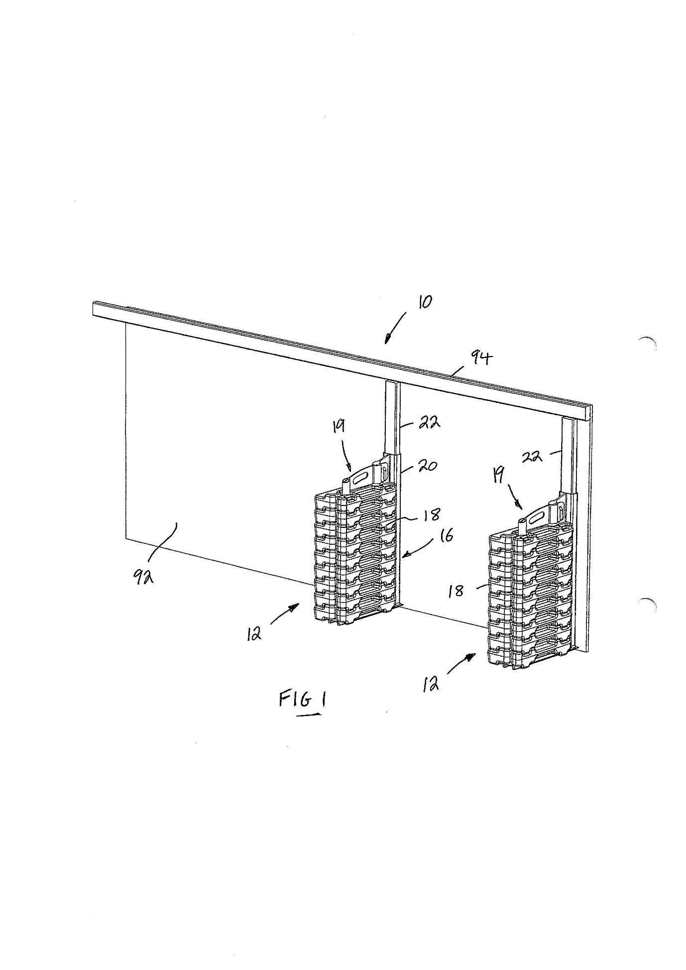
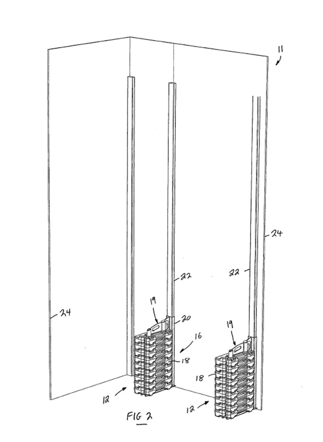
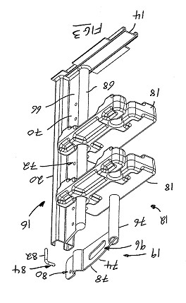
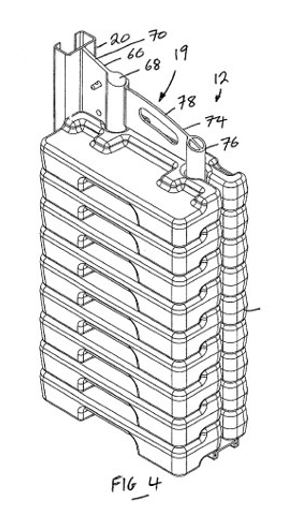
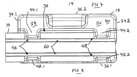
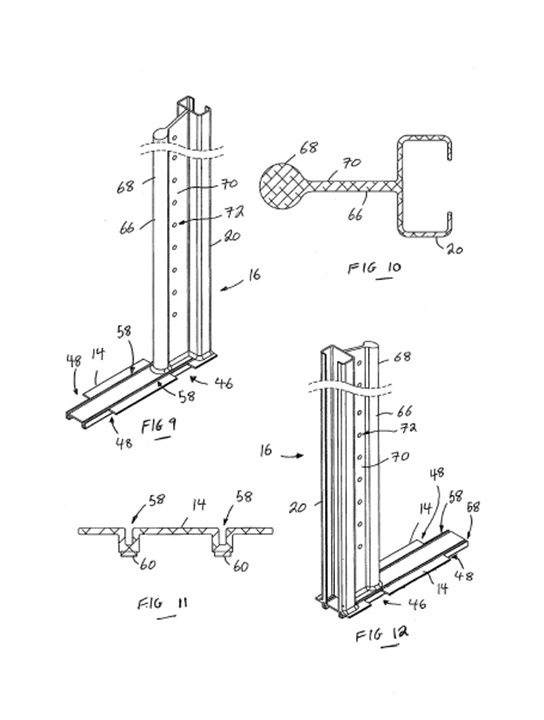
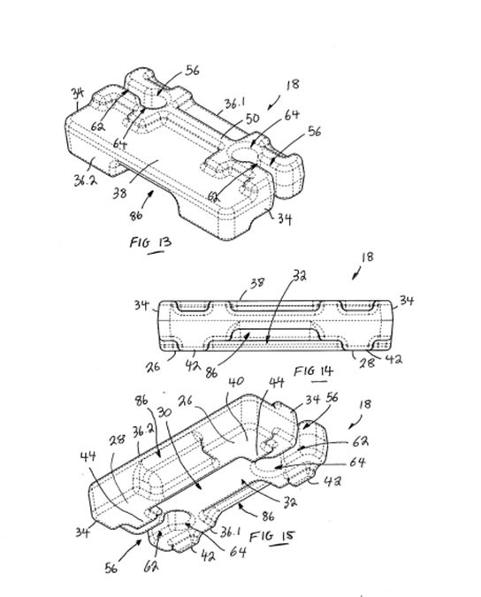
QUD 117 of 2018 | |
TITAN HOARDING SYSTEMS AUSTRALIA PTY LTD ACN 166 386 303 | |
Respondents | |
Second Respondent | HOARDING IDEAS PTY LTD ACN 604 219 712 |
Third Respondent | MARIA LOMAX |
Fourth Respondent | MARK LOMAX |

