FEDERAL COURT OF AUSTRALIA
Australian Mud Company Pty Ltd v Globaltech Corporation Pty Ltd
[2018] FCA 1839
ORDERS
DATE OF ORDER: |
THE COURT ORDERS THAT:
1. The applicants file and serve within 7 days draft minutes of order reflecting the conclusions set out in these reasons.
Note: Entry of orders is dealt with in Rule 39.32 of the Federal Court Rules 2011.
BESANKO J:
1 Australian Mud Company Pty Ltd is the registered owner of a patent titled, “Core Sample Orientation”. The claims in the patent claim priority from 3 September 2004. I will refer to this date as the Priority Date, although there is an issue about whether this is the correct priority date. In due course, I will set out the reasons I find that 3 September 2004 is the correct priority date. The patent is Australian Standard Patent Application No 2010200162 (the Patent). Reflex Instruments Asia Pacific Pty Ltd is the exclusive licensee of the Patent. Australian Mud Company Pty Ltd and Reflex Instruments Asia Pacific Pty Ltd claim that the respondents, Globaltech Corporation Pty Ltd and Globaltech Pty Ltd, have infringed claims in the Patent.
2 Before the trial, I made an order that issues of liability be heard and determined before issues of the quantum of any pecuniary relief. There is a claim for additional damages under s 122(1A) of the Patents Act 1990 (Cth) (the Act). The entitlement to that relief, but not the quantum thereof should an entitlement be established, was part of the hearing.
3 I will refer to Australian Mud Company Pty Ltd and Reflex Instruments Asia Pacific Pty Ltd together as AMC. The respondents did put a submission put that because of the exclusive licence in favour of Reflex Instruments Asia Pacific Pty Ltd (Reflex Instruments Asia), Australian Mud Company Pty Ltd was not a proper party to the proceeding. I reject that submission. This is a hearing on liability and Australian Mud Company Pty Ltd, as the patentee, is a proper party to the proceeding. The standing to sue of Reflex Instruments Asia derives from s 120 of the Act and the exclusive licence agreement with Australian Mud Company Pty Ltd.
4 I will refer to Globaltech Corporation Pty Ltd and Globaltech Pty Ltd together as Globaltech. Except in one area, there is no need to distinguish between them. The one area is infringement where Globaltech Pty Ltd claims that even if all of its other defences and the cross-claim fail, AMC has not proved that it has engaged in any conduct which amounts to an infringement of the claims in suit.
5 The claims in suit in the Patent are method claims (claims 1-4, 7-10, 16-17, 21-24, 27-28 and 65) and what are described in the Patent as system claims (claims 33-40, 46-48, 54 and 65). AMC asserts that what are described as systems claims are product claims, while Globaltech asserts that they are, in reality, method claims.
6 The Globaltech tools which are said to infringe the claims in suit are known as “Orifinder” tools and they consist of an Oritool and Oripad. There are and have been various versions of the Orifinder tool and those said to infringe the claims in suit are known as the Orifinder v3A, Orifinder v3B and Orifinder v5 respectively.
7 The major issue in the infringement action brought by AMC against Globaltech is the proper construction of the claims in suit. There was by the end of the case, very little dispute about the facts concerning the features and operations of the Orifinder tools. Globaltech submits that the proper construction of the claims in suit is such that its products do not result in an infringement of those claims. Closely associated with its construction arguments and, depending on the way in which those arguments are resolved, Globaltech raises a number of validity arguments, including a lack of clarity (s 40(3) of the Act; a lack of fair basis (s 40(3) (i.e., internal fair basis)); and a lack of utility (s 18(1)(c)). Those validity arguments were described by counsel for Globaltech as the “flipside” of its construction arguments.
8 Globaltech has filed a cross-claim challenging the validity of the claims in suit on a number of grounds. First, Globaltech claims that the claims in suit are not entitled to priority from 3 September 2004 because the claims are not fairly based on the alleged priority document, being a Provisional Application filed on 3 September 2004. The significance of this submission is that if the correct priority date is any date after September 2004, then the alleged invention is not novel because AMC’s own Ace Core Tool introduced in Australia in October 2004 is novelty-defeating. AMC accepts that if the correct priority date is after September 2004, then the claims are not novel. Secondly, Globaltech contends that even if the claims in suit are entitled to priority from 3 September 2004, they are invalid due to a lack of novelty. In this respect, Globaltech relies on an act and a document (or either), both of which relate to a tool known as the High Side Seeker. Thirdly, Globaltech contends that the claims in suit do not involve an inventive step and, for the purposes of this argument, Globaltech relies on common general knowledge alone and, in the alternative, common general knowledge and information falling within the terms of s 7(3) of the Act.
9 There are some other issues concerning infringement and there is AMC’s claim to be entitled to additional damages to be considered.
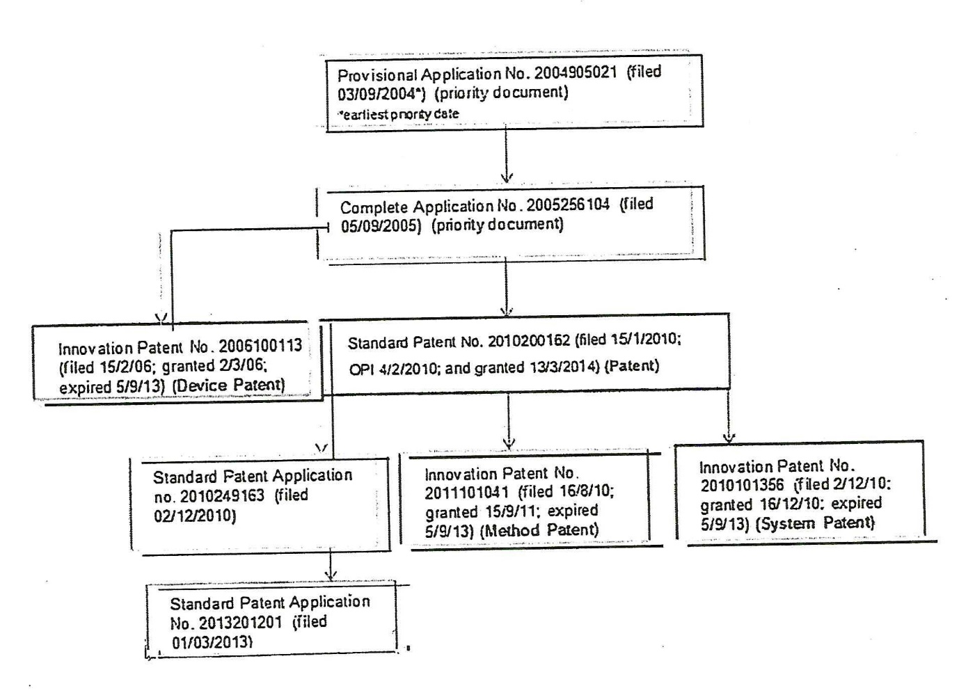
10 The Patent in this case is one of a family of patents about which there has been considerable litigation between AMC (and related companies) and a company called Coretell Pty Ltd (Coretell) and companies related to Coretell. Globaltech and Coretell are not related. For present purposes, two sets of proceedings between AMC and Coretell are relevant. Before identifying them, I note that one of the witnesses in this case, Mr Brown, produced a diagram showing the family of patents. I annex the diagram to these reasons (Annexure A). It can be seen that the Patent is a divisional of an earlier application.
11 The Method Patent and the System Patent shown in Annexure A were the subject of proceedings between AMC and Coretell in the New South Wales District Registry of this Court. There was a trial at first instance before McKerracher J (Australian Mud Company Pty Ltd v Coretell Pty Ltd (No 4) [2015] FCA 1372 (Coretell First Instance)) and an appeal to the Full Court of this Court (Coretell Pty Ltd v Australian Mud Company Pty Ltd [2017] FCAFC 54; (2017) 250 FCR 155 (Jagot, Nicholas and Burley JJ) (Coretell Full Court)). An application for special leave to appeal to the High Court was refused. The specifications and claims in the Method and System Patents were substantially the same as the specification and claims in the Patent.
12 The other proceeding was in the Western Australia District Registry and was a proceeding which I heard. It involved the Patent, but, as it happened, infringement and the validity of the Patent were not in issue (Australian Mud Company Pty Ltd v Coretell Pty Ltd (No 2) [2018] FCA 1109 (Coretell Western Australia)). Professor Tapson, a witness in this case, swore an affidavit in that case, but ultimately was not required for cross-examination.
13 The version of the Act and Patents Regulations 1990 (Cth) which is relevant is that in force prior to the “Raising the Bar” Amendments passed in 2012.
14 As I have said, the title of the Patent is “Core Sample Orientation”.
15 The Abstract in the Patent describes a core orientation device by reference to Figure 1 and the way in which it operates to provide a measure of the physical orientation of the device at a particular moment in time.
16 The Field of the Invention is said to relate to core sample orientation. The invention relates to an orientation device for providing an indication of the orientation of a core sample relative to a body of material from which the core has been extracted and also to a method of core sample orientation identification.
17 The Specification contains a heading, “Background Art” and a statement under that heading that there is a need for core sampling in geological surveying operations. It then proceeds to describe conventional core drills and how they are operated to obtain core samples. It states that core drilling operations are typically performed at an angle to the vertical and it is desirable for the purposes of analysing the sample to have an indication of the orientation of the core sample relative to the ground from which it is extracted. Therefore, there must be some means of identifying the orientation which the core sample had within the ground prior to it having been brought to the surface. Core orientation devices are used to provide an indication of the orientation of the core sample.
18 The Specification states that a common way of obtaining an indication of the orientation of a core sample was through the use of an orientation spear comprising a marker, such as a crayon, projecting from one end of a thin steel shank, the other end of which is attached to a wire line. The description of how the orientation spear is used to mark the core sample is as follows:
The orientation spear is lowered down the drill hole, prior to the inner tube assembly being introduced. The marker on the orientation spear strikes the facing surface of material from which the core is to be generated, leaving a mark thereon. Because of gravity, the mark is on the lower side of the drill hole. The inner tube assembly is then introduced into the outer tube assembly in the drill hole. As drilling proceeds, a core sample is generated within the inner tube assembly. The core sample so generated carries the mark which was previously applied. Upon completion of the core drilling run and retrieval of the core sample, the mark provides an indication of the orientation of the core sample at the time it was in the ground.
19 The Specification states that there are also mechanical core orientation devices for marking a core sample prior to its extraction from the drill hole. Unlike the orientation spear, which is used before the inner tube assembly is introduced into the drill, the mechanical devices are typically adapted for incorporation in the inner tube assembly for marking the core. An example of such a mechanical orientation device is said to be that disclosed in WO 03/038212. This reference number in the Specification is incorrect. It should be to WO 03/038232 and this is the Ezy-Mark device which I describe later in these reasons.
20 The Specification states that it is against this background and the problems and difficulties associated therewith that the invention has been developed.
21 The Specification then contains a section entitled “Disclosure of the Invention”. Before discussing this section, it is convenient to set out the two relevant independent claims in the Patent and the two claims which immediately follow them, namely, claims 1 and 2 (method claims) and claims 33 and 34 (system claims). For ease of reference later in these reasons, I have identified the five steps in claim 1.
22 Claim 1 is as follows:
1. A method of providing an indication of the orientation of a core sample relative to a body of material from which the core sample has been extracted, the method comprising:
drilling a core sample from a body of material with a core drill having an inner tube; (step 1)
recording the orientation of the inner tube at predetermined time intervals during said drilling, the time intervals being referable to an initial reference time; (step 2)
inputting the specific time beyond the reference time representative of when the core sample was separated from the body of material; (step 3)
removing the inner tube, with the core sample held therein in fixed relation to it, from the body of material; (step 4) and
relating the inputted specific time to the recorded time intervals to obtain an indication of the orientation of the inner tube and consequently the core contained therein at the specific time. (step 5)
23 Claim 2 is as follows:
2. A method as claimed in claim 1, comprising:
producing signals to indicate the orientation of the inner tube at any instant in time during said drilling;
processing the signals to determine data indicative of the orientation of the inner tube at various instants in time;
inputting a time measurement representative of the instant in time when the core sample is separated from the body of material and first held in fixed relation thereto; and
comparing the inputted time measurement to the instants in time and identifying the data indicative of the orientation of the inner tube and consequently the core sample at the instant in time.
24 Claim 33 is as follows:
33. A core orientation system for providing an indication of the orientation of a core sample relative to a body of material from which the core sample has been extracted using a core drill, the core drill having an inner tube, the system comprising:
means for recording the orientation of the inner tube at predetermined time intervals during drilling by the core drill, the time intervals being referable to an initial reference time, and for inputting the specific time beyond the reference time representative of when the core sample was separated from the body of material; and
means for relating the inputting specific time to the recorded time intervals to obtain an indication of the orientation of the inner tube and consequently the core contained therein at the specific time.
25 Claim 34 is as follows:
34. A system as claimed in claim 33, comprising:
means for providing signals associated with the physical orientation of the inner tube of the core drill during drilling;
input means for inputting into the system a time measurement indicative of the time during drilling when the core sample is detached from the body of material from which it is taken and held in fixed relation to the inner tube;
one or more processing means for processing the signals to produce data indicative of the orientation of the inner tube;
one or more processing means for processing the data produced and the inputted time measurement to produce an indication of the orientation of the core sample relative to the material from which it is detached; and
display means for the indication of the orientation of the core sample relative to the material from which it is detached.
26 As I have said, AMC contends that claim 33 is a product claim, not a method claim, because the system to which the claim is directed is “a set of interacting components forming an integrated whole for a specific purpose, being in this case to orient a core sample”.
27 Returning to the section of the Specification dealing with the Disclosure of the Invention, the first paragraph identifies what is said to be the first broad aspect of the invention and it is in the same terms as claim 1. There then follows a series of consistory clauses for the rest of the method claims. The same observations apply to the disclosure of the invention insofar as it relates to the system claims (i.e., what is described in the Specification as a second broad aspect of the invention). The third broad aspect of the invention is a core drill having a core orientation system according to the second broad aspect of the invention, and the fourth and final broad aspect of the invention is a combination of the method and system aspects of the invention.
28 The Specification includes six drawings which are described as Figures 1 – 6 inclusive and it states that the invention will be better understood by reference to the description of one specific embodiment thereof as shown in the drawings. There is then a brief description of each of the drawings.
29 The final part of the body of the Specification sets out the “Best Mode(s) for Carrying Out the Invention”. I will refer to this as the best method section. This part of the Specification extends over some seven pages and the description in this section is given by reference to numbered features shown in the drawings.
30 The best method section describes the core orientation device, the inner tube assembly, the outer tube assembly, and the relationship between these parts. According to the embodiment, the physical orientation of the core orientation device comprises rotational orientation about a longitudinal axis of the device. As AMC pointed out, this is referred to in the evidence as the “roll” orientation or “high side” orientation. Subject to some modifications which are not presently material, the core drill is described as being of conventional construction and operating in a conventional way.
31 The best method section states that the orientation of the orientation device corresponds to the orientation of the lower part of the inner tube assembly which in turn corresponds to the orientation of the core sample progressively entering the inner tube assembly as the lower part does not rotate relative to the core sample.
32 The best method section contains a description of the process involving the orientation device and core drill and that description begins by a reference to a “first step” which comprises moving the core drill having the core orientation device forming part thereof from a first location to a drilling location. The best method section refers to a “reference time” and there is a statement that the reference time corresponds to the time at which the orientation device was started and the one minute intervals commence from a reference time.
33 The best method section states that in “this embodiment”, the orientation device is started by pressing a particular key on the keypad. The best method section continues as follows:
It is also necessary to record the time duration between starting the core orientation device 10 and extracting the core sample. Typically this is achieved by starting an external stop watch at the time of starting of the orientation device 10. Other arrangements are of course possible.
The stop watch is started at the time that the orientation device 10 displays a signal on the display 31 indicating that operation of the orientation device 10 has started. This provides for added accuracy.
Once the orientation device 10 has been started and recording of the subsequent time duration commenced, the inner tube assembly 36 is inserted into a drill hole for reception in the outer tube assembly, 13, and the core drilling operation commenced. During the drilling operation, a core is progressively generated within the inner tube assembly, as previous explained.
When the core is to be extracted, the core drill operator refers to the timer and notes the time duration involved. Specifically, the operator either notes the full minute that has previously elapsed or waits until the next full minute elapses, and then records that time (as it must be recalled later).
34 A little later in the best method section, there is a statement that in the particular embodiment described subsequent rotation of the core orientation device to reflect the measure of the core orientation device is achieved by inputting the time duration as measured by the external stop watch into the orientation device through the keypad. The section provides that the time measurement measured by the operator and entered into the keypad represents the duration of time between starting the orientation device and the point at which the particular drilling process was terminated in order to fracture the core sample from the body of material to which it is attached so that the core sample can be retrieved from the drill hole and brought to the surface level.
35 The third and second to last paragraphs of the body of the Specification are in the following terms:
From the forgoing, it is evident that the present invention provides an orientation device which does not require physical marking of a core sample prior to extraction thereof from the ground. Indeed, the orientation device according to the embodiment is particularly convenient for an operator to use. All that is required is for the operator to start the orientation device prior to the inner tube assembly 36 being inserted into the drill hole, and contemporaneously start a timer for recording the time duration before the drilling operation ceases to allow the generated core sample to be retrieved.
Modifications and improvements may be made without departing from the scope of the invention. For example in other embodiment the physical orientation does not comprise a rotational orientation but rather a measure of degrees above or below the horizontal plane.
36 Although not one of the claims in suit, AMC relied on claim 6 in connection with its construction arguments. It is in the following terms:
6. A method as claimed in any one of claims 2 to 5, wherein the instant in time is representative of a duration of time relative to the initial reference time.
37 AMC relied on some separate and additional arguments in answer to Globaltech’s challenge to the validity of the following claims:
4. A method as claimed in claim 3, comprising generating data representative of the orientation of the core sample at a subsequent time and providing a visual indication of the orientation of the core sample at a time at which the drilling was terminated and/or a direction in which the core sample should be rotated at said subsequent time in order to bring the core sample into an orientation corresponding to its orientation in the identified data.
16. A method as claimed in any one of the preceding claims, comprising comparing the orientation of the core sample at the selected time interval to the orientation of the core sample at any subsequent time and providing a visual indication of the direction in which the core sample should be rotated in order to bring it into an orientation corresponding to the orientation of the core sample at the selected time.
23. A method as claimed in any one of claims 17 to 22, comprising relating the measure associated with the orientation of the core sample with a present orientation thereof such that the core sample can be rotated to reflect the measure associated with the orientation of the core sample.
46. A system as claimed in any one of claims 40 to 45, comprising means for relating the measure associated with the orientation of the core sample with a present orientation thereof such that the core sample can be rotated to reflect the measure associated with the orientation of the core sample.
Claim 4 is dependent on claim 3 which is dependent on claim 2 which is dependent on claim 1.
38 AMC submitted that an important feature of the invention is “real time orientation” as seen, for example, in claims 4 and 16, that is to say, orientation on the surface where the core is in the inner tube and the orientation device is attached to the inner tube.
39 AMC called two experts at trial, Professor Jonathan Tapson and Mr Kelvin Brown. Globaltech also called two experts at trial, Mr Michael Ayris and Mr Adrian Edmonds. Each expert swore affidavits before trial which contained their evidence-in-chief. The parties formulated a list of issues before trial and each expert addressed the issues in what I will refer to as a joint experts’ report. The one exception is that Mr Brown did not participate in the session which addressed infringement. The experts gave evidence in a joint session.
40 Dr Erik Blake was called as a witness by Globaltech. Dr Blake gave evidence by audio-visual link from Canada. Dr Blake holds a Bachelor of Applied Science in engineering physics (geophysics) from the University of Toronto (1986) and a PhD in geophysical (glaciology) from the University of British Columbia (1992). Dr Blake gave evidence as to the facts and some expert evidence. Further details of his qualifications and experience are set out in the section of these reasons which deal with Globaltech’s novelty challenge.
41 Globaltech was ordered to file a Product Description with respect to the Orifinder tools. It did that and then filed an Amended Product Description shortly before trial. Only the latter document is of present relevance. It contains a description of, and flowcharts with respect to, the Orifinder v3A, v3B and v5. The Amended Product Description was verified by Mr Khaled Hejleh, who is the managing director of Globaltech Corporation Pty Ltd. He was briefly cross-examined at the trial. The cross-examination established that, apart from an additional vibration sensor in the Orifinder v3B, the differences in the three tools related to the software program and not the hardware components.
42 Globaltech tendered an affidavit of Mr Anthony Pullen who is a patent attorney. He deposed to having received by courier on 21 August 2017, three tool parts from Icefield Tools Inc (Icefield Tools) in Canada. The relevance of those tool parts will be identified later in these reasons. Mr Pullen was not required for cross-examination.
43 I turn to summarise the qualifications and experience of the four experts who gave evidence in joint session.
44 I start with a brief summary of Professor Tapson’s qualifications and experience as he explained those matters to the Court.
45 Professor Tapson is an engineer and he is Professor at the School of Computing, Engineering and Mathematics at the Western Sydney University (WSU). He has had over 25 years’ experience in electronic and computer engineering, practising primarily in the fields of sensors and instrumentation, including designing orientation systems in drilling environments.
46 In 1994, Professor Tapson completed his PhD in engineering at the University of Cape Town (UCT). He also holds a Bachelor of Science in electrical engineering and a Bachelor of Science in physics obtained from the same university.
47 After he had completed his PhD, Professor Tapson held various academic positions in the field of electrical and computer engineering. It is not necessary for me to set out the details. It is sufficient to say that the positions were held from 1994 to the present day at the Cape Technikon (now the Cape Peninsula University of Technology), the UCT and the WSU.
48 As part of Professor Tapson’s academic responsibility at Cape Technikon, he established the Centre for Instrumentation Research (CIR) on 1 September 1995. During his tenure as Director of CIR, and thereafter, the CIR was involved in several projects in the field of orientation and mining instrumentation. These projects included systems based on ultrasonic and electrical impedance for measuring the constituents and flow rates of materials in drill pipes and slurry pipelines. The CIR also designed orientation systems that could be embedded in objects in order to measure their trajectories while passing through hostile environments, such as ball mills and autoclaves.
49 Professor Tapson’s academic responsibilities at UCT included supervising a well-equipped laboratory within the Department of Electrical Engineering. The laboratory primarily undertook research into instrumentation for industrial application. Professor Tapson gave examples of the research projects that he undertook, including in conjunction with UCT’s Centre for Minerals Research. It is not necessary for me to set out the details.
50 A good deal of Professor Tapson’s research at UCT was carried out under industrial sponsorship from De Beers Consolidated Mines (De Beers) and Anglo Platinum. He estimates that about 50% of the research projects that he worked on between 1997 and 2011 concerned instrumentation for the mining industry.
51 From 1997 to 2014, Professor Tapson regularly interacted with engineers, researchers and operators from De Beers, Anglo Platinum, Anglo American, AngloGold Ashanti, Bateman, Hatch and Honeywell Instrumentation. Some of this industrial sponsorship was obtained through the AMIRA International consortium (an Australian-based organisation of mining companies), which facilitates collaborative research projects. He had regular contact with Australian researchers in these projects. He also had contact with a number of researchers from the Julius Kruttschnitt Mineral Research Centre at the University of Queensland and geologists working with extracted mineral materials, including core samples. He has also visited mine sites in which core drilling operations have been undertaken, including, in 2003, Anglo Platinum’s core drilling operations at its Rustenburg mine site.
52 Professor Tapson has taught in the areas of Mechatronics Design, Microprocessor Systems, Process Control and Instrumentation, Electrical Engineering Design and Advanced Topics in Instrumentation. These subjects involve engineering concepts relevant to the design of instruments and techniques for orientation and position sensing in the mining industry.
53 As far as publications are concerned, Professor Tapson has been an associate editor of a number of peer-reviewed journals, including the Institute of Electrical and Electronics Engineers Sensors Journal, Frontiers in Neuroscience: Neurorobotics and Neuromorphic Engineering. He also regularly reviews articles submitted for publication in peer-reviewed journals in his field, including the Measurement Science and Technology, Review of Scientific Instruments and Control Engineering Practice. Professor Tapson has published over 100 academic papers covering a range of topics including sensor design, electronic circuits and networked systems. He has also regularly given presentations at industry conferences. Of note, is that in 2003, and again in 2004, he was invited to present the keynote address at the Annual Conference of the South African Institute of Mining and Mineral Processing regarding the state of the art of instrumentation and networked systems in the mining industry.
54 As far as membership of professional societies is concerned, Professor Tapson is a member of the following professional societies: Sensory Systems Technical Committee of the IEEE Circuits and Systems Society (since 2007); Committee Member and former President of the South African Council of Automation and Computation (from 2000 to 2007); and Fellow of the South African Academy of Engineering (since 2009).
55 Globaltech submitted that Professor Tapson’s experience and qualifications were largely of an academic, rather than of a practical nature. In light of that submission, it is necessary to mention the following. The following are examples of projects that Professor Tapson has conducted in the areas of orientation instruments and systems for the mining industry up to, and including, 3 September 2004:
(1) In 1995, he acted as a consultant for a Brisbane-based instrumentation company for the mining industry named “HiTech”. That work involved designing systems for communicating data in geological surveys.
(2) From 1997 to 2005, he supervised the development and operation of instrumentation for measuring and analysing the constituents of material recovered by a marine diamond drilling system for the Control and Instrumentation division of De Beers Research.
(3) From 2000 to 2005, he founded and was the Technical Director of a South African company, Motornostix (Pty) Ltd (Motornostix), which was, and remains, involved in a number of projects for the mining, manufacturing, recycling and electrical power industries, including for ArcelorMittal, Assmang Chrome, BHP Billiton, De Beers, Lonmin, Samancor and Xstrata. The majority of projects that he worked on while at Motornostix involved the use of accelerometers and magnetic field sensors to detect orientation, rotation and vibration. Motornostix was one of the first companies to make large scale industrial use of silicon accelerometers. As part of the development of those products, Professor Tapson conducted a comprehensive study into the use of sensors in robust environments, such as mining and manufacturing. He was involved in the installation of Motornostix systems at a number of sites in Australia, including BHP Billiton’s North Parkes mine and Sydney Water’s North Head water treatment plant.
(4) From 2001 to 2003, he supervised the design of instrumentation for measuring the orientation and movement of materials on coal conveyors.
(5) From 2002 to 2004, he worked with the Control and Instrumentation division of De Beers Research to develop instrumentation for measuring and communicating drill head orientation in marine drilling. During that time, he had direct and frequent experience with operators and geologists extracting and orientating extracted material.
(6) In 2012, he was involved in developing instrumentation and techniques for measuring petroleum, natural gas and extracted substances obtained through hydraulic fracturing techniques in the oil and gas industries.
56 Professor Tapson first became aware of core drilling assemblies used in mineral exploration drilling as result of discussions with Professor Stewart Smith of the Department of Geology and Geo-chemistry at the University of Cape Town in the late 1990s. He observed core samples and core drilling equipment before September 2004 in the course of his duties as a downhole instrument designer for the mining and drilling sector, including in consultation with De Beers, Anglo Platinum and the UCT Department of Earth Sciences. Before September 2004, he worked closely on several instrument, drilling and position sensing design projects. He has also visited mine sites before that time, where, as a consultant engineer, he observed operational core drill assemblies in the field for extracting core samples (e.g., Anglo Platinum’s core drilling operations at its Rustenburg mine site in 2003).
57 Globaltech submitted that Professor Tapson had little experience in core orientation before the Priority Date and that such knowledge and experience as he had, was obtained after the Priority Date. It is true that Professor Tapson’s practical experience before the Priority Date was in drill orientation, but he gave evidence, which I accept, that that field is extremely close to core orientation. It is also true that Professor Tapson became aware of the orientation spear, Ezy-Mark and Ballmark devices (which I discuss below) after the Priority Date and that he became aware of scribe knife methods after the Priority Date. It is also true that Professor Tapson had no practical experience in drilling for oil and gas. I have taken these matters into account in assessing his evidence. I formed the view that generally, Professor Tapson’s evidence of the matters about which he had informed himself, was reliable.
58 Professor Tapson was cross-examined about evidence he gave in Coretell First Instance and an affidavit he swore in Coretell Western Australia and I will address that evidence later in these reasons.
59 It was also suggested by Globaltech that Professor Tapson had a close association with AMC and that one example of that was the fact that he was named as an inventor on a patent without his knowledge. It is true, as Globaltech submitted, that Professor Tapson had acted for a number of years as an expert for AMC or its parent company, Imdex Pty Ltd (Imdex). I take into account the fact that Professor Tapson has given evidence in previous proceedings and that, in a sense, he has had a long association with this family of patents. However, I am not persuaded that his independence has been compromised.
60 Mr Brown is the Global Products Manager for Reflex Instruments Asia, which is the second applicant in this proceeding. Both Reflex Instruments Asia and Australian Mud Company Pty Ltd, which is the first applicant in this proceeding, are wholly owned subsidiaries of Imdex. Mr Brown has worked for Reflex Instruments Asia since 2005 and has held his current position as Global Products Manager since 2007. As I have said, Mr Brown participated fully in the joint session of experts, save and except that he was not involved in that part of the session which considered the issue of infringement.
61 Mr Brown has over 20 years’ experience in mineral exploration drilling. Over this time he has acquired knowledge and experience in all major forms of exploration drilling, including auger drilling, rotary-percussion drilling and diamond core drilling, including the technologies and instruments used in those drilling programmes.
62 From about 2005, Mr Brown has had frequent contact with clients (and potential clients) in the mining and exploration industry requiring survey and core orientation equipment, including, more recently, electronic core tools.
63 From about January 1995 to February 2001, Mr Brown was employed as a Senior Driller by PrilrCorp Western Deep Hole Drilling. During that time, he worked on core sample extraction drilling programs throughout Western Australia and was responsible for overseeing and managing all drill crew using core orientation instruments on the rigs. He also supervised and liaised with geologists and exploration companies regarding the orientation of core samples from the drilling operations.
64 From about February 2001 to about February 2003, Mr Brown was employed by Mosslake Drilling (Mosslake) (now Faraco International) as its drilling manager. As part of his role, he was responsible for overseeing and managing core drilling operations conducted on Mosslake’s rigs. His responsibilities included the management of production rates across Mosslake’s rigs, the hiring and return of equipment used on rigs and working with the executive managers of resource exploration companies and geologists regarding their exploration drilling needs.
65 Mr Brown estimates that between 1994 and 2003, he had either carried out or overseen multiple core drilling and core sample orientation operations, in which more than 90,000 metres of subterranean rock was drilled.
66 In early 2004, Mr Brown joined the Imdex group of companies (Imdex Group), working for its business division Ace Drilling Supplies (Ace Drilling) as a Technical Sales Representative. Ace Drilling was then the exclusive distributor for downhole cameras and survey navigation tools in Australia and the Asian region for a Swedish company, Reflex Instruments AB (Reflex Instruments). As a Technical Sales Representative, he provided sales and technical support to customers using Reflex products, including, on occasion, repair and dispatch of replacement equipment.
67 In January 2005, Mr Brown became a Regional Manager for Ace Drilling and held that role until January 2007. As part of that role, he visited mine sites to introduce and explain Ace Drilling’s new electronic core orientation tool known as the Ace Core Tool, which was the first electronic core orientation tool released in Australia in late September 2004.
68 As the Global Products Manager for Reflex Instruments Asia, Mr Brown, in addition to site visits and sales, has been responsible for the life cycle management of the company’s product line and the development and implementation of training programs for its sales and technical support staff.
69 In this current role, Mr Brown regularly visits the company’s regional offices in Australia, Africa, South America, North America, Canada, Europe and Asia Pacific (Imdex Regions). The purpose of these visits is, among other things, to inform the regional office staff about the products supplied by the company, including through internal product training. He also speaks to the sales staff in the Imdex Regions about product development and competitor products, and works with them on strategies to promote the company’s products.
70 Mr Brown’s visits to the Imdex Regions also involve visits to one or more customers in those regions for the purpose of promoting new products and obtaining feedback on any existing products supplied by Reflex Instruments Asia. These visits often take place on-site at the customer’s drilling operation where Mr Brown speaks directly to the customer about their needs and use of his company’s products, and is often able to observe the operation of the product first hand. Through this process, Mr Brown is able to identify technical or operational issues with the products, which he then passes on to the engineering department at Imdex so that refinements and improvements can be made to these products. On some occasions, he will demonstrate his company’s products at the customer’s drilling site.
71 In his current role, Mr Brown also works closely with the company’s technical support staff across the Imdex Regions, including the team of product engineers who reported directly to him until around the end of 2011 when Imdex appointed a Research and Development Engineering Manager, Mr Tim Price, who is based in the United States.
72 Mr Brown has contact with Mr Price on a number of occasions every week. He also engage directly with the product engineers for the purposes, among others, of channelling development ideas to them and receiving feedback on the operation of the company’s products from customers.
73 Mr Brown’s role as Global Products Manager involves liaising with the project engineers throughout the product development process. The team provides him with at least fortnightly updates on their progress. As part of his involvement in that process, he is responsible for issuing Scope of Works documents outlining the development or modification required to the products. He is also responsible for reviewing the specification documents created by the development team, and for undertaking testing of any prototypes created by the company. In doing so, he acts like an operator of the tool and applies his understanding of the application and requirements in the field to ensure that the product achieves its intended function.
74 In his current and previous roles, Mr Brown has been in regular contact with all of the major Australian mine site operators regarding their core drilling programs and the performance requirements for equipment used in the field. He regularly attends Australian and international mining events, including the Asia-Pacific International Mining Exhibition, which is the largest mining event for suppliers and end-users of drilling equipment in the Asia-Pacific Region, the Prospectors & Developers Association of Canada (PDAC) conference in Canada and Mining Indaba in Africa.
75 In 2011, Mr Brown received the Australian Prospect Mining Awards for “outstanding contribution to mining” and “miner of the year” for his role in the Chilean mine rescue in August 2010.
76 In 2011, Mr Brown was invited by the Australian Institute of Geoscientists (the largest professional body of geologists and geoscientists in Australia) to give the keynote address on the state of the art of instrumentation used in mineral exploration drilling.
77 In 2012, he was appointed by Curtin University, Western Australia, as an associate supervisor of PhD students who were undertaking research into drilling technology at the Deep Exploration Technologies Cooperative Research Centre.
78 Globaltech submitted that Mr Brown’s evidence should be treated with some caution because of his employment relationship with Reflex Instruments Asia and noted that he did not participate in the joint session of experts with respect to infringement. Globaltech also asked me to take into account that Mr Brown had no practical experience in oil and gas.
79 I have taken those matters into account. Nevertheless, I formed the view that Mr Brown was a good witness with considerable practical knowledge and experience in the relevant field. His evidence was helpful and I do not think that his relationship with Reflex Instruments Asia coloured his evidence in any way.
80 Mr Ayris is the managing director and founder of DHS (Aust) Pty Ltd, trading as “Downhole Surveys”.
81 In 1980, Mr Ayris was awarded a Diploma in Cartography at Wembley TAFE in Western Australia. Cartography is the science or practice of drawing maps.
82 In 1980, Mr Ayris began working as a Cartographer in West Perth with Associated Surveys, where he was employed to draw plans. Between 1984 and 1986, he was employed as a cartographer, and later as a Surpac consultant, in the Pilbara in Western Australia with Goldsworthy Mining (now BHP) at the Shay Gap mine site. He later moved to Kalgoorlie in Western Australia, where he worked between 1986 and 1989 as a Surpac consultant to draw drill hole location maps for various mining companies.
83 Most of Mr Ayris’ early work in the Pilbara and Kalgoorlie involved drawing straight drill holes manually on to plans. In about 1987, he became interested in researching the impact on a planned mine pit if the drill holes were not straight as had previously been assumed. These questions formed the basis for what later became several months of research into that area.
84 Mr Ayris discovered that whilst there were a small number of instruments available to survey the angle and orientation of drill holes, very few companies considered such surveys necessary. He believed that it was an important part of reporting a mineable resource and set about, as he put it, “making downhole surveys a necessary part of drilling for mine suitably assessment”.
85 In 1989, Mr Ayris opened his own business in Kalgoorlie under the name “Downhole Surveys” and continues to run that business today. At the Priority Date and since, the business is and was a mining survey consultancy and a distributor of downhole instrumentation tools to Australian and overseas mining companies.
86 When Downhole Surveys opened in 1989, Mr Ayris purchased and operated one survey tool which he used as the sole operator to survey the pit in Kalgoorlie. The survey tool was a magnetic Eastman Multishot tool, which was manufactured by a United States company, Eastman Christensen. The tool worked by lowering a film based camera down into a drill hole via a wire line and winch, along with a compass and dip circle, and multiple camera shots were taken of the compass and dip circle at pre-set time intervals (every 2 minutes) as the tool was lowered down the hole. The operator started a stop watch at the surface at time “zero” and at each pre-set time interval corresponding to the time the photograph was taken, the depth of the compass/dip circle into the drill hole would be manually recorded by the operator. Mr Ayris would then analyse the depth recordings and the compass/dip circle photographs to determine the orientation of the drill hole which allowed him to draw detailed survey maps of the drill hole location. This, in turn, allowed his customers to create a more accurate positional representation of their ore body. Mr Ayris explained that as technology improved, automatic timing devices on the surface recorded the depth on a computer or PDA at the pre-set times.
87 In about 1992, Mr Ayris began to generate more survey work for mining companies and was able to employ other staff in his business. It was around this time that he decided to expand his business to include distributing survey tools to mining companies. He also continued to offer his survey consultancy services where he used the downhole instrumentation tools to determine drill hole orientation and draw survey maps.
88 In 1993, Mr Ayris was awarded the Australasian distributorship for the Swedish company, Reflex Instruments. The distributorship continued until around 2008 when Reflex Instruments AB changed ownership. From that time until around 2009, he had a distributorship with Flexit for the Electronic Multishot System (EMS) and MEMS Gyro.
89 In 1993, and as part of the distributorship with Reflex Instruments, Mr Ayris brought into Australia a tool known as the Reflex Maxibor. The Maxibor was a non-magnetic multishot tool that included an optical device to measure the bending of a probe lowered into a drill hole. A series of optical rings were displayed down a hole at intervals of 1.5 or 3 m. A liquid level sensor was mounted in line with the reflector rings to define a vertical plane. A light source was directed at and reflected by the rings. Digital photographs of the reflector rings were taken at pre-set time intervals and the offset of the rings from the vertical analysed to determine the orientation, including high side, of the drill hole. A digital stop watch was used at the surface by the operator for recording depth at the pre-set photograph times for later correlation with the orientation measurements. Mr Ayris sold Reflex Maxibor tools to Boart Longyear and other mining companies operating in Western Australia.
90 Over the subsequent years, Mr Ayris introduced over 15 mining survey products into Australia. On 3 September 2004, Mr Ayris was the Australian distributor at least eight downhole instrumentation tools and thereafter he continued to provide his survey consultancy services to mining companies throughout Western Australia.
91 Mr Ayris said that since his business began, as at 3 September 2004, and continuing today, he has kept himself informed of, and stayed up-to-date with, downhole instrumentation tools, including geophysical probes, gyroscopes, drilling tools, survey tools and core orientation tools, available on the market in Australia and overseas, so as to ensure that he was, and still is, distributing and using the most appropriate tools for his customers.
92 Mr Ayris said that as at 3 September 2004, he kept himself informed about new downhole instruments by the following means: maintaining close relationships with tool manufacturers; conducting his own research through internet searches; reading scientific papers, conference papers and patents; reading trade publications in the drilling field, including Australian Drilling, Mining Monthly, and Geodrilling; attending educational and networking events through the Australian Drilling Industry Association (ADIA) of which he has been a member since 1987; and attending various conferences in the field. In particular, Mr Ayris said that he has attended the PDAC conference held in Canada almost every year since 1998, including the conference held between 7 and 10 March 2004. The significance of this conference will become clear when I discuss the evidence of Dr Blake. PDAC is regarded as the premier international event for the mining industry. Mr Ayris has also attended Diggers & Dealers in Kalgoorlie almost every year since it commenced in 1992. Diggers & Dealers is the leading Australian event for the mining industry.
93 Before and since 3 September 2004, and continuing today, Mr Ayris reviews scientific and conference papers and patents in the field of downhole instrumentation to stay informed of new technology and to analyse his competitors’ activity.
94 Mr Ayris is the inventor named on several patents and patent applications in the area of drilling technologies, namely a patent titled “Drill hole orientation apparatus”, as well as two patent applications titled “Apparatus for aligning drilling machines” and “Controlled rotation centraliser”.
95 In submissions, Globaltech identified Mr Ayris as representative of the person skilled in the relevant art before the Priority Date and a person who had all the necessary skills and experience in the relevant field.
96 Although AMC made submissions about the weight which should be accorded to Mr Ayris’ evidence, it did not submit that it should not be accorded any weight. Indeed, in relation to Globaltech’s case with respect to the lack of an inventive step, AMC relied on the fact that Mr Ayris, despite being active in the field since 1989, did not himself develop a core sample orientation method or system, such as that described in the Patent, and nor was he aware of any other person having done so.
97 AMC was, however, critical of Mr Ayris’ failure to disclose that his business had been a distributor of orientation tools which either allegedly infringed the Patent or, in fact, did infringe other related patents. Mr Ayris’ company supplies the Orifinder v5 under the name “Trucore” and Mr Ayris agreed that he probably should have referred to this in his affidavit. His company also supplied the Camteq Orifinder tool which was found to have infringed the Method and System Patents in Coretell First Instance and he agreed that it would have been relevant for him to have listed this tool as one of the tools supplied or distributed by his company. There was also another tool Mr Ayris’ company distributed, the Devicore tool, which had been the subject of a letter of demand from AMC and which had led Mr Ayris to read the Patent before swearing his affidavits in this proceeding. There was a settlement of that dispute and the effect of that settlement is that the obligation on his company not to distribute the Devicore tool comes to an end if the Patent is held to be invalid. He agreed on reading the deed of settlement, he had an interest in the Patent being found to be invalid. I have taken these matters into account in assessing Mr Ayris’ evidence.
98 Mr Edmonds is an electronics and software engineer. In 1994, he was awarded a Bachelor of Electrical and Electronics Engineering with First Class Honours and a Bachelor of Information Technology with Distinction from Queensland University of Technology.
99 From April 1995 to February 1998, Mr Edmonds worked as a Systems Engineer with Pacific Star Technologies/Claremont Technology.
100 Between March 1998 and January 2004, Mr Edmonds was employed by Tyco Environmental Systems (formerly Greenspan Technology) as a Product Development Manager and Electronics Engineer. One of his tasks was to design and develop a miniature depth sensor for borehole applications. The relevance of this work to the subsequent work which he did at Ranger Survey Systems (RSS) was to learn how to develop miniaturised, low power, high accuracy sensoring electronics for harsh temperature, pressure and mechanical shock environments.
101 Between January and June 2004, Mr Edmonds was employed as a Software Engineer and Team Leader with Zetron Australia.
102 In March 2004, Mr Edmonds commenced employment with RSS as an electronics and software engineer. His role was to develop electronic drill hole surveying instruments for use in underground directional drilling.
103 Mr Edmonds’ initial task at RSS in March 2004 was to develop a downhole survey tool that also could be used as an electronic rock core orientation system. He gave some details of how he went about the task. He familiarised himself with the core orientation systems and drill hole surveying instruments that were available at the time, including the Chardec Consultants Tool and tools of 2iC Australia Pty Ltd (2iC), Reflex Instruments, FLEXIT and Scientific Drilling. AMC submitted that it is highly significant that, in carrying out this task, Mr Edmonds did not discover the MI-3 tool or the High Side Seeker tool and nor did he develop, before the Priority Date, the method or system described in the Patent because the task was the same as, or very similar to, the task of the notional skilled team postulated for the purposes of determining whether there was an inventive step. Approximately three years after he first commenced the task, Mr Edmonds proposed a system that used a downhole tool incorporating an accelerometer with a below ground timer that was synchronised to a PDA or a Single Shot Module kept at the surface. The development was done in three stages with three interim product releases, being the Ranger Explorer I, Ranger Explorer II and Ranger Discoverer. The precise details of the system developed by Mr Edmonds and how he proceeded over the three year period is not made clear by the evidence.
104 The person skilled in the art is a person of the kind to whom the patent is addressed (General Tire & Rubber Co v Firestone Tyre & Rubber Co Ltd [1972] RPC 457 (General Tire) at 485). The person is likely to have a practical interest in the subject matter of the invention (Catnec Components Limited v Hill & Smith Limited [1982] RPC 183 at 242-243 per Lord Diplock).
105 In Kimberley-Clark Australia Pty Ltd v Arico Trading International Pty Ltd [2001] HCA 8; (2001) 207 CLR 1 (Kimberley-Clark v Arico) at [24], the High Court said, in the context of reading a complete specification, that the Court is to place itself “in the position of some person acquainted with the surrounding circumstances as to [the] state of the art and manufacture at the time”, quoting from the decision in British Dynamite Co v Krebs (1879) 13 RPC 190 at 192.
106 In KD Kanopy Australasia Pty Ltd v Insta Image Pty Ltd [2007] FCA 481; (2007) 71 IPR 615 at [16], Kiefel J, sitting as a judge of this Court, said that evidence may come from persons who do not precisely answer the description of the person skilled in the art and that some witnesses may be more skilled than others. The evidence is admissible and it is for the Court to come to a conclusion.
107 The person skilled in the art may be a team of persons, depending on the invention, and the complexity of the area. In General Tire, the Court of Appeal said (at 485):
The earlier publication and the patentee’s claim must each be construed as they would be at the respective relevant dates by reader skilled in the art to which they relate having regard to the state of knowledge in such art at the relevant date. The construction of these documents is a function of the court, being a matter of law, but, since documents of this nature are almost certain to contain technical material, the court must, be evidence, be put in the position of a person of the kind to whom the document is addressed, that is to say, a person skilled in the relevant art at the relevant date. If the art is one having a highly developed technology, the notional skilled reader to whom the document is addressed may not be a single person but a team, whose combined skills would normally be employed in that art in interpreting and carrying into effect instructions such as those which are contained in the document to be construed. We have already described the composite entity deemed to constitute the notional skilled addressee.
108 The experts were asked to identify at the Priority Date the qualifications and experience of the person or persons who would address the task of developing an improved method or system for providing an indication of the orientation of a core sample relative to the body of material from which the core has been extracted. The experts agreed that the answer to this question depended on the degree to which implementation was expected. As I understand it, the experts proceeded on the basis that implementation, as well as conceptual development, was part of the task and they gave their answers on the assumption that technical implementation is part of the task.
109 Professor Tapson said that the person skilled in the art would be a team consisting of an instrumentation design engineer and a person with drill experience, preferably in core orientation. Professor Tapson said that it was possible, but unlikely, that these skills would be found in one person. Professor Tapson was cross-examined about a statement he made in a statutory declaration. I do not need to go into the details. It is sufficient to say that I do not discount his evidence as a result of his cross-examination on that topic.
110 Mr Brown considered that the person skilled in the art would be engineers – electrical/software and firmware, and a driller, or combination of all three.
111 Mr Ayris said that the person skilled in the art would be a person with relevant drilling related experience, in particular, core drilling, and a software and electronics engineer.
112 Mr Edmonds said that the person skilled in the art would be an electronic and software engineer with experience in the design of survey tools and a mechanical engineer with experience in the design of drilling equipment and barrel enclosure design.
113 In my opinion, the person or persons skilled in the art would have experience or knowledge in electronics and software and drilling. There was debate before me about whether one person was likely to have all of the requisite experience and knowledge. I am of the opinion, on the balance of probabilities, that that is unlikely and it is more likely that the relevant “person” will be a team of two, or possibly more, persons.
114 In this case, each of the four experts had varying levels of expertise relevant to areas or aspects of the task.
115 The field of the invention was core orientation. It was not surveying. However, that does not of itself mean the skilled addressee would not have knowledge of and possibly have regard to survey tools. The evidence suggests that the skilled person would have knowledge of survey tools. The main area of dispute about the field of the invention was whether it was restricted to mineral exploration or included, as well, petroleum exploration. AMC submitted that the field of the invention was mining for minerals and that involves, among other things, drilling in hard rock environments. It did not include exploration for oil and gas which generally involves environments of soft and fractured rock. Globaltech submitted that there was nothing in the Specification which excluded exploration for oil and gas as well as mining for minerals. The significance of this issue seemed to be as to the common general knowledge and prior art the skilled addressee would have and would consider as relevant. AMC also put its argument in the alternative, that is, even if Globaltech is correct and the field of the invention includes oil and gas, it still could not succeed.
116 In Coretell First Instance, McKerracher J held that the Method and System Patents were restricted to mineral exploration. His decision on that topic was not challenged on appeal. His Honour said (at [242]-[243]):
As noted, the claims must be construed in the context of the specification in which they appear. Looking to, amongst other things, the field in which the inventions are directed as indicated from the specification, it is quite clear that the context of the Patents is mineral exploration. The evidence is that the claimed inventions are directed to core sampling and rock formations where exploration has been carried out for minerals. Such formations are hard rock, in which fractures are unlikely to occur and which include unfractured igneous and metamorphic rock formations.
In contrast, the formations, as the expert evidence clearly established, in petroleum exploration were likely to be soft, brittle or highly fractured. These features are requisite features in order for hydrocarbons supporting the existence of petroleum to be present. It is clear that the claimed inventions are not intended for use in orienting core in such formations and, indeed, they would not work in such formations. I am satisfied on the expert evidence that the person skilled in the art would clearly understand that such inventions would not be expected to be used other than in mineral exploration. The specifications of the Patents themselves describe the prior art methods. They are peculiar to the context of mineral exploration and drilling in hard, unfractured or solid rock. The references to the prior art methods in the ‘Background Art’ sections of the Patents are plainly directed to that context.
117 As I have already said, the specifications for the Method and System Patents considered in Coretell First Instance were substantially the same as the Specification of the Patent.
118 The evidence in this case establishes, as it did in Coretell First Instance, that mining for minerals generally involves hard rock environments and that, by contrast, oil and gas exploration is more likely to involve soft, brittle or highly fractured forms.
119 Professor Tapson considered that the field of the invention was core orientation in the mining industry and did not include oil and gas exploration and surveying. Mr Brown expressed a similar view.
120 Mr Ayris said that the field of the invention was core sample orientation device, not specifically for mining, oil and gas and surveying.
121 Mr Edmonds said that the field of the invention was core orientation for geological surveying in the mining industry and surveying, in the sense of geological surveying, and he expressed no opinion on whether it included oil and gas exploration.
122 The evidence of Mr Brown establishes that drilling in a hard rock environment is more likely to be carried out at an angle to the vertical, whereas drilling for oil and gas is more likely to be carried out at the vertical. Furthermore, in a hard rock environment, the rock and, therefore, the core sample is less likely to fracture.
123 I am persuaded by the evidence of Mr Brown and Professor Tapson that the field of the invention is drilling in hard rock environments. It is true that both witnesses under cross-examination acknowledged (as is the case) that the Specification does not contain an express statement restricting the invention to hard rock environments. It is also true, as Mr Brown acknowledged under cross-examination, that AMC in its marketing material promotes its own Ace Core Tool, which is said to be an embodiment of the invention, as suitable in badly broken formations. I am disposed to think that it is the marketing material which is at fault, rather than the marketing material casting doubt on the general proposition.
124 I consider that the following matters lead to the conclusion that the field of the invention is mining for minerals. First, the background art referred to in the Specification consists of tools and devices used in mining and not, as far as the evidence went, in oil and gas. The orientation spear and the mechanical core orientation devices for marking the core, such as the Ezy-Mark which is mentioned in the Specification, and the Ballmark which is not, are used in hard rock drilling. Secondly, the Specification refers to core drilling operations carried out at an angle to the vertical and to the core sample being held in fixed relation to the inner tube of the core drill, both features being more representative of hard rock drilling than drilling into soft or fractured rock. Thirdly, there is no reference in the Specification to the use of scribe knives which, as I will explain, were commonly used in oil and gas exploration. Finally, I consider that there is force in Professor Tapson’s opinion that the Specification is plainly about drilling into hard rock and it would be odd if the invention became less useful, the more successful the exploration task was as would be the case in the exploration for oil and gas.
125 Common general knowledge was described by the High Court in Lockwood Security Products Pty Ltd v Doric Products Pty Ltd [No 2] [2007] HCA 21; (2007) 235 CLR 173 (Lockwood [No 2]) in the following terms (at [55]):
“Common general knowledge” was well understood as being “part of the mental equipment of those concerned in the art under consideration”, and Minnesota Mining had confirmed that what was “known or used” in Australia was confined to common general knowledge, which was explained as:
“the background knowledge and experience which is available to all in the trade in considering the making of new products, or the making of improvements in old”.
(Citations omitted.)
126 In Aktiebolaget Hässle v Alphapharm Pty Ltd [2002] HCA 59; (2002) 212 CLR 411 (AB Hässle v Alphapharm) (at [31]), Gleeson CJ, Gaudron, Gummow and Hayne JJ upheld the primary judge’s rejection of information as common general knowledge in circumstances in which there was no evidence of its general acceptance and assimilation by those persons skilled in the relevant art.
127 In order to qualify as common general knowledge, it is not necessary that the knowledge be memorised by persons skilled in the art. It is sufficient if it is material in the field in which the person skilled in the art is working which he or she knows exists to which he or she would refer as a matter of course (ICI Chemicals & Polymers Ltd v Lubrizol Corp Inc [1999] FCA 345; (1999) 45 IPR 577 at [112] per Emmett J; Re ICI Chemicals & Polymers Ltd v Lubrizol Corp Inc [2000] FCA 1349; (2000) 106 FCR 214 at [57]; see Bodkin C, Patent Law in Australia (2nd ed, Thomson Reuters, 2014) at [4110]).
128 I begin with some basic facts about core sample orientation and downhole tools and instrumentation.
129 Mr Brown described the core sample orientation process and the tools which are used in that process. I accept his evidence. Core sample orientation is a process of obtaining and marking the orientation of a core sample from a drilling operation. The core is typically a solid cylindrical core of approximately three metres. Core orientation procedures are required to be carried out because, once detached from its parent rock and retrieved to the surface, the recovered sample will not reflect its original orientation underground. In order to reorientate the sample, it is typically necessary to include an orientation tool in the drilling assembly unit between the greaser unit and the inner core tube holding the core sample. The purpose of the orientation tool is to indicate the orientation of the core sample in its original underground orientation and provide that orientation data to the operator. The process of orientating drill samples allows geologists to correlate recovered samples with one another to reveal trends in rock strata and predict whether resource mining is worthwhile, and if so, where, in what direction, and how deep below the surface. Core orientation is an important process as it allows geologists to build a three-dimensional profile of subsurface resource deposits, such as iron ore or diamonds. As metal bearing deposits are often determined by the structural compositions of their enclosing rocks, it is important for the geologists to understand the structural elements in order to estimate the likely location of mineral bearing ore deposits and once located, determine the likely position, size and composition of the deposit. If a valuable ore seam is found, it is vital that the core has been orientated properly so that a true picture of the ore body can be investigated, located and estimated.
130 Mr Brown described other exploration drilling techniques and the way in which they differ from core drilling. He referred to rotary-percussion drilling and rotary-airblast drilling, which involved recovery of mixed rock chips for analysis. Other than to note that there are other exploration drilling techniques, it is not necessary to set out the details of the techniques.
131 Core sample orientation is different from measuring dip or azimuth. Core orientation requires the roll orientation of a core sample in its original underground location to be ascertained. Azimuth measures the direction or inclination to a horizontal plane.
132 Mr Ayris gave a helpful summary of downhole instrumentation which I accept. He said that the term referred to all kinds of tools that were used down boreholes and those tools included survey tools, core orientation tools, drilling tools, geophysical probes and gyroscopes. Mr Ayris said that a survey tool was a tool that provided information to plot borehole trajectory and path, usually including azimuth and direction and usually using a compass or a gyroscope or other deviation methods. He said that a core orientation tool was one that provided information as to the orientation of a core sample drilled from a borehole. He said that core orientation did not generally require a measurement of azimuth or direction. Mr Ayris described a drilling tool as a tool that has a drilling bit to cut or bore a hole.
133 I have set out earlier my conclusions concerning the qualifications and experience of the skilled addressee faced with the task at the Priority Date of developing an improved method or system for providing an indication of a core sample relative to a body of material from which the core has been extracted (at [108]-[113]).
134 The four experts were asked to provide their respective opinions about whether the skilled addressee would have known about core orientation tools and survey tools and what he or she would have known about such tools.
135 I start with core orientation tools.
136 Mr Brown said that unless the electrical or software engineers had specific exposure to the industry, it would not be necessary for such persons to know about core orientation tools. However, the drilling expert would need to understand the drilling workflow and the application requirement. Professor Tapson said that the drilling expert would need to be familiar with the core orientation problem and application, and that the engineer would not necessarily need this prior knowledge. Mr Ayris said that the skilled addressee would need to know about core orientation tools and that internet searching would have identified existing core orientation systems in the oil and gas industry. He emphasised once again, that this opinion was based on an interpretation that the task required development rather than implementation. Mr Edmonds said that the electronic and software engineer would not have had to have had experience or knowledge of orientation, whereas the mechanical engineer would have needed knowledge of core orientation systems.
137 I turn now to survey tools.
138 Mr Brown said that the diamond driller/operator would be familiar with survey tools. The electrical or software engineer would not necessarily have had that knowledge unless exposed by previous experience. Professor Tapson said that the relevant person or persons would not need to know about such tools and that the information might be acquired in the course of the task. Mr Ayris said that the skilled addressee would have known about such tools. Mr Edmonds said that the electronic and software engineer should have knowledge of survey tools, whereas the mechanical engineer would not need to know about survey tools.
139 I consider that the skilled addressee, in this case a team, would have a member who would have knowledge about core orientation tools and survey tools.
140 The four experts were asked about whether the skilled addressee they each identified would have known about tools that were used in mining and in oil and gas. All said that the person skilled in the art would have known about tools used in mining, and Mr Ayris added that in 2004, there were only a few instrument manufacturers. Mr Brown said that the skilled addressee which he had identified would not have known about tools used in oil and gas. Professor Tapson said that the skilled addressee which he had identified would not necessarily have known about tools used in oil and gas. Mr Ayris said that the skilled addressee which he had identified would have known about tools that were used in oil and gas, and that it was common practice to review developments within the oil and gas sector. Mr Edmonds offered no comment on the issue. This issue is linked to the issue concerning the field of the invention, although it does not necessarily follow that because the field of the invention is mining and not oil and gas, as I have found, the person skilled in the art would not have some knowledge of relevant developments in oil and gas exploration.
141 This lengthy description of the evidence of the four experts may be summarised in the following way. The field of the invention was core orientation in mining. The person skilled in the art is a team with the experience and qualifications previously described and they, or at least one member, would have knowledge of core orientation tools and survey tools. I am not satisfied that the team would have known about tools used in oil and gas, or at least would have had detailed knowledge of such tools.
142 Each of the four experts was asked how he kept up-to-date with what was known or used, or both, in Australia before the Priority Date. Mr Brown said that he did so by undertaking drilling studies and courses, attending exhibitions and conducting internet searches. Professor Tapson said that he did so by attending trade shows, exhibitions and academic conferences, and reading professional magazines, academic publications and carrying out patent searches. Mr Ayris said that he kept up-to-date by reviewing the internet, attending trade shows in mining and oil and gas, reading industry magazines and conference papers, and conducting patent reviews. Mr Edmonds said that he entered the industry in 2004 and was given the task of developing an improved method or system of providing an indication of the orientation of a core sample relative to a body of material from which the core had been extracted, and that all of his information was via the PDAC conference (brochures and trade materials) and the internet.
143 At the Priority Date, there were a number of mechanical core orientation devices that were known or used in Australia. Mr Brown, Mr Ayris and Professor Tapson identified the Downhole Spear, the Ezy-Mark device and the Ballmark device. Mr Brown also referred to a device known as the Van-Ruth. Mr Edmonds was only able to identify the Ezy-Mark device “by 2iC”. I should add that not all of the experts were necessarily aware of these devices as at the Priority Date.
144 A general description of how all of these devices worked is that they mark the front-end of the core, that is to say, the end at which the drilling starts, rather than the back-end, that is the point where the drilling finishes. This distinguishes each of the devices from the device identified in the Patent and the Globaltech device. All of the devices were gravity-based contact tools which means that they would not function if they were unable to make contact with the stub of the core. In addition, all of these devices marked the low side, rather than the high side of the core.
145 Mr Brown described how the orientation spear, Ezy-Mark device and Ballmark device worked and he produced instructional and marketing material with respect to the Ezy-Mark device and Ballmark device in support of that evidence. I accept Mr Brown’s evidence.
146 The orientation spear is a contact method of orientation that involved making a physical mark on the core prior to drilling. The mark made by the spear was used to reorient the sample to its original below ground position. Mr Brown described the Ezy-Mark tool as a gravity-based contact system which was continuous in the sense of not requiring a separate wire line cycle as opposed to the spear, and as faster and creating less interruption to the drilling cycle. He described it as an independent separate device.
147 AMC summarised the effect of the evidence as to the Ezy-Mark tool and the Ballmark tool in its closing written submissions in a manner which I find is accurate. The Ezy-Mark tool is a tool which fits onto the front of the inner tube of a core drill assembly. A circle of pins at the top of the tool records a physical impression of the undrilled core break and then retracts behind a shroud for protection during drilling. Three weighted orientation balls which are further down the tool are locked into place at the conclusion of the drill run. A bottom-of-hole reference generated by the weighted balls in conjunction with the matching pin profile, is used to determine the in situ orientation of the sample held in the inner core barrel. The Ballmark tool is a mechanical tool that fitted directly onto the inner tube of the core drilling assembly. When the core lifter is engaged, a hard ball is driven into contact with a disk making an impression on the disk. The mark on the disk is used to transfer the bottom-of-hole reference onto the core sample. The Ballmark system is a non-contact system that required core break to activate the marking mechanism in order to record the low gravity position as a low reference. This mechanism is fixed or connected to the inner tube by the back-end assembly.
148 The four experts were asked about their knowledge of electronic core orientation devices before the Priority Date. Only Mr Ayris said he was aware of a device and that was the Eastman Multishot. I have already referred to Mr Ayris’ description of the operation of the device as a survey tool (at [86]). In this context, he described the device as a combination survey-core orientation tool (emphasis added) that had a magnetic multiple-shot survey instrument with an orientating barrel that grooved or scribed the surface of the core. Survey images of a compass were taken throughout the course of drilling at pre-set intervals. At the same time, three knives arranged around the end of the tool would groove or scribe the side of the core. The orientation of a reference groove was recorded by photographs of the internal compass.
149 Despite his knowledge of its potential use as a core orientation tool, Mr Ayris never used the Eastman Multishot tool in that way. Nor was he aware of any other person in Australia using it as a core orientation tool. There is no evidence in this case that it was used in Australia as a core orientation tool.
150 I should mention that the experts agreed that the term “single-shot” refers to an instrument which makes a single recording, photographic or electronic, of survey data, and needs to be returned to the surface to be reset before it can make further recordings. By contrast, “a multi-shot instrument makes multiple recordings at fixed time intervals”.
151 There were electronic survey tools available at the Priority Date. The experts were asked about their knowledge of the tools and how they worked. The tools were produced by the following companies: Eastman, Reflex Instruments, Scientific Drilling and Icefield Tools.
152 Mr Brown knew of the Eastman tool and he said that there were several iterations of this tool. The timer of the tool was initially mechanical clockwork which later became electronic in subsequent versions. He said that Eastman also made a fully electronic system. Professor Tapson knew of the Eastman tool which he described as a photographic instrument that worked by taking timed shots of a gimballed compass placed within the body of the instrument. He said that Eastman also produced what he described as an electronic multishot instrument. Mr Ayris knew of the Eastman device which he described as a film-based magnetic multishot known as the “camera”. He said that the Eastman tool was set to predetermined time intervals of one or two minutes to take a photograph of an inclination of a compass card. Mr Edmonds knew of the Eastman tool and said that at one time he repaired Eastman tools. He was only aware of the single-shot version (i.e., the electronic timer version). This version used an electronic timer to activate an LED after a pre-set time to expose a film that recorded a photograph of a gimballed magnetic compass and weighted rotary encoder.
153 Mr Brown was aware of a Reflex Instruments tool which he said was known as the EZ-Shot. He said that it was a digital single-shot survey instrument that used a countdown timing system. It had an onboard LCD interface. Mr Brown referred to another Reflex product known as the Maxibor which was an optical based survey system that measured the shape of a borehole. It was a multishot instrument and needed to be referenced to a known initial dip and azimuth. The Reflex EMS was a digital multishot instrument operated by a surface controller which was similar to the Eastman EMS. The EZ-AQ was another digital EMS which was smaller than the Reflex EMS and it used a surface controller and also had an onboard interface. Professor Tapson did not know of Reflex electronic survey tools at the Priority Date. Mr Ayris knew of the following Reflex electronic survey tools: the Reflex EMS electronic multishot, the Flexit Multismart, which was also an electronic multishot, and the Reflex Maxibor. He described the Reflex Maxibor as an optical electronic multishot and his description of its operation is set out above (at [89]). Mr Edmonds was aware of the EZ-Shot tool. He said that it used an electronic fluxgate magnetometer and MEMS-based accelerometers, and an inbuilt data logger with an LCD display to record magnetic and gravitational survey readings at set intervals. He was aware of the Reflex EMS tool which was similar to the EZ-Shot tool except that it took multiple readings and used an external controller.
154 Mr Brown knew of a Scientific Drilling electronic survey tool, although he said that in 2004 he was only aware of it as being used by a service provider and had no further information about it. Professor Tapson did not know of this tool. Mr Ayris knew of a Scientific Drilling electronic survey tool. He referred to the Finder Gyro, a north-seeking gyro, the Keeper-Gyro, a more modern finder north-seeking gyro, the Supereye which was an electronic magnetic steering tool. He said that the Supereye was also a core orientation tool. Mr Ayris did not use the Scientific Drilling Electronic Multishot System (Scientific Drilling EMS) for core sample orientation before the Priority Date and there is no evidence that any other person did so in Australia before the Priority Date. Mr Edmonds said that he was aware of the Scientific Drilling EMS. He described it as a multishot survey tool which used an interface box and a laptop to retrieve the shot data.
155 I will discuss the Icefield tools – the MI-3 tool and the High Side Seeker tool – in more detail in the context of novelty. None of the experts, other than Mr Ayris, knew of the Icefield tools at the Priority Date. Mr Ayris said that he was aware of the MI-3 tool which he described as an electronic multishot tool. The MI-3 tool was an electronic borehole survey tool. The evidence is clear that it was not designed for core sample orientation and it was never used in that way. The High Side Seeker tool was not part of common general knowledge at the Priority Date. Mr Ayris attended the PDAC conference in March 2004, but he could not recall anything about the High Side Seeker tool.
156 The four experts were asked whether they were aware of any electronic survey tools before the Priority Date that used predetermined time intervals. The experts agreed that, in general, electronic multishot survey tools before the Priority Date could be configured to take shots at time intervals to be selected. The instruments would have had internal clocks, either mechanical or electronic, which counted intervals which could be selected by the user. The intervals usually selected were some multiple of a basic interval. At the expiry of each interval, the instrument would record from its sensors, which could be magnetic or gravity (accelerometers) or gyros, or some combination of the above. The recordings were logged, that is to say, stored and indexed against an interval count or a clock. When the unit is returned to the surface, the recordings are correlated against time and depth. Mr Brown knew at the Priority Date that all of the electronic survey tools of which he was aware used predetermined time intervals. Professor Tapson said that the Eastman tool and the synchronous ultrasonic downhole tools from Schlumberger used predetermined time intervals. Mr Ayris said that the electronic survey tools of which he was aware used predetermined time intervals and he referred to the Eastman camera which was the earliest known tool and which had time intervals of between 0.25 and 8 minutes. Mr Edmonds said that the electronic survey tools of which he was aware used predetermined time intervals as did the Ranger tool and the Flexit tool.
157 The experts were asked whether they were aware of any electronic survey tools before the Priority Date which used a synchronised timer. Mr Brown said that all of the electronic survey tools which he identified may have used a Synchronised Surface Timer. Professor Tapson said that the Eastman tool measurements would have been correlated by depth or time to surface data. He said that this might not have required synchronised clocks. Mr Ayris said that all of the electronic survey tools of which he was aware used a surface timer with the exception of the surface recording systems emitting signals to the surface, for example, the Scientific Drilling Finder and Keeper-Gyros. Mr Edmonds said that all of the multishot tools referred to used some sort of Synchronised Surface Timer device.
158 The experts as a group expanded on their individual evidence by saying that the use of the electronic multishot survey tools would have involved logging time on the surface. This might have required the starting of two clocks simultaneously or a continuously running surface clock might have been used, by noting the time on the clock at various times in the survey. Some units required the user to input the current time at the start of the process to update the system clock. Single-shot instruments do not require an absolute time, but simply require a specified interval before a shot is taken. The Flexit tool referred to by Mr Ayris was set to the time of the start of the survey and reflected the time of initialisation, that is, the time on the surface unit or PDA.
159 The experts were asked whether they were aware of any electronic survey tools before the Priority Date that connected to the back-end assembly of the drill. Mr Brown and Mr Edmonds were not aware of any such devices. Professor Tapson said that he was aware of prototypes that he had made for the De Beers company in an underwater drilling and mineral application. This drill structure was not a core drilling apparatus. The survey device was an inertial measurement unit that was intended to locate the drill head. Mr Ayris said that the Eastman tool connected to the back-end assembly of the drill. The Scientific Drilling EMS connected to the core barrel by way of a muleshoe. He described the muleshoe as an orientating slot in the back-end of the core barrel. He could not describe precisely how this worked as he did not have experience of them in practice.
Introduction
160 AMC’s case is that each of the relevant Orifinder tools (Orifinder v3A, v3B and v5) infringe the claims in suit. The Orifinder v5 has been supplied since about May 2015. The other Orifinder tools were supplied during earlier periods. The Orifinder v5 is the focus of AMC’s infringement claim.
161 The principal issue on AMC’s infringement claim is the proper construction of the claims in suit. It is not the only issue, but it is certainly the most important.
162 An issue which is common to all three Orifinder tools concerns the proper construction of the phrase “during said drilling” in step 2 of claim 1. Globaltech’s case is that this means while the drill bit is rotating to cut the core sample. Its case is that none of its Orifinder tools infringe claim 1 because the recorded orientations during said drilling are not used to relate to the inputted specific time to obtain the orientation of the core at core break. This is the only construction issue that arises in AMC’s infringement case in relation to the Orifinder v3A.
163 The Orifinder v3B operated and the Orifinder v5 operates differently from the Orifinder v3A and, in addition to the above issue, Globaltech contends that, on the proper construction of the claims in suit, those tools do not fall within the claims. Putting the matter broadly at this stage, Globaltech contends that the claims in suit all require the use of synchronisation with predetermined time intervals to determine the orientation of a core sample. I will discuss the meaning of synchronisation later in these reasons, but assuming that it bears the meaning advanced by Globaltech, AMC appears to accept that if Globaltech’s construction of the claims in suit is the correct one, then the Orifinder v3B and Orifinder v5 do not infringe those claims. As Globaltech put it, the primary question on infringement is whether the claims in suit are limited to methods or systems of determining the orientation of a core sample that use synchronisation, and its contention is that that question should be answered in the affirmative.
164 AMC’s pleaded case with respect to the “Orifinder 3” is that it was supplied between about February 2011 and about October 2012. Globaltech’s pleaded case in response is that it has offered the Orifinder v3A for sale or hire and sold or hired the tool during the period from about October 2011 to April 2012. Globaltech’s pleaded response is that the Orifinder v3A was supplied to potential customers outside Australia only and solely for the purpose of experimental testing and it utilised a time intervals method with synchronisation between the survey instrument (down the hole) and a handheld timer (at the surface).
165 Mr Ayris, Mr Edmonds and Professor Tapson agreed that the Orifinder v3A records orientation measurements in the following way:
All versions of the Orifinder use triaxial accelerometers to measure the orientation of the Oritool, which is attached to the inner tube by means of a screw coupling that keeps it fixed relative to the inner tube. It is expected that the core will be held in the inner tube, in a fixed relation with it and therefore the Oritool.
V3A is two devices, the OriTool (the downhole device located in the housing attached to the upper end of the core tube) and the OriPad. The OriTool has three modes: Standby, Running and Orientating. The OriPad is a handheld device.
Prior to use, the Oritool is in Standby mode, and when switched on by the Oripad is put into Running mode. The Oritool and Oripad real time clocks are synchronised within a fraction of a second. The Oritool takes measurements using the triaxial accelerometers at the end of every one minute interval and stores the measurements in memory. Data is tagged in memory (indexed) according to the interval number.
(Emphasis added.)
The experts agreed that the Orifinder v3A determines core orientation in the following way:
The Oritool uses triaxial accelerometers and is attached to the core tube. When the driller needs to break the core he stops drilling. On the Oripad he presses Mark, and the interval number is recorded. The Oripad displays “Wait” and the driller waits for 65 seconds and then breaks the core.
After retrieving the core tube and placing on the surface, the Oripad is placed close to the Oritool, and the driller presses “Find”. The Oritool goes to Orientating mode and the time interval is stopped. The Oripad transmits the target interval number mentioned above to the Oritool. Note that the target interval is the number of the interval that would have terminated during the Wait period.
The Oritool identifies the orientation data corresponding to the record at the end of the target interval as the orientation of the core before core break.
The Oritool, connected to the core tube, is then rotated until a red light is on, indicating the correct orientation of the core.
(Emphasis added to highlight significant features.)
166 The Orifinder v3A involves a synchronised system and does not use a Watchdog Timer (WDT). The only feature of the Orifinder v3A which is said to take it outside the terms of claim 1 relates to the meaning of the phrase in step 2 of claim 1, “during said drilling”.
167 I have already referred to AMC’s pleaded case with respect to the “Orifinder v3”. Globaltech’s pleaded response is that the Orifinder v3B has been offered for sale or hire and sold or hired during the period from about 30 April 2012 to about 31 October 2012. Globaltech’s pleaded case is that the Orifinder v3B was supplied to customers, both in Australia and overseas, for the purpose of experimental testing or for commercial use and it utilised a time intervals method without synchronisation between the survey instrument (down the hole) and a handheld timer (at the surface).
168 Mr Ayris, Mr Edmonds and Professor Tapson addressed the features of the Orifinder v3B. They agreed on a description of the features of the Orifinder v3B. It is not necessary for me to set that description out because it largely follows that for the Orifinder v5 which is fully described below. It is necessary for me to identify those features which differ from the Orifinder v5. The first difference may be that the Orifinder v3B does not have a sleep mode. Whether it has a sleep mode or not is not a material issue in the case. The second difference is relevant. The Orifinder v3B operated by reference to a timer, not a WDT. The third difference is that, in the case of the Orifinder v3B, the Oritool was designed to take measurements when stationary, and not to take measurements when the tool was subject to movement or vibration. The circuit included vibration sensors which were used to detect periods of movement or vibration.
169 The experts agreed on the way in which the Orifinder v3B determined orientation. Again, I do not need to set out the experts’ description because it is the same as their description in the case of the Orifinder v5, which is fully described below, save and except that the wait period is a period of 30 seconds.
170 The first two matters that arise in relation to the Orifinder v5 also arise in relation to the Orifinder v3B. The third point concerning the WDT and predetermined time intervals does not arise.
171 AMC’s pleaded case is that the Orifinder v5 has been supplied since about May 2015. Globaltech’s pleaded response is that it admits that the Orifinder v5 has been offered for sale or hire and sold or hired during the period from about May 2015 to the present. Globaltech’s pleaded defence is that the Orifinder v5 has been supplied to customers, both in Australia and overseas, for the purpose of experimental testing and for commercial use and it utilises a time intervals method without synchronisation between the survey instrument (down the hole) and a handheld timer (at the surface).
172 The experts addressed the features of the Orifinder v5 in the joint experts’ report. They agreed that the Orifinder v5 records orientation measurements in the following way:
The V5 Orifinder has four modes according to the Amended Product Description, and five according to its User Guide. The four modes are Hibernation, Standby, Running, and Orientating; the User Guide refers also to a Sleep mode. Hibernation mode extends the battery life when on the shelf. It switches from Hibernation to Standby when subject to movement, and goes back to Hibernation when in Standby and not subject to movement for four hours. On the surface, the Oritool is typically in Standby mode. When switched from Hibernation to Standby mode, the Oritool’s RTC (Real Time Clock) starts up from the factory reset value. The Oripad RTC is always running and hence reflects the time since it was powered up with batteries. This means that the RTCs in Oripad and Oritool do not reflect the same starting time.
The Oripad is switched on and then used to switch on the Oritool, which goes from Standby to Running mode. This Oritool uses a watchdog timer (WDT), which starts up in Running mode. The WDT counts 12 mini-cycles of approximately 2 seconds each and performs an orientation measurement at the end of each approximately 24 second cycle. Each of these measurements is time-stamped with the time of the Oritool RTC and stored in memory.
(Emphasis added.)
They also agreed that the Orifinder v5 determines core orientation in the following way:
When the driller wants to break the core, he stops the drill. The time of core break is recorded by pressing the “Mark” button on the Oripad – this triggers a Wait period of 33s, and then the time is recorded from the Oripad RTC (the Wait expiry timestamp). When the Oritool is returned to the surface, the Oripad communicates with the Oritool and sets it into Orienting mode (this is started by pressing “Find” on the Oripad). At this time the Oritool stops recording data. The Oripad sends the elapsed time since core break to the Oritool (the time since the Wait expiry timestamp), and the Oritool subtracts that elapsed time from its current RTC time to establish at what time on its RTC the core break happened. It then recovers the most recent orientation data prior to core break and uses that as the core orientation data.
The user then rotates the Oritool, which is still connected to the core via the inner tube, and observes the flashing of its red LED, which flashes faster as the tool gets closer to the correct orientation angle, and then lights up continuously when the angle is correct. The Oritool performs this function by using its accelerometers to measure the current orientation of the tool and compare it to the original downhole orientation, and represent the difference by means of the flashing LED.
(Emphasis added.)
173 I have emphasised features of the Orifinder v5 which are said to mean that it falls outside the terms of claim 1. There are three features of the Orifinder v5 which Globaltech submitted have the consequence that it falls outside the terms of claim 1.
174 First, claim 1 in the Patent is limited to a synchronised system and the Orifinder v5 does not employ such a system. As the experts have said in the case of the Orifinder V5, the Oripad sends the elapsed time since core break to the Oritool (the time since the Wait expiry timestamp), and the Oritool subtracts that elapsed time from its current RTC (Real Time Clock) time to establish at what time on its RTC the core break happened. As I will explain, unlike the Orifinder v3A, the respective RTCs in the Oripad and Oritool are not synchronised at the beginning of the process.
175 Secondly, claim 1 in the Patent is limited to orientation readings taken during drilling and that means while the drill is rotating and, Globaltech went so far as to contend, while coring is being carried out. The Orifinder v5 does not take any meaningful orientation readings during this time because of vibration.
176 Thirdly, step 2 in claim 1 in the Patent is limited to readings taken at predetermined time intervals and such intervals are precise time intervals. The time intervals at which readings are taken by the Oritool in the case of the Orifinder v5 are determined by a WDT, the accuracy of which can be affected by matters such as temperature and pressure. The WDT means that it cannot be said that readings are taken at predetermined time intervals.
177 Claims 1 and 33 are independent claims and the other claims are dependent claims. If Globaltech has not infringed claim 1 because claim 1 is limited to methods involving synchronisation, then none of the dependent claims are infringed. The same issues arise in relation to claim 33 and its dependent claims, subject to one matter. Claim 33 does not include a requirement that the core sample be held in fixed relation to the inner tube and Globaltech submits that if such a relationship is necessary, then claim 33 is insufficient.
178 Globaltech put an additional argument in relation to claims 2 and 34 and that is that even if claims 1 and 33 are clear, claims 2 and 34 are not clear because it is not clear how each of the integers in those claims is to be construed in combination with the integers in claims 1 and 33 respectively.
179 Finally, Globaltech submitted that there is an additional argument in relation to claim 16. It is that neither the Orifinder v3B nor the Orifinder v5 infringe claim 16 because neither provided a visual indication of the direction in which the core sample is to be rotated.
Relevant Principles for the Construction of Claims
180 The principles which govern the task of construing claims in a patent are not in dispute. In Welch Perrin & Co Pty Ltd v Worrell [1961] HCA 91; (1961) 106 CLR 588 (Welch Perrin v Worrell), Dixon CJ, Kitto and Windeyer JJ said (at 610):
If it is impossible to ascertain what the invention is from a fair reading of the specification as a whole, that, of course, is an end of the matter. But this objection is not established by reading the specification in the abstract. It must be construed in the light of the common knowledge in the art before the priority date. The general principles governing the construction of specifications are well known, and no lengthy reference to them is necessary. It is, however, fitting that we remind ourselves of the criterion to be applied when it is said that a specification is ambiguous. For, as the Chief Justice pointed out in Martin v. Scribal, referring to Lord Parker’s remarks in National Colour Kinematograph Co. Ltd. v. Bioschemes Ltd., we are not construing a written instrument operating inter partes, but a public instrument which must, if it is to be valid, define a monopoly in such a way that it is not reasonably capable of being misunderstood. Nevertheless, it is to be remembered that any purely verbal or grammatical question that can be resolved according to ordinary rules for the construction of written documents, does not, once it has been resolved, leave uncertain the ambit of the monopoly claimed (see Kauzal v. Lee). The specification must be read as a whole. But it is a whole made up of several parts, and those parts have different functions. Courts have often insisted that it is not legitimate to narrow or expand the boundaries of monopoly as fixed by the words of a claim by adding to those words glosses drawn from other parts of the specification. Similarly, if a claim be clear it is not to be made obscure simply because obscurities can be found in particular sentences in other parts of the document.
(Citations omitted.)
181 In Kimberley-Clark v Arico, the High Court said (at [24]):
It is well settled that the complete specification is not to be read in the abstract; here it is to be construed in the light of the common general knowledge and the art before 2 July 1984, the priority date; the court is to place itself “in the position of some person acquainted with the surrounding circumstances as to the state of [the] art and manufacture at the time”.
(Citations omitted.)
182 The Full Court of this Court summarised the principles in Jupiters Ltd v Neurizon Pty Ltd [2005] FCAFC 90; (2005) 222 ALR 155 (Jupiters v Neurizon) at [67] as follows:
There is no real dispute between the parties as to the principles of construction to be applied in this matter although there is some difference in emphasis. It suffices for present purposes to refer to the following:
(i) the proper construction of a specification is a matter of law: Décor Corp Pty Ltd v Dart Industries Inc (1988) 13 IPR 385 at 400;
(ii) a patent specification should be given a purposive, not a purely literal, construction: Flexible Steel Lacing Company v Beltreco Ltd (2000) 49 IPR 331 at [81]; and it is not to be read in the abstract but is to be construed in the light of the common general knowledge and the art before the priority date: Kimberley-Clark Australia Pty Ltd v Arico Trading International Pty Ltd (2001) 207 CLR 1 at [24];
(iii) the words used in a specification are to be given the meaning which the normal person skilled in the art would attach to them, having regard to his or her own general knowledge and to what is disclosed in the body of the specification: Décor Corp Pty Ltd at 391;
(iv) while the claims are to be construed in the context of the specification as a whole, it is not legitimate to narrow or expand the boundaries of monopoly as fixed by the words of a claim by adding to those words glosses drawn from other parts of the specification, although terms in the claim which are unclear may be defined by reference to the body of the specification: Kimberley-Clark v Arico at [15]; Welch Perrin & Co Pty Ltd v Worrel (1961) 106 CLR 588 at 610; Interlego AG v Toltoys Pty Ltd (1973) 130 CLR 461 at 478; the body of a specification cannot be used to change a clear claim for one subject matter into a claim for another and different subject matter: Electric & Musical Industries Ltd v Lissen Ltd [1938] 56 RPC 23 at 39;
(v) experts can give evidence on the meaning which those skilled in the art would give to technical or scientific terms and phrases and on unusual or special meanings to be given by skilled addressees to words which might otherwise bear their ordinary meaning: Sartas No 1 Pty Ltd v Koukourou & Partners Pty Ltd (1994) 30 IPR 479 at 485-486; the Court is to place itself in the position of some person acquainted with the surrounding circumstances as to the state of the art and manufacture at the time (Kimberley-Clark v Arico at [24]); and
(vi) it is for the Court, not for any witness however expert, to construe the specification; Sartas No 1 Pty Ltd, at 485–486.
(see also H Lundbeck A/S v Alphapharm Pty Ltd [2009] FCAFC 70; (2009) 177 FCR 151 at 118-120 per Bennett J (with whom Middleton J relevantly agreed).)
183 It is necessary to add one further reference to the principles of construction which is relevant in this case and that is that the claims in a patent are not to be narrowed by reference to the preferred embodiment. In Rehm Pty Ltd v Websters Security Systems (International) Pty Ltd (1988) AIPC 90-492; (1988) 81 ALR 79 (Rehm v Websters Security Systems), Gummow J, sitting as a judge of this Court, said (at 89):
The settled rule is that in ascertaining the width of a particular claim, it is not permissible to vary or qualify the plain and unambiguous meaning of the claim by reference to the body of the specification; provided that if an expression in the claim is not clear, then it is permissible to resort to the body of the specification to define or clarify the meaning of the words used in the claim: Interlego AG v Toltoys Pty Ltd (1973) 130 CLR 461 at 478–9. The use of the word “for” in patent claims to introduce expressions such as “for generating” and “for storing” has been deprecated: Blanco White, Patents For Inventions, 4th ed, § 2–213. However, the present is not a case which illustrates the concerns expressed by the learned author. Further, whilst resort may be had in the circumstances I have indicated to the body of the specification, it also must be remembered that it usually is not legitimate, in the absence of an express reference in the claim itself, to import into a claim features of the preferred embodiment. The preferred embodiment cannot properly be used to introduce into the definite words of a claim an additional definition or qualification of the patentee’s invention: Erickson’s Patent (1923) 40 RPC 477 at 491.
184 Other principles said by one or other of the parties to be relevant, are that it is not legitimate to construe a claim with reference to the alleged infringement (CCOM Pty Ltd v Jiejing Pty Ltd (1994) AIPC 91-079; (1994) 51 FCR 260 at 267-268) and a construction that would lead to a foolish result or a result where the object of the invention cannot be achieved is to be avoided (Electrical & Musical Industries Ltd v Lessen Ltd (1939) 56 RPC 23; [1938] 4 All ER 221 at 224-227).
185 The starting point is that there is no dispute that the method in claim 1 requires two timers, one in the downhole device and the other on the surface. I will identify the evidence a little later in these reasons, but it is important to recognise at the outset that it is not in dispute that two timers are involved and they are involved in a way that ultimately leads to the identification of the orientation recording at or close to the time of core break. Nor is it in dispute that the act of inputting the specific time referred to in step 3 is an act carried out by the operator on the surface.
186 I have earlier referred to Globaltech’s Defence which refers to synchronisation and “without synchronisation”. The concept of synchronisation is also referred to in Globaltech’s Particulars of Invalidity on the cross-claim and, in particular, in association with a plea of a lack of fair basis, Globaltech gave this indication of what it meant by synchronisation:
In the event the Cross-Respondent contends the Contested Claims are not limited to a method or system which includes a timer at the surface which is started contemporaneously with the timer of the orientation device prior to the inner tube assembly being inserted into the drill hole (Synchronised Surface Timer), then the Contested Claims travel beyond the matter described in the specification …
187 The important point in this passage is the reference to a timer on the surface started contemporaneously with the timer of the orientation device. That is the definition adopted by Professor Tapson in responding to Globaltech’s arguments with respect to construction. It is the method employed in the Orifinder v3A where Oritool and Oripad RTCs are synchronised within a fraction of a second, the method adopted when a stop watch is used (as per the best method for carrying out the invention) and is the construction of the claims adopted by Mr Ayris.
188 As I have said, Professor Tapson agreed with this definition of “synchronisation”. In his opinion, as I understood it, any use of two timers where the two timers are not started at the same time and then counted forward at the same rate, might be what he called “time correlation”, but was not synchronisation. For example, there might be time correlation between two timers (A and B) if the time on an already running timer is recorded. Professor Tapson referred to a number of dictionary definitions of the word “synchronise”. In Professor Tapson’s opinion, the claims included, not only synchronisation as he defined it, but also forms of time correlation and Globaltech’s case that the claims are restricted to synchronisation is easily refuted. Some examples given by Professor Tapson in support of his opinion are set out below.
189 Mr Ayris engaged in the debate about the meaning of synchronisation. Professor Tapson said that he disagreed with Mr Ayris’ definition of time synchronisation as referring “to correlating the ‘downhole’ and ‘surface’ time measurements to match up the downhole measurements with the depth surface measurements”. Professor Tapson said that his understanding of synchronisation was when clocks operate simultaneously and coincide in time. The time pieces would start running from zero at the same time, and then both show subsequent times at the same moment. Despite his apparently wider definition of time synchronisation, Mr Ayris, as I understood his evidence, said that the claims in suit require synchronisation in the strict sense, and did not include, for example, the operator noting the time on an already running surface timer when the downhole device timer was started.
190 By contrast, Globaltech’s other expert, Mr Edmonds, considered that the claims covered synchronisation and time correlation or matching of times where, as far as the surface timer is concerned, reference is made to the time shown on a wristwatch or a clock, or some other type of timer, which is already running.
191 In the end, the debate about the precise meaning of the word “synchronisation” led nowhere. AMC described the issue as a “red herring” and Globaltech said that it was happy to embrace one of the dictionary definitions advanced by Professor Tapson and that included a situation where “you have an offset”. To explain what was meant by an “offset”, Globaltech referred to the correlation of Perth/Sydney times. Globaltech submitted that it did not make any difference whether synchronisation was limited to two clocks counting from zero and counting at the same rate, or whether it included as well, a situation where there is an offset and counting is done at the same rate. Globaltech’s argument was that whichever view is taken, the Orifinder v3B and Orifinder v5 did not fall within the terms of the claim.
192 In order to identify what is meant by an “offset”, I set out an example given by Professor Tapson in the course of his evidence-in-chief. It is as follows:
Suppose that the preferred embodiment described on pages 18 to 20 of the Patent were implemented with a clock indicating Greenwich Mean Time (GMT) in place of the stopwatch referred to in page 19, 1st paragraph. The operator notes the GMT time when he/she starts the orientation device (10) and notes the GMT time when he/she initiates core break (cf. Patent, page 18, 6th paragraph to page 19, 2nd paragraph). The operator determines the difference between the former GMT time and the latter GMT time, in minutes (cf. Patent, page 19, 4th paragraph). The operator inputs the time difference into the orientation device (10) through keypad (72) (cf. Patent page 19, 6th paragraph to page 20, 1st paragraph). This inputted specific time is representative of core break.
The operator has used the difference between two points in time (i.e., the two GMT times) to determine the inputted specific time, instead of using a stopwatch that is started contemporaneously with the orientation device (10). For that reason, the embodiment I have just described is not a “Synchronised Surface Timer” as that term is defined by the Respondents.
193 In other words, Globaltech was prepared to accept that this example falls within claim 1 even though it may not fall within the definition of synchronisation that it pleaded and that Mr Ayris advanced. It matters not, according to Globaltech, because its Orifinder v3B and Orifinder v5 do not correlate time in this sense. As I have said, Mr Edmonds considered that the method in claim 1 included such a case. The important feature bringing it within claim 1 is that there was a matching of times and that both timers, or timing devices, count at the same rate. Globaltech submitted that that could not be said of the Orifinder v3B and Orifinder v5.
194 It may assist if I summarise the rival contentions.
195 First, Globaltech submitted that claim 1 is limited to synchronisation in the sense of two timers starting at the same time: This construction of the claim is denied by AMC and Professor Tapson, although Professor Tapson accepts that this is the correct meaning of synchronisation.
196 Secondly, Globaltech submitted that claim 1 is limited to time synchronisation and time correlation where two timers are counting forwards and the relevant calculation is made from the start to the relevant point which is core break. A good deal of Globaltech’s cross-examination on construction was conducted on the basis that this was its main argument. This construction of the claim is denied by AMC and Professor Tapson. Although it is somewhat imprecise, I will refer to this construction as “counting forwards” which is a phrase used in the evidence and the submissions.
197 Thirdly, AMC submitted that although claim 1 is limited to time synchronisation and time correlation, the latter phrase means where two timers are used and the relevant calculation is made either from the start to the relevant point or from the end back to the relevant point. This is AMC’s argument and Professor Tapson’s evidence. This construction of the claim is denied by Globaltech and Mr Ayris and Mr Edmonds. Again, although it is somewhat imprecise, I will refer to this construction as “counting forwards or backwards”.
198 Professor Tapson said that he did not consider that there was any difference between counting forwards or subtracting a time period. He said:
The former method is arriving at the point in chronological order whereas the latter is arriving at the point in inverse chronological order.
199 Professor Tapson made his point by giving an analogy involving a tape measure. He said the following:
Another way to look at the issue is to consider the analogy of a tape measure. The beginning of the tape measure represents the initial reference time (t=0). The end of the tape measure represents the Oritool’s RTC time (T). A person could identify a specific point (A) along the tape measure by inputting the distance from the beginning of the tape measure (t=0) to point A. Alternatively, the person could identify point A by inputting the distance from end of the tape measure to point A (T – t).
He gave a further example as follows:
A further analogy is to consider the occurrence of a solar flare on the Sun at an unknown specific time on a particular day. The initial reference time is the start of the day, GMT 0:00. Suppose it is known that it takes 8 minutes for light to travel from the Sun to the Earth. A person on Earth sees the solar flare at GMT 6:08. If the detection time (GMT 6:08) and the elapsed time interval between the solar flare and the detection time (8 minutes) are known, the time of the solar flare can be determined (GMT 6:00).
200 In a later affidavit, he said that he did not see any difference between the example he gave, and which is set out at [192] above, and the following example:
Returning to the example in [53] above, in which the preferred embodiment described on pages 18 to 20 of the Patent was implemented with a clock indicating Greenwich Mean Time (GMT) in place of the stopwatch referred to in page 19, 1st paragraph. In a different arrangement, the operator does not note the time when he/she starts the orientation device, but notes the GMT time when he/she initiates core break, and then notes the GMT time at which the device was returned to the surface (the finish time). The operator determines the difference between the latter GMT time and the former GMT time, in minutes. The operator inputs this time difference into the orientation device through the keypad. This inputted specific time is representative of core break. A simple change in the device program would be required, to subtract this time from the finish time (as reflected in the device clock), rather than add it to the start time, so as to calculate the time of core break in terms of the device clock (and hence identify the core orientation data representative of the core break time). This example satisfies all the Disputed Claims, but the surface clock is not referred to in any way when the orientation device is started, and cannot in any sense be said to be synchronised with it.
201 Finally, Professor Tapson gave a further example in the course of his oral evidence:
PROF TAPSON: It’s very straightforward. I think I have given two good examples, but I can give you another example right here in this courtroom. Your Honour, if I wanted to know on my watch at what time we had started this proceeding – today’s proceeding and I hadn’t noted it, I could ask Mr Brown had he noted the time on the courtroom clock when we started and he might say, “Yes, it was 10.15.”
And looking at the courtroom clock and seeing that it reflects 12 minutes to 11 and looking at my watch and seeing that it reflects 13 minutes to 11, I can say, with confidence, that my watch would have reflected 10.14 when we started, and I have figured out the time of an event in the past on another clock without any requirement for synchronisation. It’s not necessary to have synchronisation for these two time systems to relate their times. And I would also, with respect, say I think everybody in the courtroom could see where I was going with that example, and it’s not an unnatural thing to do. The use of time in this way is not unreasonable.
202 Both parties referred to the body of the Specification and the claims themselves.
203 I start with the body of the Specification. I do not think that it provides a great deal of assistance. The disclosure of the invention follows the words of the claims. The drawings are introduced by a statement to the effect that the invention will be better understood by reference to the following description of one specific embodiment thereof as shown in the drawings. I do not consider that this advances the task of properly construing the claims.
204 In the best method section, there is reference, as I have said, to the creation of a record of the time duration between starting the core orientation device and extracting the core sample. This is said to be typically achieved by starting an external stop watch at the time of the starting of the orientation device. The Specification then provides that other arrangements are, of course, possible. I do not consider this particular statement advances the argument that synchronisation is required. It is either referring to a timer other than an external stop watch, such as a clock or a wristwatch, or it is referring to the fact that other embodiments are possible. If it is the former, then it is referring to a process whereby two timers are correlated at the beginning of the process. If it is the latter, then it is stating what is already known. The Specification goes on to provide that when the core is to be extracted, the core drill operator refers to the timer and notes the time duration involved. The operator either notes the full minute that has previously elapsed or waits until the next full minute elapses and then records that time as it must be recalled later. The Specification provides that in the embodiment involving the best mode for carrying out the invention, the final result of the method is achieved by inputting the time duration as measured by the external stop watch into the orientation device through the keypad. The Specification provides that this is to be done by pressing the “R” key to disclose numbers “00”, and then pressing the plus/minus keys to display the relevant time duration in minutes. The Specification provides that the time measurement measured by the operator and entered into the keypad represents the duration of time between starting the orientation device and the point at which the particular drilling process was terminated in order to fracture the core sample from the body of material from which it was attached so that the core sample could be retrieved from the drill hole and brought to surface level. The Specification provides that the orientation device, according to the embodiment, is particularly convenient for an operator to use and all that is required is for the operator to start the orientation device prior to the inner tube assembly being inserted into the drill hole, and contemporaneously start a timer for recording the time duration before the drilling operation ceases to allow the core sample to be retrieved. Globaltech sought to rely on this particular passage in support of an argument that it limited the claims. I do not accept this argument. The statements are clearly made by reference to the particular embodiment. More generally, it may be said that the statements in the best method section contemplate synchronisation or, at least, counting forwards. However, as the principles make clear, one does not introduce into the claims, limitations based on the preferred embodiment. Finally, the body of the Specification provides that modifications and improvements may be made without departing from the scope of the invention. An example is given which is not relevant to the issue presently before the Court. I do not think that this statement assists either party.
205 Mr Ayris’ opinion of the proper construction of claim 1 was informed by his understanding of the prior art. He placed a good deal of weight on the fact that the prior art, which in his opinion included borehole survey tools, used a synchronisation system similar to the one which he said was the subject of the claims. He put the matter thus in his second affidavit:
At the priority date of the Patent, the ‘inverse chronological order’ method (wording as Mr Tapson uses) was not known to me, or used by persons working in the industry in Australia at that time (so far as I was aware). With the advent of electronic down hole core orientation devices replacing mechanical core marking devices, synchronisation by use of a down hole timer and a surface timer was the only method that I knew and used to ascertain down hole events. The patent does not mention using the ‘inverse chronological order’ method.
206 Furthermore, he said the following in cross examination:
MR DIMITRIADIS: So one of the examples given by Professor Tapson in his fourth affidavit, which I’m sure you will recall, involved not starting a surface timer, but rather the operator noting the time on the already running surface timer when the downhole device timer was started.
MR AYRIS: Yes.
MR DIMITRIADIS: You would say that’s outside the claim, would you?
MR AYRIS: The – the claim – when I read the claim, I’m reading it with my knowledge of survey instrumentation and my knowledge of downhole tools. And it was and is common practice to effectively start your watches or – or synchronise. The word “initialise” is used in some – some instruments, yes.
MR DIMITRIADIS: So are you saying that you do read the claim as excluding that example given by Professor Tapson for the reason you’ve just given?
MR AYRIS: Yes. My understanding that synchronisation or initialisation is required.
MR DIMITRIADIS: And that’s based on your understanding of common practice, as you put it, in the field with other tools; is that right?
MR AYRIS: Yes. That’s correct.
207 I do not consider that Mr Ayris is correct in construing claim 1 as limited to synchronisation. The word “synchronisation”, is not used in the body of the Specification or in the claims. The reference in the best method section to other arrangements being possible (i.e., other than an external stop watch) suggests, at the least, the use of a clock or wristwatch, neither of which would involve synchronisation. Neither Professor Tapson nor Mr Edmonds considered that synchronisation in a strict sense was a necessary feature of the claims. Finally, there does not appear on the whole of the evidence to be any reason why claim 1 would be limited to synchronisation.
208 I turn then to what I consider to be the more substantial argument which is whether Globaltech’s second construction argument (i.e., synchronisation and counting forwards) or AMC’s construction argument (i.e., synchronisation and counting forwards or backwards) is correct.
209 Before turning to the evidence and the words in claim 1, I need to deal with two particular submissions made in relation to AMC’s experts, Mr Brown and Professor Tapson.
210 Mr Brown gave very little evidence-in-chief about the proper construction of the claims. Globaltech submitted that in cross-examination Mr Brown agreed that claim 1 was limited to synchronisation and counting forwards. The evidence is said to be at pages 367-372 of the transcript. I do not think that Mr Brown did agree with the proposition. In the first instance, he disagreed (at p 369, line 27). He was then taken to the “only embodiment”. He agreed that that involved a synchronised stop watch at the surface and he agreed that there was no description of any other method in the Patent. He also agreed that he did not know of any method before 2004 that did not involve a communication between the surface timer and the downhole tool. He agreed that step 3 in claim 1 is carried out on the surface. It seems to me that his answers are equivocal. He said:
MS HOWARD: So, basically, that refers to two different timers – the one at the top where you identify the time of core break, and then you’ve got the time intervals in the downhole tool that gather the date, and that has to be correlated with the time - - -
MR BROWN: Yes. No, I can see what you mean.
MS HOWARD: Yes. Yes.
MR BROWN: I guess you’re referring to – there is only one time, but, yes.
In my opinion, if this is support, it is quite equivocal support and I do not place any weight on it.
211 Professor Tapson said that the claims included synchronisation and counting forwards or backwards. Globaltech challenged Professor Tapson’s impartiality. In broad terms, it was suggested to him that he had previously expressed the opinion that claim 1 was a method which involved synchronisation and possibly counting forwards, but not counting backwards. The background is that Professor Tapson gave evidence on behalf of AMC in Coretell First Instance and Coretell Western Australia. In the cross-examination of Professor Tapson, a number of passages in evidence he had previously given was put to him.
212 Before considering this cross-examination, it is important to note the following about Professor Tapson’s evidence.
213 As I have said, Professor Tapson accepts that there must be a surface timer. Although claim 1 does not specifically refer to a surface timer, it is clear that one is needed because the “inputting” referred to in step 3 is done by the operator on the surface. Furthermore, Professor Tapson agreed that step 5 talks about relating a time on the surface timer to the recorded intervals in the downhole tool. Despite the need for a surface timer, Professor Tapson said that the initial reference time referred to in step 2 included a reference time for one timer. He said that the initial reference time was linked to the predetermined time intervals, not, or not including, the starting of a surface timer. He rejected the notion that the initial reference time had to be the time at which both the downhole timer and the surface timer are started. He said that if the drafters of the Specification had envisaged a synchronised system, they could easily have said so. He agreed that the invention will not work without two timers and he said that the Patent did not require synchronisation because on page 19, the Patent states that “other arrangements are of course possible”.
214 Professor Tapson agreed that if the claims are limited to a method or system involving synchronisation (contrary to his view) then the Orifinder v3B and the Orifinder v5 do not fall within the claims and he agreed that this is illustrated by the fact that you can use two Oripads, discarding the first one at any time before core break. He disagreed with the suggestion that arriving at the relevant point in chronological order (as he put it) and arriving at the relevant point in inverse chronological order were entirely opposite methods.
215 Professor Tapson was taken to the example he gave and which is identified in [200] set out above and it was put to him that his “simple change in the device program” was not referred to anywhere in the Patent. He agreed with that proposition, but also made the point that neither was a synchronised system other than in the best method section of the Specification.
216 I was asked to draw an adverse inference from a paragraph in an affidavit Professor Tapson affirmed in Coretell First Instance as follows:
Claim 1 of the Method Patent
M.1.5 inputting the specific time beyond the reference time representative of when the core sample was separated from the body of material
90 I understand this integer to relate to the step of “inputting” the “specific time” (as measured with respect to a reference time) when the core is detached from its parent rock.
217 Claim 1 in the Method Patent was in the following terms:
1. A method of providing an indication of the orientation of a core sample relative to a body of material from which core sample has been extracted, the method comprising:
drilling a core sample from a body of material with a core drill having an inner tube;
recording the orientation of the inner tube at predetermined time intervals during the said drilling, the time intervals being referable to an initial reference time;
inputting the specific time beyond the reference time representative of when the core sample was separated from the body of material;
removing the inner tube, with the core sample held therein in fixed relation to it, from the body of material;
relating the inputted specific time to the recorded time intervals to obtain an indication of the orientation of the inner tube and consequently the core contained therein at the specific time; and
providing the indication.
218 Professor Tapson was cross-examined about a number of paragraphs in his affidavit affirmed in Coretell First Instance, but he was not cross-examined about paragraph 90. In those circumstances, counsel for AMC submitted that I should not draw any adverse inference with respect to the statement in paragraph 90 because Professor Tapson had not been cross-examined about it. On the face of it, there is a good deal of force in that submission. In response to AMC’s submission, Globaltech suggested that, until very recently, it had been unaware of what AMC’s case was as to the meaning of step 3 in the Patent. I do not accept that submission. AMC tendered a letter from its solicitors to the trade mark and patent attorneys for Globaltech dated 26 February 2016. In that letter, they said the following:
2. Integer 1.5: “inputting the specific time beyond the reference time”
The integer in full is “inputting the specific time beyond the reference time representative of when the core sample was separated from the body of material”. This refers to inputting a specific time which is representative of the time of core-break, and which thus identifies that event in time. The specific time must be beyond the reference time, but there is otherwise no requirement that it be expressed in terms of any particular relationship with a reference time, as suggested in your letter.
(Emphasis added.)
I do not accept Globaltech’s submission that in this passage AMC is making a different point, that is to say, that there is no requirement that you express the specific time in terms of duration or interval of time from the reference time. Globaltech submitted that the passage in the letter was not saying that there need be no reference to the reference time at all. As I said, I do not accept that submission. I do not propose to place any weight on paragraph 90 adverse to Professor Tapson in circumstances in which it was not the subject of cross-examination and he was not given an opportunity to provide an explanation.
219 Professor Tapson was asked about other statements in the affidavit he affirmed in Coretell First Instance. He was asked about a statement he made in paragraph 91 of his affidavit which dealt with the fifth integer of the Method Patent of inputting the specific time beyond the reference time representative of when the core sample was separated from the body of material. In paragraph 91, he said the following:
I understand “inputting” to refer to the act of entering data for automatic processing. I understand the “specific time” in integer M.1.5 to refer to the time “when the core sample was separated from the body of material”. I understand the “reference time” in integer M.1.5 to refer to the commencement of the EMI timer orientation and above ground timer. This is described at pp.11.5-6 and 11.20-22 of the specification of the Method Patent.
220 Professor Tapson was asked whether that is how he understood the integer of the claim when he considered that integer for the purposes of Coretell First Instance. He said that he understood that integer to be referring to that part of the embodiment. He understood the integer as described in the embodiment to be referring to that part of the embodiment that talks about the synchronisation or the starting contemporaneously of the stop watch at the surface and the timer in the downhole tool.
221 Professor Tapson was then taken to claim 4 of the Method Patent which dealt with inputting the selected time interval. Claim 4 was in the following terms:
4. A method for providing an indication of the orientation of a core sample relative to a body of material from which the core sample has been extracted, the method comprising:
determining and storing orientation of the core sample at predetermined time intervals relative to a reference time;
selecting a time interval;
inputting the selected time interval;
relating the selected time interval to one of the predetermined time intervals; and
providing an indication of the orientation of the core sample at the selected time interval.
222 In paragraph 234 of his affidavit in Coretell First Instance, Professor Tapson said:
I understand this integer to be practiced by the act of inputting the selected time interval noted by the operator by reference to the above ground timer into the orientation device when the orientation device is retrieved to the surface.
He agreed that in that part of the affidavit, he was not referring to the embodiment of the patent. He agreed that that was how he understood the invention in the patent to work.
223 Professor Tapson was then taken to oral evidence he gave in Coretell First Instance. In cross-examination by counsel for Coretell, the following exchange took place:
And then you engage with Dr Skopec, but isn’t the position this, Dr Tapson, that Dr Skopec has a core log and he also has a stopwatch?---Yes.
All right. Or the operators have a stop watch. And isn’t the position doesn’t a stop watch, in exactly the same way as described in the system patent, isn’t a stop watch a means for measuring a time indicative of the time during drilling when the core sample is detached from the body of material from which it is taken? It’s just a stop watch?---But it is not – it has not been used in that fashion. It doesn’t have to be a stop watch. It could be any timer as long as it is used in the fashion described in the claim.
224 It was put to Professor Tapson that in that passage, he understood that the stop watch of the embodiment was not limiting. He said that he understood that to be one example of how the patent can work. He agreed that he understood that the timer can be any timer so long as it is used in the fashion described in the claim. He agreed that the process needs a timer at the surface.
225 Professor Tapson was taken to his affidavit in Coretell Western Australia which dealt with the Patent which is the subject of this proceeding. He was taken to paragraph 252 of that affidavit where he said the following:
I understand the “preset time intervals” described in the above passage to be “referable to an initial reference time” that corresponds to the time when the downhole equipment and handset are first synchronised. As explained at paragraph 83 above, all time keeping instruments measure time relative to some arbitrary reference time and have a moment in time in which the instrument is turned on, which is an example of an “initial reference time”, or “t=0” time.
226 Professor Tapson agreed that in this passage he was giving evidence in relation to exactly the same patent as is the subject of the present proceeding. He said that in using the term “synchronised” in the above passage, he was describing the Coretell instrument in which those timers are synchronised. He meant by that that in the particular Coretell instrument at that time, both timers were set to zero. He added the qualification that he was sure that both timers did not count at the same rate. He said that he was referring to an engineering concept called synchronous and that synchronous systems are systems which continually communicate with one another in order to keep their times the same. In his opinion, “synchronised” refers to a system which has been made to reflect the same time at one point and it is not unexpected that they drift apart thereafter. He agreed that, in the context of the Patent, one does not need any line of communication between the two timers. It was put to him that the reason that there is synchronisation in the Patent is because otherwise there is no way of there being any communication between the surface timer and the downhole tool. He said that this was not synchronisation referred to in the Patent, and that the Patent does not require synchronisation.
227 Professor Tapson was then taken to paragraphs 167 and 168 of his affidavit in Coretell Western Australia. Those paragraphs are in the following terms:
These integers relate to an initialisation step to commence providing and processing the “signals” referred to integers 2.1 and 2.2 at a “first location”. I have set out my understanding of “signals” and “first location” at paragraphs 31(x) and 143 above.
The ORIshot Materials specify that, once the handset is initialised and synchronised with the downhole equipment, the downhole equipment “commenc[es] providing and processing” of the signals associated with the orientation of the inner tube at a “first location”;
Step 4: Initialise the tool. The top grey screen section is the black tool. The white bottom screen section is the white tool. Touch initialise Tool. This will take you to the setup screen
(ORIShot Quick Start Guide, p.1)
“The Coretell Multifunction Orientation Tool … can be attached to a core barrel for core orientation. When synchronised with the accompanying handset, the Coretell Multifunction Orientation Tool takes measurements at preset intervals and when returned to the surface, the handset is used to retrieve a specific timestamped measurement of orientation, inclination and temperature”.
(ORIshot Web Extract, p. 1) (See also MMW, paras 2(b)-(c))
228 Professor Tapson was asked about the difference between the terms “initialisation” and “synchronisation”. He said that initialisation was the turning on of the tools and the setting up of the measurement process and so on. He said that he had not given much thought to this because it was not one of the disputed claims. It was put to him that in the context of the Patent, it was when the operator turned on both timers. He said that he had not studied the claim for the purpose of these proceedings, but that that was probably reasonable. It was put to him that he plainly understood at the time he swore the affidavit in Coretell Western Australia what synchronised meant in the context of the Patent. He said that the Patent does not refer to synchronised and that in paragraph 168 of his affidavit he was saying that the ORIshot material specified that once the handset is initialised and synchronised with the downhole equipment. He said that he was not discussing the Patent at that stage and that it was the ORIshot materials themselves which referred to synchronisation.
229 Professor Tapson was taken to paragraph 83 of his second affidavit in Coretell Western Australia. That paragraph read in part as follows:
I understand the “preset time intervals” referred to in the ORIshot Web Extract to be “referable to an initial reference time” that corresponds to the time when the downhole equipment and handset are first synchronised. …
He agreed that in that passage he was saying that the initial reference time used in that tool is the time when the downhole timer and the surface timer are synchronised. It was put to him that he did not have any problem at all in saying that where you have the synchronised system, the initial reference time is that time of synchronisation. He said that the Patent does not require a synchronised system. He said that in Coretell Western Australia he was referring to the ORIshot system which was synchronised and that in that particular case where there is a synchronised system, it is probable that that is the initial reference time. He said that that did not mean that he considered that the Patent required a synchronised system. He said:
I am simply saying that a synchronised system may fall within the ambit of this patent.
230 It was put to Professor Tapson that in the previous proceedings where he had given evidence, he did not at any stage suggest that the claims could be interpreted so that they included systems that were not synchronised. He said that he was not sure that that was the case. He said that he did not wish to waste the Court’s time by reading the affidavits, but he would be happy to do so and see if that might be the case. He was asked to assume that in the evidence he had given previously, he had not at any stage referred to the possibility that the claims included a system that is not synchronised. He said that he was not sure that he was willing to accept that assumption.
231 It was put to Professor Tapson that in all of the previous proceedings where he had given evidence, the product alleged to have infringed has been synchronised. He said that may well be the case. He said that he could not be sure and that it might be the case. In any event, it did not change his view.
232 It was put to Professor Tapson that it simply did not occur to him before he learnt about Globaltech’s Orifinder v3B and Orifinder v5 in this case that a method or system according to the Patent, might involve a system which did not involve synchronised timing. Professor Tapson disagreed with that. He said that “we have always had” the possibility that these things were being timed against a wall clock in the drilling rig and that may work equally well or with possibly less reliability. It was put to Professor Tapson that in his previous evidence he plainly understood what was meant by synchronised in the context of the Patent and that he was happy to apply that to the products. He said that the Patent did not use the word “synchronised” and that, in those circumstances, to say that he understood what was meant by “synchronised” in terms of the Patent, was not meaningful. He did agree that he understood what was meant by the word “synchronised”. He said that it consists of two clocks set to the same time so that they can run forward from that time. It was put to Professor Tapson that it did not cross his mind that an asynchronous system, such as the Globaltech Orifinder v3B and Orifinder v5, could be captured by the claim in this Patent before he saw those products and was asked to give his opinion. He said that he was not sure that he could answer that either “yea or nay”.
233 Professor Tapson disagreed with the suggestion that he had “bent over backwards” to try and help Imdex by stretching the words in the claims to try and capture the Orifinder tools. He said that that proposition was “absolutely incorrect”.
234 Professor Tapson agreed that in his evidence in Coretell First Instance, he understood “initial reference time” to refer to the time at which the surface timer and the timer in the downhole tool in the Coretell product were synchronised. He did not agree with the proposition that he had given a much broader interpretation to “initial reference time” in this case.
235 Professor Tapson was then taken to his evidence in this proceeding and, in particular, his evidence to the effect that “initial reference time” refers to the idea that a timer must have started in the downhole tool in order that the predetermined time intervals were timestamped and that the use of the phrase “referable to an initial reference time” confirmed to him that the significance of the initial reference time is to enable timestamping of the orientation data that was captured in the downhole instrument. He further said that the initial reference time is simply the starting of a clock, for example, in the downhole system and that the reference to it did not imply or necessitate time synchronisation. It was put to him that in this proceeding he was saying that initial reference time was simply the start of the timer in the downhole tool, whereas in Coretell First Instance, he said that the initial reference time is the time that the surface timer and the downhole tool were synchronised. He responded that that was the case with the alleged infringing product in that case. He explained that he said that because in that particular embodiment, that was the time.
236 The following exchange occurred in Professor’s Tapson’s cross-examination:
MS HOWARD: Well, I suggest to you that you said that because you understood that initial reference time referred to the time – in the context of the patent, it referred to the time when the two clock were started at the same time – one at the top, one in the downhole instrument.
PROF TAPSON: Your Honour, I referred to that in respect of an instrument where that was the case, where the two timers started at the same time. But that does not imply that that means that I think that is what the patent requires.
237 Professor Tapson said that the operator at the surface has to have a surface timer and there was no dispute about that. However, it was not necessary that that timer be synchronised with the downhole timer. He said that the Patent requires a timer on the surface and that in terms of the Patent, it must allow the operator to identify the moment when core break occurred in terms of the downhole timer. That is all that the Patent requires. Professor Tapson referred back to paragraph 252 of his affidavit in Coretell Western Australia and said that it was clear by reference to paragraph 250 of that affidavit that he was referring to the Orishot materials (i.e., the alleged infringing product in that case).
238 I have considered Professor Tapson’s evidence carefully. I am not persuaded that Professor Tapson has deliberately changed his evidence from the previous proceedings to this proceeding in order to further AMC’s cause. It seems to me that in the previous proceedings, Professor Tapson was focused on the alleged infringing product in those proceedings or the preferred embodiment of the claims in suit. A method involving synchronisation clearly falls within the terms of the claims and that was the focus of Professor Tapson’s consideration in the previous proceedings. I do not think that it can be said from the passages I have identified that Professor Tapson identified the metes and bounds of the claims and has now changed his mind with a view to giving evidence that the Orifinder v3B and Orifinder v5 fall within the terms of the claims. That is not to say that the boundaries of claim 1, for example, as now stated by Professor Tapson were in his mind at the time of the previous proceedings.
239 The issue is one of construction and that is a matter for the Court to resolve. I have had the benefit of evidence as to the relevant common general knowledge and the opinions of experts as to the meaning of the claims. The issue comes down to the language of the claims in their particular context.
240 To sum up, Globaltech described its system as asynchronous. That followed, so it submitted, from the fact that there is no initial reference time and the handheld device at the surface only starts the core orientation device running. Sometime later, there is a point at which the drilling will stop. At that point, the operator starts a handheld timer, which may be different from the handheld device used at the beginning, to record the time. The core is broken and then retrieved to the surface. At that time, the handheld timer is stopped, as is the device timer. The operator is able to identify the orientation reading just prior to core break by reference to the time which has elapsed from the time when the handheld timer was started just prior to core break, and the time when it was stopped.
241 In my opinion, the construction issue concerning synchronisation and counting forwards or backwards turns primarily on the meaning of certain words and phrases in steps 2, 3 and 5 of claim 1 and, more particularly, “predetermined time intervals” and “initial reference time” in step 2, and “inputting the specific time beyond the reference time” and “representative” in step 3.
Step 2 “predetermined time intervals” and “initial reference time”
242 AMC’s submission with respect to the phrase “predetermined time intervals” is that when applied to an occurrence, the phrase means no more than that something occurs or is done at pre-programmed intervals and it does not say anything about two timers or synchronisation.
243 Globaltech’s submission is that the predetermined time intervals are pre-known sequential time intervals that are referable to a known start time and that the start time must, therefore, happen at the beginning. In general terms, that proposition may be accepted. Globaltech goes on to submit that predetermined time intervals are synonymous with synchronised operations where two devices (i.e., one in the downhole tool and one at the surface) can keep track of the same intervals because they are predetermined. To be predetermined, such intervals must have pre-known start and end points. As I understood Globaltech’s submission, it was that accurate predetermined time intervals are an essential feature of a synchronised system. It put its submission in writing as follows:
The Patent is a synchronised method that requires highly accurate timers counting at accurate intervals, otherwise it would not be possible for the inputted specific time to be related to the initial reference time and the predetermined time intervals. And it would not be possible to subsequently identify a specific time interval using the inputted specific time if the intervals are at unpredictable duration.
It may be accepted, that predetermined time intervals are a feature of a synchronised system. However, the same may be said of the methods or systems which are a feature of the use of the Orifinder v3B and Orifinder v5.
244 With respect to the phrase “initial reference time”, dictionary definitions of the word “referable” when followed by “to” suggests that it means having a particular relationship with or be directed to.
245 There was debate between the experts concerning whether the start of the RTC which occurs when the Orifinder v5 is switched from Hibernation to Standby mode, was an initial reference time or simply a time. Professor Tapson said that it was the former because every measurement thereafter is timestamped against that time, whereas Mr Edmonds considered that it is just the time on the RTC. Professor Tapson’s initial reference time in the case of the Orifinder v5 is when the tool enters Standby mode from Hibernation mode which is when the RTC starts.
246 AMC submits that “initial reference time” means no more and no less than a reference time that may be referenced time. It means something that can serve as a reference for the “predetermined time intervals” that are referred to later in the claim, for example, by timestamping. AMC submits that the Court should accept Professor Tapson’s evidence that “initial reference time” means no more than a fixed start time with respect to which the predetermined time intervals are timestamped and includes the time at which a clock in the downhole tool is started. If it meant synchronised two timers, then that could easily have been said. If it meant the starting or synchronised time (Mr Ayris), or the starting point where the two timing devices are synchronised meaning that these times are matched and they count at the same rate (Mr Edmonds), then the claim could easily have said that. Mr Edmonds’ opinion as to the meaning of “initial reference time” was linked to his understanding of the specific time beyond the reference time which is examined below.
247 Globaltech submits that an initial reference time is an essential requirement of a synchronised system. In context, it means the synchronisation of a surface timer and a timer in the downhole tool. Globaltech relied on the evidence of its experts. The reasoning of those experts was based, in part at least, on the need for an initial reference time in the case of a synchronised system, but not otherwise, and the explanation as to the operation of the best mode or method. Globaltech also made the point that the only method described in the Patent involved a timer at the surface which is started contemporaneously with the timer in the downhole tool. Globaltech submits that Professor Tapson’s construction of initial reference time as related to the start time of the downhole timer, should be rejected because all the experts are agreed that there must be a surface timer in addition to a timer in the downhole tool, and that Professor Tapson’s construction involves reading words into the claim, that is, in the downhole timer, contrary to the principles established in the authorities (Welch Perrin v Worrell at 610).
248 The construction issues in this case are by no means easy. At first blush, there is a good deal of attraction in Globaltech’s submission that in a context in which it is agreed on all sides that the method involves two timers, one on the surface and one in the hole, the reference to “initial reference time” would suggest a time to which both timers referred, and in its submission that in practical terms the only context provided by the Specification in the best method section and its reference to a synchronised or at least counting forwards method.
249 It seems to me that the meaning of “initial reference time” in step 2 is linked to the construction of the next step and, because of that link, I will set out my reasons in that context. I have reached the conclusion that the initial reference time includes the starting of a timer in the downhole device and may, but there is no requirement that it must, also be the time at which the surface timer starts or a note of the time it shows is made. Predetermined time intervals are part of the methods or systems in the Orifinder v3B and Orifinder v5 just as they are part of a synchronised system or counting forwards.
Step 3 “inputting the specific time beyond the reference time” and “representative”
250 With respect to the phrase “inputting the specific time beyond the reference time” there needs to be an inputting or recording of a specific time that must be beyond the reference time, and the specific time must be representative of when the core sample was separated from the body of material. The reference time is the initial reference time referred to in step 2. If the initial reference time means the time at which the timer in the downhole tool is started, then the specific time beyond this time will be after this has taken place. If the initial reference time means the time that something else as in relation to, or corresponds with, or in respect to, this supports Globaltech’s submission that the integers are referring to a period of time between the start of the timer in the downhole tool and, simultaneously, the start of a stop watch, and the specific time representative of when the core sample was separated from the body of material. On the other hand, the relation between the specific time and the initial reference time may be defined by the very next word after “specific time”, that is to say, the word “beyond” and may mean no more than that. A question arises as the meaning of “specific time”.
251 AMC submitted that “beyond the reference time” meant that the specific time needed to be beyond in the sense of “after” the initial reference time in a point in time. It submitted that it did not need to be an inputted time measurement that was measured or expressed as a duration of time relative to the initial reference time, which was Globaltech’s submission.
252 The submissions which AMC advanced in support of its construction were as follows. First, it pointed to the narrower dependent claims which are not in issue in this proceeding, for example, claims 6, 26 and 52 where, unlike the general claims in claims 1 and 33, the inputted time duration is a time duration relative to the initial reference time. Secondly, AMC relied on the evidence of Professor Tapson to the effect that while the predetermined time intervals are referable to the initial reference time, all the specific time had to have was the characteristic of being after the initial reference time. Thirdly, AMC submitted that the evidence of Globaltech’s experts to the effect that the specific time beyond the reference time must be a time relatable to the initial reference time was based on their view that the claim required a Synchronised Surface Timer, or that was how they considered the relevant art operated, or both.
253 Globaltech submitted that the “inputting” referred to in step 3 involves the surface timer and it must relate back to the initial reference time and, in order to do so, the surface timer must be “aware” of the initial reference time which will only be the case where the two timers were synchronised at the start. Again, Globaltech relied on the evidence of its experts, Mr Edmonds and Mr Ayris. For example, Mr Edmonds said that for the system described in the Patent, if the specific time of core break is not related to the initial reference time, then it would not be possible to determine the core orientation because the operator would not know which time interval was the correct orientation at core break. Globaltech submitted that Professor Tapson’s construction that the specific time need not relate back to the initial reference time makes “no sense” and finds no support in the body of the Specification.
254 Mr Edmonds said that his understanding of the specific time is that it is the time that it is noted or recorded on the surface and, in order to calculate or record that specific time, you need knowledge of the initial reference time on the surface “… the surface device or timer needs to be referred to the initial reference time”. He said that in Professor Tapson’s solar flare and courtroom clock examples, the clock and solar flare were used in relation to an event that happened prior to a reference time, not an event that happened after an initial reference time. Mr Edmonds said that, in his opinion, Professor Tapson’s example which is set out above (at [200]) is not within the claims because he, Mr Edmonds, reads the claims as requiring that the surface timer, and not just the downhole timer, refer or be referable to the initial reference time.
255 Significantly, Mr Edmonds agreed that pressing the mark button on the Oripad in the operation of the Orifinder v5 has the effect of inputting a specific time at the surface. It is of a time representative of core break, the frame of reference being of a clock on a handheld device. This is an important acknowledgement by Mr Edmonds and I set out his evidence on the matter:
MR DIMITRIADIS: And so the time intervals that are being counted out by the downhole tool are referrable to the initial reference time; correct?
MR EDMONDS: Yes.
MR DIMITRIADIS: And that could be something as simple as the starting of a real time clock – the initial reference time; correct?
MR EDMONDS: I guess the word “reference” to me implies that the other device is aware of it.
MR DIMITRIADIS: You get that from the word “reference” in reference time, do you?
MR EDMONDS: It’s also the next passage – because the next claim talks about the specific time beyond the reference time. I take that reference time to be the same initial reference time.
MR DIMITRIADIS: Yes. I want to put it to you that that next passage which refers to inputting the specific time beyond the reference time, representative of when the core sample was separated from the body of material, does not require the specific time to be expressed as a duration after the reference time. It just has to be a time beyond the reference time – after it. Would you agree with that?
MR EDMONDS: Yes, that’s – I agree with that.
MR DIMITRIADIS: Now, in the operation of v5 Orifinder, what occurs is that the downhole component, the Ori tool, includes a watchdog timer and a real time clock; correct?
MR EDMONDS: Just one point on what I just
MR DIMITRIADIS: Yes.
MR EDMONDS: My previous answer – I just want to clarify that. When you say that it doesn’t need to be a duration, it can be a specific time, but it does have to be a specific time beyond the reference time.
…
MR DIMITRIADIS: But you do agree that pressing the mark button has the effect of inputting a specific time at the surface?
MR EDMONDS: Yes.
MR DIMITRIADIS: Yes. Now, you agree that that specific time is representative of the core break because that’s when the operator presses the mark button; correct?
MR EDMONDS: The actual action of pushing the mark button is – coincides in real time with when they decide, prior to the breaking the core – yes.
MR DIMITRIADIS: Yes. And, in that sense, the inputting of the specific time is representative of the time of core break; correct?
MR EDMONDS: You just have to be careful – the frame of reference. It’s the frame of reference as of a clock that’s on the handheld device.
MR DIMITRIADIS: Yes. And that’s
MR EDMONDS: As far as it’s concerned, whatever a clock – whatever time it thinks its clock is, that’s what it will record against that reading.
MR DIMITRIADIS: In that frame of reference, it is the time representative of the core break; correct?
MR EDMONDS: In that frame of reference, yes.
256 Mr Ayris said that the reference time in step 3 is linked to the specific time. The former, that is to say the reference time, is the starting point. Such an approach is consistent with most survey instruments in September 2004, “you would start the time, synchronise the time, and then there would be an event at set time intervals”. As I understood Mr Ayris’ evidence, the Orifinder v5 involves part of step 3, “inputting the specific time … representative of when the core sample was separate from the body of material”, but not beyond the reference time, “meaning the reference time comes first”. It is clear that the reason, or at least a significant reason, for Mr Ayris’ approach is that it reflected common practice with borehole survey tools at the Priority Date, that is to say, all, or nearly all, of them used time synchronisation.
257 There does not appear to be a dispute about the meaning of the word “inputting” in the phrase “inputting the specific time beyond the reference time”. The pressing of the “MARK” button on the Oripad is to “input” a specific time at the surface representative of core break. As AMC put it, the pressing of the button results in the data being inputted into the system and the time can then be communicated to the Oritool in order for the relating step of the method to be performed.
258 I do not accept the opinions expressed by Globaltech’s experts. In my opinion, their construction involves reading words into the claims. There are recordings of the orientation taken at predetermined time intervals in the case of the Orifinder v3B and Orifinder v5 and those time intervals are referable to an initial reference time being the start of the timer in the device. They are referable to the initial reference time in the sense of initial reference time plus, for example, 1 minute and then a further minute and so on. As I have said, Mr Edmonds agreed that pressing the MARK button as is done with the Orifinder v3B and Orifinder v5 is inputting a specific time as per the words of step 3. Mr Edmonds placed emphasis on the word “beyond” and said that “it needs to know what the initial reference time is, to know that it’s beyond it”. I do not accept this opinion. In my opinion, “beyond” means no more than after and the operator would know that step 3 was carried out after the initial reference time. This conclusion is supported by claim 6, which is not a claim in suit. It refers to a duration of time. It is a narrower claim than claim 1. I reject Globaltech’s submission that claim 6 is no more than a widening of claim 2.
259 Step 3 requires the specific time beyond the reference time to be representative of when the core sample was separated from the body of material. The dispute between the parties on this issue is between, on the one hand, a time which is representative of an event which is a process and of which the person required to perform the act of inputting cannot know for certain, which is AMC’s construction, and an exact time or specific time, which is Globaltech’s construction. Professor Tapson gave evidence in support of AMC’s construction and, in my opinion, it is the preferable construction.
Step 5 “relating the inputted specific time to the recorded time intervals to obtain an indication of the orientation at the specific time”
260 AMC made the point that Globaltech in its written opening had relied heavily on the word “relating” as supporting its submissions that the method envisaged by the claim was a synchronised one. However, AMC submitted that what Globaltech was doing was adding words to step 5 as follows:
relating the inputted specific time in the surface device to the intervals in the downhole tool via the initial reference time to identify an interval in the downhole tool that occurred at the specific time.
261 AMC submitted that there is no warrant for adding these words. As to this integer, the opinions expressed by the experts in the joint experts report were as follows:
Mr Brown: Using the time that identified a specific event so that orientation data gathered then can be used to indicate the orientation of the core and inner tube.
Mr Ayris: Matching the time prior to core break with the downhole tool to be representative of the orientation of the core at that moment in time.
Mr Edmonds: Matching up the core break time recorded on the surface timer to the orientation measured on the downhole device that was recorded at the same time.
Professor Tapson: Relating the time representative of the core break to the timestamped orientation data, so as to identify the data sample most representative of core orientation prior to core break, given that the core is held in fixed relation to the inner tube and the orientation device at that time.
262 AMC submitted that step 5 did not require time synchronisation, as distinct from what Professor Tapson called time correlation, as Mr Edmonds accepted.
263 Globaltech relied on Mr Edmonds’ evidence to the effect that step 5 refers to how the orientation of core break is determined and refers to matching up the core break time taken on the stop watch or surface timer to the orientation from the downhole device that was recorded at the same time.
264 Significantly, Mr Edmonds agreed that the method or system of the Orifinder v5 fell within step 5 when that step is considered alone. He said the following in the course of his evidence:
MR DIMITRIADIS: So that particular elapsed time is sent as a piece of information from the Ori pad to the Ori tool; correct?
MR EDMONDS: From the – yes.
MR DIMITRIADIS: And the Ori tool subtracts that piece of time information, that duration, from its current real time clock to establish at what time on its real time clock the core break happened. Is that right?
MR EDMONDS: Yes, that’s right.
MR DIMITRIADIS: And you would agree, would you not, that that involves relating the inputted specific time to the recorded time intervals to obtain an indication of the orientation of the inner tube, and consequently the core contained therein at the specific time?
MR EDMONDS: Yes.
MR DIMITRIADIS: And so your view as to why the operation of the Orifinder v5 does not fall within the claim, it relates to your understanding of the words “beyond the reference time” in that third step of the claim, does it?
MR EDMONDS: It’s not just that, but that’s – that’s one of them.
MR DIMITRIADIS: Okay. But that’s what underlies your view as to the need for some synchronisation, whether it be starting the two clocks at the same time or having them counting from the same point?
MR EDMONDS: Yes. Yes.
MR DIMITRIADIS: Is that right?
MR EDMONDS: It’s at the start of the process.
MR DIMITRIADIS: Okay. I want to suggest to you that the claim doesn’t require that and I take it you would disagree with that on your understanding?
MR EDMONDS: Yes.
265 In conclusion, the claims are not limited to the use of a Synchronised Surface Timer and the major issue is whether the claims are limited to a method which counts forwards or includes a method that counts forwards or backwards. I accept Professor Tapson’s evidence that “initial reference time” in step 2 includes the start of the timer in the downhole device. I do not see any reason to limit the phrase to the start of two timers or the start of one timer and the recording of the time shown on another timer. I accept the evidence, particularly in light of the acknowledgments or concessions made by Mr Edmonds, that the Orifinder v5 involves an inputting of a specific time within step 3 and falls within step 5 when that step is considered alone. That really leaves for consideration the word “beyond” in the phrase “beyond the reference time” in step 3. I do not think it means anything more than after or later than.
266 In my opinion, subject to issue 2 in the case of Orifinder v3A, v3B and v5 and issue 3 in the case of the Orifinder v5, all three Orifinder tools fall within claim 1. I turn to consider issues 2 and 3.
Issue 2 - “during said drilling”
267 AMC submitted that the phrase “during said drilling” in step 2 should be construed broadly to mean the overall drilling run, including periods of drill silence.
268 Professor Tapson said that there were a number of reasons for his interpretation of the phrase “during said drilling” as meaning during the drilling run, from start to finish. They included the need to make the method work, that is to say, it will not otherwise work, various statements in the Specification, including the fact that there is a reference in the Specification to the device working when the actual rotational drilling and cutting has not yet commenced, and the fact that, to restrict the meaning of the phrase to when the drill is coring, is an unlikely construction because, as a practical matter, it is very difficult for an operator to detect when the drill is coring. Professor Tapson agreed that drilling could mean either drilling proper or drilling run, depending on the context.
269 Mr Brown said that he understood drilling to be a cyclical process and he meant by that that the process also meant removing cuttings. He agreed that claim 1 does not actually say that the core break measurement must be taken when the drill is stopped. However, he said that it is to be inferred. He agreed that the Orifinder v3B only wakes up in periods of silence and takes orientation readings, and that the Orifinder v5 only takes the reading when the drill is silent.
270 An important point made by AMC is if the phrase means during coring, that is, while the core is being created, then there will never be a recording at the time of core break. Mr Ayris did not have an answer to this point and Mr Edmonds responded by saying that he did not have a detailed knowledge of the process.
271 Globaltech submitted that the phrase should be construed to mean only while the drill rods and drill bit are rotating. Globaltech submits that if this be accepted, then:
(1) The invention in the Patent lacks utility because the evidence is that readings taken while the drill bit is rotating may not be accurate and the Patent promises accuracy and reliability;
(2) The Orifinder v3B does not infringe claim 1 because it only records the orientation of the inner tube during quiet times;
(3) None of the Orifinder tools infringe because the recorded orientations during said drilling are not used to relate to the inputted specific time to obtain the orientation of the core at core break.
In the alternative, Globaltech submitted that the meaning of the expression is unclear.
272 Mr Ayris agreed that on his definition of “during said drilling” – only when coring, for example, while the drill rods are rotating – no meaningful, in the sense of useful, core orientation readings can be taken. He also agreed that the usual practice in core operations in September 2004 was that the drill would be stopped before the core was detached and that that is how the method would be applied. He agreed that his reading of the clause is a narrow one and that the method on his interpretation would not work.
273 Mr Edmonds linked his opinion as to the meaning of “during said drilling” – when the drill is not only rotating but also when it is coring – back to step 1 which refers to drilling a core sample from a body of material. He also referred to claim 2 and the reference to “producing signals to indicate the orientation of the inner tube at any instant in time during said drilling”.
274 Dr Blake was cross-examined about the meaning of the phrase and I found his evidence persuasive. He agreed that because measurements taken while the drill is turning will not be valid because of the effect of drilling vibration, a person skilled in the art and construing the Patent in a practical way, would interpret it to mean that the measurement taken at core break would be taken while the drill is stationary. Dr Blake agreed that the usual practice was that the drill will have stopped turning at the time of core break. He agreed that the critical reading was the one at or about the time of core break and that the operator would stop the drill prior to core break. Those matters of common general knowledge mean that the person skilled in the art would give the phrase “during said drilling” a broad meaning to include the time at which the drill would ordinarily have stopped turning when the core break occurs. Although Dr Blake initially resisted that conclusion, I think that ultimately he accepted it. In any event, I think that it is correct.
275 In my opinion, the person skilled in the art would adopt a practical and common sense construction of the phrase “during said drilling” so that it would be interpreted as meaning throughout the drilling run.
276 It follows from this that Globaltech’s inutility argument insofar as it is based on the phrase “during said drilling” being restricted to while coring takes place or while the drill is operating must be rejected. Insofar as there is an inutility argument raised in relation to the broader construction – the construction I have adopted – it must be rejected. The critical reading or recording is and is known by the person skilled in the art to be that taken when the drill has stopped.
Issue 3 – “predetermined time intervals”
277 The Orifinder v5 uses a WDT. WDTs are not precisely accurate as they can be affected by temperature and pressure. The margin of error is in the region of up to 10%.
278 Globaltech submitted that the use of a WDT means that there are no predetermined time intervals because of the potential for inaccuracy. AMC submitted that even though there is a margin of error, there are still predetermined time intervals within step 2. AMC submitted that there is no requirement in the claims that the predetermined time intervals be exact or precise time intervals, and no requirement that the progression of time intervals be known or confidently predicted to within “a given second”. The best method section in the Specification does not suggest a need for such a degree of accuracy. First, the body of the Specification refers to a timer in the device, but not one exhibiting any particular degree of accuracy. Secondly, there will inevitably be a short delay between starting the orientation device and starting the external stop watch. Thirdly, the relevant time duration inputted into the orientation device is referred to as “in minutes” and not the more precise “in minutes and seconds”. In addition, Professor Tapson gave evidence to the effect that exact accuracy is not suggested in that the body of the Specification requires the operator to note the full minute that has previously elapsed or wait until the next full minute elapses and by the fact that core break is not an instantaneous event, and that, in practical terms, the actual time of core break cannot be known by the operator.
279 Mr Ayris agreed that “predetermined time intervals” in step 2 means a pre-programmed or pre-set time interval and that there is no requirement in the claim that some intervals must be expressed with any particular degree of accuracy. Time intervals of, for example, 25 seconds plus or minus 10% (resulting from the use of a WDT) are predetermined time intervals. Mr Edmonds did not agree with this for two reasons. The first reason related to the particular wording of claim 2 which I do not need to consider at this time. The second reason is that he interpreted the claim to mean that the inputted specific time on the surface timer must precisely align with the end of one of the predetermined time intervals when a predetermined time interval is taken.
280 Two points should be noted. First, the WDT in the Orifinder v5 will be accurate to plus or minus 10%. It determines when the orientation readings are taken, and while it must fulfil the requirement of readings at predetermined time intervals, there is no further accuracy issue because the timestamping is done by reference to the RTC. Secondly, core break is not instantaneous, or not necessarily instantaneous. The timestamping of each measurement is done by reference to the RTC which, in turn, refers back to the starting of the RTC (i.e., when entering Standby mode).
281 In my opinion, the WDT used in the Orifinder v5 does not mean that the recording of the orientation of the inner tube does not take place at predetermined time intervals within step 2.
Issues Related to the Construction Issues
282 At the relevant time, s 40(2) and (3) of the Act were in the following terms:
(2) A complete specification must:
(a) describe the invention fully, including the best method known to the applicant of performing the invention; and
(b) where it relates to an application for a standard patent—end with a claim or claims defining the invention; and
(c) where it relates to an application for an innovation patent—end with at least one and not more than 5 claims.
(3) The claim or claims must be clear and succinct and fairly based on the matter described in the specification.
283 Section 18(1)(c) of the Act provides that an invention is a patentable invention for the purposes of a standard patent if the invention, so far as claimed in any claim is, among other things, useful.
284 Globaltech submitted that if claim 1 is not restricted to a Synchronised Surface Timer or counting forwards, then the claim lacks clarity, internal fair basis and utility.
285 With respect to clarity, the general principle is that the claim must be sufficiently clear to enable a third party to ascertain whether or not what he or she proposes to do falls within the claim (Monsanto Company v Commissioner of Patents (1974) 48 ALJR 59).
286 It seems to me that I have answered the clarity point in the course of my discussion on construction. It is common ground that there must be two timers, one on the surface and one in the downhole tool. Step 3, inputting the specific time, is performed on the surface. The claim is limited to a Synchronised Surface Timer and counting forwards or backwards.
287 With respect to internal fair basis, Globaltech submitted that if the claims in suit are not limited to a Synchronised Surface Timer and counting forwards and includes, for example, the method or system of the Orifinder v3B and Orifinder v5, then there is no real and reasonably clear disclosure in the body of the Specification as to what is claimed. Globaltech referred to the well-known authorities dealing with internal fair basis.
288 In Lockwood Security Products Pty Ltd v Doric Products Pty Ltd [2004] HCA 58; (2004) 217 CLR 274 (Lockwood (No 1)), the High Court said (at [68]-[69]):
The approach required by s 40(3)
Erroneous principles. The comparison which s 40(3) calls for is not analogous to that between a claim and an alleged anticipation or infringement. It is wrong to employ “an over meticulous verbal analysis”. It is wrong to seek to isolate in the body of the specification “essential integers” or “essential features” of an alleged invention and to ask whether they correspond with the essential integers of the claim in question.
“Real and reasonably clear disclosure”. Section 40(3) requires, in Fullagar J’s words, “a real and reasonably clear disclosure.” But those words, when used in connection with s 40(3), do not limit disclosures to preferred embodiments.
“The circumstance that something is a requirement for the best method of performing an invention does not make it necessarily a requirement for all claims; likewise, the circumstance that material is part of the description of the invention does not mean that it must be included as an integer of each claim. Rather, the question is whether there is a real and reasonably clear disclosure in the body of the specification of what is then claimed, so that the alleged invention as claimed is broadly, that is to say in a general sense, described in the body of the specification.”
Fullagar J’s phrase serves the function of compelling attention to the construction of the specification as a whole, putting aside particular parts which, although in isolation they might appear to point against the "real" disclosure, are in truth only loose or stray remarks.
The quotation in the above passage is from the judgment of Gummow J, sitting as a judge of this Court, in Rehm v Websters Security Systems at 95 (see also the passage set out at [183] above).
289 A little later in Lockwood (No 1), the High Court said (at [99]):
Doric submitted that Olin decided that a claim based on a consistory clause cannot be fairly based. It did not. Rather, as the Patentee submitted, the correct position is that a claim based on what has been cast in the form of a consistory clause is not fairly based if other parts of the matter in the specification show that the invention is narrower than that consistory clause. The inquiry is into what the body of the specification read as a whole discloses as the invention. An assertion by the inventor in a consistory clause of that of which the invention consists does not compel the conclusion by the court that the claims are fairly based nor is the assertion determinative of the identity of the invention. The consistory clause is to be considered by the court with the rest of the specification.
(see also Sigma Pharmaceuticals (Australia) Pty Ltd v Wyeth [2011] FCAFC 132; (2011) 199 IPR 194 at [89]-[91].)
290 Globaltech submitted that I should adopt a similar analysis to that adopted by the Full Court in AstraZeneca AB v Apotex Pty Ltd [2014] FCAFC 99; (2014) 226 FCR 324 (AstraZeneca v Apotex) at [418]-[422], especially at [421].
291 AMC referred to similar authorities to those referred to by Globaltech. It submitted that the consistory statements “closely reflect the wording of the claims”. It submitted that considered in the context of the description as a whole, the statements provide a fair basis for the claims and that there is nothing inconsistent in the balance of the description in the Patent which is inconsistent with these claims. The detailed description of the preferred embodiment does not alter the fact that the description of the invention and the claims in suit are commensurate in scope.
292 It seems to me that the submissions advanced by AMC are correct and the claim of a lack of fair basis is not made out. The claims follow the terms of the consistory clauses and there is nothing in any other part of the Specification suggesting that the invention is narrower than what is set out in the consistory clauses.
293 With respect to utility, Globaltech submitted that if the invention extends beyond a Synchronised Surface Timer and counting forwards, then the methods and systems of the invention are not useful. It referred to authority to the effect that an invention must achieve the use promised by the patentee in the specification and to authority to the effect that if a claim properly construed includes within its scope means that will not produce the desired (or promised) result, then the claim will lack usefulness even if the skilled addressee would recognise the means to avoid. Globaltech submitted that everything that falls within the claim must be useful and that if a claim includes within it something which does not fulfil the promise of the invention, then the claim will be invalid for inutility. Globaltech submitted that it is implicit that the invention provides an accurate method of determining orientation that avoids the need for the physical marking of the core sample prior to extraction from the ground, and that if the method of the invention is not accurate, it will not be useful. It submitted that if a Synchronised Surface Timer or correlated timer counting forwards is not used for the method or system claimed, then it will not provide any useful indication of the orientation of a core sample relative to the body of material from which it has been extracted because it will not be accurate.
294 AMC made a number of submissions in response. First, Professor Tapson gave two examples based on the preferred embodiment in the Patent which do not use a Synchronised Surface Timer. AMC submitted that it is not necessary for the surface timer to have synchronisation or relation to the initial reference timer, this is not required by the claims nor is it necessary for the system to work. The commercial success of the Ace Core Tool shows that the tools work in practice. Secondly, Globaltech’s utility case is based on the false premise that there is a promise in the body of the Specification that the invention claimed in the Patent will obtain “accurate” core orientation results throughout the drilling run. There is no such promise of accuracy in the Specification. The promise in the Patent is simply that the methods and systems claimed in the claims in suit will provide a useful alternative to the prior art discussed in the Specification, by providing an indication of the orientation of a core sample relative to a body of material from which the core sample has been extracted. The indication must be sufficiently accurate so as to be useful to the operator, but otherwise no degree of accuracy is promised or required. The Patent suggests that it offers improvement over known mechanical systems, but it does not promise accuracy or any particular degree of accuracy. Furthermore, the experts agree that the Patent offers accuracy and reliability over the mechanical systems referred to in the Specification. Mr Ayris and Mr Edmonds do not state in the joint experts report that the Patent promised that “accurate” core orientation results would be obtained throughout the drilling run. Professor Tapson expressed the clear view that the Patent does not promise that the indication of orientation is accurate to any particular degree of accuracy and he noted that there is no mention of accuracy in the Specification.
295 I discussed the relevant principles with respect to utility in Apotex Pty Ltd v ICOS Corporation [2017] FCA 466 at [37]-[44] and I will not repeat what I said in that case. As I understood the lack of utility arguments in this case, they were two-fold. One relates to the construction of the phrase “during said drilling” and has already been dealt with. The other arises in the context of the debate about whether the method or system needs to involve a Synchronised Surface Timer or counting forwards. I have held that it does not and that it includes counting backwards. There is no suggestion that counting backwards is any less reliable than counting forwards. Certainly no such suggestion came from Globaltech which is unsurprising in view of the fact that it sells the Orifinder v5 and did sell the Orifinder v3B.
296 I understood Globaltech’s utility argument to be that if the claims were not restricted to a Synchronised Surface Timer and counting forwards, then the limits of the claims were vague and potentially very wide and there would be means of performing the invention which would not be useful. I reject this submission for the reason I have given in the context of the proper construction of claim 1.
297 I did not understand Globaltech to put forward a more general argument of inutility divorced from the construction issue. To the extent that such an argument was put, I would reject it. There is no promise of absolute accuracy in the Specification and all of the experts agreed that the invention resulted in improvements over the existing systems in terms of speed and accuracy.
298 The final matter raised in the Further Amended Particulars of Invalidity in relation to utility related to step 4 which provides for removing the inner tube with the core sample held therein in fixed relation to it, from the body of material. The argument outlined in the Particulars was not pursued by Globaltech at trial.
299 Globaltech submitted that claims 2 and 34 lacked clarity because it was not clear how the steps of the method or system described in those claims related to the previous claim, claim 1 in the case of claim 2, and claim 33 in the case of claim 34. Claims 2 and 34 are set out above (at [23] and [25]).
300 The answer in relation to claim 2 will also be the answer in relation to claim 34, and it is sufficient for me to concentrate on claim 2.
301 Mr Ayris said that integers or steps 3 and 4 of claim 2 were the same as steps 3 and 5 of claim 1 and that that was confusing. Mr Edmonds also pointed to this circumstance and said that this made claim 2 difficult to understand.
302 Mr Brown said that integer or step 3 in claim 2 inferred that the core sample is being gripped by the core lifter. Professor Tapson also referred to integer or step 3 in claim 2 and said that the phrase “first held in fixed relation” elaborated on the timing. Professor Tapson also said that integer or step 4 in claim 2 referred to a different basis for the comparison of the time of core break with the times of orientation measurement in that it refers to “instants in time” which would be time-stamped data records, whereas step 5 in claim 1 refers to “recorded time intervals” which could be, for example, a numeric count of intervals.
303 Neither party made detailed submissions on these issues. On the opinions as they have been presented, I prefer those of AMC’s experts. The claims overlap, but they can be understood.
304 Claim 4 was the subject of consideration by the experts. It is set out above (at [37]). The experts agree that the claim refers to the process of reorienting the core at the surface by using accelerometer signals to measure the current orientation of the core, and provide a display to indicate which way it should be rotated to return it to its original underground orientation. The experts agree that it was an expansion on step 5 in claim 1. Neither party made submissions with respect to claim 4.
305 Globaltech raised a sufficiency argument in relation to claim 33, but did not elaborate on the argument. AMC made no detailed submissions on the point. The argument is that there is no reference to the core sample being held in the inner tube “in fixed relation to” the inner tube. The argument is that if this is a necessary element of the invention, then its absence from claim 33 means that there is insufficiency. As I understand it, the requirement is necessary, but I think that it is sufficiently disclosed by the reference to obtaining an indication of the orientation of the inner tube and consequently the core contained therein at the specific time.
306 Globaltech submitted that the Orifinder tool did not infringe claim 16. Claim 16 is set out above (at [37]). It is an integer of claim 16 that it provide a visual indication of the direction in which the core sample should be rotated in order to bring it into an orientation corresponding to the orientation of the core sample at the selected time. Globaltech submitted that such a feature is not present in the Orifinder v3B and the Orifinder v5. Those tools have a flashing blue or green light without any preference for which way to rotate the Oritool. The flashing light only flashes faster as the rotating tool approaches the correct orientation, but it does not indicate the direction in which to rotate the tool. Professor Tapson expressed the opinion that the increase in the flashing of the light in the Oritool was a visual indication of the direction in which the core sample should be rotated to the desired position. I accept Professor Tapson’s opinion.
307 It is necessary at this point to distinguish between Globaltech Corporation Pty Ltd (Globaltech Corporation) and Globaltech Pty Ltd because the respondents submitted that whilst there is evidence of infringement by Globaltech Corporation (assuming all its other arguments fail), there is no or insufficient evidence of infringement by Globaltech Pty Ltd. The evidence on the alleged infringing conduct by the Globaltech companies was given by Mr Brown. It was not contested.
308 As I have previously said, AMC’s case is that between about February 2011 and October 2012, and since about May 2015, each of Globaltech Corporation and Globaltech Pty Ltd has, in Australia, made, sold, supplied or otherwise disposed of, offered to sell, supply or otherwise dispose of, used or kept for the purpose of doing the foregoing, or otherwise exploited, the Orifinder tools. The Globaltech companies admit that Globaltech Corporation has offered for sale or hire, or sold or hired, the Orifinder v3A from October 2011 to about April 2012, the Orifinder v3B from about 30 April 2012 to about 31 October 2012, and the Orifinder v5 from about May 2015 to the present.
309 Globaltech Corporation was incorporated on 23 April 1999. Globaltech Pty Ltd was incorporated on 27 January 1999. The directors and shareholders of Globaltech Pty Ltd are also directors and shareholders of Globaltech Corporation. The companies share the same registered office and principal business address.
310 Globaltech Pty Ltd is the owner of the domain names globaltech.com.au and globaltechcorp.com. As of March 2017, it still owned those websites. Globaltech Pty Ltd is the owner of a trade mark, being a logo mark involving the word Globaltech. The evidence establishes that the Globaltech logo mark appears on the following: the Orifinder tools, the user manuals, the 2010 Brochure and the websites.
311 Globaltech Corporation is the owner of a trade mark, being the word mark, GLOBALTECH. Globaltech Corporation has made a number of patent applications in relation to core sampling technology and one such application entitled, “Improvements to downhole surveying and core sample orientation systems, devices and methods” filed on 6 December 2013 was produced.
312 As I have said, Mr Brown gave evidence on this topic. One of the difficulties is that he did not always make it clear in his relevant affidavit whether he was referring to Globaltech Corporation or Globaltech Pty Ltd.
313 In September 2010, Mr Brown attended the ADIA annual DRILL conference in Adelaide. Globaltech was one of the exhibitors at the conference and had a stand where it exhibited the Orifinder tool. Mr Brown produced a brochure for the Orifinder tool which he obtained from Globaltech’s exhibition stand. It contains the Globaltech logo mark and a reference to the website of Globaltech Pty Ltd.
314 In October 2014, Imdex Global acquired the assets of a company called 2iC. That company was an Australian based developer and supplier of exploration, production and technical tools which included a portfolio of patented mechanical core sample orientation tools. Mr Gavin McLeod was a former director of 2iC and he joined Imdex upon its acquisition of the company. Mr Brown became aware from discussions with Mr McLeod that Globaltech had offered to supply its orientation tools to 2iC due to its established customer base in the drilling exploration industry. Mr Brown conducted a search for communications with Globaltech in relation to the supply of Orifinder tools and he found a quotation for the supply of Orifinder tools from Globaltech Corporation dated 9 May 2011. The email contains the Globaltech logo mark and contains a reference to Globaltech Pty Ltd’s website.
315 In November 2011, Mr Brown attended the Deep Exploration Technologies Cooperative Research Centre annual conference in Hahndorf, South Australia. Some of the conference events were held at the Brukunga Drilling Research and Training Facility in nearby Brukunga. During the conference, Globaltech demonstrated the Orifinder tool at the Brukinga test site. Mr Brown produced a photograph of the Orifinder tool.
316 By at least late 2011, AMC became concerned that the Orifinder tool was infringing its patented electronic orientation tool technology. AMC’s solicitors corresponded with solicitors acting for Globaltech between December 2011 and approximately August 2012. Mr Brown produced a bundle of part of that correspondence which begins on 20 January 2012 and ends on 13 August 2012.
317 At some point, Globaltech modified the operation of the Orifinder tool such that it did not use time intervals, but rather activated upon the cessation of core drilling prior to core break to record the core sample’s orientation measurement. It would seem likely that that was done in 2012. This modified tool was the Orifinder Version 4.
318 AMC makes no claim in this proceeding in relation to the core sample orientation tools supplied during the period from about October 2012 to about May 2015. This tool used a “detection of no vibrations” method. The tool was the subject of Federal Court proceedings between related entities of the applicants and the respondents involving an unrelated patent granted originally to 2iC and acquired by Imdex in 2014. This is Australian Patent No 2008229644, entitled “A core orientation tool”. Mr Brown was involved in the proceeding. It was settled confidentially between the parties with injunctions being entered by consent and without admissions. Orders were made by Bennett J on 19 October 2015.
319 Mr Brown produced a number of printouts from the website of Globaltech Pty Ltd, http://www.globaltech.com.au/products/orifinder, at various dates between 2011 and 2016. Persons wishing to purchase the tool could purchase it from this website
320 Globaltech Corporation is the registered owner of the trade mark, ORIFINDER, which was registered from 30 August 2010.
321 Mr Brown produced user guides for the Orifinder tools, one for 2011 and the other for 2015, and both in the name of Globaltech Corporation. The 2011 User Guide included the logo mark.
322 Mr Brown also gave evidence to the effect that the Orifinder tool is distributed by a number of third parties in Australia, including Boart Longyear Limited, Xnavitech and Islex Australia Pty Limited.
323 The starting point for infringement is s 13 of the Act which provides that a patent gives the patentee the exclusive rights during the term of the patent to exploit the invention and to authorise another person to exploit the invention. The word “exploit” is defined in the dictionary and distinguishes between a product on the one hand, and a method or process on the other.
324 The experts were asked to provide their opinion as to the difference between claim 1 and claim 33. Mr Ayris said that they were the same except that claim 1 defined a method and claim 33 defined a system, specifically, using a core drill. Mr Edmonds did not consider that there was any difference between the two claims. Mr Brown said that claim 33 differed from claim 1 in that it clarified that it uses a core drill that uses a core inner tube to generate the core sample. Professor Tapson considered that claim 1 specified a method of working, whereas claim 33 described a system which is a physical embodiment of the technology required to implement the method.
325 AMC advanced its infringement case on the basis that insofar as the claims involved a product, there was direct infringement, and insofar as the claims involved a method, there was infringement by reason of s 117 of the Act and authorisation or joint tortfeasorship.
326 In this case, Globaltech Corporation admits that it has offered for sale or hire, or sold and hired, the Orifinder tools. It admits that the Orifinder tools are capable of only one reasonable use and that they are not staple commercial products. It admits that the tools were sold with a user guide. I do not think that it is necessary to analyse the situation in any detail as far as Globaltech Corporation is concerned. It has infringed the claims in the Patent. It is not necessary to determine whether the system claims are product claims, as AMC contends, or method claims, as Globaltech contends. If the former, direct infringement is established, if the latter, infringement is established for the same reasons it is established in relation to claim 1 and the other method claims.
327 The dispute related to the liability of Globaltech Pty Ltd. The evidence supports the conclusions that Globaltech Pty Ltd was a participant in the infringing acts and is an infringer. Its logo mark appeared on the tools and the 2011 User Guide and logo mark and website address appeared in the 2010 brochure, quotation dated 9 May 2011, and on the historic website material produced by Mr Brown. The last category of documents included means of purchasing the tool.
Entitlement to Additional Damages
328 AMC claims that it is entitled to additional damages. Globaltech denies that claim. The only point to be determined at this stage is entitlement, not quantum. As the argument was developed, it became clear that the thrust of the argument related to the distribution by Globaltech of the Orifinder v5.
329 Section 122(1A) of the Act was introduced with effect from 28 September 2006 and it applies to infringements occurring on and after that date. It provides as follows:
(1A) A court may include an additional amount in an assessment of damages for an infringement of a patent, if the court considers it appropriate to do so having regard to:
(a) the flagrancy of the infringement; and
(b) the need to deter similar infringements of patents; and
(c) the conduct of the party that infringed the patent that occurred:
(i) after the act constituting the infringement; or
(ii) after that party was informed that it had allegedly infringed the patent; and
(d) any benefit shown to have accrued to that party because of the infringement; and
(e) all other relevant matters.
330 AMC submitted that the factors identified in subsection (1A) are the same as those in the additional damages section in the Copyright Act 1968 (Cth) and the case law relevant to that section may be deployed by analogy to patent cases.
331 I start with three matters identified by AMC which I do not think form the basis for an award of additional damages, whether considered individually or collectively. First, AMC relied on the fact that there was evidence from Mr Brown that Globaltech was dealing in Orifinder tools in 2010 and yet Globaltech in its Defence did not admit an earlier date than a date in 2011. The evidence is scant and I do not think it is sufficiently extensive to enable me to conclude that there has been an unreasonable failure to admit earlier infringing conduct such as to lead to an entitlement to additional damages. Secondly, AMC relied on the fact that Globaltech had amended the Product Description very close to trial. There was no explanation from Globaltech as to the reasons for this, but equally, there was no cross-examination of Mr Hejleh by AMC on this topic. The submission was not developed. The late amendment might be relevant to the issue of costs, but as put, it does not form the basis for an award of additional damages. Thirdly, AMC relied on the fact that Mr Ayris did not disclose his involvement in the distribution of potentially infringing tools. I have already referred to this matter and his distribution of infringing tools from Coretell. It is a matter I have taken into account in assessing his evidence. AMC has not suggested that I should discount his evidence and, indeed, relies on the fact that it never occurred to him to devise the method and system which is the subject of the Patent. Although I have not accepted Mr Ayris’ evidence in a number of areas, I accept that the substance of the opinions he expressed were genuinely held by him. The third matter is not a basis for awarding of additional damages.
332 The principal argument put by AMC in favour of an award of additional damages was that since late 2011, albeit in relation then to the Method and System Patents, Globaltech has known of AMC’s patent rights and has pressed on with their core orientation tools “working around”, or trying to work around those rights. It is in this respect that AMC relies on Mr Hejleh’s evidence that the only difference between the Orifinder v3A and the Orifinder v5 related to the software programming and there were no differences in the hardware. There are two answers to this argument. First, the construction issues in this case were not straightforward and, for the purposes of infringement, centred on the issue of a Synchronised Surface Timer, counting forwards and counting forwards or backwards. Secondly, the evidence of Dr Blake concerning the High Side Seeker tool and promotional website material (discussed below) raised a serious issue about the novelty of the invention.
333 I reject AMC’s claim for additional damages.
Novelty (Deferred Priority Date)
334 Although Globaltech’s pleaded case is that the claims in suit are not entitled to a priority date earlier than 16 August 2011, it is sufficient for its purposes to establish that the priority date was not before late September/early October 2004. That is because AMC’s Ace Core Tool was released to the Australian market in late September 2004 and is an embodiment of the Patent. As I have previously said, AMC accepts the Ace Core Tool would be a novelty-defeating publication if the priority date of the claims in suit is after late September 2004. AMC’s case is that the priority date of the claims in suit is 3 September 2004 which is the date the Provisional Application was filed.
335 The following passage appears in the Provisional Application:
According to a fifth aspect of the invention there is provided a method of providing an indication of the orientation of a core sample relative to a body of material from which the core sample has been extracted, the method comprising: drilling a core sample from a body of material with a core drill having an inner tube assembly; recording the orientation of the inner tube at predetermined time intervals with reference to an initial reference time during said drilling; recording the specific time interval beyond the reference time at which the core sample was separated from the body of material; removing the inner tube assembly and core sample contained therein from the body of material; and relating the recorded specific time to the recorded time intervals to obtain an indication of the orientation of the inner tube and consequently the core contained therein at the specific time interval.
336 For the purposes of Globaltech’s Deferred Priority Date case, the two relevant steps in claim 1 of the Patent are steps 2 and 3. Step 2 reads as follows:
recording the orientation of the inner tube at predetermined time intervals during said drilling, the time intervals being referable to an initial reference time.
This may be compared with step 2 in the above passage in the Provisional Application:
recording the orientation of the inner tube at predetermined time intervals with reference to an initial reference time during said drilling.
337 Initially, Globaltech’s case included an argument based on the difference between the phrase “referable to” in the Patent and the phrase “with reference to” in the Provisional Application. However, that argument is no longer pressed.
338 Step 3 in the Patent reads as follows:
inputting the specific time beyond the reference time representative of when the core sample was separated from the body of material.
This may be compared with step 3 in the above passage in the Provisional Application:
recording the specific time interval beyond the reference time at which the core sample was separated from the body of material.
339 Initially, Globaltech’s case included an argument based on the fact that the word “interval” appears in the Provisional Application, but not in the Patent. However, that argument is no longer pressed.
340 Two matters are pressed by Globaltech and they are as follows. First, Globaltech submitted that the word “recording” in the Provisional Application is materially different from the word “inputting” in the Patent. As I understood Globaltech’s submission, it is that recording means “merely being noted or recorded”, whereas inputting means “into something by some means”. Globaltech referred to the fact that Professor Tapson at one point in his evidence said that recording in step 2 of claim 1 is a different action to inputting in step 3. Secondly, Globaltech submitted that the phrase “at which” the core sample was separated is materially different from the phrase “representative of when” the core sample was separated. As I understood the submission, it was that the Provisional Application identified a specific time, whereas the Patent identified a representative time. Again, Globaltech sought to rely on some evidence given by Professor Tapson. These two differences form the basis of Globaltech’s claim that the claims in suit are not fairly based on the Provisional Application.
341 The principles relating to external fair basis are well-established. I have previously referred to Lockwood (No 1) at [69] (see [288]). The relevant legislative provisions are ss 43 and 79B of the Act and reg 3.12 of the Patent Regulations. It is not necessary to trace the effect of the provisions because it is common ground that the question is whether the claims in suit are fairly based on matters disclosed in the Provisional Application.
342 There was a dispute in Coretell First Instance about whether the Method Patent and the System Patent were entitled to priority from the Provisional Application. The particulars of the dispute are different to what they are in this case. The argument that the priority date should be deferred was rejected, both at first instance and on appeal, and the priority date was held to be 3 September 2004.
343 In the Full Court, Burley J (with whom Jagot and Nicholas JJ agreed) referred to the nuanced difference between external fair basis and internal fair basis. His Honour said at [134]):
There is a nuanced difference between the test for fair basis arising under s 40(3) of the Act and the test for determining priority dates pursuant to reg 3.12(1) above. The latter requires that the claim be “fairly based on matter disclosed in the specification” and the former requires that the claim described be “fairly based on the matter described in the specification” (emphasis added). A Full Court of this Court succinctly stated the practical effect of the difference in Multigate Medical Devices Pty Ltd v B Braun Melsungen AG [2016] FCAFC 21; (2016) 117 IPR 1 at [189] (citations omitted; italics in original):
… There are two linguistic differences in the phrase used for external fair basis. First, the definite article is omitted. Second, the reference is to what is disclosed rather than what is described. So, the absence of the definite article makes it plain that external fair basis can arise if some part of the overall disclosure made in the prior specification discloses the relevant matter. … Further, the use of “disclosed” rather than “described” connotes greater flexibility in the test for external fair basis in terms of ascertaining from the prior specification the requisite disclosure.
344 His Honour noted the broad nature of the disclosure in the Provisional Application. For example, he described the disclosure of the fifth aspect of the invention in the following way (at [145]):
It is notable that this aspect is expressed in broad, functional terms. The description is not limited to the manner in which the method may be carried out, although the use of a core drill having an inner tube assembly is required. Unlike the first four aspects described, the use of particular “means” is not identified.
345 In my opinion, the word “recording” includes inputting and, indeed, the word “inputting” may have a narrower scope. I have reached this conclusion for three reasons. First, the fifth aspect of the invention in the Provisional Application is describing a method and, as Burley J said in Coretell Full Court, it is a method described in broad functional terms. Secondly, having regard to step 5, the invention encompasses a recorded specific time that is inputted so that the relating step (i.e., the recorded specific time is related to recorded time intervals) can be carried out. I agree with AMC’s submission that if one has recording of the specific time according to the fifth aspect of the Provisional Application, then considering the method as a matter of substance, one will also have inputting of that time. Finally, other passages of the Provisional Application indicate that “inputting” the specific time is contemplated. The following are examples:
The time duration as measured by the timer is then inputted into the orientation device through the keypad 31.
The time measurement measured by the timer and entered into the keypad 31 represents the duration of time between starting the orientation device 10 and the point at which the particular drilling process was terminated in order to fracture the core sample from the body of material to which it is attached…
Inputting the time measurement into the keypad 31 allows the controller 53 to compare the inputted reading to the various stored readings and identify the relevant orientation reading.
346 In my opinion, the word “recording” includes “inputting” and there has been a real and reasonably clear disclosure in the Provisional Application of this aspect of step 3 of claim 1 in the Patent.
347 As to the second ground of challenge, I consider that the person skilled in the art reading the Provisional Application would know that core break is not instantaneous. To adopt the words of Professor Tapson, core break is a continuous process and there is a delay between the initiation of tension and the actual fracture, so that it is impossible to be precise as to exactly when the core sample fractures. In that sense, any time measurement is representative, rather than exact. The wording in step 3 is not beyond the bounds of the disclosure disclosed in the Provisional Application. The words “at which” must be read in a commonsense and purposive way.
348 I have carefully considered Professor Tapson’s evidence in cross-examination about the words used in the Provisional Application and the words used in the claim. The only matter that might have dissuaded me from the above conclusions is Professor Tapson’s agreement with the proposition that “representative of” was wider than “at which” because it allowed the operator to make a pragmatic choice. In light of Professor Tapson’s evidence overall and, in particular, the evidence set out in [54] of his second affidavit, I doubt that he was making a concession, but even if he was, I do not accept it.
349 I hold that the Priority Date of the claims in suit is 3 September 2004 and that the Ace Core Tool is not a novelty-defeating publication.
Introduction
350 Globaltech contends that even if the priority date of the claims in suit is 3 September 2004, the claims lack novelty. To be a patentable invention, an invention, so far as claimed in any claim, must be novel when compared with a prior art base as it existed before the priority date of the claim (s 18(1)(b)(i) of the Act). An invention is taken to be novel when compared with the prior art base unless it is not novel in light of any one of specified kinds of information (s 7(1)). The kind of information relevant in this case is prior art information made publicly available in a single document (or two or more related documents) or through doing a single act (or two or more related acts). Prior art information is information that is part of the prior art base. The prior art base means relevantly, information in a document that is publicly available whether in or out of the patent area, and information made publicly available through doing an act, whether in or out of the patent area.
351 Globaltech’s case is that a tool known as the High Side Seeker and an explanation by Dr Blake as to how the tool works and documents by way of webpages, or either of these, were anticipations of the method claims in the Patent, more particularly claims 1 and 2, and the system claims, more particularly, claims 33 and 34. Globaltech’s case is that the High Side Seeker tool and the explanation by Dr Blake of how it worked was made publicly available by Icefield Tools at a conference in Canada held by PDAC between 7 and 10 March 2004. Globaltech’s case is that the documents relating to the High Side Seeker tool were made publicly available on the website of Icefield Tools by no later than 7 June 2004.
352 The High Side Seeker tool was developed by Icefield Tools in 2003 and the tool which was described in evidence as a prototype, was produced and tendered in evidence. The evidence established that the tool produced and tendered in evidence was either the tool displayed in March 2004, or an example of it. It will assist in understanding the areas of dispute between the parties to reproduce photographs of the High Side Seeker tool which Dr Blake said he took shortly before the PDAC conference.
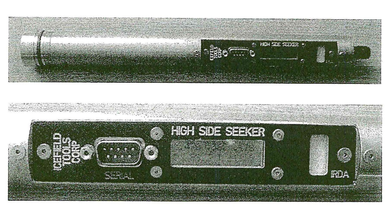
The tool that was produced and tendered in evidence was in pieces with the electrical and display features separate from the cylinder.
353 The structure of this section of my reasons is as follows: a summary of the evidence; a statement of the relevant principles; a summary of the submissions of the parties; and analysis.
354 Dr Erik Blake is the president and founder of Icefield Tools. He swore three affidavits which comprised his evidence-in-chief and he was cross-examined by counsel for AMC. He gave evidence of the factual matters supporting Globaltech’s novelty case. In addition, he was provided with the Patent before he swore his first affidavit and he gave expert evidence that the High Side Seeker tool and the webpages disclosed the integers of claims 1, 2, 33 and 34 of the Patent and he gave evidence as to the meaning of certain phrases in the claims.
355 It is necessary for me to go through the evidence carefully and at some length for the following reasons. Globaltech accepts (as it must) that Dr Blake’s explanation of the High Side Seeker tool at the PDAC conference is critical to the acceptance of that aspect of its case. It submitted that Dr Blake was not challenged in cross-examination about his explanation. Indeed, there was no attack on his credit. AMC accepted that it did not cross-examine Dr Blake on his explanation. However, it submitted that Globaltech bore the onus on novelty and that, when Dr Blake’s evidence is properly weighed, it does not support the conclusion that the claims in suit were anticipated by the High Side Seeker tool or even associated with it.
356 Dr Blake developed his own survey tools in connection with the task of drilling through ice. He was successful in his endeavours and he established Icefield Instruments. After a time, he saw an opportunity to move into the field of creating drilling technology for the mining industry. He established Icefield Tools in 2000. Since its establishment, Icefield Tools has developed and commercialised borehole survey technology for the mining industry.
357 Dr Blake gave evidence about two tools developed by Icefield Tools before the Priority Date. One was a borehole inclinometer first developed by Icefield Instruments in the early 1990’s and then its development was taken over by Icefield Tools in 2000. This borehole inclinometer was part of what Icefield Instruments and then Icefield Tools described as the MI-Series. There were different versions over the years, but Dr Blake said that the function of the inclinometers remained the same and that was as an electronic borehole survey tool which determined instrument orientation, including inclination angle, azimuth (being the direction which the tool is pointed in terms of compass direction), and roll orientation (toolface) using triaxial magnetometers and triaxial accelerometers. The relevant version of the borehole inclinometer in 2003 and 2004 was the MI-3 inclinometer. The MI-3 inclinometer was developed in 1999 and offered for sale and sold first by Icefield Instruments and then by Icefield Tools.
358 The MI-3 inclinometer is able to determine its inclination, roll orientation (high side) and magnetic azimuth. It has never been marketed for the purpose of core sample orientation and Dr Blake said that that was because Icefield Tools developed the High Side Seeker tool “for that purpose”. The MI-3 inclinometer is not alleged by Globaltech to be an anticipation, although Dr Blake said that it could be used to provide information as to roll orientation (or high side) upon including an appropriate mechanical coupling between the MI-3 and the core sample.
359 Dr Blake described the equipment which comprises the MI-3 inclinometer. I do not need to set this out, other than to note that it includes a RTC so the samples can be time-synchronised with the computer at the surface.
360 Dr Blake gave unchallenged evidence about how the MI-3 inclinometer operated and it is of assistance to summarise this because it is said that the High Side Seeker tool worked in the same way as the MI-3 inclinometer, and because the MI-3 inclinometer is also described in the documents on Icefield Tool’s website. First, a clock on a computer or PDA or a wristwatch is synchronised with a clock in the MI-3 serial connection and a time interval for the desired readings is programmed. Secondly, the relevant measurements are recorded in the memory of the MI-3 at the predetermined intervals counted from when the surveying commenced and they are able to be retrieved later through the serial port. Thirdly, the operator enters timestamped depth information into the computer or PDA or a handwritten notebook. Finally, on completion of the survey, the MI-3 tool is removed from the hole and the downhole measurements and timestamped information taken at the surface is examined and correlated to determine depth, azimuth, inclination, and/or roll orientation at a particular time during drilling.
361 As I have said, Icefield Tools developed the High Side Seeker tool in 2003. Dr Blake described it as a simplified version of the MI-3 inclinometer and said that it worked in the same way as the MI-Series inclinometers, save that it did not have an azimuth sensor.
362 Dr Blake described the equipment which comprises the High Side Seeker tool. Again, it is not necessary for me to set out the details, other than to note the presence of a RTC so that samples could be time-synchronised with the computer at the surface. He described how the tool would be operated. He accepted that it was appropriate to describe the use of the tool in terms of “would be” because at the time of the PDAC conference in March 2004, the High Side Seeker tool had not been used to orientate core.
363 Dr Blake said that the High Side Seeker tool was first offered for sale to the public in March 2004 at the PDAC conference. Dr Blake explained that the absence of an azimuth sensor in the tool allowed the tool to be smaller in size in the core drill tube than the MI-3 tool thereby allowing more space in the tube for core sample. Dr Blake said that the High Side Seeker tool measures inclination or dip and roll orientation. He said that the tool was intended as an Original Equipment Manufacturer (OEM) module that could be incorporated into third party equipment to solve a number of problems relating to drilling and borehole surveying. He said that one of these applications for which Icefield Tools developed the High Side Seeker tool was for use in determining core sample orientation. He said that he promoted this application at the PDAC conference in 2004 and on the Icefield Tools website.
364 Dr Blake also produced a brochure that he prepared for the High Side Seeker tool which is dated 2007. He could not recall if a brochure in this form was available before 3 September 2004, although he could recall that there was no difference in the way the High Side Seeker tool operated in 2004 and in 2007 as no further development of the product occurred after 2004.
365 Dr Blake’s description of the operation of the High Side Seeker tool for a core orientation application was as follows. First, the High Side Seeker tool would be introduced into the core barrel which entered the borehole during drilling. Dr Blake said that friction prevents the core sample from rotating in a freely rotating core barrel during drilling and after core break, but that sometimes the core does snap and/or rotate within the barrel. He said that it was useful to have some method to mark the core as it enters the core barrel during drilling. He said that one method of doing this was the use of a series of three scribes arranged around the core barrel, which scribe marks along the side of the core as the core enters the core barrel. He described the scribes as a “backup measure” in case the core inadvertently rotated during drilling, or after core break. Secondly, a clock on a computer or PDA, or a wristwatch, would be synchronised with the clock in the High Side Seeker tool using a serial connection, and in addition, a time interval for the desired readings was programmed. Thirdly, measurements of inclination and roll orientation would be recorded in the memory of the High Side Seeker tool via the accelerometer and the microprocessor predetermined intervals of five seconds counted from when the survey commenced and could be later retrieved through the built-in LCD screen or via the serial port. Fourthly, the operator entered time-stamped information via the computer or PDA or handwritten notebook about the instrument in the hole or other drilling events, such as core break as the drilling proceeded. Finally, at the completion of the drilling (after core break), the downhole tool would be removed from the hole and the downhole measurements and the time-stamped information taken at the surface would be examined and correlated to determine information and roll orientation at a particular time during drilling. Dr Blake said that the High Side Seeker tool could be used stand alone, with programming and data retrieval done through the built-in LCD, or one could use an external computer attached to one of two serial ports to perform these functions.
366 Dr Blake said that the time-stamp at or after core break is correlated with the downhole data at that same time to then determine the inclination and roll orientation at core break.
367 The PDAC is the leading international trade show for mining professionals and members of the PDAC and non-members may attend. Dr Blake attended the PDAC conference between 7 March and 10 March 2004 and the High Side Seeker tool was on display.
368 As part of the PDAC conference in 2004, the Canadian Association of Mining Equipment and Services for Export (CAMESE) sponsored an organised series of public technical talks called the Exhibitor’s Innovation Forum. Dr Blake said that the purpose of the CAMESE talks was to promote mining technology and products originating in Canada to overseas markets, including Australia. He explained that the talks were given in an open area of the convention on the conference floor and were accessible by any of the visitors and participants at the show. He explained that rows of chairs were set up in front of the presentation screen and presenters were able to showcase their technology to potential customers. Dr Blake said that he gave a presentation regarding the High Side Seeker tool and the MI-3 tool to participants at the PDAC conference in 2004. The title of his presentation was “New Directions in Borehole Surveying”. Dr Blake said that he spoke about new electronic survey tools, including the MI-3 range and the High Side Seeker tool. The overview of his talk was “Next-generation electronic survey tools offer new surveying methodologies that improve data quality, provide more information and reduce costs. ITC can change the way you survey holes”.
369 Dr Blake produced the PowerPoint presentation that he displayed to attendees during his talk. That presentation referred to other products and contained photographs of the High Side Seeker tool and referred to “Core Orienting, Directional Drilling”. Dr Blake explained that there were people standing behind the rows of chairs during his talk because all the chairs had been filled and that he estimated that there would have been about 50 to 60 attendees at his talk. He is confident that his competitors from Reflex Canada and others would have been present at his talk. In addition to his talk, Dr Blake manned a booth displaying tools of Icefield Tools, including the High Side Seeker tool. He said that he had an operating prototype of the tool. He said that he showed it to potential clients who came by his booth and explained to them how it worked. He talked to the potential clients in terms of supplying the High Side Seeker sensor units as OEM modules that could be incorporated into end-user equipment. Dr Blake said that he regarded his presentation and display of the High Side Seeker tool as a public viewing of the tools he had developed and he said that he did not require anyone to give any undertaking as to confidentiality as to what they saw or what he explained to them about the features of the devices, or what he said and showed in his presentation.
370 Before 3 September 2004, Dr Blake was responsible for preparing the promotional material and updating the website for all Icefield products, including the MI-Series range and the High Side Seeker tool. Dr Blake produced what he described as brochures and information that he prepared before 3 September 2004 on the MI-3 and High Side Seeker tools which brochures and information were on the Icefield Tools website as at 3 September 2004. I will refer to this material as the promotional website material. Dr Blake said that he had no reason to doubt that the promotional website material he produced was available for access by any member of the public from no later than 7 June 2004. Dr Blake explained that, as far as the High Side Seeker promotional material is concerned, he prepared the material to promote the High Side Seeker tool before he launched it at the PDAC conference in March 2004.
371 The following statements appear on the first page of the promotional website material:
Electronic Survey Tools Since 1990
• The MI-3 series inclinometer/deviation tools can be used in singleshot, multishot, and/or cable (real time) modes. It is suitable for use in mining, oil&gas, and geotechnical applications
• Exhibited at PDAC in March 2004, the new HIGH SIDE SEEKER is a simplified version of the MI3 tool. It is used to provide highside (or toolface) data was well as dip/inclination for a variety of applications.
The promotional website material then deals with the MI-3 digital borehole survey tool. The material then addresses the High Side Seeker tool and contains the following statements:
Like its big brother, the MI3 survey tool, the HIGH SIDE SEEKER is an electronic multishot tool – it operates in the same way as the MI3 with the exception that it has no azimuth sensor.
The HIGH SIDE SEEKER contains a three-component accelerometer package, so that it can provide dip and gravitational high side (toolface or roll orientation) in all orientations. High side is measured relative to a location mark on the instrument barrel.
The HIGH SIDE SEEKER has a variety of applications. For example:
• electronic dip meter.
• high side determination for core orienting work.
• complementing data from other downhole geophysical tools.
• high side determination for legacy survey tools.
The HIGH SIDE SEEKER can be configured in a number of ways to suit different applications…
Configuration: Depending on the application, the HIGH SIDE SEEKER is run with shock absorbers, pressure housings, and/or thermal shields.
The material contains details of the specifications of the tool, including a reference to a reading interval of “5s minimum”.
372 Dr Blake explained that time interval measurements (used in both the MI-3 tool and High Side Seeker tool) have been in use since at least the 1950s when Sperry-Sun introduced their photomechanical survey tool. He said that the term “multishot” was introduced by Sperry-Sun and has since become a generic term for borehole survey instruments that make interval readings. He said that almost all borehole survey tools capable of making more than one reading had worked using timed interval readings, and synchronising those timed interval readings with time-stamped depth and event information entered by an operator. He explained that the present industry term “to take a shot” means to take a time-stamp relating to particular orientation data immediately before breaking the core and that it originates from these earlier camera-based systems. Dr Blake explained that he did not file any patents for the MI-3 tool or High Side Seeker tool because he did not think that there was anything patentable about them.
373 As I have said, Dr Blake read the Patent before he swore his first affidavit and he considered claims 1, 2, 33 and 34. He considered that the MI-3 tool and the High Side Seeker tool had the combination of features in these claims. He produced tables which explained how he had reached that conclusion. In short, he considered that both these tools worked in the same way as the embodiment described in the Patent in that the orientation of the tool was recorded at predetermined time intervals while the core was being drilled, a timer on the surface was used to record the time of core break, and the two timing measurements were synchronised to determine the orientation of the core at the time of core break. Dr Blake, on reading the Patent, considered that it did not disclose anything new or inventive over what had already been developed in both the MI-3 tool and High Side Seeker tool before 3 September 2004.
374 Dr Blake supplemented his description of the High Side Seeker tool in a later affidavit. He said that prior to entering the borehole, one or more toolface offset measurements are made to establish the angular offset between the High Side Seeker’s internal reference, the High Side Seeker’s pressure housing, a reference mark on the inner tube, and/or any core marking apparatus, for example, scribes. He said that these measurements are made using the High Side Seeker’s normal interval timed measurements with the inner tube in a roughly horizontal position.
375 Dr Blake said that while the PDAC conference was targeted to people operating in the field of mining, people also attend from the oil and gas industry, and that over the years, he had seen repeated interest in his equipment from the oil and gas industry. He said that one reason for this was because the narrow diameter of the MI-3 tool was of interest to people working in oil and gas for certain applications.
376 Dr Blake said that the purpose of having a booth at the conference was to interest people in the products of Icefield Tools. He said that at the end of his talk at the Exhibitor’s Forum, he invited people to visit his booth to see both the MI-3 tool and the High Side Seeker tool. He said that he gave a demonstration of the High Side Seeker tool to approximately a dozen people who attended at the booth over the course of the four day conference, and a demonstration of the MI-3 tool to approximately 80 to 100 people who visited his booth over the course of the four day conference.
377 Dr Blake described what he did when he gave a demonstration of each of the tools. He said that he explained what each tool could do, how each tool worked, and the different applications for which each tool could be used. He said that he took each person to the physical sample of each tool and pointed out features of the device and talked about how it worked.
378 It is significant for reasons which will become clear that Dr Blake said that, in relation to the High Side Seeker tool, the features that he pointed out to people attending the booth included: first, the fact that the High Side Seeker tool could take readings of inclination/dip and roll orientation at regular time intervals; secondly, the fact that the tool processed data on board; and finally, the fact that it displayed orientation readings on an internal LCD display. Dr Blake said that in relation to the different applications for which the High Side Seeker tool could be used, he discussed core orienting applications, providing high side (roll angle) measurements on legacy instruments and deviated drilling.
379 Icefield Tools did not have any brochures prepared for the High Side Seeker tool at the PDAC conference in March 2004 because the prototypes had only been completed shortly before the conference. However, Dr Blake handed out business cards which included the Icefield Tools’ website address.
380 Dr Blake explained that on the Icefield Tools’ website the company used both terms “dip/inclination” when describing the features of the tools. “Dip” is typically used in mining to describe the inclination of the tool from a zero angle at horizontal, whereas in oil and gas, the term “inclination” is typically used to describe this same parameter but relative to zero at vertical instead of horizontal. Both terms were used because the MI-3 tool and High Side Seeker tool could be used for various applications.
381 Dr Blake identified points where he disagreed with Professor Tapson including the following: time synchronisation; use of scribe knives; fixed relation and scribe knives; reorienting the core sample; scribe knives in the MI-3 and High Side Seeker tools; MI-3 tool used for core orientation; photographs of the High Side Seeker tool; real orienting features; and tables 8, 9 and 10.
382 As I have said, Dr Blake gave his expert opinion as to the meaning of the phrase in claim 1 of the Patent, “during said drilling”. I have already addressed that evidence (at [274]).
383 It is instructive in terms of understanding how AMC puts its case on novelty and the issues which arise to note the following matters which emerged from Dr Blake’s cross-examination:
(1) Dr Blake said that he did not have much experience with drilling and coring in the petroleum industry;
(2) The MI-3 tool was an instrument for measuring the trajectory of bore holes; it was never designed for core orienting;
(3) A component called a muleshoe could potentially be used by the MI-3 tool to engage equipment down the hole;
(4) As an OEM, the High Side Seeker tool was a component intended for incorporation into other equipment in order to be of use in a particular application; it would need to be developed further by being incorporated into third party equipment for particular applications;
(5) In 2004, a User Guide and a Quick Start Guide did not exist for the High Side Seeker tool;
(6) The tool displayed at the PDAC conference was a prototype or first exemplar (fully functional, according to Dr Blake) of an OEM module;
(7) The High Side Seeker tool prototype that was displayed at the PDAC conference could not be used to orient core without further development by being incorporated into some other piece of equipment, although Dr Blake said that the modifications would be very minor;
(8) The High Side Seeker tool had not been used to orient core before the PDAC conference in March 2004 and was not used for that purpose at the conference;
(9) In order to be functional, there would need to be a coupling or other piece of equipment between the High Side Seeker tool and the core barrel and the tool would need a pressure housing;
(10) The outer sleeves of the pressure housing are not shown in the photographs;
(11) Scribe knives provide “supplemental” information for reconstructing a broken core;
(12) In the photographs of the partly dismantled tool which were produced to the Court, the outer sleeve of the pressure housing is not shown; there is no mounting means for attachment to the core drill shown; the tool as shown in the photographs has no mark on it from which to measure a toolface offset; and there are no complete suitable fittings in the housing for attachment to a back-end assembly;
(13) If a pressure housing existed in March 2004, it would have been a cylindrical piece of steel which would have covered the prototype;
(14) The electrical wires would have been potted in the final version of the tool. They are not potted in the prototype produced to the Court;
(15) The offset measurements to which Dr Blake referred need to be done because different components are likely to be at an angle to each other. Dr Blake said that there were three angles that “you need to add up to produce the correction angle to find the high side of the core”; instruments such as a goniometer or laser may be used in connection with this process;
(16) The LCD display in the cut-out part of the inner housing shows a toolface grav reading. In order to see the display, the external pressure sleeve would need to be removed. Whether the High Side Seeker tool would also need to be uncoupled from the inner tube of the core drill would depend on the arrangement and would not be necessary if the tool was attached to the top of the inner core tube. That was not something actually done at the PDAC conference, that is to say, it was not attached. Dr Blake did not rely on the tool necessarily being still coupled to the inner tube when the core was oriented;
(17) The LCD display screen does not display an arrow pointing in the direction in which the tool and consequently the inner tube of the core drill should be rotated to achieve orientation of the core. Nor were there other indicators such as flashing lights that would get faster as the tool and the inner tube were rotated closer to the orientation at the relevant time; and
(18) Dr Blake regards Icefield Tools as a highly innovative company in the field.
384 In re-examination, Dr Blake said that the High Side Seeker tool can be used for a variety of applications, the modifications that would be necessary for the High Side Seeker tool to be used to orient core were threads for pressure sleeves and an external mark on the tool to use a high side reference and that scribe knives provide a supplementary method of orienting core should it be broken into pieces.
385 Before turning to examine the relevant principles, it is important to state clearly the factual context in which the issues arise. The claims in suit are method and system claims. Globaltech relies on two separate and distinct public disclosures.
386 First, the public disclosure at the PDAC conference in March 2004 consisting of the display of the High Side Seeker tool and Dr Blake’s explanation about how it would or could work. As I have said, both elements are part of Globaltech’s case and I think a necessary part of its case. The mere display of the tool does not and I do not think could be sufficient. The tool had never been used for core orienting and was not used in that way at the conference. This is not a case of anticipation by a prior use.
387 Secondly, Globaltech relies on the public disclosure of the methods and systems of the claims in suit by the promotional website material. There is an issue here about how the material was arranged on the website – about which there is no evidence – and whether it is appropriately characterised as a single document or two or more related documents which a person skilled in the art would treat as a single source of information.
388 The onus is for Globaltech to establish that there was a public disclosure of the method or system in the claims in suit. The issue is to be determined through the eyes of the person skilled in the art. There is no issue here about whether the disclosure was public or made under an obligation of confidence. Such disclosure as was made, was a public disclosure.
389 The test for novelty is the same for a prior act as it is for a prior document. The test is the reverse infringement test, that is to say, whether the alleged anticipation would, if the patent were valid, constitute an infringement (Meyers Taylor Pty Ltd v Vicarr Industries Ltd [1977] HCA 19; (1977) 137 CLR 228 at 235). The prior publication must contain a clear description of, or clear instructions to do or make, something that would infringe the patentee’s claim if carried out after the grant of the patentee’s patent. The patentee’s claim will have been anticipated if carrying out the directions contained in the prior inventor’s publication will inevitably result in something being made or done, which if the patentee’s patent were valid, would constitute an infringement of the patentee’s claim (General Tire at 485-486).
390 The evidence of prior use may be oral evidence of witnesses to the alleged use based on their recollections of events years, sometimes many years, beforehand. Those recollections may be faulty and may be influenced by developments of which the witnesses have become aware since the relevant date. Such evidence must be approached with particular caution and bearing in mind that it is for the party asserting invalidity to establish a clear case of invalidity. I take the liberty of repeating what I said in Aspirating IP Limited v Vision Systems Limited [2010] FCA 1061; (2010) 88 IPR 52, I said (at [200]-[202]):
The correct principle is that a prior public use must be strictly proved and evidence which is not corroborated must be scrutinised with care, particularly where it is evidence of events which occurred many years ago. In Commonwealth Industrial Gases Ltd v M.W.A. Holdings Pty Ltd (1970) 180 CLR 160 (at 165-166) Menzies J said:
“It is not that I dismiss the evidence as deliberately untruthful — although I am disposed to think that the evidence relating to Ex 8 and Ex 9 — which was a less than accurate representation of Ex 8 — was not wholly frank — it is rather that I cannot accept as reliable, oral evidence relating to particular pieces of equipment to which some reference has been found in the records of the defendant company, and then, as if by unaided recollection of observations made up to twenty-eight years ago, that equipment has been identified and described by the witnesses. It is apparent that during the long period since the equipment was seen, the witnesses must have looked at hundreds, if not thousands, of unremarkable pieces of similar equipment, and I have no confidence in their stated recollections of particular pieces of equipment among those numbers.”
In Nicaro Holdings Pty Ltd v Martin Engineering Co (1990) 16 IPR 545 at 556-557 Gummow J said that proving an alleged anticipation by the recollection of witnesses and by drawings in catalogues and brochures is to be approached with “some caution”.
In Windsurfing International Inc v Petit (1983) 3 IPR 449, Waddell J (at 489) referred to the need to scrutinise evidence of an alleged prior public use with great care and said that such a use should be strictly proved.
(see also Old Digger Pty Ltd v Azuko Pty Ltd [2000] FCA 676; (2000) 51 IPR 43 at [156]; Beadcrete Pty Ltd v Fei Yu trading as Jewels 4 Pools (No 2) [2013] FCA 187; (2013) 100 IPR 188 at [100].)
391 The need for care in examining the evidence applies, arguably even more so, where the prior disclosure includes as a critical element, an explanation how a method not previously carried out, would or could be carried out.
392 In Insta Image Pty Ltd v KD Kanopy Australasia Pty Ltd [2008] FCAFC 139; (2008) 239 FCR 117 (Insta Image), the Full Court of this Court was called upon to decide whether the prior display of a collapsible canopy amounted to the making of information “publicly available” before the priority date. The Court identified the relevant principles in the following passage (at [124]):
In respect of the issue whether information was “publicly available” before the priority date, the following principles emerge from the cases:
• The information must have been made available to at least one member of the public who, in that capacity, was free, in law and equity, to make use of it (PLG Research Ltd v Ardon International Ltd [1993] FSR 197 at 226 per Aldous J cited in Jupiters at [141]). (This test of communication to a member of the public who is free in law or equity to use the information as he or she pleases had been enunciated by the English Court of Appeal as early as 1887 in Humpherson v Syer (1887) 4 RPC 407 at 413 per Bowen LJ.)
• It is immaterial whether or not the invention has become known to many people or a few people (Sunbeam Corporation v Morphy-Richards (Aust) Pty Ltd (1961) 180 CLR 98 at 111 per Windeyer J). As long as it was made available to persons as members of the public, the number of those persons is not relevant. Availability to one or two people as members of the public is sufficient in the absence of any associated obligation of confidentiality (Fomento Industrial S.A. v Mentmore Manufacturing Co Ltd [1956] RPC 87 at 99–100; Re Bristol-Myers Co’s Application [1969] RPC 146 at 155 per Parker LJ).
• The question is not whether access to an invented product was actually availed of but whether the product was made available to the public without restraint at law or in equity (Merck & Co Inc v Arrow Pharmaceuticals Ltd (2006) 154 FCR 31 (Merck) at [98]–[103]).
• In order to be “available”, information said to destroy novelty must be of a kind that would disclose to a person skilled in the relevant art all of the essential features or integers of the invention (cf RD Werner & Co Inc v Bailey Aluminium Products Pty Ltd (1989) 25 FCR 565 at 593–594).
• In order to be “available”, information said to destroy novelty must “enable” the notional person skilled in the art at once to perceive, to understand, and to be able practically to apply the discovery, without the need to carry out further experiments in order to arrive at that point (Stanway Oyster at 581–582).
393 In Insta Image, it was not suggested that the person skilled in the art would not glean all that was to be gleaned from a simple visual inspection of the canopy framework. By contrast, in Jupiters v Neurizon, the Full Court was not prepared to conclude that the party asserting a lack of novelty had discharged the onus of establishing an enabling disclosure by a mere observation of electronic gaming systems or devices in the absence of evidence from a person skilled in the art of what he or she would have gleaned from such observations.
The Submissions of the Parties
394 Globaltech made the following submissions about the evidence and the conclusions which should be drawn from it.
395 First, Globaltech submitted that it was significant that the actual High Side Seeker tool on display or its equivalent was produced to the Court and the Court was not restricted to an oral description of the tool. The prototype was a mature piece of engineering, but, in any event, there is no need for a mature piece of engineering because the claims in the Patent do not involve such a piece of engineering.
396 Second, Globaltech submitted that Dr Blake gave evidence that the tool was promoted for use in determining core sample orientation, that is, for determining high side core orientation. The fact that the tool did not have an azimuth sensor is significant because that fact would have revealed to the person skilled in the art that the tool was to be used as a method for core orientation because there must be an azimuth sensor for borehole surveying.
397 Third, Globaltech submitted that Dr Blake was an honest and credible witness. He was independent and he had developed the tool himself. He expressed the opinion that the High Side Seeker tool (and the MI-3 tool for that matter) had all of the features of the claims in the Patent which he addressed. Dr Blake was not challenged in cross-examination about a number of matters in his evidence-in-chief. He was not challenged on his evidence-in-chief as to how the High Side Seeker tool operated and the fact that he explained the device to potential customers at the PDAC conference. AMC’s attempts to prove that the tool’s use in core orientation was hypothetical are irrelevant because, in light of Dr Blake’s evidence, that does not matter for the purposes of an anticipation. Globaltech submitted that it does matter whether or not there had been actual use of the High Side Seeker tool for core orientation. In short, Dr Blake’s evidence about disclosure stands unchallenged. There was nothing confidential about the disclosure, a point reinforced by Dr Blake’s evidence that he did not think that there was anything about the tool which could be the subject of a patent.
398 Fourth, Globaltech submitted that it is important to note Dr Blake’s description of the equipment which comprises the High Side Seeker tool includes a RTC so that samples could be time synchronised with the computer at the surface. Dr Blake described how the tool could be used for a core orientation application.
399 Fifth, Globaltech referred to step 4 in claim 1 of the Patent, namely “removing the inner tube with the core sample held therein in fixed relation to it, from the body of material”. It referred to the references in the body of the Specification to “The orientation of the orientation device 10 corresponds to the orientation of the lower part 36b of the inner tube assembly 36 which in turn corresponds to the orientation of a core sample progressively entering the inner tube assembly 36, as the lower part 36b does not rotate relative to the core sample” and a little later to “As previously described, the fictional engagement of the core and the inner tube assembly 36b along with bearing 40 allows the lower part of 36b to rotate relative to the outer tube assembly 34 but not relative to the core sample”. In the context of that matter, Dr Blake said that scribes can be used as a “backup measure”. Globaltech also pointed out that the tool had a time interval for the desired readings and measurements of inclination and roll orientation recorded through the memory and that they are later retrieved.
400 Sixth, Globaltech submitted that there is a visual indication of orientation and that may be seen in the photographs of the High Side Seeker tool. That meets the requirement of an “indication” in the claims in suit. That word should be given a broad meaning in accordance with the meaning given by Professor Tapson as follows:
indication, being an indicator (such as a sign, dial or other indicator) that indicates to the operator the orientation of the core sample in space.
401 Seventh, Globaltech referred to Dr Blake’s description of the operator entering time-stamped information via the computer/PDA or handwritten notebook about the instrument in the hole or other drilling event such as core break as the drilling proceeded and then a correlation between the downhole measurements and time-stamped information to determine inclination and roll orientation at a particular time during drilling and submitted that that is an explanation or description of how, in fact, the invention described in the Patent works.
402 Eighth, Globaltech referred to Dr Blake’s evidence that there needed to be one or more toolface offset measurements to establish the angular offset between the High Side Seeker’s internal reference, the High Side Seeker’s pressure housing, a reference mark on the inner tube and any core marking apparatus, for example, scribes. Furthermore, Dr Blake’s view was that the High Side Seeker tool and the MI-3 tool included the features of claim 4 in the Patent.
403 Ninth, Globaltech submitted that the Court should reject AMC’s attack on the efficacy of the display and demonstration of the High Side Seeker tool on the basis that various technical components of it were not displayed (e.g., coupling of the inner tube and pressure housing and the outer sleeve and the female threads and the O-ring). There is no mention of any particular means of attaching the tool to the inner barrel of the core drill. The fact is, submitted Globaltech, that Dr Blake said that very minor modifications were required in order to attach the inner tube to the back of the assembly and Mr Brown did not indicate any difficulty in the attachment of the tool to the back-end of an assembly. Furthermore, there is nothing in the claims about that connection and, in fact, the Specification states:
Apart from modifications to the inner tube assembly 36 to accommodate the orientation tool 10, and also the spacer 42 provided in the outer tube assembly 36, the core drill 12 is of conventional construction and operates in a conventional way.
Globaltech submitted that any difficulties in the attachment are irrelevant because the claims are not to the means for attachment of a core orientation device to an inner tube assembly. All that is required by the claims is that the tool has the purpose of indicating core orientation and it is plain that that is the case. Furthermore, the claims are not about male and female threads.
404 Tenth, in response to what it perceived to be AMC’s suggestion that scribe knives are necessary, Globaltech submitted that the Court should accept the evidence of Dr Blake that they would only be used as a backup measure. In support of this conclusion, Globaltech submitted that if they were a primary measure, then one would have expected to see them in the promotional website material and there is no reference to them in that material. The whole issue about scribe knives being used with the High Side Seeker tool in some instances is a distraction. Both Mr Brown and Professor Tapson agreed that the claims in the Patent do not require the use of scribe knives. Furthermore, Mr Ayris gave evidence that he understood that scribe knives are used for quality assurance.
405 Eleventh, Globaltech submitted that the question of the core sample being fixed in relation to the inner tube is obvious. There is a need for this fixed relationship in order to get the orientation. The Patent does not describe a means for this fixed relation other than the frictional engagement of the core and the inner tube assembly. That allows it to rotate but not relative to the core sample. A person skilled in the art who has had the operation of the High Side Seeker tool explained to them would understand that there is a need for frictional engagement at the end in order to get correct orientation data. That is the purpose of the tool and that is how Mr Brown and Mr Ayris understood it.
406 Twelfth, Globaltech submitted that the method claims and the system claims are all method claims. The system itself uses a product which is a core drill, or can use a product which is a core drill, that is one of the dependent claims. Globaltech submitted that to say that a system that uses a product is a product itself is a nonsense.
407 Thirteen, Globaltech submitted that the promotional website material was a documentary anticipation. It is important for me to note at this point that the promotional website material was “EB1” to Dr Blake’s first affidavit. The promotional website material was also Document No 16 in the Court Book, but that document included other documents as well. The documents which were said to be a documentary anticipation were only those documents comprising “EB1”, what I have called “the promotional website material”. Globaltech relied on the evidence of Mr Ayris who said that he reviewed the materials and concluded that all of the claims in the Patent were disclosed. Globaltech also relied on a table which it had handed up as an aide memoir which contained a comparison between the claims in the Patent and the promotional website material. Globaltech submitted that certain features are described by reference to the description inherently disclosed and it submitted that the feature is implicitly disclosed to the person skilled in the art. Globaltech submitted that there can be an implicit disclosure and it referred to the decision in Danisco A/S v Novozymes A/S (No 2) [2011] FCA 282; (2011) 91 IPR 209.
408 Fourteenth, Globaltech submitted that Mr Brown accepted that the High Side Seeker tool used synchronised timing, as did Mr Edmonds. The High Side Seeker tool measures things at predetermined time intervals and it has the necessary accuracy on the clock of two seconds per day. It has a surface unit, being a computer, where the operator inputs the specific time and finally, it has the necessary sensors to determine orientation. Globaltech appeared to accept that there is no mention of inputting a specific time beyond a reference time representative of when the core sample is separated from a body of material. However, it submitted that that act is implicit in the notion of the synchronised timing system. A synchronised timing system involves synchronising the timer at the surface and the timer down the hole. Once it is understood that the system is a synchronised timing system, then it is implicit that there is a time of core break that is inputted at the surface. The materials describe the fact that you input it into a computer because they refer to a computer at the surface.
409 Fifteenth, Globaltech submitted that Mr Ayris had given evidence that the materials mention the PDAs and the computers and an LCD display, and that a person would understand from that, that the device displays orientation measurements visually. Globaltech submitted that it does not matter that the disclosure is not in the same words as it is in the claims. The fact that the material refers to computers and an LCD display and that orientation data is provided is sufficient. The fact that the precise words “visual display orientation” are not used is not by any means fatal.
410 AMC made the following submissions about the evidence and the conclusions to be drawn from it.
411 First, AMC makes a number of general points which are important to its case on novelty. It submitted that it is not sufficient to have some general disclosure which would not inevitably lead to the carrying out of the method or system that is said to have been anticipated. There must be an express disclosure of all the features of the method or system in combination. The evidence about disclosure in this case does not lead to the conclusion that the flag was clearly planted at the invention. Put another way, the alleged anticipation must provide clear and unmistakable directions to do what the patentee has claimed, or in the alternative, it must be inevitable that by following the directions in the prior disclosure, the claimed invention will be the result. Where a prior art disclosure contains a direction that is capable of being carried out in a manner which would infringe, but which would be at least as likely to be carried out in a way that will not infringe, there is no anticipation. The reverse infringement test means that infringement is necessarily entailed in carrying out the directions in the alleged anticipation.
412 AMC submitted that even on Globaltech’s case, the High Side Seeker tool was a piece of equipment that required development or modification of some kind in order to be able to be used in a method in accordance with claim 1, or to constitute a system in accordance with claim 33. The modifications and developments which would need to be carried out would be necessary in order for all the integers of claim 1 and 33 to be present.
413 AMC submitted that Globaltech had approached the issue in a very general way by submitting that everything needed was disclosed. However, there is no specificity in the evidence as to the disclosure. The promotional website material does not meet the relevant test. The evidence of Dr Blake as to the features of the High Side Seeker tool and the display of it is not sufficient. It is not enough to say that one of the tool’s potential applications was core orientation. Even that approach in itself contemplates the possibility of more than one direction being taken and it might be used for something else, not core orientation. There is no specificity in the disclosure as to how it is said that the High Side Seeker tool would be used in core orientation.
414 AMC submitted that it is sufficient for the purposes of refuting Globaltech’s lack of novelty case that one way of potentially employing the High Side Seeker tool as a module incorporated into other equipment would have been with the use of a scribe knives system to orientate core in that way. The evidence of Professor Tapson and Mr Ayris describing how scribe knives work indicates that it is quite different to the way in which the invention which is described in the Patent works. Scribe knives systems do not rely on the core being held in fixed relation to the inner tube. To the contrary, they are used because the core moves in relation to the inner tube and it is necessary through a different process to that which is claimed in the Patent, to subsequently realign the various parts of the core using the scribes that have been made along the surface of the core. The argument is that even assuming that a skilled person was aware of the High Side Seeker tool and sought to use it for core orientation, the fact that they could have attempted to do so in this way means that the reverse infringement test is not satisfied and, on this basis alone, the disclosure would not be an anticipation
415 AMC submitted that there is no evidence of any device or system being used before the Priority Date which relied on the core being held in fixed relation to the inner tube as a means for orientating the core. In relation to the High Side Seeker tool, it was put to some of the experts in cross-examination that they knew that in order to orientate core, the core would need to be held in fixed relation, and the tool would need to be fixed to the core barrel in order to orientate it that way. However, those suggestions are based on hindsight, in the sense that they are made with knowledge of how the invention claimed in the Patent works. The prior art mechanical systems did not rely on orientating the core using the core barrel as a proxy for the orientation of the core. They mark the top of the core itself.
416 In a similar way, the systems used in the oil and gas industry that involved the use of scribe knives, did not rely on the core being held in fixed relation to the inner tube as a means of orientating the core. They did not use the inner tube as a proxy for the orientation of the core sample. By contrast, they involved taking the core sample out of the inner tube and having regard to the scribe marks made on the core sample as a means of orientating it. Globaltech’s whole approach to the disclosure in relation to the High Side Seeker tool is based on the false assumption that necessarily it would be intended to be used in the way that is subsequently claimed in the Patent involving the fixed relation and using the inner tube as a proxy for the orientation of the core sample. AMC submitted that that assumption is simply not made out in the evidence.
417 Second, AMC does not dispute that the prototype about which Dr Blake gave evidence was displayed at the PDAC conference. It did not challenge Dr Blake about that. However, it submitted that the evidence does not rise to the required level in terms of the detail as to what was actually disclosed, such that it could be said that there was a disclosure of the combination of features claimed in any one or more of the claims in the Patent. AMC submitted that the reason for the lack of detail is clear in that what was displayed was a component, an OEM component, a piece of equipment that would need to be incorporated into other equipment, third party equipment, if a person sought to attempt to use it to orientate core. This was something that was never done. There is a lack of specificity. The evidence does not descend to the level of detail of the integers of the claims and it does not address the fact that there would be more than one way of potentially attempting to use such a component to orientate core and it would not necessarily be the way which is claimed in the Patent. AMC handed up an aide memoir which compared the way in which Dr Blake addressed certain matters in his affidavit and the evidence he gave in cross-examination. It is clear that the MI-3 tool was never promoted for the purpose of core sample orientation and was not appropriate for core orientation because of cost and size. There were better options and Dr Blake’s knowledge of it for core orientation was hypothetical. His clients never used it for core orientation. The High Side Seeker tool was intended to be incorporated into third party equipment and it would need to be developed further once it was incorporated into that equipment. There was no user manual or guide for it in 2004 and it was a prototype. The fact that it could not be used to orientate core without further development is significant because it means that there is no clear disclosure of all of the integers of the method and system claims in the Patent. AMC submitted that Globaltech cannot rely on inferences or suggested inherent aspects of the disclosure and it is fatal to Globaltech’s case that this was not a product that could be used to orientate core without further development. The additional equipment needed before the High Side Seeker tool could be used in core orientation was a pressure housing and a suitable fitting for attachment to a back-end assembly. Dr Blake was unable to say with any certainty whether a pressure sleeve even existed as at March 2004.
418 Nor is it permissible to supplement an alleged anticipation by adding integers from common general knowledge. AMC submitted that that is what Globaltech seeks to do in this proceeding and that can be seen from an aide memoir put forward by Globaltech. AMC submitted that it is not sufficient to rely on Dr Blake’s view, which was based on his detailed and specialised knowledge of the High Side Seeker tool. The information that was made publicly available, either through the display of tool or the promotional website material relied on, must render the combinations claimed in the claims in the Patent not novel. It needs to be publicly available information, not merely Dr Blake’s own detailed knowledge of how he considered that the tool could be used.
419 AMC submitted that Dr Blake’s evidence about what he said about the High Side Seeker tool at the PDAC conference was extremely general. It was not a specific disclosure of a method of orientating core having all the features of a claim, let alone a system of doing so. Dr Blake did not say that he discussed any particular steps of the method with interested parties, and that type of evidence is necessary to establish an anticipation. AMC submitted that in this context, it is important to bear in mind that the tool on display and the tool produced to the Court had never actually been used to orientate core.
420 There was no visual indication because the High Side Seeker tool needed a pressure sleeve in order to protect it before it went down the hole. The pressure sleeve would be made of metal and one would not be able to see the display. The way in which real time orientation works is that the core is in the inner tube and the device is attached to the inner tube.
421 In order to orientate the core as at March 2004 using the High Side Seeker tool, one would have needed to have taken the toolface grav reading, which is a numerical reading on the display, and perform calculations using offset measurements which had previously been obtained. Dr Blake accepted that the High Side Seeker tool was not coupled to the inner tube when the core was reorientated in the process that he proposed. Furthermore, he accepted that the High Side Seeker tool did not have arrows or flashing lights, or any other visual indication to indicate the direction in which the inner tube should be reorientated.
422 Again, AMC makes the point that Dr Blake confirmed orally that the prototype could not be used to orientate core without further development by being incorporated into some other piece of equipment. It would be necessary to incorporate or attach the device, the component, into the assembly of the core drill in some way in order to attach it, either incorporating it into the inner tube or attaching it to the inner tube with appropriate couplings. There is no evidence that the manner of doing that was disclosed or discussed by him at the conference. When the matter was raised with Dr Blake, he said that he considered that it would be awkward to place the High Side Seeker tool in the inner tube and that that would have some disadvantages. There are no mounting means disclosed in the photographs and no suitable fittings for threads, or threads in the housing for attachment to the back-end assembly are disclosed. Dr Blake confirmed these matters in his oral evidence. AMC also referred to Dr Blake’s evidence that a pressure housing or outer sleeve would be necessary and that is not shown in the photographs. Dr Blake did not have a clear recollection as to whether it existed in March 2004 and, if it did, he said that it would have covered the display.
423 AMC makes the point about the prototype not being a production circuit board and that the orientation of core using the High Side Seeker tool involves the use of offsets and calculations and that is quite different to how the invention claimed in the Patent works.
424 AMC submitted that whether Dr Blake thought that scribe knives were essential or not is not to the point. The point is what would the skilled person have understood from what was displayed. AMC makes the submission that given the generality and vagueness of the evidence, one possibility is that the skilled person would consider that it would be necessary, given the absence of any means for attaching the High Side Seeker tool to the back of the inner tube which would lead to a means of using it in the way claimed in the Patent, to use scribe knives as were used in a good deal of the prior art relied on by Globaltech. If scribe knives were used, that is not a method that would rely on having the core sample held in fixed relation to the inner tube and orienting it in that way. Globaltech referred to Professor Tapson’s explanation of the distinction which it submitted was convincing.
425 AMC submitted that there is no evidence to suggest that the High Side Seeker tool comprised a system into which time measurements could be inputted. There is no evidence that it actually had any software at the relevant time, or that it had actually been implemented for that purpose.
426 Third, AMC submitted, with respect to claims 4, 16, 23 and 46, that there was no visual indication as required by those claims because there would be a pressure housing covering the LCD display.
427 Fourth, AMC submitted that the promotional website material produced by Globaltech is, in fact, a combination of documents. Furthermore, the materials comprising Document No 16 in the Court Book is an even larger combination of documents. Mr Edmonds and Mr Ayris were invited to make a mosaic out of the materials and that is what they did. Such an approach is not a permissible approach to novelty.
428 Fifth, AMC submitted that the high point of Globaltech’s case with respect to the promotional website material were those documents at pages 302-303 of the Court Book. It submitted that the reference to an application of high side determination for core orienting work does not come anywhere near a disclosure of the features of any of the claims. These pages do not describe how the High Side Seeker tool is to be used in core orientation. AMC relied on Professor Tapson’s evidence to the effect that the reference to high side determination does not indicate any particular method of core orientation. Furthermore, the documents do not address a means of attachment or coupling of the component to the inner tube of a core drill, how that is to be done and whether or not it is to be used in the manner of the method and system which is claimed in the Patent. AMC relied on the evidence of Mr Ayris who conceded that no method is disclosed in pages 302-303 of the Court Book and submitted that that concession is clearly correct. AMC submitted that the High Side Seeker tool is merely a component that will tell the operator where its high side is and it is not something that has been developed for orienting core and is not capable of doing it without further modification and development. There is no mention of inputting a specific time beyond a reference time representative of when the core sample is separated from the body of material. There is no instruction, no direction and nothing implicit in what is disclosed to the effect that the operator should be inputting a specific time to obtain an orientation measurement. One way of potentially orientating core would involve the use of scribe knives, although they are not mentioned. As Mr Ayris pointed out, one could potentially use it for a different application. In those circumstances, the test of inevitable result is not satisfied. Furthermore, AMC submitted that there is nothing about a visual indication in the material at pages 302-303 of the Court Book.
429 The issue is whether the person skilled in the art would be inevitably led to carry out the method or system in the claims in suit by what he or she heard and saw at the PDAC conference in March 2004 or by reading so much of the promotional website material that was a single document or two or more related documents within s 7(1)(b) of the Act. In neither case am I satisfied that that question should be answered in the affirmative.
The PDAC conference in March 2004
430 The standard of proof with respect to the facts surrounding the PDAC conference in March 2004 is, as it is in relation to all other issues in this proceeding, proof on the balance of probabilities. Furthermore, Dr Blake was not directly challenged as to the explanation he gave at the PDAC conference in March 2004. I say “not directly challenged” because AMC did challenge his evidence as to that matter to this extent. It submitted that weighing up all relevant matters, Globaltech had not discharged the onus it bore to establish a lack of novelty.
431 I have reached three principal conclusions. First, I am not satisfied that all of the integers in the method and system claims were publicly disclosed at the PDAC conference in March 2004. Secondly, the possible use of scribe knives with the High Side Seeker tool means that it was not an anticipation. Thirdly, even if there was a disclosure of the method claim in claim 1 and the system claim in claim 33, there was no public disclosure of the visual indication and direction in which the core sample should be rotated features in claims 4, 16, 23 and 46. In view of my first two conclusions, it is probably not necessary to deal with the third matter, but I do so for the sake of completeness.
432 My reasons for reaching the first conclusion are as follows. First, I must approach Dr Blake’s evidence bearing in mind that it was given some 13 years after the relevant events. I must also take into account the possibility that his evidence of what occurred in March 2004 has been unintentionally coloured by what he has learned since March 2004. Secondly, the methods and systems were not displayed at the PDAC conference in March 2004. Self-evidently, there was no core orientation at the conference. Furthermore, none of the methods or systems had been put into practice prior to March 2004. Thirdly, the High Side Seeker tool displayed at the conference was a prototype or first exemplar. I am not satisfied on the evidence that it included a pressure sleeve or at least the outer sleeve thereof and there was no indication as to its placement in the inner core tube or the means of attachment to the tube. The tool did not contain an external reference mark which was a necessary feature for the purposes of the angular measurements which must be performed and about which Dr Blake gave evidence. Although a relatively minor matter, the electrical components were not potted as would be necessary in a working tool. The significance of these matters is not that without them there could be no disclosure of the method and system claims in the Patent. The significance of these matters is two-fold. The first is that they throw doubt on the extent to which the skilled addressee would have understood the method and system. Secondly, they throw doubt on whether Dr Blake gave a clear description of the method and system claims in the Patent. Fourthly, the High Side Seeker tool had a number of applications of which the orientation of core was but one. Dr Blake gave evidence to that effect in both his evidence-in-chief and again in re-examination. Fifthly, and significantly, Dr Blake’s evidence about what he disclosed was very general. That is probably understandable in view of the passage of time, but it does not detract from the significance of this characterisation of his evidence. Dr Blake said in his first affidavit that he explained to potential clients how the High Side Seeker tool would work and repeated that in his third affidavit. Subject to what I say below, Dr Blake did not give evidence of what he said, or the effect of what he said, to any particular attendee at the conference. The Court is being asked to conclude that Dr Blake explained his opinion of how the tool would work for core orienting. I say “would work” not “worked” because it had not been used for that purpose. I am not prepared to draw that conclusion. The issue is the understanding of the skilled addressee, not Dr Blake’s understanding and I do not think the evidence is sufficiently clear, particularly in circumstances where he did give evidence that the features he pointed out included the following: (1) that the tool could take readings of inclination/dip and roll orientation at regular time intervals; (2) the tool processed data on board, and (3) the tool displayed the orientation readings on an internal LCD display and those features are not a disclosure of all the integers in the method and system claims in the Patent. Sixthly, there is no evidence from a person skilled in the art that all of the integers of the method and system claims in the Patent were disclosed to that person at the PDAC conference in March 2004. I should make it clear that I am not saying that Dr Blake was not a generally credible witness so far as his evidence went or that he was deliberately untruthful in anyway. I am saying that, having regard to the matters I have identified, I am not satisfied that the features or integers of the method and system claims were publicly disclosed at the PDAC conference in March 2004.
433 The reasons for the second conclusion are as follows. Dr Blake described scribe knives as a useful part of the method of use of the High Side Seeker tool, but a back-up method. I should at this point set out a description of the system of using scribe knives. Professor Tapson gave a description, which I accept, and which I set out rather than attempt to summarise (omitting cross references and references to supporting material):
The two issues above (rotation of the inner tube and inadvertent core separation) mean that, for scribe knife systems and methods, the inner tube and the core sample are not held in fixed relation. This lack of fixed relation is demonstrated by scribe marks that curve around the core sample.
The two features of the scribe knife systems and methods addressed the two issues above. First, the use of scribe knives created a permanent record of the relationship between the orientation tool and the core sample at the moment the sample was cut, while it was in its in situ orientation. This record (i.e., the marks or grooves) continued to be made even as the inner tube rotated and/or inadvertent core separation occurred. Secondly, the holding of the the (sic) orientation tool and the scribe knife (which are fixedly located at opposing ends of the inner tube) in a fixed and precise alignment with one another, ensured that the orientation measurements taken by the tool could be later related to the scribe marks, even as they curved around the core sample.
The next aspect of the scribe knife systems and methods was to associate the orientation data captured by the tool with drilling depth. During the core drilling process, the operator noted drilling depths and the corresponding times on a stopwatch, which was synchronised with the start time of the tool. Depth and time were correlated to identify orientation data recorded by the tool at each depth.
The final aspect of the scribe knife systems and methods was to re-orient the individual sections of the core sample to their in situ orientation using the correlated orientation data and depth measurements. This is discussed in detail, for example, in Henry and Skopec. The re-orienting process for the scribe knife method involves the following:
(a) The inner tube is cut open and the sections of core sample are laid out on a bench.
(b) The sections of core sample are re-assembled by matching their fracture faces and visible geology, to produce a reconstruction of a continuous interval of core sample, and are marked according to measured depth.
(c) A line is drawn along the length of all sections to preserve the reconstruction and to provide a reference for axial orientation. In Henry, this line is drawn prior to re-orientation, but in Skopec, the line is drawn after re-orientation and becomes the high side mark for the core sample. In both cases, the line is referred to as a “Master Orientation Line” (MOL).
(d) The orientation data for each separate section of core sample is identified. This requires the following process:
(i) The drilling depth for that section of core sample must be identified.
(ii) The time at which the section was drilled must be established.
(iii) The corresponding block of orientation data from the core orientation tool must be identified.
(iv) The roll orientation angle in the tool orientation data must be transferred to the core sample, with an appropriate offset for the angle between tool and scribe knife. This requires a goniometer – a mechanical or electronic tool which can indicate the angle between two features (in this case, the scribe line on the core, and the calculated high side of the core).
(v) At this point, a line could be drawn on the core section to indicate the in situ high side of the core.
434 I did not understand AMC to challenge Globaltech’s proposition that the mere fact that scribe knives were used with the method did not necessarily mean that the reverse infringement was not satisfied. AMC’s point, which I think is correct, is that the skilled addressee faced with the disclosure and the use of scribe knives and the measurements required in relation to the angle offsets would be, or may well be, led away from the invention which the held in fixed relation step (i.e., step 4) is an essential integer as is the fact that the inner tube is used as a proxy for the core sample. Also relevant is the real time orientation that takes place on the surface. The mechanical core orientation devices marked the core itself and the tools used in oil and gas exploration used scribe knives and there is no evidence that there were tools that relied on a held in fixed relation feature. To say it was implicit involves an impermissible use of hindsight based on the invention itself.
435 Professor Tapson explained the matter clearly in a passage in his evidence. Before setting that passage out, I should record the fact there was considerable debate before me as to which of Dr Blake or Professor Tapson had greater experience with scribe knives. Professor Tapson had no practical experience in the oil and gas industry before the Priority Date and he had acquired his knowledge after the Priority Date. Dr Blake disclaimed any detailed knowledge of the oil and gas industry. In the end, I do not think there was any convincing answer from Globaltech to the evidence Professor Tapson gave in the last answer in the following passage of evidence:
MS HOWARD: And, Professor Tapson, you would defer, wouldn’t you, to those with practical experience in the use of scribe knives?
PROF TAPSON: I think you’re going to expand on that a little. I would defer in what respect?
MS HOWARD: Well, in terms of opinions as to why scribe knives are used, you would defer to those who have practical experience with scribe knives.
PROF TAPSON: Your Honour, I would defer to an expert who understood the reasons why scribe knives were used and the entire process by which they are used, which is by no means simple, and which I have taken a great deal of time to understand. If it was merely someone who was putting a scribe knife device downhole then I would say possibly not.
MS HOWARD: Well, you wouldn’t put Dr Blake in that category, would you?
…
MS HOWARD: Thank you, Professor Tapson. And Dr Blake also gave evidence that scribe knives are used as a backup measure in the oil and gas industry, didn’t he?
PROF TAPSON: Yes.
MS HOWARD: And you would defer to his evidence on that issue because you do not have any practical experience.
PROF TAPSON: No, I would not. Your Honour, the – it’s not a – it’s not a sensible statement to say that scribe knives may be used to augment core orientation such as is described in the patent, and I will explain very clearly why. The scribe knives score the core as it is pushed into the core tube. They are not visible unless the core is removed from the core tube because they are inside the tube intrinsically – those marks. The patent requires the tube to be held in fixed relation to the core. So you cannot both have a method which requires the core to be removed from the tube, and a method which requires the core to be in fixed to the tube being compatible. And I would suggest that Dr Blake’s assertion that that was feasible illustrates that he possibly doesn’t understand the patented method.
436 As to the third conclusion, it is sufficient for me to say there was no disclosure of the visual indication as referred to in claims 4, 16, 23 and 46 of the Patent because there would be a pressure housing covering the LCD display in the case of the High Side Seeker tool.
437 I am not satisfied that Globaltech has established that there was a clear disclosure at the PDAC conference in March 2004 of the integers of the method and system claims in the Patent. The claims in suit did not lack novelty by reason of what was disclosed at the PDAC conference in March 2004.
The Promotional Website Material
438 It was not suggested that material on a website is not a document or documents for the purposes of s 7(1) of the Act (Acts Interpretation Act 1901 (Cth) s 2B). Nor was it suggested that all material on a particular website was a single document for the purposes of s 7(1)(a) or without more, a single source of information for the purposes of s 7(1)(b) of the Act. The difficulty for Globaltech is that there is no evidence as to how the information represented now by the documents comprising “EB1” was arranged on the website. It is clear enough from the authorities that it is not open to a person alleging a lack of novelty to create a mosaic of information from various documents.
439 Globaltech sought to overcome these difficulties by submitting that those documents dealing with the High Side Seeker tool and those dealing with the MI-3 tool were related documents within s 7(1)(b) because the material relating to the former refers to the High Side Seeker tool as being like its big brother, the MI-3 survey tool, in that it is an electronic multishot tool that operates in the same way as the MI-3 with the exception that it has no azimuth sensor. Furthermore, in the introductory part of the material, the High Side Seeker tool is described as a simplified version of the MI-3 tool and it is said that it can be used to provide high side (or toolface) data as well as dip/inclination for a variety of applications. Globaltech’s submission is that these cross references would be understood by the person skilled in the art as linking the documents and conveying to the reader that the features of the MI-3 tool were also features of the High Side Seeker tool.
440 I do not accept Globaltech’s submission that the documents are related documents within s 7(1)(b) of the Act. First, there is no evidence before the Court that a person skilled in the art would treat the documents as related documents. None of the experts gave evidence that they would treat the promotional website material as I have defined it as one document or as related documents which would be treated as a single source of information. Secondly, the material given to Mr Ayris and Mr Edmonds included documents in addition to the promotional website material. The additional documents were a document describing a method of operation of the MI-3 tool and the High Side seeker tool and a 2007 brochure for the tool (i.e., well after the Priority Date).
441 In my opinion, as far as the promotional website material is concerned, it is appropriate to focus on what is disclosed in the section dealing specifically with the High Side Seeker tool (pp 302-303 of Document No 16).
442 I accept Professor Tapson’s observation that reference to “high side” determination includes core orientation, but is not necessarily limited to that application.
443 It was clear by the end of the joint session of experts that Globaltech’s novelty case, insofar as it is based on the promotional website material, relies on a number of what it described as “implicit disclosures” or matters that it contends are matters of common general knowledge. Although the alleged anticipation is to be viewed through the eyes of the person skilled in the art, it is not permissible to add integers to the disclosure by reference to common general knowledge. Mr Ayris agreed in cross-examination that the promotional website material does not expressly disclose the following:
(1) a method whereby the High Side Seeker tool can be used to orient core;
(2) a particular means of attaching the tool to the inner barrel of a core drill;
(3) inputting a specific time beyond a reference time, representative of when the core sample is separated from the body of material;
(4) the core sample being held in fixed relation to the inner tube from the time of core break as a means of orienting core;
(5) a visual indication of the orientation of the inner tube and consequently the core sample at the time of core break; and
(6) the provision of a visual indication of the direction in which the core should be rotated in order to orient it.
Mr Edmonds gave evidence to similar effect. In my opinion, the absence of these matters is fatal to Globaltech’s submission that the promotional website material establishes a lack of novelty.
444 There are two further points which are similar to the second and third conclusions in relation to the alleged disclosure at the PDAC conference in March 2004. Although there is no reference to scribe knives, they may well occur to the skilled addressee as they did to Dr Blake and that would lead away from the invention as previously discussed. There is no disclosure of the visual indication and direction in which to rotate features in claims 4, 16, 23 and 46 of the Patent.
445 I reject Globaltech’s lack of novelty case.
446 Globaltech claims that the alleged invention in the claims in suit did not involve an inventive step as required by s 18(1)(b)(ii) of the Act. To be a patentable invention, the invention, so far as claimed in any claim, must, when compared with the prior art base as it existed before the priority date of the claim, involve an inventive step. Section 7(2) of the Act provides that an invention is to be taken to involve an inventive step when compared with the prior art base unless the invention would have been obvious to a person skilled in the relevant art in light of the common general knowledge as it existed in the patent area before the priority date of the relevant claim, whether that information is considered separately or together with the information mentioned in subsection (3). Section 7(3) provides as follows:
The information for the purposes of subsection (2) is:
(a) any single piece of prior art information; or
(b) a combination of any 2 or more pieces of prior art information;
being information that the skilled person mentioned in subsection (2) could, before the priority date of the relevant claim, be reasonably expected to have ascertained, understood, regarded as relevant and, in the case of information mentioned in paragraph (b), combined as mentioned in that paragraph.
447 Globaltech’s case is that the alleged invention identified in the claims in suit was obvious at the Priority Date to a person skilled in the art in light of the common general knowledge. In the alternative, it contends that the invention was obvious to a person skilled in the art in light of the common general knowledge and any one of the following: the Scientific Drilling marketing material; the High Side Seeker tool; or the High Side Seeker promotional website material. Globaltech alleged that the MI-3 tool was part of common general knowledge and did not argue that it was part of the information referred to in s 7(3), although AMC addressed it on this basis.
448 The Scientific Marketing material consisted of 10 pages which describe Scientific Drilling’s Electronic Multishot System. It is an agreed fact that the materials for the system marketed as the “Scientific Drilling Electronic Multishot System” by Applied Technologies Associates of California, USA was made publicly available in the United States of America in 1996.
Relevant Principles
449 The onus is on Globaltech to establish the obviousness of the claimed invention. In AstraZeneca v Apotex, Besanko, Foster, Nicholas and Yates JJ said (at [200]):
Put another way, the invention is deemed to involve an inventive step when compared with the prior art base unless it would be obvious to the hypothetical skilled addressee having regard to such knowledge and information.
450 The test for obviousness has been expressed in various ways. In Lockwood [No 2], the High Court said that obviousness and inventiveness are antitheses and there is no distinction between obviousness and a lack of inventive step. The Court went on to say (at [52]):
A “scintilla of invention” remains sufficient in Australian law to support the validity of a patent. In R D Werner Lockhart J stated that there must be “some difficulty overcome, some barrier crossed”. This is consonant with older authorities in the United Kingdom which recognised that some inventiveness was required to distinguish patentable advances over the prior art from advances which “any fool” could devise. It also accords with the requirement in the United States that for an invention to be “non-obvious” it must be “beyond the skill of the calling.
(Citations omitted.)
451 In AB Hässle v Alphapharm, Gleeson CJ, Gaudron, Gummow and Hayne JJ, referred to two statements of the relevant test. First, they referred to the formulation of the test by Aickin J in Wellcome Foundation Ltd v VR Laboratories (Aust.) Pty Ltd [1981] HCA 12; (1981) 148 CLR 262 at 286:
The test is whether the hypothetical addressee faced with the same problem would have taken as a matter of routine whatever steps might have led from the prior art to the invention, whether they be the steps of the inventor or not.
Secondly, their Honours in AB Hässle v Alphapharm also referred to the reformulated “Cripps questions” (Olin Mathieson Chemical Corporation v Biorex Laboratories Ltd [1970] RPC 157 at 187-188 per Graham J) which, adapted to the circumstances of this case, would involve asking the question whether the person skilled in the art at the relevant date with the relevant knowledge would directly be led, as a matter of course, to try the claimed invention in the expectation that it might well produce a useful alternative to existing methods. As to whether there is any difference between these two tests, I respectfully adhere to what the Full Court of this Court (of which I was a member) said in Generic Health Pty Ltd v Bayer Pharma Aktiengesellschaft [2014] FCAFC 73; (2014) 222 FCR 336 at [71]):
We do not think that the plurality in Alphapharm were saying that the reformulated Cripps question was the test to be applied in every case. Rather, it is a formulation of the test which will be of assistance in cases, particularly those of a similar nature to Alphapharm. The plurality did not reject as an alternative expression of the test the question whether experiments were of a routine character to be tried as a matter of course (Wellcome Foundation Ltd v VR Laboratories (Aust) Pty Ltd (1981) 148 CLR 262 at 280-281, 286 per Aickin J). We do not think there is a divide here in terms of whether an expectation of success is relevant between a test which refers to routine steps to be tried as a matter of course and the reformulated Cripps question. It is difficult to think of a case where an expectation that an experiment might well succeed is not implicit in the characterisation of steps as routine and to be tried as a matter of course. On the other hand, we think a test formulated in terms of worthwhile to try was firmly rejected by the High Court in Alphapharm (see also Pfizer [287] per French and Lindgren JJ). The fact (if it be the fact) that the position in the United States may have shifted does not affect the binding nature of what the plurality said in Alphapharm.
(see also Apotex Pty Ltd v ICOS Corporation (No 3) [2018] FCA 1204 at [334]-[351].)
452 It is clear from what the plurality said in AB Hässle v Alphapharm that the fact that the person skilled in the art would consider a step or series of steps worthwhile to try or worth a try does not mean that the resulting invention is obvious or lacks an inventive step (see AB Hässle v Alphapharm at [71]-[76]).
453 Secondary evidence can also be relevant to a determination of whether an invention described in a patent lacked an inventive step. Secondary evidence may consist of evidence that the invention described in the patent has been a commercial success or that it has satisfied a long felt want or need, or others have failed to find a solution to the problem solved by the invention, or the invention has been copied by others such as competitors. In Lockwood [No 2], the High Court referred to evidence before the primary judge that no non-inventive person skilled in the art who were called as witnesses had come up with the combination in claim 1 of the patent in issue in that case. The Court said (at [116] and [118]):
An Australian court should be slow to ignore secondary evidence or to rely on its own assumed technical expertise to reach conclusions contrary to such evidence. Australian courts have long recognised that the importance of such evidence and its weight will vary from case to case; it will not necessarily be determinative.
…
It was of particular relevance to the primary judge that no non-inventive persons skilled in the art who were called as witnesses came up with the combination of claim 1 before the priority date, and that Doric (per Mr Alchin) copied the ‘bare idea’ of Lockwood’s improved lock. There was no error shown in the primary judge’s reliance on secondary evidence and he was entitled to give it such weight as was appropriate in all the circumstances of the case.
454 Two aspects of secondary evidence are said by AMC to be relevant in this case. First, there is evidence that the methods and systems described in the patent have been a commercial success. Secondly, neither of the two experts who gave evidence on behalf of Globaltech in joint session came up with the idea embodied in the invention.
455 Section 7(3) of the Act provides that the information which may be considered by the Court includes a single piece of prior art information (or a combination), being information in a document that is publicly available whether in or out of the patent area, or information made publicly available through doing an act whether in or out of the patent area which the person skilled in the art could be reasonably expected to have ascertained, understood, and regarded as relevant. The addition of prior disclosures does not alter the purpose of the exercise which, as the High Court noted in Lockwood [No 2], remains that of looking forward from the prior art base to see what a person skilled in the relevant art is likely to have done when faced with a similar problem which the patentee claims to have solved with the invention (at [127], see also at [149] and [151]).
456 In Lockwood [No 2], the High Court said that “ascertained” in s 7(3) simply means discovered or found out, and “understood” means having discovered the information, the person skilled in the art would have comprehended it or appreciated its meaning or import (at [132]). With respect to “relevant”, the Court said at [153]:
The question of what a person skilled in the relevant art would regard as relevant, when faced with the same problem as the patentee, is to be determined on the evidence. The starting point is the subject matter of the invention to be considered together with evidence in respect of prior art, common general knowledge, the way in which the invention is an advance in the art, and any related matters. It should be mentioned that the starting point is not necessarily the inventive step as claimed, or even agreed between parties, because the evidence, particularly in respect of a combination of integers, may support a different inventive step.
457 Globaltech handed up as an aide memoire, a table which set out those matters which it submitted were matters of common general knowledge. In its written and oral submissions, it emphasised the following matters.
458 First, Globaltech relied on Mr Ayris’ evidence as to the range of downhole instrumentation tools at the Priority Date. It submitted that core orientation tools which provided information as to the orientation of a core sample drilled from a borehole were well-known to persons skilled in the art in Australia and internationally before the Priority Date. Mr Ayris gave evidence that in the mining industry at the Priority Date, separate tools were then commonly used for surveying the hole (azimuth and direction) and for determining core orientation. However, it was also known that there were tools in the marketplace which had both the survey and core orientation functions combined in the one tool. Mr Ayris said that the Scientific Drilling EMS tool was an example.
459 Second, Globaltech submitted that the person skilled in the art was aware, not only of survey tools used in the mining industry, but also survey tools, including core orientation tools, used in the oil and gas industry. If a team were to be deployed, rather than a single person, then that team would have known about survey tools.
460 Third, Globaltech submitted that devices in the marketplace included the Eastman Multishot, Flexit Multismart, Flexit EMS, Flexit Multibor and Chardec Consultant Tools. These tools used time interval measurements and time synchronisation. Devices such as these were also being made at this time in Australia, such as the Ezy-Mark core orientation tool made in Perth by 2iC. Globaltech submitted that the use of computers and digitisation was common.
461 Fourth, Globaltech’s submitted that, in light of the level of knowledge in Australia, this was a global field in which the common general knowledge of the person skilled in the art in Australia, did not (as Globaltech put it) “differ demonstrably from that of skilled workers located overseas”.
462 The person skilled in the art knew about core lifters and core catchers for holding the core, and also the use of scribe knives as a backup measure should the core sample fracture. These matters were known because of the prospect that the core sample might move in the course of core extraction. The person skilled in the art knew that scribe knives would be useful with a method such as that disclosed in the Patent.
463 Fifth, Globaltech submitted that while devices utilising time synchronisation were well known, the notion of an unsynchronised time system was unknown in the field at the time. The Orifinder v3B and Orifinder v5 devices utilise an unsynchronised time system.
464 Sixth, Globaltech submitted that the common general knowledge in respect of electronic core orientation devices included all of the principal features of claim 1 of the Patent: the use of time synchronisation to correlate downhole and surface time measurements of orientation; the electronic timer system used for measuring orientation being commenced at the surface; the electronic recording of measurements of orientation being made at predetermined time intervals downhole; the orientation measurements made at predetermined time intervals being referable to the starting time at the surface; and relating the time which passes from the commencement at the surface to the time which is representative of core break down the hole in order to determine downhole orientation of the core sample when the sample was broken from the bedrock.
465 Seventh, Globaltech submitted that, given the extent of the common general knowledge of the person skilled in the art, the invention, the subject of the Patent which concerns core orientation system using time synchronisation was obvious in light of the common general knowledge in the field before the Priority Date alone.
466 Finally, Globaltech submitted that even if common general knowledge alone is not sufficient, it is sufficient when combined with information within s 7(3) of the Act. I have already identified the information Globaltech relies on as information within s 7(3) of the Act.
467 Globaltech submitted that each of the experts, other than Professor Tapson, was aware of the Scientific Drilling EMS tool before the Priority Date. It submitted that in light of the experts’ evidence as to how they would keep up-to-date with what was known and/or used in Australia before the Priority Date, each expert could readily have ascertained the Scientific Drilling marketing material. Globaltech submitted that Mr Ayris, as a skilled worker, could have easily ascertained the marketing material if he had wished to obtain further advice about the Scientific Drilling EMS. Mr Brown said in his oral evidence that he would have expected to find these materials if they had been available on the internet. It is the type of promotional material which Mr Edmonds was provided with by his superior upon his return from overseas conferences, such as the PDAC 2004 conference and, indeed, that is exactly how Mr Edmonds became aware of the Scientific Drilling EMS.
468 Mr Brown could only identify one difference between the device disclosed in the Scientific Drilling marketing material and the invention in the Patent and that was that the Scientific Drilling EMS did not have a “thrust bearing assembly”. At the same time, Mr Brown agreed that the system disclosed in the Patent, did not refer to a thrust bearing assembly.
469 Globaltech submitted that the Scientific Drilling EMS disclosed in the Scientific Drilling marketing material is “tantamount” to a documentary anticipation of the Patent. However, it acknowledged that it had not pleaded that the Scientific Drilling marketing material constituted an anticipation. It submitted that, to the extent that the Scientific Drilling marketing material was not a documentary anticipation, there can be little doubt that the invention, which is the subject of the Patent, does not involve an inventive step in light of the disclosure contained in the Scientific Drilling marketing material. Globaltech relies on Mr Ayris’ analysis of the features of the claims in suit as against the disclosures in the Scientific Drilling marketing material. Mr Ayris’ table (MA21) states with respect to a number of integers that there is no explicit disclosure of the feature. However, he regards the feature as inherent in the disclosure. Globaltech submitted that that is a permissible approach, that is to say, combining common general knowledge and the disclosure in the Scientific Drilling marketing material. In addition, Mr Edmonds said that the Scientific Drilling marketing material disclosed the invention as claimed in claims 1, 2, 33 and 34 of the Patent.
470 Globaltech submitted that, although Mr Edmonds gave evidence that he did not find the Scientific Drilling marketing material despite conducting a search at the time, he also gave evidence that his search was not exhaustive and that he believed that he would have found these materials if he had conducted an exhaustive search. As I have previously said, there is no evidence of what Mr Edmonds did during the period of three years between commencing his task and proposing his system, and Globaltech submitted that no inference can be drawn either way as to what he was doing.
471 Globaltech pointed to the fact that the experts agreed that if they had not been aware of the High Side Seeker tool before the Priority Date, they could have obtained information about it. Mr Brown said that he believed that he would have found the information if he had used the internet to search for it, and Professor Tapson said that he believed he would have found the information about Icefield Tools, but that he did not think he would have identified them as core orientation tools. Mr Ayris said that he was aware of the Icefield Tools, and Mr Edmonds said that he believed that he would have found this information if he had used the internet to search for it. As to the promotional website material, Globaltech submitted that the material would have been ascertained. As to the High Side Seeker tool itself, Globaltech submits that information regarding the device could be reasonably expected to have been ascertained by the skilled worker, being a person who attended major international conferences, such as PDAC. In fact, Mr Ayris attended the PDAC conference in 2004 and he attended one of Dr Blake’s presentations of the MI-3 tool and the High Side Seeker tool. One of Mr Brown’s colleagues also attended the PDAC conference in 2004. That was Mr Jeff St Jean of Reflex Canada.
472 Globaltech submitted that the skilled person could have ascertained each of the three pieces of s 7(3) information and that such a person would have understood and regarded such information as relevant to what is said in the background art section in the Patent to be the territory to which the invention is directed, namely to overcome the need for a mechanical device to mark the core before it is removed from the drill hole. When common general knowledge is combined with one or other of these pieces of s 7(3) information, it is apparent, so Globaltech submitted, that there is no inventive step in the invention.
473 AMC referred to the general evidence of Mr Brown and Mr Ayris which I have summarised above.
474 AMC submitted that the core orientation tools known and used in the field included the spear, the Ezy-Mark and the Ballmark. Each of these tools were mechanical orientation tools.
475 AMC’s case is that at the Priority Date, the person skilled in the field of the orientation of core samples in drilling operations would have used mechanical means for in situ orientation of core samples, such as the spear, Ezy-Mark and Ballmark. The spear was the most commonly used method of core orientation in 2004. Before the introduction of the Ace Core Tool after the Priority Date, there were no core orientation tools which used electronic means to measure, record and display the orientation of extracted core samples.
476 Each of the core orientation tools referred to above, other than the spear, were used in conjunction with the core drill assembly which conventionally consisted of a head assembly, an inner tube, an outer tube or core barrel, a drilling bit and a core lifter.
477 AMC referred to Globaltech’s submission that common general knowledge included electronic survey tools, such as the Eastman Multishot, Reflex Maxibor and Scientific Drilling EMS. AMC submitted that what these survey tools measured was dip or azimuth measurements rather than core orientation.
478 The Eastman Multishot was a system used in the oil and gas industry. Each of the experts were aware of the Eastman Multishot before the Priority Date but none had used it in a core orientation application. Only Mr Ayris had used the Eastman Multishot before the Priority Date and he had used it as a survey tool. His description of its use as a survey tool is set out above (at [86]). AMC submitted that recording the depth of the tool in the borehole was not the same as measuring orientation. Mr Edmonds correctly drew the distinction in stating that while he was aware of the Eastman Multishot before the Priority Date, he was not aware of any core orientation devices being used in Australia before the Priority Date.
479 The Reflex Maxibor was also an optical based survey tool and the webpage describing the Maxibor states that its function is optical measurement of angle and distance. Neither Mr Brown nor Mr Ayris identified the Reflex Maxibor as a core orientation device known to them before the Priority Date.
480 The Scientific Drilling EMS was also a borehole survey tool. Mr Ayris was aware of the Scientific Drilling EMS from at least 1996. However, he did not himself use the device for orienting core before the Priority Date. In like vein, Professor Tapson was not aware of the Scientific Drilling EMS being used for core orientation before the Priority Date.
481 AMC submitted that neither the Eastman Multishot nor the Scientific Drilling EMS could be connected to the back-end assembly of a drill without the use of a device like a muleshoe. Mr Brown gave evidence to the effect that, in the case of mineral exploration, a muleshoe could not be used effectively for core drilling because although it might give the operator a reading at the top of the back-end assembly, that reading cannot be transferred past the thrust bearing, that is to say, the middle of the back-end assembly, into the core sample due to the free rotation of the back-end assembly.
482 Furthermore, the Eastman Multishot and the Scientific Drilling EMS were used in the oil and gas industry rather than the mining industry. Mr Ayris was the only expert aware of the Eastman Multishot as a core orientation device before the Priority Date. Mr Ayris’ evidence did not demonstrate that the Eastman Multishot was used in core orientation applications.
483 With respect to the lack of an inventive step and reliance on common general knowledge alone, AMC submitted that Globaltech had put forward no evidence that it was a straightforward or obvious matter to combine all of the features of the contested claims. It referred to the evidence of Mr Ayris who said that he was active in the field from 1989. He was familiar with some of the borehole survey tools relied on by Globaltech as prior art and he even used or distributed some of these survey tools for many years before the Priority Date. Mr Ayris gave evidence concerning the Eastman Multishot tool, the Scientific Drilling EMS and the MI-3 tool from Icefield Tools. He gave evidence that he knew the first two of these tools were capable of being used as core orientation tools. However, it is clear that he himself did not use them for core orientation purposes. Nor is there any evidence that any of these tools were actually used in Australia for core orientation before the Priority Date. It follows that the fact that Mr Ayris did not use either the Scientific Drilling EMS or the Eastman Multishot for core orientation purposes before the Priority Date is significant. He had been actively involved in the field for 15 years before the Priority Date and Globaltech itself said in the course of its submissions that there was no-one else who knew more about the area at that time than Mr Ayris. However, Mr Ayris did not take the step which Globaltech contends would have been obvious or very plain for such a person based on that prior art. He did not even attempt to apply those tools to core orientation, let alone develop a method or system for orienting core samples having all the features claimed in each of the contested claims of the Patent. Nor did he give any evidence of any other person in the field having done so before the Priority Date.
484 Furthermore, even if the field of the invention includes the oil and gas industry, the oil and gas industry prior art, such as the Eastman Multishot tool and the Scientific Drilling EMS tool, is reliant on the scribe knife method for orienting core samples. The scribe knife method points away from the method and system claimed in the Patent. In particular, it points away from a method or system involving the steps of recording the orientation of the “inner tube”, the core sample being “held in fixed relation” to the inner tube, or the “relating step” (i.e., step 5 in claim 1).
485 AMC referred to the agreement of the experts as to the improvements the Patent offered in the mining industry. In addition, Mr Brown said that the Ace Core Tool which is an embodiment of the Patent resulted in a paradigm shift such that digital core orientation has become the predominant means of core orientation in Australia and the tool has had considerable commercial success.
486 With respect to common general knowledge and the High Side Seeker tool, AMC submitted that the skilled person or skilled team would not have ascertained the tool or regarded it as relevant. None of Mr Brown, Professor Tapson or Mr Edmonds were aware of the tool before the Priority Date. Furthermore, it is significant that from March 2004, Mr Edmonds was working on a task at Ranger Survey Systems to develop a downhole survey tool that could be used as an electronic core orientation system. Globaltech, in fact, described Mr Edmonds’ task at Ranger Survey Systems as “the very task of developing an electronic core orientation system, which the Patent relates to 6 months before the Priority Date”. In the course of that task, Mr Edmonds took steps to familiarise himself with the core orientation systems and drill hole surveying systems that were available at the time. In particular, in March 2004 and onwards, he had regard to PDAC conference brochures, trade materials and internet searches. Mr Edmonds did not become aware of the High Side Seeker tool despite having been engaged in the task I have described. Although Mr Ayris attended the PDAC conference in 2004, he did not recall seeing the High Side Seeker tool at the conference. Properly construed, the evidence of Mr Brown and Professor Tapson is not to the effect that they would have found the promotional website material or information about the public disclosure of the tool at the PDAC conference in 2004.
487 AMC submitted that the evidence does not establish that the skilled person would have considered the High Side Seeker tool as being relevant to core sample orientation in the mineral exploration industry. Furthermore, AMC relies on its submission that the High Side Seeker tool could not be used to orientate a core sample without extensive modifications.
488 AMC submitted that, even if the skilled person or skilled team had ascertained the High Side Seeker tool and regarded it as relevant, it would not have led to the invention claimed in the claims in suit. Globaltech has adduced no evidence establishing an intellectual pathway of the hypothetical non-inventive worker from the tool to the combination claimed in the claims in suit. It is noteworthy that Dr Blake’s evidence was to the effect that nobody had tried to apply the tool for the purpose of core orientation at any point in time. AMC submitted that that suggests that it would not have been “very plain” to the skilled worker before the Priority Date to arrive at the claimed invention.
Analysis
Common General Knowledge
489 I refer to the matters set out above (at [129]-[159]) and, in particular, the description of the mechanical orientation tools (at [144]-[147]).
490 Based on Mr Brown’s evidence, which I accept, before the Priority Date a person skilled in the field of core orientation would have used one of the mechanical core orientation devices for orienting core. The most commonly used method was the spear. Prior to the introduction of the Ace Core Tool shortly after the Priority Date, there were no core orientation tools which used electronic means to measure, record and display the orientation of extracted core samples in the field of mineral exploration. Furthermore, I accept Mr Brown’s evidence that even in 2007, mechanical methods for orientation of core samples were routine, standard and commonly used, and digital orientation tools were rare with the exception of the Ace Core Tool.
491 There was no dispute between the parties that the mechanical core orientation tools, other than the spear, were used in conjunction with the core drill assembly and that the assembly conventionally consisted of the following: a head assembly (or back-end assembly which is used to connect the inner and outer tubes and provides an arrangement for the inner tube to be retrieved to the surface at the conclusion of the drilling run); an inner tube being a tube that progressively receives and holds the 3 metre or 6 metre core sample as drilling advances in the rock; an outer tube being a tube that the inner tube fits into during core drilling. The outer tube is connected to the drilling bit; a drilling bit, being an angular cutting tool for cutting a core sample from the surround rock; and a core lifter, being a circular sleeve connected to the bottom of the inner tube that grips the core sample at the conclusion of the drilling run.
492 I have already referred to the electronic survey tools which were known at the Priority Date, including the Eastman Multishot, the Reflex Maxibor and the Scientific Drilling Multishot. They are all survey tools which measure dip or azimuth, rather than core orientation.
493 As at the Priority Date, the Eastman Multishot was used in the oil and gas industry. As outlined above, all four experts were aware of the tool, but only one had used it and that was Mr Ayris. He had used it as a survey tool. Mr Ayris did not use the Eastman Multishot for core orientation purposes before the Priority Date. Mr Edmonds was aware of the Eastman Multishot before the Priority Date, but to him, it was an electronic survey tool, not an electronic core orientation device.
494 The Reflex Maxibor has been described previously. It was also an optical based survey tool that measured the shape of a borehole by reference to a known initial dip and azimuth. Mr Brown and Mr Ayris were aware of the Reflex Maxibor before the Priority Date, but neither identified it as an electronic core orientation device.
495 The Scientific Drilling Multishot was a borehole survey tool which originated in the oil and gas industry. Mr Ayris, who gave evidence of attending trade shows in the oil and gas industry, was not aware of the Scientific Drilling Multishot being used as an electronic core orientation device and, as I have said, he never used it in that way. There is no evidence that the Scientific Drilling Multishot was used for core orientation before the Priority Date.
496 Professor Tapson was not aware of the tool being used for core orientation before the Priority Date.
497 Mr Brown gave evidence of a difficulty with using the Eastman Multishot or Scientific Drilling Multishot in core drilling which I accept. There would have to be a device like a muleshoe to connect the tool to the back-end assembly, but although that might provide a reading at the top of the back-end assembly, that reading cannot be transferred past the thrust bearing into the core sample because of the free rotation of the back-end assembly.
498 The MI-3 tool was known only to Mr Ayris. It was not designed for or ever used for core orientation. Even if it was part of common general knowledge, it was part of such knowledge as an electronic survey tool like the other electronic survey tools about which evidence was given.
499 The High Side Seeker tool was not part of common general knowledge at the Priority Date. None of the four experts were aware of it at the Priority Date. Mr Ayris went to the PDAC conference in March 2004, but he had no recollection of the High Side Seeker tool. I have already found that such public disclosure as there was at the conference was not a disclosure of the methods and systems in the Patent.
500 I am of the opinion that Globaltech has failed to establish that the invention was obvious to a person skilled in the art in light of common general knowledge alone. My reasons for reaching this conclusion are as follows. First, Mr Ayris has been involved in the field since 1989. He has used the Eastman Multishot and he has distributed the Reflex Maxibor, the Scientific Drilling Multishot and the MI-3 tool. Although he said that he understood that the Eastman Multishot could be used for core orientation, he never used it in that way, nor did he use the Scientific Drilling Multishot in that way. Mr Ayris was described in Globaltech’s opening as the person who knew as much about the field as anybody else. Secondly, the experts agreed that the methods and systems described in the Patent offer a number of improvements over the existing devices in the mining industry. Those improvements were as follows: speed of operation for the drilling contractor; accuracy and reliability over the mechanical systems; a digital system attached to the core tube; applying the advantages of electronic systems in terms of accuracy and reliability that had been experienced in survey tools to core orientation tools; the concept that identifying the time of core break is most useful in identifying the data associated with core orientation; and the use of the orientation tool to reorientate the core on the surface while the core is still in the tube. As to this last matter, it was noted that the spear method also did not require a complex reorientation process at the surface as the core was already marked. It is not insignificant that Mr Ayris described the improvement in the Patent in terms of an improvement in the mining industry from a mechanical spear to a digital system attached to the core tube. Mr Edmonds said that the Patent describes using the electronic technology known at the time for surveying tools and its inherent advantages and applies that technology to mechanical core sampling. Furthermore, there is no reason to doubt the evidence of Mr Brown and Professor Tapson where they elaborated on the advantages. Mr Brown referred to speed and accuracy over the mechanical orientation devices in the mining industry, and Professor Tapson referred to speed and the elimination of operator error. Thirdly, Mr Brown and Professor Tapson gave evidence to the effect that the invention was not obvious in light of common general knowledge at the Priority Date. Fourthly, the Ace Core Tool which is an embodiment of the claims in the Patent (and indeed is claimed by Globaltech to be an anticipation if the priority date is deferred) and which was released into the Australian market in late September 2004 has been a commercial success. Its introduction resulted in what Mr Brown described as a paradigm shift, such that core orientation has become the predominant means of core orientation in Australia. Two further versions of the tool have been made. Fifthly, Mr Edmonds, who in fact was engaged in the task, or a very similar task, to the task to be attributed to the notional skilled team for the purpose of the inventive step question, did not discover the invention. Finally, even if the field of the invention includes the oil and gas industry, the use of scribe knives is part of the use of the Eastman Multishot and Scientific Drilling Multishot. I accept the evidence of Professor Tapson and Mr Brown to that effect. Professor Tapson described the reorientation process involved in the scribe knife prior art methods and that includes the orientation taking place with the core sample removed from the inner tube (see [433] above). For reasons I have given in my discussion on novelty, I agree with AMC that this process points away from a method or system which refers to “recording the orientation of the inner tube”, the core sample being held “in fixed relation” to the inner tube and the relating step.
Common General Knowledge and the Scientific Drilling Marketing Material
501 The first issue is whether the Scientific Drilling marketing material was material the person skilled in the art could be reasonably expected to have ascertained, understood and regarded as relevant.
502 Mr Brown was not aware of the Scientific Drilling electronic survey tool being used for core sample orientation in the mining industry, an industry which he described as small. He agreed that he could have found the information if it was on the internet, but it has not been established that the information about the Scientific Drilling Multishot or the marketing material was on the internet. Professor Tapson was not aware of the Scientific Drilling Multishot at the Priority Date. Mr Edmonds said that he was aware of the Scientific Drilling Multishot survey tool and Mr Ayris said that he was aware of the tool as a borehole survey device. In any event, the Scientific Drilling marketing material would not have been regarded as relevant, bearing in mind that it involves techniques relevant in the oil and gas industry. This can be seen from passages in the material itself:
Using the surface computer, the probe is programmed or “armed” with a delay time and shot interval determined by the Survey Engineer as most suitable for the wellbore profile. … On highly deviated wells however the survey engineer may wish to pump the instrument down.
The standard steering probe is supplied for use in wellbore temperatures up to 135ºC. …
(Emphasis added.)
503 Having regard to the field of the Patent, techniques in the oil and gas industry are not relevant to core sample orientation for mineral exploration. This conclusion is supported by the fact that Mr Edmonds did not consider any oil and gas systems such as the Scientific Drilling Multishot or come across it. Mr Ayris was not aware of any core orienting techniques in oil and gas being transferred to mining and he did not transfer any himself. He said that his primary interest at the time was survey instrumentation. I am not satisfied that the Scientific Drilling marketing material could reasonably be expected to have been ascertained, understood and regarded as relevant by the person skilled in the art.
504 In any event, I am not satisfied that the invention is obvious, even if the Scientific Drilling marketing material was ascertained, understood and regarded as relevant. There are at least the following differences between the method or system envisaged by the Scientific Drilling Multishot and the methods or systems in the claims in suit.
505 The technique in the Scientific Drilling Multishot envisages that the core sample will rotate as it fills the core tube. The orientation of the inner tube is not recorded in the Scientific Drilling Multishot. The technique relies on scribe knives to physically mark the core sample as it enters the tube. The scribe knife reference mark is correlated with both depth and time measurements to calculate the orientation of any particular point of the core sample once extracted. Mr Brown said that, in his view, it is necessary in the method described in the Scientific Drilling Multishot to use scribe knives to mark the physical orientation of the core as it enters the core barrel.
506 Mr Brown addressed the description and a diagram for the “Core Orientation of Electronic Core Orientation”. The diagram shows a particular orienting core barrel, a muleshoe and scribe knives. He described a muleshoe as a piece of running gear that is coupled with the bottom hole assembly to ensure that its components are in alignment. The scribe reference mark will align up to the Scientific Drilling Multishot via the muleshoe. A muleshoe would not be used in mineral exploration.
507 Mr Brown was asked to comment on the reference to the use of a muleshoe for the purposes of connecting the Scientific Drilling tool to the back-end assembly of a drill. He said, and I accept, that in mineral exploration, one would not use a muleshoe on a back-end assembly used to core because the presence of thrust bearing means that one cannot transfer any reference past the thrust bearing part. In a back-end assembly, the middle will be a thrust bearing. Mr Brown said:
MR BROWN: So the back-end assembly, if you will, has – you can describe it as having two parts. In the middle will be a thrust bearing. It just means that both parts can move independently that can rotate independently of each other, and this is because of the nature of the coring. The top part of the back-end assembly stays fixed to the drill rods as they rotate. It rotates with them. At the thrust bearing is where that rotation starts through the workings of a bearing and that bottom section of the back-end assembly is connected to an inner tube. And that stays, normally, still as the core is fed up into it. So if you were to put a mule shoe into the top of that mineral exploration back-end assembly, it might give you a reading, but because it freely rotates, you can’t transfer that past the thrust bearing into the core sample.
508 Mr Brown said that, in the case of the Scientific Drilling Multishot technique, the orientation would be achieved by applying a toolface offset, correlating with depth, and using the scribe marks. As Mr Brown said, it is a more complicated process than “just looking at a screen”.
509 Mr Brown said, and I accept, that there are at least three differences between the method and system in the claims in suit and the Scientific Drilling Multishot technique. First, the method and system in the claims in suit are such that the orientation of the core sample is provided immediately to a drill crew and the orientation can be marked on the core sample before it is removed from the core tube. By contrast, the Scientific Drilling Multishot technique involves a calculation of orientation by reference to the deviation of scribe knife lines, as well as a combination of other recorded information, including depth measurements as well as time.
510 Secondly, in the Scientific Drilling Multishot technique, the core sample is not held in fixed relation. The core catcher does not perform this function. Its function is to stop core pieces from falling out, rather than to hold the core sample in fixed relation to the inner tube.
511 Thirdly, the Scientific Drilling Multishot does not describe “inputting a time measurement” into the system. The Scientific Drilling Multishot can only be used to calculate orientation at a point along the core sample by reference to depth as well as time.
512 The scribe knife method employed in the Scientific Drilling Multishot points away from the method and system and, in particular, the steps involving “recording the orientation of the inner tube”, the core sample being “held in fixed relation” and the “relating step”. I accept that even if the Scientific Drilling Multishot was able to obtain some kind of data relevant to roll orientation, it did not work in the manner of the claims in suit because it did not disclose the feature of the core sample being “held in fixed relation” to the inner tube. I also accept that for the method and system claims in suit to work, the inner tube must not rotate relative to the core and that the orientation reading of the inner tube serves as a proxy for the orientation of the core sample.
513 I accept Professor Tapson’s evidence that a number of features of, for example, claim 1 are either not present or it is not clear that they are present. First, although the Scientific Drilling Multishot refers to recording at predetermined time limits, it is unclear whether those measurements are of the orientation of the inner tube. Secondly, the presence of a bearing pack between the tool and the inner tube suggests that the tool and inner tube may not be held in fixed relation suggesting this feature may not be present. Thirdly, the “held in fixed relation” integer is not a feature of the Scientific Drilling Multishot because the scribe knife method is used to compensate for a lack of fixed relation between the core sample and the inner tube. If there was a fixed relation, there would be no need for the scribe knife method. Finally, with respect to the relating step, that is not disclosed in the Scientific Drilling Multishot because with scribe markings on the core used to orientate the core sample in a reconstruction process at a time when the core sample and the inner tube are no longer held in fixed relation to each other. In addition, the Scientific Drilling Multishot does not depend on identifying the specific time required by the integer and there is no mention or description of a time relation step at any part of the process of downloading of data.
514 I am not satisfied that the methods and systems identified in the Patent would have been obvious to the skilled team armed with common general knowledge and the Scientific Drilling marketing material.
Common General Knowledge and the High Side Seeker Promotional Website Material and the High Side Seeker Tool
515 Again, the first issue is whether the High Side Seeker promotional website material and the High Side Seeker tool was material the person skilled in the art could be reasonably expected to have ascertained, understood and regarded it as relevant.
516 As I have previously said, none of Mr Brown, Professor Tapson and Mr Edmonds were aware of the High Side Seeker tool before the Priority Date. Mr Ayris said that he attended the PDAC conference in March 2004, but he could not recall the content of Dr Blake’s presentations. In oral evidence, he said that he had no recollection of the High Side Seeker tool prior to being sent documents relating to it in this proceeding.
517 The evidence of Mr Edmonds is particularly significant because he was engaged in the very task that one postulates as the task undertaken by the notional skilled team, or at least a very similar task. In oral evidence, Mr Edmonds explained that he searched for information, including on the internet, to familiarise himself with the tools that were being used in the field at the time. However, he largely concentrated on information in the brochures and technical information brought back from the PDAC conference. He said he would have found the marketing material on the internet on conducting a search. He said he would have found material about Icefield Tools, the MI-3 tool and the High Side Seeker tool if Ranger Survey Systems had been examining the possibility of establishing an operation in Canada. Importantly he agreed that it is in that sense that the Court should understand his evidence that the relevant marketing material was on the internet.
518 Mr Brown clarified his previous evidence and said that he would have tracked down the business of Icefield Tools and Professor Tapson believes he would have found the information about the Icefield tools, but would not have identified them as core orientation tools.
519 It is not clear to me how it is said that the person skilled in the art would have ascertained the High Side Seeker tool and limited disclosure at the PDAC conference in March 2004. That leaves the promotional website material. Having regard to the evidence of the experts summarised above, I am not satisfied that it would have been ascertained and regarded as relevant by the person skilled in the art. There is a further problem for Globaltech. Even if the promotional website material was ascertained, I am not satisfied that the person skilled in the art would regard it as relevant in view of the developments that would be necessary before the tool could be deployed in a drilling assembly operating in accordance with the methods and systems described in the claims in suit.
520 Even if the skilled person could reasonably be expected to have ascertained, understood and regarded the promotional website material as relevant, I am not satisfied that that leads to the conclusion the invention is obvious. The extent to which the promotional website material fell short of disclosing the invention has been addressed in the context of novelty. The matter not disclosed and the possible use of scribe knives means that the skilled team would not be led to the invention by steps taken as a matter of routine.
521 The words of Lord Diplock in Technograph Printed Circuits Ltd v Mills & Rockley (Electronics) Ltd [1972] RPC 346 at 362 are apposite:
Once an invention has been made it is generally possible to postulate a combination of steps by which the inventor might have arrived at the invention that he claims in his specification if he started from something that was already known. But it is only because the invention has been made and has proved successful that it is possible to postulate from what starting point and by what particular combination of steps the inventor could have arrived at his invention. It may be that taken in isolation none of the steps which it is now possible to postulate, if taken in isolation, appears to call for any inventive ingenuity. It is improbable that this reconstruction a posteriori represents the mental process by which the inventor in fact arrived at his invention, but, even if it were, inventive ingenuity lay in perceiving that the final result which it was the object of the inventor to achieve was attainable from the particular starting point and in his selection of the particular combination of steps which would lead to that result.
522 Before leaving inventive step, I add that on any view the claims in the Patent involving a visual indication of the orientation or a direction in which the core sample should be rotated (i.e., claims 4, 16, 23 and 46) have not been shown to be obvious in light of common general knowledge and the promotional website material or the High Side Seeker tool itself.
Conclusion
523 I reject Globaltech’s lack of inventive step case.
524 The priority date of the claims in suit is 3 September 2004. The claims in suit are valid. Each of the respondents has infringed the claims in suit. The applicants are not entitled to additional damages under s 122(1A) of the Act.
525 The applicants are to file and serve within seven days draft minutes of order reflecting the conclusions set out in these reasons.
I certify that the preceding five hundred and twenty-five (525) numbered paragraphs are a true copy of the Reasons for Judgment herein of the Honourable Justice Besanko. |
Associate:
Annexure A