Davies v Lazer Safe Pty Ltd [2018] FCA 702
ORDERS
First Applicant/First Cross-Respondent TRICLOPS TECHNOLOGIES PTY LTD (ACN 117 350 464) Second Applicant/Second Cross- Respondent | ||
AND: | LAZER SAFE PTY LTD (ACN 090 113 572) Respondent/Cross-Claimant | |
DATE OF ORDER: |
THE COURT ORDERS THAT:
1. The claim and cross-claim each be dismissed.
2. Subject to any further order the reasons for judgment are not to be published except to the parties and their legal representatives before 12.00 noon, 25 May 2018.
3. Any party seeking an extension or variation of order 2 is to file and serve any interlocutory application seeking such relief together with any affidavit evidence to be relied upon by 12 noon, 25 May 2018.
4. The applicants file any materials in relation to costs or other orders within 14 days.
5. The respondent file any materials in relation to costs or other orders within a further 14 days.
6. Unless the Court otherwise orders, costs and/or any other orders, if any, be determined on the papers.
Note: Entry of orders is dealt with in Rule 39.32 of the Federal Court Rules 2011.
Table of contents
MCKERRACHER J:
1 The applicants, Mr Kevin Stephen Davies and Triclops Technologies Pty Ltd (ACN 117 350 464), claim infringement of Australian Standard Patent No. 2003229135 for the invention entitled ‘A Safety System’. The Patent is Annexure A to these reasons.
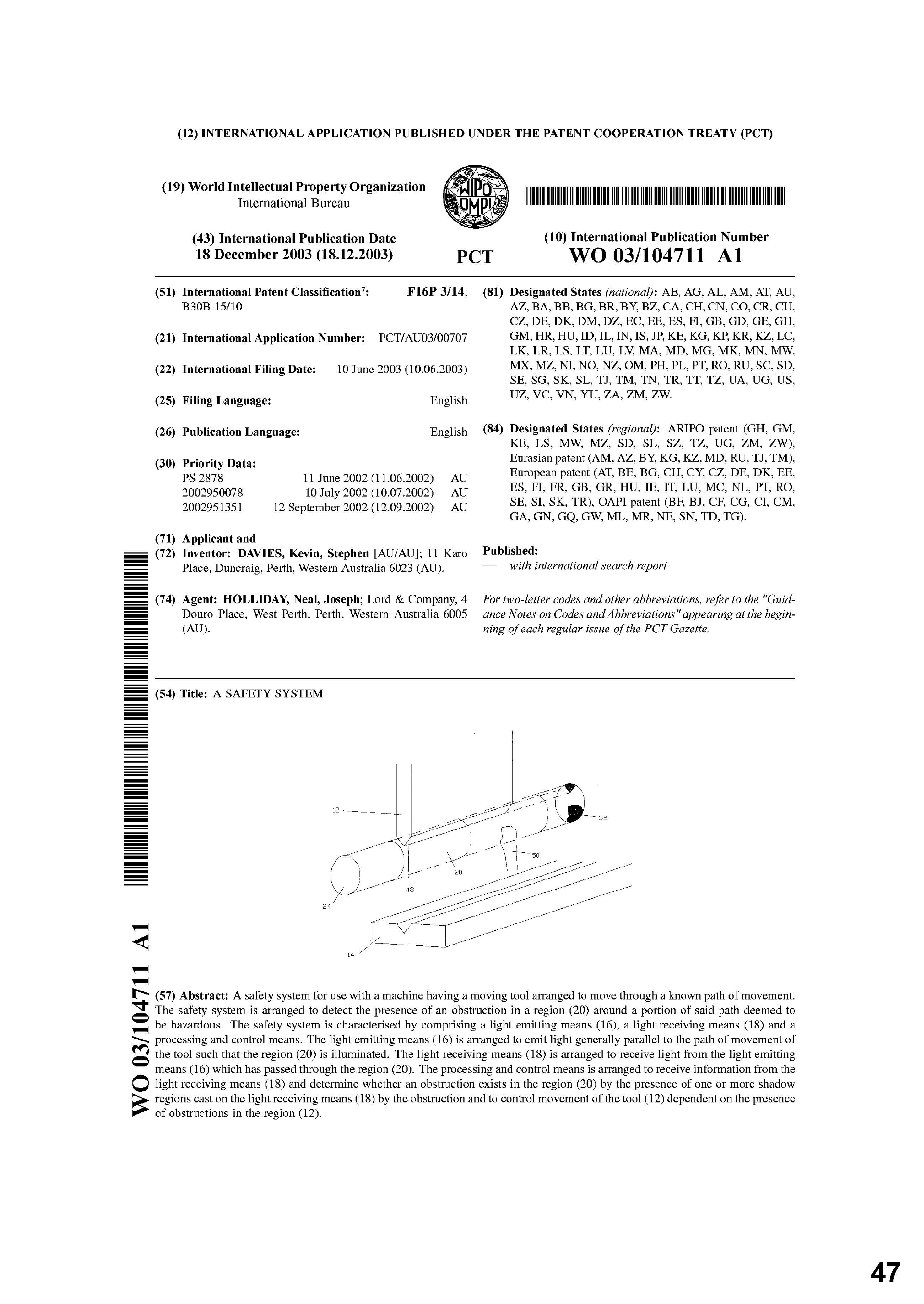
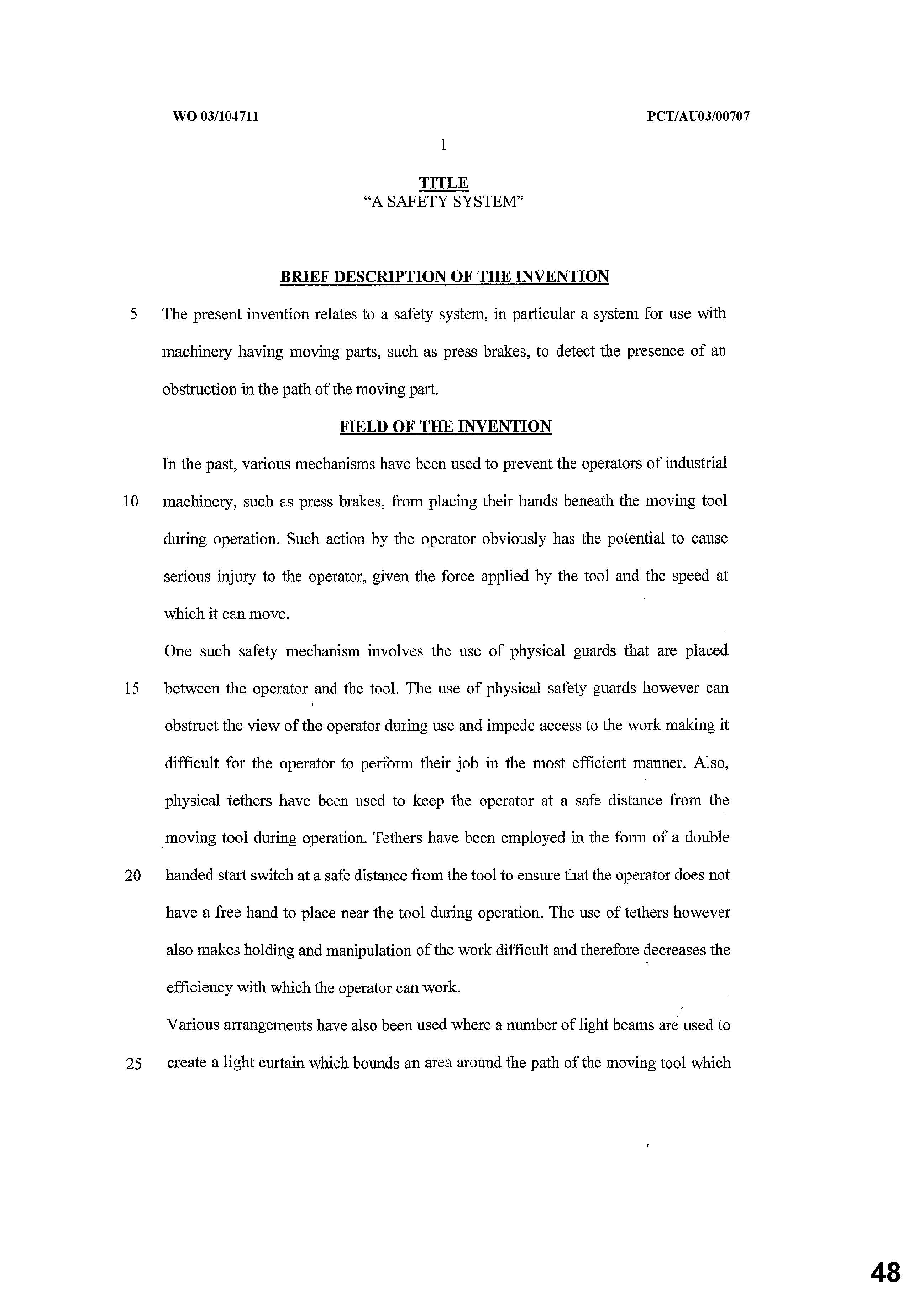
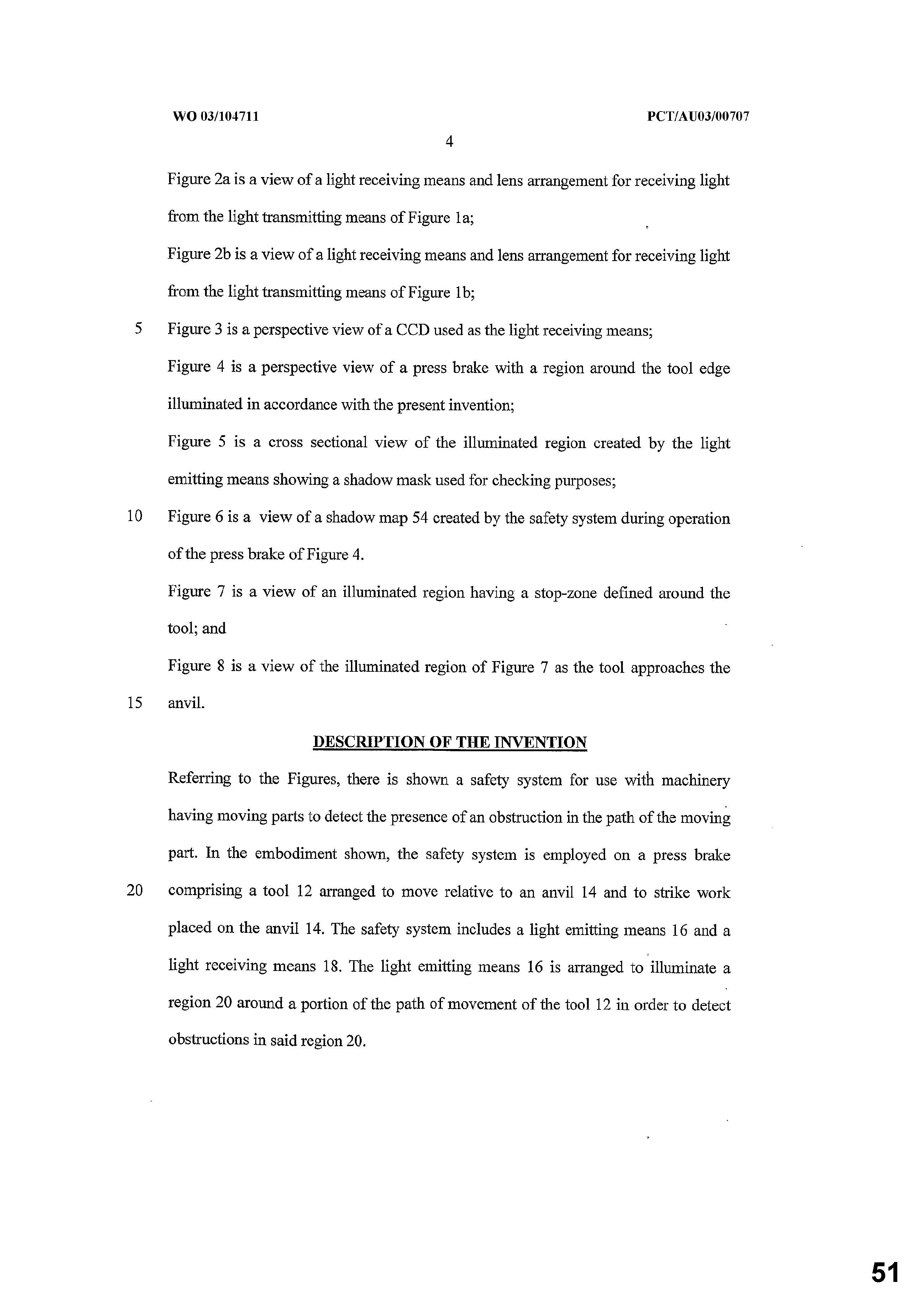
2 The Patent is for an invention relating to a safety system, in particular, for use with machinery having moving parts, such as press brakes. A press brake is a mechanical tool used for bending material, usually metal. It operates with substantial force. The safety system is to detect the presence of an obstruction in the path of a moving part in such machinery. As the Patent discloses, various mechanisms have been used in the past to prevent the operators of industrial machinery, such as press brakes, from placing their hands beneath the moving tool during operation. Such an action by the operator has the potential to cause injury, given the force applied to the tool and the speed at which it can move.
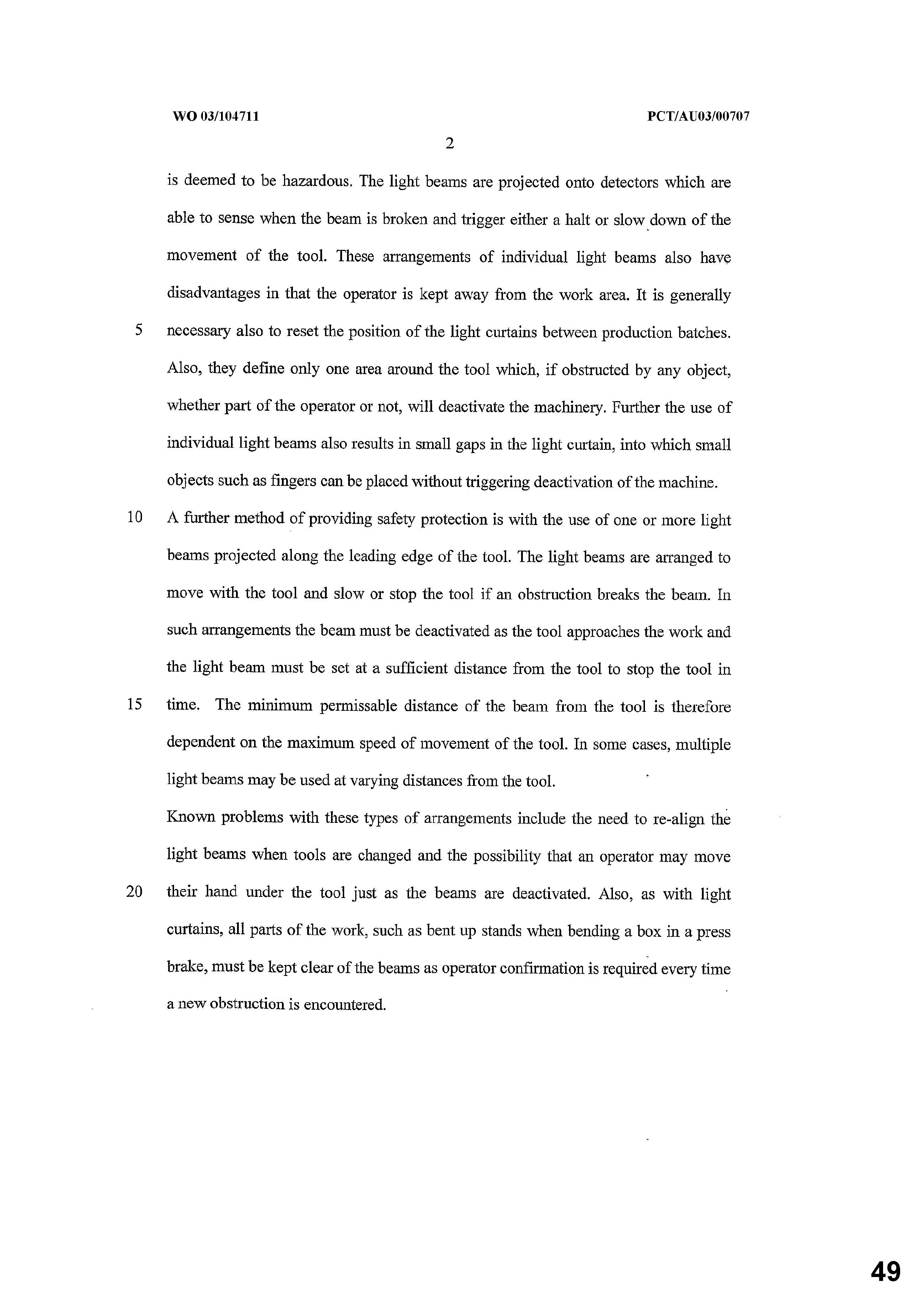
3 An example of a previous safety mechanism noted in the Patent is a physical guard placed between the operator and the tools. The use of physical guards can, however, obstruct the view of the operator during use and/or impede access to the work making it difficult for the operator to perform the job and the task in the most efficient manner. Another example provided is a light curtain which surrounds the path of the moving tool. Light beams are projected onto detectors, which are able to sense when the beam is broken and trigger either a halt or slowing down of the movement of the tool. Again, the disadvantage of the individual light beams is said in the Patent to be that operators are kept away from the work area. Another method of providing safety protection is the use of one or more light beams along the leading edge of the tool, which are arranged to move with the tool and slow or stop the tool if an obstruction breaks the beam. In such arrangements, the beam must be deactivated as the tool approaches the work and the light beam must be set at sufficient a distance from the tool to stop the tool in time. The minimum permissible distance of the beam from the tool is therefore dependent on the maximum speed and movement of the tool. Again, it is suggested in the Patent that a problem with this type of arrangement includes the need to realign light beams when tools are changed and the possibility that an operator may move a hand under the tool just as the beams are deactivated.
4 The Patent is for an invention which attempts to overcome, in part, some of the disadvantages identified in previous safety systems for detecting the presence of obstructions in hazardous areas around machines having moving parts.
5 Mr Davies is the owner of the Patent. Triclops is and has been since 8 October 2015, the exclusive licensee of the Patent.
6 The respondent (Lazer Safe Pty Ltd (ACN 090 113 572) has, since at least 20 June 2015, offered for sale and kept for sale the systems (the Lazer Safe Systems) known as:
(a) an LZS-005;
(b) an IRIS; and
(c) an IRIS Plus (or IRIS +).
7 The main difference between the three laser systems is that the IRIS and IRIS Plus systems contain additional functionalities to the LZS-005. IRIS has additional functionality known as ‘bend speed management’ (BSM). IRIS Plus also has BSM, together with an additional functionality discussed in more detail below. A Product Description was filed by the respondent detailing the Lazer Safe Systems and their functionalities (discussed in, and annexed to Appleyard #2 (defined at [29]) and contained in the Confidential Annexure to these reasons, but which is omitted from publication).
8 The applicants say that the respondent has infringed the Patent by the sale of its products. The respondent rejects the infringement allegation and asserts in response, for various reasons, that the Patent is invalid.
9 The applicants press infringement of claims 1-5, 8, 12, 14, 21, 22, 28-31, 38, 44 and 46. However, if claim 1 is found to be infringed then, given admissions made by the respondent, the dispute as to infringement of the dependent claims only concerns whether claims 2, 3, 4, 5, 14, 21, 38 and 46 are also infringed (the Disputed Claims). The respondent cross-claims for invalidity.
10 For reasons which follow, in my view, the applicants’ construction of the claims of the Patent is unrealistically broad. On the proper construction, I consider there is no infringement by the respondent’s systems. However, equally, on the proper construction, the Patent was not invalid as asserted by the respondent.
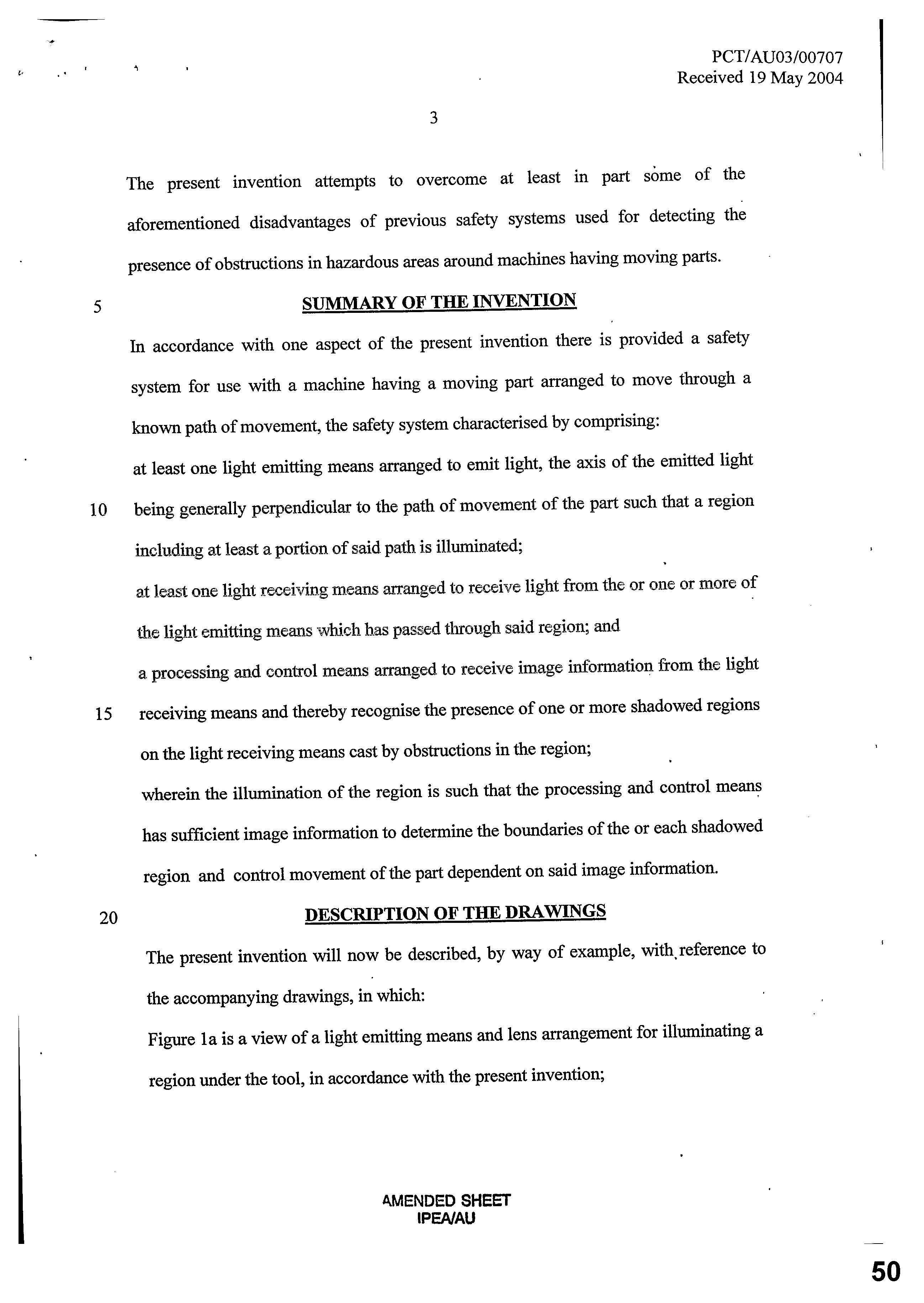
11 The ‘Summary of the Invention’ (p 3 lines 6-19) constitutes a consistory clause, referable to claim 1. This is a broad description of the nature of the invention, and does not limit the invention to one particular form (the words used are ‘[i]n accordance with one aspect of the present invention…’: p 3 line 6). The consistory clause identifies that the invention comprises three components being:
(a) ‘at least one light emitting means’;
(b) ‘at least one light receiving means’; and
(c) ‘a processing and control means’.
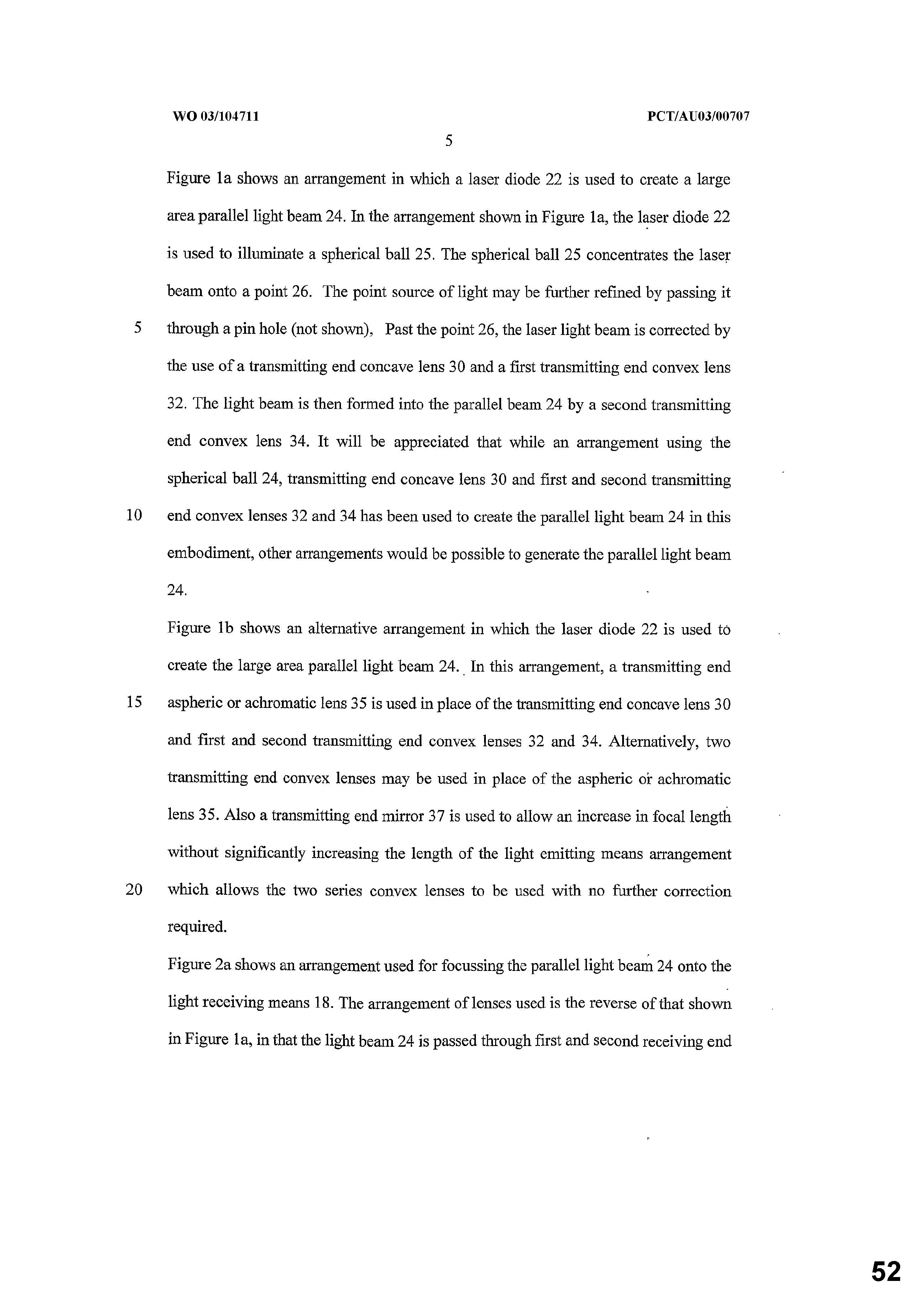
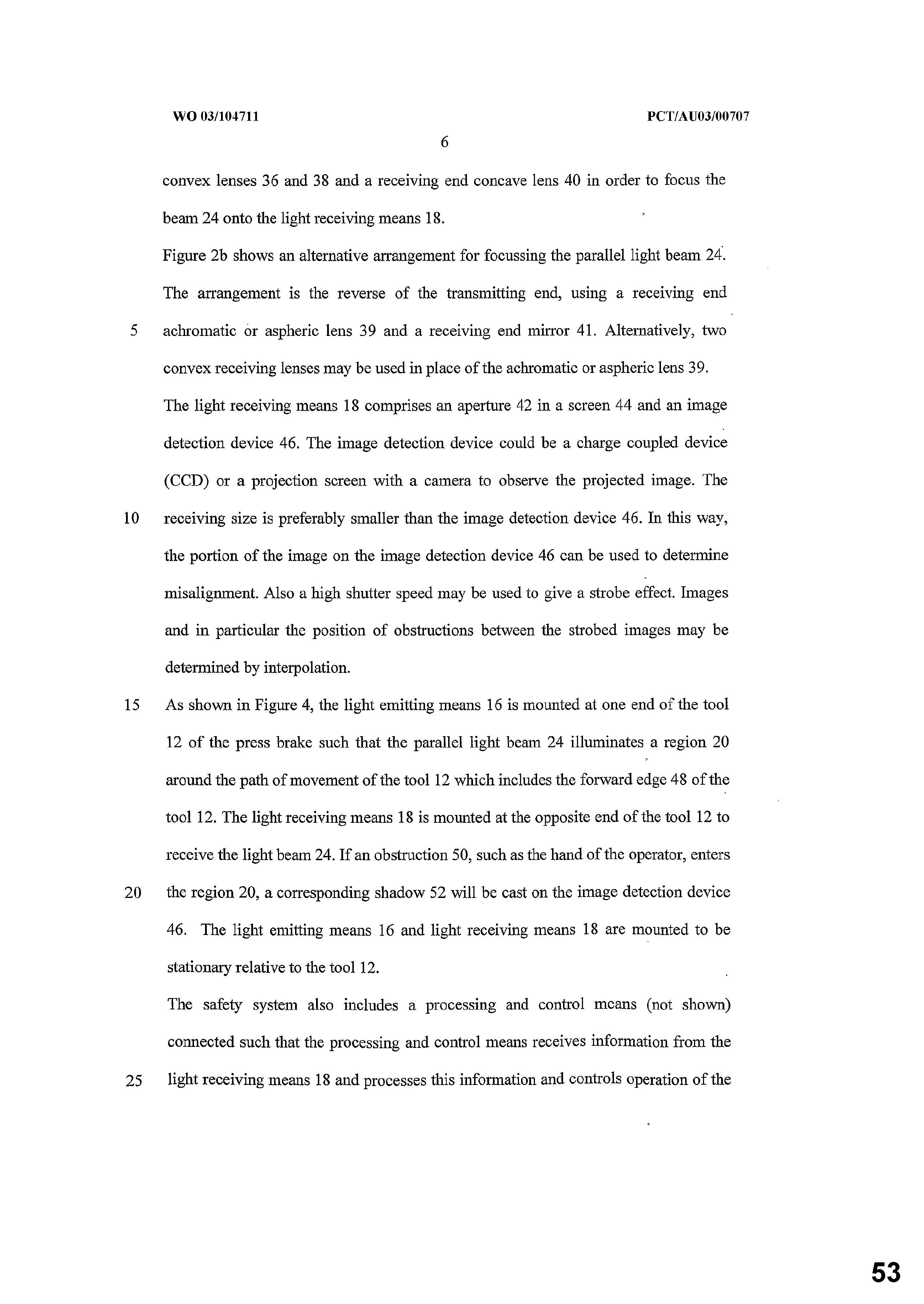
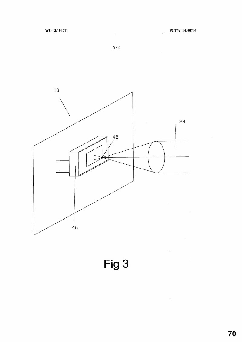
12 Any obstruction within the region illuminated by the ‘light emitting means’ will result in, for example, a shadow being cast on the light receiving means. This affects the information output by the ‘light receiving means’, which then acts upon by the ‘processing and control means’, which may, as a consequence, control movement of a part of the press brake, such as the tool. The invention is described (p 3 line 20 to p 12 line 16) ‘by way of example’ with reference to the drawings accompanying the Patent. The ‘light emitting means’ (as described in the example) serves the purpose of illuminating a region around the path of a tool in order to detect obstructions in the region. That component is used in conjunction with at least one ‘light receiving means’. The ‘light receiving means’ is said to comprise an aperture in a screen and an image detection device (p 6 lines 7-8). Examples given of the ‘image detection device’ are a ‘charge coupled device’ (a CCD) and a projection screen (with a camera to observe the projected image) (p 6 lines 8-9). Both of these types of image detection devices contain an array of light sensors, wherein each sensor outputs an electrical signal based on the level of light it receives. Different embodiments of the light emitting means and the light receiving means are described at p 5 line 1 to p 6 line 22.
13 The ‘processing and control means’ receives ‘information’ from the light receiving means. An issue will be whether ‘information’, as the applicants say, is a broad notion, not limited to, for example, ‘images’. Various embodiments are described at p 7 line 1 to p 11 line 18. The role played by the ‘processing and control means’ commences with an example describing the comparison of ‘images’ stored in the memory of the processing and control means with images received from the ‘image detection device’ (p 7 lines 4-14). That is, ‘image information’ constitutes ‘images’ in this embodiment. This embodiment may be described for present purposes as an ‘image comparison’ embodiment. Another embodiment concerns the creation of ‘a total picture made up of the image information’ received by the light receiving means (p 8 lines 1-7). This ‘total picture’ is referred to as a ‘shadow map’ (p 8 lines 4-5).
1.2.2 Common ground and issues
14 It is common ground that each of the Lazer Safe Systems possesses each of the following integers of claim 1 of the Patent:
Claim 1 | Integers |
1.1 | A safety system for use with a machine having a moving part arranged to move through a known path of movement, the safety system characterised by comprising: |
1.2 | at least one light emitting means arranged to emit light, |
1.3 | the axis of the emitted light being generally perpendicular to the path of movement of the part such that a region including at least a portion of said path is illuminated; |
1.4 | at least one light receiving means arranged to receive light from the or one or more of the light emitting means which has passed through said region; and |
15 It is also accepted that if any of the Lazer Safe Systems possess all of the integers of claim 1 of the Patent, that system also possesses all of the integers of claims 8, 12, 22, 28, 29, 30, 31 and 44 of the Patent.
16 Therefore, the following are essentially the issues in dispute in the proceedings:
(1) What is the proper construction of the Disputed Claims, particularly as to integer 1.5 and integer 1.6 of claim 1?
(2) Whether each of the Lazer Safe Systems possesses the following integers of claim 1:
Claim 1 | Integers |
1.5 | a processing and control means arranged to receive image information from the light receiving means and thereby recognise the presence of one or more shadowed regions on the light receiving means cast by obstructions in the region; |
1.6 | wherein the illumination of the region is such that the processing and control means has sufficient image information to determine the boundaries of the or each shadowed region and control movement of the part dependent on said image information. |
(1) It is also in dispute whether each of the Lazer Safe Systems possess the following integers of dependent claims:
Claim 2 | Integer |
2.2 | characterised in that the processing and control means either slows or stops the movement of the part if the processing and control means determines the presence of an obstruction in a predetermined or calculated area of the region. |
Claim 3 | Integer |
3.2 | characterised in that the processing and control means calculates the positions of the obstructions relative to the part or relative to each other and slows or stops the part dependent on the relative positions. |
Claim 5 | Integer |
5.2 | characterised in that the region is relatively large with respect to the size of a leading edge of the part and is entirely illuminated by a single parallel beam of light. |
Claim 14 | Integer |
14.2 | characterised in that the processing and control means is arranged to determine the thickness of an obstruction casting a shadow on the light receiving means and allow continued movement of the part should the thickness be less than a predetermined value, |
14.3 | the predetermined value being a value determined to be small enough that the obstruction could not be a part of the operator’s body. |
Claim 21 | Integer |
21.2 | characterised in that the light receiving means comprises a projection screen |
21.3 | and image information is detected by a camera arranged to observe the image on the projection screen. |
Claim 38 | Integer |
38.2 | characterised in that the light receiving means includes a receiving end lens arrangement such that light passing through the region is focussed by the receiving end lens arrangement. |
(2) It is also in dispute whether IRIS and IRIS Plus possess the following integers of dependant claims:
Claim 4 | Integers |
4.1 | A safety system in accordance with any one of claims 1 to 3, |
4.2 | characterised in that the processing and control means calculates the speeds of movement of the obstructions relative to the part or relative to each other and slows or stops the art dependent on the relative speeds. |
Claim 46 | Integers |
46.2 | characterised in that the tool is arranged to bend material |
46.3 | and the processing and control means controls movement of the tool during bending. |
17 In relation to the respondent’s allegation of invalidity, it is common ground that the filing date of the Patent was 10 June 2003.
18 The Patent also asserts a claim to priority from each of the following three provisional applications:
PS 2878 11 June 2002 (as to which, see [25(5)] below
220950078 10 July 2002
2002951351 12 September 2002
19 There are several issues in dispute in relation to invalidity.
20 The first is the date which each of the Disputed Claims is entitled to claim as its priority date pursuant to s 43 of the Patents Act 1990 (Cth).
21 In connection with novelty, it is agreed that:
(1) US Patent No. 4772801, in the name of Cybelec SA (Cybelec Patent), was made publicly available on 20 September 1988.
(2) European Patent Application EP 1 246 148 A2 in the name of SICK AG (SICK Patent), was made publicly available on 2 October 2002.
(3) The SICK Patent can only be relevant for the purpose of novelty if the Disputed Claims are not entitled to claim priority from any of the provisional applications (that is, the priority date of the Disputed Claims is not earlier than the filing date).
(4) Claims 3, 4 and 14 do not lack novelty in light of the Cybelec Patent.
(5) Claims 3, 4, 14 and 21 do not lack novelty in light of the SICK Patent.
22 In relation to novelty, the disputed issues are:
(1) Whether any of claims 1, 2, 5, 8, 12, 21, 22, 28, 29, 30, 31, 38, 44 or 46 of the Patent lack novelty in light of the Cybelec Patent.
(2) If the SICK Patent is relevant to the question of novelty, whether any of claims 1, 2, 5, 8, 12, 22, 28, 29, 30, 31, 38, 44 or 46 lack novelty in light of the SICK Patent.
23 There is also a claim in relation to inventive step or obviousness in connection with invalidity. It is agreed that:
(1) The Cybelec Patent was made publicly available in United States of America on 20 September 1988.
(2) The SICK Patent was made publicly available on 2 October 2002 in the German language.
(3) The SICK Patent can only be relevant for the purpose of inventive step if the priority date of the Disputed Claims is not earlier than the filing date.
(4) For the purpose of assessing inventive step, the relevant version of s 7 of the Patents Act predated the Intellectual Property Laws Amendment (Raising the Bar) Act 2012 (Cth).
(5) The common general knowledge in the relevant art is the same, whether considered at any of the filing date or the filing date of any of the provisional applications.
24 The respondent has provided the applicants with a schedule of matters asserted to form part of the common general knowledge in Australia as at both 11 June 2002 and 10 June 2003 (the respondent’s CGK Schedule). Where the applicants agree that any of those matters form part of the general knowledge as at these dates, the agreement is indicated in the applicants’ response (applicants’ response to CGK Schedule).
25 The issues in dispute in relation to inventive step or obviousness in connection with invalidity are:
(1) The identity, qualifications, experience and attributes of the hypothetical skilled worker in the relevant art as at the priority date of the Patent.
(2) Whether any of the other matters asserted to be common general knowledge in Australia in the respondent’s CGK Schedule, but not agreed in the applicants’ response to CGK Schedule did form part of the common general knowledge in Australia as the priority date of the Patent.
(3) Also in dispute is whether the invention as claimed in any of the Disputed Claims would have been obvious to the hypothetical skilled worker in the relevant art in light of the common general knowledge as it existed in Australia as at the priority date of the Patent.
(4) Whether:
(a) the Cybelec Patent could reasonably be expected to have been ascertained, understood and regarded as relevant by the hypothetical skilled worker in the relevant art before the priority date of the Patent; and if so
(b) the invention, as claimed in any of the Disputed Claims, would have been obvious to the hypothetical skilled worker in the relevant art in the light of common general knowledge as it existed in Australia as at the priority date of the Patent considered together with the Cybelec Patent.
(5) If the Disputed Claims are not entitled to claim a priority date earlier than the filing date, whether:
(a) the SICK Patent could reasonably be expected to have been ascertained, understood and regarded as relevant by the hypothetical skilled worker in the relevant art before the priority date of the Patent; and if so
(b) the invention as claimed in any of the Disputed Claims would have been obvious to the hypothetical skilled worker in the relevant art in the light of common general knowledge as it existed in Australia as at the priority date of the Patent considered together with the SICK Patent.
26 There is also a ‘fair basis’ argument. The issues in dispute are whether claim 1 and all claims dependent upon claim 1 are fairly based on the disclosure of the Patent insofar as they claim the following, being integer 1.5 and integer 1.6:
a processing and control means arranged to receive image information from the light receiving means and thereby recognise the presence of one or more shadowed regions on the light receiving means cast by obstructions in the region;
wherein the illumination of the region is such that the processing and control means has sufficient image information to determine the boundaries of the or each shadowed region and control movement of the part dependent on said image information.
27 There is also a claim based on lack of clarity in relation to invalidity. The issues in dispute in this regard are:
(1) Whether the use of the word ‘recognise’ in claim 1 is unclear; and
(2) Whether the use of the phrases ‘image information’ and ‘sufficient image information’ in claim 1 is unclear.
28 I address the issue of infringement, and the issues arising in relation to invalidity, in turn.
2.1 The key experts – an overview
29 The infringement evidence relied on was:
(a) for the applicants by affidavits of Mr John Acheson sworn on 27 April 2017 (Acheson # 2) and sworn on 5 June 2017 (Acheson # 3); and
(b) for the respondent by affidavits of Mr Robert Appleyard sworn on 17 February 2017 (Appleyard # 2) and Mr Peter Berry sworn on 16 February 2017.
30 As to invalidity, the evidence relied on was:
(a) the respondent’s evidence in chief by:
(i) affidavit of Mr Appleyard sworn on 17 October 2016 (Appleyard # 1);
(ii) affidavit of Mr Mark Pullen sworn on 17 October 2016;
(b) the applicants’ evidence in answer: affidavit of Mr Acheson sworn on 17 February 2017 (Acheson # 1);
(c) the respondent’s evidence in reply: affidavit of Mr Appleyard sworn on 28 April 2017 (Appleyard # 3); and
(d) the applicants’ evidence in answer: affidavit of Mr Acheson sworn on 14 June 2017 (Acheson # 4).
31 In relation to claim construction and the issue of infringement, I preferred the respondent’s witnesses, principally, Mr Appleyard, despite the superior qualifications and perhaps more general expertise of Mr Acheson. While Mr Acheson was more qualified generally, he had very limited experience in the particular field of this technology. I am conscious in arriving at this preference that Mr Appleyard was not independent. Despite this, he had very considerable internationally relevant experience and skills and I found his infringement evidence plausible and realistic, despite his obvious interest in the matter. On that invalidity evidence of a more general nature, as distinct from infringement, I preferred the evidence of Mr Acheson. I considered that his evidence on invalidity in response to the respondent’s claims was realistic and objective and to be preferred.
Mr Appleyard
32 Mr Appleyard is a director and principal of the respondent. He has had extensive ‘hands-on’ experience with press brake safety systems since about 1995 when he started designing and building safety systems for press brakes. In 1998, he established the respondent’s business developing safety products for use with press brakes. He was the principal designer of the respondent’s safety system known as the Lazer Safe LZS-003 System, a precursor of the LZS-005. The respondent operates worldwide, in the design and manufacture of press brake safety and control devices. Mr Appleyard has also, since 2001, been involved in writing safety standards for press brakes for the European Union and, since 2009, for the United States. He and the respondent have won various Western Australian awards for engineering excellence, industry and export since 2003. The respondent has received State and Federal funding grants since 1998 for the development of its business.
Mr Acheson
33 Mr Acheson was initially giving evidence for the applicants only as to validity, principally in answer as to the novelty and obviousness of the Patent. He is an American systems engineer based in Iowa. Since 2004, he has worked in the United States principally as a systems designer in aerospace, communications, software and defence. Between about 2002 and 2004, he worked as an intern and then part-time for Accurpress America in Rapid City, South Dakota, whilst completing his studies at the South Dakota School of Mines and Technology. His work with press brake safety systems was undertaken as a project for his studies. Mr Acheson’s exposure to press brake safety systems is quite limited: in time, in nature, in scope and geographically. His involvement with these systems centred on his part-time student design project for his engineering studies, which began in about mid-2003 and after the latest priority date. His experience is American, rather than Australian or European. His evidence discloses no substantial personal awareness or knowledge of this field at an international or Australian level at any of the priority dates. It is notable that the relevant field or art is quite restricted and confined, especially in Australia. Safety systems for press brakes are a small but sophisticated market, centred on Europe (with considerably smaller markets in the United States and even more so in Australia at the relevant time in 2002/2003). Mr Acheson expressly accepted that the United States was a ‘backwater’ for press brake safety systems in 2002/2003.
Mr Berry
34 Mr Berry is an independent electronics and software engineer. He gave evidence on infringement only, in answer to Mr Lim’s proposed evidence on behalf of the applicants. Mr Lim was then not called. Mr Berry holds a Bachelor of Science in Electronic Engineering from the University of Natal (now the University of KwaZulu-Natal) in South Africa in 1983. In 2000, he moved to Perth where he has continued to work as a self-employed engineering consultant and contractor. He has designed and implemented electronic software components and systems for over 30 years, particularly in the ‘embedded’ area where electronics and software are used to control devices and machines. He has performed work for the respondent on an ad hoc basis since about 2006, but such work is only a small proportion of his overall business. He was not involved in work relating to the specific safety features of the Lazer Safe Systems. He was not as qualified as Mr Acheson, but his evidence was helpful and plausible.
Mr Pullen
35 Mr Pullen is a patent attorney acting for the respondent in this dispute. His evidence was of a formal nature exhibiting the various documentary prior art and other relevant documents, together with a history of the application for the Patent and the publication of various prior art documents. He was not required for cross-examination.
2.2 Evidence in chief - detail
36 Before considering the arguments advanced by the parties on the construction of the Patent, I propose referring to the detail of the evidence in chief of the key witnesses, mainly on construction, but partly on infringement and invalidity. I have not relied on the infringement evidence or even comparisons as an aid to construction. The summary does not discuss the cross-examination which, when relevant, is examined in discussion as to the parties’ contentions on each of the aforementioned issues.
Mr Acheson
37 Mr Acheson is the principal systems engineer at Rockwell Collins, a United States multinational company. Rockwell Collins is engaged in the design, production and support of systems for use predominantly in the aerospace and defence industries. Mr Acheson holds a Bachelor of Science and Electrical Engineering and has had 10 years’ experience in control system design. In 2004, he completed his Bachelor of Science and Electrical Engineering in South Dakota School of Mines and Technology in Rapid City. Between the second and third years of study, in around mid-2002, he undertook a summer internship with Accurpress. Accurpress was a manufacturer of press brakes and shears for forming sheet and plate metal. After that internship, he was employed by Accurpress on a part-time basis during his next year of study. At this time, he worked on a few small research and development projects. One of the projects involved development of an angle sensor for measuring the extent to which a piece of metal had been bent by a press brake. This would facilitate partial bending of a piece of metal, that is, not using the full stroke of a machine to bend a sheet of metal to the maximum bend angle, usually 90 degrees. He undertook a variety of administrative and network administration tasks.
38 In the final years of his study, around mid-2003, as part of a final year design class, Mr Acheson undertook a design project to design and build a press brake safety system. The project was undertaken at the request of Accurpress. Accurpress funded the project and provided him with materials and support for it. This was, in effect, an extension of the work he was already performing for Accurpress.
39 After graduating in 2004, Mr Acheson commenced fulltime employment with Rockwell Collins, where he worked for some seven years. During this time he was a member of the Government Systems, Advanced Sensors and Navigation Department. His work focused on digital signal processing for communication and navigations systems and the development of signal processing algorithms. He was heavily involved in work on software defined radios. It is a type of radio where many of the parts and components, typically implemented by hardware, are instead implemented by software. It allows the radio to be reconfigured, utilising different types of signals.
40 In 2011, Mr Acheson joined a company known as Cambridge Silicone Radio. At this company, he was part of the software development of low powered GPS chips, intended for use in applications such as smart phones. After two months with Cambridge Silicone Radio, the director of software for whom he was working, left the company to join a start-up company called ‘mCube’. Mr Acheson also joined mCube at that time, working on algorithms for a navigation system for use indoors. This could be used, for example, in shopping centres or other large indoor public spaces without the need for GPS. He was named as an inventor on two patents which were filed while he was with mCube. At around 2012, the office of mCube that he was working with was spun-off into a different start-up company. He left to join Raven Industries, where he worked as an architect on precision agriculture systems. He was the lead architect on the development of numerous systems. One was a grain yield monitoring system for combine harvesters, providing accurate real-time yield maps. He also worked on the integration of sensors into GPS and automated steering systems for agricultural machinery. Whilst with Raven Industries, he was named as an inventor on eight filed patents. In about April 2016, he left Raven Industries and returned to Rockwell Collins, where he remains employed. He has a number of duties there. He is a systems analyst, working on airborne and ground based software defined radios. He is also the modelling and simulation group leader engineer and leads several software development teams.
41 Specifically, in relation to press brake safety systems, Mr Acheson was, whilst working with Accurpress, engaged to design and build a prototype press brake safety system. This came about as a result of being approached by the owner of the company, Mr Hilton. There had been some incidents with the company’s press brakes and Mr Hilton wanted Mr Acheson to look at designing a safety system to deal with this. Accurpress, at that stage, did not sell press brakes with manufacturer-fitted systems. Some of Accurpress’ dealers offered to install third party light curtain systems for customers. In simple terms, he explained a light curtain creates a vertical ‘curtain’ of light in front of a press brake which can detect objects that enter the light and stop the press brake. Light curtain systems typically operated in the following way:
(a) two vertical columns were mounted a short distance, approximately one foot in front a press brake, with one column at either end of the press brake;
(b) one column had a series of vertically spaced apart light transmitters to transmit beams of light across the front of the press brake, while the other column had a corresponding set of receivers, receive the light from the light transmitters; and
(c) if one or more of the beams of light were broken during operation, the press brake could be stopped.
42 Otherwise if Accurpress customers wanted safety systems fitted to their press brakes, they would have to obtain aftermarket safety or guarding systems and have them refitted to the systems. At this stage, one of Accurpress’ major competitors Trumpf, offered customers the option of having a light curtain system installed in their press brakes. At the time he began working on the project, Mr Acheson had been working with Accurpress for close to two years for an average of about 15 hours per week. As such, he said he had a good knowledge of the operation of press brakes.
43 Mr Acheson described a press brake as being a large piece of industrial machinery, designed to bend sheet metal. Typically, it does this by lowering a long tool or blade onto the sheet of metal to be bent and driving the sheet into a V-shaped die. The press brake pushes the metal all the way into the die to create a complete bend or only part of the way to create a partial bend. Mr Acheson was also aware of the likely safety issues that could arise for an operator of a press brake. The vast majority of press brakes were manually fed. This meant that an operator would stand next to the machine, insert the metal to be bent in the press brake and hold an end of the piece out of the path of the tool to keep the piece in place while bending occurs. The major safety risk to the operator was that he or she could inadvertently insert a part of his or her body, such as a finger, hand or arm into the path of a tool. The tool is relatively sharp and descends with great force, so if a part of an operator’s body became trapped beneath a tool, it could cause serious injury or even death.
44 Another safety risk can arise when the tool pushes the sheet metal into the die to bend the sheet. This causes the edges of the sheet to fold upwards and towards the machine in a V-shape and it is possible for the edge of the sheet to strike an operator in the head or the face as this occurs, particularly if the bending occurs at high speed. It is also possible for a part of an operator’s body to become trapped between the sheet and the side of the blade as this bending takes place. This could be the operator’s hands or fingers if the operator is holding the sheet as it is bent.
45 The first step Mr Acheson took in the project was to look at the existing market to see what types of safety systems were available. He was already aware of light curtains.
46 Mr Acheson undertook internet searches to find out what systems were available. At this time, Google was not as widespread in internet searching. He used a program known as MetaCrawler, being a service that aggregated results from a number of different early internet search engines that were available at the time.
47 He had no knowledge at that stage of whether or not any patents existed and did not undertake any searches to ascertain this. The only systems he uncovered in the searches he did conduct were the various forms of light curtains.
48 Mr Acheson expected the task to be a simple one, namely, taking an existing light curtain, developing the necessary program and applying it to an Accurpress press brake. However, it became apparent that there was a more complex problem. That was how to avoid the system being falsely triggered. By ‘falsely triggered’, he referred to a situation where the light curtain was interrupted, but without actual risk to operator safety. That could occur, for example, if the piece of metal being bent obstructed one of the light beams. This was more common where either a thick piece of metal was being bent or where a sheet was being bent into a box or similar shape in a number of operations. When a sheet was being bent into a box, the previously bent up sides of the box would present a wide profile and would be more likely to block a light beam from the light curtains and trigger a stop. At the time of conducting his inquiries, Mr Acheson was aware that this problem had been approached by varying the threshold required for a sensor of the light curtain to register as being blocked.
49 Mr Acheson understood at the time that the sensors in light curtains comprised a photodiode. A photodiode is an electrical component converting light into an electrical current. The sensors could work in one of two ways:
(a) the sensor could be set to output either a high/low or on/off signal, depending on the amount of light detected. The amount of light required to switch between signals could be adjusted by a physical adjustment of the sensor; or
(b) the sensor could output a signal of a particular voltage, depending on the amount of light detected. This was sent to a controller which could be programmed to generate an ‘on’ or ‘off’ signal, depending on whether the voltage was above or below a defined level.
50 In either case, the result was same. A binary on/off or high/low signal would be generated, depending on whether the level of light received by the photodiode was above or below a set level.
51 If a light beam was obstructed by a very thin object, for example, the edge of a sheet of metal only several millimetres thick, some light would still reach the sensor. However, if the light beam was obstructed by a larger object, the amount of light reaching the sensor would be much lower. By varying the threshold voltage at which the signal was triggered, which in turn depended on the amount of light received, the systems could be adjusted so that they did not trigger if only a very thin obstruction blocked the path of the light beam.
52 Another problem with light curtains was that the light transmitters and receivers had to be very precisely aligned. This was to ensure that the light beam, when not obstructed, was detected by the transmitter. If there was a slight misalignment, this could result in either some or all of the narrow light beam missing the receiver. This, in turn, could cause the output of the light sensor to fall below the threshold and trigger a signal, causing the press brake to stop.
53 Mr Acheson largely worked on this project alone. After reviewing the existing market for safety systems, which seemed to comprise various arrangements of light curtains, and seeing the drawbacks of light curtains, he decided to take a different approach. He considered that one way of dealing with the alignment issues would be to use a camera, which would monitor the path of the descending blades. This offered, he said, a fairly robust solution without the types of alignment issues referred to above. As long as the field of the camera covered the relevant area, it would not matter if there was a slight misalignment of the camera. There was therefore greater tolerance if the camera was not perfectly aligned.
54 The camera used at the time was a complimentary metal oxides semiconductor (CMOS) camera and is one type of technology used in cameras. The other type is a CCD. Both CCDs and CMOS cameras perform the same basic function, that is, capturing light and converting it to an electrical current.
55 Mr Acheson thought about using the camera to try and distinguish between the body of an operator and other, permitted objects, such as the workpiece, however, he quickly dismissed this as being too difficult and complex a problem requiring too much processing power.
56 Instead, he applied an optical filter to the camera and worked on distinguishing between a permitted obstruction, such as the workpiece, and an impermissible obstruction, such as part of the operator’s body, based on the intensity of light detected. In order to make a clear distinction between the intensity of light detected from a permitted obstruction and an impermissible obstruction, he used a glove coated in phosphorescent chemical, which was to be worn by an operator, and exposed this to a UV light source. When the glove was exposed to the UV light source, it emitted a high intensity of light. When this level of intensity was detected by the camera, it would trigger a signal to stop the press brake. However, the presence of other obstructions in the field of the camera, for example, the workpiece, die or tool, would not trigger such a signal. In this way, the system would only be stopped if the gloved hand of an operator entered the field of the camera. He developed a working prototype of this system, but the system was never put into commercial use as far as he knew. He believed that the requirement for the user to wear a particular type of glove made this system too cumbersome for practical use.
57 Mr Acheson said he was well aware in mid-2003 of light curtains systems where the light emitting and receiving means are fixed in front of the press brake. As a result of the work he performed on press brakes, he maintained an interest in this field after completion of the project. He became aware of systems which illuminated an area around the blade at a later time. This was one or two years after completing the project. He was not aware of those in mid-2003 and would not have regarded them as being common general knowledge, either at 11 June 2002 or mid-2003.
58 Mr Acheson said he was aware of processing and control means as a common feature of light curtain systems. He would have regarded this as common general knowledge, both at 11 June 2002 and mid-2003. However, the manner in which each system processes information, that is, the exact logic it uses, usually comprised confidential proprietary information and so would not have been immediately apparent. He would therefore not have regarded that information as common general knowledge.
59 On the detection of shadows cast by obstructions between the light emitting and receiving means, Mr Acheson said that if this is referring to the function of a light curtain detecting whether a shadow has been cast upon a light sensor, leading to a corresponding drop in output voltage from the sensor, he was aware of this and considered it was common general knowledge at both dates.
60 As to technology which could be used to record and store the images of shadows cast in the region between the light emitting and receiving means, including shadows cast by the blade, workpiece or an anvil, or an obstruction in the region, Mr Acheson said he was aware of image recording technology generally, such as CMOS cameras. However, at the time he undertook the project he had not heard of its use to record and store images in a press brake safety system. He did not regard this as being common general knowledge at either date. He ultimately used a CMOS camera in the press brake safety system he designed in around 2003. He did not, however, use the CMOS camera to record or store images. Rather, he arranged it to observe an area below the blade of the press brake and trigger if the camera detected an intensity of light corresponding to the coated glove of an operator’s hand.
61 With regard to programming the processing and control means such that it could be used with such technology to determine the boundaries of the shadows cast in the region, Mr Acheson was not aware of the use of such technology in press brake safety systems. It was not, in his view, common general knowledge at either date.
62 As to programming the processing and control means such that it stored images and could compare them with other images, similarly, Mr Acheson was not aware of the use of this technology and did not regard it as being common general knowledge at either date.
63 As to controlling, including stopping the descent of the blade, depending on detecting shadows cast by obstructions, detecting the shape of shadows cast by obstructions, or detecting the shape of shadows cast by obstructions and comparing them with the shape of other images recorded by the system, Mr Acheson was aware that light curtains operated by controlling the descent of blade based on detecting a shadow cast by an obstruction. But none of the systems he was aware of detected the shape of the shadow or controlled the blade based on such information (emphasis added). That was not, in his view, common general knowledge at either date.
64 As to the following systems in the respondent’s CGK Schedule, the Cybelec System, the TIROPS System (standing for Travelling Infra Red Operator Protection System), the Fiessler AKAS System and the Nuova System, Mr Acheson had not come across systems by those names and did not regard them as common general knowledge at either date.
The respondent’s Lazer Safe LZS-003 System
65 Mr Acheson said he recalls hearing of the respondent’s systems at the time he undertook the project. He did not recall a particular system name or model number he was aware of at the time and could not recall specifics of the systems, but his recollection was that they were light curtain systems which were generally well known. As he could not recall specifics of the Lazer Safe Systems at the time, he does not regard those systems as likely to have been common general knowledge at either date.
The Patent
66 Mr Acheson could not recall ever seeing the Patent before he was provided with a copy of it by the applicants’ solicitors. He was given various tasks in relation to the Patent.
67 He expressed the following views in relation to it.
Prior systems identified in the Patent
68 The section in the Patent headed ‘Field of the Invention’ sets out a number of prior systems and the problems that arise with each of the systems in a self-explanatory way.
69 Mr Acheson said that as at the priority date, which he was instructed by the applicants’ solicitors to regard as 11 June 2002:
(a) physical guards and tethers had been used. They had the problems described in the Patent. Mr Acheson does not regard them as being commonly used as at the priority date because of the problems. He regarded the light curtain systems as being well known at the priority date;
(b) Mr Acheson was aware of light curtains and the ‘false triggering’ problem referred to in the Patent. He was not aware of any issue with small body parts being able to be passed through a light curtain. While this would theoretically have been possible, in his experience, the problem did not arise in practice for at least one of the following reasons:
(i) the light curtain was positioned far enough away from the machine so that a finger could not reach the hazardous area of the machine. Reaching a hazardous area would require the operator to pass at least a part of his or her arm through the light curtain. The beams were closely enough spaced that an operator’s arm could not pass between light beams; or
(ii) alternatively, if the light curtain was close enough to the machine that a finger could reach a hazardous area to pass through the curtain, the light beams would be positioned closer together to prevent this from happening.
(c) as at the priority date, Mr Acheson was not aware of light beams projected along the leading edge of the tool, nor the problems associated with them.
General comments on the Patent
70 Mr Acheson said he found the Patent to be clearly written and had no trouble understanding the Patent or the invention it disclosed. It is a safety system for a press brake. It has a light transmitter and a receiver which receives light from the light emitter. The light emitter illuminates an area that is included in the path of the descending blade.
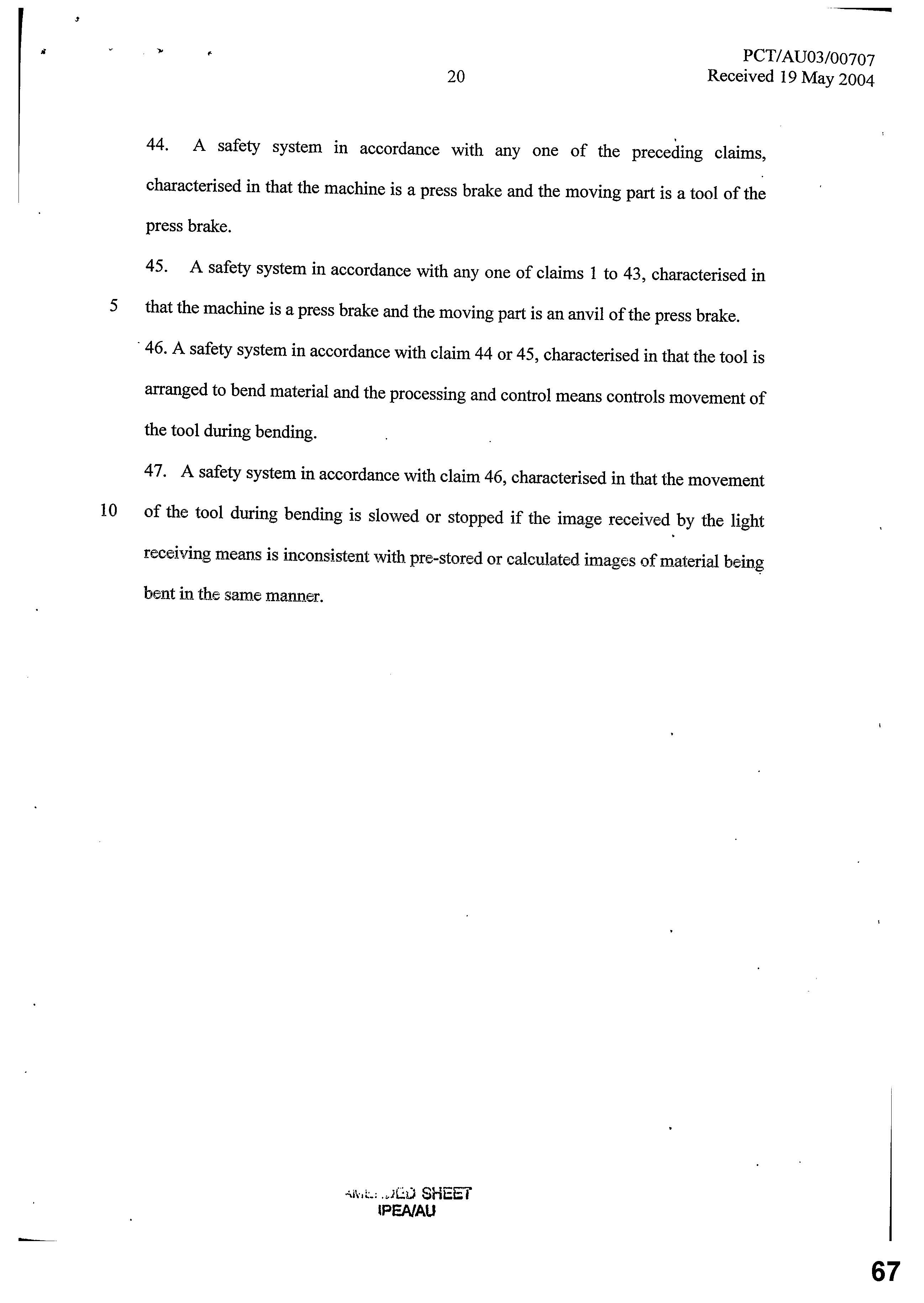
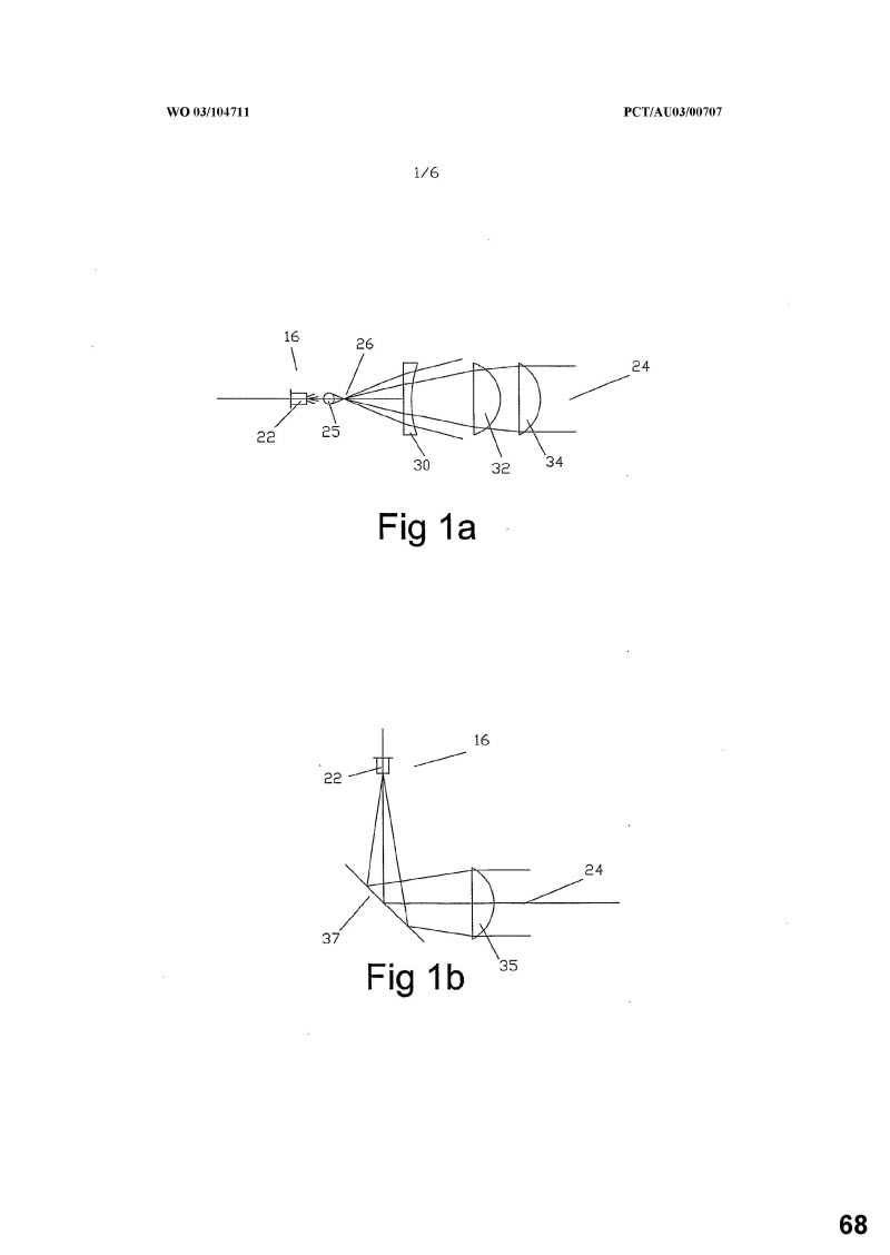
71 He said the light beam that is described in the Patent has a two dimensional cross section (that is, it is not a single point or a flat beam). The Patent described a lens arrangement at the transmitting end of the beam that is used to spread a point beam and then collimate the beam by making the rays of light that comprise the beam substantially parallel to one another so that the beam will have zero or negligible spread (that is, the cross section of the beam will not vary or vary only by a very small amount over its length).
72 At the receiver end, the Patent described a way of collapsing the light beam back to a smaller size. The light receiver also includes an image detection device. A processing and control means processes the images captured to search for unknown shadows and can stop or slow movement of the tool depending on what is detected. The Patent also mentioned that the processing and control means may use ‘shadow maps’ which are prior recorded images of what a safe view looks like as the tool moves through its path of movement. The system can compare these shadow maps with the shadows being cast on the receivers as the tool descends.
73 Mr Acheson’s view was that the invention described in the Patent is not like any systems he had seen or heard of as at the priority date or in 2003. Had he been aware of this Patent at the time he was engaged in the design of the safety system, it would have been of great interest to him and, in particular, its ability to distinguish between safe and unsafe obstructions.
Claims of the Patent
74 Mr Acheson referred to the ‘claims’ commencing at p 13 of the Patent and comprising 47 numbered paragraphs, all being for a ‘safety system’. Only claim 1 is a stand alone claim and the remaining claims add features to claim 1 or other previous claims, which ultimately trace back to claim 1. Having read the Patent, most of the words or phrases appearing in the claims of the Patent were clear and he could understand them based on his skill and present experience. He considered that he would have similarly been able to do so as at the priority date. The applicants’ solicitors asked him to provide an understanding of the meaning of certain words and phrases appearing in the claims. In relation to them, he said the following.
‘Image information’ in claim 1
75 Mr Acheson said he understood ‘image information’ to refer to the information that constitutes the ‘image’ that is detected by the image receiver; this is the image that is provided to the processing and control means. He understood that an image to be constituted by the output from one or more sensors, together with the details of its location. He considered that an image can exist where there is only one output from one location. As such, the information will be ‘image information’ as long as it includes the output of at least one sensor together with its location. It could also be the output from an array of sensors with information about the position of each sensor within the array.
‘Recognise the presence of one or more shadowed regions’ in claim 1
76 Mr Acheson took recognition to be referring to the ability to detect shadows cast by multiple independent objects. It requires the ability to ‘recognise the presence’ of a shadow that is cast. The reference to ‘presence’ he said implies a concept of time, that is, that there is an ability to know at any given time whether a shadow is there or not.
‘Obstructions in the region’ in claim 1
77 In this context, Mr Acheson understood an obstruction to be any opaque object which blocks the light travelling between the transmitter and the receiver. That could be, he said, fingers, hands, the workpiece, the anvil or the tool itself.
‘Processing and control means has sufficient image information to determine the boundaries of the or each shadowed region’ in claim 1
78 Mr Acheson said this referred to the required resolution of the image information and he understood the phrase to be saying that the resolution of the image information that is received by the processing and control means must be sufficient to allow determination of the boundaries. He noted that the phrase does not mention that the processing and control means must carry out boundary determinations. Rather, it only requires that the processing and control means have the necessary information to do so.
79 He also said that in order to understand what resolution would be required for boundary detection, it is helpful to understand how ‘boundary detection’ or ‘edge detection’ is carried out. He said it is one of the cornerstones of image analysis. He was familiar with edge detection, having applied it in projects on which he worked while at Raven Industries. While this was well after the priority date, he regarded the basic concepts as having been unchanged since around the 1970s.
80 ‘Edge detection’, he said, involves image information being analysed to search for a transition from a ‘dark’ output in one pixel to a ‘light’ output in an adjacent pixel or vice versa. In the case of photodiodes, this would involve a comparison of the voltage output of adjacent photodiodes looking for a sufficient step or difference, referred to as a gradient between the outputs. ‘Edge detection’ is a term Mr Acheson used interchangeably with ‘boundary detection’. I will refer to ‘boundary detection’ to keep the language consistent with the Patent.
81 Therefore, to have sufficient resolution to carry out boundary detection, there must be enough pixels that the transition from ‘light’ to ‘dark’ can be seen. As this phrase in claim 1 refers to ‘boundaries (plural) of the or each shadowed region’ (which are cast by one or more obstructions in the region) (emphasis added) there must be an ability to determine multiple boundaries on potentially multiple shadows. Mr Acheson regarded that requirement as being met if boundaries can be identified sufficiently to give an impression of the shape and location of a shadow, albeit in a coarse or grainy manner. As resolution increases, it becomes possible to detect boundaries with more precision. However, a relatively coarse resolution may still allow determination of the boundaries in the sense he described.
‘A single parallel beam of light’ in claim 5
82 Mr Acheson said this phrase requires that there is a single continuous beam of light, rather than using multiple point light sources in an array to illuminate an area. The phrase also requires the beam of light to be parallel, but does not say to what the beam is parallel. He therefore understood the term ‘parallel’ to refer to being parallel to itself, that is, that the rays of light in the beam are parallel to one another, or collimated, and the beams spread or beam angle is zero or very close to zero.
‘Columnated’ in claim 35
83 Mr Acheson treated this term as being a spelling error for what should be ‘collimated’. He was not familiar with the word ‘columnated’.
Acheson # 2
84 In a further affidavit, sworn on 27 April 2017 (Acheson # 2), Mr Acheson reviewed the evidence of Mr Appleyard in Appleyard # 2. Mr Acheson said that, in relation to the Lazer Safe Systems, the systems first scan and then identify the location of the tool and then blank segments representing the location of the tool. This means that the shadow cast by the tool would not stop the tool. Only if a shadow is detected in an unblanked area, that is ‘an unknown’ shadow, is the tool stopped. Mr Acheson spoke of an additional possible function for the Patent, which he understood as being as follows:
(a) a processing and control means may create ‘a total picture’ made up of the image information received as a tool moves through its path of movement, that is, a ‘shadow map’;
(b) the shadow map is a series of images, in effect, a video of what is observed as the tool passes through its full path of movement;
(c) in the first instance, it will include the tool and the anvil only, this is created on a first pass of the tool, with no workpiece present; and
(d) subsequently, additional shadow maps may be created which include images of the workpiece being bent.
85 It is only the final stage of the second function, namely the creation of shadow maps, including the workpiece, that is described by Mr Appleyard. Mr Acheson said this particular aspect of the operation of the system, being the comparison with the pre-stored images of the workpiece being bent, was specifically identified in the Patent.
86 In relation to integers 1.5 to 1.6, Mr Acheson disagreed with the view expressed by Mr Appleyard that none of the Lazer Safe Systems has integer 1.5 or integer 1.6. Mr Acheson said Mr Appleyard ‘seems to assume’ that these integers impose a range of requirements based on examples in the Patent of how the invention could operate. Mr Acheson did not see those as being requirements of claim 1 of the Patent. Mr Appleyard’s views on the matter, Mr Acheson said, seem to be influenced by:
(a) his view that the tool is not an obstruction as referred to in integer 1.5 and integer 1.6. A view with which Mr Acheson disagreed; and
(b) that the Lazer Safe Systems are not ‘safety systems’ after guarding mode is fully muted and the purpose of the BSM is to enhance productivity. Mr Acheson disagreed with this, saying the two functions described, namely, BSM and ‘Bendshield Plus’, which operate after the guarding mode is muted, provide a safety function. Systems having these functions, in Mr Acheson’s opinion, are ‘safety’ systems when these functions are active.
87 In relation to integer 1.5, Mr Acheson’s disagreement with Mr Appleyard was based on two assumptions that appeared to have been made by Mr Appleyard:
(a) that ‘image information’ meant information on the shape of an obstruction; and
(b) that ‘recognising the presence of a shadowed region’ required comparison with a stored image.
88 Mr Acheson disagreed that integer 1.5 imposed either of those requirements.
89 In relation to integer 1.6, again he considered that Mr Appleyard’s views were based on the assumption that integer 1.6 required that the system both:
(a) determined the shape of any obstruction; and
(b) controlled movement of the part based on the determination of the shapes of the obstructions or identification of the obstruction.
90 Mr Acheson disagreed that integer 1.6 imposed either of those requirements. Rather, in relation to integer 1.6, Mr Acheson said the following:
(a) the processing and control means must have sufficient image information to meet two requirements:
(i) it must have sufficient image information to determine the boundaries of each shadowed region. That term appears in integer 1.5, and refers to a shadow cast on the light receiving means by an obstruction in the illuminated region. The ‘shadowed region’ may be a shadow of only part of an object. What is likely to happen in practice is that if the hand of an operator starts to enter into the illuminated region, the tip of a finger may enter the illuminated region first. It follows that the first shadowed region from this obstruction to appear in the light receiving means will be a small shadow cast on the edge of the light receiving means by the tip of the finger. It is only the boundaries of the shadowed region that must be able to be determined. It is not the boundaries of the physical obstruction that must be capable of being determined. For example, in a case where the physical obstruction is a hand entering the illuminated region, at the moment it first appears and starts to cast a shadow on the light receiving means, the shadowed region may be only a very small section, such as a single pixel; and
(1i) it must have sufficient image information to control the movement of the parts, that is, the tool based on that information. This means that the processing and control means is able to generate output signals to control movement of the part based on the image information it is receiving. Nothing in the words of integer 1.6, or the claim when read as a whole, require that the control of the part be based on a determination of the shape or identification of what is the physical obstruction;
(b) there is no requirement that boundary determination is actually carried out, only that the image information is sufficient to do so; and
(c) the opening words of integer 1.6 require that the manner in which the region is illuminated allows the quality of image information that is required to be generated. This requires that the light transmitter transmits light with a high enough energy to create sufficient contrast between light and shadow on the receiving means. This allows a gradient to be found between the light and dark pixels as described above. It also requires that the illumination covers the range of sensors, that is, pixels sufficient for boundaries to be detected.
91 Mr Acheson also took issue with Mr Appleyard’s views about ‘obstructions in the region’. The prior description contains statements to the effect the tool was not an obstruction. Mr Acheson’s view was that the tool, and indeed any object that casts a shadow on the light receiving means, is an ‘obstruction in the region’. In the case of the tool, it is an obstruction that is deemed safe and, therefore, the system is able to continue operation, even with this obstruction present.
92 In relation to operation of the Lazer Safe Systems during ‘guarding mode’, Mr Acheson said:
(a) during set up, diagonal scanning software scans the image of the guarding area at the full camera resolution to identify the lowest point of the tool. Mr Acheson believed it must do so by detecting a boundary, that is detecting a transition from light to shadow at this point; and
(b) a predetermined number of ‘segments’ around the tool and around the corners of the guarding area are identified so that these can be blanked or disregarded. Certain segments are given a ‘weighting’ which conveyed to Mr Acheson these segments are treated differently in some way. However, this is not explained in the Product Description. Other segments are ‘blanked’, which conveyed to Mr Acheson that these segments are disregarded completely. He said that if there is weighting, rather than blanking, he would require further information as to what the term ‘weighting’ meant.
93 In relation to ‘bending mode’, Mr Acheson noted that the LZS-005 does not operate after the guarding function is muted and the tool begins to bend the workpiece. However, both IRIS and IRIS Plus provide functions during bending of the workpiece. IRIS and IRIS Plus provide the BSM function. IRIS Plus also provides angle measurement of the workpiece being bent. The feature called Bendshield Plus is also described, but is had not been put into commercial use, according to Mr Appleyard.
94 Mr Acheson understood that BSM operates by scanning the image to find a point on the top of a workpiece. This is found by the transition from a light pixel to a dark pixel, detecting a boundary of the shadow cast by a workpiece. As the workpiece is bent, the image is continuously scanned to find the new location of the top of the workpiece. By tracking the position of the top of the workpiece as it rises, the angular velocity of the workpiece can be calculated. Although this occurs after the ‘guarding’ function is turned off. In Mr Acheson’s opinion the system was still functioning as a safety system when BSM is operational. The purpose of BSM is to control the speed of the bending to avoid ‘sheet overhang injury’ as described in the Product Description. IRIS and IRIS Plus differ from the system described in the Cybelec Patent. The Cybelec Patent only provides a safety function, in his opinion, prior to the bending of the workpiece.
95 The bend angle measurement feature of IRIS Plus operates by identifying a straight line representing the edge of the workpiece on either side of the tool. The system then calculates the angle between these lines. The purpose of the function is to check, in real time, whether a target angle has been has been achieved. Mr Acheson did not regard this as a safety function.
96 However, Bendshield Plus involves a guarding function being turned back on for a period of time once bending is commenced. A significant number of segments in the obstruction matrix are blanked and it is only an area between the workpiece being bent and the tool that remains unblanked. This is to protect against an operator getting a finger trapped between the workpiece as it bends upwards and the side of the tool. It is not clear from the Product Description how the system determines which areas are to be blanked when Bendshield Plus is enabled, but Mr Acheson understood that the operation of this function would be the same as described above for guarding mode, thereby, providing a safety function.
97 In relation to location of obstructed segments, Mr Acheson expressed the view that the Lazer Safe Systems must know the location of these segments, contrary the view that expressed by Mr Appleyard, as the tool will only be stopped if an unblanked segment is deemed obstructed.
98 As to information used in BSM, in order to find the relevant pixel each time the system must be constantly scanning to locate the transition between light and dark, the boundary representing the leading edge of the workpiece. This requires analysing the output of all pixels along the scanning path in order to find this transition point.
99 Mr Acheson disagreed with Mr Appleyard’s view that the Lazer Safe Systems did not have the presence of integer 1.5. He said that the processing and control means can:
(a) during ‘set up’, identify the presence of the tool tip and blank out the segments occupied by the tool;
(b) during ‘guarding’, determine each segment, either obstructed or unobstructed, based on comparison of the voltages returned in each segment to a threshold; and
(c) during BSM, identify a point in the top service of the workpiece based on where the output of the sensors transition from light to dark.
100 Mr Acheson considered that it is only if the tool is regarded as not being an obstruction, that Mr Appleyard’s view could be correct. Mr Acheson said, however, that:
(a) the information available to the processing and control means is plainly ‘image information’;
(b) each of those processes involve ‘recognising the presence of a shadowed region’;
(c) the tool is an obstruction and the function of the system in identifying the tool during set up is relevant when considering integer 1.5; and
(d) the system is a safety system when BSM is operational and therefore the operation of BSM is relevant when considering integer 1.5.
101 Mr Appleyard’s view relied on the assertion that Lazer Safe Systems do not know the location of the obstructed segment. Mr Acheson disagreed, explaining that:
(a) the process of detection of the tool during set up clearly demonstrates that the processing and control means has sufficient image information to find the tool tip;
(b) even when considering the only segment information that is passed to the Press Controller and Safety System (PCSS), this would allow the determination of the boundary of any obstructed segment or group of segments simply by checking the status of the adjacent segments;
(c) the operation of the BSM function of each of IRIS and IRIS Plus plainly requires sufficient image information to determine boundaries, as the process involves determining a boundary;
(d) the tool is an obstruction and the function of the system in identifying the tool during set up is relevant when considering integer 1.6;
(e) the system is a safety system when BSM is operational, therefore, the operation of BSM is relevant when considering integer 1.6; and
(f) in both guarding mode and BSM, the image information is sufficient to be used, and in fact used, to control the movement of the part. In guarding mode, both the image information used to locate and blank the tool, as well as the image information received when the tool has descended, are used to stop the tool if another obstruction, outside the tool obstructed area or any other blanked areas, is detected. In BSM, the image information is used to calculate the bend speed and slow the tool if the speed is too high.
102 Integer 1.6 is present in the Lazer Safe Systems, according to Mr Acheson.
103 Mr Acheson also disagreed with Mr Appleyard in relation to the latter’s view on claims 2, 3, 4, 5, 14, 21 and 46, providing the following reasons (and some commentary on claim 38):
Claim 2
• I do not agree that the additional integer of claim 2 is not present in the Lazer Safe Systems.
• The processing and control means stops the movement of the part if an obstruction is detected in an unblanked segment of the obstruction matrix. These unblanked segments are determined during set-up, and are a “predetermined or calculated area” of the region.
Claim 3
• I do not agree that the additional integer of claim 3 is not present in the Lazer Safe Systems.
• The processing and control means is able to determine whether the obstruction is in a front, middle or rear area (relative to the tool) (see Product Description page 7). The system can respond differently depending on which area the obstruction arises. For example, when in Box Mode as described in paragraph 35 of the Product Description.
Claim 4
• I agree that the additional integer of claim 4 is not present in LZS-005.
• I do not agree that the additional integer of claim 4 is not present in IRIS and IRIS Plus.
• The BSM function calculates the angular velocity of the workpiece as it is being bent. It then slows the descent of the blade if the angular velocity is too high. This velocity could either be the velocity of just the operator side of the workpiece (relative to a stationary plane), or the velocity of the operator side of the workpiece relative to the other side of the workpiece (which, assuming a symmetrical V-shaped die, would be twice the velocity of the operator side only). In the first case, as the tool is stationary, the calculated velocity would be the velocity relative to the tool. In the second case, the calculated velocity would be of one obstruction relative to another.
Claim 5
• I do not agree that the additional integer of claim 5 is not present in the Lazer Safe Systems.
• The opinion expressed here seems based solely on the assertion that the term “relatively large” is unclear. By itself, without any reference to compare the size of the region, this term would be unclear to me. However the claim states that the region is “relatively large with respect to the size of a leading edge of the part” [emphasis in original]. This phrase however is not unclear to me. When I look at, for example, Figure 6 of the Product Description, it is clear that the region includes multiple segments to either side and below the tip of the tool, and that the tip of the tool occupies only a small area of the region. Consequently, I regard it as “relatively large” compared to the leading edge of the part.
Claim 14
• I do not agree that the additional integer of claim 14 is not present in the Lazer Safe Systems.
• Paragraph 27 of the Product Description describes that the equivalent of five fully obstructed pixels is required for a segment to be deemed obstructed. The ways in which this can occur are illustrated in RMA-30. In order to have the equivalent of five fully obstructed pixels, an obstruction must have a minimum thickness sufficient to span two pixels (as shown in the first example in RMA-30). This equates to a thickness of approximately 1.33 [millimetres], which is determined based on the pixel size. An obstruction of this size is too small to be part of the operator’s body. If an obstruction is smaller than this, it will not sufficiently obstruct enough pixels in a segment for that segment to be deemed obstructed. As a consequence, the movement of the part will not stop.
Claim 21
• I do not agree that the additional integer of claim 21 is not present in the Lazer Safe Systems.
• I am not able to understand the reason for Mr Appleyard’s opinion on this integer. He clearly states a screen is used. Paragraph 76 of the Product Description states that the screen receives the laser light from the sender unit (i.e. the image is projected onto the screen), and the camera observes its pixelated view of the screen (i.e. detects the image information).
Claim 38
• Based on the information in the Product Description and the Second Appleyard Affidavit, I am not able to either agree or disagree that the additional integer of claim 38 is not present in the Lazer Safe Systems.
• A lens at the receiver in such a system is used to refract light and focus the beam of light onto the array of sensors in the receiver. This is required where the area of the array of sensors is smaller than the area of the projected light. For example, in a typical domestic camera, a Jens arrangement is used to focus incoming light onto sensors within the body of the camera, which are much smaller than the field of view of the camera.
• Based on my knowledge and experience of the operation of systems such as this (i.e. having an array of light sensors), the only situation in which I am aware a lens would not [emphasis in original] be used is if the array of sensors is of the exact same physical size as the cross sectional area being observed. In my experience, this would be unusual, since sensor arrays are typically smaller than the area being observed, therefore require a lens to focus the light onto the sensors. I would therefore consider it unusual if the Lazer Safe System did not use such a lens. However without further information regarding the optics of the receiver, I am not able to clearly say one way or the other.
Claim 46
• I agree that the additional integer of claim 46 is not present in LZS-005.
• I do not agree that the additional integer of claim 46 is not present in IRIS and IRIS Plus.
• Plainly the tool is arranged to bend material. Plainly IRIS and IRIS Plus control the tool during bending, for example during the operation of BSM, or BendShield Plus when these features are present.
• Mr Appleyard’s opinion on this integer seems to be based on the notion that IRIS and IRIS Plus are not “safety systems” when they control the tool during bending. As I describe above, BSM is a safety function and as such, these systems are still functioning as a safety system when BSM is operational.
(paragraph numbers omitted)
104 In relation to Mr Berry’s affidavit, Mr Acheson said that Mr Berry did not provide any clear explanation of what he understood to be required by integer 1.5 and integer 1.6. However, similarly to Mr Appleyard, Mr Berry’s opinion on the presence of those integers, or otherwise, is based on the premise that claim 1 of the Patent requires the type of object identification that is described merely as a possibility in the Patent. He did not agree with that. Mr Acheson said:
While I do not agree with the premise on which Mr Berry proceeds in providing his opinion, I make the following comments on the opinion he expresses:
a) Mr Berry asserts that the Lazer Safe Systems do not attempt to determine boundaries or relative positions of silhouetted objects in the region, and do not use any form of image comparison. However, the system scans to identify the tip of the tool (i.e. finding a boundary and location). It [t]hen applies blanking based on this location. As described above, I regard this as a form of image comparison, i.e. between the map of blanked segments, and the actual output at a given time.
b) Mr Berry also asserts that there is no storage of old images. However the map of blanked segments (once created) must be stored in order to be subsequently used.
c) Mr Berry states that once an obstruction is determined in an unblanked segment, no further information is gathered, and no further processing is performed. This is plainly incorrect. The operation of L-filtering, Hard Shell Soft Centre filtering, and the operation of the latch function all require further processing once an unblanked segment is deemed obstructed. I note however that the Previous Product Description which was provided to Mr Berry in making his affidavit did not include any reference to these functions.
d) Mr Berry states that determination of boundaries cannot be made based on a single binary value. I agree with this statement. However the Lazer Safe System has more than just the binary value of the obstructed segments.
Acheson # 3
105 In Acheson # 3, Mr Acheson considered a Further Product Description, dated 23 May 2017, which he was provided a copy of by the applicants’ solicitors. Mr Acheson indicated that further elaboration of the Product Description appeared to make clear that the tool tip in the Lazer Safe Systems is detected as:
(a) the system scans along the diagonal path of pixels, commencing on the top left hand corner;
(b) it proceeds until it detects the shadow of the tool. It detects the shadow by identifying a transition from a light to dark pixel. The Further Product Description does not allow elaboration on how the system distinguishes between light and dark pixels, however, the description of what is occurring is the same as Mr Acheson had earlier alluded to. Image information is being analysed to identify a gradient, that is a sufficient step or difference between the output of the two adjacent pixels so that an edge of a shadow cast by the tool can be indicated;
(c) once the point of transition from a light to dark pixel is determined, the system commences a new scan. This new scan commences one row of pixels below the previous scan and will again continue until the shadow of the tool is detected; and
(d) the above process is repeated until the system scans from one side of the array to the other without detecting a shadow. At this point, the dark pixel in the previous scan is deemed to be the tool tip.
106 It follows that on the first scan, the system will determine the transition point between light and dark pixels corresponding to the left hand of the shadow cast by the tool at a point part-way down the tool. On each later scan, it will determine the transition point between light and dark pixels corresponding to the left hand edge of the shadow cast by the tool, one row below the previous scan. It will continue determining these points until the tool tip is found. The points together represent at least a part of the boundary of the shadowed region cast by the tool.
107 The operation of the Lazer Safe Systems in this manner reinforced his view, Mr Acheson said, that integer 1.6 is present in Lazer Safe Systems for the following reasons:
(a) the illumination of the region must be such that there is the required contrast between light and shadow. If this is not the case, the system will not be able to distinguish between light and dark pixels;
(b) the image information available to the systems is sufficient to carry out not just a single scan to identify the tool tip, but multiple scans. Each of the scans determines a point on the boundary of the shadowed region cast by the tool. The process, therefore, results in a determination of at least part of this boundary;
(c) the image information available to the system must be sufficient to allow the boundaries of any shadowed region to be determined by further scanning of the type carried out during the detection of the tool tip; and
(d) the scanning to identify the tool tip occurs during the set up of the system. By identifying the location of the tool tip, the system is able to identify the correct segments of the obstruction matrix to blank or disregard while the tool is descending. Therefore, this image information ultimately informs the system whether to respond to a segment that is deemed to be obstructed, that is, by stopping or slowing the tool, or to disregard it because the segment has been blanked. Therefore, the control of the movement of the part is based on this image information meeting the requirement previously described.
108 Mr Acheson also expressed the view that the Further Product Description confirmed to him that all values for every segment in the 15 x 15 matrix are sent to the PCSS, more specifically to the guard counter module in the PCSS. Filtering and muting refer to different things. Both processes are carried out by the guard counter module in the PCSS after receiving the values for every segment in the 15 x 15 matrix. The sequence of operation is still the same as he had previously understood when he swore Acheson # 2. Nothing in the Further Product Description changed the views he had expressed in the Acheson # 2.
Mr Appleyard
109 Mr Appleyard is the director of the respondent and has given both factual and expert evidence.
110 Mr Appleyard left school in 1973, going on to complete a two year course at TAFE and qualifying as an architectural draftsman. By the time he finished that course, his interest had turned to mechanical engineering. He was involved in sailing and yachts, competing at State and national events, and was offered a job as a draftsman and a rigger/mast builder.
111 He worked in this industry and in his mid-20s, having secured commercial production agreements with a builder and additional sponsorships, built a yacht to compete in the World Quarter Ton Cup Championships in Italy, in which he was Australian champion at the time.
112 On returning to Australia, Mr Appleyard worked as a consultant with the yachting industry for about a year. In 1982, he was approached to become the ‘state manager of the spar maker and alloy yacht master builders Alspar’, which wanted to establish a manufacturing branch in Western Australia. He worked in the engineering side for some time and subsequently purchased the Western Australian branch and bought into the Sydney business.
113 Mr Appleyard was involved in engineering throughout this time and was very involved in high level research, development and manufacturing for the America’s Cup yachts. He was involved in designing and developing technologies for these yachts for the Australian campaigns of 1983 to 1987. He was involved in the same way with the Whitbread Around the World racing yachts.
114 He carried this experience from the late-1980s and 1990s in light alloy engineering into other fields. For example, he was involved in design and manufacture of:
(a) lightweight crane systems for military patrol boats built in Henderson, south of Fremantle;
(b) alloy and stainless steel products used in the building industry;
(c) a large span 80 metre mobile irrigation system for the farming industry; and
(d) concrete form work systems for multi storied buildings.
115 Mr Appleyard first became involved in the industry and technology relevant to press brakes in about 1995. By that time, his father and brother had established a business called Safe-T-Corporation (STC) involved in designing and building safety devices for press brakes. He was involved first as a consultant, but from about 1996, as fulltime manager involved in product development, and subsequently part owner of the business. He left that business in November 1997 and established the respondent’s business in March 1998 for the purpose of developing a safety product for use with press brakes. The respondent had two directors, himself and Mr Ian Costley, an accountant with whom he had previously worked. It was funded by a number of seed investors. The first product was the Lazer Safe LZS-003 System. It was developed by Mr Appleyard over the period from 1998 to 2000 and was CE certified in 2000 (‘Conformité Européene’ or European Conformity certified), which meant that sales of the product could be made in Europe, being the main market for products of this sort at the time.
116 In general and simple terms, Mr Appleyard described press brakes and related safety systems up to 2002 to 2003 as follows:
(a) The press brake is an industrial machine used to bend sheet metal as part of the manufacturing process of metal products such as fridges and other white goods, metal building products, automotive vehicles and aeroplanes.
(b) The press brake has an electronic controller, which controls its operations. The human operator first uses the controller to input the requirements for the particular bending operation.
(c) The operator of the press brake stands in front of it and places the metal to be bent (the workpiece) on the ‘lower tool/die’, also called the anvil. The operator then causes the ‘upper tool/punch’, press tip or blade to descend by using the press brake controls. Typically a press brake will have a foot pedal which is operated by the operator such that it leaves his hands free to position the workpiece.
(d) The method of operation involves three stages:
(i) the blade, workpiece and anvil before the blade descends with the workpiece sitting on top of the anvil;
(ii) the blade as it touches the top of the workpiece; and
(iii) the blade as it continues into the V of the anvil, causing the workpiece to bend between the blade and the anvil.
(e) The blade of the upper part of the tool descends until it touches the workpiece. On continuing downwards into the V shape of the anvil, the blade causes the workpiece to bend upwards on either side. When the workpiece has been bent into the appropriate shape, often but not always 90 degrees, the blade descent will stop and will return to the start position. There are some press brake safety systems which work the other way around, with the lower part of the tool moving upwards towards the stationary upper part.
117 Based on this, Mr Appleyard stated that there is a risk to the operator in manually placing the workpiece on the anvil in that the operator may put a hand or finger between the blade and the workpiece as it sits on the anvil. If the descent of the blade is not controlled, there is a risk that the operator could suffer injury, such as amputation to a finger. Given the repetitive nature of the work being carried out, such that an operator might bend several hundred identical workpieces in a shift, there is a serious risk that an operator might lose concentration and make a mistake in the timing and placing of the workpiece.
118 Given the safety concerns, a number of safety systems were developed in the decades between the 1960s to the 1990s. By the time Mr Appleyard first became involved in the industry, one of the common safety systems was a ‘light curtain’, which had a series of light beams placed between the operator and the workpiece. If the operator broke the light beams of the light curtain at the relevant time, the system would send a signal to the controller to the stop the descent of the blade. More sophisticated systems had beams of light emitted and received on either side of the press brake, such that the beam of light was positioned below the leading edge of the blade and moved up and down with it. The emitter and receiver were accompanied by a control system, which controlled it and communicated with a separate control systems in the press brake itself.
119 The beam systems used what is known as the ‘mute point’. That is, when the blade reached the point immediately above the anvil, when it is no longer possible for the operator to place his finger between the blade and anvil because of the distance being too small, that is, between about two millimetres and 10 millimetres depending on the system used, the safety system is ‘switched off’, such that it will no longer react when the beam is broken, although the system itself is still operating. Some systems actually turn off the safety system when the mute point is reached, in this way, by the time the blade touches the workpiece and starts to bend it, the safety system is no longer detecting brakes in the beams. If the safety system continued to operate below the mute point, it would detect the workpiece itself and bending of the workpiece could not be completed. There are a number of complications, however, arising out of the use of beams systems, such as how to allow for a workpiece which has an uneven surface or where the workpiece has already had one side bent.
120 Mr Appleyard said that the respondent established itself as one of the leading companies worldwide in the field of design and manufacture of press brake safety and control devices. This has been, he said, ever since its commencement in 1998.
121 As at October 2016, the respondent employs 35 people in its Perth facility, including 12 in engineering and software, 6 in management and sales, 13 in manufacturing and 6 in administration.
122 In June 2002, the respondent had 14 employees, in addition to Mr Costley and Mr Appleyard, with 4 in management and administration, 6 in engineering and 4 in production.
123 Based on his knowledge of the press brake industry and the market for press brake safety systems, Mr Appleyard estimated that the respondent’s share of the world market in 2016 was approximately 65%. In about 2002, he estimated that the respondent’s market share was then about 30%.
124 In addition to his involvement in the design and manufacture of the respondent’s products, Mr Appleyard has become engaged in a number of committees involved in preparing standards for press brake safety systems. Since 2001, he has worked as a member of the ‘CEN/TC WG 143 Committee’, that is, the ‘Central European Normalisation Technical Committee Working Group 43’. This is the European body that writes the safety standards for press brakes and related machinery for the European Union. Mr Appleyard was on the panel of experts that wrote the latest generation standard EN12622. This was done between 2002 and 2009 and is the current standard in use today. The British standard 12622:2001 from 2001 was an early version of the standard that the Committee subsequently worked on. Based on that experience, Mr Appleyard was invited to join the ‘United States of America committee B.11’. This is the comparable standard writing body for the United States. Again, he was one of the panel of experts involved for writing the current generation press brake safety standard of 2012 for the United States. This work started in 2009.
125 Either the respondent, or Mr Appleyard, have received a number of industry awards for the products developed by the respondent over the years, including:
(a) winner of Products and Manufacturing category in 2006 WA Engineering Excellence Awards;
(b) finalist in Small to Medium Manufacturer Export Awards in 2006 West Australian Industry and Export Awards;
(c) finalist in Small to Medium Manufacturer Export Awards in 2003 West Australian Industry and Export Awards; and
(d) Australian and Western Region finalist in the Entrepreneur of the Year Award 2006.
126 The respondent has also been the recipient of various substantial State and Federal funding grants over several years, including in:
(a) 1998, $125,000;
(b) 2006, approximately $2.5 million;
(c) 2014, some $2.3 million; and
(d) eight years of qualification for and claiming of an ‘Export Marketing Development Grant’.
127 The press brake safety system developed by STC in about 1996 became known as the TIROPS System. He was involved in the development of the TIROPS System. It was based on the concept of installing light beams close to the blade, instead of the traditionally accepted practice of light curtains. This involved fitting a light emitter and receiver on either side of the press brake, such that the beam was below the blade.
128 When Mr Appleyard joined STC in about 1995, the TIROPS System product was a collection of standard third party parts, semi-assembled together and installed onto a press brake machine by STC. This was a relatively simple electrical mechanical installation, as would be done by electrical contractors. His father and brother were both electrical contractors.
129 The TIROPS System consisted of infrared light senders and receivers, readily available from a company called Banner. These were connected and therefore driven and controlled by a simple programmable logic controller (PLC). A simple set of logic was written into the PLC, such that when the lights senders were interrupted, a stop signal was given to the press brake. This is a simple operation, which would detect an interruption to any one of the two beams at first two, then later three, and the machine stopped in 100 to 300 milliseconds. This system, with its relevant overrun distance (that is the distance the tool continues before being stopped and the safety system being triggered) was only acceptable on the slow, low productivity machines, mainly in use at the time in Western Australia, that had an operating speed of up to approximately 50 millimetres per second. On faster machines, there was a risk that the system would not react quickly enough and the operator would still suffer injury by having the blade trapping his or her finger between the blade and the anvil.
130 Mr Appleyard was brought into STC to use his product development experience to turn this into a viable product. STC had sold or installed about twenty systems before he joined STC. Mr Appleyard was concerned about the quality and reliability of the early TIROPS System. It was intended to be a safety product, competing against certified failsafe light curtains. The TIROPS System used infrared light, invisible to the naked eye and which could be very divergent and reflective, that is, the light beam spread out over distances and reflected off surfaces such as the metal surfaces of the press brake itself. It was also difficult to align the beam emitter with the receiver. It used a simple single channel PLC with software written by an electrical contractor, not software engineers.
131 By 1995, however, Mr Appleyard set about a complete redesign of the whole concept and created a ‘map’ of what the product should be. He obtained a State government grant of about $50,000, which he used to commission an electronic engineering company called Omnitronics to work for him and STC to assist in its design. He selected laser light to be the light source on the basis that it is visible and can be focussed. The TIROPS System, which he designed, used photodiodes in the receiver. These are devices which generate an electric current on receiving light, the voltage of which can be measured and monitored by the PLC. When a light beam is obstructed, it causes a shadow on the diode (or part of it) which results in the lowering of the voltage which is detected by the PLC. The PLC is programmed so that it will trigger the system to stop the descent of the press brake tool on the voltage falling below a certain threshold, for example, the voltage drops by 50%.
132 Mr Davies was an employee of Omnitronics during the time that this development work was being carried out. He became involved in the development work as an engineer participating in hardware design, including circuit boards and the development of the software. As part of the development work, Mr Davies developed an algorithm which could be used to assist and determine whether a brake in the laser beams was caused by a vibration or an obstruction.
133 On completing this development work in conjunction with Omnitronics, Mr Appleyard established sales and installation of the TIROPS Systems, both in Australia and some regions of Asia. About 100 to 120 of the TIROPS Systems were sold before he left STC in November 1997.
134 In relation to the market for press brake safety systems, when Mr Appleyard first became involved in the STC business and development of the TIROPS System in the late-1990s, he realised the market in Australia was very small, with only about 150 press brakes sold per year.
135 As at June 2002 to 2003, with one exception, there were no businesses in Australia, apart from the respondent, designing and manufacturing safety systems for press brakes. STC was no longer operating. The one exception was a company called Red Eye, which was making light curtain safety systems. It was not a major competitor and went out of business in about 2004.
136 Mr Appleyard realised in the late-1990s that to build a business around a product involving press brake safety systems, it would be necessary to develop a product which could be sold overseas. In particular, he identified the European market as a market with the greatest potential for such a product. The reasons for this were:
(a) there were, and still were at the time Mr Appleyard swore his affidavit, a large number of press brakes manufactured and used in Europe. In the late-1990s, and after June 2002 to 2003, about 4000 to 5000 machines were built and sold a year;
(b) a number of the main manufacturers of press brakes in the world are based in Europe, such as Trumpf, Amada, LVD Group and Adira;
(c) most of the main manufacturers of press brake safety systems and related equipment are based in Europe, such as the German company Fiessler, Pilz, Nuova and SICK;
(d) the press brakes in Europe tended to be more sophisticated with more demanding safety requirements. Light curtains were used widely on press brakes in Europe;
(e) the regulatory regime and requirements in Europe, particularly within the European Union were, and still were at the time Mr Appleyard swore his affidavit, more stringent than elsewhere in the world, including the United States and Asia, and put the onus on press brake manufacturers to comply. For example, before a product could be sold in the European Union, it had to meet the requirements of CE certification, which could involve rigorous testing before certification. By June 2002 to 2003, press brake safety systems were required to comply with European CE safety directives and specifically CE standard EN12622, and all other standards that this referenced, to obtain CE certification.
137 In developing both the TIROPS System, and later the Lazer Safe LZS-003 System, Mr Appleyard researched press brake safety systems available in Europe, including the systems produced by Fiessler, Pilz and SICK. He obtained brochures at trade fares and exhibitions and got brochures and documents setting out operating instructions directly from customers and the press brake manufacturers. From 1999, Mr Appleyard started to regularly attend trade shows and exhibitions relating to press brakes, including:
(a) EMO, a major exhibition for metalworking machinery held once every two years in various countries in Europe;
(b) EuroBLECH, which was an event in Hanover, Germany, held once every two years, and attended by companies from all over the world involved in sheet metalworking technology;
(c) Lamiera, held once every two years in Bologna, Italy, attended by companies involved in machines and equipment for machining of sheet metal and related products; and
(d) Blech Expo, an annual international trade fare for sheet metalworking held at various venues.
138 Mr Appleyard said that press brake manufacturers and their suppliers regularly exhibited at and attended each of, the above trade shows and exhibitions from 1999 to 2002. By attending he was able to meet potential customers and see what competitors in the field were doing. The respondent first exhibited at the EMO exhibition in Paris in 1999 and on a regular basis at various exhibitions thereafter.
139 From 1999 and before June 2002 to 2003, Mr Appleyard also met with press brakes manufacturers in Europe, such as Trumpf, LVD, Amada and Adira to discuss their requirements for safety systems for press brakes.
140 By the time of the development of the Lazer Safe LZS-003 System in 1999 and by June 2002 to 2003, Mr Appleyard considered he had quite a detailed knowledge of the market for press brake safety systems and the available technology in Australia, Europe and the United States. He maintained such knowledge over the years to ensure that the respondent’s products continue to be at the leading edge of press brake safety system technology.
141 There were issues to confront when he designed the Lazer Safe LZS-003 System. The TIROPS System used three laser beams, each produced by a diode, which emits a laser beam intended to have a generally circular cross-section. Typically, the diameter of the laser beam, as emitted, will be about 6 millimetres, however, on very close inspection he noticed that due to the way the laser beams were produced, the cross-sectional shape of the laser was more like a rectangle of approximately 2 millimetres x 4 millimetres. At best, it was a blurred or a distorted circle.
142 Further, when emitted over a distance, the laser beam gradually expanded in diameter or in rectangular size. Typically for the TIROPS System, the diameter expanded to about 10-12 millimetres over a distance of about 5 metres. For the Fiessler AKAS System, this was more towards a diameter of 20 millimetres over 5 metre distance.
143 The receiver for each laser beam in the TIROPS System was a simple diode. It had a sensitive area of about 4 millimetres in diameter. When light covered the sensitive area, that is, from the laser beam, the diode produced a voltage.
144 Mr Appleyard noted the need for there to be a threshold of this level of voltage to determine the detection of an obstruction. This is to allow for inherent vibration in the whole safety system/bending machine installation. Vibration, which causes oscillations of the laser beam, is due to movement and vibration of a very large piece of machinery moving up and down at speed. The level of light received by the receiver may be going up or down or even cut off completely.
145 Another issue identified, is that light only travels in straight lines in a vacuum. When it travels through atmosphere, such as air, it moves around or deflects. This is due to the fact that the air is, in fact, a series of small mini currents of air at different temperatures. These pockets of air therefore have different densities. Cold air is more dense than warm air. Light passing from one density of air to another causes a ‘lensing’ effect, which bends the light.
146 Typically, the metal of the machine, including the bending tools, can be very cold. Then work starts and heaters (for example, the sun or air-conditioners) warm the air in the factory faster than the steel tools themselves can warm. Then the air moves around, particularly around these large moving machines and moving people. The effect can be easily seen because the laser light of most machines is visibly red. It can be seen as a red dot of laser light on the outer casing of the receiver. When a machine is completely at rest, the dot of the laser can be seen moving randomly around. This can be by 1 or 2 millimetres in all directions for a machine 3 metres to 5 metres long or even, in extreme situations, up to 10 millimetres. To combat this, the size of the laser dot was designed to be larger than the receiver area. Also, the voltage setting was typically set so the voltage drop used to detect an obstruction was typically about half of the voltage. Allowing for all tolerances and variables meant that when an obstruction, such as a hand or finger, half obstructed the laser beam receiver diode, this would cause a controlled stop of the machine.
147 The Lazer Safe LZS-003 System did not use multiple laser beams received by a corresponding number of receiver diodes. Rather, it used one large laser beam. It was approximately 2 to 4 millimetres in length and 50 millimetres wide, which Mr Appleyard described as a ‘planar’ laser on the basis that the 50 millimetres width was in one plane. The planar laser was received by one receiving structure that was 40 millimetres wide. This one structure had nine receiving photodiodes spaced equally along the 40 millimetre structure. It meant that any part of the 50 millimetre wide planar laser beam could illuminate any of the diodes.
148 Horizontal vibration did not cause a problem with the Lazer Safe LZS-003 System because there was always part of the beam being detected by the receiver diodes. For vibration in the vertical direction, lenses were placed in front of the receiving diode, receiving structure in the vertical plane, such that any light arriving in a different vertical plane was bent or deflected by these lenses to the receiving diode. But even with the extra refinement of the planar laser beam and use of lenses, in principle the Lazer Safe LZS-003 System worked in the same way as the TIROPS System or the Fiessler AKAS System. That is, if one of the photodiodes was half obstructed or shadowed, such that there was an approximately 50% drop in the voltage output detected for that diode, an obstruction was indicated and the controller would trigger a controlled stop of the machine.
149 In early-2002, the respondent developed a dual laser beam system, utilising two laser beams in parallel below the descending blade. The effect of that system is that the upper beam is positioned 4 millimetres below the blade and the lower beam is positioned 10 millimetres below the blade. In this system, when the lower beam reaches the mute point, it slows the speed of the descent of the blade and mutes. When the upper beam reaches the mute point, the safety system switches off. In this way, a controlled descent of the blade in the deceleration zone is created by the two laser beams.
150 Mr Appleyard produced a copy of the patent for the respondent’s dual beam system based on the provisional application first filed on 27 March 2002. The dual beams systems were sold to Trumpf shortly after the provisional application was filed.
151 In relation to the Fiessler AKAS System, in about 1997, when Mr Appleyard was working with STC, he was carrying out research to see what optical safety systems were available in Europe and first identified the Fiessler AKAS System in documentation obtained at that time. Later, in 1999, he saw the Fiessler AKAS System in operation on machines at the 1999 EMO Exhibition in Paris, where he first demonstrated and displayed the Lazer Safe LZS-003 System. He spoke to the Fiessler representatives and has had regular contact with them since. They sit together on the same EU standards committee. The respondent was competing directly with Fiessler and Mr Appleyard tried to keep up to date with its products and developments. He also discussed the respective merits of the Lazer Safe and the Fiessler AKAS systems with customers in Australia and overseas from 1999 to June 2002 to 2003.
152 Mr Appleyard explained that the Fiessler AKAS System, available in 1999 to 2002, operated in a similar way to the TIROPS System. There were three laser beams below the descending blade of the press brake, but in a different pattern to the TIROPS System. The three beams were received by a receiver unit which had three apertures in it to receive light from each of the beams. Behind each aperture at the back of the receiver unit were two diodes for receiving light. Mr Appleyard noted that the diodes operate in the same manner as the diodes on the TIROPS System and the Lazer Safe Systems.
153 The diameter of each of the laser beams produced by the Fiessler AKAS System was about 6 to 8 millimetres on transmission, expanding to about 20 millimetres when used in large wide press brake. By the time the beam is received by the receiver, the diameter of the light beams would be larger than the aperture. The diodes are fixed behind the apertures at the back of the receiver unit, such that they receive the constant amount of light in the absence of obstructions.
154 The Fiessler AKAS System only protected the zone directly under the tool and in front on the operator’s side. The TIROPS System at the time did this, but also the back edge of the tool as well, that is, on the other side from the operator.
155 While working on the patent application for the respondent’s planar beam system, in about May 1999, Mr Appleyard found various patents in the name of Fiessler. These were provided to him by Watermark, the respondent’s patent attorney, pursuant to search reports commissioned by the respondent or as a result of earlier systems cited against the respondent’s patent application. He studied the Fiessler patents for the purpose of the respondent’s patent application and for gathering information on what Fiessler was doing. He produced patent documentation from Fiessler. The documentation is consistent with his recollection of the Fiessler AKAS System marketed and sold by Fiessler in about 2001. According to his recollection, he read the Fiessler patent in an English translation in about 1999, when working with Watermark on the respondent’s patent application for the planar beam system.
156 What was unique with the Fiessler AKAS System as opposed to the other systems was the use of a camera or other imaging system. None of the earlier systems used a camera with an array of pixels or other imaging device for the purpose of determining the shape of the obstruction. However, when designing the Lazer Safe LZS-003 System in 1999, and in subsequent developments prior to June 2002 or June 2003, Mr Appleyard was aware of a camera and other imaging technology which could have been used with the respondent’s Lazer Safe LZS-003 System.
157 In particular, Mr Appleyard recalled discussing the use of a camera or imaging technology with colleagues, including Mr Paul Sertis and Mr Dimitre Stanev, during the development of the respondent’s dual planar laser beam in about 2001 to early-2002. The technology available at the time, and which was discussed, included:
(a) camera chips advertised online and consisting of a miniature lens and a processor which could be programmed to record and retain images;
(b) scanners, similar to barcode scanners, which consisted of a camera chip and a processor;
(c) CCDs, which typically had at the time, an array of light sensitive cells, like pixels in a camera, each of which would produce a small electrical charge on receiving the light. The charge from each cell could be identified and processed, such that an image was created;
(d) CMOS digital scanners, which had an array of light sensitive sensors or pixels, with an amplifier for each pixel, enhancing the signal. A product specification produced by Photobit, dated May 2000, was an example of documents Mr Appleyard recalls looking at around 2001 to 2002.
158 The Patent’s first provisional application refers to CCDs as being available, including use of an optical mouse and a CCD camera. It refers to a ‘standard CCD’ in discussing its use of this device. Mr Appleyard knew at June 2002 to 2003 that these systems would have given the Lazer Safe Systems the ability to record images, including images of the blade, workpiece and anvil or any obstruction. However, after looking at the available technology and discussing with his colleagues, Mr Appleyard came to the conclusion that there was no advantage to using a camera or other scanning technology over the use of diodes.
159 In Mr Appleyard’s opinion, at June 2002 to 2003 and at the time of swearing Appleyard # 1, there were no distinct disadvantages in using a camera or other means to determine the shape of the obstruction in a press brake safety system. The following reasons formed the basis of that conclusion:
(a) the system does not need to know the shape of the obstruction, it just needs to know that there is an obstruction;
(b) a system that detects the shape of the obstruction is unnecessarily complex involving additional hardware and software;
(c) a system which detects the shape of an obstruction will take more processing time, which may be critical when the system needs to trigger as soon as an obstruction is detected;
(d) there is more room for error, given the additional steps involved in detecting the shape of the obstruction and determining whether it is an obstruction which should trigger a safety system; and
(e) the safety standards which Mr Appleyard was actually involved in drafting did not require it, but emphasised the need to trigger a response as soon as an obstruction was detected.
160 So, none of the respondent’s safety systems have ever used imaging for the purposes of detecting obstructions.
161 Mr Appleyard first became aware of a system produced by Nuova, an Italian company, in about the late-1990s. The first system produced by Nuova was fixed to stands on either side of the press brake; on one side the transmitters and on the other side the receivers. It was positioned to send a single beam above the anvil of the press brake. It was static and did not move with the descending blade, unlike the TIROPS System and the Fiessler AKAS System. Nuova’s system was described as the ‘DFS System’. The instruction manual for the DFS System of 1997 shows a laser beam emitter/receiver. Mr Appleyard believes he saw that manual in the late-1990s.
162 At some time, in about late-2001 to early-2002, the respondent’s press brake customers in Italy, such as Gasparini, made him aware that Nuova had developed a new system. He attended the Lameira Exhibition in Bologna, Italy in 2002, where he saw a press brake safety system being promoted by Nuova, which he presumed was the system which the Italian customer has been referring to. Unlike the earlier DFS System described, this system had the transmitters and receivers moving with the press brake blade, fixed on either side of it, in a similar way to the TIROPS System and the Fiessler AKAS System. Mr Appleyard saw an instruction manual for the Nuova ‘DFS Laser Beam’ System dated 20 January 2004, but its content is consistent with his recollection of what he saw in the system in Bologna in May 2002.
163 The revised Nuova System had a laser beam transmitter and receiver configuration which, based upon the instruction manual, can be described as follows:
(a) the beam emitted by this system is passed through lenses, such that it forms a block laser beam in the general shape of a flattened letter ‘W’;
(b) the receiver has a number of receiving elements, specifically diodes, which generally match the shape of the beam; and
(c) the positioning of these components, the beam and receivers, can be seen in the instruction manual.
164 As with the TIROPS System, Fiessler AKAS System and Lazer Safe LZS-003 System, the Nuova DFS Laser Beam System would be triggered on obstructions casting shadows on a receiving diode, such that a voltage produced by the diode would fall below the set threshold, which Mr Appleyard assumed to be about 50%.
165 Mr Appleyard also discussed the Cybelec System. He cannot recall when he first became aware of it. He recalled reading it when he was preparing the respondent’s patent application for the planar beam system in about May 1999. He believed that it was provided to him by Watermark, having been identified in a search carried out by Watermark, or on the Cybelec Patent being cited against the respondent’s patent application. He was not aware of use of the Cybelec System, either in Australia or overseas at the time.
166 Based on his understanding and knowledge of, and experience in, press brake safety and control systems at June 2002 and 2003, there being no relevant difference in his understanding between those dates or when he first read about it in May 1999, the Cybelec Patent described to him a system which was primarily used as a control system for the purpose of measuring the angle of the workpiece as it was bent. The workpiece is bent by the blade moving downwards into the V of the anvil, each side of workpiece moves upwards, creating an angle between each side. If the workpiece is horizontal, which it usually is, the initial angle is 180 degrees. As the workpiece is bent, the Cybelec System can measure the angle as it changes from 180 degrees to, for example, 90 degrees.
167 Based on the Cybelec Patent, Mr Appleyard considered that at June 2002 to 2003 he would have understood the Cybelec System to work as follows:
(a) the light being emitted was passed through lenses which expanded into a beam with a circular cross section, the diameter being relatively large;
(b) the light being received in the embodiment consisted of a rotating box with a number of holes through which the light passes, the light being directed to diodes;
(c) the system had an angle coder and microcoordinator, or controller, used to process the information, including the light received on the diodes and the position of the box at any time;
(d) when the box stood still, the light passing through the holes and directed onto the diodes would be seen as dots of light corresponding to the size of the holes. The number of dots would depend on the number of holes. Three holes would produce three dots;
(e) when the box rotated at speed, the light passing through the holes would be received on the diodes and processed by the controller, such that the system sees a number of semi-circular arcs of light, the number of arcs corresponding with the number of holes;
(f) as the workpiece bent each side would rise up and cause a shadow to be cast on each arc of light;
(g) the system can draw a line, in effect, between the shadows cast on each side of the system, seeing two lines, one for each side of the workpiece; and
(h) this information can then be used to calculate the angle between the sides of the workpiece.
168 The Cybelec System, as disclosed, could have up to twenty holes or diodes. In those circumstances, the distance between the arcs is much smaller and the distance between the shadows cast on the arcs is also smaller. In this way, the full shape of the workpiece could be determined by the system and the angle of bend much more clearly shown.
169 According to Mr Appleyard, all of these operations happen during the bending process and after any safety device has been muted to allow bending to occur. He said that in this mode, the Cybelec System is not a safety device. If twenty holes or diodes were used instead, the Cybelec System would have the capacity to see a number of shadows cast in the arcs of light and to determine the shape of the obstruction.
170 Mr Appleyard has reviewed the Patent and, subject to certain words which he contends are unclear, understands what it claims as the invention. Based on his understanding, knowledge and experience in press brake safety and control systems as at June 2002 and 2003 (though claiming there to be no relevant difference in his understanding between those two dates) the Patent involves a safety system for use of a machine, such as a press brake, with features present and generally known in these earlier systems and this field. He asserted the system has at most as its distinguishing feature over those earlier systems, the capability to recognise the shape of an obstruction and control the machine, depending on the shape of the obstruction recognised.
171 In relation to the wording used in the Patent, Mr Appleyard considered the following words and phrases to convey the following:
(a) a ‘safety system’ is a system which is intended to protect the user of press brakes from injury caused by, for example, getting a finger trapped between the blade of the tool and the workpiece. This can be differentiated from a control or productivity system, which is concerned with other aspects of the press brake, for example, determining the correct angle of bending of the workpiece, as with the Cybelec Patent;
(b) ‘image information’ means that the shape of the obstruction must be capable of being determined and sufficient to be used by the system;
(c) the use of the word ‘recognise’ in relation to the presence of shadowed regions means that the system is not just detecting the shadowed region, but the system recognises the shape of the obstructions;
(d) a ‘shadowed region’ emphasises that the system can determine the shape of the obstruction;
(e) an ‘obstruction’ is something which is in the way of the blade of the tool and which should not be there during the descent of the tool towards the workpiece. Neither the blade nor the workpiece can be ‘an obstruction’. A clear example is the operator’s finger; and
(f) use of the words ‘boundaries of the or each shadowed region’ emphasises that the shape of the obstruction must be capable of being determined and sufficient to be used by the system.
172 Mr Appleyard said:
(a) the use of the word ‘recognise’, as opposed to ‘detect’, suggests that ‘the presence of one or more shadowed regions on the light receiving beams cast by obstructions in the region’ is recognised, i.e., already known and matched with what is known. However, by its very nature, an obstruction is something which should not be there and not known to the system. For example, the operator’s finger, which is an obstruction and which the system does not have a prior image of. In fact, it is the very fact the obstruction is not recognised, which causes the safety system to trigger and stop the descent of the blade; and
(b) the phrase ‘sufficient image information’ used in the Patent, according to Mr Appleyard, is inherently vague. It refers back to ‘image information from the light receiving means’, but it is unclear as to precisely what information is being utilised and how much information is required for it to be ‘sufficient’.
173 In relation to the provisional applications, Mr Appleyard said that while the invention described in the Patent in claim 1 is broadly described in the provisional applications, claim 1 of the Patent includes the integer that ‘… the processing and control means has sufficient [image] information to determine the boundaries of the and each shadowed region’. This phrase is not included anywhere in the provisional applications. He could not identify any other text in the provisional applications which broadly describes such an integer.
174 Mr Appleyard asserted that each of the provisional applications describe a system which does more than just detect obstructions. Instead, the system is used to build a library of images, or shadow maps, which images are recognised by the system. The images may be of the tool itself or parts of the workpiece or anvil on which the workpiece is being bent. It is only when something is recognised as not matching these images, that the safety system is triggered. The system detects an image which it compares with the images already stored in the system. If the shape of an obstruction does not match an image stored in the system, the safety system will be triggered.
175 In Mr Appleyard’s opinion, claim 1 of the Patent is wider or broader than that which is described in the provisional applications. Subject to qualifications about the word ‘recognise’, he asserted that claim 1 of the Patent does not require the system to compare the shape of an obstruction with the library of shadow maps, which are what is described in the provisional applications.
176 However, the use of the word ‘recognise’ in claim 1 suggested to Mr Appleyard that the system is comparing the shape of the obstruction with something which is known, that is, the existing library of shadow maps in the system. The system must be doing more than ‘detecting’ the shape of the obstruction, it must recognise it is not one of the shapes already known to it in the library of shadow maps.
177 Therefore, Mr Appleyard said, either:
(a) claim 1 (and all the other claims which are dependent on it) is wider than that which is described in the provisional applications, in that claim 1 does not require the system to compare the shadow of the obstruction with the shadow maps; or
(b) the word ‘recognise’ necessarily implies that the system is making a comparison between the obstruction and the shadow maps and recognising that the shadow cast by the obstruction is not the same as one of the shadow maps. Otherwise the provisional applications and the Patent disclosed no way of the system operating by ‘recognition’.
178 The Patent Cooperation Treaty (PCT) application for the Patent, filed on 10 June 2003, Mr Appleyard noted does not use the word ‘recognise’, but instead describes ‘the safety system being arranged to detect the presence of an obstruction’ (emphasis added). Claim 1 of that application does not refer to shadow maps, although it does later refer to ‘shadow regions’.
179 Further, the amendments emphasise the requirement in claim 1 that there be ‘image information’ and added the wording that ‘the processing and control means has sufficient image information to determine the boundaries of the or each shadowed region’.
180 In summary, therefore, Mr Appleyard said:
(a) the provisional applications are concerned with the use of shadow maps and a system which involves comparing known images with images which the system does not recognise;
(b) the PCT application uses the word ‘detect’, rather than ‘recognise’;
(c) the Patent, as granted, uses the word ‘recognise’, but it is unclear whether this means that claim 1 requires a comparison with known images, that is, the shadow maps.
181 For the same reason Mr Appleyard said, as discussed in relation to claim 1 in the provisional applications, claim 1 of the Patent is wider in scope than the specification, which is concerned with describing the use of shadow maps, whereas claim 1 does not refer to shadow maps, unless the word ‘recognise’ and the phrase ‘image information’ are interpreted to refer to shadow maps.
Wording in claim 1
182 Mr Appleyard disagreed with Mr Acheson’s comments on the meaning of ‘image information’ and ‘image’ as used in claim 1 of the Patent. The word ‘image’ meant to Mr Appleyard, in the context of the Patent, the shape or outline of the shadowed region cast by an ‘obstruction’. The phrase ‘image information’ means information relating to that shape or outline. The output of a single sensor may be part of the image information, but by itself, does not provide sufficient information as to the shape or outline to constitute ‘image information’.
183 He disagreed that the workpiece was an obstruction, rather it is the very thing which the blade is intended to bend as part of the normal operation of the press brake. However, if part of the workpiece is already bent, such that it is between the blade and the part of the workpiece to be bent, then part of the workpiece could be considered an obstruction because it appears between the blade and the part of the workpiece to be bent. The anvil is not an obstruction. By the time the blade reaches the anvil, it is already bending the workpiece. The anvil is not between the blade and the workpiece.
184 The tool, or specifically the blade, is not an obstruction, according to Mr Appleyard, by its very nature. The blade cannot be something between itself and something else. The introductory words in the patent specification say ‘the present invention relates to a safety system … to detect the presence of an obstruction in the path of the moving part’. The illuminated region described in claim 1 is in the path of movement of the ‘moving part’. The part itself is not an obstruction.
185 Mr Appleyard disagreed with the suggestion that the processing and control means does not actually carry out boundary determination. To function as described in claim 1, the processing and control means must determine the boundaries of the shadowed region caused by an obstruction. The ‘sufficient image information’ is the boundaries of the, or each, shadowed region, which information is then used to control the movement of the blade.
186 In Mr Appleyard’s view:
(a) a single point cannot determine an edge or boundary;
(b) to determine a boundary, there must be multiple points identified, such that the shape or outline of the boundary can be determined;
(c) identifying points along a single edge of the boundary will not determine the boundary or boundaries of an object. It will only identify the location of that edge and not the boundaries of the object; and
(d) claim 1 of the Patent requires that the actual ‘boundaries’ (plural) of each shadowed region be determined, which means that the shape or outline of the obstruction must be determined.
Terms used in the Patent
187 Mr Appleyard said:
(a) ‘image information’ cannot be just the output of a single sensor. A single output does not provide information about an image, it provides information about a single point. This is not sufficient by itself to constitute ‘image information’. There needs to be sufficient information from enough sensors such that shape of the obstruction can be determined;
(b) ‘recognise’ is unclear. If it simply means ‘detect’ then there is no need to use the word ‘recognise’. If the word ‘recognise’ is used to describe the process by which ‘allowable obstructions’ are distinguished from ‘non-allowable obstructions’ (as described above) then Mr Appleyard can see why it would be used. In such a context it means more than just detection and connotes a state of affairs involving both known and unknown shadowed regions;
(c) a ‘region’ cannot be a single point or even a number of single points. It is an area. In the context of the Patent, there needs to be sufficient information to determine the shape or boundaries of the region; and
(d) based on the wording in the Patent of the term ‘obstruction’, it is something which is in the path of the blade (and not be the blade itself) which should not be there and which causes the safety system to trigger to prevent injury. The workpiece, unless bent in such a way as to have part of it bending upwards so as to be detected, is not an obstruction. Similarly, the anvil is not an obstruction.
188 The claims of a patent serve to delineate the monopoly provided for by the patent: see Welch Perrin & Co Pty Ltd v Worrel (1961) 106 CLR 588 per Dixon CJ, Kitto and Windeyer JJ (at 609). In Electric & Musical Industries Ltd v Lissen Ltd (1938) 56 RPC 23 (at 39), Lord Russell said:
The function of the claims is to define clearly and with precision the monopoly claimed, so that others may know the exact boundaries of the area within which they will be trespassers.
189 The Court should approach the task of patent construction with a generous measure of common sense: Ranbaxy Laboratories Ltd v AstraZeneca AB (2013) 101 IPR 11 per Middleton J (at [108]); Beach J made a similar observation in GlaxoSmithKline Consumer Healthcare Investments (Ireland) (No 2) Ltd v Apotex Pty Ltd (2016) 119 IPR 1 (at [270]). The relevant principles are:
(a) the proper construction of a claim is a matter of law: Decor Corporation Pty Ltd v Dart Industries Inc (1988) 13 IPR 385 per Sheppard J (at 400);
(b) a claim is not to be read in the abstract, but is to be construed in the light of the common general knowledge and the art before the priority date: Welch Perrin per Dixon CJ, Kitto and Windeyer JJ (at 610); Kimberly-Clark Australia Pty Ltd v Arico Trading International Pty Ltd (2001) 207 CLR 1 per Gleeson CJ, McHugh, Gummow, Hayne and Callinan JJ (at [24]); Artcraft Urban Group Pty Ltd v Streetworx Pty Ltd (2016) 117 IPR 210 per Greenwood J (with whom Rares J concurred) (at [74]); GlaxoSmithKline (at [274]);
(c) the words used in a specification are to be given the meaning that the normal person skilled in the art would attach to them, having regard to his own general knowledge and to what is disclosed in the body of the specification: Decor Corporation per Lockhart J (at 391) and GlaxoSmithKline (at [276]);
(d) while the claims are to be construed in the context of the specification as a whole, it is not legitimate to narrow or expand the boundaries of monopoly as fixed by the words of a claim by adding to those words glosses drawn from other parts of the specification, although terms in the claim which are unclear may be defined by reference to the body of the specification: Welch Perrin (at 610); Kimberly-Clark (at [15]); GlaxoSmithKline (at [271]);
(e) experts can give evidence on the meaning which those skilled in the art would give to technical or scientific terms and phrases and on unusual or special meanings to be given by skilled addressees to words which might otherwise bear their ordinary meaning: Sartas No 1 Pty Ltd v Koukourou & Partners Pty Ltd (1994) 30 IPR 479 per Gummow J (at 485-486), citing Glaverbel SA v British Coal Corp [1994] RPC 443 per Mummery J (at 485-486);
(f) the Court is to place itself in the position of a person acquainted with the surrounding circumstances as to the state of the art and manufacture at the time: British Dynamite Co v Krebs (1896) 13 RPC 190 per Lord Chancellor Cairns (at 192); Kimberly-Clark (at [24]); Artcraft Urban Group (at [74]); GlaxoSmithKline (at [274]); and
(g) issues of construction must be considered without any regard for the alleged infringing articles: Fresenius Medical Care Australia Pty Ltd v Gambro Pty Ltd (2005) 224 ALR 168 per Wilcox, Branson and Bennett JJ (at [95]); Australian Mud Company Pty Ltd v Coretell Pty Ltd (No 4) [2015] FCA 1372 per McKerracher J (at [114]). A court should construe the claims as ‘if the infringer had never been born’: Welcome Real-Time SA v Catuity Inc (2001) 51 IPR 327 per Heerey J (at [21]).
190 Because a patent is not a document inter partes, but a public instrument, this imposes limits on its construction: Welch Perrin (at 610); Kimberly-Clark (at [34]); Decor Corporation per Sheppard J (at 400); Pfizer Overseas Pharmaceuticals v Eli Lilly & Co (2005) 225 ALR 416 per French and Lindgren JJ (with whom Crennan J concurred) (at [249]). The Court is not free to amend the specification under the pretext of construction. Amendment is dealt with under a separate statutory mechanism. The hypothetical construct of the skilled addressee cannot be taken so far as to re-write or amend a claim of the specification: GlaxoSmithKline (at [12] and [14]). The Court is obliged to construe the claim as it is, rather than what it should have been: GlaxoSmithKline (at [12] and [14]).
191 The person skilled in the art is the hypothetical person to whom the patent specification is addressed (the skilled addressee or worker): General Tire & Rubber Co v The Firestone Tyre & Rubber Co Ltd (1971) 1A IPR 121 per Sachs, Buckley and Orr LJJ (at 134). As Finkelstein J observed in Root Quality Pty Ltd v Root Control Technologies Pty Ltd (2000) 177 ALR 231 (at [70]), the identity of the skilled addressee is relevant for a variety of purposes:
He is the person to whom the patent is addressed and who must construe it. He is the person whose knowledge will determine whether a patent is novel. He is the person who will judge whether a patent is obvious.
192 With respect to claim 1, the terms in issue are:
(a) ‘safety system’;
(b) ‘image information’;
(c) ‘recognise the presence of’;
(d) ‘obstruction’;
(e) ‘sufficient image information to determine the boundaries of the or each shadowed region’.
193 Those terms in integer 1.5 and integer 1.6 are required to be construed in context.
3.3 Applicants’ position on construction
194 Examining the five terms in issue sequentially, the applicants contend as follows.
195 ‘safety system’: the applicants contend that the words ‘safety system’ include any modality that provides a safety function (within a system which is for use with a machine having a moving part, as set out in the preamble to claim 1). This does not limit the safety function to stopping an operator having part of their body caught beneath the blade, or require the modality to serve solely a safety function. All that is required, the applicants say, is that the modality improves or facilitates the safety of an operator.
196 The applicants say the respondent’s approach to this term seeks to read down the term ‘safety system’ by reference to p 1 lines 5-7 of the Patent. In doing so, the applicants contend that the respondent seeks to limit the otherwise plain meaning of the words to a system solely concerned with one form of safety (i.e. an operator having a part of his/her body caught beneath the blade of a press brake as the blade descends). The applicants say the respondent has ignored p 11 lines 14-18, which refers to analysing the bending of work and considering the movement of shadows. This passage concerns different forms of safety to that identified on p 1 lines 5-7 of the Patent. This passage of the Patent identifies reducing the risk of a finger becoming trapped between the workpiece and the tool (i.e while the workpiece is being bent), as well as more generally referring to determining an ‘unsafe state’ during the bending process.
197 ‘image information’: the applicants assert that this is a broad concept, properly understood as including the information that is outputted from the light receiving means. This information is in turn provided to the processing and control means. ‘Image information’ could be, for example, the output from the sensors of a CCD or a camera. The image information in such an example would be the voltages produced by each diode/pixel in the CCD or camera. The applicants note that under cross-examination Mr Appleyard conceded that the term ‘image information’ was used in one of his own company’s patent application (for the Lazer Safe LZS-003 System high speed product) to describe the information output from a light receiver. Similarly, under cross-examination Mr Berry agreed that the term ‘image information’ as it appears in claim 1 of the Patent is the output of the light receiver.
198 In light of the evidence at trial the applicants submit that their construction of this term is to be preferred.
199 ‘recognise the presence of’: the applicants argue that this term must be properly understood in light of the phrase in which it appears, i.e. ‘recognise the presence of one or more shadowed regions’. This, the applicants say, requires no more than the ability to identify the existence of a shadowed region. As such, the applicants contend the term has the same meaning as ‘detect’.
200 The Macquarie Dictionary relevantly defines ‘recognise’ as:
1. to know again; perceive to be identical with something previously known (he had changed so much that one could scarcely recognise him).
2. to identify from knowledge of appearance or character.
3. to perceive as existing or true; realise (to be the first to recognise a fact).
4. to acknowledge formally as existing or as entitled to consideration (one government recognises another).
5. to acknowledge or accept formally as being something stated (to recognise a government as a belligerent).
6. to acknowledge or treat as valid (to recognise a claim).
7. to acknowledge acquaintance with (a person, etc.) as by a salute.
8. to show appreciation of (kindness, service, merit, etc.) as by some reward or tribute.
201 The Macquarie Dictionary relevantly defines ‘detect’ as:
1. to discover or notice a fact, a process, or an action: to detect someone in a dishonest act.
2. to find out the action or character of: to detect a hypocrite.
3. to discover the presence, existence, or fact of.
…
202 Mr Acheson confirmed in his oral evidence that ‘recognise’ means the same as ‘detect’. Mr Acheson also stated that to recognise required a comparison. This need not be a comparison between images. As stated in Acheson # 1, ‘recognise the presence’ of a shadowed region requires prior knowledge of what will occur when a shadowed region is present. This could be, for example, the voltage output from a sensor dropping below a threshold. The relevant ‘comparison’ may therefore be the current output of a sensor or sensors against a pre-determined threshold. In his oral evidence, Mr Berry also confirmed that his use of the term ‘recognise’ in relation to the presence of an obstruction could be substituted for the word ‘detect’.
203 To the extent that Mr Appleyard gave the opinion that the term ‘recognise’ requires either the recognition of shapes, or alternatively a comparison with pre-stored images, the applicants contend that this ignores the plain meaning of the word as it appears in claim 1. The applicants argue that this would seek to import a limitation based Mr Appleyard’s view of the effect, on construction, of what is disclosed by a preferred embodiment described in the Patent.
204 In light of the evidence at trial the applicants submit that their construction of this term is to be preferred.
205 ‘obstruction’: as to this term, the applicants contend that ‘obstruction’ as it appears in claim 1 refers to any object which blocks light from the light emitter, thereby creating a ‘shadowed region’ on the light receiving means. This view is supported by the affidavit evidence in Acheson # 1, which was confirmed by Mr Acheson during cross-examination. An ‘obstruction’ can therefore include the tool, the workpiece, the anvil, or a part of the operator’s body. The oral evidence given by Mr Acheson on this point was to the effect that the tool, workpiece or anvil can all be within the illuminated region (i.e. they can obstruct the light beam), and can all cast a shadow on the light receiver. Some of these, such as the tool and the anvil, are expected to be present, and their presence should not (and does not in operation) require the tool to stop.
206 The applicants say that in the absence of any way of distinguishing between ‘good’ or allowable shadows (such as that cast by the tool, anvil or workpiece) and ‘bad’ shadows (such as that cast by the finger or hand of an operator) all shadows are potential obstructions. In general terms, the preferred embodiment of the invention described in the Patent is concerned with providing a safety system that can distinguish between these ‘good’ shadows and ‘bad’ shadows. For example, the Patent (at p 8 lines 8-12) refers to ‘safe’ shadow maps where ‘no obstruction is detected which would require stopping or slowing of the press brake’. Such a shadow map includes the forward edge of the tool and the anvil. In this context, the applicants say, the proper understanding of an ‘obstruction’ is any object casting a shadow.
207 In short, the applicants say the respondent attempts to narrow the meaning of the term ‘obstruction’ (in a bid to limit construction of claim 1 to a particular type of ‘image comparison’ device) by relying, with undue emphasis, on p 1 lines 5-7 of the Patent. The applicants contend that this fails to have proper regard to the plain meaning of the words of the claim. Where resort to the body of the specification is made, the applicants submit that the respondent’s approach fixates on one passage only and ignores other parts of the specification.
208 ‘sufficient image information to determine the boundaries of the or each shadowed region’: Consistent with the evidence of Mr Acheson, the applicants contend that this phrase is to be construed in the following way:
(a) it refers to the resolution or quality of information that is required;
(b) the resolution or quality of information must be such that the boundaries of the or each shadowed region are capable of determination. There is no requirement that a complete boundary, that is around the entirety of a shadowed region, must be determined by the system;
(c) determination of a boundary involves identification of a transition from ‘light’ to ‘dark’ pixels (referred to as finding a ‘gradient’). Where a gradient is found between two adjacent pixels, an ‘edge’ exists. An edge is part of a boundary, but an edge is not a boundary within the proper construction of that term in claim 1;
(d) a boundary of a shadowed region is a line that demarcates the area of the shadow that is cast. As an area is two-dimensional, it must be possible to find gradients and determine the ‘boundary’ in two dimensions; and
(e) therefore, the phrase requires that there be sufficient image information (i.e. enough pixels at a suitable resolution and spacing) to allow the gradients (i.e. transition from light to dark pixels) to be found around the perimeter of the shadowed region. If the shadowed region comprises only one ‘dark’ pixel, this requirement is met if there is sufficient image information to identify this transition from ‘light’ to ‘dark’ between that one darkened pixel and the surrounding pixels.
209 The applicants contend that Mr Acheson is the only witness who gave any proper consideration to the meaning of this term as it appears in claim 1.
210 As to Mr Appleyard (for the respondent), the applicants say:
(a) Mr Appleyard’s evidence in Appleyard # 1 was initially to the effect that this term requires that the system determine the shape of the obstruction and that the system uses this information. He simultaneously maintained that the term ‘sufficient image information’ was ambiguous and unclear;
(b) Mr Appleyard later, in Appleyard # 3, gave evidence to the effect that the processing and control means must determine the boundaries of the shadowed region, and that the ‘sufficient image information’ was itself the boundaries of the shadowed region. This assertion, the applicants say, is illogical. The plain words of the claim require sufficient image information to determine boundaries. The ‘sufficient image information’ cannot itself be the boundaries. Rather, the ‘sufficient image information’ must be information which is capable of being processed to determine boundaries;
(c) to the extent that Mr Appleyard is taken to assert that this phrase requires that the system determine the shape of the obstruction, the meaning Mr Appleyard’s gives to this term is indistinguishable from the meaning he gives to ‘image information’. Mr Appleyard’s conflation of these terms was highlighted when he expressed the view in Appleyard # 3 that ‘image information’ requires ‘sufficient information from enough sensors such that shape of the obstruction can be determined’; and
(d) this conflation clearly illustrates Mr Appleyard’s failure to give proper consideration to the actual words used in claim 1. It also indicates that he has approached the entire construction exercise from the perspective that claim 1 is to be limited to a particular embodiment described in the Patent, and has attempted to give meaning to the words in the claim in order to arrive at this conclusion.
211 As to the respondent’s suggestion to Mr Acheson in cross-examination that his construction would mean that the system would never have to determine a boundary, would never have to stop the tool and that such a system could not work as a safety system, Mr Acheson’s response was that the system still had to have the information available to it, and that just because it did not determine boundaries did not mean that it could not use this information to operate as a safety system. The applicants say that this approach is entirely consistent with the final words of integer 1.6 ‘…and control movement of the part dependent on said image information’. That is to say, the claim contemplates that the system will have available to it image information of a particular resolution or quality (i.e. which is sufficient to determine boundaries), and it will use and process that information so as to effect control over the moving part.
212 The applicants submit that:
(a) the relevant processing may require some determination concerning the location of an obstruction and/or a determination of part of a boundary of a shadow cast by an obstruction. Providing the system with ‘sufficient image information to determine the boundaries of the or each shadowed region’ ensures that the system is capable in each case of carrying out the required processing;
(b) the framework of the dependent claims further supports the view that integer 1.6 does not require the system to carry out determination of a complete boundary. Rather, this integer is concerned with ensuring that the quality of image information that is available to the system is appropriate for the types of processing that is specifically required in the dependent claims;
(c) the dependent claims of the Patent provide different embodiments or examples of the processing of the image information which can be undertaken in order to control the moving part. By way of example:
(i) claim 2: the processing and control means either slows or stops the movement of the part if the processing and control means determines the presence of an obstruction in a predetermined or calculated area of the region;
(ii) claim 3: the processing and control means calculates the positions of the obstructions relative to the part or relative to each other and slows or stops the part dependent on the relative positions;
(d) similarly, each of claims 4, 13 and 14 refer to a determination or calculation that is carried out by the processing and control means in order to control the movement of the part. None of these claims require determining the complete boundary of the shadowed region cast by an obstruction.
Integer 1.5: a processing and control means arranged to receive image information from the light receiving means and thereby recognise the presence of one or more shadowed regions on the light receiving means cast by obstructions in the region
213 Integer 1.5 requires that there is a ‘processing and control means’ which receives the output from the ‘light receiving means’ (i.e. the image information). As a result, the system is able to detect (i.e. determine the existence of) one or more shadowed regions that are cast on the light receiving means by any object that blocks the light coming from the light emitter.
214 Again, the applicants contend that properly construed, integer 1.5 does not require any ability to recognise shapes, or any comparison with pre-stored images. The ‘image information’ that is received can simply be the output of the light receiver. In the case of a CCD or camera, this will be the voltage output by each diode/pixel, wherein these voltages represent the intensity of light observed by that diode/pixel. Upon receiving this information, the processing and control means must be able to determine whether or not a shadowed region is present. This can be satisfied, for example, by comparing the voltage output against a pre-determined threshold. A shadowed region will be recognised as being present where the voltage falls below that threshold.
215 The reference to ‘one or more’ shadowed regions (cast by obstructions) in integer 1.5 contemplates that multiple shadowed regions may be present. The applicants argue that this reinforces the notion that the tool, workpiece and anvil, as well as the hand or finger of an operator, can be an ‘obstruction’ casting a shadow, as one or more of these would be required in addition to the hand or finger of an operator in order to create these multiple shadows. This ability to recognise multiple shadowed regions is a pre-condition, the applicants contend, to the capability described in the Patent to distinguish between ‘good’ and ‘bad’ shadows.
Integer 1.6: wherein the illumination of the region is such that the processing and control means has sufficient image information to determine the boundaries of the or each shadowed region and control movement of the part dependent on said image information
216 The applicants say integer 1.6 directs attention to the quality of the image information that is made available to processing and control means. The image information must be ‘sufficient’ to determine the boundaries of the or each shadowed region.
217 Integer 1.6 also directs attention, as noted by Mr Acheson in Acheson # 2, to the illumination of the region, which must be such that the ‘sufficient image information’ is available. This requires the image receiver being illuminated with light of sufficient intensity that a distinction can be made between the output from ‘light’ pixels (i.e. illuminated) and ‘dark’ pixels (i.e. shadowed).
218 Finally, integer 1.6 requires that the image information is sufficient to control movement of the part. This means that the processing and control means must be able to control the moving part, for example, by stopping, starting, slowing, or allowing continued motion of the part, based upon the image information it receives.
219 Dependent claims: It is common ground amongst the parties that no separate construction issues arise in relation to the dependent claims.
220 As noted in Professor Michael Pendleton, ‘Construe Widely and Face Invalidity – Construe Narrowly and Miss Infringements: The Dilemma of Interpreting Patent Specifications’ (2004) 11(3) Murdoch University Electronic Journal of Law, patentees often face a dilemma as to the proper construction of the claims of the Patent. The stricter the approach to construction adopted, the easier it will be for the patent to be held to possess the requisite novelty and inventive step. Applying the same approach to construction will give rise to corresponding difficulty in proving infringement – that is to show, for example, that a variant which does not definitively transgress the claims of the patent specification is an infringement. However, if one adopts a more expansive and liberal approach to construction, attendant difficulties arise in demonstrating that the patent possesses the novelty and inventive steps, yet it is easier to demonstrate infringement.
The skilled addressee?
221 The relevant art and field is safety systems for operators of industrial machinery, such as press brakes, as at June 2002 or 2003. The person skilled in the art is therefore relevantly a hypothetical manufacturer and designer of safety systems for press brakes as at June 2002 or 2003. This person is the skilled addressee for the purposes of construction, infringement and validity.
222 Such a skilled addressee would have extensive practical design knowledge and experience in the available safety systems for press brakes, and the market for such systems, particularly in Australia and Europe (where the market was centred at the time).
223 Of the witnesses in this case, as I have already indicated, I consider Mr Appleyard, not Mr Acheson, as representative of the skilled addressee and as such I prefer Mr Appleyard’s evidence, on behalf of the respondent, on claim construction and infringement.
Claim 1
Integer 1.1: A safety system for use with a machine having a moving part arranged to move through a known path of movement, the safety system characterised by comprising
224 The term ‘safety system’ means a system, as further set out in the claim, which is designed to protect operators of the machinery from injury while the machinery is in use. For a press brake, this use is usually while the blade is pressing downwards to engage a workpiece, until that workpiece is bent and the blade rises again. It means anything which functions in any way at any time to protect the operator. A ‘safety system’ is directed to the protection of the operator of the press brake from injury, caused by, for example, getting a finger trapped between the blade of the tool and the workpiece. As the respondent submits, it can be differentiated from a control or productivity system which is concerned with other aspects of use of the press brake (for example, determining the correct angle of bending the workpiece). The ‘moving part’ is usually the tool. It is not the workpiece.
Integer 1.2: at least one light emitting means arranged to emit light
225 A ‘light emitting means’, taken in context, is an arrangement from a device to emit a large area parallel beam of light, or the beams described as modifications in the Patent.
Integer 1.3: the axis of the emitted light being generally perpendicular to the path of movement of the part such that a region including at least a portion of said path is illuminated
226 The ‘axis’ is shown in fig 4 of the Patent contained in Annexure A; across the path of the downward moving press blade in a press brake in operation. The ‘illuminated region’ is also shown by fig 4: parallel light beam 24 illuminates region 20 in the downward path of forward edge 48 of tool 12 (the press brake):
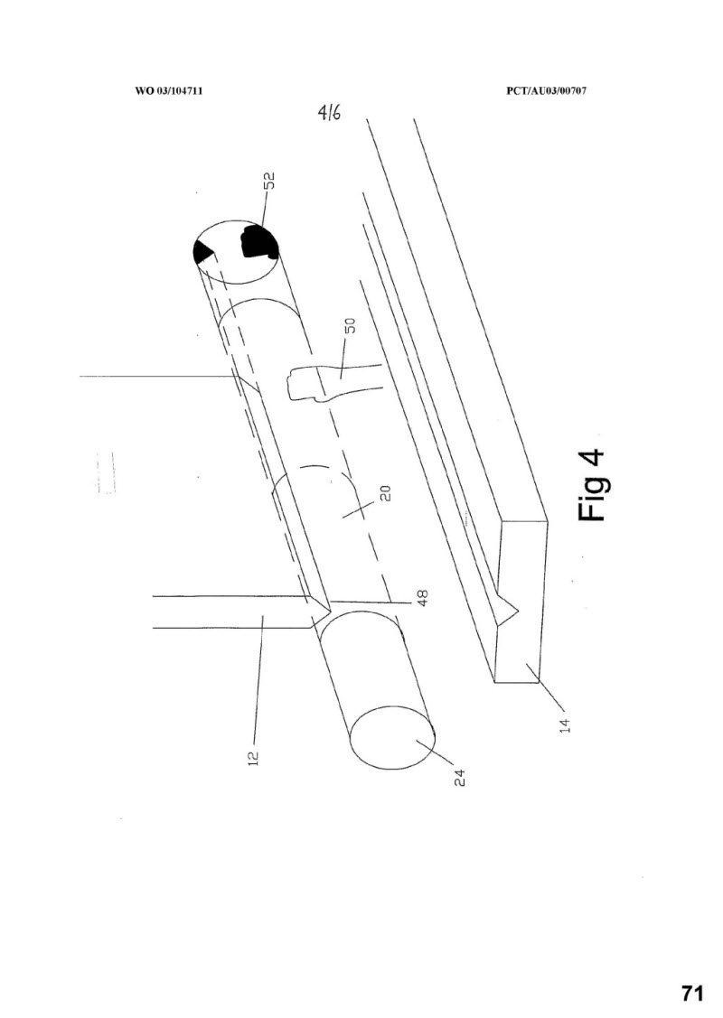
Integer 1.4: at least one light receiving means arranged to receive light from the one or more of the light emitting means which has passed through said region
227 The ‘light receiving means’ is described as an aperture in a screen and an image detection device such as a CCD or a projection screen with a camera ‘to observe the projected image’: Patent p 6 lines 7-9.
Integer 1.5: a processing and control means arranged to receive image information from the light receiving means and thereby recognise the presence of one or more shadowed regions on the light receiving means cast by obstructions in the region
228 The ‘processing and control means’ is described as being in the form of ‘a software program residing on a digital signal processor, a computer or embedded into a microcomputer which receives input from the output of the light receiving means’: Patent p 7 lines 1-3.
229 The ‘image information’ is received from the light receiving means (such as a CCD or a projection screen), but it is information used to ‘recognise the presence of one or more shadowed regions’ on the CCD or projection screen. In my view, this is an important factor. As the respondent says, it does not mean any information whatsoever about an ‘image’. ‘Image information’ means that the shape of the obstruction must be capable of being determined and sufficient to be used by the system.
230 Equally on this topic, in my view, the use of the word ‘recognise’, in context, is important, and means that the system is not just detecting a shadowed region, but the system recognises, that is, compares the shadowed region detected with what is previously known – the shape of obstructions. This is consistent with the recitation in the Patent (at p 6 line 23 to p 7 line 14), particularly the comparison of ‘the current image’ with the ‘stored image to determine the presence of any shadows’ (at p 7 lines 9-11). The reference in integer 1.5 to the ‘one or more shadowed regions’ accords with the notion that the system can determine the shape of the obstruction.
231 The emphasis is on obstructions when the machinery such as press brakes is descending.
232 Moreover, by the terms of claim 1 itself, it is quite clear that the blade itself cannot be an obstruction. It is the ‘moving part’ from integer 1.1 and the ‘part’ from integer 1.6, the movement of which is controlled. As Mr Appleyard said on behalf of the respondent, it cannot be both an obstruction and the moving part obstructing itself. Obstructions are something which is in the way of the blade of the tool and which should not be there during the descent of the tool towards the workpiece. Neither the blade nor the workpiece can be obstructions.
Integer 1.6: wherein the illumination of the region is such that the processing and control means has sufficient image information to determine the boundaries of the or each shadowed region and control movement of the part dependent on said image information
233 I accept the respondent’s submission that the reference to the processing and control means having ‘sufficient image information to determine the boundaries of the, or each, shadowed region’ is consistent in a common sense way with the focus of the claim on shape/outline recognition.
234 Specifically, the reference to ‘boundaries’ reinforces that the shapes or outlines of the obstructions must be determined sufficiently to be used by the system to control the movement of the tool. This is confirmed by the recitation at p 6 line 22 to p 7 line 14 and by the references to the processing and control means creating ‘a total picture made up of the image information’, which is referred to as a ‘shadow map’ and which is compared to ‘known safe shadow maps’ (at p 8 lines 1-12). I also prefer the respondent’s evidence and submission, in context, that an ‘edge’ is not a boundary, although it might be part of a boundary; a boundary encloses a region or area, extending around the entire perimeter of an object.
3.5 Conclusion on construction
235 Integer 1.5 and integer 1.6 of claim 1 require the safety system as claimed to engage in recognition of regions of obstructions by reference to shadow maps and their shapes, and require the comparison with either stored known safe or unstored unknown hazardous shadows of obstructions.
236 This reading is based on references to ‘recognition’, ‘boundaries’ and ‘regions’ in the claim, the disclosures in the specification discussed above and is also supported by Mr Appleyard’s evidence.
237 The construction was also supported in part by Mr Acheson’s acceptance in cross-examination that:
(a) a ‘shadowed region’ is an ‘area’ and that an area is a two-dimensional construct;
(b) the word ‘boundary’ or ‘boundaries’ of a shadowed region involves establishing the perimeter or outline of the shadowed region; and
(c) an ‘edge’ is part of a boundary.
238 Further, and even if this construction, which is narrower than that advanced by the applicants, is wrong, the proper construction of claim 1 requires the boundary determination of an obstruction claimed by recognising a realistically substantial portion or part of the shadowed region, so as to determine a sizable portion of the outline or shape of the obstruction, in contrast to a dot, spot, point or edge of any such region.
239 As will be seen, it is unnecessary to construe the dependent claims.
240 The principles concerning patent infringement are well established. A patent is infringed if, on a proper construction of the claim, a product possesses all the integers of that claim, without the patentee’s authorisation: Rodi & Wienenberger A.G. v Henry Showell Ltd [1969] RPC 367 per Lord Upjohn (at 369); Olin Corporation v Super Cartridge Co Pty Ltd (1976) 180 CLR 236 per Gibbs J (at 246); Fresenius Medical Care Australia per Wilcox, Branson and Bennett JJ (at [49]). The basic test for infringement is: ‘has the alleged infringer taken all the features referred to in one or more of the claims of the patent?’ (emphasis added): Bodkin C, Patent Law in Australia, (2nd ed, Thomson Reuters, 2014) (at [9120]).
241 The governing principle of interpretation is to give fair protection to the patentee by giving him the full extent of the monopoly of which a person skilled in the art would think he was intending to claim; but not more, so as to give a reasonable degree of protection to third parties. In Kirin-Amgen Inc v Hoechst Marion Rousell Ltd (2004) 64 IPR 444, Lord Hoffmann stated (at [48]):
The Catnic principle of construction… is intended to give the patentee the full extent, but not more than the full extent of the monopoly which a reasonable person skilled in the art, reading the claims in context, would think he was intending to claim.
242 This approach was applied by Bennett J in Sachtler GMBH & Co KG (formerly Sachtler AG) v RE Miller Pty Ltd (2005) 221 ALR 373 (at [42]).
243 As noted in the discussion of the evidence, the respondent has, pursuant to orders made 8 June 2016 and 22 February 2017, provided a verified ‘Product Description’ in respect of the allegedly infringing products. The respondent’s Product Description has been updated as the proceedings have progressed. The respondent provided the first version of the Product Description in respect of the Lazer Safe Systems, with the latest being dated 23 May 2017.
244 From the Product Description filed by the respondent, the applicants submit in general terms that the operation of different modalities of the Lazer Safe Systems is to the following effect:
Guarding function
Each of the Lazer Safe Systems provides what is described as a ‘guarding’ function while the tool descends towards the workpiece. The Lazer Safe Systems have a transmitter that transmits a beam of light (i.e. light emitting means) and a light receiver that incorporates a camera (i.e. light receiving means). The light beam illuminates a zone ahead of the tool as it descends. Interruption of the light beam by an obstruction can cause the tool to stop.
While the tool is descending, a processor located in the light receiver unit receives a raw 45 x 45 pixel matrix (for LZS-005 and IRIS), or 150 x 150 pixel matrix (for IRIS Plus). The processor then subdivides this matrix into blocks of pixels called ‘segments’. For LZS-005 and IRIS, each segment comprises a 3 x 3 array of pixels. For IRIS Plus, each segment comprises a 10 x 10 array of pixels. Both of these correspond to a 2 millimetre x 2 millimetre segment, and create a 15 x 15 array of ‘segments’.
Each Lazer Safe System then determines each segment to be ‘obstructed’ or ‘unobstructed’. This is based on whether the combined output of all pixels in the segment exceeds a pre-defined threshold. The obstructed/unobstructed value of each of the segments is called the ‘obstruction matrix’.
If any of the segments are deemed ‘obstructed’, the tool may be stopped. Depending on where the obstructed segment is located, and whether various filtering modes are being used, one obstructed segment may cause the tool to stop, or multiple adjacent segments may be required to be detected as obstructed before the tool is stopped. These filtering modes are described in more detail under the heading ‘Flexible Guarding’.
As the tool approaches the die, rows of segments beginning at the bottom of the matrix are progressively ‘muted’ (or blanked). An obstructed segment in this ‘muted’ area will not cause the tool to stop. This is done so that as the shadow that is cast by the die as the tool (and the beam of light) descends does not cause the tool to stop. Once the tip of the tool reaches the ‘mute point’ (approximately 2-3 millimetres above the workpiece), the guarding system is rendered mute and ceases to operate.
Bendshield
Bendshield is a function available in guarding mode. This function allows the tool to be within the light beam as the tool descends. This ‘envelopes’ the tip of the tool within the protective field provided by the light beam.
So that the shadow cast by the tool does not cause the tool to stop, a set-up process must be carried out to ‘deduce’ the location of the tool, and ‘remove’ the tool as a possible obstruction. During set-up, each Lazer Safe System conducts a series of scans to identify the location of the tool tip. Based on this, an area of the pixel matrix that represents the area occupied by the tool and surrounding area can be ‘blanked’. This means that if an obstruction is detected in these areas, it will not cause the tool to stop.
Flexible Guarding
Flexible Guarding is a function available in guarding mode. Flexible guarding (or ‘filtering’) involves the system being set up so that, in some circumstances, more than one segment must be detected or ‘deemed’ as obstructed before the tool is stopped. This may depend on the location of the segment.
Bendshield Plus
Bendshield Plus is a function which operates in essentially the same manner as the guarding function, save that it also operates during bending of a workpiece, and a larger area is ‘muted’ (or blanked). It is designed to protect against an operator getting a finger trapped between the workpiece and the tool as the workpiece is being bent. Only a small area between the workpiece being bent and the tool remains unblanked during the operation of Bendshield Plus.
Box Mode
In ‘box mode’ the matrix is divided into front, middle and rear sectors. This mode allows the front and rear sectors to be ‘muted’ (or blanked) if an obstruction is detected in these sectors. This is to deal with the situation where one side of a workpiece has already been bent and this bent side casts a shadow on the light receiver.
Bend Speed Management
Two of the the respondent’s systems (IRIS and IRIS Plus) also provide a functionality called ‘Bend Speed Management’ (BSM as defined at [7]). It operates once the tool approaches the workpiece (within 1 millimetre), makes contact with the workpiece and while the workpiece is being bent. This function calculates the ‘angular velocity’ of the workpiece as it is being bent, and slows the speed of the tool if the angular velocity of the workpiece is too high. This function protects an operator against ‘sheet overhang’ injury, where a long overhanging section of the workpiece may rise quickly and strike a machine operator if the workpiece is being bent too quickly.
245 On the applicants’ construction of claim 1:
(a) each of the Lazer Safe Systems possesses integer 1.5 and integer 1.6 when providing their guarding function;
(b) IRIS and IRIS Plus possess integer 1.5 and integer 1.6 when providing ‘Bendshield Plus’ (which the applicants say operates in essentially the same manner as the guarding function, save that it also operates during the bending of a workpiece); and
(c) IRIS and IRIS Plus possess integers 1.1, 1.5 and 1.6 when providing their BSM function.
246 The applicants’ primary contention on infringement is that the requirements of integer 1.5 and integer 1.6 in each of the Lazer Safe Systems are inherently met by the processor receiving the output from a camera having a high resolution, two-dimensional pixel matrix (that is, a system of this type operates in a manner which falls within the scope of integer 1.5 and integer 1.6). The applicants further contend that the specific processing steps that are undertaken by the processing and control means in the Lazer Safe Systems serve to demonstrate that the image information available to the system is sufficient to meet the requirements imposed by integer 1.5 or integer 1.6.
Guarding function
247 Integer 1.5: The applicants say that each Lazer Safe System includes a processing and control means. This includes at least a processor in the receiver, and the PCSS. The processor in the receiver receives the raw 45 x 45 matrix (LZS-005 and IRIS) or 150 x 150 matrix (IRIS Plus) (i.e. the image information) from the camera (i.e. the light receiving means).
248 The applicants say that the processor in the receiver ‘is responsible [for,] then creates’ the 15 x 15 ‘obstruction matrix’ from the raw 45 x 45 pixel matrix. The obstruction matrix is sent to the PCSS, which can then use this information to generate a ‘hardware interrupt signal’ to stop the press brake.
249 The combined output of each pixel within a segment is summed to determine whether each segment is ‘obstructed’ or ‘unobstructed’. The determination of a segment as obstructed means that the presence of a shadowed region has been recognised.
250 Integer 1.6: The applicants say that the image information received by the processing and control means is a 45 x 45 (or 150 x 150) raw pixel matrix. The applicants contend that this resolution is inherently sufficient to allow boundary detection.
251 The illumination of the region must be sufficient to determine between ‘light’ and ‘dark’ pixels and/or segments. The image information that is provided to the processing and control means permits each segment to be deemed ‘obstructed’ (i.e. dark) or ‘unobstructed’ (i.e. light).
252 Finally, the image information provided to the processing and control means, following processing to determine an obstruction, can generate a ‘hardware interrupt signal’ to stop the press brake, thereby controlling the tool based on the image information received.
Guarding function with Bendshield
253 For all of the reasons expressed above in relation to the guarding function, the applicants say that the guarding function with the Bendshield function also takes integer 1.5 and integer 1.6. The presence of these integers is contended by the applicants as being further demonstrated in the following ways:
(a) Integer 1.5: when identifying the location of the tool tip, the system identifies points at which pixels go from ‘light’ (i.e. no shadow) to ‘dark’ (i.e. shadow). Where a pixel is identified as dark, the presence of a shadowed region has been recognised.
(b) Integer 1.6: when detecting the tool during set-up, the system carries out multiple scans of the pixel matrix. These scans find a series of adjacent points where the pixels transition from ‘light’ to ‘dark’ along one side of the shadow cast by the tool. In doing this, the system identifies a portion of the boundary of the shadowed region cast by the tool. The applicants submit that this evidences the sufficiency of the information to determine the boundary of this shadowed region, or indeed any shadowed region, by a continued process of similar scans. This process ultimately results in areas of the illuminated region being ‘blanked’. Obstructions in a blanked area will not cause the tool to stop. In this way, the system relies on this process (and the resultant blanking) to allow continued movement of the tool despite the presence of shadows in certain areas.
Guarding function with Flexible Guarding
254 Integer 1.6: additionally to those reasons detailed above, the applicants say that if an obstructed segment is within an unblanked area, then depending on its location, it may either result in the tool stopping or it may only stop the tool if adjacent segments are also obstructed (i.e. more than one adjacent segment maybe required as part of the exercise carried out in this modality). Therefore, the system possesses sufficient information to determine whether a number of obstructed segments fall entirely within blanked areas, and to ascertain the obstructed/unobstructed status of any adjacent segments. Such information is sufficient to allow the determination of boundaries (at what the applicants describe as, a ‘multiple’ segment level). Where an obstructed segment is adjacent to an unobstructed segment, a gradient (transition from ‘light’ to ‘dark’) exists, indicating part of a boundary. This information can be analysed to determine all such gradients around a shadowed region, thereby determining its boundary.
Guarding function with Box Mode
255 The applicants say that for all of the reasons expressed above in relation to the guarding function, the guarding function with Box Mode also takes integer 1.5 and integer 1.6. The applicants state that Box Mode is also particularly relevant to claim 3.
Bendshield Plus
256 The respondent’s Product Description asserts that this function was trialled, but that no products have been sold with this function. However, the Product Description also identifies that the respondent is continuing to evaluate this feature and may incorporate it in the future. The respondent’s current product brochure includes reference to this feature, and Mr Appleyard during cross-examination confirmed that this brochure continues to be used in the Australian marketplace.
257 As the operation of Bendshield Plus is relevantly the same as guarding mode, the applicants contend that Bendshield Plus infringes for the same reasons set out in relation to guarding mode. The applicants accept that if they cannot establish infringement in guarding mode they also cannot establish infringement on this mode.
Bend Speed Management
258 Integer 1.1: the applicants say that based upon the applicants’ construction of the term ‘safety system’, both IRIS and IRIS Plus are safety systems when they provide the BSM function. This function protects an operator from ‘sheet overhang’ injury. The applicants contend that Mr Appleyard’s rather lengthy attempts during his oral evidence to diminish the safety function provided by BSM do not alter the proper character of this modality. Regardless, Mr Appleyard conceded that this function helps guard against sheet overhang injury, and minimises the risk of such an injury.
259 Integer 1.5: There is a Field Programmable Gate Array (FPGA), which is a type of processor in the receiver, that the applicants say forms part of the processing and control means of IRIS and IRIS Plus and receives the output from a 60 millimetre x 80 millimetre array of 0.66 millimetre pixels (i.e. image information). This image information is processed to identify a point on the top surface of the workpiece. This is done by finding a point of transition from a ‘dark’ pixel to a ‘light’ pixel (i.e. recognising the presence of the shadow cast by the workpiece).
260 Integer 1.6: The applicants say that the quality of the image information that the processing and control means holds is substantially the same in each system during guarding. For the same reasons as set out in relation to guarding mode, integer 1.6 is also ‘taken by’ BSM. However, the presence of this integer is contended to be further demonstrated in the following way.
261 The system locates and tracks the location of the top edge of the workpiece by a similar process to that used to locate the tool tip, that is, by carrying out a scan to determine where there is a transition from ‘light’ to ‘dark’. In doing this, the system identifies a portion of the boundary of the shadowed region cast by the workpiece. This evidences the sufficiency of the information to determine the boundary of this shadowed region, or indeed any shadowed region, by a continued process of similar scans. By tracking a location on the top edge of the workpiece as the workpiece is bent, the angular velocity of the workpiece can be calculated. This is used to control the movement of the moving part (i.e. the tool) by slowing its movement if the calculated angular velocity (calculated based upon the image information received by the processing and control means) exceeds a predetermined limit.
Infringement of the dependent claims
262 In the applicants’ affidavit evidence on infringement, Mr Acheson gave the following reasons for infringement of the dependent claims:
Claim | Reason |
2 | The ‘unblanked’ segments form a ‘predetermined or calculated area of the region’. The presence of an obstruction in this area stops the movement of the tool. |
3 | The system determines whether an obstruction is within the front, middle or rear area (relative to the tool). This ability is utilised in what is described as ‘Box Mode’. The system can respond differently depending on which of these areas the obstruction is within. |
4 | BSM calculates the angular velocity of the workpiece as it is being bent in. As the tool has no angular velocity, this is a calculation of the velocity relative to the tools in the IRIS and IRIS Plus systems. |
5 | The respondent’s dispute on this claim appears solely based on the assertion that the term ‘relatively large with respect to the size of a leading edge of the part’ is unclear. It is apparent that the illuminated region includes significant areas around the leading edge of the tool, and it can therefore be characterised as ‘relatively large’ with respect thereto. (I note that in his affidavit, Mr Acheson agrees with the respondent’s assertion that the phrase ‘relatively large’ is unclear. But that taken in context of the claim, which states ‘relatively large with respect to the size of the leading edge’, the phrase is not unclear.) |
14 | For a segment to be deemed obstructed, the minimum thickness of an obstruction is 2 pixels, or 1.33 millimetres. This is a value too small to be a part of an operator’s body, and so this integer is taken. |
21 | The presence of a projection screen does not appear to be in dispute. The dispute on this claim appears founded on the detection of ‘image information’ by a camera. If the applicants’ construction of ‘image information’ is accepted, there would appear to be no further cause for dispute over this claim. |
38 | Such a lens is typically used to refract light and focus the beam of light onto an array of light sensors. It would only not be present in the highly unusual circumstance where the area of the light sensors is exactly the same size as the cross sectional area of the illuminated region. |
46 | There is a tool arranged to bend material, and both IRIS and IRIS Plus control the tool during bending. One area of dispute over this claim centres on whether IRIS and IRIS Plus are ‘safety systems’ when they performing the BSM function. If the applicants’ contention on this point in relation to claim 1 is accepted, this claim is also infringed. Alternatively, if the Lazer Safe Systems infringe claim 1 insofar as they provide their guarding function, then any system having the Bendshield Plus feature will infringe this claim (there being no apparent dispute that the systems are ‘safety systems’ when providing this feature, and that this feature controls the tool during bending). |
4.3 Consideration of infringement
Claim 1 of the Patent
263 The respondent contends that the Lazer Safe Systems do not infringe claim 1 because when in usual guarding mode (until the mute point) the safety system is triggered, and the tool blade stopped, by only one segment of pixels being obstructed. All that the processing and control means knows is that the output from a segment somewhere has gone below the prescribed threshold. The processing and control means does not know or care where the segment is (except whether it is in the either the front, middle or back protection zones) or which pixels in the segment are either clear, partially obstructed or fully obstructed. A neighbouring segment may also have pixels which are either clear, partially obstructed or fully obstructed because of the same obstruction, but if the output from the segment is not below the threshold, it will not cause the system to trigger.
264 However, on the applicants’ case and in Mr Acheson’s view, integer 1.5 is satisfied because:
(a) the information that is available to the processing and control means is ‘image information’ as he understands the term;
(b) the detection of the tool tip during set up, the determination during guarding of whether each segment is obstructed or unobstructed and (in the case of the respondent’s IRIS and IRIS Plus products) the BSM function, each involve ‘recognising the presence’ of a shadowed region;
(c) the tool itself is an obstruction and the function of the system in identifying the tool during set up is relevant; and
(d) the system is a safety system when BSM is operational, so the operation of BSM is relevant. Therefore, integer 1.5 is present ‘in each of the Lazer Safe Systems’.
265 Mr Acheson did not agree that the integer requires comparison with a stored image. In his view if integer 1.5 is read that way, he would still regard that integer as being present in each of the Lazer Safe Systems. He said that the information about which zones are blanked within the obstruction matrix constitutes an ‘image’. But the muted areas in the obstruction matrix are not based on or formed by shadows (emphasis added). The system in set-up mode simply finds the tip of the tool and establishes the muted areas by reference to this point and a standard template.
266 As to integer 1.6, Mr Acheson said that:
(a) integer 1.6 would be satisfied by the system recognising and determining even ‘only a very small section’ of a shadowed region ‘such as a single pixel at the edge of the light receiving means’. He describes this as a ‘gradient’ being found between this pixel and the surrounding pixels so that the boundary of the shadowed region can be determined;
(b) ‘there is no requirement that boundary determination is actually carried out’ in integer 1.6, ‘only that the image information available is sufficient to do so’;
(c) the requirement of integer 1.6 is that ‘the illumination of the region is such that’ it requires that the light transmitter transmits light with a high enough energy to create sufficient contrast between light and shadow on the light receiving means which allows a ‘gradient’ to be found between the neighbouring light and dark pixels; and
(d) the tool itself is an obstruction ‘within the meaning of the claims and indeed any object that casts a shadow on the light receiving means would be “an obstruction in the region”’.
267 As to integer 1.6, in Mr Acheson’s view where one segment is obstructed but the adjacent segment is not, a boundary exists. He disagreed with Mr Appleyard because he ‘does not seem to consider the functions of the processing and control means in detecting the tool tip, nor does he consider the operation of BSM’. Mr Acheson stated that Mr Appleyard’s view ‘seems also to rely on the assertion that the Lazer Safe Systems do not know the location of an obstructed segment’.
268 I prefer the evidence on this issue of Mr Appleyard, who contended that the safety system of the respondent’s products is triggered ‘if one segment [of the obstruction matrix] is deemed obstructed. The system does not receive ‘image information’ (i.e. information about the shape of the obstruction)’. The Lazer Safe Systems do not ‘recognise’ the presence of the, or any, shadowed region. There is no comparison with any stored image. It simply detects that a single segment is deemed obstructed and stops the descent of the blade.
269 The safety system for the Lazer Safe Systems does not have any information ‘to determine the boundaries of the or each shadowed region’. The systems do not determine the boundaries of the shadowed regions, instead, if one segment is deemed obstructed, the system will trigger and stop the descent of the blade.
270 The Lazer Safe Systems cannot make a shadow map or store it. They do not recognise objects which could be a potential obstruction nor compare them with anything such as a shadow map.
271 While the applicants question Mr Berry’s expertise, he had, in my assessment, simply summarised in layman’s terms the very points which I consider have emerged on the comparative expert testimony. Mr Berry, for the respondent, expressed his evidence very succinctly on an essential distinction. He disagreed that integer 1.5 is present. He said that the system described in the Patent ‘relies heavily on fairly sophisticated image processing’ involving the ‘determination of shapes and sizes of elements and features within images’. He said the described system also ‘relies on the comparison of new images to historical images stored in the memory of the processing means’ but that the Lazer Safe Systems do not do that.
272 No attempt in the Lazer Safe Systems is made to ‘determine the shapes, sizes, boundaries or relative positions of any silhouetted objects in the image, and they do not use any form of image comparison’. The Lazer Safe Systems instead use a ‘relatively simple method to determine the presence of an obstruction by monitoring a list of binary values which convey the “obstructed” or “clear” state of pre-determined areas’ (referred to as the ‘segments’ and ‘obstruction matrix’). He summarised the difference between the system described in the Patent and the Lazer Safe Systems as follows:
[T]he Patent describes a system that analyses images, singly and comparatively, in much the same way that a human would – i.e. by looking at elements of the images and making determinations about which of those constitute obstructions based on the shapes, sizes, and relative positions of those elements. The Lazer Safe products on the other hand divide the area into a grid, and then view a fixed sub-set of the cells of that grid as binary values, and then determine an obstruction to be present if any one of those binary values is true.
273 In relation to integer 1.6, Mr Berry said that the Lazer Safe Systems ‘do not make any attempt to determine the elements or features present in an image’ because it is the intention of those systems to ‘stop the movement of the tool as soon as an obstruction is detected’. Once the determination is made of a single un-blocked entry in the obstruction matrix as ‘obstructed’, no further information about the obstruction is needed or gathered or further processing performed. Mr Berry pointed to an analogy with home intruder alarm systems, in which rooms are fitted with intrusion detectors, which can be selectively armed, and which are connected though a controller to a single alarm. In those systems, the alarm is raised when any one of the armed detectors senses an intrusion; the system does not make any determination about, nor is it interested in, the shape or nature of the intruder.
274 Mr Acheson disagreed with Mr Berry’s conclusions that integer 1.5 and integer 1.6 are not present in the Lazer Safe Systems. He criticised Mr Berry for not providing ‘any clear explanation of what he understands to be required by integers 1.5 and 1.6’. Moreover, he said that Mr Berry’s opinion is premised on claim 1 requiring a ‘type of object identification that is described merely as a possibility in the Patent’.
275 Mr Acheson made the following observations:
(a) Mr Berry asserted that the Lazer Safe Systems do not engage in boundary determination or use any form of image comparison. However, the system scans to identify the tip of the tool and applies blanking based on this location, which Mr Acheson regarded as a form of ‘image comparison’;
(b) Mr Berry asserted that there is no storage of old images. However, Mr Acheson stated the map of blanked segments (once created) must be stored for subsequent use;
(c) Mr Berry’s assertion that once an obstruction is determined in an unblanked segment, no further information is gathered or processing performed, is one Mr Acheson regarded as ‘plainly incorrect’. Mr Acheson regarded the operation of ‘L-filtering, Hard Shell Soft Centre filtering’ and the operation of the latch function as requiring processing once an unblanked segment is deemed obstruction (but noted these functionalities were not referenced in the product description provided to Mr Berry); and
(d) Mr Berry’s statement that the determination of boundaries cannot be based upon a single binary value, is one which Mr Acheson agreed with. However, Mr Acheson asserted that the Lazer Safe Systems have ‘more than just the binary value of the obstructed segments’.
276 I prefer the respondent’s contentions on those matters, namely:
(a) as to the applicants’ argument that if a single pixel is obstructed and an adjacent one is not, that creates a boundary and that is enough for infringement, Mr Acheson’s view in cross-examination (not set out in his affidavits) was that determination of a singular boundary required at least four pixels and for multiple shadows, more depending on how many there were. The individual pixels in the Laser Safe Systems are in the order of 0.66 of a millimetre each and the individual pixels in the IRIS Plus System are in the order of 0.2 of a millimetre each;
(b) tool tip detection is a preparatory step to guarding and does not involve any boundary determination within the meaning of integer 1.6, nor is there any safety function performed while this is being done; moreover, as a tool cannot itself be an obstruction, this is also not within the scope of integer 1.6;
(c) BSM is a productivity aid, not a safety system as claimed and it involves tracking a single pixel alone through the arc depicted in the diagram in the Product Description for the IRIS and IRIS Plus systems only (not the LZS-005 system);
(d) as to the BSM, there is no safety system as claimed, as depicted by the diagrams and text in the Product Description showing how operators might be hurt during the operation of the BSM. The sheet overhang injury relied upon by the applicants does not constitute a relevant safety system as claimed, because there is no relevant obstruction in the path of the tool; and
(e) Bendshield Plus is not a safety system as claimed and is not in use in any of the Lazer Safe Systems. It again involves a one segment stop system, which does not infringe for the reasoning set out above.
277 I prefer the views of Mr Appleyard and Mr Berry to those of Mr Acheson on this topic. I do not accept that the ‘one segment stop’ system of the Lazer Safe Systems (or BSM, tool tip detection or any other functionality relied upon) operates as a safety system as claimed in claim 1, involving the recognition of the presence of shadowed regions cast by obstructions in the illuminated region and determination of their boundaries. There is no ‘image’ in the sense claimed, no determination of ‘boundaries’ of shadowed ‘regions’, the tool is not an ‘obstruction’ and there is no comparison with stored images by ‘recognition’. I find that claim 1 is not infringed.
The other dependent claims of the Patent
278 As claim 1 is not infringed, none of the dependent claims sued on are infringed.
4.4 Conclusions on infringement
279 For these reasons, in my view, the applicants have not established, on a fair and proper construction of the relevant claims of the Patent, that any of the respondent’s Lazer Safe Systems infringe the claims as asserted.
280 The respondent raises four grounds of invalidity: novelty, obviousness, fair basis and lack of clarity. Relevant only to the grounds of novelty and obviousness, an additional argument is raised that none of the claims are entitled to maintain their earliest priority date of 11 June 2002 (which is based on Provisional PF 2878), and instead are only entitled to the filing date of the completed specification, being 10 June 2003. By reason of this deferred priority date argument, the novelty case changes in that an additional piece of prior art, known as the SICK Patent (published in German language on 2 October 2002) becomes relevant. I will deal briefly with the deferred priority date argument first after providing some brief statutory context.
281 The Patents Act has been amended several times since it was first enacted. Relevantly, the amendments set out in the Patents Amendment Act 2001 (Cth) apply to complete specifications for patents filed after 1 April 2002: see Ch 1, Pt 1, item 13 of that Act. Those amendments apply as the complete application for the Patent was filed on 10 June 2003.
282 These amendments relevantly change the scope of the test for novelty and inventive step, by permitting information made publicly available in a document or an act ‘whether in or out of the patent area’ to be included in the ‘prior art base’. This change applied to all patent applications filed on or after 1 April 2002 and for patents granted on such applications. The Patent application was applied for on 10 June 2003 and granted on 17 May 2007. However, for inventive step, the ‘common general knowledge’ referred to is nonetheless confined to ‘as it existed in the patent area’ (relevantly, Australia): s 7(2) of the Patents Act.
283 Similar considerations apply equally to the Patent Regulations 1991 (Cth), which has also been the subject of significant amendments. The amendments made to the Patents Act by the Intellectual Property Laws Amendment (Raising the Bar) Act 2012 (Cth) as to validity do not apply because the Patent was granted on 17 May 2007, well before the 15 April 2013 effective date for those amendments.
284 The tests for priority date are detailed in s 43 of the Patents Act and reg 3.12 of the Patent Regulations is:
Section 43 Priority dates
(1) Each claim of a specification must have a priority date.
(2) The priority date of a claim is:
(a) the date of filing of the specification; or
(b) where the regulations provide for the determination of a different date as the priority date—the date determined under the regulations.
…
Regulation 3.12 Priority dates generally
(1) Subject to regulations 3.13 and 3.14 and subregulation (2), the priority date of a claim of a specification is the earliest of the following dates:
(a) the date of filing of the specification;
(b) if the claim is fairly based on matter disclosed in 1 or more priority documents, the date of filing the priority document in which the matter was first disclosed;
…
285 So, generally the priority date of a claim is the date of filing the complete specification containing the claim: s 43(2) of the Patents Act. However, if a claim is fairly based on the disclosure in one of the priority documents or the basic applications, the priority date of the claim is the filing date of the earliest of the priority documents or basic applications on which it was ‘fairly based’: reg 3.12 of the Patent Regulations. This test is often referred to as ‘external’ fair basis (comparing the claims of the Patent with earlier documents), rather than ‘internal’ fair basis (comparing the claims of the Patent with the specification as a whole) (see s 40 of the Patents Act). The test for external fair basis is the same as for internal fair basis: namely whether there was ‘a real and reasonably clear disclosure’ of the claims in the priority documents: see Société des Usines Chimiques Rhône-Poulenc v Commissioner of Patents (1958) 100 CLR 5 per Fullagar J (at 11). This test has been cited in numerous cases, including F Hoffman-La Roche & Co Aktiengesellschaft v Commissioner of Patents (1971) 123 CLR 529 per Gibbs J (at 539).
5.2.2 The respondent’s contentions
286 The specific contentions of the respondent are that:
(a) the claims of the Patent are not fairly based on any of the three provisional applications because there is no disclosure anywhere in the provisional applications of integer 1.6 that ‘the processing and control means has sufficient [image] information to determine the boundaries of the and each shadowed region’.
(b) the provisional applications describe a system which does more than just detect obstructions, but instead builds a library of images (‘shadow maps’) which are recognised by the system, so that if something is not recognised as matching one of the safe images stored in the system, the safety system will be triggered;
(c) claim 1 of the Patent is wider or broader than what is described in the provisional applications, because it does not require the system to compare the shape of an obstruction with a library of shadow maps which is described in the provisional applications; and
(d) Mr Acheson accepted that none of the provisional applications disclose the features of integer 1.6 set out above expressly but argued that there are ‘numerous features described in the provisional applications that would require this ability’.
287 To be a real and reasonably clear disclosure, the question is whether the phrase in question is necessarily implied by the disclosures in the provisional applications, even though the exact words are not used, such that a skilled addressee would conclude there was a real and reasonably clear disclosure.
288 The respondent says that based on Mr Appleyard’s view as a skilled addressee and discounting Mr Acheson’s view, that there is no such disclosure. Integer 1.6 is not expressed in any of the provisional applications. Moreover, that integer is broader than any disclosure in the provisional applications, which are concerned with detecting and comparing shadow shapes.
289 The respondent says, each of the claims of the Patent (as dependent on claim 1) are not entitled to any priority date before the latest priority date of 10 June 2003, being the date of the filing of the complete specification.
290 Addressing the arguments requires consideration of each of the three provisional applications. If any one of the provisional applications in substance discloses integer 1.6, then the claims are entitled to a priority date being the date of filing of that provisional application, pursuant to reg 3.12(1)(b) of the Patent Regulations.
291 I consider that integer 1.6 is, in substance, disclosed in each of the provisional applications. There are various references in the provisional applications which disclose components that transmit and receive the image information and processes that can only be performed if the system has sufficient image information to determine boundaries (such as the ability to determine the size and position of obstructions). The applicants argue, and I accept, that these include references in the provisional applications to:
the use of a CCD in the receiver and the depiction of areas of the CCD;
the detection of misalignment by use of a shadow mask (meaning that movement of a shadow laterally or vertically can be detected);
the creation of shadow maps, and the ability to detect shadows differing from a shadow map;
the ability to determine size and position of obstructions;
the tool being able to descend to a point adjacent to an obstruction; and
the use of shadow expansion to account for vibration.
292 These references, taken together in context, show that there is sufficient image information detected to enable the determination of the boundaries of shadowed regions.
293 The PCT application filed on 10 June 2003 is practically identical to the second provisional application filed on 10 July 2002. It follows that if the amendments introducing integer 1.6 on 19 May 2004 were fairly based on the PCT application as filed, integer 1.6 must also be fairly based on at least the second provisional application (and so there can be no doubt that the Patent is entitled to at least a priority date of 10 July 2002).
294 In my view, the respondent’s contentions as to the priority date must fail and for the purpose of considering the grounds of novelty and obviousness the claims are entitled to maintain a priority date of at least 10 July 2002.
295 Section 18(1)(b)(i) of the Patents Act relevantly provides that an invention is a patentable invention for the purposes of a standard patent if (among other things) the invention, so far as claimed in any claim, when compared with the prior art base as it existed before the priority date of that claim, is novel.
296 The test for novelty of a claim is often expressed in one of two ways. The first, commonly referred to as the ‘reverse infringement’ test, was developed by Aickin J in Meyers Taylor Pty Ltd v Vicarr Industries Ltd (1977) 137 CLR 228 (at 235):
The basic test for anticipation or want of novelty is the same as that for infringement and generally one can properly ask oneself whether the alleged anticipation would, if the patent were valid, constitute an infringement.
(emphasis added)
297 In the case of a paper anticipation, that is, where the reverse infringement test cannot be applied readily, the importance of not overlooking the words ‘basic’ and ‘generally’ in Aickin J’s statement has been noted: Bristol-Myers Squibb Company v F H Faulding & Co Limited (2000) 97 FCR 524 per Black CJ and Lehane J (at [62]). See also, Nicaro Holdings Pty Ltd v Martin Engineering Co (1990) 91 ALR 513 per Gummow J (at 528).
298 The notion of ‘mere paper anticipation’ arose from Metropolitan-Vickers v B.T.H Co Ltd (1926) 43 RPC 76 per Sargant LJ (at 93), where, amongst other things, it was stated:
In Otto v. Linford, (1881) 46 L.T., at page 35, it was held that the later invention must be described in the earlier publication that is held to anticipate it; it is not sufficient that, if a machine had been made according to such description, it would have produced a result, not to be gathered from the description, which would have disclosed such invention.
299 In an article by the Hon S Crennan, ‘Obviousness: Different Paths Through Scylla and Charybdis’ (2007) 71 Journal of the Intellectual Property Society of Australia and NZ 12 (at 17), her Honour considered a number of studies that have been conducted since the 1970s on hindsight bias, saying:
The limitation of hindsight is now confidently said to be that individuals routinely overestimate the ex ante predictability of events after they have occurred and, indeed, it has been asserted that individuals are not cognitively able to prevent knowledge through hindsight from impairing their analysis of events.
Applying this to the patent context, it would follow that even the most honest of individuals will “consistently exaggerate what could have been anticipated in foresight and not only tend to view what has occurred as having been inevitable, but also as having appeared appeared relatively inevitable beforehand.”
(citation omitted)
300 In the case of a paper anticipation, such as a specification or publication, where there can be no direct application of the reverse infringement test, a hypothetical infringement may be posited on the assumption that somebody does or makes what the alleged anticipation suggests: Pfizer Overseas Pharmaceuticals per French and Lindgren JJ (at [313]). In the joint judgment of Black CJ and Lehane J in Bristol-Myers Squibb (at [63]), their Honours quoted Lord Westbury LC in Hill v Evans (1862) 45 ER 1195 (at 1199):
… the antecedent statement must be such that a person of ordinary knowledge of the subject would at once perceive, understand, and be able practically to apply the discovery without the necessity of making further experiments and gaining further information before the invention can be made useful. If something remains to be ascertained which is necessary for the useful application of the discovery, that affords sufficient room for another valid patent.
301 After considering Flour Oxidizing Co Ltd v Carr & Co Ltd (1908) 25 RPC 428; Canadian General Electric Co Ltd v Fada Radio Ltd (1930) 47 RPC 69 and General Tire & Rubber Co, their Honours said (at [67]):
What all those authorities contemplate, in our view, is that a prior publication, if it is to destroy novelty, must give a direction or make a recommendation or suggestion which will result, if the skilled reader follows it, in the claimed invention. A direction, recommendation or suggestion may often, of course, be implicit in what is described and commonly the only question may be whether the publication describes with sufficient clarity the claimed invention or, in the case of a combination, each integer of it.
(emphasis added)
302 In relation to the alleged anticipatory document, the terms should be read through the eyes of the skilled addressee in the context in which these terms appear. The terms are to be given the meaning which the person skilled in the art would attach to them, having regard to his or her own general knowledge and to what is disclosed in the body of the specification: H Lundbeck A/S v Alphapharm Pty Ltd (2009) 177 FCR 151 per Bennett J (at [118]). It is a question of the disclosure to the skilled reader. As Bennett J in Zetco Pty Ltd v Austworld Commodities Pty Ltd (No 2) [2011] FCA 848 (at [93]) stated:
Such a disclosure may be explicit or, in certain circumstances, may amount to a sufficient disclosure of each integer to a skilled worker even though not explicit ... This may occur where, for example, the prior art information is a publication which does not specify an integer but the skilled reader would understand that integer to be present in the subject matter described. The same applies to what is disclosed to the person of skill in the art by a prior product. If the prior art does not expressly specify each and every essential integer of the claimed invention, the evidence must clearly establish that, to the skilled reader, each and every essential integer is included in that prior art. …
(citations omitted)
303 Where the prior art is a document, to constitute anticipation the skilled addressee must be given clear and unmistakeable directions to make or perform the invention. Lord Hoffman has suggested that ‘the prior inventor must clearly be shown to have planted his flag at the precise destination before the patentee’ (General Tire & Rubber Co (at 137-138)), or as Gyles J observed, ‘anticipation is deadly but requires the accuracy of a sniper, not the firing of a 12 gauge shotgun’ (Apotex Pty Ltd v Sanofi-Aventis (2008) 78 IPR 485 (at [91])).
304 The parties in this case have also referred to the judgment of Bennett J in H Lundbeck A/S (at [178]-[190]), where her Honour discussed in some detail the relevant principles in respect of novelty. Her Honour explained (at [190]):
It follows that, where the prior publication is of the subsequently claimed invention, that is sufficient. Where the prior disclosure falls short of a complete disclosure, the question of the sufficiency of that disclosure arises. It is there that consideration must be given to the quality of a disclosure to the skilled addressee armed with common general knowledge. It is in that context that, in a limited fashion, questions of “enablement” can be said to arise. The use of that expression tends to cause confusion between anticipation and sufficiency. Rather, the Court, armed with the evidence of the skilled addressee as to terms of art and the nature and extent of the disclosure in the prior art document, must determine whether the prior disclosure is sufficient to enable the skilled addressee to perceive, understand and, where appropriate, apply the prior disclosure necessarily to obtain the invention.
(emphasis added)
5.3.2 The respondent’s contentions
The Cybelec Patent
305 The respondent contends that claim 1 of the Patent is not novel in the light of the Cybelec Patent at the earliest and latest priority dates. The Cybelec Patent is titled an ‘optical light beam device for automatically controlling the bending operation when bending with a press brake’.
306 In summary, Mr Appleyard said that the Cybelec Patent describes a system primarily used as a control system for measuring the angle of the workpiece as it is bent; but that it also describes and discloses the use of that system functioning as a safety device. He analysed the disclosure in the Cybelec Patent by comparison with the claim 1 of the Patent, concluding that the Cybelec Patent contains or discloses all the features of claim 1 of the Patent, by its disclosure of its use as a ‘safety device’ as described at col 3 lines 11-23 of the Cybelec Patent.
307 Mr Acheson stated that the Cybelec Patent does not disclose the features of claim 1 because it describes four separate and distinct forms of a device, but that the safety mode described does not apply to another modified constructional form (which Mr Acheson labelled the ‘Fourth Form’) which is for bend angle measurement only. He said that integer 1.5 of claim 1 of the Patent is disclosed only in respect of ‘one shadow’ in the Cybelec Patent. He also argued that in bend angle mode the Cybelec Patent only discloses the use of two photodiodes.
308 Mr Appleyard disagreed with Mr Acheson as to confining the Cybelec Patent disclosure, when used in safety mode, to what Mr Acheson described as the ‘Fourth Form’. He said that the functionality of the system disclosed in the Cybelec Patent can be applied to its use as either a safety system or a productivity system and there is no such restriction.
309 The respondent does not accept Mr Acheson’s construction of integer 1.5 or integer 1.6 of the Patent but, if he is correct, the Cybelec System (including its use as a safety system) is capable of, and discloses, edge and boundary determination. The use of a rotating box as an ‘image analyser’ in the Cybelec Patent is only an example of an image analyser. An alternative image analyser, not including a rotating box, is described at col 4 line 20 (or Mr Acheson’s ‘Fourth Form’). The emitting and receiving means can be mounted to move with the blade (col 4 line 31). The respondent says contrary to what Mr Acheson argued, there is no reason why the ‘Fourth Form’ disclosed in the Cybelec Patent cannot be used as a safety system as proposed (col 3 line 11).
310 Accordingly, the respondent says, the disclosure in the Cybelec Patent anticipates claim 1 of the Patent.
The Lazer Safe LZS-003 System and the LZS-003 Patent
311 The respondent says these disclosures are relied upon if I accept (which I did not) a broader construction of claim 1 of the Patent as to boundary determination as merely requiring the location of an edge/boundary/gradient between a dark pixel or segment and a light pixel or segment. If that construction is adopted, the respondent states the Lazer Safe LZS-003 System disclosures have that feature, as shown by the ‘nine diodes’ diagram.
312 Mr Acheson concluded that both the Lazer Safe LZS-003 System and the LZS-003 Patent disclosed systems having all the features of integers 1.1 to 1.5 of claim 1, but did not take integer 1.6. He argued that integer 1.6 was lacking because to determine the boundary of the shadowed region (or area), ‘it must be possible to find the gradient (transition from light to dark) in two dimensions’, whereas the Lazer Safe LZS-003 System could determine ‘an edge of the shadowed region … in one dimension only’.
313 The respondent says, if the broad construction is adopted, there is no good reason why the Lazer Safe LZS-003 System should not also disclose and satisfy integer 1.6, when they only have one fewer ‘edge’ (namely two) than the Patent requirement.
314 The respondent says the Lazer Safe LZS-003 System relied upon anticipate claim 1 of the Patent.
315 The respondent says that if the priority date of claim 1 of the Patent is the filing date of 10 June 2003 then the SICK Patent also comes into consideration as anticipatory, as it was published on 2 October 2002. As a filing date of 10 June 2003 is contrary to my findings, it follows that the SICK Patent cannot anticipate. However, I will consider the claim in any event.
316 Mr Appleyard noted that the SICK Patent describes a safety system for use on a press brake (or other machines) which includes an imaging system, such that the image of the shadow caused by the obstruction in the protection zone can be determined and compared with images stored in memory by the system, and thereby trigger the safety system to stop the descent of the press brake blade when the image of an obstruction detected does not match an image stored in the memory. He concluded that the SICK Patent contains or discloses all the features of claim 1 of the Patent.
317 Mr Acheson in answer provided a table commenting on the SICK Patent. He concluded that integer 1.4 is lacking because of the use of a reflector in the SICK Patent. He argued that integer 1.6 is not present because of the disclosure in the SICK Patent referring to two or four photodiodes, which would not be sufficient to get any impression of shape and location. Finally, he referred to the SICK Patent as merely disclosing triggering a signal, but that it does not say what the signal is and what it does.
318 Mr Appleyard said that the point about the use of a reflector is irrelevant, as the light receiving means still receives the light from the light emitting means. Finally, in relation to Mr Acheson’s statements regarding the triggering system, Mr Appleyard asserted that the only way that the system can operate in sufficient time to prevent injury is by it stopping the descent of the blade immediately upon detection of an obstruction. This ‘trigger/signal’, Mr Appleyard stated as being so obvious ‘it goes without saying’. With regards to Mr Acheson’s conclusions on integer 1.6, the SICK Patent discloses not just two or four diodes, but ‘a matrix disclosing a large number’ of diodes.
The Cybelec System
319 In relation to the Cybelec System, Mr Acheson believed the Cybelec Patent describes a system for measuring the bend angle of a piece of metal as it is being bent in a press brake. He did not recall having seen this document or the system it describes before being provided with it by the applicants’ solicitors. He said it describes a system that works in the following manner:
a light transmitter is fixed at one end of the ‘anvil’ of a press brake, transmitting a beam of light along the anvil towards a receiver. It illuminates the profile of the workpiece to be bent;
the receiver comprises a box with a number of holes. The light beam passes through these holes and is reflected by a mirror onto a set of corresponding photodiodes. The box is spun and the angle and position of the box at any time is known;
the system is used to calculate the angle of the workpiece based on the output of two selected diodes. As the receiver spins, the system detects the four points where the workpiece intersects the circle defined by each hole/photodiode combination. Knowing both the radius of the points and the angular displacement of each of the points, the system is able to determine the bend angle of the workpiece.
320 Mr Acheson noted that the document also mentions that the system can operate as a safety device before the initiation of bending. It describes that the system stops the descent of the ‘punch’ if a shadow is detected by a photodiode when the punch is outside the radius of the circle described by that photodiode. However, it is not clear from the document, he said, how the system is able to determine when the punch is outside this radius, such detection of the shadow cast by the descending punch would not cause the press brake to stop. Mr Acheson understood the system as addressing the issue of how to measure the bend angle of the workpiece in real time, allowing the system to be readily controlled to achieve a desired bend angle.
The Cybelec Patent
321 The Cybelec Patent describes an arrangement which makes use of a light beam and spinning photodiodes. The system has an angular encoder, which allows it to determine the angular position of the photodiode at a point in time. In effect, this allows the output of the photodiodes to be recorded at various points around concentric circles. This is common ground.
322 I accept the applicants’ contention that, insofar as the Cybelec Patent discloses any safety system at all, this disclosure is extremely limited in nature. The Cybelec Patent does not disclose a safety system having integer 1.6.
323 The respondent’s approach to the Cybelec Patent attempts to read in or combine features in the absence of any clear disclosure in the document directing a reader to do so, or any direction as to how such a combination could be achieved. I accept the applicants’ contention that this approach represents an impermissible ‘mosaic’ of features from different embodiments within a document. It falls short of the clear and unmistakeable directions that the authorities require for a document to destroy novelty.
324 The Cybelec Patent, properly read and construed, does not disclose a safety system having integer 1.6, for the following reasons:
(a) integer 1.6 requires that the processing and control means has sufficient image information to determine boundaries. The Cybelec Patent only discloses that the microcoordinator (i.e. the processing and control means) ever has the output of two of these photodiodes. That is, even if twenty photodiodes are present, the system does not pass the information from all twenty photodiodes to the processing and control means. As such, the document only discloses that the processing and control means has the output of two photodiodes. This is not sufficient image information to determine boundaries; and
(b) there is no instruction or suggestion in the document that the safety function described in col 3 lines 11-23 could be combined with the embodiment described using an image analyser. There is no reference in the document to how a safety system could be constructed using this ‘Fourth Form’.
The Lazer Safe LZS-003 System
325 Mr Acheson identified two different variations of the systems, one being the Lazer Safe LZS-003 System with a single planar beam and the other with a dual planar beam. He did not recall having seen either of the systems before being provided with it by the applicants’ solicitors.
326 As to the former, he said it is a system that has a transmitter and receiver mounted on the tool and moving with the tool. The transmitter and receiver are set at a fixed distance below the tool.
327 Unlike the previous systems, however, instead of using multiple light sources, aligned with multiple receivers, this system projects a continuous flat band of light. At the receiver, there are a number of photodiodes arranged in a horizontal line to detect the transmitted light. If an obstruction of the light beam is sensed by one of the photodiodes, motion of the tool can be stopped. The system also has the ‘mute point’. At this mute point, the sensors are disabled so they do not respond to an obstruction, allowing the workpiece and anvil to obstruct the sensors without causing the system to stop and the speed of the tool is lowered to complete the bending operation.
328 The use of a continuous horizontal beam of light, he said, provides an advantage in terms of the alignment of the transmitter and receiver. Because the beam is continuous in the horizontal direction, if there is a slight misalignment in a horizontal direction, the same amount of light from the beam can still reach each photodiode.
329 This system also has a number of operational modes for dealing with cases where the workpiece may obstruct the receivers and falsely trigger the system to stop:
in ‘normal mode’, if an obstruction is detected, the tool will stop and reverse a few millimetres. The operator can continue with the stroke by lifting their foot from the foot pedal and depressing it again. If an obstruction is detected again, the tool will stop but not reverse. If the foot press is depressed again, the tool will continue its stroke at ‘crawl speed’ with the sensors muted so that the obstruction does not stop the system again;
in ‘tray mode’, if an obstruction is detected by the front or rear receivers, the tool stops. Again, depressing a foot switch will cause the tool to continue at high speed, notwithstanding that obstruction, until the mute point is reached;
in ‘field muted mode’, all sensors are disabled. The tool operates at crawl speed only. Activation of this mode requires the use of a key.
330 In relation to the Lazer Safe LZS-003 System with a dual planar beam, the difference is that there are two parallel planar lasers, each with a corresponding row of receivers. These function in a generally similar manner to the single planar laser described above, but the advantage of having two planar lasers is that it allows the tool to move at a faster speed. The lower beam can be positioned further away from the tool, allowing faster closing speeds to be used because of the greater stopping distance between the laser and the tool. However, it must be muted when it reaches the workpiece and anvil so that it does not falsely trigger the system. If only the lower beam were present, this would leave too large an unprotected gap between the blade and the workpiece. Also, as the speed of the blade is slowed after muting, if only a lower beam were present, this would require a slow travel of the blade over a longer distance at the end of the stroke, negating the advantage of having a higher initial speed.
331 The presence of the second upper beam means that once the lower beam is muted, the blade can continue at an intermediate speed until the second beam needs to be muted. As a result, bending cycles can be completed more quickly.
The Lazer Safe LZS-003 System (prior use)
332 The applicants say the respondent’s case on prior use of the Lazer Safe LZS-003 System, properly characterised, is an attack on novelty based on information made available by the doing of an act: see s 7 of the Patents Act.
333 The requirement for pleading a prior use are set out in r 34.46 of the Federal Court Rules 2011 (Cth):
Dispute of validity of patent – particulars of invalidity
(1) A party who disputes the validity of a patent under the Patents Act must include in the pleading or other document in which the party disputes the validity, particulars of the grounds of invalidity on which the party relies.
(2) If a ground mentioned in subrule (1) is that the invention is not a patentable invention because of information about the invention in a document or through the doing of an act or thing, the particulars must specify:
(a) for a document—the time when, and the place where, the document is alleged to have become publicly available; and
(b) for an act or thing:
(i) the name of the person alleged to have done the act; and
(ii) the period within which, and the place where, the act is alleged to have been done publicly; and
(iii) a description that is sufficient to identify the act; and
(iv) if the act relates to apparatus or machinery—whether the apparatus or machinery exists and, if so, where it can be inspected.
…
334 The applicants say the Rules require prior use to be pleaded in this way so there is an instance of use that can be interrogated and analysed by the Court to determine whether the information that is made publicly available by that use constitutes an anticipation. In this case the amended particulars of invalidity provide no such detail. As such, the Court cannot properly assess what information is made available by the doing of an act, since the particulars given by the respondent do not identify any such act.
335 An allegation of prior public use must be strictly proved: Aspirating IP Ltd v Vision Systems Ltd (2010) 88 IPR 52 (at [202]), citing Windsurfing International Inc v Petit (1983) 3 IPR 449 per Waddell J (at 489). In Nicaro Holdings (at 524-525), Gummow J observed that proving an alleged anticipation by the recollection of witnesses and by drawings in catalogues and brochures is to be approached with ‘some caution’.
336 The applicants say, and I accept, that in the present case, the respondent relies upon very limited written and oral testimony of Mr Appleyard, together with a diagram prepared by his colleague, Mr Paul Gould and a product brochure.
337 The respondent’s contention regarding the disclosure by prior use of Lazer Safe LZS-003 System proceeds on the assumption that the sale of the LZS-003 product before the priority date has resulted in the disclosure, to at least purchasers, of precisely how the product works.
338 In reality none of the product brochures descend into that level of detail, nor does any instruction manual produced as part of Mr Appleyard’s evidence.
339 The respondent considers the precise mode of operation of such products as highly confidential. Confidentiality orders have been sought by the respondent and granted in relation to material contained in its Product Description. There was no evidence led from Mr Appleyard to the effect that the precise mode of operation of the Lazer Safe LZS-003 System was made publicly available (such as to purchasers of the product). Rather, the extent of evidence led as to the public disclosure of the Lazer Safe LZS-003 System was limited to high level information disclosed in product brochures. There is no evidence that the detailed information was made publicly available before the priority date.
340 The fact of a prior product sale does not alone establish that the features of the product were disclosed publicly. Where the product involves software and computer componentry, it is not appropriate for the Court to speculate as to whether the purposes and operation of such componentry were made known, or disclosed, in a publication sense, to a purchaser.
341 I note that initially, Mr Appleyard did not consider, or regard, the Lazer Safe LZS-003 System as novelty defeating. It was only by amendment of the Particulars of Invalidity (at the commencement of the second day of the trial) that it was asserted by the respondent that the Lazer Safe LZS-003 System might invalidate claim 1 of the Patent. The applicants submit, and I accept, that Mr Appleyard did not consider the Lazer Safe LZS-003 System as potentially constituting a prior art novelty defeating disclosure when preparing his affidavit evidence in the proceedings (of which he has sworn three affidavits) is telling.
The LZS-003 Patent
342 The respondent separately relies upon the information made publicly available in Australian Patent no. 738619, published on 21 November 2000. When Mr Appleyard was instructed in Appleyard # 2 to provide his opinion as to whether the integers of claim 1 were present in the allegedly infringing products, he stated that each of the ‘Prior Art Systems’ (which he defined as including the Lazer Safe LZS-003 System) possessed integers 1.1 to 1.4 of claim 1 of the Patent. However, he did not make the same observation in relation to integer 1.5 and integer 1.6.
343 The applicants say the respondent, in support of the amendment made to the Particulars of Invalidity to introduce the LZS-003 Patent, did not seek to introduce any affidavit evidence which might have construed that documentary disclosure (through the eyes of the skilled addressee). The applicants further contend that the respondent has not advanced any evidentiary case as to what is disclosed by the LZS-003 Patent or why or how (through the eyes of the skilled addressee) the integers of claim 1 are taken. Consistent with the prior use case regarding the Lazer Safe LZS-003 System, the Court is being invited and to draw inferences from Mr Appleyard’s written and oral testimony.
344 During the course of the trial (after leave was given to the applicants to amend their pleadings) the applicants filed Acheson # 4 which set out Mr Acheson’s reasons why the integers of claim 1 were not taken by the LZS-003 Patent. The focus of his analysis was on integer 1.6.
345 In relation to that topic, the applicants rely on the following principal matters (in light of Acheson # 4):
(a) its physical arrangement is diodes in a single row, which is entirely different to the nature of the invention of the Patent;
(b) it does not have ‘sufficient image information’ to determine boundaries because of its physical arrangement it is only capable of detecting, at best, an edge in a single direction or dimension. So it does not meet the requirement of integer 1.6; and
(c) the requirement of integer 1.6 is that a boundary (which is a two dimensional concept) of a region (which is also a two dimensional concept) must be capable of determination. While an edge may form part of a boundary, integer 1.6 requires that there be the capability to determine edges in two dimensions in order to determine a boundary.
The SICK System
346 Mr Acheson identified that the translated version of the German SICK Patent he was provided describes the SICK System as a device for monitoring a protection zone. It has a light emitter which emits light towards a reflector. The reflector then reflects light back to a light receiver. The light receiver and the light emitter can be part of a single unit. The system has a memory that can store an image received by the light receiver when there are no objects in the protected field and can then compare the image at a later time to the image stored in memory and trigger a signal if the image is sufficiently different to the one stored in memory. Mr Acheson stated the main advantage of this system is that it is highly robust. It is designed to be able to detect not only obstructions in the protected zone, but also any manipulation of the system that could otherwise interfere with the correct operation of the system.
347 Mr Acheson also said it is easy to set up and align the system. He said the SICK System achieves this by use of ‘codes’. One way this is done, is that the reflector has reflective and non-reflective areas. This means that the beam of light that is reflected back to the light receiver has some light areas and some dark areas. The system can compare an image that is received to this ‘code’ and look for any differences. This allows it to detect, not only an obstruction (which would lead to more darker areas where light areas were expected), but also any external light source falling on the receiver which would result in more light areas where dark areas were expected. This would allow the system to avoid a situation where an obstruction was not properly detected because light from an external source was falling on the receiver. The document also describes other forms of ‘coding’ either by the pulsing of the light or arranging the light transmitter to project the code.
348 If the reflector is moved in any way, the system can detect this. If the movement is perpendicular to the axis of the light beam, the position of the area of the light reflected back to the image receiver will change. This will lead to a variation from the recorded image. If the reflector is moved along the axis of the light beam, the size of the area of reflected light received will change. While not mentioned in the documents, Mr Acheson noted that this will only be the case if a relatively wide angled beam of light is used. If parallel beams were used, the size of the area of reflected light would be almost unchanged by movement along the axis of the light. Also, when a wide angle beam is used, the light receiver only needs to be aligned approximately to the reflector. This is, in his opinion, because the wide angle beam means that light will still fall on the reflector and be received by the receiver even if there is a slight misalignment.
349 I accept Mr Acheson’s evidence on this issue. It was not undermined in the course of cross-examination, to the effect that the Patent discloses a new invention. In my view, this is correct. Specifically, I accept his evidence and reasoning in the previous paragraph.
The SICK Patent
350 The invention described in the SICK Patent is said to relate to ‘an apparatus for monitoring a protected field’. The majority of the description relates to a system for monitoring a protected field in a general sense, without reference to any particular application. The application of the system described in the SICK Patent to a press brake is described in two paragraphs.
351 The SICK Patent, in its limited disclosure of the apparatus being applied to a press brake, does not disclose any control being exerted over the moving part (i.e. the tool/blade of the press brake). The SICK Patent does not disclose integer 1.6.
352 This is consistent with the general description of the system in the SICK Patent as a ‘monitoring’ system. The term ‘monitoring’ conveys that the system is observing and reporting on the status of something, not taking any action. The SICK Patent contains no express reference to the system being a ‘safety system’.
353 Mr Acheson said that engineering and integration work would be required to provide the system described in the SICK Patent with the ability to control the tool of the press brake, the SICK Patent was silent on this point, and that adding the function of controlling the tool of the press brake would constitute a new invention.
354 The SICK Patent (which does not, in any event, fall for consideration), does not disclose control of the moving part of the press brake. The SICK Patent contains no direction to a skilled person to carry out such work. As such, the SICK Patent cannot be said to disclose a safety system having integer 1.6.
355 The invalidity attack based on lack of novelty fails.
356 Section 18(1)(b)(ii) of the Patents Act relevantly provides that an invention is a patentable invention for the purposes of a standard patent if (among other things) the invention, so far as claimed in any claim, when compared with the prior art base as it existed before the priority date of that claim, involves an inventive step.
357 In relation to the inventive step, s 7 of the Patents Act relevantly states:
…
Inventive step
(2) For the purposes of this Act, an invention is to be taken to involve an inventive step when compared with the prior art base unless the invention would have been obvious to a person skilled in the relevant art in the light of the common general knowledge as it existed (whether in or out of the patent area) before the priority date of the relevant claim, whether that knowledge is considered separately or together with the information mentioned in subsection (3).
(3) The information for the purposes of subsection (2) is:
(a) any single piece of prior art information; or
(b) a combination of any 2 or more pieces of prior art information that the skilled person mentioned in subsection (2) could, before the priority date of the relevant claim, be reasonably expected to have combined.
…
358 As observed by the majority of the High Court in Aktiebolaget Hassle v Alphapharm Pty Ltd (2002) 212 CLR 411 per Gleeson CJ, Gaudron, Gummow and Hayne JJ (at [33]), the starting point for the law respecting obviousness is the statement by Hoffmann LJ in Société Technique de Pulverisation Step v Emson Europe Ltd [1993] RPC 513 (at 51):
The words ‘obvious’ and ‘inventive step’ involve questions of fact and degree which must be answered in accordance with the general policy of the Patents Act to reward and encourage inventors without inhibiting improvements of existing technology by others.
359 In Alphapharm (at [34]), the High Court reiterated that ‘obvious’ means ‘very plain’, as stated in General Tire & Rubber Co (at 497). Obviousness is a question of fact: Lockwood Security Products Pty Ltd v Doric Products Pty Ltd (No 2) (2007) 235 CLR 173 (at [51]) (Lockwood (No 2)).
360 In Insta Image Pty Ltd v KD Kanopy Australasia Pty Ltd (2008) 239 FCR 117 (at [80]), the Full Court has identified five steps in determining the issue of obviousness. The Full Court said that to determine this issue, it is necessary:
(1) to identify the invention “so far as claimed in any claim”;
(2) to identify the “person skilled in the relevant art”;
(3) to identify the common general knowledge as it existed in Australia before the priority date;
(4) to enquire under s 7(2) whether the invention referred to in (1) above would have been obvious to the person referred to in (2) above in light of the knowledge referred to in (3) above; and
(5) to enquire whether that invention would have been obvious to that person in the light of that knowledge when that knowledge is considered together with other kinds of information mentioned in s 7(3) (additional prior art information).
361 The test for obviousness is the question approved by the High Court in Alphapharm (at [53]), and expressed more generally as whether the skilled addressee at the relevant date in all the circumstances would directly be led as a matter of course to try the invention in the expectation that it will produce a useful result?
362 The information must be such that a person skilled in the art could reasonably be expected to have ascertained, understood and regarded it as relevant.
363 The following principles apply to this enquiry:
(a) the word ‘ascertained’ means ‘discovered’ or ‘found’: Dyno Nobel Asia Pacific Ltd v Orica Australia Pty Ltd (1999) 99 FCR 151 per Dowsett J (at [190]);
(b) a document would be ascertained if it was published in such a manner or form that it could reasonably have been expected to be found by a person skilled in the art: Nippon Katsyaku Kabushiki Kaisha and Sankyo Company, Limited v Rohm and Haas Company [1997] APO 40;
(c) in general, it may be reasonable to expect that a person skilled in the art would conduct a search of patent literature: Commissioner of Patents v Emperor Sports Pty Ltd (2006) 149 FCR 386 per Heerey, Kiefel and Bennett JJ (at [34]-[35]);
(d) evidence of usual practices in the relevant industry is admissible to assist in the determination of whether prior art information meets the requirements of ascertainability: Doric Products Pty Ltd v Lockwood Security Products Pty Ltd (2001) 192 ALR 306 per Hely J (at [217]-[225]);
(e) whether the criteria of ‘understood’ and ‘regarded as relevant’ are met in any given situation must be established by evidence: Bodkin (2014) (at [4220]); see generally, Lockwood (No 2);
(f) ‘understood’ means that, having discovered the information, the addressee would have comprehended it or appreciated its meaning or input: Lockwood (No 2) (at [132]);
(g) ‘relevance’ is to be understood as meaning relevant in solving a particular problem or meeting a long-fault want or the need as the patentee claims to have done, rather than meaning relevant to any work in the relevant art: Lockwood (No 2) (at [152]).
5.4.2 The respondent’s contentions
364 There are agreed matters of common general knowledge as identified in the applicants’ response to CGK Schedule dated 17 May 2017. Mr Appleyard, in Appleyard # 1, sets out what he described as other matters of common general knowledge:
(a) a typical hydraulically powered press brake, being a Trumpf 5000 range product from about 2002, with a laser safety system made by the respondent (the Lazer Safe LZS-003 System);
(b) the method of operation of a press brake as depicted by Mr Appleyard. I note these operational steps are detailed at [116(d)] above;
(c) more sophisticated systems with beams of light on either side of the press brake below the leading edge of the blade and moving up and down with it, an example of such a system is the planar beam system of the Lazer Safe LZS-003 System; and
(d) travelling light beam systems, utilising what is known as the ‘mute point’, such that when the blade reached a point immediately above the anvil when it was no longer possible for the operator to place his finger between the blade and the anvil, the safety system switched off, so that the bending of the workpiece could be completed.
365 The Patent itself recites that three basic types of safety systems were known and used for press brake operators, namely:
(a) the use of physical guards or tethers;
(b) the use of light beams to create a light curtain;
(c) the use of travelling light beams projected along the leading edge of the tool with the beam deactivated as the tool approaches the work.
366 These matters may be treated as admissions about the prior art and common general knowledge: Lockwood (No 2) (at [105]).
367 The Australian market for press brake safety system was very small (about 150 press brakes per year) compared to Europe (up to June 2002 to 2003 with about 4000 to 5000 machines built and sold each year). The US market for safety systems was also small at that time.
368 There were also several press brake safety systems known to Mr Appleyard, who was a regular from 1999 at international trade shows and exhibitions relating to press brakes and their safety and control systems, as well as meeting press brake manufacturers in Europe. According to the respondent, the prior art systems available in 2002 to 2003 were:
(a) the TIROPS System developed in and sold from about 1996 by STC in Australia: The inventor of the Patent, Mr Davies worked on the development of TIROPS with Mr Appleyard, for which they both received a patent;
(b) the Lazer Safe LZS-003 System developed by, made and sold by the respondent in Australia from about 1999 (and sold in Europe from July 2000) using a ‘planar’ laser light beam and from March 2002 (and sold in Europe shortly thereafter) using a dual laser beam;
(c) the Fiessler AKAS System offered for sale in Australia and Europe from about 1997 and its patent;
(d) the Nuova System offered for sale in Europe from about 1999 and revised Nuova System offered for sale in Europe in May 2002 ;
(e) the Cybelec System described in the Cybelec Patent.
369 The respondent says that each of the above systems was common general knowledge in Australia as at 11 June 2002; they were each (except Nuova and Cybelec) publicly available in Australia before any of the priority dates and would have been known to a skilled addressee in the small market in Australia for these products at that date.
370 The respondent, relying on Appleyard # 1, says that the following matters were also common general knowledge in Australia among those involved in the design and manufacture of press brake safety systems at about 11 June 2002:
(a) light emitting and receiving means fixed on either side of the blade such that the region below the blade and perpendicular to the path movement of the blade was illuminated;
(b) a processing and control means which processed information applied received by the light receiving means;
(c) the detection of shadows cast by obstructions between the light emitting and receiving means;
(d) technology which could be used to record and store the images of shadows cast in the region between the light emitting and receiving means;
(e) programming the processing and control means so that it could be used with said technology to determine the boundaries of the shadows cast in the region;
(f) programming the processing and control means so that it stored images and could compare them with other images;
(g) controlling, including stopping, the descent of the blade depending on:
(i) detecting shadows cast by obstructions;
(ii) detecting the shape of the shadows cast by obstructions; or
(iii) detecting the shape of shadows cast by obstructions and comparing them with the shape of other images recorded by the system; and
(h) the option of using a camera to determine the shape of an obstruction.
371 Mr Appleyard considered that the invention as claimed in claim 1 of the Patent would have been obvious to a person skilled in the art in the light of common general knowledge as referred to above.
372 Mr Acheson took issue with this conclusion by Mr Appleyard. Mr Acheson argued that many of the matters and systems referred to by Mr Appleyard were not known to him and were not common general knowledge; but even if they were, Mr Acheson still did not consider that the invention claimed in claim 1 would have been obvious in June 2002 or 2003. This is because Mr Acheson asserted that none of the systems referred to by Mr Appleyard suggest that the problems of false triggers mentioned in the Patent could be addressed by providing a system that could provide a level of image information ‘that allowed boundary detection’. In response to this, Mr Appleyard referred to severe limitations on Mr Acheson’s knowledge of prior art systems.
373 The respondent says with regard to ‘false triggers’, it was common general knowledge that light beam safety systems could experience false triggers by reason of a number of issues with vibration and light bending identified by Mr Appleyard in the context of the development of the Lazer Safe LZS-003 System. Determining boundaries was considered as an option by Mr Appleyard. Such an option was part of the common general knowledge in Australia.
374 The respondent notes that the applicants do not advance any evidence as to secondary indicia supporting an inventive step, such as the commercial success of products embodying the Patent having been marketed by the applicants showing the satisfying of a long-felt gap in the relevant market. It would be expected, the respondent says, that such a case would be put if the applicants could. The respondent is not aware of any commercially available system which works in the manner described in the Patent.
Common general knowledge plus the Cybelec Patent
375 Mr Appleyard was aware of the Cybelec Patent by about May 1999 when he was preparing the respondent’s patent application for a planar beam system. He read and understood that patent. The Cybelec Patent disclosed to him an imaging system which was capable of being used as a safety system on a press brake. In reaching this position, Mr Appleyard relied on the following references:
‘image analyser’;
‘the analysis of the projected shadow of the profile’;
‘an electronic image receiver and analysed by a microcoordinator’;
‘a projected shadow’; and
‘the microcoordinator is programmed so as to analyse the projected shadow of the profile of the workpiece’.
376 He concluded that if the use of an imaging system with a press brake safety system was not part of the common general knowledge of a skilled person in press brake safety systems at the priority date, the Cybelec System disclosed to him such a system and it would have been obvious to use such an imaging system with a press brake safety system, as the Cybelec Patent discloses. He noted that the Cybelec System was capable of both detecting shapes and comparing known shapes with shapes of obstructions.
377 The objections raised by Mr Acheson to the Cybelec Patent in relation to novelty arose out of his assertion that it was not a safety system and, particularly, the Fourth Form of the invention (as identified by Mr Acheson) could not be used as a safety system as described in the Cybelec Patent. The respondent said even if this was the case, a person skilled in the art of press brake safety systems, with the common general knowledge contended for by the respondent above, on reading it would have considered it relevant to such a system and would understand how it, including each of the embodiments or forms, could be used as a press brake safety system.
Common general knowledge plus the SICK Patent
378 I observe, again, that SICK post-dated the priority date that I have found. Nonetheless, the respondent says the SICK Patent is the sort of document which Mr Appleyard would have come across in researching what the respondent’s competitors were doing; as evidenced by his research before the priority date. Mr Appleyard said that he would possibly have got it translated from German to give him ‘the crux of the information’ contained in it. SICK was of particular interest to the respondent at around that time because SICK was trying to buy into the respondent. Mr Appleyard understood the patent and would have regarded it as relevant. He was aware in 2001 that SICK was developing a safety system involving the use of cameras. The respondent says:
(a) the invention claimed in claim 1 of the Patent would have been obvious to a skilled addressee in the light of common general knowledge together with the disclosure in the SICK Patent;
(b) the SICK Patent disclosed an imaging system which included ‘a memory for storing an image’; ‘a matrix consisting of a large number of light-sensitive elements’, which detected the ‘shape and quality’ of an obstruction, using camera or scanning technology and involving the projection of a shadow (emphasis placed by the respondent); and
(c) the SICK System is capable of detecting shapes and comparing known shapes with the shape of obstructions by comparing the image received from an obstruction ‘with stored image data in the comparing apparatus’.
379 The respondent says the only integers of the Patent which appear to be genuinely in dispute is whether the SICK Patent discloses a trigger signal which would stop the descent of the blade. If the respondent is wrong in asserting that this would have gone without saying, it would have been obvious to a person skilled in the art in light of the common general knowledge.
Validity of the dependent disputed claims of the Patent
380 The respondent says the dependent disputed claims are neither novel nor obvious. Comments on each of the dependent claims have been set out by Mr Appleyard, but need not be considered in light of my conclusion on claim 1.
381 To the extent that Mr Acheson may not have had sufficient experience at June 2002 and June 2003 to provide the foundation for his opinions in respect of obviousness that does not assist the respondent. The respondent is required to discharge a heavy burden cast upon it in a case such as the present to establish its case on the obviousness of the claims. The question of obviousness is being asked some fifteen years after the priority date and, as the applicants say, the passage of time brings with it the very real risk that opinions are ‘fatally infected by the seductive clarity of hindsight’. In such circumstances, the Court ought treat evidence on the question of obviousness with care.
382 As noted, in Alphapharm (at [34]), the High Court reiterated that ‘obvious’ means ‘very plain’, as stated in General Tire & Rubber Co (at 497). The majority in Alphapharm also confirmed that the question of whether an invention is obvious is a question of fact, that is, it is what was once a ‘jury question’ (at [49]). In Lockwood (No 2), the High Court said (at [51]):
Broadly speaking, the question is not a question of what is obvious to a court. As well as being a question of fact, the question of determining whether a patent involves an inventive step is also ‘one of degree and often it is by no means easy’, because ingenuity is relative, depending as it does on relevant states of common general knowledge. This difficulty is further complicated now by the need, in some circumstances, to consider s 7(3) information as well as common general knowledge.
(citations omitted)
383 Having identified the relevant claims in the Patent, I consider the subsequent four steps necessary in determining the issue of obviousness sequentially, as laid out by the Full Court in Insta Image and detailed above at [360].
The person skilled in the art (hypothetical skilled worker)
384 The applicants emphasise that the question is not whether it was or would have been obvious to the inventor or to some other worker in the field, but whether it would have been obvious to the skilled addressee. That is, whether the hypothetical addressee faced with the same problem would have taken as a matter of routine whatever steps might have led from the prior art to the invention, irrespective of whether they were taken by the inventor: Wellcome Foundation Ltd v VR Laboratories (Aust) Pty Ltd (1981) 148 CLR 262 per Aickin J said (with whom Gibbs, Stephen, Mason and Wilson JJ agreed) (at 286).
385 As to whether something was ‘a matter of routine’ (emphasis added), the majority of the High Court in Alphapharm (at [53]) said that the following reformulation of the ‘Cripps question’ by Graham J in Olin Mathieson Chemical Corp v Biorex Laboratories Ltd [1970] RPC 157 (at 187-188), is an approach that should be accepted:
Would the notional research group at the relevant date, in all the circumstances, which include a knowledge of all the relevant prior art and of the facts of the nature and success of chlorpromazine, directly be led as a matter of course to try the -CF3 substitution in the ‘2’ position in place of the -C1 atom in chlorpromazine or in any other body which, apart from the -CF3 substitution, has the other characteristics of the formula of claim 1, in the expectation that it might well produce a useful alternative to or better drug than chlorpromazine or a body useful for any other purpose?
(emphasis in original)
386 The starting point for consideration of the question of obviousness is to identify the person skilled in the art (the hypothetical skilled worker) and consider the common general knowledge of that person at the priority date.
387 The hypothetical skilled worker is one who is skilled but unimaginative and non-inventive working in the field of the invention; one who has a practical interest in the subject matter of the invention, and has a practical knowledge and experience of the kind of work to which the invention is related.
388 Just as I preferred Mr Appleyard’s expertise on infringement, I substantially discount his evidence on common general knowledge. Mr Appleyard was not a person who could be regarded as an ordinary or typical hypothetical skilled worker in the field at June 2002 to 2003. Rather, he was actively inventing (and was the inventor on at least three patents). He had substantial experience in the field at that time. In the course of cross-examination, Mr Appleyard confirmed, in effect, the following matters, all of which establish such experience at the priority date in the field of design and development of safety systems for press brakes in Australia:
(a) there were only two companies in Australia that were doing design and development work in this field at that time, of which the respondent was the market leader;
(b) he was the only person in Australia who held his level of experience. He could not think of any other person that had his level of experience;
(c) he was the only Australian appointed to the Committee for the European Standard (EN 12622), and was involved in Committee work on revising and developing the Standard;
(d) he attended international conferences and was the only Australian he recalled at the Bologna conference in May 2002 who had his experience in the relevant field who attended that conference; and
(e) he was aware of one competitor in Australia in the field of safety systems for press brakes as at the priority date, namely Red Eye. Mr Appleyard demonstrated little recall of this company. He could not recall, for example, where they were located, nor much by way of detail regarding their size and operations, although recalled that they had a dozen or so employees. This would make Red Eye a similar size operation to the respondent as at the time (the respondent having 14 employees at that time). His evidence is that Red-Eye at the time was only making light curtain systems.
389 In the international field, Mr Appleyard, on the evidence, was aware of its status to an extent surpassing any other hypothetical skilled worker in Australia at that time. Others in the field in Australia at the priority date did not possess the same level of knowledge as Mr Appleyard.
390 Mr Acheson was, by comparison, very much at the beginning of his engineering career. Nonetheless, in my view, he more closely approximated the hypothetical skilled worker by reason of his work in the field as at the priority date. Although his experience at that time was limited, he was working on electrical engineering projects relevant to the field of the present case, being the field of safety systems for machinery including, but not limited to, press brakes.
391 Further (although unnecessary), the applicants note, and I accept the following:
(a) The TIROPS System: There is no evidence of any knowledge of the TIROPS System in Australia beyond Mr Appleyard’s personal knowledge of that device.
(b) The Nuova System: Mr Appleyard saw the Nuova System at a trade exhibition in Bologna, Italy, on 23 and 24 May 2002. He was the only Australian who attended that conference who had experience of the kind held by him at that time (which is about a fortnight before the priority date of the Patent). He had not seen the Nuova System before that time, but had only heard about it in conversations in about late-2001 or early-2002. When he received the instruction manual for the Nuova System (which could have been as late as January 2005), it was placed in the respondent’s library of manuals. Mr Appleyard’s evidence does not establish the Nuova System was common general knowledge at June 2002 to 2003.
(c) The Fiessler AKAS System: the instruction manual dated 24 January 2001 was obtained by Mr Appleyard in 2001. There is no evidence to suggest its dissemination amongst persons skilled in the art at June 2002 to 2003. Mr Appleyard’s evidence is consistent with the instruction manual forming part of the respondent’s catalogue of instruction manuals. There is no evidence of any knowledge of the Fiessler AKAS System in Australia beyond Mr Appleyard’s personal knowledge of that device.
(d) The Lazer Safe LZS-003 System: There is no evidence of any knowledge of the Lazer Safe LZS-003 System in Australia beyond Mr Appleyard’s personal knowledge of that device.
(e) The Cybelec System: Mr Appleyard was not aware of any use of the Cybelec System in Australia or overseas at any time. There is no evidence of any knowledge of the Cybelec System (as disclosed in the Cybelec Patent) in Australia beyond Mr Appleyard’s personal knowledge of that document.
392 There is no evidence put forward to support the assertion that these matters, of themselves, formed part of the common general knowledge at the priority date.
Obviousness in light of common general knowledge alone
393 The test as set out in Wellcome requires an assessment of whether the hypothetical addressee faced with the same problem would have taken, as a matter of routine, whatever steps might have led directly from the prior art to the invention.
394 The evidence of Mr Appleyard does not identify any such problem. In his affidavit evidence, Mr Appleyard referred to issues he faced when he developed the Lazer Safe LZS-003 System (in the years leading up to the priority date). He specifically identified issues with machine vibration and the bending of light, leading to inaccurate measurements at the light receiver and consequent issues in the accuracy of detecting obstructions. He then stated that the Lazer Safe LZS-003 System he designed addressed the issues of vibration. Mr Appleyard provided no evidence that either he or any other person working in the field of press brake safety systems had identified any specific problem with either the Lazer Safe LZS-003 System, or any of the other systems that Mr Appleyard asserted formed part of the common general knowledge.
395 The evidence of Mr Appleyard does not disclose any motivation to modify or vary any of the systems. It cannot be the case that any hypothetical skilled worker in the field would be directly led to the invention claimed in the Patent.
396 I also accept the applicants’ contention that the opinion given by Mr Appleyard that the invention as claimed would have been obvious is heavily influenced by Mr Appleyard’s view that the common general knowledge included the possible use of cameras in press brake safety systems. However:
(a) the only evidence as to the knowledge of the possible use of cameras before the priority date is Mr Appleyard’s own knowledge, which he subsequently discussed with other Lazer Safe employees and with representatives of one other press brake safety system manufacturer (namely SICK, which post-dated the priority date). There is no evidence of any wider knowledge of this matter that would elevate this knowledge to the level of common general knowledge;
(b) Mr Appleyard’s evidence is that he dismissed the use of a camera, and saw no benefit in the use of a camera. His evidence is therefore to the effect that he, regarding himself as a person skilled in the art, would not have taken steps leading to the development of a safety system using a camera, and did not regard this as a pathway having reasonable prospects of success;
(c) Mr Appleyard did not perceive before the priority date, for example, the potential for the use of a camera to provide a solution to the problems of alignment, as identified in the Patent at p 2 lines 18-19. At a time after the priority date Mr Acheson perceived the potential for a camera to provide a solution to this problem, but dismissed it as too difficult and complex;
(d) knowledge of the possible use of a camera does not directly lead a person skilled in the art to the invention as claimed. As both Mr Acheson and Mr Appleyard acknowledge, the incorporation of a camera into a press brake safety system presents a series of challenges.
Patents as s 7(3) information
397 I also accept the applicants’ contention (at least in this case) that the patent literature does not constitute information as provided for under s 7(3) of the Patents Act. There is no plausible evidence that these Patents would reasonably be expected to have been ascertained, understood and regarded as relevant by these hypothetical skilled workers in the field as at the priority date.
398 Mr Acheson has given evidence that he did not look at patents. Mr Appleyard said that he looked at patents for the purpose of keeping abreast of competitor activities. His evidence is not consistent with him searching for patents as part of developing new products. To the contrary, Mr Appleyard identified that the activities he engaged in as part of developing new products included attending trade shows, obtaining brochures, and obtaining instruction manuals and information regarding competitor’s products from customers.
399 In relation to the Cybelec Patent, Mr Appleyard’s evidence was that his patent attorney had provided the document during drafting of the Patent, and after the Lazer Safe LZS-003 System had been devised. In relation to the SICK Patent, Mr Appleyard had no specific recollection of seeing this document before considering it for the purpose of this proceeding.
400 Additionally with respect to SICK Patent, this was a document published and only available in the German language. The evidence does not establish that a person skilled in the art (if that be Mr Appleyard for inventive step purposes) would, if that person had searched for patents, and found a patent in a foreign language, would then have obtained a translation of that document as part of that person’s inventive process. Indeed there is no evidence that a translation of this document was made until such time as the document was translated for the purpose of these proceedings.
Common general knowledge plus Cybelec Patent
401 The invention as claimed in the Patent is not obvious in light of the common general knowledge combined with the Cybelec Patent:
(a) the Cybelec Patent discloses a bend angle measurement device, with only a fleeting reference to its possible use as a safety system;
(b) Mr Appleyard’s evidence in cross-examination was that he did not think the system described in the Cybelec Patent would work, and did not undertake any development projects based on the Cybelec Patent;
(c) Mr Appleyard was not aware of any use anywhere in the world of the system described in the Cybelec Patent. This is despite the Cybelec Patent being published in 1988; and
(d) both Mr Appleyard and Mr Acheson acknowledge that the physical apparatus described in the Cybelec Patent is complex, and likely to be unreliable.
402 I consider, in the absence of any relevant or plausible evidence, that there is no sensible prospect that a hypothetical skilled person in the field would at the priority date have been directly led to the invention as claimed in each of the claims in the Patent based on the common general knowledge combined with the Cybelec Patent.
Common general knowledge plus SICK Patent
403 Mr Acheson said that the significant omission from the SICK Patent was the absence of disclosure of the system controlling movement of a moving part, i.e. the work tool. He confirmed that significant engineering and integration work would be required to provide the system described in the SICK Patent with the ability to control the tool of the press brake, and that the SICK Patent was silent on this point. Adding the function of controlling the tool of the press brake would be a new invention. The SICK Patent is addressed to the problem of avoiding malfunction due to interference from external environment, or impermissible user manipulation of the system. These are different problems to those identified as being addressed in the Patent. The hypothetical person skilled in the art would have no motivation to follow the teaching of the SICK Patent in order to address the problems that the invention in the Patent attempts to address.
404 In my view, a hypothetical skilled person in the field would not have been directly led to the invention as claimed in the Patent based on the common general knowledge combined with the SICK Patent.
405 I do not accept that the respondent has established its case on obviousness.
406 This is a short point.
407 Section 40(3) of the Patents Act as it applies in this case (see the Intellectual Property Laws Amendment (Raising the Bar) Act 2012 (Cth), Sch 1, s 55(1)) was relevantly in the following form: ‘The claim or claims must be … fairly based on the matter described in the specification’. If a claim is based on what has been cast in the form of a consistory clause, it will not be fairly based, if other parts of the specification show that the invention is narrower than that consistory clause: Lockwood Security Products Pty Ltd v Doric Products Pty Ltd (2004) 217 CLR 274 (at [99]) (Lockwood (No 1)).
408 The inquiry is into what the body of the specification read as a whole discloses as the invention, that is, real and reasonably clear disclosure in the specification of what is claimed is required: Lockwood (No 1) (at [69]), citing Fullagar J in Rhône-Poulenc (at 11). The question is whether the claims as expressed ‘travel beyond’ the matters disclosed in the specification: Olin Corporation per Barwick J (at 240), cited with approval by the High Court in Kimberly-Clark (at [15]). These considerations are approached as practical matters and without ‘over-meticulous verbal analysis’: Lockwood (No 1) (at [68]), citing CCOM Pty Ltd v Jiejing Pty Ltd (1994) 51 FCR 260 per Spender, Gummow and Heerey JJ (at 281).
409 The question, to which the parties agree, is whether claim 1 (and all claims dependent on claim 1) are fairly based on the disclosure of the Patent, insofar as they claim integer 1.5 and integer 1.6.
5.5.2 The respondent’s contentions
410 The respondent says that:
(a) internal fair basis objection arises by the terms ‘recognise’ and ‘image information’ (or ‘sufficient image information’) in integer 1.5 and integer 1.6 of claim 1 of the Patent. Putting to one side for the present any clarity objections, the word ‘recognise’ must imply that the system is comparing the obstruction with something which is known (that is, the existing library of shadow maps in the system). However, claim 1 as expressed does not require the system to compare anything such as the shadow of the obstruction with shadow maps (emphasis added). The Patent discloses no other way of the system operating by ‘recognition’. Similarly, the reference to ‘image information’ and particularly the passage that ‘the processing and control means has sufficient image information to determine the boundaries of the or each shadowed region’ necessitates the use of the shadow map system disclosed in the Patent; no other system is disclosed by the Patent involving ‘sufficient’ image information ‘to determine the boundaries of a shadowed region’;
(b) accordingly, claim 1 of the Patent is not fairly based on the disclosure in the body of the specification by reason of the consistency claim in the Patent, which is concerned with describing the use of shadow maps. Claim 1 does not refer to shadow maps (emphasis added) (unless the word ‘recognise’ and the phrase ‘image information’ are interpreted to refer to the shadow map comparison system disclosed). In this sense, the claims ‘travel beyond’ the matters disclosed in the Patent and they are not fairly based. In other words, there is no real and reasonably clear disclosure in the Patent of any claims beyond the shadow map image recognition system disclosed; and
(c) in addition, as to the latest definition of boundary determination advanced by Mr Acheson in oral evidence, Mr Acheson agreed that there was no disclosure in the Patent as a whole as to that feature except in the wording of integer 1.5 and integer 1.6 themselves. Accordingly, if the claims as to boundary determination are construed the way Mr Acheson does, they are not fairly based.
5.5.3 Consideration and conclusion
411 The last point may be disposed of as I have not adopted the construction of boundary definition preferred by Mr Acheson. As to point (a) and point (b), I consider, on applying the cited authorities and in avoiding ‘over-meticulous verbal analysis’, that claim 1 of the Patent is fairly based on the disclosure in the body of the specification by reason of the consistory clause in the Patent (at p 3 lines 6-19). There is nothing in the remainder of the specification that is inconsistent with or exceeds in nature and content, or ‘travels beyond’ the invention described in the consistory clause.
412 This is the final brief validity contention.
413 Section 40(3) of the Patents Act as it applies in this case was relevantly in the following form: ‘[t]he claim or claims must be clear’.
414 They must be clear because ‘readers should be able to ascertain the precise extent of [the] monopoly claimed’: Nesbit Evans Group Australia Pty Ltd v Impro Ltd (1997) 39 IPR 56 per Lindgren J (at 94).
415 A claim which contains irresolvable ambiguity or uncertainty is liable to be revoked on the ground of lack of clarity: Eli Lilly and Company Limited v Apotex Pty Ltd [2013] FCA 214 per Middleton J (at [754]); see also Freeman v TJ & FL Pohlner Pty Ltd (1994) 30 IPR 377 (at 381-382). The adjective ‘irresolvable’ is not without importance. The test is a practical test, not an exercise in semantics.
416 The question is approaching the matter in a practical way, rather than by searching for an arguable problem. The question is whether the use of the word ‘recognise’ and phrases ‘image information’ and ‘sufficient image information’ in claim 1 is unclear.
5.6.2 The respondent’s contentions
417 The respondent says that:
(a) claim 1 of the Patent lacks clarity (and consequently all the claims which are dependent upon that claim). A skilled addressee is not able to ascertain the precise extent of the monopoly claimed, because the meaning of the following terms in claim 1 is unclear:
(i) ‘recognise’ and ‘image information’ (integer 1.5); and
(ii) ‘sufficient image information’ and ‘image information’ (integer 1.6).
(b) the ambiguity and uncertainty of ‘recognise’ arises because:
(i) the word ‘recognise’ has an inherent ambiguity, being concerned with knowing something again, having seen it before (not seeing something not previously known, for the first time). However, by its very nature, an obstruction should not be there and is not known to the system (for example, the operator’s finger). Rather it is the fact that the obstruction is not recognised which causes the safety system claimed in the Patent to trigger and stop the descent of the blade (emphasised by the respondent);
(ii) claim 1 of the Patent requires that the image of the obstruction be ‘recognised’ which necessitates a comparison with what is recognised (stored images in the shadow map) and that which is not recognised (the shadow caused by the obstruction). If there is no stored image with which the obstruction can be compared, then the use of the word ‘recognise’ is plainly wrong and misleading – the system disclosed in the Patent works by non-recognition of an obstruction compared to stored images;
(c) in cross-examination, Mr Acheson adopted a meaning of ‘recognise’ which involved a requirement of making a ‘comparison’ with something else; and
(d) the term ‘image information’ is also vague and ambiguous, because the question arises whether the image information comprises just the image information about the obstruction or the image information as well contained in the shadow maps or other image information stored in the memory of the system. Significantly, none of the other claims in the Patent refer to the use of shadow maps and the comparison with a shadow of the obstruction to trigger the safety system, except possibly claim 47 which refers to ‘pre-stored or calculated images’ but ‘of material being bent’. There are claims dealing with how shadow maps can be stored in memory for future use if a shadow is determined to be safe (see claims 9 to 11, which the respondent has not been sued for infringement of). If the concept of ‘shadow maps’ is broadly claimed, it should be found in the wording of claim 1. If claim 1 has any broader meaning beyond the obstruction shadow recognition system disclosed involving shadow maps in the Patent, its meaning is unclear and uncertain, as well as not fairly based.
418 It is important that consideration of the expressions be in their full context. I note that despite these complaints, it is not apparent that either Mr Appleyard or Mr Berry, in truth, had any difficulty understanding in context and opining on the meanings of:
(a) ‘recognise’;
(b) ‘image information’; and
(c) ‘sufficient image information’.
419 In my view, there is nothing in these contentions. Very little was said in support of them in submissions. The complaints are not made out.
420 The attack on lack of clarity fails.
421 None of the grounds raised has been established.
422 For the foregoing reasons, each of the claim and cross-claim will be dismissed.
I certify that the preceding four hundred and twenty-two (422) numbered paragraphs are a true copy of the Reasons for Judgment herein of the Honourable Justice McKerracher. |
Associate:
ANNEXURE A