FEDERAL COURT OF AUSTRALIA
Damorgold Pty Ltd v Blindware Pty Ltd [2017] FCA 1552
ORDERS
DATE OF ORDER: |
THE COURT ORDERS THAT:
1. The parties confer, and by 4:00pm on 2 February 2018 file and serve any joint written submissions on the orders to be made (including costs), or failing agreement, separate written submissions.
Note: Entry of orders is dealt with in Rule 39.32 of the Federal Court Rules 2011.
MIDDLETON J:
1. INTRODUCTION
1 This proceeding concerns competing claims of infringement and invalidity in relation to Patent No. 760547 (the ‘Patent’) which is a patent for a spring-assisted blind control mechanism used for raising or lowering blinds.
2 The first and second applicants are, respectively, the patentee and exclusive licensee of the Patent. For convenience, I will refer to the applicants as ‘Damorgold’, unless the context otherwise requires specific mention of either applicant.
3 Damorgold contend that the respondent infringed various claims of the Patent contrary to the Patents Act 1990 (Cth) (the ‘Patents Act’), and also engaged in misleading or deceptive conduct contrary to Sch 2 of the Competition and Consumer Act 2010 (Cth) (the Australian Consumer Law or ‘ACL’) and the Trade Practices Act 1974 (Cth) (the ‘TPA’). Damorgold seek declarations, injunctions, damages, delivery up or destruction and costs against the respondent.
4 The respondent (‘Blindware’) counterclaims, alleging that the Patent is invalid. Blindware further alleges that Damorgold engaged in misleading and deceptive conduct and made unjustified threats. Blindware seeks an order revoking the Patent, and additionally seeks declarations, injunctions, damages and costs against Damorgold. Blindware also initially pressed claims of delay, acquiescence or laches, but now no longer does so.
5 These Reasons will separately consider the issues of infringement and validity. Based upon my findings in those respects, I will then consider the associated claims made by each party in relation to misleading and deceptive conduct and unjustified threats. The issues relating to relief were to be left to a later hearing. Now I turn to a consideration of the Patent itself.
2. THE PATENT
2.1 Background
6 The Patent is entitled ‘A blind control mechanism’. The inventor was Vito Fortunato.
7 The complete application for the Patent was filed on 25 August 2000, claiming priority from provisional application No. PQ2410 made on 25 August 1999.
8 The Patent was published and became open to public inspection on 22 March 2001, and was granted on 28 August 2003.
9 At all relevant times the second applicant has been the exclusive licensee of the Patent, pursuant to a written Licence Agreement entered into by the first and second applicants on 9 July 2010.
2.2 The specification
10 According to the specification, the Patent is concerned with blinds and similar arrangements that are selectively operable between open and closed conditions, especially roller blinds.
11 The specification broadly summarises roller blinds:
Roller blinds generally include a length of flexible material wound onto a cylinder with the roller blind operating between its open and closed conditions by rotation of the cylinder causing extension and retraction of the flexible material. Roller blinds generally include a mechanism for facilitating such operation.
12 According to the specification, one type of such mechanisms is a “spring roller”. This type of mechanism uses a biasing spring to counterbalance the weight of the extended flexible material and a latch to stop unauthorised retraction of the material. The material can be retracted by rotating the cylinder, in an extending direction, to a position that disengages the latch, and rotating the cylinder, in a retracting direction, at a speed that will not permit the latch to re-engage. This speed may be dictated by the release of the energy stored in the spring alone or as altered by manual intervention.
13 A problem with this mechanism is that it can be difficult to operate, as the specification observes:
This type of mechanism can be difficult to operate as the latch is controlled by rotation of the blind cylinder and what is a suitable speed to avoid re-engagement of the latch is variable. Furthermore the spring may retract the material at such a speed that the blind over rotates past its retracted position, which will affect the tension of the spring.
14 Another type of roller mechanism identified in the specification is the “clutch roller”:
The clutch roller includes a drive member which is operable to cause rotation of a driven member. The driven member cannot rotate unless it is rotated by the drive member. This is achieved by the driven member engaging a helical spring which grips a fixed shaft when a rotating force is applied directly to the driven member. The drive member is operable to release the grip of the helical spring and thereby cause rotation of the driven member, which is connected to the blind cylinder.
15 The specification identifies issues with the clutch roller system:
Operation of the blind therefore requires the user to overcome the frictional resistance of the helical spring. Furthermore, the clutch roller does not include any means to counter balance the weight of the extended material. However, operation of the blind using the clutch roller mechanism is relatively accurate.
16 Accordingly, the specification identifies the objects of the invention as:
It is an object of this invention to provide a mechanism that is relatively easy to operate. It is a further object of this invention to provide such a mechanism that accommodates, at least to some extent, the weight of the extended material.
17 A preferred embodiment is described on pages 7-12 of the specification by reference to figures 1 and 2 therein.
18 Apart from the drawings in figures 1 and 2, the Patent ends with 30 claims for a mechanism, with claims 1 and 3 being independent claims and claim 30 being an “omnibus claim”.
2.3 The claims
19 It is convenient to reproduce the claim integer table set out in Annexure B of Damorgold’s Outline of Submissions on Infringement, with which Blindware has not taken issue despite some very minor differences between it and the wording of the Patent.
20 Claim 1 identifies a mechanism which is a combination of 27 integers:
Integer | Integer Description |
1.1 | Mechanism for controlling extension and retraction of a blind or the like |
1.2 | said mechanism having a longitudinal axis and including |
1.3 | a fixed shaft located at one extreme end of said axis |
1.4 | and being connectable to a support for said mechanism so as to be thereby fixed against relative movement |
1.5 | the longitudinal axis of said fixed shaft being substantially coincident with the longitudinal axis of said mechanism |
1.6 | a cylinder for carrying a blind |
1.7 | and being connected to said fixed shaft for rotation relative thereto about an axis substantially coincident with the longitudinal axis of the mechanism |
1.8 | biasing means [spring assist] connected to said [blind] cylinder |
1.9 | and being responsive to rotation of said [blind] cylinder in a blind extending direction to store energy |
1.10 | and being responsive to rotation of said [blind] cylinder in a blind retracting direction to release said stored energy |
1.11 | and thereby apply a turning force to said [blind] cylinder tending to rotate the [blind] cylinder in said blind retracting direction |
1.12 | manually operable drive means including |
1.13 | a drive member |
1.14 | and a driven member |
1.15 | each of said members being carried by said fixed shaft |
1.16 | said drive member being capable of rotation relative to said fixed shaft |
1.17 | and thereby cause rotation of said [blind] cylinder in either said blind extending direction or said blind retracting direction |
1.18 | said driven member being connected to said drive member for limited rotation relative thereto |
1.19 | and being connected to said [blind] cylinder for rotation therewith |
1.20 | clutch means acting between said fixed shaft and said [blind] cylinder |
1.21 | and being operative in an engaged condition to at least resist rotation of said [blind] cylinder under the influence of said stored energy alone |
1.22 | and permitting such rotation when said clutch means is in a disengaged condition |
1.23 | and wherein said clutch means extends around a fixed cylindrical surface so as to be capable of engaging that surface |
1.24 | and said cylindrical surface is substantially coaxial with said longitudinal axis |
1.25 | whereby when in use, rotation of said drive member in either direction causes said clutch means to adopt said disengaged condition |
1.26 | and continued rotation of the drive member in the same direction results in corresponding rotation of both the driven member and the [blind] cylinder |
1.27 | whereas cessation of said rotation of the drive member results in said clutch means adopting said engaged condition |
21 Claim 2 adds to claim one the feature:
2.2 | said drive member is positioned between the ends of said fixed shaft |
22 Claim 3 is an independent claim for a mechanism which may be broken down into a combination of 26 features. It differs from claim 1 in that:
(1) it does not include integers 1.23 and 1.24, and
(2) includes integer 2.2.
23 Claim 4 adds to claim 3 integers 1.23 and 1.24.
24 Claim 5 adds to the claims 1, 2 and 4 the feature that:
5.2 | wherein said cylindrical surface is a surface (1.23 and 1.24) of said fixed shaft (1.3) |
25 Claim 6 adds to claims 1, 2, 4 and 5 the feature that:
6.2 | said clutch means engages directly with said cylindrical surface when in said engaged condition |
26 Claim 7 adds to the preceding claims the feature that:
7.2 | said driven member extends over a substantial part of the axial length of said fixed shaft |
27 Claim 8 adds to the preceding claims the feature that:
8.2 | said clutch means engages direct with both said drive member and said driven member, at least during transition from said engaged condition to said disengaged condition |
28 Claim 9 adds to the preceding claims the features that:
9.2 | said drive member is mounted on said fixed shaft; and |
9.3 | said driven member is mounted on said drive member |
29 Claim 10 adds to the preceding claims the feature that:
10.2 | said drive member includes a wheel section to which a turning force can be applied |
30 Claim 11 adds to the preceding claims the feature that:
11.2 | a tubular barrel section extends from one side of said wheel section in a direction away from said one extreme end of the longitudinal axis of said mechanism |
31 Claim 12 adds to the preceding claims the feature that:
12.2 | a slot is formed through the wall of said tubular barrel section and extends longitudinally along said barrel section |
32 Claim 13 adds to the preceding claims the features that:
13.2 | said clutch means includes at least one helical spring surrounding said fixed shaft in substantially coaxial relationship |
13.3 | and a laterally outwardly extending finger at each end of said helical spring |
13.4 | each said finger being located between the longitudinal edges of said slot and engageable with a respective one of said edges |
33 Claim 14 adds to the preceding claims the features that:
14.2 | said driven member includes a tubular barrel portion located over the tubular barrel section of the drive member |
14.3 | and an inwardly projecting rib formed on said barrel portion extends longitudinally thereof and is located within said slot of the drive member |
34 Claim 15 adds to the preceding claims the features that:
15.2 | said rib is located between said fingers |
15.3 | and each longitudinal side of the rib is engageable with a respective one of said fingers |
35 Claim 16 adds to the preceding claims the features that:
16.2 | wherein a direct connection exists between said driven member and said [blind] cylinder |
16.3 | said direct connection being such as to cause said driven member and said [blind] cylinder to rotate in unison |
16.4 | and said spring fingers engage directly with both said drive and driven members when the drive member is rotated relative to the fixed shaft |
36 Claim 17 adds to the claims 1 to 12 the features that:
17.2 | said clutch means includes at least one helical spring surrounding said fixed shaft in a substantially coaxial relationship |
17.3 | each end of said helical spring including a laterally outwardly extending finger forming at least part of a drive connection between said drive and driven members |
37 Claim 18 adds to the preceding claims (except claim 14) the feature that:
18.2 | said at least one helical spring includes at least three said helical springs arranged end to end |
38 Claim 19 adds to the preceding claims (except claim 14) the feature that:
19.2 | said at least one helical spring constitutes the clutch means in said mechanism influencing rotation of said [blind] cylinder |
39 Claim 20 adds to the preceding claims the feature that:
20.2 | said clutch means is the sole clutch means in said mechanism influencing rotation of said [blind] cylinder |
40 Claim 21 adds to the preceding claims the feature that:
21.2 | said drive and driven members together with said clutch means constitute the entire assembly of parts through which manually induced drive is transmitted to said [blind] cylinder |
41 Claim 22 adds to the preceding claims the feature that:
22.2 | said drive member is of unitary construction |
42 Claim 23 adds to the preceding claims the feature that:
23.2 | said driven member is of unitary construction |
43 Claim 24 adds to the preceding claims the features that:
24.2 | said biasing means [spring assist] includes an elongated cylindrical spring |
24.3 | one end of said cylindrical spring being connected to said [blind] cylinder so as to be held against relative rotation |
24.4 | and the other end of said cylindrical spring being connected to said fixed shaft so as to be held against rotation relative thereto |
44 Claim 25 adds to the preceding claims the features that:
25.2 | interconnecting means provides a connection between said biasing means [spring assist] and said fixed shaft |
25.3 | opposite ends of said interconnecting means are connected to said biasing means [spring assist] and said fixed shaft respectively |
25.4 | and the connection at each said end being such as to prevent relative rotation |
45 Claim 26 to claim 29 are not alleged to be infringed.
46 Claim 30 is in terms:
Mechanism for controlling extension and retraction of a blind or the like, substantially as herein described with reference to the accompanying drawings.
47 I note that Damorgold did not ultimately pursue a claim in respect of claim 30.
3. EVIDENCE
48 Damorgold relied upon the evidence of the following witnesses:
(1) Mr William (Bill) Hunter, a mechanical engineer called as an expert witness in these proceedings.
(2) Mr David Kelleher, a director and secretary of Blinds in Mind Pty Ltd, to whom the second applicant, Vertilux Corporation Pty Ltd (‘Vertilux’), is a supplier.
(3) Mr Ross Lava, a director of both Damorgold companies.
(4) Mr Bruce Mackie, a sales director at HMA Blinds and a previous employee of a company called Helioscreen Australia Pty Ltd (‘Helioscreen’).
(5) Mr Malcolm Neil Bell, a partner of Phillips Ormonde Fitzpatrick Lawyers who has the care and conduct of this proceeding on behalf of Damorgold.
49 Blindware relied upon the evidence of the following witnesses:
(1) Mr Andrew Crick, an industrial designer called as an expert witness in these proceedings.
(2) Mr Tommy Ruonala, a non-executive director of Uniline Australia Ltd (‘Uniline’).
(3) Ms Kristine Francis Brown, a former national marketing and sales manager at Uniline.
(4) Mr Ross Emms, the Managing Director of Ireland Blinds Pty Ltd, a company that had been a customer of Uniline.
(5) Mr Matthew Michael Bowe, a production manager at Geneng Pty Ltd, which worked with Uniline on the development of various blind components.
(6) Ms Rebekah Frances Gay, a partner of Herbert Smith Freehills who has the care and conduct of this matter on behalf of Blindware.
4. INFRINGEMENT
50 Damorgold’s pleaded case was that Blindware infringed claims 1 to 26, 29 and 30 of the Patent. However they later relinquished their claims of infringement in relation to claims 26, 29 and 30: see Damorgold’s Closing Submissions on Infringement, [34]. Before considering the impugned conduct now said to have infringed claims 1 to 25, I will first consider the relevant legal principles in relation to patent infringement.
4.1 The relevant legislative provisions
51 The Patents Act does not provide a general definition of infringement. Rather, s 13 confers on the patentee the exclusive right to exploit the invention claimed in the relevant patent and to authorise others to exploit the invention:
13 Exclusive rights given by patent
(1) Subject to this Act, a patent gives the patentee the exclusive rights, during the term of the patent, to exploit the invention and to authorise another person to exploit the invention.
(2) The exclusive rights are personal property and are capable of assignment and of devolution by law.
(3) A patent has effect throughout the patent area.
52 The Dictionary in Sch 1 of the Patents Act provides a definition of the term “exploit”:
exploit, in relation to an invention, includes:
(a) where the invention is a product—make, hire, sell or otherwise dispose of the product, offer to make, sell, hire or otherwise dispose of it, use or import it, or keep it for the purpose of doing any of those things; or
(b) where the invention is a method or process—use the method or process or do any act mentioned in paragraph (a) in respect of a product resulting from such use.”
53 This definition of “exploit” is inclusive, and not exhaustive.
54 In the case of the supply of a patented product, s 117 specifically addresses when such a supplier will be taken to have infringed that patent:
117 Infringement by supply of products
(1) If the use of a product by a person would infringe a patent, the supply of that product by one person to another is an infringement of the patent by the supplier unless the supplier is the patentee or licensee of the patent.
(2) A reference in subsection (1) to the use of a product by a person is a reference to:
(a) if the product is capable of only one reasonable use, having regard to its nature or design-that use; or
(b) if the product is not a staple commercial product-any use of the product, if the supplier had reason to believe that the person would put it to that use; or
(c) in any case-the use of the product in accordance with any instructions for the use of the product, or any inducement to use the product, given to the person by the supplier or contained in an advertisement published by or with the authority of the supplier.
4.2 Scope and nature of the products and questions at issue
55 I understand the parties to have converged in three important respects regarding the scope and nature of the products and questions at issue in Damorgold’s infringement claim. These include: (i) the reference to SL20 spring assist units as the primary product to be evaluated; (ii) Blindware’s admissions concerning the supply, design and use of the products at issue; and (iii) the understanding shared by the parties concerning the operation of the products at issue. Based on these areas of convergence, the parties agreed that the main issue to be resolved in respect of Damorgold’s infringement claim concerned the construction of the term “responsive to” in claim integers 1.9 and 1.10 as set out above (although I also note Blindware’s additional argument concerning integer 1.19). I briefly give an overview of these areas of convergence, before turning to my consideration of the main question at issue.
4.2.1 The products at issue
56 The alleged infringing conduct pertained to the supply of following products of Blindware (collectively, the ‘Blindware Spring Assists’):
SL20 spring assist units (‘SL20’);
Galaxy G300 spring-assisted clutch mechanisms (‘G300’);
Galaxy G400 spring-assisted clutch mechanisms (‘G400’).
57 Also relevant to the alleged infringing conduct were various individual components that, together with the aforementioned Blindware Spring Assists, comprised the RollEase Skyline and Galaxy spring-assisted roller blind systems (these individual components will be referred to as ‘Blindware Associated Components’).
58 Together, the Blindware Spring Assists and Blindware Associated Components will be referred to as the ‘Blindware Products’.
59 The parties were able to structure their analysis in this proceeding almost exclusively by reference to the SL20 product. This was because they agreed that the G300 and G400 mechanisms operated in the same way as the SL20 mechanism, save that they did not have the features of claim 22 of the Patent. Damorgold does not contend that claim 22 is infringed in respect of G300 and G400.
4.2.2 Blindware’s admissions concerning the supply, design and use of the products at issue
60 Blindware admitted to supplying in the patent area the Blindware Spring Assists from about October 2009, and the Blindware Associated Components from about June 2008.
61 Blindware further admitted that:
the Blindware Spring Assists were designed for and sometimes supplied with Blindware Associated Components to form a mechanism for controlling extension and retraction of a blind, although there were indeed instances where the Blindware Spring Assists were supplied individually;
the Blindware Spring Assists were capable of only one reasonable use, namely use with Blindware Associated Components to form a spring-assisted mechanism for controlling extension and retraction of a blind;
the Blindware Spring Assists were not staple commercial products;
in supplying the Blindware Products, Blindware had reason to believe that end users in the patent area would use those products to form spring-assisted mechanisms for controlling extension and retraction of a blind or the like; and
it instructed or induced end users to use the Blindware Products to form spring-assisted mechanisms for controlling extension and retraction of a blind or the like.
62 These admissions served to narrow the focus of the dispute to whether, in relation to claims 1 to 25, use of the Blindware Products by a person would infringe the Patent under the Patents Act s 117(1).
4.2.3 The operation of the products at issue
63 As mentioned, the SL20 product was considered by the parties to be representative of the Blindware Spring Assists. Subject to its qualification regarding adaptors, Blindware accepted Damorgold’s description of the operation of the drive unit and biasing spring sub-assembly of SL20, which in turn relied on certain evidence of Mr Hunter. Mr Hunter’s evidence in this regard included, inter alia, the following:
57. When assembled, the proximal hub of the biasing spring sub-assembly fits into the distal end of the drive unit. The interconnecting member M which projects through the proximal hub fits into the end of the fixed shaft, and is secured by a screw. The pair of flanges on the proximal end of the interconnecting member fit into a slot in the end of the fixed shaft. This connection holds the interconnecting member against rotation relative to the fixed shaft. The interconnecting member is fixed to the end of the metal rod and the connection between the interconnecting member and the fixed shaft therefore holds the metal rod and the distal hub against rotation. The proximal hub, however, can rotate around the interconnecting member.
58. As noted above the proximal end of the biasing spring is attached to the proximal hub. …The external profile of the proximal hub matches the internal profile of the driven member allowing he proximal hub to slide into the end of the drive unit and be held against relative rotational movement.
59. The blind cylinder is also connected to the driven member as described above via the sleeve (cylinder adaptor) which has an inner profile which matches the outer profile of the driven member.
60. Pulling of the pull chain causes the rotation of the driven member of the drive unit, which in turn causes the rotation of the blind cylinder and the proximal end of the biasing spring. As noted above the distal end of the spring is held against rotation. Consequently, depending on the direction of rotation, the rotation of the driven member either winds up the biasing spring or unwinds the biasing spring.
61. In the case of Mechanism 1 [SL20], I noted that rotation of the drive wheel by pulling on the pull chain directly caused the driven member to rotate. As the blind cylinder is connected directly to the driven member, rotation of the drive wheel causes the blind cylinder to rotate. …
64 Additionally, Mr Hunter accepted during cross-examination that the blind cylinder is not requisite to the tensioning of, or releasing of energy by, the biasing spring in SL20. This is reflected in the following exchange:
COUNSEL: …if we take away the cylinder, as you have done, from the drive end there, as you did with the Damorgold or the Vertilux product we just looked at before, which is RL4, if you were to spin the cylinder, does that put any tension into the spring?
MR HUNTER: No.
COUNSEL: No. Now, if you hold the end of the drive end and pull the cord… as you did with the Vertilux product, does that impart tension into the spring?
MR HUNTER: Yes.
COUNSEL: And so the cylinder does not need to be connected to the system to hold the tension there, does it?
MR HUNTER: No, it doesn’t.
65 It is evident from the above evidence of Mr Hunter that the tensioning of, or releasing of energy by, the biasing spring is caused by the driven member (not the blind cylinder). I do not understand this to be contested between the parties. It is likewise evident that, not only does the turning of the driven member wind or unwind the biasing spring, but it also turns the blind cylinder (ignoring for now the concerns raised by Blindware in respect of adaptors – I deal with this aspect of their case in my Reasons below). Thus, the tensioning of the biasing spring (or its releasing of energy) occurs simultaneously with, or corresponds to, the turning of the blind cylinder. Again, I do not understand this to be contested between the parties.
66 The fact that the tensioning of, or release of energy by, the biasing means in the Blindware Spring Assists merely corresponds to the turning of the blind cylinder (and is not caused by it) is critical to this question of infringement. This is because, as stated above, integers 1.9 and 1.10 of the Patent require that the storing or release of energy in the biasing means must be “responsive to rotation of” the blind cylinder.
67 Thus, in their Closing Submissions on Infringement, Damorgold stated that “the central area of dispute between the parties is the proper construction of the expression ‘responsive to’ in claims 1 and 3 (integers 1.9 / 3.9 and 1.10 / 3.10)”. Likewise, Blindware stated that “[t]he key issue in dispute on infringement concerns the construction of the words ‘respective to’ as used in claim 1 in relation to the biasing means”.
68 Accordingly, based on the foregoing areas of convergence between the parties (and again, putting to one side Blindware’s concerns regarding adaptors), I understand the issue before the Court in respect of Damorgold’s infringement case to be as follows. If, as Blindware contends, the phrase “responsive to” requires a causal connection between the blind cylinder and the biasing means, the Blindware Spring Assists would fall outside the scope of the Patent. If on the other hand, as Damorgold contend, the phrase “responsive to” is not limited to a causal connection, and it is sufficient that the operation of biasing means and blind cylinder correspond, the Blindware Spring Assists would infringe the Patent.
69 I now provide an overview of the parties’ arguments in this regard.
4.3 Arguments of Damorgold regarding “responsive to”
70 Damorgold contended that the words “responsive to” in integers 1.9 and 1.10 did not require a causal connection between the biasing means and the blind cylinder. They submitted that a broad construction was more appropriate (Damorgold Closing Submissions on Infringement, [44]):
Damorgold contends that, when understood in the context of the Patent as a whole, these integers simply require that, when the blind cylinder is turned in the relevant direction, the biasing means responds so as either to store energy (when the blind is being extended) or to release the stored energy (when the blind is being retracted) according to the direction of rotation of the blind cylinder. This feature requires only that, when something happens or is done to component A, the specified consequence occurs to or in component B. Thus, when the blind cylinder is rotated in either the blinding extending direction or the blind retracting direction, the biasing spring stores or releases energy, as the case may be.
71 Damorgold put forward the following main arguments in support of its position.
72 First, Damorgold argued that its construction of “responsive to” was more consistent with its dictionary meaning. “Responsive” is the adjectival form of which “respond” is the verb, and Damorgold pointed to the Macquarie Dictionary as offering a more extensive definition for “respond” as a verb:
1. to answer; give a reply in words …
2. to make a return by some action as if in answer …
3. (sometimes followed by to) to exhibit some action or effect as in answer; react …
4. to say in answer; reply …
73 Damorgold also noted that the Shorter Oxford English Dictionary provides the following definition of “respond” and “responsive”:
respond
1 Answer, give a reply; (of a congregation) say or sing the response in reply to a priest etc.
2 Correspond to rare.
3 Act or behave in an answering or corresponding manner; act in response or responsively (to); …
4 Answer or correspond to; reciprocate.
5 Say in response, reply. …
responsive
1 Answering, making answer or reply. Orig. spec., written in reply. …
2 Correspondent, corresponding. rare
3 Responding readily to some stimulus or influence; sympathetic; impressionable. …
4 Characterized by the use of (liturgical) responses.
74 Therefore, Damorgold contended that the expression “responsive to” had a range of meanings. It could mean “be caused by”. However, it has wider meanings that encompass not only actions “in answer”, but also actions “as if in answer” and, in addition, something which behaves in a corresponding manner. Although the Shorter Oxford English Dictionary identifies its respective second definitions of “respond” and “responsive” as “rare”, Damorgold pointed out that such an identification does not attach to the third or fourth definitions.
75 Secondly, Damorgold submitted that the skilled addressee would understand that the expression “responsive to” is used in the wider sense. They relied on the evidence of Mr Hunter, who considered that this feature of the Patent would be satisfied if energy was stored in the biasing means simultaneously with the rotation of the cylinder. In cross-examination, Hunter summarised his understanding of integer 1.9 in claim 1 (transcript, pp 81-2):
HIS HONOUR: So what does that, perhaps in your own words, explain to you, looking at the biasing means being the subject matter?
MR HUNTER: It means that the – the biasing means is responding to the rotation of the said cylinder in the blind-extending direction. In other words, when the word [sic] is being extended and lowered, that there’s energy being stored in the biasing means.
…
COUNSEL: So, Mr Hunter, your proposition, or your contention here, sorry, your understanding here is that this integer of the claim is met as long as simultaneously with the rotation of the cylinder, energy is stored into the biasing means?
MR HUNTER: That’s right.
76 Mr Hunter focused on the role that pulling on the cord has in the operation of the mechanism:
MR HUNTER: In other words, there’s an action of pulling the cord, and there’s a response to that action, which is that the various members in the drive means are rotated and the cylinder rotates. So when you start introducing the term causative, which has obviously taken place in some – in the – the various affidavits, that, to me, is introducing a word that isn’t necessary when we’re talking about responsive to.
…
COUNSEL: Well – so if the biasing means stores and releases energy as a result of – using your language – the rotation of a cylinder ---?---
MR HUNTER: Yes.
COUNSEL: --- that means the rotation of the cylinder causes the release and storage of the energy in the biasing means?---
MR HUNTER: No. Well, that’s not what I’ve said there in paragraph 18. I’ve said that – and I’ve said it consistently throughout my affidavits that the storing of energy in the biasing spring is a response to the winding of the pull cord, the driving of the drive member. It’s one of several responses that take place as a result of that.
COUNSEL: But what I’m – so the words that I’m trying to focus on here is when you talk about “passive” here you mean that each of things occur as a result of an action?---
MR HUNTER: An action---
COUNSEL: Yes? ---
MR HUNTER: ---which is the action of pulling the pull cord.
77 Thus, for Damorgold, the simultaneous rotation of the blind cylinder and storage (or release) of energy in the biasing means – each as a result of pulling the cord – is sufficient to characterise the biasing means as “being responsive to rotation of said [blind] cylinder” in integers 1.9 and 1.10. In that regard, Damorgold also relied upon Mr Hunter’s assessment that SL20 satisfies integers 1.9 and 1.10 through “simultaneous” or “passive” responsiveness of the biasing means to the blind cylinder:
[Integer 1.9]: …Simultaneous rotation of the driven member, the connected cylinder at one end of the biasing spring occurs passively only as a result of the active rotation of the drive member (i.e by pulling the pull chain). Accordingly, as the cylinder is being (passively) rotated by the active rotation of the drive member in the blind extending direction, the biasing spring is also simultaneously being (passively) wound up to store energy in it.
[Integer 1.10]: In light of integer 1.9 above, opposed rotation of the cylinder allows the biasing spring to unwind, thereby releasing energy from it.
78 For Damorgold, this reflects the understanding that a skilled addressee would have concerning “responsive to” in integers 1.9 and 1.10.
79 Thirdly, Damorgold noted that in other places within the Patent, where the relationship of cause and effect needed to be specified precisely, it was. Damorgold therefore submitted that the expression “responsive to” had been carefully chosen, and could not be treated as if it was perfectly analogous to the expression “caused by”. When the patentee intended to specify in the claims that something “caused” some other thing, that was done so in express terms. Thus, in contrast to the use of “responsive to” in these integers, other integers expressly refer to “cause” or “results in” (see, eg, integers 1.17, 1.25, 1.26 and 1.27). Thus, it would be erroneous to consider the use of the term “responsive to” as a function of whether the subject of a sentence is acting on something or being acted on. Rather, if Damorgold had intended to convey that a direct causative relationship was required, the appropriate and more accurate expression would have been “is caused by”.
80 Damorgold also submitted that the Patent specification does not provide any technical or functional reason which furnishes a basis for a narrow interpretation of “responsive to” as contended for by Blindware.
4.4 Arguments of Blindware regarding “responsive to”
81 Blindware submitted that the words “responsive to” in integers 1.9 and 1.10 of the Patent require a causal connection between the biasing means and the blind cylinder. The absence of such a causal connection in relation to the Blindware Products meant that the Patent was not infringed. Blindware presented the following main arguments in this regard.
82 First, Blindware contended that the term “responsive to” is most naturally understood as indicating a causal relationship between two things. Blindware argued that the term immediately conveys a functional interrelationship between a subject and object, in which the subject causes the object to do something. Blindware pointed to the language used by opposing counsel in opening submissions as an example (transcript, p 17):
HIS HONOUR: All right. Being responsive – so the subject matter of being responsive to is the biasing means.
MR CAINE: Yes. The spring - - -
HIS HONOUR: Spring - - -
MR CAINE: - - - has to be responsive.
HIS HONOUR: - - - has to be responsive to rotation of the cylinder. So it’s the rotation of the cylinder that works on the spring.
MR CAINE: Yes.
HIS HONOUR: All right.
MR CAINE: That’s the interrelationship, your Honour, yes.
HIS HONOUR: That’s the interrelationship.
83 Blindware contended that the approach of Mr Hunter to the meaning of “responsive to” results in the express requirement that the storing of energy in the biasing means is “responsive to the rotation of the cylinder” being read out of claim 1, whereas the effects of pulling the cord is read in. It also involves words such as “passive” and “simultaneous” which were not used in the specification, nor used by Mr Hunter when he first construed the claims in another proceeding.
84 Secondly, Blindware pointed to the dictionary definition of “responsive” in editions of the Macquarie Dictionary, wherein “responsive” is defined as:
1. making answer or reply, especially responding readily to influences, appeals, efforts, etc.
2. Physiology acting in response, as to some stimulus. …
85 Blindware contended that the latter definition was particularly apt in the present case because the term “responsive to” in the claims literally requires that the biasing means responds to the rotational stimulus of the cylinder – that is, there must be a causative relationship between the rotation of the cylinder and the storage and release of energy in the biasing means. In respect of a number of other definitions referred to by Damorgold, Blindware submitted that these do not contradict its understanding, but rather reinforce its view that the plain English meaning of “responsive” requires that there must be a response to stimulus of another thing, or a causative relationship between one thing and another. In respect of the definition referring to the notion of something acting in a “corresponding” manner, Blindware contended that this definition is denoted as “rare” in the relevant dictionary.
86 Blindware also drew on definitions of the adjectival form of “responsive” and the noun form of “response” in the Shorter Oxford English Dictionary to argue that the plain meaning of such terms is to be understood in a causative sense.
87 Thirdly, Blindware referred to the structure of claim 1 of the Patent. According to Blindware, the claim defines not only the mechanical components, but also their functional interrelationship. In that regard, Blindware argued that the claim uses causative language to describe the relationship between two components where there is a causal connection between the operation of the two components (see eg claim 1, integers 1.16, 1.17, 1.25, 1.26 and 1.27). According to Blindware, the descriptions in claim 1 regarding the functional interrelationship between components are intended to enable the skilled addressee to understand how the components interact with one another and thus how the mechanism works. Against that background, the use of the adjective “responsive” merely occurs when the positions of the relevant subject and object in the sentence make it unsuitable to use a verb such as “causes” or “results in”. Blindware pointed to the fact that the adjective “responsive” is used where the subject of the statement in the claim is the component being acted on (eg the biasing spring) by the causative operator (eg the rotation of the cylinder). Where the subject of the statement is the causative operator (eg the drive member), a verb (eg ”causes” or “results in”) is used to describe the effect it has on another component (eg the rotation of the cylinder).
88 This was further explained by Mr Crick (Crick’s second affidavit, [9]):
the words as used in claim 1, when describing the biasing means and its relationship to the cylinder, require a specific chain of cause and response in the blind extending and the blind retracting directions: a downstream thing is responsive to an upstream thing or, conversely, an upstream thing causes a downstream thing.
(Emphasis in original).
89 Fourthly, Blindware contended that its construction of “responsive to” was consistent with how that term is used in the overall context of the specification of the Patent. In each case, the causative relationship between components of the mechanism is such that the effect on each component being described would not occur without the causative operator.
90 For Blindware, the specification is concerned to ensure that the reader knows how the components of the mechanism interact to achieve operation of the blind, not simply that all of these things happen at the same time. Thus, Blindware submits that its construction of “responsive to” is consistent with how that term is used in the specification in other contexts.
91 In addition, Blindware pointed to the fact that throughout the specification of the Patent, in both the general description of the invention and the description of the preferred embodiment, the language used to describe the relationship between the biasing means and the rotation of the cylinder consistently indicates a causative relationship. That is, the rotation of the cylinder has an effect on the biasing spring:
(1) in the summary of the invention (on page 3, lines 11-23), the biasing means is “responsive to” the rotation of the cylinder;
(2) in the consistory clauses for claims 1 and 3 on page 4, lines 8-12 and page 5, lines 21-25, the biasing means is “responsive to” the rotation of the cylinder;
(3) in the general description of the invention (on page 6, lines 23-24), where the biasing means is a biasing spring, the biasing spring stores and releases energy “resulting from” the rotation of the cylinder; and
(4) in the description of the preferred embodiment:
(a) “rotation of the cylinder 1 in the blind extending direction causes the spring 16 to be tightened or tensioned, and thereby energised” (page 10, lines 28-30);
(b) “Rotation of the cylinder 1 in the blind retracting direction unwinds the spring 16 and thereby permits the release of stored energy such that the spring 16 can apply a turning force to the cylinder 1 in the blind retracting direction of rotation” (page 10, line 31 to page 11, line 2).
92 Blindware contrasted this use of language such as “responsive to”, “causes”, and “results in” to the use of the term “when” in the following passage of the specification:
The arrangement is such that the cylinder 1 is turned in the blind extending direction when the section of cord at one side of the wheel section 8 is pulled, and the cylinder 1 is turned in a blind retracting direction when the section of cord at the other side of the wheel section 8 is pulled.
(Emphasis added).
93 For Blindware, the use of “when” in this passage denotes the simultaneous occurrence of two events, namely the pulling of the cord and the rotation of the cylinder, as distinct to language used elsewhere in the specification denoting a direct causal relationship between components.
4.5 Consideration
94 As I have mentioned, the parties agree that the principal question before the Court in respect of infringement concerns the construction of the term “responsive to” in the Patent. I therefore begin with an overview of the principles of patent claim construction relevant to the present case, before turning to an evaluation of “responsive to”.
4.5.1 Principles of patent claim construction
95 The parties agree that the term at issue in the present case is not a term of art, and it should therefore be given its ordinary meaning. The principles applicable to patent claim construction are uncontroversial and have been summarised in Jupiters v Neurizon Pty Ltd (2005) 222 ALR 155 at [67]:
(i) the proper construction of a specification is a matter of law …
(ii) a specification should be given a purposive, not a purely literal, construction … and it is not to be read in the abstract but is to be construed in the light of the common general knowledge and the art before the priority date …
(iii) the words used in a specification are to be given the meaning which the normal person skilled in the art would attach to them, having regard to his or her own general knowledge and to what is disclosed in the body of the specification …
(iv) while the claims are to be construed in the context of the specification as a whole, it is not legitimate to narrow or expand the boundaries of monopoly as fixed by the words of a claim by adding to those words glosses drawn from other parts of the specification, although terms in the claim which are unclear may be defined by reference to the body of the specification … the body of a specification cannot be used to change a clear claim for one subject matter into a claim for another and different subject matter …
(v) experts can give evidence on the meaning which those skilled in the art would give to technical or scientific terms and phrases and on unusual or special meanings to be given by skilled addressees to words which might otherwise bear their ordinary meaning … the court is to place itself in the position of some person acquainted with the surrounding circumstances as to the state of the art and manufacture at the time …; and
(vi) it is for the court, not for any witness however expert, to construe the specification …
96 For a more recent articulation of these general principles, see Product Management Group Pty Ltd v Blue Gentian LLC (2015) 240 FCR 85 at [34]-[42]; Otsuka Pharmaceutical Co., Ltd v Generic Health Pty Ltd (No 2) [2016] FCAFC 111 at [93]-[97]; and Sandvik Intellectual Property AB v Quarry Mining & Construction Equipment Pty Ltd [2017] FCAFC 138 at [190]-[193] (‘Sandvik’).
97 I emphasise in particular the principle that clear and unambiguous words in a claim in a patent must be construed without resort to other parts of the complete specification. The width of a claim expressed in clear and unambiguous language cannot be varied or qualified by reference to the body of the specification: Rares J in Artcraft Urban Group Pty Ltd v Streetworx Pty Ltd (2016) 245 FCR 485 at [145] (‘Artcraft’).
98 The correct approach for a court to take in observing this principle was set out in the following two questions posed by Greenwood J in Artcraft at [81]-[82]:
First, having regard to the complete specification as a whole, comprising both the body of the document and the claims defining the invention, and then having considered the language of [the relevant claim in question], would the skilled addressee have understood, objectively viewed, the author of the patent, by using the [particular] language of the integer … to have conveyed a particular identified “plain and unambiguous” meaning?
Second, if the meaning of the integer is not plain and unambiguous, what assistance might then be gained in ascertaining the meaning of the integer by properly having regard to the body of the complete specification?
99 As stated by Barwick CJ and Mason J in Interlego AG v Toltoys Pty Ltd (1973) 130 CLR 461 at 479:
…If the expression is not clear it is then permissible to resort to the body of the specification to define or clarify the meaning of words used in the claim without infringing the rule that clear and unambiguous words in the claim cannot be varied or qualified by reference to the body of the specification …
100 If the Court is to resort to the specification, it must bear in mind that the specification and claims are to be construed in light of the common general knowledge in the relevant art before the priority date: Rares J in Artcraft at [146]. The specification must be read as a whole and construed according to the ordinary rules for construction of written documents: Welch Perrin & Co Pty Ltd v Worrel (1961) 106 CLR 588 at 610.
101 Damorgold also drew attention to the consideration of Kenny and Beach JJ in Product Management Group Pty Ltd v Blue Gentian LLC (2015) 240 FCR 85 at [103] as to whether there is “any practical or scientific reason” supporting one particular construction of a term over another.
4.5.2 Evaluation of the construction of “responsive to” and application to SL20
102 I now evaluate the term “responsive to” based on the principles of construction surveyed above.
103 Beginning with an assessment of the plain language of integers 1.9 and 1.10, it is convenient to reproduce their text, together with integer 1.8 (which provides important context):
1.8 biasing means [spring assist] connected to said [blind] cylinder
1.9 and being responsive to rotation of said [blind] cylinder in a blind extending direction to store energy
1.10 and being responsive to rotation of said [blind] cylinder in a blind retracting direction to release said stored energy
104 I observe that it is the biasing means referred to in integer 1.8 which must be “responsive to” the rotation of the blind cylinder in integers 1.9 and 1.10. Thus, the term “responsive to” is the means of expressing the connection or relationship between two elements, namely, the biasing means and the rotation of the blind cylinder. The plain language of these integers also reveals an anticipated outcome. In particular, when rotation occurs in a blind extending direction, the biasing means is “responsive to” such rotation to store energy. Conversely, when rotation occurs in a blind retracting direction, the biasing means is “responsive to” such rotation to release stored energy. Therefore, the storage or release of energy is anticipated as the outcome of the connection or relationship between the biasing means and the rotation of the blind cylinder.
105 In my view, it would be anomalous to construe the connection between two elements and a resulting outcome in terms other than as some form of interaction between those two elements. This is because, if the elements cited in conjunction did not interact in some way, it would not make sense to refer to some outcome in respect of those elements. Accordingly, based on the plain language of integers 1.9 and 1.10, it seems clear to me that a process or action is described whereby two elements interact to produce an outcome. Again, those two elements are the biasing means and the rotation of the blind cylinder. The interaction between them is described as “responsive to”. The outcome of this interaction between the two elements is described as “to store energy” and “to release said stored energy”.
106 There is no language in integers 1.9 or 1.10 concerning an intermediate role for another element – such as a drive member or the pulling of a cord – in the arriving at an outcome whereby the biasing means stores or releases energy. Rather, the connection between the biasing means and the rotation of the blind is the term “responsive to”, with the outcome described as releasing or storing energy.
107 I recall the parties’ agreement that “responsive to” should not be construed as a term of art, but rather according to its ordinary meaning. In elucidating the ordinary meaning of “responsive to”, the parties drew on a series of dictionary definitions. I accept Damorgold’s point that dictionaries should be treated with caution, particularly where they reveal a variety of different meanings relied upon selectively by each party. A similar point was made in the context of statutory interpretation by Black CJ, Jacobson and Perram JJ in Polo/Lauren Company L.P. v Ziliani Holdings Pty Ltd [2008] FCAFC 195 at [24]-[25]. Nonetheless, though not dispositive, I accept that dictionaries are capable of playing a useful role in some cases by describing the range of possible meanings for a given term.
108 In respect of the term “responsive” (and, relatedly, “respond”), the parties pointed to dictionary definitions that ranged from notions of “corresponding” to notions of “acting in response to stimulus”. In my view, the dictionary definitions to be preferred are those that comport with the plain language of the aspects of the Patent at issue. In the present case, I considered above that the plain language of integers 1.9 and 1.10 connotes a process or action whereby two elements interact to produce an outcome. In my view, the cited definitions that are limited to events occurring in parallel or a coinciding manner – such as “corresponding” – would not be consonant with the notion of an interaction that produces an outcome. Therefore, while I agree with Damorgold in the abstract that the dictionary definitions of “responsive” could include “something which behaves in a corresponding manner”, I cannot conclude in the present case that such definitions assist in the construction of this term in view of the plain language of integers 1.9 and 1.10.
109 Rather, it is apparent that the dictionary definitions connoting “react” or “responding readily to some stimulus or influence” are more compatible with the plain language understanding of integers 1.9 and 1.10 as describing a process or action whereby two elements interact to produce an outcome.
110 I turn now to the evidence adduced by the parties relating to the understanding of a skilled addressee. In considering this evidence, I am cognisant of the principle in Kimberly-Clark Australia Pty Limited v Multigate Medical Products Pty Limited [2011] FCAFC 86 cited by Damorgold that “ordinary words which are used in a patent claim should be given their ordinary meaning unless the skilled addressee would give them a different meaning” (per Greenwood and Nicholas JJ at [39]).
111 Damorgold relied principally on Mr Hunter’s understanding of “responsive to” to elucidate the meaning which the normal person skilled in the art, namely the skilled addressee, would attach to the term. In general terms, I agree with Mr Hunter that “responsive to” in integers 1.9 and 1.10 properly connotes a reaction that arises as a result of something, such as an action – which I describe above as an interaction. In particular, I note the following aspects of Mr Hunter’s evidence (transcript pp 78 and 80):
COUNSEL: Now, Mr Hunter, would you accept that the natural English meaning of responsive to is defining a causative relationship between one thing and another thing?
MR HUNTER: Not necessarily causative, no. I would say in terms of that definition, there, of respond, part 3: “Exhibit some action or effect as if in answer or react” – is quite accurate…
….
COUNSEL: …[T]hen you see definition 4: “An action or feeling caused by a stimulus or influence. A reaction.” Does that definition assist you in coming to the conclusion that a more natural meaning of responsive to, whether it be in the context of this claim or generally, is something caused by another – or caused by stimulus from another?
MR HUNTER: In the sense that that definition, there, means a reaction that arises as a result of something – an action, again, I think – or – or a reaction has been caused by an action, then, I think that that definition, there, is pertinent, again, to what I’ve said in 1.9. So something has happened – a reaction – as a response to an action. …
112 Mr Hunter’s understanding as a skilled addressee that “responsive to” connotes a reaction that arises as a result of something is consistent with the plain language understanding of “responsive to” that I have set out above, namely, a process or action whereby two elements interact to produce an outcome.
113 However, I cannot accept Mr Hunter’s construction of how this understanding ought to be applied to SL20. According to Mr Hunter, the term “responsive to” requires nothing more than two events happening in parallel in respect of SL20:
…I consider that the term ‘responsive to’ used in Claim 1 simply means that when the cylinder is rotated, the biasing means “responds” either by storing energy when the cylinder is rotated in a blind extending direction or releasing energy when the cylinder is rotated in a blind retracting energy [sic]. That is, the words “responsive to” mean that when the first thing happens (the rotation of the cylinder), the other thing (the storing or releasing of energy) also happens. …
114 Mr Hunter characterises the rotation of the blind cylinder and the tensioning of, or release of energy by, the biasing means as two “passive responses” to a third action, namely, the rotation of the drive member via the pull cord. For Mr Hunter, this characterisation – ie these two elements responding simultaneously to a third element – is sufficient to come within the scope of the term “responsive to” in integers 1.9 and 1.10.
115 It is apparent, however, that such a characterisation does not comport with the plain language understanding of the term whereby the two explicitly-listed elements interact to produce an outcome. In particular, Mr Hunter’s characterisation lacks the features of some form of interaction which, in turn, anticipates an outcome. As I have stated, it is plain from the text of integers 1.9 and 1.10 that the two interacting elements pursuant to those integers are (i) the biasing means and (ii) the rotation of the blind cylinder. Contrary to Mr Hunter’s view, there is no role in the text of those integers for a drive member or pull cord as a third element that mediates the interaction between the other two elements. Further, a circumstance whereby two events occur simultaneously in parallel does not mean that there is an interaction between the two, regardless of whether the respective events are reacting in parallel to the same third stimulus.
116 Accordingly, I do not accept that two “passive responses” to a third action, as in the case of SL20, are sufficient to come within the scope of the term “responsive to” in integers 1.9 and 1.10. I also observe that the evidence of Mr Crick is broadly consistent with the plain language reading of “responsive to” that I have set out above, including as it applies to SL20:
…[M]y understanding of the plain meaning of the words ‘responsive to’ is that one thing (in this case, the biasing means) is responding to another thing (the rotation of the cylinder). That is, the words as used in claim 1, when describing the biasing means and its relationship to the cylinder, require a specific chain of cause and response in the blind extending and the blind retracting directions: a downstream thing is responsive to an upstream thing or, conversely, an upstream thing causes a downstream thing.
(Emphasis original)
117 I turn now to the parties’ arguments that drew on other aspects of the claim and specification. Though cognisant of the above-mentioned principle that the width of a claim expressed in clear and unambiguous language cannot be varied or qualified by reference to the body of the specification, I consider the parties’ arguments in this regard in order to ascertain whether they confirm or displace the plain language reading that I have set out above. I do not do so out of any sense of ambiguity or uncertainty in respect of that plain language reading.
118 Damorgold pointed to instances within the Patent beyond integers 1.9 and 1.10 where the relationship of cause and effect between elements was referenced explicitly through language such as “caused” or “results in”. When juxtaposed against “responsive to”, the usage of these other modes of expression could infer that “responsive to” should not be treated as if it were analogous to the expression “caused by” or requiring a causative relationship.
119 I do not find that the context afforded by this other language sheds light on the present issue. As I have indicated, I agree with Mr Hunter that “responsive to” means, in general terms, “something has happened – a reaction – as a response to an action”. Mr Crick gave similar evidence, albeit using the terminology of “cause” (with which Mr Hunter disagreed). As I have indicated, these understandings of “responsive to” accord with its ordinary meaning as it appears in integers 1.9 and 1.10. The possible inferences arising from the use elsewhere in the Patent of language like “caused” or “results in” is not sufficient to displace that ordinary meaning. Otherwise, “responsive to” would not connote an interaction between the two elements described, which would not be consonant with the plain language of integers 1.9 and 1.10 insofar as it anticipates an outcome as a result of an interaction. As Kenny and Beach JJ stated in Product Management Group Pty Ltd v Blue Gentian LLC (2015) 240 FCR 85 at [37], “if a claim is clear and unambiguous, to say that it is to be read in the context of the specification as a whole does not justify it being varied or made obscure by statements found in other parts of the specification”.
120 Damorgold also submitted that the Patent specification does not provide any technical or functional reason which furnishes a basis for a narrow interpretation of “responsive to”. That may be the case. However, as I have indicated, the plain language reading of integers 1.9 and 1.10 nonetheless calls for an interpretation of “responsive to” that encompasses a process or action whereby two elements interact to produce an outcome.
121 Blindware pointed to the language in the description of the preferred embodiment suggesting that there must be a causal relationship between the rotation of the cylinder and the biasing spring. In particular, the preferred embodiment states that “rotation of the cylinder 1 in the blind extending direction causes the spring 16 to be tightened or tensioned, and thereby energised”. Damorgold responded that the preferred embodiment does not limit the scope of the claim. In my view, this language in the preferred embodiment does not displace the plain language reading of “responsive to” that I have set out above. If anything, it confirms the plain language reading.
122 In summary, the term “responsive to” in integers 1.9 and 1.10 connotes a process or action whereby two the elements described in those integers interact to produce an outcome. It is undisputed that the two relevant elements do not interact in SL20 to produce an outcome. Rather, as Mr Hunter accepted during cross-examination, the blind cylinder is not requisite to the tensioning of, or releasing of energy by, the biasing spring in SL20. I therefore conclude that SL20 does not infringe the Patent. The other impugned Blindware Spring Assists, which do not differ from SL20 in this regard, do not infringe the Patent for the same reasons.
4.5.3 “Connected to the cylinder for rotation therewith” – integer 1.19
123 Blindware submitted that some of the versions of the Blindware Spring Assists do not connect the cylinder directly to the driven member. Rather, there is an intervening adaptor. According to Blindware, this meant that claim 1 is not infringed as the driven member is not “connected to the cylinder for rotation therewith” as stipulated in integer 1.19 of the Patent, and claims 16 and 24 are likewise not infringed for similar reasons. Damorgold’s response was the rotational movement between the adaptor and the driven means was “functionally insignificant”.
124 I do not need to delay in addressing these arguments. I have concluded in respect of SL20 that the biasing spring is not “responsive to” the rotation of the cylinder in the sense of integers 1.9 and 1.10, and thus does not infringe the Patent. It is therefore immaterial whether a subset of Blindware Spring Assists do not infringe the Patent for other reasons.
125 However, my own view is that the true meaning of “rotation therewith” in context is that propounded by Blindware – in essence, requiring a direct connection.
4.6 Conclusion
126 For the foregoing reasons, I reject Damorgold’s interpretation of “responsive to” in integers 1.9 and 1.10, and conclude that Blindware does not infringe the Patent. In my view, it is not sufficient for the purposes of “responsive to” that the rotation of the blind cylinder and the tensioning of (or release of energy by) the biasing means occur merely in parallel as two “passive responses” to a third action. Rather, there would need to be some form of interaction between those two elements that leads to the anticipated outcome of storing or releasing energy. Such an interaction is not present in the Blindware Spring Assists.
127 On the basis of the parties’ submissions, this disposes of the claim of Damorgold on infringement.
5. VALIDITY
128 Before considering the issue of validity in this proceeding, I observe that in a separate and unrelated proceeding involving Damorgold, the validity of claims 1 to 30 of the Patent was questioned unsuccessfully. This resulted in a certificate being issued to Damorgold to that effect pursuant to s 19 of the Patents Act: Damorgold Pty Ltd v JAI Products Pty Ltd (2015) 229 FCR 68. I note that the outcome of that proceeding is not relevant to the determination of validity in this proceeding, but that the certificate may bear on the question of costs if Damorgold are again successful in defending the validity of the Patent: see Patents Act s 19(2) and AstraZeneca AB v Alphapharm Pty Ltd [2014] FCA 419.
129 In this proceeding, Blindware’s pleaded case in respect of validity is that the invention as claimed in each of claims 1 to 25 of the Patent is not a patentable invention. This was said to be because the invention, when compared with the prior art base as it existed before the priority date of the claims:
(1) lacked novelty; and
(2) lacked an inventive step.
130 I will consider each in turn.
5.1 Novelty
131 An invention is only a patentable invention if the invention, when compared with the prior art base as it existed before the priority date of that patent claim, is “novel”: Patents Act s 18(1)(b)(i).
132 Broadly, Blindware contended that the invention specified in the Patent was not novel because of three particular events. These were:
(1) the supply by Uniline Australia Limited to persons in Australia (prior to the priority date of the Patent) of a chain-operated blind with a helper spring, being a mechanism incorporating the combination of a spring and a clutch to control the extension and retraction of a roller blind (the ‘Uniline Product’);
(2) the publication on 1 December 1992 of US Patent No. 5,167,269 titled “Roller mechanism for roller blinds” (‘US 269’); and
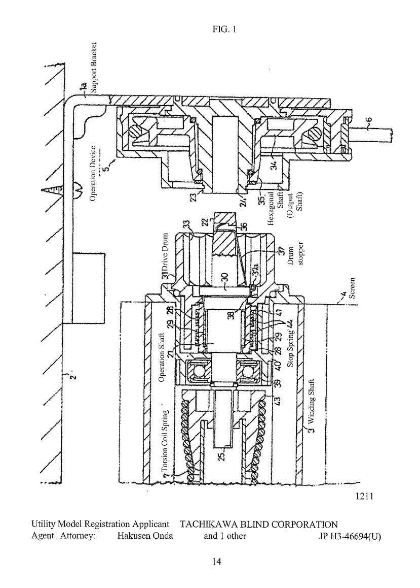
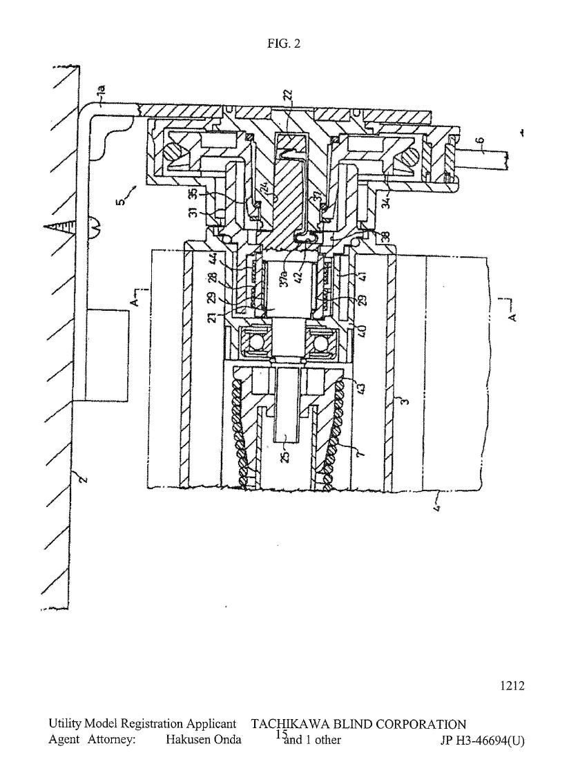
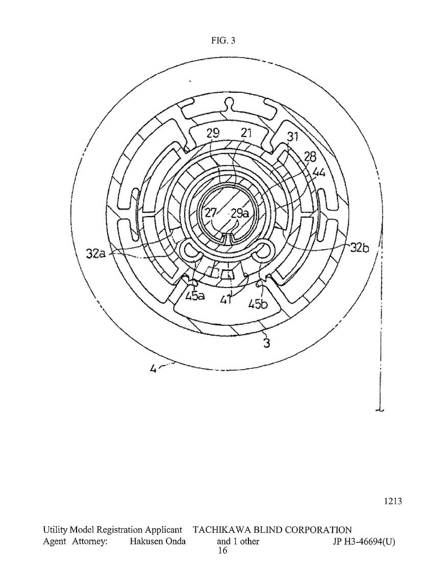
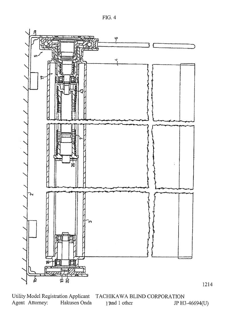
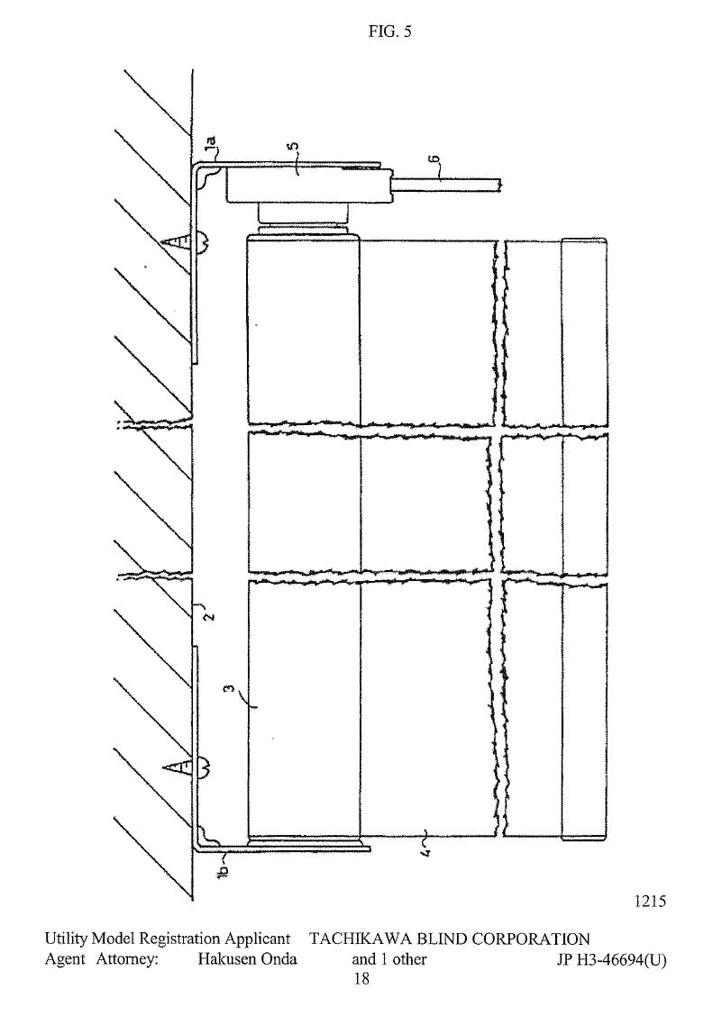
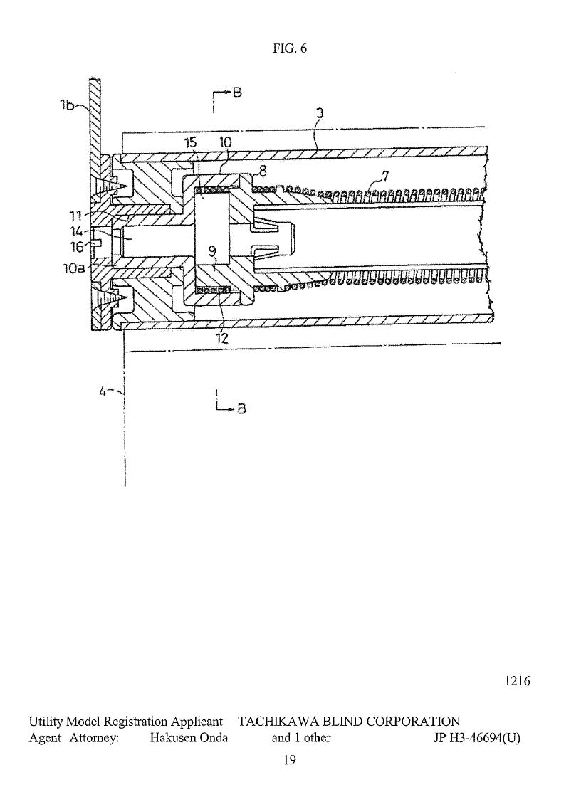
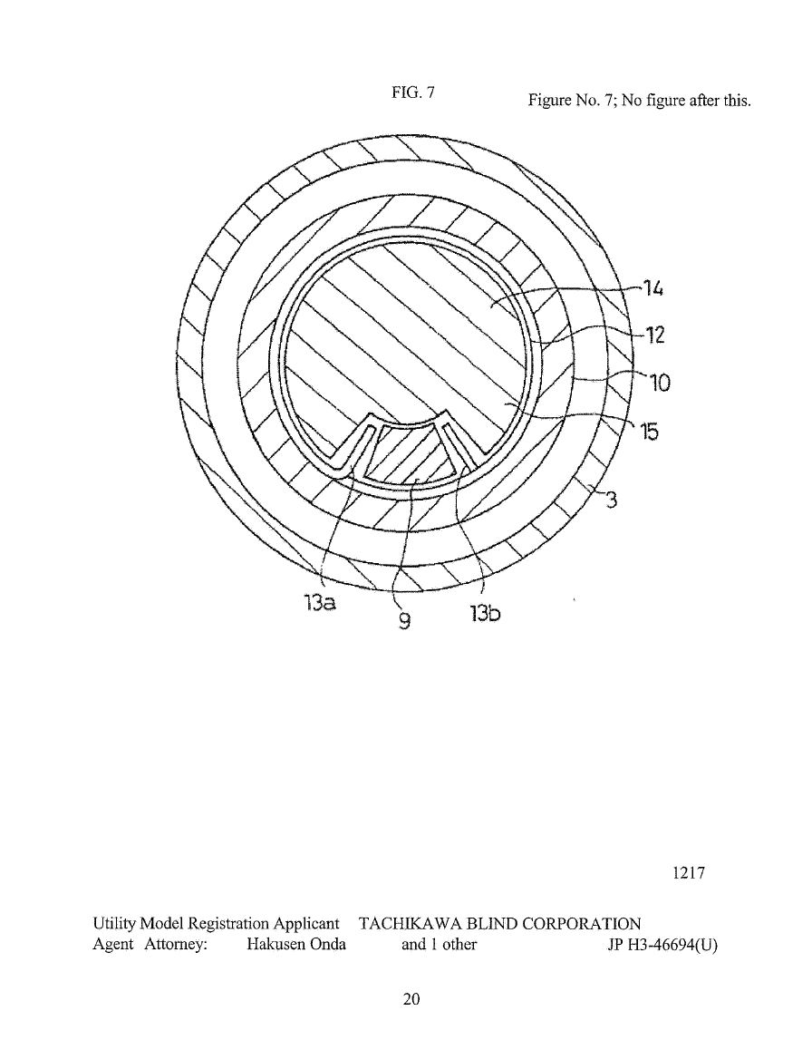
(3) the publication on 30 April 1991 of Japanese Utility Model No. H3-46694 (‘JP 694’).
133 Before turning to a detailed consideration of each event and its impact on novelty, it is prudent to cover the relevant legal principles in further detail.
5.1.1 Legal principles
134 In an earlier decision of this Court, I set out the relevant legal principles in respect of novelty: Damorgold Pty Ltd v JAI Products Pty Ltd [2014] FCA 150 at [98]-[115]. In setting out these principles below, I adopt similar language. The subsequent decision of the Full Court in Damorgold Pty Ltd v JAI Products Pty Ltd (2015) 229 FCR 68 did not, for the purposes of this proceeding, alter the applicability of those legal principles.
135 In this proceeding, the complete application was filed on 25 August 2000. Therefore, the Patents Act in the form unamended by the Patents Amendment Act 2001 (Cth) applies to determine the novelty of the patent.
136 For present purposes, s 7 of the Patents Act in the relevant form provided:
7. (1) For the purposes of this Act, an invention is to be taken to be novel when compared with the prior art base unless it is not novel in the light of any one of the following kinds of information, each of which must be considered separately:
(a) prior art information (other than that mentioned in paragraph (c)) made publicly available in a single document or through doing a single act;
(b) prior art information (other than that mentioned in paragraph (c)) made publicly available in 2 or more related documents, or through doing 2 or more related acts, if the relationship between the documents or acts is such that a person skilled in the relevant art in the patent area would treat them as a single source of that information;
…
137 The term “prior art information” used in both s 7(1) and s 7(3) was defined in the Dictionary in Sch 1 of the Patents Act by reference to the “prior art base”:
“prior art base” means:
(a) in relation to deciding whether an invention does or does not involve an inventive step:
(i) information in a document, being a document publicly available anywhere in the patent area; and
(ii) information made publicly available through doing an act anywhere in the patent area; and
(iii) where the invention is the subject of a standard patent or an application for a standard patent - information in a document publicly available outside the patent area; and
(b) in relation to deciding whether an invention is or is not novel:
(i) information of a kind mentioned in paragraph (a); and
(ii) information contained in a published specification filed in respect of a complete application where:
(A) if the information is, or were to be, the subject of a claim of the specification, the claim has, or would have, a priority date earlier than that of the claim under consideration; and
(B) the specification was published on or after the priority date of the claim under consideration; and
(C) the information was contained in the specification on its filing date.
(Note: For the meaning of “document” see section 25 of the Acts Interpretation Act 1901.)
138 It is sufficient for present purposes to treat the “patent area” as meaning Australia.
139 For the purposes of “novelty”, therefore, the prior art against which the novelty of the claimed invention is to be assessed includes any information made publicly available in a document anywhere in the world. In the case of information disclosed by doing an act, however, the act must have been done publicly in Australia.
140 The terms of s 7(1) require the prior art information to be in a single document or related documents or from doing a single act or related acts. They do not permit information in a document to be combined with information arising from doing an act, or vice versa: see, eg, Zetco Pty Ltd v Austworld Commodities Pty Ltd (No 2) [2011] FCA 848 at [129] (per Bennett J).
141 The invention (as claimed in a particular claim) is taken to be novel unless it is shown to lack novelty in light of the relevant prior art.
142 The comparison required is often described as the “reverse infringement” test. That test requires that the prior art information must disclose all the essential integers of the claimed invention. Thus, in Meyers Taylor Pty Ltd v Vicarr Industries Ltd (1977) 137 CLR 228 at 235, Aickin J explained:
The basic test for anticipation or want of novelty is the same as that for infringement and generally one can properly ask oneself whether the alleged anticipation would, if the patent were valid, constitute an infringement …
143 In General Tire and Rubber Co v Firestone Tyre and Rubber Co Ltd [1972] RPC 457 at 485-6, the stringency of the test was explained as follows:
To anticipate the patentee’s claim the prior publication must contain clear and unmistakable directions to do what the patentee claims to have invented … a signpost, however clear, upon the road to the patentee’s invention will not suffice. The prior inventor must be clearly shown to have planted his flag at the precise destination before the patentee.
144 This passage has been approved in Australia: see AstraZeneca AB v Apotex Pty Ltd [2014] FCAFC 99 at [293].
145 Relevantly, the case law is clear that all features of a product are treated as being disclosed if that product is sold to another person who is free in law and equity to make use of it: see Ronneby Road Pty Ltd v ESCO Corporation [2016] FCA 588. Similar considerations apply where there is evidence of samples of a product being provided to a customer without fetter of confidentiality: see Damorgold Pty Ltd v JAI Products Pty Ltd (2015) 229 FCR 68 at [49] per Bennett J.
146 I now turn to a consideration of the three events said by Blindware to anticipate the Patent: the supply of the Uniline Product, the publication of US 269, and the publication of JP 694.
5.1.2 The supply of the Uniline Product
147 Blindware contends that claims 1 to 17 and 19 to 23 of the Patent are anticipated by the supply of the Uniline Product.
5.1.2.1 The Uniline Product was prior art information that had been made publicly available
148 Damorgold admitted that before the priority date, Uniline had supplied the Uniline Product in Australia, such that all the materially relevant features of the Uniline Product and how those features interoperated was prior art information publicly available in Australia.
149 Therefore, the remaining question was whether the “reverse infringement” test would be satisfied having regard to the operation of the Uniline Product.
5.1.2.2 The operation of the Uniline Product
150 The Uniline Product is a roller blind that incorporates the combination of a helper spring and a clutch to control the extension and retraction of the blind. Much of the following information about the mechanism is set out in the two affidavits of Mr Tommy Ruonala (affidavits ‘R1’ and ‘R2’).
151 The Uniline Product is a modified version of an earlier product supplied by Uniline since at least mid-1996. The earlier product was a chain-operated blind with a clutch, which was marketed by Uniline under the name of ‘Sidewinder Set’.
152 The modification made to produce the Uniline Product was to add another component, marketed as a “helper spring”, to Uniline’s chain-operated blind: R1, [81]-[82].
153 The addition of the helper spring to Uniline’s chain-operated blind helped to counterbalance the weight of the blind fabric, which assisted with preventing the blind from creeping down and also reduced the force needed by the user to pull the chain in order to raise the blind: R1, [82].
154 Blindware thus contended that the Uniline Product was a roller blind mechanism that combined the prior art “clutch roller” mechanism with a biasing means/spring assist (or helper spring) to address the same problems and achieve precisely the same objects identified on pages 2 to 3 of the Patent in relation to the claimed invention. Blindware particularly pointed to the fact that the Uniline Product, like the claimed invention, is a mechanism claimed to be “relatively easy to operate” and which “accommodates, at least to some extent, the weight of the extended material” (see Patent at p 3).
5.1.2.3 Does the Uniline Product anticipate any claims of the Patent?
155 As I have said, Blindware contends that claims 1 to 17 and 19 to 23 of the Patent are anticipated by the Uniline Product. Damorgold’s chief response is that it is impossible for the Uniline Product to encapsulate the claims of the Patent. This is said to be because the Uniline Product only meets integers 1.9 to 1.11 if it is mounted on a support or similar mechanism, but claims 1 and 3 of the Patent require the invention to be self-contained (ie it must be capable of operating by itself, without an external support).
156 In respect of integers 1.9 to 1.11, Damorgold pointed to Mr Hunter’s evidence that the spring in the Uniline Product is not “responsive to” rotation of the cylinder unless the product is mounted. This is because the non-drive end of the spring in the Uniline Product is not fixed (see Hunter’s second affidavit, annexure BH-11, p 20):
The bias spring cannot respond to the rotation of the cylinder unless the mechanism interacts with additional components (being the non drive end mounting bracket, and the wall to which that bracket is attached). The non drive end mount bracket and the wall are not part of the mechanism which is claimed.
157 In respect of the requirement for a self-contained mechanism, Damorgold submitted that integer 1.4 ensures that the claims draw a clear distinction between the blind control mechanism and the means of support. In Damorgold Pty Ltd v JAI Products Pty Ltd [2014] FCA 150 at [205], I determined that:
I do not accept Dr Field’s interpretation. It is contrary to the plain meaning of the terms of claim 25 which, read with claim 1, draw a clear distinction between the blind control mechanism and the means of support. The interconnecting means required by claim 25 must be part of the blind control mechanism and not just the means of support to which the blind control mechanism is attached.
158 Damorgold submitted that the invention claimed is a blind control mechanism which does not include mounting brackets, and that the requirements of the claim must be able to be met by the mechanism separate from any support or mounting.
159 Blindware contended that there was no warrant for introducing a limitation in claim 1 that the mechanism be “self-contained” in the sense propounded by Damorgold. Blindware submitted that the overall operation of the claimed mechanism requires consideration of the mechanism connected to a support (commonly, a wall or ceiling) because, for the purpose of assessing infringement or anticipation, whether the mechanism has the functional requirements of the claims should be assessed in the context of the mechanism when in use – ie when connected to a support.
160 Blindware also pointed to the first component of the mechanism described in each of claims 1 and 3 as clearly contemplating a support to enable the components to interact in the way claimed:
a fixed shaft located at one extreme end of said axis and being connectable to a support for said mechanism so as to be thereby fixed against relative movement
161 Blindware argued that the fixed shaft, being the component around which the entire mechanism rotates, cannot be “fixed against relative movement” (a functional requirement) unless it is connected to a support (such as a wall), as contemplated by the above language. Blindware noted Mr Hunter’s evidence that:
…because the claims in the Damorgold patent are clearly saying that you have a fixed shaft which is connectable to a support to be thereby fixed against relative movement … it has to be fixed in some way to enable it not to rotate.
162 Furthermore Blindware submitted that claim 1 does not specify how the biasing means is to be fixed, only that it is responsive to rotation of the cylinder. Therefore, the fact that the Uniline Product relies on a support at the distal end of the mechanism to put energy into the biasing spring and to maintain energy in the biasing spring is insufficient to take it outside the scope of the relevant claims.
163 In my view, the Uniline Product does not anticipate the claim. For the Uniline Product to work with the “helper spring”, storing and releasing energy in response to rotation of the blind cylinder, the Uniline Product must be mounted into its associated wall brackets.
164 The invention claimed is a blind control mechanism which does not include mounting brackets. The requirements of the claim must be able to be met by the mechanism separate from any support or mounting.
165 It makes no difference that the whole purpose of the Uniline Product is to enable raising and lowering of a blind, and that this cannot be done unless the Uniline Product is mounted on a wall. I accept Mr Hunter’s evidence, relied on by Blindware, that “[t]he whole thing can’t just rotate around in fixed – in space… you have to have that fixed to a support, at least at the fixed shaft end, to enable it to work”. However, the role of the support in the Uniline Product is qualitatively different. The support performs a function in the operation of the Uniline Product beyond a contextual or auxiliary role. By contrast, I find no basis for reading such a function into the Patent. Rather, I accept Mr Hunter’s evidence that the role of the support in relation to the mechanism described in the Patent is, in essence, that of a pivot point around which the cylinder rotates.
166 Therefore, in my view, the key fact is that the blind control mechanism of the invention claimed does not need to be mounted on a support such as a wall for the specified features to interact in the way claimed, as Mr Hunter contended.
167 This is sufficient to reach the conclusion that the Uniline Product anticipates none of the claims.
5.1.3 The publication of US 269
168 Blindware contends that claims 1 to 7, 10 to 12, 20 and 22 to 25 of the Patent are anticipated by the publication of US 269
169 Damorgold admitted that before the priority date of the Patent, the information in US 269 was prior art information made publicly available: Further Amended Defence to Cross-Claim, [13A] and [13D(a)]. Therefore, the remaining question was whether the “reverse infringement” test would be satisfied having regard to the features of US 269.
5.1.3.1 The features of US 269
170 US 269 describes a roller blind mechanism that incorporates both a clutch mechanism and a “torsion coil spring” (a biasing means). Unlike the claimed invention in the Patent, the blind mechanism disclosed in US 269 can be lowered either by pulling the pull-chain or by pulling on the bottom of the blind. In addition, the blind retracts automatically under the power of the torsion coil spring, not continued rotation of the pulley. There was no dispute between Mr Hunter and Mr Crick as to the operation of the mechanism described in US 269.
171 As a general comment, in my view, the US 269 Patent thus discloses a mechanism, which in the words of Mr Hunter, is “fundamentally different to the invention claimed in the Damorgold Patent”.
172 Further, the US 269 Patent identifies as a problem with conventional roller blinds the need for:
…a continuous pulling action on the cord 54 in order to rotate the winding roller to lift or lower the screen. This requirement makes the lifting and lowering operations relatively completed [sic].
173 The solution proposed by the US 269 Patent is a winding apparatus in which the screen (blind) “can be automatically lifted by simply pulling the cord in a lowering direction”. The achievement of this objective involves a very different drive and clutch assembly to that in the claimed invention.
174 I do observe that Blindware submitted as follows:
US’269 describes a roller blind mechanism that incorporates both a clutch mechanism and a “torsion coil spring” (a biasing means). Blindware only relies on US’269 if Damorgold’s construction of the “responsive to” requirement is accepted by the Court. If that construction is accepted, Blindware relies on US’269 in relation to claims 1 to 7, 10 to 12, 20, and 22 to 25. If Blindware’s construction of the “responsive to” integer is accepted, then US’269 will not anticipate.
(Footnote omitted).
175 The Court did not accept Damorgold’s construction in that regard. I rejected that “responsive to” in integers 1.9 and 1.10 connotes “corresponding to” or reacting in parallel to the same external stimulus. Instead, I found above that the term “responsive to” in those integers connotes a process or action whereby two the elements described in those integers interact to produce certain outcomes. Relevantly for the purposes of US 269, I consider that it is the “biasing means” that must be “responsive to” the “rotation of said [blind] cylinder”, and not vice versa. That being the case, US 269 will not anticipate (as indicated by Blindware). It is nonetheless useful to consider further the question of anticipation as it is essentially dependent on questions of construction in addition to my comments above.
176 I will elaborate on the features of US 269 where appropriate in considering the submissions put by each of the parties.
5.1.3.2 Does US 269 anticipate any of the claims of the Patent?
177 Three issues arose in relation to US 269:
(1) whether integers 1.17, 1.26-1.27 and 3.18, 3.25 and 3.26 are disclosed (the “in either said direction” feature);
(2) whether integers 1.19 and integer 3.20 are disclosed (the driven member connection feature); and
(3) whether the need for the apparatus disclosed in the US 269 Patent to be mounted on a support bracket falls outside the mechanism as claimed (integers 1.9-1.11 and integers 3.9-3.11 and integers 24.4 and 25.2-25.4) (the self-contained mechanism feature).
178 Each issue must be considered in turn.
5.1.3.2.1 The “in either said direction” feature
179 Claim 1 (integer 1.17) of the Patent requires that the drive member be capable of rotation relative to the fixed shaft and:
thereby cause rotation of said cylinder in either said blind extending direction or said blind retracting direction
(Emphasis added).
180 Claim 1 (integers 1.25, 1.26 and 1.27) requires that in use:
[1.25] … rotation of said drive member in either said direction causes said clutch means to adopt said disengaged condition [1.26] and continued rotation of the drive member in the same direction results in corresponding rotation of both the driven member and the cylinder, [1.27] whereas cessation of said rotation of the drive member results in said clutch means adopting said engaged condition
(Emphasis added).
181 The evidence of the experts was clear in that integers 1.17, 1.26 and 1.27 (and corresponding integers 3.18, 3.25 and 3.26) are disclosed by US 269 in the blind extending direction: Crick’s first affidavit at [112(j)-(k)]; Hunter’s second affidavit at [79]-[84]. However, in the blind retracting direction, it is the influence of stored energy in the torsion coil spring that causes the cylinder to rotate, rather than the drive member (as required by the aforementioned claims).
182 Blindware contended that this is nonetheless sufficient to have anticipated the Patent, claiming that the phrase “either … or …” and “either said direction” in the Patent only requires that the condition is satisfied in one of the blind extending or blind retracting directions. Thus, Blindware contended that claim 1 does not require the cylinder and drive member to rotate together in both directions. Conversely, Damorgold contended that claim 1 requires that the cylinder and the drive member work (rotate) in both directions to allow both raising and lowering of the blind. I now turn to consider the arguments of each side in more detail.
183 Blindware first pointed to the plain meaning of the phrase “either … or”. Whilst conceding that the word “either” in isolation could mean either “one or the other of two” or “each of the two”, Blindware submitted that when used in conjunction with the word “or” it literally has the former meaning.
184 Blindware then argued that this meaning is consistent with the internal structure of the Patent. Blindware claimed that the structure of the dependent claims in the Patent contemplates that components other than the drive member may cause rotation of the blind in one direction of travel. For example, claim 21 is in the following terms:
Mechanism according to any preceding claim, wherein said drive and driven members together with said clutch means constitute the entire assembly of parts through which manually induced drive is transmitted to said cylinder.
185 Blindware submitted that, given claim 21 is dependent on the preceding claims, including claims 1 and 3, and therefore logically narrower, the earlier claims must encompass mechanisms in which the drive member causes the rotation of the cylinder in one direction in the manner required by claim 1, and another component or indeed another mechanism causes the rotation of the cylinder in the other direction.
186 Blindware also pointed to claim 16, which adds the requirement that:
a direct connection exists between said driven member and said cylinder, said direct connection being such as to cause said driven member and said cylinder to rotate in unison …
187 Blindware submitted that claim 1 must therefore encompass a connection between the driven member and the cylinder such that they do not rotate in unison in both directions. This is consistent with claim 1 permitting the drive member to cause rotation of the cylinder in only one direction given the drive member and driven member are both part of the drive means. Thus, Blindware claimed, the structure of the claims contemplates that, in the mechanism of claim 1, the driven member and the cylinder do not rotate together at all times.
188 Finally, Blindware contended that once it is understood that the word “either” in integer 1.17 only requires that the drive member causes rotation of the cylinder in at least one direction, it follows from the structure of claim 1 that integers 1.25-1.27 should be understood in the same way. Thus, the reference to “rotation of said drive member in either said direction” can only be a reference to “either said blind extending direction or said blind retracting direction”.
189 Damorgold first submitted that the definition of “either” from the Macquarie Dictionary does not compel the contention advanced by Blindware. Damorgold focused on how the terms should be understood in the context of the claim and the Patent as a whole, and submitted that the context of the claim supports its preferred construction.
190 Damorgold pointed to the context of the Patent, in which the blind control mechanism that is the subject of the claims is a mechanism for controlling both the extension and retraction of the blind. The claimed invention sought to address problems that had emerged with clutch roller blinds (without spring assistance). In the claimed mechanism, the extension and retraction of the blind results from rotation of the blind cylinder about the fixed shaft. If the blind cylinder does not rotate, the blind will neither be extended nor retracted. The two actions of blind extension and blind retraction store and release energy to overcome the two problems identified in the Patent.
191 In terms of the workings of the claimed mechanism, Damorgold submitted that the blind cylinder is connected to the driven member and the driven member rotates with the blind cylinder in both the blind extending and retracting directions (integers 1.19 and 3.20). Correspondingly, the driven member is connected to the drive member “for limited rotation thereto” (integers 1.18 and 3.19). The drive member itself is capable of rotation around the fixed shaft in both directions (integers 1.16 and 3.17).
192 As the driven member has only limited rotation with respect to the drive member, the drive member must be able to rotate in both the blind extending direction and also the blind retracting direction so that the driven member and hence the blind cylinder may also rotate in both directions. As they are all connected, if the drive member could rotate in one direction only, the driven member and the blind cylinder also would be able to rotate in that direction only.
193 Damorgold then pointed to the evidence of Mr Hunter at transcript, p 130:
HIS HONOUR: So if I read the claim, one way or the other, that may - as a whole, that didn’t allow for a possibility of it going up or down would be a little bit strange. Not necessarily impossible but strange?---
MR HUNTER: Well, I think it would be strange because I can’t find any reference in the invention to any other form in which the invention is described and particularly in relation to the example mechanism other than a mechanism that is for extension and retraction of a blind which works by effectively pulling the pull cord both ways. So to introduce, hypothetically, other ways in which the retraction might occur is something, quite frankly, your Honour, I hadn’t even contemplated and I don’t think the invention was really intended to apply to that, just in a commonsense manner. That’s my view.
194 On this basis, Damorgold submitted that Blindware’s contention (that the expressions “either … or” and “in either said direction” are satisfied if the mechanism works in only one direction) was not a practical, common sense construction of the claims having regard to the context of the Patent. Therefore, because US 269 only discloses the relevant integers in the blind extending direction (and not in the blind retracting direction), Damorgold claimed it did not anticipate those claims of the Patent.
195 In my view, the approach taken by Damorgold is the correct one. Blindware’s contention that the expressions “either…or…” and “in either said direction” are satisfied if the mechanism works in only one direction is not a practical, common sense construction of the claims. Further, the definition of the term “either” must be seen in the context of the claimed invention.
196 I agree with Damorgold that, in the context of the Patent, the blind control mechanism that is the subject of the claims is a mechanism for controlling both the extension and retraction of the blind. The words “in either said direction” in integer 1.25 indicate that the blind cylinder can rotate in either the blind extending or blind retracting directions; it cannot do both simultaneously.
197 Integers 1.17, 1.25, 1.26 and 1.27 do not specify rotation in one specific direction. Rather, each of these integers is open to rotation in either direction.
198 The usage in respect of the preferred embodiment in the specification is consistent with Damorgold’s construction, wherein there is a reference to rotating the cylinder “in either a blind extending direction or a blind retracting direction”.
199 Since I accept Damorgold’s construction in this regard, US 269 cannot be said to anticipate the Patent. Mr Crick and Mr Hunter agree that the above mentioned integers are disclosed by US 269 in the blind extending direction, but not in the blind retracting direction.
5.1.3.2.2 The driven member connection feature
200 Integer 1.19 requires that the driven member is “connected to said cylinder for rotation therewith”. Integer 1.26 requires that “continued rotation of the drive member in the same direction results in corresponding rotation of both the driven member and the cylinder”.
201 Both Mr Crick and Mr Hunter in their written evidence say these features are not present if the driven member is the first clutch drum, because the first clutch drum only rotates with the cylinder in the blind extending direction but not the blind retracting direction. Because of this, Damorgold contended that US 269 does not disclose either claim 1 integer 1.19 or claim 3 integer 3.20.
202 However, Blindware contended that the Court should adopt Blindware’s preferred construction of the words “either ... or” (as above). If the Court did so, Blindware submitted that the following conclusions would logically follow in respect of the relevant integers:
first, integer 1.19 would only require that the driven member rotate with the cylinder in one direction; and
secondly, integer 1.26 would only need to be satisfied in one direction.
203 Therefore, this dispute between the parties would also turn on the same construction point in relation to “either … or” as I have previously considered in these Reasons.
204 In my view, US 269 does not disclose the feature of the driven member being connected to the blind cylinder for rotation therewith.
205 This is because the driven member is the first clutch drum 12. The driven member rotates with the cylinder when the blind is being lowered. However, the driven member does not rotate with the cylinder when the blind is being lifted. When the blind is being lifted the drive member causes the clutch arm 21 to disengage the clutch spring 23 from the driven member (the first clutch drum 12). Therefore the driven member is no longer connected to the cylinder. As a result the driven member does not rotate the cylinder. The cylinder rotates as a result of the energy stored in the spring.
206 As I have interpreted the phrase “either… or…” in context, and applying that analysis here, claims 1 and 3 (and any dependent claims) are not anticipated by US 269.
5.1.3.2.3 The self-contained mechanism feature
207 Integers 1.10 and 1.11 have already been set out.
208 Blindware accepts that if its preferred construction of “responsive to” (see above in relation to infringement) is accepted by the Court, then integers 1.10 and 1.11 will not be disclosed by US 269.
209 However, conversely, if Damorgold’s construction of “responsive to” (see above in relation to infringement) is accepted by the Court, Blindware contends that US 269 does disclose integers 1.10 and 1.11.
210 Blindware accepted that, in the blind retracting direction for US 269, pulling the cord results in the cylinder being free to rotate under the influence of the stored energy in the torsion spring coil. That is, in the blind retracting direction, it is the influence of the stored energy in the torsion coil spring that causes the cylinder to rotate (rather than the spring being “responsive” to the rotation of the cylinder as per integers 1.10 and 1.11).
211 Nonetheless, Blindware pointed out that the rotation of the cylinder and the storing and release of energy in the biasing means in US 269 still occurs at the same time (see US 269, column 2 lines 53-60), which would be sufficient to satisfy Damorgold’s construction of “responsive to”.
212 Damorgold’s central response was that the invention in the Patent is a “self-contained mechanism” (the same argument which is elaborated above in relation to the Uniline Product) which does not include mounting brackets or require support from a wall, window frame or ceiling. I have already considered this issue. Damorgold submitted that, as with the Uniline Product, the mechanism disclosed in US 269 must be mounted on a support for the non-drive end of the spring to be fixed against rotation, so that the spring can store or release energy. In other words, US 269 does not disclose a “self-contained mechanism” where the biasing means is “responsive to” rotation of the blind cylinder as per integers 1.10 and 1.11.
213 Blindware disputed Damorgold’s “self-contained mechanism” construction for the same reasons as it did above in relation to the Uniline Product. In addition, Blindware replied that even if the “self-contained mechanism” construction was correct, it would not distinguish US 269 because a bracket is provided which makes the whole mechanism “self-contained”. According to the description in US 269, Blindware submitted that the support bracket is a “part of the mechanism” and forms parts of the connection between the torsion coil spring and fixed shaft. As explained by Mr Crick, the plug and bracket provide a connection between the distal end of the cylindrical spring and the fixed shaft, so that the spring is held against rotation. The plug and bracket were also said to comprise the interconnecting means between the fixed shaft and the biasing means (which, as Blindware submitted, meant that claims 24 and 25 would also be disclosed by US 269 - see further below).
214 Damorgold did not consider that the bracket could be construed as forming part of the interconnecting means as that term is used in Damorgold’s Patent. However Blindware criticised this position in light of Mr Hunter’s earlier evidence that an “interconnecting means” is “a way of connecting one component to another”, and Blindware submitted that there was no obvious reason why this should not include the connection provided by the plug and support bracket in US 269.
215 Furthermore, Blindware pointed to the fact that the description in the Patent also expressly contemplates that there may be other components that form part of the mechanism other than those described in the claims. For example, on page 8, lines 14-16, the Patent refers to how the cylinder is supported at the drive end by the fixed shaft and at the distal end by “appropriate means” as follows:
The drive means 3 and the rotatable cylinder 1, form respective parts of a rotatable assembly 9 supported at one end by the shaft 4, and supported at the other end by appropriate means (not shown).
216 Blindware submitted that the “appropriate means” could, for example, include a shaft at the distal end and mounting brackets, each of which, together with the fixed shaft at the drive end, are contemplated as forming part of the mechanism despite being used to connect to the support. Thus Blindware sought to refute Damorgold’s “self-contained mechanism” argument in the context of whether US 269 anticipated integers 1.10 and 1.11.
217 Blindware also argued that US 269 anticipated claims 24 and 25 of the Patent. Claim 24 requires, inter alia:
and the other end of said cylindrical spring being connected to said fixed shaft so as to be held against rotation relative thereto
218 Claim 25 also requires:
interconnecting means provides a connection between said biasing means and said fixed shaft opposite ends of said interconnecting means are connected to said biasing means and said fixed shaft respectively and the connection at each said end being such as to prevent relative rotation
219 Blindware relied upon its above arguments in relation to the existence of the support bracket in US 269 to contend that, accordingly, US 269 discloses a mechanism which includes the relevant connection between the biasing spring and the fixed shaft described in claim 24, and the interconnecting means described in claim 25 (thus anticipating those claims).
220 In my view, Blindware cannot rely on additional and external components to the blind control mechanism. The support bracket 1 (which allows the spring in the mechanism disclosed in US 269 to store and release energy) is not part of the mechanism that is used in claims 24 and 25. Therefore, US 269 does not disclose the features of claims 24 and 25.
5.1.3.3 Summary in relation to US 269
221 For the foregoing reasons, I reject Blindware’s submissions on novelty relying on US 269.
5.1.4 The publication of JP 694
222 Blindware contends that claims 1 to 17, 19 to 21 and 23 to 25 of the Patent are anticipated by the publication of JP 694.
223 A certified translation of JP 694 was provided by Blindware and there were no objections to that translation by Damorgold. A copy of this translation is Attachment A to my Reasons. This is attached to assist the reader to understand the description of the mechanism referred to later in my Reasons.
224 Furthermore, Damorgold accepted that for the purposes of this proceeding, JP 694 formed part of the prior art base for the assessment of novelty. Therefore, the remaining question was whether the “reverse infringement” test would be satisfied having regard to the features of JP 694.
5.1.4.1 The features of JP 694
225 There is no dispute that JP 694 describes a mechanism “for controlling extension and retraction of a blind” that combines a clutch mechanism with a spring assist (or helper spring). There is similarly no dispute that in the mechanism described in JP 694, the biasing means is attached at the drive end, which means that the mechanism can be pre-tensioned and can hold any pre-tension before it is installed and attached to a support (i.e. wall).
5.1.4.2 Does JP 694 anticipate any of the claims of the Patent?
5.1.4.2.1 Claim 1
226 In relation to claim 1, the central integers in dispute are whether JP 694 describes a mechanism in which:
(1) the clutch means is “operative in an engaged condition to at least resist rotation of said cylinder under the influence of stored energy alone” (integer 1.21); and
(2) the clutch means “extends around a fixed cylindrical surface so as to be capable of engaging that surface” (integer 1.23).
227 In respect of integer 1.21, Damorgold made two submissions:
228 First, Damorgold contended that claim 1 of JP 694 was expressed at a far too general and imprecise level and does not disclose all the features of claim 1 (or 3) of the Patent. This was a submission going beyond just integer 1.21. For example, it was submitted that claim 1 does not disclose either a drive member or a driven member as required by claim 1 and 3 of the Patent: see pp 34-6 of Damorgold’s Closing Submissions on Validity.
229 Secondly, Damorgold contended that integer 1.21 was not anticipated by JP 694 because (I have assigned a number to each part of the mechanism consistently with those used in JP 694):
JP 694 requires that there be a brake tube 28 between the stop spring 44 (the “clutch means” of JP 694 for the purposes of claim 1 of the Patent) and the operation shaft 21.
The brake tube 28 is not “integrally fixed” to the operation shaft 21 (ie it can move around that shaft).
Therefore, the operation of stop spring 44 on the brake tube 28 does not provide any resistance to rotation of the blind cylinder around the operation shaft 21 (rather, it is the clutch spring 29 that is providing the resistance to rotation of the cylinder).
230 Therefore, Damorgold claimed that the “clutch means” in JP 694 (stop spring 44) is not operative in an engaged condition to at least resist rotation of the blind cylinder (rather, it is the clutch spring 29), and therefore integer 1.21 is not anticipated.
231 Blindware disputed each of the above propositions and made the following arguments:
232 First, in relation to the presence of the brake tube 28, Blindware contended that the example depicted in the drawings is just “one embodiment” consistent with the description on page 6, with claim 1 describing an alternative arrangement with some optional features (namely, the brake tube and clutch spring) not required for the mechanism to operate if not present (see Mr Hunter at transcript, pp 277-8). Blindware submitted that the fact that the specific functions of the brake tube and clutch spring are not described in JP 694 reinforces the view that they are intended to be optional features, and that the most sensible way to understand claim 1 of JP 694 is as merely describing an alternative arrangement to the example depicted in the drawings in which the brake tube and clutch spring are not included: see Mr Crick at transcript, p 276. Blindware submitted that this understanding of JP 694 was also consistent with the description of the prior art and the stated object of the invention in JP 694 (see p 5 of JP 694).
233 Secondly, in relation to “integrally fixed”, Blindware contended that even if brake tube 28 was a necessary feature of JP 694, it was “integrally fixed” to the operation shaft 21 such that the operation of stop spring 44 on the brake tube 28 did provide resistance to rotation of the blind cylinder around the operation shaft 21. JP 694 describes at page 8 that:
Because the clutch spring 29 is always pressed to the inner circumferential face of the brake tube 28 by the elasticity thereof, the brake tube 28 and the operation shaft 21 are integrally fixed, and when a rotational force greater than a prescribed value acts on the brake tube 28, one of the end edge portions 29a of the clutch spring 29 is pressed strongly against the side face of the locking groove 27, the clutch spring 29 reduces in diameter, friction with the brake tube 28 reduces, and the brake tube 28 rotates with respect to the operation shaft 21.
(Emphasis added).
234 The issue facing Blindware was that JP 694 describes rotation between the brake tube 28 and operation shaft 21 when a rotational force greater than a prescribed value acts on the brake tube – in other words, it would appear those components are not always “integrally fixed”. However, Blindware contends that the mechanism could only operate as intended if the rotational force applied to the brake tube during normal operation is less than the prescribed value required to release the clutch spring. Otherwise, the cylinder would not remain stationary when the cord is not being pulled, and the user would not be able to control the extension and retraction of the blind by pulling the cord. Thus, for Blindware, during normal operation the brake tube 28 is “integrally fixed” to the operation shaft 21.
235 As to that normal operation, when the cord is not being pulled, Blindware points out that JP 694 expressly states that it is the stop spring 44 (acting through the brake tube 28) that prevents the cylinder from rotating (see p 10):
When the operation cap 40 is rotated by the operational force transmitted from the winding shaft 3 … the friction between the stop spring 44 and the brake tube 28 increases, and thereby, the rotation of the operation cap 40 and the winding shaft is prevented.
236 Blindware likewise pointed to the following passage of JP 694 (p 12):
Meanwhile, when the operation cord 6 is released after raising the screen 4 to a desired location, the winding shaft 3 tries to rotate in either direction by the weight of the screen 4 or the accumulated force of the torsion coil spring 7 … the friction between the stop spring 44 and the brake tube 28 increases, thereby preventing the rotation of the winding shaft 3.
237 As further explained by Mr Crick (transcript, p 287):
…When – when the – when the operation cord is being pulled to raise and lower the blinds, the brake tube remains fixed – integrally fixed to the operation shaft (21) via the clutch spring (29). And it’s – the brake tube, as we’ve just discussed, was not able to rotate around the operation shaft until a force of more than the prescribed value is applied to it. When the blind is in a stationary position, by definition a force of greater than that prescribed value is not being applied to it, otherwise the blind wouldn’t hold in a stationary position. As soon as you pull the cord and the drive drum releases – acts onto the 45A or 45B of the helical clutch spring, the force which the clutch spring is applying to the outer circumference of the brake tube is lessened rather than – rather than – rather than made greater. So therefore it’s impossible for a force of more than them prescribed value to be applied to the brake tube when the blind is being operated with the – with the pull cord.
238 Thus, Blindware submitted that the brake tube 28 and operation shaft 21 were “integrally fixed” such that integer 1.21 of the Patent would be anticipated by JP 694.
239 In reply, Damorgold disputed that any component could be described as “fixed” if it had the capability of moving in relation to another component, relying on the definition of “fixed” in Macquarie Dictionary. In particular, Damorgold pointed out that if the clutch spring 29 was not present or was not engaged with the inner face of the brake tube 28 while the stop spring 44 was engaged with the brake tube 28, the blind cylinder would rotate around the operation shaft 21: Hunter’s fourth affidavit at [28]–[30]. Mr Crick accepted that the clutch spring 29 “in combination with the other elements” controlled whether the cylinder rotated: transcript, p 292. As, according to Damorgold, the brake tube 28 can (and is intended to) rotate freely around the operation shaft 21, Damorgold submitted that it cannot be described as “fixed” and so is not part of the fixed shaft in terms of the Patent.
240 Whilst Blindware accepted that the clutch spring 29 “in combination with the other elements” controlled whether the cylinder rotated, Blindware pointed out that the fact that two things provide resistance to rotation of the cylinder does not mean that each is not responsible for resisting rotation as required in claim 1 of the Patent. The clutch spring can only provide resistance to the rotation of the cylinder if the cylinder is being prevented from rotating around the brake tube by the grip of the stop spring on the brake tube. Accordingly, Blindware contended that each of the stop spring and the clutch spring acted to resist the rotation of the cylinder under the influence of stored energy in the torsion coil spring when the cord is not being pulled. Blindware pointed to Mr Hunter’s testimony in cross-examination that “[i]t’s the two – the two springs are working together to resist the rotation. I mean, you have to have both of them” (transcript, p 294). Blindware thus contends that integer 1.21 of the Patent would be anticipated by JP 694.
241 In respect of integer 1.23, Blindware contends that the “fixed cylindrical surface” feature only requires the cylindrical surface to be fixed when the claimed mechanism is in normal operation, when the mechanism is mounted on a support and the drive means is being used to control the extension and retraction of the blind. If, as submitted by Blindware, the brake tube and the operation shaft are “integrally fixed” during that normal operation, it follows that the outer surface of the brake tube is a “fixed cylindrical surface” for the purpose of claim 1 of the Patent.
242 Damorgold disputed this, chiefly for the reasons given above, namely that the brake tube 28 can (and is intended to) rotate freely around the operation shaft 21. Thus it cannot be described as “fixed” and so is not part of the fixed shaft in terms of the Patent. Therefore, Damorgold contended that the brake tube and the operation shaft were not “integrally fixed”, and that it followed that the outer surface of the brake tube was not a “fixed cylindrical surface”.
243 It is convenient to consider the arguments in relation to integers 1.21 and 1.23 together. Looking at the embodiment reflected in Figures 1-4 of JP 694 (the ‘Particular Embodiment’), I cannot accept that the brake tube 28 is effectively part of the fixed shaft of integer 1.20 based on the wording therein that, when the clutch spring 29 is engaged with the inner face of the brake tube 28, the brake tube is “integrally fixed” with the operation shaft 21. Not only is this because the brake tube 28 and the operation shaft 21 are two separate components, but also because it is clear that the brake tube 28 is capable of rotating and intended to rotate independently of the operation shaft 21.
244 I therefore agree with Damorgold’s understanding of the phrase “integrally fixed” in this context and the consequences of such interpretation to the application of integers 1.21 and 1.23.
245 Blindware sought to overcome these aspects of the Particular Embodiment by relying on Mr Crick’s view that the brake tube 28 was fixed against rotation during “normal operation” when raising or lowering the blind by using the pull cord.
246 I do not accept that the brake tube 28 being fixed against rotation during “normal operation” is sufficient to satisfy how the relevant components are to be “fixed” within the meaning of the Patent. Rather, I agree with Mr Hunter’s view that, for the purposes of the Patent, the fixed shaft is necessary to hold the blind in place and so, necessarily, it must be fixed at all times and not just in “normal operation” when being retracted or extended. Mr Hunter explained this in the following terms:
MR HUNTER: Well, that means that the shaft is fixed all the time that the blind is installed. It has to be fixed, and remain in place, while the blind is being held, and it has to be fixed, and remain in place, when the cord is being pulled and the blind is rotating about the fixed shaft. So there’s no circumstance in Damorgold where the shaft is anything other than fixed.
COUNSEL: Well, certainly not in the preferred embodiment, but the claim itself does not require that it’s fixed the whole time. Would you accept that it only requires it to be fixed when in operation?
MR HUNTER: I don’t know what you mean by “in operation”, because effectively when the blind is holding – when it’s holding the blind statically, the blind is effectively in operation. It’s doing something.
HIS HONOUR: I think Mr Hunter’s saying it’s in operation the whole time.
COUNSEL: Yes. I think that’s the case.
MR HUNTER: That’s right.
(Emphasis added).
247 In any event, I accept Mr Hunter’s argument that there would be no point to the clutch spring 29 if it were not to control the rotation of the brake tube 28 relative to the operation shaft 21. As I have indicated, the operation shaft 21 and the brake tube 28 are separate components and, further, the brake tube 28 can (and is intended to) rotate independently of the operation shaft 21.
248 This means that the stop spring 44 can be engaged with the brake tube 28 while the brake tube 28 is rotating around the operation shaft 21. Since the brake tube 28 can (and is intended to) operate independently of the operation shaft 21, I accept Mr Hunter’s point that it is the clutch spring 29 which resists the rotation of the cylinder under the influence of the energy stored in the biasing means. If the clutch spring 29 was not present or was not engaged with the inner face of the brake tube 28 while the stop spring 44 was engaged with the brake tube 28, the blind cylinder would rotate around the operation shaft 21.
249 As already indicated, as the brake tube 28 can (and is intended to) rotate freely around the operation shaft 21, I accept Damorgold’s contention that it cannot be described as “fixed” and so is not part of the fixed shaft in terms of the Patent.
250 Accordingly, on the above basis, JP 694 does not disclose claim 1 integers 1.21 or 1.23.
251 I also accept Damorgold’s submission that claim 1 of JP 694 is expressed at a far too general and imprecise level. Taken in isolation, it does not disclose all the specific features of claim 1 (or 3) of the Patent. For example, Mr Crick accepted that claim 1 of JP 694 does not disclose either a drive member or a driven member as required by claim 1 and claim 3 of the Patent. Rather, Mr Crick inferred disclosure of the drive member and the driven member.
252 The figures and description of the Particular Embodiment describe a very particular mechanism. The description of the Particular Embodiment and the accompanying drawings do not disclose a clutch mechanism which has a drive member, a driven member and a single clutch spring only. Rather, the Particular Embodiment describes a device which includes not just a drive member and a driven member, but also the brake tube 28 and the clutch spring 29.
253 Mr Crick did consider it was possible to infer the drive member and the driven member from the reference to the prior art in JP 694 to the stop spring at either end of the longitudinal shaft. From this disclosure, the object stated in JP 694 to combine the two stop springs and a clutch mechanism with a drive member and a driven member was a well-known configuration, so it was said that it was possible to infer “how to solve the problem to consolidate those things into one”.
254 I agree with Damorgold that this process of mosaicking various elements together in the way described by Mr Crick is insufficient for the purposes of a novelty inquiry. In particular, it would not ordinarily be sufficient to choose some features disclosed in the Particular Embodiment and omit others.
255 The particular prior art stop spring described in JP 694 is of very different construction and operation to drive member, driven member and clutch spring combination claimed in the Patent. The bare reference to spring 44 does not necessarily disclose both a drive member and a driven member. Mr Hunter’s evidence was that clutch mechanisms do require a drive member and spring, but may not require a driven member.
256 I also consider that Mr Crick’s interpretation of claim 1 of JP 694 is inconsistent with the description of how the Particular Embodiment of the invention works. The passage in claim 1 and the consistory clause on which Mr Crick relies reads:
… a stop spring (44) is provided that presses on the operation shaft (21) … and prevents rotation of the winding shaft (3) ….
257 In the context of integer 1.23, Mr Crick reads this as teaching that the stop spring 44 “extends around and engages directly with the operation shaft, which is a fixed cylindrical surface.” In my view, however – and as Mr Hunter points out – if that interpretation is correct the Particular Embodiment would be outside the scope of claim 1 as that embodiment does not involve the stop spring 44 engaging directly with the operation shaft 21. As Mr Crick accepts, in the Particular Embodiment the stop spring 44 does not press on the operation shaft 21. The stop spring 44 presses on the outer surface of the brake tube 28. It engages with the operation shaft 21 only indirectly through the brake tube 28 and the clutch spring 29 which presses on the inner surface of the brake tube 28. The skilled addressee would not read claim 1 of JP 694 in a way that resulted in the Particular Embodiment falling outside claim 1 itself.
258 I also note, in respect of integer 1.23 in particular, which provides “wherein said clutch means extends around a fixed cylindrical surface so as to be capable of engaging that surface,” that Mr Crick contended that the words “fixed cylindrical surface” refer to a cylindrical surface which is fixed relative to the clutch means (ie, the stop spring 44).
259 However, in my view, the brake tube 28 is not a fixed cylindrical surface; it is capable of rotation when the clutch spring 29 is disengaged. I do not accept that “fixed” in the context of the Patent can connote something akin to “fixed relative to the clutch means”. Rather, the plain meaning of fixed, and the preferred meaning in the context of the Patent, is that “fixed” refers to being incapable of moving.
260 The words “so as to be capable of engaging that surface” at the end of integer 1.23 in claim 1 do not qualify the ordinary meaning of “fixed …” in the way Mr Crick contends for. They describe the clutch means, not the characteristics of the fixed cylindrical surface. They do not require that the surface around which the clutch means extends be “fixed”.
261 Similarly, the words “whereby … in use” in integer 1.25 of claim 1 do not assist Blindware. Mr Hunter does not consider the phrase in integer 1.25 relevant to the interpretation of the expression “fixed cylindrical surface” in integer 1.23. As a matter of construction, I agree with Damorgold’s contention that the words mean the claimed mechanism can be used to raise or lower the blind.
5.1.4.2.2 Claim 3
262 Claim 3 is the other independent claim within the Patent and it closely resembles claim 1. However the “fixed cylindrical surface” feature is not an integer of claim 3, such that the only integer in dispute for claim 3 in relation to JP 694 is the “at least resist rotation” feature.
263 My findings in relation to this claim follow upon my findings in relation to claim 1. There is no anticipation of claim 3.
5.1.4.2.3 Claims dependent upon claims 1 and 3
264 Each of claims 2 and 4 to 25 in the Patent are dependent on either claim 1 or 3. Therefore my findings in relation to claims 1 and 3 will impact my findings in relation to those dependent claims.
265 As I have determined that claims 1 and 3 are not anticipated, I do not need to consider whether JP 694 discloses a number of other features of various dependent claims. However, I briefly set out the various arguments and my view.
5.1.4.2.4 Claims 5, 6 and 19-21
266 Blindware stated:
The disputed features in these claims are as follows:
(a) “said cylindrical surface is a surface of said fixed shaft” (integer 5.2);
(b) “said clutch means engages directly with said cylindrical surface when in an engaged condition” (integer 6.2);
(c) “at least one helical spring constitutes the entire clutch means in said mechanism influencing rotation of said cylinder” (integer 19.1);
(d) “said clutch means is the sole clutch means in said mechanism influencing rotation of said cylinder” (integer 20.1); and
(e) “said drive and driven members together with said clutch means constitute the entire assembly of parts through which manually induced drive is transmitted to said cylinder” (integer 21.1).
(Emphasis original).
267 In respect of claims 5 and 19-21, Blindware relied solely on the mechanism in claim 1 of JP 694. Accordingly, the question Blindware asked this Court to resolve was whether claim 1 of JP 694 describes a mechanism in which the stop spring 44 (ie the clutch means) engages directly with the operation shaft (ie the fixed shaft), and which does not include the brake tube/clutch spring assembly. Blindware submitted that if the Court were to accept that claim 1 does describe such a mechanism, the additional features in each of these claims are satisfied by the disclosure in JP 694.
268 In respect of claim 6, Blindware relied on both the mechanism in claim 1 and the example in JP 694. Again, it conceded that the resolution reached in relation to claim 1 would also resolve this dispute.
269 In response to all of the above claims, Damorgold relied upon its arguments in relation to claim 1, which I have accepted.
5.1.4.2.5 Claims 7, 9, 11-13, 15-17 and 25
270 Blindware submitted that these remaining dependent claims in dispute related to features that are common to both the example in JP 694 and the mechanism in claim 1 of JP 694.
271 In respect of claim 7, which includes the requirement that “said driven member extends over a substantial part of the axial length of said fixed shaft”, the dispute rested on the interpretation of the term “substantial”. Mr Crick calculated that the driven member extended over 42% of the axial length of the fixed shaft: transcript, p 298. The question for this Court was whether this constituted a “substantial part”.
272 Blindware urged the Court to avoid a mathematical approach to resolving this question, and instead submitted that the ordinary and natural meaning of the words “substantial part” simply needed to be construed according to the function which the relevant component is required to perform in the operation of the alleged invention, read in the context of the specification as a whole: see, eg, Melbourne v Terry Fluid Controls Pty Ltd (1993) 26 IPR 292 at 304.
273 Therefore, Blindware contended that the reference to a “substantial part” in claim 7 should be understood as requiring a sufficient amount so as to be functionally significant to the operation of the claimed invention. The length of the driven member in JP 694 was said to meet this requirement.
274 In contrast, Damorgold were content to rely on Mr Hunter’s assessment that the extension of 42% was less than 50%, and thus not “substantial” when compared to the preferred embodiment in the Patent.
275 In my view, the approach taken by Blindware is correct. It is important to consider the functional effect of the operation of the claimed invention. The approach taken by Mr Crick on this aspect is to be preferred to that of Mr Hunter and Damorgold.
276 In respect of claim 9, which requires that “said driven member is mounted on said drive member”, the dispute concerned the interpretation of the term “mounted”. The drive member (blue) and the driven member (orange) can be seen in Mr Crick’s coloured version of Figures 1 and 3 of JP 694: court book, p 851BT.
277 Damorgold pointed to lines 26-28 of page 9 of JP 694 which states that “[a]n operation cap 40 [the driven member] is rotatably supported in the intermediate portion of the operation shaft 21 via a bearing 39”. Because the driven member (operation cap 40) is mounted on the fixed shaft (via the bearing 39), not the drive member, Damorgold submitted that JP 694 did not disclose the aforementioned feature of claim 9.
278 Blindware contended that Damorgold were proposing too narrow an interpretation of the term “mounted”, and Blindware disputed that it required something to be “held in place”. Whilst Blindware accepted there was limited rotation between the driven and drive members in JP 694, it claimed that this was fully consistent with the Patent (see integers 1.18 and 1.26) and did not preclude an interpretation that the driven member was “mounted” on the drive member. Blindware submitted that Figure 2 of JP 694 clearly shows that the drive member and the driven member are directly sleeved together. This was said to be obvious from Mr Hunter’s coloured version of Figure 2 in Annexure BH-16, which shows the driven member (yellow) being in direct contact with the drive member (blue) at a mounted point (which intersects with the green-dashed line): court book, pp 395BS-395BT. In Blindware’s view, this sleeving together, whilst not fixing the driven and drive member against rotation (as was claimed to be demanded by Damorgold), still involves the driven member being “mounted” on the drive member in the mechanism in JP 694, and in such a way that allows the two components to interact in the manner described in the claims of the Patent.
279 The preferred view is that of Blindware and Mr Crick. Figure 2 of JP 692 shows the drum member and the driven member are directly sleeved together, and this is sufficient to satisfy the requirement of claim 9.
280 In respect of claim 11 (and, as a result, dependent claim 12), which requires that “a tubular barrel section extends from one side of said wheel section away from said one extreme end of the longitudinal axis of said mechanism”, the dispute concerned the boundaries of the tubular barrel section. By reference to Mr Hunter’s coloured version of Figure 2 (court book, pp 395BS-395BT), Mr Hunter was of the view that the tubular barrel section in JP 694 was confined to the section marked within the green-dashed line, while Mr Crick was of the view that the tubular barrel section could also constitute the entire part shown in dark blue (ie drive drum 31). Damorgold submitted that, regardless of which view was adopted, the tubular barrel section of JP 694 clearly did not extend from, nor form part of, the wheel section of the pulley 34.
281 Conversely, Blindware contended that if Mr Crick is correct that the tubular barrel section constitutes the entirety of the drive drum 31, then it clearly extends from one side of the wheel section (regardless of how the wheel section is defined). Mr Crick’s view was said to be preferred because it was supported by the description of the drive drum 31 in JP 694, which is referred to as a “tube shaped drive drum 31” on page 8.
282 Even if Mr Hunter’s view was preferred, Blindware contended that one section of a mechanism can still be understood as extending from the side of another section, notwithstanding that there is separation between those sections, particularly in circumstances where the separation forms part of the connection between the two sections (as was said to be the case here).
283 In my view, the argument for Damorgold should be accepted, as the tubular barrel section of JP 694 does not form part of the wheel section of the pulley 34. This is a decisive consideration.
284 In respect of claim 13 (together with claims 15-17), which requires “a laterally outwardly extending finger at each end of said helical spring”, the dispute centred around the interpretation of the term “finger”. Relevantly, the purported “fingers” are shown in Figure 3 of JP 694 as components 45a and 45b. They constitute the ends of the helical spring and they terminate in loops.
285 Damorgold submitted that although Mr Crick considered these are “fingers”, the better view is that of Mr Hunter, who stated that these loops cannot be said to be “laterally outwardly extending fingers” – “they’re not lateral and they’re not fingers”: transcript, p 312. Mr Hunter explained that the difference led to functional differences such as whether there was line contact or point contact with the interacting members: pp 311-13.
286 Blindware submitted that the natural and ordinary meaning of the word “finger” does not require that it be a straight object. Blindware considered that, within the context of the operation of the mechanism described in the claims of the Patent, it is directed to the function rather than the shape of the ends of the helical spring, namely that they (typically) provide a radially projecting element by which it is possible for the drive member to apply a force to loosen or tighten the helical spring: Mr Crick at transcript, p 310. As noted by Mr Crick, whether such radially projecting elements are called fingers, tongues, tines, ends or otherwise, and what shape these elements are in, are beside the point provided they meet this function: transcript, pp 310, 312-13. Read in this context, Blindware contended that the ends of the stop spring in JP 694 form a radially projecting loop that extends outwards such that it forms a “laterally outwardly extending finger” at the ends of the stop spring within the meaning of claim 13 (and claims 15 to 17).
287 In my view, the evidence of Mr Crick is to be preferred, keeping in mind the function of the mechanism as described by him.
288 In respect of claim 25, which requires “opposite ends of said interconnecting means being connected to said biasing means and said fixed shaft respectively”, the dispute concerned connection of support member 43 (the interconnecting means) at the proximal end of JP 694.
289 Damorgold contended that, as shown in his Figure 1 of Annexure BH-16 (court book, p 395BS), the proximal (right hand) end of support member 43 is an “open flange”. Although the support means does connect to the (fixed) operation shaft 21, it does not connect at the end of the support member 43. Rather, for Damorgold, it connects part way along the support means.
290 Blindware relied upon lines 15-18 of p 7 of JP 694, which states:
As illustrated in FIG. 1, a base end portion 25 of the operation shaft 21 is shaped in a square shaft shape with the outer circumferential face of a round shaft ground off, a support member 43 is non-rotatably fit to the base end portion 25, and one end of the torsion coil spring 7 is fixed to the support member 43.
291 Blindware contended that Mr Crick’s approach reflects a common sense approach to the meaning of the phrase “opposite ends”, which allows for the interconnecting means to connect to the biasing means and the fixed shaft from opposite ends, even though the attachments may not be at the distal and proximal absolute ends. This is said to be consistent with how the connection is depicted in the example in the Patent.
292 For example, Blindware submitted that:
In the Patent, the interconnecting means (19) provides the connection between the biasing means and the fixed shaft.138 It can be seen in Figure 1 of the Patent that the attachment to the fixed shaft (4) is depicted at the proximal end via the mounting stem (21), although Figure 2 makes clear that the fixed shaft (4) in fact intrudes some distance into the interconnecting means, and the connection between the fixed shaft and interconnecting means extends from before the proximal end to beyond the proximal end of the interconnecting means.
The attachment to the biasing spring (16) is by the ends of the spring being wound around the grooves in the frustoconical section (20), which is located in the middle of the interconnecting means (19), as shown below (and described in the Patent at page 10, lines 25-26).
293 Blindware submitted that the attachment to the biasing spring is clearly closer to the proximal end (ie the right end) than the distal end (ie the left end) of the interconnecting means (19). It can be readily understood that the interconnecting means (19) connects to the biasing means and the fixed shaft from opposite ends of the interconnecting means (19), which is contemplated by claim 25: transcript, pp 318-19. In the same way, the support member 43 in JP 694 connects to the biasing spring and the fixed shaft from opposite ends of the support member 43, even though the connection to the fixed shaft is not at the absolute proximal end.
294 In my view, the approach of Blindware is correct. The common sense interpretation should be accepted.
5.2 Conclusion
295 For the above reasons, JP 694 does not anticipate any of the claims of the Patent.
5.3 INVENTIVE STEP
296 An invention is only a patentable invention if the invention, when compared with the prior art base as it existed before the priority date of that patent claim, “involves an inventive step”: Patents Act s 18(1)(b)(ii).
297 Before turning to a consideration of the parties’ submissions, I will further elucidate the legislative principles concerning the “inventive step” requirement. In the context of inventive step, it is important for me to note at the outset that I must apply the text of the Patents Act as it existed prior to any amendments stemming from the Intellectual Property Laws Amendment (Raising the Bar) Act 2012 (Cth).
5.3.1 Legislative principles
5.3.1.1 Inventive step
298 Section 18(1) of the Patents Act stated that:
a patentable invention is an invention that, so far as claimed in any claim:
…
(b) when compared with the prior art base as it existed before the priority date of that claim:
…
(ii) involves an inventive step; …
299 There is no definition of “inventive step”. However, s 7(2) and 7(3) of the Patents Act provided that:
(2) For the purposes of this Act, an invention is to be taken to involve an inventive step when compared with the prior art base unless the invention would have been obvious to a person skilled in the relevant art in the light of the common general knowledge as it existed in the patent area before the priority date of the relevant claim, whether that knowledge is considered separately or together with either of the kinds of information mentioned in subsection (3), each of which must be considered separately.
(3) For the purposes of subsection (2), the kinds of information are:
(a) prior art information made publicly available in a single document or through doing a single act; and
(b) prior art information made publicly available in 2 or more related documents, or through doing 2 or more related acts, if the relationship between the documents or acts is such that a person skilled in the relevant art in the patent area would treat them as a single source of that information;
being information that the skilled person mentioned in subsection (2) could, before the priority date of the relevant claim, be reasonably expected to have ascertained, understood and regarded as relevant to work in the relevant art in the patent area.
(Emphasis added).
300 Accordingly, the invention defined in a particular claim will be taken to involve an inventive step unless it is shown to be obvious to the skilled addressee in light of the relevant prior art at the relevant priority date.
5.3.1.2 Common general knowledge
301 In Lockwood Security Products Pty Ltd v Doric Products Pty Ltd (No 2) (2007) 235 CLR 173 (‘Lockwood’) at [55], the High Court accepted that common general knowledge was:
the background knowledge and experience which is available to all in the trade in considering the making of new products, or the making of improvements in old …
302 The High Court derived this explanation from Aickin J in Minnesota Mining and Manufacturing Company v Beiersdorf (Australia) Ltd (1980) 144 CLR 253, also noting that the effect of this decision was that:
for the purpose of determining inventiveness prior disclosures which were publicly available information, but which were not part of common general knowledge, were excluded from consideration.
303 In this respect, the High Court in Lockwood at [127] provided an explanation of the effect of these subsections:
by enlarging the prior art base through including relevant prior disclosures beyond those disclosures proven to be part of the common general knowledge, these provisions raise the threshold for inventiveness. However, the idea remains that the prior disclosures to be taken into account, even as enlarged by s 7(3), are being considered for a particular purpose. That purpose is the purpose of looking forward from the prior art base to see what a person skilled in the relevant art is likely to have done when faced with a similar problem which the patentee claims to have solved with the invention.
304 I now turn to a consideration of obviousness.
5.3.1.3 Obviousness
305 In its recent judgment in Sandvik, the Full Court set out the applicable principles in relation to obviousness. The Full Court drew in particular on the principles relating to obviousness discussed by French CJ (with whom Gageler, Keane and Nettle JJ agreed) in AstraZeneca AB v Apotex Pty Ltd (2015) 257 CLR 356 at [9]-[18]. His Honour in that case stated at [18] that: the judicial determination whether want of inventive step is established pursuant to s 7 is “mediated through the legal construct of the hypothetical person skilled in the relevant art”; this construct “is of a kind well-known to the law and used for setting parameters for evaluative judgments”; and the construct is a tool of analysis that is given statutory recognition, for that limited purpose, in s 7.
306 In the same case, Kiefel J (as her Honour then was), with whom Gageler, Keane and Nettle JJ also agreed, considered the issue of obviousness and the question posed by s 7(2) of the Patents Act at [61]-[70]. Her Honour said (at [70]):
In addressing s 7(2), it is to be borne in mind that the skilled person is an artificial construct, intended as an aid to the courts in addressing the hypothetical question of whether a person, with the same knowledge in the field and aware of the problem to which the patent was directed, would be led directly to the claimed invention. The statute’s creation of the skilled person construct for this purpose is not to be taken as an invitation to deal with the question posed by s 7(2) entirely in the abstract. Whilst the question remains one for the courts to determine, the courts do so by reference to the available evidence including that of persons who might be representative of the skilled person.
(Footnote omitted.)
307 I add that whether an invention is ‘obvious’ is a question of fact, and involves an objective inquiry: Lockwood at [51]. One must ask what would have been obvious to the notional skilled addressee having regard to the relevant information – common general knowledge, or that information combined with any relevant s 7(3) information.
308 The term ‘obvious’ bears its ordinary meaning of “very plain”: Lockwood at [51]. In order to demonstrate obviousness, it must be shown that the claim did not overcome some difficulty nor cross some barrier, and a mere “scintilla” of invention is sufficient to defeat any such allegation: Lockwood at [52].
309 However, the High Court has warned that particular care must be taken to avoid the effects of hindsight bias when engaging in any consideration of what is obvious: Aktiebolaget Hässle v Alphapharm Pty Ltd (2002) 212 CLR 411.
310 Of some significance in this proceeding are the following further observations made by the Full Court in Sandvik and in particular the quote from Sedley LJ at [165]:
[163] [I]n the judgment [Lockwood], in the context of considering the issue of admissions in a specification, the High Court said (at [111]):
The Full Court implied that it was obvious to conceive the reverse of a statement in the specification which noted the absence of a feature in a prior art product. But the question of whether the concept of adding integer (vi) to integers (i)-(v) (claim 1) or to the combination of integers (i)-(v), and (vii)-(x) (claim 13) is inventive will turn on what a person skilled in the relevant art, possessed with that person’s knowledge, would have regarded, at the time, as technically possible in terms of mechanics, and also as practical. That is the sense in which an idea can involve an inventive insight about a known product. A court cannot substitute its own deduction or proposition for that objective touchstone, except in the rarest of circumstances, such as where an expressly admitted matter of common general knowledge is the precise matter in respect of which a monopoly is claimed. Even if an idea of combining integers, which individually may be considered mere design choices, is simple, its simplicity does not necessarily make it obvious. Older cases concerning simple mechanical combinations illustrate this point, as does Haberman v Jackel International Ltd. Common general knowledge has negative as well as positive aspects. Practical and technical issues can affect the means by which a concept may be implemented in respect of an already known vendible product, and scepticism can inhibit recognition of the utility of applying a concept or idea to a known set of integers. …
(Footnotes omitted, emphasis added in Sandvik.)
[164] In the footnotes to the above paragraph, the High Court cited Technograph Printed Circuits Ltd v Mills & Rockley (Electronics) Ltd [1972] RPC 346, where Lord Reid said (at 355):
Whether or not it was obvious to take a particular step is a question of fact; it was formerly left to a jury. But the question is not whether it is now obvious to the court (or to the jury) but whether at the relevant date it would have been obvious to the unimaginative skilled technician. A thing which now seems obvious to anyone may at that date have been far from obvious to him.
[165] The High Court also cited, in the footnotes to the above paragraph, Dyson Appliances Ltd v Hoover Ltd [2002] RPC 22 at [87]-[88]. In that case, Sedley LJ referred to the propositions that: obvious modifications are those which technically or practically would be obvious to the unimaginative skilled addressee in the art; and “[the skilled addressee] does not and should not have to look further and consider whether the step he is taking is obvious or not for commercial reasons”. His Lordship then said (at [87]-[88]):
Accepting this unreservedly, it remains the case that the perceived limits of technical practicability are a matter of mindset, and that mindset is characteristically affected by awareness of need, of which commercial potential is both a function and an index. Just as it is highly improbable that the idea of the wheel would have occurred to anyone in a society which had no need to move loads, it is hard to believe that either the heretical idea of a heliocentric universe or the observations and calculations which eventually demonstrated its existence would have happened in a society to which chronology and marine navigation were unimportant. Historically there is always something which makes the inventive think the unthinkable and by the same token inhibits the unimaginative from doing so.
If then the intellectual horizon of practical research and innovation is in part set by the economic milieu, commercial realities cannot necessarily be divorced from the kinds of practical outcome which might occur to the law’s skilled addressee as potentially worthwhile. It is one thing to accept that this technologically skilled but wholly unimaginative person is a lawyer’s construct—a ventriloquist’s dummy, Mr Hobbs calls him—who thinks only of how things work or could be made to work. It is another to expel him altogether from the real world, where ideas do not occur to people in (so to speak) a vacuum.
5.3.2 Consideration
311 Blindware contended that the claimed invention lacked an inventive step when compared with the prior art base as it would have been obvious to a person skilled in the relevant art in the light of the common general knowledge as it existed in the patent area before the priority date of the relevant claim, whether that knowledge was considered separately or in combination with s 7(3) information (which was said to the Uniline Product). Damorgold disputed this contention.
312 The submissions of the parties focused on three connected issues:
(1) First, what was the common general knowledge in relation to the Patent?
(2) Secondly, did the Uniline Product constitute s 7(3) information?
(3) Thirdly, was the invention claimed in the Patent obvious in light of the common general knowledge when considered either alone or together with the s 7(3) information?
313 I now turn to a consideration of each issue.
5.3.2.1 What was the common general knowledge in relation to the Patent?
314 Damorgold admitted that at the priority date of each of the claims of the Patent, the common general knowledge of the person skilled in the relevant art included the following:
(1) roller blinds include a length of flexible material wound onto a cylinder with the roller blind operating between its open and closed conditions by rotation of the cylinder causing extension and retraction of the flexible material;
(2) the use of a cylinder to carry the blind;
(3) the use of clutches to control the extension and retraction of a roller blind (‘Clutch-Controlled Roller Blind’) also referred to in the evidence as chain-operated blinds;
(4) the use of manually operable drive means to cause rotation of a roller blind cylinder;
(5) spring-operated blinds or “Holland blinds”;
(6) the fact that spring-operated blinds had particular problems with the locking mechanism failing to engage or the blind retracting in an uncontrolled manner and the spring having insufficient power to raise the blind; and
(7) the fact that chain-operated blinds (or clutch roller blinds), particularly larger, heavier blinds had problems with:
(a) blind creep; and
(b) raising the blind (the lift assistance problem or issue).
315 Blindware contended that this body of common general knowledge also included the use of helper springs in a Clutch-Controlled Roller Blind to improve the operation of the mechanism. Damorgold disputed this.
316 Therefore, the issue to be determined is whether the common general knowledge included the use of a helper spring in Clutch-Controlled Roller Blinds to improve the operation of the mechanism.
317 Blindware contended that it did, and pointed to the evidence of Mr Ruonala, Mr Kelleher and Mr Lava. Each was said to have stated that they had employed this solution in their companies’ chain-operated blinds before the priority date.
318 Mr Ruonala stated in R1 at [81] to [82] that:
In early 1997, I began developing a new roller blind component … Uniline released this product in late 1997, and the product was marketed to Uniline’s customers as Uniline’s ‘helper spring’. Uniline still sells helper springs.
… while I was R&D Manager at Uniline, I was always looking for ways … to address the problem of the blind creeping down due to the weight of the blind fabric. At the time when I first began developing Uninline’s helper spring, I understood that adding the helper spring to Uniline’s chain-operated blinds helped to counterbalance the weight of the blind fabric. With the right amount of pre-tensioning, the helper spring therefore assisted with preventing the blind from creeping down and also reduced the force needed by the user to pull the chain in order to raise the blind.
319 Mr Kelleher stated in his affidavit at [33]-[41] that:
In about 1996 chain operated drives (chain drives) became available … later to be commonly referred to as “roller blinds”.
…
Campbell & Heeps started selling these roller blinds in about 1996.
…
Within a fairly short period after roller blinds started being sold, a problem of failures started to appear in the larger blinds, being those above about 2.1m in width. This problem only arose for larger and heavier blinds where the clutches were not strong enough to resist “blind creep” so that the blinds slowly unwound under the weight of the fabric.
…
The initial response was to replace the clutches …. [but] the problem would reoccur. Replacing clutches was not really a satisfactory or sustainable response.
After some time, Campbell & Heeps addressed the problem by adapting a Holland blind spring for use to counterbalance the weight of the fabric in the roller blind. I do not know where the idea came from.
320 Mr Lava stated in his affidavit at [32]-[36] that:
From about 1996 Vertilux offered roller blinds: blinds mounted on cylinders which included a clutch roller.
…
As chain operated blinds were increasingly used for increasingly larger blinds a problem arose in that the blinds were hard to wind up.
…
Another problem was that the larger, heavier blinds would slowly unwind under their own weight.
…
In order to counteract these two problems, Vertilux used a helper spring. The helper spring was a modified Holland blind spring. Vertilux obtained the springs it used to make helper springs from Uniline …
321 Mr Lava considered that the use of a helper spring was “known in the industry”: transcript, p 141.
322 Damorgold disputed that this evidence could prove that the use of a helper spring in Clutch-Controlled Roller Blinds was part of common general knowledge at the relevant time before the priority date. Damorgold contended that the evidence only revealed that each of Damorgold, Campbell & Heeps and Uniline developed their devices independently of the others.
323 Damorgold claimed that Mr Ruonala gave evidence of directly observing many other suppliers’ chain-operated blinds but, apart from a possible complicated Japanese product, does not give any evidence about seeing or testing any other suppliers’ products with helper springs used with chain-operated blinds.
324 Damorgold further claimed that Mr Kelleher (for Campbell & Heeps) did not know of the Uniline Product: Kelleher’s affidavit at [58].
325 Damorgold also claimed that Mr Lava (for Damorgold) did not know of either the Uniline Product or Campbell & Heeps’ product (transcript, pp 146-7):
COUNSEL: So if you had read this [Uniline newsletter] in late 1997, which is said when it was published or shortly after, you would have been aware that Uniline offered a spring assist for a clutch roller, wouldn’t you?---
MR LAVA: That would be the case, but I don’t recall ever seeing this newsletter.
COUNSEL: And were it not for the fact that you had your own helper spring solution, you would have purchased this from Uniline?---
MR LAVA: I’m sure if we had have known about it, if their rep had have shown us their helper spring, we would have used it, but definitely never saw it – was never shown it.
…
COUNSEL: Did you know of Campbell & Heeps in the late 1990s?---
MR LAVA: Yes.
COUNSEL Were you aware that the – in the late 1990s Campbell & Heeps also sold roller clutches with a helper spring?---
MR LAVA: No.
COUNSEL Was it more in the duties of Mr Fortunato to keep abreast of what products were being supplied by other manufacturers?---
MR LAVA: Yes.
(Emphasis added).
326 Damorgold also relied upon the evidence of Mr Mackie, the Project Manager at Helioscreen from 1990-2000. Helioscreen was a major manufacturer and retailer of internal blinds. They had experienced serious problems with blind creep and clutch failure and were actively seeking a solution to those problems: Mackie’s affidavit, [3] and [5]-[13]. Helioscreen had resorted to temporary “band aid” solutions such as “putting a screw through” the clutch. It had tried a number of different clutch suppliers to get heavier duty clutches, and had changed clutches and suppliers a number of times by the time Mr Mackie left Helioscreen in 2000. Mr Mackie also visited trade shows in Australia and overseas, including most design shows and industry events held in Australia while he was at Helioscreen. One of his goals was to find a roller blind system which would deal with these problems. Despite these efforts, Helioscreen had not been able to source a clutch which solved the problems by the time he left at the end of 2000: Mackie’s affidavit, [7]-[8], [11]. Mr Mackie’s evidence was that he was unaware that a helper spring product like the Uniline Product was available from Uniline or any other supplier: Mackie’s affidavit, [10].
327 To become common general knowledge in the relevant field, the information must have been “assimilated into common general knowledge” and be “accepted” as good basis for further action. In Ranbaxy Laboratories Ltd v AstraZeneca AB (2013) 101 IPR 11, I summarised the authorities in the following terms:
[217] As I noted in Eli Lilly, information does not constitute common general knowledge merely because it might be found, for example, in a journal, even if widely read by persons in the art: see Wake Forest University Health Sciences v Smith & Nephew Pty Ltd (No 2) (2011) 92 IPR 496; [2011] FCA 1002 at [96], citing British Acoustic Films at 250 (which was also affirmed in General Tire at IPR 135; RPC 480-1). Reference in this regard is made to the words of Luxmoore J in British Acoustic Films (1936) 53 RPC 221 at 250, cited by Lehane J in Aktiebolaget Hässle v Alphapharm Pty Ltd (1999) 44 IPR 593; [1999] FCA 628 at [39]:
In my judgment it is not sufficient to prove common general knowledge that a particular disclosure is made in an article, or series of articles, in a scientific journal, no matter how wide the circulation of that journal may be, in the absence of any evidence that the disclosure is accepted generally by those who are engaged in the art to which the disclosure relates. A piece of particular knowledge as disclosed in a scientific paper does not become common general knowledge merely because it is widely read, and still less because it is widely circulated. Such a piece of knowledge only becomes general knowledge when it is generally known and accepted without question by the bulk of those who are engaged in the particular art; in other words, when it becomes part of their common stock of knowledge relating to the art.
[218] In Alphapharm, Lindgren J observed that (at [221]):
[221] … [I]t was held in Astra that information recorded in a document, even a document widely circulated within the art, is not part of general common knowledge merely because the skilled addressee could be expected to locate it. The question is whether it is “‘generally accepted without question’” or “‘generally regarded as a good basis for further action’” by the bulk of those in the art.
328 In my view, the evidence is sufficient to demonstrate that common general knowledge included the use of a helper spring in combination with chain-operated blinds.
329 While the witnesses could not now recall each other’s particular use of helper springs in a Clutch-Controlled Roller Blind to improve the operation of the mechanism, the idea of doing so was known to designers and manufacturers of roller blinds before the priority date. Mr Ruonala, Mr Kelleher and Mr Lava each gave evidence that they employed this solution in their companies’ chain-operated blinds before the priority date. In particular, Mr Lava gave evidence that this solution was known and had been derived from others on the market. As I have already stated, according to Mr Lava, the use of a helper spring was “known in the industry”.
330 However, I do not need to delay on this aspect, because in my view the Uniline Product did constitute s 7(3) information. This is the next matter I address.
5.3.2.2 Did the Uniline invention constitute s 7(3) information?
331 Blindware also contended that it could rely upon the Uniline Product as s 7(3) information to be considered in combination with the aforementioned common general knowledge. To reiterate, s 7(3) contains the following text:
(3) For the purposes of subsection (2), the kinds of information are:
(a) prior art information made publicly available in a single document or through doing a single act; and
(b) prior art information made publicly available in 2 or more related documents, or through doing 2 or more related acts, if the relationship between the documents or acts is such that a person skilled in the relevant art in the patent area would treat them as a single source of that information;
being information that the skilled person mentioned in subsection (2) could, before the priority date of the relevant claim, be reasonably expected to have ascertained, understood and regarded as relevant to work in the relevant art in the patent area.
332 Damorgold contended that the Uniline Product was not s 7(3) information because either the skilled addressee could not reasonably have been expected to ascertain the Uniline Product, or, alternatively, the skilled addressee would not have regarded the Uniline Product as relevant.
333 I accept that it is not enough that the Uniline Product could have been found. What must be shown is that hypothetical non-inventive skilled worker could reasonably have been expected to have found it at the priority date and regarded it as relevant.
334 The expression “regarded as relevant” limits the additional prior art information to information which the skilled addressee would have regarded as relevant to the subject matter addressed by the invention. The High Court in Lockwood stated at [152]:
… the phrase “relevant to work in the relevant art” should not be construed as meaning relevant to any work in the relevant art, including work irrelevant to the particular problem or long-felt want or need, in respect of which the invention constitutes an advance in the art. The phrase can only be construed as being directed to prior disclosures, that is publicly available information (not part of common general knowledge) which a person skilled in the relevant art could be expected to have regarded as relevant to solving a particular problem or meeting a long-felt want or need as the patentee claims to have done. Otherwise the words of limitation in the last forty words of s 7(3) would have no role to play. Any piece of public information in the relevant art would be included, as is the case with the much broader and quite different formulation in the cognate provisions in the United Kingdom, which do not depend on the standard of a skilled person’s opinion of the relevance of the information.
(Footnote omitted).
335 Blindware contended that the Uniline Product is a product that the skilled person could be reasonably expected to have ascertained before the priority date and would have been regarded as relevant.
336 First, Blindware pointed to the fact that people within the blind industry looked at other products on the market generally for the purposes of keeping abreast of developments, and for ideas in developing new products, and also if faced with a problem with one of its existing roller blind products: R1 at [34]; Mackie’s affidavit at [4], [12]-[14]; Mr Hunter at transcript, p 122.
337 Secondly, Blindware noted that Uniline, as one of the leading suppliers of blind products and parts in Australia (see R1 at [13]), would be a company that the skilled person would be expected to investigate when looking at other products on the market. Blindware argued that all of Damorgold’s witnesses who worked in the blind industry in Australia before the priority date were familiar with Uniline and its products: Kelleher’s affidavit at [19]; Lava’s first affidavit at [36]-[37]; Mackie’s affidavit at [12]-[14].
338 Thirdly, Blindware submitted that the Uniline Product was easily accessible. Blindware pointed to evidence showing that, before the priority date, Uniline sold many units of the Uniline Product to its customers in Australia, either for assembly into a finished roller blind product by the customer or as a finished roller blind: R1 at [81], [94]; Mr Ruonala at transcript, pp 227-8; Brown’s first affidavit at [48]-[49]; Brown’s second affidavit at [14]-[15].
339 Fourthly, Blindware submitted that the Uniline Product had been extensively advertised. Mr Ruonala and Ms Brown gave evidence that Uniline extensively advertised the Uniline Product following its release, including by providing samples of Uniline’s helper spring, in conjunction with samples of Uniline’s chain-operated blinds, to customers: R1 at [97]; Brown’s first affidavit at [47]. For example, Mr Ruonala located from Uniline’s business records two newsletters, dated October and November 1997, sent by Uniline to its customers announcing the release of the helper spring for use in Uniline’s chain-operated blinds: R1 at [88]-[91]. Ms Brown and Mr Emms gave evidence that that those newsletters were sent to and received by Uniline’s customers before the priority date, and further that the reference to the helper spring in those newsletters would have been understood by Uniline’s customers as relating to their use in Uniline’s chain-operated blinds: Brown’s second affidavit at [6]-[8]; Emms’ affidavit at [6]-[8]. Mr Lava confirmed that, as a customer of Uniline, he also received their newsletters “from time to time”: transcript, p 146. Mr Ruonala also located from Uniline’s business records a price list dated 1 November 1998 which includes the components for the Uniline Product, including both the clutch and the helper spring. Mr Ruonala was of the view that, based on Uniline’s extensive advertising of its helper spring, the Uniline Product was “known to designers, manufacturers, suppliers and customers of roller blinds in Australia before August 1999”: R1 at [100].
340 Damorgold disputed the evidence and arguments of Blindware on these points. Damorgold’s primary response was to point out that Mr Mackie (of Helioscreen), Mr Lava (of Damorgold) and Mr Kelleher (of Campbell & Heeps) were unaware of the Uniline Product until Ruonala’s evidence was filed in this proceeding, notwithstanding that Damorgold were a customer of Uniline and Mr Mackie and Helioscreen were well aware of Uniline.
341 Blindware’s response to Damorgold’s submissions was that while Mr Mackie, Mr Kelleher and Mr Lava had indeed indicated that they had not come across the Uniline Product before the priority date, this was said to not be surprising given that Mr Kelleher and Mr Lava were not the people responsible for purchasing and keeping track of products on behalf of their respective companies (Mr Lava at transcript, p 145, and Mr Kelleher at transcript, p 186), and Uniline was not a regular supplier to Mr Mackie’s company (Helioscreen): Mackie’s affidavit at [14].
342 Damorgold also disputed many of the propositions said to be supported by the evidence of Ms Brown, namely that:
(1) the Uniline Product was displayed and demonstrated at BMAA expos, trade shows and customer visits;
(2) upon its release, the Uniline Product was promoted in newsletters, price lists and technical specifications; and
(3) there were “numerous” sales of the Uniline Product within the first 18 months of its release.
343 In relation to the first proposition, Damorgold disputed Ms Brown’s evidence that the Uniline Product was demonstrated at BMAA expos (see Brown’s affidavit at [47]). Damorgold submitted that, of the BMAA expos said to have occurred during the 1990s (in 1991, 1994 and 1999), only the 1999 expo was held in the period after the Uniline Product was introduced into the market in late 1997 (R1 at [81], [88]) and before the priority date of 25 August 1999.
344 Damorgold pointed out that Mr Mackie attended the 1999 BMAA expo as Helioscreen was an exhibitor. During the course of the expo, he visited Uniline’s stand as well as those of other suppliers. He did not see the Uniline Product or obtain any information about it. That was despite the fact that the purpose of his visit was to investigate what new products or innovative developments Helioscreen’s competitors had developed and his active search to find a solution to the blind creep problem Helioscreen was experiencing: Mackie’s affidavit at [10]-[12].
345 In relation to the second proposition, Damorgold disputed the extent and impact of the promotion of the Uniline Product. For example, in relation to the two newsletters in evidence, Mr Lava stated the obvious: one had to receive or at least read the newsletter first before it would impart any information: transcript, p 146. Damorgold’s main point in relation to the alleged promotion was that, despite it possessing a strong interest in locating and using such a product, Damorgold as an organisation never found out about the Uniline Product whether through newsletters or customer demonstrations, until Mr Ruonala’s affidavit was filed in this proceeding: Mr Lava at transcript, p 146.
346 In relation to the third proposition, Damorgold submitted that the Uniline Product had much less market penetration than was being suggested by Blindware. Ms Brown’s evidence that “many” of Uniline’s customers bought the Uniline Product from Uniline (Brown’s first affidavit at [23] and [49]) was characterised as unspecific. Damorgold also pointed out that, when pressed, Mr Ruonala revised his estimate of Uniline Product sales prior to the priority date from “sort of in the thousands per month” to a number “more than 10s and … less than thousands”: transcript, p 228. Damorgold submitted that, in the context of a market where Uniline alone was selling tens of thousands of chain-operated blinds (without the helper spring) each month and nearly every other supplier was also supplying chain-operated blinds (without helper springs) (see R1 at [79]), Ruonala’s evidence indicates that the Uniline Product had not achieved very much market penetration at all.
347 The evidence in some respects is unsatisfactory, but whilst the extent of sales of the Uniline Product and its distribution was unclear, the Product did receive some market penetration. In my view, there was sufficient market penetration to be noticed and regarded as relevant by market participants.
348 There is evidence that those in the industry followed the market generally to keep abreast of developments and for ideas to develop new products and to solve problems. As a result of Uniline’s promotion and sale of the Uniline Product, in my view the conditions of s 7(3) are satisfied. Further, the one relevant BMAA expo prior to the priority date 25 August 1999 and the various newsletters and customer demonstrations relied upon by Blindware support the view that the information about the Uniline Product was sufficiently known by the notional skilled addressee and otherwise satisfied the conditions of s 7(3).
349 I have come to this conclusion even though the evidence is that Mr Mackie (Helioscreen), Lava (Damorgold) and Kelleher (Campbell & Heeps) were themselves unaware of the Uniline Product until Mr Ruonala’s evidence was filed in this proceeding.
5.3.2.3 Was the invention claimed in the Patent obvious?
350 Blindware contends that the modifications to the Uniline Product necessary to arrive at the claimed invention amounted to no more than routine changes which would have been tried as a matter of course.
351 What must be shown to have been obvious is the combination of the features claimed in each claim as a self-contained mechanism. The claims in suit set out specific requirements defining the components and how those components interact with each other. It is each particular combination of a spring assisted blind as a self-contained mechanism that must be shown to have been obvious at the priority date.
352 This is not a situation where there is the use of well-known off the shelf components for the purposes for which they were known to be used for, as in the case of DSI Australia (Holdings) Pty Ltd v Garford Pty Ltd [2013] FCA 132. There is also no evidence to suggest in this proceeding that anyone used a biasing spring connected to the fixed shaft at the drive or clutch end, rather than the idle end.
353 Blindware’s principal evidence on this issue was given by Mr Crick. Unlike a hypothetical skilled addressee Mr Crick did not approach the task motivated by a desire to solve any particular problem with the Uniline Product. Prior to his involvement in this case Mr Crick was unfamiliar with the Uniline Product or even chain-operated blinds, and only had personal knowledge of the latching problems with Holland blinds.
354 In his affidavit evidence, Mr Crick stated that moving from the Uniline Product to the invention of the Patent, particularly connecting the biasing spring to the clutch end rather than the idle end, was “simple”, not difficult. It might require some redesigning and retooling, but it was just “incremental development which is a part of routine mass production manufacturing.” Mr Crick further stated:
[103] One simple way of fixing one end of the biasing spring is to directly connect it to the fixed shaft at the drive end. Another simple way of fixing one end of the biasing spring is to fix it at the idle end. The Uniline Product is an example of such a configuration that I would have considered before August 1999. In the Uniline Product, one end of the biasing spring is connected to the cylinder through a cylinder engagement member (as shown in Figure 9 in Annexure AC-7) so that it cannot rotate relative to the cylinder. The other end of the biasing spring is connected to the spring engagement boss (which I describe in paragraph 85(b) above). The spring engagement boss is fixed to a wall bracket, with the result that the idle end of the spring is fixed relative to the fixed shaft (which is located at the drive end of the mechanism). The connection to the spring engagement boss at the idle end has the result that the spring, at the idle end, cannot move relative to the shaft at the drive end, by virtue of the fact that both the spring engagement boss and the fixed shaft are connected to the wall via wall brackets.
[104] If, before August 1999, I had been asked to design a roller blind mechanism that combines the use of a biasing spring with a clutch roller mechanism, I do not consider that it would be difficult to design the mechanism in such a way that one end of the biasing spring is connected to the cylinder so that it cannot rotate relative to the cylinder, and the other end of the biasing spring is fixed relative to the fixed shaft at the drive end so that it cannot rotate relative to the shaft, as required by claim 24 of the Patent. I also do not consider that it would be difficult to design the mechanism in such a way as to include an interconnecting means that provides a connection between the biasing means and fixed shaft at the drive end, as required by claim 25 of the Patent.
[105] As I explained above, when designing a roller blind mechanism that combines the use of a biasing spring with a clutch roller mechanism, the biasing spring needs to be fixed at one end and free to rotate at the other end, so that the rotation at one end of the spring tightens or releases the coils of the spring. There would be a number of possible configurations for designing such a roller blind mechanism in such a way that it has each of the features of one or both of claims 24 and 25 of the Patent. In my opinion, these would all be simple variations designed to achieve the same result, namely to keep the biasing spring stationary at one end so that rotation at the other end of the spring tightens or releases the coils of the spring.
355 Mr Crick also stated:
[26] While I agree that some redesigning and retooling might be required in order to manufacture a new blind product with one end of the biasing spring directly connected to the fixed shaft at the drive end, I do not consider that it would be difficult or expensive to redesign the components and tooling for such a product. This would be an incremental development which is a routine part of mass production manufacturing.
[27] In my opinion, there are also a number of other simple variations that could be made to the Uniline Product to achieve the connection between the biasing spring and the fixed shaft at the drive end required by each of claims 24 and 25. For example, one simple variation would be to add a rod that runs along the length of the cylinder and connects the fixed shaft at the drive end to the fixed shaft at the idle end. Another simple variation would be to add a bracket that fits over the cylinder and supports both ends of the mechanism. All of these variations came to my mind easily without reference to the Patent or any matters that were only known to me after August 1999.
356 Mr Crick also gave evidence that if he had been set the task of designing a new product, he would evaluate the possibility of integrating some of the components (transcript, p 245):
I believe that if you were set the task to create a new product, you would evaluate the possibility of integrating some of the components into one assembly, rather than having two separate assemblies. It seems to me that the clutch – the roller clutch assembly in itself and the spring assembly are legacies of pre-existing technologies that have been, in somewhat of an ad hoc sense, combined together in this product.
357 When asked what would be his motivation to go down that path, Mr Crick referred to the “feedback” that he had learned listening to the evidence in Court (transcript, p 245):
I think it’s highly likely that if you started the process of redeveloping the product, so that it’s a design brief to redevelop the product, I think that you could readily identify – particularly with the – we had feedback now from installers, which I’ve heard in this courtroom, one of those feedback being that the – the tab, as I’ve referenced it on that drawing, tends to wear out the bracket because of the tension on the spring on very heavy blinds. And the second thing we’ve learnt about it is the creep of the fabric. So if these elements form part of the parameters of a design brief, then I believe it would be a relatively straightforward approach to identify that if, in fact, you anchored the spring at the drive end, the clutch would assist – would ameliorate the problem of the bracket creep in the blind fabric, because the biasing has been really helping it.
358 Mr Crick admitted that he did not know about the “tab” problem or the blind creep problem either at the priority date or when he prepared his affidavits. They were matters he learnt in Court.
359 Ultimately, during cross-examination, Mr Crick agreed that his views were formed with knowledge of the Patent (transcript, p 252):
COUNSEL: Mr Crick, your evidence at 103, which, in the first sentence, addresses a design solution which, in effect, reads onto the patent, is a design solution that you arrived at because you had read the patent and had the benefit of what was disclosed?
MR CRICK: Correct.
360 I find Mr Crick’s evidence unsatisfactory as a basis upon which to conclude that the Patent lacks an inventive step over the Uniline Product. It was tainted by hindsight, and obviously influenced by much of what Mr Crick learnt during the course of this proceeding.
361 The evidence of Mr Crick stands in contrast to the evidence of Mr Ruonala (Uniline), Mr Mackie (Helioscreen) and Mr Kelleher (Campbell & Heeps), who were actively engaged in the blind industry.
362 For instance, Mr Mackie provided the following evidence:
COUNSEL: … And the only place that you can fix the spring against the relative movement is at either side of one of the brackets – one bracket or the other?---
MR MACKIE: Yes.
COUNSEL: … And if you were adding a Holland blind-like spring to a roller clutch system, the way to do that with no re-tooling of the clutch or anything like that is simply to add the spring to the idle end, so you’ve got the clutch at the drive end?
MR MACKIE: Yes.
COUNSEL: … But if you wanted to, you could retool the clutch, so that the spring could be attached to the fixed shaft of the clutch. That was the – that’s the other alternative place that the spring could be fixed?
MR MACKIE: Yes… But that – but that – to clarify that, that would need to be an engineered solution. It’s not just a – you know, stick it down the other end and hope for the best.
COUNSEL: You would have to retool?
MR MACKIE: Yes.
COUNSEL: Yes. Yes, you couldn’t just plunk it down the end and hope it worked. You would have to modify the clutch of a – say, a Rollease clutch?
MR MACKIE: Yes. Yes.
COUNSEL: Yes. And enable it to take a fixing or some kind of interconnection between the end of the spring you wanted to stop from moving and connect it to the fixed shaft?
MR MACKIE: Yes.
COUNSEL: And that would have been obvious to you at the time?
MR MACKIE: Yes.
COUNSEL: And the difficulty you identified is really the expense and time involved in retooling the clutch?
MR MACKIE: No, I don’t think that we’ve ever gone into any dollars and cents about re-costing and doing anything like that at Helioscreen.
….
COUNSEL: Could you just amplify for his Honour what you meant by engineered solution?
MR MACKIE: Well, the – the spring assembly would have to be fabricated in such a way that it formed part of the clutch, so that it became one piece, rather than a combination of pieces being put in there.
363 This evidence suggests that there was more involved in arriving at the mechanism described in the Patent than simply switching the end at which to join a spring with a clutch system. It suggests that a number of analytical steps would have been required to ascertain how such a switch could be implemented.
364 Then there is the evidence of Mr Ruonala. Mr Ruonala has a Bachelor of Engineering. He has worked at or been involved with Uniline since 1988. From 1994 to 1999, Mr Ruonala was Uniline’s Research and Development Manager. From 1999 until his retirement in 2009, he was Uniline’s Managing Director. He continues to be a director of Uniline. Uniline is, and around the priority date was, one of the leading suppliers of blind products and parts in Australia.
365 As Research and Development Manager, Mr Ruonala’s job was to develop new products and improve Uniline’s existing products. His job was to ensure that Uniline was constantly improving its products. He did so by keeping abreast of market developments, obtaining feedback from customers and consultations with his father and Uniline’s production staff. As Managing Director, Mr Ruonala remained responsible for overseeing new product development and production, and was responsible for developing the Uniline Product.
366 Mr Ruonala’s evidence is that the two major problems with Uniline’s chain-operated blind were the problems of blind creep and the weight of the blind.
367 Before developing the Uniline Product, Mr Ruonala with his father’s input had experimented on a range of different combinations of springs, plastics and lubricants to achieve the right balance between the weight of the blind and the strength of the biasing spring.
368 The project to develop the Uniline Product took place over the course of about a year. In the course of developing the Uniline Product, Mr Ruonala also consulted about technical matters with his father and Uniline’s production people.
369 So far as Mr Ruonala and Uniline were concerned, the Uniline Product successfully solved the two problems which had arisen with the chain-operated blinds:
COUNSEL: So, Mr Ruonala, may I take it that you had set out to develop the helper spring in order to overcome the two problems we discussed. That is blind creep and providing assistance to users in the force required to lift the blind?
MR RUONALA: That’s correct.
COUNSEL: May I take it that in your view the helper spring ultimately achieved the desired goal of overcoming those disadvantages?
MR RUONALA: Yes, I believe that – that our – our product solved those two problems.
COUNSEL: By August ‘99, so that’s about two years after you had started selling the product, is it fair to say that overall customers were happy with the benefits offered by the helper spring?
MR RUONALA: Yes, I believe – well, we were selling product, so that indicated to me that the customers were using it and were happy with the additional benefits they were providing.
370 Uniline continues to offer the Uniline Product as part of its range. Despite the imperative to continually improve and update Uniline’s product offering, Mr Ruonala did not do any work on a “spring assist” device before the priority date. No-one at Uniline had any motivation to move from the Uniline Product to a “spring assist” product like that claimed in the Patent.
371 Uniline resolved to its satisfaction the problem of idle end bracket failure (the major problem with idle end spring roller blinds identified by Mr Kelleher) by supplying a heavier bracket for use at the idle end of the Uniline Product.
372 Finally, Mr Kelleher’s evidence concerning the activities of Campbell & Heeps is consistent with Mr Ruonala. Mr Kelleher was an installer and retailer, not a component manufacturer. Kelleher was aware of the aforementioned problems that were associated with roller blinds at the relevant time. His evidence is that Campbell & Heeps continued supplying and installing its idle end spring roller blinds (i.e., chain-operated blinds with modified Holland springs at the idle end) right up until he left in 2003. Campbell & Heeps did not develop a “spring assist” roller blind over all the years following its introduction of the idle end spring roller blind.
373 Although Helioscreen itself was not engaged in research and development as mentioned above, Mr Mackie’s evidence is also instructive in this regard. Neither he nor Helioscreen came up with a solution to the problems of blind creep and lift assistance before he left Helioscreen at the end of 2000. Helioscreen was not aware of the helper spring solution nor, it appears, while he was aware of the Verisol product, neither he nor anyone at Helioscreen appreciated it could be used for this purpose.
374 The evidence of Mr Ruonala, Mr Kelleher, Mr Mackie and what Damorgold’s competitors did provides a reliable guide to what the skilled addressee would have been likely to do at the priority date. It is persuasive evidence that the claimed invention was not obvious at the priority date. The fact that none of Uniline, Campbell & Heeps, Helioscreen or any of the other blind suppliers implemented the claimed invention until many years after the priority date including, in the case of Uniline and Campbell & Heeps many years after they commenced supplying chain-operated blinds with helper springs, also indicates the claimed invention was not obvious at the priority date. The claimed invention was not a path that anyone else in the marketplace took until many years later.
375 I should indicate that there is a good basis for placing a great deal of reliance on the actions of the participants in the industry.
376 Justice Hely in Doric Products Pty Ltd v Lockwood Security Products Pty Ltd [2001] FCA 1877 adopted a similar approach. In particular, I regard Mr Ruonala in the present case as being in the similar position as Mr Garland referred to by Hely J at [165]-[167]:
[165] The issue is whether the alleged invention would have been obvious to a non-inventive worker in the field, equipped with the common general knowledge in that particular field as at the priority date. The relevant field is that of manufacture and design of locks.
…
[166] In 1995 Mr Garland was set the specific task by Doric of designing a rim mounted deadlatch to compete with the old Lockwood 001. The solution to the problem referred to in the Patent did not occur to him at that time. If the idea had then occurred to him he would have mentioned it to Doric, even though he was working to a brief, and the resolution of the problem referred to in the Patent did not form part of that brief. He was then aware that the “locked in” problem was a serious problem but the solution to it did not come to his mind.
[167] In cross-examination, Mr Garland said that faced with the problem referred to in the Patent, he “may well have” come up with one of the two solutions which he proffered. That evidence falls short of establishing that a non-inventive skilled worker would, as a matter of routine, have come up with either one of those solutions. It is not sufficient for a finding of obviousness that the skilled person “could” have done what has been claimed: CIPA Guide to the Patents Act 5th ed 2001 par 3.12.
377 The High Court referred to Mr Garland’s evidence and the fact that Mr Gardland did not come up with the solution despite being aware of the relevant “locked in” problem in that proceeding: see Lockwood at [77].
378 In the present case, Mr Ruonala was actively seeking a solution to the same problem addressed by the Patent. He did not arrive at the same solution as that reflected in the Patent.
379 In summary, I accept that the use of a “helper spring” formed part of the common general knowledge, including insofar as it was implemented in the Uniline Product. However, I do not accept that the particular approach and solution reflected in the Patent was “obvious”. Industry participants seeking to address the same problem did not arrive at this solution. Conceptually, the problem reflected in the Patent may have been relatively straightforward vis-à-vis the Uniline Product, insofar as it moves the spring to the other end. However, the evidence before me is that this solution would have required a number of analytical steps, or what was referred to as an “engineered solution”. Further, the evidence suggests that moving the spring to the other end could, as in the Patent, lead to a qualitative difference in vis-à-vis the Uniline Product in respect of the function of the support. This supports the view that a number of analytical steps were required to arrive at the solution reflected in the Patent. With that in mind, I recall that to demonstrate obviousness, it must be shown that the claim did not overcome some difficulty nor cross some barrier, and a mere “scintilla” of invention is sufficient to support the claim: Lockwood at [52].
380 I do not ignore the way it was put by Senior Counsel for Blindware (transcript, p 393):
COUNSEL: On this question of inventive step my friend has set up the proposition that we needed a problem to solve. Now, that may be the case in relation to assessing inventive step in Europe, but that’s not the case in Australia. It can be just as good to say what would be a useful alternative. The question here is the device which is the Uniline device and a number of other devices all existed, and they all had the helper spring at one end. We say it’s enough simply that one could say, well, what is the alternative to that, and is it simple, is it obvious? And in this case it plainly was because there’s only two places to put the fixing of the spring, one at the fix shaft, one at the distal end. Very simple case. And all of them said that was simple, that was obvious. The only concern was how much it was going to cost, and I say there’s no invention in the cost of doing something.
381 What must be shown to have been obvious is the combination of the features claimed in each claim as a self-contained mechanism. As already indicated, the claims set out specific requirements defining components with some precision and how those components interact with each other.
382 The Court does not look at the commercial motives or the cost inhibitors or advantages in determining whether or not it was obvious to take a particular step in developing a product. However, as Sedley LJ observed in Dyson Appliances Ltd v Hoover Ltd [2002] RPC 22 at [87]-[88], the skilled addressee is not to be expelled from the real world; nor is the Court in its appreciation of what a skilled addressee would do as potentially worthwhile when considering the issue of obviousness. The mindset of the skilled addressee must be affected by their awareness of a commercial or social need, and the commercial and social background known to the skilled addressee cannot be excluded from a consideration by the Court on the issue of obviousness.
383 For completeness, I also note the following contention of Blindware:
Damorgold has elected to not lead evidence from the named inventor, Vito Fortunato, despite Mr Fortunato being available and being the best person to explain the development of the alleged invention. Mr Lava’s speculation regarding Mr Fortunato’s ability to read and explain things in English does not provide a basis for Mr Fortunato not giving evidence and should be given no weight, even if admissible. Following the rule in Jones v Dunkel, it should be inferred that Mr Fortunato’s evidence would not have supported Damorgold’s case on inventive step.
(Footnotes omitted.)
384 Jones v Dunkel (1959) 101 CLR 298 (‘Jones v Dunkel’) provides for the prospect that inferences may be drawn where a party does not call a witness whose evidence may assist in the resolution of a factual dispute. In that case, Kitto J observed (at 308):
…any inference favourable to the plaintiff for which there was ground in the evidence might be more confidently drawn when a person presumably able to put the true complexion on the facts relied on as the ground for the inference has not been called as a witness by the defendant and the evidence provides no sufficient explanation of his absence.
385 In addition, the authorities establish that a court may infer that the evidence of the absence witness would not have assisted the party that failed to call that witness.
386 However, it is important to observe that the rule in Jones v Dunkel does not permit the filling of gaps in the evidence, or to convert conjecture into inference: see Jones v Dunkel at p 308 (per Kitto J) and 320-1 (per Windeyer J). In my view, the application of Jones v Dunkel advocated by Blindware in respect of Mr Fotunato is more akin to converting conjecture into inference rather than resolving a specific question of fact. The burden was on Blindware to prove obviousness, and in my view the evidence it relied upon failed to satisfy that burden of proof.
6. MISLEADING AND DECEPTIVE CONDUCT
387 Damorgold and Blindware each sought to make claims of misleading and deceptive conduct against the other. Damorgold contended that Blindware had engaged in misleading and deceptive conduct by failing to warn end users that use of the Blindware Products in spring-assisted roller blind systems without the consent of Damorgold would infringe the Patent. Blindware contended that Damorgold had engaged in misleading and deceptive conduct by publishing notices containing false representations about the scope of Damorgold’s patent rights. I will consider each claim separately.
6.1 Did Blindware engage in misleading and deceptive conduct?
388 Damorgold pleaded that Blindware had engaged in misleading or deceptive conduct per s 18 of the ACL and s 52 of the TPA by failing to warn end users that use of the Blindware Products in spring-assisted roller blind systems without the consent of Damorgold would infringe the Patent.
389 Damorgold submitted that the supply of Blindware Products, which can only reasonably be used to infringe the Patent, and the admitted provision of instructions (Blindware’s Defence at paragraph [16]) to use the Blindware Products in an infringing way encouraged, or was intended to encourage, end users to use them in spring-assisted roller blind systems in infringement of the Patent. Damorgold relied upon the decision in Ramset Fasteners (Aust) Pty Ltd v Advanced Building Systems Pty Ltd (1999) 44 IPR 481, where a failure to warn end users of their potential exposure to liability for patent infringement was considered to be misleading.
390 Blindware’s response was to simply rely on its case in respect of non-infringement.
391 As I have found no infringement, the case of Damorgold in relation to misleading and deceptive conduct cannot succeed.
6.2 Did Damorgold engage in misleading or deceptive conduct?
392 Blindware pleaded that the publication by Damorgold of a July 2015 notice and a September 2016 notice constituted misleading and deceptive conduct per s 18 of the ACL. Blindware also drew the Court’s attention at the hearing to a further notice published in January 2017. These notices are referred to collectively as the ‘Notices’. The Notices were published in Window Furnishings Australia, and Vertilux admitted that it caused the Notices to be published and that such conduct occurred in trade and commerce: Damorgold’s Further Amended Defence to Cross-Claim at [17], [20].
6.2.1 The Notices
393 The July 2015 Notice was in the following terms:
Notice to the Blinds Industry
Spring Assist booster for roller blinds:
Damorgold’s Australian Patent 760547 entitled A Blind Control Mechanism
Damorgold Pty Ltd and Vertilux Pty Ltd are the owner and exclusive licensee respectively of Australian Patent no. 760547 (the Damorgold patent).
The Damorgold patent is entitled A Blind Control Mechanism and relates to a roller blind mechanism which incorporates a spring assist. As exclusive licensee Vertilux has the exclusive right to exploit the invention set out in the Damorgold patent within Australia until 25 August 2020.
Vertilux is aware that a number of companies have been and continue to offer for sale spring assisted roller blind mechanisms or components for such mechanisms in contravention of the Damorgold patent. Vertilux is committed to enforcing its rights as exclusive licensee and has recently taken action in the Federal Court against one such company J.A.I. Products Pty Ltd for patent infringement. In a decision of the Full Federal Court handed down on 13 March 2015, the court upheld the validity of the Damorgold patent. The court (at first instance) had previously found that J.A.I . Products had infringed the patent by supply of various spring assist components and other associated products.
However, further action will be taken by Vertilux against other infringers if necessary. Vertilux is willing to consider granting sub licences to the Damorgold patent.
If you are interested in discussing the possible licensing of the Damorgold patent with Vertilux, please contact Vertilux’s lawyers. …
(Emphasis in original).
394 The September 2016 Notice and January 2017 Notice were in similar terms, but include the following additional paragraph at the end:
The businesses list below are the only licensees of the Damorgold patent to date. The sale, use or any other act of exploitation in Australia of products obtained from an unauthorised source and which fall within the scope of the Damorgold patent constitutes an infringement of the patent and may lead to legal action.
ROLLEASE ACMEDA PTY LTD
HUNTER DOUGLAS LIMITED
(Emphasis in original).
395 The January 2017 Notice also listed Uniline Australia Ltd as a licensee. Blindware contended that in publishing the Notices, Vertilux represented to readers of Window Furnishings Australia, including customers and potential customers of Blindware, contrary to fact, that:
(1) the Patent protects all spring-assisted roller blind mechanisms and/or components for such mechanisms; and
(2) any company that supplied, sold or offered for sale any spring-assisted roller blind mechanisms and/or components for such mechanisms without license or authority from Damorgold would necessarily infringe the Patent.
(together, the ‘Representations’)
396 Blindware submitted that the Representations were false, and thus constituted misleading or deceptive conduct in contravention in s 18 of the ACL: see NSL Engineering Pte Ltd v Australian Mobile Mining Equipment Systems and Accessories Pty Limited [2016] FCA 614.
397 Damorgold’s response was that the Representations as alleged are not contained within any of the Notices.
6.2.2 Consideration
398 I agree with the submission of Damorgold. I read the Notices as merely warnings to participants in the “Blinds Industry” (the addressees to the Notices). The Notices do not contain the Representations alleged by Blindware, either expressly or impliedly. The Notices accurately refer to the Patent, and Damorgold’s ownership of the Patent.
399 More specifically, the Notices after referring to the Damorgold Patent, insert the phrase which “relates to a roller blind mechanism which incorporates a spring assist” (my emphasis) – a statement which is also accurate. The reference to the exclusive licensee is also correct. It is then states that Vertilux is aware that a number of companies have been offering for sale certain mechanisms in contravention of the Damorgold Patent. The ordinary meaning of this statement in context is not suggesting that all such mechanisms are included within the Damorgold Patent and that all therefore infringe the Patent. Rather, it is merely referring in general terms to mechanisms, which then by reference to the Patent, could amount to an infringement. The rest of the Notices merely record Vertilux’s intention, and the previous Court decision involving JAI Products Pty Ltd.
400 In my view, there is nothing in the Notices which is misleading or which is likely to mislead the addressees of the Notices. Nor is there anything in the Notices that portrays any half-truth or failure to disclose more fully the position being advocated to the public by Damorgold.
7. UNJUSTIFIED THREATS
401 Blindware’s unjustified threats claim concerns certain threats to bring patent infringement proceedings made by Damorgold in the Notices and in correspondence to Blindware. Section 128(1) of the Patents Act provides:
(1) Where a person, by means of circulars, advertisements or otherwise, threatens a person with infringement proceedings, or other similar proceedings, a person aggrieved may apply to a prescribed court, or to another court having jurisdiction to hear and determine the application, for:
(a) a declaration that the threats are unjustifiable; and
(b) an injunction against the continuance of the threats; and
(c) the recovery of any damages sustained by the applicant as a result of the threats.
402 Section 129 of the Patents Act provides that:
If an application under section 128 for relief relates to threats made in respect of a standard patent or an application for a standard patent, the court may grant the applicant the relief applied for unless the respondent satisfies the court that the acts about which the threats were made infringed, or would infringe:
(a) a claim that is not shown by the applicant to be invalid; or
(b) rights under section 57 in respect of a claim that is not shown by the applicant to be a claim that would be invalid if the patent had been granted.
403 Where a patentee makes a threat of patent infringement and the patentee fails to prove infringement or threatened infringement of any claim not shown to be invalid in subsequent proceedings, the threat may be unjustified and covered by s 128: CQMS Pty Ltd v Bradken Resources Pty Ltd (2016) 120 IPR 44; BLH Engineering & Construction Pty Ltd v Pro 3 Products Pty Ltd (2015) 114 IPR 105.
404 Blindware’s unjustified threat claims were made in respect of the Notices and further correspondence from Damorgold. It is useful now to consider each in turn.
7.1 Did the Notices contain unjustified threats?
405 The content of the Notices has been set out above.
406 Blindware’s case under s 128 of the Patents Act in relation to the threats in the Notices is aligned with its case under s 18 of the ACL in relation to the Notices. The Notices include the statement that “further action will be taken by Vertilux against other infringers if necessary”. Blindware contends that this is a clear threat to bring patent infringement proceedings of patent infringement against people selling spring assisted roller blind mechanisms.
407 Blindware submitted that if the Court accepts that the Representations (as set out above) are false (as is alleged by Blindware), then it follows that the above threat in the Notices is unjustified. This is said to be because the threat would extend to alleged “other infringers” for which Vertilux has no basis for asserting infringement, such as suppliers (including Blindware) of spring-assisted roller blind mechanisms which do not incorporate all of the features of any of the claims of the Patent.
408 Damorgold’s response was that:
(1) Blindware has not established standing as a “person aggrieved” having regard to the terms of the Notices; and
(2) in any event, the Notices do not identify any person or persons with sufficient particularity to constitute a threat instead of a general warning against infringement.
409 I have already concluded that the Notices are not misleading. Further, I characterise them as a general warning to the addressees against infringement. Without going into the question of standing, I do not regard the Notices as threats, or unjustified, as encapsulated by the operation of s 128 as explained in the authorities referred to later in my Reasons.
7.2 Did any of Damorgold’s correspondence contain unjustified threats?
410 Blindware’s claim in this respect is made specifically in relation to two letters sent from Phillips Ormonde Fitzpatrick Lawyers (‘POFL’), the solicitors for Damorgold. The letters were dated 18 December 2009 and 8 December 2014. Damorgold admitted that it caused the two letters to be sent: Further Amended Defence to Cross-Claim at [25]. I do not intend to reproduce the letters in their entirety in these Reasons, but merely the relevant extracts.
411 In the 18 December 2009 letter from POFL to Blindware, the following statements were made:
Our client is aware that you are currently offering for sale spring assisted blind control mechanisms. Specifically, we refer to the offering for sale of “Roller Blinds/Rollease” components listed on page 11 of your Price List, (“your Product”).
We have inspected a sample of your Product. It includes a clutch roller and a spring assist and meets all of the requirements of claim 1 and many other of the claims of the Patent. As such, the sale or offering for sale or other exploitation of your Product constitutes an infringement of the Patent.
412 This letter also included a demand for undertakings:
In the circumstances our client seeks an undertaking that you will:
• withdraw from sale your Product;
• cease offering for sale, selling, or otherwise doing any act which exploits the Patent; and
• agree to pay our client compensation for past infringements, the amount of which is to be agreed or failing agreement, is to be determined by the Federal Court.
413 This letter concluded with the following statement:
In the event that you are not prepared to comply with these demands we have instructions to institute proceedings against you for patent infringement.
414 In the letter of 8 December 2014, POFL stated on behalf of Damorgold:
We have again reviewed the spring assisted roller blind which you offer for sale. That product has all the features of at least claim 18 and claim 23 of the Damorgold patent.
As we explained in our 18 December 2009 letter, the supply of a product which has all of the features of at least one claim of a patent, and the supply of a component part or parts of such a product, will, in the circumstances set out in that letter, infringe the patent.
415 This letter also demanded that Blindware agree immediately to withdraw its spring assist components from sale, deliver up all spring assist products to Damorgold, provide written undertakings and pay full compensation for past infringements. The letter concluded by stating that that “[i]n the meantime our clients fully reserve their rights” (which Blindware characterised as a threat to bring patent infringement proceedings).
416 Blindware contended that the Blindware Products do not infringe any valid claim of the Patent. If the Court accepts Blindware’s case on non-infringement or invalidity, then Blindware contends that it follows that the above threats in the two letters are unjustified, relying on the principles applied in similar cases: see CQMS Pty Ltd v Bradken Resources Pty Ltd (2016) 120 IPR 44 at [158]-[159] and [174]; BLH Engineering & Construction Pty Ltd v Pro 3 Products Pty Ltd (2015) 114 IPR 105 at [84]-[98].
417 Blindware alleged that the “Sword of Damocles” in this case, being the threat of infringement proceedings, had been held over Blindware’s head for a number of years. Blindware further asserted that this was not a case where the Patent and all the claims which were originally asserted against Blindware will be found invalid; whatever the outcome, claims 26 to 30 of the Patent will remain and they were asserted up to the time of trial: Blindware’s Closing Submissions on Validity at [6.16]. In such circumstances, Blindware submitted it would be appropriate that the entire relief sought by Blindware on the grounds of unjustified threats be granted (with the question of damages left to be determined at a later date), although the form of injunctive and declaratory relief could be addressed after reasons on liability were delivered.
418 Damorgold’s response was that the letters would not constitute unjustifiable threats if the Court found that Blindware had infringed a valid claim of the Patent: Patents Act s 129.
419 Furthermore, Damorgold contended that even if Blindware was found not to have infringed a valid claim of the Patent, the threats made in the letters would not necessarily have been unjustified. This was said to be because:
(1) Damorgold had good legal grounds for asserting the rights that it did: see Telstra Corp Ltd v Phone Directories Co Pty Ltd (2014) 316 ALR 590 at [672], [681]; and
(2) this Court had previously considered and confirmed the validity of the Patent in contested proceedings, at first instance in respect of some claims of the Patent and on appeal in respect of all claims, and that those proceedings vindicated the patentee’s view of the validity of the Patent as at the time the first letter was written and before the second letter was written (which was after the decision at first instance had been handed down). Such circumstances were said to be highly relevant in any analysis of the justifiability of purported threats: see JMVB Enterprises Pty Ltd v Camoflag Pty Ltd (2005) 67 IPR 68 at [212]-[213] (‘JMVB’).
420 I do not consider that s 128 applies in respect of the position taken by Damorgold by reference to their conduct and the correspondence before me. As Bennett J said in relation to s 202 of the Copyright Act 1968 (Cth) (an analogous provision) in Nine Network Australia Pty Ltd v Ice TV Pty Ltd [2007] FCA 1172 at [232]:
[232] The history of the section suggests that it was concerned to deter unjustified threats themselves, threats that did not result in infringement proceedings or could not be justified by actual infringement; threats made to ‘frighten away competitors or to damage such persons less directly, by threatening to sue their customers or suppliers as joint tortfeasors’ (Ricketson S and Creswell C, The Law of Intellectual Property: Copyright, Designs & Confidential Information (Lawbook Co., subscription service) at [2.195]; Avel Pty Ltd v Intercontinental Grain Importers Pty Ltd (1996) 65 FCR 154 at 159)). It is a right extended to the threatened person not generally available to those threatened with an action for a civil wrong.
(Emphasis in original)
421 I appreciate that the onus is on Damorgold to prove the threat was justified (see JMVB at [210]).
422 Just because proceedings for infringement are not sustained does not necessarily mean the threats are unjustified in terms of s 128. I do not regard the threats as objectively groundless or unjustifiable in light of the matters raised by Damorgold, which I accept. Section 128 is not aimed at deterring infringement proceedings, and the conduct of Damorgold and the sending of the correspondence was not the type of conduct that s 128 was aimed at covering in its operation.
423 The question of relief on these issues (if it became relevant) was to be dealt with after the delivery of my Reasons. As it eventuates, having not accepted the claims of any party in relation to the contentions of misleading conduct and unjustified threats, no question of relief arises.
8. CONCLUSION
424 Whilst I did indicate to the parties that I would consider further submissions if I considered it necessary on the misleading conduct and unjustified threats contentions, I do not consider such submissions are necessary or needed to accord the parties any further opportunity to respond.
425 For the foregoing reasons, having also rejected the allegations of infringement and invalidity, the application and cross-claim should be dismissed.
426 At this stage, I will only order that the parties confer, and by 4:00pm on 2 February 2018 file and serve any joint written submissions on the orders to be made (including costs), or failing agreement, separate written submissions.
I certify that the preceding four hundred and twenty-six (426) numbered paragraphs are a true copy of the Reasons for Judgment herein of the Honourable Justice Middleton. |
VID 403 of 2015 | |
VERTILUX CORPORATION PTY LTD |
ATTACHMENT ‘A’