
FEDERAL COURT OF AUSTRALIA
Doric Products Pty Limited v Asia Pacific Trading (Aust) Pty Ltd [2017] FCA 849
ORDERS
DORIC PRODUCTS PTY LIMITED ACN 000 577 195 Applicant | ||
AND: | ASIA PACIFIC TRADING (AUST) PTY LTD ACN 087 624 119 First Respondent AZUMA DESIGN PTY LTD ACN 002 031 307 Second Respondent | |
DATE OF ORDER: |
THE COURT ORDERS THAT:
1. On or before 7 August 2017, the Applicant is to serve draft orders on the First Respondent reflecting the outcome of the reasons for judgment delivered on 28 July 2017, including costs.
2. On or before 16 August 2017, the parties are to confer with a view to identifying any areas of disagreement regarding the draft orders.
3. On or before 25 August 2017, the parties are to each file and serve written submissions (of not more than 5 pages) addressing any areas of disagreement as to the form of orders identified pursuant to Order 2, and whether they request a further hearing on any outstanding issues.
4. The proceedings be listed for a case management hearing at 9.30 am on 1 September 2017.
Note: Entry of orders is dealt with in Rule 39.32 of the Federal Court Rules 2011.
[1] | |
[1] | |
[6] | |
[7] | |
[11] | |
[11] | |
[14] | |
[21] | |
3.4 The person skilled in the art and the common general knowledge | [35] |
[37] | |
[37] | |
[39] | |
4.3 The “body” (818 and 260 patents); integer [2] – all asserted claims | [41] |
[41] | |
[45] | |
4.4 “Window winder” and “winder mechanism” (integers [1] - [4], all claims) | [54] |
[54] | |
[57] | |
[72] | |
[73] | |
[77] | |
5.3 Winder mechanism mounted on the body - all asserted claims | [78] |
[80] | |
[82] | |
5.3.3 Stop means movable moved by insertion and removal to change maximum length | [88] |
[102] | |
[104] | |
[125] | |
[127] | |
[127] | |
[130] | |
[132] | |
6.2.2 No window winder within integer [1] or a winder mechanism within integer [4] | [134] |
6.2.3 No sprocket engaged that is driven to move the chain within integer [6] | [138] |
[144] | |
[151] | |
[152] | |
[153] | |
[154] | |
[158] | |
[160] | |
[164] | |
[173] | |
[174] | |
[174] | |
[178] | |
[179] | |
[183] | |
[187] | |
[187] | |
[189] | |
[192] | |
[196] |
BURLEY J:
1 Doric Products Pty Limited (Doric) is the exclusive licensee of innovation patents no. 2012100818 (818 patent) and no. 2012100260 (260 patent), the registered owner of which is Azuma Design Pty Ltd (Azuma). Each innovation patent is entitled “a window winder”, and claims an invention for a device that is used for opening and closing windows. In these proceedings Doric contends that Asia Pacific Trading (Aust) Pty Ltd (APT) has exploited the invention claimed in claims 1 – 4 of the 260 patent and claims 1 – 5 of the 818 patent (asserted claims) by making, importing, selling and offering to sell a window winder called the “APT product”. APT accepts that it has made, imported and otherwise used the APT product. However, it denies that the APT product infringes the asserted claims and advances a cross-claim asserting that those claims are invalid on the grounds of lack of novelty and lack of innovative step.
2 The originating application in the proceedings initially alleged infringement only of certain claims of the 818 patent. That patent was amended by orders made on 1 September 2015 and consequential amendments were made to the application and statement of claim. On 20 May 2016 the pleadings were amended to introduce allegations of infringement of the 260 patent.
3 On 15 September 2016 orders were made by consent providing that all questions as to the quantum of any relief, including additional damages, were to be heard separately and after questions concerning liability for patent infringement. As a consequence, the issues for present determination are confined to whether or not the APT product falls within the asserted claims, and whether those claims are novel, as required by s 18(1A)(b)(i) of the Patents Act 1990 (Cth) (Act), and involve an innovative step, as required by s 18(1A)(b)(ii) of the Act. These issues largely turn on the construction of the asserted patents and the prior art documents raised in the cross-claim.
4 Despite the relatively large number of construction issues involved in the case, the hearing was confined in length to three days, for which the parties are to be congratulated.
5 The broad issues for determination may be summarised as follows:
(1) What is the correct construction of certain identified terms in the patents?
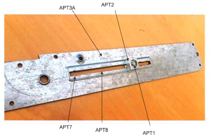
(2) Does the APT product infringe any of the asserted claims?
(3) Are claims 1 and 2 of the 818 patent novel over the disclosure contained in US patent no. 4,382,349 (Dunphy)?
(4) Are claims 1, 2 and 3 of the 260 patent novel over US patent no. 8,468,747 (Mingardi)?
(5) Do claims 1 and 2 of the 260 patent involve an innovative step in light of the disclosure contained in US patent no. 4,521,993 (Tacheny)?
(6) Do the claims of the 260 patent involve an innovative step in light of the disclosure of EU patent no. 943,774 (Lambertini)?
6 For the reasons set out in more detail below, the claims of the 260 patent are infringed by the APT product, but the claims of the 818 patent are not. Claims 1-4 of the 260 patent and claims 1-5 of the 818 patent are novel and do not lack an innovative step. In the result, the conduct of APT amounts to an infringement of the asserted claims of the 260 patent.
7 Mr Michael Brian Alchin is a director of Doric and also Azuma. His evidence was of relevance to an initially disputed issue as to whether or not Doric could be characterised as an “exclusive licensee” within the definition of that term provided in the Act. However, after he was cross-examined APT withdrew its challenge to the status of Doric as an exclusive licensee pursuant to the definition of that term in Schedule 1 of the Act, and it is unnecessary to mention his evidence further.
8 Dr Andrei Lozzi is a mechanical engineer and a senior lecturer at the University of Sydney in the School of Aerospace, Mechanical and Mechatronic Engineering. He is a professionally qualified mechanical engineer, with over 40 years of experience. He holds a Bachelor of Science, a Masters in mechanical engineering science and a PhD in mechanical engineering. Dr Lozzi gives evidence relevant to the construction, infringement and validity issues between the parties.
9 Mr William Samuel Hunter is a mechanical engineer with over 30 years of experience in many aspects of product development. He holds a Bachelor of Engineering Science and a Masters of Engineering Science. Mr Hunter also gives evidence relevant to the construction, infringement and validity issues between the parties.
10 Dr Lozzi and Mr Hunter met prior to the hearing and prepared an extensive and helpful joint expert report, which addressed the key points of difference and agreement between them. They also gave concurrent evidence and were cross-examined during the course of the hearing. I found each of these witnesses to be helpful in their explanations of the background technology and their respective understanding of the concepts and language used in the relevant documents. However, the parties agreed that, in accordance with accepted principles of patent construction, it is for the Court to determine the correct meaning to be ascribed to words and phrases in the patents and the prior art documents. In the present case, with one possible exception (identified in [68] below), it was not in dispute that the words and phrases that are the subject of disagreement are to be understood as having an ordinary English language meaning. Accordingly, whilst the evidence of the experts is of assistance, it is not of itself determinative of any of the issues, construction of the specification (including the claims) being a matter for the Court; Jupiters Ltd v Neurizon Pty Ltd [2005] FCAFC 90; (2005) 65 IPR 86 at [67].
11 The innovation patents in suit each share the same divisional parent pursuant to s 79B of the Act. The application for the 818 patent was filed on 1 June 2012 and the complete specification was published and became open to public inspection on 28 June 2012. It was certified pursuant to s 101E of the Act on 6 September 2012. The 818 patent was amended pursuant to orders of the Court made on 1 September 2015. The amended specification was published and made open for inspection on 1 October 2015.
12 The application for the 260 patent was filed on 7 March 2012 and its complete specification was published and became open to public inspection on 5 April 2012. It was certified on 24 May 2012. The 260 patent was subsequently amended, and allegations of infringement were introduced into the present proceeding by amendment made to the originating application and statement of claim on 20 May 2016.
13 It is not in dispute that the priority date for each of the 818 and 260 patents is 24 March 2009.
3.2 The structure of the patents
14 There is a substantial overlap in detail in the text of each of the two patents in suit. Each have an identical Abstract, Technical Field, Background of Invention, Object of the Invention, Brief Description of Drawings and Drawings. There are some minor differences in the Detailed Description of the Preferred Embodiment ([8]), however, the parties agreed, and I find, that these minor differences have no material bearing on the present issues of construction.
15 Each patent is an innovation patent and accordingly is limited to a maximum of 5 claims; s 40(2)(c) of the Act. In the case of the 818 patent, each claim is expressed as an independent claim with multiple integers. In the case of the 260 patent, there is one independent claim and four dependent claims, each adding an additional feature.
16 There are many common integers between claims, both within one patent and between the two patents and, as is perhaps typical in a case such as the present one, many different arguments concerning the construction of terms and expressions used in certain integers.
17 A consequence of the substantially common form of the specification for each patent is that the parties have agreed that the disclosure of the invention and the construction of the claims may broadly be considered by having regard to a single specification. The summary of the disclosure of the invention set out below is based on the 818 patent.
18 The parties have also helpfully developed a shorthand way of expressing the claims that makes it clear where common integers are expressed in different claims. This is set out in the two tables below.
19 It will be observed that in the schedule of claims of the 818 patent, each unique integer in a claim is labelled “[number]”. In the equivalent schedule for the claims of the 260 patent, many of the same integer labels appear, reflecting the fact that the integer is identically expressed in each claim to which it refers. Where one integer that is present in the 818 patent is slightly modified in the 260 patent, it is labelled with the same number as the original integer but with an “A” after the number. Where there is an identical term in more than one claim or patent (such as “body” or “winder mechanism”) the parties agree that the construction adopted for such a term in one patent and/or integer will apply equally to the other.
TABLE 1: Claims of the 818 patent
Claim | Integer |
Claim 1 | [1] A window winder to move a window panel relative to a window frame, the winder including: |
[2] a body; | |
[3] an elongated flexible element mounted in the body for movement relative thereto, and to be attached to the window panel; | |
[4] a winder mechanism mounted on the body and operatively associated with the element, the mechanism being operable by a user to cause movement of the element relative to the body between an extended position at which a desired length of the element extends from the body, and a retracted position at which the element is substantially entirely located in the body; | |
[5] a stop means operatively associated with the element to limit movement of the element to thereby limit said desired length to a desired maximum length, the stop means being movable relative to said body, by insertion and by removal, to change said desired maximum length; wherein | |
[6] said element is a chain and said mechanism includes a sprocket engaged with the chain and that is driven to move the chain between the retracted position and the extended position, and said stop means is inserted at a stop means position and is removed from said stop means position to change said desired maximum length, with said stop means position being spaced from said chain; | |
[7] wherein the stop means engages the body to determine said desired length; and | |
[8] wherein said body is adapted to receive said stop means in one of a plurality of positions, each position corresponding to a desired maximum length of the element projecting from within the body. | |
Claim 2 | [1] to [6] |
[8] | |
Claim 3 | [1] to [6] |
[9] wherein the sprocket is rotatable about a sprocket axis, and the winder includes an abutment that is engaged with and moves with the element, the abutment being located within the body and engaged by the stop means to determine said desired maximum length, with the abutment extending laterally from the chain and transverse relative to said sprocket axis to engage the stop means. | |
Claim 4 | [1] to [6] |
[10] wherein the chain has a longitudinal direction of extension, the sprocket is rotatable about a sprocket axis, and said stop means is removed and inserted in a direction generally parallel to the sprocket axis. | |
Claim 5 | [1] to [8] |
[10] |
20 TABLE 2: Claims of the 260 patent
Claim | Integer |
Claim 1 | [1] A window winder to move a window panel relative to a window frame, the winder including: |
[2] a body; | |
[3] an elongated flexible element mounted in the body for movement relative thereto, and to be attached to the window panel; | |
[4] a winder mechanism mounted on the body and operatively associated with the element, the mechanism being operable by a user to cause movement of the element relative to the body between an extended position at which a desired length of the element extends from the body, and a retracted position at which the element is substantially entirely located in the body; | |
[5A] a stop member fixed to the body at a desired first position and operatively associated with the element to limit movement of the element to thereby limit said length to a maximum length, the stop member being alterable to a further desired position and fixed to the body at the further desired position to thereby change said maximum length, the positions being spaced and predefined by the body; wherein | |
[6A] said element is a chain and said mechanism includes a sprocket engaged with the chain and that is driven to move the chain. | |
Claim 2 | [1] to [6A] |
[8A] wherein said body is adapted to receive said stop member in one of a plurality of positions, each position corresponding to a maximum length of the element projecting from within the body. | |
Claim 3 | [1] to [6A] |
Optionally [8A] | |
[9A] wherein the winder includes an abutment that moves with the element and that is located within the body, and that is adapted to engage the stop member to determine said maximum length. | |
Claim 4 | [1] to [6A] |
Optionally [8A] | |
Optionally [9A] | |
[10A] wherein the chain has a longitudinal direction of extension and said abutment moves relative to said chain so as to move about an abutment axis generally normal to said longitudinal direction of extension. | |
Claim 5 | Not asserted |
3.3 Disclosure of the patent specifications
21 The following observations apply equally to the disclosure of the 818 patent and the 260 patent. However, the summary below and the quotations come from the 818 patent.
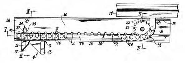
22 Each patent is entitled “A Window Winder”. The Technical Field of the invention is said to relate to window winders to move a window panel between an open and closed position relative to a jamb frame, and more particularly but not exclusively to window winders that employ a chain that is attached to the window panel and moved to cause movement of the window panel.
23 The Background of the Invention states that window winders consist of a hollow body within which a chain is mounted. The chain projects from within the body so as to have an extremity attached to a movable window panel. A winding mechanism causes movement of the chain so as to in turn cause movement of the window panel.
24 The disadvantages of the prior art window winders are then identified:
For safety purposes it is necessary to limit movement of the window panel. However this is frequently difficult in that a particular type of window winder may be employed with any size window. To limit the degree to which the window can open be opened [sic], the length of the chain is modified. This requires disassembly of the chain winder. This is therefore time consuming. This therefore leads to cost increases in respect of the installation of windows and their winders, and sometimes damage to the winder.
25 The object of the invention is stated to be to overcome or substantially ameliorate at least one of these disadvantages.
26 There then follows a Summary of the Invention that includes what may be described as a “consistory clause” in the sense that it sets out what the invention consists of: Lockwood Security Products Pty Ltd v Doric Products Pty Ltd [2004] HCA 58; 217 CLR 274 at [10]. The terms of the Summary are similar, but not identical to, the language of the claims. No party submitted that anything turned on the differences.
27 The Detailed Description of the Preferred Embodiment provides details of the single embodiment described by the patentee. It is relatively short, and for convenience it, together with the figures to which it refers, is set out in full below (as written, with paragraph numbers added).
Detailed Description of the Preferred Embodiment
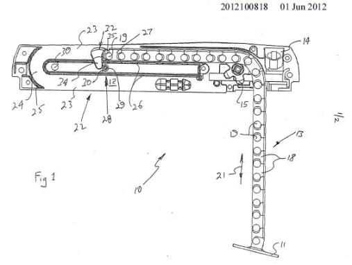
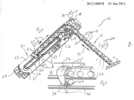
[1] In the accompanying drawings there is schematically depicted a chain winder 10.
[2] Typically the chain winder 10 would be operatively associated with a window that includes a window frame and a movable panel window pivotally attached to the frame. Typically the window panel would be angularly movable about a generally horizontal axis located near the upper frame member of the window frame. More particularly the window winder 10 would have an attachment part 11 to be attached to a lower member of the movable panel, and a hollow body 12 fixed to a lower member of the window frame.
[3] The window (chain) winder 10 illustrated would further include a cover (not illustrated) which is securable to the body 12 to generally enclose the operating mechanism of the winder 10. The winder 10 includes a chain (elongated flexible element) 13 that is movable between a retracted position at which the chain 13 is substantially entirely located within the body 12 and its associated cover, and an extended position (as illustrated) at which the chain 13 projects beyond the body 12 so as to support the window panel at an open position. In the retracted position the chain 13 maintains the window in the closed position. In the extended position the chain 13 extends beyond the body 12 by a desired length.
[4] The body 12 includes a handle support 14 that rotatably supports a handle (not illustrated). The handle at its inner end, via a drive mechanism (not illustrated) drives a winder mechanism including a sprocket 15. That is, upon an operator rotating the handle in either direction the sprocket 15 is rotated in a selected direction about the axis 16. The handle is rotated about the axis 17 which is inclined relative to the axis 16.
[5] The chain 13 consists of a plurality of links 18, with each pair of adjacent links being pivotally attached by means of a chain pin 19. Each pin 19 provides a pivot axis 20 about which adjacent links 18 move angularly relative to each other. The axes 20 extend generally normal to the longitudinal direction of the chain 13 and generally normal to the direction 21 of the chain 13.
[6] The body 12 provides a track 22 along which the chain 13 moves. The track 22 is of a "U" configuration in that it provides a pair of linear portions 23 and a curved end portion 24. The portions 23 are generally parallel, with the portion 24 being at least partly defined by a curved chain guide 25. A longitudinal guide 26 separates the portions 23 and therefrom at least partly defines the portions 23 as best seen in Figure 1.
[7] When the chain 13 is being moved to a retracted position, the end portion 27 of the chain 13 moves along the portion 23, through the portion 24 to move finally along the second portion 23. When the chain 13 is being moved to the extended position the reverse happens.
[8] The winder 10 includes stop means 28 that limits movement of the chain to therefore determine the length (desired maximum length) of chain 13 that extends from the body 12 when the chain 13 is in the extended position. Accordingly the stop means 28 determines the degree by which the window panel is opened. The stop means 28 is alterable so that the length of chain 13 extending from the body 12 can be changed to suit a particularly window. That is, the stope means 28 can be changed without altering the total length of the chain 13.
[9] In this embodiment the stop means 28 is a pin 29 that is fixed to the body 12 in one of a plurality of positions, in this instance there are two positions. The two positions are provided by apertures 30. As seen in Figures 1 and 2, the apertures 30 (portions of the stop means 28) are spaced from the chain 13. Each aperture 30 is threaded and threadably engages a shaft 31 that secures the pin 29 to the body 12. However any number of apertures may be included. The apertures 30 are spaced along the guide 26, that is the apertures 30 are spaced in the direction 21 the chain 13 moves along the guide 26. To change length of the chain 13 to extend from the body 11, the pin 29 is removed from the aperture 30 within which it is engaged.
[10] Attached to the end portion 27 is an abutment 32. Since the abutment 32 is attached to the chain 13 it moves with the chain 13 in the direction 21. However the abutment 32 extends laterally beyond the chain 13 and track 22 so as to engage the pin 29 and therefore limit the amount of chain 13 that is to extend beyond the body 12. As best seen in Figures 2 and 3 the abutment 32 extends laterally from the chain and generally transverse relative to the rotational axis 16.
[11] To enable the chain 13 to move to the fully retracted position, the abutment 32 is pivotally attached to the end portion 27 for angular movement about an axis 33. When the chain 13 is being moved to the retracted position from an initial extended position at which the abutment 32 is engaged with the pin 29, the pin 29 passes along the first portion 23 to enter the portion 24 and then pass along the second portion 23 at which stage the abutment 32 will again engage the pin 29. However as the abutment 32 is pivotally attached to the end portion 27, it is allowed to pivot to a position at which it can pass the pin 29 thereby allowing the chain 13 to move to the fully retracted position. However when the chain 13 is being moved to the extended position, the abutment 32 initially passes the pin 29 but is caused to pivot to a position at which it will again engage the pin 29 to limit movement of the chain 13. The abutment when now engaged with the pin 29 is prevented from further pivoting by engagement with the cover. As can be seen in Figures 1 and 2, the apertures 30 project in a direction generally parallel to the axes 16 and 33, accordingly the pin 29 (stop means 28) is inserted and removed in a direction generally parallel to the axes 16 and 33.
[12] As best seen in Figure 3, the abutment 32 includes an arm 34 that engages the pin 29, as well as an eyelet 35 through which one of the pins 19 passes to pivotally attach the abutment 32 to the chain 13.
Figure 1:
Figures 2 and 3:
28 It may be seen by reference to the description and the accompanying drawings, that the preferred embodiment describes a window winder, also called a “chain winder”, of various parts that includes a “body” 12 and a “handle support” 14 that rotatably supports a handle, which is not illustrated. The handle, via a drive mechanism, which is also not illustrated, drives a “winder mechanism” including a sprocket 15. Upon an operator rotating the handle in either direction, the sprocket 15 is driven to rotate in a selected direction about the axis 16. The movement of the handle accordingly enables the window to be opened or closed by the extension or retraction of the chain.
29 It is the “stop means” 28 that most relevantly addresses the objects of the invention. The stop means limits the movement of the chain which thereby determines the maximum length that it can extend from the body and accordingly the degree by which the window panel can be opened. The position of the stop means can be altered so that the length of chain extending from the body can be changed. That is, the location of stop means 28 can be changed without altering the total length of the chain.
30 It may be seen that, at least so far as the patentee is concerned, one advantage is achieved by avoiding the problem (stated in the Background to the Invention) of having to modify the length of the chain itself in order to vary the degree to which the window panel can be opened. Instead, the location of the pin can be changed, which will thereby determine the maximum travel of the chain, instead of modifying the length of the chain, which is, the Background asserts, a time consuming and therefore costly exercise and may result in damage to the winder.
31 The Detailed Description goes on to explain that in the embodiment described, the stop means may be located by inserting it into a threaded aperture into which the shaft of the pin may be screwed, thereby securing the pin to the body. There may be a number of threaded apertures spaced along the guide 26. To change the length by which the chain may extend from the body (and therefore the distance by which the window panel can be opened) the pin 29 may be removed from one aperture and screwed into another.
32 The Description refers to an “abutment” 32 which extends laterally beyond the chain and is attached to it. In operation, the abutment will travel with the chain and engage the pin (or stop means) and therefore limit the amount of chain that may extend beyond the body. The preferred embodiment has a particular means by which the chain, and attached abutment, can move to a fully retracted position, which is set out in [11].
33 Turning to the claims, the invention claimed in the 818 patent includes a “stop means” which is inserted at a “stop means position” and moved to another such “stop means position” to change the desired maximum length of the elongated flexible element (or chain) projecting from the winder.
34 The invention claimed in the 260 patent includes a “stop member” which can be fixed to the body of the winder at a “desired first position” to limit the length of the chain to a maximum length and which is able to be altered to “a further desired position” to change the maximum length of the chain projecting from the winder.
3.4 The person skilled in the art and the common general knowledge
35 There was no real debate about the correct characterisation of the person skilled in the art. It will be a person with a practical interest in the subject matter of the patent; Catnic Components Ltd v Hill and Smith Ltd [1982] RPC 183 at 242 – 243. In the present case that is likely to be a person with an interest in the design or installation of window furniture. I am satisfied that each of Dr Lozzi and Mr Hunter have the skills and qualifications sufficient to fall within the group of people who might be regarded to be persons skilled in the art. No submission was made to suggest otherwise.
36 The parties did not make specific submissions concerning the features of the common general knowledge. In broad terms, the parties accepted that the construction of the patents in suit was not influenced by any particular aspects of common general knowledge. The Court was invited to construe the language of the claims and patent specifications as matters of ordinary English, with no particular aspects of the state-of-the-art as at the priority date as being relevant to determine that construction.
37 There was no dispute between the parties as to the principles of construction. Those principles have largely been settled for many years. It is sufficient for present purposes to refer to the summary of those principles as set out in Jupiters Ltd v Neurizon Pty Ltd [2005] FCAFC 90; (2005) 65 IPR 86 at [67] and in Décor Corporation Pty Ltd v Dart Industries Inc (1988) 13 IPR 385 at 400 as reflecting the approach taken to construction in these reasons. In the present case it is particularly noted that the claims are to be construed in the context of the specification as a whole. But it is not legitimate to narrow or expand the boundaries of monopoly as fixed by the words of a claim by adding to those words glosses drawn from other parts of the specification. Terms in a claim which are unclear may be defined by reference to the body of the specification, but the body of a specification cannot be used to change a clear claim for one subject matter into a claim for another and different subject matter.
38 Furthermore, infringement is determined by the construction of the claim. As the High Court said in Radiation Limited v Galliers and Klaerr Pty Ltd [1938] HCA 17; (1938) 60 CLR 36 at 51 in considering infringement, it is “the substantial idea disclosed by the specification and made the subject of a definite claim” that must be considered. As a fundamental rule, the test for infringement is determined by the construction of the claim, and there will be no infringement unless the alleged infringer has taken all of the essential features of the claim; Fresenius Medical Care Australia Pty Ltd v Gambro Pty Ltd and Another [2005] FCAFC 220; (2005) 67 IPR 230 at [49], [50] (and authorities cited) (Wilcox, Branson and Bennett JJ)
4.2 Construction of the claims
39 The construction issues pertinent to the asserted claims are conveniently first considered by reference to the construction of the terms “body” and “window winder”. Other construction issues are later addressed in the context of the consideration of infringement.
40 The experts gave their opinion in relation to all disputed issues of construction, and generally, but by no means universally, the parties adopted the views expressed by the experts. Guided by the authorities referred to above, it is noted that it is for the Court to construe the claims by applying the recognised rules of construction. Whilst the evidence of experts is of assistance, that evidence is not determinative and largely amounts to evidence of construction of ordinary English words.
4.3 The “body” (818 and 260 patents); integer [2] – all asserted claims
41 The construction of the word “body” as it appears in the claims is relevant to infringement and novelty.
42 Doric contends that the “body” as identified in integer [2] is the main or central part of the window winder which is hollow in nature, contains the chain, which has the winder mechanism on it, and which includes the positions where the stop means or member is received or fixed.
43 APT relies on the evidence of Mr Hunter to submit that “body” in context means “the core structural element of something from which other elements are dependent or are mounted from”. It submits that the body does not include a cover of the winder, which is a separate part. This, it submits, is apparent from the distinction drawn in the preferred embodiment at [3] (emphasis added):
The window (chain) winder 10 illustrated would further include a cover (not illustrated) which is securable to the body 12 to generally enclosed the operating mechanism of the winder 10. …
44 APT points out that in the preferred embodiment the function of the cover is non-trivial, and that as a part it is identified to be distinct from the body, as is signified in the description of the preferred embodiment which provides that the abutment is prevented from further pivoting by “engagement with the cover”. APT further submits that the reference to “hollow body” in the body of the specification is to portions of the body that have been hollowed out, as illustrated in Figure 2, and as explained by Mr Hunter in his evidence.
45 The language of the claim must be construed in the context of the specification as a whole, however, it is the claim language that will ultimately determine the scope of the claim. Accordingly, I commence by examining the language of claim 1.
46 The claim identifies that the window winder includes a “body” and then proceeds to define the location and function of certain other components by reference to their relationship to the body. Thus;
(a) in integer [3] a chain (elongated flexible element) is mounted in the body for movement relative to the body;
(b) in integer [4] a winder mechanism is mounted on the body and is operable to cause movement of the chain relative to the body between an extended position that extends from the body and a retracted position located in the body;
(c) in integer [5] the stop means is also movable relative to the body by insertion and removal;
(d) in integer [8] the body is adapted to receive the stop means in one of a plurality of positions; and
(e) in integer [7] the stop means engages the body to determine the desired length (of the chain).
47 It is notable that the “body” is not limited in the claim by reference to any particular shape or configuration. The notion that parts of the mechanism are located “within” or “mounted in”, retract to be substantially entirely “located in”, or “extend from” the body indicate that “the body” has perceptible boundaries. Plainly, the claim envisages that the body has a three-dimensional form. However, the form which the body takes is not limited by the language of the claim. Provided that a window winder has something that falls within the ordinary English meaning of the word “body”, and that it possesses the relationship with the components specified in the claim (summarised above), then a body within the claim will be present.
48 The word “body” is relevantly defined (Macquarie Dictionary, fifth edition) as “the trunk or main mass of a thing” or (Australian Oxford English Dictionary, second edition) the “main or central part of a thing”.
49 These matters indicate that having regard to the language of the claim, the “body” should be understood as the main or central part of the window winder, but otherwise there is no basis upon which the claim language confines the definition of “body” beyond its ordinary English meaning as “the trunk or main mass of a thing” or the “main or central part of a thing”. To add any further constraint would be to supply a limitation to the meaning of the term that is not to be found in the language of the claim. In particular, the language of the claim does not require the body to be hollow, although it may be. Nor does the claim language require that the body be made up from a single part.
50 Both parties direct attention to the language of the specification to support their construction. In this connection it is to be noted that reference is made in the Background of the Invention to a window winder consisting of a hollow body, whereas the Detailed Description on the one hand at times distinguishes between the body and a cover (see [3] and [11] of the Detailed Description above) and yet on the other hand refers to a hollow body (see [2] of the Detailed Description above), which suggests that the cover is not part of the body. In particular, the Detailed Description of the Preferred Embodiment says at [2], [3]: “a hollow body 12 fixed to a lower member of the window frame. The window (chain) winder 10 illustrated would further include a cover (not illustrated) which is securable to the body 12 to generally enclose the operating mechanism of the winder 10” (emphasis added).
51 It is notable that the patentee has chosen not to use the adjective “hollow” in the language of the claim. That suggests that the ‘body’ in integer [2] is intended to be of wider meaning than as it is described elsewhere in the specification, where the words “hollow body” are used.
52 Furthermore, whilst in the preferred embodiment a distinction is drawn between the cover and the body, that distinction is not apparent from the language of the claim. Again, it may be considered that the patentee has deliberately chosen to leave the conception of the “body” in the claim unconfined by a distinction between two parts, one being a cover and the other being the body.
53 Accordingly, “body” is to be understood as the main or central part of the window winder that has the relationship with the other components identified in the claim.
4.4 “Window winder” and “winder mechanism” (integers [1] - [4], all claims)
54 Claim 1 of the 818 patent refers to the terms “window winder” (integer [1]) and ”winder mechanism” (integer [4]) in the following context (emphasis added):
[1] A window winder to move a window panel relative to a window frame, the winder including: [2] a body; [3] an elongated flexible element mounted in the body for movement relative thereto, and to be attached to the window panel; [4] a winder mechanism mounted on the body and operatively associated with the element, the mechanism being operable by a user to cause movement of the element relative to the body between an extended position at which a desired length of the element extends from the body, and a retracted position at which the element is substantially entirely located in the body;…[6] said element is a chain and said mechanism includes a sprocket engaged with the chain and that is driven to move the chain between the retracted position and the extended position, …
55 The parties make diverging submissions on the construction of the terms “window winder” and “winder mechanism”. The dispute is particularly relevant to aspects of the invalidity cross-claim, although it is also relevant to Doric’s infringement case. Doric submits that a window winder is a device for opening and closing a window by a user with a winding action, typically by winding a rotary handle, and that a “winder mechanism” is a mechanism operated by the user. APT contends that it is not necessary for a window winder to include a rotary handle or to be operated by a winding action. It submits that a “winder mechanism” within integer [4] is any assembly of cooperating parts which may be actuated to cause the winding or unwinding of the chain, and thereby cause the window to open or close.
56 There is no dispute that the term “window winder” as it appears in integer [1] uses ordinary English words which are to be afforded their usual English meaning, as it is to be understood in the context of the claims and the specification as a whole. No party suggests that the expression is a term of art, although Mr Hunter comes close when he refers to four examples of where electric window actuators are referred to in sales literature as “chain winders” or “electric chain winders”. I return to this evidence below.
4.4.2 Analysis: “window winder” and “winder mechanism”
57 In the context of the claim, the ordinary meaning of the words “wind” and “winder” suggest that a “window winder to move a window panel relative to a window frame” within integer [1] involves a rotary or winding action, and a “winder mechanism” is a mechanism driven by that action.
58 The Macquarie Dictionary (fifth edition) relevantly defines “winder” as:
1. someone or something that winds (bends, turns, etc) or is wound. … 4. an instrument or a machine for winding thread, etc. 5. a small knob on a watch for winding it up. …
59 In integer [1] the words “window winder to move a window panel relative to a window frame” plainly enough involves moving a window from one position to another. Those words most naturally convey a mechanism that is used for winding a window open or closed. Accordingly, in my view a “window winder” might be regarded as a device for opening and closing a window that is operated by the user with a winding action, typically by winding a rotary handle. That definition gives content to the concept of “wind”, which is tied up with “winder”. An example may be, as Dr Lozzi suggested in oral evidence, an old fashioned, manually operated car window winder which is operable using a rotary action. In closing submissions Counsel for APT, Mr Fitzpatrick, suggested that when in a car, one might nowadays be asked to “wind up the window”, even though electronic window winding devices are used. Accordingly, he submitted, the word “winder” and “wind” might no longer have a correlation with the means by which opening or closing is achieved. However, that legacy usage, no doubt drawn from the good old days of rotary window winders in cars, is a quaint way of asking for the window to be closed. But it does not amount to a reference to the mechanism used to open or close the window. In a modern car, it is a button or switch, not a winder, that achieves that function. In the claim, the expression used in integer [1] is a broad description of the device itself. As an item of window furniture, a window winder most naturally refers to a mechanism used to wind a window open or closed.
60 The words in integer [4] “a winder mechanism mounted on the body … operable by a user to cause movement…” indicate that it is the operator who manipulates the “winder mechanism”. The language does not simply require a “mechanism” but a “winder mechanism”. The parties raised two alternative meanings. One is that the user operates a winder mechanism in the same sense as identified above. Namely, by use of a winding action. That is the mechanism that is used in the preferred embodiment. The second is that the words “winding mechanism” do not have a bearing on the actions of the operator, but rather on the means by which the mechanism operates. It is the latter approach that is preferred by Mr Hunter and APT.
61 Mr Hunter proposes his definition in his first report as follows:
Window winder is a type of mechanical device which is associated with the winding or unwinding of a flexible element such as a chain around a rotating component. The movement of the flexible element causes an associated window to open or close.
62 Mr Hunter contends that a winder mechanism is an assembly of co-operating parts which may be actuated to cause the winding or unwinding of the flexible element and thereby cause the associated window to open or close.
63 It may be seen that this definition does not direct attention to the action by which the operator or user manipulates the device, but rather to the internal mechanism of the device itself. During the course of cross-examination Mr Hunter somewhat qualified his definition. He accepted that a mechanism where a flexible element was not wound about a rotating component, but nevertheless where the flexible element wrapped or wound in response to another part of the mechanism, such as a guide, would nevertheless still be regarded as a “winder” or a “winder mechanism”. Furthermore, Mr Hunter considered that a system whereby a rope was threaded through a pulley and then pulled longitudinally in a downwards direction by a person from one end would also satisfy his definition. In his view, it is not necessary for there to be a winding action at all for a device to be regarded as a “winder”.
64 There is an air of artificiality about Mr Hunter’s definition that causes me disquiet. It appears to render the reference to “winder” in “a window winder” in integer [1] and “winder mechanism” as it appears in integer [4] redundant. A more natural meaning is that such a mechanism is operated by the user using a winding action or the like.
65 APT relies heavily upon the following language in the Detailed Description to support its definition (emphasis added):
The body 12 includes a handle support 14 that rotatably supports a handle (not illustrated). The handle at its inner end, via a drive mechanism (not illustrated) drives a winder mechanism including a sprocket 15. That is, upon an operator rotating the handle in either direction the sprocket 15 is rotated in a selected direction about the axis 16. …
66 APT refers to Dr Lozzi’s acceptance that in this passage three separate components are identified; the handle, the drive mechanism (not illustrated) and the winder mechanism. Those three components should, it submits, be regarded as separate for the purpose of understanding the invention as claimed. It submits that where the patentee has carefully separated the handle and drive mechanism from the winder mechanism in the preferred embodiment, it would be an error to find that the language of the claim where it uses “winder mechanism” does not also do so. On this basis, APT contends that the claim language distinguishes between a rotary movement, which is used for a drive mechanism and the handle, and the “winder mechanism” which is indifferent to how the operator actuates it, but rather refers to the movement of the flexible element around a rotating component.
67 However, APT’s approach places too much weight on the language of the preferred embodiment over the language of the claim. In any event, the statement in the specification that the handle “… via a drive mechanism … drives a winder mechanism including a sprocket” does not lead to the conclusion that the handle itself may not also be part of a winder mechanism – the handle can both drive that mechanism and also be part of it. Taken collectively, the handle causes a drive mechanism to operate a winder mechanism and also be part of the winder mechanism. Where one part cooperates with others in this way, the role of one part of one mechanism may overlap with another.
68 Ultimately, the more natural meaning of the words in issue is that the term “winder mechanism” in integer [4] is to be understood as a mechanism that is operated by the user using a winding action. A winder mechanism is a mechanism operated by a winding action.
69 Mr Hunter refers in his evidence to four brochures that he has obtained on the internet as part of the preparation of his evidence in answer. He does not consider that the term “window winder” is a term of art, but relies on these brochures to demonstrate that a window winder is not confined to one that is operated by a rotary action. The brochures advertise the availability for sale of what appear to be chain-operated window opening devices. None are actuated by a rotary action. Each is identified by the term “electric chain winders”, “electric chain window winders” or some variation thereof. He relies on these brochures to support his contention that a “winder mechanism” need not involve the use of a rotary action by the user.
70 There is no evidence to suggest that the brochures found by Mr Hunter form part of the common general knowledge. Further, the use of “winder” in the context of these devices adds the adjective “electric” to qualify the mechanism. Needless to say the context of the use of this term is quite different to that of the claim. It was not suggested by APT that the evidence of these brochures supplies evidence that the term “winder mechanism” in integer [4] is a term of art that the skilled reader would understand to apply in the claims.
71 These examples do not cause me to consider that a person skilled in the art as at the priority date would conclude that “window winder” as it is used in the claims encompasses electric chain window winders.
72 The case pleaded on infringement is that APT has directly infringed claims 1 – 5 of the 818 patent and claims 1 – 4 of the 260 patent. APT relevantly admits that it has engaged in acts in respect of the APT product which would amount to an exploitation of the patents, if the APT product falls within the scope of any of the pleaded claims, and if those claims are held not to be invalid. The dispute that arises between the parties concerns whether or not the APT product falls within the claims. There is no disagreement about how the APT product operates, which is described below.
73 Set out below are three photographs with markings indicating various parts of the APT product. Figure 1 depicts one part of the inside of the unit. Figure 2 depicts the exterior of a silver plate (APT3A) that is fixed by screws to APT3B. Figure 3 shows the interior of silver plate APT3A.
74 The individual parts of the APT product may be described as follows;
(a) APT1 is a Phillips head screw. APT2 is a threaded square metal block that can be seen in figure 2. APT1 tightens into APT2 thereby clamping onto slot APT8;
(b) APT3A and APT3B are two parts that, in the assembled unit, are joined by screws and which together enclose the operating mechanism of the APT product;
(c) APT4 is a sprocket connected to a handle. The sprocket is “active” or driven by the rotation of the handle by an operator. This then extends or withdraws the chain (APT9);
(d) APT5 is a “passive” sprocket that engages with a chain (APT9) but which is otherwise not connected to the interior of the APT product;
(e) APT8 is a slot located in APT3A that has circular indentations (APT7) marked in four locations along its length. The markings suggest that the circular indentations correlate with the length to which the chain may be extended, namely 10 cm, 12 cm, 15 cm and 30 cm.
75 In operation, the user rotates the handle thereby driving active sprocket APT4. The teeth or protrusions of the sprocket engage with the chain to extend or retract it. As the chain is extended, passive sprocket APT5 is moved towards the centre from right to left in Figure 1. During operation, a tooth of the passive sprocket will engage with the threaded square block APT2, which thereby prevents the sprocket and chain from moving any further, thereby determining the maximum length of the chain that can be extended.
76 The screw APT1 is shaped so that it cannot be fully unscrewed. Beneath the flat head of the screw is a cylindrical base that may be located within one of the circular indentations (APT7). When so located, the screw is tightened to achieve a clamping effect in the nominated position. The evidence indicates that the screw may be tightened to clamp the metal block APT2 into position anywhere along the slot APT8, although if it is done at a position that is not coincident with one of the circular indentations then the head of the screw will slightly protrude from the slot.
Figure 1:
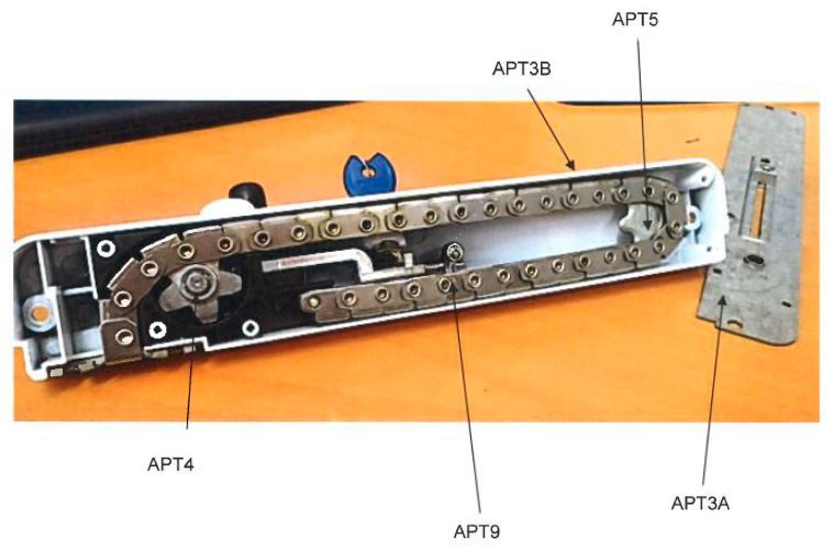
Figure 2:
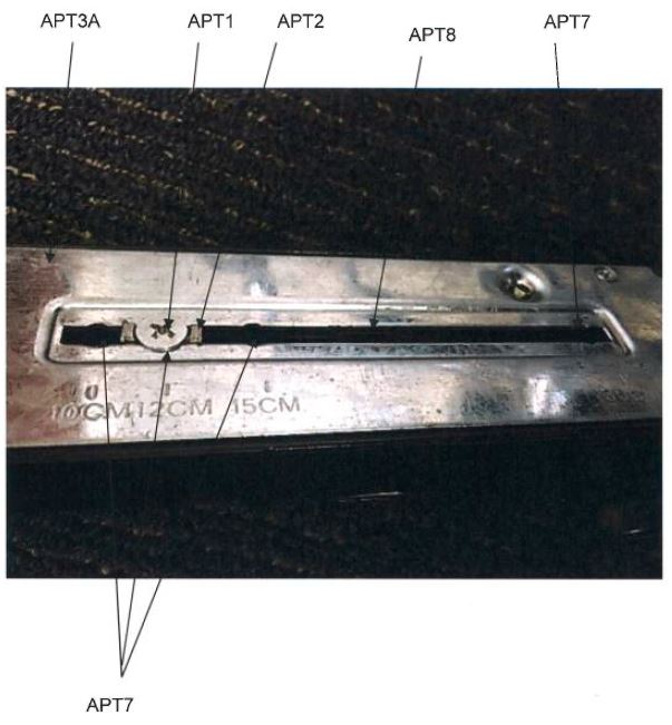
Figure 3:
77 The infringement issues that require determination concern whether the:
(1) window winder mechanism of the APT product is “mounted on” the body (all asserted claims);
(2) stop means is moveable by insertion and removal to change the desired maximum length (all claims of the 818 patent);
(3) stop means is inserted in the direction required (claims 4 and 5 of 818 patent); and
(4) APT5 is an abutment (claim 3 of the 818 patent and claims 3 and 4 of the 260 patent).
5.3 Winder mechanism mounted on the body - all asserted claims
78 Integer [4] is present in all of the asserted claims. It requires that the window winder possess a “winder mechanism mounted on the body”. APT contends that in its product the “body” is the unit identified as APT3B and that it has a separate cover which is APT3A. It submits that the body APT3B is not adapted to receive the stop means member and that the winder mechanism is not “mounted on” APT3B, as required by the claim.
79 Two issues arise for consideration in this context, first, the proper identification of the “body” in the APT product and secondly, whether the winder mechanism is mounted on the body.
5.3.1 What is the “body” in the AP T product?
80 I have construed the integer “body” (section 4.3.2 above) to mean the main or central part of the window winder device which has the relationship with the other components as identified in the claim.
81 In the APT product parts APT3A and APT3B form the main or central part of the window winder. That part has the chain (APT9) mounted in it for movement relative to the body and a winder mechanism (APT4) that is operable to cause movement of the chain relative to the body between an extended position from the body. The stop means (APT1/APT2) is also moveable relative to the body. Accordingly, the body of integer [2] should be understood to be to be APT3A when screwed together with APT3B. APT accepts that if these parts form the body, then the only remaining issue arising from “body” is whether the integer [4] requirement that there be a “winder mechanism mounted on the body” is satisfied. This is addressed in the next section.
5.3.2 Is the winder mechanism mounted on the body?
82 I have found in section 4.4.2 above that the “window winder” of the claims is a mechanism that is operated by the user with a winding or rotary action, and that the “winder mechanism” in integer [4] is to be understood as a mechanism that is operated by the user using a winding action.
83 The “winder mechanism” of the APT product is the assembly of components that transfer the rotation of the handle to the active sprocket depicted at APT4.
84 APT contends that the requirement that the winder mechanism be “mounted on” the body in integer [4] means that the winder mechanism must be held in place on an external surface of the body when it is assembled. It submits that if the body in the APT product is the combination of APT3A and APT3B when screwed together (as I have found) then the winder mechanism of the ATP product would be mounted in the body, not on the body and would accordingly not satisfy integer [4].
85 In my view this argument presents a false dichotomy. There is no reason why a component that is located within a body which, as here, is hollow, cannot fairly be characterised also as being both mounted “on” it and “in” it. The two concepts are not mutually exclusive and the claim language does not insist that the winder not also be in the body. The winder mechanism in the APT product is fixed to the body where APT4 is located on APT3B.
86 The word “mounted” has its ordinary English meaning. In context of the claims it means “fixed on or in a support, backing, setting, or the like” (Macquarie Dictionary, fifth edition). The language of claim 1, integer [4] requires that there be a winder mechanism mounted on the body. In my view, as a matter of ordinary language a winder mechanism may be mounted on the inside of the body.
87 In the present case, there is no dispute that the active sprocket APT4 is affixed to the interior of the integer marked APT3B, which is the white unit depicted in the photographs and identified by APT as the cover. That component is “mounted on” the body as required by integer [4]. Accordingly, the APT product satisfies this requirement of the claims.
5.3.3 Stop means movable moved by insertion and removal to change maximum length
88 Integer [5], which is present in all of the claims of the 818 patent, requires that the “stop means” be “moveable relative to said body, by insertion and by removal”. APT contends that the APT product stop means, comprising parts APT1/APT2 together, does not satisfy this integer. As a result, it contends that the APT infringes none of the claims of the 818 patent.
89 There is no dispute that in the APT product the “stop means” consists of the combination of Phillips head screw APT1 and the square metal block APT2. These two components cooperate with each other such that when the screw is loosened from the block it is able to slide freely along slot APT7. The screw may then be tightened into position to set the block in position which, in turn, functions as a stop means to limit the desired length of the chain. The screw is not removable from the metal block because it has been peened over or “mushroomed” at the end.
90 The experts agree that in the APT product the stop means is never removed from the part that I have found is the “body” for the purposes of the claims, namely the parts APT3A and APT3B together. It remains within slot APT7.
91 Doric submits that the references to “insertion” and “removal” in integer [5] are to be understood by reference to integer [6], and that what is required is that the stop means is inserted at a “stop means position” and removed from that position. It submits that the claim does not require that the stop means be removed entirely from the body. It places emphasis on the words “inserted at” and “removed from” in this context. It further submits that the claim should be construed having regard to the purpose of the insertion and removal, which is to change the desired maximum length of the chain. Provided that this function is achieved, there is, Doric submits, no particular requirement as to how it is achieved. Further, Doric submits that the language of the claim is consistent with the language of the Summary of the Invention and that the claim ought not to be limited to the example described in the preferred embodiment.
92 I do not consider that Doric’s construction can be sustained on the basis of the language of the claim. There is no dispute that the words “insertion” and “removal” are to be understood as ordinary English words.
93 To “insert” is relevantly defined to mean;
1. to put or set in: to insert a key and a lock. 2. to introduce into the body of something: to insert an advertisement in a newspaper.
(Macquarie Dictionary, fifth edition).
94 To “remove” is relevantly defined to mean;
1. to move from a place or position; take away; take off: to remove a book from a desk; to remove one’s tie. 2. to move or shift to another place or position. … 5. to take, withdraw, or separate (from).
(Macquarie Dictionary, fifth edition).
95 Integer [5] relevantly provides that there must be “a stop means operatively associated with the element … the stop means being movable relative to said body, by insertion and by removal, …”. The verbs “insertion” and “removal” refer to movement relative to the body, not a stop means position. When one gets to integers [6] – [8], the claim requires that “[6] … said stop means is inserted at a stop means position and is removed from said stop means position to change said desired maximum length … [7] wherein the stop means engages the body to determine said desired length; and [8] wherein said body is adapted to receive said stop means in one of a plurality of positions…” (emphasis added). The references to the “body” in these later integers reinforce the fact that the stop means is inserted into and removed from the body, and the location within the body at which the insertion and removal must occur is the stop means position.
96 Analysis of the specification leads to no different conclusion. The person skilled in the art will understand from the only embodiment that it describes that stop means 28 is a threaded pin 29 that may be fixed in one of several threaded apertures 30. To alter the location of the pin 29 it must be removed from one position and inserted into another position. When one reads the language of the claim in the context of the description of the preferred embodiment, the references in the claim that I have quoted above are easily understood. Of course, the description of the embodiment does not determine the scope of the claims. However, in the present case the construction that I have preferred is consistent with the description, which is a contextual matter that may be taken into account.
97 Accordingly, the requirement of integer [5] is not present in the APT product, because the stop means (APT1/APT2) is not inserted into or removed from the body as required.
98 APT further contends that if the APT product does not possess the “insertion” and “removal” features of integer [5], then necessarily the requirement of integer [6] (that the stop means be inserted or removed in order to “change said desired maximum length”) will not be satisfied. This is because in the APT product the desired maximum length of the chain is not caused by any “insertion at a stop means” but rather by a different mechanism, namely the clamping of the stop means to the slot APT7, by tightening of the Phillips head screw APT1.
99 The claim defines the purpose of the insertion and removal as being in integer [5] “to change said desired maximum length”, a point that is repeated in the same words in integers [6]. In the APT product the location of the square member (APT2) in a particular position along the slot does not determine the length of the chain. It cannot do so until the square block is tightened by way of clamping with the head of the screw into position. Accordingly, in the APT product it is not the insertion of the stop means that determines the length of the chain but rather the act of clamping that does so.
100 This has the result that the APT product also does not possess a “stop means” with the required features of insertion and removal within integers [5], [6] of the claims of the 818 patent.
101 This has the consequence that none of the claims of the 818 patent are infringed.
5.3.4 Is the stop means inserted in the direction required?
102 Claims 4 and 5 of the 818 patent each contain integer [10], which requires that the “said stop means is removed and inserted in a direction generally parallel to the sprocket axis”. As I agree with APT’s argument that the stop means is neither inserted or removed, I also agree with APT’s submission that this integer must necessarily be absent.
103 However, if I am wrong in my conclusion in relation to “insertion and removal”, I would find that the requirements of integer [10] are otherwise satisfied by the APT product. This is because to the extent that the Philips head screw APT1 is “inserted”, it is screwed inwardly. The sprocket to which integer [10] refers is the drive sprocket identified in the APT product as APT4. The axis of APT4 and the direction of screwing or unscrewing of APT1 are each generally parallel.
104 There are four issues that arise from the use of the term “abutment” in claim 3 of the 818 patent and claims 3 and 4 of the 260 patent.
105 The first concerns integer [9], which is present in claim 3 of the 818 patent. It provides (emphasis added):
wherein the sprocket is rotatable about a sprocket axis, and the winder includes an abutment that is engaged with and moves with the element, the abutment being located within the body and engaged by the stop means to determine said desired maximum length, with the abutment extending laterally from the chain and transverse relative to said sprocket axis to engage the stop means.
106 Doric contends that the passive sprocket APT5 is the abutment within this integer.
107 The evidence indicates that the passive sprocket is not attached to the chain and does not move directly with it. As the chain moves forward, driven by the drive sprocket APT4, the chain engages with the teeth of the passive sprocket which then moves forward in what Mr Hunter has described as a helical or corkscrew fashion.
108 There is no dispute that the winder (being the winder mechanism of integer [4]) includes the passive sprocket APT5. The dispute arises as to whether the passive sprocket is an “abutment” and whether it is engaged with and moves with the element (chain).
109 APT submits that the term ‘abutment’ must be understood to mean something that is attached to the chain and which causes the chain to cease to travel at a desired maximum length when it engages the stop member. It submits that the experts agreed with this construction. It further submits that because the passive sprocket’s function is not limited to engaging the stop means, and it also plays a role in winding the chain in and out of the housing, this suggests that it may not satisfy the integer.
110 The word “abutment” should be given its ordinary English meaning. The definition of “abut” is “to be adjacent: this piece of land abuts on a street.” (Macquarie Dictionary, fifth edition). Mr Hunter defined an abutment as “something which is intended to abut with or be held next to something else”.
111 Although the abutment described in the preferred embodiment indicates that it not only adjoins but is also attached to the chain (“abutment 32 is attached to the chain 13”), the word “abutment” itself does not require such attachment. Nothing in the language of the claim suggests that it must be, and in my view it would be to import a limitation not present in the claim to construe the word in a way that required that it not only abut, but also be attached to the chain. Put another way, it is sufficient to fall within the term if the element identified comes into contact with the chain.
112 Furthermore, the requirement that the abutment “is engaged with and moves with the element” is satisfied by the passive sprocket because, as I have noted, the chain in the APT product engages with the teeth of the passive sprocket as it moves forward. To the extent that APT submits that the role of the abutment must be confined entirely to engaging with the stop means, I disagree. Nothing in integer [9] or the balance of the claim implies such a limitation, and indeed, it is a requirement of that integer that the abutment also engage with and move with the element.
113 Accordingly, this argument in relation to integer [9] is resolved in favour of Doric. The same conclusion applies for disputed integer [9A].
114 The second issue is whether or not the passive sprocket in the APT product satisfies the requirement in integer [9] that as an abutment it “extend[s] laterally from the chain”.
115 The experts agree that the longitudinal direction of the chain may be represented by a line parallel to the length of the chain. They also agree that a line drawn which extends laterally from the chain is a line which is perpendicular to the length of the chain. Dr Lozzi gives evidence that the passive sprocket APT5 extends laterally from the chain in the sense that if one drew a line perpendicular to the longitudinal axis of the chain where the sprocket and chain touch, the perpendicular line would pass through part of the abutment, being the passive sprocket. APT contends that this is not the correct analysis. Based on the evidence of Mr Hunter, it submits that the passive sprocket does not extend laterally from the chain. There are multiple points of engagement of the sprocket with the chain at sprocket teeth and each of these teeth extends radially inwards from the chain, but not laterally, as required by the claim. Mr Hunter accepts that whilst the top tooth of the sprocket does laterally extend in an inward direction, it is not that tooth that engages with the stop means, but rather a portion of the recess between teeth that is 90° counter clockwise from the laterally extending tooth. Furthermore, the particular tooth in the passive sprocket that does engage with the stop means will vary depending on how much rotation the passive sprocket has gone through.
116 In my view, the physical requirement of this aspect of the claim is that the feature corresponding to the abutment extend laterally from the chain. Plainly it does so, as APT accepts. No functional limitation is imposed within the claim which requires that a particular portion of the abutment interact with the stop means. Nor does the claim limit the shape or configuration of the abutment or constrain the abutment from extending in other directions. To find otherwise would be to import a gloss into the language of the claim which is not present.
117 Accordingly, I find that the APT product satisfies this requirement of integer [9], which is present in the claim 3 of the 818 patent.
118 The third issue concerns claim 4 of the 260 patent where, in integer [10A], the requirement is that the abutment must move, relative to the chain, about an abutment axis. APT submits that as there is no abutment, there can be no abutment axis. However, I have found that the passive sprocket APT5 is an abutment. No submission was put to suggest that, if this is so, the balance of the requirements of integer [10A] are not present.
119 The fourth issue concerns integer [9A], in claim 3 of the 260 patent. APT submits that even if the passive sprocket APT5 is an abutment, it is not “adapted to engage the stop member to determine said maximum length” in the sense that it is not shaped to engage the sprocket. This is because in the APT product it is the stop member APT1/APT2 that is shaped to engage with the sprocket, not the other way around.
120 There are several difficulties with this argument. First, as a matter of construction the word “adapted” is best understood to mean “suited”, so that the abutment must be suitable for engagement with the stop member. The words “adapted to engage” are of broad import. They are not accompanied by any limitation as to the manner in which the engagement must take place. An abutment will be adapted to engage the stop member if it is able to perform the function required of it.
121 Secondly, the function prescribed by the claim is that the abutment is adapted to engage the stop member to determine said maximum length. These words impose a limitation by result; an abutment will be adapted within the meaning of the integer if, upon engagement with the stop member, it performs that function.
122 Thirdly, the passive sprocket in the APT product does engage with the stop member, and upon engagement the undisputed effect is that the maximum length of the chain is determined.
123 Fourthly, if one were (contrary to the view that I have expressed above) to accept that “adapted” must mean “shaped” in the sense of “shaped for the purpose of,” then the conclusion would be the same. Plainly, within the APT product one function of the sprocket is to come into contact with the stop means and thereby preventing further extension. Equally plainly, it is in a shape that enables that function to be performed.
124 Accordingly, the fourth argument is resolved in favour of Doric.
5.4 Summary of conclusions in relation to infringement
125 I have found that the APT product does not have stop means that is moveable relative to the body by insertion and by removal, or that it is so moved to change the desired maximum length of the chain within integers [5], [6] and [10] of the 818 patent. As a result, the APT product does not infringe any of the claims of the 818 patent.
126 I have otherwise rejected APT’s non-infringement arguments, with the result that the APT product infringes each of the claims of the 260 patent.
127 Subsection 18(1A)(b)(i) of the Act provides that an invention is a patentable invention for the purposes of an innovation patent if the invention, so far as claimed in any claim, when compared with the prior art base as it existed before the priority date of the claim, is novel. In the present case an invention is taken to be novel when compared with the prior art base unless it is not novel in the light of prior art information made publicly available in a single document; s 7(1)(a).
128 APT relies upon two separate documents for the purposes of anticipation. It contends that Dunphy discloses all of the integers of claims 1 and 2 of the 818 patent and that Mingardi discloses all of the integers of claims 1, 2 and 3 of the 260 patent.
129 The principles applicable to the question of whether the claims of a patent are novel over the disclosure of a prior art document were not in dispute, and it is not necessary to repeat them here. They are well summarised in the decision of Bennett J, with whom Middleton J agreed, in H Lundbeck A/S v Alphapharm Pty Ltd [2009] FCAFC 70; (2009) 177 FCR 151 at [161] – [177].
6.2 The Disclosure of Dunphy (US patent 4,382,349)
130 Dunphy is a United States patent which is entitled “Window Operator”. It discloses a device, called a “window operator”, used to control the opening and closing of hinged windows. Set out below is Figure 1 of Dunphy, which is a plan view of the window operator incorporating the embodiment relied upon by APT, with the outer housing removed and showing the device in the closed position, with the chain fully retracted.
Figure 1
131 The description of the drawings in Dunphy indicates that the window can be opened and closed by driving the chain (14) that is attached at one end to the window (17) and, at another end, to an “actuator” (4). The chain is driven by manually sliding the actuator along an elongate guide track. The sliding of the actuator moves the chain and the window between two extreme positions, a fully opened position, when the actuator is moved to the right hand side, and a fully closed position, when it is moved to the left hand side. The actuator can be retained at any one of a plurality of intermediate positions (31) in between the fully open and fully closed position. The means by which it is retained is a by a plate (32) pivotally connected at 33 to the slide member body. Movement of the slide member is prevented when the detent pin (34) is engaged with one of the locating recesses (31). The detent may be biased by spring loading to engage with locating recesses (31) which, when engaged, have the effect of hindering the further sliding movement of the actuator.
6.2.1 The issues arising from Dunphy
132 APT relies upon Dunphy as a novelty defeating disclosure of claims 1 and 2 of the 818 patent. APT initially contended that Dunphy also anticipates claims 1 and 2 of the 260 patent, although that position was abandoned during the course of closing submissions.
133 Doric answers the anticipation case by submitting, first, that Dunphy does not disclose a “window winder” or “winder mechanism” within claim integers [1] and [4]. Secondly, Doric submits that Dunphy does not disclose integer [6] in the sense of a sprocket driven to move the chain. Thirdly, it submits that the window operator in Dunphy does not have a mechanism that allows for the maximum length of the chain extending from the body to be altered within integers [5] and [6]. Fourthly, that if Mr Hunter’s evidence as to the definition of “body” is accepted, integers [3] and [4] are not satisfied, and fifthly, that if the construction propounded by APT of stop means “insertion” and “removal” is adopted, then such stop means are not present in the Dunphy patent. Each of those arguments is addressed below.
6.2.2 No window winder within integer [1] or a winder mechanism within integer [4]
134 I have found in section 4.4.2 above that the term “window winder” in integer [1] of claim 1 of each of the 818 and 260 patents is a device which is operated by a user with a winding action, typically by winding a rotary handle in order to move a window panel relative to a window frame. This, I have found, accords in ordinary English meaning to the words which is consistent with the disclosure of the specification as a whole. I have rejected Mr Hunter’s approach, which is that “window winder” means a type of mechanical device which is associated with the winding or unwinding of a flexible element such as a chain around a rotating component. I have also construed the term “winder mechanism” in integer [4] to mean a mechanism of co-operating parts that is operated with a winding action to cause the exterior or retraction of the flexible element (see [68] above).
135 These findings are determinative of the issue of novelty in relation to Dunphy.
136 Dunphy is not a window winder to move a window panel relative to a window frame within integer [1] because it does not involve operation by a user rotating a handle to move the window panel. Nor does it possess a “winder mechanism … operable by a user to cause movement of the element relative to the body between an extended position … and a retracted position” within integer [4]. The drive mechanism disclosed in the Dunphy embodiment relied upon involves linear movement of the actuator (4).
137 Accordingly, Dunphy does not possess either integer [1] or integer [4], with the consequence that the novelty challenge based on this disclosure must fail.
6.2.3 No sprocket engaged that is driven to move the chain within integer [6]
138 Integer [6] of claim 1 of the 818 patent relevantly provides (emphasis added):
said element is a chain and said mechanism includes a sprocket engaged with the chain and that is driven to move the chain between the retracted position and the extended position, …
139 The issue between the parties concerns whether this integer requires that the sprocket drive the chain, or the mechanism generally. APT contends that integer [6] only requires that the “said mechanism” be driven to move the chain, and not the sprocket. Doric contends for the former.
140 There is no dispute that in Dunphy, the driving force for the sprocket (which is wheel (23) in Figure 1) comes from the actuator (4). The sprocket is a passive sprocket and it is the movement of the chain, which is brought about by manipulating the actuator (4) that turns the sprocket.
141 Claim 1 of the 818 patent introduces the winder mechanism in integer [4] with the words “a winder mechanism mounted on the body and operatively associated with the element, the mechanism being operable by a user to cause movement of the element relative to the body”. The winder mechanism is further defined in integer [6] with the words “said mechanism includes a sprocket engaged with the chain and that is driven to move the chain”. The words “that is”, in my view, amount to a reference to the sprocket, and introduce a requirement that the sprocket be driven to move the chain. As a matter of context within the claim the winder mechanism more generally has been introduced in integer [4] and in integer [6] the description of the mechanism is being refined and narrowed by reference to the inclusion of a sprocket. The natural meaning of [6] in this respect is that it is the additional feature of the sprocket that is driven.
142 This construction conforms with a reading of the specification as a whole (noting, of course, that the language of the preferred embodiment cannot determine the meaning of the claim). In the preferred embodiment, the handle, via a drive mechanism, drives a winder mechanism which includes the sprocket. It is the rotation of the sprocket that drives the chain.
143 Accordingly, the Dunphy patent does not disclose this component of integer [6].
6.2.4 Maximum length – integers [5] and [6]
144 Doric submits that the window operator device disclosed in Dunphy does not have a mechanism that conforms with the requirement of integers [5] and [6] in that the stop means must limit the movement of the chain to a desired maximum length. APT submits that Doric seeks to import into the claim a limitation to the effect that there must be a form of secure locking achieved by the insertion of the lock means, or that the maximum length must be necessarily determined by the installer rather than the end user of the window and that neither of these limitations can be discerned from the claim.
145 As a matter of construction it is to be noted that the “maximum length” or “desired length” identified in integers [4], [5], [6] and [8] is that of the chain projecting from the body. In this regard, integer [5] requires a stop means operatively associated with the chain to limit movement of the chain to a desired maximum length, the stop means being movable by insertion and removal to achieve that length. Integer [8] requires that the body be adapted to receive the stop means in one of a plurality of positions, each corresponding to a maximum length of the element projecting from within the body.
146 Doric, relying on the evidence of Dr Lozzi, submits that the disclosure of Dunphy is that the actuator (4) has only two extreme positions; when it is fully opened and when it is fully closed, at each ends of the slot in which it sets. Between those positions, the detent pin may engage with any one of the recesses (31) via engaging pin (34), but because of the shape of the recesses, he concludes that the pin 34 may be pulled out by the user applying force. Accordingly, Dr Lozzi expresses the view that the location of the pin in the recess does not set a maximum length within the claim. Mr Hunter disagrees with this view.
147 The difficulty with Dr Lozzi’s position is that he does not read the disclosure of Dunphy as a whole. Whatever he may deduce from the schematic drawing of Figure 1 must be understood in the context of the description of the device depicted in Figure 1 in the body of the disclosure. At column 3 lines 64 to 66 Dunphy says (emphasis added):
The arrangement is such that movement of the slide member 3 in either direction is prevented whilst the detent pin 34 is so engaged [in any one of the locating recesses 31].
148 That disclosure indicates that when the detent pin is located in a recess 31 the chain is prevented from movement. Dr Lozzi accepted in cross-examination that this was so but recorded that he had “doubts” that this would be the result of the configurations as drawn. However, despite Dr Lozzi’s reservations, the plain teaching of the effect of the disclosure is as quoted above. It is not appropriate in the present circumstances to read down the teaching of the Dunphy specification by reference to a deduction that Dr Lozzi makes from Figure 1. Frequently in patent specifications drawings are schematic and are not to scale. They are, as Dunphy states (column 1), illustrative of how the invention might be put into effect.
149 In the present case it is apparent that the shape of the recess and its interaction with the detent pin that will determine how securely the pin is held in the recess. To the extent that the drawing may be ambiguous as to the degree of security afforded, that is resolved by the language of the description.
150 In the result, I consider that the disclosure of Dunphy does provide a stop means operatively associated with the chain to limit the movement of the chain and thereby change the maximum length.
151 Doric submits, in the alternative, that if the construction advanced by APT of the word “body” in integer [2] is adopted, then there is another reason why the disclosure of Dunphy does not anticipate claims 1 or 2 of the 818 patent. It is not necessary for me to consider this argument because I have rejected the construction advanced by APT in this regard.
6.2.6 Insertion and removal of stop means
152 It is apparent from the conclusion that I have reached in section 5.3.1 above that integers [5] – [7] require the stop means to be inserted and removed from the body. It is apparent that detent pin 34, which is identified by Mr Hunter as a “stop means”, is not so removed. Accordingly, this aspect of the claims is also absent from Dunphy.
6.2.7 Conclusion in relation to Dunphy
153 I have found that essential features contained in integers [1] and [4] – [7] required by claims 1 and 2 of the 818 patent are not disclosed in the Dunphy patent. Accordingly, the novelty challenge based on that publication fails.
154 Mingardi is entitled “Electromechanical actuator for a closure and an assembly including the actuator and closure”. The field of the invention is described as concerning actuators for automatically manoeuvring opening “leaves” of a house or a building in general. Figure 1 in Mingardi, set out below, shows an actuator broadly of the type described, and Figure 10 depicts the particular embodiment upon which APT relies. The actuator described uses an electric motor to rotate sprocket (3) and in turn drive a chain (4) that can be extended or retracted within a casing (10). The expert evidence suggests that such devices are usually used with large awning-style doors, often in commercial or industrial buildings, but also, although perhaps less often, in windows.
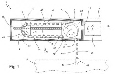
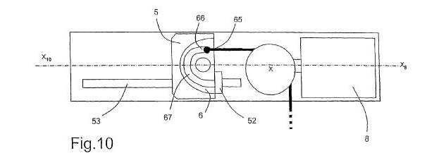
155 The interaction of the features in Figure 1 is described in column 7 at lines 33-65 as follows:
In order to gain still further on available chain length and as depicted in FIG. 10, the second end 42 of the chain may also slide in the support 5 as far as an end stop 66 provided in this support 5 at the exit from the guide 6. An immobilizing elements 65 then restrains the end 42 of the chain 4 in the support 5 at this end stop 66 when the chain is maneuvered in such a way as to leave the casing. The immobilizing element 65 is, for example, in the form of a peg able to slide in a groove 67 made in the support 5, this groove being closed at its end in order to form the end stop 66. Other embodiments of the immobilizing element 65, of the support 5 and/or the end stop 66 are of course conceivable.
…
In all the embodiments discussed, the travel of the support in a maneuver may be representative of a deployed length of chain. It is therefore advantageous to provide an adjustable end stop 52 which limits the travel of the support 5 in the direction of deployment of the chain. As depicted in FIG. 10 only, this adjustable end stop may be positioned along and adjusting strip 53 on an inner side of the casing 10 of the actuator and block the progress of the support at a given point. When the second and 42 of the chain 4 is free in relation to the support and to the casing, it is possible for the chain to continue to slide in the support 5 once the support is immobilized by the adjustable stop 52. When the end 42 of the chain 4 itself becomes immobilized in relation to the support 5, the deployed length of chain is at its maximum. Thus, the degree of opening of the opening leaf is dependent on the position of the adjustable stop 52. In this case, the stopping of the motor is determined, for example, by monitoring torque or variations in torque.
156 The immobilising element 65 can move no further than the end stop 66 at the end of guide 6. Figure 10 also depicts an adjustable end stop 52 to limit the travel of the support 5 in the direction of travel of the chain. The end stop 52 can be positioned along and adjusting strip 53 on an inner side of the casing 10. When the end of the chain becomes immobilised at the end stop 66, the deployed length of the chain is at its maximum. The adjustable end stop 52 limits the travel of the semi-circular guide 6, and thereby limits the travel of the chain and the length of chain that can protrude out of the casing.
157 Mingardi does not disclose the manner in which the adjustable end stop 52 is adjusted or can be positioned along the adjusting strip 53.
158 APT contends that Mingardi discloses all of the features of claims 1, 2 and 3 of the 260 patent. It does not advance a case that it anticipates the 818 patent. Doric advances four arguments to support its contention that Mingardi does not anticipate the relevant claims of the 260 patent as alleged.
159 First, Doric submits that Mingardi does not disclose a “window winder” or a “winder mechanism” as they appear in integers [1] and [4] respectively. Secondly, it contends that Mingardi does not disclose a stop member that can be “fixed to the body at a desired first position”, and “fixed to the body at the further desired position”, with the “positions being spaced and predefined by the body” as required by integer [5A]. Nor, it submits, is the “body adapted to receive said stop member in one of a plurality of positions” within integer [8A]. Thirdly, even if the adjustable strip 53 is assumed to be part of the body of Mingardi, Doric submits that there is no disclosure of a “plurality” of “predefined” positions on the adjustable strip at which the stop member can be located because these are not predefined by the body. As a result, integers [5] and [8A] are not disclosed.
6.4.1 Window winder and winder mechanism
160 Doric submits that Mingardi does not disclose a window winder as required by integer [1]. It discloses an electromechanical actuator which is operated by a user switching on a motor. No winding action is involved by the user. There is no winding of an element in a rotary fashion by the user to actuate the device. APT does not dispute that Mingardi does not teach the use of a rotary handle to effect movement or the winding of the chain around the sprocket. However, it contends that integer [1] does not require a rotary handle operated by a user.
161 The resolution of this aspect of the dispute turns on the definition of “window winder”, which I have addressed in section 4.4.2 above. In light of the definition adopted above, I find that integer [1] is absent from the Mingardi disclosure.
162 Doric also submits that there is no winder mechanism that is operable by a user within integer [4]. As Dr Lozzi puts it, Mingardi does not disclose such a mechanism in the sense of a handle that is rotated about an axis to rotate a sprocket in order to drive a chain. Instead, it discloses an electromechanical actuator which comprises a motor, a sprocket driven by the motor and a chain driven by the sprocket. APT submits that the winder mechanism is present because the sprocket 3 is responsible for winding the chain into and out of the housing.
163 For the reasons outlined above (in section 4.4.2), I also find that the winder mechanism of integer [4], is absent from Mingardi.
6.4.2 Stop member fixed to the body at requisite positions
164 Three sub-issues arise in relation to integer [5A]. The first is whether Mingardi discloses a stop member which is “fixed to the body” as required. The second is whether, if so fixed, the stop member is fixed at “positions being spaced and predefined by the body”. The third is whether, in integer [8A], the body is “adapted to receive said stop member in one of a plurality of positions”.
165 In relation to the first, the parties accept that in Mingardi, the end stop 52 may be considered to be a “stop member” within integer [5A]. In the joint expert report the experts agreed that in Figure 10 of Mingardi the adjustable end stop 52 must be fixed to the body to enable the invention to work.
166 As Mr Hunter explains in his evidence, the end stop 52 after being adjusted must end up being fixed to the body 10 because otherwise this feature could not achieve its stated function, which is that when the end 42 of the chain 4 becomes immobilised in relation to the support 5, the deployed length of chain is at its maximum. Thus, the degree of opening of the window is dependent on the position of the adjustable stop 52.
167 It would appear that the thrust of Doric’s submission is that Mingardi in this respect is not sufficiently clear to amount to a novelty defeating disclosure. However, the agreement of the experts on this subject indicates otherwise. Whilst the precise manner in which the end stop 52 and adjusting strip 53 are attached to the cover are not explained, the fact is, as the experts agree, that it must be fixed for it to work as described. Integer [5A] does not confine the manner by which stop member must be fixed to the body. It broadly describes the functional result of the stop member (that is, that it must be fixed “to limit movement of the element to thereby limit said length to a maximum length”). But the claim does not limit the means by which the stop member is fixed. Plainly enough, the skilled reader understands, and I find, that Mingardi discloses this result.
168 The second sub-issue is whether the end stop 52 is fixed at positions which are “spaced and predefined by the body” within integer [5A].
169 There is no dispute between the experts that the “body” in Mingardi is the component labelled 10 and described as the “casing”. However, Doric, relying on the evidence of Dr Lozzi, contends that it does not disclose any “first” or “further” positions at which the adjustable end stop 52 can be fixed, or that there are any such positions defined by a shape or feature of the body 10. APT submits that the strip 53 allows a multitude of positions at which the end stop could be fixed.
170 However, APT’s submission does not answer the nub of Doric’s submission, which is that the claim requires that the positions be “spaced and predefined by the body”. The experts agree that the “body” is the casing labelled 10, and that the strip 53 is attached to the body. That agreement contains within it the concession that the positions are not defined by the body, but by the strip. Accordingly, in this respect too, the disclosure of Mingardi does not fall within integer [5A].
171 Within this argument is another component, namely that the strip 53 does not in any event predefine positions, it providing merely a line along which the stop position may be chosen. I agree that along the continuum of the strip there are no particular positions that are predefined (accepting that the line contains an infinite number of potential positions, none of which are predefined). However, there is force in APT’s submission that at each end of the strip is a position that is fixed, for the maximum and minimum length of the chain. The word “plurality” means, in context, more than one (Macquarie Dictionary, fifth edition). Accordingly, that component of the claim would be satisfied.
172 The third sub-issue concerns integer [8A] which is in claims 2, 3 and optionally in claim 4 of the 260 patent. It requires that the body is “adapted to receive said stop member in one of a plurality of positions”. I have above rejected the proposition that the strip means 53 forms part of the body, and so this element is also not disclosed in Mingardi.
6.4.3 Conclusion in relation to Mingardi
173 As a consequence of my findings above, I find that claims essential features of integers [1], [4], [5A] and [8A] are absent, with the consequence that claims 1, 2 and 3 of the 260 patent are not anticipated by Mingardi.
174 APT contends that claims 1 and 2 of the 260 patent lack an innovative step when considered in the light of the information contained in Tacheny, and that all of the claims lack an innovative step when considered in the light of the information contained in Lambertini.
175 An invention will not be patentable for the purposes of an innovation patent if the invention, so far as claimed in any claim, does not involve an innovative step within s 18(1A)(b)(ii) of the Act. Subsection 7(4) of the Act provides that an invention is taken to involve an innovative step when compared with the prior art base unless the invention would, to a person skilled in the art, in the light of the common general knowledge as it existed before the priority date of the relevant claim, only vary from certain forms of prior art information in ways that make no substantial contribution to the working of the invention.
176 In the present case, the information by which the variation is to be assessed is prior art information made publicly available in a single document within s 7(5) of the Act. Two patents are separately relied upon for this purpose, Tacheny and Lambertini.
177 In Dura-Post (Aust) Pty Ltd v Delnorth Pty Ltd [2009] FCAFC 81; (2009) 177 FCR 239 the Full Court at [73] and [74] noted that s 7(4) requires a comparison to be made between the invention as claimed in each claim with the information s 7(5) describes. Subsection 7(6) requires that each such prior disclosure be considered separately. That is, the invention as claimed in each claim must be compared separately with each relevant prior disclosure. In making this comparison, s 7(4) requires that each comparison be made from the perspective of a person skilled in the art, whose task is to identify and assess the variations between the invention as claimed in each claim and the prior disclosure and determine whether or not these variations make a substantial contribution to the working of the invention as claimed in each claim. In this context, “substantial” contribution means “real” or “of substance”. At [79] the Full Court observed that s 7(4) requires a narrow comparison between the invention as claimed and the relevant prior disclosure, having regard to the fact that the threshold for an innovation patent is intended to be lower than for a standard patent. In substance, s 7(4) deems an invention as claimed to involve an innovative step unless the invention does not differ from the relevant prior disclosure in a way that makes a substantial contribution to the working of the invention as claimed – in the sense of the device or process the subject of each claim. This is a factual inquiry. The assessment is from the perspective of a person skilled in the art, having regard to the relevant common general knowledge.
178 APT contends that the information disclosed in Tacheny reveals that claims 1 and 2 of the 260 patent lack an innovative step.
7.2.1 The disclosure of Tacheny
179 The Tacheny patent is entitled “Chain operator for a window”. It is described below by reference to Figures 3 and 7 of Tacheny, the latter of which is set out below.
180 Tacheny discloses a chain operator for a window that may be operated by either a handle, motor or pole crank to rotate a sprocket which drives a chain around a chain guide track between a fully extended and fully retracted position. The operator has a casing with a base 25 and a two-part cover 26 and 27 (not depicted in Figure 7). The maximum extension of the chain 20 out of the casing is determined by the engagement of a stop member 100 having an upstanding flange 101 which can engage a projection 102. That stop member 100 cannot be adjusted.
181 The length that the chain 20 can extend from the casing can be adjusted by inserting a removable insert 105 between the links of a chain (referred to as the “sprocket tooth-receiving space 81”). As the sprocket rotates to extend the chain 20 outside the casing, the removable insert 105 moves towards the sprocket. The removable insert 105 prevents the teeth of the sprocket from being inserted into the space between the links of the chain that is occupied by the removable insert 105. Once the removable insert 105 reaches the sprocket, the sprocket cannot continue rotating to drive the chain out of the casing.
Figure 7:
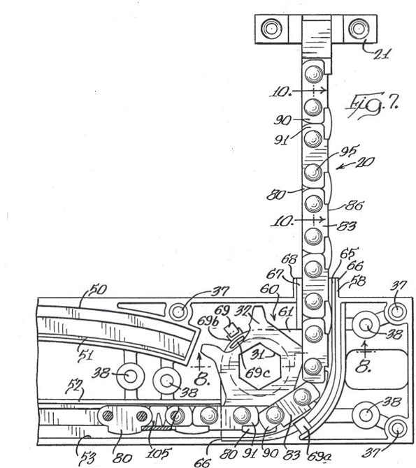
182 Most relevantly for present purposes it is the removable insert 105 that in operation represents the “stop means”. It is placed between links in the chain. When that insert comes into contact with the active sprocket, it prevents the sprocket from continuing to rotate and thereby determines the maximum length of the chain from the casing.
7.2.2 The relevant points of difference
183 The experts agree that a key difference between Tacheny and claims 1 and 2 of the 260 patent is that in Tacheny, there is a removable insert 105 which can adopt different positions in the chain, whereas the claims of the 260 patent require a stop member which can adopt different positions in the body. The experts differed as to the consequences which may be drawn from this difference.
184 Dr Lozzi’s evidence is that unlike as required by the claims of the 260 patent, the engagement locations of the insert are not unmistakable and predefined, and as a consequence the device lacks the security and safety provided by the 260 patent. Further, the Tacheny patent does not provide the installer of the window winder with the convenience and economy that the 260 patent does. On the other hand, Mr Hunter contends that the object of the 260 patent and of the disclosure of Tacheny is the same, namely to be able to adjust the desired maximum length of chain extending from the chain operator. Whilst in the 260 patent that is achieved by a variably positioned stop member in the body, in the Tacheny patent it is simply the other way around, with a variably positioned abutment in the chain.
185 In oral evidence Mr Hunter accepted that a consequence of using the removable insert 105 will be that in operation the insert stops the chain by preventing a sprocket tooth from entering a recess between links in the chain with the consequence that the engagement of the sprocket with the stop member will be a tendency to push the chain away from the sprocket so as to almost derail it. What prevents that from happening is that the adjustable stop means 105, together with the chain, are likely to be pushed up into the inner side of the case which may “jam it up” and make it a little more difficult for the user to reverse the direction of the operation of the handle.
186 The evidence of the experts supports a finding, which I make, that the apparatus claimed in claims 1 and 2 of the 260 patent differs from the prior art information contained in Tacheny in ways that make a substantial contribution to the working of the invention. The physical means by which the removable insert 105 operates in Tacheny represents a difference of substance from the stop means of the claims. The language of integers [5] – [8] of the 818 patent and [5A] and [6A] of the 260 patent require that the stop means be fixed to the body at positions that are spaced and predefined by the body. These requirements dictate that the device as claimed will ensure predicable certainty as to the length that the chain can extend. The removable insert 105 in Tacheny does not yield that result. That difference is substantial. I do not consider that the potential for the removable insert 105 to cause jamming to be relevant in the assessment for the purpose of s 7(4). The claims of the patents are silent as to how the stop means operates to limit movement of the chain. The distinction to which Doric refers is not one that arises from any limitation included in the claim and accordingly is to be set to one side; Multisteps Pty Ltd v Source and Sell Pty Ltd [2013] FCA 743; (2013) 214 FCR 323 at [285] (Yates J).
7.3.1 The disclosure of Lambertini
187 The Lambertini patent is entitled “Actuator with adjustable stroke”. The description that follows is best understood by reference to Figures 1 and 2, which are below. The text and the figure, read together, relevantly disclose an electromechanical actuator with a motor 3 (not shown) that controls the rotation of a toothed pulley 5 to drive a chain 2 around a track 4 inside a casing 1. The electromechanical actuator has an “adjustable stroke”, meaning, as Dr Lozzi explains, that the length of extension of the chain 2 from the casing 1 can be adjusted by the insertion of an insert 12 between two successive links in the chain 2. The casing 1 has an opening, referred to as an inspection hole 10, to allow for the insert 12 to be inserted by a user. The electromechanical actuator also has a microswitch 15.
188 In operation, the motor 3 will rotate the toothed pulley 5 to drive the chain 2 around the track 4. The insert 12 will move with the chain 2 towards the microswitch 15, which is at some distance from the inspection hole 10, where the insert 12 is inserted by the user. When the insert 12 comes into contact with the microswitch 15, the contact will cause a break in an electric circuit and the motor 3 is turned off. As the motor 3 is no longer able to rotate the toothed pulley 5, the chain 2 is prevented form extending any further from the casing 1.
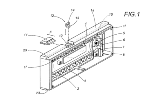
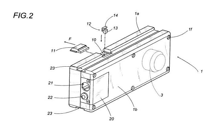
7.3.2 The relevant points of difference
189 APT accepts that Lambertini discloses an electromechanical actuator that is not a mechanical device involving operation of a winding mechanism by the use of a manual rotary action. In closing submissions APT accepted that if I were to conclude that a “window winder” or “winder mechanism” within integers [1] and [4] required a rotary winding action, then the claims of the 260 patent would not lack an innovative step over the disclosure of Lambertini.
190 Doric contended that in addition to the absence of these features, there were two other differences of significance between the disclosure of Lambertini and the claims of the 260 patent that, taken collectively, indicate that those claims do not lack an innovative step over Lambertini. First, the experts agree that Lambertini does not disclose the same stop means mechanism required in integers [5A] and [8A]. Secondly, the stop means mechanism involves trial and error to achieve the desired degree of opening.
191 There was no substantial dispute between the experts about these differences, the only area of argument was whether the differences were such that the invention as claimed in the 260 patent lacked an innovative step having regard to them.
7.3.3 Analysis of the differences
192 APT accepts that in the event that I decide that an electronically operated actuator does not fall within the claims, the disclosure of Lambertini cannot deprive the claims of the 260 patent of an innovative step. This is because Lambertini discloses a device that is actuated electronically and not mechanically. For the reasons that I have explained going to the construction of integers [2] and [4], the disclosure of Lambertini does not disclose information that falls within those integers. APT accepts that this difference is sufficient to warrant a finding of innovative step. However, in the event that I am incorrect on that point of construction, I turn to consider the further differences identified by Doric and, in that context alone, whether those differences (assuming APT’s construction of integers [2] and [4]) would deprive the 260 claims of an innovative step.
193 Doric first points to the difference between the stop mechanisms. Integers [5A] and [8A] together require the stop member to be fixed to the body at a desired first position which is spaced and predefined by the body and that the body to be adapted to receive the stop member in one of a plurality of positions, each corresponding to a maximum length of the element (chain) projecting from within the body. By contrast, in Lambertini the means by which the extension of the chain is prevented is by the insertion of the moveable insert 12. Mr Hunter points out that this achieves the same objective as the claims of the 260 mechanism and that it is simply “the other way around”.
194 The second difference is related to the first. Because there is no fixed position on the body into which the stop means is inserted, the location at which the moveable insert 12 in Lambertini is to be placed is not predefined. This has the consequence that some degree of trial and error may be required to select the desired maximum length to which the chain may be set.
195 There was no dispute between the experts as to the fact or effect of these differences. In the Joint Expert Report, Mr Hunter emphasises that both inventions achieve the same functional effect. However, the factual differences to which I have referred, in my view support the finding, which I make, that the claimed device in the 260 patent differs from the prior art information disclosed in Lambertini in ways that make a substantial contribution to the working of the invention. In Lambertini the mechanism operates by placing insert 12 between links in the chain, which in operation comes into contact with the microswitch 15 causing a break in the circuit and the electric motor to be turned off. By contrast, the stop means of the 260 patent is fixed to the body at a predefined location. The physical means by which the mechanism is operated is quite different. The functional effect is also different. The experts agreed that in the former there is a degree of imprecision, and trial and error will be involved in determining the location for the stop means. I have noted in [186] above that differences of this type arise from limitations set out in the claims of the patents in suit. They also make a substantial contribution to the working of the invention. Accordingly, even setting to one side the winder mechanism debate, the claims of the 260 patent involve an innovative step over the information contained in Lambertini.
196 Doric has established that the APT product infringes claims 1 – 4 of the 260 patent but has failed in respect of its infringement action on the basis of the 818 patent. APT has failed to establish that any of the asserted claims are invalid for lack of novelty or lack of innovative step. It is appropriate that the parties have an opportunity to make short submissions concerning the form of the final relief to be ordered, including costs. To that end, on or before 7 August 2017 Doric is to serve draft orders reflecting the outcome of the proceedings to APT, and on or before 16 August 2017 the parties are to confer with a view to identifying any areas of disagreement. On or before 25 August 2017, each party is to file and serve a submission, not exceeding five pages in length, addressing any areas of disagreement, and indicating whether they wish for there to be a further hearing on the outstanding issues.
I certify that the preceding one hundred and ninety-six (196) numbered paragraphs are a true copy of the Reasons for Judgment herein of the Honourable Justice Burley. |
Associate:

