FEDERAL COURT OF AUSTRALIA
Dincel Construction System Pty Limited v AFS Systems Pty Ltd (No 2) [2017] FCA 791
ORDERS
DATE OF ORDER: |
THE COURT ORDERS THAT:
1. The application be dismissed.
2. The cross-claim be dismissed.
3. Each party file and serve a written submission on the question of costs (limited to 2 pages) within 7 days.
4. Each party file and serve any written submission in reply (limited to 2 pages) within 14 days.
Note: Entry of orders is dealt with in Rule 39.32 of the Federal Court Rules 2011.
NICHOLAS J:
BACKGROUND
1 This is a proceeding commenced by the applicant against the first respondent for the alleged infringement of claims 1 to 4, 7 to 9, 11, 14 and 25 (“the relevant claims”) of Standard Patent No. 2002328693 (“the Patent”) entitled “Hollow interconnecting panels as lost formwork”. It is not in dispute that the applicant is the exclusive licensee of the Patent. The second respondent, the patentee, has not taken any active step in the proceeding. For ease of reference I will refer to the first respondent as “the respondent”.
2 All of the relevant claims are dependent on claim 1. It is accepted that the priority date of the relevant claims is 12 October 2001.
3 The respondent denies infringement and has filed a cross-claim seeking revocation of each of the relevant claims on the grounds that if the applicant’s construction of them is correct, then (a) the invention defined by each such claim was, as at the priority date, not novel, and (b) the claim is not fairly based on the matter described in the specification.
4 There is an interlocutory injunction in place which was granted by me following a contested hearing earlier this year. Some of what follows under the heading “The Patent” is drawn from the previous interlocutory judgment (Dincel Construction System Pty Limited v AFS Systems Pty Ltd [2017] FCA 262). The parties have co-operated to ensure that the proceeding could be made ready for an early final hearing on liability.
THE PATENT
5 The specification describes an invention consisting of a hollow building element that acts as permanent formwork into which concrete may be poured. Multiple elements may be snapped together to form a larger structure into which concrete is then poured to form a wall.
6 The specification identifies two disadvantages in the prior art building elements which the invention is intended to overcome or ameliorate. First, the prior art elements are coupled together by a vertical sliding motion which hinders their assembly and are, due to their length, difficult to handle. Second, the prior art building elements have either male or female couplings, which means that both types of elements must be manufactured and stocked.
7 The specification includes a number of consistory statements (which mirror the claims) including the following:
There is disclosed herein a hollow elongated integrally formed building element into which concrete is to be poured, said element including:
a pair of longitudinally extending spaced side walls which are generally parallel and coextensive;
transverse webs joining the side walls; wherein
each side wall has a longitudinally extending groove and a longitudinally extending flange extending from the side wall, with each flange and groove being positioned and configured to engage a respective groove or flange of a like element to secure adjacent elements together by snap engagement of the flange within its respective adjacent groove by movement of the groove and flange relative to each other and transverse of the element, with each groove being formed in a respective one of the side walls and each flange extending from a respective side wall so that the like element is locatable between the flanges to provide for engagement of the flanges and grooves, and wherein
the element further includes ramp surfaces that engage the flanges to move the flanges for said snap engagement of the flanges in the grooves.
Preferably, the flanges are urged apart for engagement in their respective groove.
Preferably, the flanges are resiliently urged apart for engagement in their respective groove.
Preferably, the ramp surface include a first ramp surface and a second ramp surface, the ramp surfaces being spaced so that each is operatively associated with a respective one of the extending flanges so that the ramp surfaces causes the resilient deformation of the flanges.
Preferably, the element further includes an end transverse web extending between the side walls, with the ramp surfaces being located adjacent the end web.
Preferably, the first and second ramp surfaces diverge from the adjacent end web towards a respective one of the grooves.
Preferably, each flange is an extension of a respective one of the side walls.
Preferably, each groove extends transversely inwardly from the respective side wall.
Preferably, said transverse web is a first web, and the element further includes a second transverse web, the second transverse web extending between the side walls to aide in stiffening the side walls.
Preferably, said second transverse web includes a central flange joined to the side walls by means of pairs of end flanges that diverge from the central flange to the side walls.
Preferably, said element is an extruded hollow longitudinally elongate building element.
Preferably, said element is extruded from a plastic material.
Preferably, the flanges undergo transverse movement relative to one another during snap engagement with their respective grooves.
8 The consistory statements are followed by a detailed description of various preferred embodiments which make reference to eight drawings (Figures 1-8). These include Figs 1, 2 and 7 as follows:
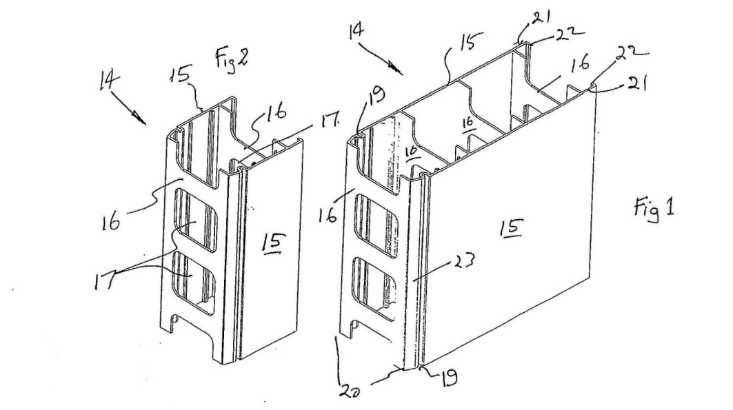
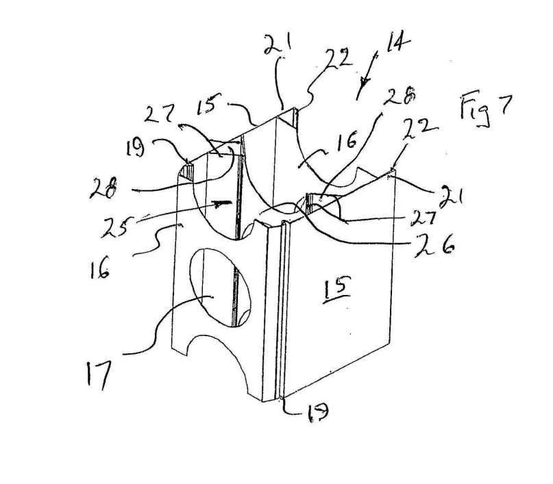
9 The description of the preferred embodiments includes the following passage at page 6 lines 10 to 17:
Each of the side walls 15 is provided with a longitudinally extending groove 19 adjacent a longitudinal edge 20 of the respective side wall 15. Extending from each side wall 15 is a longitudinally extending flange 21, the flanges 21 being generally parallel and coextensive with respect to the grooves 19. Each flange 21 includes a longitudinally extending lip 22 which is received within the grooves 19 of the next adjacent element 14. Extending to each groove 19 is a ramp surface 23. The surfaces 23, as best seen in Figure 7, are located adjacent the end transverse web 16 and diverge from adjacent the end web 16 to the adjacent groove 19.
A ramp surface (23) in the preferred embodiment is shown in Fig 1 extending between a longitudinal edge (20) and a groove (19). Figures 2 and 7 do not specifically identify the ramp surfaces (23) but their location is apparent from Fig 1. One ramp surface (23) is clearly shown in Fig 1 adjacent to the groove (19) adjoining the near side wall (15) of the building element. The other ramp surface is not expressly identified but it is clear that it is adjacent to the groove (19) adjoining the other side wall (15) on the other side of the building element.
10 It is apparent from Fig 1 that the lip (22) of the flange (21) can be coupled to a like element when the lip of the flange is forced along the ramp surface (23) in a horizontal direction until it is fully engaged by the groove into which it locks in what the specification refers to as the “snap engagement”.
11 The term “snap engagement” refers to part-to-part engagement (or “snap-fit”) that is accomplished by the deformation (or deflection) of two mating components. Such components are typically made of plastic or some other elastically deformable material. The term “snap interference distance” (which is not used in the Patent) refers to the distance that must be overcome by deformation (or deflection) before snap engagement is accomplished.
12 Claim 1 of the Patent is for:
A hollow elongated integrally formed building element into which concrete is to be poured, said element including:
a pair of longitudinally extending spaced side walls which are generally parallel and coextensive;
transverse webs joining the side walls; wherein
each side wall has a longitudinally extending groove and a longitudinally extending flange extending from the side wall, with each flange and groove being positioned and configured to engage a respective groove or flange of a like element to secure adjacent elements together by snap engagement of the flange within its respective adjacent groove by movement of the groove and flange relative to each other and transverse of the element, with each groove being formed in a respective one of the side walls and each flange extending from a respective side wall so that the like element is locatable between the flanges to provide for engagement of the flanges and grooves, and wherein
the element further includes ramp surfaces that engage the flanges to move the flanges for said snap engagement of the flanges in the grooves.
(emphasis added)
I shall refer to the last of the integers of claim 1 (which I have emphasised) as the “ramp surface integer”. The “said snap engagement of the flanges in the grooves” described in the ramp surface integer refers to the snap engagement of the flange into the adjacent groove previously described in the claim (which I have also emphasised) achieved by movement of the flange and groove relative to each other across the element.
13 Claim 1 requires that the side walls include “transverse webs joining the side wall”. These are shown in Fig 1 at four locations (16), two at either end of the element, and another two situated between the walls and transverse webs at each end of the element. Although claim 1 requires that the element include transverse webs joining the side walls, it does not require that any of these be located at either end of the element. Such a requirement is found in dependent claim 5 which refers to an element that further includes:
an end transverse web extending between the side walls, with the ramp surfaces being located adjacent the end web.”
THE PERSON SKILLED IN THE ART
14 The Patent relates to building elements used to construct the concrete walls for a building. I am satisfied that the Patent is directed to builders, architects, engineers and industrial designers who will have a practical interest in the construction of buildings or mechanical systems or devices for use in the construction of buildings.
THE EXPERT WITNESSES
15 Mr Williams Hunter is the independent expert witness for the applicant. He is a Mechanical Engineer with over 30 years’ experience. He made a total of four affidavits. In his first affidavit, he expressed his opinion that the respondent’s product (“the AFS Product”) included a ramp surface as referred to in claim 1. He produced a series of photographs (“WSH-7”) he took of the AFS Product which he annotated to show the presence of a ramp surface. He made two further affidavits responsive to affidavits made by the respondent’s expert, Mr Phillips, on the meaning of “ramp surface” and reiterated his view that the AFS Product includes the ramp surface integer. The second of those included another series of photographs (“WSH-10”) depicting the AFS Product which this time identified two different ramp surfaces. His fourth affidavit returns to that topic and also addresses the prior art relied upon by the respondent in support of its invalidity case. In Mr Hunter’s opinion, the AFS Product includes the ramp surface integer.
16 Mr Timothy Phillips is the independent expert witness for the respondent. He is an Industrial Designer who has worked in the field of industrial design for approximately 15 years specialising in the design of architectural, construction and industrial products. Mr Phillips made a total of four affidavits, the first two of which contain his response to Mr Hunter’s first and second affidavits and his explanation of what he understood the term “ramp surface” to mean and why in his view the AFS Product does not include the ramp surface integer. The third affidavit by Mr Phillips returns to that topic and also contains his analysis of the two pieces of prior art upon which the respondent relies in support of its lack of novelty case.
17 I found the evidence of both expert witnesses helpful in understanding how the building elements described in the Patent, the prior art and the AFS Product work. Importantly, while the experts agreed that the term “ramp surface” as used in claim 1 had a functional meaning (ie. a surface that acts as a ramp) both also agreed that the term is not a technical term in the sense that it does not have a defined technical meaning. Ultimately, the question of what the term “ramp surface” as used in claim 1 means is a matter for the Court to determine.
INFRINGEMENT
18 It is common ground that the AFS Product contains all of the integers of claim 1 except for the ramp surface integer. It is also common ground that the infringement case based upon all other relevant claims stands or falls along with claim 1. For that reason, the evidence and the parties’ submissions focused upon the ramp surface integer. The first question with respect to infringement relates to the proper construction of claim 1. What is the meaning of “ramp surface” as that term is used in claim 1? The second question, which may only be answered after the first question has been answered, is directed to the AFS Product. Does the AFS Product include ramp surfaces as required by claim 1?
The ramp surface integer
The principles of construction
19 The well settled principles governing patent construction are not in dispute and have been summarised in many cases including Jupiters Ltd v Neurizon Pty Ltd (2005) 65 IPR 86 at [67] and Kinabalu Investments Pty Ltd v Barron & Rawson Pty Ltd [2008] FCAFC 178 at [44].
20 The meaning of the term “ramp surface” must be ascertained from a reading of the Patent as a whole as it would be understood by the person skilled in the art equipped with the common general knowledge in the relevant field as it stood at the priority date.
21 The context in which the relevant language is used is of crucial significance to the ascertainment of its meaning. When construing a patent specification the Court seeks to give the document a purposive construction by reading the document as it would be understood by a person skilled in the art and without engaging in overly meticulous verbal analysis. It is worth repeating what Lord Hoffman said on the topic of purposive construction in Kirin-Amgen Inc v Hoechst Marion Roussel Ltd (2004) 64 IPR 444 at [34]:
“Purposive construction” does not mean that one is extending or going beyond the definition of the technical matter for which the patentee seeks protection in the claims. The question is always what the person skilled in the art would have understood the patentee to be using the language of the claim to mean. And for this purpose, the language he has chosen is usually of critical importance. The conventions of word meaning and syntax enable us to express our meanings with great accuracy and subtlety and the skilled man will ordinarily assume that the patentee has chosen his language accordingly. As a number of judges have pointed out, the specification is a unilateral document in words of the patentee’s own choosing. Furthermore, the words will usually have been chosen upon skilled advice. The specification is not a document inter rusticos for which broad allowances must be made. On the other hand, it must be recognised that the patentee is trying to describe something which, at any rate in his opinion, is new; which has not existed before and of which there may be no generally accepted definition. There will be occasions upon which it will be obvious to the skilled man that the patentee must in some respect have departed from conventional use of language or included in his description of the invention some element which he did not mean to be essential. But one would not expect that to happen very often.
22 Purposive construction requires that a patent specification be read in a practical and commonsense way. It should not be read in the abstract or in a purely literal way. On the other hand, it does not allow the Court to ignore the existence of an integer of a claim nor does it allow the Court to impose a limitation upon the clear language of a claim based upon glosses drawn from other parts of the document. As Bennett J observed in Sachtler GmbH & Co KG v R.E. Miller Pty Ltd (2005) 65 IPR 605 at [42]:
There is a fine line between, on the one hand, reading down the words of a patent claim to reflect how a person skilled in the art would understand it in a practical and commonsense way and, on the other hand, impermissibly limiting the clear words of a claim because a reader skilled in the art would be likely to apply those wide words only in a limited range of all the situations they describe: Stanway Oyster Cylinders Pty Ltd v Marks (1996) 66 FCR 577 at 585; 144 ALR 627 at 634; 35 IPR 71 at 78 per Drummond J.
23 There is a danger that in seeking to give a claim a purposive construction, or in seeking to read it in context, an impermissible gloss might be imposed upon the language used based upon material found in the body of the specification: Tramanco Pty Ltd v BPW Transpec Pty Ltd (2014) 105 IPR 18 at [175].
24 The Patent is for a combination in the sense explained by Aickin J in Minnesota Mining and Manufacturing Company v Beiersdorf (Australia) Limited (1980) 144 CLR 253 at 266 because it:
… combines a number of elements which interact with each other to produce a new result or product. Such a combination may be one constituted by integers each of which is old, or by integers some of which are new, the interaction being the essential requirement.
25 In a combination patent, the invention resides not merely in the collocation of particular integers, but also in the manner in which those integers interact. In Welsh Perrin & Co Pty Ltd v Worrell (1961) 106 CLR 588 Dixon CJ, Kitto and Windeyer JJ said at 612 that in a patent for a combination:
... the most important function of the body of the specification is to show what are the mechanical means which, operating together, produce the result claimed; and how they so operate.
26 In Rodi & Wienenberger AG v Henry Showell Ltd [1969] RPC 367, Lord Upjohn discussed the proper approach to questions of construction in terms that are wholly consistent with more recent authority. His Lordship said at 391:
First, the question is whether the relevant claim has been infringed. This is purely a question of construction of the claim read as a matter of ordinary language, in the light of the complete specification taken as a whole; but the claim must be construed as a document without having in mind the alleged infringement. What is not claimed is disclaimed. The claim must be read through the eyes of the notional addressee, the man who is going to carry out the invention described. There are many authorities on this, but it is unnecessary to review them, for I have already said enough to shew that, in my view, this document must be read through the eyes of the common man at his bench.
In considering the claim the court must ascertain what are the essential integers of the claim; this remains a question of construction and no general principles can be laid down (see my observations in Van der Lely v Bamfords Ltd [1961] RPC 296 at 313 approved on appeal to this House).
27 His Lordship then turned to the so-called “pith and marrow” theory of infringement and its application to a claim to a new combination. His Lordship continued at 391:
Secondly, the essential integers having been ascertained, the infringing article must be considered. To constitute infringement the article must take each and everyone of the essential integers of the claim. Non-essential integers may be omitted or replaced by mechanical equivalents; there will still be infringement. I believe that this states the whole substance of the "pith and marrow" theory of infringement. Furthermore, where the invention, as in this case, resides in a new combination of known integers but also merely in a new arrangement and interaction of ordinary working parts it is not sufficient to shew that the same result is reached; the working parts must act on one another in the way claimed in the claim of this patent. This is well illustrated by Birmingham Sound Reproducers Ltd v Collaro Ltd [1956] RPC 232 where Lord Evershed, M.R. delivering the Judgment of the court said at page 245:
Thus the essence of the invention resides wholly in the selection and arrangement of the parts and the manner in which they interact when arranged in accordance with the invention. It is therefore essential to the invention that it should consist of the particular parts described in the claim arranged and acting upon each other in the way described in the claim.
…
These observations were cited by Gibbs J in Olin Corporation v Super Cartridge Co Pty Ltd (1977) 180 CLR 236 at 246 in support of the now well settled proposition that the patentee cannot succeed in establishing infringement unless it is proved that the defendant’s process (or product) takes each and every one of the essential integers of the claim. They also remind us that a claim to a combination is not merely to a collocation of parts but also to the manner in which they are arranged and the way in which they interact. For there to be an infringement of a claim for a combination, the working parts must act on one another in the way claimed.
28 The fact that a mechanical device includes one or more additional integers does not necessarily put it outside a claim if the essential integers are present and they act in the manner claimed: Palmer v Dunlop Perdriau Rubber Co Ltd (1937) 59 CLR 30 at 63, Fresenius Medical Care Australia Pty Ltd v Gambo Pty Ltd (2005) 67 IPR 230 at [70]. This is true even if the addition of the additional integers may have resulted in an improved device. As Mr Blanco White QC explained in Patents for Inventions, 5th ed, Stevens & Sons, London, 1983 at p 45, if what the defendant has done falls within the claim, it will infringe no matter what additional features it contains even if these are inventive.
The parties’ submissions
29 The applicant submitted:
The term “ramp surface” as used in claim 1 refers to a sloping surface which engages the flange to move the flange for snap engagement in the groove. The claim does not require that the “ramp surface” provide any mechanical advantage.
A surface can be a “ramp surface” for the purposes of claim 1 whether it is planar, curved or compound (ie, a combination of planar and curved). Nothing in the Patent requires the ramp surfaces referred to be planar.
A “ramp surface” within claim 1 need not be fully traversed by the flange. The ramp surfaces exemplified in Fig 1 of the Patent are not fully traversed by the flanges.
Claim 1 does not preclude movement of the grooves. It specifically refers to movement of the grooves relative to the flange. In the preferred embodiment exemplified in Fig 1 of the Patent, both the grooves and the flanges move to effect the snap engagement.
Claim 1 does not require any particular amount of movement of the flanges although the applicant accepts that the flanges must move, and that their movement must be more than de minimus.
30 The respondent submitted that the language of claim 1 identifies particular integers that operate in combination, and that it also defines their working relationship. It further submitted that the words of the claim are not to be treated as providing a mere checklist which can be satisfied on the basis of a purely literal reading without having regard to their working relationship as disclosed in the specification.
31 The respondent accepted that a “ramp surface” need not be planar and that it need not be fully traversed by the flange. It also accepted that the language of claim 1 does not require that there be no movement of the groove, but it submitted (and the applicant accepted) that the flange must itself move. Thus, while claim 1 at one point speaks of relative movement between the flange and the groove, both parties accept (correctly in my view) that there must be some movement by the flange as it engages with the ramp surface.
32 The respondent further submitted, based on the evidence of Mr Phillips, that the ramp surface must provide a mechanical advantage that makes it easier for the flange to move into the groove prior to snap engagement.
33 The respondent also submitted that the word “engage” as it appears in the ramp surfaces integer refers to the first engagement between the flange and the ramp surface. It relied upon a definition of “engage” appearing in the Concise Oxford Dictionary 10th Edition, which includes the following:
4. (with reference to a part of a machine or engine) move or cause to move into position so as to come into operation.
34 Drawing upon this definition the respondent submitted that the ramp surface integer requires that when the like elements are first brought together, the flange must at that point (ie. the point of first contact) engage with a ramp surface functioning as such, that is to say, providing a mechanical advantage that assists the flange to move to the groove.
Consideration
35 I do not accept the respondent’s submission that for a building element to be within claim 1, the flange and the ramp surface must engage at the point at which the two like elements are brought together. While the preferred embodiment operates in this manner, there is nothing in the language of claim 1 that requires the initial engagement be between the flange and the ramp surface. Nor is there anything in the specification that requires that such a limitation be read into claim 1. Further, there is no evidence to suggest that a person skilled in the art would read any such limitation into the claims. Mr Flynn, counsel for the respondent, put to Mr Hunter that the Patent discloses that the work of the ramp surface is being done from the moment the two like elements are brought into place. Mr Hunter agreed with this, but it is clear that he was referring to the preferred embodiment. It was never suggested to him that he would read claim 1 as importing any such requirement. I do not think there is any basis for reading any such limitation into the claim.
36 For present purposes I think a ramp is best described as:
4. A slope; an inclined plane connecting two different levels …
(Shorter Oxford English Dictionary 5th Ed at p 2459).
37 This entry includes some specific examples of ramps such as those used to board a boat or an aircraft or to load cattle into a truck. Clearly, the ramp surfaces referred to in claim 1 are very different from these. But the general idea that is conveyed by the word ramp in these contexts is of a sloped surface that makes it easier (by reducing the amount of effort required) to move from one level to another level. In claim 1, the word is used as an adjective to describe a surface that performs a similar function.
38 Mr Phillips understood that the ramp surfaces referred to in the Patent are sloping surfaces that provide a mechanical advantage by reducing the amount of force required to move the flange from point to point. Mr Hunter, in his third affidavit, agreed with Mr Phillips, that a surface must function as a ramp to be a “ramp surface” for the purpose of the claims. Mr Phillip’s understanding accords with my own understanding of how the invention described in the body of the specification works.
39 Neither the body of the specification nor the claims refer to “mechanical advantage”. However, these words do describe the work performed by the “ramp surfaces” of the combination defined in claim 1 as it would be understood by the skilled addressee based on a reading of the specification as a whole.
40 In my view, the use of the word “ramp” to describe a surface in claim 1, read in the context of the specification as a whole, would convey to the person skilled in the art a sloping surface that is configured so as to assist the movement of the flange as it travels to the point at which snap engagement occurs, and that it does this by reducing the amount of force required to achieve this result.
41 Claim 1 does not identify the degree of mechanical advantage provided by the ramp surfaces. The claim requires that the ramp surface must engage the flange to move the flange for snap engagement of the flange in the groove. However, the ramp surface must engage the flange to move the flange, which clearly implies that the ramp surface must assist the movement of the flange. In the preferred embodiment it can be seen that the ramp surface (23) assists the lip of the flange (22) to travel from the longitudinal edge (20) into the groove (19).
The AFS Product
42 The next question is whether the applicant has established that the AFS Product incorporates the ramp surface integer. There was a considerable amount of evidence given by the expert witnesses directed to this topic. The evidence also included a number of samples of the AFS Product which I have examined.
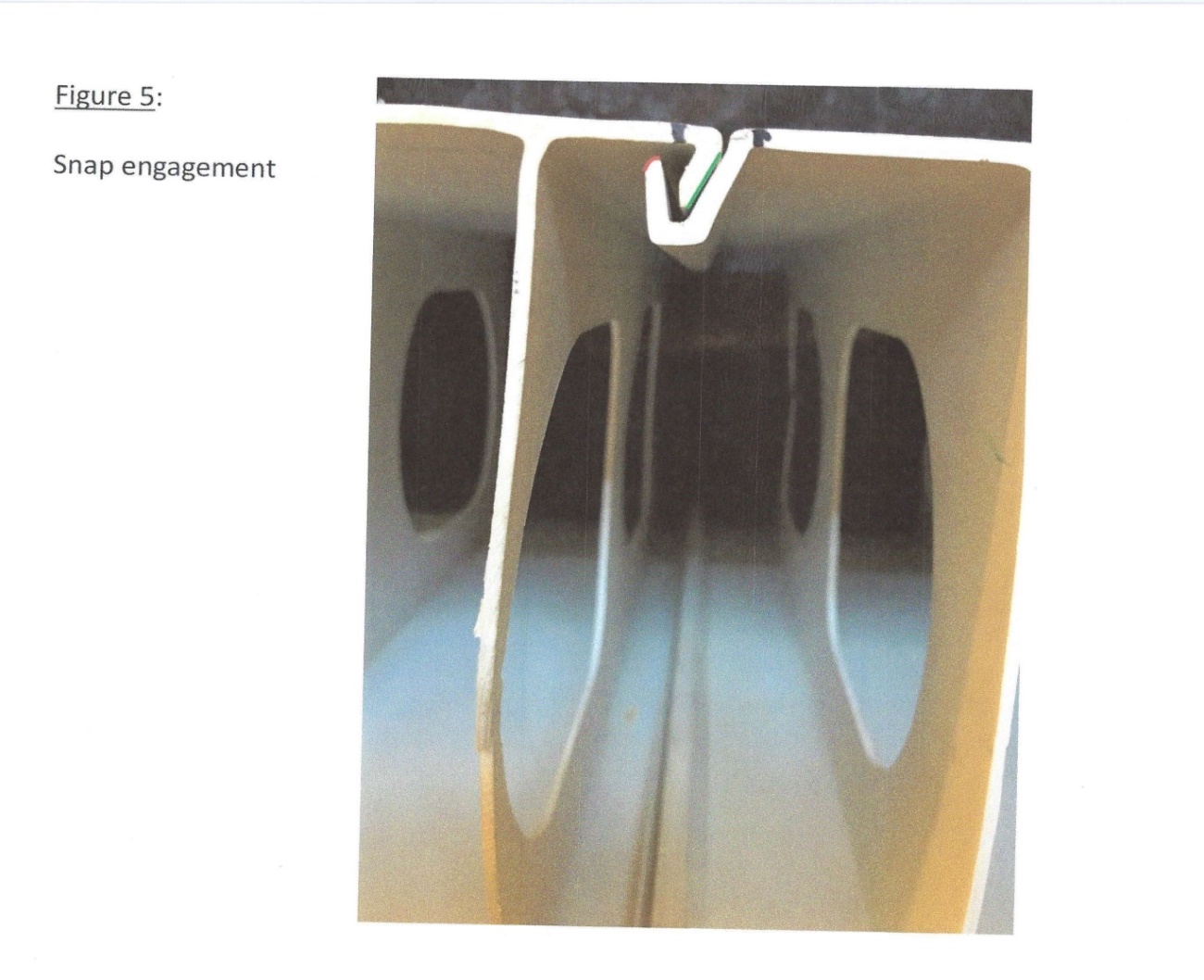
43 It is necessary to say something more concerning the photographs reproduced in Schedule A. These photographs (WSH-10) were taken by Mr Hunter as part of an experiment in which two AFS Products were slowly brought together in the transverse direction using a tie-down ratchet strap. The movement was paused at various points in the process so that Mr Hunter could take photographs and measurements. The photographs in Schedule A show the location and configuration of the flange and the groove relative to each other at various points before (Figs 1, 2, 3 and 4) and after (Fig 5) snap engagement occurs.
44 Figure 1 of Schedule A shows the two AFS Products at a point at which the top of the flange and the top of the groove first touch. Figure 2 shows that, after the two elements are further brought together, the top of the groove has moved down along the outer wall of the flange. Figure 3 shows the top of the outer wall of the groove as it approaches the bottom of the outer wall of the flange. Figure 4 shows the flange and groove, in Mr Hunter’s words, “just prior to snap engagement.” Figure 5 shows the position of the flange nestled inside the groove, after snap engagement has occurred.
45 Mr Hunter’s annotations on the photographs in Annexure A show the ramp surfaces consisting of the outer wall of the flange (coloured green) and what he refers to as the “upper ramp surface” consisting of the curved surface at the top of the groove (coloured red) running between the inner and outer surfaces of the groove.
46 It is important to point out that in his first presentation of these same photographs (WSH-8) Mr Hunter identified the ramp surface as the surface extending along the entire length of the outer wall of the groove. The applicant contends that this surface consists of a ramp surface for the purposes of claim 1. Alternatively, it says that what Mr Hunter calls the upper ramp surface is a ramp surface for the purposes of claim 1.
47 I am satisfied that the outer wall of the groove that lies beneath the curved surface at the top does not function as a ramp. It is only where the flange engages with the top of the upper portion of the wall of the groove, that the curved surface might be said to act as a ramp as the tip of the flange travels along it. Mr Hunter’s photographs do not reveal the presence of any movement which suggest that the lower portion of the outer wall of the groove functions as a ramp.
48 The respondent submitted that Mr Hunter’s experiment does not demonstrate that the tip of the flange travels along what Mr Hunter calls the upper ramp surface. When making this submission the respondent focused on Figs 4 and 5 which did not, as Mr Hunter accepted, capture any image of the lip of the flange as it travelled beyond the position it is last shown in Fig 4 before snap engagement has occurred as shown in Fig 5.
49 Mr Hunter’s evidence was that he was unable to capture images of what occurred between Figs 4 and 5. Nevertheless, his evidence was that the tip of the flange had to travel across the length of the curved surface if snap engagement was to occur and that the curved surface, along which the lip travelled, provided a mechanical advantage that assisted the flange to move absolutely, and relative to the groove, which made snap engagement possible. Mr Hunter said in his evidence:
[The] point that there’s no mechanical advantage over that second section [referring to the curved surface], that’s also not true, because the flange continues to move over an outwardly diverging portion of the groove, so there must be a mechanical advantage there. That arc must be making it easier for that – for that flange to traverse over that portion of the groove and make its way into the slot.
50 In his oral evidence, Mr Phillips said that he did not believe the curved surface was providing any mechanical advantage. Mr Phillip’s reason for believing that no mechanical advantage was provided was not that a curved surface could not function as a ramp. Mr Phillips gave the following evidence in cross-examination:
MR DIMITRIADIS: Okay. Putting aside the degree of that deflection, which I will come back, you agree that that movement of the flange riding up the curved upper portion of the distal end of the groove provides a mechanical advantage of the kind to which you referred earlier as being required for a ramp surface.
MR PHILLIPS: I don’t believe so in any practical sense.
MR DIMITRIADIS: And is that because of the degree of the deflection? Is that the reason for you not accepting that there’s a mechanical advantage?
MR PHILLIPS: And the – yes, the degree of deflection, whether it’s angular or linear, however we measure it. I consider that insignificant.
MR DIMITRIADIS: Okay. Putting aside whether the degree is insignificant, it’s nothing to do with the fact that it’s a curved surface that you’re disagreeing with me? That’s not the reason, is it?
MR PHILLIPS: No.
MR DIMITRIADIS: If it was sufficiently – sufficient in magnitude, in your view, riding up over a curved upper portion of that kind could provide a mechanical advantage of the kind we - - -
MR PHILLIPS: Yes. I think it’s not a deliberate feature of the product.
MR DIMITRIADIS: Okay, but you - - -
MR PHILLIPS: But I agree it does – could.
MR DIMITRIADIS: Do you agree it could – a curved surface of the kind that we see at the distal end of the groove could provide a mechanical advantage if the degree of movement was significant enough by the tip of the flange riding up over it?
MR PHILLIPS: Yes.
51 There was accordingly acceptance amongst the experts that a curved surface at the top of the outer wall of the groove portion was capable of acting as a ramp which would make it easier for the flange to traverse into the groove. However, I did not understand Mr Phillips to accept that the curved surface at the top of the groove in the AFS Product provided any mechanical advantage or that, if it did so, that the degree of mechanical advantage provided was of any practical significance. As Mr Phillips explained in his third affidavit, during the process of snap engagement, it is the ramp on the outer wall of the flange (and not the curved surface at the distal end of the groove) which provides the mechanical advantage necessary to deflect the groove relative to the flange for the purpose of snap engagement. Mr Hunter, in his oral evidence, similarly agreed that, save for the final millimetres when the lip of the flange rides over the curved surface, it is the ramp on the outer wall of the flange (coloured in green) which is functioning as a ramp for snap engagement in the AFS Product.
52 There was a debate between the experts regarding the degree of movement of the flange and the groove during the snap engagement process. In his written evidence, Mr Phillips explained that he had performed calculations (based on the stiffness ratio of the cantilever lengths) showing approximately 90% deflection by the groove and 10% by the flange during snap engagement of the AFS Product. He also performed a “practical test” to validate those calculations (using a ratchet strap and Vernier Calliper measurement tool) which he said revealed that, during snap engagement, the groove section had moved approximately 99.5% of the total interference, and the flange section had moved 0.5%. Mr Phillips described the results of his “practical test” as revealing “insignificant” movement of the flange during snap engagement.
53 Mr Hunter performed similar calculations and experiments (albeit on different samples of the AFS Product). His calculations and measurements revealed that the groove section had moved approximately 75% of the total interference, and the flange section had moved by approximately 25%.
54 As part of the “practical test” that Mr Phillips performed (which he said revealed de minimus movement of the flange of 0.5%), he took a series of photographs which he annotated and attached to his affidavit. Mr Phillips was taken to theses photographs during cross-examination and agreed that these photographs depicted (even to the naked eye) deflection of the flange as part the overall relative movement during snap engagement.
55 Mr Phillips was also taken to an illustration of the flange and groove deflection profiles which he also had prepared and annexed to his affidavit. He agreed that this illustration revealed “noticeable” movement of the flange during snap engagement. Both Mr Phillips and Mr Hunter were also taken to marked up versions of Mr Phillips’ illustration which included centre lines and measurements of the deflection profiles of the groove and flange during snap engagement. Both witnesses confirmed, based on their own measurements performed in the witness box, that these documents revealed 37.5% movement of the flange and 62.5% movement of the groove during snap engagement.
56 Mr Hunter’s evidence clearly establishes that the movement of the groove is assisted by what he also calls a ramp surface in the AFS Product (shown in green in Schedule A, Figs 1-5) on the outer surface of the flange. It is this inclined surface that assists the groove to move in a downward direction relative to the flange to a point at which snap engagement can occur. It is clear that it is this surface in the AFS Product that provides most, if not all, of the mechanical assistance necessary to enable snap engagement to occur.
57 I do not consider what Mr Hunter describes as the “upper ramp surface” (shown in red in Schedule A, Figs 1-5) is a “ramp surface” within the meaning of the claims. The evidence does not establish that it makes any contribution to the movement of the flange. To the extent that Mr Hunter’s evidence (see para 49 above) might be understood to suggest otherwise, it seems to me to be based on a conjecture and is not persuasive. While the lip of the flange may travel along the “upper ramp surface”, it does not necessarily follow that this surface is functioning as a ramp (ie. by assisting the movement of the flange as it travels to the point at which snap engagement is accomplished) or, assuming that it is, that its contribution to that result is of any significance to the working of the AFS Product.
58 The applicant submitted that the present case is analogous to Bitech Engineering v Garth Living Pty Ltd (2010) 86 IPR 468. I do not agree. In that case the question was whether the respondent’s device (an electric heater with a viewing screen on which simulated images of flames were projected) included “simulated flame effect means for reflecting said light to simulate flames.” The respondent’s heater included such a means but also included another means for directly projecting light to simulate images of flames. The primary judge held that about half of the relevant images were created by reflected light and about half were created by direct light. Thus, there was a substantial use of reflected light to simulate flames in the respondent’s heater. It was on that basis that the respondent’s heater was found to infringe. In the present case, it has not been established that what Mr Hunter calls the “upper ramp surface” makes any significant contribution to the movement of the flange. It is clear that in the AFS Product, it is the outer surface of the flange that performs this function. To the extent (if any) that the curved surface at the top of the groove also performs this function, its contribution to the movement of the flange into the groove is not shown to be anything more than de minimus. I am therefore not satisfied that what Mr Hunter calls the upper ramp surfaces in the AFS Product are ramp surfaces within the meaning of claim 1 as it would be understood by the notional skilled addressee.
VALIDITY
Novelty
59 The respondent submitted that its invalidity case only arose if the applicant’s construction of claim 1 was preferred. By this I understood the respondent to refer to a construction of the ramp surface integer that did not require that the ramp surfaces assist the flanges to move into the grooves. However, even if I had accepted that construction, I would not have accepted that either of the prior art documents relied upon by the respondent anticipated any of the relevant claims.
60 The relevant test for lack of novelty was discussed in some detail in the plurality judgment in AstraZeneca AB v Apotex Pty Ltd (2014) 226 FCR 324 (“Astrazeneca”). Their Honours (Besanko, Foster, Nicholas and Yates JJ) referred at [301] with approval to the joint judgment of Black CJ and Lehane J in Bristol-Myers Squibb Co v F H Faulding & Co Ltd (2000) 97 FCR 524 who, having reviewed the well-known authorities, concluded at [67]:
What all those authorities contemplate, in our view, is that a prior publication, if it is to destroy novelty, must give a direction or make a recommendation or suggestion which will result, if the skilled reader follows it, in the claimed invention. A direction, recommendation or suggestion may often, of course, be implicit in what is described and commonly the only question may be whether the publication describes with sufficient clarity the claimed invention or, in the case of a combination, each integer of it …
61 In Astrazeneca the plurality said at [302]:
Sufficiency of disclosure is a cardinal anterior requirement in the analysis of whether a prior art document anticipates a claimed invention. It is only after the stage of assessing the sufficiency of disclosure – which involves a determination about whether a prior document has “planted the flag” as opposed to having provided merely “a signpost, however clear, upon the road” or, perhaps, something less – that the notion of reverse infringement comes into play as the final and resolving step of the required analysis. It is not the first step of the required analysis; nor is it the only step.
Their Honours also said at [352]:
Although the common general knowledge can be used in a limited way to construe a prior art document, s 7(1) does not permit the common general knowledge to be used as a resource that can be deployed complementarily to arrive at a disclosure which the document alone, properly construed, does not make. If it were otherwise, the separate requirement of an inventive step to support a patentable invention (see s 18(1)(b)(ii) of the Act) would be otiose. The test of novelty would encompass the test for inventive step, without the need to satisfy the threshold requirements of s 7(3) (as it then stood) that the information in the document be information that the person skilled in the art could, before the priority date of the relevant claim, be reasonably expected to have ascertained, understood and regarded as relevant to work in the relevant art in the patent area. All that would be required is that the information in the prior art document be publicly available.
62 The prior art relied on by the respondents that is said to deprive each of the relevant claims of novelty consists of two separate and unrelated documentary disclosures. It is therefore necessary to ask whether each document, considered separately, gives a direction or makes a recommendation or suggestion that would, if it were followed by a person skilled in the art, result in the invention claimed in each of the relevant claims.
Royal
63 The Royal Building System Construction Guide (“Royal”) is a booklet that was publically available in Australia before the priority date.
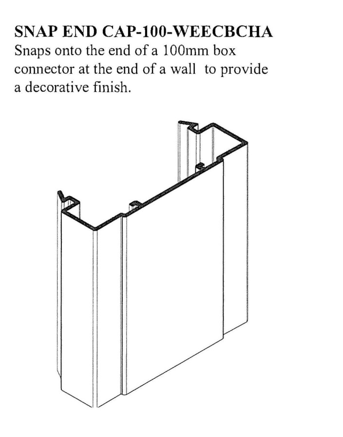
64 Photographs showing various building components in section 8, page 1 of Royal are reproduced in Schedule B, Figure 1 of the these reasons. Drawings of the components referred to as the SPACER-100X, the SPACER-150X and the SPACER-200X appear in section 25, page 10 of Royal. These drawings and the captions appearing above them are reproduced in Schedule B, Figure 3. A drawing of the component referred to as SNAP-END CAP-100 that appears in Royal in section 25, page 14 is also reproduced in Schedule B, Figure 4.
65 Photographs showing a person engaged in the installation of interlocking panels and box connectors and a number of partially installed walls appearing in section 8, page 2 of Royal are reproduced in Schedule B, Figure 2. Additional photographs depicting the installation process appear in Royal in section 8, page 3.
66 Royal describes a modular system utilising interlocutory “panels” and “box connectors” and includes the following directions:
INTERLOCKING THE PANELS AND BOX CONNECTORS
As seen in the example above, the panels and box connectors have been designed to slide into one another and to interlock, thus forming the walls of your building. This “tongue and groove” design is but one of the revolutionary benefits of The Royal Building System™. Sliding the components together can be quick and easy provided that you assemble them with the following points in mind:
• When sliding pieces together, ensure that the pieces are clean. Excessive dirt may prevent the pieces from sliding together properly. As a safety precaution, do not put your fingers through the coring as a safety precaution.
• Depending on weather conditions, the pieces may expand and/or contract. This can cause binding during assembly. If this occurs, we recommend using a rubber mallet to gently tap the pieces into place. You may also use an approved lubricant to assist in sliding the pieces together.
67 It is apparent from this description that the system of interlocking panels and box connectors utilise a vertical sliding mechanism rather than a “snap engagement” mechanism as required by claim 1. This is also apparent from the photograph in section 8, page 2 of Royal reproduced in Schedule B, Fig 2. It follows that the Royal system suffers from at least one of the two disadvantages referred to in the discussion of the prior art in the body of the specification.
68 The only suggestion that any of the Royal components might be brought together by means of any form of “snap engagement” appears in section 25, page 14 of Royal where the SNAP END CAP -100 is shown as reproduced in Schedule B, Fig 4. But this is not a building element which connects to a “like” element. It is a component that can be attached to the end of a box connector to provide a decorative finish. The snap-end-cap and the box connector are not like components.
69 The respondent’s invalidity case based on Royal must fail regardless of how the ramp surface integer is construed.
Göranson
70 US Patent No 5,201,159 (“Göranson”) was publicly available in Australia before the priority date. Göranson describes a structural element for:
… providing continuous surfaces, for example a screen, a partition wall, a hoarding or the like, essentially for screening-off noise, a view, etc.
71 Figure 1 of Göranson shows the following cross-sectional representation of the structural element described:
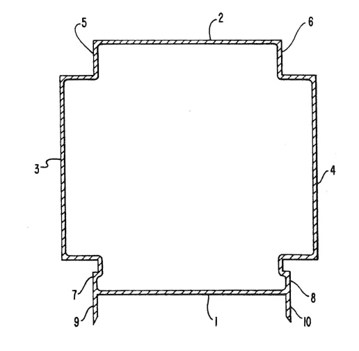
72 The specification states (at col 2 lines 56-60):
In the case that the profile or structural element according to the present invention is open, parts of or the whole of the side 1 will be dispensed with. If so desired, rigidifying flanges can be provided on the inside of all surfaces or sides 1-4.
73 None of the drawings show any “rigidifying flanges” of the type referred to and it is not possible to know from a reading of the specification how they should be arranged. The fact that they are referred to in the specification as rigidifying flanges suggests to me something quite different to an internal transverse wall joining the opposing walls as described in claim 1. Göranson does not provide any direction, recommendation or suggestion to make a building element having the “traverse webs joining the side walls” required by claim 1.
74 The respondent’s invalidity case based on Göranson must fail regardless of how the ramp surface integer is construed.
Fair Basis
75 The respondent contended that if the applicant’s construction of the ramp surface integer is correct, then it must follow that the relevant claims are not fairly based on matter described in the specification. It is not necessary for me to consider this contention.
DISPOSITION
76 Both the application and the cross-claim will be dismissed. I will hear the parties on the questions of cost which will be decided on the papers. Each party is to file and serve within 7 days a brief submission on the question of costs and any submission in reply within 14 days.
77 Orders accordingly.
I certify that the preceding seventy-seven (77) numbered paragraphs are a true copy of the Reasons for Judgment herein of the Honourable Justice Nicholas. |
Schedule A
Figure 1
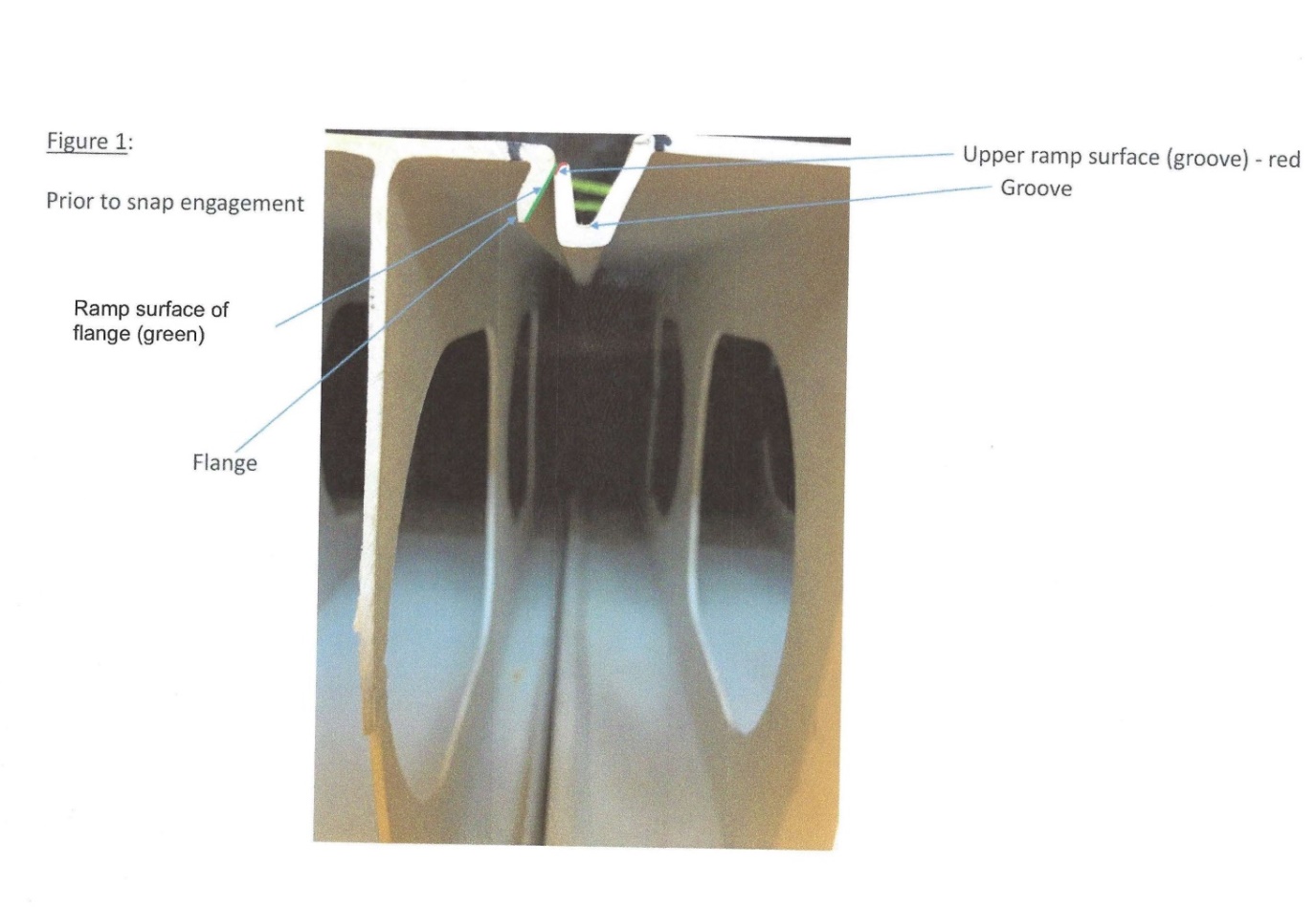
Figure 2
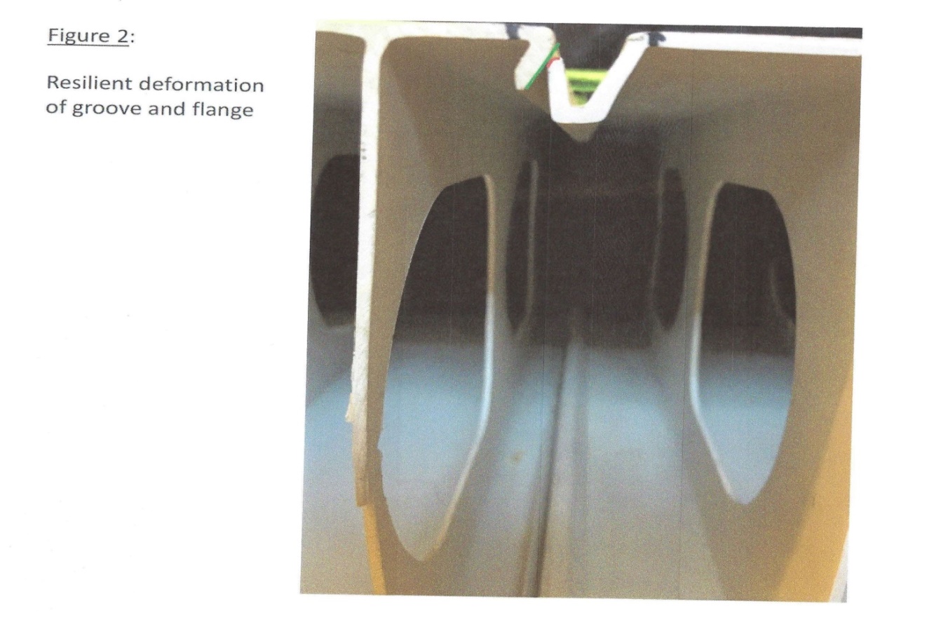
Figure 3
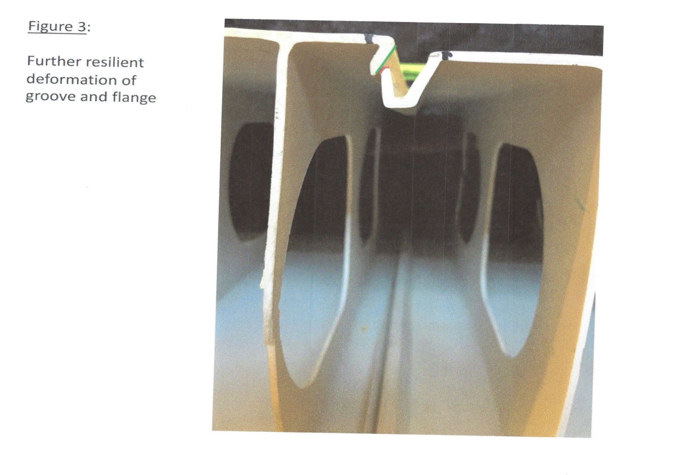
Figure 4
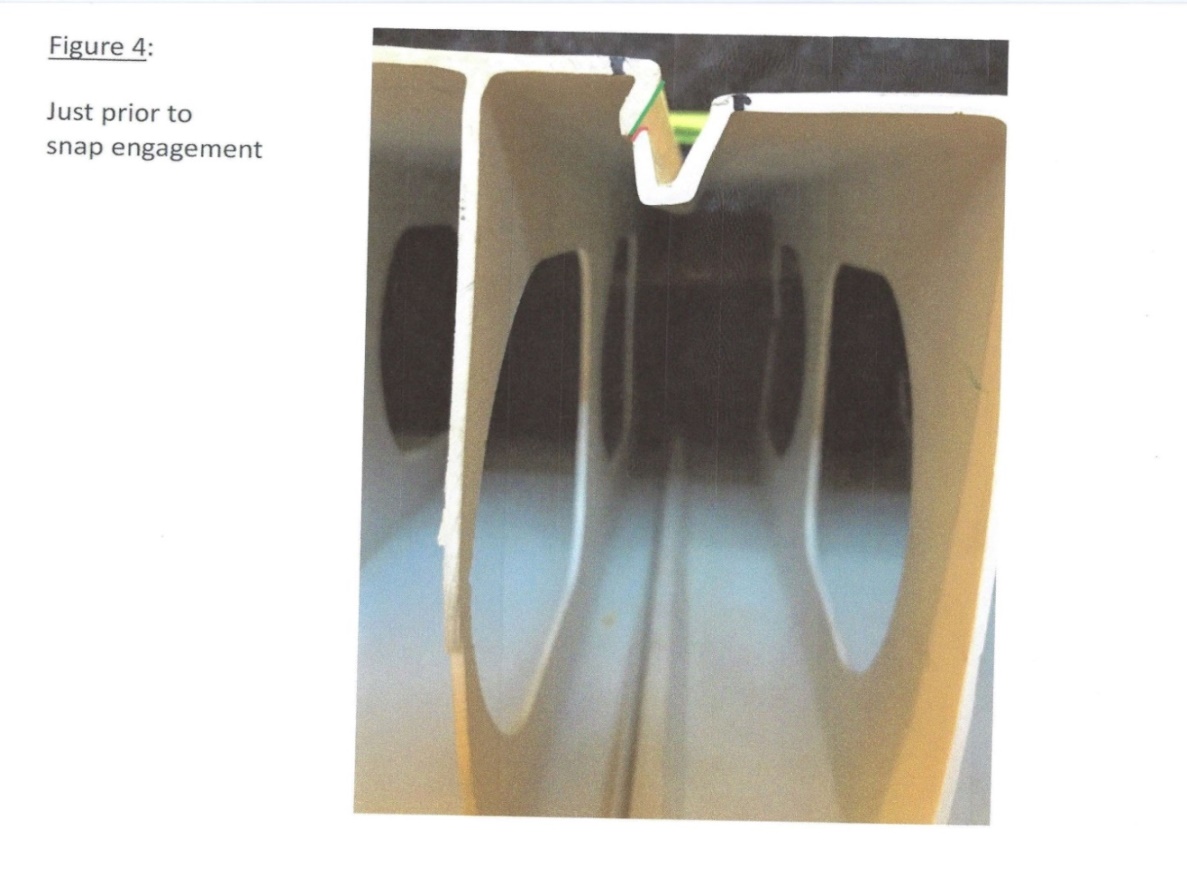
Figure 5
Schedule B
Figure 1
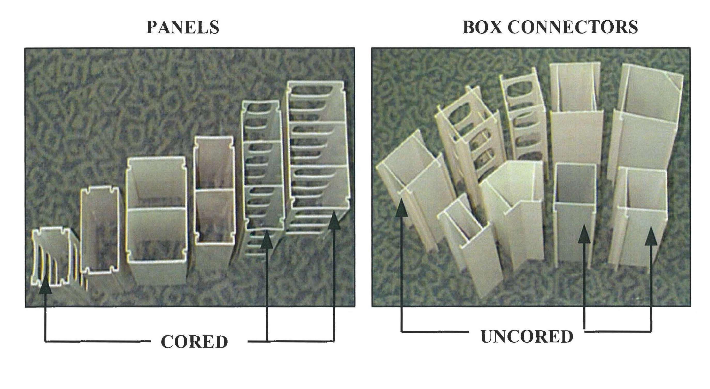
Figure 2
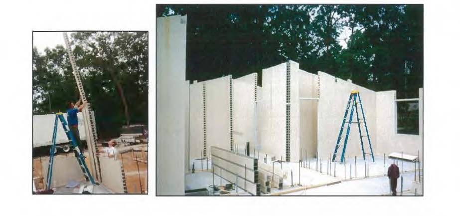
Figure 3
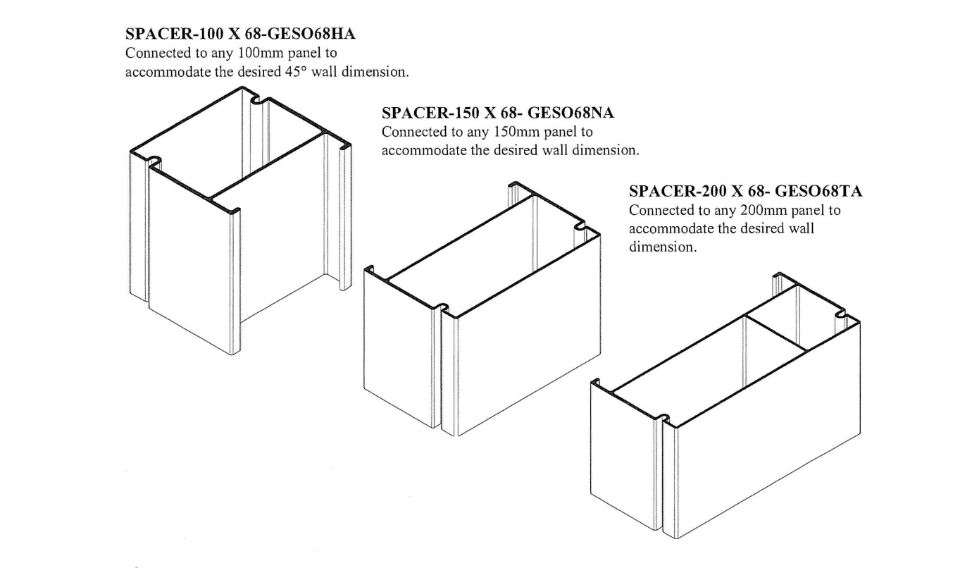
Figure 4