FEDERAL COURT OF AUSTRALIA
CQMS Pty Ltd v Bradken Resources Pty Limited [2016] FCA 847
ORDERS
DATE OF ORDER: |
THE COURT ORDERS THAT:
1. the matter be stood over for the parties to consult as to the form of final orders.
Note: Entry of orders is dealt with in Rule 39.32 of the Federal Court Rules 2011.
DOWSETT J:
THE APPLICANTS AND THE PATENTS
1 The first applicant (CQMS) holds Australian Standard Patent number 2008234400 (the “400 Patent”) and Australian Innovation Patent number 2013100615 (the “Innovation Patent”). According to the evidence of Mr Douglas Leslie Wallis, CQMS is an “intellectual property holding company”. It has licenced the second applicant (“CQMS Razer”) to use its intellectual property, including the two patents. CQMS Razer is an Australia-based company, engaged in the business of designing, manufacturing and supplying metal parts and components, including wear assemblies and ground engaging tools for mining and construction applications. A ground engaging tool (“GET”) is a part which is attached to the lip of an excavator bucket such as a dragline bucket. GETs engage with, and break up the ground. As a result the GETs suffer considerable wear. They are, in that respect, sacrificial in that they prevent the buckets from suffering wear. The GETs are replaced regularly, sometimes as frequently as every 24 hours. There is evidence concerning the meaning of the term “ground engaging tool”. However that evidence did not come from a person skilled in the art. In any event, the matter seems not to be in dispute.
THE RESPONDENTS
2 Mr Wallis asserts that there are, in Australia, three major competitors in the GET market. They are CQMS Razer, ESCO Corporation (“Esco”) and the respondents (respectively “Bradken Resources” and “Bradken Ltd”). Bradken Ltd is the ultimate holding company of Bradken Resources. Bradken Resources operates a business which designs, manufactures and supplies metal parts and components, including wear assemblies and GETs for mining and construction applications. Bradken Ltd operates businesses throughout Australia, Europe, the United Kingdom, North America and China, providing consumable parts, capital equipment and associated maintenance and refurbishment services to the mining sector and other industries.
ALLEGED INFRINGEMENT
3 In paras 7-48 of the second further amended statement of claim (the “statement of claim”) the applicants plead that the respondents have infringed both patents by the supply of identified products, together with other associated conduct. The respondents deny infringement. They also cross-claim for declarations as to invalidity and for revocation and other relief, asserting that:
the claims of the 400 Patent lack fair basis and clarity; and
the claims of the Innovation Patent lack support, sufficiency and clarity.
The respondents also cross-claim, alleging unjustified threats and seeking declaratory and injunctive relief, and damages.
THE SPECIFICATIONS AND THE CLAIMS
4 The patents differ in their claims but the specifications are effectively the same. Both are entitled “Mounting of Wear Members”. Concerning the field of each invention it is said that:
This invention is concerned with improvements in mounting of wear members to earth excavating devices.
The invention is concerned particularly, although not exclusively, with the mounting of excavator teeth adaptors to adaptor noses on an excavating device such as an excavator bucket or the like.
5 At p 1, ll 10-16, each specification recites that:
Excavator tooth assemblies mounted to the digging edge of excavator buckets and the like generally comprise a replaceable digging point, an adaptor body and an adaptor nose which is secured by welding or the like to the digging edge of a bucket or the like. The adaptor has a socket-like recess at its rear end to receivably locate a front spigot portion of the adaptor nose and a removable locking pin extends through aligned apertures in the adaptor and nose to retain the adaptor in position.
6 It seems to be accepted that the adaptor may be a discrete part, separate from the excavator tooth and the wear member, or it may be part of the wear member. In either case the wear member is often described as a “point”.
7 As excavator teeth are subjected to extensive load forces operating in various directions, there must be a snug fit between the “digging point” and the “front portion of the adaptor”, and between “the adaptor socket and the nose spigot portion”. The mounting pins must also fit snugly into their appropriate apertures to avoid premature wear of the components. As the components wear, the locking pins can loosen, thereby increasing the risk of loss of a digging point or an entire adaptor tooth combination. Replacement of these parts can be a lengthy process, possibly disrupting production. The greatest loads experienced by excavator tooth assemblies are vertical loads. Such loads may generate forces capable of rotating a tooth off the front of an adaptor, and/or rotating the adaptor off the adaptor nose.
8 Both specifications identify various existing arrangements for dealing with these problems. Concerning such arrangements, the specifications state at p 7, ll 5-12:
While generally satisfactory for their intended purpose, the abovementioned prior art nose/adaptor (or nose/tooth equivalent) combinations all suffer from one or more shortcomings or disadvantages in terms of inadequate resistance to rotation of an adaptor off a nose under the influence of vertical loads applying a rotational moment to the adaptor, a pre-disposition to premature wear, difficulties in retention of the adaptors on noses, inadequate locking systems and unduly complicated configurations, giving rise to increased fabrication costs.
9 The specifications then state that an aim of the relevant invention is to, “overcome or alleviate at least some of the abovementioned prior art disadvantages or otherwise to provide consumers with a convenient choice”. The specifications identify three embodiments of the invention. The first embodiment is a product, namely an “excavator tooth assembly” including a mounting nose, a wear member (in this case a combined adaptor and wear member) and a retaining pin assembly. The second embodiment is also a product, namely a “retaining pin assembly for an excavator tooth assembly”. The third embodiment is a method of, “removably securing a wear member to a projecting mounting nose of a digging edge of an excavator”.
10 There are seven figures included in each specification. Figures 1 and 2 relate to the first embodiment. Figures 3, 4, 5, 6 and 7 relate to the second embodiment. As I have said the third embodiment is a method claim. To some extent all of the drawings relate to that embodiment.
11 The claims in the 400 Patent are as follows:
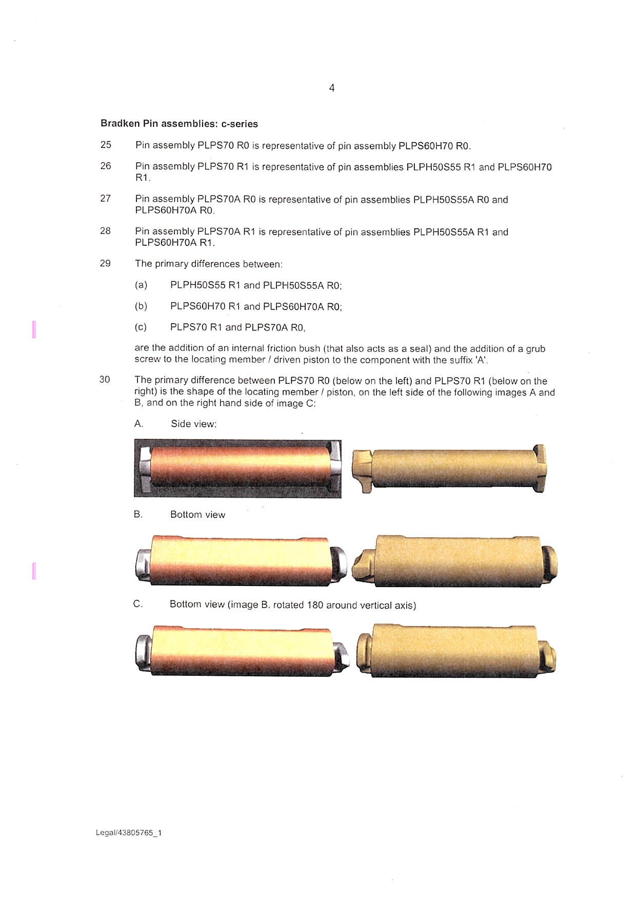
1. An excavator tooth assembly comprising:
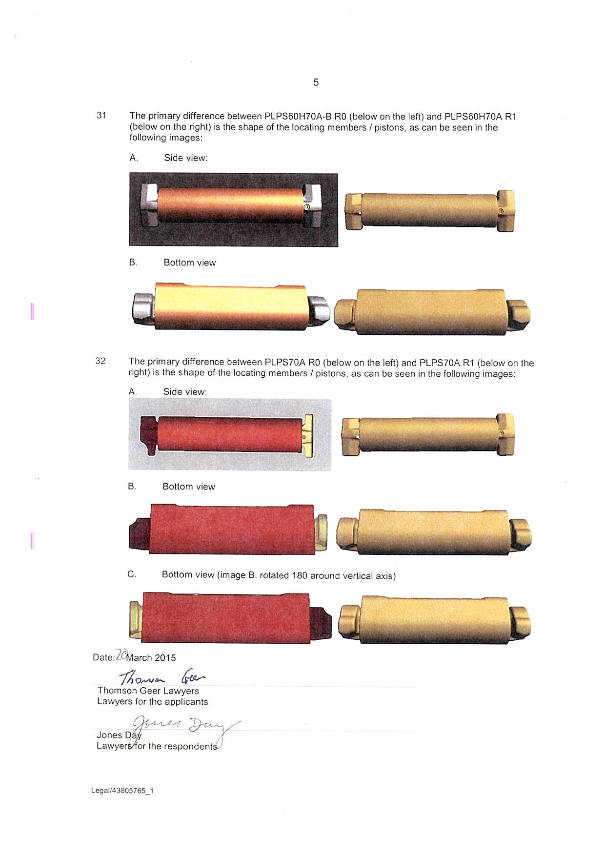
a mounting nose projectable from a digging edge of an excavator, said mounting nose including a mounting aperture extending laterally of said nose between opposite side walls thereof, said mounting aperture having a non-circular cross-section;
a wear member having a longitudinal axis, a forward end and a rearwardly opening socket for receiving said mounting nose, said wear member including opposed wall apertures communicating with a hollow interior of said socket, said opposed wall apertures, in use, being at least partially alignable with said mounting aperture; and
a retaining pin assembly, in use, non-rotatably located in said mounting aperture, said retaining pin assembly including a body member being configured to be non-rotatably located within the mounting aperture of said mounting nose prior to said wear member being mounted upon said mounting nose, locating members insertable via respective opposed wall apertures for slidable location in said mounting aperture relative to said body member, said locating members being retainable in said assembly by a tensionable retaining member extending between said locating members whereby an enlarged free end of each locating member is engagable with a wall of a respective opposed wall aperture.
2. The excavator tooth assembly of claim 1, wherein said mounting aperture has a generally oval shaped cross section.
3. The excavator tooth assembly of claim 1, wherein said mounting aperture has a generally tear drop shaped cross section.
4. The excavator tooth assembly according to any one of the preceding claims, wherein said opposed wall apertures have a generally oval shaped cross section.
5. The excavator tooth assembly according to any one of the preceding claims, wherein a longitudinal dimension of said opposed wall apertures is greater than a longitudinal dimension of said mounting aperture.
6. The excavator tooth assembly according to any one of the preceding claims, wherein at least a portion of a wall of at least one of said opposed wall apertures has an inwardly convergent tapered portion.
7. The excavator tooth assembly according to any one of the preceding claims, wherein said body member has a body aperture extending longitudinally thereof and is adapted to receive said tensionable retaining member.
8. The excavator tooth assembly according to any one of the preceding claims, wherein said enlarged free end of each said locating member is formed from an inwardly convergent wedge portion each adapted to abut and engage said wall of said respective opposed wall aperture.
9. The excavator tooth assembly according to any one of the preceding claims, wherein said tensionable retaining member comprises a screw threaded fastener, one of said locating members having a slotted aperture adapted to captively retain said screw threaded fastener therein.
10. A retaining pin assembly for an excavator tooth assembly, said retaining pin assembly comprising:
a body member being configured to be non-rotatably located within a transversely extending mounting aperture of a mounting nose of an excavator prior to a wear member being mounted upon said mounting nose;
opposable locating members each comprising a shank portion, in use, slidably insertable via a respective retaining pin aperture on opposite sides of the wear member into the transversely extending mounting aperture of the mounting nose, said locating members each having an enlarged inwardly convergent tapered wedge portion adjacent a normally outer end of a respective locating member; and
a tensionable retaining member extending between said opposable locating members from one side of said retaining pin assembly whereby, in use, tension applied to said retaining member causes relative contraction of said locating members to urge said wear member into engagement with said mounting nose by wedging engagement between each said wedge portion and a rear wall of respective retaining pin apertures.
11. The retaining pin assembly of claim 10, wherein each said shank portion and said transversely extending mounting aperture are of a non-circular cross sectional shape.
12. The retaining pin assembly of claim 10 or claim 11, further including a body member located intermediate of said locating members.
13. The retaining pin assembly of claim 12, wherein said body member comprises an aperture extending longitudinally thereof adapted to receive said tensionable retaining member.
14. The retaining pin assembly of claim 12, wherein said body member and said mounting aperture are of complimentary non-circular cross sectional shape.
15. The retaining pin assembly of claim 12, wherein said body member comprises a longitudinally extending body aperture adapted to slidably receive in opposite ends thereof a respective shank portion of said locating members.
16. The retaining pin assembly of claim 12, wherein said body aperture comprises a centrally located abutment.
17. The retaining pin assembly of any one of claims 10 to 16, wherein said tensionable retaining member comprises a screw threaded fastener.
18. The retaining pin assembly of claim 17, wherein one of said locating members has a slotted aperture adapted to captively retain said screw threaded fastener therein.
19. The retaining pin assembly of claim 17, wherein a driver engagable head of said screw threaded fastener is accessible via a longitudinally extending bore extending at least partially between opposed longitudinal ends of one of said locating members.
20. A method of removably securing a wear member to a projecting mounting nose of a digging edge of an excavator, said method including the steps of:
inserting a body member within a mounting aperture of said mounting nose prior to said wear member being located upon said mounting nose;
locating on said mounting nose, the wear member having opposed wall apertures at least partially alignable with the mounting aperture of said mounting nose;
inserting through one said opposed wall aperture, a locating member having a screw-threaded aperture at an inner end and an enlarged outer end thereof;
inserting through an opposite opposed wall aperture, a further locating member having a screw-threaded fastener located therein, a threaded end of said screw-threaded fastener extending beyond an inner end of said further locating member, a drivable head of said screw-threaded fastener being accessible via a bore extending through an enlarged outer end of said further locating member; and
coupling said screw-threaded fastener with said screw-threaded aperture of said one locating member whereby tensioning of said screw-threaded member causes relative contraction between said one locating member and said further locating member to prevent disengagement of said wear member.
21. The method of claim 20, wherein said enlarged outer end of each said locating member includes an inwardly convergent tapered portion which engages against a respective wall of said opposed wall apertures in said wear member to urge said wear member into engagement with said nose when said screw threaded fastener is tensioned.
22. The method of claim 21, wherein said opposed wall apertures include a complementary tapered portion to abut and engage with a respective tapered portion of a said locating member to urge said wear member into engagement with said nose when said screw threaded fastener is tensioned.
12 The Innovation Patent claims are as follows:
1. An excavator tooth assembly comprising:
a mounting nose projectable from a digging edge of an excavator, said mounting nose including a mounting aperture extending laterally of said nose between opposite side walls thereof, said mounting aperture having a non-circular cross-section;
a wear member having a longitudinal axis, a forward end and a rearwardly opening socket for receiving said mounting nose, said wear member including opposed wall apertures communicating with a hollow interior of said socket, said opposed wall apertures, in use, being at least partially alignable with said mounting aperture; the wear member also including a hoist loop for locating said rearwardly opening socket onto said mounting nose and,
a retaining pin assembly, in use, non-rotatably located in said mounting aperture, said retaining pin assembly including a body member being configured to be non-rotatably located within the mounting aperture of said mounting nose prior to said wear member being mounted upon said mounting nose, locating members insertable via respective opposed wall apertures for slidable location in said mounting aperture relative to said body member, said locating members being retainable in said assembly by a tensionable retaining member extending between said locating members whereby an enlarged free end of each locating member is engagable with a wall of a respective opposed wall aperture.
2. The excavator tooth assembly according to claim 1 wherein at least a portion of a wall of at least one of said opposed wall apertures has an inwardly convergent tapered portion and wherein said enlarged free end of each said locating member is formed from an inwardly convergent wedge portion each adapted to abut and engage said wall of said respective opposed wall aperture.
3. A retaining pin assembly for an excavator tooth assembly, said retaining pin assembly comprising:
a body member being configured to be non-rotatably located within a transversely extending mounting aperture of a mounting nose of an excavator prior to a wear member being mounted upon said mounting nose;
opposable locating members each comprising a shank portion, in use, slidably insertable via a respective retaining pin aperture on opposite sides of the wear member into the transversely extending mounting aperture of the mounting nose, said locating members each having an enlarged inwardly convergent tapered wedge portion adjacent a normally outer end of a respective locating member; and
a tensionable retaining member adapted to be rotated, said retaining member extending between said opposable locating members from one side of said retaining pin assembly whereby, in use, tension applied to said retaining member by rotation of the retaining member causes relative contraction of said locating members to urge said wear member into engagement with said mounting nose by wedging engagement between each said wedge portion and a rear wall of respective retaining pin apertures.
4. The retaining pin assembly of claim 3 further including a body member located intermediate of said locating members, wherein said body member comprises a longitudinally extending body aperture adapted to receive in opposite ends thereof a respective shank portion of said locating members.
5. A method of removably securing a wear member to a projecting mounting nose of a digging edge of an excavator, said method including the steps of:
inserting a body member within a mounting aperture of said mounting nose prior to said wear member being located upon said mounting nose;
lifting the wear member onto on said mounting nose using a lifting hoist located on the wear member, the wear member having opposed wall apertures at least partially alignable with the mounting aperture of said mounting nose;
placing within one said opposed wall aperture, a locating member having an aperture at an inner end and an enlarged outer end thereof;
placing within an opposite opposed wall aperture, a further locating member having a fastener located therein, an end of said fastener extending beyond an inner end of said further locating member, a drivable head of said fastener being accessible via a bore extending through an enlarged outer end of said further locating member; and,
coupling said fastener with said aperture of said one locating member whereby tensioning of said fastener causes relative contraction between said one locating member and said further locating member to cause an inwardly convergent tapered portion of said enlarged outer end of each of said locating members to engage against a respective wall of said opposed wall apertures in said wear member to urge said wear member into engagement with said nose to prevent disengagement of said wear member.
the skilled addressee
13 At the trial there was some confusion concerning the status of one of the applicants’ witnesses, Professor Wightley. Until quite late in the trial, the respondents understood him to be advanced as a skilled addressee. It is now clear that the applicants do not assert that he is a skilled addressee, at least for present purposes. Hence it is common ground that he cannot give evidence as to the skilled addressee’s understanding of the patents. However the applicants submit that he may give expert evidence as an experienced mechanical engineer. In particular, the applicants submit that Professor Wightley may give evidence identifying the various integers of the claims as they appear in the allegedly infringing products. The respondents objected to his giving such evidence upon the basis that it would be infected by his assumptions as to the proper construction of the patents. In the end I received his evidence for the sole purpose of presenting CQMS’s case on infringement. In other words, his evidence is, in effect, by way of submission rather than evidence. In these circumstances I should say something about Professor Wightley’s relevant expertize.
14 Professor Wightley has practised as an engineer for over 43 years. His work has included mechanical and structural design in the manufacturing industry, mining engineering and mine planning and operations. He holds the degrees of Bachelor of Engineering and Master of Engineering and a Post-Graduate Diploma in Business Administration. He is a Fellow of the Institution of Engineers and an active member of its national committee on engineering design. Most of his experience in the mining area has involved the design and manufacture of fixed and mobile machinery for mining facilities, including stackers, reclaimers, bucket wheel excavators, ship loaders, slurry pumps, cyclones and separators. In the course of his work in the mining industry, he has become familiar with wear assemblies for buckets. Over the years he has examined such assemblies when installed on buckets, as well as before their installation and after their removal, both in pits and in mine workshops. He has not had occasion to design such wear parts or assemblies although, in the 1990s, he examined Bradken components and suggested possible modification. He has been responsible for the development of new designs and materials in mining slurry pumps, valves and cyclones.
15 The applicants read two affidavits by Professor Wightley, one filed on 3 September 2014 and the other filed on 19 January 2015. Only very limited (and probably unimportant) parts of the second affidavit were received into evidence. They also read an affidavit by Douglas Leslie Wallis filed on 4 July 2014. Mr Wallis’s affidavit is relatively uncontroversial. Early in the trial I received a schedule in which were set out the parts of the applicants’ affidavits which had been read, any agreed limitations upon the use of the contents of such affidavits and points upon which rulings were required. The schedule became exhibit 2. However events at the trial made much of its content incorrect or irrelevant. It was withdrawn and replaced by the present exhibit 2. At a later stage I concluded that it should again be made an exhibit. It is now exhibit 2A.
16 Exhibit 2A was the product of pre-trial negotiations. Although it is not entirely clear, the applicants seem to have been concerned to avoid the possibility that expert witnesses, perhaps as skilled addressees, would usurp the Court’s role in construing the patents. Hence, the introductory paragraph of exhibit 2A states:
Where the parties have agreed to a limitation under s 136 of the Evidence Act 1995, this does not prevent a submission from either party that the witness’ understanding is in turn probative of how a person armed with common general knowledge would construe what is disclosed and claimed, and hence determine whether the products in suit possess the claimed features.
17 Throughout the document there are various statements which indicate that certain evidence was to be admitted only as demonstrating the relevant witness’s understanding of certain matters, generally questions of construction, identification of integers in the allegedly infringing products or the prior art. My overall impression is that there was to be an argument as to whether any of this evidence could be used to establish the skilled addressee’s understanding of the patents or views as to the prior art.
18 I was asked to make an order in accordance with s 136 of the Evidence Act 1995 (Cth) (the “Evidence Act”). In trying to explain the purpose of the proposed reliance on s 136 counsel for the applicants said at ts 63, ll 14-34:
Each of the witnesses – the expert witnesses – has given evidence in relation to the patents, sometimes identifying, insofar as they read them, the meaning – what is disclosed in the patents and the meaning that each of the witnesses gives to the patent, including, in some cases, the meaning of the claims.
That, of course, is a matter for your Honour – and insofar as sometimes the witnesses, in identifying whether or not a feature or features are present in the respondent’s product, expose their reasoning by reference to their understanding of the patent. Now, of course, what the meaning of the patent is a matter for your Honour, and insofar as the witness – the witness’ view diverges from that of your Honour it’s – it doesn’t matter; it’s not determinative or dispositive.
Rather than going through each of the – those parts and excising from the material that which might properly be inadmissible, the parties propose a limitation under section 136 of the Evidence Act, that it be limited to the witness’ own understanding of what is disclosed and claimed of the patent and whether or not the – those features are present in prior art, as a convenient way forward. And then the witnesses will be cross-examined, no doubt, and your Honour will have the benefit of seeing the witnesses in the cross-examination give their explanations. And then, ultimately, it will be a matter for final address.
19 The applicants appear to have assumed that the respondents would call expert evidence. They did not do so. The applicants also seem to have considered that the expert witnesses could not properly give evidence concerning construction of the patents, but would assume particular constructions in order to give evidence as to alleged infringement. It seems that the statement concerning s 136 was designed to reserve the rights of the parties to submit that the evidence in question, might or might not inform the Court’s understanding of the disclosures in the patents, its construction of the claims, assessment of the prior art and identification of any integers of the claims to be found in the allegedly infringing products. It may be that either the applicants, or the respondents, or both had doubts about the expertize of a witness or witnesses, or that there was a fundamental disagreement as to the role of expert evidence in patent litigation.
20 Junior counsel for the respondents said at ts 65, l 33 that the respondents’ witness, Mr Briscoe was a skilled addressee. In expanding upon that proposition he said at ts 65, ll 37-42:
So, your Honour, the – the idea is that each of the witnesses possesses more or less of the characteristic of – characteristics of the notional person skilled in the art. The extent to which they possess those characteristics is a matter for submission, but once the witness, having more or less of those characteristics, gives evidence of their understanding of the patent, then that is probative of how the notional person skilled in the art - - -
21 In the end, Mr Briscoe was not called. At ts 66, responding to a question from me, junior counsel for the applicants asserted that Professor Wightley was “a skilled addressee”, qualifying this by saying:
Whether or not he is the pure embodiment of the person skilled in the art in a – is a different submission will be a matter for address.
22 I doubt that any real purpose is to be served by distinguishing between the term “skilled addressee” and the term “person skilled in the art”. However it may be that counsel was seeking to distinguish between the notional skilled addressee and the witness or witnesses who might establish the relevant characteristics of such a person, his or her knowledge and his or her views and conclusions.
THE COURSE OF THE TRIAL
23 Professor Wightley was called and gave brief evidence-in-chief. He was then cross-examined for the better part of two days. Much of that cross-examination went to construction of the patents. Some of it, however, dealt with Professor Wightley’s views as to where the various integers of the claims could be located in the allegedly infringing products. In the course of preparing for trial, Professor Wightley had conferred with Mr Briscoe. Professor Wightley prepared a number of tables which, broadly speaking, summarized his views as to the presence or otherwise in the allegedly infringing products, of individual integers of the claims, with comments by Mr Briscoe and responses by Professor Wightley. As I have said, the respondents did not call Mr Briscoe, leaving Professor Wightley’s views, for what they might be worth, unchallenged by other evidence. At the end of the applicants’ case, counsel for the respondents tendered a patent (now exhibit 5), a bundle of amended pleadings (exhibit 6), a bundle of correspondence (exhibit 7), a further bundle of documents (exhibit 8) and a paragraph from Mr Briscoe’s report (exhibit 9). Counsel for the applicants then tendered exhibit 10 (an agreed statement of facts), exhibits 11, 12 and 13 (being pp B738-B740, B763-B769 and B808-B811 from the Court book) and exhibit 14 containing the applicants’ amended pleadings.
24 Relatively early on the fourth day of the trial, senior counsel for the applicants commenced his address, continuing until late on that day. In the course of his submissions counsel said at ts 248, ll 7-20:
Now, your Honour, what we have in this case is a situation where there is no technical terms or, indeed, words otherwise in general usage but which, nevertheless, in this art have special meanings for the persons skill[ed] in the trade.
In other words, this is not a case where your Honour’s construction of the patent depends upon what any other – what any witness tells you as to meaning. The whole of the patent is comprised entirely of the – of terms which are matters of ordinary language. The second thing to note in this case is that neither party has adduced evidence from a witness who purports to give expert testimony as to how the – to the effect that a person skilled in the art would be armed with any particular body of common general knowledge, or any person, whether expert or otherwise, who comes to the court and says that they read the patent in a particular way, or the claims of the patent in a particular way, as a person skilled in the art, that is, as a relevant addressee.
25 Counsel then said, concerning Professor Wightley:
Mr Wightley gave some evidence – well, gave evidence in the proceedings and is the only person who gave evidence orally before your Honour.
When your Honour looks at his affidavit in chief, your Honour will see that what he did was, as a mechanical engineer but not a person immersed in the field of excavator tooth assemblies or wear parts, identify for your Honour what he understood the integers of the claims, and the claims, to mean, for the purpose of laying bare the basis upon which he identified that particular products of the respondents exhibited all of the integers of the claims in suit. And we understand that the time taken in cross-examination of our – of Mr Wightley was to the – directed to the purpose of demonstrating that he was not a person skilled in the art, so that one couldn’t treat him as a person emblematic or representative of one of those number of persons from whom one has to construct the relevant hypothetical person skilled in the art.
26 This proposition seems to have been a departure from the position advanced at ts 66, ll 18-20 in which junior counsel for the applicants asserted that Professor Wightley was “certainly a skilled addressee” ... if “not ... the pure embodiment of the person skilled in the art ...”. In the course of exchanges between counsel and me, counsel said at ts 249, ll 37-39:
Mr Wightley says, in his affidavit in chief, “I don’t see – there are no technical engineering or other terms in this affidavit. There are no terms with a special meaning in the trade.”
27 At ts 249, counsel continued at ll 14-24:
Yes. Well, your Honour, your Honour will recall the original exhibit 2, which was proffered to your Honour but which was left for further discussion between the parties, was put to your Honour, and the 136 objection in relation to how he read the patent was identified in the – in the exhibit. And – and what we said – what my friend Mr Bevan said to your Honour was the material in relation to which the 136 limitation was being applied, or would be applied, was that material in which he set out what he said the integer meant, and that it was put only because it was relevant to him saying, otherwise, that integer is present. In other words, it exposed his thinking. So – so we never put it otherwise. And as your Honour says, it’s – it’s not relevant as evidence, expert or otherwise, as to how a skilled addressee would read the patent.
28 At ts 249, ll 32-39 counsel said:
Yes. Well, yes. It was more to enable the applicant – the respondents, I’m sorry – and your Honour to have exposed his approach to the identification of the infringements. The – and – I was going to say something else to your Honour and I’ve just lost it. The – so that was – that was the basis on which it is advanced and we don’t – we haven’t put it on another basis. And, as Mr Wightley – this was the thing that slipped from my mind, is Mr Wightley says, in his affidavit in chief, “I don’t see – there are no technical engineering or other terms in this affidavit. There are no terms with a special meaning in the trade.”
29 At the end of the applicants’ submissions, senior counsel for the respondents said at ts 301, ll 1-41:
The relevance – the important part of construction that is raised in these proceedings, is what evidence is required, and what evidence is admissible in relation to the meaning of the patent. We were taken aback by the suggestion by our friend this morning in the transcript that Mr Wightley had never been advanced as an expert. At page 248, this morning my learned friend said:
Neither party has adduced evidence from a witness who purports to give expert testimony as to how – as to the effect that as a person skilled in the art would be armed with a particular body of common general knowledge, or any person, whether expert or otherwise, who comes to the court and says that they read in a particular way, or the claims of the patent in a particular as a person skilled in the art.
Now, that’s just false. Your Honour will recall that there was a hearing before this court on 25 July last year where we attacked the first affidavit of Mr Wightley and said it was completely inadequate that we didn’t know what was to happen, and your Honour said, “Well, you weren’t going to sit down and work out all the integers,” and my learned friend said at page 50:
No, I am – I know, your Honour, but it’s important your Honour understands what the – what your Honour – when your Honour comes to my friend’s reasoning point it’s important to understand what is being done in this affidavit. So what we say is that when his Honour – what Mr Wightley’s affidavit does is give your Honour some evidence as to what a person skilled in the art gets from the construction of the claims and whether the claims, as a matter of ordinary English language, are found to be infringed on their proper instruction.
So we have taken each of the affidavits of Mr Wightley as being put to this court on the basis that they constitute evidence from a person skilled in the art. When we say our friend’s written opening we continued to have that understanding because at paragraph 31 of the outline of our friend’s opening submissions on infringement filed – I don’t know when. It’s a bit hard to tell. They were dated 31 March. At paragraph 31 our friend said:
The parties’ respective positions emerged from the affidavits of Professor Allan Wightley for CQMS and Mr Terry Briscoe for Bradken to the extent that both experts give opinions about matters that are properly for the court, such as claim construction, the parties agree that there will be some limitation, but we always understood that Mr Wightley’s evidence was being adduced as that of an expert.
At ts 302, ll 5-14 counsel said:
Now, the only way in which we didn’t, at the outset, object to Professor Wightley’s affidavit in whole is that it purported to be an affidavit from an expert giving expert evidence. Now, we note in our outline at paragraph ..... A5 starting on page 6 the relevance of expert evidence. The words used, of course, in a specification are to be given the meaning the hypothetical addressee would attach to them, both in the light of the addressee’s own general knowledge and the light of what is disclosed in the body of the specification and those – that’s language that comes from Lockhart J’s reasons in Décor. So as long ago as 13 IPR 385 at 391. It’s not controversial, and it can’t be now, that the hypothetical addressee of the specification is the non-inventive person skilled in the art before the priority date.
30 Much of the respondents’ concerns may have related to potential orders as to costs. Nonetheless, it is clear that neither side now submits that any aspect of either patent is to be construed by reference to the expert understanding of a skilled addressee. Each patent is to be construed as a whole, but upon the basis that the words have their ordinary meanings. In those circumstances, I need not identify the skilled addressee. As to the applicants’ submission that Professor Wightley may give expert evidence as a mechanical engineer, the question is as to relevance. If the patents are to be construed upon the basis outlined above, then any relevant question as to the identification of integers of the claims in the allegedly infringing products must surely be similarly addressed.
31 It may be that Professor Wightley’s experience has assisted him in identifying the presence of such integers, but in the end, I must decide whether a particular integer is present, having regard to my construction of the patent in question, unaided by any relevant expert evidence (there being none). I accept that Professor Wightley may indicate the particular features of the infringing products which may be integers of a claim. However such evidence will be a submission, not expert evidence. I understand the parties to have more or less accepted this position. In any event, I doubt whether much hangs upon it.
principles of claim construction
32 The applicants point to the following principles (which must now be understood in light of the fact that there is no relevant expert evidence as to common general knowledge or as to the understanding of a skilled addressee):
The specification is not to be read in the abstract. It must be construed in light of the common knowledge in the art before the priority date.
The claims define the invention which is the subject of the patent. They must be construed according to their terms upon ordinary principles. Any purely verbal or grammatical question that can be answered according to ordinary rules for the construction of written documents is to be resolved accordingly.
Construction of claims is a matter for the Court, not for any witness, however expert.
In construing a claim the Court should disregard the allegedly infringing article. One does not construe a patent claim with an eye to the alleged infringement.
Whilst the claims are to be construed in the context of the specification as a whole, it is not legitimate to narrow or expand the boundaries of the monopoly as fixed by the words of a claim, by adding to those words, glosses drawn from other parts of the specification. Terms in the claim which are unclear may be defined or clarified by reference to the body of the specification.
The claims may equate with, or be less than the totality of the invention.
The body of the specification cannot be used to change a clear claim for one subject matter into a claim for another, and different subject matter.
It is not correct to import claim features of a preferred embodiment that are not expressly referred to in the claim.
It is not permissible to import into an independent claim a feature that is included in another independent claim of the same specification.
Where possible different claims in the same patent are construed in such a way that their scopes are different. A dependent claim will normally be assumed to be narrower in scope than the claim or claims on which it depends. In this way the claims proceed in familiar fashion with the progressive narrowing of the invention claimed.
33 The respondents make the following points concerning the principles of construction:
When claims are being construed, the words used in the claim are to be given the meaning which a person skilled in the art would attach to them, having regard to his or her own general knowledge, and to contextual disclosures in the body of the specification which, together with the claim, must be read as a whole. The specification must be read as a whole in order that the necessary background to the invention may be known and words or expressions used in the claim may be understood.
A patent specification should be given a purposive construction rather than a purely literal one.
In construing a claim the Court should disregard the alleged infringing article. One does not construe a patent claim with an eye to the alleged infringement.
34 The respondents submit that:
In the absence of any admissible expert evidence as to how the specification and claims are to be construed by a skilled addressee, the Court is left in a position where it is unable to construe the specification and claims in the manner required. In such cases, it follows that the applicant asserting a claim of infringement will be unable to discharge its onus of demonstrating that the alleged infringing product has each and every integer of the claims, properly construed through the eyes of the skilled addressee.
35 In support of this proposition the respondents refer to the decision of Gummow J in Yamazaki Mazak Corporation v Interact Machine Tools (NSW) Pty Limited (1991) 22 IPR 79 at 89. However that case was concerned with drawings of the allegedly infringing product, and not with construction of the claims in light of the specification. Similarly, none of the cases cited by Gummow J involved construction of the patent. In C Van Der Lely NV v Bamfords Limited (1963) 80 RPC 61 at 71, the Court was concerned with anticipation. Nicaro Holdings Pty Ltd v Martin Engineering Co (1990) 91 ALR 513 at 542 was also a case of anticipation. The decision in Vax Appliances Limited v Hoover plc [1991] FSR 307 was concerned with prior use. Those cases addressed the adequacy of evidence going to particular issues in the case, the point being that mere drawings may not be sufficient to satisfy the relevant standard of proof. They were not concerned with questions of construction. In the present case the Court must perform the construction exercise. In many, perhaps most cases, evidence from skilled addressees is of assistance. However, in the absence of any such evidence, the Court must construe the claims in the light of the body of the specification. In that context the words must be given their usual meanings.
36 I turn to the questions of construction.
CONSTRUCTION
37 Prior to the trial, the parties had agreed that the construction issues were:
The 400 Patent
Claim 1
1. Meaning of the term “aperture”.
2. Meaning of the term “insertable via respective opposed wall apertures for slidable location in said mounting aperture relative to said body member”.
3. Meaning of the term “body member”.
4. Whether the components of the “retaining pin assembly” are required to be adapted to be installed as separate components.
Claim 2
5. Meaning of the term “generally oval shaped cross section”.
Claim 5
6. Meaning of the term “longitudinal dimension of said opposed wall apertures”.
7. Meaning of the term “longitudinal dimension of said mounting aperture”.
Claim 7
8. Meaning of the term “said body member has a body aperture ... adapted to receive said tensionable retaining member”.
Claim 8
9. Meaning of the term “enlarged free end of each ... locating member is formed from an inwardly convergent wedge portion”.
Claim 10
10. Each of issues 1, 3 and 4 (inclusive).
11. Meaning of the term “opposable locating members ... slidably insertable via a respective retaining pin aperture on opposite sides of the wear member into the transversely extending mounting aperture ... a tensionable retaining member extending between said opposable locating members”.
12. Meaning of the term “said locating members each having an enlarged inwardly convergent tapered wedge portion adjacent a normally outer end of a respective locating member”.
13. Meaning of the term “a tensionable retaining member extending between said opposable locating members from one side of said retaining pin assembly whereby, in use, tension applied to said retaining member causes relative contraction of said locating members”.
Claims 12, 13, 14 and 15
14. Whether claim 12 is in respect of an attribute of the “body member” of claim 10 or whether it provides for the inclusion of a second “body member”' in the “retaining pin assembly” of the claim.
15. Whether, consequently, claims 13, 14 and 15 are in respect of an attribute of the “body member” of claim 10 or whether they are in respect of a second “body member”'.
Claim 13
16. Issue 8.
Claim 15
17. Meaning of the term “adapted to slidably receive in opposite ends thereof a respective shank portion”.
Claim 17
18. Meaning of the term “screw-threaded fastener”.
Claims 20, 21 and 22
19. Whether the method requires that each step of the 5 steps of the method be performed as a separate step using a single component in the order set out in claim 20.
20. Meaning of the term “coupling said screw-threaded fastener with said screw-threaded aperture”.
The Innovation Patent
Claim 1
21. Issues 1-4 (inclusive).
Claim 2
22. Issue 9.
Claim 3
23. Issues 1, 3, 4, 11 and 12.
Claim 4
24. Issue 14 modified to read on claim 4.
25. Meaning of the term “adapted to receive in opposite ends thereof a respective shank portion of said locating members”.
Claim 5
26. Issue 19 modified to read on claim 5.
27. Meaning of the term “fastener”.
28. Meaning of the term “placing within” and whether it requires the “locating members” to be thus placed as individual components.
29. Meaning of the term “coupling said fastener with said aperture”.
Many of these issues are related. Some have fallen away in the course of the trial.
The parties’ submissions concerning construction of the 400 Patent
38 At para 84 of their outline, the applicants submit:
The combination of claim 1 is one in which:
(a) a mounting nose has a mounting aperture (opening) with a non-circular cross section that extends laterally of (i.e., across) the nose;
(b) a wear member has opposed wall apertures (openings) that communicate with a hollow interior of a rearwardly opening socket that receives the nose;
(c) the body member of the retaining pin assembly is configured to be non-rotatably located in the mounting aperture (opening) of the mounting nose before the wear member is mounted on the nose;
(d) the locating members of the retaining pin assembly are capable of insertion via (by way or by means of) the opposed wall apertures (openings) of the wear member so that:
(i) they may slide in the mounting aperture (opening) relative to the body member;
(ii) each of the enlarged free ends may engage with the corresponding (respective) wall of the opposed wall apertures (openings);
(e) a tensionable retaining member extends between the locating members and retains the locating members in the assembly;
(f) the opposed wall apertures (openings) in use are partially alignable with the mounting aperture (opening);
(g) the retaining pin assembly in use is non-rotatably located in the mounting aperture (opening).
39 However the real thrust of the applicants’ submission is at paras 87-92, particularly at paras 87 and 90. At para 87 the applicants submit that nothing in the patent warrants the confinement of the description of the retaining pin assembly to something assembled on site, to the exclusion of pre-assembled pin assemblies. At para 90, the applicants submit that claim 1 places no temporal or chronological limitation upon the point at which the locating members are inserted into the mounting aperture (and the body member).
40 It is important to note that terms such as “body aperture”, “locating members” and “tensionable retaining member” do not have fixed meanings apart from the context in which they appear. It will be necessary that I ascribe some meaning to such terms, having regard to their respective apparent purposes and functions in order that I can identify similar features in the allegedly infringing products.
41 The respondents submit that the locating members must be capable of insertion through the side wall apertures, and that they must also be able to slide into the mounting aperture during insertion. In other words, the locating members must be capable of sliding through the wall apertures and into the mounting aperture. They contrast this situation with the mere location of the locating members inside the mounting aperture, with ends protruding beyond the outer edge of each wall aperture, the latter situation having no regard to the way in which the locating members may have come to be so located.
42 The respondents also submit that because each locating member has an enlarged outer end, only one end of it may be located within the mounting aperture, with the enlarged end outside of, or only partially within such aperture. Further, each retaining member must be inserted through one of the wall apertures so that the enlarged end will be, at least partially, outside of the side wall of the wear member. Finally, they submit that the wear member must be on the mounting nose at the time at which the locating members are inserted. The respondents point out that in the body of the specification at p 8, ll 12-21, there is no reference to a body member. However such a feature is identified at p 13, ll 17-24 and in the drawings.
Claim 1
43 Claim 1 describes a mounting nose, a wear member and a retaining pin assembly. Each is described discretely, but they must work together. The descriptions of the mounting nose, mounting aperture, wall aperture and wear member are, at least superficially, quite simple, primarily describing physical features. However the wall apertures in the wear member must be at least partially alignable with the mounting aperture in the mounting nose, implying that those features may, in some circumstances, be completely aligned. The description of the retaining pin assembly is more complex. It describes the physical features of that assembly and its interaction with the mounting nose and the wear member. Those interactions involve:
the retaining pin assembly, in use, being non-rotatably located in the mounting aperture;
such assembly including a body member configured to be non-rotatably located in the mounting aperture prior to the mounting of the wear member on the mounting nose;
the locating members being insertable, via the respective opposed wall apertures, for slidable location in the mounting aperture relative to the body member; and
the said locating members being retainable in the assembly by a tensionable retaining member, extending between the locating members, an enlarged free end of each locating member being engagable with a wall of a respective opposed wall aperture.
44 Claim 1 is worded as a product claim, using words such as “alignable”, “configured to be non-rotatably located”, “insertable”, “slidable”, “retainable”, “tensionable” and “engagable”. In effect it describes design and capacity, leaving the method to be claimed separately in claims 20-22. Whatever the purpose of such an approach, the various integers of claim 1 must be construed having regard to their anticipated interaction. The repeated use of the expression “in use” highlights this consideration. The requirement that the wall apertures be, in use, at least partially alignable with the mounting aperture limits the design and location of both the wall apertures and the mounting aperture. It also says something about the way in which the wear member is to be installed on the mounting nose. Similarly, the requirement that the retaining pin assembly, in use, be “non-rotatably” located in the mounting aperture implies that its shape will be appropriate to achieve that capacity and implies its insertion into that location. Similar comments apply to the description of the body member and the requirement that it be located in the mounting aperture before the wear member is mounted on the mounting nose.
45 At ll 18-21 of claim 1, the locating members and the tensionable retaining member are identified and located, implying the need for assembly in a particular way. Finally, a particular physical characteristic of each locating member is identified: an enlarged free end of each locating member engagable with a wall of a respective opposed wall aperture. The purpose of this mechanism is not described in claim 1. However the purpose is, fairly obviously, to hold the wear member firmly on the mounting nose. As much appears from the specification at p 14, ll 19-24.
46 The applicants now identify three questions of construction arising in connection with claim 1. They are:
the meaning of the word “aperture”;
the meaning of the term “retaining pin assembly”; and
the meaning of the word “via”.
47 At paras 78-80 of their outline, the applicants submit that:
the word “aperture” should be given its ordinary English meaning;
the word is defined in the Shorter Oxford English Dictionary on Historical Principles (6th ed) (Oxford University Press, Oxford, 2007) at 96 as follows:
“An opening; a gap, a cleft, a hole”; and
the definition in the Macquarie Dictionary (6th ed) (The Macquarie Dictionary Publishers Pty Ltd, Macquarie University, 2013) at 63 is to similar effect:
“a hole, slit, crack, gap or other opening.”
48 I note that the Oxford English Dictionary (2nd ed) (Oxford University Press, Oxford, 1989) defines the word “aperture” as:
An opening, an open space between portions of solid matter; a gap, cleft, chasm or hole; the mouth of a mollusc.
49 The respondents submit that the word “aperture” should be understood as describing “a hole with a continuous perimeter”. They find support for this approach in the specification and in statements by Professor Wightley which are said to be “admissions”. Although Professor Wightley was retained as an expert by the applicants, there is no reason to believe that he had authority to make admissions in a forensic sense. Further, I have indicated the limited use to which his evidence may be put. The word must be given its ordinary meaning, having regard to the context in which it appears. The respondents also point out that the word “slot” is used elsewhere in the patent. However I gain little assistance from that consideration. Of more significance is the fact that the word “aperture” is used in describing at least two separate features, the mounting aperture and the wall apertures. Those features are not unrelated. The wall apertures must, in use, be at least partially alignable with the mounting aperture. In addition, the locating members must be able to pass through the wall apertures, on either side, and into the mounting aperture.
50 The dictionary definitions suggest that the word “aperture” has a wide variety of meanings. Many of the synonyms, themselves, have wide meanings. According to the Shorter Oxford English Dictionary, the word “gap” means a, “breach in a wall, fence, hedge etc caused by violence or natural decay … an opening or breach by which an entry, attack or escape may be effected … a notch, a small break or opening in an edge or surface”. The word “opening” means a, “vacant space between portions of solid matter; a gap, a passage; an aperture”. The word “cleft” means a, “space or division made by cleaving; a split, a fissure, a crack, a crevice”. The word “hole” means a, “hollow place, a cavity, an empty place or cavity in a solid body or in the ground, a pit, a cave, a deep place in a pond, stream, etc”. Hence, as far as dictionary definitions go, the meaning of the word “aperture” is not limited to a gap wholly surrounded by the feature in which it appears or, in the respondents’ language, having “a continuous perimeter”. In particular the words “notch” and “cleft” seem appropriate to describe a feature having a non-continuous perimeter. However the dictionary definitions must be considered in the context in which the word is used, and without regard to the allegedly infringing products.
51 The mounting aperture is three-dimensional and is to be non-circular in cross-section. The wear member is to have two wall apertures communicating with a hollow interior, which apertures are, “in use”, to be at least partially alignable with the mounting aperture. In my view, the expression “in use” and the word “mounted” are related. The Shorter Oxford English Dictionary defines “mount” as “[f]ix in position for a particular purpose; bring into readiness for operation”. In order that the various components be in use, they will have to be ready for operation or in actual operation. Each wall aperture is also three-dimensional, two dimensions being found in the surface of the wall in which it is located, and the third being the thickness of the material out of which the wall is made.
52 There appear to be two major points of dispute between the parties. The first concerns the cross-sectional shape and possibly, the location of each wall aperture. The second is the meaning of the requirement that the locating members be insertable via respective opposed wall apertures for slidable location in the mounting aperture relative to the body member. The respondents submit that each wall aperture must have a continuous perimeter, meaning that the aperture must be a gap in the wall, such gap being fully surrounded by the material out of which the wall is made. The applicants submit that there is no such requirement, and particularly, that a slot or notch located at the rear of either wall, and open to the rear, is an aperture for the purposes of claim 1.
53 Although the shape of the mounting aperture must necessarily be non-circular in cross-section, there is no such requirement for the wall apertures. However the wall apertures, in use, must be at least partially alignable with the mounting aperture. The need for at least partial alignment reflects the requirement that the locating members be “insertable via respective opposed wall apertures for slidable location in the said mounting aperture relative to the said body member”. It seems to be accepted that the body member must be inserted into the mounting aperture before the wear member is mounted on the mounting nose. The reason for this requirement is presumably that it will not be possible to insert it at a later stage. The claim contemplates the locating members being inserted after the wear member is in place on the nose. It is also clear that the locating members are to be inserted from opposing sides of the wear member, each passing through the wall aperture on the relevant side.
54 The applicants submit that the word “via” may mean “by means of” or “by way of” rather than “through”. Hence they submit that the locating members need not be inserted from either side, through the respective wall apertures. Rather, they may be inserted “via” “apertures” which have non-continuous perimeters, meaning slots or notches at the rear of the wear member. See ts 260, l 38 to ts 262, l 34.
55 It is difficult to explain these submissions other than by reference to the allegedly infringing products, a course which the parties adopted. I do so reluctantly. Each product has a component which, according to the applicants, includes a body member, locating members and a tensionable retaining member. In describing the allegedly infringing products, I may use the language of the patents to describe various components. In so doing I make no judgment as to the equivalence of such components and the integers of the patents. I shall address that matter at a later stage. The component in question is inserted into the mounting aperture from one side so that the ends of the locating members extend beyond the ends of the mounting aperture. It is inserted before the wear member is placed on the mounting nose. The applicants’ case is, in effect, that such insertion is of the body member, the locating members and the tensionable retaining member simultaneously. The applicants submit that the body member is therefore inserted into the mounting aperture before the wear member is mounted on the mounting nose. They further submit that claim 1 does not preclude components other than the body member being inserted into the mounting aperture prior to such mounting. The wear member in the allegedly infringing devices has a slot-like feature at the rear of each side wall of the wear member, so that the wear member may be slid onto the mounting nose, those parts of the retaining pin assembly which are outside of the mounting aperture, being accommodated in such slot-like features.
56 Claim 1 does not expressly require that the locating members be inserted through the wall apertures, but they must be capable of such insertion. However no other explanation is offered, in the claims or in the specification, as to how the locating members are to be so located. In my view it is at least implicit in claim 1 that one locating member is to be inserted through a wall aperture on one side of the wear member, and the other is to be similarly inserted on the other side. After passing through the wall apertures, they enter the mounting aperture. The phrase “relative to said body member” seems almost meaningless. The applicants suggest that it means that the locating members “slide in a location and a direction that is co-incident with the aperture of the body member”. One difficulty with that approach is that there is no mention in claim 1 of such an aperture, although its presence seems to be essential. It is demonstrated in the body of the specification and the drawings. It seems likely that the body member will at least be in geographical proximity to the tensionable retaining member and may, in some way, interact with it. It is the location of each locating member which is to be “relative” to the body member. According to the Oxford English Dictionary, the word “relative” may mean, “[h]aving mutual relationship, related to, or connected with each other”. Hence in the context of claim 1, it means that the locating members, when inserted, are to be “connected” with the body member, actually or by virtue of physical proximity.
57 The locating members are to be retainable in place by a tensionable retaining member. The word “tensionable” is, as far as I can see, unknown to the compilers of the Oxford English Dictionary, the Shorter Oxford English Dictionary or the Macquarie Dictionary. However the word is obviously derived from the word “tension”, used as a verb, meaning “tighten” or “make taut”. The combination of that word with the suffix “-able” indicates that the retaining member must be capable of being tightened. Such tightening is to produce a particular result, namely enabling an enlarged free end of each locating member to be engaged with a wall of a respective opposed wall aperture. According to the Shorter Oxford English Dictionary, “engage” means, when used in connection with a part of a mechanism:
come into contact with or fit into a corresponding part, so as to prevent or transmit movement; cause to do this; interlock (with).
58 In the present case, the purpose of the engagement is to prevent movement of the wear member on the mounting nose. The specification identifies reduction in relative movement of component parts as being, in effect, the primary purpose of the invention.
59 There is one aspect of such engagement which is a little unclear. It is the reference to a “wall of a respective opposed wall aperture”. I have assumed that the term “wall aperture”, used in connection with a wear member, means, “an aperture in a wall of the wear member”. I see no reason to doubt the correctness of that assumption. Initially I also assumed that the “engagement” of the enlarged free end of each locating member was with the wall in which the relevant wall aperture was located. However claim 6 seems to suggest that, at least for the purposes of that claim, the relevant “wall” is that of the aperture, being the thickness of the material in which the aperture is located, the inward convergence being designed to receive the tapered wedge portion of the enlarged free end of a locating member as in claim 8.
60 As much appears from figs 1 and 2 as explained in the specification at p 14, ll 7-10 and ll 19-24. Figure 3 and the explanation at p 17, ll 5-8 suggest that the “relieved region 41” is designed to allow the wedge shaped end of the locating member to engage with the “inner wall” of the wall aperture. Figures 1 and 2 demonstrate this point. As stated at p 16, ll 1-4, the outwardly divergent tapering rearward wall of the side wall aperture (item 23) seems to be the thickness of the wall, the tapered portion of the locating member being item 22. The relevant engagement is between the enlarged end of the locating member and the wear member, such engagement necessarily occurring in the area surrounding the wall aperture. The force exerted by the tensioning process is to be transmitted to the wear member via the enlarged end of each locating member engaging with the wall. If that end has a clearly defined, disk-like head, the engagement may be between the lower side of the head and the area of the wall immediately surrounding the wall aperture. If the end is tapered, but the inner wall of the aperture is not, the engagement may occur only at the rim of the wall aperture. If the inner wall of the aperture is tapered, the engagement may occur by the engagement of the tapered part of the enlarged end and the tapered inner wall of the wall aperture. Claim 1 may claim all three situations, whilst claims 6 and 8, together, may claim only the third. Claim 9 may claim the second situation. Claims 6 and 8 are dependent on claim 1. Hence they may be read as providing more specific details of the engagement required by claim 1. The use of the word “wall” in the various claims may not be entirely consistent but the clear intention is that the tensioning process apply force to each of the walls of the wear member.
61 In my view, it is not the word “aperture” which must be construed, but the term “wall aperture”. Further, the term must be construed having regard to the claim as a whole, and in the context of the specification. The only apparent purpose of the wall aperture is to facilitate insertion of a locating member into the mounting aperture. Such insertion is part of the mechanism for securing the wear member on the mounting nose. The mounting aperture has both a cross-section and a length. It is non-circular in cross-section but must house the body member, parts of the locating members and the tensionable retaining member. Hence the components to be inserted through the wall apertures will have shapes apt to be so inserted and housed. Given these considerations, it follows that a wall aperture will be of a shape to receive such an object and will be located so as to facilitate passage through it and into the mounting aperture: hence the requirement that each wall aperture be at least partially aligned with the mounting aperture. It is clear, in my view, that claim 1 contemplates the insertion of a locating member from each side, and not from the rear. Given that context, any person who reads the patents would conclude that the wall apertures were to pierce the respective walls. It would not occur to such a person that the apertures might be a notch or slot at the rear of the wall and open at the rear. Claim 1 also requires engagement of the head of each locating member with the wall. Such engagement would be interrupted if the perimeter of the cross-section of the aperture were non-continuous. In light of the function of the wall aperture, that term should be understood as describing an aperture with a continuous perimeter, piercing each side wall of the wear member. In reaching that conclusion I have consciously tried to exclude from my consideration, the allegedly infringing products.
62 There is no support in the drawings, or otherwise in the specification, for the proposition that a wall aperture may be a “notch” or “slot” at the end of a side wall. Further, the prominence given to there being “opposed” wall apertures makes it plain that each was to be used in the same way, for allowing the insertion of locating members into a position of proximity with opposing ends of the mounting aperture, such insertions being from opposing sides of the wear member.
63 I have concluded that the wall aperture described in claim 1 has a continuous perimeter. I further conclude that although the word “via” may mean “through”, “by way of” or “by means of”, the phrase “via respective opposed wall apertures” means that such insertion must be through, by way of, or by means of, each aperture. The locating members are to be inserted, one from each side and through the relevant wall apertures.
64 The construction point concerning the meaning of the term “retaining pin assembly” seems to relate only to the applicants’ characterization of the respondents’ case as being that the retaining pin assembly had to be assembled on site. That proposition is really a rhetorical flourish, designed to distract attention from the express words of claim 1 concerning the characteristics of the components of the invention. The retaining pin assembly is comprised of the body member, the locating members and the tensionable retaining member, each having the characteristics identified in the claim. Each of the locating members is to be inserted through the opposing wall apertures. The means of inserting the tensionable retaining member does not appear in claim 1.
65 The body member is described in the third embodiment of the invention at p 13, ll 17-24 of the specification and in the figures. It is hollow, having a cross-sectional shape complementary to that of the mounting aperture, so that it may be slidably, but non-rotatably located in the mounting aperture. It is also described at p 9, l 15 to p10, l 1.
66 The final construction question said to arise out of claim 1 is as to whether the components of the retaining pin assembly are required to be adapted to be installed as separate components. In my view the body member must be inserted into the mounting aperture before the wear member is located on the mounting nose. The locating members may then be inserted through the wall apertures. As I have said, the claim does not address the point at, or method by which the tensionable retaining member is to be inserted. At p 14, ll 1-5 of the specification, it is said that such member may be attached to one of the locating members. In such case it would be inserted at the same time as that locating member is inserted.
Claims 2, 3, 4, 5, 6, 7, 8 and 9
67 I do not understand there to be any remaining matters in dispute concerning these claims, some of which are not pressed.
Claim 10
68 Claim 10 is for a retaining pin assembly. It is not dependent on claim 1. Nonetheless, my reasons and conclusions concerning claim 1, will apply to, and resolve all but two aspects of that claim. The first outstanding matter is the meaning of the word “adjacent”. I agree with the applicants that the word means, “lying near (to), adjoining or contiguous (to)” (Shorter Oxford English Dictionary); or “lying near, close or contiguous; adjoining; neighbouring” (Macquarie Dictionary). The second question concerns the term “retaining pin aperture”. The parties did not suggest that such feature was materially different from the wall aperture of claim 1.
Claim 11
69 I do not understand there to be any outstanding question of construction arising out of this claim.
Claim 12
70 The applicants are concerned that claim 12 may be construed as requiring a body member in addition to that identified in claim 10. I agree with the applicants that the claim should not be so construed. The claim should be understood as requiring that the body member be located intermediate (between) the ends of the locating members.
Claim 13
71 This claim is closely related to claim 7. I do not understand there to be any outstanding construction question arising out of it.
Claim 14
72 There seems to be a typographical error in this claim. The word “complimentary” should be “complementary”.
Claim 15
73 I do not understand there to be any outstanding construction issues arising out of this claim.
Claim 16-22
74 Some of these claims are not pressed. The others raise no outstanding construction issues.
The Innovation Patent
75 Any construction issues arising out of claims 1 and 2 are resolved by my reasons concerning:
in the case of claim 1, claim 1 of the 400 Patent; and
in the case of claim 2, claims 6 and 8 of the 400 Patent.
76 I do not understand there to be any outstanding construction issues arising out of claims 3 and 4.
77 Claim 5 is not pressed.
INTEGERS OF THE CLAIMS
The 400 Patent
78 The integers of claim 1 are as follows:
An excavator tooth assembly comprising:
(1) a mounting nose projectable from a digging edge of an excavator;
(2) said mounting nose including a mounting aperture;
(3) said mounting aperture extending laterally of said nose between opposite side walls thereof;
(4) said mounting aperture having a non-circular cross-section;
(5) a wear member having a longitudinal axis, a forward end and a rearwardly opening socket for receiving said mounting nose;
(6) said wear member including opposed wall apertures;
(7) which wall apertures communicate with a hollow interior of said socket;
(8) said opposed wall apertures, in use, being at least partially alignable with said mounting aperture;
(9) a retaining pin assembly, in use, non-rotatably located in said mounting aperture;
(10) said retaining pin assembly including a body member, being configured to be non-rotatably located within the mounting aperture of the mounting nose;
(11) said location to occur prior to said wear member being mounted upon said mounting nose;
(12) locating members;
(13) said locating members being insertable via respective opposed wall apertures;
(14) for slidable location in said mounting aperture;
(15) relative to said body member;
(16) said locating members being retainable in said assembly by a tensionable retaining member extending between said locating members;
(17) whereby an enlarged free end of each locating member;
(18) is engagable with a wall of a respective opposed wall aperture.
79 Claim 2 is for the excavator tooth assembly in claim 1, wherein the mounting aperture has a generally oval shaped cross-section.
80 Claim 3 is for the excavator tooth assembly in claim 1, wherein the mounting aperture has a generally tear drop shaped cross-section.
81 The applicants do not press claims 4 or 5.
82 Claim 6 is for an excavator tooth assembly according to any one of the preceding claims, wherein at least a portion of a wall of at least one of the said opposed wall apertures has an inwardly convergent, tapered portion.
83 Claim 7 is for an excavator tooth assembly according to any one of the preceding claims, wherein the body member has:
(i) a body aperture extending longitudinally thereof;
(ii) said body aperture being adapted to receive the said tensionable retaining member.
84 Claim 8 is for an excavator tooth assembly according to any of the preceding claims, wherein:
(i) the said enlarged free end of each said locating member is formed from an inwardly convergent wedge portion;
(ii) said wedge portion being adapted to abut and engage said wall of said respective opposed wall aperture.
85 Claim 9 is not pressed.
86 Claim 10 is for a retaining pin assembly for an excavator tooth assembly, said retaining pin assembly comprising:
(a) a body member;
(b) said body member being configured to be non-rotatably located within a transversely extending mounting aperture of a mounting nose of an excavator;
(c) said location occurring prior to a wear member being mounted upon said mounting nose;
(d) opposable locating members;
(e) each said locating member comprising a shank portion;
(f) each said locating member, in use, being slidably insertable into the transversely extending mounting aperture of the mounting nose;
(g) said insertion being via respective retaining pin apertures (wall apertures) on opposite sides of the wear member;
(h) said locating members each having an enlarged and inwardly convergent, tapered wedge portion;
(i) said wedge portion being adjacent a normally outer end of a respective locating member;
(j) a tensionable retaining member;
(k) said retaining member extending between said opposing locating members;
(l) from one side of said retaining pin assembly;
(m) whereby, in use, tension applied to the said member causes relative contraction of said locating members;
(n) in order to urge said wear members into engagement with said mounting nose;
(o) by wedging engagement between each said wedge portion and a rear wall of the respective retaining pin apertures (wall apertures).
87 Claim 11 is not pressed.
88 Claim 12 is for the retaining pin assembly in claim 10 or claim 11, further including a body member located “intermediate of said locating members”.
89 Claim 13 is for the retaining pin assembly in claim 12, wherein:
(i) the said body member comprises an aperture extending longitudinally thereof;
(ii) said aperture being adapted to receive the tensionable retaining member.
90 Claim 14 is for the retaining pin assembly in claim 12, wherein the said body member and said mounting aperture are of complementary non-circular, cross-sectional shape.
91 Claim 15 is for the retaining pin assembly in claim 12, wherein the said body member:
(i) comprises a longitudinally extended body aperture;
(ii) said body aperture being adapted to slidably receive, in opposite ends thereof, the respective shank portions of said locating members.
92 Claim 16 is not pressed.
93 Claim 17 is for the retaining pin assembly in any of claims 10 to 16, wherein the tensionable retaining member comprises a screw-threaded fastener.
94 Claim 18 is not pressed.
95 Claim 19 is for the retaining pin assembly in claim 17, wherein:
(i) a driver engagable head of the screw-threaded fastener is accessible via a longitudinally extending bore;
(ii) said bore extending at least partially between opposed longitudinal ends of one of the locating members.
96 The applicants do not press claims 20-22.
The Innovation Patent
97 Claim 1 is virtually identical to claim 1 of the 400 Patent, save that there is an additional integer concerning the wear member, namely “a hoist loop for locating said rearwardly opening socket onto said mounting nose ...”.
98 Claim 2 is for an excavator tooth assembly according to claim 1 wherein:
(i) at least a portion of a wall of at least one of said opposed wall apertures has an inwardly convergent tapered portion;
(ii) said enlarged free end of each said locating member is formed from an inwardly convergent wedge portion;
(iii) each locating member being adapted to abut and engage said respective opposed wall aperture.
99 Claim 3 is for a retaining pin assembly for an excavator tooth assembly, which assembly comprises:
(i) a body member;
(ii) said body member being configured to be non-rotatably located within a transversely extending mounting aperture of a mounting nose of an excavator;
(iii) said location to occur prior to a wear member being mounted upon said mounting nose;
(iv) opposable locating members each comprising a shank portion;
(v) said members being, in use, slidably insertable into the transversely extending mounting aperture of the mounting nose;
(vi) said insertion being via respective retaining pin apertures (wall apertures) on opposite sides of the wear member;
(vii) said locating members each having an enlarged, inwardly convergent tapered wedge portion;
(viii) said wedge portion being adjacent a normally outer end of a respective locating member;
(ix) a tensionable retaining member;
(x) said tensionable retaining member being adapted to be rotated;
(xi) said retaining member extending between said opposable locating members from one side of said retaining pin assembly;
(xii) whereby, in use, tension applied to said retaining member by rotation of the retaining member causes relative contraction of said locating members;
(xiii) so urging said wear member into engagement with said mounting nose;
(xiv) said engagement being by wedging engagement between each said wedge portion and a rear wall of the respective retaining pin aperture.
100 Claim 4 is for a retaining pin assembly as in claim 3 including:
(i) a body member;
(ii) said body member being located intermediate of said locating members;
(iii) said body member comprising a longitudinally extending body aperture;
(iv) said body aperture being adapted to receive in opposite ends thereof a respective shank portion of said locating members.
101 Claim 5 is not pressed.
HAVE THE RESPONDENTS INFRINGED?
102 The applicants submit that the respondents are infringing, or have infringed either or both patents by:
making, hiring, selling or otherwise disposing of;
offering to make, sell, lease or otherwise dispose of;
using or importing; and/or
keeping for the purpose of doing any of these things,
various products.
103 Some of the alleged infringements are said to be “direct” infringements. Others are said to be “indirect”, being infringements by virtue of s 117 of the Patents Act 1990 (Cth) (the “Patents Act”).
104 The statement of claim describes various combinations of allegedly infringing products. The respondents have supplied and/or supply two ranges of products, the “Penetrator Max” and the “Penetrator Solid” ranges. The Penetrator Max range includes adaptors and retaining pin assemblies. The Penetrator Solid range includes combined adaptor/points and retaining pin assemblies. The products in each range vary in design to reflect the differing designs of mounting noses supplied by the respondents, Esco and the applicants.
105 The applicants seek to prove that various combinations contain each integer of one or more of the claims in either of the patents. I have previously referred to the tables prepared by Professor Wightley. There are six such tables, dealing with the various alleged infringements as follows:
Exhibit ACW-14 | alleged infringements of the 400 Patent by combinations of the respondents’ nose or noses with the respondents’ Penetrator Max and Penetrator Solid components; |
Exhibit ACW-15 | alleged infringements of the Innovation Patent by combinations of the respondents’ nose or noses with the respondents’ Penetrator Max and Penetrator Solid components; |
Exhibit ACW-16 | alleged infringements of the 400 Patent by combinations of the Esco nose or noses with the respondents’ Penetrator Max and Penetrator Solid components; |
Exhibit ACW-17 | alleged infringements of the Innovation Patent by combinations of the Esco nose or noses with the respondents’ Penetrator Max and Penetrator Solid components; |
Exhibit ACW-18 | alleged infringements of the 400 Patent by combinations of the applicants’ nose or noses with the respondents’ Penetrator Max and Penetrator Solid components; and |
Exhibit ACW-19 | alleged infringement of the Innovation Patent by combinations of the applicants’ nose or noses with the respondents’ Penetrator Max and Penetrator Solid components. |
106 In these tables, Professor Wightley identifies the features of the Bradken products which, on the applicants’ case, comprise relevant integers of the claims. I should say that I understand Professor Wightley’s view to be based on the examination of photographs/computer generated images and a video recording annexed to his first affidavit, rather than examination of actual products. The tables reflect integers of the relevant claims formulated by Professor Wightley. They are not precisely the same as those which I have formulated above, although they are very similar. I use the expression “photograph/computer image” to describe certain exhibits. It is not necessarily clear to me that a particular image is one or the other.
107 The applicants’ case is, of course, that numerous combinations show all of the integers of one or more claims in either or both patents. As far as I can see, the only integer said by Professor Wightley to be absent from any of the product combinations appears in exhibit ACW-14, concerning the 400 Patent. It is said that one integer of claim 3 is not present in that the mounting apertures in the Penetrator Max and Penetrator Solid noses do not include a generally tear drop shaped cross-section. Professor Wightley’s method in these tables is to indicate where, in the photographs/computer images or video recording he has identified a particular integer. Hence my task is to go to the photographs/computer images and the video recording in order to see whether I agree that the integer is present. In the photographs/computer images, Professor Wightley has marked the relevant features. I have no such assistance in my examination of the video recording.
108 The respondents’ case is summarized at paras 137-143 of their outline as follows:
137. First, the wear members of the [respondents’] products do not have “opposed wall apertures” or “retaining pin apertures”.
138. Second, properly construed, the claims require the components of the excavator tooth assembly to be suitable for assembly in the following sequence as separate components:
(a) insertion of the body member into the mounting aperture (400 claim 1 lines 12 and 13, 400 claim 10 line 10, 615 claim 1 lines 15-16, 615 claim 3 lines 12-14);
(b) placing the wear member on the mounting nose (400 claim 1 line 15, 400 claim 10 line 12, 615 claim 1 lines 17-18, 615 claim 3 line 14 );
(c) inserting from opposite sides of the wear member, two locating members through respective opposed wall apertures (400 claim 1 line 16, 400 claim 10 line 14, 615 claim 1 lines 18-19, 615 claim 3 lines 15-17);
(d) slidably locating the locating members in the mounting aperture [relative to the body member, 400 claim 1, 615 claim 1] (400 claim 1 line 17,400 claim 10 line 15, 615 claim 1 lines 19-20, 615 claim 3 lines 16-17).
The [respondents’] retaining pin assemblies do not have any features making them suitable for that sequence of assembly as separate components (indeed, the [respondents’] retaining pin assemblies are pre-assembled).
139. Third, the [respondents’] retaining pin assemblies do not have locating members which are “insertable via respective opposed wall apertures for slidable location in said mounting aperture relative to said body member”. This is because:
(a) when the wear member is placed on the mounting nose, the retaining pin assembly comprising the “body member”, “locating members” and “tensionable retaining member” has already been installed into the mounting aperture. Therefore, when the wear member is placed over the mounting nose, the slots of the wear member slide over the ends of the “locating members”. Accordingly, even if the slots of the [respondents’] wear member are considered “apertures”, the “locating members” are not “insertable” through the opposed wall apertures of the [respondents’] wear member. If placing the wear member over the ends of the “locating members” of the [respondents’] pin assembly is considered to be insertion of the “locating members” into the opposed wall apertures, this does not satisfy the requirement of “insertable via” since, if they are insertable at all, the two locating members are both only insertable in the same direction from the rear of the wear member, rather than being insertable through opposed apertures in the side walls of the wear member (i.e. from opposite directions, outside-in);
(b) the locating members are not insertable (capable of insertion) for slidable location in the mounting aperture at all, because the [respondents’] product is a preassembled retaining pin assembly in which the locating members are in the body member, which is already in the mounting aperture when the wear member is installed, and thus the locating members are not insertable for any purpose, let alone the purpose of slidable location;
(c) the locating members are not insertable (capable of insertion) for slidable location in the mounting aperture relative to the body member, because the locating members are already in the body member in the mounting aperture, and thus there is no location of the locating members in the mounting aperture.
140. Fourth, none of the [respondents’] products contain a “tensionable retaining member extending between opposable locating members from one side of said retaining pin assemblies” within the meaning of claim 10 of the 400 Patent or claim 3 of the 615 Patent.
141. Fifth, none of the [respondents’] products satisfy the requirement of claim 8 of the 400 Patent and claim 2 of the 615 Patent that the “enlarged free end of each said locating member is formed from an inwardly convergent wedge portion each adapted to abut and engage said wall of said respective opposed wall aperture”.
142. Sixth, none of the [respondents’] products have a second body member as appears to be required by claim 12 of the 400 Patent and claim 4 of the 615 Patent.
143. Seventh, not all of the [respondents’] products satisfy the requirement of claim 10 of the 400 Patent and claim 3 of the 615 Patent that the locating members “each having an enlarged inwardly convergent tapered wedge portion adjacent a normally outer end of a respective locating member”. The products which do not satisfy that requirement, by reason of lacking the quality of having a wedge portion adjacent a normally outer end, are those with the following part numbers:
PLP10H-E R1, PLP30H-E R1, PLP45H-E R1, PLPH50S55 R1, PLPS60H70 R1, PLPS70 R1, PLP1OHA-E R0, PLP30HA-E R0, PLP45HA-E R0, PLPS70A R0, PLPH50S55A R0, PLPS60H70A R0, PLP10HA-B R1, PLP30HA-B R1, PLP45HA-B R1, PLP10HA-E R1, PLP30HA-E R1, PLP45HA-E R1, PLPH50S55A R1, PLPS60H70A R1, PLPS70A R1, PLPS60H70A-B R0.
109 Although the statement of claim identifies numerous combinations of products which are said to infringe, the parties have agreed that certain products may be treated as relevantly typical of groups of products. The relevant agreed statement of facts was filed by the parties on 24 March 2015. It is exhibit 10. A copy is attached to these reasons. The respondents’ typical mounting nose appears in exhibit ACW-8. The applicants’ typical mounting nose appears in exhibit ACW-10. The typical Esco mounting nose is not so easily identified. The only evidence seems to be that which appears in exhibit ACW-9 and exhibit ACW-12. The Esco nose is the rear-most feature of the combinations shown in those exhibits. The typical Penetrator Max adaptors appear in exhibits ACW-8 and ACW-10. The typical Penetrator Solid combined adaptor/points appear in exhibit ACW-11 and in the agreed tender bundle at tab 10 p 4 of 6 and in the computer depictions. These mounting noses all have apertures which satisfy the requirements of claim 1.
110 All of the respondent’s Penetrator Max adaptors and Penetrator Solid combined adaptors and points appear to satisfy the requirements of claim 1, save for the requirement for opposed wall apertures. For the reasons which I have given in connection with the construction of claim 1, I do not accept that the rearward slot or notch features of the respondents’ products are wall apertures as that term is used in claim 1. I concede that if one were seeking to describe the slots or notches, one might describe them as “apertures”, although it would be necessary to explain the open ends to anybody who had not seen them. If they were simply described as wall apertures, the addressee would, in my view, assume that they had continuous perimeters. The question is whether they are wall apertures as that term is used in claim 1. I conclude that they are not. At a later stage, I shall say a little more about this subject.
111 The position with regard to the retaining pin assemblies is a little more complicated. Exhibit 10 identifies three typical pins for use with the respondents’ mounting noses (b series), five typical pins for use with the Esco noses (e series) and four typical pins for use with the applicants’ noses (c series). Exhibit 10 discloses that some pins differ from others in that some have an internal friction bush, together with a grub screw. I do not understand the parties to suggest that this variation is of any present relevance. Exhibit 10 also indicates that there are some variations in the shapes of the locating members (or pistons) particularly in the visible ends of those features. Again, I do not understand the parties to have attached much significance to those variations. However it is possible that they may be relevant in my consideration of those claims which focus on the shape of the enlarged ends of the locating members or pistons.
112 It is not immediately apparent that the respondents’ retaining pin assemblies contain any of the integers of the various claims. Each pin comes as a single unit which is inserted into one side of the mounting aperture prior to the mounting of the wear member on the mounting nose. Nonetheless the applicants submit that it satisfies the requirements in the claim for a body member, locating members and a tensionable retaining member.
THE RESPONDENTS’ PRODUCTS
113 I should briefly describe the respondents’ products, highlighting the alleged differences between them and the claimed inventions. As I have observed the various mounting noses all satisfy the requirements of ll 1-6 of claim 1. I have previously referred to the fact that in some cases, the wear member is an adaptor to which a point can be connected, whilst in other cases, the wear member is one component performing the functions of both an adaptor and a point. The case has been conducted upon the basis that this distinction is generally irrelevant. In other words, the focus of the case is upon the design and operation of the mechanism for attaching the adaptor or the combined adaptor/point to the mounting nose.
114 There are four typical examples of the respondents’ adaptors described as follows:
PA30P12H (shown in exhibit ACW-8);
PA30P22H (shown in exhibit ACW-8);
PA30X22H (shown in exhibit ACW-8); and
PA70P22H (shown in exhibit ACW-10).
115 Each of these adaptors has a notch or slot at the rear end of each side wall, which features are said by the applicants to satisfy the requirement that the wear member have opposed wall apertures. From the outside, these features have an overall “U” shape. Towards the mouth of the “U”, the straight sides project into the space within the “U”, narrowing the entry to that space. Such projections do not occupy the full thickness of the wall of the adaptor. The projections are apparently shaped in such a way as to guide the insertion of a broadly cylindrical object into both “U” shaped features and to obstruct the exit of such object from the “U”, such insertion being from the rear rather than either side. The only question which arises in connection with the respondents’ adaptors is whether each includes opposed wall apertures, communicating with a hollow interior of the socket, said opposed wall apertures, in use, being at least partially alignable with the mounting aperture.
116 I have given my reasons for construing claim 1 as describing apertures having continuous perimeters so as to be capable of receiving the two locating members, one from each side of the wear member, each passing through a wall aperture and into the mounting aperture. It follows that the features in the respondents’ adaptors are not wall apertures in the sense in which that term is used in claim 1.
117 I turn to the combined adaptors and points. The typical products are depicted as follows:
PPS30GP (shown in exhibit ACW-11);
PPS30PT (shown in exhibit ACW-12);
PPS70GP at (shown in exhibit ACW-7); and
PPS70PT at (shown in exhibit ACW-7).
My comments and conclusions concerning the adaptors apply to the combined adaptors and points.
118 The parties agree that the following retaining pin assemblies are typical of all pin assemblies:
PLP30H-B R1;
PLP30HA-B R0;
PLP30HA-B R1;
PLP30H R0;
PLP30HA R0;
PLP30H-E R1;
PLP30HA-E R0;
PLP30HA-E R1;
PLPS70 R0;
PLPS70 R1;
PLPS70A R0; and
PLPS70A R1.
For difference between various pins see the attached agreed statement of facts at paras 15, 16, 22, 23, 24, 29, 30, 31 and 32.
119 The respondents’ pin assemblies are certainly designed to hold the wear members in position on the mounting noses. Each may properly be described as a “retaining pin assembly”. The various depictions of it indicate that it has at least four components. They are best described from inside out. At the core of the assembly is a piston-like component with a screw-thread on the outer surface of one end. The piston fits inside two cylindrical “inner members” with knob-like ends, the screw-thread on the piston apparently engaging with a feature inside one of the inner members. It appears to be capable of being tightened. That assembly fits inside an “outer case” which has a cross-section which includes a circular part appropriate to accommodate the inner members so that they are able to be rotated. On opposite sides of the circular part of the cross-section there are two longitudinal bulges, running the length of the outer case. On one side, the bulge is pierced to accommodate the insertion of lugs, which lugs fit into grooves in the circumference of each inner member, so restricting their capacity to be rotated. The knobbed ends of the inner members extend beyond the ends of the outer case. The overall assembly is capable of being located non-rotatably in the mounting aperture of the mounting nose. As it is one discrete unit, it may only be inserted from one side.
120 In inquiring as to whether a particular integer of any claim is present in an allegedly infringing product, it is not sufficient to consider whether the verbal formula used to identify the integer may be descriptive of a particular feature of the allegedly infringing product. For example, it would be easy to identify the inner members of the allegedly infringing pins as looking somewhat like the locating members identified in claim 1 and in the specification and drawings. However the patent grants a monopoly for the invention, not the language used to describe it. General appearance and a descriptive name may be relevant considerations, but so are purpose and design.
121 For present purposes, I must consider the meaning of the terms “body member”, “locating member” and “tensionable retaining member”. The body member poses special problems. In claims 1 and 10, no particular function is assigned to it. However pursuant to claim 7 and its dependent claims, it must have a longitudinal body aperture and must be adapted to receive the tensionable retaining member. In claim 12, no purpose is assigned to the body member but claims 13-15 add various further requirements. In the specification, the second embodiment describes an apparently optional body member, but the first and third embodiments do not refer to it. It is, nonetheless, included in the drawings. I infer that wherever referred to in the 400 Patent, the body member’s function is to hold the tensionable retaining member and some part of each locating member. The outer case of the respondents’ product seems to perform that function. It is non-rotatably locatable in the mounting aperture, prior to the mounting of the wear member on the mounting nose. I find that the allegedly infringing products include a body member as that term is used in claim 1.
122 According to claim 1, the locating members are to be insertable via respective opposed wall apertures for slidable location in the mounting aperture relative to the body member, and retainable in the assembly by a tensionable retaining member. The term “locating member” has no clear meaning, apart from its use in the patents. In particular the object to be located is not expressly identified. As far as I can see, it is the wear member (whether it be an adaptor or combined adaptor and point) which is to be located, such location to be on the mounting nose. Part of the process of location is the placement of the wear member in a position on the nose which will permit the insertion of the locating members through the wall apertures, one from each side. The subsequent tightening process is also part of the location of the wear member on the mounting nose. The respondents’ pin assembly certainly holds the wear member on the mounting nose. However the two inner members are not capable of being inserted via respective opposed wall apertures. First, as I have found, there are no wall apertures. Second, the inner members are located within the outer case, and so can only be inserted as part of the overall component. Such insertion must necessarily be from one side or the other of the wear member, but not both.
123 Alternatively, it might be said, as the applicants seem to say, that the whole of the pin assembly is to be inserted from the rear. Such insertion could not accurately be equated to the requirement that the locating members be capable of insertion via respective opposed wall apertures for slidable location in the mounting aperture. Further, the inner members (as part of the overall assembly), are inserted into the mounting aperture before the wear member is mounted on the nose, and at the same time as the body member is so inserted. Claim 1 clearly contemplates the insertion of the locating members after the body member has been inserted into the mounting aperture and when the wear member is in place on the nose. It may be true, as the applicants say, that the requirement that the body member be inserted into the mounting aperture prior to the mounting of the wear member on the mounting nose, does not necessarily mean that only the wear member must be so mounted. However claim 1 clearly contemplates the insertion of the locating members whilst the wear member is in place on the nose, and therefore after it has been so mounted.
124 In summary, all mounting noses satisfy integers (1)-(4) of claim 1. The adaptors or combined adaptor/points satisfy integer (5) but not integer (6). The notches or slots in the respondents’ adaptors and adaptor/points are not opposed wall apertures as that term is used in claim 1. It follows that integers (7) and (8) are not present, there being no wall apertures.
125 I accept that the retaining pin assembly in the respondents’ products is non-rotatably located within the mounting aperture, being integer (9). In claim 1, the body member seems primarily to serve the purpose of housing the tensionable retaining member and parts of the locating members. Without deciding whether those components are present in the respondents’ products, I accept that the outer case of each product serves a similar purpose, satisfying the requirements of integer (10). The outer case is to be inserted into the mounting aperture prior to the mounting of the wear member on the mounting nose, satisfying the requirement of integer (11).
126 The next question is whether the inner members of the respondents’ pin assembly are locating members as that term is used in claim 1. I have observed that in claim 1, the locating function of the locating members appears to be to hold the wear member on the mounting nose and tighten its grip on that nose. Such task is to be performed in conjunction with the tensionable retaining member. Tightening is achieved by transmitting the force created by the tensioning process to the side walls of the wear member. In the respondents’ products, outer ends of inner members, in conjunction with the piston-like member, perform the same function. I accept that the tensioning mechanism in the respondents’ products indicates the presence of a tensionable retaining member. Claim 1 does not provide that the tensionable retaining member should perform the tensioning process by itself. The process includes the locating members and the side walls of the wear member.
127 Claim 1 requires that the locating members be insertable via respective opposed wall apertures. My construction of that requirement is that there are to be two such members, one inserted from one side, through a wall aperture, and one inserted from the other side, through the other wall aperture. The absence of wall apertures in the respondents’ products means that the inner members cannot be insertable via such features. Further, such members are part of a larger assembly which is to be inserted as a unit, prior to the mounting of the adaptor or adaptor/point on the mounting nose. Because it is in one piece, it can be inserted only from one side. Whilst it may be possible to disassemble the pin assembly, I do not understand the applicants to suggest that such a possibility assists them for present purposes. They rather submit that the requirement of the patent is satisfied by insertion of the pin from the rear, entering each of the rearward features at the same time. I have already held that such insertion is not that contemplated in claim 1. I conclude that there are no locating members in the sense in which that term is used in the 400 Patent. It follows that none of integers (12)-(18) is met. I accept that each of the respondents’ products includes a tensioning mechanism. However they do not otherwise satisfy the requirements of integer (16). The respondents’ products do not infringe claim 1.
128 Claims 2-9 are dependent on claim 1. Hence the respondents’ products do not infringe any of those claims. In addition, I doubt whether the shape of the mounting aperture in any of the noses can be described as having a generally oval cross-section as required by claim 2. The applicants’ nose may have a tear drop shaped cross-section as required by claim 3. The rearward features of the respondents’ adaptors and adaptor/points cannot be described as having a generally oval shaped cross-section as required by claim 4. The applicants do not press claim 5.
129 As to claim 6, Professor Wightley refers to certain of the computer images, suggesting that they demonstrate an inwardly convergent tapered portion of a wall. I have looked at the computer images and at the videos. I am not satisfied that there is any such feature. I cannot say that Professor Wightley is wrong in his interpretation. Rather, as the tribunal of fact, I am unable to reach that conclusion. The cases to which I have previously referred draw attention to the pitfalls inherent in interpreting drawings and photographs. I should say that my examination of the model, exhibit 1, also disclosed no such feature.
130 As to claim 7, the body member or outer case in the respondents’ product has a body aperture extending longitudinally and adapted to receive the tensionable retaining member.
131 Claim 8 claims an excavator tooth assembly according to any of the preceding claims, in which the enlarged free end of each locating member is formed from an inwardly convergent wedge portion adapted to abut and engage the wall of the opposed wall aperture. As far as I can see, Professor Wightley has indicated the point on the wear member at which abuttal might occur. However he has indicated no part of the enlarged end of the inner member which might be described as an inwardly convergent wedge portion. Again, I am not satisfied that this integer is present in the respondents’ products.
132 The applicants do not press claim 9.
133 Claim 10 is for a retaining pin assembly. My earlier findings lead me to conclude that integers (a), (b) and (c) of claim 10 are present in the respondents’ devices. For the reasons which I have given integers (d)-(i) are not present. Concerning the wedge portion mentioned in integers (h) and (i), Professor Wightley has sought to identify the wedge portion on the enlarged end of the retaining pin assembly. It may well be that such identification would also suffice for the purposes of claim 8. However, as with claim 6, I am unable to discern, with any degree of certainty, a feature matching the description of the wedge feature in claims 8 and 10.
134 Whilst there may be a tensionable retaining member in the respondents’ products, thus satisfying the requirements of integer (j), I find it difficult to identify such a component “extending between the opposable locating members” in such products. Assuming that the tensionable retaining member must be comprised of, at least, the piston-like feature, it cannot be said to extend between the locating members. Rather, it seems to run through both of them. It may extend from one side of the retaining pin assembly. Whilst integers (j), (l), (m) and (n) may be present, integers (k) and (o) are not. It follows that the respondents’ products do not infringe claim 10, and so do not infringe any of claims 11-19, all of which are dependent on claim 10.
135 The applicants do not rely on claim 11.
136 Claim 12 adds to claim 10 a requirement that the body member be intermediate of the locating members. The word “intermediate” means “between”. The outer case in the respondents’ products surrounds most of the inner members (which are, in any event, not locating members). Integer (12) is not present in the respondents’ products.
137 Claim 13 provides for a longitudinal aperture in the body member. This integer is present in the outer case of the respondents’ products.
138 I accept that the outer case in the respondents’ products has a complementary cross-sectional shape to that of the mounting aperture as provided in claim 14.
139 Claim 15 claims a retaining pin assembly as in claim 12, with a body member comprising a longitudinally extending body aperture adapted to slidably receive in opposite ends the shank portions of the locating members. As there are no locating members in the respondents’ products, this integer is not present.
140 The applicants do not press claim 16.
141 Claim 17 claims a retaining pin assembly as claimed in any of claims 10-16, wherein the tensionable retaining member comprises a screw-threaded fastener. The screw-thread is certainly present in the respondents’ products. I infer that it is part of a fastener. That integer of claim 17 is present in the respondents’ products.
142 The applicants do not press claim 18.
143 Claim 19 is for the retaining pin assembly in claim 17, wherein a driver engagable head of the screw-threaded fastener is accessible via a longitudinally extending bore, extending at least partially between opposed longitudinal ends of one of the locating members. Professor Wightley claims to identify this feature on photograph BS8 where, as he says, he marked it as feature 400 19(i). I see no such mark on that photograph. Nor am I able to identify any such feature. Professor Wightley also says that the feature can be seen in the video. Again, I am unable to identify it. In those circumstances, I make no finding as to that aspect of the applicants’ case.
144 The applicants do not press claims 20-22.
145 As I have previously observed, claim 1 of the Innovation Patent differs from claim 1 of the 400 Patent only in that there is a further integer, that the wear member have a hoist loop. The respondents’ adaptors and adaptor/points have such a feature. My reasons given in connection with claim 1 of the 400 Patent otherwise lead to the conclusion that the respondents’ products do not infringe claim 1.
146 Claim 2 is for an excavator tooth assembly in which a portion of the wall of at least one wall aperture has an inwardly convergent tapered portion, the enlarged free end of at least one locating member having a complementary feature. I have previously discussed the convergent tapered form of the inner walls of the wall aperture as in claim 6 of the 400 Patent. Professor Wightley finds such features in drawings BM2 and BM19. I am unable to discern them. Further, there are no wall apertures.
147 Claim 3 is for a retaining pin assembly. This claim differs from claim 10 of the 400 Patent only in that in the final paragraph of claim 3, the tensionable retaining member is to be “adapted to be rotated”, such rotation to apply tension to the tensionable retaining member in order to cause the relative contraction of the locating members. The “retaining pin apertures” appear to be the wall apertures of claim 1 of the 400 Patent. There are no such apertures in the respondents’ products. Nor do those products have locating members as that term is used in the Innovation Patent.
148 I have sufficiently dealt with claim 4 in my discussion of claim 3 of the Innovation Patent and claims 12 and 15 of the 400 Patent. The applicants do not rely upon claim 5.
RESULT ON INFRINGEMENT
149 It follows that no infringement of either patent has been demonstrated.
150 In those circumstances, I need not deal with the operation of s 117 of the Patents Act. I do not understand the respondents to have disputed:
that each of the respondents’ products is capable of only one reasonable use, namely as part of a wear assembly;
that such products are not staple commercial products; or
that the respondents supply the wear assemblies with instructions to use them with the Esco and CQMS noses.
151 I need not make any findings concerning flagrancy.
THE CROSS CLAIM
152 By cross-claim the respondents seek:
declarations as to invalidity of certain claims;
revocation of certain claims;
rectification of the register;
a declaration as to unjustified threats;
an injunction restraining unjustified threats; and
damages for unjustified threats.
153 Paragraph 7 of the respondents’ statement of cross-claim pleads that claims 1, 2, 3, 6, 7, 8, 10, 12, 13, 14, 15, 17, and 19 of the 400 Patent are invalid and liable to be revoked on the grounds set out in the accompanying particulars of invalidity. Paragraph 8 of the respondents’ statement of cross-claim pleads that claims 1-4 of the Innovation Patent are invalid and liable to be revoked on the grounds set out in the accompanying particulars of invalidity. The particulars of invalidity have, at one time or another included the following:
The 400 Patent
lack of an inventive step;
lack of fair basis;
lack of utility;
lack of clarity; and
lack of novelty.
The Innovation Patent
lack of support;
lack of utility;
lack of clarity;
lack of sufficiency; and
lack of novelty.
154 At the trial, as regards the 400 Patent, the respondents pressed only lack of fair basis and lack of clarity. As regards the Innovation Patent, the respondents pressed only lack of support, lack of sufficiency and lack of clarity. The respondents also pursued their claims for relief in connection with unjustified threats.
Fair basis, lack of support and lack of sufficiency
155 Section 40 of the Patents Act was amended by the Intellectual Property Laws Amendment (Raising the Bar) Act 2012 (Cth). That amendment came into effect on 15 April 2013. The Innovation Patent application was filed on 29 April 2013. As I understand it, s 40 of the Patents Act, in its unamended form, applies to the 400 Patent. In its amended form it applies to the Innovation Patent. The amending legislation may have raised a number of interesting questions. However at para 202 of their outline, the respondents made it clear that any argument as to fair basis would only arise if I construed any claims in a way which led to a finding of infringement. Similarly, at para 253, the respondents indicated that questions of sufficiency and support would only arise in connection with the Innovation Patent if I were to adopt such a construction. In the circumstances, I need not consider these matters.
Clarity
156 The respondents challenge the validity of both patents, alleging lack of clarity. The lack of clarity is said to arise out of claim 12 of the 400 Patent, upon which claims 13-15 are dependent. Claims 17 and 19 may be similarly dependent. In their particulars of invalidity, the respondents also assert that claims 1-4 of the Innovation Patent lack clarity. It is not clear that the respondents persist in the assertion that the Innovation Patent lacks clarity. The matter seems not to be mentioned in the respondents’ closing submissions. In any event, I shall deal briefly with it.
157 The lack of clarity is said to arise out of the reference in claim 12 of the 400 Patent to the retaining pin assembly of claims 10-11 “further including a body member located intermediate of said locating members”. Claim 10, upon which claim 11 is dependent, claims a retaining pin assembly, having a body member configured to be non-rotatably located in the mounting aperture, prior to the mounting of the wear member on the mounting nose. The applicants sought construction of claim 12, submitting that I should not construe it as requiring a body member additional to that specified in claim 10. I accepted that submission. The respondents’ case on want of clarity would only arise if I were to construe claim 12 as prescribing a second body member. Such a finding might lead to an otherwise infringing product not infringing because it had no such second body member. For reasons which I have given the question does not arise. Claim 4 of the Innovation Patent should be similarly construed. In those circumstances, there is no want of clarity in either claim.
UNJUSTIFIED THREATS
158 The respondents seek declaratory and injunctive relief concerning, and damages arising out of allegedly unjustified threats particularized in para 9 of the amended statement of cross-claim. Such threats are said to have been contained in:
i. Letter from the [applicants’] patent attorneys, Fisher Adams Kelly, to the [respondents], dated 30 September 2013, which alleged the infringement of:
a. claims 1, 10 and 20 of the 400 Patent and “many claims dependent thereon”, which are not specified in the letter; and
b. claims 1, 3 and 5 of the 615 Patent and “many claims dependent thereon”, which are not specified in the letter.
ii. Letters from the [applicants’] legal representatives, Thomsons Lawyers, to the [respondents’] legal representatives, Jones Day, dated 18 and 23 October 2013.
iii. Emails from the [applicants] dated 6 or 7 November 2013 and 8 September 2014 to the [respondents’] customers and potential customers that the [respondents’] products infringe the 400 Patent and the 615 Patent.
159 My conclusion that there has been no infringement means that the threats were unjustified.
160 Sections 128-132 of the Patents Act provide:
128 Application for relief from unjustified threats
(1) Where a person, by means of circulars, advertisements or otherwise, threatens a person with infringement proceedings, or other similar proceedings, a person aggrieved may apply to a prescribed court, or to another court having jurisdiction to hear and determine the application, for:
(a) a declaration that the threats are unjustifiable; and
(b) an injunction against the continuance of the threats; and
(c) the recovery of any damages sustained by the applicant as a result of the threats.
(2) Subsection (1) applies whether or not the person who made the threats is entitled to, or interested in, the patent or a patent application.
129 Court’s power to grant relief if threats related to a standard patent or standard patent application
If an application under section 128 for relief relates to threats made in respect of a standard patent or an application for a standard patent, the court may grant the applicant the relief applied for unless the respondent satisfies the court that the acts about which the threats were made infringed, or would infringe:
(a) a claim that is not shown by the applicant to be invalid; or
(b) rights under section 57 in respect of a claim that is not shown by the applicant to be a claim that would be invalid if the patent had been granted.
129A Threats related to an innovation patent application or innovation patent and court’s power to grant relief
...
(3) If an application under section 128 for relief relates to threats made in respect of a certified innovation patent, the court may grant the applicant the relief applied for unless the respondent satisfies the court that the acts about which the threats were made infringed, or would infringe, a claim that is not shown by the applicant to be invalid.
130 Counter claim for infringement
(1) The respondent in proceedings under section 128 may apply, by way of counter claim, for relief to which the respondent would be entitled in separate proceedings for an infringement by the applicant of the patent to which the threats relate.
(2) Where the respondent applies by way of counter claim, the applicant may, without making a separate application under Chapter 12, apply in the proceedings for the revocation of the patent.
(3) The provisions of this Act relating to infringement proceedings apply, with the necessary changes, to a counter claim.
...
(4) The provisions of this Act relating to proceedings under section 138 for the revocation of a patent apply, with the necessary changes, to an application under subsection (2).
...
131 Notification of patent not a threat
The mere notification of the existence of a patent, or an application for a patent, does not constitute a threat of proceedings for the purposes of section 128.
132 Liability of legal practitioner or patent attorney
A legal practitioner or a registered patent attorney is not liable to proceedings under section 128 in respect of an act done in a professional capacity on behalf of a client.
161 Pursuant to ss 128 and 129, where a person threatens infringement proceedings with respect to a standard patent, the Court may grant relief to the recipient of the threats, unless the person threatening satisfies the Court that the relevant acts by the threatened person infringed, or would infringe a claim of the patent, which claim was not shown to be invalid. Sections 128 and 129A(3) provide for similar relief in connection with innovation patents, provided that they have been certified.
162 Section 130 facilitates the resolution of all questions relating to infringement and validity, including revocation. Section 131 is self-explanatory. I note that whilst s 132 provides that a legal practitioner or patent attorney is not liable under s 128 for acts done in a professional capacity on behalf of a client, such conduct may constitute a threat by the client for the purposes of s 128.
163 In considering the alleged threats, one must keep in mind the fact that these proceedings were commenced on 6 November 2013. In the letter of 30 September 2013, the applicants’ patent attorneys set out relevant facts concerning the patents, the legislation and the conduct of which the applicants complained. The patent attorneys then asserted the applicants’ view that such conduct entitled them to various forms of relief from a court and demanded that the respondents do certain things. At pp 6 and 7, the patent attorneys stated:
Our Client specifically reserves its right to acquire, after receipt of the Statutory Declaration mentioned in 3 above, at its election, either damages or an account of Bradken’s profits in respect of all infringing conduct by Bradken.
If Bradken does not provide the undertakings required of it, or fails to comply with any of the undertakings once given, we [are] instructed that our Client may commence legal proceedings against Bradken in the Federal Court of Australia without further notice to you whatsoever.
Genuine Steps
Litigants are required to comply with the requirements of the Civil Dispute Resolution Act 2011 (Cth) to take genuine step[s] to resolve a dispute prior to commencing proceedings in the Federal Court of Australia.
This letter constitutes our Client’s genuine steps to resolve this dispute.
Our Client otherwise reserves all of its rights.
164 There can be little doubt that the letter contained a threat of infringement proceedings with respect to both patents. It is not possible to identify exhaustively the claims allegedly infringed, but they included claims 1, 10 and 20 of the 400 Patent and claims 3 and 5 of the Innovation Patent. The reference to the Civil Dispute Resolution Act 2011 (Cth) (the “Dispute Resolution Act”) may be of some significance. I shall return to that matter.
165 The solicitors’ letter of 18 October 2013 primarily concerned the mechanics of a proposed conference, called for the purpose of resolving the dispute. The letter concludes:
For the purposes of the without prejudice conference, our client is prepared to limit the issues to be discussed to the independent claims referred to in the Letter. Of course, should the matter not resolve and proceedings issue, our client reserves its rights to claim infringement of the dependent claims.
In our view, our client has discharged its obligations under the Civil Dispute Resolution Act 2011.
In my view, the letter could be construed as threatening infringement proceedings, particularly having regard to the reference to the letter of 30 September 2013.
166 The solicitors’ letter of 23 October 2013 sought to clarify the allegedly infringing products. It concluded:
As to the issue raised in your letter about the pin, the Letter clearly identifies that the pins in dispute are the pins to attach an adaptor to a nose (such as PLP45H-B). The letter does not refer to the pins that attach the tooth to the adaptor (such as PLP12HA).
Our client remains willing to meet. Please note that as our instructor is travelling, we are currently only available to meet by telephone between 1pm and 3pm today, 23 October 2013. Please let us know if you wish to participate.
Finally, as is abundantly clear from our letter of 18 October 2013, our client has not withdrawn its allegations regarding the dependent claims and it is unhelpful and inflammatory for your clients to make such an assertion.
167 The letter does not, itself, make any express threat. However the reference to the letter of 30 September 2013, and the assertion that the applicants had not withdrawn the allegations concerning the dependent claims, were capable of being so construed.
168 The applicants also sent to “customers” an email dated 6 November 2013 as follows:
CQMS Razer commences court proceedings against Bradken for patent infringement
CQMS Razer Pty Ltd, and its related entity CQMS Pty Ltd (CQMS), have today filed patent infringement proceedings in the Federal Court of Australia against Bradken Resources Pty Limited and Bradken Limited (BKN).
CQMS is the owner of a number of patents relating to ground engaging tools (GET) and manufactures steel engineered wear parts for the mining industry, including GET.
BKN, also manufactures a variety of engineered steel products for the mining industry, has recently introduced a range of GET branded Penetrator Max into the mining sector.
CQMS believes some of these products infringe two of its patents.
After issuing a letter and attempting to resolve the dispute, CQMS commenced the proceedings against BKN alleging that:
1. Certain Penetrator Max products directly infringe CQMS’ registered patents. Specifically, the system that the relevant products use to affix the GET to mining machines, infringes the patents;
2. By selling certain components of the Penetrator Max products to its customers to be used as GET, BKN has infringed, and authorised the infringement of, the patents. However, CQMS’ dispute is with BKN not with the customers who use the GET.
CQMS has taken this action as a last resort as it believes it is necessary to protect its intellectual property rights.
The proceedings are scheduled for a first directions hearing in the Federal Court of Australia (Queensland Division) on 13 December 2013.
For further information contact:
Willow Forsyth,
General Manager
Willow.forsyth@cqmsrazer.com
+61 2 4985 9000
6 November 2013
Sydney, Australia
169 The respondents allege that the email was sent to their customers. There may be no evidence to that effect, but it is a reasonable inference that it was sent to persons who could be expected to purchase products from the applicants, the respondents or Esco. Given the limited number of suppliers, the customers of one supplier would be potential customers of the others. The applicants appear to accept that the email was sent to customers.
170 In the fifth paragraph the applicants refer to the allegations in their pleadings that certain of the respondents’ products infringed their patents, and that by selling such products to other customers, the respondents had both infringed their patents and authorized infringement by others. Fairly clearly, the authorized infringements were by the respondents’ customers. The alleged infringement by customers, in the context of litigation against a supplier, would inevitably raise, in the minds of the customers, their own potential liability, should the applicants decide that such litigation was necessary in order to protect their intellectual property rights. The indication that the existing dispute was between the applicants and the respondents may have offered some reassurance, but the threat was still present. That the applicants chose to offer such reassurance suggests that they expected that the email would come to the attention of the respondents’ customers. A customer (actual or potential) would inevitably wonder about the reason for sending such a notice. At the very least, that customer would conclude that any future acquisition of one of the respondents’ products would be risky. I have no real doubt that the applicants intended that the email produce that effect. It is the effect on the reasonable recipient which is reliant. I have identified that effect. I find that the notice was a threat to the customers.
171 On 8 September 2014, the applicants sent a notice to “customers”. It is headed “Notice of Federal Court Proceedings” and reads as follows:
CQMS Razer’s patent infringement case against Bradken is progressing to Trial. Potential infringement by Bradken’s customers of the CQMS RAZER Wedgelock Patents.
We are writing to you as our records show that your mine site or company may have purchased CQMS Razer’s (CR) WedgelockTM hammerless ground engaging tools (GET) locking system, or products associated with that system. This email is an update on the status of CQMS Razer’s patent infringement case against Bradken Resources Pty Ltd and Bradken Limited (BKN) which is associated with the WedgelockTM.
CR treats its intellectual property rights seriously and continues to enforce our patents rigorously. CR’s claim of patent infringement against BKN is in part, based on BKN supplying product to their customers whereby those customers’ use of that product results in BKN’s customers infringing CR’s patent rights. You may have been unaware of this if you have purchased the particulat GET assemblies from BKN.
CQMS Razer and CQMS Pty Ltd (together CR) commenced proceedings in the Federal Court of Australia against BKN after the introduction of BKN’s GET assemblies branded Penetrator Max and Solid Series, claiming:
1. an injunction restraining BKN from infringing two patents relating to GET (Wedgeck Patents);
2. delivery up of products that infringe thise patents; and
3. monetary compensation.
It is CR’s WedgelockTM product that is the commerical embodiment of the Wedgelock Patents referred to above.
The Penetrator Max series includes a nose, adaptor and pin assembly. It also includes a tooth and pin assembly to be fitted onto an adaptor but CR makes no complaint in relation to those components in this dispute. The Penetrator Solid Series GET assembly includes a point, pin assembly and a nose.
Further to our update to you on this matter on 7th November last year, the trial of these proceedings has been listed to commence on 7th April 2015 in the Federal Court of Australia.
In thes proceedings , CR alleges that BKN’s supply of component parts of Penetrator Max (save for the tooth and pin assembly to be fitted onto an adaptor) and Solid wear assemblies contributes to the direct infringement by BKN’s customer of the CR Wekock Patents, when that BKN customer assembles the GET assembly onto the nose of a bucket.
CR has taken the above steps to enfore its patents as it treats its intellectual property rights seriously. It has not made a claim against any other party other than BKN. However, if a Court agrees with CR’s position and find that the Wedgelock Patents have been infringed, then CR will consider further action.
For futher information contact:
Willow Forsyth,
General Manager Category Management + Strategy
Willow.forsyth@cqmsrazer .com
(Spelling errors included in original.)
172 Notwithstanding the assertion in the second paragraph that the applicants were writing to their own customers, in the third paragraph, they effectively assert infringement by the respondents’ customers, referring to them in the second person. The last sentence of that paragraph plainly indicates that the applicants were also addressing the notice to the respondents’ customers. The second last paragraph (commencing “CR has taken ...”) is a clear threat of future action, presumably against customers who had acquired the respondents’ products. As with the earlier email, it was thought desirable to provide a contact point for the acquisition of further information.
173 I note that the first three letters were generated and sent within a period of about five weeks prior to the commencement of proceedings. The email dated 6 November 2013 was sent on, or shortly after the commencement of proceedings. The email dated 8 September 2014 was sent after the matter had been set down for trial, about ten months after the commencement of proceedings and about seven months before the commencement of the trial.
174 The threats of infringement proceedings have been established. The applicants have failed to prove infringement, or threatened infringement of any claim not shown to be invalid. In those circumstances, the applicants seek injunctive relief and damages.
175 The applicants raise one point of substance. They submit that they have commenced and prosecuted infringement proceedings, at least implying that if infringement proceedings are commenced, the recipient of such threats is no longer an aggrieved person. There is some suggestion to this effect in the decision of the Court of Appeal in Benmax v Austin Motor Coy Ltd (1953) 70 RPC 284 at 295. The thinking which underlies that proposition may be that which appears in the decision of Conti J in Sydney Cellulose Pty Ltd and Anor v Ceil Comfort Home Insulation Pty Ltd and Others (2001) 53 IPR 359 at [35] as follows:
35. The combined operation of ss 128 and 129 is such as to impose the onus of proving justification of the threats upon the patentee or patent licensee who advanced the same: U & I Global Trading (Australia) Pty Ltd v Tasman-Warajay Pty Ltd (1995) 32 IPR 494 at 500 per Cooper J. Earlier in Mechanical Services (Trailer Engineers) Ltd v Avon Rubber Co Ltd [1977] RPC 66 at 75, Graham J found the same statutory requirement to operate in the United Kingdom, for the following policy reason to be identified in its patent legislation:
“A patentee’s first and proper remedy when he considers the defendant is infringing is to bring an action for infringement, without making any threats at all. This is however in the life of the market place no doubt a counsel of perfection and, patentees and travellers being human as they are, no doubt threats against potential defendants will continue to be made. That does not mean to say that the law approves of such action, which, as already stated, can obviously cause serious damage which it is often difficult or impossible to recover. On the other hand there is good reason for saying that a patentee who proves that his patent is valid and has been infringed by a defendant ought not to be liable for an action for damages in respect of threats which he is able, in any action brought by virtue of the section, to show are justified.
What the section therefore does is to give to the person threatened (the plaintiff) a right to damages and an injunction against the continuance of the threats in question unless the person making the threat (the defendant) is able to justify them in any action under the section. The section gives a right to the plaintiff but not to the defendant. The latter is only given a shield or defence when he is able successfully to prove justification. He is not given any right to make a threat even if in fact it ultimately turns out to be justified. As patentee he can perfectly well bring his action for infringement without making a threat … If however a defendant does make a threat and it is held that he was unjustified, there is every reason why, if in all the circumstances including the generality of the threat it appears just and convenient, he should be restrained in general terms from making such threats in the future in respect of the plaintiffs’ goods or methods of manufacture. Such an injunction causes him no hardship for the reasons given above. The person threatened, on the other hand, will by such an injunction expressed in general terms be properly protected in the future against again having to go through the very expensive business of bringing an action to invalidate another of his rivals’ patents in order to show that such threats were unjustified. Only thus can the damage liable to be caused by threats unaccompanied by a patent action be positively prevented.”
At [36] Conti J continued:
36 On my reading of the letter of Ceil Comfort’s legal representatives the same plainly constituted a threat made at least to Sydney Cellulose of infringement proceedings, in the event that Sydney Cellulose was to undertake the Department of Housing contract. Given that Aussie Fluff, a company related to Sydney Cellulose, was to undertake such contract, the letter by clear implication constituted a threat to Aussie Fluff as well within s 128 of the Act, and no suggestion has been advanced to the contrary on behalf of the Respondents. It has been long established incidentally that a threat of infringement proceedings may be contained in a solicitor’s letter: see Halsbury’s Laws of England (4th ed) Vol 35, p 375. As indicated in [30] above, the respondents for their part did not initiate any legal process against the applicants, pursuant to the threats made in their lawyers’ lengthy letter of demand, notwithstanding that the applicants or one of them at least had been awarded the Department of Housing contract. The respondents were apparently content to make threats of legal proceedings, but to take no further action, notwithstanding the following judicial advice of Bowen LJ in Skinner & Co v Perry (1893) 10 RPC 1 at 8:
“The legislature desires that threats of patent action shall not hang over a man’s head; that the sword of Damocles, in such case, should either not be suspended, or should fall at once … ”
176 Conti J appears to have adopted both the passage from the judgment of Graham J in Mechanical Services (Trailer Engineers) Ltd v Avon Rubber Co Ltd (1977) 94 RPC 66 and that of Bowen LJ in Skinner & Co v Perry (1893) 10 RPC 1. Two matters must be considered in connection with those decisions and that in Benmax. First, it seems that at the time of the decision in Skinner, the relevant legislation in the United Kingdom provided that it was a defence to proceedings for a declaration as to non-infringement, that infringement proceedings had been commenced. See Terrell, Law of Patents (18th ed, BIRSS (ed), Sweet and Maxwell, 2016) at 24-03. That provision was repealed in 1932. In 1909 a similar provision was inserted into the Patents Act 1903 (Cth) as s 91A. However, in the Patents Act 1952 (Cth), s 121 provided that a person could obtain a declaration, injunctive relief and/or damages, unless the person threatening satisfied the court that the acts in question infringed a claim not shown to be invalid. The present legislation (ss 128-132) is in much the same form. Under the pre-1932 legislation in the United Kingdom and the pre-1952 Australian legislation, statutory relief was not available if the person threatening, with due diligence, commenced and prosecuted infringement proceedings. Since 1952, the threatened person may be entitled to relief unless the person threatening demonstrates infringement of a claim not shown to be invalid.
177 It seems that in their earlier forms, the relevant provisions were designed to induce the commencement of proceedings, presumably in the expectation that the rights and wrongs of the matter would be resolved in those proceedings. A common law remedy was (and perhaps is) available to a threatened person, independent of the statutory provisions. See Terrell at 24-01 and 24-02. Under the current regime, the statutory entitlement to relief will only be lost if infringement is demonstrated. The current legislation is not designed merely to relieve the person threatened of the threat of proceedings. It provides a remedy against the consequences of unjustified threats, which remedy will be available unless infringement is proven.
178 The second matter which tends to detract from the authority of the passages cited by Conti J is the enactment of the Dispute Resolution Act to which I have previously referred. Pursuant to s 6(1) of that Act an applicant in civil proceedings in this Court, or the Federal Circuit Court must file a “genuine steps” statement at the time of filing the application. Although the provisions are somewhat unclear, ss 11-13 seem to contemplate there being adverse consequences for a litigant who has not taken genuine steps to resolve the dispute in advance of litigation. Section 6(2) provides:
(2) A genuine steps statement filed under subsection (1) must specify:
(a) the steps that have been taken to try to resolve the issues in dispute between the applicant and the respondent in the proceedings; or
(b) the reasons why no such steps were taken, which may relate to, but are not limited to the following:
(i) the urgency of the proceedings;
(ii) whether, and the extent to which, the safety or security of any person or property would have been compromised by taking such steps.
179 The term “genuine steps to resolve a dispute” is defined in s 4 as follows:
(1A) For the purposes of this Act, a person takes genuine steps to resolve a dispute if the steps taken by the person in relation to the dispute constitute a sincere and genuine attempt to resolve the dispute, having regard to the person’s circumstances and the nature and circumstances of the dispute.
(1) Examples of steps that could be taken by a person as part of taking genuine steps to resolve a dispute with another person, include the following:
(a) notifying the other person of the issues that are, or may be, in dispute, and offering to discuss them, with a view to resolving the dispute;
(b) responding appropriately to any such notification;
(c) providing relevant information and documents to the other person to enable the other person to understand the issues involved and how the dispute might be resolved;
(d) considering whether the dispute could be resolved by a process facilitated by another person, including an alternative dispute resolution process;
(e) if such a process is agreed to:
(i) agreeing on a particular person to facilitate the process; and
(ii) attending the process;
(f) if such a process is conducted but does not result in resolution of the dispute—considering a different process;
(g) attempting to negotiate with the other person, with a view to resolving some or all the issues in dispute, or authorising a representative to do so.
(2) Subsection (1) does not limit the steps that may constitute taking genuine steps to resolve a dispute.
180 Section 7 provides:
(1) A respondent in proceedings who is given a copy of a genuine steps statement filed by an applicant in the proceedings must file a genuine steps statement before the hearing date specified in the application.
(2) A genuine steps statement filed under subsection (1) must:
(a) state that the respondent agrees with the genuine steps statement filed by the applicant; or
(b) if the respondent disagrees in whole or part with the genuine steps statement filed by the applicant—specify the respect in which, and reasons why, the respondent disagrees.
181 It is at least possible that genuine steps taken in anticipation of the commencement of infringement proceedings, may constitute threats of such proceedings. Although the Dispute Resolution Act does not expressly say so, its effect is to require, or at least encourage the taking of such steps, with the possibility of disadvantage in the event that they are not taken. In Mechanical Services Graham J observed:
A patentee’s first and proper remedy when he considers the defendant is infringing is to bring an action for infringement, without making any threats at all.
182 In light of the Dispute Resolution Act, that proposition may no longer be a “counsel of perfection”. The proposition is, at least potentially, inconsistent with modern views which favour the resolution of disputes without the need for litigation. It may be necessary, in proceedings in which unjustified threats are alleged, that the Court distinguish between genuine steps to resolve a dispute and threats of infringement proceedings. Further, particular conduct may be both a genuine step and a threat. The Court may have to decide whether such a threat is actionable, having regard to the policy and effect of the Dispute Resolution Act.
183 In any event, it is necessary that I consider the alleged threats in light of the Dispute Resolution Act. In the patent attorneys’ letter of 30 September 2013, the author asserted that it constituted genuine steps. I accept that such an assertion may be relevant to the characterization of the relevant conduct as a genuine step, but it will not be conclusive of that matter. The letter seems to be more a statement of the applicants’ case at its highest, coupled with a demand for all of the relief to which they might, in any circumstances, be entitled, than a genuine step, designed to lead to settlement. It is, in effect, a letter of demand. In my view it is a threat of infringement proceedings.
184 As to the letter of 18 October 2013, the first paragraph is an assertion of authority to act on behalf of the applicants. The second and third paragraphs seem to be designed to facilitate resolution of part, or all of the dispute. The fourth paragraph clarifies an aspect of the applicants’ case, undeniably a step towards settlement. The fifth paragraph relates to the agenda for the proposed conference. The solicitors accepted that it should be limited to discussion of the independent claims, but stipulated that the applicants’ agreement to that course was not to be taken as compromising its case concerning the dependent claims. In the sixth paragraph the solicitors asserted that they considered that the applicants had satisfied the requirements of the Dispute Resolution Act. The final paragraph is a mere formality. As I have said, the assertion of rights implicitly threatens infringement proceedings. Nonetheless the letter is clearly a genuine step towards settlement. I see no reason to doubt that it was sent in good faith. Similar comments apply to the letter of 23 October 2013. The first and sixth paragraphs are purely formal. The second and third paragraphs clarify the applicants’ case. The fourth paragraph is associated with the proposed conference. The fifth paragraph seeks to correct a perceived misapprehension on the part of the respondents or their lawyers. If written in good faith, the letter should be seen as a genuine step towards resolution of the dispute. I see no reason to doubt that it was written in good faith.
185 In my view the letters of 18 October 2013 and 23 October 2013, were genuine steps taken in order to resolve the dispute, as implicitly required by the Dispute Resolution Act. The respondents would have understood that the letters were genuine steps and not threats. In the circumstances, neither contained a threat.
186 The email dated 6 November 2013, the date upon which proceedings were commenced, is of a different kind. It is clearly not a genuine step towards resolution of the dispute. As it was written after the filing of the application, it cannot be said to be a threat to bring infringement proceedings against the respondents. However it refers to sale by the respondents to customers of the allegedly infringing components. Although the letter asserts that any dispute is with the respondents, and not with the customers, one must wonder why the email refers to the sale of infringing products. One must also wonder why it was written at all, unless it was intended to make purchasers and potential purchasers aware of the proceedings. Undoubtedly, the applicants hoped that at the very least, it would discourage potential customers from buying the respondents’ products. It could only do so by creating in the customers some apprehension of possible disadvantage to them, should they do so. The only apparent source of such disadvantage was infringement proceedings against them. In my view the email of 6 November 2013 was a threat of future action against customers.
187 The notice of 8 September 2014 is clearly a threat to customers or potential customers. I have previously pointed out that although it starts as if it were addressed to the applicants’ customers, its contents suggest that it was also directed to the respondents’ customers. The applicants’ allegations are set out. The letter refers directly to infringement by the respondents’ customers and indicates that if the applicants are successful in these proceedings, they will consider further action, presumably against the respondents’ customers. There is no attempt to resolve any such dispute. The notice is an actionable threat.
188 The applicants make one further point concerning the threats. They submit that the respondents have not proven any damage and so are not entitled to seek an “enquiry” as to damages. As I understand it such an enquiry would normally be conducted by a registrar, once liability for damages had been established. Such procedure is regulated by Div 30.4 of the Federal Court Rules 2011 (Cth) (the “Rules”). In the notice of cross-claim the respondents seek declaratory and injunctive relief and damages. I am not sure that they have ever indicated a desire for an enquiry as to damages, but if that is the best way of quantifying their loss, then I see no reason for denying that remedy. However it is not necessary to consider the question of entitlement to an enquiry. On 13 December 2013, I ordered that the issue of liability be determined separately, and prior to determination of the issue of “quantum”. That order was of the kind contemplated by r 30.01 of the Rules. At that time, only the applicants’ claim was on foot. The notice of cross-claim was not filed until 14 March 2014. Hence the orders made on 13 December 2013 related to the applicants’ claim. It seems that in the subsequent case management process, little or no attention was paid to the cross-claim. However the orders made on 25 July 2014 and 17 February 2015 seem clearly to have contemplated evidence-in-chief being given by affidavit, and the exchange of affidavits in advance of trial. If the applicants expected that issues going to the quantum of the respondents’ loss were to be heard and determined at this stage in the proceedings, they would surely have sought particulars and access to the evidence to be led. In my view, the case has been conducted on the basis that all issues of quantum were to be addressed after the questions of liability had been resolved.
189 The applicants seem to submit that in order to demonstrate a cause of action sounding in damages, the respondents had to prove some loss, as is generally the case in tort. Hence the applicants seem to submit that on the issue of liability, the respondents had to prove some loss, even if quantification of that loss was to be the subject of a second hearing. There are two possible answers to such a submission. First, it highlights the fact that in case management, the distinction between issues of liability and issues of quantum is not always clear. When used in connection with the conduct of proceedings, the distinction is a matter of convenience rather than principle. The only real necessity is that the parties be accorded procedural fairness. Further, the applicants did not, themselves, lead any evidence as to their own damages. Secondly, the causes of action created by s 128(1), s 129 and s 129A(3), contemplate that upon proof of the threats, the threatened person will become entitled to a range of relief, including damages, unless the party threatening has proven infringements. I see no reason why the question of damages cannot be deferred until other matters have been resolved.
PROPOSED ORDERS
190 The applicants’ claim should be dismissed. There will be a declaration as to the unjustified threats. Those threats lead me to conclude that the grant of injunctive relief is justified. I shall stand the matter over in order that the parties may negotiate the appropriate terms of the declaratory and injunctive relief. If the applicants were to offer an appropriate undertaking, I would reconsider the need for an injunction.
191 In the event that the parties require any further finding as to the facts, or if I have failed to rule on the admissibility of any evidence, the parties should apply accordingly.
192 The quantification of the respondents’ damages for unjustified threats will be stood over for further directions. The cross-claim should be otherwise dismissed.
193 I shall hear submissions as to costs.
I certify that the preceding one hundred and ninety-three (193) numbered paragraphs are a true copy of the Reasons for Judgment herein of the Honourable Justice Dowsett. |
Associate:
SCHEDULE OF PARTIES
QUD 736 of 2013 | |
BRADKEN LIMITED ACN 108 693 009 | |
CQMS RAZER PTY LTD ACN 010 402 990 |