
FEDERAL COURT OF AUSTRALIA
NSL Engineering Pte Ltd v Australian Mobile Mining Equipment Systems and Accessories Pty Limited [2016] FCA 614
ORDERS
DATE OF ORDER: |
THE COURT ORDERS THAT:
1. The proceeding be listed at 10:15 am on 17 June 2016 for the purpose of receiving the parties’ submissions as to –
(a) the orders to be made conformably with the reasons of the court published this day; and
(b) the directions to be given for the further conduct of the proceeding.
2. Costs be reserved.
Note: Entry of orders is dealt with in Rule 39.32 of the Federal Court Rules 2011.
JESSUP J:
1 In this proceeding, it is established on the pleadings that the applicant, NSL Engineering Pte Ltd (“NSL”), is a supplier of equipment used in the handling of containers, including at container ports and terminals. NSL supplies, offers to supply and promotes, in Australia and overseas, a spreader product known as the “RAM Revolver”, which is used to handle containers, including for the purpose of loading the contents of a container into the hull of a ship. It is likewise established that the first respondent, Australian Mobile Mining Equipment Systems and Accessories Pty Limited (“AMMESA”), is the registered owner of Australian Certified Innovation Patent No. 2013100396 (“the Patent”) and that the second respondent, Murray Bridle, is the sole director and shareholder of AMMESA.
2 NSL alleges that, by correspondence to which I shall refer in due course, AMMESA represented to its customers, and to itself, that the RAM Revolver infringed the Patent. This is said to have amounted to threats of infringement. NSL seeks a declaration under s 128(1)(a) of the Patents Act 1990 (Cth) (“the Act”) that the threats were unjustifiable, and an injunction and damages under paras (b) and (c) of that subsection respectively. AMMESA admits the fact of the correspondence in which the threats are alleged to have been made, but says that, to the extent that that correspondence amounted to threats, they were justifiable in the sense that the RAM Revolver did and does, it is alleged both in the Defence and by Cross-claim, infringe the Patent. NSL also alleges that AMMESA’s correspondence amounted to misleading or deceptive conduct in trade and commerce, and seeks remedies for contraventions of s 18 of the Australian Consumer Law (“the ACL”), Sch 2 to the Competition and Consumer Act 2010 (Cth).
THE PATENT
3 It is stated in the specification that the invention relates to the handling of bulk materials, such as ore, coal and grain, for shipping purposes. More particularly, the invention relates to an improved system to handle containers where side access is limited.
4 Under the heading “Background to the Invention”, it is stated that bulk materials have traditionally been loaded into the holds of ships by the use of conveyors and grapples that cannot load containers effectively or have restricted loading mechanisms which cannot deliver material to a desired location. That method is said to be expensive, slow and complex. Thus it is preferred to use standard cargo containers of the type that are hoisted and located by the use of gantry cantilevered cranes, a method which involves many advantages, including the ability to load and to off-load cargo containers from various transport means, including flat-bed trucks and rail cars. Another benefit is said to be that bulk material within a container is protected from the environment, and the environment is protected from the bulk material. Further, where the bulk material is to be tipped into the hold of a ship, the use of containers allows much more precise placement of the material.
5 The specification then refers to US Patent No. 4,496,275, which discloses a tipping adapter that permits a cargo container, suspended from a hoisting device such as a gantry cantilever crane, to be selectively tipped about an axis extending longitudinally through the container to place the contents into a ship’s hold or other receiving space. The adapter includes a drive support frame which connects to the crane, or a crane-supported container spreader, at the connection points normally used in connecting the container to the spreader. A pivotal frame connects to the container in the same manner in which the spreader connects to the container. The drive support and pivotal frames are pivotally engaged so that one or more drive motors, mounted on the drive support frame, can be used selectively to pivot the pivotal frame and thereby tip the container.
6 The specification then refers to a difficulty with a tipping adapter of the kind just described. At least some of the drive mechanisms and the frame need to extend on each side of the container. When the containers are packed tightly in a horizontal plane (for example, when they are delivered by train), the apparatus cannot engage a container because there is insufficient room to accommodate the tipping adapter.
7 Under the heading “Summary of the Invention”, it is stated that the invention relates to an apparatus for delivering bulk material from a cargo container to a designated area by tipping the cargo container. The specification continues:
[0007] In a broad aspect, the invention relates to apparatus for engaging and handling a cargo container, said apparatus having a frame assembly including:
(a) a longitudinal support member;
(b) two spaced apart sub-frames depending from the longitudinal support member;
each sub-frame having a container support arm pivotally mounted by means of a rotating assembly on its inner face, said rotating assembly connecting the sub-frame to its respective container support arm; and
(c) a drive means to rotationally drive the rotating assembly connecting the sub-frame to its container support arm;
wherein the container support arms have support surfaces, being a substantially planar region on the surface of each container support arm, which support surfaces will abut and support the end walls of a cargo container when held partially or wholly in the space between the two sub-frames of the apparatus;
the cargo container being rotatable by the apparatus to discharge its contents.
8 The specification next summarises the means of providing power for driving the rotating assembly, and the potential range of rotation of the container support arms. These aspects are not presently controversial and do not need to be exposed further.
9 The specification continues:
[00010] In one embodiment, which makes it easier to pick up containers which are packed tightly together in a horizontal plane, each container support arm includes one or more movable component having an engaging member for cooperation with a cargo container;
the movable components of the container support arms being movable such that:
a cargo container engaged by the engaging members is movable between at least two positions with respect to the sub-frames,
in the first position, the container being located beyond the space between the two sub-frames and, in the second position, the container being located partially or wholly in the space between the two sub-frames.
10 Finally in the “Summary” section of the specification, reference is made to a locking means, and to mechanical or electrical stops, which may be provided. It is said that the apparatus may be suspended from or mounted on a hoisting device, such as a crane, forklift or reach stacker.
11 The detailed description of the invention proceeds by reference to drawings contained in the specification. While it would not be easy to understand the invention without the assistance of these drawings, the specification makes two things clear: (1) “[a]lthough the description includes exemplary embodiments, other embodiments are possible, and changes may be made to the embodiments described without departing from the spirit and scope of the invention”; and (2) some of the dimensions shown in the drawings “may have been modified and/or exaggerated for the purposes of clarity or illustration.”
12 Subject to those riders, Fig. 1 is the following:
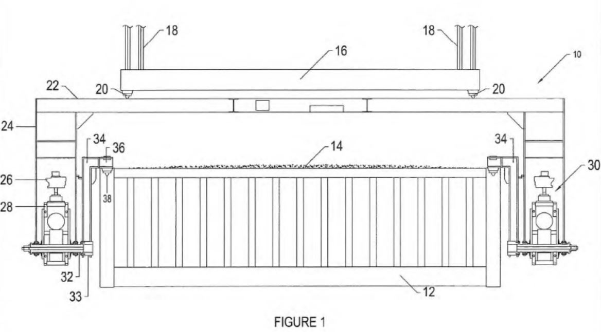
13 In Fig. 1, numerals 16, 18 and 20 identify elements of the crane (for example) from which the apparatus the subject of the invention is suspended. Numeral 12 identifies the container (and numeral 14 identifies the contents of the container). All other elements shown in the drawing are part of the apparatus itself.
14 Commencing from the crane end of things, as it were, the first element depicted is the longitudinal support member of the apparatus - numeral 22. That member supports two sub-frames, one at each end - numeral 24. In the embodiment shown in the drawing, the drive source for the apparatus is provided by motors (numeral 26) with their associated gearboxes (numeral 28) located within the sub-frames. Each motor/gearbox drives a shaft (numeral 32) which is linked via a boss (numeral 33) to a container support arm (numeral 34). The support arm, in turn, engages the container by way of an end-piece (numeral 36) “through the well-known twist-lock system” (numeral 38). In operation, the motor and the gearbox rotate the shaft, thereby causing the container to rotate around its longitudinal axis.
15 The specification proceeds to deal with aspects of the invention - not of direct relevance to the present controversy - that relate to the support arms being rotatable through 360° and to the provision of a safety brake and electronic proximity sensors.
16 The specification then turns to what will be apparent from a perusal of Fig. 1 itself, namely, that the sub-frames located on either side of the apparatus occupy “an appreciable amount of lateral space”, which could be a problem when the apparatus is picking up a container from a group of containers that are packed tightly in a horizontal plane. The configuration depicted in Fig. 1 is not, it is acknowledged in the specification, “appropriate when a container is to be picked up from a group or line of containers which are arranged very close side-by-side” (which, I take it, means end-to-end, since it is in the space beyond the ends of a container that the sub-frames are located as shown in Fig. 1). It is suggested in the specification that this problem “may, for example, be at least partially alleviated by locating the pivotal attachment point (e.g. shaft 32) of the container support arms 34 at or proximal to the lower ends of their respective sub-frames”; although I cannot, for myself, appreciate quite how that alleviation would be effected (ie given that such a location of the attachments is shown in Fig. 1 itself).
17 Be that as it may, the specification then turns to an embodiment of the invention that requires attention to be given to the drawing marked as Fig. 2:
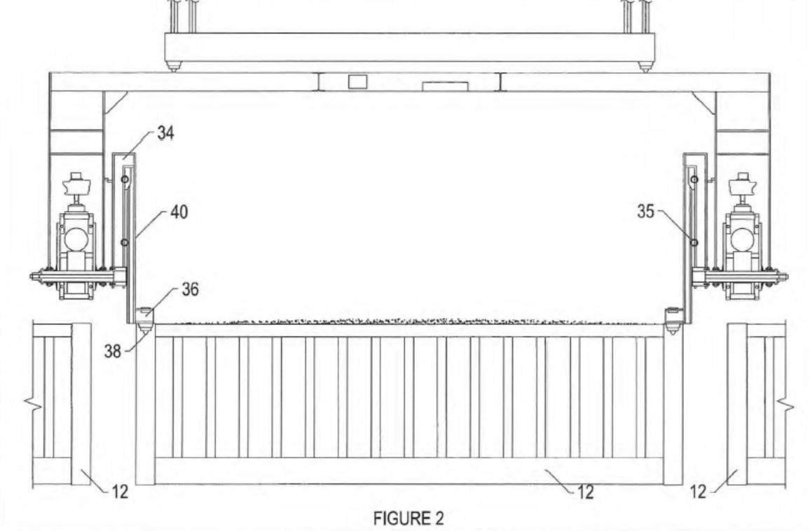
In this drawing, the problem of the lateral space occupied by the sub-frames is clearly apparent: to the left and right of the container to be lifted, the adjacent containers are shown in a way that makes it apparent that the sub-frames would not fit in the space between.
18 The specification continues:
[00027] To further alleviate this problem, the container handling apparatus 10 may include movable components (e.g. extendible members 40 which form sub-arms of the container support arms 34), to which the end-pieces 36 are attached. The extendible members 40 are, for example, slidingly attached to the container support arms 34 so that they can be moved from a first position within the perimeter of those arms to a second position where they extend beyond the perimeter of those arms. There may, for example, be two extendible members per container support arm, and these extendible members are preferably metal rods. The sliding attachment can be provided by means of a roller or ball mechanism on a track or slide system, on support surfaces 35 of the container support arms, along which the extendible members can slide. In that way, and as shown best in Figure 2, they enable the endpieces 36 of the container handling apparatus to be extended beyond the sub-frames 24 and readily engage the container by means of a twist-lock system 38.
[00028] This allows the extendible members 40 to be lowered downwards below the lowest point of the sub-frames so that they can engage (by means of the twist-lock system 38) with the container 12, even when that container forms part of a closepacked group or line of containers. The extendible members 40 of the container support arms 34 are then moved upwards to raise the container.
[00029] Thus, where a container that is effectively enclosed by other containers needs to be engaged, the crane operator simply adjusts the whole container-handling
assembly until the sub-frames 24 are above the upper level of the container, whilst
ensuring that the twist-locks 38 are still able to engage the container.
19 It is then said that the twist-locks (numeral 38) of the end-pieces (numeral 36) engage the top rails of the container and increase the strength of them in the sense that the container itself effectively forms a “chassis”. The specification continues:
[00031] When engagement has occurred, the container handling apparatus is operated to cause the container to be lifted vertically to a predetermined height or point and, when there is sufficient room, operates so that the extendible members 40 move to position the container at least partially within the space between the sub-frames 24. With the container thus held between the sub-frames 24, the end walls of the containers receive at least some degree of support from a support surface 35 of each of the container support arms 34. These support surfaces 35 are, for example, substantially planar regions on the surface of each of the container support arms, which support surfaces will abut and support the end walls of the container when held in this raised position, with the container being located at least partially between the sub-frames 24, ready for rotating to discharge its contents. The support provided to the end walls of the container by the support surfaces 35 of the container support arms will normally mean that other forms of support (such as the supporting pistons of many prior art systems) will not be needed.
20 When the container is at an appropriate level to be rotated, and is positioned above, for example, a ship’s hold, the apparatus is locked in position and the container rotated by the operator, thereby emptying its contents.
21 The Patent makes five claims, as follows:
(1) Apparatus for engaging and handling a cargo container, said apparatus having a frame assembly including:
(a) a longitudinal support member;
(b) two spaced apart sub-frames depending from the longitudinal support member;
each sub-frame having a container support arm pivotally mounted by means of a rotating assembly on its inner face, said rotating assembly connecting the sub-frame to its respective container support arm; and
(c) a drive means to rotationally drive the rotating assembly connecting the sub-frame to its container support arm;
wherein the container support arms have support surfaces, being a substantially planar region on the surface of each container support arm, which support surfaces will abut and support the end walls of a cargo container when held partially or wholly in the space between the two sub-frames of the apparatus;
the cargo container being rotatable by the apparatus to discharge its contents;
wherein each container support arm includes one or more movable component having an engaging member for cooperation with a cargo container; and
wherein the engaging members are twist-lock systems.
(2) Apparatus according to Claim 1, wherein the container support arms are rotatable through 360°.
(3) Apparatus according to Claim 1 or Claim 2, including locking means capable of locking each of the container support arms in a preferred position.
(4) Apparatus according to any one of Claims 1 to 3, wherein each container support arm includes one or more movable component having an engaging member for cooperation with a cargo container; the movable components of the container support arms being movable such that:
a cargo container engaged by the engaging members is movable between at least two positions with respect to the sub-frames,
in the first position, the container being located beyond the space between the two sub-frames and, in the second position, the container being located partially or wholly in the space between the two sub-frames, and
the cargo container being rotatable by the apparatus to discharge its contents.
(5) Apparatus according to any one of Claims 1 to 4, further including one or more brake assembly to provide positive braking to either side of the container being handled.
THE RAM REVOLVER
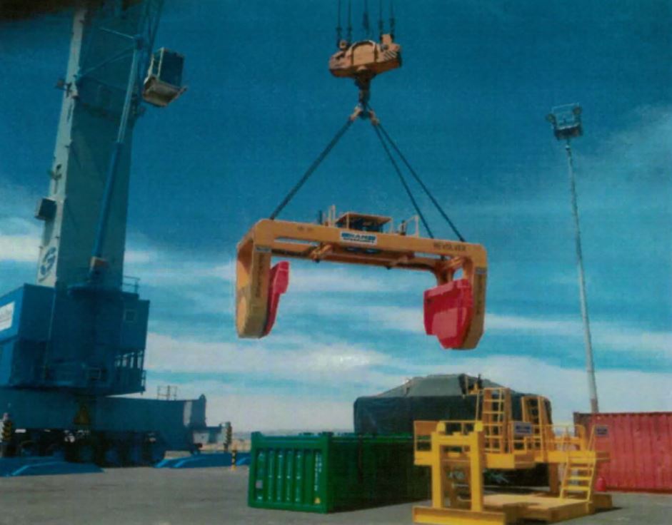
22 The RAM Revolver is an apparatus for lifting, moving, revolving and thus emptying a shipping container much as described in the prior art referred to above. The following photograph of this apparatus is taken from AMMESA’s Particulars of Infringement:
23 It was accepted by the parties that the court had no need of a detailed understanding of this apparatus or how it worked, since the only issues in contest related to the following requirements of Claim 1 of the Patent:
the planar support surfaces of the support arms “will abut and support the end walls of a cargo container” when held partially or wholly in the space between the two sub-frames of the apparatus; and
each container support arm “includes one or more movable component” having an engaging member for cooperation with a cargo container.
In other respects, it is accepted by NSL that the RAM Revolver falls within the terms of Claim 1.
24 In final submissions made on its behalf, it was AMMESA’s case that the RAM Revolver infringed Claims 2 and 3 also, but the viability of that case turns on the success of AMMESA’s case under Claim 1, which was the focus of attention in the case.
25 The live issues in the case substantially involve the construction of Claim 1 of the Patent. Here the parties relied on the expert evidence of Alan Foulkes and Bill Hunter. Mr Foulkes, called by NSL, has had substantial experience, most recently in management roles, in the materials handling industry. Mr Hunter, called by AMMESA, is a professional mechanical engineer who holds a Master of Engineering Science degree from the University of Melbourne. He has had extensive mechanical engineering design experience. The relevance of their expertise to the matters in contest was accepted by both sides.
ABUT AND SUPPORT
26 This integer of Claim 1 is controversial because the support arms of the RAM Revolver are equipped with planar support surfaces, but they do not make contact with the ends of the container when the container is held wholly or partially in the space between the sub-frames. It is submitted on behalf of AMMESA that contact is not necessarily conveyed by the term “abut”, and that the “indirect” support which the planar support surfaces provide to the end walls of the container is within the meaning of the integer. By contrast, it is submitted on behalf of NSL that “abut” implies direct contact, and that it is by way of such contact that support is provided to the end walls of the container.
27 Each of the experts provided his interpretation, from the perspective of someone skilled in the relevant art, of the term “abut and support”. Mr Hunter commenced with what he understood to be the conventional meaning of “abut”: referring to the Shorter Oxford English Dictionary, he opined that it meant “to end at” or “to border on”. Thus this aspect of Claim 1 was to be understood as conveying the sense that “the support surfaces of the container support arms would or would not necessarily be in contact with the end walls of the container.” He relied on Fig. 1 in the specification, which showed the container in the raised position, that is, in the space between the sub-frames. It was apparent from this that “there can be a space or gap between the inside face of the container support arms and the container end walls.” Mr Hunter said that such a gap –
… makes sense in order to allow some degree of free play when the apparatus is being manoeuvred into position to pick up the container. Indeed, without such a gap it is difficult to see how the ends of the apparatus could practically be configured to reliably make contact with the end walls of cargo containers which in practice are likely to have considerable geometric tolerance variations in the longitudinal dimension.
Mr Hunter said that, notwithstanding that they were not in contact with the end walls of the container, the support arms were “still providing a high degree of structural support” to those walls. In his understanding of this aspect of Claim 1, the support surfaces of the support arms needed only to be positioned in “close proximity” to, and parallel with, the end walls of the container.
28 Before he had read Mr Hunter’s views as set out above, and without yet having any knowledge of the issues in this case, Mr Foulkes expressed the following opinion:
Each support arm must have a substantially flat area on its internal face that is capable of abutting and supporting the ends walls of the cargo container that is held within the sub-frame. To provide that support the planar regions would need to contact the end walls of the cargo container, and in this context I understand the word “abut” to mean that the support surface contacts the end wall of the container so as to provide the support to the end walls.
Once he had considered Mr Hunter’s views, Mr Foulkes accepted that the word “support” could mean “to bear a load”, that all parts of the support arms, including any external planar surfaces, would operate to bear the load of the container, and that, since the end walls were part of the container, they were relevantly supported by the support arms, including the substantially planar surfaces thereof. This kind of support - indirect support, as Mr Foulkes described it - however, was not what was being described in Claim 1 of the Patent. He said that, in designing the container support arms, an engineer would conduct a “finite element” analysis to assess where the stresses were higher, and may make design changes to address those stresses, that is, to spread them out over a larger area. In making design changes, the engineer would operate within constraints which included intended function (including the need to rotate), weight and cost. Mr Foulkes would not have expected that planar surfaces on the support arms would provide “any particular advantage” by way of contribution towards supporting the load of the container. He could see not any indication in the Patent that suggested that that was the type of “support” that the patentee was intending to describe.
29 Mr Foulkes expressed the view that, on Mr Hunter’s understanding of this integer of Claim 1, the end walls of the container would be relevantly “supported” only because they were part of the container as a whole. The words “end walls of a” in Claim 1 could be deleted without changing the meaning of the claim. In an indirect form of support such as contemplated by Mr Hunter, since the points of connection between the support arms and the container were presumptively at the four corners of the container, there would be no “separate degree of support” for the end walls, in the opinion of Mr Foulkes. He maintained the view that Claim 1 required there to be “a more direct form of support provided by the planar regions, being support that is specifically directed to the end walls of the container.”
30 In his second affidavit, Mr Hunter responded to Mr Foulkes. He referred again to Fig. 1 in the specification where, he observed, there was shown to be “a considerable gap” between the planar regions of the support arms and the end walls of the container being supported. He said that, without some degree of gap at this point, it was difficult to see how the invention could work. It was necessary to have a gap between each support arm and the corresponding end wall of the container to allow some free play when the apparatus was being manoeuvred to pick up the container. Under the relevant international standard, shipping containers were dimensioned within stated tolerances, such that there could be no confidence that even a new container would necessarily fit snugly between planar support surfaces that were functionally required to be in contact with the ends walls thereof. In practice, Mr Hunter added, it was commonplace for containers to become slightly damaged in use, such that the end walls would often have imperfections which would compromise the operation of any lifting apparatus that relied on such a snug fit. Thus Mr Hunter took the view that it was most unlikely that the inventors intended the planar support surfaces to be in contact with the end walls of a container.
31 Mr Hunter disagreed with Mr Foulkes also insofar as the latter proposed that the end walls of the container, as such, did not bear any particular load, ie as distinct from the load borne by the container generally. He (Hunter) incorporated the following diagram in his second affidavit:
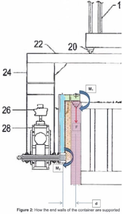
Mr Hunter said that the load constituted by the container and its contents, indicated as F on the diagram, was transferred from the end walls of the container (at the twistlocks) to the horizontal portion of the support arms (shown in green) and thence to the arms themselves. He said that, as the load was also distributed over the base of the container, there was also a large bending moment M1 which was transferred at the twistlocks. This bending moment caused the end walls of the container to try to rotate in the clockwise direction (in the example shown). The load F and the bending moment M1 were transferred from the horizontal portion of the support arm to the vertical portion (shown in pale blue on the diagram). The bending moment was supplemented by an additional bending moment component to become a larger bending moment M2. Mr Hunter concluded that the support arm was required to support “the end walls of the container by being able to support both the compressive load F, and the bending moment M2.”
32 Mr Hunter said that the support arms would be subjected to substantial bending loads, which would cause them to bend inwardly as shown in the diagrams below:
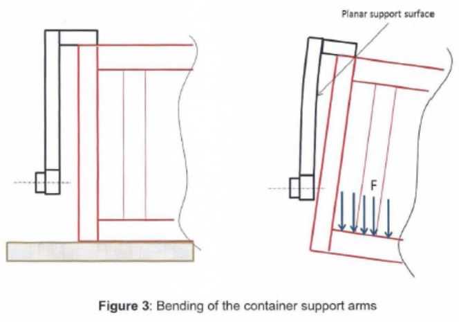
The diagram on the left represented the situation when the support arms engaged the container just prior to lifting. The diagram on the right represented the situation when the container was lifted, and was an exaggerated shape of how the container arms would bend as a result of the bending moments transferred to them as described above. Mr Hunter said that a large proportion of the bending load on the support arms would be resisted by the planar support surfaces. In an appendix to his affidavit, Mr Hunter laid out a calculation which indicated that the bending stiffness and strength in the support arms might be increased by a factor of approximately 2.5 by adding planar support surfaces to a prior art design. Thus he did not agree with Mr Foulkes that the words “end walls of a” in Claim 1 could be deleted without changing the meaning of the claim.
33 The joint report of the experts substantially reflected their respective positions as summarised above. They added a summary of each of their areas of agreement and disagreement. They agreed on the following matters:
24. To enable the invention to work, from a practical standpoint there must be a gap between the planar support surfaces of the container support arms and the end walls of the container.
25. Figures 1 and 2 of the Patent shows a gap between the planar support surfaces of the container support arms and the end walls of the container.
26. The addition of planar support surfaces to the structure of the container support arms would add to their strength and stiffness.
34 They disagreed on the following matters:
27. Whether in the case of a gap being present between the planar surfaces and the container the term support only allows for indirect support of the container via the twistlocks (Mr Foulkes) or whether it includes both direct and indirect support (Mr Hunter)
28. Whether the term abut as used in claim 1 means “in contact with” (Mr Foulkes), or whether it includes both “in contact with” and “in close proximity with” (Mr Hunter).
35 In determining this aspect of the controversy between the parties, I should commence with two constructional points made by Mr Hunter which I do not accept. The first relates to his use of the Shorter Oxford English Dictionary. It is apparent from the second edition of the Oxford English Dictionary that the meaning of “to end at” or “to border on” are meanings assigned to the word “abut” in the context of real estate: “Of an estate, country, piece of land, etc.: to end at, border on (adjacent land, a neighbouring country, etc.)”, as in, “Pristine forests abut shimmering salt marshlands and streets lined with homes”: NY Mag 30 July 32/1. This is not an engineering context. Of closer relevance is, “Of an object, esp. a part of a building: to touch (something) with a projecting end or point; to end on; to lean against at one end for rest or support”, as in, “Particular attention was paid to methods of construction as well as to how walls abut each other”: National Trust Mag Spring 34/2. Generally with respect both to real estate and to construction methods, it seems, “abut”, used intransitively (ie not as used in Claim 1), can mean, “to meet, touch, to be adjacent; (of two or more pieces of land, etc.) to border on one another (at a particular point)”, as in, “Where the two tracts abut in the northeast corner of the lake is a promising location for an international reserve”: P Mattheissen Birds of Heaven i. 37.
36 The normal meaning of the word “abut”, therefore, does not travel the full distance in making the discrimination which the facts of the present case require. Depending on context, the word can imply physical contact or mere adjacency.
37 The other of Mr Hunter’s constructional points that I do not accept relates to his reliance on the gap between the planar support surface of the support arm and the end of the container as shown in Fig. 1. There is nothing in the text of the specification that makes this gap of any significance. An arrangement without the gap would be equally consistent with the specification (and, for that matter, with Claim 1). Indeed, as mentioned in para 11 above, the inventors made it clear that dimensions of certain of the parts shown in the drawings might have been modified and/or exaggerated for the purposes of clarity or illustration. I would regard the gap shown in Fig. 1 as no more significant than for the detail it shows of the structural separation between elements of the support arm and the end wall of the container.
38 Turning to the context in which the word is used in Claim 1, as a matter of normal English I would regard the expression, “which support surfaces will abut and support the end walls of a cargo container” as implying the provision of support by physical contact. This conclusion is not affected by the corresponding description of the invention in the specification (see para 7 above), which really does not take the matter any further. However, it is a conclusion which I would reach as a layperson, with no more appreciation of the relevant field of engineering than would be had from a reading of the Patent itself. While an important starting point, the authorities make it clear that, in a technical area, such a level of appreciation is not to be regarded as sufficient. It is the skilled addressee’s reasonable understanding of things which should provide the setting for a proper construction of the claims of a patent.
39 Here, despite his initial opinion, ultimately Mr Foulkes agreed with Mr Hunter that, to enable the invention to work, from a practical standpoint there had to be a gap between the planar support surface of a support arm and the corresponding end wall of the container (see para 33 above). Mr Hunter’s point, of course, was that, in this field of engineering, the tolerances between different components which were required to move one relative to the other were much too inexact to make contact between them a necessary ingredient of the design. In his oral evidence, Mr Foulkes repeated his agreement on this limited, but important, point. That did not mean that Mr Foulkes agreed with Mr Hunter as to the meaning of the relevant integer of Claim 1, but it did produce the result, as it seems to me, that to construe the claim as requiring the support surface to be in gapless contact with the end wall of the container would, from a practical standpoint, be to propose an apparatus which did not work.
40 A practical, workable, construction of Claim 1, therefore, would be one which did not require contact between the planar support surface and the end wall of the container. Where would this leave the requirement of “support”? By the stage of final submissions at trial, this question came down to the distinction between direct and indirect support. It became, effectively if not strictly, common ground that the end wall of a container which was not in direct contact with the corresponding planar support surface would derive some indirect support from such a surface in an apparatus which otherwise conformed with Claim 1. It would not, of course, derive any direct support. As is apparent from what I have written above, Dr Foulkes did not accept that it was the end wall of the container as such that would derive the indirect support, contending that the support was transferred to the body of the container as a whole. But, ultimately, he accepted that the end wall, as part of the container, would derive some indirect support from the planar support surface.
41 The position reached, therefore, is that a gap of some order between the planar support surface of the support arm and the end wall of the container is required to make the embodiment of the invention claimed in Claim 1 workable in practice, and, notwithstanding the presence of such a gap, the support surface would still provide some indirect support to the end wall. The position for which AMMESA contends must, therefore, be accepted. In relevant respects, the RAM Revolver falls within the terms of this claim.
MOVABLE COMPONENT
42 Again, each of the experts provided his interpretation, from the perspective of someone skilled in the relevant art, of the term “movable component”. I shall commence with Mr Hunter’s first affidavit presently, but it is convenient to refer first to a relevant aspect of the prior art that was explained in Mr Foulkes’ affidavit. It relates to the means by which a container-lifting apparatus engages with the container itself. In the simplest case, that engagement is done at each of the four top corners of the container. Each corner is equipped with what is referred to as a “twistlock pocket” or a “corner casting”, represented as follows:
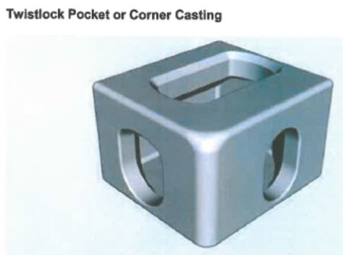
The lifting arm of the apparatus will be equipped with a “twistlock” device, the operative part of which is, in Mr Foulkes’ words, “an arrow-shaped forged steel pin that is operated by ‘twisting’, or rotating, through 90 degrees which then locks with the receiving pocket”. This pin is lowered into the elongated slot shown on the top of the twistlock pocket (the smaller slots on the sides are not presently material). In Mr Hunter’s second affidavit, an example of such a pin is shown as follows:
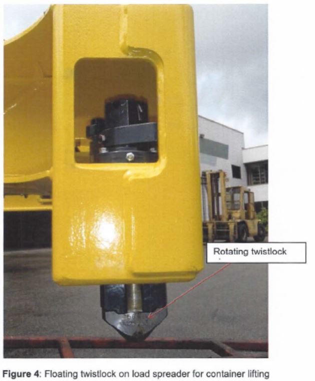
Mr Foulkes said that the twistlock system has a sensing system that signals to the operator when the twistlock has landed into the receiving pocket and is ready to be rotated to latch the two entities together.
43 Against that background, I can turn now to Mr Hunter’s first affidavit. One of the integers which he identified in Claim 1 of the Patent was expressed as follows:
… wherein each container support arm includes one or more movable component having an engaging member for cooperation with a cargo container;
He construed that integer as involving two aspects, as follows:
one or more movable component - some part of the container support arm includes at least one, but possibly more than one component(s) that are able to move in some manner
engaging member - some part of one of the movable component(s) included in each container support arm has an element which is used to engage with (that is connect to) the cargo container.
44 Mr Hunter expressed the view that the RAM Revolver conformed with these integers because it had what was described as a “floating twistlock”. Mr Hunter referred to the following drawing of the twistlock arrangement (to use a generic term at this stage) on the RAM Revolver:
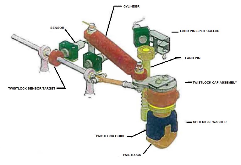
Mr Hunter said:
The component arrowed “TWISTLOCK” is an engaging member which has the sole purpose of engaging with the mating corner casting of a cargo container. The twist lock assembly shown in (4) is a floating twistlock, and it is movable with respect to the container support arm to engage with the cargo container. These twistlocks must be part of the container support arm to enable the container to rotate with the container support arm as shown on the front page of (2).
45 In his affidavit, Mr Foulkes explained what a floating twistlock was. He said:
Although the containerisation system is built upon uniformity, the reality is that slight distortions occur in the exact envelope that twistlocks must operate in. Most twistlock assemblies therefore incorporate a degree of movement to enable them to more easily enter a twistlock pocket and not get hung up. This feature is commonly known as a ‘floating twistlock’, and the design of a floating twistlock is such that the vertical pin is able to move laterally to a limited degree ….
46 Before reading Mr Hunter’s first affidavit, Mr Foulkes provided his opinion on the “movable component” integer of Claim 1 of the Patent. He said that each of the support arms was required to have a movable component with a twistlock system located on it. The movable component was movable relative to the support arm, and enabled the container to be moved relative to the sub-frame. The purpose of such a feature, in Mr Foulkes’ assessment, was that it allowed a container to be picked up from below the level of the sub-frame, and then raised within the sub-frame for handling and rotation.
47 Having read Mr Hunter’s first affidavit, Mr Foulkes said that he did not agree that the reference in Claim 1 to a “movable component” could be understood as including part of the twistlock system itself. A difficulty with Mr Hunter’s approach, according to Mr Foulkes, was that it involved “a circularity”. He said:
The relevant ‘movable component’ must ‘have’ an engaging member for cooperation with a cargo container, wherein the engaging member is a twistlock system. That is, the ‘movable component’ must ‘have’ a ‘twistlock system’. In my view that language is consistent with the sort of movable component that is described in the Patent at paragraph [00027]. I do not understand, however, how a component of a twistlock system, namely the ‘twistlock’ itself, can be said to ‘have’ a twistlock system.
48 As to the drawing of the twistlock arrangement on the RAM Revolver to which Mr Hunter had referred, Mr Foulkes marked up a version of that drawing as follows:
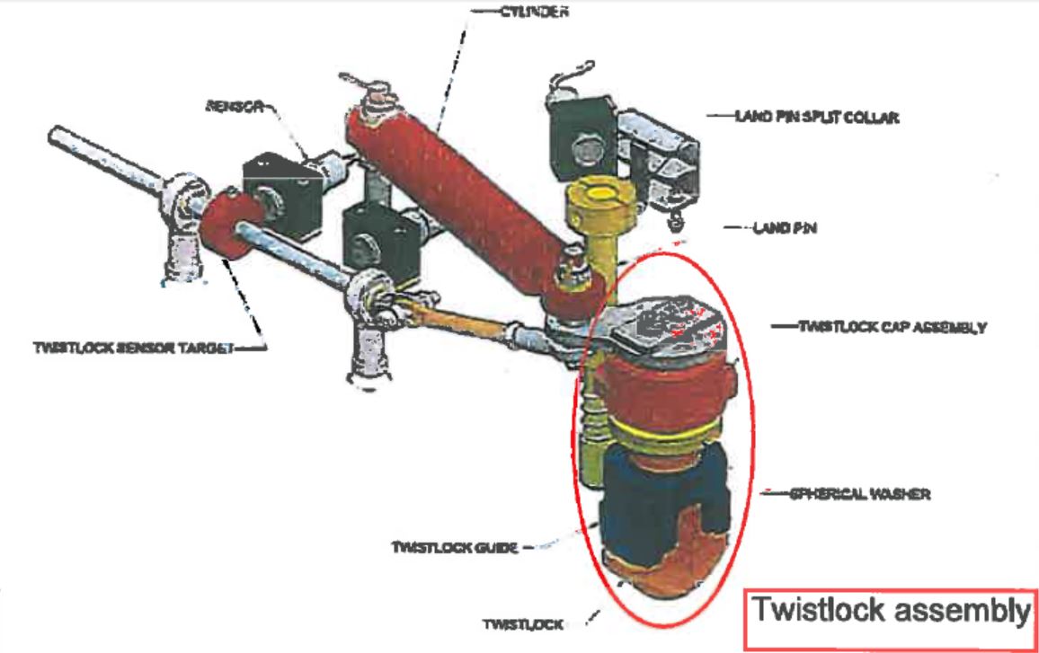
He said that what he described as the twistlock assembly, shown here inside the red oval-shaped outline, comprised the twistlock engaging member as such (at the bottom, coloured brown), the twistlock guide (coloured navy blue), and the twistlock cap assembly. The other components included the actuating mechanisms that rotated the twistlock from the open to the locked positions, and the land pin. Mr Foulkes continued:
The fact that it is a floating twistlock, rather than a fixed twistlock, means that it is designed so that in addition to its rotational movement, it also allows some degree of lateral and longitudinal movement. The purpose of this is so it can locate into a receiving pocket even if the receiving pocket is located a short distance from its design position (for example, because of some distortion of the container frame).
Otherwise, Mr Foulkes could not see any other part of the RAM Revolver that was a relevant “movable component” as required by Claim 1.
49 In his second affidavit, and having had the benefit of reading Mr Foulkes’ affidavit, Mr Hunter maintained his original position. He said that his reading of Claim 1 did not involve circularity. He said:
The engaging member of claim 1 is the rotating twist lock pin. When I read in claim 1 “and wherein engaging members are twist-lock systems”, I took this to mean that the engaging members are of a particular type which conform to the industry-standard twistlock system. This standard defines the attributes of the twistlock pins and the corner castings with which they are engaged.
That is to say, each engaging member was a twistlock as such - what Mr Foulkes described as the “arrow-shaped forged steel pin” - and, because it was a “floating” device, it was movable apropos the support arm.
50 Mr Hunter also commented on Mr Foulkes’ view that the purpose of having a component which was movable in relation to the support arm was that it would allow a container to be engaged at a point below the level of the sub-frame, and then raised to a point within the sub-frame for handling and rotation. He (Hunter) pointed out that this understanding of Claim 1 was effectively what was claimed in Claim 4 and, if Claim 1 were confined in the way proposed by Mr Foulkes, Claim 4 would be redundant.
51 Again, the joint report of the experts substantially reflected their respective positions as summarised above. If anything, the views which they respectively expressed in their joint report were yet more entrenched. Mr Foulkes said:
[I]t is clear that the patent throughout is referring to the moveable components and the twistlock system as two separate entities. The movable components are indelibly linked to the embodiment that enable the apparatus to pick up closely stacked containers being item 40 in Figure 2. On the other hand the twistlock system is referred to in para 00017 line 9 as “the well known twistlock system” and referenced in figures 1 and 2 as item 38 is clearly a known art and requires no further description in the patent.
52 For his part, Mr Hunter then advanced, for the first time as I would understand it, a reading of Claim 1 that would allow the actuating mechanism of the twistlock system to constitute the “movable component”. He said:
That mechanism is almost certainly going to be an assembly of multiple moving parts. For example, in the RAM Revolver, the assembly drawings titled “Floating Twistlocks” show a co-operative arrangement of multiple moving parts. Thus in the context of the RAM Revolver and claim 1, the floating twistlocks on the container support arms are each a cooperative assembly of moving parts (ie they are collectively a movable component). This moving component includes an engaging member for cooperation with a cargo container (the rotating twistlock pin). The engaging member is a twistlock system, which means that it conforms to well-known industry standards (including dimensions) for such twistlock systems.
53 The experts added a summary of each of their areas of agreement and disagreement. They agreed on the following matters:
47. Figure 2 of the Patent shows an embodiment in which the use of extendible members with the twistlocks attached move up and down to lift the container. These are the movable components.
48. The use of the term movable component(s) in claim 4 is consistent with the arrangement shown in Figure 2.
49. The patent is broader than the specific arrangement shown in Figure 2, and the broadest form of the invention is described in paragraph [0007] of the ‘396 Patent.
54 They disagreed on the following matters:
50. The use of the term “movable component” in all the claims must be an extendible component plus the end piece incorporating the twistlock as per the embodiment shown in Figure 2 (Mr Foulkes).
51. The “movable component” in claim 1 has a broader meaning and simply means the twistlock assembly. It is claim 4 that claims the specific combination of the vertical extendible component plus the twistlock assembly as shown most clearly in Figure 2. If this were not the case (ie broader interpretation for claim 1, narrower interpretation for claim 4), then claims 1 and 4 would have the same meaning, which does not make sense to me (Mr Hunter).
55 Here too I commence with the words of the claim: “wherein each container support arm includes one or more movable component having an engaging member for cooperation with a cargo container; and wherein the engaging members are twist-lock systems.” The singular form of “component” is awkward grammatically, but the meaning is clear. Each support arm must have a movable component (or more than one movable component). Each movable component must have an engaging member for cooperation with a cargo container. And each engaging member must be a twist-lock system. That is to say – and ignoring the plural form for the sake of simplicity – each support arm must have a movable component with a twist-lock system for engaging with a cargo container. As a matter of normal language, the twist-lock system is something which the movable component must have: it is not the movable component itself.
56 How does this understanding of Claim 1 line up with the description of the invention in the specification? I refer first to the passage in the “Summary” section set out in para 9 above. The “movement” referred to is one which occurs after the container has been engaged by the engaging members, and involves the movement of the container as such. This teaches away from Mr Hunter’s position, both in its primary (see para 49 above) and in its alternative (see para 52 above) formulations.
57 I refer next to the passage in the specification set out in para 18 above. The “problem” which is said to be further alleviated by the inclusion of movable components is the lateral space occupied by lifting arrangements to be found in the prior art. The extendible members referred to are said to be an example of what might be included as movable components. One thing is clear: if the movable components were, or could be, nothing more than a floating twist-lock as such or the actuating mechanisms of a twist-lock, it is not apparent what contribution they would make to the alleviation of the lateral space problem, and none was suggested on behalf of AMMESA.
58 Furthermore, reading the claims and the specification as a whole, there is no hint of a suggestion that the inventors claimed to have made any contribution to the prior art in the matter of twist-locks. They treated twist-locks as commonly used, readily available, arrangements which required no further explanation, the assumption being that they would be used in any lifting apparatus of the kind with which the inventors were concerned, whether in the prior art or as invented.
59 So far, then, both the wording of Claim 1 and the textually related passages in the specification provide quite obvious support for the position taken by Mr Foulkes and little or no support for the position taken by Mr Hunter.
60 But, additionally to what I have discussed to date, Mr Hunter did have a constructional point of some force: Mr Foulkes’ understanding of this integer of Claim 1 appeared to remove any point of distinction between that claim and Claim 4. Claim 4 is expressed to be limiting apropos the terms of Claim 1, conveying the idea that Claim 1 was concerned with something broader than the specific arrangement proposed in Claim 4.
61 The first comment I would make about this point is that it is essentially one of grammatical construction. Although made by an engineer, the point was not, in my view, informed by the special expertise which Mr Hunter otherwise brought to the issues upon which he gave evidence. It was, at base, little more than a particular application of a long-standing maxim of construction applied by courts over the years, that it should be presumed that the creator of a document intended every part thereof to have its own work to do. In my view, in the context of a patent with a cascading series of dependent claims, that is a maxim of obvious relevance.
62 The result of taking such an approach, however, is not that Claim 1 must be speaking of an arrangement in which the movable component is, or may be, the twist-lock itself or the actuating mechanism thereof. For reasons I have given, that conclusion would derive little or no support from the wording of the claim or the relevant sections of the specification. The answer, in my view, it to recognise that the embodiment of the invention claimed in Claim 4, and described in some detail in the specification, is an example only of an apparatus in which the support arms are equipped with movable components. Indeed, so much is stated in the specification itself:
The extendible members 40 are, for example, slidingly attached to the container support arms 34 so that they can be moved from a first position within the perimeter of those arms to a second position where they extend beyond the perimeter of those arms. There may, for example, be two extendible members per container support arm, and these extendible members are preferably metal rods. [Emphasis added]
63 It is true that, on this construction, there is nothing in the specification which lays out a detailed description of an embodiment of the invention wherein the support arms have movable components other than that apparently claimed in Claim 4, but that is not fatal. If a manufacturer devised an apparatus which did have that feature but which, for one reason or another, was not caught by Claim 4, there is no doubt but that he or she would be caught by Claim 1 (at least in respect of this integer). This would not be the first time that inventors have expressed their independent claim in broad, generic, terms and provided a detailed description only in a narrower, dependent, claim. By so proceeding, they sail close to the wind on fair basis, of course, but that is another question.
64 I would resolve the apparent problem presented by the terms of Claim 4 in the way proposed above. The construction of Claim 1 which I prefer is that the movable component is a component of the support arm other than the twist-lock or the actuating mechanism thereof.
65 Once the twist-locks and their actuating mechanisms are taken out of the frame, it is common ground that the support arms on the RAM Revolver do not have movable components. That apparatus does not, therefore, fall within Claim 1 of the Patent.
THREATS OF INFRINGEMENT PROCEEDINGS
66 In August 2014, patent attorneys acting on behalf of AMMESA dispatched five letters alleging that the RAM Revolver infringed the Patent. Those letters were in substantially identical terms, two having been addressed to entities related to NSL and three having been sent to unrelated parties who were, it seems, using or trading in the RAM Revolver. It is accepted by AMMESA that this correspondence amounted to threats of infringement proceedings within the meaning of s 128 of the Act.
67 AMMESA’s defence under s 128 is that the threats were not unjustifiable because the sale and use of the RAM Revolver did involve an infringement of Claim 1, at least, of the Patent. That matter has now been resolved favourably for NSL, and I do not understand AMMESA to advance any other basis upon which its threats might be justified. In the circumstances, I accept NSL’s case under s 128.
NSL’S CASE UNDER THE ACL
68 Of the five letters to which I have referred, NSL relied on the three sent to unrelated entities as containing representations which were misleading or deceptive within the meaning of s 18 of the ACL.
69 AMMESA resisted NSL’s ACL case, even in a circumstance in which the court found, as it has, that the RAM Revolver did not infringe Claim 1 of the Patent. It was said that NSL, which relevantly carried the onus, had to show “a representation as to fact as pleaded”. The representations alleged by NSL were that the RAM Revolver product infringed the Patent, that the RAM Revolver had all of the essential features of one or more valid claims of the Patent, and that the RAM Revolver product was a product of which AMMESA had the legal right to prevent the sale in Australia. Although the letters were admitted, these allegations were denied. To resolve the point made by AMMESA, therefore, it will be necessary to commence with the terms of the letters themselves.
70 In the letter sent to Kew Project Management (Australia) Pty Ltd on 7 August 2014, which is representative, the writer said that “[t]he container-handling apparatus depicted on your website appears to include all of the features defined in Claim 1 (at least) of the Patent, in that it includes the following features”. There followed, in a bulleted list, reference to five of the integers in Claim 1. The integer which, as held above, was not present in the RAM Revolver was not an item on this list. The writer proceeded to refer to “conventional twist-lock systems” which were understood to be part of the RAM Revolver. The writer drew the addressee’s attention to the Act, and specifically to what constituted the infringement of a patent, to the definition of “exploit” and to s 117. The letter concluded with a demand that the addressee cease to supply, market and promote the RAM Revolver and that it make the necessary adjustments to its website. Absent compliance with those demands, the writer foreshadowed, AMMESA would “take whatever action is necessary or recommended in order to enforce their rights in this matter and, in doing so, seek to recover all legal costs incurred in the defence of their patent rights.”
71 In my view, the terms of this letter made good NSL’s allegations in its Statement of Claim. Notwithstanding what might, in isolation, be regarded as no more than an opinion, even a tentative one, the demands contained in the letter carried the strong impression that the addressee was, by dealing in the RAM Revolver, infringing at least one of the claims in the Patent and engaging in conduct which AMMESA was legally entitled to prevent. That was, in my view, misleading. It would be no defence to point out – which, I would add, AMMESA did not in submissions made on its behalf – that the writer of the letter made no reference to the integer the absence of which ultimately saved NSL from a finding of infringement. If anything, by turning a Nelsonian eye to that aspect of the matter, the writer was omitting to disclose, and to confront, an issue of obvious significance. Notwithstanding that omission, she proceeded to make quite firm demands that the addressee desist from carrying on business in a respect which has now been found to have been lawful.
72 It was also alleged by NSL Mr Bridle was “involved” in AMMESA’s conduct in contravention of the ACL, but that allegation was not pressed. NSL’s case against Mr Bridle must, therefore, be dismissed.
DISPOSITION OF THE PROCEEDING
73 Both sides requested the opportunity to consider the findings I would make before being called upon to make submissions as to the orders that would be appropriate to reflect those findings. I shall proceed conformably with that request.
I certify that the preceding seventy-three (73) numbered paragraphs are a true copy of the Reasons for Judgment herein of the Honourable Justice Jessup. |

