FEDERAL COURT OF AUSTRALIA
Bradken Resources Pty Ltd v Lynx Engineering Consultants Pty Ltd [2015] FCA 1100
Table of Corrections | |
21 October 2015 | Paragraph [71] – Amend last sentence to read “viz. bent or pressed into a single piece of material.” |
6 November 2015 | Paragraph [27] – Amend third sentence to read “understanding of the term” |
6 November 2015 | Paragraph [91] – Amend final sentence to read “not so constructed” |
IN THE FEDERAL COURT OF AUSTRALIA | |
DATE OF ORDER: | |
WHERE MADE: |
THE COURT ORDERS THAT:
1. The following preliminary question:
Does the Bradken BHP Iron Ore Wagon include at least one internal ridge which:
(a) includes a “first wall portion”;
(b) is “integrally formed within said side wall”; and
(c) is “running therebetween” at least one adjacent pair of vertical reinforcing members;
within the meaning of claim 1 of the Patent?
be answered:
“No”.
2. The parties’ legal representatives confer with a view to agreeing upon the terms of all other orders to be made consequent upon order 1.
3. The parties submit a minute of their proposed further orders (including in relation to costs) within 14 days.
4. The proceeding stand over to a date to be fixed for the making of further orders.
Note: Entry of orders is dealt with in Rule 39.32 of the Federal Court Rules 2011.
IN THE FEDERAL COURT OF AUSTRALIA | |
NEW SOUTH WALES DISTRICT REGISTRY | |
GENERAL DIVISION | NSD 2002 of 2013 |
BETWEEN: | THE PILBARA INFRASTRUCTURE PTY LTD (ACN 103 096 340) Applicant |
AND: | LYNX ENGINEERING CONSULTANTS PTY LTD (ACN 059 949 469) Respondent |
AND BETWEEN: | LYNX ENGINEERING CONSULTANTS PTY LTD (ACN 059 949 469) Cross-Claimant |
AND: | THE PILBARA INFRASTRUCTURE PTY LTD (ACN 103 096 340) First Cross-Respondent |
FORTESCUE METALS GROUP LTD (ACN 002 594 872) Second Cross-Respondent |
JUDGE: | NICHOLAS J |
DATE OF ORDER: | 20 october 2015 |
WHERE MADE: | SYDNEY |
THE COURT ORDERS THAT:
1. The following preliminary question:
Do the CSR Ore Cars or the QRRS (CNR) Ore Cars each considered individually, include at least one internal ridge which:
(a) includes a “first wall portion”;
(b) is “integrally formed within said side wall”; and
(c) is “running therebetween” at least one adjacent pair of vertical reinforcing members;
within the meaning of claim 1 of the Patent?
be answered:
“No”.
2. The parties’ legal representatives confer with a view to agreeing upon the terms of all other orders to be made consequent upon order 1.
3. The parties submit a minute of their proposed further orders (including in relation to costs) within 14 days.
4. The proceeding stand over to a date to be fixed for the making of further orders.
Note: Entry of orders is dealt with in Rule 39.32 of the Federal Court Rules 2011.
NEW SOUTH WALES DISTRICT REGISTRY | |
GENERAL DIVISION | NSD 2461 of 2007 |
BETWEEN: | BRADKEN RESOURCES PTY LTD Applicant |
AND: | LYNX ENGINEERING CONSULTANTS PTY LTD (ACN 059 949 469) Respondent |
AND BETWEEN: | LYNX ENGINEERING CONSULTANTS PTY LTD (ACN 059 949 469) Cross-Claimant |
AND: | BRADKEN RESOURCES PTY LTD First Cross-Respondent |
BRADKEN LIMITED Second Cross-Respondent | |
AND BETWEEN: | BRADKEN RESOURCES PTY LTD Cross-Claimant |
AND: | LYNX ENGINEERING CONSULTANTS PTY LTD (ACN 059 949 469) Cross-Respondent |
IN THE FEDERAL COURT OF AUSTRALIA | |
NEW SOUTH WALES DISTRICT REGISTRY | |
GENERAL DIVISION | NSD 2002 of 2013 |
BETWEEN: | THE PILBARA INFRASTRUCTURE PTY LTD (ACN 103 096 340) Applicant |
AND: | LYNX ENGINEERING CONSULTANTS PTY LTD (ACN 059 949 469) Respondent |
AND BETWEEN: | LYNX ENGINEERING CONSULTANTS PTY LTD (ACN 059 949 469) Cross-Claimant |
AND: | THE PILBARA INFRASTRUCTURE PTY LTD (ACN 103 096 340) First Cross-Respondent |
FORTESCUE METALS GROUP LTD (ACN 002 594 872) Second Cross-Respondent |
JUDGE: | NICHOLAS J |
DATE: | 20 october 2015 |
PLACE: | SYDNEY |
REASONS FOR JUDGMENT
Introduction
1 Before me for determination is a separate question in each of two proceedings. In the first proceeding (“the Bradken proceeding”) the cross-claimant (“Lynx”) seeks relief against two cross-respondents (“the Bradken parties”) for infringement of various claims of Australian Patent No 749848 (“the Patent”) entitled “Side reinforced bulk material transport container.” In the second proceeding (“the TPI proceeding”) Lynx seeks relief against two cross-respondents (“the TPI parties”) for infringement of various claims of the Patent.
2 In each proceeding the cross-respondents are alleged to have (inter alia) authorised the manufacture of “Ore Wagons” or “Ore Cars” used to transport iron ore by rail and thereby infringed the Patent. Each of the cross-respondents deny infringement. They also allege that the various claims upon which they are sued are invalid and should be revoked.
The Preliminary Question
3 On 23 April 2014 orders were made in both proceedings for the determination of a separate question (“the Preliminary Question”). The Preliminary Question in the Bradken proceeding is as follows:
Does the Bradken BHP Iron Ore Wagon include at least one internal ridge which:
(a) includes a “first wall portion”;
(b) is “integrally formed within said side wall”; and
(c) is “running therebetween” at least one adjacent pair of vertical reinforcing members;
within the meaning of claim 1 of the Patent?
4 At the time the order of 23 April 2014 was made, the Bradken parties gave the following undertakings to the Court:
If the Preliminary Question is answered negatively in respect of the Bradken BHP Iron Ore Wagon then, subject to any successful appeal by the respondent/cross-claimant, the applicant/cross-respondents will seek leave to discontinue its cross-claim for invalidity against the respondent/cross-claimant with no order as to costs in respect of the cross-claim for invalidity.
If the Preliminary Question is answered negatively in respect of the Bradken BHP Iron Ore Wagon then, subject to any successful appeal by the respondent/cross-claimant, the applicant will seek orders for the progression of its claim for unjustified threats of patent infringement.
If the Preliminary Question is answered affirmatively in respect of the Bradken BHP Iron Ore Wagon then, subject to any successful appeal by the applicant/cross-respondents, the applicant/cross-respondents will not advance any non-infringement arguments for the Bradken BHP Iron Ore Wagon in respect of claims 1 – 6 of the Patent other than grounds of invalidity.
5 In the TPI proceeding an order to the same general effect was made but referring to each of the CSR Ore Cars and the QRRS (CNR) Ore Cars instead of the Bradken BHP Iron Ore Wagon. The TPI parties also gave undertakings to the Court substantially to the same effect as were provided by the Bradken parties except that their undertakings refer to the CSR Ore Cars and the QRRS (CNR) Ore Cars.
6 The Preliminary Questions raise the question whether each of the relevant Ore Wagons or Ore Cars is within claim 1 of the Patent. In each proceeding the answer to the Preliminary Question will depend upon the proper construction of claim 1 of the Patent and a consideration of whether or not the Ore Wagon or Ore Car has each of the three integers referred to in the Preliminary Question. Though the Preliminary Questions refer to three integers, the evidence and submissions were principally directed to the second of them, viz. “[said] at least one internal ridge is integrally formed within said side wall.”
7 All claims of the Patent apart from claim 23 are dependent on claim 1. Claim 23 is an omnibus claim.
The Priority Date of the CLaims
8 In Bradken Resources Pty Ltd v Lynx Engineering Consultants Pty Ltd (2012) 97 IPR 424 McKerracher J dismissed two related appeals (NSD 439/2007 and WAD 212/2009) brought by Bradken Resources Pty Ltd (“Bradken Resources”) pursuant to s 60 of the Patents Act 1990 (Cth) (“the Act”) against a decision of the Commissioner to allow Patent Application No 749848 to proceed to grant. Following his Honour’s decision, and after the making of orders on 21 December 2012, the Patent was duly granted. In the course of his reasons, McKerracher J noted that there was an issue between the parties (which arose in the context of a cross-appeal brought by Lynx) as to the correct priority date: Bradken Resources contended that it was 30 March 1999, and Lynx contended that it was 30 March 1998. McKerracher J found that the correct priority date was 30 March 1999 and his Honour made a declaration that the application proceed to sealing with the priority date of its claims being 30 March 1999.
9 The declaration made by his Honour was not the subject of any appeal or application for leave to appeal. Whether or not it is open to the parties to the proceedings heard and determined by his Honour (Lynx and Bradken Resources) to dispute the correctness of his Honour’s finding, at least as between themselves, seems to me to be highly doubtful. In any event, for the purposes of deciding the Preliminary Question, nothing turns on the 12 month difference between 30 March 1998 and 30 March 1999. In particular, no party suggested that the common general knowledge was likely to be any different at one such date as opposed to the other.
The Field of the Invention
10 The field of the invention described in the Patent relates to bulk transport containers used in rail and road transport. The Patent is not limited to containers used to transport iron ore or coal (as opposed to other bulk products) although it would appear that the invention is likely to be most advantageous when used to carry heavy materials that place extreme stresses on a container’s side walls. I am satisfied that the Patent is directed to mechanical and structural engineers with a practical interest in the design, construction and use of bulk transport containers for use in rail or road transport.
THE Witnesses
General Observations
11 None of the parties took any objection to the affidavit evidence and each invited me to evaluate the affidavit evidence and accord it such weight as I considered appropriate.
12 A good deal of the affidavit evidence filed by the parties was both argumentative and repetitive. Nevertheless, it was generally helpful to me in understanding the common general knowledge and the background to the invention including how, and from what, bulk containers, especially those used in rail transportation, are constructed. It was also of considerable assistance in so far as it concerned the technical terms “form” and “formed” when used in the context of metal fabrication and in describing techniques used to shape, cut and join metal components used to make bulk containers.
13 The following brief summary of the expert witnesses’ evidence is not intended to be exhaustive but merely to indicate the general thrust of each witness’s evidence and the views expressed by the him on the key issue. Of course, the proper construction of the patent specification, including the claims, is ultimately a matter for the Court to decide.
Peter Grove
14 Mr Grove is a mechanical engineer who was called by Lynx. His areas of engineering specialisation are railway wagon design and applications, mobile equipment, mining, materials handling and special purpose machines. He worked for Queensland Rail as Design Engineer (1999-2003) and Wagon Projects Engineer (2004-2011). During the course of this work Mr Grove was involved in investigating the feasibility of designing a new iron ore wagon. As explained in his affidavit, Mr Grove’s role was to investigate “… the feasibility of Queensland Rail creating a … design to meet the physical requirements of transport of iron ore and to improve the traditional iron ore wagon that had been in use in Western Australia for some decades (which was an open-top wagon with slab sides and external ribs).”
15 According to Mr Grove, railway wagons had four side walls and a base, manufactured separately and then combined to form a gondola structure. He said that “[s]ide walls for ore application are typically manufactured from either a single sheet of metal or two or more sheets welded together.”
16 He gave evidence in relation to the relevant welding standards and his understanding of the patent specification including, in particular, the reference to the internal ridge generally described at page 2, lines 10-26. He understood that such a ridge can be integrally formed within the side wall of a wagon if the ridge is welded or riveted to the sheet or sheets which comprise the side wall.
Henry Wolfkamp
17 Mr Wolfkamp is a mechanical engineer who was called by Lynx. He worked as a mechanical engineer with the Ford Motor Company of New Zealand Limited (1978-1981), Fisher & Paykel Industries Ltd (1981-1985), and Fletcher Brownbuilt in New Zealand (1985-1995). He commenced working in Australia for BHP Steel International as Technical Manager, Roll Forming. Mr Wolfkamp left BHP Steel in 2001 to form his own consultancy company. Most of Mr Wolfkamp’s work between 2002 and 2012 was with Australian Rollforming Manufacturers Pty Ltd (“ARM”) which he and others formed in 2001 when ARM acquired the business of the Special Sections Rollforming Division of BHP Steel. Since that time ARM has manufactured rollformed products, and rollformers used in the manufacture of those products. Mr Wolfkamp is ARM’s Technical and Operations Manager.
18 In the course of his work at ARM, Mr Wolfkamp has overseen the manufacture of components for various coal wagons for Queensland Rail, Goninian, and Bradken. He gave evidence in relation to the process by which wagons are usually manufactured. His evidence was that the manufacture of wagons usually involves cutting or guillotining sidewalls or components for sidewalls from metal sheets or rollforming the sidewall sheets. He explained that rollforming is a cold process (there is no heating of the metal) whereby coiled steel is passed through a rollforming machine in order to obtain a desired cross-sectional profile. The rollformed product is then cut to size as required. Mr Wolfkamp described various other techniques used in the fabrication of metal components including pressing, rolling, forging, extrusion, drawing, welding, shearing, riveting, swaging and clinching.
19 Mr Wolfkamp also gave evidence as to his understanding of the patent specification including claim 1. He said that “integrally formed” was not a phrase that he used in his day to day work. However, he understood the word “formed” as used in claim 1 to refer to a product that is “formed” when it changes shape from its parent material or is otherwise assembled into a new shape. He understood the phrase “integrally formed” to refer to a product that “is incapable of being disassembled other than by use of a destructive method such as cutting (by use of a saw or grinder) or tearing.” In an affidavit in reply Mr Wolfkamp elaborated on this evidence as follows:
As to the word “integrally”, I consider that this word in the context of claim 1 of the Patent indicates that the internal ridge is part of the side wall in the sense that they form a single, integral whole. As described in my First Affidavit this will be the case if the product or component is incapable of being disassembled other then by the use of a destructive method such as cutting or tearing. Further, in my opinion, it makes no sense to adopt [a] metal-specific definition of “formed” because to do so would make the word “integrally” redundant in the context of claim 1 of the Patent.
Colin Butcher
20 Mr Butcher is a mechanical engineer who was called by the Bradken parties. He initially worked with British Rail as a cadet engineer while undertaking study for his degree in mechanical engineering. He moved to Australia in 1966 and commenced work as a mechanical engineer with Clyde Engineering in Granville, Sydney, where he was engaged in design work. Between 1970 and 1973 he was involved in tender and design work for Comeng. Between 1973 and 1989 he held various positions at Comeng including Engineering Manager (1983-1987) and Group Engineering Manager (1987-1989). After leaving Comeng he worked as a consultant before taking up the position of General Manager, Engineering Division, ABB Transportation. From 1993 to 2000 he provided consulting services in relation to rolling stock.
21 Mr Butcher gave evidence concerning the design of bulk transport containers and the methods by which they are loaded and unloaded.
22 He also gave evidence in relation to his understanding of claim 1. He considered that claim 1 described an internal ridge that is part of the side wall and is made from the same piece of material as the section of side wall plate containing the internal ridge. He gave evidence of the technical meaning of “formed” which he said a mechanical engineer would understand to refer to one sheet of material bent or pressed into another shape. Referring to the phrase “integrally formed”, Mr Butcher said that this indicated to him that the internal ridge “must be manufactured so that it becomes part of the contour of the side wall and therefore a part of it.” In his view this requires that the ridge be pressed or bent into the side wall.
Mark Winton
23 Mr Winton is an engineer who was called by the TPI parties. He originally qualified as a mechanical engineer. He worked as a mechanical engineer from 1988 to 1992. He is also a qualified structural engineer. Mr Winton joined A Goninan and Company Limited in 1988. That company, or its business, has apparently had various changes of name and ownership in the 26 years Mr Winton has worked for it and is now known as UGL Limited (“UGL”). Mr Winton’s current position with UGL is “Technical Specialist – Structural Engineering”. Mr Winton has occupied various positions during his time with UGL including Mechanical Engineer (1988-1992), Structural Engineer (1992-1994), Senior Structural Engineer (1994-2014). During his time with UGL, Mr Winton has worked solely within the Rail Division of the company, and has been responsible for the design and engineering of rolling stock, including freight cars, locomotives and passenger vehicles. His work in the period 1996-1998 included leading a design team that developed a new design of coal car for the NSW Government’s rail agency.
24 Mr Winton gave evidence in relation to structural and engineering aspects of freight car design including the various loads (systems of forces) to which they are exposed over their working life including fatigue loads, in-plane loads and out of plane loads.
25 Mr Winton explained that in the context of metal fabrication, “forming” means the application of force to a piece of parent metal so as to exceed the parent metal’s yield stress and cause it to plastically deform into a desired shape. He said that the process of “forming” changes the shape, but not the mass, of the parent material. It could involve rolling, bending and rollforming the parent material, as opposed to joining (such as by welding or riveting) two or more pieces of material to make up the desired shape.
26 Mr Winton gave evidence as to his understanding of the patent specification and his interpretation of the phrase “integrally formed” as those words are used in claim 1. He said that the word “formed” was used in claim 1 to refer to the process by which the parent material was shaped.
Graham Fry
27 Mr Fry was called by the Bradken parties. He is the director of Technoweld Pty Ltd and has extensive qualifications and experience in the field of welding. He gave evidence as to his understanding of the term “formed” and the phrase “integrally formed” as used in the patent specification including, in particular, claim 1. He gave evidence that the term “formed” is a technical term meaning that the shape of a sheet of material has changed through the process of metal forming such as bending or pressing.
Derek Baigent
28 Mr Baigent is the solicitor for the Bradken parties. He made an affidavit concerning amendments made by Lynx to the PCT application filed on 30 March 1999 (“the PCT application”) upon which the Patent was based. The documents exhibited to Mr Baigent’s affidavit include copies of the PCT application, and correspondence between the Australian Patent Office and Lynx’s patent attorneys between October and December 1999. This material was said by the cross-respondents to be relevant to the construction issues by reason of s 116 of the Act and “file wrapper estoppel”.
Common General Knowledge
29 The notion of common general knowledge was explained by Aickin J in Minnesota Mining and Manufacturing Company v Beiersdorf (Australia) Limited (1980) 144 CLR 253 as follows at 292:
The notion of common general knowledge itself involves the use of that which is known or used by those in the relevant trade. It forms the background knowledge and experience which is available to all in the trade in considering the making of new products, or the making of improvements in old, and it must be treated as being used by an individual as a general body of knowledge.
30 At the priority date, the notional skilled addressee would have been aware of a number of matters that were common general knowledge. The following list of matters is not intended to be (and is obviously not) exhaustive, but consists of matters that are of particular relevance to the skilled addressee’s understanding of the patent specification including the invention described and claimed.
Aerodynamic Drag
31 Aerodynamic Drag is a force which opposes the motion of an object through air. The Patent discusses “drag-coefficient” (see, for example, page 10, lines 1-4) which is a dimensionless quality used to compare the aerodynamic drag of various shapes. The lower the drag coefficient of the shape, the lower its resistance to motion through air.
Angle of repose
32 The angle of repose is the horizontal plane at which bulk material will stand freely at rest.
Hang-up
33 Hang-up refers to the retention of bulk material in a freight car after unloading. When designing freight cars, engineers will seek to eliminate hang-up because it reduces the amount of bulk material that the freight car is able to carry next time it is loaded.
Loading/Unloading
34 Most railway bulk containers are loaded from large storage bins about the track. This generally ensures that the load is symmetrical. Other methods of loading involve using a large front end loader to pick up the material from a stockpile and load the container from one side. Unloading is usually achieved by either rotating the container about the longitudinal axis of the coupler to tip the contents into a reception hopper below the track (the rotary method) or by opening doors in the bottom of the container (the bottom dump method). In Australia most coal is unloaded by the bottom dump method, which requires the container to have large doors in the bottom that can be securely locked during transit. Some coal is transported in wagons that have no doors in the bottom, which is unloaded by rotary method in what is generally called a “tippler”. Iron ore is generally unloaded by the rotary method. The containers used to transport coal do not usually have doors in the bottom. The design of these containers is typically simpler than those designed for unloading by the bottom dump method.
Metal Forming
35 The term “metal forming” is a technical term used in the context of metal fabrication to describe the process of causing a piece of metal to change shape without the removal or addition of mass. Usually this will be achieved by bending or pressing a single piece of metal into a desired shape. I shall refer to the evidence and submissions relating to this term in greater detail later in these reasons.
Welding
36 Welding refers to “the permanent joining of two materials, usually metals, through localised coalescence resulting from a suitable combination of temperature, pressure and metallurgical conditions” (E. Paul Degarmo, Materials and Processes in Manufacturing, 4th ed, MacMillan Publishing Co Inc, 1974).
The Patent Specification
37 The Patent specification (“the Specification”) commences with a general description of the field of the invention followed by a brief description of prior art and the object of the invention. The Specification states (at page 1, lines 1-2) that the invention relates to bulk transport containers and, in particular, containers used in rail and road transport.
38 The discussion of the prior art (at page 1, lines 10-16) refers to the age of the designs of the containers presently used by both Australian and international transport companies to carry bulk products, which are based on designs that are at least 20 years old. The Specification states (at page 1, lines 17-19) that it is an object of the invention to provide a container for bulk product transport that is more efficient and cost effective than existing containers.
39 The Specification includes the following consistory statement (at pages 1, line 20 – 2, line 2):
With the above object in mind the present invention provides a container for transporting bulk material including two side walls, two end walls and a base, wherein at least one said side wall includes at least one ridge running along said at least one side wall between said end walls, and wherein said ridge is integrally formed within said at least one side wall and the distance from which said ridge projects from said side wall is greater than the thickness of said side wall.
Another form of the present invention provides a container for transporting bulk material and for rotary or side tip unloading, the container including two side walls, two end walls and a base, wherein at least one said side wall includes at least one internal ridge running along said at least one side wall between said end walls, the at least one internal ridge including a first wall portion and the material flows across the at least one ridge when unloading the container, and wherein said at least one ridge is integrally formed within said at least one side wall and said internal ridge has a depth greater than the thickness of said side wall.
40 The Specification then describes various preferred features as follows (at page 2, lines 3-32):
Preferably, there will be at least one internal ridge between each of the reinforcing members.
Preferably, there will be at least one internal ridge between an end wall and a first reinforcing means.
In some instances extra reinforcing members might be required to satisfy the structural strength of any or all panels on the side wall and/or floor and/or end wall.
Ideally, the internal ridge includes a first wall portion angled from the wall towards the interior of the container, and a second wall portion rejoining the first wall portion to the wall. The angle of the first wall portion is in the direction of flow during unloading of the material to be transported.
Alternatively, the internal ridge includes a first wall portion deflected inwardly a progressively increased degree relative to the intersection of the side wall and the base, and a second wall portion extending from the first wall portion and being deflected outwardly a progressively decreased degree relative to the intersection of the side wall and the base.
The angle of the first wall portion may be determined by subtracting the natural angle of repose of the transported product, from the angle the container is rotated during unloading. Whilst the first and second wall portions may be symmetrical, they may also be of uneven length.
In further embodiments, the internal ridge may also include a third wall portion between the first wall portion and the second wall portion. This third wall portion may be flat or concave. Any such flat third wall portion may additionally be parallel to the side wall.
In some applications, a partial internal ridge may extend along the top edge or rim of the side walls. Such a partial internal ridge may consist of the first wall portion of the internal ridge. In this case an additional strengthening member along the edge or rim of the side wall would be included.
In a preferred embodiment, the base of the container also includes at least one internal ridge extending substantially along the length of the base.
41 The Specification then states (at page 2a, lines 1-17):
A further form of the present invention provides a container for transporting bulk material and for rotary or tipping unloading, the container including two side walls, two end walls, and a base; said side walls including a plurality of vertical reinforcing members spaced along the length of each said side wall, wherein a section of said side wall between at least one adjacent pair of said reinforcing members includes at least one internal ridge running therebetween, the said at least one internal ridge including a first wall portion angled towards an interior of the container, wherein the angle is in the direction of flow of the material during the rotary or tipping unloading, and wherein said at least one internal ridge is integrally formed within said side wall and said at least one internal ridge has a depth greater than the thickness of said side wall.
It will be convenient to further describe the invention by reference to the accompanying drawings which illustrate possible embodiments of the invention and improvements over the prior art. Other embodiments of the invention are possible and consequently the particularity of the accompanying drawings is not to be understood as superseding the generality of the preceding description of the present invention.
42 The Specification includes a detailed description of possible embodiments of the invention by reference to various drawings. These drawings are reproduced in Schedule A to these reasons.
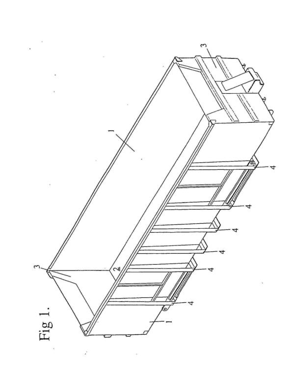
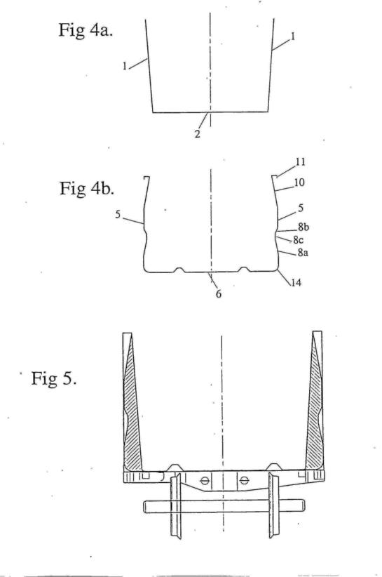
43 Figure 1 depicts a conventional container. According to the Specification, the conventional container includes two side walls (1), a base (2), and two end walls (3). The size of these containers have certain dimensional limitations in that neither the height nor the width can exceed pre-defined dimensions determined by both rail and road standards and practical limitations of loading and unloading facilities. Whilst it is desirable to increase payloads, the size of conventional containers cannot be increased without decreasing their strength. The walls of these containers do not extend to the maximum possible dimensions due to the structural requirements of the container because the bulk product places extreme stresses on the walls which must be reinforced by a number of supporting or reinforcing members to strengthen the walls. These can conveniently take the form of ribs (4), extending around the body of the container. The addition of ribs to strengthen the walls results in a much heavier container and a decrease in the aerodynamics of the container.
44 The Specification states (page 4, lines 9-10) that the invention reduces the number of ribs that are required compared to a conventional container of equal size which will reduce the container’s weight and improve the container’s aerodynamics resulting in a more cost effective container. The Specification also states that the container of the invention may be used for bulk transportation by either road or rail.
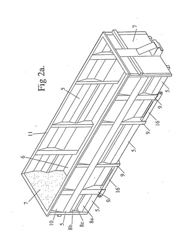
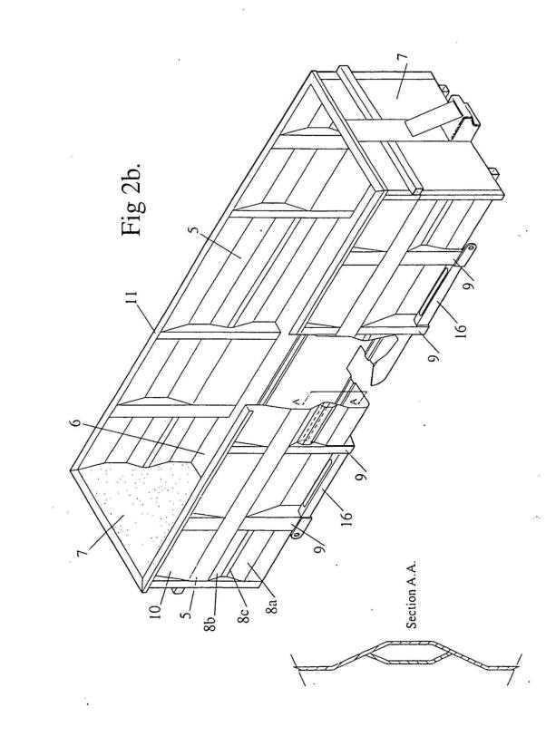
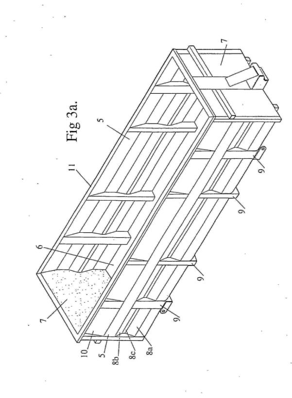
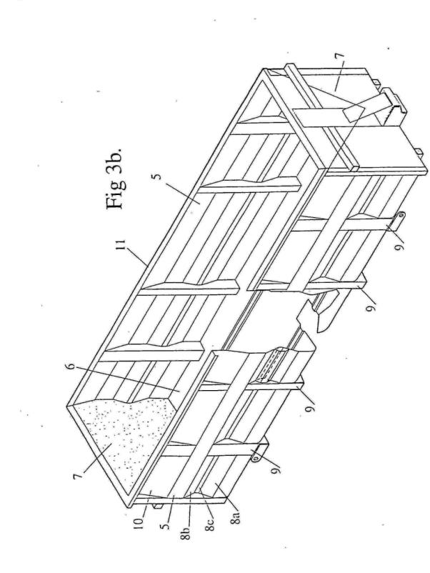
45 Figures 2a and 2b illustrate a preferred embodiment. Figure 2b includes a sectional drawing (Section AA) to better show the internal ridge. The longer element shown in Section AA turning to the right-hand side of the drawing (toward the interior of the container) and then back towards the left (toward the exterior of the container) incorporates the internal ridge.
46 The Specification states that the preferred embodiment has two side walls (5), two end walls (7) and a base (6) and at least one internal ridge (8). The main element of the internal ridge is a first portion (8a) which extends from the wall of the container at an angle towards the interior of the container. A second portion (8b) can be adapted to complete the internal ridge by rejoining the wall to the end of the first portion. The internal ridge may also include a third portion (8c) which joins the first and second portions.
47 The Specification states that the internal ridge is designed to run along the length of the side wall between the supporting frame members. The number and placement of the internal ridges may be dependent upon the size of the container and may reduce the number of strengthening ribs required on a conventional container.
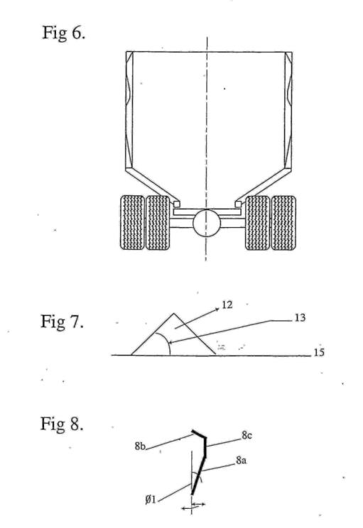
48 The angle at which the first portion of the internal ridge extends from the wall of the container (Ø1) is described in the Specification in some detail. The Specification states (at pages 4, line 26 – 5, line 12):
It is noted that as we move along the first portion 8a from the side wall 5, the angle between the side wall 5 and the position on the first portion 8a relative to the intersection of the side wall 5 and base 6 progressively increases. Similarly, as we return along the second portion 8b, the angle relative to the intersection between the side wall 5 and base 6 progressively decreases.
The angle Ø1 at which the portion 8a, extends from the wall 5 towards the interior of the container is chosen to ensure that the product to be carried by the container is unloaded completely. That is, the angle is preferably dependent on the type of product carried and on the method the operator uses to unload the product. The dimensions of the internal ridge 8, are further determined as a function of the structural strength required and of the natural angle of repose of the material that is to be transported.
The angle at which the first portion 8a extends towards the interior of the container may preferably be determined by the following mathematical formula:
Ø1< Ø2–Ø3 – 90
where
Ø1–is the angle between the vertical wall 5, and the first portion 8a.
Ø2–is the angle the container is rotated in the unloading facility.
Ø3–is the natural angle of repose for the product to be transported.
49 The Specification states that the natural angle of repose (Ø3) is dependent on the product to be carried and includes an explanation of how this angle can be determined. The shape of the second and third portions (8b, 8c) are chosen to complete the internal ridge (8) and fulfil the structural requirements of the container. The Specification states at page 6, lines 19 – 34:
The length and shape of the internal ridge 8, will depend on the structural requirements of the side walls 5 and the base 6. It will also depend on the spacing between supporting frame members 9, and the natural angle of repose of the material. As the distance or spacing between the supporting frame members 9 increases, it will be necessary to increase the depth 16 of the internal ridge 8, to ensure the necessary structural strength. Accordingly, it is possible to design a container specifically for a certain type of material to be transported, by considering the mass of the material and the pressure the material will place on the walls of the container.
A container constructed with an internal ridge of the present invention provides a container that is able to transport bulk product. Furthermore, the internal ridge acts as an in-built longitudinal structural stiffener. This internal ridge, then ensures that the structural requirements, such as strength, fatigue resistance, and buckling capacity, are met, while ensuring that more product can be loaded into a container that has the same exterior dimensions as a conventionally designed container.
50 The Specification also states at pages 8, line 29 – page 9, lines 1-6:
By the addition of at least one internal ridge in the wall of the container, the present invention results in a container that is lighter than conventional containers as the side wall containing the internal ridge does not require as many structural reinforcements as conventional containers, since the internal ridge itself adds to the structural strength of the wall. Again this can be seen by comparison of Figures 1 and 2, whereby the number of ribs or strengthening elements is less than [over to page 9] in the original design. The decrease in the number of ribs 9 also leads to a cheaper container. The decrease in the number of vertical elements, and protruding parts generally improves the aerodynamic shape of the container, thereby making a more efficient and economical container. Further, because fewer welds are required the design ensures that there are fewer areas of stress concentration, thereby making the improved container more fatigue resistant.
The Claims
51 The Patent has 26 claims. Claims 1-6 are as follows:
1. A container for transporting bulk material and for rotary or tipping unloading, the container including two side walls, two end walls, and a base; said side walls including a plurality of vertical reinforcing members spaced along the length of each said side wall, wherein a section of said side wall between at least one adjacent pair of said reinforcing members includes at least one internal ridge running therebetween, the said at least one internal ridge including a first wall portion angled towards an interior of said container, wherein the angle is in the direction of flow of the material during said rotary or tipping unloading, and wherein said at least one internal ridge is integrally formed within said side wall and said at least one internal ridge has a depth greater than the thickness of said side wall.
2. A container as claimed in claim 1 further including at least one said at least one internal ridge between each of said reinforcing members.
3. A container as claimed in claim 1 or 2 including additional reinforcement aligned along said at least one internal ridge between each of said reinforcing members.
4. A container as claimed in any one of claims 1 to 3, further including at least one said internal ridge between one said end wall and a first reinforcing member.
5. A container as claimed in any preceding claim including a second wall portion rejoining said first wall portion to said wall.
6. A container as claimed in any one of claims 1 to 5, wherein at least one said internal ridge includes said first wall portion deflected inwardly a progressively increased degree relative to the intersection of said side wall and said base, and a second wall portion extending from said first wall portion and being deflected outwardly a progressively decreased degree relative to the intersection of said side wall and said base.
52 Later in these reasons I refer to claim 20. To make sense of that claim I also need to refer to claims 17-19. Claims 17-20 are in the following terms:
17. A container as claimed in any one of claims 1 to 16, wherein at least one said side wall further includes a partial ridge along the top or rim of said at least one side wall, said partial ridge being formed by a fourth wall portion, said fourth wall portion being equivalent to said first wall portion.
18. A container as claimed in claim 17, wherein said fourth wall portion is of equal length to said first wall portion.
19. A container as claimed in claim 17 or 18 wherein said partial ridge further includes a strengthening member along the periphery of said fourth wall portion, said strengthening member forming the rim of said container.
20. A container as claimed in claim 19, wherein said strengthening member is integrally formed within said at least one side wall.
The Construction Issue
The principal issue
53 The principal issue is whether the internal ridge referred to in claim 1 must be “formed” within the side wall of the bulk container in the technical sense of that word, when used in the context of metal fabrication, or whether it includes an internal ridge otherwise fixed (eg. by welding or riveting) to the side wall, so as to become a permanent part of the side wall. The answer to this question depends on what the words “… wherein said … internal ridge is integrally formed within said side wall” mean when read in the context of the Specification as a whole.
The proper approach to patent construction
54 The principles governing patent construction were not in dispute. They have been summarised in many cases including by the Full Court in Jupiters Ltd v Neurizon Pty Ltd (2005) 222 ALR 155, 65 IPR 86 where Hill, Finn and Gyles JJ said at [67]:
(i) the proper construction of a specification is a matter of law: Décor Corporation Pty Ltd v Dart Industries Inc (1988) 13 IPR 385 at 400;
(ii) a patent specification should be given a purposive, not a purely literal, construction: Flexible Steel Lacing Co v Beltreco Ltd (2000) 49 IPR 331; [2000] FCA 890 at [81] (Flexible Steel Lacing); and it is not to be read in the abstract but is to be construed in the light of the common general knowledge and the art before the priority date: Kimberley-Clark Australia Pty Ltd v Arico Trading International Pty Ltd (2001) 207 CLR 1; 177 ALR 460; 50 IPR 513; [2001] HCA 8 at [24];
(iii) the words used in a specification are to be given the meaning which the normal person skilled in the art would attach to them, having regard to his or her own general knowledge and to what is disclosed in the body of the specification: Décor Corporation Pty Ltd at 391;
(iv) while the claims are to be construed in the context of the specification as a whole, it is not legitimate to narrow or expand the boundaries of monopoly as fixed by the words of a claim by adding to those words glosses drawn from other parts of the specification, although terms in the claim which are unclear may be defined by reference to the body of the specification: Kimberley-Clark v Arico at [15]; Welch Perrin & Co Pty Ltd v Worrel (1961) 106 CLR 588 at 610; Interlego AG v Toltoys Pty Ltd (1973) 130 CLR 461 at 478; the body of a specification cannot be used to change a clear claim for one subject matter into a claim for another and different subject matter: Electric & Musical Industries Ltd v Lissen Ltd [1938] 4 All ER 221 at 224–5; (1938) 56 RPC 23 at 39;
(v) experts can give evidence on the meaning which those skilled in the art would give to technical or scientific terms and phrases and on unusual or special meanings to be given by skilled addressees to words which might otherwise bear their ordinary meaning: Sartas No 1 Pty Ltd v Koukourou & Partners Pty Ltd (1994) 30 IPR 479 at 485–6 (Sartas No 1 Pty Ltd); the court is to place itself in the position of some person acquainted with the surrounding circumstances as to the state of the art and manufacture at the time (Kimberley-Clark v Arico at [24]); and
(vi) it is for the court, not for any witness however expert, to construe the specification; Sartas No 1 Pty Ltd at 485–6.
55 In Kirin-Amgen Inc v Hoechst Marion Roussel Ltd [2004] UKHL 46; (2004) 64 IPR 444 (Kirin-Amgen) Lord Hoffman observed at [33] that “[t]here is no presumption about the width of the claims” and that “[a] patent may, for one reason or another, claim less than it teaches or enables.” This observation was followed by his Lordship’s lucid exposition of the proper approach to claim construction at [34]-[35]. Lord Hoffman said:
[34] “Purposive construction” does not mean that one is extending or going beyond the definition of the technical matter for which the patentee seeks protection in the claims. The question is always what the person skilled in the art would have understood the patentee to be using the language of the claim to mean. And for this purpose, the language he has chosen is usually of critical importance. The conventions of word meaning and syntax enable us to express our meanings with great accuracy and subtlety and the skilled man will ordinarily assume that the patentee has chosen his language accordingly. As a number of judges have pointed out, the specification is a unilateral document in words of the patentee’s own choosing. Furthermore, the words will usually have been chosen upon skilled advice. The specification is not a document inter rusticos for which broad allowances must be made. On the other hand, it must be recognised that the patentee is trying to describe something which, at any rate in his opinion, is new; which has not existed before and of which there may be no generally accepted definition. There will be occasions upon which it will be obvious to the skilled man that the patentee must in some respect have departed from conventional use of language or included in his description of the invention some element which he did not mean to be essential. But one would not expect that to happen very often.
[35] One of the reasons why it will be unusual for the notional skilled man to conclude, after construing the claim purposively in the context of the specification and drawings, that the patentee must nevertheless have meant something different from what he appears to have meant, is that there are necessarily gaps in our knowledge of the background which led him to express himself in that particular way. The courts of the UK, the Netherlands and Germany certainly discourage, if they do not actually prohibit, use of the patent office file in aid of construction. There are good reasons: the meaning of the patent should not change according to whether or not the person skilled in the art has access to the file and in any case life is too short for the limited assistance which it can provide. It is however frequently impossible to know without access, not merely to the file but to the private thoughts of the patentee and his advisors as well, what the reason was for some apparently inexplicable limitation in the extent of the monopoly claimed. One possible explanation is that it does not represent what the patentee really meant to say. But another is that he did mean it, for reasons of his own; such as wanting to avoid arguments with the examiners over enablement or prior art and have his patent granted as soon as possible. This feature of the practical life of a patent agent reduces the scope for a conclusion that the patentee could not have meant what the words appear to be saying. It has been suggested that in the absence of any explanation for a restriction in the extent of protection claimed, it should be presumed that there was some good reason between the patentee and the patent office. I do not think that it is sensible to have presumptions about what people must be taken to have meant but a conclusion that they have departed from conventional usage obviously needs some rational basis.
56 See also Greenwood and Nicholas JJ in Kimberly-Clark Australia Pty Ltd v Multigate Medical Products Pty Ltd (2011) 92 IPR 21 (Multigate) at [45] in which reference was made to Lord Hoffman’s speech in Kirin-Amgen and Lord Upjohn’s observation in Rodi v Wienenberger AG v Henry Showell Ltd [1969] RPC 367 at 392 that “… some claims may on a superficial reading appear to be unnecessarily circumscribed, but those who have drafted them may have done so in light of the prior art …”. Dixon J made an observation to the same effect many years earlier in Walker v Alemite Corporation (1933) 49 CLR 643 at 656.
57 In Multigate Greenwood and Nicholas JJ also referred to the situation in which a claim used a word or expression that had both an ordinary meaning and a technical meaning. Their Honours said at [39]:
A patent specification may incorporate a definition of a word or expression which subsequently appears in the claims. Leaving that possibility aside, ordinary words which are used in a patent claim should be given their ordinary meaning unless the skilled addressee would give them a different meaning. There are words used in patent claims that have no ordinary meaning apart from their technical or scientific meaning. There are also words used in patent claims that have a technical or scientific meaning as well as an ordinary meaning. In the latter situation the words may have been intended to be used in accordance with their technical or scientific meaning or in accordance with their ordinary meaning. Expert evidence may be received to assist in determining which of these meanings was intended.
58 The key difference between the parties in this case is whether the relevant words in claim 1 should be given a technical or special meaning or what is said by Lynx to be a broader meaning that reflects the ordinary signification of those words.
Lynx’s submissions
59 Lynx’s submissions commenced with some general propositions.
60 Lynx submitted that the Patent does not restrict the invention to use in railway wagons or impose any limitation as to the material from which it is constructed, that bulk material containers described in the patent need not be made from metal, and that the patent is concerned with the configuration of the container rather than how it is made. Lynx also submitted that the description of the invention is illustrative and non-limiting. In particular, the invention is not limited to any preferred embodiment.
61 Lynx then submitted that claim 1 does not use the word “formed” in a technical sense because that usage is only applicable in the context of metal fabrication. It submitted that the technical definition is not apt to apply in the context of non-metal fabrication involving, for example, bulk containers made from plastic or fibreglass. Lynx submitted two pieces will be “formed” within the meaning of claim 1 if they are joined and this would include, according to Lynx, by welding or riveting of metal components.
62 Lynx submitted the word “integrally” as used in claim 1 indicates that the internal ridge must be an integral or permanent part of the side wall that cannot be disassembled or removed from the wall by non-destructive methods. It submitted that a welded or riveted part of the side wall meets that definition. Lynx also submitted that, on the cross-respondents’ construction of claim 1, the word “integrally” is redundant because if the word “formed” is given a narrow technical meaning, then the word “integrally” adds nothing since two pieces that have been “formed” will necessarily be “integrally formed”.
The cross-respondents’ submissions
63 The cross-respondents submitted that the word “formed” was used in the Patent in the technical sense to indicate that the parent material is deformed into a different shape without the addition or subtraction of material. This implies that the material has been pressed or bent into shape without the addition of material by (for example) welding, riveting or bolting. The cross-respondents submitted that the term “formed” could also be used in an analogous way to describe various processes used to shape plastic (for example, thermoforming or moulding) or other similar materials.
64 The cross-respondents also submitted that, even if the word “formed” is not used in claim 1 in its technical sense, the words “integrally formed within said side wall” denote that the internal ridge must be “within” the side wall and that this, coupled with the words “integrally formed”, confirm that the whole phrase is intended to be read in much the same way as it would be if the word “formed” was used in its technical sense.
Consideration
65 The construction issue is a relatively narrow one. There is no dispute that to the skilled addressee the word “formed” has an ordinary meaning and a technical meaning. According to its ordinary meaning, the word “formed” can refer to something that has been given shape or appearance in any number of ways, including by joining together a number of different parts. This would include joining them by welding, riveting or bolting. In its technical meaning, the term “formed” refers to a part that consists of a single piece of metal that has been bent, pressed or otherwise deformed into a particular shape.
66 The question whether “formed” is used in claim 1 in the ordinary sense of the word or in its technical sense depends upon the context in which it is used in the Patent including, in particular, the whole of claim 1. Of course, the Patent must be read in light of the common general knowledge relevant to the field of the invention and drawing upon any expert evidence that may provide assistance in understanding how the notional skilled addressee would interpret the claim, especially where it includes a term or phrase that is susceptible of a technical or special meaning.
67 In my opinion the word “formed” and the phrase “integrally formed” as used in claim 1 refer to a piece of material that has been bent, pressed or moulded into shape. There are a number of considerations which lead me to this conclusion.
68 The Patent is concerned with bulk material containers used in road and rail transportation. The object of the invention is to provide an improved container that is more efficient and effective than existing containers. The prior art bulk material containers referred to in the Patent (which are admitted common general knowledge) were invariably constructed of metal. The Specification does not say this expressly, but it is something that would be well known to the skilled addressee. This is an important aspect of the common general knowledge and one which is of considerable significance in resolving the construction issue. Nowhere does the Patent recommend or suggest the use of any material other than metal in the construction of the inventive bulk containers. The skilled addressee would naturally and sensibly assume that a bulk container made in accordance with the Patent would be made from metal.
69 I accept that the Patent does not specify what materials are to be used to make a bulk container having the features of the invention. I also accept that it may be inapt to use the word “formed” in its technical sense in relation to the bulk containers that are not made from metal. Nevertheless, the skilled addressee taking a practical approach to his or her reading of the Specification would assume, consistent with the description of conventional bulk containers, the common general knowledge, and the absence of any indication to the contrary, that the inventive bulk containers described in the Specification would be made from metal.
70 The passage in the Specification at page 9, lines 1-6 indicates that a claimed advantage of the invention is the need for fewer reinforcing ribs, and that this in turn results in fewer welds. This is said to make the bulk container more fatigue resistant. Of course, this passage of the Specification is not describing the design or configuration of the internal ridge. Nevertheless, it does tend to confirm that the Patent will be read and understood by the skilled addressee as describing and comparing a conventional container made from metal with a new and inventive container also made from metal. Welds are usually used to join metal components, a fact that would be known and understood by the notional skilled addressee.
71 The drawings included in the Specification are schematic drawings, not engineering or mechanical drawings. The skilled addressee would not expect them to include engineering details that were not necessary to fully describe the invention and the best method known to the patentee of performing it. Nevertheless, Section AA in Fig 2b depicts a section of the internal ridge of the preferred embodiment in a manner that the skilled addressee would readily perceive and understand as “formed” in the technical sense of that word, viz. bent or pressed into a single piece of material.
72 The cross-hatching shown in Section AA implies that the internal ridge (8a) is formed from the same piece of material (which the skilled addressee would presume to be metal sheet) that makes up the side wall (5) as shown in Fig 2a and Fig 2b. The other component shown to the left-hand side of Section AA joined to the internal ridge has different cross-hatching thereby indicating to the skilled addressee that it is not made from the same piece of material as the internal ridge to which it has instead been welded or riveted. As explained at page 4, lines 19-25 of the Patent, the component shown on the left-hand side is an extra reinforcing element that may be added to the internal ridge to provide additional strength if required.
73 Of course, Fig 2a and Fig 2b depict a preferred embodiment. It is not legitimate to import into claim 1 a limitation or qualification based upon a feature of a preferred embodiment that is not otherwise found within the claim properly construed. Here, however, there is a real question as to what claim 1 means and it is not only appropriate, but necessary, to resolve that question (if it can be resolved) based upon a reading of the patent specification as a whole.
74 That the word “formed” as used in claim 1 was intended to be given a technical or special meaning is in my view confirmed by the other words that make up the relevant phrase “integrally formed within said side wall” which serve to emphasise that what is being referred to is a single piece of material as opposed to two or more pieces of material joined together. I do not accept that the word “integrally” is redundant on this interpretation of the claim. In my view it makes reasonably clear what may otherwise have been left unclear viz. the internal ridge is made from the same piece of material from which the side wall is constructed. Further, when read in context, the word “within” also suggests that the ridge is formed from (as opposed to added onto) the side wall. It is true that the word “within” could be used to locate the ridge (on the interior of the side wall), but I do not think so in this case because the word “internal” already makes this tolerably clear.
75 Another matter that I regard as significant is the description of the internal ridge at page 6, lines 28-34 of the Specification. The internal ridge is there said to act as “an in-built longitudinal structural stiffener.” Read in context, this implies that the internal ridge is built into the side wall so as to enhance the strength and fatigue resistance of the container. The term “in-built” is not apt to describe a ridge that has been joined to the side wall by (for example) welding or riveting.
76 I do not accept that what appears at page 6, lines 28-34 of the Specification relates solely to the preferred embodiment depicted in the drawings. What is described in this passage is a characteristic of “the present invention” and improvements and advantages it provides compared with the prior art.
77 Claim 19 refers to “a strengthening member” along the periphery of the “fourth wall portion … forming the rim of the … container”. In the drawings of the preferred embodiment an example of such a rim appears most clearly in Fig 4b which depicts the strengthening member (11) forming the rim of the bulk container. Thus, claim 19 refers to a strengthening member “forming” a rim. This choice of language is to be contrasted with the words appearing in claim 20 which pick up the crucial language of claim 1 viz. the strengthening member must be “integrally formed within” at least one side wall. Claim 19 explicitly requires that the strengthening member form the rim of the container, but is otherwise neutral as to how the strengthening member and the side wall are connected. Claim 20, on the other hand, is in my view referring to a situation in which the strengthening member is “integrally formed” within the side wall in the sense that they must have been made from a single piece of material.
78 The purely hypothetical question whether a bulk container made from plastic, fibreglass, or some other non-metallic material can include an internal ridge “integrally formed within said side wall” (which was a particular focus of Lynx’s submissions) is not a question that arises for decision in this case. However, I do not see why a side wall incorporating an internal ridge constructed from a single sheet of moulded fibreglass or moulded plastic could not be “integrally formed” for the purposes of claim 1. Of course, if the side wall and internal ridge were made from separate parts that were bolted, glued or otherwise attached (viz. not “integrally formed”) they would fall outside the scope of claim 1 as interpreted by me.
Section 116
79 Section 29A of the Act requires that a PCT application be treated as a complete application for a standard patent, and that the description, drawings and claims contained in the PCT application be treated as a complete specification filed in respect of the application. Section 116 of the Act provides that a court may, in interpreting a complete specification as amended, refer to the specification without amendment.
80 Claim 1 in the PTC application was to:
[a] container for transporting bulk material including two side walls, two end walls and a base, wherein at least one said side wall includes at least one ridge running the length of said at least one side wall.
81 It is not disputed by Lynx that the PCT application, including claim 1, was amended pursuant to an amendment request dated 13 December 1999. The effect of the amendment was to substitute in claim 1 the words “at least one internal ridge … integrally formed within said side wall” for “at least one said side wall [that] includes at least one ridge.” The detailed description of the invention by reference to the drawings, and the drawings themselves, did not change in any material respect.
82 Claim 1 in its original form requires that at least one side wall includes at least one ridge. Claim 1 in its amended form requires that there be an internal ridge integrally formed within the side wall. It is clear that the amendment narrowed the scope of claim 1.
83 Lynx submitted that the amendment history does not show that the words “integrally formed within said side wall” mean what the cross-respondents say they mean. I accept that they do not do so in any direct or definitive manner. However, on Lynx’s construction of claim 1, the change in language did no more than require that the ridge be a permanent part of the side wall. I do not think that can be right.
84 The amendment to claim 1 strongly suggests that the new wording is to be understood to convey something more than that the ridge must be integral in the sense of being a permanent, or permanently attached, part of the side wall. In my view the amendment tends to confirm that, properly construed, claim 1 requires that the ridge and the side wall be “integrally formed” in the sense that they must be bent, pressed or moulded into shape from the one piece of material.
File wrapper estoppel
85 The cross-respondents also relied upon a letter from Lynx’s patent attorney to the Commissioner of Patents dated 13 December 1999. That letter includes at page 2 the following statements:
The container of the present invention, unlike prior art, uses a reinforcing ridge or ridges that are formed from the flat plate that makes up the side walls. One plate only is required, as the ridge or ridges are achieved through bending and not through welding or any other connections or fasteners.
There is little doubt that the patent attorney’s interpretation of claim 1 in its amended form, as represented in the letter of 13 December 1999, is to much the same effect as that which Lynx invites the Court to reject in favour of the far broader interpretation which it now propounds.
86 I do not think the patent attorney’s letter is admissible evidence as to the proper construction of claim 1. The reasons why are apparent from the passages in the speech of Lord Hoffman in Kirin-Amgen to which I have previously referred and the reasons of Gummow J (with whom Northrop J agreed) in Prestige Group (Australia) Pty Ltd v Dart Industries Inc (1990) 26 FCR 197 (Prestige). As Gummow J observed at 213, the scope of the monopoly depends upon the proper construction of the claims read in the context of the specification as a whole and in light of the common general knowledge. The authorities in this country have eschewed recourse to extrinsic materials (such as correspondence between the patent applicant and the Commissioner) for the purpose of ascertaining the true scope of a claim.
87 The TPI parties sought to rely upon the doctrine of “file wrapper estoppel”. As Gummow J explained in Prestige at 212, this refers to a US doctrine which may permit a statement made by a patentee in the course of prosecuting a patent application to be relied upon as an aide to construction where infringement is asserted in reliance upon the US doctrine of equivalents. As his Honour pointed out, although the US legislation provides “legislative encouragement” for such an approach, the Patents Act 1952 (Cth) (with which his Honour was concerned) did not do so. His Honour’s point is equally true of the 1990 Act.
88 As the Bradken parties correctly submitted, Gummow J did not express a final view on the application of the “file wrapper estoppel” doctrine in Australia. His Honour indicated at 211 that his views were “provisional” and went on to state at 212:
… there appear to be significant difficulties in founding “file wrapper estoppel” in either the law of evidence as to admissions or in the law as to estoppel by representation as they are presently understood in this country. But I would not regard the issue of the role of “file wrapper estoppel” in this country as other than still open for decision.
89 Lockhart J, like Gummow J, said that he regarded the question of the application of file wrapper estoppel in Australia as still open for decision, but chose not to express a view as to the difficulties standing in the way of the acceptance of the doctrine.
90 Although the applicability of the US doctrine of “file wrapper estoppel” may not have been settled by the Full Court’s decision in Prestige, the observations of Gummow J in that case highlight the considerable obstacles that are involved in applying the doctrine in this country. The Bradken parties were unable to point to any developments in the law since Prestige was decided that might suggest that these obstacles are now any less weighty than Gummow J’s reasons suggest them to be. In circumstances where I have decided the construction point in accordance with more well-settled principles, it is unnecessary for me to consider this issue any further except to say that I have not had regard to the letter of 13 December 1999 for the purpose of construing claim 1.
Infringement
91 Having resolved the construction issue it is necessary to determine whether the cross-respondents’ ore wagons or ore cars are within claim 1. I did not understand there to be any real issue that if the words “… internal ridge is integrally formed within said side wall” were properly understood as referring to an internal ridge bent, pressed or moulded from the same piece of material as the side wall, then none of the cross-respondents’ ore wagons or ore cars will infringe claim 1. That they are not so constructed is readily apparent from the various drawings and photographs that are in evidence as Exhibit A.
92 The drawings and photographs in Exhibit A show that the Bradken Iron Ore Wagon incorporates (at least one) internal ridge that is welded onto the inside of the side wall. The internal ridge in the Bradken Iron Ore Wagon is not “integrally formed within said side wall” as required by claim 1.
93 The drawings and photographs of the CSR Ore Car in Exhibit A show that it has (at least one) internal ridge welded onto the inside of the side wall. The internal ridge is not “integrally formed within said side wall” as required by claim 1.
94 The drawings and photographs of the QRRS (CNR) Ore Car in Exhibit A show that it has (at least one) internal ridge on the inside of the side wall made up of a number of parts (block plates and a pressed dish) welded into position. The internal ridge in the QRRS (CNR) Ore Car is not “integrally formed within said side wall” as required by claim 1.
Disposition
95 The Preliminary Question in each proceeding will be answered in the negative. I will give the parties an opportunity to agree upon the terms of other orders consequential upon that answer. The proceedings will be stood over to a date to be fixed for the purpose of making further orders.
I certify that the preceding ninety-five (95) numbered paragraphs are a true copy of the Reasons for Judgment herein of the Honourable Justice Nicholas. |
Associate:
SCHEDULE A