
FEDERAL COURT OF AUSTRALIA
Streetworx Pty Ltd v Artcraft Urban Group Pty Ltd [2014] FCA 1366
IN THE FEDERAL COURT OF AUSTRALIA |
|
|
Applicant ARTCRAFT URBAN GROUP PTY LTD and another named in the schedule Respondents |
|
ARTCRAFT URBAN GROUP PTY LTD and another named in the schedule Cross Claimants STREETWORX PTY LTD Cross Respondent |
DATE OF ORDER: |
18 December 2014 |
WHERE MADE: |
1. The applicant file and serve on or before 16 January 2015 proposed minutes of orders to give effect to these reasons including any submissions on costs.
2. The respondents file and serve on or before 23 January 2015 proposed minutes of orders to give effect to these reasons including any submissions on costs.
3. The further hearing of this proceeding be adjourned to 9.30 am on 30 January 2015 for the making of orders to give effect to these reasons, including orders for costs and for further directions as to the future disposition of this matter.
4. Costs reserved.
Note: Entry of orders is dealt with in Rule 39.32 of the Federal Court Rules 2011.
VICTORIA DISTRICT REGISTRY |
|
GENERAL DIVISION |
VID 853 of 2013 |
BETWEEN: |
STREETWORX PTY LTD Applicant ARTCRAFT URBAN GROUP PTY LTD and another named in the schedule Respondents ARTCRAFT URBAN GROUP PTY LTD and another named in the schedule Cross Claimants STREETWORX PTY LTD Cross Respondent |
JUDGE: |
BEACH J |
DATE: |
18 December 2014 |
PLACE: |
MELBOURNE |
REASONS FOR JUDGMENT
1 This proceeding involves questions concerning the construction, validity and infringement of innovation patent claims for lighting assemblies known as luminaires for use in public areas, in particular street lighting.
2 On 22 August 2013, the applicant, Streetworx Pty Ltd (Streetworx) commenced proceedings against Artcraft Urban Group Pty Ltd (AUG) and Murray John Saint (Saint) alleging infringement of Australian Innovation Patent No. 2009101103 (the 103 Patent) and Australian Innovation Patent No. 2009101104 (the 104 Patent). The relief sought by Streetworx has included:
Declarations of infringement against the respondents;
Injunctions restraining the respondents from further infringement;
Damages or an account of profits (an election is still to be made);
Delivery up of all infringing articles;
Additional damages pursuant to s 122(2A) of the Patents Act 1990 (Cth) (the Act).
AUG and Saint deny infringement. Further, by way of cross-claim filed on 4 October 2013 they allege that various claims of the 103 Patent and the 104 Patent are invalid.
3 This trial has only dealt with issues of liability. An order has been made that liability be heard and determined separately from and prior to issues of relief.
4 In summary, in my view, none of the allegations of invalidity made by AUG and Saint have been made out. As to Streetworx’s case on infringement, it has been made good in relation to the three luminaires supplied by AUG. But in my view, Saint did not relevantly “authorise” such exploiting conduct of AUG within the meaning of s 13(1) of the Act.
I: The Parties, the Patents and the issues
5 Streetworx is a street lighting company. It is the registered proprietor under the Act of the 103 Patent and the 104 Patent for inventions described as lighting assemblies. Streetworx is part of the Ace group of companies, which includes Ace Energy Services Pty Ltd.
6 AUG has supplied and supplies lighting assemblies, including:
The Windowless Artcraft Luminaire (Artcraft model AUGT5) (Windowless Artcraft Luminaire) for several months in mid-2012;
The Artcraft Luminaire (Artcraft model AUGT5) (Artcraft Luminaire) from early May 2013 to December 2013; and
The Modified Artcraft Luminaire (Artcraft model AUGT5) (Modified Artcraft Luminaire) from about January 2014.
7 The ascription T5 refers to a type of lamp. “T” represents the shape of the lamp (tubular) and “5” represents the diameter of the fluorescent lighting tube in eighths of an inch. T5 lamps are reliable and have good energy efficiencies. The Windowless Artcraft Luminaire, Artcraft Luminaire and Modified Artcraft Luminaire are luminaires that utilise T5 lamps.
8 Until 2009, a division of Artcraft Pty Ltd known as “Artcraft Urban Group” traded in the design and manufacture of street lighting and street furniture. From 2009, that division of Artcraft Pty Ltd was established as a separate company, AUG. Saint transitioned from the general manager of that division to being a director and the general manager of AUG, with day-to-day control of its business. Saint indirectly held 20% of the shares in AUG. Rodney Wellington and Ronald Slabak were also directors and held indirectly 40% each of the shares in AUG.
9 AUG supplied to its customers AUG manufactured luminaires as well as luminaires manufactured by other companies such as the Pierlite T5 Greenstreet Luminaire. From August 2010 to sometime in 2013, AUG also supplied the Streetworx Enviro T5 Luminaire.
The 103 Patent – general
10 The 103 Patent is titled “Lighting Assembly” and has a priority date of 30 October 2009. The complete specification for the 103 Patent was published and became open for public inspection on 26 November 2009. The 103 Patent was examined and certified by the Commissioner of Patents on 15 February 2013, after which infringement proceedings could be pursued (s 120(1A) of the Act).
11 The abstract for the 103 Patent states:
The present invention provides an improved lighting assembly suitable for a range of uses, particularly in public areas and thoroughfares, which lighting assembly has reduced maintenance and servicing needs. In a particular preferred embodiment the lighting assembly has a casing comprising a main body defining a port for receiving a support and mains cable, and a visor, the casing enclosing;
- a reflector assembly for receiving at least one lamp, and
- a termination chamber for location of a PE cell.
wherein the visor is of unitary construction for covering both the reflector assembly and the termination chamber.
12 The complete specification for the 103 Patent provides the following description.
13 The invention relates to the field of lighting, in particular lighting assemblies and fixtures suitable for a range of uses outdoors, including street lighting as well as flood lighting and the illumination of stadiums for sporting events. In particular, the invention relates to a light assembly, being an electric device used to create artificial illumination.
14 The term “lighting assembly” includes a luminaire within its scope. A luminaire is a term of art that includes a lighting assembly comprising a light source (lamp), a reflector for directing the light, an aperture covered by a lens, an outer casing for lamp alignment and protection, an electrical ballast and a connection to a power source.
15 The use of electric street lighting dates back to the late 19th century, when carbon arc lamps employing alternating current were used to ensure the electrodes burned down at the same rate. By the start of the 20th century they had been replaced by incandescent light bulbs which remained in use until replaced by the high-intensity discharge lamps or high pressure sodium lamps used today. The use of compact fluorescent lamps has also become common.
16 Street lights are located at the top of poles to maximise the light cast below. Street lighting has progressed from the use of straight vertical poles of 3-4 metres in height to up to 10 metres in height, often curved at the top, including a bracket to locate the light closer to the centre of the thoroughfare. Such street lights include those sold under the registered Australian trade mark Greenstreet® by Pierlite Pty Ltd; such street lights are described in Pierlite’s patent application AU 2004205200. The Pierlite Greenstreet product is portrayed in the following picture:
17 In lighting assemblies such as the Greenstreet®, there are often multiple parts for entry to internal portions of the lens or visor. Further, the component area may not be locked and can vibrate loose. Further, the fixture may not be attached with lanyard. Such issues may warrant increased ongoing maintenance. With additional parts included by having a separate cover arrangement, the apparatus may become loose and there is a potential for falling parts. This can be an occupational health and safety (OHS) issue. Further, these arrangements may allow a point of entry for vermin, spiders (webs), insects and other pests to enter the luminaire and may facilitate weather or pollution exposure (e.g. salt in coastal areas), which can then create potential risks such as fire, electrocution and OHS hazards.
18 Further, service and maintenance of street lighting incurs significant cost. The elevated position of each light contributes to the time, cost and difficulties associated with servicing and maintaining the light system. To save time and avoid interruption to service, street light systems are not usually turned off during maintenance or servicing. The lighting system is left “live” whilst the linesmen are at work. Typically, linesmen manually handle cables operating at 196-254V AC or 176-254V DC.
19 One of the problems with street lights is that they are time consuming for linesmen to maintain due to servicing occurring when the system is “live”. Linesmen must wear thick protective gloves which limit their dexterity. Further, the breakability of the components (due to them being brittle or corrosion), the size of the components (comparatively small) and the need to work at elevated heights all create difficulties. Further, the malfunctioning of photoelectric (PE) cells (e.g. failure to turn off, shortening the lifespan of the light components (day burners)) can be a problem. A PE cell is typically present in each street light. The PE cell controls the activation and deactivation of the street light based on ambient light level.
20 The objects of the invention embodied in the claims include reducing the maintenance and servicing requirements for lighting assemblies and improving the ease and speed of service and maintenance.
21 The claims defining the invention are:
1. A lighting assembly having a casing comprising a main body defining a port for receiving a mains cable, and a visor, the casing enclosing;
- a reflector assembly for receiving at least one lamp, and
- a termination chamber located laterally in relation to the reflector assembly,
wherein the visor is of unitary construction for covering both the reflector assembly and the termination chamber, at least part of the termination chamber and at least part of the reflector assembly being visible through the visor.
2. A lighting assembly according to claim 1 which includes at least one integral hinge that permits movement of the visor from a first, closed position to a second, open position permitting full access to the reflector assembly and termination chamber without the visor disengaging from the main body.
3. A lighting assembly according to claim 1 or 2 which includes a clip that is capable of independently supporting the visor on the main body.
4. A lighting assembly according to any one of the previous claims which includes at least one fastener comprising a first part that pivots on the main body of the casing but does not contact the visor, and a second part in operative connection with the first part, wherein the second part contacts the visor but does not contact the main body.
5. A lighting assembly according to any one of the previous claims wherein the reflector assembly and termination chamber are fastened by single throw turning lock screws.
The 104 Patent – general
22 The 104 Patent is also titled “Lighting Assembly” and has a priority date of 30 October 2009. The completed specification for the 104 Patent was published and became open for public inspection on 3 December 2009. The 104 Patent was examined and certified by the Commissioner on 19 March 2013.
23 The field of invention and prior art set out in the complete specification to the 104 Patent is identical to that of the 103 Patent.
24 In the 104 Patent specification, the claims defining the invention are:
1. A lighting assembly having a casing comprising a main body defining a port for receiving a mains cable, and a visor, the casing enclosing;
- a reflector assembly for receiving at least one lamp, and
- a termination chamber for location of a PE cell,
wherein the visor is of unitary construction for covering both the reflector assembly and the termination chamber and the portion of the visor covering the termination chamber is adapted to allow visual inspection of components within the termination chamber.
2. A lighting assembly according to claim 1 wherein the PE cell resides entirely within the casing.
3. A lighting assembly according to any one of the preceding claims wherein the visor is clear in an area adjacent the PE cell.
4. A lighting assembly according to any one of the preceding claims wherein the visor further includes a frosted region for preventing unwanted de-activation of the PE cell due to ambient artificial light.
5. A lighting assembly according to claim 1 and substantially as herein described with reference to the drawings.
Streetworx Enviro T5 luminaire
25 The lighting assembly developed, manufactured and intended by Streetworx to be made in accordance with and protected by the 103 Patent and 104 Patent is the Enviro T5 Luminaire. The “Enviro T5” was launched by Streetworx prior to June 2010. Of course, the claims of the 103 Patent and the 104 Patent are to be construed without regard to the Streetworx Enviro T5. But I describe the Streetworx Enviro T5 at this point only as background to the later discussion of the s 13(1) authorisation question concerning Saint’s conduct, where Saint had reference to this actual product.
26 According to Streetworx, its “Enviro T5” has the following integers:
• A visor of unitary construction;
• One or more integral hinges;
• The PE cell within the termination chamber;
• A non-opaque section of the visor over the termination chamber;
• The part of the visor over the termination chamber being frosted for preventing unwanted deactivation of the PE cell due to ambient artificial light;
• One or more two-part clips (fasteners) capable of independently supporting the visor;
• A clear window over the PE cell; and
• An ability to see into the termination chamber through the visor.
27 The Enviro T5 Luminaire is portrayed in the following picture:
28 As to the strictly separate matter of the integers of the relevant claims of the 103 Patent and the 104 Patent, Streetworx asserts that these are innovations that constitute important and economically valuable improvements over the prior art which reduce the need for, and improve the ease and safety of, maintenance and servicing of lighting assemblies.
Alleged infringement of the Patents
29 Streetworx contends that the supply of the Artcraft Luminaire and Windowless Artcraft Luminaire infringed each of claims 1 to 4 of the 103 Patent and claims 1 to 4 of the 104 Patent (except for claim 3 of the 104 Patent in respect of the Windowless Artcraft Luminaire).
30 Streetworx contends that the supply of the Modified Artcraft Luminaire infringes and has infringed each of claims 1 to 4 of the 103 Patent. It is not contended that the Modified Artcraft Luminaire infringes any of the claims of the 104 Patent.
Alleged infringement of 103 Patent and 104 Patent by Artcraft Luminaire
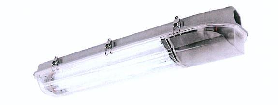
31 Since at least 7 December 2009 AUG developed and manufactured, and from early 2013 to about December 2013 supplied the Artcraft Luminaire.
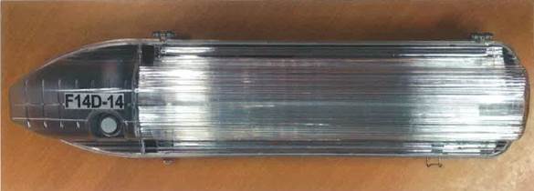
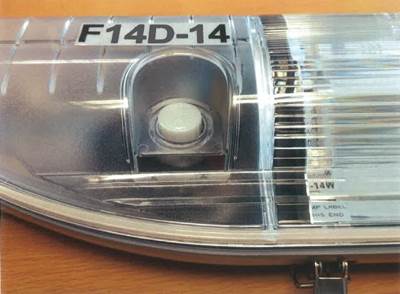
32 The Artcraft Luminaire is portrayed in the following pictures:
33 Streetworx alleges that AUG has without the licence or authority of Streetworx used, made or imported, offered for sale, sold or otherwise disposed of, kept for the purpose of selling or otherwise disposing of and authorised others to do each of such acts in respect of the Artcraft Luminaire in infringement of claims 1-4 of the 103 Patent and claims 1-4 of the 104 Patent. Further, it alleges that Saint authorised such conduct.
34 In these proceedings it has not been in dispute that AUG has imported, manufactured, offered for sale, sold, kept for the purpose of selling and authorised others to sell the Artcraft Luminaire in the patent area within the meaning of s 13(1) of, and the Dictionary to, the Act. What is in dispute is whether that product has taken all the integers of each of the relevant claims of the Patents, and whether Saint authorised AUG’s alleged infringing conduct.
35 Accordingly, the questions in respect of infringement are whether that product falls within the scope of each asserted claim of the Patents and whether Saint authorised the infringing conduct of AUG.
36 In respect of the 103 Patent, Streetworx has alleged that the Artcraft Luminaire:
(a) had all integers of claim 1, including a visor of unitary construction, with at least part of the termination chamber and at least part of the reflector assembly being visible through the visor (claim 1);
(b) had all integers of claim 1 and included an integral hinge that in an open position permitted full access to the reflector assembly and termination chamber without the visor disengaging from the main body (claim 2);
(c) had all integers of claim 1 or 2 and included a clip capable of independently supporting the visor on the main body (claim 3); and
(d) was a lighting assembly according to any one of the previous claims and included a multiple-part fastener which operated in a particular manner (claim 4).
37 In respect of the 104 Patent, Streetworx has alleged that the Artcraft Luminaire:
(a) had all integers of claim 1, including a visor of unitary construction with the portion of the visor covering the termination chamber adapted to allow visual inspection of components within the termination chamber (claim 1);
(b) had all integers of claim 1 wherein the PE cell resided entirely within the casing (claim 2);
(c) was a lighting assembly according to any one of the preceding claims wherein the visor was clear in an area adjacent to the PE cell (claim 3); and
(d) was a lighting assembly according to any one of the preceding claims wherein the visor further included a frosted region for preventing unwanted deactivation of the PE cell due to ambient artificial light (claim 4).
Alleged infringement of 103 Patent by Modified Artcraft Luminaire
38 Apparently, due to commercial concerns about the potential impact of the present litigation on AUG’s business with respect to contracts for the supply of T5 luminaire products to Victorian municipal councils, AUG introduced a modified T5 luminaire into the Australian market (the Modified Artcraft Luminaire), with modifications that were designed with the intention of avoiding any patent infringement.
39 The key modification was to the design of the visor, being the acrylic/polycarbonate/polymer outer casing of the luminaire, with respect to coverage of the visor over the termination chamber, being the internal portion of the luminaire where the mains cable terminated, housing inter alia the PE cell (cf with the reflector assembly being the internal portion of the luminaire, housing inter alia the lamps which reflect emitted light).
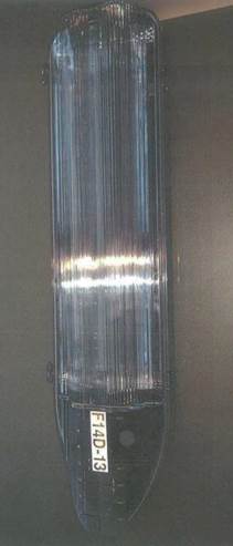
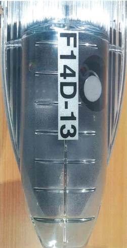
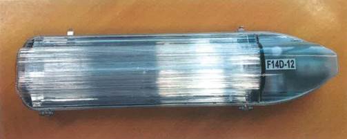
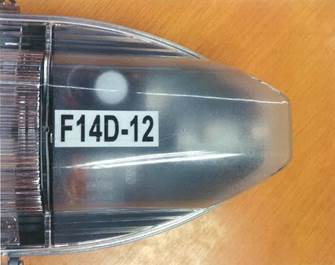
40 In the Artcraft Luminaire, the PE cell was located in the termination chamber, completely enclosed within the visor with no part projecting through the visor. The portion of the visor located directly above the PE cell was a fully transparent oval shape of approximately 5 cms in diameter, allowing the PE cell and most of the termination chamber to be visible through the transparent portion. The remaining portion of the visor above the termination chamber was lightly frosted. Contrastingly, in the Modified Artcraft Luminaire the detector portion of the PE cell (approximately 1 cm at the tip of the PE cell) projected through an opening in the visor located over the termination chamber. The visor was designed so that the tip of the PE cell protruded through an aperture or sleeve in the visor in the shape of a circular cavity, which fitted closely around the PE cell (although there was approximately a 2 mm gap between the edge of the aperture and the PE cell). An insert in the visor, a semi-circle shaped depression, surrounded the aperture. There was no fully transparent portion of the visor above the termination chamber; the entirety of the visor in that region was frosted, in a slightly heavier opacity when compared to the Artcraft Luminaire.
41 The Modified Artcraft Luminaire is portrayed in the following pictures:
42 Streetworx alleges that from January 2014, AUG has without the licence or authority of Streetworx used, made or imported, offered for sale, sold or otherwise disposed of, kept for the purpose of selling or otherwise disposing of and authorised others to do such acts in respect of the Modified Artcraft Luminaire in infringement of claims 1-4 of the 103 Patent. Further, it alleges that Saint authorised such conduct.
43 In the present case, the dispute is whether the Modified Artcraft Luminaire has taken all the integers of the relevant claims of the 103 Patent, and whether Saint authorised AUG’s alleged infringing conduct, despite the Modified Artcraft Luminaire purportedly being developed by AUG to avoid any patent infringement.
44 In respect of the 103 Patent, Streetworx has alleged that the Modified Artcraft Luminaire in summary:
(a) had all integers of claim 1, including a visor of unitary construction, with at least part of the termination chamber and at least part of the reflector assembly being visible through the visor (claim 1);
(b) had all integers of claim 1 and included an integral hinge that in an open position permitted full access to the reflector assembly and termination chamber without the visor disengaging from the main body (claim 2);
(c) had all integers of claim 1 or 2 and included a clip capable of independently supporting the visor on the main body (claim 3); and
(d) was a lighting assembly according to any one of the previous claims and included a multiple-part fastener which operated in a particular manner (claim 4).
Alleged infringement of 103 Patent and 104 Patent by Windowless Artcraft Luminaire
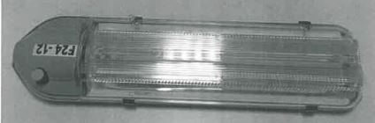
45 The Windowless Artcraft Luminaire was a design of luminaire produced by AUG before the Artcraft Luminaire. In contrast to the Artcraft Luminaire, the portion of visor above the PE cell of the Windowless Artcraft Luminaire was completely frosted (albeit lightly frosted).
46 A small number of Windowless Artcraft Luminaire were produced by AUG, but the design was subsequently modified to introduce a clear window in the visor above the PE cell.
47 The Artcraft Luminaire was then produced by AUG and replaced the Windowless Artcraft Luminaire. In both designs, the PE cell was located inside the termination chamber, completely enclosed within the visor with no part projecting through the visor.
48 The Windowless Artcraft Luminaire is portrayed in the following pictures:
49 Streetworx alleges that AUG has without the licence or authority of Streetworx used, made or imported, offered for sale, sold or otherwise disposed of, kept for the purpose of selling or otherwise disposing of and authorised others to do such acts in respect of the Windowless Artcraft Luminaire in infringement of claims 1-4 of the 103 Patent and claims 1, 2 and 4 of the 104 Patent. Further, it alleges that Saint authorised such conduct.
50 As with the Artcraft Luminaire, the dispute is whether the Windowless Artcraft Luminaire took all the integers of the relevant claims of the Patents, and whether Saint authorised AUG’s alleged infringing conduct.
51 In respect of the 103 Patent, Streetworx has alleged that the Windowless Artcraft Luminaire in summary:
(a) had all integers of claim 1, including a visor of unitary construction, with at least part of the termination chamber and at least part of the reflector assembly being visible through the visor (claim 1);
(b) had all integers of claim 1 and included an integral hinge that in an open position permitted full access to the reflector assembly and termination chamber without the visor disengaging from the main body (claim 2);
(c) had all integers of claim 1 or 2 and included a clip capable of independently supporting the visor on the main body (claim 3); and
(d) was a lighting assembly according to any one of the previous claims and included a multiple-part fastener which operated in a particular manner (claim 4).
52 In respect of the 104 Patent, Streetworx has alleged that the Windowless Artcraft Luminaire in summary:
(a) had all integers of claim 1, including a visor of unitary construction with the portion of the visor covering the termination chamber adapted to allow visual inspection of components within the termination chamber (claim 1);
(b) had all integers of claim 1 wherein the PE cell resided entirely within the casing (claim 2); and
(c) was a lighting assembly according to any one of the preceding claims wherein the visor further included a frosted region for preventing unwanted deactivation of the PE cell due to ambient artificial light (claim 4).
Defence to infringement and cross-claim alleging invalidity
53 AUG denies any infringement of the Patents. Further, with respect to the involvement of Saint in the alleged infringements, Streetworx has asserted that Saint made the relevant decisions, undertook, delegated and outsourced the tasks in relation to the development, manufacture, importation, testing, promotion and sale of the allegedly infringing products. Streetworx says that Saint had the power to prevent AUG’s allegedly infringing conduct and failed to do so. Accordingly, it says that Saint authorised AUG’s infringing conduct within the meaning of s 13(1) of the Act. AUG denies that Saint authorised the allegedly infringing conduct of AUG and submits that at all times Saint was acting with the approval, sanction and authority of the board of directors of AUG and without any intention to infringe the Patents or to procure infringement.
54 Further, by way of a notice of cross-claim filed on 4 October 2013, AUG and Saint have also sought orders that the 103 Patent and the 104 Patent be revoked.
55 In their further amended particulars of invalidity dated 10 April 2014, the respondents assert that the 103 Patent was invalid on the basis of a lack of novelty, a lack of innovative step, a failure to constitute a manner of manufacture, a lack of utility, a lack of clarity and a lack of fair basing. In particular, the respondents assert that:
Claims 1-4 lack novelty as the alleged invention was not novel compared to prior art existing before the priority date of the claims.
The alleged invention in each of the claims 1-5 was not a patentable invention in that when compared to the prior art as it existed before the priority date of each claim it did not involve an innovative step.
The alleged invention in claim 2 (and claims 3-5 insofar as they are dependent on claim 2) and in claim 4 (and claim 5 as dependent) are not patentable inventions as they are not an “invention” or are not a “manner of manufacture” within the meaning of s 6 of the Statute of Monopolies 1623 (Imp). It is said that the invention in claim 2 is a mere collocation as there is no working relationship between the requirement in claim 2 that the hinge be of integral construction and the feature of visibility described in claim 1 on which claim 2 is dependent. It is also said that the invention in claim 4 is a mere collocation as there is no working relationship between the requirement in claim 4 that “at least one fastener comprising a first part that pivots on the main body of the casing but does not contact the visor, and a second part in operative connection with the first part, wherein the second part contacts the visor but does not contact the main body” and the features described in the claims on which claim 4 is dependent.
The alleged invention in claims 1-5 and dependent claims are not patentable as they are not useful. It is said that claim 1, and claims 2-5 as dependent claims, includes embodiments that do not give the asserted benefit of a linesman being able to carry out a visual inspection of components within the luminaire without having to remove any cover as stipulated in the specification. It is said that claim 3, and claims 4-5 insofar as they are dependent on claim 3, is not useful as it includes embodiments where the “independent” clip does not provide any maintenance advantage, namely embodiments where the integral hinge does not have a removable pin. It is said that claim 4, and claim 5 insofar as it is dependent, is not useful as the two part fastener described would not achieve a reduction in corrosion in the fastener. Further, the fasteners would not achieve a reduction in corrosion in the fastener, and the casings (when used with the relevant fasteners) would also not achieve a reduction in corrosion.
It is said that claim 3 (a lighting assembly according to claim 1 or 2 which includes a clip that is capable of independently supporting the visor on the main body) lacks clarity as claim 1 does not require the luminaire to have a hinge. Claims 4-5 are said to be unclear insofar as they rely on claim 3.
Further, it is said that claim 1 and its dependent claims are not fairly based. Further, claim 3 and each of its dependents are said not to be fairly based – “[t]here is no real and reasonably clear disclosure of the use of an ‘independent’ clip other than with an integral hinge that has a removable hingepin”. Further, claim 4 and each of its dependents are said not to be fairly based – “[t]here is no real and reasonably clear disclosure of the use of a two part fastener for luminaires that do not have a metal casing”.
56 Further, the respondents assert that the 104 Patent was invalid on the basis of lack of novelty, a lack of innovative step, a lack of utility and a failure to constitute a manner of manufacture. In particular, the respondents assert that:
Each of claims 1-5 lack novelty as the alleged invention was not novel compared to the prior art existing before the priority date of the claims.
The alleged invention in each of the claims 1-5 was not a patentable invention in that when compared to the prior art as it existed before the priority date of each claim it did not involve an innovative step.
The alleged invention in claim 2 (and claims 3-5 insofar as they are dependent on claim 2) is not a patentable invention as it is not an “invention” or a “manner of manufacture” as there is no working relationship between the requirement in claim 2 that the PE cell reside “entirely within the casing” (as distinct from merely being located inside the termination chamber) and the features of the visor that are identified in claim 1 or in claims 3-4.
The alleged invention in claims 3-4, and claim 4 insofar as dependent on claim 3, are not patentable as they are not useful. The features of claims 3 and 4, or some embodiments included within each of claims 3 and 4, do not:
ensure that the PE cell correctly detects the level of ambient light;
achieve a useful reduction in the level of unwanted de-activation of the PE cell due to reflected or early ambient artificial light; or
achieve a reduction in the incidence of “day burners”.
II: Construction
57 It is convenient to begin with questions of construction, as this is the foundation for considering the asserted grounds of invalidity, the asserted grounds under s 40(3) and, finally, the case for alleged infringement.
(a) Legal principles
58 The principles applicable to the construction of a claim are not in doubt. The proper construction of a claim is a question of law.
59 A claim is construed by the Court from the perspective of a person skilled in the relevant art as to how such a person would have understood the patentee to be using the words of the claim in the context in which they appear. Further, a claim is to be construed in the light of the common general knowledge including the art before the priority date.
60 A generous measure of common sense should be used (Ranbaxy Laboratories Ltd v AstraZeneca AB (2013) 101 IPR 11 at [108] per Middleton J). Further, ordinary words should be given their ordinary meaning unless a person skilled in the art would give them a technical meaning or the specification ascribes a special meaning (Kimberly-Clark Australia Pty Ltd v Multigate Medical Products Pty Ltd (2011) 92 IPR 21 at [39] per Greenwood and Nicholas JJ).
61 In terms of how the body of the specification may be used in construing a claim:
The claim should be construed in the context of the specification as a whole even if there is no apparent ambiguity in the claim (Britax Childcare Pty Ltd v Infa-Secure Pty Ltd (2012) 290 ALR 47 (Britax Childcare) at [222] per Middleton J and more generally Welch Perrin & Co Pty Ltd v Worrel (1961) 106 CLR 588 (Welch Perrin) at 616);
Nevertheless, it is not legitimate to narrow or expand the boundaries of the monopoly as fixed by the words of a claim by adding to these words glosses drawn from other parts of the specification (Jupiters Ltd v Neurizon Pty Ltd (2005) 65 IPR 86 (Jupiters) at [67]; Kinabalu Investments Pty Ltd v Barron & Rawson Pty Ltd [2008] FCAFC 178 at [44]); and
More particularly, if a claim is clear and unambiguous, to say that it is to be read in the context of the specification as a whole does not justify it being varied or made obscure by statements found in other parts of the specification.
62 Now the specification may stipulate the problem in the art before the priority date and the objects of the invention that are designed to address or ameliorate this. It will also stipulate the preferred embodiments of the invention, including the best method. And no doubt the Court is to read the specification in the logical sequence of its structure. Nevertheless, what is being construed are the claims. The specified objects may be useful in construing a claim in context. Further, the specified objects may be useful in considering any lack of utility argument. Nevertheless, the specified objects are not controlling in terms of construing a claim; you cannot justify glosses drawn from the objects.
63 A claim should be given a “purposive” construction. To elaborate, words should be read in their proper context. Further, a too technical or narrow construction should be avoided. Further, the integers of a claim should not be considered individually and in isolation. Further, a construction according to which the invention will work is to be preferred to one in which it may not (Pfizer Overseas Pharmaceuticals v Eli Lilly & Co (2005) 68 IPR 1 at [250]).
64 But to give a claim a “purposive” construction “does not involve extending or going beyond the definition of the technical matter for which the patentee seeks protection in the claims” (Sachtler GmbH & Co KG v RE Miller Pty Ltd (2005) 221 ALR 373 at [42] per Bennett J). To apply a “purposive” construction does not justify extending the patentee’s monopoly to the “ideas” disclosed in the specification (GlaxoSmithKline Australia Pty Ltd v Reckitt Benckiser Healthcare (UK) Ltd (2013) 305 ALR 363 (GSK v Reckitt) at [60]).
65 A claim is to be construed from the perspective of how a person skilled in the art would have understood the patentee to be using the words, informed by the notional skilled addressee’s general knowledge and what has been disclosed in the specification.
66 But to consider such a perspective does not entail that the Court necessarily requires expert evidence to assist on construction. If it is clear that the claims are to be read according to their ordinary meaning with no special meaning given to any word or phrase, if the science or technical issues are easily comprehensible and if, more generally, the Court does not require expert assistance in understanding the context of the claims, then expert evidence on construction may not only be unnecessary, but unhelpful and distracting. The nature and complexity of the patent in suit and the issues raised will determine the utility or necessity for expert evidence on construction (Britax Childcare at [225] per Middleton J). But to say that expert evidence may not be required on construction does not entail that expert evidence may not in any event still be required on other issues such as novelty or innovative step, even if not necessary on construction per se.
67 The Court is to place itself in the position of a person acquainted with the state of the art and manufacture prior to the priority date. In terms of the skilled addressee, one is using a hypothetical construct. The following principles are applicable:
First, to identify the characteristics of the skilled addressee, the field to which the invention relates must be identified.
Second, the skilled addressee is taken to be a person of ordinary skill (as opposed to a leading expert) in that field and equipped with the relevant common general knowledge including the art before the priority date (Minnesota Mining & Manufacturing Co v Beiersdorf (Aust) Ltd (1980) 144 CLR 253 (Minnesota Mining) at 293; Kimberley-Clark Australia Pty Ltd v Arico Trading International Pty Ltd (2001) 207 CLR 1 at [24]; Jupiters at [67]).
Third, the qualifications and experience of the skilled addressee will depend on the particular case, having regard to the nature of the invention and the relevant industry. Formal qualifications are not essential. Practical skill and experience in the field may suffice (Britax Childcare at [239] per Middleton J). A patent specification is addressed to those having a practical interest in the subject matter of the invention; such persons are those with practical knowledge and experience of the kind of work in which the invention is intended to be used.
Fourth, the hypothetical person skilled in the art may possess an amalgam of attributes drawn from a team of persons whose combined skills, even if disparate, would normally be employed in interpreting and carrying into effect instructions such as those contained in the specification (The General Tire & Rubber Co v The Firestone Tyre & Rubber Co Ltd [1972] RPC 457 (The General Tire) at 485).
Fifth, as the skilled addressee comes to a reading of the specification with the common general knowledge of persons skilled in the relevant art, they read it knowing that its purpose is to describe and demarcate an invention. But the person skilled in the art is not particularly imaginative or inventive (or innovative) (NSI Dental Pty Ltd v University of Melbourne (2006) 69 IPR 542 at 570).
68 Generally, the Court is to place itself in the position of such a skilled addressee, using such expert evidence that is of assistance to the construction task.
69 Finally, in construing a patent claim the Court should disregard any alleged infringing article. The Court should not construe a patent claim with an eye to alleged infringement. I accept this.
(b) Expert and industry evidence
70 The parties have adduced expert evidence on construction. Streetworx called Mr Sylvan Sherwood Browne (Browne), a registered patent attorney and partner at intellectual property firm FB Rice with approximately 16 years’ experience as an international and domestic patent practitioner in engineering-related fields. Browne also holds a degree in electrical engineering.
71 The respondents called Mr John Robert Rogers (Rogers), a consultant lighting engineer with qualifications in illuminating engineering and 56 years’ experience in the area of lighting including having worked at GEC from 1957 to 2010, primarily in the manufacture of commercial lighting including in management and technical roles. Rogers is a life fellow of the Illuminating Engineering Society of Australia and New Zealand and presently provides consulting services for a major consulting engineering company. He also conducts educational workshops for the lighting industry and has been and continues to be a member of a number of different lighting-related committees for Standards Australia.
72 Further, other witnesses called by the parties gave evidence relevant to construction, namely:
Mr Stephen James Furzey (Furzey), the technical manager of Sylvania Lighting Australasia Pty Ltd (one of the largest manufacturers of lighting in Australia), with approximately 49 years’ experience in the design and manufacture of lighting having worked in the UK lighting industry since 1965 and in the Australian lighting industry since 1983. Furzey was called by Streetworx. Furzey holds diplomas in electrical engineering and lighting design and has worked as Sylvania’s technical manager since about 1993 with responsibility for factory engineering including the engineering of street lighting. Furzey has been and continues to be a member of several Lighting Standards committees and advisory committees to the federal government on lighting trends and lamp efficacy, and has taught lighting subjects at the University of Sydney and the National Institute of Dramatic Arts. He is a life fellow of the Illuminating Engineering Society of Australia and New Zealand.
Mr Stephen Krueger (Krueger), a qualified linesman and the sole owner and director of B&M Towers Pty Ltd (a street lighting maintenance company subcontracted to Ace Energy Services Pty Ltd to provide street lighting maintenance and repairs) with more than 30 years’ experience as a linesman including working for the State Electricity Commission of Victoria for 16 years and Power Services Victoria. Krueger presently works as a linesman on a daily basis. Krueger was called by Streetworx.
Mr John Charles Joosten (Joosten), a leading hand/auditor at CD Patrols Pty Ltd (a street lighting maintenance company who holds an exclusive contract with Energex, a power authority responsible for the maintenance of public street lighting across South East Queensland) with approximately 25 years' experience performing maintenance of public street lighting, including as a linesman. Joosten’s present duties include the supervision and auditing of crews of linesmen during the installation and maintenance of street lighting. Joosten was called by the respondents.
73 In my view, the person skilled in the art for the purposes of the issues in the present case is one who possesses the general skills of a designer of street lights, with practical knowledge and experience of the way in which street lights are repaired and maintained and the issues which can arise in the course of such maintenance and associated service. This hypothetical person may comprise a team, for example a designer of street lights, a maintenance person and a linesman. In what I discuss below and in my statements and conclusions on questions of construction, such statements and conclusions are expressed from the perspective of how such a skilled addressee would construe the claims.
(c) Various integers
Visibility – Claim 1 (103 Patent)
74 Claim 1 uses the concept of visibility in the phrase “at least part of the termination chamber and at least part of the reflector assembly being visible through the visor”.
75 The word “visible” just looking at the language of claim 1 itself does not provide any express content or context. Visible from what perspective? The ground? An elevated work platform? Visible under what conditions? Further, “visible” is a relative term. Is it good visibility, poor visibility or any visibility? In other words, how clearly is a person to see through the visor? How clearly visible is a part of the termination chamber to be? How clearly visible is a part of the reflector assembly to be? Does the visor need to be completely transparent? Can it be frosted? And if so, to what degree? Further, it is to be noted that claim 1 does not expressly refer to any visibility of any components within either the termination chamber or reflector assembly (cf claim 1 of the 104 Patent).
76 In order to construe claim 1 in context, a number of features may be noted about the complete specification:
The invention is conveniently described in terms of street lighting (p 2).
Street lights are located at the top of the poles; at the time of the filing of the complete specification, poles up to 10 metres in height have been used, often “curved at the top or including a bracket to locate the light closer to the centre of a thoroughfare” (p 3).
There are many servicing and maintenance issues involving street lighting; moreover, visual inspections may be required at regular intervals (pp 3-4).
The elevated position of a street light contributes to the time, cost and difficulties associated with servicing and maintenance (p 4).
Street lights are serviced live; the necessity to wear thick gloves limits manual dexterity (p 4).
77 In dealing with the embodiments described under the heading “Summary of Invention”, the following may be noted:
An object of the embodiments of the invention is to reduce maintenance and servicing (p 5).
A further object of the embodiments of the invention is to improve the ease and speed with which lighting assemblies can be serviced or maintained (p 5).
In a first aspect of embodiments, there is provided a visor which incorporates within its structure a lens for optimising the casting of light from the lamp (p 6).
The second and third aspects of embodiments also incorporate a visor (pp 8-9).
In describing the third aspects of embodiments there is then said (p 10):
Preferably the components located within the termination chamber as well as the components of the reflector assembly are visible through the visor. For example, this part of the visor may be clear or lightly frosted compared to the remainder of the visor. Similar light fittings of the prior art have included a two part visor - a first part comprising a clear lens for the lamp and a second part comprising an opaque cover for the termination chamber. A preferred embodiment of the present invention allows a linesman to carry out a visual inspection of the components without having to remove any covers. Typically the part of the visor in the vicinity of the PE cell is clear so that the PE cell correctly detects the level of ambient light. Using frosting in other parts of the visor however may provide the advantage of preventing reflected or early ambient light impinging on the PE cell and causing it to prematurely deactivate. In particular, the use of frosting as in this preferred embodiment can avoid "day burners" (lights that are emitting 24 hours per day or at least into periods of the day not requiring artificial lighting). In related art systems, the avoidance of "day burners" was achieved by the addition of or attachment of a shield to the casing to shield the sensor or PE Cell. These shields were not attached to the lens/visor.
Then it is said that advantages provided by the lighting assembly of preferred embodiments comprise (pp 11-12):
• can be installed as part of a new lighting structure or retrofitted to existing lighting assemblies, structures or supports;
• requires less time for installation and routine maintenance;
• malfunctions are reduced;
• provides better access to components for repair and replacement,
• easier to maintain and service;
• lower occupational health and safety risks during installation, servicing and maintenance;
• can operate using “green” lamps adapted to reduce energy consumption.
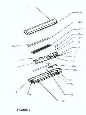
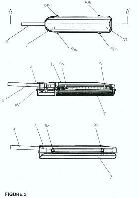
78 In the section “Detailed Description” (pp 12-16) there is a discussion and explanations of Figures 1, 2 and 3, being accompanying drawings, but these are by way of illustration only (pp 18-20). Figures 1, 2 and 3 are represented as follows:
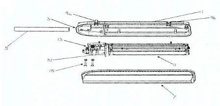

79 In terms of Figure 1, which is an exploded view of a preferred embodiment, there is a discussion of the visor in terms (p 13):
The visor (7) is of unitary construction and at least in the vicinity of the lamp it is conformed to act as a prismatic lens. The visor is typically made of acrylic, polycarbonate or other hard wearing polymer that can be made clear or translucent, however, other suitable materials may used as would be understood by the person skilled in the art. The components located within the termination chamber (13) as well as the components of the reflector assembly (11) are visible through the visor (7).
80 In terms of Figure 3, which illustrates the fully assembled lighting assembly of Figure 1 viewed from underneath, it is said (p 15):
Figure 3(a) illustrates the fully assembled lighting assembly of Figure 1 when viewed from underneath. This is the view that a person would have if they walked underneath the lighting assembly and looked up. In this view they would see through the visor (7) to the reflector tray (23) and lamps and the PE cell (37).
81 Finally, in terms of the preferred embodiments, it is said (p 15):
As the present invention may be embodied in several forms without departing from the spirit of the essential characteristics of the invention, it should be understood that the above described embodiments are not to limit the present invention unless otherwise specified, but rather should be construed broadly within the spirit and scope of the invention as defined in the appended claims. The described embodiments are to be considered in all respects as illustrative only and not restrictive.
82 Streetworx has contended that in the context of the specification, the integer “at least part of the termination chamber ... being visible through the visor” means that one can see through the visor the presence of components located within the termination chamber, but not necessarily the components in detail. So, one can discern that there are components, but that one might not necessarily see or need to see what they are. So, parts of each of the termination chamber and reflector must be visually discernible, without necessarily being able to see components in detail. Streetworx contends that the need to see what the components are is encapsulated in the preferred embodiment of being able to conduct a visual inspection of the components.
83 Browne for Streetworx described the quality of visibility required in these terms, including by comparison to the more prescriptive requirement of “allowing visual inspection” discussed in the specification.
84 Although Rogers for the respondents questioned the reason for this requirement, he did not have any difficulty in understanding the meaning of “visible”. Further, when considering the construction of claim 1 of the 104 Patent, Rogers described differing levels of visibility required by the two expressions in the same manner as set out in the evidence of Browne. Rogers revealed under cross-examination (in the context of being asked about whether the solid control gear chamber in the Boronia met the visibility requirement of claim 1 of the 103 Patent) that he had originally construed the term alone, without reference to the body of the specification. That was not appropriate. When asked to consider what the term meant in light of the body of the specification, he agreed that claim 1 was directed to the language on p 10, lines 13-16 of the Patents which required visibility of the components but not necessarily needing to be able to discern what they were. That is a lesser requirement than the visibility required to perform a visual inspection of components as set out in claim 1 of the 104 Patent.
85 The respondents fixed upon a preferred embodiment (p 10) of the claimed invention (that the visor allows a linesman to carry out a visual inspection of the components of the termination chamber). But for construction purposes, all features of a claim must be considered, not just those which relate to what has been identified as a preferred embodiment.
86 The respondents said that Streetworx’s position on limited “visibility” was at odds with the purpose explained in the Patents at p 10:
Preferably the components located within the termination chamber as well as the components of the reflector assembly are visible through the visor. For example, this part of the visor may be clear or lightly frosted compared to the remainder of the visor. Similar light fittings of the prior art have included a two part visor - a first part comprising a clear lens for the lamp and a second part comprising an opaque cover for the termination chamber. A preferred embodiment of the present invention allows a linesman to carry out a visual inspection of the components without having to remove any covers.
and, in relation to the drawing which is Figure 1 (p 13):
The components located within the termination chamber (13) ... are visible through the visor (7).
87 But the respondents have paid little attention to the words “[in] a preferred embodiment” in the last sentence of the quote, which described the level of visibility required in claim 1 of the 104 Patent not claim 1 of the 103 Patent. A “preferred embodiment” of an invention is a narrower form of the invention described.
88 The respondents submit that the word “visible” must be understood in the context of the specification as a whole, and in a purposive sense, as involving visibility assessed by reference to there being a practical level of visibility into the termination chamber, sufficient to allow an inspection of the internal components by persons, such as linesmen, maintaining the luminaire.
89 I accept that the word “visible” must be understood in the context of the specification as a whole as involving visibility assessed by reference to there being a practical level of visibility into the termination chamber. But I do not accept that the level of visibility must be sufficient to allow an inspection of the internal components by persons, such as linesmen, maintaining the luminaire.
90 In my view, the construction advanced by Streetworx is correct when seen through the perspective of a skilled addressee. Although there must be a practical level of visibility into the termination chamber, particularly from an EPV, it is not required that there be sufficient visibility to allow an inspection of the internal components. The wording of the integer does not stipulate for such a requirement. Further, it is incorrect to take the meaning from a preferred embodiment. Further, Streetworx’s construction conformably fits with the specification as a whole. In terms of a purposive construction, it is consistent with making the invention work.
Termination Chamber – Claim 1 (103 Patent)
91 Claim 1 uses the description of “a termination chamber”. This is not defined in the specification.
92 In terms of that description, the following may be said on the question of construction. First, the termination chamber appears to be something separate from the reflector assembly. In claim 1, both descriptions are separately used, and this is also reinforced by the phrase “a termination chamber located laterally in relation to the reflector assembly”. Second, it is apparent that the termination chamber is not a chamber to receive a lamp; by inference, this is the function and design of the reflector assembly. Third, the termination chamber is, of course, part of the lighting assembly. The lighting assembly consists of a casing and a visor. The casing is said to “enclos[e]” the termination chamber. Thus the termination chamber is enclosed on one side by the casing and covered on the other side by the visor. It is not apparent, just considering the language of claim 1 only, as to whether “chamber” is just a space enclosed on one side by the casing and on the other side covered by the visor or is itself separately physically bounded so that it becomes a separated space within a space. It is also not apparent, just considering the language of claim 1 only, what is contemplated by the descriptor “termination” or the composite phrase “termination chamber”.
93 Reference to the terms of the complete specification provides the following context:
In the first aspect of embodiments, there is reference to “attaching the termination chamber to the main body of the casing and/or the reflector assembly to the termination chamber”;
In a second aspect of embodiments there is reference to “the termination chamber being at least 20-25% of the volume of the casing”;
There is also reference to “the non-conductive envelope” comprising of a combination of, inter alia, a “Terminal block”;
It is also said that the “increased volume of the termination chamber… allows easier manual handling of the mains cable and easier manipulation of other parts and components within the casing such as the PE cell and the terminal block…”; this suggests that the termination chamber may include within it the PE cell (or at least part of it) and terminal block, at least in a particular preferred embodiment (see the abstract as well); the third aspect of embodiments refers expressly to “a termination chamber for location of a PE cell”.
There is also the possible suggestion that the control gear is also to be located in the termination chamber, although there is some uncertainty and this is an unlikely reading, a matter I discuss later. It is said (p 9) that:
Furthermore, the increase in volume of the termination chamber is preferably also due to increased depth of the casing. This assists in dissipating heat and reducing the operating temperature. In particular it keeps the control gear cooler by locating it further away from the casing surface. Most lighting assemblies have electronic ballast components rated to 50°C however it is common for sun exposure to cause the storage and/or radiation of heat in excess of 60°C. Optionally, the addition of a reflective coating to the exterior surface of the main body of the casing may further reduce operating temperature.
Preferably the lighting assembly includes an equaliser that acts as a heat valve to dissipate excess heat.
However, another and more likely reading is that the increased volume has this effect, but with the control gear behind the reflector assembly (i.e. not in the termination chamber).
The termination chamber is to be contrasted with the reflector assembly which is described to include “a reflector tray adapted to receive a single, double or compact fluoro lamp or more than one lamp without restriction on wattage”.
In referring to “[s]imilar light fittings of the prior art” (p 10) it is implied that that part of the casing which includes the termination chamber does not include the lamp.
Figure 1 separates out the reflector assembly (11) from the termination chamber (13); Figure 1 shows the termination chamber with the PE cell.
Figure 2 shows the reflector assembly with a gear tray having lamp holders, a reflector tray, an electronic ballast (also known as control gear, which controls and potentially limits current and regulates current fluctuations), and a 3-way terminal socket and lanyard; in the embodiment illustrated, the reflector assembly is adapted to support the electronic ballast and two lamps.
Then there is a more fulsome description of the termination chamber in terms (p 14):
The termination chamber (13) includes a terminal tray (33), a terminal block (35) of plastic or other suitable material and is adapted to hold a PE cell (37). The termination chamber is at least 25% of the volume of the casing. This is combined with improved layout of the components within the termination chamber (13). For example, the port (3) is elongated to provide additional stability for the light fitting when located on the support (5), and in addition, this makes it easier for the linesman to thread the live main cable into the light fitting. Furthermore, the terminal block (35) is of increased size to make it easier for the linesman to connect the mains cable, which is typically a twin cable of large gauge (6 mm²) and is relatively inflexible and resistant to bending.
The PE cell (37) is seated in the terminal tray (35)…
Figure 3 shows the fully assembled lighting assembly of Figure 1 viewed from underneath including in a particular cross-section (Figure 3(b)) which shows the termination chamber consistently portrayed as previously described.
94 Furzey gave evidence to the effect that the “termination chamber” is a separate, enclosed area as opposed to a compartment which is not necessarily enclosed or segregated. Furzey explained that this is based on the meaning of the terms “termination” and “chamber” and the industry understanding of what constitutes a “chamber”. The evidence is not clear whether the term “termination chamber” itself is widely used, but according to Furzey it was understood to mean a closed area where the mains cable terminated. Other similar terms were in use such as “terminal chamber” in technical documents, for example the Pierlite Greenstreet instructions.
95 It is apparent that the term “chamber” (and each of the terms “lamp chamber” and “control gear chamber”) has a specific meaning to a person skilled in the art. Australian Standard AS1158.6 (the Australian Standard) provides for different ingress protection (IP) ratings in respect of different chambers found within a street light and refers expressly to the concepts of “lamp chamber” and “control gear chamber” (see at section 2.2.2), but not “termination chamber” in terms. If a chamber was not fully enclosed, the concept of different IP ratings for different chambers would be meaningless. Accordingly, a “termination chamber” would be properly understood by a person skilled in the relevant art as defining an enclosed space, not one that is necessarily airtight, but an enclosed space separate to the remainder of the luminaire.
96 Furthermore, in my view a “termination chamber” in the context of the specification ought not to be construed as a chamber with control gear in it. Furzey accepted that interpretation, which is consistent with the Patents. Rogers also appeared to accept that a chamber with control gear in it would most likely be called a control gear chamber. Further, technical documents such as the Pierlite Greenstreet instructions separately refer to a “lamp and gear chamber” and a “terminal chamber” as present in that luminaire.
97 Streetworx has submitted that for “termination chamber” to overcome its natural and technically understood meaning of a chamber that would not include control gear, it would be necessary for the Patents to clearly and precisely disclose that it was intended as an option that control gear could be in that chamber. I am inclined to agree.
98 Further, the preferred embodiment discloses control gear behind the reflector assembly, not in the termination chamber. Now Rogers explained how he relied on the language of the first two sentences of the paragraph at p 9, line 13 of the specification as meaning that a termination chamber might include control gear. But Furzey held a different view. The passage at p 9, lines 13-20, as I have set out earlier, reads:
Furthermore, the increase in volume of the termination chamber is preferably also due to increased depth of the casing. This assists in dissipating heat and reducing the operating temperature. In particular it keeps the control gear cooler by locating it further away from the casing surface. Most lighting assemblies have electronic ballast components rated to 50°C however it is common for sun exposure to cause the storage and/or radiation of heat in excess of 60°C. Optionally, the addition of a reflective coating to the exterior surface of the main body of the casing may further reduce operating temperature.
99 When the first two lines are read in the context of the paragraph as a whole and the paragraphs that follow, in my view the person skilled in the art would understand that the first sentence leads into a new topic, namely the increased depth of the casing. It is the depth of the casing (the whole casing) which is the object of the next two sentences. This is how the paragraph would naturally be read by the skilled addressee. Other features of the specification confirm that position:
The only way control gear is expressly disclosed as being located in a position that keeps it “further away from the casing surface” is on a gear tray behind the reflector tray.
There is no exemplification of control gear in the termination chamber.
The electronic ballast disclosed in the specification is long and thin and would not naturally fit within the termination chamber.
100 Now I accept that the Australian Standard would not necessarily exclude the possibility of a “termination chamber” including control gear if the Australian Standard otherwise referred to a “termination chamber”. Furzey confirmed that for the requirement to achieve an ingress protection rating of IP54 for the “lamp chamber”, what is of concern is to identify and test a sealed area that contained the lamps, but it did not matter for that analysis whether other components, including the control gear and/or the terminal block, were contained within that same chamber. Similarly, an analysis of whether the “gear chamber” met the requirement of IP24 involves looking at the chamber that contains the control gear, but it may contain other components. Further, the gear chamber may, for the purpose of the Australian Standard, relevantly be the same chamber as the “lamp chamber” that was assessed for its IP rating (of course they will then have the same rating). The respondents contended that so extending that logic to what a “termination chamber” would mean if it was otherwise included in the Australian Standard, it could include a chamber containing the terminal block, and it would not matter if the chamber also enclosed the lamps and the control gear. Such reasoning may be correct in its hypothetical generality. But the specification and its context does not support a construction that the “termination chamber” includes the control gear.
101 More generally, the respondents say that the term “termination chamber” contemplates a chamber containing the mains cable, terminal block, PE cell and other components. So much may be accepted.
102 Rogers explained that a “termination chamber” is the part of a luminaire in which the mains cables terminate within the luminaire. He said that it is not a precise term and can refer to any sort of enclosure where this occurs. He said in some luminaires the termination chamber can be separate from the optical chamber (which contains the lamp) but in other luminaires it may not be separate. In my view, whatever be the position with some luminaires, in the present case, what is described in the relevant claim in the context of the specification is something separate and enclosed as described by Furzey.
103 Krueger said that “termination chamber” was not a term that he would typically use, but understood it to mean a place where the power supply wire connects to the light fitting.
104 In summary, in my view a skilled addressee would construe “termination chamber” such that:
(a) it needed to be an enclosed area;
(b) it is an area separate from the reflector assembly;
(c) it is enclosed on one side by the casing and on the other side by the visor;
(d) it does not include the control gear;
(e) it contains the terminal block; and
(f) it may include the PE cell (I note that this is expressly stipulated in claim 1 of the 104 Patent).
Visor of “unitary construction” – Claim 1 (103 Patent)
105 Claim 1 refers to a visor of unitary construction for covering both the reflector assembly and the termination chamber. What is meant by “unitary construction”?
106 In considering the context, in the complete specification there is a discussion of problems and deficiencies in the prior art in terms (p 3):
In lighting assemblies such as the Greenstreet® apparatus there is often multiple parts for entry to internal portions of the lens/visor, the component area may not be locked and could vibrate loose. Also the fixture may not be attached with lanyard. These issues may contribute to warranting increased ongoing maintenance. With the additional part(s) included by having a separate cover arrangement, there is an opportunity for the apparatus to be loose, moving and a potential for falling parts, which can be a serious OHS issue. These arrangements allow a point of entry for vermin, spiders (webs), insects/pests to enter the light and allows weather/pollution exposure and effects (e.g. salt in coastal areas). Risk introduced because of the above include that of fire, electrocution and general OHS hazards.
107 Other aspects to note are the following:
The description “visor” seems to be interchangeable with “lens”, although sometimes it is said that “[t]he visor incorporates within its structure a lens”;
There is only one covering (on the side other than the casing) for both the reflector assembly and the termination chamber, described as “the visor”;
Occasionally there is reference to a “unitary visor” and one of its advantages is said to be “ease of replacement if the visor is broken”;
It is also said that in a preferred embodiment there is a clip capable of independently supporting the visor;
Further, it is said that there is a “gasket of silicon or neoprene or other suitable material” which is “provided along at least part of the interface between the visor and the main body”;
Further, in describing a third aspect of embodiments, reference is made to similar light fittings of the prior art, which have included “a two part visor - a first part comprising a clear lens for the lamp and a second part comprising an opaque cover for the termination chamber”;
In reference to Figure 1, there is a description in the following terms (p 13):
The visor (7) is of unitary construction and at least in the vicinity of the lamp it is conformed to act as a prismatic lens. The visor is typically made of acrylic, polycarbonate or other hard wearing polymer that can be made clear or translucent, however, other suitable materials may used as would be understood by the person skilled in the art. The components located within the termination chamber (13) as well as the components of the reflector assembly (11) are visible through the visor (7).
The main body (1) and visor (7) are held together by two clips (9a, 9b) and two integral hinges (10a, 10b not shown) located in corresponding positions on the other side of the main body and visor, thus permitting movement of the visor (7) from a first, closed position to a second, open position permitting full access to the reflector assembly (11) and termination chamber (13).
108 The specification describes a visor or lens in one piece rather than multiple parts. Does “unitary construction” mean an end product that is one unit? Or does it look to the anterior assembly or construction to see whether there was only one part used for construction rather than multiple parts that were then transformed into one unit?
109 Originally, Browne, Furzey and Rogers agreed that a visor of unitary construction for covering both the reflector assembly and termination chamber meant a visor that was constructed or made during the manufacturing process as one piece. But at trial, Rogers came to a different view on the meaning of the phrase “visor of unitary construction”. He accepted that if a piece was constructed in a factory in a manner which was plainly not intended to be taken apart (e.g. if the parts were glued, welded or riveted together) then that piece would be of unitary construction.
110 Streetworx now accepts Rogers’ interpretation. Further, it points to the fact that the specification raises a concern about two part visors such as found in the Pierlite Greenstreet (mentioned on p 3, line 21 and inferentially at p 10, lines 16-18) and the problems that arise from multiple parts dislodging or falling off the luminaire, particularly the problem with the cover over the component area not being locked and vibrating loose (p 3, lines 23-25).
111 Streetworx now says that Furzey concentrated on simplicity of manufacture in his interpretation of the term “visor of unitary construction”, but that this was not a stated object.
112 Streetworx further contends that a visor which has a part added to it (such as a gasket, an end-cap or an insert around the PE cell), but which still covers the termination chamber and reflector assembly, is a visor of unitary construction within the meaning of claim 1 of each Patent. It is asserted that it is a visor of unitary construction even if it is not moulded of one piece, as long as it is not designed to be taken apart. Of course, if one has a gasket or end-cap, that is quite consistent with having a visor of unitary construction; you are simply adding something to it.
113 The respondents contend that the expression “unitary construction” is to be understood as meaning a part that has been formed as a single unit in the construction process, such as a single moulded part. They say that this interpretation accords with the ordinary meaning of the words, construed in the context of the specification as a whole. They say that if the patentee had intended simply to refer to a visor which covered both the termination chamber and the reflector assembly (and opened as one piece) it would have been more natural to refer to “unitary visor”. The word “construction”, on the other hand, indicates that it is to be constructed as one piece. This is the construction given to the expression by Browne. It is also the view of Furzey. Unsurprisingly, the respondents do not agree with the revised construction of Rogers.
114 It is apparent that the parties have flip-flopped in their respective positions on this aspect, which has not greatly assisted me. In my view, the skilled addressee would take the expression “unitary construction” to focus on the visor as an end product. So, if the visor was constructed in a factory in a manner such that the end product could fairly be said to be one unit, then that would be sufficient. That accords with the plain language. It also accords with a purposive approach. Further, I can see little sense in the alternative construction. Moreover, how atomistic would one need to go on the alternative construction? In one sense, all manufacturing processes have a composite aspect at some particular level. Streetworx’s contention is to be preferred.
Reflector assembly – Claim 1 (103 Patent)
115 The reflector assembly is the group of parts in the luminaire which reflect light emitted from the light source (which is a separate component). In my view, it is a separate group of parts from the casing since the casing is said to “enclose” the reflector assembly. Rogers accepted that the natural meaning of the term assembly was a group of parts, that a fair reading of “reflector assembly” in the Patents was as separate to the casing, and further: “The way I read is the - is it a part - it's a part that's fitted into - into the casing”.
116 Although the respondents suggested that there was an issue between the experts as to whether the casing or body of the luminaire can be a reflector if it performs a reflective function, Rogers' evidence reveals that he considered that a reflector was a different component from the body of the luminaire, as did Furzey. I accept their construction. Furthermore, a reflector assembly must be something made of more than one part, otherwise the term “assembly” is otiose. It cannot simply be the casing. In my view the skilled addressee would similarly so construe “reflector assembly”.
Integral Hinge – Claim 2 (103 Patent)
117 Claim 2 describes an integral hinge as included within the lighting assembly according to claim 1. Browne, Rogers and Furzey agreed that an integral hinge was one built into the visor and main body and formed part thereof.
118 In the first aspect of embodiments this is described in the following terms (pp 5-6):
Preferably the casing includes at least one integral hinge that permits movement of the visor from a first, closed position to a second, open position permitting full access to the reflector assembly and termination chamber, without the visor disengaging from the main body. This avoids the problem associated with prior art lighting assemblies which have a hinge separate to the casing and a plurality of parts that are prone to coming apart and disengaging from the casing. Further, the integral hinge portion prevents excess freedom of movement of the visor/lens with respect to the casing, which can result in misalignment of the two parts upon closing up of the light assembly at the end of maintenance and/or service.
119 Further, in a discussion of Figure 1 reference is made as to how the main body and visor are held together in one particular embodiment, in terms (p 13):
The main body (1) and visor (7) are held together by two clips (9a, 9b) and two integral hinges (10a, 10b not shown) located in corresponding positions on the other side of the main body and visor, thus permitting movement of the visor (7) from a first, closed position to a second, open position permitting full access to the reflector assembly (11) and termination chamber (13).
120 Streetworx contended that claim 2 of the 103 Patent requires the result that when the visor is in an open position, there is immediately full access to the reflector assembly and termination chamber with the visor still attached to the main body. The respondents submit that claim 2 is describing the attributes of the hinge – i.e. it permits full access to these areas without the visor disengaging from the main body. I agree with Streetworx’s position which flows naturally from the language of claim 2. A skilled addressee would so construe it. I expand on this later when discussing the Boronia luminaire.
Independent Clip – Claim 3 (103 Patent)
121 Claim 3 describes a lighting assembly according to claim 1 or 2 which includes a clip that is capable of independently supporting the visor on the main body. Thus the clip must be able to prevent the visor from falling off, independently of anything else holding the visor to the casing. Further, the claim refers to a clip rather than multiple clips. Rogers suggested that the clip must act independently only of the hinges, rather than anything else. But that is not what claim 3 says.
122 In terms of “independently supporting”, it is not specified as to how long or under what conditions. Further, there is no stipulation as to where along the visor (or indeed the main casing) the clip needs to be located.
123 In discussing the first aspect of embodiments, it is said (p 6):
In a preferred embodiment, the casing comprises a clip that is capable of independently supporting the visor on the body of the casing, that is, without additional support from the hinge. The clip may be adjacent the hinge. If a linesman is replacing the visor, the clip may function to hold the visor in place so that hinge pins can be removed or replaced in the hinge.
Two Part Fastener – Claim 4 (103 Patent)
124 Claim 4 describes a lighting assembly according to any one of claims 1-3 which includes one fastener comprising “a first part that pivots on the main body of the casing but does not contact the visor” and “a second part in operative connection with the first part, wherein the second part contacts the visor but does not contact the main body”.
125 The specification describes such a fastener in terms (p 6):
Preferably the casing includes a locking system including at least one external fastener comprising a first part that pivots on the main body of the casing but does not contact the visor, and a second part in operative connection with the first part, wherein the second part contacts the visor but does not contact the main body. This avoids seizing of the locking system when, for example, the main body of the casing is made of a metal (e.g. marine grade cast aluminium) and the fastener is made of ferrous or other metals, thus creating an electrochemical interaction that causes corrosion and seizing of the fastener. The external fastener may comprise one or a combination of clips, bolts or other fasteners as would be considered suitable by the person skilled in the art.
126 Rogers and Furzey understood the claim to be referring to a “toggle clip” or “two part fastener”.
127 Browne considered the claim to mean that the first part of the fastener must contact the main body (that is the pivoting must be direct rather than indirect) and that the requirement that the second part not contact the main body must be met when the fastener is open, closed or partially closed.
128 Streetworx contended that this is not what is meant and contended the following:
There was no requirement that the first part of the fastener be in direct contact with the main body – the requirement is only that the first part pivots on the main body so that if it pivoted on a plate that was fixed on the main body, the integer would be satisfied. That is, the pivoting point may be on the plate. The pivoting is relative to the main body;
The requirement that the second part not contact the main body must be met only when the fastener is closed, because the clip is closed for the great majority of the working life of the luminaire. It is in that position that the second part should not contact the main body, lest corrosion, or seizing for other reasons, occur.
129 Again I accept such contentions of Streetworx which flow naturally from the language used and how the skilled addressee would construe it adopting a purposive approach.
Visibility – Claim 1 (104 Patent)
130 Claim 1 of the 104 Patent refers to the concept of visibility in terms that “the portion of the visor covering the termination chamber is adapted to allow visual inspection of components within the termination chamber”. This is in contrast to the language of claim 1 of the 103 Patent.
131 There are a number of features to note.
132 First, visibility is to perform the function of allowing visual inspection of components within the termination chamber (contrast the language of claim 1 of the 103 Patent which does not expressly so stipulate).
133 Second, visibility is described only in terms of the portion of the visor covering the termination chamber (contrast the language of claim 1 of the 103 Patent which refers to “at least part of the termination chamber and at least part of the reflector assembly being visible through the visor”).
134 Third, visibility is described in terms of “visual inspection of components within the termination chamber” (contrast the language of claim 1 of the 103 Patent which refers to “at least part of the termination chamber…being visible through the visor”).
135 I should say that although I have noted the difference in the language of claim 1 of the 104 Patent as compared with claim 1 of the 103 Patent, the claims in the 104 Patent are to be construed independently or as free-standing (but in the context of the complete specification of the 104 Patent). I have noted the contrasts to merely flag differences which may have significance when dealing with other issues, for example, under s 18(1A)(c) or s 40(3) of the Act or concerning infringement.
136 Further, I should say, more generally, that claim 1 of the 104 Patent (and the subsequent claims) appear to deal with the third aspect of preferred embodiments (see pp 9-11 of the specification).
137 Both Browne and Furzey contrasted “adapted to allow visual inspection” (104 Patent) to “visible through the visor” (103 Patent), concluding that the level of visibility required is higher for the former phrase. Streetworx did not contend, however, for Browne's further view that the visor would be adapted to allow visual inspection if the visor could be moved aside. At p 10, lines 13-20 of the specification, the context of this feature of the claim is that the components are visible through the visor, and that a preferred embodiment allows visual inspection without having to remove any cover.
Termination Chamber and PE Cell – Claim 1 (104 Patent)
138 Claim 1 in the 104 Patent also refers to a termination chamber and states that it is “…for location of a PE cell” (claim 1 in the 103 Patent makes no such reference).
139 Claims 2, 3 and 4 of the 104 Patent also deal with the PE Cell.
140 The specification refers to the PE cell in the following respects:
A “problem with street lights of the prior art is the malfunctioning of the PE cell”. As stated earlier, a PE cell controls the activation and deactivation of a street light according to the ambient light level. When there is no ambient light (night time), the PE cell will activate to turn the street light on. When there is sufficient ambient light (day time), the PE cell will deactivate the street light. Sometimes a PE cell will fail to deactivate the street light; this causes “day burners” (street lights that emit 24 hours per day). This may occur when something blocks the PE cell from sensing ambient light. Alternatively, a PE cell may fail to activate the street light. For example, at night time, if the PE cell is impinged upon by stray light (say reflected light or illumination from an adjacent street light), it may fail to activate the street light.
A third aspect of embodiments describes a lighting assembly with “a termination chamber for location of a PE cell” where “at least the detector portion of the PE cell is entirely enclosed within the casing” (p 10).
It is said that (pp 10-11):
Lighting assemblies of the prior art typically comprised PE cells seated in the termination chamber, but projecting through an opening in the casing so that at least part of the PE cell is external to the casing. Over time the opening would typically fill with dirt or insect nests, enshrouding the PE cell to block it from the ambient light and cause it to malfunction [i.e. it would activate to turn the light on]. Accordingly, inclusion of the PE cell within the casing such that the detector portion of the PE cell is enclosed so as to avoid any opening or breach in the casing proximate the PE cell avoids these problems.
Then it is said that (p 10):
Preferably the components located within the termination chamber as well as the components of the reflector assembly are visible through the visor. For example, this part of the visor may be clear or lightly frosted compared to the remainder of the visor. Similar light fittings of the prior art have included a two part visor - a first part comprising a clear lens for the lamp and a second part comprising an opaque cover for the termination chamber. A preferred embodiment of the present invention allows a linesman to carry out a visual inspection of the components without having to remove any covers. Typically the part of the visor in the vicinity of the PE cell is clear so that the PE cell correctly detects the level of ambient light. Using frosting in other parts of the visor however may provide the advantage of preventing reflected or early ambient light impinging on the PE cell and causing it to prematurely deactivate [i.e. it would deactivate to turn the light off]. In particular, the use of frosting as in this preferred embodiment can avoid “day burners” (lights that are emitting 24 hours per day or at least into periods of the day not requiring artificial lighting) [this is confused as I later discuss]. In related art systems, the avoidance of “day burners” was achieved by the addition of or attachment of a shield to the casing to shield the sensor or PE Cell. These shields were not attached to the lens/visor.
Moreover, initial prototyping of a preferred embodiment of the present invention identified that by frosting the visor/lens to eliminate ambient light entry; light was also being reduced to the sensor/PE Cell. This was solved by a preferable arrangement whereby a non-frosted region of visor/lens/casing enables sensor/PE Cell to receive the correct lighting entering the apparatus. This has shown that this embodiment provides a saving in maintenance costs hence a saving in the likelihood of “day burners” [this is confused as I later discuss].
Further, in describing a particular embodiment in Figure 2 it is said (p 14):
The PE cell (37) is seated in the terminal tray (35) and can be completely enclosed within the casing, with no part projecting through the visor (7). The part of the visor (7) in the vicinity of the PE cell (37) is clear so that the PE cell (37) correctly detects the level of ambient light. Using frosting in other parts of the visor (7) however may provide the advantage of preventing reflected or early ambient light impinging on the PE cell (37) and causing it to prematurely deactivate.
PE Cell – Claim 2 (104 Patent)
141 Claim 2 stipulates a lighting assembly according to claim 1 with the PE cell residing “entirely within the casing”. So, no part of the PE cell can protrude outside or beyond the casing. Contrast this with the language of claim 1, which refers to “a termination chamber for location of a PE cell”. So, as a matter of language, the PE cell is to be located in the termination chamber and it must all be “entirely within the casing”.
142 The specification (p 10) refers to some PE cells which are seated in the termination chamber but project through an opening in the casing; some part of the PE cell is then external to the casing. Claim 2 by its language does not so countenance.
PE Cell – Claim 3 (104 Patent)
143 Claim 3 stipulates a lighting assembly according to any one of the preceding claims where “the visor is clear in an area adjacent to the PE cell”. In context, as Furzey explained, this means the area of the visor directly below the PE cell when the luminaire is correctly positioned affixed to a light pole.
144 The specification refers to “[t]ypically the part of the visor in the vicinity of the PE cell is clear so that the PE cell correctly detects the ambient light”.
145 So, claims 1 and 2 deal with the location of the PE cell. Claim 3 includes an integer which impacts on its functionality.
PE Cell – Claim 4 (104 Patent)
146 Claim 4 stipulates a lighting assembly according to any one of the preceding claims wherein “the visor further includes a frosted region for preventing unwanted de-activation of the PE cell due to ambient artificial light”. This apparently is to prevent undesired operation of the PE cell.
147 A PE cell is designed to deactivate the street light where there is sufficient ambient natural light (i.e. day time). If there is ambient artificial light, this may cause the PE cell to deactivate the street light. One way to prevent artificial ambient light from impacting on the PE cell is to use frosting. As the specification says (p 10):
Using frosting in other parts of the visor however may provide the advantage of preventing reflected or early ambient light impinging on the PE cell and causing it to prematurely deactivate. In particular, the use of frosting as in this preferred embodiment can avoid “day burners” (lights that are emitting 24 hours per day or at least into periods of the day not requiring artificial lighting). In related art systems, the avoidance of “day burners” was achieved by the addition of or attachment of a shield to the casing to shield the sensor or PE Cell. These shields were not attached to the lens/visor.
Moreover, initial prototyping of a preferred embodiment of the present invention identified that by frosting the visor/lens to eliminate ambient light entry; light was also being reduced to the sensor/PE Cell. This was solved by a preferable arrangement whereby a non-frosted region of visor/lens/casing enables sensor/PE Cell to receive the correct lighting entering the apparatus. This has shown that this embodiment provides a saving in maintenance costs hence a saving in the likelihood of “day burners”.
148 Now this description in the specification is erroneous. The frosting, if it prevents ambient artificial light from being read by the PE cell, ensures that there is no premature deactivation. It is not to avoid “day burners”.
149 An ambiguity was said to exist concerning the concept of “deactivation”, but that is of little moment. The claim requires the frosting to be capable of preventing undesired operation of the PE cell.
150 The difficulty with the construction of this claim is that neither expert contended that having a frosted region of the visor would, in fact, achieve a prevention of “unwanted deactivation of the PE cell”. The experts also agreed, as I have indicated, that the section of the specification that discusses this feature contains an error – the discussion in the specification asserts that the claim feature will also prevent “day burners”, which is the opposite problem (that is, instead of the light going off when it is still night-time, it fails to turn off when it is daytime and so burns all day).
151 Further, Furzey explained that, depending on the type of frosting, and the position of the PE cell, the frosting could have the opposite effect and could instead activate the cell by redirecting light onto the PE cell. He said that the actual effect of frosting could only be determined by testing, which he explained he had not done.
III: Prior art – Novelty and Innovative Step
(a) Description
152 The prior art relevant to the 103 Patent and the 104 Patent consists of:
The Optimum luminaire, which was supplied in Australia before the priority date;
The Boronia luminaire, which was supplied in Australia before the priority date;
The Prospect style luminaire, which was manufactured by Famco (the parties have agreed that the Wyt-Ray product can be put to one side) and supplied in Australia before the priority date (although there is an evidentiary contest on this last question);
The Pierlite application containing a complete specification for patent No. AU 2004205200 A1 (the parties agreed that Pierlite application No. AU 2009201158 A1 could be put to one side).
(b) Novelty
(i) Legal principles
153 The legal principles are not in issue.
154 For a patentable invention so far as claimed in a claim, the question is whether it is novel when compared with the prior art base before the priority date of the claim (s 18(1A)(b)(i) of the Act). An invention is to be taken to be novel when compared with the prior art base unless it is not novel in the light of, inter alia prior art information made publicly available in a single document or prior art information made publicly available through doing a single act (see s 7(1)(a) and the definitions of “prior art base” and “prior art information” in the Dictionary set out in Sch 1 of the Act).
155 The onus is on the respondents to establish that such a single document or single act of prior art overcomes the presumption of novelty.
156 A useful test to determine lack of novelty is the “reverse infringement” test. Would the alleged anticipation, if the patent was valid, constitute an infringement (Meyers Taylor Pty Ltd v Vicarr Industries Ltd (1977) 137 CLR 228 at 235 per Aickin J)?
157 For there to be anticipation, the prior art, whether it is a prior publication or prior use of a product must constitute a clear and unmistakeable disclosure of each and every integer of the relevant claim the subject of the challenge (Flour Oxidizing Co Ltd v Carr & Co Ltd (1908) 25 RPC 428 at 457 per Parker J; Minnesota Mining at 298 per Aickin J).
158 If the prior art is a document, it should be read through the eyes of the skilled addressee in the context in which these terms appear (Blue Gentian LLC v Product Management Group Pty Ltd [2014] FCA 1331 (Blue Gentian LLC) at [88] per Middleton J). It is a question of the disclosure to the skilled reader. As Bennett J in Zetco Pty Ltd v Austworld Commodities Pty Ltd (No 2) [2011] FCA 848 at [93] stated:
Such a disclosure may be explicit or, in certain circumstances, may amount to a sufficient disclosure of each integer to a skilled worker even though not explicit (H Lundbeck A/S v Alphapharm Pty Ltd (2009) 177 FCR 151; Nicaro Holdings Pty Ltd v Martin Engineering Co (1990) 91 ALR 513). This may occur where, for example, the prior art information is a publication which does not specify an integer but the skilled reader would understand that integer to be present in the subject matter described. The same applies to what is disclosed to the person of skill in the art by a prior product. If the prior art does not expressly specify each and every essential integer of the claimed invention, the evidence must clearly establish that, to the skilled reader, each and every essential integer is included in that prior art.
The terms are to be given “the meaning which the person skilled in the art would attach to them, having regard to his or her own general knowledge and to what is disclosed in the body of the specification” (see e.g. H Lundbeck at [118] per Bennett J).
159 If the prior art is a document, the skilled addressee must be given clear and unmistakeable directions to make or perform the invention, if it is to be demonstrated as being an anticipation. More colloquially expressed, “the prior inventor must clearly be shown to have planted his flag at the precise destination” (The General Tire at 485-6). Even more colourfully expressed, “anticipation is deadly but requires the accuracy of a sniper, not the firing of a 12 gauge shotgun” (Apotex Pty Ltd v Sanofi-Aventis (2008) 78 IPR 485 at 491; H Lundbeck A/S v Alphapharm Pty Ltd (2009) 177 FCR 151 (H Lundbeck) at [170]).
160 It is not sufficient to demonstrate that a prior publication is capable of being carried out in a manner which would equally infringe or not infringe the particular claim. In such a case there would not be the relevant anticipation (The General Tire at 485-6). To elaborate, if the prior art is a document and there is ambiguity in the sense that the disclosure can be read in two or more ways, such that one way would, if carried out, infringe, and one or more other ways would not, then there has been no anticipation. Anticipation must not merely be a possibility or even a likely consequence of performing the invention disclosed by the prior art, but it must necessarily be entailed in or an inevitable result of carrying out the disclosure (SmithKline Beecham Plc’s (Paroxetine Methanesulfonate) Patent [2006] RPC 10 (SmithKline Beecham) at [22]-[23]; Abbott GmbH & Co KG v Apotex Pty Ltd (No 2) (2010) 87 IPR 561 (Abbott v Apotex) at [55]-[59]).
(ii) Analysis
Optimum luminaire
161 The Optimum luminaire relied on by AUG is the version of this type of luminaire with a PE cell. It is a luminaire that was supplied in Australia before the priority date. The physical exhibit in the present case is the version without a PE cell.
162 Produced below are pictures of the Optimum luminaire.
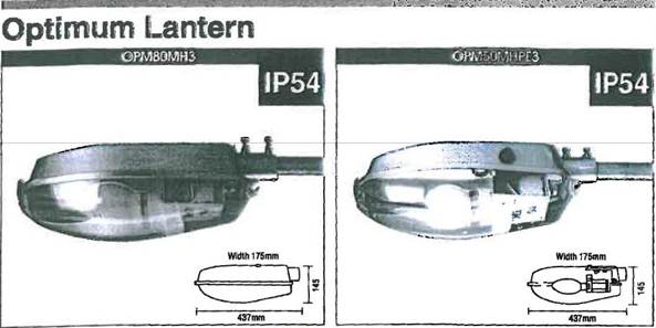
163 The question is whether the Optimum luminaire, in respect of claim 1 of the 103 Patent, contains the features of a reflector assembly and a termination chamber.
164 Furzey made a comparison of the Optimum luminaire to the claims of the 103 Patent as set out as follows:
Claim of 103 Patent |
Comparison to the Optimum |
1. A lighting assembly |
Yes |
having a casing comprising a main body, |
Yes |
the casing enclosing: |
|
a reflector assembly for receiving at least one lamp; |
No. Although there is a reflector (the inside surface of the casing), there is no reflector assembly. See p 5 of Annexure SJF-5. |
a termination chamber located laterally in relation to the reflector assembly; |
No. There is no “chamber”, because of the open sides of the area which contains the terminal block. Furthermore, that area is not separate to the area which contains the control gear. See pp 5 and 6 of Annexure SJF-5. |
wherein the visor is of unitary construction for covering both the reflector assembly and the termination chamber, |
No, because there is no termination chamber or reflector assembly. However, the visor is of unitary construction. |
at least part of the termination chamber and at least part of the reflector assembly being visible through the visor. |
No, because there is no termination chamber. However, it is possible to see the components under the gear tray with a restricted view (see p 7 of Annexure SJF-5). |
2. A lighting assembly according to claim 1 |
No (see above) |
which includes at least one integral hinge |
Yes (see p 5 of Annexure SJF-5) |
that permits movement of the visor from a first, closed position to a second, open position |
Yes |
permitting full access to the reflector assembly and termination chamber |
No, because there is no reflector assembly or termination chamber. When the visor is open, it is possible to fully access the reflector but it is not possible to fully access components in the gear tray without removing the gear tray |
without the visor disengaging from the main body. |
Yes |
165 In my view the Optimum luminaire does not have a termination chamber. This is because:
(a) there is no such “chamber” – the termination block is found in an area with open sides which are open to the lamp area;
(b) further, the area containing the terminal block also contains the control gear such that, even if the area could be called a “chamber”, it would more properly be described as a “gear chamber” rather than a “termination chamber”.
166 Further, the Optimum luminaire does not have a “reflector assembly”. The inside surface of the casing acts as a reflector, but there is no reflector assembly as such being a group of parts which function to at least reflect light of the lamp(s). It is not practical to describe the reflective interior of the main body of the Optimum luminaire as a “group of parts” that is enclosed by the main body and visor as required by claim 1. Further, as I have said earlier, the assembly must be separate to the casing in claim 1. It is a thing (as opposed to simply a space) enclosed by the casing, which casing comprises the visor and main body.
167 The respondents have made various submissions concerning Furzey’s evidence that the fact that the reflector is formed by the inside surface of the casing means that there is no “reflector assembly” within the meaning of the claims. They submitted that such an approach does not accord with a “purposive construction” of the claim. They said that neither the Patents nor the claim are directed to the componentry of the reflector assembly. The only requirement is that there be a component that has the functional purpose of reflecting light out of the luminaire.
168 The respondents referred to Radiation Ltd v Galliers & Klaerr Pty Ltd (1938) 60 CLR 36 (Radiation Ltd v Galliers) which was said to provide an analogous illustration of such an approach. The Court considered a claim for a gas-heated cooking apparatus, which employed a “partition” between a rear burner and a rear flue outlet. This assisted the effective circulation of hot gases. The defendant did not install a separate “partition” wall, but rather added holes to the back of the oven and placed a box there for the flue outlet, although the practical effect was the same. The Court found that, in the context of the patent and when the invention was properly understood, the rear wall of the oven was capable of being the relevant “partition” as required by the claims.
169 The respondents contended that the invention, as properly understood from reading the specification, placed no emphasis upon the reflector assembly. The skilled addressee would understand the term as used in claim 1 of each Patent as simply listing a basic functional requirement of a luminaire, and accordingly it should be read broadly.
170 I do not accept the respondents’ contentions. The Optimum luminaire has no reflector assembly. And as I have said, on the construction I have given to “termination chamber”, the Optimum luminaire has no termination chamber either.
171 As for claim 2 of the 103 Patent, both Furzey and Rogers accepted that the Optimum luminaire has an integral hinge. Streetworx contended that when the visor of the Optimum luminaire was opened, the gear tray remained in place so as to restrict access to the components of the area containing the termination block and control gear. Accordingly, it could not be said that the hinge permitted movement of the visor to an open position permitting “full access” to that area. Accordingly, the Optimum luminaire did not possess all of the features of claims 1 or 2 of the 103 Patent. The respondents did not accept that contention, but I accept Furzey’s evidence to that effect.
172 The respondents have also relied on the Optimum luminaire in relation to claim 1 of the 104 Patent only. For the reasons set out above, the Optimum luminaire did not possess all of the features of claim 1 of the 104 Patent in terms of a “reflector assembly” and a “termination chamber”.
Boronia luminaire
173 The Boronia luminaire is a physical exhibit. It was also a luminaire that was widely supplied in Australia before the priority date.
174 Produced below are pictures of the Boronia luminaire:
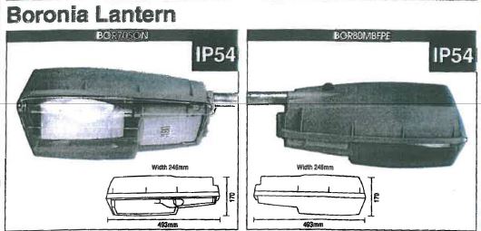
175 The question is whether the Boronia luminaire, in respect of claim 1 of the 103 Patent, contains the features of a termination chamber and part of such a chamber being visible through the visor.
176 Again, it is convenient first to set out Furzey’s evidence.
177 Furzey made a comparison of the Boronia luminaire to the claims of the 103 Patent as follows:
Claim of 103 Patent |
Comparison to the Boronia |
1. A lighting assembly |
Yes |
having a casing comprising a main body defining a port for receiving a mains cable, and a visor, |
Yes |
the casing enclosing: |
|
a reflector assembly for receiving at least one lamp; |
Yes (see pp 1 and 2 of Annexure SJF-5) |
a termination chamber located laterally in relation to the reflector assembly; |
No. There is no separate termination chamber which is distinct from the gear chamber. That is, the termination block and control gear are in the one chamber, which I consider to be space enclosed by the box labelled “M80D” (see pp 1 and 2 of Annexure SJF-5). |
wherein the visor is of unitary construction for covering both the reflector assembly and the termination chamber, |
No, because there is no termination chamber. However, the visor is of unitary construction and does cover the lamp chamber and gear chamber. |
2. A lighting assembly according to claim 1 |
No |
which includes at least on integral hinge |
Yes |
that permits movement of the visor from a first, closed position to a second, open position |
Yes |
permitting full access to the reflector assembly and termination chamber |
No. First, there is no termination chamber but a gear chamber. Second, even with the visor open, you cannot immediately access the components of the gear chamber (they are under the box labelled “M80D”). |
without the visor disengaging from the main body. |
Yes |
4. A lighting assembly according to any one of the previous claims |
No |
which includes at least one fastener comprising a first part that pivots on the main body of the casing but does not contact the visor, |
Yes |
and a second part in operative connection with the first part, |
Yes |
wherein the second part contacts the visor but does not contact the main body |
Yes. While the bottom of the clip touches the main body when the clip is closed, the top part of the clip which touches the visor does not touch the main body. This seems to me to be the purpose of the requirement. See p 3 of Annexure SJF-5. |
178 Streetworx accepts that the area in which the termination block is located in the Boronia luminaire is a “chamber” in the sense earlier discussed on the question of construction. However, that chamber also includes the control gear for the luminaire and, as Furzey has explained, such a space would be called a “gear chamber”. As such, the feature of “termination chamber” is not satisfied in the Boronia luminaire.
179 Claim 1 also requires that at least part of the termination chamber be visible through the visor. In the Boronia luminaire, the termination block and control gear are enclosed in an opaque box sitting inside the casing. It is not possible to see inside the box. Rogers said that this feature of claim 1 is satisfied because he could see the outside of the box containing the termination block. The respondents contend that as drafted, claim 1 only states requirements of the visor (in terms of visibility of the termination chamber); it does not stipulate requirements of the termination chamber itself. It is said that the patentee, in words of its own choosing, did not require the termination chamber to be designed so as to allow one to see into the termination chamber. I reject such a narrow construction. In my view, the visibility requirement is only met where it is possible to see into the termination chamber. Accordingly, claim 1 is not anticipated by the Boronia luminaire.
180 In relation to claim 2 of the 103 Patent, it is agreed by both experts that the Boronia luminaire has an integral hinge. Streetworx through the evidence of Furzey contends that the Boronia does not have the feature of the visor “permitting full access” to the termination chamber once the visor is opened.
181 On the question of the construction of claim 2, Browne and Furzey have agreed that claim 2 requires a hinge that permits certain defined movement, between two specified positions. Both have agreed that the second position is defined as being an open position permitting full access to the reflector assembly and termination chamber without the visor disengaging. Furzey has explained that this means the user is able to immediately work with the components in the reflector assembly and termination chamber (without any additional step being required to be taken). Once the visor is opened, it is a quick, straightforward exercise to gain full access without the visor disengaging.
182 The respondents contend that this involves a strained reading by Furzey of the language of claim 2, which is a claim that is said to be describing the action of the hinge – namely that it can move from a closed to an open position without the visor disengaging from the main body. The respondents contend that Furzey is reading additional language into the claim.
183 In my view, Furzey has not adopted a strained reading of the clear words of claim 2 or imported an additional and uncertain requirement. Rather, that additional requirement is already part of the claim on a plain and common-sense reading.
184 For completeness, I should mention that Rogers demonstrated in Court a way in which to gain access to the inside of the box, although this was not explored with the linesmen, Joosten and Krueger, and there is no marking on the Boronia indicating that the box can be opened in the manner demonstrated by Rogers. Rogers in cross-examination confirmed the presence of threaded points for screws to hold the box down, and that screws were used in that way, which would not permit access in the manner he demonstrated. His demonstration can be put to one side.
185 In relation to claim 4 of the 103 Patent, the experts agreed that the additional features of the claim are satisfied by the Boronia luminaire (assuming the earlier claims were met, which they have not been for claims 1 and 2).
186 In summary, the Boronia luminaire does not possess all of the features of claims 1, 2 or 4 of the 103 Patent. The respondents do not persist with any lack of novelty assertion in relation to claim 3 of the 103 Patent in respect of the Boronia luminaire.
187 Further, the respondents rely on the Boronia luminaire in relation to claim 1 of the 104 Patent only. The respondents no longer press their lack of novelty assertions in relation to claims 2 and 3 of the 104 Patent in respect of the Boronia luminaire.
188 Furzey made a comparison of the Boronia luminaire to claim 1 of the 104 Patent as follows:
Claims of 104 Patent |
Comparison to the Boronia |
1. A lighting assembly |
Yes |
having a casing comprising a main body defining a port for receiving a mains cable, and a visor, |
Yes |
the casing enclosing: |
|
a reflector assembly for receiving at least one lamp; |
Yes (see pp 1 and 2 of Annexure SJF-5) |
a termination chamber for location of a PE cell |
No. There is no separate termination chamber which is distinct from the gear chamber. That is, the termination block and control gear are in the one chamber, which I consider to be space enclosed by the box labelled “M80D” (see pp 1 and 2 of Annexure SJF-5). There is a PE cell which resides partially in the gear chamber. |
wherein the visor is of unitary construction for covering both the reflector assembly and the termination chamber |
No, because there is no termination chamber. However, the visor is of unitary construction and does cover the lamp chamber and gear chamber. |
and the portion of the visor covering the termination chamber is adapted to allow the visual inspection of components within the termination chamber. |
No, because there is no termination chamber. Furthermore, it is not possible to see inside the gear chamber through the visor. |
189 The same reasoning as set out earlier in relation to claim 1 of the 103 Patent is equally applicable to claim 1 of the 104 Patent.
Prospect style luminaire
190 The “Prospect” style of luminaire was made by at least two different manufacturers, Wyt-Ray and Famco. The parties have confined their cases and submissions to the Famco version and I will do likewise in relation to my analysis.
191 Streetworx has challenged whether the Famco luminaires were publicly used prior to 30 October 2009 (the priority date for each Patent). It asserts that the prior use must be “strictly proved”. There is nothing in the Act that imposes a different standard of proof to that set out in s 140 of the Evidence Act 1995 (Cth) (Evidence Act). Aspirating IP Ltd v Vision Systems Ltd (2010) 88 IPR 52 simply notes that care must be taken in considering an oral description of a use that occurred a long time ago; see also Windsurfing International Inc v Petit [1984] 2 NSWLR 196 where the prior use was established by an oral description. But in the present case AUG has obtained and relies on physical samples of the Famco luminaire. No mere oral description is the sole evidentiary foundation.
192 There is substantial evidence supporting the likelihood that those samples and such luminaires more generally were publicly used before the priority date. In this respect:
(a) Such samples have manufacturing labels attached with the name “Famco” and a date, which show that they were manufactured in 1989 and 1997;
(b) Krueger confirmed that luminaires are commonly marked with dates of manufacture and then usually installed within about a year of manufacture;
(c) Rogers said that the physical state of each sample luminaire showed that it had been used outdoors for at least 10 years;
(d) the samples are consistent with the luminaire illustrated in a Famco brochure dated February 1995, which also referred to there being a version with a PE cell;
(e) Mr Brian Bishop, AUG’s State Manager for South Australia and the Northern Territory, gave evidence of the public use of Famco luminaires before 2009, as did Rogers;
(f) Furzey, who had expertise in street lighting, gave evidence that he had observed one in his street prior to 2009.
193 In my view, each of Exhibits JRR-13 and JRR-14 were publicly used before the priority date and form part of the prior art base. More generally, “Prospect” luminaires manufactured by Famco, as exemplified by Exhibits JRR-13 and JRR-14, were publicly used before October 2009.
194 The prospect style of luminaire made by Famco is portrayed in the following picture:
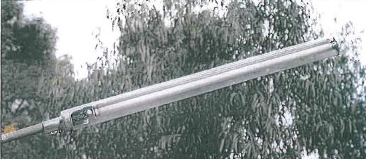
195 The respondents rely on the Prospect luminaire in relation to claim 1 of the 103 Patent only. The issue is whether it contains a termination chamber. The Prospect luminaire has a gear tray that on one side has the control gear, and on the other side a terminal block. The area containing the terminal block is not a separate enclosure to the reflector assembly or the control gear. As Furzey observed, the walls of the gear tray where the control gear is found do not extend to the visor so as to provide a “chamber” and further, the side which has the terminal block on it has no wall at all extending towards the visor; it is not a compartment or a chamber.
196 Rogers appeared to contend that a flat piece of metal constituting a gear tray could equally be called a gear chamber or gear housing. That is not an appropriate interpretation.
197 Further, Furzey considered that the visor of the Prospect luminaire was not of unitary construction. The basis was that it had a cap on its end. But Streetworx submitted that this does not deprive the Prospect luminaire from having a visor of “unitary construction for covering both the reflector assembly and termination” block area. I agree. A visor which has a part added to it such as a gasket or an end-cap, but which still covers the termination chamber and reflector assembly, is a visor of unitary construction within the meaning of claim 1 of each Patent.
198 In summary, the Prospect luminaire does not possess all of the features of claim 1 of the 103 Patent.
199 In relation to claim 1 of the 104 Patent, for the reasons set out above, there is no “termination chamber” in the Prospect luminaire. Furthermore, the PE cell in the Prospect luminaire is found in its own area, next to the control gear area. Accordingly, even if the termination block area could be called a “termination chamber”, the PE cell is not found in that chamber as required by claim 1 of the 104 Patent. Rogers accepted that the PE cell was in a separate compartment to the termination block and control gear.
200 In relation to claim 2 of the 104 Patent, apart from its dependency on claim 1, the experts agreed that the additional feature of the claim was satisfied by the Prospect luminaire.
201 In relation to claim 3 of the 104 Patent, apart from its dependency on claim 1, the experts agreed that the additional feature of the claim was satisfied by the Prospect luminaire.
202 In summary, the Prospect luminaire does not possess all of the features of claims 1, 2 or 3 of the 104 Patent.
Pierlite application
203 The Pierlite application is a patent specification (AU 2004205200). It is referred to in the 103 Patent and the 104 Patent and disclosed as a form of prior art, although that is not of course conclusive. Illustrative embodiments of the invention as portrayed in the Pierlite application are reproduced below:
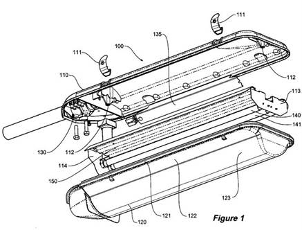
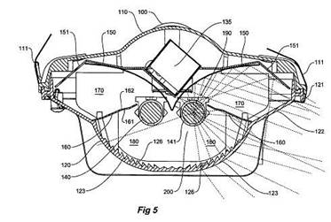
204 Before proceeding further, it is appropriate to note, as Furzey has observed, that the Pierlite application and the invention disclosed is principally directed to the optical performance of the described luminaire. Examples may be noted in the Pierlite application complete specification as follows:
“It is an object of the present invention to … additionally [control] the direction and intensity of emitted light” (p 2);
References to “first light emitting region” and a “second light emitting region” (p 3);
The use of a “planar lens element” and a “parabolic reflector” (p 3);
The use of a “plurality of prismatic elements” including a “saw tooth formation integrally formed onto the inner surface of said second lens element” (p 4);
Further, “[p]referably, said first substantially planar lens element and said second lens element form sections of a common lens element…” (p 4);
Further, claims 1-10 reflect that the invention embodied in each is principally directed to optical performance (pp 10-12).
205 The issues in dispute in relation to the Pierlite application are whether it clearly and unmistakeably discloses a visor of unitary construction for covering both the reflector assembly and termination chamber and the termination chamber is visible through the visor.
206 Rogers and Furzey both accepted that the text of the Pierlite application does not describe either of these features. Accordingly, they turned to the drawings to see if they provided such disclosure. Further, as a preliminary matter I should note that Furzey confirmed that he had not, prior to attending Court, seen up close the Pierlite Greenstreet product, which was a commercial embodiment of the Pierlite application. Rogers may have proceeded on the assumption that the Pierlite application disclosed a different device to the Greenstreet of which he was aware. I should also say, as a preliminary matter, that I have put to one side the Greenstreet Installation Instructions (Exhibit A3) and only had regard to the Pierlite application. Let me turn to a more detailed consideration of the Pierlite application.
207 Furzey concluded that the drawings of the Pierlite application show a visor of two sections, a lens (marked as “120”) and a cover over the termination chamber, with the two separated by a light shield. The separation is denoted by a solid line in Figure 1 of the drawings. Furzey was cross-examined about his interpretation of the drawings of the Pierlite application but maintained his view. Furzey further explained “it’s very difficult to tell from these drawings exactly where it [the gasket] is, because there isn't enough detail”. Further, it appeared that there was no room for a gasket around the cover for the termination chamber; the item identified as a gasket in the drawings ended where the cover for the termination chamber began. I agree with Furzey’s conclusions.
208 Further, in my view the text of the Pierlite application described the lens as being the clear or transparent section of a lighting assembly from which the light emanates. This could not be a reference to the termination chamber. Accordingly, the Pierlite application did not clearly disclose that the visor is of unitary construction for covering both the termination chamber and reflector assembly. At best, the Pierlite application disclosed a two part visor with separate parts covering the termination chamber and reflector assembly, respectively. In any event, there was no clear and unmistakeable direction of a visor of unitary construction for covering both the reflector assembly and termination chamber or that the termination chamber was visible through the visor.
209 Rogers asserted that the entire visor was shown as being clear, and the entire lens was described as being “formed from moulded transparent acrylic”, which Rogers understood to mean that the entire lens was clear.
210 Rogers asserted that, in respect of the visor, “a single part is illustrated”. It is unclear how Rogers has reached such a definitive position in respect of the drawings. Rogers observed that the “visor” was shown in Figure 1 of the Pierlite application as being unitary. However, there is no mention of a “visor” as so described. It is only the “lens” that is described as being unitary. This relates to the unitary nature of light refracting elements. Such terms would only be relevant to that part of the cover which covered the light emitting part of the luminaire, not the termination chamber.
211 Rogers’ reply evidence observed that:
…the ‘lens 120’ is described as being attached to the periphery of the upper housing by stainless steel clips and having a ‘complementary shape to upper housing’ and including an integral gasket so as to provide an effective seal against the environment when secured to ‘the periphery of upper housing 110’
212 But those features are all achieved by a clear lens which ends at the termination chamber. The lens in such a case is still complementary in shape to the housing, it has clips on it and has a gasket to provide a seal against the environment. The gasket (121) ends at the cover for the termination chamber. The gasket goes around the periphery of the lens in a normal fashion. The periphery matches the periphery of the casing, in the sense that it matches the outer lip of the casing and the inner divider between the termination chamber and reflector assembly chamber.
213 Rogers said that the figures in the application show the entire visor as being a single piece, and that there is no reference to it being made of multiple components; in my view, the figures do not support Rogers’ certitude. Further, as I have just said, he explained that the Pierlite application describes the “lens 120” as having a complementary shape to the upper housing and including an integral gasket to provide an effective seal against the environment when secured to the periphery of upper housing 110. This was said to show that the “lens” is the entire component that matches the corresponding shape of the upper body of the luminaire – that is, the term “lens” refers to the entire visor. But in my view, it is unclear that such words would be so construed as pointing to the entire visor rather than the lens. Further, the manufacture of the “lens” as a single component is expressly described in the Pierlite Patent as being a “unitary moulded item” (p 7, lines 1-2). But again, the lens appears, on one view, to be a different concept to the entire visor. The respondents also submitted that Furzey agreed in cross-examination that having a “complementary shape” (p 6, line 16) means that the periphery will match up; that may be so, but the question is how much of the periphery. Moreover, Furzey also said that the drawings were pictorial, rather than engineering drawings, and so from the drawings alone it was unclear where the gasket went. The respondents also contended that while in cross-examination Furzey maintained his view that the “lens” that was described could only refer to the section over the lamp chamber, his view appeared to be solely based on his independent understanding of what the term “lens” meant, rather than the way in which the expression “lens 120” is used in the Pierlite application. That is an incomplete way to portray Furzey’s evidence, particularly when regard is had to the drawings (as Furzey had regard to). Rogers' evidence was that the terms “lens” and “visor” were used interchangeably in the industry. But of course the relevant assessment is what the words “lens 120” meant as used in the Pierlite application. The respondents further contended that Streetworx sought to introduce uncertainty over the clear language used on p 6 by referring to a small “step” illustrated in Figure 1 on the outside of the visor. The tenor of Streetworx’s cross-examination of Rogers was that this feature on the outside of the visor meant that the gasket “121” would be interrupted and therefore would not continue around the periphery of that visor, notwithstanding (so the respondents said) that the clear wording on p 6, lines 15-18 was that the gasket was included “to provide an effective seal against the environment when secured to the periphery of upper housing 110”; but this again begs the question of how much of the periphery is being referred to at that point of the application. Finally, the respondents made the point that there was no separate reference to the part identified as the lens. But all of this shows how unclear the Pierlite application was on this aspect.
214 There may be some merit in the submissions of the respondents. But this uncertainty, and scope for reasonable minds to differ, all points in my view to the conclusion that the Pierlite application as read by a skilled addressee contained no clear direction on this aspect. The unedifying debate before me between the experts and also between the lawyers on the topic merely confirmed the uncertainty.
215 At the least, there is ambiguity in the Pierlite application on these issues. This is a situation in which a documentary disclosure can be read in at least two ways: one way that would infringe, and another way that would not. But anticipation must not merely be a possible or even likely consequence of performing the invention disclosed by the prior disclosure; it must be necessarily entailed (SmithKline Beecham at [22]-[23] and Abbott v Apotex at [56]). It must be an inevitable result of carrying out the disclosure (Abbott v Apotex at [55]-[59]).
216 As Lord Hoffman said in SmithKline Beecham at [23]:
If there is more than one possible consequence, one cannot say that performing the disclosed invention will infringe. The flag has not been planted on the patented invention, although a person performing the invention disclosed by the prior art may carry it there by accident or (if he is aware of the patented invention) by design.
217 As Sachs, Buckley and Orr LJJ said in The General Tire at 485-6:
If the prior inventor's publication contains a clear description of, or clear instructions to do or make, something that would infringe the patentee's claim if carried out after the grant of the patentee's patent, the patentee's claim will have been shown to lack the necessary novelty, that is to say, it will have been anticipated ... if carrying out the directions contained in the prior inventor's publication will inevitably result in something being made or done which, if the patentee 's patent were valid, would constitute an infringement of the patentee's claim, this circumstance demonstrates that the patentee's claim has in fact been anticipated.
If, on the other hand, the prior publication contains a direction which is capable of being carried out in a manner which would infringe the patentee's claim, but would be at least as likely to be carried out in a way which would not do so, the patentee's claim will not have been anticipated, although it may fail on the ground of obviousness. To anticipate the patentee's claim the prior publication must contain clear and unmistakable directions to do what the patentee claims to have invented ... A signpost, however clear, upon the road to the patentee's invention will not suffice. The prior inventor must be clearly shown to have planted his flag at the precise destination before the patentee.
The Pierlite application does not give the skilled addressee clear and unmistakeable directions to make or perform the invention as claimed in claim 1 of the 103 Patent. This analysis concerning “visor of unitary construction for covering both the reflector assembly and termination chamber” in respect of claim 1 of the 103 Patent also applies to claim 1 of the 104 Patent.
218 But in respect of the 104 Patent, it is also necessary to consider whether the Pierlite application clearly and unmistakeably discloses that the portion of the visor covering the termination chamber is adapted to allow visual inspection of components within the termination chamber. It does not. Rogers accepted that it could be the case that the termination chamber was opaque.
219 In relation to claim 2 of the 104 Patent, the drawings in the Pierlite application on one view show that the PE cell is protruding through the cover over the termination chamber, and thus cannot give a clear and unmistakeable direction to a luminaire with the PE cell residing entirely within the casing as required by claim 2 of the 104 Patent. Furzey explained by reference to the drawings why this was the case. Rogers under cross-examination accepted that it was equally likely that the PE cell was protruding through the cover for the termination chamber. Rogers explained that if the drawings were intended to show the PE cell as protruding through an external hole, then the exploded view shown in Figure 1 would show that part of the PE cell below the visor, and there would also be a separate concentric circle included in the diagram. Furzey agreed that if the drawings were properly drawn then two concentric circles would be shown; he also accepted that a space around a PE cell would negatively affect the IP rating, which would need to be addressed. The drawings and generally the Pierlite application were also equivocal on this point. The respondents submitted that the Pierlite application disclosed a visor with a moulded surround to the PE cell, with the PE cell being located entirely within the visor. As I have indicated, I do not accept that there was such a clear and unmistakeable direction to that effect.
220 Further, for the reasons that Furzey gave in respect of claim 1 of the 103 Patent and claim 1 of the 104 Patent, the Pierlite application does not clearly and unmistakeably direct that the visor is clear in an area adjacent the PE cell as required by claim 3 of the 104 Patent.
221 In summary, the Pierlite application does not give the skilled addressee clear and unmistakeable directions to make or perform the invention as claimed in claims 1, 2 or 3 of the 104 Patent. The respondents no longer press lack of novelty in relation to claim 4 of the 104 Patent in respect of the Pierlite application.
(c) Innovative step
(i) Legal principles
222 The applicable legal principles are not in issue.
223 For a patentable invention so far as claimed in a claim, the question is whether it involves an innovative step when compared with the prior art base as it existed before the priority date of the claim (s 18(1A)(b)(ii) of the Act).
224 In terms of what is meant by an “innovative step”, s 7(4) of the Act at the relevant time elaborated in the following terms:
7 Novelty, inventive step and innovative step
…
Innovative step
(4) For the purposes of this Act, an invention is to be taken to involve an innovative step when compared with the prior art base unless the invention would, to a person skilled in the relevant art, in the light of the common general knowledge as it existed in the patent area before the priority date of the relevant claim, only vary from the kinds of information set out in subsection (5) in ways that make no substantial contribution to the working of the invention.
225 It is noted that the present s 7(4) reads slightly differently, and has been amended as emphasised: “…in the light of the common general knowledge as it existed (whether in or out of the patent area) before the priority date of the relevant claim…”.
226 Relevantly, s 7(5) refers to information of the kind, inter alia, of prior art information made publicly available in a single document or through doing a single act.
227 There is a presumption that an invention involves an innovative step. Accordingly, the onus is on the respondents to establish otherwise in terms of establishing the “no substantial contribution” aspect.
228 Before proceeding further, a number of general observations should be made.
229 First, the “innovative step” requirement is a different and lower threshold requirement than the “inventive step” requirement; one is considering lower level inventions, with the trade-off being the lower patent term of eight years rather than twenty years.
230 Second, the task to be undertaken is to:
(a) identify the invention as claimed in the particular claim; this is not to be confused with loose concepts such as the “key idea”;
(b) identify the relevant common general knowledge;
(c) identify the relevant prior art information against which the invention as claimed is to be compared;
(d) identify the person skilled in the relevant art; and
(e) then pose and answer the question as to whether the claimed invention only varies from the particular single prior art in a way that makes no substantial contribution to its working.
231 But what is meant by “substantial” in the phrase “no substantial contribution to the working of the invention”? It does not mean “great” or “weighty”, but rather means “real” or “of substance” (Dura-Post (Australia) Pty Ltd v Delnorth Pty Ltd (2009) 177 FCR 239 at [74]). So, not only is the “innovative step” a lower threshold than the “inventive step”, the latter of which only requires a “scintilla” of inventiveness in any event (Lockwood Security Products Pty Ltd v Doric Products Pty Ltd (No 2) (2007) 235 CLR 173 at [52]), but for the “innovative step” one only requires a real or of substance contribution to the working of the invention. Moreover, this is in effect deemed to be the case unless the respondents prove otherwise.
232 What is meant by the concept of “working of the invention”? Assume that the invention as claimed varies in a particular respect from the relevant prior art information and the question is whether this variation does or does not make a substantial contribution to the working of the invention. The question is not whether, absent the variation, the invention could still work effectively or whether, by other means, it could be adapted to so work. The question is whether the variation makes a substantial contribution (Vehicle Monitoring Systems Pty Ltd v Sarb Management Group Pty Ltd (No 2) (2013) 101 IPR 496 (Vehicle Monitoring) at [226]-[227] per Yates J). Moreover, the substantial contribution to the working of the invention must be across the full scope of the claim (see Multisteps Pty Ltd v Source & Sell Pty Ltd (2013) 214 FCR 323 at [285] per Yates J).
233 Further, the specification does not need to expressly identify or set out the substantial contribution that any particular integer of a claim might make to the working of the invention. That is to be ascertained by the Court with or without expert assistance.
234 Further, and contrary to the respondents’ submission, it is erroneous to assert that the test for “substantial contribution” requires establishing a difference between the prior art and the claim such that it could be characterised as an “advantage”. That is not the language of the Act. One may still have a “substantial contribution” even if the overall effect could be characterised in evaluative terms such as neutral or negative from a particular perspective; any issue arising under s 18(1A)(c) as to utility is a separate question. But if it was necessary to show some “advantage”, then in my view, on the facts, there was such an “advantage” in each of the scenarios discussed below; of course, it was for the respondents to show no such “advantage”, which in my view they have failed to demonstrate.
(ii) Analysis
235 It is appropriate to commence with a number of preliminary observations. First, it is appropriate to consider in respect of each claim in each of the 103 Patent and 104 Patent the variation from the particular single prior art identified earlier as part of my rejection of the respondents’ lack of novelty case, and to consider whether such a variation makes a substantial contribution to the working of the invention as claimed.
236 Now in terms of Rogers’ evidence, he may not have been tasked with the correct inquiry. Rogers was asked to consider certain features of the claims identified for him by the respondents' solicitors, including addressing the purpose of the features, and then to identify whether such features were present in the prior art. Rogers was not asked to consider the contribution the features may make to the invention as claimed in any claims of the Patents. Instead, he was asked, if “any feature in ... [a claim] was not present in each [prior art] luminaire, to explain the contribution (if any) that that feature made to the operation of the [prior art] luminaire". His consideration of claims 2 and 3 of the 103 Patent in light of the Pierlite application is explained in the following terms:
• As to the practical significance of this difference between claim 2 and the luminaire shown in the Pierlite application… I do not consider that the use of a non-integral hinge, compared with the use of an integral hinge, is of any practical significance to the operation of such a luminaire [i.e. the luminaire shown in the Pierlite application]; and
• As to the difference between this feature of claim 3 and the luminaire described in the Pierlite application, I do not consider that this gives rise to any practical difference as the two stainless steel clips shown in the Pierlite application would not have hinge pins to be replaced.
237 This is not the assessment required to determine whether the feature is an innovative step. Such an assessment requires consideration of the contribution the feature would make to the working of the invention as claimed, not the contribution it would make to the prior art luminaire.
238 Second, it is irrelevant whether Streetworx has identified advantages not specifically described in the Patents or does not expressly refer to an advantage which is described in the Patents. The analysis required is whether the features in question make a substantial contribution to the working of the claimed invention, not whether the evidence as to that contribution matches the text of the patent specification.
239 Third, in relying on assertions such as “there is no suggestion that the luminaire would not work just as effectively whether the visor happens to have been moulded in one part, or in more than one part”, the respondents adopt the error condemned by Yates J in Vehicle Monitoring in which his Honour stated (at [227]) that:
…the question is not whether, absent the identified feature, the apparatus could still work effectively or whether, by other means, it could be adapted to work just as effectively. The question is whether, by this particular identified feature, a substantial contribution is made to the working of the invention as claimed.
240 Fourth, a feature can make a substantial contribution to the working of an invention without resulting in reduced expense. A feature does not need to provide an economic benefit in order to meet the test for innovative step.
241 Fifth, the fact that some features may also raise potential disadvantages is largely irrelevant to whether there has been a substantial contribution to the working of the invention.
103 Patent: innovative step in light of the Pierlite application
242 To establish a lack of innovative step in respect of claim 1 of the 103 Patent, in light of the Pierlite application, the respondents must establish that the following make no substantial contribution to the working of the invention according to claim 1:
A visor of unitary construction for covering both the reflector assembly and termination chamber; and
At least part of the termination chamber and reflector assembly being visible through the visor.
243 Furzey identified three advantages of having a visor of unitary construction, namely:
(a) It may be easier to assemble (the entire luminaire).
(b) For the same surface area, it would require less clips. Krueger, who had over 30 years' experience as a linesman and has been maintaining street lights on a daily basis for the last ten years, explained that defective clips pose a maintenance problem.
(c) It would involve one less step in the manufacturing process. Rogers agreed that a visor of unitary construction “would potentially involve one less step in the manufacturing process”.
244 Further, Furzey explained that a street light designer would seek to minimise points of entry into the light fitting (an aim which would be advanced by having a visor of unitary construction), as a result of issues with respect to vermin, spiders, insects and other pests and weather and pollution exposure. This advantage also arises on Rogers' construction.
245 Further, Saint observed that where a visor for covering the termination chamber and reflector assembly was not made of one piece, as was the case for the Pierlite Greenstreet T5 product, the part covering the termination chamber was prone to falling off. The problem of a two part visor was also expressly identified in the Patents concerning the Greenstreet luminaire (p 3):
With the additional part(s) included by having a separate cover arrangement, there is an opportunity for the apparatus to be loose, moving and a potential for falling parts, which can be a serious OHS issue. These arrangements allow a point of entry for vermin, spiders (webs), insects/pests to enter the light and allows weather/pollution exposure and effects (e.g. salt in coastal areas). Risk introduced because of the above include that of fire, electrocution and general OHS hazards.
246 Rogers also acknowledged that having a visor of unitary construction would reduce the risk of the cover falling off. Further, he expected that it would be easier to replace a whole cover rather than a part-cover, although he was unfamiliar with the process. Further, having a part cover such as that of the Greenstreet luminaire, provided a point of ingress for insects and dust.
247 Accordingly, whether the visor was made of a single moulded part or parts fused by glue, welding or the like for covering the termination chamber and reflector assembly, there is an advantage in maintenance and safety in the visor being of “unitary construction”. I reject the respondents’ assertions that there was no relevant advantage or more correctly “substantial contribution”, particularly as their own expert witness appeared to acknowledge several of the advantages.
248 As to the question of enhanced visibility, Krueger explained that if components of a termination chamber were visible through the visor of the street light, a linesman could see possible issues with the light both upon approach and in some circumstances from the ground, for example blackened or melted components, insects, spiders, or water inside the light fitting.
249 Joosten agreed that he would be able to see insect nests or detritus, water and black soot (created by an electrical fault in the termination chamber) both from the ground and when approaching the luminaire, in circumstances where the termination chamber was visible through the visor.
250 Rogers acknowledged that a problem with a component may be visible through the visor and that it may be possible to see build-up of insects and pooling of water through the visor.
251 With such observations, a linesman could better prepare for the maintenance task, including taking any necessary safety precautions. Krueger outlined the safety issues with maintaining street lights. Any observations and consequent information available to the linesman about the light he was approaching could only make the process safer. Such observations and information would allow the linesman to approach the light more cautiously, or take additional steps such as isolating the power supply. Further, there may be efficiency benefits. Joosten agreed that everything about maintenance was about saving time, and safety, and that being up in an elevated platform vehicle (EPV) (sometimes known as an elevated work platform (EWP)) was a potentially dangerous environment. Joosten agreed that it was generally not a good idea to be surprised while operating at height on the EPV. He acknowledged that before getting in the EPV, a linesman would assess the luminaire from the ground and would be looking for wires and all sorts of dangerous things. Joosten stated that before getting in the EPV, the linesman would, as a result of being able to assess the condition of the termination chamber of the luminaire from the ground, take the following steps:
(a) He would ensure that he lined up the EPV in a manner that ensured that any water coming out of the luminaire (if present) would go into the bucket of the EPV when the visor was opened; water and electricity do not safely mix in such a context.
(b) He would ensure that he lined up the EPV in a manner that avoided insects (particularly those still alive) coming out of the luminaire and either going into the bucket of the EPV or onto the linesman when the visor was opened. Joosten stated that a linesman would be cautious by encouraging insects to fly out of the luminaire before opening it fully to avoid being bitten or stung or having insects all over him including down his shirt or in a glove.
(c) He would determine in some cases that it was likely that a luminaire needed to be replaced due to black soot in the termination chamber and therefore take a luminaire up in the bucket with them. The linesman would avoid wasting time having to make repeated trips up the pole, first to assess the problem, second, returning to the ground to get a new luminaire and, third, returning to the top of the pole.
(d) He would isolate the luminaire at the ground, which is ordinarily not done before a linesman goes up in the EPV, if he observed that the lamp had shorted as manifested by black soot in the termination chamber. The key priority for this is safety. As Joosten explained, some of the components could still be active and catch fire or explode upon a change in environment such as opening the chamber.
252 Further, Joosten stated that being able to see into the terminal chamber from the EPV would be advantageous because even if the linesman had not noticed from the ground that the luminaire had water in it, he would still seek to open the cover in a way that avoided getting water on himself or in the EPV bucket; further, if he had not noticed insects in it, he would (in the case of live insects) be slightly more cautious and seek to open the cover in a way that encouraged them to fly out of the luminaire before opening it fully or avoided dead ones falling into the bucket of the EPV.
253 Furzey agreed that there were safety benefits resulting from the termination chamber being visible through the visor, which he said would better allow the linesman to identify ingress of insects, dust and water.
254 Rogers appeared in effect to concede that he would expect that having the termination chamber visible through the visor would provide degrees of assistance, which included forewarning the linesman in some circumstances. Rogers’ evidence in any event carries the least weight in this area given his paucity of relevant linesman experience.
255 Clearly there is advantage in being forewarned as to potential issues with the luminaire. Again, in my view, the respondents’ contentions of a lack of substantial contribution should not be accepted, particularly in light of the evidence given by Rogers and Joosten, their witnesses.
256 In respect of claim 2, the respondents must establish that the features discussed earlier with the addition of the following features together and assessed in totality make no substantial contribution to the working of a luminaire according to claim 2:
An integral hinge;
Such a hinge permitting movement from a first closed to second open position;
Such a second position permitting full access to the reflector assembly and termination chamber; and
The movement from the closed to open position occurring without the visor disengaging from the main body.
257 The addition of an integral hinge, which moves in the manner prescribed by the claim provides the following advantages:
It has the inherent purpose of preventing the visor disengaging from the main body in the open position;
It will be less prone to malfunctioning;
It allows the user to immediately work with components of the reflector assembly and termination chamber;
It does not require the whole of the visor to be completely removed along the length of the fixture; and
It avoids issues arising from hinges where metal contacts metal, which could lead to a corrosive chemical reaction.
258 Saint had no difficulty in accepting the use of an integral hinge as beneficial. Further, Rogers agreed that a visor that had an integral hinge that prevented the visor from disengaging with the main body was advantageous over a luminaire with either no means of retaining the visor on the main body (for instance a lanyard), or which had a lanyard that had malfunctioned or was broken or connected incorrectly. This was because of the heighted risk of the visor falling to the ground. Again, there is little substance to the respondents’ contentions that there was no innovative step.
259 The same analysis applies in respect of claim 2 in light of the Prospect luminaire.
260 In respect of claim 3, the respondents must establish that the features discussed earlier with the further addition of a clip capable of independently supporting the visor on the main body, assessed in totality, together make no substantial contribution to the working of a luminaire according to claim 3.
261 Furzey explained the advantage of a clip capable of independently supporting the visor on the main body as being that it will stop the visor from falling off should all other things holding the visor to the casing fail. Krueger agreed that such a feature would be beneficial from both a maintenance and a safety perspective. Joosten demonstrated during cross-examination with respect to the Artcraft Luminaire and the Modified Artcraft Luminaire that if you removed all other fasteners on the lamp, which would have to be done if replacing a visor, the visor would remain on the body and not fall to the ground. Further, even if this only had a temporary effect, this was practically useful.
262 Rogers claimed that the use of a clip to secure the visor when replacing it does not offer any significant advantage because at some point the linesman will need to support the visor before disengaging the last support from the casing. Further, Rogers stated that he was not familiar with there being any practical need to replace the hinge pins; but the Patents refer to hinge pins being replaced or removed (the latter of which would be required if the visor was being completely removed).
263 In any event the clip operates independently of all things, not just hinges and whether the Pierlite application discloses the use of a hinge having a removable hinge pin is irrelevant once the focus turns to assessing whether the features in question make a substantial contribution to the working of the invention as claimed. In my view, the respondents have not demonstrated that this was not an innovative step.
264 The same analysis applies in respect of claim 3 in light of the Boronia luminaire, Optimum luminaire and Prospect luminaire.
265 In respect of claim 4, the respondents must establish that the features discussed earlier, with the further addition of a fastener comprising a first part that pivots on the main body of the casing but does not contact the visor, assessed in totality, together make no substantial contribution to the working of a street light according to claim 4.
266 Furzey explained that the pivoting two part fasteners provided or created a fulcrum effect which could assist with compressing the visor to the body when the clip was in its fixed (closed) mode, thus preventing unnecessary movement. Further, the fact that the second part contacts the visor but not the main body may assist with the prevention of corrosion or seizing for other reasons.
267 The respondents have contended the following:
The relevant claim is not drawn in terms that necessarily confer any such advantage since:
• whether there is such a corrosion problem at all depends on what the body and the visor are made from;
• a fastener made in accordance with the claims may still have corrosion problems, including: at the connection between the metal casing and the 'first part'; if the fastener is made from untreated mild steel; and also if the fastener is made from two types of metal; and
• a fastener falling outside the scope of the claims may be just as resistant to corrosion – for example a three-part fastener.
Mr Furzey explains that he understands the features of claim 4 as describing 'something like a toggle clip' and he includes in his affidavit a photograph of a 'typical toggle clip'. He identifies a separate purpose of having such a clip, namely the manner in which a toggle clip creates a seal by compressing the visor and the body together. However, such an advantage is not limited to clips as claimed – a three-part clip would also provide such an advantage, as would a two-part clip where the first part contacted the visor or the second part contacted the main body. Further, the skilled addressee in following the directions in the Pierlite Application, would use fasteners that complied with the requirements of the Standard (AS/NZS 1158.6) since that was generally required by power companies in Australia, and by councils. Those requirements are set out in part 2.5.1 of the Standard, as Mr Furzey confirmed in cross-examination, and include requirements as to not causing rolling of the gasket. Mr Furzey further confirmed that a one-part clip could achieve compliance with the Standard. Mr Krueger confirmed in cross-examination that his evidence about corrosion of fasteners in practice included all types of fasteners, including one part, two part, single-action and double-action. It follows that this claim integer does not give, alternatively does not necessarily give, any advantage, and so cannot support the existence of an innovative step.
268 In my view these contentions should be rejected. First, the focus is unduly narrow on the issue of corrosion only. Second, the phraseology “… that necessarily confer any such advantage…” is unduly narrow. Third, the fact that other types of fasteners may also confer similar advantages is not really to the point.
269 The same analysis applies in respect of claim 4 in light of the Boronia luminaire, Optimum luminaire and Prospect luminaire. The respondents do not come close to establishing a lack of innovative step.
103 Patent: innovative step in light of the Boronia luminaire
270 In order to establish a lack of innovative step in respect of claim 1 of the 103 Patent, in light of the Boronia luminaire, the respondents must establish that the following makes no substantial contribution to the working of a street light according to claim 1:
The presence of a termination chamber located laterally in relation to the reflector assembly.
And at least part of the termination chamber and reflector assembly being visible through the visor.
271 Furzey explained the benefit of having a termination chamber located laterally in relation to the reflector assembly as being to improve speed of access to the termination chamber. Further, the existence of the termination chamber allows for different IP ratings across the different areas in the luminaire; this is impliedly supported by Furzey’s evidence that “[u]sing chambers also enables the lamp chamber to have a different IP rating from other areas in the luminaire”. It also assists in reducing heat exchange from the lamp area. Furzey's evidence view in relation to improved speed of access to the termination chamber and reduction of heat exchange from the lamp area was not challenged by the respondents. Indeed, Furzey stated that the Famco design:
would be regarded as dangerous if you were to try to use it, because you've got all the other components sitting there as well… [and that having a specific termination chamber] would be a tick that the client would give a product... [t]hey would always see that as an improvement.
272 The requirement that at least part of the termination chamber and reflector assembly are visible through the visor and the advantages therefrom have been discussed earlier.
273 In respect of claim 2, the respondents must establish that the features discussed earlier with the addition of an integral hinge permitting movement from a first closed to second open position permitting full access to the reflector assembly and termination chamber, assessed in totality, together make no substantial contribution to the working of a luminaire according to claim 2. This additional requirement has also been addressed earlier.
274 The same analysis applies in respect of claim 2 in light of the Optimum luminaire.
275 Claims 3 and 4 have already been addressed.
103 Patent: innovative step in light of the Optimum luminaire
276 In order to establish a lack of innovative step in respect of claim 1 of the 103 Patent, in light of the Optimum luminaire, the respondents must establish that the following makes no substantial contribution to the working of a street light according to claim 1:
The presence of a termination chamber located laterally in relation to the reflector assembly.
And the presence of a reflector assembly for receiving at least one lamp.
277 Furzey and Rogers have agreed that a reflector assembly serves the purpose of reflecting light of the lamps down onto the street. Furzey further identified the benefit of a separate reflector assembly being to provide increased flexibility of photometric design. Rogers agreed and also accepted that having a reflector assembly that was separate from the casing would make it easier to replace. Such a feature therefore makes a substantial contribution to the working of the invention as claimed in claim 1 of the 103 Patent.
278 The requirement that there be a termination chamber has been discussed earlier.
279 Further, claims 2, 3 and 4 of the 103 Patent have already been addressed.
103 Patent: innovative step in light of the Prospect luminaire
280 In order to establish a lack of innovative step in respect of claim 1 of the 103 Patent, in light of the Prospect luminaire, the respondents must establish that the following make no substantial contribution to the working of a street light according to claim 1:
The presence of a termination chamber located laterally in relation to the reflector assembly.
And a visor of unitary construction for covering both the reflector assembly and termination chamber.
281 The requirement that there be a termination chamber has been discussed above. Likewise, the requirement that there be a visor of unitary construction for covering both the reflector assembly and termination chamber has been discussed above.
282 Further, claims 2, 3 and 4 of the 103 Patent have already been addressed.
104 Patent: innovative step in light of the Pierlite application
283 In order to establish a lack of innovative step in respect of claim 1 of the 104 Patent, in light of the Pierlite application, the respondents must establish that the following makes no substantial contribution to the working of a street light according to claim 1:
A visor of unitary construction for covering both the reflector assembly and termination chamber.
And a portion of the visor covering the termination chamber being adapted to allow visual inspection of components within the termination chamber.
284 The requirement that there be a visor of unitary construction for covering both the reflector assembly and termination chamber has been discussed above.
285 On the question of visibility, both Browne and Furzey contrasted “adapted to allow visual inspection” to “visible through the visor”, concluding that the level of visibility required is higher for the former phrase. The benefits outlined earlier with respect to the broader concept of having a termination chamber that is “visible through the visor” are applicable and enhanced a fortiori when it comes to the question of a visor that is “adapted to allow visual inspection of components within the termination chamber”.
286 In respect of claim 2, the respondents must establish that the features discussed above with the addition of a PE cell residing entirely within the casing, assessed in totality, together make no substantial contribution to the working of a luminaire according to claim 2.
287 Krueger explained the following:
If the PE cell is uncovered, this will encourage insects and spiders to gather in and around the PE cell, because the point where the PE cell protrudes from the body of the light fitting will become an access point for those insects and spiders.
In some cases, the coverage by spiders' webs will be such that the PE cell does not work properly.
Further, an issue can arise when spiders have gained access to the terminals connecting the PE cell to the light fitting; this can cause damage to the internal mechanisms of the PE cell or the terminals.
288 Such evidence is consistent with the advantage of this feature explained in the 104 Patent, at p 10, lines 5-12. Further, contrary to Rogers' assertion that he is “not aware of any ... problems [with spider webs covering a PE cell] in practice” and that spiders would preferentially build their webs around latches rather than the PE cell, Joosten said that in his experience spiders start building “under the luminaire rather than over the top of it… spiders and wasps will build webs and nests all across the base of the light”; the expression “all across the base” would then encompass and affect any downward directed PE cell covered or uncovered.
289 Further, while Joosten said in evidence that locating the PE cell inside the visor would not affect the incidence of wasp nests or spiders webs, he did appear to concede that having the PE cell inside the visor would mean a reduced incidence of wasps building nests on the luminaire; wasps usually attach nests to PE cells sticking out, although they also build nests on flat surfaces (the under carriages).
290 During cross-examination of both Furzey and Krueger, it was faintly suggested that the issues concerning spider webs or dirt growing over the PE cell were largely related to those luminaires that have downward projecting PE cells and that this was avoided by upward projecting PE cells. But this does not detract from the substantial contribution that is achieved by enclosing the PE cell entirely within the casing. The fact that there are multiple ways to address a particular problem does not deprive any of those contributions of the quality of innovation. In any event, Furzey and Rogers both gave evidence about a number of other problems associated with having the PE cell projecting upwards, which would not be encountered by a luminaire whose PE cell is entirely within the casing, including the effects of ultraviolet light (Rogers did not agree, however, that UV light was an issue) and birds landing or sitting on top of, defecating on or otherwise destroying them.
291 The same analysis applies in respect of claim 2 in light of the Boronia luminaire and Optimum luminaire.
292 In respect of claim 3, the respondents must establish that the features discussed above with the addition of the visor being clear in an area adjacent the PE cell, assessed in totality, together make no substantial contribution to the working of a street light according to claim 3.
293 Furzey explained that this feature maximises the amount of ambient light available to the part of the PE cell which senses light, and this would enable the PE cell to more accurately sense “dusk until dawn”. I agree.
294 The same analysis applies in respect of claim 3 in light of the Boronia luminaire and Optimum luminaire.
295 In respect of claim 4, the respondents must establish that the features discussed above with the further addition of the visor including a frosted region for preventing unwanted de-activation of the PE cell due to ambient artificial light, assessed in totality, together make no substantial contribution to the working of a street light according to claim 4.
296 Furzey identified that the frosted region foreshadowed in claim 4 could reduce the amount of ambient artificial light reaching the PE cell, which will affect its operation and thus extend the time when the lamp is on. During cross-examination, Furzey stated that frosting might not achieve deactivation in every case. But it was not put to Furzey that frosting would never have the effect of preventing unwanted deactivation of the PE cell. Rather, it would depend on, among other things, the design of the luminaire, including the location of the PE cell and how the frosting is done on the visor. Furthermore, Krueger agreed that the frosting could reduce the amount of light getting into the chamber in which the PE cell sits, thus also affecting the operation of the PE cell.
297 The respondents have failed to establish that the frosting does not make a substantial contribution to the working of a street light according to claim 4. At best, the respondents have established that it might not where the luminaire is designed in a particular way.
298 The same analysis applies in respect of claim 4 in light of the Boronia luminaire and Optimum luminaire.
104 Patent: innovative step in light of the Boronia luminaire
299 In order to establish a lack of innovative step in respect of claim 1 of the 104 Patent, in light of the Boronia luminaire, the respondents must establish that the following makes no substantial contribution to the working of a street light according to claim 1:
A termination chamber for location of a PE cell.
And a portion of the visor covering the termination chamber being adapted to allow visual inspection of components within the termination chamber.
300 The requirement that there be a termination chamber for location of a PE cell has the benefit of locating the PE cell closer to the termination block, which produces advantages such as reducing the amount of circuit wiring, avoiding heat from components in the lamp chamber and locating the PE cell further from the light source. Further, the requirement that a portion of the visor be adapted to allow visual inspection of components therein has also been discussed.
301 The same analysis applies in respect of claim 1 in light of the Prospect luminaire.
302 Claims 2, 3 and 4 have already been addressed above. The same analysis also applies in respect of such claims in light of the other prior art.
104 Patent: innovative step in light of the Optimum luminaire
303 In order to establish a lack of innovative step in respect of claim 1 of the 104 Patent, in light of the Optimum luminaire, the respondents must establish that the following makes no substantial contribution to the working of a street light according to claim 1:
A reflector assembly for receiving at least one lamp.
A termination chamber for location of a PE cell.
And a portion of the visor covering the termination chamber being adapted to allow visual inspection of components within the termination chamber.
304 The requirement that there be a termination chamber for location of a PE cell has been discussed above. The requirement that there be a reflector assembly has been discussed above. The requirement that a portion of the visor is adapted to allow visual inspection has been discussed above. There is no substance to the respondents’ assertions that these integers make no substantial contribution
104 Patent: innovative step in light of the Prospect luminaire
305 Claims 1, 2 and 3 have been addressed above.
306 In order to establish a lack of innovative step in respect of claim 4 of the 104 Patent, in light of the Prospect luminaire, the respondents must establish that the following makes no substantial contribution to the working of a street light according to claim 4:
A termination chamber for location of a PE cell.
A portion of the visor covering the termination chamber being adapted to allow visual inspection of components within the termination chamber.
And the visor including a frosted region for preventing unwanted de-activation of the PE cell due to ambient artificial light.
307 The requirement that there be a termination chamber for location of a PE cell has been discussed above. The requirement that there be a reflector assembly has been discussed above. The requirement that a portion of the visor is adapted to allow visual inspection has been discussed above. The requirement that the visor include a frosted region to prevent the PE cell’s unwanted deactivation due to ambient light has been discussed earlier. Again, there is no substance to the assertion that these integers make no substantial contribution.
IV: Manner of manufacture
(a) Legal principles
308 For an invention to be a patentable invention, it must be "a manner of manufacture within the meaning of section 6 of the Statute of Monopolies" (s 18(1A)(a) of the Act).
309 The respondents assert that certain dependent claims of the Patents are "mere collocations", and therefore are not a "manner of manufacture".
310 For a combination to be patentable, there must be a working interrelationship or potential working interrelationship between the component integers. The Court in Smith & Nephew Pty Ltd v Wake Forest University Health Sciences (2009) 82 IPR 467 (Wake Forest) at [16] stated:
A mere collocation of parts, each performing its own separate function, is not patentable. However, a claim may validly combine a number of elements which interact with each other to produce a new result or product. Such a combination may be one constituted by integers each of which are old, or by integers some of which are new, the interaction being the essential element: Minnesota Mining and Manufacturing Co v Beiersdorf (Australia) Ltd (1980) 144 CLR 253 at 266 per Aickin J, and Firebelt Pty Ltd v Brambles Australia Ltd (2002) 188 ALR 280 at [21].
311 Further, British Celanese Ltd v Courtaulds Ltd (1935) 52 RPC 171 (British Celanese) at 194 stated:
In truth and in fact there is no inter-related working between the integers in the sense that any one of the integers is doing something which it could not do without the presence of one or more of the others. Each integer is in fact performing its own part and is not functionally dependent upon the presence of any other integer at all. I think therefore that the invention lacks subject-matter.
312 The correct approach to construing the “result” requires consideration of not only the claims, but the specification as a whole. In Palmer v Dunlop Perdriau Rubber Co Ltd (1937) 59 CLR 30 ( Palmer v Dunlop) at 73, Dixon J stated:
In applying the test thus stated, it is always important to determine what is the result which the combination achieves. In the present case, it may be said the result is a vulcanized box produced in a different and more efficient manner. But the characteristic which a combination of known integers must possess in order to afford subject matter is mutual relation in the operation of such integers. Separate elements may be brought together and yet each may continue to operate as it did before. In other words, all that the patentee may have done is to assemble together things or ideas which apart from sequence, order, position and proximity of association continue to perform their known functions as before. He may in such a case have produced a more convenient and a better appliance or process but he has contributed nothing in doing so which amounts to invention.
His Honour’s finding was in relation to claim 1. That claim read (at 34):
In a rubber-moulding apparatus, the combination of a mould; a separable lining; a mould core; power-actuated mechanism forcing relative movement between the mould lining and the core; means associated therewith disengaging the lining from the mould; and means subjecting the mould to vulcanizing heat.
313 The “result” identified by Dixon J was not described anywhere in the words of that claim. His Honour appears to have identified the result from the specification as a whole; the full text is reproduced in the judgment at 32 and included the following summary:
After the mould is finally closed by the press it is held in this closed position during vulcanization and then the core is forcibly stripped by the apparatus from the mould and the separable liners of the mould itself are stripped from the mould thus making the discharge of the finished box very rapid and very efficient.
314 The respondents' argument emphasised a need for the integers of the claim to be combined together so as to produce “one result”, a “new result” or a “desired result”. How should the relevant “result” be characterised? The respondents argued that claim 1 of the 103 Patent is directed to one result, whilst claim 2 is directed to another. Both results are identified by the respondents by construing the words of the claims alone. But this approach is incorrect. The correct approach to construing the "result" requires consideration of not only the claims, but the specification as a whole.
315 As with the claim before Dixon J in Palmer v Dunlop, the claims that I have to consider identify only the individual components of each relevant combination. That being so, the relevant “result” for the purposes of claims 1, 2 and 4 of the 103 Patent and claim 2 of the 104 Patent, is to be identified by reference to the specification as a whole, and in particular, the objects of the invention stated at p 5 of both Patents in the following terms:
An object of the embodiments of the present invention is to reduce the maintenance and servicing required for lighting assemblies. A further object of the embodiments of the present invention is to improve the ease and speed with which lighting assemblies can be served or maintained. It is an object of the embodiments herein to overcome or alleviate at least one of the above noted drawbacks of related art systems or to at least provide a useful alternative to related art systems.
316 Properly construed, the relevant “result” for the purposes of claims 1, 2 and 4 of the 103 Patent, and claims 1 and 2 of the 104 Patent is the same: namely, a lighting assembly configured to facilitate easier, faster, safer and less frequent maintenance and servicing. Each of the integers of claims 1, 2 and 4 of the 103 Patent interact with the other integers in respect of the particular claim to achieve this result; likewise the integers of claims 1 and 2 of the 104 Patent. The impugned claims are therefore not “mere collocations”.
317 The respondents sought comfort from the Full Court's approach in Wake Forest. But Wake Forest is distinguishable because both of the claims considered by the Full Court in Wake Forest commenced with words specifically identifying the desired result, unlike the claims before me, namely:
claim 49 commenced with the words “An apparatus for applying negative pressure to a wound...”, leading the Court to identify the “desired result” of that claim as “the application of negative wound pressure” ([24] and [26]); and
claim 36 commenced with the words “An apparatus for facilitating the healing of wounds...”, leading the Court to identify the “desired result” as “facilitating the healing of wounds” ([26]).
318 The respondents also relied on what Dixon J referred to in 1937 (Palmer v Dunlop at 73-4) as an “often-cited passage” of Buckley LJ in British United Shoe Machinery Co Ltd v A Fussell & Sons Ltd (1908) 25 RPC 631 at 657-8, to draw a distinction between “simple” and “complex” results. But to make an overt distinction between “simple” and “complex” is not a generally accepted principle of patent law in Australia. There has been little judicial approval or reference to that distinction since Dixon J’s reference to it.
(b) Analysis
319 In the Patents, the integers of the integral hinge, the two-part fastener, and the PE cell located inside the casing are all functional components of the invention. They are not properly described as components “merely collocated” with other parts, that is, components merely put in the same place but having no interaction with the other components. Each feature interacts with one or more of the other features to make the invention work. To “work” here should be understood in the context of the Patents, where considerations are involved such as:
(a) reducing the maintenance and servicing required for luminaires;
(b) improving the ease and speed with which luminaires can be serviced or maintained; and
(c) addressing safety and other issues arising from the entry of vermin, spiders (webs), inspects and pests, weather and pollution exposure and effects, and working at elevated heights with live cables.
320 Properly construed, the “new result” of the Patents is a luminaire configured to facilitate easier, faster, safer and less frequent maintenance and servicing. The integers of the luminaires interact with each other to produce a new result.
321 In the case of each of claim 2 of the 103 Patent, claim 4 of the 103 Patent and claim 2 of the 104 Patent, there is a working interrelationship between the integers in respect of each claim.
322 The wording of claim 2 of the 103 Patent demonstrates the working interrelationship between the integral hinge and the visor of claim 1.
323 Further, the specified parts of the two-part fastener of claim 4 of the 103 Patent interact with the main body of the casing and the visor of claim 1.
324 Further, in respect of claim 2 of the 104 Patent, the requirement that the PE cell reside entirely within the casing has a working interrelationship with, first, the termination chamber for location of the PE cell and, second, the visor of unitary construction for covering the reflector assembly and termination chamber. The respondents unduly focus upon the alleged benefit of visibility through the visor, rather than focusing on the interaction between the location of the PE cell inside the casing on the one hand, and one or more integers of claim 1 of the 104 Patent on the other.
325 In addition to the respondents’ mischaracterisation of the “desired result”, their approach is further flawed. They incorrectly select one particular integer of the relevant claim 1, and then assess only whether that selected feature interacts with the integer in question, that is, the hinge of claim 2 of the 103 Patent, the two-part fastener of claim 4 of the 103 Patent, or the location of the PE cell in claim 2 of the 104 Patent. But British Celanese makes it plain that the relevant interaction must be between an integer on the one hand, and one or more integers on the other hand.
326 In summary, claim 2 of the 103 Patent (and its dependent claims), claim 4 of the 103 Patent and claim 2 of the 104 Patent (and its dependent claims) each constitute a “manner of manufacture”.
V: Section 40(3) – Fair basis
(a) Legal principles
327 The test is whether there is a real and reasonably clear disclosure of the particular claim in the body of the specification. Is the invention described by the claim broadly or in a general sense described in the body of the specification (Lockwood Security Products Pty Ltd v Doric Products Pty Ltd (No 1) (2004) 217 CLR 274 (Lockwood Security (No 1)) at [69])? Or does the claim “travel beyond” what is described in the body of the specification?
328 In assessing this question, “an over meticulous verbal analysis” should not be used (Lockwood Security (No 1) at [68]). Further, it is incorrect to:
(a) just consider preferred embodiments for the purpose of assessing the question;
(b) reason that there is a lack of fair basis simply because the claim does not include a feature of some element described as a preferred embodiment; or
(c) approach the task by seeking to isolate essential integers or features from the body of the specification and then to simplistically see whether they correspond with the essential integers of the claim.
329 Fair basis can be established by a comparison with the consistory clause(s). However, even if the claim is based on and mirrors the form of the consistory clause(s), it will not be fairly based if other parts of the specification show that the invention is narrower than the consistory clause(s). What has been described as a “coincidence of language” between a claim and part of the body of a specification does not per se establish fair basing if that part of the language of the specification does not reflect the description of the invention in the light of the specification as a whole (Lockwood Security (No 1) at [87]).
330 Further, it is also appropriate to restate that the complete specification is not to be read in the abstract; it is to be construed in the light of the common general knowledge and the relevant art before the priority date.
(b) Analysis
331 The respondents contend that claims 1, 3 and 4 of the 103 Patent are not fairly based.
Claim 1 (103 Patent) and its dependent claims
332 The respondents contend that Streetworx advocates a construction of the word “visible” requiring only limited “visibility”, such that the “visible” claim integer is satisfied by the ability to discern insects, dust or grime resting upon the inner surface of the visor.
333 It is then said that if I find that claim 1 has such breadth, then it would follow that claim 1 is not fairly based. The respondents assert that the “real and reasonably clear” disclosure in the specification is only of visibility such that a “linesman [can] carry out a visual inspection of the components without having to remove any covers”; but that extract refers to a particular preferred embodiment (p 10, lines 18-20).
334 In my view, Streetworx contends for the same meaning of “visible” in claim 1 as that term has in the specification. It is apparent that there is a real and reasonably clear disclosure in the specification of “at least part of the termination chamber and at least part of the reflector assembly being visible through the visor” (see for example p 10, lines 13-16: "Preferably the components located within the termination chamber as well as the components of the reflector assembly are visible through the visor. For example, this part of the visor may be clear or lightly frosted compared to the remainder of the visor”). Claim 1 of the 103 Patent does not travel beyond the matter disclosed in the specification and is fairly based.
Claim 3 (103 Patent) and its dependent claim
335 The respondents contend that the only advantage of an “independent clip” asserted in the specification is for use as part of a luminaire that has a hinge with a removable hinge pin. However, it is said that claim 3 is broader in that it claims the use of an independent clip with any luminaire, including luminaires without hinges, and luminaires with hinges that do not have hinge pins (the Optimum luminaire is an example of such a hinge). The respondents assert that it follows that claim 3 is not fairly based.
336 Regarding claim 3 of the 103 Patent, the specification contains a real and reasonably clear disclosure of a clip that is capable of independently supporting the visor on the main body. An example given on p 6, lines 5-7 of the Patents (being a preferred embodiment) is a clip that operates independently of a hinge. That example does not mean that claim 3 “travels beyond” the matter disclosed in the specification. The words “that is” on p 6, line 7 of the Patents, in context, should be understood to be setting out an example – not confining the meaning of the word “independently”. Further, it is impermissible to focus on the purported “advantage” of the clip of claim 3 and seek to confine the real and reasonably clear disclosure to that advantage alone. In any event, the discussion of that feature is predicated with the word “may” which indicates that what follows is a non-exhaustive example (see p 6, line 8 of the Patents). The assertion of a lack of fair basis is not made out.
Claim 4 (103 Patent)
337 The respondents assert that the only advantage asserted in the specification is that a fastener having the features described in claim 4 will not seize due to electrochemical corrosion that can result when two different metals contact each other, specifically the metal of the luminaire casing (usually aluminium) and the metal of the fastener (usually stainless steel). But it is said that claim 4 is broader in that it is not limited to luminaires that have a metal body or casing. Accordingly, it is said that the claim is not fairly based.
338 But as to this claim, there is a real and reasonably clear disclosure in the specification of a two-part fastener operating in the way described in the claim (see p 6, lines 21-25). This operation is said to avoid seizing of the locking system. And although a particular example of “seizing of the locking system” is given (p 6, lines 25-28) relating to corrosion, this does not confine the claim to only the corrosion context. The assertion of a lack of fair basis is not made out.
VI: Utility
(a) Legal principles – s 18(1A)(c)
339 The invention as claimed must attain the result promised for it by the patentee (Decor Corp Pty Ltd v Dart Industries Inc (1988) 13 IPR 385 at 394); moreover, the result promised must be useful (Ranbaxy Australia Pty Ltd v Warner-Lambert Co LLC (2008) 77 IPR 449 at [141]). Such requirements apply to everything within the scope of the relevant claim (H Lundbeck at [81] and [217]). Further, in determining the result promised, it is not to be assumed that a feature or property of a preferred embodiment is part of or within the ambit of the result promised.
340 Generally, three questions may be posed. What has the patentee promised for the invention as described in the relevant claim? Is the promise useful? Has that promise been met?
(b) Analysis
341 The analysis of this issue overlaps with the analysis of the assertion of lack of fair basis to which reference should also be made.
Claim 1 (103 Patent) and its dependent claims
342 Like the ground of fair basing, this ground of invalidity is advanced by the respondents in the event that I determine that the word “visible” in claim 1 should be given a meaning which requires only limited “visibility” (hence broadening the claim). It is said that if claim 1 is construed as including limited “visibility”, then the invention as claimed is not useful as claim 1 will therefore include embodiments that do not fulfil the promise of allowing a linesman “to carry out a visual inspection of the components without having to remove any covers”.
343 For reasons advanced earlier, the respondents’ contentions should be rejected. First, they do not accurately describe the promise (see at [20], [82], [89]-[90], [248]-[255], [319]-[320] and [346]). Second, the promise of the invention, as accurately stated (see earlier), has been adequately met.
Claim 3 (103 Patent) and its dependent claim
344 Further to the submissions on the lack of fair basing of claim, the respondents contend that because claim 3 includes the use of an “independent clip” on luminaires without hinges with hinge pins, the promised advantage is not provided across the full scope of the claim. Again, the promise is not accurately stated (see [20], [121]-[123], [261]-[263], [319]-[320] and [335]-[336]).
Claim 4 (103 Patent)
345 Further to the submissions on the lack of fair basing of claim 4, the respondents contend that claim 4 lacks utility in that, even if I was to accept that the fastener of claim 4 was capable of addressing an existing corrosion problem for luminaire fasteners at all, the claim includes embodiments that could not provide any such advantage. The claim includes the following:
Luminaires that do not have a metal body, and hence no relevant electrochemical corrosion arising from the contact of different metals as between the casing and the fastener;
Luminaires that have metal bodies that are powder-coated;
Luminaires that have plastic catches, for which no such problem exists; and
The use of fasteners made from untreated mild steel, which is likely to have worse corrosion than a one-part stainless steel fastener.
It follows, it is said, that the invention as claimed is not “useful”. Again, I disagree. Again, the promise is not accurately stated (see [20], [124]-[128], [266]-[268], [319]-[320], [337]-[338] and [346].
346 Generally, in the case of each impugned claim the respondents mischaracterise the result promised by the patentee by casting the “promise” in an overly narrow way. For example, regarding claim 1 of the 103 Patent, the purported “promise” referred to by the respondents is in fact a description of an advantage of a preferred embodiment of the invention. Similarly with claim 4 of the 103 Patent, the purported “promise” regarding corrosion is merely given as an example in the Patents of a way in which the locking system may seize. But the result promised by the patentee can be any of the objects of the invention identified earlier. That is what the patentee has promised the invention will do. Each of the impugned claims achieves one or more of those promises. Further, as I have earlier explained, such promises are useful.
VII: Section 40(3) – lack of clarity
(a) Legal principles
347 A claim is clear if either there is no ambiguity therein or the ambiguity can be resolved by properly construing the claim applying the principles that I have set out earlier. But if a claim as drafted is so ambiguous such that its proper construction must always remain a matter of doubt, then the claim is invalid for lack of clarity (Blue Gentian LLC at [187] per Middleton J).
348 Further, if a claim is clear, it is not to be made obscure or treated as obscure merely because obscurities appear elsewhere in the specification (Welch Perrin at 610). Further, it is not to be obscured by taking elements of a preferred embodiment not referred to in the claim and artificially creating obscurity (Rehm Pty Ltd v Websters Security Systems (International) Pty Ltd (1988) 81 ALR 79 at 89).
(b) Analysis
349 The issue has been raised by the respondents concerning claim 3 of the 103 Patent and its dependent claims.
350 Claim 3 requires that the lighting assembly of claim 1 or claim 2 include “a clip that is capable of independently supporting the visor on the main body”. The respondents submit that the claim integer “independently supporting” is unclear.
351 The specification describes this feature as follows:
In a preferred embodiment, the casing comprises a clip that is capable of independently supporting the visor on the body of the casing, that is, without additional support from the hinge. The clip may be adjacent the hinge. If a linesman is replacing the visor, the clip may function to hold the visor in place so that hinge pins can be removed or replaced in the hinge.
352 The respondents contend that the specification:
clearly describes the 'independence' as being independence from a hinge. However, claim 3 is dependent on either claim 1 or 2, and claim 1 does not require there to be a hinge – for example, the visor could instead be retained in place solely using clips.
In these circumstances, so the respondents contend, it is not clear what the word “independently” relates to. They submit that it is not possible to resolve this lack of clarity so as to give the word “independently” a clear meaning, and accordingly the claim lacks clarity. This is an overly narrow construction of the claim. The respondents’ contention is made by reference to a preferred embodiment. This is an impermissible approach. Claim 3 requires the presence of “a clip that is capable of independently supporting the visor on the main body”. The word “independently” means that the clip referred to in claim 3 can, without any further support required, support the visor on the main body of the lighting assembly. In other words, the clip must be able to prevent the visor from falling off independently of other things. That meaning was accepted by Furzey and Browne. That is the ordinary meaning of the (ordinary) word “independently”. Accordingly, claim 3 of the 103 Patent is clear.
VIII: Infringement
(a) Legal principles
353 There is infringement if the relevant allegedly infringing article takes each and every one of the essential integers of the claim, and not otherwise. However, non-essential integers may be omitted or replaced by mechanical equivalents (Rodi & Wienenberger AG v Henry Showell Ltd [1969] RPC 367 at 391 per Lord Upjohn; DSI Australia (Holdings) Pty Ltd v Garford Pty Ltd (2013) 100 IPR 19 at [129] per Yates J).
354 The respondents appeared to assert that for ascertaining infringement I should somehow identify the “substantial idea” or “substance of the invention” and then see whether the alleged infringing article embodied that so called “substantial idea” or “substance”. And if it did not, then I was invited to find no infringement. In support of this submission I was referred to what Dixon J said in Radiation Ltd v Galliers at 51 and then instructed that his observations had been followed repeatedly and that I should not stray from the path. I am not at all convinced that the respondents have not sought to unduly diminish the emphasis given to the words “and made the subject of a definite claim” in the cited passage. In any event what the Full Court of this Court said in GSK v Reckitt is compelling.
(b) Factual analysis
103 Patent – infringement
355 Streetworx submits that all three products infringe various claims of the 103 Patent. I agree.
Claim 1 of the 103 Patent
356 In respect of claim 1, there is no dispute on the evidence that the Artcraft Luminaire, Modified Artcraft Luminaire and Windowless Artcraft Luminaire each possess the following integers of claim 1:
They are lighting assemblies.
They have a casing comprising a main body defining a port for receiving a mains cable and a visor.
They have a casing enclosing a reflector assembly for receiving at least one lamp.
They have a termination chamber located laterally in relation to the reflector assembly.
In the case of the Artcraft Luminaire and Windowless Artcraft Luminaire, they have a visor of unitary construction for covering both the reflector assembly and the termination chamber (there was some debate at trial concerning the Modified Artcraft Luminaire).
The reflector assembly is visible through the visor.
Termination chamber “visible” through the visor
357 Browne had little difficulty in identifying that part of the termination chamber of each luminaire was visible through the frosted section of the visor. In relation to the Artcraft Luminaire, the components of the termination chamber are also specifically visible through the clear unfrosted “window” section of the visor. The respondents accept that this integer of claim 1 of the 103 Patent is taken by the Artcraft Luminaire.
358 In addition, Browne observed that the Modified Artcraft Luminaire had clear edge portions which were not frosted, allowing for visibility of parts of the termination chamber. But Streetworx, at least by the close of the trial, did not contend for a construction of “visible through the visor” that includes within its scope being able to see the presence of components of the lighting assembly through a “clear edge portion”. Streetworx now accepts that a view of components through a “clear edge portion” of the luminaires would not afford a practical level of visibility into the termination chamber alone.
359 During cross-examination, the respondents’ expert witness linesman Joosten was shown the Modified Artcraft Luminaire. He accepted that through the frosting, he could see the presence of components in the termination chamber, which he described as “blurry coloured shapes”. When shown the Artcraft Luminaire, Joosten said that he could see inside the termination chamber “better than the other one” (being a reference to the Modified Artcraft Luminaire), and confirmed that he could see (and identify) the terminals, a fastening strap, bolts and would expect to be able to see a burnt out terminal block.
360 In relation to the Artcraft Luminaire, Krueger was asked whether blackened or melted components might be seen through the part of the visor covering the termination chamber. He said that “you may not be able to see it clearly, but you may be able to see something in there, something not right”. In relation to the same luminaire he expected to be able to see a “fallen down” PE cell through the visor, from the ground.
361 These examples satisfy the meaning of “visible”, that is, being able to discern that there are components, but not necessarily needing to see the components in detail.
362 Rogers also implicitly conceded that at least part of the termination chamber was visible through the relevant visor in respect of each of the luminaires. He gave the following evidence:
In respect of the Artcraft Luminaire, Rogers claimed that the window section was not for the purpose of allowing visual inspection of the components within the termination chamber. Nevertheless, he agreed that at least part of the termination chamber was visible through the visor (he specifically referred to the terminal block and the PE cell). During cross-examination, Rogers confirmed that seeing through the frosting of the Artcraft Luminaire, he could discern the existence of components, and more specifically could identify the PE cell base.
In respect of the Modified Artcraft Luminaire, Rogers admitted that it was possible to make out the outline of objects within the termination chamber, but claimed that no relevant details were visible, or alternatively, there was no practical ability to discern relevant details. No explanation was provided of what constitutes “relevant” details. During cross-examination, Rogers confirmed that seeing through the frosting of the Modified Artcraft Luminaire, he could make out a blue shape and the end of a bolt (although he was not quite sure that it was a bolt).
In respect of the Windowless Artcraft Luminaire, Rogers gave evidence in chief that he did not consider that there was any relevant visibility through the visor. Relevantly, Browne noted that the frosting on the Windowless Artcraft Luminaire was lighter than that on the Modified Artcraft Luminaire. During cross-examination, however, Rogers stated that through the frosting of the Windowless Artcraft Luminaire, he could make out the existence of components and discern what they were. Specifically, he could see the terminal block, the photocell and the label on the photocell.
363 Rogers purported to identify the purpose of this visibility feature in the specification as being to allow a linesman to carry out a visual inspection of the components. But that benefit, as described on p 10 of the Patents, is a preferred embodiment of the claimed invention, and did not confine the broad meaning of the plain words of claim 1 of the 103 Patent. Such evidence has little if any bearing on the infringement analysis. In summary, each of the Artcraft Luminaire, the Modified Artcraft Luminaire and the Windowless Artcraft Luminaire satisfied the integer of “at least part of the termination chamber… being visible through the visor”.
Unitary construction of visor – Modified Artcraft Luminaire
364 A further issue arose in respect of the Modified Artcraft Luminaire, as to whether the visor was of unitary construction for covering both the reflector assembly and the termination chamber, as required by claim 1 of the 103 Patent. With the visor of the Modified Artcraft Luminaire, there is an insert glued into the hole adjacent the PE cell.
365 Browne considered that the Modified Artcraft Luminaire had a visor constructed as one piece, thus containing the essential integer of the claim, as well as what appears to be an insert added onto it.
366 The presence of the insert did not affect Browne's interpretation that there was a visor present that was formed of unitary construction: that is, with or without the second piece, there remained a visor of unitary construction for covering both the reflector assembly and the termination chamber. During cross-examination, Browne maintained this position.
367 This is consistent with Rogers' final view at trial. He accepted that this was of unitary construction. At trial, Rogers confirmed that as a result of his further consideration of the meaning of “unitary construction”, he considered the Modified Artcraft Luminaire to be “of unitary construction”.
368 Rogers originally said in his affidavit sworn 2 May 2014 at [13]:
The visor of the Modified Luminaire has a separately moulded part that surrounds the
PE cell, and which has been fixed by adhesive to the rest of the visor. I do not therefore consider that the visor could be said to be of unitary construction since it is made of two parts.
But during the running of the trial he changed his position (see T225 lines 22-30, T256 line 42-T258 line 17, T279 lines 25-45, T283 lines 30-44 and T314 lines 24-31). In my view, and consistently with the views of both experts, the Modified Artcraft Luminaire has a visor of unitary construction (see also my earlier discussion on the question of construction in Section II of these reasons).
Claim 2 of the 103 Patent
369 Each of the Artcraft Luminaire, Modified Artcraft Luminaire and Windowless Artcraft Luminaire has the additional integers of claim 2 of the 103 Patent, namely, an integral hinge which operates in the way envisaged.
Claim 3 of the 103 Patent
370 Browne accepted in cross-examination that he had tested for the presence of this integer in each of the Artcraft Luminaire, the Modified Artcraft Luminaire and the Windowless Artcraft Luminaire in relation to two clips, rather than a single clip. However, the correct test was carried out in court in respect of the Modified Artcraft Luminaire and the Artcraft Luminaire. Such tests showed that this integer was present in at least those two luminaires. Joosten tested the presence of this feature in the Modified Artcraft Luminaire and Artcraft Luminaire by unscrewing the hinges, releasing one clip and raising the light holding just the main body (not the visor). In both instances the single clip independently supported the visor, such that the visor did not fall away from the main body. Joosten accepted that the clip alone was holding the visor to the main body, and that it would stay there without interference from for example, a great amount of wind or the like. To the extent that Rogers' affidavit evidence explained that he sought to test the operation of individual clips, I was not able to observe his tests. But on 3 September 2014, Rogers carried out further in court demonstrations concerning whether the visor could be independently supported by one clip. These in court demonstrations (see ss 53 and 54 of the Evidence Act) concerned the Artcraft Luminaire and the Modified Artcraft Luminaire. I put to Counsel what I observed concerning these demonstrations in the following terms:
It seems, just from my observation – and both counsel can comment on this – that if you didn’t touch it, it would seem that it would stay in place. If you touch it in the seam and apply any sort of force you are going to, effectively, lever the visor from the cover, and it will fall away. Those are my two observations, and this last demonstration [in] touching it with some force in other places may cause it to fall away, and it doesn’t seem like very much force would need to be applied to force it away. That’s my observation sitting here.
Counsel for all parties seemed content enough with that description. It appeared to me that each of those luminaires contained the integer referred to in claim 3 of the 103 Patent, and I would likewise accept that for the Windowless Artcraft Luminaire. I should say for completeness that the respondents have now raised criticisms of the in court tests of Joosten. First, they do so belatedly. Most were not raised at the time of these tests. Second, they only go to weight at most. And on that aspect, I found them to be probative and of assistance as compared with Rogers’ out of court tests that lacked any useful transparency. Moreover, Rogers’ in court tests in my view confirmed Joosten’s in court tests.
371 Finally, the respondents' evidence was to the effect that the hinges and fasteners of the Windowless Artcraft Luminaire were identical to the hinges and fasteners of the Artcraft Luminaire, such that the Court could accept that the additional feature of claim 3 were also present in the Windowless Artcraft Luminaire.
Claim 4 of the 103 Patent
372 Streetworx contended that in each of the Artcraft Luminaire, Modified Artcraft Luminaire and Windowless Luminaire, the fastener did in fact comprise a first part that pivots on the main body, to which it was affixed, and had a second part connected to that first part, which contacted the visor but did not contact the main body. I agree. These features can be readily observed in the Artcraft Luminaire, the Modified Artcraft Luminaire and the Windowless Artcraft Luminaire.
373 Streetworx contended that Browne's interpretation of the claim did not accord with the ordinary meaning and interpretation of the words used, and thus maintained that claim 4 was infringed. Notably, Rogers' evidence on this question adopted, without explanation, the interpretation given by Browne in his affidavit (which Rogers has been provided with), and is at odds with his actual understanding of the toggle clip type of fastener envisaged by the claim as set out in his first affidavit.
374 Rogers then further sought to limit the application of the words in the claim by looking to one possible advantage of the claimed feature, as stated in the specification, namely to avoid an electrochemical reaction arising from direct contact between two different metals (see p 6, lines 25-28). However, this was described as an example of the primary advantage of this embodiment (being to avoid seizing of the locking system) and as such cannot be used to limit the breadth of the claim. Generally, I refer to the views I expressed earlier in Section II on the construction question.
Claim 5 of the 103 Patent
375 Streetworx does not assert infringement of claim 5 of the 103 Patent.
104 Patent – infringement
376 Streetworx contends that the Artcraft Luminaire and Windowless Artcraft Luminaire, but not the Modified Artcraft Luminaire, infringe the 104 Patent. I agree.
Claim 1 of the 104 Patent
377 The Artcraft Luminaire and Windowless Artcraft Luminaire contain the features common to the 103 Patent, as well as a termination chamber for location of a PE cell, as required by claim 1 of the 104 Patent.
378 Browne and Furzey interpreted this claim as requiring a higher level of visibility than being “visible through the visor”. Further, Browne concluded that the level of frosting on each luminaire was sufficiently able to transmit light that the components inside the termination chamber could be visually inspected through the frosting on the visor. In respect of the Artcraft Luminaire, the clear part of the visor adjacent the PE cell also allowed for visual inspection of the components within the termination chamber.
379 Joosten, Krueger and Rogers demonstrated that the visors of the Artcraft Luminaire and Windowless Artcraft Luminaire satisfied the higher requirement of being adapted to allow visual inspection of components of the termination chamber. In particular:
When shown the Artcraft Luminaire, Joosten confirmed that he could see the terminals a fastening strap, bolts and would expect to be able to see a burnt out terminal block.
When shown the Artcraft Luminaire, Krueger stated that he expected to be able to see a “fallen down” PE cell through the visor, the end of a wire sitting up against the visor, and discolouration of components.
When shown the Artcraft Luminaire Rogers confirmed that, through the frosting, he would be able to identify components (he then identified the PE cell base).
When shown the Windowless Artcraft Luminaire, Rogers confirmed that through the frosting he could see the terminal block, the photocell and the label on the photocell.
Claim 2 of the 104 Patent
380 Both the Artcraft Luminaire and Windowless Artcraft Luminaire have the additional integers of claim 2 of the 104 Patent, namely, the PE cell residing entirely within the casing.
Claim 3 of the 104 Patent
381 The Artcraft Luminaire has the additional integer of claim 3 of the 104 Patent, namely, the visor is clear in an area adjacent the PE cell. The Windowless Artcraft Luminaire is not alleged to infringe this claim.
Claim 4 of the 104 Patent
382 As to the additional integer in claim 4, a region of the visor on the Artcraft Luminaire and Windowless Artcraft Luminaire is frosted. Browne explained why this frosted region of the visor would attenuate light passing through the visor in areas other than the clear part, thus necessarily reducing stray ambient artificial light which would impinge on the PE cell and could lead to undesirable operation of the PE cell. He further explained in cross-examination:
It's based on the concepts of physics, where, when you have something that's translucent, as opposed to transparent, you’re going to get more light attenuation through that than if it were transparent. So the frosted areas are what we could call translucent, somewhere between transparent and opaque, and so you’re going to get some light attenuation ... So it's more on the concept of physics, as opposed to testing.
383 Rogers speculated that the frosting would only have a negligible impact on the transmittance of light, without substantiating that view, and claimed that it appeared to have been included for aesthetic reasons. However, the claim does not define a specific level of light transmittance allowed. Rogers accepted that frosting would attenuate light passing through the visor and explained the “time effect” that the attenuation of light would have on the operation of a PE cell through frosting by way of a hand-drawn diagram.
384 Furthermore, Ironbark Australia in an Ironbark Independent Technical and Market Assessment Report recommended to AUG that:
.... a small area of the control gear chamber cover over the PE cell be changed to transparent rather than translucent... [to] ensure proper operation of the PE Cell.
385 This recommendation, which was followed by AUG in the course of its product development, was for the reason that the frosting has an impact on light transmittance.
386 The respondents have submitted that no tests have been done to confirm whether the frosting on their luminaires in fact attenuated light or that it did so in a manner which would prevent unwanted de-activation of the PE cell as contemplated by the claim. But Kevin Godfrey (Godfrey), the technical manager of AUG at the relevant time, conducted a test which showed a 3% reduction in light transmittance between a totally clear and a frosted visor in the Windowless Artcraft Luminaire. In light of that test and Rogers' analysis, and given that the degree of frosting on the Artcraft Luminaire and Windowless Artcraft Luminaire was not different (the addition of the window on the former can be put to one side), this integer was taken by the Artcraft Luminaire and Windowless Artcraft Luminaire.
Claim 5 of the 104 Patent
387 Streetworx does not assert infringement of claim 5 of the 104 Patent.
(c) Authorisation – legal principles
388 Section 13(1) of the Act grants a patentee the exclusive right not only to exploit the invention but also to authorise another to exploit the invention. It is alleged that Saint authorised AUG to exploit the invention in the present case.
389 What is meant by “authorise”, a term not defined in the Act?
390 The preponderance of authority in this Court is to the effect that the term “authorise” in the Act has the same meaning as that term has in s 101 of the Copyright Act 1968 (Cth) (see for example Bristol-Myers Squibb Co v FH Faulding & Co Ltd (2000) 97 FCR 524 at [97] per Black CJ and Lehane J; Inverness Medical Switzerland GmbH v MDS Diagnostics Pty Ltd (2010) 85 IPR 525 (Inverness) at [199] per Bennett J; SNF (Australia) Pty Ltd v Ciba Specialty Chemicals Water Treatments Ltd (2011) 92 IPR 46 (SNF Australia) at [305]-[306] and [325] per Kenny J (also on appeal (2012) 204 FCR 325) and Bristol-Myers Squibb Co v Apotex Pty Ltd (No 5) (2013) 104 IPR 23 at [409] per Yates J). I do not consider that approach to be plainly wrong and I will apply it.
391 Generally, to “authorise” is to “sanction, approve or countenance” (University of New South Wales v Moorhouse (1975) 133 CLR 1 (Moorhouse) at 20-21; Roadshow Films Pty Ltd v iiNet Ltd (2012) 248 CLR 42 (Roadshow Films) at [49]-[52] per French CJ, Crennan and Kiefel JJ and at [124]-[125] per Gummow and Hayne JJ).
392 But a person may not be said to “authorise” unless at least a person has a power to prevent the particular conduct (Moorhouse at 12-13). Now the power to prevent may be a necessary condition for “authorise”, but it may not be a sufficient condition.
393 A director or other officer of a company can be considered in some circumstances to “authorise” the relevant conduct separate to that of the company (Inverness at [200]-[203] per Bennett J). But a director of a company merely by his position alone cannot be said to authorise. It is necessary to show actions of the director that demonstrate that he sanctioned, approved or countenanced the acts. Engaging or personally participating in relevant acts of infringement coupled with the power to prevent may be sufficient to demonstrate such sanctioning, approval or countenance. Indeed, if the director personally directs the acts which constitute infringement then “authorise” may be established, although something less than that may be sufficient (Kimberly-Clark Australia Pty Ltd v Arico Trading International Pty Ltd (1998) 42 IPR 111 at 129 per Burchett J).
394 For “authorise”, no intention to infringe or knowledge that the relevant acts would or would be likely to infringe is necessary. More particularly, knowledge of the patentee’s intellectual property rights does not need to be shown. All that may be required is knowledge of the acts that constitute infringement rather than their legal characterisation as infringing acts.
395 Now the respondents contend that even accepting that the copyright law of “authorise” is to be applied, Bennett J in Inverness was incorrect in stating that there is no requirement that the person knows that the authorisation is of an infringement of a patent and incorrect in stating that infringement of the right to authorise does not look to whether the person authorising that conduct intends to authorise infringement or knows that the product will infringe. But I accept her Honour’s pellucid analysis. The respondents assert that if the concept of “authorise” in copyright law is to be accepted, then it requires an awareness of either the fact of infringement or the likelihood of such infringement. I disagree. Jacobs J in Moorhouse at 21-22 referred to the fact that knowledge may be “clearly unnecessary”; McTiernan ACJ agreed with Jacobs J. Gibbs J’s observations at 12-13 were not picked up by Jacobs J. In Roadshow Films, French CJ, Crennan and Kiefel JJ cite Jacob J’s position. Further, although Gibbs J’s observations are referred to, there is no express endorsement by French CJ, Crennan and Kiefel JJ of a mental element that is required in all cases; if you have the mental element, that may assist to find authorisation, but a failure to have the mental element does not deny authorisation. Further, in Gummow and Hayne JJ’s passage at [110], the reference to the necessity for a mental element is in the context of the tort of inducing breach of contract, a context which is largely irrelevant.
396 The respondents further assert that “authorise” means “give authority or legal power to”. But in my view, that approach is too narrow and that narrowness is not justified on the authorities. Certainly, meeting such a standard would be sufficient to establish “authorise”, but it is not a necessary standard. Justice Bennett in Inverness explained that such an approach was too narrow (see at [197]-[203]). The respondents’ position seems only to resonate with the outdated approach of Heerey J in Bristol-Myers Squibb Company v FH Faulding & Co Ltd (1998) 41 IPR 467 at 488, which did not find favour on appeal ((2000) 97 FCR 524 at [97] per Black CJ and Lehane J).
(d) Authorisation – factual analysis
397 There is a dispute regarding whether Saint authorised AUG’s infringing conduct such that he personally infringed the Patents.
398 The matrix of facts regarding Saint’s conduct in this context are mostly not in dispute.
399 Saint was at the relevant times the general manager and a director of AUG and the general manager of the predecessor business division of Artcraft Pty Ltd. In performing this role, his responsibilities included management of orders, customers and sales as well as development of AUG’s T5 luminaires.
400 Sometime in 2006, Rodney Wellington (Wellington) initiated discussions with Saint about a prototype T5 luminaire developed by Artcraft’s New Zealand office.
401 On 7 October 2009, Saint attended an AUG board meeting with Wellington, Ronald Slabak (Slabak) and Tania Entwisle (AUG’s company accountant) where a budget for development of a T5 luminaire was discussed. Saint told the board that the T5 “was taking the market by storm”. Wellington responded that the T5 development should be “given priority”.
402 After the meeting, Saint told Godfrey to commence work on the design of a new T5 luminaire for AUG. Saint was involved in the design of the AUG T5 and Godfrey reported to him.
403 Sometime before 7 December 2009, Saint gave Godfrey a briefing for the design of the T5, requesting that it be designed to “get around using internal aluminium reflectors like the Pierlite, because [of] copyright issues” and to overcome three “failings” of the Pierlite being that the terminal cover was easily dislodged, the visor retention clips constantly failed and the inner reflectors were too sharp. Godfrey was not called as a witness in the proceeding.
404 On 7 December 2009 a meeting took place between Saint and Sue Korver (Korver) (a sales person) of AUG, Vincent Calvi (Director of Streetworx), Joe Calvi (project manager of Ace Energy Services Pty Ltd) and Marion Hamilton (Hamilton) (a senior executive officer of Streetworx) at Streetworx’s business premises at 185-191 Liverpool Rd, Kilsyth, Victoria (the Kilsyth meeting) regarding a potential purchase by AUG of the Streetworx T5 development. The exact discussions that transpired at the Kilsyth meeting are contested. It is noted that Vincent Calvi, Joe Calvi and Korver did not give evidence in the proceeding.
405 Hamilton, a senior executive officer of Streetworx, gave evidence summarised as follows:
Vincent Calvi (Calvi) asked Hamilton to attend the Kilsyth meeting a few days prior to the meeting occurring;
Calvi told Hamilton that Saint had initiated the Kilsyth meeting;
Calvi directed Hamilton to mention “the Patents” at the Kilsyth meeting;
at the meeting Hamilton said words to the effect that the meeting was “commercial in confidence”;
Saint said words to the effect that AUG wanted to use and sell Streetworx’s T5 lantern, and that AUG needed a T5 product available to it so it could get a foot in the market;
Hamilton said words to the effect “you do understand that our T5 is covered by Patents?”;
Hamilton did not recall exactly what Saint said in response, but said that Saint questioned whether Streetworx could patent a street light, to which Hamilton responded words to the effect of “well we have”; and
Hamilton understood at the conclusion of the meeting that AUG would put forward a proposal in writing if they wished to continue discussion of any proposed acquisition of Streetworx’s T5 product.
406 AUG and Saint deny this version of what was said, claiming that at that time and until May 2013 Saint and AUG had no knowledge of the Patents. Saint said that Korver had informed him that Streetworx had developed or was developing a T5 luminaire. Saint then asked Korver to set up a meeting with Streetworx. Saint gave evidence about what occurred at the Kilsyth meeting summarised as follows:
Saint told Streetworx that AUG had started developing a T5 luminaire but that AUG was interested in purchasing Streetworx’s T5 development;
Saint told Streetworx that AUG was in a better position to market street luminaires and questioned whether it would be viable for Ace to get into the lighting business (appearing to refer to marketing and selling products rather than installation and maintenance);
Calvi said to Saint that Streetworx would be “ready for approval submissions early in the new year” (meaning 2010);
Saint stated that AUG could take over the Streetworx development and would pay for the work done to date including tooling and development costs, and that in return AUG would provide the product back to Streetworx at a good price;
Hamilton asked Saint for “a price”, appearing to mean a purchase price for the Streetworx T5 development;
Saint said he would need some indication of how much money Streetworx had spent and what stage of development the Streetworx T5 was at;
Saint said he would need to go back and talk to Wellington and have a discussion about any proposal;
Hamilton said that she would inform Saint of the development costs;
Calvi and Hamilton said words to the effect that any proposal made by AUG would be considered;
Saint questioned alleged rumours of an action by Pierlite against Ace for patent infringement; Calvi replied that there was no such action; and
At no stage did Calvi, Joe Calvi or Hamilton state that Streetworx had patent/s on its T5 development or had applied for a patent; no dollar figures were discussed at the meeting and there was no discussion about a date that AUG’s proposal would be provided.
407 Both Saint and Hamilton attempted to give their honest recollections as to what was said at the meeting. Neither witness had contemporaneous notes. Moreover, both witnesses were seeking to give their recollections of a meeting over 5 years ago. The reality is that neither witness could recall precise words or be credible to the extent that they asserted that they could recall precise words. Moreover, the email communications that followed made no reference to such patents; it might be expected that they would have if they had been referred to at the meeting. There was reference to “intellectual property” in Saint’s email to Hamilton at 1.25 pm on 28 May 2010, but this has been explained by Saint (see below). Further, Saint’s later conduct is not consistent with being so put on notice. If the patents had been mentioned at the meeting (or Saint had recalled this), one might have expected after the 23 June 2010 Board meeting that Saint would have contacted Jeffrey Winch of Callinans Patent and Trade Mark Attorneys (Winch), a registered patent attorney used by Artcraft Pty Ltd, not only about the Pierlite application but also about the Patents; but he did not do so. Further, if Saint knew about the Patents, then the Minutes of the Board meeting on 23 June 2010 would not have been expressed as they were; they refer to the proposition that “We believe Ace had a major patent issue [with Pierlite]”; if Saint knew that Streetworx had the Patents, such a statement was not aptly focused. Further, the Product Development Submission dated July 2010, which went to the Board, discussed the Pierlite product and “any possible patent issues”, in context, with that product. Further, if Saint knew about the Patents at an earlier point in time, then one might have expected the Modified Artcraft Luminaire to have been developed earlier. As it is, this was only developed after Streetworx’s letter of demand dated 7 May 2013 through Streetworx’s patent and trade mark attorneys. In my view, the probabilities are that:
Hamilton did not make specific reference to the Patent.
If she made reference to the Patents, she was indirect or cryptic and it was not so understood.
Alternatively, if she made reference to the Patents, Saint may have not been paying attention.
At all events, I am not prepared to find that Saint was consciously aware that Streetworx had the Patents at any time prior to 7 May 2013.
408 After the Kilsyth meeting and until about the first half of 2010, Hamilton and Saint exchanged emails and had phone conversations regarding AUG’s potential purchase of Streetworx T5 luminaire development. In particular, Hamilton emailed Saint numerous times seeking AUG’s proposal.
409 Calvi, Joe Calvi and Saint met informally on a few occasions, including in or about April 2010 when Calvi and Joe Calvi attended a football game with Saint as guests of AUG. There were some discussions about Streetworx’s T5 development.
410 Soon after the Kilsyth meeting, Saint met with Wellington to discuss Streetworx’s likely development costs. Wellington worked out some figures in relation to estimated development costs likely incurred by Streetworx.
411 On 21 December 2009, Saint attended an AUG Board meeting where general product development was discussed. With respect to the Streetworx T5, Saint told the Board that informal discussions had been had with Ace regarding purchase of their development. Saint stated that the four options were buying Streetworx’s T5, entering into an exclusive sales agreement with Streetworx, entering into a preferred customer arrangement with Streetworx or competing against Streetworx.
412 From about October 2009 to mid-2012, Saint had discussions with the AUG Board regarding the development of AUG’s T5 product and the progression of Streetworx’s development.
413 At a Board meeting on 19 May 2010, patent issues arose in the context of discussing a Pierlite patent “pending on the [Pierlite] visor”. Wellington told Saint to contact Winch to “assist with a Pierlite patent search”.
414 On 28 May 2010, Saint sent an email to Hamilton stating “I have spoken with the other two Directors of Artcraft Urban and we are very keen to pursue the possible outright purchase of the Enviro T5 development. This would include design & development costs, tooling and intellectual property”. Under cross-examination Saint said that Wellington gave him the words “intellectual property”. Wellington did not have this recollection, but I accept what Saint says.
415 Sometime in early June 2010, after 4 June 2010, Hamilton informed Saint that Streetworx was not going to sell the T5 product development to AUG. Hamilton stated that there was a large gap between AUG’s estimation and Streetworx’s estimation of what the research and development recovery would be as well as compensation for future income.
416 In June 2010, the Enviro T5 was launched by Streetworx to the market. On or about 16 June 2010, Saint purchased four Streetworx Enviro T5 luminaires.
417 From about February or March 2010, Godfrey’s role was more concentrated on product development, review and improvement. By June 2010 Godfrey had allegedly prepared preliminary concept designs for an AUG T5 luminaire. Saint sent one Streetworx T5 luminaire and one Pierlite luminaire to Godfrey in Adelaide on 19 June 2010 so that Godfrey could “review those two competitor products”. Around this time AUG developed a development cost estimate for an AUG T5.
418 At an AUG board meeting on 23 June 2010, Saint stated in the context of discussing product development for the T5 “I believe that ACE had a significant patent issue. There is no doubt that ACE copied the [Pierlite] light fitting. I am confident ours won't compete with the Pierlite patent the way the Streetworx product did”. Slabak responded that it was worth getting Winch to “look at this and get his professional opinion” before proceeding with the AUG T5 development. Saint stated that he would discuss with Winch “next week”.
419 Saint claims that this occurred and that he contacted and had a discussion with Winch about the Pierlite patent. Winch’s evidence was that he did not recall this discussion; Winch did not produce any documents recording communications between his firm Callinans Patent and Trade Mark Attorneys and AUG or Saint regarding patent applications in the name of Streetworx or Pierlite prior to 7 May 2013. I accept what Saint says about the matter. Slabak was not called as a witness in the proceeding.
420 Sometime prior to 22 July 2010, Saint circulated a product development proposal for the T5 to the AUG Board. At an AUG Board meeting on 22 July 2010, after examining the Pierlite patent to allegedly ensure no infringement occurred, Saint may have told the Board that “Pierlite did have a patent, but there were no issues and that Pierlite had given up on enforcing their rights”, although Saint’s recollection is that this was said at a later time.
421 Between about July-October 2010, the T5 project was put on hold by AUG. On or about 14 October 2010 (or at a later date for the purpose of giving the manufacturer instructions as to how to manufacture the AUG T5 product), Saint sent an email with attachments, allegedly concept drawings and 3-dimensional “photos” of the Streetworx product, to the Chinese manufacturer. The Chinese manufacturer responded on the same day with a quote for production. AUG continued to refine its T5 product development.
422 On 2 December 2010, Godfrey emailed Saint stating “[t]he design philosophy has been to incorporate all the good bits from the competition and keep it as simple as possible”. There was no mention of the Streetworx Enviro T5 specifically.
423 Godfrey corresponded with the Chinese manufacturer to discuss specifications and tooling. Godfrey subsequently travelled to China on several occasions to liaise with the manufacturer as development and testing continued.
424 At an AUG Board meeting on 16 December 2010, Saint reported that Godfrey had finalised the product design drawings and was working with the manufacturer on design and production of tooling, and allegedly showed the Board renderings of the luminaire. Saint left the meeting with the understanding that Slabak and Wellington had approved the design.
425 On 11 March 2011, the Chinese manufacturer sent AUG invoices which included photographs of the Streetworx product.
426 On 30 August 2011, Godfrey sent Saint an email in which he stated that “[t]he toolmaker here is suggesting that we add two extra clips the same as ACE have done”. Saint said that this did not ultimately occur as AUG instead modified the sealing.
427 On 19 January 2012, Saint placed AUG’s first production order with the Chinese manufacturer.
428 Testing took place between February 2012 and August 2012, with formal approval ultimately being provided by the Municipal Association of Victoria (MAV).
429 On 26 February 2013, AUG secured its first order of T5 luminaires from Powercor. On or about 1 May 2013, AUG was approved by the MAV as a preferred supplier of T5 luminaires.
430 Throughout the development, testing, approval, production and sale processes, Saint regularly reported on developments to the AUG Board through board meetings, meetings with Wellington and general manager’s reports. Streetworx allege that the “design” and “ongoing development” of the AUG T5 was “never formally approved by the board”, and that the T5 product was not made available to Wellington or Slabak during the design process. Saint said that samples of the Streetworx Enviro T5 product had been “left in the board room… for quite some time”. Wellington could not recall the first time he saw the Streetworx Enviro T5 product.
431 On 7 May 2013, Saint received a letter of demand from patent lawyers acting for Streetworx. He claims that this was when he first became aware of the Patents. I accept that evidence; see my earlier discussion concerning the 7 December 2009 meeting.
432 In July 2013, Saint had discussions with the AUG Board and Godfrey regarding changes to be made to the AUG T5 design. In particular, Saint said to Godfrey that his preferred option for seeking to “avoid infringement” was to change the visor to comprise of two pieces with separate covers for the termination chamber and optical chamber. Godfrey responded that doing so would be very expensive and he could not guarantee that a two piece visor would achieve full sealing of the terminal cover area and might lead to other problems.
433 On or about 29 August 2013, Saint and Wellington discussed a plain to modify the AUG T5 design to a point where infringement of the Patents “could not even be raised or argued”. In early September Godfrey allegedly devised a modified design to the AUG T5. Between 3 and 11 September 2013, AUG sought and obtained legal advice on a proposed visor modification to the Artcraft Luminaire. Generally, in terms of the development of the Modified Artcraft Luminaire, according to Saint’s evidence three changes were contemplated, namely:
(a) re-tooling the visor to make it a two piece visor (not proceeded with);
(b) putting the PE cell through the visor (implemented);
(c) using rougher frosting (implemented).
Originally it was intended as to the last matter that the section of the visor covering the termination chamber was to be heavily etched to achieve the result whereby it was impossible to view or inspect the internal components of the termination chamber. Around late 2013, AUG introduced the Modified Artcraft Luminaire to the market.
434 On 19 December 2013, Saint sent letters to AUG customers stating that the Modified Artcraft Luminaire had only one change, being a modification to the mounting position of the PE-cell to expose it through the aperture.
435 In summary, with respect to authorisation, Streetworx has submitted that since at least 7 December 2009, Saint with respect to the Artcraft Luminaire and Windowless Artcraft Luminaire:
(a) sourced the manufacturer for the Artcraft Luminaire [including the Windowless Artcraft Luminaire] and instructed the manufacturer on the specifications for the Artcraft Luminaire;
(b) kept the AUG Board abreast of the development of, and production timelines and delivery dates for, the Artcraft Luminaire;
(c) oversaw the activities of Godfrey, who was primarily tasked with communicating with the manufacturer of the product regarding the production of the Artcraft Luminaire;
(d) negotiated with and entered into agreements on behalf of AUG with the proposed manufacturer of the Artcraft Luminaire, including negotiating the price of the manufacture of the Artcraft Luminaire and its components;
(e) placed orders for the manufacture of the Artcraft Luminaire;
(f) suggested changes to the design of the Artcraft Luminaire and approved proposed changes to the design of the Artcraft Luminaire proposed by third parties including Ironbark Sustainability and directed Godfrey to make such changes;
(g) decided upon (and signed off on) the final look and construction of the Artcraft Luminaire;
(h) raised concerns with the manufacturer about the manufacturing process or quality of the Artcraft Luminaire;
(i) communicated with the manufacturer and component suppliers in order to broker supply of components;
(j) sought, on behalf of AUG, accreditation of the Artcraft Luminaire with Ironbark Sustainability, and in particular, was the point of contact with Ironbark Sustainability with respect to the accreditation process for the Artcraft Luminaire;
(k) was the point of contact for Australian Customs concerning the import of the Artcraft Luminaire into Australia;
(l) communicated with power companies in Australia (including Jemena and Powercor) to obtain their approval of the Artcraft Luminaire and deal with changes they proposed or concerns they had with the product during its design. In particular, in October 2012, Saint corresponded with Steven Timms, technical standards engineer of Electricity Networks for CitiPower Pty & Powercor Australia Ltd regarding their concerns about the design and/or manufacture of the Artcraft Luminaire; and
(m) communicated with customers or potential customers about AUG’s involvement in, and position in respect of, this proceeding, including advising that the litigation would have no effect, now or in the future, on AUG’s ability to supply the Artcraft Luminaire.
436 In my view, and based upon the summary of the evidence set out earlier, each of these factual propositions has been made good. But whether they establish authorisation is another matter.
437 Streetworx has also submitted that since at least October 2013, Saint with respect to the Modified Artcraft Luminaire:
(a) decided that changes ought to be made to the design of the Artcraft Luminaire as a result of this proceeding;
(b) instructed, and directed that Godfrey instruct, the manufacturer of the Modified Artcraft Luminaire on changes required to be made to the design, specifications and manufacture used for the original Artcraft Luminaire;
(c) kept the Board of AUG abreast of the development, production timelines and delivery dates for the Modified Artcraft Luminaire;
(d) oversaw the activities of Godfrey, who was primarily tasked with communicating with the manufacturer of the product regarding the production of the Modified Artcraft Luminaire, and who informed Saint of any unilateral communications with the manufacturer;
(e) negotiated the price for the manufacture of the Modified Artcraft Luminaire and its components, and the timing for supply of the Modified Artcraft Luminaire;
(f) dealt with issues arising from the tooling upgrade required to manufacture the Modified Artcraft Luminaire;
(g) placed orders for the manufacture of the Modified Artcraft Luminaire;
(h) approved proposed changes to the design of the Modified Artcraft Luminaire;
(i) signed off on the final look and construction of the Modified Artcraft Luminaire;
(j) raised concerns with the manufacturer about the manufacturing process, quality, production and, in particular, delivery timetable for the Modified Artcraft Luminaire;
(k) was the point of contact for Australian Customs concerning the import of the Modified Artcraft Luminaire into Australia;
(l) communicated with power companies in Australia (including Jemena and Powercor) to obtain their approval of the Modified Artcraft Luminaire and to deal with concerns they had with the product;
(m) promoted to customers or potential customers, including the MAV and local Government authorities, the existence of the Modified Artcraft Luminaire, including making available samples of the product; and
(n) negotiated and reached agreement on the commercial terms for supply of the Modified Artcraft Luminaire to local Government authorities.
438 In my view, each of these factual propositions are made good. But whether they establish authorisation is another matter.
439 Streetworx also said that Saint concealed from, or failed to disclose to, the Board relevant information about the existence or potential existence of intellectual property rights in the Streetworx product, the extent to which he had complied with the Board's direction to obtain patent advice about the development process of the AUG luminaires (in the sense that they were relevantly copied from the Streetworx product) and the actual design of the AUG luminaires, and that whether or not Saint intended to procure infringement, he had sufficient knowledge that Streetworx had or potentially had intellectual property rights in the Streetworx product and actual knowledge of the design similarities between the products, such that any necessary mental element has been satisfied. I disagree that any such mental element was established on the facts. But in any event, no such mental element needs to be shown to establish authorisation.
440 The respondents have submitted that the personal involvement of Saint in developing AUG’s T5 luminaires was in the course of performing his employment obligations. Further, that Saint did not have the power to prevent AUG from developing and selling its T5 luminaire. It is also submitted that any similarities between AUG’s products and Streetworx’s Enviro T5 luminaire were attributable to Streetworx's product being similar to Pierlite's Greenstreet product, which also influenced the design of the AUG T5 luminaires. I agree with these submissions.
441 The respondents have submitted that Saint acted at all times with the approval, sanction and authority of the Board of AUG, with no intention to infringe the Patents, but they accepted that he:
(a) directed and supervised employees of AUG to negotiate, and also negotiated himself, with third parties to sell and supply them with luminaires;
(b) was involved, to the extent that he supervised Godfrey of AUG, in matters regarding the design, the tooling, tooling upgrades, the production and manufacture of the luminaires;
(c) directed employees of AUG to implement changes to the design of the Artcraft Luminaire that resulted in the Modified Luminaire·
(d) was involved in commercial negotiations regarding the production and manufacture of the luminaires, including in relation to invoicing, payment, delivery schedules, shipping arrangements and quality issues;
(e) directed others to obtain all necessary approvals as required from the MAV, Ironbark Sustainability, National Association of Testing Authorities (Australia) (NATA) approved testers, or International Testing and Certification Services (ITACS) approved or authorised testers in relation to the luminaires;
(f) was involved, together with AUG personnel, in obtaining from Distribution Networks, including amongst others, Powercor, Jemena, SPAusnet and United Energy, approval of the luminaires; and
(g) was involved together with others in communicating and promoting to customers the existence of the luminaires.
I also agree with these submissions.
442 Streetworx has invited me to make adverse credit findings against Saint. In my view, such findings are not justified. The only significant credit contest in my view arose concerning the differing versions of what was said at the meeting in December 2009 as between Saint and Hamilton. But as I have said, I have not disbelieved Saint as to his version of what he recalled. As for the broader chronological sequence of events, I have no sound reason to disbelieve Saint on any aspect of his version of the chronological sequence, including his communications with Godfrey and the Board. It is true that from time to time, Saint’s version of events differed from Wellington’s version of events. But on the whole, that did not disincline me from accepting Saint’s credibility generally or his version of events. In my view, he sought to give frank and truthful evidence and he was, of course, closer to the particular events and expected to have a more detailed recall than Wellington. Slabak was not called and Streetworx sought to rely upon a Jones v Dunkel (1959) 101 CLR 298 (Jones v Dunkel) inference accordingly. But in my view this does not take Streetworx far. Slabak was not involved in many of the significant meetings or events. At most, Slabak may have been expected to have given a similar version to Wellington; but even so, that does not carry Streetworx any further on issues where Saint could have been expected to have had better recall than either Wellington or Slabak. There is a further Jones v Dunkel issue that arises. Vincent Calvi and Joe Calvi were present at the December 2009 meeting but not called by Streetworx. But equally, Korver was also present at the meeting but not called by the respondents. Any Jones v Dunkel inference sought to be drawn against one party for such a failure is in my view countered by such an inference against the other. Generally, resort to the refuge of such inferences adds little to my assessment of what was said and done at that meeting.
443 Streetworx has sought to demonstrate that Saint copied its products. But as the respondents rightly pointed out, there is nothing unlawful about copying a competitor’s product per se as long as there is no infringement of any patent. Copying has the salutary advantage of increasing market efficiency and improving competition. Further, it would seem that Streetworx copied its optical system from Pierlite’s Greenstreet product.
444 Streetworx asserts that Saint ought to have known of Streetworx’s intellectual property rights prior to May 2013; Streetworx has put constructive knowledge as a fall-back position to actual knowledge, the latter assertion of which I have rejected. In addition to what I have said earlier, the respondents quite rightly point out that it would have been unrealistic to expect a person in Saint’s position to be aware of innovation patents, with their lower level patentability requirements, and accordingly to conceive that commonplace features without any inventiveness could be patentable. Innovation patents were introduced in the early 2000s; many lawyers even in 2009 may not have been aware of such rights. I agree with the respondents. Streetworx’s assertion of “ought to have known” should also be rejected. It is not made out on or to be inferred from the facts.
445 Finally, let me elaborate on the processes of AUG’s Board. The evidence demonstrates that the design and approval processes for the new luminaires took more than two years, and was the subject of regular supervision by AUG’s Board.
446 Both Wellington's and Saint's evidence demonstrates that the Board considered the AUG T5 luminaires on many occasions. Wellington's evidence referred to ten Board meetings at which the AUG T5 luminaire was discussed before it went on sale in 2012.
447 From October 2009 the AUG Board directed that Saint should have at the “top of his list” adding a T5 luminaire to AUG's product range. The Board minutes confirm Wellington’s and Saint's evidence that there was regular reporting by Saint to the Board on the progress of that project. The Board was shown copies of the renderings of the proposed design, and had the features of the design explained during board meetings.
448 There was no challenge to Wellington’s descriptions of the general processes of the Board, the Board's consideration of the T5 project during the course of its development, and the general division of responsibility as between the Board and Saint. Saint was not the personification of or guiding mind of AUG for relevant purposes. The Board exercised tight control over the affairs of AUG. Saint was required to obtain Board approval for new projects such as the development of the T5.
449 Moreover, Saint did not have the power to prevent AUG from developing and selling its T5 luminaire.
450 The relevant decisions were for the Board to make. Wellington pointed out for example that Saint was not in favour of the shift in emphasis from street furniture to street lighting products. Nevertheless, the Board made that decision and the shift in emphasis occurred. Similarly, the decision to proceed with the T5 development was a decision for the Board to make. Approval from the Board was required at each major stage of development. Saint may have been able to raise objection had he not favoured the project. But he could not necessarily have prevented it. The Board may have decided to proceed over his objection. I do not consider that Saint was in an analogous position to Dr Appanna, whose position was discussed by Bennett J in Inverness; moreover, comparison with fact intensive results in other cases is usually a sterile exercise.
451 Each of the acts (i.e. sale, importation etc) that were undertaken by AUG in relation to the luminaires was an act that was authorised by the Board. It was the Board that had the relevant “power to prevent” AUG from undertaking any of the acts constituting an exploitation. In summary, I do not consider that Saint “authorised” AUG’s exploitation.
(e) Conclusion – infringement and authorisation
452 In summary, AUG’s supply and sale of the Windowless Artcraft Luminaire and the Artcraft Luminaire infringed the relevant claims of both the 103 Patent and the 104 Patent. Further, AUG’s supply and sale of the Modified Artcraft Luminaire has infringed the claims of the 103 Patent.
453 In relation to Saint, in my view he did not authorise such conduct of AUG.
IX: Summary
454 All of the respondents’ invalidity claims have failed. As for Streetworx’s infringement claims, these have been made good as against AUG but not Saint.
455 I will give the parties an opportunity to consider these reasons and to make submissions concerning what orders I should made to reflect these reasons and to deal with the future disposition of this matter.
|
I certify that the preceding four hundred and fifty-five (455) numbered paragraphs are a true copy of the Reasons for Judgment herein of the Honourable Justice Beach. |
Associate:
Schedule
VID 853 of 2013
Federal Court of Australia
District Registry: Victoria
Division: General
Second Respondent: MURRAY JOHN SAINT
Second Cross Claimant: MURRAY JOHN SAINT

