FEDERAL COURT OF AUSTRALIA
B. Braun Melsungen AG v Multigate Medical Devices Pty Ltd [2014] FCA 1110
|
VICTORIA DISTRICT REGISTRY |
|
|
GENERAL DIVISION |
VID 463 of 2013 |
|
BETWEEN: |
B. BRAUN MELSUNGEN AG First Applicant B. BRAUN AUSTRALIA PTY LTD (ACN 002 945 155) Second Applicant MULTIGATE MEDICAL DEVICES PTY LTD (ACN 132 290 058) Cross-Claimant |
|
AND: |
MULTIGATE MEDICAL DEVICES PTY LTD (ACN 132 290 058) Respondent B. BRAUN MELSUNGEN AG First Cross-Respondent B. BRAUN AUSTRALIA PTY LTD (ACN 002 945 155) Second Cross-Respondent |
|
JUDGE: |
PAGONE J |
|
DATE: |
17 October 2014 |
|
PLACE: |
MELBOURNE |
REASONS FOR JUDGMENT
1 B. Braun Melsungen AG (“Braun”) and B. Braun Australia Pty Ltd claim that Multigate Medical Devices Pty Ltd (“Multigate”) infringed two patents. The first is Australian Patent Number 2012258327 entitled “IV Catheter” (“the 327 Patent”) filed on 21 November 2012. The second is Australian Patent Number 2012260577 entitled “IV Catheter” (“the 577 Patent”) filed on 30 November 2012. Multigate admits having offered for sale, sold, supplied or kept for sale two catheters and that it intends to market and sell a third (referred to in these reasons, respectively, as catheters A, B and C), but denies infringement and has cross-claimed seeking revocation of the two patents on the grounds of invalidity. Braun claims that Multigate’s catheters infringe claim 1 of the 327 Patent and claims 1 to 6 of the 577 Patent.
2 Both patents are for a safety needle protecting device for an intravenous catheter. Both claim the priority date of 12 June 1998 through the same chain of intermediate patents. The original ancestor was patent application 1998095323 entitled “Spring clip as needle tip protection for a safety IV catheter”. The intermediate patents in the chain from the original ancestor included Australian Patent Application 2009233612 filed 30 October 2009 (“the Parent”), Australian Patent Application 2005203491 filed 5 August 2005 (“the Grandparent”) and Australian Patent Application 200142070 filed 4 May 2001 (“the Great Grandparent”). The original ancestor was filed as an international application numbered PCT/EP98/05231 later published as WO99/08742. The original ancestor has an effective filing date of 18 August 1998 because of entry into the Australian National Phase through the Australian Patent Office, but claims the priority date from two US patents, the first being US Patent Application No. 08/915,148 filed on 20 August 1997 (referred to by the parties as PD1), and the second being US Patent Application No 09/097,170 filed on 12 June 1998 (referred to by the parties as PD2). Aspects of the original ancestor that could be relevant to the patents in suit were first disclosed in PD2 and, therefore, the earliest possible priority date is 12 June 1998.
3 The 327 Patent has only one claim, namely:
1. An IV catheter apparatus including a tubular catheter having a proximal end and a distal end, a needle having a needle shaft and a tip and wherein the needle is attached to a distal end of a needle hub, said needle being received within said tubular catheter when the needle is in a ready position, a catheter hub attached to the proximal end of said catheter, said catheter hub having a hollow interior and an inner wall, said needle being movable between said ready position in which said tip is outside of said catheter hub and a retracted position in which said tip is within the interior of said catheter hub, a needle guard positioned in the interior of said catheter hub in a spaced apart relationship from the distal end of the needle hub;
wherein the needle guard has a resilient portion engaged by said needle shaft when said needle is in its ready position, the needle guard resilient portion is movable within the interior of said catheter hub to a blocking position distal of said needle tip when said needle is in its retracted position in which said needle shaft no longer exerts a force on said resilient portion of said needle guard;
wherein an outer contact surface on the needle guard is secured to a groove formed in the catheter hub hollow interior when the resilient portion is engaged by the side of the needle shaft and biased radially outwardly; and
wherein the needle guard further includes a needle guard proximal end, wherein the needle guard is secured to the needle tip when the needle is in the fully retracted position by a portion of the needle guard proximal end making contact with a needle crimp and the resilient portion blocking the needle tip.
The 577 Patent has seven claims of which claims 1 to 6 are in suit and claims 2 to 6 depend on claim 1. Those claims are:
1. A safety IV catheter comprising:
a) a needle having a needle shaft and a needle tip;
b) said needle shaft comprising a bulge;
c) a hollow tubular catheter having a proximal end;
d) said hollow tubular catheter is secured to the distal end of a catheter hub;
e) said catheter hub having a hub section, wherein a chamber is formed in said hub section, and having an inner wall;
f) a resilient spring clip needle guard located within said chamber being formed in said hub section of said catheter hub and having a distal end wall;
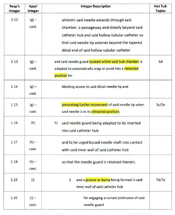
g) said needle being received within said hollow tubular catheter when in a ready position, wherein said needle extends through said chamber, a passageway and distally beyond said catheter hub and said hollow tubular catheter so that said needle tip extends beyond the tapered distal end of said hollow tubular catheter and said needle guard located within said hub chamber is adapted to automatically snap or pivot into a retracted position for blocking access to said distal needle tip and preventing further movement of said needle tip when said needle is in its retracted position;
h) said needle guard being adapted to be inserted into said catheter hub and to be urged by said needle shaft into contact with said inner wall of said catheter hub so that the needle guard is retained therein;
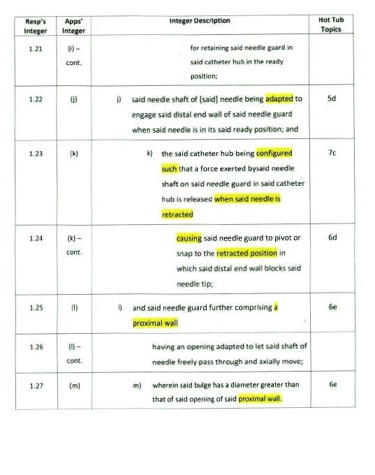
i) and a groove or bump being formed in said inner wall of said catheter hub for engaging a curved protrusion of said needle guard for retaining said needle guard in said catheter hub in the ready position;
j) said needle shaft of needle being adapted to engage said distal end wall of said needle guard when said needle is in its said ready position; and
k) the said catheter hub being configured such that a force exerted by said needle shaft on said needle guard in said catheter hub is released when said needle is retracted causing said needle guard to pivot or snap to the retracted position in which said distal end wall blocks said needle tip;
l) and said needle guard further comprising a proximal wall having an opening adapted to let said shaft of needle freely pass through and axially move;
m) wherein said bulge has a diameter greater than that of said opening of said proximal wall.
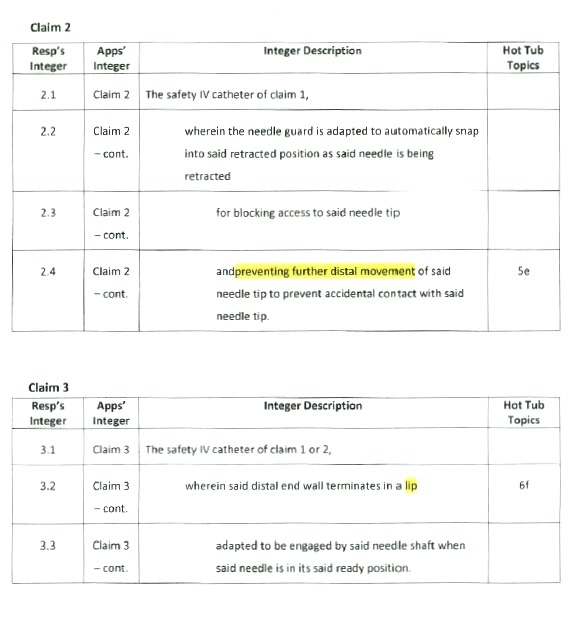
2. The safety IV catheter of claim 1, wherein said needle guard is adapted to automatically snap into said retracted position as said needle is being retracted for blocking access to said needle tip and preventing further distal movement of said needle tip to prevent accidental contact with said needle tip.
3. The safety IV catheter of claim 1 or 2, wherein said distal end wall terminates in a lip adapted to be engaged by said needle shaft when said needle is in its said ready position.
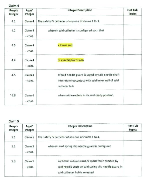
4. The safety IV catheter of any one of claims 1 to 3, wherein the said catheter is configured such that a lower end or curved protrusion of said needle guard is urged by said needle shaft into retaining contact with said inner wall of said catheter hub when said needle is in its said ready position.
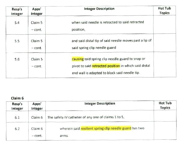
5. The safety IV catheter of any of claims 1 to 4, wherein said spring clip needle guard is configured such that a downward or radial force exerted by said needle shaft on said spring clip needle guard in said catheter hub is released when said needle is retracted to said retracted position, and said distal tip of said needle moves past a lip of said spring clip needle guard causing said spring clip needle guard to pivot or snap to said retracted position in which said distal end wall is adapted to block said needle tip.
6. The safety IV catheter of any one of claims 1 to 5, wherein said resilient spring clip needle guard has two arms.
7. The safety IV catheter of claim 6 wherein each of said arms has a distal end wall.
A description of the invention appeared in the body of the patents in suit and will need to be referred to later in these reasons.
4 The patents included a number of diagrammatic representations of the inventions. It may be helpful for the purpose of explanation in these reasons to reproduce the first two of those diagrams. Figure 1 (modified with the additional words as explained below) is a longitudinal section across an embodiment of an intravenous catheter device:
|
Distal to User |
Proximal to User |
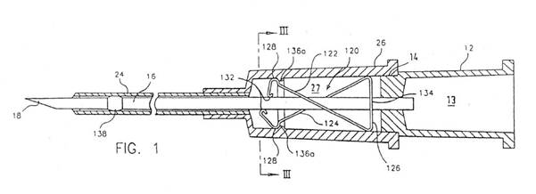
Figure 2 shows the distal end of the needle with the needle protecting means protecting the needle point when the needle has been removed from the catheter:
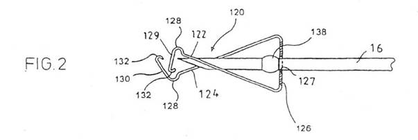
The figures in the patents do not include the words “Distal to User” and “Proximal to User” which have been added to the reproductions of those figures in these reasons as those words were used and understood in the proceeding.
5 The parties prepared claim charts for the proceeding in which the text of the claims was divided into and set out as integers or features, and instructed their expert witnesses to refer to those integers in a joint report prepared for the purposes of the hearing. Counsel submitted copies of the claims charts for each of the two patents identifying, by yellow highlighting, the issues which were in dispute between the experts. The claims charts reproduce in all but one respect Multigate’s formal admissions made for the purposes of the proceeding. A copy of the admissions is annexure A to these reasons and the claims charts are, respectively, annexures B and C to these reasons.
6 There are many common features to the claims in the inventions in the 327 and 577 Patents but Multigate drew attention to what were contended to be important differences. The first was that the 327 claim provides that the needle has a crimp whereas the claims in the 577 Patents provide that the needle shaft comprises a bulge. Secondly, the 327 claim provides that the needle guard “has a resilient portion on which the needle shaft exerts a force which is engaged by the side of the needle shaft and biased radially outwardly by it, which is moveable within the interior of the catheter hub to a blocking position distal of the needle tip and which blocks the tip of the needle tip when the needle is retracted”, whereas the claims in the 577 Patents (a) specify that the needle guard is a resilient spring clip needle guard which is adapted automatically to snap or to pivot into a retracted position for blocking access to the distal needle tip, and (b) further specify that the needle guard has a distal end wall such that the needle shaft is adapted to engage the distal end wall when the needle is in its ready position, and the distal end wall blocks the needle tip when the needle guard is in its retracted position. Thirdly, the 327 claim provides that the needle guard is secured to a groove formed in the catheter hub interior, whereas the 577 claims provide that a curved protrusion of the needle guard is engaged by a groove or bump being formed in the inner wall of the catheter hub. Fourthly, that the 327 claim provides that the needle guard is secured to the needle tip when the needle is fully retracted, whereas the 577 claims provide that the needle guard blocks access to the needle tip and prevents further distal movement of the needle tip when the needle is in its retracted position. Fifthly, that the 327 claim provides that a portion of the needle guard proximal end makes contact with a needle crimp when the needle is in its fully retracted position, whereas the 577 claims provide that the needle guard has a proximal wall having an opening adapted to let the shaft of the needle freely pass through and axially move where the diameter of the opening is less than the diameter of the needle bulge. Sixthly, that the 327 claim does not require the feature in the 577 claims which provides that the catheter hub is configured such that a force exerted by the needle shaft on the needle guard is released when the needle is retracted causing the needle guard to pivot or snap to the retracted position. Seventh, that the 327 claim specifies that the needle is attached to a distal end of a needle hub, and that there is a “spaced apart relationship” between the needle guard and the distal end of the needle hub, whereas the 577 claims are silent about attachment of the needle to the needle hub and any requirement for a spaced apart relationship between the needle guard and the distal end of the needle hub. Eighthly, that in the 327 claim the needle has a ready position in which the needle is received within the tubular catheter, the needle tip is outside the catheter hub and the needle shaft engages a resilient portion of the needle guard, whereas in the 577 claims the needle has a ready position in which the needle is received within the tubular catheter, the needle tip extends beyond the tapered distal end of the tubular catheter and the needle shaft is adapted to engage a distal end wall of the needle guard.
Construction of the patents
7 The determination of infringement depends upon whether the product in question embodies each and every essential integer of the particular claim of the patent in question: Populin v HB Nominees Pty Ltd (1982) 41 ALR 471 (‘Populin’), 475. Ultimately that will depend upon looking at the products said to infringe the patents and comparing them with the claims in the patent. The first step in that process, however, requires a construction of the patent without an eye to the alleged infringement: Bitech Engineering v Garth Living Pty Ltd (2010) 86 IPR 468 at [26]; Fresenius Medical Care Australia Pty Ltd v Gambro Pty Ltd (2005) 224 ALR 168, 184 at [95]; GlaxoSmithKline Australia Pty Ltd v Reckitt Benckiser Healthcare (UK) Limited (2013) 305 ALR 363, 379 at [60]. In that process the court “derives assistance from experts who are skilled addressees” and in doing so should be careful “to avoid assuming a technical expertise” which the court does not have: CCOM Pty Ltd v Jiejing Pty Ltd (1994) 51 FCR 260, 284.
8 The parties disagreed about the principles to be applied in the construction of the words of the patents in relation to what was described in the proceedings as the “pith and marrow” principle expressed by Lord Cairns in Clark v Adie (1877) 2 App Cas 315 at 320. The disagreement concerned the extent to which a finding of infringement required an exact correspondence between the terms of the claim and the alleged infringing device. The principle was explained in C Van Der Lely NV v Bamfords Ltd (1961) 1A IPR 86, 96 and protects a patentee whose invention is taken without exact textual infringement: see also Commonwealth Industrial Gases Ltd v MWA Holdings Pty Ltd (1970) 180 CLR 160, 167-168; Olin Corp v Super Cartridge Co Pty Ltd (1977) 180 CLR 236, 246; Minnesota Mining & Manufacturing Co v Beiersdorf (Australia) Ltd (1980) 144 CLR 253, 286; Catnic Components Ltd v Hill & Smith Ltd [1982] RPC 183, 242-3; Populin, 476-7; Azuko Pty Ltd v Old Digger Pty Ltd (2001) 52 IPR 75, [31(4)], [36]; Sachtler GmbH & Co KG v RE Miller Pty Ltd (2005) 221 ALR 373, [51]-[56]; Fresenius Medical Care Australia Pty Ltd v Gambro Pty Ltd (2005) 224 ALR 168, [50]; Leonardis v Sartas No 1 Pty Ltd (1996) 67 FCR 126, 148. In Radiation Ltd v Galliers and Klaerr Pty Ltd (1938) 60 CLR 36, Dixon J said at 51 that:
…on a question of infringement, the issue is not whether the words of the claim can be applied with verbal accuracy or felicity to the article or device alleged to infringe. It is whether the substantial idea disclosed by the specification and made the subject of a definite claim has been taken and embodied in the infringing thing.
That passage was followed by the full court of the Federal Court in Populin at 475. Counsel for Multigate contended, however, that “the question of infringement is not of taking the ‘pith and marrow’, ‘substance’ or ‘idea’ of the invention”.
9 The relevant principles were considered by Bennett J in Sachtler GmbH & Co KG v RE Miller Pty Ltd (2005) 221 ALR 373 (‘Sachtler’) at [43]-[67]. In particular, her Honour said at [50]-[53]:
50 In Populin at 475, the Full Court reiterated the fundamental proposition that, to establish infringement of a combination patent, the patentee must show that the defendant has taken each and every one of the essential integers of the claim. If, on its true construction, the claim is for a particular combination of integers and the alleged infringer omits one of the essential integers, the infringer escapes liability (Populin at 475). A defendant will not escape liability if an inessential integer is omitted or replaced by an equivalent.
51 In Populin at 475 the Full Court discussed the taking of the substantial idea disclosed by the specification and infringement of the claims:
… it is whether the substantial idea disclosed by the specification and made the subject of a definite claim has been taken and embodied in the infringing thing… [Emphasis added.]
This is the “pith and marrow” test which is based on a statement by James LJ in Clark v Adie (1875) LR 10 Ch App 667 that one should look to whether the allegedly infringing article is the same in substance and effect or is a substantially new or different combination. This principle applies to immaterial variations where an inessential part or step is omitted or substituted. A modification may be so small as to be insignificant and to have no material effect on the way the invention works: Commonwealth Industrial Gases Ltd v MWA Holdings Pty Ltd (1970) 180 CLR 160 at 168; Rehm at ALR 92 per Gummow J.
52 This is consistent with the principle in Catnic, as discussed in Kirin-Amgen at [50], that there is no infringement if a variant has a material effect on the way the invention works. Put another way, if the variant were of an inessential integer, it would not be a mechanical equivalent.
53 This does not mean that there is infringement where there has been no taking of all the essential integers of the claim (Olin Corporation v Super Cartridge Co Pty Ltd (1977) 180 CLR 236 at 246 per Gibbs J) or where the wording of the claims make it clear that the relevant area has been deliberately left outside the claim: 3M at CLR 286. Catnic is clear authority for the proposition that it is the essential integers of the claim that constitute the “pith and marrow” of the claim: at 243.
Her Honour’s observations were endorsed by the Full Court in Australian Mud Company Pty Ltd v Coretell Pty Ltd (2011) 93 IPR 188, 198 [64] where the Full Court went on to caution against applying the “pith and marrow” principle as extending a patentee’s monopoly to products or processes that the patentee did not, by the claims, define as the invention. The Court said at [66]-[69]:
66 In Nicaro Holdings Pty Ltd v Martin Engineering Co (1990) 91 ALR 513 Gummow J (when in this Court) observed (at 528-529) that, for an Australian court dealing with patent infringement, Catnic did not propound any novel principle or new category of “non-textual infringement”: see also Rehm Pty Ltd v Websters Security Systems (International) Pty Ltd (1988) 81 ALR 79 at 92; Fisher & Paykel Healthcare Pty Ltd v Avion Engineering Pty Ltd (1991) 103 ALR 239 at 255.
67 In Olin Corporation v Super Cartridge Co Pty Ltd (1977) 180 CLR 236 at 246 Gibbs J, when dealing with the so-called “pith and marrow” principle of infringement, cautioned that the application of that principle did [not] mean that there would be infringement where the patentee has, by the form of his claim, left open that which the alleged infringer has done.
68 Indeed, in C Van der Lely NV v Bamfords Ltd (1962) 1A IPR 86, on which Gibbs J based his observation in Olin, Viscount Radcliffe (at 96) said:
When, therefore, one speaks of theft or piracy of another’s invention or says that it has been “taken” by an alleged infringer and this “pith and marrow” principle is invoked to support the accusation, I think that one must be very careful to see that the inventor has not by the actual form of his claim left open to the world the appropriation of just that property that he says has been filched from him by piracy or theft. After all, it is he who has committed himself to the unequivocal description of what he claims to have invented, and he must submit in the first place to be judged by his own action and words.
See also the discussion in Populin v HB Nominees Pty Ltd (1982) 41 ALR 471 at 476-477.
69 To give a purposive construction to a patent specification, and in particular its claims, is not to engage in a process of reasoning that extends the patentee’s monopoly to the “ideas” disclosed in the specification. Nor does it extend the patentee’s monopoly to products or processes that the patentee did not, by the claims, define as the invention, even if those products or processes can be seen to perform the same function as the invention or to be based on the patentee’s “ideas”.
[The word “not” in [67] above has been added as agreed between the parties to have been omitted from the judgment by a typographical error].
Recourse to broad notions of the “pith and marrow”, the “substance” or “the idea” disclosed by a specification in the interpretation of a patent cannot, therefore, impermissibly enlarge a claim if not fairly made on a proper reading of the patent. The test of infringement is whether the infringing item embodies each and every essential integer of the claim and in that task regard must be had to the terms of the claim. The application of the “pith and marrow” test must, therefore, be based on the claim in the patent. The test does not permit recourse to the substantial idea disclosed by the specification but requires that it be found in the subject of a definite claim.
10 The parties were otherwise in agreement that the approach to the construction of a patent is similar to that of construing any other commercial instrument. In H Lundbeck A/S v Alphapharm Pty Ltd (2009) 177 FCR 151 Emmett J said at [53]-[54]:
53 While the last proposition is correct, and evidence as to how the hypothetical addressee would have understood a specification at the relevant date may strictly be admissible, the underlying principle is that contained in the first proposition stated above, namely, that the construction of a specification, including the claims, is a question of law for the Court. However, the Court may be informed, for example, as to the way in which particular terms were, as a general rule, used by relevant addressee at the relevant time or what the use of a particular term or expression disclosed or conveyed to a relevant addressee at the relevant time, so long as it is shown that an understanding different from the ordinary usage of English was generally accepted by relevant addressees.
54 In that regard, there should be no difference in the approach to the construction of a patent from the approach to the construction of any other commercial instrument. That is to say, neither a patent nor any other commercial instrument should be construed in a vacuum but must be construed in the context in which the patent or instrument is being considered. Thus, the claims and specification of a patent must be construed in the way in which they would be understood by the relevant addressee. In the same way, a commercial instrument would be construed in the light of facts that might reasonably be expected to be known to the parties to the commercial instrument.
[Bennett J agreeing at [148] and Middleton J agreeing at [250]].
In Kinabalu Investments Pty Ltd v Barron & Rawson Pty Ltd [2008] FCAFC 178 the Full Court said at [44]-[45]:
44 The principles of construction applicable were not in dispute. When determining the nature and extent of the monopoly claimed, the specification must be read as a whole. But as a whole it is made up of several parts which have different functions. The claims mark out the legal limits of the monopoly granted. The specification describes how to carry out the process claimed and the best method known to the patentee of doing that. Although the claims are construed in the context of the specification as a whole, it is not legitimate to narrow or expand the boundaries of monopoly as fixed by the words of a claim, by adding to those words glosses drawn from other parts of the specification. If a claim is clear and unambiguous, it is not to be varied, qualified or made obscure by statements found in other parts of the document. It is legitimate, however, to refer to the rest of the specification to explain the background of the claims, to ascertain the meaning of technical terms and resolve ambiguities in the construction of the claims. See Flexible Steel Lacing Co v Beltreco Ltd (2000) 49 IPR 331 at [73]-[75] (Hely J).
45 Other more specific principles of construction collected in Flexible Steel at [81] are:
• a specification should be given a purposive construction rather than a purely literal one;
• the hypothetical addressee of the specification is the non-inventive person skilled in the art before the priority date;
• the words used in a specification are to be given the meaning the hypothetical addressee would attach to them, both in the light of the addressee’s own general knowledge and in the light of what is disclosed in the body of the specification;
• as a general rule, the terms of the specification should be accorded their ordinary English meaning;
• evidence can be given by experts on the meaning those skilled in the art would give to technical or scientific terms and phrases, and on unusual or special meanings given by such persons to words which might otherwise bear their ordinary meaning;
• however, the construction of the specification is for the court, not for the expert. In so far as a view expressed by an expert depends upon a reading of the patent, it cannot carry the day unless the court reads the patent in the same way.
Ordinarily, therefore, words are to be given their ordinary meaning unless a person skilled in the relevant art would, in the context of a claim, give a special meaning to them or unless the specification ascribes a special meaning to the words: DÉcor Corporation Pty Ltd v Dart Industries Inc (1988) 13 IPR 385, 391, 400, 410-11. What is left unclaimed by the words of the claim properly construed is not within the patentee’s monopoly: GlaxoSmithKline Australia Pty Ltd v Reckitt Benckiser Healthcare (UK) Limited (2013) 305 ALR 363, [60]. The patent is not to be construed “in some way to be ‘fair to the patentee’… [there being] no presumption about the width of the claims” (Sachtler at [60]), although the claim is to be construed with “an eye benevolent to the inventor and with a view to making the invention work”: Martin v Scribal Pty Ltd (1954) 92 CLR 17, 97 (applied in Leonardis v Sartas No 1 Pty Ltd (1996) 67 FCR 126, 134). In DÉcor Corporation Pty Ltd v Dart Industries Inc (1988) 13 IPR 385 Sheppard J said at 400 (in a passage noted with approval in Pfizer Overseas Pharmaceuticals v Eli Lilly & Co (2005) 225 ALR 416, 467-9 and PAC Mining v Esco Corporation (2009) 80 IPR 1, [26]-[29]):
(1) The claims define the invention which is the subject of the patent. These must be construed according to their terms upon ordinary principles. Any purely verbal or grammatical question that can be answered according to ordinary rules for the construction of written documents is to be resolved accordingly.
(2) It is not legitimate to confine the scope of the claims by reference to limitations which may be found in the body of the specification but are not expressly or by proper inference reproduced in the claims themselves. To put it another way, it is not legitimate to narrow or expand the boundaries of monopoly as fixed by the words of a claim by adding to those words glosses drawn from other parts of the specification.
(3) Nevertheless, in approaching the task of construction, one must read the specification as a whole.
(4) In some cases, the meaning of the words used in the claims may be qualified or defined by what is said in the body of the specification.
(5) If a claim be clear, it is not to be made obscure because obscurities can be found in particular sentences in other parts of the document. But if an expression is not clear or is ambiguous, it is permissible to resort to the body of the specification to define or clarify the meaning of words used in the claim.
(6) A patent specification should be given a purposive construction rather than a purely literal one.
(7) In construing the specification, the court is not construing a written instrument operating inter partes, but a public instrument which must define a monopoly in such a way that it is not reasonably capable of being misunderstood.
(8) The body, apart from the preamble, is there to instruct those skilled in the art concerned in the carrying out of the invention; provided it is comprehensible to, and does not mislead, a skilled reader; the language used is seldom of importance.
(9) Nevertheless, the claims, since they define the monopoly, will be scrutinised with as much care as is used in construing other documents defining a legal right.
(10) If it is impossible to ascertain what the invention is from a fair reading of the specification as a whole; it will be invalid. But the specification must be construed in the light of the common knowledge in the art before the priority date.
11 Multigate also submitted that in construing the patents it was relevant to take into account the circumstances in which the patents in suit were brought into being. The two patents in suit are the fifth generation of their family of patents in claims for a safety intravenous catheter apparatus. The two patents in suit were applied for, respectively, on 21 and 30 November 2012. The agreed statement of facts included an admission by the applicants that they had been aware of Multigate’s catheter B before 21 November 2012 when the second applicant obtained a sample of catheter B in its packaging from the intensive care unit of Epworth Eastern Hospital in early November 2012. Multigate had first imported samples of catheter A in May 2012 and had supplied them to customers between August and November. It had been provided for exhibition at the conference of the Australian College of Infection Prevention and Control in October 2012. Multigate submitted that in these circumstances the Court should proceed cautiously before adopting a broad construction of any of the terms in issue and should not accept that the similarity of the substantial idea of a feature of a claim, or similar functionality of a feature, sufficed to establish infringement. Multigate’s submission in this respect was, in essence, that the patents in suit were filed only after the Multigate catheters A and B were supplied in to the market and that the claims were framed with knowledge of the Multigate catheters. Multigate otherwise conceded, however, that there was no material difference between catheter A and catheter C other than what was referred to in the submissions as the tolerance gap.
12 The parties also relied upon expert evidence on the construction of the patents in suit as well as on questions of infringement and invalidity. Five expert witnesses were called to give evidence in the proceeding. They provided a joint report and gave oral evidence concurrently. Their evidence was directed to the meaning of the words in the claims although, ultimately, the construction of the claims is a matter for the Court: Minnesota Mining & Manufacturing Co v Tyco Electrics Pty Ltd (2001) 53 IPR 32, [92]; Fresenius Medical Care Australia Pty Ltd v Gambro Pty Ltd (2005) 224 ALR 168, [34]. In that task the claims are to be seen by the Court through the eyes of a non-inventive skilled worker in the relevant field as the relevant person to whom the patent is addressed before the priority date: Welch Perrin and Co Pty Ltd v Worrel (1961) 106 CLR 588, 610. In Kimberly-Clark Australia Pty Ltd v Arico Trading International Pty Ltd (2001) 207 CLR 1 the High Court said at [24]:
It is well settled that the complete specification is not to be read in the abstract; here it is to be construed in the light of the common general knowledge and the art before 2 July 1984, the priority date; the court is to place itself "in the position of some person acquainted with the surrounding circumstances as to the state of [the] art and manufacture at the time".
[Footnotes omitted.]
In Root Quality Pty Ltd v Root Control Technologies Pty Ltd (2000) 177 ALR 231 Finkelstein J said at [71]:
Generally speaking the skilled addressee is the person who works in the art or science with which the invention is connected. In Plimpton v Malcolmson (1876) 3 Ch D 531 Jessel MR said (at 556):
What is meant is that if [the invention] is a manufacture connected with a particular trade, the people in the trade shall know something about it; if it is a thing connected with a chemical invention, people conversant with chemistry shall know something about it.
In Catnic Lord Diplock said (at 242) that skilled addressees are "those likely to have a practical interest in the subject matter of [the] invention". A variety of people may have that interest. There are those who might wish to make or construct the invention, those who may wish to compound the invention and those who may wish to use the invention. The skilled addressee seems to me to be a relative expression which does not identify any specific person. Because the patent is directed to a person interested in making, constructing, compounding or using the invention (see, for example, s 27(3)(b) of the Patent Act 1993 (Canada); International Standard Electric Corp v Ooms 157 F 2d 73 (1946)), this hypothetical person, the patent lawyer's "reasonable man", may be required to be skilled in more than one art. Such a person might be thought of as the composite being, mentioned by Buckley LJ in Tetra Molectric at 583. It may be preferable not to search for a composite addressee but a team whose combined skills are to be employed. In General Tire & Rubber Co v Firestone Tyre & Rubber Co Ltd [1972] RPC 457 at 485; (1971) lA IPR 121 at 137-8, Sachs LJ said:
The construction of these documents is a function of the court, being a matter of law, but, since documents of this nature are almost certain to contain technical material, the court must, by evidence, be in the position of a person of the kind to whom the document is addressed, that is to say, a person skilled in the relevant art at the relevant date. If the art is one having a highly developed technology, the notional skilled reader to whom the document is addressed may not be a single person but a team, whose combined skills would normally be employed in that art in interpreting and carrying into effect instructions such as those which are contained in the document to be construed.
In this case the field of inventions of the patents in suit is the design and manufacture of safety intravenous catheters. Multigate submitted that the relevant notional person to whom the patents were addressed was a team of people comprising a designer or engineer skilled in medical device design and production, a clinical advisor and a toolmaker. Multigate relied upon the expert evidence of Mark Bennett, Vincent Leskowich and Timothy Spencer who, together, Multigate contended, constituted the notional team to which the patents were directed, namely: an expert user (Mr Spencer), a medical devices designer (Mr Leskowich) and a tool maker (Mr Bennett). The applicants relied upon the expert evidence of Dr Haindl and Dr Esnouf. Dr Haindl had spent much of his professional life working in the design, development and manufacturing of medical devices and intravenous catheters. Dr Esnouf had been a qualified medical doctor since 1979 and had worked in various hospitals in surgical roles and in private practice in which he had engaged in inserting intravenous catheters into patients on a regular daily basis. The use made of that evidence is best considered below in the context of the specific question of construction raised by the parties.
13 The approach adopted by the parties to the issues raised in this litigation was to have posed, and to have asked as questions for the experts, a number of questions in the three broad areas of dispute, namely, construction of the patents, infringement and invalidity. There was, in this approach, substantial overlap of the issues arising for considerations and of the positions taken and of the views expressed. Thus, for example, the first question posed to the experts for their joint report in relation to the construction of the 327 Patent was “where is the distal end of the needle hub?” and the first question in relation to infringement in respect of the 327 Patent was “where and what is the distal end of the needle hub?”. This approach, however, carries with it the need for caution to ensure that questions concerning the proper construction of the patent were not being answered “with an eye to infringement”. The experts had also been asked for their views about the presence of the integers in dispute in Multigate’s catheters A, B and C. The joint expert report set out their respective views on the presence in the Multigate catheters of the integers in the respective patents, and the experts were cross-examined about some of those views in the concurrent evidence given by them orally. The first step in the ultimate determination of infringement requires a construction of the patent without an eye to the alleged infringement (Bitech Engineering v Garth (2010) 86 IPR 168 at [26]; Fresenius Medical Care Australia Pty Ltd v Gambro Pty Ltd (2005) 67 IPR 230, 246 at [95]; GlaxoSmithKline Australia Pty Ltd v Reckitt Benckiser Healthcare (UK) Limited (2013) 103 IPR 487, 503 at [60]) and care must therefore be taken to ensure that answers given to questions raised for construction are not given to secure an outcome when the corresponding question is raised in the context of infringement or validity. It is also important not to lose sight of the fact that the words in a patent are used in a context and their meaning must be discerned and should reflect their use in that context.
Construction issues in the 327 patent
14 Multigate conceded that its catheters A, B and C have each of the integers of claim 1 of the 327 Patent except for those integers in which the words and phrases were underlined and emboldened as appears in annexure A to these reasons. The claim under the 327 Patent, as in contention between the parties, was relevantly:
An IV catheter apparatus including a tubular catheter having a proximal end and a distal end, a needle having a needle shaft and a tip and wherein the needle is attached to a distal end of a needle hub, said needle being received within said tubular catheter when the needle is in a ready position, a catheter hub attached to the proximal end of said catheter, said catheter hub having a hollow interior and an inner wall, said needle being movable between said ready position in which said tip is outside of said catheter hub and a retracted position in which said tip is within the interior of said catheter hub, a needle guard positioned in the interior of said catheter hub in a spaced apart relationship from the distal end of the needle hub;
wherein the needle guard has a resilient portion engaged by said needle shaft when said needle is in its ready position, the needle guard resilient portion is movable within the interior of said catheter hub to a blocking position distal of said needle tip when said needle is in its retracted position in which said needle shaft no longer exerts a force on said resilient portion of said needle guard;
wherein an outer contact surface on the needle guard is secured to a groove formed in the catheter hub hollow interior when the resilient portion is engaged by the side of the needle shaft and biased radially outwardly; and
wherein the needle guard further includes a needle guard proximal end, wherein the needle guard is secured to the needle tip when the needle is in the fully retracted position by a portion of the needle guard proximal end making contact with a needle crimp and the resilient portion blocking the needle tip.
15 The first area of disputed construction of the 327 Patent concerned the needle hub. The first question within this topic was about the meaning of the words “distal end” in relation to the needle hub, and illustrated the need for caution when construing the claims of a patent that the words of the claim should not be construed with an eye to infringement. The differences between the parties, and between their respective experts, concerning the meaning of the words “distal end” of the needle hub was essentially about whether the distal end was a specific point or region. Multigate contended that the distal end of the needle hub meant “the most distal perimeter or the outer face of the needle hub”. That was the view advanced in the joint report by two of Multigate’s experts, namely, Mr Leskowich and Mr Bennett. The construction advanced by Multigate had, of course, a favourable consequence for Multigate in relation to whether its catheters A, B or C had infringed the 327 Patent because, as Mr Bennett said in the joint report, in each case “the needle [was] not attached to the distal most face but in the central section of the needle hub”. The construction advanced by Braun, in contrast, was that the words “distal end” referred to a region rather than to an end point. That construction, in turn, had an unfavourable consequence for Multigate’s infringement case, and a corresponding favourable consequence for Braun’s infringement case, since it was possible to contend, on that construction, that the needle was attached to a distal end of the needle hub if the distal end was, as Dr Haindl said in the joint report, any region “distal from the midpoint of the length”.
16 The words “distal end” appear more than once in claim 1 of the 327 Patent. The words appear in the second and third lines preceded by the indefinite article and in the thirteenth line preceded by the definite article in the context of the positioning of the needle guard in a spaced apart relationship. In each case, however, the words are not used to refer to the furthest distal point of the needle hub but to a more general area which is distal to the user. The patent does not use such words as “distal point”, “distal end point” or “furthest distal point”, which would be more specific and narrower in meaning than “a distal end” or “the distal end”. The words “distal end” are more general and in their ordinary and natural meaning are apt to encompass the region ending with the furthest most distal point and including the area of the needle hub up to its centre. The patent relevantly refers to the attachment of the needle to the needle hub. The place of attachment is identified as “a distal end” and informs the reader of an aspect of the construction of the catheter; namely that the attachment occurs, as can be seen by figure 1, in a wider region than only at an end point. The needle hub is connected to the needle in the centre of the needle hub. The hub is a structure with a rotational symmetry and the needle is attached to the centre. The distal end, in that context, is that part of a wider region than just the end point at which the attachment occurs: the point of attachment is in the axial centre of the needle hub.
17 The second question for construction raised by the parties in respect of the needle hub concerned the meaning of the phrase “spaced apart relationship” in relation to the needle guard and the distal end. The words appear in the last line of the first paragraph of the claim in the 327 Patent concerning the positioning of the needle guard in the interior of the catheter hub. Multigate contended that the term should be given its ordinary English meaning to require that the needle guard and the distal end of the needle hub be separate from, or be some distance apart from, each other. Thus, to be in a “spaced apart relationship” from the needle hub, as submitted for Multigate, the needle guard must physically be outside the needle hub. In other words, that the needle guard and the distal end of the needle hub will only be spaced apart if there is an intended gap between the needle guard and the distal end of the needle hub. The construction of “spaced apart relationship” urged for Braun, in contrast, was that there was no need for a gap between the needle guard and the needle hub. The latter is seen in figure 1 marked with the number 12. The needle guard is located within the catheter hub (numbered 16) and for present purposes may be understood to include the mechanism within the catheter hub including the features identified with the numbers 122, 126, 128, 132 and 136a. For present purposes what is significant is the space appearing in figure 1 between the rear wall of the needle guard (identified with the number 126 and described in the patent as “rear wall of needle protecting means”) and the distal end of the needle hub. Braun contended that the words “spaced apart relationship” in the claim which described the relationship between the needle guard and the needle hub did not require there to be a gap between the two and that they could be in a “spaced apart relationship” even though they might be touching, provided that they were not constructed as connected. The construction of the words “spaced apart relationship” urged by Braun, which permitted the needle guard and the needle hub to be touching, was contended by Multigate to be “a nonsense”.
18 The construction advanced for Braun is to be preferred. Figure 1 does show a gap in the catheter in the ready position but the function of the requirement of a “spaced apart relationship” is to enable the needle to be withdrawn and be secured in the needle guard. The invention in the patent requires the needle hub to move independently of the needle guard so that the needle may be guarded when retracted. The relationship between the needle guard and needle hub is that they are to be placed separately within the device during the course of construction without there needing to be a gap: any space or gap between the two would serve no function; what does serve a function is that the two be separate for the operation of the device. The relationship of being spaced apart is not a relationship which prevents the two from having a connection or to be touching at all times. The need for a gap between the two only becomes a necessary feature in the operation of the catheter and is provided for by a construction of the catheter which ensures that the gap emerges in its operation. The description of the words refers to a relationship of two elements of the apparatus. The description in the claim is not that the needle guard is placed in the ready position with a gap between the needle guard and the distal end of the needle hub. Rather, the claim refers to a relationship between the needle guard and the needle hub. That relationship points to a positioning of the needle guard as a separate part of the apparatus permitting movement between the two. Mr Leskowich accepted that there was no need for a gap to be present for the proper functioning of the device.
19 The second topic raised for construction concerned the needle, including the various positions of the needle. Question 2(a) in the joint report dealt with the needle’s ready position. Braun contended that the use of the words “ready position” in the claim referred to any position where the needle tip protrudes from the distal end of the catheter hub. Mr Leskowich, in contrast, contended that the words “ready position” when used in the claim meant ready for insertion into the patient, as might be assumed to be depicted in figure 1. The construction advanced by Mr Leskowich has an intuitive appeal with the words “ready position” presupposing readiness for a purpose or use. However, the claim is not describing the use of the intravenous catheter in connection with a patient. Relevantly what is described is the position of the needle and its moveability from a ready position to a retracted position. The former describes the situation in which the needle is exposed and not secured by the needle guard. The latter is that point when the needle guard is positioned in the interior of the catheter hub and is not exposed. The ready position, therefore, within the meaning of the claim, is where the needle tip protrudes from the distal end of the catheter hub.
20 The second question concerning the needle raised for construction in the joint report concerned the position of the needle in the retracted position and the fully retracted position. The difference between the experts in relation to the retracted position of the needle was about whether the needle might be in the retracted position whilst the needle tip was still outside the needle guard. Mr Leskowich held the view that the needle tip might still be outside the needle guard in the retracted position because until fully retracted the needle could be returned to be ready for use if desired. Mr Spencer agreed with that view and agreed also with the view expressed by Mr Bennett that the retracted position referred to the points along the path of the needle retraction following withdrawal from the catheter. The view advanced for Braun was that the retracted position was where the needle tip had been withdrawn into the catheter hub including where the needle guard blocked the needle tip.
21 The terms of the claim clearly enough indicate that the retracted position of the needle was when the needle “tip [was] within the interior of [the] catheter hub”. It is distinguished in the claim itself from what is described in the last paragraph as the “fully retracted position”, namely, when the needle guard has done its work in securing the needle tip. The fully retracted position, as it seemed all of the experts agreed, is when the needle tip is within the needle guard and can no longer be returned to the ready position. It is not necessary, as Mr Spencer had opined, that the words “fully retracted position” be construed to require the needle guard to have been removed from the catheter hub; although, of course, it may be assumed that the needle will be in the fully retracted position when the catheter hub is removed. The words “retracted position” include the position when the needle is fully retracted but includes also where it is within the catheter hub but not yet fully secured in the needle guard.
22 The final question in relation to the needle raised by the parties and considered by the experts was the meaning of the words “needle crimp”. All agreed that the crimp was the deformation of the needle shaft. Dr Esnouf explained the process which caused a deformation of the needle shaft by applying external force to the wall of the shaft to change its shape. The process creates a flattened portion of the tube and corresponding bulge where the wall had been deformed radially by the crimping force. The purpose of the crimp, as revealed in the claim, can be seen when the needle is in the fully retracted position. In that position the needle crimp blocks the needle within the needle guard when the crimp of the needle reaches the proximal end of the guard.
23 The third broad topic for construction concerned the needle guard. Three questions were considered in the experts’ joint reports on this topic, namely: what is the “resilient portion” of the needle guard; what does it mean to say that the needle guard is “secured to” the needle tip when the needle is in the fully retracted position; and what is the “proximal end” of the needle guard. An issue of disagreement between the parties concerning the “resilient portion” of the needle guard was whether it included the arms identified in figure 1 by the numbers 122 and 124. The word “resilient” itself indicates something which resumes its original shape or position after movement. The needle guard in this invention blocks the needle tip when the needle is in the fully retracted position because parts of the guarding mechanism blocks the needle from moving forward. The claim refers to “the resilient portion blocking the needle tip” and the dispute concerning the construction of those words was whether that portion was limited to those parts of the guarding mechanism physically blocking the needle when fully retracted. Mr Bennett pointed to the use of the words “portion” as indicating that only part of the needle guard was referred to by the claim rather than the whole of the mechanism which effected the blockage when the needle was fully retracted. His view was that the resilient portion did not include the arms but was intended to refer more narrowly to the parts of the mechanism that blocked the needle in the fully retracted position. Mr Leskowich expressed a similar view in the joint report when saying that the resilient portion was the area in figure 2 between the lip identified by the number 132 and the elbow identified by the number 128.
24 The patent itself refers to the arms moving “resiliently” into the position shown in figure 2 when the needle point passes the lips and arms:
When the needle point passes the lips 132 the arms 122, 124 resiliently move into the position shown in Fig. 2 in which the front walls 129, 130 cover the needle point. […] The annular projection 136a retains the needle protecting means 120 in the catheter hub 26 when the needle 16 is removed from the catheter hub 26 until the arms 122, 124 of the needle protecting means 120 are no longer supported by the needle 16 and resiliently move towards the inside.
[Emphasis added.]
No doubt what causes the movement in the guard is the pressure in the points on the arms which is released when the needle tip passes the lips of the distal end of the guarding mechanism. The arms (numbered 122 and 124) in the mechanism shown in figure 2 spring together once the needle tip moves past the distal end of mechanism in the proximal direction. The force or pressure in the mechanism (including the arms) which had been applied to the needle is released when the needle passes the lips. It is the whole of the mechanism (including the arms by the release of the pressure but excluding the proximal end wall) which blocks the needle tip when it resiliently effects the blockage of the needle.
25 The debate concerning the construction of the needle guard being “secured to” the needle tip was about whether the words required that there be some form of attachment, locking or fixing of the needle tip to the needle guard. Mr Leskowich construed the terms of the patent as indicating that the crimp on the needle performed the function of securing the needle guard to the needle tip to prevent movement of the guard in the distal direction. In that context “secured” was said to mean that the guard over the needle’s tip could not be pulled off or removed. The relevant description in the patent of the operation by reference to figure 2 was:
When the needle 16 is removed from the catheter 24 the needle protecting means 120 is retained in the catheter hub 26 such that the needle 16 slides through the catheter hub. When the needle point passes the lips 132 the arms 122, 124 resiliently move into the position shown in Fig. 2 in which the front walls 129, 130 cover the needle point. In this condition the engagement element 127 abuts the irregularly configured portion 138 such that the needle protecting means 120 is prevented from sliding beyond the distal end of the needle 16.
The “securing to” of the needle guard to the needle tip in the patent explains that the needle guard in the position shown in figure 2 cannot move in such a way that would expose the needle tip or which would permit the needle tip to leave the guard. No part of the invention affixes the needle tip to the needle guard in any way that might be regarded as an attachment or affixing of one onto the other. The needle guard, however, in the position shown in figure 2, is secured such that it cannot permit the needle to move distally.
26 The experts also disagreed about whether the securing contemplated by these words meant that the needle guard was secured in one or two directions. Dr Haindl was of the view that the securing had a two directional function whilst Mr Leskowich considered that the securing of the needle guard had only a one directional function because, in his view, the needle in a fully retracted position engaged the crimp which, according to Mr Leskowich, performed “the function of securing the needle guard to the needle tip to prevent movement of the guard in the distal direction (towards the needle tip)”. However, the crimp is not locked into the proximal wall of the needle guard and it is the blocking arms which perform the function of preventing needle exposure from distal movement of the needle tip. Accordingly the view of Dr Haindl is preferred.
27 Debate about the meaning of the words “the proximal end of the needle guard” was about whether what was to be understood by those words was the proximal face of the wall marked as number 126 on figure 1 or the whole of the wall and not just its outer (proximal) face. Dr Haindl urged the construction that the proximal end of the needle guard was the whole wall whilst Mr Bennett urged the view that the words referred to the most proximal perimeter or face of the needle guard. Mr Leskowich in this respect appeared to support Dr Haindl rather than Mr Bennett. The view of Dr Haindl is the more natural meaning of the words in the claim. The last paragraph in the claim refers to a needle guard proximal end as part of the mechanism of securing the guard to the needle tip. What is described in that function is performed by the whole of the proximal wall labelled 126 in figure 2 and not just one of its faces. The example used in argument of the difference between the paint on a wall and the wall itself may not be a perfect analogy but usefully points to the competing views. The function in the patent is relevantly performed by the wall and not just by its surface: indeed, without the wall the surface would neither exist nor be capable of performing the function Mr Bennett ascribed to it.
28 The next topic for construction of the claim concerned the catheter hub. In that context the experts were asked four questions for their joint report, namely: what does “attached to the proximal end” mean in relation to the catheter hub and catheter; what does “positioned in the interior of said catheter hub” mean in relation to the needle guard; what is a groove; and what does “secured to a groove in the catheter hub hollow interior” mean.
29 The claim describes the catheter hub being attached to the catheter at the proximal end of the catheter. Figure 1 shows the catheter hub numbered 26 being attached to the catheter numbered 24. The attachment of the catheter hub is at the proximal end of the catheter; that is, the distal end of the catheter hub is attached at the proximal end of the catheter. Mr Bennett, an expert called by Multigate, said that the words “attached to” in this context referred to a direct attachment of the kind shown in figure 1, but “does not include indirect attachment”. Mr Leskowich agreed with Mr Bennett to the extent that figure 1 showed “a direct connection between the two” but otherwise said that the words from a design engineer’s perspective meant that there had to be a connection between the catheter hub and the catheter that would meet the ISO requirements for tensile strength to ensure that the catheter did not break or dislodge when pulled during use. Dr Haindl agreed with Mr Leskowich’s comments in respect of the ISO requirements but expressed the view that it did not matter “if the connection happen[ed] directly or indirectly”. In Dr Haindl’s view the words meant that the proximal end of the catheter was “received in a distal hole of the catheter hub and [was] firmly connected with the hub”. The words of the claim require that the catheter hub be attached to the catheter but they do not exclude indirect attachment. It may be inferred that the attachment must be one that would meet the ISO requirements for tensile strength but there is otherwise no reason to construe the words to imply a limitation that the attachment be only a direct attachment.
30 The meaning to be given to the words “positioned in the interior of the said catheter hub” gave rise to sharp disagreement between the parties and their experts. The dispute focused upon the extent, if any, to which the needle guard was to be positioned in the interior of the catheter hub. Dr Haindl’s view was that the needle hub would be positioned in the interior of the catheter hub if it was either wholly or largely positioned in the interior. The view expressed by Mr Bennett in the joint report overlapped with that of Dr Haindl but Mr Bennett expressed himself as construing the words to be satisfied if the needle guard was positioned only partly in the interior of the catheter hub. Mr Leskowich, in contrast, expressed the view that the words required that the whole of the needle guard be entirely positioned in the interior of the catheter hub.
31 The needle guard shown in figure 1 is wholly positioned in the interior of the catheter hub but the claim is not limited in that way and should not be interpreted as if it were limited. Nor is there reason to reject Mr Bennett’s view that the words might be satisfied by less than the majority of the needle guard being positioned within the interior of the catheter hub. The extent of positioning within the interior of the catheter hub may be so slight that it could not be regarded as being positioned in the interior of the catheter hub in any meaningful sense but the words need not be restricted to a 50% or more interior placement of the needle guard within the catheter hub.
32 The question concerning the meaning of the word “groove” arose in the context of the role played by what was described in the legend to figure 1 as an “annular projection” and marked as numbered 136a. The claim refers to the needle guard being “secured to a groove” formed in the catheter hub hollow interior. The description in the claim can be seen from figure 1 with the resilient portion of the needle guard being engaged by the sides of the needle shaft in the ready position. The figure shows the distal end of the needle guard being pushed outwards as the needle passed through with the annular projections on the wall of the catheter hub securing the needle guard from moving in the proximal direction. The meanings given by each of the experts to the word “groove”, in this context, did not differ materially. In each case the word was said to mean an increase in the projected internal diameter of the interior hollow portion of the catheter hub in some part of its surface.
33 The differences between the experts about the meaning of the phrase “secured to a groove in the catheter hub hollow interior” was about whether the securing needed to be fixed or locked. Mr Bennett considered the words “secured to a groove” to mean “firmly attached, fixed to or locked together, as may be illustrated by a dovetail joint”. All other experts took a more general view. Mr Leskowich, for example, considered the words to mean that there be a “frictional fit present”. The views expressed by the experts, apart from Mr Bennett, best express the words in the claim, that is, that the words of the claim do not require that the securing of the needle guard be fixed or locked, provided that what occurs secures the needle guard to a groove when the resilient portion is engaged.
Construction issues in the 577 patent
34 Multigate also conceded that its catheters A, B and C have each of the integers to claims 1 to 6 of the 577 Patent except for those integers in which the words and phrases were underlined and emboldened as appeared in annexure A to these reasons. The claims under the 577 Patent, as in contention between the parties, were relevantly:
In claim 1 of the 577 patent:
A safety IV catheter comprising:
(a) a needle having a needle shaft and a needle tip;
(b) said needle shaft comprising a bulge;
(c) a hollow tubular catheter having a proximal end;
(d) said hollow tubular catheter is secured to the distal end of a catheter hub;
(e) said catheter hub having a hub section, wherein a chamber is formed in said hub section, and having an inner wall;
(f) a resilient spring clip needle guard located within said chamber being formed in said hub section of said catheter hub and having a distal end wall;
(g) said needle being received within said hollow tubular catheter when in a ready position, wherein said needle extends through said chamber, a passageway and distally beyond said catheter hub and said hollow tubular catheter so that said needle tip extends beyond the tapered distal end of said hollow tubular catheter and said needle guard located within said hub chamber is adapted to automatically snap or pivot into a retracted position for blocking access to said distal needle tip and preventing further movement of said needle tip when said needle is in its retracted position;
(h) said needle guard being adapted to be inserted into said catheter hub and to be urged by said needle shaft into contact with said inner wall of said catheter hub so that the needle guard is retained therein;
(i) and a groove or bump being formed in said inner wall of said catheter hub for engaging a curved protrusion of said needle guard for retaining said needle guard in said catheter hub in the ready position;
(j) said needle shaft of needle being adapted to engage said distal end wall of said needle guard when said needle is in its said ready position; and
(k) the said catheter hub being configured such that a force exerted by said needle shaft on said needle guard in said catheter hub is released when said needle is retracted causing said needle guard to pivot or snap to the retracted position in which said distal end wall blocks said needle tip;
(l) and said needle guard further comprising a proximal wall having an opening adapted to let said shaft of needle freely pass through and axially move; [denied for Catheters A and C, admitted for Catheter B]
(m) wherein said bulge has a diameter greater than that of said opening of said proximal wall. [denied for Catheters A and C, admitted for Catheter B]
In claim 2 of the 577 Patent:
"wherein said needle guard is adapted to automatically snap into said retracted position as said needle is being retracted for blocking access to said needle tip and preventing further distal movement of said needle tip to prevent accidental contact with said needle tip."
In claim 3 of the 577 Patent:
"wherein said distal end wall terminates in a lip [denied for Catheter B, admitted for Catheters A and C] adapted to be engaged by said needle shaft when said needle is in its said ready position."
In claim 4 of the 577 Patent:
"wherein the said catheter is configured such that a lower end or curved protrusion of said needle guard is urged by said needle shaft into retaining contact with said inner wall of said catheter hub when said needle is in its said ready position."
In claim 5 of the 577 Patent:
"wherein said spring clip needle guard is configured such that a downward or radial force exerted by said needle shaft on said spring clip needle guard in said catheter hub is released when said needle is retracted to said retracted position, and said distal tip of said needle moves past a lip of said spring clip needle guard causing said spring clip needle guard to pivot or snap to said retracted position in which said distal end wall is adapted to block said needle tip ."
In claim 6 of the 577 Patent:
"wherein said resilient spring clip needle guard has two arms."
35 The first topic for construction presented by the parties concerned the needle and gave rise to five questions. The experts agreed on the construction of the first two questions which they had been asked on this topic. The first was “what is the bulge in the needle shaft”. The experts agreed that the bulge is a section of the needle where the diameter is greater in a localised region. Mr Leskowich, with whom the others agreed, said that the word bulge meant the flattened section of a needle diameter that decreased the diameter in one direction and increased the diameter in another direction creating an irregularly configured portion of the needle shaft resulting in two outward protrusions. That construction of the word can readily be accepted and may be seen in figures 1 and 2. The second question was “what is a ready position in relation to the needle”. On this question of construction all agreed with the views expressed by Dr Haindl and Mr Leskowich. The former said that the patent defined “ready position” as when the needle tip extends beyond the tapered distal end of the hollow tubular catheter. Mr Leskowich said that it meant when the needle tip protrudes from the catheter as shown in figure 1. Those views of the meaning of the words may also be accepted.
36 The third question for construction presented by the parties in relation to the needle, and put to the experts, was “what is a retracted position, in relation to the needle”. The views of the experts appeared not to differ materially and were to the effect that the needle was in a retracted position when its tip was blocked within the needle guard. The words appear in several places in claim 1 including subparagraph (g). There, and in the other paragraphs in the claim where the words appear, it refers to the position of the needle when locked by the needle guard.
37 The fourth question presented by the parties and considered by the experts was “what does adapted mean in the phrase ‘adapted to engage the distal end wall of the needle guard when the needle is in its ready position’”. The word “adapted” in claim 1(j) is used in the sense of made or constructed to suit a purpose. That may occur by the modification of something from a standard model, as indicated by Mr Bennett, but something need not be a modification from a standard for it to be “adapted”. It is sufficient, as Dr Haindl and Mr Leskowich said, for the needle to be designed and constructed to perform a specific function. In other words, something may relevantly be “adapted” where it is constructed to suit a need irrespective of any difference it may or may not have from some standard or norm.
38 The last question in this group was “what does preventing further movement of said needle tip mean”. This phrase is similar to the word “secured” previously considered in the context of patent 327. The experts were largely in agreement, and their view is accepted, that the phrase conveyed the meaning of preventing the movement of the needle in the distal direction (beyond, perhaps, manufacturing tolerances) but not necessarily preventing rotational or other movement.
39 The next group of terms presented by the parties for construction concerned the resilient spring clip needle guard in the 577 Patent. The first question posed for the experts was the meaning of the words “resilient spring clip needle guard”. Claim 1(f) of the 577 Patent describes the catheter as comprising a resilient spring clip needle guard located within the chamber being formed in the hub section of the catheter and having a distal end wall. The experts differed sharply on the meaning of the words “resilient spring clip needle guard” and their disagreement included whether such a clip could be produced by any material other than metal. Dr Esnouf, with whom Dr Haindl agreed, said that the words “resilient spring clip needle guard” were to be understood as referring to a needle guard which had the characteristics of a spring (that is, which had the capacity to store energy), and was resilient such that following deformation the spring could return to its pre-deformation state. Dr Esnouf believed that it was possible to fabricate a spring clip needle guard from non-metallic material. He was cross-examined about this and confirmed his belief that it would be possible to fabricate a spring clip needle guard of the appropriate size to fit inside an intravenous catheter other than from metallic material. His evidence was of personal experience with folding material of sheet plastics reinforced with non-metallic materials in the context of a very small resilient ring used in a laryngeal mask and that evidence is accepted. Mr Bennett and Mr Leskowich, in contrast, maintained that the words meant a spring metal material such as stainless steel or spring steel. The terms in the patent, without an eye to infringement, do not require the words in question to be construed as limited to a spring clip made from a metallic substance. The words are to be understood as referring to a clip having a resilient feature in the sense of moving back into a position after its static state was altered.
40 The second question posed by the parties, and dealt with by the experts in this topic was what does “located within” mean in terms of the relationship between the needle guard and the chamber? The views of the experts on this question were the same as those they had expressed in relation to the same words in the context of the 327 Patent. There is no reason to adopt a different construction of the words in the 577 Patent from that in the 327 Patent. Mr Leskowich stated in the joint report that the text of the patent did not clearly define the position of the clip needle guard within the interior of the catheter hub but that a review of figure 1 revealed that the guard was shown to be fully and entirely contained within the catheter hub. Mr Leskowich supported that conclusion by his review of the prior art in which he saw in every figure a needle guard to be fully and entirely contained within the catheter hub. Similarly, the abutment of the needle hub (identified with the number 12 in figure 1) to the catheter hub (identified with the number 26 in figure 1) would, Mr Leskowich said, make it impossible for the needle guard to be anything other than fully and entirely contained within the hub. However, the terms of the patent are not so proscribed. The patent does not limit the needle guard to be located wholly within the catheter hub.
41 The third question asked about the meaning of the words “distal end wall” of the needle guard. The words are used in claim 1(f) by reference to an attribute of the spring clip needle guard and, therefore, relevantly refer to the whole of that feature of the needle guard. For that reason the view of Mr Leskowich (with whom Mr Bennett agreed) cannot be accepted to the extent that the distal end wall was seen as limited to what he considered to be the resilient portion of the needle guard, namely the points labelled 129 and 130 in figure 2. What is referred to as the “distal end wall” in the patent is a part of a structure having a thickness as well as a regional position and function.
42 The fourth question concerned the meaning of the words “retracted position” in relation to the needle guard in respect of which the parties and their experts found more agreement. Those words, as in relation to the 327 Patent, referred to the position of the needle guard when fully retracted for blocking access of the needle tip in the distal direction. Mr Leskowich considered there to be some ambiguity in the words because the words “further movement of the needle tip” were not clearly defined in the patent. Mr Bennett and Mr Spencer agreed with Mr Leskowich, but the absence of specific definition does not create ambiguity if the words are capable of sufficient understanding and meaning. The meaning of those words, in the context of an intravenous catheter designed to prevent injury from needle prick, is that in the retracted position the needle tip cannot move in the distal direction whatever its movement might otherwise be within the enclosing chamber.
43 The next question posed by the parties and considered by the experts was the meaning of the words “proximal wall” of the needle guard. Those words gave rise to disagreement concerning whether the wall referred to was to be understood as one of its sides rather than the entirety of the structure of the wall. Mr Bennett considered the words “proximal wall” to refer not to the entirety of the wall but to the most proximal perimeter or end of the needle guard. There is, however, no reason to confine the words “proximal wall” to a part of the wall. The words refer to a structure having a function within the apparatus and are to be understood as referring to the entirety of the structure such as that labelled 126 in figures 1 and 2 and not just to one of its surfaces.
44 The last question in this group presented for construction asked about the meaning of the word “lip” of the distal end wall of the needle guard. The needle guard may be described generally as having a proximal wall and a distal wall connected by two arms. The proximal wall is a continuous structure but the distal wall may be seen to be in two parts each connected to one of the arms. It is in two parts to permit the needle to pass through when in the ready position and to snap back resiliently to block the needle when fully retracted. The lip appearing in figures 1 and 2 is that part of the distal wall numbered 132. That accords with the views expressed by Dr Haindl and Mr Bennett. The view of Mr Leskowich was somewhat more proscriptive because he saw the “lip” to be a bend in the metal of more than 90 degrees which was not made itself to be resilient, and which he considered could only be accomplished with metal. The limitation Mr Leskowich placed upon the word “lip” is not warranted by the terms of the patent.
45 The last topic of questions for construction concerned the catheter hub. The first question presented by the parties and dealt with by the experts in their joint report was “what is the distal end of the catheter hub”. The catheter hub itself is identified in figure 1 by the number 26. The distal end of that structure is a region to the left of the drawing. It is referred to in claim 1(d) of the 577 Patent as the place where the hollow tubular catheter is secured. On that basis the distal end is at least that part of the catheter hub (identified by the number 26 in figure 1) which can be seen under the number 132 in figure 1. To that extent the distal end of the catheter hub is as identified by Mr Leskowich. There is, however, no reason to exclude other portions of the catheter hub up to about half of the length of the catheter hub itself, as Dr Haindl suggested. Mr Bennett’s view was that the distal end of the catheter hub was “the most distal perimeter or face of the catheter hub”, but there is no basis upon which that construction should be accepted. Indeed, it is not clear how such a meaning could be given practical effect.
46 The second and third questions posed in respect of the catheter hub for construction, and considered by the experts in their joint report, found them in general agreement. The second question asked what was meant by “secured to” in the context of the relationship between the catheter hub and the hollow tubular catheter, and the third question asked what did “configured” mean in relation to the catheter hub. In general terms the words “secured to” was approached by the experts in the 577 Patent as they had approached the same words in the 327 Patent. A difference between the experts concerned whether, as Mr Bennett thought, the words “secured to” required that the hollow tubular catheter had to be “firmly attached or fixed directly to the catheter hub”. However, for the same reasons as were considered in relation to the 327 Patent, the words “secured to” do not require to be interpreted as referring to direct securing. In relation to the word “configured” there appeared to be no material difference between the views expressed by the experts. The word “configured” relevantly means the design or arrangement of the catheter hub in a way that allows the needle guard to operate as intended.
47 The last two questions concerning the catheter hub which were posed for construction and considered by the experts asked, respectively, about the meaning of the words “groove” and “bump”. The words were used to some extent interchangeably as may be seen from claim 1(i) which refers to “a groove or bump being formed” in the inner wall of the catheter hub. It may be seen visually in figures 1 and 2 marked with the number 136(a) being an inward projection from the internal wall of the catheter hub having the function of keeping in place the needle guard when in the ready position.
Patent 327 Infringement
48 It is next relevant to turn to questions of infringement. An explanation of whether there has been an infringement of the patent as construed may, however, require some repetition of the matters previously considered. Multigate, as previously mentioned, conceded that catheters A, B and C have each of the integers in claim 1 of the 327 Patent except the integers in the words and phrases underlined and emboldened in annexure A to these reasons. Multigate’s written submissions dealt with common integers in dispute together where the same integer arose in the same way in a claim in one or either patents. That process will be followed in these reasons. To determine infringement it is necessary to look at each of the three Multigate catheters and to determine whether they infringe the claims in the patents as construed. Examples of each of catheters A, B and C were tendered in evidence, and it is to the examples to which regard must be had. The parties, however, also tendered photographs of catheters A, B and C showing enlarged views of various aspects of the catheters. The photographs also had annotations which were treated as submissions and not as evidence. The photographs were of assistance because the size of the catheters themselves did not always reveal by ordinary visual inspection the detail necessary to determine whether they contained the elements claimed by Braun in its patents.
49 The first of the integers in dispute identified in Multigate’s submissions (and which had been dealt with in the joint expert report as topics 1(a) and (b) in their construction of the patents and in topics 8(a)-(c) in their joint report concerning infringement) was whether the needle in the Multigate catheters was attached to the distal end of a needle hub, which was in a ‘spaced apart relationship’ relative to the needle guard. Multigate contended that the needle was “not attached to the distal end of a needle hub”. Catheters A, B and C have differences which may be seen by their visual inspection but in this respect are relevantly the same. For present purposes a photograph of catheter C can be taken as illustrative of each of the three catheters. Dr Haindl took a photograph of catheter C which was tendered in evidence and, in respect of this issue, is sufficiently like catheters A and B as revealed by a visual inspection. The photograph (omitting Dr Haindl’s annotations) was:
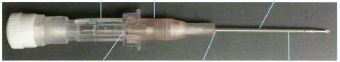
Each of catheters A, B and C have a needle hub with an outer peripheral collar and a seat for the catheter hub. The catheter hub appears in about the middle of the photograph above and the needle is attached to the distal end of the needle hub in the sense previously explained. The photograph is copied above in the same orientation as presented in evidence but may be reversed to show the same orientation as in figure 1:
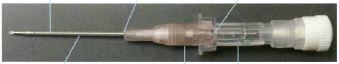
The needle can be seen in the photograph to be attached to that part of the region of the needle hub distal of the catheter hub. This integer of the patents is present because it is not sufficient to say, as was maintained by Mr Bennett, that the needle was attached in the central section of the needle hub and not attached at “the distal most face”.
50 It was next contended that the needle guard of each of the catheters in suit was not in a “spaced apart relationship” from the distal end of the needle hub. The relationship, spaced apart or otherwise, of the catheters and the distal end of the needle hub in each of the catheters in suit is not easy to determine by a visual inspection of the catheters without the aid of a magnifying glass or an enlarged photograph showing the area to be looked at of the catheters themselves. Enlarged photographs were provided which assisted in looking at the catheters in evidence. The area showing the relevant relationship in each catheter was in photographs taken by Dr Haindl. The photograph of the area taken by Dr Haindl of catheter A (including his annotations but remembering that the annotations were submissions and not evidence proving their contents) was:
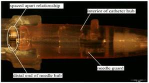
The relevant portion in catheter B is not materially different from that in catheter A but, for completeness, the photograph taken by Dr Haindl of Multigate’s catheter B was:
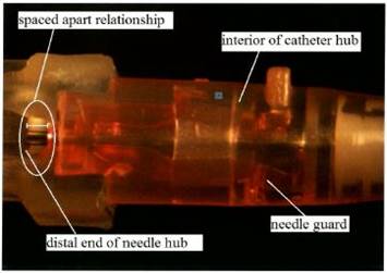
The relevant portion of what was in dispute as the spaced apart feature was identified in an x-ray image of catheter C tendered through Dr Haindl:
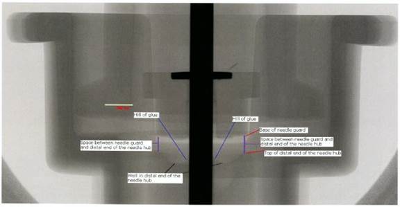
In each case the needle guard and the distal end of the needle hub of the catheters in suit have a relationship with each other of being separate. The two are placed separately within the catheters in suit and it does not matter that the two may be touching or that there is not a physical gap between the two. Indeed, the spaced apart relationship of the needle guard and the distal end of the needle hub in each of the catheters in suit may be seen in the alternative submission advanced by Braun, namely, that a physical separation may be seen when the catheters in suit are in a ready position. A photograph of the spaced apart relationship which is evident when the catheters are in a retracted position can be seen by another of Dr Haindl’s photographs of catheter C (omitting the annotations):
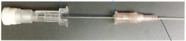
The needle guard in this photograph is to the right and the needle hub to the left. The two are physically separate as contemplated by the design and function of the patents.
51 The next integer considered in Multigate’s submissions was that there be “a catheter hub attached to the proximal end of [the] catheter”. The experts had considered the construction of these terms as topic 4(a) of the joint report and the questions of infringement as topic 10(a). The place of attachment of the catheter hub to the Multigate catheters in suit may be seen from the photograph of catheter C above which, in this respect, sufficiently reveals the attachment in catheters A and B as seen by an ordinary visual inspection. The catheter hub is relevantly attached to the proximal end of the catheter as those words were previously construed. The inclusion of a white conical slip ring (as can be seen in the photograph of catheter C) does not make the catheter hub any less attached to the proximal end of the catheters in suit. The attachment contemplated by the patent, as previously construed, does not require a direct fixing as had been maintained by Mr Bennett.
52 The third integer in dispute identified in Multigate’s submissions concerned the integer in the claim of “a needle guard positioned in the interior of [the catheter hub]”. The competing constructions of this integer were dealt with as topic 4(b) by the experts in their joint report and as topic 10(b) in relation to infringement. It was also considered by the experts as topic 15 in relation to questions of prior art to which reference will be made later. Both experts who expressed a view about this integer agreed that Mulitgate’s catheters A, B and C were “positioned in the interior” of the catheter hub. Multigate, however, contended that the integer was not established because the needle guards protrude from the catheter hub. The construction of the integer as not requiring that the needle guard be “wholly” positioned in the interior of the catheter hub, however, requires the conclusion upon an examination of catheters A, B and C that this integer is also present in the patents in suit.
53 The fourth group of integers dealt with in Multigate’s submissions concerned the needle guard and, in particular, its resilient portion. The experts had considered the competing constructions of the relevant terms as topic 3(a) of the joint report and as topic 9(a) and (b) in relation to infringement. It was also relevant to questions concerning prior art and considered by the experts in their joint report as topic 14 to which reference will be made later. Multigate contended that this element was lacking in its catheters A, B and C because none were said to have a resilient portion within the meaning of claim 1 of the 327 Patent.
54 The needle guards in the Multigate catheters are constructed differently from those shown in figure 1 of the 327 Patent. Another of the photographs taken by Dr Haindl assists in seeing how the needle guard operates in the Multigate catheters:
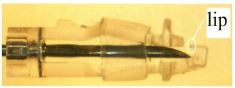
The degree of detail shown by this photograph could not readily be seen by a visual inspection of the catheter without magnification and taking it apart. A distinctive feature in the Multigate catheter is the presence of an elastomeric ring which can be seen as a translucent band in the photograph around the centre and right of the photograph. Mr Bennett said that the three Multigate catheters did not have the integer of a resilient portion of the needle guard because the needle guard in the Multigate catheters had an open natural position and “will not block the needle without the elastomeric ring in place”. Dr Haindl, in contrast, said that the two arms of the needle guard in the Multigate catheters “will block the needle guard without the help of the elastomeric ring as long as the needle tip is in the normally assembled rotational position”.
55 Multigate contended that the claim in the patent required that the resilient portion have the following “qualifications” or “characteristics”:
(a) it must be engaged by [the] needle shaft when [the] needle is in its ready position;
(b) it must be moveable within the interior of [the] cathether hub to a blocking position distal of [the] needle when the needle is in its retracted position in which [the] needle shaft no longer exerts a force on [the] resilient portion;
(c) it must enable an outer contact surface of the needle guard to be secured to a groove formed in the catheter hub hollow interior when the resilient portion is engaged by the side of the needle shaft and biased radially outwardly; and
(d) when the needle is in the fully retracted position, the resilient portion [must be] blocking the needle tip.
It was contended that without these characteristics, a catheter would not have the relevant integer in the patent.
56 It is difficult to determine the presence of this integer in the Multigate catheters without the assistance of experts. The Multigate catheters are too small to be tested by an untrained observer. In particular it is difficult, without the assistance of experts, to determine the role played by the arms in the Multigate catheters without the elastomeric ring. Dr Haindl’s evidence was that the two arms of the needle guard in the Multigate catheters are resilient. He explained that they are directly engaged by the needle shaft and, in cross-examination, explained his findings from experiments he had made by dismantling the elastomeric ring. Dr Haindl’s evidence was that he found that the needle guards worked without the elastomeric ring when the needle was in the rotational position in which the catheters are delivered. Little difference was found if the needle was turned by 180 degrees. In the normal fashion of use, therefore, the needle will be blocked by the needle guard when the distal wall of the needle guard touches the needle tip. He accepted that there was a greater risk of needle prick when the elastomeric ring had been removed than when the ring was on, but that the needle would pass even with the elastomeric ring in place if manipulated in a different rotational position. His evidence was that the elastomeric ring was not that which predominantly moved but, rather, that all three structures (namely the two arms and the ring) moved resiliently together. Plainly the elastomeric ring has some function to perform in the blocking of the needle effected by the needle guard in the Multigate catheters. That, however, does not mean that the needle guard is not within the claim of the 327 Patent. The needle guard in the catheters is engaged by the needle when the needle is in the ready position. The two arms of the needle guard in the Multigate catheters are directly engaged and the elastomeric ring is, at most, indirectly engaged as the needle in the ready position pushes back the two arms of the needle guard to the extent caused by the needle and kept in position by the elastomeric ring. The resilient portion of the needle guard in the Multigate catheters is moveable within the interior of the catheter hub to a blocking position distal of the needle tip when the needle is in its retracted position. When the needle shaft no longer exerts force the two arms do move back to block the needle. The resilient portion of the needle guard does enable an outer contact surface of the needle guard to be secured to a groove formed in the catheter hub hollow interior when the resilient portion is engaged by the side of the needle shaft and biased radially outwardly (which will be considered below). And the arms, being part of the resilient portion of the needle guard, do block the needle tip when the needle is in the fully retracted position.
57 The fourth topic of infringement dealt with by Multigate’s written submissions concerned the securing of the needle guard to a groove. The competing claims for the construction of the words were dealt with by the experts in their joint report as topic 4(d) and in relation to infringement as topic 10(c). The relevant integer in the claim was:
wherein an outer contact surface on the needle guard is secured to a groove formed in the catheter hub hollow interior…
The critical words for present purposes are those concerned with whether the needle guards in Multigate’s catheters A, B and C were “secured to a groove” in the catheter hub.
58 The groove in figure 1 of patent 327 was shown diagrammatically as the space between the annular projection numbered 136(a) and the inner distal wall of the distal end of the catheter hub. Its purpose is to secure the needle guard, and the groove is formed in the catheter hub hollow interior as shown in figure 1 above. The equivalent feature in contention in each of the Multigate catheters in suit can be seen by photographs taken by Dr Haindl showing the relevant area in enlargement. His photographs (which are reproduced with his annotations but which for present purposes are submission and not evidence) of each of the three catheters in suit are:
CATHETER A
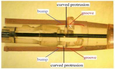
CATHETER B
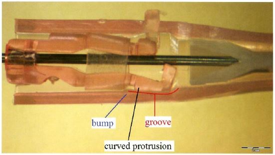
CATHETER C
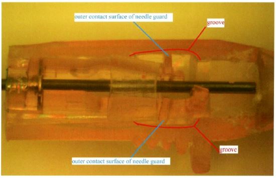
Each of these three photographs of the respective catheters in suit are of the needle guard sitting within the catheter hub hollow interior. Each reveals a depression within the catheter hub hollow which in the case of each of the three photographs has been submitted to be, and identified, with a line and the word “groove” pointing to it. The construction of the depression in the catheters in suit is different from the groove shown in figure 1 but each is apt to be described as a groove and each secures the needle guard when the resilient portion of the needle guard is engaged by the side of the needle shaft and biased radially outward. The claim in the patent does not require that the needle guard be held “firmly in position in physical contact to the groove” but, rather, that when the needle guard is engaged by the resilient portion of the needle guard, it (the needle guard) is secured to a groove.
59 The sixth topic in Multigate’s written submissions concerns the securing of the needle guard to the needle tip when the needle is in the fully retracted position. The question of construction of this integer was considered by the experts as topic 3(b) in their joint report and questions of infringement were considered by them as topic 9(c) of their joint report. The relevant words in the claim in the patent are:
…wherein the needle guard is secured to the needle tip when the needle is in the fully retracted position…
Multigate contended that this integer of the 327 Patent was not present in any of catheters A, B and C because, in essence, the needle guard was not “secured to” the needle tip. Critical to that submission was the construction advanced for Multigate that the words “secured to the needle tip” would only be satisfied if the needle tip was “firmly attached, locked, or fixed to the needle tip” as Mr Bennett had maintained. Multigate criticised the construction advanced for Braun on the basis that its experts ignored the word “to” following the word “secured”. However, the words in the patent do not require the construction advanced by Mr Bennett nor does the word “to” have the effect of requiring that the needle guard be “firmly attached, locked or fixed to the needle tip”.
60 Mr Bennett also gave evidence that the needle was capable of movement in each of the three catheters when in the needle guard was in the fully retracted position. He quantified this movement as a percentage of the distance between the needle tip and the needle bulge. In the case of catheter A that movement was estimated at 31.25%, in the case of catheter B at 41.32% and in the case of catheter C at 38.52%. However, the fact of movement does not establish that the needle guard was not secured to the needle tip when the needle is in the fully retracted position once it is accepted that “secured to” does not mean “firmly attached, locked or fixed” as had been contended. The words “secured to” mean that the needle tip is effectively trapped within the needle guard when the needle is in the fully retracted position. That feature is the fundamental objective of the catheters to prevent needle stick injury by a device that ensures that the needle tip is not exposed once it is fully retracted. Each of Multigate’s catheters in suit have that integer.
61 Topic 7 in Multigate’s written submissions concerned the proximal end of the needle guard making contact with the needle crimp. The competing construction of the words were dealt with by the experts as topic 3(c) in their joint report and questions of infringement were dealt by them in their joint report as topic 9(d). The relevant words in the claim were:
…wherein the needle guard further includes a needle guard proximal end …
…wherein the needle guard is secured to the needle tip when the needle is in the fully retracted position by a portion of the needle guard proximal end making contact with a needle crimp…
Multigate contended that the proximal end of the needle guard refers to the proximal wall of the needle guard and not to any items which are close to the needle guard end but which do not form part of it. Multigate catheters A and C each have a washer described in Multigate’s submissions as sitting “in front of the proximal wall”. Mr Bennett’s view was that it is the washer, and not the proximal wall in the catheters in suit, that blocks the crimp. There appeared to be no evidence of a washer in catheter B and Multigate’s submissions were, therefore, restricted to whether catheters A and C had the relevant feature of the 327 Patent claim. The washer in catheters A and C are visible in the following photographs taken by Dr Haindl:
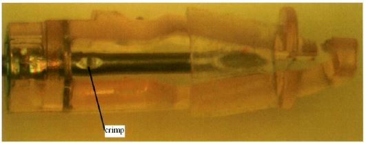
The washer in each case appears to the left of the photograph as the dark coloured vertical item within the otherwise translucent structure making up the needle guard. The washer, as Mr Bennett conceded in cross-examination, is not loose from the wall but is wholly integrated within it. The needles in each of the catheters in suit have a crimp or bulge which prevents the needle from travelling beyond the washer (in the case of catheters A and C) or the plastic material of the proximal end of the wall (in the case of catheter B). The washer in the case of catheters A and C is not a freely moveable part and must be seen as part of the proximal wall. There is no reason to assume that the proximal wall must have only one layer and that, as in the case of catheters A and C, the wall may not have both a metal layer and a plastic layer. Dr Haindl gave evidence of attempts physically to separate the metal from the plastic but his evidence was that he had been unable to separate the washer from the plastic. The introduction of the washer is, at best, a modification to the invention which does not add to the working of the device: see Commonwealth Industrial Gases Ltd v MWA Holdings Pty Ltd (1970) 180 CLR 160, 167. Accordingly, the integer in question is present in each of the three Multigate catheters in suit.
patent 577 infringement issues
62 Multigate conceded that catheters A, B and C had each of the integers of claims 1 to 6 of the 577 Patent except those integers in which the words and phrases were underlined and emboldened in annexure A to these reasons. Each of claims numbered 2 to 6 were dependent upon claim 1 of the 577 Patent.
63 The first topic considered under this heading in the submissions of Multigate concerned the words “preventing further movement” in claims 1 and 2 of the 577 Patent. The competing construction of the words was considered as topic 5(e) in the joint expert report and questions of infringement were considered by the experts as topic 11(c) in the joint expert report. The relevant words in the claim, as set out by Multigate in their written submissions, were:
CLAIM 1:
… said needle guard located within said hub chamber is adapted to automatically snap or pivot into a retracted position for blocking access to said distal needle tip and preventing further movement of said needle tip when said needle is in its retracted position; …
CLAIM 2 (Dependent claim):
…wherein said needle guard is adapted to automatically snap into said retracted position when said needle is being retracted for blocking access to said needle tip and preventing further distal movement of said needle tip to prevent accidental contact with said needle tip.
Multigate contended that none of catheters A, B or C have a needle guard which is capable of “preventing further movement of the needle tip when the needle is in the retracted position”.
64 The issues raised by this integer are similar to those raised by the words “secured to” in the context of the 327 Patent. Indeed, Mr Bennett repeated in the context of infringement issues relating to the 577 Patent his calculations of the movement of the needle which he had given in respect of the issue raised in the context of the 327 Patent. In both cases Mr Bennett had added the following observation to his percentage calculations of the travel of the needle within the needle guard:
This proves my point that this is significant movement far greater than normal manufacturing tolerance...
However, the words “preventing further movement” mean that the needle could not escape the needle guard, not that there was no further movement within the needle guard. The purpose of the invention is to ensure that the needle, once fully retracted, is safely within the needle guard and cannot escape from the needle guard so as to cause needle prick. Each of catheters A, B and C has the feature of movement of the needle tip being prevented in that sense when the needle is retracted.
65 The second topic considered in Multigate’s submissions was concerned with the spring clip of the needle guard. The issue arises in the context of claim 1 and dependent claims 5 and 6 of the 577 Patent. The competing construction of the words was dealt with by the experts in their joint report as topic 6(a) and the infringement issues were considered by them in the joint report as topic 12(a). The relevant words in the claim as identified in Multigate’s written submissions are:
CLAIM 1:
… a resilient spring clip needle guard …
CLAIM 5 (dependent claim):
… wherein said spring clip needle guard is configured such that a downward or radial force exerted by said needle shaft on said spring clip needle guard in said catheter hub is released when said needle is retracted to said retracted position, and said distal tip of said needle moves past a lip of said spring clip needle guard causing said spring clip needle guard to …
CLAIM 6 (dependent claim):
… said spring clip needle guard has two arms …
[Emphasis in original.]
Multigate contended that its catheters A, B and C do not have the requisite integers of this claim because its needle guard was made of plastic (not metal) and was differently configured from the spring clip needle guard shown in the figures of the 577 Patent.
66 Mr Bennett’s opinion concerning infringement was that none of the three catheters in suit had a “resilient spring clip needle guard” in each case “because the needle guards are not made from a spring metal material, the blocking elements cannot move to a blocking position without assistance from other elements”. It is true that the only description in the 577 Patent of the material of which the needle protecting means of the invention shown in figures 1 and 2 of the 577 Patent is “an integral part made of spring steel”. Multigate submitted that that, plus prior art, would cause a person skilled in the art to understand the disclosure in the 577 Patent to be limited to a spring metal material. The claim itself, however, is not so confined and should not so be limited. The expert evidence was that things with a springing effect can be made from plastic and materials other than metal. The description of the needle protecting means relied upon by Multigate as “spring steel” is a description of the needle protecting means depicted in figures 1 and 2 and not a general limitation to the claim; the word “steel” is not otherwise used in the claim to limit the material from which the spring clip may be made. The fact that the needle guard in catheters A, B and C is not made from metal, but plastic, therefore, does not negate those catheters having the relevant integer of the 577 Patent.
67 The other reason given by Mr Bennett, and advanced for Multigate in its submissions, was that their configuration was such that the needle guard itself, without the elastomeric ring, would not cause the needle guard to move to a blocking position. For the reasons set out above, however, the evidence does not support the submission that “the needle guard itself, without the elastomeric ring, does not” have the characteristics of both spring and resilience. It may be accepted, as Dr Haindl agreed, that there was a higher risk of needle prick when the elastomeric ring was absent from the catheters, and that the reliability and safety of the catheters is in part due to the presence of the elastomeric ring, but the evidence was that the Multigate catheters in suit do move to a blocking position without the assistance from such other elements of the elastomeric ring.
68 The third topic dealt with in Multigate’s submissions concerned the location of the needle guard within the chamber of the catheter hub. The construction of the terms was considered in the joint expert report as topic 6(b) and the questions of infringement were considered by them as topic 10(b). The issues raised here were similar to the comparable issues raised in relation to the 327 Patent. The terms of the claim identified in Multigate’s written submissions were:
CLAIM 1:
… (a resilient spring clip needle guard) …
located within said chamber being formed in said hub section of said catheter hub …
said needle guard located within said hub chamber …
Multigate contended that each of its catheters A, B and C in suit do not have this integer because the needle guard in each case protrudes from the catheter hub and none have a needle guard “wholly within a closed space”. However, for the same reasons considered above in relation to the comparable words in the 327 Patent, each of catheters A, B and C have a needle guard which is “located within” the catheter chamber. The claim does not require that the needle guard be wholly positioned within the interior of the catheter hub and, if it be relevant, that conclusion was expressed both by Dr Haindl and Mr Bennett in 10(b) of the joint expert report.
69 The fourth topic dealt with by Multigate’s written submissions concern the proximal wall of the needle guard in claim 1 of the 577 Patent. Construction of the relevant words was considered in the joint expert report as topic 6(e) and issues relating to infringement were considered by them as topics 11(a) and 12(b). The relevant words in claim 1 of the 577 Patent were identified in Multigate’s written submissions as:
CLAIM 1:
… (said needle shaft comprising a bulge) …
and said needle guard further comprising a proximal wall
having an opening adapted to let said shaft of needle freely pass through and axially move;
wherein said bulge has a diameter greater than that of said opening of said proximal wall.
Multigate submitted that its catheters A and C do not have this feature. Mr Bennett’s conclusion to that effect was based upon the view that the “proximal wall of catheters A and C refers to the most proximal perimeter of the needle guard and does not include the washer”. Accordingly, Mr Bennett concluded that the proximal wall of the needle guard in catheters A and C did not contact the needle bulge during use and that it was therefore not relevant to consider whether the needle in those catheters had a bulge with a diameter greater than the opening of the proximal wall. The conclusion, however, that the proximal wall includes the washer leads to a contrary conclusion and that each of catheters A, B and C do have this integer of claim 1 of the 577 Patent.
70 The fifth topic dealt with in Multigate’s submissions concerned the words “secured to” as used in claim 1 of the 577 Patent. The construction of the terms was considered as topic 7(b) in the joint expert reports and the questions of infringement were dealt with as topic 13(b) in that report. The relevant words in the claim were that the “hollow tubular catheter is secured to the distal end of a catheter hub”. Mr Bennett maintained that the catheter hub was not connected directly to the white conical portion of the catheter and, therefore, that the catheters in suit do not have this integer. However, for the reasons expressed above, the words “secured to” do not require that the hollow tubular catheter be attached or fixed directly to the catheter hub. The catheter hub is, relevantly, secured to the hollow tubular catheter by clamping the catheter wall between the inner wall of the hub and the outer wall of an additional part. The introduction of the white cone in catheters A, B and C does not require a conclusion that the tubular catheter was not secured to the distal end of the catheter hub. A visual inspection of the catheters, as well as the photographs, show that each of the catheters in suit has this integer.
71 The sixth topic considered in Multigate’s written submissions concerned the configuration of the catheter hub such as to cause the needle guard to pivot or snap to the retracted position. The construction of the relevant words had been considered by the experts in their joint report as topic 7(c) and the infringement issues had been considered by them as topic 13(c). The relevant words in the claim were identified in Multigate’s written submissions as:
… said catheter hub being configured such that a force exerted by said needle shaft on said needle guard is released when said needle is retracted …
Multigate contended that its catheters did not have this feature. The acceptance of Dr Haindl’s evidence concerning the effect of the arms of the catheters in suit independently of the elastomeric ring requires the contrary conclusion. The configuration of the catheters in suit is of a needle guard with two arms and a blocking mechanism where the arms block the needle tip when the needle is retracted. That may be assisted by the elastomeric ring but Dr Haindl’s evidence, which is accepted, was that it is not the elastomeric ring alone which had the effect of causing the needle guard to pivot or snap to the retracted position in which the distal end wall blocks the needle tip.
72 Accordingly, it follows that Braun has established its claims of infringement of the two patents subject to the following consideration of defences and the claim of invalidity.
Defences under sections 119 and 123 of the Patents Act
73 Two defences were relied upon by Multigate in addition to its affirmative challenge to be considered below. The first defence is that based on s 119 of the Patents Act 1990 (Cth) which provides that a person may do an act that would otherwise infringe a patent if, immediately before the priority date, the person was exploiting the product in the patent area or had taken definite steps to exploit the product in the patent area. The parties agree that whether this defence is established turns upon the proper priority date of the patents which will be considered in the context of the challenges to the patents below. Multigate relies upon s 119 if the priority date of the patent is its date of filing, namely, 21 November 2012 for the 327 Patent, and 30 November 2012 for the 577 Patent. Multigate was exploiting, and had taken definite steps to exploit the catheters sold under product code IV090012, namely, catheters A, B and C, in the patent area before 21 November 2012. The availability of this defence, therefore, depends upon whether patents 327 and 577 had the earlier priority dates claimed through their relevant ancestors.
74 The second defence, namely, that under s 123 of the Patents Act 1990 (Cth), depends upon a finding that Multigate was unaware, and had no reason to believe, of the existence of Braun’s patents before the date of infringement. Section 123 of the Patents Act 1990 (Cth) provides:
(1) A court may refuse to award damages, or to make an order for an account of profits, in respect of an infringement of a patent if the defendant satisfies the court that, at the date of the infringement, the defendant was not aware, and had no reason to believe, that a patent for the invention existed.
The burden of proof to establish the condition for the application of the defence in s 123 falls upon Multigate, but Braun agreed that it would not press for an award of damages or for any account of profits in respect of Multigate’s sales of catheters A and B prior to 11 May 2013. The evidence in the agreed facts was that Multigate first became aware of the existence of the 327 and 577 Patents around 11 May 2013. Multigate could not have been aware of the specifications in the patents until they became open for public inspection being, respectively, 13 December 2012 and 20 December 2012. However, the concession made by Braun based upon the agreed facts makes it appropriate to apply s 123 with the consequence that there will be no award of damages, or an order for an account of profits, in respect of Multigate’s sales of catheters A and B prior to 11 May 2013.
Challenges to validity
75 Multigate challenges the validity of the patents in suit on a number of bases. Section 138(3) of the Patents Act 1990 (Cth) provides that a patent may be revoked, either in whole or so far as it relates to a claim, on grounds including that “the invention is not a patentable invention”. Section 18(1) of the Act relevantly provides that:
… an invention is a patentable invention […] if the invention, so far as claimed in any claim:
[…]
(b) when compared with the prior art base as it existed before the priority date of that claim:
(i) is novel;
[…]
Multigate contends that each of the claims in the 327 and 577 Patents is not novel as required by s 18(1)(b)(i) in light of the cited prior art publications.
76 Multigate also contended that the claims in each of the 327 and 577 Patents are not entitled to the claimed priority date because the claims in each of the divisional applications were contended not to be “fairly based” on matters disclosed in the ancestor applications from which the priority is claimed. Multigate also contended that each of the claims is not fairly based on the matters described in the specifications for the patents as required by s 40(3). It also contended that each of the specifications in the respective patents did not describe the invention fully, including the best method known to the applicant of performing the invention, as required by s 40(2)(a) of the Patents Act 1990 (Cth).
77 Braun claimed priority dates for each of the two patents through a chain of ancestor patents. Each of the two patents in suit were filed as divisional applications of application numbered 2009233612 (“the parent application”). The parent application was filed on 30 October 2009 as a divisional application of application numbered 2005203491 (“the grandparent application”). The grandparent application had been filed on 5 August 2005 as a divisional application of application numbered 2001042070 (“the great grandparent application”); sometimes referred to as 42070/01. The great grandparent application had been filed on 4 May 2001 as a divisional application of application numbered 199895323 (“the original ancestor”), international application numbers W099/08742 and PCT/EP98/05231, which had been filed on 18 August 1998. The original ancestor claimed priority from two United States patents being (a) US Patent Application No 09/097170 filed 12 June 1998 (PD2); and (b) US Patent Application No 08/915148 filed 20 August 1997 (PD1). For present purposes, Braun accepted that the earliest priority date it could claim for each of the 327 and 577 Patent was 12 June 1998 based upon the earliest ancestor which disclosed the bulge/crimp feature of the invention in PD2.
Priority date – external fair basis
78 It is appropriate to proceed, as submitted by Multigate, by determining first the correct priority date before turning to the challenges to the validity of the claims in the patents. The priority dates for each of the two patents are to be determined under ss 43 and 79B of the Patents Act 1990 (Cth) and reg 3.12 of the Patents Regulations 1991 as they were in force before 15 April 2013. Section 43 relevantly provided (before it was amended with effect from 15 April 2013):
43 Priority Dates
(1) Each claim of a specification must have a priority date.
(2) The priority date of claim is:
(a) the date of filing of the specification; or
(b) where the regulations provide for the determination of a different date as the priority date – the date determined under the regulations.
(3) Where a claim defines more than one form of an invention, then, for the purposes of determining the priority date of the claim, it must be treated as if it were a separate claim for each form of the invention that is defined.
(4) The priority date of a claim of a specification may be different from the priority date of any other claim of the specification.
Section 79B relevantly provided:
79B Divisional applications prior to grant of patent
(1) If a complete patent application for a patent is made (but has not lapsed or been refused or withdrawn), the applicant may, in accordance with the regulations, make a further complete application for a patent for an invention:
(a) disclosed in the specification filed in respect of the first-mentioned application; and
(b) where the first-mentioned application is for a standard patent and at least 3 months have elapsed since the publication of a notice of acceptance of the relevant patent request and specification in the Official Journal – falling within the scope of the claims of the accepted specification.
Regulation 3.12 relevantly provided:
3.12 Priority dates generally
(1) Subject to regulations 3.13 and 3.14 and sub-regulation (2) the priority date of a claim of a specification is the earliest of the following dates:
(a) The date of filing of the specification;
(b) If the claim is fairly based on matters disclosed in one or more relevant applications – the date of making the relevant application in which the matter was first disclosed; […]
(c) If the specification is a complete specification filed in respect of a divisional application under s 79B of the Act and the claim is fairly based on matter disclosed in the specification referred to in paragraph 79B(1)(a) of the Act – the date mentioned in sub-regulation (2C).
(2) For the purposes of sub-paragraph (1)(b), “relevant application” means:
[…]
(b) the application that relates to the specification containing the claim is a Convention application, a document of any of the following kinds is a priority document:
(i) a basic application that is related to the Convention application;
(ii) a specification, or another document filed in respect of or at the same time, as, a basic application that is related to that Convention application; or
(iii) a specification in respect of a basic application that is related to that Convention application, being a specification that was filed after the basic application was made;
[…]
(2C) The date for a specification to which paragraph 3.12(1)(c) applies is the date that would have been the priority date of the claim if it had been included in the specification referred to in paragraph 79B(1)(a) of the Act.
The effect of these provisions upon the claimed priority date of the two patents in suit depends upon determining whether the claims in each of them is “fairly based on matter disclosed” in the specification of an ancestor parent. The claim will have the priority date to which it would have been entitled in each of the patents if the claim was fairly based on matter disclosed in its parent application. The priority date inherited from the parent in turn depends upon whether the claim was fairly based on the specification filed in respect of the grandparent application, because regulation 3.12(2C) requires consideration of what “would have been the priority date of the claim if it had been included in the specification referred to” in s 79B(1)(a). It is common ground between the parties that this process was to be repeated in respect of each of the preceding ancestral claims in turn to the original ancestor: see Sigma Pharmaceuticals (Australia) Pty Ltd v Wyeth [2011] FCAFC 132 (‘Sigma Pharmaceuticals’), [83] and [151]. In that process the parties were also in agreement that the specifications in the alleged parent and the alleged grandparent were relevantly the same. Accordingly, each claim of the relevant patent is to be assessed as if it were a claim, first of the alleged parent and alleged grandparent, then of the alleged great grandparent, then of the alleged original ancestor.
79 The parties disagreed about whether there was a difference between the concept of “external fair basis” arising from the requirement in reg 3.12(c) that the claim be “fairly based on matter disclosed” in the specification of the ancestor, and the concept of “internal fair basis” arising under s 40(3). Multigate contended that the effect of reg 3.12(2C) was to make clear that reg 3.12(1)(c) did not create a different test as between external and internal fair basis by providing that the date for a specification under reg 3.12(1)(c) is the date that would have been the priority date “if it had been included” in the specification referred to in s 79(B)(1)(a). The parties agreed, however, that whether a claim is “fairly based on matter disclosed” depends upon whether there was “a real and reasonably clear disclosure” in the ancestor. In Lockwood Security Products Pty Ltd v Doric Products Pty Ltd (2004) 217 CLR 274 the Court said in a joint judgment, albeit in respect of the approach required by s 40(3), at 300-1 [68]-[69]:
68 Erroneous principles. The comparison which s 40(3) calls for is not analogous to that between a claim and an alleged anticipation or infringement. It is wrong to employ ‘‘an over meticulous verbal analysis’’. It is wrong to seek to isolate in the body of the specification ‘‘essential integers’’ or ‘‘essential features’’ of an alleged invention and to ask whether they correspond with the essential integers of the claim in question.
69 ‘‘Real and reasonably clear disclosure’’. Section 40(3) requires, in Fullagar J’s words, ‘‘a real and reasonably clear disclosure’’. But those words, when used in connection with s 40(3), do not limit disclosures to preferred embodiments.
“The circumstance that something is a requirement for the best method of performing an invention does not make it necessarily a requirement for all claims; likewise, the circumstance that material is part of the description of the invention does not mean that it must be included as an integer of each claim. Rather, the question is whether there is a real and reasonably clear disclosure in the body of the specification of what is then claimed, so that the alleged invention as claimed is broadly, that is to say in a general sense, described in the body of the specification.”
Fullagar J’s phrase serves the function of compelling attention to the construction of the specification as a whole, putting aside particular parts which, although in isolation they might appear to point against the ‘‘real’’ disclosure, are in truth only loose or stray remarks.
[Footnotes omitted.]
The test of real and reasonably clear disclosure thus requires attention not to whether a subsequent claim had previously been made but whether in the body of an earlier specification there had been a real and reasonably clear disclosure of a claim which was made subsequently. The description in the earlier specification must be of the alleged invention in a broad sense. It would be senseless, as was explained by Fullagar J in SociÉtÉ des Usines Chimiques RhÔne-Poulenc v Commissioner of Patents (1958) 100 CLR 5, at 11, for the requirement of “fair dealing” to be satisfied only if the subject matter of a subsequent claim had actually been claimed in the earlier specification. A real and reasonably clear disclosure in the specifications need not be made only in the verbal description, but may be made in the accompanying drawings (CCOM Pty Ltd v Jiejing Pty Ltd (1994) 51 FCR 260, 280; Leonardis v Sartas No 1 Pty Ltd (1996) 67 FCR 126, 137) and need not be disclosed “as part of the invention” (RGC Mineral Sands Pty Ltd v Wimmera Industrial Minerals Pty Ltd (1998) 89 FCR 458, 467-8). The task of determining whether there has been real and reasonably clear disclosure is not to be undertaken with an over-meticulous verbal analysis but as an enquiry to determine whether a subsequent claim “travels beyond the matter disclosed in the specification”: Olin Corporation v Super Cartridge Co Pty Ltd (1997) 180 CLR 236, 240; approved in Kimberly-Clark Australia Pty Ltd v Arico Trading International Pty Ltd (2001) 207 CLR 1, at 12 [15] and in Lockwood Security Products Pty Ltd v Doric Products Pty Ltd (2004) 217 CLR 274, at 296 [57].
80 Multigate submitted that each of the patents in suit, and each of the intervening antecedents claimed to descend from the original ancestor, sought to distance itself from the invention of the original ancestor and, therefore, that by “their very words, each of the specifications disclaimed the claim to priority through to the original ancestor”. In that context Multigate relied upon the observation in Sigma Pharmaceuticals at [66] that:
… a patentee cannot set forth one basis for and description of the invention to obtain an early priority date and then change the basis and the characterisation and description of the invention while keeping the same early priority date.
In Multigate’s submission what was described in the observation in Sigma Pharmaceuticals was “the very thing” that had occurred in the present case. Multigate’s analysis of the specifications in the successive generation of patents is that they began with a statement of a problem with the prior art which, in each case, was said to be followed by each subsequent antecedent claim seeking “to distance itself from the invention of the original ancestor”. This, Multigate submitted, was to be seen as each “of the specifications [disclaiming] the claim to priority through to the original ancestor”.
81 The specifications in each of the patents in suit, and each of the successive antecedents, began by identifying the same problem in the same terms. In each case the problem was identified as, in effect, the danger to health care workers from accidental needle sticks. The original ancestor identified the background of the invention stating:
The problem is that immediately after the withdrawal of the needle from the patient’s vein, the health care worker who is, at this time, involved in at least two urgent procedures must place the exposed needle tip at a nearby location and address the tasks required to accomplish the needle withdrawal. It is at this juncture that the exposed needle tip creates a danger of an accidental needle stick occurring, which under the circumstances, leaves the health care worker vulnerable to the transmission of various, dangerous blood-borne pathogens, including AIDS and hepatitis.
This danger to the health care worker from accidental needle sticks has caused an impetus for the development of a safer IV catheter in which the occurrence of such accidental needle sticks is prevented. Safety catheters that have been developed to achieve this result are disclosed…
The prior art safety catheters all exhibit one or more drawbacks that have thus far limited their usefulness and full acceptance by health-care workers. For example, in the safety catheter disclosed in the Lemieux patent, the force required to engage the needle slot within the guard flange is relatively great and would interfere with the removal of the needle.
Each of the patents in suit, and each of the intervening descendants, referred to the intravenous catheter device disclosed in the original ancestor and each case identified some difference between the earlier claim and the new claim made in the new application. Thus, for example, the 327 Patent relevantly said:
A safety intravenous catheter device is disclosed in [the original ancestor] by the present applicant. […] In the case of the known catheter device the projection, with which the needle protecting means lockingly engages, is configured as a retaining protrusion moulded to the inner wall of the catheter hub, or a retaining groove.
A catheter device of this type protecting means poses the problem that the needle protecting means must be fastened to the catheter hub with a bend or an elbow of the needle protecting means having to be moved over the projection of the inner side of the catheter hub, such that a reliable support of the needle protecting means in the hollow space of the catheter hub is ensured.
It is an object of the present invention to provide an intravenous catheter device comprising a needle protecting means where fastening of the needle protecting means in the catheter hub is facilitated.
The identification of the original ancestor in this way and the description of how the invention in the patent application is different from a predecessor patent does not mean that the subsequent patent was not based on matter fairly disclosed by the antecedent specification. The question required to be answered by the legislation is not determined by a characterisation of the words in a patent as an attempt in a subsequent document to seek to distance itself from the invention in the preceding patent.
82 The question of what has been disclosed by prior specifications may need to be answered by considering the effect of combined specifications provided that one has unequivocally and plainly demonstrated the incorporation of the other. In Nicaro Holdings Pty Ltd v Martin Engineering Co (1990) 91 ALR 513 Lockhart J said at 517:
The invention must appear in a single disclosure, so it is not permissible to make a pattern or mosaic of or to read together various pieces of prior art in different patents. It is, however, permissible to refer not only to the patent relied on as the source of disclosure but to another patent or other patents incorporated by reference provided that it is plain that the incorporation by reference unequivocally and plainly demonstrates that the draftsman has adopted the cross-referencing system solely as a shorthand means of incorporating a writing disclosing the invention …
In Leonardis v Sartas No 1 Pty Ltd (1996) 67 FCR 126 (‘Leonardis’) the Full Court at 138 described as “unquestionably correct” the view of the learned trial judge that two provisional applications had been effectively linked together by words of incorporation. The language in the second provisional specification linking the former was a reference to the previous specification followed by a general description of the invention in the first specification: see also Re Imperial Chemical Industries Ltd (Clark’s) Application [1969] RPC 574, 584 (‘ICI’); Danisco A/S v Novozymes A/S (No 2) (2011) 91 IPR 209, [363]-[365]; Merck & Co Inc v Arrow Pharmaceuticals Ltd (2006) 154 FCR 31, [27].
83 Each of the two patents in suit specifically referred to the disclosure both in the parent and in their common original ancestor. Each specification stated:
The disclosure of the complete specification of Australian Patent Number 2009233612 as originally filed is incorporated herein by reference.
[…]
A safety intravenous catheter device is disclosed in International Application WO 99/08 742 by the present applicant.
Each of the parent and grandparent of the patents in suit contained further reference to the original ancestor. In these circumstances, and in light of the authorities, it is sufficient to conclude that the disclosure in the patents in suit included that which was disclosed in the parents and in the original ancestor. Multigate submitted that it required an “extremely inventive person” to have “the inventive inquisitiveness to obtain” a copy of the original ancestor to determine what had been disclosed. The evidence of both Dr Haindl and Dr Esnouf is that a skilled addressee reading the patent, the parent or the grandparent would have formed the view that the original ancestor needed to be taken into account in determining what had been disclosed. Both Dr Haindl and Dr Esnouf considered it important to have reviewed all of the figures in the original ancestors to determine what had been disclosed. The patents themselves disclosed the original ancestor by specific reference to the ancestors and, therefore, disclosed the earlier specifications. I accept the evidence of Dr Haindl and Dr Esnouf that the skilled addressee would therefore have had regard to the original ancestor and to the drawings to determine what had been disclosed.
84 Multigate contended that the invention disclosed by the alleged parent had, as a necessary feature, a needle guard having two resilient arms, each joined at a proximal end to the rear wall, and crossing in a distal direction, and with a guard wall at the distal end of each resilient arm. It submitted that, read as a whole, there was “no real and reasonably clear disclosure in the alleged parent of a catheter having a needle guard that does not have two resilient arms crossing in a distal direction, with a guard wall at the distal end of each arm”. These submissions relied upon the evidence of Mr Bennett who considered there to be four necessary features of the invention disclosed in the alleged grandparent namely: (a) a needle guard having a rear (proximal) wall; (b) a needle guard having two resilient arms each joined at the proximal end to the rear wall, and crossing in a distal direction; (c) a guard wall being at the distal end of each resilient arm, the guard walls abutting a needle shaft in a ready position and located in front of a needle tip in a blocking position, and (d) an enlarged needle shaft portion retaining the needle guard on the needle in the blocking position. On that basis, Mr Bennett concluded that what had been disclosed was an invention which required “a needle guard with a particular configuration”, which the two patents in suit did not require. Neither of the patents in suit required the needle guard to have two resilient arms crossing in a distal direction with a guard wall at the distal end of the arm. The 327 Patent required only that the needle guard have a resilient portion which is movable to the blocking position and which blocks the needle tip. Claim 1 of the 577 Patent requires that the needle guard be a resilient spring clip needle guard having a distal end wall and claim 6, which introduced the requirement that the needle guard have two arms, did not require that the arms cross.
85 The invention disclosed in the original ancestor was said to relate generally to intravenous catheters and in particular "to a safety IV catheter in which the needle tip is automatically covered after needle withdrawal to prevent the health-care worker from making accidental contact with the needle tip". The invention was summarised as having four objects, and the specification set out a number of embodiments. At page 15 of the specification of the original ancestor there is described an embodiment depicted in figures 7A to C which are described in the embodiment as differing from the previously described embodiments "primarily with regard to the construction and operation of the spring clip needle guard 96". It is in that context that the description of the embodiments, and the diagrams showing them, disclosed the matters claimed in the subsequent patents including the great grandparent, the grandparent, the parent and each of the 327 and 577 Patents. The specification in the original ancestor relevantly provided:
As shown in Fig. 7A, spring clip needle guard 96, when in the ready position illustrated therein, is inserted within catheter hub 26 so as to allow the needle 16 to pass through opening 58 and slot 100. As in the previously described embodiments, the curved end 104 abuts against the inner upper wall of the catheter hub 26 at point b, and curved section 110 seats within the mating groove 48 at point a formed in the lower, inner wall of the catheter hub. In addition, the lower curved section 108 contacts at a point f the lower, inner wall of the catheter hub 26 at a location proximal to point b.
In operation, the needle is initially withdrawn into the catheter hub until it reaches the tab engaged position illustrated in Fig. 7B, in which is therein shown, the locking tab 118 is received within the needle groove or slot 60. At this point, the spring clip remains in contact with the inner wall of the catheter hub at points a, b and f while the needle tip 18 engages curved end 114, thereby to urge section 110 into groove 48 at point c. The relative position of point f with respect to point b prevents the needle and clip from being prematurely released from the catheter hub by preventing the distal end of the clip from tipping upwards and the proximal end from slipping downward with the clip in the tab engaged position in Fig. 7B.
As the needle is withdrawn further away from the patient, as shown in Fig. 7C, the needle tip passes beyond curved end 114, thereby releasing the downward force that had been previously exerted on curved end 114 by the needle.
This sudden release of the downward force on the spring clip end causes the distal end of the spring clip 96 to pivot upward so that distal end 112 of spring clip 96 moves rapidly to a position in which it prevents or blocks motion of the needle in the distal direction. The spring clip 96 is retained on the needle 16 and will be removed from the catheter hub 26 when the needle is completely removed. Movement of the spring clip 96 from its protecting or retracted position shown in fig 7C is further prevented by the insertion of the locking in tab 118 into the needle groove 60 which prevents the spring clip from rotating around the periphery of the needle. This, in turn, secures the spring clip on the needle even if the clip were subjected to a twisting and pulling force.
The specification continued by describing the use of a locking tab inserted into a needle groove. This integer is described in the specification by specific reference to the catheter illustrated in figures 7D and 7E:
The safety IV catheter illustrated in fig 7D and 7E is the same as that illustrated in fig 7A and 7B except that the slot 60 in the needle shaft in the latter is replaced in the former by a bulge 61 whose diameter is greater than that of opening 58 in vertical arm 54. If an attempt is made to move the protected needle illustrated in fig 7D in the rearward or proximal direction, bulge 61 would engage with wall 54 and will not be able to pass through opening 58, so as to prevent any further proximal movement of the needle and removal of the needle from the needle guard, as desired.
The parent and grandparent to the patents in suit referred to the original ancestor and at page 5 specifically referred to the configuration of the needle protecting means being different. The parent and grandparent relevantly stated:
On the needle point 18 a needle protecting means 120 is provided which is configured generally in the same way as a needle protecting means shown and described in figs 10A, 10B and 11 of WO99/08 742. However, a needle protecting means may also be of different configuration and numerous configurations are suggested by the prior art. In particular the needle protecting means need not comprise any clamping means for clamping the needle in the locked position.
These words, consistent with the evidence of Dr Haindl to the same effect, making reference to the original ancestor and to the parent and grandparent of the patents in suit, meant that the needle guard disclosed in the parent and grandparent was not limited to one having precisely the same configuration as shown in the figures of the parent and grandparent. The configuration disclosed by these references, consistently with the view expressed by Dr Haindl, was that the needle guard could be as shown in the original ancestor. A skilled addressee referring to the original ancestor, including the figures in the original ancestor, would have seen configurations which do not have two arms or two arms crossing each other. However, neither claim of the 577 Patent nor claim of the 327 Patent requires the resilient needle guards to have two arms. The figures in the parent and grandparent showed a needle guard having two arms but the disclosure by incorporation was broader and the terms of the claims in the patents in suit was not limited to a configuration with two arms or two arms crossing. Claim 6 of the 577 Patent added such a limitation to claim 1 but the claim was not so limited.
86 On a fair reading of the parent, features of claim 1 in each of the 327 and 577 Patents were disclosed in the parent, including, by incorporation, the disclosure in the original ancestor. The invention in each of the two claims involved a safety IV catheter with a resilient needle guard where the resilience affects how the needle guard is securely held in the catheter hub, how the needle guard moves to block the needle tip, and how the needle guard remains in a position which blocks the needle tip once the needle is fully retracted from the catheter hub. The disclosure in the parent, grandparent and original ancestor was not limited to a needle guard having crossing arms but, as shown in a number of the figures in the original ancestor, included configurations with only one arm moving to block the tip of the needle when retracted. It follows that the 327 and 577 Patents are entitled to the priority date from at least the parent and grandparent.
87 Multigate next contended that the claims in suit could not have the priority date of the alleged great grandparent because an essential parameter of the invention disclosed in the great grandparent had been omitted from the claims in suit. Mr Bennett’s evidence had been that the invention claimed in each of the claims in suit were substantially different from the matter disclosed in the alleged great grandparent because it required “the catheter hub to have a projection with a generally annular configuration”, but, as was contended, the claims of the patents in suit did not.
88 The great grandparent, like the parent and grandparent to the claims in suit, referred to the original ancestor. The skilled addressee was, therefore, alerted to the original ancestor to understand what the patentee was disclosing. The specification to the great grandparent stated that the invention related to an intravenous catheter device and went on to state:
An intravenous catheter device, on which the characterising part of claim 1 is based, is known from WO99/08 742 [namely, the original ancestor].
A further reference to the original ancestor contained the same words concerning different configurations being possible and being suggested by the prior art apart from those configurations shown in figures 10A, 10B and 11 of the original ancestor.
89 Whether the claims in the patents in suit were fairly based upon matter disclosed in the great grandparent is not to be determined by an identification and comparison of what are said to be the “essential features” of the prior disclosures with the present claim. The question is, rather, whether the present claim was fairly based on prior disclosures. The great grandparent describes safety IV catheters having a resilient guard that works in the same way as the IV catheter of claim 1 of the 577 Patent and claim 1 of the 327 Patent. Each of the features of those claims of the patents in suit are described in the great grandparent from the information in the figures of the great grandparent. In particular, as Dr Haindl observed in his evidence: (a) the groove (being a feature of integer (k) of claim 1 of the 327 Patent and of feature (i) of the 577 Patent) is disclosed on page 1 of the specification of the great grandparent and in figure 1 of the figures in the specification of the great grandparent; and (b) a bulge formed by a crimp on the needle shaft is described on page 7 of the great grandparent. The great grandparent also refers to a “bend 128” in the needle guard with the function disclosed in the passage “when the bends 128 abut the annular projection 136a the advance movement of the needle protecting means is stopped”.
90 Dr Esnouf also drew attention to the fact that the specification of the great grandparent was almost identical to the specifications of the two patents in suit and that the figures in all three were identical. Figure 1 in each of the three specifications included a groove. Dr Esnouf tendered a copy of figure 1 from the three patents on which he marked the location of what he said was a groove:
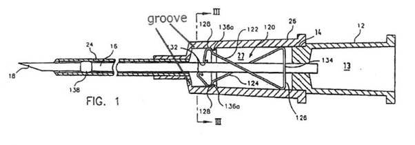
What is depicted as the groove, but bearing in mind that the annotation itself was not evidence, is formed by the annular projection disclosed in the great grandparent. The annotation of the annular projection as forming a groove is not evidence of a groove but the projection itself is evidence as is the figure. The relevant feature of the claim in each of the two patents in suit is, therefore, formed by the annular projection disclosed in the great grandparent and performs the same function of securing the needle guard in the ready position. This aspect of the claim of the patents in suit is described in a general sense in the great grandparent and is not a claim of a characteristic of the invention about which the great grandparent had been wholly silent: cf F Hoffman-La Roche & Co Aktiengesellschaft v Commissioner of Patents (1971) 123 CLR 529, 539. It follows that the two patents in suit are fairly based on matter disclosed in the great grandparent and, therefore, are entitled at least to the priority dates of the great grandparent.
91 Next, Multigate submitted that the patents in suit were not entitled to the priority date of the original ancestor because there were at least two significant differences between the claims of each of the 327 and 577 Patents and the disclosure of the original ancestor. The critical differences were said to be that: (a) the patents in suit do not require that the needle guard be a unitary spring clip needle guard and (b) that the two patents in suit do not require that the needle guard operates by clamping onto the needle shaft.
92 Multigate’s focus in its submission upon essential features in prior disclosures should not distract attention from the task of determining whether the claims in the patents in suit are fairly based upon matter disclosed in the original ancestor. That task may conceivably be helped by describing the subject matter of what may need to be found as having been disclosed but description or characterisation of what is to be found is apt to distract attention from the proper task to be undertaken as was explained in Lockwood Security Products Pty Ltd v Doric Products Pty Ltd (2004) 217 CLR 274. A fair reading of the original ancestor, however, shows that the two features relied upon by Multigate were not limitations in what was disclosed in the original ancestor.
93 The embodiments of the needle guard disclosed in the original ancestor were not limited to a “unitary” needle guard. The body of the specification referred to a unitary spring clip by reference to figures as described:
As shown in Figs. 1A and 1B, the needle tip guard 40 is in the form of a unitary spring clip that is preferably made of a resilient metal such as stainless steel. The spring clip includes a distal arm 42 terminating at its upper end in a curved lip 44, and at its lower end in a pointed end 46, which, in the embodiment of figure 1, is received within a mating groove 48 formed in the lower interior wall of catheter hub 40.
The embodiments described to include “a unitary spring clip” are depicted in a number of the figures. Alternative embodiments, however, are also disclosed in the specification which do not include a “unitary spring clip”. A lengthy passage in the specification from pages 15 to 18, and the figures to which they refer, disclosed embodiments which were not limited to a unitary spring clip. It is also doubtful that the word “unitary” was used in the original ancestor in the sense taken by Multigate in its submissions. The word “unitary” appearing before the words “spring clip” may have been used to suggest that the spring clip was part of the unit making up the assembly rather than as a description of a feature of the spring clip itself. That, if it mattered, is the better construction of the word and is consistent with the whole of the drawings and other terms of the specification which do not insist upon the spring clip itself to be something satisfying the description as a “unitary” feature. In any event, it is clear from the figures in the original ancestor that what was disclosed included matter beyond a “unitary spring clip” in the sense used in Multigate’s submissions. Furthermore, it cannot be said that the configuration of the needle guard claimed in each of the patents in suit was not based on matter disclosed in the original ancestor. Figure 11 of the original ancestor disclosed features of the spring clip needle guard of the kind claimed in each of the 327 and 577 Patents:
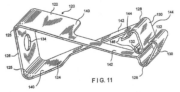
94 The second limitation said to have been part of the disclosure in the original ancestor but said not to be found in the patents in suit was that the needle protecting means was to operate by clamping onto the needle shaft. The original ancestor, however, disclosed some embodiments of the invention which did not include a clamping means. Figures 7D and 7E in the original ancestor were two embodiments which do not include any clamping means:
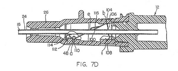
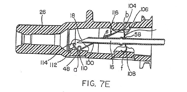
Figures 7D and 7E are described in the body of the specification as follows:
The safety IV catheter illustrated in Figs. 7D and 7E is the same as that illustrated in Figs. 7A and 7B, except that the slot 60 in the needle shaft in the latter is replaced in the former by a bulge 61 whose diameter is greater than that of opening 58 in vertical arm 54. If an attempt is made to move the protected needle illustrated in Fig. 7D in the rearward or proximal direction, bulge 61 will engage wall 54 and will not be able to pass through opening 58, so as to prevent any further proximal movement of the needle and removal of the needle from the needle guard, as desired.
The original ancestor did not disclose devices limited to the needle guard operating by clamping onto the needle shaft. The patents in suit made clear that “the needle protecting means need not comprise any clamping means for clamping the needle in the locked position”, but the claim, without that limitation, was fairly based on what had been disclosed in the original ancestor. The purpose of the needle guard clamping onto the needle shaft in some embodiments is to stop the needle guard sliding off the end of the needle when the needle has been removed from the catheter. However, stopping the needle guard from sliding off the end of the needle may be achieved, as shown in the figures disclosed in the original ancestor, by use of a tether (figure 6B) or by use of a bulge on the needle shaft which engages the needle guard (as in figures 7E and 10B). The bulge referred to in the description of Figure 7E and said to be numbered 61 does not appear in the diagrams but is clearly enough shown and marked by the line extending to the right of the figure and which may be assumed to have been intended to have had the number 61 placed next to it (as Dr Esnouf believed to have been intended). The omission of the number appears to have been an oversight.
95 The disclosure of the specification of the original ancestor is, as Dr Esnouf demonstrated in his evidence, broader than the inventions disclosed in the 327 and 577 Patents. Dr Esnouf drew attention to the features of each of the devices claimed in the patents in suit which were disclosed in the body of the specification of the original ancestor. These included the description in the original ancestor of different types of needle guard, including those claimed in the 327 and 577 Patents. The needle guards disclosed in the original ancestor included needle guards with one or two arms and needle guards that use different types of means for contacting the needle shaft in order to secure the needle tip within the guard. These means included the use of a tether and the use of a tab on the needle guard to engage with a groove in the needle shaft. Figure 11 in the original ancestor (depicted above) disclosed features of the spring clip needle guard in claim 1 of the 577 Patent. The original ancestor describes features of a groove in the inner wall of the catheter hub used to retain the needle guard. An example of such a groove was shown in figure 10A as item 136 of the original ancestor:
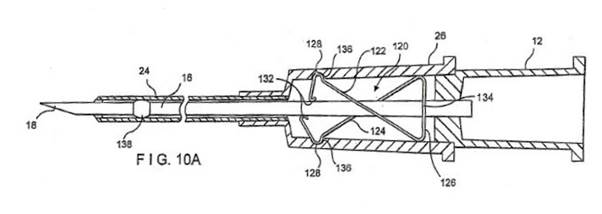
That groove is depicted in a different way from the groove shown in figure 1 of the 327 and 577 Patents but, as shown in the figure annotated by Dr Esnouf, what is disclosed is relevantly a “groove” as claimed in each of the 327 and 577 Patents.
96 Another figure in the original ancestor, figure 2A, shows a retaining bump on the inner wall of the catheter for the purpose of retaining the needle guard. Some of the other figures in the original ancestor show a “bulge” on the shaft of the needle identified as item 61 on figures 1C and 1D in the original ancestor and described in the text of the specification. It is also described by reference to figure 7E (shown above), said to be numbered as 61 in that figure (being the feature near item 58). It is probable, as Dr Esnouf believed, and as said above, that the number 61 was intended to have been inserted on the line to the right of the drawing indicating the position of the bulge.
97 The original ancestor also discloses the use of a crimp on the shaft of the needle as claimed in the 327 Patent. The original ancestor describes the feature of a bulge on the shaft of the needle. One way of forming a bulge on the shaft of a needle is to deform the needle by crimping it. The references to “bulge” in the specification of the original ancestor are apt to encompass a bulge that has been created using a crimping process. The item described as numbered 61 in figure 7E of the original ancestor, but marked by the line without a number, depicts a crimp. Figure 10A in the original ancestor contains item numbered 138 (described in the specification as an “increased diameter bulge”) which is the same as item 138 of figures 1 and 6 of the 327 Patent. The original ancestor also uses the terms “retracted” and “fully retracted” in relation to the needle and refers to the needle guard pivoting or snapping into the retracted position. It also refers to the resilient arms and the distal end wall of the needle guard performing the blocking function.
98 Multigate appeared also to contend that there were “at least two significant differences between the disclosure of each of the 327 and 577 Patents and the disclosure of the original ancestor”. It is not clear from their submissions whether these two “significant differences” were intended as a separate challenge or as a conclusion from those previously contended. The second was plainly that considered immediately above, namely, that the needle protecting means of the catheter devices in the two patents in suit “need not comprise any clamping means” and, for the reasons given above, that need not be considered separately. The other difference, however, was said to be that the two patents in suit each provided additional disclosure which facilitated the fastening of the needle protecting means in the catheter hub. The submission was not independently developed in Multigate’s submissions but appears to be a repetition either of its argument concerning the unitary spring clip needle guard or of the contention concerning the feature of a groove in the inner wall creating the annular groove or ring which was also considered above. The original ancestor described the feature of a groove in the inner wall of the catheter hub used to retain the needle guard. The specification in the original ancestor described this item as “an angular groove or ring” and depicted it differently from the “groove” in figure 1 of the 327 and 577 Patents, but appears to disclose the same feature: SociÉtÉ des Usines Chimiques RhÔne-Poulenc v Commissioner of Patents (1958) 100 CLR 5. Figure 2A of the original ancestor also disclosed a “retaining bump” on the inner wall of the catheter hub for the purpose of retaining the needle guard. There are several disclosures of features “which facilitates the fastening of the needle protecting means in the catheter hub”. Figure 4A identifies item 68 which is described in the specification as a “bump”. Figures 7A-E contain an item numbered 48 which is described in the specification as a “mating groove”. A fair reading of the original ancestor reveals that the claims in the two patents in suit do not travel beyond or broaden the disclosures in the original ancestor.
99 The original ancestor does provide a real and reasonably clear disclosure of the inventions in each claim of the 327 and 577 Patents including (a) a needle guard which is not limited to being “unitary”; (b) a needle protecting means which is not limited to having a clamping means; and (c) an additional feature facilitating the fastening of the needle guard to the wall of the catheter hub including an annular groove or projection. It contains “a description of the general nature of the invention [in the patents in suit], its field of application and the anticipated results” in the sense considered in ICI and endorsed in Leonardis. What is claimed by the patents in suit was described in the original ancestor in a general sense and is not inconsistent with the original ancestor or includes a feature as to which the original ancestor was wholly silent: Re Mond Nickel Co Ltd’s Application [1956] RPC 189; approved by Gibbs J in F Hoffman-La Roche & Co Aktiengesellschaft v Commissioner of Patents (1971) 123 CLR 529. Accordingly the patents in suit are entitled to the priority date of the original ancestor, as derived from PD2 (being the earliest ancestor which discloses the bulge or crimp feature), namely 12 June 1998.
Novelty
100 Multigate next contended that each of the inventions claimed in the 327 and 577 Patents were anticipated by prior publication in a number of documents. Section 138(3) of the Patents Act 1990 (Cth) provides that a patent may be revoked, either wholly or so far as it relates to a claim, on grounds which include that “the invention is not a patentable invention”: s 138(3)(b). Section 18(1) relevantly provides that:
… an invention is a patentable invention […] if the invention, so far as claimed in any claim:
[…]
(b) when compared with the prior art base as it existed before the priority date of that claim:
(i) is novel; …
In relation to “novelty” s 7 relevantly provides:
Novelty
7(1) For the purposes of this Act, an invention is to be taken to be novel when compared with the prior art base unless it is not novel in the light of any one of the following kinds of information, each of which must be considered separately:
(a) prior art information (other than that mentioned in paragraph (c)) made publicly available in a single document or through doing a single act;
(b) prior art information (other than that mentioned in paragraph (c)) made publicly available in 2 or more related documents, or through doing 2 or more related acts, if the relationship between the documents or acts is such that a person skilled in the relevant art would treat them as a single source of that information;
(c) prior art information contained in a single specification of the kind mentioned in subparagraph (b)(ii) of the definition of prior art base in Schedule 1.
Inventive step
(2) For the purposes of this Act, an invention is to be taken to involve an inventive step when compared with the prior art base unless the invention would have been obvious to a person skilled in the relevant art in the light of the common general knowledge as it existed (whether in or out of the patent area) before the priority date of the relevant claim, whether that knowledge is considered separately or together with the information mentioned in subsection (3).
(3) The information for the purposes of subsection (2) is:
(a) any single piece of prior art information; or
(b) a combination of any 2 or more pieces of prior art information that the skilled person mentioned in subsection (2) could, before the priority date of the relevant claim, be reasonably expected to have combined.
Innovative step
(4) For the purposes of this Act, an invention is to be taken to involve an innovative step when compared with the prior art base unless the invention would, to a person skilled in the relevant art, in the light of the common general knowledge as it existed (whether in or out of the patent area) before the priority date of the relevant claim, only vary from the kinds of information set out in subsection (5) in ways that make no substantial contribution to the working of the invention.
(5) For the purposes of subsection (4), the information is of the following kinds:
(a) prior art information made publicly available in a single document or through doing a single act;
(b) prior art information made publicly available in 2 or more related documents, or through doing 2 or more related acts, if the relationship between the documents or acts is such that a person skilled in the relevant art would treat them as a single source of that information.
(6) For the purposes of subsection (4), each kind of information set out in subsection (5) must be considered separately.
The term “prior art information” used in both s 7(1) and s 7(3) is defined in the dictionary in schedule 1 of the Act by reference to the “prior art base” as follows:
prior art base means:
(a) in relation to deciding whether an invention does or does not involve an inventive step or an innovative step:
(i) information in a document that is publicly available, whether in or out of the patent area; and
(ii) information made publicly available through doing an act, whether in or out of the patent area.
(b) in relation to deciding whether an invention is or is not novel:
(i) information of a kind mentioned in paragraph (a); …
Multigate contended, and Braun did not dispute, that although the terms of s 7 and the definition of “prior art base” have altered throughout the period in question in this proceeding, nothing relevantly turned on the changed wording of the provisions. At all relevant times what was to be considered was prior documentary publication anywhere, whether in or out of the patent area. Accordingly, it is relevant to assess the novelty of the claims against any information made publicly available in a document anywhere in the world.
101 The test for anticipation or lack of novelty was explained by Aitken J in Meyers Taylor Pty Ltd v Vicarr Industries Ltd (1977) 137 CLR 228 at 235:
The basic test for anticipation or want of novelty is the same as that for infringement and generally one can properly ask oneself whether the alleged anticipation would, if the patent were valid, constitute an infringement…
In Bristol Myers Squibb Co v F H Faulding & Co Ltd (2000) 97 FCR 524 Black CJ and Lehane J reviewed the authorities on the question of what was required in a prior publication to constitute anticipation and said at 548 [67]:
What all those authorities contemplate, in our view, is that a prior publication, if it is to destroy novelty, must give a direction or make a recommendation or suggestion which will result, if the skilled reader follows it, in the claimed invention. A direction, recommendation or suggestion may often, of course, be implicit in what is described and commonly the only question may be whether the publication describes with sufficient clarity the claimed invention or, in the case of a combination, each integer of it.
In Hill v Evans (1862) 45 ER 1195 Lord Westbury LC expressed the test in terms of whether a person with ordinary knowledge of the relevant subject would be able practically to apply the prior published discovery without the necessity of making further experiments: see also H Lundbeck A/S v Alphapharm Pty Ltd (2009) 177 FCR 151, 190-1 [173]-[174].
102 Multigate relied upon four publications which were said to contain anticipations of the claims in the patents in suit. Three publications were relied upon in relation to the 327 Patent, namely, (a) patent WO199731666 (“Kuracina”) published on 4 September 1997 in Switzerland, (b) the original ancestor published on 8 March 1999 in Australia, and (c) US Patent US6616630 (“Woehr 3”) published 9 September 2003 in the United States. Multigate also relied upon each of these three patents in relation to its claim of anticipation regarding the 577 Patent, but relied also upon Australian Patent Application AU1996055827 (“Van Heugten”) published on 19 December 1996 in Australia. The determination of the priority date claimed under the original ancestor makes it unnecessary to consider anticipation through publication of the original ancestor or that in Woehr 3 published on 9 September 2003. Braun accepted that each of the original ancestor and Woehr 3 disclosed all of the integers of all claims of the 577 Patent and the 327 Patent. It also, for that matter, accepted that each of the great grandparent, grandparent and parent disclosed all of the integers of all of the claims of the 577 Patent and of the 327 Patent. The priority date which the patents in suit may claim from the original ancestor, however, makes it necessary to consider whether there had been anticipation by publication of the Van Heugten and Kuracina patents.
103 The Van Heugten patent is claimed by Multigate to have anticipated claims 1 to 5 of the 577 Patent but not claim 6, nor the claim in the 327 Patent. The Van Heugten patent, to that extent, is not relied upon as a defence to infringement of claim 6 of the 577 Patent or of claim 1 of the 327 Patent. Braun accepted that the Van Heugten patent was published in Australia on 19 December 1996 and predated any claim made by Braun for the 577 Patent. It also admitted that the Van Heugten patent disclosed all except five integers of claims 1 to 5 of the 577 Patent. The aspects of the integers in dispute in this context were the features emphasised below which Braun contended were absent from the Van Heugten disclosure, namely:
(a) integer 1(f), namely, “a resilient spring clip needle guard located within said chamber being formed in said hub section of said catheter hub”;
(b) a further aspect of integer 1(f), namely, “a resilient spring clip needle guard having a distal end wall”;
(c) integer 1(j), namely, “said needle shaft of [said] needle being adapted to engage said distal end wall of said needle guard when said needle is in its ready position”;
(d) integer 1(k), namely, “said catheter hub being configured such that a force exerted by said needle shaft on said needle guard is released when said needle is retracted causing said needle guard to pivot or snap to the retracted position in which said distal end wall blocks said needle tip”;
(e) integer 1(l), namely, “said needle guard further comprising a proximal wall having an opening adapted to let said shaft of needle freely pass through and axially move”; and
(f) integer 1(m), namely, “wherein said bulge has a diameter greater than that of said opening of said proximal wall”.
104 Braun submitted that the answer to Multigate’s claim based upon the Van Heugten publication was that it did not disclose a distal end wall which “blocks the needle tip” as required by claim 1 of the 577 Patent. The experts were each asked questions about the presence of a distal end wall and disagreed in the opinions they expressed. The Van Heugten device has a cylindrical guard with a moveable latch identified as item 52 in the following three diagrams:
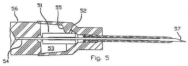
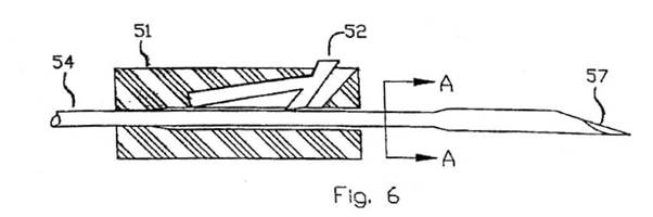
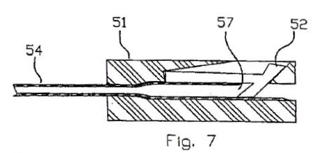
The invention in the Van Heugten disclosure seen in these diagrams includes a needle guard. The invention is entitled “protective needle cover containment” and disclosed an IV catheter with an automatic self-locating needle guard. The Van Heugten device has a cylindrical needle guard with a moveable latch which is pushed into the eye (also called the “hollow” or “lumen”) of the needle bevel when the needle is retracted as can be seen in the figures above. The specification explains:
In greater detail, the non-round deformed outer shape of the needle guard also rotationally orients the needle, and the needle guard further includes a latch mechanism to engage the lumen of the needle to prevent the needle guard from travelling towards the proximal end of the needle when the latch mechanism is engaged.
The blocking mechanism caused by the latch is further explained in the specification:
As the round section of needle 54 seats into needle point guard 51, latch 52 is now directly over the opening of needle lumen 57, and is now no longer being held up by the surface of needle shaft 54 and is driven down into the opening of needle lumen 57 by the spring pressure of latch 52. When driven down, two things occur, first, latch 52 will prevent needle point guard 51 from retracting back on the needle shaft to re-expose the needle point and second, latch 52 is now clear of projection 55, allowing needle point guard 51 and latch 52 to retract out of cavity 53 while secured onto the distal end of needle shaft 54 and it is removed from the catheter hub.
It is therefore correct, as Dr Haindl explained, that there was no distal wall that blocked the needle tip of the kind claimed in the 577 Patent. The invention in the 577 Patent had the distal wall blocking the needle tip:
When the needle point passes the lips 132 the arms 122, 124 resiliently move into the position shown in fig 2 in which the front wall 129, 130 cover the needle point.
In contrast, the Van Heugten device discloses no blockage of the needle tip by a distal end wall. Figure 7 of the Van Heugten patent shows, as Dr Haindl said, that the needle tip in the blocked position is distal of the latch (that is, to the right in the diagram) and, therefore, that the latch itself cannot be regarded as a distal end wall. Furthermore, there is no proximal wall in the Van Heugten device. It is a cylinder, or tubular structure, with a reduction of internal diameter. The reduction, as Dr Haindl believed, could be called “a flange, a gate, or in common language, a bottle neck, but not a wall”. It is the reduction in diameter that prevents the needle moving distally but not the latch which itself is not distal of the needle point. It is unnecessary to consider whether the other features in dispute were otherwise present in the Van Heugten patent which did not anticipate the 577 Patent.
105 Multigate relies upon the Kuracina patent as disclosing each integer of claim 1 of the 327 Patent and each integer of claims 1 to 5, but not claim 6, of the 577 Patent. Braun admits that Kuracina discloses various integers of claims 1 to 5 of the 577 Patent and of claim 1 of the 327 Patent but says that there was absent in the Kuracina patent the features italicised below from the integers in each of the 327 and 577 Patent, namely:
(a) integer (g) in the 327 Patent, namely, “said needle being moveable between said ready position in which said tip is outside of said catheter hub and a retracted position in which said tip is within the interior of said catheter hub”;
(b) integer (h) of the 327 Patent, namely, “a needle guard positioned in the interior of said catheter hub in a spaced apart relationship from the distal end of the needle hub”;
(c) integer (j) of the 327 Patent, namely, “the needle guard resilient portion is moveable within the interior of said catheter hub to a blocking position distal of said needle tip when said needle is in its retracted position in which said needle shaft no longer exerts a force on said resilient portion of said needle guard”;
(d) integer (f) of the 577 Patent, namely, “a resilient spring clip needle guard located within said chamber being formed in said hub section of said catheter hub and having a distal end wall”;
(e) integer (g) of the 577 Patent, namely, said needle guard located within said catheter hub is adapted to automatically snap or pivot into a retracted position for blocking access to said needle tip and preventing further movement of said needle tip when said needle is in its retracted position.
106 The dispute between the parties concerning the disclosure of the Kuracina patent came down essentially to whether the blocking mechanism disclosed by Kuracina was located within the catheter hub. The experts were asked whether there was a needle guard located within the chamber in the Kuracina patent with conflicting opinions expressed by them. Dr Haindl expressed the opinion that the needle guard was not located within the chamber of the catheter hub but that it was connected with it by a modified cone and a moveable arm to hook into a recess in the catheter chamber. Mr Bennett took the contrary view and Mr Leskowich referred to some additional drawings to which the other two had not made reference in which he maintained that the needle guard was shown to be located within the catheter hub of the chamber.
107 Kuracina was published on 4 September 1997 in Switzerland and is entitled “needle tip guard for hypodermic needles” and disclosed a range of hypodermic needle devices including IV catheters. The invention is summarised in various embodiments and, in particular, referred to a needle guard assembly containing a moveable needle trap that is biased against or towards the hypodermic needle which has a tether or other limiting means to limit the forward movement of the needle guard along the needle. On page 6 of the Patent one embodiment is described as follows:
In one embodiment the needle guard assembly of the present invention includes a needle guard that is slidably mounted on a hypodermic needle having a needle tip located at the distal end of the needle. The needle guard contains a moveable needle trap that is biased against or towards the hypodermic needle. The needle trap advances over the tip of the needle, entrapping the needle tip as the needle guard is urged forward near the sharpened distal end of the hyper-dermic needle. A tether, or other limiting means, limits the forward movement of the needle guard along the needle. In one embodiment, the needle guard is manually urged forward along the shaft of the needle by the user. In yet another embodiment, a spring, or other biasing means, is used to move the needle guard along the shaft of the needle.
Later, the specification provides:
In one embodiment, the coupling mechanism includes an arm having a proximal end and a distal end. The proximal end of the arm is attached to the moveable needle trap. The distal end of the arm includes a projection that is releasably retained within a recess of a catheter hub. Hence, as the needle trap moves inward to entrap the needle tip, the arm also moves inward. The inward movement of the arm causes the arm’s distal projection to be released from the catheter hub recess, thereby permitting a separation between the needle guard assembly and the catheter hub.
Figures 61 to 63 were described as illustrating a catheter in accordance with one embodiment of the Kuracina invention. The figures relevant to the present dispute are mainly those numbered 61 to 63, although Mr Leskowich added 114, 118 and 123 to which reference will be made later.
108 Figures 61, 62 and 63 show a catheter in accordance with the Kuracina invention:
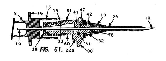
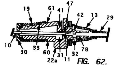
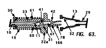
The patent described figures 61 to 63 as follows:
Figure 61 is a cross sectional top view of the invention shown on an indwelling catheter 29 embodiment, having a movable needle guard 22a and a separable indwelling I.V. catheter 29, said catheter 29 being fixedly attached to a catheter hub 13, an I.V. catheter mounting section 9 having a fixedly attached hollow bore hypodermic needle 10 having a sharpened distal end 11; a hub portion 15 having a section 16 for removably attaching a protective storage cover 54, a slidable needle guard 22a being fixedly attached to said hub portion 15 by means of a limiting tether, said needle guard 22a having a projection or finger post 80 for advancing said separable catheter 29 and said needle guard 22a along said hypodermic needle 10 so said catheter may be inserted into a blood vessel, said hypodermic needle 10 being slidable through a guide aperture 47 in said movable needle guard 22a, said needle guard 22a having a movable needle trap 41 with a corresponding slot 31 for receiving the needle trap 41 when said trap 41 moves beyond the needle tip 11, said needle guard 22a having an open collar or washer 30 for retaining the resilient member 19 on the proximal end of said needle guard 22a, said resilient member 19 being slidably
held on said needle guard 22a by the notch or indentation 60, said movable needle trap 41 having a lead-in area 33 for locating said resilient member 19 on said needle guard 22a into notches 60 and/or 61, said needle trap 41 also having a notch or indentation 61 for retaining said end coils of said resilient member 19, with the distal end of said needle guard 22a having a male section 78 for removably attaching an indwelling I.V. catheter hub 13, with a section of said male section 78 having a movable arm 42 for releasably retaining a catheter hub 13 from said male section 78 during initial insertion of the catheter 29 into a patient. Said catheter hub 13 having an inner channel, recess, slot or undercut 32 for being releasably held by said movable arm 42. Said movable arm 42 could also comprise a metal component which is inserted during or after said male section 78 is manufactured.
Said hub portion 15 could also comprise the latching arm 26 shown in other drawings in this application, otherwise said needle guard 22a would be releasably held adjacent to said hub portion 15 prior to use by a frictional or wedged means.
Figure 62 is a cross sectional top view of the movable needle guard 22a shown in Figure 61 on an indwelling catheter embodiment, containing the elements shown and described in the movable needle guard 22a, whereby the catheter 29 has been inserted in a blood vessel and the needle 10 is being retracted into said needle guard 22a as the needle 10 is being pulled away from said catheter insertion site, whereby the movable arm 42 on the male section 78 is free to move where the needle has been residing within the distal male section 78 of the needle guard 22a, allowing the catheter hub 13 to remain in the blood vessel and freely separate from the needle guard 22a, with the needle trap 41 sliding on said needle 10. The needle guard 22a is attached to the hub portion 15 shown in Figure 61 whereby a fixedly attached tether (not shown) limits the forward movement of the needle guard 22a, safely trapping the needle tip 11.
Said catheter hub 13 having an inner channel, recess, slot or undercut 32 for being releasably held by said movable arm 42.
Figure 63 is a cross sectional top view of the movable needle guard 22a shown in Figures 61 and 62 on an indwelling catheter 29 embodiment, containing the elements shown and described in Figures 61 and 62, including the movable needle guard 22a, a tether (not shown) and catheter 29, whereby the catheter 29 has been inserted in a blood vessel and the needle 10 is safely retracted within said needle guard 22a whereby the movable arm 42 has moved inwardly releasing the hold on the catheter hub 13, with the needle trap 41 now safely trapping the needle tip 11. Movable arm 42 includes a corresponding receiving slot 166 for receiving said movable arm 42. Said needle guard 22a having said movable needle trap 41 located within the corresponding slot 31 after said trap 41 has moved beyond the needle tip 11. Said needle guard 22a is attached to the hub portion 15 as shown in Figures 61 and 62 whereby a tether limits the forward movement of the needle guard 22a, safely trapping the needle tip 11. Said catheter hub 13 having an inner channel, recess, slot or undercut 32 for being releasably held by said movable arm 42.
The movable arm protrusion 42 can comprise a "v" shaped configuration which allows the catheter hub 13 to separate even in the event the movable arm 42 has taken a set during storage. A set during storage could inhibit the separation of said catheter hub 13 from said mounting section 78.
Much of the dispute between the parties, and their competing experts, was about the role played by items 41 and 42 in the diagrams and the description in the patent. Mr Bennett concluded that Kuracina disclosed a needle guard located within or positioned in the interior of the catheter hub because item 42 was located within the catheter hub chamber. That assumed that moveable arm 42 of figures 61 to 63 blocked the needle tip. In oral testimony Mr Bennett said:
The problem for the designer is that now unless item 42 blocks the needle tip, the device is actually dangerous because the catheter hub can fall away and the needle will be exposed and that’s why he’s created this groove here, exactly the same situation as in the other blocking device. So my interpretation of the drawing is that this is definitely designed to act as a needle guard in what I’m calling the retracted position…
Dr Haindl, on the other hand, saw the needle trap as the item numbered 41 and that the item labelled 42 was only a moveable arm to couple the needle guard to the catheter hub. Dr Haindl’s opinion is consistent with figure 63 and what is said in the body of the specification, namely, that 42 releases the catheter hub while 41 traps the needle.
109 The better view is that of Dr Haindl. Figures 61, 62 and 63 show the point of attachment of the needle protecting means and the catheter hub. The hub is separate from the needle protecting means and the latter is not within the interior of the catheter hub. The moveable arm 42 does not, as can be seen in figure 63, block the needle tip, but has as its only function the attachment of the needle guard to the catheter hub. The evidence of Dr Haindl is also to be preferred on this question because of his extensive expertise in the design, development and manufacture of safety IV catheters in comparison to Mr Bennett’s relative lack of experience in that field with safety IV catheters. Mr Bennett’s view about the role of moveable arm 42 should also not be accepted because his view of the blocking role of moveable arm 42 is not the subject of a direction, recommendation or suggestion by the patent itself: see Bristol Myers Squibb Co v F H Faulding & Co Ltd (2000) 97 FCR 524, [67].
110 The Kuracina patent also does not disclose integer (g) in claim 1 of the 327 Patent because the claim requires the tip of the needle to be blocked within the catheter hub in its retracted position and the moveable arm in figure 63 of Kuracina is not within the catheter hub in its retracted position. Dr Haindl accepted that the needle tip was within the catheter hub when the needle had moved past moveable arm 42 in figure 62 but not that it was within the catheter hub in the retracted position.
111 Mr Leskowich offered an additional comment in support of Multigate’s contention that feature (f) of the 577 Patent could be seen to be located within the catheter hub from figures 114, 118 and 123. The relevant features are best seen figure 118 of the Kuracina patent:
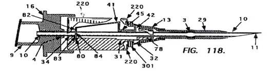
Multigate submitted, based upon Mr Leskowich’s observation, that it was apparent from figure 118 that lip 42 was located within the catheter hub. Mr Bennett was asked about figure 118 in light of the description of the needle guard in Kuracina as being adjacent to the catheter hub rather than being located within the interior. His evidence was that, despite the patentee’s wording, the needle trap 41 was actually inside the catheter hub as shown in figure 118. That was because, according to Mr Bennett, the lip part numbered 42 in figure 118 is part of the needle trap numbered 41 and the lip part numbered 42 is located within the chamber of the catheter hub. It is true that figure 118 shows that part of the feature including both items numbered 41 and 42 are within the catheter hub but to regard that part numbered 41 as being within the catheter hub because a small portion of it (namely that numbered 42) is within the catheter hub would not be an accurate statement as a matter of language or as a matter of function of the invention. An element of the needle trap shown in figure 118 is within the interior of the catheter hub but it is not wholly “located within” or “within the interior” of the catheter hub nor is it substantially or significantly located within or within the interior of the catheter hub such as to be an anticipation of the patents in suit.
INTERNAL FAIR BASIS
112 Multigate also contended that the claims in the patents in suit are not fairly based on matter disclosed in the body of the specifications. Section 40(3) of the Patents Act 1990 (Cth) requires that the claims in patents be “fairly based on the matter described in the specification”. In assessing Multigate’s claim it is necessary to split the patent into the claims and the body of the specification to determine whether the former are fairly based on the matter described in the latter: Lockwood Security Products Pty Ltd v Doric Products Pty Ltd (2004) 217 CLR 274, [49] (‘Lockwood’). The question as posed by Barwick CJ in Olin Corporation v Super Cartridge Co Pty Ltd (1977) 180 CLR 236 at 240 was “whether the claim to the product being new, useful, and inventive, that is to say, the claim as expressed, travels beyond the matter disclosed in the specification”: see also Lockwood, [57]. There must be a real and reasonably clear disclosure in the body of the specification of what is claimed so that the alleged invention as claimed is broadly, that is to say in a general sense, described in the body of the specification (Lockwood, [69]), but the words “a real and reasonably clear disclosure” do not limit the relevant disclosure to the preferred embodiments: Vehicle Monitoring Systems Pty Ltd v SARB Management Group Pty Ltd (2013) 101 IPR 496, 517 [121]-[123]; Lockwood, [68]-[69]; Rehm Pty Ltd v Webster Security System (International) Pty Ltd (1988) 81 ALR 79, 95.
113 Multigate contended that claim 1 of the 327 Patent was not fairly based on the specification when requiring that an outer contact surface on the needle guard be secured to a groove formed in the catheter hub hollow interior. It also claimed that there was no real and reasonably clear disclosure in the 577 Patent specification that a groove can be used to engage the needle protecting means in the catheter hub and no explanation or identification of anything as integer (k) of claim 1 of the 577 Patent to give it a fair basis.
114 Claim 1 of the 327 Patent requires that an outer contact surface on the needle guard is secured to a groove formed in the catheter hub hollow interior. The relevant description of the integer in the claim in the 327 Patent is:
wherein an outer contact surface on the needle guard is secured to a groove formed in the catheter hub hollow interior when the resilient portion is engaged by the side of the needle shaft and biased radially outwardly…
Multigate contended that the specification of the patent does not provide a real and reasonably clear disclosure of this groove feature.
115 The groove in question is that portion visible in figure 1 of the 327 Patent above, being the space between the annular projection marked as 136a and the inner distal wall at the distal end of the catheter hub. It was marked by Dr Esnouf as a groove in the figure considered above at paragraph 90. The experts were asked for their opinions about this and gave conflicting answers. Mr Spencer, called for Multigate, considered that the annular projection was not a groove and he could not identify any disclosure in the 327 Patent specification of a groove which secured the needle guard. He could find only three references to a “groove”, namely, in the specification in the consistory clause (which he believed did not disclose how the feature would work), in prior art, and in the context of a snap ring inserted into the groove where the ring and not the groove secured the needle guard. Dr Haindl, in contrast, identified the “groove” in figure 1 extending from the distal end of the bump marked 136a to the inner distal wall of the catheter hub. His evidence included the following statements:
I disagree with Mr Spencer’s view […] regarding a groove which secures the needle guard into the catheter hub. In figure 1 of both the ‘327 Patent and the ‘577 Patent there is a groove extending from the distal edge of bump 136a to the inner distal wall of the catheter hub. I have marked the groove on the figure 1 below [not reproduced in these reasons but substantially the same as annotated by Mr Esnouf above]. In the sense that the distal edge of bump 136a defines one edge of the groove, there is a relationship between the bump and the groove […]
Figure 1 alone enables me to understand how the groove will work, that is:
(a) the groove is for securing an outer contact surface on the needle guard in the catheter hub hollow interior when the resilient portion is engaged by the side of the needle shaft and biased radially outwards, as required by feature (k) of claim 1 of the ‘327 Patent. The outer contact surfaces of the needle guard are “form locked” in the groove, so they are secured in the groove in this manner; and
(b) the groove is for engaging a curved protrusion of the needle guard for retaining the needle guard in the catheter hub in the ready position, which is an aspect of feature (i) of claim 1 of the ‘577 Patent. The curved protrusions of the needle guard are “form locked” in the groove, so the groove retains the needle guard in the catheter hub in this manner.
The groove was referred to in the consistory clause on page 2 at lines 24 to 27 which stated:
wherein an outer contact surface on the needle guard is secured to a grove formed in the catheter hub hollow interior when the resilient portion is engaged by the side of the needle shaft and biased radially outwardly.
The conclusion of Dr Haindl is consistent with other views expressed by the experts. Mr Bennett stated in the joint report that a “groove” means an increase in the projected internal diameter of the interior hollow portion of the catheter hub in a localised region. Dr Esnouf expressed a similar understanding of a “groove”, namely, that a groove was a depression, sulcus or undercut whereby the floor of the feature is lower than the adjacent structure. Mr Spencer had stated in the joint report that a “groove” is defined as a cut or a trench in a given surface.
116 Whether there has been disclosure of the feature depends upon an inquiry “into what the body of the specification read as a whole discloses as the invention” including the consistory clause: Lockwood, [92], [99]. In CCOM Pty Ltd v Jiejing Pty Ltd (1994) 51 FCR 260 at 280 it was said that it was “well established that a claim may be fairly based on matter in the specification which is not verbal description [found in the] but accompanying drawings”. The specifications are to be read by “the skilled addressee” (SociÉtÉ des Usines Chimiques RhÔne-Poulenc v Commissioner of Patents (1958) 100 CLR 5, 11; CCOM Pty Ltd v Jiejing Pty Ltd (1994) 51 FCR 260, 280), and in the context of claim 1 of the 327 Patent the integer in the claim was fairly based on the disclosure in the specification from the drawing in figure 1 and the consistory clause. It is clear from the drawing, as explained by Dr Haindl, how the groove would work.
117 In relation to the 577 Patent, Multigate contended that there was no real and reasonably clear disclosure that a groove could be used to engage the needle protecting means in the catheter hub and that there was no explanation or identification of anything which might be construed as integer (k) of claim 1. Claim 1 of the 577 Patent requires that the intravenous catheter has a “groove or bump” formed in the inner wall for engaging a curved protrusion of a needle guard. The words in the claim in 1(i) are:
and a groove or bump being formed in said inner wall of said catheter hub for engaging a curved protrusion of said needle guard for retaining said needle guard in said catheter hub in the ready position…
Multigate claimed that there was no real or reasonably clear disclosure in the 577 Patent specification that a groove can be used to engage the needle protecting means in the catheter hub and, therefore, that the claim lacked fair basis. This issue in the context of the 577 Patent is essentially the same as that considered above in relation to the 327 Patent and, for the reasons given in that context, the submissions of Multigate are not accepted. The groove can be seen in figure 1 of the 577 Patent which is the same figure as in the 327 Patent, and the consistory clause in the 577 Patent referred to “a groove or bump being formed in said inner wall of said catheter hub for engaging a curved protrusion of said needle guard for retaining said needle guard in said catheter hub in the ready position”. Accordingly, this feature of the claim was fairly based on matter disclosed in the 577 Patent specification.
118 The second challenge by Multigate to the claim in the 577 Patent concerned the configuration of the catheter hub in integer (k) of claim 1 in that patent. That feature was expressed in the claim as follows:
the said catheter hub being configured such that a force exerted by said needle shaft on said needle guard in said catheter hub is released when said needle is retracted causing said needle guard to pivot or snap to the retracted position in which said distal end wall blocks said needle tip…
Multigate contended that the specification of the 577 Patent “does not mention feature (k), other than in the first consistory statement” and that there was no explanation or identification of anything which might be construed as integer (k) or which gave it fair basis.
119 The experts had also been asked about this feature, including the meaning of the word “configured” as appearing in the specification. The experts disagreed about the meaning of the word “configured” in the patent. Multigate’s witnesses all agreed with the view expressed by Mr Leskowich that the word “configured” was “the same as ‘designed’”. Dr Haindl, in contrast, considered the word to mean in relation to a catheter hub that the catheter hub contains structures to ensure that the biasing force of the needle shaft must be released before the needle guard can leave the catheter hub. Dr Esnouf expressed the same idea more simply, namely, that “configured” meant that the catheter hub was “arranged” in a fashion that allows the needle guard to operate as intended. The experts were also asked further questions in oral testimony in which they essentially confirmed their views.
120 Integer (k) of claim 1 of the 577 Patent is separate from integer (i). The latter is concerned with retaining the needle guard in the hub in preparation for operation when the needle is fully engaged and the bend of the distal end of the arms abut the annular projection. Integer (k), on the other hand, is concerned with the release of a force when the needle is retracted. It is concerned with the means by which the distal end walls of the needle guard block the needle tip when the needle is retracted. Figure 1 discloses that and is described in the specification in the following lines:
The needle protecting means 120 is retained in the catheter hub 26. For this purpose an annular projection 136a extending about the inner wall of the catheter hub 26 is provided. While the lips 132 press against the outer walls of the needle 16 from opposite sides (Fig. 1), the bends 128 grip behind the projection 136a. When the needle 16 is removed from the catheter 24 the needle protecting means 120 is retained in the catheter hub 26 such that the needle 16 slides through the catheter hub. When the needle point passes the lips 132 the arms 122, 124 resiliently move into the position shown in Fig. 2 in which the front walls 129, 130 cover the needle point. In this condition the engagement element 127 abuts the irregularly configured portion 138 such that the needle protecting means 120 is prevented from sliding beyond the distal end of the needle 16. In the embodiment shown in fig 1 the projection 136a is a completely round or continuous configuration. The annular projection 136a retains the needle protecting means 120 in the catheter hub 26 when the needle 16 is removed from the catheter hub 26 until the arms 122, 124 of the needle protecting means 120 are no longer supported by the needle 16 and resiliently move towards the inside. Here, the projection 136 is integrally molded to the catheter hub 26, e.g. by injection molding.
What is thus disclosed is a configuration, in the sense of an arrangement or structure, operating in the way identified in integer (k) of claim 1 of the 577 Patent. The feature may also be seen by the further embodiments shown in figures 4 and 5:
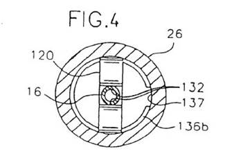
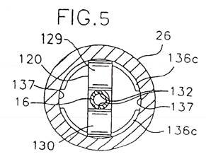
The embodiment in figure 4 is disclosed in the specification as follows:
In the embodiment shown in Fig. 4 the projection 136b oriented towards the inside is of generally C-shaped configuration. Said C-shaped projection 136b can be made from a metal snap ring partially seated in an annular groove on the inside of the catheter hub. In this way it is possible to produce the projection 136b by inserting the snap ring into the catheter hub 26 until it lockingly engages the corresponding groove.
Figure 5 is disclosed in the specification as follows:
Fig. 5 shows another alternative where the projection 136c is divided into two segments with intermediate interruptions 137. Each segment has a larger circumferential extension than the immediate interruptions 137. Further, the circumferential extension is considerably larger than the width of the distal front walls 129, 130 of the needle protecting means. Preferably, the generally annular projection projecting towards the inside does not have any interruptions 137 whose width is larger than the width of the distal front walls 129, 130, respectively, of the needle protecting means. The interruptions 137 being dimensioned such that they are smaller than the width of the front walls prevents the needle protecting means 120 from unintentionally passing the interruptions 137 thus sliding out of the catheter hub without covering the needle point. According to the present invention any number of separate segments forming a generally annular projection may be provided as long as the needle protecting means 120 is securely retained in the catheter hub when the needle 16 is removed from the catheter 24.
In each case what is disclosed is the configuration claimed as integer (k) permitting the release of the force exerted when the needle guard pivots or snaps to the retracted position in the catheter hub by the needle being retracted.
sufficiency
121 Multigate challenged the sufficiency of the 327 and 577 Patents substantially on the same basis as its challenges to internal fair basis. That is, that the disclosure in the 327 Patent specification would not enable a skilled addressee to produce a catheter in which an outer contact surface of the needle guard was secured to a groove in the catheter hub, and that the disclosure in the 577 Patent specification would not enable a skilled address to produce a catheter which included integer (k).
122 Section 40(2)(a) of the Patents Act 1990 (Cth) requires that a complete specification describe the invention “fully”. In Kimberly-Clark Australia Pty Ltd v Arico Trading International Pty Ltd (2001) 207 CLR 1 the High Court said at [16] in a joint judgment:
Other considerations arise from the statutory text where the issue concerns par (a) of s 40(2). The question then is whether the invention has been fully described in the complete specification. The text speaks here of the complete specification, not any one part thereof. From the distinction drawn in s 40(2) between describing the invention in the complete specification and defining the invention in any claims with
which the complete specification ends, it does not follow that the description is to be gleaned solely from one part (the body) and that it is forbidden to obtain any assistance by regard to the remainder (the claims) of the complete specification. Rather, the text indicates that the specification must be read as a whole and that reference to the claims may dispel ambiguity or uncertainty from the body of the specification concerning the description of the invention.
In Lockwood the High Court said in another joint judgment at [49] that in assessing whether a patent complies with the requirement of s 40(2)(a) it is “necessary to take into account the whole of the complete specification – both the body of the specification and the claims”.
123 Multigate’s contention that what was disclosed would not enable a skilled addressee to produce a catheter with the relevant features in the claim relied primarily upon the evidence of Mr Spencer. Braun objected to that evidence of Mr Spencer relating to this issue on the grounds that his opinion was not based on any specialised knowledge from his training, study or experience and, therefore, was said not to be admissible under s 79(1) of the Evidence Act 1995 (Cth). Mr Spencer has had long experience as an end user of intravenous catheters but did not claim any experience in the design or manufacture of them or of any other medical device. His evidence did not identify specialised knowledge based on training, study or experience in the design or manufacture of intravenous catheters and, in oral testimony, confirmed that he had never been involved in either the design or the manufacture of IV catheters. He had, however, in 1998 been part of a focus group that had looked at the workings of catheters but not in the sense of actually designing catheters. In the end, it is not necessary to rule upon the admissibility of his evidence but to receive it subject to the qualification of taking into account the grounds upon which it had been challenged in considering the weight it should be given. That is because the question for determination is one of fact, and Mr Spencer’s opinion, although not as an expert in design of intravenous catheters, may assist in evaluating the evidence. Whether a specification discloses a method is best determined by receiving evidence from persons skilled in the art (Universal Oil Products Co v Monsanto Co (1972) 46 ALJR 658, 661) and the finding to be made in this case may benefit from the view of an end user able to inform the Court about how the end user understood the disclosure. However, in this case, it follows from the conclusions in relation to internal fair basis, and the acceptance of the evidence of Dr Haindl in particular, that what is disclosed is sufficient to “enable the addressee of the specification to produce something within each claim without new inventions or additions or prolonged study of matters presenting initial difficulty”: see Kimberly-Clark Australia Pty Ltd v Arico Trading International Pty Ltd (2001) 207 CLR 1, 17 [25]. In other words, the disclosure in the 327 Patent specification would enable a skilled addressee to produce a catheter in which an outer contact surface of the needle guard was secured to a groove in the catheter hub and the disclosure in the 577 Patent specification would enable a skilled addressee to produce a catheter which included integer (k) in the sense of having the configuration of the catheter hub in that part of the claim.
Unjustified threats
124 In light of the findings made above, it is not necessary to consider Multigate’s claim under ss 128 and 129 of the Patents Act 1990 (Cth). Those sections provide:
128 Application for relief from unjustified threats
(1) Where a person, by means of circulars, advertisements or otherwise, threatens a person with infringement proceedings, or other similar proceedings, a person aggrieved may apply to a prescribed court, or to another court having jurisdiction to hear and determine the application, for:
(a) a declaration that the threats are unjustifiable; and
(b) an injunction against the continuance of the threats; and
(c) the recovery of any damages sustained by the applicant as a result of the threats.
(2) Subsection (1) applies whether or not the person who made the threats is entitled to, or interested in, the patent or a patent application.
129 Court's power to grant relief if threats related to a standard patent or standard patent application
If an application under section 128 for relief relates to threats made in respect of a standard patent or an application for a standard patent, the court may grant the applicant the relief applied for unless the respondent satisfies the court that the acts about which the threats were made infringed, or would infringe:
(a) a claim that is not shown by the applicant to be invalid; or
(b) rights under section 57 in respect of a claim that is not shown by the applicant to be a claim that would be invalid if the patent had been granted.
The effect of these provisions is to prohibit the making of unjustified threats and to impose an onus of justification upon the party making the threat. On 11 May 2013 Braun’s solicitors wrote to Multigate stating, in part:
We act for B. Braun Melsungen AG and its Australian exclusive licensee, B. Braun Australia Pty Ltd.
B. Braun Melsungen AG is the proprietor of Australian Standard Patent Numbers 2012258327 and 2012260577 (collectively, “the Patents”), and B. Braun Australia Pty Ltd is the Australian exclusive licensee for the Patents. Copies of these Patents are *enclosed for your information. Each of the Patents was granted by the Australian Commissioner of Patents on 2 May 2013, and is registered with an effective term of monopoly from 18 August 1998 to 18 August 2018.
Pursuant to section 13(1) of the Patents Act 1990 (Cth) our clients have the exclusive right in Australia to exploit the inventions the subject of the Patents that is, to make, sell or otherwise dispose of the safety IV catheter claimed in the Patents, and to offer to make, sell, hire or otherwise dispose of the safety IV catheter, or use or import it, or keep it for the purpose of doing any of those things.
Our clients have become aware that, without our clients' consent, your company has been importing, offering for sale, selling, using or otherwise exploiting in Australia, the PolyMed safety IV cannula ("the infringing product").
Our clients consider that the infringing product infringes claim 1 of Patent Number 2012258327 and at least claims 1 to 6 inclusive of Patent Number 2012260577.
In addition, our clients are aware that:
(a) your company exhibited the infringing product at the recent Australia & New Zealand College of Anaesthetists meeting held in Melbourne from 4 to 8 May 2013;
(b) your company has recently given the Infringing product to several Victorian hospitals, presumably for trial purposes;
(c) Health Purchasing Victoria (HPV) recently invited bids for tender for a 3-year purchasing contract for products including safety IV catheters, intended to commence on 3 October 2013. Submissions for tender close on 21 May 2013; and
(d) your company has previously submitted tenders relating to the infringing product for health purchasing contracts in other Australian states and territories, including its successful tender in the Northern Territory in late 2012.
Given that it is a condition of the HPV tendering process that products offered for tender must be trialled in Victorian or other hospitals, and in light of your company's recent promotional activities and previous bids to win other health purchasing contracts in relation to the infringing product, it can reasonably be inferred from the circumstances that your company intends to submit a tender for the HPV contract on or before 21 May 2013. Our clients view this as a clear and imminent threat to infringe their patent rights.
It is our clients' policy to rigorously enforce their intellectual property rights and they are prepared to institute legal proceedings where necessary to enforce those rights. However, before embarking on that course in respect of the infringing product we have been instructed to write to you to see whether the matter can be resolved without resort to Court proceedings. You should note however that this should not be taken as any indication of a lack of resolve on our clients' part; it simply reflects our clients' desire to comply with their obligations under the Civil Dispute Resolutions Act 2011 (Cth) and their desire not to incur unnecessary legal costs.
With that in mind, our clients are prepared to refrain from commencing court proceedings but only if a properly authorised officer of your company provides the following undertakings on behalf of the company and each of its directors, servants and agents.
1. THAT your company, whether acting by itself, its directors, officers, servants or agents or otherwise howsoever will immediately cease and until 18 August 2018 desist from making, selling or otherwise disposing of the infringing product, offering to make, sell or otherwise dispose of the infringing product, or using or importing, or offering to import the infringing product, or keeping the infringing product for the purpose of doing any of those things.
2. THAT, without limiting the generality of paragraph 1, your company, whether acting by itself, its directors, officers, servants or agents or otherwise howsoever, will immediately:
(a) cease and refrain until 18 August 2018 from submitting any tender to Health Purchasing Victoria (HPV) (or to any other Australian health or other purchasing entity) which refers to, promotes or offers to sell the infringing product; and
(b) to the extent that such a tender has already been submitted to HPV or any other Australian health or other purchasing entity, immediately withdraw your company's tender.
3. THAT your company, whether acting by itself, its directors, officers, servants or agents or otherwise howsoever, will immediately recall from all of its outlets, agents and distributors all infringing product in its power, possession or control, or otherwise in the power, possession or control of its servants or agents and deliver them to our clients care of Davies Collison Cave Law, Level 15, 1 Nicholson Street, Melbourne, Victoria, or at our clients' direction.
4. THAT an authorised representative of your company will provide, within seven days of giving these undertakings a Statutory Declaration specifying full particulars of:-
(i) The manufacturers and suppliers of the infringing product;
(ii) The quantity of infringing product supplied to it;
(iii) Those to whom the infringing product have been sold;
(iv) The number of infringing product that have been sold;
(v) How much each infringing product costs to produce or acquire;
(vi) The sale price of each infringing product; and
(vii) Your company's agents, distributors and/or re-sellers of the infringing product.
5. THAT your company will deliver up to our clients, care of Davies Collison Cave Law, Level 15, 1 Nicholson Street, Melbourne, Victoria, all copies in its possession, power or control, or in the possession, power or control of its servants or agents, of advertisements, brochures, catalogues or other documents that advertise, promote, display or offer for sale the infringing product.
6. THAT your company will pay our clients damages, or at our clients' option, an account of profits in respect of your company's infringing conduct.
Accordingly, to avoid our clients instituting patent Infringement proceedings, our clients require your company to give, and comply with, the undertakings set out in paragraphs 1 to 6 above, by no later than 2.00pm on Tuesday 14 May 2013.
The undertakings may be given by an authorised representative of your company signing the endorsement below and sending it to us by the date and time specified.
Please note that if our clients do not receive the undertakings by the date and time specified, our clients intend to immediately institute, without further notice to you, patent infringement proceedings against your company in the Federal Court of Australia. These proceedings will include an application for the grant of an interlocutory injunction restraining your company from any dealings with the infringing product pending the outcome at trial.
It was contended that the letter constituted a threat and that it was unjustified. In Mechanical Services (Trailer Engineers) Ltd v Avon Rubber Co Ltd [1977] RPC 66 Graham J said at 75:
A patentee’s first and proper remedy when he considers the defendant is infringing is to bring an action for infringement, without making any threats at all. This is however in the life of the market place no doubt a counsel of perfection and, patentees and travellers being human as they are, no doubt threats against potential defendants will continue to be made. That does not meant to say that the law approves of such action, which, as already stated, can obviously cause serious damage which it is often difficult or impossible to recover …
The [UK equivalent to s 128 of the Act] gives a right to the plaintiff [in the threat suit] but not to the defendant. The latter is only given a shield or defence when he is able successfully to prove justification. He is not given any right to make a threat even if in fact it ultimately turns out to be justified. As patentee he can perfectly well bring his action for infringement without making a threat. […] If however a defendant does make a threat and it is held that he was unjustified, there is every reason why, if in all the circumstances including the generality of the threat it appears just and convenient, he should be restrained in general terms from making such threats in the future in respect of the plaintiffs’ goods or methods of manufacture. Such an injunction causes him no hardship for the reasons given above. The person threatened, on the other hand, will by such an injunction expressed in general terms be properly protected in the future against having to go through the very expensive business of bring an action to invalidate another of his rivals’ patents in order to show that such threats were unjustified. Only thus can the damage liable to be caused by threats unaccompanied by a patent action be positively prevented.
The conclusions in these reasons in favour of Braun also establish justification and it is, therefore, unnecessary to consider whether the threat ought not to have been made by Braun or whether the observations by Graham J fairly represent the law in Australia since the enactment of the Civil Disputes Resolution Act 2011 (Cth) which require that “genuine steps” be taken to resolve a dispute prior to instituting legal proceedings, or whether, in the circumstances any discretion should be exercised in favour of Braun: see JMVB Enterprises Pty Ltd v Camoflag Pty Ltd (2005) 67 IPR 68, 108 [212]. For present purposes it is sufficient to note that claims brought under ss 128 and 129 of the Patents Act 1990 (Cth) may need to take into account the impact, if any, of the provisions in the Civil Disputes Resolutions Act 2011 (Cth). On the findings in these reasons there is no occasion to make the orders sought under those sections.
Orders
125 Accordingly there will be judgment for the applicants and Multigate’s cross-claim will be dismissed. The parties will be heard on the form of the orders and on any question about the costs of the proceeding.
|
I certify that the preceding one hundred and twenty-five (125) numbered paragraphs are a true copy of the Reasons for Judgment herein of the Honourable Justice Pagone. |
Associate:
ANNEXURE A

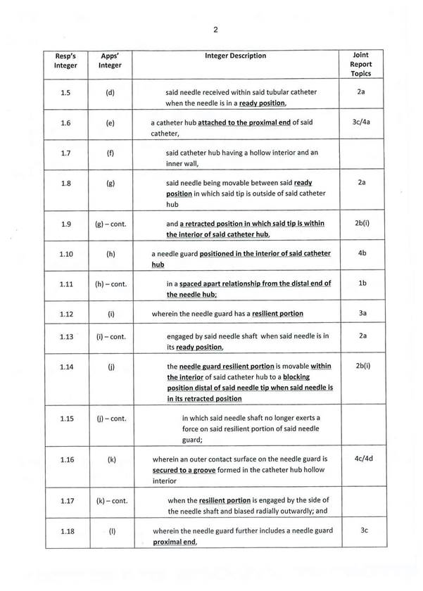

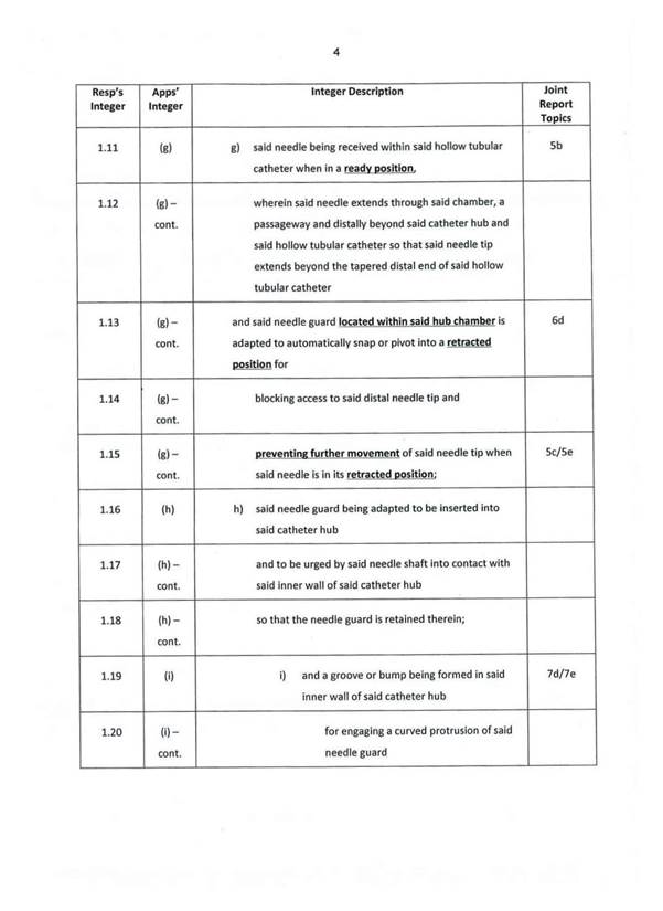
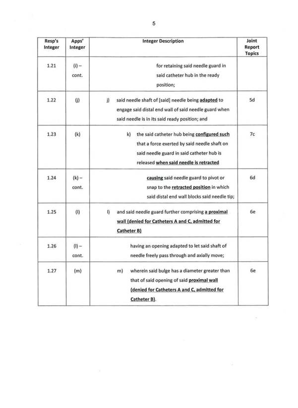
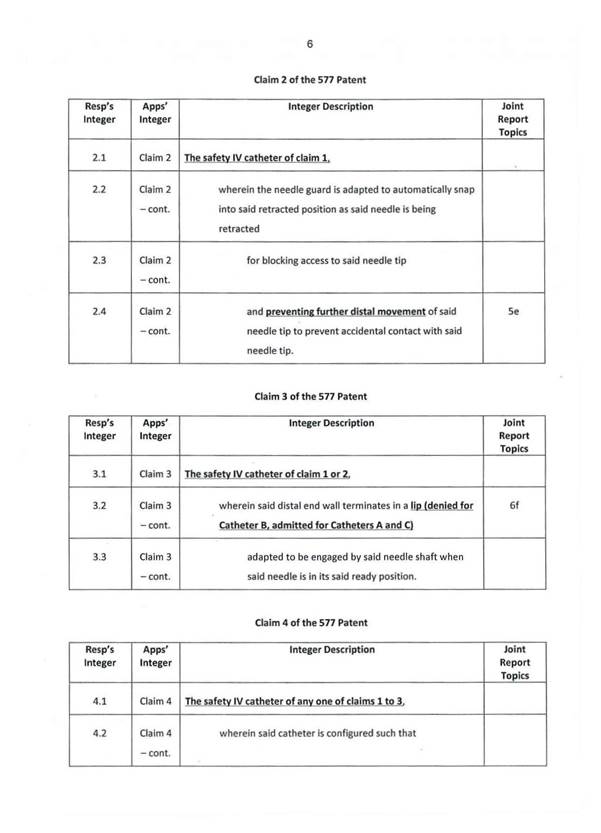
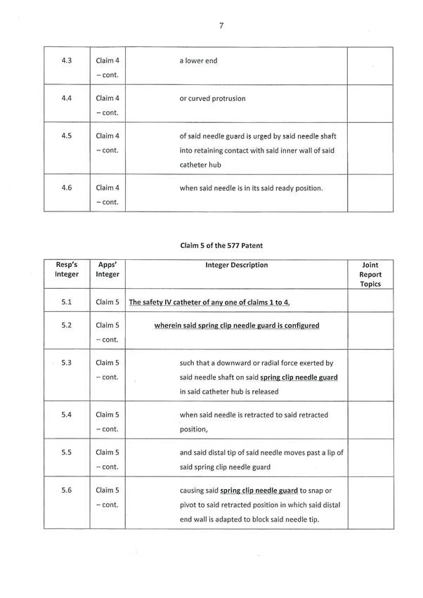
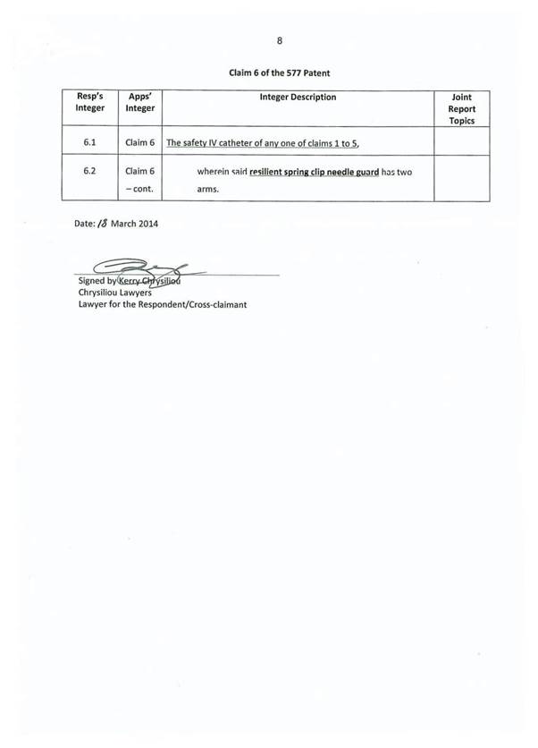
ANNEXURE B

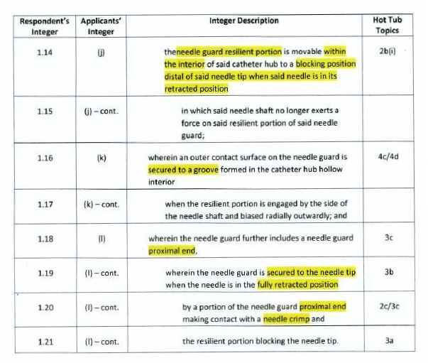
ANNEXURE C