
FEDERAL COURT OF AUSTRALIA
DSI Australia (Holdings) Pty Ltd v Garford Pty Ltd [2013] FCA 132
Place: |
Sydney |
Division: |
GENERAL DIVISION |
Category: |
Catchwords |
Number of paragraphs: |
|
Counsel for the Respondent: |
Ms S Goddard SC with Mr H Bevan |
Solicitor for the Applicants: |
Spruson & Ferguson Lawyers |
Solicitor for the Respondent: |
Teller & Associates |
IN THE FEDERAL COURT OF AUSTRALIA |
|
DSI AUSTRALIA (HOLDINGS) PTY LTD (ACN 115 848 265) First Applicant DYWIDAG SYSTEMS INTERNATIONAL PTY LIMITED (ACN 093 424 349) Second Applicant |
|
AND: |
GARFORD PTY LTD (ACN 009 119 180) Respondent |
DATE OF ORDER: |
|
WHERE MADE: |
THE COURT ORDERS THAT:
1. The parties provide to the Associate to Yates J draft orders reflecting these reasons by 4.00 pm on 10 March 2013.
2. If the parties are unable to agree upon the form of the orders, the applicants and the respondent serve the draft orders they respectively seek by 4.00 pm on 10 March 2013, with copies of those drafts to be provided to the Associate to Yates J at the same time. The draft orders are to be supported by written submissions not exceeding three pages in length.
Note: Entry of orders is dealt with in Rule 39.32 of the Federal Court Rules 2011.
NEW SOUTH WALES DISTRICT REGISTRY |
|
GENERAL DIVISION |
NSD 767 of 2010 |
BETWEEN: |
DSI AUSTRALIA (HOLDINGS) PTY LTD (ACN 115 848 265) First Applicant DYWIDAG SYSTEMS INTERNATIONAL PTY LIMITED (ACN 093 424 349) Second Applicant
|
AND: |
GARFORD PTY LTD (ACN 009 119 180) Respondent
|
JUDGE: |
YATES J |
DATE: |
28 FEBRUARY 2013 |
PLACE: |
SYDNEY |
REASONS FOR JUDGMENT
1 This proceeding concerns the infringement and validity of Australian Patent No. 770594 (the patent). The patent claims an apparatus and method for manufacturing multi-strand rock bolts having spaced-apart bulbs. The respondent, Garford Pty Ltd (Garford), is the patentee.
2 The proceeding was commenced by the applicants, DSI Australia (Holdings) Pty Ltd (DSI Australia) and Dywidag Systems International Pty Limited (DSI) (together, the DSI parties) who seek relief against Garford for unjustifiable threats of infringement of the patent: s 128(1) of the Patents Act 1990 (Cth) (the Act). DSI is a subsidiary of DSI Australia. They are part of a larger international group of companies, of which Dywidag Systems International, Canada Ltd (DSI Canada) is also a member.
3 Garford has cross-claimed against DSI Australia and DSI for infringement of the patent. It alleges that claims 1, 5 to 11 and 12 to 14 have been infringed by, and by the use of, an apparatus which I will call the DSI apparatus. In their joint defence to this cross-claim, the DSI parties deny infringement and allege that the relevant claims are, in any event, invalid and liable to be revoked. To this end, they have also filed a cross-claim seeking an order revoking all the claims on which they have been sued.
4 There is no dispute that Garford has threatened to bring patent infringement proceedings against each of the DSI parties: see paragraph 5 of Garford’s defence. If either DSI Australia or DSI has not infringed the patent (including because the relevant claims are invalid), it will follow that the allegation of unjustifiable threats will have been made out.
5 For the reasons that follow, I have found that (a) claims 1, 5 to 11 and 12 to 14 of the patent are invalid because the invention, as claimed, does not involve an inventive step; (b) claims 12 to 14 are invalid because of Garford’s secret use of the methods there claimed; and (c) claim 12 is invalid because the claimed method is not novel. But for these findings, I would have found that claims 1, 7 to 10 and 12 to 14 of the patent have been infringed.
6 In light of these findings, the DSI parties’ case of unjustifiable threats has been established.
The witnesses
7 A number of witnesses were called for each party.
8 The following witnesses gave evidence on behalf of the DSI parties:
Ernest (Ernie) Walton.
Peter Gilmour Fuller.
9 Mr Walton has worked as a mechanical engineer and design draftsman for more than 30 years. He holds the degree of Bachelor of Engineering (Mechanical) as well as a Mechanical Engineering Certificate. He is a Chartered Professional Engineer. He is a member of a number of professional associations. He has worked on the development and design of mining equipment, as well as a range of other equipment. From 1989 to 1995, he was employed as a Senior Design Engineer in an engineering consulting business based in Newcastle. His focus in that role was mechanical and structural engineering and nearly all his work was related to the mining industry. He worked on the design of a wide range of equipment including flotation cells, industrial access structures, autoclaves, piping systems, specialised handling equipment and glass-reinforced plastic tanks. Some of the work he conducted involved the design of new equipment, while other work involved resolving problems with or improving the performance of existing equipment.
10 From 1995 to the present time, he has been the Principal Engineer of DME Technology Pty Ltd, a company which he founded. In that role, he has continued to provide engineering consulting services across a wide range of industries involving the design, modification and testing of various kinds of process equipment. In particular, he has worked on the design of mining equipment, pressure equipment, piping systems, conveyors, lifting beams, augers, shafts, handling equipment, road and rail vehicles, cranes, and specialised structures.
11 He has also designed cable bolt production machinery. In 2001, he designed a machine that was capable of forming a single bulb in a length of cable. In 2002, he designed a machine that was capable of forming up to four bulbs at a time in a length of cable.
12 Mr Walton made two affidavits and prepared a joint experts’ report with Mr Wightley, to whom I refer below.
13 Dr Fuller is a consultant geotechnical engineer. He has worked as a consultant engineer to the mining industry since 1980. He holds the degrees of Bachelor of Engineering (Chemical) and Doctor of Philosophy (Materials Engineering). He is a Fellow of the Australasian Institute of Mining and Metallurgy. He is a member of a number of professional associations. Prior to becoming a consultant, he was employed as a research scientist by CSIRO in the Division of Applied Geomechanics. In this capacity, he led a small team of scientists and technicians investigating the effectiveness and efficiency of rock bolts and cable bolts. Dr Fuller made three affidavits.
14 The following witnesses gave evidence on behalf of Garford:
Allan Neville Hedrick.
Allan Clifford Wightley.
Christopher Reginald Windsor.
Adrian Alington.
15 Mr Hedrick is the Managing Director of Garford and the inventor named in the patent. He has 22 years of experience in inventing, developing and making cable bolt manufacturing equipment. Mr Hedrick made five affidavits.
16 Mr Wightley is a mechanical engineer and a director of Wightley Engineering Pty Limited. He holds the degrees of Bachelor of Engineering and Master of Engineering. He also holds a Drafting Certificate. He has worked as an engineer for over 40 years. He is a Fellow of Engineers Australia. He is a member of a number of professional associations. He is an Adjunct Professor – Mechanical and Mechatronic Engineering at the University of Technology Sydney. He is a member of the Course Advisory Committee for the Bachelor of Engineering degree at that university. Mr Wightley made three affidavits. As noted above, he prepared a joint experts’ report with Mr Walton.
17 Mr Windsor is a research engineer. He holds the degrees of Bachelor of Engineering (Civil Engineering) and Master of Science. He holds the Diploma of Imperial College London. His postgraduate studies focussed on the theoretical and computational modelling of the behaviour of devices used to reinforce planes of weakness such as faults, joints and fractures in rock. He has worked as a research and consultant engineer to the mining industry since 1981.
18 Like Dr Fuller, Mr Windsor worked for CSIRO’s Division of Geomechanics. Mr Windsor was a research scientist and, later, a senior research scientist. In 1994, he became the Principal Research Engineer and Manager of the Rock Reinforcement Group in CSIRO’s Division of Exploration and Mining. Between 1995 and 2003, he was a director and employee of Rock Technology Pty Ltd, providing technical advice to mining companies, particularly with respect to rock excavation design and stability and rock support and reinforcement. He remains a director of that company. Since 2003, he has been a Principal Research Fellow and Associate Professor of Engineering and Research at the Western Australian School of Mines at Curtin University. In these capacities, he conducts rock mechanics research for mining and civil engineering industries, as well as rock mechanics education at postgraduate tertiary level. He is a member of a number of professional associations. He made one affidavit.
19 Mr Alington is the Manager of Garford. He has had personal experience in the production of continuous bulbed cable, as manufactured by Garford. He made one affidavit.
20 All witnesses were cross-examined. Mr Walton and Mr Wightley also gave concurrent evidence.
background
21 Mr Hedrick described bulbed cable bolts in the following terms:
Bulbed cable bolts are rock anchors comprising steel tendons with bulbs, which are inserted into bore holes in the roofs and walls of mines and rock tunnels to help prevent cave-ins and rock falls. Typically, such tendons are of steel cable having a central or ‘king wire’ around which further – usually six – steel wires are wound. The bulbed cable bolts are inserted into the bore holes and grout is pumped in under pressure. The grout fills the bore holes and fills the bulbs and also enters any gaps or fissures in the surrounding rock. The force caused by the bulbs against the grout, wedges them into the bore holes. Once set in place, a plate is put over the protruding end of the strand and against the rock and a barrel and wedges are used to hold the strand against the plate and are tensioned.
22 This description of cable bolts and their manner of use accords generally with the other evidence given at the hearing. There was no challenge to this description.
23 Garford claims to be the leading manufacturer of bulbed cable bolts in Australia. At the hearing, Mr Hedrick gave an account of how, in earlier years, Garford went about manufacturing continuous bulbed cable for use as cable bolts. This evidence was supported by Mr Alington’s evidence. There had been an initial challenge concerning the feasibility of manufacture according to this method – thereby calling into question a claim by Garford that it used the method to make continuous bulbed cable on a commercial scale – but, ultimately, the DSI parties did not persist with that particular challenge.
24 The following account represents my findings of fact.
25 Until early 1995, the only bulbed cable bolts which Garford manufactured were relatively short, bulbed cable bolts from precut links of steel cable.
26 In late 1994, Mr Hedrick conceived the idea that there might be a market for bulbed cable bolts that were formed directly from steel cable (of whatever length) and rolled into coils (continuous bulbed cable). Initially, Mr Hedrick thought that the continuous bulbed cable could be wound onto 1,300 metre coils, with the coils then being sent to mines where the mine operators could cut them into lengths suiting their own requirements for cable bolts. He thought that coils of that length would be suitable because non-rotating framed receiving dispensers used by mine operators to hold plain strand (that is, unbulbed) cable usually held a volume of 2,600 metres of plain strand per coil. He estimated that the volume which the bulbed cable would take up as a coil in one of these receiving dispensers would be about double that of unbulbed cable. In the event, 1,300 metres of continuous bulbed cable, as a coil, fitted well into the receiving dispensers.
27 Between January 1995 and October 1999, Garford used a particular method to make continuous bulbed cable from plain strand steel cable placed on a rotatable supply reel. The method required two operators – one engaged principally to operate a bulb-forming mechanism (which formed three bulbs); the other engaged principally to operate a take-up reel on which the continuous bulbed cable was wound, following bulb formation. Plain strand steel cable was pulled from a rotatable supply reel. This was achieved, at least for some considerable part of the process, by the winding of the formed continuous bulbed cable onto a take-up reel. By this means, the plain strand steel cable was pulled into a bulb-forming mechanism from the supply reel. The bulb-forming mechanism was placed between the supply reel and the take-up reel. It is not in question that the manner in which the bulbs were formed was substantially in accordance with the general method described in the first Garford patent (to which I make further reference below) using apparatus of the general kind there described. The apparatus included an hydraulic valve which was operated manually.
28 Mr Hedrick described the process in the following terms:
One man principally operated the bulbing mechanism and the other principally operated the take up reel. Movement of the steel cable was stopped manually for the formation of each set of 3 bulbs, and was re-started manually after the bulb-forming operation was complete. The man operating the bulbing mechanism would walk forward to the take up reel after each set of bulbs formed and watch for the last bulb to reach the stop mark and then tell the man winding to stop. Then the first man would return to form another set of 3 bulbs and the process would be repeated. The distance from the last bulb in the set of 3 bulbs to the position enabling the next bulb to be formed was measured manually, initially with chalk marks and later (to enable changes of bulb frequency per metre) by using a sliding metal adjustable bar.
A ratchet with a stopper on the take up reel prevented any unravelling of cable from the take up reel or any reverse movement and the leading end of the cable was attached to the take up reel with a barrel and wedges to prevent dislodging.
The 2 men could operate the apparatus without over exertion of effort and certainly without health or safely concerns …
[As in original]
29 I accept this evidence. Mr Hedrick provided other details about the specific manner in which the take-up reel was operated. It is not necessary for me to descend to any further detail in that regard.
30 In about 1996, Mr Hedrick experimented by fitting a small motor and gearbox to the shaft of the winder on the take-up reel to assist in winding the continuous bulbed cable. The operator was required to turn the motor on and off each time the set of three bulbs was made. The motor had to be turned off early so that the take-up reel did not continue to wind and cause the cable to run past the stop marker. It was therefore necessary for the operator to continue to wind the winder manually for some part of the progress of the cable. Mr Hedrick came to the view that this modification would not be practical or efficient in a fully-automated machine.
31 From 1995 until 1997, all completed coils of continuous bulbed cable manufactured by Garford were 1,300 metres in length. These coils were loaded onto pallets and sent to mining sites. Mine operators dealt with them using their existing equipment. Although there is no direct evidence on the matter, Mr Hedrick said that, so far as he was aware, these mine operators would use their standard non-rotating, square-framed dispensers, from which the continuous bulbed cable was pulled from a central axis. There was no challenge to this evidence as representing the likely state of affairs. The continuous bulbed cable was cut to a desired length and installed in a manual process which was slow and labour-intensive.
32 Early in 1997, Mr Hedrick decided to adapt a machine called a Tamrock Cabolter to be used with continuous bulbed cable. Up to that time, the Tamrock Cabolter had been used at mining sites to install cable bolts made from plain strand cable. The machine operated by boring a hole into the mine wall or roof; forcing a tube to the top of the hole; filling the hole with grout or resin under pressure; and then pushing the cable bolt into the hole through the grout or resin. The machine operated with an attached cassette to receive coils of cable. It is my understanding of the evidence that, in operation, the Tamrock Cabolter cut the bulbed cable to a desired length for use as a cable bolt.
33 The process of bulbed cable bolt installation using the modified Tamrock Cabolter was less labour-intensive and approximately three times faster than the manual method by which these bolts had been installed previously. As a result, demand for continuous bulbed cable increased and, from April 1997, Garford started to receive and fill orders for continuous bulbed cable coils in lengths of less then 1,300 metres (generally under 700 metres) to suit appropriately modified Tamrock Cabolter machines.
34 Using the particular method of production I have described, Garford was capable, if required, of manufacturing 650,000 metres of continuous bulbed cable per year. However, Garford was never required to manufacture to this capacity, and not all lengths were made to order. Demand was not predictable and fluctuated from month to month. In this period, Garford made continuous bulbed cable in lengths of 1,300, 700, 600, 550 and 500 metres and stored it on site in advance of receiving orders, so that it could meet demand in a timely fashion.
35 The continuous bulbed cable made by Garford in the period 1995 to October 1999 was supplied to a number of customers in the mining industry. There is no doubt in my mind that this supply was on a significant commercial scale. I am satisfied that Garford manufactured and sold hundreds of kilometres of continuous bulbed cable in this period. The particular method by which Garford carried out this manufacture was not, however, made public.
36 With the increasing orders for continuous bulbed cable brought about by the modifications to the Tamrock Cabolter, Mr Hedrick turned to consider the building of a machine that would enable Garford to achieve increased output and efficiency.
37 He described the development of this machine in the following terms:
For approximately 2 years leading up to September 1999 I was working when I could, between other work, to create and build a new machine.
I knew that the inclusion of an accurate, reliable and consistent automated means of bulb spacing measurement was crucial. This is because the mining industry requires bulbs at different set lengths along the cable bolt to suit different rock contexts. If the distances between bulbs were variable, the bulbed cable bolt may not be suitable for the rock contexts in which they are to be installed. Bulb spacing is therefore a critical quality control issue which changes in accordance with each customer’s assessed requirements.
I realised that obtaining accurate measurements could be complicated by a number of factors, including over-run of the take up reel, general slippage of the cable, and movement of the cable during bulb formation. I realised, in particular, that the interaction of the measurement means and the take up reel was crucial.
From my experience in operating the manual method I also realised that we needed a way to get the plain strand from the 3 tonne coils of cable as delivered to us into the machine in an automated and reliable and even manner without twisting the cable and that the measurement means and the take up reel had to be fully synchronized.
I made the entire new machine from scratch. I could not just buy off the shelf components for the machine. The only components I could buy were the hydraulics, pneumatic cylinders, bearings, valves, fittings hoses, electrics, switches, chains and sprockets. The remainder of the new machine, including frames, guide wheels, pusher wheels, the mechanism for blocks for cylinders, supply reel, supply reel gates and expanding leaves, fastening devices to clamp the inside end of the strand onto the supply reel, gripping jaws, bulb sensing device, brake, bail arm, bail arm frame, take up reel and take up reel gate, air valve cabinet, hydraulic cabinet and attachments, motor and gear box attachments for bail arm, bail arm, linear breaking frame were all designed and built by me.
It took me about 2 years to develop and build the new machine, working between other jobs, with many months spent by me in designing, making prototypes, trialling, testing, fixing and changing plus, I estimate, the equivalent of at least 7 months of full time work just to manufacture all the components for and put together the machine. I developed the design for the new machine by making and testing prototypes not by the use of drawings. As stated already, this work was done by me in the Garford factory which was not open to the public and only accessed by employees of Garford.
[As in original]
38 I accept this evidence.
39 There was some controversy in the evidence as to when the new machine was deployed to manufacture commercial quantities of continuous bulbed cable. Garford’s case was that production of this kind did not take place until around the second week of October 1999, after the priority date of the claims (13 September 1999). The DSI parties submitted that the new machine was deployed for purposes other than reasonable trial or experiment before the priority date. I will return to this controversy when considering the case on secret use advanced by the DSI parties.
The patent
40 The patent is a standard patent. It was applied for on 5 September 2000 and granted on 14 June 2001. As I have noted, the priority date of the claims is 13 September 1999. On 17 April 2001, the complete specification of the patent was published as open to inspection.
41 The patent specification has 11 apparatus claims and three method claims.
42 Claims 1 to 11 are the apparatus claims. Claims 2 to 11 are dependent, directly or indirectly, on claim 1.
43 Claim 1 is as follows:
An apparatus for manufacturing multi-strand rock bolts having spaced apart bulbs formed therein, characterised by a feed means for supplying a multi-strand cable from a rotatable supply reel, a means for forming the cable with bulbs at spaced intervals and a means for determining the position of the cable to stop operation of the feed means to enable a further bulb to be formed.
44 Claims 5 and 6 characterise the “feed means”. These claims are as follows:
An apparatus according to any one of the preceding claims, characterised in that the feed means has a plurality of rollers which clamp the multi stand [sic] cable to cause it to be fed from the supply reel.
An apparatus according to claim 5, characterised in that at least one of the rollers of the feed means is rotatably driven by a drive means.
45 Claim 7 characterises the means for forming a bulb. It is accepted that these means were publicly known as at the priority date.
46 Claim 8 further characterises the apparatus claimed in one or more of the earlier claims by providing means for collecting the multi-strand cable formed with bulbs at spaced intervals on a take-up reel. Claim 9 is as follows:
An apparatus according to Claim 8, characterised in that there is provided an axially rotatable bail arm having a bail member which guides the multi strand cable onto the take up reel.
47 Claims 10 and 11 further characterise this bail member so that, in operation, the bail member can travel along the shaft of the rotatable bail arm (claim 10) for a predetermined distance using a timer cooperating with a trip member associated with the take-up reel (claim 11).
48 Claims 12 to 14 are the method claims. Claim 13 is dependent on claim 12. Claim 14 is, in turn, dependent on claim 13.
49 Claim 12 is as follows:
A method of manufacturing a multi strand rock bolt having spaced apart bulbs formed therein characterised by feeding a multi strand cable from a rotatable supply reel, sensing when the cable has reached a certain position and stopping movement of the cable, forming a bulb in the stopped cable, recommencing movement of the cable and repeating the cycle.
50 Claim 13 characterises the method by providing for collection on a take-up reel of the cable formed with the bulbs. Claim 14 characterises the method in claim 13 in that the cable is fed onto the take-up reel over a predetermined width to collect the cable substantially evenly across that width.
51 The complete specification contains a brief description of the invention. It describes the invention as providing an apparatus:
… which is for the manufacture of multi-strand rock bolts formed with bulbs in which the feed material is fed from a rotatable reel.
52 The brief description then sets out a number of consistory statements which find expression in each of claims 1 to 10 and 12. The invention is described in terms which show that it has two broad aspects – an apparatus aspect and a method aspect.
53 The invention is then described more fully by reference to a single embodiment illustrated in two drawings. The complete specification makes clear that this embodiment is an “example” and that “[m]odifications and variations as would be apparent to a skilled addressee are deemed to be within the scope of the present invention”. Recognising this fact, it is nevertheless instructive to summarise the features and workings of this embodiment, in the way in which it is described in the complete specification. In the following summary, I adopt the numerical references used in the complete specification to relate various features to the patent drawings. The patent drawings are reproduced in Schedule 1 to these reasons.
54 The apparatus is said to include a rotatable supply or feed reel (13) on which a multi-strand cable (11) is wound. This is the “rotatable supply reel” or “supply reel” referred to in the claims.
55 The multi-strand cable is fed from the supply reel by a “displacement device” (20). This device is the “feed means” referred to in the claims. Except for the consistory clauses, the expression “feed means” is not used in the body of the specification itself.
56 In the preferred embodiment, the displacement device has upper and lower rollers (22 and 24), one of the lower rollers being driven by a chain or belt from a separate drive wheel (28). The upper and lower rollers are urged together (such as by one or more pneumatic cylinders) to “clamp or grip” the multi-strand cable between them. When the driven roller rotates, the multi-strand cable is “pulled off” the rotatable supply reel. The multi-strand cable is “thereby caused to be fed off the supply reel” through various componentry between the supply reel and the displacement device, and then through the displacement device itself, to pairs of jaws (30 and 32). One pair of jaws (32) is arranged to be moved longitudinally (in a direction generally parallel to the direction of travel of the multi-strand cable) towards, and away from, the other pair of jaws (30). This movement is effected by a ram (38) associated with the first pair of jaws (32). The first pair of jaws is located upstream from the second pair of jaws.
57 There is a point in time when the multi-strand cable is stationary. This occurs when the drive to the rollers of the displacement device is discontinued and a brake (16) is applied to engage the multi-strand cable, to arrest its movement.
58 At that point, the pairs of jaws grip the multi-strand cable and the (upstream) first pair of jaws is pushed by the ram towards the (downstream) second pair of jaws. This action forces the multi-strand cable to expand laterally to form a bulb (12).
59 Once the bulb is formed, the pairs of jaws are withdrawn from the multi-strand cable and the (upstream) first pair of jaws is pulled away from the (downstream) second pair of jaws.
60 The rollers of the displacement device are then caused to rotate again and the brake is released. The complete specification says that the apparatus is started again “by any convenient means such as manually, by means of relays with timers, or by computer timing control”.
61 The multi-strand cable is then moved along longitudinally until the newly-formed bulb encounters the downstream “sensor means” (40), also referred to in the complete specification as the “switch means”. In the preferred embodiment, the sensor means includes a pair of rollers (50). These rollers are forced apart by the newly-formed bulb. This causes a signal to be sent from a switch (52) to the drive wheel to stop drive to the rollers. The brake is then hydraulically activated to arrest movement of the multi-strand cable. A signal is also sent to stop the drive of a motor (47) associated with a take-up reel (46) onto which the multi-strand cable with formed bulbs is received. When the multi-strand cable is stationary, the pairs of jaws are again activated and a further bulb is then formed, as previously described. This cycle is repeated to form bulbs at spaced intervals. It is in this sense that the complete specification says that “the present invention provides a continuous means for the manufacture of multi strand rock bolts with bulbs formed at spaced intervals”.
62 Downstream from the sensor means, a bail arm (44) directs the multi-strand cable (with formed bulbs) so as to ensure that it is received on the take-up reel “across a predetermined width of the reel”, rather than being taken up “in an unduly narrow portion of the reel”.
63 The bail arm includes a threaded shaft (54) with which a bail member (56) is “threadingly engaged”. When the shaft rotates (by means of a belt attached to a motor), the bail member moves along the bail arm and thus guides the cable onto the take-up reel.
64 Modifications and variations to the preferred embodiment are exemplified by reference to the means by which movement of the cable can be arrested. In the preferred embodiment, this is achieved by application of the brake and the discontinuance of the drive to the wheels of the displacement device. The complete specification says that the movement of the multi-strand cable could also be arrested for bulb formation by means of a timer mechanism or by means of a trip means on a wheel to cause the apparatus to stop at each revolution of the wheel.
65 The patent specification says that the present invention provides a more efficient means for manufacturing multi-strand rock bolts than “prior art methods”. The only prior art identified by the patent specification is Australian Patent No. 640906 which is said to describe an apparatus for the manufacture of a multi-strand rock bolt formed with bulbs. Garford was the patentee of that patent (the first Garford patent). Mr Hedrick was named in that patent as the inventor. The first Garford patent was granted on a PCT application. The DSI parties rely on the publication of that application as part of their case that the invention as claimed in claims 1 and 5 to 7 of the patent is not novel.
66 The patent specification also refers to an advantage of the present invention being that the take-up reel containing the multi-strand rock bolts can be sold directly to customers. There is nothing in the patent specification that characterises the take-up reel in any specific way so as to provide this advantage.
some issues of construction
67 The general principles relating to the construction of patent claims have been discussed in a number of cases in this Court. They are well-known. There is no dispute about them in the present case. It would be a work of supererogation to attempt to provide a further summary of them. The following cases identify the principles to which I have had regard in construing the claims in the present case: H Lundbeck A/S v Alphapharm Pty Ltd (2009) 177 FCR 151 at [118]-[120]; PAC Mining Pty Ltd v Esco Corporation (2009) 80 IPR 1 at [26]-[29]; Jupiters Ltd v Neurizon Pty Ltd (2005) 65 IPR 86 at [67].
68 The parties were at issue as to the construction of a number of features of the claims. The debate on these issues is best identified and determined when I consider the question of infringement. There are, however, six general conclusions concerning the construction of the patent and its claims which I should express at the outset.
69 First, I do not read any of the relevant claims as confining the claimed apparatus and methods to the preferred embodiment, with all its particularly described features and specific mode of operation. In describing the invention, the body of the specification makes clear that there are a number of preferred, but not necessarily essential, features of the invention. The preferred embodiment is expressly given as an example only. The body of the specification states that “modifications and variations as would be apparent to a skilled addressee are deemed to be within the scope of the present invention”. This statement, of course, cannot expand Garford’s patent monopoly beyond that which is properly defined by the claims themselves. But the statement nevertheless makes clear that there is nothing in the description of the invention that should confine the invention to its, or any, preferred embodiment.
70 Secondly, although the invention, as claimed, is not confined to its or any preferred embodiment, I am satisfied that where features of the apparatus or method are specifically identified by successive claims, each of these features is an essential feature of the invention that is defined by the particular claim.
71 Thirdly, there was a theme in Garford’s case – expressed principally through Mr Wightley’s evidence and advanced in Garford’s opening and closing submissions – that the apparatus claimed in claim 1 of the patent “must be read as part of a complete machine, operating continuously making bulbed cable in an automatic process”.
72 It would be an error to approach the construction of claim 1 or any other claim of the patent on that basis. Although the claims of the patent should be construed in light of the specification as a whole, neither the wording of the claims themselves, nor the context provided by the description of the invention in the body of the specification, would warrant Garford’s particular approach to the construction of the claims in the present case.
73 As the DSI parties correctly pointed out, nowhere in the body of the specification (and perhaps more importantly, nowhere in the claims themselves) is there a requirement, expressed as an essential feature of the invention, that there be an “automatic” or “complete” apparatus, whatever additional meaning these words might impart. The body of the specification itself makes clear that aspects of manual operation of the apparatus might be present. Moreover, although the body of the specification refers to the invention providing “a continuous means for the manufacture of multi strand rock bolts with bulbs formed at spaced intervals”, the context in which that statement appears makes clear that this is a reference to the repetitive or cyclic formation of bulbs in a continuous length of cable – in the order of 850 to 1,300 metres – taken from a supply reel.
74 Fourthly, where the apparatus claims of the patent refer to the means by which the apparatus is characterised, they are referring, in each case, to an essential feature of the apparatus itself that provides the means by which the apparatus functions in that regard. However, the precise manner in which these means might operate is limited only by the words of the claim itself. Human intervention might be involved.
75 Fifthly, the method claims are not confined to a sequence of steps that is carried out by a single apparatus. They only require the presence of an apparatus to undertake a particular step in the method where the claims themselves identify the apparatus to carry out that step. Importantly, claim 12 does not claim, for example, a method of manufacturing a rock bolt using the apparatus claimed in claim 1 of the patent. Had that been the patentee’s intention, it would have been an easy thing for the draftsman to have said so. Indeed, the wording of claim 12 is conspicuous in that it is not, in terms, limited to the operation of the apparatus claimed in claim 1 or, indeed, to the operation of any other single apparatus.
76 Sixthly, although the patent describes and claims apparatus and methods for manufacturing multi-strand rock bolts having spaced-apart bulbs, it is clear that this refers to, and would be understood by the person skilled in the art as referring to, bulbed cable manufactured for use as rock bolts. The person skilled in the art would understand that, strictly speaking, a section of the continuous bulbed cable only becomes a rock bolt when it is cut to a desired length from the cable to be used as a rock bolt.
The DSI Apparatus
77 The DSI apparatus and its mode of operation can be described by reference to a diagram prepared by Mr Wightley. He used this diagram to describe his observation of the working of the DSI apparatus in the course of a court-ordered inspection. His diagram is reproduced in Schedule 2 to these reasons.
78 The operation of the DSI apparatus, as inspected by Mr Wightley, was also recorded in a format that enabled it to be shown to the Court by means of a DVD during Garford’s opening: Ex A.
79 It is not in dispute that the DSI apparatus is one for manufacturing multi-strand rock bolts (cable bolts) having spaced-apart bulbs. The supply reel (or pay-out reel, as designated in the diagram) and the take-up reel are driven by variable frequency control electric motors through roller chain drives. The supply reel and take-up reel operate at variable speeds. Mr Wightley’s evidence was that, in operation, the supply reel and the take-up reel almost come to a stop during the bulb-forming process. Certainly my own observation (based on viewing the DVD during the course of Garford’s opening) was that, although its speed was variable, the supply reel did not stop rotating during bulb formation. In that sense, its rotation and the supply of cable from it, was continuous. As pointed out in Mr Walton’s evidence, the point at which the supply reel slows down is not immediately before bulb formation, but after bulb formation has begun. Once the bulb is formed, the rotation of the supply reel speeds up again.
80 The DSI apparatus has two accumulators. One is located between the supply reel and the cable drive (the upstream accumulator); the other is located between the bulb-forming device and the take-up reel (the downstream accumulator). The accumulators are operated by pneumatic cylinders. The upstream accumulator takes up the slack that occurs when the movement of a portion of the cable is arrested and that portion is stationary to enable bulb formation in it to take place. The downstream accumulator gives up slack when the cable is stationary during bulb formation. Thus, the balance of the cable towards each end of the apparatus (that is, upstream of the upstream accumulator and downstream of the downstream accumulator) continues to move throughout the process. Mr Walton described the effect of this as follows:
In the [DSI apparatus], the supply reel and the take up reel are decoupled by the accumulators from the part of the apparatus that forms the bulbs, so that the movement of the supply reel (and the take up reel) is independent of the bulb forming process. This enables the supply reel to continue to rotate throughout the entire process, thus avoiding the need for it to be stopped and re-started repeatedly. By contrast, in the apparatus described in the [patent], the cable is fed directly from the supply reel into the bulb forming apparatus, so that the supply reel must stop when a bulb is being formed. This creates inefficiencies because of the energy required to overcome static friction and start the supply reel moving again after every bulb is formed. Similar comments apply in relation to the take up reel, which kept moving in the [DSI apparatus] but must stop while a bulb is being formed in the apparatus described in the [patent].
81 A cable drive (also referred to as a caterpillar drive) indexes the cable to the bulb-forming device. The caterpillar drive comprises a system of rollers and caterpillar belts which are in contact with the cable. One caterpillar belt is above the cable and the other is below. The cable is “sandwiched” between the belts. The caterpillar belts are endless and, in each case, pass around three rollers or pulleys (I will refer to them as rollers) that are associated with it. In each caterpillar belt/roller set, one of the three rollers (the drive roller, also referred to as a head roller) is driven by a motor acting directly on its axle. Each drive roller is offset (in a direction away from the cable) from the other rollers with which it is associated. The other two rollers in each caterpillar belt/roller set were referred to in the evidence as a snub pulley (closest to the drive roller) and a tail pulley (distal from the drive roller). In each caterpillar belt/roller set, there is also a series of further “lazy” rollers which are non-driven. The lazy rollers lie between the snub pulley and the tail pulley and apply a compressive load on the belt, thereby pressing the belt against the cable. The drive rollers do not apply any compressive load on their associated belts to press them against the cable. In this configuration, the drive rollers do not themselves clamp the cable in any way. The belts grip the cable under the influence of the other rollers (the snub pulley and the tail pulley) and the lazy rollers associated with each of them, with sufficient force to move the cable towards the bulb-forming device.
82 The indexing of the cable by the caterpillar drive is achieved through the operation of a device which is located between the caterpillar drive and the bulb-forming device. This device has two toothed belts in contact with the cable – one belt on top of the cable; the other, underneath the cable. The belts are held in place by pneumatic cylinders. The toothed belts pass over four flat-toothed pulleys. One of these pulleys is fitted with a revolution counter. The counter sends a signal to a programmable logic controller. This controller then sends a signal to the caterpillar drive to stop and start the caterpillar drive at a location that is programmed to achieve formation of the bulb at the correct location along the length of the cable. Mr Wightley referred to this as a “location or position sensor device”. Mr Walton disagreed with this description of the device. He said that this device does not “sense” the location or position of the cable. Rather, the programmable logic controller is preprogrammed to allow the cable to move forward during each iteration until the shaft encoder has undergone a preset rotational displacement. This will equate to a fixed displacement of the cable, assuming there is no slippage of the cable. There was no disagreement between the witnesses as to how the device works. The only dispute concerned the aptness of the description “location or position sensor device”.
83 During operation, the pulleys of the caterpillar drive rotate forward while indexing of the cable takes place. When the cable is stopped, the pulleys are stopped. Mr Wightley’s evidence was that, during bulb-forming compression (described below), “the pulleys move forward a small distance” and that “the pulleys move backwards a shorter distance during spring-back after the bulb-forming compression”. The pulleys again rotate forward as the cable is indexed.
84 As I have stated, during bulb formation, a portion of the cable is stopped. It is clamped by a pair of jaw sets – one upstream, the other downstream. A bulb in the cable is formed when the upstream set of jaws is moved toward the downstream set of jaws, which remains stationary. This movement is brought about by the action of an extending rod of an hydraulic cylinder. A compressive force is thereby exerted on the cable. The resulting strain causes the strands of the cable to move into their plastic zone and to splay outwards, forming a bulb. Mr Wightley’s evidence was that the outside diameter of the bulb reduces in size as the upstream set of jaws is moved away from the downstream set of jaws. This is what he termed “spring-back”. The cable is released from each jaw set by the operation of the pneumatic cylinders. The upstream jaw set is then moved back to its original position. The cable is indexed along. The bulbed cable is then wound evenly onto the take-up reel. This is achieved by a level wind device which consists of four grooved sheaves between which the cable passes. The sheaves are mounted in the one vertical plane within a housing. There is a female-threaded nut underneath the housing which engages with a male-threaded shaft at right angles to the cable. As the threaded shaft rotates, the nut transits along the shaft and takes the housing and the sheaves with it, thus exerting a sideways force on the cable, forcing it to form a uniform layer across the take-up reel.
Infringement
Claim 1
85 The DSI parties submitted that claim 1 of the patent is not infringed because the DSI apparatus does not have a feed means for supplying a multi-strand cable from a rotatable supply reel, whose operation is stopped to enable a further bulb to be formed. In this connection, they emphasised the distinction between the drive motor associated with the supply reel of the DSI apparatus and the caterpillar drive also present in that apparatus. They submitted as follows:
… [the DSI apparatus] includes two separate components, being a drive motor that drives the supply reel and thereby supplies cable from it, and a caterpillar drive that indexes cable into the bulb forming unit. These two components are physically separate and operate independently of each other, in the sense that the drive motor operates and causes the supply reel to feed cable at all times, whereas the caterpillar drive stops operation repeatedly to enable each bulb to be formed. Neither is connected in terms of the speed and velocity of their operation. The accumulators manage this process by taking up the slack, de-coupling the process of bulb formation from the supply of cable.
86 They also submitted:
The components of the [DSI apparatus] and method (including the cable reel drive motor, the caterpillar drive – also referred to as the “cable drive” – and the accumulators) interact differently to the apparatus and method of [the patent] to produce a new and different combination. In particular, because the supply of cable from the reel is continuous and de-coupled from the process of bulb formation, the elements of the combination interact to produce the new result that movement of a short length of cable only (7 or 8 m) is stopped to enable each bulb to be formed. This gives rise to two benefits of substance compared with [the patent], which by comparison involves stopping and restarting the whole length of cable on the supply reel and the take-up reel (which may be 1300 m or 2600 m in length).
87 The DSI parties identified these benefits to be, first, a more rapid production rate and, secondly, energy and efficiency savings associated with avoiding the supply reel repeatedly coming to a stop and having to restart every cycle.
88 The essence of the DSI parties’ submission was that the drive motor corresponded to the feed means referred to in claim 1 of the patent because that was the component that caused the cable to be fed off the supply reel. They also submitted that claim 1 does not require the supply reel to be part of the apparatus. In this connection, they submitted that it was sufficient that the feed means be capable of supplying multi-strand cable from a rotatable supply reel.
89 Whilst I accept that the DSI apparatus functions in the manner described by the DSI parties, I do not accept that the feed means referred to in claim 1 is one that is required to cause the cable to be fed off the supply reel; nor do I accept that the supply reel is not part of the apparatus that is claimed.
90 In this latter connection, it is my view that claim 1 can only be sensibly read in the context of the specification as a whole if a rotatable supply reel is an essential feature of the apparatus that is claimed. The following integer of claim 1:
… feed means for supplying a multi-strand cable from a rotatable supply reel …
defines the apparatus as one that contains a feed means and a rotatable supply reel. This construction is available not only as a matter of the ordinary language of the integer quoted above, but is supported by the ordinary language of the statement of the invention in the body of the specification (at page 1 lines 16-18), namely:
The present invention provides an apparatus which is for the manufacture of multi-strand rock bolts formed with bulbs in which the feed material is fed from a rotatable reel.
[Emphasis added]
91 It is plain from both the language of claim 1 and the description in the specification that it is an essential feature of the apparatus that the cable is fed from a rotatable reel, not from any other source. The construction advanced by the DSI parties requires the supply reel to be present for the working of the claimed apparatus but, apparently, does not require the reel to be a feature of it. Such a construction involves deliberately leaving out of the claim the essentiality of the supply reel, but not the cable sourced from the supply reel. In my view, that would be a contrived construction. It is not one that I am able to accept.
92 As will be apparent from the above, my analysis of the words of the claim itself, read in the context of the specification as a whole, leads to this construction of the relevant integer. It is also supported, however, by a reading and comparison of the claims as a whole. In this connection, claim 5 is dependent on claim 1. Claim 5 proceeds on the existence of the supply reel in the apparatus claimed in claim 1. However, it does not, by its own terms, add that feature. Rather, claim 5 further characterises the feed means itself, a matter to which I shall return.
93 The plain words of the integer require an association between the feed means and the rotatable supply reel in relation to the multi-strand cable. However, this association is not the one for which the DSI parties contended. The integer simply means that the feed means functions to supply a multi-strand cable, and that the cable it supplies comes from a rotatable supply reel. No closer association is required between the feed means and the rotatable supply reel. The feed means is not itself characterised in claim 1, beyond answering the description of a “feed” means and functioning in the apparatus to “supply” cable, although that particular function, for the person skilled in the art, would be implicit in the description “feed” itself. In context, the feeding which is referred to is the feeding of the cable for bulb formation. In the passage quoted above (from page 1 lines 16-18 of the specification), the feed material is the cable. Thus, the feed means is the means by which the cable is fed for bulb formation.
94 I therefore reject the DSI parties’ submission that the apparatus claimed in claim 1 is characterised by feed means that causes the multi-strand cable to be fed from the supply reel. The apparatus for claim 1 could be one in which the feed means does cause the multi-strand cable to be fed from (in the sense of taken from) the supply reel, but that is not an essential feature of that particular apparatus.
95 In this connection, the apparatus defined in claim 1 is to be distinguished from the apparatus claimed in claim 5, which further characterises the apparatus in three respects: the feed means must have a plurality of rollers; the rollers must clamp the multi-strand cable; and the action of this clamping must cause the multi-strand cable to be fed from the supply reel.
96 Here, the word “supplying” in claim 1 and the word “fed” in claim 5 (which is dependent on claim 1) should not be confused for one another. The apparatus claimed in claim 5 is one where the feed means functions in the apparatus to supply the cable and, having the constructional features set out in claim 5, to cause the cable to be fed from (in the sense of taken from) the supply reel, when the apparatus is in operation. In short, there is required a specific causal relationship between the feed means (having those particular constructional features) and the feeding of the multi-strand cable from the rotatable supply reel, in that particularly claimed embodiment.
97 The preferred embodiment described in the complete specification is characterised in this particular way. In the preferred embodiment, the displacement device (which functions as the feed means) is described as pulling off the multi-strand cable from the supply reel, by means of rollers gripping the cable. But claim 1 does not claim the described preferred embodiment. There is no legal requirement that it should.
98 In my view, the DSI apparatus includes a rotatable supply reel, and means for supplying a multi-strand cable from that supply reel. The feed means, however, is not the drive motor associated with the supply reel, but the caterpillar drive that indexes the cable into the bulb-forming unit. It is accepted that the operation of the caterpillar drive is stopped to enable a bulb to be formed in that part of the cable which the caterpillar drive has supplied to the bulb-forming unit. I accept that, in the DSI apparatus, the drive motor associated with the supply reel, rather than the caterpillar drive, is responsible for causing the cable to be fed from the supply reel by causing the supply reel to rotate. But, in my view, it is not to the point, for the purposes of claim 1, that the caterpillar drive does not cause the cable to be fed from the supply reel or is not otherwise adapted to perform that particular function.
99 For completeness, I am satisfied that all other features of the apparatus claimed in claim 1 of the patent are present in the DSI apparatus.
Claim 5
100 Claim 5 requires the apparatus to have feed means characterised by a plurality of rollers which clamp the cable to cause it to be fed from the supply reel.
101 The DSI parties submitted that this feature is not present in the DSI apparatus because, first, the caterpillar drive in that apparatus does not cause the cable to be fed from the supply reel and, secondly, the rollers of the caterpillar drive do not clamp the cable. By way of elaboration of the second point, the DSI parties submitted that the drive operates by means of caterpillar belts which come into contact with and clamp the cable.
102 I accept that, in the DSI apparatus, the caterpillar drive does not cause the cable to be fed from the supply reel. In operation, the drive motor associated with the supply reel rotates it, such that the cable is fed from the supply reel and taken by the upstream accumulator. The caterpillar drive than takes the cable from the upstream accumulator and supplies it to the bulb-forming unit. In that way, it could be said that, in operation, the caterpillar drive is pulling the cable from the upstream accumulator. It cannot be said, however, that the caterpillar drive, functioning as the feed means, also causes the cable it supplies to be fed from the supply reel. The cable is fed from the supply reel by operation of the drive motor associated with the supply reel which, during bulb formation, operates continuously. The slack in the cable is managed by the upstream accumulator.
103 Thus, I am not satisfied that the DSI apparatus possesses this feature of claim 5. This finding is sufficient to deny a finding of infringement of claim 5. It is not necessary, therefore, for me to consider the second matter raised by the DSI parties. However, for completeness, I find that the DSI apparatus does possess feed means which has a plurality of rollers which clamp the cable. In this connection, it makes no difference that the caterpillar drive of the DSI apparatus functions with caterpillar belts. The belts are brought into contact with the cable by the pressure exerted by the rollers – specifically, the snub pulley, the tail pulley and the lazy rollers, but not the drive roller of each caterpillar belt/roller set acting cooperatively. These rollers thus clamp the cable, albeit in association with their corresponding caterpillar belts. The degree of clamping is not defined or described in claim 5 beyond the fact that, in that condition, the feed means must cause the cable to be fed from the supply reel. It is idle to speculate whether that degree of clamping is present in the caterpillar drive of the DSI apparatus because, as configured, the caterpillar drive does not cause the cable to be fed from the supply reel.
Claim 6
104 Claim 6 further characterises the feed means in that at least one of the rollers of the feed means is rotatably driven by a drive means. It is not in question that two of the rollers associated with the caterpillar drive (the drive rollers) are rotatably driven by a drive means. However, as I have noted, these rollers are offset from the rollers that work cooperatively to clamp the cable. The DSI parties submitted that the feature added by claim 6 is not present in the DSI apparatus because, as claim 6 is dependent on claim 5, at least one of the rollers which clamp the multi-strand cable to cause it to be fed from the supply reel must be rotatably driven by a drive means. According to this submission, the only rollers in the DSI apparatus that are driven are those that are also offset and thus do not clamp the cable.
105 Attractive though this submission might sound at first blush, I do not accept it. It ignores the presence of the snub pulley and the tail pulley in each caterpillar belt/roller set. Each of these is a roller that clamps the cable. Each of these is also rotatably driven by a drive means. This is because the caterpillar belt in each caterpillar belt/roller set that is driven by the drive roller also drives the snub pulley and the tail pulley by the action of the caterpillar belt on these pulleys. In principle, this is no different from the preferred embodiment described in the patent where the drive roller is driven by means of a drive wheel and belt arrangement which causes the drive roller to rotate.
106 Despite this finding, the DSI apparatus does not possess the features of claim 6 simply because claim 6 is dependent on claim 5. If the DSI apparatus does not possess the features of claim 5, claim 6 cannot be infringed.
Claim 7
107 Claim 7 requires the apparatus to have means for forming a bulb characterised in a specific way which involves the use of pairs of opposed jaws. The DSI parties do not dispute that the features of claim 7 are present in the DSI apparatus.
Claim 8
108 Claim 8 requires the apparatus to have means for collecting the bulbed cable at spaced intervals on a take-up reel. The DSI parties do not dispute that the features of claim 8 are present in the DSI apparatus.
Claims 9 and 10
109 Claim 9 further characterises the collecting means by providing that the apparatus has an axially rotatable bail arm having a bail member which guides the multi-strand cable onto the take-up reel. One issue of construction that arises is whether claim 9 requires the bail member to be part of the bail arm and, therefore, be rotatable itself.
110 The DSI parties submitted that certain affidavit evidence given by Mr Walton should be understood as stating that such an arrangement was possible. I do not read Mr Walton’s evidence in that way. I only understand him to have said that it would be possible to have a bail member that is part of the rotatable bail arm, not that it would be possible to have such a bail member that could also be rotatable with the bail arm. Mr Walton’s evidence, as I understand it, was simply addressing the issue of whether claim 9 requires the bail member to be integral with the bail arm (in the sense that the bail arm and bail member are composites) or whether it permits a configuration in which the bail arm and the bail member are separate components. In my view, claim 9 includes a configuration in which the rotatable bail arm and the bail member work cooperatively to collect the bulbed cable at spaced intervals on the take-up reel, albeit that, as a matter of analysis, they could be regarded as separate components. This construction is supported when the claims are considered as a whole. In this connection, claim 10 is dependent on claim 9. Claim 10 further characterises the apparatus of claim 9 by stipulating that “the bail arm has a axially rotatable threaded shaft and the bail member is threadedly engaged with the threaded shaft such that the bail member can travel along the shaft as the latter rotates”. Thus, claim 9 at least includes an apparatus in which the bail arm and the bail member function cooperatively in a manner illustrated by the apparatus of claim 10.
111 The DSI parties did not advance a positive submission that the DSI apparatus does not possess the characteristic specified in claim 10. Mr Wightley’s evidence was that the level wind device of the DSI apparatus included a threaded shaft which rotates on its axis and would be identified as a bail arm. He said that the combination of the sheaves mounted in the housing with the nut operated in the same way as a bail member. This was because, in operation, as the threaded shaft rotates, the nut transits along the shaft and takes the housing (containing the sheaves) with it, thus exerting a sideways force on the cable and forcing it to form uniform layers of bulbed cable across the take-up reel. Mr Walton agreed with that description. Both Mr Wightley and Mr Walton agreed that the DSI apparatus possessed the feature characterised in claim 10 of the patent.
112 Although, in simple form, a “bail” is a hoop-like feature, the person skilled in the art would not read claims 9 and 10 as requiring a bail having any particular shape or configuration beyond that described in these claims. A person skilled in the art would understand the expression “bail member” as meaning a feature that functions like a bail to provide for the collection of the bulbed cable on the take-up reel at spaced intervals. In my view, the sheaves mounted in housing in the DSI apparatus is a bail member within the meaning of claims 9 and 10. I am satisfied, therefore, that the DSI apparatus possesses the particular characteristics set out in claims 9 and 10 of the patent.
Claim 11
113 Claim 11 further characterises the collecting means by providing for a bail arm timer. Although Garford alleged that the DSI apparatus infringed claim 11, it did not advance any submission as to why this was so. I am not satisfied that the DSI apparatus possesses a bail timer.
Claims 12 to 14
114 The DSI parties submitted that the method of claim 12 of the patent was not infringed because, in operation, the DSI apparatus does not involve the integer of “sensing when the cable has reached a certain position and stopping movement of the cable”. In that connection, they distinguished this particular feature from the following feature of claim 1:
… means for determining the position of the cable …
115 In relation to that feature of claim 1, they pointed to the fact that Mr Walton and Mr Wightley had agreed that the means for determining the position of the cable may include a shaft encoder, timer or mechanical stop. The specification itself exemplifies the use of a timer mechanism as a means by which the movement of the cable could be arrested in order for a bulb to be formed in the stopped cable. The specification does not explain the difference between the notions of “determining the position of the cable” and “sensing when the cable has reached a certain position.” Claim 2 illustrates that the claims do distinguish between means for determining the position of the cable and means for sensing the position of a formed bulb. Claim 2 claims:
An apparatus according to Claim 1, characterised in that the means for determining the position of the cable comprises means for sensing the position of a formed bulb.
116 In the context of a claim (such as claim 2) that defines the characteristics of an apparatus, it is clear that the sensing means (in that case, to sense the position of a formed bulb) must be an apparatus feature. But, the DSI parties submitted that there was nothing in the method of claim 12 that required the sensing of the position of the cable to be done by an apparatus. They submitted, nonetheless, that the sensing referred to in claim 12 must mean the detection of some feature or property of the cable itself to ascertain when it has reached a certain position. They submitted that such sensing might be, for example, by physical contact or by sight. They submitted that the requirement of sensing referred to in claim 12 was not satisfied by simply monitoring the displacement of the cable, such as by the location or the position sensor device of the DSI apparatus. In other words, determining the position of the cable by a calculation based on monitoring rotation of the shaft encoder could not satisfy the requirement of “sensing when the cable has reached a certain position”.
117 This position was supported by Mr Walton’s evidence. The DSI parties also drew attention to Mr Wightley’s affidavit evidence that “some property of the raw cable must be ‘sensed’ …”. It is clear, however, that Mr Wightley was not intending to use the word “property” with the meaning intended by the DSI parties because, in this part of his evidence, he was stating that a revolution counter or shaft encoding device mounted on the axle of a wheel of fixed diameter, or even a timer device, would constitute an indirect means of sensing when the cable has reached a certain position (assuming no slippage).
118 The DSI parties also invoked the example of an odometer: an odometer might calculate the distance a car has travelled (by measuring the number of revolutions of a component such as the output shaft on a gearbox), but would not sense the position that the car has reached on the road.
119 In my view, it is clear that claim 12 does not require the sensing of the position of a formed bulb in the cable: cf claim 2. All that is required is “sensing when the cable has reached a certain position”. The claim does not define any particular means or way by which that might be done in the method which it otherwise defines. Thus, the step does not require sensing means in the form of an apparatus, although a step carried out by such means would fall within the scope of the claim. Claim 12 does make clear that this step is the precursor to stopping movement of the cable so that a bulb can be formed in the stopped cable. In context, it seems to me that the word “sensing”, as used in claim 12, refers to no more than perceiving or estimating or, indeed, determining when the cable has reached a position in which it is intended that a bulb be formed so that, at that point, movement of the cable is stopped.
120 The question for infringement that arises in this regard is whether the method of manufacturing bulbed cable carried out by the DSI apparatus contains the step of “sensing when the cable has reached a certain position”. In the DSI apparatus, the cable is indexed linearly to the bulb-forming means. The extent of the cable’s intended displacement is determined by the location or position sensor device I have described. Given the configuration of the DSI apparatus, the extent of the intended displacement of the cable equates with “a certain position” of the cable within that apparatus, under normal operating conditions. The certain position is the position of that part of the cable in which it is intended that a bulb be formed, relative to the bulb-forming means itself. By displacing the cable linearly by a certain distance, the DSI apparatus has, in a practical way, “[sensed] when the cable has reached a certain position”, so as to then stop movement of the cable by stopping the operation of the feed means.
121 The example of the odometer calculating the distance a car has travelled, but not sensing the position that the car has reached, is a flawed analogy. It is, nevertheless, illustrative. It proceeds on the basis that the distance that the car has travelled does not necessarily equate with “a certain position”. So expressed, that proposition may be accepted. But if it is known that the car will proceed linearly in a given direction for a given distance so as to arrive at an intended and known place, the odometer will register the distance that has been travelled and, upon reaching a set distance, it will be known that the car has arrived at its intended destination. Under these particular conditions, there is a known relationship between the distance travelled and a particular location or position. Thus, in a real and practical way, the arrival of the car at its intended position will be known from a particular reading given by the odometer. Equally, this is true when a cable is advanced linearly in a given direction for a given distance so as to arrive at an intended position for bulb formation. The location device of the DSI apparatus measures the distance that has been travelled under these conditions, and by its readings, senses when the cable has reached its intended position to stop the operation of the caterpillar drive. Therefore, I am satisfied that the step of “sensing when the cable has reached a certain position” is present in the operation of the DSI apparatus.
122 The DSI parties also submitted that the method of claim 12 was not infringed by the operation of the DSI apparatus because it did not include the step of “stopping movement of the cable”. In this connection, the DSI parties pointed to the continued paying-off of the cable from the supply reel even when movement of part of the cable is stopped for bulb formation. In short, they submitted that the claimed method requires all movement of the cable be stopped, and then recommenced.
123 I do not accept that submission. The claimed method requires the steps (amongst others) of, sequentially, “stopping movement of the cable, forming a bulb in the stopped cable, recommencing movement of the cable and repeating the cycle”. In my view, on its proper construction, claim 12 does not require all movement of all parts of the cable to be stopped. Rather, it requires that that part of the cable that is presented for bulb formation be stopped. In my view, this is made sufficiently clear by the integer “forming a bulb in the stopped cable”. There is no dispute that, in the operation of the DSI apparatus, that part of the cable that is presented for bulb formation is stopped to enable that step to be performed. The movement of that part of the cable is then recommenced after the bulb has been formed. This aspect of the operation of the DSI apparatus is undertaken cyclically. I am satisfied, therefore, that the step of “stopping movement of cable” is present in the operation of the DSI apparatus.
124 Claim 13 claims a method according to claim 12, characterised in that the cable formed with bulbs is collected on a take-up reel. Claim 14 claims a method according to claim 13 characterised in that the cable is fed onto the take-up reel over a predetermined width in such a manner as to collect the cable substantially evenly across that width. The DSI parties did not dispute that these steps are present in the operation of the DSI apparatus.
125 I am satisfied, therefore, that the operation of the DSI apparatus has resulted in an infringement of claims 12 to 14 of the patent.
Other aspects relating to the question of infringement
126 Apart from disputing that a number of features of the claims were not present in the DSI apparatus or in its mode of operation, the DSI parties advanced a separate submission that infringement could not be established in any event because the DSI apparatus was a “new and different combination”. In this connection, they pointed to the specific difference in the way in which the DSI apparatus operates compared with the description in the body of the specification of the way in which the preferred embodiment operates. In support of this submission, the DSI parties relied upon the following well-known passage in the judgment of James LJ in Clark v Adie (1875) 10 Ch App 667 at 675:
The patent is for the entire combination, but there is, or may be, an essence or substance of the invention underlying the mere accident of form; and that invention, like every other invention, may be pirated by a theft in a disguised or mutilated form, and it will be in every case a question of fact whether the alleged piracy is the same in substance and effect, or is a substantially new or different combination.
127 The DSI parties also sought to rely on the following observations of the Full Court in Fresenius Medical Care Australia Pty Ltd v Gambro Pty Ltd (2005) 67 IPR 230 at [51]:
As was said in Clark v Adie … and cited in [Populin v HB Nominees Pty Ltd (1982) 41 ALR 471 at 476], when considering infringement of a claim to a combination, a relevant question is whether the alleged infringement “is the same in substance and effect or is a substantially new or different combination”.
128 Thus, the DSI parties sought to advance a free-standing basis on which it could be said that there is no infringement in the present case, namely, the existence of “a substantially new or different combination”.
129 In my view, this contention must be rejected. The DSI parties’ reliance on the above-quoted passages is misplaced. In Populin (at 475), the Full Court noted that James LJ’s observation in Clark v Adie represented the classic statement of the “pith and marrow” doctrine. Under this doctrine, infringement might be established where an invention has been taken in substance but covered up by colourable equivalents which are inessential to the invention. In Rodi & Wienenberger A.G. v Henry Showell Ltd [1969] RPC 367, Lord Hodson, speaking of infringement under the Patents Act 1949 (UK), remarked (at 384) that the pith and marrow doctrine had lost much of its importance because the modern form of claims means that the essential features of the invention are covered whereas, in earlier days, it was often necessary to search the specification for the pith and marrow of what was claimed. In the same case, Lord Upjohn (at 391) said:
To constitute infringement the article must take each and every one of the essential integers of the claim. Non-essential integers may be omitted or replaced by mechanical equivalents; there will still be infringement. I believe that this states the whole substance of the “pith and marrow” theory of infringement.
130 In Olin Corporation v Super Cartridge Co. Pty. Ltd. (1977) 180 CLR 236, Gibbs J (at 246) observed:
… the principle that there may be infringement by taking the “pith and marrow” or the substance of an invention does not mean that there will be an infringement where the patentee has by the form of his claim left open that which the alleged infringer has done. And it does not affect the fundamental rule that there will be no infringement unless the alleged infringer has taken all of the essential features or integers of the patentee’s claim.
131 In Minnesota Mining and Manufacturing Company v Beiersdorf (Australia) Limited (1980) 144 CLR 253, Aickin J (at 286) said:
Notwithstanding the undoubted fact that the doctrine of Clark v. Adie concerning the taking of the pith and substance of an invention, but nonetheless staying outside the express words of the claim, is less often applicable at the present time than it was at the time of that decision, it remains the law that a defendant may not take the substance of an invention unless the wording of the claims makes it clear that the relevant area has been deliberately left outside the claim.
132 The above-quoted passages make clear that, in determining infringement, the terms of the claims are all-important. The Full Court in Fresenius expressed no different view. Their Honours (at [50]) said:
Infringement is determined by the construction of the claim… As the High Court said in Radiation Ltd v Galliers and Klaerr Pty Ltd (1938) 60 CLR 36 at 51 in considering infringement, it is “the substantial idea disclosed by the specification and made the subject of a definite claim” (emphasis added) that must be considered.
133 Thus, it counts for nought that the DSI apparatus has features which distinguish it from the preferred embodiment described in the patent, or operates in specific ways differently from the way in which the preferred embodiment is described as operating, if the DSI apparatus possesses the essential features of the apparatus claimed in the patent or if, in operation, it carries out the steps of the methods claimed in the patent. Importantly, in the present case, there is no ground advanced that the claims of the patent are not fairly based on the matter described in the body of the specification. The question for infringement, assuming claim validity, is whether the DSI apparatus possesses all the essential features of the apparatus claimed in each of claims 1 and 5 to 11 or, in operation, carries out the essential steps of the methods claimed in each of claims 12 to 14.
134 Based on the findings I have made above, the DSI apparatus has all the features claimed in claims 1 and 7 to 10 of the patent and, in operation, carries out all the steps of the methods claimed in claims 12 to 14. The remaining question for infringement is, therefore, whether each of these claims is valid.
Validity: General observations
135 The DSI parties’ challenge to the validity of the relevant claims is particularised in their second further amended particulars of invalidity dated 24 February 2012. Leave to file those particulars was granted during the course of the hearing.
136 The DSI parties alleged that the patent is invalid on two broad grounds.
137 First, the applicants alleged that the invention as claimed in each of the claims was not a patentable invention: s 138(3)(b) of the Act.
138 In that connection, s 18(1) of the Act relevantly provides:
… an invention is a patentable invention for the purposes of a standard patent if the invention, so far as claimed in any claim:
(a) is a manner of manufacture within the meaning of section 6 of the Statute of Monopolies; and
(b) when compared with the prior art base as it existed before the priority date of that claim:
(i) is novel; and
(ii) involves an inventive step; and
(c) is useful; and
(d) was not secretly used in the patent area before the priority date of that claim by, or on behalf of, or with the authority of, the patentee or nominated person or the patentee’s or nominated person’s predecessor in title to the invention.
139 The DSI parties’ case was that each limb of this definition is missing from the invention claimed in each of the relevant claims.
140 Secondly, they alleged that the patent is invalid because the patent specification does not comply with s 40(2) of the Act: s 138(3)(f) of the Act. Section 40(2)(a) of the Act provides that a complete specification must describe the invention fully, including the best method known to the patent applicant of performing the invention.
Secret use
Introduction
141 An invention will not be a patentable invention for the purposes of a standard patent if the invention, so far as claimed in any claim, was secretly used in the patent area before the priority date of that claim by, or on behalf of, or with the authority of, the patentee: s 18(1)(d).
142 This challenge to validity by the DSI parties concerns claims 1 and 5 to 14 of the patent.
143 The prevailing authority holds that the secret “use” to which s 18(1)(d) is directed is one that involves the patentee effectively reaping a commercial benefit. In Azuko Pty Ltd v Old Digger Pty Ltd (formerly SDS Digger Tools Pty Ltd) (2001) 52 IPR 75, Gyles J (at [181]), with whom Beaumont J agreed (at [72]), referred to and quoted the following passage from the speech of Lord Diplock in Bristol-Myers Co v Beecham Group Ltd [1974] AC 646 at 680-681:
… For the other mischief against which that statute was directed was that even monopolies of new manufactures should not extend beyond 14 years. If the inventor had already reaped commercial benefit from a de facto monopoly in his discovery owing to his concealment from all other traders of the way in which the new substance could be made, he was not to be permitted to prolong his monopoly for an additional 14 years. So “public use” in the sense of commercial dealing in a product claimed as an invention, by any trader even though it were by the inventor himself, rendered invalid any patent for the product claimed.
In the case of use by traders, at any rate, the expression “public use” was not employed to mark the contrast between public and secret use but to distinguish commercial from experimental use in the course of discovering, perfecting and trying out the invention so as to test its suitability for commercial use. As the expression “manufactures” in the Statute of Monopolies indicates, it was the commercial usefulness of new inventions that provided the reason for encouraging them by grants of temporary monopolies to their inventors, and this object of the statute would be defeated if mere experimental uses of this kind either by the applicant for the patent or by others who had worked privily on the same discovery were to be a bar to the grant of a patent to him who first publicly disclosed the way in which the invention could be carried out. (Emphasis added)
144 His Honour then observed (at [181]):
This passage suggests a practical test: has what occurred amounted to a de facto extension of the patent term? The answer to this will usually depend upon whether the patentee reaped commercial benefit from what was done before the priority date.
145 His Honour elaborated on this concept (at [183]):
The test of illegitimate extension of the patent term yields satisfactory results in differing circumstances. If the invention is a process or method, to secretly use the process or method to make goods for sale can readily be seen as a secret commercial use of the invention which would extend the patent if done prior to the priority date. Another example of secret commercial use of that character is if the product which is manufactured according to a product claim is then secretly used as part of a manufacturing process to make other goods before the priority date. Another example would be the use of a device made according to the SDS patent as part of a drill rig engaged in commercial drilling, but in conditions of secrecy, prior to the priority date. To make an article for ultimate sale has, no doubt, a commercial aspect, but it does not amount to use of the product made and does not involve any de facto extension of the term of a patent claiming the product. The manufacturing of goods is not, in my opinion, commercial use of those goods.
146 The genesis for the allegation of secret use in the present case was a statement made by Mr Hedrick in an affidavit sworn on 30 July 2010 at an interlocutory stage in the proceeding for the purpose of supporting an application to inspect the DSI apparatus. In that affidavit, Mr Hedrick said:
From my 22 years of experience in inventing, developing and making cable bolt manufacturing apparatus, I believe that the apparatus and method taught in the [patent] represents the only known means of manufacture of continuous cable bolts which can operate efficiently and on a commercial scale without any product quality problems. To my knowledge [Garford] has been the only source of functioning, fully tested, non infringing, quality compliant continuous cable bolt in Australia from 2000.
147 The DSI parties seized upon this statement, and Garford’s considerable commercial supply of continuous bulbed cable from January 1995, to reason that Garford must have been exploiting the invention claimed in the patent for years before the priority date, not just from 2000 as Mr Hedrick’s statement suggested.
148 The DSI parties further reasoned that the patent apparatus and method must have been used by or with the authority of Garford for the purpose of trade and not in any way that involved the exceptions provided by s 9 of the Act, which provides:
For the purposes of this Act, the following acts are not to be taken to be secret use of an invention in the patent area:
(a) any use of the invention by or on behalf of, or with the authority of, the patentee or nominated person, or his or her predecessor in title to the invention, for the purpose of reasonable trial or experiment only;
(b) any use of the invention by or on behalf of, or with the authority of, the patentee or nominated person, or his or her predecessor in title to the invention, being use occurring solely in the course of a confidential disclosure of the invention by or on behalf of, or with the authority of, the patentee, nominated person, or predecessor in title;
(c) any other use of the invention by or on behalf of, or with the authority of, the patentee or nominated person, or his or her predecessor in title to the invention, for any purpose other than the purpose of trade or commerce;
(d) any use of the invention by or on behalf of the Commonwealth, a State, or a Territory where the patentee or nominated person, or his or her predecessor in title to the invention, has disclosed the invention, so far as claimed, to the Commonwealth, State or Territory.
149 The DSI parties did not profess to be able to state, in more specific terms than stated by Mr Hedrick, how this manufacture was carried out. Their case, in this regard, was that the tender of Mr Hedrick’s statement cast upon Garford an evidential burden to demonstrate, if possible, how that manufacture did not involve the use of apparatus and a method that did not fall within one or more of the relevant claims.
150 Garford took up this challenge and adduced evidence from Mr Hedrick and Mr Alington. They described how continuous bulbed cable was manufactured by Garford before the priority date. I have already considered this evidence: see my findings in [27] to [35] above.
151 As finally argued, the DSI parties’ case on secret use had two aspects.
152 The first aspect of the DSI parties’ case on secret use was that Garford’s manufacture of continuous bulbed cable by the method described in [27] to [35] above deployed the use of apparatus (which they termed the old apparatus) which had all the features of the apparatus claimed in claims 1 and 7 to 10 and which, in operation, involved a method which had the steps of claims 12 to 14, of the patent. Although not public use, this use was, indubitably, a commercial use of the apparatus and of the method of manufacture thereby carried out. This use did not fall within any of the exceptions contained in s 9 of the Act.
153 The second aspect of the DSI parties’ case on secret use concerned Garford’s use before the priority date of its own embodiment of the claimed invention (which the DSI parties termed the new apparatus). The DSI parties relied, specifically, on the use of the new apparatus to manufacture a length of bulbed cable (said to be at least 400 metres) before the priority date. They submitted that this manufacture involved “use” of the new apparatus by Garford for which it reaped a commercial benefit (the sale of the bulbed cable in question). They submitted that this use did not involve one of the excepted uses under s 9 of the Act. There is no doubt about the fact that the new apparatus was accepted by Garford as possessing all the essential features of the apparatus claimed in the relevant claims which, in operation, carried out the methods claimed in the method claims. The DSI parties thus submitted that this aspect of their case concerned the secret use of the apparatus claimed in claims 1 and 5 to 10 and of the methods claimed in claims 12 to 14 of the patent.
154 The second aspect of the DSI parties’ case on secret use involved an alternative submission. The DSI parties reserved the right to contend on any appeal that the “use” to which s 18(1)(d) of the Act refers includes any act that would fall within the meaning of “exploit” as defined in the Act. This alternative submission could only succeed if Azuko was not followed on the meaning of “use” in the context of s 18(1)(d). The DSI parties’ reservation was an acknowledgement that, on this aspect of the case on secret use, I am bound by the majority decision in Azuko.
The first aspect: use of the old apparatus
155 Garford submitted that the old apparatus did not have the features of claim 1 of the patent for three reasons. First, although used to manufacture continuous bulbed cable, the old apparatus was not a “complete” apparatus or one that involved “continuous” and “automatic” manufacture. Secondly, the old apparatus had no “feed means for supplying a multi-strand cable from a rotatable supply reel”. Thirdly, the old apparatus did not have “a means for determining the position of the cable to stop operation of the feed means to enable a further bulb to be formed”.
156 Garford also submitted that, as the old apparatus could not infringe claim 1, it could not infringe claims 7 to 10 of the patent, each of which is dependent on claim 1.
157 In my view, Garford’s first submission cannot be sustained, for the reasons I have given in [71] to [73] above. It proceeds upon a gloss placed on the definition of the invention in claim 1 which is not justified by either text or context. Garford’s second and third submissions, however, require further analysis.
158 The DSI parties submitted that, in the old apparatus, the feed means was provided by particular apparatus that was used by one of the operators to rotate the take-up reel. They submitted that the effect of rotating the take-up reel was to draw cable off the rotatable supply reel through the bulb-forming part of the apparatus then, after bulb formation, to wind the bulbed cable onto the take-up reel. The DSI parties also submitted that the motor and gearbox which Mr Hedrick fitted to the shaft on the winder on the take-up reel also constituted a feed means within the meaning of claim 1. It seems to me that this submission effectively treats the take-up reel itself as a feed means or at least a component part of the feed means on which the DSI parties rely, because it is the rotation of the take-up reel that creates the force that results in the movement of the cable that is taken from the supply reel. Indeed, in the old apparatus, it causes the supply reel itself to rotate.
159 I am satisfied that the features of the old apparatus on which the DSI parties rely, taken in combination with the take-up reel, constituted feed means within the meaning of claim 1. Indeed, I am satisfied that the take-up reel itself constituted such feed means. The use of the word “feed” characterises the expression “feed means” in a functional way. It denotes an apparatus feature or features for advancing the feed material (here, the plain strand cable) for processing (here, bulb formation). No doubt a feed means can be one that involves a pulling force. The apparatus in claim 5 exemplifies an apparatus that exhibits that characteristic. But the essential characteristic for the purposes of claim 1 is that the feed means be one that undertakes the function of “feeding”, however that might be achieved. The take-up reel, under rotation, provided that means in the old apparatus. It makes no difference that the force for that rotation, which in turn provided the motive force operating on the cable, was provided with human intervention.
160 As to Garford’s third submission, the DSI parties submitted that, in order to determine when to stop the cable to enable a further set of three bulbs to be formed in the correct position, one operator visually lined up the last bulb formed in the cable with the stop marker and instructed the other operator to cease winding the take-up reel or (in the later embodiment of the old apparatus) to stop the electric motor fitted to the take-up reel. They submitted, therefore, that the stop marker constituted the relevant means.
161 I am unable to accept that submission. The feature – “means for determining the position of the cable to stop operation of the feed means to enable a further bulb to be formed” – plainly refers to apparatus means. Moreover, the integer defines a composite or compound apparatus feature. It requires an interrelationship in which the means both determines the position of the cable and functions to stop operation of the feed means. This complex is not provided by the stop marker.
162 For this reason alone, I am not persuaded that Garford’s operation of the old apparatus constituted a use of the invention as claimed in claim 1 of the patent. As claims 7 to 10 of the patent are dependent on claim 1, it follows that there could not have been any use of the invention claimed in these claims.
163 As to the method claims, Garford submitted, first, that the case on secret use encountered an immediate problem because the patent describes an apparatus and a method employing that apparatus to make continuous cable. It submitted that it was “a nonsense to suggest that the method claim can be satisfied by a person doing each of the things” identified by the integers of claim 12. Secondly, Garford submitted that, in using the old apparatus, there was “no continuous cyclical movement of the cable that is or needs to be stopped or recommenced”. It elaborated on this submission as follows:
… simply using a motor to help draw the cable off the supply reel is not the sort of cyclical movement contemplated by the plain words of claim 12. There is no moment in this manual process when the cable commences some perpetual, but interrupted, motion, as contemplated by claim 12. It is not otherwise in “movement”. The feeding and sensing [integers of the claim] cannot possibly include the conduct of the factory workers at Garford doing that task.
164 I do not accept these submissions. Once again, they involve the placing of considerable glosses upon the plain words of claim 12. As I have found above in [75], the method claims are not confined to apparatus features. They only require the presence of an apparatus to undertake a particular step in the method where the claims identify an apparatus to carry out that step. Thus, for example, claim 12 requires apparatus in the form of a rotatable supply reel, from which the multi-strand cable can be fed. Claim 13 requires apparatus in the form of a take-up reel, in order for the bulbed cable to be collected. The draftsman of the method claims has otherwise sought to occupy a field of activity (manufacturing multi-strand rock bolts having spaced-apart bulbs) whose boundaries are only set by the sequence of steps set out in the method claims themselves. It is true that the specification says that the invention “relates to an apparatus for the manufacture of rock bolts”. However, as I have noted, the specification later makes clear that there are two aspects to the invention. One aspect relates to an apparatus (see page 1 line 20 to page 2 line 21 of the specification) and the other aspect relates to a method (see page 2 lines 23 to 28 of the specification). The method is there described in terms almost identical to claim 12 and stands as a consistory clause supporting that claim. There is nothing in that consistory clause that would provide a different context in which claim 12 or its dependent claims should be construed. Moreover, there is nothing in the specification that requires the consistory clause for claim 12 itself to be read down as being wholly apparatus-dependent.
165 No doubt it might be expedient to attempt to read down claim 12 and its dependent claims in some convenient way to avoid a challenge to the validity of these claims. In my view, however, the taking of such a step would be outside that which is permitted for the proper construction of patent claims. The specification and its claims is not a document inter rusticos for which broad allowances must be made. It is, rather, a unilateral statement of the invention in words of the patentee’s own choosing, usually undertaken with skilled advice: Kirin-Amgen Inc v Hoechst Marion Roussel Ltd [2005] RPC 169 at [34] per Lord Hoffman.
166 The operation of the old apparatus involved a sequence of steps that took all the essential steps of the method claimed in claim 12. It included the step of feeding a cable from a rotatable supply reel. It included the step of sensing when the cable had reached a certain position and stopping movement of the cable. This step was undertaken by viewing the movement of the cable and stopping that movement when the newly-formed bulb reached the stop marker. It included the step of forming a bulb in the stopped cable. It included the repetition of that cycle to manufacture bulbed cable for use as rock bolts. Moreover, that operation was carried out for commercial purposes. In my view, therefore, the DSI parties have established that there was a use of the invention claimed in claim 12 of the patent that was a secret use within the meaning of s 18(1)(d) of the Act: see, generally, Azuko. To permit that claim to stand would be to grant a de facto extension of the patent term in respect of that method.
167 Garford did not advance an alternative case that would require claims 13 and 14 to be treated differently. In particular, Garford did not suggest that, should its defence of claim 12 be unsuccessful, there were additional reasons why claims 13 and 14 avoided the consequences of secret use and were valid. In any event, I am satisfied that the operation of the old apparatus also involved the method characterised by each of claims 13 and 14. It follows that the DSI parties have also established that there has been a use of the invention claimed in claims 13 and 14 of the patent that was a secret use.
168 Strictly speaking, these findings make it unnecessary for me to consider the second aspect of the DSI parties’ case on secret use. However, given the possibility that a different view of the construction of claims 12, 13 and 14 might be taken, I will now turn to consider this second aspect.
The second aspect: use of the new apparatus
169 Mr Hedrick’s evidence was that Garford commenced to manufacture continuous bulbed cable for rock bolts using the new apparatus in about the second week of October 1999. This evidence was contentious. However, based on Mr Hedrick’s evidence and Mr Alington’s evidence, I am satisfied that this was the case. Their evidence is supported by a job card dated 4 October 1999 which had been filled out by Mr Alington at the time. This confirmed Mr Hedrick’s recollection that use of the new apparatus for commercial manufacturing could not have occurred before this date.
170 Another factor was that Mr Hedrick was having problems with one of the hydraulic valves in the new apparatus. He said that he had to wait for a new valve to arrive from eastern Australia. There is documentary evidence that supports the finding, which I make, that this valve arrived at Garford’s premises on about 23 September 1999, after the priority date. The DSI parties seized on the fact that the requirement for a replacement valve meant that, before the priority date, Garford was in possession of an apparatus that could make continuous bulbed cable. I accept that this must have been the case. But it does not follow from that finding that Garford was deriving any commercial benefit from the new apparatus, let alone that the new apparatus was operating satisfactorily. In this connection, Mr Hedrick’s evidence was that he discovered the problem of the faulty valve during the trial of the new apparatus in late August 1999. He noticed that the new apparatus produced continuous bulbed cable in which a bulb was sometimes missing. He described the apparatus, at that stage, as “a prototype” that had “failed”. Mr Hedrick said that, in the trial, only about 500 metres of continuous bulbed cable was formed. He said that he did not want to waste any more cable in carrying out the trial. This cable was subsequently cut up and sold by Garford as precut rock bolts. Mr Hedrick was prepared to accept that the cable could have been made in early September but initially said that he could not recall whether these rock bolts were sold before or after September 1999. Ultimately, he said that the bulbed cable was cut and sold as rock bolts after September 1999.
171 The DSI parties’ submission on this aspect of its secret use case rests on the fact that the precut rock bolts were sold commercially. It followed, in their submission, that there had been a secret use by Garford of the invention claimed in claims 1, 5 to 10 and 12 to 14 of the patent. In this connection, it is to be remembered that Garford accepts that the new apparatus was an embodiment of the invention as claimed in claims 1 and 5 to 10 and that, in operation, it performed the methods claimed in claims 12 to 14 of the patent.
172 Moreover, the DSI parties submitted that the fact of sale (whenever that occurred) removed the case from the exception provided by s 9(a) of the Act because that provision is directed to reasonable trial or experiment only. They submitted that this express qualification necessarily excludes from the scope of the exception any use of an apparatus and method for manufacturing bulbed cable to be used for rock bolts that produces a product to be sold.
173 I am not persuaded that, on this second aspect, the DSI parties have established a case of secret use. Mr Hedrick’s evidence, which I accept, was that, at the time that this continuous bulbed cable was produced, Garford was trialling the new apparatus. There is no evidence that, at the time the continuous (but faulty) bulbed cable was produced, Garford was engaged in manufacture for sale. The fact that at some time (including, quite possibly, after the priority date) Garford must have determined to cut up the coil and sell it as precut rock bolts does not provide a sound foundation for a finding that, at the time the new apparatus was used for that manufacture, and the coil was produced, there was a “use” having the attributes required for secret use under s 18(1)(d) of the Act.
174 I am satisfied, therefore, that use of the new apparatus before the priority date was for reasonable trial, and for no other purpose. That use was not denied that character simply because the fruits of the trial were subsequently turned to account. It would be an extraordinary result if s 9(a) were to be construed otherwise. No doubt evidence of commercial dealing may be relevant to determining the question whether a challenged use is “for the purpose of reasonable trial or experiment only”. Much will turn, however, on the particular facts and circumstances of the case.
175 In the present case, I am able to conclude comfortably on the evidence before me that, at the time when this particular coil was produced, the new apparatus was only being used for the purpose of trialling it to see whether it could produce, satisfactorily, continuous bulbed cable for rock bolts. In fact, the trial showed that the new apparatus could not be used reliably for that purpose. The intended output of the new apparatus was a coil of continuous bulbed cable that could be supplied in that form (that is, as a coil with regularly spaced bulbs) to be used, ultimately, for rock bolts. The operation of the new apparatus failed to achieve the intended output. The fact that Garford, at some point, determined that it should cut up the failed product and sell it as precut rock bolts is, in my view, neither here nor there. If the true purpose of the use is for trial and the trial is reasonable – matters which I accept are present in the instant case – any collateral commercial advantage to the patentee is irrelevant: Grove Hill Pty Ltd v Great Western Corporation Pty Ltd (2002) 55 IPR 257 at [229] and [349].
176 I accept that, objectively assessed, the development of a machine such as the new apparatus would require significant trial. This is not to accept in the same breath that an inventive step is present. It is no more than a recognition of the fact that there may be a need for the refinement and optimisation of a particular working example of the alleged invention.
novelty
Introduction
177 An invention will not be a patentable invention for the purposes of a standard patent if the invention, so far as claimed in any claim, is not novel, when compared with the prior art base as it existed before the priority date of that claim: s 18(1)(b)(i) of the Act. In the present case, the prior art base comprises information in a document that is publicly available anywhere in or outside the patent area (because the patent is a standard patent), and information made publicly available through doing an act anywhere in the patent area: see the definition of “prior art base” in Schedule 1 of the Act (prior to the amendments introduced by the Patents Amendment Act 2001 (Cth)). The definition of prior art base also includes information contained in a published specification filed in respect of a complete application where: (a) if the information is, or were to be, the subject of a claim of the specification, the claim has, or would have, a priority date earlier than that of the claim under consideration; (b) the specification was published after the priority date of the claim under consideration; and (c) the information was contained in the specification on its filing date and when it was published. An allegation of lack of novelty based on a comparison of the invention as claimed with information contained in a published specification, as so described, is referred to colloquially as a “whole of contents” objection. An invention is taken to be novel unless it is shown to be not novel: s 7(1) of the Act.
178 This challenge to validity concerns claims 1 and 5 to 7 of the patent. It also concerns a challenge to claim 12, should the method not be confined to one that requires physical sensing of the position of the cable. For the reasons I have given, claim 12 is not so confined.
179 The DSI parties submitted that each of the following publications constituted prior art information forming part of the prior art base. The publication date of each publication was not in issue:
(a) International publication No. WO 90/05811, published at the International Bureau of WIPO, Geneva on 31 May 1990 (the Garford No. 1 Application).
(b) Australian patent publication No. AU-B-46215/89 published at the Australian Patent Office on 9 September 1993. The application to which this publication relates matured into the first Garford patent.
(c) Australian patent publication No. AU-A-53892/98 published at the Australian Patent Office on 27 August 1998 (the Rock Engineering No. 2 Application).
180 The publication of the complete specification of the first Garford patent in (b) corresponds to the publication identified in (a). The parties accepted that it is not necessary for me to deal separately with the disclosures in the complete specification of the first Garford patent.
181 The DSI parties also raised a whole of contents objection based on Australian patent publication No. 200027804 A1 published at the Australian Patent Office on 26 October 2000 claiming a priority date of 23 April 1999 (the IRF Application).
182 The issue presented on this aspect of the case is one of so-called “paper anticipation”. Before turning to deal with the disclosures in each of these documents and the challenge to novelty made by the DSI parties based on them, it is convenient to identify the general principles on which such a challenge proceeds.
183 In Samsung Electronics Co Ltd v Apple Inc (2011) 286 ALR 257, the Full Court (at [127]) said:
It is trite law that, if the alleged paper anticipation is to deprive an invention of novelty, it must clearly disclose each and every essential feature of that invention, as claimed. This principle has its genesis in Lord Westbury's seminal statement in Hill v Evans (1862) 4 De GF & J 288; 1A IPR 1 at 7 that “the information as to the alleged invention given by the prior publication must, for the purposes of practical utility, be equal to that given by the subsequent patent”, a statement which Lord Reid described in C Van der Lely NV v Bamfords Ltd (1962) 1A IPR 86 at 90; [1963] RPC 61 at 72 (Van der Lely) as “universally accepted”. The stringency with which the prior disclosure is to be assessed in order to be novelty-destroying has been discussed in a number of decisions in this court, most notably in Nicaro Holdings Pty Ltd v Martin Engineering Co (1990) 91 ALR 513; 16 IPR 545 (Martin Engineering) and Ramset Fasteners (Aust) Pty Ltd v Advanced Building Systems Pty Ltd (1999) 164 ALR 239; [1999] FCA 898 (Ramset) and, more recently, in H Lundbeck A/S v Alphapharm Pty Ltd (2009) 177 FCR 151; 81 IPR 228; [2009] FCAFC 70. It is not necessary to set out the discussion in those cases of the relevant principles. It is enough to note that a prior publication will not amount to an anticipation of an invention claimed as a combination if it discloses some, but not all, of the essential features of that combination.
184 In this area of patent law, metaphors abound. They illustrate the quality of the disclosure that is required in order for it to be novelty-destroying:
“A signpost, however clear, upon the road to the patentee’s invention will not suffice. The prior inventor must be clearly shown to have planted his flag at the precise destination before the patentee”: The General Tire & Rubber Company v Firestone Tyre and Rubber Company Limited [1972] RPC 457 at 486.
A prior disclosure will not be novelty-destroying if reading it requires “rummaging through the … flag locker” to find a flag that the author of the document “possessed and could have planted”, but did not: ICI Chemicals & Polymers Ltd v The Lubrizol Corporation Inc (2000) 106 FCR 214 at [51].
“Anticipation is deadly but requires the accuracy of a sniper, not the firing of a 12 gauge shotgun”: Apotex Pty Ltd v Sanofi-Aventis (2008) 78 IPR 485 at [91].
185 It is recognised that implicit disclosure might suffice. In C. Van Der Lely N.V. v Bamfords Limited [1963] RPC 61 at 71-72, Lord Reid discussed how this might be so in the context of a photograph of a particular apparatus. But the notion of implicit disclosure has its limits. In Ramset Fasteners (Aust) Pty Ltd v Advanced Building Systems Pty Ltd (1999) 44 IPR 481, the Full Court, after referring to Lord Reid’s discussion of implicit disclosure, expressed (at [23]) the following caution:
It is important to appreciate that what Lord Reid was prepared to infer was the actual existence of a feature (referred to as “ground drive”) in the combination alleged to be an anticipation, although that feature was not visible in the photograph which was relied on as a publication. What is not permissible is to draw from a disclosure of one thing a conclusion that a different thing, different by the addition of an essential integer, would clearly be a good idea.
186 The Full Court then quoted the following passage in Hoechst Celanese Corp v BP Chemicals Ltd [1998] FSR 586 at 600-601:
[I]f what is said to be implicit in a document is given too much scope you will be blurring the distinction between lack of novelty and obviousness. On the other hand it must be right to read the prior document with the eyes of a skilled man. So if he would find a teaching implicit, it is indeed taught. The prior document is novelty-destroying if it explicitly teaches something within the claim or, as a practical matter, that is what the skilled man would see it is teaching him.
187 In Ramset, the claimed combination required “a release cable” attached to the distal end of a lever arm “to remotely operate the lever arm by rotating it outwardly and downwardly to a predetermined degree …”. The release cable was essential to the claimed invention, which was directed, in this aspect, to the speedy and safe release of a ring clutch used as a hoisting attachment for tilt-up walls. It was alleged that the combination was anticipated by the prior publication of photographs of a ring clutch being used in an appropriate hoisting application in which the lever arm of the clutch was shown with a hole in the end of it, to which something (such as a release cable) could be attached. The Full Court held, however, that the claimed combination was not disclosed by the photographs. In so finding, the Full Court (at [25]) said:
Whether or not a skilled worker might deduce the desirability of adding such a feature, it cannot be said that any of the pictures in the advertisements, or anything said in them, infers that the device to which they relate involved the presence of this feature. The appellant argued that the alleged invention makes no “difference in substance from that which was known”, presumably by virtue of these advertisements. But this way of putting the matter, which departs from an investigation as to whether the essential integers of the combination were revealed, risks a coalescence between considerations of novelty and obviousness so as to create an amorphous test on which the modern law of patents has turned its back.
The Garford No. 1 Application
Disclosure
188 The Garford No. 1 Application describes an invention having three aspects: a rock anchor; an apparatus for manufacturing a rock anchor; and a method of making a rock anchor.
189 The rock anchor is described as follows:
… a rock anchor comprising a tendon composed of a plurality of strands, the tendon having at least one bulbous portion, wherein all the strands in the or each bulbous portion are spaced apart from one another substantially around the periphery of each bulbous portion.
190 There is no dispute that a rock anchor is, for present purposes, to be taken as being the same as a rock bolt described in the patent and that the “tendon composed of a plurality of strands” is to be taken as the multi-strand cable referred to in the patent.
191 The apparatus of the Garford No. 1 Application is described as follows:
… an apparatus for manufacturing a rock anchor comprising two or more spaced clamp means movable relative to one another and able to clamp a tendon, and clamp displacement means to displace the clamp means relative to one another.
192 The method is described as follows:
… a method for manufacturing a rock anchor comprising clamping a tendon in two or more spaced clamp means moveable relative to one another, displacing the movable clamp means towards the fixed clamp means to form at least one bulbous portion in the tendon, and releasing the tendon from the clamp means.
193 It is common ground between the parties that the Garford No. 1 Application discloses an apparatus for manufacturing multi-strand rock bolt having spaced-apart bulbs formed in the cable. It is also common ground that the Garford No. 1 Application discloses a bulb-forming apparatus corresponding to that part of the preferred embodiment described in the complete specification of the patent that forms the bulbs in the multi-strand cable by clamping the cable between two sets of clamps and moving the clamps relatively closer to each other to form the bulb.
194 The invention described in the Garford No. 1 Application is exemplified by three embodiments of an apparatus to manufacture rock anchors. The DSI parties relied principally upon the disclosure of the second and third of these embodiments.
195 The second embodiment has a “tendon displacement means”. This means is provided by one of the sets of clamps used for bulb formation. After a bulb has been formed, the bulb lies between the two sets of clamps. The downstream set of clamps (whose assembly is fixed) is deactivated. In that state, the bulbed cable is able to pass through that set of clamps. The upstream set of clamps (whose assembly is slidable) is activated to clamp the cable. The upstream set of clamps is then moved a predetermined distance downstream towards the fixed set of clamps by the action of a ram and plunger. In this manner, the clamped cable is moved a predetermined distance downstream, such that (a) the cable with the recently-formed bulb is moved downstream beyond the fixed set of clamps and (b) plain cable is presented between the sets of clamps for bulb formation. The downstream, fixed set of clamps is then activated to grip the cable. In the operation I have described, the distance that the cable is moved is equal to the spacing between adjacent bulbs. The activation and deactivation of the clamps, and the operation of the ram and plunger associated with the upstream set of clamps, is carried out under hydraulic pressure. The coordination of the sequential operation of these components of the apparatus is undertaken by an hydraulic timer. As will be apparent, the upstream set of clamps is not only part of the bulb-forming means, but constitutes the tendon displacement means.
196 The third embodiment is a modification of the apparatus comprising the second embodiment. In this embodiment, a tendon displacement means is provided upstream of the slidable set of clamps. This tendon displacement means has its own slidable clamp means operating in association with a ram and plunger. The activation and deactivation of this clamp means and its associated ram and plunger is also operated under hydraulic pressure. As will be apparent, this tendon displacement means operates separately from the two sets of clamps used for bulb formation. Also, in this embodiment, the hydraulic lines associated with the two sets of clamps used for bulb formation are connected to a common manifold so that the downstream, fixed set of clamps and the upstream, slidable set of clamps are activated and deactivated simultaneously for bulb formation by an hydraulic timer.
197 In operation, after a bulb has been formed, the two sets of clamps used for bulb formation are deactivated, as is the ram and plunger associated with the upstream, slidable set of clamps. This allows the cable to pass between the two sets of clamps. The clamp means of the tendon displacement means is then activated to clamp the cable. Sequentially, the ram and plunger associated with the tendon displacement means are activated to cause the tendon displacement means, which is clamping the cable, to be moved (slide) towards the downstream, fixed set of clamps of the bulb-forming means, by a predetermined distance. This moves the cable with the recently-formed bulb downstream beyond the fixed set of clamps of the bulb-forming means. The distance the cable is moved is equal to the spacing between adjacent bulbs. The plain cable is presented for bulb formation. The clamp means of the tendon displacement means and its associated ram and plunger are deactivated.
198 The Garford No. 1 application discloses that this tendon displacement means may, alternatively, comprise “an electric motor driving a wheel”, where an idler wheel bears upon the driven wheel, such that the cable passes between the idler and driven wheels. A timer activates the electric motor to rotate the driven wheel to move the cable.
Submissions and findings
199 Garford submitted that the Garford No. 1 Application does not disclose an apparatus that has the features of the apparatus claimed in claims 1 and 5 to 7 of the patent because there is no disclosure of the following matters:
a complete, repetitive and automatic apparatus;
a rotatable supply reel from which multi-strand cable is supplied;
a feed means that is of sufficient power to pull cable from a supply reel; and
a means for determining the position of the cable to stop operation of the feed means to enable a further bulb to be formed.
200 I am not persuaded that the Garford No. 1 Application discloses the apparatus claimed in claim 1 of the patent. Significantly, the apparatus does not disclose the presence and use of a rotatable supply reel as part of the apparatus that is described. Mr Walton’s evidence was that the tendon displacement means (as I have described it) would be capable of supplying cable from a supply reel. In cross-examination, Mr Wightley agreed. But the Garford No. 1 Application does not disclose the source of the cable supplied to the described apparatus, let alone that it is supplied from a rotatable supply reel. For example, the described apparatus could equally operate using cable that has been cut to fixed lengths. Indeed, the evidence established that, for the purpose of forming bulbs, the multi-strand cable could be supplied by a variety of different means, including being pulled from the centre of a coil or from a fixed or rotating dispenser in which a coil of cable is housed, or even from a coil of cable suspended from the tines of a forklift. The fact that, under certain instances of commercial operation, it might be convenient, or even a good idea, to use a rotatable supply reel is not to the point.
201 This finding is fatal to the DSI parties’ case on anticipation based on this particular publication. Nevertheless, for completeness, I find that the apparatus described in the Garford No. 1 Application discloses all the other features of the apparatus claimed in claim 1 of the patent. A feed means is disclosed, albeit not of cable from a rotatable supply reel. The feed means is disclosed as the various tendon displacement means which I have described. It is convenient to note here, for the purposes of claim 5, that one of these means is constituted by a plurality of rollers – namely, the alternative idler and driven wheel combination to which I have referred. But, even so, the essential features of the invention claimed in claim 5 of the patent are not disclosed, because that claim is dependent on claim 1 and no rotatable supply reel is disclosed. It also follows that there is no disclosure, as required by claim 5, of roller means which clamps the cable to cause it to be fed from a supply reel. Similarly, although there is, for the purposes of claim 6, the disclosure of a roller that is rotatably driven, the dependency of claim 6 on both claims 1 and 5 necessitates that there is no disclosure of the apparatus claimed in claim 6.
202 For the purposes of claim 1, I am also satisfied that the Garford No. 1 Application discloses an apparatus with means for determining the position of a cable to stop operation of the feed means to enable a further bulb to be formed. This is disclosed by the description of the operation of the hydraulic timer, particularly in the context of the second embodiment that is described in the Garford No. 1 Application. In the arrangement there described, the timer coordinates (amongst other things) the operation of the tendon displacement means to ensure that it moves the cable a distance that equates with the desired spacing of the bulbs that are to be formed and to then stop operation of the tendon displacement means to enable bulb formation to occur in the portion of the cable that has been presented for that purpose.
203 As I have noted, there is no question that the apparatus described in the Garford No. 1 Application has the features of the means for bulb formation described in claim 7 of the patent. However, once again, claim 7 is dependent on claim 1 and, therefore, the Garford No. 1 Application does not disclose the invention claimed in claim 7 of the patent.
204 It follows from these findings that I do not accept the first, third and fourth submissions made by Garford, which I have noted above. I do not accept the first submission because, for the reasons I have already explained, claim 1 of the patent does not claim as an essential feature that there be a “complete, repetitive and automatic apparatus”. I do not accept the third submission. It is contrary to the evidence given by both experts called on this question. I do not accept the fourth submission because I am satisfied that there has been an explicit disclosure of this feature.
The Rock Engineering No. 2 Application
Disclosure
205 The Rock Engineering No. 2 Application states that one of its objects is to provide a “bulb-forming machine” that is an improvement on the bulb-forming machine disclosed in the Australian patent specification corresponding to the Garford No. 1 Application.
206 The Rock Engineering No. 2 Application contains a consistory clause, as follows:
In accordance with the invention there is provided a bulb forming machine for forming a bulb in a strand … said bulb forming machine having an input end for feeding input strand, and an output end for discharging strand with a bulb formed therein; said bulb forming machine having a first clamping means located adjacent said output end, for clamping said strand; a second clamping means spaced from said first clamping means and located between said first clamping means and said input end, for clamping said strand; and means for displacing said clamping means toward each other in the axial direction of said strand to form said bulb; wherein said second clamping means includes one way clamp means through which said strand may pass from said input end to said output end (forward direction), but which rigidly clamps said strand to prevent said strand from moving in an opposite direction (reverse direction).
207 It is common ground that “the strand” referred to includes multi-strand cable of the kind referred to in the patent. It is also common ground that the Rock Engineering No. 2 Application discloses an apparatus for manufacturing multi-strand rock bolts having spaced-apart bulbs formed in the cable.
208 The improvement which the Rock Engineering No. 2 Application claims is said to be the provision of one-way clamping means (the second clamping means) which is, in effect, a collet type jaw which comprises three separable segments making up a frustoconical sleeve which is housed within a similar, but differently angled, sleeve. A “strand” can pass through an aperture formed by the three segments, except when the segments are brought together. The segments are brought together by a compression spring which biases the segments to a seating position within the sleeve. Put another way, the segments are moved towards the narrower end of the sleeve by the biasing spring, and are thereby brought closer together. In that state, the aperture they form has an effective diameter that is less than the diameter of the strand. Moreover, the internal surface of the aperture formed by the segments is provided with gripping means. When the strand is forced in a reverse direction (such as in the bulb-forming operation described), the strand is gripped around its circumference and prevented from moving in the reverse direction. The collet type jaw thus provides a one-way clamp means. The first clamping means is provided by a pair of jaws which are brought together by the action of cylinders that are operated hydraulically. The first clamping means can be moved towards the second clamping means by the action of an hydraulic ram. An issue between the parties is whether this arrangement – in which the second clamping means is configured in the way that I have described – has the features of the means for bulb formation characterised in claim 7 of the patent.
209 The strand is advanced through the bulb-forming machine by pinch rollers which are hydraulically driven, although the Rock Engineering No. 2 Application also makes clear that the pinch rollers can be omitted if the bulb-forming machine is to be used manually. A counter wheel is also provided. This feature is essential if automated control of the bulb-forming machine is required. The counter wheel provides a signal input to a programmable logic controller for measuring the distance that the strand travels in the bulb-forming machine. No particular interaction between the function of the programmable logic controller and the pinch rollers is described. However, in my view, it is implicit in the disclosure that is made, and would be understood by the person skilled in the art, that, under conditions of automatic operation, as indicated in the Rock Engineering No. 2 Application, the pinch rollers operate under the instructions of the programmable logic controller in advancing the strand to the bulb-forming means. Moreover, it is implicit in the description that is given that the strand is only advanced a predetermined distance, calculated using the counter wheel, before it is stopped to allow bulb formation to take place by the operation and relative movement of the two clamping means. It is implicit, therefore, that the pinch rollers are stopped in order to arrest the continued advancement of the strand.
210 In operation, the strand is fed into the input end of the bulb-forming machine and through the one-way clamp means (the second clamping means) to the first clamping means. The jaws on the first clamping means are activated by the pistons so as to grip the strand. Once the strand is gripped, the first clamping means is advanced towards the second clamping means by the operation of the hydraulic ram. In this operation, the wires of the strand are deflected outwardly to form the bulb. Once the bulb is formed, the jaws of the first clamping means are retracted, thereby allowing movement of the cable, and the first clamping means is moved back to its starting position towards the output end of the apparatus. The strand is then advanced through the bulb-forming machine, such that the machine is ready to form another bulb. In the embodiment described, it is clear that this renewed advancement is through the operation of the pinch rollers.
Submissions and findings
211 Garford submitted that the Rock Engineering No. 2 Application does not disclose an apparatus that has the features of the apparatus claimed in claim 1 of the patent because there is no disclosure of the following features:
• continuous, automated operation;
• a rotatable supply reel from which multi-strand cable is supplied; and
• means for determining the position of the cable to stop operation of the feed means to enable a further bulb to be formed.
212 Garford also submitted that the Rock Engineering No. 2 Application does not disclose the means for forming a bulb as characterised in claim 7 of the patent.
213 I am not persuaded that the Rock Engineering No. 2 Application discloses the apparatus claimed in claim 1 of the patent. My reason for this conclusion is the same as I have expressed above in relation to the Garford No. 1 Application: there is no disclosure of a rotatable supply reel from which the cable is supplied. I am satisfied, however, that the other features of the apparatus claimed in claim 1 are disclosed.
214 In this connection, I do not accept Garford’s first submission noted above. There is no requirement in claim 1 of the patent that there be continuous, automated operation, whatever gloss is intended to be added by that expression to the otherwise clear words of the claim.
215 I do not accept Garford’s third submission noted above. I am satisfied that means for determining the position of the cable to stop operation of the feed to enable a further bulb to be formed is disclosed. This disclosure is made by the description of the counter wheel in conjunction with the programmable logic controller and the pinch rollers in the context of the option of automated operation. For the reasons I have given above, the person skilled in the art would understand, as a matter of implicit disclosure, that there is an interaction between the counter wheel, the programmable logic controller and the operation of the pinch rollers whereby, under the control of the programmable logic controller, the pinch rollers will feed the cable to a certain position before they are stopped to enable bulb formation to take place. Both Mr Wightley and Mr Walton had no difficulty in recognising this from their reading of the Rock Engineering No. 2 Application.
216 As to the remaining claims, I am satisfied that the pinch rollers, as described in the Rock Engineering No. 2 Application, are a plurality of rollers that clamp the multi-strand cable (claim 5) and that at least one of them is rotatably driven by a drive means (claim 6). Indeed, the Rock Engineering No. 2 Application makes explicit that both pinch rollers are rotatably driven. Once again, both Mr Wightley and Mr Walton agreed or accepted that the pinch rollers, as described, would be capable of causing cable to be fed from a supply reel. But because the Rock Engineering No. 2 Application does not disclose the presence of a rotatable supply reel, and because of the pendency of claims 5 and 6 on claim 1 of the patent, there can be no disclosure in the Rock Engineering No. 2 Application of the apparatus claimed in claims 5 and 6 of the patent. Specifically, in terms of claim 5, there is no disclosure of a feed means that causes the cable to be fed from a supply reel.
217 Similarly, given the dependency of claim 7 of the patent on claim 1, the Rock Engineering No. 2 Application does not disclose the apparatus claimed in claim 7 of the patent. For completeness, I should add that, contrary to the DSI parties’ submissions, I am not satisfied, in any event, that the bulb-forming means disclosed in the Rock Engineering No. 2 Application has the characteristics of the bulb-forming means of the apparatus claimed in claim 7 of the patent.
218 Mr Wightley gave evidence that the collet type jaw disclosed in the Rock Engineering No. 2 Application performed the same clamping function as the jaws identified in claim 7 of the patent. He said, however, that the collet type jaw does so by “a different engineering approach”. In this connection, he said that the collets employ a wedge principle through the use of a taper, which is different from the hydraulic actuation of the clamps of the preferred embodiment described in the patent.
219 I would accept that the collet type jaw of the second clamping means operates differently to the jaws of the preferred embodiment of the patent in relation to the precise manner in which the multi-strand cable is clamped. This does not mean, however, that, for this reason, the bulb-forming means of the apparatus disclosed in the Rock Engineering No. 2 Application does not have the characteristics of the bulb-forming means claimed in claim 7. There is, nevertheless, a particular constructional feature of the collet type jaw disclosed in the Rock Engineering No. 2 Application which removes it from the bulb-forming means characterised in claim 7.
220 The definition of the bulb-forming means in claim 7 is bedevilled by a confusing use of the words “pairs” and “pair” in describing the jaws of the claimed bulb-forming means. When the claim refers to “the jaws of each pair being arranged to be brought together to clamp the multi strand cable” and “the pairs of jaws being arranged to subsequently release the multi strand cable”, I understand the claim to specify the presence of two jaw sets each comprising two jaws, which are brought together to clamp the cable and, subsequently, to release the cable. When the claim refers to “pairs of opposed jaws which are initially spaced apart by a first distance” and “the pairs of jaws being subsequently arranged to be moved closer together to be spaced apart by a second smaller distance so as to form a bulb in the multi strand cable”, I understand the claim to specify that there be relative movement between the two jaw sets towards each other so as to form a bulb in the cable.
221 So read, each jaw set is characterised in claim 7 by a pair of opposed jaws. This feature is not present in the bulb-forming apparatus disclosed in the Rock Engineering No. 2 Application because, in that apparatus, the collet type jaw of the second clamping means is divided into three separable elements, not two. Thus, the second clamping means disclosed in the Rock Engineering No. 2 Application cannot be a “pair” of jaws, even though the three segments of the collet type arrangement can be regarded as jaws which are arranged to be brought together to clamp the multi-strand cable. For this reason alone, I am not persuaded that the Rock Engineering No. 2 Application discloses bulb-forming means having the particular characteristics of the bulb-forming means defined in claim 7 of the patent.
The IRF Application
Disclosure
222 As I have noted, the IRF Application is a complete specification for a standard patent published on 26 October 2000, after the relevant priority date. The DSI parties relied on it to mount a challenge on a “whole of contents” basis.
223 The IRF Application describes “an apparatus and a method for manufacturing a rock anchor of the type that comprises or includes a cable having a plurality of strands and at least one enlarged portion in which the strands of the cable are spaced apart from one another”.
224 This publication also discloses the first Garford patent as prior art, in the following terms:
Australian patent No. 640,906 … in the name of Garford Pty Ltd describes an apparatus for manufacturing a rock anchor from a cable, which apparatus comprises at least two first clamp means. Each of the first clamp means comprise an hydraulic ram bearing a plate arranged to clamp the cable against an opposed plate. The apparatus also comprises a cable displacement means for displacing the cable longitudinally relative to the first clamp means after a bulbous portion has been formed in the cable. The cable displacement means comprises a second clamp means arranged to grip the tendon for longitudinal displacement of the tendon. This apparatus suffers the disadvantage of requiring at least two hydraulic rams, and, in most embodiments, more than two hydraulic rams, which require regular maintenance”.
225 The IRF Application claims to provide an improved apparatus and method for manufacturing a rock anchor.
226 The following consistory clause is included in the disclosure:
In a first aspect, the present invention provides an apparatus for manufacturing a rock anchor of the type including or comprising a cable having a plurality of strands and at least one enlarged portion in which the strands are spaced apart from one another, the apparatus comprising feeding means for feeding the cable, a first holding means which allows the cable to pass therethrough in a forward direction and which holds the cable and substantially prevents the cable from moving in a reverse direction when a force tending to move the cable in the reverse direction is applied to the cable, a second holding means for selectively clamping and unclamping the cable and wherein the first holding means and the second holding means are movable relative to one another.
227 The first and second holding means are each described as preferably comprising a wedging apparatus comprising a collet arrangement.
228 The IRF Application discloses feeding means in the following terms:
The feeding means advantageously comprises a pinch roller arrangement. Such arrangements are well known in the art of feeding cables from spools or reels and need not be described further. The feeding means preferably are selectively operable to allow the cable to be fed through the forming apparatus at an appropriate time.
229 The IRF Application discloses that, in operation, the feeding means feeds a cable from, for example, a spool or reel, through the first holding means and through the second holding means. Each holding means includes two collets. When the cable is passed through to a sufficient extent to enable a bulb to be formed in the correct position of the cable, the feeding means is stopped and a wedge associated with the second holding means is actuated to cause the two collets of the second holding means to be brought together so as to tightly grip the cable and prevent it from moving in either direction through the second holding means. The second holding means is then moved relatively towards the first holding means. In this state, the cable wants to move in a rearwards direction but this causes the wedging means associated with the first holding means to cause the two collets of the first holding means to be brought together so as to tightly grip the cable and immobilise it. Consequently, the cable is held securely or clamped by both the first and second holding means through the action of their respective collets. The first and second holding means continue to be moved relatively closer to each other, causing the strands of the cable to move apart to form a bulb. When the bulb has been formed, the first and second holding means are moved apart. In this state, the collets of the first and second holding means no longer grip the cable and the cable is allowed to move through in a forward direction. The feeding means is then reactivated to feed more cable to the bulb-forming apparatus and to move the recently-formed bulbed portion out of the bulb-forming apparatus.
Submissions and findings
230 Although they submitted that it was not necessary for them to do so, the DSI parties formulated a set of notional claims – in obedience to the requirement referred to by Emmett J in E I Du Pont de Nemours and Co v ICI Chemicals and Polymers Ltd (2005) 66 IPR 462 at [81]-[84] – in order to test whether the disclosures of the IRF Application deprive the relevant claims of the patent of novelty. I have reproduced the notional claim set in Schedule 3 to these reasons. I discuss, below, the terms in which the notional claims are expressed.
231 Garford submitted that the IRF Application does not disclose an apparatus that has the features of the apparatus claimed in claim 1 of the patent because there is no disclosure of the following features:
• a rotatable supply reel from which a multi-strand cable is fed;
• feed means for supplying a multi-strand cable from a rotatable supply reel; and
• means for determining the position of the cable to stop operation of the feed means to enable a further bulb to be formed.
232 I am not persuaded that the IRF Application discloses an apparatus that has the features of the apparatus claimed in claim 1 of the patent. It does not disclose means for determining the position of the cable to stop operation of the feed means to enable a further bulb to be formed. The IRF Application only discloses that, once the cable has passed through the apparatus to the extent that the correct position for formation of a bulb is reached, “the feeding means is stopped”. There is no disclosure of an apparatus means for determining the position of the cable. Further, there is no disclosure of any interaction between such means and the feed means so as to stop operation of the feed means. The description in the IRF Application would equally embrace manual intervention by an operator to stop the feed means at an appropriate time. I am satisfied, however, that the other features of the apparatus claimed in claim 1 are disclosed.
233 In this connection, I do not accept Garford’s first submission noted above. The IRF Application states that the coil can be fed “from a spool or reel”. So described, I am satisfied that the word “reel”, in that combination of words, would convey unequivocally to the person skilled in the art that a rotatable device is referred to. On the other hand, the word “spool” is capable of conveying, and is more likely to convey, a static device. I also do not accept Garford’s second submission. The presence of “feed means” is expressly disclosed as such, and more particularly described as a pinch roller arrangement that, preferably, is “selectively operable” to allow the cable to be fed through the apparatus at an appropriate time.
234 As to the remaining claims, I am satisfied that, for the purposes of claim 5, the pinch roller arrangement comprises a plurality of rollers that clamp the cable. However, I am not satisfied – even though Garford’s submissions appeared to concede the point – that there is sufficient disclosure of an arrangement that causes the cable to be fed from a rotatable supply reel. Similarly, I am not satisfied that, for the purposes of claim 6, at least one of the rollers is rotatably driven by a drive means. The IRF application is, at best, equivocal as to how the pinch roller arrangement is configured and operated. The IRF Application is content to merely state that “[s]uch arrangements are well known in the art of feeding cables from spools or reels and need not be described further”. An indeterminate variety of arrangements is thus contemplated. Therefore, even absent my finding that the IRF Application does not disclose the apparatus claimed in claim 1 of the patent, I would not have been persuaded that it discloses the apparatus claimed in claims 5 and 6 of the patent.
235 Similarly, given the dependency of claim 7 of the patent on claim 1, the IRF Application does not disclose an apparatus that has the features of the apparatus claimed in claim 7 of the patent. However, contrary to Garford’s submission, I am satisfied that the bulb-forming means of the apparatus disclosed in the IRF Application has the characteristics claimed in claim 7 of the patent. In this connection, unlike the apparatus disclosed in the Rock Engineering No. 2 Application, each holding means includes two collets (a pair) that function as jaws that are arranged to be brought together to clamp the cable and, subsequently, to release it. There is also relative movement between the two holding means towards each other so as to form a bulb in the cable. Garford submitted that this arrangement could be distinguished from the arrangement claimed in claim 7 in that, in the apparatus described in the IRF Application, the clamping of the jaws on the cable does not precede the relative movement between the clamping means to form the bulb. I do not accept this submission. The IRF Application plainly discloses the prior clamping of the cable by each holding means before the continued actuation of the hydraulic cylinder that causes the second holding means to move closer to the first holding means and, thereby, to form the bulb. Claim 7 of the patent does not define how the jaws of each jaw set are brought together. It only requires that they be arranged to be brought together. This arrangement could include one in which there is some interaction between the cable and the jaws, including by movement of the cable itself. What claim 7 does require is that the jaws clamp the cable before the jaw sets are moved closer together to form the bulb. It does not preclude relative movement between the jaw sets by way of an anterior step, to actuate the jaws to clamp the cable.
236 A further issue raised by the DSI parties with respect to the IRF Application was the disclosure of the method claimed in claim 12. Garford submitted that the IRF Application does not disclose a method which includes the steps of:
• feeding a cable from a rotatable supply reel;
• sensing when the cable has reached a certain position and stopping movement of the cable; and
• recommencing movement of the cable and repeating the cycle.
237 I do not accept these submissions. In my view, each of these steps is disclosed in the operation of the apparatus as it is described in the IRF Application. As I have already found, the use of a rotatable supply reel is disclosed. As to the other two steps, the IRF Application includes the following disclosures:
The feeding means preferably are selectively operable to allow the cable to be fed through the forming apparatus at an appropriate time …
When the cable has passed through to a sufficient extent to enable the correct position of the bulbous [portion], the feeding means is stopped …
When the bulbous portion has been formed … the feeding means may then be activated to feed more cable to the apparatus and to move the bulbous portion out of the apparatus …
… once the collet pieces 37, 39 of the second holding means are in their retracted position, the feeding means is then activated to feed the cable and the enlarged portion through the aperture in the second holding piece …
If desired, further enlarged portions may be made in different parts of the cable to provide a rock anchor having a plurality of enlarged portions …
238 I am satisfied that, on reading the IRF Application, the person skilled in the art would understand that it is proposed that the described apparatus can be operated cyclically (repeatedly) to form bulbed cable and that the steps in that operation include using the feed means (the pinch roller arrangement) selectively to advance the cable through the apparatus to form multiple bulbs (enlarged portions) in the cable. The person skilled in the art would understand that selective operation involves advancing the cable through the bulb-forming means then stopping the feed means so that the cable is stopped to enable a bulb to be formed in a desired position. Implicit in such a disclosure is the fact that the intended position of the cable for bulb formation has been determined as a step in the process. As I have found above at [119], claim 12 does not define any particular means or way of sensing when the cable has reached a certain position. As used in claim 12, the word “sensing” refers to no more than perceiving or estimating or determining when the cable has reached a position in which it is intended that the bulb be formed. I am satisfied, therefore, that each of the steps of the method claimed in claim 12 is disclosed in the operation of the apparatus described in the IRF Application.
239 It is necessary for me to say something about the notional claims which the DSI parties have propounded on this aspect of their case on invalidity. As I have noted, this claim set was provided in obedience to the reasoning in E I Du Pont de Nemours and Co v ICI Chemicals and Polymers Ltd. In that case, Emmett J discussed the conceptual basis for the part of the definition of “prior art base” in Schedule 1 of the Act that speaks of information in a published patent specification having an earlier priority date than the claim under consideration, if that information were to be the subject of a claim: see paragraph (b)(ii)(A) of the definition. At [81] to [84], Emmett J said:
81 There are at least two possible interpretations of paragraph (b)(ii)(A). They are as follows:
• having identified a relevant piece of information, consideration is then given to whether that information was present in a document that would take priority over the claims under consideration; or
• having identified a relevant piece of information, consideration is then given to whether that information is the subject of an actual claim. If the information is the subject of an actual claim, consideration is then given to whether the claim would take priority over the claims under consideration. If the information is not the subject of an actual claim, consideration is then given to whether the information could be the subject of a claim. If the information could be the subject of such a notional claim, consideration is then given as to whether that notional claim would take priority over the claims under consideration.
One aspect of the second construction is whether any such notional claim needs to be capable of being characterised as a valid claim. That is to say, the question is whether such a notional claim would satisfy the requirements of s 40 in relation to the complete specification of the patent said to contain the relevant information.
82 Paragraph (b)(ii)(A) speaks in terms of “a priority date”. That directs attention to s 43 of the Act, which relevantly provides that:
• each claim of a complete specification must have a priority date; and
• the priority date of a claim is the date determined under the regulations.
Regulation 3.12 relevantly provides that the priority date of a claim of a specification is the earliest of:
• the date of filing of the specification; and
• if the claim is fairly based on matter disclosed in one or more relevant applications, the date of making the relevant application in which the matter was first disclosed.
83 There is no mechanism under which information can be compared between documents for the purpose of giving that information a priority date. Only a claim can have a priority date. That consideration suggests that the second interpretation is to be preferred. If the first interpretation were to be adopted, it would be necessary to consider the relevant nexus between the information in a specification as filed and the information in the relevant priority document. The Act recognises no such process.
84 Further, there must be some relationship between the notional claims and the specification in which information is said to have been disclosed. That relationship is provided by the requirement that the notional claim must be a valid claim of the specification in question. To be a valid claim, the notional claim must be fairly based on the specification in question.
240 In the present case, Garford submitted that the notional claims propounded by the DSI parties were not fairly based on the matter described in the IRF Application. I am of the view that the notional claims, if they were to be claims of the IRF Application, would be fairly based on the matter described in the specification of that application for the purposes of s 40(3) of the Act. I am satisfied that there is real and reasonably clear disclosure in the body of the specification of the invention that is notionally claimed. Importantly, in this connection, the enquiry as to fair basis is directed to the question of claim width: see, for example, Olin Corporation at 240. A claim may be fairly based for the purposes of s 40(3) of the Act where it adds a feature to a combination otherwise described in the specification and, by that addition, limits the described invention, as a matter of definition, to a more restrictive form than that to which the patentee might otherwise be entitled. In short, a claim may be fairly based for the purposes of s 40(3) of the Act even when all the characteristics by which the invention is defined in the claim are not described in the body of the specification itself, provided those characteristics are truly limiting ones in the sense that I have described.
241 In the present case, notional claim 1 defines the invention as including the following feature:
… means for determining when said cable has passed through the apparatus to a sufficient extent to stop operation of the feeding means to enable a further bulbous portion to be formed …
242 For the reasons given above, I am not persuaded that that feature is disclosed by the IRF Application. However, for the reasons I have given, it does not follow that notional claim 1 is not fairly based on the matter described in the specification of the IRF Application for the specific purposes of s 40(3) of the Act.
243 For completeness, I note that notional claim 4 – which claims a method of manufacture – includes the following step:
… determining when the cable has been fed to a correct position for formation of a bulbous portion and stopping movement of the cable …
244 In light of the way in which I have construed the word “sensing” as used in claim 12 of the patent, I am satisfied that the above-quoted feature in notional claim 4 speaks of an equivalent step.
inventive step
Introduction
245 An invention will not be a patentable invention for the purposes of a standard patent if the invention, so far as claimed in any claim, does not involve an inventive step when compared with the prior art base as it existed before the priority date of that claim: see s 18(1)(b)(ii) of the Act. Once again, in the present case, the prior art base comprises information in a document that is publicly available in or outside the patent area (because the patent is a standard patent), and information made publicly available through doing an act anywhere in the patent area.
246 However, an invention is to be taken to involve an inventive step when compared with the prior art base unless the invention would have been obvious to a person skilled in the relevant art in the light of the common general knowledge as it existed in the patent area before the priority date of the relevant claim, whether that knowledge is considered separately or together with other information: s 7(2) of the Act. Relevantly for present purposes, the relevant information can be any single piece of prior art information provided it is information that the skilled person could, before the priority date of the relevant claim, be reasonably expected to have ascertained, understood and regarded as relevant: s 7(3) of the Act.
247 This challenge to validity by the DSI parties concerns claims 1 and 5 to 11 of the patent. It also concerns a challenge to claims 12 to 14 of the patent should the methods there claimed not be confined to physical sensing of the position of the cable. For the reasons I have given, those claims are not so confined.
The starting point
248 There was debate about the correct starting point, in the present case, for determining whether there was an inventive step or whether the invention, as claimed, was obvious.
249 Garford submitted that it was inappropriate to adopt a problem/solution approach because the description of the invention does not speak of any problem to be overcome. It submitted that an inventive step was present and that that inventive step included the conception that there could be a combination of integers that would interact to provide an apparatus that manufactured continuous bulbed cable.
250 The DSI parties submitted that, in the present case, there was a clear starting point – the first Garford patent. They pointed to the fact that this patent was identified as prior art in the body of the specification of the subject patent. On their argument, if there is an inventive step, it must lie somewhere between the first Garford patent – which disclosed bulb-forming means in conjunction with feed means in an apparatus for the manufacture of a multi-strand rock bolt – and the apparatus as claimed in the claims under challenge.
251 In my view, it would be inappropriate to take the first Garford patent as the starting point for determining the question of obviousness. I do not accept that it can be treated as the starting point simply because it has been identified as prior art information in the subject patent. The DSI parties’ submission treats the first Garford patent as if its disclosure of the various bulb-forming apparatus there described were part of the common general knowledge. There is no evidence to sustain that particular proposition.
252 There must, of course, be a starting point in order to carry out the evaluation required by s 7(2) of the Act. In the present case, that starting point can only be the invention as claimed. I would accept that, on that approach, the conception that there could be a combination of integers that would interact to provide an apparatus that manufactured continuous bulbed cable might be capable of providing an inventive step. I shall return to consider whether that is so in the present case.
The person skilled in the art
253 The identity and characteristics of the notional person skilled in the art were not the subject of debate. Indeed, these matters were not the subject of any real discussion by the parties. The DSI parties said that the person skilled in the art, for the purposes of the present case, was an engineer working in the field of cable bolts. Garford did not demur.
254 There was no challenge to the qualification of the principal witnesses to speak about what was commonly known in Australia, at the relevant time, in the field of cable bolts and, more generally, on engineering matters relating to mining equipment and industrial machinery. Leaving aside Mr Hedrick as the inventor and Mr Alington, who had specific experience in the manufacture of cable bolts, these witnesses all held qualifications as engineers. Their work involved, at least in part, practical experience and knowledge, before the priority date, that related to the design of machinery and equipment used in mining operations including structural members such as cable bolts. In light of the way in which the case was conducted, I have treated the knowledge and experience of these witnesses as representative of the knowledge and experience that should be attributed to the person skilled in the art to whom the patent is addressed.
The common general knowledge
255 The evidence makes clear that, before September 1999, the common general knowledge of the person skilled in the art, insofar as it related to cable bolts for use in mining operations, included the following matters:
Cable bolts could be made from multi-strand cable.
Bulbs could be formed in this cable by applying forces acting coaxially with the axis of the cable, to compress it (axial compression).
Cable bolts, in the form of bulbed cable, could be supplied in precut lengths or in continuous lengths of cable (including lengths of up to 1,300 metres) in the form of a coil.
These coils could be used in dispensers at mining sites.
Continuous bulbed cable supplied by Garford could be used in a Tamrock Cabolter.
256 That most of these matters formed part of the common general knowledge, for relevant purposes, is made clear from Garford’s own substantial supply in Australia, from about January 1995, of continuous bulbed cable for use as cable bolts. Indeed, the nature and characteristics of bulbed cable for use as cable bolts was well-known because of Garford’s significantly earlier supply of precut bulbed cable bolts. The fact that all these matters were part of the common general knowledge at the priority date is amply supported by the evidence given by Mr Wightley and Mr Windsor, on behalf of Garford, and Mr Walton and Dr Fuller, on behalf of the DSI parties. I will refer more specifically to some of this evidence below.
257 The evidence makes clear that the following matters, relating more generally to manufacturing apparatus and methods, were also part of the common general knowledge of the person skilled in the art before September 1999:
Multi-strand cable, including that suitable for use as cable bolts, could be supplied from a rotatable supply reel as well as by other means such as drawing the cable from a coil.
Pinch roller arrangements could be used as part of an apparatus to advance material for processing by that apparatus.
Position and location sensor devices in a variety of forms, including in the form of counter wheels and programmable logic controllers, could be used as part of an apparatus, to determine the position of material within that apparatus and to control the sequence of processing or manufacturing steps to be carried out by that apparatus.
Bail-like devices, in various configurations, including those employing axially rotating bail arms, could be used as part of an apparatus to ensure that material, such as cable, is evenly wound around a take-up device, such as a reel.
258 Once again, these findings are based on the evidence given by Mr Wightley and Mr Windsor, and Mr Walton and Dr Fuller. There was no dispute in the evidence about these matters.
259 When referring to the preferred embodiment described in the patent specification, Mr Walton said that, while not aware of that particular type of apparatus before September 1999, there is nothing unusual about the manner in which the various components of it were to function. He gave the following evidence in his first affidavit, which was not challenged:
It is apparent to me [that] most if not all of the components in the apparatus could have been sourced as “proprietary” (ie, off the shelf) components in September 1999, including the reel 13 and support for it; the guide wheels 14; the hydraulic brake 16 (and the members 18); the counter 19 which would be an encoder type device mounted to a wheel, being common technology in many industries; the drive 28 and rollers 22 and 24 in a belt or chain arrangement; the hydraulic rams 34, 36 and 38; the components of [the] bulb sensor 40, 50 and 52, being rollers and a trip switch; the further guide rollers 42; the bail arm arrangement components 54, 56, 58, 44 and 60 which wind the cable evenly onto the take up reel; and the take up reel 46 and drive arrangement for it 47 and 47a. I was familiar with all of these types of components before September 1999. The jaws 30 and 32 and the support frame for the apparatus would probably be specially made, but there is nothing technically complex about this and they are the sorts of specific components I designed and had produced in the course of my work.
By way of example, the use of a bail arm arrangement such as that described is something with which I was familiar before September 1999. The purpose of such an arrangement is to ensure that the cable is wound evenly onto (in this case) the take up reel. I had seen and worked with such arrangements in other kinds of equipment such as shuttle cars in the course of my work. To provide a more commonplace example, such arrangements are used on some types of garden hose reels.
260 It should be noted that Mr Walton was specifically addressing the preferred embodiment described in the patent specification. He was not addressing the particular working embodiment that Mr Hedrick said he had built.
261 On the other hand, as I have made clear above, I do not accept that the various bulb-forming apparatus disclosed in the first Garford patent were part of the common general knowledge. But this finding in no way detracts from my earlier finding that, before the priority date, the person skilled in the art would know that bulbs could be formed in multi-strand cable by compressing the cable axially.
262 In this connection, Mr Windsor’s evidence was that, for an engineer with an interest in cable bolts for mining applications, the way in which the bulbs were formed in the cable was a matter of ordinary perception based on viewing a section of the bulbed cable itself. He was the author of a 1992 conference paper that was included in a publication titled Rock Support in Mining and Underground Construction. In that paper, Mr Windsor said:
In the last few years a number of other ‘modified’ weave strands have appeared in the form of ‘bulbed’ strand (Garford, 1990) and ‘ferruled’ strand (Windsor, 1990). Bulbed strand is formed by gripping the strand and compressing it axially to separate and deform the wires over a small interval …
263 When questioned about how bulbed cable is formed, Mr Windsor gave the following evidence:
… [Y]ou stated in your 1992 paper the following:
Bulbed strand is formed by gripping the strand and compressing it axially to separate and deform the wires over a small interval.
Do you see that? Yes.
Now, that was a view that you formed from your own inspection of the bulbed strand product. Is that right? Rather than inspection, a viewing.
Of the product itself? Of the product itself, a sample of the product.
... You hadn’t seen the manufacturing process when you formed that view? No, this was a sample with one bulb and the sample length was approximately one and a half metres.
... So you were able to tell from looking at that product, drawing upon your knowledge and experience as an engineer, of course, that the bulbed strand was formed in that way that you’ve described in this statement? I believe the sample was delivered by Neville Hedrick to the CSIRO laboratories and a number of CSIRO staff viewed the sample and I am not sure if I surmised personally that that’s how you would make the bulb or whether it was a case of a number of us deciding that collectively.
But in any event, whether it was you yourself or you and your colleagues as engineers, you were able to form the view from looking at the product that that was how it was formed? Most likely, yes.
And you at least had sufficient confidence that that was how it was formed to be able to refer to it in your 1992 paper? Exactly, yes.
…. Now, when you referred in that statement to gripping the strand, you were indicating that the process would involve – is this right – clamping the strand in two places using some form of grip or clamp? Yes.
And then moving those grips or clamps closer to each other in relative terms so as to compress the strand? In relative terms, yes and by that I mean either moving both simultaneously or locking one and moving the other.
…. And when you referred in that statement to compressing it axially … does that mean that as the grips or clamps were moved closer to each other, whether it’s relatively or in absolute terms so as to compress the strand, that occurred along the axis of the strand. Is that correct? Yes. What I meant was that all forces were coaxial with the [axis] of the strand.
264 In his affidavit, Mr Windsor referred to his description in the 1992 conference paper of how bulbed cable was formed:
… This is more or less the description I use to this day, together with my two hands and a blackboard pointer, to explain the forming process in my industrial and academic courses on cable bolting. …
265 When questioned about this, he said:
Now, you also indicate … that you have used more or less the same description of the process for forming bulbed strand in courses that you’ve given on cable bolting? Yes.
And you did that before September 1999 as well? Yes.
Those courses took place in Australia? Yes.
Are you able to indicate how many courses you would have given before September 1999 that included that discussion? Okay. I would guess it would be in the order of more than one a year and sometimes up to three a year and that would occur every year and occasionally the course would also be given overseas, and these courses were given both as an additional little course at conferences, at universities and at mine sites.
... Could you give an indication of what sorts of people attended those courses, from what industries or what? Okay. At the conferences with the short courses, discussion groups, they would be scientific research personnel and senior mining personnel and manufacturers of other devices, people involved in the mines departments; at the universities undergraduate and postgraduate students; at the mine sites the engineering staff and technical staff and the actual mining staff, their contractors and the supervisors.
So people who would be, to put it generally, interested in the product in some way, bulbed strand in either using it or perhaps making or in some way being involved in it in their profession? Okay. Well, the average course would take a day and the bulbed strand would be one aspect of cable bolting which would be one aspect of the course.
266 He gave the following evidence concerning the distribution of Rock Support in Mining and Underground Construction:
… Was that publication, to your knowledge, widely distributed amongst the mining industry in Australia? I am not sure of the correct answer to that. It is widely available and widely known of. Copies are in all of the mining engineering libraries at the universities and it is referred to often, but I cannot tell you the numerical value of how many were distributed.
And the position that you’ve just described, that was the case before September 1999, was it? Yes, I believe so.
And I think you’ve already said this, but your paper has been referenced extensively in other papers. Is that correct? I believe so, yes.
Including prior to September 1999? Yes.
267 Dr Fuller also gave evidence about his knowledge of how bulbed cable was formed. In a paper published in September 1994 (Cable Bolting in Australian Coal Mines), which he coauthored, he said:
The ‘Garford Bulb Anchor’ is manufactured by the patented process of gripping the strand at two points and forcing them together to form the bulb. Variable sized bulbs may be placed at varying intervals along a strand.
268 It is likely that this awareness was based on information provided by Mr Hedrick himself. In that connection, Dr Fuller gave the following evidence:
… I became aware of Mr Hedrick’s involvement in the development of bulbed cable sometime between 1985 and 1990. During this period (I cannot recall when), I contacted Mr Hedrick by telephone and we had a general discussion about bulbed cable. During our discussion, Mr Hedrick told me the manufacturing process for bulbed cable was very simple and involved two clamps comprising jaws, one of which was moved towards the other clamp to form each bulb. To the best of my recollection, Mr Hedrick did not describe any further details about the process of manufacturing bulbed cable.
Consideration and findings on inventive step
269 The enquiry directed by s 18(1)(b)(ii) of the Act, considered according to the prescription of s 7(2), is whether the invention, as claimed, would have been obvious to the person skilled in the art, before the relevant priority date, in light of the common general knowledge considered separately or with certain other information.
270 Against the background of my findings on the common general knowledge before September 1999, it can be seen that the invention, as claimed in claim 1 of the patent, is directed to an apparatus for manufacturing a product (continuous bulbed cable) that was commonly known. That product was also supplied in a commonly known form (a coil) for a commonly known application (to be used as cable bolts). The general manner in which bulbs were formed in the cable (that is, by axial compression of the cable) was both a matter of ordinary perception for the person skilled in the art and a matter of common general knowledge. Moreover, and importantly, it would have been readily apparent to the person skilled in the art, before September 1999, that continuous bulbed cable was manufactured by some industrial process involving the use of apparatus to form the bulbs and that, at the commencement of that process, the product was in the form of a continuous length of plain strand cable. Thus, contrary to Garford’s submission, the perception or recognition that there could be a combination of integers that would interact to provide an apparatus for processing the continuous length of plain strand cable to form a continuous length of bulbed cable could not have been a matter involving an exercise of inventive ingenuity at the priority date.
271 It is trite law that a “scintilla of invention” can sustain a valid patent, but there must be “some difficulty overcome, some barrier crossed”: Lockwood Security Products Pty Ltd v Doric Products Pty Ltd [No. 2] (2007) 235 CLR 173 at [52]; R D Werner & Co Inc v Bailey Aluminium Products Pty Ltd (1989) 25 FCR 565 at 574.
272 In Allsop Inc v Bintang Ltd (1989) 15 IPR 686, the Full Court (at 701) said:
But although a simple idea may be inventive, it is essential for validity that there be inventiveness. Though small, it must be present. As was said in Graham v John Deere Co, supra, at 15 (footnote), there is a “requirement that the subject matter sought to be patented must be beyond the skill of the calling”. The question, as Lord Herschell said in Vickers, Sons & Co Ltd v Siddell [1890] 15 App Cas 496 at 502 is whether the subject of the patent “was so obvious that it would at once occur to anyone acquainted with the subject, and desirous of accomplishing the end, or whether it required some invention to devise it”. In R D Werner & Co Inc v Bailey Aluminium Products Pty Ltd (1989) 13 IPR 513 at 523; 85 ALR 679 at 689, Lockhart J said: “There must … be some difficulty overcome, some barrier crossed”. He cited a dictum of Cotton LJ that “it must be a question of whether there is sufficient invention to justify a monopoly being granted by the Crown in the particular thing”.
273 In Elconnex Pty Limited v Gerard Industries Pty Limited (1991) 32 FCR 491, Burchett J (at 507) observed:
As the Latin derivation (obvius, in the way) makes plain, something is obvious if it is lying in the way, so that one who takes the ordinary route will be likely to come upon it. The doctrine which goes by the name of obviousness is concerned with testing whether there is anything out of the way, in the sense of requiring inventive ingenuity, in the claimed invention.
274 Here, the enquiry must be directed to whether the separate combinations by which the apparatus is characterised and defined in the relevant claims were obvious. It is only within these combinations that an inventive step might lie. Was the invention, as so claimed, obvious in light of the common general knowledge before the priority date? In my view, it was.
275 The combination claimed in claim 1 of the patent, albeit evidencing a working interrelationship of components, is no more than an assemblage of functionally-described components, which have been selected to fulfil well-known and well-understood processing steps. Considered at the priority date, the selection of those components, and their combination, were matters within the ordinary perception and competence of the person skilled in the art seeking to process a continuous length of cable to form bulbs in it. The evidence makes clear that there could be no invention in simply taking cable from a reel for processing or in advancing its movement by a feed means. There could be no invention in simply specifying the presence of “means for forming the cable with bulbs at spaced intervals”. To characterise the apparatus in that way is to do no more than identify the need for an apparatus feature to carry out the very function that the apparatus is to perform. Furthermore, there could be no invention in simply specifying the presence of “means for determining the position of the cable” so as to “stop operation of the feed means to enable a further bulb to be formed”. The claimed combination is no more than the sum of its individual functionally-described components, providing an apparatus that carries out a sequence of ordinary and readily-perceived processing steps to achieve the output of bulbed cable according to a known physical operation (axial compression of the cable).
276 Claims 5 to 11 elaborate on the mechanical attributes of the apparatus, but this elaboration does not provide any inventive step. Claims 5 and 6 characterise the feed means by reference to no more than a well-known and well-understood pinch roller arrangement. The fact that the arrangement should be configured to cause cable to be fed from the supply reel speaks of no more than a particular, desired design feature. Moreover, it would have been a matter of ordinary perception for the person skilled in the art at the priority date that one of the rollers could be driven by “a drive means”.
277 Claim 7 characterises the “means for forming a bulb” but, in doing so, it merely describes mechanical features that are apt to carry out that processing step. The cable is clamped securely by two pairs of jaws which, by relative movement towards each other, exert axial compression on the cable in the region between the clamps. The jaws thereafter release the cable and the clamps are returned to their starting position so that the process can be repeated. There is, however, nothing in those mechanical features that would have been outside the ordinary perception and competence of the person skilled in the art seeking to make bulbed cable at the priority date. They simply speak of ordinary means by which an apparatus can grip and compress a section of cable.
278 Claims 8 to 11 concern a means for collecting the bulbed cable on a take-up reel. This means is exemplified by the operation of a bail which guides the bulbed cable onto the take-up reel. Although the claims deal with an increasing characterisation of the mechanical features and operation of the bail, there is nothing in the evidence before me to suggest that any of these features, either alone or in combination, involves any invention or adds an inventive step to any of the other combinations earlier claimed.
279 The same conclusions in relation to obviousness can be made about the method claimed in claim 12 of the patent and its dependent claims. Claim 12 merely propounds a series of process steps which, as a combination, are apt for forming bulbed cable for use as rock bolts. As at the priority date, that combination would have been arrived at by the person skilled in the art as a matter of ordinary perception and without the exercise of any inventive faculty whatsoever. Once again, the evidence makes clear that there could be no invention in simply taking cable from a reel and “feeding it” for processing. In my view, there could be no invention in “sensing” when the cable has reached the position in which the bulb is to be formed, and stopping the cable to enable that processing step to be carried out. Furthermore, there could be no invention in simply recommencing movement of the cable to repeat that sequence of steps. There is nothing in the additional features mentioned in claims 13 and 14 that would provide an inventive step.
280 The DSI parties also called in aid a publication cited as D.J. Hutchinson and M.S. Diederichs, Cablebolting in Underground Mines (1996). They submitted that certain passages of this publication constituted prior art information which, for the purpose of considering obviousness, could be taken into account with the common general knowledge: s 7(2) of the Act. They submitted that these passages constituted information that the person skilled in the art could, before September 1999, be reasonably expected to have ascertained, understood and regarded as relevant: see s 7(3) of the Act.
281 There were two passages in the publication on which the DSI parties placed particular reliance. The first was as follows:
Finally the bulbed strand (Garford Pty Ltd, 1990; Bawden and Hyett, 1994) is formed by clamping a section of plain strand between two hydraulic grips and crimping the intervening section to create a deformed bulb. This process, if performed correctly, does not damage the strand and has the advantage of preserving the tight wind of the rest of the cable.
282 The second passage was a statement of the advantages of bulbed cable for use as a cable bolt. These included the advantage that bulbed cable can be shipped in a continuous reel.
283 Dr Fuller described this publication as “the Bible of cable bolting” in Australia. Mr Windsor agreed that the publication was a comprehensive handbook for the mining industry covering virtually all aspects of cable bolting. He agreed that it was an essential guide for rock mechanics and ground control engineers in mining and civil construction. He made clear that his agreement on these matters was a view that, if asked, he would have expressed at the priority date. There is also evidence that, before the priority date, the publication was discussed and consulted as a reference text among engineers and others involved in the mining industry. I am satisfied that the passages relied on constitute information that the person skilled in the art could reasonably be expected to have ascertained, understood and regarded as relevant, before the priority date. However, in the end result, this information does not add materially to what I have already found to be part of the common general knowledge of the person skilled in the art at the relevant time.
Dr Fuller’s evidence
284 I am fortified in coming to my conclusions on the question of obviousness by other evidence given in the case. Dr Fuller was approached by the solicitors for the DSI parties to design an apparatus to manufacture bulbed cable for use as rock bolts, in continuous form suitable for loading onto a reel. He was asked to undertake this task having regard only to what he knew as at September 1999. I am satisfied that Dr Fuller had no advance notice of this request. He said that he had not previously designed such an apparatus or considered how to do it. He also said that, at this time, he had never seen an apparatus to manufacture bulbed cable in continuous reel form. I accept this evidence.
285 He responded to the task he had been set by sketching an apparatus having certain features. He did this in the space of approximately 25 minutes at the solicitors’ office. He subsequently described the features of his sketch in an affidavit. Without descending to all the details of Dr Fuller’s description, his apparatus had the following features and functioned in the following way.
286 The apparatus is fed with a coil of cable. The cable is positioned with its central axis in a horizontal plane. The cable is drawn from the centre of the coil manually and fed into rubberised cylindrical drive rollers. These rollers are powered mechanically to withdraw the cable from the coil and progressively feed it horizontally through the apparatus. Both rollers are in contact with the cable. The two axles of the rollers are retained by compression springs to provide clamping force onto the cable so that there is sufficient traction to advance it through the bulbing unit and, eventually, onto a cassette.
287 To enable the bulb-formation unit to create bulbs at predetermined and regular intervals, the rubber rollers are controlled rotationally to advance the cable by a fixed amount into the bulbing unit and, thereafter, to temporarily stop the cable to allow bulb formation to occur. After bulb formation is complete, the cable is further advanced by a fixed amount to permit the next bulb to be formed. The fixed amount is determined according to the desired specification of bulb spacing on the cable. The bulb spacing corresponds to the number of revolutions of the rubber rollers. For this purpose, the apparatus includes an electrical sensor to monitor the number of revolutions of the rollers and to instruct a control unit to start and stop the rollers as necessary. The roller sensing mechanism involves a disc through which a light would be detected by a sensor for each revolution of the rollers. The sensor communicates with the control unit by electrical impulses which are counted by the controller. This stops the motor driving the rubber rollers when a predetermined number of pulses has been reached.
288 The bulb-forming unit comprises two pneumatically or hydraulically activated clamps, each having a pair of opposing jaws. When activated, these jaws come together to grip the cable. The jaws have serrated faces which are designed, when so activated, to grip the cable firmly. The first clamp is fixed to a base frame of the bulbing unit. It does not move in the direction of the cable. The second clamp is mounted onto a moveable arm which pivots to allow the second clamp to move towards the first clamp, in the longitudinal direction of the cable. This movement is powered hydraulically. The bulb is formed by the clamps clamping the cable and the second clamp being moved towards the first clamp to compress the cable axially. Once the bulb is made, the jaws of both clamps are released and the jaws of the second clamp are further retracted a sufficient distance to allow the formed bulb to pass freely between the jaws of the second clamp. The second clamp is retracted to its original position relative to the first clamp. The above process is then repeated, such that bulbs are formed and spaced evenly along a continuous length of cable.
289 There is a tubular guide which functions to feed the bulbed cable into an open-topped cassette positioned with a vertical axis of rotation. The internal surface of the outer casing forms a cylindrical surface against which the cable is wound in spiral form. The fully-loaded cassette is then ready for supply to the customer. Where the mine has a Tamrock Cabolter, the cassette can be loaded onto that machine.
290 Dr Fuller’s evidence was that the apparatus he designed was “a basic combination of standard manufacturing equipment components”.
291 During the course of this design process, he made a number of amendments. These are matters of detail that do not need to be discussed further. He also gave evidence that, on his way home from this meeting, he gave further thought to the design of this apparatus.
292 In that connection, he said that as at September 1999, he was aware that cable was supplied in centre-pull or external-pull coils by cable manufacturers. A centre-pull coil is one where the product is fed from the centre of the coil. An external-pull coil is one where the cable is fed from the exterior of the coil. In preparing his design, he assumed that the cable would be supplied in centre-pull form. With that form, the coil could either be mounted to be fixed or rotate about a central axis as the cable is drawn from the centre of the coil. If the product sourced was an external-pull coil, the cable would need to be mounted so that it is able to rotate. Dr Fuller realised that one consequence of using a fixed centre-pull coil is that the cable may rotate around its axis as the cable is withdrawn from the coil. He said that, when reflecting on the matter on his homeward journey, it occurred to him that it would be preferable to mount the coil so that it is able to rotate.
293 The second matter that occurred to Dr Fuller was an alternative mechanism for advancing the cable. He thought that, instead of using the rubber rollers to advance the cable into the bulbing unit, it would be possible to use the second clamp for this purpose. Dr Fuller gave evidence of the details of such an arrangement. It is not necessary for me to repeat these details.
294 The third matter that occurred to Dr Fuller was that, as the cable is advanced, a tubular guide could be employed to ensure that it aligns with the clamps in the bulbing unit.
295 The fourth matter was that, as originally designed, Dr Fuller’s apparatus had a guide tube to feed the cable upwards and downwards across the internal cylindrical former surface of the cassette in multiple spiral layers. The guide tube pivots vertically and horizontally to feed the cable across the width of the cylindrical former and also allow for the decreasing radius of the coil for each successive layer of the cable that fills the cassette. The pivoting is controlled with an arrangement of springs and stops, to ensure that the cable is layered evenly. It occurred to Dr Fuller that an alternative to this arrangement would be to wind the cable externally onto a rotating wheel. In this configuration, he said that he would adopt a guide tube (through which the cable passes) attached to a “worm drive”. He described the worm drive as a helical thread which engages a matching internal thread that is fixed to the guide tube. Rotation of the worm drive would cause the guide tube to move laterally along the worm drive so as to distribute the cable across the width of the worm drive. The worm drive has two stops situated at predetermined locations corresponding to its edges. When the guide tube hits one of these stops, the direction of movement of the worm drive is reversed, such that the guide tube moves in the opposite direction until it hits the other stop – at which point, the direction of movement of the worm drive is again reversed. In this way, the cable is distributed evenly across a predetermined width.
296 There was a considerable amount of evidence directed to criticising aspects of the apparatus that Dr Fuller had designed. It fomented a degree of debate between the parties. On the whole, it seems to me that this body of evidence failed to engage the real significance of Dr Fuller’s evidence which was that unprompted – save for the terms of the task he had been set – he conceived of an apparatus for manufacturing bulbed cable that was characterised by a substantial number of the features identified in the challenged claims. Where the features of Dr Fuller’s apparatus are not exactly the same as those identified in the claims, they simply provide alternative means to carry out a desired function. The fact that Dr Fuller did not replicate in his apparatus a precise mechanical feature referred to in the claims does not mean that the presence of that feature in the claims provides an inventive step which is otherwise missing.
297 Importantly, Dr Fuller’s apparatus was one where the cable could be supplied from either a fixed or rotatable coil, and fed by feeding means in the form of rollers that are rotatably driven and clamp the cable to advance its movement from its supply source and through the apparatus. In his apparatus, the position of the cable is determined by the rotation of the rollers of the feed means, such that after the cable has been advanced a certain distance, the rollers are stopped. Thereupon, the movement of the cable is stopped to allow a bulb to be formed. The bulb is formed by clamps, each having two jaws that grip the cable. In order to form a bulb, the clamped cable is compressed axially by the action of one clamp being brought closer to the other. Once the bulb is formed, the jaws of the clamps release the cable. In the case of the second downstream clamp, the jaws are arranged to allow the formed bulb to pass between them. The second clamp is also arranged so that it retracts to its former position, ready to repeat the bulb-forming operation. Dr Fuller’s apparatus also functions so that it could either collect the bulbed cable in a cassette or on a reel. In either case, his apparatus uses means by which the bulbed cable is distributed evenly within or across the collecting device. One embodiment he envisaged includes a bail member that operates in cooperation with a threaded shaft, to enable the bail member to move back and forth to evenly distribute the cable.
298 Garford criticised Dr Fuller’s evidence in this regard, principally in relation to the process he was asked to undertake and the manner in which he undertook it. I do not propose to detail all of those criticisms. I do not think that they materially diminish the evidence he gave. The thrust of a number of these criticisms was that Dr Fuller was led in the way that he conceived certain aspects of his design. I do not accept these submissions. I am satisfied that his design was entirely his own conception, unaided by others.
299 Garford also criticised Dr Fuller’s design because it contained a number of alternatives. I do not accept that, simply because Dr Fuller conceived of alternatives within his own design, the significance of his evidence is diminished accordingly. In this vein, Garford also submitted that, ultimately, Dr Fuller’s apparatus is “no more than a wish list of assorted parts that likely as not will not work together”. That submission is really directed to a number of very specific design features which Mr Hedrick criticised and which Dr Fuller maintained were appropriate for the task. Once again, Garford’s submission ignores the fact that Dr Fuller’s apparatus was characterised by a substantial number of the features identified in the challenged claims. If, viewed at the level of generality of the claims, Dr Fuller’s apparatus is a wish list of assorted parts that will not work together, then the same would be true of the claimed apparatus. In the end result, I do not think that this characterisation of Dr Fuller’s apparatus is warranted when the true significance of his evidence is appreciated.
300 Dr Fuller’s evidence does not stand as the reason why I regard the invention, as claimed in the challenged claims, to be obvious. I regard the invention, as so claimed, to be obvious in light of the common general knowledge, for the reasons I have given above. I have reached that conclusion independently of Dr Fuller’s evidence. Nevertheless, the way in which Dr Fuller was readily able to describe the components and working of an apparatus that would function to manufacture bulbed cable in continuous form suitable for use as rock bolts – being the apparatus I have discussed above – supports my conclusion that, before the priority date, the invention, as claimed, was obvious.
Other evidence
301 Mr Windsor was cross-examined about the manufacture of continuous bulbed cable by reference to the period before September 1999. The following exchange took place:
... I now want to ask you some questions, if I may, about the manufacture of the continuous bulbed strand on a reel. Do you understand? Yes.
... And again, I would like you to answer these questions based on the knowledge and experience you had prior to September 1999? Yes.
Now, you were aware – I think you’ve indicated before September 1999 – that continuous bulbed strand was available on a reel, correct? I have seen – I saw continuous bulbed strand on a reel, yes.
Before September 1999? Yes.
... And you were also aware before September 1999 that plain strand could be supplied on a reel. Is that correct? Yes.
And you understood – is this right – before September 1999 that in order to make continuous bulbed strand on a reel you would start with plain strand on a reel. Is that a reasonable proposition? Yes.
Thank you. You would do that, wouldn’t you, because you would need a length of plain strand sufficient to form the bulb strand and wind that onto a reel to have the finished product? Yes. Yes.
And that was your understanding before September 1999? Yes.
And indeed, if you had wanted, yourself, to make some bulbed strand before that date, that’s how you would have done it, isn’t it, starting with a reel of plain strand? I believe so, yes.
... Now, in order to do that, in order to make some continuous bulbed strand on a reel, starting with a reel of plain strand, you would have to feed the plain strand from the reel of plain strand, correct? You may, rather than feed, you may draw.
Draw it off? Draw.
Okay. So you would taking – in some way, you would take the strand off the reel of plain strand, correct? Yes. I believe that I would draw it off.
Draw it off. And you would then carry out the bulb forming process in some way on the strand? Yes.
And then you would feed the strand onto the reel which it was going to be collected on as bulbed strand, correct? I think I would wind it under tension onto the
... So you would wind it onto the other reel, correct? Yes.
And for the purposes of that process, you would have the reels rotatable. Is that right? Yes.
So you would rotate the first reel, draw off the plain strand, conduct the bulb forming process and then wind the bulbed strand onto the other reel which was also rotatable? Yes.
... And that’s the case, based on your knowledge and experience before September 1999? That’s what I guessed would be happening, and that’s what I would do if I was asked to do it.
302 Garford called into question the weight to be given to this evidence, principally because of the leading nature of the questions that were asked. There is some force in that criticism. Even so, as with Dr Fuller’s evidence, Mr Windsor’s evidence supports the conclusion I have reached, independently, on the question of obviousness.
Secondary indicia
303 In Lockwood [No. 2], the High Court (at [115]) said:
Something further also needs to be said about secondary evidence. Secondary evidence, such as commercial success, satisfying a long-felt want or need, the failure of others to find a solution to the problem at hand and copying by others such as competitors, has a role to play in a case concerning an inventive step. In Molnlycke AB v Procter & Gamble Ltd [No 5], Nicholls V-C warned that secondary evidence should not be permitted to "obscure the fact that it is no more than an aid in assessing the primary evidence". That observation can be compared with the treatment of secondary evidence in the United States of America. Under § 103 of the Patents Act 1952 (US) it is necessary to make a number of factual inquiries when making a determination of invalidity based on obviousness. The primary considerations include determining the scope and content of prior art, identifying the differences between the prior art and the advance over the prior art which is claimed and assessing the level of ordinary skill in the art. Secondary considerations of non-obviousness, if any, are also to be determined. In Graham v John Deere Co of Kansas City the Supreme Court of the United States identified the role of secondary evidence:
“Such secondary considerations as commercial success, long felt but unsolved needs, failure of others, etc, might be utilised to give light to the circumstances surrounding the origin of the subject matter sought to be patented. As indicia of obviousness or nonobviousness, these inquiries may have relevancy.”
Since Graham, the inquiry into secondary considerations of non-obviousness has been treated as being an important inquiry which must be taken into account because prior art cannot be evaluated in isolation.
[Footnotes omitted]
304 In the present case, Garford submitted that there were secondary indicia that the invention, as claimed in the challenged claims, was not obvious. It relied on:
The commercial success of its sales of continuous bulbed cable.
“Unfelt” want (that is, nobody, other than the patentee, sensed that such an invention would be useful).
The absence of evidence of any other person attempting to design a process for manufacturing continuous bulbed cable.
An allegation that the DSI parties “copied” a machine for making continuous bulbed cable that had been made and supplied by Garford overseas.
305 I am not persuaded that any of these matters shows that the invention, as claimed in the challenged claims, was other than an obvious combination.
306 No doubt the development and use of Garford’s new apparatus enabled it to produce continuous bulbed cable more efficiently, and in greater quantities to meet demand, than its previous method involving the manual intervention of the two operators. However, it is important, in my view, to distinguish between the commercial success of continuous bulbed cable and the commercial success of the invention as claimed.
307 I would accept that increasing sales of bulbed cable reflects the commercial success of that particular product. But there may be a number of reasons for that success. Mr Hedrick’s evidence was that, prior to making the new apparatus, the demand for continuous bulbed cable had increased and was increasing because of adaptations he had made to the Tamrock Cabolter. This, it seems to me, was an important development that enhanced the utility of bulbed cable bolts in mining operations. It must have contributed to the increased sales of continuous bulbed cable. The commercial success of Garford’s continuous bulbed cable may also have been assisted by its holding of the first Garford patent, which did not expire until 2009. There may be a number of other sound reasons for the increasing volume of Garford’s sales, including, perhaps, good marketing. These matters were simply not explored in the evidence.
308 In Firebelt Pty Ltd v Brambles Australia Ltd (t/as Cleanaway) (2002) 54 IPR 449, the High Court quoted with approval the following passage from Haberman v Jackel International Ltd [1999] FSR 683 at 699, which is apposite to the present case:
If skilled workers in the art had looked at the priority date both at the prior art relied on and had turned their minds to solving a known problem their reactions would come closer to showing what would have been the approach of the hypothetical skilled man. Unfortunately evidence in that form rarely exists. However some insight into the thinking of those in the art at the priority date can be provided by evidence of commercial success. To this end patentees sometimes prove schedules of sales to support their claims to inventiveness. In most cases this type of evidence is of little or no value because it does no more than show that a particular item or process which employs the patented development has sold well. The mere existence of large sales says nothing about what problems were being tackled by those in the art nor, without more, does it demonstrate that success in the market place has anything to do with the patented development nor whether it was or was not the obvious thing to do. After all, it is sometimes possible to make large profits by selling an obvious product well. But in some circumstances commercial success can throw light on the approach and thought processes which pervade the industry as a whole.
309 Importantly, in the present case, there is no evidence that Garford is in the business of manufacturing and supplying apparatus to manufacture continuous bulbed cable. Thus, there is no measure of the commercial success of the invention that is claimed, beyond the recognition that it allows for better commercial production of an apparently successful, and possibly increasingly successful, product. That certainly signifies that its new apparatus is useful to that end. It does not follow, however, that the invention as claimed (which should not be confused with a particular working embodiment of the invention) possesses the necessary quality of inventiveness to support the grant of a patent.
310 Garford’s assertion of “unfelt” want, and the absence of evidence of others seeking to design a machine for making continuous bulbed cable, must be seen in a similar light. The existence of the first Garford patent may well have been a deterrent to others to attempt to enter the field. Indeed, the mere existence of the subject patent may itself have been a deterrent. There may be other explanations of a commercial nature which acted as a disincentive to others to attempt to enter the field. Thus, Garford’s reliance on these two matters provides a fragile basis to suggest, contrary to the other evidence to which I have referred, that the invention as claimed possesses an inventive step.
311 As to copying, Garford submitted that the DSI parties had an opportunity to copy and did in fact copy an asserted embodiment of the invention, having regard to certain events that occurred in Canada. The brief facts are as follows.
312 Camada Technology International Pty Limited (Camada), an Australian company, entered into a joint venture agreement with Thiessen Equipment Ltd (Thiessen), a Canadian company, for the manufacture and supply of Garford cable bolts to certain distributors in Canada and the western region of the United States of America. Garford had previously appointed Camada its licensee. For this purpose, Garford built and supplied Thiessen with a machine for making continuous bulbed cable which Thiessen used in Canada. Garford did not seek to establish the particular features of that machine beyond Mr Hedrick’s assertion that it was “Garford’s patented apparatus”. That self-serving description does not convey, in any meaningful way, the features of the machine in question.
313 In March 2004, Mr Hedrick was informed by one of Camada’s directors that Camada had terminated its joint venture arrangement with Thiessen and was proposing to enter into a sub-licence with a DSI Canadian company. The evidence is unclear as to the identity of that company. It is likely that it was DSI Canada. I will proceed on that basis. DSI Canada subsequently purchased either Thiessen’s assets or its shares. In any event, it seems to have gained possession of the machine that Garford had supplied to Thiessen. Thereafter, DSI Canada manufactured and supplied continuous bulbed cable using this machine. It paid royalties to Camada under a licence arrangement. Camada, in turn, paid royalties to Garford. After DSI Canada’s licence with Camada expired (it seems by effluxion of time), DSI Canada commenced negotiations with Garford for a further licence. Those negotiations did not proceed to a concluded licence. DSI Canada then offered to purchase Garford’s assets. That offer was rejected. DSI Canada continued to make continuous bulbed cable. The identity of the machine used for that purpose is not clear. It could have been the machine originally supplied by Garford; it may not have been. Garford subsequently sued DSI Canada for infringement of Garford’s Canadian patent rights.
314 Garford sought to use this evidence in various ways, including in relation to its case on infringement. This evidence is plainly not relevant to that question. But evidence of this nature can be relevant to the issue of obviousness. Its probative value, however, depends on the facts of the particular case. For example, if a rival has sought to solve a problem for some time and, upon publication of a patent, copies the alleged invention that is disclosed, the inference might be irresistible that the disclosure is truly inventive: see the discussion in Elconnex at 510-511. Those are not the facts in the present case. The more likely complexion to be placed on the facts of the present case is that, after manufacturing continuous bulbed cable in Canada, and after having failed to reach appropriate commercial arrangements with Garford in respect of the continued use of the machine that had originally been supplied to Thiessen, DSI Canada simply decided to continue to engage in manufacture. The evidence does not establish what machine was used for that purpose. If it was the original machine supplied by Garford, the evidence does not enable me to conclude that it had the features of the invention as claimed. I am not prepared to speculate on that matter. In any event, no relationship between the features of that particular machine and the features of the DSI apparatus, the subject of the present infringement proceeding, has been established. In the end result, I would not infer from these facts that the invention, as claimed in the challenged claims, possesses an inventive step.
Manner of manufacture
315 An invention will not be a patentable invention for the purposes of a standard patent if the invention, so far as claimed in any claim, is not a manner of manufacture within the meaning of s 6 of the Statute of Monopolies: s 18(1)(a) of the Act.
316 This challenge to validity by the DSI parties concerns claims 1 and 5 to 14 of the patent.
317 In essence, the DSI parties submitted that, because the specification of the patent mentions the first Garford patent as prior art, and because the first Garford patent uses an arrangement to produce bulbs that would fall within at least claims 1 and 5 to 7 of the patent, an admission has been made that, at least so far as those claims are concerned, there is no new apparatus. Consequently, they submitted, there was no manner of manufacture within the meaning of s 6 of the Statute of Monopolies.
318 I do not accept this submission. First, I cannot accept that any such admission is made on the face of the specification. Secondly, I do not accept that the arrangement to produce bulbs disclosed in the first Garford patent is conterminous with the invention claimed in claims 1 and 5 to 7 of the patent. Thirdly, and in any event, this particular contention is one that is properly characterised as being directed to a lack of novelty, not that the invention as claimed is not a manner of manufacture for the purposes of s 18(1)(a) of the Act. I have rejected the challenge to novelty respecting the apparatus claims considered against the disclosures of the Garford No. 1 Application (which the parties have accepted are the same as the disclosures in the first Garford patent).
319 The DSI parties submitted, alternatively, that the invention claimed in claims 1, 5 to 10 and 12 to 14 of the patent is a mere new use of an apparatus already known, being the use of the apparatus already disclosed in the first Garford patent, to produce a known product and is thus not a manner of manufacture. I do not accept this alternative submission. It fails on the same basis as the DSI parties’ first submission.
320 I am satisfied that the invention as claimed in claims 1 and 5 to 14 of the patent constitutes a manner of manufacture for the purposes of s 18(1)(a) of the Act.
Sufficiency of description and best method
321 The validity of a patent can be challenged on the ground that the specification does not comply with, for example, s 40(2) of the Act: see s 138(3)(f) of the Act. As I have noted, s 40(2)(a) of the Act provides that a complete specification must describe the invention fully, including the best method known to the patent applicant of performing the invention.
322 As ultimately argued, this ground of invalidity was distilled into two contentions. The first contention related to the brake which forms part of the preferred embodiment described in the specification. In that connection, the specification says:
If it is desired to arrest movement of the multi strand cable 11 the relatively reciprocable members 18 of the brake 16 are moved hydraulically relative to one another to engage the multi strand cable 11. In this case, the drive to the rollers 24 would be discontinued.
323 I accept that, in context, the word “if” commencing this passage, must be understood as meaning “when”. The specification then describes the bulb-forming process, after which it describes the continued operation of this particular embodiment as follows:
Further, the rollers 22 and 24 are caused to rotate again, the brake 16 is released and the takeup reel 46 is caused to rotate again. The multi strand cable 11 is then moved along longitudinally until the newly formed bulb 12 encounters the switch means 40 and the cycle is repeated.
324 The DSI parties submitted that, because the specification describes the brake as arresting the movement of the cable prior to bulb formation, the preferred embodiment will not work. According to the DSI parties, this is because once the brake is applied and the movement of the cable is arrested, it would not be possible for the bulb-forming unit (which is downstream from the brake) to compress the cable in the particular manner described – which would require further movement of the cable when the upstream pair of jaws is moved towards the downstream pair of jaws.
325 The DSI parties’ submission is certainly supported by the evidence given by Dr Fuller, and by Mr Wightley in particular. Mr Wightley suggested that the brake might be applied only when the operator of the apparatus wanted to arrest movement of the cable (otherwise than for the purpose of bulb formation). Mr Wightley’s explanation is clearly not the operation of the brake that is described in the specification, although, no doubt, it could be used in that way.
326 Mr Wightley also said that, if the brake were to be applied other than in the way he suggested, a bulb could not be formed unless one of two “unlikely” events occurred – either the cable stretched or the cable slipped in the brake, which Mr Wightley said would be “bad from a maintenance point of view”.
327 The specification must be read in a commonsense way. Plainly, the person skilled in the art would understand that, although in the preferred embodiment the general movement of a cable has been arrested, the cable must nevertheless be capable of some further movement sufficient to enable the upstream pair of jaws (which has gripped the cable) to be moved closer to the downstream pair of jaws, to form the bulb. Therefore, despite Mr Wightley’s evidence on this point, I am satisfied that on reading the specification, the person skilled in the art would understand that the brake is not arresting movement of the cable in some absolute sense, such as to prevent the limited movement of the cable that is necessary to form a bulb.
328 Mr Hedrick said that in the machine used by Garford, the brake has a regulator which allows the hydraulic pressure operating on it to be adjusted. The brake will clamp with sufficient pressure to stop the general movement of the cable, but not to stop the cable going through it when the ram associated with the upstream pair of jaws moves that pair of jaws towards the downstream pair of jaws. In this connection, I have no doubt that the person skilled in the art would understand that the forces acting on the cable to move it at that point in the process would be far greater than the motive forces acting on it at other times.
329 Mr Hedrick’s explanation of the mode of operation of the brake is not explicit on the face of the specification. But I am not satisfied that, for that reason, the specification fails the requirements of s 40(2)(a) of the Act.
330 In Kimberly-Clark Australia Pty Limited v Arico Trading International Pty Limited (2001) 207 CLR 1, the High Court quoted with approval (at [25]) the following observations of Romer LJ in No-Fume Ltd v Frank Pitchford & Co Ltd (1935) 52 RPC 231 (at 243):
[I]n other words, [it is essential] that the patentee should disclose his invention sufficiently to enable those who are skilled in the relevant art to utilise the invention after the patentee's monopoly has come to an end. Such disclosure is, indeed, the consideration that the patentee gives for the grant to him of a monopoly during the period that the patent would run. …
It is not necessary that he should describe in his specification the manner in which the invention is to be performed, with that wealth of detail with which the specification of the manufacturer of something is usually put before the workman who is engaged to manufacture it.
331 The High Court then said:
The question is, will the disclosure enable the addressee of the specification to produce something within each claim without new inventions or additions or prolonged study of matters presenting initial difficulty?
332 In the present case, I am persuaded that this question should be answered affirmatively. As I have said, the person skilled in the art would understand that the brake is not arresting movement of the cable in some absolute sense. Furthermore, the fact that pressure acting on an hydraulic brake can be adjusted to regulate the force with which it clamps could hardly be a matter that would not be known to the person skilled in the art at the priority date and readily applied by that person to provide a working example of the preferred embodiment. It is not necessary for the specification to give details which the person skilled in the art could supply for himself or herself. Mr Wightley thought that slippage of the cable through the brake would be undesirable for maintenance reasons. I would assume from Mr Hedrick’s evidence that he would disagree, because he said that that was, indeed, the way that Garford’s machine works. He said that the brake acts as a drag brake. But whether the operation of the brake in that manner presents a maintenance problem or not, it does not follow that the invention has not been fully described or that the best method of performing it, as known to the patentee, has not been given.
333 The second contention related to Mr Hedrick’s criticisms of the apparatus that Dr Fuller designed. The DSI parties submitted that if Mr Hedrick’s criticisms are to be accepted, it followed that the patent must be invalid for want of sufficient description of the invention and the best method of performing it. In my view, that simply does not follow at all.
334 The patentee’s obligations under s 40(2)(a) of the Act do not extend to describing or cautioning against something that will not work. The patentee’s only obligation is captured by the question posed by the High Court in Arico which I have quoted above. Whatever criticisms Mr Hedrick has of particular features of the specific design of Dr Fuller’s apparatus (a matter to which I shall return below), I am satisfied that the specification complies with the requirements of s 40(2)(a) of the Act.
Utility
335 An invention will not be a patentable invention for the purposes of a standard patent if the invention, so far as claimed in any claim, is not useful: s 18(1)(c) of the Act.
336 This challenge to validity by the DSI parties concerns claims 1 and 5 to 14 of the patent. The DSI parties’ case on invalidity on this ground was advanced on the same basis as their case on insufficiency. However, the two bases of attack are different. The distinction between the two is summarised in T.A. Blanco White, Patents for Inventions, 5th ed (1983) (Blanco White) at 4-404:
The distinction between inutility and insufficiency is in principle clear: insufficiency is when you can’t make the thing, inutility when you can but it doesn’t work when you have.
337 In my view, the case on utility cannot be sustained. The question of utility is directed to the claims themselves and not to the description of the preferred embodiment in the specification. Specifically, the question is whether any embodiment of the invention made within the claims will work: Lane Fox v Kensington and Knightsbridge Electric Lighting Company [1892] 3 Ch 424 at 431; Martin Engineering Co v Trison Holdings Pty Ltd (1989) 14 IPR 330 at 336. The issue is further explained in Blanco White at 4-409 as follows:
The function of a claim is to delimit the monopoly given by the patent, not to give instructions for the working of the invention, and it is consequently not necessary that the claim should contain these instructions; even the body of the specification is required to contain only those instructions that the reader cannot supply for himself. It would be unreasonable to expect the claims to contain more. A distinction should accordingly be drawn between cases in which the invention claimed is not useful unless an additional feature or features be added to those claimed (the claim then being invalid), and cases where the qualifications and expedients necessary to make the article claimed work can be, and on a true construction of the claim are, left to the reader to supply for himself. Since in cases where the reader can make the thing work the courts tend wherever possible to construe claims as requiring him to do so, it is not in practice enough to ask whether the claim includes things that are not useful; it is necessary to ask also whether there is anything in the language of the claim positively pointing to some useless construction. The successful utility attacks are nearly always in cases of that sort.
338 In my view, it cannot be said – and, indeed, it has not been argued – that any of the challenged claims lacks an essential integer that is required to make the invention, as claimed, useful or that there is anything in the language of the challenged claims that points to anything that is inutile. That, it seems to me, marks the end of the DSI parties’ case on this ground.
339 In any event, this part of the DSI parties’ case rests on an acceptance of the proposition that the apparatus designed by Dr Fuller will not work for the intended purpose of making a multi-strand rock bolt having spaced-apart bulbs. Despite Mr Hedrick’s criticisms of Dr Fuller’s design, that proposition has not been established on the evidence. Furthermore, a patent is not rendered inutile simply because the claims present the public with choices by which, depending on the choices that are made, the invention can work with greater or lesser efficiency.
ADDITIONAL MATTERS
340 Given my findings on the validity of the claims asserted against the DSI parties, there can be no liability on their part for infringement of those claims. It is unnecessary for me to decide two additional issues which were raised at the hearing, namely, whether DSI Australia was liable for infringement on the basis of authorisation (it being conceded by DSI that it was the party who made and operated the DSI apparatus) and whether a case for additional damages has been established.
341 Finally, at the hearing, I made a number of rulings by which evidence was admitted provisionally: see s 57 of the Evidence Act 1995 (Cth). My rulings in that regard are included in Administrative Exhibit 1. The parties were content for me to consider the unconditional admissibility of that evidence when preparing these reasons.
342 When all the evidence is considered, I am not satisfied that the following evidence (which had been provisionally admitted) passes the test of relevance: the affidavit of Allan Clifford Wightley sworn 11 October 2011 (paras 44, 45, 59 (second sentence, the words “As stated above”) and 61 (fourth sentence)); the affidavit of Christopher Reginald Windsor sworn 31 October 2011 (paras 23 to 31, 33 and 34); and Exhibit K tabs 2 to 12, 14, 20, 21, 31, 33, 34 and 35. I therefore reject that evidence. I admit unconditionally the other evidence that had been admitted provisionally.
343 There is an aspect of this evidence (now unconditionally admitted) to which I should make reference. Exhibit B is a copy of International Patent Application WO 2010/071935 A1 (the DSI patent application). David Evans is named as an inventor in that application. Mr Evans is also DSI’s Engineering and Technical Manager. He has held that position since November 2007. Prior to that time, he held a number of other engineering-related positions within DSI, which he joined in 1998. Mr Evans swore an affidavit in which he said that the DSI apparatus had the features of the apparatus described in the DSI patent application. He also said that the DSI apparatus operated in accordance with the method described in that application. This assertion was also made in correspondence by DSI’s solicitors. In order to establish its case on infringement, Garford sought to rely on certain statements made in the DSI patent application as admissions. Notwithstanding these statements, I am not satisfied that the DSI apparatus has precisely the same features as the apparatus described in the DSI patent application or that it operates in precisely the same way as described in that application. This finding does not lead to a rejection of Ex B. Overall, however, I have relied on Mr Wightley’s and Mr Walton’s description of the DSI apparatus and its operation. That description accords with my viewing of Ex A, Mr Wightley’s diagram and certain still images of the DSI apparatus. It also accords with what I understand to be the common position of the parties.
Disposition
344 The parties are to bring in draft orders giving effect to these reasons within 10 days. If they are unable to agree upon the form of the orders, they are to provide, within the same period, drafts of the orders they each seek, supported by written submissions. The submissions are not to exceed three pages in length.
I certify that the preceding three hundred and forty-four (344) numbered paragraphs are a true copy of the Reasons for Judgment herein of the Honourable Justice Yates. |
Associate:
Schedule 1
The patent drawings
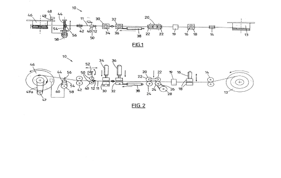
Schedule 2
The DSI Apparatus
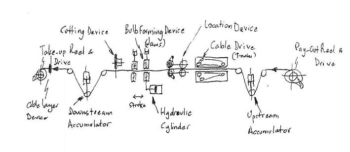
Schedule 3
Notional Claims for the IRF Application
The claims defining the invention are as follows:
1. An apparatus for manufacturing a rock anchor of the type comprising a cable having a plurality of strands and a plurality of bulbous portions formed in different parts of the cable;
characterised by a feeding means for feeding a cable having a plurality of strands from a spool or reel;
a first holding means which allows the cable to pass therethrough in a forward direction and which holds the cable and substantially prevents the cable from moving in a reverse direction when a force tending to move the cable in the reverse direction is applied to the cable, a second holding means for selectively clamping and unclamping the cable, wherein the first holding means and the second holding means are moveable relative to one another to form bulbous portions in different parts of the cable; and
means for determining when said cable has passed through the apparatus to a sufficient extent to stop operation of the feeding means to enable a further bulbous portion to be formed.
2. An apparatus according to claim 1;
characterised in that the feeding means comprises a pinch roller arrangement which pinches the cable to cause it to be fed from the spool or reel.
3. An apparatus according to any one of the preceding claims;
characterised in that the first holding means has a first pair of opposed collet pieces defining a first aperture therebetween for passage of the cable, the first pair of opposed collet pieces initially being in a first position in which the first aperture is sized to allow the cable to pass therethrough,
the second holding means has a second pair of opposed collets which are initially in a retracted position;
the first pair of opposed collets being arranged to be brought together to reduce the size of the first aperture so as to grip the cable;
the second pair of opposing collets being arranged to close so as to grip the cable;
and the first and second pairs of opposing collets being subsequently arranged to be moved to reduce the distance therebetween so as to form a bulbous portion in the cable;
and the first pair of opposing collets being arranged to subsequently allow the cable to be pulled therethrough and to be moved to the first position;
and the second pair of collets being arranged to subsequently release the cable and to be moved back to the retracted position.
4. A method of manufacturing a rock anchor of the type comprising a cable having a plurality of strands and a plurality of bulbous portions formed in different parts of the cable;
characterised by feeding a cable having a plurality of strands from a spool or reel;
determining when the cable has been fed to a correct position for formation of a bulbous portion and stopping movement of the cable;
forming a bulbous portion in the stopped cable; and

