
FEDERAL COURT OF AUSTRALIA
Tramanco Pty Ltd v BPW Transpec Pty Ltd [2012] FCA 613
IN THE FEDERAL COURT OF AUSTRALIA | |
QUEENSLAND DISTRICT REGISTRY | |
GENERAL DIVISION | QUD 114 of 2009 |
BETWEEN: | TRAMANCO PTY LTD (ACN 010 101 872) Applicant
|
AND: | BPW TRANSPEC PTY LTD (ACN 006 645 272) First Respondent BPW TRANSPEC PTY LTD (ACN 006 645 272) Cross Applicant TRAMANCO PTY LTD (ACN 010 101 872) Cross Respondent
|
JUDGE: | DOWSETT J |
DATE: | 5 SEPTEMBER 2012 |
PLACE: | BRISBANE |
SUPPLEMENTARY REASONS FOR JUDGMENT
1 In these proceedings the applicant (“Tramanco”) alleged that the first respondent BPW Transpec Pty Ltd (“BPW”) had infringed its patent. BPW denied infringement and sought revocation of the patent for want of novelty, want of inventiveness and failure to comply with s 40 of the Patents Act 1990 (Cth) (the “Patents Act”). I published my reasons for judgment on 14 June 2012, indicating that I might make editorial changes in the course of further proofing. The reasons in their final form have now been provided.
2 The parties have made submissions as to appropriate orders, including orders as to costs. There is a substantial issue as to costs. I propose to defer dealing with that matter until it is more convenient to do so, having regard to my other commitments. However I propose to deal with other orders so that they may be the basis of any notice of appeal. I shall endeavour to deal with the issue of costs within a period of time which will allow any appeal as to costs to be heard with any appeal on substantive issues.
3 The parties agree that there should be a declaration that the patent is invalid and an order for its revocation. I shall order accordingly. It is also agreed that there should be an order discharging certain interlocutory orders made on 22 May 2009 and on 4 May 2011. I shall order accordingly. The parties agree that there should be an order as to the assessment of compensation payable pursuant to an undertaking, given by Tramanco as a condition of the grant of interlocutory relief. There is, however, a dispute as to whether such assessment should be limited to compensation payable to the respondent or should extend to compensation payable to “… any other person adversely affected”. The undertaking extends to such other persons. The order should reflect the wording of the undertaking. The assessment should extend, to the extent that it may be relevant, to compensation payable to BPW or any other person adversely affected. It is also agreed that there should be directions as to the conduct of the assessment proceedings. I shall order accordingly. It is proposed that BPW be relieved from undertakings given to the Court on 4 May 2011. This seems appropriate.
4 Tramanco seeks the following additional order:
Upon the Applicant undertaking to the Court that, during the period of the stay made by this Order, it will not threaten, commence or pursue proceedings for infringement of Australian Patent 2004264997 against any person or entity (including, but not limited to, the Respondent), that it will not seek to amend any of the claims of the said patent other than in the course of or in connection with any Appeal it makes against any of these Orders, and, further, to expeditiously prosecute any such Appeal, the operation of paragraphs 2, 4 and 5 of these Orders be stayed until the later of:
(a) 28 days from the date of the making of these Orders; or
(b) the date on which any Appeal against the whole or any part of these Orders is finally determined.
5 BPW submits that the following order should be made by way of stay:
Upon the Applicant by its counsel undertaking to the Court:
(a) to prosecute any appeal expeditiously;
(b) during the period of the stay, not to threaten any person with proceedings for infringement of Australian Patent No 2004264997; and
(c) during the period of the stay, not to seek to amend any claims of the Australian Patent No 2004264997 other than in the course of or in connection with these proceedings;
the operation of paragraph 2 of this Order be stayed:
(d) for 21 days from the date of the Order; and
(e) if the Applicant within that 21-day period lodges an appeal against paragraph 2 of this Order, until the determination of that appeal or further order.
6 Order 2 is the proposed order for revocation. Orders 4 and 5 contain directions as to the assessment of compensation. Thus the parties agree that there should be a stay of the order as to revocation. Tramanco also seeks a stay of the orders relating to the assessment.
7 Apart from the matters in dispute between the parties, I was concerned by the reference in the proposed orders to an application for amendment of the patent. In the final submission at the trial no application was made for any such amendment. Hence I cannot see how the question could arise in the course of any appeal. The argument seems to be that s 105 of the Patent Acts 1990 (Cth) contemplates an application being made to the Court at any time. Similarly, s 104 contemplates an application to the Commissioner. In my view any difficulties which may arise in this regard can best be met by requiring Tramanco to give an undertaking not to make any such application to the Court or the Commissioner other than upon seven days’ notice in writing to BPW. As to the orders relating to assessment of compensation, I see no reason why they should be stayed. I need not, at this stage, set a date for hearing.
8 I propose to give the parties one more opportunity to work co-operatively together in order to bring this litigation to finality. Hopefully they will demonstrate a more constructive approach than has, until now, been demonstrated. I direct the parties to bring in, within seven days from the publication of these reasons, appropriate draft orders.
9 I have previously invited the parties to seek any further findings of fact which they may consider to be appropriate. Neither party has sought such findings. As I have not yet disposed of the question of costs, the proceedings must remain on foot. I adjourn then to a date to be fixed.
I certify that the preceding nine (9) numbered paragraphs are a true copy of the Reasons for Judgment herein of the Honourable Justice Dowsett. |
Associate:
Dated: 5 September 2012
QUEENSLAND DISTRICT REGISTRY | |
GENERAL DIVISION | QUD 114 of 2009 |
BETWEEN: | TRAMANCO PTY LTD (ACN 010 101 872) Applicant
|
AND: | BPW TRANSPEC PTY LTD (ACN 006 645 272) First Respondent BPW TRANSPEC PTY LTD (ACN 006 645 272) Cross Applicant TRAMANCO PTY LTD (ACN 010 101 872) Cross Respondent
|
JUDGE: | DOWSETT J |
DATE: | 14 JUNE 2012 |
PLACE: | BRISBANE |
REASONS FOR JUDGMENT
THE PATENT
1 The applicant and cross-respondent (“Tramanco”) holds Australian Patent No 2004264997, (the “Patent”), said to concern a “method for logging the performance of a vehicle suspension system”. The Patent was granted pursuant to the Patents Act 1990 (Cth) (the “Patents Act”). The priority date is 19 August 2003.
2 The suspension system of a vehicle is the mechanism which connects the road wheels of the vehicle (including the axles) to its body. Trucks, trailers and other heavy haulage vehicles are usually equipped with self-levelling suspension systems, designed to compensate for changes in load so that the vehicle always remains at approximately the same height off the road, whether empty, partially laden or fully laden. Self-levelling is generally effected by devices which measure the vertical distance between, for example, the trailer bed and the extension arm. The greater the load, the smaller this distance tends to become. An initial variation in the distance operates a valve which controls the height adjustment system. Usually, height adjustment takes place at both ends of the vehicle and at each axle or group of axles. The suspension is also designed to ameliorate the effects of vertical forces on the vehicle. I shall deal with this aspect in more detail at a later stage.
3 The suspension may be comprised of springs or shock absorbers, but many vehicles have air suspension, using collapsible, pressurized air containers in place of those mechanisms. In such a system, the upward movement of a wheel reduces the volume of contained air, raising the pressure within the container so that it tries to expand again. A height control valve connects the air container to a high pressure air reservoir so that air flows into the container when the load is increased. When the load is reduced, pressure is released to the atmosphere. Air suspensions generally have dampers, often referred to as “shock absorbers”. Dampers are designed to damp out vibrations so as to minimize bouncing of the suspension in response to an impulsive load. They do so by absorbing energy stored in the suspension. A damper may be “single action” or “double action”, depending upon whether it acts in one or both directions (ie up and/or down).
4 Logging the performance of a suspension system may be useful in assessing the condition of the suspension and, therefore, the need for maintenance. It may also facilitate assessment of the “road-friendliness” of the vehicle. As I understand it, the term “road-friendliness” describes the likely adverse effect of a motor vehicle upon roads which it uses. The National Road Transport Commission (the “NRTC”) is responsible for assessing the road-friendliness of vehicles according to established standards. In April 1999 the NRTC issued Vehicle Standards Bulletin 11 (“VSB-11”). It prescribed four criteria which a suspension had to meet in order to be considered “road friendly”. They were:
the frequency of the sprung mass above the axle or axle group in free transient vertical oscillation must not be higher than 2.0 Hz;
the mean damping ratio must not be more than 20% of critical damping for the suspension in its normal operating condition;
the damping ratio of the suspension with all dampers (if fitted) removed or incapacitated must not be more than 50% of the damping ratio; and
static load share between axles in the axle group must be within 5%.
5 The level of road-friendliness determines whether or not a vehicle may use particular roads and/or the loads which it may carry. The Patent specification (the “specification”) asserts that “conventional” suspension testing may not be consistently reliable, particularly for larger vehicles. In particular, it may not accurately reflect the combined effect of vehicle weight, suspension geometry, shock absorber characteristics and other considerations. The specification also identifies the need, in some cases, to remove components from the vehicle for testing, resulting in the vehicle being out of service, and the substantial cost associated with removing and replacing such components. Further, it is said that testing of shock absorbers, whilst isolated from their operating environment, may be unsatisfactory as it involves measurement against an arbitrary standard rather than relative to the suspension system of which it is a part. The invention is said to be directed to a method for logging the performance of a vehicle suspension system “which may at least partially overcome the above-mentioned disadvantages or provide the consumer with a useful or commercial choice”.
6 One form of the invention resides in
a method for logging the performance of a vehicle suspension system including the steps of measuring the dynamic effect of an impulsive load with an electronic weighing system, wherein the electronic weighing system is mounted on board the vehicle, and determining one or more parameters selected from the group consisting of the dampening ratio of the suspension, the oscillation frequency of the suspension and the impact loading of the vehicle.
7 This form of the invention is the basis of claim 1. The “dampening” (damping) ratio is measured in percentage terms, the percentage indicating the extent of reduction in the amplitude of the oscillation which the suspension undergoes in response to an impulsive load. To be “road friendly”, the damping ratio must be greater than 20%. The frequency of oscillation is measured in Hertz. I understand this concept to involve the number of oscillations produced in response to the application of an impulsive load. To be road-friendly, the oscillation frequency must be less than 2 Hz. The meaning of the term “impact loading” is not so clear. I shall return to that matter, and to the term “dynamic effect of an impulsive load”. When a wheel rises after going over an irregularity in the road surface, it places pressure on the suspension from below. The suspension will absorb some of the force so transmitted. The rest will pass into the body which will rise off the suspension and then fall back onto the suspension. The suspension will again have a damping effect on the force, the remaining force passing to the wheels and ultimately, the road. Any stored energy in the suspension may result in force again being applied upwards.
8 The specification discloses existing methods for testing suspensions as including:
application of force to the body of the vehicle, with visual identification of any responsive rocking motion;
the European drop test, in which a set of axles is mounted on a test rig and driven over a sheer drop of approximately 80 mm, the responding damping ratio and frequency being measured using load cells attached to the test rig;
the bump test, in which a vehicle is driven at a particular speed over a “nominal” bump; and
road testing on a normal, uneven road at speed.
9 I assume that in the bump test and road test, load cells are also used. I shall discuss the term “load cell” in the context of novelty. Broadly speaking, the specification identifies a method of logging suspension performance using an onboard electronic weighing system to measure and/or collect data. It may be inferred from the specification that such data is to be used in calculating the damping ratio, frequency of oscillation and/or impact loading of the vehicle. However it is not clear that such use is an element of the invention as claimed. I shall return to that matter.
10 The method may include a meter displaying the data and/or collated results. It may also include a capacity for storing such information. The relevant data may be collected from various points in the suspension, in particular, from areas in the vicinity of the axles, using load cells or pressure transducers associated with signal amplifiers. The collected information may be stored according to date, time or “particular dynamic parameters” which may be pre-set or varied to suit operating conditions. I understand the reference to “dynamic parameters” to mean, in this context, that information may be recorded or not, depending upon the magnitude of the impulsive load. The meter may be connected to a tool for analysis of collected information, either on board or elsewhere, in the latter case using a transmitting system. The vehicle may also have a vehicle locating means, preferably a satellite global positioning system (“GPS”). Alternatively other means, such as a trip meter, may be used. The method may also utilize some form of “remote interrogation” to allow access to the data, presumably from some distant point.
11 Another embodiment of the invention assesses performance of the suspension over a variable road section at different times, with the vehicle’s location being known at all times. This test may be described as a “trip test”. It yields data concerning road conditions and vehicle performance. The test may be triggered by an impulsive load of pre-set magnitude.
12 At pp 12-18 of the specification, there is a description of a test carried out on a newly constructed 34 tonne, four-axle trailer using the patented method. The suspension of the trailer was tested using a version of the European drop test, the bump test and on-road testing. The specification asserts that the drop test produced no data capable of meaningful analysis. The bump test was deemed successful. I infer that the on-road test was also deemed to be successful.
THE CLAIMS
13 The relevant claims in the Patent, for present purposes, are claims 1, 12, 13, 14, 19, 20, 21, 22 and 23 as follows:
1. A method for logging the performance of a vehicle suspension system including the steps of measuring the dynamic effect of an impulsive load with an electronic weighing system, wherein the electronic weighing system is mounted onboard the vehicle, and determining one or more parameters selected from the group consisting of the dampening ratio of the suspension, the oscillation frequency of the suspension and the impact loading of the vehicle.
…
12. A method according to claim 1 wherein the performance of the vehicle suspension system is logged over a standard road section at different times to test the performance of an individual axle or group of axles to an impulsive load.
13. A method according to claim 12 including the step of comparing the performance of the vehicle suspension system to predetermined standards.
14. A method according to claim 12 wherein the performance of the vehicle suspension system when the suspension is new is compared to performance at various periods throughout the life of the suspension in order to ensure that the performance of the suspension remains within the predetermined standards.
…
19. A method according to claim 12 including a test in which the variation in a mass signal is recorded as the combination test rig vehicle travels along a normal, uneven road at speed.
20. A method according to claim 19 wherein a location device is linked to the data collected, to precisely locate the portion of road upon which the test was conducted for future comparison.
21. A method according to claim 12 wherein the performance of the vehicle suspension system is logged over a variable road section at different times, the position of the vehicle being identifiable at all times during the logging process, allowing data to be collected about the condition of the roads which a test vehicle travels over.
22. A method according to claim 21 wherein the logging is triggered by the application of a particular preset magnitude impulsive load.
23. A method according to claim 22 wherein the location of the vehicle is ascertainable with precision using locating means.
14 It is worth noting that all other claims are dependent upon claim 1, and that it claims a method for logging the performance of a vehicle suspension system. The dependent claims should be read in that context. Claims 13, 14, 19, 20, 21, 22 and 23 are also dependent upon claim 12. Further, claim 22 is dependent upon claim 21, and claim 23 is dependent upon claim 22. Claim 1 is expressed in very general terms. Such generality is significant in this case.
THE RESPONDENT
15 The respondent (“BPW”) is a wholly owned Australian subsidiary of a German company, BPW Bergische Achsen KG (the “parent company”). The parent company manufactures trailer axles and electronic braking systems for trailers. BPW conducts business throughout Australia. It has offices in New South Wales, Victoria, Queensland and Western Australia. Tramanco asserts that BPW has infringed the Patent by importing, making, selling or otherwise dealing with an electronic braking system manufactured by the parent company. It asserts that the system incorporates a vehicle suspension system logging method in a computer programme, with associated hardware and devices. BPW admits that it has imported the component parts of an electronic braking system and assembled and sold, in Australia, an electronic braking system (the “BPW EBS”). For the sake of clarity I shall hereafter generally use the acronym “BPW EBS” to describe both the braking system as mounted on a vehicle and associated hardware and software used in connection with it. However I shall later discuss that associated hardware and software. Where necessary I shall distinguish the braking system from other items of hardware or software.
16 BPW further admits that it had proposed to market, in Australia, a version of the BPW EBS which includes a software programme to utilize information captured by an air pressure transducer connected to a vehicle’s airbag suspension, in order to provide an indication of the overall condition of the roads over which the vehicle has travelled (the “RCM feature”). However, after the commencement of these proceedings, BPW arranged for the removal of the RCM feature from the BPW EBS being sold in this country. Apart from the BPW EBS, three other BPW products are relevant. Trailer Manager software is not usually sold by BPW. It is used internally to create trailer-specific brake programmes for installation in the BPW EBS when installed in a trailer. BPW does not plan to release the Trailer Manager software on the general market as it prefers to retain control over programming and testing. Trailer Manager software can also be used to generate fault reports.
17 The Trailer Monitor Unit is a small “side of vehicle” device which can be connected to a BPW EBS fitted to a trailer, for the purpose of reading some information stored in the BPW EBS. Information is generally shown in text. It has only limited graphic capacity. It is an optional extra which may be acquired in conjunction with a BPW EBS.
18 Trailer Analyser software is separate software which runs on a personal computer (“PC”). The PC must be connected to a valve in the BPW EBS (the “valve”). I shall say more about the valve at a later stage. The connection is via a dongle. The Trailer Analyser software is used to download data from the valve whilst the trailer is stationary. In order to view the data, the PC must be connected to the valve and to the computer. The Trailer Analyser software and dongle are not presently being supplied to Australian customers. At a later stage, I shall discuss the data available using the Trailer Analyser software.
19 Although the Patent is for a method, BPW imports and supplies a product, the BPW EBS. It denies performance of the method. At a very late stage, Tramanco sought leave to add a claim pursuant to s 117 of the Patents Act. Leave was given.
TRAMANCO’S CLAIM
20 At para 12 of its amended statement of claim Tramanco pleads that the BPW EBS possesses each of the integers of claims 1 and/or 12 and/or 13 and/or 14 and/or 19 and/or 20 and/or 21 and/or 22 and/or 23 of the patent. In para 12 of the further amended statement of claim this allegation is particularized as follows:
(a) The [BPW] method contains a “road conditions monitoring” function which … “logs the pressure spikes in trailer air bags to give a road roughness count”;
(b) The system … for monitoring road conditions … [by] logging the pressure spikes in trailer airbags … must contain the following features:
(i) a method for logging the performance of a vehicle’s suspension system;
(ii) within or as part of that method, steps for measuring the dynamic effect of an impulsive load;
(iii) a form of electronic system for logging that performance;
(iv) that weighing system being mounted on board the vehicle;
(v) the program in that system containing means for measuring the damping ratio of the suspension or means of extrapolating data from the [damping] ratio, the oscillation frequency of the suspension and the impact loading of the vehicle;
(vi) a means of so logging the performance of a vehicle over a standard road section at different times to test the performance of an individual axle or group of axles on a trailer or on a prime mover or truck (or other form of vehicle) to an impulsive load;
(vii) a program for recording the variation in a mass signal as the vehicle travels along a normal, uneven road at speed;
(viii) a program which enables the data collected to locate the portion of road upon which the vehicle was travelling at the time that the testing was carried out using the [BPW] method and/or the [BPW] device and a means of retaining that data for future comparison;
(ix) a program wherein the performance of the vehicle’s suspension system is logged over a variable road section (thus measuring varying road conditions) at different times, the position of the vehicle during that logging process being identifiable at all times and thus allowing data to be collected at the condition of the roads over which the vehicle was travelling at the time of testing; that is to say, testing the roughness of the road conditions over which the vehicle is travelling at the time of the testing and thus being able to monitor damage that may be caused to the vehicle by the roughness of those road conditions at the time of the test;
(x) a further programming means whereby the logging is triggered or activated by the Applicant (sic) of a particular, preset magnitude impulsive load;
(xi) a means within the program whereby the location of the vehicle at the time of the test is ascertainable with precision using some form of locating means (including but not necessarily limited to some form of global positioning system or like means or any other means of location);
(xii) a means within the program whereby a predetermined standard is set as to the performance of a vehicle’s suspension system. [BPW’s] system provides for a means of capturing and monitoring peak loads in the vehicle’s suspension system. Data is accumulated on a trip made by the vehicle and used as a reference for further tests on later trips made by that vehicle. The program provides for the measurement from time to time of the performance of the suspension or wear against the standards as so predetermined. Further, there is a “Compare” function provided in [BPW’s] Trailer Analyser Software that is used to compare a suspension’s performance against a predetermined standard or standards.
BPW’S DEFENCE AND CROSS-CLAIM
21 BPW pleads that para 12 of the further amended statement of claim is embarrassing and liable to be struck out on the ground that it fails to particularize the alleged infringements and to identify components, if any, which infringe. BPW also denies each of the allegations in para 12. In particular it denies the assertion or assumption in para 12(b) that the BPW EBS “must contain” features (i) to (xi). BPW pleads as follows:
as to subparas (i) to (iii), it denies that the BPW EBS with the RCM feature contains a method for logging the performance of a vehicle suspension system;
as to subpara (iv), it admits that the BPW EBS with the RCM feature is mounted on board a vehicle, but pleads that it is an electronic braking system and that, to the extent that it records data referable to variations in mass, it does so imprecisely and so as to regulate braking performance;
as to subpara (v), it denies that the programme within the RCM feature contains a means for measuring the damping ratio of the suspension or for extrapolating data from the damping ratio, or that it contains a means of measuring the oscillation frequency of the suspension;
as to subpara (vi), it again denies that the RCM feature contains a means of logging the performance of a vehicle suspension system;
as to subpara (vii), it admits that the RCM feature processes variations in air pressure in the airbags of the air suspension of the vehicle;
as to subpara (viii) it denies that there is a programme in either the BPW EBS or the RCM feature which records data as to location of the vehicle on which the BPW EBS is fitted or which time stamps any data collected; and
as to subparas (ix), (x) and (xi), it denies that the RCM feature contains programmes of the kinds alleged.
22 Although BPW generally denies subpara (xii) it has not pleaded specifically to it.
23 BPW also pleads prior use and cross-claims for revocation of the Patent on the grounds that the claims:
lack novelty;
lack an inventive step; and
fail to disclose the best method of performing the invention and are not clear, succinct and fairly based on the specification.
A PRELIMINARY MATTER
24 It is fair to say that Tramanco’s case lacks a degree of precision and has changed in the course of the trial. BPW’s response to Tramanco’s case has similar characteristics. As a result, much time has been spent in cross-examining various witnesses on issues which, in the end, may not be relevant. Out of fairness to Tramanco, I should say that, to some extent, its problems arise out of BPW’s inability to provide it with certain “source codes” relevant to the operation of the BPW EBS or elements thereof. Out of fairness to BPW, I should say that it attributes such inability to the fact that the source codes are within the knowledge of a third party supplier to the parent company. Out of fairness to counsel, I should add that their closing submissions did much to remedy the lack of focus which characterized the trial.
25 The course of the trial has also caused difficulty. It was conducted over ten days in October 2010 and five days in April 2011. I received final written submissions in July 2011.
CONSTRUCTION OF THE PATENT
26 In Kimberley-Clark v Arico Trading International Pty Ltd (2001) 207 CLR 1 at [15], the High Court said:
… Where the question concerns infringement of a claim or the sufficiency of a claim to “define” the invention, it has been held in this Court under the 1952 Act that the plain and unambiguous meaning of a claim cannot be varied or qualified by reference to the body of the specification. However, terms in the claim which are unclear may be defined or clarified by reference to the body of the specification.
27 This principle is of particular importance in the present case. In Kinabalu Investments Pty Ltd v Barron & Rawson Pty Ltd [2008] FCAFC 178 at [44]-[45], the Full Court said:
44 The principles of construction applicable were not in dispute. When determining the nature and extent of the monopoly claimed, the specification must be read as a whole. But as a whole it is made up of several parts which have different functions. The claims mark out the legal limits of the monopoly granted. The specification describes how to carry out the process claimed and the best method known to the patentee of doing that. Although the claims are construed in the context of the specification as a whole, it is not legitimate to narrow or expand the boundaries of monopoly as fixed by the words of a claim, by adding to those words glosses drawn from other parts of the specification. If a claim is clear and unambiguous, it is not to be varied, qualified or made obscure by statements found in other parts of the document. It is legitimate, however, to refer to the rest of the specification to explain the background of the claims, to ascertain the meaning of technical terms and resolve ambiguities in the construction of the claims. See Flexible Steel Lacing Co v Beltreco Ltd [2000] 49 IPR 331 at [73]-[75] (Hely J).
45 Other more specific principles of construction collected in Flexible Steel at [81] are:
• a specification should be given a purposive construction rather than a purely literal one;
• the hypothetical addressee of the specification is the non-inventive person skilled in the art before the priority date;
• the words used in a specification are to be given the meaning the hypothetical addressee would attach to them, both in the light of the addressee’s own general knowledge and in the light of what is disclosed in the body of the specification;
• as a general rule, the terms of the specification should be accorded their ordinary English meaning;
• evidence can be given by experts on the meaning those skilled in the art would give to technical or scientific terms and phrases, and on unusual or special meanings given by such persons the words which might otherwise bear their ordinary meaning;
• however, the construction of the specification is for the Court, not for the expert. In so far as a view expressed by an expert depends upon a reading of the patent, it cannot carry the day unless the Court reads the patent in the same way.
28 Lord Hoffmann said, in Kirin-Amgen Inc and Others v Hoechst Marion Roussel Ltd and Others (2004) 64 IPR 444 at [32]-[35]:
32 Construction, whether of a patent or any other document, is of course not directly concerned with what the author meant to say. There is no window into the mind of the patentee or the author of any other document. Construction is objective in the sense that it is concerned with what a reasonable person to whom the utterance was addressed would have understood the author to be using the words to mean. Notice, however, that it is not, as is sometimes said, “the meaning of the words the author used”, but rather what the notional addressee would have understood the author to mean by using those words. The meaning of words is a matter of convention, governed by rules, which can be found in dictionaries and grammars. What the author would have been understood to mean by using those words is not simply a matter of rules. It is highly sensitive to the context of and background to the particular utterance. It depends not only upon the words the author has chosen but also upon the identity of the audience he is taken to have been addressing and the knowledge and assumptions which one attributes to that audience. … .
33 In the case of a patent specification, the notional addressee is the person skilled in the art. He (or, I say once and for all, she) comes to a reading of the specification with common general knowledge of the art. And he reads the specification on the assumption that its purpose is both to describe and to demarcate an invention – a practical idea which the patentee has had for a new product or process – and not to be a textbook in mathematics or chemistry or a shopping list of chemicals or hardware. It is this insight which lies at the heart of “purposive construction”. If Lord Diplock did not invent the expression, he certainly gave it wide currency in the law. But there is, I think, a tendency to regard it as a vague description of some kind of divination which mysteriously penetrates beneath the language of the specification. Lord Diplock was in my opinion being much more specific and his intention was to point out that a person may be taken to mean something different when he uses words for one purpose from what he would be taken to mean if he was using them for another. The example in the Catnic case was the difference between what a person would reasonably be taken to mean by using the word “vertical” in a mathematical theorem and by using it in a claimed definition of a lintel for use in the building trade. The only point on which I would question the otherwise admirable summary of the law on infringement in the judgment of Jacob LJ in Rockwater Ltd v Technip France SA … is when he says in subpara (e) that to be “fair to the patentee” one must use “the widest purpose consistent with his teaching”. This, as it seems to me, is to confuse the purpose of the utterance with what it would be understood to mean. The purpose of a patent specification, as I have said, is no more nor less than to communicate the idea of an invention. An appreciation of that purpose is part of the material which one uses to ascertain the meaning. But purpose and meaning are different. If, when speaking of the widest purpose, Jacob LJ meant the widest meaning, I would respectfully disagree. There is no presumption about the width of the claims. A patent may, for one reason or another, claim less than it teaches or enables.
34 “Purposive construction” does not mean that one is extending or going beyond the definition of the technical matter for which the patentee seeks protection in the claims. The question is always what the person skilled in the art would have understood the patentee to be using the language of the claim to mean. And for this purpose, the language he has chosen is usually of critical importance. The conventions of word meaning and syntax enable us to express our meanings with great accuracy and subtlety and the skilled man will ordinarily assume that the patentee has chosen his language accordingly. As a number of judges have pointed out, the specification is a unilateral document in words of the patentee’s own choosing. Furthermore, the words will usually have been chosen upon skilled advice. The specification is not a document inter rusticos for which broad allowances must be made. On the other hand, it must be recognised that the patentee is trying to describe something which, at any rate in his opinion, is new; which has not existed before and of which there may be no generally accepted definition. There will be occasions upon which it will be obvious to the skilled man that the patentee must in some respect have departed from conventional use of language or included in his description of the invention some element which he did not mean to be essential. But one would not expect that to happen very often.
35 One of the reasons why it will be unusual for the notional skilled man to conclude, after construing the claim purposively in the context of the specification and drawings, that the patentee must nevertheless have meant something different from what he appears to have meant, is that there are necessarily gaps in our knowledge of the background which led him to express himself in that particular way. The courts of the UK, the Netherlands and Germany certainly discourage, if they do not actually prohibit, use of the patent office file in aid of construction. There are good reasons: the meaning of the patent should not change according to whether or not the person skilled in the art has access to the file and in any case life is too short for the limited assistance which it can provide. It is however frequently impossible to know without access, not merely to the file but to the private thoughts of the patentee and his advisors as well, what the reason was for some apparently inexplicable limitation in the extent of the monopoly claimed. One possible explanation is that it does not represent what the patentee really meant to say. But another is that he did mean it, for reasons of his own; such as wanting to avoid arguments with the examiners over enablement or prior art and have his patent granted as soon as possible. This feature of the practical life of a patent agent reduces the scope for a conclusion that the patentee could not have meant what the words appear to be saying. It has been suggested that in the absence of any explanation for a restriction in the extent of protection claimed, it should be presumed that there was some good reason between the patentee and the patent office. I do not think that it is sensible to have presumptions about what people must be taken to have meant but a conclusion that they have departed from conventional usage obviously needs some rational basis.
The skilled addressee
29 Tramanco takes a pragmatic approach to identification of the skilled addressee, apparently accepting that all of the expert witnesses who offered opinions as to construction of the Patent and associated matters fitted the description. BPW takes a more focussed approach. It identifies the skilled addressee as “a person who is familiar with the performance characteristics of heavy vehicle suspensions and the interrelationship of suspension performance with road damage”. It submits that the notional skilled addressee “would know that oscillation frequency and damping ratio were performance characteristics of a suspension and know of the VSB-11 requirements, the reason for their adoption by regulators … and how to test them”. It further submits that such an addressee would not necessarily have conducted those tests but would understand the principles behind them. These aspects seem to be common ground.
30 BPW also submits that the skilled addressee would understand the phrase “impact loading of the vehicle” to refer to the force exerted by the tyres on the road surface, a matter which is of some importance in this case. Further, the skilled addressee would know that the impact loading of vehicles has been determined in the past “through the determination of dynamic load co-efficients”. I accept that the skilled addressee is a person who is familiar with the performance characteristics of heavy vehicle suspensions and the inter-relationship of suspension performance with road damage. Most of the other attributes referred to by BPW are matters to be proven as part of the relevant common general knowledge rather than characteristics of the skilled addressee. The meaning of the term “impact loading” is very much in dispute.
31 BPW’s identification of the skilled addressee accurately reflects the nature of the problem to be addressed in this case. The evidence demonstrates that there are recognized standards and tests which are relevant to that problem, that there are persons with relevant training and/or experience and that there is a national body engaged in the area, the NRTC.
32 BPW submits that Dr Sweatman and Mr Di Cristoforo (both called by BPW) are skilled addressees. BPW also accepts that Dr Blanksby (called by Tramanco) “was perhaps a skilled addressee by 2010, although not in 2003”. BPW at least implies that Dr Gilmore (called by Tramanco) was not a skilled addressee, or that his evidence should, for other reasons, be given little weight. Having regard to the evidence, and in the absence of any submission to the contrary by Tramanco, I accept that Dr Sweatman and Mr Di Cristoforo are skilled addressees. Dr Sweatman’s curriculum vitae clearly demonstrates as much, as does Mr Di Cristoforo’s. As to Dr Blanksby, between 2000 and 2004 his work was unassociated with heavy road vehicles. However he had previous experience in that area and re-entered it in about 2006. I accept him as a skilled addressee. Dr Gilmore’s curriculum vitae does not disclose a close association with heavy road transport. However, in cross-examination, he claimed some engagement in that area, including vehicle suspension. I am inclined to accept him as a skilled addressee, but to note that he has limited experience in the relevant area as compared to that of the other three witnesses. I am not sure whether Mr Sack, the managing director of Tramanco, is advanced as a skilled addressee. I proceed on the basis that he is a skilled addressee.
33 Although the expert witnesses were cross-examined at some length concerning the meaning of terms used in the claims, the construction remains a matter for the Court. The differences between the parties concerning construction are manifested in two ways. First, Tramanco seeks to minimize the importance of demonstrating road-friendliness as an object of the claimed invention whilst BPW tends to emphasize it. There can be no doubt that a major purpose of the invention, according to the specification, is to assist road users in complying with NRTC requirements associated with road-friendliness. However it is also clear from the specification that the claimed invention is said to serve other purposes, particularly facilitating vehicle maintenance and improving safety. The second aspect of the case which demonstrates the differences between the parties is the extent to which Tramanco seeks to rely upon the specification effectively to narrow the very broad terms used in claim 1 and, indeed, all other claims in the Patent. For that reason it is most important that I keep in mind the views expressed in Kimberley-Clark.
A system for logging
34 As a noun the New Shorter Oxford English Dictionary defines the word “log” to mean:
… A systematic record of things done, found, experienced, etc., as (a) a record of discoveries or variations at successive depths in drilling a well; a graph or chart displaying this information; (b) a record with details of journeys kept by a lorry driver; (c) a record of what is broadcast by a radio or television station.
35 As a verb the word is said to mean:
Enter (esp. the distance made by a ship) as information in a log or logbook; … enter (information) in a regular record.
36 The Macquarie Dictionary (5th ed) defines the word as a noun to mean:
… official record which a ship’s master is obliged by law to keep, of particulars of a ship’s voyage as weather, crew, cargo, etc … the record which the engine room and bridge officers keep of the particulars of each watch … also, “flight log” a listing of navigational meteorological and other significant data concerning an air journey … any similar record of a journey … the register of the operation of a machine.
37 As a verb the word is said to mean:
To enter in a ship’s log … to record in an aeroplane’s log (the number of hours spent in the air).
38 Clearly, and relevantly for present purposes, the word is primarily used in connection with journeys by ship, aircraft or motor vehicle. It is also used in relation to the operation of machinery. The definitions suggest that the process of logging is generally consistent and ongoing. I take the word “logging” to mean “recording in a systematic way”. The words “a method for logging” should be so read.
Performance of a vehicle suspension system
39 The meaning of the expression “performance of a vehicle suspension system” is in dispute, but, as far as I can see, the controversy relates only to the meaning of the word “performance”. I do not understand there to be any challenge to the following description of the term “vehicle suspension system”, which description appears in the specification:
Generally, trucks and trailers and other heavy haulage vehicles are equipped with self-levelling suspension systems. The systems are designed to compensate for changes in the load by modifying the springing or dynamic characteristics of the suspension so that the vehicle(s), always remain approximately the same height off the road, whether empty, partially loaded, or fully loaded.
The systems are designed to ensure that, even when the vehicle is fully laden, the full upward travel of the suspension system is available for absorbing bumps. Other related effects are things such as the headlights are kept in proper focusing alignment, whatever the distribution of the load.
Any form of self-levelling is generally operated by one or more load-sensing devices which measure the vertical distance between, for example the trailer bed and the suspension arm. The greater the load, the smaller this distance tends to become. An initial variation in the distance operates a valve which controls the height-adjusting system. Usually, height adjustment takes place at both ends of vehicle, and in particular generally takes place at each axle or group of axles.
Air suspensions are relatively simple in principle. Collapsible, pressurized air containers take the place of conventional springs or shock absorbers; the upward movement of the wheel reduces the volume of the air spring, raising its pressure, so that it tries to extend itself again. If the air spring is inflated more, it can carry a heavier load before contracting to a given height. A height-control valve connects the air spring to a high-pressure air reservoir when the load is increased, and pressure is released through the valve to the atmosphere when the load is reduced.
Air suspensions generally also comprise dampers, often referred to as “shock absorbers”. Dampers are designed to damp out vibrations so that the suspension does not continuously bounce up and down in response to an impulsive load. The purpose of dampers is to reduce oscillation by absorption of energy stored in the suspension. A damper may be single action or double action in which damping is controlled in both directions.
40 Tramanco’s position with respect to the word “performance” is that:
Evidence in relation to the meaning of this word is irrelevant. It is an ordinary English word that does not bear any special meaning different from its English meaning.
41 BPW submits that “the context of the patent is the road-friendliness or otherwise of vehicle suspensions”. It submits that in such context the word “performance” in claim 1 should be construed as meaning performance in terms of one or more of the three “parameters” identified in the claim. As I have said, I do not read the Patent as addressing solely the question of road-friendliness. The starting point should be that urged by Tramanco, namely identification of the plain English meaning of the word. According to the New Shorter Oxford English Dictionary “performance” means:
The execution or accomplishment of an action, operation, or process undertaken or ordered; the doing of any action or work; the quality of this, esp. as observable under particular conditions; … the capabilities of a machine, esp. a motor vehicle or aircraft, measured under test.
42 The Macquarie Dictionary offers the following meaning:
… execution or doing, as of work, acts or feats. … a particular action, deed, or proceeding … an action or proceeding of a more or less unusual or spectacular kind … the act of performing … the way in which something reacts under certain conditions or fulfils the purpose for which it was intended.
43 Clearly, the specification is concerned with the extent to which a suspension system performs its function in varying conditions, at particular points in time, and over time. In that context, “performance” means, adopting the words of the New Shorter Oxford English Dictionary, “the quality with which a suspension system performs its function”, or, adopting the words of the Macquarie Dictionary, “the way in which a suspension system fulfils the purpose for which it was intended”. In my view the expression “logging the performance of a vehicle suspension system” means recording, in a systematic way, the quality of the suspension system’s performance of its intended function.
Including the steps of
44 Clearly, the method must include the two steps which are subsequently identified, one being described as “measuring” and the other as “determining”. However the claim does not disclose any necessary connection between the measurement of whatever is to be measured and the determination of whatever is to be determined. The specification suggests that the measurement is to be utilized in the determination, but the claim does not say that. The specification demonstrates methods for calculating oscillation frequency and damping ratio from weight. Clearly, the drafter understood that oscillation frequency and damping effect were established criteria for determining the effectiveness of a suspension system. However no such disclosure is made concerning the method of calculating impact loading.
Measuring the dynamic effect of an impulsive load
45 As I understand it, the parties accept that the term “dynamic effect” describes a result caused by a force not in equilibrium. The term “impulsive load” is a force applied momentarily to an object or system. The method is for logging the performance of a vehicle suspension system. The impulsive load will often, but not always be the force applied to a vehicle’s suspension system as the result of the vehicle’s encountering an irregularity in the road surface. The dynamic effect is the effect of such application. The logging will be of the effectiveness with which the suspension system accommodates the impulsive load. By reference to the specification, Tramanco submits that the measurement is to be of forces acting at various points in the suspension, but claim 1 does not say that. Tramanco submits that the dynamic effect is to be measured by weighing, and the outcome weight used in calculating the three parameters – damping ratio of the suspension, oscillation frequency of the suspension and impact loading of the vehicle. As I have said, claim 1 does not say, in terms, that the weight is to be the basis for calculating the parameters. I proceed on the basis that the claim is not so limited.
Electronic weighing system
46 I turn to the meaning of the words “electronic weighing system”. According to the New Shorter Oxford English Dictionary, the word “weigh” means:
(d)etermine or measure (a) weight … (d)etermine the heaviness of (a body or substance), esp. by balancing it in a pair of scales or against a counterpoise of known heaviness.
47 Physicists distinguish between mass and weight, but the distinction is not of great significance in this case. I shall return to the question of “weighing” in considering the question of novelty and other aspects of the case. Both parties submit that the words are wide enough to encompass any electronic form of weighing. They also submit that, in the words of the specification, such a system “may comprise at least one load measuring element, usually a load cell or pressure transducer, each associated with one or more suspension component”. I accept these submissions.
Determining one or more parameters selected from the group consisting of the damping ratio of the suspension, the oscillation frequency of the suspension and the impact loading of the vehicle
48 The other step in the logging process is to determine one or more of three identified parameters. According to the New Shorter Oxford English Dictionary, the word “determine” means “(s)ettle or decide ... (c)onclude from reasoning or investigation, deduce …”. That dictionary defines the word “parameter” to mean:
A distinguishing or defining characteristic or feature, esp. one that may be measured or quantified; an element or aspect of something; a boundary, a limit.
49 In the present case the term seems to mean the performance characteristics of a suspension system in responding to impulsive loads, particularly those caused by variations in road conditions, and over time.
50 The meanings of the expressions “dampening (or damping) ratio” and “oscillation frequency” appear from the specification and are set out above. Both terms are used in claim 1 to describe characteristics “of the suspension”. The term “impact loading of the vehicle” is not so easily defined. However it is significant that the term “impact loading” is used in relation to the vehicle, and not its suspension. BPW submits that the impact loading of the vehicle is, in effect, the force transmitted to the road surface through the tyres. Tramanco now submits that the term refers to loads within the suspension. However, in particulars provided by letter dated 28 August 2009, Tramanco’s solicitors said:
“(I)mpact loading” is the “weight or force” transmitted to the road by the impact (namely the “action of one body coming forcibly into contact with another”) of the vehicle, commonly transmitted by its tyres.
51 There is conflicting evidence from the witnesses skilled in the art. Dr Blanksby said:
In the context of the patent, I understand “impact loading” to be referring to the transient forces on the tyres as they move over an uneven road surface, and the subsequent transient forces on the body as forces on the tyres are transmitted through axle and the suspension. Impact loading would, more commonly, refer to the first part of the preceding definition (often also referred to as dynamic wheel loads). However, as I understand the patent, it puts forward a method that aims to measure the load transmitted through the suspension, and from that makes inferences about the performance of the suspension or about the axle loads generated by variations in the road surface, hence the broader definition.
52 Dr Gilmore initially suggested that the term “impact loading” is “a dynamic force applied to an object or system”. However he subsequently said that:
A “parameter” is a value derived normally through calculation that characterises the system to which it relates. Thus, an “impact loading of the vehicle parameter” is a value derived through calculation that characterises the impact loading of the vehicle. As an example, “maximum trip load” would be an impact loading parameter as it is dependent on all of the impact loadings of the vehicle over the trip. However, the specific impact loading at any given time would not be a parameter as it is not derived from calculation, and does not characterise the system.
53 I understand Dr Gilmore to be saying that the parameters identified in claim 1 are not the individual results of particular driving incidents, but rather characteristics of the vehicle, having a degree of permanence, although perhaps declining over time. I doubt whether, in claim 1, the word “parameter” is used in this sense. It is rather used to describe the process by which data is collected, which data may be used to calculate the values to which Dr Gilmore refers.
54 Dr Sweatman said:
“Determining one or more parameters selected from the group consisting of the dampening ratio of the suspension, the oscillation frequency of the suspension and the impact loading of the vehicle” is poorly expressed and confusing. I assume that a group of parameters is being invoked. Parameters are metrics for characterizing a given mechanical system. The “parameters” referred to apply to different mechanical systems: the damping ratio and frequency are suspension parameters. The “impact loading of the vehicle” is not a single or specific parameter, and of course applies to the whole vehicle. I therefore assume that the claim refers to the two suspension parameters as well as a more general measurement of the dynamic wheels loads of the vehicle, such as the dynamic peak force applied at a particular point of the road. To be clear, the frequency and damping are specific suspension parameters which relate to, but do not equate to, the dynamic wheel forces imparted to the road; the impact loading is a general reference to the dynamic wheel forces imparted to the road (and appropriate parameters would need to be formulated and specified).
I therefore assume that the claim refers to both specific suspension parameters (frequency and damping) as well as general measurement of dynamic wheel forces.
55 Mr Di Cristoforo said that:
In my opinion there is no formal engineering definition for the impact loading of a vehicle. In the context of the patent, “impact loading of a vehicle” speaks to the force with which a vehicle’s tyres press onto the road and induce wear or damage in the pavement layers below the road surface, with particular interest in the high dynamic (varying) forces applied during the period of transient motion after a wheel has been disturbed in the vertical direction by road surface unevenness when travelling at speed (e.g. after hitting a bump or pot-hole in the road). Such forces need to be measured instantaneously at rapid time intervals, using electronic sensors and computers, to capture the variation in force as the force oscillates about a mean value over time. The sampling frequency should be about an order of magnitude greater than the highest frequency of interest in order to be able to capture the peak loads with sufficient confidence. For a heavy vehicle, where axle hop frequency is typically in the range 10-15 Hz, a sampling frequency of at least 100 Hz is desirable.
In my opinion the impact loading of a “vehicle” per se cannot be measured directly. An engineer may measure the impact loading of individual wheels and then form a subjective opinion of the impact loading of the vehicle, or may undergo the process of summarising wheel load information into a single value for an axle group, or perhaps for an entire vehicle, using an appropriate formula or algorithm. This is analogous to measuring the ‘price’ of the Australian stock market; one may measure the price of a single stock, or of many different stocks separately, and may form an opinion of the overall condition of the market based on those prices, but the overall market ‘price’ can only be measured indirectly using a formula to convert individual stock prices into a summary value such as the All Ordinaries Index.
In my opinion impact loading is very difficult to measure accurately using only vehicle mounted equipment, even under controlled experimental conditions. Blanksby et al. (2009) performed a literature review to examine the methods used in previous research involving the measurement of heavy vehicle wheel loads dynamically. Most of the previous research was conducted well before July 2003. The methods examined each included a different form of vehicle-mounted transducer calibrated to vertical wheel load in the laboratory and then tested on the road. The transducers included tyre pressure, wheel hub force, optical sensing of axle-to-ground distance, and axle bending strain (but not airbag pressure). Each method was found to have its drawbacks, with some being used to produce reasonable but qualified research outcomes only under strictly controlled experimental conditions. In my opinion there is no accepted method of accurately and reliably measuring the impact loading of the tyres of a commercially operational heavy vehicle using only equipment mounted on-board the vehicle.
Impact loading is measured in units of force which, in the metric system, is Newton (N). At times engineers use the Dynamic Load Coefficient (DLC), which is the standard deviation of instantaneous wheel force divided by the mean wheel force; DLC has no units. DLC indicates how much the wheel force varies about its mean value as a proportion of the mean value and does not indicate the absolute magnitude of the wheel force. This is a good way of comparing the dynamic loading characteristics of different suspensions loaded to different steady-state axle loads, as the values of the dynamic loads are in effect normalised.
56 Dr Blanksby focuses on the effect of a force passing through the tyres to the suspension and the rest of the vehicle. Such an approach would be relevant to a consideration of the performance of the suspension upon vehicle condition and maintenance. The approach taken by Dr Sweatman and Mr Di Cristoforo addresses the effect of the vehicle upon the road, having relevance, one would expect, to road-friendliness. I found Dr Gilmore’s evidence on this aspect to be of no assistance.
57 The body of the specification is somewhat equivocal concerning this question. At one level it appears to be concerned with forces within the suspension. However there is also the question of road-friendliness which one would expect to focus upon the forces applied to the road through the tyres. See the Patent at p 3 ll 2-9 and at p 4 ll 1-9. Clearly, at least one purpose of the invention is to facilitate the testing of road-friendliness. Road-friendliness is concerned with the effect of road usage upon roads. Of the criteria identified in VSB-11 for measuring road-friendliness, three deal with vertical oscillation and damping effect. The fourth deals with the sharing of loads between axles in an axle group. This criterion clearly seeks to ensure the relatively even distribution of weight amongst axles within axle groups, so as to spread the overall weight of the vehicle and thus minimize impact on the road.
58 As a noun, the word “impact” is defined in the New Shorter Oxford English Dictionary as “The striking of one body on or against another; a collision”. As a verb, the word means “Come forcibly into contact with a (larger) body or surface”. The dictionary also suggests that an “impact” may, in a more abstract sense, describe an effect, including a non-physical effect. There is a similar verbal meaning. In the more concrete sense, the obvious impact is by the vehicle and its load upon the road. No doubt other parts of the vehicle impact upon the suspension, and the suspension impacts upon other parts of the vehicle. However claim 1 speaks of the impact loading of the vehicle, not of the inter-relationship of forces within the vehicle. I conclude that the term “impact loading of the vehicle”, must describe the effect of the vehicle upon something else, in this case, a road surface. The impact loading of the vehicle is the force transmitted to the road surface through the tyres. This was, of course, the position taken by Tramanco’s solicitors in the letter of 28 August 2009. I should add that BPW submits that Tramanco ought not be allowed to depart from the particulars provided in that letter. Whilst that is an attractive option, given the difficulty in resolving the evidence on this point, the case was conducted by both parties upon the basis that the issue was in dispute. The extent of the dispute was clearly identified. It is not appropriate now to dispose of the question on a technical pleading point.
59 One other matter requires consideration. It involves the meaning of the word “determining” and the inter-relationship between the process so denoted and the measuring of the dynamic impact of an impulsive load. Tramanco seems to assert that the determination must depend upon the measured dynamic impact. BPW, at least implicitly, submits that no such limitation is contained in claim 1. As much is implicit in its reliance on an item of prior art knowledge discussed subsequently and described as “Tal”.
60 As I understand it, measurement of the oscillation frequency involves counting the number of times that the suspension (and the load above it) rises and falls following the vehicle’s encounter with an uneven point in the road surface. In some of the prior art this is done by detecting upward and downward movements and counting them. The specification may suggest that it is to be done by counting the number of increases and decreases of weight carried by the suspension on the axle as that weight rises and falls. The damping ratio is presumably to be calculated by comparing the variations in the extent of each rise and fall cycle, either in height or, according to the specification, in weight. As I understand the matter, the object is to measure the performance of the suspension in coping with a particular impulsive load.
61 As I have said, claim 1 does not assert any particular relationship between the measured weight and any of the three parameters. The specification certainly discloses use of weight, but claim 1 is wide enough to include measurement of weight using an electronic weighing system and determination of oscillation frequency and damping ratio in other ways disclosed in the evidence, such as by use of vertical accelerometers. The question is complicated by uncertainty as to the meaning of the term “impact loading of the vehicle”. Variations of the weight on the suspension or of that weight and that of the suspension on the axle would not yield the weight on the road surface. In the former case it would not include the weight of the suspension, axle and wheels. In the latter case, it would not include the weight of axle and wheels.
62 Tramanco submits that this difficulty is a reason for rejecting the construction of the term “impact loading” which I have adopted. However, as I have observed I see no other acceptable construction.
63 I conclude that claim 1 is not limited to determination of any of the three parameters by reference only to dynamic impact measured by weight.
A standard road section; a normal, uneven road; a variable road section
64 Claim 12 refers to logging of the performance of a suspension system over “a standard road section at different times to test the performance of an individual axle or group of axles to an impulsive load”. This claim picks up the language of the specification at p 6 ll 9-11. Claims 19 and 20 are also dependent upon claim 12, save that the standard road section is to be a normal, uneven road, picking up the language of the specification at p 7 ll 3-5. Claim 20 differs from claim 19 only in that a location system is included. Claims 21, 22 and 23 are dependent upon claim 12 so that a “standard road section” may also be a “variable road section”, picking up the language of the specification at p 7 ll 13-16. Each includes a location system.
65 Tramanco submits that these descriptions of road conditions use English words with ordinary English meanings, and that expert evidence is not necessary in order to construe them. BPW submits that in their letter of 28 August 2009 the solicitors for Tramanco particularized the terms “standard road section” and “variable road section”. The former term was said to be “a road section used as the standard in tests as described in the body of the specification …”. The term “variable road section” was said to be “a section of road that has variations in surface or characteristics (bumps, straight sections, corners, etc) …”.
66 In my view the words “a standard road section” in claim 12 should be construed as referring simply to an identified road surface which is capable of identification and re-use. The expression “a normal, uneven road” in claim 19 clearly identifies a road in general use. The New Shorter Oxford English Dictionary relevantly defines the word “uneven” as “(n)ot smooth or level; irregular; inconsistent; variable; not uniform”. Claim 12 does not require such unevenness. Pursuant to claim 19, unevenness is to be identified and recorded according to variations in the mass signal.
67 As to claim 21 and dependent claims 22 and 23, the road section is to be “variable”. Although the word “uneven” may mean “variable”, the words are not necessarily synonymous. The New Shorter Oxford English Dictionary defines the word “variable” as meaning “Varying or liable to vary in state or quality; mutable, changeable, fluctuating, uncertain …”, although other meanings are given. Such variability may be over time. This seems to be the meaning in claim 21 which speaks of logging performance over a variable road section at different times. The data might therefore disclose information about changes in road conditions over time or changes in the suspension system. Claims 22 and 23 should be similarly construed.
68 I accept that there may be difficulties in deciding whether a road section is variable or uneven, but each concept is clear enough in theory. I do not, at this stage, wish to pre-empt any issue as to adequacy of the claims or fair basing.
69 Tramanco submits that the reference in claim 20 to a “location device” should be construed as including a trip meter, referring to p 5 l 32 to p 6 l 3 of the specification which states:
According to the present invention, each vehicle utilising the method of the present invention may be provided with a vehicle locating means. According to a particularly preferred embodiment, the vehicle locating means may preferably be a satellite global positioning system. However, other locating means, such as trip meters, may be used according to the invention.
70 I accept that the locating device referred to in claim 20 may be a trip meter.
INTEGERS OF CLAIM 1
71 Tramanco identifies the integers of claim 1 as follows:
(a) a method for logging the performance of a vehicle suspension system,
(b) including the steps of measuring the dynamic effect of an impulsive load,
(c) with an electronic weighing system,
(d) wherein the electronic weighing system is mounted on board the vehicle, and
(e) determining one or more parameters selected from the group consisting of:
i the dampening ratio of the suspension,
ii the oscillation frequency of the suspension, and
iii the impact loading of the vehicle.
72 BPW identifies the integers as:
(a) logging the performance of a vehicle suspension system (integer 1.1) including the steps of
(b) measuring the dynamic effect of an impulsive load (integer 1.2)
(c) with an electronic weighing system (integer 1.3), wherein the electronic weighing system is mounted on-board the vehicle (integer 1.4), and
(d) determining one or more parameters (integer 1.5) selected from the group consisting of
(i) the dampening ratio of the suspension (integer 1.5.1),
(ii) the oscillation frequency of the suspension (integer 1.5.2), and
(iii) the impact loading of the vehicle (integer 1.5.3).
73 There is no significant difference between the two approaches. It may be easier to adopt that proposed by BPW simply because it provides a more unified, shorthand system for describing the various aspects of the claim. In other words, it is marginally easier to refer to integer 1.5.3 than to integer (e)iii.
INVALIDITY
74 Pursuant to s 138(3) the Court may revoke a standard patent upon numerous bases including that the invention is not a patentable invention, and that the specification does not comply with subs 40(2) or (3). Section 18(1) of the Patents Act provides:
Subject to subsection (2), an invention is a patentable invention for the purposes of a standard patent if the invention, so far as claimed in any claim:
(a) is a manner of manufacture within the meaning of section 6 of the Statute of Monopolies; and
(b) when compared with the prior art base as it existed before the priority of that claim:
(i) is novel; and
(ii) involves an inventive step; and
(c) is useful; and
(d) was not secretly used in the patent area before the priority date of that claim by, or on behalf of, or with the authority of, the patentee or nominated person or the patentee’s or nominated person’s predecessor in title to the invention.
NOVELTY
75 The question of novelty is dealt with in s 7(1) which provides:
(1) For the purposes of this Act, an invention is to be taken to be novel when compared with the prior art base unless it is not novel in the light of any one of the following kinds of information, each of which must be considered separately:
(a) prior art information (other than mentioned in paragraph (c)) made publicly available in a single document or through doing a single act;
(b) prior art information (other than that mentioned in paragraph (c)) made publicly available in 2 or more related documents, or through doing 2 or more related acts, if the relationship between the documents or acts is such that a person skilled in the relevant art would treat them as a single source of that information;
(c) prior art information contained in a single specification of the kind mentioned in subparagraph (b)(ii) of the definition of prior art base in Schedule 1.
76 As I understand it, upon the basis of my construction of the claims, BPW now relies upon three items of prior art as anticipating the Patent. They are:
a paper by Dr Sweatman entitled “A Study of Dynamic Wheel Forces in Axle Group Suspensions of Heavy Vehicles” (“Sweatman 1983”);
a further paper by Dr Sweatman entitled “Ranking of the Road Friendliness of Heavy Vehicle Suspensions: Low Frequency Dynamics” (“Sweatman 1994”); and
United States Patent No 5,973,273 entitled “A Method for Determining Weight of a Vehicle in Motion” (“Tal”).
Tramanco accepts that each of these items is prior art information for the purposes of s 7(1).
77 In Meyers Taylor Pty Ltd v Vicarr Industries Ltd & Ors (1976-1977) 137 CLR 228 at 235, Aickin J said:
The basic test for anticipation or want of novelty is the same as that for infringement and generally one can properly ask oneself whether the alleged anticipation would, if the patent were valid, constitute an infringement … .
78 In Nicaro Holdings Pty Ltd v Martin Engineering Co (1990) 16 IPR 545 at 560, Gummow J said:
There was some discussion before us as to the significance of the reverse infringement test as a criterion for judging anticipation. In the Meyers Taylor case … Aickin J was dealing with alleged anticipation of a combination patent; none of the alleged anticipations incorporated all the integers of any one of the claims. Therefore, as his Honour said … none of them “could therefore possibly constitute an infringement”. In such a situation, the adequacy of the reverse infringement test will be readily apparent, given the fatal effect upon an infringement suit of omission from the alleged infringement of an essential integer. But Aickin J described this test only as “generally” applicable. Where the alleged anticipation is a paper publication, particularly a prior patent specification, there may be ground for debate in a comparison with the specification in suit as to the presence of inessential integers and mechanical equivalents. … There may also be dispute whether what has been disclosed sufficiently reveals an essential integer, in the light of the principals in Hill v Evans … .
79 In Hill v Evans (1862) 31 LJ Ch 475; 1A IPR 1 at 7, Lord Westbury LC said at 6-7:
The only peculiarity attending the specification of a prior patent is this, that it must of necessity be considered as a publication. … With regard to a specification there can be no doubt, because the specification is that which the patentee gives to the public and makes the matter publici juris in return for the privilege which he receives. But upon all principle a specification is not to be distinguished from any prior publication contained in a book published in the ordinary manner. The question then is, what must be the nature of the antecedent statement? I apprehend that the principle is correctly thus expressed: the antecedent statement must be such that a person of ordinary knowledge of the subject would at once perceive, understand, and be able practically to apply the discovery without the necessity of making further experiments and gaining further information before the invention can be made useful. If something remains to be ascertained which is necessary for the useful application of the discovery, that affords sufficient room for another valid patent. … If, therefore, in disproving that allegation which is involved in every patent, that the invention was not previously known, appeal be made to an antecedently published book or specification, the question is, what is the nature and extent of the information thus acquired which is necessary to disprove the novelty of the subsequent patent? There is not, I think, any other general answer that can be given to this question than this: that the information as to the alleged invention given by the prior publication must, for the purposes of practical utility, be equal to that given by the subsequent patent. The invention must be shewn to have been before made known. Whatever, therefore, is essential to the invention must be read out of the prior publication. If specific details are necessary for the practical working and real utility of the alleged invention, they must be found substantially in the prior publication.
80 An integer of claim 1 is that there be a determination of one or more of three “parameters”, namely “the dampening ratio of the suspension, the oscillation frequency of the suspension and the impact loading of the vehicle”. The parties accept that infringement may be proven by demonstrating that the BPW method and/or BPW device involves the determination of any one of the three parameters, together with the other aspects of the claim. BPW submits that for the purposes of anticipation it need only show that a relevant item of prior art information discloses any one of the three parameters, together with the other features of the claim. However Tramanco asserts that the test for anticipation will only be satisfied if the relevant prior art information discloses all three. In this respect it submits that the reverse infringement test should not be applied. Tramanco submits that:
The patentee’s “invention” is not limited to a method which determines only one parameter. What the patentee has invented is a method of using an onboard electronic weighing system in a method which determines a “group” of parameters. (Italics in original.)
81 At para 179 and 180 of its outline of submissions Tramanco submits:
179 There appears to be no Australian authority supporting the respondent’s argument. Accordingly it is submitted that the court should approach the matter by applying the fundamental rule as set out in the oft approved Hill v Evans namely that the information as to the alleged invention given by the prior publication must, for the purposes of practical utility, be equal to that by the subsequent patent. The invention must be shown to have been before made known. Whatever, therefore, is essential to the invention must be read from the prior publication.
180 It is submitted that what is essential to the invention is a method that is capable of determining the group of parameters, of dampening ratio, oscillation frequency and impact loading of the vehicle. Part of the invention is the group of parameters and their determination by the novel method disclosed. The fact that, on a proper construction of the language of the claim there is infringement if a subsequent method determines only “one or more” selected from that group, does not mean that the whole of the invention is disclosed in a prior document which only describes determining one of the parameters.
82 BPW simply submits that the reverse infringement test should be applied. It submits that it would be “an extraordinary result” if infringement could be established by the presence of one of the three integers together with the other features of the Patent, whilst anticipation required the presence of all three in one piece of prior art information. Perhaps more persuasively, BPW relies upon the decision in The British Hartford-Fairmont Syndicate Ltd v Jackson Bros (Knottingley) Ltd (1932) 49 RPC 495 (at first instance and in the Court of Appeal); (1934) 51 RPC 254 (in the House of Lords). That case concerned a method of feeding molten glass where the shape of certain “masses or gathers” of glass was to be controlled:
… by variation of the movement of a movable controlling member adapted to act as a piston in the outlet, or by the means for separating the mold charges, or by variation of the location of the controlling member or of the said separating means relatively to the outlet.
83 It seems that the patentee argued that in some way, the four, apparently alternative methods should be read cumulatively. This construction was rejected at all levels in the proceedings. At first instance Luxmoore J said at 524:
I therefore construe Claim 1 as a claim for a method of feeding molten glass of the “gob-feeding” class in which the shape of the gather is controlled by any one of four different means, two of these means being effected by operations of what is called the “movable member” and the other two by operations of the severance means … .
84 After an examination of the prior art, his Lordship concluded at 528:
In my judgment, the Claim in the Patent in suit to control the shape of the gather by the means for separating the gathers, namely, the second alternative of Claim 1, is anticipated by each of the following letters patent … . I think the second alternative of claim 1 is also anticipated by … . The fourth alternative of claim 1 is, in my judgment, anticipated by each of the following Letters Patent … to which I have already referred as anticipating the second alternative of Claim 1, (with one exception). With regard to the Claims in the Patent in suit to control shape by the use of the movable member, having regard to the construction I have decided is to be placed on such Claims, I am of the opinion that each of such Claims is anticipated by the Letters Patent granted to Howard … .
85 Alternatives 1 and 3 involved use of a moveable member. Luxmoore J described his approach at 529:
By what I have said with regard to anticipation I do not of course intend to suggest that each of the Letters Patent to which I have referred anticipates every feature coming within the particular Claims of the Patent in suit. What I mean by saying that the Plaintiffs’ Claims are anticipated is that the Plaintiffs’ particular Claims are wide enough to cover the subject-matter of the respective Letters Patent. I should perhaps also make it clear that in coming to this conclusion I have not in any sense of the word attempted to piece together any of the anticipating Letters Patent in the sense of attempting to create out of them a mosaic. I have dealt with each of such Letters Patent by itself and without reference to the other Letters Patent referred to.
In the result, I hold that the Patent in suit is invalid because it has been anticipated.
86 In the Court of Appeal Lawrence LJ said at 547:
As in view of the state of public knowledge at the date of the Patent in suit … a claim for controlling the shapes of gathers merely by the means for separating them was clearly bad, it follows that the whole Claim is bad unless it bears the construction contended for by Counsel for the Plaintiffs’.
87 Romer LJ held that as he construed the four alternatives disjunctively, the claim was invalid, presumably because of anticipation as found by Luxmoore J. In the House of Lords, the patentee conceded that if the alternatives were to be construed disjunctively, the claim was anticipated. On that basis, it failed.
88 Tramanco does not argue that the three alternative parameters should be construed cumulatively (as was argued in Hartford). In those circumstances I cannot see that this case differs in any way from that case, save for the different legislative framework. There seems to be no Australian case following or commenting upon this decision. No doubt the question hangs upon the proper construction of s 7(1) of the Patents Act. It may not be possible to read those provisions as clearly prescribing either of the positions advanced by the parties in this case. However, pursuant to s 18(1)(b)(i), it is the invention, as claimed “in any claim” which must be novel. If novelty is to be assessed by reference to the invention as claimed in any claim, then it seems to me that the whole of the claim must be novel. Thus I shall apply British Hartford and proceed on the basis that only one of the parameters must be present with other features of the claim in order to constitute anticipation by a single document or single act.
89 I turn to the prior art information upon which BPW relies in order to demonstrate anticipation. In considering the prior art information it may be important to keep in mind two features of the Patent. First, the detailed description of the invention (at p 9 et seq of the specification) focuses on air suspension and suggests recording of changes in pressure in airbags. However the earlier parts of the specification refer to suspension systems generally, as do the claims. The evidence in the case also tended to focus on air suspension systems. Secondly, at p 4 ll 16-19 of the specification, it is said that weight data is to be used in calculating damping ratio and frequency of oscillation. However, as I have pointed out, the claims do not require that those parameters be so calculated. Claim 1 is very broadly drawn. The breadth of the claims is as critical to the question of anticipation as it is to that of infringement.
Tal
90 The abstract in Tal describes the relevant invention as follows:
A method for determining a total weight supported by the suspension system of a vehicle in motion starts by obtaining information sufficient to calculate a representative value of a spring constant for the suspension system of the vehicle. Measures are then obtained of the vertical acceleration of the centre of mass of the vehicle over a period of time, and these are analyzed to identify a frequency of vertical oscillation of the vehicle. This frequency, together with the spring information, is used to determine an estimate of the total weight supported by the suspension system of the vehicle. Preferably, the measure of vertical acceleration is obtained by processing outputs of at least three motion sensors attached to the vehicle. In one embodiment, the motion sensors include one linear sensor deployed to measure vertical motion information for a part of the vehicle and two angular sensors deployed to measure pitch and roll information for the vehicle.
91 Tal states:
(at column 1, ll 9-16)
Vehicle weight is known to be a key parameter in road safety. Overloading of vehicles is often responsible for braking failures as well as roll-overs. Overloading also frequently results in shortening of the mean time between failures (MTBF) of various vehicle subsystems, leading to system malfunction and vehicle failures which may lead to accidents. Overloading is also a major cause of damage to road infrastructure.
(at column 2 ll 5-36)
The present invention may be employed for estimating and monitoring the weight of any type of wheeled vehicle, including but not limited to automobiles, buses, trucks, trailers, trains as well as aircraft on the wheels. The invention enables estimation of total vehicle and payload weight, without using any external source of information that could introduce errors.
The weight estimation may be performed continuously, and is first obtained within a very short time from any vehicle loading. The system output can be used for enforcing weight limitations by police or by road operators, and for self-check of the load by the vehicle driver. Real time remote monitoring of vehicle weight may be provided to enhance the effectiveness of law enforcement or other regulations. The system may also be used to provide a log of vehicle loading to be used for periodic maintenance, and to guard the interests of vehicle manufacturers against vehicle owners violating the warranty terms. Preferably, the system provides advance warning to the vehicle operator on initial operation of the vehicle under potentially dangerous overloaded conditions.
Thus, according to the teachings of the present invention there is provided, a method for determining a total weight supported by the suspension system of a vehicle in motion, the method comprising: (a) obtaining information sufficient to calculate a representative value of a spring constant for the suspension system of the vehicle; (b) obtaining measures of vertical motion for the center of mass of the total weight over a period of time; (c) analysing the measures of vertical motion to identify a frequency of vertical oscillation of the total weight; and (d) determining from the frequency and the information an estimate of the total weight supported by the suspension system of the vehicle.
92 At column 3 l 40 to column 4 l 10 Tal discloses a method of assessment of the response by a vehicle suspension system as a whole to shocks and impacts. At column 4 ll 40-49, it discloses a system for measuring the weight supported by the suspension system of a vehicle, excluding the weight of the wheels, axles and some parts of the suspension system themselves. It also discloses that these other components of the vehicle will have a constant weight which can be measured or calculated and added to the weight carried by the suspension system in order to determine the total weight. The weight on the suspension will vary as the load above it moves up and/or down, reflecting the upward force generated by the hitting of a bump on the road, the downward force of gravity and energy stored in the suspension. Weight on particular wheels may also be influenced by lateral movement.
93 Broadly speaking, Tal discloses a method which measures vertical acceleration of the suspension in response to shocks and impacts, using linear sensors. From that data, it calculates the oscillation frequency of the suspension. This data, in conjunction with the assessed “spring constant” of the suspension as a whole, is then used to calculate total weight on the suspension.
94 Tramanco points out that this process uses the oscillation frequency as a means of calculating the total weight on the suspension, whereas the Patent calculates the weight, and then uses that figure in calculating the oscillation frequency. Put another way, Tramanco submits that Tal discloses a method of determining total weight supported by a suspension system of a vehicle in motion, rather than a method of logging performance of a suspension system using an electronic weighing system. It submits that the oscillation frequency to which Tal refers is not that of the suspension, but of the “total weight of the vehicle”. It also submits that the determination of such oscillation frequency is not the final step in determining the total weight of the vehicle or of the total weight supported by the suspension system. Tramanco submits that the linear sensors do not measure oscillation frequency of the suspension, which term includes “body bounce” and “axle hop”. Axle hop occurs when the axle bounces on the road surface. Body bounce occurs when tyres are compressed and then expand.
95 Tal discloses location of the linear sensors on the roof of the vehicle. Tramanco submits that such sensors would measure movements of the roof, not the suspension, and that there is no determination of damping ratio or impact loading. In effect, Tramanco submits that whereas the Patent discloses use of an electronic weighing system to calculate oscillation frequency, Tal discloses use of oscillation frequency to calculate the weight.
96 BPW submits that Tal discloses a method for using an onboard electronic weighing system to measure the reaction of a suspension system to shocks and impacts imparted by bumps by determining the oscillation frequency of the suspension system. From that data, and using changes in stored values, it identifies suspension deterioration or faults. BPW points out that Dr Gilmore said, at para 2.7 of the report exhibited to his affidavit filed on 6 October 2010, that Tal disclosed the measurement of the oscillation frequency of the suspension but asserted that Tal did not disclose logging of the performance of a suspension system. He said that it constituted a method for measuring weight but yielded no information relating to performance of a suspension system. He also said that calculation of the oscillation frequency was only a means to an end, and was immaterial to calculation of the mass of the vehicle.
97 Dr Blanksby described Tal as disclosing a method for determining the weight of a vehicle by calculating the primary frequency of oscillation of the vehicle on its suspension, using accelerometers mounted on the vehicle. That figure, used in conjunction with a factor, which he described as “spring stiffness”, allowed the calculation of mass. In his report Dr Blanksby said that Tal did not disclose a method of measuring the performance of a vehicle suspension, but he eventually agreed in cross-examination at ts 334 ll 43-44, that there was “some measure of performance degradation in that patent”. Dr Blanksby also noted that Tal disclosed an onboard electronic weighing system for use in service which was “a very different approach to determining weight than described by the Tramanco patent”. He said that the method described by Tal:
… works on an analysis in the frequency domain (requiring dynamic data) and could not be used in a static condition (unlike the system described in the Tramanco Patent). Ability to determine weight in the static condition (for example, following loading or unloading) is a key component of the system.
98 In conclusion he said that Tal discloses:
… a method for determining body bounce frequency (although it does not call it that or recognise its importance to suspension). It does not describe a method for measuring suspension damping, and does not specifically determine impact loading.
99 In cross-examination he conceded that Tal disclosed logging performance by means of measuring the dynamic effect of an impulsive load.
100 Mr Di Cristoforo considered that Tal disclosed:
logging the performance of a vehicle suspension system using linear acceleration sensors deployed to measure vertical acceleration of the vehicle body;
measuring the dynamic effect of an impulsive load by measuring the vertical acceleration of the vehicle body in response to the reaction of the vehicle suspension system to various shocks and impacts imparted by bumps in the ground and other stimuli;
using an electronic weighing system wherein the electronic weighing system is mounted on board the vehicle in a method for determining the total weight of a vehicle in motion, the figures in the Patent indicating that such system was mounted on board; and
determining the oscillation frequency of the suspension by analyzing the measures of vertical motion to identify a frequency of vertical oscillation of the total weight.
101 I accept that the oscillation frequency spoken of in Tal is effectively the same as the oscillation frequency discussed in the Patent. I say that having regard to the evidence of Mr Di Cristoforo and that of Dr Gilmore. Dr Blanksby did not suggest to the contrary. In fact there is, as far as I can see, no evidence to support the distinction which Tramanco seeks to draw. Clearly, the increases in height measured at the top of the vehicle reflect movement of the part of the vehicle which is mounted on the suspension. It follows that increases in height indicate forces applied to the suspension and, through the suspension, to that part of the vehicle which is mounted on it.
102 Tramanco’s submission concerning anticipation by Tal is based upon an interpretation of claim 1 which reflects more of the specification than is permitted by the decision of the High Court in Kimberley-Clark. One must neither use the specification to add unnecessary glosses to the wording of the claim, nor to detract from its natural meaning. Claim 1 identifies a method for logging the performance of a vehicle suspension system which involves two steps. One step is “measuring the dynamic effect of an impulsive load with an electronic weighing system, wherein the electronic weighing system is mounted on board the vehicle”. The other step is “determining one or more parameters selected from the group consisting of the dampening ratio of the suspension, the oscillation frequency of the suspension and the impact loading of the vehicle”. The method necessarily involves both steps, that is, measuring the dynamic effect of an impulsive load and determining one or more of the three identified parameters. Tramanco’s submission assumes that measuring the dynamic effect of an impulsive load is necessarily a step in the calculation of one or other of the three parameters. I have rejected that assumption.
103 As to integer 1.1, Tal refers to logging at column 2 ll 18-22. The passage at column 1 ll 25-35 suggests the logging of information to determine oscillation frequency and total weight supported by the suspension. Tal clearly discloses the measurement of dynamic effect of an impulsive load. This process is performed by measuring oscillation frequency, using a constant figure calculated to reflect known qualities of the suspension as a whole and calculating load weight. The reference to periodic maintenance at column 1 l 19 suggests that collected information concerning performance of the suspension system and loads will be relevant to such maintenance. Tal discloses integers 1.1 and 1.2.
104 As to integers 1.3 and 1.4, Tramanco’s real point seems to be that Tal discloses a method of weighing rather than a method of logging performance of a vehicle suspension system. Certainly, the emphasis in Tal is on weight, whilst the Patent focuses on wider performance issues. However that may be more a matter of wording than substance. Tal seeks to improve or facilitate vehicle maintenance, road safety and road protection by recording information concerning the load on the suspension and its performance in terms of oscillation frequency. The Patent prescribes the recording of such information for the same purposes. Tramanco asserts that Tal is an electronic weighing system, but does not disclose use of such a system. It is also said that the system is a different type of weighing system from that contemplated in the specification. Claim 1 contains no such limitation. In Tal the electronic weighing system is on board the vehicle. It is certainly nowhere else. Integers 1.3, 1.4 and 1.5.2 are disclosed by Tal. I am inclined to the view that it also discloses integer 1.5.3 – impact loading of the vehicle. It does this by disclosing the addition of the weight of lower parts of the vehicle to the calculated weight on the suspension.
Sweatman 1983
105 Sweatman 1983 is entitled “A Study of Dynamic Wheel Forces in Axle Group Suspensions of Heavy Vehicles”. The report addresses wheel forces in axle groups, specifically in connection with effect on road surfaces. In part, it examines an assumption that in axle groups, each axle in the group bears a uniform share of the relevant load. In collecting data for the report, Dr Sweatman used a wheel force transducer. In oral evidence, he described that instrument as a rotating load cell. The specification refers to the use of load cells for weighing. The term “load cell” is defined by Mr Di Cristoforo at folio 56.1 in the addendum to Annexure RDC 1 to his affidavit filed 2 September 2010 at p 1 as “a powered load supporting device that returns a voltage signal whose magnitude varies in sympathy with the load placed on it”. Such load cells were generally available in Australia in August 2003. In the specification at p 4 ll 19-21, the term is used to describe an instrument capable of weighing. Electronic weighing systems were on sale in Australia before August 2003. Some used air pressure transducers. Others used load cells. Dr Sweatman fitted the transducer between the wheel and the hub. I take the passage in the last paragraph on p 6 commencing “However, Whittemore …” to mean that Dr Sweatman considered any difference between forces at that point and at the tyre/road interface to be insignificant.
106 At para 4.1.1 of his report Dr Blanksby says, concerning Sweatman 1983:
This document sets out to provide an improved understanding of the dynamic wheel forces, and consequent road wear, associated with axle groups of multi-combination heavy vehicles. Inherent in this is the assessment of the relative pavement damaging effects of different suspension systems.
107 Dr Blanksby says that it described the development of a system:
involving wheel force transducers … and an on board instrumentation system and data logger to record the wheel forces during travel on a road. The system was calibrated using known forces. Further calibration of the dynamic response was undertaken using a “bump dynamometer” to ensure good response of the system under dynamic conditions, including high frequency inputs. In this calibration, the frequency response of the suspension to known inputs was measured.
108 At para 4.1.2 Dr Blanksby says:
While the tests in Sweatman [1983] do provide, in the context of those tests, a method for reporting (and therefore “logging”) suspension performance characteristics (it is the aim of the Sweatman system to measure and record a variety of metrics about vehicle suspensions, specifically in relation to the road damaging properties), Sweatman doesn’t disclose a method for logging the performance of a vehicle’s suspension as envisaged in the Tramanco patent and as claimed in Claim 1.
109 Tramanco submits that Sweatman 1983 does not disclose determination of the oscillation frequency and damping ratio. It further submits that the Patent does not claim to measure force at the tyre/road interface, as Dr Sweatman’s tests did, but loads within the suspension. However I have concluded that as a matter of construction, impact loading is to be measured at that point. Tramanco also submits that:
While strictly the system was electronic and was capable of determining a “load”, it was not an electronic weighing system as that term is used in claim 1, read in the context of the specification. Further, although there was a “tape recorder” in the cab of the track on which data was recorded the signals were later processed in the lab – done by subsequent analysis using a computer program.
110 Dr Blanksby considers that the method would not be viable for in-service use which capacity, he asserts, is central to the Patent. The reasons for such alleged unsuitability are said to be:
the need to remove the wheel force transducer in order to change the wheel;
the absence of an in-cab monitor which could be used by the driver to monitor loading and unloading or payload weight;
the fact that the load is measured at only one wheel, meaning that the weight of the vehicle or payload could not be measured; and
the fact that for the purposes of testing, the relevant vehicles had been removed from service.
111 Dr Blanksby also considers that the cost and availability of the wheel force transducer is prohibitive. He says that cost is significant “because the concept in the patent is to piggy-back” on a proven/commercial on board electronic weighing system”. These concerns seem to be based on the specification, not the claim. He also points out that damping ratio was not determined in any of the tests and that, whilst the frequency response function was determined as part of the method, the “body bounce frequency” was not determined.
112 Tramanco submits that Sweatman 1983 does not disclose a method to be used whilst the vehicle is in service, nor the ideas of doing “trip tests” or “road tests”. It submits that whilst it may disclose measurement of the load between the wheel and the hub for one wheel, it did not disclose calculation of the oscillation frequency.
113 BPW points out that both Dr Sweatman and Dr Blanksby say that Sweatman 1983 discloses measurement of the impact loading of the vehicle and otherwise points to the fact that Dr Blanksby’s concerns were not based on the content of claim 1.
114 Sweatman 1983 addresses the performance of vehicle suspensions. Dr Sweatman’s work followed on from earlier work done by him in that area. At para 4.1 its objective was said to be identification of axle group suspensions producing severe dynamic pavement loads. I take this to mean that the objective was to identify particular axle group suspensions which had the capacity to exert damaging loads on road surfaces. The method adopted was to study dynamic pavement loading characteristics of a representative range of truck suspensions, over a variety of road surfaces, and at a range of speeds. The transducer was then explained. Results were to be logged. The logging process was described in para 4.2 on p 7. The testing was described in para 4.4. It involved the measuring of “dynamic road loading”. Although Sweatman 1983 does not, in terms, speak of weighing, Dr Sweatman indicated that the transducer was in fact, a rotating load cell. In the specification at p 4 ll 19-24, it is said that:
Typical electronic weighing systems may comprise at least one load measuring element, usually a load cell or pressure transducer, each associated with one or more suspension component. Each load cell or pressure transducer may also be associated with a signal amplifier. Each signal amplifier may be associated with a central power module and a meter to display the data and/or the collated results of the tests performed.
115 Dr Sweatman said, concerning Sweatman 1983, at para 4.1.1 of his report in these proceedings:
The document introduces the results of a pilot study into load sharing of suspensions, and suspension impact loading when traversing a 40 mm bump. The document then describes the development of a system involving wheel force transducers (modified wheel hubs with strain gauges and signal amplifiers fitted) and an on board instrumentation system and data logger to record the wheel forces during travel on a road. The system was calibrated using known forces. Further calibration of the dynamic response was undertaken using a “bump dynamometer” to ensure good response of the system under dynamic conditions, including high frequency inputs. In this calibration, the frequency response of the suspension to known inputs was measured.
The document then describes a series of tests on a range of suspensions. The tests were conducted on a measured road section, and the wheel forces measured. Analysis of the wheel forces was used to determine a range of metrics including the distribution of dynamic loads, Dynamic Load Co-efficient (DLC), Load Sharing Co-efficient (LSC), and impact factor.
The document produced a range of conclusions about the measurement of road damaging effects of suspensions, the relative properties of the suspensions in the study, and a range of other factors that may influence road damage.
116 Dr Sweatman says that Sweatman 1983 discloses measurement of impact loading at one wheel position. He does not claim to have measured the damping ratio of the suspension or the oscillation frequency of the suspension. The Patent, itself, recognizes impact loading of the vehicle as a characteristic of suspension system performance. As to the other criticisms made by Dr Blanksby, the evidence does not suggest that the transducer would seriously impede the changing of a wheel. Claim 1 does not require that there be a monitor in the cabin of the vehicle. As to the fact that the study measured load at only one wheel, it is the load at each wheel which impacts on the road. The Patent is for a method. The vehicles were taken out of service but not, as I understand it, because of the method used. Finally, claim 1 does not claim use of a commercially available weighing system.
117 Clearly, Sweatman 1983 discloses measuring of the impulsive loading of a suspension system. It discloses measurement by weighing, using an electronic weighing system on board the vehicle. It disclosed recording of such data. It may be arguable that logging of performance data necessarily involves ordinary use rather than experimental use. On the other hand, this is a method claim. An experimental method may be used commercially. The subject matter of the experiment was the performance of vehicle suspension systems, and the results were logged. Integers 1.1, 1.2, 1.3 and 1.4 were disclosed as part of the method adopted. It also disclosed measurement of impact loading. It is true that the test was performed at one wheel only, but it is not suggested that the method could not be used on all wheels. In any event, the impact loading could only be delivered to the road through the wheels. Thus the measurement at one wheel was the measurement of one of numerous impact loadings of the vehicle, there being one at each wheel. Integer 1.5.3 was disclosed by Sweatman 1983.
Sweatman 1994
118 Sweatman 1994 is entitled “Ranking of the Road Friendliness of Heavy Vehicle Suspensions: Low Frequency Dynamics”. It was prepared by Dr Sweatman and three others, S McFarlane, C Ackerman and RM George. It was prepared in the course of a review by the NRTC of mass limits for heavy vehicles operating throughout Australia. Components of the review were:
definition of “road-friendly” vehicles and means of assuring compliance with a more complex axle weight limit regime;
assessment of effects on roads and bridges;
safety and environmental impacts;
operational effects on a current national fleet of which only a minority of vehicles may be “road-friendly”; and
implications for variations in road user charges.
119 It then refers to other research in progress and observes at p 2:
In order to obtain a timely indication of the position of current Australian heavy vehicle suspensions with regard to potential criteria of road friendliness – and to contribute to the development of appropriate suspension assessment procedures – the NRTC initiated a suspension test program, the results of which are reported here.
120 The objectives of the suspension test were:
to investigate test methods and test criteria for road-friendly suspensions; and
to test and rank heavy vehicle suspensions commonly available in Australia.
121 Various prime movers, semitrailers, axles, suspensions and other equipment were tested, using an electronic weighbridge. At p 4 in connection with that test methodology, Sweatman 1994 refers to European testing and states:
In arriving at this Directive, an EC working group considered evidence … that (i) dynamic wheel loads increase monotonically with the sprung mass frequency of the suspension and that (ii) there is an optimum damping ratio of the suspension at which dynamic wheel forces are minimised (and that the optimum level of damping depends on the sprung mass frequency).
122 Concerning “frequency” it states that:
Annex III states that the frequency of oscillation of the sprung mass above an axle or bogie – as influenced by the total vertical stiffness between the road surface and the sprung mass – “can be estimated by measuring the time for as many cycles of oscillation as can be observed”.
123 Again referring to earlier work, Sweatman 1994 observes that damping may be estimated by reference to a particular formula.
124 The procedures adopted for the purposes of Sweatman 1994 appear at p 10:
In view of the potential difficulties identified with the step and drop tests, a simulation model was developed to assist in developing a workable test procedure which would meet NRTC objectives. The EC pull-down test … was excluded from further consideration because it was considered that – due to the nonlinear characteristics of hydraulic dampers which generate considerably higher damper forces in rebound than in bounce … inappropriately high damping would be measured when the first test event was suspension rebound.
125 The simulation exercise proceeded on the basis that:
as many axles as possible were to be dropped simultaneously;
mixed modes of vibration were to be considered, especially for short semi-trailers;
level of suspension excitation was to be controlled by controlling vehicle speed;
dynamic wheel force – or impact factor – represented the level of suspension excitation; and
laden axle weights and tyre inflation pressures were to be well controlled.
126 At 5.3 the report states:
ARRB provided instrumentation to measure suspension and vehicle behaviour during the tests. In addition, all axles of suspensions 1 and 3 had been instrumented by BPW, to measure dynamic wheel forces. The electronic mass unit (EMU) and VICROADS Officer was also used to measure impact factors on all test suspensions. The load cell output from the EMU was connected to the ARRB data logging system.
All data was signal-conditioned and logged at a sample rate of 100 Hz on a lap-top computer.
127 Under the heading “Suspension Behaviour” at p 17 it is said that:
All axles of subject suspensions were fitted with displacement transducers (one per axle, located in the centre of the axle) to measure vertical motion between axle and chassis.
The chassis of the test vehicle was fitted with an accelerometer mounted above the centre of the axle group, to measure vertical acceleration of the sprung mass.
In the case of suspensions 1 & 3, all axles were strain-gauged to measure axle shear forces at each end of the axle; in addition, accelerometers were fitted to the axles to measure vertical acceleration (the so-called inertial component of the dynamic wheel force).
128 All tests were conducted at a weighbridge. Steps and ramps were designed and constructed to be used in conducting the test. Impact was measured using an electronic mass unit (“EMU”) to determine “the impact factor”. At p 19 it is said that:
This test procedure is not considered to be suitable for general use for suspension testing, due to the large amount of time and effort required to obtain useable data. However, it did provide appropriate data for the purposes of the NRTC suspension ranking program.
129 Under the heading “Methods of Measurement” at p 19 it was said that:
In the cases of suspensions 1 & 3, it was intended to compare suspension parameters obtained from three sources: (i) suspension displacement, (ii) sprung mass acceleration and (iii) dynamic wheel force (strain gauged axles). Table 3 summarises these results and shows that, subject to the limitations of the data, the displacement and acceleration measures agree well with the wheel force information. It is also apparent that the damping ratio is a less-accurately-defined parameter than the sprung mass frequency.
130 At p 24 there is a discussion of the relationship between road-friendliness and the test outcomes, particularly as to sprung mass frequency. It is said that:
It must be further recognised that the suspension tests carried out relate only to the low-frequency vehicle natural modes. The high-frequency axle-hop modes also affect dynamic road loading, particularly under certain conditions of road roughness, and more research is needed to quantify these effects and to investigate the response pavements and bridges to high-frequency dynamic loading.
131 Mr Di Cristoforo considers that this document anticipates claims 1, 12, 13, 15 and 16 of the Patent. He points out that determination of both oscillation frequency and damping ratio are disclosed, as is logging of the dynamic effect of an impulsive load and using an electronic weighing system mounted on board the vehicle. Dr Blanksby concedes that Sweatman 1994 discloses a method for reporting and, therefore, logging suspension performance characteristics, but says that the method for logging is not as envisaged in the Tramanco patent and as claimed in claim 1. This conclusion is based upon references in the specification to overcoming disadvantages in earlier testing methods and providing the consumer with a useful commercial choice. Further, he points out that the specification sought a method to be implemented whilst the vehicle was in use, without requiring its removal from service. Hence there must be an onboard electronic weighing system which, Dr Blanksby says, is not disclosed in Sweatman 1994.
132 Dr Blanksby also considers that Sweatman 1994 discloses use of a laptop computer, connected to weighbridge load sensors, which method would be inappropriate for use whilst travelling. He notes that there is no disclosure of an in-cab monitor for use by the driver to monitor loading and unloading, or to give payload weights. He understands that the laptop computer was outside of the vehicle. However he considers that, even if it were on board, it would be unsuitable for use in monitoring weights without substantial modification. He also doubts the robustness of the system and, therefore, its suitability for on-road use. Dr Blanksby says that the test required the removal of vehicles from service and points out that the report itself says that its method is not suitable for general use for suspension testing. He also observes that use of the weighbridge is not use of an onboard system. Finally, he says that overall cost would be an issue.
133 Dr Gilmore says in his report that integers 1.3 and 1.4 are not disclosed by Sweatman 1994. In his opinion the strain gauge system was not an “electronic weighing system”. He says that it is not described as weighing anything. Rather, it is dedicated to measuring dynamic wheel forces. He argues that calculations to derive forces from strain gauge measurements were not conducted on board. Dr Blanksby and Dr Gilmore seem to have been uncertain as to the weighing system used in the Sweatman 1994 experiments.
134 At paras 242-245 of its written outline, Tramanco submits:
242. It is submitted that the complete answer to this claim of anticipation emerges from Mr Di Cristoforo’s own reasoning in relation to claim 1. In relation to the required integer of measuring the dynamic affect [sic] of an impulsive load with an electronic weighing system mounted on board the vehicle Mr Di Cristoforo correctly characterises the whole of this testing as being a test based on the European Community step test … . The patent specification, dealing with “Background Art” and describing methods for testing the performance of vehicle suspension systems that were generally known (before the priority date) expressly refers to the “European Drop Test, in which a set of axles is mounted on a test rig and is driven over an inclined ramp with a sheer drop of approximately 80 mm on its facing edge. The damping ratio and frequency of the suspension is then measured using loading cells attached to the test rig.”
243. Dr Sweatman described the test as being in a “laboratory type situation” – on a weighbridge with the vehicle was instrumented for the purpose of measuring oscillations and damping as the vehicle travels the ramp and landed on a weighbridge.
244. The principal object of the invention in the patent in suit is to provide for an accurate test procedure for testing the performance of suspension components on a vehicle to determine whether the suspension is functioning properly and within legally acceptable limits while the vehicle is in use and without requiring the removal of the vehicle from service. … The specification states that the invention is directed to a method for logging the performance of a vehicle suspension system which may at least partially overcome the “disadvantages” (of the prior art – which obviously includes the European Drop Test”). The first consistory clause, which accords with claim 1, follows immediately by stating that, in one form, the invention resides in the method for logging the performance of a vehicle suspension system that includes the steps of claim 1.
245. Accordingly, as a matter of construction, the specification teaches that the invention is for a new method for logging the performance of a vehicle suspension system using an electronic weighing system mounted on board the vehicle to measure the dynamic affect of an impulsive load and determine the parameters. It expressly excludes the prior art testing, including the European Drop Test.
135 Tramanco submits that “(t)his is clearly not a method contemplated by claim 1 … .”. Tramanco also points out that Sweatman 1994 states that the “test procedure is not considered to be suitable for general use for suspension testing, due to the large amount of time and effort required to obtain usable data”. Further, it is said that “significant practical difficulties were encountered with the step test method used in the study and with the time constraints of the project”.
136 BPW asserts that Dr Blanksby, Dr Sweatman and Mr Di Cristoforo agree that all three of the claim 1 parameters are determined in this research. It concedes that there was initially some confusion as to whether the impact loading parameter was undertaken on board or using a device described as an EMU. This was clarified by reference to an annexure to the report, exhibit 5, which shows the determination of impact loads from on-board data and not EMU data. The evidence makes it clear that axles 1 and 3 had on-board weighing systems from which such data was drawn.
137 In effect Tramanco’s ultimate case, in connection with Sweatman 1994 is that the method adopted involved a version of the European Drop Test which, it is said, the Patent sought to avoid. This submission focuses on the term “impulsive load” and implies that such load must be a load experienced in the course of day-to-day operation of a commercial vehicle. Once again the difficulty is that claim 1 does not so limit the impulsive load, the dynamic effect of which is to be measured. The second argument is that the test is not suitable for commercial use. This may be so, but again claim 1 is not so limited.
138 Sweatman 1994 anticipates all aspects of claim 1.
ANTICIPATION OF OTHER CLAIMS
139 Mr Di Cristoforo concludes that Sweatman 1994 anticipates claims 12, 13, 15 and 16. This conclusion depends upon his view that “the type of step test used is a standard road section”. In other words, Mr Di Cristoforo argues that the artificial situation created on the weighbridge weighing platform involved the logging of a vehicle suspension system over a standard road section. I have already addressed the meaning of the term “standard road section”. I consider that a standard road section necessarily involves a section of roadway, not a site dedicated to weighing motor vehicles and designed for that purpose. In my view Sweatman 1994 does not disclose the logging of the performance of a suspension system over a standard road section. Similar comments apply to claim 13. Claims 12 and 13 are not, in that respect, anticipated by Sweatman 1994.
140 Claim 15 contemplates a method according to claim 12 which includes a “step test” in which a step downward from a specified height is used to create a “negative step input” to the vehicle suspension, apparently describing a measured downward step in a standard road section. Such a situation seems unlikely, although possible. However it is not anticipated, in that respect, by Sweatman 1994. Claim 16 is dependent upon claim 15 and, for the same reason, is not anticipated in that respect.
OBVIOUSNESS
141 Section 18(1)(b)(ii) of the Patents Act provides that a patentable invention is an invention which “so far as claimed in any claim”:
(b) when compared with the prior art base as it existed before the priority date of that claim … involves an inventive step … .
142 At the relevant time ss 7(2) and (3) of the Patents Act provided:
(2) For the purposes of this Act, an invention is to be taken to involve an inventive step when compared with the prior art base unless the invention would have been obvious to a person skilled in the relevant art in the light of the common general knowledge as it existed in the patent area before the priority date of the relevant claim, whether that knowledge is considered separately or together with information mentioned in subsection (3), each of which must be considered separately.
(3) For the purposes of subsection (2), the kinds of information are:
(a) prior art information made publicly available in a single document or through doing a single act; and
(b) prior art information made publicly available in two or more related documents, or through doing two or more related acts, if the relationship between the documents or acts is such that a person skilled in the relevant art in the patent area would treat them as a single source of that information;
Being information that the skilled person mentioned in subsection (2) could, before the priority date of the relevant claim, be reasonably expected to have ascertained, understood and regarded as relevant to work in the relevant art in the patent area.
143 The parties have helpfully referred me to many of the current authorities concerning obviousness. In particular, I have had regard to the extensive discussion of the question in the majority judgment of the High Court in Aktiebolaget Hässle & Anor v Alphapharm Pty Ltd (2002) 212 CLR 411, especially at 427 et seq, and the judgment of the High Court in Lockwood Security Products Pty Ltd v Doric Products Pty Ltd (No 2) (2007) 235 CLR 173 at [36]-[66]. In the latter case at [59] the Court cited the following passage from Fletcher Moulton’s book, The Present Law and Practice Relating to Letters Patent for Inventions (1913) at p 24:
An invention may, and usually does, involve three processes. Firstly, the definition of the problem to be solved or the difficulties to be overcome; secondly, the choice of the general principle to be applied in solving this problem or overcoming these difficulties; and thirdly, the choice of the particular means used. Merit in any one of these stages, or in the whole combined, may support the invention … .
144 The High Court then observed at [59]-[60]:
59 … Distinctions between the idea or concept or principle informing an invention and the means of carrying it out or embodying it in a manner of new manufacture have long been made despite certain expressions of caution from time to time. In Hickton’s Patent Syndicate v Patents and Machine Improvements Co Ltd … Fletcher Moulton LJ stated that “invention may lie in the idea, and it may lie in the way in which it is carried out, and it may lie in the combination of the two” … .
60 In a sense, an idea simpliciter cannot be patented, as no patent would be granted except to a manner of manufacture within s 6 of the Statute of Monopolies. An idea which is part, even the main part, of an inventive step “has got to end in a new method of manufacture …”. When an idea is incorporated into a means for carrying out an idea, the idea itself can be taken into account when considering validity, and inventiveness may repose largely in the idea. As a mater of language, it is almost inevitable that the subject matter of an invention which involves an improvement to a known combination will be spoken of as “an idea” or “a concept”, as occurred here, and the invention may lie in “the idea of taking the step in question …”. To the extent that such language is used, an inventive step can be “having an insight which, although simple, genuinely requires an act of insight rather than a mere development and application of existing ideas …”.
145 At [61] the High Court cited the following extract from the decision of Oliver LJ in Windsurfing International Inc v Tabur Marine (Great Britain) Ltd [1985] RPC 59:
The first [step] is to identify the inventive concept embodied in the patent in suit. Thereafter, the court has to assume the mantle of the normally skilled but unimaginative addressee in the art at the priority date and to impute to him what was, at that date, common general knowledge in the art in question. The third step is to identify what, if any, differences exist between the matter cited as being ‘known or used’ and the alleged invention. Finally, the court has to ask itself whether, viewed without any knowledge of the alleged invention, those differences constitute steps which would have been obvious to the skilled man or whether they require any degree of invention.
146 The passage was not, however, approved, the idea of inventive concept not having been adopted in this country. At [65]-[66] the High Court continued:
65 … Ingenuity may lie in an idea for overcoming a practical difficulty in circumstances where a difficulty with a product consisting of a known set of integers is common general knowledge … . This is a narrow but critical point if, as here, the circumstances are that no skilled person in the art called to give evidence had thought of a general idea or general method of solving a known difficulty with respect to a known product, as at the priority date.
66 When considering the patentability of ideas it is necessary to remember that a “manner of manufacture” requires “something of a corporeal and substantial nature” … . The expansion of “a manner of new manufacture” through case law which has been “characteristic of the growth of patent law” … came to rest with the acknowledgement in National Research Development Corporation v Commissioner of Patents … that any attempt to fetter the exact meaning of “a manner of new manufacture” could never be sound … .
147 I note also the general approval given in Alphapharm to the test formulated by Graham J in Olin Mathieson Chemical Corporation v Biorex Laboratories Ltd [1970] RPC 157 at 187-188. Adopting and adapting that formula, counsel for Tramanco postulates the present question as follows:
Would the person skilled in the art, in all the circumstances, which include a knowledge of all relevant prior art, directly be led as a matter of course as a method for logging the performance of a vehicle suspension system to try using an electronic weighing system mounted on board the vehicle to measure the dynamic effect of an impulsive load and determine one or more apparent parameters selected from the group of damping ratio, oscillation frequency or impact loading of the vehicle, in the expectation that it might produce a useful alternative to existing methods for testing vehicle suspensions (for example methods such as the European Drop Test and similar tests in Australia)?
The problem to be solved
148 In this case the specification discloses that the inventor was seeking a method of logging the performance of vehicle suspension systems (including those of axle groups) which method:
was accurate;
did not require the removal and replacement of components (eg shock absorbers);
did not require withdrawal of the vehicle from service;
was performed whilst the system was in its operating context;
took into account the damping effect of the system;
would demonstrate whether the system was operating properly, satisfied statutory requirements concerning the loading and suspension characteristics of vehicles as to road-friendliness and would improve the working life of the vehicle, reduce maintenance costs, and increase road safety; and
was not dependent upon subjective technical assessments.
149 The Patent attempts to solve this problem by measurement of the dynamic effect of an impulsive load, using an onboard electronic weighing system, calculating one or more of the three parameters and logging the information measured and/or determined. As I understand it the electronic weighing system is used to measure “weight” which, in this context, varies by virtue of interaction of the upward force generated when the vehicle hits an irregularity in the road surface, the force of gravity and, in some respects, energy stored momentarily in the vehicle’s suspension system.
Common general knowledge
150 In Re ICI Chemicals and Polymers Ltd v Lubrizol Corp Inc (1999) 45 IPR 577 at [111] and [112], Emmett J said, concerning common general knowledge:
111 The notion of common general knowledge involves the use of that which is known or used by those who are in the relevant field or area. It forms the background knowledge and experience which is available to all in that field in considering the making of new products or making of improvements in old products. It must be treated as being used by an individual as a general body of knowledge: … .
112 The common general knowledge is the technical background to the hypothetical skilled worker in the relevant art. It is not limited to material which might be memorised and retained at the front of the skilled workers mind but also includes material in the field in which he is working which he knows exists and to which he would refer as a matter of course. It might, for example, include:
• standard texts and handbooks;
• standard English dictionaries;
• technical dictionaries relevant to the field; [and]
• magazines and other publications specific to the field.
151 I proceed upon that basis.
152 In its written submissions BPW identifies items of information which are said to be common general knowledge. In general the submissions also identify the evidence which is said to support the inclusion of such items in common general knowledge. These matters appear primarily in paras 216 and 242 of the written submissions. In the course of preparing these reasons I noted that references to the evidence had not been supplied in connection with some items. I therefore inquired of the parties, in particular BPW, whether relevant references to the evidence could be supplied. In a very short time counsel for BPW provided the information sought. Tramanco has had an opportunity to comment upon it.
153 BPW points out that in Tramanco’s final written submissions it says, at para 308:
As to common general knowledge this clearly included airbag suspension systems of the type discussed in the specification, electronic weighing systems using air pressure transducers, electronic braking systems and various laboratory style tests of suspension systems to determine parameters such as oscillation frequency and damping ratio (for example the “European drop test” referred to in the body of the specification and, in Australia, the Roaduser International drop test rig used for VSB-11 testing).
154 I note that at paras 309 and 310 Tramanco also says:
309 As to section 7(3) information it is either denied or not admitted that the large number of documents (mainly patent specifications) relied upon by the respondent are documents which the skilled addressee could reasonably have been expected to have ascertained before the priority date. In the circumstances it was incumbent upon the respondent to prove, by evidence, that a skilled addressee could reasonably have been expected to have found or discovered (the meaning of “ascertained”) these documents.
310 The respondent did lead evidence in an attempt to prove section 7(3) information. Dr Hart, the respondent’s expert witness on alleged lack of inventive step or obviousness was asked pertinent and comprehensive questions in this regard. In response to these questions Dr Hart did not identify any of the pleaded documents as been [sic] documents that he could reasonably have found before the priority date.
155 BPW also draws attention to the following statements by Tramanco in the course of oral submissions:
(at ts 1239 ll 37-43)
… VSB-11 tests, for example, are tests for a roadfriendly suspension. And they are tests which were well known before the priority date and they are referred to in the body of the specification and they are tests which were drop tests to determine damping ratio, oscillation frequency and various other things. Load sharing and some other things. Those were all well known terms and concepts and everybody skilled in the art, your Honour, understood those concepts in relation to the suspension and had no difficulty, your Honour, with respect.
(at ts 1240 ll 22-25)
Now, my instructing solicitor points out to me that damping ratio, your Honour, is a constant theorem that one applies to the data that you have collected from your tests, and likewise oscillation frequency. So everybody knows what those tests are.
(at ts 1252 ll 8-9)
It’s certainly well known that oscillation frequency and damping ratio were well known parameters.
156 At para 216 in BPW’s closing submissions it identifies common general knowledge as follows:
It was common general knowledge to a skilled addressee at the priority date that:
(a) although expressed in kilograms (a measurement of mass in pure scientific terms) weight is actually a force;
(b) a variety of off-board and on-board electronic weighing systems were available for commercial sale in Australia, including those offered for sale by Air-Weigh, Elphinstone and Loadmaster;
(c) such systems generally utilised load cells or air pressure transducers, and were intended for use and produced accurate weight readings only whilst the vehicle to which they were fitted were stationary;
(d) such systems measure force and then convert the number obtained into a weight figure in kilograms;
(e) such conversion is undertaken by calibrating them with items of known weight;
(f) any device which measured force and which is sufficiently accurately so calibrated also measures weight; and
(g) load cells, strain gauges and air pressure transducers all measure forces that can be converted to weight.
157 At para 242 BPW submits:
The common general knowledge for the Tramanco patent includes the following matters, each of which was known to a skilled addressee at the priority date:-
(a) heavy haulage vehicles cause the majority of damage that occurs to road pavements on highways and like roads, and regulators place weight limits on such vehicles in order to minimise the road damage that they cause;
(b) such weight limits are a method of controlling the loads (forces) that heavy vehicles exert on pavements to cause damage;
(c) a range of on-board weighing systems were commercially available for sale in Australia which were used by vehicle operators to estimate the payload of their vehicles so as to ensure compliance with prescribed weight limits;
(d) such systems commonly used load cells or pressure transducers, which are standard items of equipment that measure force or pressure;
(e) the interrelationship of force, mass, weight and acceleration eg Force (F) = mass (m) x acceleration (a). Weight = mass x gravitational acceleration. Thus weight is a measure of force when an object (vehicle) is exposed to a defined rate of acceleration (ie when it is stationery);
(f) when travelling a vehicle’s components are exposed to a range of dynamic forces in a variety of directions, and the vertical acceleration of a vehicle’s mass varies depending on a range of factors, including the road profile that it encounters and the interaction of the moveable parts of the vehicle and such forces;
(g) the suspension is that part of a vehicle between the axle and the chassis rails. It allows relative movement between the axle and the chassis rails to less [sic] road vibration experienced by the latter;
(h) the design of heavy vehicle suspensions can moderate the extremes of the dynamic forces that occur when a vehicle is travelling;
(i) a roadfriendly suspension is one that is thought to cause less damage to road than others in its weight class by moderating these dynamic forces;
(j) the general regulatory regime in Australia for heavy vehicles, the increasing use of performance standards for regulatory purposes and the fact that before the priority date various supplier representative organisations were interested and involved in the development of roadfriendly suspension standards and rules in the context of lobbying for increased axle weight limits on commercial vehicles;
(k) Dr Sweatman’s 1983 and 1994 publications, Vehicle Standard Bulletin 11 (VSB-11) and the Roaduser drop test rig (the Sweatman 1994 publication is specifically referred to in the section of the Patent regarding the tests supplied, Mr Sack knew of VSB-11 at the priority date and the Roaduser drop test was widely publicized before the priority date);
(l) In addition to VSB-11 itself the reason for VSB-11’s introduction and the general nature of the testing undertaken pursuant to it were well known including:-
(i) what the oscillation frequency of a suspension is;
(ii) what the damping ratio of a suspension is;
(iii) that oscillation frequency and damping ratio can be determined in standard tests by exciting a suspension with a sudden force or load and measuring the resultant vertical movement of the mass above the axle group; and
(iv) that VSB-11 sets out particular numerical values for damping ratio and oscillation frequency that were chosen because previous studies had indicated that suspensions with those characteristics moderated the impact of the vehicle on the road.
158 In paras 243 and 244 BPW submits:
243. Although outside the field of the patent a skilled addressee would also know of the existence of:-
(a) electronic braking systems; and
(b) the International Roughness Index (IRI) and road profiling techniques generally, which were either response-based or which measured the road profile directly, including the fact that response-based road profiling techniques required the use of a vehicle of known suspension and other vehicle characteristics.
244. Finally, to the extent that it might be argued that any of the publications referred to above are not part of the common general knowledge, they are documents under section 7(3) of the Patents Act, being documents that a skilled addressee would have ascertained, understood and regarded as relevant. Dr Hart’s evidence as to sources of information including the National Road Transport Commission (NRTC) as a central source with links to the Australian Road Research Board (ARRB) and Dr Sweatman’s research at RoadUser International is relevant in this regard, as is the fact that even Dr Gilmore knew of Dr Sweatman, that he worked at the Australian Road Research Board for many years and, in that capacity, rose to be well-known throughout Australia and probably internationally, in the field of truck behaviour.
159 As I have said, BPW has provided comprehensive references to the evidence supporting these various propositions.
160 In its response Tramanco says:
Unless otherwise stated the Applicant does not challenge that the evidence referenced by the Respondent is generally supportive of the allegation of common general knowledge in the relevant paragraph (of the Respondent’s Submissions). However, there are instances, particularly in the transcript references, where the evidence referenced needs to be read with other parts of the evidence for proper context. In those instances we provide the Court with additional transcript references. In addition, there are some instances where the Respondent challenges the relevance of the referenced evidence to [common general knowledge] in [216] or [242] of [the Respondent’s Submissions].
161 I take this statement to mean that unless otherwise stated, there is evidence which suggests that each item identified by BPW was, at the relevant time, part of common general knowledge. Most of the comments made by Tramanco, concerning the references to the evidence provided by BPW, seem to go to the way in which the item of common general knowledge in question may be relevant to issues in the case, rather than to whether that item was relevant common general knowledge.
162 I accept that some of the evidence of some witnesses concerned events after the priority date. However, as far as I can see, the overall thrust of the evidence as to common general knowledge is unaffected by that deficiency.
163 In some cases BPW refers to disclosures in the specification as evidence of common general knowledge. Tramanco submits that I should only treat such disclosures as evidence of common general knowledge if the statements amount to relevant admissions. See Insta Image Pty Ltd v KD Kanopy Australasia Pty Ltd (2008) 78 IPR 20 at [104]. An example of this objection is the items of common general knowledge described in para 242(a) and (b) of BPW’s submissions. BPW asserts that it was common general knowledge that heavy vehicles caused the majority of damage to road surfaces, and that load limits were imposed to limit damage. BPW points to p 3 ll 2-9 of the specification, together with other evidence, as supporting the proposition. Tramanco responds as suggested above. The evidence in the case clearly indicates that, at the priority date, the matters identified in paras 242(a) and (b) of BPW’s submissions were matters of concern for road authorities and transport operators. Nothing in the specification suggests that Tramanco was claiming to have identified a new problem. I have no doubt that such concerns were matters of common general knowledge at the priority date.
164 Tramanco takes the same point in answer to BPW’s reliance on p3 ll 2-9 and p 4 ll 1-15 of the specification in connection with para 242(j) of its submissions. BPW submits that at the priority date the general regime for heavy vehicles was common general knowledge as were the increasing use of performance standards for regulatory purposes, and the fact that suppliers’ representative bodies were involved in the development of standards and rules in the course of lobbying for the increase in permissible loads. BPW relies on these same passages in the specification in connection with para 242(k). In support of its assertion that the matters in para 242(l) were relevant common general knowledge, BPW relies on p 1 ll 23-26 of the specification. In each case Tramanco asserts that there has been no relevant admission. However, in each case, there is other evidence. In general, Tramanco does not assert that the relevant items of information were not part of common general knowledge at the priority date.
165 As far as I can see, Tramanco only challenges the inclusion, as part of common general knowledge, of some of the documentary items identified in para 242(k) of BPW’s submissions. Such challenge emerges in para 309 of Tramanco’s written submissions. I do not understand Tramanco to challenge the inclusion of VSB-11 or the roadside drop test in common general knowledge. It is not entirely clear that it challenges the inclusion of Sweatman 1983 or Sweatman 1994, however I proceed on the basis that the inclusion of those documents is challenged. As to all other items of common general knowledge, as alleged by BPW, I find that they were, at the priority date, part of the relevant common general knowledge.
166 As to Sweatman 1983 and 1994, I accept that at the priority date, Dr Sweatman was prominent in the relevant industry and that, as Dr Hart said, a person skilled in the art, looking for guidance in solving the problem addressed in the specification, would have been directed to him, had he or she made enquiries of the various transport and/or industry bodies. That fact and the fact that the reports were then in the public domain lead me to infer that they were then part of common general knowledge. In any event, I doubt whether much hangs on the point. If they were not part of common general knowledge, they would, nonetheless, be considered separately pursuant to s 7(3).
Doctor Hart’s evidence
167 In connection with the issue of obviousness, Dr Hart’s evidence is potentially of some importance. He is highly qualified, both academically and by practical experience, in areas which are presently relevant. He holds the degrees of Bachelor of Engineering with Honours, Master of Engineering Science, and Doctor of Philosophy in Monash University, is presently the principal of a company providing mechanical and electrical engineering consultancy and has been closely involved with heavy vehicle dynamics, mechanics and braking. He has provided four different reports to the solicitors for BPW. In the first report, Dr Hart answered 15 questions which had been posed by the solicitors. He was told in his letter of retainer that:
The priority date for the Patent is 19 August 2003. When you are considering what comprises the common general knowledge and prior art base you need to do so by reference to this date and to ignore any information that is after that date.
The terms “prior art base” and “common general knowledge” were then defined.
168 Question 1 enquired as to the way in which a vehicle’s suspension system works by reference to a typical vehicle suspension available in Australia prior to 19 August 2003. Question 2 enquired as to other systems available prior to that date. Question 3 asked as to characteristics, measurements or criteria commonly used as indicators of suspension performance, again by reference to components of the typical system. Questions 4 and 5 directly concerned the Patent. Dr Hart was provided with those parts of the Patent headed “Field of Invention” and “Background Art”. The questions addressed those parts. I shall return to those questions. In Question 6 Dr Hart was asked about the regulatory regime in existence in Australia at and prior to 19 August 2003 in relation to suspension performance of haulage or freight trucks, including NRTC Guidelines. Question 7 dealt with road-friendly suspensions, enquiring as to tests, rules, guidelines or other parameters and methods of testing. Question 8 was as to the capacity to measure damping ratio, oscillation frequency and/or road-friendliness of a suspension system whilst the vehicle was in use, and as to whether such measurement had been done at or prior to 19 August 2003. Question 9 again dealt with the Patent, seeking Dr Hart’s view as to the problem identified by the Patent and the solution. His reply was :
The problem or problems that are identified in the “Field of Invention” and “Background Art” statements that are desirable/necessary to solve are:
• Development of a test that can be conducted quickly without dismantling any parts;
• Development of a test that is accurate and takes into account vehicle weight, suspension geometry, multi-axle suspension characteristics and shock absorber characteristics;
• Following on from the point immediately above, development of pass/fail criteria for the method that is developed.
169 Question 10 was as to common general knowledge as at 19 August 2003, although that expression was not used. I shall return to his answer to that question at a later stage. Question 11 similarly dealt with common general knowledge. Question 12 dealt with available tests of suspension performance in 2003. Question 13 was as to organizations or companies which tested suspensions for road-friendliness as at August 2003 in Australia. Question 14 asked as to commercially available systems for measuring suspension performance in Australia at or prior to 19 August 2003. Question 15 was as to the way in which any such system worked, and whether it required removal of the vehicle from service.
170 In a second report described as the “Stage 1A Report” he considered three further questions. Question 16 was as to whether electronic braking systems and electronic weighing systems were available in Australia prior to 10 August 2003 and, if so, how they worked in relation to suspension components. Question 17 was as to whether any of those systems monitored suspension performance as part of their operation and, if so, how they operated. In Question 18 Dr Hart was asked to attempt to solve the problem posed in the background art. I shall set out below the problem as posed for his consideration. In a third report, described as the “Stage 1B Report” Dr Hart was asked four questions, designed to clarify aspects of the terminology used in Report 1A, and two questions designed to clarify his methods of solving the problem. In the fourth report, described as the Stage 1C Report he was asked four further questions, all designed to explain or expand upon his proposed solutions.
171 Much of Dr Hart’s evidence concerning suspension systems generally confirmed the evidence of other witnesses and is largely non-controversial. To the extent necessary I have summarized that overall body of evidence in earlier parts of this judgment. His evidence otherwise goes primarily to the questions of common general knowledge and inventiveness.
172 Question 10 enquired as to sources of knowledge and information which a person in Australia, interested in suspension performance monitoring, was likely to have ascertained, understood and regarded as relevant prior to 19 August 2003. Dr Hart identified various organizations and publications. By question 11 he was asked how, if he had wished to keep himself informed of relevant developments in suspension performance monitoring in August 2003, he would have done so. He replied:
Contact the Australian office of the [Society of Automotive Engineers] and ask for the name of an Australian expert and follow up. Seek information about upcoming technical meetings.
Visit the then NRTC website. Read reports being done for the NRTC by consultants. Go to review meetings organized by the NRTC. Speak with NRTC officers and ask for reference to Australian experts.
The NRTC reference would probably have led to Dr Peter Sweatman at Roaduser International in Melbourne. The references would probably also have led to the Australian Road Research Board in Vermont near Melbourne Victoria. Dr Sweatman formerly worked at the ARRB.
Contact the Australian Road Research Board and determine whether they were working in this domain.
173 In Question 12 he was asked about suspension performance testing in 2003. The only tests of which he was aware were tests to determine compliance with road-friendly suspensions, in particular VSB-11. In answer to Question 13 he identified organizations or companies then involved in testing suspensions for road-friendliness. In Question 14 he was asked if there were any commercially available systems in Australia, at or prior to 19 August 2003, which monitored suspension performance as part of their operations. He was not aware of any such instruments other than roller shakers. These devices were not mounted on the vehicle under examination. He identified some electronic braking systems as having been available prior to 10 August 2003. They did not monitor vehicle suspension. He said, concerning electronic weighing systems:
On-board weighing systems calculate the vehicle weight based on signals from air-bag pressure or load-cells. As a vehicle load is increased, the pressure in the air-bags of an air-spring suspension (if fitted) increases proportionate to the load on the suspension. If all the air-bags are sensed then a reasonably accurate estimate of the weight on the axle group can be made. Onboard weighing systems must be calibrated after set-up and periodically thereafter. That is, a known load is placed onto the truck at the usual position and the system is set to give an accurate reading.
A load estimate can also be obtained using load cells that are placed under the feet (or otherwise on the mounting plate) of a fifth-wheel coupling. This type of coupling is used on a prime-mover to pull a semi-trailer. The coupling supports the weight of one end of the trailer. If a measure of deflection or stress is available, then the imposed weight on the coupling can be estimated.
It is also possible to estimate the weight on a spring suspension by monitoring the deflection of the spring using a load cell or strain gauge. However, I do not believe that such a system was commercially available in Australia for road trucks in August 2003.
I am also not aware of load-cell based monitoring of fifth wheel couplings being commercially available in Australia in August 2003.
I recall that weighing systems that monitor air-bag pressure (Air-Weighing Systems AWS) were available in Australia in August 2003. They were available from a number of suppliers. …
174 In Question 17 he was asked whether any of these systems monitored suspension performance as part of their operation. He replied:
Both air-weighing systems (AWS) and Electronically Controlled Braking Systems (EBS) monitor suspension air-bag pressure. They do not monitor suspension performance. These systems specifically reject (or cannot follow) any high frequency pressure variations that arise from road bumps. They respond to the quiescent pressure level.
175 As I have observed, in question 18 Dr Hart was asked to attempt to solve particular problems allegedly posed in the acknowledged background art, namely:
It is therefore desirable to provide for an accurate test for testing the performance of suspension components on a vehicle to determine whether the suspension is functioning properly and within legally accessible limits while the vehicle is in use and without requiring the removal of the vehicle from service. In addition, it is desirable to provide for a test procedure for testing vehicle suspension components that does not require subjective interpretation by a technician.
176 Dr Hart said:
A suspension on a heavy truck must perform three essential functions. It must transfer the load weight from the truck onto the axle. Secondly, it must alter the height of the chassis rails in response to changes in the road surface height or orientation. Thirdly it must isolate the suspended parts from road bumps to an acceptable degree.
…
Hence, the essential characteristic of a suspension on a heavy road truck is to reduce the level of road bumps that are experienced by the suspended parts. The road bumps are experienced at a much higher frequency than are changes in road height/orientation. Therefore, the “quality” of the isolation is mainly concerned with the higher-frequency part of the suspension response. I will call the third function the bump-isolation performance.
A fourth functional aspect might be added to the list of suspension requirements. This is that the suspension response does not cause unacceptable road damage. This aspect is of particular concern to road-agencies. It is relevant only to heavy laden trucks. Road damage is related to but somewhat different from bump-isolation performance.
…
A suspension that has a degraded or broken component is unlikely to have an acceptable bump-isolation or road friendly performance. Therefore, a suspension that fails the road friendly suspension test may be defective. I will adopt the “road-friendliness” requirements as stated in VSB11 … as the definition of objective suspension performance. Other definitions could be developed.
177 Dr Hart then identified four ways in which the in-service performance of a suspension could be checked. The first method was probably not viable in August 2003, the relevant technology not being available. It involved measurement of the distance between the axle and the chassis rails at each suspension location. This information would provide a measure of the natural frequency and damping ratio. Solutions 2, 3 and 4 were as follows:
Solution 2:
Measure the air-pressure in each air-bag of an air-spring suspension. Determine the overshoot and damping performance from the air-pressure fluctuations. From these measurements infer the performance of the individual suspension.
A pressure sensor capable of responding to higher-frequency pressure changes (say 10 HZ) is needed. Electronic analysis of the pressure signals is then conducted. The suspension performance might be inferred from the pressure variations.
Method 2 relies upon measurement of the pressure variations in each of the air-bags. It is only applicable to suspensions that contain an air-spring. The technology needed to implement this method was available in August 2003.
Solution 3:
Measure the wheel speed on each wheel. Determine the variation of wheel speed during each tyre revolution. Look for tyre slip events that indicate that the tyre has lost contact with the pavement. This may indicate excessive suspension overshoot.
178 There was more detail concerning this method but clearly, it did not involve determination of forces acting on the suspension by weighing. However it would perform the same task as that prescribed in the Patent and would be on board the vehicle.
179 Solution 4 was:
Sense when a clash occurs between the suspension and the bump stop. Excessive clash on one suspension probably indicates excessive overshoot. A suspension that experiences substantially more clashes than other suspensions in the group may be defective.
180 Again, there is further detail. Again, the proposed solution does not involve weighing. Again, it would fulfil the same purpose as that identified in the Patent and would be mounted on board the vehicle.
181 The term “overshoot” was discussed in Report 1B. In effect, it is the extent to which the suspension moves away from its final position before settling in that position. The term “bump stop” is also explained in Report 1B. A suspension usually has two bump stops. They limit the travel of the suspension in each direction.
182 In the Stage 1B Report Dr Hart provided further details of the steps for each method. As to method 2 he provided two alternative approaches which appear at pp 15-18 of his report as follows:
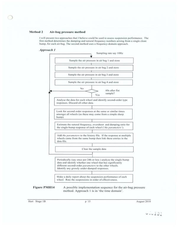
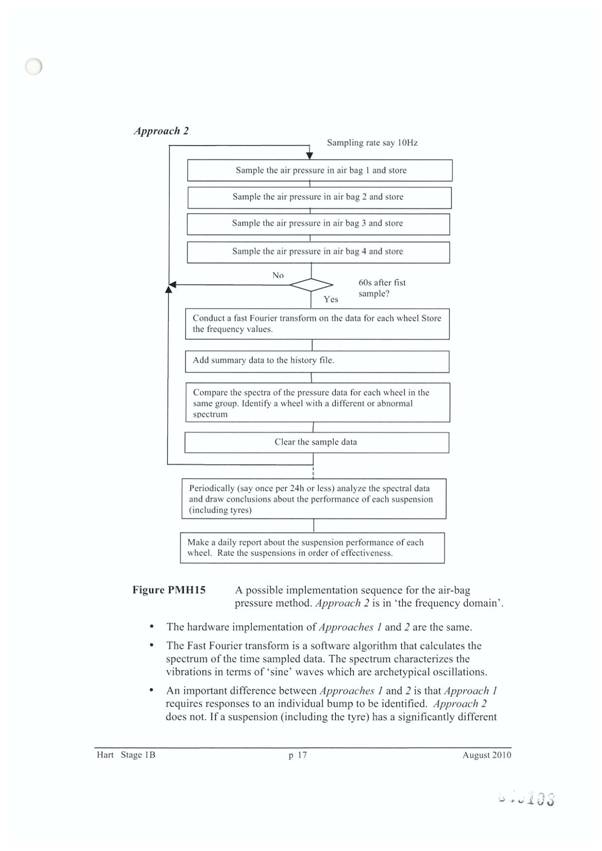
183 The first paragraph on p 16 is misplaced. It relates to one of Dr Hart’s other proposed solutions. The first paragraph should read:
The air bag pressure sensor is an (analog) electronic device that produces an instantaneous value for the air pressure in the air bag referenced to atmospheric pressure.
184 Dr Hart was also asked to identify the equipment required for each of his proposed methods. He responded at pp 8 and 9 of the Stage 1C Report as follows:
Method 2 Air-bag pressure method
There are four functional elements needed for this method:
Sensor: A pressure sensor (also called a transducer) is required for each of the air-bags in each suspension that is monitored. In the usual design, air pressure variations cause expansion or movement of a chamber that in turn causes an electrical resistance to change its resistance value. Thereby a voltage variation in an electric circuit occurs.
Pressure sensors that give an electrical output are commonly used on trucks to measure the air pressure in the brake system. In this application the sensor must be able to respond to the rapid pressure fluctuations that may occur in a suspension air-bag. That is, a sensor with an adequate frequency response is needed.
ECM: This is an electronic unit that runs a program. It electrically monitors inputs and thereby learns about the signal level from the sensors. The ECM would receive and analyse the signal(s) from the sensor(s).
For this method the signal is a continuously-varying voltage level. Analysis of the signal is needed to determine the overshoot, damping ratio and the natural frequency. That is, the ECM would probably determine the second-order mechanical system parameters of associated bumps for each monitored suspension.
Alternatively the ECM might determine the frequency spectrum of each suspension over a preset time period. If one spectrum is different to others, a faulty suspension might be indicated.
The ECM has outputs that cause processed information to be transferred to a display or to a computer for further analysis.
The ECM could be a custom-designed electronic circuit or a PLC electronic card. Further details are provided in the answer to Question 29.
If the suspension monitoring system is not permanently installed the ECM might be a lap top computer with an input card.
Operator Interface / Display: This allows the report from the ECM to be seen. Operator inputs such as a reset or request for the history of one of the suspensions might be entered via the display unit and transmitted to the ECM.
The Display might have a liquid crystal display unit or an LED display unit and some switches or lights. Such technology was readily available in August 2003.
Base computer: The data might be transferred from the ECM to an external computer via an output data port. Thereby records for the truck (and potentially for the fleet of trucks) might be stored and made available to the workshop and other interested people. Data transfer could occur via a serial computer port or via a CAN (controlled area network) connection.
185 All of the components were commercially available in 2003.
186 Dr Hart was cross-examined only briefly. At ts 1067 ll 30-45 he agreed that interesting information would be derived from the measurement of forces experienced between the axle and the chassis and recorded over time. He agreed that it might be a useful way of assessing suspension degradation. He agreed that in his report he had identified the need for a “clean bump” in order that his methods might work. He suggested that such a bump might be recognized from a response in the data which was typical of a “broad sharp bump”, such as hitting a speed hump. I understood Dr Hart to have meant that a clean bump would generate a response in the suspension which would be identifiable as coming from such a bump.
187 A substantial part of the cross-examination concerned the question of whether Dr Hart’s second solution included weighing. Commencing at ts 1072 l 43 the following passage occurs:
Mr Franklin: Now, there is no weighing in this flow chart method you - - -?---No, I haven’t shown it, but clearly the weight is - would need to be known.
The weight of a truck would need to be known?---Well, yes.
Yes. But actually when you are taking the pressure sensed in the airbags you don’t have to, for example, use the sort of air pressure transducer that one would find in an airway system to convert that into the weight for the purpose of the system. What you need is to sense the pressure and record – sample the air pressure and record those air pressure figures?---Air pressure is being measured and various other parameters are being inferred from the air pressure measurement.
Yes.
HIS HONOUR: What other parameters are being inferred?---Well, the weight, for example, your Honour, on the - that the airbag is carrying would be important.
MR FRANKLIN: Well - - -
HIS HONOUR: So you do infer the weight from the air pressure?---Yes, that’s true. Yes.
Mr Franklin: But the actual parameters that you are determining from your sampled air pressure in this flow chart method are defined. You estimate the natural frequency, the overshoot and the damping ratio. Now, for the purpose of doing that you don’t need to determine the weight associated with an air pressure signal, do you?---The weight is relevant because the natural frequency, for example, will change with weight. So you should know what the weight is so you can then judge whether the natural frequency is an acceptable number.
Right, yes. I understand that. You should know what the weight of the - carried by the suspension is before you start the test?---During the test, yes.
His Honour: Did you say “during the test”?---During the test.
Mr Franklin: And that - but that would - during the test you would want to know the weight carried by the suspension and that is a weight determined prior to commencing your test. So you know what the weight carried by the suspension is if it is “X” tonnes?---Well, you are assuming that it is the same as when you – before you started the test. It may not be. The truck might be leaning over, in which case the weight on a particular suspension might be different from that on the other side.
What I am suggesting to you, Dr Hart, that in the flow chart that you have set out here what you are doing is sampling air pressure in each of the four airbags, comparing that air pressure and, as we have discussed, looking for the odd man out. This system that you have described here would not, for example, I would suggest to you - could not, for example, be described as an electronic weighing system?---I have assumed that the weight was known.
Yes. And your system of sampling the air pressure in all the four airbags wouldn’t properly be described as an electronic weighing system, would it?---I would want to be sure that I knew the weight in each of these suspension airbags. So weird [sic] is an inherent measurement in this process.
Where in this flow chart do you refer to weight?---I don’t.
If weight was an important characteristic that you needed to determine for the purpose of this, shouldn’t you have mentioned it?---Yes, I should have. I should have said something about weight.
Now you don’t need the weight to determine the damping ratio, do you?---No. But you need the weight to interpret that number against any pass/fail criteria.
Well don’t you in your system - this system here - all you need is your second order type responses in respect of each airbag, and that will be an air pressure that has been sensed installed?---Yes.
And you look for second order type responses, discard all other data, and then what you do ultimately, having – sorry. Then you look for second order type responses that are consistent with a clean bum [sic], and that is the next block, a simple sharp bum [sic]. And then from those second order responses which are the stored air pressure second order responses, you estimate three things: natural frequency, overshoot and damping ratio?---Yes.
And then you add those parameters to the history file and then ultimately you analyse that and you look for the odd man out?---Yes, but the looking for the odd man out assumes that the weight is equal on each airbag. So it is relevant to know what the weight is. Trucks - trailers, if they lean over, your Honour, if the camber of the road causes them to tilt you tend to get more weight on one side than on the other. So you should take that into account.
You are not in that - you want to know as part of your - the background to estimate your natural frequency, overshoot and damping you will want to know that the weight is equal on all of the airbags. Now, assume that - - -
His Honour: Or that it is not equal, I suppose.
Mr Franklin: Or that it is not equal?---Yes, it is known.
But assume that it now tells you that the weight is equal on all airbags or satisfactorily close to mean that you could - - -? --- Yes.
- - - discard weight variations such as cornering from the consideration?---Yes.
You don’t need - you don’t then need any weight measurements to make the determinations, do you, to determine the parameters?
His Honour: Well you have got it, haven’t you? You have been told they are equal. You haven’t - you are just assuming that they are equal is what you are saying. Is that what you are saying?---Yes, your Honour.
Well, you do have the information, don’t you? You know they are equal. How can you find that out without weighing?
Mr Franklin: Well, it - - -
His Honour: I really don’t understand what you are trying to do here, but anyway, go on.
Mr Franklin: You use - on what you have just told his Honour, you would want to know the weight on the airbags - - - ?---Yes.
- - - before you make the determination?---Yes.
Now having established the weight on the airbags, you don’t actually use the kilogram figure, for example, to determine damping ratio, do you? It is not part of the determination of damping ratio?---That is true, however damping ratio changes as the weight changes. So the interpretation of the number you get should be made with respect to the weight that is carried.
188 There was a question concerning the term “overshoot”, and then Mr Franklin asked:
And you don’t use the weight information for the purpose of overshoot, do you?---Overshoot - pressure overshoot can be measured without weight. It is - I am not really understanding the question sorry.
Well, you say - I think you have answered the question?---Yes.
That you can ascertain the pressure overshoot without the weight.
HIS HONOUR: Well, what is overshoot? What do we mean by that?---It is the extreme - the peak value of the pressure with respect to the average value. So there is an oscillation in the pressure and the overshoot is the first peak value.
I see.
MR FRANKLIN: And you don’t use the weight information to determine the oscillation frequency, do you?---No.
189 As I understand Dr Hart’s evidence he would sense changes in pressure in the air bags in order to calculate, from such changes, the extent of overshoot, damping performance and natural frequency. Tramanco’s preferred embodiment involves measurement of changes in air pressure, followed by a conversion of the measurement into weight. At least in the preferred embodiment, fluctuation in weight is used to determine oscillation frequency, damping ratio and impact loading of the vehicle. The conversion of pressure changes to weight changes may, or may not make it easier to calculate oscillation frequency and damping effect. However such conversion would facilitate determination of impact loading. Dr Hart seems not to have identified any reason to calculate that figure as part of his task. However he considered that knowledge of the load on each vehicle wheel at the time of the pressure measurement was necessary. It is, I suppose, arguable that Dr Hart did not recognize the possibility of using the same information to calculate weight on the axle or on the road surface, assuming that such weight could be accurately measured whilst the vehicle was moving, a problem referred to in the evidence. The Patent seems to assume, rather than provide a solution to that problem.
Mr Sack’s evidence
190 Roger Philip Sack is the managing director of Tramanco. His evidence may go to both obviousness and infringement. It is convenient that I address all of his evidence at this stage. Tramanco has two divisions. One, “Para-transit”, supplies wheel chair loaders and associated accessories. The other is “Chek-Way”, an electronics division producing electronic weighing and data logging systems. It produces software-based systems. It sells its products in Australia and Papua New Guinea and has plans to expand into the United States of America, South-East Asia and New Zealand. Mr Sack initially studied civil engineering but transferred to mechanical engineering. For family reasons he did not complete his studies. He also undertook studies in economics. His experience is in the mechanical truck engineering industry, including employment at various truck engineering companies between 1965 and 1975. In 1975 he was employed by a company called Transequip, which company he acquired, changing its name to Tramanco. He has continued working in the mechanical truck engineering industry since then.
191 In about 1980 Tramanco became an Australian distributor for an American company, supplying on-board mass monitoring systems for heavy trucks and trailers. Mr Sack became aware of shortcomings in the American system and began developing a micro-processor-based system which he called Chek-Way Eliminator. He chose the name because he considered that he had eliminated known problems with onboard scales and introduced many innovative features. He continued to improve and develop the Chek-Way Eliminator, dealing with issues which he identified through regular use of the system. Eventually it evolved into its present form. In or about 1998 he first installed a data logging and reporting feature. The GPS units, which are now in common use, were not then readily available. Data recording and logging were performed by an onboard computer system and transferred via radio communication or portable electronic devices.
192 The system was further developed to include onboard electronic weighing, data-logging and reporting on road surface conditions and functionality (or road-friendliness) of air suspensions on vehicles. This was done by identifying spikes in air pressure in air springs and airbags. He subsequently included a GPS to pinpoint the location of road irregularities. He thought that this information would be of interest to road authorities for reasons of public safety. At some stage he realized that this technology had not yet been “commercialized” and could offer extensive benefits to the truck and trailer and road transport industries, and to road authorities. It could perform a major role in monitoring and protecting the infrastructure by monitoring road roughness and reporting on a real-time basis. He developed the system in conjunction with an employee of Tramanco, Mr Peter Doust. Although Mr Sack had designed the system, he did not have the relevant skills to write the necessary software. Mr Doust had those skills.
193 The system now includes standard hardware components which form part of the Chek-Way electronic weighing and data logging system. Each system has the same software built into it. There are additional software-based applications which may be activated, depending on each client’s individual requirements. Each client is able to select the software applications. Tramanco charges fees for such applications. They are capable of being updated on a regular basis, or changed, depending on a client’s requirements. Mr Sack said that Tramanco provides a “unique system for each client’s requirements. The systems are able to be adapted easily to suit changing circumstances”. INS-COM is one such software programme which can be activated if required by the client.
194 Under the National Intelligent Access Program (“IAP”) Stage 1 (which the NRTC was to implement on July 1 2009), vehicles with GPS tracking on board were to be permitted to carry increased payloads. Stage 2 of the IAP was called the “On Board Mass” (“OBM”). It would permit all vehicles equipped with on board mass-measuring equipment and a GPS to carry even greater loads. All of these benefits were conditional upon suspension functionality or road-friendliness which, as Mr Sacks said, “is critically dependent upon correct shock absorber function”. Mr Sack considered that his system would allow the transport industry to replace dampers before vehicle and payload damage occurred. At the same time shock absorbers which remained serviceable, notwithstanding the fact that they had high mileage, would not need to be replaced. Road authorities would benefit through reduced wear and tear from heavy vehicles.
195 Mr Sack consulted patent attorneys in 2003. The patent attorneys subsequently filed applications in Australia, the United Sates of America, New Zealand and South Africa. All applications were granted. Other applications are pending in European countries.
196 At paras 34 to 36 of his affidavit, Mr Sack describes the patented invention as follows:
34 The Patent in it’s [sic] simplest description covers two components of the Patented System, the first being the on board electronic weighing system to monitor the mass of the vehicle (including the ability to weigh both an unloaded vehicle and a vehicle with a load, or subsequent loads to determine each load weight and ensure that each vehicle is within its weight load limits for particular roads), and the second being the systems ability to perform the Road Roughness count and other conditions and report that information.
35 Electronic on board weighing systems are not novel or new within the truck and trailer industry and there are several companies in the market that have their own electronic on board weighing system.
36 However there were no other system on the market at the time of our patent application and continuing until now, that have the ability to monitor and log Road Roughness count and provide data linked to a GPS on the vehicle in that manner. That is specifically the intellectual property that I was seeking to protect when I instructed [the patent attorneys] to file the Patent applications.
197 Mr Sack said that in about 2003, the patented system became available for sale on the market and has been marketed, promoted and sold since that time. Tramanco has a network of dealers selling the patented system on its behalf. Tramanco charges a fee for installing and calibrating the system, and providing driver training. Tramanco has a service support agreement with each client pursuant to which it monitors the client’s vehicles for a fee. Mr Sack claims that Tramanco has a wide network of clients to whom it has sold the system, and whose operations it continues to support. Tramanco has also established associations with some government departments for involvement in research projects. There is such an involvement with the Queensland Transport and Main Roads’ Department for testing road-friendliness or suspension functionality of suspensions systems, and accuracy of on board mass systems. Transport Certification Australia uses the patented system to prove accuracy and robustness, together with damper efficiency. It is said that the system has been referred to as the “gold standard” for onboard mass systems.
198 Mr Sack first discovered BPW’s alleged infringement on or about 7 May 2009. He said at paras 49-50:
49 On or about 7 May 2009 I read a copy of the May/June Edition of Diesel Magazine in which I noticed that [BPW] had a feature article which mentioned their EBS system with a function for “road roughness count” and I was immediately concerned about their infringement of the Patent.
50 Prior to reading this article I was aware that [BWP] was selling an Electronic Braking System. I had not been aware that [BPW] also offered a system with the ability to offer load sensing and a road roughness count, which is clearly exactly part of what our Patented System provides.
199 He discovered another article in the April edition of Trailer Magazine. It referred to BPW’s product being shown at the upcoming Queensland Truck and Machinery Show in Brisbane, commencing on Thursday, 14 May 2009. The article referred to the product having features such as brake balance and road roughness monitoring, and the ability to store spare parts information electronically. He conducted an Internet search and discovered another article referring to BPW’s product.
200 The evidence indicates that in the years 2003-2004 to 2008-2009 Tramanco derived the following revenue from sales of its patented system.
2003-2004 $ 10,881.00
2004-2005 $ 45,673.00
2005-2006 $189,975.80
2006-2007 $396,478.18
2007-2008 $473,649.77
2008-2009 $474,168.10
2009-2010 $587,884.18
201 I am told that for the period 1 July 2010 to 31 December 2010 anticipated sales totalled $870,000. It is said that these figures justify an inference that the invention has been commercially successful.
202 In his affidavit evidence Mr Sack emphasizes his system’s ability to perform a road roughness count (“RRC”). Broadly speaking, the concept seems to involve the counting of the number of times the vehicle experiences roughness in the road surface. See paras 34 and 50 of his affidavit filed on 13 May 2009. The term “road roughness count” does not appear anywhere in the Patent. He said in his cross-examination that he had used that expression because it was used by BPW in connection with the BPW EBS. He agreed that he wished to create the impression that by performing that function, the BPW EBS infringed the Patent. I shall say a little more about RRCs when I discuss the evidence of Mr Ignatius.
203 Mr Sack agreed that at the priority date, onboard electronic weighing machines were not novel. He agreed that he had envisaged a system which identified the location of bumps and potholes by a combination of a GPS and an onboard weighing system. He also agreed that there was no suggestion in the BPW publicity that its electronic braking system could determine the road or roads on which there were bumps or potholes. He agreed that the BPW material suggested that its logging system would produce histograms showing RRCs per kilometre and categorizing them according to severity, recorded over the life of the vehicle. It was put to him that the histograms did not show RRCs on a per trip basis, but rather over the life of the vehicle. He disagreed.
204 He rejected the suggestion that the histogram information did not say anything about the locations at which RRCs were experienced. He said that such function could be performed by reference to the driver’s log book. He said that he had assumed that the system offered such functionality and still understood this to be the case. It was suggested to him that his allegation in para 36 of his affidavit, that his system had the ability to monitor and log RRCs, was misleading. He denied this. He agreed that he had not, prior to swearing his affidavit, suggested that his system provided the ability to perform an RRC. His attention was drawn to a paper which he gave in September-October 2004 in conjunction with Mr Lloyd Davis. In the introduction it was said that:
Trucks with road friendly suspensions – RFS – but with ineffective shock absorbers can damage the roads more than trucks with steel suspensions.
205 The paper also said:
This paper outlines the ground work for a low cost testing method for finding out the natural frequency and damping ratio of heavy vehicle suspension.
206 It was suggested to him that these comments suggested that his work in developing the patented system was directed to the question of road-friendly suspensions. He denied this, saying that the road-friendliness of a suspension would already have been proven and certified before the vehicle went into service, and that the Patent was not for a test for VSB-11 compliance. He said that he had predicted the introduction of in-service testing of the performance of suspension systems. He agreed that one aspect of the patented system was ascertaining whether or not a vehicle suspension system remained road-friendly during its life. He agreed that oscillation frequency and damping ratio gave an indication as to road-friendly characteristics. It was pointed out to him that he had also said in the paper:
Should such testing be formalised by combining vehicle telematics and remote monitoring technologies, the possibility exists for heavy vehicle operators to have healthier suspensions on their fleet without recourse to expensive testing facilities. The labour cost of replacing any healthy suspension parts deemed to be beyond their expiry date or the damage to roads from suspensions outside their correct specification could be reduced by employing such low cost testing. Road authorities would also have confidence in the road friendliness of any heavy vehicles thus analysed and reported with mutual benefits to all concerned.
207 He agreed that in determining the oscillation frequency and damping ratio he was ascertaining whether or not the suspension exhibited road-friendly characteristics, and that “healthy suspensions” were road-friendly suspensions. He said that prior to commencing proceedings he did not know whether the BPW EBS determined the oscillation frequency of a suspension system but had determined in his own mind that it did, based on what he had read. He considered that the BPW EBS also measured damping ratio.
208 Mr Sack pointed out that one of the articles said that the BPW system involved a valve which recorded pressure spikes in airbags and returned an RRC, and that operators had indicated that such information would be very useful. He considered that this description constituted use of the patented method in measurement of an impulsive load. A further statement in the material was that “(It) is also good to know just how much punishment a trailer is subjected to”. He denied that these statements were consistent with the BPW EBS simply indicating whether or not a trailer had been on rougher or smoother roads. He eventually agreed that at the time of swearing his affidavit he had seen no information which indicated that the BPW EBS calculated either oscillation frequency or damping ratio.
209 As to monitoring road conditions, counsel for BPW suggested that he had no knowledge of anything in the BPW EBS which had that function. He said that he had seen something which suggested that the operator would always know where the trailers were. He asserted that there was such a document on the BPW website. It was again put to him that he had no basis for asserting that oscillation frequency or damping ratio was determined by the BPW EBS. He said that as they were recording pressure spikes over time, “… you can actually monitor the frequency and the rate of decay and that signal will give you the damping ratio. So it’s quite clear they have the data.” It was put to him that he nonetheless had no basis for thinking that the BPW EBS was being used for that purpose and responded “No. Only on the basis of what they stated they record spikes in the pressure signals from the airbags.”
210 It seems that in order to facilitate replacement of parts, the BPW system stores component identity numbers. It is also possible to use an onboard computer to call for replacements parts, using the Internet. Mr Sack asserted that such capacity would enable the location of bumps and potholes in particular roads. He said:
Well, if you look at the peak load diagrams, it tells you the distance from a particular point. It tells you, then you download the information. If you are on the Internet, you can certainly pick up information from the valve. You can pick up the information in relation to where the vehicle was located.
211 He agreed that the relevant statement in the BPW promotional material concerned the ordering of replacement parts. His view seems to have been that as BPW used the Internet for data management and for ordering spare parts, he was “not sure exactly what are the functionalities in their software, to be honest”.
212 In support of his views concerning the capacity of the BPW EBS to give information as to location, and after an opportunity to examine material, he referred to a sentence in the BPW promotional material which, apparently addressing a vehicle operator or owner, stated: “No doubt you know where and when your trailer is being used”. He asserted that this implied the presence of some sort of GPS. Obviously enough, the statement might refer to the use of a GPS, but it is more likely that it merely reflects an assumption that at any particular time, an operator would know that a vehicle had been dispatched to travel from A to B.
213 Mr Sack may suspect that the BPW EBS and associated software have functions similar to those of the patented process, based upon statements by BPW in its promotional material. However his evidence added little to my understanding of his suspicion. He also said very little concerning the way in which he developed the patented process.
Was the Tramanco invention obvious?
214 BPW identifies the problem to which the Patent is addressed as being development of a method for logging the performance of a vehicle suspension system in order to assess the performance of that suspension, using a method that does not require removing the vehicle from service. Put another way it is said that the aim of the invention was to enable VSB-11 or like testing to be conducted using an on-board system that minimized disruption to fleet operators and allowed for regular checks of VSB-11 performance criteria. Tramanco submits that known systems at the priority date taught away from the invention which satisfied “a long-felt need”. It refers to the evidence of Dr Hart that:
I generally agree that it is desirable to have a reliable and objective test for suspension conditions that does not involve removal of components.
215 Tramanco submits that:
This of course is one of the objects of the invention.
216 Tramanco also refers to the following passage which appears at p 34 of Dr Hart’s Stage 1 Report:
I am unaware of any in-service testing of the performance of Road Friendly Suspensions in 19 August 2003 (but see the answer to the next Question). The issue of possible degradation of suspension performance with vehicle age was recognized. However, periodic suspension testing was not required. The test procedures that are used to conduct the type – approval tests were considered to be impractical for road-side in-service testing.
Road Agencies would have had an interest in ensuring that Road Friendly Suspensions continued to meet an adequate performance level. They probably assumed that the usual truck road worthiness tests would determine whether the suspension was in acceptable condition. Some State Road Agencies require heavy trucks to undergo annual inspections and some of these tests are done at government test stations. Suspension condition is checked.
217 In his answer to the next question Dr Hart raises the issue of how the term “in-service testing” should be defined. He suggests that a better definition of an in-service test might be a test in which no component or load of the truck need be removed before conducting the test. Thus he considers that testing at a weighbridge would be in-service testing. On the other hand, if components or load had to be removed such a test would require the vehicle’s removal from service. Dr Hart’s evidence does not really support Tramanco’s submission that there was a long-felt need for the benefits of the invention. In saying that, I do not necessarily mean to deny, out of hand, that the invention may be an improvement on methods previously available. Mr Di Cristoforo was not aware of any person who had considered using sensed changes in air pressure to determine the dynamic effect of an impulsive load on a suspension system. On the other hand Dr Sweatman seems to have considered that anybody would have been led to the test which was the simplest, cheapest and closest to the VSB-11 standard. Dr Sweatman considered that he had identified such a test.
218 Tramanco submits that there is a misunderstanding as to the nature of VSB-11 in that some of the witnesses seem to think that there is no requirement for ongoing in-service testing. He points out the VSB-11 anticipates ongoing checks by state and territory authorities as being at least a possibility, including checks as to ongoing road-friendliness and possible loss of permits to carry increased mass. Tramanco also submits that Dr Hart, to the extent that he solved the problem, brought to bear his knowledge in 2010. I do not accept this submission. It is quite clear that Dr Hart was given very specific instructions concerning the importance of the priority date. There is ample evidence in his report which demonstrates that he was alive to the relevant time consideration. I see no basis for Tramanco’s assertion.
219 As to Dr Hart’s second solution, Tramanco submits that it did not involve the use of an electronic weighing system to measure the dynamic effects of an impulsive load and then determine parameters, notwithstanding that Dr Hart said that weight measurement was necessary. It is true that Dr Hart considered that an electronic weighing system could not monitor suspension performance because it rejects, or cannot follow high frequency pressure variations arising from road bumps. Such equipment responds to quiescent pressure levels. If that is so, then Tramanco would have to deal with the problem in order that the method in the Patent be successfully performed. Tramanco also submits that I should infer that the invention has been commercially successful, suggesting a previously unsatisfied need.
220 According to Mr Sack the invention arose out of an inquiry from Queensland Transport as to whether he could assist in collecting data about suspension systems. The Chek-Way system was already on the market. It measured onboard weight by reference to air bag pressure. Queensland Transport wished to track vehicles with GPS in order to monitor load and position of the vehicle. At least one reason for the inquiry concerned the determination of road-friendly characteristics. Mr Sack agreed that it was a straight-forward step to use the pressure data for the purpose of calculating oscillation frequency and damping ratio. He said:
We understood that we could capture dynamic data, and then we were going to capture that data from a real vehicle and just see what we could determine. We expected, because of the way vehicles operate, that that could be the frequency, the damping ratio and the reaction to impulsive loads.
221 It was then put to him:
Yes, but you expected, prior to undertaking this test work, that you would be able to determine oscillation frequency and damping ratio? …
---by sourcing the data in the air bags?---That was our expectation. Yes.
222 As I understand this evidence, Mr Sack was saying that he was already using an onboard weighing machine to weigh loads and realized that he could use variations in load to calculate both oscillation frequency and damping ratio.
223 The question of inventiveness only arises where anticipation has been excluded. In the present case I have found anticipation, largely because the claims in the Patent are so widely drawn. Nonetheless, it is possible that had the claims been more narrowly drawn, they may have involved an inventive step. The evidence indicates that the Tramanco product has received a degree of favourable acceptance in the market. That is by no means conclusive on the question of inventiveness, but it is a relevant consideration.
224 The specification discloses the idea of using a commercially available, onboard weighing system and calculation of the identified parameters. No inventive step can lie in the choice of parameters. VSB-11 clearly prescribes oscillation frequency and damping ratio as elements relevant to road-friendliness. The requirement that static load share between axles be within 5% indicates that measurement of the weight carried by each axle and transferred to the road surface is also relevant. If there was an inventive step it must have lain in the idea of using a commercially available, onboard weighing system and logging the outcomes. Onboard weighing systems were available in Australia before the priority date but seem not to have been used for the purpose identified by Tramanco. The evidence suggests that they were unsuitable for use whilst the vehicle was moving. It is not clear to me whether, and if so how the Patent deals with that problem.
225 It is true that Dr Sweatman had developed a system for onboard weighing. However the evidence suggests that the equipment was expensive and not readily available. It certainly was not commercially available. Although Tal anticipated claim 1, it is not suggested that it was part of common general knowledge at the relevant time. Further, there is no evidence to suggest that a person skilled in the relevant art could, before the priority date, be reasonably expected to have ascertained its existence.
226 Tramanco’s invention offered the opportunity to measure both oscillation frequency and damping ratio from the measurement of weight, together with the weight on the suspension or, perhaps the weight on the suspension and the weight of the suspension, itself. Tal demonstrated a relatively easy way of calculating, from this weight, the weight on the road surface, but the Patent did not take this step.
227 I am not satisfied, on the balance of probabilities, that the idea of using a commercially available weighing system for the purposes identified in claim 1 lacked an inventive step. The weighing exercise involved measurement of changes in air pressure. That measurement was then to be used to calculate weight, as well as oscillation frequency and damping ratio. Calculation of all three parameters from the one measurement seems to me to have been inventive. However Tramanco’s claim is much more widely drawn.
SECTION 40
228 Section 40 of the Patents Act provides that:
(1) A provisional specification must describe the invention.
(2) A complete specification must:
(a) describe the invention fully, including the best method known to the applicant of performing the invention; and
(b) where it relates to an application for a standard patent – end with a claim or claims defining the invention; and
(c) where it relates to an application for an innovation patent – end with at least one and no more than 5 claims defining the invention.
(3) The claim or claims must be clear and succinct and fairly based on the matter described in the specification.
(4) The claim or claims must relate to one invention only.
229 In Kimberley-Clark at [25] the High Court said, concerning s 40(2):
The question is, will the disclosure enable the addressee of the specification to produce something within each claim without new inventions or additions or prolonged study of matters presenting initial difficulty?
230 BPW submits that claim 1 is invalid pursuant to s 40(2)(a) and s 40(3). It submits that the Patent discloses no method for determining the impact loading of the vehicle. BPW points out that whilst damping ratio and oscillation frequency are well known concepts in connection with a suspension, the notion of impact loading of a vehicle is not. At pp 15, 16 and 17, the specification discloses methods for calculating both the oscillation frequency and the damping ratio, but there is no information as to the method of calculating the impact loading of the vehicle. BPW submits that, in those circumstances, the invention has not been fully described, including the best method known to the applicant of performing the invention. It is also said that the claim is not fairly based on the specification. BPW submits that failure to describe the best method known to the applicant of performing the invention must be satisfied for each of the three parameters. Tramanco makes no specific submission in this regard. For reasons previously given, I accept BPW’s submission. The requirement for fair basing should be similarly treated. As I understand it, Tramanco accepts that upon my construction of the meaning of the expression “impact loading of the vehicle” there is no compliance with the requirements of s 40(2)(a) or 40(3). It follows that claim 1 is invalid pursuant to both provisions.
231 BPW also attacks claim 21 and its dependent claims 22 and 23, on the basis that there is no explanation as to the way in which the invention is to be performed. The method in claim 21 involves logging of the performance of a vehicle suspension system over a variable road section at different times, the position of the vehicle being identifiable at all times during the logging process, thus allowing data to be collected about the condition of the roads over which a test vehicle travels. BPW makes numerous practical criticisms, going to the likelihood or otherwise of such a system working. But lack of utility is not a basis for revocation. BPW also submits that the method does not address the difficulties in isolating variations in suspension pressure related to road conditions rather than other causes. Further, claim 21 does not identify the data to be collected and makes the rather dubious assumption that a vehicle travelling over the same route will generally traverse the same pothole in different trips. There is also the evidence concerning the difficulties in measuring air pressure accurately.
232 These criticisms seem to me to be valid, but they do not necessarily go to the questions of sufficiency and fair basing. As I read claim 21 the claimed invention is simply the use of the process identified in claim 1, as modified by claim 12, but on a “variable” road section at different times, and with a GPS or similar device. The data to be collected is the data that is collected pursuant to claims 1 and 12, a collection of weight data, based on pressure sensing.
233 Claim 21 seems to reflect the material in the specification at p 7 as follows:
According to a second particularly preferred embodiment of the invention, the performance of the vehicle suspension system is logged over a variable road section at different times, the position of the vehicle being identifiable at all times during the logging process.
This testing procedure may be termed a “trip test”. The trip test may preferably allow data to be collected about the condition of the roads which a test vehicle travels over whilst gathering data in the form of the axle test for analysis, at the same time. Each trip test may be expanded into a series of axle tests for such purposes. For example, an impulsive load may be imposed on the suspension if the test vehicle drives over a pothole in the road. If a test vehicle uses the same route, it would generally traverse the same pothole on different trips. By assessing the performance of the suspension in response to the impulsive load applied to the suspension on different trips, a user may determine whether the pothole is getting larger or deeper or whether it has been repaired or not.
The trip test may be triggered by the application of a particular preset magnitude impulsive load. The test may further require that the location of the vehicle be ascertainable with precision. This may be accomplished using locating means such as GPS devices linked to the system. Upon triggering the trip test, the system may begin to record the performance of the suspension and the position of the vehicle when the test was triggered.
234 Claim 21 appears to be designed to collect data about the road rather than data about the suspension, the performance of the suspension system being used to indicate road conditions.
235 To my mind the difficulty with claim 21 lies in its failure to explain the process in which data is to be used. It implies a comparison between data on one occasion and data on another, but does not expressly assert such a comparison. It assumes a sufficiently accurate GPS to enable a more or less precise traverse by the vehicle of the route previously followed. Assuming such a device to be available, it would be necessary to address the difficulty in isolating the signal attributable to road conditions. In my view Tramanco has not described the invention fully, including the best method known to it of performing the invention. Further claim 21 is not fairly based on the matter described in the specification.
INFRINGEMENT
236 In the May/June 2009 issue of the magazine “Diesel”, under the heading “The Tail End”, it was asserted that:
Trailer electronic braking systems (EBS) are becoming increasingly more accepted by truck operators as an effective means of improving heavy combination safety. Trailer EBS combines the potentially life-saving measures of anti-lock and load sensed braking with a roll stability program which uses strategic brake applications of individual wheels when the system senses that a roll over is imminent. Many operators now have these systems fitted to their trailers and are experiencing the benefits of this new technology.
237 Beneath that statement is an article entitled “BPW Launches New Trailer EBS”. It states that BPW is to launch its own EBS. It had previously marketed another brand. The passages which concerned Mr Sack were contained in a reported statement made on behalf of BPW as follows:
We wanted to offer operators extra benefits with EBS over and above the well known safety and economic advantages of the system. Firstly, as running gear suppliers we have many enquiries from the field for parts lists for equipment fitted to trailers. It is sometimes difficult to identify over the telephone what is fitted to the trailer. So, we have reserved some of the memory inside the computer at the heart of the EBS valve to allow the storage of the parts data on the valve. It is therefore a simple matter of plugging in a laptop to get to the parts information.
Secondly, the valve records pressure spikes in the airbags and returns a road roughness count, which operators have indicated will be very useful. It is also good to know just how much punishment a trailer is subjected to, to allow a more informed judgment on the choice of vehicle to do a particular job.
The third BPW feature is a brake performance monitor. BPW believes there is a need for an on-board indicator that can dynamically measure the braking effort applied by both the truck and the trailer. This is then presented graphically in a simple histogram. This tool is very effective in identifying problems such as overly aggressive truck or trailer brakes, or overuse of the trailer brake hand piece, before it causes costly premature brake wear.
The BPW EBS special features are included to give operators extra tools to manage their fleets and are included in the valve together with the standard EBS features such as ABS, load-sensing, trailer stability and various monitoring abilities, … .
238 The evidence suggests that the reference to air pressure spikes is over-simplified or wrong. In the Autumn edition of Trailer Magazine there was an advertisement for the BPW EBS, mentioning its road roughness monitoring function (the “RCM”) and indicating that the product would be on display at a forthcoming show.
239 At para 101 of its written outline Tramanco submits that BPW has admitted that:
(a) Since at least 2009, and without authorisation of [Tramanco], [BPW] has imported into Australia and sold the [BPW EBS];
(b) the [BPW EBS] includes a software program that utilizes information captured by an airbag pressure transducer connected to the airbags of the vehicle’s airbag suspension on which the BPW EBS is installed as to changes in air pressure to provide an indication of the overall condition or “roughness” of the road over which the vehicle to which BPW EBS has been fitted has travelled …;
(c) the BPW EBS is mounted on board the vehicle;
(d) the RCM feature processes variations in air pressure in the airbags of the air suspension of the vehicle on which the BPW EBS is installed.
240 Paragraph (b) may place a slight gloss upon BPW’s admissions. The assertion that BPW had admitted that the BPW EBS captured information concerning the “overall condition or roughness of the road over which the vehicle … has travelled” may suggest that BPW has admitted that the BWP EBS is capable of identifying the road upon which a particular “roughness” is experienced. That matter remains in dispute. BPW describes the RCM feature as providing a “road roughness count” (“RRC”). Broadly speaking it is the number of occasions on a particular trip on which the suspension of the vehicle encounters a force within a particular range, expressed as a number of such incidents per kilometre travelled.
241 Tramanco does not now press its claim that the BPW EBS determines oscillation frequency or damping ratio. However it submits that it determines impact loading of the vehicle as Tramanco defines that term. I have rejected that construction. At para 117 of its submissions Tramanco concedes that the BPW EBS does not measure the load between the tyres and the road. Thus it does not determine impact loading of the vehicle as I have defined it. Tramanco’s case on infringement must fail. Nonetheless I shall say something more about the infringement case, lest my construction should not find favour on appeal.
Electronic braking systems
242 Mr Di Cristoforo’s evidence is most helpful on this aspect. Trailer air brake systems are installed on heavy commercial trailer units for the purpose of applying wheel brakes in response to driver commands from the hauling unit, using compressed air as a medium for delivering braking power. A supply of compressed air is typically produced by means of an air compressor driven by the engine on the hauling unit. Some of the compressed air is stored in tanks or reservoirs on that unit for use in its own braking system and its air suspension system, if fitted. Compressed air is also piped to the trailer unit where it is stored in reservoirs. This compressed air is used primarily for the operation of the trailer brakes and, if fitted, its air suspension system. A trailer air braking system operates by supplying air to the internal chambers of a brake booster at each braked wheel. Its function is to force a push rod out or in, in order to apply or release the brakes. In the absence of compressed air, a trailer air braking system will default to the “brakes on” position by means of a mechanical spring. Trailer brakes are typically controlled from the driver’s cabin by use of the air supply button, the brake pedal or a hand piece. As I have said, there are also circumstances in which the trailer brakes will be applied automatically. A braking system may be controlled electronically.
The BPW EBS
243 The defining component of the BPW EBS is the trailer brake valve (the “valve”). This valve controls most of the functions of the BPW EBS by means of an electronic control unit, onboard memory and associated equipment. It provides electronic control of the braking system but has other functions. Its load sensing feature allows it autonomously to apply less braking force to the trailer’s wheels for a given driver demand pressure when the wheels are lightly laden. The effect is to reduce the risk of unintended wheel lock. The BPW EBS senses the load on the trailer axle group by means of an air line connected to one of the axle group suspension airbags. The pressure in a suspension bag is a good indicator of the load carried by the suspension when the vehicle is stationary, on a flat and level surface, with the brakes disengaged. Accuracy reduces when those conditions are not met. For the purposes of load sensor braking it is sufficient that there be a moving average of the axle load calculated from a varying mass signal or other similar approach. The valve is calibrated to convert the sensed airbag pressure into an axle group load. There are also anti-lock and roll stability functions, and the RCM feature.
The RCM feature
244 Inclusion of the RCM feature was motivated by the fact that BPW gives warranties in connection with its trailer suspensions. Validity of the warranty typically depends upon a number of operational factors, including the rated axle load, operation speeds, areas of operation and whether the vehicle is used off-road. The RCM provides an objective tool for determining the level of “punishment” which a trailer suspension has suffered during its life. This information may be useful to BPW when responding to warranty claims. BPW also promotes the feature as a means of providing fleet managers with useful information about the use of their trailers. The RCM feature is based on readings of the pressure in an air line connected to one of the trailer’s suspension airbags. It reports a measure that BPW calls “rough road count per kilometre” (the “RRC”), being the average number of rough road counts per kilometre travelled. In evidence the terms “rough road count” and “road roughness count” have been used interchangeably. Both terms are denoted by the abbreviation “RRC”.
245 Since the 1920s measurement of road roughness has been the subject of research all over the world. There are two independent methods, one “response-type” and the other “profile-based”. Response-type road roughness measurement is based on the dynamic response of a mechanical system with known properties. Typically, a response-type road roughness measurement system is an instrumented, wheeled vehicle that has its axle-to-chassis displacement measured in a cumulative manner, such that the summation of all vertical axle movements relative to the chassis can be expressed in meters per kilometre travelled. The profile-based method effectively involves a survey of the actual road surface, these days using laser equipment and mathematical analysis.
Mr Di Cristoforo
246 Mr Di Cristoforo holds the degree of Bachelor of Engineering in Aerospace Engineering and specializes in the safety and efficiency of heavy commercial vehicle operations in the areas of vehicle design, technology and regulation. His curriculum vitae demonstrates a wide range of experience in that area and the publication of numerous papers.
247 Mr Di Cristoforo considers that the BPW EBS will not yield an accurate weight reading in certain circumstances. The mechanics of the air line, the pressure of which is sensed at the valve, is likely to be lower than the pressure in the airbag when the airbag is being rapidly compressed, and higher than the pressure in the airbag when the airbag is being rapidly extended. Further, Mr Di Cristoforo considers that at the moment when a suspension is rapidly forced up towards the chassis by an impact from the road, the pressure in the airbag will rise rapidly. Due to the large volume of air trying to escape from the airbag through a small hole, there may be a considerable pressure drop across the hole. That is, the air, once it has passed through the hole, will exert less pressure because it will be in a larger space. Thus there is a filtering of the larger frequency pressure variations. Mr Di Cristoforo considers that such inaccuracy is unimportant for the purposes of load sensing but means that the system cannot accurately measure the larger variations which occur during on-road travel. Thus its pressure measurement may not accurately reflect suspension movement due to impulsive loads associated with irregular road surfaces.
248 Mr Di Cristoforo concedes that the BPW EBS includes a weight-sensing function but doubts whether it could be accurately described as an electronic weighing system. I infer that his view is that its limited accuracy indicates that its primary function is to contribute to operation of the braking system rather than to measure weight, and that it should be characterized accordingly. Further, the BPW EBS measures mass but not the mass of the vehicle, only part of it. The mass of the whole vehicle is responsible for the impact loading of the vehicle on the road. He also concludes that there is no mechanism for calculating the oscillation frequency. He does not recognize the term “dampening ratio” and seems not to be willing to assume that it means “damping ratio”. In any event, as I have observed, Tramanco’s final case depends upon the allegation that impact loading of the vehicle is measured. To the extent that the BPW EBS measures weight, it is of the load on the axles.
249 I should say that it has sometimes been unclear whether Tramanco’s case is that the impact loading is the weight on the suspension or the weight on the axles, including the weight of the suspension. The ambiguity arises from the fact that nothing is said in the Patent concerning the precise location at which weighing is to occur. At p 4 ll 19-21, the Patent refers to a load cell or pressure transducer “associated with” a suspension component. It contemplates there being more than one such load cell or pressure transducer associated with more than one suspension component. In its written submissions, Tramanco submitted that measurement is of the load on a pressure bag between the axle and the chassis. However, as I understand it, the suspension is between the axle and the chassis, so that the weighing is apparently to be at any suitable point in the suspension. The references to “axle tests” on p 6 et seq further confuse the matter. This difficulty accentuates the fact that nowhere in the Patent is the method for measuring impact loading really discussed, save that it is to be done using an electronic weighing system, perhaps using a load cell or pressure transducer associated with a suspension component.
250 Mr Di Cristoforo’s evidence did not go unchallenged. Indeed he was cross-examined at great length. However, as I have previously suggested, much of the cross-examination seems to be of little or no relevance given the form in which Tramanco’s case is now advanced. Mr Di Cristoforo suffered from the same disadvantage as did Tramanco and indeed, BPW, in that information concerning the valve technology is held by Haldex, a Swedish company which manufactures the valve for the parent company. Although Tramanco made efforts to obtain such information from BPW and the parent company, it did not seek to obtain it from Haldex. BPW submits that it ought to have done so, if it wanted access to that information, and should bear the consequences of not having done so. That proposition may be a little unrealistic in view of the likely difficulty in enforcing such an order against a company which has not been shown to be within the jurisdiction.
251 In the end, much of Mr Di Cristoforo’s evidence is largely uncontroversial, save for his concluding opinions. I consider him to have been a generally reliable witness, subject to the limitations imposed by lack of access to the valve technology. His evidence was supplemented by evidence from employees of BPW and the parent company. Much of their evidence is also now irrelevant to the questions which fall for determination.
Mr Ignatius
252 Mr Ignatius completed a university degree in mechanical engineering whilst completing an apprenticeship with the parent company. Since graduation he has worked with that company as a development engineer in the research and development department. In recent times his duties have included:
a detailed review of trailer EBS systems;
training on functionalities of such systems including brake, suspension and auxiliary functions;
preparation and review of BPW technical documentation, particularly concerning the BPW EBS;
review and functional testing of the BPW EBS Trailer Manager and Trainer Analyser software;
functional testing of the Trailer Monitor firmware;
designing brake layouts for BPW EBS kits; and
support and consulting services to BPW EBS customers.
253 Mr Ignatius certainly has a better knowledge of the BPW EBS than any other witness. There were some inconsistencies between his understanding of it and the views of some other BPW witnesses. It is possible that such differences arose out of local variations to the equipment or, perhaps, the development of different models. None of the inconsistencies was clearly demonstrated or of any real importance. I find that the most reliable evidence concerning the BPW EBS is that of Mr Ignatius, supplemented by the evidence concerning the actual screens displayed by the equipment as they appear in the evidence. Much of the following summary comes directly from Mr Ignatius’s affidavit evidence.
254 An electronic braking system uses an electronic load sensing device (“ELS”) automatically to adapt the braking force to the load of the vehicle. With an EBS all brake applications are electronically controlled. When the EBS receives a brake request it checks the load and freezes this value for the time of braking. It then applies the brakes with the pressure corresponding to the sensed load, using the ELS function. Whilst the brakes are applied the actual pressure in the brake chamber is checked and, if necessary, the pressure is adapted again so that it meets the pressure corresponding to the control line pressure derived from elsewhere in the system. In a vehicle with air suspension, the ELS senses EBS internal pressure regularly while the vehicle is travelling. The sensed pressure is continually changing in response to changes in the road, particularly gradient, camber and road surface, changes within the vehicle such as application of the brakes and the level of internal movement of the vehicle’s parts, including its suspension. The amount and distribution of the trailer’s load, and shifts in the forces that result from the carriage of the load, will affect the sensed pressure, as will the speed at which the vehicle is travelling, whether the trailer is cornering, or travelling straight ahead, and driver behaviour.
255 When the vehicle is stationary, on a flat surface there is a direct relationship between the sensed pressure and the vehicle load, depending on the type of suspension that is being used and its characteristics, assuming the brakes are off and the load is evenly distributed. This means that the EBS can be programmed to use that pressure as an indication of the load and to apply a level of braking that corresponds most suitably to that load. In all cases the load pressure so sensed has to be an overall figure, meaning that it has to ignore the changes in pressure which result from other causes. For the purposes of braking, it is not necessary or desirable that high rates of change in the signal be measured. The ELS has only to detect the average load of the vehicle which normally only changes when the vehicle is being loaded or unloaded while stationary, not while the vehicle is moving.
256 In a moving vehicle, components vibrate at a range of frequencies and as the result of multiple events. In sensing output data all EBS filter the signals which they capture from sensors such as those in the air bellows. Filtering is used in this way to remove unwanted variations or background “noise”. For example a 2 Hz low pass filter will filter out or remove signal variants with a frequency greater than 2 Hz. A 2 Hz high pass filer will retain all signals with a frequency of greater than 2 Hz and remove those less frequent than this. It is also possible to use a filter that only captures variations in signal that relate to particular frequency bands. The filtering function and the rate of data captured will vary, depending on the information required.
257 Anti-lock braking is another of the main features of an EBS. It is used to achieve maximum brake force without locking wheels. To detect whether a wheel is locked the EBS uses wheel speed sensors. Another important function of the trailer EBS is the stability function. This uses lateral acceleration sensors, in most cases integrated into the EBS. When cornering at a high speed the system detects whether the trailer is exceeding pre-defined thresholds in lateral acceleration. If these thresholds are exceeded, a test pressure not affecting the velocity of the vehicle is applied to the inside wheels in order to discover whether the wheel has lifted off the road. If so, the brake pressure is adjusted accordingly.
258 Various pressure parameters and axle loads for the unladen and fully laden vehicle are entered into the valve of the EBS when it is first installed. They are based on manufacturers’ information as to characteristics of the trailer and suspension. The weight carried by the trailer axles is called the axle load sum of the trailer. It is derived from a reading taken from the bellows pressure sensors in the valve, using the ELS bellow pressure parameters and the stored axle loads for the laden and unladen vehicle. Where a trailer is unladen, it is sometimes more difficult to handle as the suspension is designed to carry heavy loads. To overcome this problem, manufacturers have introduced a capacity to lift one or more axles off the ground when the trailer is unladen. Sensed air pressure below a certain value causes the axle to be lifted.
259 Mr Ignatius then discusses various other systems before turning to the BPW EBS. The BPW EBS is built by Haldex to specifications provided by BPW. It is, in principle, identical to the Haldex EB+ Gen 2 EBS, with some modifications. For manufacturers and installers of EBS it is important to be able to see what is happening in the valve. They do so by performing diagnostic tests. EBS valves are programmed to send out diagnostic trouble codes or error messages if internal checks fail. The information output from an EBS, used to ensure that the EBS is installed and operating correctly, also provides information about the trailer which can be useful to the operator. The Haldex Diag+ is the programming software for the Haldex EB+. It is used to programme the valve with data about the trailer’s configuration, laden and unladen weight and other matters. With the Haldex EB+ Gen 1, an external hardware device is also available called Info Centre. It attaches to the Haldex EB+ when it is on the trailer and can be used to read information stored in the valve.
260 In 2002 Haldex released analysing software called “Fleet Log Reader”. It offered customers the capacity to read out, and save on a computer, data logged by the EB+ from different pressure sensors and wheel speed sensors mounted in the EBS. Some readings were in the form of Histograms. The Fleet Log Reader is personal computer-based software with which the memory in the valve can be read out. A personal computer (“PC”) is connected to the valve using specialized hardware, normally when the vehicle is at rest. Mr Ignatius explains various aspects of data recording and displays. The Haldex Fleet+ is the updated analyzing software equivalent to Fleet Log Reader for the Haldex EB+ Gen 2.
261 The displays on the Fleet+ are mostly the same as those in the BPW EBS Trailer Analyzer software, save for certain differences relative to extra features of the BPW EBS subsequently discussed. One display is a “trip log” which displays data relating to the last 1,000 trips. When the number exceeds 1,000 earlier trip information is overwritten. Another screen displays the average and maximum axle loads for each trip. A snapshot facility records and displays data at a particular moment in time. The available snapshots concern diagnostic trouble code (fault) events, stability, speed, suspension, reservoir pressure and battery voltage. A maximum of either 20 or 32 snapshots can be stored, depending on the snap shot type. Older snapshots are overwritten once the maximum number is reached. When a snapshot is recorded the data captured includes vehicle speed, various pressures, the kilometre reading and the day and month.
262 A suspension snapshot is recorded if the load percentage exceeds a certain predefined setting. This suspension snapshot tells you only that the trailer has, at some stage in travel, exceeded by a certain percentage the fully laden weight. Several different events could cause this, for example it may indicate that “traction assist” was engaged. It does not mean that the vehicle has necessarily exceeded its allowed weight limit. It may, for example, occur if a trailer axle is lifted, in which case pressure at the axles which are in operation is increased and entered as corresponding to the laden weight when the vehicle is fully laden, even though the vehicle is not in fact fully laden. Only one suspension snapshot is recorded for each session during which the valve is operating. Thus, whether a trip is 10 kms long or 1,000 kms long, there is only one peak load reading and a maximum of one suspension snapshot. It will read zero if the threshold has not been exceeded.
263 Additional features of the BPW EBS are assembly data management (“ADM”), road condition monitoring (the “RCM feature”) and brake performance monitoring (“BPM”). These features do not result in any observable differences in the valve itself. However the BPW EBS valve carries additional programming relating to these features. Users view the RCM feature and BPM data using the Trailer Analyser software. The data for the RCM feature is displayed in the RCM histogram and the RRC per kilometre trip log. The histogram is an accumulating record of the number of RRCs per kilometre which a vehicle experiences over its lifetime. Each kilometre of travel is classified according to the number of rough road counts in that kilometre. Depending on that number, a unit is added to the relevant part of the histogram. One such classification is for RRCs between zero and four rough road events per kilometre. Thus if a kilometre of travel involves four rough road events, the histogram in the zero to four classification column will increase by one.
264 The RCM feature does not have the capacity to determine when or where, on a particular trip, an event which triggered an RRC occurred. Further, the triggering event may not be an instantaneous event. A series of events may, together, amount to an RRC. A kilometre of travel over a well maintained, gravel road might result in the same RRC as a kilometre of travel over a bitumen road which is in need of repair, generally smooth but with some very rough portions. The RCM feature is therefore an “overall per kilometre” indication of road roughness. It cannot be inferred that an RRC was caused by a bump. It is not possible to isolate the magnitude or location of a bump in the road from the RRC data.
265 The RCM feature records the outcome of a process in which pressure values are weighted to reflect their significance for RRC purposes, depending on the situation. In some situations it is known that a particular pressure reading, which might otherwise be significant for RRC purposes, is likely to occur as a result of things unconnected with the road surface. Such readings may reflect, for example, application of the brakes or loading of the trailer. Pressure readings likely to result from such circumstances are specifically excluded from the RRC. This is done by switching off RRC data collection when the trailer is stationary and also, during travel, whenever the brakes are applied. Thus, pressure changes which are most likely to be relevant to road condition are isolated and recorded as constituting an RRC.
266 The BPW EBS does not record the duration during which the sensed pressure is above a designated level. It also does not measure the extent of the excess over that level. In other words, no quantitative pressure reading is taken when an RRC count occurs. The RRC feature records only the number of RRCs experienced in a given kilometre of travel. It is not possible to tell whether a particular circumstance which results in an RRC has produced a pressure variation which is just above, or two or three times above the threshold pressure. The RCM feature does not log the occurrence, location or size of instantaneous spikes in air pressure. Rather it determines the number of RRCs for each kilometre of travel by counting how many times pre-programmed, sensed pressure levels are reached. It then expresses that number as an RRC figure and increases the relevant column in the RCM histogram accordingly.
267 The BPW EBS does not store data about individual RRC events. No snapshot is taken, nor is such information recorded in snapshots initiated by other events. The RCM histogram is a non-resettable set of data that accumulates over the life of the EBS. It demonstrates how much “punishment” the vehicle has seen over its lifetime. Where the vehicle has spent most of its time on smooth highways, the RCM histogram will have most RRC results at the lower end. Where the vehicle has travelled over rougher roads more often, the histogram will have more results at the upper end.
268 The trip log RRC screen displays RRC information in a different way. This screen displays the number of rough road counts per trip divided by the number of kilometres travelled. This “average” gives a general indication of whether a trip was, on average, over a rough or smooth road. A trip “starts with the ignition cycle” of the EBS and ends with a “power-down” of the system. However trips at speeds of less than ten kilometres per hour, and trips covering less than one kilometre are not recorded. There is no correlation between the RCM histogram and the trip log RRC screen. The histogram is added to, entry by entry, on a per kilometre basis. It is not possible to relate an entry to a particular trip. It is not possible to see an RCM histogram for one trip, unless there has been only one trip.
269 The BPW EBS does not calculate the oscillation frequency or damping ratio of the suspension of the vehicle to which it is attached. In Europe the majority of trailer suspensions are air suspensions. There is no requirement that such suspensions meet a particular standard in terms of oscillation frequency or damping ratio before they may be sold. There is also no requirement for in-service testing of suspension in terms of these characteristics. The BPW EBS does not record geographical data as to the location of the EBS or include any GPS function. There is no possibility of linking stored RCM information to a location which could be identified, using a GPS device.
270 Exhibit “WI-8” suggested operating and installation instructions for the BPW EBS. The document states that the Trailer Manager programme is a software programme for setting the parameters of the BPW EBS. It is used for factory configuration of available functions. The document also mentions the storage of component identification information. Concerning the RCM feature, it states:
A practical additional function in the Trailer Analyser has been specially developed by BPW for the [BPW EBS]: Road Condition Monitoring (RCM). This function makes it possible to record and evaluate precisely what are the profiles of the roads on which your trailers drive. This means you have a diagnostic tool at your disposal that gives you a precise insight into vehicle usage. As a result, Road Condition Monitoring also offers you the opportunity to increase the resale value of your vehicles.
271 Mr Ignatius said that the RCM feature does not simply monitor pressure spikes. It measures the difference between the highly filtered and lightly filtered air pressure over a particular time period, the length of which is commercially sensitive. The time period is greater than one second. The RCM feature measures the number of RRC events over that period of time. As the vehicle speed varies, the road distance covered in that period of time will also vary. The calculation of the RRC per kilometre depends upon data which classifies road roughness events according to whether they exceed one or more of three threshold events during the specified time period. If there is one road roughness event during the specified period, the count will be one. If there are two, it will be two. If there are three or more, it will be five. Although the evidence is not entirely clear, my understanding is that the RRC per kilometre will reflect this weighting.
272 The RCM feature senses pressure at the rate of 100 times per second. The pressure readings are filtered, both lightly and heavily. The lightly filtered pressure is close to the actual pressure reading. The highly filtered reading will diverge further from the actual figure. The RRC is calculated by reference to the difference between those figures. The filtering process seeks to isolate the actual pressure change caused by the road surface from changes resulting from other causes. A very high pressure signal (over eight bars) is recorded as eight bars as that is the upper limit of the equipment. High frequency signals unlikely to reflect actual conditions are excluded. Light filtering excludes fewer signals and so is closer to the actual signal.
273 Finally, Mr Ignatius said that an RRC could be recorded if a vehicle was going down hill or as a result of cornering, without regard to road surface. Speed can affect the RRC because of the shorter distance travelled in the specified time period and the reduced impact on the suspension at lower speeds.
274 I infer that the RRC describes the overall effect per kilometre experienced by the vehicle over a particular, unidentified time period. The length of road surface over which it travels during that period will vary, depending upon speed. It is a weighted measure of the number of occasions on which thresholds have been crossed in the relevant time frame.
275 Finally, Mr Ignatius said that axle load is sensed. Accumulated axle loads are averaged over every ten millisecond period. The highest ten millisecond average for the whole of the trip is recorded. Other readings are not recorded. In cross-examination Mr Ignatius agreed that the Trailer Analyser software allowed measurement of maximum axle loads experienced, measured through the suspension, and calculation of an average maximum. He agreed that calculations were used to convert the pressure sensing to a load figure at the axle.
Mr Thomson
276 Mr Ian Thomson is the engineering manager of BPW in Australia. He is an engineer by occupation. He prepared and submitted the technical documentation necessary to obtain Australian approval of the BPW EBS and was responsible for implementing the engineering required to change over from previous brands to the BPW EBS. He was also responsible for preparing, submitting and coordinating the required testing in order to obtain approval. The Trailer Manager software is not generally sold by BPW. Rather, it is used internally to prepare the programming information to be installed in each vehicle. BPW does not intend to release the Trailer Manager software generally in Australia. It prefers to keep control of the programming and to complete its own testing on behalf of customers.
277 The BPW EBS valve is built by Haldex. It is a modified version of a valve marketed by that firm. It was modified to meet the particular needs of the parent company. The valve includes three BPW-specific features, namely:
road condition monitoring;
brake performance monitoring; and
assembly data management.
278 The software for each of these functions is installed on the internal processor or computer housed within the valve. Presently, BPW is selling valves from which the RCM function has been removed because of these proceedings.
279 I have previously referred to the Trailer Monitor Unit. It is a small “side of vehicle” electronic device, connected to the BPW EBS. It is mainly used to read fault diagnosis information. It is also possible to read the trailer’s vehicle identification number (“VIN”), some configuration information, brake pressure settings and some live air pressures. Information is shown as text. The device has only limited graphic capabilities. It uses a liquid crystal display to show the general schematic layout of the trailer but it is very basic. It is an optional device and is not sold with the BPW EBS unless a customer specifically requests it. There is a battery version and a non-battery version which is suitable if hazardous goods are being transported. Other EBS available on the market have similar displays.
280 The Trailer Analyser software is separate software which runs on a personal computer. A diagnostic adaptor called a “dongle”, is used to connect a PC to the valve when the trailer is stationary. The Trailer Analyser software is then used to download data from the valve. Five types of information screens are displayed by the Trailer Analyser software as follows:
(a) an overview screen which gives the general overall key data from the valve/trailer such as the number of trips, kilometres, fault counts and stability events;
(b) snapshots of “fault” events that are recorded in the valve’s data file. There are several different types of snapshot but only the most recent 20-32 of each type of event that the valve has experienced are displayed, as older ones are overwritten;
(c) histograms, which display in summary form data collected over the entire period of the valve’s operation. These histograms cannot be reset (except for the brake performance one) and thus represent a cumulative record of the valve’s operation;
(d) trip information which displays certain data relating to each trip that the valve is used for (except that it is not activated for trips at speeds of less than 10 km an hour or which cover less than one kilometre). Further trip information is overwritten so that only data for the most recent 1,000 trips are scored; and
(e) a user information section where notes and comments can be added to a trailer analyzer file.
281 Road Condition Monitoring information is displayed using the Trailer Analyser software as rough road count (RRC) per kilometre in the histogram section and on a “per trip” basis for the most recent trips in the “trip logs”. The RRC number in the trip log is an average derived by taking the total number of RRC events recorded for the trip and dividing it by the total kilometres travelled on that trip. The RCM histogram is not trip-based. It displays the number of rough road kilometres over which the valve has been driven. The number of RRC events for each kilometre travelled is recorded and included in the RCM histogram. Thus the histogram shows the number of kilometres a particular valve has travelled over roads that have zero to four RRCs per kilometre, five to nine RRCs per kilometre, and so on.
282 The RCM feature provides data as to frequency, not magnitude of load. In other words it records the number of events, not the size of those events. Further, the trip log RRC figure is an average for a trip. The RCM histogram screen continuously accumulates data on a “counts per kilometre” basis over the life of the valve. The analyzer has no capacity to determine when or where, during a trip, a certain rough road event occurs or which part of the trip was the roughest.
283 In the course of his cross-examination Mr Thomson agreed that the BPW EBS information produces weight information in kilograms, but subject to the qualification that it would not measure a “dynamic load”. This qualification presumably reflects other evidence which suggests that there is a filtering process which has the effect of excluding loads above and below certain specified levels and the potential for inaccuracy in the sensing of air pressure. The load in question is the load on the suspension.
Mr Colosimo
284 Mr Mario Colosimo is the product centre manager, Trailer Equipment Division, of BPW. He is an engineer by profession. At paras 27 and 28 of his affidavit he said:
27 Unless a commercial onboard weighing system is calibrated to some degree of accuracy, it will be ineffective in providing an estimation of the weight a trailer is carrying. A simple way of calibrating an onboard weighing system is for the driver to drive the trailer over a weigh bridge to obtain the weight of the vehicle, and enter the weight of the vehicle into the weighing system.
28 The BPW EBS gives an indication of onboard mass but it is not calibrated. In order to calibrate a BPW EBS a technician would need to plug a laptop into the valve while the trailer was over a weigh bridge, and then make changes to the valve’s settings using the Trailer Manager software. If the weight showing on the weigh bridge is not the same weight that is indicated by the valve, and the valve is calibrated to the weigh bridge, then the settings of the valve will be affected and the performance of the EBS itself will be affected, particularly the load sensing settings. This is acceptable if done correctly, but if done incorrectly, not only will the weight read-out be wrong (which is not a serious problem), but the brake settings will be affected due to the load sensing functionality of the valve, which may be a major safety issue. The process is therefore not one that could or should be carried out by a fleet operator or a driver, as it requires technical knowledge of the Trailer Manager software (which is not currently available commercially), and a high level of understanding as to how to program the valve. For this reason, in my opinion the BPW EBS as supplied by [BPW] in Australia (without Trailer Manager software) is not and cannot be marketed as a commercial onboard weighing system.
285 At para 31 he said:
I also note that variations in air bag pressure or axle loads can occur in numerous circumstances, such as a change in tyre pressure, driving up or down inclined roads (hills), or applying the brakes. When the brakes are applied, and when tyre rolling resistance is increased due to, for example, tyre pressure reduction, the force supported by the air bags increases (which increases the air bag pressure) in order to balance the moments applied to the axle/suspension, even though the load supported by the axle group has not changed. With severe brake applications, there may also be significant weight shift either from or onto an axle group, depending on the trailer geometry. Since the BPW EBS relies on air bag pressure measurements for determining axle load, and variations in air bag pressures can occur due to a number of external factors, air bag pressure, in my opinion, is not a reliable indicator of suspension performance. The readouts available in Trailer Analyser give the transport operator a good overview of the trailer’s operation, to help the operator manage his fleet, not to determine suspension performance.
The screens
286 The various screens in the Trailer Analayzer software offer an insight into the capacity of the BPW EBS and associated software. They are best described in the cross-examination of Mr Meyers. His evidence should be read in light of a document described as “Ecotronic EBS Trailer Analyser Operating Instructions”. It states that:
With the Trailer Analyser you can read analysis data stored in the ECO Tronic EBS ECU to a PC and evaluate this data.
287 It is also said that:
The vehicle data is stored in the ECO Tronic EBS ECU. It remains stored even when the power to the EBS system is switched off.
The ECU is the electronic control unit located in the valve.
288 The start screen for the programme identifies five tabs under which information may be located, namely “Overview”, “Snapshots”, “Histograms”, “Trip Log” and “User Info”. The first tab, “Overview”, is illustrated on p 8 of the document. The term “trip” is of some relevance in examining the various screens. It is defined as follows:
A trip describes the transports in which the vehicle reaches at least 10 km/h per hour and covers a distance of at least one km thus excluding travel over very short distances.
289 The second tab, “Snapshots”, is discussed at pp 9-10 of the document. The term “snapshot” is defined to mean:
The recording of data at a particular moment in time. The recording is triggered by threshold values previously set in the Trailer Analyzer or the occurring faults. The default values of these thresholds are described on the following page.
The snapshots only show the most current events.
290 One snapshot is of suspension pressure expressed in bars. A suspension snapshot is recorded when a “certain limit value” is exceeded. It is said to be “130%”. However the figure may be varied. Tramanco reads this reference to mean 130% of the fully loaded weight of the vehicle. However the pressure is measured in bars, not kilograms. Further, it is the bellows pressure in the air bags.
291 On p 11 of the document the histogram menu is discussed. Mr Meyers agrees that a histogram is a means of displaying the distribution of a collection of data according to particular parameters. The witness also agrees that in the case of Trailer Analyser the histograms display the allocation of data over the life of the vehicle. With one exception the data cannot be erased. The exception concerns brake performance.
292 At the top of p 12 are two examples of the RCM histogram. It is a bar graph showing, on the x axis, the number of RCCs per kilometre, apparently in increments of 5. The y axis shows total kilometres travelled over the life of the vehicle. Thus the first column shows the total kilometres travelled on roads having five or fewer RRCs, the second column, 6-10, and so on. These figures may be inconsistent with some of Mr Ignatius’s evidence but, as I have said, any inconsistency may be attributable to differences between devices marketed in Europe and those marketed in Australia. Alternatively, there may have been different versions of the system at different times. In the first histogram it appears that by far the greatest part of the vehicle’s history involved travel over roads showing zero to five rough road counts per kilometre. The second histogram shows a much wider variation in the road surfaces encountered.
293 On p 14 diagram 11 plots distance travelled and axle load, again over the life of the vehicle. After each kilometre travelled the bellows pressure is monitored, the axle load is calculated from the bellows pressure using parameters stored in the ECU by the Trailer Manager. The result is a “load profile” as displayed in the diagram. On the horizontal axis it plots axle load and, on the vertical axis, total distance travelled. In other words it shows the cumulative distance, over the life of the vehicle, during which it was loaded within various specified ranges.
294 On p 15 there are examples of “Trip Logs”. This facility stores information by trip for up to 1,000 trips. When data is recorded for more than 1,000 trips, older trips are overwritten. The trips are numbered. The numbering system continues even after 1,000 trips have been performed. Information available includes date, trip distance in kilometres, trip distance with axle lifted, brake demand average in bars, brake applications, brake applications 24 N (presumably 24 newtons), average speed, maximum speed, stability events, ABS events (the anti-locking mechanism), axle load average (in kilograms), axle load maximum (in kilograms), minimum reservoir pressure, maximum reservoir pressure, trip duration in minutes, lift axle (number of operations), steer axle (number of operations), warning lamp ignored in minutes, residual pressure time in minutes, rough road count per kilometre and event codes. On p 18, diagrams 12 and 13 display axle load averages per trip and maximum axle loads per trip.
295 Mr Meyers agrees that the average axle load and maximum axle load information are not snapshots. In other words, the information is not attributable to any particular point in time or, inferentially, any geographical location. They are, however, attributed to particular trips.
296 On p 20 diagram no 21 shows RRC per kilometre. It is said that:
This diagram displays the number of rough road counts per trip divided by the number of kilometres travelled per trip. This allows the direct comparison of the number of rough road counts/km for the different trips. For trip 10, for example, a mean value of 5.13 rough road counts/km was registered.
297 Mr Meyers suggested at para 8.5.4 of his report, (exhibit “DM-4” to his affidavit filed on 24 September 2010) that trip data could be compared in order to determine road conditions by having the same vehicle with the same driver on the same route with different vehicles with the same driver on the same route and the same vehicle with different drivers on the same route.
298 This focus on the RCM function appears to have been prompted, at least in so far as concerns Mr Meyers, by his perception that:
Of the inputs available to the [BPW EBS] the only one that could be used to deduce road conditions is the suspension pressure.
Does the BPW EBS infringe?
299 Tramanco submits that BPW has infringed its exclusive right to exploit the invention conferred by s 13 of the Patents Act. The term “exploit” is defined in relation to an invention as:
(a) where the invention is a product – make, hire, sell or otherwise dispose of the product, offer to make, sell, hire or otherwise dispose of it, use or import it, or keep it for the purpose of doing any of those things; or
(b) where the invention is a method or process – use the method or process or do any act mentioned in paragraph (a) in respect of a product resulting from such use.
300 This being a method claim, Tramanco depends upon para (b) of the definition. However BPW submits that it has not, in that sense, exploited the method. The submission seems to be that supplying a product manufactured by another may only be an exploitation in the extended sense contemplated by s 117 of the Patents Act. Section 117 provides:
Infringement by supply of products
(1) If the use of a product by a person would infringe a patent, the supply of that product by one person to another is an infringement of the patent by the supplier unless the supplier is the patentee or licensee of the patent.
(2) A reference in subsection (1) to the use of a product by a person is a reference to:
(a) if the product is capable of only one reasonable use, having regard to its nature or design–that use; or
(b) if the product is not a staple commercial product–any use of the product, if the supplier had reason to believe that the person would put it to that use; or
(c) in any case–the use of the product in accordance with any instructions for the use of the product, or any inducement to use the product, given to the person by the supplier or contained in an advertisement published by or with the authority of the supplier.
301 At a very late stage Tramanco sought. and was granted leave to amend by adding an alternative claim based upon s 117.
302 The fundamental question on infringement is whether or not the BPW EBS demonstrates exploitation of the patented method by either the parent company or BPW. The primary question is whether the BPW EBS contains the combination of integers claimed in claim 1. Tramanco seems to rely upon the feature of the BPW EBS which I have identified above as evidence of infringement. Those features are:
the suspension pressure snapshot;
the RCM feature histogram;
the distance vs axle load histogram; and
the trip log, particularly the RRC per kilometre, and the axle load average and axle load maximum.
303 Having regard to my construction of claim 1, the first question must be whether the BPW EBS logs the performance of a vehicle suspension system. In other words, does it record, in a systematic way, the quality of a suspension system’s performance of its intended function? In its written submissions Tramanco seems to submit that sensing air pressure changes in an air bag and inferring actual loads is logging the performance of a vehicle suspension system. Such an approach overlooks the meaning of the word “performance” which involves the quality of such a system’s performance of its intended functions. Logging fluctuations in air bag pressure may provide information from which suspension performance can be assessed. However, by itself, it does not necessarily constitute logging of such performance. Thus calculation of one or more of the three integers is an essential element of logging the performance of a suspension system as described in claim 1. The “weight” measured in the suspension may be the result of an impulsive load or of the way in which the suspension has dealt with such a load. Ascertainment of weight at any particular point in the vehicle, or at any particular moment in time, is not necessarily a logging of the performance of the suspension system. The BPW EBS measures pressure in the air bags and/or weight on the axle to adjust the braking system. In so doing it accepts and uses the outcome of the performance by the suspension system of its function, but does not log performance of that function.
304 Similarly, the RCM feature is not designed to log, nor to be used for the purpose of logging suspension performance. It is designed and used for the purpose of identifying and logging the number of rough road counts which occur per kilometre of travel over the life of the vehicle or per trip. The RCM feature may use as raw data the outcome of the performance of the suspension system of its function, but it does not log such performance. Further, the filtering process disclosed by Mr Ignatius suggests a much more complex exercise than that involved in measuring and recording weight. It actually excludes some fluctuations in the weight as being attributable to factors other than road roughness. This is because the focus is on road roughness and not on the performance of the suspension system.
305 Nothing in the screen data suggests the purpose of logging performance of the suspension system.
306 The next question is whether the system uses an electronic weighing system mounted on board the vehicle. In my view, an electronic system, used to sense air pressure and convert it into a mass or weight figure, is an electronic weighing system. There clearly is such a system in the BPW EBS. It is mounted on board the vehicle.
307 I turn to the question of whether the electronic weighing system is used to measure the dynamic effect of an impulsive load. The RCM feature sorts such effects into three classes, according to the evidence of Mr Ignatius. The events over each time period are weighted accordingly, and the weighted outcome used in calculating the RRC per kilometre. Such a process may involve measuring the dynamic effect of an impulsive load. However it is a filtered process which is designed, as far as possible, to exclude effects attributable to loads created by causes other than the road surface. Claim 1 does not require that the method measure the dynamic effects of all impulsive loads. However I doubt whether a system which seeks to measure only the dynamic impact of impulsive loads attributable to the road surface would be sufficient to constitute logging of the performance of the vehicle’s suspension system, given that such performance will include accommodation of loads which the BPW EBS seeks to exclude. I need not take that matter any further. I accept that the BPW EBS measures the dynamic impacts of some impulsive loads.
308 As to the three parameters, Tramanco now asserts only that the BPW EBS determines the impact loading of the vehicle. In its final written submissions it addresses only that issue. I have defined the impact loading as being the force acting between the tyre and the road. Clearly, the BPW EBS does not determine that force. It may measure the force at the axle or on the suspension. However, in neither case is that force the impact loading of the vehicle.
309 In those circumstances the BPW EBS, with or without the associated software, does not infringe. It is not necessary to consider whether exploitation must be determined by reference to s 117 of the Patents Act. It is also not necessary that I consider an argument based on s 121A of the Patents Act. BPW has abandoned reliance on s 119 of the Patents Act.
DEPENDENT CLAIMS
310 My finding that claim 1 is not infringed disposes of Tramanco’s submissions that some of the dependent claims are also infringed. However I should say a little about those claims. Claim 12 claims logging of the performance of a vehicle suspension system over a standard road section at different times “to test the performance of an individual axle or group of axles to an impulsive load”. As far as I can see nothing in the BPW EBS suggests that it can or may be used in that way. There is no sensible way of locating the road sections which have produced RRCs. Tramanco’s submission is based upon possible use of the features of the BPW EBS for purposes for which they were not designed. Claim 13 claims a method according to claim 12 which includes the step of comparing the performance of the vehicle suspension to pre-determined standards. Again nothing in the BPW EBS suggests such a function. Tramanco suggests that the 130% threshold which triggers a snapshot of the suspension pressure in the air bags is “a pre-determined standard against which the impact loads experienced in the suspension air bags are tested”. I do not accept this submission. The measurement of air pressure (in bars) occurs because a threshold is exceeded, but the occurrence of that event says nothing about the performance of the suspension system, particularly as none of the three parameters is to be calculated. The threshold of 130% is not said to be a “standard”. It is rather a limit.
311 Claim 14 depends upon claims 1 and 12. It claims a system in which performance of the suspension system at various periods throughout its life is compared with its performance when new, in order to ensure that the performance of the suspension remains within “pre-determined standards”. Tramanco submits that the first trip log will contain information relating to the suspension system when new, which information can be compared with subsequent trips. Even if this be so, in the absence of any determination of the parameters, there is no relevant basis for assessing performance of the suspension system. Further, the BPW EBS contains no predetermined standard.
312 Tramanco also asserts infringement of claims 19, 20, 21, 22 and 23. Claim 19 claims a method according to claim 12 which includes a test in which the variation in a mass signal is recorded as the vehicle travels along a normal, uneven road at speed. This claim has the complication of requiring that a road surface be both a standard road, as stipulated in claim 12, and a normal uneven road, as stipulated in claim 19. Claim 12 necessarily involves the comparison of performance over the same road section at different times. The BPW EBS does not perform this function; nor does BPW suggest that it may be performed. For the same reason, there is no infringement of claim 19 or claim 20.
313 Claims 20, 21, 22 and 23 all involve a location device capable of “precisely” locating the portion of a road upon which the test was conducted for future comparison. The BPW EBS is clearly not designed to perform such a function. Nor does BPW suggest that it be used in this way. It has no GPS. It has a trip meter. Whilst I have accepted that a trip meter may be a locating device, there must be limits upon its capacity to provide precise locations. Pursuant to claims 20 and 21, it will be necessary only that it be able to locate a particular section of road. It may be adequate for that purpose. However, for the purposes of claims 22 and 23, the location device is to be used to locate actual bumps or potholes. One must wonder about a trip meter’s capacity so to do.
314 Claim 22 claims a method according to claim 21 wherein the logging is triggered by the application of a particular pre-set magnitude impulsive load. Tramanco submits that this claim is infringed by virtue of the snapshot of the suspension pressure being triggered by its exceeding 130% of the static laden weight of the vehicle. I again point out that the pressure is measured in bars, not kilograms. Suspension pressure snapshots are recorded when a programmed threshold is exceeded. Recording of the pressure in such limited circumstances can hardly be described as logging the performance of a suspension system.
ORDERS
315 It follows that the Patent should be revoked and any interlocutory relief or other arrangements discharged. However I shall allow the parties an opportunity to agree on appropriate orders, including orders as to costs. If consent orders are not filed within 14 days of the publication of these reasons, the parties are, within a further seven days, to file written submissions as to appropriate orders. Should any party require further findings of fact, it should apply within 14 days.
I certify that the preceding three hundred and fifteen (315) numbered paragraphs are a true copy of the Reasons for Judgment herein of the Honourable Justice Dowsett. |
Associate:

