FEDERAL COURT OF AUSTRALIA
Britax Childcare Pty Ltd v Infa-Secure Pty Ltd [2012] FCA 467
IN THE FEDERAL COURT OF AUSTRALIA | |
| Applicant | |
AND: | Respondent/Cross-Claimant |
DATE OF ORDER: | |
WHERE MADE: | SYDNEY (HEARD IN MELBOURNE) |
THE COURT ORDERS THAT:
1. The proceeding be adjourned for directions on 12 June 2012 at 9.30am.
Note: Entry of orders is dealt with in Rule 39.32 of the Federal Court Rules 2011
VICTORIA DISTRICT REGISTRY | |
GENERAL DIVISION | VID 109 of 2009 |
BETWEEN: | BRITAX CHILDCARE PTY LTD Applicant
|
AND: | INFA-SECURE PTY LTD Respondent/Cross-claimant
|
JUDGE: | MIDDLETON J |
DATE: | 9 MAY 2012 |
PLACE: | SYDNEY (HEARD IN MELBOURNE) |
REASONS FOR JUDGMENT
(CONSTRUCTION)
INTRODUCTION
1 In this proceeding the applicant, Britax Childcare Pty Ltd (‘Britax’) seeks relief from the respondent and cross-claimant, Infa-Secure Pty Ltd (‘Infa’), for infringement of nine innovation patents and one Australian standard patent owned by Britax concerning child safety seats, including the tethering and connection means for such seats.
2 The subject matter of the proceeding entails the following 10 patents owned by Britax and the following claims alleged to be infringed:
Patent | Claims alleged to be infringed |
Innovation Patent No. 2007100856 (‘First Patent’) | 1, 2 and 5 |
Innovation Patent No. 2007100854 (‘Second Patent’) | 1, 2, 3 and 4 |
Innovation Patent No. 2008100763 (‘Third Patent’) | 1, 2, 3, 4 and 5 |
Innovation Patent No. 2008100764 (‘Fourth Patent’) | 1, 2, 3 and 4 |
Innovation Patent No. 2008100765 (‘Fifth Patent’) | 1, 2 and 3 |
Innovation Patent No. 2009100835 (‘Sixth Patent’) | 1, 2, 3, 4 and 5 |
Innovation Patent No. 2009100836 (‘Seventh Patent’) | 1, 2, 3, 4 and 5 |
Innovation Patent No. 2009100837 (‘Eighth Patent’) | 1, 2, 3, 4 and 5 |
Innovation Patent No. 2009100445 (‘Ninth Patent’) | 1, 2 and 5 |
Standard Patent No. 680150 (‘Tenth Patent’) | 1, 19 and 20 |
3 The particular wording of the claims, and the integers which inform them, are set out further below in these reasons. These reasons only deal with issues of the construction of these claims.
4 The products which Britax allege infringe the patents in suit include a range of child safety seats manufactured and previously sold by Infa at various times since at least September 2006 and are designated by model numbers CS53, CS54, CS55, CS56 and CS57. Due to the various versions of these products there are 16 different products in issue in this proceeding.
5 Infa denies infringement of the patents based on its contentions as to the construction of the claims in each of the patents in suit. Infa’s particular construction of the claims is pressed via the opinion of its expert witness, Mr Newman, who provided affidavit and oral evidence, including a joint expert report written in conjunction with Britax’s expert, Mr Hunter, as to the proper way of construing the claims in suit, among other things. The evidence of Mr Newman and Mr Hunter as to the proper construction of the relevant claims is dealt with later in these reasons. I should say at the outset, however, that whilst expert evidence can aid the construction of claims, and the integers which form each claim, claim construction is, in the end, a matter for the Court.
6 Further to denying Britax’s case on infringement, Infa filed a cross-claim alleging invalidity of the patents in suit and sought revocation of the claims in suit within them.
7 At the commencement of the trial, Infa’s claims of invalidity were based, generally, on the following grounds:
the claims of the First to Eighth Patents and Tenth Patent were not fairly based and did not, therefore, comply with s 40(3) of the Patents Act 1990 (Cth) (‘the Act’) and could be revoked pursuant to s 138(3)(f) of the Act;
the inventions so “claimed” in the First to Ninth Patents lacked novelty under s 18(1A)(b)(i) of the Act and could be revoked pursuant to s 138(3)(b) of the Act;
the invention so “claimed” in the Tenth Patent lacked novelty and was therefore not patentable under s 18(1)(b)(i) of the Act and could be revoked pursuant to s 138(3)(b) of the Act;
the alleged inventions in the First to Ninth Patents did not involve an innovative step as required under s 18(1A)(b)(ii) of the Act and could be revoked pursuant to s 138(3)(b) of the Act;
the alleged invention claimed in the Tenth Patent did not involve an inventive step and therefore did not comply with s 18(1)(b)(ii) of the Act and could be revoked pursuant to s 138(3)(b) of the Act;
none of the claims in suit in the First to Ninth Patents and claim 19 of the Tenth Patent were clear and succinct and therefore they did not comply with s 40(3) of the Act and could be revoked pursuant to s 138(3)(f) of the Act;
Britax was not entitled to the patents pursuant to ss 15 and 138(3)(a) of the Act. This was raised against each of the First to Ninth Patents; and
the First Patent (claims 1 and 2), the Third Patent, and the Fifth Patent were not patentable inventions because they were not useful and therefore lacked the required utility to comply with s 18(1A)(c) of the Act. As a result they could be revoked pursuant to s 138(3)(b) of the Act.
8 During the course of the trial, amendment to the pleadings by Infa was sought.
9 Infa sought to raise a new ground of invalidity in relation to the Tenth Patent, namely that the invention was not useful and therefore lacked the required utility. This application for leave to amend arose after evidence was given by certain witnesses relevant to this issue, Mr Bowtell and Mr Hunter. As it eventuated, neither party wanted to lead any further evidence if the amendment were to be allowed, and the issue became one of whether, on the basis of the evidence already led, the ground of invalidity had been made out by Infa. The application to amend was able to be left (as it was) to the giving of reasons as to revocation.
10 Infa also sought to expand its allegations of external fair basis, because of the evidence of Mr Hunter. Again, this was ultimately to be a matter of legal argument, based upon the evidence of Mr Hunter (which evidence was accepted by Britax). There has been an exchange of written submissions between the parties that has enabled the parties ample opportunity to deal with these matters. I will address this matter in later reasons dealing with revocation.
11 Infa also contended that in the course of, and prior to, this proceeding, Britax made unjustified threats of patent infringement proceedings. To the extent that this Court finds that the Infa products do not infringe any of the Britax patents, or that any of the claims of those patents are invalid, Infa contended that such threats of infringement made by Britax were unjustifiable. Whether there have been unjustified threats will follow from the findings made in relation to the other allegations made in this proceeding. I observe that the unjustified threats do not relate to all the patents, and much will depend on whether there has been infringement, and the extent of any infringement.
12 The Court originally ordered that only the question of liability be determined as this stage, although it became apparent during the course of the trial, and has become apparent in the course of preparing these reasons, that the complete disposal of these proceedings will involve a number of staged enquiries and determinations even as to liability.
13 For instance, one issue that the parties agreed should remain for later determination (if necessary) was when various sales of infringing products occurred, and the relevant date from which infringement could occur.
14 Further, the parties had approached infringement and revocation on the basis that one or other of the expert witnesses as to construction would be accepted by the Court. From that approach, certain consequences as to infringement and revocation followed. However, as I have not accepted completely either expert witness on construction, the approach adopted by the parties causes it own difficulties in the circumstances of this proceeding, having regard to the different combinations and permutations that may result from findings on construction.
15 As the High Court of Australia said in Kimberly-Clark Australia Pty Ltd v Arico Trading International Pty Ltd (2001) 207 CLR 1 at [34]:
… [t]he issues in revocation actions, particularly those which turn upon construction, notoriously intersect and overlap.
16 In the circumstances of this proceeding, with the number of patents and issues in dispute as to construction alone, the intersection and overlap is extensive.
17 Claim construction is central to this proceeding. The following was observed in the text Patent Law in Australia by Bodkin C, (Thomson Lawbook Co, 2008) at p 220:
…the novelty and inventiveness of a claim cannot be assessed until its precise scope has been determined; neither can it be decided whether a claim has utility or is fairly based on the disclosure of the specification without a determination of its meaning and scope; and the infringement or otherwise of a claim may depend on a careful analysis of what it encompasses.
18 As I have already noted, Messrs Hunter and Newman prepared and provided to the Court a joint expert report in which they identified points of agreement and difference as to the meaning and interpretation of terms within the patents in suit. The joint expert report also identified points of agreement and difference between the experts as to the presence of integers within the claims in suit in various models and versions of the Infa products. The experts agreed that a large proportion of the points of difference of opinion between them as to the presence of integers in Infa products were directly or indirectly a consequence of differences of opinion between them as to the meaning of terms within and the interpretation and understanding of the patents in suit.
19 The parties themselves have already reached some consensus on infringement on the basis of a particular construction of the patent. However, as noted, this was on the premise that I adopt the views of one or other of the expert witnesses. I have good reason to believe that once the construction issues are decided, similar consensus could be reached on the basis of the findings of the Court. In addition, the issues concerning revocation will become crystallised once the proper construction of each patent is finalised, and the task of determining Infa’s cross-claim can then proceed on the basis of the correct construction of each patent.
20 Therefore, in accordance with the approach dictated by s 37M of the Federal Court of Australia Act 1976 (Cth), the Court will first deal with the construction issues as presented by the parties.
INNOVATION PATENTS
21 Before turning to construction, it is useful to make some brief observations on innovation patents.
22 Each of the nine innovation patents in suit claims a priority date of 9 June 2004 through PCT application PCT/AU 2005/000820 (Australian No. 2005251826) (the ‘Parent Application’) from Australian provisional patent application 2004903092, filed 9 June 2004. The Parent Application being for a standard patent, is entitled “Child Safety Seat, Shell and Harness”, was filed on 9 June 2005 and published by the World Intellectual Property Organisation on 22 December 2005 under international publication number WO 2005/120910.
23 Pursuant to regs 3.12(1)(b) and 3.12(2) of the Patents Regulations 1991 (Cth) (‘the Regulations’), in order to maintain the priority date of 9 June 2004, the claims of the Parent Application must be fairly based on provisional patent application 2004903092. Infa challenged the entitlement of each innovation patent to claim priority from the Parent Application and, therefore, the right to claim the priority date of 9 June 2004. Infa contended that the alleged invention claimed by each of the innovation patents is not fairly based on the matter disclosed in the specification filed in respect of the Parent Application and, therefore, the earliest priority date to which the claims of each innovation patent may be entitled is the date of its own filing.
24 Infa has not challenged the Parent Application’s entitlement to claim priority from provisional patent application 2004903092. Infa does not challenge the Tenth Patent’s claim to a priority date of 1 August 1994, based on an Australian provisional application No. PM7154.
25 The innovation patent system is intended to fill the “gap” that existed with regard to minor and incremental innovations. It offers a quick, less expensive and simple form of protection.
26 The innovation patent system was introduced in mid-2001 as a result of the Advisory Council on Intellectual Property (‘ACIP’) Review of the Petty Patent System. The Patents Amendment (Innovation Patents) Act 2000 (Cth) amended the existing Act to accommodate the innovation patent system. The majority of features of the innovation patent were adopted from ACIP’s recommendations. Accordingly, innovation patents have a maximum eight year term, cover no more than five claims, are not subject to opposition proceedings prior to grant, and are only subject to substantive examination at the direction of the Commissioner, or after grant at the request of the patentee or a third party. The threshold level of inventiveness is lower.
27 Each of the nine innovation patents in this proceeding was “divided” out of the Parent Application: see s 79B of the Act. Britax has submitted that Infa has made various modifications to its products in an endeavour to escape from the monopoly permitted to Britax based on the Parent Application. Some of the innovation patents and claims within those innovation patents were specifically drafted to catch within their scope the alleged infringing Infa products, and to bring those products before the Court.
OUTLINE OF THE PATENTS
28 I now turn to outline the specification of the patents in suit. As fair basis is in issue, it is useful to turn to the Parent Application first.
The Parent Application
29 The field of the invention applied for is stated to be “child safety seats”.
30 The Parent Application then gives a brief outline of the prior art and the impetus for the proposed invention:
In current child safety seats, the child is restrained in the safety seat by a child harness, which is connected at the top and bottom to the shell of the safety seat. The seat shell itself is connected to the vehicle by means of the vehicle seat belt, for example a lap/sash belt. In addition, it is usual to have a tether strap connected to the shell and to a vehicle anchorage point. Typically, an upper tether strap is connected to a vehicle anchorage point on a shelf behind the rear seat using a latching hook connector.
However, the shell of a child safety seat can have imperfections and weak points, which may give way in the event of a collision, thereby compromising the safety of the infant. Furthermore, children of different sizes are not always sufficiently restrained in the safety seat.
It is an object of the present invention to reduce or eliminate some or all of the disadvantages of conventional child safety seat arrangements.
31 The specification to the Parent Application then moves to a summary of the invention. Four aspects of the invention are given.
32 The first aspect is that there is a child safety seat arrangement including a harness to hold a child in a safety seat; a “first mounting arrangement” to secure the harness to the vehicle, where the first mounting arrangement is independent of the safety seat. Preferably, the child safety seat arrangement includes a seat shell to seat the child, and further, a “second mounting arrangement” to secure the seat shell with respect to the vehicle.
33 From this, it appears that the “first mounting arrangement” allows the harness to be connected to the vehicle (and hold the child) independently of there being any seat shell. The “second mounting arrangement” is attached to the seat shell, so the seat shell is also secured to the vehicle.
34 The specification describes these arrangements by reference to deficiencies that were then apparent in relation to child safety seats:
Current arrangements rely on the mechanical integrity of the seat shell to secure the child with respect to the vehicle. In the event of a collision, the collision loads are applied to the seat shell. Therefore, the safety of the infant is dependent on the integrity of the seat shell. However, this disadvantage is alleviated with the present invention, wherein the harness is secured independently of the seat shell.
35 Given that the harness is independent of the seat shell, the specification describes how it is attached to the vehicle. Usually, both the upper and lower parts of the harness will be “secured” to the vehicle. The upper part is generally secured to an “upper vehicle anchorage point”, and the lower part is generally secured to the vehicle via the vehicle seat belt. It is contemplated that the first mounting arrangement may include “one or more loops to accommodate a vehicle seat belt”, so the lower part of the harness can be secured to the vehicle.
36 The first mounting arrangement, which connects the harness to the vehicle, may also be connected to one or more vehicle anchorage points, as may the second mounting arrangement. Both the first and second mounting arrangements may therefore include a connecting component, such as a latching hook connector. So, although the first and second mounting arrangements may be independent of one another, they may include shared components, and it may be preferable for them to do so. Often, the specification notes, anchorage points often provide only one aperture or fitting to receive a latching hook connector.
37 Accordingly, in some embodiments of the proposed invention, one of the mounting arrangements may include a connecting component to connect to the vehicle anchorage point, which also features an aperture to receive a connecting component of the second mounting arrangement.
38 As noted, the first aspect of the invention also contemplates a harness to hold the child in a safety seat. The harness may include two shoulder straps to extend over the child’s shoulders and along their chest. The shoulder straps may be “provided” by looping a main harness strap behind the seat shell and through apertures in the seat shell. At the bottom end of the harness, it is preferable that the straps have a loop through which the vehicle seat belt can be placed.
39 The length of the harness is preferably adjustable by a buckle. The buckle may be covered when in use by padding. In some embodiments of the proposed invention, the harness may also be adjusted by passing it through higher or lower apertures in the seat shell.
40 It is preferable that the harness includes a cross strap connecting the two shoulder straps below the child’s shoulders. This may be “strongly fixed” to one strap (for example, by stitching) and is attached to the other strap, but removable (for example, by a loop through which the other shoulder strap can be passed.
41 In addition, a crutch strap, which is attached to the seat shell, may be secured to the harness or the vehicle seat belt to keep the vehicle seat belt as low as possible.
42 The first mounting arrangement may also include extension straps which are adjustable via buckles to allow adjustment of the distance between the harness and the point or points at which it is secured to the vehicle.
43 The specification then turns to the second aspect of the proposed invention. That is, a child safety seat arrangement including a seat shell to seat a child. This seat will have at least one aperture, and a harness to hold the child in the seat shell. The harness includes two shoulder straps to pass over the child’s shoulders, wherein the harness passes through at least one aperture in the seat shell.
44 According to the specification, this second aspect allows the shoulder straps to be closer to the child’s shoulders than in the then current child safety seat arrangements, thus retaining the child more securely.
45 It is preferable that there are one or more pairs of apertures through which shoulder straps can be passed. The shoulders straps are provided by looping a main harness strap through a pair of apertures behind the seat shell. Ideally, the pairs of apertures are “vertically spaced” allowing the height of the shoulder straps to be adjusted. It is also preferable that the shoulder straps each include a loop to receive a vehicle seat belt.
46 As already mentioned in relation to the first aspect of the invention, the specification repeats that the harness may feature a cross strap connecting the two shoulder straps which is removable from one strap. This may be accomplished by a loop of the cross strap that can be slipped on or off the bottom of the shoulder strap.
47 In a third aspect of the proposed invention, there is a seat shell for a child safety seat having apertures through which one or more parts of a harness can be passed. Preferably, there are two or more pairs of apertures, thereby allowing the height of the harness to be adjusted.
48 In a fourth aspect of the proposed invention, there is a harness for a child safety seat arrangement, including a main shoulder strap which can be looped behind a seat shell to provide two shoulder straps to extend over a child’s shoulders.
49 The harness may also be suitable for use simply with the vehicle seat, without any seat shell.
50 The specification filed with the Parent Application gives a “brief description of the drawings” annexed to the specification. The 11 drawings annexed are stated to be an illustrative embodiment of the invention. These Figures have been annexed to this judgment as Annexure ‘A’. These Figures also feature in the nine innovation patents which derive from the Parent Application, though there are some changes (for example, additional numbers feature) or the number given to the particular figure is different. For simplicity, I will refer to figures substantially reproduced in the innovation patents by their number reference given in the Parent Application. Figure 1 is a view of the harness for use according to the present invention. Figure 2 is a view of a harness according to another embodiment of the present invention. Figure 3 is a view of a child safety seat arrangement according to a preferred embodiment of the present invention, in operation. Figure 4 shows a rear view of a child safety seat arrangement according to a preferred embodiment of the present invention. Figure 5 is a top rear view of a child safety seat arrangement according to a preferred embodiment of the present invention, attached to a vehicle anchorage point. Figures 6 to 11 show detailed views of the mounting arrangements as used in various embodiments of the present invention.
51 The specification filed with the Parent Application then gives a description of the preferred embodiment of the proposed invention, by reference to Figures 1 to 11.
52 Figure 1 shows a child harness (indicated by the number 20), consisting of two shoulder straps (21) and a cross strap (22). The shoulder straps have padding (23) and the lower end of each shoulder strap has a loop (24) to receive a vehicle seat belt. The length of the harness is adjustable in length by an adjustable buckle (21) covered by the padding (24). There is also a latching hook connector (26) on the upper end of the harness.
53 Figure 2, being another embodiment of the present invention, shows the same harness with an additional extension strap (27) which is adjustable by means of another adjustable buckle (29). The extension strap has a connection buckle (35) that enables attachment to the latching hook connector (26). A second latching hook connector (29) is attached to the other end of the extension strap (27).
54 Figure 3 gives a front view of the operation of the proposed invention. The harness is shown holding the child in a seat shell (30), by means of shoulder straps. The harness is passed through a pair of apertures (32) in the seat back of the seat shell. The shoulder straps extend over the child’s shoulders and chest. The vehicle lap belt (33) is passed through loops at the lower end of the shoulder straps. The lap belt can then optionally be connected to the seat shell by means of a crutch strap (34), which helps keep the lap belt as low as possible.
55 The mounting arrangements for securing the harness (20) and the shell (30) to the vehicle are shown in Figures 4 and 5. A tether strap (40) is connected at one end to the seat shell at connection points (41 and 42), and at the other end to a vehicle anchorage point (50) through a latching hook connector (43). The length of the tether strap is adjustable through the buckle (46) allowing the mounting arrangement to suit different vehicles.
56 In Figures 3 and 5, the seat shell is shown to include multiple pairs of apertures (32, 32a and 32b). The harness can be looped through any of these pairs to adjust the height of the shoulder straps. It is preferable that the straps are located close to the child’s shoulders as this gives greater retention of the child in the safety seat. Multiple pairs of apertures are preferable; but the invention works if there is only one aperture through which to pass the harness. The shoulder straps could be joined before they are passed through a single aperture.
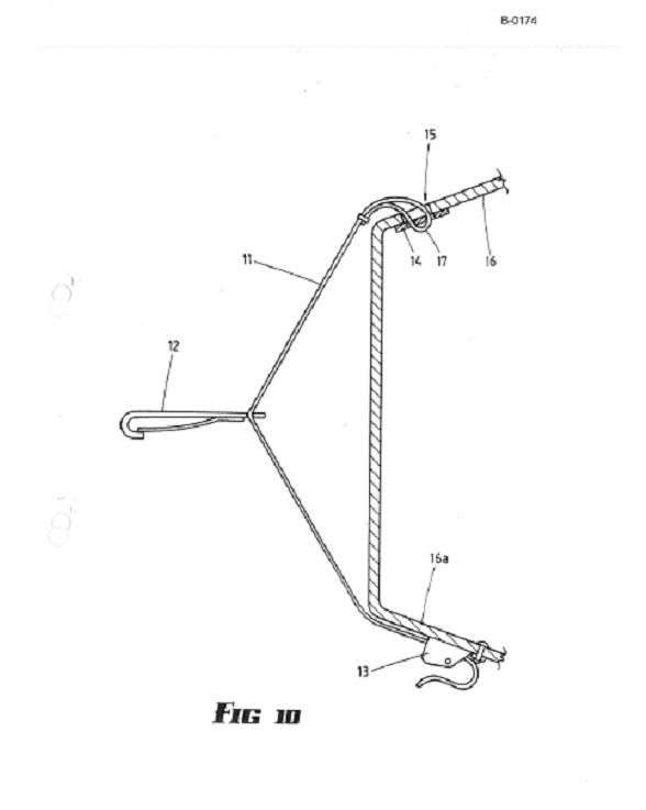
57 The specification states that the mounting arrangements for securing the harness and the seat shell to the vehicle may take other forms. Figures 6 to 11 show a variety of mounting arrangements for the harness and seat shell.
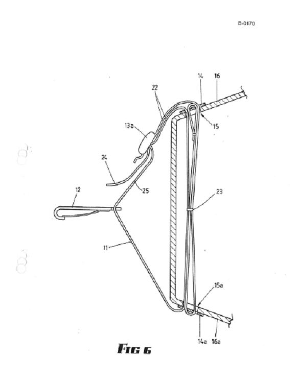
58 The mounting arrangement in Figure 6 does not require the connection strap (44), the harness is secured to the vehicle anchorage point (50) simply by means of the two latching hook connectors (26) and (43). The latching hook connector (43) in Figures 6 and 7 includes two apertures to receive both the tether strap (40) and hook connector (26). Typically, latching hook connectors only include one aperture to receive the strap they are intended to secure. However, in the proposed invention, a single latching hook may be common to both of the mounting arrangements for the harness and for the seat shell. Therefore, the latching hook may need to be attached to one or more components from both mounting arrangements. The additional aperture in latching hook connector (43) in Figure 6 increases flexibility in attaching multiple other components to a single latching hook connector.
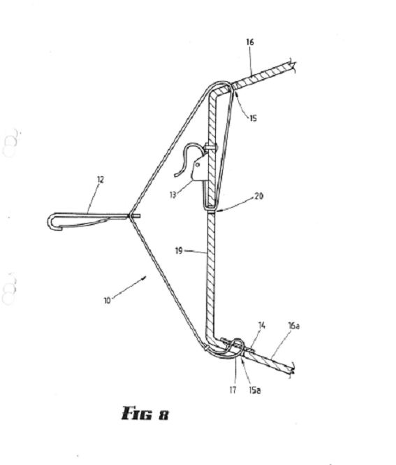
59 Figure 8 shows in more detail the mounting arrangement shown in Figures 4 and 5. A tether strap (40) is connected to a vehicle anchorage point (50) through latching hook connector (43). The harness is secured with respect to the vehicle through the latching hook connector (26), connection strap (44), buckle (45) and latching hook connector (43). In this instance, the latching hook connector (43) is common to both the mounting arrangement for the harness and the mounting arrangement for the seat shell.
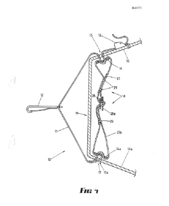
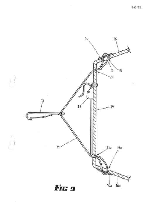
60 Figures 7 and 9 show other options for securing a tether strap (40) to the latching hook connector (43).
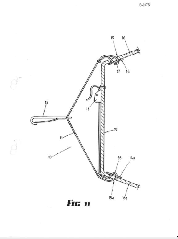
61 Figures 10 and 11 show arrangements which can be used when there are two vehicle anchorage fittings (51 and 52). Here, the mounting arrangements for the seat shell (30) and the harness (20) are independent. The seat shell (through the tether strap (40)) is secured to the vehicle by connecting the latching hook connector (43) to one of the vehicle anchorage fittings (51). The harness is connected to a separate vehicle anchorage fitting (52). Figure 11 shows a connection directly by means of latching hook connector (26), whereas in Figure 10 the connection strap (44) and buckle (45) are also used to secure the child harness to vehicle anchor fitting (52).
62 The specification filed with the Parent Application then notes that although a number of embodiments of the present invention have been described, the invention is not limited to the embodiments disclosed. It is capable of numerous rearrangements, modifications and substitutions without departing from the scope of the invention. Modifications and variations such as would be apparent to a skilled addressed “are deemed within the scope of the present invention”.
63 The specification then ends in 32 claims. Claims 1, 21, 29 and 30 can be considered the “main claims”. Claims 2 to 20 relate to claim 1. Claims 22 to 28 relate to claim 21. Claims 31 and 32 are omnibus claims.
64 The Parent Application was not granted. However, from its complete specification for a standard patent, nine innovation patents were filed as divisional applications.
The First Patent – “Improved tether strap for a child safety seat”
65 The first patent states the field of its invention to relate to a “tether strap for a child safety seat”. The background to the invention is described in the same terms as the background in the Parent Application.
66 The summary of the invention gives only one aspect to the invention, which is to provide a tether strap for a child safety seat for connection to an anchorage point on a motor vehicle comprising: a tether strap having both ends secured with respect to the child safety seat and the tether strap secured with respect to the anchorage point intermediate its ends; and a connection strap carried by the tether strap and secured at a first end with respect to the anchorage point and having a connection means at the other end.
67 It is preferable that the connection strap provides a means of attaching the harness used in the safety seat while also securing the tether strap to the same anchorage point. The upper end of the shoulder straps is able to be secured directly with respect to the anchorage point rather than to the shell of the safety seat.
68 As in the specification filed with the Parent Application, the specification to the First Patent then goes onto describe the problem with “current arrangements” for child safety seats. Namely, the mechanical integrity of the seat shell can be compromised in the event of a collision so the safety of the infant is dependent on the integrity of the seat shell. The specification then goes on to describe how the present invention alleviates this problem. This feature of the specification recurs throughout all nine innovation patent specifications, with some minor differences.
69 In this instance, the specification specifies that the upper securement point of the harness is able to be secured independently of the seat shell (as opposed to the harness generally being secured independently).
70 The specification filed with the Parent Application goes on to describe the way in which “both an upper part and a lower part of the harness will be secured to the vehicle”. The specification for the First Patent does not detail the ways in which the harness can be secured to the vehicle. It goes on to describe the harness arrangement in largely the same terms as the specification to the Parent Application. That the connecting strap is adjustable in length is a feature added to the first patent. The First Patent also contemplates that a separate extension strap can be used which is ideally adjustable in length by adjustable buckles. The Parent Application specification only considered that the first mounting arrangement may include extension straps (plural) which are ideally adjustable by buckles.
71 The First Patent specification also clarifies that the apertures are in the “backrest portion”, as opposed to the “seat shell” or “seat back”. “Seat shell” is also described in the First Patent as “safety seat”.
72 The specification then lists a brief description of the drawings. It features Figures 1 to 5 from the Parent Application, and lists Figure 8 (re-labelled as Figure 6 in the First Patent) as showing a view of a mounting arrangement as used in various embodiments of the present invention. Figure 1, referring to the same figure as in the Parent Application, is said to be a view of a harness “incorporating an extension strap”. This feature was not emphasised in the Parent Application specification.
73 A description of the preferred embodiment of the First Patent is then given by reference to the Figures. Figures 1 to 5 are described in substantially the same terms as in the Parent Application specification. In relation to Figures 3 to 5, it is noted that it is possible to have the harness passed through a single aperture in the “head end of the backrest portion or around grooves in the perimeter of the backrest portion”. There is no mention of such grooves in the Parent Application specification. It is also specifically stated that there is an aperture in the buckle (45) which forms part of the various components forming the arrangement by which the harness is connected to the vehicle.
74 Again, the First Patent notes that the mounting arrangements for securing the harness and safety seat can take other forms. Figure 8 is said to show in more detail the mounting arrangement in Figures 4 and 5. It is described in the same terms as in the Parent Application specification.
75 The First Patent specification then notes, in the same way as the Parent Application, that the invention is not limited to the embodiments disclosed, but capable of numerous rearrangements, modifications and substitutions.
76 The First Patent specification then ends in five claims, the first being the same as the consistory clause in the summary of the invention. The three claims in issue are outlined below.
The Second Patent – “Child safety seat, shell and harness”
77 The field of the Second Patent is said generally to relate to child safety seats. Again, the background of the invention is materially the same as in the Parent Application specification.
78 The summary of the invention states that the invention provides a child safety seat for a motor vehicle including: a seat for seating a child therein comprising a seat portion and a backrest portion wherein the motor vehicle seat belt extends across the waist of the child; a tether strap, secured with respect to a head end of the backrest portion and adapted to be secured to an anchorage point on the motor vehicle; and a harness to secure the child with respect to the safety seat comprising a pair of shoulder straps that are each connected at their lower end to the vehicle seat belt adjacent to the child’s waist and wherein the harness extends behind the backrest portion to be secured at its upper-end with respect to the anchorage point.
79 The specification then describes problems with current child safety seat arrangements and how the present invention alleviates this in the same terms as the Parent Application specification.
80 The Second Patent specification then describes the way in which the harness is secured with respect to the vehicle in similar terms to the Parent Application. The patentee has also added that the upper part of the harness will generally be secured to a vehicle anchorage point “such as on a rear parcel shelf or on the floor behind the seat”.
81 When describing the way in which the lower part of the harness is secured with respect to the vehicle by a vehicle seat belt, the Second Patent adds more detail than in the Parent Application specification. The sash and lap portion (or just the lap portion if it is a lap only seat belt) of the seat belt may be brought together over the waist of the child “and therefore act to restrain the child and safety seat”. The lower part of the harness may include one or more loops through which the vehicle seat belt locates, allowing the lower part of the harness to be secured with respect to the vehicle. Another difference is that the Parent Application specification referred to the loops in the lower end of the harness as being part of the “first mounting arrangement”, rather than the harness specifically.
82 The Second Patent specification states that the tether strap may comprise a connection strap attached to and extending from the tether strap latching hook to which the harness is attached. As such, the tether strap and harness may be independent of each other, but they may also include shared components. This part of the specification differs from the Parent Application specification in that the latter referred more generally to the “first and second mounting arrangements” being independent, but also including shared components. It would seem that the patentee has refined this aspect of the specification by the time they turned their mind to this innovation patent.
83 Accordingly, in some embodiments, the tether strap may include a connecting component to connect to the vehicle anchorage, which is further provided with an aperture to receive the harness latching hook connector. The connecting component which is connected to the vehicle anchorage could then be shared by both the tether strap and harness. The specification further contemplates that “there are, of course, other ways in which a component may be shared”.
84 The harness is described largely in the same terms as the First Patent. In saying this I am aware that two separate patents cannot be construed together; I wish to highlight that the Second Patent specification has adopted similar changes in wording as the First (for example from referring to a “seat shell” to a “safety seat”). In the Second Patent, the connecting component (for the harness) “may” include extension straps ideally adjustable by buckles.
85 The Second Patent adds that the connection of the harness to an upper vehicle anchorage point allows the shoulder straps to be located closer to the child’s shoulders than in current child safety seat arrangements, allowing the child to be more securely retained.
86 Again, preferably there are one or more pairs of apertures in the backrest portion, or grooves in the perimeter of the head end of the backrest portion, through which the shoulder straps can be passed to retain the shoulder straps in position. Again, the “grooves” in the backrest are a new feature in the Second Patent as compared to the Parent Application specification.
87 The specification then gives a brief description of Figures 1 to 6. The description of Figures 1 to 5 are largely the same as in the Parent Application specification, though Figure 1 is, again, said to “incorporate an extension strap”. Figure 8 from the Parent Application specification is re-labelled as Figure 6, said to show a view of a mounting arrangement as used in various embodiments of the present invention.
88 Turning to a description of the preferred embodiment with reference to the figures, the preferred embodiment is described much the same way as the First Patent. Figure 1, notably, is said to have a child harness (20) consisting of two shoulder straps (21) “formed from a length of strap” and a cross strap (22). There are no other material differences between the First and Second Patents. It is not necessary to repeat the preferred embodiment again, though I reiterate that in doing so, patent documents are self-contained, independent documents, and must be construed as such.
89 The specification ends in five claims, the first being the same as the consistory clause in the summary of the invention. The four claims which are in issue are outlined below.
The Third Patent – “Improved tether strap for a child safety seat incorporating a connection means”
90 The field of the invention of the Third Patent is said to relate to a “tether strap for a child safety seat”.
91 The background of the invention is the same as that in the Parent Application specification.
92 The first (and only) aspect of the invention is for a tether strap for a child safety seat to an anchorage point on a motor vehicle, wherein a harness is used with the child safety seat to restrain a child in the child safety seat, the tether strap comprising: a strap having ends secured with respect to the child safety seat and secured with respect to the anchorage point at a point intermediate its ends; and a connection means carried by or with respect to the tether strap, the connection means extending away from the tether strap towards the child safety seat and having an aperture at an end spaced from the tether strap for attachment of the harness.
93 It is preferable that the connection means allows attachment of the harness used in the safety seat while also securing the tether strap to the same anchorage point. The upper end of the shoulder straps are able to be secured directly with respect to the anchorage point rather than to the shell of the safety seat.
94 The Third Patent repeats the “current arrangements” for child safety seats and problems therein. It then continues that the disadvantage stated is alleviated with the present invention, where the upper securement point of the harness can be secured independently of the seat shell and with respect to the anchorage point to which the tether strap is connected.
95 The description of securing the mounting arrangements to the vehicle is not repeated in the Third Patent. It does, however reiterate the description of the harness and the crutch strap in substantially the same terms as in the Parent Application. The connecting means for the harness may comprise a strap that is adjustable in length or a separate extension strap which is adjustable by buckles.
96 A brief description of the drawings is given. Again, Figures 1 to 5 are annexed to the Third Patent. Figure 8 is also annexed, but re-labelled as Figure 6. These descriptions are, on the whole, in the same terms as in the First and Second Patents.
97 A description of the preferred embodiment of the invention with reference to the figures is then given. Again, it is in similar terms to that given in the First and Second Patents. Figures 4 and 5 are particularly helpful describing the invention. They show clearly the tether strap (40) is connected to the backrest portion of the safety seat shell (30) at connection points (41 and 42), and at the other to a vehicle anchorage point (50) through latching hook connector (43). The length of the tether strap (40) can be adjusted through the adjustable buckle (46) to allow the mounting arrangement to suit different vehicles.
98 The specification ends in five claims, the first being the same as that in the consistory clause in the summary of the invention. All claims are in issue. They are outlined below.
The Fourth Patent – “A child safety seat having a harness secured with respect to a tether strap”
99 The field of the Fourth Patent relates to “child safety seats”.
100 The background of the invention is largely the same as in the Parent Application. It should be noted, however, that the tether strap is not described in this Patent as being “connected to the shell and to a vehicle anchorage point” but as being “connected between the shell and a vehicle anchorage point”.
101 The summary of the invention states that the invention provides a child safety seat for a motor vehicle including: a seat for seating a child therein comprising a seat portion and a backrest portion wherein the motor vehicle seat belt extends across the waist of the child; a tether strap secured with respect to a head end of the backrest portion and adapted to be secured to an anchorage point on the motor vehicle; and a harness to secure the child with respect to the safety seat comprising a pair of shoulder straps that are each connected at their lower end to the vehicle seat belt adjacent the child’s waist and wherein said harness extends behind the backrest portion to be secured at its upper-end with respect to said tether strap anchorage point.
102 The specification then reproduces what was said in the Parent Application about problems with “current arrangements” for child safety seats and the way in which the invention alleviates these problems.
103 In giving a summary of the invention, the Fourth Patent specification reproduces much of the text used in the Parent Application specification in relation to the first aspect of the invention described in that Application. Some amendments have been made. Notably, the terms “first mounting arrangement” and “second mounting arrangement” have been replaced with a more precise description of those arrangements, being the harness and the tether strap and related components.
104 For example, rather than saying that the “first and second mounting arrangements may be independent of each other, [although] they may include shared components”, the patentee has chosen to say that the tether strap may comprise a connection means carried by the tether strap to which the harness is attached.
105 Rather than the “first mounting arrangement” being adjustable, the Fourth Patent states that it is the connecting component that may include extension straps which are ideally adjustable in length by buckles.
106 The harness is connected with respect to an upper vehicle anchorage point allowing the shoulder straps to be located closer to the child’s shoulders than in current child safety arrangements.
107 Figures 1 to 5 are annexed to the Fourth Patent. Figure 8 is likewise annexed, though again, re-labelled as Figure 6 for the purposes of the Fourth Patent.
108 A description of the preferred embodiment of the invention is given with reference to the figures. It is similar to the other patents already mentioned.
109 The invention ends in five claims. The first claim corresponds with the consistory clause given in the summary of the invention. The four claims in issue are outlined below.
The Fifth Patent – “A child safety seat having a tether strap with connection means”
110 The field of the Fifth Patent is stated to be “child safety seats”. The background of the invention is largely the same as that in the Parent Application, and has the same amendments as the Fourth Patent.
111 The summary of the invention begins with a consistory clause corresponding with claim 1 of the invention, stating that the present invention provides a child safety seat for a motor vehicle including: a seat for seating a child therein comprising a seat portion and a backrest portion; a tether strap, secured with respect to a head end of the backrest portion and adapted to be secured to an anchorage point on the motor vehicle; and a connection means carried by the tether strap by a first aperture securable at a first end to the anchorage point and including at an opposed second end a second aperture.
112 The specification then outlines the problems with “current arrangements” for child safety seats and how the present invention alleviates these problems. This is in the same terms as in the Parent Application specification.
113 The remainder of the summary and the specification is materially the same as the Fourth Patent.
114 The invention ends in five claims. Three of those are in issue, and are outlined below.
The Sixth Patent – “A tethering means for a child safety seat arrangement”
115 The field of the Sixth Patent is stated to relate to a “tethering means for a child safety seat”.
116 The background of the invention is, for the most part, the same as that described in the Parent Application specification. The application for the Sixth Patent was filed on 21 August 2009. The patentee begins by acknowledging that “in some child safety seats, the child is restrained in the safety seat by a child safety harness which is connected… to the shell of the safety seat”. In previous divisional patents, it was said that this arrangement was “current”. It is also added (as compared to the Parent Application specification) that “children of different sizes are not always sufficiently restrained in the safety seat of this type”.
117 It is then noted that it is an object of the invention to eliminate some or all of the disadvantages of “the above described” child safety seat arrangements. In the First to Fifth Patents, the child safety seat arrangements are described as “conventional”.
118 The Sixth Patent is a departure from the first five. It describes four aspects to the invention.
119 In the first aspect, the invention provides a tethering means for a child safety seat in a motor vehicle wherein the child safety seat has seat and backrest portions, the tethering means comprising: a first strap for tethering the backrest portion of the child safety seat with respect to an anchorage point in the motor vehicle, and a second strap carried by or with respect to the first strap and having a connection means at its free end to which a child safety harness is adapted to be connected.
120 In a second aspect, the invention provides a tethering means for a child safety seat for connection to an anchorage point in a motor vehicle wherein a child safety harness is used to restrain a child in the child safety seat, the tethering means comprising: means for tethering the child safety seat and securable with respect to the anchorage point; and a connection means carried by or with respect to the tethering means, the connection means extending towards the child safety seat and having an aperture adapted for attachment of the child safety harness.
121 In a third aspect, the invention provides a tether strap for tethering a child safety seat to a vehicle, wherein the tether strap incorporates means for connecting both the tether strap and a child safety harness used with the safety seat to an anchorage point of the vehicle.
122 In a fourth aspect, the invention provides a tethering means in the form of a strap for tethering a child safety seat to an anchorage point in a motor vehicle, wherein a child safety harness is used to restrain a child in the safety seat, the tethering means including: a connection means carried by the strap by locating the strap through a first aperture in the connection means, the connection means securable at a first end to the anchorage point and including at an opposed end a second aperture for an attachment of a child safety harness.
123 It is preferable that the second strap or connection means allows attachment of the child safety harness used with the child safety seat while also being able to separately secure the tethering means to a single anchorage point. The upper end of the shoulder straps is then also able to be secured with respect to the same anchorage point rather than to the shell of the safety seat.
124 The Sixth Patent then goes onto note the problems associated with “child safety seats where the child safety harness attaches to the shell”. This is largely the same as the problems described with “current arrangements” in the First to Fifth Patents. That is, such seats rely on the mechanical integrity of the seal shell to secure the child with respect to the vehicle. In the event of a collision, the safety of the infant is dependent on the integrity of the seat shell. This disadvantage is alleviated in the Sixth Patent, where the upper securement point of the child safety harness is able to be secured independently of the seat shell and with respect to the same anchorage point to which the tether strap is connected.
125 The specification goes on to describe the harness in similar terms to the Parent Application specification. The way in which the shoulder straps are formed and passed through the apertures is described slightly differently. Relevantly, a child safety harness includes two shoulder straps that extend over the child’s shoulders and chest. These shoulder straps may be provided by a length of strap with ends locating through respective pairs of apertures in the backrest portion of the safety seat. Further, the shoulder straps preferably each include a loop at their ends to receive a vehicle seat belt.
126 As in the Parent Application specification, the harness is preferably adjustable by a buckle which may be covered by padding. Higher or lower apertures in the seat shell may also permit adjustment. The cross strap and crutch strap is likewise described in similar terms to the Parent Application.
127 The specification then turns to a brief description of the drawings annexed. Figures 1 to 9 from the Parent Application are annexed.
128 Some figures are, however, given a different and more detailed description in the Parent Application. All the figures in the Sixth Patent have been annexed to this judgment as Annexure ‘B’. I will outline those which are relevantly different to those in the Parent Application. Figure 2 is said to be a view of a child safety harness incorporating an adjustable extension means. Figure 4 is a rear view of a child safety seat arrangement according to a preferred embodiment of the present invention showing the child safety seat harness attached to a connection means on the tether strap. Figure 5 is a top rear view of a child safety seat arrangement as shown in Figure 4 with the tether strap attached to a vehicle anchorage point. Figure 6 shows a detailed view of a latching hook connector and connection means with a tether strap and child safety harness attached. Figure 7 shows a detailed view of a latching hook connector similar to that shown in Figure 6, but with a single tether strap attached. Figure 8 shows a latching hook connector with a connection means carrying a buckle for connection of the child safety harness. Figure 9 shows a latching hook connector having a single tether strap attached with a connection means and buckle attached to the tether strap.
129 The specification then turns to a description of the preferred embodiment of the invention, with reference to Figures 1 to 9. Figures 1 to 9 annexed to the specification contain various additional number references not previously used in the Parent Application specification. Figures 6 to 9 in particular detail additional features. I will describe these in turn.
130 Figure 6 shows a variation to the connection of a tether strap (40) and child safety harness (20) to an anchor bracket (50). The latching hook connector (43) comprises a body having a flat plate portion (48) with a hook (39) at one end that attaches to the aperture (51) of the anchor bracket (50). The latching hook connector (43) has an aperture (49) through which the tether strap locates which enables the tether strap (40) to extend between the connection points (41 and 42). The connection means comprises the portion of the plate (48) that extends between the aperture (49) and the aperture (47) with the latching hook (26) of the child safety harness attaching to the aperture (47). This thereby secures the child safety harness with respect to the anchorage bracket.
131 Figure 7 shows a similar arrangement, but the tether strap (40) is a single strap having one connection point to the safety seat (30). The apertures (49 and 47) are more closely spaced than in Figure 6, with a loop (53) on the end of the tether strap (40) passing through both apertures. The latching hook connector (26) connects to the aperture (47) and locates in a recess (54) on one edge of the aperture (47).
132 Figures 8 and 9 show a variation on the arrangement shown in Figures 4 and 5. In Figure 8, the bracket (45) has two apertures (56 and 57) with a connection strap attached through and extending between the aperture (49) in the latching hook connector (43) and the aperture (56) in the bracket (45). The latching hook connector (26) then attaches to the aperture (57) in the bracket (45). The tether strap (40) also passes through aperture (49).
133 In Figure 9, a single tether strap (40) is used as in the version shown in Figure 7. However, the connection strap (44) is stitched to the tether strap (40) at one end and connected to aperture (56) of bracket (45) at the other end. The latching hook connector (26) then attaches to aperture (57).
134 Again, the specification states that it should be understood that the invention is not limited to the embodiments disclosed.
135 The specification then ends in five claims, all of which are in issue. They are outlined below.
The Seventh Patent – “A child safety seat and tethering means and child safety harness for the child safety seat”
136 The field of the Seventh Patent is stated to relate to child safety seats.
137 The background of the invention is stated as in the Sixth Patent.
138 The summary of the invention gives four aspects to the invention. In a first aspect, the invention provides a child safety seat for a motor vehicle including: a seat for seating a child therein comprising a seat portion and a backrest portion wherein the motor vehicle seat belt extends across the waist of the child; a tethering means for tethering the backrest portion and adapted to be secured to an anchorage point on the motor vehicle; and a child safety harness to secure the child with respect to the safety seat comprising a pair of shoulder straps that are each connected at their lower end to the vehicle seat belt adjacent the child’s waist and wherein the child safety harness extends from the backrest portion to be secured with respect to the anchorage point by a connection means carried by or with respect to the tethering means.
139 In a second aspect, the invention provides a child safety seat for a motor vehicle including: a seat for seating a child therein comprising a seat portion and a backrest portion; a tethering means for tethering the backrest portion of the child safety seat and adapted to be secured to an anchorage point on the motor vehicle; and a connection means which is adapted to be secured at one end to the anchorage point having a first aperture adapted to have connected thereto a child safety harness and having a second aperture through which the tethering means locates.
140 In a third aspect, the invention provides a child safety seat arrangement for anchoring a child safety seat, and a child safety harness used with the child safety seat, to an anchorage point of a motor vehicle including: connection means attachable to the anchorage point and including a first aperture for facilitating location of a tethering means of the child safety seat including a second aperture for facilitating connection with the child safety harness such that the child safety seat and the child safety harness are anchored to the anchorage point of the motor vehicle.
141 In a fourth aspect, the invention provides means for securing a child safety harness and child safety seat to an anchorage point in a motor vehicle including: a child safety seat having seat and backrest portions; a child safety harness for a child seated in the safety seat; means for tethering the safety seat to an anchorage point in the motor vehicle by a tethering means which is adapted to tether the safety seat to the anchorage point by a connection means, the connection means also adapted to have the child safety harness connected thereto.
142 It is preferable that the tethering means is in the form of a tether strap which is secured to the backrest portion of the safety seat but may also be secured towards the upper end of the backrest portion adjacent or at the head end of the safety seat.
143 The specification then repeats the problem outlined in the Sixth Patent about child safety seats which have the harness attached to the seat shell. In the same way, the specification outlines how the present invention seeks to alleviate this problem.
144 The specification then outlines the way in which the child safety harness can be secured with respect to a vehicle. This is in similar terms to those used in the Fourth and Fifth Patent specifications.
145 In some embodiments, the tethering means may include a connecting component to connect to the vehicle anchorage point, which is further provided with an aperture to receive the child safety harness latching hook connector. The connecting component which is connected to the vehicle anchorage point could then be shared by both the tether strap and child safety harness. The specification considers that there are, of course, other ways in which a component may be shared.
146 The harness is then described in similar terms as in the Fourth and Fifth Patents, with some changes in wording. The harness is said to include two shoulder straps to extend over the child’s shoulders and chest. These may be provided by a length of strap positioned behind the safety seat and extending through a pair of apertures in the backrest portion. Further, each end of the shoulder straps preferably includes a loop to receive a vehicle seat belt.
147 The harness is again stated to be preferably adjustable by way of a buckle. It also preferably includes a cross strap and a crutch strap as described in the Fourth and Fifth Patents. The connecting component is likewise adjustable as described in the latter patent specifications.
148 Preferably, there are one or more pairs of apertures in the backrest portion or grooves in the perimeter of the head end of the backrest portion through which, or around which, the shoulder straps can be passed to retain the shoulder straps in position.
149 The specification then gives a brief description of the drawings, which is the same as that in the Sixth Patent. Figures 1 to 9 feature the same changes as the figures annexed to the Sixth Patent. Similarly, the description of the preferred embodiment of the invention with reference to the figures is the same as that in the Sixth Patent.
150 The invention ends in five claims. Claims 1, 2, 4 and 5 correspond with the consistory clauses (aspects) of the invention in the specification. All claims are in issue and are outlined below.
The Eighth Patent – “Means of tethering a child safety seat and child safety harness to a single anchor point in a motor vehicle”
151 The field of the Eighth Patent is stated to relate to child safety seats, and child safety harnesses adapted to be secured to a single anchorage point of a motor vehicle.
152 The background of the invention is the same as given in the Sixth and Seventh Patents.
153 The summary of the invention states it to enable both the tethering means of a child safety seat and a child safety harness to be secured with respect to a single anchorage point in a motor vehicle.
154 The specification states that in one aspect, the invention provides apparatus to secure a child safety seat and a child safety harness to a single anchorage point in a motor vehicle comprising a connection means arrangement adapted to cooperate with a tether strap adapted to tether the child safety seat, wherein the connection means arrangement secures both the tether strap and the child safety harness to the single anchorage point.
155 The specification then outlines problems associated with child safety seats where the harness attaches to the seat shell, and how the present invention alleviates this.
156 The specification then repeats the same material as used in the Seventh Patent. Again, in referring back to the Seventh Patent in this way, I do not read or construe the Patents together.
157 Figures 1 to 9 from the Parent Application specification are annexed to the Eighth Patent. The numbering of the Figures is the same as that given in Annexure ‘B’ to these reasons. The brief description of these Figures is in the same terms as in the Sixth and Seventh Patent. The description of the preferred embodiment of the invention with reference to the Figures is materially the same as that in the Sixth and Seventh Patents.
158 The invention ends in five claims. All five are in issue and are outlined below. Claim 1 corresponds with the consistory clause in the summary of the invention. Claims 2, 3, 4 and 5 all make specific reference to the drawings in the annexed figures.
The Ninth Patent – “A connector for securing a tether strap of a child safety seat”
159 The field of the invention is stated to relate to child safety seats and in particular to connectors to secure tether straps and harnesses used with child safety seats.
160 The background of the invention is substantially the same as that in the Parent Application specification.
161 The summary of the invention states that the invention provides a connector to secure a tether strap of a child safety seat to an anchor point of a motor vehicle and to attach to the connector a child safety harness adapted to be used with the child safety seat, the connector comprising: a body; a connection means at one end of the body to attach the connector to said anchorage point of the motor vehicle; a first aperture in the body through which said tether strap locates; and a second aperture in the body to receive an attachment means of the child safety harness.
162 The specification outlines the problems with “current arrangements” for child safety seats. Namely, they rely on the mechanical integrity of the seat shell in the event of a collision. This disadvantage is alleviated when the harness can be secured independently of the seat shell via the connector.
163 The Ninth Patent describes the invention in considerably different terms to the Parent Application specification.
164 The tether strap for the child safety seat is secured to the seat shell and preferably comprises a strap connected at each side of the backrest of the child safety seat. The tether strap locates through the first aperture of the connector and the connector is then attached to the vehicle anchorage point via the connection means which preferably comprises a hook with a latch member.
165 The harness for securing an infant is described in similar terms to the Parent Application: it comprises a pair of shoulder straps which can be secured at the lower end by the motor vehicle seat belt. The lower end of the harness may have loops through which the vehicle seat belt locates.
166 The part of the harness which extends over the infant’s shoulders and behind the child safety seat is preferably provided with a hook means attached to the harness which itself then attaches to the second aperture of the connector. This thereby secures the harness independently of the child safety seat and instead secures it at either end with respect to the motor vehicle.
167 It is preferable that the harness comprises a single length of strap which loops behind the safety seat through a pair of apertures in the backrest portion of the seat and each end has loops through which the vehicle seat belt locates.
168 The connector is then described in more detail. The specification states that the edge of the second aperture in the connector may have an indentation within which the hook means of the tether strap is received. It is preferable that the indentation is located over the longitudinal centre line of the connector so that, when the harness is placed in tension, the hook means of the harness is retained in a centrally located position within the second aperture. This ensures that the hook means of the harness is therefore aligned with the longitudinal centre line of the connector. This, in turn, prevents the hook means of the harness locating in one side of the second aperture therefore applying an asymmetric load to the connection means of the connector.
169 It is preferable that the body of the connector comprises a plate of metal with the first aperture being located between the connection means and the second aperture. Preferably, the second aperture comprises an aperture having a rectilinear out line, with the indentation located in the edge of the aperture furthest from the connection means.
170 Five figures are annexed to the Ninth Patent. The specification gives a brief description of the annexed figures. Figures 1, 3, 5, 6 and 7 from the Parent Application are annexed. They are, however, labelled according to different numbers. Figures 3, 5, 6 and 7 (re-labelled as Figures 2, 3, 4 and 5 respectively in the Ninth Patent) contain some new numbers and features. Figure 4 (Figure 6 in the Parent Application) is a view of the connector attached to a vehicle anchorage bracket and having attached thereto a tether strap and a harness. Figure 5 (Figure 7 in the Parent Application) is said to be a second preferred embodiment of a connector having a single tether strap attached thereto. It is convenient to annex to this judgment as Annexure ‘C’ all the figures in the Ninth Patent.
171 The specification then gives a description of the preferred embodiment of the invention with reference to the annexed figures. The description of Figure 1 is largely the same as that in the Parent Application. The only difference is that the harness is described as having two shoulder straps “fanned from a length of strap”.
172 Figure 2 (Figure 3 in the Parent Application) is described in similar terms to those used in relation to Figure 3 in the First through to the Fifth Patents. It is not substantially different from the description in the Parent Application. Figure 3 (Figure 5 in the Parent Application) is likewise described in similar terms.
173 Figure 4 (Figure 6 in the Parent Application) shows in greater detail the connector (43) which comprises a pressed metal plate. Formed at one end of the connector is the connection means which comprises a hook (50). The hook locates in the aperture or a vehicle anchorage bracket (51) and has a sprung latching member (52) that closes the hook so as to prevent accidental unhooking from the vehicle anchorage bracket.
174 The connector (43) has a first aperture (54) which comprises an elongate slot. The tether strap (40) locates through the first aperture. The connector also has a second aperture which comprises the rectangular opening (56). The latching hook connector (26) of the harness (20) is attached to the connector plate (43) by locating in the rectangular opening (56).
175 The edge of the rectangular opening (56) furthest from the hook (50) has an indentation (57) within which the latching hook connector (26) locates. The indentation is placed generally over the longitudinal centre line of the connector (43) and has a width which is equal to the width of the latching hook connector which locates therein so as to prevent lateral movement of the latching hook connector within the opening (56). This ensures that the latching hook connector (26) is held on the longitudinal centre line of the connector (43) to prevent asymmetric loads being applied to the connector (43) as might be the case if the latching hook connector were to lodge in one or other of the ends of the opening (56). If this were to occur, then the hook (50) would not remain square to the aperture within which it locates in the vehicle anchorage bracket. Accordingly, when tension is applied to the harness (20), the latching hook connector (26) and connector (44) are thereby kept inline.
176 Figure 5 (Figure 7 in the Parent Application) shows a second embodiment in the arrangement shown in Figure 4 (Figure 6 in the Parent Application) and incorporates all of the features shown in Figure 4 except that the tether strap (40) is a single length of strap which is attached to the connector (43) by a loop (59) which locates through both the first and second apertures (54 and 56).
177 The specification then ends in five claims. Claims 1, 2 and 5 are in issue and are outlined below. Claim 1 corresponds with the consistory clause given in the summary of the invention.
The Tenth Patent – “Safety seat tether strap”
178 The Tenth Patent does not have its genesis in the Parent Application. As stated, a provisional application no. PM7154 was filed on 1 August 1994. A complete specification was filed on 28 July 1995.
179 The invention is stated to relate to a safety seat tether strap, and in particular to a tether strap suitable for use with a safety seat that can be used in either a forward or rearward facing position in a vehicle.
180 The specification describes then common child safety seats. Two types were common: a rear facing seat in which the infant’s back faces the direction of travel; or a forward facing seat. Both arrangements make use of a tether strap extending from the head end of the seat to an attachment point that is fixed with respect to the vehicle. In rear facing seats, it is normal for a pair of straps to extend from either side of the head end to the rear connection point. In a front facing seat, it is normal for a single strap to be used, extending from the head end of the seat.
181 The specification then describes difficulties with single straps. A number of components comprise a single strap, which often means the length of the strap is too long for use with the most convenient attachment point in the vehicle.
182 The specification notes that “dual purpose” seats were then becoming common. In these arrangements, it was common for a single support seat to be adapted for use in both rear and forward facing modes. Most such seats make use of two tether straps, one for when the seat is in a rear facing mode, and one for when the seat is in a forward facing mode. The specification states that this adds “unnecessary added cost” and means there is the possibility of incorrect installation if the wrong tether is used.
183 The specification states that it is an object of the invention to overcome these problems. The invention provides for a single tether strap which can be used with seats either in rear or forward facing mode. The invention also allows for minimum distance between the rear of the seat and the attachment point on the vehicle.
184 The specification gives the invention in its broadest form. This corresponds with Claim 1. It is a safety seat, for use in a vehicle, comprising a seat portion, having a head end remote from the seat portion, first and second mutually spaced anchorage locations on the head end of said backrest, a connector for engagement with a securement point on the vehicle, the connector having a strap opening, a tether strap extending in a loop from the first anchorage location, through the said strap opening, to the said second anchorage location, and adjustment means for adjusting the length of the said loop.
185 The tether strap can either extend away from the rear portion of the backrest of the seat, or may extend away from the forward surface of the rear portion of the seat as would be the case in a rear facing seat.
186 The adjustment means may comprise either a cam-type strap clamp, or may comprise a three bar slide. The length adjuster may also comprise an in-line length adjuster located on a portion of the tether strap. The use of such adjustment means will allow the length of the tether strap to be reduced so that there is a very short distance between the hook and the rear of the safety seat.
187 The tether strap may be attached to side walls of the safety seat, or the tether strap may extend across the backrest through apertures in the side walls of the safety seat. In addition, metal brackets may be attached to the backrest or the side walls of the safety seat with the tether strap being attached to the brackets. The metal brackets may have slots or apertures through which the tether strap may locate.
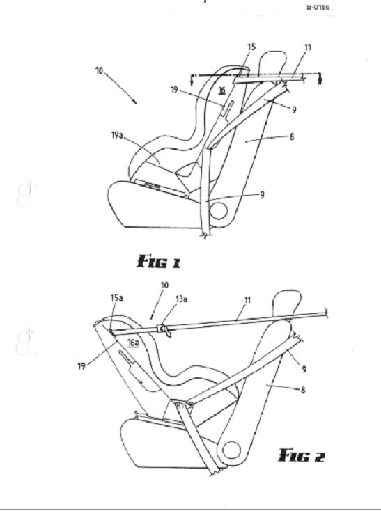
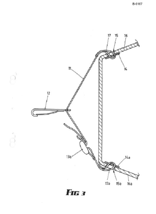
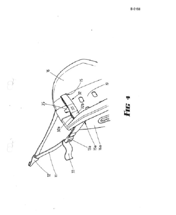
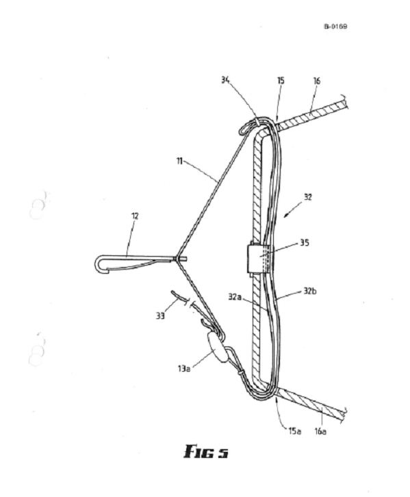
188 The invention then gives the preferred embodiment of the invention by reference to 11 figures. These figures have been annexed to this judgment as Annexure ‘D’. Figure 1 shows a side view of a safety seat on a vehicle seat in a forward facing position. Figure 2 shows a side view of a safety seat on a vehicle seat in a rearward facing position. Figure 3 shows a cross-section of a safety seat as shown in Figure 1. Figure 4 shows a part perspective view of the head end of a safety seat with attached tether strap. Figure 5 shows a cross-sectional view of a safety seat as shown in Figure 4. Figures 6 to 11 show a cross-sectional view of a safety seat with alternative configurations for the tether strap and adjustment means. The figures display numbers which are used in the specification to assist with the description of the various integers of the invention.
189 The specification then outlines the key features of various embodiments. All comprise a tether strap (11), a connector (12) and an adjustment means (13 or 13a). Apertures (15 and 15a) are formed in the side walls (16 and 16a) of a safety seat (10). The safety seat (10) is held to the vehicle seat (8) by the vehicle seat belts (9).
190 In each of the embodiments, the safety seat is formed from a unitary moulding which incorporates the side walls (16 and 16a), the backrest (19) and the seat portion (19a). The tether strap (11) extends in a loop between the first and second anchorage locations, comprising apertures (15 and 15a) that are formed in the side walls. Depending on which of the embodiments is used, other apertures may be formed, and adjustment means (13) may be secured to a portion of the safety seat.
191 Figure 3 gives the simplest form of the invention. An in-line strap adjuster (13) is fitted to the tether strap (11) and loops (17 and 17a) are formed in the end of the tether strap, and locate through apertures (15 and 15a). The loops are attached to three bar slides (14 and 14a) which abut against the inside surface of the side walls (16 and 16a).
192 Figures 4 and 5 show a safety seat (10) with a tether strap (11) extending through apertures (15 and 15a) so that a portion (32) of the tether strap (11) extends between the apertures (15 and 15a) between the inside surfaces of the side walls (16 and 16a).
193 In this embodiment, the adjustment means is an in-line adjuster (13a) with the first end (33) of the tether strap (11) looped through one side of the in-line adjuster (13a). The end (33) is sufficiently long to enable lengthening of the tether strap from the forward facing mode shown in Figures 4 and 5 to a rearward facing mode. The tether strap extends from the in-line adjuster (13a) through the strap opening in the connector (12) and through the aperture (15). The tether strap extends through aperture (15a), loops through the in-line adjuster (13a), and returns back through the aperture (15a) and is stitched off (34). This means that portion (32) is formed from two parallel strap portions (32a and 32b).
194 A strap segment (35) is stitched at one end to strap portions (32a and 32b) to hold portion (32) of the tether strap in place. The other end of the strap segment (35) is secured to the backrest (19). This prevents movement of the tether strap with respect to the side walls (16 and 16a) and backrest.
195 The specification then states that this arrangement enables the strap to be used with the safety seat in either a forward or rearward facing mode. Sufficient length of the tether strap is provided to enable it to be lengthened in the case of a rearward facing seat, or shortened when used in a forward facing seat.
196 Figures 6 to 11 show cross-sectional views of a safety seat with alternative configurations for the tether strap and adjustment means. The adjustment means varies in each depiction. For example, the embodiment in Figure 6 uses an in-line strap adjuster (13a). Adjustment is achieved by pulling the free end (24) so only portion (25) of the tether strap moves with respect to the adjuster. In Figure 7, a cam-type clamp adjuster (13) is attached to the side wall (16) of the safety seat. Figure 7 features a more complicated arrangement, including “tensioner straps” (18) which provide additional strength under high loads that might occur during impact.
197 Figures 8 to 11 also feature cam-type clamp adjusters attached to the seat in various positions. It is not necessary to go into these embodiments in greater detail.
198 The specification states that all embodiments described have the advantage of the tether strap being used for either a rearward or forward facing seat. The tether strap can be pulled into the required position regardless of the direction in which the seat faces. Other embodiments would likewise be possible to achieve this advantage.
199 The specification ends in 20 claims. Three of these claims are in issue, and are outlined below.
THE WITNESSES AT TRIAL
200 I now turn to the witnesses at trial, some of whom dealt with matters other than the construction issues presently being considered by the Court.
201 Infa called both lay and expert witnesses to present evidence to the Court.
202 Britax relied solely on expert evidence and Mr Stuart Robert Crossman, who gave evidence about parts and their availability at certain times. Mr Crossman’s evidence was objected to on the basis of relevance, but he was not cross-examined. Mr Crossman’s evidence has no impact on, or relevance to, the construction issues.
203 Britax’s primary evidence on construction (and infringement) was presented in the form of the expert evidence of Mr Hunter. Mr Hunter is a qualified mechanical engineer who works as an engineering consultant specialising in product development and engineering design, including design performance parameters and stress and strain analysis. Mr Hunter has over 20 years practical experience as a mechanical design engineer and is the founding principal of Bill Hunter Design Services, a mechanical engineering consultancy. Mr Hunter also has extensive mechanical design experience across a range of market sectors and applications, including transport, heavy engineering, fast moving consumer goods, automated process machinery, medical devices and scientific instruments. Mr Hunter assisted Britax in the early 1990s in the design of a new lightweight plastic moulded shell for a child seat restraint.
204 Infa’s expert evidence was presented by Mr Newman, a trained mechanic/automotive technician who set up his business, Australian Child Restraint Resource Initiative (‘ACRI’), in 2004 to 2005 to provide training programs and resources for fitters and retailers of child restraints and child care professionals. ACRI also provides consultation services relating to requirements for child safety restraints to vehicle manufacturers, and bodies such as VicRoads, the Royal Automobile Club of Victoria (‘RACV’) and municipal councils. ACRI and Mr Newman also provide training for parents who want to know how to install and remove child safety restraints.
205 I should say that much of the material presented by both Mr Hunter and Mr Newman went far beyond what may be properly called admissible evidence, and fell more into expression of view or submission. During the course of the trial, some rulings were made as to admissibility, mainly relating to hearsay. Otherwise, I find that each affidavit of each expert insofar as it relates to construction satisfies the requirements of s 79 of the Evidence Act 1995 (Cth) (‘the Evidence Act’). Further, the evidence has probative value, and should not be excluded pursuant to s 135 of the Evidence Act or be limited in its use pursuant to s 136 of that Act.
206 Furthermore, for the purposes of determining the construction issues, to separate sentence by sentence, or paragraph by paragraph, that material which is more in the way of submission, is unnecessary. I say this having regard to the way the parties presented their cases, and the way the proceedings progressed, particularly having regard to the existence and reliance by the parties (and the Court) on the joint report of the experts. If the material is not capable of being received into evidence, I direct that the affidavits of each expert be received by way of submission on the construction issues whether or not the opinions expressed be admissible as evidence: see r 5.04 of the Federal Court Rules 2011 (Cth).
207 The joint report and concurrent evidence at trial were successful in identifying for the Court the competing arguments on the central issue in this proceeding, namely, construction. I will need, however, to return to the specific objection made by each of the parties as to the question of whether either expert witness was a “skilled addressee” or was otherwise capable of assisting the Court. If the expert witness was not a “skilled addressee” or not otherwise capable of assisting the Court, then the evidence would not be relevant, and hence would not be admissible in any event despite compliance with s 79 of the Evidence Act.
208 The following principal lay witnesses were called by Infa – Mr Wade, Mr Wainohu, Mr Hall, Mr Doherty and Mr Bowtell.
209 Mr Wade is a mechanic with over 20 years’ experience in fitting child restraints in vehicles. Mr Wade’s business, Engine Fit Brunswick, is an accredited Restraint Fitting Station with VicRoads and the RACV. As part of that accreditation, Mr Wade was specially trained by VicRoads to install approved infant and child restraints. Mr Wade provided evidence relating to the historical use of connection means in the installation of child safety seats.
210 Mr Wainohu is the sole director of Restraint Research Pty Ltd, a company which provides services in the nature of technical development for occupant restraint systems (including child restraints) in vehicles. He provided both expert and factual evidence. Mr Wainohu has extensive experience in testing of occupant restraint products, including child restraints. Mr Wainohu has been a member of the Standards Australia Technical Committee (CS-085) relating to child restraints for use in motor vehicles since around 1992. Mr Wainohu was requested by Infa to provide his opinion as to the function of the Infa Century seat loops/guides in relation to its tether strap, to consider the particular connection means employed (a “pigtail” connection), and attended a testing facility to observe the testing of connections.
211 It is important to recall that Mr Wainohu actually observed the testing, and took notes of the testing. In this way his evidence of the results was both evidence relating to what he observed, and then evidence about various conclusions he drew (as an expert) from such observations.
212 After some debate, and objection by Britax, I ruled the evidence of Mr Wainohu admissible. Mr Hunter was able to respond to Mr Wainohu’s evidence during the course of the hearing. In the end, the dispute between them was a very discrete point going to the breakage of the loops at the anchorage locations and the function of the “pigtail” connection. I considered that Britax, through Mr Hunter, had ample opportunity to respond to Mr Wainohu’s evidence, and no injustice resulted from permitting Mr Wainohu’s evidence to be received by the Court.
213 Mr Hall has a mechanical engineering, development and design background with extensive experience in automotive engineering. For the years between 1984 and 1995 Mr Hall worked for a number of different entities, including the Traffic Accident Research Unit (‘TARU’) in Sydney, and the National Road and Motorists Association (‘NRMA’) in the development of child restraint anchorage systems in vehicles, amongst other things. Mr Hall was also involved in the inspection of vehicles for compliance with the design rules and standards relevant to child restraint use in Australia. Mr Hall’s evidence related mainly to the use of the “pigtail” double anchorage connection in the “Safe-n-Sound Travel Safe” booster seat product available from the mid 1980s.
214 Mr Doherty is a registered patent attorney with the Melbourne office of Infa’s solicitors, Chrysiliou Law. Mr Doherty provided evidence of particular Infa patents, along with proving the exchange of correspondence between the parties relating to the alleged infringement by Infa of the Britax patents, and exhibiting certain industry papers relating to the fitting of child safety restraints.
215 Mr Bowtell is a retired mechanical engineer who, among other things, was responsible for the development of a number of child restraint products for vehicles, including the Safe-n-Sound Travel Safe booster seat. Mr Bowtell is also one of the two named inventors of the Tenth Patent for the “safety seat tether strap”. Mr Bowtell gave evidence as to the development of child restraint products, including the invention the subject of the Tenth Patent.
216 Other lay witnesses were called by Infa to prove uncontroversial facts concerning the happening of certain events on particular dates, and I need not rehearse their evidence.
217 Each of the Infa’s lay witnesses described above was cross-examined by Counsel for Britax, as was Infa’s expert witness, Mr Newman. Counsel for Infa also cross-examined Britax’s expert witness, Mr Hunter, following the giving of joint evidence to the Court by Messrs Newman and Hunter during a joint or “hot tub” session.
218 No issue arose during trial as to the credit of any witness. Submissions were made by Counsel as to particular witnesses’ experience and expertise and as to the reliability of their evidence in proving certain facts, to which I will return in dealing with specific issues.
CLAIMS IN ISSUE
219 It is convenient at this point to set out the claims in issue, highlighting the principal terms in dispute and where they appear in certain of the claims. This was essentially the approach adopted by the parties through Mr Hunter and Mr Newman, and in the joint report.
Innovation Patent 2007100856 – First Patent
Title: Improved tether strap for a child safety seat
Claim 1
Integer | Integer Description |
1.1.1 | A tether strap for a child safety seat for connection to an anchorage point on a motor vehicle comprising |
1.1.2 | a tether strap having both ends secured with respect to the child safety seat |
1.1.3 | and the tether strap secured with respect to the anchorage point at a point intermediate its ends |
1.1.4 | and a connection strap carried by the tether strap |
1.1.5 | and secured at a first end with respect to the anchorage point |
1.1.6 | and having a connection means at the other end. |
Claim 2
Integer | Integer Description |
1.2.1 | A tether strap according to claim 1 |
1.2.2 | wherein the connection strap is attached to the tether strap adjacent the intermediate point. |
Claim 5
Integer | Integer Description |
1.5.1 | A child safety seat for a motor vehicle including: |
1.5.2 | a seat for seating a child therein comprising |
1.5.3 | a seat portion |
1.5.4 | and a backrest portion |
1.5.5 | wherein the motor vehicle seat belt extends across the waist of the child |
1.5.6 | a tether strap, secured with respect to a head end of the back rest portion |
1.5.7 | and adapted to be secured to an anchorage point on the motor vehicle |
1.5.8 | a connection strap carried by the tether strap |
1.5.9 | and secured at one end with respect to the anchorage point |
1.5.10 | and having a connection means at the other end |
1.5.11 | a harness to secure the child with respect to the safety seat comprising |
1.5.12 | a pair of shoulder straps |
1.5.13 | that are each connected at their lower end to said vehicle seat belt adjacent the child’s waist |
1.5.14 | and wherein said harness extends behind the backrest portion |
1.5.15 | to be secured at its upper-end to the connection means on the connection strap. |
Innovation Patent 2007100854 – Second Patent
Title: Child safety seat, shell and harness
Claim 1
Integer | Integer Description |
2.1.1 | A child safety seat for a motor vehicle including: |
2.1.2 | a seat for seating a child therein comprising |
2.1.3 | a seat portion |
2.1.4 | and a backrest portion |
2.1.5 | wherein the motor vehicle seat belt extends across the waist of the child |
2.1.6 | a tether strap, secured with respect to a head end of the back rest portion |
2.1.7 | and adapted to be secured to an anchorage point on the motor vehicle |
2.1.8 | a harness to secure the child with respect to the safety seat comprising |
2.1.9 | a pair of shoulder straps |
2.1.10 | that are each connected at their lower end to said vehicle seat belt adjacent the child’s waist |
2.1.11 | and wherein said harness extends behind the backrest portion |
2.1.12 | to be secured at its upper-end with respect to said anchorage point. |
Claim 2
Integer | Integer Description |
2.2.1 | A child safety seat according to claim 1 |
2.2.2 | wherein said harness comprises a length of strap having at least one loop at each end |
2.2.3 | to allow said vehicle seat belt to pass there through to thereby connect the harness to said vehicle seat belt |
2.2.4 | and wherein said harness further comprises a latching hook means |
2.2.5 | having a strap aperture through which said strap slidably locates for connection with respect to said anchorage point. |
Claim 3
Integer | Integer Description |
2.3.1 | A child safety seat according to either claim 1 or 2 |
2.3.2 | wherein the tether strap has connected to it a latching hook which attaches to said anchorage point |
2.3.3 | and [the child safety seat] further comprising |
2.3.4 | a connection strap attached to and extending from the tether strap latching hook |
2.3.5 | to which the upper ends of said shoulder straps are attached. |
Claim 4
Integer | Integer Description |
2.4.1 | A child safety seat according to any one of the preceding claims |
2.4.2 | wherein a length adjustment means is incorporated in the harness. |
Innovation Patent 2008100763 – Third Patent
Title: Improved tether strap for a child safety seat and incorporating a connection means
Claim 1
Integer | Integer Description |
3.1.1 | A tether strap for a child safety seat for connection to an anchorage point on a motor vehicle |
3.1.2 | wherein a harness is used with the child safety seat to restrain a child in the safety seat, the tether strap comprising: |
3.1.3 | a strap having ends secured with respect to the child safety seat |
3.1.4 | and secured with respect to the anchorage point at a point intermediate its ends, and |
3.1.5 | a connection means carried by or with respect to the tether strap, |
3.1.6 | the connection means extending away from the tether strap towards the child safety seat |
3.1.7 | and having an aperture at an end spaced from the tether strap for attachment of the harness. |
Claim 2
Integer | Integer Description |
3.2.1 | A tether strap according to claim 1 |
3.2.2 | wherein the connection means is attached to the strap adjacent the intermediate point. |
Claim 3
Integer | Integer Description |
3.3.1 | A tether strap according to claim 1 further comprising |
3.3.2 | a latching hook connector that is attached with respect to the strap by a strap opening in the latching hook connector |
3.3.3 | that allows the latching hook connector to slidably locate on the strap, |
3.3.4 | the connection means being attached to the latching hook connector. |
Claim 4
Integer | Integer Description |
3.4.1 | A tether strap according to claim 3 |
3.4.2 | wherein the connection means is attached at a first end of the connection means to the strap opening of the latching hook connector. |
Claim 5
Integer | Integer Description |
3.5.1 | A child safety seat for a motor vehicle |
3.5.2 | for use with a harness having an upper and lower end to retain a child in the safety seat including: |
3.5.3 | a seat for seating a child therein comprising |
3.5.4 | a seat portion |
3.5.5 | and a backrest portion |
3.5.6 | wherein the motor vehicle seat belt extends across the waist of the child |
3.5.7 | and the lower end of the harness is secured to the motor vehicle seat belt |
3.5.8 | a tether strap, secured with respect to a head end of the back rest portion |
3.5.9 | and adapted to be secured to an anchorage point on the motor vehicle |
3.5.10 | a connection means carried by or with respect to the tether strap, |
3.5.11 | the connection means extending away from the tether strap towards the child safety seat |
3.5.12 | and having an aperture at an end spaced from the tether strap for attachment of the upper end of the harness. |
Innovation Patent 2008100764 – Fourth Patent
Title: A child safety seat having a harness secured with respect to a tether strap
Claim 1
Integer | Integer Description |
4.1.1 | A child safety seat for a motor vehicle including: |
4.1.2 | a seat for seating a child therein comprising |
4.1.3 | a seat portion |
4.1.4 | and a backrest portion |
4.1.5 | wherein the motor vehicle seat belt extends across the waist of the child; |
4.1.6 | a tether strap, secured with respect to a head end of the back rest portion |
4.1.7 | and adapted to be secured to an anchorage point on the motor vehicle; and |
4.1.8 | a harness to secure the child with respect to the safety seat comprising |
4.1.9 | a pair of shoulder straps |
4.1.10 | that are each connected at their lower end to said vehicle seat belt adjacent the child’s waist |
4.1.11 | and wherein said harness extends from the backrest portion |
4.1.12 | to be secured at its upper-end with respect to said anchorage point to which said tether strap is secured |
Claim 2
Integer | Integer Description |
4.2.1 | A child safety seat according to claim 1 |
4.2.2 | wherein said harness comprises a length of strap having at least one loop at each end |
4.2.3 | to allow said vehicle seat belt to pass there through to thereby connect the harness to said vehicle seat belt |
4.2.4 | and wherein said harness further comprises a latching hook means |
4.2.5 | having a strap aperture through which said strap slidably locates for connection with respect to said anchorage point. |
Claim 3
Integer | Integer Description |
4.3.1 | A child safety seat according to either claim 1 or 2 |
4.3.2 | wherein the tether strap has connected to it a latching hook which attaches to said anchorage point |
4.3.3 | and [child safety seat] further comprising |
4.3.4 | connection means attached to and extending from the tether strap latching hook |
4.3.5 | to which the upper ends of said shoulder straps are attached. |
Claim 4
Integer | Integer Description |
4.4.1 | A child safety seat according to any one of the preceding claims |
4.4.2 | wherein a length adjustment means is incorporated in the harness. |
Innovation Patent 2008100765 – Fifth Patent
Title: A child safety seat having a tether strap with connection means
Claim 1
Integer | Integer Description |
5.1.1 | A child safety seat for a motor vehicle including: |
5.1.2 | a seat for seating a child therein comprising |
5.1.3 | a seat portion |
5.1.4 | and a backrest portion |
5.1.5 | a tether strap, secured with respect to a head end of the back rest portion |
5.1.6 | and adapted to be secured to an anchorage point on the motor vehicle; and |
5.1.7 | a connection means carried by the tether strap |
5.1.8 | by a first aperture securable at a first end to the anchorage point |
5.1.9 | and including at an opposed end a second aperture. |
Claim 2
Integer | Integer Description |
5.2.1 | A child safety seat according to claim 1 |
5.2.2 | wherein the connection means slidably locates on the tether strap |
Claim 3
Integer | Integer Description |
5.3.1 | A child safety seat according to any one of the preceding claims |
5.3.2 | wherein the connection means further includes at the first end a latching hook connector for securing the tether strap to the anchorage point. |
Innovation Patent 2009100835 – Sixth Patent
Title: A tethering means for a child safety seat arrangement
Claim 1
Integer | Integer Description |
6.1.1 | A tethering means for a child safety seat for use in a motor vehicle |
6.1.2 | wherein the child safety seat has seat and backrest portions, the tethering means comprising: |
6.1.3 | a first strap for tethering the backrest portion of the child safety seat with respect to an anchorage point in the motor vehicle, and |
6.1.4 | a second strap carried by or with respect to the first strap |
6.1.5 | and having a connection means at its free end to which a child safety harness is adapted to be connected. |
Claim 2
Integer | Integer Description |
6.2.1 | A tethering means for a child safety seat for connection to an anchorage point in a motor vehicle |
6.2.2 | wherein a child safety harness is used to restrain a child in the child safety seat, the tethering means comprising: |
6.2.3 | means for tethering the child safety seat and securable with respect to the anchorage point, and |
6.2.4 | a connection means carried by or with respect to the tethering means, |
6.2.5 | the connection means extending towards the child safety seat |
6.2.6 | and having an aperture adapted for attachment of the child safety harness. |
Claim 3
Integer | Integer Description |
6.3.1 | A tether strap for tethering a child safety seat to a vehicle, |
6.3.2 | wherein the tether strap incorporates means for connecting both the tether strap and a child safety harness used with the safety seat to an anchorage point of the vehicle. |
Claim 4
Integer | Integer Description |
6.4.1 | A tether strap for tethering a child safety seat to a vehicle, |
6.4.2 | wherein the tether strap incorporates means for connecting both the tether strap and a child safety harness used with the safety seat to an anchorage point of the vehicle |
6.4.3 | substantially as herein described and with reference to the accompanying drawings. |
Claim 5
Integer | Integer Description |
6.5.1 | A tethering means in the form of a strap for tethering a child safety seat to an anchorage point in a motor vehicle, |
6.5.2 | wherein a child safety seat is used to restrain a child in the child safety seat, the tethering means including: |
6.5.3 | a connection means carried by the strap by locating the strap through a first aperture in the connection means, |
6.5.4 | the connection means securable at a first end to the anchorage point and including at an opposed end |
6.5.5 | a second aperture for attachment of a child safety harness. |
Innovation Patent 2009100836 – Seventh Patent
Title: A child safety seat and tethering means and child safety harness for the child safety seat
Claim 1
Integer | Integer Description |
7.1.1 | A child safety seat for a motor vehicle including: |
7.1.2 | a seat for seating a child therein comprising |
7.1.3 | a seat portion |
7.1.4 | and a backrest portion |
7.1.5 | wherein the motor vehicle seat belt extends across the waist of the child; |
7.1.6 | a tethering means for tethering the backrest portion |
7.1.7 | and adapted to be secured to an anchorage point on the motor vehicle; and |
7.1.8 | a child safety harness to secure the child with respect to the safety seat comprising |
7.1.9 | a pair of shoulder straps |
7.1.10 | that are each connected at their lower end to said vehicle seat belt adjacent the child’s waist |
7.1.11 | and wherein said child safety harness extends from the backrest portion |
7.1.12 | to be secured with respect to said anchorage point by a connection means carried by or with respect to the tethering means. |
Claim 2
Integer | Integer Description |
7.2.1 | A child safety seat according to claim 1 |
7.2.2 | wherein the tethering means is secured to the head end of the backrest portion. |
Claim 3
Integer | Integer Description |
7.3.1 | A child safety seat for a motor vehicle including: |
7.3.2 | a seat for seating a child therein comprising |
7.3.3 | a seat portion |
7.3.4 | and a backrest portion |
7.3.5 | a tethering means for tethering the backrest portion of the child safety seat |
7.3.6 | and adapted to be secured to an anchorage point on the motor vehicle; and |
7.3.7 | a connection means which is adapted to be secured at one end to the anchorage point |
7.3.8 | having a first aperture adapted to have connected thereto a child safety harness |
7.3.9 | and having a second aperture through which the tethering means locates. |
Claim 4
Integer | Integer Description |
7.4.1 | A child safety seat arrangement for anchoring a child safety seat, |
7.4.2 | and a child safety harness used with the child safety seat, |
7.4.3 | to an anchorage point of a motor vehicle including: |
7.4.4 | connection means attachable to the anchorage point and including |
7.4.5 | a first aperture for facilitating location of a tethering means of the child safety seat there through |
7.4.6 | and including a second aperture for facilitating connection with the child safety harness |
7.4.7 | such that the child safety seat and the child safety harness are anchored to the anchorage point of the motor vehicle. |
Claim 5
Integer | Integer Description |
7.5.1 | An arrangement for securing a child safety harness and child safety seat to an anchorage point in a motor vehicle including: |
7.5.2 | a child safety seat having seat and backrest portions, |
7.5.3 | a child safety harness for a child seated in the safety seat, |
7.5.4 | means for tethering the safety seat to an anchorage point in the motor vehicle by a tethering means |
7.5.5 | which is adapted to tether the safety seat to the anchorage point by a connection means |
7.5.6 | the connection means also adapted to have the child safety harness connected thereto. |
Innovation Patent 2009100837 – Eighth Patent
Title: Means of tethering a child safety seat and child safety harness to a single anchor point in a motor vehicle
Claim 1
Integer | Integer Description |
8.1.1 | Apparatus to secure a child safety seat and a child safety harness to a single anchorage point in a motor vehicle comprising |
8.1.2 | a connection means arrangement adapted to co-operate with a tether strap adapted to tether the child safety seat, |
8.1.3 | wherein the connection means arrangement secures both the tether strap and the child safety harness to the single anchorage point. |
Claim 2
Integer | Integer Description |
8.2.1 | Apparatus to secure a child safety seat and a child safety harness to a single anchorage point in a motor vehicle |
8.2.2 | substantially as hereinbefore described |
8.2.3 | and illustrated in any one of: figures 4 and 5 figure 6 figure 7 figure 8, or figure 9 |
Claim 3
Integer | Integer Description |
8.3.1 | A child safety seat and child safety harness |
8.3.2 | adapted to be secured to a single anchorage point of a motor vehicle |
8.3.3 | by a connection means arrangement |
8.3.4 | substantially as hereinbefore described |
8.3.5 | and as illustrated in any one of: figures 4 and 5 figure 6 figure 7 figure 8, or figure 9 |
Claim 4
Integer | Integer Description |
8.4.1 | A child safety seat and child safety harness |
8.4.2 | adapted to be secured to a single anchorage point of a motor vehicle |
8.4.3 | by a connection means arrangement |
8.4.4 | substantially as hereinbefore described |
8.4.5 | and illustrated in the accompanying drawings |
Claim 5
Integer | Integer Description |
8.5.1 | Apparatus to secure a child safety seat and a child safety harness to a single anchorage point in a motor vehicle |
8.5.2 | substantially as hereinbefore described |
8.5.3 | and illustrated in the accompanying drawings. |
Innovation Patent 2009100445 – Ninth Patent
Title: A connector for securing a tether strap of a child safety seat
Claim 1
Integer | Integer Description |
9.1.1 | A connector to secure a tether strap of a child safety seat to an anchorage point of a motor vehicle |
9.1.2 | and to attach to said connector a child safety harness adapted to be used with said child safety seat, the connector comprising: |
9.1.3 | a body, |
9.1.4 | a connection means at one end of the body to attach the connector to said anchorage point of the motor vehicle, |
9.1.5 | a first aperture in the body through which said tether strap locates, and |
9.1.6 | a second aperture in the body to receive an attachment means of said child safety harness. |
Claim 2
Integer | Integer Description |
9.2.1 | A connector according to claim 1 |
9.2.2 | wherein the second aperture is adapted to receive the attachment means of the child safety harness in the form of a hook. |
Claim 5
Integer | Integer Description |
9.5.1 | A connector according to any one of claims 1 to 4 |
9.5.2 | wherein the body comprises a plate of metal |
9.5.3 | with the first aperture being located between the connection means and the second aperture. |
Patent 680150 – Tenth Patent
Title: Safety seat tether strap
Claim 1
Integer | Integer Description |
10.1.1 | A safety seat, for use in a vehicle, comprising: |
10.1.2 | a seat portion, |
10.1.3 | a backrest having a head end remote from said seat portion, |
10.1.4 | first and second mutually spaced anchorage locations on said head end of said backrest, |
10.1.5 | a connector for engagement with a securement point on said vehicle, |
10.1.6 | said connector having a strap opening, |
10.1.7 | a tether strap with one end extending from said first anchorage location, extending in a loop through said strap opening, to said second anchorage location, and |
10.1.8 | adjustment means for adjusting the length of said loop. |
Claim 19
Integer | Integer Description |
10.19.1 | A safety seat in combination with a vehicle, the vehicle having: |
10.19.2 | a vehicle seat having a seat back portion, and |
10.19.3 | an anchorage point behind said seat back portion, |
10.19.4 | the safety seat comprising: |
10.19.5 | a seat portion, |
10.19.6 | a backrest having a head end remote from said seat portion, |
10.19.7 | first and second mutually spaced anchorage locations on said head end of said backrest. |
10.19.8 | a connector for engagement with a securement point on said vehicle, |
10.19.9 | said connector having a strap opening, |
10.19.10 | a tether strap with one end extending in a loop from said first anchorage location, extending in a loop through said strap opening, with the other end extending to said second anchorage location, and |
10.19.11 | adjustment means for adjusting the length of said loop. |
Claim 20
Integer | Integer Description |
10.20.1 | A safety seat substantially as hereinbefore described with reference to and as illustrated in the accompanying drawings. |
CONSTRUCTION
General overview
220 It is helpful before seeking to construe the claims in issue to set out some general principles of construction in relation to patent specifications and claims.
221 As I have said, claim construction is ultimately a matter of law for the Court. The applicable principles of construction have been summarised many times, and are not in contention between the parties. I do not intend to rehearse these principles verbatim within these reasons. I will, however, make the following preliminary observations before later going to the specific approach I have taken in this proceeding as to construction.
222 When claims are being construed, the specification is to be read as a whole so that the necessary background to the invention and context may be known and words or expressions used in the claims may be understood. The specification requires consideration even if there is no apparent ambiguity in the claim.
223 However, the Full Court’s comments in Kinabalu Investments Pty Ltd v Barron & Rawson Pty Ltd [2008] FCAFC 178 must be noted (at [44]):
...When determining the nature and extent of the monopoly claimed, the specification must be read as a whole. But as a whole it is made up of several parts which have different functions. The claims mark out the legal limits of the monopoly granted. The specification describes how to carry out the process claimed and the best method known to the patentee of doing that. Although the claims are construed in the context of the specification as a whole, it is not legitimate to narrow or expand the boundaries of monopoly as fixed by the words of a claim, by adding to those words glosses drawn from other parts of the specification. If a claim is clear and unambiguous, it is not to be varied, qualified or made obscure by statements found in other parts of the document. It is legitimate, however, to refer to the rest of the specification to explain the background of the claims, to ascertain the meaning of technical terms and resolve ambiguities in the construction of the claims. See Flexible Steel Lacing Co v Beltreco Ltd (2000) 49 IPR 331 at [73]-[75] (Hely J).
224 Further, ordinary words should be given their ordinary meaning unless a person skilled in the relevant art would, in the context of the claims, give a special meaning or unless the specification ascribes a special meaning to them: see Décor Corporation Pty Ltd v Dart Industries Inc (1988) 13 IPR 385 at 391 per Lockhart J and at 400 per Sheppard J; see also Kimberly-Clark Australia Pty Ltd v Multigate Medical Products Pty Ltd (2011) 92 IPR 21; [2011] FCAFC 86 at [39] per Greenwood and Nicholas JJ.
The role of expert evidence
225 It is necessary to say something concerning the role of expert evidence. A court may be in the position to construe a patent without the aid of any expert evidence, if it is clear that the patent is to be read according to its ordinary meaning and no special meaning is to be given to any word or phrase, and the court does not need assistance in understanding the context of the patent in suit. Expert evidence may be required in relation to other issues (for example, lack of novelty or obviousness) but at the moment, I am only focussing on construction. If, for example, no evidence was sought to be led by any party from an expert on construction, a court could proceed to interpret the claims in much the same way it would proceed to interpret any other written instrument. In determining whether to proceed without expert evidence, much will depend upon the nature and complexity of the patent and issues in the proceeding. If, for instance, the only issue involved the grammatical interpretation of a phrase for which it was accepted contained words of ordinary meaning, the task of construction could be undertaken by a judge without the aid of expert evidence.
226 Where a close analysis of drawings or descriptions (particularly from patent specifications) is called for, a court may require the assistance of those with appropriate technical expertise: see eg Leonardis v Sartas No 1 Pty Ltd (1996) 67 FCR 126 at 137-138 and JMVB Enterprises Pty Ltd v Camoflag Pty Ltd (2005) 67 IPR 68; [2005] FCA 1474 Crennan J at [77]-[78]. Ultimately, it will all depend upon the nature of the patent in suit and the issue of construction in the proceeding.
227 Whether expert evidence is relied upon, or is available, it is always to be borne in mind that the claims are to be read through the eyes of a person to whom the patent is directed, as at the priority date. In some instances, a court will need to be aided by expert evidence to undertake this task.
228 In Kimberly-Clark Australia Pty Ltd v Arico Trading the Court identified to approach to take (at [24]):
... the complete specification … is to be construed in the light of the common general knowledge and the art before … the priority date; the court is to place itself “in the position of some person acquainted with the surrounding circumstances as to the state of [the] art and manufacture at the time”.
229 It is instructive to look at the way in which Windeyer J in Sunbeam Corporation v Morphy-Richards (Aust) Pty Ltd (1961) 180 CLR 98 at 102, addressed the problem of construction in a case which involved the frying pans:
Read literally [claim 1] is, I consider, restricted to articles that can properly be called “frying pans or the like”. That construction is confirmed when it is read in conjunction with the body of the specification. The two expressions “an electric cooking vessel”, “frying pan or the like” are in apposition. The monopoly claimed is thus only for an article that answers the description of an electric cooking vessel, being a frying pan or the like, and which includes — that is to say has as elements or components of it — things as described. The specification is to be read as addressed to persons having a knowledge of the art, which, I take it, in this case means persons having a sufficient understanding of the mechanism of electrical appliances generally, and in particular of those in which electricity is used for the generation of heat. It will be convenient, therefore, to consider what meanings the various phrases in the claim would at the relevant date have had for such persons in the light of the then common general knowledge. On this aspect my conclusions, except on matters of purely literary construction, are based upon the evidence given, and in particular on that of Mr Julius and Mr Davy, well known consulting engineers. Their evidence did not differ on technical matters. With their explanations, and those of the other expert witnesses called, I was able to understand — I think correctly — some parts of the specification and drawings and also of other documents tendered, which could cause some difficulty to anyone not skilled in the art. An apparatus that to the uninstructed seems a complex mechanism may to a highly qualified engineer appear at once as, in essence, a simple application of well known devices. But this does not determine the question whether it is a patentable invention. (Own emphasis).
230 Likewise, although probably less likely, it may be inappropriate to make assumptions about the meaning of the specification without evidence from a skilled addressee, even where an apparatus may appear “simple”.
231 In Root Quality Pty Ltd v Root Control Technologies Pty Ltd (2000) 177 ALR 231; [2000] FCA 980, Finkelstein J, at [49], explained the purpose of the skilled addressee:
The proper construction of the specification is a matter of law … It is, however, a task that must be undertaken through the eyes of the person to whom the specification is directed … who may give expert evidence to inform the court what is the generally accepted meaning of technical terms and also to explain how things actually work …
232 The Root Quality case was itself concerned with relatively simple technology. However, I note that Finkelstein J did not approach the construction task on his own initiative his Honour said was guided by the evidence of expert skilled addressees at [46]. His Honour needed to do this to place himself in the position of someone with a practical interest in the subject matter.
233 Of course, if there are technical terms and such terms are used as such in the patent, expert evidence is essential.
234 Recently, in Uniline Australia Ltd v SBriggs Pty Ltd (2009) 81 IPR 42; [2009] FCA 222 at [25], Greenwood J referred to the process of construction, including as to the meaning of technical terms as follows:
… Plainly enough, evidence can be given by experts of the meaning those skilled in the art relevant to the field of the invention would give to technical terms, phrases and concepts accepted within the relevant discipline. Where the specification addresses and the claims contain, technical terms, the Court must have evidence before it of the technical meaning so as to understand the meaning a person familiar with the state of the art at the priority date would attribute to those terms. A proper understanding of how a relevantly skilled reader would understand such terms enables the Court to construe the claims in the context of the specification and attribute meaning to the claims in isolating the essential integers. In undertaking that exercise, the Court will determine what weight ought to be attributed to particular expert evidence. The construction of the patent is a matter entirely for the Court aided by evidence of the understanding of the skilled reader. The proper construction of the patent is not determined by findings preferring one expert’s view of the construction of the patent, over another. The patent will be construed according to the ordinary meaning to be attributed to the language of the document informed by the Court’s understanding of technical terms through evidence reflecting the understanding of a person skilled in the relevant art (as to these principles generally, see Sachtler GmbH & Co KG v Re Miller Pty Ltd (2005) 65 IPR 605; per Bennett J and particularly those authorities assembled at [20], [21] and [22]). (Own emphasis).
235 In Alphapharm Pty Ltd v Wyeth (2009) 82 IPR 71; [2009] FCA 945 the Court (Jagot J) dealt with the matter by recognising that construction is a matter for the Court, but evidence of experts can assist in explaining the patent in its context, as well as the scientific or technical terms used in the patent. At [51] her Honour stated:
… Although Alphapharm is correct to emphasise that construction is a matter for the Court alone, the evidence of experts can assist in explaining the prior art and thus the context of, as well as scientific or technical terms used in, the method patent. (Own emphasis).
236 In H Lundbeck A/S v Alphapharm Pty Ltd (2009) 177 FCR 151 at [52] to [53] the Full Court said:
The primary judge summarised the approach that he took to the construction question as follows:
• The construction of a specification is a question of law and is a matter for the Court, although the Court must construe a specification as it would be understood by the notional skilled addressee as at the relevant date. Evidence from a skilled addressee in the field of the invention as to how he or she would have understood the specification at the relevant date is admissible evidence.
• The claims of a specification must be construed in the context of the complete specification as a whole: the rest of the specification may explain the background to the claims, assist in ascertaining the meaning of technical terms or aid in the resolving of ambiguities in the construction of the claims.
• A specification must be given a purposive rather than a purely literal construction and must be construed in a practical commonsense manner, avoiding a too technical or narrow construction in favour of a construction under which the invention will work, as against one according to which it may not work.
• The hypothetical addressee of a patent is the non-inventive person, with the common general knowledge of a person, skilled in the relevant art at the priority date.
• The words used in the specification and the claims of a patent are to be given the meanings that that skilled addressee would give them, both in the light of his or her own general knowledge and what is disclosed in the body of the specification.
While the last proposition is correct, and evidence as to how the hypothetical addressee would have understood a specification at the relevant date may strictly be admissible, the underlying principle is that contained in the first proposition stated above, namely, that the construction of a specification, including the claims, is a question of law for the Court. However, the Court may be informed, for example, as to the way in which particular terms were, as a general rule, used by [a] relevant addressee at the relevant time or what the use of a particular term or expression disclosed or conveyed to a relevant addressee at the relevant time, so long as it is shown that an understanding different from the ordinary usage of English was generally accepted by relevant addressees.
237 Importantly, if evidence is given that a particular word or phrase used in the claim has a meaning different from its ordinary English usage, the Court should only accept that evidence if it is clear that the special usage was generally accepted by relevant addressees. Further, such a meaning must be consistent with the usage adopted in the patent specification in question.
The relevant skilled addressee
238 In this proceeding, expert evidence was relied upon by both parties, said by the party calling the expert to be evidence of a reader skilled in the art. Both Mr Hunter and Mr Newman were objected to by the opposing party as not being a “skilled addressee”. The contest became, at times, inconsistent in approach, because when it suited its case, each party seemed to embrace the other side’s expert witness, including their qualification to opine as a skilled addressee. However, I turn now to consider whether either of the experts were skilled addressees or could otherwise assist the Court as to construction. I treat “skilled addressee” as being equivalent to, and interchangeable with, “a person skilled in the relevant art”, a term used in different contexts in the Act.
239 Traditionally the person, or persons, skilled in the art fits the description of a hypothetical, non-inventive worker in the relevant field of technology in Australia, who is equipped with the common general knowledge in the art: Minnesota Mining and Manufacturing Co v Beiersdorf (Australia) Ltd (1980) 144 CLR 253 at 293 per Aickin J. The person skilled in the art may have practical skill in the field, and does not necessarily need to be qualified: see Sartas No 1 at 146.
240 The person skilled in the art is said to be a non-inventive worker in the field to normally exclude, for example, patentees and others of particularly inventive disposition: see eg, Abbott Laboratories v Corbridge Group Pty Ltd (No 2) [2001] FCA 810 at [56]; Doric Products Pty Ltd v Lockwood Security Products Pty Ltd (2001) 53 IPR 270; [2001] FCA 1877 at [165]; Gambro Pty Ltd v Fresenius Medical Care South East Asia Pty Ltd (2004) 61 IPR 442; [2004] FCA 323 at [401].
241 The person, purely hypothetical, who is skilled in the relevant art, known as the skilled addressee, is referred to in different contexts in patent law. For instance, in the Act, both s 7(1) (dealing with novelty) and s 7(2) (dealing with inventive step) refer to a “person skilled in the relevant art”. Whatever meaning be given to those phrases in describing the relevant person, I do not consider that the attributes of the skilled addressee need to be the same in the context of claim construction on the one hand and novelty and inventive step on the other. It may be, as a matter of statutory construction, the term “person skilled in the relevant art” is to be construed so the characteristics of the skilled addressee are the same in ss 7(1) and 7(2) of the Act. However, the principles of patent construction, and the role of the skilled addressee, are not controlled by that statutory term and any perceived need for consistency in the use of the term “person skilled in the relevant art” when interpreting the Act. By this I mean that the Act does not expressly refer to the principles applicable to interpreting a patent and their reference to the person skilled in the relevant art, which principles have been developed by judges over time. Therefore, I am not bound as a matter of statutory construction to require the skilled addressee able to assist on the construction of a patent as having the same attributes as the person skilled in the relevant art referred to in ss 7(1) and 7(2).
242 I make this further observation. As a matter of general principle, I do not see the absolute need for a person to have a non-inventive quality before they can be qualified as a skilled addressee in giving evidence on construction of a patent. Undoubtedly, an inventive person may have certain predilections in considering issues relating to the validity of a patent. There may be a risk that evidence is tainted as a result of a witness applying hindsight or a particular bias. However, even then, as with all witnesses who present evidence to a court of law, this can be evaluated in considering the evidence and the ultimate weight to be given to it. This occurs in other areas of jurisprudence, even where there is a risk of applying inappropriate hindsight.
243 Having said this, I nevertheless proceed on the basis that the skilled addressee even relating to construction should not be particularly inventive, although he or she does not need to be completely uninventive. This does not mean, as I will come to, that a person not a skilled addressee because of his or her “inventiveness” may not provide evidence relating to the construction of a patent.
244 Infa contended that Mr Hunter was “inventive, across several fields”, and that his evidence should be rejected because he was “inventive”, and thereby disqualified as a relevant “person skilled in the art”.
245 Mr Hunter accepted that he was the named inventor of a number of inventions, but did not consider himself to be inventive in the field of child restraints. There is nothing in the evidence that shows him to be inventive in the field of child restraints. All inventions of which he was the named the inventor concerned unrelated fields of mechanical engineering.
246 Whilst accepting that generally a particularly inventive person is not to be regarded as a “skilled addressee”, I do not consider that even if Mr Hunter was to be treated as so “inventive”, this disqualifies him from providing evidence to assist the Court on matters of construction and infringement. The position may well be different where the Court considers issues relating to novelty and inventive or innovative step, although in this context both parties seemed to be relying on his evidence as a person skilled in the art.
247 The courts have accepted evidence on matters of construction and infringement from witnesses who, are highly qualified and skilled as well as being somewhat inventive: see eg Esco Corporation v PAC Mining Pty Ltd (2008) 76 IPR 191; [2008] FCA 640 at [69]-[71]; and on appeal: PAC Mining Pty Ltd v Esco Corporation (2009) 80 IPR 1; [2009] FCAFC 18; Ranbaxy Australia Pty Ltd v Warner-Lambert Company LLC (No 2) (2006) 71 IPR 46; [2006] FCA 1787 and on appeal Ranbaxy Australia Pty Ltd v Warner-Lambert Company LLC (2008) 77 IPR 449; [2008] FCAFC 82; JMVB Enterprises and Australian Mud Company Pty Ltd v Coretell Pty Ltd (2010) 88 IPR 270; [2010] FCA 1169. It seems all to be a matter of degree.
248 In Australian Mud Company Barker J at [36]–[38] accepted that an inventive person could assist on construction, even if not the non-inventive skilled addressee of the patent in suit:
The respondents concede that the field of the invention, core sample orientation tools, could include, or overlap with, the discipline of mechatronic engineering. To this extent the respondents accept that Professor Trevelyan is a competent witness. However, the respondents say that Professor Trevelyan is inventive and therefore cannot be regarded as a non-inventive skilled addressee. The respondents supported this contention by tendering a schedule outlining the patenting activities of Professor Trevelyan: Ex R10. Consequently, the respondents say that the court should qualify the weight to be attributed to Professor Trevelyan’s evidence. However, the respondents accept and seek to rely on portions of the evidence of Professor Trevelyan adduced in cross-examination.
The applicants say that although Professor Trevelyan might himself be described as inventive this should not disqualify him from addressing the court in relation to the patent. Professor Trevelyan’s uncontested evidence is that as a professor of mechatronics he is required to work closely with and supervise his own students — many of whom work in the mining industry — and this gives him considerable insight into how a person skilled in the art would understand the patent: transcript, pp 147, 197. The applicants say that this information is relevant and assists the court in construing the claims in the patent.
I accept that Professor Trevelyan’s evidence is relevant to the issues in dispute in this proceeding and I accept that his evidence may go to what the non-inventive but skilled worker engaged in the design, manufacture or operation of core sample orientation tools would understand the patent to mean. However, given the uncontested evidence that Professor Trevelyan is inventive, I do not accept that he himself is the non-inventive skilled addressee of the subject patent. (Original emphasis)
249 The decision of Barker J was appealed and his decision was affirmed, although the above comments were not the subject of the appeal decision: see Australian Mud Company Pty Ltd v Coretell Pty Ltd (2011) 93 IPR 188; [2011] FCAFC 121.
250 Therefore, on this basis, even accepting that Mr Hunter is inventive, his evidence would be relevant and admissible.
251 In view of Infa’s other objections to Mr Hunter, I need say more regarding his background. Mr Hunter has been a trained and well-experienced professional mechanical engineer. Mr Hunter has had some limited practical experience of designing and testing child safety seats and associated restraint systems before the earliest claimed priority date of 1 August 1994 (for the Tenth Patent). However, putting aside this experience, Mr Hunter, as a trained and well-qualified mechanical engineer, is appropriately qualified to assist the Court by his evidence without more. The relevant art falls within the scope of mechanical engineering, and his training and qualifications give Mr Hunter sufficient qualification.
252 Despite this, Infa attacked Mr Hunter’s qualification as a relevant addressee on the ground that his sole experience in child safety seats consisted of supervising and participating in a multi-person team involved in the adaptation of a single child seat for Britax in 1993. Whether this is so or not, in view of Mr Hunter’s mechanical engineering experience and qualification, is of no consequence. Nevertheless, I make the following observations.
253 The priority date for the Tenth Patent is 1 August 1994 and the priority date for the First to Ninth Patents is 9 June 2004. In my view, putting aside any issue as to inventiveness, Mr Hunter was qualified as a skilled addressee as at the priority date of the Tenth Patent. His engineering qualifications and experience made him inherently capable of addressing design, manufacture and testing issues concerning child safety seats. It can then at least be said that from his experience with Britax in 1993, he had specific industry knowledge and experience in the design, manufacture and testing of child safety seats, and the technology associated with the components of such seats.
254 Further, a span of 10 years between the priority date of the Tenth Patent and the First to Ninth Patents, of itself, cannot disqualify Mr Hunter as a skilled addressee given his consultancy experience as a skilled engineer. He retained his inherent knowledge and capability as a consulting engineer and so was able to give competent and compelling evidence to assist the Court. In any event, while there may have been a number of incremental developments over the 10 years between 1994 and 2004, the technology of child safety seats was not one of rapid fundamental technological advancement and remains, relevantly, largely unchanged.
255 In my view, Mr Hunter displayed an expansive knowledge of the matters relevant both to child safety seats and mechanical engineering.
256 I turn then to Infa’s expert, Mr Newman. Mr Newman’s experience is confined to general motor mechanics, the fitting of child safety seats to motor vehicles and the training of others to fit such child safety seats. Mr Newman seems to have had no involvement in the assessment, design and manufacture of child safety seats and associated restraint systems. Whilst he gives no evidence of any professional engineering training and no evidence of any qualifications to assist the Court with the consideration of applicable forces in the dynamic situation of a motor vehicle accident, I do not think this means he does not meet the requirements of a person skilled in the relevant art. His practical knowledge over many years qualifies him in this respect. He may not be “as” skilled, or as aware of certain matters of design or manufacture, as others, but Mr Newman is sufficiently skilled in the field of child safety seats to be of assistance to the Court.
257 As, in my opinion, both Mr Newman and Mr Hunter are both able to assist the Court as to construction, it is then a matter of considering their views, and reaching a conclusion of my own as to the appropriate construction.
258 I do not think it is useful to look at either witness generally and attack their overall approach to construction. It is not a matter of preferring one expert over another. As will be apparent, I come to accept various conclusions reached by both experts, depending on my own view of the context of the claims.
Approach adopted in this proceeding
259 In addition to the preliminary observations I made earlier, I make the following comments on the approach I have adopted in this proceeding as to construction.
260 The field of the invention is the design and manufacture of child safety seats for use in a motor vehicle and the tethering and connection arrangements therefore. Significantly, the seats are “child safety seats” to protect the child in an accident situation, although the seat is also there to keep restrained a child whilst sitting, during acceleration, and turning corners. I do not consider it affects the construction of any of the claims, but the main focus of the inventions is upon their operation in the event of collision. This is made particularly plain by the words in the description of each of the nine innovation patents, as exemplified by the following statement in the First Patent at page 3, lines 7-13:
Current arrangements rely on the mechanical integrity of the seat shell to secure the child with respect to the vehicle. In the event of a collision, the collision loads are applied to the seat shell. Therefore, the safety of the infant is dependent on the integrity of the seat shell. However, this disadvantage is alleviated with the present invention, where the upper securement point of the harness is able to be secured independently of the seat shell and with respect to the same anchorage point to which the tether strap is connected.
261 Like words appear in each of the other innovation patents. Although like words do not specifically appear in the earlier dated Tenth Patent, the same sentiments apply by reason of the therein described invention being directed to a child safety seat for use in a vehicle (and note the reference to “high loads that might occur during impact” at page 6, lines 12-13).
262 However, as I have said, the construction of the claims is not dependent on viewing them in a static or dynamic situation. The Court can determine, as did the experts, the meaning of the terms whether or not they are considered in a dynamic situation – such as tether strap, connection strap, connection means, back rest portion.
263 All of the claimed features in the combinations as claimed have a recognisable physical characteristic as an existing feature on the apparatus, regardless of whether the invention is considered in a static or dynamic situation. This is the case even with anchorage locations, which have a particular designated position.
264 Whether or not an accident or deceleration situation is considered, has not, therefore, formed part of my reasoning as to construction. The claims have been construed according to their language and any findings as to infringement will necessarily flow from what I consider to be the correct construction of the claims in suit.
265 Further, it would be wrong to adopt an interpretation of terms such as “tether strap” and “strap” based upon what a witness considered to be standard use of those terms amongst fitters or users of the child seats without reference to the description and drawings in the patent specification, and the context in which those terms appear. The standard industry usage may not be picked up in the patent. As Bennett J said in H Lundbeck at [156] a patent does not necessarily use standard industry terminology:
… I do not accept that a convention that applies to publications of research results or to chemical catalogues necessarily applies to the construction of a claim by a court.
266 It is also impermissible for either the Court or the witnesses to approach the issues of construction with any regard to the alleged infringing articles. As observed by Heerey J in Welcome Real-Time SA v Catuity Inc (2001) 113 FCR 110 at [21]:
All that needs be added is the perhaps trite observation that the alleged infringement is to be ignored when construing the patent. Although the forensic contest will throw up the particular construction issues to be resolved, a patent must, as the saying goes, be construed as if the infringer had never been born.
267 The correct approach to construction is the “purposive construction” approach: see Catnic Components Ltd v Hill & Smith Ltd [1982] RPC 183 at 242-243 (Lord Diplock), quoted with approval by Bennett J in Sachtler GmbH & Co KG v RE Miller Pty Ltd (2005) 65 IPR 605; [2005] FCA 788 at [48].
268 The specification is not to be interpreted in a way that would be understood by a person skilled in the art to lead to unworkability – see Welch Perrin & Co Pty Ltd v Worrel (1961) 106 CLR 588 at 601-602 per Menzies J; Minnesota Mining & Manufacturing Co; Elconnex Pty Ltd v Gerard Industries Pty Ltd (1991) 32 FCR 491; and Sunbeam.
269 Nevertheless, the Court is not entitled to correct or amend the claims. Where the words are clear and unambiguous, they should be interpreted according to their ordinary or technical meaning (if there is one). It is one thing to read down wide and unqualified words of a claim if they include matters which are not practical, but it is quite impermissible to narrow a term that is clear: see eg, Kimberly-Clark Multigate Medical Products at [41] per Greenwood and Nicholas JJ.
270 In this proceeding, the meaning of particular words and phrases in the claims was disputed. For instance, particular argument was directed to the meaning of the words “waist” and “ends” as found in certain of the patents in suit. This brought to the fore the delicate balance that is to be struck between confining a patentee to their claims, and recognising that there is often more than one possible construction of the language used. The principles of “purposive construction”, now widely accepted in Australia, attempt to meet this task. Of particular relevance to the approach I will be taking, are the following comments of Lord Hoffmann in Kirin-Amgen Inc v Hoechst Marion Roussel Ltd (2004) 64 IPR 444; [2004] UKHL 46 beginning at [32]:
Construction, whether of a patent or any other document, is of course not directly concerned with what the author meant to say. There is no window into the mind of the patentee or author of any other document. Construction is objective in the sense that it is concerned with what a reasonable person to whom the utterance was addressed would have understood the author to be using the words to mean. Notice, however, that it is not, as is sometimes said, “the meaning of the words the author used”, but rather what the notional addressee would have understood the author to mean by using those words. The meaning of words is a matter of convention, governed by rules, which can be found in dictionaries and grammars. What the author would have been understood to mean by using those words is not simply a matter of rules. It is highly sensitive to the context of, and background to, the particular utterance. It depends not only upon the words the author has chosen but also upon the identity of the audience he is taken to have been addressing and the knowledge and assumptions which one attributes to that audience ...
271 In many instances, there may be a clear and unambiguous meaning to the words in the patent claims. However, patents in themselves describe something that is new and there may be no accepted definition of the subject-matter. Language often carries with it more than one meaning. The nature of the invention may be difficult to describe or explain, and account must be taken of the inherent difficulties in language to communicate ideas and concepts. What Lord Hoffmann highlights is that when there is more than one possible construction, the relationship between the words, their context, and the audience to whom they are addressed is critical in discerning their meaning.
272 There are two oft-cited dangers associated with the purposive approach. The first is reading down, or expanding the plain words of the patent claims by drawing an impermissible gloss from the specification in an attempt to read in the claims in context: Inverness Medical Switzerland GmbH v MDS Diagnostics Pty Ltd (2010) 85 IPR 525; [2010] FCA 108 at [15]; and Sachtler at [42]. The second is crossing the fine distinction between reading down the words of a patent to reflect how the skilled addressee would understand them in a practical common sense way, and impermissibly limiting the words of the claim because a person skilled in the art would likely to apply those words only in a limited range of situations: Stanway Oyster Cylinders Pty Ltd v Marks (1996) 66 FCR 577 at 585; Inverness at [15]; Sachtler at [42]; Norton & Gregory Ltd v Jacobs (1937) 54 RPC 271. As the Full Court noted recently, there is no warrant for adopting a method of construction giving the patentee what they may have wished to claim, rather than what the words of the claim actually say: see the Full Court in Australian Mud Company. Further, as the Full Court reminded us recently, a patentee may have good reason for introducing a limitation into a claim: see Kimberly-Clark v Multigate Medical Products at [45] per Greenwood and Nicholas JJ.
273 Furthermore, in reading the claims, it must be borne in mind that “a claim is a description of an invention which it is intended to be put to practical use…” (Stanway Oyster at 582). In Ranbaxy Australia v Warner-Lambert at first instance, Young J said at [126] in relation to the claim in issue that it “must be construed in a practical, common sense manner, with an eye to the utility of the invention, and avoiding a construction which is overly meticulous or unduly technical…”. So, if on one construction, an embodiment of the invention would be absurd or surprising, and on another construction – read with a measure of common sense – the embodied invention is plainly practical, the latter construction is to be preferred: Stanway Oyster at 583.
274 This approach is the one I intend to apply, but keeping in mind that if non-technical words are plain and are not otherwise “defined” in the specification, then that plain meaning should be adopted by the Court.
275 There is a further matter of significance to this proceeding, involving as it does a number of innovation patents which are related in the sense that they relate back to the one Parent Application. Each of the patents in suit in this proceeding constitutes a separate monopoly grant to be considered independently of any of the other patents in suit in this proceeding. Each of the claims of each patent must be separately considered and each claim constitutes a separate monopoly in its own right. This is not to say that one ignores entirely the relationship between the patents; such a relationship may “inform” an approach to construction, but cannot ignore the principles of construction as they apply to each patent.
The words in issue
276 As I have already indicated, Britax and Infa’s expert witnesses (Messrs Hunter and Newman) met to confer and prepare a joint expert report on the issues of construction and infringement.
277 Within the joint expert report, Messrs Newman and Hunter agreed that the words and phrases on which there were agreement and those for which there were differences of opinion could be grouped according to the issues they presented. There were 15 groups. During the course of the proceeding, Britax dropped its allegation of infringement in relation to claim 2 of the Tenth Patent, and issue 15 thereupon became irrelevant.
278 The 14 remaining issues are listed below.
Issue | Term in issue |
Issue 1 | Tether strap |
Issue 2 | Ends secured (tether strap) |
Issue 3 | Secured |
Issue 4a | Ends |
Issue 4b | Point intermediate its ends |
Issue 5a | Strap |
Issue 5b | Connection strap |
Issue 6 | Carried by |
Issue 7 | Connection means |
Issue 8 | Attached to the tether strap adjacent the intermediate point |
Issue 9 | Waist |
Issue 10 | Head end of the backrest portion/backrest having a head end |
Issue 11 | Harness |
Issue 12 | Pair of shoulder straps |
Issue 13 | Means for tethering/tethering means (agreed for the Sixth Patent but not for the Seventh Patent) |
Issue 14 | Mutually spaced anchorage locations (only relevant to the Tenth Patent) |
279 It is to be noted that, by agreement between the parties, and having regard to the extensive interchanges between the expert witnesses and the joint expert report, it was accepted that the rule in Browne v Dunn (1893) 6 R 67 was inapplicable to the evidence of those witnesses on construction and infringement. Neither witness was cross examined on all issues in dispute raised by their evidence. During the hearing both witnesses gave joint evidence orally and were subject to questioning by the Court and by counsel on matters of construction, amongst other things. Each party’s position on the disputed issues of construction were clarified to some extent. On the other hand, during the course of the joint oral evidence, other matters of construction arose which required consideration. However, these really only related to putting the above words or phrases in proper context, which is the task that must be undertaken. However, as I have indicated, it is not just a matter of preferring one expert over another; it is for the Court to decide the construction of the terms in issue, to which I now turn.
Construing the patents and claims in suit
280 Before construing each term or phrase in issue, the following consistencies claimed by the expert witnesses should be noted. The expert witnesses assert in the joint expert report that Issues 1, 2, 3, 4, 5, 6, 8, 9, 10, 11 and 12 represent universal points of difference between Mr Newman and Mr Hunter, which are common across the patents where these terms are used. This does not necessarily mean, however, that once a decision as to the construction of one of these “Issues” is reached, it will apply globally to each claim in suit. Each must be assessed in the context of the claim in which it appears using, if necessary, the specification of the patent to aid construction. The context must not be forgotten even though we are focussing on particular words or phrases.
The First Patent
281 The construction issues in the First Patent relate to the meaning of the following terms within the patent’s claims in suit:
Issue 1: tether strap;
Issue 2: ends secured (tether strap);
Issue 3: secured;
Issue 4a: ends;
Issue 4b: point intermediate its ends;
Issue 5b: connection strap;
Issue 6: carried by;
Issue 7: connection means;
Issue 8: attached to the tether strap adjacent the intermediate point;
Issue 9: waist;
Issue 10: head end of the backrest portion; and
Issue 11: harness.
282 I deal with the construction of each Issue in turn below.
Issue 1: tether strap
283 The term “tether strap” appears numerous times in the claims of the First Patent. Relevantly the term appears in claims 1, 2 and 5.
284 The point of difference between Mr Hunter and Mr Newman is whether the tether strap, as it appears within the claims in suit of the First Patent, does or does not include the latching hook that connects the tether strap to the anchorage. Mr Hunter’s view was that the term “tether strap” does not include a latching hook unless specifically stated otherwise in an integer to the claim. This was Mr Hunter’s view of the term as it is used in all of the innovation patents – that the tether strap does not include the latching hook or attachment clip. In support of his view, Mr Hunter sought to rely on the Australian Standard AS1754 and the Australian Design Rules (‘ADR’) 34/00 (Child Restraint Anchorage and Child Restraint Anchor Fittings 2006) which defines the upper anchorage strap (the tether strap) and the attaching clip (the latching hook) separately. Further, Mr Hunter expressed the view that all ten patent specifications define a tether strap (flexible webbing strap) and latching hook as separate items.
285 Mr Newman contended that the term tether strap has a specific meaning and is used in the industry with that specific meaning. In Mr Newman’s experience, the term was well understood in the industry to mean a strap of flexible webbing material together with a latching hook that secures or fixes the upper part of a restraint to an anchorage point in a vehicle for the purpose of restraining the seat from moving forward in ordinary use and during a collision. Mr Newman contended that the latching hook is connected to the webbing strap to enable tethering of the seat. Without the latching hook to achieve the tethering, the strap is not able to be “tethered”. As such, the presence of the latching hook is necessarily included with the webbing in the term “tether strap”.
286 Britax submitted that Mr Newman’s position on the term “tether strap” was confused and, contrary to Mr Newman’s contention, was not supported by any industry position. Britax noted that of all the Infa witnesses called, none provided evidence to support any special industry usage of the term, despite Infa advancing evidence of very experienced fitters and others skilled in the art such as Messrs Wade, Hall and Duke. Further, Britax highlighted references in the specifications concerning the separate components of “tether strap” and “latching hook” or “latching hook connector”. Mr Newman himself noted in the joint report that his understanding of the term is unworkable when considering other patents, such as the Fifth Patent, where he must consider “tether strap” on the basis that it is a strap without a latching hook or similar.
287 Infa urged the Court to prefer Mr Newman’s meaning as it reflected industry usage. Infa contended that common sense dictated that a tether strap, or connection strap, must include a means of connection. In its closing submissions, Infa posited that Mr Hunter’s interpretation of “tether strap” as comprising no attachment means originated with the need to help Britax reconcile the drafting infelicities of the claims in the patents in suit, and therefore aided Britax’s allegations of infringement.
288 A consistent theme of Mr Newman’s evidence was that the phrase “tether strap” has a particular technical meaning and industry usage. That is, “tether strap” refers to the webbing and latching hook together. Mr Hunter disagreed, and by reference to each of the patent specifications, considered that a tether strap (as a piece of webbing) was described and numbered separately to a latching hook in the relevant patents. Further, Mr Hunter could find no support for any industry usage, as asserted by Mr Newman, in either the ADR or the Australian Standards.
289 I do observe that Mr Newman in his third affidavit said that “tether strap” could have two meanings, one meaning including the latching hook, and the other meaning not including any “hardware”.
290 Whatever be the position in the industry, I do not accept that the term “tether strap” is to be construed in the way suggested by Mr Newman, given the context in which the claims appear in the First Patent. In other words, even if there was an industry understanding of the term, it has not been adopted in this patent. When assessing the term within the claims of the First Patent, and the context in which the term is used, I am led to the conclusion that a latching hook connector, or any other connection means, does not necessarily need to form one and the same apparatus from the point of view of construction of the term “tether strap”. The tether strap is, therefore, merely the material which connects through various connection means to the connection strap and the child safety seat itself.
291 The purpose of a tether strap, in Mr Hunter’s own words, is to “restrain the head end of a child’s safety seat from moving in a forward direction in the event of an accident”. Infa argued that a tether strap cannot achieve this purpose unless it includes a latching hook or attachment clip to fix it to the anchorage location in the car. This may be true. However, this is to look at the phrase “tether strap” in isolation. Terms such as “connection means”, “latching hook” and “latching hook connector” are separately defined and referred to within the claims of the First Patent, and each works closely together to form the mechanical apparatus to achieve its purpose. A common sense reading of the patent leads to the conclusion that the tether strap includes the material which makes up the strap itself and nothing more. As such I adopt Britax’s position on the construction of the term “tether strap” within the First Patent, and in each of the claims in suit within the First Patent.
Issue 2: ends secured (tether strap); Issue 3: secured; and Issue 4a: ends
292 During the hearing, both parties and the Court found that the interrelation between the terms in each of Issues 2, 3 and 4a meant that it was appropriate to assess the construction of these terms together, rather than separately. The term “ends secured” appears only within claim 1 of the First Patent, in integer 1.1.2: “a tether strap having both ends secured with respect to the child safety seat”. The terms “secured” (Issue 3) and “ends” (Issue 4a), on the other hand, appear separately, and numerous times within the claims of the First Patent.
293 Mr Newman, on behalf of Infa, suggested that the term “ends secured” required there to be some form of fixation of each of the ends of the tether strap to the child safety seat in order for the ends to be secured. To be secured, Mr Newman believed that the ends of the tether strap must be reliably positioned and located in such a way so that they cannot be displaced. In assessing the term “secured”, Mr Newman highlighted integer 1.1.3 of claim 1 in the First Patent: “…and the tether strap secured with respect to the anchorage point…” According to Mr Newman, this integer, which relates to the manner in which the tether strap and the anchorage point are related, further supports the term “secured” as requiring some fixation, as referred to in integer 1.1.2: “both ends secured”. The latching hook provides a fixed connection to the anchorage point that cannot be readily displaced.
294 Mr Hunter suggested that fixation is not required to secure the tether strap ends with respect to the safety seat. Mr Hunter cited commercial examples of safety seats where the ends of the tether strap are not fixed to the safety seat and are able to be displaced, yet the tether strap is still secured with respect to the safety seat. Mr Hunter gave the example that a child may be secured with respect to the safety seat but not “fixed” to it. In Mr Hunter’s view, the term “ends secured” does not require fixation where the tether strap ends cannot be displaced as these words are not present in any of the integers of the claims in the First Patent. Mr Hunter believed that “secured” refers to the overall requirement that in use, the child safety seat and the child in the safety seat will be restrained in the event of an accident. Mr Newman did not see the requirement of being “secured” as being limited to the event of a collision.
295 Mr Newman contended that the term “ends” suggests that the tether strap has two ends and there is some form of fixation of each of the ends of the tether strap to the child safety seat. Mr Newman believed each end of the tether strap is the strap’s finite end which terminates at the seat at the point at which the strap is secured. In contrast, Mr Hunter viewed the ends of the tether strap as the load bearing points where the tether strap has the seat load transferred to it. Mr Hunter stated that this is not necessarily the same thing as the physical ends of the tether strap, or the free ends of the tether strap.
296 Both expert witnesses agreed that the term “with respect to”, as it appears in integer 1.1.2 of the First Patent, means that the securing may be either direct or indirect.
297 Infa submitted that Mr Newman’s interpretation of “ends” (as a physical end or the termination of the strap) accords with the ordinary meaning of the word. Infa highlighted that the patentee did not specify “ends” to be points of load, or use the phrase “loaded ends” or “load bearing points”. It was argued that had the patentee wished to encompass the concept of load bearing points, not being physical ends, the sensible word to use would not have been “ends” but a phrase that made it clear that the point of loading need not be the termination of the tether strap, such as “load bearing points”. As the patentee did not do so, Infa argued that the ordinary meaning is clear and contextually appropriate.
298 No party suggested that the term “ends secured”, “ends”, or “secured”, had any specific or technical industry meaning.
299 As regards “ends secured”, and, inevitably, the term “secured”, I do not accept Infa’s contention that a permanent “fixation” is required in order to secure the tether strap ends with respect to the safety seat. In the end, Mr Newman accepted that a slideable connection could be secured and, as long as it could not be displaced readily, would be treated as secured. Common sense dictates that a thing may be secured to another without it being fixed to it. Further, I accept Britax’s argument that a requirement for fixation, or inability to displace, does not appear in any of the claims of the patent and therefore should not be used in order to interpret the wording of the claims. The ordinary meaning of the term “ends secured” should be preferred, that being that the ends of the tether strap are firmly fastened with respect to the child safety seat. How that fastening is achieved, or whether that fastening is slideable, is of no consequence to the construction of the term so long as the fastening is firm, so that it will not tear or break when used for the purpose for which it was developed.
300 As regards the term “ends”, I accept and adopt the construction proposed by Infa. For the reasons set out by Infa (which are rehearsed above), in the context of this patent, the “ends” of the tether strap refer to their physical termination points. Ends are ends. They are not load bearing points or fixation points where the tether strap connects to the child safety seat or the anchorage location. If the patentee sought the type of meaning for the term “ends” it now contends for it needed to be much more specific within the terminology of the claims.
301 The word “ends” has only one meaning according to the dictionary which would apply to this invention. Namely, an “end” is defined as “the furthest or most extreme part or point of something”: New Oxford Dictionary of English (Oxford University Press, 2001). So “ends”, are either extremity of something that has length. Further, there is no dictionary in the body of the specification that informs another meaning. This is a situation where the word “ends” has a plain meaning, and I do not think anything in the specification (including the diagrams) can be used to make the word mean something different. I do not regard this interpretation as overly meticulous or unduly technical; nor would an embodiment of the invention upon this reading of the word “ends” be absurd or surprising. The word used in the claim in this instance is clear, and this is not a case where due allowance needs to be made for an aspect of the invention which may be difficult to explain. Simple language has been employed, and the word “ends” should be interpreted accordingly.
Issue 4b: point intermediate its ends
302 The term “point intermediate its ends” appears only within claim 1 of the First Patent. It appears at integer 1.1.3: “…and the tether strap secured with respect to the anchorage point at a point intermediate its ends”. The expert witnesses agreed that a “point intermediate its ends” is a point “around about the middle”. The ordinary dictionary meaning of “intermediate” is set out in the New Oxford Dictionary of English as “coming between two things in time, place, order, character”.
303 I construe the term to mean the midpoint between the two ends of the tether strap. Where exactly that midpoint is situated then turns on the construction of the term “ends”. I have just found in these reasons that the ends of the tether strap are not the load bearing points of the tether strap but are the physical ends of the tether strap where the tether strap terminates. As such the “point intermediate its ends” is the exact midway point between the two physical ends.
Issues 5a and 5b: strap and connection strap
304 Whilst the term “strap” is not an Issue for the purposes of the First Patent, the term “connection strap” is. The two terms are interrelated and therefore I shall deal with their construction together.
305 Mr Newman, for Infa, contended that the term “strap” has a specific meaning and is used in the industry with that specific meaning. In his evidence (namely, his fourth affidavit) Mr Newman stated:
Strap is a common term used in the industry to refer to a flexible webbing woven material as is commonly used in a seat belt of a vehicle. Such “straps” are used for a variety of purposes within the child restraint industry. I do not consider a strap to be anything other than a piece of webbing material; such is its common usage in the industry.
306 Mr Newman considered a connection “strap” to be a length of webbing material that is used for some form of connection. It must, therefore, have something to enable connection to occur, which may be a loop formed by the strap, a buckle or a similar addition.
307 Mr Hunter argued that the term “strap” should be given a broad, functional and contextual interpretation as the term is often prefixed with another word, such as “shoulder straps”, “tether strap” and “extension strap”. Mr Hunter contended that many of these straps are not only flexible webbing but also have other components such as rigid plate metal connectors, buckles and adjusters. Mr Hunter gave “strap” its ordinary dictionary definition – a strip of leather or other flexible material, often with a buckle or other fastening for holding things together, or a strip of metal used to secure or connect: see New Oxford Dictionary of English. Mr Hunter explained a connection strap to be an interconnecting device which allows the harness and the tether strap to be connected to the vehicle anchorage point.
308 During the hearing, Mr Newman stated that a strap would always be long, thin and narrow. Mr Hunter accepted Mr Newman’s statement that the term “strap” would generally refer to a piece of webbing which required flexibility. For a connection strap, Mr Hunter suggested that a piece of steel could be used as it connects the harness over a very short distance without the requirement for flexibility inherent in a strap. From a functional standpoint, Mr Hunter did not see the requirement for webbing in a connection strap. Mr Newman accepted this point, but went on to argue that because of the short distance involved in connection, it is unlikely that a piece of steel, if used for the task, would be referred to as a “strap”. Mr Hunter conceded that using steel for a connection strap would not be the most obvious conclusion. Nevertheless, Mr Hunter would not confine the term “strap” to being made of flexible webbing only.
309 Infa argued that Mr Hunter’s construction of “strap” and “connection strap” was absurd and ignored the common meaning of the terms as used in the child restraint industry and as described in Australian Standard AS1754:
A flexible component designed to restrain the occupant of a child restraint, or the child restraint, or a combination of these…
310 Britax argued that Mr Newman’s view of the term was inconsistent with what is disclosed by the patent specification. Britax argued that it would make no sense to exclude from patent protection forms of connection strap other than those made of long pieces of flexible webbing.
311 I accept Mr Hunter’s approach on this issue. In the context of the patent, using the purposive approach, and the ordinary dictionary definition of “strap”, I consider that “connection strap” is to be interpreted as including a strip of metal used to secure or connect. The term “strap” on its own, may be both flexible webbing and a metal strip, but when put in context its specific meaning becomes apparent. Furthermore, the term “strap” in child restraints, is often prefixed by another word (such as “shoulder strap”, “tether strap”, and “extension strap”) which gives context to the type of material the skilled addressee would expect the strap to be. For instance, a shoulder strap would be of flexible webbing material, and clearly not made of metal.
Issue 6: carried by
312 The term “carried by” appears in claims 1 and 5 of the First Patent in the following context: “a connection strap carried by the tether strap”. Mr Hunter’s position on the term was that it comprises any form of connection where moving or rearranging the tether strap would result in the connection strap being carried with the tether strap. This does not necessarily require the connection strap to be fixed to the tether strap. Mr Newman contended that the term, in its ordinary meaning, suggests that the connection strap rests on, or is transported by, the tether strap. The tether strap, therefore, bears the load of the connection strap. At the very least, according to Mr Newman, there must be an interaction between the two components. In respect of a load being carried, which Mr Newman posited is the intention of the invention, fixation is necessary.
313 During oral evidence, Mr Newman’s position on the term “carried by” became more closely aligned with that of Mr Hunter. Mr Newman agreed that “carried by” did not mean that the connection strap had to be fixed to a location, but that the two components had to be in a position so as they could not be separated. Mr Hunter agreed that “carried by” meant that the carrier bears the load of the thing being carried. In this context, the tether strap bears the load of the connection strap. In essence, as both experts agreed at the hearing, and I accept, the term “carried by” in the claim suggests that the connection strap is transported by the tether strap and that the tether strap bears the load of the connection strap. The experts also agreed, and I accept, that the term suggests an interaction between the two components (the tether strap and the connection strap) in respect of a load being carried, which is the intention of the tethering invention.
314 Infa submitted that the term “carried by” indicates that the tether strap must carry the connection strap directly and not in some indirect arrangement where the carrying can only be seen through intermediate components. I agree. The wording in the claims is simple and direct: “a connection strap carried by the tether strap”.
315 Whilst Mr Newman at one stage argued that a fixation is necessary in the interpretation of “carried by”, this is not in the same context as in Issues 2 and 3. In the context of Issue 6, it was agreed by Mr Newman, and I accept, that the connection between the tether strap and the connection strap does not require fixation to a location but does require a level of fixedness so as the two components are not able to be separated from one another.
Issue 7: connection means
316 The term “connection means” appears in claim 1 and claim 5 of the First Patent. In integers 1.1.6 and 1.5.10 the term appears in the following context: “a connection strap carried by the tether strap and secured at a first end with respect to the anchorage point and having a connection means at the other end”. At integer 1.5.15 the context is slightly different: “…said harness extends behind the backrest portion to be secured at its upper-end to the connection means on the connection strap”. The term “connection means” seems to appear in different contexts throughout the various patents. Britax argued that, as a result, the construction of the terms required a careful claim-by-claim approach. Infa seemingly contended, via Mr Newman, that the term should have a consistent meaning across all patents and all relevant claims.
317 In Mr Hunter’s view, the specific meaning of the term within each patent and each relevant claim must be considered in the context of each patent specification. I agree. At a general level, however, Mr Hunter considered the term to encompass any item or thing which would form the function of connection. For the First Patent, Mr Newman agreed that whilst the term “connection means” was initially unclear to him, he appreciated that it was a broad term and could include any means for enabling connection. Reviewing the figures annexed to the patent, Mr Newman came to the opinion that “connection means” refers to the buckle for the harness. Mr Hunter contended that “connection means” is not limited to a buckle.
318 The specification of the First Patent states that “preferably, the connection strap provides a means of attaching the harness used in the safety seat…” As such, Mr Hunter contended that the connection means could be any item or thing (including a buckle) which performs the function of connection, allowing, in the First Patent, attachment of the harness to the connection strap. In his oral evidence, Mr Hunter commented that the connection means did not necessarily have to be a buckle and that any aperture for connecting the harness would do as a connection means. For instance, if the connection strap had an aperture or a loop in it, then the connection means would be that aperture, and not a separate buckle. For the First Patent, the experts seemed to agree from a reading of the specification and a review of the figures, that the connection means referred to is the buckle. However, in the claims the “connection means” is not limited to a buckle. After all, the claims are not to be read down by reference to preferred embodiments described in the body of the specification.
Issue 8: attached to the tether strap adjacent the intermediate point
319 It was decided during the course of joint evidence given by each of the party’s experts that there was no real issue as to the construction of the term “attached to the tether strap adjacent the intermediate point”. Rather, the issue related to whether there had been an infringement. It was not in issue that the term “adjacent” should not given its natural or ordinary meaning, that being “next to or adjoining something else”: New Oxford Dictionary of English. It was agreed that “attached to” did not necessarily require fixation. It could refer to the connection strap being slideably attached to the tether strap. I accept this conclusion.
320 Mr Newman considered that the figures annexed to the First Patent illustrate the connection strap as being at the intermediate point between the ends of the tether strap rather than adjacent to it. Mr Hunter saw the connection as resulting in a slideable attachment of the connection strap to the tether strap adjacent the intermediate point, that being next to the tether strap but offset slightly towards the seat backrest. Context is important here. The word “adjacent” is the adjective to “the intermediate point” – so one is looking at nearby or next to that point. Depending on where the “ends” of the tether strap are located, the attachment needs to be at, or near, the intermediate point of the tether strap.
Issue 9: waist
321 The term “waist” appears in the First Patent at integer 1.5.5: “wherein the motor vehicle seat belt extends across the waist of the child”. Infa argued, through Mr Newman, that the waist is the midriff area of the child – the area between the top of the child’s hips and the ribs. This is the ordinary and natural meaning of the word: see New Oxford Dictionary of English. In practice, and this was accepted by Mr Newman, the waist (defined in this way) is not where the skilled addressee would expect a seatbelt to contact a child. Properly adjusted, a seatbelt should run across the hips or legs of the child, which is the area known as the “lap”. In oral evidence, Mr Newman stated that the use of the term “waist” in the claims was illustrative of “casual” or “sloppy” drafting, although he knew what was the object of the reference to “waist” if it was not read literally. Mr Hunter argued that the integer is referring to the lap belt part of the seatbelt and not the midriff.
322 Britax’s submissions also referred to Figure 3 annexed First Patent specification (also found at Annexure ‘A’ of these reasons). In actual reality, it may be that a seatbelt comes into contact with a greater area of a child than envisioned. Certainly Figure 3 shows the seatbelt as coming into contact with the lower ribs, the abdomen, the hips, and the tops of the legs. That does not mean that this whole area now incorporates the waist. The drawing is not to perfect scale and is employed to illustrate an embodiment of the language of the patent. However, the drawing is an indication of the contact area.
323 As regards the ordinary meaning of the term “waist”, as I have said, this is the area on a person from the lower part of the rib cage to the top of the hips. It is, on proportionate people, the narrowest part of the torso. However, it is clear that a seatbelt, or lap belt, is not intended to extend across a child’s waist, but rather across the top of one’s lap — that being the area between the lower part of the hips and the top of the legs.
324 As with all other words or expressions, the word “waist” must take its meaning from the context of the patent specification. In each case, as shown by Figure 3, the harness is attached to a lap belt which is depicted as passing across “the waist” of a child which is not in accordance with dictionary definition of the word “waist”.
325 In my view, based on the evidence of Mr Newman and Mr Hunter, the skilled addressee would readily read and understand the word “waist” in the broader sense I have described. In other words, the word “waist” would not be read in the literal sense as defined in the dictionary. I approach the task of construction in a practical common sense way, based upon evidence before the Court. Even Mr Newman, although focussing upon the dictionary definition, knew, with an eye to the utility of the invention, that the word “waist” in the patents needed to be interpreted other than in its literal dictionary meaning.
326 The term “waist” is then to be construed in the context of the invention as described. The ordinary meaning of the word “waist” does not equate to a “lap”. However, in the context of the claim, I consider that the term “waist” is to be understood to mean, and would be understood to mean by the skilled addressee, the area generally around the waist (as strictly defined) and the lap.
Issue 10: head end of the back rest portion
327 There is no special industry or technical meaning for the term “head end of the back rest portion”. Both parties sought to proffer different meanings. Infa, through Mr Newman, contended that “head end of the back rest” suggests that it is the upper end of the most vertical part of the back rest portion of the child restraint. Mr Newman would not define this feature by reference to a child. For instance, where a car seat has an adjustable head rest, the head end of the back rest was the upper part of the back rest which is situated immediately underneath the adjustable head rest. Whilst not explicitly mentioned by Mr Newman, it seemed that he, and Infa, sought to distinguish between a back rest portion and a head rest. Mr Hunter, on the other hand, viewed the head end of the back rest by reference to the child sitting in the seat. Mr Hunter believed the head end of the back rest portion to encompass the back part of the seat (that is, the part which makes contact with the vehicle seat itself) where the child’s head would be. This could be the area from the bottom of the chin of the smallest child to the top of the head of the tallest child that might sit in the seat.
328 I do not accept Mr Hunter’s approach. I consider that one should consider the term “head end” by reference to the seat construction, not the child. Common sense indicates that a back rest and a head rest form two distinct parts of the child restraint. The words “head rest” are not used by the patentee in this context. However, there is no doubt that a head rest portion would refer to the upper portion of the child restraint and would generally include the vertical zone of height from the bottom of the chin of the smallest child to the top of the head of the tallest. The question is whether the head rest, and what is referred to as the upper end of the back rest, are indeed one and the same thing. The answer, I believe, depends on whether the child restraint has an adjustable head rest section. Where it does, the head end of the back rest portion will be, as Mr Newman contended, the upper part of the back rest underneath the head rest. Where there is no adjustable head rest section, I consider that the term “head end of the back rest portion” simply refers to the upper part of the back rest.
Issues 11 and 12: harness and pair of shoulder straps
329 It became apparent that there was no dispute between the experts as to the construction of the term “harness” – namely a device comprised primarily of flexible webbing used to restrain a child with respect to the seat. A harness may be integral with, or independent of (as in the case of an external harness), the seat shell. Similarly there was no dispute as to construction of the term “pair of shoulder straps” when a harness is in place for the occupant of a child safety seat. Both experts agree, as do I, that a “pair” is two of the same thing, here being two shoulder straps. Further, it seemed to be accepted by Infa that there was infringement as regards the term “harness”.
The Second Patent
330 The construction issues in the Second Patent relate to the meaning of the following terms within the patent’s claims in suit:
Issue 1: tether strap;
Issue 3: secured;
Issue 5b: connection strap;
Issue 10: head end of the back rest portion; and
Issue 11: harness.
331 I deal with the construction of each Issue in turn below.
Issue 1: tether strap
332 For the Second Patent I adopt the same construction of the term “tether strap” as I have for the First Patent – tether strap does not include the latching hook or any other connector. It could be argued that in the Second Patent the term “tether strap” is more likely to include the latching hook. The phrase “…attached to and extending from the tether strap latching hook” appears in claim 3 at integer 2.3.4 and is also adopted in the patent specification at page 3, line 29. I do not accept, however, that the use of this terminology creates a construction which sees the latching hook and the tether strap as one and the same item. This language merely refers to the latching hook as being attached to the tether strap, which exists as a separate item and does not include the latching hook. In the Second Patent, as with the First Patent, the tether strap is the material of the strap and nothing more.
Issue 3: secured
333 The term “secured” is used in both the claims and the specification of the Second Patent in much the same way as it is in the First Patent. I adopt the meaning given to the term therein as applying to the Second Patent.
Issue 5b: connection strap
334 The term “connection strap” is used in both the claims and the specification of the Second Patent in much the same way as it is in the First Patent. As such, I see no reason to move from the construction of the term as set out above in the First Patent and I adopt the meaning given to the term therein as applying to the Second Patent. I add, as I have done above in relation to the term “tether strap”, that the use of the phrase “…a connection strap attached to and extending from the tether strap latching hook” at page 3, line 29 of the Second Patent specification does not alter my view that the connection strap does not include the connecting item (such as a buckle or latching hook).
Issue 10: head end of the back rest portion
335 The term “head end of the back rest portion” is used in the same manner in the specification and claims of the Second Patent as it is in the First Patent. Accordingly, I adopt the construction of the term set out above in the First Patent. To reiterate, the meaning of the term “head end of the back rest portion” depends on whether the child restraint has an adjustable head restraint section. Where it does, the head end of the back rest portion will be, as Mr Newman contended, the upper part of the back rest underneath the head rest. Where there is no adjustable head rest section, I consider that the term “head end of the back rest portion” to refer to the upper part of the back rest which inevitably includes the back of the head rest.
Issue 11: harness
336 There was, in the end, across all patents, no dispute between the parties as to the construction of the term “harness” – namely a device comprised primarily of flexible webbing used to restrain a child with respect to the seat. A harness may be integral with, or independent of (as in the case of an external harness), the safety seat shell.
The Third Patent
337 The construction issues in the Third Patent relate to the meaning of the following terms within the patent’s claims in suit:
Issue 1: tether strap;
Issue 2: ends secured;
Issue 3: secured;
Issue 4b: point intermediate its ends;
Issue 7: connection means;
Issue 9: waist; and
Issue 10: head end of the back rest portion.
338 I deal with the construction of each Issue in turn below.
Issue 1: tether strap
339 I adopt the construction of the term “tether strap” preferred in the previous patents as applying to the Third Patent. I do so having considered the use of the phrase “a tether strap… further comprising a latching hook connector” in integers 3.3.1 and 3.3.2 and having considered Figure 1 annexed to the Third Patent (reproduced in annexure ‘A’ to these reasons), which illustrates, at 26, a latching hook connector slideably located on the tether strap. It is my view that despite these subtle departures from the First Patent, as a matter of common sense, a tether strap does not include the means by which it connects to the other apparatus (that is, the latching hook). I am also comforted by the use of the term “strap” in claim 3 of the Third Patent, which undoubtedly refers to the tether strap (and the strap only) and in so doing suggests that the latching hook and the tether strap are mutually exclusive components. In my view, the words “further comprising” in claim 3 can be readily interpreted to mean “in addition, involving…”. This also suggests that the latching hook is something which is in addition to, and, therefore, separate to, the tether strap. I have reproduced claim 3 below to highlight the precise use of the words.
A tether strap according to claim 1 further comprising a latching hook connector that is attached with respect to the strap by a strap opening in the latching hook connector that allows the latching hook connector to slidably locate on the strap, the connection means being attached to the latching hook connector.
Issue 2: ends secured; and Issue 3: secured
340 I adopt the construction of the terms “ends secured” and “secured” preferred in the previous patents as applying to the Third Patent. To reiterate, I understand “ends” to mean the physical end or termination points of the tether strap, rather than the load bearing points of the tether strap. As for the term “secured”, this refers to the ends of the tether strap being firmly fastened with respect to the child safety seat (at the head end of the back rest portion) and with respect to the vehicle anchorage point. How that fastening is achieved, or whether that fastening is slideable, is of no consequence to construction of the term as long as the fastening is firm, that is, it will not tear or break when used for the purpose for which it was developed. Having said that, I do accept that as a matter of practicality, it is unlikely that a slideable connection would be used to secure the tether strap to the vehicle anchorage point.
Issue 4b: point intermediate its ends
341 I accept and adopt the construction of the term “point intermediate its ends” preferred in the First Patent as applying to the Third Patent.
Issue 7: connection means
342 The term “connection means” led to some confusion as to how it is presented in the Third Patent. I have reproduced below the integers in which the term appears.
343 Integers 3.1.5, 3.1.6 and 3.1.7:
…a connection means carried by or with respect to the tether strap, the connection means extending away from the tether strap towards the child safety seat and having an aperture at an end spaced from the tether strap for attachment of the harness.
344 Integer 3.2.2:
…wherein the connection means is attached to the strap adjacent the intermediate point.
345 Integer 3.3.4:
… the connection means being attached to the latching hook connector.
346 Integer 3.4.2:
…wherein the connection means is attached at a first end of the connection means to the strap opening of the latching hook connector.
347 Integers 3.5.10 and 3.5.11:
… a connection means carried by or with respect to the tether strap, the connection means extending away from the tether strap towards the child safety seat and having an aperture at an end spaced from the tether strap for attachment of the harness.
348 Infa argued that Britax’s interpretation of “connection means” leads to inconsistencies across the patents — in the Third Patent Britax’s interpretation of “connection means” refers to a latching hook connector, a connection strap or plate, and/or a buckle, depending on which claim and which part of the specification one is reading. According to Infa, this is in contrast to the First Patent, for instance, where the connection means refers only to the buckle, or plate end. Britax, through Mr Hunter, accepted and endorsed that the term “connection means” should be broadly interpreted and applied, and that it can refer to any item or thing which will perform the function of connection. I agree with Britax’s contention.
349 Accordingly, for the Third Patent, I accept Mr Hunter’s conclusion that “connection means” should be construed to include, at various times, the latching hook, the connection strap or plate, and the buckle. This is so whether the connection means refers to that connecting the tether strap and harness to the anchorage point, or that connecting the tether strap to the child safety seat. This approach to the construction of this term is reflected across the other patents.
Issue 9: waist
350 I adopt the construction of the term “waist” preferred in the First Patent as applying to the Third Patent.
Issue 10: head end of the back rest portion
351 I adopt the construction of the term “head end of the back rest portion” preferred in the First and Second Patents as applying to the Third Patent.
The Fourth Patent
352 The construction issues in the Fourth Patent relate to the meaning of the following terms within the patent’s claims in suit:
Issue 1: tether strap;
Issue 3: secured;
Issue 7: connection means;
Issue 9: waist;
Issue 10: head end of the back rest portion; and
Issue 11: harness.
353 I deal with the construction of each Issue in turn below.
Issue 1: tether strap
354 I adopt the construction of the term “tether strap” preferred in the previous patents as applying to the Fourth Patent. I do so having considered the use of the phrase “… wherein the tether strap has connected to it a latching hook which attaches to the said anchorage point” in integer 4.3.2. I believe that this further suggests that the latching hook and the tether strap are two distinct items. I rehearse what I have outlined above, that a common sense construction of the term “tether strap” cannot include the latching hook and refers to the strap, or the woven flexible webbing material only. I refer to the specification to the Fourth Patent (see page 3, lines 26-30) in support of this:
… in some embodiments, the tether strap may include a connecting component to connect to the vehicle anchorage, which is further provided with an aperture to receive the harness latching hook connector. The connecting component which is connected to the vehicle anchorage could then be shared by both the tether strap and the harness.
355 I do not accept that the use of “include” in line 26 refers to the latching hook as being a necessary part of the tether strap, and therefore a part of the construction of that term. The “connecting component”, the latching hook, remains a separate component to the tether strap. It is my view that the latching hook is “included” “along with”, or “in addition to” the tether strap, and not “included” “within” or “as part of” the tether strap.
Issue 3: secured
356 I see nothing in the claims or the specification of the Fourth Patent which would lead me to form a different conclusion as to construction of the term “secured” to the conclusion reached with regard to the first three patents. As such, I refer to and repeat my findings on the construction of that term as set out above, referring also to the added fact that as a matter of practicality, it is unlikely that a slideable connection would be used to secure the tether strap to the vehicle anchorage point.
Issue 7: connection means
357 Mr Hunter and Mr Newman were in agreement as to construction of the term “connection means” as it appears in integer 4.3.4 of the Fourth Patent. Both experts understood “connection means” to be a means for the purpose of connecting the harness shoulder straps to the tether strap and ultimately to the anchorage point on the motor vehicle. I believe that the broad interpretation of “connection means” is to be preferred for the Fourth Patent, so as to include any item or thing which will perform the function of connection. Indeed, this interpretation supports the agreement reached between the parties for the term’s application in the Fourth Patent.
Issue 9: waist; Issue 10: head end of the back rest portion; and Issue 11: harness
358 I see nothing in the claims or the specification of the Fourth Patent which would lead me to form a different conclusion on the construction of these terms than as in the first three patents. Accordingly I adopt the construction of these terms preferred in the previous three patents and apply them to the Fourth Patent.
The Fifth Patent
359 The construction issues in the Fifth Patent relate to the meaning of the following terms within the patent’s claims in suit:
Issue 1: tether strap;
Issue 3: secured;
Issue 7: connection means; and
Issue 10: head end of the back rest portion.
360 I deal with the construction of each Issue in turn below.
Issue 1: tether strap; Issue 3: secured; Issue 10: head end of the back rest portion
361 I see nothing in the claims or the specification of the Fifth Patent which would lead me to form a different conclusion on the construction of these terms than as in the first four patents. Accordingly, I adopt the construction of these terms preferred in the previous four patents and apply them to the Fifth Patent.
Issue 7: connection means
362 As regards construction of the term “connection means” in the Fifth Patent, the term is mentioned in the following integers:
Integers 5.1.7, 5.1.8 and 5.1.9:
… a connection means carried by the tether strap by a first aperture securable at a first end to the anchorage point and including at an opposed end a second aperture.
Integer 5.2.2:
… wherein the connection means slidably locates on the tether strap.
Integer 5.3.2
… wherein the connection means further includes at the first end a latching hook connector for securing the tether strap to the anchorage point.
363 In analysing integer 5.1.7 and following, Mr Newman admitted to being confused as to whether the latching hook connector became part of the tether strap or whether it was part of the connection means. In Mr Newman’s estimation, judging from Figure 6 of the specification, and the specification itself, the tether strap includes a latching hook connector, and the connection means (which is essentially the connection strap) shares the latching hook with the tether strap. The connection means is, as a result, “securable at a first end”, via the latching hook, “to the anchorage point”. Whilst as a matter of practice the end result may be the same, the latching hook, by virtue of its role as a “connector”, is a component to the connection means and not a component to the tether strap. The latching hook is both securable to the anchorage point as part of the connection means and is also connected to the tether strap.
364 Mr Newman believed, in the alternative, that if the connection means is only the connection strap, and it is carried by the latching hook (as part of the tether strap), then the connection means is indirectly securable at a first end to the anchorage point via the loop made between the connection strap and the latching hook.
365 Mr Hunter’s interpretation, as read from the joint expert report, seemed to differ little from that of Mr Newman. Mr Hunter contended that in this patent the connection means (which could be a unitary component or a plurality of components) could be any item or thing which allows interconnection of the harness and the tether strap to the vehicle anchorage point.
366 Both interpretations accord with my broadly stated construction of “connection means” as set out above. This construction bears as much relevance to the Fifth Patent as to the previous four. Accordingly I adopt that construction for the Fifth Patent in relation to integer 5.1.7 and following. The connection means includes the latching hook, which is not a part of the tether strap. This analysis can then be applied to the experts’ arguments as regards integers 5.2.2 and 5.3.2. Mr Hunter agreed that “there is only one latching hook which is common to both the tether strap and the connection means”, whilst Mr Newman accepted that in these claims, the connection means includes the latching hook. Mr Newman struggled to reconcile this position with his interpretation of “tether strap” as including the latching hook. Such reconciliation is not required when one is of the view, as I am, that the tether strap does not include the latching hook. Again, “connection means” is to be construed as being any item or thing that will perform the function of connection.
The Sixth Patent
367 The construction issues in the Sixth Patent relate to the meaning of the following terms within the patent’s claims in suit:
Issue 1: tether strap/strap for tethering;
Issue 3: secured/securable;
Issue 5a: strap;
Issue 6: carried by;
Issue 7: connection means; and
Issue 13: means for tethering/tethering means.
368 I deal with the construction of each Issue in turn below.
Issue 1: tether strap/strap for tethering
369 Firstly, I proceed on the basis that the term “tether strap” and the term “strap for tethering”, as it appears in integer 6.1.3 (and presumably the term “tethering means in the form of a strap” – once the construction of the term “tethering means” is resolved) are substitutable terms. That is not to say that the term “tethering means”, in itself is substitutable with the term “tether strap”. I would conclude, in fact, that it is not. Having said that, it is my conclusion that there is nothing in the claims, or in the specification of the Sixth Patent, which would lead me to form a different conclusion as to construction of these terms to the conclusions reached with regard to the construction in the first five patents. To illustrate, I refer to page 3, line 6 of the specification:
… a tether strap for tethering a child safety seat to a vehicle, wherein the tether strap incorporates means for connecting both the tether strap and a child safety harness used with the safety seat to an anchorage point in the vehicle.
370 I reiterate then for the Sixth Patent, as I have done for the previous five patents, that the tether strap does not include the means for connection (for example, a latching hook).
Issue 3: secured/securable
371 I consider the term “securable” to mean “able to be secured”. In terms of the Sixth Patent, the claims and specification provide no context to depart from my earlier construction of the term “secured”. The term “secured” refers to the means for tethering (as described in claim 2 and page 3, line 15 of the specification) being firmly fastened both to the vehicle anchorage point at one end, and to the child safety harness at the other. How that fastening is achieved, or whether that fastening is slideable or fixed, is of no consequence to the construction of the term as long as the fastening is firm, so it will not tear or break when used for the purpose for which it was developed. The term “securable” merely refers to the particular items in the apparatus capable of achieving the result of fastening.
Issue 5a: strap
372 The term “strap” has been reviewed in the context of the First Patent, in the section relating to the term “connection strap”. I concluded that the terms were interrelated.
373 The meaning of words and phrases may subtly change depending on how they are used and how the words and phrases give practical operation to the invention.
374 I interpret “strap” to have the same meaning in the Sixth Patent as it did in the First Patent. A strap could be a strip of metal. Again, the context in which it is used will indicate whether the strap is metal or a piece of webbing. A connection strap could be made of metal, but a shoulder strap would be a reference to webbing material having regard to the intended use of a should strap.
Issue 6: carried by
375 Mr Hunter’s position was that “carried by” means any form of connection where moving or rearranging is possible. So, in the Sixth Patent, the first strap would result in the second strap being carried with the first strap. This does not necessarily require the second strap to be fixed to the first. Mr Newman originally contended that the term, in its ordinary meaning, suggests that the second strap rests on, or is transported by, the first strap and that the first strap, therefore, bears the load of the second. At the very least, Mr Newman would say, there must be an interaction between the two components. In respect of a load being carried, which Mr Newman posited is the intention of the invention, fixation is necessary.
376 As I mentioned earlier, Mr Newman’s position on the term “carried by” became more closely aligned with that of Mr Hunter during oral evidence. Mr Newman agreed that “carried by” did not mean that the straps (in this case the connection strap, as per the First Patent) had to be fixed to a location, but that the two straps had to be in a position so that they could not be separated. Mr Hunter agreed that “carried by” necessarily meant that the carrier bears the load of the thing being carried. In essence, as both experts agreed at the hearing, and I accept, the term “carried by” suggests in the Sixth Patent that the second strap is transported by the first and that the tether strap (the first strap) bears the load of the connection strap (the second strap). The experts also agreed, and I accept, that the term suggests an interaction between the two straps in respect of a load being carried, which is the intention of the tethering invention.
377 Infa submitted that the term “carried by” indicates that the load is carried directly so the first strap must carry the second strap directly and not in some indirect arrangement where the carrying can only be seen through intermediate components. I agree. Carried “by” is to be contrasted with carried “with”, and carried “with respect to”. The wording in integer 6.1.4 is “a second strap carried by or with respect to the first strap”. The use of the term “or with respect to” must have some work to do, and is not as simple and direct as the term “carried by” on its own. Therefore, “carried by” used on its own is referring to the direct carrying; carried “with respect to” may involve indirect action. As emphasised by the word “by”, the phrase “carried by” requires an active carrier and a passive thing carried.
378 It was agreed between the parties, and I accept, that “carried by” does not require fixation to a location but does require a level of connection so that the two components are not able to be separated from one another.
Issue 7: connection means
379 I refer to and adopt my approach to the interpretation of “connection means” as set out for the relevant patents above. In the Sixth Patent, the term “connection means” appears in integers 6.1.5, 6.2.4, 6.3.2 and 6.5.3. Mr Newman pleaded inconsistency between these integers. In 6.1.5, for instance, he considered that the term is being used to refer to a buckle, whereas in 6.2.4 the term could include and involve a second strap. In integer 6.5.3 the term “connection means” includes a latching hook. This is evident when one reviews the figures annexed to the Sixth Patent. Mr Hunter saw no inconsistency so long as the broad interpretation of “connection means” is employed. For reasons expressed above, I agree, and the broad approach is to be favoured.
Issue 13: means for tethering/tethering means.
380 There was no dispute between the parties as to the construction of this term for the Sixth Patent. The term “tethering means”, or “means for tethering”, suggests any means for tethering a child safety seat to a vehicle and, therefore, would include a tether strap but could also be more than the tether strap. It could, therefore, include the connection means, such as a latching hook. I agree with this construction and note that there was disagreement as to the construction of this term as it appears in the Seventh Patent. This is discussed later in these reasons.
The Seventh Patent
381 The construction issues in the Seventh Patent relate to the meaning of the following terms within the patent’s claims in suit:
Issue 3: secured;
Issue 7: connection means;
Issue 9: waist;
Issue 10: head end of the back rest portion;
Issue 11: harness; and
Issue 13: tethering means.
382 I deal with the construction of each Issue in turn below.
Issue 3: secured
383 I see nothing in the claims or the specification of the Seventh Patent which would lead me to form a conclusion as to the construction of the term “secured” which would be different to the conclusion reached with regard to the previous relevant patents. Accordingly, I adopt the construction of “secured” preferred in the previous relevant patents and apply that construction to the Seventh Patent.
Issue 7: connection means
384 Similarly, the construction of the term “connection means” in the Seventh Patent is the same as the construction preferred for that term in the Sixth Patent and earlier patents.
Issue 9: waist; Issue 10: head end of the back rest portion; and Issue 11: harness
385 There are no clear points of difference in the claims or the specification of the Seventh Patent which would lead me to form a different conclusion as to the construction of these terms than the conclusion I reached in relation to the earlier relevant patents. Accordingly, I adopt the construction of these terms earlier preferred.
Issue 13: tethering means
386 Whilst both experts agreed as to the construction of this term as it applied to the Sixth Patent (that is, it could include a latching hook with the tether strap), Mr Hunter and Mr Newman were in dispute as to the term’s construction in the Seventh Patent. Mr Newman read the term “tethering means” in a like manner for the Sixth and Seventh Patents and would include a tether strap and a latching hook in a tethering means. By contrast, Mr Hunter argued that the specification for the Seventh Patent defined the expression “tethering means” as not including a latching hook or similar because the definition of “tethering means” in this instance is the tether strap. The term is said to be defined in the specification at page 3, line 30:
Preferably, the tethering means is in the form of a tether strap…
387 However, this is only a preferred embodiment. Whilst in the Seventh Patent the specification specifically directs attention to the tethering means being the tether strap, it assumes there may be other means of tethering. I see no reason not to apply the same meaning to “tethering means” as I have done previously.
The Eighth Patent
388 The only construction issue arising out of the Eighth Patent was the construction of the term “tether strap”. The term appears twice in the claims in issue in the Eighth Patent, at integers 8.1.2 and 8.1.3. There are no clear points of difference in the claims or the specification of the Eighth Patent which would lead me to form a different conclusion on construction. Accordingly, I accept and adopt the construction of “tether strap” as preferred in the earlier relevant patents and apply it to the Eighth Patent.
The Ninth Patent
389 The construction issues in the Ninth Patent relate to the meaning of the following terms within the patent’s claims in suit:
Issue 1: tether strap;
Issue 7: connection means; and
Issue 11: harness.
390 I deal with the construction of each Issue in turn below.
Issue 1: tether strap
391 I see nothing in the claims or the specification of the Ninth Patent which would lead me to form a conclusion as to construction of the term “tether strap” which would be different to the conclusion reached with regards to the previous relevant patents. Accordingly, I adopt the construction of “tether strap” preferred in the previous relevant patents and apply that construction to the Ninth Patent.
Issue 7: connection means
392 I adopt the construction of the term “connection means” as found in earlier relevant patents and apply it to the Ninth Patent. Given the breadth of the definition I have given to this term there is no requirement for altering my conclusion as regards the Ninth Patent merely because the context differs slightly from earlier patents. In the Ninth Patent, the “connection means” is referred to as the “connector”, being a pressed metal plate with two apertures (see page 6, line 22 of the specification).
Issue 11: harness
393 I adopt the construction of the term “harness” as found in earlier relevant patents and apply it to the Ninth Patent. To reiterate, a harness is a device comprised primarily of flexible webbing used to restrain a child with respect to the seat. A harness may be integral to, or independent of (as in the case of an external harness), the safety seat shell.
The Tenth Patent
394 The construction issues in the Tenth Patent relate to the meaning of the following terms within the patent’s claims in suit:
Issue 1: tether strap;
Issue 10: back rest having a head end; and
Issue 14: first and second mutually spaced anchorage locations.
395 I deal with the construction of each Issue in turn below.
Issue 1: tether strap
396 I adopt my construction of the term “tether strap” as it applies to earlier relevant patents and apply it in the context of the Tenth Patent.
Issue 10: back rest having a head end
397 This term differs slightly from “head end of the back rest portion”, which was discussed in relation to the First Patent, along with others, earlier in these reasons. There is no special industry or technical meaning for either term. Both parties sought to proffer different meanings, which I have discussed in relation to the First Patent.
398 I adopt the same construction of the term as I have applied in respect of “head end of the back rest portion” in earlier relevant patents and apply it in the context of the Tenth Patent.
399 Integer 10.1.3 in the Tenth Patent refers to “a back rest having a head end remote from said seat portion”. It may be said that the reference to “back rest having a head end”, more clearly indicates the separation of a back rest and “head” rest. I do not believe that the “remoteness” referred to in the claim changes my construction of this term. The upper part of the back rest, whether it is the head end being a head rest (for a non-adjustable seat) or the head end of the back rest (in terms of an adjustable seat) will inevitably be a component of the child safety seat which is remote from the seat portion.
Issue 14: first and second mutually spaced anchorage locations
400 First, I accept that “anchorage”, in the sense of an “anchorage location”, is not dependent on the tether strap being under tension (in an accident). An anchorage location is a dedicated place. In this case it is a place on the head end of the back rest, where anchorage occurs or can occur. It is a point where the tether strap, which, via the connection strap and connection means (or whatever other apparatus), is anchored to the vehicle at the vehicle anchorage point.
401 As accepted by the parties, and as expressed by Mr Hunter, generally the term “anchorage location” is a location or position at which there is a contrivance (that is, a design feature) which holds fast, or gives security to, the seat and occupant in the event of sudden movement or deceleration. These locations remain anchorage locations even when not in use.
402 Looking at the constituent parts of the term, both experts agreed on the construction of the term “mutually spaced”. That is, the two locations being the “first and second locations”, are spaced apart from a vertical centre line on the back rest portion. I accept this meaning, adding only for clarity that the centre line will be equidistant the first and second anchorage locations. As to “first and second”, I agree with Britax that this construction of the term does not change when there are further anchorage locations (as argued by Infa). “First and second” merely describes what could be the first two anchorage locations.
FURTHER MATTER
403 Another matter is raised for consideration in relation to construction. This relates to other material sought to be relied upon by Britax in aid of its submissions on construction.
404 In written submissions dated 11 March 2011 entitled “Britax submissions relating to s 28 material by Infa in relation to patents in suit”, Britax sought to rely on material Infa had earlier provided to the examiner as delegate of the Commissioner of Patents during the examination prior to certification of the Third, Fourth and Fifth Patents. Britax’s submissions sought to rely on correspondence, passing between the examiner and Infa’s patent attorney, Mr Doherty, as well as supporting statutory declarations, which were copied to Britax’s patent attorney in 2008.
405 Infa submitted that all of Britax’s submissions, and the accompanying material attached to them, should not be entertained by the Court.
406 Britax’s submissions argued that Infa made submissions before the Patent Office which are different and inconsistent to those it makes before the Court. Therefore, Britax submitted that the Court should treat Infa’s position before the Court to the extent it is inconsistent with Infa’s communications to the examiner as of little weight.
407 Under s 28 of the Act, a person may notify the Commissioner of reasons why an invention described in an innovation patent lacks novelty or an innovative step within a limited time after grant and before certification. There is also a limit on the type of material that can be submitted under s 28. Further, notification of reasons for invalidity can only be in respect of novelty and inventive step, not s 40 issues such as clarity and fair basis. For this reason, the material provided to the Patent Office by Infa pursuant to s 28 (commonly referred to as a “s 28 notice”) in effect assumes that all other terms and issues in the claim are valid. Further, once a s 28 notice has been submitted, there is no further opportunity for the writer to correspond further with the examiner and Patent Office. The procedure involving a s 28 notice is not equivalent to opposition proceedings.
408 The patentee, however, is informed that a s 28 notice has been submitted to the Patent Office, and is able to correspond with the examiner and argue its case, and also to make amendments to the patent under examination. In the present case, Britax corresponded and made amendments seeking to overcome objection. Infa was not party to any of this correspondence and was not given any opportunity to make submissions. Further, the extent to which the examiner considered the material now sought to be relied upon by Britax must remain a matter of speculation.
409 The attached material to the submissions sought to be relied on by Britax is not evidence in this proceeding. The fact that such material was placed before the examiner does not confer on it the status of evidence in this proceeding. It must be relevant and then be admitted into evidence in this proceeding.
410 I do not propose to allow the submissions or attached material to be part of my consideration. It is not evidence in this proceeding, and there is no proper basis upon which it could become evidence introduced before me, as it was, after the hearing of Britax’s case.
411 In any event, I do not regard the s 28 material as either amounting to admissions against Infa (informal at best), as relevantly detracting from Infa’s arguments, or as demonstrating anything but the views of the Patent Office in the limited context in which these views may be discerned.
412 Relevantly to construction, the Court itself needs to decide the construction issues, and the parties have provided extensive evidence on these construction issues without recourse to the additional submissions and attached material sought to be relied upon by Britax.
CONCLUSION
413 I propose to allow the parties to consider these reasons, and then return to the Court for directions as to the further conduct of this proceeding.
I certify that the preceding four hundred and thirteen (413) numbered paragraphs are a true copy of the Reasons for Judgment herein of the Honourable Justice Middleton. |
Associate:
ANNEXURE ‘A’
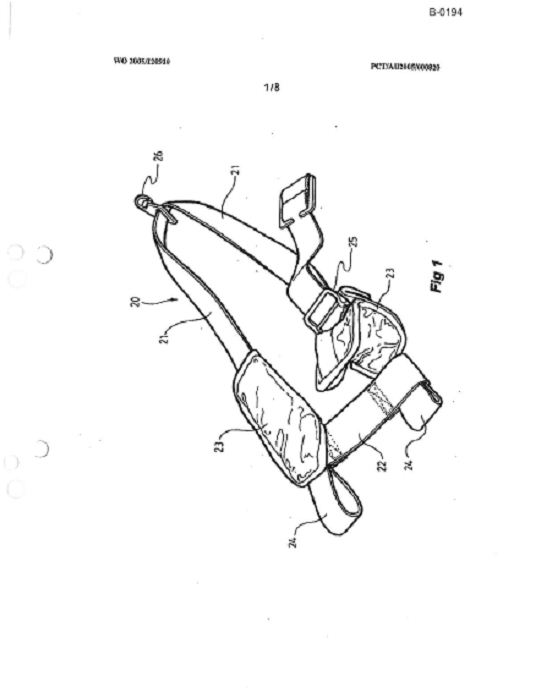
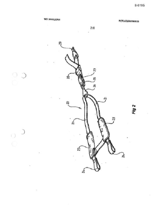
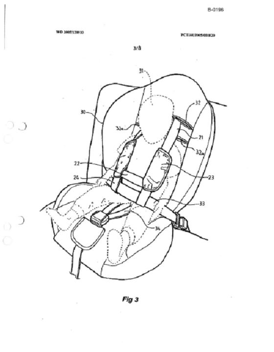
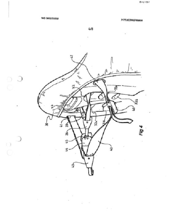
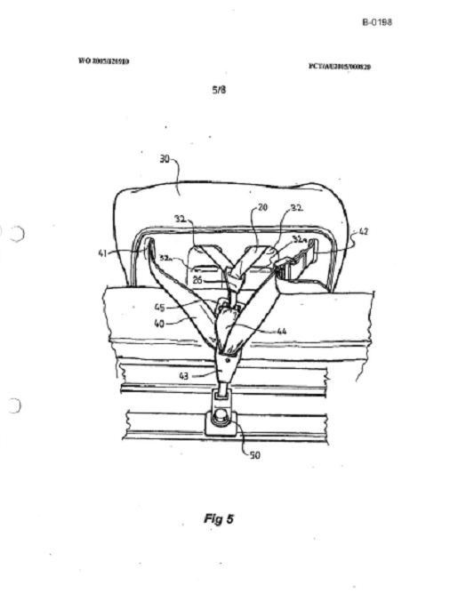
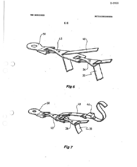

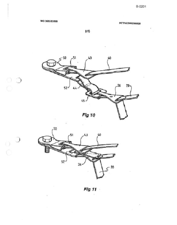
ANNEXURE ‘B’
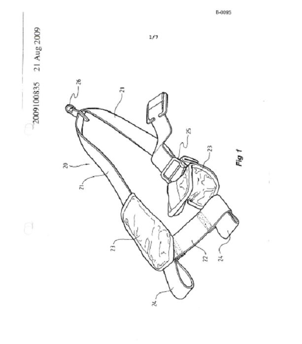
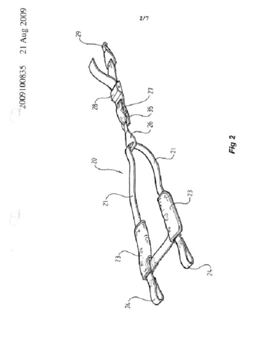
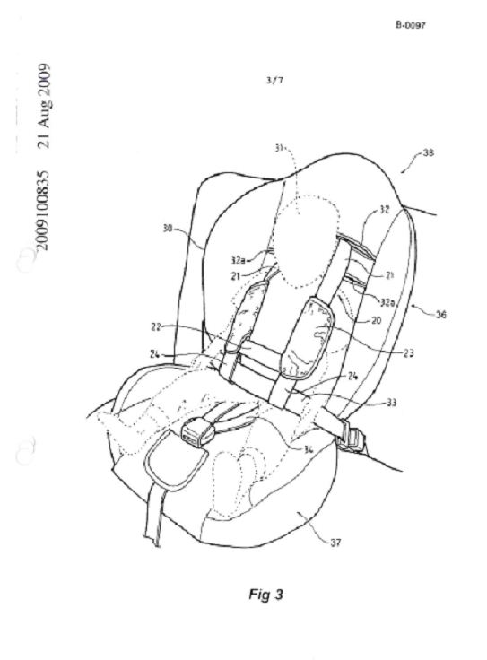
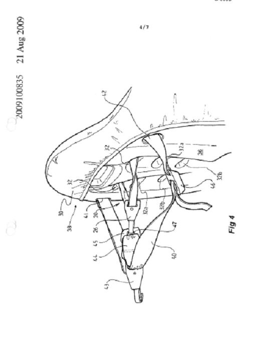
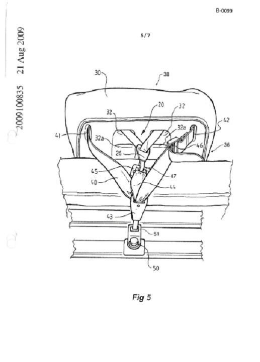
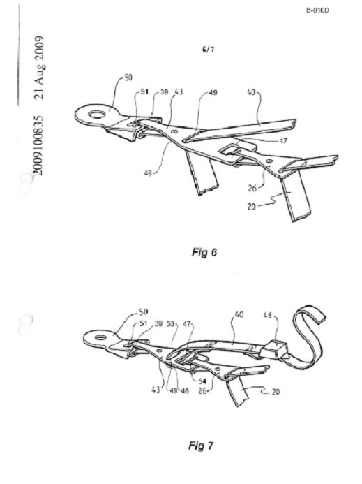
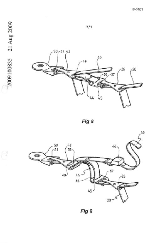
ANNEXURE ‘C’
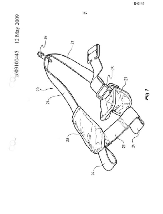
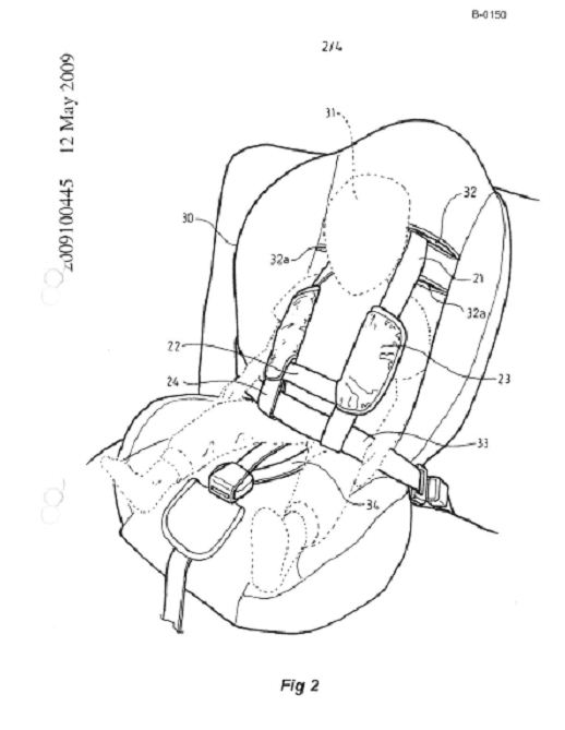
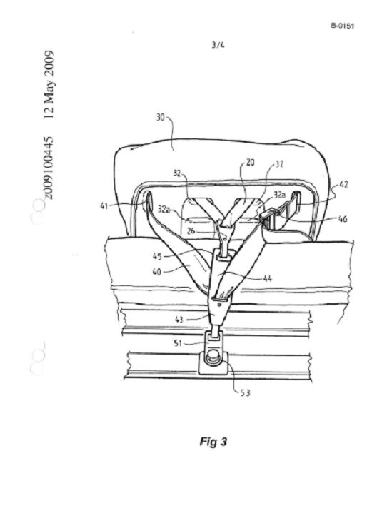
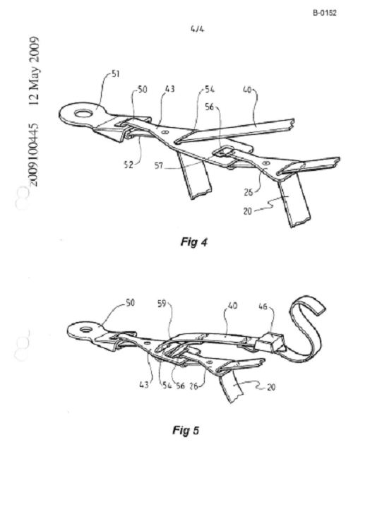
ANNEXURE ‘D’