
FEDERAL COURT OF AUSTRALIA
Bitech Engineering v Garth Living Pty Ltd [2009] FCA 1393
Held: (1) The respondents did not infringe the applicant’s Patent.
(2) The Patent was not invalid and should not be revoked.
Patents Act 1952 (Cth), s 40, s 100, Pt XVI
Patents Act 1990 (Cth), ss 7, 40, 138, 234
Bitech Engineering v Flameglow Pty Ltd [2008] FCA 1583 related
Aktiebolaget Hassle v Alphapharm Pty Ltd (2002) 212 CLR 411 applied
Alphapharm Pty Ltd v H Lundbeck A/S (2008) 76 IPR 618 applied
Bristol-Myers Squibb Co v FH Faulding & Co Ltd (2000) 97 FCR 524 applied
General Tire & Rubber Co v Firestone Tyre & Rubber Co Ltd (1971) 1A IPR 121, [1972] RPC 457 applied
ICI Chemicals & Polymers Ltd v The Lubrizol Corporation Inc (2000) 106 FCR 214 applied
Jupiters Ltd v Neurizon Pty Ltd (2005) 222 ALR 155, (2005) 65 IPR 86, (2005) AIPC 92-098 applied
Lockwood Security Products Pty Ltd v Doric Products Pty Ltd (2004) 217 CLR 274 applied
Meyers Taylor Pty Ltd v Vicarr Industries Ltd (1977) 137 CLR 228 applied
Minnesota Mining and Manufacturing Company v Beiersdorf (Australia) Ltd (1980) 144 CLR 253 applied
Populin v HB Nominees Pty Ltd (1982) 59 FLR 37, (1982) 41 ALR 471 applied
Ranbaxy Australia Pty Ltd v Warner-Lambert Co LLC (No 2) (2006) 71 IPR 46 applied
Rehm Pty Ltd v Websters Security Systems (International) Pty Ltd (1988) 81 ALR 79 cited
Welch Perrin & Co Pty Ltd v Worrel (1961) 106 CLR 588 applied
Blanco White TA, Patents for Inventions (5th ed, Stevens, 1983)
NSD 1681 of 2006
BITECH ENGINEERING v BUNNINGS GROUP LIMITED (ACN 008 672 179)
NSD 43 of 2007
BITECH ENGINEERING v FLAMEGLOW PTY LTD (ACN 117 672 518); FLAMEGLOW PTY LTD (ACN 117 672 518) v BITECH ENGINEERING
NSD 105 of 2007
BITECH ENGINEERING v HOTPOINT (AUST) PTY LTD (ACN 082 599 086); HOTPOINT (AUST) PTY LTD (ACN 082 599 086) v BITECH ENGINEERING
NSD 2056 of 2007
FOSTER J
26 November 2009
SYDNEY
| IN THE FEDERAL COURT OF AUSTRALIA |
|
| NEW SOUTH WALES DISTRICT REGISTRY |
|
| GENERAL DIVISION | NSD 1681 of 2006 |
| BITECH ENGINEERING Applicant/Cross-Respondent
| |
| AND: | GARTH LIVING PTY LTD (ACN 111 145 432) First Respondent/Cross-Claimant
COHEN NOMINEES PTY LIMITED (ACN 008 526 994) Second Respondent
|
| JUDGE: | |
| DATE OF ORDER: | 26 november 2009 |
| WHERE MADE: | SYDNEY |
THE COURT ORDERS THAT:
1. The Application be dismissed.
2. The Cross-Claim by Garth Living Pty Ltd against the applicant be dismissed.
3. The parties file and serve Written Submissions on the question of costs within seven (7) days of the date of the making of these Orders.
4. The question of the costs of the principal proceeding and of the Cross-Claim made by Garth Living Pty Ltd against the applicant be reserved to be determined in light of the parties’ Written Submissions.
5. The exhibits may be returned at the expiration of twenty-one (21) days from the date of these Orders.
Note: Settlement and entry of orders is dealt with in Order 36 of the Federal Court Rules.
The text of entered orders can be located using eSearch on the Court’s website.
| IN THE FEDERAL COURT OF AUSTRALIA |
|
| NEW SOUTH WALES DISTRICT REGISTRY |
|
| general division | NSD 43 of 2007 |
| BETWEEN: | BITECH ENGINEERING Applicant
|
| AND: | BUNNINGS GROUP LIMITED (ACN 008 672 179) Respondent
|
| JUDGE: | FOSTER J |
| DATE OF ORDER: | 26 November 2009 |
| WHERE MADE: | SYDNEY |
THE COURT ORDERS THAT:
1. The Application be dismissed.
2. The parties file and serve Written Submissions on the question of costs within seven (7) days of the date of the making of these Orders.
3. The question of the costs of the proceedings be reserved to be determined in light of the parties’ Written Submissions.
4. The exhibits may be returned at the expiration of twenty-one (21) days from the date of these Orders.
Note: Settlement and entry of orders is dealt with in Order 36 of the Federal Court Rules.
The text of entered orders can be located using eSearch on the Court’s website.
| IN THE FEDERAL COURT OF AUSTRALIA |
|
| NEW SOUTH WALES DISTRICT REGISTRY |
|
| GENERAL DIVISION | NSD 105 of 2007 |
| BETWEEN: | BITECH ENGINEERING Applicant/Cross-Respondent
|
| AND: | FLAMEGLOW PTY LTD (ACN 117 672 518) Respondent/Cross-Claimant
|
| JUDGE: | FOSTER J |
| DATE OF ORDER: | 26 november 2009 |
| WHERE MADE: | SYDNEY |
THE COURT ORDERS THAT:
1. The Application be dismissed.
2. Those claims made by Flameglow Pty Ltd against the applicant in the Cross-Claim for relief that Australian Patent No 621713 be declared invalid and be revoked be dismissed.
3. The balance of the Cross-Claim be listed for directions before Foster J at 9.30 am on 3 December 2009.
4. The parties file and serve Written Submissions on the question of costs within seven (7) days of the date of the making of these Orders.
5. The question of the costs of the principal proceeding and of the Cross-Claim insofar as the claims referred to in par 2 above are concerned be reserved to be determined in light of the parties’ Written Submissions.
6. The question of the costs of the balance of the Cross-Claim be reserved to await the determination of the claims made in the balance of that Cross-Claim.
7. The exhibits may be returned at the expiration of twenty-one (21) days from the date of these Orders.
Note: Settlement and entry of orders is dealt with in Order 36 of the Federal Court Rules.
The text of entered orders can be located using eSearch on the Court’s website.
| IN THE FEDERAL COURT OF AUSTRALIA |
|
| NEW SOUTH WALES DISTRICT REGISTRY |
|
| general division | NSD 2056 of 2007 |
| BETWEEN: | BITECH ENGINEERING Applicant/Cross-Respondent
|
| AND: | HOTPOINT (AUST) PTY LTD (ACN 082 599 086) Respondent/Cross-Claimant
|
| JUDGE: | FOSTER J |
| DATE OF ORDER: | 26 november 2009 |
| WHERE MADE: | SYDNEY |
THE COURT ORDERS THAT:
1. The Application be dismissed.
2. The Cross-Claim be dismissed.
3. The parties file and serve Written Submissions on the question of costs within seven (7) days of the date of the making of these Orders.
4. The question of the costs of the principal proceeding and of the Cross-Claim be reserved to be determined in light of the parties’ Written Submissions.
5. The exhibits may be returned at the expiration of twenty-one (21) days from the date of these Orders.
Note: Settlement and entry of orders is dealt with in Order 36 of the Federal Court Rules.
The text of entered orders can be located using eSearch on the Court’s website.
| IN THE FEDERAL COURT OF AUSTRALIA |
|
| NEW SOUTH WALES DISTRICT REGISTRY |
|
| GENERAL DIVISION | NSD 1681 of 2006 |
| BETWEEN: | BITECH ENGINEERING Applicant/Cross-Respondent
|
| AND: | GARTH LIVING PTY LTD (ACN 111 145 432) First Respondent/Cross-Claimant
COHEN NOMINEES PTY LIMITED (ACN 008 526 994) Second Respondent
|
| IN THE FEDERAL COURT OF AUSTRALIA |
|
| NEW SOUTH WALES DISTRICT REGISTRY |
|
| general division | NSD 43 of 2007 |
| BETWEEN: | BITECH ENGINEERING Applicant
|
| AND: | BUNNINGS GROUP LIMITED (ACN 008 672 179) Respondent
|
| IN THE FEDERAL COURT OF AUSTRALIA |
|
| NEW SOUTH WALES DISTRICT REGISTRY |
|
| general division | NSD 105 of 2007 |
| BETWEEN: | BITECH ENGINEERING Applicant/Cross-Respondent
|
| AND: | FLAMEGLOW PTY LTD (ACN 117 672 518) Respondent/Cross-Claimant
|
| IN THE FEDERAL COURT OF AUSTRALIA |
|
| NEW SOUTH WALES DISTRICT REGISTRY |
|
| GENERAL DIVISION | NSD 2056 of 2007 |
| BETWEEN: | BITECH ENGINEERING Applicant/Cross-Respondent
|
| AND: | HOTPOINT (AUST) PTY LTD (ACN 082 599 086) Respondent/Cross-Claimant |
| JUDGE: | FOSTER J |
| DATE: | 26 november 2009 |
| PLACE: | SYDNEY |
REASONS FOR JUDGMENT
1 The applicant (Bitech) is a company incorporated in the Republic of Ireland. It is the patentee of Australian Patent No 621713 for an invention described in the patent as “Apparatus for Simulating Flames” (the Patent). The essential object of the invention is to achieve a realistic simulation of flames emanating from a simulated combusting log or coal fire. It has application in electric and gas fired domestic room heaters.
2 Bitech commenced four sets of proceedings. The respondent parties in each proceeding are different. The issues in the proceedings, however, are broadly the same. The four sets of proceedings were heard together with the evidence in each proceeding being evidence in all of the other proceedings, and vice versa.
3 In each proceeding, Bitech has sued the respondent parties for infringement of the Patent by, amongst other things, importing and selling certain electric heaters which also have a simulated flame effect. Attached to these Reasons for Judgment as Table A is a table in which the conduct on the part of each respondent said to constitute infringement of the Patent is more particularly described. Bitech claimed permanent injunctive relief, delivery up of all infringing articles, damages or account of profits, interest and costs.
4 In three of the four proceedings, three of the respondents sought orders that the Patent be declared invalid and that it be revoked. Cohen Nominees Pty Limited (Cohen), the second respondent in proceeding NSD 1681 of 2006, did not cross-claim for revocation of the Patent. Nor did Bunnings Group Limited (Bunnings), the sole respondent in proceeding NSD 43 of 2007. Flameglow Pty Ltd (Flameglow), the sole respondent in proceeding NSD 105 of 2007, also claimed damages against Bitech for allegedly making unjustified threats of patent infringement proceedings.
5 The hearing before me involved liability only. All questions concerning damages or account of profits have been reserved for further consideration in light of these Reasons for Judgment.
6 Only Garth Living Pty Limited (Garth Living) (the first respondent in proceeding NSD 1681 of 2006) put in issue the allegation that it engaged in infringing conduct by importing and selling heaters of the type which Bitech alleged infringed its patent. It will, therefore, be necessary to determine whether Garth Living did import and sell those heaters. Bitech also alleged that Garth Living was party to a common design involving the importation and sale in Australia of the BH heaters by Bunnings and the MS-5 heater by Cohen. There was no dispute on the part of the other respondents that each of them engaged in the particular conduct attributed to them by Bitech, particulars of which are set out in Table A. Of course, all respondents denied that their conduct constituted any infringement of the Patent. Cohen said that it had ceased to sell the MS-5 heater in February 2007 and proved that fact in evidence. The main issue between Bitech and the respondents which arose in the infringement case involved the proper construction of Claim 1 of the Patent and dependent Claims 8 and 20. Initially, Bitech also contended that the respondents had infringed dependent Claims 12 and 14 of the Patent. That contention was abandoned in final address.
7 The Claims for a declaration of invalidity and for revocation of the Patent raise the following issues:
(a) Whether the invention defined in Claims 1, 8, 12, 14 and 20 of the Patent was novel;
(b) Whether the invention defined in those Claims involved an inventive step; and
(c) Whether those Claims are fairly based on the matter described in the specification of the Patent.
8 The unjustified threats Claim will turn on the resolution of the other issues referred to in [6] and [7] above. That Claim was adjourned on 21 October 2008 because Mr Ogilvie, the principal witness to be called by Flameglow in support of that Claim, was ill and could not attend Court when the hearing of the other liability issues took place. The orders made on that occasion and the reasons for them are to be found in Bitech Engineering v Flameglow Pty Ltd [2008] FCA 1583. In addition, Flameglow did not participate to any real extent in the hearing before me. Its participation was confined to seeking to have its unjustified threats claim adjourned and to seeking to read an affidavit sworn by Mr Ogilvie, which I rejected.
The 1990 Patents Act Applies to the Patent
9 The application for the Patent was filed on 9 February 1990. At that time, the provisions of the Patents Act 1952 (Cth) (the 1952 Act) were in force.
10 The Patent was granted on 20 July 1992.
11 Subsections (2) and (5) of s 234 of the Patents Act 1990 (Cth) (the 1990 Act) are in the following terms:
234 Applications under 1952 Act
…
(2) Where, before the commencing day:
(a) a patent application had been lodged under the 1952 Act; and
(b) a complete specification, or a petty patent specification, had been lodged under that Act in respect of the application; and
(c) the application had not been withdrawn or finally dealt with;
then, subject to this Chapter and the regulations, this Act applies on and after that day:
(d) in relation to the application as if it were a complete application made under this Act; and
(e) in relation to the petty patent specification as if it were a complete specification filed under this Act in respect of the application.
…
(5) Objection cannot be taken to:
(a) an application mentioned in subsection (2); or
(b) a patent granted on such an application;
and such a patent is not invalid, so far as the invention is claimed in any claim, on any ground that would not have been available against the application or patent, as the case may be, under the 1952 Act.
12 The 1990 Act commenced on 30 April 1991.
13 By the operation of s 234(2) and s 234(5), the 1990 Act applied to the application. However, the Patent cannot be revoked on a ground that would not have been available against the Patent under the 1952 Act.
14 These propositions were confirmed by the Full Court in ICI Chemicals & Polymers Ltd v The Lubrizol Corporation Inc (2000) 106 FCR 214 at [22]–[23] (p 224), where the Court said:
Applicable statutory regime
22 The patent was granted under the Patents Act 1952 (Cth) (the 1952 Act). The 1952 Act has been repealed and the legislation now in force is the Patents Act 1990 (Cth) (the 1990 Act). Section 233 of the 1990 Act provides:
“(1) Subject to this Chapter and the Regulations, this Act applies in relation to a standard patent or a petty patent granted under the 1952 Act as if the patent had been granted under this Act.
...
(4) Objection cannot be taken to a patent mentioned in subsection (1), and such a patent is not invalid, so far as the invention is claimed in any claim, on any ground that would not have been available against the patent under the 1952 Act.”
23 It follows that the patent can only be revoked under the 1990 Act, and only on a ground of invalidity which is provided by that Act and would also have been available under the 1952 Act. And where the ground of invalidity under the 1952 Act is narrower than the corresponding ground under the 1990 Act, the patentee has the benefit of the narrower ground. That follows from the decision of the Full Court in NV Philips Gloeilampenfabrieken v Mirabella International Pty Ltd (1993) 44 FCR 239 at 253-254.
15 Section 234(2) and s 234(5) are also relevant to the cross-claimants’ claims that the Patent is invalid and should be revoked.
The Relevant Principles (Construction of Patents)
16 In the present case, there is no dispute amongst the parties as to the principles of construction to be applied to the Patent. All parties referred me to the joint judgment of the Full Court in Jupiters Ltd v Neurizon Pty Ltd (2005) 222 ALR 155, (2005) 65 IPR 86, (2005) AIPC 92-098 at [67]. Reliance was also placed by some of the respondents upon the statements made at [68] in the same case. Those paragraphs are in the following terms:
67 There is no real dispute between the parties as to the principles of construction to be applied in this matter although there is some difference in emphasis. It suffices for present purposes to refer to the following:
(i) the proper construction of a specification is a matter of law: Décor Corporation Pty Ltd v Dart Industries Inc (1988) 13 IPR 385 at 400;
(ii) a patent specification should be given a purposive, not a purely literal, construction: Flexible Steel Lacing Co v Beltreco Ltd (2000) 49 IPR 331 ; [2000] FCA 890 at [81] (Flexible Steel Lacing); and it is not to be read in the abstract but is to be construed in the light of the common general knowledge and the art before the priority date: Kimberley-Clark Australia Pty Ltd v Arico Trading International Pty Ltd (2001) 207 CLR 1 ; 177 ALR 460 ; 50 IPR 513 ; [2001] HCA 8 at [24];
(iii) the words used in a specification are to be given the meaning which the normal person skilled in the art would attach to them, having regard to his or her own general knowledge and to what is disclosed in the body of the specification: Décor Corporation Pty Ltd at 391;
(iv) while the claims are to be construed in the context of the specification as a whole, it is not legitimate to narrow or expand the boundaries of monopoly as fixed by the words of a claim by adding to those words glosses drawn from other parts of the specification, although terms in the claim which are unclear may be defined by reference to the body of the specification: Kimberley-Clark v Arico at [15]; Welch Perrin & Co Pty Ltd v Worrel (1961) 106 CLR 588 at 610; Interlego AG v Toltoys Pty Ltd (1973) 130 CLR 461 at 478; the body of a specification cannot be used to change a clear claim for one subject matter into a claim for another and different subject matter: Electric & Musical Industries Ltd v Lissen Ltd [1938] 4 All ER 221 at 224–5 ; (1938) 56 RPC 23 at 39;
(v) experts can give evidence on the meaning which those skilled in the art would give to technical or scientific terms and phrases and on unusual or special meanings to be given by skilled addressees to words which might otherwise bear their ordinary meaning: Sartas No 1 Pty Ltd v Koukourou & Partners Pty Ltd (1994) 30 IPR 479 at 485–6 (Sartas No 1 Pty Ltd); the court is to place itself in the position of some person acquainted with the surrounding circumstances as to the state of the art and manufacture at the time (Kimberley-Clark v Arico at [24]); and
(vi) it is for the court, not for any witness however expert, to construe the specification; Sartas No 1 Pty Ltd at 485–6.
68 We may add that the area of invention with which this proceeding is concerned is a particularly narrow one. It is one in which business rivals are striving to invent around the patented inventions of others and within narrow regulatory limits. In such a context it is, in our view, important to recognise that claims made for an invention may need to be formulated narrowly to avoid invalidity. While accepting the primacy of purposive construction in interpreting patents, such a construction may well provide little by way of illumination where, as here, the inventive context is a cramped one. It is not appropriate to take a claim carefully drawn to avoid invalidity and then permit a wider “purposive” construction of it for infringement purposes: Grove Hill Pty Ltd v Great Western Corp Pty Ltd (2002) 55 IPR 257; [2002] FCAFC 183 at [311].
17 In Ranbaxy Australia Pty Ltd v Warner-Lambert Co LLC (No 2) (2006) 71 IPR 46 at [62]–[64] (pp 61–62), Young J distilled from a number of authorities a set of principles which his Honour held should ordinarily guide the construction of patents. The observations which his Honour made in that case are reminiscent of the statements made by the Full Court in Jupiters 222 ALR 155, 65 IPR 86, AIPC 92-098 and need not be set out in full here. However, I am content to adopt and apply what his Honour said, which, to some extent, helpfully adds to the statements of principle made by the Full Court in Jupiters 222 ALR 155, 65 IPR 86, AIPC 92-098.
18 In Welch Perrin & Co Pty Ltd v Worrel (1961) 106 CLR 588, a Full Court of the High Court (Dixon CJ, Kitto and Windeyer JJ), said (at 609):
Most of the argument before us centred upon the construction of the specification and, as in every patent case, it is necessary to determine from it what exactly is the invention it describes and for which a monopoly is claimed, before proceeding to consider objections to the validity of particular claims: Electrical and Musical Industries Ltd. v. Lissen Ltd [(1938) 56 RPC 23, at p 39].
19 At 610, the Court said:
If it is impossible to ascertain what the invention is from a fair reading of the specification as a whole, that, of course, is an end of the matter. But this objection is not established by reading the specification in the abstract. It must be construed in the light of the common knowledge in the art before the priority date. The general principles governing the construction of specifications are well known, and no lengthy reference to them is necessary. It is, however, fitting that we remind ourselves of the criterion to be applied when it is said that a specification is ambiguous. For, as the Chief Justice pointed out in Martin v. Scribal [(1954) 92 CLR 17, at p 59], referring to Lord Parker’s remarks in National Colour Kinematograph Co. Ltd. v. Bioschemes Ltd [(1915) 32 RPC 256], we are not construing a written instrument operating inter partes, but a public instrument which must, if it is to be valid, define a monopoly in such a way that it is not reasonably capable of being misunderstood. Nevertheless, it is to be remembered that any purely verbal or grammatical question that can be resolved according to ordinary rules for the construction of written documents, does not, once it has been resolved, leave uncertain the ambit of the monopoly claimed (see Kauzal v. Lee [(1936) 58 CLR 670, at p 685]). The specification must be read as a whole. But it is a whole made up of several parts, and those parts have different functions. Courts have often insisted that it is not legitimate to narrow or expand the boundaries of monopoly as fixed by the words of a claim by adding to those words glosses drawn from other parts of the specification. Similarly, if a claim be clear it is not to be made obscure simply because obscurities can be found in particular sentences in other parts of the document.
20 The Court then moved to consider in some detail the patent in dispute in that case. After setting out the objects of that patent, the Court said (at 612):
At this point in a modern specification one might expect to find a general description of what the inventor asserts his invention consists of, commonly called a "consistory clause". This, however, is not an essential part of the body of a specification. It is not required by the Act. Its purpose may be quite well met by the claims themselves: United Shoe Machinery Corporation’s Application [(1939) 57 RPC 71]. Indeed, the usual practice in England is now to use in the consistory clause the wording of the broadest of the claims: see Mr. Blanco White’s book, Patents for Inventions 2nd ed. (1955) p. 34n. The present Australian Act expressly requires the claim or claims to define the invention: s. 40. In a patent for a combination, such as this is, the most important function of the body of the specification is to show what are the mechanical means which, operating together, produce the result claimed; and how they so operate.
21 In deciding whether a patent has been infringed, the Court is obliged to adopt a common sense construction of the claims in the patent, having regard to the prior knowledge as at the priority date, and, having done so, to determine whether the alleged infringer has taken all of the essential features or integers of the patentee’s claims as determined by that construction (Populin v HB Nominees Pty Ltd (1982) 59 FLR 37 at 40–41, (1982) 41 ALR 471 at 475).
The Construction of the Patent
22 The Patent is for an invention entitled “Apparatus for Simulating Flames”. It was granted on 20 July 1992 on an application filed on 9 February 1990 as a Convention Application pursuant to Pt XVI of the 1952 Act. It claims priority from the filing of two basic applications in the United Kingdom on 10 February 1989 and on 15 September 1989 respectively.
The Description
23 The specification commences with a description of the nature of the invention and some relevant background. The first two paragraphs of that description, which appear between lines 3 and 16 on p 1a of the Patent, are in the following terms:
This invention relates to apparatus for simulating flames. The apparatus may be part of, or embodied in a heating appliance (such as an electric or gas fire) in order to create the impression of flames due to combusting fuel.
Many attempts have been made in the past to simulate combusting fuel. The prior art devices often included some means intended to represent flickering flames but they lacked realism. Moreover, when an appliance having such an effect is seen from day to day, it becomes less convincing with the passage of time. In many prior art devices, dust and dirt can also build up on various surfaces so that any initially pleasing effect is spoilt thereby detracting from any realism. At least the preferred embodiments of the invention seek to solve these problems.
24 That description is then followed by the consistory clause in the Patent. That clause mirrors the wording of Claim 1. The consistory clause is then followed by a detailed description of various preferred embodiments.
25 Between line 30 on p 1a of the Patent and line 4 on p 4 of the Patent, the following appears:
Preferably, the apparatus is mounted in a casing having a transparent front panel through which the simulated fuel and the screen are visible. This helps to exclude dust and dirt. Preferably, the flame effect means is sealed against the ingress of dust and dirt.
Preferably, the flame effect means comprises pieces of material supported in such a way that they move in response to a current of air provided, for example, by a small fan. In a preferred embodiment of the invention, ribbons of material extend between spaced supports and the ribbons are supported in such a manner so as to promote their movement due to the current of air. The ribbons may be made of silk, satin or a similar fabric which reflects light and tends to undulate in an air stream so as to provide a constantly changing reflecting surface similar to the appearance of a flame. Such ribbons are preferably suspended or held in a substantially vertical orientation. They can be suspended or held substantially edgewise to the screen means or they can be twisted so that e.g. a lower portion of each ribbon is edgewise to the screen means whilst an upper portion is substantially parallel to the screen means. They may also be shaped to improve the realism of the effect, for example, they may be triangular, or trapezoidal, or other shapes which tend to imitate the shape of a flame and/or increase its movement e.g. with ragged or curling edges, and they may also have slits or holes to promote this effect. The ribbons can also be coated with material to improve their reflectivity.
Preferably, the screen means includes one or more panels. For example, a single panel may be used which is made so that it partly transmits, partly reflects and also diffuses light. More specifically, a single panel may have a partly or lightly silvered front surface to reflect light and its rear surface treated so as to diffuse light. In any event, the partially reflective property is such as to reflect light from the simulated fuel bed so that the simulated flames appear to emanate from a position between the simulated fuel and its reflection in the screen. This considerably improves the realism of the simulated flames and is surprisingly effective. The diffusing action of the screen is such as to prevent the ribbons (or their equivalent) from being seen too clearly through the screen whilst at the same time allowing sufficient light there-through (reflected from the ribbons) to give the simulated flame effect. This kind of diffusion may be provided by a surface having closely spaced lines and such a surface may be part of a single panel which is also partly reflective. Alternatively, it can be part of a separate panel. Such a diffusing effect also tends to create a magnified image due to refraction. The lines may be spaced at about 1,000 lines to the cm. and they can be horizontal (as viewed), or cross-hatched.
An alternative screen means has a clear or transparent panel (e.g. of glass) mounted closely adjacent [to] a diffusing panel (e.g. of heat resistant plastics). Suitably, the diffusing panel is matt on the side immediately opposite the transparent panel. Suitably, a diffusing panel is made of material which usually has two polished or shiny sides and one side is made matt by e.g. abrasion. A suitable panel can be made from polycarbonate (available under the Trade Mark “Lexan”.) When such a screen is used, the transparent panel acts partly as a reflector for light received either directly from the simulated fuel means, or indirectly from the latter means after at least one reflection from the transparent front panel which is preferably partly silvered to promote such reflection. The transparent panel directly transmits the light received from the flame effect means and the diffusing action softens the edges of the images of the ribbons.
In a preferred embodiment of the invention, the flame effect means is positioned closely adjacent [to], but not touching the screen means. More generally, the flame effect means is preferably positioned at a distance from the screen means (on one side) which does not exceed the amount by which the simulated fuel bed extends away from the screen means (on the other side).
Where a front panel is provided for enclosing a casing containing the apparatus, the front panel may be tinted so that the means for simulating flames and combusting fuel are not visible when the light source is extinguished. However, a clear sheet may be used where this effect is not required. In either case, the front panel may be partly or lightly silvered so that it is both reflective and transparent whereby the simulated fuel bed appears to extend more deeply into the back of the fire (due to multiple front-to-back reflections between confronting surfaces of the screen means and the front panel) and the simulated flames appear to emanate from different regions in the extended fuel bed.
26 The flame effect means is referred to in this part of the Patent between line 35 on p 1a and line 19 on p 2. The screen means is referred to in this part of the Patent between line 20 on p 2 and line 22 on p 3.
27 The particular embodiments described in that part of the Patent in which the preferred embodiments are described incorporate a flame effect means which comprises a series of ribbons suspended vertically in the apparatus. These ribbons ripple or undulate in a current of air which is provided by a fan unit located within the apparatus. They also reflect light from a light source so as to provide the desired flame effect.
28 Bitech submitted, and I accept, that the scope of the claims made in a patent may, and almost always does, extend beyond a description of the preferred embodiment. In Rehm Pty Ltd v Websters Security Systems (International) Pty Ltd (1988) 81 ALR 79 at 95, Gummow J said:
The circumstance that something is a requirement for the best method of performing an invention does not make it necessarily a requirement for all claims; likewise, the circumstance that material is part of the description of the invention does not mean that it must be included as an integer of each claim. Rather, the question is whether there is a real and reasonably clear disclosure in the body of the specification of what is then claimed, so that the alleged invention as claimed is broadly, that is to say in a general sense, described in the body of the specification.
29 These observations made by his Honour were cited with approval by the High Court in Lockwood Security Products Pty Ltd v Doric Products Pty Ltd (2004) 217 CLR 274 at [69] (pp 300–301).
30 After the description of the preferred embodiments set out in the Patent, there is a description of an embodiment of the invention by reference to accompanying schematic drawings. This description is to be found between line 5 on p 4 and line 20 on p 9 of the Patent. Eight drawings are depicted in the schematic drawings forming part of the Patent.
The Claims
31 The Patent contains 20 Claims which define the invention. These are found on pp 10–12 of the Patent. There are two independent Claims (Claims 1 and 15). As is usually the case, each of the independent Claims is followed by several dependent Claims which become progressively narrower as additional features or limitations are added to the invention.
32 Claims 1–14 and 20 are in the following terms:
1. Apparatus for simulating flames, the apparatus comprising a source of light, simulated flame effect means for reflecting said light to simulate flames, simulated fuel means to simulate a bed of combusting fuel, and screen means on which to view an image of the simulated flames, said screen means being positioned between said flame effect means and said simulated fuel means, said screen means being capable of diffusely transmitting light reflected by said flame effect means and also being capable of reflecting light from said simulated fuel means so that the simulated flames appear to emanate between the simulated fuel means and an image of the latter means reflected in said screen means.
2. Apparatus according to Claim 1 wherein said flame effect means comprises pieces of material supported so that they are capable of movement, and means for causing said movement.
3. Apparatus according to Claim 2 wherein said pieces of material are ribbons extending between spaced supports.
4. Apparatus according to Claim 3 in which each of said ribbons is twisted.
5. Apparatus according to Claim 3 or 4 wherein the means for causing said movement generates a current of air.
6. Apparatus according to Claim 5 wherein said means for causing movement includes an electric fan and a cylinder mounted for rotation by the air stream generated by the fan the cylinder being provided with air deflection means for imparting a more random movement to said ribbons to improve the simulated flame effect.
7. Apparatus according to Claim 3, 4, 5 or 6 wherein said ribbons are shaped in such a way as to imitate the shape of a flame and/or to increase their movement.
8. Apparatus according to any one of the preceding Claims wherein said screen means is a translucent or transparent panel or panels having a partially reflective surface and a diffusing surface.
9. Apparatus according to any one of the preceding Claims in which said screen means is a single panel having a partially reflective front surface and a rear surface on which are provided a multiplicity of closely spaced lines.
10. Apparatus according to Claim 9 wherein said lines are horizontal, as viewed from the front of the apparatus, inclined, as viewed from the front of the apparatus, or cross-hatched.
11. Apparatus according to any one of Claims 1-7 in which said screen means comprises a transparent panel situated closely adjacent [to] a diffusing panel.
12. Apparatus according to any one of the preceding Claims mounted in or forming part of a casing having a transparent front panel through which the simulated fuel and the screen means are visible.
13. Apparatus according to Claim 12 wherein said transparent front panel is tinted so that the simulated fuel and the screen means are substantially obscured when the source of light is extinguished.
14. Apparatus according to Claim 12 or 13 wherein the front panel is both transparent and reflective whereby multiple front-to-back images of the simulated fuel means are provided and the simulated flames appear to emanate from different regions in an extended bed of fuel.
…
20. A heating appliance incorporating the apparatus according to any one of the preceding Claims.
33 Claims 8, 12, 14 and 20 are dependent on Claim 1 and provide further definition in respect of particular features.
Construction
34 The case advanced by Bitech was that the respondents’ heaters infringed Claim 1 and dependent Claims 8 and 20 of the Patent. I have reproduced the full text of those Claims at [32] above.
35 Claim 1 is the critical Claim. The apparatus defined in Claim 1 comprises the following mechanisms or devices or means (which is the word used for the most part in the text of Claim 1 in respect of the various devices comprising the apparatus the subject of Claim 1):
(a) A source of light;
(b) Simulated flame effect means for reflecting said light to simulate flames;
(c) Simulated fuel means to simulate a bed of combusting fuel; and
(d) Screen means on which to view an image of the simulated flames, said screen means having the attributes or characteristics more particularly described between lines 5 and 11 on p 10 of the Patent. These are the last six lines of Claim 1.
36 The integer of the apparatus defined as the simulated flame effect means for reflecting said light to simulate flames is met when the light from the light source is reflected by the simulated flame effect means in order to simulate flames in a manner which can be observed upon the screen means (the viewing screen) which is referred to later in Claim 1. The simulated fuel means refers to a bed of simulated combusting fuel (such as imitation wood or coal) intended to mimic the combustion of that fuel, so as to create an image of combusting fuel on the viewing screen which also can be observed by a person sitting or standing in front of the device in which the apparatus is installed.
37 The viewing screen must be positioned between the device which creates the flame effect and the simulated fuel means. The viewing screen must be capable of diffusely transmitting light reflected by the flame effect means and must also be capable of reflecting light from the simulated fuel means so that the simulated flames which are observable on the viewing screen appear to emanate from an area located between the simulated fuel means and an image of that simulated fuel means which is reflected on the viewing screen.
38 As I read Claim 1, the source of light contemplated by that Claim must be so located within the chamber of the heater or other device within which the apparatus is constructed so as to enable light reflected by the flame effect means contemplated by Claim 1 to reach the viewing screen which in turn must be capable of diffusely transmitting that reflected light so as to create an image of flames on the screen appearing to emanate from the area which I have described in [37] above. The idea captured in Claim 1 is that, from the perspective of a viewer sitting or standing in front of the heater or other device in which the apparatus is installed, there appears on a viewing screen within the device simulated flames the creation of which begins with a light source and the development of which is attributable to some flame effect means (not described in detail in Claim 1) which reflects light from the light source to the viewing screen through which that reflected light is diffusely transmitted in order to create flame images on the screen. Those flame images must appear to emanate from an area located between the simulated fuel means and the viewing screen.
39 The essence of the way in which light from the light source is ultimately used to create the images of flames on the screen is reflection. Claim 1 does not contemplate, in my opinion, that the flame effect means will substantially rely upon or involve to any significant degree a process whereby light is directly emitted from that means to the viewing screen so that the images viewed on the screen are substantially or predominantly the result of the transmission of light directly emitted from the flame effect means.
40 Consideration of the language employed in Claim 8 leads to the same conclusion.
41 There is just no mention of directly emitted light in either Claim 1 or in Claim 8. Each of the Claims proceeds upon the basis that the means by which the light from the light source will be transferred to the screen in a way which creates flame images will be by reflection.
42 The language of the description, the preferred embodiments and the other embodiments in the specification tends to support this construction of the Patent. Further, that language does not suggest that the flame effect means includes the inner surface of the back panel of a consumer product in which the apparatus defined by the Patent might be installed—for example, the inner surface of the back panel of an electric domestic room heater. Nor does that language suggest that the flame effect means includes other surfaces of the outer casing of such a product.
43 For example, the Patent goes into some detail in order to describe the way in which the ribbons referred to in the preferred embodiments section of the Patent might be set up in order to create the necessary flame effect. The whole purpose of deploying ribbons in the way described in that part of the Patent is to transmit reflected light to the viewing screen. In addition, the other embodiments which are the subject of the text and the schematic drawings forming part of the Patent all proceed upon the basis that the process by which light from the light source is transported via the flame effect means to the viewing screen has to be by way of reflection.
44 An apparatus that relies to a substantial degree upon the transmission of directly emitted light from or via the flame effect means to the viewing screen in order to simulate flames on that screen is outside the monopoly claimed by Bitech in the Patent.
45 Counsel for Hotpoint (Aust) Pty Ltd (Hotpoint), the respondent in proceeding NSD 2056 of 2007, made an additional submission as to the proper construction of Claim 1. This submission was adopted by Counsel for Garth Living, Bunnings and Cohen. She submitted that the type of reflected light called for by Claim 1 is light produced by specular reflection, and by specular reflection alone. She relied upon a number of indications in the Patent in support of that submission, in particular, the language which emphasised that all reflective surfaces should be kept clean and free of dust.
46 Claim 1 does not make a distinction, either expressly or implicitly, between specular and diffuse reflection when it speaks of reflection. The language of Claim 1, understood in the context of the balance of the Patent and looked at from the point of view of a skilled reader familiar with optics, having regard to that reader’s general knowledge and to what is disclosed in the body of the specification, does not distinguish between types of reflection. The Patent contemplates that the reflected light, which is integral to the invention, might be specular, diffuse or a combination of the two. I do not accept the submission made by Counsel for Hotpoint that the reflected light called for by Claim 1 must be specular.
Expert Evidence
47 Three experts gave evidence at the trial. Bitech called Dr Ian Cowling, who is an Associate Professor in the School of Physical and Chemical Sciences of the Queensland University of Technology (QUT). His field of expertise is optics, which is the study of the behaviour and properties of light. He has been involved in that field for more than 25 years. The respondents called Professor Keith Nugent, who is the Laureate Professor of Physics and Federation Fellow, Executive Research Director, ARC Centre of Excellence for Coherent X‑Ray Science in the School of Physics at the University of Melbourne. Professor Nugent said that he was expert in the field of optical methods and technologies. The respondents also called Professor Tanya Monro, who is the Professor of Physics with the Chair of Photonics and a Director of DSTO Centre of Expertise in Photonics, School of Chemistry and Physics at the University of Adelaide.
48 Each expert was amply qualified in the relevant field of physics, although none of the experts had ever been involved in the design or manufacture of heaters or devices endeavouring to simulate flame effects.
49 In his first affidavit, Dr Cowling gave a succinct but very helpful synopsis of the behaviour and properties of light insofar as those matters are relevant to the present proceedings. At pars 23–28 of that affidavit, Dr Cowling said:
23 Light is a form of energy, or radiation, that is generally accepted as having the properties of waves. A beam of light is actually a number of different waves travelling through the air (or other medium) together. From a scientific perspective, light behaves in a predictable manner.
24 Energy that has the properties of waves, such as light, will be partially transmitted and partially reflected at the boundary or surface between any two media. Generally speaking, when a beam of light strikes the surface of a new medium (or substance), two things happen. Some of the energy will be reflected off the surface of the new medium in the form of reflected light, and some energy will be transmitted through or absorbed into the new medium. In effect, what this means is that all surfaces reflect light to some degree. Conversely, no surface reflects 100% of light, because some of the energy is always absorbed.
25 At its simplest, reflection of light is the change in the direction of light waves when they hit a surface and bounce off it, retaining their energy. Because not all of the light is reflected, the intensity of the reflected light decreases. This will be the case if that light is again reflected off another surface, with the intensity of the light decreasing with each incident of reflection. The amount of reflection that there is occurring, and consequently the decrease in intensity of the reflected light, depends on the nature of the surface that the light is hitting.
26 It is generally accepted that there are two types of reflection – specular and diffuse reflection:
26.1 Specular reflection occurs when light is reflected off a smooth surface (such as a mirror, glass or other shiny surface). The waves of light remain concentrated during specular reflection, and are reflected uniformly off the surface in a particular direction rather than being scattered in different directions. This creates an image behind the surface that can be detected by the eye. The most obvious example of this is an image in a mirror.
26.2 Diffuse reflection occurs when a wave of light is reflected off rough surfaces (such as wood, walls or fabric), and scatters in different directions. While this may (depending on the degree of scattering that takes place) be sufficient to produce an outline of an image on the surface, it is not the clear mirror image that can be seen in the case of specular reflection.
27 It is possible to measure the reflection and transmission of light from different materials, and I have the capability to do so at QUT’s Photometric Laboratory. Through my experience in conducting such measurements, I am generally aware of the reflective qualities of different kinds of materials. By way of example, from my own knowledge and experience, I am aware that glass typically has a reflectivity of about 8% (that is, it reflects about 4% as it enters and another 4% as it emerges from the glass, with the remaining light being transmitted through or absorbed into the glass).
28 When light encounters an obstacle in its path which is not transparent (so that it does not transmit light, as for example glass does), the obstacle, to a significant degree, tends to block the light waves. Some of the light waves will be reflected off the obstacle and some will be absorbed by the obstacle. In addition, however, some light will diffract (bend) around the edges of the obstacle, which is why shadows can have what appear to be fuzzy edges. Diffraction is the change of direction of waves as they pass around an obstacle or barrier.
50 The matters set out in the paragraphs of Dr Cowling’s first affidavit which I have extracted at [49] above were not controversial. Professor Monro agreed with Dr Cowling’s exposition. She also agreed with Dr Cowling’s opinion that those matters were part of the common knowledge of persons with an undergraduate qualification in the field of optics in Australia prior to 10 February 1989 and as at late 2008.
51 In his first affidavit, Dr Cowling went on to set out his understanding of the essential features of the invention the subject of the Patent in order to provide an appropriate setting for evidence which he gave later in the same affidavit concerning particular features of the respondents’ heaters. Dr Cowling then analysed particular features of a number of those heaters and expressed views as to whether or not those heaters infringed the Patent.
52 In his first affidavit, Dr Cowling dealt with the following electric flame effect heaters which came to be known by reference to their model numbers, namely, BH1, BH2, BH4, BH5, BH6, BH7, BH9, BH10, BH12, MS-5 and FG150.
53 Dr Cowling testified that he had personally inspected physical samples of each of those heaters with the exception of that described as BH5. He had only looked at photographs of that heater. One of the conclusions which Dr Cowling reached after inspecting each of those samples was expressed as follows:
Although the size, casing and exterior presentation of the various models of the Electric Flame Effect Heaters which I have inspected are different, I am satisfied from my inquiries that each contains an apparatus for simulating flames which is essentially the same between the various models.
54 Dr Cowling fleshed out that conclusion by describing the essential features of each of the respondents’ heaters (moving from the back of the apparatus to the front), as follows:
60. In particular, each of the Electric Flame Effect Heaters include the following features (moving from the back of the apparatus to the front):
60.1 a source of light, being one light globe in the smaller models or two light globes in the larger models, situated in a rotating cylinder;
60.2 a rotating cylinder with zig zag shaped apertures (approximately 1.5mm x 17mm); in the case of Garth Living Electric Flame Effect Heater Reference No. BH6, Fineline 4440175 (referred to in paragraph 57.5 above), and Garth Living Electric Flame Effect Heater Reference No. BH12, Fineline 4440191 (referred to in paragraph 57.9 above), the cylinder has both a set of zig zag shaped apertures (approximately 1.5mm x 17mm), and an alternate row of approximately 6 smaller flame shaped apertures (approximately 8mm x 5 mm).
60.3 with the exception of Garth Living Electric Flame Effect Heater Reference No. BH12, Fineline 4440191 in which this feature is absent, a metal plate with a flame shaped cut out, similar to a stencil of flames emanating from a fire, situated between the light rotating cylinder and a screen;
60.4 a screen, positioned between the metal plate with the flame shaped cut out and a bed of simulated log and/or coal fire, consisting of a panel of glass with either a film of translucent plastic material adhered to the glass, or a matt, sandblasted finish that faces backwards towards the metal plate with the flame shaped cut out, and a semi-mirrored finish facing the bed of simulated log and/or coal fire;
60.5 a bed of simulated coal and/or log fire.
55 Dr Cowling described the flame effect presented to an observer looking at the front of the heater as follows:
When they are in operation, a simulated flame is visible on the screen from the front of the heater. The flame appears to emanate from between the simulated fuel and the reflection of the simulated fuel bed that appears at the bottom of the screen.
56 In the respondents’ heaters, the source of light is the filament in a light globe housed in the rear chamber of the appliance. In all but one of those heaters, that light globe is situated within a rotating cylinder made of plastic and finished with a matt black coating. The Flameglow FG150-2 model heater has a shiny stainless steel cylinder, not a plastic matt black coated cylinder. In all models, the rotating cylinder is located behind the viewing screen. That screen is used to transmit light and to project the flame image to the observer looking at the heater from the front. The light from the light globe is initially radiated in a number of directions within the cylinder. Dr Cowling said that some of that light passes out through some of the apertures in the cylinder and into the rear chamber of the appliance. In his view, the simulated flames in the respondents’ heaters are produced by the combined operation of the light globe, the rotating cylinder with apertures, a metal plate with a flame shaped cut out, the interior surfaces of the rear chamber and the viewing screen on which the image of the flames is seen. In all but one of the respondents’ heaters (heater BH12), there is a flame shaped cut out metal plate located behind the viewing screen but above the rotating cylinder.
57 Dr Cowling accepted that some of the light which hits the rear of the screen to produce an image of simulated flames on the screen is directly emitted from the light source, in the sense that it passes from the filament of the light globe, out through some of the apertures in the rotating cylinder (those located towards the middle of the length of the cylinder), through the flame shaped cut out plate and onto the screen without hitting any surface in between. That light is not reflected off any surface within the chamber or compartment which houses the apparatus. Dr Cowling said that the light which is directly emitted from the light source onto the screen produces relatively bright images on the screen which reflect the shape of the apertures in the rotating cylinder. He said that these images appear to be moving because of the rotation of the cylinder. Dr Cowling also said that:
Other light reaching the screen is reflected light, in the sense that it reflects from one or more surfaces in the rotating cylinder and/or the rear chamber, before making its way to the back of the screen. This reflected light is of lower intensity and produces weaker and more diffuse images on the screen which are dispersed around the brighter images produced by the directly emitted light, adding to the realism of the simulated flames.
58 The statement which I have quoted at [57] above is at the heart of such controversy as there was between the experts called by the parties at the trial in relation to infringement. Dr Cowling contended that a substantial part of the flame effect that can be observed from the front of the heater by someone looking at the heater is contributed to by reflected light. In their affidavit materials, the experts called by the respondents asserted that the contribution to the flame effect seen on the screen made by reflected light is almost zero or is, at most, negligible, and that reflected light only creates a static background glow which, although part of the image, is not part of the flame effect itself because it does not have the necessary shape nor does it give the necessary impression of movement.
59 At pars 66–69 of his first affidavit, Dr Cowling said:
66 In more detail, a number of things are happening simultaneously in the operation of the heater, as follows:
66.1 As identified above, all surfaces are reflective. The light being emitted from the light globe that hits the rotating cylinder itself will be both partially reflected from, and partially absorbed into, the cylinder.
66.2 Some of the light radiating from the light globe will be emitted directly out through the apertures in the rotating cylinder.
66.3 Some of the light that hits the internal surface of the rotating cylinder will reflect off that surface inside the cylinder. A percentage of this reflected light will ultimately pass out of the apertures in the cylinder.
66.4 Once light is emitted through the apertures, some will pass directly through the flame shaped cut out in the metal plate and hit the back of the screen. Some light will hit the interior surfaces of the rear chamber or the metal plate itself. Some of this light will be reflected off those surfaces, and may ultimately pass through the flame shaped cut out and hit the back of the screen, while some light will be absorbed.
66.5 Some of the light that passes through the apertures and the flame shaped cut out in the metal plate will be diffracted around the edges of the apertures and the cut out, although I would expect such diffraction to produce only a minimal effect.
66.6 As identified above, the light that is transmitted through the screen will be diffused due to the partially diffusing surface.
67 In my opinion, the rotating cylinder and the metal plate with the flame shaped cut out have a number of functions. The rotating cylinder creates a varying obstacle for the light radiating from the light globe. The light that is ultimately viewed on the screen is made more random, and therefore realistic, by the shaped apertures in the metal cylinder, and the flame shaped cut out in the metal plate. These features work together to direct light from the light source to the back of the screen in a manner which, in my opinion, simulates a more realistic flame effect.
68 I have made some detailed observations in relation to my inspection of the Flameglow FGI50 Floor Standing Model with Glass Door. I noted that, as the cylinder rotates, there is at any one time, only one set of apertures along the cylinder which faces in the direction of the screen. Of this one set of apertures, approximately half of these apertures (being the centre three or four) allow light to pass directly through the flame shaped cut out of the metal plate and onto the screen. The other half of the apertures facing the screen, and the apertures facing in different directions, allow light out of the cylinder into the rear chamber of the apparatus, where it is reflected off surfaces.
69 When considering the total area of the screen on which one views the simulated flame effect in the Electric Flame Effect Heaters, I estimate that approximately equal areas of the screen are illuminated by directly emitted light (passing through the centre three or four apertures facing the screen) and by less intense reflected light. In this regard, my observations in relation to the Flameglow FG150 Floor Standing Model with Glass Door indicate that approximately 30% to 40% of the area of the screen in the line of one set of apertures is illuminated by light emitted from the centre three or four apertures facing the screen – that is, directly emitted light. A further 40% of that area of the screen in that heater is illuminated by less intense reflected light, and the remaining part of that area of the screen (20% to 30%) is not illuminated at all. I have set this out schematically in the following diagram:
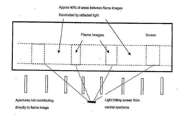
60 Dr Cowling said that his assessment set out in par 69 of his first affidavit applied to all of the models of heaters which he inspected.
61 As mentioned in [56] above, one of the models of the respondents’ heaters, the Flameglow model FG150-2 tendered in evidence, has a silver or polished stainless steel rotating cylinder as part of its mechanism instead of a cylinder with the matt black finish used in the other models inspected by Dr Cowling. Dr Cowling said that the apparatus in that particular model of heater generates a brighter simulated flame effect image and illuminates a greater area of the screen with reflected light than does the apparatus in those models which have matt black finished rotating cylinders. This is because the shiny stainless steel surface of that particular rotating cylinder has a much higher reflectivity than the matt black surface of the cylinders in the other models.
62 At par 78 of his first affidavit, Dr Cowling said:
With regard to paragraph 77.2 above and the simulated flame effect means, as explained in paragraph 69 above, in my opinion the simulated flame effect in the Electric Flame Effect Heaters is achieved by a contribution of directly emitted and reflected light. While the majority of the light reaching the screen is directly emitted light that is more intense than the reflected light, the area of the screen which is illuminated by each is, in my opinion, approximately equal (as explained in paragraph 69 above). The directly emitted light, being more intense than the reflected light, produces the brightest images on the screen. However, reflected light also makes a significant contribution to the flame effect. The light that is periodically emitted through the shaped apertures, in combination with the contrasting glow of the less intense, reflected light, achieves the object of simulating flames arising from a bed of combusting fuel. Without the reflected light, the screen would only be illuminated with intermittent flashes of directly emitted light. In my opinion, reflected light makes a significant contribution to achieving the objective of a more realistic flame effect.
63 Dr Cowling said that the simulated flame effect in the respondents’ heaters could not be achieved without a significant contribution from reflected light. In his opinion, therefore, those devices employed the same principle as is embodied in the Patent.
64 In affidavits subsequently sworn by Dr Cowling, he related the views which he had expressed in his first affidavit to two further models of electric flame effect heaters namely, the Flameglow model FG100 and the Flameglow model FG400. He also updated his views about the heater BH5 based upon an inspection of a sample of that heater and not merely upon the photographs of the model which he had previously used in order to found his opinions. In effect, Dr Cowling said that the observations which he had made in his first affidavit applied equally to those additional models.
65 Professor Nugent provided one affidavit which was mostly directed to the Cross-Claim for revocation of the Patent brought by Garth Living. In two additional affidavits, he also expressed some opinions directed to the issue of infringement.
66 In his affidavits addressing issues related to infringement, Professor Nugent said that the simulated flame effect is produced in the respondents’ heaters by a combination of the operation of the rotating cylinder, the viewing screen and the flame shaped metal plate. These items allow light from the light source in the globe to form patterns of light on the screen that mimic the form of natural flames. In his view, although some light will inevitably be reflected from the surface of the interior of the rotating cylinder, such reflection will be a diffuse reflection and will detract from the flame effect by contributing a featureless bright background and not contribute much, if at all, to the flame effect depicted on the screen. In his affidavit material, Professor Nugent stated unequivocally and in an unqualified manner that:
A diffuse reflection will not contribute to the flame effect. The interior of Rotating Sleeve B has been treated so as to effectively eliminate reflected light.
67 The essence of this opinion, as I understood it, was that, because the rotating cylinder is made of plastic and coated with a matt black finish, almost no reflected light is generated from that cylinder. Professor Nugent went on to conclude that specular reflection from the interior of the rotating cylinder would be negligibly small. Professor Nugent conducted an experiment in order to assess the contribution that diffuse reflection made to the flame effect in the respondents’ heaters. In light of his experiment, he concluded that reflections from the interior of the rotating sleeve do not contribute to the flame effect in the respondents’ heaters. He went on to conclude that:
… the mechanism in the Electric Flame Heaters involves only transmission of light through apertures, a quite distinct physical mechanism from reflection of light.
68 In his third affidavit, Dr Cowling took up the challenge thrown out by the views of Professor Nugent which I have summarised above. Dr Cowling amplified his assertion that other surfaces within the compartment of the device, including the inner surface of the rear panel, provide reflective surfaces for the purposes of conveying light from the light source (the filament in the globe) through the rotating cylinder and ultimately to the screen. Dr Cowling said that he disagreed with Professor Nugent that reflection has been effectively eliminated in the respondents’ heaters by means of the matt black finish on the rotating cylinder. Further, Dr Cowling disagreed with Professor Nugent that a diffuse reflection will detract from and not contribute to the flame effect depicted on the screen. Dr Cowling conducted tests which depended upon a visual and measurement assessment of three of the respondents’ heaters in order to ascertain the contribution made by the reflected light to the flame effect depicted on the screen. As a result of these tests, Dr Cowling reaffirmed his view that reflected light does contribute to the observable illumination of a significant proportion of the screen during operation of the respondents’ heaters. He estimated that proportion to be of the order of 40% of the screen area.
69 Professor Nugent subsequently swore his third affidavit. In that affidavit, he concluded that:
(a) Reflections off the inner surface of the rear outer casing of the respondents’ heaters do not contribute at all to the flame effect depicted on the screen; and
(b) The flame effect in those heaters is created entirely by the direct transmission of light produced by the light globe located within the rotating cylinder passing through the flame shaped holes cut in that cylinder and striking the viewing screen.
In part, these conclusions were based upon certain experiments conducted by Professor Nugent.
70 In her first affidavit, Professor Monro concentrated on the Flameglow FG150 model with the matt black finished rotating cylinder. In dealing with the question of the degree to which reflected light contributed to the flame effect on the screen in the respondents’ heaters, Professor Monro said the following, in respect of the Flameglow FG150 heater:
I do not agree with the conclusions described in paragraphs 63–75 inclusive [of Dr Cowling’s first affidavit] and the additional material in Exhibit IRC-6. In particular, I disagree with Dr Cowling’s interpretation of the amount of contribution that reflected light makes to the overall image of the simulated flames. My direct observations of the FG150 Heater were that the patterns visible from the front are not due to reflections either within the cylinder or within the chamber behind the screen, and are instead predominantly due to the direct transmission of light through the slits and then the metal plate. The contribution of the reflected light is minimal, and while not zero, it makes little contribution to the overall patterns observed from the front of the heater while the apparatus is operational.
71 Professor Monro went on to explain those remarks in the succeeding paragraphs of her first affidavit. She accepted that some light reaching the screen is light which is reflected internally but contended that very little of the light reaching the screen is in that category. She said that the limited reflections that occur from matt black surfaces are predominantly diffuse light and that diffuse light emerging from the apertures cannot produce a clear image of the apertures on the screen. She said that that type of light emerging from the apertures acts only to increase slightly the overall illumination on the screen.
72 Dr Cowling answered Professor Monro’s first affidavit in his fifth affidavit (one of the affidavits sworn by him on 3 March 2008). He observed that the dominant type of reflection which was observable on the screen of the respondents’ heaters is not specular reflection, but is diffuse reflection. He repeated his contention that all surfaces, including matt black finished surfaces, reflect light to some degree. He took issue with Professor Monro’s assertion that the appearance of the flames to the eye of an observer placed in front of the unit is qualitatively similar, regardless of whether the back panel is fixed to the unit or not. On the critical question for present purposes, Dr Cowling said:
… reflected light does contribute to the observable illumination of a significant proportion of the screen during the operation of the Electric Flame Effect Heaters. Whether the reflected light dispersed around the brighter images gives a more realistic flame effect is a matter of opinion for the viewer. In my opinion, as stated in my First Affidavit, reflected light does make a significant contribution to achieving the objective of a more realistic flame effect.
73 Dr Cowling went on to say that the reflected light hitting the viewing screen improves the image and makes it more realistic in the respondents’ heaters.
74 In a separate affidavit sworn on 3 March 2008, Dr Cowling said that his essential views as to the contribution which reflected light makes to the flame effect images on the viewing screen in the respondents’ heaters applied equally to the one model of Hotpoint heater in issue in the proceedings, namely, the large heater tendered in evidence. The basic workings of the Hotpoint heater are the same as those of the other heaters which are alleged to have infringed the Patent. However, there are some differences which, in light of the decision to which I have come on infringement, need not be traversed.
75 In his final affidavit, Dr Cowling adhered to the views which he had expressed in par 69 of his first affidavit but refined matters somewhat when he said that:
… approximately equal areas of the screen in the FG150 heater with the black rotating cylinder are illuminated by directly emitted light [from the light source] and by reflected light.
76 Dr Cowling explained this conclusion when he went on to say that only the apertures in the middle of the rotating cylinder contributed directly emitted light to the screen and that light passing through the outer apertures on the length of the rotating cylinder hits the outer edges of the compartment and the flame shaped cut out plate and is reflected off those surfaces. He thought that approximately 35% of the screen along the line of the apertures is illuminated by directly emitted light.
77 Dr Cowling was cross-examined at some length by Counsel for Bunnings, Garth Living and Cohen and briefly by Counsel for Hotpoint. The cross-examination of Dr Cowling took place after a demonstration had been conducted in Court during which each of the experts had an opportunity to make observations, ask questions and give testimony. Each of them was sworn for the purposes of providing evidence during that demonstration. Throughout his cross-examination, Dr Cowling adhered to his views that reflected light reaches the viewing screen and contributes to the image of flame depicted on the screen. He said that the reflected light that reaches the screen is reflected light that has been diffusely reflected from behind the screen. He repeatedly adhered to his view that all surfaces both reflect and absorb light and that the extent to which a particular surface did so was always a matter of degree. In cross-examination, Dr Cowling agreed that the plate with the flame shapes cut into it had no role to play in reflection or in creating the time-varying aspect of the flame effect. The plate was simply included in all but one of the respondents’ heaters in order to limit the height of the flames to the observer looking at the heater from the front in order to make the flame effect more realistic. He said that all reflective surfaces within the device contribute to the time varying effect of the flame effect shown on the screen. He agreed that there is a significant contribution from directly emitted light to the production of the flame effect in the respondents’ heaters. This, of course, was not inconsistent with the evidence which he had provided to the Court in his affidavits.
78 It seemed to me that all of the experts were endeavouring to address the question of whether or not there is a substantial amount of reflected light reaching the viewing screen in the respondents’ heaters and being transmitted through that screen and, if so, whether it is contributing substantially to the flame effect shown or depicted on the viewing screen to the observer looking at the device from the front. Various tests were undertaken by the experts in an endeavour to separate out the relative contributions being made to the flame effect depicted on the viewing screen by directly emitted light from the light source through the apertures in the rotating cylinder and by reflected light originating at the same light source but being reflected from the inner surface of the rotating cylinder and other surfaces inside the chamber in which the device is housed.
79 Ultimately, I have benefitted most from the demonstrations which took place on the first and second days of the hearing. That is not to say that the evidence of the experts contained in their affidavits and oral evidence was not significant. That evidence served to crystallise the main issue between Dr Cowling, on the one hand, and Professors Nugent and Monro, on the other hand viz did reflected light contribute substantially to the flame effect depicted on the screen in the respondents’ heaters and, if so, in what way and to what extent? That evidence also provided a descriptive analysis and context in which I could assess that contribution for myself during the demonstrations.
The Demonstrations
80 On the first day of the hearing, Counsel provided a demonstration to me. This demonstration did not incorporate any commentary or evidence from the experts. Samples of three of the respondents’ heaters were placed side-by-side in the body of the Court. These were samples of the BH1, MS-5 and FG150-2 heaters. Various operations were performed with each of those heaters.
81 Initially, the MS-5 heater was operated normally, just as it would be by the ultimate consumer in his or her sitting room. The back panel was removed from the BH1 heater and then it was operated. The MS-5 heater continued to operate whilst the BH1 heater was operated. The FG150-2 heater was also turned on. Observations were then made.
82 A matt black finished metal baffle (Exhibit A) was then inserted into sample heater BH1 adjacent to the light globe. It was designed to prevent light from the light source passing through the middle apertures of the rotating cylinder thus preventing any directly emitted light from reaching the viewing screen. The back of the heater was then reaffixed to the body of the heater. On the assumption that the baffle operated to do that which it was designed to do, it was then possible to observe whether reflected light was making any contribution to the flame effect and, if so, in what way and to what extent.
83 The bright light in the flame effect in the baffled unit was effectively removed by the insertion of the baffle. My own observations at this point were recorded as follows:
I am seeing what I might call softer flame in the baffle unit which appears to me nonetheless to extend across the width of the unit fairly much uniformly but with intermittent appearance of slightly brighter yellow flames but nowhere near as bright as the unit which does not have the baffle. And I think the only other observation that I want to record is that to my eye, the unit that does not have the baffle’s central flames in the centre of the unit seem a little higher to me. And that depending upon whether one is perhaps sitting down or standing, looking at the baffled unit, one gets a slightly different level of intensity of the flame, that is to say, standing up, it looks a little softer than sitting down. They’re the observations that I am seeing and would wish to have recorded – anybody disagree with that?
84 Those remarks were regarded by the parties as an accurate record of what could be observed.
85 A similar baffle (Exhibit B) was then inserted into the Flameglow heater FG150-2. I then made the following observations:
And my observations are similar to those that I made in respect of the comparison between the unbaffled unit and the baffled unit BH1 earlier, although it is fair to say that what one sees with the baffle inserted in the Flameglow unit is a much stronger flame than the observation that can be made in respect of the baffled unit, BH1 with a bit more of what one might call a yellow flame appearing from time to time. But the effect … putting the baffle in is to diminish the appearance of the flame both in intensity and colour as occurred with the insertion of the baffle in the earlier device.
86 Counsel for Hotpoint then said that, in the case of the heater FG150-2, the difference between the observable flame effect with the baffle in place and the observable flame effect during normal operation was not as marked as it had been with the heater BH1. I thought that that was a reasonable observation.
87 On the second day of the hearing, a further demonstration took place. This demonstration was enhanced by the direct participation of all of the expert witnesses. During the demonstration, all of the witnesses made observations which I have found to be most helpful. The format of this demonstration followed the format of the earlier demonstration. The baffle used on this occasion (Exhibit L) was longer than the baffle that had been used in the first demonstration. All of the experts agreed that this longer baffle would prevent all of the directly emitted light reaching the viewing screen.
88 I will now set out my conclusions as to the observations which were made during the second demonstration looking at the heaters from the front (the position of the ultimate consumer sitting in his or her armchair):
(a) When sample heater BH1 was operated with the baffle in place, a time varying array of images could be seen right across most of the viewing screen. The time variation seemed to be in sequence with the rotation of the cylinder. Some of the images had a discernable flame shape and others were more blurred but these latter images nonetheless gave the impression of movement of flames as the cylinder rotated. The flame images went about half way up the screen at their highest point and were of generally lower intensity than those which were observed when the baffle was not in place;
(b) The reflected image on the viewing screen of the simulated fuel from the simulated fuel bed was static, giving an ambient background;
(c) The observable contribution made to the flame effect by the directly transmitted light tended to be by way of two or three brighter flame images located in the centre area of the screen which travelled further up the viewing screen than the remaining images visible on the screen;
(d) The directly transmitted light had a range of intensities;
(e) The brighter images created by the directly transmitted light overlapped some of the images created by reflected light; and
(f) In the case of heater FG150-2, the reflected light was brighter and more extensive than was the case with the other heaters involved in this demonstration. It contributed to the overall flame effect.
89 Dr Cowling was of the opinion that the images referred to in subpar (a) of [88] above were reflected off the rear of the chamber (meaning the inner surface of the outer casing of the heater). Professor Nugent thought that those images were most likely the consequence of reflections within the matt black rotating cylinder. He said that it was impossible to eliminate entirely reflections from that source. Professor Monro agreed with both Dr Cowling and Professor Nugent. She agreed that there were time varying light distributions observable on the viewing screen but wanted to see further demonstrations before she would accept that they were significant.
90 When the MS-5 heater was operated without the baffle, Professors Nugent and Monro both expressed the view that the contribution to the flame effect made by reflected light was not significant. They said that the structure of the images on the screen was such that there was no additional flame effect created by reflected light. Rather, the flame effect created by reflected light was contained within the envelope of the image observable on the screen which was created by the directly emitted light. Dr Cowling reiterated that, in his opinion, images created by reflected light covered most of the width of the viewing screen whereas the direct light images only occupied specific parts of the screen.
91 The observations which I have recorded in [90] above were the only points of difference amongst the experts as to what could be observed during the second demonstration. My own observations accorded more with those of Dr Cowling. I thought that the images created from reflected light did contribute to the observable flame effect to some extent.
Does Reflected Light Contribute Substantially to the Flame Effect in the Respondents’ Heaters
92 Putting to one side the light source itself and the viewing screen, in the respondents’ heaters, the simulated flame effect means comprises at least the rotating cylinder and the flame shaped cut out plate. Dr Cowling also includes within that means the inner surface of the rear panel of the outer casing of the heater and perhaps other similar surfaces above and below the rotating cylinder.
93 All experts agreed that some of the flame shaped images observable on the viewing screen from the front of the heater were transmitted to and created on that screen by reflected light. The dispute between Dr Cowling, on the one hand, and Professors Nugent and Monro, on the other hand, concerned:
(a) Whether images created by reflected light added anything to the flame effect; and
(b) If so, whether the contribution to the flame effect by reflected light was significant.
94 Dr Cowling measured the respective contributions made by directly emitted light and reflected light to the images observable on the viewing screen and concluded that each contributes about half of the observable effect. He accepted that, in the sense described in subpars (c), (d) and (e) of [88] above, the images created by the directly emitted light were the dominant observable images. Professors Nugent and Monro focussed more on the shape and intensity of the contributions. Professor Nugent concluded that the contribution to the flame effect by reflected light was negligible.
95 Professor Monro expressed similar views to those of Professor Nugent but seemed to accept that the contribution from reflected light was greater than Professor Nugent was prepared to accept.
96 The observations made and recorded by the experts and by me during the demonstrations supported Dr Cowling’s opinions and conclusions. Indeed, at one point in his evidence, Professor Nugent was driven to the following admission:
I don’t understand how those reflections created that sharp an image. Because there is a diffuse reflection I would have expected the apertures to be somewhat more—the image to be somewhat more diffuse.
97 At the point in his cross-examination where he gave that evidence, Professor Nugent was being challenged in respect of the opinion which he had expressed in his affidavit evidence that, because the reflected light which was being transmitted through the viewing screen was diffuse, not only could it not produce a flame shape on the screen but it would also detract from the flame image effect on the screen by contributing a featureless bright background.
98 It seemed to me that Professor Nugent was unable to explain the presence on the viewing screen of flame shaped images transmitted there by diffusely reflected light. His view was that diffusely reflected light could not produce such images. Professor Monro was of the same view but was prepared to concede that the flame shaped cut out metal plate may have contributed to the observable flame shaped images on the screen. However, she said that that plate was not part of the simulated flame effect means.
99 I find that diffusely reflected light emanating from the filament in the globe inside the rotating cylinder reaches the viewing screen, is transmitted through the viewing screen and results in the formation of flame shapes on the viewing screen and other images which are visible to the users of the respondents’ heaters when those heaters are put to their ordinary use. That diffusely reflected light may be reflected off the inner surfaces of the rotating cylinder and other inner surfaces of the heater (eg the back panel). As Professor Nugent ultimately agreed, there are both flame shaped and non flame shaped images attributable to reflected light visible on the screen. The overall image with which the viewer is presented consists of the following moving images:
(a) Images formed from directly emitted light which are flame shaped because of the apertures in the rotating cylinder and the flame shaped cut out plate;
(b) Images formed from diffusely reflected light that are flame shaped; and
(c) Images formed from diffusely reflected light that are not clearly flame shaped but which nonetheless contribute to the overall flame effect.
100 About half the viewing screen is occupied by images sourced from reflected light, although they occupy the full width of the viewing screen. The images created by directly emitted light are found in the centre area of the viewing screen, are brighter and fuller than other images and dominate the flame effect.
Decision on Infringement
101 The respondents who were represented at the hearing conceded that each of the respondents’ heaters had:
(a) A source of light;
(b) Simulated fuel means to simulate a bed of combusting fuel;
(c) Screen means on which one can observe an image of simulated flames, said screen means being positioned between said flame effect means and said simulated fuel means; and
(d) The capability of producing images of flames on the said screen means which appear to emanate from the area between the simulated fuel means and an image of the simulated fuel means reflected in the screen means.
102 The respondents contended, however, that the flame effect means in the respondents’ heaters comprised only the rotating cylinder and the flame shaped cut out plate (putting the light source to one side) and that that means did not fall within the flame effect means envisaged by the Patent because very little (if any) of the light which is transmitted to the viewing screen by those devices is reflected light. Rather, most of the light travelling to the viewing screen from those devices is light which is directly emitted from the light source via the cylinder and the flame shaped cut out plate.
103 I have found that, in the respondents’ heaters, a substantial and predominant contributor to the light which is transmitted through the viewing screen and is thus the source of the flame shapes observable on that screen is light which is directly emitted (and not reflected) from the light source. On the construction of the Patent which I have found, that finding means that the flame effect means in the respondents’ heaters falls outside the scope of the Patent. Therefore, the respondents have not infringed the Patent and Bitech’s claim must be dismissed.
The Conduct of Garth Living
104 In the final version of its Defence (its Amended Defence filed in Court on 23 October 2008), Garth Living denied that it imported, supplied, sold, offered to sell or hire, advertised, kept or used any of the allegedly infringing electric flame heaters. It also denied that it directed, procured, aided or abetted such acts by others. It also denied Bitech’s allegation that it was involved in a common design with Bunnings and Cohen involving the importation, sale and distribution in Australia of those heaters. This Defence was filed at a time when the evidence was closed.
105 Bitech proved the following facts:
(a) The packaging in which the BH range of heaters is supplied all bears the name “Garth Living”;
(b) The Safety Information and Instruction Manual for the BH1 heater is branded “Garth Living”. On that documentation, there is reference to Garth Living’s website;
(c) Australian Customs documentation showed Garth Living as the owner in respect of the importation into Australia of some of the BH model heaters. That documentation showed GSM Gas Appliance Inc (a Chinese corporation) as the supplier and Garth Living as the paying entity to whom the goods were directed;
(d) GSM Gas Appliance Inc invoiced Garth Living for substantial quantities of the BH range of heaters in April 2006;
(e) Garth Living is shown on the BH models that were tendered in evidence as the distributor of those models;
(f) The Safety Information and Operation Manual in respect of the MS-5 heater is branded “SUNCO by Garth” and refers to Garth Living’s website;
(g) Email communications passing between Garth Living and Cohen indicated that Cohen was importing the MS-5 heater in the interests of and on behalf of Garth Living;
(h) Garth Living placed an order with Cohen for the MS-5 heater; and
(i) The name “Garth Living” is not a corporate or business name of any entity other than the respondent party in proceeding NSD 1681 of 2006.
106 By letter dated 12 July 2006, Bitech’s solicitors wrote a letter of demand to Garth Living in which they made detailed allegations to the effect that:
(a) Garth Living was selling and offering for sale electric flame effect heaters (MS-5 and BH1) which were manufactured by a Chinese corporation;
(b) Garth Living supplied those heaters to Cohen;
(c) Garth Living supplied those heaters to Bunnings;
(d) Garth Living supplied those heaters to the Good Guys businesses; and
(e) The heaters infringed the Patent.
107 In that same letter, Bitech’s solicitors threatened proceedings and sought undertakings.
108 By letter dated 25 July 2006, Garth Living’s solicitors responded to the letter of demand. The response was detailed and was stated to have been made on the instructions of Garth Living. The response took up issues in relation to infringement but did not contain any denial that Garth Living was relevantly involved in the importation, sale and distribution of the allegedly infringing heaters. Indeed, Garth Living seemed to accept the truth of the allegations in terms of its conduct when its solicitors said:
Whilst your correspondence of 12 July 2006 does not actually mention it, I am instructed that you have also written to my client’s clients, Sonny Cohen and Son and Bunnings, making similar allegations and claims against them. As you will no doubt appreciate, such threats may lead to my client suffering significant loss and damage.
109 Garth Living led no evidence at all directed to supporting its pleaded denial of its involvement in the importation, sale and distribution of the allegedly infringing heaters.
110 It is apparent from the findings which I have made in [105] above that there is a good deal of evidence before the Court supporting the proposition that Garth Living was directly involved in the importation, sale and distribution in Australia of all of the allegedly infringing electric flame heaters. Its failure to deny such involvement is significant. I am comfortably satisfied that Bitech has made good its pleaded allegations that Garth Living was directly involved in those activities. I am reinforced in this conclusion by the circumstance that Garth Living made no attempt at all to challenge the import of that evidence or to explain any of that evidence.
111 Given the findings which I have made in [105] above, it is not necessary for me to consider whether Garth Living was involved in the alleged common design. Had it been necessary to do so, I would have found that it was involved in the allegations of common design pleaded against it by Bitech.
112 Given the views to which I have come as to the proper construction of the Patent and as to the question of whether or not the respondents’ heaters infringe the Patent, it is strictly not necessary for me to make findings in respect of Garth Living’s conduct. However, I consider that it is appropriate to do so for at least two reasons:
(a) There may be an appeal from my decision in which the matter may become a live one; and
(b) These findings are relevant to the question of costs.
113 Bitech has been put to some additional time, trouble and expense by reason of Garth Living’s denial of its involvement in the importation, sale and distribution in Australia of the respondents’ heaters. Further, Bitech was driven to seeking to amend its pleading to allege common design because of Garth Living’s denial of those matters. These circumstances may be relevant to the way in which I should exercise my discretion in respect of the costs of the proceedings.
Invalidity and Revocation
The Relevant Provisions
114 As mentioned at [13] and [15] above, the transitional provisions contained in s 234 of the 1990 Act apply to the Patent. The effect of s 234(2) and s 234(5) is that the grounds of invalidity and revocation available under the 1990 Act apply, with the qualification that the Patent cannot be revoked on a ground that would not also have been available under the 1952 Act.
Novelty
115 Section 7(1) of the 1990 Act provides that the invention is taken to be novel when compared with the prior art base unless it is not novel in the light of (relevantly) information made publicly available in a single document or through the doing of a single act. As was submitted by Bitech, this standard does not differ materially from the standard which was applicable under s 100(1)(g) of the 1952 Act, save that, in the case of the latter provision, the applicant for revocation was required to establish publication of the relevant prior art in Australia. In the present case, there is no dispute that each of the four items of the prior art referred to and relied upon by Garth Living, Flameglow and Hotpoint in support of their claims for revocation was published in Australia before the priority date of the relevant Claims made in the Patent.
116 The items of prior art ultimately relied upon by the revocation applicants were:
(a) A domestic room heater sold in Australia in the 1960s and made by a company called HECLA;
(b) Australian Patent Application No 3567/66;
(c) United States Patent No 3,603,013; and
(d) Australian Patent No 406594.
117 It was submitted on behalf of Garth Living and Hotpoint that the Patent does not contain a patentable invention and is therefore liable to be revoked pursuant to the provisions of s 138(3)(b) of the 1990 Act. Those parties pressed their claims for revocation only in respect of Claims 1, 8, 12, 14 and 20 of the Patent (and no other Claims).
118 In Meyers Taylor Pty Ltd v Vicarr Industries Ltd (1977) 137 CLR 228 at 235, Aickin J said:
The basic test for anticipation or want of novelty is the same as that for infringement and generally one can properly ask oneself whether the alleged anticipation would, if the patent were valid, constitute an infringement (see, e.g., Harwood v. Great Northern Railway Co. [(1865) 11 H.L.C. 654, at p. 681 [11 E.R. 1488, at pp. 1498-1499]). Here no prior object and no object according to a prior document involved or incorporated all the integers of any one of the claims and could therefore possibly constitute an infringement. Accordingly I am satisfied that the objection of want of novelty has not been made out.
119 This test is applicable to the circumstance where the alleged anticipation resides in a prior apparatus that would, if it contained all of the necessary integers, fall within the scope of the claims. Therefore, this test would directly apply to the alleged anticipation constituted in the present case by the HECLA heater.
120 In Bristol-Myers Squibb Co v FH Faulding & Co Ltd (2000) 97 FCR 524, Black CJ and Lehane J, in a joint judgment, after reviewing several relevant authorities at [64]–[66] (pp 547–548), at [67] (pp 548–549) said:
What all those authorities contemplate, in our view, is that a prior publication, if it is to destroy novelty, must give a direction or make a recommendation or suggestion which will result, if the skilled reader follows it, in the claimed invention. A direction, recommendation or suggestion may often, of course, be implicit in what is described and commonly the only question may be whether the publication describes with sufficient clarity the claimed invention or, in the case of a combination, each integer of it.
121 The United Kingdom Court of Appeal in General Tire & Rubber Co v Firestone Tyre & Rubber Co Ltd (1971) 1A IPR 121, [1972] RPC 457 at 485–486 held that, if the prior inventor’s publication contains a clear description of, or clear instructions to do or make, something that would infringe the patentee’s claim if carried out after the grant of the patentee’s patent, the patentee’s claim will have been shown to lack the necessary novelty. In that sense, it will have been anticipated. It is a question of whether or not the prior inventor’s publication would render the later effort an infringement of the patentee’s claim, on the assumption that the patentee’s patent is valid. The Court of Appeal held ([1972] RPC at 486):
If, on the other hand, the prior publication contains a direction which is capable of being carried out in a manner which would infringe the patentee’s claim, but would be at least as likely to be carried out in a way which would not do so, the patentee’s claim will not have been anticipated, although it may fail on the ground of obviousness. To anticipate the patentee’s claim the prior publication must contain clear and unmistakable directions to do what the patentee claims to have invented: Flour Oxidising Co Ltd v Carr & Co Ltd ((1908) 25 RPC 428 at 457, line 34, approved in BTH Co Ltd v Metropolitan Vickers Electrical Co Ltd (1928) 45 RPC 1 at 24, line 1). A signpost, however clear, upon the road to the patentee’s invention will not suffice. The prior inventor must be clearly shown to have planted his flag at the precise destination before the patentee.
122 These statements were expressly approved by the Full Court in ICI Chemicals & Polymers Ltd 106 FCR 214 at [51] (p 230).
123 In his text Patents for Inventions (5th ed, Stevens, 1983) Blanco White said (at 4-102) (p 53):
The test for lack of novelty is essentially the same as the test for infringement; that is to say, a prior use will invalidate a claim … if it was such that it would infringe that claim if carried out after the grant of the patent concerned; while a prior disclosure will invalidate if it contains a clear description of, or clear instructions to do or make, something that would infringe if carried out after grant.
This formulation has been applied in Australia (see Alphapharm Pty Ltd v H Lundbeck A/S (2008) 76 IPR 618 at [157] (p 657) (per Lindgren J)).
124 In assessing novelty, each alleged anticipation must be considered separately. Each alleged anticipation must disclose each and every one of the essential integers of a claim or claims under consideration.
125 The case advanced by Garth Living and Hotpoint in support of the proposition that the relevant claims in the Patent lacked novelty was rather loosely put in the sense that, as I understood it, it was impermissibly founded upon selectively aggregating individual items of information in order to present a mosaic or an entire picture favourable to those parties’ case for revocation. This type of approach was rejected by the High Court in Minnesota Mining and Manufacturing Company v Beiersdorf (Australia) Ltd (1980) 144 CLR 253 at 292–293.
126 Bitech submitted that:
… Neither the HECLA heater nor the apparatus described in any of the three prior patent specifications incorporates the feature of “screen means” which is capable of both diffusely transmitting light from a flame effect means and reflecting light from a fuel means so that simulated flames appear to emanate between the fuel means and an image of the latter means reflected on the screen means. This being an essential integer of Claim 1, upon which the other relevant claims are dependant, it is not necessary to go further.
127 That submission was made good by my inspection of the HECLA heater and by a careful consideration of the prior patent specifications. The HECLA heater contains a very primitive attempt to simulate flames and fuel and plainly goes nowhere near the essential integers of the Patent referred to in Bitech’s submission. The prior patent specifications do not provide clear and unmistakeable directions to construct an apparatus which incorporates the feature of the screen means which was the subject of Bitech’s submission extracted at [126] above. Garth Living and Hotpoint were unable to present a coherent and persuasive submission which identified such clear and unmistakable directions. The evidence of Professors Nugent and Monro did not assist in that endeavour.
128 Both Professors Nugent and Monro accepted that there was a step required to be taken from the prior patent specifications to the Claims made in the Patent but each of them attempted to assert that the step did not involve novelty. I do not accept these opinions. Garth Living and Hotpoint bore the onus of establishing lack of novelty and have failed to do so.
Inventive Step
129 Section 7(2) of the 1990 Act provides that the particular invention is taken to involve an inventive step when compared with the prior art base unless it:
… would have been obvious to a person skilled in the relevant art in the light of the common general knowledge as it existed in the patent area before the priority date of the relevant claim, whether that knowledge is considered separately or together with the information mentioned in subsection (3).
130 Section 7(3) of the 1990 Act is in the following terms:
(3) The information for the purposes of subsection (2) is:
(a) any single piece of prior art information; or
(b) a combination of any 2 or more pieces of prior art information;
being information that the skilled person mentioned in subsection (2) could, before the priority date of the relevant claim, be reasonably expected to have ascertained, understood, regarded as relevant and, in the case of information mentioned in paragraph (b), combined as mentioned in that paragraph.
131 Section 100(1)(e) of the 1952 Act was in the following terms:
(1) A standard patent may be revoked, either wholly or in so far as it relates to any claim of the complete specification, and a petty patent may be revoked, on one or more of the following grounds, but on no other ground:
…
(e) that the invention, so far as claimed in any claim of the complete specification or in the claim of the petty patent specification, as the case may be, was obvious and did not involve an inventive step having regard to what was known or used in Australia on or before the priority date of that claim;
…
132 The terms of s 100(1)(e) of the 1952 Act did not permit recourse to the type of information covered by s 7(3) of the 1990 Act (see Aktiebolaget Hassle v Alphapharm Pty Ltd (2002) 212 CLR 411 at [15]–[16] (pp 421–422). Those terms restricted the analysis to a consideration of the common general knowledge before the priority date.
133 The standard for the assessment of obviousness or inventive step was not otherwise different.
134 In the present case, Garth Living and Hotpoint relied upon the HECLA heater and other patents “… for the purposes of s 7(3) of the Act …”.
135 It is clear that, at least to some extent, those parties are relying upon s 7(3) of the 1990 Act in support of this ground of revocation. They seek to rely upon information which did not form part of the common general knowledge but which could potentially be taken into account under s 7(3). In my judgment, they are not permitted to do so for the reason which I have noted at [132] above.
136 Further, the generalised assertions made by Professors Nugent and Monro to the effect that the existence of the HECLA heater and Australian Patent Application No 3567/66 was part of the common general knowledge before the priority date of the Patent are not persuasive. The knowledge must be available to all in the relevant trade and must be treated as part of a general body of knowledge in that trade (see Minnesota Mining and Manufacturing Company 144 CLR at 292). Patent specifications do not become part of the common general knowledge merely by reason of their publication: Minnesota Mining and Manufacturing Company 144 CLR at 294–295.
137 Even if the prior art relied upon by Garth Living and Hotpoint could be taken into account, there is no evidence that would justify a finding that the claimed invention was obvious in light of that prior art. The evidence tendered by Garth Living and Hotpoint falls well short of the test expounded in Aktiebolaget Hassle 212 CLR 411 at [53]–[54] (pp 433–434) where Gleeson CJ, Gaudron, Gummow and Hayne JJ in their joint judgment, after addressing the question of whether or not the experiments were part of the asserted inventive step or simply of a routine character which would inevitably have been attempted as a matter of course, said (at [53]–[54] (pp 433–434)):
53 That way of approaching the matter has an affinity with the reformulation of the “Cripps question” by Graham J in Olin Mathieson Chemical Corporation v Biorex Laboratories Ltd [[1970] RPC 157]. This Court had been referred to Olin in the argument in Wellcome Foundation [(1981) 148 CLR 262 at 267. See also Washex Machinery Corporation v Roy Burton & Co Pty Ltd (1974) 49 ALJR 12 at 16]. Graham J had posed the question [Olin Mathieson [1970] RPC 157 at 187-188. The approach taken in Olin appears now to be disfavoured by the English Court of Appeal: Pharmacia Corporation v Merck & Co Inc [2002] RPC 775 at 819-820, but it still has support in the English profession: Cole, “Inventive Step: Meaning of the EPO Problem and Solution Approach, and Implications for the United Kingdom -- Part II” [1998] European Intellectual Property Review 267, at p 270]:
“Would the notional research group at the relevant date, in all the circumstances, which include a knowledge of all the relevant prior art and of the facts of the nature and success of chlorpromazine, directly be led as a matter of course to try the CF3 substitution in the ‘2’ position in place of the C1 atom in chlorpromazine or in any other body which, apart from the CF3 substitution, has the other characteristics of the formula of claim 1, in the expectation that it might well produce a useful alternative to or better drug than chlorpromazine or a body useful for any other purpose?” (Emphasis added.)
That approach should be accepted.
The reasoning of the primary judge
54 Lehane J did not treat “routine” in that way. He erred by giving it an operation more favourable to Alphapharm’s case. What his Honour did was in line with the position which now apparently obtains in England, that “all of the courses of action which present themselves without the exercise of invention are obvious” [Pharmacia Corporation v Merck & Co Inc [2002] RPC 775 at 818]. His Honour did not assess what was said by the expert witnesses concerning the procedures they would have followed by making findings whether they would have been led directly as a matter of course to pursue one avenue in the expectation that it might well produce the claimed compound.
This ground of revocation has not been made out.
Fair Basis
138 Section 40(3) of the 1990 Act requires that the claims of the Patent be fairly based on the matter described in the specification. This is substantially the same requirement as was laid down by s 40 of the 1952 Act.
139 Fair basis involves a comparison between the claims made in the Patent and what is disclosed in the specification in order to determine whether there is a “real and reasonably clear disclosure” of the invention claimed, or whether the claims “travel beyond” the invention described (see Lockwood Security Products Pty Ltd 217 CLR 274 at [57] (p 295), [69] (p 300) and [83] (p 306) (per Gleeson CJ, McHugh, Gummow, Hayne and Heydon JJ)). I cannot see how, in the present case, the claims travel beyond the invention which has been described in the specification.
140 Garth Living and Hotpoint seemed to be advancing this ground as a means of dealing with Bitech’s construction of the Patent. Having regard to the construction which I have placed upon Claim 1, I do not think there is any room for a challenge based upon the absence of fair basis. This ground must be rejected.
Conclusions
141 For the above reasons, Bitech’s Application must be dismissed as must the Cross-Claims for a declaration of invalidity in respect of the Patent and for revocation of the Patent. I will make orders accordingly.
142 The parties have requested that I defer ruling on costs until they have had an opportunity to consider these Reasons for Judgment. I am prepared to accede to that request. I will provide a timetable for dealing with costs in the orders which I will make.
TABLE A
CONDUCT ALLEGED TO CONSTITUTE INFRINGEMENT
| Respondent | Allegation |
| Garth Living Pty Ltd (NSD 1681 of 2006)
| Garth Living Pty Ltd hasimported and sold the BH1, BH2, BH4, BH5, BH6,BH7, BH9, BH10 and BH12heaters. Further, or in the alternative,Garth Living has been a partyto, and participated in, a common design involving theimportation and sale anddistribution in Australia of the BH1, BH2, BH4, BH5, BH6, BH7, BH9, BH10 and BH12 heaters by Bunnings Group Limited. |
|
| Garth Living Pty Ltd hasimported and sold the MS-5heater. Further, or in the alternative,Garth Living Pty Ltd was aparty to, and participated in, acommon design involving theimportation and sale anddistribution in Australia of theMS-5 heater. |
|
| Samples of the BH1, BH2,BH4, BH5, BH6, BH7, BH9, BH10, BH12 and MS-5heaters were purchased fromparticular stores within Australia. |
| Cohen Nominees Pty Limited (NSD 1681 of 2006) | Cohen Nominees Pty Limited hassupplied, sold and offered tosell the MS‑5 heater;advertised kept and used theMS-5 heater for the foregoingpurposes; and directed,procured, aided and abetted the doing of the foregoing actsby others. |
|
| A sample of the MS-5 heater was purchased from a Good Guys store. |
| Bunnings Group Limited (NSD 43 of 2007) | Bunnings Group Limited hassupplied, sold and offered tosell or hire the BH1, BH2, BH4, BH5, BH6, BH7, BH9, BH10 and BH12 heaters;advertised, kept and used theBHI, BH2, BH4, BH5, BH6, BH7, BH9, BH10 and BH12heaters for the foregoingpurposes; and directed,procured, aided and abettedthe doing of the foregoing actsby others. |
|
| Samples of the BH1, BH2, BH4, BH5, BH6, BH7, BH9, BH10 and BH12 heaters were purchased from particular Bunnings stores. |
| Flameglow Pty Ltd (NSD 105 of 2007) | Flameglow Pty Ltd hasimported, offered for sale,advertised, sold and suppliedthe FG150, FG100 andFG400 heaters. |
|
| Samples of the FG150 (withblack rotating cylinder),FG100 and FG400 heaters were purchased from particular stores within Australia. |
|
| A sample of the FG150-2 (with silver rotating cylinder) heater was purchased from a Clive Peeters store. |
| Hotpoint (Aust) Pty Ltd (NSD 2056 of 2007) | Hotpoint (Aust) Pty Ltd has imported, sold and offered for sale the Hotpoint Electric Fireplace Model No HPDBL2HY (HP1) heater. |
|
| A sample of the HP1 heater was purchased from a Harvey Norman store. |
| I certify that the preceding one hundred and forty-two (142) numbered paragraphs are a true copy of the Reasons for Judgment herein of the Honourable Justice Foster. |
Associate:
Dated: 26 November 2009
| Counsel for Bitech Engineering: | Mr JV Nicholas SC, Mr C Dimitriadis |
|
|
|
| Solicitor for Bitech Engineering: | DLA Phillips Fox |
|
|
|
| Counsel for Garth Living Pty Ltd, Cohen Nominees Pty Limited and Bunnings Group Limited: | Ms J Rawlings |
|
|
|
| Solicitor for Garth Living Pty Ltd and Bunnings Group Limited: | Eales & Mackenzie Melbourne |
|
|
|
| Solicitor for Cohen Nominees Pty Limited: | Bradley Allen Lawyers |
|
|
|
| Counsel for Flameglow Pty Ltd: | Mr MR Hall (on 21 October 2008) |
|
|
|
| Solicitor for Flameglow Pty Ltd: | Donaldson Walsh |
|
|
|
| Counsel for Hotpoint (Aust) Pty Ltd: | Ms ST Chrysanthou |
|
|
|
| Solicitor for Hotpoint (Aust) Pty Ltd: | Rutland’s Law Firm |
| Dates of Hearing: | 20, 21, 22 and 23 October 2008 |
|
|
|
| Date of Judgment: | 26 November 2009 |

