FEDERAL COURT OF AUSTRALIA
Uniline Australia Ltd ACN 010 752 057 v SBriggs Pty Ltd ACN 007 415 518
[2009] FCA 222
INTELLECTUAL PROPERTY – Patents – construction of claims – consideration of the relevant field of art – consideration of expert evidence – consideration of the skilled addressee – consideration of grammatical questions and syntax of the object statement contained in the specification
INTELLECTUAL PROPERTY - consideration of whether a contended infringing spring clutch achieves the same functionality of a spring clutch of claim 13 of the patent in suit – consideration of grounds of revocation including lack of clarity, inutility, lack of novelty and false suggestion
Patents Act 1990 (Cth), ss 128, 138
Sachtler GmbH & Co. KG v R E Miller Pty Ltd (2005) 221 ALR 373; (2005) 65 IPR 605 - cited
Fresenius Medical Care Australia Pty Ltd v Gambro Pty Ltd (2006) 224 ALR 168; (2006) 67 IPR 230 - cited
K D Kanopy Australasia Pty Ltd v Insta Image Pty Ltd (2007) 71 IPR 615 - cited
Clorox Australia Pty Ltd v International Consolidated Business Pty Ltd (2006) 68 IPR 254 - cited
Nufarm Ltd v Jurox Pty Ltd (2008) 75 IPR 341 - cited
Ranbaxy Australia Pty Ltd v Warner‑Lambert Co. LLC (No. 2) (2007) 71 IPR 46 - cited
Pfizer Overseas Pharmaceuticals v Eli Lilly & Co. (2006) 68 IPR 1 - cited
Breville Pty Ltd v Warehouse Group (Australia) Pty Ltd (2006) 67 IPR 576 - cited
Flexible Steel Lacing Company v Beltreco Ltd (2000) 49 IPR 331 - cited
Minnesota Mining and Manufacturing Company v Beiersdorf (Australia) Limited (1980) 144 CLR 253 - cited
Kimberly‑Clark Australia Pty Limited v Arico Trading International Pty Ltd (2001) 207 CLR 1 - cited
Catnic Components Ltd v Hill & Smith Ltd [1982] RPC 183 - cited
Kirin‑Amgen Inc. v Hoechst v Marion Roussel Ltd (2004) 64 IPR 444 - cited
PhotoCure ASA v Queen’s University at Kingston (2005) 216 ALR 41 - cited
Improver Corporation v Remington Consumer Products Ltd [1990] FSR 181 - cited
Root Quality Pty Ltd v Root Control Technologies Pty Ltd (2000) 177 ALR 231 - cited
Décor Corporation Pty Ltd v Dart Industries Inc. (1988) 13 IPR 385 - cited
Insta Image Pty Ltd v K D Kanopy Australasia Pty Ltd (2008) 78 IPR 20 - cited
Kinabalu Investments Pty Ltd v Barron & Rawson Pty Ltd [2008] FCAFC 178 - cited
PAC Mining Pty Ltd v Esco Corporation [2009] FCAFC 18 - cited
Lockwood Security Products Pty Limited v Doric Products Pty Limited (2004) 217 CLR 274 - cited
Olin Corporation v Super Cartridge Co. Pty Ltd (1977) 180 CLR 236 - cited
Nicaro Holdings Pty Ltd & Ors v Martin Engineering Co. & Anor (1989) 91 ALR 513 - cited
Evans Medical Ltd Patent [1998] RPC 517 - cited
Prestige Group (Australia) Pty Ltd v Dart Industries Inc. (1990) 26 FCR 197 - cited
JMVB Enterprises Pty Ltd v Camoflag Pty Ltd (2005) 67 IPR 68) - cited
NSI Dental Pty Ltd v University of Melbourne (2006) 69 IPR 542 - cited
ICI Chemicals & Polymers Ltd v Lubrizol Corporation Inc. (2000) 106 FCR 214 - cited
QUD236 of 2007
GREENWOOD J
16 MARCH 2009
BRISBANE
| IN THE FEDERAL COURT OF AUSTRALIA |
|
| QUEENSLAND DISTRICT REGISTRY | QUD236 of 2007 |
| UNILINE AUSTRALIA LTD ACN 010 752 057 Applicant/First Cross‑Respondent/Further Cross‑Claimant
| |
| AND: | SBRIGGS PTY LTD ACN 007 415 518 Respondent/Cross‑Claimant/First Further Cross‑Respondent
CARMELO JOSEPH LICCIARDI DI STEFANO Second Cross‑Respondent/ Second Further Cross‑Respondent
|
| JUDGE: | GREENWOOD J |
| DATE OF ORDER: | 16 MARCH 2009 |
| WHERE MADE: | BRISBANE |
THE COURT DECLARES THAT:
1. The threat made by SBriggs Pty Ltd by a letter from its solicitors to Uniline Australia Ltd on 4 April 2007 of bringing infringement proceedings against Uniline Australia Ltd for infringement of claim 13 of Australian Patent No. 706458 is unjustifiable.
2. The threat made by SBriggs Pty Ltd by a letter from its solicitors to Uniline Australia Ltd, by its patent attorneys, on 16 July 2007 of bringing infringement proceedings against Uniline Australia Ltd for infringement of claim 13 of Australian Patent No. 706458 is unjustifiable.
THE COURT ORDERS THAT:
3. SBriggs Pty Ltd be restrained by itself, its directors, employees or agents from making any further threats of patent infringement proceedings in respect of Australia Patent No. 706458 to Uniline Australia Ltd or any party acting on behalf of Uniline Australia Ltd.
4. The Amended Cross‑Claim of SBriggs Pty Ltd by which it seeks relief in relation to contended infringement of claim 13 of Australian Patent No. 706458 by Uniline Australia Ltd is dismissed.
5. The Amended Further Cross‑Claim of Uniline Australia Ltd by which it seeks revocation of Australian Patent No. 706458 is dismissed.
6. The costs of the proceeding are reserved for determination upon receipt of further submissions.
7. The application is adjourned generally for the making of further directions in relation to those claims for relief to be determined separately.
Note: Settlement and entry of orders is dealt with in Order 36 of the Federal Court Rules.
The text of entered orders can be located using eSearch on the Court’s website.
| IN THE FEDERAL COURT OF AUSTRALIA |
|
| QUEENSLAND DISTRICT REGISTRY | QUD236 of 2007 |
| BETWEEN: | UNILINE AUSTRALIA LTD ACN 010 752 057 Applicant/First Cross‑Respondent/Further Cross‑Claimant
|
| AND: | SBRIGGS PTY LTD ACN 007 415 518 Respondent/Cross‑Claimant/First Further Cross‑Respondent
CARMELO JOSEPH LICCIARDI DI STEFANO Second Cross‑Respondent/ Second Further Cross‑Respondent
|
| JUDGE: | GREENWOOD J |
| DATE: | 16 MARCH 2009 |
| PLACE: | BRISBANE |
REASONS FOR JUDGMENT
Background and short synopsis of contentions
1 In this proceeding the applicant Uniline Australia Ltd (“Uniline”) seeks, under s 128(1) of the Patents Act 1990 (Cth) (“the Patents Act”), a declaration that threats of patent infringement proceedings made by the respondent SBriggs Pty Ltd (“SBriggs”) are unjustifiable; an injunction restraining SBriggs from making further threats of such proceedings; and damages arising out of such threats. The threats are contained in a letter dated 4 April 2007 from the solicitors for SBriggs to Uniline and a letter dated 16 July 2007 from those solicitors to Uniline’s Patent Attorneys.
2 SBriggs accepts that the letters contain threats of infringement proceedings in respect of claim 13 of Australian Patent No. 706458 entitled “Spring Clutch” (the patent in suit). The specification recites that the invention “relates to a spring for a spring clutch and, more particularly, for a spring clutch for use with rollers for blinds and the like”. SBriggs says the threats are not unjustified as Uniline has sold and offered for sale a product described as a Unidrive Spring Clutch Assembly (the “Uniline Spring Clutch”) which contains each and every essential integer of claim 13 of the patent in suit. By an Amended Cross‑Claim, SBriggs seeks a declaration of infringement of claim 13; an injunction restraining continuing infringement; an order for delivery up of all infringing products; and damages and related relief.
3 Uniline in response contends that claim 13 of the patent claims as an essential integer of a spring clutch, a particular component described as a helical spring, wound according to any one of claims 1 to 12 of the patent which, properly construed, describes a helical spring of unitary construction, that is, a single unitary spring. Uniline says that since the spring clutch sold and offered for sale by Uniline does not embody a single unitary helical spring but operates by a section of the clutch device engaging, in a particular manner, separate helically wound springs, an essential integer of claim 13 is not present in the Uniline spring clutch and thus no infringement of claim 13 arises. Uniline concedes, subject to its Amended Further Cross‑Claim, that if claim 13 of the patent describes a spring clutch that comprises, as a matter of construction of claim 13, three separate springs assembled within a spring clutch in the manner assembled within Exhibit 1, infringement of claim 13 of the patent is made out.
4 By its Amended Further Cross‑Claim, Uniline says that claims 1 to 13 of the patent in suit are invalid on grounds of lack of novelty; lack of sufficient clarity; failure to fairly base each claim on matter disclosed in the specification; lack of utility; obtaining the grant of the claims by false suggestion or misrepresentation; and obtaining on 23 March 2007 by false suggestion and misrepresentation, an amendment to claims 13 and 14 and the deletion of claim 15 of the patent.
5 Lack of novelty is said to arise out of prior art information publicly available in Australia prior to the priority date by publication of United States Patent No. 5,375,643 (US Patent 643).
6 As to lack of clarity, Uniline says that claims 1 to 13 are not clear as required by s 40(3) of the Patents Act as the amendment to claim 14, so as to claim the spring clutch of claim 13 “wherein the spring is of unitary construction”, renders unclear whether claims 1 to 13 of the patent, claim an invention which includes helical springs assembled as multiple separate helically wound springs, rather than a unitary single spring.
7 As to fair basis, Uniline says that if claim 13 claims multiple single helical springs, claims 1 to 13 of the patent are not fairly based on matter described in the specification. As to lack of utility, Uniline says that if claim 13 claims multiple single helical springs, claims 1 to 13 are not useful as the invention as claimed does not achieve its object as recited in the specification. Uniline says one object of the invention so recited is to be understood as providing for a bi‑directional clutch that “avoids the need for a plurality of helical springs”. Uniline says that if claim 13 extends to a spring clutch which includes multiple helically wound springs and is not confined, properly construed, to a spring of unitary construction, the invention so claimed does not avoid the need for a plurality of springs within a bi‑directional spring clutch and thus is not useful as an invention as claimed.
8 As to the object of the invention recited in the specification, SBriggs says, put simply, that the object of the invention, properly understood, is to solve the problem of the prior art by providing for a bi‑directional clutch that avoids the need to use multiple separate springs in combination with a complexly configured element of a clutch that engages such springs. The invention as claimed is said to achieve the object as it avoids the need for recourse to multiple springs engaging a section of a clutch component configured in a complex manner. The object is said to be satisfied by a spring clutch that either uses multiple springs assembled according to the helical windings of claims 1 to 12 but which engage a simplified engagement device or, alternatively, by a single unitary spring wound according to claims 1 to 12 of the patent which engages a simplified engagement device within the clutch. Either way, the invention as claimed avoids, it is said, the prior art need in a bi‑directional clutch for multiple springs engaged by a complexly configured second shaft.
9 Uniline says such an approach misunderstands two things.
10 First, claims 1 to 12 concern claims simply for a spring. That spring is said to be a unitary spring helically wound according to particular configurations described in the sequence of claims. Secondly, claim 13 claims a spring clutch that includes such a spring. Uniline says the object of the invention is to provide for a bi‑directional clutch that avoids the need for a plurality of helical springs (e.g., the need for multiple helically wound springs) by use of the single unitary spring as described in claims 1 to 12. Uniline says a second object of the invention is to avoid the need for a complex engagement device. The object of the invention so understood is said to inform the construction of claim 13 with the result that the non‑inventive skilled addressee in the relevant art would construe claim 13 as requiring the inclusion of a spring of unitary construction as an essential feature of the invention. Since that essential feature is not present in the Uniline spring clutch, no infringement of claim 13 is made out.
11 As to false suggestion, Uniline says claims 1 to 13 should be revoked pursuant to s 138(3)(d) of the Patents Act on the footing that the claims of the patent as originally granted were obtained by false suggestion or misrepresentation as the inventor, in order to obtain the grant of the patent, represented that the invention claimed was an advance over the prior art by providing for a spring clutch consisting of a bi‑directional clutch which avoided the need for multiple helical springs in favour of a single helical spring of unitary construction. Uniline says that this representation is contained in the body of the complete specification and is false to the extent that SBriggs now says that claims 1 to 13 should be construed so as to extend to “multiple springs wound in opposite directions which function as a single spring”.
12 Uniline also says that if claim 13 is construed in the way SBriggs contends, claims 1 to 13 of the patent ought to be revoked pursuant to s 138(3)(e) of the Patents Act on the footing that the amendment secured to claim 14 on 23 March 2007 was obtained by false suggestion or misrepresentation by the patentee representing that the aim of the amendment was “to include two claims of narrow scope for the purpose of better distinguishing the invention from the prior art”. The representation to this effect is said to be contained in a letter from the solicitors for SBriggs to IP Australia dated 24 October 2006 and a request dated 24 October 2006 to amend the specification. The representation is said, by para 10 of the Amended Particulars of Invalidity, to be false in circumstances where:
10.3 in the body of the specification, including the original form of claims 1 to 13, the invention is distinguished from the relevant prior art on the basis that it provides a bi‑directional spring clutch which avoids the need for a plurality of springs;
10.4 by the amendment to claim 13, the invention is distinguished from the relevant prior art on a different basis, namely the form of the control means adapted to cause engagement or disengagement of the helical spring;
10.5 by the amendment to claim 14, the scope of claims 1 to 13 of the patent is thought to be expanded so as to extend to multiple springs wound in opposing directions which function as a single spring.
13 Uniline seeks a declaration that claims 1 to 13 of the patent are invalid; an order revoking claims 1 to 13 of the patent and related relief. In response to the cross‑claim for revocation, SBriggs puts in issue all of Uniline’s contentions and so far as lack of utility is concerned, SBriggs says that such a claim is bad in law on the footing that the invention as claimed includes a spring clutch which avoids the need for a plurality of helical springs, consistent with the objective recited in the patent.
14 The central question between the parties is whether the Uniline spring clutch contains each and every essential integer of claim 13 of the patent. That question turns on whether the Uniline spring clutch includes a helical spring according to any one of claims 1 to 12 of the patent. That question is to be answered by determining whether, according to settled principles of construction of the language of the claims in the context of the specification, the phrase “a helical spring according to any one of claims 1 to 12” is confined to a unitary spring of single construction helically wound according to the claims, as Uniline contends, or whether claim 13 brings within the monopoly a spring clutch that includes unconnected multiple springs arranged within the clutch according to any one of the helical windings of claims 1 to 12, as SBriggs contends.
15 SBriggs contends, having regard to the evidence of Mr William Hunter, an expert mechanical engineer and a person said to be skilled in what is said to be the relevant art, namely, the mechanical translation of rotational forces from one shaft to another by operation of a spring clutch device, that a spring clutch comprising multiple springs wound helically as described in claims 1 to 12 of the patent functions in the same way as a spring clutch comprising a single spring wound helically as so described. SBriggs says it follows that physically disconnected springs, where the separate springs reflect a winding sequence according to any one of claims 1 to 12 of the patent, are not excluded from the monopoly. SBriggs says that to the extent that the language of the claims in the context of the specification is to be construed as a reference to a single spring reflecting the particular windings of the claims, a single spring is not an essential feature of claim 13.
16 The issues of construction, infringement and validity are by order made at a directions hearing, to be determined separately from damages and other relief. These proceedings only concern the former issues.
The patent
17 The second respondent, Mr D Stefano, is the patentee of the patent in suit. SBriggs is the exclusive licensee of the patent. The patent claims a priority date of 2 February 1996. Mr Luxton swore an affidavit in the proceedings setting out the history of an amendment to the patent. On 24 October 2006, an application was made to IP Australia to amend the patent by making changes to claims 13 and 14 and deleting claim 15. Leave to amend was granted on 1 November 2006 and details of the request were advertised on 16 November 2006. On 28 February 2007, IP Australia requested the applicant to say whether any action of the kind contemplated by s 122 of the Patents Act was pending (that is, any claim for relief in respect of patent infringement). The applicant advised IP Australia on 1 March 2007 that no such action was pending and on 3 May 2007 the amendment was advertised in the Official Journal of Patents.
18 Claims 13, 14 and 15 of the patent in suit prior to amendment were in these terms:
13. A spring clutch including:
(i) a first shaft;
(ii) a helical spring according to any one of claims 1 to 12, frictionally engaging the first shaft; and
(iii) a control means adapted to cause engagement or disengagement of the helical spring to or from the first shaft.
14. The spring clutch of claim 13, wherein the control means selectively moves one or more of the tabs to tighten or loosen the helical spring about the shaft
15. The spring clutch of claim 14, wherein the control means includes:
(i) a second shaft rotatable to loosen the helical spring on the shaft; and
(ii) a third shaft rotatable to tighten the helical spring on the shaft.
19 The claims the subject of the proceeding are set out later in these reasons.
20 The specification describes the invention as one that relates to a spring for a spring clutch and more particularly a spring clutch for use with rollers for blinds although the invention is not so limited. The specification describes the background to the invention and the mechanical role played by a spring clutch. Spring clutches are designed to translate rotational forces from one shaft to another coaxial shaft, smoothly. A typical illustrative example of one known type of spring clutch described in the background to the invention in the specification, as applied to roller blinds is this.
21 A roller blind is necessarily mounted on a roller. That roller rotates in order to lower and raise the blind. The roller at one end is connected to a tubular shaft that rotates when a user pulls a pullcord in a particular direction thus initiating the rotational force applied to the shaft and therefore the roller. That shaft (to which the roller is connected) is typically located over and surrounds another inner tubular shaft which typically forms part of a housing (usually plastic) fixed to a wall or window surround. Thus, one end of the blind which contains the rotation device (that is, the spring clutch) is fixed in place together with an adjacent pull cord. At the other end of the blind, the roller sits passively in a catch. Rotational movement is effected by a user imparting rotational force by agitating the pullcord. The translation of rotational force from one shaft to another is effected by the device of the spring clutch.
22 Interposed between the inner tubular shaft fixed by the housing to the wall or window surround (and thus stationary), and the outer tubular shaft carrying the roller (and attached blind) is a spring having a spiral or helical winding to enable the spring to be installed on, that is to say, wrapped around, the inner shaft and grip the shaft by frictional engagement. Such helical springs are often called “wrap springs”. Typically, the helical spring has an internal diameter which is slightly smaller than the outer diameter of the inner shaft. The spring is installed by slightly expanding the spring and then sliding the spring onto the inner shaft which gives rise to the relevant degree of frictional engagement between the spring and the inner shaft. The outer shaft surrounding both the inner shaft (and thus coaxial with it) and helical spring, engages one end of the spring. Pulling the pullcord imparts a rotational force to the outer shaft. Any resistance to rotation of the outer shaft is initially absorbed by the engaged helical spring which grips the first shaft. Excessive resistance might cause a spring to deform as it continues to absorb rotational force. However, if the resistance absorbed by the spring exceeds a pre‑determined level, the helical spring will slip about the inner shaft ensuring that excessive rotational force otherwise described as rotational “torque” is not applied to the roller blind.
23 The specification also describes another type of spring clutch disclosed in Australian Patent No. 557825 (“AP825”) which is said to address the problem of “stairstepping” and excessive torsional loads applied to the inner shaft: that is, a particular spring clutch that permits rotational force to be transmitted to the roller blind by a number of helical springs on the inner shaft, engaged in sequential steps. The specification identifies the particular features of that spring clutch; the disclosure by AP825 of a bi‑directional spring clutch; the method of achieving such functionality; and perceived difficulties with that clutch as a solution to the problem of translating rotational force from one shaft to another in either direction of rotation, by such a spring clutch.
24 In construing the language of the claims and thus the boundaries of the monopoly determined by the words of the claims, it will be necessary to have regard to the specification as a whole to understand the context in which words have been used; the problem in the prior art the invention seeks to address and the object of the invention; and to answer the question: What would a non‑inventive person skilled in the art, as the notional addressee of the patent, have understood the patentee to mean by the language selected to define the monopoly?
The experts and some principles governing reference to expert opinion
25 The Court might be aided in answering that question by evidence given by experts. Plainly enough, evidence can be given by experts of the meaning those skilled in the art relevant to the field of the invention would give to technical terms, phrases and concepts accepted within the relevant discipline. Where the specification addresses and the claims contain, technical terms, the Court must have evidence before it of the technical meaning so as to understand the meaning a person familiar with the state of the art at the priority date would attribute to those terms. A proper understanding of how a relevantly skilled reader would understand such terms enables the Court to construe the claims in the context of the specification and attribute meaning to the claims in isolating the essential integers. In undertaking that exercise, the Court will determine what weight ought to be attributed to particular expert evidence. The construction of the patent is a matter entirely for the Court aided by evidence of the understanding of the skilled reader. The proper construction of the patent is not determined by findings preferring one expert’s view of the construction of the patent, over another. The patent will be construed according to the ordinary meaning to be attributed to the language of the document informed by the Court’s understanding of technical terms through evidence reflecting the understanding of a person skilled in the relevant art (as to these principles generally, see Sachtler GMBH & Co. v R E Miller (2005) 65 IPR 605 per Bennett J and particularly those authorities assembled at [20], [21] and [22]).
26 Uniline called evidence from an expert, Dr Duncan Gilmore. Dr Gilmore holds the degrees of Bachelor of Engineering, Master of Engineering Science and a Doctor of Philosophy. Dr Gilmore is a Fellow of the Institution of Engineers Australia and the Society of Automotive Engineers Australasia and a member of other professional bodies in the engineering field. Dr Gilmore has undertaken design work in relation to “hand winders” for a participant in the blinds industry and has undertaken work for Uniline. Dr Gilmore has provided a number of affidavits with reports annexed. Dr Gilmore’s evidence provides an analysis and explanation of the spring clutch assembly described in the patent in suit. Dr Gilmore describes the spring, the assembly of the components, the general utility of the assembly and the functional operation of the clutch. Dr Gilmore considers in detail claim 13 of the patent in suit and at page 12 of his report dated 11 February 2008, Dr Gilmore sets out his preferred interpretation of claim 13. Dr Gilmore also expresses views about the features of assembly of Uniline’s spring clutch, its functionality and whether the Uniline spring clutch embodies each of the integers falling within claim 13 of the patent in suit.
27 Apart from the question of construction of the patent in suit and matters going to functionality of each assembly, Dr Gilmore gives evidence as to the features of the spring clutch assembly described in US Patent 643 and expresses an opinion as to whether the disclosures in that patent anticipate essential features of the patent in suit.
28 SBriggs called evidence from an expert, Mr William Hunter. Mr Hunter holds the degrees of Bachelor of Engineering Science (Hons) (Mechanical) and Master of Engineering Science. Mr Hunter has also provided a number of affidavits addressing the same field of issues Dr Gilmore addresses. Mr Hunter sets out his understanding of the problem of the prior art the invention of the patent in suit seeks to solve. Mr Hunter obtained a copy of AP825 to understand the subject matter of the patent and references in the specification to it. Mr Hunter construes the object statement recited in the specification in a particular way which assists him in reaching a construction of the claims. Mr Hunter, like Dr Gilmore, seeks to explain references in the specification to “surprising findings” and the true subject matter of those findings. Mr Hunter expresses his view of whether references in the claims to a helical spring comprehend a spring that includes a single spring wound according to claims 1 to 12 or several springs. Mr Hunter develops his functional analysis of the operation of the Uniline spring clutch to conclude that the use of three disconnected springs positioned on the first or inner shaft in the manner adopted by Uniline in its spring clutch, has the same functional operation as a spring clutch of the patent in suit containing a single unitary spring assuming the reference to a helical spring according to claims 1 to 12 is construed as a reference to a single spring of unitary construction.
29 Mr Hunter says a spring clutch incorporating three separate springs aligned in the manner of the Uniline spring clutch of Exhibit 1 functions in precisely the same way as a spring clutch incorporating a single unitary spring wound according to the claims. This evidence is the foundation on which SBriggs says that incorporating a single unitary spring within a claim 13 spring clutch, if that is the proper construction of claim 13, is an inessential integer of claim 13. Dr Gilmore disagrees with Mr Hunter’s view of the construction of the object statement and disagrees with Mr Hunter’s comparative functional analysis of the spring clutch of claim 13 (incorporating a single unitary spring) and the Uniline spring clutch. Dr Gilmore contends that the Uniline spring clutch due to the very likely non‑axial alignment of “tabs” (that is, end sections of a wound spring that protrude in an uplifted or radial way and engage components of the clutch), caused by a number of factors including manufacturing tolerances, does not operate in the same way as the clutch mechanism of the patent in suit comprising a single unitary spring.
Mr Kaye
30 Uniline contends that neither Dr Gilmore nor Mr Hunter can be regarded as non‑inventive persons skilled in the relevant art. Uniline contends that Mr Russell Kaye, a Director of Uniline, is a person skilled in the relevant art and no objection was taken to Mr Kaye’s evidence nor was Mr Kaye cross‑examined. Mr Kaye holds a Bachelor’s Degree in Business. He has not undertaken any formal course of study in engineering or design although Mr Kaye says that he has spent the past 18 years designing and selling window furnishing products. He says that Uniline specialises in the manufacture, supply and wholesaling of components used in products such as roller blinds and other classes of blinds. In 1998, he commenced the role of Research and Development Manager at Uniline in which he was responsible for product development, manufacturing process improvements and quality control of product manufacture.
31 Mr Kaye says that he has read the specification and claims of the patent in suit. In Mr Kaye’s affidavit of 11 February 2008 at paras 8, 9 and 10, he expresses a brief view of his interpretation of the construction to be given to the description of the spring in the patent in suit. He says that the point of differentiation between the assembly in the patent in suit and the Uniline spring clutch is that the Uniline assembly is formed from three springs rather than a single spring made up of sections. He says that by having three separate springs, the Uniline spring clutch is both visually and functionally different to the product described in the SBriggs patent.
32 Mr Kaye swore a further affidavit on 26 March 2008. In that affidavit Mr Kaye describes a product known in the window‑furnishing industry as a “sidewinder”. A sidewinder is a product which controls the operation of a roller blind through the use of a clutching mechanism. The clutching mechanism is activated by plastic components within the mechanism engaging protruding tabs on springs so as to expand the spring reducing frictional engagement on the shaft holding the spring. Mr Kaye says that the Uniline spring clutch is an example of such a sidewinder. He says the spring clutch referred to in the SBriggs’s patent is also an example of a sidewinder. Mr Kaye says that by 1994/1995 many companies such as Valectro Industries, RollEase Incorporated and JAI Products were selling a sidewinder clutch. The clutching mechanism sold by those companies incorporated either one, two or three springs mounted on the shaft designed to carry the spring.
33 Mr Kaye says that at 2 February 1996 it was part of his common general knowledge as a product designer for components within the blinds industry and, in his view, also known to others engaged in the design and manufacture and sale of clutching mechanisms for blinds, that many forms of sidewinders had been developed over previous years, most with a similar design operation; these sidewinders included sidewinders sold by the three companies mentioned earlier; many of these sidewinders included clutch mechanisms that had multiple springs engaged and disengaged from a central shaft by operation of plastic components engaging with tabs protruding from the springs; and no sidewinders included clutching mechanisms that adopted a single spring with alternately wound sections.
34 Uniline says that neither Dr Gilmore nor Mr Hunter bring to their evidence any experience in dedicated research into and development of components for mechanisms designed to enable a roller blind or any other blind to operate. Only Mr Kaye brings, it is said, to the Court industry experience in product development and manufacturing process improvements to the design of components for spring clutch assemblies. Thus, only Mr Kaye can be properly regarded as a person skilled in the relevant art. The relevant art is said to be specific industry knowledge relating to the component composition of clutching mechanisms designed to control the operation of roller blinds.
35 I accept the unchallenged evidence of Mr Kaye.
36 Whilst it is true that Mr Kaye has discharged the roles and functions he describes and has become familiar over a period of 18 years with spring clutch mechanisms commonly used to control the operation of roller blinds over that time, it seems to me that the Court, on the construction question, is best assisted by an understanding of the mechanical operation of the clutch mechanism described in the patent in suit and the operation of the Uniline clutch mechanism. That involves an understanding of the inter‑relationship between the components in each clutch assembly, the role one or more springs incorporated within an assembly plays and the mechanical distribution of rotational forces effected by the particular clutch assembly.
37 In other words, the relevant art is the art within the discipline of mechanical engineering as it is that skill which is apt to explain the way in which a mechanical device translates rotational forces from one shaft to another by means of a mechanism which is designed, through engaging a spring, to initially absorb rotational force and then translate that force from one component to another in facilitating the functional operation of an article such as a roller blind. It may be that Mr Kaye as a person experienced in the applied industrial development of components for clutch mechanisms used in roller blinds, can give contextual evidence of the range of spring clutch devices and spring components used in such clutches over the 18 years of his experience, as applied to roller blinds recognising that the patent in large part addresses a spring for a spring clutch “for use with rollers for blinds and the like”.
38 However, since the patent is concerned with the mechanical translation of rotational forces in the manner described, it seems to me that the relevant art informing construction of the patent falls within the discipline of mechanical engineering and each expert witness is a person skilled in that art. Mr Kaye does not seek to explain the operation of a sidewinder spring clutch, the operation of the spring clutch of claim 13 or the Uniline spring clutch.
Utility of the expert evidence
39 In that regard, I have found the evidence of Dr Gilmore and Mr Hunter useful in explaining the functional operation of the clutch mechanism of the patent in suit. There is substantial disagreement between Dr Gilmore and Mr Hunter as to whether the Uniline spring clutch incorporating three separate springs in the manner of Exhibit 1 functions in the same way as the spring clutch of claim 13 of the patent in suit assuming for the moment that claim 13 is confined to a clutch mechanism incorporating a single unitary spring. Each expert has proffered a view of the preferred construction to be adopted of the language of the claims, the meaning to be given to sentences in the specification and the syntax of the object statement. In explaining the operation of each clutch mechanism, each expert has explained the mechanical concepts inherent in the operation of each clutch and the working of the preferred embodiment of the invention by reference to the drawings and the numbered components in those drawings. I have relied upon the evidence of the experts in explaining the functional operation of each clutch mechanism and the underlying mechanical forces at work when the clutch is engaged, rather than the opinion of the experts as to questions of construction. The Court is aided in its task by the evidence of the experts going to functional and operational matters.
40 It is now necessary to turn to the construction of the language of the patent in the light of the evidence given by Dr Gilmore and Mr Hunter and the relevant weight to be attributed to aspects of that evidence. There are some terms which might usefully be defined and they are these (The New Oxford Dictionary of English, Oxford University Press 2001, 2nd Edition, 2001):
axis an imaginary line about which a body rotates
axial forming or relating to an axis
friction the resistance that one surface or object encounters when moving over another
frictional of or produced by the action of one surface or object rubbing against or moving over another
helical having the shape or form of a helix; spiral
helix an object having a three‑dimensional shape like that of a wire wound uniformly in a single layer around a cylinder or cone, as in a corkscrew or spiral staircase
plurality the fact or state of being plural
radial of or arranged like rays or the radii of a circle; diverging in lines from a common centre
torque mechanics: a force that tends to cause rotation
torsion the action of twisting or the state of being twisted, especially of one end of an object relative to the other; derivative torsional
41 Each expert accepts that there are no terms having particular technical meaning used in the specification and claims that require expert definition.
Construction principles
42 The principles to be applied in construing the claims have been reviewed extensively in a number of recent authorities (Sachtler GmbH & Co. KG v R E Miller Pty Ltd (2005) 221 ALR 373; (2005) 65 IPR 605 per Bennett J (Sachtler); Fresenius Medical Care Australia Pty Ltd v Gambro Pty Ltd (2005) 224 ALR 168; (2006) 67 IPR 230, per Wilcox, Branson and Bennett JJ; K D Kanopy Australasia Pty Ltd v Insta Image Pty Ltd (2007) 71 IPR 615 per Kiefel J; Clorox Australia Pty Ltd v International Consolidated Business Pty Ltd (2006) 68 IPR 254 per Stone J; Nufarm Ltd v Jurox Pty Ltd (2008) 75 IPR 341 per Middleton J; Ranbaxy Australia Pty Ltd v Warner‑Lambert Co. LLC (No. 2) (2007) 71 IPR 46 per Young J; Pfizer Overseas Pharmaceuticals v Eli Lilly & Co. (2006) 68 IPR 1 per French and Lindgren JJ and Crennan J agreeing). I have had particular regard to the decision of the Full Court in Pfizer, the statement of ten principles of construction identified by Sheppard J in Décor Corporation Pty Ltd v Dart Industries Inc. (1988) 13 IPR 385 at 400, the judgment of the Full Court in Insta Image Pty Ltd v K D Kanopy Australasia Pty Ltd [2008] FCAFC 139; (2008) 78 IPR 20 at [82], the judgment of the Full Court in Kinabalu Investments Pty Ltd v Barron & Rawson Pty Ltd [2008] FCAFC 178 at [44] and [45] and the judgment of the Full Court in PAC Mining Pty Ltd v Esco Corporation [2009] FCAFC 18 at [26] to [29]. As Lindgren J observed in Breville Pty Ltd v Warehouse Group (Australia) Pty Ltd (2006) 67 IPR 576 at [41], the Court is frequently called upon to refer to the principles which govern the construction of claims and “on each new occasion it seems that the same authorities plus the last preceding one are reviewed. And so the list lengthens.” I propose to simply state the propositions to be applied derived from these authorities and some others in construing claim 13 of the patent in suit and any claim upon which it rests.
43 The principles are these.
44 The claims define the monopoly.
45 When determining the boundaries of a claim, the specification must be read as a whole. It describes the patentee’s best known method. If the language of a claim is clear and unambiguous, it is not to be rendered ambiguous, obfuscated or qualified by statements extracted from the specification as if those statements form part of the language of the claim defining the monopoly (Flexible Steel Lacing Company v Beltreco Ltd (2000) 49 IPR 331). Although the language of the claim defines the monopoly, the claim marks out the boundary of a particular solution to a problem not solved by the prior art and thus has a context. Reference should be made to the specification to understand that context, to explain the background to the claims and to ascertain the meaning of technical terms (Minnesota Mining and Manufacturing Co. v Beiersdorf (Aust) Ltd (1980) 144 CLR 253). Although the clear language of a claim should not be diluted, qualified or obfuscated by reference to the specification, unclear language used in a claim might usefully be made clear by reference to words used in the specification, in the relevant context (Kimberly‑Clark Australia Pty Ltd v Arico Trading International Pty Limited (2001) 207 CLR 1). The specification will, among other things, describe aspects of the prior art, unresolved problems in the prior art, the object the invention seeks to achieve and preferred embodiments of the invention and will recite a claim or claims staking out the patentee’s exclusive ground. The Court reads that document in the logical sequence of its contentions and seeks to construe the claims, according to the words chosen in the claims, taking account of those matters, recognising that an identified embodiment or a preferred embodiment does not limit the natural language of a claim yet, the patentee may by clear language choose to limit the scope of the monopoly.
46 In that sense, the Court does not first construe the claims without reference to the specification and then determine whether ambiguity exists (Sachtler). The document is read in its entirety and clear meaning is to be given to the clear words of a claim. Although the Court seeks to construe the language of the claims taking account of the skilled reader’s (e.g. a person skilled in the relevant art) practical and commonsense understanding of terms and particular language, clear language ought to be given its natural and apparent meaning and not read down as though the evidence of the skilled reader imported a qualification upon a claim inconsistent with that meaning. No doubt evidence of particular applied terms of art in any given field or discipline may make the construction of the language of a claim using those terms a difficult question of balance between the natural expression of the language of the claims and the conditioning influence of terms of art.
47 Adopting a purposive approach to construction of the claims does not mean that clear limitations in the scope of the monopoly contained in the language of the claims can be avoided or the reach of the monopoly extended beyond the clear limits of the language selected. A purposive approach to construction as opposed to a purely literal one will raise the question of whether persons with practical knowledge and experience of the kind of work in which the invention was intended to be used, would understand that strict compliance with the descriptive words or phrases used in a claim was intended to be an essential requirement of the invention. If so, as a matter of construction, a variant would fall outside the monopoly claimed even though it could have no material affect on the way the invention works. That question does not arise where the variant would in fact have a material affect upon the way the invention works (Catnic Components Ltd v Hill & Smith Ltd [1982] RPC 183; Kirin‑Amgen Inc. v Hoechst Marion Roussel Ltd (2004) 64 IPR 444). The construction of the language of a claim, adopted by the Court, ultimately determines infringement. The question is whether the alleged infringement is comprehended by the clear language of the claim (Sachtler applying Catnic and PhotoCure ASA v Queen’s University at Kingston (2005) 216 ALR 41).
Construction of the claims
48 The patent is entitled “Spring Clutch” and the field of the invention “relates to a spring for a spring clutch and, more particularly, for a spring clutch for use with rollers for blinds and the like”. The specification explains that spring clutches are designed to provide smooth translation of rotational movement of one shaft to another coaxial shaft and that in the absence of such types of clutches, “a direct translation is provided which can make the rotation difficult to initiate and control”. The specification at p 1, ll, 9 to 28 describes one known type of spring clutch described at [20], [21] and [22] of these reasons. At p 2, ll, 1 to 6, the specification describes another type of spring clutch described in AP825. The specification of the patent in suit recites that the problem of “stairstepping” and “excessive torsional loading” of spring clutches is discussed in AP825. The specification describes the disclosure of AP825 in this way:
A spring clutch is described which permits torque to be transmitted to the load (eg. a blind) in graduated steps to allow for a slower acceleration of the load than is the case when the maximum rated torque is applied suddenly to the load.
49 The specification at p 2, ll, 7 to 19 describes the characteristics of such a spring clutch in these terms:
The spring clutch disclosed in that patent is characterised by having at least two helical springs frictionally engaging a first shaft. Each of the helical springs have tabs affixed to their ends which engage in openings in the surrounding coaxial second shaft. The openings have a configuration such that upon rotation of the first shaft, and consequently the helical springs, the tabs are sequentially engaged. This arrangement allows the first helical spring to contract to transmit torque to the second shaft prior to a second helical spring doing likewise. Further, the frictional engagement between the first helical spring and the first shaft is such that the second helical spring will not engage the second shaft unless the first helical spring is caused to slip about the first shaft. This will occur if the torque applied to the first helical spring exceeds a predetermined limit. The second helical spring operates in a similar way as does a third helical spring and so on. Accordingly, a number of helical springs are sequentially used to transmit torque loads from the first shaft to the second shaft.
50 A number of things should be noted about this description of the characteristics of a spring clutch the subject of AP825. First, the spring clutch is characterised by having at least two helical springs frictionally engaging the first shaft. Secondly, each of the helical springs have tabs or end sections which engage with openings in the second shaft that surrounds the first shaft and each spring on the first shaft. Thirdly, the openings on the second shaft that engage each spring, have a particular configuration so that on rotation, in this particular spring clutch, of the first shaft (and thus each helical spring) the end sections of each spring are engaged in a sequence. The sequential engagement is said to allow the first helical spring to contract and transmit rotational force to the second shaft before the second helical spring contracts and transmits rotational torque to the second shaft. This sequential transmission of torque loads by use of a number of helical springs, from one shaft to another, is further effected in this way. The frictional engagement between the first helical spring and the first shaft is such that the second spring will not engage the second shaft unless the first spring is caused to slip about the first shaft. The first spring will so slip if the rotational force applied to it exceeds a predetermined limit. As the specification says, the second helical spring operates in a similar way as does a third and so on. As the specification also points out, what emerges is that a number of helical springs are sequentially used to transmit torque loads from the first shaft to the second shaft.
51 At p 2, ll, 20 to 26, the specification describes a “bi‑directional clutch” disclosed by AP825. The specification describes how this functionality is achieved, in these terms:
This patent also discloses a bi‑directional spring clutch. To achieve this, both ends of each helical spring are provided with upstanding tabs. All the helical springs are provided with a common winding direction. Different ends are engaged depending upon the direction of rotation of the first shaft. A complex configuration of openings and barriers is necessary in the second shaft to achieve this functionality. Consequently such a bi‑directional clutch is expensive to manufacture and assemble.
52 Some things should be noted about this description. First, both ends of each spring have upstanding tabs and all helical springs are wound in a common direction. Secondly, different ends of each spring are engaged depending upon the direction of rotation of the first shaft. To achieve this bi‑directional functionality, a complex configuration of openings and barriers is necessary in the second shaft engaging the tabs of each spring. What follows is that consequently, such a bi‑directional clutch is expensive to manufacture and assemble.
53 The specification then sets out at p 2, ll, 26 to 28, the object the invention seeks to achieve, in these terms:
Object of the invention
It is an object of the invention to provide a bi‑directional clutch which avoids the need for a plurality of helical springs and complex configuration of the second shaft.
54 Mr Hunter and SBriggs say the syntax of that sentence joins together that which the invention avoids, namely, the need for a combination of multiple springs in conjunction with a complex configuration of openings and barriers in the second shaft in order to provide for a bi‑directional clutch. SBriggs reads the word “and” in the object statement as conveying the meaning “with”. Dr Gilmore and Uniline say the syntax of that sentence joins together, in an orthodox way in one sentence, two separate notions and the sentence properly understood reads:
It is the object of the invention to provide a bi‑directional clutch which avoids the need for a plurality of helical springs and which avoids the need for complex configuration of the second shaft.
55 Claims 1 to 12 of the patent define an invention described at claim 1 as “a helical spring” comprising certain features and at claims 2 to 9, “the helical spring” of claim 1 and at claims 10, 11 and 12, the helical spring of claims 1 to 9. Those claims are in these terms.
1. A helical spring for a spring clutch comprising:
(i) at least one right hand wound section;
(ii) at least one left hand wound section; and
(iii) tabs projecting from both the right hand wound section and the left hand wound section.
2. The helical spring of claim 1, wherein the tabs project outwardly.
3. The helical spring of claim 1 comprising at least two of the right hand wound sections, wherein at least one of the left hand wound sections is positioned between the right hand wound sections.
4. The helical spring of claim 1 comprising at least two of the left hand wound sections, wherein at least one of the right hand wound sections is positioned between the left hand wound sections.
5. The helical spring of claim 1 comprising two of the right hand wound sections, wherein at least one of the left hand wound sections is positioned between the right hand wound sections.
6. The helical spring of claim 1 comprising two of the left hand wound sections, wherein at least one of the right hand wound sections is positioned between the left hand wound sections.
7. The helical spring of claim 1 comprising two of the left hand wound sections and two of the right hand wound sections, wherein the right hand wound sections and the left hand wound sections are positioned so that the spring has alternate left and right hand wound sections.
8. The helical spring of claim 1, wherein at least one right hand wound section abuts at least one left hand wound section.
9. The helical spring of claim 1, wherein at least one right hand wound section abuts at least one left hand wound section and one of the tabs connects each abutting right hand wound section and left hand wound section.
10. The helical spring of claim[s] 1 to 9, wherein the tabs are substantially radial projections.
11. The helical spring of any one of claims 1 to 9, wherein at least two of the tabs are axially offset from each other.
12. The helical spring of claim 1 to 9, wherein at least two of the tabs are axially substantially aligned.
56 Claim 13 claims an invention described as a spring clutch in these terms:
13. A spring clutch comprising:
(1) a first shaft;
(2) a helical spring according to any one of claims 1 to 12, frictionally engaging the first shaft; and
(3) a control means adapted to cause engagement or disengagement of the helical spring to or from the first shaft, the control means comprising:
(a) a second shaft which is tubular to receive the first shaft and having a single longitudinal opening defined by edges that selectively engage one or more of the tabs, the second shaft being rotatable to loosen the helical spring of the second shaft; and
(b) a third shaft which is tubular to receive the first and second shafts and having an inwardly extending keyway, the third shaft being rotatable to tighten the helical spring on the shaft.
57 Claim 14 is in these terms:
14. The spring clutch of claim 13 wherein the spring is of unitary construction.
58 Claim 1 speaks of a helical spring comprising at least one right hand wound section and at least one left hand wound section and tabs projecting from each wound section. In the summary of the invention at p 3, ll, 2 to 7 of the specification the helical spring of claim 1 is described in terms of the language of claim 1 and the specification then notes that:
It has been surprisingly found that the use of a single spring of this configuration facilitates smooth transmission of rotational forces between the input and output shafts of a spring clutch.
59 Element 3 of such a spring describes tabs “projecting” from both the right hand wound and left hand wound sections of the spring. The specification explains the projections to the addressee in these terms:
A skilled person will understand that for the spring to operate in a spring clutch, the tabs of such a spring merely need to project from the respective sections so they can be contacted by the input and/or the output shafts. However, preferably the tabs project outwardly from those sections. Likewise, preferably the tabs are directed substantially radially.
[emphasis added]
60 Figure 1 (which is Schedule 1 to these reasons) depicts a helical spring. A description of the spring of Figure 1 is set out at [84]. Figure 1 is described as a perspective view of a spring according to one form of the invention. Figure 1 is described at p 5, ll, 10 to 19 of the specification in these terms:
Figure 1 depicts a helical spring 1 having three sections A, B and C. Each section shown is substantially identical and has seven windings, though any number of desired windings or coils may be selected depending upon the application of the spring clutch. At the lower end of the helical spring 1 is tab 2 which extends radially from the helical spring 1. The upper end of the helical spring 1 also has a tab 3 which extends radially from the helical spring 1.
Section A, B and C are connected by radially extending U shaped tabs 4 and 5. These tabs 4 and 5 are formed by reversing the direction of rotation of the helical spring 1 during its formation. Consequently the direction of the winding in section B is the opposite to the direction of winding of sections A and C.
[emphasis added]
61 Figure 2 (Schedule 2 to these reasons) is a perspective view of a spring of indefinite length according to another form of the invention. Figure 2 is described at p 5, ll, 20 to 28 in these terms:
Figures 2 to 5 show a similar helical spring to figure 1 except the spring is shown with broken lines in section D to depict that the spring can be of indefinite length. The number of winding sections may varying [vary] depending upon the application required for the helical spring 1. The winding sections are connected by radially extending U shaped tabs 40 and 41. These tabs 40 and 41 are formed by reversing the direction of rotation of the helical spring 1 during its formation and are axially aligned respectively with tabs 42 and 43. The direction of winding of the sections of indefinite length will alternate. Whilst in figure 3 the tabs are aligned, the person skilled in the art will appreciate that the tabs need not be in alignment.
62 As to the tabs of such a spring, the specification at p 3, ll, 16 to 20 summarises aspects of the invention concerning the relationship between or alignment of the tabs, in these terms:
At least two of the tabs may be axially offset from each other where sequential and/or bi‑directional operation of a spring clutch is required. Similarly, at least two of the tabs may be axially substantially aligned to distribute the application of any force to the spring more evenly.
Preferably, the right hand wound sections and the left hand wound sections are positioned so that the spring has alternate left and right hand wound sections.
Preferably, at least one right hand wound section and at least one left hand wound section abut each other. In this arrangement, one of the tabs connects each abutting right hand wound section and left hand wound section.
[emphasis added]
63 Figure 1 shows tabs 5 and 4 and tabs 3 and 2 axially offset whilst tabs 3 and 4 and tabs 5 and 2 are axially aligned. The preferred embodiment of the spring exhibits left hand wound sections alternating with right hand wound sections and preferably at least one right hand wound section and at least one left hand wound section abutting each other. In such an abutting arrangement one of the tabs connects each abutting right and left hand wound section. This description of the arrangement of the sections of a helical spring suggests a single continuous spring unifying and connecting wound sections of the spring.
64 At p 6, ll, 3 to 11 of the specification, the typical manufacturing technique adopted for the making of the helical spring is described in these terms:
The helical spring is typically manufactured from spring steel. The spring is formed by machinery which is programmed to form (for example) the left hand wound section A in the spring material. It then reverses the winding adjacent one end of the left hand wound section A to form the tab 5 and then forms the right hand wound section B. Thereafter, tab 4 is formed followed by a left hand section C. A final tab 2 is formed at the end of the left hand wound section C. As depicted in figures 2 to 5, the formation of the tabs and the windings can be repeated for a predetermined number of times depending on the length of the hub [shaft] on which the spring will be mounted and the load of blind.
[emphasis added]
65 Accordingly, it seems to me that the natural and plain language of claim 1 describes a single spring comprised of united sections (at least two) helically wound as described, exhibiting tabs projecting from each wound section. That construction of claim 1 is consistent with figure 1 which depicts a single helical spring of three united sections, A, B and C and figure 2 that demonstrates united infinite sections of a single spring. The utility of such a single spring so configured was found to be surprising in its facilitation of the smooth transmission of rotational forces between the input and output shafts of a spring clutch. No part of claim 1 uses language which suggests that a helical spring comprised of sections wound as described, comprehends a plurality of springs or multiple springs or a sequence of springs assembled in a way that reflects the windings of claim 1. The method of construction of the helical spring of claim 1 describes a continuous process of forming connected sections of a single wire spring of reverse winding. What is required by the natural meaning of the language of claim 1, in context, is a single united spring comprised of at least the sections wound as described in claim 1.
66 Claims 2, 3, 4, 5, 6 and 7 also prima facie describe a single united spring according to the windings described by those claims. Claims 8 and 9 introduce into the language of the claims the word “abuts”. Claim 1 describes a helical spring “comprising” sections and claims 3, 4, 5, 6 and 7 describe “the helical spring of claim 1” comprising sections “positioned” in a particular way. Claim 8 describes “the helical spring of claim 1” where at least one right hand wound section abuts at least one left hand wound section. Claim 9 also recites the helical spring of claim 1, adopts the same additional words of claim 8 and adds the words “and one of the tabs [that is, the tabs projecting from each wound section as required by claim 1] connects each abutting right hand wound section and left hand wound section”. The word “abut” means “to be next to or have a common boundary with” (The New Oxford Dictionary of English, 2nd Ed., 2001). The use of the word “abuts” in claim 8 might suggest contiguous proximity but not necessarily singularity or unity. The use of the word “abuts” might convey the notion of a helical spring made up of at least one right hand wound spring next to at least one left hand wound spring and thus refer to multiple springs. The term does however include the notion of a common boundary.
67 Claim 8 begins by reciting the helical spring of claim 1 as an element of claim 8. Claims 3, 4, 5, 6, and 7 describe the helical spring of claim 1 comprising “at least” particular nominated sectional windings and the particular positional relationship of the required windings one to another. Claim 3 for example speaks of at least two right hand wound sections where at least one left hand wound section is positioned between the right hand wound sections (at least, R L R). Claim 4 contemplates “at least” L R L. Claim 5 contemplates two right hand wound sections (as opposed to “at least” two such sections (as in claim 3)) and “at least” one left hand wound section positioned between those two sections (R L R but possibly L R L R or R L R L). Claims 6 and 7 are also concerned with specific relational positions of particular sectional windings within a spring comprising at least but possibly more than, three sections (or at least four sections in the case of claim 7). Claim 8 does not, in terms, deal with the relational position of sectional windings within a group of wound sections. Claim 8 requires simply at least one right hand wound section to abut one left hand wound section. Claim 9 describes such a spring where one of the tabs connects each abutting right hand wound and left hand wound section. Claim 9 describes the connection by one of the tabs of each abutting section. Claims 10, 11 and 12 describe a helical spring of claims 1 to 9 reflecting radial tab projections; axially offset tabs; and axially substantially aligned tabs.
68 It seems to me that the language of claim 1 describes a single unitary spring of at least two sectional windings, one to the right and one to the left. Although claim 8 uses the term “abuts”, claim 8 also incorporates a reference to the helical spring of claim 1 and a requirement that at least one right hand wound section of the claim 1 spring is next to or in common boundary with at least one left hand wound section. Claim 9 requires that one of the protruding tabs connects each section. Claims 8 and 9 are consistent with a single unitary spring. The language of the claims does not adopt terms or phrases otherwise used by the author of the specification to describe a sequence of springs, a number of springs or a plurality of springs so as to clearly state boundaries of the monopoly that include, within the references to a helical spring wound according to the claims, multiple disconnected (and hence separate) springs assembled so as to reflect the directional windings described in the various claims.
69 There is another basis for suggesting that the patent addresses a single unitary spring of reverse winding. At para (f) of p 12 of Dr Gilmore’s report dated 11 February 2008, Dr Gilmore expresses this opinion:
(f) The construction of a single spring as depicted in Figure 1 of the Patent, requires that the direction of wire winding reverse at tab 5 (ie. between Sections designated as A and B), and also again at tab 4 (ie. between Sections designated as B and C), in order that the spring behave correctly as a clutch. If for example, the wire tab 5 continued on in Section B in the same winding direction as Section A, then as tab 5 was pushed by Plastic Component Number 10 [the second shaft] to unwind Section A and loosen its grip on the shaft [the first shaft], then tab 5 would also tighten the grip of Section B … The single spring is specified to be constructed according to Figure 1 [75#] so as to achieve a clutching action. This in turn dictates Claims 1 to 9 of the Patent in order that a single spring achieve a clutching action. If multiple springs are used there is no need to alternate the winding of adjacent springs from, for example left hand wound to right hand wound or vice versa. Multiple springs will work successfully as a clutch if they are all wound in the same direction, rendering Claims 1 to 9 inapplicable. However, for a single spring interpretation, Claims 1 to 9 are vital to achieve a spring clutch operation.
70 Mr Hunter in response at para 25 of his affidavit sworn 14 March 2008 said this:
It is readily apparent that multiple springs can work in a spring clutch when they are all wound in the same directions – for example, prior art such as US‑5,375,643 confirms this. … As stated at paragraph 12 [of the Hunter statement dated 15 January 2008, Annexure B to Mr Hunter’s affidavit of 11 February 2008], with reference to the invention of the [AP825], the principal advantage of having multiple springs is to provide sequential engagement of the springs with the shaft, so the clutch loading is applied to the shaft in a progressive manner and avoids drawbacks which the patent refers to as “stairstepping”.
71 Although Mr Hunter considers the implication of multiple springs in the context of a problem described as “stairstepping” which Mr Hunter analyses in the context of AP825, it seems clear that multiple springs can achieve a clutching action as described by Dr Gilmore when the multiple springs are all wound in the same direction. It seems to follow that if the single unitary spring is broken into three separate sections, the reverse winding of the sections would not be necessary. The patent in suit specifies a single spring with reverse winding, an embodiment of which is reflected in figure 1, so as to achieve a clutching action. In oral evidence, Mr Hunter was asked to explain why a plurality of springs with alternate windings could avoid stairstepping. However, Mr Hunter was not able to do so. I accept Dr Gilmore’s evidence in this regard ([69]).
The alternative construction – Mr Hunter’s view
72 Mr Hunter says the real signpost to the construction of claims 1 to 12 is to recognise that claim 1 describes a spring for a spring clutch and particularly a bi‑directional spring clutch the subject of claim 13, the only claim said to be infringed. That leads Mr Hunter, as a person skilled in the art, to the problem the spring clutch of claim 13 seeks to solve and therefore the object statement for the invention. The object statement is read by Mr Hunter in the context of the preceding discussion of the prior art, to properly understand the object of the invention and thus throw light on the meaning and construction to be given to the spring described by claims 1 to 12 and the spring clutch of claim 13.
73 Mr Hunter noted the reference to the problem of “stairstepping” discussed by AP825. He was not familiar with that term or AP825. Mr Hunter obtained a copy of the patent to better understand that term of art and the method discussed in that specification for transmitting rotational torque in graduated steps. Uniline says it was not open to Mr Hunter to have regard to AP825 in giving evidence as a person skilled in the art, of the method used in the patent in suit, because AP825 was not known to him at all and there is no evidence that the art of AP825 formed part of the common general knowledge of such a person.
74 Dr Gilmore also had regard to AP825. Whilst that patent and the references to stairstepping as a description of the abrupt transmission of rotational forces otherwise described as “intermittent” or “jerky” transitional movement, was not known to either expert, reference to AP825 by each expert assisted them in understanding the discussion of the prior art spring clutch disclosed in AP825, set out at p 2, ll, 7 to 25 of the patent in suit.
75 The correct approach to the use of AP825 for the purposes of construction, is not to read the document and substitute into the patent in suit the content of the prior art disclosures made by the document. The prior patent may be read by a person skilled in the art of the patent in suit to give context to and better understand the particular discussion selected by the author of the patent in suit in the specification, concerning the device or method the subject of the prior patent.
76 The author of the patent in suit refers to AP825 to identify a type of spring clutch which permits rotational forces to be transmitted in graduated steps thus avoiding stairstepping and excessive torsional loading. The author isolates the characteristics of such a clutch and emphasises the use of at least two and possibly three or four or more helical springs sequentially engaged by the configured openings in the surrounding coaxial second shaft of the clutch by tabs at the end of each helical spring. The manner of that sequential engagement of those springs is described at p 2, ll, 13 to 19 of the specification ([49] of these reasons). The author then describes features of the bi‑directional clutch of AP825. Emphasis is given to each helical spring wound in a common direction with upstanding tabs engaged depending upon the direction of rotation of the first shaft. The author notes that a complex configuration of openings and barriers is necessary in the second coaxial shaft to achieve bi‑directional functionality.
77 Mr Hunter sees this description of the prior art spring clutch of AP825 as isolating two particular features, the sequential functional engagement of a number of helical springs deployed in a spring clutch and the need for a complex configuration of openings and barriers in the second shaft to achieve bi‑directional functionality. This leads Mr Hunter to conclude that the object of the invention of the patent in suit as recited in the object statement is to eliminate the need for multiple springs engaging a complex configuration of openings and barriers in the second shaft of a spring clutch. Mr Hunter says that since this is the object of the invention, all references in the claims, relevant contextual descriptive or explanatory statements in the specification or embodiments depicted in drawings, to a helical spring comprised of sections wound according to the various claims, necessarily include a reference to both a single spring of unitary construction and to multiple springs or a plurality of springs engaged by a non‑complex engagement shaft or shafts. That follows because the object statement tells the skilled addressee that the author sought to exclude a plurality of helical springs from the field of the invention engaged by a complex series of openings and barriers in the engagement shaft. Where that complexity is not part of the invention (as it is not, in this invention) the skilled addressee would understand that a single unitary spring or a plurality of separate springs satisfies the object. It follows that the language of the claims and any other contextual references in the specification properly taken into account in construing the claims, should be understood (and construed) as including within the monopoly of the claims, a reference to a single unitary helical spring and a plurality of helical springs assembled in a way which reflects the windings of claims 1 to 12 of the patent. Thus, the Uniline spring clutch falls within the monopoly of claim 13.
78 The object statement logically takes up two features identified by the author of the patent in suit in the author’s discussion of the prior art spring clutch of AP825. That discussion identifies the functionality of sequentially engaged multiple springs in effecting the transmission of torque loads and the need, dictated by the presence of a number of helical springs within the spring clutch, for complex openings and barriers in the engagement shaft engaging those multiple springs. The object statement suggests that the object of the invention is to avoid each of these features. That is to say, the object of the invention is to provide for a bi‑directional clutch which avoids the need for the presence of a number of springs within a bi‑directional clutch (and hence the reference in the object statement to avoiding the need for a “plurality of helical springs”) and avoids a complex configuration of openings and barriers in the second shaft. That object statement suggests that both advantages of the invention need to be present to achieve the object of the invention which suggests that the object statement contemplates a monopoly to be defined by the claims in terms of a bi‑directional clutch that has the advantage of simply a single spring (rather than many) and a second advantage that complex openings and barriers in the configuration of the second shaft (traditionally associated with the use of multiple springs, at least as identified by the author of the specification in the author’s discussion of the spring clutch of AP825) engaging that single spring, are avoided.
79 An examination of the language defining the claims suggests that claims 1 to 12 are consistent with the avoidance of a multiplicity of springs. The claims address a single spring united by U shaped tabs reflecting the reverse helical windings of the particular claims. The language of those claims is consistent with the monopoly suggested by the object statement as construed at [77] and [78] with the result that a single spring is required by the claims; multiple springs are outside claims 1 to 12; and the inclusion of multiple springs in a spring clutch takes such a spring clutch outside the monopoly of claim 13, as a matter of construction. However, the language of claim 13 and the functional operation of a spring clutch described by claim 13 might suggest another construction.
The spring clutch of claim 13
80 Claim 13 is set out at [56]. A summary of claim 13 is set out at p 3, ll, 25 to 29 and p 4, ll, 1 to 6, of the specification in these terms:
In another aspect of the invention, a spring clutch is provided which uses the helical spring of the type described above. Typically, the spring comprises:
(i) a first shaft;
(ii) the helical spring of the type described above, frictionally engaging the first shaft; and
(iii) a control means adapted to cause engagement or disengagement of the helical spring to or from the first shaft.
Preferably, the control means selectively moves one or more of the tabs to tighten or loosen the helical spring about the shaft. One example of the control means comprises:
(i) a second shaft rotatable to loosen the helical spring on the shaft; and
(ii) a third shaft rotatable to tighten the helical spring on the shaft.
81 Figure 6 of the patent in suit is Schedule 3 to these reasons. It depicts the disassembled components of a spring clutch. Both Dr Gilmore and Mr Hunter have provided an explanation of the operation of the spring clutch of claim 13. Whilst the oral evidence and reports of each expert depart on the question of construction of the object statement; functional similarity of operation when comparing the spring clutch of claim 13 (assuming a single unitary spring reflecting the windings of claims 1 to 12) and that of Uniline incorporating multiple springs; and the description of the method of engagement of spring tabs in the process of unwinding a blind using such a clutch, each expert essentially agreed about the operation of the claim 13 clutch and its method of transmitting rotational forces, at least so far as the clutch engages a spring configured according to figure 1 of the patent as one embodiment of a claim 1 spring.
82 That evidence reveals this.
83 Figure 6 (Schedule 3) depicts a number of principal components of a claim 13 spring clutch and one spring. The principal components are a housing (7) which has a central hub or shaft (14) which will bear the helical spring; a pulley cover (8); a pullcord (9); and a pulley base (10) which has a tubular extension (23) described as the second shaft of the clutch. That shaft has a portion of the circumferential wall removed to form an opening. That opening is important as the tabs of the spring (numbered (1) in figure 6 and being the spring depicted in Schedule 1 to these reasons), loaded on to the first shaft (14) forming part of the housing (7), are positioned so that each tab of the spring is located within the opening in the second shaft (23) overlaying or coaxial with the first shaft (14) and a third shaft called a roller cover (11). The relevance of the position of the tabs will be examined shortly. The inner roll of a roller (which ultimately holds the blind) sits on or over the exterior of the third shaft. That third shaft is configured in such a way that it has an inwardly protruding section called a “keyway” (25). When the roller cover (11) surrounds or encircles the second shaft (23), the inwardly extending keyway section (25) is located in the opening created in the second shaft (23). When the spring clutch is assembled with the first shaft and loaded spring surrounded by the second shaft (with tabs positioned within the opening in the second shaft), in turn surrounded by the third shaft, the keyway section of the third shaft is located between the sets of tabs of the spring, aligned so that the keyway sits between tabs 3 and 4 of the spring on one side and tabs 5 and 2 on the other. That alignment can be seen in figures 7, 8 and 9 which are Schedules 4, 5 and 6 to these reasons.
84 As to the spring, figure 6 depicts a spring according to figure 1. That spring comprises three sections, A, B and C formed from one piece of wire (as described). Sections A and C are wound in the same direction (clockwise). Section B is wound in the reverse direction to those sections (anti‑clockwise). As figure 1 shows, tabs 2 and 3 are unconnected end sections which project radially. The other two tabs (tabs 4 and 5 of figure 1) between sections A and B (tab 5) and sections B and C (tab 4) are formed by bending the wire back against its direction of winding, projecting the wire outwards radially and then inwards so as to form a U shape with the wire then wound in section B in the reverse direction of section A. Section C is wound in reverse direction to section B thus creating the U shape of tab 4 of figure 1. As a result, tabs 5 and 4 each connect two sections of a single spring and sections A, B and C are integrated by tabs 5 and 4.
85 The spring has an inside diameter slightly smaller than the outside diameter of the first shaft (14). The spring must be slightly unwound so as to slide over the first shaft and frictionally grip it. The spring attempts to compress the cylindrical first shaft along the length of the spring forming a tight fit and frictional engagement causes the spring to resist rotational movement. Once the spring is loaded, the pulley cover (8) is fitted into the housing (7) with pullcord. The pulley base (10) is located within housing (7) so that the second shaft (23) forming part of component (10) surrounds the first shaft (14) with the tabs of the spring positioned in the circumferential opening. The third shaft (11) with its keyway, surrounds the second shaft extending the keyway between the tabs of the spring through the longitudinal opening in the second shaft.
86 If rotational force is applied by means of the pullcord component (8) and thus component (10) to lower the blind, rotation of components (8) and (10) also causes the second shaft (sometimes described as the control element) to rotate. As the second shaft rotates, the edge of the opening in the second shaft pushes against tabs 4 and 3 of the spring. That causes expansion and therefore unwinding of the spring on the first shaft. When that happens, the keyway (25) comes into operation and engages tabs 2 and 5 of the spring which results in a contraction of each section of the spring thereby providing a breaking or clutching engagement of the spring with the first shaft (14). Consequently, the rotational force applied by the pullcord (9) to lower the blind must exceed the frictional torque which results from the static weight of the blind to enable the blind to be lowered. In a counter‑intuitive sense, the application of rotational force (for example, in lowering the blind) has the effect of applying at one and the same time, by operation of control element (23) and the engagement of keyway (25), both release of the spring on the first shaft as tabs 4 and 3 are engaged and contraction of the spring on the first shaft as the keyway engages tabs 2 and 5.
87 Mr Hunter points out that the clutch can also hold the blind. When no force is applied to the pullcord, the weight of the blind exerts a rotational force on the roller cover (11) connected to the blind roller. Keyway (25) pushes against tabs 2 and 5 in an anti‑clockwise direction thus causing the spring to tighten on the first shaft (14) and hold the blind in position.
88 When the pullcord is engaged to wind up the blind, rotational force is exerted on the spring in the opposite direction. When holding the blind, the keyway (25) exerts a force in an anti‑clockwise direction against tabs 2 and 5 causing the spring to tighten on the first shaft (14). When the pullcord is activated to wind up the blind, the applied rotational force is exerted in the opposite direction to the holding force. When the applied rotational force to wind up the blind exceeds the holding forces applied to the spring, the spring releases from the first shaft. The whole assembly can then move in the opposite direction. When the pulling force applied to the pullcord ceases, rotational force is no longer applied and the clutch holds the blind to stop it rolling up or rolling down.
89 I have accepted the evidence of Mr Hunter in describing these features at [82] to [88].
90 At p 4, ll, 7 to 14 of the specification, the author observes:
It has been surprisingly found that by using a helical spring having sections of opposing windings, that smooth transmission of rotational movement in either direction can be achieved in a spring clutch without adopting complex shapes for the tubular second shaft. More particularly, the helical spring will slip if the amount of load applied by the first shaft exceeds predetermined limits.
[emphasis added]
91 As to the relationship between the spring and frictional engagement with the first shaft, the specification at p 4, ll, 15 to 20 says:
It is also possible to increase or decrease the frictional engagement of the spring on the first shaft by shortening or lengthening the number of sections of the spring. Preferably, the spring has four sections which will occupy the substantial length of the first shaft. The frictional engagement may be lessening [ed] in either or both directions by removing sections. In this way the feel of the blind rolling movement may be stiffened or softened as desired.
[emphasis added]
92 Mr Hunter also says this.
93 Each of the U shaped tabs have radial portions and a longitudinal portion. Each of the radial portions engages the edge of the opening in the second shaft or control element (23). The longitudinal portion connects together the two counter‑wound sections of the spring. Mr Hunter says:
If you took away the longitudinal portions of tab 4 and tab 5, that multi‑spring arrangement would functionally operate the same as the spring clutch of [the patent in suit], that is, with three springs A, B and C. The control element 23 would still have the same shape. That three spring arrangement would also still satisfy the outcome at page 4 lines 8 to 10 “that smooth transmission of rotational movement in either direction can be achieved in a spring clutch without adopting complex shapes for the tubular second shaft”. Such arrangement would also still be consistent with the object stated at page 2. … Consequently, when the specification refers to the single spring in the clutch of the [patent in suit], it could be referring to a unitary spring (that is, a single spring), or a spring arrangement that can function as a unitary spring in the clutch. Both arrangements are consistent with a spring clutch which would satisfy the object statement.
[emphasis added]
94 There seems to me to be nothing, as a question of construction, in the language of claim 13 or in the discussion in the specification of a claim 13 spring clutch, that suggests the engagement of anything other than a unitary spring comprised of reverse wound sections. That language is consistent with the “surprising finding” [90] that use of a helical spring having sections of opposing windings, in a spring clutch, without adopting complex shapes for the second shaft, achieves the smooth transmission of rotational movement in either direction. That construction is also consistent with the object of the invention which suggests finding within the monopoly defining the invention of a claim 13 spring clutch, both identified advantages of the invention. Those objectives are achieved by what is apparent in claim 13, namely, the inclusion of a single unitary spring engaging a tubular second shaft which avoids the need for complex shapes. Moreover, the advantage of the invention, expressed in the claims defining the invention, of avoiding use or recourse to multiple springs in a bi‑directional spring clutch can only be regarded as central to the invention, that is, the proper construction suggests that avoiding the need for a plurality of springs is an essential integer of the invention. There seems very little room for concluding that claims defining the invention which command a single unitary spring as an integer of the monopoly, thus giving expression to the avoidance of the need for a plurality of helical springs, can be construed as including a plurality of springs or that the presence of a single unitary spring is an inessential integer.
95 Mr Hunter says that there is a further powerful consideration.
96 Mr Hunter says that even if the claims properly construed are confined to a single unitary spring, the longitudinal portions of tabs 4 and 5 might simply be removed or treated as “snipped” off in which event the spring clutch would include a sequence of springs or a multi‑spring arrangement which would function in precisely the same way as a spring clutch of the patent in suit. In such a case there would be three springs reflecting the winding arrangement of sections A, B and C of the unitary spring. Mr Hunter says that there is simply no point of differentiation between the functional operation of a spring clutch of the patent in suit and a spring clutch including three springs as described. Because there is no functional differentiation between the two, the requirement that a spring clutch of claim 13 include a single unitary spring ought to be regarded as an inessential element of claim 13. Mr Hunter makes that point at para 29 of his statement of 15 January 2008, at paras 22, 23, 27, 52, 53 and 54 of his affidavit of 11 February 2008 and paras 10, 28 and 29 of his affidavit of 14 March 2008 and in his oral evidence. For example, at paras 22 and 23 of Mr Hunter’s affidavit of 11 February 2008 he says:
In my opinion, the individual springs [identified] act operationally as a single spring. So whether the spring clutch included a single spring comprising alternate windings, or separate springs of alternate windings it would still work the same.
97 At para 54 of his affidavit of 11 February 2008, Mr Hunter says:
… the concept of using multiple springs of the type used in the Uniline product to achieve identical operation to a unitary spring is an alternative apparent to me.
98 At para 10 of his affidavit of 14 March 2008, Mr Hunter says:
... with reference to claim 13 of the SBriggs Patent, whether the spring clutch included a single spring comprising alternate windings or separate springs of alternate windings it would still work the same.
[emphasis added]
99 At para 29 of his affidavit of 14 March 2008, Mr Hunter says:
… obviously the springs are designed to operate within a spring clutch. Due to the geometry of the control element and keyway, the springs cannot move independently and are forced to operate as a single spring. Specifically, within the spring clutch assembly they cannot be moved independently and cannot be moved tangentially to tighten or loosen the complete helical spring.
[emphasis added]
Therefore, Mr Hunter says the three springs must act as a single spring.
100 Dr Gilmore, in his affidavit of 11 February 2008, describes the components and assembly of the Uniline spring clutch. The assembly comprises three individual and separate helically wound springs with “tabs” that start and end each of the windings resulting in six tabs in all with tabs projecting radially outwards from the circular cross‑section of the spring. No spring in the Uniline spring clutch exhibits integrated reverse winding with connecting tabs. Two springs are wound in the same direction (clockwise) and one in the opposite direction (anti‑clockwise). The spring wound in the opposite direction is placed between the two springs wound in the same direction. The direction of winding of the three individual springs thus alternates. The three springs are loaded sequentially and adjacent one after the other on the first shaft so as to frictionally engage that shaft. A second shaft with a hollow cylindrical section and longitudinal opening surrounds the first shaft such that all six tabs of the three springs are positioned within the opening. Accordingly, when the second shaft is rotated, the edge of the opening will engage one tab on each spring, that is, three tabs will be engaged by one edge in one direction of rotation and three other tabs by the other edge in the opposite direction of rotation. A third tubular shaft is fitted over shafts 1 and 2. That shaft also contains a keyway that slides into the longitudinal opening of shaft 2 and sits between each set of three tabs.
101 At p 5, para 4.3 of Dr Gilmore’s report dated 11 February 2008, he describes the utility of the Uniline assembly in this way:
If torque is applied to [the second shaft] while [the first shaft] is held stationary, the edge of the opening [in shaft 2] which engages one set of three tabs on the springs pushes those tabs to slightly unwind all three springs. This provides the physical effect of marginally reducing the frictional grip of the springs [on the first shaft]. This action of loosening the three springs will physically occur for both directions of rotation of [shaft 2]. The springs all act in the same manner to loosen whether the three individual tabs on one side are pushed say clockwise or the three on the opposite side are pushed anti‑clockwise as [shaft 2] is rocked one way or another.
[emphasis added]
102 As to the operation of the keyway, Dr Gilmore at p 5, para 4.3 says this:
… when [shaft 3] is rotated in either direction, one of the edges of the key engages one set of three tabs on the springs on the opposite side to that which would be engaged by rotating [shaft 2].
[emphasis added]
103 As to the functional operation of the key, Dr Gilmore at p 6, para 4.3 says this:
If torque (rotational force) is applied to [shaft 3], while [shaft 1] is held stationery, the key on [shaft 3] which engages one set of three tabs on the three individual springs pushes those tabs to tighten the winding of all three springs and therefore increase the frictional grip of the springs on [shaft 1]… . Thus, rotating [shaft 3] in either direction is more difficult.
[emphasis added]
104 In further describing the operation of the Uniline clutch, Dr Gilmore at p 6, para 414 says this:
Any rotational force, or load, that the blind exerts on [shaft 3] in either direction, by virtue of its weight for example, causes the three individual metal springs to tighten their frictional grip or lock on to [shaft 1] (and therefore the wall). By virtue of this action, the Unidrive assembly [the Uniline spring clutch] is able to resist any rotational force induced by the blind itself … .
When the beaded pullcord is pulled in “either” direction, it applies torque to [shaft 2] which engages the three tabs on either side of all springs and reduces the frictional grip of the springs on [shaft 1]. This enables [shaft 2] to rotate under the action of the pullcord and drive [shaft 3] by pushing the same set of spring tabs against the key on [shaft 3].
Pulling in one direction will wind up the blind and pulling in the opposite direction will wind down the blind. When little or no force is applied to the beaded cord, the three individual springs hold the blind in place by frictional grip and resist any force applied to the blind that would tend to wind it in either direction.
[emphasis added]
105 That discussion suggests similarity of function of the Uniline spring clutch and the spring clutch of claim 13. Three tabs are engaged by either side of the opening in the second shaft upon rotation and the key engages one set of three tabs to tighten the winding on all three springs. Mr Hunter says these observations of Dr Gilmore confirm that the three springs are forced to act as a single spring, cannot move independently and “the three springs operate together as a set of components” (para 30, Hunter, 14 March 2008).
106 Dr Gilmore in his later affidavit of 14 March 2008 disagrees that each spring clutch would operate in the same way, for these reasons. Although each radial side of tab 4 (see figure 1, Schedule 1) (that is, the two straight limbs of the U shape) and the two radial sides of tab 5 may not be in perfect alignment (due to manufacturing variations), movement of one radial limb or side of each tab must cause equal movement in the other limb. In other words, the two joined radial sides of each tab act together to increase or decrease frictional grip of the spring sections. Independence of operation of each radial limb of tab 4 or tab 5 cannot occur. Although, tabs 2 and 5 and tabs 3 and 4 of the single reverse wound spring may be in alignment (and all are shown to be aligned in one of the drawings of the patent in suit), Dr Gilmore says that misalignment is the probable result due to manufacture. Dr Gilmore says tabs 2 and 5 and tabs 3 and 4 are inevitably constrained to move in unison as they are joined. Dr Gilmore says that when the assembly operates, the “clutching operation will … generally be achieved [as generally described]” although the method of operation will vary because the rotating second shaft (10) (see figure 6, Schedule 3) will engage either tab 3 or tab 4 or tabs 3 and 4 (and in the other direction, tab 2 or tab 5 or tabs 2 and 5). Therefore, if tabs 3 and 4 or 2 and 5 of the single spring are not perfectly aligned (and Dr Gilmore considers this unlikely in practical assemblies) the spring sections attached to the tab engaged first will begin to lose frictional grip. As more rotational force is applied, further tabs will be engaged. Only once all tabs are engaged will the clutch operate (as generally described) by loosening all sections of the spring (and contracting upon engagement of the key). Dr Gilmore says the clutching action will be “unpredictable” and “changeable” because engaging a tab will loosen either one spring section or two simultaneously as sections A and B are joined and B and C are joined. If tab 3 is first engaged, one third of the spring will be loosened. If tab 4 is engaged, two sections will be loosened.
107 The conclusionary point Dr Gilmore makes is that this problem of unpredictability or changeability of engagement can only be resolved by ensuring that tabs 4 and 3 and tabs 5 and 2 are either “perfectly aligned or all misaligned”. Dr Gilmore says that the two sets of three tabs of the three adjacent separate springs are, in some examples in evidence shown to be misaligned and, as a general matter of manufacture, not likely to be aligned. That follows because springs are individually made from different sections of wire of different strength on potentially different machines and thus variations will exist in the “angular spacing of the tabs on either end of each spring”. Dr Gilmore says that it follows that as the angular spacing between the tabs on either end of each spring is going to be slightly different due to practical manufacturing processes or “because of design intent”, the tabs will never align exactly. Dr Gilmore says that if three tabs on one side align in parallel with the axis of the shaft (on shaft 1) then the three tabs on the other end of each spring would not be expected to align in parallel with the axis of shaft 1. Dr Gilmore says that when the Uniline assembly is operated as described in paras 4.3 and 4.4 of his report of 11 February 2008 ([90] to [93]), “clutching operation will still generally be achieved as described” although a “distinct variation” in the method of operation will be present. Dr Gilmore describes the variation in the method in this way:
As torque (rotational force) is applied to [shaft 2], while [shaft 1] is held stationery, the edge of the opening on [shaft 2] will initially engage one tab on one of the springs (all tabs will not be contacted simultaneously because they are offset …). This one spring of the three individual springs in total will begin to lose frictional grip as it is unwound.
As further torque is applied, gradually the second spring tab will be contacted and then the third. Once all three tabs are contacted, the operation will be exactly as described in [paras 4.3 and 4.4, Gilmore, 11 February 2008]. However, by this time, two of the springs will have been slightly loosened.
The general effect is to provide a “soft” or “gradual” clutching operation. The operation will be more gradual than if the three tabs on one side of the spring are all contacted simultaneously and rotated uniformly (if all three tabs are aligned), or if two tabs are contacted simultaneously (as in the Patent drawings where adjacent sections of a single spring are connected by a “U” shaped bridging tab). The necessary applied torque (rotational force) to achieve the clutching action will increase in three steps rather than increase more rapidly in either one or two steps. This will provide a gradual and potentially more subjectively attractive clutching action in my opinion i.e., more well‑developed and fine‑tuned.
[emphasis added]
That is, the tabs will be engaged in a sequence and thus the springs will be sequentially engaged.
108 Mr Hunter responds to this analysis in his further affidavit sworn 20 March 2008. Mr Hunter agrees with Dr Gilmore that it is quite possible that in the patent in suit tabs 2 and 5 and tabs 3 and 4 may be misaligned due to “manufacturing tolerance variation”. However, it is not possible in Mr Hunter’s view, to state with any certainty that misalignment is of any functional significance. Mr Hunter notes that the patent acknowledges (p 5, l 27) that such variations are to be expected and in such a case certain of the tabs will be engaged first and the section of the spring immediately associated with that tab will then be made subject to torsional compression or expansion. Mr Hunter disagrees with Dr Gilmore that there will be any material difference in the feel in operation under an aligned set of tabs and a misaligned set of tabs. Mr Hunter says that if the tabs are aligned (or there is a unitary spring), the spring(s) or spring sections will release gradually as the contraction torque applied by the weight of the blind is overcome by the expansion torque being applied by activation of the pullcord. There is no reason to assume that this is not a smooth operation, in Mr Hunter’s view.
109 Mr Hunter also agrees that perfect alignment of single adjacent springs would be unusual having regard to normal manufacturing tolerances. The question is whether “such tolerance in any one of many of the components … makes any material change to the operation of the spring clutch” (para 36, Hunter, 20 March 2008). Mr Hunter says Dr Gilmore’s view is based simply on assumption and speculation. Mr Hunter although agreeing that the tabs of the three springs in the Uniline product are unlikely to align exactly, says that there is no basis for inferring that the manufacturer has sought to misalign the tabs “because of design intent”. Mr Hunter accepts that engineering tolerances are fundamental to mechanical engineering and knowledge of them is part of an engineer’s “basic stock of knowledge”. Mr Hunter says that for a spring clutch assembly there would be “myriad tolerances” and the tolerances will vary from one spring to the next and within a spring. Mr Hunter says engineers are familiar with the consequences of all tolerances that might affect the assembly of such components and Dr Gilmore has not taken account of all of these tolerances in formulating his views.
110 Mr Hunter refers to professional literature governing the range of tolerances accepted for torsion springs, free angle of ends and other matters. Mr Hunter concludes that the Uniline assembly accommodates well understood and well accepted tolerances for spring assemblies. Mr Hunter refers to Dr Gilmore’s view that misalignment of the tabs in the Uniline spring assembly results in sequential engagement of three spring tabs in three steps giving rise to a smooth clutching operation. Although Mr Hunter agrees that the Uniline assembly would have a smooth clutching operation, Mr Hunter says at para 48 of his affidavit sworn 20 March 2008:
I repeat that I disagree with Dr Gilmore that somehow there will be a material difference between the feel under an aligned set of tabs and a misaligned set of tabs. If the tabs are aligned (or there is a unitary spring), the spring(s) or spring sections will release gradually as the contraction torque applied to the weight of the blind is overcome by the expansion torque applied via the pullcord.
111 Mr Hunter also disagrees with Dr Gilmore’s view that the operation of the spring clutch of the patent in suit will be unpredictable and unmanageable and “somewhat distinguishable from the use of multiple springs”.
113 The difficulty is this.
114 Although it is true that the initial affidavit of Dr Gilmore made no reference to the points of differentiation, by reference to questions of misalignment of tabs, in the functional operation of a spring clutch incorporating three separate springs as compared with the functional operation of a spring clutch of claim 13 incorporating a single unitary reverse wound spring, the evidence of Mr Hunter and Dr Gilmore in its totality, as persons skilled in the relevant art, is such that it is simply not possible to conclude that a variation from the language of the claims of the patent in suit constituted by the use of three separate adjacent springs loaded onto shaft 1 in the manner of Exhibit 1, has no material affect upon the way the invention of claim 13 works, for the purposes of question 1 of the Improver questions. If two experts emblematic of persons skilled in the relevant art (at least for the purposes of these proceedings), cannot agree that a spring clutch incorporating three separate adjacent springs positioned on shaft 1 of a spring clutch in the manner of Exhibit 1, functions in a way which would reflect no material affect upon the evident functionality of a spring clutch incorporating a single unitary spring of reverse winding, the Court cannot be satisfied that the variation has no material affect upon functionality. The question is not to be resolved by simply accepting one person skilled in the art over another but by approaching construction taking account of the total evidence of those skilled in the art. The weight of the evidence having regard to Dr Gilmore’s evidence is such that it cannot be said or found that no material affect by the use of the variant is established.
115 That being so, Improver questions 2 and 3 do not arise. Even if I accept entirely the evidence of Mr Hunter and reject the evidence of Dr Gilmore on this aspect of the case (thus answering Improver question 1, yes) and assume or accept that the variant of adopting three adjacent separate springs of alternate winding was obvious at the date of publication of the patent in suit to a reader skilled in the relevant art (thus answering the second Improver question, yes), the answer to the third Improver question must necessarily be, no. Here, the patentee has selected language that defines a monopoly in terms of a single spring engaging a non‑complex single longitudinal slot and key configuration of two shafts (coaxial with a first shaft) to achieve identified advantages of the invention. A single spring is essential to the claims. It is the integer which enables the spring clutch to discharge its clutching function. A skilled reader would understand from the language of the claims in the context of the specification that the patentee intended that strict compliance with the primary meaning of the language of the claims was an essential requirement of the invention. Moreover, Mr Hunter acknowledges that multiple springs can work in a spring clutch when they are all wound in the same direction.
116 Having adopted the construction of the claims reflected in these reasons, that construction determines infringement. The Uniline spring clutch does not incorporate a single unitary spring of reverse winding and thus no infringement arises.
The implications of claim 14
117 A question arises as to the significance of claim 14 of the patent as an aid to the construction of claims 1 to 13. Claim 14 claims the spring clutch of claim 13 where the spring “is of unitary construction”. Claim 14 was introduced into the patent by amendment by leave granted by IP Australia on 1 November 2006 consequent upon an application made by the patentee on 24 October 2006. Amendments to claim 13 were made at the same time (see [17] and [18] of these reasons). Mr Hunter gave evidence that claim 14 does not add anything to the scope of claims 1 to 13 as those claims comprehend a helical spring of unitary construction with reverse winding and a plurality of helical springs of alternate winding which operate in the same way as a spring clutch incorporating a spring of unitary construction with reverse winding. In that sense, it is not said by Mr Hunter or SBriggs that claim 14 aids in the construction of claims 1 to 13 on the footing that claim 14 prescribes a monopoly directed to the integers of claim 13 limited to a unitary spring and thus claim 13 must address something other than a spring clutch incorporating a unitary spring. It is not said that, by inference drawn from claim 14, claims 1 to 13 are directed to multiple adjacent separate springs of alternate winding. SBriggs says claims 1 to 13 bring within the monopoly a helically reverse wound unitary spring and a plurality of springs that cause the spring clutch of Exhibit 1 to operate in the same way as a spring clutch incorporating a reverse wound unitary spring. As Mr Hunter points out, it is then difficult to see exactly what claim 14 adds to the scope of claims 1 to 13, on that view of those claims. Mr Hunter is correct in this respect.
118 The language of claim 13 requires as an essential integer of the monopoly, the presence of a single reverse wound unitary spring. The introduction into the patent of claim 14 (in its current amended terms) with the result that selective engagement of the tabs of the helical spring of claims 1 to 12, was elevated into an amended claim 13 as part of a redefined control means (see claim 13(3)(a) and (b)), does not say anything about the helical spring of claims 1 to 12. In order to construe the language of claims 1 to 13 post‑amendment in a way which extends the integers of those claims to multiple separate springs of alternate winding, further amendments would have been necessary to claims 1 to 13 to adopt clear language that brought a plurality of springs within the boundaries of the monopoly. That result does not arise simply by inference from an amendment to claim 14 (and related amendments to claim 13). The express reciting in claim 14 of a spring of unitary construction adds nothing to claims which address a single unitary spring of reverse winding.
119 Having regard to the construction adopted in relation to claims 1 to 13, it follows that the threats of infringement proceedings made by SBriggs by the letter from its solicitors to Uniline dated 4 April 2007 and the further letter dated 16 July 2007 from those solicitors to the patent attorneys for Uniline are unjustifiable as no infringement is made out. The Amended Cross‑Claim for infringement of the patent in suit fails.
Issues going to validity of the patent assuming the “counter‑factual” (construction) hypothesis
General approach
120 There remain however the questions arising out of Uniline’s Amended Further Cross‑Claim for revocation of the patent. The parties in written and oral submissions have emphasised that questions of validity only arise for determination in the event that the claims are construed to include a plurality of springs of alternate winding and Exhibit 1 is found to infringe the claims of the patent. That is not the construction I have reached. However, the parties put validity in issue as part of the controversy and I will deal with each issue. I will do so in a less detailed way than would have been the case had I adopted a different view of the preferred construction.
121 In addressing questions of validity, I will assume where relevant, the “counter‑factual” (a general term used to describe an hypothesis of a construction of the claims that includes a plurality of reverse wound springs, although the construction question is a question of law).
Fairly based
122 Uniline says that if the claims of the patent, properly construed, include within the monopoly a spring clutch comprised of a plurality of springs with reverse windings and tabs, such claims are not fairly based upon disclosures in the body of the specification. Uniline says that the invention as claimed by the terms of the monopoly might well be narrower than the disclosures contained in the specification but the claims cannot travel beyond the disclosures in the body of the specification. Uniline asks, consistent with Lockwood Security Products Pty Limited v Doric Products Pty Limited (2004) 217 CLR 274, whether there has been a real and reasonably clear disclosure in the body of the specification of that which is claimed or, put another way, whether the claims travel beyond the disclosures in the specification (Olin Corporation v Super Cartridge Co. Pty Ltd (1977) 180 CLR 236). I have construed the claims to require a single unitary reverse wound spring as an essential integer. Those claims so construed are consistent with the disclosures in the specification. If, however, an assumption is made that the proper construction of the claims brings within the scope of the monopoly a plurality of springs of alternate winding, do the claims travel beyond the specification? The specification contemplates an invention answering the problems of the prior art by providing for a bi‑directional spring clutch that confers the advantages of a single spring engaging a non‑complex slot and key engagement mechanism or control means. The specification plainly discloses the use of multiple springs sequentially engaged in prior art spring clutches by a complex configuration of openings and barriers as an aspect of a prior art bi‑directional clutch. If the counter‑factual hypothesis is adopted that the claims include use of a plurality of springs, that hypothesis would seem to follow necessarily from an acceptance of the proposition that the object of the invention, properly construed, is to avoid a plurality of springs in combination with a complex configuration of openings and barriers. Therefore, on that hypothesis of construction, a plurality of springs engaging a slot and key control means (that is, a non‑complex control means) is sufficiently disclosed by the specification by reason of the description of the object of the invention and the claims are thus, upon the counter‑factual, fairly based. However, neither the object nor the claims contemplate a plurality of springs as an integer of the claimed invention. If the object of the invention is construed to require the presence of the two identified advantages (within the invention and thus the monopoly), claims which, upon the counter‑factual hypothesis, include a plurality of springs of alternate winding, travel beyond the disclosure.
Inutility
123 Uniline also says that if claim 13 of the patent is construed in the manner contended for by SBriggs, claim 13 is invalid on the ground of inutility. Uniline says the invention claimed by the patent is not useful and thus not a patentable invention (s 18(1)(c) of the Patents Act) because the invention as claimed, adopting the hypothesis that the proper construction of the claims includes a plurality of springs engaging a non‑complex slot and key device, does not achieve the object of the invention. That follows for all the reasons earlier mentioned derived from the construction of the object clause, namely, the object of the invention is to confer, in a bi‑directional spring clutch, the advantages of a single spring reverse wound engaging a non‑complex engagement mechanism and once the claims comprehend the engagement of a plurality of springs, an essential element of the object of the invention is unsatisfied. Thus, the invention is not useful in terms of its overt object. Lack of utility rises or falls on the construction of the object of the invention recited in the specification. Since the object clause has the construction I have attributed to it, it follows that claims defining the monopoly, upon the hypothesis that the monopoly includes a plurality of springs of alternate winding, do not express the object and thus the invention as claimed is not useful. If, however, the hypothesis of the counter‑factual is also extended to the object clause such that the object clause is construed to contemplate an invention that avoids the need for a plurality of springs engaging a complex configuration of openings and barriers, claims defining a spring clutch incorporating a plurality of springs engaging a non‑complex slot and key device would be consistent with that hypothesis of the operation of the object clause. However, the object clause does not bear that hypothetical construction and claims which include, within the monopoly, a plurality of springs would define the boundaries of an invention that is then not useful in terms of the object for it.
Novelty
124 Uniline also challenges the validity of the patent on grounds of lack of novelty by reason of the disclosures in US Patent 643. The abstract for that patent describes the patent in these terms:
A spring clutch assembly with reduced radial bearing forces is described. The clutch includes a shaft, at least first and second helically wound axially mounted springs for making frictional contact with the shaft and engaging means corresponding to each of the first and second springs for selectively applying a tightening force to one end of the springs in order to prevent rotation with respect to the shaft. Each of the engaging means is radially and symmetrically disposed along the shaft for eliminating radial bearing force induced by the spring ends.
125 Mr Hunter and SBriggs concede that claims1, 2, 8, 10 and 11 of the patent in suit have been anticipated by reason of figure 12 in US Patent 643 (Table A, para 38, Hunter affidavit, 6 March 2008). Figure 12 shows two helical springs of reverse winding. At column 7, line 8 of US Patent 643, a reference is made to a complex arrangement of interleaved springs which will afford the advantages of the invention. An example is given of three springs which could be interleaved and used with a housing engaging three keys placed in a particular way. At line 13 of column 7, another way is described to bring the tabs of a spring close together. The specification says this:
Yet another way to bring the spring tangs [another word which describes tabs of a spring] close together along the spring axis is to use two springs, one spring wound with a clockwise helix, and the other with a counterclockwise helix. FIG 12 depicts a possible spring configuration for such a spring. These springs could be used in place of springs 95 and 97 of the clutch of FIGS 10 and 11 to provide the benefit of our invention for loading in one direction.
[emphasis added]
126 The above reference suggests that two springs of reverse winding might be used in the depiction in the Figure 10 drawing. Figures 10 and 12 are Schedules 7 and 8 to these reasons.
127 Claim 1 of US Patent 643 is in these terms:
1. A spring clutch for lowering and raising a window shade comprising:
a shaft;
at least first and second helically wound axially mounted springs having first and second ends for making frictional contact with the shaft;
first engaging means corresponding to each of said at least first and second springs for selectively applying a tightening force to one of the said ends of each of said springs for inhibiting rotation thereof with respect to said shaft;
second engaging means for selectively applying a loosening force to the other of the said ends of each of said springs for promoting rotation thereof with respect to said shaft;
wherein each of said first engaging means is radially and symmetrically disposed about said shaft for substantially eliminating radial bearing forces.
128 The background to the invention says that because frictional drag and uneven operating forces are intrinsically present in prior art devices due to construction, the invention of US Patent 643 provides for minimising frictional drag and variations in operating forces. The specification explains that:
According to the principles of our invention, a clutch employing a multiplicity of springs can be configured to support the output load with very nearly a pure couple without producing reaction forces in the bearings as a direct result of the forces produced by the springs. This can be accomplished by redesigning the elements that interface with the spring tangs so as to provide interfacing surfaces symmetrically disposed about the axis of the device.
129 The object of the invention of US Patent 643 is to provide an improved spring clutch assembly, without bearing friction, resulting from reaction to output torque while achieving reduced bearing loads. Claim 2 incorporates a reference to a spring clutch of claim 1, with particular features. Each claim is then dependent upon the spring clutch of the previous claim subject to particular additional matters addressed by each claim. Claim 7 is such a dependent claim where each end of each spring comprises a tang or tab element for selective operative engagement by the housing engagement mechanism during relative rotational movement of the housing with respect to the shaft. Claim 15 is in these terms:
The spring clutch of claim 7, wherein said at least first and second springs comprise a first spring with a clockwise helix and a second spring with a counterclockwise helix.
[emphasis added]
130 Uniline says that a consideration of claim 15 makes it clear that claim 15 discloses a spring clutch which contemplates at least two springs wound alternately and thus claim 15 discloses two or more springs wound in a clockwise and counter‑clockwise direction. Therefore, Uniline says it follows that claims 3, 4, 5, 6 and 7 of the patent in suit are anticipated as they address multiple helical springs wound in a clockwise and counter‑clockwise direction as described in those claims. That seems to be so. Claim 12 of the patent in suit ([55] of these reasons) claims the helical spring of claims 1 to 9 where at least two of the tabs are axially substantially aligned. Figure 12 of US Patent 643 shows tabs of each spring axially offset. Perhaps that led to the concession by SBriggs of anticipation in relation to claim 11 of the patent in suit. Claim 11 addresses the helical spring of any one of claims 1 to 9 where at least two of the tabs are axially offset from each other.
131 Uniline says claim 12 is also anticipated by Figure 12 of US Patent 643 and so too is claim 13 of the patent in suit for these reasons. Figure 12, it is said, clearly shows two springs with tabs axially offset. Those springs can therefore be used in a spring clutch which has an engagement mechanism with two longitudinal and opposite openings. The two springs of Figure 12 of US Patent 643 are plainly not united or connected. Uniline says that it follows that one spring could be independently rotated on the shaft holding the springs so that the tabs would rotate to a position where the tabs of that spring were in axial alignment with the second spring. Uniline says that the depiction in Figure 12 of US Patent 643 of disconnected springs with axially offset tabs is sufficient to teach independent rotation which would lead to axial alignment of tabs and thus teach the disclosure of an integer of substantial axial alignment for the purposes of claim 12 of the patent in suit.
132 Uniline says that a further consideration is this.
133 First, the author of US Patent 643 directs the addressee to Figures 1 to 13 of the US Patent. Figures 1 to 6 depict what is described by the specification as the “prior art”. Figure 4 shows a shaft (otherwise described as Shaft 2 for the purposes of comparison with the spring clutch of the patent in suit) with a circumferential longitudinal slot with edges that engage spring tabs. Secondly, Figures 1 to 11 of US Patent 643 are drawings typical of devices where the first or innermost shaft is fixed and the second shaft rotates around that shaft. Thirdly, because US Patent 643 directs the addressee to Figures 1 to 13, the addressee is led expressly to an assessment of the disclosures in the prior art drawings (Figures 1 to 6) in a sequence of drawings including drawings 7 to 13 which reflect an embodiment of the invention claimed. Therefore, Uniline says it is artificial to isolate, as SBriggs does, disclosures drawn from drawings 1 to 6 from disclosures in other drawings in that sequence. In other words, in determining whether a claim of the patent in suit is anticipated by US Patent 643 that which is shown in the first six drawings is properly to be considered in conjunction with the other drawings contained in the patent depicting embodiments of aspects of the invention. Uniline says that a consideration of the prior art drawings and drawings depicting embodiments of the invention is a legitimate source of instruction and does not involve “mosaicing”, as SBriggs contends. Uniline does not seek to draw together disparate disclosures in a range of documents. It seeks to have regard to all of that which is disclosed in the particular document. What follows, it is said, is that US Patent 643 by Figure 12 in conjunction with claim 15, discloses a plurality of reverse wound springs as something novel. The addressee could take that disclosure and incorporate a number of springs of reverse winding in a spring clutch consisting of, in part, a shaft as depicted in Figure 4 of US Patent 643 containing a longitudinal slot with a circumferential opening with edges that engage the spring tabs of springs of reverse winding. Figure 4 is Schedule 9 to these reasons.
134 Uniline says that if the addressee took that course and applied the disclosure in that way, the tabs on rotation of the second shaft would be substantially axially aligned so as to enable the spring clutch to work. Thus, it follows, it is said, that claims 1 to 12 (although excluding claim 9) are anticipated by the disclosures contained within US Patent 643. Uniline says it follows that dependent claim 13 falls away to the extent that it relies upon claims 1 to 12 (excluding claim 9). Uniline further says that US Patent 643 “suggests” the use of multiple reverse wound springs in spring clutches. More particularly, the addressee is led to the use of multiple springs of reverse winding in springs depicted in the prior art, that is, the conjunction of multiple reverse wound springs with an engagement mechanism that exhibits a single longitudinal slot or opening in the circumference of a second coaxial shaft, as depicted in the prior art (Figure 4). Uniline says it is legitimate for an uninventive skilled person to read US Patent 643 as a whole as disclosing that combination. Uniline says Figure 4 clearly discloses a circumferential opening in the second shaft creating a single longitudinal slot. It follows, it is said, that claim 13 can only be novel to the extent that it claims a combination of the prior art and a novel spring. If claims 1 to 12 in relation to the spring (excluding claim 9) are anticipated by US Patent 643 it follows, it is said, that claim 13 lacks novelty except to the extent that claim 13 combines a single longitudinal opening in a second shaft with a unitary spring of claim 9.
135 The question to be determined is whether US Patent 643 discloses to a skilled addressee with common general knowledge of the relevant art, each of the integers demanded by the claims defining the monopoly (Fresenius Medical Care Australia Pty Ltd v Gambro Pty Ltd (supra) at [128] to [152]) and in that sense, the test of anticipation is the reverse infringement test. Would use of a spring clutch in accordance with the disclosures in US Patent 643 infringe claim 13? The skilled addressee must be able to read and understand the document as disclosing all of the integers of the monopoly in the combination without the exercise of “inventive ingenuity and the taking of an inventive step” (Nicaro Holdings Pty Ltd & Ors v Martin Engineering Co. & Anor (1989) 91 ALR 513, per Gummow J at 531 and 532) and without deducing an integer as part of a combination claim, by taking an obvious and non‑inventive step to reach the combination. The disclosure in the document must be clear in the sense that the language of the document must provide unmistakable instruction to the addressee as to how the combination claimed is used, although the language of the disclosure need not be that of the claim. An anticipation of a claim is not determined merely by a textual comparison of the disclosure and the claim. The language of the disclosure might well be different to the language of the claim but the disclosure must teach the skilled addressee the invention (the combination of integers) and its use (Pfizer (supra) at [311] to [324]; Evans Medical Ltd Patent [1998] RPC 517 at 576; Nicaro Holdings (supra))
136 Claim 13 of the patent in suit demands the presence of a single unitary reverse wound spring engaging a longitudinal slot and key device. Plainly, that invention is not anticipated by US Patent 643. If claim 13 extends to the inclusion of a plurality of multiple springs of alternate winding with tabs engaged by the control device of claim 13, is that invention disclosed by US Patent 643? Each expert has sought to answer that question by applying a different method of analysis. Mr Hunter isolated the essential features of claim 13 (and other claims upon which it depends) and compared those features with the invention disclosed by US Patent 643, that is, the novel elements claimed for the invention (Table A, para 38, Hunter affidavit, 6 March 2008). Mr Hunter could not see all the integers of claim 13 in the integers of the invention of US Patent 643 (claims 3, 4, 5, 6, 7, 9, 12, 13 (as to a helical spring for the purposes of claims 3 – 7, 9 and 12; and as to the feature of a single longitudinal opening defined by edges selectively engaging one or more of the tabs of the spring) and 14). Thus, no anticipation arises in his view. Mr Hunter separately considered the essential features with the prior art disclosures identified in US Patent 643 (Table B, para 38, Hunter affidavit, 6 March 2008). Mr Hunter could not see all of the integers of claim 13 in the prior art (claims 1, 2, 3, 4, 5, 6, 7, 8, 9, 10, 11, 12, claim 13 (because the prior art does not disclose alternate wound springs, but otherwise all essential elements of claim 13 disclosed) and 14). Mr Hunter did not accept as correct, the methodological approach adopted by Dr Gilmore to determining anticipation by looking to the prior art disclosures of US Patent 643 and the disclosures in that part of US Patent 643 which identify features of novelty in the invention (and ultimately the integers of the claims of that patent) so as to put the disclosures together to see and understand whether the combination of claim 13 of the patent in suit is disclosed in US Patent 643.
137 SBriggs says that, unremarkably, US Patent 643 discusses the prior art and then distinguishes the invention from it. It does so, in part, by depicting embodiments of the invention in drawings 7 to 13 and distinguishing the invention from the prior art depicted in drawings 1 to 6. The specification describes the shortcomings of prior art clutches manifested in variations in frictional drag due to differential radial loads at bearing surfaces of prior art clutches (see [127] and [128] of these reasons). SBriggs says that the specification teaches away from the prior art and combinations evident in the prior art. It says Mr Hunter, as a skilled addressee, is led away from the prior art configuration of a single longitudinal slot to the particular features of US Patent 643 in which novelty is claimed as determined by the integers of those claims. Mr Hunter cannot see the combination of a plurality of springs of alternate winding engaging a non‑complex single longitudinal slot and key device, in any of those claims. Mr Hunter separately compares the prior art of Figures 1 to 6 with the discussion of the prior art and concludes that the integers of claim 13 are not disclosed in the prior art. In particular, the prior art does not disclose springs of alternate winding. Moreover, US Patent 643, it is said, does not claim a clutch that includes a second shaft with a single longitudinal opening with edges of that opening that selectively engage one or more of the tabs, as claim 13 of the patent in suit requires.
138 The method adopted by Mr Hunter might usefully lead the skilled addressee to an answer to the question of whether the integers of claim 13 are anticipated by US Patent 643. Mr Hunter has sought to find that answer by looking to the prior art disclosures. He has looked to the discussion of the invention, the assertions of novelty and the integers of the claims of US Patent 643 to see if he can find the integers of claim 13 revealed in those claims. If the answer to either inquiry conducted by Mr Hunter is yes, the method would usefully reveal anticipation. If the answer to either inquiry is no, the method may simply reflect an impermissibly restricted inquiry. In determining whether a document, in this case US Patent 643, discloses the integers of claim 13, it is legitimate to look to the whole of the document to isolate the presence or disclosure of elements of the combination of claim 13 in the prior art (and relevant drawings) and in the discussion of the advantages of the invention over the prior art, the integers of the claims recited in the patent and drawings embodying the invention. The disclosures in the patent taken as a whole may reveal to a skilled addressee, the combination of the claim in the patent in suit.
139 If, however, the combination is to be found in a combination of disclosures rather than a disclosed combination, the skilled addressee must see and reach the combination without calling in aid his own inventive skills or ingenuity in making the combination. Nor will the disclosures anticipate the combination of claim 13 (assuming the counter‑factual) even though putting together the combination might be obvious to a person skilled in the relevant art (whether Dr Gilmore or Mr Hunter or any other skilled addressee). US Patent 643 does not disclose the combination of a plurality of springs of alternate winding engaging a non‑complex single longitudinal slot and key configuration to facilitate smooth transition of rotational forces between the input and output shafts of a spring clutch. The patent addresses use of multiple springs (some of which may be reverse wound in one embodiment) to support the output load in a way that overcomes an asymmetrical application of supporting forces (that produces reaction forces at the bearing surface within the clutch) by configuring a clutch employing a multiplicity of springs so as to support the load with very nearly a pure couple of forces without producing reaction forces in the bearings as a direct result of the forces produced by the springs. The invention thus eliminates frictional drag and US Patent 643 is entirely directed to that objective. The discussion in US Patent 643 of firstly the disadvantages of prior art clutches and secondly, the manner of overcoming frictional drag by a pure couple of forces, does not disclose the combination of claim 13 of the patent in suit. To the extent that such a combination might be revealed to a person skilled in the art, such a person would need to apply an inventive step in doing so. Thus, applying the counter‑factual, US Patent 643 does not anticipate the combination of claim 13 of the patent in suit.
False suggestion
140 The final ground of revocation involves a contention that SBriggs obtained the patent by fraud, false suggestion or misrepresentation ([11], s 138(3)(d) of the Patents Act) and that the amendment to the patent ([12], [17], [18], [56] and [57]; s 138(3)(e) of the Patents Act) was also obtained by fraud, false suggestion or misrepresentation. The question is whether the conduct of SBriggs said to bear the character required by the section, materially contributed to the Commissioner’s decision to grant the patent or amend the claims. It is sufficient if the conduct is a material inducing factor which led to either of those outcomes (Prestige Group (Australia) Pty Ltd v Dart Industries Inc. (1990) 26 FCR 197; Pfizer (supra); JMVB Enterprises Pty Ltd v Camoflag Pty Ltd (2005) 67 IPR 68). Sections 138(3)(d) and 138(3)(e) do not require proof of a deliberate intention on the part of the applicant for the patent (or amendment) to deceive the Commissioner (Pfizer). If the representation is based upon a belief, it is relevant to consider whether the belief is false or not held reasonably (NSI Dental Pty Ltd v University of Melbourne (2006) 69 IPR 542).
141 In this case, the representations made to the Commissioner are said to be these. First, that the invention claimed was an advance over the prior art by providing for a spring clutch consisting of a bi‑directional clutch which avoided the need for multiple helical springs in favour of a single helical spring of unitary construction. The representation is said to be contained in the body of the complete specification and is false to the extent that SBriggs now says that claims 1 to 13 should be construed so as to extend to or include “multiple springs wound in opposite directions which function as a single spring”. Uniline says that this construction fundamentally changes the character of the representation put to the Commissioner in the specification in describing the advances over the prior art, the object of the invention and that which is claimed as the monopoly. The second representation relied upon by Uniline is a representation that the amendment to delete claim 15; incorporate elements of claim 14 within claim 13; and amend claim 14 was necessary so as “to include two claims of narrow scope for the purpose of better distinguishing the invention from the prior art”. This representation is contained in a letter from the solicitors for SBriggs to IP Australia dated 24 October 2006 and a request to amend the specification also dated 24 October 2006.
142 As to the first representation, the falsity of the representation turns upon a construction of the claims. Uniline says that the object of the invention and the claims defining the invention as described in the specification are inconsistent with the construction SBriggs now adopts. It follows, so the argument goes, that if SBriggs is correct in its construction, the plain language of the specification and the claims must constitute a misrepresentation. However, the construction put by SBriggs is that the object of the invention, taking account of the discussion of the prior art, reflects a construction which is consistent with the claims. That consistency reveals, it is argued, the use of a multiplicity of alternately wound separate springs engaging the control mechanism of claim 13. It is difficult to conclude that a false representation arises out of an applicant putting its view or opinion of the construction of the patent to the Commissioner. SBriggs simply puts its view of construction which, it says, is consistent when the specification, the discussion of the prior art, the object and the claims are properly read in context.
143 As to the second representation concerning the amendments, the statements in the documents dated 24 October 2006 concern the effect of the prior art. A statement made by an applicant in good faith to the Commissioner concerning the effect of the prior art is unlikely to provide a basis for concluding that such a statement of opinion is false, when that opinion is subsequently shown to be incorrect (ICI Chemicals & Polymers Ltd v Lubrizol Corporation Inc. (2000) 106 FCR 214). A statement made expressing an opinion about the relationship or otherwise between disclosures in the prior art and changes to the scope of the monopoly defining the claims, so as to address differentiation of the invention from elements of the prior art, simply reflects a debate between the Commissioner and the applicant about the scope of the claims and the effect of proposed changes to the language of the claims judged against the prior art. Statements about those matters are simply, as in this case, argumentative statements going to matters of opinion about which minds might, in good faith, differ. There is no suggestion of bad faith on the part of SBriggs. The suggestion in this case is that SBriggs proposed an amendment which had the effect of impermissibly broadening the scope of claims 1 to 13 by reference to the express limitation contained in claim 14. Claim 14 is limited in its terms to a spring of unitary construction. Claims 1 to 13 are not said to bear an inclusive construction of multiple springs of alternate winding as a matter of inference from claim 14. They are said to bear that construction for the reasons earlier identified. The amendments proposed by SBriggs either narrow the scope of two claims to better differentiate the invention from the prior art or not. Whether that statement is true or correct is simply a matter of debate between the applicant and the Commissioner. As Mr Hunter says, claim 14 adds nothing to claims 1 to 13. No false statement or misrepresentation arises out of putting a view of the effect of the changes.
144 Accordingly, declarations will be made that threats of patent infringement proceedings made by SBriggs on 4 April 2007 by its solicitors and a further letter by its solicitors dated 16 July 2007 are unjustifiable. SBriggs shall be restrained from further threats of patent infringement. The Amended Cross‑Claim of SBriggs by which relief is sought for infringement of claim 13 of the patent in suit, is to be dismissed. The Amended Further Cross‑Claim by Uniline by which revocation of the patent in suit is sought, which only arises if infringement is found, is to be dismissed.
| I certify that the preceding one hundred and forty‑four (144) numbered paragraphs are a true copy of the Reasons for Judgment herein of the Honourable Justice Greenwood. |
Associate:
Dated: 16 March 2009
| Counsel for the Applicant: | Mr Crowe SC and Mr Cooper |
|
|
|
| Solicitor for the Applicant: | DLA Phillips Fox |
|
|
|
| Counsel for the Respondents: | Mr Musgrave |
|
|
|
| Solicitor for the Respondents: | Mallesons Stephen Jaques |
| Date of Hearing: | 14, 15, 16 and 17 April 2008 |
|
|
|
| Date of Judgment: | 16 March 2009 |
SCHEDULE 1
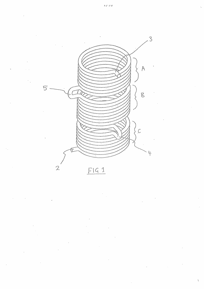
SCHEDULE 2
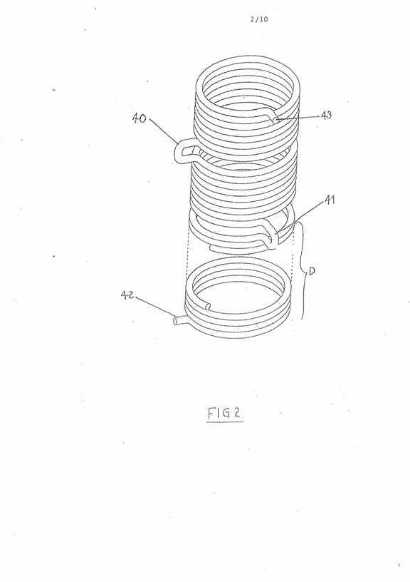
SCHEDULE 3
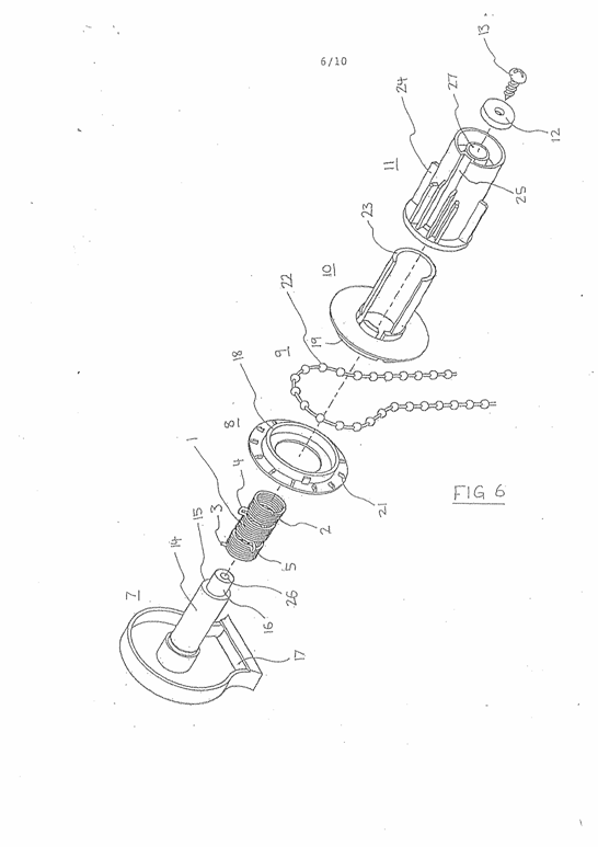
SCHEDULE 4
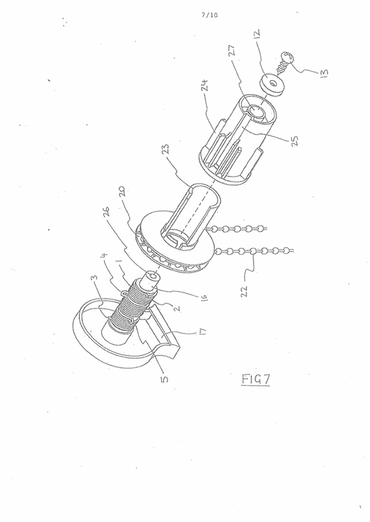
SCHEDULE 5
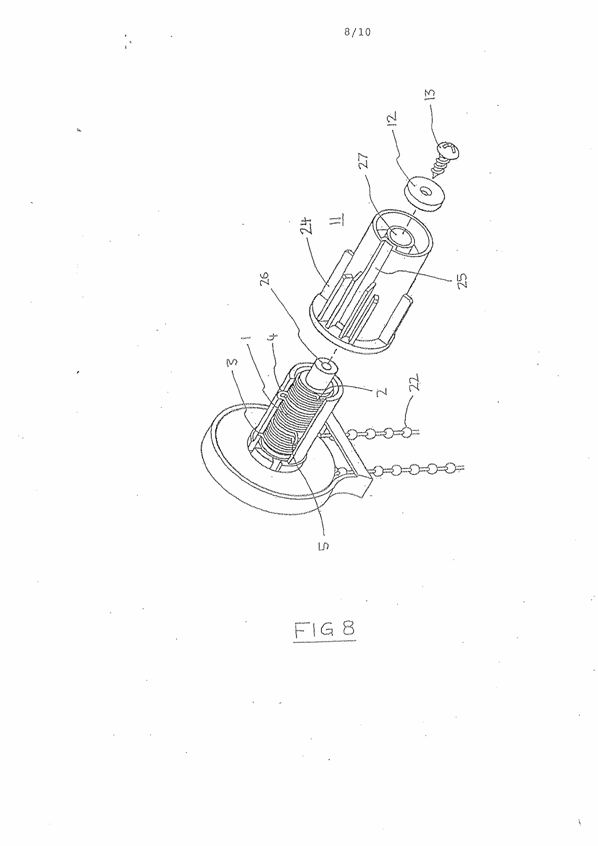
SCHEDULE 6
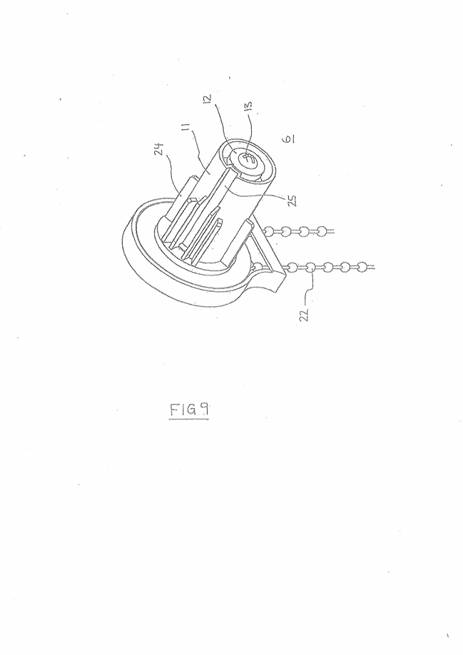
SCHEDULE 7
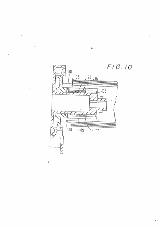
SCHEDULE 8