FEDERAL COURT OF AUSTRALIA
Norm Engineering v Digga Australia [2007] FCA 761
INTELLECTUAL PROPERTY – consideration of a claim of infringement of copyright in drawings for the components of an assembled industrial bucket used with ‘Bobcat’ equipment – consideration of originality and authorship, subsistence of copyright, use by a respondent of a three‑dimensional article to indirectly produce drawings relied upon in manufacturing three‑dimensional articles – consideration of conscious copying - consideration of Part III, Division 8 (ss 74-77) – designs copyright overlap – consideration of reproduction of the work by application of a corresponding design to articles (pre‑17 June 2004 position) – consideration of embodiment of a corresponding design in a product (post‑17 June 2004 position) – consideration of damages pursuant to s 115(2) of the Copyright Act 1968 (Cth) and s 115(4) of that Act
Copyright Act 1968 (Cth), ss 10(1), 13, 14(1), 21(3), 31(1)(b), 32, 35(6), 36(1), 74-77, 77A, 115(2), 115(4)
Designs (Consequential Amendments) Act 2003 (Cth), s 14
Designs Act 1906 (Cth)
Designs Act 2003 (Cth)
G.A. Cramp & Sons Limited v Frank Smythson Limited [1944] A.C. 329 - cited
Ladbroke (Football) Ltd v William Hill (Football) Ltd [1964] 1 All ER 465 - cited
Sands & McDougall Pty Ltd v Robinson (1917) 23 CLR 49 - cited
University of London Press v University Tutorial Press [1916] 2 Ch 610 - cited
Kalamazoo (Aust) Pty Ltd v Compact Business Systems Pty Ltd (1990) 1 Qd.R 231 - cited
Clarendon Homes (Aust) Pty Ltd v Henley Arch Pty Ltd [1999] FCA 1371 - cited
Amalgamated Mining Services Pty Ltd v Warman International Ltd (1992) 24 IPR 461 - cited
S W Hart & Co. Pty Ltd v Edwards Hot Water Systems (1985) 159 CLR 466) - cited
Walter v Lane [1900] AC 539 - cited
Interlego AG v Croner Trading Pty Ltd (1992) 111 ALR 577 - cited
Francis Day & Hunter Ltd v Bron [1963] Ch. 587 - cited
CIPEC v First Melbourne Securities Pty Ltd [1999] FCA 660 – cited
Henley Arch Pty Ltd v Clarendon Homes Pty Ltd (1998) 41 IPR 443 - cited
Eagle Homes Pty Ltd v Austec Homes Pty Ltd (1999) 161 FCR 503 - cited
Blackie & Sons Ltd v Lothian Book Publishing Co Pty Ltd (1921) 29 CLR 396 - cited
Hogg v Scott (1874) LR 18 Eq 444 at 458 - cited
Chatterton v Cave (1878) 3 App Cas 483 - cited
Anchor, Mortlock, Murray & Woolley Pty Ltd v Hooker Homes Pty Ltd [1971] 2 NSWLR 278 - cited
Bradbury v Hotten (1872) 8 LR Ex 1 - cited
Chappell & Co Ltd v D C Thompson & Co Ltd [1928-35] MacG Cop Cas 476 - cited
AMP Incorporated v Utilux Pty Limited (1971) FSR 572 - cited
Hosokawa Micron International Inc v Fortune (1990) 26 FCR 393 - cited
Greenfield Products Pty Ltd v Rover‑Scott Bonnar Limited [1990] FCA 154 - cited
Shacklady v Atkins (1994) 30 IPR 387 - cited
Dart Industries v Décor Corporation Pty Ltd (1989) 15 IPR 403 - cited
Burge & Ors v Swarbrick [2007] HCA 17 - cited
Firmagroup Australia Pty Ltd v Byrne & Davidson Doors (Vic) Pty Ltd (1987) 180 CLR 483 - cited
Columbia Pictures Industries Inc v Luckins (1996) 34 IPR 504 - cited
Autodesk Australia Pty Limited v Cheung (1990) 94 ALR 472 - cited
Microsoft Corporation v Goodview (2000) 49 IPR 578 - cited
Interfirm Comparison (Aust) Pty Limited v Law Society of New South Wales (1975) 6 ALR 445 - cited
Bailey v Namol Pty Limited (1994) 53 FCR 102 - cited
Aristocrat Technologies Australia Pty Limited v DAP Services [2007] FCAFC 40 - cited
McRae v Commonwealth Disposals Commission (1951) 84 CLR 377 - cited
Enzed Holdings Limited v Wynthea Pty Limited (1984) 57 ALR 167 - cited
The Commonwealth v Amann Aviation Pty Ltd (1992) 174 CLR 64 - cited
Raben Footwear v Polygram Records Inc. (1997) 75 FCR 88 - cited
Polygram Pty Ltd v Golden Editions Pty Ltd (1997) 76 FCR 565 - cited
Sony Entertainment (Australia) Limited v Smith (2005) 215 ALR 788 - cited
Autodesk Inc. v Yee (1996) 68 FCR 391 - cited
Lamb v Cotongo (1987) 164 CLR 1 - cited
Ravenscroft v Herbert and New English Library Limited [1980] RPC 193 - cited
Microsoft Corporation v PC Club of Aust Pty Limited (2005) 148 FCR 310 - cited
NORM ENGINEERING PTY LTD (ACN 010 799 943) v DIGGA AUSTRALIA PTY LTD (ACN 010 443 875)
QUD285 OF 2005
GREENWOOD J
18 MAY 2007
BRISBANE
| IN THE FEDERAL COURT OF AUSTRALIA |
|
| QUEENSLAND DISTRICT REGISTRY | QUD285 OF 2005 |
| BETWEEN: | NORM ENGINEERING PTY LTD (ACN 010 799 943) Applicant
|
| AND: | DIGGA AUSTRALIA PTY LTD (ACN 010 443 875) Respondent
|
| GREENWOOD J | |
| DATE OF ORDER: | 18 MAY 2007 |
| WHERE MADE: | BRISBANE |
THE COURT ORDERS THAT:
1. The proceeding stands adjourned to a date to be fixed.
2. The costs of the proceeding and any question in relation to the applicant’s claim for interest, are reserved.
Note: Settlement and entry of orders is dealt with in Order 36 of the Federal Court Rules.
| IN THE FEDERAL COURT OF AUSTRALIA |
|
| QUEENSLAND DISTRICT REGISTRY | QUD285 OF 2005 |
| BETWEEN: | NORM ENGINEERING PTY LTD (ACN 010 799 943) Applicant
|
| AND: | DIGGA AUSTRALIA PTY LTD (ACN 010 443 875) Respondent
|
| JUDGE: | GREENWOOD J |
| DATE: | 18 MAY 2007 |
| PLACE: | BRISBANE |
REASONS FOR JUDGMENT
Background
1 The applicant is a manufacturer of equipment and accessories used in earthmoving applications.
2 One example of such equipment is a bucket designed to be attached to a primary apparatus commonly described as a ‘Bobcat’ (which is a machine made by a particular manufacturer and badged under that trade name) but which is more generally described as a species of ‘skid steer equipment’. That term derives from the fact that motors attached to the wheels of the machine enable it to turn sharply or abruptly in a way that effects a skidding movement.
3 The standard bucket attached to skid steer equipment is in the shape of a scoop and allows the operator of the machine to push, load or scoop material using the leading edge of the bucket manipulated by the hydraulic arms of the skid steer apparatus. A standard bucket is a fixed shape in the sense that there is no capacity to open sections of the bucket or effect a separation between the front scoop section and the rear section of the bucket in something akin to a jaw‑like effect.
4 The applicant however also manufactures a bucket that does have that effect.
5 It is commonly called a ‘4 in 1 bucket’. When attached to the primary skid steer apparatus, additional hydraulic rams attached to the bucket, operated in conjunction with the skid steer’s hydraulic system, enables the lower part of the bucket to open and close thus enabling the operator to undertake four additional versatile functions of cutting, pulling or scraping material, a loading function and a clasping, holding or ‘grab’ action.
6 The applicant’s 4 in 1 bucket is a piece of equipment assembled by the applicant comprising components or parts manufactured by the applicant and some components supplied to the applicant by other component manufacturers. The total number of parts comprising the applicant’s 4 in 1 bucket is more than 30 and less than 40.
7 The applicant contends in these proceedings that it owns the copyright subsisting in drawings for five particular components of its 4 in 1 bucket and the copyright subsisting in two drawings depicting aspects of the assembly of sections of its 4 in 1 bucket. Copyright is said to subsist in the drawings as original artistic works of authorship (s 31(1)(b) Copyright Act 1968 (Cth) ‘Copyright Act’) of Mr Norman Pesch who originated the plans in March 2002 in his capacity as an employee of the applicant (s 35(6) Copyright Act). The applicant contends that the respondent in October or November 2003 elected to incorporate a 4 in 1 bucket within its product range as a manufacturer and supplier of earthmoving equipment.
8 The applicant contends that in order to do so, the respondent had regard to both an early version of the applicant’s 4 in 1 bucket (the ‘old Norm 4 in 1 bucket’, 1988) and a later version available in the market in October 2003 (a ‘new Norm bucket’ available in that form from 2002) not only for the purpose of conscious use of the old and new Norm 4 in 1 buckets as a source of ideas for the manufacture, assembly and sale of a competing 4 in 1 bucket but for the purpose of conscious copying of five components of the applicant’s 4 in 1 bucket. Those components are said by the applicant to comprise key elements of its 4 in 1 bucket because each component is significant and material to the function and operation of the 4 in 1 bucket as a whole and the components are central to the geometry of the opening and closing mechanism of its 4 in 1 bucket.
9 The respondent is said to have examined those five components in three‑dimensional form and brought into existence two‑dimensional drawings for the manufacture of the five components for assembly in the respondent’s 4 in 1 bucket and each respective drawing constitutes a reproduction of the applicant’s plan for the corresponding Norm part. Secondly, the respondent is said to have constructed a three‑dimensional bucket in accordance with those plans. The applicant’s complaint is framed in terms of the respondent’s overall conduct of copying its bucket. However, the foundation of its claim is seven specific drawings (‘plans’ (s 10(1) Copyright Act) for five components of its 4 in 1 bucket said to have been ‘reproduced’. Copyright, by s 32 of the Copyright Act,subsists in an original artistic work. Section 31(1)(b)(i) provides that one of the exclusive rights comprised in the copyright in an artistic work is a right to reproduce the work in a material form which by s 10(1) includes any form of storage (electronic or otherwise) of the work or a substantial part of the work. Section 14(1)(b) provides that a reference to reproduction of the work includes a reference to reproduction of a substantial part of the work and s 21(3) provides that an artistic work shall be deemed to have been reproduced:
(a) in the case of a work in a two-dimensional form – if a version of the work is produced in a three-dimensional form; or
(b) in the case of a work in a three-dimensional form – if a version of the work is produced in a two-dimensional form.
10 Section 36 provides that an artistic work is infringed by a person who does or authorises the doing in Australia of any act comprised in the copyright without the licence or authority of the copyright owner and s 13 makes it plain that ‘an act comprised in the copyright’ is a reference to the bundle of exclusive rights conferred by s 31 including the reproduction right.
11 The applicant has made an election to claim damages (s 115(2), Copyright Act). The applicant seeks a declaration as to infringement of its copyright in the plans for the five components and assembly drawings; an injunction restraining the respondent from infringing the applicant’s copyright in the plans by ‘constructing or manufacturing any equipment by use of the plans or any substantial part thereof’; additional damages pursuant to s 115(4) of the Copyright Act; and an order for delivery up of all infringing copies of the plans and related relief.
Short synopsis of the respondent’s contentions
12 The respondent accepts that it had access to the old Norm 4 in 1 bucket and in October 2003 made conscious use of the bucket as a source of ideas for the design and manufacture of a 4 in 1 bucket but denies conscious copying of the five components.
13 The respondent makes these additional contentions.
14 First, it denies use of the new Norm 4 in 1 bucket as a source of ideas. Secondly, it contends that the applicant has adopted an unorthodox approach in adducing evidence of its claim of authorship and originality of the works and thus subsistence of copyright in the plans with the result that, at the threshold, the applicant’s case necessarily fails for lack of proof. Thirdly, it contends that if the sequence of development of the plans by the applicant involved developing a three‑dimensional part and then a two‑dimensional drawing simply as a version of the three‑dimensional work, copyright can not subsist in the drawing:– the drawing must come first. Fourthly, the diversity of buckets available in the market at the dates on which the drawings are said to have been originated for the applicant’s 4 in 1 bucket, is compelling evidence of a lack of originality in the plans. Fifthly, it contends that the applicant did not originate the plans in suit at the date alleged and thus copyright did not subsist in the plans at the moment in time when the respondent is said to have engaged in infringing conduct. Sixthly, it contends that an examination of the plans makes it plain that its drawings do not constitute a reproduction of the applicant’s drawings. Seventhly, the diversity of manufactured buckets in the market at the moment in time when the respondent developed its 4 in 1 bucket is compelling evidence that the features reflected in the respondent’s plans are consistent with features well known in the market and thus any similarity of features has not derived from copying the applicant’s components for its 4 in 1 bucket. Eighthly, the applicant has failed to properly establish a foundation for the calculation of damages.
15 Ninthly, the respondent contends that if copyright subsists in each artistic work, the applicant has nevertheless industrially applied a corresponding design in circumstances where the corresponding design was either not registrable or had not been registered at the material time and thus by reason of Part III, Division 8, ss 74 to 77 of the Copyright Act, it is not, for the period prior to 17 June 2004, an infringement of the copyright in each artistic work to reproduce the works by applying that corresponding design to an article, at any time after articles made to the corresponding design were first sold (or offered for sale). Further, the respondent contends that after 17 June 2004, it is not an infringement of the copyright in each artistic work, by force of s 77(2) of the Copyright Act (introduced into the legislation by the Designs (Consequential Amendments) Act 2003 effective from 17 June 2004) to reproduce each artistic work on or after the day on which products made to the corresponding design were first sold (or offered for sale), by embodying that corresponding design in a product.
16 The applicant joins issue with the respondent on all of those contentions and says firstly that even though the respondent made changes to its drawings for the components in March 2005 and further changes in October 2005, the changes are simply cosmetic changes designed to obfuscate the continuing conscious reproduction of the applicant’s works and secondly, the pre‑conditions for the operation of s 77 of the Copyright Act whether under the form of the legislation in existence prior to 17 June 2004 or as amended by the Designs (Consequential Amendments) Act 2003, are not satisfied.
The foundation of the applicant’s case
17 The applicant asserts subsistence and ownership of the copyright in the following plans said to have been made on the following dates for five components of the applicant’s 4 in 1 bucket, namely:
1. a ‘side cutter bar’ (drawing BC 41 D013) dated 12 March 2002.
2. an ‘outside mounting bracket’ (drawing BC 41 D018) dated 4 March 2002;
3. an ‘inside mounting bracket’ (drawing BC 41 D016) dated 4 March 2002;
4. a part described as the ‘pivot arms’ (drawing BC 41 D015) dated 12 March 2002; and
5. a ‘floor side plate’ (drawing BC 41 D014F) dated 12 March 2002.
18 The applicant also asserts subsistence and ownership of the copyright in two assembly drawings said to have been made on the following dates, namely:
(a) a ‘front bucket assembly’ drawing (BC 41 A004) dated 4 March 2002; and
(b) a ‘rear bucket assembly’ drawing (BC 41 A003) dated 4 March 2002.
19 On 22 December 2005, Mr Pesch swore two affidavits. One was the applicant’s verified List of Documents and the other contained paragraphs identifying by reference to the list, the drawings Mr Pesch said he drew reflecting improvements made to earlier drawings generally called the ‘first plans’ made by Mr Pesch’s father‑in‑law, Mr Acimovic. Mr Pesch says these improvements are the result of his skill, labour, effort and work and thus this second group of plans are said to be original and the source of the applicant’s copyright. Mr Pesch identified this second group of plans as documents 5 to 24 of the list. The List of Documents attaches a copy of drawings 5, 6, 7, 8, 9, 10 (a second composite drawing for document 10 also marked BC 41 D0002), documents 11 to 22 inclusive and another drawing (marked BC 41 D014) reflecting aspects of the drawing at document 22. No copy of drawing 23 (BC 41 D015) or document 24 (BC 41 B016) was attached to the list. Drawings 5 to 8 and 10 to 22 attached to the List of Documents are all dated 9 October 2003.
20 On 18 October 2005, the applicant filed a Statement of Claim and by paragraph 9 identified 19 plans in which copyright is said to subsist as the foundation of the applicant’s copyright. Those plans were the plans identified in the applicant’s list (and nominated by Mr Pesch as the original works) pleaded in the order of the pleading, as documents 6, (another document being a version of document 6 designated with an additional letter ‘F’), 7, 8, 10, 11, 12, 13, 17, 16, (16 again), 15, 19, 14, 18, 20, 21 and 22 twice. All of these plans were said by the pleading to have been made in March 2002.
21 On 6 October 2005, the applicant filed an Amended Statement of Claim but made no change to plans said to be the foundation of the action.
22 On 7 March 2006, the applicant filed a Further Amended Statement of Claim. The applicant abandoned any reliance upon 17 of the 19 drawings previously pleaded; continued to rely upon two of the plans previously pleaded (BC 41 A003), an assembly drawing and (BC 41 D013) a drawing for a component described as a ‘side cutter bar’. The pleading of 7 March 2006 introduced five additional plans into the action, namely:
(a) BC 41 A004 - a front assembly drawing;
(b) BC 41 D018 – an outside mounting bracket drawing;
(c) BC 41 D016 – an inside mounting bracket drawing (which is referred to in the applicant’s List of Documents as document 24 by that drawing number);
(d) BC 41 D014F – a front side plate drawing; and
(e) BC 41 D015 – a drawing depicting the ‘pivot arms’ for the bucket (which is referred to in the applicant’s List of Documents as document 23 by that drawing number).
23 Mr Pesch says by paragraph 2 of his further affidavit of 29 May 2006 that these seven plans the subject of the action, described as plans 185A to 185G, were drawn by him ‘at about the same time’ he drew plans numbered 5 to 24 in the applicant’s List of Documents. All of these seven plans discovered as 185A to 185G are dated in March 2002.
24 The respondent says this fundamental reorganisation of the foundation of the action informs the answer to the question of when the works the subject of the suit were actually made and the consequential question of whether or not the conduct of the respondent could (absent any other considerations) involve a reproduction of any of the drawings in suit and thus an infringement of the applicant’s copyright, as no copyright subsisted in the plans in suit at the date of the respondent’s contended conduct.
25 The reference to ‘BC’ in the applicant’s drawings is an abbreviation of bobcat. The reference to 41 is an abbreviation of 4 in 1 and the ‘D’ reference signifies that the drawing is a drawing for a medium sized 4 in 1 bucket. 4 in 1 buckets are made in three sizes; a small bucket 300 millimetres (mm) to 1500mm in width; a medium bucket 1500mm to 1900mm; and a large bucket 1900mm to 2.5 metres. This action concerns medium buckets.
26 These reasons attach a schedule that contains a drawing (marked 1.1) which depicts an elevated view of the Norm 4‑in‑1 bucket from both the side/front and the side/rear aspect of the 4 in 1 bucket showing the arrangements of the components. The schedule also contains a number of photographs merely to illustrate the shape and configuration of the components in issue in the proceeding. The photographs depict features present in a new Norm bucket being a bucket made after March 2002 reflecting in a three‑dimensional form features continuously present in new buckets made by the applicant and features present in a bucket made by the respondent on 12 October 2004. The photographs in the schedule were taken by Mr Gould an expert called by the applicant and they are these:
(a) at Schedule 1.2, a photograph marked No. 9 of the applicant’s outside mounting bracket, floor side plate and side cutter bar;
(b) at Schedule 1.3, a photograph marked No. 10 of the equivalent components of the respondent;
(c) at Schedule 1.4, a photograph marked No. 11 of the applicant’s pivot mechanism (frontal view);
(d) at Schedule 1.5, a photograph marked No. 12 of the respondent’s pivot mechanism (frontal view);
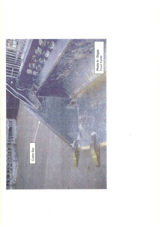
(e) at Schedule 1.6, a photograph marked No. 7 of the applicant’s pivot mechanism, floor side plate and side cutter bar taken from inside the bucket;
(f) at Schedule 1.7, a photograph marked No. 8 of the respondent’s equivalent components.
These photographs are simply illustrative of the description of the relevant features in the applicant’s 4 in 1 bucket and features depicted in the respondent’s three‑dimensional 4 in 1 bucket. The issue to be determined in this action is whether the respondent’s three‑dimensional version involves a reproduction of any of the applicant’s drawings in suit and whether the respondent has made a reproduction of the applicant’s drawings by making a drawing either in the course of enabling a corresponding design to be applied for the manufacture of components or an assembled bucket, or otherwise.
A description of the components in issue
27 The shape of the applicant’s bucket might be broadly described as a scoop.
28 The front section of the bucket comprises a floor which might be flat or slightly elevated. The floor is essentially rectangular in shape. The front section of the bucket has two sides attached to the base or floor, called ‘front side plates’. They are triangular in shape with the base of the triangle welded to the floor plate with the cut off apex of the triangle providing, near the top, a point of welded attachment to a pivot apparatus which works in conjunction with the rear section of the bucket through manipulation of the pivot mechanism in conjunction with the inside and outside mounting brackets, to open and close the rear and front sections of the bucket.
29 The back section of the bucket is a hollowed out rectangular section that joins the base plate when closed completing an integrated bucket of base, sides and rear section.
30 Because the front triangular edge of each side plate is the immediate point of contact (together with the bevelled front edge of the floor plate) with earth, sand, rocks etc, the edge of each side plate suffers major wear and tear. Accordingly, another component called a ‘side cutter bar’ is fixed to the triangular section of each side plate to effect the cutting action on presentation of the bucket under force to particular material and to absorb the wear and tear of that action. The bucket has a particular functional geometry. The side assembly of the rear section of the bucket is made up of a plate called an ‘outside mounting bracket’ that joins and partially closes over the front side plates of the bucket. The outside mounting bracket, in the assembled position, has a pivot point in the top section for interaction with the pivot arms and, in a sense diagonally opposite that pivot point, a pivot point in the bottom section of the plate or bracket for attachment to an hydraulic ram.
31 Attached to the top pivot point of the bracket by a pin is a component described as the ‘pivot arms’ or pivot mechanism. The pivot mechanism is made up of two sections or ‘arms’. The ‘outer arm’ is a straight section or flat plate welded to the front side plate of the bucket. A second plate or ‘inner arm’ makes up a ‘double arm’ pivot around a pin. The inner arm is separated from the outer arm by a circular tube between the two arms at the pivot point with the outside mounting bracket. The inner arm is bent or folded some distance below the separating circular tube to abut the outer arm. Between the two arms as the inner arm folds towards the outer arm, the notional triangular gap between the two is filled by a stiffening section or single plate. At the top of each arm (viewed in the closed position for the bucket) is another pivot point for the attachment of an hydraulic ram. A ram attached to the rear of the bucket located between the inside and outside mounting brackets when activated by the operator will pull down on the section between the top pivot points on the pivot arms which will cause the section of the pivot arms welded to the side plates of the bucket to lift the front section of the bucket open and cause rotation around the pin in turn connected to the top pivot point of the outside mounting bracket. Pushing the hydraulic ram open closes the bucket. The hydraulic ram is itself connected to the outside mounting bracket at the lower pivot point diagonally opposite the upper pivot point on the bracket. The inside mounting bracket provides a corresponding connection point to the pin for the pivot arms and the outside mounting bracket provides some protection for the hydraulic ram and is shaped so as to facilitate appropriate access by the hydraulic hoses to the hydraulic ram.
32 In functional terms, the interaction and operation of the inside and outside mounting brackets and the pivot arms is critical to the opening and closing of the front and rear sections of the 4 in 1 bucket. One further preliminary matter should be mentioned. The applicant suggested that it might be helpful to physically view the applicant’s new 4 in 1 bucket and compare it with the respondent’s 4 in 1 bucket. During the course of the trial, a view was conducted. In determining the issues in controversy I have not had regard to any matter or circumstance arising out of the view.
The evolution of the plans in suit
33 Mr Vlada Acimovic swore an affidavit dated 22 December 2005.
34 Mr Acimovic is a European migrant; a boilermaker and general engineer by trade having studied at the Technical College at Belgrade, Serbia between 1948 and 1954; and the father‑in‑law of Mr Norman Pesch. The applicant was founded by Mr Acimovic and was incorporated on 29 March 1988. Before the applicant commenced business, Mr Acimovic operated a general engineering company which was sold in 1983. In about 1984, Mr Acimovic purchased two skid steer loaders which formed part of an equipment hire business conducted by him. Mr Acimovic was not satisfied with the bucket which was fitted to those machines.
35 Mr Acimovic approached the new owners of his former business so as to use those facilities to build a new bucket which better suited identified needs and which was said to be an improvement on the buckets fitted to the two machines. Mr Acimovic says that he worked in the workshop of his former business for some time and devised what he described as a ‘unique design’ for a 4 in 1 bucket. Mr Acimovic says he used these buckets in a hire business which he operated after selling the former business. Mr Acimovic says that a client expressed interest in the bucket and Mr Acimovic agreed to manufacture a bucket for that customer and sold him the finished product. Requests grew for the supply of the buckets and this activity became the foundation of the applicant’s manufacturing activity. Mr Acimovic says the request for buckets was so frequent that he elected to sell the hire business and began manufacturing 4 in 1 buckets full time according to his design.
36 Mr Acimovic says that he established the new bucket manufacturing business; registered the name Norm Engineering; adopted the name ‘Norm’ because it was his son‑in‑law’s name; recognised that his son‑in‑law had an engineering background and intended that the new business would be Mr Pesch’s business.
37 At paragraph 8 of his affidavit, Mr Acimovic says this:
‘8. Before the business was established, no plans of significance existed. By this I mean that the only notes from which I manufactured the buckets were rough or rudimentary. These were disposed of some time ago probably 1995. These plans were prepared by me when I was principal of the business. In the four year period in which the unincorporated business operated [1984-1988], I brought various rudimentary plans into existence and refined the design of the buckets. It was not until after the applicant was incorporated that I began developing more sophisticated plans for the larger scale manufacture of 4‑in‑1 buckets with the assistance of draftsmen employed by the applicant.’
38 At paragraph 10, Mr Acimovic says this:
‘10. After the Applicant was incorporated, I, for the first time, instructed draftsmen to prepare plans to my specifications and direction. The draftsman’s name was Joe. I cannot recall his last name. He was a full time employee of the applicant. Those plans are document numbers 174 to 185 on the Applicant’s List of Documents. This was the first time my design for buckets was systematically and comprehensively recorded (the First Plans).’
39 Mr Acimovic makes these further observations:
‘12. The Applicant produced 4‑in‑1 buckets utilising the First Plans for a period of about 14 years, until the design was changed.
13. Between 1993 and 1997, the Applicant’s plans for the bucket were prepared in electronic form on the Applicant’s computer system by my son‑in‑law Norm Pesch. These plans were transferred on to the computer system by him using Autocad software at a time when my son‑in‑law was employed full time by the Applicant.
14. I retired from the business in or about July 1998.’
40 Mr Acimovic said that in designing his bucket he started with a standard bucket and thought it would be useful to ‘get something open and close and at that time there’s not many bucket’. Mr Acimovic says that the bucket that he designed was the second such bucket in Australia. The first was a Hughes bucket designed by Mr Tony Hughes from the Gold Coast which was sold to a business called Miller Brothers. Mr Acimovic said that he did not know about the Hughes bucket when he designed his bucket. Mr Acimovic said the 1988 drawings were made based on the bucket he designed in 1984. Mr Acimovic said that he did not understand how to make drawings. He understood how to make the product. Mr Acimovic said that he helped Mr Pesch in 2001 in developing the later version of the bucket and again Mr Acimovic worked with the bucket not drawings. Mr Acimovic said that he doesn’t ‘understand even to try drawing’. I accept the evidence of Mr Acimovic.
41 Mr Norman Pesch swore an affidavit on 22 December 2005.
42 Mr Pesch said that he started work for the applicant in 1989/1990 employed initially as a workshop supervisor although over time he became the general manager or principal of the business. He presently holds that position. Mr Pesch and his wife are the only directors of the applicant. Mr Pesch also says that the applicant produced 4‑in‑1 buckets utilising the ‘First Plans’ as described by Mr Acimovic, for a period of about 14 years until the design was changed in 2001/2002. Mr Pesch describes the development of the plans for the applicant’s 4‑in‑1 buckets in this way:
‘8. Between 1993 and 1997 the Applicant’s plans for the bucket were prepared in electronic form on the Applicant’s computer system while I was employed full time by the Applicant. These plans were transferred on to the computer system by me using Autocad software. My name appears on the plans as drawer. Those plans are document numbers 25 to 153 on the Applicant’s List of Documents. Most of these plans were drawn in 1994. Some are marked with the copyright endorsement dated 1997. That is because the Applicant had buckets constructed in Thailand for a short period around that time and wanted to be certain of copyright protection given that the plans were to be released to the overseas manufacturer for that purpose. Nevertheless, those plans were brought into existence in 1994.
9. There are no significant changes between the First Plans and the plans I transferred on to the Applicant’s computer system. At the time I transferred the plans on to the computer system, I was employed full time by the Applicant. My aim was not to change the design; just to update and improve the applicant’s records.’
43 It is clear therefore that the act of Mr Pesch of transferring the ‘First Plans’ developed by Mr Acimovic on to the applicant’s Autocad computer system did not involve any act of original authorship.
44 Mr Pesch continues:
‘10. The Applicant used the plans I had transferred on to the computer system until about 2001/2002. At this time, the design for the buckets was changed. This was because demands of customers had changed and the machines being produced by companies such as Toyota were of greater horsepower. The changes evolved initially by working with the buckets in the workshop. That process was managed by me working with employees of the Applicant to improve and make changes to the previous design.’
45 At paragraphs 11 and 12 of his affidavit, Mr Pesch describes the process of making changes to the First Plans and some of the changes which brought into existence additional plans, in these terms:
‘11. Once those changes had been made, the plans were changed to reflect the improvements me, my father‑in‑law and employees of the Applicant had decided should be made. Those plans are document numbers 5 to 24 on the Applicant’s List of Documents (the Second Plans). There are 19 plans comprising that bundle. Each of those plans show only component parts of the bucket. I also drew those plans using Autocad. The main changes made to the buckets were to the pivot system to incorporate a stronger and better structure. We had found that with machines of greater horsepower, buckets were susceptible to break at this point. The other major change was to the geometry of the way the bucket functioned. This meant that two sides of the buckets were altered so that wear was reduced.
12. The buckets manufactured by the Applicant replace a standard bucket used on machines commonly known as bobcats. Those buckets have hydraulic rams attached to them which operate to open and close the lower part of the buckets. The bucket is connected to the bobcat or similar machine using a lip connection at the top rear of the bucket and two pin connectors at the bottom of the bucket.’
46 On 29 May 2006, Mr Pesch swore a further affidavit referring to paragraph 11 of the affidavit sworn on 22 December 2005 deposing to the plans. By paragraph 2 of the subsequent affidavit, Mr Pesch described matters relevant to the development and authorship of documents numbered 185A to 185G in these terms:
‘2. Documents numbered 185A to 185G were also drawn by me using autocad on or about the dates appearing on those plans. I drew these plans at or about the same time I drew the plans which are documents 5 to 24 of the applicant’s list and while I was employed full time by the applicant. The plans which are documents 185A to 185G were also drawn to reflect improvements which me, my father-in-law and employees of the applicant had decided to make.’
47 Documents 185A to 185G are the documents referred to in [17] and [18]. A number of things emerge from paragraphs 10 and 11 of Mr Pesch’s affidavit of 22 December 2005 and paragraph 2 of his affidavit of 29 May 2006.
48 First, the moment in time when Mr Pesch made design changes to the ‘First Plans’ for the bucket is said to be 2001/2002. Secondly, the changes are described as ‘design changes’. Thirdly, the changes were made necessary so as to respond to demands from some customers due to the greater horsepower of some machines using the buckets. Fourthly, initial changes occurred by making changes to the bucket itself in the workshop and as a result Mr Pesch says he managed the process to ‘improve and make changes to the previous design’. Fifthly, once the changes had been made to the bucket, the plans were changed to ‘reflect’ the changes. Sixthly, the plans which show the content of the changes emanating from Mr Pesch’s improvements to the First Plans comprise 19 new plans called the ‘Second Plans’. Those 19 plans are identified by reference to the applicant’s List of Documents and all 19 plans are attached to the list verified by Mr Pesch in December 2005. Seventhly, each of the 19 plans relates to component parts of the bucket and Mr Pesch says he drew those plans using Autocad software. Eighthly, Mr Pesch describes two features of the componentry for the bucket and the orientation of those components as an explanation of the changes to the bucket and thus the changes resulting in the second plans. Mr Pesch says that it was necessary to incorporate a stronger and better structure for the buckets because under additional horsepower, the buckets tended to break using the existing design for the pivot system which under hydraulic pressure would cause the bucket to open and close. Mr Pesch says the other major change to the design resulting in changes to the plans concerned the geometry of the bucket which meant that ‘two sides of the buckets were altered so that wear was reduced’.
49 Paragraphs 10 and 11 of Mr Pesch’s affidavit of 22 December 2005 and paragraph 2 of his affidavit of 29 May 2006 represent the total evidence‑in‑chief of the applicant as to the scope and content of the skill, work, effort and labour deployed by Mr Pesch as author of the Second Plans to bring into existence original works in which copyright subsists.
50 Ordinarily, the author of each artistic work would identify the plan, explain each of the circumstances which caused the plan to be brought into existence, the precise steps taken to address the inadequacies in the existing plans and those features of each drawing which are the emanation of the work, skill, effort and labour of the author. The applicant in this case has elected to identify the plans by reference to the List of Documents, assert authorship of the 19 plans and plans 185A to 185G and identify the scope and content of the changes to the First Plans by means of inviting a comparison between the pre‑existing First Plans and the Second Plans aided by the explanation at paragraph 11 of the affidavit of 22 December 2005 and paragraph 2 of the affidavit of 29 May 2006.
51 However, Mr Pesch gave oral evidence of the development of the plans in suit and the date of creation of changes to the 4 in 1 bucket and the consequential changes to the drawings. It is necessary to closely examine this evidence in assessing the originality of the Second Plans and in determining the date of authorship of those plans.
52 Mr Pesch says this.
53 In 1988, the applicant continued to manufacture 4 in 1 buckets based on the design developed by Mr Acimovic although the plans were changed in 1988. The First Plans are properly to be understood as those plans altered by the applicant in 1988 and used until the changes in 2001/2002.
54 Mr Pesch has computer design skills and until 2006 Mr Pesch was the person who did most of the design work using computer aided design software called ‘Autocad’.
55 Using those skills, Mr Pesch transferred the handwritten First Plans on to the computer system.
56 In order to do so or otherwise design a drawing for a component using Autocad, the author starts with a standard size title block (setting out the name of the company, part description, drawing number, date drawing made, date of revision etc) and a standard A3 or A4 ‘outline’ to contain the drawing to be developed. The author will when setting up the A3 or A4 title block and outline insert manually the name of the author and the date of that action.
57 After transferring the First Plans on to the computer system and into the title block and outline format, the applicant no longer had any real need for the retention of hard copy drawings and ‘pretty much’, says Mr Pesch, ‘no longer relied on manual drawings’.
58 The applicant operates an administration or drafting office where the computer operating the Autocad software is located. Downstairs from that office is the workshop. Some drawings are stored in the administration office. Components made occasionally by the applicant would require a drawing to be printed from the Autocad system and taken to the workshop. Drawings for other components made more often are kept in the workshop.
59 When plans are amended using Autocad, the Autocad system stores or represents the latest version of the drawing. Changes or revisions to a drawing ought to be noted manually by the author in the title block in the ‘revision’ lines. Revision details (and dates) were not always entered as a matter of good discipline. Mr Pesch says that if he remembers to enter the revision date when a change is made, the title block will reflect those revision details; if not, it will not.
60 When creating a drawing on the Autocad system, sometimes the author will copy the title block and the drawing into the new A3 or A4 outline and make changes to the drawing. The date of the transfer and consequential changes giving rise to the new drawing should be manually entered in the title block. As a result of transferring or copying across a title block, the date depicted in the title block in the new drawing might not reflect the date the drawing was drawn. The date the drawing is done is contained in a box at the foot of the title block and the date of revision is a separate set of boxes above the title of the applicant in the title block.
61 Notwithstanding the lack of discipline concerning the insertion of a revision date, Mr Pesch acknowledged that he appreciated the importance of inserting a date in a drawing.
62 In 2001 and 2002, Mr Pesch, together with the assistance of his father‑in‑law and some employees of the applicant made changes to the 4 in 1 buckets; began making the changed buckets in November 2001; first brought into existence the new drawings [17] and the assembly drawings [18] in March 2002 thus ‘formalising’ the physical changes made to the 4 in 1 buckets; and thereafter, from time to time, amended the drawings.
63 The respondent put to Mr Pesch that the Second Plans were actually created in September 2003. Mr Pesch said ‘no’ and said he ‘would have said 2002’. Mr Pesch said he would not rule out the possibility that it was that late and agreed that he was not sure of the date but ‘I thought it was done much earlier than that’.
The floor side plate drawing (BC 41 D014F) – document 185D
64 Document BC 41 D014F for the ‘floor side plate’ bears the date 12 March 2002. Mr Pesch said he could not recall the exact date of creation of the drawing but that it was early 2002. Mr Pesch accepted that it was possible that the document was created as late as September 2003. The respondent drew Mr Pesch’s attention to the noted addition of ‘flat floor dimensions’ to the drawing on 3 February 2006. That version of the drawing was produced by the applicant in discovery in March 2006. Thus the respondent put to Mr Pesch that the drawing incorporates any revisions made to the document up to the date of printing out the drawing. If so, the drawing reflecting the original work leading to the changes in November 2001 and March 2002 could not be seen in document 185D. Mr Pesch said that the drawing reflects the features of the floor side plate ‘right at the start’ of the changes he made.
65 As to the floor plate itself, Mr Pesch agreed that the ‘borders’ of the old plan (1994) for the floor side plate depict a general triangular form; the triangular form is ‘pretty much the same’ in the new drawing (BC 41 D014F); and that as to the shape at least, the two drawings are just the same. Mr Pesch says the dimensions however are not the same.
66 As to the date of creation of the new drawing, the respondent took Mr Pesch to a printout of a ‘statistics’ box produced automatically by the Autocad system for plan BC 41 D014F which records ‘Created: Thursday, 18 September 2003 3:12:50PM’ and ‘Modified: Sunday, 5 February 2006 1:18:57AM’ and ‘Total editing time: 56 hours, 16 minutes’.
67 Mr Pesch says that the statistics box does not accurately state the date and time of creation of the drawings; the statistics box records a date and time but it is ‘not what happened’; and the drawing was drawn ‘well before then … in early 2002’. Mr Pesch attributes the information contained in the statistics box to a legacy of upgrades of the Autocad system of which there were either two or three. Mr Pesch suggests that such upgrades are a possible explanation for the entry. Mr Pesch says the ‘Modified’ information reflecting a time of 18 minutes past 1 in the morning on Sunday, 5 February 2006 is not accurate and highly unlikely because Mr Pesch would have no reason to be in the administration office where the computer is located at that early hour of Sunday morning.
68 The respondent took Mr Pesch to page 30 of Mr Pesch’s sworn List of Documents on behalf of the applicant. At page 30 of the list is a version of the applicant’s plan BC 41 D014. This plan depicts a floor side plate for a Norm 4 in 1 bucket with an elevated floor plate whereas BC 41 D014F represents a floor side plate for a ‘flat’ floor 4 in 1 bucket. Mr Pesch says that there are no real differences between the two plans and they are essentially the same plan but for the elevation. The ‘F’ simply identifies that drawing BC 41 D014F is the drawing for the flat floor 4 in 1 bucket. The version of the plan at page 30 reveals a date of creation of 9 October 2003 drawn by ‘CMK’. The document also notes a revision entry of ‘original issue’, CMK, 10 October 2003. Document 22 in the applicant’s discovery is also a version of drawing BC 41 D014 which bears a creation date of 12 March 2002. The respondent put to Mr Pesch that the date of 12 March 2002 was not the date of creation of the document having regard to the inconsistent later date of October 2003 noted in the document at page 30 to the List of Documents. The respondent also put to Mr Pesch that his evidence as to the date of creation of the document was simply not correct; that the Autocad statistics correctly reflect the date of first creation in September 2003; and that the author of the document was not Mr Pesch but the individual whose initials are CMK.
69 Mr Pesch denied these contentions and offered an explanation for the reference to CMK. Mr Pesch says that the initials CMK are the initials for Mr Colin McKay. Mr Colin McKay is a consulting engineer from a company retained by the applicant to undertake a stress and load‑bearing analysis called a ‘finite element analysis’ on the applicant’s 4 in 1 buckets. The drawings for the applicant’s ‘4 in 1 buckets were electronically transferred to Mr McKay who undertook the engineering analysis and electronically transferred the drawings back to the applicant. Mr Pesch says that Mr McKay did not create the drawings but merely undertook the finite element analysis in order to deal with the stress and load‑bearing failures reported to the applicant.
70 Mr Pesch says that notwithstanding the apparent inconsistency between dates, he was the author of drawing BC 41 D014F; that the drawing was created in early 2002 and that Mr McKay’s engagement to undertake the finite element analysis explains the entry of the initials CMK into the document.
Outside mounting bracket (BC 41-D018) – document 185G
71 Drawing 3000 OS for a Norm outer mounting plate dated 30 August 1993 is the drawing Mr Pesch transcribed from the old plans to the Autocad system. The date 30 August 1993 was manually entered into that system. Drawing BC 41 D002 dated 4 March 2002 represents the equivalent part designed by Mr Pesch. Mr Pesch says that the two drawings are similar. They are not the same. One difference is that the pivot points are not the same distance apart. Another difference is that the lower front edge of the bracket which meets the floor side plate has three teeth used for gripping articles. A further difference is that the back section of the bracket contains a straight edge leading down to the base of the bracket which reflects a protrusion leading down to and around the lower pivot point for the bracket, commonly described as a kink.
72 A further difference is an acute angle from the top pivot point to a point approximately 40% along the line of the front edge of the bracket and a less acute angle of line continuing to the lower pivot point, in the 1993 bracket on the one hand, and a slight angle from the top pivot point to a point approximately 15% along the line of the front edge and then a continuous gradual slope until the commencement of the three teeth in the new bracket, in the new drawing, on the other hand. Mr Pesch says that these were design choices he made which could have been any one of a number of permutations of design choices available to him. The respondent put to Mr Pesch that he decided to adopt these changes because he thought it would look and work better and Mr Pesch agreed.
73 Drawing BC 41 D018 is the same part reflected in BC 41 D002 but standing in an upright position. Both drawings reflect a date of creation of 4 March 2002. The respondent put to Mr Pesch that having regard to the numbering sequence D002 to D018, drawing D018 was necessarily created later than D002. Mr Pesch agreed that because the drawings have a different drawing number, each drawing was created at a different time. One of the differences between the drawings apart from the upright presentation of the bracket is that drawing D018 contains dimensions such as the distance between the centre points of the two pivot points and other dimensional information.
74 The respondent put to Mr Pesch that the two documents could not possibly have the same actual date of creation of 4 March 2002 being separated by 16 other numbered drawings. Mr Pesch gave evidence that the date of creation could be the same for each document if the title block for the earlier document was copied into the title block and outline for the drawing for D018. Mr Pesch agreed that the date appearing in the title block might be the date copied across but the date of actual creation may be ‘somewhat different’. The respondent suggested to Mr Pesch that the date of creation of drawing BC 41 D018 is likely to be about September or October 2003. Mr Pesch disagreed. The respondent then took Mr Pesch to a similar print out of the statistics box for drawing BC 41 D018 contained within the Autocad system which reveals a date of creation of Thursday, 18 September 2003 at 3:12:50pm and a date of modification of Saturday, 4 February 2006 at 10:00:24am and a total editing time of 62 hours and 58 minutes.
75 The respondent put to Mr Pesch that 18 September 2003 at 3:12pm was the date and time that the layout and title block was created for the purpose of creating drawing BC 41 D018. Mr Pesch disagreed and gave evidence that he was not exactly sure how the Autocad system generated electronic information of that statistical kind but that changes to the Autocad system previously described as ‘upgrades’ might explain the generation of those dates. The respondent put to Mr Pesch that his evidence seemed to be that the electronic system was wrong but that his manually entered date was correct. Mr Pesch gave evidence that, ‘What I am suggesting is, I’m not sure. I’m telling you the drawings were created before that date, well and truly before that date’.
The inside mounting bracket (BC 41 D016) – document 185F
76 Drawing 3001 OS dated 22 September 1994 is a drawing of an inside mounting bracket forming part of the First Plan which Mr Pesch electronically transferred on to the Autocad system. The drawing for that part amended by Mr Pesch and forming part of the Second Plan is drawing BC 41 D001 which bears a date of 4 March 2002. A drawing for the same part depicting the part in an upright version is drawing BC 41 D016 (document 185F).
77 Mr Pesch agreed that the general relationship between the pivot points of the inside mounting bracket depicted in the 1994 drawing and BC 41 D001 is approximately the same. Mr Pesch agreed that on the right hand side of the mounting bracket in the old version (ie. the First Plan version), there is a cut away section of the bracket at the lower point (in an upright position) whereas in the new version or Second Plan there are two pivot points. Mr Pesch agreed that the general shape of the old and new versions is approximately the same. Mr Pesch also agreed that the differences between the two drawings are design choices made by the designer of the new part to make the part work better and make it look better. Mr Pesch agreed that there could have been any number of other permutations that might have been selected.
78 Other differences selected in relation to the new Second Plan include the angulation of the front section of the bracket, the angulation of the back section from the point of the back hydraulic hose fitting to the top pivot point and the shape of the bottom section of the bracket with the introduction of a pivot point within the bottom section of the bracket. Mr Pesch agreed that BC 41 D001 is a drawing created before BC 41 D016 and that both drawings reflect the same part reflecting the same defined shape. Mr Pesch agreed that the difference between the two drawings BC 41 D001 and BC 41 D016 is that there are dimensions noted on BC 41 D016 and the orientation of the part in that drawing is in an upright position whereas in BC 41 D001 the part is displayed horizontally.
79 The respondent put to Mr Pesch that drawing BC 41 D016 was not incorporated into the applicant’s Autocad system until 18 September 2003 and that having regard to the statistical properties box for drawing BC 41 D016 in the Autocad system, the drawing was created on Thursday, 18 September 2003 at 3:12:50pm and modified on Sunday, 5 February 2006 at 1:18:18am with total editing time in all of 60 hours and 7 minutes. Mr Pesch accepted that the statistics box reflected that information but attributed the information to an upgrade in the Autocad software and possibly upgrades in the applicant’s computers as well.
80 Mr Pesch explained that the applicant holds a licence for the use of Autocad software; the licence is operated on one computer; that computer has been upgraded; it is located in the administration office; and that an upgrade has occurred in the last 18 months. Mr Pesch acknowledged that he did not know how the statistical information in the properties box is logged by the Autocad system or how that system selects the date and precise times identified in the box. Mr Pesch suggested that the drawings may have been copied and then transferred on to a new computer. The respondent took Mr Pesch to a version of BC 41 D001 contained at page 15 of the applicant’s list of documents which Mr Pesch agreed was the same drawing as document number 8 in the applicant’s discovery bearing the date 4 March 2002. Mr Pesch agreed that the only difference in the two drawings is that document 8 is endorsed in the title block with a date of creation of 9 October 2003 and in the revision block the notation ‘Original Issue, CMK, 15.10.2003’.
81 The respondent put to Mr Pesch that drawing BC 41 D001 which is the same drawing reflected in BC 41 D016 although in a different orientation was drawn by the person whose initials are CMK. Mr Pesch again explained that the role of Mr McKay was to undertake a stress testing analysis; that a copy of the drawing was communicated to Mr McKay on a CD; that Mr McKay entered the revision details of 15 October 2003 in the revision boxes and that Mr McKay inserted his initials of CMK, manually. Mr Pesch was again pressed about these issues and his contention that Mr McKay made those changes. Mr Pesch said he had no other explanation for the insertion of the reference to CMK or the date and that it could only have arisen in that way. Mr Pesch said that he sent the documents to Mr McKay for the purpose of the analysis and it may be that Mr McKay inserted his details as he was dealing with the drawings for the 4 in 1 bucket for the purposes of the finite element analysis. The respondent put to Mr Pesch that Mr McKay had no reason to include his own name in the document. Mr Pesch accepted that proposition. The respondent put to Mr Pesch that it is more probable than not that Mr Pesch changed the title block in the document which was later produced (BC 41 D016) to reflect a date of 4 March 2002. The respondent also suggested that the true date of creation of BC 41 D001 and BC 41 D016 was September 2003.
82 Mr Pesch disagreed with both those propositions.
The side cutter bar (BC 41 D013) – document 185C
83 Drawing 5071 NS dated 20 September 1994 is a drawing of a ‘side cutting edge’ for a 4 in 1 bucket being a plan Mr Pesch translated on to the Autocad system from the manual drawings in 1994. That drawing depicts a shape for the side cutter bar which Mr Pesch agrees is the same shape as the drawing for a side cutter bar marked with the number 1 on drawing BC 41 D013. Both drawings contain a shape for the side cutter edge or bar which reflects a shape described as a ‘lopsided arrow feature’. Mr Pesch gave evidence that the particular detail described as the lopsided arrow feature was necessary in order to fit around the floor side plate. The drawing BC 41 D013 also reflects an edge profile for the cutter bar with bevelled edges. Mr Pesch says that selection was a design choice selection. Drawing BC 41 D013 depicts a typical flame cut bevel section with steel thickness of 16mm. Mr Pesch accepted that the applicant’s 4 in 1 buckets are not made to a thickness of 16mm and that drawing BC 41 D013 is not an accurate drawing for manufacturing purposes.
84 The respondent took Mr Pesch to the information contained in the statistics box within the Autocad system which suggests that the drawing was created on Thursday, 18 September 2003 at 3:12:50pm and modified on Saturday, 4 February 2006 at 5:19:36am with a total editing time recorded for the document as 39 hours and 32 minutes. Mr Pesch denied that the information in the statistics box accurately reflects the date on which the Autocad file was first opened for the purpose of creating drawing BC 41 D013 for the reasons previously articulated. Mr Pesch gave evidence that in February 2006 he was the only person who worked on the drawings the subject of this action. Mr Pesch acknowledged that another draftsman employed by the applicant had access to the computer; that the draftsman did not have access to the applicant’s premises at 5:19am on a Saturday as the applicant’s workplace was not open; that Mr Pesch did not have a computer at home where he could be making amendments to drawings; and as far as Mr Pesch knows, no other person has such access.
85 The respondent took Mr Pesch to a document at page 29 of the applicant’s discovery bundle which is a version of BC 41 D013. Mr Pesch agreed that both drawings depicted the same part and that they are identical except that the document at page 29 is dated 9 October 2003, bears the endorsement of CMK as the drawer of the document and notes a revision date by CMK of 15 October 2003. Mr Pesch acknowledged that he had no explanation for the change other than the explanations given previously for like changes. The respondent suggested to Mr Pesch that he had manually changed the title block in drawing BC 41 D013 to suggest a date of 12 March 2002 which inaccurately reflected the proper time of creation of the drawing. Mr Pesch disagreed with the respondent and observed that in using the computer and Autocad design software ‘Quite a few things are copied, backed up, shifted around on the computer. Perhaps we have two different sets here. I’m not sure’.
86 Mr Pesch acknowledged that in fact he had no idea of the source of or explanation for the inconsistencies. The respondent put to Mr Pesch that the correct answer is that the Autocad software accurately records information. Mr Pesch disagreed that the information in the statistics box accurately reflects the date of creation of the document.
The pivot arms (BC 41 D015) – document 185E
87 Drawing 3003OS depicts the pivot arm of the applicant’s 4 in 1 bucket in accordance with the First Plans during the period of manufacture between 1993 and 1997. It shows a single pivot arm connected to the side plate of the bucket. Drawing 3003 OS also depicts the main pivot arm, the shape, fold line and profile drawing. Drawing BC 41 D015 depicts a pivot arm that comprises two sections described as the inner and outer pivot arms. The outer section (ie the section furtherest away from the centre point of the bucket looking towards the front assembly for the bucket) is a straight section welded to the floor side plate. The inner section is a partially straight section with an identified fold line that ‘cranks’ or ‘folds’ the inner section to join the outer pivot arm. The two sections are stiffened by a single plate between them. Immediately above the stiffening plate at the lower of the two pivot points is a circular section. The top pivot point is the top end of the pivot mechanism to which the hydraulic ram is attached which manipulates the pivot causing the bucket to open and close.
88 The pivot assembly necessarily contains two pivot points. The top point is the place of attachment of the ram and the lower point is the point of rotation effecting the separation of the two sections of the bucket. The pivot assembly depicted in the Second Plans is a different design conception to that of the First Plans. The respondent put to Mr Pesch that in drawing 3003 OS and drawing BC 41 D015 the distance between the centre point of each pivot point is essentially the same. Mr Pesch disagreed and gave evidence that the difference between those points is a distance of approximately 22mm.
89 The top section of drawing BC 41 D015 depicts the outer pivot arm; the outer pivot arm in profile (top right) and a dimensional drawing for the outer pivot arm in the top left section.
90 The bottom section of drawing BC 41 D015 depicts the inner pivot arm, the inner pivot arm in profile (bottom right) and an inner pivot arm dimensional drawing at the bottom left section of the drawing. The respondent in order to save time did not put to Mr Pesch the same sequence of questions concerning inconsistencies in dates between the date nominated on the block for drawing BC 41 D015 of 12 March 2002 and later dates emerging from a consideration of the statistics box derived from the Autocad software. That statistics box suggests for the purposes of BC 41 D015 that the document was created on Thursday, 18 September 2003 at 3:12:50pm, modified on Friday, 3 March 2006 at 9:10:48am and total editing time for the document is recorded at 64 hours and 41 minutes.
Front assembly bucket (BC 41 A004) – document 185B
91 Drawing BC 41 A004 depicts the front assembly of the bucket and shows the pivot mechanism, looking towards the bucket from directly in front of the bucket (the centre drawing); the pivot arm looking towards the pivot mechanism from outside the bucket (the left drawing); and the pivot mechanism viewed from inside the bucket (the right hand drawing). The drawing also shows the relationship between the pivot arms, the floor side plate and the side cutter bar. The components primarily depicted in the assembly drawing are the orientation of the pivot arms. Mr Pesch agrees that there is no difference between the pivot arms depicted in this assembly drawing and those depicted in BC 41 D015. The date endorsed on drawing BC 41 A004 is 4 March 2002. Similarly, the statistics box for the Autocad system contains information which suggests that this drawing was created on Thursday, 18 September 2003 at 3:12:50pm, modified on Saturday, 4 February 2006 at 5:13:38am with total editing time for the drawing being 58 hours and 20 minutes. The respondent adopted the same position in relation to the apparent anomalies in the creation and modification dates for this drawing as put to Mr Pesch in respect of the earlier drawings.
Rear bucket assembly (BC 41 A003) – document 185A
92 Drawing 4400 NS depicts the applicant’s drawing for the assembly of the rear section of the bucket at 20 May 1997. This drawing is one of the ‘First Plans’ translated by Mr Pesch on to the Autocad system. Drawing BC 41 A003 bears the date 4 March 2002 and is a drawing from the Second Plans of the rear bucket assembly. The drawing in the top right hand section depicts the relationship between the inside and outside mounting brackets viewed from the rear of the bucket. The drawing from the First Plans also shows the relationship between the inner and outer mounting brackets. Mr Pesch notes that there is a difference between the drawings from the perspective of the rear section of the bucket in that the bushes in the Second Plans are wider apart because the distance of the pivot arm has been extended. Mr Pesch is able to distinguish that difference because of his knowledge of manufacture of the 4 in 1 bucket. However, Mr Pesch acknowledges that the difference he has identified can not be discerned by simply looking at the drawings.
93 Mr Pesch identifies a second difference which he puts this way. An examination of the earlier drawing (item 4 on the 1997 drawing) shows that the inner gusset is a different shape due to the change in the shape of the pivot arms. A further difference is that because the mount for the cylinder for the hydraulic arm has been redesigned the features noted at items 5 and 8 of the 1997 drawing are not present in the later drawing. Drawing BC 41 A003 is document 185A. In this drawing the detail containing references to the Autocad system depicted as particular numbers within a circle, have been deleted and in their place dimensional information has been inserted in the drawing. The drawing containing these deletions and additions also bears the date 4 March 2002.
94 Mr Pesch accepted that he inserted the measurements into the drawing; could not recall when the measurements were inserted; accepted that they were not inserted on 4 March 2002; accepted that at 9 September 2005 drawing BC 41 A003 contained the Autocad references; accepted that the deletions and additions to the drawing were done by Mr Pesch well after the proceedings commenced; and that the drawing with the deletions and dimensional additions were supplied to Mr Gould, the applicant’s expert, on the footing that the drawing bore the date of 4 March 2002.
95 The following exchange then took place between the respondent and Mr Pesch.
‘Q: And yet the details included in that drawing weren’t put in then [4 March 2002] were they?
A: No.
Q: And in fact you inserted those dimensions into the drawing to improve your prospects in these proceedings against Digga, didn’t you?
A: Only to make it more clear.
Q: To make it more clear for your case?
A: No, illustrating the dimensions of the parts are the same.
Q: So you did that so that the court would look at that and think that there were more similarities between the two drawings, didn’t you?
A: Yes.
Q: And so you have been tailoring this material so that it becomes better for you in your case against Digga, haven’t you?
A: No.
Q: Did you draw those dimensions to Mr Gould’s attention when you provided the drawings to him?
A: I don’t believe so, no.
Q: You have had a conversation with Mr Gould though, haven’t you?
A: Yes, I have.
Q: And you’ve talked about the drawings, haven’t you?
A: I don’t think these specific drawings, no.
Q: Now, whereabouts in the revision block does it indicate that you made those amendments?
A: It doesn’t.
Q: You deliberately didn’t include that in the revision block because you knew it wouldn’t assist your case, didn’t you?
A: No, I did not.
Q: You knew that dates were important in the context of this case, didn’t you, the drawings?
A: I did not.’
96 Like the other drawings, the statistics box for drawing BC 41 A003 suggests that the document was created on Thursday, 18 September 2003 at 3:12:50pm and modified on Sunday, 5 February 2006 at 3:42:12am.
97 In re‑examination on these issues, Mr Pesch gave evidence that he added the dimensions to the drawing and removed the references previously discussed but did not alter or change in any way the structure or design of the drawing. In terms of adding dimensions, Mr Pesch gave evidence that the image reflected in the drawing is drawn in full size on the computer and the Autocad system has a function that enables dimensions between two nominated points to be automatically imposed on the drawing. Mr Pesch says the addition of the dimensions does not change the depiction itself.
The anomaly of the dates
98 Mr Pesch has given evidence that each of the drawings in suit were created in March 2002 apart from drawing BC 41 A003 which Mr Pesch acknowledges was not created on 4 March 2002 and that the deletions and additions to bring into existence document 185A occurred well after the proceedings commenced. As to the remaining documents, Mr Pesch maintains the position that they were brought into existence in March 2002.
99 The first anomaly in relation to the dates of creation for the drawings is that each of the drawings from pages 13 to 30 of the List of Documents sworn December 2005 are endorsed with a date of 9 October 2003. The second anomaly is that the statistics box for each of the drawings in suit suggest a date of creation of Thursday, 18 September 2003 at 3:12:50pm which is precisely the same time to the second for every drawing. Moreover, some of the drawings suggest times of modification which seem inherently unlikely such as Sunday, 5 February 2006 at 1:18:57am for drawing BC 41 D014F. It is unlikely that modifications were occurring to a drawing at that time, at least according to an ordinary course of business assessment. Plainly, each of the drawings could not have been created at the precise same second.
100 One explanation for the common creation date in each drawing is that offered by Mr Michael Bruce Jarvis in an affidavit sworn 20 June 2006 which seems consistent with an explanation offered by Robert Lewis Stanford in an affidavit sworn 21 June 2006.
101 Mr Jarvis is the manager of ADA CAD Partners Pty Ltd which is described by Mr Jarvis as the ‘authorised Autodesk Systems Centre’ for Queensland. Autodesk creates and supplies Autocad computer system drafting programs to the market. Mr Jarvis says that he is very familiar with the operation of the Autocad software program and how it works. Mr Jarvis says this. The date ‘Created’ field is automatically entered into the statistics part of the properties file by the program itself by interaction between the software with the particular computer’s internal clock which is built into the operating system for each computer. The ‘Created’ field displays the date and time when a particular file was first created. The date which appears on a printed copy of a drawing stored electronically can be changed by the user at a later time but the program will continue to record the original date of creation both as to date and time.
102 That information will remain constant.
103 If data stored electronically in the Autocad system is transferred from one computer to another (such as in the case of a user’s purchase of new equipment), the date created information would not change simply as a function of transposition of the data from one computer to another. Similarly, if a user upgrades to an updated version of Autocad then subsequent use of the updated version of the software would not change the date created information. That data is retained electronically.
104 Mr Jarvis was asked to comment on the circumstance that a number of engineering drawings might display the precise same date and time of creation in a series of Autocad files. Consistent with Mr Jarvis’s explanation of a creation date being generated automatically when a particular file is first created, one would expect each separate file to bear a creation date unique to that file with its CAD file drawing reference. Mr Jarvis suggests that the explanation is likely to be that the user has elected to bring into existence a template as a master template for the creation of drawings. The template is likely to contain a title block reflecting the creation of the template. The template is likely to have been saved as a master file. When the user has then made or created each drawing, the user, in all probability, has opened the master file and brought the template into the new drawing (ie saved the template to the new drawing to be created). The saving of the template to the new drawing would carry into the new drawing a creation date of the template as the creation date for the new drawing itself. The user might complete that drawing and then elect to create further drawings and repeat the process. This process, if implemented, would have the effect that each of those drawings even though they were created after the date of creation of the master template, will all have the same ‘Created’ date, dictated by the template.
105 Mr Jarvis says that there may be another date to be considered as well. Mr Jarvis says the ‘Created’ date in the electronic file is the date the drawing was actually created by the user (and that date might derive from a template date as discussed) but another date might appear on the hard copy printout of an electronically stored drawing (which Mr Jarvis calls the ‘face date’) and that date is usually the date when the actual drawing was completed or released (that is, after the date of creation). The term ‘completed or released’ presumably means the moment in time when the drawing, using the Autocad software, is in a final form. The term ‘usually’ presumably means that in the ordinary course of events the hard copy document would exhibit a face date consistent with the date the drawing was finalised or released by the author to the client, to the workshop etc.
106 Mr Stanford is an engineering consultant and computer analyst who is an independent contractor to the respondent. In that sense, Mr Stanford is not independent. Mr Stanford also says that having regard to his experience recited in the affidavit the presence of precisely the same date (to the second) for each of the drawings indicates to him that each file was created using a template as a basic layout for a plan and that the template was first established at the nominated time and date and then utilised as a foundation template for each subsequent drawing. As to the ‘Modified’ field, in respect of each drawing, that field reflects the date when the file was ‘last saved after being opened’.
107 Mr Gould also swore an affidavit in relation to a test he undertook on the computer operating the Autocad software at the applicant’s premises. Although that test revealed some distortions in the date of creation of a test document by reason of a manual adjustment to the setting for the computer’s clock, Mr Gould’s affidavit does not provide an explanation for the precise identicality of time of creation for a multiplicity of documents.
108 Although the notion of the creation of a master template providing the foundation for the creation of subsequent drawings is an explanation for each subsequent drawing having the same creation date and time, it remains odd that the properties box suggests that modifications were made to drawings at times such as Sunday, 5 February 2006 at 1:18:57am; the same date at 1:18:18am; Saturday, 4 February 2006 at 5:19:36am; Sunday, 5 February 2006 at 3:41:12am.
109 The explanation for odd times might in part be the evidence that each computer contains a clock which functions to allocate a time and date for an activity by reference to an industry standard within the computer that adopts a Julian calendar and Greenwich meantime. In such a case, an activity might take place at midday in the Eastern States of Australia on a Monday but the computer might recognise that activity as having occurred at 2:00am, Sunday morning Greenwich time. Normally, this would never occur because the computer by drop‑down box in the software or by otherwise setting the operating system’s software adopts a time and date at the place of use (ie time is adjusted according to a longitudinal variation from Greenwich to reflect the time at the place of use). Mr Pesch gave evidence that no modifications were being made to the drawings at the times suggested by the ‘Modified’ field; that the computer operating the Autocad software is located in the administration office; and at the times suggested the computer was not accessible.
110 The applicant says that these anomalies in the dates are not explained by the respondent in any way which is inconsistent with the proper acceptance of the evidence of Mr Pesch that the drawings were brought into existence during the course of March 2002. The applicant says that it is plain on all the evidence that the applicant commenced manufacturing and selling a modified 4 in 1 bucket changed in accordance with the work done by Mr Pesch in November 2001 and that the applicant continued to sell buckets from the early part of 2002 so altered. To do so, it was necessary for the applicant to bring drawings into existence stored on its Autocad system and printed from the administration office and taken to the workshop area. As the workshop became familiar with the changes it retained some drawings in the workshop area. However, the drawings were stored electronically, accessed and used electronically and when necessary, copies were printed in hard copy form for use. The applicant says that its core commercial activity of manufacturing and selling buckets could not have taken place in respect of the new 4 in 1 bucket without the new or second plans having been brought into existence at the time or very close to the time that the changes were thought about, conceived and adopted in the manufacturing process.
The issue of originality and the date of making the drawings in suit
111 In weighing the evidence as to the date the drawings were created I am satisfied that it is more likely than not that the new drawings were brought into existence on or about 18 September 2003. In reaching that conclusion, I am conscious of the evidence Mr Pesch initially gave in cross examination that the date may have been later than March 2002 and that he would not rule out the possibility that authorship occurred as late as September 2003 notwithstanding his belief that early March 2002 was the correct date.
112 I am also conscious of the concession Mr Pesch made that drawing BC 41 A003 (that is, drawing 185A, the subject of the deletions and additions, being a version of BC 41 A003) although it bears the date 4 March 2002 was in fact brought into existence well after the proceedings commenced. It seems to me likely that Mr Pesch created a master template which was to form the framework document or template for the subsequent development of the drawings. This approach is consistent with the practice noted by Mr Pesch [56], [57], [60], [64] and [74]. The explanation by Mr Jarvis and Mr Stanford as to the precise date of creation for each drawing seems, on balance, to be the most likely explanation for the anomalies in the dates.
113 I accept the evidence of Mr Pesch that he is the author of the seven plans in suit. I accept that Mr Pesch applying his own labour, skill, effort and judgment, brought the seven plans into existence using electronic computer aided software. Although other manufacturers had produced and sold a version of a 4 in 1 bucket at the time of Mr Pesch’s origination of the drawings in suit, I find that the seven plans are the emanation of the work, effort, skill, labour and judgment of Mr Pesch and the plans, subject to [123] and [124] are original works of authorship of Mr Pesch. Suggestions were put to Mr Pesch by the respondent that the author of the plans in suit was Mr McKay. I find that Mr McKay was retained by the applicant to undertake a load bearing analysis in relation to the applicant’s 4 in 1 buckets but that that task did not involve Mr McKay in the authorship of the plans in suit.
114 I find that the date of creation of the drawings the subject of the proceedings is on or about 18 September 2003. There are two versions of drawing BC 41 A003 (rear bucket assembly). Both drawings are dated 4 March 2002. The first, contains no dimensional measurements and I find that that drawing was brought into existence on or about 18 September 2003. The second is the version of the drawing produced by Mr Pesch which deletes certain information and adds dimensional measurements (185A). I am not able to make any finding as to the date upon which that drawing was made except that it was after the commencement of the proceedings.
115 In reaching the conclusion that the plans in suit were made on or about 18 September 2003, it seems to me that Mr Pesch, in a frank way, recognised the very real possibility that the drawings were created as late as September 2003 and that drawing BC 41 A003 was brought into existence much later than 4 March 2002. In reaching these conclusions, it seems to me that Mr Pesch has a recollection of the date of creation of the plans which is in error and thus I do not accept his evidence as to the date of authorship. With the benefit of all the evidence, the better view is that the documents were brought into existence on or about 18 September 2003.
116 Since the master template was created on that date and consistent with the respondent’s propositions put to Mr Pesch in cross examination that each drawing was made on that date, I infer that the work on each subsequent drawing was done by Mr Pesch very shortly after that date and thus on or about that date.
117 In reaching a finding that the plans in suit were made on or about 18 September 2003, it nevertheless seems likely that a number of plans were made in or about March 2002. The respondent’s evidence is that it produced electronic plans to enable its 4 in 1 buckets to be manufactured and Mr Pesch similarly says that drawings had to exist to enable a 4 in 1 bucket to be made and sold in March 2002 by the applicant. Perhaps some of those drawings are one or more of the documents numbered 5 to 24 of the applicant’s List of Documents. However, this case is presented on the footing that the documents in suit in the action as reconstituted were made in March 2002. The evidence is not that these drawings are the best evidence of the drawings made in March 2002 (by reason of only electronic storage of the applicant’s documents rather than a continuous physical record of drawings and changes to those drawings). Rather, the evidence is that the seven drawings were made in March 2002.
118 In addition, the applicant has sworn in a reasonably limited way to facts identifying the forensic evolution of the plans. Because continued reference to the Second Plans once transferred to the CAD system no longer remained an important issue, Mr Pesch has not been able to adduce evidence of the sequential development of the plans which would have aided him in speaking to and supporting a recollection of a date of creation of March 2002 in relation to the drawings in suit.
Basis for conclusions on originality
119 The parties have called expert evidence to assist the court in aspects of the functioning of 4 in 1 buckets, the role the components play in the geometry and operation of the buckets, the features of the components, the orientation, alignment and configuration of the components and their relationship one to the other and other such matters. Some of that evidence goes to the difference in features between the First Plans and the Second Plans and a commentary upon the points of distinction between the applicant’s plans the subject of the suit and the respondent’s drawings for corresponding components.
120 Ultimately, the question to be determined on the issue of originality is one of fact and degree in every case (G.A. Cramp & Sons Limited v Frank Smythson Limited [1944] A.C. 329 at 335) as to whether the author of each work has deployed a sufficient level of skill, work, labour, care, concentration, analysis or effort so as to bring into existence a work in which copyright subsists (Ladbroke (Football) Ltd v William Hill (Football) Ltd [1964] 1 All ER 465 at 476477; Sands & McDougall Pty Ltd v Robinson (1917) 23 CLR 49; University of London Press v University Tutorial Press [1916] 2 Ch 610; Kalamazoo (Aust) Pty Ltd v Compact Business Systems Pty Ltd (1990) 1 Qd.R 231; Clarendon Homes (Aust) Pty Ltd v Henley Arch Pty Ltd [1999] FCA 1371 per Heerey, Sundberg and Finkelstein JJ), whether or not the plans or drawings comprising the artistic works exhibit ‘artistic quality’ (Amalgamated Mining Services Pty Ltd v Warman International Ltd (1992) 24 IPR 461; S W Hart & Co. Pty Ltd v Edwards Hot Water Systems (1985) 159 CLR 466). Originality in this sense means the work of an author not copied from another work (Walter v Lane [1900] AC 539). When the plans in suit have a genetic footprint in earlier drawings to which the author has had regard, the degree of work, labour, skill, effort and judgment deployed in bringing the plans in suit into existence, must exhibit, as the expression of that effort, visually identifiable changes that make it plain that the drawing is a new artistic work and not simply a copy of the earlier drawings (Interlego AG v Croner Trading Pty Ltd (1992) 111 ALR 577).
121 The expert called by the respondent Dr Duncan Gilmore considered the material differences between the 1988 Norm 4 in 1 bucket and the seven drawings in suit and made these observations:
‘5.1 The material differences between the 1988 NORM bucket and the seven 2002 NORM plans are in my opinion as follows (without taking measurements from the 1988 bucket):
(i) the Floor Side Plate in the actual 1988 NORM bucket contains a bend line making it non‑planar. The leading edge does not possess a vertically chamfered section shown to be 42mm high in the drawing for the 20” floor (drawing BC 41‑D014F);
(ii) the Inside Mounting Bracket contains shape differences including “particularly” a tapered top edge (drawing BC 41‑D016);
(iii) the Outside Mounting Bracket contains shape differences including “particularly” a tapered top edge, a straight back edge and no teeth (a single tooth is welded to this plate) (drawing BC 41‑D018);
(iv) the Front Bucket Assembly shows the side plates in the actual bucket contained a bend line and the pivot arm is a single steel plate, not a pair of plates (drawing BC 41‑A004);
(v) the Pivot Arms show a single steel plate, not a pair of plates (drawing BC 41‑D015);
(vi) the Rear Bucket Assembly shows different inside and outside mounting brackets (drawing BC 41‑A003);
(vii) the Side Cutter Bar in the actual bucket contains a bend line making it non-planar (drawing BC 41‑D013).
5.2 The side plate shape of the 1988 bucket appears to be reproduced in the Front Bucket Assembly 2002 drawing BC 41-A004 (no front chamfer) although there is no bend line present in the 2002 plans.’
122 Dr Gilmore expressed the view that approximately 90% of the 1988 bucket is reproduced in the 2002 Norm ‘whole of bucket plans’. Dr Gilmore’s report suggests that the 10% of the bucket which is not apparently reproduced is comprised of differently shaped inner and outer mounting brackets, differently configured pivot arms and bent floor side plates and bent side cutter bars.
The component drawings
123 As to the floor side plate (BC 41 D014F), I am not satisfied, based upon a comparison of that drawing with the drawing from the First Plans dated 20 September 1994 for the equivalent part having regard to the evidence of Mr Pesch, that a sufficient degree of work, labour, effort and skill has been deployed by Mr Pesch to be bring into existence an original work. Mr Pesch concedes that the shapes depicted in the drawings are essentially the same and although Mr Pesch contends that there are dimensional differences, Mr Pesch has not explained the reasons for the dimensional differences, the problems sought to be addressed by changing the dimensions and the true scope and content of the changes.
124 As to the side cutter bar (BC 41 D013), I am not satisfied, based upon a comparison of that drawing with the drawing from the First Plans dated 20 September 1994 for the equivalent part having regard to the evidence of Mr Pesch, that a sufficient degree of work, labour, effort and skill has been deployed by Mr Pesch to bring into existence an original work. Mr Pesch agreed that the drawing dated 20 September 1994 depicts a shape for a side cutter bar which is the same shape marked on drawing BC 41 D013. Mr Pesch says that the shape was necessary in order to fit around the floor side plate. The drawing BC 41 D013 reflects a bevelled edge profile for the cutter bar which was a design choice made by Mr Pesch. Notwithstanding the bevelled edge profile, I am not satisfied that the evidence establishes originality in this drawing.
125 As to the outside mounting bracket (BC 41 D018), I am satisfied that the features of shape reflected in this drawing are significantly different (that is, visually distinctive) from the features of shape reflected in the drawing from the First Plans dated 30 August 1993. Those features include the profile of the front edge of the bracket, the profile of the rear edge of the bracket, changes to the pivot points and the introduction of the three protuberant teeth. See also the comments at 63. Thus, the work, labour, effort and skill deployed by Mr Pesch in undertaking the changes has resulted in an original work.
126 As to the inside mounting bracket (BC 41 D016), I am similarly satisfied that the features of shape reflected in the drawing as compared with those features apparent in the drawing from the First Plans dated 22 September 1994 are significantly different. I do not propose to recount the differential features. See the features discussed at [77] and [78]. The visual distinction is readily apparent from a comparison of the drawings. However, I am satisfied that the work, labour, effort and skill deployed by Mr Pesch in undertaking the changes has resulted in an original work.
127 As to the pivot arms (BC 41 D015), I am similarly satisfied that the pivot mechanism is substantially different to the mechanism depicted in the drawing from the First Plans dated 30 August 1993 and that the work, labour, skill and effort by Mr Pesch in redesigning the pivot mechanism reflected in BC 41 D015 is original (see [87] - [90]) and the changes are visually apparent.
128 As to the front bucket assembly (BC 41 A004), I am satisfied that the work, labour, skill and effort deployed by Mr Pesch in creating this drawing is original. The drawing reflects the front assembly mechanism depicting particularly the pivot arm structure and a perspective of the pivot mechanism from inside and outside the bucket. Since the pivot mechanism itself is significantly different from the first plans, the front assembly drawing depicting those differences is itself original.
129 As to the rear bucket assembly (BC 41 A003), I am satisfied that this drawing is original. The drawing depicts two views in profile of the outside mounting bracket, a detail perspective showing the floor intersection for reference and a perspective of the inner and outer mounting brackets on the rear of the bucket. The rear assembly drawing is in a sense a consequential drawing depicting the assembly and features of the outside mounting bracket arising out of the redesign of the inside and outside mounting brackets and showing the relationship between those components from a rear perspective of the bucket. There are two versions of this drawing. The second drawing reflects the same features of shape as the original first drawing. The second, a copy with dimensional data, is a version of an earlier drawing.
130 I find that copyright subsists in each of the drawings the subject of the suit other than the drawings for the floor side plate and the side cutter bar and that copyright has subsisted in those drawings as original artistic works of authorship of Mr Pesch on and from 18 September 2003 and that at the date of authorship of the plans Mr Pesch was an employee of the applicant and brought the works into existence in the course of his employment. The respondent also says that the drawings in suit can not be original because they were drawn by Mr Pesch from the three‑dimensional components after trial, error and development and no originality can subsist in simply translating the three‑dimensional article into a drawing. The respondent says the drawing must come first otherwise someone (for example, a third party) making a drawing of a three‑dimensional article would bring into existence an original artistic work merely by translation. I reject this submission. It seems to me that the making of an original artistic work involves a process of deploying work, skill, judgment and labour resulting in the expression of a conception. The evolution of that expression may begin by a process of applied trial and error, change, selection of features and other work until the author of the drawing is satisfied that the elements to be expressed in an emergent drawing are settled in the form to be expressed. The authorship of the drawing reflecting that settled expression is the end point of the process of origination which may have started by dealing with physical objects and changes to them. The drawing arising out of that process when reduced to a material form (either physical or in a form of electronic storage) gives rise to a work in which copyright subsists.
Causal nexus
131 Mr Jeff Preece swore an affidavit on 16 May 2006.
132 Mr Preece says that he is the sales manager for the respondent and has been actively involved as the respondent’s sales manager in the sale and promotion of the respondent’s 4 in 1 buckets since they first came on the market in December 2003. Mr Preece says that the respondent manufactures and sells three models of a 4 in 1 bucket. The Digga 4 in 1 bucket range comprises a 1550mm wide bucket commonly known in the industry as a 61” bucket; a 1600mm bucket and a 1727mm bucket commonly known as the 68” bucket. The buckets reflect, like the applicant’s bucket, a raised floor or flat floor. The 1727mm or 68” bucket is the most popular of the respondent’s 4 in 1 buckets and is the industry standard size for 4 in 1 buckets.
133 Mr Preece says that he has been involved with sales for 11 years and for one half of that period he has been the respondent’s sales manager. Mr Preece says that until about late 2003, the respondent did not sell a 4 in 1 bucket; the first of the Digga buckets was sold on 2 December 2003 approximately; and that the process Digga adopted for producing 4 in 1 buckets began in October or November 2003. Mr Preece was asked:
‘Q: And you had an involvement, didn’t you, and I’ll ask you about the details in a moment, but you had an involvement in the production process that Digga went through before producing its 4 in 1 buckets?
A: From an involvement, I’d say without a shadow of a doubt. The sales team put forth the idea that we should make a bucket because our clients were asking for that product.
Q: Yes and you’re in a position to know that, aren’t you?
A: Absolutely.
Q: Because, as you say, you interface, if you like, to use modern terms, with the customer?
A: Absolutely.
Q: So the sales team is the initiator, is it, of the idea that Digga should produce a 4 in 1 bucket.
A: We would put forth ideas all the time, and that – at that time, yes, we all agreed that would be a great add on sales tool for us.
Q: It’s an idea you put forward?
A: Yes, absolutely.
Q: And it’s an idea which was acted upon by Digga?
A: Yes.’
134 Mr Preece was asked these further questions.
‘Q: Are you aware whether Digga had regard to any other 4 in 1 buckets, that is, of other manufacturers?
A: What do you mean by had regard?
Q: Well, considered buckets of other manufacturers as part of designing its own 4 in 1 bucket?
A: I’d say yes.
Q: And one of those buckets considered, again I am just using a general term for the moment, included a Norm bucket; is that correct?
A: The Norm bucket was the major selling bucket in the market so it was something you’d – I’d assume you’d have to look at.
Q: Yes, you’d have regard to it because it’s the major selling bucket?
A: That’s fair.
Q: And a successful bucket in the market?
A: Correct.
Q: Because ultimately you judge success of buckets from your perspective of sales manager, by sales?
A: Yes.’
135 Mr Preece accepted that at about the time Digga began the process for producing its 4 in 1 bucket in October/November 2003, Digga had on its premises a Norm 4 in 1 bucket along with other buckets from customers. Mr Preece said that he could not say whether he was aware in October 2003 that the applicant had changed the design of its buckets because at that time the respondent ‘did not really have a lot of knowledge’ on buckets, that is, ‘prior to our people looking at manufacturing a bucket’.
136 Mr Preece acknowledged that his interest in buckets manufactured by the applicant was from a sales perspective because ‘from a sales perspective, a 4 in 1 bucket is what you’d be looking at and that’s what we needed’. Mr Preece acknowledged that he looked at the Norm bucket on Digga’s site (the old Mustang version). When asked was there more than one Norm bucket, Mr Preece said buckets come into the respondent’s building all the time but he had no positive recollection of there being more than one bucket: ‘… not an absolute [recollection] “there’s a bucket”. There’s buckets coming into our place all the time’. Mr Preece was asked:
‘Q: And when you looked at it, did you look at it with a view to understanding what it’s features were from a sales perspective, because you were going to try and sell these things to people weren’t you?
A: Absolutely.
Q: And wouldn’t you want to know therefore what was the attractive features or attractive force of this bucket verses another?
A: The main thing that we did from our sales perspective was ask our customers and they said “build me a flat floor bucket, 4 in 1 bucket”.’
137 Mr Stewart James Wright, a director of the respondent, swore an affidavit on 21 December 2005 which addresses a number of matters including the design process adopted by the respondent. Mr Wright says that some time in 1988 or 1989 Digga acquired a second hand Mustang branded skid steer which had attached to it a Norm bucket. Mr Wright says that neither he nor Digga had any interest in the Norm bucket. In October or November 2003 at the latest, Mr Wright says he gave an instruction to a Digga employee, Mr Arrowsmith, to ‘have a look at the old Norm bucket that was on the Mustang skid steer’ and ‘have a look at other manufacturers’ buckets to help us evaluate our ability to manufacture these buckets and so that we can try and work out some costings and get some general ideas of design issues. I then want you to design a 4 in 1 bucket for us’.
138 Mr Wright says that he observed Mr Arrowsmith ‘look’ at the old bucket and says he has ‘… not [an] entirely certain recollection that I observed him make some very rough measurements of it’. Mr Wright says that Mr Arrowsmith at some time later said to him ‘I have had a look at 4 [or 5] other manufacturers’ buckets on various sites’. Mr Wright says ‘I understood that the purpose of this exercise was, in accordance with my instructions, not to copy the Norm bucket but rather just to get some general ideas of design issues so that Mr Arrowsmith could assess the scope of the project and then create Digga’s own design for its 4 in 1 buckets’.
139 Mr Wright says that based on his own knowledge of design and his observations of Mr Arrowsmith, Mr Arrowsmith identified each of the individual components that would be used in a Digga 4 in 1 bucket and that Mr Arrowsmith then drew each of those components on Digga’s computer aided drafting system. Mr Wright says that Mr Arrowsmith then assembled the components on the CAD system to configure a 3D model of the 4 in 1 bucket and Mr Arrowsmith then ‘played around with the design of the individual components to ensure that all the clearances were correct and that he then ended up with a working model’. Mr Wright says that pursuant to a technology exchange agreement with a company called ATI, Digga obtained ATI’s plans for a 4 in 1 bucket and gave them to Mr Arrowsmith. Mr Arrowsmith, Mr Wright and another employee, Mr Dryden, spent some time one afternoon going through those ATI plans as part of the design process. Mr Wright says the use of those ATI plans was just one of a number of sources that Digga went to prior to designing its own 4 in 1 bucket. Mr Wright says ‘I absolutely deny any copying by Digga to my knowledge or belief’..
140 The first Digga 4 in 1 bucket was sold on 2 December 2003.
141 Mr Wright accepted that he asked Mr Arrowsmith, an engineer, to evaluate the old Norm bucket in either October or November 2003 and the evaluation was ‘for a costing purpose’. Mr Wright accepted that he instructed Mr Arrowsmith to ‘evaluate’ the bucket in a broad sense and that it is quite possible that following those instructions Mr Arrowsmith took measurements and possibly drew sketch plans of the bucket. It was put to Mr Wright that it would make sense that if Mr Arrowsmith was requested to evaluate the bucket he might take some measurements and diagrams relating to it. Mr Wright said that he only asked Mr Arrowsmith to do so from a costing point of view and not a design point of view. Mr Wright acknowledged that Mr Arrowsmith was ‘given a pretty quick time frame though’. Mr Wright was asked whether he knew of a newer version of a Norm bucket being brought on to Digga’s premises and whether it was possible such a bucket was on the premises. Mr Wright accepted that it was ‘more than likely – rarely a day or a week would go by where a Norm bucket didn’t come into our premises as a Hughes or a Daiken or whatever’. Mr Wright was asked:
‘Q: And indeed it’s feasible isn’t it because what you were asking Mr Arrowsmith and his team to do was to look at competitors’ buckets in order to design a good bucket for you.
A: I wanted them to refer to them, yes.
Q: Well they’re not going to refer to an old model, are they? They’re going to refer to the most current model, aren’t they in order to give you the most up to date information regarding the competitor’s bucket?
A: They would refer to both.
Q: Yes. Logical isn’t it?
A: Yes.
Q: But it was feasible, in accordance with your instructions, I suggest, that you’d look at other buckets other than the old Norm bucket which you have on the premises.
A: I hoped they looked at more.’
142 Joseph Michael Gouder worked for the respondent from 1999 to 2004 as a welder fabricator and became production manager during the last two and a half years of his employment. Mr Gouder said that during and prior to the production of the respondent’s 4 in 1 bucket he had an involvement. He gave evidence that he was instructed by Mr Peter Wright, the managing director of the respondent, to ‘go down and just measure up the bucket and have a look at it so we could work out how long it would take to produce one’. Mr Gouder gave evidence, in these terms, that a meeting took place at which he was present: ‘We were having a meeting because we had been instructed that they wanted to introduce the bucket into the product range and me and a few other guys from the fabrication area were asked to go down, have a look at the bucket, measure it up and basically work out how long we think it would take to produce one’. Mr Gouder said that the bucket was a Norm Engineering 4 in 1 bucket located at the back side of Digga’s yard in an area generally described as the Research and Development Shed. The other individuals involved in the task were Paul Winmill and Ian Roy. Mr Gouder said, ‘We went down [with a ] tape measure, measured it up, basically looked at how much work was involved in the bucket and discussed amongst ourselves how long we thought it would take to produce one, to finish one’. Mr Gouder says that no notes were taken at that stage. Mr Gouder says that he and the others reported back to Mr Peter Wright and gave him their assessment of ‘what we thought could be done and how long we thought it would take to make one’. Mr Gouder says that he had no further involvement until ‘… given directions to go ahead, like, drawings and stuff to go ahead with it. … Once we’d been given drawings, it was my job to schedule plasma and all that sort of thing so we started cutting parts and started to make a prototype’.
143 Mr Gouder says that he inspected not only one Norm bucket but another Norm bucket. Mr Gouder says that it was either on the first or second occasion that he (and others) inspected the first bucket that Jeff Preece said he could get a new Norm bucket for inspection. Mr Gouder says that is what happened. Mr Gouder was asked to try and recall the precise words. His recollection of Mr Preece’s comment was ‘If we want to get a newer model bucket in, I can get one when you need one’. Mr Gouder says that a day or two later a new Norm 4 in 1 bucket came in for inspection. Mr Gouder was asked how he knew that this second bucket was a newer Norm bucket as opposed to an older Norm bucket and said, ‘Well, obviously the condition of the bucket because the one that had been on site had been there for a while and used quite a bit, and there was minor modifications made to where the hoses ran for better protection and that sort of thing’.
144 Mr Gouder says that he had a look at the new bucket just to see what modifications had been made with the new model. Mr Gouder says the two inspections of the old Norm bucket and the inspection of the new bucket occurred around October or November of 2003. Mr Gouder says that Mr Arrowsmith, an engineer employed by Digga, also had a role to play in this process of examining the Norm buckets. Mr Gouder says that on the first occasion that he and others inspected the old Norm bucket to measure it up, Mr Arrowsmith was also involved and Mr Arrowsmith took measurements and did sketches of the old Norm bucket.
145 As to the inspection of the new Norm bucket, Mr Gouder says that he and other employees from the fabrication area were involved but he does not recall Mr Martin Arrowsmith being present when the first examination of the new bucket occurred. Mr Gouder was asked whether he was personally aware of Mr Arrowsmith inspecting the newer Norm bucket at any time. Mr Gouder did not see Mr Arrowsmith inspect the new Norm bucket but recounted the fact that words were spoken at a meeting at which he was present where somebody mentioned that Mr Arrowsmith had looked at both buckets. Mr Gouder ceased employment with the respondent in July 2004.
146 Mr Gouder accepted that in examining the two Norm buckets at the respondent’s premises, he did not examine the new bucket with a view to trying to identify when it was produced. It was suggested to Mr Gouder that the newer Norm bucket was identified as a new bucket because it looked cleaner. Mr Gouder said, also, the bucket had modifications made to it. Mr Gouder agreed that the examination of the modifications was conducted by him to determine the time it might take to build a bucket of that general arrangement. Mr Gouder agreed that in 2003 he was aware that there were other 4 in 1 buckets in the market including a ‘DirtQuip’ bucket and a ‘Daiken’ bucket.
147 Mr Robert James Robinson swore an affidavit on 22 September 2005. Mr Robinson says that he has worked for the respondent on three separate occasions since 1992, the most recent period of employment ending during November 2004. During the most recent period of employment Mr Robinson held the position of shift supervisor in the respondent’s machine shop. That position involved supervising staff within the machine shop (generally 12 employees) and undertaking machining work. Mr Robinson says that Digga began producing a 4 in 1 bucket in late 2003 or early 2004. Mr Robinson says that during late 2003 he saw a Norm 4 in 1 bucket on the workshop floor of the Research and Development Shed at the back of the respondent’s premises at 25 Christensen Street, Staplyton, Queensland which is the same premises where the machine shop is located.
148 Mr Robinson says in his affidavit that the 4 in 1 bucket he saw was a Norm bucket because of the distinctive Norm Engineering grill; the distinctive gusset contained within the inside of the Norm bucket; and his experience within the industry enabled him to recognise the bucket as a Norm 4 in 1 bucket. In oral evidence Mr Robinson was able to identify the 4 in 1 bucket as a new Norm 4 in 1 bucket because of the shape of the clevis on top of the bucket and the gripping teeth on the side of the bucket.
149 In oral evidence, Mr Robinson was taken to a photograph of a new Norm bucket contained at page 365 of the affidavit of Dr Gilmore sworn 20 April 2006, an expert called on behalf of the respondent, and asked to identify whether a photograph on that page depicted a bucket consistent with his recollection of the bucket he saw. Mr Robinson gave evidence that photograph 1 on that page is in the form of the bucket he saw. The photograph from Dr Gilmore’s report is endorsed ‘Photograph 1 – The New NORM Bucket’ and accordingly Mr Robinson’s identification by reference to the photograph is powerfully aided by the description.
150 Mr Robinson says that he saw a number of Digga employees in the Research and Development Shed taking measurements and making drawings of the Norm bucket during late 2003. Mr Robinson is unable to identify the exact dates on which these measurements were taken but thinks it was some months before Digga produced and sold its own 4 in 1 bucket. In oral evidence Mr Robinson was asked to identify the employees he saw taking measurements and making drawings. Mr Robinson says they were Martin Arrowsmith and Joe Gouder. Mr Robinson was asked which of the employees associated with the Research and Development Shed were taking measurements and making drawings and he said Martin Arrowsmith. Mr Gouder agreed that he was not employed in the research and development department; did not do research and development work and was not consulted about doing research and development work. Mr Robinson accepted that his role was to make new items. Mr Robinson said that he had some direct knowledge of what people in the research development department did because in his role he had to confer with them for ‘sizes and tolerance’. Mr Robinson agreed that apart from that he had no direct involvement in the planning or work done in the research and development department.
151 Mr Robinson says that he is aware that drawings for the respondent’s bucket were produced by Digga during late 2003. Mr Robinson says he saw a bound book of plans specifically relating to the design and manufacturing process of the Digga bucket. These plans were stored in the Archives Department of the respondent’s Staplyton plant. Mr Robinson says these plans were necessary for the production of the bucket which involved using plasma cutting equipment which utilised computer aided design (CAD) software in the manufacturing process. The process also involved use of a large rectangular workshop table where sheet metal was placed on the table and CAD software caused plasma cutting equipment to cut out the various component dimensions for the sheet metal. Mr Robinson says that once production of the respondent’s 4 in 1 bucket commenced, that activity formed a ‘big part of the production process of Digga Australia with the workshop producing 2 to 3 buckets each day’. The respondent’s premises had been relocated from Staplyton to Yatala.
152 The respondent put to Mr Robinson that his recollection was two years old and was not reliable as he had only turned his mind to the issues recently. Mr Robinson said that these events have been in his mind the whole time especially since he swore his affidavit and that ‘it doesn’t go out of your head’. The respondent suggested to Mr Robinson that he had seen a modern Norm bucket more recently than late 2003 and that either the day of his evidence or the day before giving evidence the notion was put into his head that the bucket he identified as the new Norm bucket, was a new Norm bucket. Mr Robinson maintained that it was the version of the bucket that he saw at the time. The respondent put to Mr Robinson that he was making up his evidence which he denied. Mr Robinson agreed that his separation from Digga in 2004 was unhappy. Although Mr Robinson agreed that he walked off the job he did not accept that he did not return and said that he did return after a certain time.
153 There are two further matters arising out of the evidence of Mr Stewart Wright that are important.
154 In cross‑examination of Mr Stewart Wright, Mr Wright was taken to exhibit 15 which is a document that comprises pages numbered 43 to 65. The document has been discovered in the action by the respondent on the footing that it is relevant to the factual controversy (item 110 in the respondent’s List of Documents). The document was disclosed in the respondent’s List of Documents sworn by Mr Stewart Wright. Mr Wright was asked if he was aware whether Mr Arrowsmith made sketch plans, sketches or other notes as a result of his evaluations of the bucket or buckets. Mr Wright responded that he did not know whether exhibit 15 is Mr Arrowsmith’s notes or not. Exhibit 15 comprises pages of drawn or freehand sketches of components which have the appearance of components for a 4 in 1 bucket. The pages contain freehand sketches of various components or a section of a component and in each case in which a drawing is depicted, the drawing has dimensional measurements endorsed upon it. Although the drawings are not draftsman’s drawings in the sense of having the precision of a formally drawn plan, the drawings are nevertheless quite precise. They are much more than a mere sketch or an impression. They convey information in the form of the characteristics of shape and the relationship of that shape to particular measurements. They are plainly meaningful to a skilled addressee. I do not propose to describe each and every drawing in these reasons but it is sufficient to say that the drawings are identifiable as components of a 4 in 1 bucket and are informative to a skilled addressee.
155 Page 65 of exhibit 15 was adduced into evidence as exhibit 1. That page contains a photograph of the rear view of a piece of equipment. Mr Pesch was asked to identify the item depicted in the photograph. Mr Pesch identified it as one of the applicant’s 4 in 1 buckets manufactured after November 2001 for the reason that the sticker on the back of the cylinder attached to the back of the equipment had affixed to it the applicant’s distinctive logo near the top section; from the rear view Mr Pesch was able to identify a distinct difference in the pivot assembly where the cylinder connects to the top of the assembly; previous buckets were manufactured differently; the photograph depicts a pivot assembly split into two separate pieces rather than the single piece of the earlier Norm bucket; and the yolk on the top of the assembly was distinctly different from that depicted in the photograph.
156 Mr Wright agreed that the documents came from the respondent’s records and that they are sketch plans. The suggestion was put to Mr Wright that the documents are the sketch plans prepared by Mr Arrowsmith as a result of Mr Wright’s instructions. Mr Wright said that he does not know if the documents are Mr Arrowsmith’s sketch plans. Mr Wright said, ‘I can’t repeat it in any other way. I cannot – I don’t know if that’s his handwriting or not’. Mr Wright agreed that the sketch plans were prepared by an employee of the respondent.
157 Mr Wright was also asked questions about the chronology of the development and sale of the respondent’s bucket. Mr Wright agreed that the first 4 in 1 bucket was sold by the respondent in early December 2003. Mr Wright agreed that the respondent was able to move from a position of having no plans and no 4 in 1 bucket to having a bucket in production very quickly. As to testing, Mr Wright said that safety was not a problem and that the customer who purchased the early bucket agreed ‘he would do the testing for us’. Mr Wright said that they tested the opening and closing of the bucket but as far as digging was concerned very little of that was done, with the respondent relying upon responses from the customer. As to testing steel thicknesses, Mr Wright said the respondent relied upon industry knowledge. Mr Wright denied that the explanation for no formal testing of the bucket was because the respondent knew it worked for the reason that the respondent had copied it from a working operational bucket, namely the applicant’s new 4 in 1 bucket.
158 Mr Buddy Dryden, a draftsman employed by the respondent since August 2002 swore an affidavit on 21 December 2005. Mr Dryden says that Martin Arrowsmith was employed to work on Digga’s research and development activities. Mr Dryden, ‘worked alongside’ Mr Arrowsmith in an open plan office. Mr Dryden recalls that in late 2003 Mr Arrowsmith began working on the engineering of Digga’s proposed 4 in 1 bucket. Mr Dryden observed Mr Arrowsmith doing work on the matter. Mr Dryden recalls Mr Arrowsmith saying, ‘I’ve had a look at some other buckets and taken some rough measurements of a 4 in 1 bucket’. No contextual reference is made in the affidavit to any particular buckets. Mr Dryden recalls that Mr Arrowsmith worked for a week or so creating a computer model of the bucket he had been asked to engineer. Mr Dryden says that Mr Arrowsmith would sometimes return to the office and say, ‘I’ve seen some other 4 in 1 buckets’.
159 Mr Dryden also recalls that during this design process Digga obtained plans from a company called ATI pursuant to a technology exchange agreement. ATI also manufactures a 4 in 1 bucket. Mr Dryden gave the ATI plans to Mr Arrowsmith. Mr Dryden says that he, Mr Stewart Wright and Mr Arrowsmith spent some time one afternoon looking at the ATI plans and a decision was reached that, ‘the ATI bucket is not really suitable for us as it’s too complicated to manufacture’. Mr Dryden says that he observed Mr Arrowsmith at work and spoke with him. He says that the ATI plans were just one of a number of sources that were referred to by Mr Arrowsmith to create the Digga bucket.
160 Mr Dryden says that later in the engineering process, Mr Arrowsmith had to undertake university exams and Mr Dryden took over completing the drawings for Mr Arrowsmith. This task involved Mr Dryden in completing some of the 3D computer modelling for the Digga bucket and then translating the 3D modelling into two‑dimensional hard copy form. Mr Dryden says that at no time did he ever see any plans of Norm Engineering. Mr Dryden says that the plans he helped finish off for Mr Arrowsmith were for steel works that went into the bucket. Mr Dryden in November 2003 was involved in developing workshop plans and drawings for the hydraulic rams to be used in the Digga bucket.
Conclusions concerning conscious use and conscious copying
161 In weighing the evidence of a causal connection between the conduct of the respondent and the applicant’s 4 in 1 bucket or buckets these factors are important.
162 First, Mr Preece initiated the idea of introducing a 4 in 1 bucket into the respondent’s product range because the sales team was receiving requests from customers for a 4 in 1 bucket. It was perceived as a good idea for sales. It was acted upon. The Norm bucket was the major selling bucket in the market at the time. It was a successful bucket. It was what the respondent needed. The process of developing the respondent’s bucket began in either October or November 2003.
163 Secondly, Mr Stewart Wright gave an instruction to Mr Arrowsmith to have a look at the old Norm bucket. Mr Wright says that Mr Arrowsmith’s inspection of the old Norm bucket was part of a process of evaluation so that Digga could try and work out some costings and get some general ideas of design. Mr Wright in an equivocal way said that he did not have an entirely certain recollection of observing Mr Arrowsmith make rough measurements of the old Norm bucket. Mr Wright says that the processes undertaken by Mr Arrowsmith were to obtain general ideas of design not to copy the bucket. However, Mr Wright says that Mr Arrowsmith was examining the bucket and perhaps making drawings and measurements of some kind, for a costing purpose. The purpose of identifying the costs in context was one of identifying with some precision the cost of making the bucket and thus a precise understanding of the dimensions of the bucket, its componentry, the amount, grade and quality of steel that would be required, the dynamics of the assembly mechanism, the functionality of the bucket and other such matters so that the cost of labour, time and materials could be accurately determined. The respondent would then know the cost of producing such a bucket and thus be in a position to determine a retail and wholesale price for its buckets.
164 Thirdly, since the initiative to introduce a 4 in 1 bucket into the respondent’s product range came from the sales team and particularly Mr Preece against the background of Mr Preece’s assessment of the sales success by October 2003 of the Norm bucket, it is entirely unlikely that the respondent did not have regard to and inspect the new successful Norm bucket. Mr Wright accepts that the individuals given the task of developing the respondent’s bucket would have referred to both the old and the new Norm buckets; that such an approach was logical and that he hoped that they would have looked at more than the old Norm bucket. Mr Wright recognises that Mr Arrowsmith was given a pretty quick time frame to deliver a ‘designed’ bucket. Mr Wright recognises that new Norm buckets are readily available to the respondent and Mr Preece seems to have been in a position to obtain a new Norm bucket on one or two days’ notice.
165 In circumstances where the respondent as a manufacturer of articles of this kind was seeking to produce a new bucket to meet market competition presented by the new Norm 4 in 1 bucket against the background of requests from the sales team, the only reasonable conclusion open is that employees of the respondent examined a new Norm bucket.
166 Fourthly, Mr Gouder was instructed by the managing director to measure up the Norm 4 in 1 bucket and work out how long it would take to produce one. Mr Gouder says that he with others took a tape measure and measured up the old Norm 4 in 1 bucket and together with others made an assessment of how long it would take to produce a finished bucket. Mr Gouder reported their assessment to the managing director and then instructions were given to go ahead and prepare drawings. Mr Gouder says that once the drawings were done the consequential steps such as scheduling the plasma cutter etc were to be implemented. Mr Gouder says that a day or two after Mr Preece volunteered he could secure access to a new Norm 4 in 1 bucket, a new bucket was brought in to Digga’s premises and inspected to determine the scope of modifications from the old Norm bucket. Mr Gouder says that Mr Arrowsmith was involved in the first inspections but he cannot recall Mr Arrowsmith being involved in the inspection of the new bucket.
167 I place no reliance upon anything said at the subsequent meeting concerning Mr Arrowsmith’s involvement.
168 The conduct of the respondent identified by Mr Gouder as a direct instruction from the managing director was not just to engage in some qualitative intellectual design analysis about the features of the 4 in 1 bucket but to measure the features to determine what it would cost to make and how long it would take to make it. Although that conduct is directly referable to the old bucket, it seems very likely, on balance, that the same attitude of mind influenced the examination of the new Norm bucket constrained by seeking to identify the modifications or changes which might have been made and thus might be necessary to identify in determining the costs and time to manufacture for the newer bucket.
169 Fifthly, Mr Robinson says he saw a new Norm bucket. That evidence seems consistent with Mr Wright’s expectation that such a bucket was easily available to the respondent and logically ought to have been examined. Mr Robinson says he saw such a bucket and saw Digga employees making drawings of the bucket in late 2003. Mr Robinson thinks those employees were Martin Arrowsmith and Joe Gouder. Mr Gouder cannot say whether Mr Arrowsmith made any drawings of a new Norm bucket.
170 Sixthly, Mr Wright gave discovery of the documents comprising exhibit 15. Plainly they are relevant to the issues otherwise they would not have been discovered by Mr Wright. It is odd that Mr Wright from his own knowledge as a person involved in the design process did not recognise the authorship and origin of the sketch drawings making up exhibit 15 or alternatively was not in a position to be able to say in the witness box based upon enquiries made in his capacity as a director of the respondent in the forensic preparation of the issues for trial that those sketches, drawings and measurements were either the work of Mr Arrowsmith or another identified employee of the respondent. Mr Wright seems to know nothing about the origin of those drawings and sketches and has not made any enquiry about them.
171 Seventhly, Mr Dryden has been called by the respondent to give evidence of his observations of the activity of Mr Arrowsmith and some statements he made about examining other 4 in 1 buckets. Those statements have no contextual connection. Mr Dryden is not able to say anything of the precise work done by Mr Arrowsmith; the buckets he said he examined; or whether his CAD drawings were based upon measurements, sketches, drawings or notes made in the course of conducting an examination of the old or the new Norm bucket, or not.
172 Eighthly, Mr Arrowsmith has not provided an affidavit nor has he been called by the respondent to give evidence of the process of design, analysis, thinking or assessment of the old or new Norm buckets he undertook or a similar process that he may have undertaken in respect of any other 4 in 1 buckets available in the market. Nor has Mr Arrowsmith provided any explanation of the perceived limitations or inadequacies in the design of 4 in 1 buckets and particularly the Norm old or new 4 in 1 buckets which may have led him to introduce design features adapted to making a better 4 in 1 bucket or to demonstrate the attractive force of Digga’s ‘new design’. Mr Arrowsmith through Mr Dryden and Mr Wright obtained access to the drawings for a 4 in 1 bucket manufactured by ATI pursuant to a technology exchange agreement but those plans were rejected because ATI’s bucket was too complicated to manufacture.
173 Ninthly, there is no evidence of any developmental design work or any testing such as static or dynamic load testing of the respondent’s 4 in 1 bucket. It may be that all of the work was done using computer aided design techniques and that as to testing, the respondent intended to rely upon the responses from customers. There seems, however, to be some force in the applicant’s submission that an inference ought to be drawn that since there is no evidence on these matters, the respondent was confident that its bucket would function because it was based upon a close and detailed analysis and measurement of an existing working bucket.
174 Tenthly, Mr Pesch was able to establish from exhibit 1 which formed part of exhibit 15 disclosed by the respondent that the photograph depicts a new Norm bucket.
175 Eleventhly, Mr Gouder in giving evidence said that he examined the sketch drawings comprising exhibit 15 and page 54 of exhibit 15 appears to depict a drawing for the pivot mechanism adopted in the new Norm bucket.
176 For the purpose of deciding the question of whether a causal connection is made out between the use of the applicant’s old or new 4 in 1 bucket, I accept the evidence of Mr Gouder and Mr Robinson. Although Mr Gouder cannot recall Mr Arrowsmith making sketches or drawings or taking measurements of the applicant’s new 4 in 1 bucket, I find that either Mr Arrowsmith or other employees of the respondent examined the old and new Norm buckets, made drawings and measured the buckets to determine precisely the cost of time, labour and materials that would need to be deployed to make a 4 in 1 bucket based on the features of the components contained in the old Norm 4 in 1 bucket as amended by the newest version of that bucket. Whilst it is possible that Mr Arrowsmith in undertaking the task allotted to him considered the functionality of the new Norm 4 in 1 bucket and conceived of design differences or the possibility of changes dictated by a function or design, no evidence has been led from any individual within the respondent’s cohort of participants in the design process to explain or identify the precise range of 4 in 1 buckets actually examined in developing the respondent’s design or what degree of skill or labour was deployed in taking steps to introduce differences of design. Having regard to the matters at [162] to [175], I find that the respondent made conscious use of the applicant’s old and new 4 in 1 buckets and did so for the purpose of consciously copying the new bucket representing the most recent emanation of the most successful Norm 4 in 1 bucket in the market the respondent was seeking to meet.
177 I accept that Mr Stewart Wright had an expectation that some element of design contribution would be made by the respondent’s employees in developing its version of a 4 in 1 bucket. However, having regard to all of the evidence, I am satisfied that the respondent has consciously copied the old and new Norm buckets.
The new Norm bucket used by the respondent
178 Mr Pesch gave evidence that the applicant’s 4 in 1 buckets are manufactured pursuant to work orders which set out the basic functions involved such as the assembly of the bucket, welding tasks, fitting out, painting and assembly of the hydraulic components. In the year ending 30 June 2004, the applicant had increased its sale of 4 in 1 buckets by 33% over the previous year. Production of 4 in 1 buckets was a systemic business representing 58% of the applicant’s total sales in 2003. By way of comparison, Mr Robinson gave evidence that once the respondent’s production of 4 in 1 buckets began, the respondent produced two to three buckets each day. Mr David John Forbes, a boilermaker employed by the respondent from February - March 2001, gave evidence that the respondent, deploying the resources described in his affidavit, can manufacture a 4 in 1 bucket in 10 hours and 15 minutes.
179 Mr Pesch also gave evidence that in 2003, the applicant was experiencing some delay in filling orders. Customers may have had to wait three or possibly four weeks from the date of order for delivery of a new 4 in 1 bucket. The respondent sold its first bucket on 2 December 2003. If the first bucket took two or three days (rather than 10 hours and 15 minutes) to manufacture and assemble, that work was, on balance, undertaken on approximately 30 November, 1 December or possibly 2 December. Mr Wright thought the instruction he gave to Mr Arrowsmith occurred in October or November 2003, at the latest. Mr Gouder thinks the inspection of the old and new Norm buckets occurred around October or November 2003. Mr Robinson could not recall the date of inspection but thinks it was some months before Digga sold its 4 in 1 bucket. Mr Dryden recalls that Mr Arrowsmith, with whom he worked, began working on the engineering of the respondent’s bucket in late 2003. It seems more likely than not having regard to the ‘pretty quick time frame’ to complete the development of manufacturing drawings and complete manufacture and assembly of the respondent’s bucket that the manufacturing and assembly occurred close to 2 December 2003 and that the preparation of the manufacturing drawings by Mr Arrowsmith occurred towards the middle to end of November 2003. Mr Gouder recalled Mr Preece volunteering that a new Norm bucket could be obtained. Within a day or two, a new clean Norm bucket was delivered to the respondent’s site. Mr Gouder says the new Norm bucket was inspected around October or November. It seems very likely that this step occurred in late October or November 2003.
180 I find therefore that on the balance of probabilities the new Norm bucket inspected by the respondent’s employees was a new Norm bucket manufactured by the applicant after on or about 18 September 2003.
Reproduction of the applicant’s plans
181 In this case, the applicant contends that the respondent made each of its relevant drawings in two‑dimensional form by copying the applicant’s version of its works in three‑dimensional form and used those infringing drawings to manufacture 4 in 1 bucket components being infringing three‑dimensional reproductions of the applicant’s drawings in suit. The applicant says that as a result, the respondent, for all practical purposes, has copied its bucket.
182 Although I have found that the respondent made conscious use of the applicant’s new 4 in 1 bucket and has consciously copied components of the bucket, the court must be satisfied that the respondent reproduced each of the applicant’s drawings or a substantial part of them. The test of reproduction is whether there is a sufficient degree of objective similarity between the applicant’s drawings and the respondent’s drawings (Francis Day & Hunter Ltd v Bron [1963] Ch. 587 at p 614 per Wilmer LJ; S W Hart & Co Pty Ltd v Edwards Hot Water Systems (1985) 159 CLR 466 at 472 per Gibbs CJ; CIPEC v First Melbourne Securities Pty Ltd [1999] FCA 660; (1999) 44 IPR 512 [52] per Merkel J). The question of what amounts to substantial reproduction in any case is not capable of precise definition and is a matter of fact and degree (Ladbroke (Football) Ltd v William Hill (Football) Ltd [1964] 1 All ER 465 at p 473 per Lord Evershed). The question of reproduction is a separate question from causal use and causal copying although the two overlap (Clarendon Homes (Aust) Pty Ltd v Henley Arch Pty Ltd [1999] FCA 1371 per Heerey, Sundberg and Finkelstein JJ [27]).
183 In CIPEC v First Melbourne Securities (supra), Merkel J [52] noted the principles governing copyright infringement in architectural plans, isolated by his Honour in Henley Arch Pty Ltd v Clarendon Homes Pty Ltd (1998) 41 IPR 443 at 460 and concluded that the same principles apply in determining infringement by reproduction of drawings for the manufacture of three‑dimensional components of industrial manufacture (in that case, expansion joints). Those principles recognise that no reproduction arises where substantially similar works are produced through independent efforts; greater weight will be given to the quality of that copied than to its quantity; in considering the quality of that copied, the simpler and more common place the plans or drawings the more closely must the alleged infringer adhere to the applicant’s work; where a significant proportion of the features found in the challenged plan and that of the work in suit are common to all plans for the relevant subject matter, the subsistence of copyright in respect of those features may be limited; and in determining objective similarity, the court will be assisted by expert evidence which is of value in exposing facets of the ultimate question.
184 Because s 14(1) of the Copyright Act recognises that reproduction of an artistic work in a material form includes a reference to reproduction of a substantial part of such a work, the Copyright Act recognises a distinction between the undifferentiated whole of a particular artistic work and a substantial part of it (Eagle Homes Pty Ltd v Austec Homes Pty Ltd (1999) 161 FCR 503 (Full Court) per Lindgren J [70]). One class of case might involve a question of whether the respondent’s work is a colourable imitation of the applicant’s undifferentiated work. Another class of case might simply involve a question of whether a part of the applicant’s work has been taken in which event the question will be whether the identified part constitutes a substantial part of the applicant’s work. If not a copy, the court must then decide whether that which is reproduced is a colourable imitation of the identified part.
185 Accordingly, the analysis of reproduction might well involve a range of different questions.
186 In this case, the applicant relies upon seven drawings in respect of five components and says that the undifferentiated drawing for each component has been copied. The question is not whether a substantial part of each drawing has been taken. The applicant also says that each component copied is a material and significant component critical to the operation of the assembled 4 in 1 bucket. However, the copyright infringement question is not one of whether the respondent’s drawing for a particular component and the respondent’s manufacture of a three‑dimensional component itself is a reproduction of a ‘substantial part’ of either the applicant’s 4 in 1 assembled bucket or a drawing for the bucket, that is, in the overall sense. The materiality of the component part to the bucket, is, of course, important in assessing the damages flowing from infringement of the particular drawing in suit. However, the copyright infringement question is whether indirect copying of the applicant’s discrete component drawing or drawings has occurred by reason of the respondent making a two‑dimensional drawing of the identified component, and a three‑dimensional component, being versions of the applicant’s relevant drawing.
187 The respondent also contends that there are many manufacturers of 4 in 1 buckets in the market; that these buckets reflect common features necessarily present in 4 in 1 buckets in order that such a bucket might open and close and thus exhibit the functional requirements of a 4 in 1 bucket; that these buckets were in the market at the moment in time when the respondent developed its drawings and commenced manufacture on 2 December 2003 of its 4 in 1 bucket; and that as a result, the court should be slow to draw any conclusion that similarities of feature reflect a reproduction or a substantial reproduction of any of the applicant’s drawings for any of its component parts. Secondly, the respondent says that differences evident in the respondent’s drawings and thus its three‑dimensional components sufficiently differentiate the respondent’s work and components from that of the applicant’s drawings with the result that reproduction in a material form is not made out.
188 Although the respondent has placed emphasis upon these contended common features evident in other buckets, the respondent did not call evidence of the range of buckets or differentiating features in the field of buckets available in the market which usefully informed the ‘designer’ within the respondent’s research and development group during the course of November 2003 leading up to the design and manufacture of the respondent’s finished bucket on 2 December 2003. I am invited to conclude that because these other examples of 4 in 1 buckets were available in the market with similar features, the conduct of the respondent does not amount to reproduction.
189 The respondent does not contend that all of the features of shape of the components the subject of the applicant’s drawings are dictated by function. The respondent contends that although there is a significant functional element in respect of each component in order to make the bucket work there nevertheless remains a role for some differentiation of features in the configuration of each component such that a range of choices might ultimately be made in bringing a particular shape or form for a component into a drawing.
190 In the context of these observations, the following remarks of Lindgren J in Eagle Homes v Austec Homes (supra) concerning the role a finding of conscious copying plays in aiding the determination of the question of reproduction apply in the present case. The observations are these:
‘[91] …In no case concerning project homes of which I am aware, where there has been such a finding of actual copying, has it been held that nonetheless the copier will not have infringed copyright unless there is in addition an extraordinarily close resemblance between his or her drawing and the copyright work. Rather, I think that the issue of sufficient objective similarity simply poses in the case of project homes, as in other cases, the usual question whether the copyright drawing can still be seen embedded in the allegedly infringing drawing, that is, whether the allegedly infringing drawing has adopted the “essential features and substance” of the copyright work Hanfstaengl v HR Baines & Co Ltd [1895] AC 20 at 31 [Lord Shand].
[92] … I do not accept, however, that where, as here, actual copying is found to have occurred, “reproduction”, and therefore infringement, cannot be proved in the absence of such a specially close similarity as might be required in a particular case to support an inference of subjective copying. To insist that a copyright owner can satisfy the “sufficient objective similarity” limb of reproduction only by establishing such a close similarity is a hurdle too high to be placed before a copyright owner who is found to have proved subjective copying.
The way of the copier, including the copier of a plan of a project home, should not be made easy. A copier intends to benefit from another’s skill and labour. It may transpire that what the copier produces is, at the end of the day and as a result of whatever intervening causes, so dissimilar from the copyright drawing that the copyright drawing cannot be seen in the allegedly infringing drawing. But in my view that is not this case.
…
[94] A similar observation was made by Starke J in Blackie & Sons Ltd v Lothian Book Publishing Co Pty Ltd (1921) 29 CLR 396. His Honour, sitting at first instance, found actual copying and said (at 404):
“It is not for the court to make the way of the taker of copyright matter easy. It is a sound principle of copyright law that the court should not allow one man to take away the result ‘of another man’s labour, or, in other words, his property’, unless it is satisfied that the part taken is ‘so slight, and the effect upon the total composition was so small’, ‘as to render the taking perfectly immaterial’, or, what is much the same thing, that the part taken is an unsubstantial part: Hogg v Scott (1874) LR 18 Eq 444 at 458; Chatterton v Cave (1878) 3 App Cas 483 at 490, 495.
…
[98] The two elements of “causal link” and “sufficient objective similarity” are not referred to in the Act and are but aspects of “reproduction”. The two are interrelated and it can be artificial to consider them separately, at least in a case like the present one where actual copying is found to have occurred. A finding of copying can add significance to objective similarity; cf Anchor, Mortlock, Murray & Woolley Pty Ltd v Hooker Homes Pty Ltd [1971] 2 NSWLR 278 at 289; S W Hart & Co Pty Ltd v Edwards Hot Water Systems (1985) 159 CLR 466 at 474; 61 ALR 251 (Wilson J).
[99] It is often suggested that, once a copyright owner has established subjective copying, that makes easier the task of proving that what was taken was “a substantial part” of a protective work. For example, in Anchor, Mortlock, Street J said (at 289) “I have already … inferred that the defendant did engage in unfair copying of the plaintiff’s plans and houses. This adds significance to the similarities that do exist and diminishes significance from the dissimilarities”. See also Bradbury v Hotten (1872) 8 LR Ex 1 and Chappell & Co Ltd v D C Thompson & Co Ltd [1928-35] MacG Cop Cas 476 (Ch D).’
191 These observations equally apply in cases of indirect copying.
The Digga drawings and the components
192 Mr Gould emphasises the importance of the geometry of the opening and closing mechanism as the key element of the applicant’s 4 in 1 bucket together with the operation of the hydraulic ram attached to the bucket. That functionality is achieved through the operation of the pivot arms in conjunction with the inner and outer mounting brackets as earlier described [28] – [31]. Mr Gould focuses upon the essential ‘functionality’ of the opening and closing mechanism whereas the question to be determined is one of objective similarity revealed by the respondent’s drawings and the three‑dimensional shape of the respondent’s components. In an attempt to establish a benchmark of objective similarity, Mr Gould examined a new Norm 4 in 1 bucket and a 4 in 1 bucket manufactured by the respondent on 12 October 2004. By paragraph 7 of the further amended statement of claim, the applicant adopts the analysis of Mr Gould and asserts identicality in respect of these matters relevant to the plans in suit:
‘(a) …
(b) …
(c) the side of both buckets is made up of a plate with a cutter bar of the dimensions and placed in the same position on both buckets;
(d) the pivot points for the ram and pivot of the front to back on the buckets are located in the same position;
(e) the pivot mechanism on both buckets is the same in that in both buckets:
(i) the pivot mechanism is made up of two separator plates with a double pin arrangement;
(ii) the fabrication of the pivot mechanism consists of a flat plate to the outside and a cranked plate on the inside which is stiffened by a single plate between them and a circular tube at the lower pivot point top;
(iii) the top pivot point is the top end of the ram;
(f) the grease nipple for the lower pivot point is in the same position on both buckets and the locating pin for the top arm of the ram is held in both in position by a tear shaped piece of plate that is bolted to the main assembly;
(g) the pivot is the same in both being comprised of a flat plate on the outside, a cranked plate on the inside, a single plate between them ...;
…
(q) the inside plate forming the pivot connection is machined in a similar way to accommodate the hydraulic pipes through this plate;
(r) the connection of the rams and the cutting bar that makes up the front of the back section on both buckets is the same;
…’
193 Mr Gould also took measurements in order to test for dimensional similarity between the applicant’s new 4 in 1 bucket and the respondent’s bucket.. The applicant adopted Mr Gould’s dimensional comparison at paragraph 7 of the amended statement of claim. The measurements are these:
| Location | Norm 4 in 1 | Digga 4 in 1 | Dr Gilmore |
| Centre of pivot to the centre of ram | 545mm | 545mm |
|
| Pin diameter – top of ram | 25mm | 25mm | 25.4mm |
| Pin diameter – bucket pivot | 30mm | 30mm | 31.8mm |
| Pivot plate assembly – spacing between plates | 51mm | 51mm |
|
| Pivot plate assembly – plate thickness | 16mm | 16mm |
|
| Side cover bar – plate thickness | 12mm | 12mm |
|
| Outside dimension from bottom of the bottom plate to top of the front cover bar | 520mm | 520mm | 515mm |
| Rear side plate, centre of ram pin to the bottom front corner of the back of the bucket | 235mm | 235mm | 240mm |
| Rod in the ram diameter | 40mm | 40mm | 38.1mm |
| Pivot assembly between bucket pivot and bottom of the ram – outside plate | 10mm | 10mm |
|
| Pivot assembly between bucket pivot and bottom of the ram – inside plate | 8mm | 8mm |
|
| Stiffener plate for attachment of hydraulics | 8mm | 8mm |
|
| Centre to centre of hydraulic feeds to the rams | 315mm | 315mm | 325mm |
| Parallel flange channel on back of bucket | 75mm x 50mm | 75mm x 50mm | (N/A) 75 x 50 (RHS) |
| Centre of curved section to the front face of the back of the bucket to the back edge of the front side plate | 100mm | 100mm | 120mm |
| Centre of the bucket pin to the centre of the hydraulic ram pin | 125mm | 125mm | 120mm |
| Width of the cutter bar on the back section of the bucket (underneath) | 80mm | 80mm | 74mm |
| Top of the bottom plate in the bucket to the centre of the bucket pivot pin | 560mm | 560mm |
|
194 The respondent says that these measurements are not as accurate as they might be as they were measured with a tape measure. Mr Gould accepts that more accurate measurements were taken by Dr Gilmore. Dr Gilmore’s measurements are noted in column 4 [193]. Dr Gilmore further says that the components now relied upon by the applicant in the reconstituted action represent a small subset of the components required to manufacture the bucket. Dr Gilmore agrees that the inside and outside mounting brackets of the applicant’s 4 in 1 bucket are ‘essential components of the whole NORM bucket which allow the rear face of the bucket to open and close under hydraulic forces’ and that the pivot arms allow the bucket to be opened and closed. However, Dr Gilmore says that these identified components are ‘generic’ or ‘well accepted’ components for this type of ‘excavator bucket’, ‘notwithstanding variations in detailed shape which did exist in all buckets’.
195 The respondent says that, ‘resemblance’ to the copyright work is critical to reproduction; ‘visual appearance’ is central to resemblance not function; the evidence of other 4 in 1 buckets (DirtQuip, Caterpillar, Bobcat, Wedge and the buckets of manufacturers identified by Mr Preece) make it plain that in this field of design and manufacture the features of the bucket emphasised by the applicant are common place, straightforward or well known and therefore ‘resemblance’ is not made out; moreover water, does not flow uphill in the sense that because the applicant’s drawings do not supply manufacturing data, indirect copying of these drawings will not cause an appropriation of the applicant’s work, labour or skill; and because the fundament of the case is copyright in seven drawings for five discrete parts which must combine together (with other components) the ‘designer’ of each component in suit must understand the working integration of all the other components so as to make an entire bucket and thus the reproduction of five parts can not be a substantial reproduction of the bucket.
196 As to the specific dimensional differences between the applicant’s drawings and the corresponding drawings of the respondent, the respondent identifies these differences.
Differences between 7 Norm Drawings and
Corresponding Digga Drawings
| Norm Drawing BC41-d014F | Digga Drawing SSB-042 |
| |
|
|
|
| |
| 22” Floor. Floor Side Plate. | Side Plate |
| |
| | |
| |
| Base 487 mm | 485 mm |
| |
| Height 501 mm (actual bucket measured 03.10.05 as 522 mm) | 500 mm |
| |
| | |
| |
| Back rake angle 80.5º | Back rake angle 81.1º |
| |
| Front rake angle 53º | Front rake angel 54 º |
| |
| Top width 55 mm | Top width 78 mm |
| |
| Nose height 42 mm | Nose Height 47 mm |
| |
| | |
| |
| | |
| |
| Norm Drawing BC41-A004 | Digga Drawing SSB-003 |
| |
|
|
|
| |
| Front Bucket Assembly | Blade … |
| |
|
|
|
| |
| Width over pivot arms 1562 mm therefore front | Width over pivot arms 1517 mm (smaller rake angle larger to still give 0.3 cubic metres |
| |
| capacity) | |
| |
| Side Cutter bar has straight bevel each end Pivot bush height 581 mm | Side cuter bar has arrow shaped top Pivot Bush Height 580 mm |
| |
| | |
| |
| Top Hydraulic Cylinder mount hole height 696 mm | Top Hydraulic Cylinder mount Hole height 695 mm |
| |
| | |
| |
| Top Hydraulic Cylinder mount hole has no adjacent hole | Top Hydraulic Cylinder mount hole has an adjacent hole |
| |
| | |
| |
| Pivot bush setback from rear edge 57 mm | Pivot bush setback from rear edge 60 mm |
| |
| | |
| |
| Top Hydraulic cylinder mount 36 mm from pivot bush | Top Hydraulic cylinder mount 37 mm from pivot bush |
| |
| Norm Drawing BC41-D018 | Digga Drawing SSB-026 |
| |
|
|
|
| |
| Outside Mounting Bracket | End Plate |
| |
|
|
|
| |
| Top Bush hole 52 mm Bottom Bush Hole 53 mm Bottom hole 176 mm back from top hole Top hole 516 mm above bottom hole 3 teeth Step in left hand edge Specific CAD cutting profile could not | Top Bush Hole 51 mm Bottom Bush Hole 51 mm Bottom hole 179 back from top hole Top hole 513 mm above bottom hole 4 teeth No step in left hand edge Different and specific CAD cutting profile – Be used to create a NORM Bracket |
| |
| | |
| |
| Norm Drawing BC41-D016 | Digga Drawing SSB-034c |
| |
|
|
|
| |
| Inside Mounting Bracket | Inner End Plate |
| |
| | |
| |
| Top Bush hole 52 mm Bottom Bush Hole 53 mm Bottom hole 176 mm back from top hole Top hole 516 mm above bottom hole Lower hose-hole oval shaped Upper hose cut-out has parallel sides | Top Bush Hole 51 mm Bottom Bush Hole 51 mm Bottom hole 179 back from top hole Top hole 513 mm above bottom hole Lower hose-hole circular shaped. Upper hose cut-out has diverging sides |
| |
| | |
| |
| Upper hose cut-out 317 mm above lower hose-hole | Upper hose cut-out 324 mm above lower hose-hole |
| |
| | |
| |
| Step in left hand edge | No step in left hand edge |
| |
| | |
| |
| Gentle indent in right hand side edge out adjacent upper cut-out | Sharp indent in right hand edge above upper cut- |
| |
| | |
| |
| 11 mm dia holes adjacent bush holes absent | Two x 11 mm dia holes present in plate |
| |
| | |
| |
| Specific CAD cutting profile could not | Different and specific CAD cutting profile – Be used to create a NORM Bracket |
| |
| | |
| |
| Norm Drawing BC41-D013 | Digga Drawing SSB-044 |
| |
| | |
| |
| Side Cutter Bar 22” Floor | Wear Plate |
| |
| Length 674 mm Width 75 mm Base rake angle 53º Arrow included angle 53º 16 mm Commercial flat steel stock thickness | 658 mm Width 75 mm = Commercial flat steel stock size Base rake angle 54º Arrow included angle 54º 12 mm Commercial flat steel stock thickness | ||
| | | ||
| Norm Drawing BC41-A003 | Digga Drawing SSB-002B | ||
| | | ||
| Rear Bucket Assembly | Bucket … | ||
| | | ||
| Lower to Upper bush centre distance 545 mm Channel section to reinforce rear of bucket | Lower to Upper bush centre distance 543 mm Square Hollow section to reinforce rear of bucket | ||
| | | ||
| Norm Drawing BC41-D015 | Digga Drawing SSB-057 | ||
|
|
| ||
| Pivot Arms | Boss Support | ||
|
|
| ||
| Hole horizontal separation 118 mm Hole to centre of tip radius 205 mm Tip centre vertically 87 mm from main bush Lower edge curve radius 50 mm Main bush hole 50 mm above lower edge | Hole Horizontal separation 116.2 mm Hole to centre of tip radius 210 mm Tip centre vertically 94 mm from main bush Lower edge curve radius 65 mm Main bush hole 65 mm above lower edge | ||
| | | ||
| Norm Drawing BC41-D015 | Digga Drawing SSB-067 | ||
|
|
| ||
| Pivot Arms | Boss Support Bracket B | ||
|
|
| ||
| Hole horizontal separation 118 mm Main bush hole 50 mm above lower edge 3/8” tapped hole 10 mm above lower bush Arm is 226 long from centre main bush Bend is 86 mm from centre main bush Nose width 58 mm | Hole Horizontal separation 116.2 mm Main bush hole 65 mm above lower edge 3/8” tapped hole 20 mm above lower bush Arm is 232 long from centre main bush Bend is 84 mm from centre main bush Nose width 60 mm | ||
197 The respects in which the respondent’s 4 in 1 bucket and the respondent’s plans are said to be versions of or reproduce the applicant’s plans (and the Norm 4 in 1 bucket – particular No. 2) are set out in the following schedule:
| Norm Engineering Drawing | Digga Drawing evidencing reproduction | Features reproduced in both the Respondent’s plans and bucket | ||
| DRG No. | Date | Part No. | Date |
|
| BC41-A003 (Fig 1 to Mr Gould’s report) | 04/03/02 | BU-000040 SSB-004B SSB-002B BU-000001 | 01/10/03 09/10/03 01/10/03 09/10/03 | A. Essentially identical to dimensions for the overall width of the custom designed mechanism including height, distance between pivot points, space to accommodate pivot arm and overall width of pivot arm.
B. Identical plate thickness of the inner and outer mounting brackets.
|
| BC41-A004 (Fig 2 to Mr Gould’s report) | 04/03/02 | SSB-003 | 01/10/03 | The pivot and support mechanism are essentially replicated. The dimensions which determine the geometry associated with the effective operation of the front bucket assemblies are effectively identical including the height from the underside of the bucket to the centre of the pivot pin and to the centre of the top pin of the hydraulic ram, the centre to centre distance between the bucket pivot pin and the top ram pin. |
| BC41-D013 (Fig 3 to Mr Gould’s report) | 12/03/02 | SSB-044 SSB-045 | 1/10/2003 5/11/2003 | The dimensions critical to the geometry of the side cutter bar are effectively identical. |
| BC41-D014F (Fig 4 to Mr Gould’s report) | 12/03/02 | SSB-042 | 01/10/03 | A. The depicted shapes are identical, with the same corresponding linear and angular dimension included.
B The plate thickness is identical.
|
| BC41-D015 (Fig 5 to Mr Gould’s report) | 02/03/02 | SSB-057 SSB-067 | 05/11/2003 05/11/2003 | A. Effectively identical dimensions which determine the geometry associated with the effective operation of the front bucket assemblies including the diameters of the circular holes to accommodate the pivot support boss and the top ram.
B. The restraining threaded circular 3/8 inch hole is also dimensioned identically in imperial units.
C. General arrangement and relative location are substantially the same.
D. Plate thickness is the same.
E. The horizontal centre to centre dimensions between the pivot and top ram supports are effectively identical.
|
| BC41-D016 (Fig 6 to Mr Gould’s report) | 04/03/02 | SSB-034c | 06/10/03 | A. Corresponding dimensions between the centres of the upper and lower connections of the hydraulic rams which are located between the inner and outer brackets/end plates are effectively identical.
B. The angle of deflection from the vertical of the line joining the hole centres of the lower and upper connections for the ram are effectively identical.
C. The diameter of the circular holes to accommodate the lower connection of the hydraulic ram is effectively identical.
D. The thickness adopted for the inner and outer plates are identical.
E. The outlines of the plate shapes are very similar with only cosmetic differences.
|
| BC41-D018 (Fig 7 to Mr Gould’s report) | 04/03/02 | SSB-025 | 01/10/03 | As for BC41-D016 above |
Conclusions in relation to the question of reproduction
198 As to the outside mounting bracket, the points of differentiation between the respective drawings are the ‘kink’ or extension at the lower rear section of the bracket around the rear lower pivot point in the applicant’s bucket and the presence of three gripping teeth on the front section of the applicant’s bucket whereas the respondent’s bucket adopts four gripping teeth on the front section of the respondent’s bracket. Mr Gould, the applicant’s expert made a number of observations arising out of his comparison of the applicant’s outside mounting bracket for its new 4 in 1 bucket with that of the Digga bucket. Mr Gould says the outlines of the plate shapes are very distinctive exhibiting very similar design with all dimensions either being identical or effectively identical; subtle differences are observable when comparing the drawings of the applicant and the respondent; most of these differences are cosmetic although the outer plate on the respondent’s drawing shows four cutting profiles whereas the applicant’s outside bracket has only three; these differences are not material. In addition, Mr Gould says the corresponding dimensions between the centre of the upper and lower connections for the hydraulic rams are effectively identical being 545mm and 543.5mm in the applicant and respondent’s brackets respectively; the angle of deflection from the vertical of the line joining the hole centres of the lower and upper connections for the hydraulic ram is calculated as 29 degrees to the nearest whole degree from the respective relevant corresponding dimensions shown on the Norm Engineering and Digga drawings; and these dimensions are critical in order to maintain consistency with the geometry associated with the effective operation of the front bucket assembly; in essence, they are effectively identical; the diameter of the circular holes to accommodate the lower connection of the hydraulic ram is shown as 53mm on the applicant’s drawings and 51mm in the case of the respondent.
199 The respondent emphasises that Mr Gould seemed particularly concerned about ‘function’ and contends that Mr Gould’s references to ‘cosmetic’ are intended to mean ‘inconsequential differences’ because the function of the component has not altered.
200 Both Mr Gould and Mr Pesch were asked by the respondent to examine a transparency reflecting an outline of the outside mounting bracket for the applicant’s bucket and an outside mounting bracket for a 4 in 1 bucket made by ‘DirtQuip’. Each witness was asked to assume the dimensional accuracy of each transparency. When overlaid, it was put to each witness that a substantial degree of similarity existed between the shape and configuration of the bracket in each case. A visual comparison of the two transparencies overlaid demonstrates that there is some similarity in the alignment of the two pivot points. However, the shape of each is otherwise, in my view different and the differences become more apparent depending upon the orientation of the two overlays one to the other.
201 Notwithstanding the contentions put by the respondent [195], I am satisfied that as to the outside mounting bracket (BC 41 D018), the visual appearance or resemblance of the respondent’s outside mounting bracket (drawing SSB‑025) is substantially similar to the applicant’s drawing.
202 As to the inside mounting bracket (BC 41 D016), the visual appearance of the respondent’s inside mounting bracket (drawing SSB‑34C) is substantially similar to the applicant’s drawing. Although there are some dimensional differences between the two drawings there is a very high degree of correlation between the shape of the component and the relative relationship between the upper and lower pivot points; the U-shape indentation at the rear edge of the bracket and the angulation of the front edge of the bracket. The previous observations of Mr Gould in relation to the outside mounting bracket are comments expressed in relation to both the inside and outside mounting brackets. I am satisfied that there is a high degree of similarity between the respondent’s drawing and that of the applicant.
203 As to the pivot mechanism or pivot arms (BC 41 D015), the visual appearance of the outer pivot arm and the inner pivot arm both making up a ‘double arm’ pivot around a pin depicted in the drawings of the respondent (SSB‑067; a further drawing designated SSB‑067; and drawing SSB‑057) are substantially similar to the inner and outer pivot arm drawings of the applicant and the profile double arm drawing of the applicant contained in drawing BC 41 015. The features of the pivot mechanism described at [31] are present in both the applicant and the respondent’s drawings for the pivot mechanism. The affidavit of Dr Gilmore (exhibit 28) sworn 20 April 2001 attaches a patent specification for ‘earthmoving apparatus’ in the name of E.A. Drott. The specification exhibits drawings for a bucket which has a front and back section which separates under hydraulic action. The specification contains drawings which exhibit a pivot mechanism that effects the separation around a pivot point. Aspects of the pivot mechanism are revealed at pages 361, 362 and 363 of exhibit 28. Exhibit 28 also attaches at page 347 two photographs of the pivot arm mechanism for the ‘DirtQuip’ bucket and at page 348 a photograph of the pivot arms for the ‘caterpillar’ bucket. Page 366 of exhibit 28 attaches a photograph of a ‘Daiken’ bucket and a ‘Miller Brothers’ bucket both of which exhibit, in profile, a pivot mechanism which in particular depicts the outside pivot arm as it descends from the top pivot point through the pin attachment to the outside mounting bracket and behind the side plate.
204 Although there are some similarities between the pivot arms making up the pivot mechanism for the caterpillar bucket and the pivot mechanism in the DirtQuip bucket, there are also differences between those illustrations and the applicant’s drawings and differences in the pivot assembly mechanism between manufacturers, a matter Dr Gilmore recognised [194]. The point of these references is to support an argument that the features exhibited in other pivot mechanisms in the market (that is, pivot mechanisms that are common place, well known and straightforward) are such that the differences between the respondent’s pivot mechanism and that of the applicant do not give rise to a conclusion of objective similarity. Nevertheless, I have formed the view that there is substantial similarity between the respondent’s drawings for its inner and outer pivot arms making up the pivot mechanism of its 4 in 1 bucket with that of the applicant’s drawing.
205 I have found that the applicant’s drawings for the side cutter bar and the floor side plate are not original and thus no copyright subsists in those drawings. Had I found originality on the part of the author and thus subsistence, I would have concluded that the respondent has infringed the applicant’s copyright in such drawings as the respondent’s drawings SSB‑044 and SSB‑045 for the side cutter bar are substantially similar to the applicant’s drawing BC 41 D013 and the respondent’s drawing SSB‑042 is substantially similar to the applicant’s drawing BC 41 D014F for the floor side plate.
206 As to the applicant’s front assembly drawing (BC 41 A004), the visual appearance of the respondent’s front bucket assembly drawing (SSB‑003) is substantially similar to the applicant’s drawing. Each drawing depicts the features described at [91]. A comparison of the drawings reveals the clear degree of objective similarity.
207 As to the rear bucket assembly drawing (BC 41 A003), I am not satisfied that the respondent’s drawing is a substantial reproduction of BC 41 A003 of 18 September 2003 and because the evidence does not establish the date upon which drawing 185A was produced, I am not satisfied that copyright subsists in that drawing from any particular date, on the evidence.
208 In October 2005, the respondent brought into existence redesigned drawings for the components in issue. In relation to the redesigned drawings, I make the following findings.
209 As to the outside mounting bracket described by the respondent as an ‘end plate’, I accept that there are some visually apparent differences between the applicant’s drawing and the first version of the respondent’s redesigned drawing which incorporates a slight scalloping or ‘swish’ feature on the front edge of the plate. However, I am satisfied that the first redesigned drawing is substantially similar to the applicant’s drawing for its outside mounting bracket. The respondent further redesigned the end plate in October 2005. I am satisfied that the redesigned version 2 of the respondent’s end plate is not substantially similar to the applicant’s drawing for its outside mounting bracket.
210 As to the inside mounting bracket, the respondent’s drawing remains a substantial reproduction of the applicant’s drawing.
211 As to the pivot mechanism, the respondent redesigned its drawings for the outside pivot arm and inside pivot arm in October 2005. Having regard to a visual comparison between the drawing for the respondent’s pivot mechanism both as to the inside and outside pivot arms of October 2005 and the applicant’s drawing for its pivot mechanism, differences are apparent in the two sets of drawings. The outside pivot arm designed or drawn by the respondent in October 2005 exhibits a curve or indentation which commences at approximately the centre point of the pivot point and scallops towards the centre point of the top pivot point on both sides of the arm. The lower section of the arm from approximately the centre point of the lower pivot point exhibits a thicker appearance with slight scalloping on each edge with a more rounded or bulbous end. The inner pivot arm replicates the scalloped feature in the top section from the centre pivot point to the top pivot point of the inner pivot arm and a less obvious scalloping from the centre point to the base of the arm. In cross‑examination of the respondent’s expert, Dr Gilmore, he conceded that having closely examined the three‑dimensional buckets manufactured by the respondent, the new buckets still continue to use the old pre‑October 2005 design for the respondent’s pivot mechanism adopting the straight edge and not the curvy edge feature seen in the drawings. Having been pressed on that issue, Dr Gilmore accepted that the pivot mechanism actually adopted by the respondent in its three‑dimensional bucket does not contain the re‑design, that is, the curvy feature. It appears therefore that the respondent although having undertaken a process of re‑design which involved Mr Pesch and his wife electing to introduce the swish or curvy feature into some of the components, has not in fact adopted in three‑dimensional form the pivot arms reflected in the October 2005 drawings. In determining whether the October 2005 drawings of the respondent are a substantial reproduction of the applicant’s drawings I have formed the view that there is substantial similarity and therefore a substantial reproduction of the applicant’s drawings notwithstanding some differences of feature. I have concluded that those differences are cosmetic in the sense that they have been introduced to give the appearance of a differentiation of design in the shape and outline of the pivot arms. Those shapes and outlines have not in fact been adopted by the respondent which suggests that the differences that do appear are not a genuine attempt to independently redesign the pivot arms for the respondent’s bucket in a way which is not reliant upon the use of the applicant’s drawings. Those drawings continue to represent a substantial reproduction of the applicant’s drawings through an act of conscious copying.
212 As to the side cutter bar, although I have found that originality does not subsist in the applicant’s drawing, I also conclude that the respondent’s redesign drawing for its cutter bar is not substantially similar to the applicant’s drawing for its side cutter bar. I take a similar view in relation to the second version of the respondent’s redesign side plate drawing.
213 Accordingly, subject to consideration of s 77(2) of the Copyright Act, I make the following findings:
1. The respondent has infringed the applicant’s copyright subsisting in the applicant’s drawing for an outside mounting bracket (BC 41 D018) by making a plan or drawing for an outside mounting bracket for a 4 in 1 bucket and by manufacturing a three‑dimensional outside mounting bracket for a 4 in 1 bucket between 2 December 2003 and approximately October 2005 being the date of introduction by the respondent of a redesigned outside mounting bracket for its 4 in 1 bucket.
2. The respondent has infringed the applicant’s copyright subsisting in the applicant’s drawing for an inside mounting bracket (BC 41 D016) by making a plan or drawing for an inside mounting bracket for a 4 in 1 bucket and by manufacturing a three‑dimensional inside mounting bracket for a 4 in 1 bucket from 2 December 2003.
3. The respondent has infringed the applicant’s copyright subsisting in the applicant’s drawing for a pivot mechanism comprising an inner pivot arm and an outer pivot arm as reflected in the applicant’s drawing BC 41 D015 by making a plan or drawing for an outside pivot arm and inside pivot arm as a dual arm pivot mechanism for a 4 in 1 bucket and by manufacturing a three‑dimensional component which is a reproduction of the applicant’s drawing.
4. The respondent has infringed the applicant’s copyright subsisting in the applicant’s front assembly drawing by making a plan or drawing of the front assembly of the respondent’s bucket.
214 The evidence of Dr Gilmore is that notwithstanding the development of the amended drawings in October 2005 for the pivot mechanism, the respondent has not adopted a pivot mechanism of that design and continues to manufacture and assemble a pivot mechanism in accordance with its initial drawings which are a substantial reproduction of the applicant’s drawings. In any event, the drawings of the respondent of October 2005 for the pivot mechanism remain a substantial reproduction of the applicant’s drawing.
The relationship between an artistic work and a corresponding design
215 The applicant contends that the copyright subsisting in seven drawings made in March 2002 (although found to have been made on or about 18 September 2003 but for drawing 185A) have been infringed by the respondent copying five three‑dimensional components of its 4 in 1 bucket from 2 December 2003, in two‑dimensional form and then making a three‑dimensional version of the applicant’s drawings. The respondent contends that s 77(2) of the Copyright Act, in the circumstances of this case, has the effect that the conduct of the respondent is not an infringement of the applicant’s copyright. The Designs Act 2003 (Cth) commenced operation on 17 June 2004 repealing the Designs Act 1906 (Cth). The Designs (Consequential Amendments) Act 2003 (Cth) (the ‘D (CA) A 2003’), amended ss 74-77 of the Copyright Act and those changes took effect from 17 June 2004. As a result, the conduct of the respondent must be examined in the period 2 December 2003 to 17 June 2004 having regard to ss 74 and 77 of the Copyright Act as enacted, prior to the commencement of the D (CA) A 2003 and any relevant provisions of the Designs Act 1906 as enacted prior to repeal on 17 June 2004 of that Act; and in the period 17 June 2004 to the present by reference to the amendments to ss 74 and 77 of the Copyright Act that commenced on 17 June 2004 and the Designs Act 2003 (Cth).
The pre-17 June 2004 position
216 Sections 74 and 77 prior to 17 June 2004 were in these terms:
‘Division 8 – Designs (Part III)
74 Corresponding design
In this Division:
corresponding design, in relation to an artistic work, means a design that, when applied to an article, results in a reproduction of that work, but does not include a design consisting solely of features of two‑dimensional pattern or ornament applicable to a surface of an article.
…
77 Application of artistic works as industrial designs without registration of the designs
(1) This section applies where:
(a) copyright subsists in an artistic work (other than a building or a model of a building, or a work of artistic craftsmanship) whether made before the commencement of this section or otherwise;
(b) a corresponding design is applied industrially, whether in Australia or elsewhere, by or with the licence of the owner of the copyright in the work in the place where the industrial application happens;
(c) at any time on or after the commencement of this section, articles to which the corresponding design has been so applied (in this section called articles made to the corresponding design) are sold, let for hire or offered or exposed for sale or hire, whether in Australia or elsewhere; and
(d) at that time, the corresponding design is not registrable under the Designs Act 1906 or has not been registered under that Act.
(2) It is not an infringement of the copyright in the artistic work to reproduce the work, on or after the day on which articles made to the corresponding design are first so sold, let for hire or offered or exposed for sale or hire, by applying that, or any other, corresponding design to an article.
(3) This section does not apply in relation to any articles in respect of which, at the time when they were sold, let for hire or offered or exposed for sale or hire, the corresponding design concerned was excluded from registration by regulations made under the Designs Act 1906, and, for the purposes of any proceedings under this Act, a design shall be conclusively presumed to have been so excluded if:
(a) before the commencement of the proceedings, an application for the registration of the design under that Act in respect of those articles had been refused;
(b) the reason, or one of the reasons, given for the refusal was that the design was excluded from registration under that Act by regulations made under that Act; and
(c) when the proceedings were commenced, no appeal against the refusal had been allowed or was pending.
(4) The regulations may specify the circumstances in which a design is, for the purposes of this section, to be taken to be applied industrially.’
Section 77 in this form was first introduced into the Copyright Act by an Amendment Act of 1989 which was repealed by the Copyright Amendment (Re‑enactment) Act 1993 (Cth) which re‑enacted certain provisions of the 1989 Act. The re‑enacted provision was given effect as from 1 October 1990 by s 4 of the 1993 Act.
217 The pre‑condition to the operation of s 77(2) involves four integers. First, the subsistence of copyright in an artistic work. Secondly, the industrial application of a ‘corresponding design’ by or with the consent of the copyright owner. Thirdly, the sale (or hire or offering for sale) of ‘articles’ to which the ‘corresponding design’ has been ‘applied’ and fourthly, at the time of sale (or hire or offering for sale) of articles to which a corresponding design has been applied industrially, the corresponding design was not registrable under the Designs Act 1906 or had not been registered under that Act.
218 In those circumstances, s 77(2) provides that it is not an infringement of the copyright in the artistic work to reproduce the work on or after the relevant date by applying the corresponding design or any other corresponding design to an article. A corresponding design in simple terms is a design which has a relevant correspondence with the artistic work. A ‘corresponding design’ in relation to an artistic work, in precise terms, means a ‘design’ that when ‘applied’ to an ‘article’ results in a ‘reproduction’ of that work (leaving aside the exclusion in the concluding words of the definition (s 74)).
219 The term ‘design’ is not defined in the Copyright Act but it is a central conception of the Designs Act 1906 (Cth). There it is defined to mean ‘features of shape, configuration, pattern or ornamentation applicable to an article, being features that, in the finished article, can be judged by the eye, but does not include a method or principle of construction’ (s 4).
220 Sections 74 to 77 of the Copyright Act seek to provide a solution to the overlap between the bundle of exclusive rights comprising the copyright in an artistic work (and their duration) and the perceived need for limitations upon those rights in respect of a design inherent in the artistic work applied industrially in the manufacture of articles which exhibit, to the eye, those design features. Since the scope and duration of rights in such a design, if registered, is comparatively constrained by the Designs Act 1906, ss 74 and 77 of the Copyright Act seek to constrain the reach of the copyright in the artistic work so that no copyright infringement arises if the challenged conduct is the application of the design to a particular article that results in a reproduction of the artistic work even though the copyright owner’s design was not registered nor registrable.
221 Without tracing the history of the amendments to ss 74 and 77 it is sufficient to note that s 77(2) immediately prior to the introduction of the formulation at [216] provided, in substance, that no infringement of the artistic work arose by doing anything that at the time it was done, would have been within the scope of the monopoly in the corresponding design if the corresponding design had, immediately before that time, been registered in respect of the relevant articles. That particular formulation of s 77(2) and its relationship with s 77(1)(d) raised the ‘critical question’ noted by Franki J (Edwards Hot Water Systems v S W Hart & Co Pty Ltd (supra) at p 632) as to whether a design which is not ‘registrable’ under the Designs Act 1906 could fall within s 77(2) at all. A design might not be registrable because that sought to be registered did not satisfy the definition of ‘design’ in the Designs Act 1906 or because the design was not ‘new or original’, or was otherwise disqualified. This focus on registrability arising out of that formulation of s 77(2) taken in conjunction with no definition of the term ‘design’ in the Copyright Act, led Franki J to conclude that ‘there will, of course, be designs that come within the word “design” in s 74(1) [giving meaning to “corresponding design”] which are not new or original but I consider that before a design can be a corresponding design within Div 8, Part III of the Copyright Act, it must satisfy the definition of design within the Designs Act’.
222 The elements of a design under the Designs Act 1906 in, for example, the pre‑1981 formulation involved an industrial design applicable in any way by any means ‘to the purpose of ornamentation, or pattern, or shape or configuration of an article’ and under the post‑1981 amendment, features of ‘shape, configuration, pattern or ornamentation applicable to an article capable of being judged by the eye in the finished article but not including a method or principle of construction’.
223 Consistent with long established principle, some aspect of visual appeal to the eye has been critical to a design. Although AMP Incorporated v Utilux Pty Limited (1971) FSR 572 suggested a shape ‘chosen’ solely to perform functional requirements of an article did not qualify as a design under the United Kingdom legislation, the Australian position from the outset (that is, enactment of the Designs Act 1906) has been that a design was not rendered invalid simply because a particular shape selected by the designer assisted a functional purpose (Hosokawa Micron International Inc v Fortune (1990) 26 FCR 393 at p 429‑430; Interlego AG v Croner Trading Pty Ltd (1992) 39 FCR 348 at p 375). The Designs Act 1906 was amended by Act No. 42 of 1981 (perhaps as a result of the Utilux decision) to provide that a design would not be incapable of registration by reason that the features of shape serve only a functional purpose. Although qualification as a design has been discussed in the authorities in the context of registrability, qualification as a design depends simply on the definition of design, not the Designs Act’s further requirements for registrability (Greenfield Products Pty Ltd v Rover‑Scott Bonnar Limited [1990] FCA 154 at p 25; (1990) 17 IPR 417 at 431‑432). In other words, what are the features that inhere in a contended design and what is the role of the exclusion in the definition?
224 The formulation of s 77(2) at [216] addresses reproduction of the artistic work by applying a design to an article and operates whether the corresponding design was either not registered or not registrable (s 77(1)(d)). Notwithstanding the change to the earlier formulation of s 77(2) and the inherent ‘critical question’ identified by Franki J partially raised by the earlier formulation, a design for the purposes of s 74 and s 77 under the formulation at [216] remains a design as defined by the Designs Act (Hosokawa Micron International v Fortune (supra) at 396; Shacklady v Atkins (1994) 30 IPR 387 at 394 and CIPEC v First Melbourne Securities Pty Ltd [1999] FCA 660 at [82]).
225 Moreover, the fundament of a design remains that there must be some aspect of visual appeal to the eye. It may well be that the features of shape serve a functional purpose or assist in making function efficacious but these attributes will not disqualify the features of shape or orientation as a design for the purposes of the Designs Act 1906 if the designer has selected features of shape or configuration or, put differently, ‘if there was room for choice by the designer’ (Hosokawa per Gummow J at p 429‑430).
226 As a result, it is not an infringement of the reproduction right comprised in the copyright subsisting in an artistic work to reproduce the work by applying features of shape, pattern or configuration derived by selection by the designer (author) notwithstanding efficacious functional contribution, to an article that when so applied, those features are capable of being judged by the eye in the finished article.
227 The essence of the applicant’s case is that features of shape or configuration for five components are revealed in the artistic works in suit and those features can be seen in the finished manufactured 4 in 1 bucket of the respondent which contains assembled components representing three‑dimensional versions of the applicant’s artistic works amounting to reproduction of each artistic work.
228 The applicant says that this conduct is something quite different from the application of a corresponding design inherent in the artistic work to an article in a way which enables the features of shape or configuration to be seen in a finished article. The applicant says there is no design within the meaning of the Designs Act 1906 and thus no corresponding design and therefore no role to play for s 77(2). That submission ultimately turns on three things. First, whether there is a corresponding design in relation to an artistic work capable of application to an article. Secondly, whether the article in question is the 4 in 1 bucket or alternatively components comprised in an assembled bucket. Thirdly, whether, by reason of the notion of a focus upon ‘registrability’, the artistic work is deprived of registration as a design because each drawing does not qualify for registration under the Designs Act 1906 as a design.
229 As to the first, it seems to me from an examination of each of the applicant’s artistic works in suit and particularly those drawings for the components I have found to be original drawings, namely, drawings for the outside mounting bracket, inside mounting bracket and pivot arms comprising the pivot mechanism, that features of shape or configuration are apparent. Having regard to the evidence of Mr Pesch and that of Mr Gould, the shape of the outside mounting bracket might vary in its configuration having regard to the shape a designer might select. The criticism Mr Gould makes is that whatever shape a designer might select, the real question is whether a range of possible shaped outside mounting brackets will perform the function an outside mounting bracket is required to perform. It seems clear that the designer of the outside mounting bracket has selected the particular shape evident in the applicant’s artistic work and in that sense there has been ‘room for choice’ by Mr Pesch. Mr Pesch gave evidence that the designer could have made one of a number of choices and that the shape selected by the author/designer was made to make the component look better and function more efficiently. As to the pivot mechanism, there is no doubt that the outer pivot arm and cranked inner pivot arm assume the features of shape in very large part to give structural strength to the opening mechanism under hydraulic load. That design change was brought into existence as a result of complaints to Mr Pesch of failures in the bucket under load by users. Clearly, the pivot mechanism with its two arms exhibit features of shape. However, it seems to me that these features are more than a blend of industrial efficiency with visual appeal. These features are very substantially determined by the requirements of strength and configuration for a double arm mechanism to enable the applicant’s 4 in 1 bucket to open and close under hydraulic static and dynamic load. The demands of function overwhelm the features of shape for such a utilitarian component of a utilitarian bucket.
230 The notion of appeal to the eye does not necessarily mean aesthetic appeal (although that may well be present in a particular design) but simply means a ‘mental conception conveyed to the mind of the eye’ (Dart Industries v Décor Corporation Pty Ltd (1989) 15 IPR 403); in that sense, visual differentiation of shape is required. In some cases, the drawings potentially exhibiting a design may be complex such as detailed sectional engineering drawings and the features of shape may therefore be difficult to discern with the result that any element of appeal to the eye is solely based on the functional efficiency of the component (such as an engineering drawing for a sealed expansion joint for a bridge (CIPEC v First Melbourne Securities (supra)). Although the pivot mechanism exhibits identifiable features of shape, I am satisfied that those features, although they involve some minor element of shape selection, are almost entirely dictated by the utilitarian function that a pivot mechanism must perform in facilitating the separation of the front and back sections of the bucket. In respect of that component therefore, there is no relevant design. However, I take a different view in relation to the inside mounting bracket and accept that the drawing for that component exhibits a design.
231 The second question is whether the relevant drawings, although satisfying the first limb of the definition of ‘design’ because they exhibit features of shape, satisfy the second limb as features applicable to an article.
232 The applicant says the article is the assembled bucket. The term ‘article’ is not defined in the Copyright Act. However, the term is defined in the Designs Act 1906 to mean ‘any article of manufacture and includes a part of such an article if made separately but does not include an integrated circuit, or part of an integrated circuit within the meaning of the Circuit Layouts Act 1989 or a mask used to make such a circuit’, and provides the source of the meaning of the term for the construction of the Copyright Act provisions.
233 It seems to me that the applicant’s 4 in 1 bucket is an article of manufacture. Articles of manufacture might be finished articles produced by a process which moulds or configures or extrudes particular material to a shape and in that sense the manufactured article is a single article. Articles of manufacture might also be an integrated whole made from assembled components. The definition plainly contemplates that an article of manufacture includes a part of an article if made separately. If the article is considered to be the assembled bucket, each component for the assembled bucket is itself an article and thus the features of shape or configuration qualifying as a design inherent in the artistic work are at least capable of application to the manufacture of the component part.
234 In Muscat v Le 60 IPR 276, Finkelstein J was prepared to proceed on the assumption that the application of a design to an article involved a determination of whether each component (namely, five components for a pattern) making up a garment ought to be addressed separately in terms of an embodiment of a design rather than simply looking to the assembled garment as an article although in that case the patterns were not articles of manufacture. In Edwards Hot Water Systems v S W Hart & Co Pty Ltd (supra) at p 633, Franki J noted the appellant’s argument that in considering the application of a design to an article, the court had to look not only at the completed article (in that case the whole of the solar panel) but also to each individual component depicted in the drawing for the solar panel. In that case, the primary Judge was not satisfied that the individual components were articles for the purposes of the Designs Act 1906. However, Franki J noted that the conclusion of the primary Judge depended upon legislative provisions (subsequently repealed) and further noted that ‘the amendment to the definition of “article”, whereby an article includes part of an article if made separately, may be a significant change’. It seems to me the change is significant. That approach of testing the question by reference to the components and not just the assembled finished article, is consistent with the approach adopted by Pincus J in Greenfield Products Pty Ltd v Rover‑Scott Bonnar Limited (supra) where his Honour considered the application of a design to five component parts (central bearings, shafts, clutch‑fork, clutch plate and pulleys) of a drive mechanism for an assembled article namely a ride‑on lawnmower, for use in parks and gardens and not simply the ride‑on mower itself.
235 The third feature of a design is whether the features of shape satisfying the first limb of the term ‘design’ inherent in the artistic work once applied to an article of manufacture (the second limb) are features that are capable of being judged in the finished article. It seems to me an inescapable conclusion on the facts of this case that the finished article exhibits the features of shape apparent to the eye.
236 The third matter of contention [228] involves the notion that there can be no corresponding design because the plans are not registrable as a design. However, the question is not whether the plans are registrable as a design but whether a corresponding design inherent in the drawing exhibits features of shape or orientation which would qualify for registration because it satisfies the definition of ‘design’. The question is not whether the plan can be lodged and registered as a design.
237 The protection afforded by s 77(2) of the Copyright Act applies only when a respondent reproduces the applicant’s work ‘by applying that or any other corresponding design to an article’. An article means any article of manufacture [231] (Amalgamated Mining Services Pty Ltd v Warman International Ltd (1992) 24 IPR 461. The process of application by the respondent of a corresponding design inherent in the applicant’s artistic work involved a particular process. The respondent brought into existence a two‑dimensional drawing representing a substantial reproduction of the applicant’s work. That two‑dimensional reproduction was used by the respondent to enable it to apply the corresponding design in the applicant’s drawing to an article of manufacture. The applicant contends that the step of making a two‑dimensional drawing which is a reproduction of the applicant’s relevant work is not susceptible of protection under s 77(2) (Amalgamated Mining Services Pty Ltd v Warman International Ltd (supra) at 474; Shacklady v Atkins (1994) 30 IPR 387 at 393; CIPEC v First Melbourne Securities Pty Ltd (supra) at 530), because the statutory immunity applies only in relation to the application of a corresponding design to articles of manufacture. The two‑dimensional drawings of the respondent are not articles of manufacture. If this contention has force, it gives rise to a counter‑intuitive anomaly of a respondent being free to apply the applicant’s industrially applied corresponding design to articles of manufacture yet being constrained by infringement of copyright in the applicant’s artistic work in making a two‑dimensional drawing as a step along the way to the application of the corresponding design to articles of manufacture.
238 The authorities mentioned above which are said to support the notion that making a two‑dimensional drawing as a step along the way to the application of the corresponding design to articles of manufacture is not an infringement of the copyright in the artistic work, require brief examination. In CIPEC v First Melbourne Securities, Merkel J acknowledged that it was common ground between the parties that s 77(2) only applies to three‑dimensional reproductions of the drawings in suit and, ‘Thus, s 77 has no application to plan to plan copyright infringement: see Shacklady at 393’. Accordingly, there was no controversy about the question between the parties and no contradictor to the proposition that s 77(2) might extend to provide immunity in respect of the two‑dimensional drawing. In Shacklady, Davies J accepted that the defence in s 77 ‘merely concerns itself with three dimensional reproductions in the context of a corresponding design that is applied industrially’. That assumed position was adopted by Davies J in response to a submission that s 77 did not apply in the circumstances of the case because Mr Shacklady’s right to enforce his copyright was influenced by a transitional period between the statutory regimes arising out of re‑enactment of particular provisions taking effect from 1 October 1990 and one issue was the operation of the section in relation to past events in circumstances where, nevertheless, articles to which the corresponding design had been applied were sold after the commencement of the new provisions. Notwithstanding that contextual question, it is clear that Davies J proceeded on the footing that the immunity provided by s 77(2) only operates in relation to three‑dimensional reproductions brought about by application of an industrially applied corresponding design. In Amalgamated Mining v Warman (supra), the facts involved both production of an infringing two‑dimensional plan used as a step along the way to application of a corresponding design and use of the applicant’s two‑dimensional artistic work itself to make the two‑dimensional infringing plan used as a step along the way. Nevertheless, Wilcox J accepted that s 77 only provided an immunity, relevantly, in relation to acts ‘within the scope of the copyright in the corresponding design’ being the aggregate of things that the registered owner of a design would have the exclusive right to exercise. Therefore, s 77 ‘does not include a sheet of paper whose only function is to carry the design. It follows that the subsection has no application to plan to plan copying. The doing of such a thing is not an infringement of the monopoly in the registered design; it is not “within the scope of the copyright” – or “monopoly” – “in the corresponding design”.’
239 The immunity conferred by s 77(2) from copyright infringement arising out of reproduction of the work might logically be thought to include the making of a two‑dimensional drawing along the way to application of the corresponding design to articles of manufacture otherwise the lawful act of applying the design to three‑dimensional manufacture would be frustrated. It may be that not every application of the corresponding design involves the intermediate step of making a two‑dimensional drawing in order to apply the features of shape to articles of manufacture. However, plainly enough, in a number of cases such a step is orthodoxy in the lawful application of the corresponding design. The scope of the immunity must ultimately be governed by the language of the sections selected by the Parliament but construed according to the legislative scheme adopted for striking the balance mentioned at [220] and discussed more broadly by their Honours Gleeson CJ, Gummow, Kirby, Heydon and Crennan JJ in Burge & Ors v Swarbrick [2007] HCA 17, [21]‑[44].
240 On the face of s 77(2), the immunity is one from infringement of the reproduction right in the work expressed by applying a corresponding design to an article which having regard to s 74 is a design that ‘when applied to an article, results in a reproduction of [the] artistic work’. Since the term ‘design’ for the purposes of the term ‘corresponding design’ must be understood having regard to the definition in the Designs Act 1906, the relevant reproduction seems logically to be confined to features capable of being judged in the finished article, that is, three‑dimensional reproduction. Section 74 itself contemplates a resultant reproduction of the work by application of the design to an article. Although a construction of the provisions which avoids the frustration or partial frustration of the conferral of an immunity from copyright infringement in the application of a corresponding design industrially applied by the copyright owner, to articles of manufacture, has considerable merit, the court in CIPEC, Shacklady and Warman has accepted that the scope of the immunity does not extend to the two‑dimensional infringing plan produced as a step along the way. Moreover, the Parliament intervened in a way which the respondent describes as merely declaratory or clarifying of the true prevailing position in any event so as to eliminate what is only an apparent anomaly, by introducing s 77A into the Copyright Act by s 14 of the D (CA) A 2003 which, subject to the terms of the section to be discussed shortly, in principle, provides that no infringement of copyright in the artistic work arises out of reproduction of the work derived from a three‑dimensional product that embodies a corresponding design in relation to the artistic work. Accordingly, making a two‑dimensional drawing from a three‑dimensional product embodying the corresponding design is not an infringement of the reproduction right of the copyright owner in the artistic work. The Explanatory Memorandum for the Designs (Consequential Amendments) Bill 2002 before the House of Representatives at clause 46, provides:
‘Sections 75 and 77 permit three‑dimensional products to be reproduced without infringing copyright in an artistic work that relates to the design. However, a practical problem arises from the fact that it is not permissible to produce either a plan or drawing, or possibly a mould from which the product is made. That is, a drawing or plan made in the course of manufacturing non‑infringing three‑dimensional products may infringe copyright in the original drawing or plan. Unless such indirect copying in the course of manufacture is permissible, the legislative purpose of avoiding dual copyright and design protection for three‑dimensional products may be frustrated.’
241 It seems to me that the only conclusion open to me is that s 77(2) in the period 2 December 2003 to 17 June 2004 did not operate so as to provide the respondent with an immunity from copyright infringement in relation to the applicant’s artistic works reproduced by making a two‑dimensional drawing as a step along the way to industrial application of a corresponding design (where applicable) to articles of manufacture reflecting the features of shape in the finished article.
242 There is one further matter which might have the effect of removing the features of shape from the scope of a design for the purposes of the Designs Act 1906 and, as a result, from the notion of a corresponding design. A design excludes ‘a method or principle of construction’. As Merkel J notes in CIPEC v First Melbourne Securities (supra) [95] – [98], the relevant principles emerged from the judgment of the High Court in Firmagroup Australia Pty Ltd v Byrne & Davidson Doors (Vic) Pty Ltd (1987) 180 CLR 483 at 488. The notion is that only design features or those features which convey the idea of a particular shape qualify as a design. The contended design will not qualify to provide the proprietor with a monopoly in data or information conveying a method or principle of construction. To the extent that a drawing exhibits features of shape or ornamentation and thus exhibits a design but also contains dimensional data or other technological information facilitative of construction of an article of manufacture, such a drawing nevertheless continues to exhibit a design and is not prevented from falling within the scope of the definition of design merely by reason of the addition of other information. Although Wilcox J took a different view and determined that engineering drawings containing technological data either necessary or desirable for the manufacture of parts for slurry pumps for mining operations were not capable of registration as designs as a method or principle of construction and thus outside the definition of a design, I concur with the view of Merkel J in CIPEC v First Melbourne Securities that such a view adopts too broad an approach to the exclusion.
243 Accordingly, I am not satisfied that the applicant’s drawings constitute a method or a principle of construction.
244 Accordingly, in the period 2 December 2003 to 17 June 2004 the application of a corresponding design in relation to the applicant’s drawings for the outside mounting bracket and inside mounting bracket to articles of manufacture by the respondent so as to bring into existence components of its 4 in 1 bucket which evince the relevant features of shape and thus a reproduction of each work does not involve an infringement of the copyright subsisting in the applicant’s drawings. However, the making of a two‑dimensional drawing as a step along the way amounts to a reproduction of the applicant’s drawings for the outside and inside mounting brackets and is an infringement of the copyright subsisting in those artistic works. The respondent has also infringed the copyright in the applicant’s drawings for the pivot mechanism by making a two‑dimensional reproduction of that drawing. The three‑dimensional reproduction of the applicant’s pivot mechanism drawing is also an infringement as that conduct is not within the immunity conferred by s 77(2). As to the front assembly drawing, it seems to me that the drawing exhibits features of shape applicable to a 4 in 1 bucket which when viewed from the front perspective looking towards the bucket evince features to the eye consistent with a reproduction of the work.
Post 17 June 2004 period
245 The relevant provisions operative from 17 June 2004 are these:
‘Division 8 – Designs (Part III)
74 Corresponding design
(1) In this Division:
corresponding design, in relation to an artistic work, means visual features of shape or configuration which, when embodied in a product, result in a reproduction of that work, whether or not the visual features constitute a design that is capable of being registered under the Designs Act 2003.
(2) For the purposes of subsection (1):
embodied in, in relation to a product, includes woven into, impressed on or worked into the product.
77 Application of artistic works as industrial designs without registration of the designs
(1) This section applies where:
(a) copyright subsists in an artistic work (other than a building or a model of a building, or a work of artistic craftsmanship) whether made before the commencement of this section or otherwise;
(b) a corresponding design is or has been applied industrially, whether in Australia or elsewhere, and whether before or after the commencement of this section, by or with the licence of the owner of the copyright in the place of industrial application; and
(c) at any time on or after the commencement of this section, products to which the corresponding design has been so applied (the products made in the corresponding design) are sold, let for hire or offered or exposed for sale or hire, whether in Australia or elsewhere; and
(d) at that time, the corresponding design is not registrable under the Designs Acct 2003 or has not been registered under that Act or under the Designs Act 1906.
(1A) This section also applies if:
(a) a complete specification that discloses a product made to the corresponding design; or
(b) a representation of a product made to the corresponding design and included in a design application;
is published in Australia, whether or not paragraphs (1)(b) and (c) are satisfied in relation to the corresponding design.
(2) It is not an infringement of the copyright in the artistic work to reproduce the work, on or after the day on which:
(a) products made to the corresponding design are first sold, let for hire or offered or exposed for sale or hire; or
(b) a complete specification that discloses a product made to the corresponding design is first published in Australia; or
(c) a representation of a product made to the corresponding design and included in a design application is first published in Australia;
by embodying that, or any other, corresponding design in a product.
(3) This section does not apply in relation to any articles or products in respect of which, at the time when they were sold, let for hire or offered or exposed for sale or hire, the corresponding design concerned was excluded from registration by regulations made under the Designs Act 1906 or the Designs Act 2003, and, for the purposes of any proceedings under this Act, a design shall be conclusively presumed to have been so excluded if:
(a) before the commencement of the proceedings, an application for the registration of the design under the Designs Act 1906 in respect of those articles, or under the Designs Act 2003 in respect of those products, had been refused;
(b) the reason, or one of the reasons, given for the refusal was that the design was excluded from registration under that Act by regulations made under that Act; and
(c) when the proceedings were commenced, no appeal against the refusal had been allowed or was pending.
(4) The regulations may specify the circumstances in which a design is, for the purposes of this section, to be taken to be applied industrially.
(5) In this section:
building or model of a building does not include a portable building such as a shed, a pre-constructed swimming pool, a demountable building or similar portable building.
complete specification has the same meaning as the Patents Act 1990.
design application has the same meaning as in the Designs Act 2003.
representation, in relation to a design, has the same meaning as in the Designs Act 2003.
77A Certain reproductions of an artistic work do not infringe
copyright
(1) It is not an infringement of copyright in an artistic work to reproduce the artistic work, or communicate that reproduction, if:
(a) the reproduction is derived from a three‑dimensional product that embodies a corresponding design in relation to the artistic work; and
(b) the reproduction is in the course of, or incidental to:
(i) making a product (the non-infringing product), if the making of the product did not, or would not, infringe the copyright in the artistic work because of the operation of this Division; or
(ii) selling or letting for hire the non-infringing product, or offering or exposing the non‑infringing product for sale or hire.
(2) It is not an infringement of copyright in an artistic work to make a cast or mould embodying a corresponding design in relation to the artistic work, if:
(a) the cast or mould is for the purpose of making products; and
(b) the making of the products would not infringe copyright because of the operation of this Division.’
246 The new s 77(2) provides an immunity from infringement of the copyright in an artistic work by reproduction, by embodying a corresponding design in a product. The notion of application of a corresponding design to an article has been abandoned. A corresponding design in relation to artistic work means visual features of shape or configuration which when embodied in a product result in a reproduction of that work whether or not the visual features constitute a design capable of registration under the Designs Act 2003. For the purposes of the Designs Act 2003, ‘a thing that is manufactured or handmade is a product’ (s 6(1)). A ‘component part’ of a ‘complex product’ may be a ‘product’ for the purposes of the Designs Act 2003 if it is made separately from the manufactured thing. A ‘complex product’ means ‘a product comprising at least two replaceable component parts permitting disassembly and re‑assembly of the product’.
247 Accordingly, the component parts of the applicant’s 4 in 1 bucket are products for the purposes of the Designs Act 2003 and the application of a corresponding design in relation to the applicant’s drawings for the inside and outside mounting brackets when embodied in the component part result in a reproduction of those drawings. As a result, it is not an infringement of the copyright in those works to reproduce them by embodying those visual features of shape or configuration in the component part. Under the new provisions, the immunity provided by s 77(2) provides a defence to the respondent in respect of the three‑dimensional embodiment of the corresponding design in those component parts corresponding with the applicant’s drawings for the inside and outside mounting brackets. The immunity provided by s 77(2) does not provide a defence to the respondent’s three‑dimensional embodiment of the features of shape reflected in the applicant’s drawings for the pivot mechanism.
248 Section 77A does provide a defence to the respondent in relation to the making of two‑dimensional drawings which are a reproduction of the applicant’s drawings for the inside and outside mounting brackets as reproduction has occurred in the course of or is incidental to making the non‑infringing product by embodying the corresponding design in the product.
249 The front assembly drawing seems to me to reflect visual features of shape which when embodied in a 4 in 1 bucket, viewed from the front perspective of the bucket consistent with the perspective exhibited in the front assembly drawing, results in a reproduction of the drawing and accordingly, s 77A provides that no infringement of the copyright in the work arises because reproduction has occurred in the course of or incidental to making a non‑infringing product.
Damages
250 The applicant claims damages in respect of each act of infringement.
251 The acts of infringement found are these.
252 First, an infringement of the copyright in the applicant’s drawings for the pivot mechanism, outside mounting bracket, inside mounting bracket and front assembly drawing in the period 2 December 2003 to 17 June 2004 by the respondent making a two‑dimensional reproduction of those drawings.
253 Secondly, an infringement of the copyright in the applicant’s drawing for the pivot mechanism by the respondent making a two‑dimensional reproduction of that work and a three‑dimensional component effecting a substantial reproduction of the drawing, from 2 December 2003 to trial.
254 The question is, what measure of damage should be awarded in respect of these acts of infringement in order to provide reasonable compensation to the applicant.
255 The applicant claims damages pursuant to s 115(2) of the Copyright Act and additional damages pursuant to s 115(4). The applicant has made an election to claim damages rather than seek an account of profits. The applicant also seeks delivery up of all infringing copies of the plans. The applicant does not seek damages pursuant to s 116 of the Copyright Act in respect of any claim based upon conversion or detention. Accordingly, the first claim for damages is for compensatory damages in respect of the loss occasioned by the infringement.
256 In the period 2 December 2003 to 17 June 2004 in respect of the infringement by making a two‑dimensional drawing of the inside and outside mounting brackets and the front assembly drawing, damages might be awarded on the basis of a nominal licence fee which would be paid by a notional willing licensee to a notional willing licensor. This method adopts a construct of a willing licensor/licensee notwithstanding that the applicant may never have been willing to licence the reproduction right in its drawings to the respondent or any other party. This construct is simply one way of attempting to determine what reasonable compensation ought to flow to the applicant in respect of the infringing exercise of the reproduction right. Such a measure reflects compensation to the applicant as owner of the copyright which recognises that the act of three‑dimensional reproduction of the components in reliance upon the infringing drawing is however a non‑infringing act and that making each two‑dimensional drawing by the respondent is simply a step along the way towards a lawful act of three‑dimensional reproduction through the application of the corresponding design.
257 There may be three difficulties with such an approach. The first is that there is no evidence that the applicant either was or might be willing to licence the reproduction of its drawings. There is evidence that the applicant had in mind licensing its drawings in 1997 and for that reason on a drawing dated 20 September 1994, the applicant endorsed the reference ‘Copyright and Confidential Information of Norm Engineering Pty Ltd © Norm Engineering Pty Ltd 1997’. However, this step and these endorsements relate to the first plans and not the plans in suit although an inference might be drawn that the applicant’s disposition to licence in 1997 reflects a disposition to do so now. However, I am not prepared to draw that inference. Secondly, a royalty or perhaps a licence fee does not provide an appropriate measure of damages where the copyright owner would not have granted a licence (Columbia Pictures Industries Inc v Luckins (1996) 34 IPR 504 at 509; Autodesk Australia Pty Limited v Cheung (1990) 94 ALR 472 at 476‑477; and Microsoft Corporation v Goodview (2000) 49 IPR 578 [55]). Thirdly, although the making of the infringing drawing is a step along the way to non‑infringing three‑dimensional reproduction, the non‑infringing act was arguably only made possible by engaging in the infringing act. However, it seems to me that loss suffered by the applicant however it might be measured is referable to the non‑infringing act rather than the reproduction of the drawing and accordingly reasonable compensation for the infringing act is a nominal amount of $100 in respect of each drawing. Although nominal, the applicant is entitled to damages for this infringement pursuant to s 115(2).
258 The infringement from 2 December 2003 by the respondent making a two‑dimensional reproduction of the applicant’s drawing for its pivot mechanism and a three‑dimensional version of the applicant’s drawing is in a different category. The evidence of both Dr Gilmore and Mr Gould is that the pivot mechanism is a critical component of the applicant’s 4 in 1 bucket and is essential to the opening and closing mechanism of each bucket. The evidence of Mr Pesch is that the bucket is made up of between 30 and 40 components but it is clear on all the evidence that there are a much smaller number of components of greater materiality and significance to the essential functionality of the bucket. The pivot mechanism is one of those components. So too is the interaction between the outside mounting bracket, inside mounting bracket and the front section of the bucket. The only component drawing the subject of continuing infringement from 2 December 2003 both in two‑dimensional and three‑dimensional form is the pivot mechanism. It is, however, clearly a major component.
259 The applicant called evidence from Mr David Van Homrigh an expert accountant in formulating a calculation of the loss suffered by reason of infringement. In doing so, Mr Van Homrigh assumed for the purposes of the calculation that each sale of a 4 in 1 bucket made by the respondent is a lost sale to the applicant. The respondent criticises the validity of the assumption as one not supported by any evidence. The respondent says that Mr Pesch conceded in cross‑examination that there are a number of different firms (perhaps as many as eight or nine) manufacturing medium sized buckets of equivalent functionality. Thus, if a sale of a 4 in 1 bucket had not been made by Digga, it would have been a sale made by any one of the supply side competitors in the market.
260 In cross‑examination Mr Pesch acknowledged a number of ‘same style’ buckets in the market including a DirtQuip bucket (although Mr Pesch was not sure how long that bucket had been on the market); a Caterpillar 4 in 1 bucket (although Mr Pesch said that ‘that bucket hasn’t been around for a long time’); a Drott 4 in 1 bucket (which Mr Pesch acknowledged has been on the market for some time although the shape of Drott buckets has changed over time); a Miller Brothers bucket (which Mr Pesch accepted as an established bucket in the market) among others. Mr Preece, the respondent’s sales manager gave evidence that there are at least 25 to 30 manufacturers of 4 in 1 buckets in the Australian market place which is a highly competitive market. Manufacturers include Bobcat, Cougar, Caterpillar, Komatsu, Palm Equipment, Miller Brothers, McCormack, Kubota. Of these 25 to 30 manufacturers, Mr Preece says that there are at least nine ‘major players’ in the 4 in 1 bucket market and they are Miller Brothers, Dake, Robo Attachments, McCormack Industries, Salmon Brothers, Bosco, Aswide Buckets, Alweld and Atlas and Norm Engineering. Mr Preece says there are quite a number of second tier suppliers and the respondent falls into that group. In terms of distribution, Mr Preece says that the major skid steer manufacturers (for whose machines buckets are supplied by the bucket manufacturers), tend to have extensive dealer networks throughout Australia an example of which is Bobcat which has 100 or more dealers. In addition, customers often want to incorporate optional accessories into the 4 in 1 bucket and each of the major suppliers is in a position to provide a range of optional extras.
261 I accept that there is a competitive market for the supply of 4 in 1 buckets and accessories and that the supply side of that market is made up of many participants but in particular approximately something less than 10 primary supply side competitors and probably something in the order of eight such participants. However, the evidence establishes that Mr Preece in his capacity as sales manager for the last 11 years for the respondent was pivotal in agitating for the respondent to enter the market and to do so by focusing upon the 4 in 1 bucket made and sold by the applicant. The reason the applicant’s 4 in 1 bucket attracted the attention of Mr Preece is explained at [133] and [134]. From a sales perspective, the applicant’s bucket was attractive because it was the major selling bucket in the market. It was successful and Mr Preece would ultimately judge the success of the respondent’s entry into the market by reference to sales. The reason the respondent had close regard to and use of the applicant’s old and new 4 in 1 buckets and ultimately engaged in conscious copying was because the applicant’s bucket was the major selling bucket in the market and the respondent intended to meet the market.
262 Clearly, the respondent concluded that the features, structure and functional operation of the applicant’s bucket was one which should be the foundation of the respondent’s product entry into the market.
263 The power to award damages for infringement of copyright is conferred by s 115(2) of the Copyright Act. In that sense, damages are at large but the aim of an award, by way of relief, is to compensate the applicant for the loss suffered as a result of the infringement. One method of calculating the loss suffered by a copyright owner is to examine the revenues derived from exploitation of the copyright work and determine the capital value of the copyright as an asset by means of a discounted cash flow analysis. Conversion of the revenues attributable to the exploitation of the asset may usefully provide a present day capital value of the asset. The measure of the loss might be an assessment of the diminution in the capital value of the asset which might be made the subject of an award of compensatory damages. Ultimately, an assessment of the diminution in the value of the asset is measured by the difference between the present day capital value of the asset measured by reference to lost cash flow by reason of lost sales attributable to infringement and the pre‑infringement capital value. However, the useful focus in forming a view of compensatory damages is upon the extent to which the infringing conduct of the respondent has contributed to lost sales and thus lost cash flow to the applicant. As a result, a diminution in the present day capital value of the copyright as an asset might be then determined.
264 Measuring the diminished capital value of the asset is not the only way of forming a view as to the proper amount of ‘reasonable compensation’ attributable to the loss suffered by a copyright owner. The purpose of an award of damages for breach of copyright is to compensate the applicant for the loss suffered as a result of the respondent’s infringing conduct (Interfirm Comparison (Aust) Pty Limited v Law Society of New South Wales (1975) 6 ALR 445 at 446 (Bowen CJ); Bailey v Namol Pty Limited (1994) 53 FCR 102 at 111 (Burchett, Gummow and O’Loughlin JJ).
265 Mr Preece seemed to recognise the market significance of the applicant’s bucket. The agitation for the respondent to make and sell a 4 in 1 bucket came from the sales area as the respondent required this product to broaden its product range available to customers and in order to use it as a device to sell other Digga products within the range. It was in that sense an essential tool to use in securing a relationship with customers.
266 In the circumstances, an approach to determining an assessment of reasonable compensation, might be to adopt a stepped method which provides a reasoned foundation for an assessment of compensatory loss. The steps might be these.
267 First, examine the number of sales made by the respondent of the relevant 4 in 1 buckets.
268 Secondly, assume that since Digga was trying to meet the market leader by introducing its 4 in 1 bucket, it was at least trying to capture sales from the supply side market leader (and no doubt from other suppliers).
269 Thirdly, assume that the number of sales actually made by the respondent represents sales, on balance, the applicant would have made, as a starting point.
270 Fourthly, in recognition that it does not follow that a sale by Digga would necessarily have been a sale by the applicant, a discount factor must be applied either to the number of sales or to the amount of compensation determined according to proper principles, so as to reflect a proportionate sense of the impact upon the applicant of the respondent’s conduct of selling a competing supply side substitute incorporating the infringing component.
271 Fifthly, a further discount factor needs to be taken into account to reflect the particular circumstances of the conduct. In this case, the applicant’s 4 in 1 bucket is made up of between 30 to 40 components in all and a much smaller number of essential components. All of the components no doubt are required for the functionality of the bucket but both Dr Gilmore and Mr Gould recognised some components are more important than others. In that sense, the pivot mechanism is a major component. However, the 4 in 1 bucket is a product made up of assembled parts or components and even though the pivot mechanism is essential to functionality, the extent of its contribution to the loss suffered by the applicant needs to bear a proportionate relationship to the materiality of its contribution as component to the 4 in 1 bucket. By applying such a method, it ought to be possible to determine a reasonable analogue for the purposes of compensatory damages of the loss suffered by the applicant by reason of the respondent’s conduct.
The applicant’s approach to assessment of loss
272 The applicant called evidence from Mr Van Homrigh, an expert accountant. Mr Van Homrigh prepared a report which seeks to identify the loss suffered by the applicant by reason of the respondent’s infringement. In undertaking that exercise, Mr Van Homrigh had regard to the financial statements of the applicant for the years ending 30 June 2001 to 30 June 2004; four spreadsheets provided by the applicant setting out sales of the 4 in 1 bucket by the applicant for the years ending 30 June 2002 to 30 June 2005; a spreadsheet from the applicant setting out sales of the applicant’s 4 in 1 bucket for the period 1 July 2005 to 31 October 2005 and documents relating to credit adjustments for the financial year ending 30 June 2005.
273 At ss 4.1 and 4.2 of Mr Van Homrigh’s report (the first report – exhibit ‘DVH1’ to Mr Van Homrigh’s affidavit sworn 1 June 2006 (exhibit 31)), Mr Van Homrigh identifies the methodology adopted in calculating damages and the assumptions upon which that methodology rests. At 4.1.1, Mr Van Homrigh says that the general purpose in making an assessment of damages for loss of profits is to put the claimant in the same financial position it would have been had the incident not taken place and leave the claimant no better or worse off as a result of the incident or as if the contract had been performed.
274 Mr Van Homrigh explained that this methodology did not adopt a contract measure of damage for the assessment of loss but rather was intended to reflect the assumption that the applicant ‘would have gained the sales that Digga enjoyed in the relevant periods’ and that the words ‘as if the contract had been performed’ did not have any direct bearing on the task he performed. At 4.1.2, Mr Van Homrigh notes that economic loss can generally be constructed in terms of a loss of gross profits where the impact on the business is limited to the short term and that a loss of gross profits is generally calculated by applying a rate of gross profit to a volume of lost sales in a period of loss following the incident in question. In determining the gross profit, Mr Van Homrigh says that gross profit is generally regarded as the sales value less variable or direct costs of production, distribution and sales and that a rate of gross profit can be applied to a volume of lost sales to provide an estimate of the loss flowing from the infringement. Mr Van Homrigh says the rationale for the deduction of variable or direct costs is that the claimant would have had to incur certain costs to derive the incremental volume of sales. At 4.1.4, Mr Van Homrigh notes that an allowance should be made for additional or saved fixed or non‑direct costs incurred as a result of the infringement, in calculating the loss.
275 As to the assumptions, Mr Van Homrigh has assumed that damages have in fact been suffered by the applicant as a result of the infringement; that the loss in quantity of bucket sales as a result of the alleged infringement of copyright is equal to the sales of buckets made by the respondent; that the loss of sales commenced from 2 December 2003; that the average sales price per bucket to be assumed for the calculation is equal to the ‘average price of buckets (identical to the relevant buckets of Digga)’ achieved by the applicant in each financial year; that accessories are estimated to represent 10% of bucket sales; and that the average sales per bucket do not include any freight charged on sales.
276 Applying the methodology in conjunction with the assumptions, Mr Van Homrigh has calculated the loss of profits for the period 2 December 2003 to 31 October 2005 suffered by the applicant as $323,618.00.
277 That calculation is derived on this basis.
278 Lost sales for the period amount to $1,016,800.00 made up of lost sales in the years ending 30 June 2004, 30 June 2005 and the period to 30 October 2005 of $223,896.00, $590,472.00 and $202,432.00 respectively. That calculation is based upon the number of 4 in 1 buckets sold by the respondent in each of the three periods namely, 89, 225 and 75 respectively. The sale price in each year adopted for the calculation of gross sales in that year is a ‘derived average sale price’ calculated by Mr Van Homrigh by examining spreadsheets provided by the applicant which set out the sales achieved for buckets and dividing sales by the number of buckets sold. The spreadsheet provided by Mr Pesch sets out a detailed line by line list of sales. In determining the derived average sale price, Mr Van Homrigh confined himself to a consideration of 4 in 1 buckets and excluded the number of units of accessories and ‘sorted out’ from the number of buckets sold, any bucket not being a 4 in 1 bucket. The aim of the calculation using actual sales was to strike an average price per bucket for each year and then multiply the price by the number of 4 in 1 buckets sold by the respondent. The derived average sale price for each bucket for the financial year ending 30 June 2004, financial year ending 30 June 2005 and the period 1 July 2005 to 31 October 2005 is $2,266.00, $2,364.00 and $2,432.00 respectively.
279 Having determined the gross sales, Mr Van Homrigh then determined the gross profit margin in respect of those sales. Mr Van Homrigh approached that exercise this way. Mr Van Homrigh assumed as a reliable basis for the calculation that the profit margin on 4 in 1 buckets equates to the total profit margin generated by the applicant for all of the sales in its business. Mr Van Homrigh says that such a margin is based upon the achieved margin for the applicant in its business and recognises that sale of 4 in 1 buckets is a significant part of the total sales of the applicant’s business. Appendix 1 to his report contains a schedule of sales for the financial years ending 2001, 2002, 2003 and 2004 and reflects a gross profit calculation which demonstrates a gross profit margin in each year of 32%, 30%, 38% and 32%. These calculations derive from the financial records of the applicant for the financial years 30 June 2001 to 30 June 2004. The gross profit calculation takes revenues in each financial year and deducts what Mr Van Homrigh describes as the direct costs of manufacture including opening stock values, purchases, closing stock values, freight and cartage, expenses paid to subcontractors, factory wages costs and employee hire to derive the gross profit and thus the gross profit margin. Schedule 1 then sets out a further series of ‘Expenses’ including such things as accountancy fees, bank charges, electricity and gas, entertainment, insurance, licence fees, motor vehicle expenses, rates, superannuation and many others. In determining the gross profit margin for the damages calculation, Mr Van Homrigh has brought to account as a further deduction from revenue the costs and charges associated with ‘electricity and gas, repairs and maintenance and warranty expenses’ but not the remaining items of expensesin Schedule 1. The gross profit margin for the years ending 30 June 2004, 30 June 2005 and the period 1 July 2005 to 30 October 2005 have been calculated by Mr Van Homrigh by reference to s 3.1.1 of his report as 32%, 34% and 37% respectively.
280 Having determined the gross profit margin less ‘below the line’ expenses of electricity and gas, repairs and maintenance and warranty expenses, the gross profit represents $347,946.00. The distribution of some additional overheads ($24,327.00) results in a gross profit of $323,618.00 the applicant would have derived had the applicant manufactured each of the buckets made by the respondent.
281 Mr Van Homrigh was challenged by the respondent in relation to both the methodology and the assumptions in deriving an estimate of the gross loss of profit. The respondent put to Mr Van Homrigh that in a manufacturing business some items will have a greater profit margin than others (Mr Van Homrigh agreed); and that a more precise way of calculating actual profits made by a company in respect of the sale of one item or one line of items would be to conduct a cost accounting exercise in respect of that item. Mr Van Homrigh accepted that it might be more precise but that any of the methodologies for determining gross lost profit have ‘inherent uncertainties in any of these calculations’. Mr Van Homrigh said that he undertook a check calculation of the derived average margin by using the applicant’s ‘time and materials’ data and that calculation revealed a higher margin than an average whole of business margin. The respondent put to Mr Van Homrigh that in properly calculating actual profit made on the sale of a particular product it would be necessary to have regard to all of the expenses or all of the costs. Mr Van Homrigh said that he had not done that exercise. Rather, the exercise was not to determine the amount of profit derived by the applicant for the purpose of an annual report but rather to ‘work out the amount of damages’ by attempting to ‘estimate the effect on profit of the loss of these particular buckets [sales by Digga] under the assumptions we’ve discussed, which means clearly estimating a sales figure margin … and then looking at any other costs that might have changed as a result of the loss of these sales’.
282 Mr Van Homrigh did not accept that items in the expenses column in Schedule 1 had been ignored as those expenses that ought to be taken into account namely electricity and gas, repairs and maintenance and warranty expenses were brought into the calculation. Mr Van Homrigh says that the lost sales (389 units in all) represent only a relatively small change in sales in terms of the production activity and the task is to identify the ‘consequential variable costs’ affecting profitability. Mr Van Homrigh says that additional overhead costs have been taken into account in the below the line calculation. Mr Van Homrigh notes the distinction between selecting an analogue for profitability based on a derived average as compared with a product line, in this way. One task is to try and assess the profitability of the company as a whole on its complete production of its products of which the 4 in 1 bucket is a substantial activity. In that case, the determination of the gross profit does not involve taking into account particular overheads that might normally be allocated to an annual profit and loss statement where all expenses are brought to account. This task is a different one to allocating overheads that might be distributed (such as all the fixed overheads) to try and measure the impact of those costs on the profit and loss of each product in a product mix. Mr Van Homrigh says the exercise here involved an attempt to determine the average gross profit for what is a relatively small operation as a good and accurate indication of the likely profit margin which would have been derived on the 4 in 1 buckets sold by Digga had they been made and sold by the applicant, adjusted by particular changes to the costs by reason of the additional production numbers and most directly the movement in the variable costs. Mr Van Homrigh does not agree that in such a case as the present, it is appropriate to include production overheads in the calculation of gross profit, on the footing that those particular overheads have not altered. Since the number of buckets involved is 389 buckets over the relevant financial years in all, it ‘… doesn’t necessarily have a major impact on the costs of his operation. So costs – given it’s a relatively small change to his production volume, you’d expect less costs to change than if he’d, for example, lost all the production of the buckets’. Mr Van Homrigh emphasises that the real task is to assess the effect upon profit and loss from the loss of the Digga sales not to assess the profitability of a particular product line.
283 As to the accessories, Mr Van Homrigh assumed that accessories are estimated to be 10% of bucket sales. In the gross sales of $1,016,800.00, accessories represent $100,764.00 at an average profit margin of 34.3% resulting in a profit margin on accessories of $34,562.00.
284 Mr Van Homrigh was tested in relation to the apparent impact upon sales of 4 in 1 buckets by the applicant due to the presence of the respondent in the market. Mr Van Homrigh acknowledged that over the years 2003, 2004 and 2005 there had been a trend of increasing sales by the applicant which according to the expert called by the respondent, Mr Parker, is inconsistent with a loss suffered by the applicant as a result of sales by Digga. Mr Van Homrigh has noted that the trend of increasing sales had slowed and particularly so in 2005. Mr Van Homrigh inferred that the slowing of the growth in sales in 2005 may on balance be attributable to Digga’s entry into the market with its 4 in 1 bucket. Mr Van Homrigh notes that in 2004 sales by the applicant of its 4 in 1 bucket increased by 33% and in 2005 sales increased by 10%. The average bucket sales value increased from $2,266.00 in 2004 to $2,364.00 in 2005. Mr Van Homrigh notes that sales of buckets and accessories by the applicant represented approximately 58% of total sales in 2003. The percentage declined to 48% in 2005 and 46% in 2006.
285 The respondent called evidence from Mr Warwick Parker, a chartered accountant. Mr Parker prepared a report which critiques the report of Mr Van Homrigh. The critique addresses both the approach to determining the profits made by the respondent for the purposes of an account of profits claim and the methodology and assumptions adopted in calculating damages suffered by the applicant. The applicant, of course, has elected to claim damages. However, some aspects of the approach to the proper basis for determining the calculation of the profit derived by the respondent has informed the respondent’s approach to the determination of the profit derived by the applicant, for the purpose of calculating compensatory damages. In particular, the respondent contends and put to Mr Pesch and Mr Van Homrigh that in determining the profit the applicant would have made had it manufactured and sold the 4 in 1 buckets made by the respondent, gross profit ought to be determined by not only taking account of the direct costs of manufacture but also by distributing particular overhead costs to the ‘production cost’ of the buckets. Mr Parker says that such an approach to determining the profit on the production of a 4 in 1 bucket is consistent with Accounting Standard AASB102 for determining the cost of inventories and Australian Taxation Office Ruling TR2005/11 for the use of absorption costing in valuing trading stock for tax purposes. Although Mr Parker does not say that these notions directly apply in the calculation of damages, the contention is that in determining the cost of manufacture of the buckets, regard should be had to not only materials and labour costs but consequential direct labour costs such as superannuation and workers’ compensation costs and other direct factory costs. These categorised ‘direct factory costs’ are said to be ‘production overheads’ which ought to be brought to account. One way of doing so is to determine the percentage of total sales represented by sales of the bucket and then using that percentage to allocate factory overhead costs. Such a process would give a true and accurate indication of the likely real profit the applicant would have derived had it made and sold the buckets, made and sold by Digga.
286 In dealing specifically with the damages calculation based upon an assessment of the loss of profits by the applicant, Mr Parker criticises the assumption made by Mr Van Homrigh that a sale made by Digga would have been a sale made by the applicant and analytically contends that in a competitive market the true approach is to distribute those sales amongst the supply side participants according to market shares. As to the determination of the profit lost by reason of infringement for the purposes of a damages calculation, Mr Parker says that any loss suffered by the applicant will depend upon ‘a comparison between the costs of production of a Norm bucket as against the sale price of a Norm bucket’. As a result, Mr Parker says that the assumption that the margin earned by the applicant on its buckets is the same margin earned on the sale of all of its products is flawed.
287 In cross‑examination, Mr Parker accepted that he had not attempted to calculate a comparative assessment of lost profit but had simply conducted a critique of Mr Van Homrigh’s report. Mr Parker agreed that in calculating damages, the determination of the profit derived by the applicant needs to take account of variable expenses and savings made and only those costs that have changed (or would be likely to change as a result of the applicant manufacturing the lost units) ought to be taken into account. Mr Parker nevertheless contended that Mr Van Homrigh’s approach to determining the gross profit margin remained incorrect for the reasons previously identified.
288 It seems to me that the question to be answered is what profit would the applicant have made had it manufactured and sold the buckets made and sold by the respondent. That calculation involves determining the likely sale price of each bucket in the relevant financial period and I accept the approach adopted by Mr Van Homrigh to that matter. Secondly, the costs that would have been incurred in deriving those sales revenues need to be identified. Those costs are the direct costs of manufacture identified by Mr Van Homrigh together with the below the line costs identified by him. As to the overhead costs, the facts of this case are that the applicant had a certain manufacturing infrastructure deployed in the making of its buckets. In the 2003 year being the calendar year in which the respondent commenced manufacture of its buckets, 58% of total sales of the applicant represented the manufacture and sale of buckets. Had the applicant made and sold the buckets of the respondent, its production process would have been deployed to that task. It is not suggested that in order to make the additional buckets, the applicant would have incurred additional costs of either debt or equity to expand its production facilities, add a new line or acquire additional equipment. The question is, what identified variances of cost would the applicant have incurred in order to derive the additional revenue? Those variances must be taken into account because they represent an additional cost of producing the revenue lost by reason of the infringement. Distributing production overheads which would have been incurred in any event as part of the establishment cost of conducting the business is not a proper way of determining the gross profit lost as a result of infringing conduct.
289 Mr Parker accepts that the applicant is a small business and not a particularly sophisticated business operation. Ultimately, these calculations of derived profit from infringing conduct are imprecise. Nevertheless, it seems to me that Mr Van Homrigh’s approach is a fair and reasonable one in trying to reach a reliable estimate of the loss actually suffered by reason of the respondent’s conduct.
290 Accordingly, I accept Mr Van Homrigh’s approach to the matter, subject to the assumption made that each sale by the respondent is a sale the applicant would have made.
291 I find that the applicant has suffered damage by reason of the infringement. Mr Parker notes that in the financial year to 30 June 2003 the applicant increased its sales of buckets by 37% over the previous year and in the financial year ending 30 June 2004 the increase over the previous year was 40%. In the year ending 30 June 2005 the increase had declined to 21%. Mr Parker notes that sales of buckets represented 57% of the applicant’s sales in 2003/2004 as compared with 58% in the 2002/2003 year.
292 I am satisfied that the evidence demonstrates that during the course of the 2004/2005 financial year the applicant was experiencing a significant and measurable impact upon its sales of 4 in 1 buckets. That may have been attributable to a number of factors but I am satisfied that one of those factors was sales by the respondent of an immediate market substitute for the 4 in 1 bucket of the applicant incorporating the infringing three‑dimensional component. The evidence of Mr Preece and the urgency (in October and particularly November 2003 leading to the first sale on 2 December 2003) with which the respondent elected to enter the market with such a bucket to contest sales of buckets by the applicant as the market leader, gives rise to the proper inference that the conduct of the respondent caused damage to the applicant. The applicant introduced its bucket to the market on 2 December 2003 in the financial year ending 30 June 2004. By the next financial year after that (30 June 2005), the substantial increase evident in the financial year ending 30 June 2004 (from the previous financial year) had been significantly arrested. In addition, it is clear from the evidence that the respondent focused very directly upon the market position of the applicant’s bucket and the attractive force to the market of that bucket. The respondent discovered an email from Mr Alan Wade to Mr Alister Rayner which indicates the particular emphasis given by the respondent to the applicant’s bucket. Mr Wade said this:
‘New product (4 in 1)
Is there a call in England or Europe for a 4 in 1 Skid Steer Bucket. We have produced our first prototype here and are putting it to the field for testing.
The call in Australia came to us from dealers, searching for another supplier other than the current (Norm, Hughes etc). I will send you some photo’s for you to look at. I viewed the first couple on Friday and in comparison they are every bit as good as the Norm and Hughes if not better. They should be as we have taken all the good points from both of these, added pieces at the request of dealers and contractors and produced our own. You mentioned to me before about staying out of certain markets. I did not know if this fell into that category. I needed to inform you regardless.’
293 The respondent criticised the inclusion within the calculation of lost profit of approximately $35,000.00 in respect of the ‘accessories’ and whether the margin on accessories was consistent with the whole of business margin. I propose to discount the profit component in respect of the accessories by 50% to $17,500.00.
294 Accordingly, I find that the loss of profit suffered by the applicant had it made and sold all of the buckets made and sold by the respondent amounts to $306,118.00.
295 However, that sum does not represent a reasonable or fair estimate of the compensatory loss actually suffered by the applicant because it represents a construct based on the particular assumption. The court must do its best to quantify the actual loss even if some degree of speculation or even possible guess work is involved in this exercise (Aristocrat Technologies Australia Pty Limited v DAP Services [2007] FCAFC 40 per Black CJ and Jacobson). The court is not relieved from the duty of assessing the loss merely because circumstances do not admit of damages being assessed with certainty (McRae v Commonwealth Disposals Commission (1951) 84 CLR 377 at 412 per Dixon and Fullagar JJ; Enzed Holdings Limited v Wynthea Pty Limited (1984) 57 ALR 167 at p 183 per Sheppard, Morling and Wilcox JJ where their Honours said, ‘The principle is clear. If the court finds damage has occurred it must do its best to quantify the loss even if a degree of speculation and guess work is involved. Furthermore, if actual damage is suffered, the award must be for more than nominal damages’. See also The Commonwealth v Amann Aviation Pty Ltd (1992) 174 CLR 64 at 83 per Mason CJ and Dawson J, where their Honours said, ‘The settled rule, both here and in England, is that mere difficulty in estimating damages does not relieve a court from the responsibility of estimating them as best it can’).
296 Applying those principles, it seems to me that a reasonable estimate of the profit the applicant would have derived subject to [298] had it made and sold the buckets made and sold by the respondent, is an amount determined by discounting the figure at [294] by 50% which results in an assessment of $153,059.00.
297 However, that sum reflects the lost profit upon sales of the bucket rather than the loss suffered by the applicant by reason of infringement of the copyright in the drawing for the pivot mechanism itself. It seems to me that a further discount should apply to take account of that proportion of the profit which is attributable to a component forming part of an assembled article. In this case, it seems to me that the copyright owner is only entitled to damages that represent the loss attributable to the copyright material taken. Although speaking in terms of conversion damages, the principle in relation to severance was expressed this way by Lockhart J in Polygram Pty Ltd v Golden Editions Pty Ltd (1997) 76 FCR 565 at 571:
‘If the court is presented with goods that comprise infringing and non‑infringing matter, it will be necessary to decide whether the goods can be severed into infringing and non‑infringing components.
If the goods can be severed then the court can find that it was the making of the infringing component that constituted an infringement of the work, and therefore that the infringing copy is only comprised by that component. In such a case, the copyright owner is only entitled to damages that represent the value of the copyright material taken.’
298 I have accepted that the pivot mechanism is a major component and is, on the expert evidence, central to the functioning and operation of the bucket. It is the mechanism within the bucket that under hydraulic load causes it to function and articulate. Many of the other parts (although plainly not all), play a dependent role in the configuration of the bucket. It seems to me that the supplementary discount is not simply a question of whether the part or component is one of five or seven or 12 or 30 components within the bucket resulting in a proportionate allocation of the lost profit but whether the component is a material component of real importance. It seems to me that the pivot mechanism is clearly such a component. Its relative importance is a matter of judgment and in determining a reasonable view of compensatory loss it seems to me that the amount at [296] ought to be further discounted by 60% resulting in an amount of $61,223.00.
299 Accordingly, the measure of damage is $61,223.00.
300 I propose to award damages pursuant to s 115(2) in respect of the infringement of the copyright subsisting in the applicant’s drawings for the outside and inside mounting brackets and the front assembly drawing in the period 2 December 2003 to 17 June 2004 of $300.00 and damages in respect of the respondent’s infringement of the applicant’s drawing for the pivot mechanism by two‑dimensional copying and three‑dimensional reproduction of the drawing, of $61,223.00.
Damages pursuant to s 115(4)
301 Section 115(4) is in these terms:
‘Where, in an action under this section:
(a) an infringement of copyright is established; and
(b) the court is satisfied that it is proper to do so, having regard to:
(i) the flagrancy of the infringement; and
(ia) the need to deter similar infringements of copyright;
(ib) the conduct of the defendant after the act constituting the infringement or, if relevant, after the defendant was informed that the defendant had allegedly infringed the plaintiff’s copyright; and
(ii) whether the infringement involved the conversion of a work or other subject‑matter from hard copy or analogue form into a digital or other electronic machine‑readable form; and
(iii) any benefit shown to have accrued to the defendant by reason of the infringement;
(iv) all other relevant matters;
the court may, in assessing damages for the infringement, award such additional damages as it considers appropriate in the circumstances.’
302 The principles influencing an assessment of damages under the section are these (Aristocrat Technologies Australia Pty Limited v DAP Services (supra) [40]‑[45]). Flagrancy is not an essential pre‑requisite for an award of additional damages; it is sufficient if the court is satisfied that any one or more of the circumstances set out in s 115(4)(b) is established (Raben Footwear v Polygram Records Inc. (1997) 75 FCR 88 at 93 per Burchett J; per Tamberlin J at 103 and per Lehane J at 104; Polygram Pty Ltd v Golden Editions Pty Ltd (1997) 76 FCR 565 per Lockhart J at 575; Sony Entertainment (Australia) Limited v Smith (2005) 215 ALR 788 per Jacobson J [158]); additional damages under s 115(4) may be assessed having regard to principles derived from awards of aggravated and exemplary damages at common law (Autodesk Inc. v Yee (1996) 68 FCR 391 per Burchett J at 394; Lamb v Cotongo (1987) 164 CLR 1 per Mason CJ, Brennan, Deane, Dawson and Gaudron JJ at pp 9, 10); one objective of an award is deterrence; an element of penalty is an accepted factor (Autodesk v Yee (supra) at p 384); the accrual of benefit by reason of the infringement to the respondent is a further factor and the notion of ‘benefit’ suggests a pecuniary benefit to the respondent in excess of the damages otherwise payable (Ravenscroft v Herbert and New English Library Limited [1980] RPC 193 per Brightman J at 208); the benefit need not be pecuniary (Polygram v Golden Editions Pty Ltd (supra) per Lockhart J, p 576); and there need not be any proportionality between the amount of compensatory damages awarded pursuant to s 115(2) and the amount of additional damages awarded pursuant to s 115(4) (Raben Footwear v Polygram Records (supra), pp 93, 103 and 104; Microsoft Corporation v PC Club of Aust Pty Limited (2005) 148 FCR 310 at pp 409, 410 per Conti J); and the assessment of the amount to be awarded is necessarily an imprecise exercise (Bailey v Namol Pty Limited (supra) per Burchett, Gummow and O’Loughlin JJ at p 114).
303 In this case, I have found conscious copying on the part of the respondent. The respondent has, in the period 2 December 2003 to 31 October 2005, sold 389 buckets. The applicant has suffered loss by reason of the infringement which has resulted in a compensatory assessment of the above amount having regard to the principles identified. Notwithstanding that it is unsound to proceed on the footing that a sale made by the respondent would have been a sale achieved by the applicant, it nevertheless remains the position that the respondent has derived the benefit of 389 sales incorporating the infringing three‑dimensional component. Mr Parker says based upon the financial information supplied by the respondent that Digga has suffered a loss of $1,164.00 on every bucket it sells on the footing that it sells a bucket on average for $2,487.00; incurs direct costs of $1,839.00; and ‘additional costs’ of $56.00 amounting in all to $1,895.00 resulting in a profit of $592.00 subject to two other factors. The first is the distribution of overheads of $713.00 and the second is the taking account of a ‘mark‑up’ on the article of $1,043.00 constituting $1,756.00. Having regard to those two additional items, the gross profit becomes a loss of $1,164.00. Nevertheless, it is artificial to strike the profit or loss position in relation to sales of buckets by the respondent by making a full distribution of the overheads and introducing into the calculation a failure to achieve a notional mark‑up.
304 I propose to make an award of statutory damages pursuant to s 115(4) to take account of the conscious copying by the respondent; in recognition of an element of deterrence and having regard to the benefit derived by the respondent, on the following basis. The respondent sold 389 buckets. 50% of those buckets is 194 buckets. I have assumed a profit on each bucket of $250.00 which amounts to $48,625.00. That amount should be discounted by 60% having regard to the matters discussed earlier. The amount to be awarded is $19,450.00.
305 Accordingly, I propose to make the following orders. First, a declaration that the respondent has infringed the copyright subsisting in the applicant’s drawings for an outside mounting bracket, an inside mounting bracket and a front assembly drawing by making a two‑dimensional reproduction of the drawing in the period 2 December 2003 to 17 June 2004.
306 Secondly, I propose to make a declaration that the respondent has infringed the copyright subsisting in the applicant’s drawing for a pivot mechanism by making a two‑dimensional and three‑dimensional reproduction of the work from 2 December 2003 to trial.
307 Thirdly, I propose to grant an injunction restraining the respondent from reproducing the applicant’s pivot mechanism drawing either in two‑dimensional or three‑dimensional form whether by reference to the respondent’s first drawing of pivot arms for its pivot mechanism or by reference to the respondent’s October 2005 drawings or in any other means constituting a substantial reproduction of the applicant’s work.
308 Fourthly, I propose to make an order for delivery up by the respondent to the applicant of copies of the respondent’s drawings for its pivot mechanism whether in the form of the respondent’s first or second version (October 2005) of those drawings.
309 Fifthly, I propose to make an order that the respondent pay damages pursuant to s 115(2) of the Copyright Act as follows: an amount of $300.00 in respect of the infringement of the copyright in the drawings for the inside and outside mounting brackets and the front assembly drawing between 2 December 2003 and 17 June 2004; an amount of $61,223.00 in respect of the infringement of the copyright in the drawings for the pivot mechanism from 2 December 2003 both in two‑dimensional and three‑dimensional form, to date.
310 Sixthly, I propose to make an order that the respondent pay damages pursuant to s 115(4) of the Copyright Act in respect of the two‑dimensional and three‑dimensional infringement of the drawing of the applicant’s pivot mechanism in an amount of $19,450.00.
311 I propose to adjourn the matter for further argument in relation to the question of costs and interest once the parties have had an opportunity to consider these reasons. I direct that the applicant prepare and provide to my Associate within seven days, draft orders reflecting the proposed orders and provide a copy of the draft to the respondent. I propose to re‑list the matter for argument in relation to the question of costs as soon as possible. If any controversy emerges in relation to the form of orders, I will list the matter for further argument to determine the content of the orders.
| I certify that the preceding three hundred and eleven (311) numbered paragraphs are a true copy of the Reasons for Judgment herein of the Honourable Justice Greenwood. |
Associate:
Dated: 18 May 2007
| Counsel for the Applicant: | Mr D J Campbell SC and Mr J M Horton |
|
|
|
| Solicitor for the Applicant: | LeMass Solicitors |
|
|
|
| Counsel for the Respondent: | Mr S Burley |
|
|
|
| Solicitor for the Respondent: | Bennett & Philp Solicitors |
|
|
|
| Date of Hearing: | 19, 20, 21, 22 and 23 June 2006 |
|
|
|
| Date of Supplementary Submissions: | 4 May 2007 |
|
|
|
| Date of Judgment: | 18 May 2007 |
Schedule 1.1
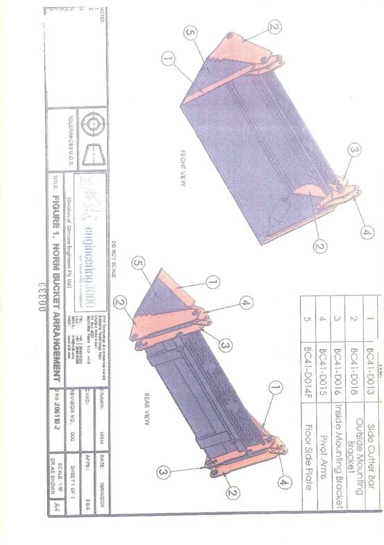
Schedule 1.2
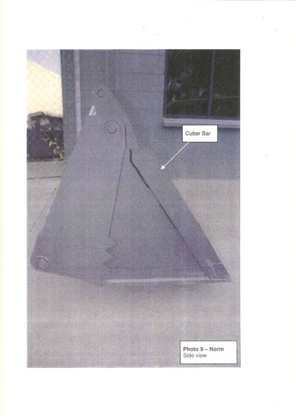
Schedule 1.3
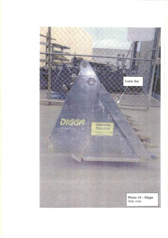
Schedule 1.4
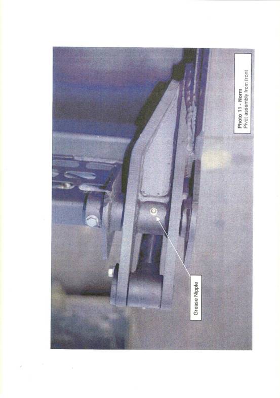
Schedule 1.5
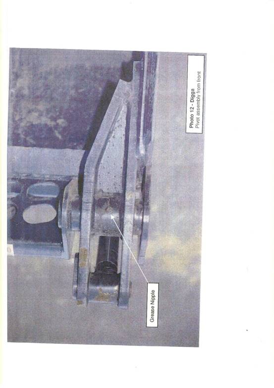
Schedule 1.6
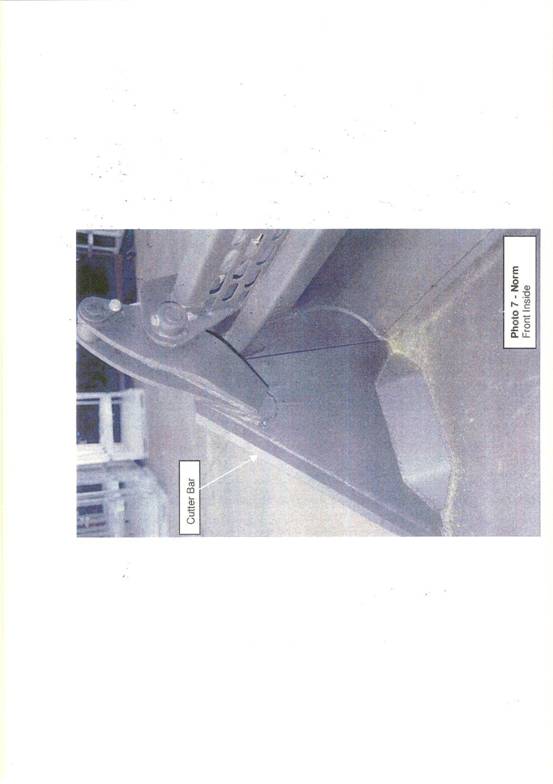
Schedule 1.7