
FEDERAL COURT OF AUSTRALIA
Great Western Corporation Pty Ltd v Grove Hill Pty Ltd [2001] FCA 423
INTELLECTUAL PROPERTY - patents - infringement by supply - construction of claims - invalidity - whether sufficient description of invention in complete specification - fair-basing - whether claims fairly based on description in specification - novelty - whether invention anticipated by prior publications of other patent specifications - prior use - inventive step - whether combination of known integers obvious
Statutes
Patents Act 1990 (Cth)ss 7, 9, 18, 40, 117, 138(3)(d), Schedule 1
Cases
American Cyanamid Company v Ethicon Ltd [1979] RPC 215 Refd
AMP Incorporated v Utilux Pty Ltd (1971) 45 ALJR 123 Cited
Bristol-Myers Squibb Company v F H Faulding & Co Limited (2000) 97 FLR 524 Appl
Catnic Components Ltd v Hill & Smith Ltd [1982] RPC 183Cited
CCOM Pty Ltd & Anor v Jiejing Pty Ltd & Ors (1994) 51 FCR 260 Cited
Decor Corporation Pty Ltd v Dart Industries Inc (1988) 13 IPR 385 Cited
Electric and Musical Industries Ld v Lissen Ld & Anor (1939) 56 RPC 23 Cited
Firebelt Pty Ltd v Brambles Australia Ltd & Anor (1998) 43 IPR 83 Cited
Firebelt Pty Ltd v Brambles Australia Ltd & Ors [2000] FCA 1689 Refd
General Tire & Rubber Co v Firestone Tyre & Rubber Co Ltd [1972] RPC 457
Interlego AG v Toltoys Pty Ltd (1973) 130 CLR 461 Cited
Kimberly-Clark Australia Pty Ltd v Arico Trading International Pty Ltd [2001] HCA8 Appl
Leonardis v Sartas (1996) 67 FCR 126 Appl
Minnesota Mining and Manufacturing Co Ltd v Beiersdorf (1980) 144 CLR 253 Appl
Montecatini Edison SpA v Eastman Kodak Co (1971) 45 ALJR 593 Cited
Nicaro Holdings Pty Ltd & Ors v Martin Engineering Co (1989) 91 ALR 513 Appl
Old Digger Pty Ltd v Azuko Pty Ltd [2000] FCA 676 Refd
Olin Corporation v Super Cartridge Co Pty Ltd (1977) 180 CLR 236 Cited
Palmer v Dunlop Perdriau Rubber Co Ltd (1937) 59 CLR 30 Cited
Patent Gesellschaft AG v Saudi Livestock Transport & Trading Company (1997) 37 IPR 523 Refd
Ramset Fasteners (Aust) Pty Ltd v Advanced Building Systems Pty Ltd (1999) 46 IPR 481 Refd
Rehm Pty Ltd v Websters Security Systems (International) Pty Ltd (1988) 81 ALR 79 Cited
Rosedale Associated Manufacturers Ld v Carlton Tyre Saving Coy Ld [1960] RPC 59 Cited
Rotocrop International Ltd v Genbourne Ltd [1982] FSR 241 Refd
Sartas No 1 Pty Ltd v Koukourou & Partners Pty Ltd & Anor (1995) 30 IPR 479 Refd
Wellcome Foundation Ltd v VR Laboratories (Aust) Pty Limited (1981) 148 CLR 262 Refd
Windsurfing International Inc & Anor v Petit & Anor [1984] 2 NSWLR 196 Refd
GREAT WESTERN CORPORATION PTY LTD v GROVE HILL PTY LTD
QG 144 of 1997
KIEFEL J
BRISBANE
17 APRIL 2001
|
IN THE FEDERAL COURT OF AUSTRALIA |
|
|
BETWEEN: |
GREAT WESTERN CORPORATION PTY LTD APPLICANT
|
|
AND: |
GROVE HILL PTY LTD RESPONDENT
|
|
DATE OF ORDER: |
|
|
WHERE MADE: |
THE COURT DECLARES THAT:
1. The respondent infringed Australia Registered Petty Patent No 678130 during its term.
2. The respondent has infringed Australia Registered Patent No 705201.
THE COURT ORDERS THAT:
3. The respondent, by itself, its servants or agents or howsoever be restrained from infringing Australia Registered Patent No 705201.
4. The issue of damages or other relief consequent upon infringement is adjourned to a date to be fixed.
5. The respondent pay the applicant’s costs of and incidental to the proceedings.
Note: Settlement and entry of orders is dealt with in Order 36 of the Federal Court Rules.
|
IN THE FEDERAL COURT OF AUSTRALIA |
|
|
QG 144 OF 1997 |
|
BETWEEN: |
GREAT WESTERN CORPORATION PTY LTD APPLICANT
|
|
AND: |
RESPONDENT
|
|
JUDGE: |
|
|
DATE: |
|
|
PLACE: |
REASONS FOR JUDGMENT
1 On 15 May 1997 the applicant Great Western Corporation Pty Ltd was granted Australian Petty Patent No 678130 for an invention entitled “Improvements in or in relation to a Row Cultivator”. The provisional application was filed on 22 December 1993 (“the priority date”). On 26 August 1999 it was granted Australian Patent No 705201 (“the standard patent”). The patent was now entitled “A Tool for a Row Cultivator”. The inventor named on the patents was Mr Peter Mansur. The invention was and is marketed as the “Cleansweep” product.
2 Mr Mansur’s family were seed crop farmers in the United States of America and he has been involved in cotton farming in Australia. He has experience in row cropping and row cultivation. He and other members of his family have been involved in the development of farming equipment for some time.
3 Row cropping refers to plants grown in rows which are wide enough to allow a tractor to drive through. The space between the rows is known as a furrow. The land may be flat between the plant beds, or hills, or may contain channels, in the case of irrigated land. Whilst there are a number of steps in the production of crops grown in rows, Mr Mansur lists seven as usual. Row cultivation (or “inter row cultivation” as it is also called) refers primarily to the killing of weeds in the furrows between rows of plants after planting. It can also be utilised for the aeration of the soil or warming the soil for seedlings prior to planting. It applies to the cultivation of both flat beds and grooved furrows.
4 Row cultivation, in the sense of weed eradication, was achieved by using a series of tools which were pulled through each furrow. The tools used included, in sequence, two discs, two knives and an “Alabama”, a shovel-like tool. The discs would break up the soil and the knives would follow and cut the weeds. This was referred to by the applicant’s witnesses as a “traditional rig” or set of tools. Extra knives might also be added. It was accepted by most witnesses that these tools and their combination were commonly employed, although farmers could be expected to use any number of combinations, and a lesser number of tools might be used in narrower furrows. The basic premise remained. General use prior to the invention commonly involved a number of tools on a number of tool-carrying shanks.
5 A “row cultivator” refers to the equipment used in row crop cultivation and comprises both the tool-carrying system and the tools attached to it. It may be a number of transverse tool bars with tools fixedly mounted to each tool bar, or a transverse tool bar with tools mounted onto a parallelogram arrangement, which provides for independent height adjustment.
6 Generally speaking, tools in common use in row cultivation before the priority date included sweeps and the Alabamas mentioned, although they were not utilised at the front of a traditional rig; cutting knives and friction trip assemblies. The latter refers to a mechanism which tilts on a centre pivot when the front of the tool to which it is attached hits an obstruction in the soil. The extent to which combinations of the tools were employed is a matter taken up by the respondent in connection with a number of issues.
7 The patents explain some of the problems associated with row cultivation:
“One disadvantage arises where cutter blades are employed behind a tool. Typical tooling for cultivating row crops consists of five vertical shank assemblies per row of crop with a tool comprising either “L” shaped knives or a single disc attached to the end of the shank. Each tool’s position can be independently adjusted vertically and horizontally.
The main problems with this type of arrangement are:-
(i) the difficulty in adjusting the shank assemblies; and
(ii) the narrow knives or discs allow weeds to bend around the tooling if the weed is not struck “dead-centre.
The present cutter blade arrangements are inefficient.”
8 An additional disadvantage is identified in the standard patent, but it is not presently relevant. Although there was much evidence put forward by the respondent to show that the difficulties in the “traditional rig” were overstated, the evidence generally supported the problems identified. The fact that some farmers might not all be as efficient or competent as those teaching in the area would not seem to detract from this.
9 The specification states that those disadvantages are sought to be alleviated:
“…by providing a row cultivator having a transverse tool bar and a plurality of tool carrying shanks mounted on and projecting downwardly from the tool bar, each shank having a pair of plates mounted to the shank on opposite sides of the shank and forming a lower shank section, the lower shank section having a forwardly projecting portion fitted with a leading blade and a pair of rearward cutting blade attachment means having respective cutting blades attached thereto so as to be spaced rearwardly from and separate of the leading blade, the leading blade being followed by the pair of cutting blades, the cutting blades being adapted to travel just below soil level to sever weeds on either side of the leading blade, the cutting blades having respective leading edges diverging rearwardly and outwardly on opposite sides of the leading blade.”
10 The preferred embodiment is described:
“The tool preferably includes a lower shank section in the form of a blade carrier unit secured to the shank, the carrier unit having a forward leading blade attachment means and a rearward cutting blade attachment means, the rearward cutting blade attachment means preferably comprising a pair of spaced vertical plates receiving a cutting blade carrier unit in the form of an inverted generally T-shaped plate.
Each cutting blade is preferably tapered, having a broad forward cutting edge portion located behind the inside the periphery of the leading blade.
Each cutting blade preferably has a forward portion located within the shadow of the leading blade.”
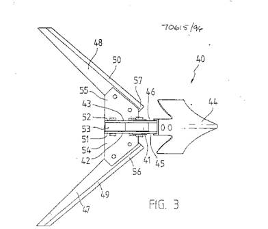
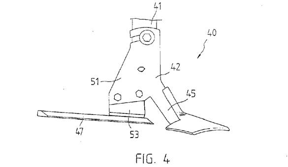
11 Reference is then made to the drawings accompanying the specification. I will not set out the explanation given of them in the specification. Parts of that discussion will be dealt with at later points in these reasons. The first two drawings show a side view of an overall assembly of the frame and tool bar. Figures 3 and 4 assume greater relevance in the proceedings and are here set out.
12 The claims of the petty patent, and claims 1 to 3 of the standard patent, are in these terms:
“THE CLAIMS DEFINING THE INVENTION ARE AS FOLLOWS:
1. A row cultivator having a transverse tool bar and a plurality of tool carrying shanks mounted on and projecting downwardly from the tool bar, each shank having a pair of plates mounted to the shank on opposite sides of the shank and forming a lower shank section, the lower shank section having a forwardly projecting portion fitted with a leading blade and a pair of rearward cutting blade attachment means having respective cutting blades attached thereto so as to be spaced rearwardly from and separate of the leading blade, the leading blade being followed by the pair of cutting blades, the cutting blades being adapted to travel just below soil level to sever weeds on either side of the leading blade, the cutting blades having respective leading edges diverging rearwardly and outwardly on opposite sides of the leading blade.
2. A row cultivator according to claim 1 wherein the pair of plates are pivotally mounted on the shank so that the inclination of the cutting blades can be adjusted.
3. A row cultivator according to claim 1 including means for changing the inclination of the blades.”
13 Of the additional claims in the Standard patent, claims 4, and 9 to 13 inclusive are relevant to infringement:
“4. A tool for a row cultivator, the tool comprising:
an elongated shank having an upper shank section and a bifurcated lower shank section pivotally coupled to the upper shank section, the lower shank section comprising leading blade attachment means projecting in a forward direction from the shank, and a plurality of cutting blade attachment means physically separated from the leading blade attachment means in a rearward direction from the leading blade attachment means;
a leading blade for cultivating a furrow, said leading blade being mounted to the leading blade attachment means of said shank, and having a rear end; and
a pair of cutting blades, adaptable to travel just below a soil level to sever weeds on either side of the leading blade, the pair of cutting blades having respective forward ends and leading edges diverging rearwardly and outwardly on opposite sides of a line passing through the leading blade, and being secured to the respective cutting blade attachment means such that the rear end of the leading blade is physically separated from respective front ends of the cutting blades.
…
9. A tool according to Claim 4, wherein each cutting blade is tapered, having a broad forward cutting edge portion located behind and inside a periphery of the leading blade.
10. A tool according to Claim 4, wherein each cutting blade has a forward portion located within a shadow of the leading blade.
11. A tool according to Claim 4, including means for changing an inclination of the blades.
12. A tool according to Claim 4 wherein the lower shank section comprised interfitting plates, said cutting blade attachment means comprising a pair of lobes for separate attachment of the respective cutting blades to the lower shank section.
13. A row cultivator employing a tool according to any one of claims 4 to 12.”
preliminary observations - issues and witnesses
14 In one respect, which I have found necessary to mention, the statement of claim diverged from its particulars. The respondent’s case was generously pleaded. Largely as a result of that it was not always easy to determine the currency of an issue, or particulars of it, during the trial. I have therefore attempted to summarise what appears to be the respondent’s final position on each issue. In that process I have assumed that if a part is not taken up and argued in the respondent’s lengthy written submissions, it is not pursued. So far as concerns witnesses, despite some general observations, which I shall shortly state, I have attempted to deal with pertinent evidence in connection with each issue.
15 As a general rule I have not relied upon Mr Mansur’s evidence with respect to whether an inventive step was involved. This does not detract from the reliability of his evidence on other issues. Mr Woodward, a person fulfilling the role of a skilled person to whom the patent might be addressed and called by the applicant, was an impressive witness. A lengthy cross-examination in my view confirmed him as objective and well-versed in his field. The respondent sought to impugn his credit-worthiness because he had not disclosed that a business largely operated by his son was supplied from time to time with some products or parts by the applicant. No financial benefit was said to accrue to Mr Woodward. In the area in which he and his family reside and work the applicant is amongst other suppliers. It was not suggested that he had any other connection with the applicant such that his evidence was likely to be affected. I do not consider the independent nature of his evidence to be in question. Mr Carew, also called as a witness by the applicant but not to fulfil any role of a relevantly skilled witness, so far as I could determine, was of assistance only with respect to listing the essential integers.
16 I did not consider Mr Gessner to be a wholly reliable witness, for the reasons I later give. This follows especially from my findings on his evidence on infringement. There were other aspects of the respondent’s evidence, and its approach to it, which did not assist it. Mr McFarlane, who had been a consultant for some years to the respondent, was distinctly partisan in his approach and could not fulfil the role of quasi-expert. It was not apparent to me that Mr Yeomans was able to contribute much upon the issues arising. This was perhaps made especially difficult for him because his evidence on many important aspects mirrored almost exactly the evidence in Mr McFarlane’s affidavits. This led me to doubt both witnesses as having expressed their own opinions. Mr Yeomans did not satisfy me that he was fully aware of what he had said and on occasions he attempted to resile from evidence he had earlier given. The repetition of evidence on some issues also affected Mr Murray’s evidence, albeit to a lesser extent. Mr Murray was called by the respondent and clearly had the necessary knowledge in the area to be qualified as a skilled person. Regrettably however he assumed a combative approach which detracted in many respects from the weight which his evidence might otherwise have. He was unable to consider alternative propositions. Overall I regret to observe that some aspects of the respondent’s witnesses’ evidence appears to have been driven or guided on particular issues. In this respect I refer in particular to the practice which was adopted, of reiterating the same concerns and opinions.
17 Save for an issue as to whether a guidance system should be added as an essential integer, the respondent accepted the essential features of claims 1 to 3, listed by Mr Carew, as follows:
“Claim 1 has the essential integers set out below and numbered A1 to A16. Claim 2 has the additional essential integer numbered A17. Claim 3 has the additional integer numbered A18:-
A1 “A row cultivator having a transverse tool bar”
A2 “and a plurality of tool carrying shanks”
A3 “mounted on”
A4 “and projecting downwardly from the tool bar”
A5 “each shank having a pair of plates”
A6 “mounted to the shank on opposite sides of the shank”
A7 “and forming a lower shank section”
A8 “the lower shank section having a forwardly projecting portion”
A9 “fitted with a leading blade”
A10 “and a pair of rearward cutting blade attachment means”
A11 “having respective cutting blades attached thereto”
A12 “so as to be spaced rearwardly from”
A13 “and separate of the leading blade”
A14 “the leading blade being followed by the pair of cutting blades”
A15 “the cutting blades being adapted to travel just below soil level to sever weeds on either side of the leading blade”
A16 “the cutting blades having respective leading edges diverging rearwardly and outwardly on opposite sides of the leading blade”
A17 “A row cultivator according to claim 1 wherein the pair of plates are pivotally mounted on the shank so that the inclination of the cutting blades can be adjusted”
A18 “A row cultivator according to claim 1 including means for changing the inclination of the blades”
INFRINGEMENT
18 It is alleged that the petty patent has been infringed since about June 1997. The occasions referred to in the particulars provided in the amended statement of claim were not taken up in evidence. In final argument the respondent made the point that the pleading did not contain any particular of infringement which was relied upon by the applicant . It was however clear from an early point in the trial that the case was conducted upon the evidence of advertisements of the “Terminator” with the attachments, and invoices of sales of the Terminator with the “Versasweep”. The case conducted was that particularised in the claims relating to the standard patent, namely that the respondent infringed the patent by selling the Terminator with the Versasweep, and also by selling the Versasweep alone, since it could only be used as a row cultivator. What constitutes the Versasweep tool assembly was a matter of some contention.
19 Consistent with the stand taken by its patent attorneys in the pre-action exchange of correspondence, the principal defence by the respondent to the allegations of infringement was that in neither case did it sell as a product or assembly, something which combined “a forwardly projecting portion fitted with a leading blade” and a pair of rearward cutting blade attachment means.
(i) The Versasweep
20 Mr Lindsay Gessner and his brother are the directors of the respondent Grove Hill Pty Ltd. The company trades as Gessner Industries. He had earlier been involved in the sale of farm machinery but did not manufacture or sell row crop cultivators. In about April 1994 the respondent purchased a product from Pioneer Industries which was then called the “Rowmaster”. After some modifications were made to it, it was marketed by the respondent as the “Rowmaster 2000” and from 1996 as the “Terminator”.
21 Mr Gessner describes the original Rowmaster as a parallelogram frame assembly with a transverse tool bar to which were attached a series of tool carriers. He says that the Terminator largely follows this. A reference to Pioneer’s advertisements for the product shows that it could carry three tools in line for irrigated crops: tooling discs, crescent knives and an Alabama sweep. Pioneer also had a tool assembly called the “Supersweep”. The assembly generally comprised a friction trip to which was bolted a pointed chisel-like blade at the front and, close behind it, two wings or blades. Its use in relation to cultivating in furrows was regarded by some witnesses as limited.
22 The respondent’s case was that its “components” were sold separately. Mr Gessner said that the Terminator was sold separately from the tools, which were ordered by the customer. The Versasweep was first sold in 1996, both with the Terminator and separately. It was said to comprise only a pair of rear blades and a friction trip mechanism, to which they are attached. A forward blade or sweep is manufactured by the respondent and it may be ordered by a client and sold with the Versasweep. In that event the respondent regards them as having been sold as component parts. Other tools may also be ordered and used with the Versasweep.
23 The tool which does not include the forward blade, and which appears depicted in Mr Gessner’s affidavit (as LJG5 and LJG6), was said to have been devised by Mr Ken Wells. Mr Wells at an earlier time manufactured the rear blades for Mr Mansur’s assembly. (Mr Mansur at this time traded under the name “Excel”). He supplied the blades to Mr Mansur between April 1994 and April 1995 and was also permitted to sell the complete product. Because of delays in Mr Wells’ production, Mr Mansur terminated this arrangement with him. He then obtained the blades from a foundry. The last Cleansweep product supplied to Mr Wells for resale was in December 1995.
24 Mr Wells is said to have approached Mr Gessner, or the respondent, with respect to developing the tool identified by the respondent as the Versasweep. An unsigned Memorandum of Undertaking between Mr Wells and the respondent refers to an agreement for his income from sales of a “Versafoot Assembly” but it is not clear what it refers to. It might be the rear blades.
25 The sale invoices produced in evidence show, that during the period relevant to the petty patent, the respondent sold the Terminator together with a number of “Versasweeps” and that Versasweeps were sold independently of the Terminator. The reference to the Versasweep is not consistent, words such as “assemblies”, “units” and “assemblies complete” often being added. There is nothing however to indicate that when “Versasweep” is referred to without more, it is a reference to the rear blades section alone. The only evidence to suggest this might be the case is that of Mr Gessner.
26 The advertisements and illustrations in evidence depict both forward and rear parts attached to a Terminator, sometimes with an Alabama added at the rear. The depiction, separately, of a Versasweep “adjustable cultivator shank system” is the same. During the course of the hearing the respondent pointed out that the principal advertisement relied upon by the applicant (in Exhibit 2) was published prior to the grant of the petty patent. It is however consistent with the way in which the respondent later advertised these products. The respondent’s catalogues and brochures do show a rear blade or blades attached only to a friction trip; but they also show it combined with a forward blade. Combined in this way it is said to suit a Terminator. It is also shown attached to other shank assemblies or tool bars. The clear inference is that the respondent has marketed the Versasweep as a product combining the forward and rear tools. Mr Murray had no difficulty in identifying the Versasweep product from the literature. That is how it is intended to be used. Indeed it may be said that is its only effective use.
27 Mr Gessner attempted to maintain, in the face of this evidence, that although the advertisements and drawings would suggest this, nevertheless the Versasweep product did not include the forward leading blade portion. No other evidence supports such an assertion. Mr Wells is hardly likely to have designed the rear blade portion in a vacuum, as counsel for the applicant submitted. Mr Mansur pointed out that the rear blades could only be used in conjunction with the forward part. If the rear cutting blades were used on their own they would simply “plug up”, a reference to weeds becoming caught around the blades. To be efficient they needed the protection of the forward blade.
28 In response to this, Mr Gessner and Mr McFarlane contended that the forward and rear blade sections could be mounted separately on shanks standard in the industry, one forward of the other. Curiously, the respondent did not itself supply such a shank. Those sold by it were of a size which would accommodate both attachments which are manufactured and supplied in such a way as to permit one to fit over the other. That is to say the pair of plates to which the forward blade is attached sits over the plates with the rear blades and the two are held together with bolts. If only one attachment was mounted on the shank it would be necessary to employ spacer plates. This seems an unlikely scenario. Mr Gessner then suggested that, nevertheless, they could be fitted to a shank two inches wide and standard in the industry but was obliged ultimately to concede that such a shank was not standard. Mr McFarlane maintained this contention, but in light of Mr Gessner’s concession, I would not be inclined to accept his evidence on this point.
29 Mr Gessner also gave evidence that when a Terminator is ordered with tooling, it leaves the factory with the tooling attached and this has been the respondent’s practice since August 1996. The reference in invoices to the supply of a Terminator “complete with” Versasweep is likely to fall into this category. In some cases the Versasweep might not be fitted, in which case it would be supplied in kit form. In this event Mr Gessner says that the Versasweep is supplied in parts on separate pallets. It was then suggested for the respondent that it could have no idea what farmers might do with the parts. As a question of fact that would seem to be fanciful.
30 The common law position is that the mere prospect that purchasers will use items so as to infringe is insufficient for liability: Ramset Fasteners (Aust) Pty Ltd v Advanced Building Systems Pty Ltd (1999) 46 IPR 481. There the manner of use was in the hands of a building contractor or crane operator. It is otherwise where there is no other use to which the components, or kit, as supplied, can be used or where the supplier provides comprehensive assembly instructions; see Windsurfing International Inc & Anor v Petit & Anor [1984] 2 NSWLR 196; Rotocrop International Ltd v Genbourne Ltd [1982] FSR 241.
31 In the present case the evidence is clear: the assembly can only be put to one use, as Mr Mansur said. It has not been suggested that the parts cannot be put together by purchasers. A farmer, even without the respondent’s diagrams or illustrations, would readily understand how the tools were to be fitted together.
32 Section 117 of the Patents Act 1990 (Cth) provides, so far as is relevant:
“Infringement by supply of products
117(1)If the use of a product by a person would infringe a patent, the supply of that product by one person to another is an infringement of the patent by the supplier unless the supplier is the patentee or licensee of the patent.
(2) A reference in subsection (1) to the use of a product by a person is a reference to:
(a) if the product is capable of only one reasonable use, having regard to its nature or design - that use; or
…
(c) in any case - the use of the product in accordance with any instructions for the use of the product, or any inducement to use the product, given to the person by the supplier or contained in an advertisement published by or with the authority of the supplier.”
33 I have found that the relevant Versasweep product sold is constituted by both the forward and rear parts. The respondent submitted that the section could only refer to a product assembled, that which is supplied is that which is used.
34 Section 117 is not to be read narrowly and in a way which gives it little more operation than to reiterate the monopoly rights defined by s 13: Bristol-Myers Squibb Company v F H Faulding & Co Limited (2000) 97 FLR 524, 557-8. Whilst Black CJ and Lehane J were there dealing with infringement of an invention which is a method or process, by supply of a product, their Honours’ observations as to the purpose of s 117, to give effect to the recommendations of the Industrial Property Advisory Committee with respect to contributory infringement, apply here. Its report had pointed out the difficulty faced by patentees in having to sue direct infringers when it was more reasonable to permit action to be taken against the supplier or “middleman” who facilitates the commission of the infringing act by the ultimate consumer. It went on:
“The most common example of indirect, secondary or contributory infringement is where goods, materials or parts are supplied to a consumer with the intention that they be used, consumed or assembled in a way which constitutes an infringement of a patent. The intention might be evident, for example, from the provision of brochures containing instructions on how to make a product or use a process which would infringe a patent, or by advertisements soliciting the commission of an act which would infringe.”
35 The section enables an inference to be drawn that infringement will occur following supply. Applying the section to the present case, if one regards the Versasweep assembly as “the product”, it is capable of only one reasonable use and s 117(2)(a) permits the application of s 117(1). The respondent’s submissions seek to narrow the reference to “the product” to a singular or assembled product, but there is nothing in the section which suggests that such a limitation is necessary and that part of the Committee report set out above tells to the contrary. So long as all the necessary parts were provided, so that they could be put together for that use, it could not have been intended that a supplier escape liability by leaving a part or parts unattached. In any event, on the facts of this case it would seem to me that the supply of the two component parts of the assembly would constitute an inducement to use the product, within the meaning of s 117(2)(c).
(ii) The Guidance System
36 The respondent also argued that the respondent’s products were outside the claims in two respects: because the Terminator did not employ a guidance system, as had been depicted in the applicant’s specification and drawings; and because the respondent’s Versasweep employed two pairs of plates to make up the lower shank section. In each case the respondent reads the claims with the specification.
37 The claims must be construed according to their terms upon ordinary principles: Electric and Musical Industries Ld v Lissen Ld & Anor (1939) 56 RPC 23; Rosedale Associated Manufacturers Ld v Carlton Tyre Saving Coy Ld [1960] RPC 59, 69; Sartas No 1 Pty Ltd v Koukourou & Partners Pty Ltd & Anor (1995) 30 IPR 479, 485-6. It is not permissible to confine or add to the claims by reference to some limitations or gloss found in the body of the specification but which cannot, by proper inference, be reproduced in the claims themselves: EMI case, 41; Decor Corporation Pty Ltd v Dart Industries Inc (1988) 13 IPR 385, 398-9. In Rosedale Associated Manufactures Ld v Carlton Tyre Saving Coy Ld, Lord Evershed MR said at 69:
“On the other hand, it is clearly no less legitimate and appropriate in approaching the construction of the claims to read the specification as a whole. Thereby the necessary background is obtained and in some cases the meaning of the words used in the claims may be affected or defined by what is said in the body of the specification. ”
which was taken by Sheppard J in Decor Corporation v Dart Industries (399) to mean that resort is to be had to the body of the specification to define or clarify the meaning of words used in the claim when an expression is not clear (and see Interlego AG v Toltoys Pty Ltd (1973) 130 CLR 461, 479).
38 Where the question which arises is purely verbal or grammatical, ordinary principles would dictate that it be resolved by those means: Decor Corporation v Dart Industries, 400. It would not be necessary to resort to expert evidence, except as to the accepted meaning of technical terms and explain how things actually work: see American Cyanamid Company v Ethicon Ltd [1979] RPC 215, 254. Such evidence may, in appropriate circumstances, be provided by a person to whom the specification can be taken to be addressed, a person skilled in the art or science to which it relates.
39 With respect to the guidance system, it would not seem to me to be necessary to obtain the opinion of experts as to what falls within claim 1, upon which the other two claims depend. There is no reference to a guidance system in the claim and nothing in it to indicate that it must have been intended as part of the claim. Reference to it is made in Figure 1 and in the discussion of that drawing. A preferred embodiment cannot however be taken as adding to, or limiting, the claim itself. Reliance was also placed by the respondent on the words “according to the present invention” in the following description of the drawing:
“Figure 1 is a side view of a row cultivator employing a guidance system and shanks suitable for mounting tools to provide a row cultivator according to the present invention”
in order to show that a guidance system was intended as part of the invention. Such a conclusion does not follow from an ordinary reading of the description. In accordance with the principles above resort to the description is, in any event, only necessary where the words of the claim are not clear.
40 Were it necessary to resort to evidence on the point, even that of the respondent’s witnesses was consistent with the view I have expressed. Mr Woodward said that he did not understand the reference to the guidance system to be a part of the claim. This was consistent with Mr Mansur’s evidence that a guidance system is desirable, but not necessary, for its operation. It is explained in the specification that as the cultivator moves forward, the tool bar is inclined to drift and the deviation can be corrected by the guidance system. This would obviously be advantageous; but it is not part of the invention the subject of the claim. A reference to a “row cultivator” would not normally convey that a guidance system was used.
41 Mr Gessner was amongst the witnesses who claimed to be convinced that the guidance system was important, if not essential, to the invention. In cross-examination however he was unable to explain how he came to this view, except that there were references to it in the body of the specification. He understood that it was not part of the claims. Mr Murray, who was called as an independent expert witness by the respondent, had only assumed that the claims would include it because of brochures he had seen illustrating the applicant’s products. He agreed that when he read the claims he then understood the guidance system formed no part of the invention. Mr. Yeomans, himself an inventor of farm implements, also agreed under cross-examination that a reading of the patent suggested that the cultivator may or may not have a guidance system. It is unfortunate that despite the state of the evidence, before and during the hearing, the respondent persisted with this issue.
(iii)A Pair of Plates
42 It is common ground that “a pair of plates” is an essential feature of the patents. Each shank mounted on the tool bar is to have a pair of plates mounted to the opposite sides of the shank and forming a lower shank section. The respondent’s assembly employs two pairs, one sitting over the other. The applicant says that the words of the claim do not require the lower shank section to be formed solely by a single pair of plates. The respondent contends that “singularity” is an essential feature of the claims read in light of the specification.
43 On this issue expert evidence might be of assistance. In Catnic Components Ltd v Hill & Smith Ltd [1982] RPC 183 at 242-3 Lord Diplock said:
“My Lords, a patent specification is a unilateral statement by the patentee, in words of his own choosing, addressed to those likely to have a practical interest in the subject mater of his invention (i.e. “skilled in the art”), by which he informs them what he claims to be the essential features of the new product or process for which the letters patent grant him a monopoly. It is those novel features only that he claims to be essential that constitute the so-called “pith and marrow” of the claim. A patent specification should be given a purposive construction rather than a purely literal one derived from applying to it the kind of meticulous verbal analysis in which lawyers are too often tempted by their training to indulge. The question in each case is: whether persons with practical knowledge and experience of the kind of work in which the invention was intended to be used, would understand that strict compliance with a particular descriptive word or phrase appearing in a claim was intended by the patentee to be an essential requirement of the invention so that any variant would fall outside the monopoly claimed, even though it could have no material effect upon the way the invention worked.”
44 There was surprisingly little evidence on this point given the reliance placed upon it by the respondent. Mr McFarlane’s evidence was unhelpful. It was confused and at points inconsistent and in any event I have doubts about the objectivity with which he is able to give evidence, given his close connection with the respondent at relevant times, as I have earlier mentioned. Mr Carew, who was called by the applicant, simply pointed out that there was nothing in the description which indicated it was essential to the working of the invention. Much was made of Mr Carew’s approach to the construction of the claims. The point he makes is however consistent with Mr Mansur’s explanation. It was alleged by the respondent in submissions that Mr Mansur agreed that the claims spoke of a single pair of plates but this is not a proper description of his evidence. Mr Mansur said that the formation of the lower shank section by two plates is an essential feature for without them the tools attached to the plates could not be located in the centre of the furrow.
45 It seems to me that whilst it is clearly essential that the lower shank section be formed by plates, and that as a minimum there must be a pair, it is not essential that there only be one pair performing this function, two pairs overlapping can also make up the section. The section itself however is to be singular.
INVALIDITY: SECTION 40
46 Section 40 “Specifications” provides:
“(1) A provisional specification must describe the invention.
(2) A complete specification must:
(a) describe the invention fully, including the best method known to the applicant of performing the invention; and
(b) where it relates to an application for a standard patent—end with a claim or claims defining the invention; and
(c) where it relates to an application for a petty patent—end with a single claim, or a single independent claim and not more than 2 dependent claims, defining the invention.
(3) The claim or claims must be clear and succinct and fairly based on the matter described in the specification.
(4) The claim or claims must relate to one invention only.”
47 Both the particulars pleaded and the respondent’s witnesses took an unnecessarily pedantic approach to the complete specification. In most cases the suggested difficulties in understanding it were obviously overstated and were shown to be upon little questioning. This was not a factor which gave confidence in the evidence of Mr Murray, the respondent’s principal witness on this topic and Mr McFarlane, upon whose evidence I have already commented.
48 Although the particulars were more numerous, and a general reference was made to them in the written submissions of the respondent, the focus of the evidence and the argument was narrowed to the issues I shall shortly list.
49 The grounds of invalidity upon which the respondent relied were that there was a failure to sufficiently describe the invention and that the complete specification was misleading with respect to its description of prior art and common general knowledge. The main area of evidence focussed upon the aspect of independent adjustability of the front and rear blades. The respondent contended such an aspect of the invention was not depicted or described. There were, in addition, a number of contentions that the claims were not fairly based upon the specification.
50 In relation to the description of the invention, the question under s 40(2) is whether the invention has been fully described in the complete specification, not any one part of it. The text of s 40 indicates that the specification must be read as a whole. Reference to the claims may be used to dispel ambiguity or uncertainty from the body of the specification concerning the description of the invention: Kimberly-Clark Australia Pty Ltd v Arico Trading International Pty Ltd [2001] HCA8, [16]. The term “invention” is used in different senses in the 1990 Act. In s 40(2) it means “the embodiment” which is described and around which the claims are drawn: AMP Incorporated v Utilux Pty Ltd (1971) 45 ALJR 123, 127; Kimberly-Clark, [19]. If it is not possible to ascertain what the invention is from a fair reading of the specification as a whole, that is an end to the matter, but this is not established by reading the specification in the abstract. The specification contains a full description if it makes the nature of the invention plain to persons having a reasonable knowledge of the subject and also makes plain how to perform the invention: Patent Gesellschaft AG v Saudi Livestock Transport & Trading Company (1997) 37 IPR 523. This assumes some importance here.
51 A claim should not be wider than the disclosure in the specification: CCOM Pty Ltd & Anor v Jiejing Pty Ltd & Ors (1994) 51 FCR 260, 276. As the Court there observed (277), what is at issue is the identification of “the matter described” in the body of the specification (or the provisional application). When the issue is one of the “fair basing” of a claim, under s 40(3), a comparison is undertaken between the matter described in the specification and the claim which defines the scope of the monopoly: Kimberly-Clark, [15]. The question is a narrow one: whether the claim, as expressed, goes beyond the matter disclosed in the specification: Olin Corporation v Super Cartridge Co Pty Ltd (1977) 180 CLR 236, 240. This differs from the considerations relevant to s 40(2).
(i) The Invention Description
52 The respondent’s complaints concerning whether the invention was sufficiently described were changeable and there was some confusion as to what issues remain.
53 The first particular pleaded was a general one, that the specification was unclear and misleading as to what was the prior art and that it was not possible to discern what the invention was. As this argument was developed, however, it became clear that what was complained of was a failure to describe the inventive step, not that the specification failed to make plain what was comprised in the invention or how it was to be performed. The argument posed the question as to what it “involved”, but in the sense that there ought to be disclosed what the applicant had done to some existing implement.
54 Mr Murray’s evidence at first also attempted to expand on the general allegation of insufficiency of description. It is necessary to detail it. He said that the “precise nature of the invention” “is not entirely clear to me”. This arose largely, he said, because there was an inappropriate use of “standard” industry terminology and misleading generalisations with respect to existing row crop technology. He went on to disagree with the typical tooling of a row cultivator at the priority date as necessarily requiring five vertical shank assemblies. For medium to narrow spaced crops only three were used. This was used to show that the difficulties stated in the patents may be overstated; indeed he could not determine whether a real disadvantage was identified because it was unclear whether it was said to arise from the number of adjustments or the nature of the adjustments to be made. There was, in his view, an artificial problem created with respect to the other stated disadvantage, weeds bending around the tooling. Whilst it was well recognised, it was minimised by using overlapping and wider sweeps. The argument focuses upon whether the common general knowledge, so far as concerns the disadvantages of equipment available and utilised at the priority date, was correctly stated. It did not analyse what was conveyed concerning the invention itself, although I accept that it is possible for a misstatement of what was already known to distort the picture given of an invention and what it is supposed to achieve. In truth, it seemed to me that the argument was one of lack of inventiveness, or was to be used in aid of such argument, not of lack of specification.
55 Clearly at the relevant date there were problems associated with the traditional rigging of row cultivators and Mr Murray eventually conceded this in accepting the advantages offered by the invention. In the result the impression created was that Mr Murray’s evidence was inflated and unduly argumentative. The reference to the use of five vertical shank assemblies per row of crop in the specification was in the context of “typical tooling”. That was borne out by the preponderance of the evidence. What Mr Murray spoke of was less common usage. The suggested ambiguity, as to whether the disadvantages were said to arise from the nature or number of adjustments to be made, does not put Mr Murray in a good light as a witness. It was clear that he understood, as did the other witnesses, what advantage was to be gained. Persons to whom the patent was addressed would understand that it was seeking to overcome the time and costs associated with multiple tooling, which all require adjustment. Mr Murray agreed at one point that easier adjustment was a priority with respect to farm machinery and that it would be a “boon” to a farmer to be able to adjust one tool rather than many. The fact that some farmers could better manage their equipment so that weeds did not become caught around the cutting discs which follow the knives would not seem to me to negate the problem which was seen to arise.
56 Three more specific particulars relating to insufficiency of description were pleaded but were not taken up in argument. In any event they related to what the inventor alleged to be the significance of features such as the spacing, and the extent of the spacing, of the rear and forward blades; the lower shank section being formed by a pair of plates mounted to a shank; and the elongated shank having a bifurcated lower shank section. That is to say their relevance appears to have been as to their essentiality as features. A foreshadowed amendment to add an allegation that there had been a failure to describe the best method of performing the invention was not pressed.
57 The consistory clause in the specification reiterates claim 1 in its reference:
“…respective cutting blades attached thereto so as to be spaced rearwardly from and separate of the leading blade, the leading blade being followed by the pair of cutting blades,the cutting blades being adapted to travel just below soil level to sever weeds on either side of the leading blade …”
(emphasis added).
58 In evidence an issue was raised as to the meaning to be given to “adapted to travel”. It is not entirely clear whether it was intended to be further pursued and if so whether it is said that the invention description is insufficient, or whether the claim itself was not clear or lacked definition. The applicant has however addressed argument to an issue of ambiguity and I will attempt to deal with it and the further issue raised concerning independent adjustment of the front and rear blades.
59 When regard is had to the conditions in which the blades are to operate, it would be clear to an addressee that the rear cutting blades were to travel just below the soil level in a number of situations. Mr Woodward explained that when a machine is set up for use its blades can be said to be “adapted”. “Adapted to travel” in the context of this apparatus and having regard to the disadvantages it addressed, which arise in a number of circumstances, refers to the blades being shaped or inclined so as to travel under the soil surface from the base of the furrow and up the sides of the furrow. There is a need to adjust the attitude of the blades to better ensure they travel below the soil surface in furrows of various shapes (the Pioneer Supersweep, by way of example, could not operate in this situation).
60 Mr Woodward considered that this was one of the most important aspects of claim 1. The claim does not limit the need to travel below soil level to a flat inter-row space. This is a tool for a row cultivator and it would be understood that it was to be used in both types of inter row spacing, which is to say flat and grooved, where furrows were formed. People talk of furrows even in flat land situations. Elsewhere there was evidence that furrowed rows change shape during the season. The blades have to be adaptable to handle that range of possibilities.
61 To be adaptable to these various conditions and to achieve weed eradication requires an element of adjustability of the blades. This stands in contrast to Mr Mansur’s evidence that the specification suggested a fixed tool. Mr Woodward pointed out that the furrow shapes are not great, being flatter rather than v-shaped, and ranging only from about zero to thirteen degrees. If it were read only as a tool for flat land, a limitation not expressed in the claim, the specification could not achieve the object of a row cultivator and have the features of the claim.
62 There did not appear to be real dissent from the need for adjustability to meet the requirement that it be adapted to travel below the soil to sever weeds. In cross-examination it was put to Mr Woodward, and he agreed, that “adapted to” equated with “adaptable to travel”. Mr Murray agreed that you need adjustability to satisfy the element that the cutting blades be adapted to travel, and that the major function of inter-row cultivating is to kill weeds (although not agreeing it is the “primary” function, which clearly it is). To do so the blades would have to meet the shape of the furrow.
63 It was generally agreed that without independent adjustment, as between the front and rear blades, the tool was limited in its application as it did not have the capacity to conform to the shapes of the different furrows. Mr Mansur had apparently appreciated this after his third prototype when he proceeded to devise the T-shaped section shown on Figures 3 and 4, which could bolt between the two plates at the back of the friction trip. This step assumes further importance on the issue as to the trials and experiments he conducted.
64 Mr Woodward explained that the reference in the description of the drawings to “the blades and sweep can be tilted as desired” meant “in relation to one another”. That, taken with what was conveyed by the drawings, would make clear how it was to be executed. The common method employed would be a friction clamping arrangement, although other methods could be employed. Mr Woodward spoke of a friction clamping arrangement between the T-shaped section or plate (53) and the plates (42) and (43) (on Figs 3 and 4). Whilst one could read section 53 as being fixed, the need for a method of adjustment would be obvious to any skilled person. They would understand that it was to be achieved by simple means, by oversizing the bolt holes to permit movement; putting the bolt holes in different positions or allowing arcuit slots, as was shown on the preferred embodiment.
65 The respondent’s witnesses agreed that these methods would be obvious to someone performing the invention and they would permit the tool to conform to different furrow shapes. Mr Murray even agreed that the petty patent provided a person skilled in the art with sufficient information to make the apparatus depicted in Exhibit 15. Mr Murray later attempted to reduce the effect of this evidence, but I do not accept that he misunderstood what had earlier been put to him. Mr McFarlane was also able to volunteer how he would go about achieving the objective of claim 1, by changing the length of the blades or the position of the bolts or T-plate.
66 The additional claims pleaded, of ambiguity with respect to claims in the standard patent, were not developed in submissions save for that relating to what is meant by “a bifurcated lower shank section”. The meaning of “bifurcated” is apparent; if it were not the description and drawings make it plain. The other complaints, concerning particular words assessed largely devoid of context, are insubstantial.
(ii) Fair Basing
67 The main complaints pleaded under this heading concerning claims 1 to 3 are restatements of the respondent’s claims to construction raised in connection with infringement. They require no further consideration here.
68 The complaints that the pivotal mounting of the pair of plates and a bifurcated lower shank section, contained in claims 4 and following of the standard patent, were not disclosed in the provisional specification are not made out, particularly when regard is had to the drawings and to the understanding of the skilled addressee reading them: see CCOM Pty Ltd v Jiejing Pty Ltd, 280.
69 The balance of the contentions for a later priority date, on account of some disconformity between the provisional specification and the later complete specification, also turns upon the construction of claims for which the respondent contended and which I have not accepted. A reference to the provisional specification, including the drawings of the tool, provide a reasonably clear disclosure of what is later claimed. The invention as claimed is broadly described in the body of the provisional specification: Rehm Pty Ltd v Websters Security Systems (International) Pty Ltd (1988) 81 ALR 79, 95.
70 The respondent also contended for a later priority date on the basis that the complete specifications added for the first time a reference to the lower shank section and to its being comprised of a pair of plates. Likewise there was no reference to a bifurcated lower shank section in the provisional specification. What is later called a lower shank section and the places comprising it is disclosed in the drawings throughout the process, even if the terminology changes. So much is acknowledged by the respondent. The description of the preferred embodiment in the provisional specification also discloses the lower shank section and a pair of plates.
NOVELTY
71 Section 18(1) provides:
18.(1) Subject to subsection (2), a patentable invention is an invention that, so far as claimed in any claim:
…
(b) when compared with the prior art base as it existed before the priority date of that claim:
(i) is novel; and
(ii) involves an inventive step; …”.
72 Section 7(1) provides that an invention is to be taken as novel when compared with the prior art base unless it is not novel according to the matters listed, which must each be considered and considered separately. Those matters which are here relevant are:
“(a) prior art information (other than that mentioned in paragraph (c)) made publicly available in a single document or through doing a single act;
(b) prior art information (other than that mentioned in paragraph (c)) made publicly available in 2 or more related documents, or through doing 2 or more related acts, if the relationship between the documents or acts is such that a person skilled in the relevant art in the patent area would treat them as a single source of that information;
(c) prior art information contained in a single specification of the kind mentioned in subparagraph (b)(ii) of the definition of “prior art base” in Schedule 1.”
73 Schedule 1 - Dictionary defines “prior art information” and “prior art base” as:
“prior art information” means:
(a) for the purposes of subsection 7(1) - information that is part of the prior art base in relation to deciding whether an invention is or is not novel; and
(b) for the purposes of subsection 7(3) - information that is part of the prior art base in relation to deciding whether an invention does or does not involve an inventive step.”
“prior art base” means:
(a) in relation to deciding whether an invention does or does not involve an inventive step:
(i) information in a document, being a document publicly available anywhere in the patent area; and
(ii) information made publicly available through doing an act anywhere in the patent area; and
(iii) where the invention is the subject of a standard patent or an application for a standard patent - information in a document publicly available outside the patent area; and
(b) in relation to deciding whether an invention is or is not novel:
(i) information of a kind mentioned in paragraph (a); and
(ii) information contained in a published specification filed in respect of a complete application where:
(A) if the information is, or were to be, the subject of a claim of the specification, the claim has, or would have, a priority date earlier than that of the claim under consideration; and
(B) the specification was published after the priority date of the claim under consideration; and
(C) the information was contained in the specification on its filing date and when it was published.”
74 An invention is not novel if the prior art anticipates the patentee’s claim:
“If the prior inventor’s publication contains a clear description of, or clear instructions to do or make, something that would infringe the patentee’s claim if carried out after the grant of the patentee’s patent, the patentee’s claim have been shown to lack the necessary novelty, that is to say, it will have been anticipated.”
(Nicaro Holdings Pty Ltd & Ors v Martin Engineering Co (1989) 91 ALR 513, 529, Gummow J).
75 His Honour went on:
“If, on the other hand, the prior publication contains a direction which is capable of being carried out in a manner which would infringe the patentee’s claim, but would be at least as likely to be carried out in a way which would not do so, the patentee’s claim will not have been anticipated, although it may fail on the ground of obviousness. To anticipate the patentee’s claim the prior publication must contain clear and unmistakable directions to do what the patentee claims to have invented: Flour Oxidizing Co Ltd v Carr & Co Ltd (1908) 25 RPC 428 at 457, line 34, approved in BTH Co Ltd v Metropolitan Vickers Electrical Co Ltd (1928) 45 RPC 1 at 24, line 1.”
76 Lockhart J (517) after stating that the generally accepted test for anticipation is the “reverse infringement” test (General Tire & Rubber Co v Firestone Tyre & Rubber Co Ltd [1972] RPC 457, 485-6); said that is also well established that the prior art must disclose:
“… all features of the invention embodied in the patent in suit and must do so in clear, unequivocal and unmistakeable terms. The prior art must enable the notional skilled addressee at once to perceive and understand and be able practically to apply the discovery without the necessity of making further experiments. Whatever is essential to the invention must be read out of or gleaned from the prior publication.
…
… the prior publication must disclose all of the integers with the possible exception of the substitution of “mechanical equivalents to perform analogous purposes”.”
77 The prior art relied upon was made up of a number of prior publications, namely patent specifications and documents such as brochures, catalogues and advertisements and prior use. The sources pleaded but not taken up in submissions I take to have been abandoned.
Lodwig (Beet Plow) US Patent 1279733
78 Mr McFarlane in his first affidavit was of the opinion that all of the features of claims 1 to 3 of the present invention were present save for integers (a) (b) and (c). Regrettably Mr Yeomans’ affidavit was in identical terms. Mr McFarlane agreed in cross-examination that the specification for this invention describes a plough to be used to break up the ground and remove beets, potatoes and similar vegetables. It is not a tool for a row cultivator. That aspect of integer (a) is therefore not present. Mr Mansur’s and Mr Woodward’s evidence stands.
79 It was submitted for the respondent that Mr McFarlane’s evidence, that shanks and blade carriers of the kind disclosed by the Lodwig patent could be employed with a modern row cultivator, should be accepted. The submission overlooks the further concessions made by Mr McFarlane that it was not for use on shanks which were to carry a number of tools and that it had no rear cutting blades adapted to travel (integers (b) and (c)). Mr Murray did not suggest anticipation in the case of this patent. Mr Woodward also points out that integers (i)(j) (o) (p) (q) and (r) are not present.
Lane - US Patent No 1851190
80 This invention, the specification of which refers to an apparatus in the nature of a plow drawn by an animal, also fails to describe a row cultivator. I do not accept Mr McFarlane’s evidence that it might be put to such a use. In any event he conceded that integers (c) and (b) are missing.
81 Most of the attention of the witnesses with respect to this invention was focussed upon whether there was a clear disclosure of a pair of plates. The evidence did not establish this. It is not apparent from the diagrams or the text. McFarlane was unconvincing about what he saw, or said he saw, in Figures 8 and 9. Mr Murray saw the forward extending arms, described as parallel bars, and also the cutting wings or blades as plates, which evidence I do not find convincing.
Seaholm
82 It is not to the respondent’s credit that it persisted with this patent as an anticipation. It is tolerably clear from the specification, and particularly the drawings, that there is not a pair of plates and that there is no separation (“spaced rearwardly from”) of the cutting blades from the leading blade. Mr McFarlane conceded both aspects in cross-examination. He was effectively led to attempt to retract the concession concerning the plates in re-examination. He gave no explanation as to how he might have been in error or suffered some misunderstanding when he was earlier questioned. It goes some way towards confirming my view as to the limited reliance which can be placed upon much of his evidence. Despite his concession, properly made, as to the lack of spacing between the blades, a feature of the present invention, the respondent sought to rely upon his evidence in chief, which was at best equivocal, as if it imported some doubt as to the meaning of “spaced rearwardly from”.
Skinner: US Patent No 2487737
83 The question which arises is whether this patent discloses a pair of cutting blades. What might be taken for blades on Figures 1 & 2 are described as “wings or blades” at one point in the specification, but there is nothing to suggest they are for the purpose of cutting. There is something in the applicant’s submission that they are not depicted as having cutting edges and they are not tapered. A “blade” can mean either a broad flattened paddle-like utensil or one with a cutting edge. The present invention qualifies the blades as the latter by description and purpose.
84 The description appearing at the commencement of the specification of the Skinner patent has the wings “for a cultivating sweep”. The wings are said to be adjustable “so as to properly deflect the soil in any desired manner in the cultivation of different types of plants”. It goes on to describe the apparatus as functioning with or without the wings, which is to say as a shovel; or with them “for such operations as harvesting peanuts, potatoes or the like wherein the use of substantially wide spread wings are desirable”. It is described as both a cultivating instrument and for harvesting.
85 Mr Woodward was of the view that the integer was not clearly described. Mr McFarlane was adamant that cutting blades were disclosed, which may be contrasted with the evidence of both Mr Murray and Mr Gessner - that minds could reasonably differ on this question. It may be that that effectively disposes of this claim to invalidity, but I shall proceed to consider the further evidence upon which the respondent relies.
86 Mr McFarlane did not consider it necessary to have sharp blades for weed cutting. Other aspects of his evidence also tended to underscore the implement as one not involving cutting blades, but one which operated like a sweep and pulled the weeds or moved the soil. It was necessary for the respondent to contend, in submissions, that “sever” meant these things which is, however, to deny any meaning to the adjective, “cutting”. Mr McFarlane’s evidence was unpersuasive.
87 Mr Yeomans considered that the Skinner apparatus might be employed for weed cutting although he clearly understood the blades to work the soil, spread dirt and be used primarily in harvesting operations. His explanation, that the inventor could be taken to refer to a weed cutting implement, is difficult to accept and does not seem to me a proper approach to a reading of prior art. He suggested that the inventor of the Skinner patent was refrained from referring to weed cutting knives or blades because they were not patentable.
88 There was further evidence on this patent called by the respondent, Mr Martin, who was experienced in relation to crop cultivation and farm machinery. He expressed the view that the blades would do more than only turn the soil and that a weed cutting function was involved by the reference in the specification to “blades”. It did not seem to me that the term was so clear, especially when read with the balance of the specification and the drawings. In cross-examination Mr Martin conceded that it was at the very least unclear whether the wings were intended to perform this function. He explained that his opinion in this respect had been influenced by his observations of someone using the Skinner apparatus in the United States, but that of course is not relevant to the task at hand. He agreed that the drawings did not depict weed-cutting blades. If that was intended one would expect the blades to be chamfered or to have a sharpened edge. Without such features you would only have limited weed control. Whilst conventional tools are often purchased chamfered, sweeps such as the rear wings are not used just for weed control.
89 The effect of the evidence of Mr Murray and Mr Woodward was that it is possible that the wings on the Skinner apparatus might perform as cutting blades, if they were raked at a particular angle. There was extensive cross-examination of Mr Woodward as to the depth at which the lead blade operated and how the rear wings or blades were positioned. The effect of it seemed to be that either the tool depicted would be working at too shallow a depth to be effective or, if it were configured differently, it would cut a slot with the leading blade which would be deeper than the level of the rear blades. That is to say, it was not shown that the reader could imagine some way in which weeds could be severed by its efficient use. It is not really suited to the task.
90 The feature of the rearward cutting blades is not sufficiently clear in the Skinner patent.
The Martin Multi-Till
91 This tool is not for use in inter-row cultivation. It is used for lightly ripping the soil and it is used for planting in standing stubble. It is in that sense only a cultivating machine. Integer (a) is missing. Additionally it does not have a pair of rearward cutting blade attachment means. There is no pair of plates pivotally mounted on the shank and no means for changing the indication of the blades.
92 A similar argument to that raised in connection with the Pioneer Supersweep was raised. I shall shortly refer to that. It must be rejected for the same reasons. The cutting blade attachment means in the present invention are not constitutedby bolts.
Pioneer Supersweep: Australian Design Registered No 114093
93 The physical embodiment of this design is relied upon.
94 A brief reference to the Supersweep indicates the likelihood of differences in the position of the rear blades and the lead blades. The applicant submits that the attachment means are also relevant and also whether the cutting blades are adapted to travel etc and whether there is at present a means for changing the inclination of the blades (integers (j) to (o) inclusive and integer (r)).
95 The Pioneer Supersweep is a friction trip assembly to which is attached a chisel point at the front. A pair of cutting blades is attached to the assembly by way of welds. The welds do not themselves constitute components and a pair of cutting blade attachment means. Mr Woodward distinguished the means to which the blades are attached from the means by which they are attached. This may be contrasted with the view expressed by Mr Murray, which does not in any event resolve this question, that integer (j) should be read to require the attachment means themselves to be rearward. Plainly it is the cutting blades that are spoken of as rearward. Further the blades are not rearward and arguably not separate from the chisel.
The Orthman Row Crop Cultivator/Supersweep
96 The integers missing from this apparatus are (l) and (m): the cutting blades are not spaced rearwardly from, nor separate of, the leading blade. These integers are directed to the spacing. Mr McFarlane’s evidence that “separate” could mean “independent pieces” is useful only to highlight the approach taken to the giving of evidence. Further, it is not clear that the cutting blades are adapted to travel below the soil so as to sever weeds.
Buffalo 6200 Cultivator and Sweep
97 I accept the opinion expressed by Mr Woodward that the plates depicted form only part of the lower shank section. The balance is formed by a single boot-shaped plate. In turn the plates forming the lower shank section do not have a forwardly projecting portion fitted with a leading blade. The rear blade attachment means is not fitted to the pair of plates, but the boot shaped forward plate. It does not have any means for changing the inclination of the blades. Integers (g) (h)(i)(j) and (l) are missing.
The Goertzen Quick Sweep
98 Some uncertainty surrounds the interpretation of the brochures depicting this tool. Mr Woodward was found to make some assumptions. In any event it was accepted that the features were similar to the Buffalo so that the same comments are applicable to this tool.
The Keech Shank Accessory - KAG 110 Mould Blade Assembly
99 The respondent did not appear to place much reliance upon these products in evidence. These tools are, as the advertising suggests, for deep tillage purposes and not inter row cultivation. Integer (a) is missing. Mr Woodward’s evidence was that (e),(f),(g),(o),(q) and (r) were also missing.
100 None of the prior art pointed to by the respondent amounts to an anticipation of the patent.
PRIOR USE
101 The respondent, although having pleaded invalidity on account of public demonstration for commercial purposes, did not pursue this allegation in evidence. Its focus, in relation to secret use, was upon Mr Mansur’s prior use of the equipment on his farm which, it was submitted, went beyond the reasonable trial and experiment permitted.
102 Section 18(1)(d) provides that a patentable invention is an invention that, so far as claimed in any claim:
“(d) was not secretly used in the patent area before the priority date of that claim by, or on behalf of, or with the authority of, the patentee …”
103 Section 9(a) provides that any use of the invention on or behalf of the patentee for the purpose of reasonable trial or experiment only is not to be taken to be such secret use. The onus of proving invalidity in this respect and other respects rests upon the respondent: Montecatini Edison SpA v Eastman Kodak Co (1971) 45 ALJR 593, 595-6; Old Digger Pty Ltd v Azuko Pty Ltd [2000] FCA 676, [156].
104 The respondent’s case on this point fastens upon the third prototype which was completed by Mr Mansur by September 1992. It is said it contained each of the claimed features. The evidence shows that Mr Mansur went on to devise the T-plate section which is connected with the element of independent adjustability. Even assuming the prototype contained all of the features of the invention, it seems to me that Mr Mansur’s evidence explained the need for testing it over almost one year which is to say two seasons. He needed to assess its performance over that period and in the changing conditions which occur throughout the seasons. Questions of Mr Mansur did not establish that the trial was unreasonable in duration.
FALSE SUGGESTION
105 I have dealt with the Skinner patent and the issue concerning the “wings” or “blades”. It may be accepted for present purposes that minds may differ about what was conveyed in that respect by that patent’s specification and drawings.
106 In response to an enquiry from the Examiner of Patents, the applicant’s patent attorney submitted that the patent was not relevant to a consideration of the present invention. I will not set out the submission. It was an argument which sought to distinguish features of the Skinner apparatus and its uses. It had regard to the terms of that patent and compared it with the applicant’s invention. The examiner could not possibly have been misled by what was put forward, even if the argument was not wholly accepted. Nevertheless the respondent pleaded that the applicant’s patent ought to be revoked pursuant to s 138(3)(d) on the basis that it was “obtained by fraud, false suggestion or misrepresentation”. The respondent submits the patent attorney’s submissions amount to a false suggestion. This is a serious allegation and one which I consider had no real foundation.
107 It is notable that the respondent’s pleading does not identify with precision just what the false suggestion was. It would seem to amount to no more than the patent attorney denying the relevance of the Skinner patent. I have found that to be the case, but even without that finding it could not have been said that the application had no reasonable basis for the argument it put forward.
inventive step
108 Sections 7(2) and (3) provide:
“(2) For the purposes of this Act, an invention is to be taken to involve an inventive step when compared with the prior art base unless the invention would have been obvious to a person skilled in the relevant art in the light of the common general knowledge as it existed in the patent area before the priority date of the relevant claim, whether that knowledge is considered separately or together with either of the kinds of information mentioned in subsection (3), each of which must be considered separately.
(3) For the purposes of subsection (2), the kinds of information are:
(a) prior art information made publicly available in a single document or through doing a single act; and
(b) prior art information made publicly available in 2 or more related documents, or through doing 2 or more related acts, if the relationship between the documents or acts is such that a person skilled in the relevant art in the patent area would treat them as a single source of that information;
being information that the skilled person mentioned in subsection (2) could, before the priority date of the relevant claim, be reasonably expected to have ascertained, understood and regarded as relevant to work in the relevant art in the patent area.”
109 Section 7(2) “dictates a consideration of what would have been obvious to a person skilled in the relevant art in the light of two matters, namely common general knowledge as it existed before the priority date, and prior art information made publicly available, being information that the skilled person in question could, before the priority date, be reasonably expected to have ascertained, understood and regarded as relevant to work in the relevant art. A person skilled in the relevant art is said to be a ‘non-inventive skilled worker in the field’”: Dowsett J, Firebelt Pty Ltd v Brambles Australia Ltd & Anor (1998) 43 IPR 83,110 (on appeal, Firebelt Pty Ltd v Brambles Australia Ltd & Ors [2000] FCA 1689); and see Wellcome Foundation Ltd v VR Laboratories (Aust) Pty Limited (1981) 148 CLR 262.
110 Where there is an invention that is a combination of known integers, the inventive step lies in the combination. One must however be careful not to find obviousness in hindsight by the selection of elements from prior specifications. This is particularly pertinent in this case. As Aickin J pointed out in Minnesota Mining and Manufacturing Co Ltd v Beiersdorf (1980) 144 CLR 253, 293-4:
“In the case of alleged lack of an inventive step the question of making a mosaic must operate (if at all) in a very different matter. An allegation of want of inventive step is not made out by saying you may take one or two, or twenty-one or twenty-two, prior publications and then select from them appropriate extracts or pieces of information, which will add up to the invention claimed and so demonstrate that it was obvious. So to proceed is to mistake the nature of an invention and the nature of the objection of obviousness. The question is, is the invention itself obvious, not whether a diligent searcher might find pieces from which there might have been selected the elements which make up the patent. If this were not so, there could never be a valid patent for a new combination of old integers. The proper question is not whether it would have been obvious to the hypothetical addressee who was presented with an ex post facto selection of prior specifications that elements from them could be combined to produce a new product or process. It is rather whether it would have been obvious to a non-inventive skilled worker in the field to select from a possibly very large range of publications the particular combination subsequently chosen by the opponent in the glare of hindsight and also whether it would have been obvious to that worker to select the particular combination of integers from those selected publications. In the case of a combination patent the invention will lie in the selection of integers, a process which will necessarily involve rejection of other possible integers. The prior existence of publications revealing those integers, as separate items, and other possible integers does not of itself make an alleged invention obvious. It is the selection of the integers out of, perhaps many possibilities, which must be shown to be obvious.”
(Emphasis added)
111 As Aickin J also observed (294), it is less likely to have been obvious to put integers together if you have to look widely to find them. This arises where a large number of publications are relied upon as establishing lack of inventive step.
112 It is necessary to recall that a patentable combination involves a number of features, each of which may be known, but which together produce a new result (or a known result in a more useful way). In Palmer v Dunlop Perdriau Rubber Co Ltd (1937) 59 CLR 30, 75 it was said:
“…the combination contained in the patentee’s machine falls outside the class where the integers continue, so to speak, their independence and within that where a new co-operation is established so that by an adaptation of each integer to the working of every other integer an entirety is provided which is new and implies invention. In saying this, I am speaking of the machine described in the specification as distinguished from the combination or combinations stated in the various claims. This actual machine does, I think, bring the integers sufficiently into relation in the production of the one article as an entirety.”
113 Simple ideas may be sufficient for the requisite inventive step not to be obvious, so long as it provides a solution, overcomes some difficulty or crosses some barrier: Leonardis v Sartas (1996) 67 FCR 126, 147. It is this aspect of the question upon which the applicant places reliance.
114 I have discussed the wide-ranging prior art information above. The alleged invention stands as different from previous tools and tool assemblies, as Mr Murray acknowledged. The combination is new, as is the interaction achieved. I refer in particular to the detailed evidence upon the juxtaposition of the rear and forward blades and their adjustability. The effect achieved is a tool which can be used widely in row cultivation; where the number of tools are reduced; they are attached on a single shank with consequent reduction in both set-up and adjustment time; and where greater weed eradication can be achieved. Difficulties are overcome and efficiencies achieved.
115 The respondent’s case focussed largely upon the various elements of the alleged invention as old. Even considered individually this was not entirely accurate. The rear blades do not equate with knives and the friction trip assembly is substantially modified. Further, such an approach does not address the combination. The evidence of witnesses such as Mr Weston showed that they were looking for something which was significantly new for it to be described as an invention. This misunderstands the requirement. Some of the witnesses, such as Mr Yeomans and Mr Martin, might be regarded as over-qualified given their experience as inventors. In any event no witness was able to explain how an imaginative but skilled person might draw together aspects of known tools and usage; put them together in a new way and modify them to achieve efficiency and adaptability. I refer to the formation of a lower shank section by plates having additional functions; the use of a friction trip substantially modified to carry blades; and the positioning of the blades with respect to each other. The combination amounts to more than the respondent’s description of it - an adapted friction trip assembly. The assertion that the combination of forward and rear blades was well-known is half accurate and does not properly address what is here employed. If it is accepted, in relation to this issue, that the T-shaped section is one obvious solution to the requirement of adjustability, the other features of the combination are not.
CONCLUSION
116 The respondent’s claims to invalidity of the patent fail. Its defences are not made out. The evidence shows infringing sales and advertisement, in the petty patent period and since the standard patent came into force. There will be declarations as to infringement and an injunction restraining future infringement. The issue of damages or other relief consequent upon infringement will be adjourned to a date to be fixed. The respondent will pay the applicant’s costs of the proceedings.
|
I certify that the preceding one hundred and sixteen (116) numbered paragraphs are a true copy of the Reasons for Judgment herein of the Honourable Justice Kiefel. |
Associate:
Dated: 17 April 2001
|
Counsel for the Applicant: |
Mr J Nicholas |
|
|
|
|
Solicitor for the Applicant: |
Lees Marshall Warnick |
|
|
|
|
Counsel for the Respondent: |
Mr B Hess |
|
|
|
|
Solicitor for the Respondent: |
Hunt & Hunt |
|
|
|
|
Date of Hearing: |
10-12 April 2000; 17-20 April 2000; 26-28 April 2000; 18-20 July 2000; 24-27 July 2000; 1 August 2000 |
|
|
|
|
Date of Judgment: |
17 April 2001 |

