
Federal Court of Australia
MMD Australia Pty Ltd v Camco Engineering Pty Ltd [2024] FCAFC 38
ORDERS
First Appellant MMD DESIGN AND CONSULTANCY LIMITED Second Appellant | ||
AND: | CAMCO ENGINEERING PTY LTD ACN 067 041 641 Respondent | |
DATE OF ORDER: |
THE COURT ORDERS THAT:
1. The appeal be dismissed.
2. The cross-appeal be dismissed.
3. The appellants’ pay the respondent’s costs of the appeal and cross-appeal.
Note: Entry of orders is dealt with in Rule 39.32 of the Federal Court Rules 2011.
THE COURT:
Introduction
1 This is an appeal brought by MMD Design and Consultancy Limited and MMD Australia Pty Ltd (together MMD) from the decision of the primary judge in MMD Design and Consultancy Limited v Camco Engineering Pty Ltd [2023] FCA 827, in which MMD made unsuccessful allegations of patent infringement and contravention of s 18 of the Australian Consumer Law against Camco Engineering Pty Ltd (Camco). Camco made an unsuccessful cross-claim for revocation.
2 The patent in issue (being Application No 2004289510) was filed on 5 November 2004 and is due to expire on 5 November 2024 (the Patent). The Patent concerns a tooth construction for a mineral breaker, also known as a mineral sizer. Mineral sizers are large pieces of equipment used predominantly on mine sites to break mineral ore into smaller sizes so that the rocks are a suitable size for processing. Mineral sizers typically comprise two counter-rotating parallel shafts, with each shaft having a series of adjacent drums with radially projecting teeth, the teeth from each shaft being offset so as to be interlaced. With a sizer of the relevant kind, mineral lumps are broken down by gripping the lumps and applying tensile forces to cause the lumps to break by a snapping action. Each tooth is exposed to large breaking forces applied onto the front of the tooth and also onto the rear of the tooth. A tooth construction is the combination of a support body (also known as a “horn”) covered by a shell which protects the horn.
The Patent
3 The complete specification (“Specification”) sets out the purpose of the invention on page 1, lines 19–27:
In order to enable each tooth to withstand the breaking forces without snapping it is desirable to construct each tooth so as to have a core formed of ductile metal which is covered with a tooth shell of a wear resistant material, which in itself can be relatively brittle. In order to be capable of breaking particularly hard minerals, such as for example granite, it is necessary to be able to transmit, from the drive shaft, relatively large forces. These large forces, in turn, exacerbate the securance of a tooth shell on the tooth core or horn and also require the core or horn construction to be robust enough to transmit the relatively high forces required.
4 At the foot of the first page, the Specification sets out the first consistory clause in language which mirrors claim 1:
According to one aspect of the present invention there is provided a tooth construction for a mineral breaker, the tooth construction including a tooth shaped support body covered by a shell which defines the outer shape of the tooth construction, the shell being composed of a plurality of covers which are fixedly secured to one another and/or to the support body by welding to define a unitary tooth construction the support body having a front face and an opposed rear face and the plurality of covers including at least a front cover weldingly secured to and seated in face to face contact with the front face of the support body and a separate rear cover weldingly secured to and seated in face to face contact with the rear face of the support body.
5 The Specification includes various figures which relate to two embodiments of the invention. Various aspects of the invention are described in the following section of the Specification by reference to the figures:
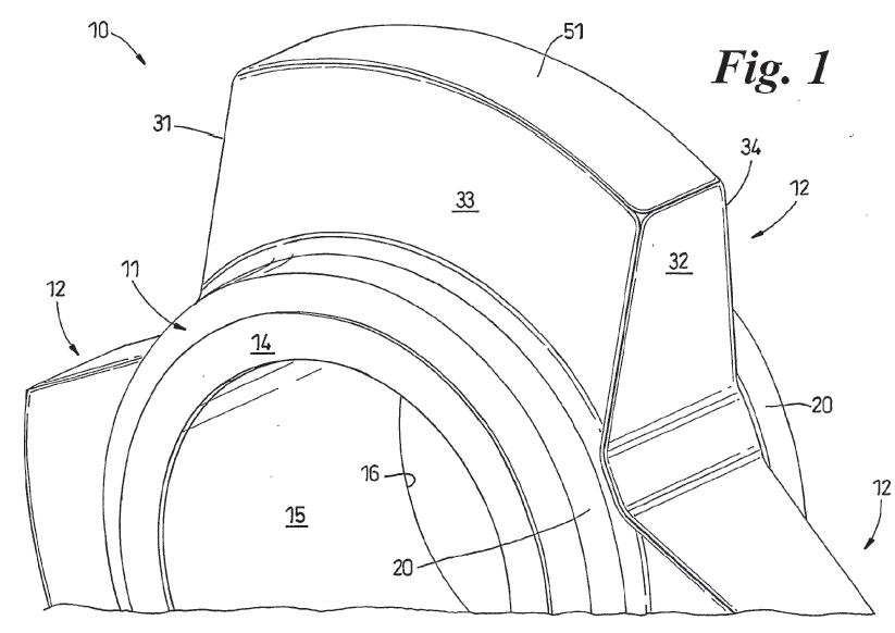
Figure 1 is a part perspective view of a drum annulus according to an embodiment of the present invention;
Figures 2 to 6 illustrate a sequence of construction steps, according to a first embodiment, for creating a toothed annulus for a mineral breaker using the drum annulus of Figure 1;
Figures 7 to 11 illustrate a sequence of construction steps, according to a second embodiment, for creating a tooth annulus for a mineral breaker using the drum annulus of Figure 1 …
(Emphasis added.)
6 Figure 1 is as follows:
7 Figures 2 to 6 are said to illustrate the method of construction to produce a breaker tooth of a given height (the first embodiment). The method of construction of a breaker tooth illustrated in Figures 7 to 11 enable a breaker tooth of a height greater than that of the first embodiment to be produced whilst using the same size of drum annulus (the second embodiment).
8 The “two methods of construction” are said to be illustrative of the principle that the same drum annulus may be used to produce breaker teeth of different heights. The Specification notes that this is particularly advantageous since it enables the same size of drive shaft and drum annulus to be used for the construction of mineral breakers having different sizes of teeth. The Specification also notes that “these two methods of construction” are also illustrative of different ways of securing covers to each horn to define the outer, exposed faces of breaker teeth.
9 Although the claims in the Specification are product claims, rather than method claims, the Specification describes a series of steps (or method of construction) to assemble two embodiments of a tooth construction of the invention.
10 The method of construction according to the first embodiment is described at pages 4 to 6 as follows (with emphasis added and insertion of the relevant Figures at appropriate places in the description):
As shown in Figure 2, the axial side faces 33, 34 of the horn 12 are partially covered by a pair of side covers 36, 37.
Each side cover 36, 37 include a plate-like body 38 and an arcuate flange 39 located at the lower edge of body 38.
Preferably the side faces 33, 34 are planar and bodies 38 are preferably formed from a metal plate which is also planar.
The front and rear edges 40, 41 of body 38 are preferably co-planar with the front and rear faces 44, 45 respectively of the horn 12. The upper edge 47 of each body 38 is preferably rectilinear and extends from the upper part of the front face 33 to the upper part of the rear face 34 of the horn 12. Accordingly the upper portions of side faces 33, 34 are left exposed to define a crown portion 50.
The side covers 36, 37 are secured to the horn 12 preferably by welding. Preferably this is achieved by providing welding along the front, upper and rear edges 40, 47, 41 respectively to produce a welded seam 55. Accordingly the side covers 36, 37 are securely bonded to the horn 12.
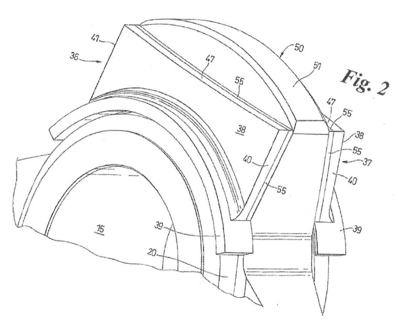
The arcuate flange 39 is seated upon a portion of the annular shoulder 20 and serves to cover that part of the shoulder 20.
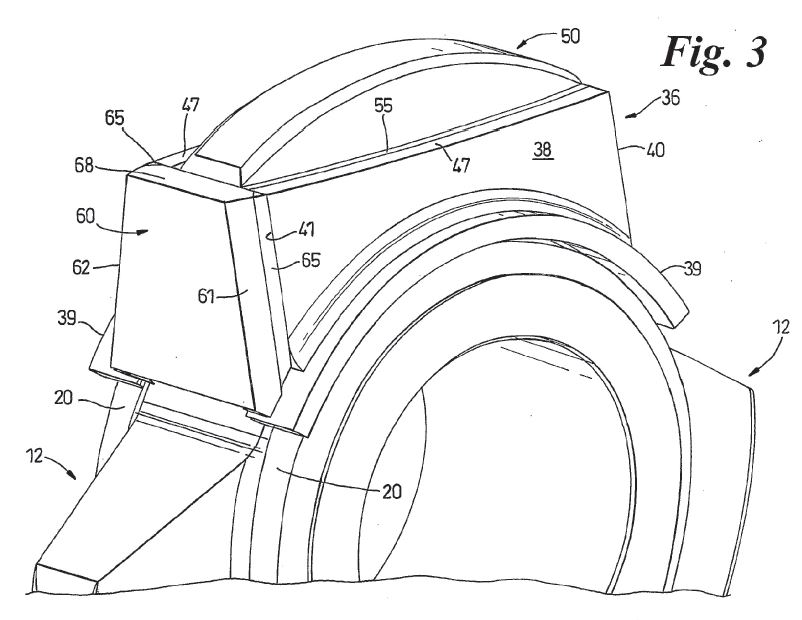
As shown in Figure 3, a rear cover 60 is then provided which is seated in face to face contact with the rear face 31 of horn 12. The cover 60 has side edges 61, 62 which are co-planar with the outer face of bodies 38 and so covers the rear edges 41 of both side covers 36, 37. The rear cover 60 is preferably formed from a metal plate.
The rear cover 60 is secured to the horn 12 and side covers 36, 37 preferably by welding. Preferably this is achieved by welding along the side edges 61, 62 to produce welded seams 65. Whilst it is preferred that the cover 60 is directly welded to the horn 12 it is envisaged that it may be indirectly welded to the horn 12 by being welded to side covers 36, 37 only (which in turn are weldingly connected to the horn).
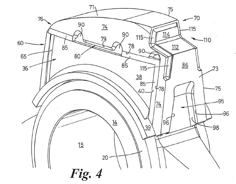
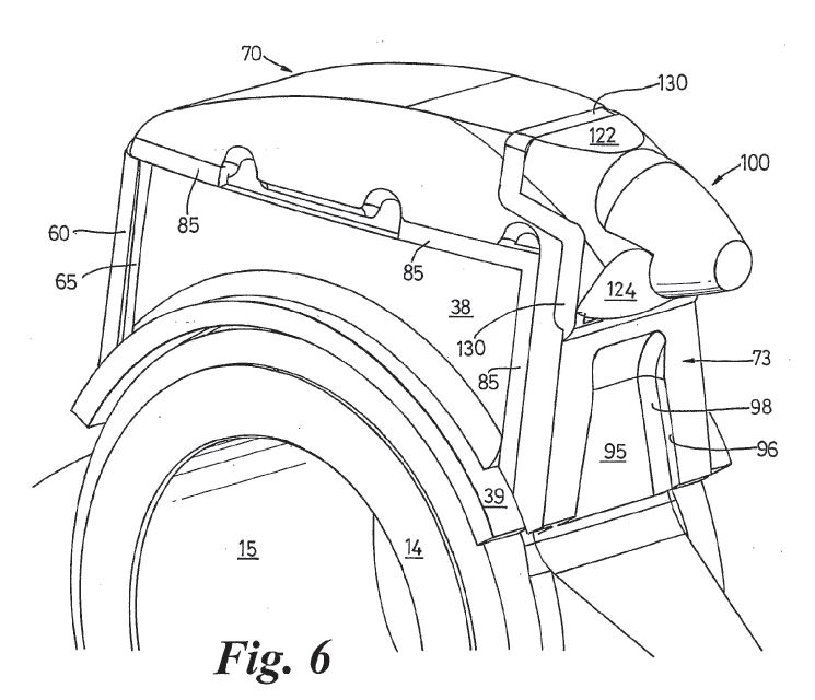
As shown in Figure 4, the horn 12 is then provided with a front and top cover 70.
Cover 70 includes a top portion 71 which has an inner groove (not shown) of complementary shape and size to the exposed crown 50 of the horn 12 which is left exposed after securance of side covers 36, 37 and rear cover 60. Cover 70 further includes a depending front wall portion 73 which has an internal face (not shown) which is seated in face to face contact with the front face 32 of the horn 12. The front wall portion 73 has an upper front face 86 which is preferably planar. The lower portion 87 of the front wall portion 73 preferably includes a window 95. Side walls 96 of the window 95 are preferably secured to the exposed front face of the horn 12 by welded seams 98 in order to directly weldingly secure the front wall portion 73 to the horn 12.
The cover 70 has outer side faces 74, 75 which lie in the same plane as the outer face of side plates 38 and so have inner faces 78, 79 respectively which face and overlie edges 40, 47 of the side plates 38. Preferably a rear end portion 76 of the cover 70 overlies the upper edge 68 of cover 60.
Preferably the side edges of top portion 71 which define faces 78 are spaced from opposed edges 47 to form a gap 80 extending along the edge 47 (only a portion of gap 80 is shown). This enables the inner surface of the top portion 71 to seat upon the upper portion of crown 50.
The cover 70 is then secured to the horn 12 preferably by welding so as to join the opposed faces between cover 70 and plates 38 to one another via a welded seam 85.
A further welded seam 86 is preferably provided to weldingly join the upper edge 68 of cover 60 to the end portion 76.
The weld seam 85, where it extends along the upper edge 47 of each plate 38, also fills the gap 80 and so is weldingly joined to that part of the horn 12 which is exposed by gap 80. Preferably recess windows 90 are provided to enable a gouging tool to be inserted for removal of the weld seam 85 to thereby enable the cover 70 to be removed in the event of a replacement cover 70 being necessary due to wear.
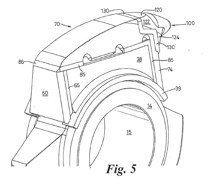
11 There is a description of the addition of the breaking tip member at page 7, line 1 to page 8, line 12 (with emphasis added and insertion of the relevant Figures at appropriate places in the description):
To complete the tooth, a breaking tip member 100 is preferably secured to the cover 70.
In this respect, the cover 70 in the embodiment illustrated in Figure 6, is provided with a recess in the form of a rebate 110 having a bottom wall 112 and an upper wall 114. A peripheral groove 115 is preferably provided which extends around the external periphery of the rebate 110 and also extends downwardly along the outer edges of the upper portion of the front portion of cover 70.
The tip member 100 preferably has a mounting body 120 in which is secured a pick-like tip 121. The mounting body 120 has an upper part 122 which seats in rebate 110 and a lower depending part 124 which has an inner face which lies in face to face contact with the upper front face 86 of wall portion 73. The body 120 has outer edges which overlie the peripheral groove 115 and is preferably secured to the cover 70 by a welded seam 130 extending along groove 115.
The above arrangement produces a breaker tooth in which a horn 12 is provided which is completely enclosed by a fabricated shell-like tooth cap defined by covers 36, 37, 60 and 70. The tooth cap is fabricated in-situ on the horn 12, preferably by welding covers 36, 37, 60, 70 to one another and/or the horn 12. This provides a very strong tooth construction having a shell-like construction which is securely fixed to the horn 12.
In this construction, the front of the tooth is fully seated on the horn front face 32 at the time of assembly and so is highly resistant to loosening during operation by being exposed to impacts on the front of the tooth. Similarly, the rear of the tooth shell (as defined by plate 60) is fully seated on the rear face 31 of the horn during assembly and is fixed in position independently of the front of the tooth. This means that the rear plate 60 of the shell is highly resistant to loosening by impacts on the rear of the tooth. It follows therefore that the fabricated shell is highly resistant to loosening by repeated alternate impacts to the front and rear of the tooth.
As wear takes place, in use, replacement covers can be simply installed by removal of the worn cover and insertion of a new one. Removal is easily achieved by first removing the relevant welded seam.
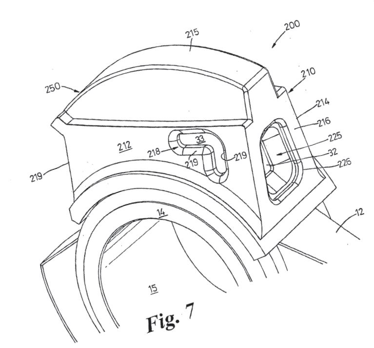
12 The second embodiment which is illustrated in Figures 7 to 11 is said to be an example of a tooth construction which uses the same sized horn as the first embodiment but has a tooth height greater than that of the first embodiment as depicted in Figure 6. This is achieved primarily by the provision of an intermediate cover.
13 The second embodiment is described as follows on pages 8 to 9 (again with emphasis added and insertion of the relevant Figures):
In embodiment 200, the horn 12 is first covered with a cover 210 which is preferably cast from a suitable metal. The cover 210 has a pair of opposed sides 212, 214, a front wall 216 and a top 215. The cover 210 has an open back (not shown).
The cover 210 defines an internal pocket which has faces which seat in face to face contact with faces 32, 33, 34 and 50 of the horn 12.
The side walls 212, 214 include at least one window or aperture 218 which exposes a portion of the underlying face 33 or 34 of the horn 12. The aperture 218 has side walls 219 which are secured to the exposed face 33 or 34 of the horn 12 by welding. Preferably the entire aperture 218 is filled with weld.
Similarly, the front wall 216 is provided with at least one window or aperture 225 which exposes a portion of face 32.
The aperture 225 has side walls 226 which are secured to the exposed portion of face 32 by welding.
The rear end faces 219 of the cover 210 are preferably co-planar with the rear face 31 of horn 12 and are secured to the horn 12 by a welded seam extending between the internal edges of faces 219 and the horn 12.
Accordingly the cover 210 is securely fixed to the horn 12 by welding located at the front, both sides and rear of the cover 210.
The top 215 of cover 210 defines an upper crown 250 of similar shape to crown 50.
As shown in Figure 8, a rear cover 60 is provided which overlies the rear face 31 and end faces 219 of the cover 210. The cover 60 is formed of a metal plate and is located in face to face contact with rear face 31. It is secured to the cover 210 and horn by a seam of weld 65 which extends along both sides of plate 60.
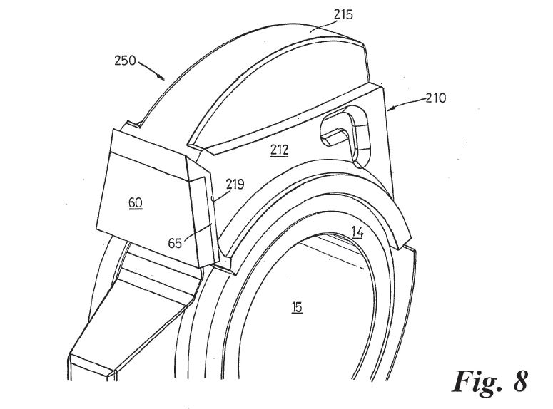
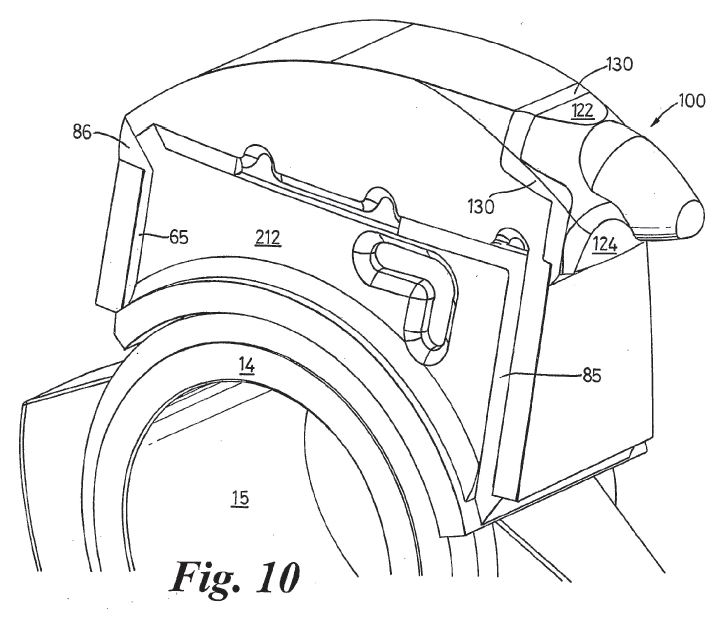
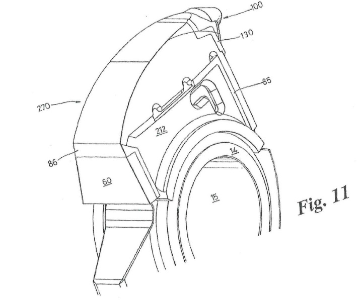
As shown in Figure 9, a cover 270 similar to cover 70 is located on the crown 250 and is secured in place by welded seams 85.
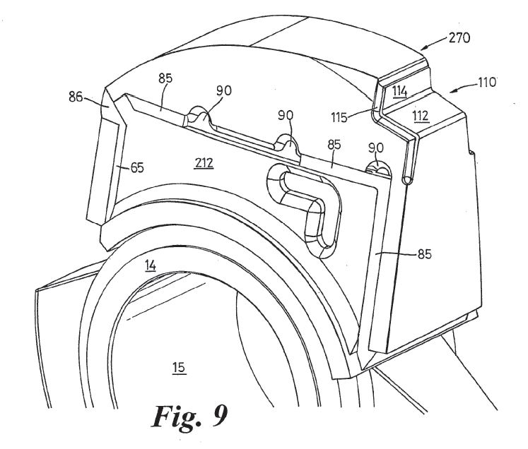
The cover 270 is provided with a tip member 100 which is secured in position by welded seam 130.
14 At page 10, the Specification notes that the construction of the breaker tooth, as exemplified in the two embodiments, provides a very strong breaker tooth since welding of the covers to the horn in effect adds strength to the horn. This means that the tooth construction of the invention can transmit relatively high forces for breakage of very hard minerals with a reduced risk of snapping and in addition without a risk of the tooth shell or cover working loose. The Specification notes that the strength of the tooth construction according to the invention is also enhanced by the fact that the horn is solid, ie does not contain through bores as is commonly required with prior art constructions.
15 The Specification has 19 claims.
16 Claim 1 claims:
A tooth construction for a mineral breaker, the tooth construction including a tooth shaped support body covered by a shell which defines the outer shape of the tooth construction, the shell being composed of a plurality of covers which are fixedly secured to one another and/or to the support body by welding to define a unitary tooth construction the support body having a front face and an opposed rear face and the plurality of covers including at least a front cover which is weldingly secured to and seated in face to face contact with the front face of the support body and a separate rear cover which is weldingly secured to and seated in face to face contact with the rear face of the support body.
(Emphasis added.)
17 Claims 2 to 9 are dependent on claim 1. Claims 2, 7 and 8 are as follows
2. A tooth construction according to Claim 1 wherein the support body has a pair of side faces and a top face.
…
7. A tooth construction according to Claim 2 wherein the front cover forms the front wall of an intermediate cover which also includes, opposed side walls, a top and an open rear wall overlying respective front, side and top faces of the support, the side and front walls each having at least one aperture formed therein to expose the underlying face of the support, the walls of the apertures being welded to the exposed underlying faces of the support.
8. A tooth construction according to Claim 7 wherein a top cover is mounted on the intermediate cover, the top cover having a top wall portion and a front wall portion overlying the top wall and front wall of the intermediate cover, the top cover being secured to the intermediate cover by welding.
Relevant principles of construction of the Patent
18 The primary judge said at [206] that the principles governing patent construction were well established and were not in dispute, and had been summarised in many Full Federal Court cases, such as Jupiters Limited v Neurizon Pty Ltd [2005] FCAFC 90; (2005) 65 IPR 86; 222 ALR 155 at [67] (Hill, Finn and Gyles JJ); ESCO Corporation v Ronneby Road Pty Ltd [2018] FCAFC 46; (2018) 131 IPR 1 at [144] (Greenwood, Rares and Moshinsky JJ); and GlaxoSmithKline Consumer Healthcare Investments (Ireland) (No 2) Ltd v Generic Partners Pty Ltd [2018] FCAFC 71; (2018) 264 FCR 474 at [102] (Middleton, Nicholas and Burley JJ). No criticism was made on the appeal of the primary judge’s statement at [207] of the following principles as being of particular relevance in the present case:
(a) in construing the claims, a generous measure of commonsense should be used: Product Management Group Pty Ltd v Blue Gentian LLC [2015] FCAFC 179; (2015) 240 FCR 85 at [36] (Kenny, Nicholas and Beach JJ);
(b) a construction according to which the invention will work is to be preferred to one in which it may not: Pfizer Overseas Pharmaceuticals v Eli Lilly and Company [2005] FCAFC 224; (2005) 68 IPR 1; 225 ALR 416 at [250] (French, Lindgren and Crennan JJ); Blue Gentian at [39];
(c) a patent specification should be given a purposive, not a purely literal, construction;
(d) a patent specification is not to be read in the abstract but is to be construed through the eyes of the person skilled in the art in the light of the common general knowledge and the art before the priority date: Jupiters at [67(ii)];
(e) the claims are to be construed in light of the specification as a whole, but the plain and unambiguous meaning of a claim cannot be varied or qualified by reference to the body of the specification: Welch Perrin & Co Pty Ltd v Worrel (1961) 106 CLR 588 at 610 (Dixon CJ, Kitto and Windeyer JJ);
(f) claims in a patent are not to be narrowed by reference to the preferred embodiment: Rehm Pty Ltd v Websters Security Systems (International) Pty Ltd (1988) 11 IPR 289 at 299 (Gummow J); and
(g) the preferred embodiment cannot be used to introduce into the definite words of a claim an additional definition or qualification of the patentee’s invention: Erickson’s Patent (1923) 40 RPC 477 at 491; Globaltech Corporation Pty Ltd v Australian Mud Company Pty Ltd [2019] FCAFC 162; (2019) 145 IPR 39 at [111] (Kenny, Robertson and Moshinsky JJ); Welch Perrin at 612.
19 At [208]–[209], the primary judge dealt with the concept of a person skilled in the art, in a manner which again was not the subject of any criticism on the appeal. The primary judge referred to a person skilled in the art as being a person of the kind to whom a patent specification is addressed: General Tire & Rubber Co v Firestone Tyre & Rubber Co Ltd [1972] RPC 457 at 485 (English Court of Appeal), cited with approval in Nicaro Holdings Pty Ltd v Martin Engineering Co (1990) 16 IPR 545 at 574 (Gummow J). The primary judge referred to the relevant principles relating to the hypothetical skilled person as having been summarised by Beach J in Meat and Livestock Australia Limited v Cargill, Inc [2018] FCA 51; (2018) 129 IPR 278 at [219]. The person skilled in the art is not a reference to a specific person but is a legal construct: Root Quality Pty Ltd v Root Control Technologies Pty Ltd [2000] FCA 980; (2000) 49 IPR 225 at [71] (Finkelstein J). The notional person is not an avatar for expert witnesses whose testimony is accepted by the Court, and as French CJ observed in AstraZeneca AB v Apotex Pty Ltd (2015) 257 CLR 356 at [23], the notional person is a tool of analysis rather than a real person.
20 At [239], the primary judge recorded that it was not suggested that any of the terms of the claims in the Specification were technical terms, or anything other than ordinary English words. Neither party sought to depart from that position on the appeal. As the primary judge stated at [239], the construction of the terms is a matter for the Court: Airco Fasteners Pty Ltd v Illinois Tool Works Inc [2023] FCAFC 7; (2023) 170 IPR 225 at [59] (Rares, Moshinsky and Burley JJ).
21 The notice of appeal raises issues of construction concerning three aspects of the language used towards the end of Claim 1 of the Specification (which we have emphasised in bold type above), namely (a) “seated in face to face contact”, (b) “front cover”, and (c) “separate rear cover”. We deal with each of those issues in turn.
Construction of “seated in face to face contact”
22 The contest between the parties as to the proper construction of this expression is between, on the one hand, the primary judge’s construction of “face to face contact” as referring to configurations in which a cover physically touches the support body across most of the faces of the cover and the support body, and on the other hand, MMD’s submission that this integer contemplates both direct and indirect transmission of force between the faces of two components, and includes transmitting force through an intermediate component, such as weld or another cover (and in circumstances where most of the force is transmitted as shear force but part of the force is transmitted as compressive force). Although neither party contended that the expression adopted technical terms or terms of art, rather than words of ordinary English, expert evidence relating to the expression and the practical implications of it was given by Mr de Vos, who was engaged by MMD, and Dr Huggett, who was engaged by Camco.
The Reasons of the Primary Judge
23 The primary judge’s reasoning on this particular issue may be summarised as follows. According to Mr de Vos, the word “contact” imports into the claims the critical concept of the efficient transfer of forces, in that a robust tooth construction must be capable of efficiently and effectively transmitting forces from the covers to the support body: [256]. As a result of the large forces that are imparted on the teeth, it is necessary for those forces to be efficiently transmitted to the support body and the shaft in order for the teeth to be sufficiently robust, otherwise the large forces that are imparted onto the teeth during operation can cause the means of securing the covers to fail, and failure of tooth covers in between scheduled maintenance breaks is very undesirable: [257]. According to Mr de Vos, the most efficient way of transmitting force is a “compressive force”, which involves pushing into, or compressing, a component, and as compressive forces do not rely on a fastening medium (unlike tensile and shear forces), it is preferable for the forces imparted on the covers during use to be transmitted to the support body through compressive forces: [258]. (A tensile force relies on a fastening medium to transmit the force between components, and involves pulling away from, or stretching, a component; a shear force is a transverse, rather than an axial, force: [96]–[97].) Mr de Vos observed that the Specification emphasises the importance of the ability of the tooth construction to transmit forces from the covers to the support body to ensure that the welds securing the covers do not fail as a result of the forces imparted on them during use: [259]. The primary judge considered that the emphasis on the effective transmission of force was inconsistent with the welds being the means for the transmission of the majority of the force as shear force, as depicted in the diagram which became known at the trial as Diagram 3 (Exhibit A11), which we have reproduced below:
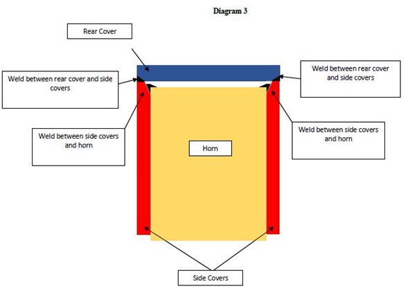
The primary judge said that in the configuration as depicted in Diagram 3, the majority of the forces are being transmitted through the welds, thereby placing the welds under stress which may cause them to crack and fail early: [259]. The primary judge referred to the evidence of Mr de Vos to the effect that weld will most commonly fail where large shear forces or tensile forces are repetitively imparted on the weld (third affidavit of Mr de Vos at [853]). We note that MMD criticises the primary judge for not also referring to the evidence of Mr de Vos in that affidavit at [857], relevantly to the effect that in practice it is possible to create a tooth construction with clearances between the covers and support body provided that the cover is made with thick steel that is able to withstand the relevant forces even if there is a gap between the cover and the support body, the weld is thick enough, and the way the forces are transmitted to the support body does not place the welds under too much stress. The primary judge said that the person skilled in the art would be aware that mineral sizers undergo regular maintenance, and the tooth construction must be robust enough to break the ore and remain intact for the duration of the maintenance period: [260]. The welds must secure the covers of the tooth construction for the entire maintenance period, but as the tooth constructions are replaced at regular intervals, there is no need for the tooth constructions to be made to last as long as possible: [260].
24 The primary judge said that all of the words in the phrase “seated in face to face contact” have a role to play: [261]. The primary judge considered MMD to be focusing on the face of the support body as the face of interest, and referred to its submissions speaking of methods to ensure the requisite transmission of force “from the covers” to the support body, not the faces of the covers or the faces of the support body (as the claims require): [262]. The primary judge referred to Diagram 3 as depicting an arrangement where the rear cover does not directly touch the rear face of the support body. The primary judge said that the words “face to face” contemplate the existence of two faces (the face of the front (or rear) cover, and the front (or rear) face of the support body), and said that being in face to face contact required the two faces to be in physical contact: [262]. The primary judge observed that each time the phrase “face to face contact” is used, it is in the context of a description of the placement of two faces: the front or rear cover, and the front or rear face of the horn. In contrast, the discussion of welding in the specification refers to welding “to the horn”, not specifically to the front or rear faces of the horn: [263]. The primary judge observed that the phrase “face to face contact” first appears at page 5, line 11, in the description of the placement of the rear cover in the first embodiment, in which the rear cover is described as being seated in face to face contact with the rear face of the horn: [264]. The primary judge observed that there is no mention of how the rear cover is held in place until the next paragraph in which the rear cover is said to be preferably secured to “the horn” (not the rear face of the horn) by welding, and it is also noted that the rear cover may be “indirectly welded to the horn” by being welded to the side covers: [264]. The primary judge said that later on page 5, line 30, the internal face of the top cover is said to be seated in “face to face contact” with the front face of the horn, and the top cover is then said at page 6, line 18, to be “secured to the horn 12, preferably by welding”: [265]. The primary judge observed that there is no reference to a particular face of the horn, and said that the welding direction is to join the opposed faces between the top cover and the plate-like body of the side cover to one another: [265].
25 The primary judge expressed the view that “seated” in the phrase “seated in face to face contact” means positioned: [266]. The primary judge then said that the front cover is the front cover which is in physical contact with the front face of the horn: [266].
26 The primary judge referred to the specification as describing a method or sequence of the construction of the tooth construction, in which the cover is described as being “seated in face to face contact” with the relevant face of the horn, well before any discussion of how it is secured to the horn: [267]. That point was developed further by the primary judge at [280], in which her Honour referred to the Specification as speaking of weld as a preferable way to secure the covers of the tooth construction, but saying nothing about the transmission of forces through welds or the adjustment of the welds to bear transmission of the majority of the force as shear forces. The primary judge said that if welds were contemplated by the inventor as components through which large forces were intended to be transmitted efficiently to the horn and thereby effect face to face contact, it would be expected that the patentee would have said something about that topic, including in relation to the importance, size and nature of the welds required to effect the invention: [280]. Further, on the same hypothesis, the primary judge also said that the specification’s sequence of construction would not describe components as seated in face to face contact before welding had taken place. The primary judge observed that welding is said in the specification only to secure the components after they are seated in face to face contact, referring at [280] to page 5, lines 10–17; page 5, line 29 to page 6, line 3; and page 8, line 27 to page 9, line 4 (to which reference may be added to similar statements at page 6, lines 13 to 20; page 7, lines 13 to 19; and page 9, lines 23 to 27).
27 The primary judge then turned to the topic of sand casting: [268]. The primary judge had earlier referred to three common forms of casting, being sand, die and investment casting: [101]. The primary judge referred to sand casting as having the advantages of relatively low production costs, and the ability to cast large components: [102]. However, sand casting is not a high-precision production method, and components that are produced using sand casting have relatively large manufacturing tolerances and relatively rough surfaces: [103]. The primary judge described die casting and investment casting as providing greater precision but involving more expense than sand casting: [105]–[106]. However, while investment casting was said to be more expensive than sand casting, the proposition was qualified in circumstances where the sand cast part is machined to increase its precision, as machining increases costs: [106]. The primary judge described machining as involving cutting the part into the desired shape using a variety of different tools and said that it was possible to increase the precision of a cast component by machining it after it has been cast: [107]. The primary judge referred to machining as being a labour-intensive process, which therefore adds substantially to the cost of producing the part, and so is usually only used when a high degree of precision is required: [107]. At [268], the primary judge referred to sand casting being relatively imprecise, and described components that are produced using sand casting as having relatively rough surfaces. In practice, the primary judge said that there will still be some clearances between the face of the support body and the front and/or rear covers due to the imprecision involved with sand casting: [268]. The front and/or rear covers will undulate across their surface, meaning that part of the face of the covers will touch the support body and part will not: [268]. The primary judge had earlier referred to the evidence of Mr de Vos to the effect that the covers of tooth construction are most commonly sand cast, and as the covers are sacrificial parts and designed to be replaced periodically, there is an imperative to minimise manufacturing costs: [121]. Further, as the covers do not have a particularly intricate design, Mr de Vos expressed the opinion that they were suitable for sand casting: [121].
28 The primary judge then expressed disagreement with the proposition that the expression “seated in face to face contact” required that the two faces must be “flush” to the extent that “flush” requires intimate contact across all surfaces of the faces, and referred to Dr Huggett’s evidence that he contemplated that the majority of the surfaces would be in contact, rather than a perfect 100%: [269]. The primary judge also referred to the evidence of Mr de Vos that the surfaces of the covers are unlikely to be smooth, even with the best manufacturing tolerances, as cast surfaces are likely to have undulations, and over a lifetime of use and refurbishment (including gouging off old welded-on covers) the surfaces of the horn are unlikely to be entirely smooth or identical to each other: [270].
29 The primary judge next expressed the conclusion that a commonsense construction of “face to face contact” in the context of front and rear covers which are likely to be sand cast, means physically touching across most of the faces of the cover and the support body (allowing for undulations inherent in the casting process): [271]. The primary judge said that the same total force will be transmitted between two components, irrespective of whether they are “flush in intimate contact across their surfaces without any gaps” or there are some gaps between them: [271].
30 The primary judge then referred to weld as being discussed in the specification merely as the way to secure components, not as the primary conduit of force from the covers to the support body, referring to the method of construction outlined for the first embodiment: [272]. The primary judge said that there is no discussion in the specification of adjusting the weld to bear the transmission of the majority of the force as shear force if there is no physical contact across the faces of the covers and the support body: [272].
31 The primary judge criticised MMD’s construction of Claim 1 as almost becoming a claim by result; that is, anything which achieves the functionality of, or results in, a robust tooth construction falls within Claim 1, even where it is an embodiment with only point to point contact with the side cover such as is shown in Diagram 3: [273]. The primary judge referred to MMD’s submission that a robust tooth construction can be created that is designed to transmit forces between the covers and the support body entirely through weld (as in Diagram 3), and said that such a construction ignores the references to face to face contact in the specification and gives the word “contact” no work to do: [273]. The primary judge said that the submission also ignores the notion of efficient transmission of compressive forces, which was said by Mr de Vos to be imported by the word “contact”: [273]. The primary judge said that where there is a permanent gap between a cover and a support body, the cover or weld could break during use, referring to Mr de Vos’s evidence that the weld securing the cover to the support body may crack over time if there is a permanent gap between the cover and the support body, and, in his experience, welds will most commonly fail where large shear forces or tensile forces are repetitively imparted on the weld: [276]. The primary judge referred to Mr de Vos’ agreement that where the rear cover and the rear face of the support body are “flush” (in the sense of contact across the majority of their faces), then the transfer of forces would be much more effective than when there is a gap such as that depicted in Diagram 3: [277]. The primary judge referred to MMD’s submission that Diagram 3 shows that forces are transmitted from the rear cover to the peripheral sides of the rear face of the support body, and that although forces may only be transmitted to the outer few millimetres of the rear face of the support body, they are still transmitted to the rear face of the support body, which was said by MMD to be sufficient for the claims of the Specification: [278]. The primary judge then said that on MMD’s case, the size of the weld is important because (in the Diagram 3 scenario) if the weld is only a few millimetres and is required to take a high amount of shear force, this renders it prone to cracking or failure, with the consequence that the cover is likely to fall off during operation: [279]. In that context, the primary judge made the observations, to which we have referred above, as to the Specification speaking of weld as a preferable way to secure the covers of the tooth construction, but saying nothing about the transmission of forces through welds or the adjustment of the welds to bear transmission of the majority of the force as shear forces: [280].
Submissions by MMD
32 At the heart of MMD’s oral submissions was the proposition that there are “extreme practical consequences” that follow from the primary judge’s requirement that covers must physically touch over most of their respective faces, such that a person skilled in the art would not construe the claims as the primary judge did (T11.18–21). MMD’s written submissions were pitched at a similarly high level, contending that achieving direct physical contact across most (or any) of the face is “unnecessary, impractical (if not impossible) and prohibitively costly” (at [5]). The primary judge’s construction was said to lead to “an unworkable result” (T11.24) in respect of two key components that form part of the relevant covers. First, MMD draws attention to the description of the intermediate cover 210 in the second embodiment, in which reference is made to the cover 210 defining an internal pocket which has faces which “seat in face to face contact” with faces 32, 33, 34 and 50 of the horn, those faces being the front, sides and crown of the horn: page 8, lines 27 to 28 and Figure 7. Second, MMD draws attention to the reference to the tip member 100 in the first embodiment which is described as preferably having a mounting body 120, with the mounting body 120 having an upper part 122 which seats in rebate 110 and a lower depending part 124 which has an inner face which “lies in face to face contact” with the upper front face 86 of wall portion 73: page 7, lines 12 to 16 and Figures 4 to 6. MMD’s argument is that the primary judge’s construction of face to face contact is “unworkable in the case of the intermediate cover and prohibitively expensive in the case of the tip member” (T12.46–47).
33 The starting point of the argument is the finding by the primary judge that the covers are likely to be sand cast at [271]. While the Specification refers only to the intermediate cover being “preferably cast” (page 8, line 23), the primary judge’s finding is consistent with the understanding to be attributed to a person skilled in the art that the casting would be by way of sand casting. Dr Huggett agreed that it was typical for covers for sizers to be sand cast: T348.37–9. Accordingly, MMD submits that an addressee would approach a consideration of what the specification is teaching through the prism that the components to which the Specification is referring are at least typically sand cast. In relation to the second embodiment, Dr Huggett agreed that all of the components are cast except the rear steel plate (T278.30–33). Dr Huggett also accepted that with sand casting there are significant manufacturing tolerances and the surface of the cover that has been sand cast will not be perfectly flat (T348.41–349.10). As the primary judge said at [268], there will be undulations across covers with the result that only part of the face of the covers will touch the horn. MMD also referred to evidence given by Mr de Vos as to the approximate range of tolerances in relation to smaller components, being plus or minus 2.2 millimetres, ie 4.4 millimetres in total: T353.14–22, 384.08–385.25. While Dr Huggett gave evidence that a tolerance of less than half a millimetre variation could be achieved in casting a flat surface, Mr de Vos responded that the top and the sides of the intermediate cover were not flat but were curved (T349.46–350.44).
34 In light of those manufacturing tolerances, MMD submits that it is “practically impossible” to achieve direct contact between the intermediate cover and the horn across most of the matching faces (T16.09–10), as Mr de Vos said (at T335.39–336.80). In the first place, each intermediate cover will differ in size and shape by up to 4.4 millimetres in total. Further, MMD submits that each support body will differ in size and shape due to the refurbishment process. MMD submits that in relation to the support body, during the refurbishment the weld that secured the intermediate cover to the horn has to be gouged off by a process called air arc gouging. Arc gouging gouges material out in an effort to remove the weld, thereby taking material out of the horn leaving gouge marks in the support body which are later built up or refilled with weld during refurbishment (referring to Dr Huggett’s evidence at T355.34–356.10). The result is that when one comes to fit the intermediate cover on the support body, there is a different mating relationship between each intermediate cover and the horn (which Dr Huggett said was more than likely at T356.12–15). MMD submits that in light of those practical issues, the person skilled in the art would cast the intermediate cover so that the top wall rests on the top face of the support body, but leaving a clearance between the side walls and the side faces to enable the intermediate cover to fit over the support body, and the person skilled in the art would then secure the intermediate cover by weld through the apertures in the side walls, with the result that the weld would be the only physical connection between the side walls and the side faces of the horn (T17.41–18.04). MMD contends that once the intermediate cover is welded in place, the walls can then be said to be in face to face contact with the support body in two ways, namely by direct physical contact at the top, and through weld at the side walls.
35 In relation to the sand casting of the tip member, and in particular taking into account the fluctuations in manufacturing tolerances, Mr de Vos gave evidence that it is “highly unlikely” that both upper and lower depending parts would make direct physical contact with the top cover (T367.01–04). However, MMD submits that the person skilled in the art can still implement the tip member in the manner described in the Specification using sand casting if the mounting body is cast to be slightly larger than the rebate, leaving a clearance, and face to face contact is achieved by peripheral welding which bridges that clearance (T19.21–27).
36 MMD then sought to confront the proposition advanced by Dr Huggett that the problem created by the manufacturing tolerances of sand casting can be resolved by way of machining. Dr Huggett gave evidence that in the casting industry, if there is a face that actually needs to be in full contact with another face and is oversized, then it could be machined back to ensure full face to face contact (T276.12–15). Mr de Vos accepted that for the surfaces of the components to be in direct contact, they would have to be machined (T279.06–280.12). MMD criticised the primary judge’s reasoning at [268]–[271] by attributing to the primary judge the view that it is possible to have sand cast components directly touch across most of their faces without machining. We regard that criticism as misplaced, given that the primary judge had already referred at [107] to machining as a means whereby the precision of a cast component could be increased, noting that it is a labour-intensive process and adds substantially to the cost of producing the part, and thus is usually only used when a high degree of precision is required. Moreover, the primary judge said specifically at [125] (drawing on the first affidavit of Mr de Vos at [148]) that if there is a poor fit between the intermediate cover and the support body after casting, then the intermediate cover will have to be machined or ground for the two components to fit together, that being a time-consuming and costly exercise.
37 In any event, in order to answer the proposition that the machining of sand cast components was an available means to resolve the problem of manufacturing tolerances inherent in sand casting, MMD contended that machining is too difficult, expensive and time-consuming to be a viable solution: T21.14–15; written submissions at [11]. However, we observe at this point that the evidence on which MMD relied for that contention fell well short of the submission. Mr de Vos referred to machining as being “very costly and expensive”, and said that while it was relatively simple to achieve full abutment of surfaces by machining flat surfaces, it was much more difficult to achieve full abutment with curved surfaces, so that machining would be “quite expensive” (T278.45–279.04). Dr Huggett agreed that machining the covers would be a significantly more difficult and time-consuming process than most machining processes, in circumstances where the products had to pair with each other and they may well have non-flat surfaces (T356.32–36). Dr Huggett agreed that cost is relevant in all manufactured goods, but said that the Specification does not actually mention that it is a cheaper or cost-efficient version of production (T358.10–17). It was at that point that Dr Huggett was asked whether the machining cost would have the result that machining was not economically viable, to which Dr Huggett responded that “that would depend on what level of machining would be required and how that was done” (T358.30–35). Dr Huggett then recognised the possibility (using the phrase “it may well be”) that, given the type of machining and surface requirements of intimate and flush direct contact, getting the covers to mate with the horn in that manner might not be able to be satisfied (T358.37–41). Dr Huggett accepted that someone reading the specification in a practical and commonsense way would recognise those difficulties and the cost (T358.43–47). The only other occasion in the written or oral evidence when the issue of the economic viability of machining sand cast components was addressed was in Dr Huggett’s fourth affidavit at [69(c)], where Dr Huggett said that the benefit of having covers seated in face to face contact with the support body “may” (again, the language of possibility) outweigh the additional manufacturing cost incurred when parts are machined because parts assembled in this way would be less likely to fail during use (and would therefore be less likely to require repair within a maintenance cycle).
38 We should indicate at this point that we do not regard the evidence as rising any higher than establishing that machining the sand cast components would be relatively costly and time-consuming. The evidence does not support the submission that the need for machining of sand cast components would render it impractical, impossible or not economically viable for the components to be seated in face to face contact with each other.
39 MMD also submitted that machining is unnecessary, in the sense that it is not required to create robust tooth constructions (T22.46–23.01). The primary judge held that the covers are routinely replaced (at [89]) and that the welds need to last only for the maintenance period (at [260]). Dr Huggett appeared to accept that if localised contact by way of point to point contact between the components was sufficient, then that objective could be achieved by appropriate design (T359.14–42, 376.10–377.16), and Mr de Vos said that the weld and covers could be designed so that the stresses on the weld were within acceptable levels and the covers would not come loose (T382.19–383.39, 437.41–438.05). Accordingly, MMD submitted that the person skilled in the art could apply common general knowledge to make configurations of the intermediate cover and the tip member in which the forces were transmitted solely through weld robust enough to last the maintenance period by increasing the thickness of the weld. MMD submitted that the absence in the Specification of an explanation of the importance, nature and size of the weld required to transmit force is not of significance in that these are matters of common general knowledge that did not need to be spelt out in the specification. However, we note that whether or not face to face contact across most of the surfaces was strictly necessary for the effective operation of the tooth construction, it may still have been beneficial. In that regard, Dr Huggett expressly rejected the proposition that machining the covers would not improve the strength or the structural integrity of the tooth construction in any way, saying that if one has more surface area coverage then one would improve the contact between the surfaces, and that if the force is applied over a very narrow surface area, then that would put very high stress on the structure which may exceed the material properties in terms of mechanical stress (T359.01–23). The primary judge described it as obvious that there are distinct advantages with respect to the transmission of forces in having the front and rear covers being fully abutted with the support body (at [231]).
40 As to the possibility of using investment casting in order to achieve greater precision, MMD relies on the primary judge’s finding as to the likelihood of the front and rear covers being sand cast (at [271]). Further, MMD refers to the evidence of Mr de Vos being that investment casting is not generally used for components of the relevant size because of the cost associated with it, and that it would be far more economical to use sand casting and machining than it would be to use investment casting (T386.26–28).
41 MMD also submits that its construction (which is sufficiently broad to include the configuration shown in Diagram 3) is supported by references in the specification concerning both the first and second embodiments to the side covers being “preferably co-planar” with the front and rear faces: page 4, lines 25 to 26; page 9, lines 13 to 14. Given that that is expressed merely as a preference, MMD submits that the Specification contemplates that the side covers can be shorter or longer than the face of the horn (as illustrated in Diagram 3 where the side covers extend beyond the horn).
Consideration
42 In our view, the primary judge was correct in construing the expression “seated in face to face contact” as meaning physically touching across most of the faces of the cover and the support body. The natural meaning of the ordinary English words used in the relevant expression is that the surfaces directly and physically touch across their surfaces. The well-established insistence in the authorities (referred to above) on adopting a commonsense construction means that, in the context of components which are sand cast, the physical touching need not be perfectly across all of the respective surfaces, but must allow for undulations and roughness in the surfaces, such that physical touching across most of the surfaces is sufficient. The notion that the expression is wide enough to include the indirect transmission of force through an intermediate component (whether an intermediate cover or weld) is inconsistent with the clear language used in Claim 1.
43 We regard that ordinary and natural meaning of the expression as being plain and unambiguous. As the High Court said in Welch Perrin at 610, if a claim is clear it is not to be made obscure simply because obscurities can be found in particular sentences in other parts of the document. See to the same effect Kimberly-Clark Australia Pty Ltd v Arico Trading International Pty Ltd [2001] HCA 8; (2001) 207 CLR 1 at [15] (Gleeson CJ, McHugh, Gummow, Hayne and Callinan JJ).
44 Further, in our view the detailed method of construction described in the Specification for both the first embodiment and the second embodiment reinforces the plain meaning of the expression in Claim 1. In particular, we respectfully adopt the reasoning of the primary judge at [267] and [280] to which we have referred above, to the effect that the Specification speaks of weld as a preferable way to secure the covers of the tooth construction but says nothing about the transmission of forces through weld or the adjustment of the welds to bear transmission of the majority of the force as shear force, and describes components as seated in face to face contact before welding has taken place.
45 As we have indicated above in dealing with MMD’s submissions on the point, we do not regard the references to “face to face contact” in relation to the intermediate cover and the tip cover as pointing towards MMD’s construction. The evidence on which MMD sought to rely established that the perceived practical difficulties could be met by machining the sand cast components, which would involve a costly and time-consuming process, but could not be described as impractical, impossible or not economically viable.
46 As to MMD’s submission based on references in the Specification concerning both the first and second embodiments having side covers which are “preferably co-planar” with the front and rear faces, we do not regard those references as pointing towards MMD’s construction, the effect of which would be to permit a clearance or gap between the horn and the front and rear covers respectively. The point may be illustrated by reference to the diagrams referred to at the trial as Diagrams 1 and 2 (Exhibit A10), which are reproduced below:
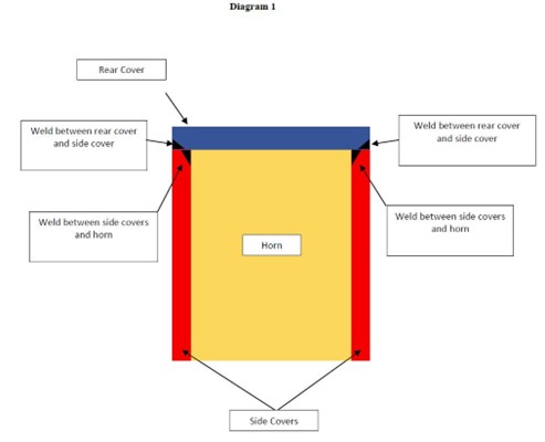
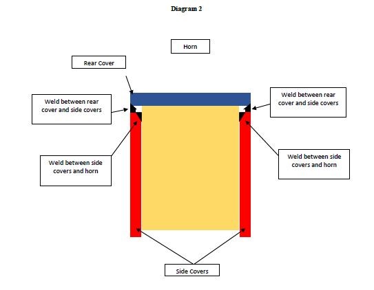
Diagram 1 shows the ends of the side covers being co-planar with the rear face of the horn. Diagram 2 shows the ends of side covers not being co-planar with the rear face of the horn, because they are shorter than the horn. However, Diagram 2 is consistent with Claim 1, in that the rear cover is seated in face to face contact with the rear face of the horn. In other words, in Diagram 2, the respective surfaces are in physical direct contact with each other, even though the ends of the side covers are not co-planar with the rear face of the horn.
47 There was considerable discussion at the hearing of the appeal concerning the so-called “ore fines issue”, which the primary judge dealt with at [33]–[48] and elsewhere in her Honour’s reasons. This issue arose out of a submission made by MMD in its written opening submissions to the effect that the integer of “seated in face to face contact” can be satisfied by the indirect transmission of force through an intermediate component, which might be made up of ore fines or corrosion which over time filled up what had initially been a clearance between the cover and the horn. That contention was abandoned by MMD on day 7 of the trial. In its closing submissions, MMD relied for the submission as to indirect transmission of forces and intermediate components only on the presence of weld for the transmission of force from the cover to the support body (as shown, for example, in Diagram 3). The debate before us concerned whether the evidence of Mr de Vos had been infected by earlier references in his evidence to the ore fines issue. In our view, it is not necessary for us to express any view on that matter, and we have proceeded on the basis (which is favourable to MMD) that the evidence of Mr de Vos and the case put by MMD can be understood as relying on weld as the relevant intermediate component for the transmission of force, independently of any reliance on the ingress of ore fines into tooth constructions and their compaction (together with any corrosion) during operation to fill any gaps. Further, we have not found it necessary to form a view concerning the evidence of Mr Fusco of Camco as to a conversation with MMD’s Production Director, Mr Balmer, about the way in which MMD may have required Camco to conduct repairs to MMD’s mineral sizers during their previous commercial relationship.
Construction of “front cover”
48 The issue as to the meaning of “front cover” in the concluding words to Claim 1 arises in the context of alleged infringements comprised in the tooth constructions referred to at first instance as the First Yandi Construction and the Solomon Construction, in which there is both an intermediate cover and a top cover. MMD’s submission was that such tooth constructions have two front covers, the first being the front wall of the intermediate cover, and the second being the front wall of the top cover. On the other hand, Camco submitted that the front of the intermediate cover is the relevant front cover for the purpose of Claim 1. Camco referred to Claims 7 and 8 of the Specification to support its submission that there is only one front cover in that scenario, namely the front wall of the intermediate cover being the front cover for the purposes of the claims.
49 The primary judge referred to Claim 7 as claiming a tooth construction according to Claim 2, which in turn claims a tooth construction according to Claim 1: [326]. The primary judge noted that in Claim 7, the front cover is described as forming “the front wall of an intermediate cover”. The primary judge then said that Claim 7 contemplates an additional cover added over the intermediate cover, and in that configuration it is the front wall of the intermediate cover that forms the “front cover” for the purposes of the claim. The primary judge said that Claim 7 does not, however, derogate from the requirement in Claim 1 that the “front cover” must be “seated in face to face contact with the front face of the support body”. The primary judge referred to Camco’s submission that Claim 7 makes it clear that the addition of a top cover does not change the identity of “the” front cover of the claims, which remains the front wall of what is now the intermediate cover, and it is from this cover that the rear cover needs to be separate: [326].
50 The primary judge then referred to Claim 8 as claiming a tooth construction according to Claim 7, wherein a “top cover is mounted on the intermediate cover”: [327]. The primary judge referred to Camco’s submission that Claim 8 contemplates two separate and distinguishable covers, but does not derogate from the front wall of the intermediate cover (in Claims 7 and 8) being the “front cover” in Claim 1. The primary judge said that Claims 7 and 8 confirm that the “front cover” in Claim 1 is a cover that is immediately adjacent to the support body; in the language of the claim, it is a cover that is “seated in face to face contact” with the front face of the support body: [327]. The primary judge referred to Camco’s submission that its construction is supported by the lack of any description in the specification of any part of the top cover as being a “front cover”: [327].
51 The primary judge then referred to the evidence of Mr de Vos that in the case of the second embodiment, where there is an intermediate cover and a top cover, the patentee is telling the reader that the front cover is not the front wall of the top cover, but rather the front wall of the intermediate cover: [328]. The primary judge said that the proposition that the front wall of the intermediate cover is the front cover for the purposes of the claims is also consistent with her Honour’s construction of the “seated in face to face contact” integer: [328]. The primary judge then said that there is no direct physical contact between the inner face of the front wall of the top cover and the front face of the support body: [329].
52 At [354], in dealing with the Solomon Construction, the primary judge concluded that the front wall of the top cover does not constitute a “front cover” for the purposes of Claim 1.
53 In our view, the primary judge was correct in concluding, for the reasons given by her Honour by reference to Claims 7 and 8, that the front cover of Claim 1 must be the front wall of the intermediate cover in the case where there is both an intermediate and a top cover. That is the plain meaning of the language used in Claims 7 and 8.
54 MMD challenges the primary judge’s finding that Mr de Vos agreed with that construction. It is not a matter of any particular importance whether Mr de Vos did so or not. But as we read his evidence (at T333.33–334.09), Mr de Vos did agree with that construction, at least at that stage (and after some equivocation at T331.38–332.47). Two days later, Mr de Vos expressed a different view, to the effect that each of the intermediate cover and top cover provides a front cover in Claim 7 (T525.15–34). As the proper construction of the Specification is a matter for the Court, it does not matter which of those versions represents the considered view of Mr de Vos. However, we do not regard the primary judge as being validly open to criticism for having said (at [328]) that where there is an intermediate cover and a top cover, the front cover is the front wall of the intermediate cover, not the front wall of the top cover.
Construction of “separate rear cover”
55 In relation to this expression, MMD accepts that the primary judge correctly held at [216], [245] and [305] that a “separate rear cover” in the concluding words to Claim 1 is separate from the front cover. However, MMD submits that the primary judge erred at [246] in concluding that the rear cover must be separate from the front wall of an intermediate cover. But if the primary judge was correct in finding that the front wall of the intermediate cover is the front cover referred to in Claim 1, as we have held above, then it must follow that the rear cover is separate from the front wall of the intermediate cover.
Conclusion
56 It follows, in our view, that the primary judge was correct on the issues of construction concerning the three integers of Claim 1 with which we have dealt. MMD’s submissions concerning infringement pre-suppose that MMD’s construction of one or more of those integers is the preferred construction. Given that we have rejected MMD’s submissions concerning the construction of those integers, the issues of infringement do not arise. In the absence of any infringement, MMD’s ground of appeal concerning additional damages also does not arise. Similarly, MMD’s claim for contravention of s 18 of the Australian Consumer Law, which was directed to an alleged representation by Camco that Camco and its customers were lawfully entitled without the consent of MMD to exploit Camco’s products in Australia and failed to warn customers of infringement of the Patent, does not arise. Nor is there any need to deal with the grounds set out in Camco’s notice of contention and cross-appeal.
57 Accordingly, the appeal and cross-appeal should be dismissed. The appellant must pay the respondent’s costs of the appeal and cross-appeal.
I certify that the preceding fifty-seven (57) numbered paragraphs are a true copy of the Reasons for Judgment of the Honourable Justices Yates, Burley and Jackman. |
Associate:

