
Federal Court of Australia
Jusand Nominees Pty Ltd v Rattlejack Innovations Pty Ltd [2023] FCAFC 178
ORDERS
Appellant | ||
AND: | RATTLEJACK INNOVATIONS PTY LTD First Respondent PAN AUSTRALIS PTY LTD Second Respondent MURRAY ENGINEERING PTY LTD Third Respondent LEIGH SUTTON Fourth Respondent | |
DATE OF ORDER: |
THE COURT ORDERS THAT:
1. The appeal be dismissed.
2. The Appellant pay the Respondents’ costs of the appeal as taxed, assessed or agreed.
Note: Entry of orders is dealt with in Rule 39.32 of the Federal Court Rules 2011.
PERRAM J:
Introduction
1 This appeal concerns a patent for an invention used in the mining industry. Although there were several patents in dispute at trial, by the time of the appeal the debate between the parties had narrowed to one patent, Australian Innovation Patent No. 2019100556 (‘556 Patent’), which is entitled ‘Safety System and Method for Protecting Against a Hazard of Drill Rod Failure in a Drilled Rock Bore’ (‘Safety System’). Further, the debate between them about that patent had narrowed to Claim 1 of that patent which is in these terms:
A safety system for protecting against a hazard of drill rod failure in a drilled rock bore above horizontal, and especially a hazard posed by a broken drill rod section within the bore, comprising:
an anchor member configured to be fixed in a proximal end region of the bore adjacent to a rock-face; and
an impact reduction member for reducing an impact of the broken drill rod section striking the anchor member in the proximal end region of the bore, wherein the impact reduction member is configured to be located in the proximal end region of the drilled bore and to extend within the bore above the anchor member to be impacted or struck directly by the broken drill rod section falling within the bore.
2 The relevant question before the trial judge was whether the First Respondent’s product, the SafetySpear, infringed Claim 1. The First Respondent cross-claimed contending that the patent was invalid and seeking its revocation. The trial judge concluded that the SafetySpear did not infringe Claim 1, that the patent was invalid and that it should be revoked. From the orders giving effect to those conclusions the Appellant now appeals. There are three sets of issues: first, the proper construction of Claim 1; secondly, whether the SafetySpear infringes Claim 1 properly construed; and thirdly, whether the patent is invalid. In relation to validity the issues are whether the specification of the patent discloses the invention in a manner which is clear enough and complete enough for the invention to be performed by a person skilled in the relevant art (i.e. the requirement of s 40(2)(a) of the Patents Act 1990 (Cth) (‘the Act’)) and whether Claim 1 is supported by matter disclosed in the specification (i.e. the requirement of s 40(3)). For the reasons which follow the appeal should be dismissed with costs.
The Construction Issues (Grounds 1-5)
3 Claim 1 of the 556 Patent is set out above. There are two debates between the parties about the proper construction of Claim 1. These are the meanings of the expressions ‘anchor member’ and ‘configured to be fixed in the proximal end region of the bore’. In relation to the first, the Appellant claims that the anchor member referred to in Claim 1 is capable of moving down the bore hole when struck by the broken drill rod section. The trial judge rejected this argument and concluded that the anchor member could only move by a de minimis amount on impact. As to the second, the Appellant submits that ‘configured to be fixed in the proximal end region of the bore’ meant that the Safety System is suitable to be installed at the end of the bore closest to the bore opening and can, therefore, be inserted some distance into the bore. The trial judge rejected this concluding that the expression required the Safety System to be installed flush with the rock face although it might be inserted some 10-15 cm up the bore to find purchase in solid rock not compromised by the blasting process used to excavate the corridor beneath the bore. I will deal with the issues in that order.
‘Anchor member’ (Grounds 1-3)
4 The primary judge held that an anchor member: (a) was required to stop the movement of the Safety System relative to the rock when impacted by a falling broken drill rod section; and (b) once struck should not move by more than a de minimis distance in the order of 1-5 mm.
General approach to interpretation
5 The experts agreed that the term ‘anchor’ did not have a technical or special meaning in the mining industry and the parties agree therefore that it bears its ordinary meaning. About its ordinary meaning they are, however, in dispute. The Appellant submits that the ordinary meaning of ‘anchor’ encompasses a denotation where an object can retard the movement of something else and, at the same time, can move (for example, a ship dragging its anchor). The Respondents submit that an anchor is necessarily fixed (for example, where a ship’s anchor drags, it is not really operating successfully as an anchor).
6 The parties adopt the same interpretative methodology used by the primary judge. They begin first with the ordinary meaning of the word ‘anchor’ as revealed by various dictionary definitions and then bring to account the various contextual implications which can be drawn from the terms of the 556 Patent. The disagreement between them lies, therefore, only in the application of that otherwise agreed methodology. On the question of application they differ both as to what can be gleaned from the dictionary definitions and as to what may be implied from the terms of the 556 Patent.
Dictionary definitions
7 Dealing first with the dictionary debate, the Appellant submits that an ordinary meaning of ‘anchor’ is a ‘device…for checking motion’ (citing the Macquarie Dictionary noun definition (2)) and that to ‘check’ means to ‘slow or bring to a stop’ (citing the Merriam-Webster Dictionary) or to ‘stop or slow the progress of’ (citing the Oxford Languages Dictionary). It followed that the meaning of anchor could encompass a thing which slowed the progress of another thing.
8 The Respondents submit that this does not assist the Appellant because the question is not whether the anchor member retards the downward motion of the falling drill rod section but rather whether, in doing so, the anchor member is itself permitted to move. There is some force in this submission. However, whilst not fully articulated by the Appellant, it is nevertheless implicit in its submission that where an anchor is used to slow or halt the progress of another thing, the anchor may itself move. If this were not its position, its case would make no sense since its argument is that the anchor member in Claim 1 is permitted to move down the bore hole after the Safety System is struck by the falling drill rod section.
9 The difference between the parties on the question of the denotation of ‘anchor’ therefore turns on this question: can something which moves whilst retarding the motion of something else ever be considered an anchor? The relevant primary non-specialist definitions of ‘anchor’ from the Macquarie Dictionary were set out at [106] of the trial judge’s reasons (‘J’) in these terms:
anchor
noun 1. a device for holding boats, vessels, floating bridges, etc., in place.
2. any similar device for holding fast or checking motion.
...
–verb (t) 11. to hold fast by an anchor.
12. to fix or fasten; affix firmly.
...
–verb (i) ...
16. to keep hold or be firmly fixed.
10 The Respondents submit that ‘the plain meaning of the definition as a whole’ entailed that whatever else an anchor might be it was not something which moved. In essence, this is a contention that something will not be operating successfully as an anchor if it moves whilst retarding the motion of something else; i.e. in the example of the ship dragging its anchor above, the anchor is not working as it should. I would accept that the anchor referred to in the noun definition in (1) is a device which is fixed and does not move. If an anchor is holding a boat in place, it is not moving. Correspondingly, I would accept that the similar devices referred to in the first part of the noun definition in (2) (devices ‘for holding fast’) are also fixed for the same reason.
11 However, I do not accept that the similar devices referred to in the second part of the noun definition in (2) (devices ‘for…checking motion’) are necessarily fixed. The reference to ‘checking motion’ cannot be a reference to ‘holding fast’ since otherwise it would be otiose. Thus, the checking motion referred to in noun definition (2) is a reference to the retardation of motion rather than its instantaneous cessation. In reaching that conclusion it is not necessary to resort to the definition of the word ‘check’.
12 Once that be accepted, I see no particular reason why the anchor must remain stationary when it retards the motion of something else. Where ‘anchor’ is used figuratively it seems reasonably clear that the contemplated retardation wrought by the figurative anchor may involve it moving to some extent. Thus in Australian English the phrase ‘to hit the anchors’ apparently means, inter alia, to apply the brakes: Rowe KP, Dictionary of Australian Analogies, Similes, & Idioms (2nd ed, Trafford, 2018). By this one does not mean that the car immediately stops. And if that be so it is difficult to avoid the conclusion that the figurative anchor must, to some extent, be dragging someway behind. ‘To cast anchor’ is said to mean ‘to throw out the anchor in order to bring the vessel to a standstill’: Room A, Brewer’s Dictionary of Phrase & Fable (16th ed, Cassell & Co, 1999). But until the vessel is brought to a standstill, it seems inevitable that the anchor drags even if not for very long. So too, it is within the legitimate realms of judicial notice to observe that in commercial litigation the expression ‘to throw out the anchors’ is sometimes used to connote a strategy of slowing down the progress of a matter towards a final hearing by the artful deployment of interlocutory disputation.
13 Whilst accepting that very often anchors, both actual and figurative, are fixed, I nevertheless do not accept that as a matter of ordinary English this is by any means inevitable, particularly where the anchor is used to retard rather than to tether or to fix. I would therefore reject the Respondents’ submission that the Appellant’s approach to the meaning of ‘anchor’ undermines ‘the plain meaning of the definition as a whole’. It is in any event doubtful that it is sound to attempt to determine from the meaning of a series of different dictionary definitions of the same word some core or essential meaning. It is certainly not possible in the case of contronyms such as ‘cleave’ (to split apart or to hold close) or ‘dust’ (to remove dust or to cover something in fine powder). Nor is it feasible in the case of less exotic words such as ‘hedge’ (a way of avoiding financial loss or a fence formed from shrubs) or ‘bar’ (a place of libation or a collective noun for advocates) although in that latter example some common thread may perhaps be perceived. In any event, as I have endeavoured to explain, as a matter of ordinary parlance a retardant anchor can move.
14 Thus the word ‘anchor’ is in fact capable of bearing the competing meanings for which the Appellant and the Respondents respectively contend. I would agree that the Respondents’ meaning is probably the more common but this is not sufficient to exclude the Appellant’s approach which, it seems to me, is nevertheless one which is extant.
15 Since ‘anchor’ may bear both meanings it becomes necessary then to determine which meaning it bears in Claim 1.
The implications about the meaning of the word ‘anchor’ which can be drawn from the terms of the 556 Patent
16 Both parties proceeded on the basis that it was legitimate to use the terms of the specification of the patent to resolve this ambiguity and the primary judge approached the matter in the same way. This is consistent with authority: Décor Corporation Pty Ltd v Dart Industries Inc (1988) 13 IPR 385 (‘Décor’) at 400 per Sheppard J (‘…if an expression is…ambiguous, it is permissible to resort to the body of the specification to define or clarify the meaning of the words used in the claim’); Pfizer Overseas Pharmaceuticals v Eli Lilly and Company [2005] FCAFC 224; 225 ALR 416 (French and Lindgren JJ citing Décor at [249] and, at [260], concluding that if a term were ambiguous ‘it would be permissible to look to those words in the body of the specification to resolve the ambiguity’); Kinabalu Investments Pty Ltd v Barron & Rawson Pty Ltd [2008] FCAFC 178 at [44] (‘It is legitimate, however, to refer to the rest of the specification to…resolve ambiguities in the construction of the claims.’).
17 The primary judge analysed the terms of the specification and came to the conclusion that the anchor member referred to in Claim 1 could not move more than a de minimis amount of 1-5 mm. The Appellant takes issue with the following five textual considerations which led the primary judge to this conclusion:
(1) The specification contains no reference to the anchor member moving although it contains many references to the impact reduction member moving.
(2) At a number of points, the specification refers to the anchor member as being able to ‘readily withstand’ the impact loading caused by the falling drill bit which the primary judge did not think carried a connotation that the anchor member could substantially move.
(3) The Safety System in Figure 3 is shown to be working ‘flush with the rock face’. Her Honour reasoned that if this were so then, should the anchor member be permitted any substantial degree of movement, the Safety System might fall out of the bore hole which would be contrary to its stated purpose.
(4) At two places the specification referred to the anchor member being fixed in a manner similar to that known for a ‘“split-set” type of rock anchor’. The Appellant submitted that the primary judge concluded that this supported a construction of ‘anchor member’ which did not countenance substantial movement once struck by the falling drill bit.
(5) The trial judge construed the patent as requiring that a single device be suitable for every conceivable use of the Safety System.
18 I deal with these in turn below.
(a) The absence of references in the specification to the anchor member moving
19 The Appellant accepts that the anchor member depicted in Figures 2 and 3 does not move by more than a de minimis amount when struck by the falling drill rod section. However, it submits that this is not so in the case of the invention depicted in Figure 4. All of the references relied upon by the trial judge to conclude that the anchor member could not move by more than a de minimis amount were concerned with the invention depicted in Figures 2 and 3 and, so the argument went, her Honour had failed to attend to the fact that the anchor member in the invention in Figure 4 could, in fact, travel down the bore hole. That fact was said to teach powerfully that the anchor member could move by more than a de minimis amount.
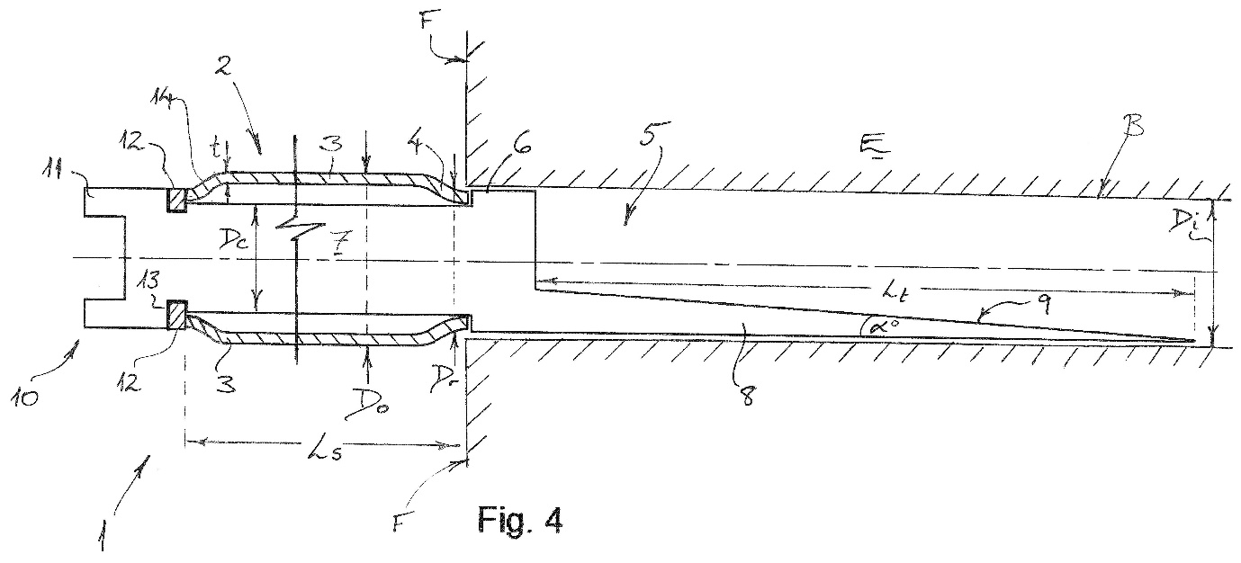
20 To grasp the Appellant’s point about this it is necessary to detour through the differences between the embodiment depicted in Figures 2 and 3 and the embodiment depicted in Figure 4. The first embodiment is depicted in two different positions, one with the anchor member located outside the bore but with the impact reduction member within the bore (Figure 2) and the other with the anchor member fully inserted into the bore hole (Figure 3). The second embodiment is depicted only with the impact reduction member fully inserted into the bore hole and the anchor member outside the bore (Figure 4). The notational references for all three figures are largely the same. Figures 2, 3 and 4 are as follows:
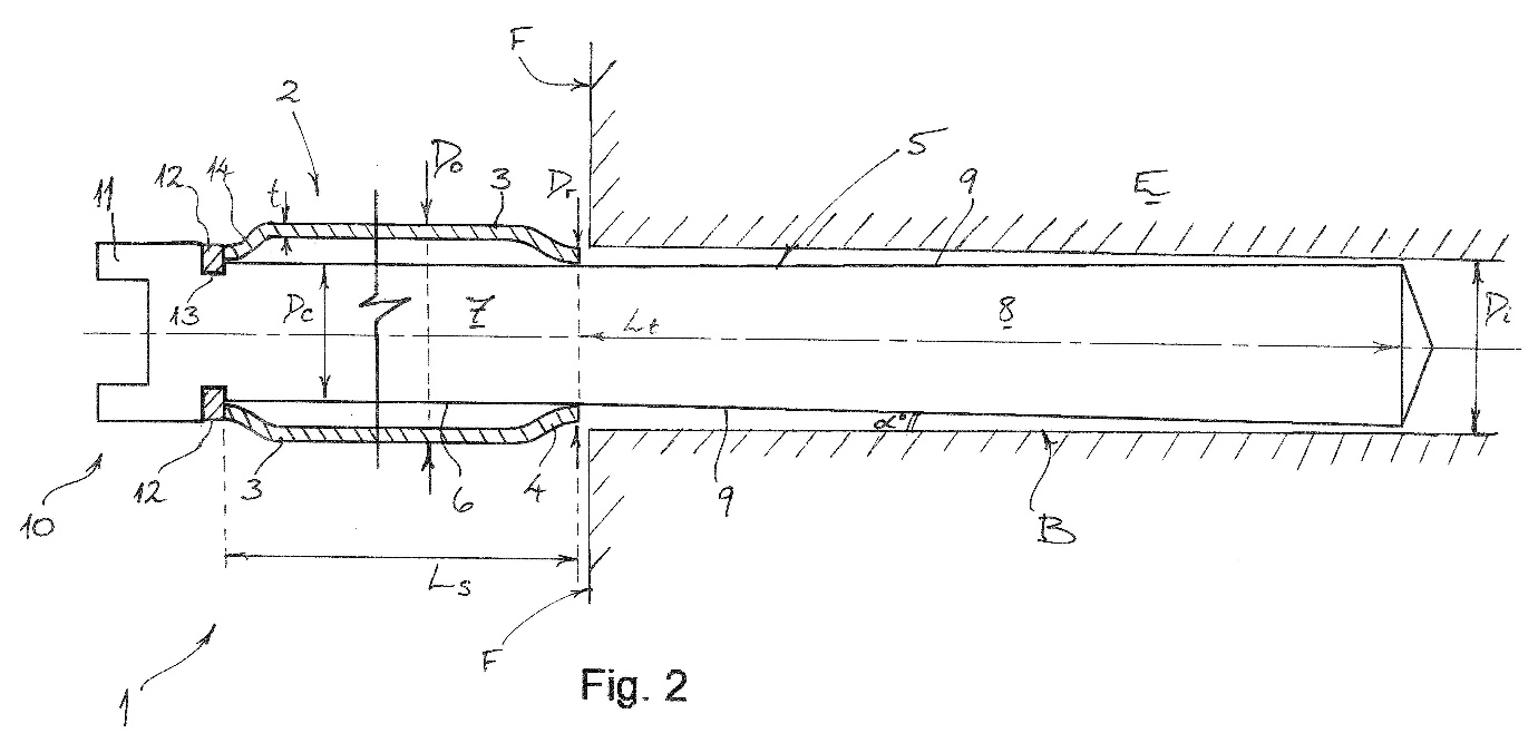
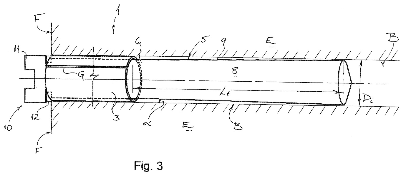
21 For present purposes it is to be noted that the detailed description of the embodiments in the specification explains that:
(a) the impact reduction member is numbered ‘5’;
(b) the anchor member is numbered ‘2’;
(c) the anchor member consists of a ‘split’ tube formed from a round steel tube or pipe which is numbered ‘3’;
(d) the split in the tube is a gap which extends longitudinally along the tube and is only illustrated at ‘G’ in Figure 3;
(e) the diameter of the split tube (‘Do’) is larger than the diameter of the bore hole (‘Di’);
(f) however, the diameter of the split tube at the front end of the anchor member (‘Dr’) is smaller than that of the bore hole (‘Di’) which permits it to be inserted into the bore hole;
(g) when the part of the split tube which is wider than the diameter of the bore hole reaches the bore hole it is able to contract as it is forced in (because of the presence of the gap or slit at ‘G’), thus enabling it to maintain a friction fit inside the bore;
(h) the difference between Figures 2 and 3 demonstrates how the predominantly wider split tube is forced into place in the narrower bore hole; and
(i) in each figure the impact reduction member has a taper of α° although it will be seen that the nature of what is tapered is quite different as between the two embodiments.
22 In the case of the embodiment in Figures 2 and 3, the central idea is that when the falling drill rod section hits the impact reduction member (in both figures travelling from the right) it drives the impact reduction member into the anchor member. The deeper into the anchor member the tapered impact reduction member travels the greater its girth becomes and the more outward pressure it exerts on the steel tube of the anchor member. This, at first, retards and, then, ultimately stops the movement of the impact reduction member.
23 It is not in dispute that on and shortly after impact, the anchor member in the embodiments depicted in Figures 2 and 3 would move by no more than a few millimetres. In these embodiments, there is significant movement of the impact reduction member relative to the anchor member so as to achieve a ‘gradual or extended transfer of impact loading’ to the anchor member: 556 Patent at p 10 line 27 to p 11 line 12.
24 By contrast, the embodiment in Figure 4 works in a different way. In this embodiment, it will be seen that the impact reduction member is different to the impact reduction member in the embodiment in Figures 2 and 3. Whilst both impact reduction members may be said to be tapered, their retardant action differs. In Figure 4, the retardant action of the tapered impact reduction member derives from its interaction with the falling drill rod section which is forced into contact with the bore wall the further down the tapered impact reduction member it travels. In this embodiment, the anchor and impact reduction members do not move relative to each other. In the embodiment in Figures 2 and 3, by contrast, the retardant action of the impact reduction member derives from its movement relative to, and consequent interaction with, the anchor member.
25 The debate between the parties about the Figure 4 embodiment is whether the anchor member in Claim 1 provides braking action by itself travelling down the bore hole. A proposition which sounds as though it answers this question but which does not is that the anchor member, in the event that it did travel down the bore, would provide braking action in the course of doing so. The debate between the parties concerns how the anchor member in Claim 1, properly construed, in fact operates. This deceptively similar proposition is, by contrast, a theoretical statement about what would happen if the anchor member in Claim 1 did in fact travel down the bore hole. It takes as its point of departure an assumption that the anchor member in Claim 1 does, in fact, travel down the bore and, hence, assumes the answer to the question under consideration. Here the important point is that proof that an anchor member driven down a bore hole provides braking action through frictional force is not proof that this is, in fact, what the anchor member in Claim 1, properly construed, is intended to do. A sofa tied to the back of a car will operate to retard its forward progress but this tells one nothing about the sofa’s intended purpose.
26 There was evidence of this theoretical kind that an anchor member, if driven down the bore hole, would provide frictional braking force. At trial the Appellant called Mr Davison, an expert in mining engineering, and he gave evidence to this effect at [109] of his affidavit (‘…it remains the case that any movement of the safety system will have the effect of absorbing the kinetic energy from the falling drill rod’). The Respondents called Dr Fuller, a geotechnical engineer who is also an expert in mining engineering. He accepted that if the anchor member in Claim 1 was not required to keep the Safety System in place when struck by a falling drill rod section, the effect of its movement down the bore hole would be to brake the motion of the falling drill rod section (I discuss this evidence in more detail below). However, neither Mr Davison’s nor Dr Fuller’s evidence to this effect is evidence that the anchor member in Claim 1 is intended to retard the motion of the falling drill bit by travelling down the bore hole.
27 On the actual question between the parties of whether the anchor member in Claim 1 could, when struck by the falling drill rod section, travel down the bore hole and thereby provide braking action, there was also evidence. The Appellant submits that this evidence showed that the anchor member in Claim 1 could travel down the bore hole once struck by a falling drill rod section and thereby contribute to slowing the falling drill bit by the generation of frictional force between the anchor member and the bore wall. For the following reasons, I do not accept that the evidence established this proposition. It comprised two different portions of testimonial evidence.
28 The first portion consisted of evidence from Mr Davison at [42] of his affidavit that the anchor member performed ‘the role of locating and holding the safety system in position in the bore until such time as it may be struck by a falling drill rod section’. If accepted, this evidence left open the possibility that after the Safety System was struck by a falling drill rod section the anchor member ceased to hold the Safety System in place. If read that way, one might extract from it that from that point on (i.e. during the impact event) the anchor member might travel down the bore hole and thereby generate frictional force. It is not entirely clear to me that Mr Davison really did go so far as to say this but, in any event, it is not necessary to determine whether he did so because Mr Davison himself abandoned any such contention.
29 This he did in the Joint Expert Report at p 2 where he indicated for the purposes of clarity that he did not mean in [42] of his affidavit that the holding function of the anchor member was performed ‘only until such time as it may be struck by a falling drill rod section’; that is to say, the holding function of the anchor member continued after the Safety System was struck by the falling drill rod section. As such, Mr Davison’s evidence did not establish that the anchor member in Claim 1 slowed the falling drill rod section by travelling down the bore and generating frictional force.
30 The second portion of testimonial evidence relied upon by the Appellant came from Dr Fuller. Dr Fuller’s evidence was that the anchor member in Claim 1 did not travel down the bore hole. In his third affidavit at [8], Dr Fuller said, in response to Mr Davison’s statement at [42] to which I have just referred, that ‘To the contrary, the specifications of each of the Patents disclose to me that the purpose of the anchor member is to hold the safety system in place both before and during the impact from a falling drill rod section.’
31 However, Dr Fuller was cross-examined about this and the Appellant submits that in his cross-examination he conceded the anchor member in Claim 1 could retard the motion of the falling drill rod section by moving down the bore hole during the impact event.
32 The cross-examination took this course: first, the cross-examiner, Mr Smith, endeavoured to have Dr Fuller agree that a feasible mode of operation for the Figure 4 embodiment was one which involved the anchor member in a degree of ‘downhole movement’ which Dr Fuller rejected (‘No, I don’t agree’): T214.24-214.28.
33 Secondly, Mr Smith then embarked on a series of questions about the alleged infringing product, the SafetySpear. Here it is useful to know that the SafetySpear has three plastic rings which do indeed retard the movement of the falling drill bit by travelling down the bore. The nub of the debate between counsel and Dr Fuller concerned Mr Smith’s suggestion that since the SafetySpear had the same purpose as the Figure 4 embodiment it was logical that the anchor member in Figure 4 could also travel down the bore. Cutting out some unnecessary detail, Dr Fuller declined to go down this path with Mr Smith on the basis that it wrongly assumed that the three rings in the SafetySpear were anchor members within the meaning of Claim 1 which, in his view, they could not be since they moved when the anchor member in Claim 1 could not: T215.10-215.23.
34 Thirdly, Mr Smith then suggested that Dr Fuller was basing his understanding of the Figure 4 embodiment on his interpretation of the word ‘anchor’, a proposition with which Dr Fuller agreed at T215.31.
35 Fourthly, Mr Smith then sought to elicit what Dr Fuller’s understanding of the Figure 4 embodiment would be if the word ‘anchor’ were omitted from the 556 Patent. This elicited an objection from Mr Cordiner who appeared for the Respondents at trial. The debate occupies a page or so of the transcript. The primary judge expressed the view that Mr Smith’s question did not appear to be particularly relevant but permitted it anyway: T217.11-217.12. The question was then asked again. There was a further objection which, after some back and forth, was withdrawn and the final form of the question was put at T218.22-218.26 in these terms:
MR SMITH: And what I’m suggesting to you is, putting the word “anchor” to one side and just considering how that might work in practice, that a sensible mode of operation for [the Figure 4 embodiment] is that it might resist that falling drill rod by slowing it down to a stop, including by the lower section moving down through the bore with frictional resistance.
36 Before committing himself to answering this question Dr Fuller indicated a desire to know where the anchor member was located in the bore; in particular, whether it was flush with the rock face or whether it was further up the bore hole. His concern was that if it was installed at the rock face then any downward movement would reduce its ‘capacity’ (T218.33-218.35) by which it may be assumed he meant that the anchor member would, to some extent, no longer be in the bore and hence would have reduced frictional resistance (or, one imagines, if it went far enough, none apart from that afforded by the air through which it would then be falling). Mr Smith adjusted his question to overcome this point by inviting Dr Fuller to assume that the anchor member was located two metres within the bore.
37 Dr Fuller then accepted that in this case the anchor member would act to slow down the falling drill rod section. Dr Fuller’s full answer was at T219.5-219.6 and included a caveat:
DR FULLER: Yes, it would slow it down. But whether it would slow it down sufficiently to stop it, I don’t know.
38 Thus Mr Smith was successful in winning from Dr Fuller the concession that if the patent did not contain the word ‘anchor’ and if the not-the-anchor member were inserted two metres into the bore, it was possible that the not-the-anchor member would slow down the falling drill rod section by travelling down the bore although whether it would slow the drill rod section sufficiently so as to stop it was not known. As I have observed above, this evidence demonstrated that if the anchor member did travel down the bore after it had been struck it would generate frictional force with the bore wall and retard the downward motion of the descending drill rod section. But, as I have also indicated above, that was not the question to which the case gave rise which was instead whether the anchor member in Claim 1 was intended to travel down the bore hole or remain fixed in place.
39 Thus, I do not accept that there was any evidence from Mr Davison or Dr Fuller on that question. Necessarily, I reject the Appellant’s allied contention that the trial judge had overlooked this non-existent evidence. The primary judge referred to this debate, such as it was, at J [113]-[114]:
113 Second, Jusand criticised Dr Fuller’s reasoning which it said was based on the particular embodiment shown in Figure 2. According to Jusand, Dr Fuller read down the disclosure in the Patents to fit with his assumed meaning of the word “anchor”. Jusand submitted that Dr Fuller read the Patents with an assumption that the patentee intended to exclude from the scope of its monopoly embodiments that Dr Fuller recognised in cross-examination would feasibly work so as to achieve the object of the Patents.
114 In cross-examination Dr Fuller agreed that down-hole movement of an anchor member would absorb energy. When Dr Fuller was asked to consider the embodiment shown in Figure 4, he understood that it did not rely on the same principle shown in the Figure 2 embodiment, and that it relied solely on its frictional engagement with the bore walls. It would therefore have a more constant capacity to resist downward movement.
40 It is true her Honour did not refer to the detail of the cross-examination set out above but the reasons show that her Honour was perfectly aware that the Appellant was putting a case on the Figure 4 embodiment. Whilst it is true that her Honour did not refer to the concession that Mr Smith had won from Dr Fuller this is because that concession did not relate to what the anchor member in Claim 1 meant but to the theoretical (and, as the Respondents correctly submitted, irrelevant) question of whether an anchor member driven down a bore hole generates frictional force with the bore wall and hence retards the falling drill rod section.
41 Another way of seeing why this is so is to observe that what Dr Fuller accepted, with a caveat, was that if the word ‘anchor’ did not appear in Claim 1 then he would accept that the anchor member in Figure 4 could operate to break the falling drill rod section by travelling down the bore hole. For this evidence to be of any use, it was necessary for the hypothesis on which the evidence rested to be made good. That hypothesis was that Claim 1 did not use the word ‘anchor’. That hypothesis could never have been made good. Whilst I well understand on pragmatic grounds why the primary judge permitted this line of questioning to proceed, there was never any possibility that it was relevant since there was never any possibility that Claim 1 did not have the word ‘anchor’ in it. Her Honour’s presentment that this evidence was probably not relevant at T217.11 was therefore correct.
42 Turning then to the principal complaint into which this debate feeds, the Appellant submits that the trial judge erred in referring to parts of the specification which were notable in their failure to refer to any movement of the anchor member and contrasting those with the frequent references to the movement of the impact reduction member. The Appellant argues that the parts of the specification referred to by the primary judge were all parts which concerned the embodiment in Figures 2 and 3.
43 However, as will shortly appear, the primary judge explicitly relied upon parts of the specification dealing with Figure 4 to reach the conclusion that the anchor member could not move. The analysis began at J [125] with the observation that ‘No movement of the anchor member relative to the rock-face or the bore is described in the context of the functioning of the embodiments in Figures 3 and 4.’ Her Honour then referred to a part of the specification which said:
In [the Figure 4] embodiment, however, the impact reduction member 5 is not configured for any significant movement relative to the plug member 2 upon impact by the falling broken drill rod section S. Rather, as the falling broken drill rod section S initially impacts or contacts the surface 9 of the tapered portion 8, the drill rod section S is gradually deflected towards and into contact with the opposite inner wall of the bore B. This contact generates friction which acts to brake the falling object and dissipate the impact. Again, therefore, the tapered portion 8 acts to cause gradual or extended transfer of impact loading from the drill rod section S to the anchor member 2. In particular, by extending the stopping distance for the falling drill rod section S (i.e. the distance travelled by the drill rod section S after initial impact) via the tapered portion 8, the impact force is again reduced significantly, such that the friction fit or interference fit of the anchor member 2 within the bore B can readily withstand the impact loading.
44 The trial judge referred to this passage at J [128] as part of her Honour’s discussion of why the anchor member could not move. What is striking about the final sentence is its reference to the ‘friction fit or interference fit’ of the anchor member in the Figure 4 configuration which her Honour explicitly mentioned at J [128]. Thus, the contention that the trial judge overlooked the Figure 4 embodiment in concluding that the anchor member did not move is not correct.
45 The highest one can put the Appellant’s case is its submission that the patent contains no express direction that the anchor member cannot move. However, as the trial judge was astute to observe, it just as equally lacks any suggestion that the anchor member should move: J [125]. And, in relation to the Figure 4 embodiment, the references to the ‘friction fit or interference fit’ of the anchor member are slim pickings indeed for a contention that the anchor member was intended to operate by travelling down the bore hole.
46 The next step in the argument was that her Honour had failed to bring to account the evidence that the embodiment in Figure 4 could travel down the bore. However, this was the evidence of Mr Davison and Dr Fuller to which I have referred and, as I have explained, was evidence of the theoretical retardant effect of the anchor member if driven down the bore hole rather than evidence that this was what the anchor member in Claim 1 was intended to do.
47 There is also the point made by the trial judge that the anchor member was to be ‘fixed’ when installed: J [145]. The Appellant’s riposte to this is that it does not entail that the anchor member must remain fixed once struck by the falling drill rod section. However, there was no evidence for this view. As I have explained above, Dr Fuller denied it and whilst Mr Davison had initially suggested that the anchor member’s fixation purpose ceased once the impact event began he retreated from this in the Joint Expert Report.
48 Next the Appellant submitted that the primary judge found at J [98] that the person skilled in the art would understand that the two components of the Safety System operate together to absorb the energy of the falling drill rod section. What her Honour said at J [98] was this:
In the context of the Patent, the person skilled in the art at the priority date would understand:
• The hazard posed by the falling broken drill rod is extreme and potentially fatal;
• The only way identified in the Patents to protect against the hazard is to stop the broken drill rod section from leaving the bore hole;
• The safety system of the Patents must stop the drill rod section falling from the bore each time;
• The impact force from a falling drill rod section, which is primarily a function of drill rod section size, weight, drop length and bore angle, is substantial, in the order of up to possibly hundreds of tonnes;
• A different safety system may be required for bores of different diameters;
• Stopping the falling drill rod section will involve absorbing the energy of and decelerating the falling drill rod section; and
• The one safety system will need to work for the all the potential forces up to the maximum possible impact force potentially experienced in a bore hole; i.e. whether the drill rod falls from a short distance or from the far end of the bore hole.
49 This is an overall description of how the Safety System works and does not descend into the detail of which component does what. In particular, it does not say that the anchor member is intended to generate frictional force by travelling down the bore. As such, it does not advance the Appellant’s submission.
50 Thus there is nothing in the Appellant’s submission that the person skilled in the art would understand that the anchor member described in the Figure 4 embodiment would decelerate a falling drill rod section as the anchor member moved downwardly against the frictional resistance of the bore wall. It follows that the Appellant is not correct to submit that the Figure 4 embodiment taught powerfully that the anchor member could travel down the bore. To the contrary, as the Respondents correctly submitted, this is precisely what it does not show.
(b) Significance of the words ‘readily withstand’
51 At p 10 line 27 to p 11 line 12 of the 556 Patent this passage appears:
In this embodiment, the impact reduction member 5 is configured for movement relative to the plug member 2 upon impact by the falling broken drill rod section S. That is, the body 6 of the impact reduction member 5 is configured for movement into an interior of the plug member 2 if impacted or struck by the drill rod section S. In this way, the outer surface 9 of the tapered portion 8 of the body 6 contacts and bears against an inner surface of the split tube 3. As an initial impact by the broken drill rod section S drives the elongate body 6 downwards into the split tube 3, the slight taper of the tapered portion 8 exerts an outward force on the split tube 3 and thus enhances or increases engagement between the bore B and the tube 3. The tapered portion 8 thereby acts to effect a gradual or extended transfer of impact loading from the broken drill rod section S to the plug member 2. In particular, by extending the stopping distance for the falling drill rod section S (i.e. the distance travelled by the drill rod section S after initial impact) via the tapered portion 8, the impact force is reduced significantly, such that the friction fit or interference fit of the anchor member or plug member 2 within the bore B can readily withstand the impact loading. In this way, the safety system 1 of this embodiment can effectively and reliably protect workers and/or equipment in the cavity C from the hazard of broken drill rod sections S falling from a bore B drilled above horizontal.
52 The equivalent passage in relation to the Figure 4 embodiment at p 12 line 29 to p 13 line 9 is set out above and contains a relevantly identical reference to the anchor member being able to ‘readily withstand the impact loading’ from the falling drill rod section.
53 The Appellant submits that the primary judge was wrong to conclude the phrase ‘readily withstand’ was inconsistent with the notion that the anchor member could move substantially down the bore hole. Rather, it submits that in the context of the Safety System it is clear that the phrase refers not to the anchor member absorbing the impact loading from the falling drill bit but to the fact that the Safety System provides protection from the hazard of drill rod sections falling from the bore.
54 The trial judge examined this issue at J [127]-[129]. Her Honour noted that in both embodiments the impact reduction member was said to reduce the impact force of the falling drill bit such that the friction fit or interference fit of the anchor member could thereby ‘readily withstand the impact loading’. At J [129] the trial judge observed that ‘withstanding does not connote substantial movement’.
55 This observation is, with respect, plainly correct. A building does not ‘withstand’ cyclonic winds by falling over once buffeted by them but, rather, by staying upright. So too, it is difficult to see how the anchor member can be said to ‘withstand’ the depredations of the falling drill rod section if its first reaction is to slide down the bore hole the moment it is struck. The Appellant’s answer to this was that ‘readily withstand’ referred not to the anchor member but was instead to be understood ‘in the context’ that the Safety System provided protection from the hazard of drill rod sections falling from the bore. The use here of the expression ‘in the context’ is a retreat into the dim language of vagueness. By its vagueness the submission impermissibly evades committing itself to the identity of the object which does the act of readily withstanding. When the vagueness is dispelled, the problem with the submission is that the sentences at p 11 line 9 and p 13 line 9 explicitly identify what readily withstands the impact. It is the friction fit or interference fit of the anchor member. I therefore reject the submission.
(c) The significance of whether the Safety System needed to work whilst flush with the rock face
56 Part of the trial judge’s reasons for concluding that the anchor member could not move more than a de minimis distance once struck concerned an observation her Honour made at J [131] that the invention depicted in Figure 3 needed to work whilst flush with the rock face (‘If there was any more than de minimis movement in that example, it is possible that the safety system would fall from the bore hole.’). That statement was made in the course of her Honour’s consideration of the meaning of ‘anchor member’. In another part of the reasons, her Honour dealt with the meaning of ‘a proximal end region of the bore adjacent to a rock-face’; the discussion of which began at J [151]. The Appellant relies on a passage in that discussion appearing at J [178] which, so it submits, shows that the trial judge was wrong to approach the construction of ‘anchor member’ on the basis that the Figure 3 embodiment had to be installed flush with the rock face. Why? Because when considering what was meant by ‘a proximal end region of the bore adjacent to a rock-face’ her Honour had accepted that the Safety System (and hence the anchor member) did not need to be installed flush with the rock face.
57 The passage the Appellant relies upon is at J [178]:
Figure 3 of the Patent shows the installation of an embodiment of the safety system with its base at the rock-face. I agree with Rattlejack that the safety system of the invention as illustrated in Figure 3 is installed “flush” with the rock-face. I also agree that the safety system of the invention must work in the installed position illustrated in Figure 3. However, the claims are not limited to the embodiments and the specification describes friable rock at the bore entry point and the need to insert the safety system into more competent rock. In that situation the base of the safety system will not be, and nor do the claims require it to be, flush or substantially flush with the rock-face.
58 The reference to ‘competent rock’ requires explanation. This the trial judge had provided at J [169]-[170]:
169 Dr Fuller’s evidence was that the first 10 to 15 cm of rock in the bore (ie the rock that constitutes the collar and the initial short length of the bore) can be damaged during the process of blasting to create the tunnel. The strength of that rock can be reduced, so in order to act as an anchor, Dr Fuller considered that the anchor member of this system would need to be at least partly in rock above the blast damage zone.
170 Mr Davison’s evidence was to similar effect: that the quality of the rock at the lowest end of the bore hole may be compromised and unstable because of the blasting to create the stope, the natural quality or stability of the rock and/or the stresses and strains at the rock-face. Furthermore, in the joint report Mr Davison agreed that there might be bad ground conditions at the “rock-face/mine opening interface”. I assume from his earlier evidence and the context of his comment in the joint report that Mr Davison’s reference to “mine” opening meant the opening of the bore hole at the rock-face. Mr Davison did not give an estimate of the length that the damaged rock might extend up the bore hole.
59 Thus the point was that the blasting process may make the first 10-15 cm of rock unreliable for anchoring purposes. As her Honour observed at J [172] the specification contemplated this situation at p 12 lines 3-6:
This may be particularly useful where the rock at the rock face F is friable or crumbing, because it enables the safety system 1 to be driven deeper into the bore B beyond the rock face F where it can be soundly founded in competent rock.
60 Returning then to J [178], contrary to the Appellant’s submission, her Honour did not accept that the embodiment in Figure 3 was to be installed other than flush with rock face. On the other hand, the trial judge accepted that the Safety System could be installed some way up the bore hole to avoid the problem of friable rock (noting that the embodiment in Figure 3 is a particular example of the Safety System). The immediate point of J [178] was to reject the Appellant’s contention that ‘a proximal end region of the bore adjacent to a rock-face’ merely identified in which half of the bore the Safety System was to be installed (the proximal as opposed to the distal end, as Mr Caine put it). But there is no doubt that J [178] proceeded on the basis that the anchor member was to be fixed because her Honour accepted the Respondents’ submission that ‘the safety system…must work in the installed position illustrated in Figure 3’.
61 Returning then to the suggested tension between J [131] and [178], I do not accept that there is any tension. The discussion at J [131] concerns the Figure 3 embodiment whereas the critical statement at J [178] upon which the Appellant now relies is about the meaning of the claims. Both paragraphs recognise that the Figure 3 embodiment works flush with the rock face but her Honour’s point at J [178] is that this is not a requirement of the claims and that the passage at p 12 lines 3-6 shows that the invention as claimed does not need to be inserted so that it is flush with the rock face.
62 Further, J [131] is also clear that the claims of the patent do not require the invention to be installed flush with the rock face (‘The embodiment of the invention shown installed in Figure 3 needs to work while flush with the rock-face, even if it is not required to be installed there.’). The critical idea which appears at both J [131] and [178] is that the Safety System must not, under any circumstance, fall out of the bore hole. At J [131] so much is explicit for it is there stated that any more than de minimis movement of the anchor member would mean that it was ‘possible that the safety system would fall from the bore hole’. At J [178] it is implicit in the statement that the Safety System ‘must work in the installed position illustrated in Figure 3’.
63 Once that is accepted, there is no tension between J [131] and [178] and the suggested error in the trial judge’s approach to the meaning of ‘anchor member’ does not arise. The invention depicted at Figure 3 is installed flush with the rock face. But the invention itself is not so limited. Friable rock may require it to be installed further up the bore. But the fact that the invention at Figure 3 is installed flush with the rock face demonstrates that the anchor member referred to in the claims cannot move by more than a de minimis amount. If it did, it would fall out of the bore hole and the Safety System would not be a safety system at all. The nature of the anchor member does not vary depending on how far into the bore hole the Safety System is inserted for there is no conceivable peg in the language of Claim 1 for such a differential operation. Consequently, if the anchor member does not move in the form of the invention in Figure 3, it does not move when the Safety System is inserted further into the bore hole.
(d) ‘Fixed’ like a ‘rock anchor’
64 The trial judge relied on references in the 556 Patent to the anchor member being ‘fixed’ in the bore like a ‘“split-set” type rock anchor’ to support the conclusion that the anchor member does not move substantially. There are two such references in the patent. The first is at p 4 lines 2-5:
In this way, the anchor member or plug member comprising the split tube can be fixed in the proximal end region of the bore adjacent the rock-face in a friction fit or an interference fit, in a manner similar to that known for a “split-set” type of rock anchor.
65 The second reference is at p 9 line 32 to p 10 line 3:
In this way, the plug member 2 comprised of the split tube 3 can be fixed in the proximal end region E of the bore B adjacent the rock-face F in a friction fit, in a manner similar to that known for a “split-set” type of rock anchor.
66 The trial judge concluded at J [129] that the first passage also ‘supported[ed] a construction where the anchor member does not move substantially’. The Appellant submitted that the trial judge had erred in thinking that the reference to the anchor being fixed in a manner similar to that known for a ‘split-set’ type of rock anchor threw any light on whether the anchor member, once struck by the falling drill bit, could move. On this view, the statement at p 4 lines 2-5 was concerned not with the behaviour of the anchor member after impact but rather with the manner in which the Safety System was installed in the first place.
67 This submission cannot survive the findings at J [137]-[138]:
137 Mr Davison’s initial construction would have the anchor member functioning as an anchor only until it is hit by falling drill rods, at which point it could cease to operate as an anchor and instead slide down the bore. There is nothing in the Patents to support that construction.
138 However, in the joint report, Mr Davison clarified his position. He did not mean that the anchor member held the safety system in place only until such time as it may be struck. He agreed that the anchor member may move by “a few millimetres or more”.
68 Thus the patent provides no warrant for reading ‘anchor member’ as importing different behaviours before and after the descent of the falling drill rod section (as indeed Mr Davison accepted in the Joint Expert Report). The Appellant then submitted that there was no evidence at trial that a ‘rock anchor’ would not move at all when subjected to a sudden load. This is true, however, the trial judge did not say that a rock anchor could not move. Her Honour’s reasoning about rock anchors was not concerned with their peripatetic qualities but rather with whether the word ‘anchor’ was known and used in the mining industry. That this is so is clear from J [143]-[144] where her Honour referred to evidence from Mr Davison concerning a patent he had filed in relation to a ‘split-set anchor’:
143 Mr Davison referred to “split-set anchors” and “a split-set (rock anchor) product” in his written evidence. The term “anchor” is also used by Mr Davison in the specifications of the patents and patent applications for his inventions relating to rock bolts.
144 One example of Mr Davison’s “developments and innovations” relates to a grouted friction stabiliser which uses grout to improve the frictional performance of “split-set anchors” by a factor of about four. That invention is the subject of Australian Patent no. 2014295889 which is entitled “A grouted friction bolt”.
69 It will be seen that the discussion about the split-set anchor fed into her Honour’s consideration of what the word ‘anchor’ meant at J [145]. Mr Davison’s evidence about the split-set anchor was at [17] of his first affidavit and was in these terms:
In the course of my work I have also been responsible for a number of developments and innovations, including several that have been the subject of patent applications and granted patents. A list of the Australian versions of those applications and granted patents is Annexure GRD-3 to my affidavit. Those innovations include a grouted friction stabiliser, which uses grout to improve the frictional performance of split-set anchors by a factor of about four. That product has been commercialised by Gazmick Pty Ltd, of which I am a director. Gazmick licenses its patents to manufacturers who supply the products to mines.
70 GRD-3 was not included in the appeal papers and neither party took the Court to it. What the trial judge then did with Mr Davison’s evidence about rock anchors appears at J [148] which, with respect, is expressed with some care:
Whilst the safety system described and claimed in the Patents is taken to be new and innovative, it is not a new invention of the kind where the patentee is struggling to find the words to adequately describe the concepts involved. The term “anchor” is known and used in the mining industry in the context of fixings. The specification itself makes reference to the friction fit of the anchor member or plug member in the bore being in a manner similar to that known for a “split-set” type rock anchor. In choosing to describe the safety system, the patentee chose to describe the lower member as an “anchor member”, not a braking or checking or restraining member. If the patentee intended to claim a safety system that was held in place until it was struck by a falling drill rod and then moved down the bore hole to eventually stop the broken drill rod from falling out of the hole, there were more apt words available than “anchor”.
71 The trial judge’s conclusion was not that rock anchors could not move. Rather it was that the word ‘anchor’ was known and used in the industry in the context of fixings. That statement is consistent with the evidence of Mr Davison who had himself filed a patent using the expression. Thus, whilst it may be accepted that there was no evidence about whether rock anchors did or did not move, this was not the use to which her Honour put the evidence. Her Honour’s point at J [148] was that the patentee had chosen to use the word ‘anchor’ and that the use in the industry of that word as relating to fixings made it inapt to describe an invention that had a twofold operation; that is to say, an operation where it first fixed the Safety System in place and then, once struck by the falling drill rod section, moved down the bore hole. As such, I do not accept that her Honour erred in the manner suggested by the Appellant.
(e) Suitable for every use
72 The Appellant submitted that in weighing the competing constructions of a patent claim, it is proper to look through the tutored eye of the person skilled in the art and to construe the claim with ‘a generous measure of common sense’: Product Management Group Pty Ltd v Blue-Gentian LLC [2015] FCAFC 179; 240 FCR 85 at [36] per Kenny and Beach JJ. Thus the person skilled in the art would know that the purpose of the specification is to describe and demarcate the invention. So much may be accepted.
73 Next the Appellant submitted that a common sense approach would include an understanding of the circumstances in which the Safety System would be used and the implications of those circumstances. In that regard, the patent was silent on the conditions under which the claimed movement of the anchor member should be assessed. This was said to recognise the practical reality that the circumstances in which the Safety System would be used could vary greatly. For example, how the Safety System operated in a 5 m bore hole which was closer to the horizontal than it was to the vertical was obviously very different to how it might operate in a bore hole consisting of a vertical shaft of 60 m where the impact force would be very considerable.
74 This mattered because the person skilled in the art would also recognise that the patentee would not have intended to have defined the Safety System in such a way as to exclude commercially useful products. In the example of the vertical 60 m bore hole, it might well be commercially useful to permit the anchor member to move by more than a de minimis amount.
75 I do not accept this submission. As the trial judge correctly observed in the last bullet point of J [98] (set out above) the Safety System needed to work ‘for all the potential forces up to the maximum possible impact force potentially experienced in a bore hole; i.e. whether the drill rod falls from a short distance or from the far end of the bore hole’. The Appellant criticised this statement by submitting that it amounted to a statement that the patent was to be construed as requiring that a single Safety System product should be suitable for every conceivable use.
76 The trial judge made no such error. The terms of the patent itself demonstrate that the Safety System was intended to be used in bores of variable lengths and at varying angles from the horizontal. Under the heading ‘Detailed Description of the Embodiments’ the patent referred to Figure 1:
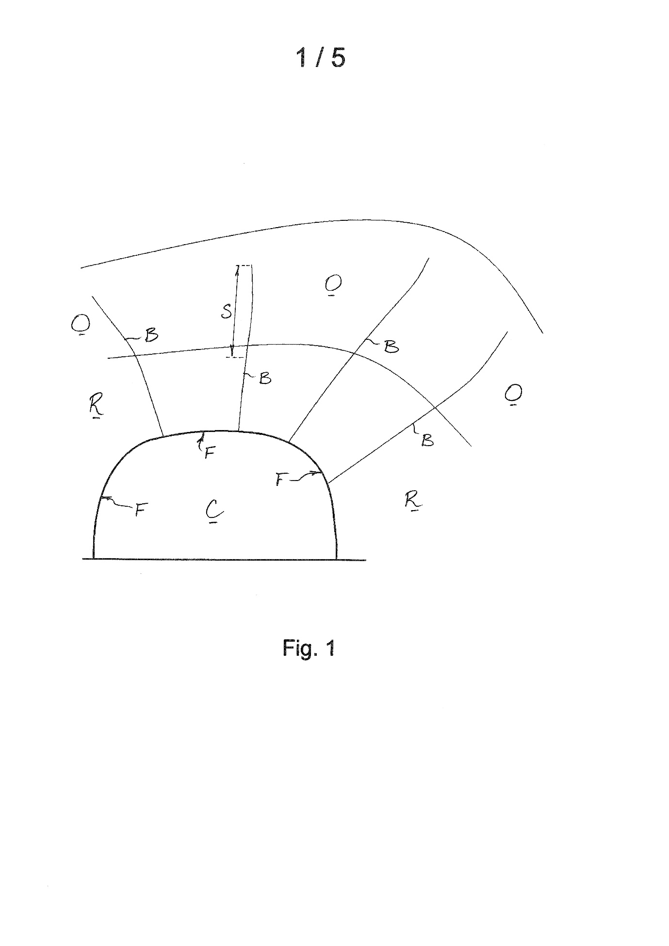
77 At p 8 line 31 to p 9 line 12 this explanation of the bore B is given:
When drilling the multiple bores B upwards into the rock strata R towards the ore body O, the individual bores drilled are often tens of metres long (e.g. in the range of 20 to 60 metres) and the drill rods (not shown) which extend over that length may have a diameter of about 80 millimetres. As the composition and properties of the rock strata R typically varies through its depth, and in any case in comparison to the composition and properties of the ore deposit O, the drill rods are subjected to varying and unpredictable loading during the drilling of each bore B. Failure or breakage of a drill rod is not uncommon when multiple bores B are being drilled to lay the explosive charges above the cavity C. Thus, a section S of drill rod, which may, for example, be 20 or 30 metres long with a mass in the range of 100 kg to 500 kg, may be left in the bore B extending above the cavity C presenting a major hazard to personnel and/or equipment in the cavity C, as this massive broken drill rod section S could unexpectedly fall out of the bore B.
78 It is clear from Figure 1 and this passage that: first, the invention is intended to be used in bores between 20 m and 60 m long and with drill rod sections weighing up to 500 kg; and secondly, that the bore holes will be of varying angles from the horizontal. Thus it is not correct to say that by reasoning that the person skilled in the art would understand that the one Safety System had to work for all the potential forces up to the maximum impact force potentially experienced in the bore hole (as her Honour did in the last bullet point at J [98]) her Honour had thereby construed the patent as requiring that the Safety System be suitable for every conceivable use. Rather, the trial judge simply construed the patent as requiring that the Safety System be suitable for the purposes which the patent itself contemplated. The suggested error was not made by the trial judge.
Conclusions on Grounds 1-3
79 All of the challenges to the trial judge’s reasoning on the meaning of ‘anchor member’ fail. Grounds 1-3 should be rejected.
‘Configured to be fixed in a proximal end region of the bore’ (Grounds 4 and 5)
80 There are two debates between the parties in relation to these grounds. First, how far into the bore does the ‘proximal end region of the bore’ extend? The trial judge concluded that this meant ‘at or near the rock-face’ and that it extended ‘a short distance into the bore’: J [181]. The Appellant takes issue with this and submits that the proximal end region of the bore merely means the end of the bore closest to the bore opening. The second debate concerns the word ‘configured’. The trial judge found that ‘configured’ meant that ‘the anchor member was ‘put together, arranged or constructed so it is suitable for the purpose of being fixed in the proximal end of the bore’: J [175]. The Appellant submits that this conclusion does not entail that the device had, in fact, to be fixed in that location and that the trial judge had erred in concluding otherwise. I deal with these two issues in turn.
The meaning of ‘proximal end region of the bore’
81 According to Claim 1, the anchor member must be ‘configured to be’ fixed in ‘a proximal end region of the bore adjacent to a rock-face’. The Appellant and the Respondents agree that ‘proximal end region’ is not a term of art. There are four areas of debate between the parties as to the meaning of the phrase.
82 First, the Appellant submits that the ‘proximal end region’ is the end of the bore closest to the bore opening. Mr Caine for the Appellant submitted that the ‘proximal end’ was to be contrasted with the ‘distal end’ which is the end furthest from the bore opening: T31.35. Thus, the work done by the words ‘adjacent to a rock-face’ is to confirm that the proximal end of the bore is being discussed. I did not apprehend the Appellant to submit that the bore was to be considered as consisting of two halves, one being the proximal half and the other being the distal half. Rather, the point was that the bore had two ends and that ‘adjacent to a rock-face’ reinforced which end Claim 1 was talking about.
83 If read this way ‘adjacent to a rock-face’ does not say precisely where the anchor member is to be configured to be fixed but rather only for which end of the bore it is to be so configured . It would be possible on this view for the anchor member to be configured to be fixed some way up the bore but not next to the rock face so long as the place where it was configured to be fixed could still be said to be in the proximal end region of the bore. If the Appellant be correct about this, the effect of this construction is to deprive the word ‘adjacent’ in the expression ‘adjacent to a rock-face’ of its ordinary meaning of ‘next to’.
84 I do not accept that ‘adjacent to a rock-face’ operates in this manner. The language of the claim identifies that the anchor member is to be configured to be fixed at the ‘proximal end region of the bore’. Consequently, on the Appellant’s construction, ‘adjacent to a rock-face’ merely tells one something which one already knows: i.e. that the device is not to be inserted at the distal end of the bore. If the claim said that the anchor member was to be configured to be fixed at ‘an end region of the bore’ rather than at the ‘proximal end region of the bore’ then perhaps there might be something to the point. Even then, however, the Appellant would confront the difficulty identified by the Respondents that it is not possible for the anchor member to be configured to be fixed at the distal end because this is inevitably where the broken drill bit is situated. The point of the device is to absorb the force of a falling drill bit. If the device were installed snug against the broken drill bit then it could never fall and the impact reduction member would never have any impact to absorb. As such, the Appellant cannot be correct that the work to be done by the words ‘adjacent to a rock-face’ is merely to confirm the end of the bore in which the anchor member is to be fixed. I reject the argument.
85 Secondly, the Appellant submits that the patent does not teach that the ‘proximal end region’ is of any specific length. In each of Figures 2, 3 and 4 the proximal end region is denoted by the letter ‘E’ and is not specified to be of any particular length. I do not think that anything useful, at least from the Appellant’s perspective, can be obtained from these figures. In all three figures, it is true that the proximal end region of the bore is indicated by the letter ‘E’ without any accompanying explanation of what size precisely that region might be. However, I am unable to glean from Figures 2, 3 and 4 anything which suggests that the invention may be inserted a significant distance up the bore hole. They simply do not address that topic. Further, there is force in the Respondents’ contention that these figures illustrate the invention inserted (or in the case of Figures 2 and 4, partially inserted) into the bore in a zone which is necessarily the proximal end region. Insofar as Figure 3 is concerned the situation for the Appellant is no better. As Ms St John for the Respondents correctly submitted, Figure 3 shows the device inserted flush with the rock face. Whilst Figure 3 does not necessarily mean that the device must always be inserted flush with the rock face (as Ms St John recognised), it is meagre material for an argument that the proximal end region of the bore can extend substantially up the bore. I therefore reject the Appellant’s submission.
86 Thirdly, the Appellant submits that the specification accepted at p 12 lines 1-6 that where the rock face was friable or crumbling the invention could be driven deeper into the bore beyond the rock face. The relevant passage is as follows:
This configuration enables the anchor member 2 and the impact reduction member 5 of the safety system 1 to be driven into the drilled bore B beyond the rock face F. This may be particularly useful where the rock at the rock face F is friable or crumbing, because it enables the safety system 1 to be driven deeper into the bore B beyond the rock face F where it can be soundly founded in competent rock.
87 The trial judge unexceptionally accepted that this was so at J [172]. The Appellant submits, however, that the patent does not set any limit on how far it may in fact be necessary to drive the anchor member beyond the rock face in order to find competent rock. The Appellant also submitted that there was no suggestion of such a limit in the evidence.
88 This submission does not withstand scrutiny. Whilst it is true that the patent does not give a limit to how far the anchor member may be inserted into the bore, the trial judge nevertheless found at J [68] that it was part of the common general knowledge that the first 10-15 cm of rock could be damaged in the blasting process involved in the excavation of the mine corridor beneath the ore body. Her Honour reached this conclusion having accepted Dr Fuller’s evidence to this effect at J [169]. For his part, Mr Davison did not place an estimate on how far the friable rock might extend into the bore but he did accept that such a region nevertheless existed: J [170].
89 As the Respondents correctly submit, there was, therefore, unchallenged evidence about how far up the bore blast-damaged rock extended. Thus, whilst it is true that the patent is silent on how far it may be necessary to drive the anchor member into the bore to overcome the problem of blast-damaged rock, it was common general knowledge that such rock extended no more than 10-15 cm. As such, the fact that the device might be driven an unspecified distance into the bore to overcome the problem of blast-damaged rock provides no warrant for reading the patent as if it permitted the device to be driven further into the bore than would be necessary for that purpose. I would therefore reject the Appellant’s submission.
90 Fourthly, the Respondents submit that the Appellant’s construction does not answer the question which the trial judge necessarily had to answer which was how far up the bore the proximal end region extends. The trial judge asked this question at J [166] and answered that it meant ‘at or the near the rock-face’ and that it extended ‘a short distance into the bore’: J [181]. The Appellant does not cavil with the question which the trial judge posed herself but only with the answer her Honour gave. The Appellant submits that her Honour should have answered the question by saying that the proximal end region of the bore was the ‘lower region of the bore’. I agree with the Respondents’ submission that this formulation does not answer the question. Rather, it exchanges the words used in the claim with words which are not in the claim. I therefore accept this criticism of the Appellant’s construction.
91 Drawing these matters together, I detect no error in the trial judge’s conclusion at J [181] that the anchor member had to be at or near the rock face and could be located a short distance into the bore. It seems to me to have been a common-sense conclusion. The device was required to be located adjacent to the rock face. Adjacent means ‘next to’. There was a possibility that there might be friable rock due to blast damage at the rock face. In that case, the device could be inserted further until hard rock was found which could secure the anchor member. But the person skilled in the art would understand that the friable rock would extend no more than 10-15 cm up the bore. This aspect of Grounds 4 and 5 should therefore be rejected.
The meaning of ‘configured’
92 The Appellant next submits that the trial judge correctly concluded that ‘configured’ meant ‘put together, arranged or constructed’ so as to be suitable for the purpose of being fixed in the proximal end region of the bore: J [175]. Being thus configured did not, however, require the conclusion that this was, in fact, where the device was to be fixed in the bore. The Appellant therefore submitted that the trial judge erred in concluding at J [181] that the device was to be located ‘at or near the rock-face’ which encompassed ‘a short distance into the bore’. What the trial judge said at J [181] was this:
I consider that the skilled reader would understand the totality of the phrase to mean that the anchor member is configured to be fixed at the collar end of the bore, at or near the rock-face. The safety system would be located entirely within the rock part of the bore, with no part extending out into the shotcrete or mine chamber. This would encompass the anchor member being placed a short distance into the bore to be situated beyond the friable rock (if any) so as to be fixed in the competent rock.
93 The Appellant’s contention, as I understood it, relates to the second and third sentences of this passage. The question is whether one reads these sentences as throwing light on the configuration discussed in the first sentence or, instead, as statements about how the device is to be used. I think the former reading is to be preferred. It is clear that Claim 1 does not require the device to be inserted at any particular location. Rather, it requires that the anchor member be ‘configured’ to be fixed in the proximal end region of the bore adjacent to the rock face. It would be surprising if the trial judge had decided to add a requirement to Claim 1 that plainly is not there. The second and third sentences are expressed in the subjunctive mood which is quite inconsistent with the idea that her Honour was, in fact, making a statement about where the device was to be installed. The better reading of the paragraph is that her Honour set out the suitability requirement in the first sentence and that the second and third sentences are to be seen as matters going to that configuration. I therefore do not accept the Appellant’s submission about J [181].
Conclusions on Grounds 4 and 5
94 In those circumstances Grounds 4 and 5 should be dismissed. In the Respondents’ written submissions a point was taken about the wording of Ground 4. On the first day of the appeal leave was granted to file a further amended notice of appeal which overcame this problem. It is not necessary therefore to deal any further with that point.
Infringement (Grounds 7-14)
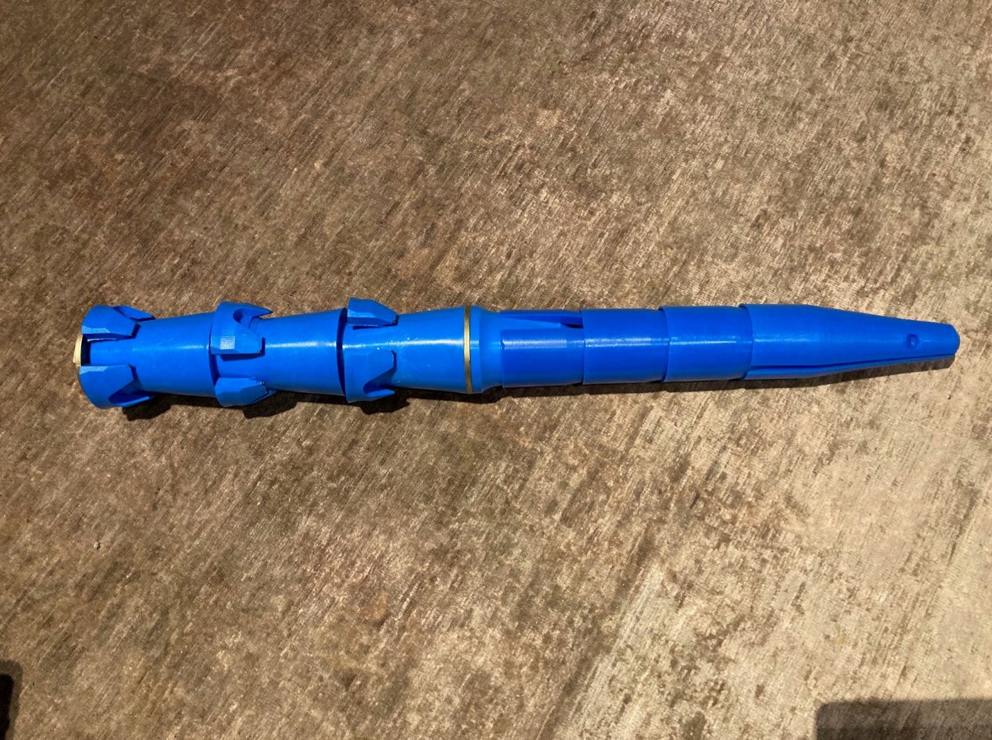
95 The SafetySpear is a large blue plug-like object made from steel and hard nylon. The instructions which accompany it suggest that it is to be installed in a bore for the purpose of preventing the egress of falling drill rod sections. The SafetySpear looks like this:
96 The Appellant claimed at trial that the SafetySpear infringed Claim 1 of the patent.
97 The first issue on infringement is whether the SafetySpear has an anchor member within Claim 1 and is comprised in Grounds 7-10. It will be observed that the SafetySpear has three plastic expansion rings along it. The Appellant claimed that the shaft of the SafetySpear was an impact reduction member (which is not in dispute) and that the plastic rings were an anchor member within the meaning of Claim 1. The debate about this concerns whether the Appellant had proved that the plastic rings travelled down the bore hole by no more than a de minimis amount when the SafetySpear was struck by a falling drill rod section. The trial judge concluded that it had not been demonstrated that the SafetySpear included a Claim 1 anchor member largely, although not entirely, because there was no experimental evidence before the Court about how the SafetySpear behaved when struck by a falling drill rod section.
98 The second infringement issue is whether the SafetySpear was ‘configured to be fixed in a proximal end region of the bore adjacent to a rock-face’ and is comprised in Grounds 11-14. The debate about this concerned how far up the bore hole the SafetySpear was suitable to be inserted and, in particular, whether it was suitable to be installed adjacent to the rock face. This issue was intertwined with the anchor member issue inasmuch as it involved the Respondents’ contention that the SafetySpear’s braking action was derived from interaction between the three plastic rings and the bore wall as the rings expanded upon the SafetySpear being driven down the bore by the force of the falling drill rod section. On this view of the SafetySpear, it travelled by more than a de minimis amount when struck by the falling drill rod section and, if this were so, installation at or near the rock face would cause it to fall out of the bore, defeating its purpose. The trial judge concluded that the Appellant had not proven that the SafetySpear was suitable to be installed adjacent to the rock face.
Whether the SafetySpear included an ‘anchor member’ (Grounds 7-10)
99 The SafetySpear includes three expansion rings which, putting the matter neutrally at this stage, operate to check the movement of the SafetySpear down the bore when struck by a falling broken drill rod section. Having correctly rejected the Appellant’s construction of the phrase ‘anchor member’ in Claim 1, the issue on infringement before the trial judge became whether these three expansion rings constituted such an anchor member. On the correct construction of that term this then devolved, as the trial judge correctly apprehended, to a factual inquiry into whether the SafetySpear moved by more than a de minimis amount of about 5 mm when struck by a falling broken drill bit. The evidence about this was scant. There was no direct evidence about how the SafetySpear actually operated and neither expert conducted any tests upon it.
100 Instead, both experts gave evidence about how they thought the SafetySpear would behave if struck by a falling drill rod section but their evidence turned on their respective inspections of the SafetySpear and their ruminations about it. Both Dr Fuller and Mr Davison agreed that the SafetySpear could move down the bore when it was struck by a falling drill rod section but they disagreed on the extent of this movement.
101 In addition to this evidence, there was evidence of some drop tests which had been conducted on a prototype of the SafetySpear in August 2020. These tests were conducted at the Carosue Dam mine by the operator of that mine, a firm associated with the Third Respondent: J [191]-[192], [201]. Leaving to one side for now what this actually means, the prototype SafetySpear passed the drop tests and subsequently the mine operator was provided with 200 of the SafetySpears which are the subject of the infringement proceeding (not being the prototype SafetySpear which was the subject of the drop tests). The person who conducted the drop tests was a project manager called Mr Spencer. Mr Spencer provided a report to the mine operator describing what the drop tests showed.
102 The trial judge concluded that the Appellant had not proven that the SafetySpear travelled by no more than 5 mm down the bore when struck by a falling drill rod section. The Appellant takes issue with three aspects of this conclusion.
First issue: the adequacy of the trial judge’s treatment of Mr Spencer’s evidence
103 The Appellant submitted that there was evidence that the SafetySpear did not move down the bore when struck by a falling drill bit. It consisted of the evidence about the August 2020 drop tests. The trial judge did not accept that this evidence showed that the SafetySpear did not move when struck by a falling drill bit: J [218]. The Appellant took issue with this conclusion. It submitted that the trial judge had decided not to accept this evidence because it was based solely on two blurry photographs. The Appellant submits that this was erroneous because there was evidence about the drop tests beyond the two blurry photographs.
104 This was Mr Spencer’s evidence about what he observed during the drop tests. Relevantly, Mr Spencer had said in his report that the SafetySpear had not budged from its original position other than very marginally. He also explained that the photographs in his report did not show the position as clearly as he had observed it.
105 There are two problems with this. First, it is not correct that the trial judge said that the test results were based solely on two blurry photos. In fact, the trial judge explicitly referred to Mr Spencer’s statements ‘to the effect that the SafetySpear had not moved during the trial’ at J [210] and to his statement that ‘the prototype had not moved substantially or budged during the drop test’ at J [215]. In the same passage the trial judge discounted this evidence because it was ‘only a rough estimation, made from where [Mr Spencer] stood below the bore hole watching the test without the benefit of any measurements other than comparing the approximate distance of a painted line on a stick from the shotcrete covered ceiling of the mine’.
106 Secondly, the trial judge also brought to account her own examination of the two photographs and reported that ‘on close inspection of the blurry enlarged photographs taken of the August 2020 drop test, there appears to be movement of the SafetySpear of more than a few millimetres (ie there is a detectable difference in the position of the pink circle)’: J [216]. Having inspected the photographs myself, I agree with the trial judge’s observation. But regardless of my view, the trial judge’s observation makes it impossible to accept that her Honour’s rejection of the utility of the drop tests was based solely on two blurry photographs. The suggested error is therefore not demonstrated.
Second issue: significance of the fact that Mr Spencer’s tests were done on a prototype of the SafetySpear which differed from the product alleged to infringe
107 The trial judge found that the prototype SafetySpear used in the drop tests was different to the SafetySpear product which allegedly infringed the patent. The difference between the prototype and the allegedly infringing product was that the prototype lacked an outwardly flared lip on the expansion rings: J [213]. Dr Fuller gave evidence that the outwardly flared lip made downward movement of the SafetySpear more likely which the trial judge recorded at J [214].
108 According to the Appellant there were two problems with this. First, the trial judge should have inferred that the SafetySpear, and not just the prototype SafetySpear, did not move more than a de minimis amount when struck by a falling drill bit. Secondly, Dr Fuller’s evidence was not based on any testing and consequently given improper weight by the trial judge.
109 I do not accept either of these submissions. As to the first, the prototype was tested at the Carosue Dam mine and the tests were successful. Based on those tests the operator of the mine was supplied with 200 of the allegedly infringing SafetySpear products (i.e. not the prototype which had been tested). The Appellant submits that neither the designer of the SafetySpear (who had arranged the drop tests) nor the mine operator considered that the SafetySpear product as supplied behaved any differently to the prototype. Since, according to the Appellant, the prototype SafetySpear had not moved more than a de minimis amount during the drop tests, it could be inferred that the supplied SafetySpear product itself did not move more than a de minimis amount.
110 There are problems with this submission. It involves the drawing of an inference from the fact that SafetySpear products were supplied to the mine operator after the drop tests. I do not accept that such an inference should be drawn. The fact that following the drop tests of the prototype the mine operator wished to acquire, and did acquire, 200 non-prototype SafetySpears shows that the tests were successful from its point of view. The same may be said of the position of the designer of the prototype SafetySpear. It seems that everyone involved was content with the performance of the prototype SafetySpear during the drop tests and the Appellant is correct to submit as much.
111 The question, however, is what inference may be drawn from this shared sense of contentment. Is it that the mine operator and the designer believed, as a result of the drop tests, that the prototype SafetySpear was an effective product, safe from a workplace perspective and suitable for the purpose of dealing with errant falling drill rod sections? Or is it instead that the mine operator and the designer believed that the prototype SafetySpear had not moved by more than 5 mm during the drop tests? As Mr Cordiner submitted at T77.35 it is conceptually possible that the SafetySpear could work safely and still not pass the de minimis test. For the Appellant to show that from the success of the drop tests it should be inferred that the SafetySpear did not move more than 5 mm when hit by a falling drill bit, it would be necessary for it to have demonstrated what the designer and mine operator understood constituted a successful drop test. For example, was success to be constituted by the SafetySpear remaining in the bore once struck rather than popping out? Or was success rather that the SafetySpear did not move more than a de minimis amount in that circumstance? Without evidence of that kind, any attempt to infer something about how far the SafetySpear actually moved when struck based on the fact that the drop tests of the prototype were successful is speculation only. But if speculation were necessary, it appears to me inherently more likely that the purpose of the drop tests was to see if the SafetySpear worked safely rather than determining whether it infringed Claim 1 of the patent by seeking to discern whether it moved by no more than 5 mm; a requirement which was only subsequently revealed in this litigation.
112 An additional element was added to this argument in the Appellant’s reply submissions. This was that the designer and the mine operator had more familiarity with the SafetySpear than Dr Fuller and, therefore, that their views ought to be preferred. For the reasons I have just given, this does not assist the Appellant because the conduct of the designer and the mine operator is incapable of supporting an inference that the SafetySpear does not move more than a de minimis amount. More fundamentally, as will shortly be explained, the problem here is that the trial judge did not prefer the evidence of Dr Fuller but instead found that the Appellant had not discharged its burden of proof.
113 The Appellant’s second contention is that Dr Fuller’s evidence was to be discounted because he had not himself conducted any tests on the SafetySpear or observed it in operation. His evidence was that the SafetySpear product was more likely to move down the bore than the prototype because of the outwardly flaring lip on its expansion rings. This was because the outward flare of the lip meant that only the surface area of the lip itself was in contact with the bore wall. The expansion rings on the prototype, by contrast, were flat because they did not have a lip and therefore had an increased area of contact with the shaft wall.
114 There is nothing in this point. Her Honour conducted a careful review of the state of the expert evidence on this issue at J [219]-[230]. This included noting that neither expert had seen the SafetySpear in operation and that Dr Fuller had said that experiments would be necessary to determine what forces were required to move it down a bore: J [220]. Contrary to the Appellant’s submission, the trial judge did not make any findings about either Dr Fuller’s or Mr Davison’s evidence. Her Honour’s review of the evidence showed only that very little could be gleaned from this evidence one way or the other since no experiments had been conducted. Consequently, the trial judge concluded that the Appellant had failed to discharge its burden of proof: J [231]. No question of discounting Dr Fuller’s evidence therefore arises since the trial judge did not make any findings based on Dr Fuller’s evidence. In other words, the Appellant seeks to conflate a finding that it had failed to discharge its burden of proof with a finding of fact contrary to its interests. There was no such finding of fact.
Third issue: the adequacy of the trial judge’s conclusion that Mr Spencer’s drop tests were unsuitable for determining movement in the order of 5 mm or less
115 The tests conducted by Mr Spencer involved drilling a bore between two mine shafts, driving the prototype SafetySpear 1.8 m up the lower end of the bore and then dropping a string of five 1.8 m rods from the upper end of the bore. Before the string was dropped Mr Spencer inserted a ‘paint stick’ which from the photographs appears to be a tube of some sort with a pink line marked on it so as to see how far up the bore the prototype SafetySpear was. A photograph was taken before the string was dropped. This photograph was as follows:
116 The string was then dropped. The tube was then inserted back into the bore to see where the SafetySpear was. A second photograph was taken. This photograph was as follows:
117 Mr Spencer’s description of this methodology was set out at J [198], the pertinent part of which was as follows:
After completion of the hole we installed the Safety Spear at 1.8m (One tube length) into competent ground.
We confirmed this using a paint stick to measure the installation depth, the pink mark on the paint stick below is at 2m.
The tubes were then dropped and successfully caught by the SafetySpear.
A second measurement was taken using the paint stick and as you can see from the picture below (sort of) it has not budged the plug from its original position, if it has then very marginally.
118 According to the Appellant, the trial judge concluded at J [215] that Mr Spencer’s use of the paint stick would only be useful to demonstrate movement in the order of half a metre or so: T30.25. The Appellant submits, first, that there was no evidence to support this observation and, secondly, that it was not put to Mr Spencer.
119 I do not accept either submission. The principal problem is that the Appellant’s submission misstates the trial judge’s finding which was, in fact, in these terms at J [215]:
The use of a painted line on a long stick is an imprecise and inaccurate method by which to measure whether there has been movement of greater than the order of 5 mm. Whilst such a method might be sufficient to demonstrate substantial movement in the order of half a metre or so, it is not adequate to establish whether there has been movement of 5 mm.
120 Contrary to the Appellant’s submission, the trial judge did not find that the painted stick could only be used to demonstrate movement in the order of half a metre or so. Rather, her Honour found that it was not adequate to demonstrate movement in the order of 5 mm. The Appellant’s submission does not engage with that finding.
121 However, once the 5 mm finding is identified as the critical one, it becomes impossible to accept the Appellant’s contention that there was no evidence to support it. The August 2020 tests had been preceded by two earlier sets of tests, both of which had failed when the prototype SafetySpear popped out of the bore. Mr Spencer was not trying to measure whether the prototype moved by more than 5 mm. Rather he was attempting to determine: first, whether the prototype SafetySpear would even stay in the bore when struck by the string of rods; and secondly, if it did whether it moved substantially. In that circumstance, he is not to be criticised for adopting a methodology which is singularly inapt for determining whether movement in the vicinity of 5 mm took place. In my opinion, the trial judge was entirely correct to conclude that the methodology could not be used for that purpose. Amongst the problems confronting it is a failure to measure how far the movement actually was. All that is available is the two photographs. As the trial judge correctly noted, an inspection of the photographs shows that there had been movement. However, in the absence of some kind of scale accompanying the photographs, one cannot determine from them the extent of any movement with the necessary precision. I see no reason why the trial judge was not adequately placed to make a decision about the accuracy of this methodology, as Mr Cordiner correctly submitted at T77.23.
122 That leaves the Appellant’s contention that the inability of the test to be used to measure movement in the vicinity of 5 mm was not something which had been put to Mr Spencer. The Respondents did not make a submission in response to this contention so I will assume that it is indeed so. The question is whether the Respondents were obliged to put this to Mr Spencer. Mr Spencer was cross-examined by Mr Cordiner at T53.5-11 about his statement (set out above) explaining the methodology of the test:
What observations were you relying on to make that statement?---So from my viewings on the scene at the time, in – in my view, from where I – where I was standing, I did not think that it had moved at all. And then obviously once I downloaded the pictures and I was looking at them, it was – it was hard to tell. So the – the – the pictures weren’t very clear, I guess, is what I’m saying. So it was – it 10 was hard to – to gauge effectively. But certainly while I was there at the time on the scene, it – it didn’t look like they moved – or the plug had moved.
123 Having obtained Mr Spencer’s concessions that ‘it was very hard to tell’ whether the prototype had moved and that the ‘pictures weren’t very clear’, it does not seem to me to have been necessary to put to Mr Spencer that the test could not be used for determining whether there had been movement in the vicinity of 5 mm. The submission was consistent with the evidence that he had given. I therefore would reject this submission.
124 For completeness, it is useful to also say something brief about another submission made by Mr Cordiner. This relates to the relevance of the judgment of Beach J in GlaxoSmithKline Consumer Healthcare Investments (Ireland) (No.2) Limited v Apotex Pty Ltd [2016] FCA 608; 119 IPR 1 (‘GlaxoSmithKline’). In his address Mr Cordiner submitted that there was no evidence that the SafetySpear moved by less than 5 mm. If the Appellant had proved that the SafetySpear did not move by more than 5 mm during the drop tests then, so Mr Cordiner submitted, it would have been open to the Respondents to prove that when used in different conditions – for example, a steeper, longer bore – the SafetySpear did move by more than 5 mm. If this had occurred the situation would then be similar to that considered by Beach J in GlaxoSmithKline at [560]-[561]. What Beach J said there was this:
560 But as mesh size, mesh configuration and sampling procedure are not essential integers of the asserted claims, GSK does not need to prove that the alleged infringing products infringe the claims using all possible mesh configurations or sampling procedures.
561 Further, I also agree with GSK’s contention that if the respondents wished to assert that under different experimental conditions the alleged infringing products did not infringe, they bore an evidentiary onus of establishing that the alleged infringing products would not fall within the scope of the claims using a different mesh size or a different sampling method once a prime facie case of infringement had been established.
125 However, since it was not shown by the Appellant that the SafetySpear moved by less than 5 mm in the tests, this question does not arise. Mr Cordiner’s ultimate submission about this was at T59.30-.34:
So from [GlaxoSmithKline] it is apparent that for a claim where there can be various manners in which infringement may be tested, it is reasonable to test only one method, but if the infringer finds a non-infringement by another reasonable method that falls within claim, then you’ve got a debate and perhaps how that debate is to be determined is a matter for another case at another time.
126 In this case the Respondents did not prove a non-infringement ‘by another reasonable method’ so I accept Mr Cordiner’s point that whatever this debate was it was ‘for another case at another time’. In that circumstance, it is also not necessary to consider Mr Caine’s submission that it was sufficient for the Appellant to establish that the SafetySpear infringed in one circumstance. It was said here that non-infringement in another circumstance could not negative an established infringement although it might impact on the form of injunctive relief. As with Mr Cordiner’s submission, this is of no import where there was no evidence that the SafetySpear moved by less than 5 mm.
Conclusions on Grounds 7-10
127 No error is shown in the trial judge’s conclusion that it had not been shown that the SafetySpear included an anchor member within the meaning of Claim 1. Each of the Appellant’s submissions about this have failed and Grounds 7-10 should be dismissed. It is not necessary to deal in that circumstance with Mr Cordiner’s contention that Ground 7 was bad for want of particulars or that Ground 8 was bound to fail in the absence of experimental evidence about the SafetySpear.
Whether the SafetySpear was configured to be fixed in a proximal end region of the bore adjacent to a rock face (Grounds 11-14)
128 The Appellant submits that to demonstrate an infringement of Claim 1, it needed to prove on the balance of probabilities that the SafetySpear product was configured to be fixed in a proximal end region of the bore adjacent to a rock face. The trial judge had concluded that ‘configured’ as used in Claim 1 meant that the anchor member had to be ‘put together, arranged or constructed so it is suitable for the purpose of being fixed in the proximal end of the bore’: J [175]. The question therefore was whether the SafetySpear was suitable for that purpose. I agree with this analysis.
129 The instructions for the SafetySpear product required that it should be pushed at least 1.5 m into the bore and into competent (i.e. non-friable) rock. The instructions indicated that this 1.5 m was to be measured from the base of the SafetySpear. The Appellant submitted that her Honour inferred that the SafetySpear product would be installed in accordance with its accompanying instructions and therefore concluded that the anchor member would be installed at the outer limits of the proximal end. Consequently, no part of the SafetySpear would be adjacent to or near the rock face: J [240]. As such, the trial judge found that the Appellant had failed to prove that the SafetySpear had the integer of Claim 1 that required an anchor member which was configured to be fixed in a proximal end region of the bore adjacent to a rock face: J [241].
130 The Appellant submits that it was erroneous to assess the suitability of the SafetySpear to be installed at or near to the rock face by reference to its accompanying instructions. Here the point was that what the instructions said about how the SafetySpear was to be used did not negate that it might be suitable for other purposes. Accordingly, just because the instructions required the SafetySpear to be inserted at least 1.5 m into the bore did not entail that it was not suitable for being inserted some lesser distance into the bore. In particular, it did not entail that the SafetySpear was not in some circumstances suitable to be fixed at or near to the rock face.
131 Mr Caine submitted therefore that the trial judge had failed to consider the suitability of the SafetySpear for being installed at or adjacent to the rock face. There were three sources of evidence on this topic:
(a) the testimony of Mr Davison and Dr Fuller;
(b) the results of the August 2020 drop tests; and
(c) the instructions.
132 The Appellant focussed on one aspect of Dr Fuller’s evidence in (a), the results of the August 2020 drop tests in (b) and denied the relevance of the instructions in (c). What (a)-(c) do not include, as Ms St John correctly pointed out, was a skerrick of experimental evidence that the SafetySpear was suitable to be installed at or near to the rock face. This was because there was no experimental evidence about the performance of the SafetySpear (as opposed to the prototype) and the August 2020 drop tests of the prototype had not involved its installation at or near to the rock face.
133 The absence of any direct evidence that the SafetySpear was suitable for installation at or near to the rock face was a significant lacuna in the Appellant’s case that the SafetySpear was suitable for that purpose. But, in some circumstances, such lacunas can be filled by other means. In this case, the question is whether the evidence in (a)-(c) could fill that lacuna.
134 The trial judge made no finding that the SafetySpear was or was not suitable for installation at or near to the rock face. Rather, her Honour’s conclusion at J [241] was that the Appellant had failed to prove that it was (‘Jusand has failed to establish that the SafetySpear has this integer.’). This conclusion identifies the correct domain of discourse as involving a consideration of what the Appellant had proved rather than involving the question of whether her Honour had made an incorrect finding of fact. The trial judge made no finding of fact about what the SafetySpear was suitable for.
135 For the reasons which follow, the trial judge was correct to conclude that the available evidence in (a)-(c) did not permit an inference to be drawn that the SafetySpear was suitable for installation at or near to the rock face.
(a) The expert evidence
136 The expert evidence was sparse. Neither expert had seen the SafetySpear in operation which the trial judge noted at J [220] (‘Neither of the experts had seen the SafetySpear in operation.’). Next, Mr Davison’s evidence was that it would be difficult to understand how the SafetySpear functioned even if he were to see it in operation at a mine (which he had not): J [220]. Dr Fuller said that experiments would need to be undertaken to determine what forces would be required to move the SafetySpear down a bore. Further, as the trial judge noted at J [235], it was Dr Fuller’s evidence that if the SafetySpear were installed flush with the collar of the bore there would be a significant risk of the whole apparatus being expelled from the bore by the falling drill rod sections:
Dr Fuller’s evidence was that if the SafetySpear was installed with its base flush with the collar of the bore, “there would be a significant risk of the whole lot moving right out of the bore – being pushed out by the falling drilling rods”. Mr Davison’s view was that if the operation of the SafetySpear depended on whether or not one ring was exposed from the collar of the bore then the device wouldn’t work in any circumstances.
137 Dr Fuller also gave evidence that on the assumption that the SafetySpear’s expansion rings were made from Nylon 66 with a 6.5 degree α angle on the cones the horizontal forces would be expected to be less than the vertical forces. Thus he doubted ‘very much’ that the SafetySpear might stop its movement down the bore in less than 5 mm. The trial judge noted this evidence at J [229]:
In the joint session, Dr Fuller referred to the three split or expansion rings, in particular their very small contact area and their overall small dimensions, as a reason why he expected the SafetySpear to move down the bore in operation. When it was put to Dr Fuller that the split rings of the SafetySpear might stop movement down the bore of more than a few millimetres, Dr Fuller said he “would doubt that very much”. He based his response on a calculation of the forces involved, in which he assumed that the split ring would act as two separate elements. Dr Fuller described the two-dimensional calculation of wedge forces as relatively straightforward; the lateral force is a ratio of the downward force which is a function of the α angle on the cones and the coefficient of friction between the two sliding materials. Assuming that the material was Nylon 66, and a 6.5 degree α angle on the cones, on Dr Fuller’s calculation, the horizontal forces would be expected to be less than the vertical impact force.
138 On the other hand, whilst not lingering on these somewhat adverse matters, Mr Caine submitted that the evidence of Dr Fuller at T40.19-21 assisted the Appellant. This appears to involve a transcription error and I will treat it as a reference to T240.
139 At T240.11-41, this exchange between Mr Smith and Dr Fuller occurred:
DR FULLER: It was – no, I’m not referring back to that. I’m thinking about the SafetySpear having to be designed to manage, if I can use that term, generally, the impact involved. And the - - -
MR SMITH: Do you - - -
DR FULLER: - - - maximum level of impact involved. I’m sorry.
MR SMITH: Do you agree at least that there would be lesser impacts that, in all likelihood – it would be more likely than not not to cause the SafetySpear product to move down by more than a few millimetres.
DR FULLER: There could be, yes. I accept that.
MR SMITH: And is it the case as well that when you – that another part of the reason why you have the view that the product does move more substantially is based on the images in annexure 4 to your first affidavit.
DR FULLER: Yes.
MR SMITH: And but do you recall in your first affidavit at paragraph 6 that you were told to disregard that annexure.
DR FULLER: Yes.
MR SMITH: But, in fact, in the joint expert report, you haven’t done that, have you?
DR FULLER: No.
MR SMITH: No further questions .....
140 I would take from this that Dr Fuller accepted that it was possible to imagine that under sufficiently low impact loads the SafetySpear would move by less than 5 mm.
141 The question then is whether it is open to be inferred from this evidence that the SafetySpear was suitable for installation at or near to the rock face. Here Mr Caine submitted that at sufficiently low impact loads the SafetySpear was suitable to be installed in that way because of the evidence of Dr Fuller. The fact that it might not be suitable at higher impact loads did not detract from this but merely went to the scope of any injunctive relief.
142 One answer to this might be that the instructions for the SafetySpear suggested that it could be used in bores of up to 25 m in length. However, the Appellant’s riposte to this is that the instructions cannot alter the actual suitability of the SafetySpear for a given purpose. It is useful to assume the correctness of this submission.
143 At J [231] the trial judge said that ‘Ultimately, neither expert could say definitively if, or how far the SafetySpear would move in the bore under any impact loading.’ That statement was made in assessing a submission in the Appellant’s infringement case that the SafetySpear had an anchor member within the meaning of Claim 1. However, it is just as apposite to her Honour’s conclusion that the Appellant had failed to prove that the SafetySpear was suitable for installation at or near to the rock face. I would infer that in making that statement her Honour was aware of and considered Dr Fuller’s evidence under cross-examination which is, in reality, to the same effect.
144 I do not accept the Appellant’s submission that the answer given by Dr Fuller provides any basis for departing from her Honour’s conclusion. The legal nature of the conclusion was that it was a refusal to draw an inference. On appeal, this Court can depart from such a refusal only if it involves error. Once error is discerned, this Court stands in the same position as the trial judge on the question of whether the inference should have been drawn: Aldi Foods Pty Ltd v Moroccanoil Israel Ltd [2018] FCAFC 93; 261 FCR 301 at [47]-[48]. I am not persuaded that any error is shown in her Honour’s conclusion that she would not draw the inference. Even if I were, I too would not draw the inference.
145 As to the question of error, the trial judge’s ultimate conclusion on this aspect of Dr Fuller’s evidence was at J [231]. Whilst I accept that J [231] was concerned with the infringement case on the anchor member integer, it was equally applicable on this aspect of the evidence to the integer relating to the suitability of the SafetySpear to be installed at or near to the rock face. What her Honour said was this:
Ultimately, neither expert could say definitively if, or how far the SafetySpear would move in the bore under any impact loading. In the absence of any experiment to establish whether the SafetySpear moves down the bore hole in operation, and if so, how far, or probative expert evidence on this subject, Jusand has failed to discharge its onus and thus the infringement case must fail.
146 I agree. Dr Fuller’s statement was couched in unquantifiable terms. At best, the cross-examination of Dr Fuller provided evidence that under unspecified loads in a bore of unspecified length the SafetySpear might move only a few millimetres. Assuming that it should be inferred from this evidence that the SafetySpear was therefore suitable to be installed at or near to the rock face in those unspecified circumstances, the difficulty for the Appellant lies in identifying those circumstances. Dr Fuller may have been referring to an implausible bore length of 2 m for all the Court knows or a bore at 10 degrees to the horizontal with a 1 kg drill rod section. Without knowing the precise import of Dr Fuller’s answer it is impossible to assess whether these scenarios were realistic ones in the mining industry. I thus do not accept that Dr Fuller’s answer provides a proper basis for inferring infringement. The trial judge did not therefore err in declining to draw such an inference. Even if some error had been shown in the trial judge’s approach, I would for the same reason also refuse to draw the inference.
147 The issue may perhaps be further illustrated by picking up on Mr Caine’s submission that once Dr Fuller’s evidence showed that infringement was possible only the scope of injunctive relief was left for debate. But, on that view, what injunctive relief did Dr Fuller’s evidence imply for the Appellant? Given the absence of any specification about impact loads or the length of the bore, it would be impossible to fashion an injunction which would be a reason for refusing it. In reality the evidence of Dr Fuller established no more than a conceptual possibility untethered to any real circumstance which could be assessed against plausible uses of the SafetySpear in the mining industry. The trial judge did not err in failing to draw an inference from the expert evidence that the SafetySpear was suitable for installation at or near to the rock face.
(b) The results of the August 2020 drop tests
148 Here Mr Caine pursued a similar point to the one he had made about Dr Fuller’s answer under cross-examination. The August 2020 tests showed that even under a 20 m vertical drop there was, at best, limited movement of the SafetySpear. It followed that under less extreme circumstances such as a 5 m drop along a bore at 45 degrees to the horizontal (my example), the impact forces would be less. If a 20 m vertical drop produced little movement it could be inferred that, in this lower impact scenario, the SafetySpear would move even less and was therefore suitable to be fixed at or near to the rock face. Indeed, as Mr Caine observed, the instructions suggested that the SafetySpear could be used in bores up to 25 m in length and this fact confirmed the same point; viz. that there must be lower impact circumstances in which the SafetySpear was suitable to fixed at or near to the rock face.
149 I would reject this submission for two reasons. First, the August 2020 drop tests did not provide any evidence about the performance of the SafetySpear in contradistinction to the prototype SafetySpear as the trial judge noted at J [212]-[213]. Further, even if they did the most that could be inferred is that in some unspecified circumstances involving an undefined lower impact load than obtained in the case of the 20 m bore used in the drop test, the SafetySpear might move by less than 5 mm. As with Dr Fuller’s answer above, this proves nothing tangible from which an infringement could legitimately be inferred. At best, it is a thought experiment.
(c) The instructions
150 I do not think that the instructions provided any evidence that the SafetySpear was suitable to be installed at or near to the rock face. As the trial judge correctly observed, the instructions tended in the opposite direction. They stated that the SafetySpear was only to be used in accordance with the instructions and that it was to be inserted at least 1.5 m into the bore. The instructions did not therefore remotely demonstrate that the SafetySpear was suitable for installation at or near to the rock face.
151 The trial judge reasoned that the Appellant had not demonstrated that the SafetySpear was installed contrary to the instructions: J [239]. On the other hand, installation in accordance with the instructions would mean that the SafetySpear was not installed at or near to the rock face (since they instructed that the SafetySpear was to be inserted at least 1.5 m into the bore): J [240]. It was in light of those two observations that the trial judge observed at J [241] that the Appellant had failed to prove that the SafetySpear had infringed Claim 1 by being suitable for installation at or near to the rock face.
152 Whatever use was to be made of the instructions, the unavoidable fact remains that they provided no evidence that the SafetySpear was suitable for installation at or near to the rock face. Consequently, there can have been no error in the trial judge’s conclusion that the Appellant had failed to discharge its onus of proof in relation to this aspect of its infringement case.
Conclusions on Grounds 11-14
153 The trial judge was correct to conclude that there was no evidence that the SafetySpear was suitable for installation at or near to the rock face. It had never been tested for that purpose; with the exception of Dr Fuller’s answer under cross-examination, the expert evidence was either neutral or against the proposition; Dr Fuller’s answer did not correspond with any identified plausible use of the SafetySpear; and the August 2020 drop tests were concerned with a different device. The trial judge was therefore entirely correct to reject the Appellant’s infringement case that the SafetySpear was suitable for installation at or near to the rock face. Grounds 11-14 must be dismissed.
Validity: sufficiency and support where an invention may be performed in a variety of fashions
Introduction
154 Amongst the various grounds on which a patent may be found invalid are two which concern the relationship between the claims of the patent and its specification. This relationship is regulated by ss 40(2)(a) and (3) of the Act which provide:
(2) A complete specification must:
(a) disclose the invention in a manner which is clear enough and complete enough for the invention to be performed by a person skilled in the relevant art; and
…
(3) The claim or claims must be clear and succinct and supported by matter disclosed in the specification.
155 The requirement in s 40(2)(a) is often referred to as the sufficiency obligation whilst the requirement in s 40(3) is referred to as the support requirement. The sufficiency requirement requires that the patentee should sufficiently disclose in the specification how to perform the invention. The support requirement requires that the claims defining the patent should themselves be supported by what appears in the specification. In many cases these obligations may tend to be the same since they are describing the same relationship although viewed from the differing perspectives of the claims and the specification. As Burley J has observed in Merck Sharp & Dohme Corporation v Wyeth LLC (No 3) [2020] FCA 1477; 155 IPR 1 (‘Merck Sharp’) at [543], they may often be viewed as two sides of the same coin. But they may nevertheless sometimes differ as Birss J (as his Lordship then was) explained in Illumina Cambridge Ltd v Latvia MGI Tech SIA [2021] EWHC 57 (Pat); RPC 12 (‘Illumina’) at [255].
156 The Respondents submit, and the trial judge found, that the specification did not sufficiently disclose how to make the Safety System and that the claims were not supported by the specification. The basic reason for this was that, properly construed, the patent conferred a monopoly in relation to the Safety System fabricated from any material whereas the specification only disclosed how to make it from steel. There were other materials from which it could plausibly be made. However, the trial judge found that the choice of these materials and the concomitant design implications of that choice meant that the skilled addressee would need to apply inventive skill and undue burden to implement the Safety System in any material apart from steel. The patent was therefore invalid for want of sufficiency. Largely for the same reasons, the claims of the patent for a Safety System unlimited as to the material from which it was made were wider than the invention described in the specification which was made only from steel. The patent was therefore also invalid due to a lack of support.
157 Sufficiency and support are large topics. This appeal is, however, concerned with their operation where the claims of a patent are expressed such that it is possible to perform the invention in a range of ways. The parties are in agreement on the relevant principles to be applied. These are:
(a) the specification must disclose how to perform the invention across the whole of that range without inventive skill or undue burden; and
(b) this obligation does not apply unless the specified range is relevant to the invention.
158 They are in dispute, however, as to the correct criteria by which the relevance of a range to an invention is to be determined. The Appellant submits that the relevance of the range of materials from which the Safety System may be made is to be gauged by identifying the essence or core of the invention. It identifies that essence or core as being constituted by the insight that the interaction of an anchor member with a tapered impact reduction member can be used to convert the downward weight force of the falling drill rod section into lateral braking forces.
159 The Respondents deny this in two ways. First, they say that the relevance of a range is not to be judged against the essence or core of the invention but rather by asking whether the range is denominated by a variable which significantly affects the value or utility of the invention for its purpose. In light of the trial judge’s findings, the Respondents submit that it is obvious that the material from which the Safety System is made significantly affects its utility. Secondly, if, contrary to their first submission, it is necessary to consider the essence or core of the invention then the Appellant has not correctly identified that essence or core. The essence or core should instead be assayed by considering together both the technical contribution the invention makes to the art and its inventive concept. In this case, whilst the Appellant correctly identifies what makes the Safety System inventive (the conversion of downward weight force into lateral braking force by the interaction of an anchor member and a tapered impact reduction member), it impermissibly leaves out of account the technical contribution the patent makes to the art; namely, how to make the Safety System from steel. Once that is brought to account in ascertaining the essence or core of the invention, it follows that the range of materials from which the Safety System may be made is relevant.
160 As will be seen, the resolution of this question turns on the approach to be taken to the interpretation of ss 40(2)(a) and (3) and the correct understanding of a decision of the United Kingdom Supreme Court (Regeneron Pharmaceuticals Inc v Kymab Ltd [2020] UKSC 27; RPC 22 (‘Regeneron’)) and a decision of the High Court of England and Wales (Illumina). Prior to the High Court’s decision in Lockwood Security Products Pty Ltd v Doric Products Pty Ltd [2004] HCA 58; 217 CLR 274 (‘Lockwood’) this Court had sought to develop the law of sufficiency and support in line with the law of the United Kingdom. In Lockwood, the High Court concluded that Australian law had diverged from English law in material ways as a result of the United Kingdom signing the Convention on the Grant of European Patents, opened for signature 5 October 1973, 1065 UNTS 199 (entered into force 7 October 1977) (‘European Patent Convention’) in 1973. The effect of Lockwood was that in Australia a patentee could obtain a monopoly over the invention defined by its claims if the specification explained how to perform the invention in at least one way. Applied to this case, Lockwood would entail that the 556 Patent is valid since the specification does disclose how to make the Safety System from steel. However, after Lockwood the Parliament enacted the Intellectual Property Laws Amendment (Raising the Bar) Act 2012 (Cth) (‘the Raising the Bar Act’) which was explicitly intended to reverse this approach and to make the Australian law of sufficiency and support the same as that of its major trading partners. The resort to decisions of European patent bodies and courts of the United Kingdom was also encouraged.
The effect of the Raising the Bar Act
161 Sections 40(2)(a) and (3) in their current form were introduced following the passage of the Raising the Bar Act. Section 40(2) offers no guidance on how much disclosure will be ‘complete enough’ and s 40(3) does not explain the extent of the support which that disclosure requires. Both provisions are therefore ‘ambiguous’ within the meaning of s 15AB(1)(b)(i) of the Acts Interpretation Act 1901 (Cth) (‘the Acts Interpretation Act’) since their open-textured nature entails a range of possible meanings from which it is necessary to choose. As such, the Court is authorised by the same provision to consider materials not forming part of the Act to assist in the ascertainment of their meaning. By ss 15AB(2)(e) and (f) of the Acts Interpretation Act, these materials include both the bill’s Explanatory Memorandum and any speech made by a Minister when the motion that the bill be read a second time was moved in either Chamber.
162 If, after construing the provisions in light of that material, there remain possible competing constructions, s 15AA of the Acts Interpretation Act requires the Court to prefer the interpretation ‘that would best achieve the purpose or object of the Act (whether or not that purpose or object is expressly stated in the Act)’. There is an interesting question as to whether the discernment of statutory purpose under s 15AA is confined to the text of the Act or whether, even without anterior ambiguity, that purpose may be discerned from extrinsic materials: see the useful discussion of this question by the Honourable James Spigelman in ‘The Intolerable Wrestle: Developments in Statutory Interpretation’ (2010) 84 ALJ 822 which traces the tension between what the High Court said in CIC Insurance Ltd v Bankstown Football Club Ltd (1997) 187 CLR 384 and what it said in Saeed v Minister for Immigration and Citizenship [2010] HCA 23; 241 CLR 252. However, that question does not arise in this case because the use of extrinsic materials under s 15AB(1) is already authorised.
163 The Explanatory Memorandum distributed to the members of both Chambers on the introduction of the Intellectual Property Laws Amendment (Raising the Bar) Bill 2011 (Cth) identified the mischief at which the amendments to s 40 were directed at pp 46-49. The former sufficiency requirement in s 40(2)(a) had provided that the specification must ‘describe the invention fully, including the best method known to the applicant of performing the invention’. This had been held by the High Court in Kimberly-Clark Australia Pty Ltd v Arico Trading International Pty Ltd [2001] HCA 8; 207 CLR 1 (‘Kimberly-Clark’) at [25] and Lockwood at [60] to require the specification to disclose enough to enable the person reading the specification to produce something within each claim without new inventions or additions or prolonged study of matters presenting initial difficulty. After referring to this case law and identifying problems with the sufficiency requirement as it then was, the Explanatory Memorandum continued at p 47:
The item is intended to modify the wording of paragraph 40(2)(a) of the Act so as to require enablement across the full width of the claims, while adopting language that is consistent with that used in other jurisdictions. The wording in the amendment is similar to s 14(3) of the UK patents legislation, which has been interpreted as imposing this requirement. The wording is also similar to art 83 of the European Patent Convention, which has been interpreted with similar effect. The intention is that paragraph 40(2)(a) be given, as close as is practicable, the same effect as the corresponding provisions of UK legislation and the European Patent Convention. (citations omitted)
164 It addressed what might be thought to be the situation in this case at pp 47-48:
A specification that provides a single example of the invention may satisfy the requirements, but only where the skilled person can extend the teaching of the specification to produce the invention across the full width of the claims, without undue burden, or the need for further invention.
However, it is expected to be more likely that, where the claims are broad, the specification will need to give a number of examples or describe alternative embodiments or variations extending over the full scope of the claims. This ensures that the monopoly extends only to that which could reasonably be said to be disclosed and no further.
165 The Explanatory Memorandum also discussed the former support obligation in s 40 which had been known as the ‘fair basis’ requirement. The discussion was at pp 48-49 and was in these terms:
This item amends the Act to replace the ‘fair basis’ requirement with a ‘support’ requirement.
Subsection 40(3) of the Patents Act requires the claims of a complete specification to be, among other things, ‘fairly based’ on the matter described in the specification. The concept of ‘fair basis’ in Australian patent law is intended to achieve two results:
• ensuring consistency between the monopoly claimed in the patent and the description of the invention; and
• ensuring that the claims of a patent are entitled to the priority date which the patent applicant asserts.
A lengthy body of case law has developed interpreting the ‘fair basis’ requirement, culminating in the High Court decision Lockwood Security Products Pty Ltd v Doric Products Pty Ltd. This decision clarified the application and operation of the fair basis requirement: the requirement being met where there is consistency between what is claimed and what the body of the specification read as a whole discloses as the invention. The High Court also noted that recent UK case law on ‘support’ is of no assistance in interpreting fair basis under the Australian patents legislation.
Overseas law generally requires there to be a relationship between the claims and the description, and between the claims and any document from which priority is being claimed. This is expressed by the requirement that a claim be ‘supported by’ or ‘fully supported by’ the description. Broadly speaking, the terms ‘support’ and ‘full support’ pick up two concepts:
• there must be a basis in the description for each claim; and
• the scope of the claims must not be broader than is justified by the extent of the description, drawings and contribution to the art.
Despite the underlying concept and policy between fair basis and support being similar, the different terminology has produced different substantive law in different countries.
The difference in substantive law in different countries causes unnecessary complexity and uncertainty for applicants seeking protection in Australia and other jurisdictions. As discussed above (see item 7), having different standards in different countries imposes costs on global innovators, who must familiarise themselves with the varying requirements.
This item is intended to align the Australian requirement with overseas jurisdictions’ requirements (such as the UK). Overseas case law and administrative decisions in respect of the ‘support’ requirement will be available to Australian courts and administrative decision-makers to assist in interpreting the new provision.
There must also be consistency, or basis, for each claim in the description. (citations omitted)
166 Similar remarks, more generally expressed, were made by the Ministers who moved for the second reading of the bill in each Chamber. In particular, both Ministers were explicit that the provisions were intended to mirror provisions in the United Kingdom and Europe and that Australian courts would be able to take into account decisions from these jurisdictions.
167 Before turning to the case law it is useful to note the statutory provisions which apply in the United Kingdom and Europe. Sufficiency is dealt with in Art 83 of the European Patent Convention:
The European patent application shall disclose the invention in a manner sufficiently clear and complete for it to be carried out by a person skilled in the art.
168 This is embodied in s 14(3) of the Patents Act 1977 (UK) in these terms:
The specification of an application shall disclose the invention in a manner which is clear enough and complete enough for the invention to be performed by a person skilled in the art.
169 Support is dealt with in Art 84 of the European Patent Convention in these terms:
The claims shall define the matter for which protection is sought. They shall be clear and concise and be supported by the description.
170 The support obligation appears in s 14(5) of the Patents Act 1977 (UK):
The claim or claims shall—
(a) define the matter for which the applicant seeks protection;
(b) be clear and concise;
(c) be supported by the description; and
(d) relate to one invention or to a group of inventions which are so linked as to form a single inventive concept.
171 It will be seen therefore that the European and United Kingdom provisions are relevantly the same as ss 40(2)(a) and (3). I would conclude from that equivalence, the clear statements made to both Chambers by the Ministers who moved for the bill’s second reading and the Explanatory Memorandum that the purpose of the amendments was to ensure that the Australian law of sufficiency and support developed along the same lines as the law of the United Kingdom and the members of the European Union (each of which is a signatory to the European Patent Convention).
172 In Encompass Corporation Pty Ltd v InfoTrack Pty Ltd [2018] FCA 421; 130 IPR 387 at [152]-[172] I considered whether the previous law concerning sufficiency and support had survived the passage of the Raising the Bar Act and concluded that it had not. That case, however, did not call for any detailed consideration of what the new sufficiency and support requirements necessitated and did not involve their application to an invention which could be made from a range of materials.
173 So far as I have been able to discern, the first judge to give detailed consideration to the meaning of the new forms of ss 40(2)(a) and (3) in relation to an invention claimed over a range of products was Burley J in Merck Sharp. The case concerned competing vaccines for immunisation against Streptococcus pneumoniae which causes meningitis, pneumonia and severe invasive disease in people, especially infants and young children. Both parties claimed the other’s vaccines infringed their own patents. One of the patents relied upon by Merck was the 844 Patent. Claim 1 of the 844 Patent was in these terms:
A multivalent immunogenic composition, comprising polysaccharide-protein conjugate together with a physiologically acceptable vehicle, wherein each of the conjugates comprises a capsular polysaccharide from a different serotype of Streptococcus pneumoniae conjugated to a carrier protein, and the capsular polysaccharides are prepared from [the 13 chosen serotypes], wherein the carrier protein is CRM197 for use as a vaccine to protect or treat a human susceptible to pneumococcal infection.
174 His Honour had earlier concluded that properly construed the word ‘comprising’ was inclusive so that any composition comprising the 13 chosen serotypes would infringe the claim. In relation to what the specification disclosed his Honour made this finding at [550]:
There is no doubt that the disclosure of the specification focusses on the 13 chosen serotypes. As I have found, it discloses the idea to add serotypes 1, 3, 5, 6A, 7F and 19A to the Prevnar 7 serotypes and to conjugate them to CRM197, coupled with the practical means by which this is achieved. There is no disclosure of the conjugation of any additional serotypes to CRM197. The evidence of Professor Paton is that he does not consider that it is possible to extrapolate the data in the composition patents to other serotypes, because it is focussed on the serotypes covered by the patents. That evidence is uncontested. My findings as to the common general knowledge reveal that adding serotypes to the composition claimed would be a complex and difficult process.
175 At [552] and [553] he then said this:
The technical contribution to the art as described in the specification lies in the identification of the additional chosen serotypes, the choice of CRM197 as the protein carrier and the provision to the skilled reader of a means by which the claimed 13-valent composition may be made. The disclosure of the specification is not for a principle of general application beyond the product.
I consider that MSD has established that the asserted 844 patent claims do not satisfy the claim support obligation under s 40(3) and as consequence they are invalid for want of support. The patentee has established in its specification that it has hit upon a new product which has a beneficial effect, but it has claimed a monopoly that includes compositions that are not the product of the technical contribution to the art provided by the specification. The inclusively worded claims do not correspond to the technical contribution to the art. The claims cover products that the specification does not enable, and the specification discloses no principle that would enable others to be made: [Biogen Inc v Medeva Plc [1996] UKHL 18; [1997] RPC 1] at 50 – 51.
176 The question then was what ss 40(2)(a) and (3) required. Justice Burley analysed the background to the Raising the Bar Act and drew from it the same conclusion I have reached; namely, that the decisions in Lockwood and Kimberly-Clarke were to be put aside and that the new sufficiency and support requirements were explicitly intended to align Australian patent law with the patent law of the United Kingdom and Europe.
177 Justice Burley then undertook a detailed and, with respect, very helpful analysis of the law of sufficiency and support in the United Kingdom. As his Honour explained, s 40(2)(a) corresponds with what in the United Kingdom is called ‘classical insufficiency’ whereas s 40(3) corresponds with what is called ‘Biogen insufficiency’. Justice Burley also explained why this curious terminology exists at [527]: in short, the Patents Act 1977 (UK) contains a lacuna because whilst it imposes a requirement that the claims should be supported by the patent specification it provides no corresponding ground of revocation. This has resulted in courts in the United Kingdom treating support as an aspect of sufficiency so that a patent can be revoked where it does not comply with the support obligation even though no such ground exists. This problem does not exist with ss 40(2)(a) and (3).
The decision in Regeneron
178 Like the present case Regeneron was concerned with questions of sufficiency and support for an invention which could be performed in a range of ways. The case was concerned with a patent for the creation of mice which could produce human antibodies. There was no dispute about the significant problem that the patent solved. It had been well-recognised at the priority date that antibodies could be used for the treatment of disease in humans by the augmentation of the patient’s own antibodies. Mammals produce antibodies and since humans could not ethically be used for that purpose mice had been identified as suitable platforms for the generation of antibodies.
179 Two difficulties however lay in the path of using mice for this purpose. (At this point it is useful to know that the word ‘murine’ means of or pertaining to mice.) The first difficulty was that humans tend to reject murine antibodies. This first problem could be overcome if human antibody genes were genetically implanted into the mouse. If that was done, the mouse would produce human antibodies coded from the implanted human genes. However, doing this then gave rise to the second problem which was that the implantation of human antibody genes would produce a decreased immune response in the mouse and in turn reduce the development of suitable antibodies. This was referred to as rendering the mouse ‘immunologically sick’. This was the problem which the patent now solved.
180 To understand how it solved this problem it is necessary to know more about mammalian antibodies. All mammalian antibodies are proteins which share a characteristic structure. That structure consists of a constant region and a variable region. The invention claimed by the patent combined in one antibody gene the murine constant region and the human variable region which solved the problem of the mouse becoming immunologically sick. The inventive concept underpinning that advantage was the insight of conjoining the constant murine region to the human variable region in a hybrid gene structure known as a ‘reverse chimeric locus’.
181 Without dwelling too much on the detail, the human variable region is comprised of various segments which in different arrangements produce different antibodies. The more antibodies one produces, the more effective the body’s immunological response to disease is likely to be. The segments in the human variable region can be rearranged in about 1.5 million combinations. It was generally understood at the priority date that antibody production was likely to be optimised if the reverse chimeric locus implanted in the mouse had as many segments of the human variable region as possible.
182 The invention, as claimed, was for the production of a transgenic mouse containing the whole of the human variable region. Both the trial judge and the Court of Appeal construed this as extending to the range of mice with a reverse chimeric locus featuring any segment of the human variable region up to and including the whole of the human variable region. The Court of Appeal found (contrary to the trial judge) that the common general knowledge combined with the teaching of the patent would allow the skilled addressee (or team) to produce mice with a reverse chimeric locus but only in relation to a small subset of the human variable region. This concomitantly meant that the actual mice enabled by the patent could produce only a small subset of the full range of human antibodies.
183 But the terms of the patent were much broader than this. The claimed invention was therefore a range of transgenic mice which included any part, up to and including the whole, of the human variable region but the specification disclosed how to make only some of the mice within that range. Further, the creation of transgenic mice for the other parts of the human variable region would have involved the application of considerable inventiveness and substantial work.
184 The Supreme Court found the patent invalid for a want of sufficiency. The basic problem was that whilst the patentee had indeed unlocked a tremendous breakthrough by using a reverse chimeric locus to solve the problem of immunological sickness in transgenic mice, all that it had invented were mice which used a reverse chimeric locus for a small part of the variable human region. Put another way, it had only actually created a small subset of the range of transgenic mice over which it was claiming a monopoly. The patentee had not solved the very substantial technical difficulties which lay in the path of using a reverse chimeric locus for the whole of the human variable region.
185 Thus, leaving aside the language of sufficiency and support, the fundamental question which arose in Regeneron was whether the patent protected the ground breaking idea of using a reverse chimeric locus to prevent immunological sickness in mice or the mice themselves. The Court of Appeal had concluded that it was the former but the Supreme Court reversed this conclusion. It held that the monopoly conferred by a patent should correspond with the contribution made to the art which, in product claims, is in turn delimited by the product enabled to be made by the disclosure, not the underlying inventive idea. In the case, the products enabled by the patent were certain mice which could produce a limited range of human antibodies without becoming immunologically sick. Since the patentee had not disclosed in the patent how to make mice which produce the full range of human antibodies using a reverse chimeric locus it was not entitled to a monopoly for mice across that range.
186 It will be seen that, like this case, Regeneron was concerned with the question of when a range is relevant. Regeneron had submitted that the invention in the patent was the idea of using a reverse chimeric locus to solve the problem of immunological sickness in transgenic mice and that the range of the human variable region over which a reverse chimeric locus could be applied was not relevant to its invention. The Supreme Court rejected this contention. Having examined the English and European authorities, Lord Briggs for the majority of the Supreme Court set out this test at [56]:
Reflection upon those European and UK authorities yields the following principles:
(i) The requirement of sufficiency imposed by art. 83 of the EPC exists to ensure that the extent of the monopoly conferred by the patent corresponds with the extent of the contribution which it makes to the art.
(ii) In the case of a product claim, the contribution to the art is the ability of the skilled person to make the product itself, rather than (if different) the invention.
(iii) Patentees are free to choose how widely to frame the range of products for which they claim protection. But they need to ensure that they make no broader claim than is enabled by their disclosure.
(iv) The disclosure required of the patentee is such as will, coupled with the common general knowledge existing as at the priority date, be sufficient to enable the skilled person to make substantially all the types or embodiments of products within the scope of the claim. That is what, in the context of a product claim, enablement means.
(v) A claim which seeks to protect products which cannot be made by the skilled person using the disclosure in the patent will, subject to de minimis or wholly irrelevant exceptions, be bound to exceed the contribution to the art made by the patent, measured as it must be at the priority date.
(vi) This does not mean that the patentee has to demonstrate in the disclosure that every embodiment within the scope of the claim has been tried, tested and proved to have been enabled to be made. Patentees may rely, if they can, upon a principle of general application if it would appear reasonably likely to enable the whole range of products within the scope of the claim to be made. But they take the risk, if challenged, that the supposed general principle will be proved at trial not in fact to enable a significant, relevant, part of the claimed range to be made, as at the priority date.
(vii) Nor will a claim which in substance passes the sufficiency test be defeated by dividing the product claim into a range denominated by some wholly irrelevant factor, such as the length of a mouse’s tail. The requirement to show enablement across the whole scope of the claim applies only across a relevant range. Put broadly, the range will be relevant if it is denominated by reference to a variable which significantly affects the value or utility of the product in achieving the purpose for which it is to be made.
(viii) Enablement across the scope of a product claim is not established merely by showing that all products within the relevant range will, if and when they can be made, deliver the same general benefit intended to be generated by the invention, regardless how valuable and ground-breaking that invention may prove to be.
187 The Respondents rely upon proposition (vii). So far as is relevant to this case it would require this Court to ask whether the material from which the Safety System is made significantly affects its utility for the purpose for which it is to be made (or, one might add, used).
Illumina
188 This case concerned patents relating to gene sequencing and was decided after Regeneron. One of the claims of one of the patents claimed a method of sequencing a chain of nucleotides. The method involved monitoring the incorporation of nucleotides into that chain and required that ‘at least one’ incorporation should be of a nucleotide specified elsewhere in the patent: [163], [247]. Those words meant that the invention as claimed could be performed in a range of ways. The question was whether the specification enabled the invention over that range.
189 The case was decided by a very eminent patent judge, Birss J (as his Lordship then was). At [276] he turned to consider when a range would be relevant in the sense mentioned by Lord Briggs. Lord Briggs’s test required one to ask whether the range was denominated by reference to a variable which significantly affects the value or utility of the product in achieving the purpose for which it is to be made. Whilst that test is couched in terms of products Birss J accepted that it could be applied to processes: [254]. The same reasoning would support the conclusion that it can be applied to methods. The critical conclusion he reached was at [279(iv)] where he linked Lord Briggs’s reference to the purpose for which an invention is made to the essence or core of the invention:
An example of another range, not relevant in the Regeneron sense, will be a descriptive feature in a claim (whether structural or functional) which can cover a variety of things, but for which that variety does not significantly affect the value or utility of the claimed product or process in achieving its relevant purpose. The relevant purpose is judged in all the circumstances, starting from the terms of the claim itself but also, where appropriate, by reference to the essence or core of the invention.
190 It will be noted that this was not an absolute statement. The question is to be judged in all the circumstances beginning (although not necessarily ending) with the terms of the claims and extending, where appropriate, to the essence or core of the invention. At [277] he explained that the essence or core of an invention is distinct from the invention but is ‘closely related to the technical contribution and/or the inventive concept’. Paragraph [277] includes a celebrated discussion of a teapot to illustrate his Lordship’s thinking on when a range is relevant in the sense discussed in Regeneron:
To take an example mentioned in argument in this case, say an inventor invented a new teapot which was inventive and useful because its spout was shaped in a new way so as not to drip. The claim would be to a teapot with the spout shaped in that special way. The claim might well not say anything about the material from which to make the teapot, because it is irrelevant to the invention. Equally the claim might refer to “a tea pot made of any suitable material”. There would be no difference between a claim which expressly said that or one which was silent. Either way the claim can be said to encompass a range of teapots made of different materials. Now the patent needs to enable the skilled person to make the product. In the example I will assume the skilled person could choose, identify and test suitable materials at the priority date without an undue burden. China would work and chocolate would not. However the claim would be infringed later on even if a teapot was made using a new inventive form of Pyrex glass which had not been invented at the teapot patent’s priority date. Furthermore in my judgment this fact, that the claim covers types of teapot which it does not enable, does not reveal some insufficiency. The fact that the skilled person could not make such a teapot at the priority date of the teapot patent does not matter. What does matter is that the descriptive feature of the claim, which is at least implicit in the claim, that the teapot has to be made of a suitable material, is not a relevant range in the Regeneron sense. However note the potential for error here. The material from which a teapot is made is plainly crucial to its function as a teapot. There are materials which are not suitable to use for teapots. That is not the kind of relevance which Regeneron is referring to. Relevance in the Regeneron sense is a much more particular concept which depends on examining all the circumstances, and depends not simply on the invention (that is to say the claim as drafted) but also on what I can only think of calling the essence or core of that invention (closely related to the technical contribution and/or the inventive concept). Although the invention in this example is (by definition) a teapot since that is what is claimed (s.125, 1977 Act), nevertheless the value, utility and purpose referred to by Lord Briggs in principle (vii) are concepts which in this example would be focussed on the shape of spout. In fact I doubt this teapot example has much of a relevant range (of spout shapes) at all. On the facts of Regeneron itself the range of numbers of segments was clearly relevant to the essence of the invention since it was the means for getting high antibody diversity, whereas different kinds of mice was not. In other words when applying this test one may need to examine the essence of the invention as well as the claim language itself.
191 I would accept that Illumina is an attempt to explain Regeneron to patent lawyers and judges. The reasons of Birss J betray at various points a degree of frustration with the looseness of expression in Lord Briggs’s reasons, particularly the use of general language not confined to product claims and, perhaps, an under-appreciation of the perils of broad generalisation in patent law. Paragraphs [277] and [279(iv)] seek to read the relevance of a range as being judged against the invention as claimed and, where appropriate, against its essence or core where that is understood to be related to the technical contribution the specification makes to the art and/or its inventive concept.
192 Unsurprisingly, the Appellant relies on this aspect of Birss J’s judgment. The question in this case therefore turns on how Lord Briggs’s proposition (vii) relates to Birss J’s explanation of that principle.
193 In my view, unless Lord Briggs’s proposition (vii) is read as Birss J suggests then it cannot be correct. The example of the teapot demonstrates that the application of a pure question of utility cannot in every case give a correct answer. One can make the same point about the length of the mouse’s tail discussed by Lord Briggs in proposition (vii). If one exchanges the length of the mouse’s tail for the length of its life the point becomes clearer. The Regeneron mice were not claimed to be genetically engineered to live any particular length of time. But such engineering might result in mice with triple the life expectancy of ordinary mice. Human antibodies could more efficiently be produced from such mice due to the decreased number which would need to be bred given that longevity. Viewed this way, the lifespan of the mice would be a variable which significantly impacts the utility or value of the invention for its purpose and the patent would therefore need to enable what it taught across that range in accordance with Lord Briggs’s proposition (vii). However, this is an outlandish result which Lord Briggs can hardly be taken to have been suggesting. Thus, like Birss J, I would apprehend that Lord Briggs’s reference to the purpose of the product in proposition (vii) has work to do.
194 I would therefore respectfully agree that Lord Briggs’s concept of the product’s purpose, carefully adapted so that it applies to inventions of all kinds and not just inventions which are products, must import an inquiry into the nature of the invention. A good place to start is with the invention as it is claimed but the inquiry can extend into the invention’s essence or core. An assessment of that essence or core is likely to include a consideration of the patent’s technical contribution to the art and may involve an assessment of what it is that makes the invention inventive.
195 It is then useful to consider what makes an invention inventive and what its technical contribution to the art is.
The inventive concept
196 The Act requires an applicant for a patent to file a complete specification: ss 29(1) and (4A)(c). In the case of an innovation patent, with which this case is concerned, the complete specification of the patent must ‘end with at least one and no more than 5 claims defining the invention’: s 40(2)(c). Whilst the number of claims that can be made in a standard patent is not limited, the complete specification for such a patent is likewise required to ‘end with a claim or claims defining the invention’: s 40(2)(b). Thus it is the claims made at the end of the specification that define the invention and, subject to presently immaterial exceptions, where the Act speaks of ‘the invention’ it is speaking of the invention as defined by the claims.
197 On the other hand, another requirement of the Act is that the invention ‘involves’ an ‘inventive step’ (s 18(1)(b)(ii) for a standard patent) or ‘innovative step’ (s 18(1A)(b)(ii) for an innovation patent). The word ‘step’ is apt to suggest that the invention defined by the claims must ‘involve’ a measure or action which is inventive. And, indeed, it is open to a patentee to prove that the claims defining the invention ‘involve’ such a step by showing that they in terms provide for that step. However, this is not in every case necessary. In part, this is because the concept of ‘involvement’ is different to the concept of specification but also, in many cases, because of the operation of ss 7(2) and (4):
Inventive step
(2) For the purposes of this Act, an invention is to be taken to involve an inventive step when compared with the prior art base unless the invention would have been obvious to a person skilled in the relevant art in the light of the common general knowledge as it existed (whether in or out of the patent area) before the priority date of the relevant claim, whether that knowledge is considered separately or together with the information mentioned in subsection (3).
…
Innovative step
(4) For the purposes of this Act, an invention is to be taken to involve an innovative step when compared with the prior art base unless the invention would, to a person skilled in the relevant art, in the light of the common general knowledge as it existed (whether in or out of the patent area) before the priority date of the relevant claim, only vary from the kinds of information set out in subsection (5) in ways that make no substantial contribution to the working of the invention.
198 These provisions have forensic consequences in proceedings in this Court in which a party seeks to revoke a patent on the ground that it lacks an inventive or innovative step. The party seeking revocation will bear the onus of proving on the balance of probabilities that the patent does not involve an inventive or innovative step under s 18(1)(b)(ii) or s 18(1A)(b)(ii). This will entail that the revoking party must negate the presumption in s 7(2) or s 7(4). In the case of a standard patent this will be done by demonstrating that the invention would have been obvious to a person skilled in the relevant art in the light of the common general knowledge as it existed before the priority date. In the case of an innovation patent the party seeking revocation will need to demonstrate that the person skilled in the art with the relevant knowledge at the relevant time would think that the invention only varied from the prior art in ways that make no substantial contribution to the working of the invention.
199 Ordinarily, the revoking party will do this by calling an expert skilled in the relevant art to testify that at the relevant time and in light of the relevant knowledge the invention would have been obvious to that expert (or the equivalent question under s 7(4)). If that testimony is not accepted the party seeking revocation will fail to discharge its burden of proof under s 7(2) or s 7(4) and the allegation will fail. It is a common, although not invariable, feature of revocation proceedings that the patentee does not identify the inventive or innovative step and indeed such proceedings often turn into a contest between experts about whether an invention is obvious or not. It is entirely possible for the patentee to win this contest without identifying the inventive or innovative step which the invention involves.
200 I mention these matters because they show that it is possible that the identification of what is inventive about an invention may involve an abstract idea which is separate from the invention even if the invention, by ss 18(1)(b)(ii) and 18(1A)(b)(ii), must ‘involve’ that abstract concept. But the monopoly granted by the patent is not, without more, a monopoly to exploit the abstract idea. Rather, the monopoly is granted over the invention which is defined in the claims.
201 The important implication of this is that the patent does not prevent another person from using the abstract concept which makes it inventive unless that use infringes the claims of the patent. Thus in Regeneron whilst the inventive concept was the use of a reverse chimeric locus to overcome the problem of immunological sickness in transgenic mice, the invention claimed (notwithstanding the patent’s want of sufficiency) was a range of mice which by using a reverse chimeric locus for any part, up to and including the whole, of the human variable region were able to express the full range of human antibodies without becoming immunologically sick. The invention as claimed was not the idea of using a reverse chimeric locus to overcome the immunological sickness of mice.
202 Lord Briggs appears to have applied his proposition (vii) at [57]:
Application of those principles to the facts of the present case shows clearly that Claim 1 fails for insufficiency. At the priority date the disclosure of the two patents, coupled with the common general knowledge, did not enable transgenic mice to be “made” with a Reverse Chimeric Locus containing more than a very small part of the human variable region gene locus. The extent to which that variable region of the human antibody gene structure could be included in the hybrid antibody gene structure was, at that date, understood to be a very important factor affecting the diversity of useful antibodies capable of being “discovered” by the use of transgenic mice, so that the range thus denominated was a relevant range for sufficiency purposes, even though it did not affect the immunological health of the transgenic mouse. Thus the claim to a monopoly over the whole of that range went far beyond the contribution which the product made to the art at the priority date, precisely because mice at the more valuable end of the range could not be made, using the disclosure in the patents.
203 Utilising Birss J’s interpretation of proposition (vii) the result is the same. The relevance of the range is to be determined by considering the invention as claimed (here mice using a reverse chimeric locus over any part of the human variable region). The technical contribution to the art was the explanation of how to make such mice. The inventive concept was twofold. First, the idea of using a reverse chimeric locus to overcome the problem of immunological sickness in mice. Secondly, the utilisation of that idea to create mice which could produce human antibodies for the entirety of the human variable region. The question then in light of each of these matters was the correct characterisation of the invention’s essence or core. Although the question in Regeneron caused significant conceptual division between the majority of the Supreme Court and the Court of Appeal, it seems difficult to avoid the conclusion that the invention claimed was for mice with particular features.
Technical contribution to the art
204 After some missteps it is accepted at least in relation to a product claim that a patent’s technical contribution to the art is the product and not the inventive step: Regeneron at [56(ii)]. Birss J explained in Illumina why some care needed to be exercised when applying that principle more generally beyond product claims at [255]:
However when it comes to specifics, the sub-paragraphs above [from [56] in Regeneron] are clearly focussed on product claims. For example principles (ii) and (viii) are of particular importance in Regeneron because (ii) defines the contribution to the art in such a case as being the ability to make the product itself and (viii) deals with consequences. One can see why this was the case given the issue in Regeneron but in other cases, even about product claims, there may be a different kind of insufficiency alleged for which the ability to make a product will not be the relevant technical contribution. In some cases the products are easy enough to make but where patent claims fall down is because the (alleged) property of those products, which was said to be the thing which made them inventive in the first place, was not shared by all the products within the claimed range. The products could be made alright but they do not do what is promised and so the claim exceeds that technical contribution for that reason. This is Agrevo (albeit Agrevo is a form of obviousness, the same principle applies to sufficiency – MYCOGEN/Modifying plan cells (T694/92) [1998] EPOR 114). It is not what Lord Briggs is talking about in these principles at all, nor do I read these principles as seeking to overturn that line of reasoning. I mention all this simply to illustrate the point that care needs to be taken when transposing these the principles summarised by Lord Briggs in one context in order to apply them to different circumstances.
205 Noting that caution, in a method claim such as the present concerned with a mechanical apparatus I would accept that the technical contribution of the patent to the art is the explanation of how to perform the method disclosed in the specification. The technical contribution to the art is not the same as the inventive step, although the inventive step may constitute an element of the contribution to the art.
206 Having identified the relevant principles, it is then useful to turn to the Safety System.
The Safety System
207 As the trial judge noted at J [410], Dr Fuller and Mr Davison had agreed that the claims of the patent were not limited to a Safety System which used steel and her Honour recorded at J [417] their agreement that the skilled addressee would understand that it could potentially be constructed from a range of materials including plastics and fibre-reinforced polymer materials such as fibreglass or carbon fibre. Unsurprisingly, in light of that evidence, the trial judge accepted at J [478] that its construction from materials other than steel was a plausible working of the claims defining the Safety System. On the other hand, the specification only disclosed a working of the invention utilising two materials: principally, steel and to a limited extent, a polymer foam material. To be precise, one embodiment of the invention described the impact reduction member as comprising ‘an impact dampening material’ which in turn ‘may, for example, comprise a polymer foam material’: p 5 lines 15-17, 20.
208 In relation to the embodiment in Figures 2 and 3, the patent disclosed that the plug member ‘comprises a split tube 3 formed from a round steel tube or pipe’: p 9 lines 21-22. For both the embodiment in Figures 2 and 3 and the embodiment in Figure 4, the part of the impact reduction member known as the elongate body was said to ‘be formed of steel (e.g. mild steel) and may be machined from bar stock with a round cross-section’: p 10 lines 15-16, p 12 lines 16-18.
209 Thus, as the trial judge found at J [454]-[458], the specification did not provide any guidance to the skilled addressee on the selection of materials other than steel and, in the limited case of a component of the impact reduction member, a polymer foam material. The trial judge then turned to consider what the skilled addressee would need to do to construct the Safety System from materials other than steel and/or polymer foam. The principal focus of the expert evidence had been on what would need to be done in order to select an appropriate plastic (recalling that the experts had also agreed that the range of materials could include fibre-reinforced polymer materials such as fibreglass or carbon fibre). As will be seen, the trial judge’s reasons for concluding that the specification did not sufficiently disclose how to operate the Safety System using plastic were equally applicable to these other materials. Her Honour also noted that the experts agreed (with some reluctance on the part of Mr Davison) that there were some materials which would not be suitable such as paper and glass: J [411].
210 On the findings of the trial judge the patent therefore claimed an invention which the skilled addressee would understand could plausibly be made from a range of materials. The range included steel, plastics and fibre-reinforced polymer materials such as fibreglass or carbon fibre but did not include materials such as paper or glass. A component of the impact reduction member could be made from a polymer foam material. For the purposes of these reasons the role of the polymer foam material may be disregarded since the problem which arises does not relate to it.
211 Having examined in detail the evidence of Dr Fuller and Mr Davison the trial judge preferred the evidence of Dr Fuller because he had qualifications in material science: J [404]. Her Honour then made these findings based on that detailed survey of the evidence at J [475]-[479]:
475 The steps the skilled person would need to take in following the teaching of the specification in order to make a system out of plastic, or even a mixture of steel and plastic, would go well beyond the ordinary steps of trial and error which a skilled person would realise would be necessary and normal to produce a practical result.
476 There are a plethora of potential polymers, and other non-steel materials that could be explored. The person skilled in the art would need to engage in undue effort and invention to first identify a suitable material and then get to work to produce a safety system within the scope of the claims. The skilled person would need to take many factors into account in light of the properties of the materials identified above and how they would work with each other and the rock in a dynamic way as contemplated by the claimed invention. This includes how to stop the system from crumpling or being damaged during installation or upon impact from falling drill rods; how to stop it from falling down the bore hole; how to make sure that it developed the necessary friction without melting or burning; the appropriate length and shape of the anchor member and impact reduction member; whether the anchor member and the impact reduction member should be joined together and, if so, how; and how the anchor member and the impact reduction member should interact. None of that information in relation to plastics, or any material other than steel, is disclosed in the Patents.
477 Aides such as materials handbooks or finite element analysis might shorten the process of narrowing the field of potential materials but they do not provide the solution. As discussed above, a change in one property of a material or aspect of the product design may very likely affect other properties. Furthermore, even after finding a material with potentially suitable mechanical properties, the person skilled in the art would need to consider whether it was necessary to redesign the system from that depicted in the Figures of the Patents to take into account the variation of the properties of the material from those of steel.
478 I consider that it is plausible that the invention can be worked across the full scope of the invention — that a safety system of the invention could be made from a material or materials other than steel. I put to one side materials such as glass or paper, which might fall within the broad claims, but which, despite Mr Davison’s reluctance to abandon, I consider are not materials that the person skilled in the art would seriously consider as potential materials from which to construct a safety system to stop falling drill bits. There are still many materials, such as plastic, which potentially would be suitable to make a safety system that would fall within the claims and which would not be peremptorily disregarded by a skilled addressee looking to make the safety system of the invention.
479 However, the Patents provide no guidance to the person skilled in the art seeking to perform the invention by making a safety system out of a material other than steel. In order to make a safety system out of plastic (or another material other than steel) the skilled person would need to undertake a process of prolonged research, enquiry and experiment. It would not be the work of a non-inventive skilled person, requiring an exercise of inventive skill or ingenuity or undue effort.
212 Since it was a plausible working of the claims of the patent to carry out the invention in materials apart from steel, the trial judge reasoned that to do so the skilled addressee would need to engage in the two endeavours identified by her Honour at J [475]-[479] (set out above): first, the skilled addressee would need to select a material which would be suitable for the Safety System’s construction having regard to the enormous forces to which it would be subjected during the impact event; and secondly, the skilled addressee would need to design the Safety System having regard to the physical qualities of the material thus selected. As the trial judge explained, this was because different materials had different degrees of elasticity and stiffness (‘modulus’) (J [420]-[427]), different compressive strengths (J [428]-[432]), different coefficients of friction (J [433]-[435]), different degrees of ductility (J [436]-[437]) and different behaviours when it came to shearing and galling (J [438]-[440]), as well as having different melting points (J [441]-[442]) (noting that the impact event generates heat).
213 One of the design issues which was affected by these matters was the taper angle of the impact reduction member: J [464]. If an appropriate material could first be selected, the trial judge was satisfied that it was within the province of the skilled addressee to determine the taper angle without inventiveness or undue burden: J [518]. But her Honour was not satisfied that this was so in relation to the balance of the necessary design process once the material, with all its varying characteristics, had been selected. Her Honour noted at J [464] Dr Fuller’s evidence that the relationship between the questions of which material to select and how to design the Safety System utilising that selected material gave rise to a catch-22 situation: the design would impact the material selected but the material selected would impact the design. In negotiating these various pitfalls, the trial judge found that the skilled addressee would need to exercise inventive skill to come up with ways to address the choice of a suitable material and the correlative task of fashioning the Safety System from that material. Even with the skilled addressee undertaking these tasks there could be no guarantee that the skilled addressee would meet with success: J [465].
214 Based on those findings of fact, the trial judge concluded that the patent was invalid due to want of sufficiency and support. Her Honour reasoned that the Safety System, as claimed, related to an anchor member and impact reduction member made from a range of materials which the skilled addressee would understand included steel and other materials including plastics whereas the only working versions of the invention disclosed in the specification were for the embodiment in Figures 2 and 3 and the Figure 4 embodiment which could both be made from steel. The selection of an appropriate plastic and then the design of the Safety System once that plastic was selected would involve inventiveness and undue burden.
Sufficiency
215 In my view, the conclusions of the trial judge were correct. The invention as claimed was the Safety System which disclosed only a method using an anchor member and a tapered impact reduction member made from steel. Its innovative step was the idea of converting downward weight force into lateral braking forces using the interaction of an anchor member with a tapered impact reduction member. Its technical contribution to the art was taking that idea and explaining how to use it in a Safety System utilising steel. I would therefore see the essence or core of the invention, in terms of Illumina, as involving a consideration of each of these concepts.
216 Doing so, I think it impossible to accept the Appellant’s submission that the material from which the Safety System is to be made is irrelevant to it. Whilst the innovative concept underpinning the Safety System is the ingenious conversion of downward weight force into lateral braking forces, this does not allow one to ignore the context in which that concept is deployed in the invention as claimed. The trial judge adverted to what this context could include when her Honour noted some evidence of Dr Fuller’s at J [423]. The bore hole could be up to 60 m long. The falling drill rod section could be 20 m long and weigh 500 kg. The impact load when such a falling projectile struck the Safety System would be 67,000 kg. The materials engineering issues involved in creating anchor and impact reduction members which could withstand the instantaneous application of forces of that magnitude are self-evidently not trivial (which was the burden of Dr Fuller’s evidence). Just as Birss J’s teapot could not be made from chocolate so too the Safety System can obviously not be made from paper or glass (as the trial judge found).
217 I therefore accept that the range of materials from which the Safety System may be made is part of its essence or core (in terms of Illumina). In applying proposition (vii) from Regeneron the question then is whether the material from which the Safety System is made significantly affects its utility for its purpose where its purpose is assessed by reference to that essence or core. The answer to that question is that it does. Unless the material can withstand an instantaneous collision with a 500 kg falling drill rod section, it will have no utility for its purpose. That purpose is to prevent falling drill rod sections falling into the chamber below. Thus, applying proposition (vii) in Regeneron as explained by Birss J in Illumina, I would conclude that the range of materials from which the Safety System may be made is a relevant range.
Undue Burden
218 Next the Appellant took issue with the trial judge’s conclusion that the selection of the material from which to make the Safety System would involve undue burden. Mr Caine for the Appellant submitted that a skilled person, with knowledge about substantial impact forces and mechanical properties, would find it obvious that some materials are suitable and others are not. Thus, it did not matter whether other materials within that range were considered unsuitable. Since it was common ground that as at the priority date the Safety System could be made from steel and that the skilled addressee could select it without undue burden, this was enough to enable the claims and sufficiently disclose the invention.
219 I do not accept this submission which would effectively subvert the effect of the Raising the Bar Act by reinstating the previous law concerned with fair basis. As the trial judge found, there were other suitable materials in the range but the specification proffered no guidance on how these materials could be selected or what design the Safety Spear would need to have if those different materials were used. It said nothing about the modulus or frictional coefficient of the materials or their shearing or galling qualities. The effect of the trial judge’s findings, based on the evidence of Dr Fuller, was that once a material other than steel was selected the skilled addressee would basically need to invent the Safety System from scratch.
220 This is the critical difference between the Safety System and Birss J’s teapot. Where Birss J assumed that the person skilled in the art could select an appropriate material for the teapot (such as porcelain) without inventive skill or undue burden, that assumption cannot be made in the case of the Safety System.
221 I would therefore reject the Appellant’s submission about this.
Support
222 In many cases, the inquiries into sufficiency and support are two sides of the same coin. Whilst support can differ from sufficiency, this is not one of those cases. The invention as claimed was a Safety System able to be constructed from a range of materials but the specification showed only how to make it from steel. Thus the monopoly defined by the claims exceeded the technical contribution made to the art. Effectively, if this patent were upheld it would confer upon the Appellant a monopoly over a range of Safety Systems which it has simply not invented. This would reward the patentee for something it has not done and it would prevent others of an inventive disposition from discovering how to make ingenious systems of anchor and impact reduction members from other materials including materials not yet known.
223 The Appellant has conceived the ingenious idea of converting downward weight force into lateral braking force. That idea carries with it the need to solve a second problem – how to construct a system of anchor and impact reduction members which can withstand the enormous forces present during the impact event. It has solved that problem with the invention it discloses in the specification using steel.
224 However, the inventive and burdensome task of using other, possibly superior, materials lies in the inventive future. The Appellant is not entitled to prevent others from using its insight to create inventions from materials other than steel when the only invention it has actually disclosed is one made from steel. If the selection and design of the Safety System in these other materials did not require inventive skill or undue burden, the answer would be different. However the short of the matter is that these endeavours do involve inventive skill and undue burden. In effect, therefore, this case is indistinguishable from Regeneron.
Conclusions
225 The appeal should be dismissed with costs.
I certify that the preceding two hundred and twenty-five (225) numbered paragraphs are a true copy of the Reasons for Judgment of the Honourable Justice Perram. |
Associate:
REASONS FOR JUDGMENT
NICHOLAS J:
226 I have had the advantage of reading a draft of Perram J’s reasons for judgment. I agree that the appeal should be dismissed with costs for the reasons given by his Honour.
I certify that the preceding one (1) numbered paragraph is a true copy of the Reasons for Judgment of the Honourable Justice Nicholas. |
Associate:
Dated: 13 November 2023
REASONS FOR JUDGMENT
MCELWAINE J:
227 I have had the considerable advantage of reading in draft the reasons of Perram J. I agree and there is nothing that I wish to add.
I certify that the preceding one (1) numbered paragraph is a true copy of the Reasons for Judgment of the Honourable Justice McElwaine. |
Associate:
Dated: 13 November 2023

