
Federal Court of Australia
Reflex Instruments Asia Pacific Pty Ltd v Globaltech Corporation Pty Ltd [2023] FCAFC 158
ORDERS
REFLEX INSTRUMENTS ASIA PACIFIC PTY LTD (ACN 124 204 191) Appellant | ||
AND: | GLOBALTECH CORPORATION PTY LTD (ACN 087 281 418) Respondent | |
DATE OF ORDER: |
THE COURT ORDERS THAT:
1. The appeal be dismissed.
2. The appellant pay the respondent’s costs, as agreed or taxed.
Note: Entry of orders is dealt with in Rule 39.32 of the Federal Court Rules 2011..
THE COURT:
Introduction
1 The respondent, Globaltech Corporation Pty Ltd (Globaltech), is the patentee of Australian Standard Patent No. 2012297564 (the Patent) for the invention titled “Optical device for use with downhole equipment”. In the proceeding at first instance, Globaltech alleged that the appellant, Reflex Instruments Asia Pty Ltd (Reflex), had infringed certain claims of the Patent. Reflex commenced a cross-claim against Globaltech alleging that the asserted claims were invalid for lack of novelty and lack of inventive step. Ultimately, Reflex admitted that it had infringed the Patent by supplying in Australia certain downhole survey instruments, therefore, the only issues at the hearing were whether the Patent was invalid for lack of novelty or lack of inventive step.
2 The primary judge dismissed Reflex’s cross-claim: Globaltech Corporation Pty Ltd v Reflex Instruments Asia Pacific Pty Ltd [2022] FCA 797 (the Reasons). As set out in the Reasons at [2], in summary, her Honour held:
(a) In relation to novelty, that the three prior art documents (referred to as Iizuka, Bergren, and Sun) did not anticipate the invention as claimed in the Patent for numerous reasons in each case.
(b) In relation to inventive step, the inventive step in the present case was the perception and the related idea at the priority date that existing downhole tools could be improved by an arrangement that enabled the light signal within the optical device to be reflected to an infrared communication port on the side of the instrument housing, which would mean that when the instrument was brought to the surface for data communication, the end of the housing did not need to be uncoupled to enable access to the infrared port for the data to be obtained, as it could be communicated from the side port to a hand-held communication device. This perceived capacity for a material improvement to existing devices was not obvious at the priority date. While the method chosen to effect this improvement would have been obvious to a person skilled in the art who had been asked to make that particular improvement at the priority date, there was no such problem perceived with the existing designs and no need felt to improve the designs in this or any similar manner. The inventiveness of the perception and related idea to improve the existing designs in this or some similar manner was sufficient to sustain the inventive step of the invention as claimed.
3 Reflex appeals from the judgment of the primary judge on six grounds, which can be summarised as follows:
(a) The primary judge erred in construing the phrases “downhole equipment” and “downhole data gathering system” as used in claims 1, 5, 7, 8, 9, 10, 12, 17, 21, 22, 24, 25, 26, 27 and 29 (the asserted claims) of the Patent as excluding equipment for use in holes drilled for oil and gas exploration and production and wireline telemetry equipment (Ground 1).
(b) The primary judge erred in construing the phrases “electromagnetic signal direction altering means”, “reflector” and “communicate wirelessly” as used in the asserted claims of the Patent as excluding the use of optical fibre to transmit an electromagnetic signal (Ground 2).
(c) The primary judge erred in concluding that the invention as claimed in the asserted claims of the Patent was novel in the light of information made publicly available in United States Patent No. 7777643 (Sun) (Ground 3).
(d) The primary judge erred in concluding that the invention as claimed in claims 1, 5, 8, 9, 10, 12 and 17 of the Patent was novel in the light of information made publicly available in United States Patent No. 4899277 (Iizuka) (Ground 4).
(e) The primary judge erred in finding that the invention as claimed in the asserted claims of the Patent involved an inventive step in the light of the common general knowledge (Ground 5).
(f) The primary judge erred in finding that the invention as claimed in the asserted claims of the Patent involved an inventive step in the light of the common general knowledge taken together with information made publicly available in either Sun or Iizuka (Ground 6).
4 It is noted that Bergren, which was one of the pieces of prior art in the proceeding at first instance, is not relied on by Reflex on appeal. It is also noted that the grounds concerning novelty (grounds 3 and 4) largely turn on the outcome of the construction issues (grounds 1 and 2).
5 Globaltech has filed a notice of contention, by which it contends that the judgment of the primary judge should be affirmed on certain grounds that were not relied on by the primary judge. The grounds of the notice of contention that are pressed are:
(a) The primary judge should have found that the Patent was novel over Iizuka for the additional reasons that: (i) the sonde 14 is not, and was not said by Reflex to be, an “optical device”; and (ii) the “electronics unit” of Iizuka does not include the light source 13 and thus the “electromagnetic wave source” is not associated with the “electronics unit” (NOC ground 1).
(b) The primary judge should have found that the Patent was novel over Sun for the additional reason that the system described in Sun does not involve “wireless communications” (NOC ground 2).
6 For the reasons that follow, we have concluded, in summary, that:
(a) In relation to novelty, no error is shown in the primary judge’s conclusion that the invention did not lack novelty. However, we would reach this conclusion on the basis of, in some respects, a different construction of the Patent from that adopted by the primary judge.
(b) In relation to inventive step, no error is shown in the primary judge’s conclusion that the invention did not lack an inventive step. In particular, having regard to the way the “lack of inventive step” case was run below, it was open to the primary judge to conclude that Reflex had not established that the invention lacked an inventive step.
7 It follows that the appeal is to be dismissed.
The Patent
8 The claimed priority date of the Patent is 15 August 2011.
9 The inventors are Gordon Stewart and Michael Klass, both current directors of Globaltech.
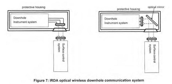
10 The first section of the Patent is headed “Field of the invention” and comprises just one paragraph as follows:
FIELD OF THE INVENTION
[0001] The present invention relates to devices enabling data to be transmitted to and from downhole equipment, such as core orientation units and borehole telemetry probes.
11 The above paragraph refers to “borehole telemetry probes”. The word “telemetry” is relevant to a number of the construction issues to be discussed later in these reasons. At this stage, it may be helpful to note that, according to a dictionary definition, the word “telemetry” refers to the science and technology of the automatic transmission and measurement of data conveyed by wire, radio or other means, from remote sources (Macquarie Dictionary, 6th ed, 2013, p 1510). However, as discussed later in these reasons, the primary judge held that, in the context of the Patent, the word “telemetry” refers to sensing (or measuring) data while equipment is down a hole without immediate transmission of the data to the surface (Reasons, [324]).
12 The “Background to the invention” was explained at [0002]-[0020]:
[0002] Core orientation is the process of obtaining and marking the orientation of a core sample from a drilling operation.
[0003] The orientation of the sample is determined with regard to its original position in a body of material, such as rock or ore deposits underground.
[0004] Core orientation is recorded during drilling, and analysis is undertaken during core logging. The core logging process requires the use of systems to measure the angles of the geological features, such as an integrated core logging system.
[0005] Whilst depth and azimuth are used as important indicators of core position, they are generally inadequate on their own to determine the original position and attitude of subsurface geological features. Core orientation i.e. which side of the core was facing the bottom (or top) of a borehole and rotational orientation compared to surrounding material, enables such details to be determined.
[0006] Through core orientation, it is possible to understand the geology of a subsurface region and from that make strategic decisions on future mining or drilling operations, such as economic feasibility, predicted ore body volume, and layout planning.
[0007] In the construction industry, core orientation can reveal geological features that may affect siting or structural foundations for buildings. Core samples are cylindrical in shape, typically around 3 metres long, and are obtained by drilling with an annular hollow core drill into subsurface material, such as sediment and rock, and recovering the core sample.
[0008] A diamond tipped drill bit is used at the end of the hollow drill string. As the drill progresses deeper, more sections of hollow steel drill tube are added to extend the drill string. An inner tube assembly captures the core sample. This inner tube assembly remains stationary while the outer tubes rotate with the drill bit. Thus, the core sample is pushed into the inner tube.
[0009] A ‘back end’ assembly connects to a greaser. This greaser lubricates the back end assembly which rotates with the outer casing while the greaser remains stationary with the inner tubing.
[0010] Once a core sample is cut, the inner tube assembly is recovered by winching to the surface. After removal of the back end assembly from the inner tube assembly, the core sample is recovered and catalogued for analysis.
[0011] Various core orientation systems have previously been used or proposed. Traditional systems use a spear and clay impression arrangement where a spear is thrown down the drill string and makes an impression in clay material at an upper end of the core sample. This impression can be used to vindicate the orientation of the core at the time and position the spear impacted the clay.
[0012] A more recent system of determining core orientation is proposed in Australian patent number 2006100113 (also as US patent number 7,584,055). This patent document describes a core orientation device for a core drill. The device provides signals associated with a physical orientation of a core orientation device for a particular moment in time. The device includes a memory for storing and providing the orientation data when required.
[0013] The system described in AU 2006100113 provides a two unit replacement for the greaser described above. A first orientation system unit houses electronics and a battery used to record orientation data, and the second greaser unit is an extended greaser accommodating a physical screw on connector for the first unit as well as serving as the greaser. This combination forms part of the inner tube assembly with the core tube, orientation system ‘first’ unit and the connector/greaser ‘second’ unit.
[0014] However, as a result of the now extended length of the combined orientation system and greaser units compared with a standard greaser only unit, the outer drill string casing now requires a matching extension piece to extend the outer casing an equal amount. The core orientation system has a display on one face which is used when setting up the unit prior to deployment, and to indicate core sample alignment when the core sample is recovered. At the surface before removing the core sample from the inner tube assembly, the operator views the display fitted on the system. The display indicates for the operator to rotate the unit and the sample within the tube until the whole core tube and sample is oriented with the lower section of the core sample at the lower end of the tube. The core sample is marked (usually by pencil) before being removed from the core for future analysis.
[0015] However, the device described in AU 2006100113 has been found to have certain limitations. The orientation unit is connected to the greaser by a screw thread and o-ring seal arrangement. In the harsh down hole environment within the drill string, it has been realised that the o-ring seals are not always effective and can let fluid into the space between the orientation unit and the greaser. The display unit allows fluid into the electronics of the orientation, resulting in a risk of fault or failure of the device. Furthermore, the orientation unit must be disassembled from the greaser unit before the display and orientation unit can be viewed, rotated and the required core orientation displayed. Thus, the device of AU 2006100113 requires manual manipulation before any reading can be viewed on the display, if the display and the electronics have survived any ingress of fluid past the o-ring seal.
[0016] Similar issues arise with downhole probes that are used to obtain borehole telemetry data to determine drilling progress, such as depth and direction of the borehole and change in surrounding magnetic field.
[0017] Typically the downhole equipment is brought to the surface once sufficient data is gathered or task completed, such as obtaining a core sample. It is common practice to manually have to separate the backend assembly from an electronics package used for gathering downhole data. This task involves unscrewing the backend assembly from the electronics package, which takes time and risks thread damage as well as resulting in risk of ingress of dirt and water into the thread. Also, o-ring seals protecting the electronics unit may be compromised through separation and refitting of the backend assembly and electronics unit. Similar issues exist with separating the electronics unit of a downhole probe from its backend assembly.
[0018] It has been found desirable to provide means of obtaining signals/data from or providing signals/data to downhole equipment electronics units, such as used in core sample orientation units or downhole probes.
[0019] One improved system is described in the applicant's international patent application PCT/AU2011/000954, the contents of which are incorporated herein in its entirety. At least one embodiment described in PCT/AU2011/000954 utilises an optical device extending from an end of a data gathering device, such as an electronics unit, into an end of a greaser unit. Light from LEDs in the data gathering device is reflected out of apertures in the greaser unit behind the optical device. The present invention improves on such a system.
[0020] With this in mind, it has been found desirable to provide improved means for obtaining signals/data from or providing signals/data to an electronics unit of downhole equipment.
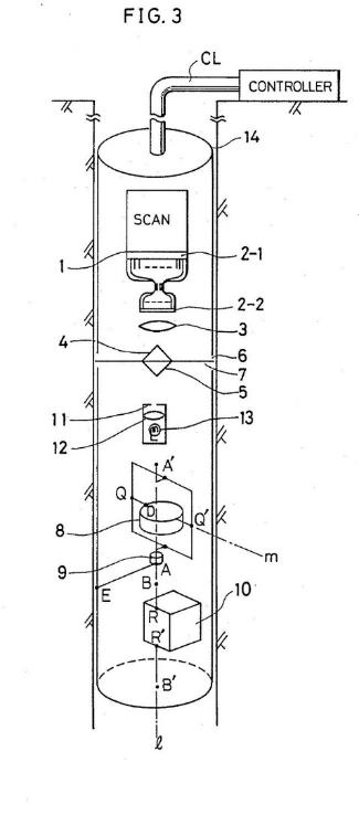
(Emphasis added.)
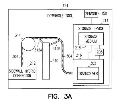
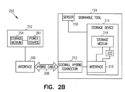
13 It is convenient to note at this stage that, at [0015], the specification identifies certain limitations of existing core orientation equipment. In particular, the equipment needed to be disassembled before the data could be obtained. In that context, [0016] states that “[s]imilar issues arise with downhole probes that are used to obtain borehole telemetry data to determine drilling progress”. The primary judge reasoned that the “[s]imilar issues” were those identified in [0015]; those issues all concerned the problems associated with manual manipulation of the device at the surface to obtain data; this indicated that, by “borehole telemetry data to determine drilling progress”, the Patent did not mean data that is communicated from down the hole to the surface while the equipment is down the hole (Reasons, [324]).
14 The “Summary of the invention” comprises [0021]-[0045] and includes:
[0021] With the aforementioned in mind, in one aspect the present invention provides a device that transfers at least one electromagnetic signal to or from an electronics unit of downhole equipment, the device including a body and an electromagnetic signal direction altering means, the body having a light path arranged to allow the electromagnetic signal from an electromagnetic wave source associated with the electronics unit to pass to the electromagnetic signal direction altering means, the electromagnetic signal direction altering means causing the electromagnetic signal to change direction of travel, the device, in use, configured to transmit or receive the electromagnetic signal through at least one aperture through a side wall of a component of downhole equipment.
…
[0025] The optical signal direction altering means may act on optical signals incoming to the electronics unit and/or outgoing from the electronics unit.
[0026] The optical signal direction means may include a boundary of or within the body of the optical device. For example, refraction may occur at a surface edge of the optical device. The boundary and/or the nature of the material (refractive index) may be used to change the path of the light in order to transfer the light signal via the device.
[0027] Alternatively, refraction may occur at a change of material or material density within the body of the optical device. Such refraction may cause the transmitted optical signal to emit sideways/transversely with respect to a longitudinal extent of the optical device.
…
[0032] Preferably the transmitted signal emits to the side of the device, which is beneficial in aiding signal detection through at least one overlying aperture formed or provided in the downhole equipment. Such at least one aperture may be the water supply hole(s) through a greaser unit or at least one aperture provided in part of a downhole probe assembly.
…
[0036] The electronics unit (and hence the optical device) may be connected to other equipment, such as a portion of a downhole probe.
[0037] An advantage of the present invention is that the greaser or other equipment to which the electronics unit attaches does not need to be separated from the electronics unit in order to obtain access and communicate with the device to obtain data. This avoids needing to unscrew components of the downhole equipment and risk ingress of dirt/water or damaged threads, as well as reduces time taken to obtain data.
[0038] In addition, the electronics unit can be started or stopped remotely and at the most opportune time. For example, in known devices an operator usually delays turning on the electronics unit until the last minute in order to conserve the unit's onboard battery power. The operator then starts the electronics unit and assembles the unit to the other equipment, such as a greaser or probe assembly.
[0039] The present invention avoids the need for such urgent activity by allowing an operator to switch the unit on or off by sending an optical signal from a hand held device to the optical device through an overlying aperture, the device then transmitting the optical signal to the electronics unit to activate/deactivate the unit. Data to/from the unit can also be sent/received utilising the same optical device.
…
[0042] A further aspect of the present invention provides downhole equipment having an electronics unit configured to obtain data relating to a borehole into which the electronics unit is inserted or to obtain data relating to equipment used within the borehole system, and an optical device associated with the electronics unit, and an optical device according to any one of the preceding claims configured to enable optical signals to be transmitted to or received from the electronics unit whilst the electronics unit is connected to the downhole equipment.
15 The summary at [0021] is in similar language to claim 1. The summary also includes the following paragraph that is similarly worded to claim 21:
[0044] A still further aspect of the present invention provides a downhole data gathering system, including a communication device arranged to communicate wirelessly with an electronics unit of downhole equipment, the downhole equipment including an electronics unit configured to obtain data relating to a borehole into which the electronics unit is inserted or to obtain data relating to equipment used within the borehole system, and a device that transfers electromagnetic signals to or from the electronics unit of the downhole equipment, the device including a body and an electromagnetic signal direction altering means, the body having a light path arranged to allow the electromagnetic signals from an electromagnetic wave source associated with the electronics unit to pass to the electromagnetic signal direction altering means, the electromagnetic signal direction altering means causing the electromagnetic signal to change direction of travel and wherein the device is configured to enable the electromagnetic signals to be transmitted to or received from the electronics unit whilst the electronics unit is connected to the downhole equipment, the device enabling transmission of the electromagnetic signals from the electronics unit to the wireless communication device, or from the wireless communication device to the electronics unit, through at least one aperture in a side wall of the downhole equipment.
16 The Patent includes a number of figures that are described in sections headed “Brief description of the drawings” and “Description of preferred embodiment”.
17 Figure 1 (set out below) shows an end on view of a core sample orientation device or downhole probe having an indicator window whereby indicator lights provide optical signals to an optical device according to an embodiment of the present invention: [0047].
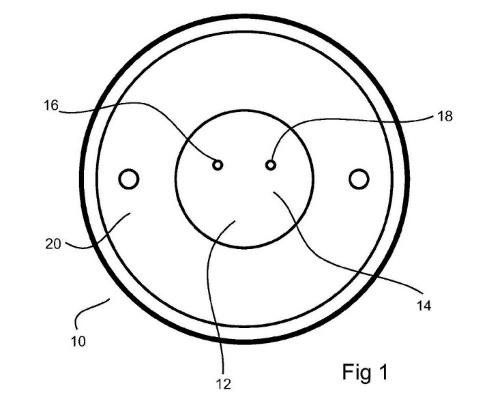
18 As explained at [0051] of the Patent, figure 1 depicts the indicator window end 12 of an electronics unit of a core sample orientation data gathering device 10 and includes a window 14. Indicator lights 16, 18 can be seen through this window, at least when illuminated. The window end is sealed by a retaining plate 20. Two lights, eg red and green LEDs, are shown, though there may be more or less lights. The left hand 16 (red) LED illuminates to indicate to a user to rotate the unit 10 anti-clockwise. The right hand 18 (green) LED illuminates to indicate to a user to rotate the unit 10 anti-clockwise. When correct core sample orientation is achieved, both LEDs might illuminate, such as steady or flashing red and green, or another illuminated indication might be given, such as a white light (steady or flashing).
19 Figures 2a and 2b (set out below) show an arrangement of a data-gathering device incorporating an optical device: [0048].
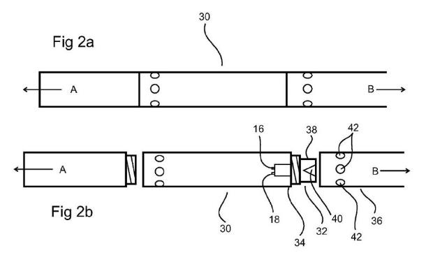
20 The description of figures 2a and 2b is as follows:
[0058] As shown in figures 2a and 2b, an electronics unit 30 for gathering data downhole houses the light emitters 16,18. Light from these emitters (e.g. LEDs) passes through the window 14 (shown in figure 1).
[0059] Reference arrow A refers to the drill bit end direction, and reference arrow B refers to the backend assembly direction.
[0060] An optical device 32 according to an embodiment of the present invention is provided at the end 34 of the electronics unit 30 and which device extends into the greaser unit 36 of the backend assembly when connected thereto.
[0061] The optical device has a body 38 and a light path altering means 40. The body also defines a light path therethrough (see figure 3) arranged to allow the optical signal from a light source(s) 16,18 associated with the electronics unit to pass to the light path altering means.
[0062] The light path altering means 40 can be arranged to cause the optical signal from/to the electronics unit to change direction of travel and emit out of the body/into the body of the optical device.
[0063] The greaser unit 36 has apertures 42 that allow light therethrough. Light from the emitters is directed onto at least one light path altering means of the device.
[0064] The emitted light can be observed through the apertures 42 in the greaser.
21 The description includes:
[0066] The red-green indications (or whatever selected colour combination of light is used) can be observed through the aperture(s) when a remote device (such as a handheld device) reads the optical data signal. Also, a handheld device can transmit data via an optical signal or use a transmitted optical signal to operate the electronics unit or store data in the unit. Thus, advantageously, when the unit is recovered from down the hole, the unit need not be separated from the rest of the downhole equipment in order to determine required information or control the electronics unit. Thus, wireless communication to/from a remote device, such as a hand held device, to transfer data between the electronics unit and the remote device, can also be effected by transmitting through … at least one aperture.
[0067] Embodiments of the present invention provide the advantage of a fully operating downhole electronics unit without having to disconnect or disassemble the unit from the inner tube and/or from the backend assembly or any other part of the drilling assembly that the unit would need to be assembled within for its normal operation.
[0068] Disconnecting or disassembling the unit from the backend and/or inner tube risks failure of seals at those connections and/or risks cross threading of the joining thread. Also, because those sections are threaded together with high force, it takes substantial manual force and large equipment to separate the sections.
[0069] High surrounding pressure in the drill hole means that the connecting seals between sections must function perfectly otherwise water and dirt may ingress into and damage the device.
[0070] Having an electronics unit that does not need to be separated from the inner tube and/or backend sections in order to determine core sample orientation and/or to gather data recorded by the unit means that there is less risk of equipment failure and drilling downtime, as well as reduced equipment handling time through not having to separate the sections in order to otherwise obtain core sample orientation. Known systems require end on interrogation of the unit. By providing a sealed unit and the facility to determine orientation of the core sample, by observing the orientation indications through one or more apertures in the side of the greaser or other section, reliability and efficiency of core sample collection and orientating is improved. Consequently operational personnel risk injury, as well as additional downtime of the drilling operation. Without having to separate the unit from the inner tube and/or backend, the orientation of the core sample can be determined and the gathered information retrieved with less drilling delay and risk of equipment damage/failure.
22 Figure 3 (set out below) shows an optical device according to an embodiment of the present invention arranged to be at least partially received into a housing or casing of an electronics unit of downhole equipment: [0049].
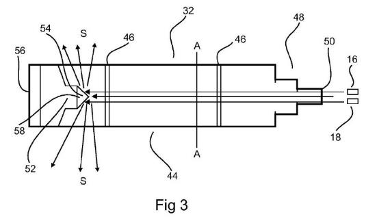
23 The description of figures 3 is as follows:
[0071] Figure 3 shows a particular embodiment of an optical device 32 for use with a downhole electronics unit. The optical device is shown in side, profile view. In practice, the device is cylindrical in cross section A-A.
[0072] The optical device has a body 44 of a transparent machined plastics material, such as polycarbonate, acrylic, nylon etc. Glass may also be used, though a plastic material is preferred.
[0073] The body has annular grooves 46 therearound to receive o-rings for sealing the device within a housing or casing of a downhole unit, such as an electronics unit. In this embodiment, the transparent material of the body allows light to pass therethrough. Thus, the body forms a light path of the light to travel through. Other materials can also be suitable, depending on the type of light or other electromagnetic wave used. Preferably the body allows infra red light to pass therethrough. UV (ultra-violet light) may also be transmitted, or alternatively light in the visible spectrum.
[0074] At least a portion of the body is shaped to fit within a housing or casing of a component of downhole equipment, such as an electronics unit or a greaser unit or extension piece etc.
[0075] A first end 48 of the body is shaped so that an end surface 50, in use, faces the light emitters 16,18 or other light emitters depending on the equipment used and required application.
[0076] Light from one or more such emitters is transmitted by the light path through the body to impinge on a light path altering means 52. In this embodiment, the light path altering means includes a reflector 54.
[0077] The reflector reflects some or a majority of the light impinging upon it, and said reflected light is re-directed sideways (S) with respect to a longitudinal direction (L) of the device. The light path altering means may be provided, as in this embodiment, by forming a recess in its second end 56. The recess may form a conical surface 58 to which a reflective material is applied, such as a silvery coating.
24 Figure 4 (set out below) shows an alternative embodiment of an optical device according to the present invention: [0050].
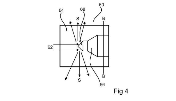
25 The description of figure 4 is as follows:
[0078] Figure 4 shows an alternative embodiment of the present invention which works in the same manner as that of figure 3.
[0079] This alternative form of optical device 60 is provided as an insert for use with a downhole probe. Again, this device as the one above in figure 3, is shown in side view but is a cylinder with a circular cross section B-B. Light 62 entering the device 60 passes through the body 64 material and reflects off of a protrusion 66 into the envelope of the cylinder.
[0080] The protrusion is a machined surface coated from the exterior with a reflective material. A conical surface 68 assists in diffracting light sideways (S).
26 The description of the preferred embodiment includes:
[0082] It will be appreciated that the optical device can be inserted into a downhole component and removed from replacement or access to an end of the electronics unit as required. Otherwise, the optical device can be left in situ to transmit light from/to the electronics unit. This can avoid the need to disassemble the electronics unit from the backend assembly, greaser unit or probe etc to which it is connected.
[0083] The electronics unit can be switched on or off by sending a controlling optical signal to the electronics unit through the optical device.
[0084] It will be appreciated that the optical device may be formed of one or multiple parts. For example, the optical device may be machined as a monolithic component or may be formed of multiple sub-components brought together, which may be bonded together or simply abutting in use.
[0085] It will be appreciated that light impinging on the light path altering means can be emitted sideways omni-directionally. Thus, and of great benefit to an operator, the optical device needs no alignment with … at least one aperture of the downhole assembly through which the light is to be transmitted.
27 Claim 1 in the Patent is as follows:
1. A device that transfers at least one electromagnetic signal to or from an electronics unit of downhole equipment, the optical device including a body and an electromagnetic signal direction altering means, the body having a light path arranged to allow the electromagnetic signal from an electromagnetic wave source associated with the electronics unit to pass to the electromagnetic signal direction altering means, the electromagnetic signal direction altering means causing the electromagnetic signal to change direction of travel, the device, in use, configured to transmit or receive the electromagnetic signal through at least one aperture through a side wall of a component of downhole equipment.
28 Claims 5, 7, 8, 9, 10, 12 and 17, which are also in issue, are dependent on claim 1.
29 Claim 21 is as follows:
21. A downhole data gathering system, including a communication device arranged to communicate wirelessly with an electronics unit of downhole equipment, the downhole equipment including an electronics unit configured to obtain data relating to a borehole into which the electronics unit is inserted or to obtain data relating to equipment used within the borehole system, and device-that transfers electromagnetic signals to or from the electronics unit of the downhole equipment, the device including a body and an electromagnetic signal direction altering means, the body having a light path arranged to allow the electromagnetic signals from an electromagnetic wave source associated with the electronics unit to pass to the electromagnetic signal direction altering means, the electromagnetic signal direction altering means causing the electromagnetic signal to change direction of travel and wherein the device is configured to enable the electromagnetic signals to be transmitted to or received from the electronics unit whilst the electronics unit is connected to the downhole equipment, the device enabling transmission of the electromagnetic signals from the electronics unit to the wireless communication device, or from the wireless communication device to the electronics unit, through at least one aperture in a side wall of the downhole equipment.
30 Claims 22, 24, 25, 26, 27 and 29, which are also in issue, are dependent on claim 21.
The Reasons of the primary judge
Non-expert evidence
31 After describing the Patent, the primary judge discussed the non-expert evidence (in Section 3 of the Reasons). This comprised evidence of Kelvin Brown, the Global Lead (Directional Drilling) of Reflex. Her Honour noted, at [25], that Mr Brown had over 20 years’ experience in mineral exploration drilling. Mr Brown’s evidence covered core sample orientation, which was explained in the Reasons at [30].
Expert evidence
32 In Section 4 of the Reasons, the primary judge discussed the expert evidence. Two experts gave evidence during the hearing: Professor Jonathan Tapson, who was called by Reflex; and Assoc Professor J Christian Dupuis, who was called by Globaltech.
33 Professor Tapson is an electrical and electronic engineer. At the time of trial, he had 32 years of experience in electrical and electronic engineering, primarily in the field of sensors and instrumentation. This included designing and building orientation systems for the mining and resources industry, including drilling applications: Reasons, [36].
34 Before being provided with the Patent, Professor Tapson was asked to complete a design task: Reasons, [39]. The task Professor Tapson was given was to design a downhole instrument for transferring data based on the common general knowledge at the priority date: Reasons, [52]. Professor Tapson’s response to the task is described in the Reasons at [53]-[68]. This section describes a number of steps that Professor Tapson would undertake in response to the task. These steps included, as the last step, figure 7, which is set out below:
35 Professor Tapson’s evidence in relation to figure 7 (as summarised in the Reasons at [66]) included:
It would be preferable not to uncouple or otherwise interfere with the coupling of the housing in order to communicate with the instrument. It would therefore be advantageous to access the instrument through the side wall rather than the ends of the housing. With optical wireless communications, this is easily achieved either by rotating the transmitter-receiver pair through 90 degrees, or simply bending the optical axis 90 degrees by means of a mirror, as shown in figure 7 below. The latter method has the advantage that the basic instrument board does not need to be modified from the above system and can be used in both cases. In typical IRDA-type optical wireless communication, the transmitted optical beam is quite wide, perhaps 20–30 degrees, so some misalignment from the direct optical axis is tolerable.
36 Professor Dupuis has qualifications in electrical engineering and geology. At the time of the trial, he had over 12 years of experience working in the mineral exploration industry: Reasons, [124]. Since 2008, Professor Dupuis has been part of teams tasked with the development of borehole instruments and measurement systems to facilitate borehole geophysics and improve mineral exploration efficiency: Reasons, [125].
37 Professor Dupuis’s evidence included a description of the essence of the invention disclosed in the Patent. This was summarised by the primary judge at [135] of the Reasons:
According to Professor Dupuis, the essence of the invention disclosed in the patent is to offer a means of obtaining signals/data from, or providing to, electronic units of downhole equipment without having to disassemble the downhole equipment to gather that data from the electronics unit. This is achieved by an optical device that is capable of altering the direction of signals travelling to or coming from an electronics unit of the downhole equipment when the device is at the surface. The optical device is capable of effecting this transfer of data even when it is located inside of a part of downhole equipment through apertures which maintain a line of sight to the optical device, and thereby one of the advantages of the invention is that the downhole equipment does not have to be taken apart to get access to a data transferral port to effect the data transfer, making for a much quicker data retrieval process.
It is apparent from the Reasons generally that the primary judge broadly accepted the above description of the invention disclosed in the Patent.
38 At [169]-[175] of the Reasons, the primary judge summarised Professor Dupuis’s evidence about the design task undertaken by Professor Tapson. Professor Dupuis gave evidence that: Professor Tapson’s figure 7 (set out above) showed two devices consisting of two components that were in close proximity to each other and orthogonal to each other; this configuration could not be deployed inside the confines of a borehole; thus, Professor Tapson’s design exercise was to design a means for human-machine interface (HMI) to interact with a borehole instrument: Reasons, [169].
39 Professor Dupuis’s response to the design task undertaken by Professor Tapson included the following (as summarised in the Reasons at [173]):
The final designs in Professor Tapson’s figure 7 appear to Professor Dupuis to emerge from a need not initially disclosed in the design exercise for the user to be able to interact with a borehole instrument that is housed in a pressure housing (that is, the unexplained proposition that it would be preferable not to uncouple or otherwise interfere with the coupling of the housing in order to communicate with the instrument).
40 Professors Tapson and Dupuis prepared a joint expert report, which was summarised by the primary judge at [193]-[236]. The oral evidence of the experts was summarised by her Honour at [237]-[269].
41 One of the differences between the experts concerned the reference in claim 21 to a “downhole data gathering system”. In summary, the respective positions of the experts were as follows:
(a) For Professor Dupuis, a downhole data gathering system involved a form of accumulation of downhole data for storage and later retrieval. Professor Dupuis considered that the invention disclosed in the Patent did not communicate with the surface and was a standalone tool, having regard to [0017] of the Patent. Professor Dupuis also noted that all the interactions described in the Patent between the driller and the invention imply that the aperture was accessible and visible to the driller. In his view, this meant that the invention must be at the surface, and therefore that the data was gathered downhole but only retrievable once the invention was back at the surface: Reasons, [212], [250].
(b) Professor Tapson considered that a downhole data gathering system was a system that is designed to gather data about the downhole environment or the downhole tools. In his view, the system could be continuously transmitting data or it could accumulate and store the data until downloading is possible: Reasons, [213].
42 In support of his view, Professor Tapson noted the references to “borehole telemetry” in [0001] and [0016] of the Patent. Professor Tapson considered that this made clear that the authors intended the Patent to include devices which used telemetry links: Reasons, [213]. It is apparent that Professor Tapson was referring to “telemetry” in the sense of real-time communication of data from equipment (while down a hole) to the surface. In response, Professor Dupuis considered that the word “telemetry” was misused in the Patent and, in the context of the Patent, referred to the acquisition of downhole data and not to a communication link with the surface for real-time communication of data: Reasons, [214]. See also the Reasons at [246].
43 At [243], the primary judge noted that Professor Dupuis accepted in oral evidence that telemetry is normally employed more in the oil and gas field, than in the mineral industry.
Construction of the Patent
44 In Section 5 of the Reasons, the primary judge considered the construction of the Patent. Her Honour set out the applicable principles at [270]-[292]. There is no challenge to this statement of the principles. The applicable version of the Patents Act 1990 (Cth) was after the amendments made by the Intellectual Property Laws Amendment (Raising the Bar) Act 2012 (Cth).
45 The primary judge made some observations about the expert evidence at [293]-[306]. Her Honour found that it was apparent that both experts possessed far more expertise than the common general knowledge attributed to the person skilled in the art: Reasons, [303]. Her Honour stated that “[b]oth experts are high-level research scientists at the top of their fields who are inventive”: Reasons, [303]. This did not mean that their evidence was inadmissible or unhelpful; it meant that it was necessary to scrutinise their evidence to ascertain what aspect of it represented the approach the skilled addressee would take and what aspects of it represented the approach of the inventive research scientist: Reasons, [304]. Her Honour also stated that this was not a case where one expert was more persuasive overall: Reasons, [306].
46 In Section 5.3 of the Reasons ([307]-[336]), the primary judge considered the field of the invention in the context of considering who was the person skilled in the art. This section of the Reasons is the subject of challenge in ground 1 of the appeal. In summary, her Honour found or concluded as follows:
(a) The primary judge inferred from the whole of the evidence that drilling for minerals was a different field from drilling for oil and gas: Reasons, [307].
(b) Having regard to the evidence, a person who was skilled in the art of drilling for mineral exploration was not necessarily skilled in the art of drilling for oil and gas exploration and production: Reasons, [311].
(c) At [314], the primary judge stated that, the question that then arose was: who is the person skilled in the art who is likely to have a practical interest in the Patent? The primary judge acknowledged there was apparent circularity involved in the exercise. Her Honour stated that the Patent is to be construed through the eyes of the skilled addressee in the field, but the field is to be identified from the terms of the Patent. Her Honour considered that there were two fields and that the hypothetical person skilled in the art should not be attributed with the common general knowledge in both fields (apart from as required by s 7(2) of the Patents Act, when dealing with the issue of inventive step): Reasons, [314].
(d) Her Honour stated that, while the field of the invention in [0001] of the Patent was expressed in general terms, the background to the invention disclosed that the primary field was exploration for mining as that term is conventionally understood (that is, mining for minerals) (see, eg, [0006]): Reasons, [315]. The primary judge also referred to [0003] and [0007] of the Patent: Reasons, [317].
(e) The primary judge considered that the references to “telemetry” in the Patent did not necessarily mean that the oil and gas industry must have been in contemplation: Reasons, [321]; see also [323], [324], [325], [330].
(f) The primary judge did not accept that the Patent’s focus on “core orientation” led to the conclusion that the field of the invention was drilling in the oil and gas industry: Reasons, [331].
(g) The primary judge noted that the Patent, at [0007], referred to the construction industry on the basis that “core orientation can reveal geological features that may affect siting or structuring foundations for buildings”: Reasons, [333]. The primary judge reasoned that the kind of core orientation activity that would be used in construction would be obtaining a rock core to determine the stability and other qualities of the ground for the placement of a building; while this was different from mineral exploration, the Patent recognised expressly that the invention was capable of being used in that hard rock environment; the important point was that both contexts (that is, mineral exploration and the construction industry) involved extraction of a core of rock for exploratory, rather than resource productive, purposes: Reasons, [333]; see also [334].
(h) The context of the Patent as a whole indicated that the field of the invention was an aspect of drilling boreholes for mineral exploration (albeit that the Patent recognises that the invention can also be used to assist in siting buildings in the construction industry, which involves the same hard rock environments as the minerals industry): Reasons, [334]; see also [335].
47 The primary judge discussed the evidence concerning the common general knowledge at [337]-[342].
48 The primary judge considered the construction of “downhole equipment” at [343]-[355]. This section of the Reasons is also challenged by ground 1 of the appeal. In it, the primary judge considers two issues: first, whether “downhole equipment” is confined to equipment for use in a hole that is drilled for mineral exploration (or subsurface exploration for construction of buildings) or whether it also extends to equipment for use in a hole for the exploration and production of oil and gas; and secondly, whether “downhole equipment” includes wireline telemetry.
49 In relation to the first issue, her Honour concluded that “downhole equipment” should be construed as meaning equipment that goes down a hole used for mineral or construction exploration, and not equipment that goes down a hole used for oil and gas exploration and extraction: Reasons, [346], [355].
50 In relation to the second issue, the primary judge concluded that “downhole equipment” should be construed as not including wireline telemetry equipment: Reasons, [350]-[355].
51 The primary judge considered the construction of “optical device” at [356]-[367] and “electronics unit” at [368]-[373]. These sections are not challenged in the appeal grounds.
52 The primary judge considered the construction of “electromagnetic signal direction altering means” at [374]-[390]. For ease of expression, in these reasons, the electromagnetic signal direction altering means will be referred to as the Altering Means. This section of the Reasons is challenged by ground 2. Having noted the different views of the experts, the primary judge stated that there was an anterior issue, namely whether the Patent contemplated that the Altering Means might be an optical fibre: Reasons, [377]. In relation to that issue, her Honour concluded that the person skilled in the art would not read the Patent as contemplating an optical fibre as an Altering Means: Reasons, [379], [381]-[386], [390]. Her Honour also made two other points in this passage of the Reasons:
(a) In the Patent, the light path is not the Altering Means; they are two separate things. The body has a light path allowing the light to pass to the Altering Means: Reasons, [378].
(b) The dispute between the experts related to the characterisation of light; however, neither expert explained the nature of light; they assumed a knowledge of light that needed to be proved by evidence. If it were necessary to resolve this issue, Reflex would fail on the onus of proof as the party asserting invalidity of the Patent: Reasons, [388].
53 The primary judge considered the construction of “downhole data gathering system” (used in claim 21) at [391]-[403]. This section is also challenged by ground 1 of the appeal. Consistently with her earlier reasoning and conclusions, the primary judge held that the “downhole data gathering system” referred to in claim 21 did not include: (a) a system involving holes for oil and gas exploration and production; or (b) wireline telemetry, in the sense of the gathering of data downhole that is communicated from down the hole to the surface: Reasons, [391], [403].
54 The primary judge considered the construction of “communicate wirelessly” and “wireless communication” (used in claim 21) at [404]-[410]. This section is also challenged by ground 2 of the appeal. The primary judge held that: anything constituting a physical link would not be wireless; it did not matter if the physical link was metallic or an optical fibre; once the task of communication is achieved through a physical link between the communication device and the electronics unit, the communication is not “wireless”: Reasons, [408]; see also [409]-[410].
Novelty
55 The primary judge set out the relevant statutory provisions and applicable principles at [415]-[419]. There is no challenge to this section of the Reasons.
56 Reflex contended that the asserted claims were not novel by reason of the prior art base as disclosed in Iizuka, Bergren and/or Sun. In relation to Iizuka, Reflex conceded that Iizuka did not disclose claim 21 or its dependent claims: Reasons, [424].
57 The primary judge considered whether Iizuka disclosed claims 1, 5, 7, 8, 9, 10, 12 and 17 of the Patent at [424]-[440] of the Reasons. Her Honour concluded that Iizuka did not disclose the relevant claims for the following reasons:
(a) Iizuka involved wireline telemetry as shown by the item “CL”, which is a cable telemetry link, in figure 3 (set out below): Reasons, [427]. The primary judge referred to and relied on her earlier conclusion that she did not accept that the person skilled in the art would construe “downhole equipment” as meaning or including wireline telemetry: Reasons, [429]. It followed that Iizuka did not disclose “a device that transfers at least one electromagnetic signal to or from an electronics unit of downhole equipment” in accordance with claim 1 of the Patent (and dependent claims): Reasons, [429].
(b) In Iizuka, the Altering Means included the optical fibres 2-2 (in figure3). Consistently with the primary judge’s earlier conclusions, she did not accept that the Patent contemplates an Altering Means comprising optical fibres: Reasons, [435]. While the Patent contemplated that the light path might be via a conduit (which could be an optical fibre) to enable light to pass from the wave source to the Altering Means, it did not contemplate that such a conduit would itself be an Altering Means: Reasons, [435].
(c) For the same reasons, the relevant dependent claims were not disclosed by Iizuka: Reasons, [438].
58 Figure 3 of Iizuka was as follows:
59 The primary judge considered whether Sun disclosed the asserted claims at [455]-[471]. Her Honour concluded that Sun did not disclose the claims for the following reasons:
(a) The invention in Sun did not involve “downhole equipment” within the meaning of claim 1 of the Patent because Sun involved optical communication equipment that went down a well for the production of hydrocarbons. Consistently with her earlier conclusions, the primary judge stated that the “hole” in “downhole equipment” in claim 1 of the Patent was a borehole for mineral exploration (and subsurface exploration in the construction industry) and was not a hole for the exploration and production of hydrocarbons: Reasons, [458]-[459].
(b) Sun did not involve an Altering Means within the meaning of claim 1 of the Patent as the signal in Sun was transmitted and had its direction change via an optical signal carrier such as a fibre optic cable (304 in figure 3A, set out below): Reasons, [460]. The body in Sun did not have a light path arranged to allow the signal to pass to the Altering Means as claim 1 of the Patent requires, as the optical fibre was not an Altering Means: Reasons, [461].
(c) Even if the optical fibre could be a potential Altering Means, Sun did not disclose that the means was to alter the direction of travel of the light signal; the alteration of the direction of travel was optional: Reasons, [465]-[466].
(d) Consistently with the above reasoning, the optical fibre was also not a “reflector” within the meaning of claim 7 of the Patent and dependent claims: Reasons, [467].
(e) Sun did not disclose a “downhole data gathering system” as referred to in claim 21 of the Patent because of the meaning of “downhole” in the Patent, which did not include a hole for the exploration and production of hydrocarbons: Reasons, [468].
(f) Sun did not disclose a “communication device arranged to communicate wirelessly” as referred to in claim 21 of the Patent. An essential part of the communication in Sun involved the hybrid cable (208 in figure 2B, set out below). This was not a “wireless” communication device within the meaning of the Patent: Reasons, [469].
60 Figure 3A of Sun was as follows:
61 Figure 2B of Sun was as follows:
Inventive Step
62 The primary judge considered the inventive step issue in section 7 of the Reasons.
63 At [472]-[474], the primary judge set out the relevant provisions and applicable principles. There is no challenge to this part of the Reasons.
64 Reflex contended that the invention as claimed in the asserted claims did not involve an inventive step in light of the common general knowledge alone. Further or alternatively, Reflex based its contention on the common general knowledge together with prior art as referred to in s 7(3) of the Patents Act.
65 The primary judge considered Reflex’s contention based on the common general knowledge alone at [476]-[515]. Her Honour concluded that Reflex’s case based on the common general knowledge alone failed. In summary, her Honour reasoned as follows:
(a) Her Honour did not accept Reflex’s submission that Professor Tapson was representative of the hypothetical non-inventive skilled addressee before the priority date: Reasons, [476].
(b) Professor Tapson approached the design task armed with certain knowledge as described at [477]. In particular:
(i) The instructions from Reflex’s lawyers to Professor Tapson (in relation to the design task) focussed specifically on a design that did not involve uncoupling: Reasons, [477], [482(2)], [484].
(ii) Further, at the time he was asked to carry out the design task, Professor Tapson had already seen the Globaltech Orifinder tool, which involved communication laterally out of the tool: Reasons, [477], [484].
(c) By reason of the above, Professor Tapson was informed about the perceived problem that the invention in the Patent addresses and the solution to that problem that the Patent involves: Reasons, [484]. This was in a context where there was no evidence of a need felt within the industry at the priority date to effect such an improvement over the prior art, and the evidence established a lack of a common perception at the priority date that there was a known problem calling for a solution: Reasons, [482].
(d) In addition, Professor Tapson was very familiar with patents and patent litigation. His knowledge base would have alerted him, on receipt of the instructions, that the problem was the top uncoupling requirement: Reasons, [485].
(e) In the present case, the perception of the room for improvement and the idea to make the improvement involved an inventive step: Reasons, [490], [497], [506]. The weight of the evidence was against any inference that the perceived problem or need for improvement was part of the common general knowledge or would have been obvious to the person skilled in the art at the priority date: Reasons, [510]; see also [511]-[513].
66 In support of the above analysis, the primary judge referred to and relied on: Zetco Pty Ltd v Austworld Commodities Pty Ltd (No 2) [2011] FCA 848 (Zetco) at [229]; Lockwood Security Products Pty Ltd v Doric Products Pty Ltd (No 2) [2007] HCA 21; 235 CLR 173 (Lockwood Security Products) at [59] and [85]; and Aktiebolaget Hässle v Alphapharm Pty Ltd [2002] HCA 59; 212 CLR 411 (Alphapharm HCA) at [51].
67 The primary judge considered Reflex’s case based on the common general knowledge together with prior art as referred to in s 7(3) at [516]-[519]. Her Honour rejected this case.
The orders of the primary judge
68 On 12 July 2022, the primary judge made orders that the cross-claim be dismissed, and the cross-claimant (Reflex) pay the cross-respondent’s (Globaltech’s) costs of the cross-claim.
69 On 26 July 2022, the primary judge made a declaration that Reflex had infringed the asserted claims of the Patent. The primary judge made an order restraining Reflex from infringing the Patent in Australia, including by doing certain things as specified in the order (paragraph 3 of the orders). By paragraph 4 of the orders, Reflex was required to undertake certain steps in relation to its products. By paragraph 6, Reflex was ordered to pay Globaltech damages or, at Globaltech’s election, an account of profits. Paragraph 8 provided for the enquiry as to damages or an account of profits to be listed for case management on a date to be fixed. By paragraph 9, Reflex was ordered to pay Globaltech’s costs of its claim in respect of liability for infringement.
70 By paragraphs 14 to 16 of the orders made on 26 July 2022, the primary judge granted a temporary stay of certain orders.
The appeal
71 On 21 September 2022, a judge of the Court made an order granting Reflex leave to appeal from paragraphs 1 and 2 of the orders made on 12 July 2022 and paragraphs 1 to 12 of the orders made on 26 July 2022.
72 By notice of appeal dated 19 October 2022, Reflex appeals from paragraphs 1 and 2 of the orders made on 12 July 2022 and paragraphs 1 to 12 of the orders made on 26 July 2022. The grounds in the notice of appeal have been summarised in the Introduction to these reasons.
73 By notice of contention dated 9 November 2022, Globaltech contends that the judgment should be affirmed on grounds other than those relied on by the Court. The grounds in the notice of contention (to the extent pressed) have been summarised in the Introduction to these reasons. Paragraph 1(c) of the notice of contention is not pressed and is not summarised in the Introduction.
Principles of construction
74 Grounds 1 and 2 of the appeal raise issues of construction of the Patent. There is no issue between the parties as to the applicable principles. It is sufficient for present purposes to set out the following principles.
75 In Jupiters Ltd v Neurizon Pty Ltd [2005] FCAFC 90; 222 ALR 155, the Full Court of this Court (Hill, Finn and Gyles JJ) summarised the principles of construction as follows (at [67]):
There is no real dispute between the parties as to the principles of construction to be applied in this matter although there is some difference in emphasis. It suffices for present purposes to refer to the following:
(i) the proper construction of a specification is a matter of law: Décor Corporation Pty Ltd v Dart Industries Inc (1988) 13 IPR 385 at 400;
(ii) a patent specification should be given a purposive, not a purely literal, construction: Flexible Steel Lacing Co v Beltreco Ltd (2000) 49 IPR 331; [2000] FCA 890 at [81] (Flexible Steel Lacing); and it is not to be read in the abstract but is to be construed in the light of the common general knowledge and the art before the priority date: Kimberley-Clark Australia Pty Ltd v Arico Trading International Pty Ltd (2001) 207 CLR 1; 177 ALR 460; 50 IPR 513; [2001] HCA 8 at [24];
(iii) the words used in a specification are to be given the meaning which the normal person skilled in the art would attach to them, having regard to his or her own general knowledge and to what is disclosed in the body of the specification: Décor Corporation Pty Ltd at 391;
(iv) while the claims are to be construed in the context of the specification as a whole, it is not legitimate to narrow or expand the boundaries of monopoly as fixed by the words of a claim by adding to those words glosses drawn from other parts of the specification, although terms in the claim which are unclear may be defined by reference to the body of the specification: Kimberley-Clark v Arico at [15]; Welch Perrin & Co Pty Ltd v Worrel (1961) 106 CLR 588 at 610; Interlego AG v Toltoys Pty Ltd (1973) 130 CLR 461 at 478; the body of a specification cannot be used to change a clear claim for one subject matter into a claim for another and different subject matter: Electric & Musical Industries Ltd v Lissen Ltd [1938] 4 All ER 221 at 224-5; (1938) 56 RPC 23 at 39;
(v) experts can give evidence on the meaning which those skilled in the art would give to technical or scientific terms and phrases and on unusual or special meanings to be given by skilled addressees to words which might otherwise bear their ordinary meaning: Sartas No 1 Pty Ltd v Koukourou & Partners Pty Ltd (1994) 30 IPR 479 at 485-6 (Sartas No 1 Pty Ltd); the court is to place itself in the position of some person acquainted with the surrounding circumstances as to the state of the art and manufacture at the time (Kimberley-Clark v Arico at [24]); and
(vi) it is for the court, not for any witness however expert, to construe the specification; Sartas No 1 Pty Ltd at 485-6.
76 In Globaltech Corporation Pty Ltd v Australian Mud Company Pty Ltd [2019] FCAFC 162; 145 IPR 39 (Globaltech), the Full Court set out certain principles that are also relevant here. The Full Court stated at [93]-[95]:
93 The leading authority on the principle that the claims are to be construed in the context of the specification as a whole is Welch Perrin. In that case, the High Court (Dixon CJ, Kitto and Windeyer JJ) stated at 610:
If it is impossible to ascertain what the invention is from a fair reading of the specification as a whole, that, of course, is an end of the matter. But this objection is not established by reading the specification in the abstract. It must be construed in the light of the common knowledge in the art before the priority date. The general principles governing the construction of specifications are well known, and no lengthy reference to them is necessary. It is, however, fitting that we remind ourselves of the criterion to be applied when it is said that a specification is ambiguous. For, as the Chief Justice pointed out in Martin v Scribal, referring to Lord Parker’s remarks in National Colour Kinematograph Co Ltd v Bioschemes Ltd, we are not construing a written instrument operating inter partes, but a public instrument which must, if it is to be valid, define a monopoly in such a way that it is not reasonably capable of being misunderstood. Nevertheless, it is to be remembered that any purely verbal or grammatical question that can be resolved according to ordinary rules for the construction of written documents, does not, once it has been resolved, leave uncertain the ambit of the monopoly claimed (see Kauzal v Lee). The specification must be read as a whole. But it is a whole made up of several parts, and those parts have different functions. Courts have often insisted that it is not legitimate to narrow or expand the boundaries of monopoly as fixed by the words of a claim by adding to those words glosses drawn from other parts of the specification. Similarly, if a claim be clear it is not to be made obscure simply because obscurities can be found in particular sentences in other parts of the document.
(Footnotes omitted.)
See also Interlego AG v Toltoys Pty Ltd (1973) 130 CLR 461 at 478–9 per Barwick CJ and Mason J; Kimberly-Clark v Arico at [15] per Gleeson CJ, McHugh, Gummow, Hayne and Callinan JJ; and Davies v Lazer Safe Pty Ltd [2019] FCAFC 65 at [42]–[45] per Greenwood, White and Burley JJ.
94 It has been said, and we accept, that it is usually not legitimate, in the absence of an express reference in the claim itself, to import into a claim features of the preferred embodiment. In Rehm v Websters Security Systems, Gummow J stated at ALR 89; IPR 298:
The settled rule is that in ascertaining the width of a particular claim, it is not permissible to vary or qualify the plain and unambiguous meaning of the claim by reference to the body of the specification; provided that if an expression in the claim is not clear, then it is permissible to resort to the body of the specification to define or clarify the meaning of the words used in the claim: Interlego AG v Toltoys Pty Ltd (1973) 130 CLR 461 at 478–9. The use of the word “for” in patent claims to introduce expressions such as “for generating” and “for storing” has been deprecated: Blanco White, Patents For Inventions, 4th ed, § 2-213. However, the present is not a case which illustrates the concerns expressed by the learned author. Further, whilst resort may be had in the circumstances I have indicated to the body of the specification, it also must be remembered that it usually is not legitimate, in the absence of an express reference in the claim itself, to import into a claim features of the preferred embodiment. The preferred embodiment cannot properly be used to introduce into the definite words of a claim an additional definition or qualification of the patentee’s invention: Re Erickson’s Patent (1923) 40 RPC 477 at 491.
95 It is established that a patent specification is not to be read in the abstract, but is to be construed in light of the common general knowledge and the art before the Priority Date. This principle was expressed by the High Court in Kimberly-Clark v Arico at [24]:
It is well settled that the complete specification is not to be read in the abstract; here it is to be construed in the light of the common general knowledge and the art before 2 July 1984, the priority date; the court is to place itself “in the position of some person acquainted with the surrounding circumstances as to the state of [the] art and manufacture at the time”.
(Footnotes omitted.)
Ground 1 (construction of “downhole equipment” etc)
77 By ground 1, Reflex contends that the primary judge erred in construing the phrases “downhole equipment” and “downhole data gathering system” as used in the asserted claims of the Patent as excluding equipment for use in holes drilled for oil and gas exploration and production and wireline telemetry equipment. The particulars to this ground refer to the Reasons at [307]-[336], [343]-[355] and [391]-[403].
78 Reflex submits that her Honour’s analysis focussed on a consideration of the field of the Patent rather than the words of the claims. Reflex submits that: the claim language (“downhole equipment” and “downhole data gathering system”) is broad, clear and not limited to any particular field; these phrases naturally comprehend any equipment which is used downhole in drilling operations, in any field in which such operations are conducted; the ordinary meaning of the phrases, and the language and structure of the contested claims considered as a whole, support an understanding of the phrases that includes all equipment used down a borehole.
79 Reflex submits that: in any event, the primary judge also erred in construing the field of the invention as being limited to drilling for mineral exploration or subsurface exploration for the construction of buildings, as opposed to oil and gas exploration and production; the skilled person understood “borehole telemetry” as normally being used in oil and gas extraction (Reasons, [241], [243]); the skilled person would have taken the references to “core orientation units” and “borehole telemetry” in the description of the field of the invention at [0001] as indicating that the field extends to oil and gas drilling (in which borehole telemetry was a commonplace activity and core orientation was used).
80 Reflex submits that, in finding that “downhole equipment” and “downhole data gathering system” excluded wireline telemetry (for the purpose of communication from down the hole to the surface), the primary judge impermissibly limited the claim language to the alleged improvement described in the specification (see the Reasons at [348]-[350], [396]). Reflex submits that the description cannot be used to qualify the words of the claim, or to narrow or expand the boundaries of the monopoly fixed by the words of the claim, by adding glosses drawn from other parts of the specification: Globaltech at [94]; Davies v Lazer Safe Pty Ltd [2019] FCAFC 65 at [42]-[44].
81 In response, Globaltech submits that Reflex’s approach is unorthodox because it says, in effect, that the words of the claims are to be read in isolation from the body of the specification.
82 In relation to the field of the invention, Globaltech submits that: Reflex has not explained, by reference to the expert evidence at trial, why or how the primary judge erred; the only basis upon which it is suggested that this alleged error arose is because the term “borehole telemetry” was used in oil and gas extraction; that does not disclose a sufficient basis upon which to disturb the primary judge’s finding as to the field of the invention.
83 Globaltech submits that: once the relevant field has been identified, one asks what the skilled person in that field would understand the language of the claim to mean; it is not enough simply to assert that the relevant expressions should be given their ordinary meaning; plainly, the construction question is informed by the field of the invention.
84 In relation to whether the “downhole equipment” and “downhole data gathering system” include wireline telemetry instruments, Globaltech submits that: Reflex’s submissions are contrary to the principle that the claim is to be construed in light of the specification as a whole; the improvement made by the invention is clearly described at [0037]-[0039] of the Patent as avoiding having to manually unscrew the downhole equipment to obtain the data gathered down hole; wireline telemetry instruments do not require this.
85 In the context of this ground, the primary judge relevantly held: first, that the field of the invention was limited to drilling for mineral exploration, as distinct from drilling in the oil and gas industry (Reasons, [307], [334], [336]); secondly, that the expressions “downhole equipment” and “downhole data gathering system” in claims 1 and 21 of the Patent were to be construed as referring to equipment or a system for use in mineral exploration and construction exploration, but not oil and gas exploration and production (Reasons, [346], [355]); and thirdly, that the expressions “downhole equipment” and “downhole data gathering system”, as used in claims 1 and 21, do not include wireline telemetry, in the sense of a wired (real-time) communication of data from down the hole to the surface. For the reasons that follow, we consider there to be difficulties with these conclusions.
86 In relation to the field of the invention being limited to drilling for mineral exploration, first, the Patent is not in terms so limited. The section of the Patent headed “Field of the invention” comprises one paragraph ([0001], set out at [10] above) that is expressed in general terms.
87 Secondly, the Patent refers expressly to another field – the construction industry – at [0007]. The primary judge dealt with this by drawing parallels between drilling for mineral exploration and drilling in the construction industry (namely, that they both involve extraction of a core of rock for exploratory, rather than resource production purposes – Reasons at [333]) and acknowledging that the Patent recognises that the invention can also be used in the construction industry (Reasons, [334]). However, the more readily apparent inference is that the field of the invention is not limited to drilling for mineral exploration.
88 Thirdly, the Patent uses a number of expressions that, based on the evidence of the experts as referred to in the Reasons, are used both in drilling for mineral exploration and drilling for oil and gas. In particular, it is apparent from the Reasons that the terms “core orientation”, “borehole” and “borehole telemetry probes” are utilised in oil and gas exploration as well as mineral exploration. While some of these expressions may be less common in the field of drilling for oil and gas, the evidence referred to in the Reasons was that they are used in that field. Nor are the examples in the background to the invention properly to be considered determinative as to the field of the invention; the fact that the equipment referred to in the background concerns mineral exploration does not confine the field of the invention, in circumstances where these references are given as examples.
89 Fourthly, the primary judge did not accept that the Patent’s focus on core orientation leads to the conclusion that the field of the invention includes drilling in the oil and gas industry. However, the evidence of both experts, as summarised in the Reasons at [331]-[332], was to the effect that core orientation is relevant to both oil and gas exploration and mining exploration.
90 For these reasons, we consider that the primary judge unduly confined the field of the invention.
91 In relation to the construction of “downhole equipment” and “downhole data gathering system” in claims 1 and 21, the primary judge’s reasoning is set out at Reasons, [348]-[355].
92 Her Honour observed that there was an issue between the experts as to whether “downhole equipment” is to include “wireline telemetry”. She considered that the Patent has nothing to do with wireline telemetry: it does not mention “wireline” at all, does not mention telemetric communication with the surface from down the hole and refers only to “borehole telemetry probes” and “borehole telemetry data”, which she considered to be references to probes in the form of sensing or measuring instruments, not to an instrument to communicate to the surface. At [348]-[350] her Honour continued:
348 … I also consider that the patent consistently teaches away from wireline telemetry. The patent concerns a device which is manipulable at the surface to obtain data with the advantages described of avoiding damage and ingress of foreign substances from the manipulation. The patent says that the invention “improves on” the prior art. The improvement (the side infrared communication port rather than the infrared communication port being at the top of the device) is all about ease of access to the infrared communication port at the surface without the associated time and risk associated with having to uncouple the top of the device to obtain access to the communication port. If the device included communication from downhole to the surface via wireline telemetry, the benefit of the improvement would be immaterial. Accordingly, this invention is not concerned with the uncommon and difficult (even physically impossible, according to Professor Dupuis) feat of enabling wireline telemetry in mineral exploration drilling while drilling is occurring.
349 Reflex also placed too much emphasis on the word “typically” in [0017] of the patent (“[t]ypically the downhole equipment is brought to the surface once sufficient data is gathered or task completed”). This is a description of the prior art, not the invention. The patent as a whole discloses that the improvement concerns the operation of the side communication at the port so as to avoid uncoupling the top of the device from the rest of the device and the rig to access the top axially aligned communication port. This improvement is focused on events at the surface enabling communication from the device. It is not concerned at all with communication to the surface from down the hole.
350 For these reasons, the downhole equipment in the patent would not be understood by the person skilled in the art as including wireline telemetry. The person skilled in the art would know that wireline telemetry is not used in most mineral exploration borehole drilling for good practical reasons and that this patent is not saying anything about making such use practical or worthwhile. The concept of wireline telemetry, in the sense of communication via wire to and from the surface while drilling, would not occur to the person skilled in the art as contemplated by the patent.
(Emphasis added.)
93 Having reached this conclusion, the primary judge noted that the optical device of the invention goes down the hole as a component of the downhole equipment and transmits or receives the signal through at least one aperture on the side of a component of the downhole equipment: Reasons, [351]. Her Honour noted that that the downhole equipment includes core orientation units, which function while the drilling of the borehole is taking place. The primary judge rejected the evidence of Professor Dupuis to the effect that “downhole equipment” would not include a probe for sensing or measuring down the borehole as a separate activity from the drilling of the borehole (at Reasons, [352]).
94 After referring to numerous passages in the specification, the primary judge concluded that there is no reason from the specification why the person skilled in the art would confine “downhole equipment” to a core orientation device or other device that only goes down the hole as part of a drilling operation with drilling equipment. As her Honour concluded at Reasons [354]:
… I do not accept that the person skilled in the art would read the patent as confining “downhole equipment” to equipment involved in or attached to the activity of drilling the hole. The references to “probe” in the patent indicate that it contemplates that the hole may be drilled in whole or part and the downhole equipment may include a downhole probe including the optical device.
95 Her Honour concluded at Reasons [355]:
In summary, I consider that to the person skilled in the art at the priority date “downhole equipment” in the patent means equipment that goes down a hole used for mineral or construction exploration, but not equipment that goes down a hole used for oil and gas exploration and extraction, excluding wireline telemetry equipment for the purpose of communication from down the hole to the surface, but including equipment used down the hole for mineral or construction exploration while drilling is not occurring.
96 We have set out above why we differ from the primary judge’s conclusion that the field of the invention is confined to mineral or construction exploration. To the extent that her Honour concluded that the words “downhole equipment” and “downhole data gathering system” in claims 1 and 21 must also be understood as confined to such equipment when used in mineral or construction exploration, but not oil and gas exploration and extraction, we consider that this too was in error. In our view, even if (contrary to the above) the primary judge were correct in her identification of the field of the invention, this construction places a gloss on the words of the claims drawn from the body of the specification. The words “downhole equipment” are not said to be words of art and, while it may be inferred that they generally arise in the context of mining, they are otherwise unlimited. In Atlantis Corporation Pty Ltd v Schindler [1997] FCA 1105; 39 IPR 29, which was embraced in Lockwood Security Products at [80] and [87], the Full Court refused to read down the language of a claim, which was open as to the manner in which a device could be used, by reference to words of limitation in the specification. Accordingly, we consider that the primary judge erred in her construction of the expressions “downhole equipment” and “downhole data gathering system”.
97 For the following reasons, we also consider that the primary judge erred in concluding that the words “downhole equipment” and “downhole data gathering system” must be understood to exclude wireline telemetry.
98 In broad terms, claim 1 is for an optical device located within “downhole equipment” that transfers one or more electromagnetic signals to or from an “electronics unit” “through at least one aperture through a side wall of a component of downhole equipment”. The primary judge found that the Patent as a whole discloses that the “improvement” concerns the operation of the side communication at the port so as to avoid uncoupling the top of the device from the rest of the device and the rig to access the top axially aligned communication port and that it was not at all concerned with communication to the surface from down the hole.
99 However, whilst that conclusion was relevant to an understanding of the invention as disclosed in the specification, it could not be the sole determinant to be applied in the construction of the claims; the task of claim construction requires close consideration of the language of the claim when understood in the light of the specification as a whole: Fresenius Medical Care Australia Pty Ltd v Gambro Pty Ltd [2005] FCAFC 220; 67 IPR 230 (Fresenius) (Wilcox, Branson and Bennett JJ) at [39], [43]. The words chosen in the claim must be given meaning and whilst they are to be construed in the context of the specification as a whole, it is axiomatic that it is not legitimate to narrow or expand the boundaries of the monopoly as fixed by the words of the claim by adding glosses drawn from other parts of the specification: Kimberley-Clark Australia Pty Ltd v Arico Trading International Pty Ltd [2001] HCA 8; 207 CLR 1 at [15]; Welch Perrin & Co Pty Ltd v Worrel [1961] HCA 91; 106 CLR 588 at 610; Interlego AG v Toltoys Pty Ltd [1973] HCA 1; 130 CLR 461 at 478. The reasoning of the Full Court in Fresenius demonstrates that it is inapposite to read down the language of a claim by reference to what may be characterised as the “essence” or (as the primary judge found here) the “improvement” said by the patentee to have been achieved by the invention absent sufficient words of limitation in the claim itself.
100 Claims 1 and 21 are silent as to whether or not the downhole equipment of the claim includes a wired communication from the point of the probe to the surface. It is not possible to discern from the language of either of those claims a limitation such that “downhole equipment” and “downhole data gathering system” are to be understood to exclude “wireline telemetry” equipment from their scope. In the absence of any words of limitation, we can see no basis upon which the person skilled in the art would construe these expressions to exclude equipment used in conjunction with wired telemetry. Indeed, the specification refers in two places to “telemetry”.
101 It follows that ground 1 is made out.
Ground 2 (construction of the Altering Means etc)
102 By ground 2, Reflex contends that the primary judge erred in construing the phrases “electromagnetic signal direction altering means” (referred to in these reasons as the Altering Means), “reflector” and “communicate wirelessly” as used in the asserted claims of the Patent as excluding the use of optical fibre to transmit an electromagnetic signal. The particulars to this ground of appeal refer to the Reasons at [374]-[390], [404]-[410] and [467].
103 Reflex submits that, on the evidence, optical fibre is a component that meets the descriptions of “electromagnetic signal direction altering means”, “reflector” and “communicate wirelessly”. Reflex submits that: on the primary judge’s findings, the ordinary meaning of these phrases in the asserted claims encompasses optical fibre; optical fibres are not comprised of metal, and are therefore not wires (Reasons, [108]); they are comprised of a core material and a cladding material, and light waves propagate through the core of the optical fibres (Reasons, [108], [109]); communication that takes place through optical fibres is wireless (Reasons, [108], [113], [46(3)]).
104 Reflex submits that the primary judge’s analysis at [378]-[380] and [382]-[386] failed to recognise that the primary functional role of the Altering Means is to cause the direction of light signals to change so that the light signals are redirected out of (or into) the sidewall of the downhole equipment – see claims 1 and 21. Reflex submits that the primary judge’s findings show that, as a matter of fact, where an optical fibre is bent, light entering the fibre along the optical axis at one end would exit in the different direction in which the optical axis was projecting at the other end (Reasons, [116]); that is, by propagating along the fibre, the light will change direction relative to the downhole equipment, and exit in a different direction to that at which it entered (Reasons, [116], [209]-[211], [249]).
105 Reflex submits that this functional role of the Altering Means is also reflected in the body of the specification: see [0021], [0025], [0026], [0027], [0032], [0040], [0044].
106 Reflex submits that the primary judge also erred in concluding that the component that is the Altering Means cannot also be the component that is the “body” with a “light path” (Reasons, [378], [382]-[383], [386]). Reflex submits that: the clear language of the claims imposes no such requirement; the specification specifically discloses that the optical device may include a one-piece body or be formed from one component ([0022], [0033], [0084]; claim 2); it follows that the same single component, such as a conical mirror or an optical fibre, may be both the “body” and the Altering Means within the meaning of the asserted claims.
107 Reflex submits that the primary judge’s construction of “communicate wirelessly” in claim 21 disregarded the plain meaning of the word “wireless”, which excludes wires, not fibre optics; further, the language of claim 21 makes plain that it is the communication, as opposed to the entirety of the optical device, that must be wireless.
108 In response, Globaltech submits that the primary functional role of the Altering Means is readily apparent from [0062]-[0064] of the specification and figures 2, 3 and 4, which were referred to or reproduced by the primary judge at [17]-[19] of the Reasons.
109 Globaltech submits that, having regard to the evidence of Professor Dupuis, optical fibres do not alter the direction of propagation of the electromagnetic wave and are better characterised as wave guides rather than Altering Means. Globaltech submits that the change in direction of travel that must be caused by the Altering Means in claim 1 is a change in direction so that the signal moves off the light path it was formerly taking inside the body of the optical device.
110 In relation to the construction of “communicate wirelessly”, Globaltech submits that the word “wirelessly” does not have the plain meaning contended for by Reflex; the evidence included dictionary definitions that supported both interpretations; the primary judge correctly looked at the word in context.
111 Insofar as Reflex challenges the primary judge’s conclusion that the Patent does not contemplate that the Altering Means could be an optical fibre (Reasons, [379], [381], [390]), we consider that the real question is to define what the Altering Means is, or rather may be, and what the Altering Means would do. It is a functional description (“means”) that is not confined as to the mechanism of action, so long as the electromagnetic signal is altered as contemplated in the claim. Neither the language of the claim, nor the specification more generally, indicate that the Altering Means could not be constituted by an optical fibre.
112 These matters suggest that, in principle, the Altering Means may be able to be constituted by an optical fibre. However, as noted above, the primary judge relied on two other points in relation to this issue. First, her Honour held that, in the Patent, the light path is not the Altering Means; they are two separate things. Her Honour reasoned at [378]:
As noted above, in the patent the light path is not the electromagnetic signal direction altering means. They are two separate things. The body has a light path allowing the light signal to pass to the electromagnetic signal direction altering means. It is that light path which might be provided by a light transmitting conduit within the body. The patent does not say that the electromagnetic signal direction altering means may be a light path with a bend in it. At [0041] it says that “the direction of the light signal may be altered within the body of the optical device or a surface of the device, or a combination of both”.
(Emphasis added.)
113 Secondly, her Honour stated that, if it were necessary to decide the issue, Reflex had failed to discharge its onus of proof. Her Honour stated at [388]:
It is apparent from the experts’ evidence that the dispute between them related to the characterisation of light. Professor Dupuis described Professor Tapson’s characterisation of light within a multimode fibre as over-simplified “ray optics”. However, neither expert explained the nature of light. They assumed knowledge about the nature of light which would have to be proved by evidence. If it were necessary to resolve this issue, Reflex would fail on the onus of proof as the party asserting invalidity of the patent. Professor Dupuis’ evidence, insofar it went about the nature of light in a multimode fibre, would not be discounted. It would prevent the acceptance of Professor Tapson’s evidence about this issue being accepted as having been proved on the balance of probabilities.
(Emphasis added.)
114 We are not persuaded that any error is shown in the primary judge’s conclusions in relation to the above two matters. In relation to the first matter, contrary to Reflex’s submissions, we consider that the language of claim 1 requires the body (with a light path) and the Altering Means to be two separate things. The optical device is to include “a body and an electromagnetic signal direction altering means”, with the body having a light path arranged to allow the signal to “pass to” the electromagnetic signal direction altering means. These elements of claim 1 are required to be present even if, as required by claim 2, the device includes a unitary or monolithic body.
115 In relation to the second matter, on the evidence summarised in the Reasons, it was open to the primary judge to form the view that Reflex had not established that light passing through an optical fibre changes direction within the meaning of the Patent.
116 For these reasons, we consider that no error is shown in her Honour’s overall conclusion in relation to the optical fibre issue.
117 In relation to the expression “reflector”, in its particulars to ground 2 Reflex challenges the following passage of the primary judge’s consideration of that term as considered in the context of the disclosure of Sun (Reasons at [467]):
Consistent with the reasoning above, the optical fibre is also not a “reflector” within the meaning of the patent (specifically, claim 7 and dependent claims). The evidence discloses that a multimode optical fibre is a waveguide that transmits light by total internal reflection. However, as discussed above, the evidence does not establish that the common general knowledge of the person skilled in the art includes the way in which light propagates through a multimode (as opposed to a single) optical fibre by total internal reflection or what exactly total internal reflection means in the context of the nature and theories of light. The person skilled in the art would look to the specification to understand the meaning of “reflector” in the claims. On reading the patent, that person would understand a reflector to mean a device or part of the body having a reflective coating: see the patent at [0028]–[0030], [0043], [0076]–[0077]. That person would not consider a multimode optical fibre to be a reflector by reference to the theory or actuality of total internal reflection as the means by which light is propagated down a multimode optical fibre (in contrast, for example, to its mode of propagation down a single mode optical fibre).
118 Insofar as the primary judge, in the above passage, considered that the person skilled in the art would understand a “reflector” to mean only a device or part of the body having a reflective coating, we have some difficulty with this conclusion. The characteristic of being a reflector is not medium dependent, and is a question of fact according to the meaning of the word. A patent may encompass means not yet invented (or reflectors not yet conceived); provided that the function falls within the scope of the claim, the claim may be infringed (leaving aside questions of sufficiency and support in the context of s 40 of the Patents Act). Accordingly, the question for determination is whether Sun includes a “reflector” as the person skilled in the art would understand that term as used in the claim. However, in the third sentence of the above passage, the primary judge considered that the evidence did not establish that the common general knowledge included the way in which light propagates through a multimode (as opposed to a single) optical fibre. It was open to the primary judge to form this view having regard to the evidence set out in the Reasons. On this basis, we are not persuaded that her Honour erred in her overall conclusion on the “reflector” issue.
119 In relation to the expression “communicate wirelessly”, we consider that the construction adopted by the primary judge was correct. Having regard to the words used, read in the context of the specification as a whole, the expression refers to a form of communication where there is no physical link (whether this be a wire or an optical cable). Contrary to Reflex’s submissions, this is consistent with ordinary usage. One would not ordinarily describe communication through a physical link as communicating “wirelessly”. Furthermore, in our view this construction is consistent with the disclosure of the body of the specification of the Patent when understood in the context of the problem identified in the Background to the Invention.
120 For these reasons, ground 2 is not made out.
Ground 3 (whether the Patent lacked novelty on the basis of Sun)
121 By ground 3, Reflex contends that the primary judge erred in concluding that the invention as claimed in the asserted claims of the Patent was novel in the light of information made publicly available in Sun. In the particulars under this ground, Reflex relies on the construction contentions that it makes in grounds 1 and 2. In addition, Reflex contends that the primary judge erred in finding that Sun did not disclose the Altering Means as claimed because the alteration of the direction of travel was optional (at [465]-[466]).
122 Reflex submits that: Sun discloses an optical communications device whereby borehole data obtained from sensors in the downhole tool 124 can be transmitted to a computing device or portable handset 206 located on the surface via a hybrid cable 208 (col 3.56, 5.25-5.40, 7.14-18; figure 2A); the device is related to the field of oil and gas but is capable of equal application and use in mining; the light signal in Sun is transmitted, and has its direction changed, via an optical signal carrier 304 consisting of optical fibre (col 8.13), which changes the path of light travelling within it using total internal reflection, and the spindle 314 and routing fixtures 312A, 312B, which support the optical fibre 304 and are thereby able to change its direction; it is apparent from figure 3A (see [60] above) and figure 3B, that there are bends in the optical fibre, which in turn changes direction of light signals travelling within it; light from the light source in the transceiver 302 travels though the optical fibre 304, out the sidewall hybrid connector 212 to the external hybrid cable 208 (itself including optical fibre) and from there to the storage medium 254 (figures 3A, 2B).
123 Reflex submits that, if it is accepted that the primary judge erred in her construction of the Patent in the respects outlined in grounds 1 and 2, it follows that Sun deprives each of the asserted claims of novelty.
124 For the reasons given above, we have upheld ground 1 and have rejected ground 2. It follows from the conclusions that we have reached in respect of these grounds that Sun does not deprive the asserted claims of novelty. This is because:
(a) The invention in Sun does not involve an “electromagnetic signal direction altering means” within the meaning of claims 1 and 21 of the Patent as the signal in Sun is transmitted and has its direction change (if at all) via an optical signal carrier 304 consisting of optical fibre (col 8.13). For the reasons given above, no error is shown in the primary judge’s conclusion that Reflex did not discharge its onus of proof of establishing that, in an optical fibre, the signal changes direction. Insofar as Reflex submits that the Reasons at [460] contain an implicit finding of change of direction, we would not read the paragraph in that way, having regard to the Reasons as a whole.
(b) Further and in any event, the body in Sun does not have a light path arranged to allow the signal to pass to the electromagnetic signal direction altering means, as claims 1 and 21 of the Patent require. In Sun, the conduit that constitutes the light path (304) and the asserted electromagnetic signal direction altering means (304) are one and the same thing (see figure 3A, set out at [60] above).
125 Further, in relation to claim 7 of the Patent (and dependent claims), Reflex did not discharge its onus of proof in establishing that the optical fibre was a “reflector” within the meaning of claim 7 of the Patent. Although we have rejected one aspect of the primary judge’s reasoning in relation to the meaning of “reflector”, her Honour also considered (at [467]) that the evidence did not establish that an optical fibre functioned as a reflector, and we have concluded that it was open to her Honour to reach that conclusion.
126 In light of the above, it is unnecessary to determine whether the primary judge was in error in concluding that, even if the optical fibre could be a potential Altering Means, Sun did not anticipate the invention in the Patent because the alteration of the direction of travel was optional (Reasons, [465]-[466]).
127 Further, in relation to claim 21 of the Patent (and dependent claims), Sun does not disclose a communication device arranged to “communicate wirelessly” as referred to in claim 21 of the Patent. An essential part of the communication in Sun involves the hybrid cable (208 in figure 2B, set out at [61] above). This was not a communication device arranged to “communicate wirelessly” within the meaning of claim 21, for the reasons given above. We therefore uphold NOC ground 2.
128 For these reasons, ground 3 is not made out.
Ground 4 (whether the Patent lacked novelty on the basis of Iizuka)
129 By ground 4, Reflex contends that the primary judge erred in concluding that the invention as claimed in claims 1, 5, 8, 9, 10, 12 and 17 of the Patent was novel in the light of information made publicly available in Iizuka. (Reflex does not contend that claim 21 and dependent claims were anticipated by Iizuka.) The particulars under this ground indicate that Reflex relies on its construction contentions in grounds 1 and 2.
130 Reflex submits that: Iizuka discloses a downhole survey tool and system being a bore hole scanner, which uses light to scan the wall of the borehole to establish an optical survey of the borehole (col 2.28-2.45) and to send those images to the surface via the input image controller 15 where it can be viewed on a monitor 16 and processed by a data processor 17 (figure 5); the bore hole scanner uses a sonde 14 as an optical device whereby light from a light source 13 is projected onto a bore hole wall via the lens 12 and through a slit 11 to the conical mirror 5 and the lower side of the light shielding plate 7 to the lower side of the slit 6 located on the side of the sonde 14 (figure 3, set out at [58] above); the modulated light reflected from the bore hole re-enters via the upper side of the slit 6, is projected to the upper side of the light shielding plate 7 and to a further conical mirror 4 (figure 3); this reflected light is condensed using a lens 3 before travelling through optical fibres 2-2 to a photoelectric transducer 2-1 whereby the light signals are converted to electric signals corresponding to the intensity of the reflected beam (figure 3); the electrical signals are scanned by the scanner 1 to read the data (figure 3); the sonde is raised and lowered in the bore hole to produce a continuous image and positional data indicative of the bore hole wall surface (col 2.29-2.55).
131 Reflex submits that, if the primary judge erred on construction as contended by grounds 1 and 2, it follows that Iizuka deprives claims 1, 5, 8, 9, 10, 12 and 17 of the Patent of novelty.
132 For the reasons given above, we have upheld ground 1 and have rejected ground 2. It follows from the conclusions that we have reached in respect of these grounds that Iizuka does not deprive claims 1, 5, 8, 9, 10, 12 and 17 of the Patent of novelty. This is because the invention in Iizuka does not involve an “electromagnetic signal direction altering means” within the meaning of claim 1 of the Patent as the signal in Iizuka is transmitted and has its direction change (if at all) via an optical signal carrier consisting of optical fibre (2-2 in figure 3). For the reasons given above, no error is shown in the primary judge’s conclusion that Reflex had not discharged its onus of proof of establishing that, in an optical fibre, the signal changes direction.
133 For these reasons, ground 4 is not made out. In these circumstances, it is unnecessary to consider NOC ground 1.
Ground 5 (whether the Patent lacked an inventive step based on common general knowledge alone)
134 By ground 5, Reflex contends that the primary judge erred in finding that the invention as claimed in the asserted claims of the Patent involved an inventive step in the light of the common general knowledge (alone).
135 Reflex submits that, in light of the primary judge’s findings as to the common general knowledge and the approach of the notional skilled person, the primary judge ought to have found that the invention claimed in the asserted claims of the Patent was obvious in light of the common general knowledge alone.
136 Reflex notes that the primary judge found that an inventive step lay in the perception and related idea that existing downhole tools could be improved by an arrangement that enabled the light signal within the optical device to be reflected to an IR communication port on the side of the instrument housing, which would mean that when the instrument was brought to surface for data communication, the end of the housing did not need to be uncoupled to enable access to the IR port for data to be obtained (Reasons, [2], [348], [511], [515]). However, Reflex submits that this issue was well known in the field, as evidenced by the primary judge’s findings that it was common general knowledge at the priority date:
(a) that the instrumentation in the external housing of downhole instruments had to be protected from water and dirt ingress in the harsh downhole environment and on the surface (Reasons, [45], [58], [63], [511(1)], [511(2)]);
(b) that seals on electrical ports and electrical connectors on the external housing of the downhole instrument and points of detachment were potential vulnerable points in the design of the external housing where dirt and water ingress can be introduced (Reasons, [45], [58], [63], [159], [511(1)], [511(2)]);
(c) to include infrared communication ports, for optical wireless communication of data, in downhole instruments (Reasons, [46(3)], [56], [187]-[188], [192]); and
(d) to mount infrared communication ports axially and to protect those communication ports with a protective cover or by the external pressure housing (Reasons, [192]).
137 Thus, Reflex submits, the weight of her Honour’s findings was that the perceived uncoupling problem or need for improvement was itself part of the common general knowledge (cf Reasons, [510]).
138 Reflex submits that: where, as in this case, the problem addressed by a patent specification is itself common general knowledge, then such knowledge or information will be attributed to the notional person skilled in the art for the purpose of assessing obviousness: AstraZeneca AB v Apotex Pty Ltd [2014] FCAFC 99; 226 FCR 324 (AstraZeneca) at [203]; it is therefore appropriate in the circumstances of this case to apply a problem/solution analysis in determining whether the claims were obvious; that is, to ask whether the hypothetical addressee faced with the same uncoupling problem would have “taken as a matter of routine” the steps between the prior art and the claimed invention: Wellcome Foundation Ltd v VR Laboratories (Aust) Pty Ltd [1981] HCA 12; 148 CLR 262 (Wellcome Foundation) at 286, cited in AstraZeneca at [214].
139 Reflex submits that: the primary judge also erred in finding that the “fact that there is no evidence that Reflex tried to solve the uncoupling problem confirms that there was no perceived problem at the priority date” (at [506]); Reflex did not bother to solve the uncoupling problem before the priority date because, at that time, its ACT core orientation tool was enjoying “100 percent market share. It tells you that it’s not broken. Don’t fix it” and it was market-driven in its design development of downhole instruments (Reasons, [499]); her Honour’s findings do not support an inference that there was no perceived problem or no need for improvement.
140 Reflex submits that the answer to that question is straightforward here, in light of the primary judge’s finding that, if improving existing designs of downhole instruments to avoid the need for uncoupling the top of the external housing, it would have been obvious to adopt an arrangement as claimed in the asserted claims (Reasons, [2(2)], [492], [511(5)], [513]).
141 Reflex submits that: while a “scintilla” of inventiveness may be sufficient (Lockwood Security Products at [52]), the fact that the uncoupling problem was a minor issue or inconvenience not worth the commercial trouble of fixing does not make the claimed invention inventive; the specification here does not suggest that the perception of the problem was part of the invention (see Winner v Ammar Holdings Pty Ltd [1992] FCA 561; 24 IPR 137 at 140-143 (upheld on appeal – Winner v Ammar Holdings Pty Ltd (1993) 41 FCR 205); and contrast Zetco, referred to by the primary judge at [512]).
142 Reflex submits that the absence of other secondary evidence of non-obviousness also ought to have been given weight.
143 Reflex accepts that it was open to the primary judge to find that the evidence as to Professor Tapson’s development pathway was tainted by hindsight (Reasons, [477]-[484]) and should be put aside given his level of expertise. However, Reflex contends that its submissions do not place any reliance on that evidence or otherwise seek to undermine her Honour’s findings that it should be put aside.
144 In its outline of submissions in reply, Reflex submits that at trial Globaltech accepted that at the priority date, there were known limitations in respect of prior art tools by reason of having to disassemble and re-assemble the tools from the backend assembly to access data, and the known problem of water ingress, and did not resile from the parts of the specification describing those known problems (see the Patent at [0015]-[0017], [0037]-[0039]. Reflex submits that the primary judge ought to have given effect to those admissions: see Bristol-Myers Squibb Co v FH Faulding & Co Ltd [2000] FCA 316; 97 FCR 524 at [30]; Lockwood Security Products at [109].
145 The fundamental difficulty with Reflex’s submissions on this ground is that they depart from the way in which its lack of inventive step case was advanced at first instance. Reflex’s case that the invention lacked an inventive step was largely, if not wholly, based on the design task given to Professor Tapson. However, that approach to establishing obviousness suffered from several weaknesses: Professor Tapson’s inventiveness stood him apart from the notional uninventive worker in the field; Professor Tapson was instructed in a way that directed his attention to the problem of uncoupling; and Professor Tapson had background knowledge of Globaltech’s product that involved lateral communication.
146 The primary judge’s reasoning on inventive step included:
510 Ultimately, the motivation of the person skilled in the art to improve existing technology and the direction such improvement might take are matters for evidence. It may be accepted that, “when faced with a problem”, the person skilled in the art is not to be assumed to be indifferent or idle. It should not be accepted that, if the evidence indicates that the person skilled in the art saw no problem, that the identification of the problem and an idea for fixing it is obvious (even if the means chosen to fix the problem are themselves obvious). That would be to assume away the invention itself. In the present case, the weight of the evidence is against any inference that the perceived problem or need for improvement was itself part of the common general knowledge or would itself have been obvious to the person skilled in the art at the priority date.
511 Accordingly, and in summary having regard to the whole of the evidence, I consider that:
(1) it was common general knowledge at the priority date that the instrumentation in the housing of downhole instruments had to be protected from water and dirt ingress in the harsh downhole environment;
(2) it was common general knowledge at the priority date that seals and other points of detachment were potential vulnerable points in the design of the external housing protecting the instrumentation;
(3) there is a material difference between the general recognition of the issues referred to in (1) and (2) above and the drawing of an inference that it was common general knowledge that existing designs could be improved by re-aligning the light signal within the housing so that it existed through a side port and that this would remove the need for uncoupling the end of the instrument to obtain access to the communication port. To the contrary, there is no evidence suggesting that it was common general knowledge that there was any such problem or even a hint of a need for this improvement over existing designs at the priority date;
(4) specifically, there was no perceived need at the priority date to improve the existing designs of downhole instruments by arranging the instrumentation, either by reflecting mirror or transceiver placement and design, to carry the light signal to a port on the side of the device so as to avoid the need to uncouple the end of the housing to access the communication port;
(5) if asked to improve existing designs to avoid the need for the uncoupling of the top of the housing, Professor Tapson and Professor Dupuis both knew or would have known at the priority date that a design solution generally as shown in the two options in figure 7 (in the design exercise) would have advantages and be preferable in design terms. Further, to them these design solutions would have been logical and obvious had they been tasked with improving the existing designs for such equipment to avoid the need for the top uncoupling at the priority date;
(6) however, there is no persuasive evidence (apart from the invention itself) that at the priority date the person skilled in the art perceived any need or particular advantage in giving a person such as Professor Tapson and Professor Dupuis such a design task; and
(7) Reflex itself (with its overwhelmingly dominant market share) did not perceive the invention as meeting an unfelt need or as having any worthwhile commercial advantage to it until it adopted the integers of the invention in two of its products in 2016.
512 In circumstances where a “scintilla of invention” is sufficient to defeat a claim of lack of inventive step I am not persuaded that the invention claimed in the patent (which includes the idea that existing designs of downhole instruments could be improved by a side communication port and includes a means to achieve the redirection of the light signal to that side communication port) would have been obvious to the person skilled in the art (whether inside or outside of the patent area) at the priority date. This is because, as in Zetco, it was inventive simply to have the idea that the existing designs could be improved by re-aligning the light signal to exit the device via a side port so there was no need to uncouple the end of the housing to access the side communication port. That is, the idea of the potential improvement was not obvious at the priority date.
513 I accept, however, that once the relevant idea had been conceived that an improvement could be effected by a side communications port, the methods to achieve the improvement by either design in figure 7 (rotating the transmitter-receiver pair through 90 degrees or bending the optical axis 90 degrees by means of a mirror) would have been obvious at the priority date. That is, once the person skilled in the art had the idea that the side communication port would be an improvement as it would avoid the need for uncoupling the top of the device, both designs in figure 7 involve routine steps that the person would have been directly led as a matter of course to try in the expectation that it might well produce a useful alternative to or better device than the existing devices.
(Emphasis added.)
147 It was open to the primary judge to form the view that the evidence did not establish that the problem was part of the common general knowledge. No error is shown in her Honour’s conclusion to that effect. Nor is any other error shown in her Honour’s treatment of the evidence, which was set out in comprehensive detail in the Reasons.
148 Insofar as Reflex submits that the Patent at [0015] and [0017] contains an admission that the problem was part of the common general knowledge (citing Lockwood Security Products), this does not appear to be the way in which Reflex presented its lack of inventive step case at first instance, which was based on the design task issued to Professor Tapson. Further, we doubt that [0017] of the specification amounts to an admission on its face as to the common general knowledge of the problem. The preceding paragraphs all refer to prior art patents that had not been proven to be part of the common general knowledge.
149 It was consistent with principle for her Honour to conclude that inventiveness lay in the idea that the existing designs could be improved by re-aligning the light signal to exit the device via a side port so there was no need to uncouple the end of the housing to access the side communication port. In Wellcome Foundation, in the context of discussing whether evidence of the steps taken by the patentee was relevant and therefore admissible in a revocation action, Aikin J stated at 280-281:
Evidence of what he did by way of experiment may be another matter. It might show that the experiments devised for the purpose were part of an inventive step. Alternatively it might show that the experiments were of a routine character which the uninventive worker in the field would try as a matter of course. The latter could be relevant though not decisive in every case. It may be that the perception of the true nature of the problem was the inventive step which, once taken, revealed that straightforward experiments will provide the solution. It will always be necessary to distinguish between experiments leading to an invention and subsequent experiments for checking and testing the product or process the subject of the invention. The latter would not be material to obviousness but might be material to the question of utility.
(Emphasis added.)
150 In Lockwood Security Products, Gummow, Hayne, Callinan, Heydon and Crennan JJ stated at [59]-[60]:
59 … Distinctions between the idea or concept or principle informing an invention and the means of carrying it out or embodying it in a manner of new manufacture have long been made despite certain expressions of caution from time to time. In Hickton’s Patent Syndicate v Patents and Machine Improvements Co Ltd, Fletcher Moulton LJ stated that “invention may lie in the idea, and it may lie in the way in which it is carried out, and it may lie in the combination of the two”.
60 In a sense, an idea simpliciter cannot be patented, as no patent will be granted except to a manner of manufacture within s 6 of the Statute of Monopolies. An idea which is part, even the main part, of an inventive step “has got to end in a new method of manufacture”. When an idea is incorporated into a means for carrying out an idea, the idea itself can be taken into account when considering validity, and inventiveness may repose largely in the idea. As a matter of language, it is almost inevitable that the subject matter of an invention which involves an improvement to a known combination will be spoken of as “an idea” or “a concept”, as occurred here, and invention may lie in “the idea of taking the step in question”. To the extent that such language is used, an inventive step can be “having an insight which, although simple, genuinely requires an act of insight rather than a mere development and application of existing ideas”.
(Footnotes omitted; emphasis added.)
151 For these reasons, ground 5 is not made out.
Ground 6 (whether the Patent lacked an inventive step based on common general knowledge together with Sun or Iizuka)
152 By ground 6, Reflex contends that the primary judge erred in finding that the invention as claimed in the asserted claims of the Patent involved an inventive step in the light of the common general knowledge taken together with information made publicly available in either Sun or Iizuka.
153 Reflex submits that, in light of the primary judge’s findings as to the common general knowledge and the approach of the notional skilled person, and the errors of construction referred to in grounds 1 and 2, the primary judge erred in failing to find that the invention claimed in the asserted claims was obvious in light of the common general knowledge considered together with the information in either Sun or Iizuka.
154 Ground 6 is largely premised on acceptance of the construction arguments advanced in grounds 1 and 2. While we have upheld ground 1, we have concluded that ground 2 is not made out. In these circumstances, the premise of a large part of ground 6 is not established. Further and in any event, having regard to the construction we have adopted above, and the reasons given above in relation to ground 5, we are not persuaded that the invention lacked an inventive step on the basis of the common general knowledge together with Sun or Iizuka.
155 For these reasons, ground 6 is not made out.
Conclusion
156 For these reasons, the appeal is to be dismissed. There is no apparent reason why costs should not follow the event. Accordingly, there will also be an order that Reflex pay Globaltech’s costs of the appeal.
I certify that the preceding one hundred and fifty-six (156) numbered paragraphs are a true copy of the Reasons for Judgment of the Honourable Justices Moshinsky, Burley and Kennett. |
Associate:

