
Federal Court of Australia
Caffitaly System S.P.A. v One Collective Group Pty Ltd [2021] FCAFC 118
ORDERS
Appellant | ||
AND: | ONE COLLECTIVE GROUP PTY LTD (ACN 604 582 854) First Respondent TRENT KNOX Second Respondent JULIA TINK Third Respondent | |
DATE OF ORDER: |
THE COURT ORDERS THAT:
1. The appeal be allowed in part.
2. Order 1 made in proceeding NSD 179/2019 on 19 June 2020 be discharged.
3. Subject to Order 4, the appellant pay the costs of the appeal, as agreed or assessed.
4. If the appellant seeks a different costs order, it may, within seven days, file and serve a written submission of not more than two pages supporting the costs order it seeks, in which event the respondents may, within a further seven days, file and serve a responding written submission of not more than two pages, and the issue of costs will be determined on the papers.
Note: Entry of orders is dealt with in Rule 39.32 of the Federal Court Rules 2011.
[1] | |
[7] | |
[7] | |
[19] | |
[20] | |
[30] | |
[32] | |
[48] | |
[48] | |
[58] | |
[77] | |
[77] | |
[89] | |
[108] | |
[111] | |
[123] | |
[123] | |
[128] | |
[129] | |
[130] | |
[138] | |
[138] | |
[141] | |
[144] | |
[145] | |
[145] | |
[153] | |
[161] | |
[161] | |
[176] | |
[188] | |
[188] | |
[191] | |
[209] |
THE COURT:
1 The appellant, Caffitaly System S.p.A. (Caffitaly), is the patentee of three patents: Patent 2003200627 (the 627 patent), Patent 2010227121 (the 121 patent), and Patent 2008259388 (the 388 patent). The patents relate to coffee capsule technology.
2 Caffitaly brought a proceeding in the Court against the respondents for infringement of certain claims of the patents based on the importation and sale by the first respondent, One Collective Group Pty Ltd (OCG), of various coffee capsules. The second and third respondents were sued because, on Caffitaly’s case, they had authorised, or induced or procured, OCG’s alleged infringements.
3 The primary judge rejected Caffitaly’s infringement claims. He also found that:
(a) the asserted claims of the 627 patent were invalid for lack of inventive step;
(b) the asserted claims of the 121 patent were invalid for lack of inventive step; and
(c) the asserted claims of the 388 patent were invalid because the invention defined by each claim was not fully described in the complete specification, as required by s 40(2)(a) of the Patents Act 1990 (Cth) (the Act).
4 On 19 June 2020, the primary judge made orders revoking the relevant claims. Those orders have been stayed pending the determination of this appeal.
5 Caffitaly appeals against the primary judge’s findings on infringement and claim validity. The respondents have filed a notice of contention in which, in relation to the 121 patent, they contend that, if the claim construction advanced by Caffitaly is accepted, then the asserted claims are not novel in light of European Patent Application 1 364 605 A1 (EPA605).
6 For the reasons that follow, we have concluded that the appeal succeeds in relation to Ground 3, and in relation to Ground 4 in part, concerning the primary judge’s finding that the invention claimed in claims 1, 2, 9, 16, and 17 of the 627 patent lacks an inventive step. The appeal otherwise fails.
7 The complete specification of the 627 patent is entitled “Cartridge containing a single serving of a particulate substance for preparing a beverage”. The priority date of the relevant claims is 14 March 2002.
8 At first instance, Caffitaly contended that claims 1, 2, 9, 16, and 17 had been infringed. Claims 1 and 2 are independent claims. Claims 9, 16, and 17 are dependent claims that are directly or indirectly dependent on various claims, including claims 1 and 2. Caffitaly no longer contends that claim 16 was infringed.
9 For the purposes of this appeal, it is only necessary for us to set out claim 1:
A cartridge adapted to contain a single serving of a particulate substance, extractable by means of water for preparing a beverage, comprising an essentially cup- or bucket-shaped main body portion having a bottom portion and an open end opposite to said bottom portion, and a cover member adapted to be sealingly attached to said open end of said main body portion, wherein there is provided at least one fluid director member having essentially disc-shaped configuration with a central longitudinal axis and a dimension essentially corresponding to the interior cross sectional dimension of said main body portion, said fluid director member adapted to be received in the interior of said main body portion, whereby said fluid director member has a plurality of openings and a plurality of embossings, each of said embossings having a raised portion, whereby a plurality of communicating fluid channels is created between said raised portions of said embossings.
(Emphasis added.)
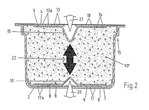
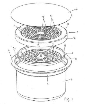
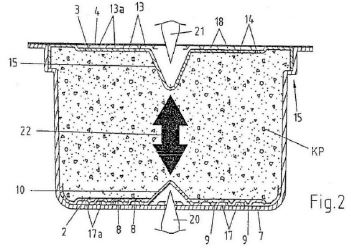
10 Figures 1 and 2 of the complete specification assist in identifying and explaining the features of the invention. They are illustrative of an embodiment of the invention. Figure 1 is an exploded view of a cartridge adapted to contain a single serving of a particulate substance used in the preparation of a beverage. Figure 2 is a longitudinal sectional view of an assembled cartridge containing a single serve of coffee powder.
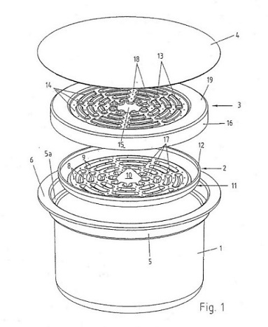
11 These figures show a cartridge with a main housing portion (1), a lower fluid collection member (2), upper fluid distribution member (3), and a cover (4). Coffee powder is stored in the main housing portion (1) between the lower fluid collection member (2) and the upper fluid distribution member (3). The main housing portion (1) and the cover (4) consist of a gas-tight multi-layer composite foil material.
12 Claim 1, it will be noted, defines the cartridge as having at least one “fluid director member” which has an essentially disc-shaped configuration. The parties accept that the lower fluid collection member (2) and the upper fluid distribution member (3) are, each, a “fluid director member” of the kind referred to in the claim. Claim 2 defines a cartridge in which the “fluid director member” is a fluid collection member located in the interior of the cartridge between the particulate substance and the bottom of the main body portion. Thus, the invention is not limited to a cartridge having both an upper fluid distribution member and a lower fluid collection member, although such a capsule is a preferred embodiment. Figures 1 and 2 must be understood accordingly.
13 The lower fluid collection member, as exemplified in Figure 1, is further described (page 9, lines 1 – 13):
The collection member 2 is provided with a plurality of embossings having the shape of annular segments; these embossings show as raised portions 9 protruding from the bottom surface of the lower collection member 2. Once the collection member 2 having been inserted into the main portion 1 of the cartridge, the raised portions 9 rest on the flat bottom surface of the main portion 1, with the result that a plurality of fluid channels 17 are created, running from the central longitudinal axis of the collection member 2 radially outwards and concentrically around the central longitudinal axis of the collection member 2. Beside the raised portions 9, i.e. in the region of the thus created fluid channels 17, the collection member 2 is provided with a plurality of openings 8.
14 The complete specification explains (page 9, lines 21 – 23) with respect to this particular embodiment that, so far as design is concerned, the upper fluid distribution member (3) is essentially a mirror image of the lower fluid collection member (2).
15 With respect to fluid collection in this embodiment, the complete specification says (page 10, line 31 – page 11, line 6):
Moreover, it can be clearly seen that fluid channels 17 are created by the raised portions 9 of the lower collection member 2 resting on the bottom of the main cup- or bucket-shaped main portion 1 of the cartridge. Similarly, fluid channels 18 are created by the raised portions 9 of the upper distribution member 3 resting on the bottom surface of the cover 4 of the main portion 1 of the cartridge.
16 We flag for later reference that, in this embodiment, fluid channels are said to be created by raised portions of the lower collection member resting on the bottom of the main portion of the cartridge. In this appeal, Caffitaly placed significance on this disclosure, and similar disclosures in the complete specification, as signifying an implicit limitation of the invention claimed in claims 1 and 2. In essence, Caffitaly’s position is that fluid channels would not be present in the lower collection member without the raised portions of the embossings “resting” on the bottom of the main portion of the cartridge.
17 However, claims 1 and 2 do not define the channels in these terms. They define the fluid channels, with respect to the fluid director member—whether as a lower fluid collection member or an upper fluid distribution member—as “communicating fluid channels” that are created by the raised portions of the embossings on that member, and nothing more.
18 Further, the complete specification describes embodiments in which the lower fluid collection member and the upper fluid distribution member are not resting on, respectively, the base and the cover (page 15 lines 21 – 29):
If the distribution member or the collection member is located in a certain distance from the bottom 7 and the cover 4 of the cartridge, respectively, there is no need to provide recesses 10 and 15, respectively, in the collection and distribution members, respectively, for receiving the piercing member 20 or 21, since the piercing member 20 or 21 can extend into the free space between bottom 7 and cover 4, respectively, of the cartridge and distribution and collection member, respectively, without damaging the one or the other one of these members.
19 For the purposes of this appeal, it is only necessary to summarise some of the primary judge’s findings.
20 Claims 1 and 2 require that the fluid director member has a plurality of openings and a plurality of embossings. Each embossing has a raised portion. As we have noted, these claims define the invention by stating that the raised portions of the embossings create communicating fluid channels.
21 The parties disagreed as to the meaning of “embossings” and “communicating fluid channels”, as used in these claims and their dependent claims.
22 The primary judge noted that, although not defined in the complete specification, the term “embossings” and the expression “communicating fluid channels” are closely related. He reasoned that the function performed by the raised portions of the “embossings” is relevant to understanding the meaning of that term.
23 The respondents argued that “embossings” had a technical meaning. That meaning referred to a type of manufacturing process that introduces shape or geometry into a flat surface. Such processes would include stamping, pressing or deep drawing, resulting in a raised area above the top plane of the material, matched by a cavity on the lower plane.
24 Caffitaly argued that this meaning was too narrow. According to it, “embossings” referred to the geometry of any shape raised on a surface.
25 After referring to the evidence given by Dr Davis (one of Caffitaly’s experts) and Mr Winkler (one of the respondents’ experts)—which the primary judge did not consider to be of assistance on this question—his Honour concluded that “embossings” referred to the “bulging or convex nature of the shape” of the feature. In reasoning to this conclusion, his Honour had regard not only to the evidence given by Dr Davis (which included reference to the word “boss” as an engineering term) and Mr Winkler, but also to dictionary meanings given to “emboss” (as a verb), “embossing” (as a noun) and “embossed” (as an adjective), and the detailed description in the complete specification of the preferred embodiments.
26 Taking these matters into account, his Honour rejected the notion that “embossings” had a technical or special meaning. Rather, the term was to be given an ordinary and natural meaning best suited to the context provided by the complete specification. His Honour said:
42. … I think in context it is used to describe a surface of the fluid director member that has been “embossed”. This implies that the surface is bulging or convex. The words bulging and convex both feature in the OED definitions of emboss and embossed.
27 The primary judge continued:
43. When regard is had to the detailed description of the preferred embodiments, it is clear that the raised portions (9, 13) of the embossings protrude from the top surface of the upper distribution member (3) and the bottom surface of the lower collection member (2). They are bulging and convex in shape. They create the fluid channels referred to in the claim.
44. Embossings, in the sense that word is used in the claims, may be stamped, pressed or deep drawn into the surface on which they reside. That is not to say that they must be made by any particular manufacturing process. Provided they exhibit the bulging and convex appearance that can be achieved using those processes, it does not matter how they are manufactured. There is no reason why the relevant effect might not be achieved by a process of injection moulding. It is the bulging and convex shape of the relevant feature in the finished componentry that will determine whether the requirement that there be a plurality of embossings is satisfied.
28 It can be seen from these passages that the primary judge found that, by using the term “embossings”, the claims were defining particular features of the fluid director member by reference to aspects of shape and configuration and not by the manufacturing process by which those features were formed on the fluid director member.
29 As to the meaning of “communicating fluid channels”, the primary judge accepted the respondents’ submission that this feature is not referring to the path or flow of fluid itself—which was the way in which Caffitaly advanced its case at trial—but to a physical feature of the fluid director member, being the shape or geometry provided by the raised portions of the embossings that will contain and direct the flow of liquid when the cartridge is in use.
30 Caffitaly contended that various versions of OCG’s coffee capsules infringed the patents. So far as the 627 patent was concerned, only the “version 5” capsule was advanced as an infringement. This capsule has a lower fluid director member with six “piercers” or ribs on its underside. Caffitaly argued that these were “embossings” because they were raised portions which stood the filter off the base of the capsule. According to Caffitaly, they allowed fluid to flow between them to a central region, where the flow merged.
31 The primary judge was not persuaded by this argument. He considered the “piercers” or ribs to be just that; they were not “embossings”. The “piercers” or ribs were not bulging or convex in shape. Further, they did not control or direct fluid flow in any meaningful sense. Their true function was to pierce a foil member that was integral with the capsule as manufactured, and to provide structural support for the filter when placed inside the capsule. For these reasons, the version 5 capsule did not infringe the asserted claims.
32 The respondents contended that each of claims 1, 2, 9, 16, and 17 were invalid for lack of an inventive step. The respondents advanced their case on the basis that, as at the priority date of the relevant claims, the invention would have been obvious to the person skilled in the art in light of the common general knowledge considered alone or, alternatively, considered with US patent 4,921,712 (the 712 patent) as information available under s 7(3) of the Act.
33 Mr Winkler gave evidence about the different types of coffee making machines that were well-known at the priority date. The primary judge gave the following summary, based on Mr Winkler’s evidence, of those machines, which his Honour accepted as part of the common general knowledge:
78. A single serve coffee machine is a machine that utilises a capsule containing a predetermined amount of coffee grounds to make a standardised cup of coffee. The single serve coffee machine delivers an amount of water heated to a particular temperature under pressure into the capsule to extract certain flavours from the coffee grounds. The coffee beverage then passes through a filter and exits the machine into a receptacle for drinking.
79. In traditional espresso machines, a portafilter is utilised rather than a capsule. A portafilter has a handle and a filter basket for holding the coffee grounds. Coffee grounds are manually placed into the filter basket by the operator. The operator then uses a tamp to manually compact the coffee grounds in the filter basket. The portafilter is then attached to the espresso machine. The espresso machine then delivers heated water under pressure through the coffee grounds through a shower head mechanism. The shower head provides an even coverage of water over the coffee grounds to ensure that the coffee grounds are fully extracted. The coffee beverage then passes through the filter in the bottom of the filter basket and exits the machine into a receptacle for drinking. The operator then removes the portafilter from the espresso machine and removes the used coffee grounds. Espresso machines are generally considered to produce good quality espresso coffee. However, the manual handling of the coffee grounds can be messy and the process of preparing the coffee beverage can be time consuming.
...
81. In drip coffee machines, the coffee grounds are held in a large conical paper filter in a brewing basket. Heated water is then fed onto the coffee grounds through a shower head mechanism and the flavours of the coffee are extracted from the grounds. However, unlike in an espresso machine, the extraction does not occur under pressure. Drip coffee machines usually create between 8 to 12 cups of coffee at a time and, therefore, are not suitable for making a single serving of coffee.
82. Drip coffee is made by pouring hot water over the top of coffee grounds, which are held in a filter, and letting the water slowly pass through the coffee grounds and the filter by the force of gravity. In contrast, an espresso coffee is made by pressing hot water at a high pressure through compacted coffee grounds. Drip coffee has a different flavour profile to espresso coffee. Espresso coffee is generally made using darker roast coffee beans which give it a stronger flavour. Drip coffee is made with a lighter roast and has a lighter, more nuanced flavour. The grind profile of an espresso coffee is generally finer than for drip coffee. The finer particles allow for a more compacted coffee bed which increases the resistance of water passing through the coffee bed. This extracts soluble compounds from the coffee grinds, which have a different flavour profile from the coffee grinds used in drip coffee which are generally considered to be sharper and have a different mouth feel. In drip coffee, the heavier grind and larger particles facilitate the passage of the water through the coffee bed under the force of gravity alone.
34 In an affidavit made on 18 October 2019, Mr Winkler gave evidence as to what he considered to be the features of single serve coffee capsules that were well-known and generally accepted by engineers working in the field of developing single serve coffee machines and capsules (such as himself) as at the priority date:
49. As at March 2002, I considered it to be well-known and generally accepted by me and other engineers working in the field of developing single serve coffee machines and capsules that single serve coffee capsules had at least the following features:
(a) an enclosure for storing the coffee grounds. Cup-shaped capsules were preferred because it was easier to store the coffee grounds in a cup-shaped capsule in the manufacturing process;
(b) an entrance means for the water to enter the enclosure;
(c) an exit means for the water to exit the enclosure;
(d) at least one filter inside the enclosure between the coffee grounds and the exit means to prevent the coffee grounds from exiting the capsule with an open area beneath the filter for the water to flow and exit the enclosure; and
(e) be hermetically sealed.
35 The primary judge accepted that features (a) – (c) and (e) were standard features of single serve coffee capsules at the priority date, but not feature (d). No coffee capsule having feature (d) was shown to have been common general knowledge at the priority date.
36 In his affidavit, Mr Winkler described the features he would have adopted had he been tasked with developing a single serve espresso coffee capsule at the priority date. His description was informed by the information he knew and regarded to be well-known and generally accepted by engineers working in the field at that time. He said:
55. If I was developing a coffee capsule for a single serve espresso coffee machine as at March 2002, I would have included the standard features in paragraph 49 above. A cup shape is particularly relevant for an espresso coffee capsule because cup-shaped capsules replicate the function of the portafilter of traditional espresso machines. This is beneficial because the methods of extraction used in traditional espresso machines can be applied to the capsules. Additionally, depending on the particular design of the capsule, it may be compatible with traditional espresso machines. I would have made the capsule from materials which were able to withstand the pressure required to make an espresso coffee, were impermeable to oxygen and would be capable of being hermetically sealed. I would have also included an optional second filter between the coffee grounds and the entrance means to act like a shower head to evenly disperse the water across the coffee grounds. This replicates the shower head of a standard espresso machine which I consider was well known as at March 2002.
37 To illustrate this approach, Mr Winkler created three designs. He said that the inspiration for the designs was his desire to replicate, in a capsule, the features of a portafilter from a traditional espresso machine, so far as he could. The main difference between the designs was the method by which the exit filter was affixed.
38 Mr Winkler’s third design is of particular relevance to this appeal. He considered this design to be superior to the other two designs because it provided more versatility in the way the design could be executed:
39 As can be seen, this design utilised an entrance filter and an exit filter. The entrance filter resembled an inverted showerhead with upwardly facing cylindrical bosses. The exit filter was of the same design, but placed in the filter so as to face in the opposite direction to the entrance filter (ie, the cylindrical bosses faced downwardly). Mr Winkler said:
58. ... In the third design, the [exit] filter is press-fit into the capsule and is spaced away from the bottom of the capsule by stand offs which form part of the filter. This feature was known more broadly in product development engineering.
40 Mr Winkler emphasised that the filter was “a standard showerhead design with circular holes and protrusions”. He said that “the filter would need to include space for the water to flow through the holes”. Otherwise, “the holes would be blocked by the bottom of the capsule and the lid and would not function”. Mr Winkler said that ribs, located in the “cup” (meaning the capsule) or the filter itself, could be used as a means of achieving “the standard feature of creating an open area under the filter so that the liquid can flow through the filter”. It seems that Mr Winkler’s inspiration for adopting ribs, to achieve an open area under the filter of his design, was inspired by the disclosures of the 712 patent, to which his attention was directed. We observe that the 712 patent was not part of the common general knowledge at the priority date.
41 The primary judge noted, at [96], that Mr Winkler’s third design had all the features of the cartridge claimed in claims 1 and 2, subject to satisfaction of the requirement that the fluid director member (specifically, the exit filter in his designs) have a plurality of embossings whose raised portions create a plurality of communicating fluid channels.
42 The primary judge accepted Mr Winkler’s evidence as to how he would have gone about designing a single serve espresso coffee capsule as helpful and, generally speaking, persuasive. His Honour said:
113. … In my view, the design pathway followed by Mr Winkler (including its starting point) would have been obvious to a person skilled in the relevant art at the priority date and was one that would have directly led to an espresso coffee cartridge within claims 1 and 2 of the 627 patent subject only to the requirement that the fluid director member have a plurality of embossings (as I have interpreted that word) and fluid channels.
43 In dealing with the question of whether Mr Winkler’s designs incorporated a fluid director member having a plurality of embossings and communicating fluid channels, the primary judge said:
114. The applicant did not suggest that there was anything unusual about the shape or configuration of the embossings in the lower distribution member of the invention claimed in claims 1 and 2. That is hardly surprising in circumstances where the applicant has always contended that the word “embossing” refers to no more than the geometry of any shape that is raised off a surface. That said, it is still necessary to ask whether the shape or configuration of the embossings referred to in the claims, as I have construed them, might somehow involve an inventive step.
115. Whether or not the bosses on the underside of the exit filter in Mr Winkler’s third design (Fig 3) are embossings in the sense that word is used in the claim is doubtful. I would not describe their shape as bulging or convex. But on the issue of inventive step I do not regard that as a matter of any real significance. If similar shapes were to be created using well-known manufacturing techniques such as pressing or deep drawing, then they would be likely to exhibit the bulging or convex shapes that would also create fluid channels as described in the claims. The difference between what Mr Winkler produced and what is claimed seems to me to reflect small differences in detail that are of no importance to the inventive step analysis. The fact that Mr Winkler’s designs may not in all respects have met the exact requirements of the claims does not diminish the value of his evidence.
44 The primary judge found that the design of an espresso coffee cartridge for use in an espresso machine having the features of the combination defined by claims 1 and 2 would be obvious to a non-inventive product design engineer equipped with the common general knowledge at the priority date. The primary judge also concluded that none of the relevant dependent claims added any additional feature to the combination described in claims 1 or 2 that would render such a combination inventive.
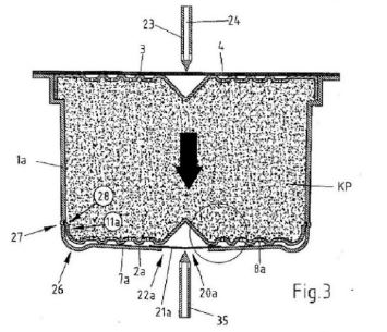
45 In this latter regard, claim 9 claims a cartridge in which the plurality of openings in the fluid director member are located in the communicating fluid channels created between the raised portions of the embossings. As to this claimed embodiment, the primary judge said:
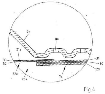
119. ... In circumstances where the function of the fluid channels is to direct brewed coffee out of the cartridge, there cannot be any inventive step arising out of the addition of this requirement. The use of exit holes and channels in the surface of the exit filter reflects a simple design choice that would be well within the capabilities of a non-inventive product design engineer who was tasked with designing a single serve coffee cartridge suitable for making expresso coffee in a pressurised coffee machine as at the priority date.
46 As will be clear, the primary judge’s finding of obviousness in respect of all the relevant claims was based essentially on the design task undertaken by Mr Winkler, in particular his third design, considered against the common general knowledge alone. Having reached that finding, the primary judge did not consider it necessary to consider the respondents’ alternative case incorporating the disclosures of the 712 patent.
47 For completeness, we note that, before the primary judge, Caffitaly referred to four features which it said distinguished the cartridges, described in the complete specification, from the prior art. The primary judge found, at [110], that these features were features of preferred embodiments, but not the essential features of the cartridges claimed in claims 1 and 2. His Honour emphasised that the question whether an invention involves an inventive step is to be answered by reference to the invention as claimed.
48 Grounds 1 and 2 can be dealt with together:
1. The trial judge erred in holding that the first respondent’s version 5 cartridges did not infringe the asserted claims of the 627 Patent: J [53], and ought to have held that first respondent’s version 5 cartridges did infringe the asserted claims of the 627 Patent.
2. The trial judge:
(a) erred in holding that “embossings” is to be construed so as to require a bulging or convex shape in a surface: J [41]-[44];
(b) ought to have held that “embossings” is to be construed so as to require a geometry of any shape that is raised off a surface; and
(c) ought to have held that the first respondent’s version 5 cartridges had “a plurality of communicating fluid channels” .. “created between” said embossings.
49 As will be apparent, these grounds challenge the correctness of the primary judge’s findings as to the meaning of “embossings” as used in claims 1 and 2, and the correctness of the finding that the version 5 capsule did not infringe the 627 patent. Although the grounds of appeal do not directly challenge the primary judge’s finding as to the construction of “communicating fluid channels”, Caffitaly nonetheless challenged his Honour’s construction in submissions. The respondents did not object to this course being taken. Caffitaly accepted that the question of infringement turns on the construction issues it had raised.
50 As to the meaning of “embossings”, Caffitaly advanced, on appeal, the same case that the primary judge rejected at trial.
51 Caffitaly submits that “embossings” refers to the geometry of any shape that is raised off a surface. This was the construction given to “embossings” by Caffitaly’s expert Dr Davis. It was a meaning with which Mr Winkler agreed in oral evidence in the context of describing the filters in his third design. Each of the filters had an annular circumferential ring which Mr Winkler described as an embossing. He also accepted in the course of concurrent evidence that the cylindrical bosses in the filters (displaying the showerhead feature) were embossings. Later, Mr Winkler agreed that the shape of an embossing is not necessarily cylindrical. He also agreed that an embossing is a raised structure.
52 Caffitaly submits that its construction is supported by the dictionary meanings of “emboss” to which the primary judge referred. It points to the fact that, although the dictionary entries quoted by the primary judge at [36] and [37] include “bulging” and “convex”, they extend to meanings such as “to make protuberant” and “to cause … to stand out, project or protrude …”.
53 The Oxford English Dictionary meanings also include “to ornament with or as with bosses or studs”. The significance of the respondents drawing attention to this meaning is that, in order to support the construction he proffered, Dr Davis called in aid the term “boss” as used in engineering. The primary judge reasoned that the meaning of “boss” as an engineering term was narrower than the meaning of “embossing” proffered by Dr Davis, and that there was nothing to indicate in the dictionaries that the word “boss” and “embossing” had the same meaning. Caffitaly argues that the meaning “ornament with or as with bosses or studs” pointed to the primary judge giving a more limited meaning to “embossings” than was warranted.
54 Given that the stated purpose of the “embossings” in the relevant claims is to create channels between the raised portions thereof, Caffitaly submits there is no requirement for them to be convex in order to achieve that purpose. It contends that, when dealing with the question of inventive step, the primary judge appeared to accept, at [115], that the cylindrical bosses in the filters in Mr Winkler’s third design would have created fluid channels. It submits that his Honour should have reasoned similarly when dealing with the question of construction so as to find that “embossings” should not be given the more nuanced meaning which, in fact, his Honour gave to that term.
55 Caffitaly submits that, in arriving at his construction of “embossings”, the primary judge impermissibly placed a gloss on the term by reference to the patent drawings—a gloss which, according to Caffitaly, found no corresponding description in the text of the complete specification. Further, relying on Dr Davis’ evidence and Mr Winkler’s oral evidence, Caffitaly submits that the complete specification would not suggest to the person skilled in the art that the “embossings” be convex. Caffitaly points to the fact that the respondents themselves did not contend for the meaning found by the primary judge or, indeed, that any particular shape was required for the “embossings”.
56 As to the meaning of “communicating fluid channels”, Caffitaly submits that, here too, the primary judge placed a gloss on the claim language. The complete specification does not say that the “embossings” “contain” or “direct” the fluid flow. Caffitaly argues that “embossings” are expressed as no more than a physical feature which, by reason of their “shape and dimension”, in combination with the “interior floor of the main body portion on which they are designed to rest”, are “apt to create channels in which the brewed fluid can flow, and in that manner, create communicating fluid channels”.
57 Building on these submissions, Caffitaly submits that the six “piercers” or ribs in the filter of the version 5 capsule are in contact with the internal floor of the capsule once the filter is inserted and create, in combination with the floor of the capsule, fluid channels. It submits that there is no requirement that the fluid flow be contained or directed. Therefore, the version 5 capsule infringes claims 1, 2, 9, and 17 (noting, once again, that Caffitaly no longer advances claim 16 as having been infringed).
58 The task of construction was for the primary judge to perform. Whilst it is undoubtedly true that the specification (including the claims) must be read through the eyes of the hypothetical person skilled in the art, the primary judge was not required to accept, uncritically, the views of the parties’ experts as to what they understood the term “embossings” to mean.
59 Plainly, the primary judge did not ignore Dr Davis’ and Mr Winkler’s evidence. Equally plainly, the primary judge did not consider their evidence to be of assistance. The primary judge explained his reasons for coming to this view. His Honour was satisfied that Dr Davis had wrongly equated “embossings” with the word “boss” itself and had given insufficient attention to the context in which “embossings” appears in the relevant claims when read in light of the complete specification as a whole.
60 The primary judge also thought this to be true of Mr Winkler’s oral evidence. As to that evidence, it is clear that the primary judge was perplexed by the unexplained difference between what Mr Winkler had said in his affidavit (namely that “embossing” refers to a particular type of geometry in which there is a raised area above the plane of the material which is matched by a cavity on the underside of the plane) and what he had later said in oral evidence. We also observe that, in a Joint Expert Report which he had prepared with Dr Davis, Mr Winkler had said that the raised circumferential flange in each filter in his third design was “equivalent” to the raised portions of the “embossings” referred to in the 627 patent, not that it was an “embossing” as claimed. We would add that, having read the evidence for ourselves, the primary judge’s hesitance in acting on Mr Winkler’s evidence on the meaning of “embossings” is entirely understandable.
61 In undertaking his analysis, the primary judge was clearly mindful that the word “embossings” had been deliberately chosen, rather than some more general term such as “projections”. Hence, his Honour’s resort to (what he described as) a more nuanced meaning for the term.
62 Importantly, the primary judge had the context provided by the complete specification itself, which exemplified what was intended to be conveyed by “embossings” when used in the relevant claims. We do not accept that, simply by resorting to the complete specification for assistance in understanding the features of the invention as claimed, it can be said that the primary judge thereby put a gloss upon the claim language. The primary judge was required to construe the term “embossings” in the context of the complete specification itself. It would have been an error for his Honour not to have done so.
63 The complete specification uses the term “embossings” without further explanation, save for two matters.
64 First, the complete specification illustrates “embossings” in its accompanying figures. These show the bulging and convex shape to which the primary judge referred. We do not think that, by using the term “convex”, his Honour was intending to convey a precise geometrical shape. His Honour’s use of the corresponding term “bulging”—a term without a geometrically precise meaning—suggests this conclusion. We think that his Honour used the terms “bulging” and “convex” as a hendiadys to convey the general shape of something that is an “embossing”, as understood by the claims.
65 Secondly, it is noteworthy that, in describing the “embossings” on the fluid director member, the relevant claims refer to them as each having a “raised portion”. This is important. It distinguishes the term “embossings” as meaning something more than a “raised portion” as such. Had the claims intended to characterise the fluid director member simply by the presence of “raised portions” on the fluid director member or, as Caffitaly would have it, any shape raised off the surface of that member, then the use of “embossings” in the claims would have been mere surplusage. This would not be a sensible way to construe them. In the primary judge’s words, it would give insufficient attention to the context in which “embossings” appears in the relevant claims when read in light of the complete specification as a whole.
66 The meaning given to “embossings” by the primary judge is clearly supported by the dictionary entries to which he referred. It may be accepted that there are entries which give a broader meaning. But these meanings are abstracted from the primary source of information available to the primary judge, which was the complete specification itself. The primary judge’s task in construing the claims was not to search for the broadest possible meaning of “embossings” but to arrive at the meaning by which Caffitaly had chosen to define and describe its invention.
67 For these reasons, we are not persuaded that the primary judge erred in the construction he gave to the term “embossings”.
68 We are of the same view in respect of the construction which the primary judge gave to “communicating fluid channels”.
69 Caffitaly’s submission is that, by commenting that the “communicating fluid channels” are of a shape or geometry that can “contain and direct” the flow of liquid, the primary judge was placing an impermissible gloss on the language of the claims.
70 We do not accept that submission. There can be no cogent criticism of his Honour’s use of either “contain” or “direct” when describing the “communicating fluid channels”. His Honour was doing no more than describing the function of the channels, consistently with the description in the complete specification.
71 In this connection, it is to be noted, firstly, that the channels are a feature of the “fluid director member”. As the complete specification makes clear, the advantage of this defined member, when located at the inlet side of the cartridge above the particulate substance—where it functions as a fluid distribution member—is to ensure a uniform distribution of the extraction water fed into the cartridge, independently of the number and size of the cartridge’s inlet perforations. It also acts as a filter. When located downstream from the particulate substance, this defined member acts as a fluid collector member, as well as a filter. The use of the word “director” for this member can only signify that its function is to direct the flow of the fluid.
72 The use of the word “channels” signifies that this feature of the “fluid director member” sets the course for the direction of that flow, whether functioning as a fluid distribution member or a fluid collection member. In this sense, the channels “contain” the flow.
73 When considering the features of the “fluid director member”, one relevant matter of context is that, in the embodiment illustrated in Figure 2, the brewing water enters the cartridge under pressure through an upper perforation (created by a piercing member (21)) into a recess (15). In this embodiment, the provision of the recess means that the “fluid director member” is not damaged by the piercing. The “fluid director member” then functions as a fluid distribution member for the flow of the water through the particulate (coffee). Once the water passes through the particulate, it is then collected by the lower “fluid director member” (functioning as a fluid collection member) and exits the cartridge through a lower perforation (created by a piercing member (20)) in a lower recess (10). This illustrates how, in at least one embodiment, the “fluid director member” (as a fluid distribution member and as a fluid collection member) functions with its defined features.
74 For these reasons, Ground 2 of the appeal is not made out.
75 OCG’s version 5 cartridges do not possess all the essential features of the claims in suit. These cartridges do not have the plurality of “embossings”, which are an essential feature of the claims. Further, we see no error in the primary judge’s finding that the six piercers or ribs in these cartridges do not control or direct fluid flow in any meaningful sense—meaning that they are not “communicating fluid channels”, which are also an essential feature of the claims in suit. Put compendiously, OCG’s version 5 cartridges do not have a plurality of embossings that create a plurality of communicating fluid channels between the raised portions of the embossings.
76 It follows that Ground 1 of the appeal is not made out.
Caffitaly’s submissions
77 Grounds 3 and 4 can be dealt with together:
3. The trial judge erred in holding that claims 1, 2, 9, 16 and 17 of the 627 Patent lacked an inventive step: J [124], and ought to have held that claims 1, 2, 9, 16 and 17 of the 627 Patent involved an inventive step.
4. The trial judge:
(a) erred in holding that the question whether the hypothetical designs of the respondents’ expert Mr Winkler met the requirements of the claims, including with respect to the presence of embossings, communicating fluid channels, and the location of apertures, was of no real significance on the issue of inventive step: J [115]-[121];
(b) ought to have held, and ought to have treated as a matter of significance, that Mr Winkler’s hypothetical designs did not embody the invention claimed by claims 1, 2, 9, 16 and 17 of the 627 Patent.
(c) erred in rejecting the submission that there was no satisfactory explanation as to why the non-inventive worker would have included in a hypothetical coffee capsule design a filter element which also acts as a fluid collection member by incorporating features which stand it off from the base of the capsule so that beverage can flow beneath it (J [104], [110]).
78 The focus of the case on inventive step was Mr Winkler’s hypothetical design task, with specific reference to his third design: [38] above.
79 As we have noted, the primary judge considered it doubtful that the underside of the exit filter in Mr Winkler’s designs met the requirement of claims 1 and 2, insofar as those claims specified the need for embossings creating communicating fluid channels. Proceeding on the basis that these requirements were not met in Mr Winkler’s designs, his Honour was persuaded that the differences between Mr Winkler’s designs and the cartridge claimed in claims 1 and 2 were:
(a) small differences in detail that were of no great importance to the inventive step analysis; and
(b) if similar shapes were to be created using well-known manufacturing techniques, such as pressing or deep drawing, then they would likely produce the bulging or convex shapes that would create the communicating fluid channels described in the claims.
80 Caffitaly submits that Mr Winkler’s designs “departed radically” from the prior art. In oral argument, it developed the following submissions in conjunction with its written outline of submissions.
81 First, Caffitaly submits that the prior art could not have inspired the inclusion, in Mr Winkler’s designs, of the exit filter, particularly given the primary judge’s acceptance (at [84] and [86]) that there was no coffee capsule shown to be part of the common general knowledge at the priority date which contained feature (d) (referred to at [33] – [34] above), namely:
... at least one filter inside the enclosure between the coffee grounds and the exit means to prevent the coffee grounds from exiting the capsule with an open area beneath the filter for the water to flow and exit the enclosure.
82 In essence, Caffitaly submits that Mr Winkler’s design exercise, which commenced with a filter having feature (d), proceeded from a starting point that was not part of the common general knowledge. Caffitaly submits that, in reaching his conclusion on lack of inventive step, the primary judge overlooked his finding that feature (d) was not common general knowledge.
83 Secondly, Caffitaly submits that the primary judge erred in misunderstanding the design and function of the cylindrical bosses in Mr Winkler’s showerhead design for the filter. At [94], the primary judge said that the cylindrical bosses on the exit filter in Mr Winkler’s design allowed the filter to stand off the bottom of the cartridge, thereby creating a space which allows the coffee to collect and pass to the exit. Caffitaly points out that Mr Winkler’s evidence was that, in his design, a raised outside flange, which runs around the perimeter of the filter, is the element that holds the filter “off the bottom”, not the bosses. Indeed, as Mr Winkler stressed in his affidavit evidence, a space had to be provided under the bosses otherwise the holes in them, through which the coffee passes, would not function; they would be blocked by the bottom of the cartridge.
84 Further, Mr Winkler said that the cylindrical bosses in his design were a means of providing support in the injection moulding process. They were not the means of providing support for the filter when inserted in the capsule. As Caffitaly puts it, the cylindrical bosses in Mr Winkler’s showerhead design are no more than “by-products of the injection moulding process ...”.
85 Thirdly, Caffitaly submits that neither Mr Winkler nor the primary judge identified any specific component of a portafilter (on which Mr Winkler said he based his design) which had the features of the fluid director member referred to in claims 1 and 2.
86 Fourthly, and relatedly, Caffitaly submits that even if the cylindrical bosses in Mr Winkler’s showerhead design for the filter were “embossings” within the meaning of the claims—a proposition which the primary judge doubted—the bosses did not create “communicating fluid channels” because, on Mr Winkler’s evidence, the bosses do not reach the base of the cartridge. Once again, a space is required to be created so that the exit holes in the cylindrical bosses are not blocked.
87 Fifthly, Caffitaly submits that it is an inherent feature of claims 1 and 2 that the “plurality of openings” in the fluid director member be located in the “communicating fluid channels” created between the raised portions of the embossings. In Mr Winkler’s design, the openings are in the cylindrical bosses themselves.
88 Caffitaly submits that, given these matters, Mr Winkler did not arrive at the cartridge claimed in claims 1 and 2. Further, it submits that the primary judge erred in finding (at [115]) that the differences between Mr Winkler’s designs, and the cartridge claimed in claims 1 and 2, are “small differences in detail that are of no importance to the inventive step analysis”. Caffitaly submits that, to the extent that, in undertaking his analysis, the primary judge “added the missing features” to arrive at this conclusion, he did so without expert evidence as to whether, hypothetically, the person skilled in the art would have added such features, and without expert evidence as to how or why the person skilled in the art would have added those features.
89 We do not accept a number of Caffitaly’s submissions.
90 First, we do not accept that, in reaching his conclusion on lack of inventive step, the primary judge commenced his analysis from a point that was not common general knowledge. Mr Winkler specifically identified the portafilter from a traditional espresso machine as the impetus for his designs. He said that he endeavoured to replicate, as much as possible, the features of a portafilter into his design of a coffee capsule for a single serve espresso machine. He also said that he adopted the showerhead design to replicate the showerhead of a standard espresso machine. The primary judge accepted this evidence at [79] of the reasons (quoted at [32] above). Importantly, his Honour found that traditional espresso machines—in which a portafilter, rather than a capsule, is used—were part of the common general knowledge. There is no appeal against those findings.
91 It is tolerably clear that Mr Winkler’s desire to replicate, in a capsule, the features of a portafilter from a traditional espresso machine, is the design pathway, and the starting point, to which the primary judge referred. It was in following that pathway that Mr Winkler adopted the showerhead design for the filter, and noted that, in adopting that design, a space below the filter was required to enable the extracted coffee to flow through the holes of the cylindrical bosses.
92 Secondly, we do not accept that claims 1 and 2 require the “communicating fluid channels” to be created by the embossings resting on the bottom portion of the cartridge, such that the raised portions of the embossings and the bottom portion of the cartridge delimit the fluid channels. This is certainly a feature of one preferred embodiment of the invention described in the complete specification, but the cartridge of claims 1 and 2 is not so limited. We have already remarked (at [16] – [18] above) that claims 1 and 2 do not define the channels in these terms, and that the complete specification describes embodiments (also falling within claims 1 and 2) in which the lower fluid collection member, and the upper fluid distribution member, are not resting on, respectively, the base and the cover of the cartridge. Caffitaly’s submissions put an unwarranted gloss, and hence an impermissible limit, on these claims.
93 Thirdly, we do not accept that it is an implicit feature of the cartridge claimed in claims 1 and 2 that the “plurality of openings” in the fluid director member are located in the “communicating fluid channels”. Once again, Caffitaly’s submission puts an unwarranted gloss and impermissible limitation on claims 1 and 2.
94 However, we do accept that the primary judge erred at [94] of the reasons, when his Honour said that the downwardly facing cylindrical bosses in Mr Winkler’s showerhead design for the exit filter allow the filter to stand off the bottom of the cartridge, allowing coffee to collect and pass to the exit.
95 Mr Winkler’s evidence on this point was clear and unequivocal. In his designs, the raised outside flange that runs around the perimeter of the exit filter holds it off the bottom of the capsule to create the space that is required. The cylindrical bosses on the showerhead of the exit filter cannot perform the function of spacing the filter from the bottom of the capsule because, if they did, the exit holes in the bosses would not function; they would be blocked by contact with the bottom of the capsule.
96 But this misunderstanding is of no great significance when it is appreciated that, contrary to Caffitaly’s submission, claims 1 and 2 are not limited to a cartridge in which the “communicating fluid channels” are delimited by contact of the embossings of the “fluid director member” with the lower portion of the cartridge.
97 What is of significance is the fact that Mr Winkler did not arrive at the invention claimed in claims 1 and 2. As we have noted, the primary judge considered the differences between Mr Winkler’s exit filter and the “fluid director member”, as claimed, to be small matters of detail which might be arrived upon if, in manufacture, techniques such as pressing or deep drawing were employed. It is on this basis that the primary judge concluded that the invention claimed in claims 1 and 2 does not involve an inventive step because the invention would have been “obvious to a non-inventive product design engineer equipped with the common general knowledge at the priority date”.
98 In considering whether the primary judge erred in reaching that finding, we consider the following matters to be important.
99 First, in his design task, Mr Winkler did not conceive of a “fluid director member”. His designs incorporated an exit filter to replicate the portafilter of a traditional espresso machine. A portafilter is not a “fluid director member” as understood by claims 1 and 2.
100 Secondly, Mr Winkler’s designs did not result, either by design or by chance, in a capsule (cartridge) with a “fluid director member”, let alone a “fluid director member” having embossings with raised portions that create a plurality of “communicating fluid channels” between those raised portions. In fact, his designs are no closer than the respondents’ version 5 capsule in having the features of invention.
101 Thirdly, we do not see the present case as analogous to cases such as DSI Australia (Holdings) Pty Ltd v Garford Pty Ltd [2013] FCA 132; (2013) 100 IPR 19. In that case, the hypothetical design task did not result in a combination incorporating the precise mechanical features referred to in the relevant claims. It did, however, result in a combination which provided alternatives which, properly considered, were mere design variants of the precise mechanical features claimed. In the present case, the feature of a “fluid director member” is entirely missing in Mr Winkler’s designs.
102 Fourthly, just as Mr Winkler did not conceive of a “fluid director member” in his design task, we see no reason to conclude that, by deploying ordinary skill and the common general knowledge, the person skilled in the art would have conceived of such a member if seeking to provide, before the priority date, an improved single serve cartridge of the general kind discussed in the complete specification.
103 The requirement of s 7(2) of the Act, relevant to the present case, is that an invention is to be taken as involving an inventive step unless it would have been obvious to the person skilled in the art in light of the common general knowledge as it existed before the priority date. Given the matters to which we have referred immediately above, we are unable to accept that the invention claimed in claims 1 and 2 would have been obvious to the person skilled in the art. The invention would not have been obvious simply because it might have been achieved, by chance—in substance, by accident—in the execution of Mr Winkler’s designs—specifically, his showerhead design—in circumstances where a “fluid director member” was not even in Mr Winkler’s contemplation. In our respectful view, the primary judge erred in concluding otherwise.
104 With reference to claim 9, Caffitaly submits that the primary judge erred in finding that there cannot be any inventive step by locating the plurality of holes between the raised portions of the embossings. It submits that the primary judge’s error was to treat this feature as an addition to Mr Winkler’s designs, rather than testing this feature against the common general knowledge.
105 Claim 9 is dependent on any one of claims 1, 2, 4, and 7. Like claims 1 and 2, the cartridge of claims 4 and 7 also requires a “fluid director member” with the features we have discussed. Given the conclusion we have reached above, it is unnecessary for us to decide whether the primary judge erred in finding that claim 9 does not add a feature that could provide inventiveness. Even so, we are not persuaded that the primary judge erred in finding (at [119]) that the use of openings in the fluid channels between the raised portions of the embossings reflects a simple design choice that would be well within the capabilities of a non-inventive product design engineer tasked with designing a single serve coffee cartridge. However, given claim 9’s dependency, the primary judge erred in finding that claim 9 lacks an inventive step.
106 Grounds 3 and 4 also allege error by the primary judge in finding that claims 16 and 17 lack an inventive step. Caffitaly did not direct any submissions to these particular claims. We note, however, that each claim is dependent, directly or indirectly, on any of claims 1, 2, 4, and 7. For the reasons we have given, it also follows that the primary judge erred in finding that these claims lack an inventive step.
107 We would allow Ground 3, and Ground 4 in part.
108 The claims of the 121 patent in issue were claims 1 to 5 and 14. Caffitaly alleged that these claims were infringed by “versions 1, 2(a), 2(b), 3 and 4” of OCG’s coffee capsules. The issue of infringement turned on a question of construction of claim 1. The primary judge decided that construction issue in favour of the respondents. It followed that OCG’s products did not infringe the relevant claims.
109 The primary judge went on to consider the respondents’ challenge to the validity of the relevant claims. The respondents relied on the following grounds: lack of novelty, lack of inventive step, and lack of utility. The primary judge rejected the respondents’ contentions based on lack of novelty and lack of utility, but accepted their contention based on lack of inventive step. Accordingly, his Honour made an order that claims 1 to 5 and 14 of the 121 patent be revoked.
110 By Grounds 5 to 9 of its notice of appeal, Caffitaly challenges the primary judge’s construction of claim 1 (and thus his Honour’s conclusion on infringement) and his Honour’s reasons and conclusion relating to lack of inventive step. By a notice of contention, the respondents seek to uphold the primary judge’s judgment on the additional basis of lack of novelty.
The complete specification
111 The complete specification of the 121 patent is entitled “Cartridge containing one serving of coffee powder for preparing a coffee beverage”. The priority date of the relevant claims is 13 January 2004.
112 The complete specification states that the present invention refers to a cartridge containing one serving of coffee powder for preparing a coffee beverage, and that such cartridges are “well known in the art in a plurality of embodiments, whereby particularly cartridges for preparing so-called espresso coffee beverage are in widespread use”. It is then stated that the “fundamental advantage” of such cartridges (that is, those already in use) “may be seen in the fact that they are gas-tight, whereby the coffee powder is contained therein without oxygen that would impair the quality of the coffee powder during storage of the cartridge” (page 2, lines 7 – 13).
113 The complete specification contains a description of prior art coffee makers and coffee cartridges. The following passage appears (page 2, line 25 – page 3, line 14):
All these above mentioned species of coffee maker usually comprise a hollow so-called brewing spike provided with radial outlet openings for injecting brewing water into the cartridge that is also adapted to punch the bottom and the cover, respectively, of the cartridge. Also known are manually operated coffee makers in which the cartridge retainer is provided with a plurality of embossments located on an outlet grate; these embossments break open the cover of the cartridge as soon as brewing water is injected into the cartridge from the opposite side thereof and the cartridge is pressed against the embossments under the influence of the hydraulic overpressure created by the pressurized brewing water. During the subsequent brewing operation, the brewing water is injected into the cartridge by means of the brewing spike, with the result that [it] flows under pressure through the coffee powder contained in the cartridge and escapes from the cartridge through the opening created by the embossments.
Independent of the fact whether it is a manually operated coffee maker or a semi-automatic or a fully automatic machine, the coffee maker is designed and adapted to the cartridge so as to produce a coffee beverage having froth on its surface; that froth usually is considered as a characteristic of a good coffee beverage.
Even if great efforts have been taken to ensure that the prepared coffee beverage has durable froth on its surface, in certain countries the desire arises to prepare also conventional coffee in the sense of a filter coffee by means of these coffee makers. In place of the expression “filter coffee”, also the expression “gentle coffee” is used.
114 Following that passage, there is a description of a cartridge of the kind disclosed in US Patent document 2003/172813, which (based on the description in the 121 patent) corresponds to the invention disclosed in the 627 patent. The complete specification states (page 3, line 15 – page 4, line 2):
The U.S. Patent document 2003/172813 discloses a cartridge of the kind referred to herein. It contains a substance extractable by means of water for preparing a beverage, preferably an espresso coffee. Thereby, a sieve-like member is disposed between the bottom of the cartridge and the substance and/or between the cover of the cartridge and the substance, provided with a plurality of axial apertures. The sieve-like member is provided with stampings directed towards the bottom of the cartridge and the cover of the cartridge, respectively, such that fluid channels are formed between the sieve-like member and the bottom of the cartridge, and the sieve-like member and the cover of the cartridge, respectively. In these channels, the brewing water can be distributed over the cross sectional area of the cartridge, and the prepared beverage can be collected in these channels, respectively. In order to prevent that the sieve-like member is punched upon piercing the cartridge, the sieve-like member comprises a central recess directed towards the interior of the cartridge into which the piercing member can extend once the cover or the bottom of the cartridge have been pierced. Even if such a cartridge is well suitable for preparing espresso coffee, it can hardly be used for preparing normal filter coffee, since the cartridge presents a high flow resistance to the brewing water flowing therethrough; the result is a formation of froth. In such a cartridge, moreover, the sieve-like member can move with regard to the bottom of the cartridge.
115 The complete specification states (page 4, lines 15 – 18):
Embodiments of the present invention to provide a cartridge containing one serving of coffee powder for preparing a coffee beverage of the kind disclosed in patent US 2003/172813 in which the sieve-like member is fixed with respect to the bottom of the cartridge.
116 There follows a consistory statement in substantially the same terms as claim 1 (page 4, lines 19 – 28):
According to a first aspect of the present invention there is provided a cartridge containing one serving of coffee powder for preparing a coffee beverage, comprising a cup-like shaped lower portion and a cover portion attached to said lower portion, and a filter element located inside said cartridge lower portion between said coffee powder and a bottom portion of said cartridge lower portion, wherein the interior of said cup-like shaped lower portion of said cartridge is provided with an annular groove, whereby said filter element is provided with a·peripheral edge portion engaging said groove for fixing said filter element to said lower portion of said cartridge, wherein the peripheral edge portion engages said groove for clampingly fixing said filter element to said lower portion of said cartridge.
(Emphasis added.)
117 The construction issue that arises on appeal concerns the words highlighted in bold. The issue, in summary, is whether it is a requirement of claim 1 that the fixing of the filter element be achieved solely by the engagement between the peripheral edge portion of the filter element and the annular groove.
118 The complete specification then states (page 4, line 29 – page 5, line 16):
As described herein, the cartridge may be capable of being used in a conventional espresso machine to prepare a normal coffee beverage not having froth on its surface and corresponding in taste to a normal filter coffee.
In this last case, by providing at least the bottom portion of the cartridge with a passage constituted by an aperture, adapted to avoid a hydraulic pressure build-up in the interior of the cartridge during brewing and extracting the coffee powder, the fundamental prerequisite is realized to use such a cartridge in a conventional espresso machine for preparing a coffee beverage corresponding in appearance and taste to a normal filter coffee. The passage ensures that the pressurized brewing water fed into the cartridge cannot create a substantial pressure build-up in the interior of the cartridge. Thus, the brewing water can flow through the cartridge and, thereby, through the coffee powder contained therein without any substantial resistance, thereby avoiding the formation of froth.
In order to prevent the coffee powder contained in the cartridge from escaping the cartridge through the afore mentioned passage and from being flushed out by the brewing water, a filter element is arranged between the passage and the coffee powder contained in the cartridge. In order to ensure that the coffee powder contained in the cartridge keeps well during an extended period of time in spite of the passage provided in the cartridge, the passage is covered by a gas-tight foil. The latter one is either manually removable or designed such that it can be easily pierced by a punching member.
119 The complete specification then describes an embodiment of the cartridge according to the invention, with reference to certain drawings. There are four drawings (Figures 1 to 4). Figures 1 and 2 show the elements of a coffee powder cartridge that does not incorporate the subject of the present invention. Then, Figures 3 and 4 show an embodiment of a coffee powder cartridge according to the invention. Figures 1 to 4 are as follows:
120 On pages 5 to 10 of the specification, the embodiment represented in Figures 1 and 2 is described in some detail. The specification then describes the embodiment represented in Figures 3 and 4, referred to as a “second embodiment”. It is stated that Figure 3 “shows a longitudinal sectional view of a second embodiment, according to the invention, of a cartridge filled with coffee powder KP, whereby the reference numerals of corresponding parts and elements are the same as used in Figs. 1 and 2, but with the letter “a” added” (page 10, lines 4 – 7). The specification describes a “first difference” to the embodiment discussed in connection with Figures 1 and 2. That difference is not relevant for present purposes. The specification continues (page 10, line 28 – page 11, line 2):
In the second embodiment [ie, that represented in Figures 3 and 4], moreover, according to the invention the cup-like shaped lower portion 1a of the cartridge is provided with a circumferential groove 27 located at the inside of the lower portion la, while the edge 11a of the filter element 2a is provided with a circumferential annular projection 28 engaging the groove 27 to clampingly fix the filter element 2a in the interior of the cartridge.
(Emphasis added.)
121 The specification also contains a description of Figure 4, but that need not be set out for present purposes.
122 The 121 patent contains 15 claims. The claims in issue are:
1. Cartridge containing one serving of coffee powder for preparing a coffee beverage, comprising a cup-like shaped lower portion and a cover portion attached to said lower portion, and a filter element located inside said cartridge lower portion between said coffee powder and a bottom portion of said cartridge lower portion, wherein the interior of said cup-like shaped lower portion of said cartridge is provided with an annular groove, whereby said filter element is provided with a peripheral edge portion engaging said groove for fixing said filter element to said lower portion of said cartridge wherein the peripheral edge portion engages said groove for clampingly fixing said filter element to said lower portion of said cartridge.
2. Cartridge according to claim 1 wherein the groove is located at the inside of the lower portion.
3. Cartridge according to claim 1 or claim 2 wherein the cover portion is sealingly attached to said lower portion.
4. Cartridge according to any one of the previous claims, wherein said cup-like shaped lower portion of the cartridge is dimensionally stable.
5. Cartridge according to any one of the previous claims, wherein said filter element is dimensionally stable and comprises a plurality of apertures.
…
14. Cartridge according to any one of the previous claims, wherein said filter element comprises at least one central recess directed towards the interior of the cartridge.
(Emphasis added.)
The primary judge’s findings
Construction
123 The primary judge dealt with issues of construction at [146]-[162].
124 At [149]-[152], the primary judge dealt with, and rejected, a submission put forward by the respondents relating to the words “engaging” and “engages”. Although not directly relevant for present purposes, it is necessary to refer to this passage to provide context. As recorded in the primary judge’s reasons at [149], the respondents submitted that the engagement between the peripheral edge portion of the filter element and the annular groove referred to in the claim must be one in which the entire geometry of the peripheral edge portion of the filter element is engaged with the entire geometry of the annular groove. The primary judge did not accept that submission:
151. The respondents’ construction of the claim imposes a gloss on what in my view is clear language. The language used does not, either expressly or by implication, require that the engagement referred to occur along the entire circumference of the peripheral edge portion of the filter element.
152. It is true that the preferred embodiment described in the specification shows the annular groove and the peripheral edge portion of the filter element engaged along the entire circumference of each of those elements. However, the language used in the claim is not limited to that specific configuration.
125 On appeal, no issue is raised regarding this aspect of the primary judge’s reasoning.
126 The primary judge then considered a submission made by the respondents relating to the words “clampingly fixed”. The respondents contended, in summary, that it was a requirement of claim 1 that the fixing of the filter element be achieved solely by the engagement between the peripheral edge portion of the filter element and the annular groove referred to in the claim. In contrast, Caffitaly submitted that it was not a requirement of claim 1 that the fixing of the filter element be achieved solely by the engagement between the peripheral edge portion and the groove. Caffitaly submitted that the word “for” as used in claim 1 means that the engagement between the peripheral edge portion and the groove is made for the purpose of producing the result of clampingly fixing the filter element. It submitted that this does not mean that it must be the only element that contributes to that result. In support of its submission, Caffitaly pointed to the embodiment depicted in Figure 3, which shows the base of the capsule abutting the base of the filter element, indicating (Caffitaly submitted) that the base also contributes to holding the filter element in place.
127 The primary judge held that the respondents’ construction was correct. His Honour reasoned as follows:
155. The applicant [Caffitaly] relied on evidence given by Mr Winkler who accepted in cross-examination that in the embodiment depicted in Fig 3, where the filter engages with the groove, the base is also playing a role in preventing the movement of the filter. That answer was given in the context of a broader exchange as follows:
|
| |
|
| |
|
| |
|
| |
|
| |
|
| |
|
| |
|
| |
|
| |
|
| |
|
| |
| ||
| ||
|
| |
|
| |
|
| |
|
| |
|
| |
156. It is true that the cartridge depicted in Fig 3 shows that the downward annular segments of the filter element are in contact with the base of the cartridge. However, the specification does not suggest that it is the function of the base of the cartridge to fix the filter in position or that the base acts as a clamping means. The specification makes clear at page 10, line 29 – page 11, line 2 that the embodiment depicted in Fig 3 is one in which the circumferential annular projection (28) of the filter element (2a) engages the groove (27) to clampingly fix the filter element (2a) in the interior of the cartridge so as to prevent movement in either a horizontal or vertical direction. It is apparent from a reading of the specification as a whole that the particular embodiment around which claim 1 has been drawn provides for the filter element to be fixed in position by the clamping action of the groove on the edge of the filter element with which it engages.
157 In my opinion claim 1 requires that the groove clampingly fix the filter element into position so as to prevent both horizontal and vertical movement relative to the main body of the cartridge by the engagement of the annular groove of the main body and the peripheral edge portion of the filter element.
Infringement
128 The primary judge dealt with the issue of infringement at [163]-[165]. After setting out a photograph of one of OCG’s cartridges, the primary judge explained that, in the relevant OCG products, vertical movement in the downwards direction is prevented, not by the engagement of the peripheral edge of the filter element and the annular groove, but by the engagement of the base of the filter and the base of the cartridge. It was not, therefore, a configuration that met the requirements of the claim (as construed by the primary judge).
129 The primary judge considered the issue of lack of novelty at [166]-[177]. In light of the conclusions we reach below, it is not necessary to set out this aspect of the primary judge’s reasons.
Lack of inventive step
130 The issue of lack of inventive step was dealt with by the primary judge at [178]-[211]. As recorded in the primary judge’s reasons at [178], the respondents submitted that none of the relevant claims involved an inventive step. They submitted that the invention, as claimed, would have been obvious to a person skilled in the art in light of the common general knowledge as at the priority date, whether considered separately or together with the information disclosed in EPA605 or the application for the 627 patent (the 627 application). They did not suggest that these disclosures could be combined.
131 The primary judge discussed, at [179]-[181], the problem to which the 121 patent was said to provide a solution. The primary judge stated that, on Caffitaly’s case, the invention defined by claim 1 was directed to providing a cartridge in which the filter member does not move relative to the bottom of the cartridge in which it is housed.
132 The primary judge considered, at [182]-[195], whether EPA605 was information as described in s 7(3) of the Act, to which regard could be had when determining the issue of inventive step. His Honour concluded, at [195], that EPA605 constituted information that the person skilled in the art could be reasonably expected to have ascertained, understood, and regarded as relevant to the relevant design task.
133 His Honour then considered, at [196]-[207], whether the relevant claims of the 121 patent would be obvious to the person skilled in the art as at the priority date, having regard to the common general knowledge and the information disclosed in EPA605.
134 At [197]-[198], his Honour described the fixing means as a “snap fit” arrangement and referred to the evidence of Dr Davis:
197. The fixing means described in the detailed description of the invention of the 121 patent consists of an annular groove that extends along the inside wall of the cartridge which is adapted to receive the circumferential edge of the filter element. This fixing means was variously described in the evidence as a “snap fit” arrangement that could be used as an alternative to the fixing means used in the preferred embodiment of the 121 patent.
198. Dr Davis described the “snap fit” method as an economical, fast and popular assembly method that could be used to join dissimilar plastics. This type of assembly is particularly desirable if different plastics are used to make the housing of the cartridge and the filter element, and welding is not an option. It is clear that a snap fit arrangement of the kind described in the 121 patent constituted a well-known method of attaching components as at the priority date. Snap fit arrangements, including those that include a recessed groove, were common general knowledge at the priority date.
(Emphasis added.)
135 After referring to the evidence of Mr Winkler and other evidence of Dr Davis, the primary judge reasoned:
204. EPA605 does not disclose a means for fixing the filter to the lower portion of the cartridge of the kind required by claim 1. The fixing means disclosed by EPA605 consists of a protruding circumferential collar that extends inwards from the inside wall of the lower portion of the cartridge which prevents the filter from moving away from the base. But it would be obvious to a person skilled in the art equipped with the common general knowledge and EPA605 that he or she could take a cartridge of the type depicted in that document and include a different fixing means to prevent the filter from moving away from the base. One means of preventing the filter from moving is to incorporate a groove moulded or cut into the side wall of the cartridge into which the peripheral edge of the filter element could then be snap fit so that the filter did not move relative to the base of the cartridge. A design modification of this kind to the cartridge disclosed in EPA605 is something that could be achieved by the person skilled in the art with ease through the routine use of a well-known design feature and without any element of ingenuity.
205. It was also submitted by the applicant that there were reasons why a skilled addressee might choose not to use a groove in place of the collar as the fixing means in the cartridge of the kind shown in EPA605. In particular, it was submitted by the applicant that the 121 patent discloses for the first time in the art the “counterintuitive possibility” of using a groove in the side wall for clampingly fixing the filter.
206. The evidence does not support the proposition that use of a groove to clampingly fix the filter to the cartridge was a counterintuitive possibility. In my view, the use of a groove in the wall of a coffee cartridge of the kind shown in EPA605 to clampingly fix the filter to the cartridge reflects no more than the application of well-known design principles. A person skilled in the art would be directly led to try such an arrangement in the expectation that it would provide a useful way in which to prevent the filter moving relative to the base of the cartridge.
(Emphasis added.)
136 The primary judge also considered whether the relevant claims would be obvious to the person skilled in the art as at the priority date having regard to the common general knowledge and the information in the 627 application (at [208]-[210]).
137 His Honour concluded, at [211], that all of the relevant claims of the 121 patent were invalid for lack of inventive step over the common general knowledge, combined with either EPA605 or the 627 application.
Grounds 5(a) and (b) of the appeal
Caffitaly’s submissions
138 Grounds 5(a) and (b) are:
5. The trial judge:
(a) having correctly found that the language of claim 1 of the 121 Patent does not require that the groove be engaged with the entire circumference of the peripheral edge portion of the filter element: J [151]], erred in holding that claim 1 is to be construed so as to require that the annular groove in the lower portion of the cartridge clampingly fix the filter element into position so as to prevent both horizontal and vertical movement relative to the main body of the cartridge by the engagement of the annular groove and the peripheral edge portion of the filter element: J [157];
(b) ought to have held that claim 1 of the 121 Patent is to be construed so as to require engagement between the peripheral edge portion of the filter element and the groove for the purpose of clampingly fixing the filter element so as to prevent both horizontal and vertical movement relative to the lower portion of the cartridge (and the groove need not be the only element contributing to this purpose);
139 Caffitaly submits that, on its true construction, claim 1 does not require the clamping to be done by the groove alone. In other words, Caffitaly’s argument is that the engagement with the annular groove need not be the only element responsible for fixing the filter element in position. Caffitaly submits that the following matters support its construction: (a) the claim commences by using the general word “engages” in respect of the groove, which merely requires some form of touching or interlocking; (b) the claim defines the required result as clampingly fixing the filter element as a whole rather than the peripheral edge portion of it; and (c) the claim requires that the engagement of the groove be “for” producing that result, which permits other elements also to be used to contribute to the result, such as the base of the capsule.
140 Caffitaly notes that the primary judge accepted that the language of the claim (“engaging”) does not require engagement on all sides of the edge of the filter element, and pointed out that it was not permissible to place a “gloss on that language” by reference to the preferred embodiments. Caffitaly submits that the primary judge “proceeded to make precisely that error”. Caffitaly submits that, instead of considering the claim language (relevantly, that it is the filter element as a whole – not the edge portion – that must be clampingly fixed, and that the engagement of the groove be “for” producing that result), the primary judge considered the question by reference to the preferred embodiment in Figure 3 (at [155]-[156]).
141 We do not accept Caffitaly’s submissions. In our view, the construction adopted by the primary judge is consistent with the language of the claim, read in the context of the complete specification as a whole. The claim refers to the filter element, the lower portion of the cartridge and the annular groove. It then states that the filter element is provided with “a peripheral edge portion engaging said groove for fixing said filter element to said lower portion of said cartridge wherein the peripheral edge portion engages said groove for clampingly fixing said filter element to said lower portion of said cartridge”. It states that the annular groove is “for” clampingly fixing the filter element to the lower portion of the cartridge. There is no reference to any other part of the cartridge contributing to the filter element being held in place. Read in context, the language of the claim suggests that the fixing of the filter element in position is to be done by the groove alone and not, for example, by the groove in conjunction with the base of the cartridge.
142 Insofar as Caffitaly submits that the primary judge erred by considering the question by reference to the preferred embodiment in Figure 3, we do not accept that submission. His Honour’s discussion of that embodiment at [155]-[156] was in response to a contention of Caffitaly that the preferred embodiment supported its construction. Caffitaly sought to rely on evidence given by Mr Winkler during cross-examination that, in the embodiment depicted in Figure 3, the base was also playing a role in preventing the movement of the filter. His Honour’s statements in [156] were made in response to that contention. It is apparent from [156] and [157] that his Honour relied on the language of the claim, read in the context of the complete specification as a whole, and did not fall into the error of construing the claim by reference to a preferred embodiment.
143 For these reasons, we are not persuaded that the primary judge erred in his construction of claim 1. Grounds 5(a) and (b) are not made out.
Grounds 5(c) and (d) and 6 of the appeal
144 Grounds 5(c) and (d) and 6 of the notice of appeal relate to infringement. As noted in Caffitaly’s outline of submissions, the question of infringement follows the question of construction. Given our conclusion in respect of grounds 5(a) and (b), it is not necessary for us to deal with Grounds 5(c) and (d) and 6, save to say that his Honour did not err in finding that the relevant OCG products did not infringe the relevant claims.
Caffitaly’s submissions
145 Grounds 7 to 9 can be dealt with together:
7 The trial judge erred in holding that claims 1, 2, 3, 4, 5 and 14 of the 121 Patent lacked an inventive step: J [211], and ought to have held that claims 1, 2, 3, 4, 5 and 14 of the 121 Patent involved an inventive step.
8 In relation to the trial judge’s finding of lack of inventive step in light of the common general knowledge combined with EPA605, the trial judge:
(a) erred in holding that EPA605 could reasonably be expected to have been regarded as relevant by a person skilled in the art and/or that that person would have used the disclosure in it to include a feature for affixing the filter to the cartridge: J [190][195].
(b) erred in holding that using a groove in the wall of a coffee cartridge as a means of affixing the filter to the cartridge would have been obvious to a person skilled in the art equipped with the common general knowledge and EPA605: J [204]-[206];
(c) failed to have regard to the evidence that Mr Winkler’s hypothetical designs did not include a groove, that he only considered EPA605 after he was prompted to consider additional designs, and that EPA605 taught away from the use of a groove.
(d) ought to have held that using a groove in the wall of a coffee cartridge as a means of affixing the filter to the cartridge would not have been obvious to a person skilled in the art equipped with the common general knowledge and EPA605;
9 In relation to the trial judge’s finding of lack of inventive step in light of the common general knowledge combined with the 627 application, the trial judge:
(a) erred in holding that the 627 Application could reasonably be expected to have been regarded as relevant by a person skilled in the art and/or that that person would have used the disclosure in it to include a feature for affixing the filter to the cartridge: J [190]-[195]
(b) erred in holding that the 627 application disclosed a method of fixing the filter element relative to the base of the cartridge: J [209]-[210], and in particular erred in holding, if his Honour so held, that the pressure resistant rigid frame in Figure 6 fixed the filter element relative to the base of the cartridge in circumstances where such a finding was not supported by the evidence of any witness;
(c) ought to have held that the 627 application did not disclose a method of affixing the filter element relative to the base of the cartridge;
(d) it being the case that the 627 application did not disclose any method of fixing the filter element relative to the base of the cartridge, erred in holding that using a groove in the wall of a coffee cartridge as a means of affixing the filter to the cartridge would have been obvious to a person skilled in the art equipped with the common general knowledge and the 627 application: J [210]; and
(e) ought to have held that using a groove in the wall of a coffee cartridge as a means of affixing the filter to the cartridge would not have been obvious to a person skilled in the art equipped with the common general knowledge and the 627 application.
146 As at the priority date (13 January 2004), s 7 of the Act relevantly provided as follows:
Inventive step
(2) For the purposes of this Act, an invention is to be taken to involve an inventive step when compared with the prior art base unless the invention would have been obvious to a person skilled in the relevant art in the light of the common general knowledge as it existed in the patent area before the priority date of the relevant claim, whether that knowledge is considered separately or together with the information mentioned in subsection (3).
(3) The information for the purposes of subsection (2) is:
(a) any single piece of prior art information; or
(b) a combination of any 2 or more pieces of prior art information;
being information that the skilled person mentioned in subsection (2) could, before the priority date of the relevant claim, be reasonably expected to have ascertained, understood, regarded as relevant and, in the case of information mentioned in paragraph (b), combined as mentioned in that paragraph.
147 The definition of “prior art base” was relevantly as follows:
prior art base means:
(a) in relation to deciding whether an invention does or does not involved an inventive step or an innovative step:
(i) information in a document that is publicly available, whether in or out of the patent area; and
(ii) information made publicly available through doing an act, whether in or out of the patent area.
…
148 In support of its contention that the primary judge erred in his consideration of lack of inventive step, Caffitaly submits that none of the three alternative designs produced by Mr Winkler involved using an annular groove, even though Mr Winkler paid particular attention to the means by which the filter was affixed to the cartridge. Caffitaly submits that the first design was welded, the second involved the filter being snapped between upper and lower segments of the capsule, and the third – Mr Winkler’s preferred design – involved a press fit: see the primary judge’s reasons at [89]-[93]; Mr Winkler’s affidavit dated 18 October 2019 (Mr Winkler’s affidavit) at paragraphs 58-59; trial transcript at page 397. Accordingly, Caffitaly submits, Mr Winkler’s design exercise failed to establish obviousness.
149 Caffitaly submits that Mr Winkler then received a “rather heavy push” from his instructing solicitors. Notwithstanding that he had already considered the question of affixing the filter and found a solution with which he was satisfied, Mr Winkler was asked whether there were any other means of fixing the filter to the cartridge of which he was aware (see Mr Winkler’s affidavit at paragraph 116). Mr Winkler responded that there were not, but he was prompted to engage in a prior art search. One of the documents he found was EPA605. The key elements of that document had nothing to do with fixing the filter, but rather involved the use of perforable parts in the top and base of the capsule. EPA605 also disclosed the use of an annular collar (the opposite of a groove) to fix the filter.
150 Caffitaly submits that the primary judge failed to have regard to the fact that Mr Winkler only arrived at EPA605 after he was prompted to reconsider his hypothetical designs, and failed to have regard to the fact that the key features of EPA605 are not directed to fixing the filter to the cartridge. On the basis of those matters, Caffitaly submits that it could not be concluded that EPA605 would have been regarded as relevant for the purposes of s 7(3) of the Act.
151 Caffitaly further submits that even if EPA605 were relevant, the primary judge failed to have regard to Mr Winkler’s concession that EPA605 “taught away” from using a groove in the side walls of a pressurised capsule (see trial transcript, pages 576 – 577). Caffitaly submits that the primary judge failed to have regard to this evidence and instead appears to have formed his own view that a groove was simply one of a number of alternative affixing means that the skilled addressee would use, without a proper technical foundation for concluding that it would be used in this particular context.
152 In relation to the primary judge’s conclusion on obviousness with reference to the common general knowledge and the 627 application, Caffitaly submits that the 627 application discloses no means of affixing the filter to the cartridge. Indeed, the 121 patent refers to an equivalent of the 627 patent and identifies that a problem was that the filter element was not fixed and could move.
153 In our view, Caffitaly has not established error in his Honour’s conclusion that the invention, as claimed in the relevant claims, was obvious having regard to the common general knowledge and EPA605.
154 Insofar as Caffitaly contends that EPA605 was not information as described in s 7(3) of the Act, on the basis that it was not information that the person skilled in the art could “be reasonably expected to have … regarded as relevant”, we do not accept its submission. EPA605 is entitled “Cartridge for coffee and soluble products, device for the extraction of drinks from said cartridge and relevant drink production method”. As noted by the primary judge, at [190], the search results produced by Ms Susan Hantos included both the abstract and Figure 1 to EPA605. These disclosed to the person skilled in the art that the coffee cartridge described in EPA605 comprised an airtight cartridge made of plastic, fitted with an internal filter inside the cartridge, designed to be used in a pressurised coffee making system. In light of these matters, it was open to the primary judge to find that EPA605 could reasonably be expected to be regarded as relevant by a person skilled in the art engaged in the task of designing a coffee cartridge that could be used to prepare coffee in a pressurised coffee machine. We note also that it was regarded as relevant by Mr Winkler at paragraph 119 of his affidavit.
155 Insofar as Caffitaly submits that his Honour erred in concluding that the invention was obvious having regard to the common general knowledge and EPA605, we do not accept its submission. His Honour’s conclusion was supported by the evidence of Dr Davis, set out in [198] of the primary judge’s reasons, that a “snap fit” arrangement, which his Honour treated as equivalent to the fixing means described in the detailed description of the invention, was an economical, fast, and popular assembly method that could be used to join dissimilar plastics. This was apparently based on Dr Davis’ affidavit, dated 26 January 2020, at paragraph 56 and the joint report of Mr Winkler and Dr Davis at item A.1.7. It was open to his Honour, on the basis of this evidence, to find (as he did at [204]) that a snap fit arrangement was something that “could be achieved by the person skilled in the art with ease through the routine use of a well-known design feature and without any element of ingenuity”: cf Wellcome Foundation Ltd v VR Laboratories (Aust) Pty Ltd (1981) 148 CLR 262 at 280-281, 286 per Aickin J. It was also open to his Honour to find (as he did at [206]) that “[a] person skilled in the art would be directly led to try such an arrangement in the expectation that it would provide a useful way in which to prevent the filter moving relative to the base of the cartridge”: cf Aktiebolaget Hässle v Alphapharm Pty Ltd (2002) 212 CLR 411 at [53] per Gleeson CJ, Gaudron, Gummow, and Hayne JJ.
156 It may be accepted that none of the three alternative designs produced by Mr Winkler involved using an annular groove to fix the filter element in place. However, the skilled person is not an avatar for expert witnesses whose evidence is accepted or rejected by the Court: see AstraZeneca AB v Apotex Pty Ltd (2015) 257 CLR 356 at [23] per French CJ. It was for the Court to make findings of fact in the light of all the evidence. It was thus open to the primary judge to rely on the evidence of Dr Davis regarding the “snap fit” method and to make the findings that his Honour did at [204] and [206].
157 Insofar as Caffitaly submits that EPA605 “taught away” from using a groove in the side walls of a pressurised capsule, we do not accept its submission. The passages of EPA605 highlighted in the questioning of Mr Winkler at trial transcript, pages 576 – 577, which relate to the thickness of the walls of the cartridge, are expressed generally and are not directed to an annular groove. As the primary judge stated in [204], the fixing means disclosed in EPA605 consists of a protruding circumferential collar that extends inwards from the inside wall of the lower portion of the cartridge which prevents the filter moving away from the base. However, as the primary judge also stated, it would be obvious to a person skilled in the art equipped with the common general knowledge and EPA605 that he or she could take a cartridge of the type depicted in that document and include a different means of fixing the filter element in place. EPA605 did not teach away from using a snap fit arrangement; it merely provided a different means of fixing the filter element in place.
158 For these reasons, no error is shown in the primary judge’s conclusion that all of the relevant claims of the 121 patent were invalid for lack of inventive step over the common general knowledge combined with EPA605.
159 In light of that conclusion, it is unnecessary to consider the aspect of the primary judge’s reasons relating to the common general knowledge and the 627 application. Grounds 7 to 9 are not made out.
160 It is also unnecessary to consider the notice of contention, relating to lack of novelty. As we have noted, Caffitaly accepts that the notice of contention only arises if its construction of claim 1 of the 121 patent is correct.
The complete specification
161 The complete specification of the 388 patent is entitled “Method for preparing a drink and apparatus and capsule for application of this method” and was published on 11 December 2008. Caffitaly sued for infringement of claims 34, 35, and 36 and the respondents contended that those claims were invalid. The primary judge:
(a) decided in favour of the respondents on the basis of their challenge brought under the insufficiency ground in s 40(2)(a) of the Act, finding that the invention defined by each of those claims was not fully described in the specification;
(b) rejected the respondents’ invalidity challenge on the basis of lack of utility within s 18(1)(c) of the Act; and
(c) found that, as a matter of construction, had the claims been valid they would not have been infringed.
162 On appeal, Caffitaly challenges only the primary judge’s adverse validity finding based on lack of sufficiency of description.
163 The complete specification states that the invention relates to a method for preparing a drink by passing pressurised hot water in a sealed capsule, and to an apparatus and a capsule which allows this method to be implemented. The invention is said to be intended to be used for preparing any drink which can be obtained by passing hot water in a capsule containing a substance to be extracted or dissolved, and in particular to the preparation of coffee (page 1, lines 5 – 14).
164 By way of background, the complete specification notes that the use of disposable, usually sealed, capsules, through which hot water, under pressure where necessary, is injected to extract the coffee from the powder or grains contained in the capsule, has been known for many years. Over time, many processes and apparatuses have been developed. The outflow of the drink is said to be guaranteed by an opening made through the second wall of the capsule.
165 The specification says (page 1, line 21 – page 3, line 18):
Since the quality of the drink obtained is very much dependent on the methods with which the water is passed through the capsule, with the passage of time many processes and apparatuses intended for preparing such drinks have been developed. For example, a capsule containing a mixture of powdered coffee can be used to obtain a simple infusion by slowly percolating low pressure hot water through it, or the so-called “espresso” (that is to say, a drink with significantly different organoleptic properties) if pressurised hot water is percolated through it. The quality of the espresso may be further improved by forced pre-infusion before starting to dispense the drink from the capsule, then maintaining a predetermined pressure in the capsule during the entire dispensing period.
Usually, the times, temperatures and pressures during the pre-infusion and dispensing steps, the intergranular flow speed and therefore the micro-turbulences generated are essential for obtaining a good organoleptic result. Since not all soluble substances contained in coffee are useful for an optimum result, attempts must be made to optimise the extraction cycle so that the appearance, smell and taste confirm the positive outcome of the process. Up to now, these empirical means have been the only ones considered really reliable to define the quality of the coffee.
Thus, the main technique for making a good quality espresso is broadly speaking widely known. However, in practice achieving a good level of quality and maintaining it constant with the passage of time are not certain and not easy. This is because there are many factors which contribute to the success of the operation, difficult to quantify and sometimes not even clearly identifiable, since even minimal changes in operating circumstances may produce considerably different effects. Moreover, when selecting production methods, preference should be given to simple, reliable methods with low industrial cost, but which guarantee a good end result. It is not commercially feasible to use methods that are too complex and therefore too expensive in order to achieve an optimum result.
As already indicated, one of the techniques recognised as being able to improve the result in terms of the quality of espresso coffee is pre-infusion. This consists of introducing hot water into the capsule, preventing it from flowing out until the internal pressure has reached a predetermined value (and if necessary this has been maintained for a predetermined time). This operation should allow the water to deeply penetrate the micro-pores of the coffee granules/powder, thanks to its own pressure compressing and therefore reducing the volume of the gaseous substances present in said pores. This deep penetration on one hand would allow the water to strike a significantly larger surface than that formed exclusively by the granule outer covering, and on the other would allow extraction of the aromas and essential oils found in the granule which represent most of those possessed by the coffee. Therefore, in this way, a significantly improved coffee flavour and aroma could be extracted.
(Emphasis added.)
166 The complete specification describes numerous prior art patents which are said to describe three main methods for preparing coffee or drinks using disposable sealed capsules (page 4, lines 9 – 16):
... a first method in which the second wall of the capsule is pierced before water is injected into it, which therefore does not use pre-infusion; a second method making use of the inward opening of an openable portion of the base of the capsule…; and a third method, which instead uses pre-infusion, and in which the second wall of the capsule is pierced as a direct consequence of the increase in internal pressure due to injecting water into it.
167 After describing particular aspects of the second and third methods, the complete specification states that the prior art solutions have several disadvantages, and proceeds to describe them, before addressing the technical purpose which is said to form the basis of the invention, being (page 7, lines 29 – 35):
… to provide a method for preparing a drink and a relative capsule and apparatus able to allow the preparation of drinks with optimum organoleptic properties. Another technical purpose of the present invention is to provide a method for preparing a drink and a relative capsule and apparatus which guarantee a result which can be repeated and remains constant with the passage of time.
168 The figures depict schematic views in accordance with embodiments of the invention including: an apparatus in Figures 1 and 2; a capsule and capsule cutting means in Figures 3 and 4; and schematic illustrations of several steps for making the cut in the capsule in Figures 5 to 7.
169 Figure 2 shows a sectional view of the apparatus which comprises a housing (13) in which the capsule (1) containing coffee (5) is inserted. The cutting means shown in Figure 2 used to penetrate the second wall of the capsule is a blade (12). The blade is activated by a movement means (20) comprising a rocker arm (21), an actuator element (22), a pivoting bar (24), and a rod (37).
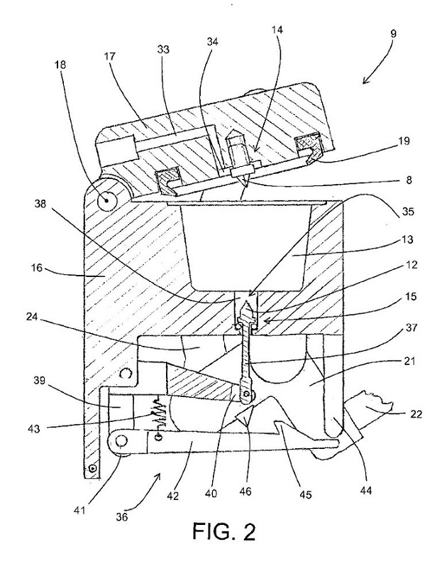
170 Figure 3 shows a schematic view of the capsule and the capsule cutting means. Figure 4 shows a sectional view of the capsule and cutting means of Figure 3, which includes a blade (12) used to penetrate the second wall (3) of the capsule (1).
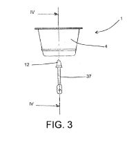
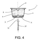
171 The complete specification describes the cut in the second wall by reference to Figures 5 to 7, which are “schematic illustrations of several steps of the method in accordance with the present invention”.
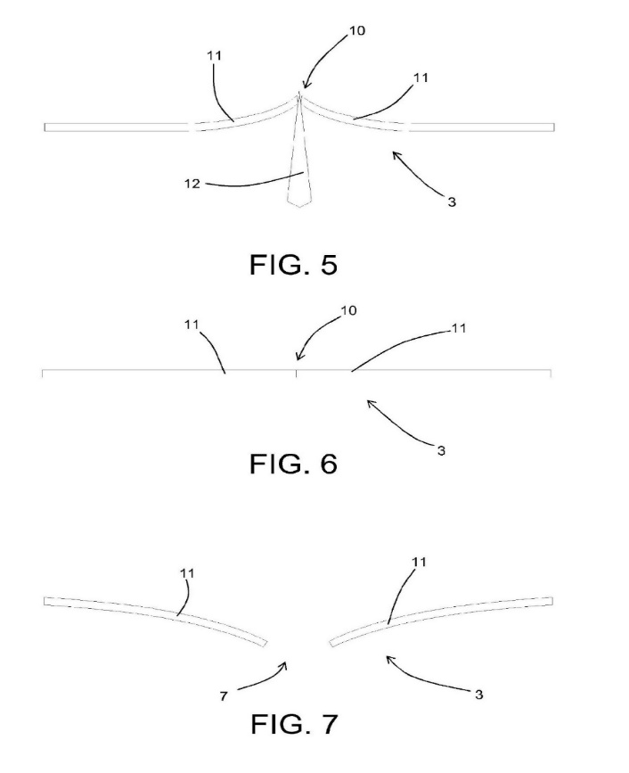
172 The passages in the complete specification most directly relevant the primary judge’s findings in relation to claim 34 describe the cut in the second wall by reference to Figures 5 to 7 and warrant repetition in full:
Page 9, line 17 – page 10, line 10:
… according to the present invention, the step of creating the second opening 7 through with [sic] the drink must be able to flow out, comprises a plurality of steps. First, there is an operating step in which at least one cut 10 extending in a linear fashion is made through the second wall 3 of the capsule 1. Said cut 10, preferably made before the injection step, is advantageously substantially made without removing material from the capsule 1 wall, so that it is delimited by two adjacent portions 11 of the second wall 3. The cut 10 is preferably obtained using a blade 12. Moreover, it may be made both extending in a straight fashion, and extending in a curved fashion, although it is preferably made in such a way that it does not delimit lobed portions, that is to say, so that the distance between two non-adjacent points of the cut 10 is always greater than the reciprocal distance between all of the points in between the first two.
In addition, the step for creating the cut 10 is preferably carried out without affecting what is contained in the capsule 1 (in particular, the filter 6 which may separate the base of the capsule from the coffee powder). Finally, in the most common embodiments, the cut 10 is normally made so that it has a length of between 2 and 6 mm.
Page 10, line 15 – page 12, line 25:
It should also be emphasised that the step of making the cut 10 may be carried out at a different moment to that of preparing the drink. The cut may already be made at the moment the capsule 1 is produced. In such a case, however, the cut 10 is preferably covered to preserve the organoleptic properties of the substance contained in the capsule. For example, each capsule may be individually packaged in a hermetically sealed wrapper, or the cut may be covered with an adhesive protective film which must be removed before using the capsule.
After the cut 10 has been made, there follows a step during which the adjacent portions 11 of the second wall 3, which delimit the cut 10, may draw near one another again, to substantially prevent, directly or indirectly, as described below, the drink from flowing out through the cut. This entails, firstly, removal if necessary, from the cut 10, of the cutting means 35 used (blade 12 or other). Only at this point are the adjacent portions 11 which delimit the cut 10 free to draw near one another again, if necessary returning to their starting position. In particular, when the operating [sic] to create the cut 10 has moved (by elastic deformation) the adjacent portions 11 from their original position (typically a movement towards the inside of the capsule 1), the actual drawing near again of the adjacent portions may take place both before the subsequent injection step (for example thanks to the elasticity of the adjacent portions 11) or after the injection step due to the increase in pressure generated inside the capsule 1. Moreover, the expulsion of the cutting means 35 from the cut 10 may be caused by the increase in pressure inside the capsule 1 due to the injection step.
In any event, according to the present invention the step of drawing near again is performed in such a way that after said step the cut 10 has a transversal size and/or a shape such that it substantially prevents the passage of liquid through it, but it does allow the passage of air. As described below, in this way the cut 10 allows air to be emptied out of the capsule 1 and, at the same time, optimum pre-infusion of the drink. If this were not possible, after the step of drawing near again the cut 10 would still preferably have a transversal size and/or a shape such that it substantially prevents the passage through it of particles of the substance 5 to be extracted (coffee) which are normally removed by the first drops of water passing through the substance. Therefore, in this case, another operating step may be identified, of blocking the cut 10 by means of said particles carried close to the cut 10 by the water injected into the capsule 1. As may easily be inferred, during this blocking step some drops of liquid exit the second opening 7 until the latter is completely blocked. However, in this case it is not possible to refer to drink dispensing.
Therefore, when the cut 10 is made in such a way that it has a transversal size such that it satisfies one of the two above-mentioned requirements, following injection of the water into the capsule 1 at least part of the air contained in it is expelled, after which several drops of liquid may be dispensed, but this is followed by a period in which drink dispensing is substantially inhibited.
In other words, at the moment when the water enters the capsule 1, the cut 10 made through the second wall 3 acts as a valve, practically open for the air or the gases contained in the capsule 1 but closed for the very first drops of liquid arriving which are dense with solid particles.
This is also the case when the transversal size of the cut 10 is too small to allow the passage of air. In that case, the edges delimiting the cut 10 are substantially coplanar and butted together but without being integral with one another. However, a minimal overpressure in the capsule 1 (for example around 0.1 bar) is sufficient for the two edges delimiting the cut 10 to move away from one another, bending slightly in such a way as to create a gap sufficient for the passage of a gas. However, in this patent, said minimal bending is not considered a deformation of the second wall 3, since that definition is reserved for deformations which allow the passage of the drink.
Page 13, line 1 – page 14, line 18:
As already indicated, at this point of the method disclosed, the drink is still unable to exit the capsule 1, since the second opening 7 can still not be considered completely formed.
Consequently, in the subsequent step of the method disclosed, after the above-mentioned air expulsion, by continuing the step of injecting hot water into the capsule 1, the internal pressure in the capsule 1 is further increased to produce a substantial deformation (elastic or permanent) of the second wall 3, and a consequent movement away from one another of the adjacent portions 11 delimiting the cut 10, so that the drink can pass. Moreover, depending on requirements, the deformation of the second wall 3 may affect only part of the second wall (as in the case of the apparatus illustrated in the accompanying drawings), or the whole of the second wall 3.
Therefore, advantageously the injection step is in turn divided into a first sub-step during which the internal pressure in the capsule 1 increases without deforming the second wall 3 but expelling the air, and a second sub-step during which the pressure is further increased and instead deforms the second wall 3 (advantageously an elastic deformation). In practice, the passage from the first to the second sub-step corresponds with exceeding a threshold pressure to overcome the structural resistance of the second wall 3 of the capsule 1 and/or allow the expulsion of any particles blocking the cut 10.
It is immediately clear that the force necessary for the step of substantially deforming the second wall 3 must be much greater than that needed to allow the edges to move away from one another so that the air can flow out if the cut 10 has a very limited transversal size. This circumstance is accentuated by the fact that the microscopic particles accumulated at the cut 10 have a blocking action on the [sic] 10 which helps to keep it substantially hermetically sealed, preventing the passage of liquid through it. It should be noticed that, approximately and schematically, it is possible to imagine the micro-particles having a spherical shape with an average diameter of around 0.1-0.2 mm, so that, to allow them to pass through the cut 10 and consequently unblock the cut 10 and allow the liquid to flow out, the deformation required is much greater than that sufficient to allow the passage of air or liquid only. From this it may be inferred that the pressure must rise significantly before the cut 10 actually opens and allows the passage of the drink. Approximately, the overpressure must be at least 20-30 times that which allows the simple passage of air. However, it should be noticed that all of the values supplied here are given by way of example only and in no way limit the scope of the invention, since in practice they are inseparably linked to the shape and size of the cut 10 and to the thickness and type of the material used to make the second wall 3 of the capsule 1.
173 The independent claims address different aspects of the invention. Claim 1 sets out a method for preparing a drink by passing hot water in a capsule which has a first wall and a second wall and which contains a substance to be extracted. Claim 24 is for an apparatus for preparing such a drink.
174 Independent claim 34, with integers added as supplied by the primary judge at [230], is as follows:
34. (a) A capsule for preparing drinks containing a substance to be extracted and (b) comprising at least a first wall designed to form an inlet wall for water to be injected into the capsule, and (c) a second wall designed to form an outlet wall for a drink obtained by the interaction between the water and the substance to be extracted, (d) the second wall having at least one cut extending in a linear fashion, substantially made without removing material from the second wall, and (e) delimited by two adjacent portions of the second wall drawn near one another, (f) the cut having a size and/or shape such that, after the adjacent portions delimiting the cut have drawn near one another again substantially, directly or indirectly, the cut prevents the passage of liquid, (g) the capsule being characterized in that the cut has a transversal size and/or a shape such that, after the adjacent portions delimiting the cut have drawn near one another again, and at least when a minimal overpressure is created in the capsule, the cut allows the passage of air while substantially preventing, directly or indirectly, the passage of liquid; and in that (h) said adjacent portions are also deformable towards the outside of the capsule in such a way to form an opening for the beverage flowing out.
175 Dependent claims 35 and 36 are as follows:
35. The capsule according to claim 34, wherein the distance between two non-adjacent points of the cut is always greater than the reciprocal distance between all of the points in between the first two.
36. The capsule according to claim 34 or claim 35, wherein the cut has a size and/or shape such that, after the adjacent portions delimiting the cut have drawn near one another again, the cut substantially prevents the passage of particles of the substance contained in the capsule, the particles and the cut operating in conjunction with one another to prevent the passage of the liquid.
The primary judge’s findings
176 The primary judge concluded that claims 34, 35, and 36 were invalid because the invention defined by each of those claims is not fully described in the specification as required by s 40(2)(a) of the Act.
177 After reciting the relevant legal principles, about which there is no complaint on appeal, the primary judge noted, at [242], that the difficulties with the sufficiency of the description of the capsule defined by claim 34 emerge when one comes to the requirement that the adjacent portions delimiting the cut draw near one another again to substantially prevent the passage of liquid (integer (f)); the further requirement that after the adjacent portions have drawn near one another again, and when a minimal overpressure is created in the capsule, the cut allows the passage of air, while substantially preventing the passage of liquid (integer (g)); and the final requirement that the adjacent portions be deformable towards the outside of the capsule to form an opening for the beverage to exit (integer (h)).
178 The primary judge considered that claim 34 describes a cut that will, in the first place, allow the passage of air but substantially prevent the passage of liquid, and in the second place, allow the formation of an opening which will thereafter allow the beverage to flow out of the capsule. He found, at [245], that the person skilled in the art would understand from the specification that the invention is intended to facilitate pre-infusion of the coffee granules and, when that had occurred, to provide a means for allowing the water that passes through the pre-infused coffee granules, to exit the capsule as liquid coffee. The primary judge noted, at [245], that the complete specification does not provide any indication of the length of time during which pre-infusion should occur, even though it states that the organoleptic result will depend on the time, temperature, and pressure applied to the capsule during the pre-infusion and dispensing steps.
179 The primary judge considered that the complete specification provided limited information to assist the person skilled in the art, noting, at [246], that it discloses only that the blade is to have a thickness that is “preferably limited”, the cut is to be normally made so that it has a length of between 2 mm and 6 mm but with a “very limited transversal size”, that the materials of the second wall have “elasticity”, and that, as to pressure:
A minimal overpressure in the capsule is sufficient for the two edges delimiting the cut to move away from one another, and to create a gap for the passage of a gas but not liquid. Overpressure of 0.1 bar is given as an example. The deformation of the wall necessary to permit exit of the drink occurs at a significantly higher pressure before the cut actually opens to allow the passage of the drink. This overpressure should be approximately 20 to 30 times that which allows passage of the air.
180 The primary judge found, at [247], that the term “overpressure” referred to a condition in which the internal pressure of the vessel (for example, the capsule) exceeds ambient pressure, and considered, at [248], that it was important that the complete specification states that:
… all of the values supplied here are given by way of example only and in no way limit the scope of the invention, since in practice they are inseparably linked to the shape and size of the cut 10 and to the thickness and type of the material used to make the second wall 3 of the capsule 1.
181 In this context, his Honour noted, at [249], that no more specific information is disclosed in the complete specification as to the size and width of the cut, the material from which the second wall of the capsule is made, or the temperature and pressures at which water is injected into the capsule in any preferred embodiment. Nor would a person skilled in the art find any more specific information in the complete specification as to the pressure at which pre-infusion should occur or for how long pre-infusion should occur before the second wall deforms to allow passage of the drink. In this context, the primary judge found at [251]:
Whether or not the capsule would exhibit the characteristics described in claim 34 would necessarily depend on a range of factors including the temperature and pressure at which water is introduced into the capsule, the pressure within the capsule, and the pressure on the second wall. Pressure within the capsule would in turn be influenced by the density of the coffee granules in the capsule, the size and shape of the water inlet, the size and shape of the cut made in the second wall of the capsule, and the strength and elasticity of the material used to make the second wall.
182 In a statement criticised on appeal, the primary judge found, at [250], that in order to make a capsule that meets the requirements of claim 34 “it would be necessary for the person skilled in the art to do so by reference to a particular coffee making machine”, and that the detailed description, whilst disclosing a machine with which a capsule can be used, does not include any information in relation to its operating temperatures or pressures, or any disclosure as to the period of time during which pre-infusion occurs before liquid is allowed to exit the capsule.
183 The primary judge was persuaded by the evidence of Professor D’Urso (an expert called by the respondents) that a system in which the capsule will be used necessarily involves many different variables that would affect the behaviour of the capsule. He accepted that Professor D’Urso would not follow a trial and error approach because it would be too difficult and it would be unlikely to produce the desired result. Professor D’Urso’s view was that the necessary parameters could not be established by trial and error due to the complex interactions involved.
184 The primary judge was also persuaded by the evidence of Mr Winkler to the effect that the amount of overpressure needed to facilitate deformation of the cut to enable the beverage to exit the capsule could, depending on the level of pressure inside the capsule and the tendency of the capsule to yield, happen very quickly, but if deformation happened too quickly, then pre-infusion would not be achieved. After quoting a lengthy passage of the oral evidence of Mr Winkler, the primary judge noted that his evidence was consistent with that of Professor D’Urso in that neither of them would attempt to adjust the variables (such as the size of the cut or the thickness of the wall) for the purposes of creating a system in which the capsule met the requirements of the claim.
185 Having made these findings, the primary judge noted that, whilst claim 34 does not stipulate that pre-infusion must occur, or for how long:
254. ...the person skilled in the art reading the claim in light of the specification as a whole would understand that the whole purpose of creating a capsule with the particular design characteristics referred to in claim 34 is to enable the coffee granules to be pre-infused before the beverage is produced.
255. What the claim makes clear, as Mr Winkler’s evidence confirms, is that the capsule must be capable of first allowing the passage of air but not liquid through the cut so that pre-infusion may occur, before the beverage is permitted to exit the capsule. This is what Mr Winkler was referring to when he spoke of a two stage system.
(Emphasis added.)
186 The primary judge noted that the problem of deformation occurring too quickly, which had been identified by Mr Winkler, will depend on more variables relevant to the operation of the system than the length of the cut or the thickness of the second wall. He accepted the evidence of Mr Winkler and Professor D’Urso, at [256], that the cut and its adjoining portion are part of a complex system with a number of variables which affect their ability to behave in the manner required by the claim. The primary judge noted that apart from the length of the cut and the thickness of the wall, it would be necessary to determine what material would be used in the construction of the wall. He further noted that, although the specification indicates that the second wall should be made from an elastic material (a relative term), it provides no more specific indication as to what material would be suitable for use in the construction of the second wall, which is critical to the two-step process.
187 In concluding that the claims were invalid for insufficiency, the primary judge said:
257. In the course of the cross-examination to which I have referred Mr Winkler was ultimately asked to assume that he was working with an existing machine with certain pressure specifications. It was then put to him that if he found the capsule was collapsing too quickly, adjustments could be made to the size of the cut and the material used. However, there is nothing in the claims that requires that the capsule described be used on a certain machine. This is significant because, as I think Mr Hunter correctly accepted, whether or not a particular capsule was within the scope of claim 34 would depend on the characteristics of the machine in which it was used. In any event, even if the capsule was designed to operate with a particular coffee machine, Mr Winkler’s opinion was that the two-step process in which pre-infusion is achieved before the beverage exits the capsule is unlikely to occur. His evidence indicates that the adjacent portions of the cut would collapse before pre-infusion was achieved. It follows that the specification does not provide the person skilled in the art with the information needed to create, at least not without undue difficulty, a capsule with a cut that allows for the passage of air (but not liquid) before forming an opening through which the beverage may later exit.
258. I found Professor D’Urso’s and Mr Winkler’s evidence persuasive. Even if it is accepted that by a process of trial and error a person skilled in the art would be able to devise a capsule meeting the requirements of claim 34, I find that this exercise would extend well beyond what might reasonably be characterised as standard or routine work in the field. I find that the steps that the person skilled in the art would be required to take in order to make a capsule meeting the requirements of claim 34, would be neither readily apparent nor standard or routine in character. The problems that would be likely to arise would require that person to engage in a prolonged and difficult exercise in problem solving with an uncertain outcome.
Grounds 10 and 11 of the appeal
Caffitaly’s submissions
188 Grounds 10 and 11 are:
10 The trial judge erred in holding that claims 34, 35 and 36 of the 388 Patent were invalid on the ground of insufficiency: J [259], and ought to have held that the insufficiency ground failed in relation to those claims.
11 The trial judge:
(a) erred in holding that in order to make a capsule that met the requirements of claim 34 of the 388 Patent, it would be necessary for the person skilled in the art to do so by reference to a particular coffee making machine: J [250], [257];
(b) ought to have held that a person making a capsule that met the requirements of claim 34 of the 388 Patent would be able to do so:
(i) without reference to a particular coffee making machine;
(ii) by testing or modelling the behaviour of the capsule at minimal overpressure and at greater than minimal overpressure; and
(iii) if necessary, adjusting the size or shape of the cut, or the material or thickness of the wall to adjust the time at which the cut permits the passage of liquid.
(c) erred in holding that Mr Winkler’s evidence was that the adjacent portions of the cut in the capsule would collapse before pre-infusion was achieved, and ought to have held that no such proposition had been established (J [257]); and
(d) erred in holding that a process of trial and error in making a capsule meeting the requirements of the claims would be unduly prolonged and difficult, and ought to have held that no such proposition had been established (J [258]).
189 In relation to grounds 11(a) and (b), Caffitaly submits that when one pays regard to the particular features of the capsule in the claim, it is apparent that those features are properties of a capsule, and that their presence may be tested independently of any particular coffee machine. It submits that the first relevant requirement is that, at a minimal overpressure the cut must prevent the passage of liquid while permitting the passage of gas. This, it submits, Mr Winkler accepted could be tested by applying a minimal overpressure such as 0.1 bar to a capsule, and that Mr Hunter performed such experiments on capsules by using a simple apparatus, not a coffee machine. It submits that the second relevant requirement that the wall adjacent to the cut be “deformable” outwards so as to form an opening for the beverage to flow out, contains no parameter as to the particular pressure required and is accordingly also not specific to a machine. Whether the walls are “deformable” can be analysed by modelling, as Mr Hunter did.
190 In relation to grounds 11(c) and (d), Caffitaly submits that the findings of the primary judge as to the likely difficulty of achieving a capsule within the claim by trial and error wrongly relied on the evidence of Professor D’Urso and Mr Winkler, which was of the most conclusory and generalised kind and was unsupported by any actual trial and error attempt, in contrast to the evidence of Mr Hunter who both performed experiments on capsules using a simple apparatus and simulated what would happen to the walls of the capsule under increased internal pressure. Caffitaly submits that the primary judge erred in relying on the evidence of Mr Winkler because the only substantiation that he gave for the proposition that pre-infusion could not be achieved (because the capsule wall would either collapse immediately, or would not collapse soon enough) was an elliptical reference to work that he had done, but could not discuss for reasons of confidentiality.
191 The relevant principles applicable to consideration of whether the invention defined by each of those claims is not fully described in the specification as required by s 40(2)(a) of the Act were considered by the High Court in Kimberly-Clark Australia Pty Ltd v Arico Trading International Pty Ltd [2001] HCA 8; 207 CLR 1 and, as the primary judge noted, explained by French and Lindgren JJ in Pfizer Overseas Pharmaceuticals v Eli Lilly & Co [2005] FCAFC 224; 68 IPR 1 at [325]-[328]:
325. Section 40(2)(a) of the Act requires that a complete specification “describe the invention fully including the best method known to the applicant of performing the invention”. The first limb of that requirement, namely, that the invention be described “fully” imports the requirement of sufficiency of description.
326. The complete specification referred to in s 40(2)(a) is the whole document inclusive of the claims: Kimberly-Clark at [31]. The court there said (at [16]):
[16] The question then is whether the invention has been fully described in the complete specification. The text speaks here of the complete specification, not any one part thereof. From the distinction drawn in s 40(2) between describing the invention in the complete specification and defining the invention in any claims with which the complete specification ends, it does not follow that the description is to be gleaned solely from one part (the body) and that it is forbidden to obtain any assistance by regard to the remainder (the claims) of the complete specification. Rather, the text indicates that the specification must be read as a whole and that reference to the claims may dispel ambiguity or uncertainty from the body of the specification concerning the description of the invention.
327. The requirement of full description of the invention depends for its content, in part, upon the meaning of the word “invention” as used in s 40(2)(a). The relevant meaning was stated by McTiernan J in respect of s 40(1) of the 1952 Act in AMP Inc v Utilux Pty Ltd [1971] ALR 495 at 499; 45 ALJR 123 at 127:
I take it to mean “the embodiment which is described, and around which the claims are drawn”.
The High Court in Kimberly-Clark approved that formulation and its application to s 40(2)(a) of the 1990 Act.
328. For the purpose of assessing sufficiency the complete specification is to be read in the light of the common general knowledge and the art before the priority date. The court is required to place itself “in the position of some person acquainted with the surrounding circumstances as to the state of [the] art and manufacture at the time”: Kimberly-Clark at [24] citing British Dynamite Co v Krebs [1879] 13 RPC 190 at 192. The relevant question formulated by the High Court in Kimberly-Clark (at [25]) is:
[25] … will the disclosure enable the addressee of the specification to produce something within each claim without new inventions or additions or prolonged study of matters presenting initial difficulty?
192 The premise underlying the submissions advanced by Caffitaly based on grounds 11(a) and (b) is that the primary judge erred in his characterisation of the “embodiment which is described, and around which the claims are drawn” for the purpose of considering sufficiency of description within s 40(2)(a) of the Act: Pfizer Overseas at [327]. For the following reasons we are not satisfied that this is so.
193 Integers (f), (g), and (h) of claim 34 involve relative terms concerning the cut in the second wall and its purpose. The cut must be of a size and/or shape such that, after the adjacent portions delimiting the cut have drawn near one another, “substantially, directly or indirectly, the cut prevents the passage of liquid” (integer (f)). The cut has a transversal size and/or shape such that after the adjacent portions have drawn near one another, the cut allows the passage of air “while substantially preventing, directly or indirectly, the passage of liquid” at least “when a minimal overpressure is created in the capsule” (integer (g)). The adjacent portions of the cut are also to be “deformable” towards the outside of the capsule “in such a way to form an opening for the beverage flowing out” (integer (h)).
194 As we have noted, the specification describes the embodiment referable to claim 34. On appeal, there is no challenge to the primary judge’s observation, at [233], that the detailed description of the capsule defined in claim 34 is connected to the method by which it is used depicted by reference to Figures 3 and 4, as further described in the specification in the passages that we have set out in [226] above. Nor is there any challenge to the primary judge’s summary, at [234], of the method as involving three steps: first, the making of a cut without removing material from the second wall (Figure 5); second, following the withdrawal of the cutting means, the adjacent portions drawing together and thereby substantially preventing the flow of liquid through the cut, but allowing the passage of air, thereby allowing air to be emptied from the capsule for optimum pre-infusion of the drink to occur (Figure 6); third, at the point at which the liquid is still unable to flow through the cut, the increase in pressure achieved by continuing to inject hot water into the capsule will produce substantial deformation of the wall that produces an opening through which the drink can then pass (Figure 7).
195 The primary judge noted that claim 34 does not expressly state that pre-infusion must occur, nor for how long. However, his Honour found that the person skilled in the art reading the claim in light of the specification as a whole would understand that the whole purpose of creating a capsule with the particular design characteristics referred to in claim 34 is to enable the coffee granules to be pre-infused before the beverage is produced (see [245], [254] and [263]). His Honour found at [255]:
What the claim makes clear, as Mr Winkler’s evidence confirms, is that the capsule must be capable of first allowing the passage of air but not liquid through the cut so that pre-infusion may occur, before the beverage is permitted to exit the capsule.
196 In our view that was a construction open to the primary judge, on the basis of the disclosure of the specification and the construction of the experts to whose evidence he had regard. Indeed, that conclusion accords with Caffitaly’s own characterisation on appeal of the novel and inventive aspect of the invention being a capsule that first provides for a period of pre-infusion during which the slit-type opening allows gas to exit the capsule and then, once internal pressure has increased, deformation outwards to allow the egress of liquid.
197 On appeal, Caffitaly does not directly challenge the primary judge’s construction of claim 34, although it does so implicitly by relying on the evidence of Mr Hunter and certain passages of the cross-examination of Mr Winkler. That evidence addresses the integers of claim 34 without regard to the achievement of any pre-infusion.
198 In broad summary, Mr Hunter prepared a test rig involving emptying one of OCG’s capsules, putting a cut in its base, adding some inky blue fluid to the capsule, and then clamping the capsule over a glass of water (with a seal at the top) such that the bottom portion of the capsule sat beneath the surface of the water in the glass. He then used a syringe to inject air into the capsule body and, with respect to some of the capsules tested by him, observed air bubbles with minimal blue-dyed water to match integer (g) (see [271] – [275]). However, although these tests were said to illustrate the presence of integers (f) and (g) of claim 34, this test did not involve consideration of whether or not the capsules would facilitate pre-infusion, as his Honour interpreted claim 34 to require. The primary judge, at [286], rejected the test as being incapable of reproducing the conditions necessary to establish the behavioural characteristics of the capsule defined by claim 34, which he considered must depend, at least to some extent, on the machine in which the capsule is used.
199 The primary judge recorded that Mr Winkler was asked in cross-examination to assume that he was working with an existing machine with certain pressure specifications. It was then put to Mr Winkler that if he found that deformation was happening too quickly, adjustments could be made to the size of the cut and the material used. It was in this context that the primary judge noted, at [257], that Mr Hunter had accepted that whether or not a particular capsule was within the scope of claim 34 would depend on the characteristics of the machine in which it was used. His Honour noted that, even then, Mr Winkler did not think that the two-step process in which pre-infusion is achieved would occur. In making this observation about Mr Winkler’s evidence, his Honour reinforced his earlier conclusion that the specification did not provide sufficient information to enable a person to make the invention claimed in claim 34. Not only did the specification fail to teach the person skilled in the art how to make something within the claim, even had all of the parameters of a functioning machine been provided, Mr Winkler could not conceive of the capsule functioning in the required way.
200 In our view, it was appropriate to consider the sufficiency of the disclosure by reference to whether or not a person skilled in the art would be able to produce a capsule within claim 34. The evidence of Mr Hunter did not purport to do so. Rather, it focussed on establishing that the integers of the claim were met using a test rig that in no way sought to emulate the conditions pertinent to the pre-infusion of coffee granules. Nor did the passage of the cross-examination of Mr Winkler address the invention so characterised. Accordingly, Grounds 11(a) and (b) of the appeal are not made out.
201 This then leads to the second aspect of Caffitaly’s argument as set out in Grounds 11(c) and (d). The primary judge found that the complete specification lacked sufficient description because information required to enable the person skilled in the art to perform the invention without new inventions or additions or prolonged study of matters presenting initial difficulty was absent. In this regard, his Honour was persuaded by the evidence not only of Mr Winkler, but also of Professor D’Urso. Much of the challenge advanced on appeal focussed on passages of the cross-examination of Mr Winkler, but little was said of the evidence of Professor D’Urso other than that it was expressed at a level of generality that deserved little weight.
202 Professor D’Urso was found by the primary judge, at [10], to be a satisfactory witness whose familiarity with the state of the art with respect to coffee machines (and that of Mr Winkler) exceeded that of Caffitaly’s witnesses.
203 The primary judge found persuasive Professor D’Urso’s evidence that he would not follow a trial and error approach to bringing into effect the invention because the necessary parameters would be too complex, and accepted Mr Winkler’s evidence to a similar effect (at [252], [253], [256], and [258]). It can be no answer to these findings for Caffitaly to submit that the evidence of these witnesses should be rejected because it was not supported by any actual trial and error attempts. Plainly enough, the primary judge was satisfied with the evidence given that such attempts would be of no assistance. It may readily be understood that the reason for that was because there were too many variables to put such attempts to good effect.
204 Professor D’Urso was challenged in cross-examination on his evidence. The primary judge accepted his opinion. Having regard to the aspects of Professor D’Urso’s evidence to which we were taken on appeal, we do not consider that the challenge to the weight given to it by the primary judge has been established.
205 In oral submissions, Caffitaly addressed the evidence of Mr Winkler in some detail, submitting that the primary judge erred in concluding that the evidence of Mr Winkler supported the conclusion of lack of sufficiency. However, in the passages relied upon by Caffitaly in argument, Mr Winkler maintained his position that the information in the specification was insufficient to enable him to produce a capsule that effected pre-infusion. That was a position that Mr Winkler maintained in the passage of his evidence quoted in some length, at [253] of the primary judge’s reasons, where, consistently with the evidence of Professor D’Urso, he rejected the proposition that one could simply “adjust [the system] in certain ways” to overcome any difficulty of deformation of the capsule as pressure is increased. He considered the claim was to a system in which there were multiple variables in addition to the length of the cut and the thickness of the material used for the second wall.
206 We do not consider that the position adopted by Mr Winkler equates to “a refusal to go any further” of the type identified in Pfizer Overseas at [332]. Rather, Mr Winkler provided a reasoned basis, accepted by the primary judge, for considering that such testing would not provide the answer. Contrary to the submission advanced by Caffitaly, that evidence was not dependent for its substantiation on confidential information.
207 Having regard to the evidence before the primary judge we do not consider that matters to which Caffitaly has referred warrant the conclusion that his Honour erred in placing too much weight on the evidence of Professor D’Urso and Mr Winkler.
208 Accordingly, Grounds 10 and 11 of the appeal are not made out.
209 As we have recorded, Ground 3 of the appeal succeeds, and Ground 4 succeeds in part. It follows that Order 1 in the proceeding below, on 19 June 2020, which revokes claims 1, 2, 9, 16, and 17 of the 627 patent, should be discharged.
210 Although Caffitaly has had success on appeal, that success is limited. Ultimately, its claim of infringement by the respondents has failed at first instance, and on appeal. Our provisional view is that Caffitaly should pay the costs of the appeal. We do not think a differential costs order is warranted. Further, we would not interfere with the costs order made below. We will, however, give the appellant the opportunity to be heard on the question of costs. If the appellant takes this opportunity, the respondents will have a corresponding opportunity to respond, and we will then determine the question of costs on the papers.
I certify that the preceding two hundred and ten (210) numbered paragraphs are a true copy of the Reasons for Judgment of the Honourable Justices Yates, Moshinsky and Burley. |
Associate:

