FEDERAL COURT OF AUSTRALIA
Dincel Constructions Systems Pty Ltd v AFS Systems Pty Ltd [2018] FCAFC 157
ORDERS
DINCEL CONSTRUCTION SYSTEM PTY LTD (ACN 083 839 614) Appellant | ||
AND: | AFS SYSTEMS PTY LTD (ACN 168 782 429) Respondent | |
DATE OF ORDER: |
THE COURT ORDERS THAT:
2. The appellant pay the costs of the respondent, to be assessed if not agreed.
Note: Entry of orders is dealt with in Rule 39.32 of the Federal Court Rules 2011.
KENNY J:
1 I have had the advantage of reading in draft the reasons for judgment prepared by Besanko and McKerracher JJ. For the reasons their Honours have stated, I agree with the orders proposed.
I certify that the preceding one (1) numbered paragraph is a true copy of the Reasons for Judgment herein of the Honourable Justice Kenny. |
Associate:
REASONS FOR JUDGMENT
BESANNKO AND MCKERRACHER JJ:
2 The appellant, Dincel Construction System Pty Ltd (ACN 083 839 614) appeals from a liability judgment (Dincel Construction System Pty Limited v AFS Systems Pty Ltd (No 2) [2017] FCA 791) and a costs judgment (Dincel Construction System Pty Limited v AFS Systems Pty Ltd (No 3) [2017] FCA 919) in a patent dispute. The respondent, AFS Systems Pty Ltd (ACN 168 782 429), does not cross-appeal, but has filed a notice of contention.
3 In the liability judgment, the primary judge dismissed Dincel’s claim for infringement of its Patent and AFS’s cross-claim for invalidity. For reasons that follow, we consider the primary judge was correct. The appeal from each judgment will be dismissed with costs.
THE PATENT
4 The specification to the Patent describes an invention consisting of a hollow building element that acts as permanent formwork into which concrete may be poured. Multiple elements may be snapped together to form a larger structure into which concrete is then poured to form a wall. The method by which the elements are snapped together was the primary focus of attention in the debate between the parties. The Dincel infringement claim related to the relevant claims of Standard Patent No. 2002328693 entitled “Hollow interconnecting panels as lost formwork”. Concrete is poured into the formwork and the elements remain in place permanently after the concrete is cured. Thus it is named “lost” formwork.
5 Dincel is the exclusive licensee. Mr Burak Dincel, the sole director of Dincel, took no active steps in the proceeding, although he was named as second respondent in the proceeding at first instance being the patentee.
6 It was common ground that all of the relevant claims were dependent on claim 1 and that the priority date of the relevant claims was 12 October 2001.
7 AFS cross-claimed, seeking revocation on the grounds that the invention was not novel as at the priority date and was not fairly based on the matters described in the specification.
THE PRIMARY JUDGMENT
8 The description of the Patent by the primary judge was not in dispute on appeal and it is convenient to set out those parts of his Honour’s liability judgment (at [6]-[7]) which addressed it:
THE PATENT
6 The specification identifies two disadvantages in the prior art building elements which the invention is intended to overcome or ameliorate. First, the prior art elements are coupled together by a vertical sliding motion which hinders their assembly and are, due to their length, difficult to handle. Second, the prior art building elements have either male or female couplings, which means that both types of elements must be manufactured and stocked.
7 The specification includes a number of consistory statements (which mirror the claims) including the following:
There is disclosed herein a hollow elongated integrally formed building element into which concrete is to be poured, said element including:
a pair of longitudinally extending spaced side walls which are generally parallel and coextensive;
transverse webs joining the side walls; wherein
each side wall has a longitudinally extending groove and a longitudinally extending flange extending from the side wall, with each flange and groove being positioned and configured to engage a respective groove or flange of a like element to secure adjacent elements together by snap engagement of the flange within its respective adjacent groove by movement of the groove and flange relative to each other and transverse of the element, with each groove being formed in a respective one of the side walls and each flange extending from a respective side wall so that the like element is locatable between the flanges to provide for engagement of the flanges and grooves, and wherein
the element further includes ramp surfaces that engage the flanges to move the flanges for said snap engagement of the flanges in the grooves.
Preferably, the flanges are urged apart for engagement in their respective groove.
Preferably, the flanges are resiliently urged apart for engagement in their respective groove.
Preferably, the ramp surface include a first ramp surface and a second ramp surface, the ramp surfaces being spaced so that each is operatively associated with a respective one of the extending flanges so that the ramp surfaces causes the resilient deformation of the flanges.
Preferably, the element further includes an end transverse web extending between the side walls, with the ramp surfaces being located adjacent the end web.
Preferably, the first and second ramp surfaces diverge from the adjacent end web towards a respective one of the grooves.
Preferably, each flange is an extension of a respective one of the side walls.
Preferably, each groove extends transversely inwardly from the respective side wall.
Preferably, said transverse web is a first web, and the element further includes a second transverse web, the second transverse web extending between the side walls to aide in stiffening the side walls.
Preferably, said second transverse web includes a central flange joined to the side walls by means of pairs of end flanges that diverge from the central flange to the side walls.
Preferably, said element is an extruded hollow longitudinally elongate building element.
Preferably, said element is extruded from a plastic material.
Preferably, the flanges undergo transverse movement relative to one another during snap engagement with their respective grooves.
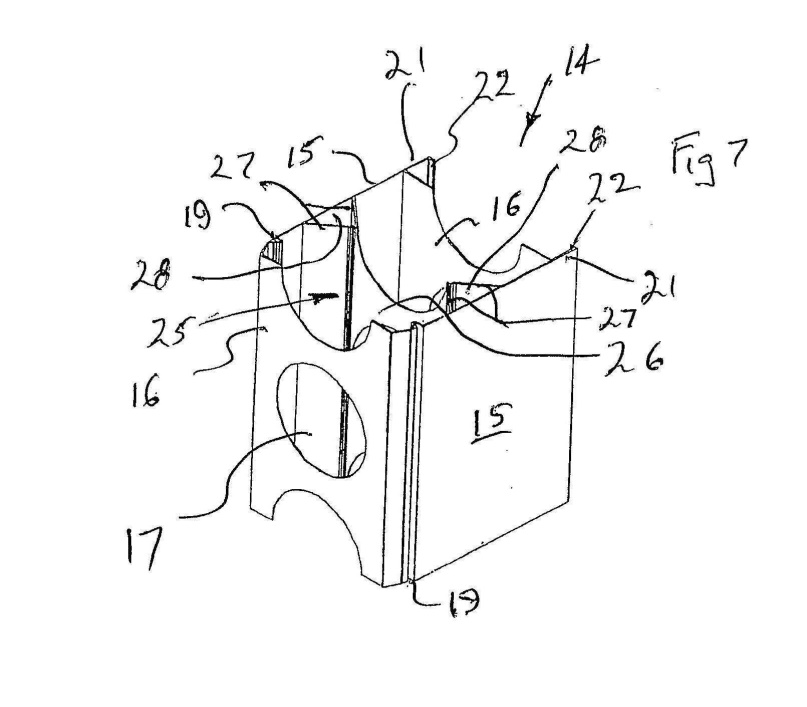
9 The primary judge then noted that the consistory statements are followed by a detailed description of various preferred embodiments which refer to eight drawings (Figures 1-8). He reproduced three of them, including Figures 1, 2 and 7:
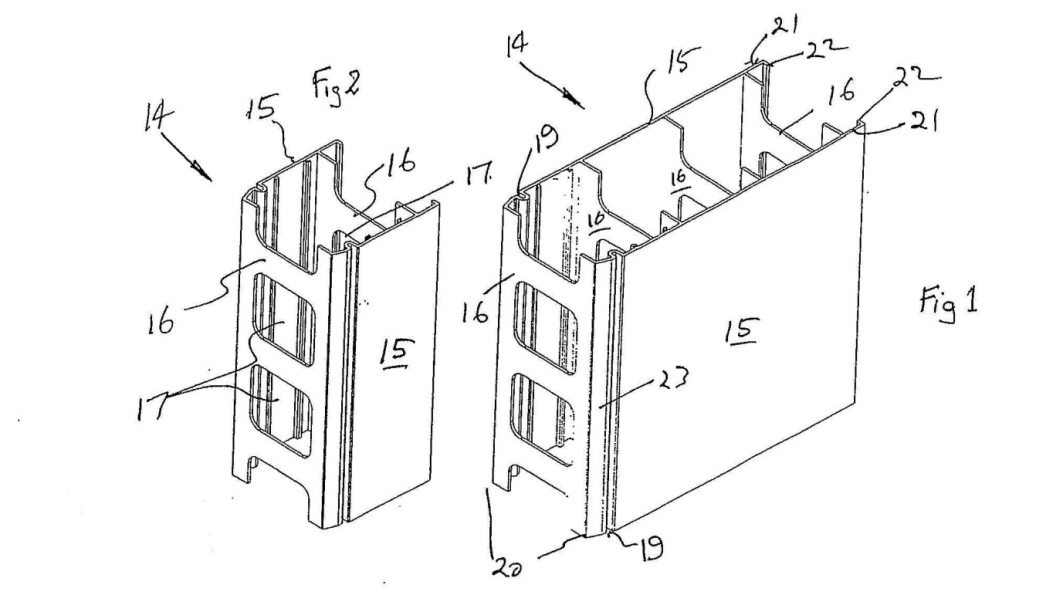
10 His Honour noted (at [9]) that the description of the preferred embodiments includes the following passages at page 6 lines 10 to 17 of the Patent:
Each of the side walls 15 is provided with a longitudinally extending groove 19 adjacent a longitudinal edge 20 of the respective side wall 15. Extending from each side wall 15 is a longitudinally extending flange 21, the flanges 21 being generally parallel and coextensive with respect to the grooves 19. Each flange 21 includes a longitudinally extending lip 22 which is received within the grooves 19 of the next adjacent element 14. Extending to each groove 19 is a ramp surface 23. The surfaces 23, as best seen in Figure 7, are located adjacent the end transverse web 16 and diverge from adjacent the end web 16 to the adjacent groove 19.
11 His Honour went onto observe:
A ramp surface (23) in the preferred embodiment is shown in Fig 1 extending between a longitudinal edge (20) and a groove (19). Figures 2 and 7 do not specifically identify the ramp surfaces (23) but their location is apparent from Fig 1. One ramp surface (23) is clearly shown in Fig 1 adjacent to the groove (19) adjoining the near side wall (15) of the building element. The other ramp surface is not expressly identified but it is clear that it is adjacent to the groove (19) adjoining the other side wall (15) on the other side of the building element.
12 Importantly, his Honour noted that it was apparent from Figure 1 that the lip (22) of the flange (21) can be coupled to a like element when the lip of the flange is forced along the ramp surface (23) in a horizontal direction until it is fully engaged by the groove into which it locks in what the specification refers to as the “snap engagement”.
13 The primary judge recorded that the term “snap engagement” referred to part-to-part engagement (or “snap-fit”) that is accomplished by the deformation (or deflection) of two mating components. Such components are typically made of plastic or some other elastically deformable material. The term “snap interference distance” (which his Honour noted is not used in the Patent) refers to the distance that must be overcome by deformation (or deflection) before snap engagement is accomplished.
14 Finally, dealing with the critical claim, the primary judge said (at [12]-[13]):
12 Claim 1 of the Patent is for:
A hollow elongated integrally formed building element into which concrete is to be poured, said element including:
a pair of longitudinally extending spaced side walls which are generally parallel and coextensive;
transverse webs joining the side walls; wherein
each side wall has a longitudinally extending groove and a longitudinally extending flange extending from the side wall, with each flange and groove being positioned and configured to engage a respective groove or flange of a like element to secure adjacent elements together by snap engagement of the flange within its respective adjacent groove by movement of the groove and flange relative to each other and transverse of the element, with each groove being formed in a respective one of the side walls and each flange extending from a respective side wall so that the like element is locatable between the flanges to provide for engagement of the flanges and grooves, and wherein
the element further includes ramp surfaces that engage the flanges to move the flanges for said snap engagement of the flanges in the grooves.
(Emphasis added [in original])
I shall refer to the last of the integers of claim 1 (which I have emphasised) as the “ramp surface integer”. The “said snap engagement of the flanges in the grooves” described in the ramp surface integer refers to the snap engagement of the flange into the adjacent groove previously described in the claim (which I have also emphasised) achieved by movement of the flange and groove relative to each other across the element.
13 Claim 1 requires that the side walls include “transverse webs joining the side wall”. These are shown in Fig 1 at four locations (16), two at either end of the element, and another two situated between the walls and transverse webs at each end of the element. Although claim 1 requires that the element include transverse webs joining the side walls, it does not require that any of these be located at either end of the element. Such a requirement is found in dependent claim 5 which refers to an element that further includes:
an end transverse web extending between the side walls, with the ramp surfaces being located adjacent the end web.”
15 From this it may be seen that the key to the invention was the “snap engagement process”, rather than the longitudinal sliding process. In order to achieve the snap engagement, there were ramp surfaces engaging flanges and which moved the flanges so to achieve the snap engagement of the flanges within grooves (the ramp surface integer).
16 The primary judge went on to observe that the Patent related to building elements to be used in construction for concrete walls and was, therefore, directed to builders, architects, engineers and industrial designers who would have a practical interest in the construction of buildings or mechanical systems or devices for use in the construction of buildings.
17 Evidence in the hearing was given by two independent expert witnesses: Mr Williams Hunter for Dincel, and Mr Timothy Phillips for AFS. Mr Hunter expressed the view that the AFS Product included the ramp surface integer, whereas Mr Phillips opined that the AFS Product did not include the ramp surface integer. The primary judge found both expert witnesses helpful in understanding how the building elements described in the Patent, the prior art and the AFS Product worked. He noted that while the experts agreed that the term “ramp surface”, as used in claim 1, had a functional meaning, that is, a surface that acts as a ramp, the experts also agreed that it was not a technical term or a term requiring a defined technical meaning. His Honour said that the meaning of “ramp surface”, as used in claim 1, was for the Court to determine.
18 The area of dispute was quite narrow as it was also common ground that, subject to one exception, the AFS Product contained all of the integers of claim 1. The exception was the parties’ differing opinions on whether the AFS Product included the ramp surface integer. It followed that the infringement case, based on all other relevant claims, was centred on the construction of claim 1, with the focus of attention being on the nature of the ramp surface integer. The arguments which arose in this respect before the primary judge were two-fold, namely, the construction of claim 1, specifically, whether “ramp surface” within the claim ought to be construed as providing a mechanical advantage and the contention that, irrespective, the AFS Product provided the requisite mechanical advantage.
Infringement
19 Asking the questions in the appropriate order, the primary judge addressed the first question of the meaning of “ramp surface” as used in claim 1? The second question, which could only be answered after the first question, was whether the AFS Product included the ramp surface as required by claim 1?
Construction of “ramp surface”
20 After considering the principles of patent construction, his Honour turned to the parties’ arguments in relation to “ramp surface”, noting that Dincel had submitted:
The term “ramp surface” as used in claim 1 refers to a sloping surface which engages the flange to move the flange for snap engagement in the groove. The claim does not require that the “ramp surface” provide any mechanical advantage.
A surface can be a “ramp surface” for the purposes of claim 1 whether it is planar, curved or compound (i.e., a combination of planar and curved). Nothing in the Patent requires the ramp surfaces referred to be planar.
A “ramp surface” within claim 1 need not be fully traversed by the flange. The ramp surfaces exemplified in Figure 1 of the Patent are not fully traversed by the flanges.
Claim 1 does not preclude movement of the grooves. It specifically refers to movement of the grooves relative to the flange. In the preferred embodiment exemplified in Figure 1 of the Patent, both the grooves and the flanges move to effect the snap engagement.
Claim 1 does not require any particular amount of movement of the flanges although the applicant accepts that the flanges must move, and that their movement must be more than de minimus.
21 The primary judge noted, however, that AFS had submitted that the language of claim 1 identifies particular integers that operate in combination, and that it also defines their working relationship. AFS further submitted that the words of the claim are not to be treated as providing a mere checklist which can be satisfied on the basis of a purely literal reading without having regard to their working relationship as disclosed in the specification. AFS accepted the “ramp surface” need not be planar and it need not be fully traversed by the flange.
22 AFS noted that the language of claim 1 did not require that there be no movement of the groove, but the flange must itself move. Thus, while claim 1 at one point speaks of relative movement between the flange and the groove, the parties each accepted, correctly in the view of the primary judge, that there must be some movement by the flange as it engages with the ramp surface.
23 AFS also submitted, based on the evidence of Mr Phillips, that the ramp surface must provide a mechanical advantage that makes it easier for the flange to move into the groove prior to snap engagement. AFS submitted that the wording “engage”, as it appears in the ramp surface integer, refers to the first engagement between the flange and the ramp surface. Thus, AFS adopted the definition of “engage” appearing in the Concise Oxford Dictionary 10th Edition, which includes the following:
4. (with reference to a part of a machine or engine) move or cause to move into position so as to come into operation.
24 It followed, AFS said, drawing on that definition, that the ramp surface integer requires that when the like elements are first brought together, the flange must, at that point (that is, at the point of first contact) engage with a ramp surface functioning as such. Thus, AFS contended that the ramp surface integer was providing a mechanical advantage that assisted the flange to move to the groove.
25 The primary judge did not accept AFS’s submission that for a building element to be within claim 1, the flange and ramp surface must engage at the point at which the two like elements are brought together. Although the preferred embodiment did operate in that manner, there was nothing in the language of claim 1 that the primary judge regarded as requiring the initial engagement be between the flange and the ramp surface. Nor was there anything in the specification requiring that such a limitation be read into claim 1. Further, there was no evidence before his Honour to suggest that a person skilled in the art would read any such limitation into the claims. Mr Hunter agreed that the Patent disclosed that the work of the ramp surface is being done from the moment the two like elements are brought into place, but Mr Hunter was referring to the preferred embodiment, rather than claim 1 generally.
26 His Honour thought a “ramp” was best described by the Shorter Oxford English Dictionary 5th Edition (at p 2459):
4. A slope; an inclined plane connecting two different levels …
His Honour noted that the Shorter Oxford English Dictionary went on to speak of different examples of ramps, such as those used to board a boat or an aircraft, or to load cattle onto a truck. The general idea was of a slope and that the slope made it easier, by reducing the amount of effort required, to move from one level to another level. The primary judge considered that the word, where used in claim 1, was an adjective to describe a surface performing a similar function.
27 Mr Hunter and Mr Phillips had agreed that a surface must function as a ramp to be a “ramp surface” for the purpose of the claims, that is, they must be sloping surfaces providing a mechanical advantage by reducing the amount of force required to the move the flange from point to point. There was no reference to “mechanical advantage” either in the body of the specification or in the claims, but his Honour was satisfied that those words do describe the work performed by the “ramp surface” of the combination defined in claim 1 as it would be understood by a skilled addressee based on a reading of the specification as a whole.
28 In summary, the primary judge considered that the use of the word “ramp” to describe a surface in claim 1, read in the context of the specification as a whole, would convey to the person skilled in the art a sloping surface configured so as to assist the movement of the flange as it travels to the point at which snap engagement occurs. It does this by reducing the amount of force required to achieve this result. Claim 1 did not identify the degree of mechanical advantage provided by the ramp surfaces. However, the ramp surface must engage “to move the flange” which clearly implies, the primary judge said, that the ramp surface must assist the movement of the flange.
The AFS Product
29 The primary judge then turned to consider the AFS Product to ascertain whether it included the ramp surface integer. Part of the evidence before his Honour included an experiment, conducted by Mr Hunter, in which two AFS Products were slowly brought together in the transverse direction using a tie-down ratchet strap. The movement was paused at various points in the process so that Mr Hunter could take photographs and measurements which showed the location and configuration of the flange and the groove relative to each other at various points before snap engagement occurred. From those photographs, which are reproduced at Sch A to this judgment, the primary judge was satisfied that (at [44]-[45]):
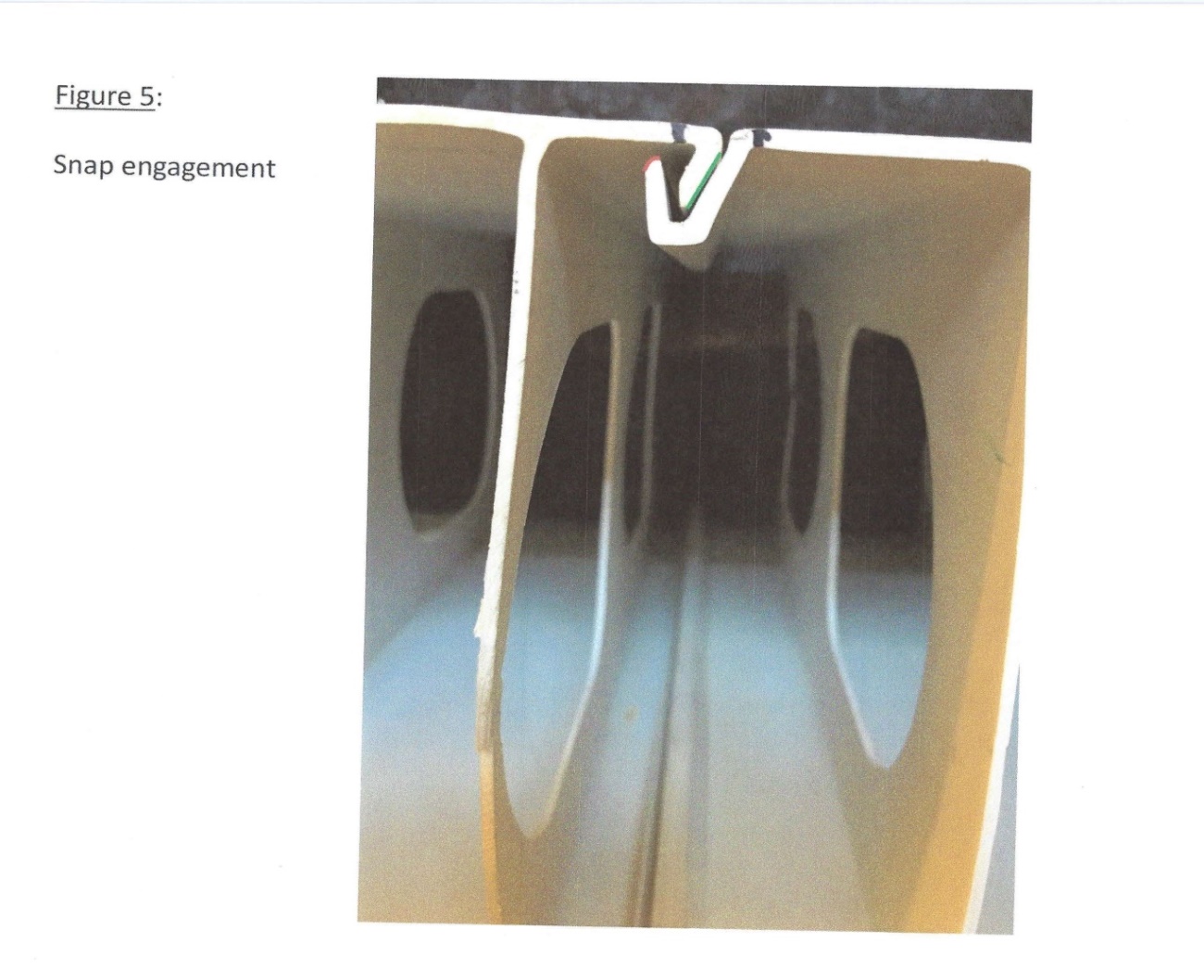
44 Figure 1 of Schedule A shows the two AFS Products at a point at which the top of the flange and the top of the groove first touch. Figure 2 shows that, after the two elements are further brought together, the top of the groove has moved down along the outer wall of the flange. Figure 3 shows the top of the outer wall of the groove as it approaches the bottom of the outer wall of the flange. Figure 4 shows the flange and groove, in Mr Hunter’s words, “just prior to snap engagement.” Figure 5 shows the position of the flange nestled inside the groove, after snap engagement has occurred.
45 Mr Hunter’s annotations on the photographs in Annexure A show the ramp surfaces consisting of the outer wall of the flange (coloured green) and what he refers to as the “upper ramp surface” consisting of the curved surface at the top of the groove (coloured red) running between the inner and outer surfaces of the groove.
30 The primary judge recorded that in his first presentation of the photographs, Mr Hunter identified the ramp surface as being the surface extending along the entire length of the outer wall of the groove. That surface, Dincel contended, consisted of a ramp surface for the purposes of claim 1. Alternatively, it said that what Mr Hunter called the “upper ramp surface” was a ramp surface for the purpose of claim 1.
31 That proposition was rejected by the primary judge. His Honour was satisfied that the outer wall of the groove lying beneath the curved surface at the top did not function as a ramp. His Honour concluded that it was only where the flange engages with the top of the upper portion of the wall of the groove, that the curved surface might be said to act as a ramp as the tip of the flange travels along it. His Honour noted that Mr Hunter’s photographs did not reveal the presence of any movement suggesting that the lower portion of the outer wall of the groove functions as a ramp.
32 AFS had also submitted that Mr Hunter’s experiment did not demonstrate that the tip of the flange travelled along what Mr Hunter called the upper ramp surface. In doing so, AFS focussed on Figure 4 and Figure 5, which did not, as Mr Hunter accepted, capture any image of the lip of the flange as it travelled beyond the position last shown in Figure 4 before snap engagement occurred as shown in Figure 5.
33 Mr Hunter explained that he was not able to capture images of what occurred between Figure 4 and Figure 5, but his evidence, nonetheless, was that the tip of the flange had to travel across the length of the curved surface if snap engagement was to occur and that the curved surface along which the lip travelled provided a mechanical advantage, which assisted the flange to move absolutely and relatively to the groove, making a snap engagement possible. The primary judge referred to the evidence of Mr Hunter (at [49]), who said:
[The] point that there’s no mechanical advantage over that second section [referring to the curved surface], that’s also not true, because the flange continues to move over an outwardly diverging portion of the groove, so there must be a mechanical advantage there. That arc must be making it easier for that – for that flange to traverse over that portion of the groove and make its way into the slot.
34 After referring to the evidence of Mr Phillips as well, the primary judge noted that the experts accepted that the curved surface of the top of the outer wall of the groove portion was capable of acting as a ramp which would make it easier for the flange to traverse into the groove. However, his Honour did not understand Mr Phillips to be accepting that the curved surface at the top of the groove in the AFS Product provided any mechanical advantage or that, if it did so, the degree of mechanical advantage provided was of any practical significance. Rather, according to Mr Phillips, it was the ramp on the outer wall of the flange (and not the curved surface at the distal end of the groove) which provided the mechanical advantage necessary to deflect the groove relative to the flange for the purpose of snap engagement. In his oral evidence, Mr Hunter similarly agreed that, save for the final millimetres when the lip of the flange rode over the curved surface, it was the ramp on the outer wall of the flange which functioned as a ramp for snap engagement in the AFS Product.
35 The primary judge discussed the competing evidence and debate between the experts about the degree of movement of the flange and the groove before the snap engagement process in these terms, noting (at [52]) that:
… In his written evidence, Mr Phillips explained that he had performed calculations (based on the stiffness ratio of the cantilever lengths) showing approximately 90% deflection by the groove and 10% by the flange during snap engagement of the AFS Product. He also performed a “practical test” to validate those calculations (using a ratchet strap and Vernier Calliper measurement tool) which he said revealed that, during snap engagement, the groove section had moved approximately 99.5% of the total interference, and the flange section had moved 0.5%. Mr Phillips described the results of his “practical test” as revealing “insignificant” movement of the flange during snap engagement.
36 Having noted that it was the inclined surface which assisted the groove to move in a downward direction relative to the flange to a point of snap engagement, and that it was that surface in the AFS Product which provided most, if not all, the mechanical assistance necessary for snap engagement, his Honour rejected Mr Hunter’s description of the “upper ramp surface” as being a “ramp surface” within the meaning of the claim. His Honour concluded that the evidence did not establish that it made any significant contribution to the movement of the flange and that Mr Hunter’s evidence to the contrary was based on conjecture and was not persuasive.
37 Rather, in the AFS Product, it was clear that the outer surface of the flange performed that function. The primary judge considered to the extent (if any) that the curved surface at the top of the groove also performed the function, it was a contribution to the movement of the flange into the groove not shown to be anything more than de minimus. His Honour was therefore not satisfied that the “upper ramp surface” in the AFS Product was a ramp surface within the meaning of claim 1 as it would be understood by the notional skilled addressee.
Invalidity
38 The primary judge then went on to consider the contention by AFS that the Patent was invalid. As there is no cross-appeal, it is unnecessary to consider this aspect.
Costs judgment
39 In the subsequent costs judgment, apart from issuing a certificate certifying as to the validity of the relevant claims in the Patent, the primary judge ordered Dincel to pay AFS’s costs of the application. While there is also an appeal from this judgment, no separate grounds are raised. In other words, Dincel contends if it succeeds on the appeal of the liability judgment, it should have its costs below as well as on the appeal and also concedes the contrary position.
GROUNDS OF APPEAL
40 Much of the appeal turns on a short point. Dincel contends the primary judge erred in construing claim 1 by finding that to be “ramp surfaces” within the meaning of claim 1, a surface must confer some “mechanical advantage” in addition to the surfaces being sloping surfaces that engage the flanges to move the flanges relative to the grooves for the snap engagement of the flanges in the grooves. Dincel further appeals on the alternative ground that, if there is to be a mechanical advantage, the AFS Product provides it.
41 In the context of assessing whether the AFS Product infringed, Dincel says the primary judge erred in assessing the evidence relevant to the features of the AFS Product and finding that:
(a) the outer surfaces of the flanges in the AFS Product provided most, if not all, of the mechanical assistance necessary to enable snap engagement to occur;
(b) the evidence did not establish that the outer surfaces of the distal ends of the grooves in the AFS Product made any contribution, or any significant contribution, to the movement of the flanges; and
(c) in the premises, the outer surfaces of the distal ends of the grooves in the AFS Product were not “ramp surfaces” for the purpose of claim 1 of the Patent.
42 Dincel’s grounds of appeal continue as follows:
4. Having correctly found or accepted evidence that:
(a) for present purposes, a ramp was best described as “[a] slope; an inclined plane connecting two different levels” (at [36]);
(b) claim 1 of the Patent did not require that the “ramp surfaces” engage the flanges at the point at which the two like elements were brought together (at [35]);
(c) the outer surfaces of the distal ends of the grooves in the AFS Product engaged the flanges in the latter part of the snap engagement process when the tips of the flanges travelled along the curved portions of those surfaces (at [47]);
(d) claim 1 did not require that the “ramp surfaces” be planar, and the curved portions of the outer surfaces of the distal ends of the grooves in the AFS Product were capable of acting as ramp surfaces which would make it easier for the flanges to traverse into the grooves (at [51]); and
(e) there was evidence that the relative movement of the flanges and the grooves of the AFS Product during snap engagement involved about 37.5% movement of the flanges and 62.5% movement of the grooves (at [55]),
his Honour ought to have further found that:
(f) there was evidence that about 2 [millimetres] of the total snap interference distance of about 5-6 [millimetres] in the AFS Product was overcome when the flanges traversed the curved portions of the outer surfaces of the distal ends of the grooves;
(g) there was evidence that the ratio of relative movement of the flanges and the grooves in the AFS Product remained the same throughout the process of snap engagement;
(h) it followed that, if necessary, there was evidence of the particular contribution to the movement of the flanges made by the outer surfaces of the distal ends of the grooves in the AFS Product, and that contribution was not de minimis [sic];
(i) it followed that, if necessary, there was evidence that the outer surfaces of the distal ends of the grooves in the AFS Product provided a “mechanical advantage” during the process of snap engagement; and
(j) in the premises, the outer surfaces of the distal ends of the grooves in the AFS Product, or alternatively the curved portions of those surfaces, were “ramp surfaces” within the meaning of claim 1, with the result that infringement was established.
…
NOTICE OF CONTENTION
43 By its notice of contention, AFS argues that, first, the primary judge erred in failing to find that for a building element to be within claim 1 of the Patent, the flange and the ramp surface must engage at the point at which two like elements are brought together. Secondly, AFS contends that in addition to the matters relied upon by the primary judge in finding that the AFS Product is not a product within the scope of claim 1 of the Patent, his Honour should also have found that the AFS Product was not within the scope of claim 1 because the flange and the “upper ramp surface” of two like AFS Products do not engage at the point at which they are brought together.
DINCEL’S ARGUMENTS ON APPEAL
The “real review” point
44 The grounds of appeal challenge fact finding as well as the primary judge’s approach to the law. Insofar as the fact finding is concerned, AFS submits that Dincel must demonstrate that the facts as found are wrong by “incontrovertible facts or uncontested testimony”, or they are “glaringly improbable” or “contrary to compelling inferences”: Robinson Helicopter Company Incorporated v McDermott (2016) 90 ALJR 679. AFS submits that Dincel has not done so and that this Court ought not to accept Dincel’s attempt to relitigate in detail on appeal the facts found at the trial.
45 In Robinson Helicopter, the High Court (French CJ, Bell, Keane, Nettle and Gordon JJ) said (at [43]):
The fact that the judge and the majority of the Court of Appeal came to different conclusions is in itself unremarkable. A court of appeal conducting an appeal by way of rehearing is bound to conduct a “real review” of the evidence given at first instance and of the judge’s reasons for judgment to determine whether the judge has erred in fact or law. If the court of appeal concludes that the judge has erred in fact, it is required to make its own findings of fact and to formulate its own reasoning based on those findings. But a court of appeal should not interfere with a judge’s findings of fact unless they are demonstrated to be wrong by “incontrovertible facts or uncontested testimony”, or they are “glaringly improbable” or “contrary to compelling inferences”. In this case, they were not. The judge’s findings of fact accorded to the weight of lay and expert evidence and to the range of permissible inferences. The majority of the Court of Appeal should not have overturned them.
(Emphasis added, citations omitted.)
46 Nothing in Robinson Helicopter expressly or implicitly departs from the plurality judgment in Fox v Percy (2003) 214 CLR 118, where Gleeson CJ, Gummow and Kirby JJ said (at [28]-[29]):
… In particular cases incontrovertible facts or uncontested testimony will demonstrate that the trial judge’s conclusions are erroneous, even when they appear to be, or are stated to be, based on credibility findings.
That this is so is demonstrated in several recent decisions of this Court. In some, quite rare, cases, although the facts fall short of being “incontrovertible”, an appellate conclusion may be reached that the decision at trial is “glaringly improbable” or “contrary to compelling inferences” in the case. In such circumstances, the appellate court is not relieved of its statutory functions by the fact that the trial judge has, expressly or implicitly, reached a conclusion influenced by an opinion concerning the credibility of witnesses. In such a case, making all due allowances for the advantages available to the trial judge, the appellate court must “not shrink from giving effect to” its own conclusion. Finality in litigation is highly desirable. Litigation beyond a trial is costly and usually upsetting. But in every appeal by way of rehearing, a judgment of the appellate court is required both on the facts and the law. It is not forbidden (nor in the face of the statutory requirement could it be) by ritual incantation about witness credibility, nor by judicial reference to the desirability of finality in litigation or reminders of the general advantages of the trial over the appellate process.
(Citations omitted.)
47 In Australian Securities and Investments Commission v Geary [2018] VSCA 103, the Victorian Court of Appeal (Ferguson CJ, Weinberg JA and Sifris AJA) dealt with the discussion which had followed in a number of cases after Robinson Helicopter (at [208]-[222]). Following this consideration, the Court of Appeal said:
The better view seems to be that Robinson Helicopter governs the approach that should be taken to appeals on questions of fact that involve challenges to findings of fact based substantially upon the credibility of witnesses who have testified during the trial. Once the primary facts have been established, however, the question whether particular inferences should be drawn from those established facts is a matter as to which an appellate court is generally in as good a position as a trial court to consider for itself. The strictness with which Robinson Helicopter approaches findings of primary fact is not applicable to purely inferential reasoning.
(Emphasis added.)
48 We would agree with the conclusion as to the effect of Robinson Helicopter as described by the Victorian Court of Appeal in Geary. Nothing in Robinson Helicopter purported to reverse the decision in Warren v Coombes (1979) 142 CLR 531 or Fox v Percy. Robinson Helicopter, somewhat in contrast to this three day patent dispute, was a five week trial, during which nearly 20 witnesses gave oral evidence, including a number of experts. The trial judge alone, as the High Court said, had the opportunity of hearing and seeing those witnesses giving their evidence. There was also a large number of exhibits, including physical exhibits and documentary exhibits, which only the trial judge had the opportunity to read and consider completely. The trial judge also had the unique benefit of viewing two helicopters of the kind which crashed. The trial judge had the opportunity to consider the evidence in its totality and to reflect at length upon it. In Robinson Helicopter, the High Court specifically cited Warren v Coombes and Fox v Percy. We do not think Robinson Helicopter would preclude this Court in this case, and contrary to the contention for AFS, from arriving at different factual conclusions from the primary judge if those facts are properly characterised as inferences to be drawn from uncontested evidence.
49 Further, in relation to appellate review in this Court, the decision in Robinson Helicopter has been subject to recent Full Court consideration in Aldi Foods Pty Ltd v Moroccanoil Israel Ltd [2018] FCAFC 93. Allsop CJ (at [2]-[3]) and Perram J (at [54]) (with whom Markovic J agreed) emphasised that Robinson Helicopter ought not to be understood as overruling or departing from Warren v Coombes and Fox v Percy.
50 The application of the principles of appellate review to evaluative assessments is a question which frequently arise in the context of intellectual property appeals. In Aldi Foods, Allsop CJ (at [4] and the cases therein cited) and Perram J (at [43]-[53]) referred to the decision of Allsop J (as his Honour then was) in Branir Pty Ltd v Owston Nominees (No 2) Pty Ltd (2001) 117 FCR 424, where his Honour identified the relevant principles to appellate review. In Branir, it was relevantly observed:
the High Court’s comments in Warren v Coombes, that an appellate court must not “shrink from giving effect to its own conclusion”, were premised on a conclusion that the decision of the trial judge was wrong and should be corrected (at [21]);
the task of a court on appeal by way of a rehearing is the correction of error (at [22]);
what is error in any given case depends, of course, not only on the evidence, but also on the nature of the findings or conclusions made by the primary judge. The demonstration of error may not be straight-forward where findings or conclusions involve elements of fact, degree, opinion or judgment or when the findings or conclusions in question can be seen as made with the advantage of hearing the evidence in its entirety, presented as it unfolded at the hearing with the opportunity over the course of the hearing and adjournments for reflection and mature contemporaneous consideration and assessment, in particular in a long and complex hearing (at [24] and the cases therein cited);
in circumstances where, by the nature of the fact or conclusion, only one view is (at least legally) possible, the preference of the appeal court for one view would carry with it the conclusion of error. However, other findings or conclusions may be more easily open to legitimate differences of opinion (at [25]);
the appeal court must make up its own mind on the facts (at [28]);
the appeal court’s decision on the facts can only be done in the light of, and taking into account and weighing, the judgment appealed from, where the advantages of the trial judge may reside in the credibility of witnesses (at [28]);
while the appeal court has a duty to make up its own mind, it does not deal with the case as if trying it at first instances. Rather, in its examination of the material, it accords proper weight to the trial judge’s views (at [28]);
in the process of considering the facts for itself and giving weight to the views of, and advantages held by, the trial judge, if a choice arises between conclusions equally open and finely balanced and where there is, or can be, no preponderance of view, the conclusion of error is not necessarily arrived at merely because of a preference of view of the appeal court for some fact or facts contrary to the view reached by the trial judge (at [28]);
the degree of tolerance for any such divergence in any particular case will often be a product of the perceived advantage enjoyed by the trial judge (at [29]); and
the proper approach is not to ask the court to survey all the evidence and to ask it to arrive at its own conclusion, nor for the appeal to be treated as if it were a new trial and constrained merely by the unassailable factual findings (at [30]).
51 We have regard to these principles. As it happens, we do not disagree with the primary judge. With respect to the primary judge’s preferences as to expert evidence, his Honour had the advantage of seeing and hearing the expert witnesses and made findings which we regard as according with the weight of the evidence at trial and with the range of permissible inferences. We find insufficient bases to disturb the primary judge’s conclusion on this matter. We consider the primary judge reached the right decision on the facts and inferences to be drawn from them. We would not on this appeal interfere with the primary judge’s preferences as to the expert witnesses. If we were to disagree with the construction of the patent or with inferences that might be drawn from the substantial amount of uncontested evidence, we could reach a different conclusion on those matters. However, in this instance, we do not disagree.
THE DINCEL ARGUMENTS
52 The five sub-grounds of appeal may be considered together.
53 As noted, Dincel’s main claim in relation to the construction of the Patent is that the primary judge erred in construing claim 1 by importing into it an additional requirement of the need for mechanical advantage. The principles of construction are well established in Jupiters Ltd v Neurizon Pty Ltd (2005) 222 ALR 155 where the Full Court (Hill, Finn and Gyles JJ) (at [67]) said:
…
(i) the proper construction of a specification is a matter of law: Décor Corporation Pty Ltd v Dart Industries Inc (1988) 13 IPR 385 at 400;
(ii) a patent specification should be given a purposive, not a purely literal, construction: Flexible Steel Lacing Company v Beltreco Ltd (2000) 49 IPR 331; [2000] FCA 890 at [81]; and it is not to be read in the abstract but is to be construed in the light of the common general knowledge and the art before the priority date: Kimberley-Clark Australia Pty Ltd v Arico Trading International Pty Ltd (2001) 207 CLR 1; 177 ALR 460; 50 IPR 513; [2001] HCA 8 at [24];
(iii) the words used in a specification are to be given the meaning which the normal person skilled in the art would attach to them, having regard to his or her own general knowledge and to what is disclosed in the body of the specification: Décor Corporation Pty Ltd at 391;
(iv) while the claims are to be construed in the context of the specification as a whole, it is not legitimate to narrow or expand the boundaries of monopoly as fixed by the words of a claim by adding to those words glosses drawn from other parts of the specification, although terms in the claim which are unclear may be defined by reference to the body of the specification: Kimberley-Clark v Arico at [15]; Welch Perrin & Co Pty Ltd v Worrel (1961) 106 CLR 588 at 610; Interlego AG v Toltoys Pty Ltd (1973) 130 CLR 461 at 478; the body of a specification cannot be used to change a clear claim for one subject matter into a claim for another and different subject matter: Electric & Musical Industries Ltd v Lissen Ltd [1938] 4 All ER 221 at 224-5; (1938) 56 RPC 23 at 39;
(v) experts can give evidence on the meaning which those skilled in the art would give to technical or scientific terms and phrases and on unusual or special meanings to be given by skilled addressees to words which might otherwise bear their ordinary meaning: Sartas No 1 Pty Ltd v Koukourou & Partners Pty Ltd (1994) 30 IPR 479 at 485-6; the Court is to place itself in the position of some person acquainted with the surrounding circumstances as to the state of the art and manufacture at the time (Kimberley-Clark v Arico at [24]); and
(vi) it is for the Court, not for any witness however expert, to construe the specification; Sartas No 1 Pty Ltd, at 485-6.
54 The wording of the claims must be construed in context and in light of the common general knowledge before the priority date, but their meaning cannot be altered by any gloss drawn from other parts of the specification. While expert evidence may assist, the proper construction of the claims is a matter of law for the Court.
55 In relation to the “ramp surfaces integer”, Dincel says that it is apparent that claim 1 is directed to a building element that can be connected to another like element by a snap engagement mechanism. In general terms, each element has flanges on one end and grooves on the other. As the elements are pushed together, the flanges and grooves move relative to one another and transverse of the element. The elements have “ramp surfaces that engage the flanges to move flanges for said snap engagement of the flanges in the grooves”. This is the “ramp surfaces integer”. The movement that is referred to, is movement of the flanges and grooves relative to each other. Dincel contends, as it did at first instance, that the function of the “ramp surfaces” is as spelt out expressly in the ramp surface integer, namely, to engage the flanges to move the flanges relative to the grooves for the snap engagement of the flanges in the groove to occur. Dincel contends there was no requirement that the ramp surfaces convey any particular “mechanical advantage” over and above that function, contrary to what the primary judge held.
56 Dincel argues that “ramp surfaces” means simply a slope or inclined surface extending from an adjacent surface. The remaining words in the ramp surface integer define the function that must be performed by the ramp surfaces, that is the functional requirement is to engage the flanges to move the flanges for “said snap engagement” with the grooves. Dincel challenges the finding of the primary judge that a ramp surface within the meaning of claim 1 must confer a “mechanical advantage” by “reducing the amount of the force required to achieve [movement of the flange]”. At [38] of the liability judgment, his Honour said:
Mr Phillips understood that the ramp surfaces referred to in the Patent are sloping surfaces that provide a mechanical advantage by reducing the amount of force required to move the flange from point to point. Mr Hunter, in his third affidavit, agreed with Mr Phillips, that a surface must function as a ramp to be a “ramp surface” for the purpose of the claims. Mr Phillip’s understanding accords with my own understanding of how the invention described in the body of the specification works.
(Emphasis added.)
57 Dincel contends there is no justification for introducing this requirement. It was a concept introduced by Mr Phillips, and responded to by Mr Hunter, but Dincel contends that the experts’ application of the concept of “mechanical advantage” was different from the primary judge’s application. Dincel contends that the experts used the term “mechanical advantage” to describe the conceptual, technical framework that underlies the functional requirement. In contrast, the primary judge applied “mechanical advantage” as an additional requirement that a surface had to meet in order to be a “ramp surface” within the meaning of claim 1 over and above the definitional and functional requirements on which Dincel relied. The function of the ramp surface it says is simply to engage the flanges to move the flanges for snap engagement of the flanges in the grooves. This is the express functional requirement, but the primary judge imported a different and additional functional requirement, namely, that the ramp surfaces provide a “mechanical advantage”. Dincel says this is unwarranted because claim 1 already prescribes in terms the function of the ramp surfaces. To the extent that it goes beyond the express functional requirement, Dincel says it is inconsistent with the wording of the claim. Dincel contends this adds, in effect, an impermissible gloss to the words of claim 1.
58 Dincel stresses, as the primary judge acknowledged, that neither the body of the specification, nor the claims refer to “mechanical advantage”. Dincel challenges the primary judge’s finding (at [39]) that “these words do describe the work performed by the ‘ramp surfaces’, of the combination defined in claim 1 as it would be understood by the skilled addressee based on a reading of the specification as a whole”. At [56] of the liability judgment, the primary judge said:
Mr Hunter’s evidence clearly establishes that the movement of the groove is assisted by what he also calls a ramp surface in the AFS Product (shown in green in Schedule A, Figs 1-5) on the outer surface of the flange. It is this inclined surface that assists the groove to move in a downward direction relative to the flange to a point at which snap engagement can occur. It is clear that it is this surface in the AFS Product that provides most, if not all, of the mechanical assistance necessary to enable snap engagement to occur.
59 This is an example, Dincel says, of the way in which the primary judge applied the “mechanical advantage” requirement. His Honour compared the ramp surfaces on the grooves with the ramp surfaces on the flanges in the AFS Product and found that it was the ramp surfaces on the flanges that were providing “most, if not all, of the mechanical assistance necessary to enable snap engagement to occur”. This process led his Honour to conclude that the surfaces on the grooves in the AFS Product were not “ramp surfaces” within the meaning of claim 1 (at [58]).
60 Once it is accepted that mechanical advantage is not required, Dincel says it must follow that the AFS Product embodies the ramp surface integer, it being clear that the “upper ramp surfaces” in the AFS Product are ramp surfaces that perform the function of engaging the flange to move the flanges relative to the grooves for the snap engagement of the flange in the grooves.
61 Dincel asserts that properly construed as a whole, and with no additional functional requirement in the words “ramp surfaces”, the ramp surface integer requires “sloping or inclined surfaces that engage the flanges to move the flanges for snap engagement in the grooves”, nothing more and nothing less. It says the integer must be present in the AFS Product because the “upper ramp surfaces” in the AFS Product are plainly sloping or inclined surfaces. Consistently with this, the evidence shows, Dincel argues, that the flanges must ride over the upper ramp surfaces to get into the grooves so that they traverse the whole of the upper ramp surfaces. Dincel argues that, contrary to the AFS’s submission, the evidence shows that the flanges move while they are traversing the upper ramp surfaces. That movement can only be attributable to the engagement with the upper ramp surfaces, as explained by Mr Hunter before the primary judge. There is nothing else contacting the flanges at that point that could cause such movement. Finally, the movement of the flanges is for snap engagement with the grooves because, after traversing the upper ramp surfaces, the flanges snap into the grooves. Dincel argues that this means that all the disputed elements of claim 1 are present in the AFS Product.
62 Dincel points to evidence that the relative movement of the flanges and the grooves of the AFS Product during snap engagement involved about 37.5% movement of the flanges and 62.5% movement of the grooves, which was a figure broadly consistent with Mr Hunter’s measurements and calculations indicating that about 25% of the movement was attributable to the flanges. It follows that there was clear evidence, according to Dincel, that a substantial proportion of the overall relative movement of the flanges in the grooves during the snap engagement with the AFS Product involved the movement of the flanges. This was important because it is also clear that movement of the flanges was caused by the “upper ramp surfaces” engaging the flanges. Dincel contends that in the proper construction of claim 1, without any reference to, or requirement of, “mechanical advantage”, that is sufficient to establish the presence of the ramp surface integer and, thus, infringement of claim 1 by the AFS Product.
63 Alternatively, and in any event, Dincel submits, even on the primary judge’s construction of the claim, there was evidence of mechanical advantage of the kind contemplated, such that the ramp surface integer was present in the AFS Product. There was evidence of the overcoming of the snap interference or engagement distance as discussed above at [13]. The snap interference distance is the distance the two elements of the product must move relative to one another in order for the product to “snap-fit” or snap shut. No finding was made about the amount of the “snap interference distance” in the AFS product, that is, the total amount of relative movement between the groove and the flange necessary to effect the “snap-fit”. Dincel argues that the primary judge should have found that this distance was about 2 millimetres of a total snap interference distance of about 5-6 millimetres.
64 Dincel further contends that there was evidence before the primary judge, if required, that the ratio of the relative movement of the flanges and the grooves in the AFS Product remained the same throughout the process of snap engagement. No finding was made to the contrary. It follows, Dincel argues, that the proportion of relative movement attributable to movement of the flanges during the final 2 millimetres of the snap engagement is the same as the proportion attributable to movement of the flanges throughout the snap engagement, that is, being 37.5% or, in the alternative, 25%, as found by Mr Hunter.
65 This means, Dincel argues, that there was evidence of the particular contribution to the movement of the flanges made by the upper ramp surface. That contribution was not, Dincel argues, de minimus. As for the quantum of that effect, Mr Hunter’s evidence, based on his figure of 25%, was that the flanges would move about 0.5 millimetres as they traversed the upper ramp surfaces. That would be higher, if the figure of 37.5% were applied. Dincel argues 0.5 millimetres could not be regarded as de minimus in the context of the invention described and claimed in the Patent. Snap engagement requires small, not large, distances. There was evidence that an entire snap engagement can be effective with a “snap interference distance” of 0.5 millimetres.
66 Dincel argues that for the same reason the primary judge erred in finding that the outer surfaces of the flanges in the AFS Product provided most, if not all, of the mechanical assistance necessary to enable snap engagement to occur and erred in finding that the evidence did not establish that the upper ramp surfaces made any contribution, or any significant contribution, to the movement of the flanges. There was no contest at trial as to whether the upper ramp surfaces were sloping surfaces extending from adjacent surfaces. As for the functional requirement, Dincel argues that, if necessary, the upper ramp surfaces did provide a mechanical advantage during the process of snap engagement. They made it easier for the flange to traverse over that portion of the groove and make its way into the slot by making the deformation of the flange more gradual than it would otherwise be. Dincel contends that it therefore follows, for the same reason, that the primary judge erred in finding that the upper ramp surfaces in the AFS Product were not ramp surfaces within the meaning of claim 1.
CONSIDERATION
67 In our view, as noted, we do not consider that anything in Robinson Helicopter or otherwise, precludes us from reviewing the correctness or otherwise of the primary judge’s construction of the Patent specification. In any event, the process of the construction of the Patent is a matter of law. While it is true that the primary judge reached conclusions about what the words of the ramp surface integer in context would convey to a skilled addressee, many of the foundational facts were common ground. The precise question is whether the primary judge made an error by importing an additional requirement of mechanical advantage into the claims. The alternative approach is that mechanical advantage was considered by both of the experts and the primary judge to be a term that describes the work performed by the ramp surfaces through the combination defined in claim 1.
68 AFS makes the point, in which there is some force, that Dincel’s approach is erroneous in substituting in isolation the word “ramp” with the widest dictionary synonym, namely “sloping or inclined”, then seeking to identify with knowledge of the Patent and the allegedly infringing product, some surface in that product that could be described as sloping or inclined so as to meet the wide dictionary synonym. We consider the difficulty in this approach is that it deprives the ramp surface integer of any functional requirements in relation to the ramp, which is inconsistent with the evidence given by both experts.
69 The primary judge was well aware that neither the body of the specification nor the claims referred to “mechanical advantage”. His Honour explicitly states as such. However, in the process of construing claim 1 by determining what the ramp surface integer would convey to a person skilled in the relevant art, his Honour expressly recognised that, despite the absence of reference to mechanical advantage and aided by the accepted evidence of Mr Phillips, the words described the work performed by the ramp surfaces as understood by a skilled addressee. Indeed, as noted, the primary judge recorded that Mr Hunter agreed with Mr Phillips that a surface must function as a ramp in order to be a “ramp surface” for the purpose of the claims. It is not enough simply to be a sloping surface. Construing the claim, the primary judge was entitled to conclude that where “ramp” was used, it was intended, in context, to describe a surface performing the function of making it easier to move from one level to another level.
70 The snap engagement feature of claim 1 is a separate process and a separate requirement to that of the ramp surface feature, which read in context defines the specific mechanism by which the “said snap engagement” is achieved. It is achieved by a ramp surface that engages the flanges to facilitate the snap engagement of the flanges in the grooves.
71 In particular, the approach taken by the primary judge to the claim construction draws on the principles of purposive patent construction, as discussed in Jupiters. “Ramp” is required to be given a purposive functional meaning. Applying that functional or practical meaning in context has not added any gloss to the words of the claim.
72 When considering the AFS Product, the primary judge concluded that Dincel had not established that there was a surface functioning as a ramp and/or that its contribution to that result is of any significance to the working of the AFS Product. There was a sound basis for his Honour’s conclusion. It was apparent, for example, that Mr Hunter in his first affidavit did not identify the upper ramp surface now relied upon by Dincel as being a ramp surface for the purpose of the Patent. Rather, he appeared to identify a much larger ramp surface on the groove. It was in his second affidavit, responding to Mr Phillips first affidavit, that the concept of an “upper ramp surface” was developed. He accepted in cross-examination that the photographs were a repurposing of his original photos carried out after he had changed his view about what the relevant “ramp surface” was.
73 The primary judge made a finding that even if the lip of the flange were to travel along the “upper ramp surface”, it did not follow that the surface was functioning as a ramp or, if it did, that its contribution was of any significance to the working of the AFS Product. The primary judge was entitled to reach the conclusion that Mr Hunter’s evidence, in advancing the suggestion that the upper ramp surface (as described by Dincel) made any contribution to the movement of the flange, was nothing other than conjecture and was not persuasive. These findings, which in essence involve a preference for the expert evidence of Mr Phillips for AFS, are the province of the primary judge. His Honour participated in the questioning of the experts drawing that contemporaneous evidence, as is apparent from the transcript of the hearing.
74 Even if there was some movement of the flange, this does not mean that there exists the mechanism described by the ramp surface feature, specifically whether the particular surface is functioning to provide the requisite functional advantage. His Honour was entitled to conclude there was no basis on which he could be satisfied that the “upper ramp surface” of the AFS Product was a ramp surface, namely, a sloping surface configured so as to assist the movement of the flange as it travels to the point at which snap engagement occurs by reducing the amount of force required to achieve this result.
75 His Honour concluded, as he was entitled to, that although Mr Hunter’s evidence clearly established that movement of the groove on the AFS Product was assisted by a ramp surface in the AFS Product, the evidence did not establish that the “upper ramp surface”, as described by Mr Hunter, was a “ramp surface” within the meaning of the claims. The evidence did not establish, as his Honour noted, that the “upper ramp surface” of the AFS Product made any contribution or any significant contribution to the movement of the flange, even if the lip of the flange did travel along the “upper ramp surface”. This was part of the evidence of Mr Hunter that his Honour described as mere conjecture. As senior counsel for AFS noted, there were no relevant measurements or other supporting evidence such as a high speed video camera to support this view.
CONCLUSION
76 Dincel has not demonstrated error on the part of the primary judge. In those circumstances, it is unnecessary to consider the notice of contention. The appeals must be dismissed with costs.
I certify that the preceding seventy-five (75) numbered paragraphs are a true copy of the Reasons for Judgment herein of the Honourable Justices Besanko and McKerracher. |
Associate:
Dated: 18 September 2018
Schedule A
Figure 1
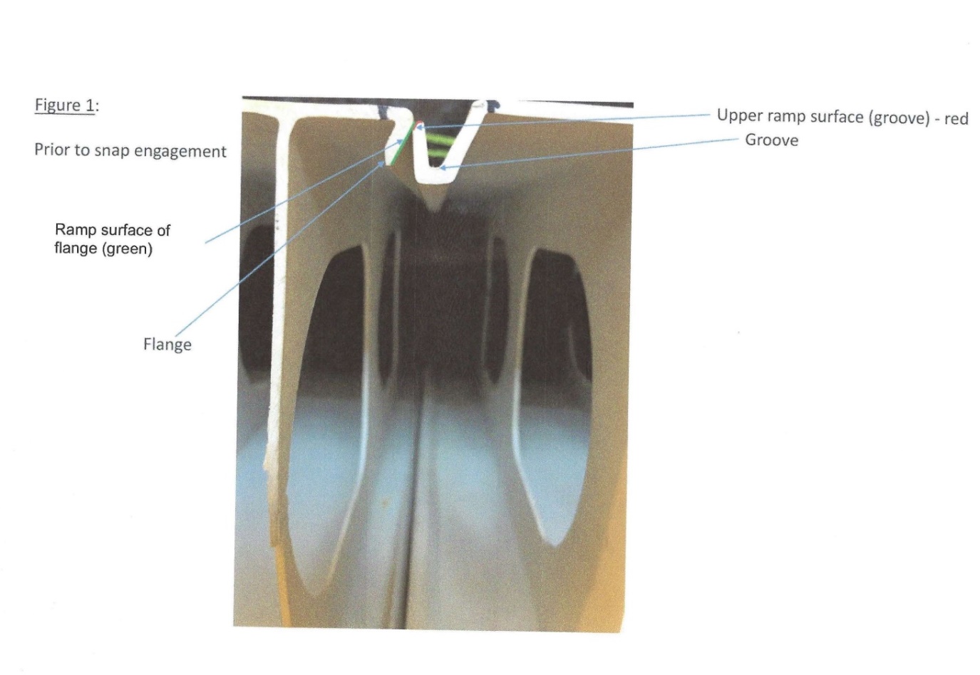
Figure 2
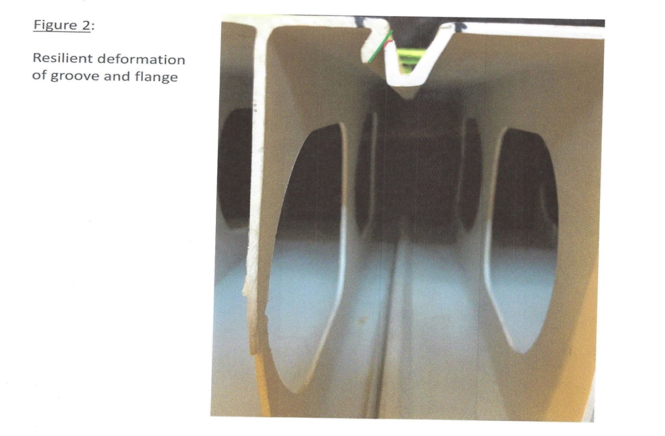
Figure 3
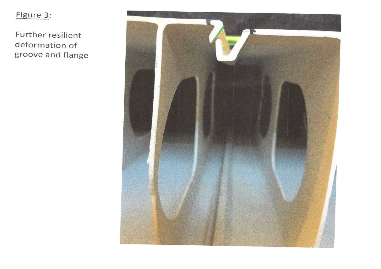
Figure 4
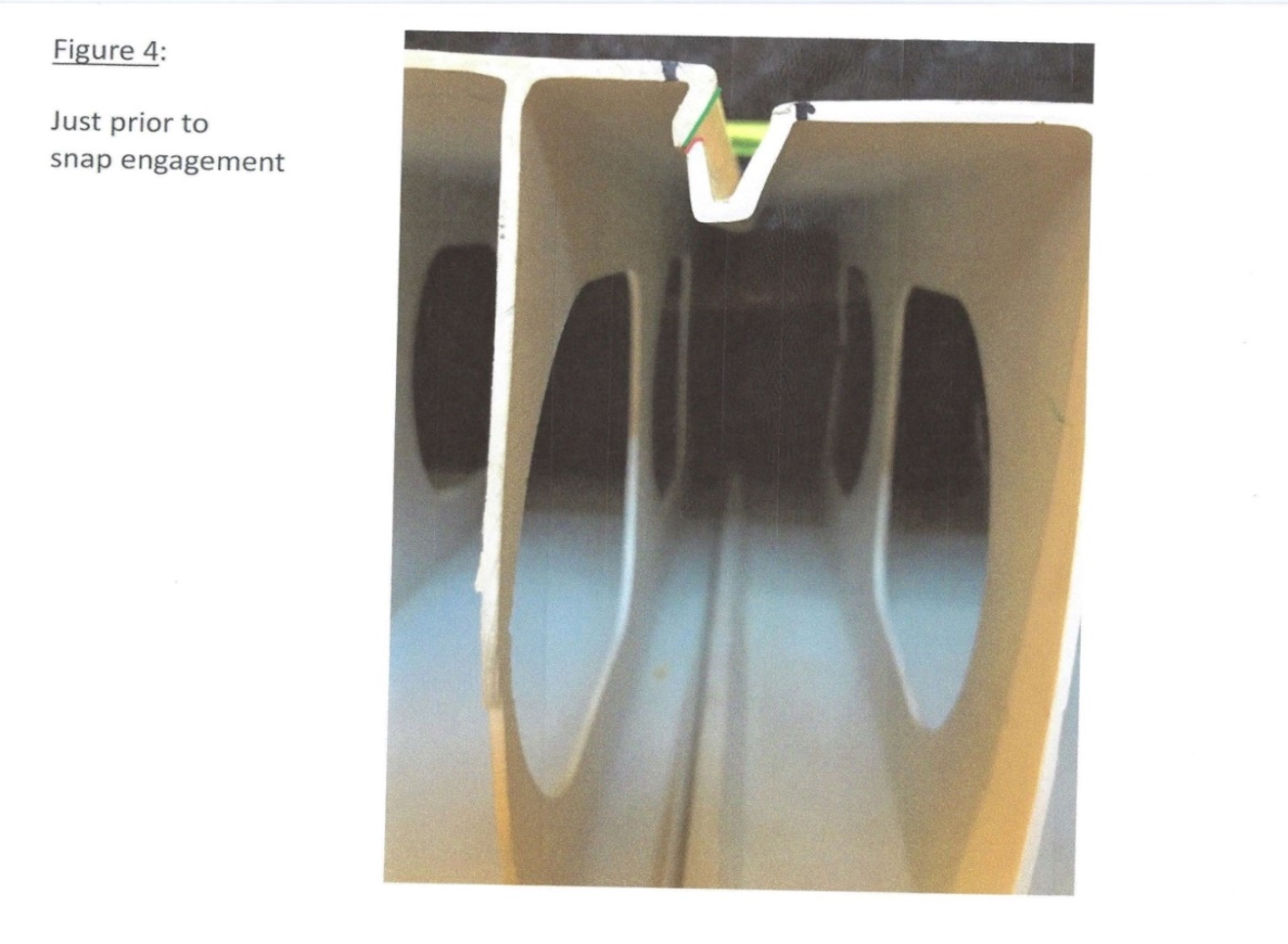
Figure 5