
FEDERAL COURT OF AUSTRALIA
Multigate Medical Devices Pty Ltd v B Braun Melsungen AG [2016] FCAFC 21
ORDERS
VID 693 of 2014 |
MULTIGATE MEDICAL DEVICES PTY LTD (ACN 132 290 058) Appellant | |
AND: | First Respondent B BRAUN AUSTRALIA PTY LTD (ACN 002 945 155) Second Respondent |
DATE OF ORDER: | 3 March 2016 |
THE COURT ORDERS THAT:
1. In proceeding VID 681 of 2014, leave to appeal be granted and the appellant’s appeal be allowed in part.
2. The parties file and serve within 7 days of the date hereof minutes of orders and short submissions (limited to two pages, if necessary) as to any setting aside of or variation to the primary judge’s orders in proceeding VID 463 of 2013 numbered 1 to 5 and 9 to 12 and on the question of costs of that proceeding before his Honour and the costs of the application for leave to appeal and the appeal in proceeding VID 681 of 2014.
3. In proceeding VID 693 of 2014, the appellant’s appeal be dismissed.
4. The appellant pay the respondents’ costs of and incidental to that appeal.
Note: Entry of orders is dealt with in Rule 39.32 of the Federal Court Rules 2011.
THE COURT:
1 At first instance B Braun Melsungen AG and B Braun Australia Pty Ltd claimed that Multigate Medical Devices Pty Ltd (Multigate) infringed two patents being:
(a) Australian Patent Number 2012258327 entitled “IV Catheter” (the 327 Patent) filed on 21 November 2012; and
(b) Australian Patent Number 2012260577 entitled “IV Catheter” (the 577 Patent) filed on 30 November 2012.
2 B Braun Melsungen AG is the patentee of both patents with Braun Australia Pty Ltd being the exclusive licensee (together, Braun). The Braun parties claimed that Multigate’s catheters infringed claim 1 of the 327 Patent and claims 1 to 6 of the 577 Patent. Multigate admitted that it had offered for sale, sold, supplied or kept for sale two catheters and that it intended to market and sell a third (referred to by the primary judge and in these reasons as catheters A, B and C respectively), but it otherwise denied infringement. It cross-claimed seeking revocation of the two patents on the grounds of invalidity.
3 The primary judge found that Multigate’s catheters infringed the relevant claims. He dismissed Multigate’s cross-claim. Before us Multigate has sought leave to appeal his Honour’s determination of infringement (VID 681 of 2014) and has appealed against the dismissal of the cross-claim (proceeding VID 693 of 2014).
4 In summary, we would grant leave to appeal to Multigate (as we have previously announced) in relation to his Honour’s determination on infringement and allow the appeal in proceeding VID 681 of 2014 in part. We would dismiss Multigate’s appeal in proceeding VID 693 of 2014.
5 It is convenient to address first the terms of the claims of the patents in suit and questions of construction. Our reasons and conclusions in both appeals principally turn on questions of construction.
THE PATENTS
6 The 327 Patent and the 577 Patent relate to a safety needle protecting device used as part of an intravenous catheter. Such a device is used in an intravenous catheter to prevent needlestick injuries. The specifications state that the invention relates to a safety needle assembly which can form part of a safety intravenous (IV) catheter device. Safety IV catheter devices comprise a needle protecting means which slides to the needle point as the needle is removed from the catheter and permanently blocks the needle point such that the needle point cannot thereafter be inserted into objects or persons.
7 The two patents in suit are the fifth generation of a family of patents with claims for such a device. They were applied for on 21 and 30 November 2012 respectively. The original ancestor was patent application 199895323 entitled “Spring clip as needle tip protection for a safety IV catheter”. The intermediate patents in the chain working backwards from the patents in suit included Australian Patent Application 2009233612 filed on 30 October 2009 (the parent), Australian Patent Application 2005203491 filed on 5 August 2005 (the grandparent) and Australian Patent Application 200142070 filed on 4 May 2001 (the great grandparent). The original ancestor was filed as an international application numbered PCT/EP98/05231 later published as WO99/08742. The original ancestor had an effective filing date of 18 August 1998, but claimed priority from two US patents, the first being US Patent Application No 08/915,148 filed on 20 August 1997 and the second being US Patent Application No 09/097,170 filed on 12 June 1998. Braun contended below that aspects of the original ancestor that could be relevant to the patents in suit were first disclosed in the latter mentioned application. Accordingly, the earliest possible priority date was 12 June 1998. It has not been in issue before us that this was the earliest possible priority date for the claims in suit, although the actual priority date is in issue. We will return to this question later when considering the question of external fair basis.
8 The 327 Patent had one claim, namely:
An IV catheter apparatus including a tubular catheter having a proximal end and a distal end, a needle having a needle shaft and a tip and wherein the needle is attached to a distal end of a needle hub, said needle being received within said tubular catheter when the needle is in a ready position, a catheter hub attached to the proximal end of said catheter, said catheter hub having a hollow interior and an inner wall, said needle being movable between said ready position in which said tip is outside of said catheter hub and a retracted position in which said tip is within the interior of said catheter hub, a needle guard positioned in the interior of said catheter hub in a spaced apart relationship from the distal end of the needle hub;
wherein the needle guard has a resilient portion engaged by said needle shaft when said needle is in its ready position, the needle guard resilient portion is movable within the interior of said catheter hub to a blocking position distal of said needle tip when said needle is in its retracted position in which said needle shaft no longer exerts a force on said resilient portion of said needle guard;
wherein an outer contact surface on the needle guard is secured to a groove formed in the catheter hub hollow interior when the resilient portion is engaged by the side of the needle shaft and biased radially outwardly; and
wherein the needle guard further includes a needle guard proximal end, wherein the needle guard is secured to the needle tip when the needle is in the fully retracted position by a portion of the needle guard proximal end making contact with a needle crimp and the resilient portion blocking the needle tip.
9 The 577 Patent had seven claims, but only claims 1 to 6 are presently relevant. Claims 2 to 6 depend upon claim 1. Those claims were:
1. A safety IV catheter comprising:
a) a needle having a needle shaft and a needle tip;
b) said needle shaft comprising a bulge;
c) a hollow tubular catheter having a proximal end;
d) said hollow tubular catheter is secured to the distal end of a catheter hub;
e) said catheter hub having a hub section, wherein a chamber is formed in said hub section, and having an inner wall;
f) a resilient spring clip needle guard located within said chamber being formed in said hub section of said catheter hub and having a distal end wall;
g) said needle being received within said hollow tubular catheter when in a ready position, wherein said needle extends through said chamber, a passageway and distally beyond said catheter hub and said hollow tubular catheter so that said needle tip extends beyond the tapered distal end of said hollow tubular catheter and said needle guard located within said hub chamber is adapted to automatically snap or pivot into a retracted position for blocking access to said distal needle tip and preventing further movement of said needle tip when said needle is in its retracted position;
h) said needle guard being adapted to be inserted into said catheter hub and to be urged by said needle shaft into contact with said inner wall of said catheter hub so that the needle guard is retained therein;
i) and a groove or bump being formed in said inner wall of said catheter hub for engaging a curved protrusion of said needle guard for retaining said needle guard in said catheter hub in the ready position;
j) said needle shaft of needle being adapted to engage said distal end wall of said needle guard when said needle is in its said ready position; and
k) the said catheter hub being configured such that a force exerted by said needle shaft on said needle guard in said catheter hub is released when said needle is retracted causing said needle guard to pivot or snap to the retracted position in which said distal end wall blocks said needle tip;
l) and said needle guard further comprising a proximal wall having an opening adapted to let said shaft of needle freely pass through and axially move;
m) wherein said bulge has a diameter greater than that of said opening of said proximal wall.
2. The safety IV catheter of claim 1, wherein said needle guard is adapted to automatically snap into said retracted position as said needle is being retracted for blocking access to said needle tip and preventing further distal movement of said needle tip to prevent accidental contact with said needle tip.
3. The safety IV catheter of claim 1 or 2, wherein said distal end wall terminates in a lip adapted to be engaged by said needle shaft when said needle is in its said ready position.
4. The safety IV catheter of any one of claims 1 to 3, wherein the said catheter is configured such that a lower end or curved protrusion of said needle guard is urged by said needle shaft into retaining contact with said inner wall of said catheter hub when said needle is in its said ready position.
5. The safety IV catheter of any of claims 1 to 4, wherein said spring clip needle guard is configured such that a downward or radial force exerted by said needle shaft on said spring clip needle guard in said catheter hub is released when said needle is retracted to said retracted position, and said distal tip of said needle moves past a lip of said spring clip needle guard causing said spring clip needle guard to pivot or snap to said retracted position in which said distal end wall is adapted to block said needle tip.
6. The safety IV catheter of any one of claims 1 to 5, wherein said resilient spring clip needle guard has two arms.
10 Both of the patents included diagrams portraying the inventions. It is useful to reproduce some of these diagrams (as the primary judge did in his reasons).
11 Figure 1 is a longitudinal cross-section of an embodiment of the claimed intravenous catheter device (we have added the words “Distal to User” and “Proximal to User” to assist comprehension of the issues later discussed):
Distal to User Proximal to User
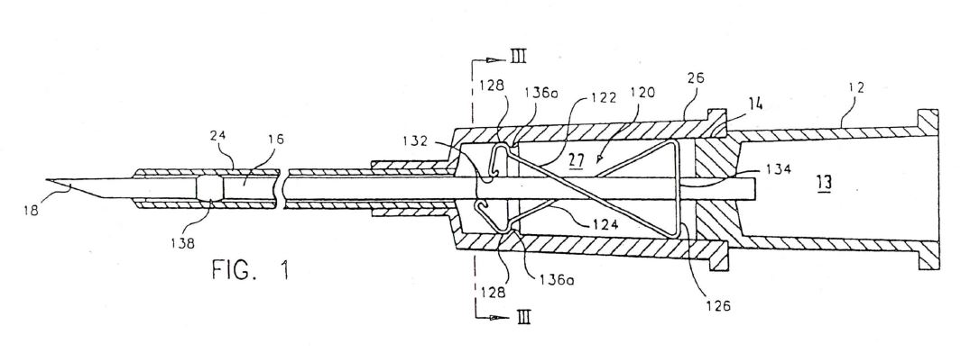
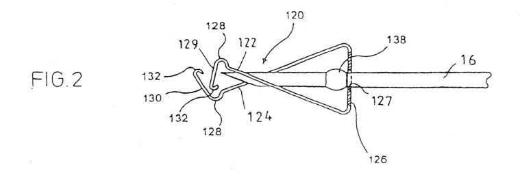
12 Figure 2 shows a magnified part of Figure 1, particularly the distal end of the needle with the needle protecting means protecting the needle point when the needle has been removed from the catheter:
13 There are many common features to the claims in the 327 Patent and the 577 Patent, but there are differences. His Honour explained these differences in the following terms (at [6]) which it is convenient for us to set out. First, the claim of the 327 Patent provides that the needle has a crimp. Contrastingly the claims in the 577 Patent provide that the needle shaft comprises a bulge. Second, the claim of the 327 Patent provides that the needle guard has a resilient portion on which the needle shaft exerts a force which is engaged by the side of the needle shaft and biased radially outwardly by it, which is moveable within the interior of the catheter hub to a blocking position distal of the needle tip and which blocks the tip of the needle tip when the needle is retracted. Contrastingly, the claims in the 577 Patent:
(a) specify that the needle guard is a resilient spring clip needle guard which is adapted automatically to snap or to pivot into a retracted position for blocking access to the distal needle tip; and
(b) further specify that the needle guard has a distal end wall such that the needle shaft is adapted to engage the distal end wall when the needle is in its ready position, and the distal end wall blocks the needle tip when the needle guard is in its retracted position.
14 Third, the claim of the 327 Patent provides that the needle guard is secured to a groove formed in the catheter hub interior. Contrastingly the claims of the 577 Patent provide that a curved protrusion of the needle guard is engaged by a groove or bump being formed in the inner wall of the catheter hub. Fourth, the claim of the 327 Patent provides that the needle guard is secured to the needle tip when the needle is fully retracted. Contrastingly the claims of the 577 Patent provide that the needle guard blocks access to the needle tip and prevents further distal movement of the needle tip when the needle is in its retracted position. Fifth, the claim of the 327 Patent provides that a portion of the needle guard proximal end makes contact with a needle crimp when the needle is in its fully retracted position. Contrastingly the claims of the 577 Patent provide that the needle guard has a proximal wall having an opening adapted to let the shaft of the needle freely pass through and axially move where the diameter of the opening is less than the diameter of the needle bulge. Sixth, the claim of the 327 Patent does not require the feature in the claims of the 577 Patent which provide that the catheter hub is configured such that a force exerted by the needle shaft on the needle guard is released when the needle is retracted causing the needle guard to pivot or snap to the retracted position. Seventh, the claim of the 327 Patent specifies that the needle is attached to a distal end of a needle hub, and that there is a “spaced apart relationship” between the needle guard and the distal end of the needle hub. Contrastingly the claims of the 577 Patent are silent about attachment of the needle to the needle hub and any requirement for a spaced apart relationship between the needle guard and the distal end of the needle hub. Eighth, in the claim of the 327 Patent the needle has a ready position in which the needle is received within the tubular catheter, the needle tip is outside the catheter hub and the needle shaft engages a resilient portion of the needle guard, whereas in the claims of the 577 Patent the needle has a ready position in which the needle is received within the tubular catheter, the needle tip extends beyond the tapered distal end of the tubular catheter and the needle shaft is adapted to engage a distal end wall of the needle guard.
CONSTRUCTION — GENERAL
15 Multigate has contended that his Honour erred in his reasons at [16], [18], [24], [38], [49], [50], [56], [60] and [64] by failing to apply accepted principles of patent claim construction as expounded in cases such as Kinabalu Investments Pty Ltd v Barron & Rawson Pty Ltd [2008] FCAFC 178 at [44] to [45] per Sundberg, Emmett and Greenwood JJ and Jupiters Ltd v Neurizon Pty Ltd (2005) 222 ALR 155 at [67] per Hill, Finn and Gyles JJ and, relevantly, in Sachtler GmbH and Co KG (formerly Sachtler AG) v RE Miller Pty Limited (2005) 65 IPR 605 at [20] to [22], [41] and [42] per Bennett J. We do not need to set out these principles. They are well accepted and we incorporate by reference what has been said in Kinabalu and Jupiters. Such principles were not in contention before us. We should say at the outset that, subject to one point of construction on which our views have differed from the primary judge, we do not consider that his Honour made any error in either the exposition of the applicable principles or their application save in inconsequential respects.
16 Multigate elaborated on its criticisms. It contended that in construing the claims his Honour impermissibly expanded the boundaries of the monopoly as fixed by the words of the claims, by adding to those words glosses drawn from other parts of the specification. Multigate contended that in many instances his Honour had regard to what he perceived as the purpose or function of integers in order to construe the terms of the claims. In doing so, he impermissibly, so it is asserted, adopted a functional “pith and marrow” approach to construing the essential integers of the claims of the patents as well as in determining whether the claims were infringed and whether they were fairly based. Generally, in our view such a contention lacks substance. The judge acknowledged (at [9]) that the “pith and marrow” test did not permit recourse to the substantial idea disclosed by the specification rather than what was to be found in the subject of a definite claim. He also recited the limitations of the application of the “pith and marrow” principle at [10]. Multigate contended that contrary to the cautions expressed in cases such as Populin v HB Nominees Pty Ltd (1982) 41 ALR 471 (to which his Honour referred at [8] and [9]) and Australian Mud Company Pty Ltd v Coretell Pty Ltd (2011) 93 IPR 188 (to which his Honour referred at [9]), the primary judge engaged in a process of reasoning extending the monopoly to ideas disclosed in the specification. We disagree.
17 In elaboration, Multigate contended that his Honour erroneously looked at whether the general idea disclosed by the specifications was substantially taken by the Multigate catheters, relying on functional similarities, rather than looking at whether the essential integers of the claim (and thus the invention as claimed) were taken. In our opinion, generally speaking, such a characterisation of his Honour’s approach has not been made good.
18 Multigate contended that his Honour’s erroneous approach to construction led him to misconstrue the following words and phrases:
(a) in claim 1 of the 327 Patent, “distal end” at [16], “spaced apart relationship” at [18] and [50], “ready position” at [19], “resilient portion” at [24] and “positioned in the interior” at [31]; and
(b) in claims 1 to 6 of the 577 Patent “preventing further movement” at [38], “bump” at [47] and “resilient spring clip needle guard” at [39] and [66].
19 As a consequence, Multigate contended that by reason of inter alia such errors, his Honour was led into error in his conclusions on validity (by applying his constructions of the terms “distal end”, “spaced apart relationship”, “resilient portion”, “positioned in the interior”, “bump” and “resilient spring clip needle guard”) and in his findings on infringement (by applying his constructions of the terms “distal end”, “spaced apart relationship”, “ready position”, “resilient spring clip needle guard” and “preventing further movement”). Apart from what we consider to be an error made by his Honour in construing “spaced apart relationship” (and its consequences for the infringement case concerning the claim of the 327 Patent), we consider that none of the other challenges made by Multigate are made out.
20 Multigate also asserted that his Honour should have applied but did not apply the ordinary English meaning of such words and phrases in circumstances where, so it was said,:
(a) there was no evidence that the terms were terms of art in the field of medical devices;
(b) his construction was not supported by the specifications; and
(c) his construction was other than the plain meaning of the terms.
21 In our opinion, none of these criticisms are made out save as we have said as to one matter dealing with his Honour’s construction of the term “spaced apart relationship”.
22 Before proceeding further, it is appropriate to note at this point that the field of invention of the patents in suit is the design and manufacture of safety intravenous catheters. Multigate had submitted below that the relevant notional person to whom the patents were addressed was a team of people comprising a designer or engineer skilled in medical device design and production, a clinical advisor and a toolmaker. We do not see any difficulty with the use of that composite. At trial, Multigate relied upon the expert evidence of Mark Bennett (a tool maker), Vincent Leskowich (medical devices designer) and Timothy Spencer (expert user) who, together, so Multigate contended, constituted the notional team to which the patents were directed. The Braun parties relied upon the expert evidence of Dr Hans Haindl and Dr Philip Esnouf. Dr Haindl had spent his professional life working in the design, development and manufacturing of medical devices and intravenous catheters. Dr Esnouf had been a qualified medical doctor since 1979. He had worked in various hospitals in surgical roles and in private practice. He had engaged in inserting intravenous catheters into patients on a regular daily basis. The experts gave evidence in the areas of construction and invalidity. The experts also expressed views about the presence of the integers in dispute in Multigate’s catheters A, B and C. A joint expert report was prepared and tendered. The experts were cross-examined, although perhaps not as fulsomely as one might have expected in the areas of contention. Nevertheless, the parties agreed that no Browne v Dunn type point would be taken.
23 It is appropriate to make several preliminary comments concerning the use of expert evidence in this context.
24 First, as cited by Hely J in Flexible Steel Lacing Co v Beltreco Ltd (2000) 49 IPR 331 at [147] and observed in O’Kelly Holdings Pty Ltd v Dalrymple Holdings Pty Ltd (1993) 45 FCR 145 at 156 by Sweeney and O’Connor JJ quoting the words of the trial judge in that case:
the Court’s duty is to form and act on its own original opinion, taking such assistance as it can from the opinion of experts, but it is not bound, nor should it defer, to the opinion of experts in the sense of permitting experts to hijack the fundamental fact finding obligation of the Court.
25 Second, and relatedly, the evidence of a skilled reader is not determinative of a construction question. It is always a matter for the Court to construe the particular claim adopting the relevant lens, but giving such weight to the expert evidence that it sees fit.
26 Third, it is not the province of an expert to give evidence of the meaning of words or phrases used in a claim if those words or phrases bear their ordinary English meanings and are not suggested to have a technical or special meaning.
27 Fourth, and relatedly, if words or phrases are used in a claim in their ordinary English meaning, their meaning cannot be distorted by an expert’s use of a functionality lens to give them an application in tension with their plain meaning.
28 Fifth, where an expert is opining on both construction and infringement, the expert’s opinion must be carefully assessed to ensure that the expert’s particular construction has not been given with an eye to infringement.
THE 327 PATENT
29 Multigate conceded before his Honour that each of its catheters A, B and C had each of the integers of the claim of the 327 Patent, except for those integers in which the following words and phrases are underlined and emboldened:
An IV catheter apparatus including a tubular catheter having a proximal end and a distal end, a needle having a needle shaft and a tip and wherein the needle is attached to a distal end of a needle hub, said needle being received within said tubular catheter when the needle is in a ready position, a catheter hub attached to the proximal end of said catheter, said catheter hub having a hollow interior and an inner wall, said needle being movable between said ready position in which said tip is outside of said catheter hub and a retracted position in which said tip is within the interior of said catheter hub, a needle guard positioned in the interior of said catheter hub in a spaced apart relationship from the distal end of the needle hub;
wherein the needle guard has a resilient portion engaged by said needle shaft when said needle is in its ready position, the needle guard resilient portion is movable within the interior of said catheter hub to a blocking position distal of said needle tip when said needle is in its retracted position in which said needle shaft no longer exerts a force on said resilient portion of said needle guard;
wherein an outer contact surface on the needle guard is secured to a groove formed in the catheter hub hollow interior when the resilient portion is engaged by the side of the needle shaft and biased radially outwardly; and
wherein the needle guard further includes a needle guard proximal end, wherein the needle guard is secured to the needle tip when the needle is in the fully retracted position by a portion of the needle guard proximal end making contact with a needle crimp and the resilient portion blocking the needle tip.
30 At trial, many issues of construction arose in relation to such words and phrases in such contested integers. But on appeal, only some of those questions have now been pressed. It is convenient to deal with each in turn and in the order in which they appear in the claim.
(a) Distal end
31 What is meant by the words “distal end” in relation to the needle hub? The differences between the parties were essentially about whether the distal end was a specific point or a region. Multigate contended that the distal end of the needle hub meant “the most distal perimeter or the outer face of the needle hub”. That was the view advanced in the joint expert report by two of Multigate’s experts, Mr Leskowich and Mr Bennett. Contrastingly, the construction advanced by Braun was that the words “distal end” referred to a region rather than to an end point.
32 The primary judge referred (at [16]) to the fact that the words “distal end” appeared more than once in the claim. The words appear in the second and third lines preceded by the indefinite article and in the thirteenth line preceded by the definite article in the context of the positioning of the needle guard in a spaced apart relationship. His Honour pointed out that in each case, however, the words were not used to refer to the furthest distal point of the needle hub but to a more general area which is distal to the user. As his Honour said, the patent does not use phrases such as “distal point”, “distal end point” or “furthest distal point”, which would be more specific and narrower in meaning than “a distal end” or “the distal end”. His Honour said that the words “distal end” are more general and in their ordinary and natural meaning are apt to encompass the region ending with the furthest most distal point and including the area of the needle hub up to its centre. The patent relevantly refers to the attachment of the needle to the needle hub. The place of attachment is identified as “a distal end” and informs the reader of an aspect of the construction of the catheter, namely that the attachment occurs, as can be seen by Figure 1, in a wider region than only at an end point. The needle hub is connected to the needle in the centre of the needle hub. The hub is a structure with a rotational symmetry and the needle is attached to the centre. His Honour concluded that the distal end, in that context, is that part of a wider region than just the end point at which the attachment occurs: the point of attachment is in the axial centre of the needle hub. We agree with his Honour’s reasoning and conclusion.
33 Multigate contended that the primary judge construed “distal end” of the needle hub as encompassing a region including the area up to the centre of the needle hub — half way along the device — and in so construing the phrase “distal end” ignored the ordinary English meaning of “end”. It is said that there was no support in the specification for him to do so. It is said that there was no evidence from a skilled addressee that the phrase had a special technical meaning or was a term of art in the field of medical devices. Further, it was said that such a definition results in uncertainty: a reader cannot know whether or not the needle in their device is attached to the distal end of the needle hub in accordance with the claim, nor whether or not it is in a spaced apart relationship from the distal end of the needle hub. Multigate contended that his Honour ought to have found that the “distal end” meant the distal boundary of the needle hub and did not extend inwards from the furthermost part of the needle hub proximally to the centre of the needle hub.
34 In our opinion there was no error made by his Honour on this aspect. It was supported by the expert evidence, the plain meaning of the integer and the specification as a whole.
35 Dr Esnouf stated in the joint expert report that the “distal end” is a regional definition, not an end point, and that this definition is consistent with Figure 1. Dr Haindl followed Dr Esnouf’s definition. Dr Haindl noted that if you look at Figure 1 of the 327 Patent, you can see that the needle hub is connected to the needle in the centre of the needle hub. The needle hub is a structure with a rotational symmetry and the needle is attached in the centre. Dr Haindl explained that “distal end point” might refer to the furthest distal point, whereas “distal end” is very general. He gave the example that “[y]ou could say in medical language the distal end of the arm is the forearm, or something on another anatomic structure, and that always means region”. The patent includes a mixture of technical language and medical language, because it deals with medical devices. He said further “I was a bit confused about this formulation ‘a distal end’ because I thought if it is a distal end, there must be multiple distal ends. But if we come to a regional understanding, I think there is no contradiction between that”.
36 Contrastingly, Mr Leskowich stated in the joint expert report that “the ‘distal end’ must be the extreme furthest face of the needle hub. There cannot be more than one ‘furthest point’ or region”. Mr Bennett stated that the distal end means the most distal perimeter or the outer face of the needle hub.
37 But in cross-examination, Mr Leskowich confirmed that he took this definition from a dictionary. He agreed that within the claim language there was no reference to a specific point of attachment, but that he obtained the description of a “point” from a dictionary. He conceded that neither claim 1 nor Figure 1 identified a specific “point” of attachment, and that Figure 1 showed an intersection of the cannula (needle) and the needle hub.
38 His Honour, in our view correctly, accepted the more general approach of Dr Haindl and Dr Esnouf (at [16]). In our opinion his approach reflected a reading of the specification as a whole, particularly Figure 1. This approach also avoided adding a gloss to the plain words of the claim by reading the more general “distal end” as the more specific “distal end point”.
(b) Spaced apart relationship
39 What is meant by the phrase “spaced apart relationship”? The words appear in the last line of the first paragraph of the claim concerning the positioning of the needle guard in the interior of the catheter hub. Multigate contended before his Honour that the term should be given its ordinary English meaning. So it contended that the needle guard and the distal end of the needle hub were required to be separate from, or be some distance apart from, each other. Thus, to be in a “spaced apart relationship” from the needle hub, the needle guard had to be physically outside the needle hub. The needle guard and the distal end of the needle hub would only be spaced apart if there was an intended gap between the needle guard and the distal end of the needle hub. Contrastingly, the construction of “spaced apart relationship” argued by Braun below was that there was no need for a gap between the needle guard and the needle hub. Of course, such a gap was seen in Figure 1. The needle guard was located within the catheter hub (numbered 26) and was to be understood to include the mechanism within the catheter hub including the features numbered 122, 126, 128, 132 and 136a. There was a space appearing in Figure 1 between the rear wall of the needle guard (numbered 126 and described in the patent as “rear wall of needle protecting means”) and the distal end of the needle hub. Braun nevertheless contended below that the words “spaced apart relationship” in the claim which described the relationship between the needle guard and the needle hub did not require there to be a gap between the two and that they could be in a “spaced apart relationship” even though they might be touching, provided that they were not constructed as connected.
40 His Honour held (at [18]) that the construction advanced by Braun was to be preferred. His Honour reasoned that Figure 1 did show a gap in the catheter hub in the ready position, but that the function of the requirement of a “spaced apart relationship” was to enable the needle to be withdrawn and to be secured in the needle guard. His Honour said that the invention in the patent required the needle hub to move independently of the needle guard so that the needle may be guarded when retracted. His Honour said that the relationship between the needle guard and needle hub was that they were to be placed separately within the device during the course of construction without there needing to be a gap. His Honour said that any space or gap between the two would serve no function, but that what did serve a function was that the two be separate for the operation of the device. His Honour said that the relationship of being spaced apart is not a relationship which prevents the two from having a connection or to be touching at all times. The need for a gap between the two only becomes a necessary feature in the operation of the catheter and is provided for by a construction which ensures that the gap emerges in its operation. His Honour said that the description of the words refers to a relationship of two elements of the apparatus. The description in the claim is not that the needle guard is placed in the ready position with a gap between the needle guard and the distal end of the needle hub. Rather, the claim refers to a relationship between the needle guard and the needle hub. That relationship, so his Honour said, points to a positioning of the needle guard as a separate part of the apparatus permitting movement between the two.
41 We disagree with his Honour’s construction. In our opinion Multigate’s position is to be preferred. It accords with the plain meaning of the language used and the specification as a whole. It also gives meaning to the separate words “spaced” and “apart”. In other words, there must be separation and in a spatial sense. They must be apart, spatially; they cannot be in the same space, including one fitting within the space of the other.
42 His Honour’s construction has the effect of varying or qualifying a clear and unambiguous term in the claim. There is no reason why the words “spaced apart” should be given anything other than their ordinary English meaning.
43 As Multigate contended, the definition of the word “spaced” in the Macquarie Dictionary is expressed in the following terms:
verb 1. past participle of space. (In turn, the verb “space” is defined as: to fix the space or spaces of; divide into spaces; to set some distance apart; Printing, etc. to separate (words, letters, or lines) by spaces.)
adjective 2. placed at specific distances apart: evenly spaced; widely spaced.
44 Moreover, as Multigate contended, the following definitions of the adverb “apart” in the Macquarie Dictionary connote separation, being:
1. in pieces, or to pieces: to take a watch apart.
2. separately or aside in motion, place, or position.
3. to or at one side, with respect to purpose or function: to set something apart.
4. separately or individually in consideration.
…
45 In our opinion “spaced apart” has an ordinary English meaning. That meaning does not encompass no gap between the relevant objects or that the objects can be in the same space or that they can be touching. Such a construction ignores the word “spaced”. Multigate contended, and we accept, that no expert suggested that “spaced apart” had a special technical meaning in the field. Indeed, his Honour did not suggest that it had a special technical meaning. Accordingly, the construction of this phrase falls to be determined from the plain meaning in the context of the integer, in the context of the claim, and in the context of the specification as a whole.
46 Further, the specification does not define or describe the “spaced apart” integer at any point. Nor does it suggest that the integer has a temporal aspect such that the needle guard and needle hub can be spaced apart at some times but not others, which appears to be contemplated by Braun’s construction. Indeed, the only depiction of the claimed invention in Figure 1 shows the needle guard and needle hub in a spaced apart relationship within the ordinary English meaning of that phrase.
47 We agree with Multigate that the primary judge’s approach was erroneously influenced by irrelevant functional considerations. His Honour’s perspective was that it was not apparent to him that a gap between the needle guard and the needle hub would serve any function. He said at [18]:
The relationship between the needle guard and needle hub is that they are to be placed separately within the device during the course of construction without there needing to be a gap: any space or gap between the two would serve no function; what does serve a function is that the two be separate for the operation of the device. … Mr Leskowich accepted that there was no need for a gap to be present for the proper functioning of the device.
48 His astigmatic focus was on the function of the “spaced apart” integer in the course of operation and manufacture, which he relied on as a basis for ignoring the plain meaning of the words used.
49 Generally, his Honour’s approach also contradicts a principle of construction that the patentee must be taken to have used words of its own choosing. Tartly expressed, what is not claimed is disclaimed.
50 Braun has sought to support the primary judge’s approach. It did so in part by the expert evidence adduced before his Honour.
51 Dr Haindl stated in the joint expert report that he understood “spaced apart” as separate in the sense that there was no direct constructive connection between parts. During the concurrent oral evidence, he explained that he did not think that there had to be a big space between the two objects to make them spaced apart. If one could just take one off from the other, i.e. there were no forces between them or connections, then to his understanding they were separate and spaced apart. In other words the two objects could touch but still be spaced apart. However, he said that if something fitted within another structure tightly, then he would not regard it as spaced apart. Dr Haindl explained further that:
[T]he 327 Patent defines multiple ready positions and in only one of these multiple ready positions it’s possible that the two structures touch one another. In all the other positions, when there is more distance between the needle hub and the needle guard, then they can’t touch one another; and if in such a multitude of positions there is one position where they might touch — I don’t say they do — then I see them in a spaced apart relationship to one another.
…
Even if they might touch in the variety of these different positions, I think they are still in a spaced apart relationship, they are not connected to one another.
52 Contrastingly, Mr Bennett stated in the joint expert report that the “spaced apart” relationship means separate from or some distance apart. In cross-examination during the concurrent oral evidence he added that the 327 Patent is trying to indicate that these parts are not touching or in what he would regard as a manufacturing tolerance gap and that there was a significant gap there.
53 Mr Leskowich stated in the joint expert report that a “spaced apart relationship” means there is an intended gap that has been designed to be in between the distal face where the needle is mounted on the needle hub and the proximal wall of the needle guard. He did not understand the need for a gap to be present for proper functioning of the device. He believed that it refers to the method by which the device is assembled; the space is created during the assembly process. In cross-examination Mr Leskowich agreed that assembling one of these devices involves urging the catheter hub onto the needle guard. He agreed “absolutely” that when you do that the needle guard will jump forward as it goes over the protrusion. Braun has contended that Mr Leskowich’s interpretation was not inconsistent with Dr Haindl’s view that the two objects may touch each other but still be spaced apart. Braun also referred to the fact that the primary judge at [18] noted Mr Leskowich’s acceptance that there was no need for a gap to be present for the proper functioning of the device. Of course, that focuses upon functionality rather than what the words of the claim or the particular integer mean.
54 Braun also contended that one of the Macquarie Dictionary definitions for the words “spaced” and “apart” reveals a meaning which was said to be entirely consistent with that applied by the primary judge (at [18]) and the experts. It was said that “apart” encompasses the meaning of “in pieces”, “separately”, “to or at one side”. It was said that this is entirely consistent with the acceptance by the primary judge that the phrase required that the parts were not constructed to be connected.
55 It was also said that there is nothing in the dictionary definitions requiring the determination of manufacturing tolerances. It was asserted that Multigate’s construction that the two parts must be “separated from, and some distance apart from, each other (significantly more than a working tolerance gap or clearance)” impermissibly adds a substantial gloss to the words of the claim.
56 In our opinion it is apparent from their evidence given in the joint expert report that each of Mr Bennett, Mr Leskowich and Mr Spencer read the phrase “spaced apart relationship” with its ordinary English meaning. This meaning reflects the dictionary meaning of the two words “spaced” and “apart” read together and with the word “relationship” in the phrase used in the claim. It is not, as Braun would submit, the meaning of “apart” alone. Dr Esnouf agreed that the integer required that there be a physical space or distance between the objects but also, inconsistently, agreed with Dr Haindl.
57 The evidence of Mr Bennett, Mr Leskowich, Mr Spencer and Dr Esnouf is consistent with Figure 1 of the 327 Patent, which shows a space between the needle hub and the needle guard, and is not contradicted by anything in the body of the specification (which is silent on this issue).
58 Braun has resorted to function to read down the clear words of the claim. But the words of the claim are chosen by the patentee as we have already said. It has its reasons. It is not for us to speculate as to the patentee’s motives in choosing the particular words. Speculation as to functional motives is irrelevant. It is an attempt to read down the clear words of a claim, in the absence of any evidence which would demonstrate a rationale for such a departure.
59 Further, Mr Leskowich’s acceptance of the method of assembly over the protrusion in the catheter hub is inconsistent with Dr Haindl’s argument that components can be touching yet spaced apart. The 327 Patent explains that the needle guard is urged over the protrusion in the inner wall of the catheter hub with a special tool (page 7 lines 15 to 21). The needle hub does not touch the needle guard in assembly of the invention described in the specification. And when the apparatus is fully constructed, there is a gap between the relevant components, as shown in Figure 1. There is no need to resort to withdrawal of the needle after use to create a gap to fit the wording of the claim.
60 Moreover, Braun has ignored the component “spaced” in the phrase, and has relied on the explanation of Dr Haindl, who sought to bolster his construction by reference to so called multiple ready positions. It was enough for Dr Haindl if the needle guard and needle hub components were separate pieces that moved as the needle was withdrawn from the patient. But as Multigate correctly contended, this is nothing more than what the general type of safety IV catheters, with which the specification is concerned, inherently require. The needle and needle hub have to move relative to the needle guard.
61 Generally, the meaning given by his Honour at [18] adds various impermissible glosses to the plain meaning, namely: in the sense of “being placed separately within the device in the course of construction, and may have a connection or be touching”; and in the sense of “in operation moving independently when withdrawn from use within a patient and in the course of being retracted”.
62 His Honour’s reliance on the operation of the catheter to justify his construction adds glosses that are unnecessary if the ordinary meaning is used. The claim is not to a method for the use and disposal of a safety catheter; it is an apparatus claim.
63 In summary, we would uphold this ground of Multigate’s appeal. Moreover, and as we will address later, the correct construction of this integer has the consequence that Multigate’s catheters A, B and C do not infringe the claim of the 327 Patent. We would note at this point, however, that the 577 Patent does not contain this integer. Accordingly, his Honour’s findings on the infringement of the 577 Patent are not affected by this construction question.
(c) The ready position
64 What was meant by “ready position” in relation to the position of the needle?
65 His Honour dealt with this at [19]. He referred to Braun’s contention that the use of the words “ready position” in the claim referred to any position where the needle tip protrudes from the distal end of the catheter hub. Mr Leskowich, in contrast, contended that the words “ready position” when used in the claim meant ready for insertion into the patient, as might be assumed to be depicted in Figure 1. His Honour said that the construction advanced by Mr Leskowich had an intuitive appeal with the words “ready position” presupposing readiness for a purpose or use. However, his Honour said that the claim is not describing the use of the intravenous catheter in connection with a patient. Relevantly what is described is the position of the needle and its moveability from a ready position to a retracted position. The former describes the situation in which the needle is outside of the catheter hub and not secured by the needle guard. The latter is that point when the needle is positioned in the interior of the catheter hub and secured by the needle guard. His Honour concluded that the ready position is where the needle tip protrudes from the distal end of the catheter hub. Multigate has taken issue with his Honour’s construction.
66 Multigate contended that “ready position” is not separately defined in the 327 Patent. That is correct. It contended that the term “ready” in the context of the specification means the needle tip is exposed, “ready for insertion into the patient” (e.g. as shown in Figure 1). Instead, it was said that his Honour disregarded the context and made the findings referred to above.
67 It was also said that his Honour ignored the evidence of a clinician with experience in using intravenous safety catheters, namely, Mr Spencer.
68 Multigate contended that his Honour’s preferred construction did not give the word “ready” its usual English meaning. The first Macquarie Dictionary definition is “completely prepared or in due condition for immediate action or use”. The first Oxford Dictionary definition is “In a suitable state for an action or situation; fully prepared”. It was also said that his Honour’s construction ignored the context of the specification. It is said that the description of the invention in the specification reinforces the plain and clear meaning of the word “ready”. It is accepted that the claim is to an apparatus, the product being an improved safety IV catheter. It is said to be clear from the context provided by the specification that the safety needle assembly forming part of the safety IV catheter device is designed for insertion into a patient, and that it is designed to have two modes: one in which the needle point can safely be inserted into objects or persons, and one after the removal of the needle from the catheter (that is, after use) in which it cannot. It is said that these two modes are what are described in the claim as the “ready position” and the “retracted position”. However, the claim itself makes it clear that the “said ready position [is one] in which said tip is outside of said catheter hub”; it is not necessarily limited to readiness to use in a patient.
69 Multigate contended that it is legitimate to refer to the rest of the specification to explain the background of the claims. It is said that the words “ready” and “retracted” in the claims take their meaning from the specification. In particular, the specification states that:
Safety IV catheter devices comprise a needle protecting means which slides to the needle point as the needle is removed from the catheter and permanently blocks the needle point such that the needle point cannot be inserted into objects or persons (p 1 lines 4 to 8).
70 It is said that elements of the needle assembly are also described by reference to their position in relation to the patient (see the use of “proximal” on p 3 line 25).
71 Multigate contended that it was anything but practical to construe, as the primary judge did, the term “ready position” in the claim as meaning any position where the needle tip protrudes from the distal end of the catheter hub, rather than a position in which the needle tip could be inserted in the patient and so be used. It was said that this want of practicality was starkly demonstrated by the judge’s acceptance (relied on by him in his construction of “spaced apart relationship”) that the partially dismantled catheter C depicted at [50] at the top of p 34 satisfied the description of “ready position” (the reference to “retracted” at p 34 line 1 of his Honour’s reasons should refer to “ready”).
72 In our opinion, no error has been shown in his Honour’s approach. Further, it was supported by the expert evidence, although we accept that this cannot be definitive of the question.
73 Dr Haindl stated in the joint expert report that lines 5 to 10 of the claim define multiple ready positions, being any position where the needle tip protrudes from the distal end of the catheter hub. In cross-examination, Dr Haindl also said that the needle is in a “ready position” until it is engaged by the needle guard. Dr Haindl also explained that once the needle tip is withdrawn inside the catheter tube a small distance, it may be pushed forward again prior to insertion into the patient, with effectively no risk of damage to the catheter tube. This evidence contradicted the evidence of Mr Spencer of a “potential” risk of the needle bevel cutting the catheter.
74 Dr Esnouf stated in the joint expert report that he agreed with Dr Haindl (that is, there are multiple ready positions, where the needle tip protrudes from the distal end of the catheter hub), but also agreed that a “ready position” is a position that allows insertion of the catheter into a patient.
75 Mr Bennett stated in the joint expert report that the “ready position” refers to the position of the needle within the hollow tubular catheter outside the catheter hub. The needle may be protruding through the distal end of the catheter. As such, Mr Bennett’s construction did not exclude Dr Haindl’s construction.
76 Contrastingly, Mr Leskowich stated in the joint expert report that “ready position” means ready for insertion into the patient as depicted in Figure 1. He noted however that in accordance with other integers the needle was not ready to be used on a patient, but were referred to in terms of “ready position”. Accordingly, Mr Leskowich adopted his construction notwithstanding that the effect was an inconsistency with “ready position” as used in other integers being:
(a) “said needle being received within said tubular catheter when the needle is in a ready position”;
(b) “said needle being movable between said ready position in which said tip is outside of said catheter hub and a retracted position in which said tip is within the interior of said catheter hub”; and
(c) “wherein the needle guard has a resilient portion engaged by said needle shaft when said needle is in its ready position”.
77 Mr Spencer stated in the joint expert report that the needle’s “ready position” means the needle is ready to be inserted into the patient and ready for use. Insofar as Mr Spencer’s construction was consistent with that of Mr Leskowich, it suffered from the same vice.
78 In our opinion, given the difficulties with the construction advanced by Mr Leskowich and Mr Spencer, his Honour was entitled to reject their construction and adopt a construction which gave meaning to the claim and was consistent with the evidence of Dr Haindl and Dr Esnouf and not otherwise excluded by Mr Bennett.
79 On appeal before us, Multigate has relied on a dictionary definition apparently not cited to the primary judge to contend that “ready position” should be construed as “ready to use position”. But Multigate’s construction adds a gloss to the plain words of the claim: the patent could have used, but did not use, the term “ready to use position”.
80 In summary, the term “ready position” was appropriately construed by the primary judge. It accorded with the preponderance of expert evidence. It accorded with the plain meaning. It was also consistent with other references in the claim.
(d) Resilient portion
81 The question of construction raised before us concerned what was meant by the “resilient portion” of the needle guard.
82 His Honour dealt with this at [23] and [24]. He referred to the issue of disagreement between the parties concerning the “resilient portion” of the needle guard, which was whether it included the arms identified in Figure 1 by the numbers 122 and 124. His Honour said that the word “resilient” itself indicates something which resumes its original shape or position after movement. The needle guard in the invention blocks the needle tip when the needle is in the fully retracted position because parts of the guarding mechanism block the needle from moving forward. The claim refers to “the resilient portion blocking the needle tip” and the dispute concerning the construction of those words was whether that portion was limited to those parts of the guarding mechanism physically blocking the needle when fully retracted. His Honour referred to the fact that Mr Bennett pointed to the use of the word “portion” as indicating that only part of the needle guard was referred to as resilient by the claim rather than the whole of the mechanism which effected the blockage when the needle was fully retracted. His view was that the resilient portion did not include the arms but was intended to refer more narrowly to the parts of the mechanism that blocked the needle in the fully retracted position. Mr Leskowich expressed a similar view in the joint expert report when saying that the resilient portion was the area in Figure 2 between the lip identified by the number 132 and the elbow identified by the number 128.
83 His Honour referred to the fact that the patent (at page 5, lines 21 to 30) refers to the arms moving “resiliently” into the position shown in Figure 2 when the needle point passes the lips and arms:
When the needle point passes the lips 132 the arms 122, 124 resiliently move into the position shown in Fig. 2 in which the front walls 129, 130 cover the needle point. … The annular projection 136a retains the needle protecting means 120 in the catheter hub 26 when the needle 16 is removed from the catheter hub 26 until the arms 122, 124 of the needle protecting means 120 are no longer supported by the needle 16 and resiliently move towards the inside.
(emphasis added)
His Honour said that what causes the movement in the needle guard is the pressure in the points on the arms, which is released when the needle tip passes (backwards) the lips of the distal end of the guard. The arms (numbered 122 and 124) in the mechanism shown in Figure 2 spring together once the needle tip moves past the distal end of the mechanism in the proximal direction. The force or pressure in the mechanism (including the arms) which had been applied to the needle is released when the needle passes the lips. It is the whole of the mechanism (including the arms by the release of the pressure but excluding the proximal (rear) end wall of the needle guard) which blocks the needle tip when it resiliently effects the blockage of the needle.
84 Multigate has contended that the claim requires that a “portion” of the needle assembly be resilient. It says that the word “portion” means “a part of a whole” (Oxford Dictionary; first definition) or “a part of any whole, whether actually separated from it or not” (Macquarie Dictionary; first definition).
85 Multigate has contended that the claim of the 327 Patent also sets out certain other defining characteristics required of the resilient portion. It provides that the resilient portion of the needle guard:
(a) is engaged by the needle shaft when the needle is in its ready position;
(b) is movable within the interior of the catheter hub to a blocking position distal of the needle tip when the needle is in its retracted position in which the needle shaft no longer exerts [an outward] force on the resilient portion;
(c) enables an outer contact surface on the needle guard to be secured to a groove formed in the catheter hub hollow interior when the resilient portion is engaged by the side of the needle shaft and biased radially outward; and
(d) blocks the needle tip when the needle is in the fully retracted position.
86 Multigate asserted that rather than construing the term on the basis of the claim language having regard to the above defining characteristics, his Honour relied on a description in the specification of the arms as moving “resiliently” into position. It is said that on that basis his Honour concluded that the operation described involved the whole of the guard (but excluding the proximal end wall) (at [24]). Multigate has contended that in so doing, his Honour ascribed a meaning to the integer at odds with the words of the claim.
87 But again, in our view no error was made by his Honour. His construction was supported by the expert evidence and the claim language.
88 Dr Esnouf stated in the joint expert report that he understood the “resilient portion” of the needle guard to be that section which was capable of reciprocal movement during the operation of the needle guard. He believed this portion to be most of the needle guard excluding the proximal end wall. He did not believe that it was necessary for the resilient portion to be inherently resilient. In other words, in regard to the portion that was deemed resilient, it was not necessary that every part of it must be resilient. He believed this to be the case in regard to the needle guard shown in Figures 1 and 2.
89 In cross-examination, Dr Esnouf explained that it was not necessary that every part of the needle guard be resilient. Referring to Figure 1, Dr Esnouf did not see the area marked 132, which is the lip, as resilient in its own right. His reading of the nature of the formation of that metal curve suggested to him that it was quite rigid, not particularly resilient, and his interpretation of it was that the resilient portion included the lip, the wall, the elbow and the arms. His view was that the only portion that he would not regard as the resilient portion was the proximal end wall. In Figure 2, the parts he pointed to were all one physical part and it was consistent with his understanding of resilient portion in that Figure that it be one piece, but that not every part of that one piece be resilient. The resilient portion needed to move. There was a requirement for reciprocal motion, which gave it a characteristic that it would return to its original position after movement.
90 Dr Haindl stated in the joint expert report that he agreed with Dr Esnouf. If he compared Figure 1 with Figure 2, Dr Haindl saw that the crossing point of the arms would also move, which proved that they were also resilient.
91 Mr Leskowich stated in the joint expert report that, as defined in the patent, the “resilient portion” of the needle guard was defined as the area between the lip 132 and the elbow 128 on Figure 2. However, in cross-examination Mr Leskowich agreed that the arms were resilient because they moved resiliently. He also agreed that from page 5 line 27 of the patent the arms were identified as the resilient part of the needle protecting means.
92 Multigate’s other witness Mr Bennett took a position which adopted a narrow and uncertain construction of “portion”. Mr Bennett stated in the joint expert report that the “resilient portion” needed to satisfy a number of criteria, including having the ability to move without assistance from other elements to a blocking position when the needle shaft no longer exerted a force. He also stated that the use of the word “portion” indicated that only part of the needle guard was referred to as resilient and engaged the needle shaft in the ready position. In cross-examination Mr Bennett stated that the walls (items 129 and 130 in Figure 2) were part of what he would call the resilient portion. He maintained that these were the only parts of the needle guard referred to as the “resilient portion”, and said that “the arms may be resilient, but they’re not part of what I regard as the resilient portion, as described in the patent”. Mr Bennett’s opinion thus proceeded on a narrow construction of “portion”. He stated that the arms could not be part of the resilient portion because “that would no longer be a portion, it would be the entire needle guard”, notwithstanding that it would not include the proximal wall. He stated further that “[t]he resilient portion to me is a small part of the whole. If we were talking about the arms as being part of the resilient portion, it would be 99 per cent of the device, because the end wall is only 1 per cent of the entire length”.
93 The preponderance of expert evidence supported his Honour’s position. His Honour also noted (at [24]) that the patent refers to the arms moving “resiliently”. This was consistent not only with the views of Braun’s experts, but also with the view of Multigate’s expert Mr Leskowich. Even Mr Bennett agreed that the arms may be resilient, but took an isolated position based on his narrow construction of “portion”.
94 In our view, no error has been demonstrated in the construction of the primary judge that the term “resilient portion” of the needle guard includes its arms.
(e) “Positioned in the interior”
95 The final topic for construction of the claim of the 327 Patent concerned the catheter hub. There was only one issue of construction raised before us on appeal, namely, the meaning of “positioned in the interior of said catheter hub” in relation to the needle guard.
96 His Honour dealt with this issue at [30] and [31]. As he identified the issue, the dispute focused upon the extent, if any, to which the needle guard was to be positioned in the interior of the catheter hub. Dr Haindl’s view was that the needle guard would be positioned in the interior of the catheter hub if the majority of its length or volume was positioned in the interior. The view expressed by Mr Bennett overlapped with that of Dr Haindl, but Mr Bennett expressed himself as construing the words to be satisfied if the needle guard was positioned partially (even less than the majority) or wholly within the catheter hub. Contrastingly, Mr Leskowich expressed the view that his review of the Figures showed that the words required that the whole of the needle guard be entirely positioned in the interior of the catheter hub.
97 His Honour referred to the fact that the needle guard shown in Figure 1 was wholly positioned in the interior of the catheter hub, but the claim was not limited in that way and should not be interpreted as if it were limited. His Honour also said that there was no reason to reject Mr Bennett’s view that the words might be satisfied by less than the majority of the needle guard being positioned within the interior of the catheter hub. His Honour said that the extent of the positioning within the interior of the catheter hub may be so slight that it could not be regarded as being positioned in the interior of the catheter hub in any meaningful sense, but the words need not be restricted to a 50% or more interior placement of the needle guard within the catheter hub.
98 In our opinion, no error has been shown in his Honour’s approach to construction on this aspect.
THE 577 PATENT
99 Multigate has conceded that its catheters A, B and C had each of the integers to claims 1 to 6 of the 577 Patent, except for those integers in which the following words and phrases are underlined and emboldened:
In claim 1 of the 577 patent:
A safety IV catheter comprising:
(a) a needle having a needle shaft and a needle tip;
(b) said needle shaft comprising a bulge;
(c) a hollow tubular catheter having a proximal end;
(d) said hollow tubular catheter is secured to the distal end of a catheter hub;
(e) said catheter hub having a hub section, wherein a chamber is formed in said hub section, and having an inner wall;
(f) a resilient spring clip needle guard located within said chamber being formed in said hub section of said catheter hub and having a distal end wall;
(g) said needle being received within said hollow tubular catheter when in a ready position, wherein said needle extends through said chamber, a passageway and distally beyond said catheter hub and said hollow tubular catheter so that said needle tip extends beyond the tapered distal end of said hollow tubular catheter and said needle guard located within said hub chamber is adapted to automatically snap or pivot into a retracted position for blocking access to said distal needle tip and preventing further movement of said needle tip when said needle is in its retracted position;
(h) said needle guard being adapted to be inserted into said catheter hub and to be urged by said needle shaft into contact with said inner wall of said catheter hub so that the needle guard is retained therein;
(i) and a groove or bump being formed in said inner wall of said catheter hub for engaging a curved protrusion of said needle guard for retaining said needle guard in said catheter hub in the ready position;
(j) said needle shaft of needle being adapted to engage said distal end wall of said needle guard when said needle is in its said ready position; and
(k) the said catheter hub being configured such that a force exerted by said needle shaft on said needle guard in said catheter hub is released when said needle is retracted causing said needle guard to pivot or snap to the retracted position in which said distal end wall blocks said needle tip;
(l) and said needle guard further comprising a proximal wall having an opening adapted to let said shaft of needle freely pass through and axially move; [denied for Catheters A and C, admitted for Catheter B]
(m) wherein said bulge has a diameter greater than that of said opening of said proximal wall. [denied for Catheters A and C, admitted for Catheter B]
In claim 2 of the 577 Patent:
“wherein said needle guard is adapted to automatically snap into said retracted position as said needle is being retracted for blocking access to said needle tip and preventing further distal movement of said needle tip to prevent accidental contact with said needle tip.”
In claim 3 of the 577 Patent:
“wherein said distal end wall terminates in a lip [denied for Catheter B, admitted for Catheters A and C] adapted to be engaged by said needle shaft when said needle is in its said ready position.”
In claim 4 of the 577 Patent:
“wherein the said catheter is configured such that a lower end or curved protrusion of said needle guard is urged by said needle shaft into retaining contact with said inner wall of said catheter hub when said needle is in its said ready position.”
In claim 5 of the 577 Patent:
“wherein said spring clip needle guard is configured such that a downward or radial force exerted by said needle shaft on said spring clip needle guard in said catheter hub is released when said needle is retracted to said retracted position, and said distal tip of said needle moves past a lip of said spring clip needle guard causing said spring clip needle guard to pivot or snap to said retracted position in which said distal end wall is adapted to block said needle tip.”
In claim 6 of the 577 Patent:
“wherein said resilient spring clip needle guard has two arms.”
100 Only a limited number of construction issues regarding these integers now remain in contention before us.
(a) “Preventing further movement”
101 The relevant part of claim 1 in which this integer appears is:
“…said needle guard located within said hub chamber is adapted to automatically snap or pivot into a retracted position for blocking access to said distal needle tip and preventing further movement of said needle tip when said needle is in its retracted position.”
102 The primary judge found (at [38]) that the experts were largely in agreement as to the meaning of “preventing further movement” in this context. His Honour accepted their view that the phrase conveyed the meaning of preventing the movement of the needle in the distal direction (beyond, perhaps, manufacturing tolerances) but not necessarily preventing rotational or other movement.
103 Multigate contended that his Honour’s construction of “preventing further movement” did not reflect the ordinary meaning of the phrase, nor was there any technical definition which was used in the specification or in the field.
104 Multigate said that his Honour impermissibly construed the phrase “preventing further movement” in the claims of the 577 Patent by reference to a “similar” word in the claim of the 327 Patent, stating at [38] that “[t]his phrase is similar to the word ‘secured’ previously considered in the context of patent 327”. It was said that his Honour’s association of these terms was central to his conclusion on infringement (at [64]). Multigate contended that it was not permissible to construe the terms of an independent patent claim by reference to another claim, particularly one from another patent.
105 It was said by Multigate that his Honour’s reliance on the function of “securing” to construe “preventing further movement” revealed the judge’s misconceived approach to claim construction. It was said that this flawed approach was apparent from the judge’s observations on the meaning of the phrase at [64] in the context of infringement:
However, the words “preventing further movement” mean that the needle could not escape the needle guard, not that there was no further movement within the needle guard. The purpose of the invention is to ensure that the needle, once fully retracted, is safely within the needle guard and cannot escape from the needle guard so as to cause needle prick.
106 We accept that it would be wrong to use the term “secured” in the 327 Patent as an aid to construction of the phrase “preventing further movement” as used in claim 1 of the 577 Patent. However, if that is what his Honour did, such error was, ultimately, without significance.
107 Multigate pointed to this part of claim 1, namely (emphasis added):
… for blocking access to said distal needle tip and preventing further movement of said needle tip when said needle is in its retracted position …
and said that the addition of “further” introduces an additional limitation to the prevention of movement inherent in the integer “blocking access to said distal tip” which, Multigate submitted, stops movement of the needle tip outside the needle guard. Multigate argued that the claim specifies that the needle guard is adapted to snap or pivot into a retracted position both for blocking access to the needle tip and for preventing further movement of the needle tip. Multigate submitted that the primary judge’s construction robs each integer of a separate meaning.
108 Multigate also pointed to dependent claim 2, which includes the additional limitation of “preventing further distal movement of the needle tip to prevent accidental contact with said needle tip” (emphasis added). In doing so, Multigate seems to submit that it was appropriate to use this claim to construe claim 1 – which is, of course, what the experts did, albeit in a way contrary to Multigate’s proffered construction.
109 Braun submitted that the primary judge construed the claim having regard to the purpose of the invention and that his Honour’s “purposive construction” was within established principles. It also relied on the understanding of its experts on this aspect.
110 We do not accept either approach. The primary judge accepted the evidence of the experts, in particular Dr Haindl and Mr Leskowich. In the joint expert report, Dr Haindl (with whom Mr Leskowich agreed) said that further movement in claim 1 meant “preventing further distal movement of said needle tip to prevent accidental contact with the said needle tip”. However, those additional words do not appear in claim 1. Dr Haindl (and, it would seem, Mr Leskowich) impermissibly relied on the further limitations of claim 2 and imported them into claim 1. The result was to add a gloss to the words of claim 1.
111 The phrase “preventing further movement” is to be construed according to its ordinary English meaning. It is not necessary to resort to notions of “purposive construction”. The experts did not give the phrase a technical meaning. Rather, they engaged in an impermissible mode of claim construction. The primary judge’s finding at [38] was affected by that error.
112 When claim 1 is read in its totality and in the context of the specification, it is apparent that when the needle guard is in a retracted position, it is adapted to block access to the needle tip and to prevent further movement of the needle tip beyond the confines of the retracted needle guard. This is, in fact, the construction adopted by the primary judge when considering (at [64]) the question of infringement. We agree with that construction. It is consistent with the object of the invention, as stated in the specification, of a needle protecting means which is fastened or retained in the catheter hub of the safety IV catheter device.
113 It is difficult to understand what limitations are added by claim 2 although, at the end of the day, it is not necessary for us to come to a view on that question. It may be, as Braun suggested in oral submissions, that claim 2 imports the limitation that the needle guard snaps into the retracted position “as the needle is being retracted”. But it does not seem to us that the words “preventing further distal movement of said needle tip to prevent accidental contact with said needle tip”, as used in claim 2, provide any practical limitation that is not already encompassed within, and effectively addressed by, the words “preventing further movement” as used in claim 1.
(b) “Resilient spring clip needle guard”
114 What was meant by the words “resilient spring clip needle guard”?
115 His Honour dealt with this issue at [39] and made the following observations. Integer (f) of claim 1 described the catheter as comprising a resilient spring clip needle guard located within the chamber being formed in the hub section of the catheter and having a distal end wall. The experts differed on the meaning of the words “resilient spring clip needle guard” and their disagreement included whether such a clip could be produced by any material other than metal. Dr Esnouf, with whom Dr Haindl agreed, said that the words “resilient spring clip needle guard” were to be understood as referring to a needle guard which had the characteristics of a spring (that is, which had the capacity to store energy), and was resilient such that following deformation the clip could return to its pre-deformation state. Dr Esnouf believed that it was possible to fabricate a resilient spring clip needle guard of a similar pattern to the design in Figures 1 and 2 from non-metallic material. He was cross-examined but confirmed his opinion that it would be possible to fabricate a resilient spring clip needle guard of the appropriate size to fit inside an intravenous catheter other than from metallic material although he did not necessarily say that the wall thickness of the guard would be identical. His evidence was of personal experience with folding material of sheet plastics, some of which had been reinforced with non-metallic materials in the context of a very small resilient ring used in a laryngeal mask. Mr Bennett and Mr Leskowich, in contrast, maintained that the words meant a spring metal material such as stainless steel or spring steel. Mr Leskowich in the joint expert report also stated that the resilient spring clip needle guard was to be made of “sheet metal”. His Honour concluded that the terms in the patent do not require the words in question to be construed as limited to a spring clip made from a metallic substance. His Honour said that the words were to be understood as referring to a clip having a resilient feature in the sense of moving back into a position after its static state was altered.
116 Before us, Multigate persisted with its contention that a “resilient spring clip needle guard” is one that is made of a metallic material with spring and resilient characteristics.
117 Multigate said that in construing the phrase his Honour relied on Dr Esnouf’s “belief” that a resilient spring clip needle guard possibly could be made of a non-metallic material (at [39]). It said that although evidence of Dr Esnouf’s belief in relation to this issue was given on the basis of his experience as an inventor, it was apparent from his Honour’s reasons at [12] that he accepted Dr Esnouf’s evidence on the basis that he was a qualified medical practitioner; contrastingly, contrary evidence was given by the toolmaker Mr Bennett and the medical device maker Mr Leskowich.
118 Multigate contended that as a medical practitioner, Dr Esnouf was not qualified to give opinion evidence as to whether a spring clip needle guard could be fabricated from non-metallic material. Multigate contended that the evidence of a medical devices designer and toolmaker should have been accepted and preferred over the evidence of a medical practitioner, because they were qualified by experience and training to give evidence on this issue. It was said that they did not need to speculate. Mr Bennett’s evidence was that he understood a resilient spring clip needle guard to be a needle guard made of a spring metal material. Mr Leskowich’s understanding was similar.
119 Further, it was said that such experts’ views were consistent with, and informed by, the description of the spring clip needle guard in the patent. The specification described the guard as “an integral part made of spring steel” (577 Patent page 6, line 16) and all of the Figures show a unitary metal guard.
120 Multigate also said that his Honour further erred by construing the phrase in a manner which did not give any meaning to the term “spring clip” within the phrase. It was said that it is apparent from the specification that a spring clip is an integral part made of spring steel (577 Patent page 6 line 16 and all Figures). His Honour accepted that the specification only disclosed an integral steel guard, but concluded that “[t]he claim itself, however, is not so confined and should not so be limited” (at [66]). In so concluding, Multigate contended that his Honour construed the invention claimed as being broader than the disclosure in the specification. At [93], the judge observed “it cannot be said that the configuration of the needle guard claimed in each of the patents in suit was not based on matter disclosed in the original ancestor. Figure 11 of the original ancestor disclosed features of the spring clip needle guard of the kind claimed in each of the 327 and 577 Patents” and reproduced Figure 11. According to Multigate, Figure 11 shows a unitary spring clip. At [95], the judge said “Figure 11 in the original ancestor (depicted above) disclosed features of the spring clip needle guard in claim 1 of the 577 Patent”.
121 In summary, Multigate contended that the judge ought to have found that a resilient spring clip needle guard was a needle guard made of metallic material with spring and resilient characteristics.
122 In our view, no error was made by his Honour. The claim did not limit the resilient spring clip needle guard to one made of metallic material. While the embodiment was specifically stated to be spring steel, the patentee did not import that wording, or limitation, into the claim; nor was the patentee required to.
123 Further and again, it was supported by the expert evidence.
124 As we have said, Dr Esnouf stated in the joint expert report that his understanding of the meaning of “resilient spring clip needle guard” is a needle guard which has the characteristics of a spring (that is the capacity to store energy) and resilience wherein following deformation the clip can return to its pre-deformation state. The primary judge accepted that evidence (at [39]). Dr Haindl also agreed with that evidence.
125 Multigate complains that the primary judge ought to have preferred the evidence of Mr Leskowich and Mr Bennett as a medical devices designer and a toolmaker over Dr Esnouf’s evidence as a medical practitioner. As Braun has correctly contended, this complaint has no substance. Dr Esnouf was not only a medical practitioner but had been involved in inventing and designing a range of medical devices since 1994, including the laryngeal mask referred to in this part of his evidence. Further, Dr Esnouf’s evidence was agreed to by Dr Haindl who had considerable experience in the design, development and manufacturing of medical devices and intravenous catheters.
126 Further, Mr Leskowich conceded in cross-examination that there were many materials in existence that showed resiliency and it is possible to make them in small sizes. If we may say so, this was almost to state the self-evident. Similarly, Mr Bennett said in cross-examination that “you can definitely make springy things out of plastic” and that his view on the configuration of the spring clip needle guard was confined to the embodiments shown in Figures 1 and 2 of the 577 Patent. But we note that the passage on page 6, lines 10 to 14 of the 577 Patent identified that “the needle protecting means may also be of different configuration”.
127 There is no substance to Multigate’s challenge on this aspect.
(c) Meaning of “bump”
128 The last question concerned the catheter hub and the meaning of the words “groove” and “bump” (see his Honour’s reasons at [47]). His Honour said that the words were used to some extent interchangeably as may be seen from claim 1(i) which refers to “a groove or bump being formed” in the inner wall of the catheter hub. It may be seen visually in Figures 1 and 2 marked with the number 136(a) being an inward projection from the internal wall of the catheter hub having the function of keeping in place the needle guard when in the ready position. We will return to this issue later when dealing with the question of invalidity, particularly the issue concerning external fair basis.
INFRINGEMENT
129 Before turning to the invalidity questions, it is convenient for us, as his Honour did, to deal with infringement based upon our conclusions on the construction questions, assuming the claims to be otherwise valid.
(a) Infringement of claim 1, 327 Patent “spaced apart relationship”, “ready position” and the judge’s conclusion that the Multigate catheters had a needle guard in a spaced apart relationship from the distal end of the needle hub.
130 His Honour dealt with this issue at [50] in the following terms:
It was next contended that the needle guard of each of the catheters in suit was not in a “spaced apart relationship” from the distal end of the needle hub. The relationship, spaced apart or otherwise, of the catheters and the distal end of the needle hub in each of the catheters in suit is not easy to determine by a visual inspection of the catheters without the aid of a magnifying glass or an enlarged photograph showing the area to be looked at of the catheters themselves. Enlarged photographs were provided which assisted in looking at the catheters in evidence. The area showing the relevant relationship in each catheter was in photographs taken by Dr Haindl. The photograph of the area taken by Dr Haindl of catheter A (including his annotations but remembering that the annotations were submissions and not evidence proving their contents) was:
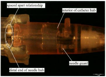
The relevant portion in catheter B is not materially different from that in catheter A but, for completeness, the photograph taken by Dr Haindl of Multigate’s catheter B was:
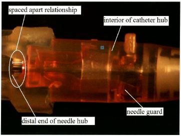
The relevant portion of what was in dispute as the spaced apart feature was identified in an x-ray image of catheter C tendered through Dr Haindl:
In each case the needle guard and the distal end of the needle hub of the catheters in suit have a relationship with each other of being separate. The two are placed separately within the catheters in suit and it does not matter that the two may be touching or that there is not a physical gap between the two. Indeed, the spaced apart relationship of the needle guard and the distal end of the needle hub in each of the catheters in suit may be seen in the alternative submission advanced by Braun, namely, that a physical separation may be seen when the catheters in suit are in a ready position. A photograph of the spaced apart relationship which is evident when the catheters are in a retracted position can be seen by another of Dr Haindl’s photographs of catheter C (omitting the annotations):
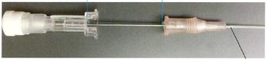
The needle guard in this photograph is to the right and the needle hub to the left. The two are physically separate as contemplated by the design and function of the patents.
131 As we have said, the meaning of “spaced apart relationship”, claim 1 of the 327 Patent requires that the needle guard and the distal end of the needle hub are separated and some distance apart from each other, being more than a working tolerance gap or clearance.
132 On the proper construction of the term “spaced apart relationship”, the needle guard was not in a spaced apart relationship from the distal end of the needle hub in any of the Multigate catheters A, B or C.
133 In the case of catheter C, under x-ray imaging and magnification the evidence was there was a variable distance of between 0.12 mm and 0.48 mm between the needle guard and needle hub, which were very small distances not apparent to the naked eye. Nor was a space visible to the naked eye in catheters A and B. Again, any space could only have been perceived in the three catheters under photographic magnification. The average gap was within the standard manufacturing tolerance for plastic parts. Further, in the case of each of the catheters, the needle guard was received within the needle hub and abutted the wall of the needle hub that was at the distal end of the needle hub. The needle guard, as to part, therefore was in the same space as the needle hub and not spaced apart.
(b) Infringement of claim 1, 327 Patent — “distal end”
134 His Honour construed “distal end” of the needle hub as encompassing a region including the area up to the centre of the needle hub, half way along the device. As we have said, we agree with his Honour’s construction.
135 The consequence of his Honour’s construction was that the Multigate catheters each had a needle attached to the distal end of the needle hub. Based upon his Honour’s construction, there was no error in his Honour’s findings on infringement in relation to this integer.
(c) Infringement of claim 1, 327 Patent — finding that a portion of the needle guard proximal end in Multigate catheters A and C made contact with the needle crimp
136 Catheters A and C contain a metal washer in front of the plastic proximal wall of the needle guard. The opening in the plastic proximal wall is larger than the needle crimp. The opening in the metal washer is smaller than that in the plastic proximal end wall. His Honour referred to the fact that it was common ground between Mr Bennett and Dr Haindl that in catheters A and C, the needle crimp makes contact with the metal washer fixed in the needle guard. Mr Bennett’s evidence was that in the absence of the metal washer, the wall of catheters A and C would not stop the needle crimp coming through the wall. Dr Haindl accepted that it was the washer which stopped the needle crimp from going through to the proximal side of the needle guard.
137 His Honour concluded that the washer was part of the proximal end of the wall (at [61]). Accordingly, he concluded that a portion of the needle guard proximal end in Multigate catheters A and C made contact with the needle crimp (at [69]). This conclusion in turn relied on his finding that Dr Haindl had been unable to separate the metal washer in each of those catheters from the plastic. But Multigate contended that that finding did not reflect the totality of Dr Haindl’s evidence. Dr Haindl said:
DR HAINDL: In my understanding, a wall may have more layer than one and in this case the wall has one metal layer and one plastic layer and they are close together and you can’t separate them easily.
MS BAIRD: You can separate them, can’t you?
DR HAINDL: I think it’s possible to get it out, yes.
MS BAIRD: You didn’t try?
DR HAINDL: I tried it, but it was not easy. … I didn’t get it out. … But I think it’s possible.
138 Multigate has contended that in light of this evidence, his Honour’s finding that the washer was part of the proximal end of the needle guard cannot be sustained. We disagree with Multigate’s contention.
139 His Honour also made an alternative finding at [61] that “the introduction of the washer is, at best, a modification to the invention which does not add to the working of the device”. We disagree with his Honour’s alternative conclusion. Such a conclusion cannot be sustained in light of the uncontradicted evidence that without the washer, the needle guard of Multigate catheters A and C would not block the needle crimp.
140 Multigate principally contended that his Honour ought to have found that:
(a) the proximal end of the needle guard in Multigate catheters A and C did not include the metal washer; and
(b) the proximal end of the needle guard of the Multigate catheters A and C did not make contact with the needle crimp.
141 We would reject Multigate’s contentions. In our view his Honour was quite entitled to accept Dr Haindl’s evidence and to reach the conclusions that he did.
142 Dr Haindl gave evidence that in each of the Multigate catheters, the proximal end of the needle guard made contact with a needle crimp. In catheters A and C, this contact was made by a metal inlay of the proximal wall (a washer). In catheter B, it was made by the plastic material of the proximal end. The metal inlay was not a freely moveable part. It was a fixed part of the proximal end. The opening in the proximal wall was smaller than the maximum diameter of the crimp. We do not consider that the thrust of his evidence was significantly affected by the said answers given in cross-examination.
143 True it is that it was Mr Bennett’s view that the washer and not the proximal wall of the needle guard blocks the crimp. But his Honour noted Mr Bennett’s concession in cross-examination that the washer was not loose from the wall. The washer achieved the effect of blocking the needle crimp.
144 Dr Haindl explained that he did not test whether the proximal wall, absent the washer would have a diameter sufficiently small to stop the crimp of the needle passing through the wall because the washer was “rather fixed” in its slit, and to his understanding was part of the wall. We accept that a wall may have more than one layer. In the present context the wall had one metal layer and one plastic layer, which together formed the needle guard proximal end and they were close together, so that one could not separate them easily, as Dr Haindl said.
145 We agree with his Honour at [61] that there is no reason to assume that the proximal end must have only one layer.
(d) Infringement of claim 1 of 327 Patent — “resilient portion” and finding that each of the Multigate catheters had a resilient portion
146 His Honour dealt with this topic at [53] to [56] in the following terms:
The fourth group of integers dealt with in Multigate’s submissions concerned the needle guard and, in particular, its resilient portion. The experts had considered the competing constructions of the relevant terms as topic 3(a) of the joint report and as topic 9(a) and (b) in relation to infringement. It was also relevant to questions concerning prior art and considered by the experts in their joint report as topic 14 to which reference will be made later. Multigate contended that this element was lacking in its catheters A, B and C because none were said to have a resilient portion within the meaning of claim 1 of the 327 Patent.
The needle guards in the Multigate catheters are constructed differently from those shown in figure 1 of the 327 Patent. Another of the photographs taken by Dr Haindl assists in seeing how the needle guard operates in the Multigate catheters:
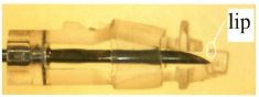
The degree of detail shown by this photograph could not readily be seen by a visual inspection of the catheter without magnification and taking it apart. A distinctive feature in the Multigate catheter is the presence of an elastomeric ring which can be seen as a translucent band in the photograph around the centre and right of the photograph. Mr Bennett said that the three Multigate catheters did not have the integer of a resilient portion of the needle guard because the needle guard in the Multigate catheters had an open natural position and “will not block the needle without the elastomeric ring in place”. Dr Haindl, in contrast, said that the two arms of the needle guard in the Multigate catheters “will block the needle guard without the help of the elastomeric ring as long as the needle tip is in the normally assembled rotational position”.
Multigate contended that the claim in the patent required that the resilient portion have the following “qualifications” or “characteristics”:
(a) it must be engaged by [the] needle shaft when [the] needle is in its ready position;
(b) it must be moveable within the interior of [the] cathether hub to a blocking position distal of [the] needle when the needle is in its retracted position in which [the] needle shaft no longer exerts a force on [the] resilient portion;
(c) it must enable an outer contact surface of the needle guard to be secured to a groove formed in the catheter hub hollow interior when the resilient portion is engaged by the side of the needle shaft and biased radially outwardly; and
(d) when the needle is in the fully retracted position, the resilient portion [must be] blocking the needle tip.
It was contended that without these characteristics, a catheter would not have the relevant integer in the patent.
It is difficult to determine the presence of this integer in the Multigate catheters without the assistance of experts. The Multigate catheters are too small to be tested by an untrained observer. In particular it is difficult, without the assistance of experts, to determine the role played by the arms in the Multigate catheters without the elastomeric ring. Dr Haindl’s evidence was that the two arms of the needle guard in the Multigate catheters are resilient. He explained that they are directly engaged by the needle shaft and, in cross-examination, explained his findings from experiments he had made by dismantling the elastomeric ring. Dr Haindl’s evidence was that he found that the needle guards worked without the elastomeric ring when the needle was in the rotational position in which the catheters are delivered. Little difference was found if the needle was turned by 180 degrees. In the normal fashion of use, therefore, the needle will be blocked by the needle guard when the distal wall of the needle guard touches the needle tip. He accepted that there was a greater risk of needle prick when the elastomeric ring had been removed than when the ring was on, but that the needle would pass even with the elastomeric ring in place if manipulated in a different rotational position. His evidence was that the elastomeric ring was not that which predominantly moved but, rather, that all three structures (namely the two arms and the ring) moved resiliently together. Plainly the elastomeric ring has some function to perform in the blocking of the needle effected by the needle guard in the Multigate catheters. That, however, does not mean that the needle guard is not within the claim of the 327 Patent. The needle guard in the catheters is engaged by the needle when the needle is in the ready position. The two arms of the needle guard in the Multigate catheters are directly engaged and the elastomeric ring is, at most, indirectly engaged as the needle in the ready position pushes back the two arms of the needle guard to the extent caused by the needle and kept in position by the elastomeric ring. The resilient portion of the needle guard in the Multigate catheters is moveable within the interior of the catheter hub to a blocking position distal of the needle tip when the needle is in its retracted position. When the needle shaft no longer exerts force the two arms do move back to block the needle. The resilient portion of the needle guard does enable an outer contact surface of the needle guard to be secured to a groove formed in the catheter hub hollow interior when the resilient portion is engaged by the side of the needle shaft and biased radially outwardly (which will be considered below). And the arms, being part of the resilient portion of the needle guard, do block the needle tip when the needle is in the fully retracted position.
147 The claim itself requires that the portion of the needle guard that has the defining characteristics identified above must be resilient.
148 His Honour found that each of the Multigate catheters had a resilient portion, on the basis of his findings as to the role played by the arms in the Multigate catheters without the elastomeric ring (at [56]).
149 His Honour stated that “[i]t is difficult to determine the presence of this integer in the Multigate catheters without the assistance of experts” (at [56]), and it is apparent that he relied heavily on the oral evidence of Dr Haindl proffered by him in concurrent session as to “his findings from experiments he had made by dismantling the elastomeric ring” (at [56]) on catheter B.
150 Multigate now complains about a lack of procedural fairness concerning this evidence, but we consider that such a complaint has little if any substance.
151 Multigate contended that it was apparent from Dr Haindl’s evidence that the arms in catheter B were not as effective from a safety perspective in blocking the needle tip without the elastomeric ring. Although Dr Haindl said in the joint expert report that the two arms of the catheter B needle guard would block the needle tip without the elastomeric ring “as long as the needle tip is in the normally assembled rotational position”, he qualified this statement in the joint concurrent evidence session by saying that that differed if the needle was turned around by 180 degrees. Under cross-examination Dr Haindl agreed that:
(a) the risk of needle prick was greater where the elastomeric ring had been removed;
(b) there was a qualitative difference in the reliability of the blocking without the elastomeric ring; and
(c) he would have a concern from a safety perspective if the catheter were supplied without the elastomeric ring although he also said that the relevant question addressed in the joint expert report as to resiliency was a different question.
152 On the basis of Dr Haindl’s evidence, his Honour accepted that removal of the elastomeric ring of the Multigate catheters A, B and C resulted in a higher risk of needle prick and that the reliability and safety of the Multigate catheters was in part due to the elastomeric ring (at [67]). Multigate asserts that in making his finding as to “resilient portion”, the judge overlooked this evidence. We disagree.
153 It was also said that his Honour’s summary of Dr Haindl’s evidence (“[l]ittle difference was found if the needle was turned by 180 degrees”) (at [56]) was not open to him on the totality of Dr Haindl’s evidence. It is said that Dr Haindl conceded “that differs a little bit if I turn the needle around by 180 degrees”. It was said that his evidence was not that there was little difference.
154 Multigate also said that having taken into account Dr Haindl’s evidence as to his experiments, his Honour ought to have given equal weight to Mr Bennett’s evidence as to his own experiments on all three catheters.
155 Multigate contended that Mr Bennett’s evidence was that two of the three catheters were ineffective in blocking the needle tip when the elastomeric ring was removed, and that the third was only effective when the needle guard was in its correct assembled position. In the face of Mr Bennett’s evidence, and the absence of evidence to the contrary, it is said that it was not open to his Honour to infer that Dr Haindl’s anecdotal experiments in relation to catheter B could be applied to catheters A and C, given the difference between the construction of the catheters. Catheters A and C were more similar in structure to each other than catheter B.
156 Generally, it is said that his Honour’s conclusion:
(a) disregarded the context of the specification (at [2]; 327 Patent at p 1 lines 4 to 8);
(b) was inconsistent with his findings that the catheter was an IV catheter designed to prevent injury from needle prick (at [42]) and that the problem with the prior art was the danger to health care workers from accidental needlestick injury (at [81]); and
(c) was not open on the totality of the evidence.
157 It is said that his Honour should have found that none of Multigate catheters A, B and C had a resilient portion within the meaning of claim 1 of the 327 Patent because in every case the arms of the catheter (in the absence of the elastomeric ring) were not sufficiently resilient to reliably move to block access to the needle tip when the needle was retracted (and in the case of catheters A and C, the arms by themselves were not sufficiently resilient in any circumstances to block the needle tip) so as to prevent needle stick injury.
158 In our opinion, Multigate’s arguments should be rejected.
159 At [56], his Honour recognised that it was difficult to determine the presence of this integer in the Multigate catheters without the assistance of experts; they were too small to be tested by an untrained observer, and it was difficult without the assistance of experts to determine the role played by the arms without the elastomeric ring. Accordingly, the expert evidence on this aspect had particular significance in relation to his findings. Multigate did not suggest otherwise.
160 Dr Haindl stated in the joint expert report that the resilient portion of the needle guard in catheters A, B and C was the two arms of the needle guard working together as a resilient portion and cooperating in blocking the needle tip. The elastomeric ring could as well be regarded as part of the resilient portion as it helped the two arms blocking the needle tip. The two arms of the needle guard would block the needle tip without the help of the elastomeric ring as long as the needle tip was in the normally assembled rotational position. Dr Haindl further confirmed that the two arms of the resilient portions were directly engaged by the needle shaft. The elastomeric ring was indirectly engaged by the needle shaft.
161 Dr Haindl explained in cross-examination that he made an experiment to dismantle the elastomeric ring and he found out that when the needle was in the rotational position in which it is delivered, then the needle guard worked without the elastomeric ring. It differed a little bit if he turned the needle around by 180 degrees. But in the normal fashion of use, it worked in that if he pushed back the needle guard on the needle, the needle guard would be blocked when the distal wall of the needle guard touched the needle tip. He accepted that the risk of needle prick was greater where the elastomeric ring had been removed than if the ring was on, but he noted that even with the elastic ring sometimes if you manipulate the needle in a different rotational position, it would pass out of the needle guard. He denied that it was predominantly the elastomeric ring which moved — all three structures (the two arms and the ring) moved together.
162 His Honour was entitled to and did rely on the evidence of Dr Haindl at [56].
163 Multigate has asserted that Dr Haindl’s “anecdotal experiments” were limited to catheter B. But Dr Haindl confirmed in cross-examination that he had also tried and proved “resilient arms” experiments on catheters A and C, and offered to show Multigate’s senior counsel what he had done. That offer was not taken up.
164 Multigate has contended that his Honour should have given equal weight to Mr Bennett’s experiments.
165 Mr Bennett stated in the joint expert report that a resilient portion was not present in each of catheters A, B and C, because these needle guards had an open natural position and would not block the needle without the elastomeric ring in place. To qualify as a resilient portion, the blocking elements needed to move to the blocking position without assistance from other elements.
166 In cross-examination he explained that he also undertook an experiment, although he had not given any prior evidence of an experiment.
167 He explained in cross-examination that you could easily pivot the needle guard on the needle, which then allows the needle to pass through. To this extent the experiments of Dr Haindl and Mr Bennett disclosed the same result: if the elastomeric band was removed and the needle guard was rotated on the needle tip, the needle tip could then pass through the guard out of the blocking position.
168 Further, Mr Bennett conceded that “the arms are definitely resilient”.
169 In summary, his Honour was entitled to rely upon the expert evidence of Dr Haindl. In any event, the claim language is a “resilient portion”. The arms and the elastomeric ring together could well be said to constitute the resilient portion where the ring assists the movement of the arms resiliently. No error has been shown in his Honour’s conclusion that the needle guard of each of Multigate’s catheters had a resilient portion.
(e) Infringement of claims 1 to 6, 577 Patent — “resilient spring clip needle guard”
170 The Multigate catheters contain guards all parts of which are plastic, not metal. Further, all three catheters rely for their operation on an elastomeric ring. On his Honour’s construction of this integer, which we have accepted, his Honour’s findings that Multigate’s catheters contained this integer are not impeachable.
171 Further, for the reasons set out earlier in relation to “resilient portion”, we reject Multigate’s contentions that his Honour:
(a) gave undue weight to Dr Haindl’s evidence of experiments on Multigate catheter B;
(b) wrongly inferred that that evidence was equally applicable to all of the catheters in suit;
(c) misunderstood Dr Haindl’s evidence as to catheter B;
(d) failed to have regard to the evidence of Mr Bennett as to his own experiments on the catheters; and
(e) did not give sufficient weight to the context of the invention (at [67]).
172 In our opinion, his Honour did not err in his finding at [67] that:
the evidence does not support the submission that “the needle guard itself, without the elastomeric ring, does not” have the characteristics of both spring and resilience. … the evidence was that the Multigate catheters in suit do move to a blocking position without the assistance from such other elements of the elastomeric ring.
173 Generally, his Honour was entitled to find that the Multigate catheters A, B and C had a resilient spring clip needle guard within the meaning of claim 1 of the 577 Patent, and consequently the dependent claims.
(f) Infringement of claims 1 to 6, 577 Patent — finding that the proximal wall of the needle guard in Multigate catheters A and C had an opening adapted to let the shaft of the needle freely pass through and axially move wherein the diameter of the needle bulge is greater than that of the proximal wall opening
174 As summarised earlier, the evidence before his Honour was that:
(a) in catheters A and C, the needle bulge made contact with the metal washer fixed in the needle guard;
(b) the opening in the metal washer was smaller than that in the plastic proximal end wall;
(c) it was the washer which stopped the needle bulge from going through to the proximal side of the needle guard; and
(d) the washer could be removed from the wall, although not easily.
175 His Honour’s conclusion that the opening of the proximal wall of the needle guard in Multigate catheters A and C had a diameter less than that of the needle bulge was based on his finding that the washer was part of the proximal wall (at [61] and [69]).· His Honour found that the metal washer in Multigate catheters A and C formed part of the proximal wall of the needle guard in each of those catheters and that thereby the needle of each of those catheters had a bulge with a diameter greater than the opening of the needle guard’s proximal wall (at [69]).
176 As we have said, no error has been shown in his Honour’s conclusions.
(g) Infringement of claims 1 to 6 of 577 Patent — “preventing further movement of said needle tip” and finding that the needle guard in each of the Multigate catheters prevented further movement of the needle tip when the needle was in the retracted position
177 His Honour dealt with this issue at [63] and [64] in the following terms:
The first topic considered under this heading in the submissions of Multigate concerned the words “preventing further movement” in claims 1 and 2 of the 577 Patent. The competing construction of the words was considered as topic 5(e) in the joint expert report and questions of infringement were considered by the experts as topic 11(c) in the joint expert report. The relevant words in the claim, as set out by Multigate in their written submissions, were:
CLAIM 1:
… said needle guard located within said hub chamber is adapted to automatically snap or pivot into a retracted position for blocking access to said distal needle tip and preventing further movement of said needle tip when said needle is in its retracted position; …
CLAIM 2 (Dependent claim):
… wherein said needle guard is adapted to automatically snap into said retracted position when said needle is being retracted for blocking access to said needle tip and preventing further distal movement of said needle tip to prevent accidental contact with said needle tip.
Multigate contended that none of catheters A, B or C have a needle guard which is capable of “preventing further movement of the needle tip when the needle is in the retracted position”.
The issues raised by this integer are similar to those raised by the words “secured to” in the context of the 327 Patent. Indeed, Mr Bennett repeated in the context of infringement issues relating to the 577 Patent his calculations of the movement of the needle which he had given in respect of the issue raised in the context of the 327 Patent. In both cases Mr Bennett had added the following observation to his percentage calculations of the travel of the needle within the needle guard:
This proves my point that this is significant movement far greater than normal manufacturing tolerance …
However, the words “preventing further movement” mean that the needle could not escape the needle guard, not that there was no further movement within the needle guard. The purpose of the invention is to ensure that the needle, once fully retracted, is safely within the needle guard and cannot escape from the needle guard so as to cause needle prick. Each of catheters A, B and C has the feature of movement of the needle tip being prevented in that sense when the needle is retracted.
178 Mr Bennett’s evidence, which was summarised by his Honour at [60], was that:
the needle was capable of movement in each of the three catheters when in the needle guard was in the fully retracted position. He quantified this movement as a percentage of the distance between the needle tip and the needle bulge. In the case of catheter A that movement was estimated at 31.25%, in the case of catheter B at 41.32% and in the case of catheter C at 38.52%.
179 Mr Bennett’s further evidence was that “this is significant movement far greater than normal manufacturing tolerance”. Although Mr Bennett’s evidence was accepted by his Honour, he found that the Multigate catheters nonetheless possessed the integer (at [64]):
Each of catheters A, B and C has the feature of movement of the needle tip being prevented in that sense when the needle is retracted.
180 Multigate has contended that his Honour should have found that none of the Multigate catheters had a needle guard which prevented further movement of the needle tip when the needle was in the retracted position.
181 We would reject Multigate’s contention.
182 Claim 1 requires that there be no further movement of the needle tip when the needle is in the retracted position. Claim 2 requires that there be no further distal movement of the needle tip. When these claims are read in their totality and in the context of the specification, it is apparent that the needle guard in the retracted position blocks access to the needle tip and prevents further movement of that needle tip and where the distal wall blocks the needle tip. The primary judge concluded that the words mean that the needle could not escape the needle guard, not that there was no further movement within the needle guard. We are not satisfied that the primary judge was thereby in error. If follows that Multigate’s argument on infringement must also be rejected
EXTERNAL FAIR BASIS
183 Braun has claimed priority dates for each of the two patents through a chain of ancestor patents. The patents in suit were filed as divisional applications of application numbered 2009233612 (“the parent application”). The parent application was filed on 30 October 2009 as a divisional application of application numbered 2005203491 (“the grandparent application”). The grandparent application had been filed on 5 August 2005 as a divisional application of application numbered 200142070 (“the great grandparent application”). The great grandparent application had been filed on 4 May 2001 as a divisional application of application numbered 199895323 (“the original ancestor”), which was filed as international application number PCT/EP98/05231 and later published with the number WO99/08742, which had been filed on 18 August 1998. The original ancestor claimed priority from two United States patent applications: (a) US Patent Application No 09/097,170 filed 12 June 1998; and (b) US Patent Application No 08/915,148 filed 20 August 1997. For present purposes, Braun accepted that the earliest priority date that it could claim for the claims of the patents in suit was 12 June 1998 being the earliest ancestor (Application No 09/097,170) which disclosed the bulge/crimp feature of the relevant invention.
(a) Relevant principles
184 The priority dates for each of the claims of the patents in suit are to be determined under ss 43(2) and 79B(1) of the Patents Act 1990 (Cth) and reg 3.12 of the Patents Regulations 1991 as they were in force before 15 April 2013. Section 43 relevantly provided (before it was amended with effect from 15 April 2013):
43 Priority Dates
(1) Each claim of a specification must have a priority date.
(2) The priority date of claim is:
(a) the date of filing of the specification; or
(b) where the regulations provide for the determination of a different date as the priority date — the date determined under the regulations.
(3) Where a claim defines more than one form of an invention, then, for the purposes of determining the priority date of the claim, it must be treated as if it were a separate claim for each form of the invention that is defined.
(4) The priority date of a claim of a specification may be different from the priority date of any other claim of the specification.
…
185 Section 79B relevantly provided:
79B Divisional applications prior to grant of patent
(1) If a complete patent application for a patent is made (but has not lapsed or been refused or withdrawn), the applicant may, in accordance with the regulations, make a further complete application for a patent for an invention:
(a) disclosed in the specification filed in respect of the first-mentioned application; and
(b) where the first-mentioned application is for a standard patent and at least 3 months have elapsed since the publication of a notice of acceptance of the relevant patent request and specification in the Official Journal — falling within the scope of the claims of the accepted specification.
…
186 Regulation 3.12 relevantly provided:
3.12 Priority dates generally
(1) Subject to regulations 3.13 and 3.14 and sub-regulation (2) the priority date of a claim of a specification is the earliest of the following dates:
(a) The date of filing of the specification;
(b) If the claim is fairly based on matters disclosed in one or more relevant applications — the date of making the relevant application in which the matter was first disclosed; …
(c) If the specification is a complete specification filed in respect of a divisional application under s 79B of the Act and the claim is fairly based on matter disclosed in the specification referred to in paragraph 79B(1)(a) of the Act — the date mentioned in sub-regulation (2C).
(2) For the purposes of sub-paragraph (1)(b), “relevant application” means:
…
(b) the application that relates to the specification containing the claim is a Convention application, a document of any of the following kinds is a priority document:
(i) a basic application that is related to the Convention application;
(ii) a specification, or another document filed in respect of or at the same time, as, a basic application that is related to that Convention application; or
(iii) a specification in respect of a basic application that is related to that Convention application, being a specification that was filed after the basic application was made;
…
(2C) The date for a specification to which paragraph 3.12(1)(c) applies is the date that would have been the priority date of the claim if it had been included in the specification referred to in paragraph 79B(1)(a) of the Act.
187 The effect of these provisions upon the claimed priority date of the relevant claims depends upon determining whether the claims were “fairly based on matter disclosed” in the specification of a parent. The claim will have the priority date to which it would have been entitled in each of the patents if the claim was fairly based on matter disclosed in its parent application. The priority date inherited from the parent in turn depends upon whether the claim was fairly based on the specification filed in respect of the grandparent application. Regulation 3.12(2C) requires consideration of what “would have been the priority date of the claim if it had been included in the specification referred to” in s 79B(1)(a). It is accepted that this process is to be repeated in respect of each of the preceding ancestral claims back to the original ancestor. For present purposes, the parties agreed that the specifications in the alleged parent and the alleged grandparent were relevantly the same. Accordingly, each claim of the patents in suit is to be assessed as if it were a claim, first of the alleged parent and alleged grandparent, then of the alleged great grandparent, then of the alleged original ancestor.
188 One conceptual issue that the parties debated before us was whether there was a difference between the concept of “fair basis” arising from the requirement in reg 3.12(1)(c) that the claim be “fairly based on matter disclosed” in the specification of the ancestor, and the concept of “fair basis” arising under s 40(3). Multigate contended that the effect of reg 3.12(2C) was to make clear that reg 3.12(1)(c) did not create a different test as between external and internal fair basis by providing that the date for a specification under reg 3.12(1)(c) is the date that would have been the priority date “if it had been included” in the specification referred to in s 79(B)(1)(a). We generally agree (see Sigma Pharmaceuticals (Australia) Pty Ltd v Wyeth [2011] FCAFC 132 at [65] per Bennett J referring to Inverness Medical Switzerland GmbH v MDS Diagnostics Pty Ltd (2010) 85 IPR 525 at [142]). The parties agreed that whether a claim is “fairly based on matter disclosed” depends upon whether there was “a real and reasonably clear disclosure” in the ancestor (cf Lockwood Security Products Pty Ltd v Doric Products Pty Ltd (2004) 217 CLR 274 (Lockwood No 1) at [69] per Gleeson CJ, McHugh, Gummow, Hayne and Heydon JJ). We have proceeded on the basis that this is the practical test to be applied.
189 But there is a subtlety that should not be overlooked. For internal fair basis (s 40(3)), what is required is that “the claim … must be … fairly based on the matter described in the specification” (our emphasis). Contrastingly, for external fair basis, reg 3.12(1)(c) uses the language “the claim is fairly based on matter disclosed in the specification” (our emphasis). There are two linguistic differences in the phrase used for external fair basis. First, the definite article is omitted. Second, the reference is to what is disclosed rather than what is described. So, the absence of the definite article makes it plain that external fair basis can arise if some part of the overall disclosure made in the prior specification discloses relevant matter (see Vehicle Monitoring Systems Pty Ltd v Sarb Management Group Pty Ltd (No 2) (2013) 101 IPR 496 at [125] and [126] per Yates J, applying Leonardis v Sartas No 1 Pty Ltd (1996) 67 FCR 126 (Leonardis) at 139 per Burchett, Hill and Tamberlin JJ). Further, the use of “disclosed” rather than “described” connotes greater flexibility in the test for external fair basis in terms of ascertaining from the prior specification the requisite disclosure.
190 In the context of external fair basis, the test of real and reasonably clear disclosure requires attention not on whether a subsequent claim had previously been made, but whether in the earlier specification there had been a real and reasonably clear disclosure of the invention that is claimed. Further, a real and reasonably clear disclosure in the prior specification need not be made only in the verbal description, but can appear from the accompanying drawings (CCOM Pty Ltd v Jiejing Pty Ltd (1994) 51 FCR 260 (CCOM) at 280 per Spender, Gummow and Heerey JJ; Leonardis at 137 per Burchett, Hill and Tamberlin JJ referring also to the fact that expert assistance may be necessary to interpret the drawings). Further, the relevant passage(s) from the prior specification need not be disclosed as part of the invention claimed therein. Further, the task of determining whether there has been a real and reasonably clear disclosure is not to be undertaken with an over-meticulous verbal analysis: Olin Corporation v Super Cartridge Co Pty Ltd (1977) 180 CLR 236 at 240 per Barwick CJ; approved in Kimberly-Clark Australia Pty Ltd v Arico Trading International Pty Ltd (2001) 207 CLR 1 at [15] per Gleeson CJ, McHugh, Gummow, Hayne and Callinan JJ and in Lockwood No 1 at [57], [68] and [69]. Further, the relevant disclosure is not limited to the description of preferred embodiments.
(b) Primary judge’s reasons
191 Multigate had submitted to his Honour that each of the patents in suit, and each of the intervening antecedents claimed to descend from the original ancestor, had sought to distance themselves from the invention of the original ancestor. Therefore, that by “their very words, each of the specifications disclaimed the claim to priority through to the original ancestor”. Multigate’s analysis of the specifications in the successive generation of patents was that they began with a statement of a problem with the prior art which, in each case, was said to be followed by each subsequent antecedent claim seeking “to distance itself from the invention of the original ancestor”.
192 His Honour identified that the specifications in each of the patents in suit, and each of the successive antecedents, began by identifying the same problem in the same terms. In each case the problem was identified as, in effect, the danger to health care workers from accidental needle sticks. The original ancestor identified the background of the invention that it claimed, stating in terms:
The problem is that immediately after the withdrawal of the needle from the patient’s vein, the health care worker who is, at this time, involved in at least two urgent procedures must place the exposed needle tip at a nearby location and address the tasks required to accomplish the needle withdrawal. It is at this juncture that the exposed needle tip creates a danger of an accidental needle stick occurring, which under the circumstances, leaves the health care worker vulnerable to the transmission of various, dangerous blood-borne pathogens, including AIDS and hepatitis.
This danger to the health care worker from accidental needle sticks has caused an impetus for the development of a safer IV catheter in which the occurrence of such accidental needle sticks is prevented. Safety catheters that have been developed to achieve this result are disclosed …
The prior art safety catheters all exhibit one or more drawbacks that have thus far limited their usefulness and full acceptance by health-care workers. For example, in the safety catheter disclosed in the Lemieux patent, the force required to engage the needle slot within the guard flange is relatively great and would interfere with the removal of the needle.
193 His Honour said that each of the patents in suit, and each of the prior intervening descendants from the original ancestor, referred to the intravenous catheter device disclosed in the original ancestor and each case identified some difference between the earlier claim and the new claim made in the new application. But his Honour said that the identification of the original ancestor in this way and the description of how the invention in the successor patent was different from a predecessor patent did not mean that the subsequent patent was not fairly based on matter disclosed by the antecedent specification. His Honour said that the question required to be answered was not to be determined by a characterisation of the words in a subsequent patent as an attempt to distance itself from the invention in the preceding patent. If we might say so at this juncture, we agree with his Honour generally speaking, but the language of a successor document seeking to distance itself from the invention claimed in a predecessor document is not irrelevant.
194 His Honour said that the question of what has been disclosed by prior specifications may need to be answered by considering the effect of combined specifications provided that one has unequivocally and plainly demonstrated the incorporation of the other. Again, we accept that proposition at the level of generality with which it has been expressed.
195 His Honour said that each of the two patents in suit specifically referred to the disclosure both in the parent and in their common original ancestor. Each specification stated:
The disclosure of the complete specification of Australian Patent Number 2009233612 as originally filed is incorporated herein by reference.
[…]
A safety intravenous catheter device is disclosed in International Application WO 99/08 742 by the present applicant.
Each of the parent and grandparent of the patents in suit contained further reference to the original ancestor. In those circumstances, his Honour said that it was sufficient to conclude that the disclosure in the patents in suit included that which was disclosed in the parents and in the original ancestor. His Honour accepted the evidence of Dr Haindl and Dr Esnouf that the skilled addressee would have had regard to the original ancestor and to the drawings to determine what had been disclosed. Again, at a level of generality, such conclusions may be accepted, but with the qualification that the relevant question for consideration was how much should be treated as being effectively incorporated by reference or to which one might have regard.
Parent and grandparent
196 Multigate had contended before his Honour that the invention disclosed by the parent had, as a necessary feature, a needle guard having two resilient arms, each joined at a proximal end to the rear wall, and crossing in a distal direction, and with a guard wall at the distal end of each resilient arm. It submitted that, read as a whole, there was “no real and reasonably clear disclosure in the alleged parent of a catheter having a needle guard that does not have two resilient arms crossing in a distal direction, with a guard wall at the distal end of each arm”. It was said that the claim of the 327 Patent required only that the needle guard have a resilient portion which was movable to the blocking position and which blocked the needle tip. It was said that claim 1 of the 577 Patent required that the needle guard be a resilient spring clip needle guard having a distal end wall. Moreover, claim 6, which introduced the requirement that the needle guard have two arms, did not require that the arms cross.
197 His Honour referred to the fact that the invention disclosed in the original ancestor was said to relate generally to intravenous catheters and in particular “to a safety IV catheter in which the needle tip is automatically covered after needle withdrawal to prevent the health-care worker from making accidental contact with the needle tip”. The invention was summarised as having four objects, and the specification set out a number of embodiments. At page 15 of the specification of the original ancestor there was described an embodiment depicted in Figures 7A to C which was described in the embodiment as differing from the previously described embodiments “primarily with regard to the construction and operation of the spring clip needle guard 96”. His Honour said that it was in that context that the description of the embodiments, and the diagrams showing them, disclosed the matters claimed in the subsequent patents including the great grandparent, the grandparent, the parent and each of the 327 and 577 Patents. The specification in the original ancestor relevantly provided:
As shown in Fig. 7A, spring clip needle guard 96, when in the ready position illustrated therein, is inserted within catheter hub 26 so as to allow the needle 16 to pass through opening 58 and slot 100. As in the previously described embodiments, the curved end 104 abuts against the inner upper wall of the catheter hub 26 at point b, and curved section 110 seats within the mating groove 48 at point a formed in the lower, inner wall of the catheter hub. In addition, the lower curved section 108 contacts at a point f the lower, inner wall of the catheter hub 26 at a location proximal to point b.
In operation, the needle is initially withdrawn into the catheter hub until it reaches the tab engaged position illustrated in Fig. 7B, in which is therein shown, the locking tab 118 is received within the needle groove or slot 60. At this point, the spring clip remains in contact with the inner wall of the catheter hub at points a, b and f while the needle tip 18 engages curved end 114, thereby to urge section 110 into groove 48 at point c. The relative position of point f with respect to point b prevents the needle and clip from being prematurely released from the catheter hub by preventing the distal end of the clip from tipping upwards and the proximal end from slipping downward with the clip in the tab engaged position in Fig. 7B.
As the needle is withdrawn further away from the patient, as shown in Fig. 7C, the needle tip passes beyond curved end 114, thereby releasing the downward force that had been previously exerted on curved end 114 by the needle.
This sudden release of the downward force on the spring clip end causes the distal end of the spring clip 96 to pivot upward so that distal end 112 of spring clip 96 moves rapidly to a position in which it prevents or blocks motion of the needle in the distal direction. The spring clip 96 is retained on the needle 16 and will be removed from the catheter hub 26 when the needle is completely removed. Movement of the spring clip 96 from its protecting or retracted position shown in fig 7C is further prevented by the insertion of the locking in tab 118 into the needle groove 60 which prevents the spring clip from rotating around the periphery of the needle. This, in turn, secures the spring clip on the needle even if the clip were subjected to a twisting and pulling force.
198 His Honour referred to the fact that the specification continued by describing the use of a locking tab inserted into a needle groove. This integer was described in the specification by specific reference to the catheter illustrated in Figures 7D and 7E:
The safety IV catheter illustrated in fig 7D and 7E is the same as that illustrated in fig 7A and 7B except that the slot 60 in the needle shaft in the latter is replaced in the former by a bulge 61 whose diameter is greater than that of opening 58 in vertical arm 54. If an attempt is made to move the protected needle illustrated in fig 7D in the rearward or proximal direction, bulge 61 would engage with wall 54 and will not be able to pass through opening 58, so as to prevent any further proximal movement of the needle and removal of the needle from the needle guard, as desired.
199 His Honour referred to the fact that the parent and grandparent to the patents in suit referred to the original ancestor and at page 5 specifically referred to the configuration of the needle protecting means being different. The parent and grandparent relevantly stated:
On the needle point 18 a needle protecting means 120 is provided which is configured generally in the same way as a needle protecting means shown and described in figs 10A, 10B and 11 of WO99/08 742. However, a needle protecting means may also be of different configuration and numerous configurations are suggested by the prior art. In particular the needle protecting means need not comprise any clamping means for clamping the needle in the locked position.
200 His Honour said that these words, consistent with the evidence of Dr Haindl to the same effect, making reference to the original ancestor and to the parent and grandparent of the patents in suit, meant that the needle guard disclosed in the parent and grandparent was not limited to one having precisely the same configuration as shown in the Figures of the parent and grandparent. His Honour said that the configuration disclosed by these references, consistently with the view expressed by Dr Haindl, was that the needle guard could be as shown in the original ancestor. His Honour said that a skilled addressee referring to the original ancestor, including the Figures in the original ancestor, would have seen configurations which do not have two arms or two arms crossing each other. And as his Honour noted, the claim of the 327 Patent and claim 1 of the 577 Patent do not require the resilient needle guards to have two arms. Moreover, although his Honour accepted that the Figures in the parent and grandparent showed a needle guard having two arms, the disclosure by incorporation was broader and the terms of the claims in the patents in suit were not limited to a configuration with two arms or two arms crossing.
201 His Honour then concluded that on a fair reading of the parent, features of claim 1 in each of the 327 and 577 Patents were disclosed in the parent, including, by incorporation, the disclosure in the original ancestor. The invention in each of the two claims involved a safety IV catheter with a resilient needle guard where the resilience affected how the needle guard was securely held in the catheter hub, how the needle guard moved to block the needle tip, and how the needle guard remained in a position which blocked the needle tip once the needle was fully retracted from the catheter hub. The disclosure in the parent, grandparent and original ancestor was not limited to a needle guard having crossing arms but, as shown in a number of the Figures in the original ancestor, included configurations with only one arm moving to block the tip of the needle when retracted. His Honour said that it followed that the 327 and 577 Patents were entitled to the priority date from at least the parent and grandparent.
Great grandparent
202 Multigate further contended before his Honour that the claims in suit could not have the priority date of the great grandparent because an essential parameter of the invention disclosed in the great grandparent had been omitted from the claims in suit. It was said that the invention claimed in each of the claims in suit was substantially different from the matter disclosed in the great grandparent because the great grandparent required that “the catheter hub must have a bump with a generally annular configuration”, but the claims of the patents in suit did not so require.
203 His Honour referred to the fact that the great grandparent, like the parent and grandparent to the claims in suit, referred to the original ancestor. The specification to the great grandparent stated that the invention related to an intravenous catheter device and went on to state:
An intravenous catheter device, on which the characterising part of claim 1 is based, is known from WO99/08 742 [namely, the original ancestor].
204 A further reference in the great grandparent to the original ancestor contained the same words concerning different configurations being possible and being suggested by the prior art apart from those configurations shown in Figures 10A, 10B and 11 of the original ancestor.
205 His Honour said that whether the claims in the patents in suit were fairly based upon matter disclosed in the great grandparent was not to be determined by an identification and comparison of what were said to be the “essential features” of the prior disclosures with the present claims. The question was, rather, whether the present claim was fairly based on prior disclosures. The great grandparent described safety IV catheters having a resilient guard that worked in the same way as the IV catheter of claim 1 of the 577 Patent and claim 1 of the 327 Patent. Each of the features of those claims of the patents in suit was described in the great grandparent from the information in the Figures of the great grandparent.
206 Further, the specification of the great grandparent was almost identical to the specifications of the two patents in suit and the Figures in all three were identical. Figure 1 in each of the three specifications included a groove. Tendered before his Honour was a copy of Figure 1 from the three patents on which Dr Esnouf marked the location of what he said was a groove:
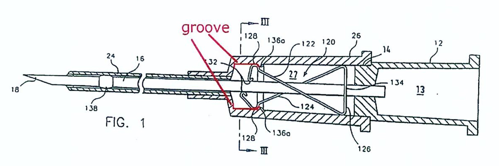
What was depicted as the groove was formed by the annular projection disclosed in the great grandparent. The relevant feature of the claim in each of the two patents in suit was, therefore, so his Honour said, formed by the annular projection disclosed in the great grandparent and performed the same function of securing the needle guard in the ready position. His Honour said that this aspect of the claim of the patents in suit was described in a general sense in the great grandparent and was not a claim of a characteristic of the invention about which the great grandparent had been wholly silent. It followed, so his Honour held, that the two patents in suit were fairly based on matter disclosed in the great grandparent and, therefore, were entitled at least to the priority dates of the great grandparent.
Original ancestor
207 Multigate submitted to his Honour that the patents in suit were not entitled to the priority date of the original ancestor because there were significant differences between the claims of each of the 327 and 577 Patents and the disclosure in the original ancestor. The principal differences were said to be that the patents in suit did not require that:
(a) the needle guard be a unitary spring clip needle guard; and
(b) the needle guard operate by clamping onto the needle shaft.
Further, claim 1 of the 327 Patent required a crimp on the shaft of the needle which was not disclosed in the original ancestor and also a groove formed in the catheter hub hollow which was not disclosed in the original ancestor.
208 His Honour stressed that Multigate’s focus upon essential features in prior disclosures should not distract attention from the task of determining whether the claims of the patents in suit were fairly based upon matter disclosed in the original ancestor. We agree with that cautionary observation. His Honour said that a fair reading of the original ancestor showed that the two features relied upon by Multigate were not limitations in what was disclosed in the original ancestor.
209 His Honour said that the embodiments of the needle guard disclosed in the original ancestor were not limited to a “unitary” needle guard. The body of the specification referred to a unitary spring clip by reference to Figures as described:
As shown in Figs. 1A and 1B, the needle tip guard 40 is in the form of a unitary spring clip that is preferably made of a resilient metal such as stainless steel. The spring clip includes a distal arm 42 terminating at its upper end in a curved lip 44, and at its lower end in a pointed end 46, which, in the embodiment of figure 1, is received within a mating groove 48 formed in the lower interior wall of catheter hub 40.
210 The embodiments described to include “a unitary spring clip” were depicted in a number of the Figures. But alternative embodiments were also disclosed in the specification which did not include a “unitary spring clip”. A lengthy passage in the specification from pages 15 to 18, and the Figures to which they referred, disclosed embodiments that were not limited to a unitary spring clip. His Honour said that it was also doubtful that the word “unitary” was used in the original ancestor in the sense now used by Multigate in its submissions. His Honour said that the word “unitary” appearing before the words “spring clip” may have been used to suggest that the spring clip was part of the unit making up the assembly rather than as a description of a feature of the spring clip itself. His Honour said that if it mattered, that was the better construction of the word and was consistent with the whole of the drawings and other terms of the specification (such as the reference to the catheter hub as a “unitary assembly”) which did not insist upon the spring clip itself as being a “unitary” feature. In any event, so his Honour said, it was clear from the Figures in the original ancestor that what was disclosed included matter beyond a “unitary spring clip” in the sense used by Multigate. Furthermore, his Honour said that it cannot be said that the configuration of the needle guard claimed in each of the patents in suit was not based on matter disclosed in the original ancestor. Figure 11 of the original ancestor, which we have reproduced below, disclosed features of the spring clip needle guard of the kind claimed in each of the 327 and 577 Patents:
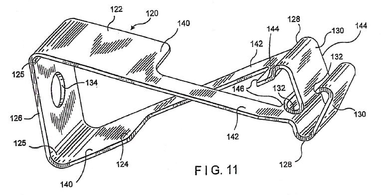
211 His Honour then dealt with the next aspect of Multigate’s argument. A further limitation said to have been part of the disclosure in the original ancestor but said not to be found in the patents in suit was that the needle protecting means was to operate by clamping onto the needle shaft. But the original ancestor disclosed some embodiments of the invention which did not include a clamping means. For example, Figures 7D and 7E in the original ancestor, which we have also set out, were two embodiments which did not include any clamping means:
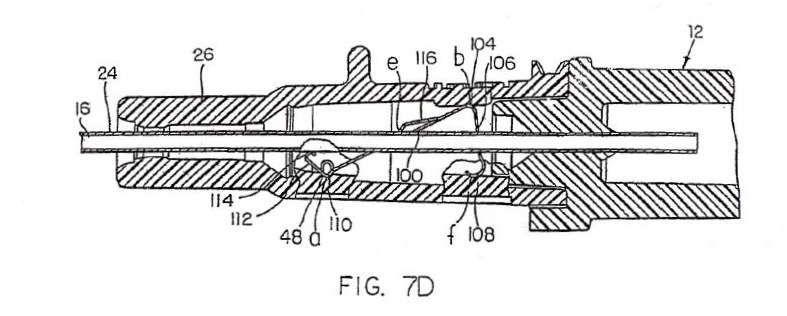
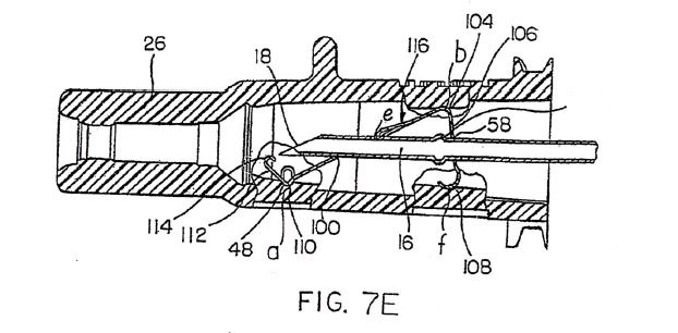
Figures 7D and 7E were described in the body of the specification as follows:
The safety IV catheter illustrated in Figs. 7D and 7E is the same as that illustrated in Figs. 7A and 7B, except that the slot 60 in the needle shaft in the latter is replaced in the former by a bulge 61 whose diameter is greater than that of opening 58 in vertical arm 54. If an attempt is made to move the protected needle illustrated in Fig. 7D in the rearward or proximal direction, bulge 61 will engage wall 54 and will not be able to pass through opening 58, so as to prevent any further proximal movement of the needle and removal of the needle from the needle guard, as desired.
212 His Honour said that the original ancestor did not disclose devices limited to the needle guard operating by clamping onto the needle shaft. The purpose of the needle guard clamping onto the needle shaft in some embodiments was to stop the needle guard sliding off the end of the needle when the needle had been removed from the catheter. But stopping the needle guard from sliding off the end of the needle could be achieved, as was shown in the Figures disclosed in the original ancestor, by the use of a tether (Figure 6B) or by the use of a bulge on the needle shaft which engaged the needle guard (as in Figures 7E and 10B). The bulge referred to in the description of Figure 7E, said to be numbered 61 but which number did not appear in the diagrams, was clearly shown and marked by the line extending to the right of the Figure and which his Honour said may be assumed to have been intended to have had the number 61 placed next to it. His Honour said that the omission of the number appeared to have been an oversight.
213 His Honour held that the disclosure in the specification of the original ancestor was broader than the inventions disclosed in the 327 and 577 Patents. His Honour also relied upon the evidence of Dr Esnouf. Dr Esnouf considered that the features of each of the devices claimed in the patents in suit were disclosed in the body of the specification of the original ancestor. These included the description in the original ancestor of different types of needle guard, including those claimed in the patents in suit. The needle guards disclosed in the original ancestor included needle guards with one or two arms and needle guards that used different types of means for contacting the needle shaft in order to secure the needle tip within the guard. These means included the use of a tether and the use of a tab on the needle guard to engage with a groove in the needle shaft. Figure 11 in the original ancestor (as we have set out earlier) disclosed features of the spring clip needle guard in claim 1 of the 577 Patent. The original ancestor described the feature of a groove in the inner wall of the catheter hub used to retain the needle guard. An example of such a groove was shown in Figure 10A as item 136 of the original ancestor:
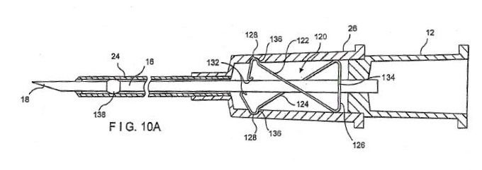
214 His Honour said that that groove was depicted in a different way from the groove shown in Figure 1 of the 327 and 577 Patents but, as shown in the Figure annotated by Dr Esnouf (as we have reproduced earlier), what was disclosed was relevantly a “groove” as claimed in each of the patents in suit.
215 His Honour also referred to the fact that another Figure in the original ancestor, Figure 2A, showed a retaining bump on the inner wall of the catheter for the purpose of retaining the needle guard. Further, some of the other Figures in the original ancestor showed a “bulge” on the shaft of the needle identified as item 61 on Figures 1C and 1D in the original ancestor and described in the text of the specification. It was also described by reference to Figure 7E, said to be numbered as 61 in that Figure (being the feature near item 58), although as we have noted that number did not appear on Figure 7E.
216 Further, his Honour said that the original ancestor also disclosed the use of a crimp on the shaft of the needle as claimed in the 327 Patent. The original ancestor described the feature of a bulge on the shaft of the needle. His Honour said that one way of forming a bulge on the shaft of a needle was to deform the needle by crimping it. His Honour said that the references to “bulge” in the specification of the original ancestor were apt to encompass a bulge that had been created using a crimping process. The item described as numbered 61 in Figure 7E of the original ancestor, but marked by the line without a number, depicted a crimp. Figure 10A in the original ancestor contained item numbered 138 (described in the specification as an “increased diameter bulge”) which was the same as item 138 of Figures 1 and 6 of the 327 Patent. The original ancestor also used the terms “retracted” and “fully retracted” in relation to the needle and referred to the needle guard pivoting or snapping into the retracted position. It also referred to the resilient arms and the distal end wall of the needle guard performing the blocking function.
217 His Honour concluded that the original ancestor provided a real and reasonably clear disclosure of the inventions in each claim of the 327 and 577 Patents including:
(a) a needle guard which was not limited to being “unitary”;
(b) a needle protecting means which was not limited to having a clamping means; and
(c) additional features including a crimp and an annular groove or projection.
His Honour held that what was claimed by the patents in suit was described in the original ancestor in a general sense and was not inconsistent with the original ancestor or included a feature as to which the original ancestor was wholly silent. Accordingly, so his Honour held, the patents in suit were entitled to the priority date of the original ancestor, as derived from PD2 (being the earliest ancestor which disclosed the bulge or crimp feature), namely 12 June 1998.
MULTIGATE’S APPEAL CONTENTIONS
(a) Alleged error by incorporation of the original ancestor into each of the patents in suit, the parent, the grandparent and the great grandparent
218 As we have set out earlier, his Honour found that the original ancestor was incorporated in its entirety by reference into each of the patents in suit, the parent, the grandparent and the great grandparent. Multigate has contended that his reasoning as to the effect of such incorporation founded his conclusions in relation to both external fair basis (in relation to the parent, grandparent and great grandparent) and internal fair basis. Multigate contended that his Honour erred both in finding that the original ancestor was incorporated in each case, and in his conclusions as to the effect of the incorporation.
219 Multigate referred to the fact that his Honour relied on the evidence of Dr Haindl and Dr Esnouf that they would have had regard to the original ancestor to see what was disclosed. Multigate contended that such evidence was irrelevant to the legal question of whether the entire disclosure of the original ancestor (or some part, and if so, which) was made part of the disclosure of the invention in the patents in suit (or any of their claimed antecedents).
220 Multigate contended that although each of the specifications of the 327 Patent and the 577 Patent referred to both the original ancestor and the parent, the form of the reference to each was “very different”.
221 Multigate contended that the 327 specification and the 577 specifications each expressly incorporated the disclosure of the parent by reference. Contrastingly, each of the specifications referred to the original ancestor (327 Patent at page 1 line 9 to page 2 line 9; 577 Patent at page 1 line 9 to page 2 line 9) for the specific purpose of identifying a problem to be overcome in the following terms:
A safety intravenous catheter device is disclosed in International application WO 99/08 742 by the present applicant. Said catheter device comprises …
A catheter device of this type protecting means poses the problem that the needle protecting means must be fastened in the catheter hub, with a bend or an elbow of the needle protecting means having to be moved over the projection on the inner side of the catheter hub, such that a reliable support of the needle protecting means in the hollow space of the catheter hub is ensured.
It is an object of the present invention to provide an intravenous catheter device comprising a needle protecting means where fastening of the needle protecting means in the catheter hub is facilitated.
(emphasis added)
222 Multigate also contended that the same problem with the original ancestor was identified in each of the alleged antecedent specifications to the patents in suit.
223 Multigate also pointed out that each specification also referred to another discrete part of the original ancestor (327 Patent at 4 lines 15 to 21, 577 Patent at page 6 lines 8 to 14):
On the needle point 18 a needle protecting means 120 is provided which is configured generally in the same way as the needle protecting means shown and described in Figs. 10A, 10B and 11 of WO 99/08 742. However, the needle protecting means may also be of different configuration and numerous configurations are suggested by the prior art. In particular the needle protecting means needs not comprise any clamping means for clamping the needle in the locked position.
(emphasis added)
224 The first reference pointed out shortcomings in the original ancestor and taught away from it, and the second directed the reader to the original ancestor for the limited purpose of referring to the configuration of the needle protecting means (i.e. needle guard) shown in Figures 10A, 10B and 11. Multigate contended that the subsequent reference that other “configurations are suggested by the prior art” did not broaden the scope of the direction beyond those three Figures to other parts of the original ancestor; it merely told the reader that the needle protecting means need not have the clamping means of those Figures.
225 Multigate said that neither of these references to the original ancestor had the consequence of incorporating the entire disclosure of the original ancestor. The first reference in each specification sought to distance itself from the invention of the original ancestor. The second reference to the original ancestor in each case provided no more assistance. At most, it incorporated Figures 10A, 10B and 11 of the original ancestor, together with as much of the specification as was necessary to understand those Figures in relation to the needle guard.
226 Generally, Multigate contended that the reader was directed to the original ancestor for a limited purpose only, and only to a limited part of the prior document. Reference for such a limited purpose did not incorporate the entirety of the disclosure of the earlier document for all purposes.
227 Generally, it was contended that his Honour erred in law in holding that the specifications of each of the 327 Patent and the 577 Patent should be construed as incorporating the entirety of the disclosure in the original ancestor by reference.
228 Braun supported the primary judge’s reasoning and conclusion (at [83]) that the disclosure in the patents in suit included that which was disclosed in the “parents” and in the original ancestor. Braun also advanced the alternative contention that, even if the whole of the original ancestor was not incorporated in each succeeding generation of patent application from which the patents in suit claim priority, there was at least incorporated, and hence disclosed, the various needle guards described in the original ancestor.
229 In our respectful view, the primary judged erred in finding that the whole of the specification of the original ancestor is incorporated in the specification of each succeeding generation of the family of patent applications. In our view, the language of the text of the specifications in question does not support the incorporation of the original ancestor to this extent.
230 In finding that the whole of the original ancestor had been incorporated, his Honour placed significant reliance on what some of the expert witnesses had said about what they considered to be necessary for them to read in order to understand the invention described in the specifications of the patents in suit. Whilst we would not rule out the possibility that evidence from those who are representative of the person skilled in the art might, in an appropriate case, be an aid to construction on the question of whether, and if so what, externally made statements have been incorporated into a particular patent specification, we do not think that such evidence is of assistance in the present case, where the question can, and should, be answered by a consideration of the text alone of each specification. However, for the reasons given below, it does not seem to us that the incorporation of the whole of the original ancestor in the succeeding patent specifications is necessary in order for the claims of the patents in suit to have the priority dates which the original ancestor would provide.
231 Unquestionably, the specification of the parent (Australian Patent Application No 2009233612), as originally filed, is incorporated, by express reference, in the specification of each patent in suit. Further, Multigate accepts that the specifications of the parent and the grandparent are in materially the same terms and make like disclosures. Thus, at this point in the analysis, the inventions as claimed in each patent in suit would have the priority dates accorded by, at least, the grandparent, provided they are fairly based on their own incorporated disclosures.
232 Further and significantly, the specification of each patent in suit, and the specifications of each earlier generation deriving from the original ancestor (parent, grandparent, and great grandparent), makes explicit reference to the original ancestor in two ways.
233 First, there is a reference to, and description of, a particular embodiment of a safety intravenous catheter device said to be disclosed in the original ancestor. It is said, however, that this particular embodiment has “a problem” with the fastening of the needle protection means in the catheter hub, which the invention seeks to address by providing a retaining element. The retaining element comprises a projection within the catheter hub. The projection is of a generally annular configuration extending, at least, at two diametrical locations in the hub.
234 Second, when describing an embodiment of the invention that is claimed, each specification refers to an exemplification of a needle protecting means disclosed in the original ancestor. The relevant passage referring to the original ancestor is quoted at [223] above. This passage is significant. In our view, it incorporates into each specification not only Figures 10A, 10B and 11 of the original ancestor, but also the written description of those Figures. Multigate accepted this to be the case. We point out that Figures 10A and 10B are the same as Figures 1 and 2 in the specifications of the patents in suit as well as the specifications of the parent, grandparent and great grandparent: see [11] and [12] above. Figure 11 is depicted at [210] above.
235 The description of Figures 10A, 10B and 11 in the original ancestor is as follows:
The embodiment of the spring clip needle guard 120 disclosed in Figs. 10A, 10B, and 11 comprises first and second arms 122 and 124 respectively joined at their proximal ends in a hinged arrangement at 125 to the ends of a rear wall 126. The distal ends of arms 122, 124 each include a curved protrusion 128 extending to a distal end wall 130, which in turn terminates in a lip 132. As seen best in Fig. 11, rear wall 126 includes a central opening 134, and arms 122 and 124 each include a narrow portion 142 that extends between a distal wide portion 140 and a proximal wide portion 144. A lateral clamping edge 146 is defined at the distal wide portion 144.
As shown in Fig. 10A, when the needle guard 120 is in its ready position, the curved protrusions 128 in each of arms 122, 124 are received in an annular groove or ring 136 formed in the inner wall of catheter hub 26, which, as in the prior embodiments, is removably fit into the distal end of a needle hub 12. Also as in the prior embodiment, a needle 16 having a sharpened tip 18 at its distal end is received within a tubular catheter 24, which is secured to the distal end of catheter hub 26. The proximal end of needle 16 passes through opening 134 in rear wall 126. Needle 16 includes an increased diameter bulge 138, which is sufficiently small to allow needle 16 to move axially along catheter 24, but greater in diameter than opening 134 for reasons to be described below.
In the ready position illustrated in Fig. 10A, the needle shaft passes through the needle guard and applies an outward radial force on resilient arms 122, 124 by means of its engagement with lips 132, so as to urge the curved protrusions 128 of each of the arms into the annular groove 136, so as to retain needle guard 120 in a fixed position within the inner wall of catheter hub 26. The shaft of needle 16 that passes through the needle guard 120 frictionally engages the inner edges of the narrow portions 142 of arms 122, 124 so as to further retain the needle in its ready position.
When the needle is retracted axially, to the right as viewed in Fig. 10A, within the catheter hub, and moves past the end lip 132 of the needle guard, the radial force previously exerted on arms 122, 124 of needle guard 120 is suddenly released. This causes the distal end walls 130 of the needle guard to be released from their seat in the annular groove 136 and to pivot inwards into the catheter hub until, as seen in Fig. 10B, the end walls 130 overlap one another at a location distally in front of the needle tip, thereby to form a barrier that prevents inadvertent contact with, and distal movement of, the needle tip. At the same time, the clamping edges 146 of the needle guard are urged against the needle tip to restrict further axial movement of the needle.
As also shown in Fig. 10B, the needle guard 120 and the needle clamped to the needle guard after needle retraction can be removed from the catheter hub as a unitary assembly, and safely discarded. If an attempt is made, intentionally or inadvertently, to pull the needle further to the right, as viewed in Fig. 10B, out of the needle guard, the bulge 138 on the needle shaft will come into contact with the end wall 126, and since its diameter is greater than that of opening 134, the end wall 126 will at this point prevent any further axial movement of the needle out of the needle guard.
236 However, the passage quoted at [223] above is also significant in that it makes clear that the needle protection means does not have to be configured in this way. It can be configured in numerous different ways – it being disclosed that there are numerous configurations suggested by the prior art. In particular, the needle protection means need not be configured so as to clamp the needle (i.e. it may or may not be configured so as to the clamp the needle).
237 Contrary to Braun’s submission, we do not think that the passage quoted at [223] above incorporates the specific descriptions of the various needle protecting means otherwise exemplified in the original ancestor or, indeed, that might be exemplified in other prior art disclosures. Nevertheless, the person skilled in the art is taught that the configuration of the needle protecting means shown in Figures 10A, 10B and 11 of the original ancestor is but an example. It is not itself limiting of the broader “matter” concerning the needle protecting means that is disclosed. Thus, we do not accept the thrust of Multigate’s submission that the disclosure of the passage quoted at [223] above is limited to the configuration of the needle protecting means shown in Figures 10A, 10B and 11.
238 It is convenient at this point to also record that we do not accept Multigate’s submission that simply because the specifications of the patents in suit, and the specifications of the parent, grandparent and great grandparent, each express the object of overcoming a perceived “problem” in a particular embodiment of an IV catheter disclosed in the original ancestor, each patent application proceeding from the original ancestor cannot be a divisional application for the purposes of s 79B(1) of the Act or that the inventions as claimed in those applications cannot be fairly based on matter disclosed in the original ancestor.
239 In this connection, Multigate relied on certain observations in Sigma Pharmaceuticals (Australia) Pty Ltd v Wyeth (2011) AIPC 92-428; [2011] FCAFC 132 at [242]-[243] per Yates J (Bennett J concurring at [92]) to support its submission. Multigate argued that the statement in the specifications of the patents in suit as to the identified deficiency in the described embodiment cannot be ignored by “cherry picking useful elements from the earlier documents to provide fair basis”. At a high level of generality, this might be true. But the statements made in the specifications under consideration in Sigma are far removed from the statement (on which Multigate relies) made in the specifications under consideration in the present case.
240 In any event, the fact remains that the applications for the patents in suit, the parent, the grandparent and the great grandparent were filed as divisional applications under s 79B of the Act, ultimately deriving from the original ancestor. The relevant question is what, in that state of affairs, is the priority date accorded to the relevant claims of the patents in suit having regard to the serial or iterative application of regs 3.12(1)(c) and 3.12(2C) to each alleged priority document?
241 Thus, at this point in the analysis, it is convenient to ask whether the relevant claims in suit are fairly based on “matter” disclosed in the specifications of the parent, grandparent and great grandparent, considered separately (but noting the commonality of the disclosures in each), and, if so, whether, in turn, they are fairly based on matter disclosed in the original ancestor? In answering this question, it is not to the point that the parent, grandparent and great grandparent might themselves have claimed, as inventions, different or, arguably, more limited embodiments of the IV catheter apparatus claimed in the 327 patent or the safety IV catheter claimed in the 577 patent. The question in each case is, what “matter” is disclosed in the earlier specifications?
242 We note at this point that Multigate accepts that, if the relevant claims of the patents in suit are fairly based on the original ancestor, then those claims are entitled to a priority date of 12 June 1998.
243 We now turn to consider specific contentions made by Multigate in relation to the applications of regs 3.12(1)(c) and 3.12(2C).
(b) No priority claim through the parent/grandparent: the invention disclosed in the parent/grandparent was a needle guard with two arms crossing distally
244 Multigate has contended that his Honour’s erroneous reliance on the incorporation of the whole of the disclosure in the original ancestor into the specifications of the patents in suit and in the parent, grandparent and great grandparent led him into error at [86] in holding that the disclosures in the parent and grandparent were not limited to a needle guard having crossing arms. It is said that this conclusion was not open on a plain reading of the parent and grandparent. Each of the three aspects of the invention described in the parent and grandparent specified that the invention comprised a needle guard including a rear wall and two resilient arms each joined at a proximal end to a respective end of the rear wall and which had each said arm being generally oriented and crossing each other in a distal direction. It was said that the reference to the original ancestor did not broaden the invention disclosed, since each of Figures 10A, 10B and 11 also showed a needle guard with two arms crossing distally. Each of the claims of the parent and grandparent was to a needle guard with two arms crossing distally.
245 Multigate referred to the fact that his Honour relied on the second reference to the original ancestor in the parent and grandparent (see the passage quoted at [223] above, and his Honour’s comments at [85]) to support his conclusion that the needle guard could have multiple configurations, including those without two arms crossing. But Multigate contended that, in context, this reference did not amount to a real and reasonably clear disclosure that the needle guard of the invention disclosed in the parent and grandparent need not have two arms which crossed distally.
246 Generally, it was contended that claim 1 of the 327 Patent was not limited to a needle guard with two arms crossing distally. Nor were claims 1 to 6 of the 577 Patent. It followed, so it was said, that neither the invention claimed in the 327 Patent nor the invention claimed in claims 1 to 6 of the 577 Patent was entitled to claim priority from either the parent or the grandparent. Further, it was asserted that the incorporation by reference of the parent in each of the patents in suit did not overcome these limitations.
247 We reject Multigate’s contentions.
248 It may be accepted that, in each of the three described aspects of the IV catheter claimed as the invention in the parent and the grandparent, it is essential that the needle guard have two arms crossing each other in a distal direction. But, as we have explained, this is not the limit of the disclosures that are made in the parent and grandparent concerning the configuration of the needle guard.
249 It may also be accepted that the IV catheter apparatus claimed in the 327 Patent, and the safety IV catheter claimed in claims 1 to 5 of the 577 Patent, do not require, as an essential feature, that the needle guard has two arms, let alone two arms generally oriented and crossing each other in a distal direction. Claim 6 of the 577 Patent does require the needle guard to have two arms, but the arms do not have to cross each other. But, here, the relevant inquiry is not whether the claims of the patents in suit match the claims of the parent and grandparent (or, indeed, the claims of the great grandparent or the original ancestor). The relevant inquiry is whether there is a real and reasonably clear disclosure in the parent and grandparent, and subsequently in the great grandparent and original ancestor, of a needle guard having the essential features that each patent in suit relevantly claims for the needle guard. As Gummow J remarked in Rehm Pty Ltd v Websters Security Systems (International) Pty Ltd (1988) 81 ALR 79 at 95:
... the question is whether there is a real and reasonably clear disclosure in the body of the specification of what is then claimed, so that the alleged invention as claimed is broadly, that is to say in a general sense, described in the body of the specification.
250 These remarks were quoted with approval by the High Court in Lockwood No 1 at [69]. Although directed to the application of s 40(3) of the Act, these remarks apply equally when considering fair basis in the present context.
251 So far as concerns the IV catheter apparatus claimed in the 327 Patent, it is an essential feature that the needle guard have, relevantly, a resilient portion engaged by the needle shaft when the needle is in the ready position. It is also essential that this position be moveable within the interior of the catheter hub to a blocking position distal of the needle tip when the needle is in its retracted position and no longer exerts a force on the resilient portion of the needle guard.
252 These essential features of the needle guard are disclosed in the parent and grandparent by the incorporated description of Figures 10A, 10B and 11 of the original ancestor. It follows, of course, that these features are also disclosed in the great grandparent and the original ancestor. It is true that the illustration of these features is given with reference to a needle guard having two arms, and thus, it may be said, more than one resilient portion. But this does not matter. The relevant inquiry is whether a needle guard having the essential features as claimed, is disclosed. As we have discussed, the person skilled in the art is taught in the parent and grandparent that numerous, different configurations for the needle guard can be adopted to achieve the invention that is claimed. Multigate does not suggest that the essential features of the needle guard, as claimed in the 327 Patent, can only be possessed by a needle guard with two arms crossing distally. Its case is that the parent and grandparent limit their disclosures to a needle guard configured so as to have two arms crossing each other distally. That contention is not tenable in light of the passage quoted at [223] above.
253 A similar analysis applies in relation to the 577 Patent. So far as concerns the safety IV catheter claimed in claims 1 to 5, it is an essential feature that the needle guard be a resilient spring clip which is adapted to automatically snap or pivot into a retracted position for blocking access to the needle tip and preventing further movement of the needle tip when the needle is in its retracted position. For claim 6, the needle guard is further limited to one with two arms. Once again, the essential features of the needle guard claimed in claims 1 to 5, and in claim 6, are disclosed in the parent and grandparent by the incorporated description of Figures 10A, 10B and 11. They are also similarly disclosed in the great grandparent and the original ancestor. Although the features are illustrated by a needle guard having two arms crossing each other distally, the person skilled in the art is, once again, taught that numerous, different configurations for the needle guard can be adopted to achieve the invention that is claimed. Multigate does not suggest that the essential features of the needle guard claimed in claims 1 to 5 of the 577 Patent can only be possessed by a needle guard configured with two arms crossing distally or that, in the case of claim 6 where the needle guard does have two arms, the essential features can only be present if the two arms cross distally. Thus, as with the 327 Patent, Multigate’s contention that the disclosures of the parent and grandparent are limited to a needle guard having two arms crossing distally is not tenable in light of the passage quoted at [223] above.
254 Multigate’s contentions proceed on the erroneous basis that, in order to be fairly based on an earlier priority document, the relevant claims of the patents in suit must possess the essential features of an embodiment described in the earlier document. This approach was rejected by the High Court in Lockwood No 1 at [68] and [69].
(c) No priority claim through the great grandparent: the invention disclosed in the great grandparent was to a generally annular projection — not a groove (327 Patent) or bump or groove (577 Patent claims)
255 His Honour found that Figure 1 in the specification of each patent in suit showed a groove within the claims of the patents (at [32] in relation to the 327 Patent and at [47] in relation to the 577 Patent). This finding led him to decide at [90] that Figure 1 of the great grandparent disclosed a groove and that the relevant claims were fairly based on that disclosure.
256 Multigate contended that his Honour erred.
257 The great grandparent states (from page 1 line 28 to page 2 line 17):
In the case of the known catheter device [of the type described in the Original Ancestor] the projection, with which the needle protecting means lockingly engages, is configured as a retaining protrusion molded to the inner wall of the catheter hub, or a retaining groove.
A catheter device comprising a needle protecting means poses the problem that the needle protecting means must be fastened in the catheter hub, with a bend or an elbow of the needle protecting means having to be moved over the projection on the inner side of the catheter hub, such that a reliable support of the needle protecting means in the hollow space of the catheter hub is ensured.
It is an object of the present invention to provide an intravenous catheter device comprising a needle protecting means where fastening of the needle protecting means in the catheter hub is facilitated.
This object is solved according to the invention with the features stated in claim 1. Thus the projection is of a generally annular configuration and extends at at [sic] least two diametrical locations of the catheter hub. This means that the projection, with which the needle protecting means lockingly engages, is not only a local singular projection but a discontinuous or open ring generally extending about the overall circumference of the hollow space.
(emphasis added)
258 Multigate referred to the fact that the great grandparent explained that the problem with a local singular projection (a localised bump) or groove could be overcome by using a projection that was of a generally annular configuration in the catheter hub (i.e. a projecting ring that may be discontinuous or open, or continuous) to engage the needle protecting means.
259 Multigate contended that, in this context, the single reference to the groove on page 1 in the great grandparent did not provide a real and reasonably clear disclosure of a groove. It said that it was a loose or stray remark, inconsistent with the disclosure of the invention in the great grandparent as a whole. It was said that the disclosure in the specification as a whole was to use a generally annular projection to fasten the needle guard in the catheter hub.
260 Multigate referred to the fact that his Honour relied on the annular projection indicated by numeral 136a in Figure 1 as disclosing a groove (at [89] to [90]), on the basis that “the relevant feature of the claim is, therefore, formed by the annular projection disclosed in the great grandparent and performs the same function of securing in the needle guard”. It was said that his Honour erred in so finding. According to Multigate, Figure 1 does not show a groove.
261 Alternatively, Multigate contended that even if his Honour was correct in holding that the great grandparent had incorporated the entire original ancestor, that incorporation did not change the general description of the invention in the great grandparent. The passage identifying the problems with the original ancestor remained, and the disclosure still was that these problems could be overcome by using a generally annular projection. Accordingly, so it was said, a skilled addressee would disregard references to a retaining groove in the original ancestor as inconsistent with the invention disclosed in the great grandparent.
262 Generally, Multigate contended that the claim of the 327 Patent is to a needle guard which is secured to a groove in the catheter hub. It is inconsistent with, and not fairly based on, matter disclosed in the great grandparent, in which the needle guard is fastened in the catheter hub by means of a generally annular projection which extends in at least two diametrical locations. Claims 1 to 6 of the 577 Patent provide that either a groove or a bump can be used to engage a curved protrusion of the needle guard to retain the needle guard in the needle hub. They are also inconsistent with, and not fairly based on, matter in the great grandparent, because they travel beyond the disclosure in that document. It is said that this is so whether or not the original ancestor is incorporated into that document.
263 We reject Multigate’s contentions. They are not supported by the evidence, in particular the interpretation of Figure 1 in the great grandparent (which Figure is, as we have noted, the same in the specifications of the patents in suit, the parent and the grandparent, and the same as Figure 10A in the original ancestor).
264 In C Van Der Lely N.V. v Bamfords Ltd [1963] RPC 61, Lord Reid discussed the role of the expert in drawing inferences from what is disclosed in photographs and drawings. The context of this discussion was whether a photograph or a drawing of a device could amount to an anticipation of an alleged invention. His Lordship’s observations are apposite to the question of whether an alleged invention is fairly based on an earlier disclosure in a priority document. Lord Reid said (at 71):
There is no doubt that, where the matter alleged to amount to anticipation consists of a written description, the interpretation of that description is, like the interpretation of any document, a question for the court assisted where necessary by evidence regarding the meaning of technical language. It was argued that the same applied to a photograph. I do not think so. Lawyers are expected to be experts in the use of the English language, but we are not experts in reading or interpretation of photographs. The question is what the eye of the man with appropriate engineering skill and experience would see in the photograph, and that appears to me to be a matter for evidence. Where the evidence is contradictory the judge must decide. But the judge ought not, in my opinion, to attempt to read or construe the photograph himself; he looks at the photograph in determining which of the explanations given by the witnesses appears to be most worthy of acceptance.
265 In CCOM, the Full Court considered the relevance of expert evidence from skilled addressees in determining questions of fair basis. At 284, the Full Court said:
Counsel accepted that because “fair basing” raises an issue of law it is open for an appellate court to entertain a fresh argument that there is a lack of fair basing. That is true, but in deciding these and other issues of construction of patent documents, the court derives assistance from experts who are skilled addressees. The court should be careful to avoid assuming a technical expertise it does not have. The point was made by Lord Reid in C Van Der Lely NV v Bamfords Ltd [1963] RPC 61 at 71. Thus, the absence of such assistance, because the new point had not arisen at the trial, may present a particular problem for an appeal court in embarking upon what is a new inquiry…
266 In that case, the Full Court found no such difficulty to be present. Such difficulty does not arise in the present case because the primary judge had the benefit of a significant body of expert evidence directed to the question of whether Figure 1 discloses a “groove” to the person skilled in the art.
267 So far as concerns the IV catheter apparatus claimed in the 327 Patent, it is an essential feature that an outer contact surface of the needle guard be secured to a groove formed in the catheter hub hollow interior when the resilient portion of the needle guard is engaged by the side of the needle shaft and biased radially outwardly. So far as concerns the safety IV catheter claimed in claims 1 to 6 of the 577 Patent, it is an essential feature that a groove or bump be formed in the inner wall of the catheter hub to engage a curved protrusion of the needle guard to retain it in the catheter hub in the ready position.
268 In each case, Dr Esnouf identified the groove formed by the intersection of the projection in the inner wall of the catheter hub with the wall itself, as indicated by the annotations to Figure 1 reproduced at [90] of the primary judge’s reasons. We pause to note that the monochrome reproduction in his Honour’s reasons does not show the extent of the annotation which was, in fact, directed to that intersection. Dr Haindl identified the groove in the same place.
269 The identification of this location as describing a groove was not inconsistent with the evidence of the other experts given with respect to the general meaning of the word “groove”. Mr Bennett said a groove was an increase in the projected internal diameter of the interior hollow part of the catheter hub in a localised region. Mr Leskowich described a groove as a trench or cut out. Mr Spencer gave similar evidence.
270 Where, on the question of whether Figure 1 revealed a “groove” for the purposes of the claims in suit, there was any difference between Dr Esnouf’s and Dr Haindl’s evidence on the one hand, and Mr Bennett’s, Mr Leskowich’s and Mr Spencer’s evidence on the other, the primary judge was entitled to rely on the evidence given by Dr Esnouf and Dr Haindl. We can see no error in that choice.
271 Claims 1 to 6 of the 577 Patent refer to “a groove or bump” formed in the inner wall of the catheter hub. Multigate argued that the primary judge did not separately construe the words “groove” and “bump”, noting that, at [47], his Honour said that “the words were used to some extent interchangeably as may be seen from” claim 1 of the 577 Patent. Multigate contended that a “bump” cannot be a “groove” and that the words have opposite meanings.
272 We accept that, as a matter of ordinary language, a “bump” is not a “groove”. However, we do not understand his Honour to have suggested otherwise. His Honour’s statement that the words were “used to some extent interchangeably” should be understood as referring to the fact that, when considered in the context of Figure 1, the “bump” is identified as the projection shown by index 136a and that this projection forms a groove at its point of intersection with the inner wall of the catheter hub, as identified by Dr Esnouf and Dr Haindl.
273 We note that, in any event, the great grandparent discloses (at page 1 lines 29 to 31) an IV catheter device in which the needle protecting means engages either a retaining protrusion moulded to the inner wall of the catheter hub, or a retaining groove. Multigate sought to dismiss the disclosure of the retaining groove as a mere “loose or stray remark” that was inconsistent with the invention in the great grandparent. We do not accept that this disclosure can be dismissed in this simple fashion. It constituted “matter” that was disclosed in the great grandparent, as it was also disclosed in the parent and grandparent, as well as the original ancestor. The fact that the grandparent went on to describe and claim alternative embodiments that were said to facilitate the fastening of the needle protecting means in the catheter hub, is really beside the point. Once again, the issue is one of disclosure, and the parent, grandparent and great grandparent, as well as the original ancestor, in terms disclose an IV catheter device in which there is a real and reasonably clear disclosure of a needle guard that engages a retaining groove in the inner wall of the catheter hub in order to fasten the needle guard in the hub and, as an alternative, a retaining protrusion moulded to the inner wall of the catheter hub to provide this function.
(d) No priority claim through to the original ancestor: the invention disclosed in the original ancestor was of a unitary spring clip needle guard which operated by clamping onto the needle shaft
274 Multigate has contended that even if the inventions claimed in claim 1 of the 327 Patent and claims 1 to 6 of the 577 Patent are fairly based on the parent, grandparent and great grandparent, they are not fairly based on matter disclosed in the original ancestor. Multigate contended that his Honour erred in his findings at [85], [92] to [95] and [98] to [99] as to the disclosure in the original ancestor, by concluding that the IV catheter there disclosed is not limited to one having a unitary spring clip needle guard, or one which operates by clamping onto the needle shaft, or, additionally, one which has a localised retaining “bump” on the inner wall of the catheter hub to retain the needle guard.
275 At [85] and also at [93], [94], [96], [97] and [98], and in reaching his conclusion at [99], the judge relied in particular on Figures 7A to 7E in the original ancestor, and the discussion of each of those Figures. Multigate has contended that none of the Figures or discussion, nor any other of the Figures or discussion referred to or relied on by his Honour, support his findings.
276 Multigate referred to the fact that, in the device shown in Figures 7A to 7E, the spring clip needle guard clamps the needle shaft after the needle has been sufficiently retracted to allow the removal of the needle guard from the catheter hub when the needle is withdrawn: see page 4 line 25 to page 5 line 7. The needle guard in these Figures has a clamping point e, which is further explained in relation to Figure 1B on page 11, last paragraph to the end of the first paragraph on page 12. Further, Multigate argued, the needle guard there shown and described is a unitary spring clip needle guard in the sense that it is formed as a single piece. Multigate argued that this is made clear by Figure 8, which is a perspective view of the spring clip needle guard used in the embodiment of Figure 7. Multigate said that his Honour did not refer to Figure 8.
277 Multigate pointed to his Honour’s finding that the word “unitary” in the term “unitary spring clip” in the description in the original ancestor did not mean that the spring clips there disclosed were limited to a “unitary spring clip”. Multigate argued that his Honour’s reliance at [93] on the “lengthy passage in the specification from pages 15 to 18, and the Figures to which they refer” as disclosing embodiments not limited to a unitary spring clip (meaning, “formed of a single piece”) was unfounded. Multigate argued that this passage, and those Figures, refer to the device shown in Figures 7A to 7E, and Figure 8.
278 Multigate argued that the entirety of the disclosure, including all of the Figures of the original ancestor shown and described, are of unitary spring clip needle guards formed in one, single piece.
279 Multigate said that, whilst it may be that Figure 11 of the original ancestor falls within the scope of claim 1 of the 327 Patent and claims 1 to 6 of the 577 Patent, that Figure does not provide fair basis for the breadth of those claims, contrary to the primary judge’s conclusion at [93]. Multigate said that his Honour misunderstood the matter. Figure 11 shows a spring clip needle guard having two joined resilient arms crossing in a distal direction, and does not disclose a needle guard of any other configuration.
280 Accordingly, Multigate said that it is apparent that the original ancestor only disclosed a needle guard which:
(a) was a unitary spring clip needle guard, in the sense that the needle guard was made of one piece; and
(b) required a clamping means.
281 Contrastingly, Multigate said that the claims of the patents in suit were not so limited. Thus, Multigate argued, the original ancestor does not provide a real and reasonably clear disclosure of the invention claimed in claim 1 of the 327 Patent or claims 1 to 6 of the 577 Patent.
282 We reject Multigate’s contentions.
283 Figures 1A and 1B in the original ancestor depict a needle guard described in the accompanying text as being “in the form of a unitary spring clip”. The embodiment illustrated by Figure 2 is described in the original ancestor as being “similar to” that disclosed in Figure 1. The embodiment illustrated by Figures 3A and 3B are said to be “essentially the same” as that of Figure 2. However, other embodiments are not so described. For example, the original ancestor says that the embodiment shown in Figures 7A to 7C “differs from the previously described embodiments primarily with regard to the construction and operation of the spring clip needle guard”. Similarly, the needle guard in the embodiment shown in Figures 10A, 10B and 11 is not described as a “unitary” spring clip. The original ancestor does describe the needle guard of this embodiment as capable of being removed from the catheter hub with the retained needle “as a unitary assembly”. This passage plainly refers to the needle and the needle guard, but it suggests that the word “unitary”, where used in the original ancestor, might not be confined to meaning “formed of a single piece”, as Multigate has contended. Perhaps more importantly, nowhere in the original ancestor is it said with respect to any embodiment of the IV catheter that the needle guard should be “formed of a single piece”; nor are similar words used, unless such a limitation is necessarily imported by the adjective “unitary”. But, even then, as we have noted, the word “unitary” is not used in the original ancestor to describe all embodiments.
284 The primary judge concluded that the better view was that, when used in the original ancestor, the word “unitary” is a reference to the needle guard as a unit that is used to make up the assembly of the IV catheter with other parts. We do not think it can be said that this meaning of “unitary” was not open to his Honour on a proper reading of the original ancestor or that his Honour erred in the conclusion to which he came. There is no indication in the original ancestor that some advantage is to be attained or some problem avoided by requiring the needle guard to be “formed of a single piece”. On the other hand, the import of the description of the needle guard is that it is a functional unit within the assembly of other units making up the IV catheter, such as the needle shaft, the catheter hub, the needle hub and, indeed, the tubular catheter itself.
285 Having made these observations, it does not seem to us that the correctness of his Honour’s conclusion on this aspect of construction is determinative of the correct priority date of the claims of the patents in suit. Even if, contrary to his Honour’s conclusion, the word “unitary” be understood as meaning “formed of a single piece”, the disclosure of the original ancestor with respect to the needle guard is broader than that of a needle guard that is formed of a single piece. The summary of the invention in the original ancestor makes no mention of the needle guard being a “unitary” needle guard or of any requirement that it should be formed of a single piece. And, as we have noted, the word “unitary” is only used in connection with some of the preferred embodiments which are described in later parts of the original ancestor.
286 With respect to “clamping”, there are certainly embodiments of the needle guard described in the original ancestor which employ clamping as a means of retaining the needle with the needle guard when the needle is in its retracted position. The needle guard illustrated in Figures 10A, 10B and 11 has that feature. But the original ancestor does not disclose this feature as essential to the working of a needle guard in the described IV catheter. Moreover, contrary to Multigate’s submission, the original ancestor does describe embodiments of the IV catheter in which the needle guard does not operate by clamping.
287 For example, the embodiments of the IV catheter illustrated in Figures 7A to 7C (which, as we have noted, are described in the original ancestor as differing from the previously described embodiments, primarily with regard to the construction and operation of the needle guard) employ a locking tab which is received within a groove or slot in the needle shaft when the needle is withdrawn into the catheter hub and reaches the “tab engaged” position. By this means, rotational movement of the needle guard around the periphery of the needle is prevented. This, in turn, secures the needle guard on the needle, even if the needle guard is subjected to a twisting and pulling force. This embodiment can be compared and contrasted with the needle guard illustrated in Figure 1A, which also has a locking member which engages a slot in the needle shaft. However, in the Figure 1A embodiment, when the needle is in the retracted position, the original ancestor teaches that the needle shaft becomes clamped to the needle guard at two points. If a subsequent attempt is made to move the needle further in a rearward or proximal direction a segment of the needle guard will seat into the slot (which is located distally from the clamped position on the needle shaft) and provide an additional force to retain the needle guard on the needle.
288 The safety catheter in Figures 7D and 7E serves as another illustration in the original ancestor of a needle guard that does not employ clamping. The original ancestor says that, for this embodiment, the slot in the needle shaft of the embodiment illustrated by Figures 7A to 7C is replaced by a bulge whose diameter is greater than that of an opening in the rear wall of the needle guard. The original ancestor discloses that if an attempt is made to move the protected needle in the rearward or proximal direction, the bulge will engage the rear wall and will not be able to pass through the opening, thereby preventing any further proximal movement of the needle.
289 Thus, we do not accept, as Multigate contended, that the original ancestor only discloses a needle guard that is a unitary spring clip, in the sense that the needle guard was “made of one piece”, that also requires a clamping means. As we have said, the disclosures of the original ancestor with respect to the configuration of the needle guard are broader than the limited disclosure urged by Multigate. The primary judge did not err in the conclusions to which he came in that regard.
290 Multigate raised an additional argument in relation to claims 1 to 6 of the 577 Patent. Multigate argued that, contrary to the primary judge’s finding at [98] and [99], there is no disclosure in the original ancestor of a “groove or bump”. According to Multigate, the only disclosure in the original ancestor is of a retaining groove or (in Multigate’s words) a “localised bump (that is, a hill or pimple)”. This argument is, with respect, difficult to follow. In our view, it cannot be seriously argued that the original ancestor does not disclose a “groove or bump”. Undoubtedly, it does make this disclosure. Multigate’s argument appears to be that claims 1 to 6 of the 577 Patent may include a “bump” that is configured differently to the “bump” illustrated in the original ancestor in that, in the 577 Patent, the “bump” would include an annular projection. If that is its argument, it is without merit. It proceeds, once again, on the erroneous basis that a claim will only be fairly based if it secures the particular features of an earlier described preferred embodiment.
(e) The limited disclosure of a needle guard … in a spaced apart relationship from the distal end of the needle hub — all antecedent patents
291 Multigate contended that the only disclosure of a needle guard within the interior of the catheter hub in a spaced apart relationship from the distal end of the needle hub, as required by the 327 Patent, is in Figure 1 of the specifications of the parent, grandparent and great grandparent, and Figure 10A of the original ancestor. It argued that the primary judge’s construction of this feature is not disclosed in the prior specifications.
292 This challenge to the priority date of claim 1 of the 327 Patent is answered immediately by our rejection of the primary judge’s construction of this feature: see [39] to [63] above. In any event, the specifications of the parent, grandparent, great grandparent and the original ancestor all show, by reference to Figure 1 or, in the case of the original ancestor, Figure 10A, the needle guard in a spaced apart relationship from the distal end of the needle hub. Accordingly, this challenge to the priority date of claim 1 of the 327 Patent fails.
(f) Conclusion in relation to external fair basis
293 For these reasons, the primary judge did not err in concluding that the invention claimed in claim 1 of the 327 Patent, and the invention claimed in claims 1 to 6 of the 577 Patent, were fairly based on matter disclosed in the specifications of the parent, grandparent, great grandparent and original ancestor, considered separately, and that the priority date of those claims is the date accorded by the original ancestor. As we have noted, Multigate accepts that, should we be of this view, the priority date of the claims is 12 June 1998.
INTERNAL FAIR BASIS — SECTION 40(3)
(a) Groove — 327 Patent and 577 Patent
294 Multigate argued that claim 1 of the 327 Patent and claims 1 to 6 of the 577 Patent were not fairly based on the matter described in their respective specifications because a “groove” was not described. In support of this argument, Multigate said that the original ancestor was not incorporated in the specifications of the patents in suit and the consistory statements in the specifications of the patents in suit do not provide a sufficient basis. Thus, according to Multigate, the relevant claims travel beyond the descriptions of the inventions that have been given.
295 We reject these contentions. They are answered by our findings and conclusions at [264] to [272] above.
296 In particular, we do not accept that the consistory statements for claim 1 of the 327 Patent and claim 1 of the 577 Patent (on which claims 2 to 6 are dependent, directly or indirectly), considered in the context of the descriptions made, particularly with respect to Figure 1, do not provide a fair basis for the invention claimed.
(b) 577 Patent — catheter hub feature
297 Claim 1 of the 577 Patent requires that “the catheter hub be configured such that a force exerted by said needle shaft on said needle guard in said catheter hub is released when said needle is retracted”. His Honour found that this feature was concerned with the means by which the distal end walls of the needle guard block the needle tip when the needle is retracted (at [120]).
298 Multigate has contended that the passages relied on by his Honour to support his construction do not disclose the feature. The first passage described the removal of the needle but not that the design of the catheter hub plays a role in ensuring that the force exerted by the needle will be released when the needle is retracted. The second passage described the means by which the catheter hub is constructed, and does not refer to the needle at all. The third passage explained that the dimensions of the annular projection need to be such that the needle guard cannot slide out of the catheter hub and is retained in the catheter hub when the needle is withdrawn. It does not describe the needle as exerting any force.
299 It is said that the specification of the 577 Patent does not provide any description of how the integer might function. The only references to the integer are in the first consistory statement and claim 1. It is said that it is not possible to give the feature a meaning by regard to the specification. In summary, it is said that the feature is not fairly based on the description in the specification of the 577 Patent.
300 Generally, it is said that his Honour ought to have found that the catheter hub feature of the claims of the 577 Patent was not fairly based on the disclosure in the body of the specification.
301 We do not accept any of these contentions. We agree with Braun that Multigate has ignored the role played by Figure 1 and the basis that its role played in his Honour’s reasons.
NOVELTY — 327 PATENT
302 Multigate has contended that the invention claimed in the 327 Patent was anticipated by the Kuracina patent being patent WO199731666, published on 4 September 1997 in Switzerland. This is the only relevant prior art left in the frame if his Honour’s and our views are correct concerning the priority date.
303 Multigate submits that the Kuracina patent disclosed every integer of claim 1 of the 327 Patent. The Kuracina patent was published in Australia on 16 September 1997, earlier than the earliest possible priority date of the claim of the 327 Patent. It is said that the Kuracina patent therefore qualified as prior art information under s 7(1)(a) and was capable of anticipating the claim of the 327 Patent.
304 Section 18(1)(b) relevantly provides that:
… an invention is a patentable invention … if the invention, so far as claimed in any claim:
…
(b) when compared with the prior art base as it existed before the priority date of that claim:
(i) is novel; …
305 In relation to “novelty” s 7(1) relevantly provides:
Novelty
(1) For the purposes of this Act, an invention is to be taken to be novel when compared with the prior art base unless it is not novel in the light of any one of the following kinds of information, each of which must be considered separately:
(a) prior art information (other than that mentioned in paragraph (c)) made publicly available in a single document or through doing a single act;
(b) prior art information (other than that mentioned in paragraph (c)) made publicly available in 2 or more related documents, or through doing 2 or more related acts, if the relationship between the documents or acts is such that a person skilled in the relevant art would treat them as a single source of that information;
(c) prior art information contained in a single specification of the kind mentioned in subparagraph (b)(ii) of the definition of prior art base in Schedule 1.
306 The term “prior art information” used in s 7(1) is defined in the dictionary in schedule 1 of the Act by reference to the “prior art base” as follows:
prior art base means:
(a) in relation to deciding whether an invention does or does not involve an inventive step or an innovative step:
(i) information in a document that is publicly available, whether in or out of the patent area; and
(ii) information made publicly available through doing an act, whether in or out of the patent area.
(b) in relation to deciding whether an invention is or is not novel:
(i) information of a kind mentioned in paragraph (a); …
(a) His Honour’s reasons
307 Multigate contended, and Braun did not dispute, that although the terms of s 7 and the definition of “prior art base” have subsequently altered, nothing relevantly turned on the changed wording.
308 His Honour referred to the test for anticipation explained by Aickin J in Meyers Taylor Pty Ltd v Vicarr Industries Ltd (1977) 137 CLR 228 at 235:
The basic test for anticipation or want of novelty is the same as that for infringement and generally one can properly ask oneself whether the alleged anticipation would, if the patent were valid, constitute an infringement …
309 His Honour also referred to Bristol-Myers Squibb Co v F H Faulding & Co Ltd (2000) 97 FCR 524 where Black CJ and Lehane J said at [67]:
What all those authorities contemplate, in our view, is that a prior publication, if it is to destroy novelty, must give a direction or make a recommendation or suggestion which will result, if the skilled reader follows it, in the claimed invention. A direction, recommendation or suggestion may often, of course, be implicit in what is described and commonly the only question may be whether the publication describes with sufficient clarity the claimed invention or, in the case of a combination, each integer of it.
310 His Honour also referred to Hill v Evans (1862) 45 ER 1195 at 1199; 1A IPR 1 where Lord Westbury LC expressed the test in terms of whether a person with ordinary knowledge of the relevant subject would be able practically to apply the prior published discovery without the necessity of carrying out further experiments: see also H Lundbeck A/S v Alphapharm Pty Ltd (2009) 177 FCR 151 at [173] and [174] per Bennett J (with whom Middleton J agreed).
311 Before the primary judge, Multigate relied upon the Kuracina patent as disclosing each integer of claim 1 of the 327 Patent. Braun admitted that the Kuracina patent disclosed various integers of claim 1 of the 327 Patent but said that there was absent in the Kuracina patent the features italicised below from the integers in claim 1 of the 327 Patent, namely:
(a) “said needle being moveable between said ready position in which said tip is outside of said catheter hub and a retracted position in which said tip is within the interior of said catheter hub”;
(b) “a needle guard positioned in the interior of said catheter hub in a spaced apart relationship from the distal end of the needle hub”;
(c) “the needle guard resilient portion is moveable within the interior of said catheter hub to a blocking position distal of said needle tip when said needle is in its retracted position in which said needle shaft no longer exerts a force on said resilient portion of said needle guard”.
312 In essence, the dispute before his Honour concerning the disclosure of the Kuracina patent came down to whether the blocking mechanism disclosed by the Kuracina patent was located within the catheter hub. The experts were asked whether there was a needle guard located within the chamber in the Kuracina patent. Conflicting opinions were expressed. Dr Haindl expressed the view that the needle guard was not located within the chamber of the catheter hub, but that it was connected with it by a modified cone and a moveable arm to hook into a recess in the catheter chamber. Mr Bennett took the contrary view, namely, that the needle guard was located in the catheter hub. Mr Leskowich referred to some additional drawings to which the other two had not made reference in which he maintained that the needle guard was shown to be located within the catheter hub of the chamber.
313 As we have said, the Kuracina specification was published on 4 September 1997 in Switzerland. It is entitled “needle tip guard for hypodermic needles” and disclosed a range of hypodermic needle devices including IV catheters. The invention was summarised in various embodiments. It referred to a needle guard assembly containing a moveable needle trap that was biased against or towards the hypodermic needle, which had a tether or other limiting means to limit the forward movement of the needle guard along the needle. On page 6, one embodiment was described:
In one embodiment the needle guard assembly of the present invention includes a needle guard that is slidably mounted on a hypodermic needle having a needle tip located at the distal end of the needle. The needle guard contains a moveable needle trap that is biased against or towards the hypodermic needle. The needle trap advances over the tip of the needle, entrapping the needle tip as the needle guard is urged forward near the sharpened distal end of the hyper-dermic needle. A tether, or other limiting means, limits the forward movement of the needle guard along the needle. In one embodiment, the needle guard is manually urged forward along the shaft of the needle by the user. In yet another embodiment, a spring, or other biasing means, is used to move the needle guard along the shaft of the needle.
314 Later, the specification provided:
In one embodiment, the coupling mechanism includes an arm having a proximal end and a distal end. The proximal end of the arm is attached to the moveable needle trap. The distal end of the arm includes a projection that is releasably retained within a recess of a catheter hub. Hence, as the needle trap moves inward to entrap the needle tip, the arm also moves inward. The inward movement of the arm causes the arm’s distal projection to be released from the catheter hub recess, thereby permitting a separation between the needle guard assembly and the catheter hub.
315 Figures 61 to 63 were described as illustrating a catheter in accordance with one embodiment of the Kuracina invention. The Figures principally relevant to the present issue were those numbered 61 to 63, although before his Honour, Mr Leskowich referred to 114, 118 and 123.
316 Figures 61, 62 and 63 showed a catheter in accordance with the Kuracina invention:
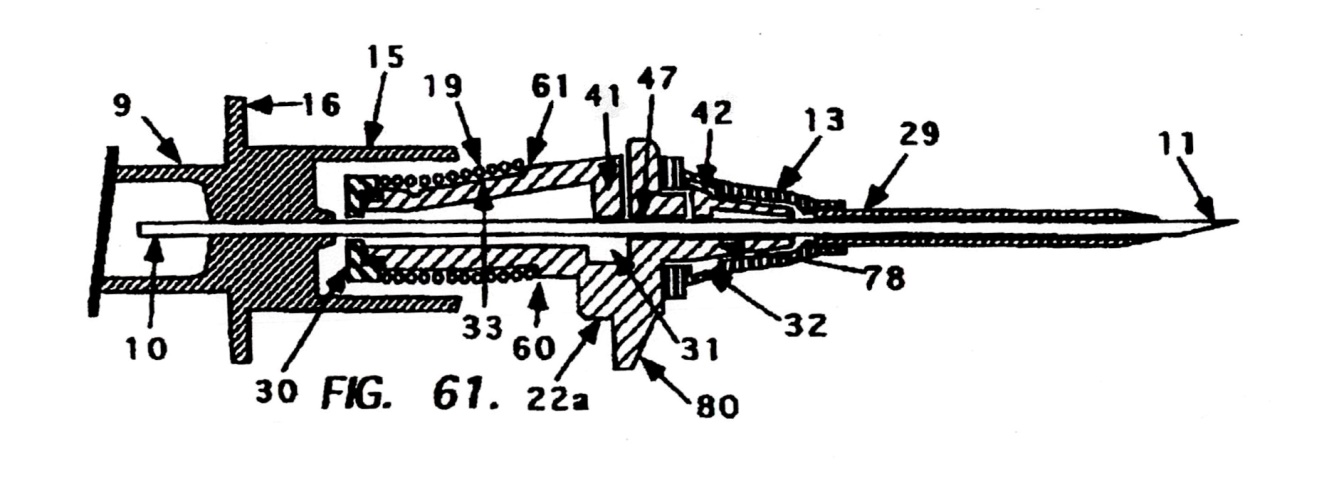
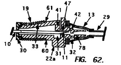
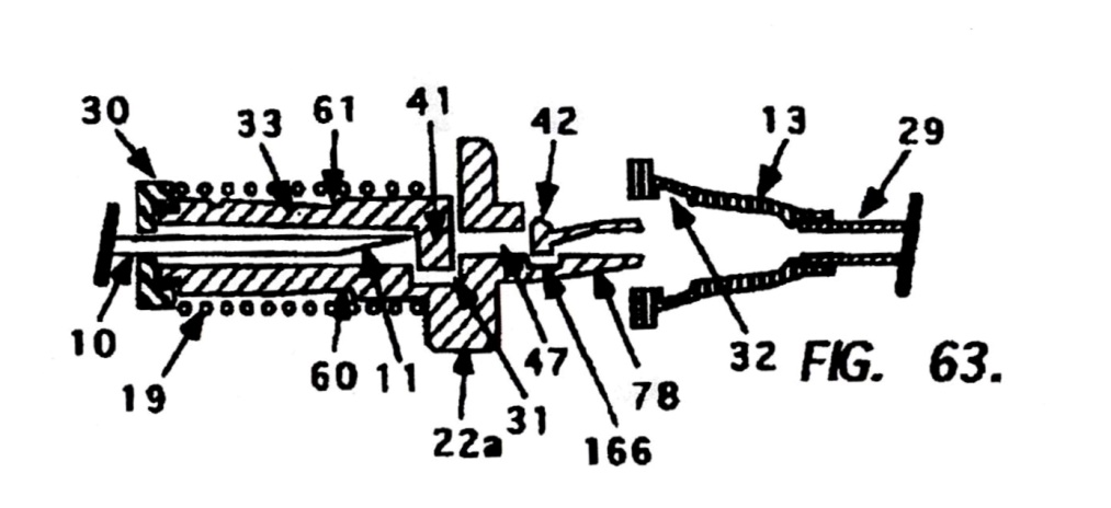
317 The Kuracina patent described Figures 61 to 63 in the following terms:
Figure 61 is a cross sectional top view of the invention shown on an indwelling catheter 29 embodiment, having a movable needle guard 22a and a separable indwelling I.V. catheter 29, said catheter 29 being fixedly attached to a catheter hub 13, an I.V. catheter mounting section 9 having a fixedly attached hollow bore hypodermic needle 10 having a sharpened distal end 11; a hub portion 15 having a section 16 for removably attaching a protective storage cover 54, a slidable needle guard 22a being fixedly attached to said hub portion 15 by means of a limiting tether, said needle guard 22a having a projection or finger post 80 for advancing said separable catheter 29 and said needle guard 22a along said hypodermic needle 10 so said catheter may be inserted into a blood vessel, said hypodermic needle 10 being slidable through a guide aperture 47 in said movable needle guard 22a, said needle guard 22a having a movable needle trap 41 with a corresponding slot 31 for receiving the needle trap 41 when said trap 41 moves beyond the needle tip 11, said needle guard 22a having an open collar or washer 30 for retaining the resilient member 19 on the proximal end of said needle guard 22a, said resilient member 19 being slidably held on said needle guard 22a by the notch or indentation 60, said movable needle trap 41 having a lead-in area 33 for locating said resilient member 19 on said needle guard 22a into notches 60 and/or 61, said needle trap 41 also having a notch or indentation 61 for retaining said end coils of said resilient member 19, with the distal end of said needle guard 22a having a male section 78 for removably attaching an indwelling I.V. catheter hub 13, with a section of said male section 78 having a movable arm 42 for releasably retaining a catheter hub 13 from said male section 78 during initial insertion of the catheter 29 into a patient. Said catheter hub 13 having an inner channel, recess, slot or undercut 32 for being releasably held by said movable arm 42. Said movable arm 42 could also comprise a metal component which is inserted during or after said male section 78 is manufactured.
Said hub portion 15 could also comprise the latching arm 26 shown in other drawings in this application, otherwise said needle guard 22a would be releasably held adjacent to said hub portion 15 prior to use by a frictional or wedged means.
Figure 62 is a cross sectional top view of the movable needle guard 22a shown in Figure 61 on an indwelling catheter embodiment, containing the elements shown and described in the movable needle guard 22a, whereby the catheter 29 has been inserted in a blood vessel and the needle 10 is being retracted into said needle guard 22a as the needle 10 is being pulled away from said catheter insertion site, whereby the movable arm 42 on the male section 78 is free to move where the needle has been residing within the distal male section 78 of the needle guard 22a, allowing the catheter hub 13 to remain in the blood vessel and freely separate from the needle guard 22a, with the needle trap 41 sliding on said needle 10. The needle guard 22a is attached to the hub portion 15 shown in Figure 61 whereby a fixedly attached tether (not shown) limits the forward movement of the needle guard 22a, safely trapping the needle tip 11.
Said catheter hub 13 having an inner channel, recess, slot or undercut 32 for being releasably held by said movable arm 42.
Figure 63 is a cross sectional top view of the movable needle guard 22a shown in Figures 61 and 62 on an indwelling catheter 29 embodiment, containing the elements shown and described in Figures 61 and 62, including the movable needle guard 22a, a tether (not shown) and catheter 29, whereby the catheter 29 has been inserted in a blood vessel and the needle 10 is safely retracted within said needle guard 22a whereby the movable arm 42 has moved inwardly releasing the hold on the catheter hub 13, with the needle trap 41 now safely trapping the needle tip 11. Movable arm 42 includes a corresponding receiving slot 166 for receiving said movable arm 42. Said needle guard 22a having said movable needle trap 41 located within the corresponding slot 31 after said trap 41 has moved beyond the needle tip 11. Said needle guard 22a is attached to the hub portion 15 as shown in Figures 61 and 62 whereby a tether limits the forward movement of the needle guard 22a, safely trapping the needle tip 11. Said catheter hub 13 having an inner channel, recess, slot or undercut 32 for being releasably held by said movable arm 42.
The movable arm protrusion 42 can comprise a “v” shaped configuration which allows the catheter hub 13 to separate even in the event the movable arm 42 has taken a set during storage. A set during storage could inhibit the separation of said catheter hub 13 from said mounting section 78.
318 Before his Honour much of the dispute between the parties concerned the role played by items 41 and 42 in the diagrams and the description in the patent. Mr Bennett concluded that Kuracina disclosed a needle guard positioned in the interior of the catheter hub because item 42 was located within the catheter hub. That assumed that moveable arm 42 of Figures 61 to 63 blocked the needle tip. Mr Bennett said:
The problem for the designer is that now unless item 42 blocks the needle tip, the device is actually dangerous because the catheter hub can fall away and the needle will be exposed and that’s why he’s created this groove here, exactly the same situation as in the other blocking device. So my interpretation of the drawing is that this is definitely designed to act as a needle guard in what I’m calling the retracted position …
319 Contrastingly, Dr Haindl saw the needle trap as the item numbered 41 and that the item labelled 42 was only a moveable arm to couple the needle guard to the catheter hub. Dr Haindl’s opinion was said to be consistent with Figure 63 and what was said in the body of the specification, namely, that 42 releases the hold on the catheter hub while 41 traps the needle tip.
320 His Honour considered that the better view was that of Dr Haindl. In our view his Honour was quite entitled to prefer Dr Haindl’s opinion. His Honour elaborated. Figures 61, 62 and 63 showed the point of attachment of the needle protecting means and the catheter hub. The hub is separate from the needle protecting means and the latter is not within the interior of the catheter hub. The moveable arm 42 does not, as can be seen in Figure 63, block the needle tip, but has as its only function the attachment of the needle guard to the catheter hub. His Honour said that the evidence of Dr Haindl was also to be preferred on this question because of his extensive expertise in the design, development and manufacture of medical devices in comparison to Mr Bennett’s relative lack of experience in the field. His Honour said that Mr Bennett’s view about the role of moveable arm 42 should also not be accepted because his view of the blocking role of moveable arm 42 was not the subject of a direction, recommendation or suggestion by the patent itself.
321 His Honour also said that the Kuracina patent did not disclose the integer referred to in [311(a)] above in claim 1 of the 327 Patent because the claim required the tip of the needle to be blocked within the catheter hub in its retracted position and the moveable arm in Figure 63 of the Kuracina patent was not within the catheter hub in its retracted position.
322 His Honour referred to the fact that Mr Leskowich offered an additional comment in support of Multigate’s contention that the relevant feature of the 577 Patent could be seen to be located within the catheter hub from Figures 114, 118 and 123. His Honour said that the relevant features were best seen from Figure 118 of the Kuracina patent:
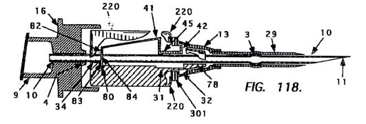
Multigate submitted to his Honour, based upon Mr Leskowich’s observation, that it was apparent from Figure 118 that lip 42 was located within the catheter hub. Mr Bennett was asked about Figure 118 in light of the description of the needle guard in the Kuracina patent as being adjacent to the catheter hub rather than being located within the interior. His evidence was that, despite the patentee’s wording, the needle trap 41 was actually inside the catheter hub as shown in Figure 118. That was because, according to Mr Bennett, the lip part numbered 42 in Figure 118 is part of the needle trap numbered 41 and the lip part numbered 42 is located within the chamber of the catheter hub. His Honour said that it was true that Figure 118 shows that part of the feature including both items numbered 41 and 42 was within the catheter hub but he said that to regard that part numbered 41 as being within the catheter hub because a small portion of it (namely that numbered 42) is within the catheter hub would not be an accurate statement as a matter of language or function of the invention. His Honour said that an element of the needle trap shown in Figure 118 was within the interior of the catheter hub but it was not wholly “located within” or “within the interior” of the catheter hub nor was it substantially or significantly located within the interior of the catheter hub such as to be an anticipation of the 327 Patent.
323 Ultimately, his Honour held that there had been no anticipation.
(b) Multigate’s arguments
324 Multigate has contended that his Honour gave the phrase “positioned in the interior” of the catheter hub an uncertain and indeterminate meaning, which was not supported by anything in the specification. As we have said earlier, we reject that contention.
325 As his Honour noted at [106], the dispute between the parties concerning the disclosure of the Kuracina patent came down essentially to whether the blocking mechanism disclosed by the Kuracina patent was located within the catheter hub.
326 This issue was dealt with as topic 15 of the joint expert report, which posed the question: does the Kuracina patent disclose a needle guard “positioned in the interior” of a catheter hub?
327 Mr Bennett’s answer was “Yes, shown in Figure 61/62(42), item 42 is positioned in the interior of the catheter hub and acts as a needle guard during needle retraction”.
328 Figures 61, 62 and 63 have been reproduced earlier at [316]. It is apparent that item 42 (movable arm) is located wholly within the catheter hub both prior to the retraction of the needle (Figure 61) and when it moves during retraction of the needle (Figure 62).
329 But there was no dispute that item 41 (needle trap) is a “needle guard”. And item 41 is located outside the catheter hub at all times.
330 Contrary to Multigate’s submissions, the acceptance or rejection of Mr Bennett’s evidence did not turn upon a construction of “positioned in the interior”, but rather turned on whether movable arm 42 constituted a “needle guard” which blocked the needle in addition to needle trap 41.
331 The issue of alleged lack of clarity asserted by Multigate is without substance.
332 At [109] the primary judge accepted Dr Haindl’s evidence that the movable arm 42 of the Kuracina patent does not block the needle tip, but has as its only function the attachment of the needle guard to the catheter hub. The primary judge correctly held that this can be seen in Figure 63.
333 Generally, the primary judge at [109] preferred the evidence of Dr Haindl over that of Mr Bennett because of Dr Haindl’s extensive directly relevant experience by contrast with that of Mr Bennett.
334 Dr Haindl’s evidence confirms that the Kuracina specification, as the primary judge correctly identified, does not direct, recommend or suggest that the “movable arm 42” has a blocking role, whereas it does do so with respect to “the needle trap” 41. As the “needle trap 41” is not within the needle hub, Figures 61 to 63 of the Kuracina patent did not anticipate claim 1 of the 327 Patent.
CONCLUSION
335 We have rejected all of Multigate’s grounds of appeal on invalidity. Accordingly its appeal in VID 693 of 2014 must be dismissed. We also do not see any good reason why costs ought not follow the event.
336 As to Multigate’s appeal on the question of construction and infringement, Multigate has had partial success in that we have concluded that its catheters A, B and C do not infringe the claim of the 327 Patent. Accordingly, the appeal in VID 681 of 2014 should be allowed in part.
337 We will give the parties an opportunity to file short submissions in terms of the appropriate consequential orders that should be made in VID 681 of 2014 and on the question of costs.
I certify that the preceding three hundred and thirty-seven (337) numbered paragraphs are a true copy of the Reasons for Judgment herein of the Honourable Justices Bennett, Yates and Beach. |

