FEDERAL COURT OF AUSTRALIA
Kinabalu Investments Pty Ltd v Barron & Rawson Pty Ltd [2008] FCAFC 178
Patents Act 1990 (Cth) ss 18, 138
Hill v Evans (1862) 4 De GF & J 288; 45 ER 1195 applied
Flour Oxidizing Co Ltd v Carr & Co Ltd (1908) 25 RPC 428 applied
Bristol‑Myers Squibb Co v FH Faulding & Co Ltd (2000) 97 FCR 524 applied
Pfizer Overseas Pharmaceuticals v Eli Lilly & Co (2005) 68 IPR 1 cited
Flexible Steel Lacing Co v Beltreco Ltd (2000) 49 IPR 331 applied
QUD 63 of 2008
SUNDBERG, EMMETT AND GREENWOOD JJ
31 OCTOBER 2008
BRISBANE
|
IN THE FEDERAL COURT OF AUSTRALIA |
|
|
QUEENSLAND DISTRICT REGISTRY |
QUD 63 of 2008 |
|
ON APPEAL FROM A SINGLE JUDGE OF THE FEDERAL COURT OF AUSTRALIA |
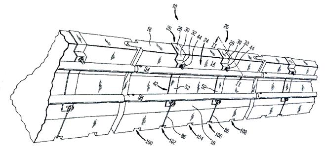
|
BETWEEN: |
KINABALU INVESTMENTS PTY LTD (ACN 001 469 718) Appellant
|
|
AND: |
BARRON & RAWSON PTY LTD (ACN 000 065 636) First Respondent
ANTHONY J CAREY Second Respondent
WAY TO GO AUSSINDO PTY LTD (ACN 080 761 511) Third Respondent
|
|
JUDGES: |
SUNDBERG, EMMETT AND GREENWOOD JJ |
|
DATE OF ORDER: |
31 OCTOBER 2008 |
|
WHERE MADE: |
BRISBANE |
THE COURT ORDERS THAT:
1. The appeal be dismissed.
2. The appellant pay the respondents’ costs of the appeal.
Note: Settlement and entry of orders is dealt with in Order 36 of the Federal Court Rules.
|
IN THE FEDERAL COURT OF AUSTRALIA |
|
|
QUEENSLAND DISTRICT REGISTRY |
QUD 63 of 2008 |
|
ON APPEAL FROM A SINGLE JUDGE OF THE FEDERAL COURT OF AUSTRALIA |
|
BETWEEN: |
KINABALU INVESTMENTS PTY LTD (ACN 001 469 718) Appellant
|
|
AND: |
BARRON & RAWSON PTY LTD (ACN 000 065 636) First Respondent
ANTHONY J CAREY Second Respondent
WAY TO GO AUSSINDO PTY LTD (ACN 080 761 511) Third Respondent
|
|
JUDGES: |
SUNDBERG, EMMETT AND GREENWOOD JJ |
|
DATE: |
31 OCTOBER 2008 |
|
PLACE: |
BRISBANE |
REASONS FOR JUDGMENT
THE COURT:
BACKGROUND
1 The appellant is the registered proprietor of Australian Patent No. 774224 entitled “A Barrier” the priority date for which is 10 August 1999 (the Patent). The Patent is concerned with barriers, particularly with barriers which have road traffic applications. The function of a traffic barrier is to redirect or arrest an errant vehicle safely, and prevent it passing through the barrier. The purpose of the barrier is to prevent the vehicle colliding with the roadside or other hazard or colliding with people in the area behind it.
2 The first respondent manufactured and offered for sale the Guardliner traffic barrier system. The second respondent was a consultant to the first respondent who placed advertisements for the Guardliner system and, together with the third respondent, had tests done relevant to the system and liaised with authorities in Australia to obtain regulatory approval for it.
3 The appellant alleged that the Guardliner system infringed claims 1, 2 and 4 of the Patent. At trial the question of infringement turned on whether the system possessed the integer of claim 1 – “at least one thin walled, longitudinally extending guard member that is mounted on and overlies the side walls of at least two adjacent barrier elements”. The primary judge found that it did and that each respondent would be liable for infringement, if the Patent is valid.
4 The first and second respondents, by cross claim, contended that claims 1, 2 and 4 were invalid for lack of novelty, and that the alleged invention claimed in each claim of the Patent was invalid for lack of inventive step, lack of patentable subject matter, lack of clarity and because it was not a manner of manufacture. The primary judge upheld the want of novelty ground over US Patent No. 5,531,540 (Wasserstrom), and rejected the others. His Honour declared the Patent invalid and ordered that it be revoked.
5 The appellant appeals against the finding of invalidity. By a notice of contention the respondents seek to have the judgment below affirmed on grounds additional to those relied on by the primary judge, namely that his Honour should have found:
(a) that the guardrail of the Guardliner road barrier system did not possess the feature of claim 1 ‑ “mounted on and overlies the side walls of at least two adjacent barrier elements”;
(b) that the claims of the Patent were also invalid because the invention, as claimed in each claim:
(i) did not satisfy the threshold requirement of “an invention”;
(ii) did not involve an inventive step, because it would have been obvious to a person skilled in the art in light of common general knowledge as it existed in the patent area before the priority date of the claims, considered separately or together with:
· Wasserstrom;
· Design Construction and Maintenance of Highway Safety Features and Appurtenances ‑ User’s Handbook, National Highway Institute (1997) (Handbook); or
· Road Design Guide, Roads and Traffic Authority, NSW (1996) section 6;
(c) that claims 6, 7, 8 and 9 were invalid because the invention as claimed in each of those claims was not a manner of manufacture within the meaning of s 6 of the Statute of Monopolies 1623, and
(d) that each of the claims was unclear in relation to the feature that the “guard member … overlies the side walls of at least two adjacent barrier elements”.
THE PATENT
6 The Patent first identifies the problem with prior art systems which the invention claims to overcome (at 1):
Demountable traffic barriers typically include a plurality of hollow, water fillable, barrier elements which are arranged end to end and are linked by a plurality of pin joints or by interlocking end portions.
Often the connection means connecting adjacent barrier elements and/or the side walls of individual barrier elements are damaged by collisions with motor vehicles. The resulting damage often severely weakens the structural integrity of the barrier.
7 The consistory clause asserts that the invention resides broadly in a barrier system including (at 1):
a plurality of hollow, ballast‑fillable, demountable barrier elements that are arranged end to end so as to form a barrier, each of said barrier elements having opposing side walls and opposing end portions, said end portions being adapted to combine with an opposing end portion of an adjacent barrier element to form a joint connecting adjacent barrier elements together, and
at least one thin walled, longitudinally extending, guard member that is mounted on and overlies the side walls of at least two adjacent barrier elements.
8 After noting a number of preferred embodiments the specification continues (at 3):
The longitudinally extending guard overlies two or more of the barrier elements. Advantageously, providing a guard which overlies a plurality of adjacent barrier elements serves to increase the stability of the barrier system and render it less deformable when subjected to minor impact. It is preferred that the guard overlie and be mounted on a multiplicity of adjacent barrier elements. Where the guard is formed from a plurality of guard segments, it is preferred that each guard segment overlie two or more of the barrier elements. It is preferred that where the longitudinally extending guard is formed from a plurality of guard segments, each guard segment is a multiple of the length of each barrier element such that whereby a plurality of guard segments are connected, they each overlie a plurality of barrier elements and terminate along the side wall of the barrier element rather than adjacent to the end of the barrier element where it abuts an adjacent barrier element. It is preferred that each guard segment terminate at the mid portion of a barrier element. The guard may be secured to a barrier element by any convenient means. For example, by a plurality of threaded fasteners which extend through tubes connecting opposing side walls of the barrier element. In other embodiments, the guard may be secured to the barrier element using one or more clamps or clips.
(The word “whereby” in the fifth sentence should probably read “where”.)
9 The figure depicted in Annexure A and taken from the Patent is “a pictorial view of a barrier constructed in accordance with the present invention”, and illustrates a preferred embodiment of the invention. The figure is described in the specification (at 4) as follows (with numbered references as marked):
Figure 1 shows a barrier 10 that includes a plurality of hollow, water fillable, barrier elements 11 that have been arranged end to end so as to form a substantially continuous, longitudinally extending obstacle. The barrier elements 11 each include a pair of opposing side walls 12 that are maintained in a spaced relationship by a top wall 13 and a base wall 14.
Preferably adjacent barrier elements 11 are connected by a plurality of threaded fasteners 15 that retain mating end portions 16 of the respective barrier elements 11 engaged.
The barrier 10 also includes a number of guards 17 manufactured from a thin walled, rolled section, of galvanised steel. The guards 17 are arranged end to end and are secured to the barrier elements by threaded fasteners 18. Individual guards are positioned such that they overlie the connection between adjacent barrier elements 11.
In use, the guards 17 protect the barrier elements 11 from direct contact with a motor vehicle and help strengthen the connection between adjacent barrier elements.
10 Claim 1 of the claims defining the invention is in the same terms as the consistory clause quoted at [7].
WASSERSTROM – REINFORCEMENT SYSTEM FOR HIGHWAY BARRIERS
11 The respondents’ claim of lack of novelty was based on Wasserstrom. Before the primary judge the expert witnesses agreed that all of the integers of claims 1, 2 and 4 of the Patent were present in Wasserstrom, except for (a) mounted on the side walls and (b) overlies the side walls of at least two adjacent barrier elements. On the appeal only exception (a) is in issue.
12 Wasserstrom’s Abstract describes:
[a] reinforcement system for highway barriers comprising a frame structure mounted on the surface of an associated highway barrier and force distributing members that are adapted to distribute forces along a horizontal direction upon impact of a vehicle into the associated highway barrier so as to lessen the degree of force applied to the highway barrier and to thus provide additional strength to the associated highway barrier.
13 The field of invention is said to relate:
to reinforcement systems for highway barriers. More particularly, the present invention relates to a reinforcement system for highway barriers which can be used to effectively distribute and transfer forces away from and along a highway barrier, which may occur upon impact of a vehicle upon which the reinforcement system is mounted.
(Column 1, line 6)
14 Under the heading Background of the Invention appears:
Although the design of the highway barriers disclosed in the aforementioned [Yodock] patents has been shown to be superior over conventional highway barriers, a need continues to exist for a reinforcement system for use in connection with highway barriers which will transfer forces away from the highway barriers upon impact of a vehicle and which will distribute the forces in such a manner so that the support strength of an associated highway barrier system is enhanced. Such an improved system will prevent heavy vehicles, or vehicles driven at great rates of speed, from crashing through a continuous line of highway barriers.
(Column 1, line 40)
15 Under the heading Summary and Objects of the Invention Wasserstrom says:
The present invention addresses the aforementioned needs by providing a reinforcement system for highway barriers. In accordance with a preferred embodiment, the reinforcement system comprises a frame structure which [is] adapted to be mounted on the surface of an associated highway barrier. The reinforcement system also comprises force distributing means for distributing forces along a horizontal direction upon impact of a vehicle into the associated highway barrier. The distribution of the forces will lessen the degree of force that would otherwise be applied to the highway barrier as a result of the impacting vehicle. The [force] distributing means is secured to the frame structure and extends substantially horizontally and parallel to the associated highway barrier and the road surface on which the highway barrier is arranged.
(Column 1, line 55)
16 Wasserstrom then speaks of a preferred embodiment in which:
… the frame structure comprises a pair of top sections, which may also be considered saddles, which are seated on the top surface of an associated highway barrier. The frame structure may also [comprise] a pair of side [assemblies] that are connected to the pair of top sections at respective opposite sides of the associated highway barrier. Each of the side assemblies may extend downwardly along the pair of side surfaces toward the bottom surface of the associated highway barrier. It is preferable for the pair of side [assemblies] to be substantially identical.
…
The frame structure of the present reinforcement system may comprise securing means for securely mounting the frame structure to the associated highway barrier. In a preferred embodiment, the securing means may comprise at least one cable which has a first end connected to one of the side assemblies and a second end connected to the other side assembly. In this preferred embodiment, the cable preferably extends between the first and second side assemblies along the bottom surface of the associated barrier when the reinforcement system is in its assembled position.
(Column 2, line 10)
17 Wasserstrom then describes a “particularly preferred embodiment”:
[T]he force distributing means is arranged on the frame structure on both sides of an associated highway barrier. In such embodiments, the force distributing means may comprise of a pair of pipes connected to the frame structure on each side of the highway barrier substantially adjacent to the side surfaces thereof. Each of the pair of pipes include a lower pipe secured to the frame structure at a location selected for impact with the tires on most vehicles upon impact of a vehicle into the associated highway barrier. An upper pipe is also included on each side of the highway barrier which is spaced apart from the lower pipe so that a trap zone is set up wherein the front bumper on most vehicles will impact the associated highway barrier, if at all, between the lower and upper pipes.
(Column 3, line 24)
18 The Summary and Objects part of Wasserstrom concludes:
Accordingly, it is an object of the present invention to provide a reinforcement system and a method of assembling such a system on associated highway barriers wherein the reinforcement system provides additional strength to the highway barriers on which they are placed.
It is another object of the present invention to provide a reinforcement system which will distribute forces which may occur due to the impact of a vehicle into the reinforcement system away from and along an associated highway barrier so that the effectiveness of a highway barrier system is enhanced.
(Column 4, line 37)
19 Wasserstrom’s claim 1 is as follows:
A reinforcement system comprising:
a frame structure mountable on a surface of an associated highway barrier, said frame structure comprising at least one side assembly; and
force distributing means for distributing forces along a substantially horizontal direction upon impact of a vehicle into the associated highway barrier so as to lessen the degree of force applied to the associated highway barrier, said force distributing means comprising at least one hollow pipe secured to said at least one side assembly of said frame structure and extending substantially horizontally and parallel to the associated highway barrier and the road surface on which the highway barrier is arranged.
(Column 12, line 4)
20 The figure in Annexure B is a “perspective view of a highway barrier system including the reinforcement system” described by Wasserstrom. The saddles referred to at [16] are marked 26 (their components are marked 28, 30 and 32). The side assemblies referred to at [16] (also referred to as the pipe assemblies) are marked 42 (their components are marked 44 and 52). The cabling referred to at [17] is marked 86. The pipes referred to at [16] are marked 54 and 58. They may be welded to the side assembly.
PRIMARY JUDGE ON NOVELTY
21 The primary judge set out extensive passages from the evidence of the two experts – Dr Troutbeck for the respondents and Dr Jenkins for the appellant. His Honour agreed with Dr Jenkins that:
· the barrier system described in Wasserstrom and that described in the Patent both set out to solve and reduce problems caused by the impact from collisions;
· both systems attempt to do this by using a structural component (the force distributing means or pipes in the Guardian and Wasserstrom systems, and the guard member in the Patent), which may be assembled from multiple segments, and when assembled, extends beyond the ends of individual barrier units, and
· the pipes or force distributing means overlie the side walls in the Guardian or Wasserstrom systems.
22 However his Honour did not agree with Dr Jenkins’ conclusion that Wasserstrom does not fulfil the requirement that the force distributing means be mounted on the side walls of the barrier units. His Honour said:
93 The Abstract speaks of “a reinforcement system for highway barriers comprising a frame structure mounted on the surface of an associated highway barrier ...”. Dr Jenkins frequently expresses the view that the frame assembly is not secured or connected to the barrier units: “The frame assembly in the Wasserstrom System is not secured or connected to the barrier units”. It follows, in Dr Jenkins’ view, that it would not operate to provide the composite beam effect, because it is not secured or connected to the side wall of the barrier unit.
94 In Dr Jenkins’ view, “It is possible for the frame assembly to move longitudinally as well as vertically.”
95 Dr Jenkins, at para 59, again expressed the view that:
... the metal pipes (or force distributing means) in the Wasserstrom Patent are mounted on the frame assemblies which, in turn, are not mounted on (in the sense used by Kinabalu Patent; this requires physical connection to achieve the composite structure effect) the side walls of the barrier elements.
…
97 Later, Dr Jenkins expressed the view in para 61 that:
The essential point of difference between the Wasserstrom system and the Kinabalu Patent System is that in the Kinabalu System the guard member and the barrier elements operate together as a single structural unit. This does not occur in the Wasserstrom system because there is no physical connection between the metal pipes and the barrier elements.
98 In my view, there is a physical connection between the metal pipes and the barrier elements. In my view, in the Wasserstrom patent, the force distributing means are mounted on the frame assemblies, which, in turn, are mounted on the side walls of the barrier elements. The suggestion by Dr Jenkins is that the frame assemblies are mounted on the barrier elements in the same way that one could say a rider is mounted on a horse. That is to say, the saddle, the frame structure, sits on the barrier element, but is not physically connected to the barrier element, in the same way that a rider mounted on a horse is not physically connected to the horse.
99 In my opinion, a closer analogy relates to the relationship of a saddle to a horse. The saddle is, in my view, secured or connected to the horse by means of the girth strap or cincture in the same way that the frame structure consists of the upper saddle secured to the barrier element by “at least one cable [which has a first end] connected to one of the side assemblies, and [a] second end connected to the other side assembly”. In this sense, the frame structure is “securely mounted” to the associated highway barrier.
23 His Honour thus concluded that Wasserstrom anticipated the Patent.
GROUNDS OF APPEAL
24 The appellant’s grounds of appeal include the following:
(a) the primary judge erred in finding that Wasserstrom disclosed a guard member that was “mounted on” the side walls of at least two adjacent barrier elements;
(b) his Honour erred in failing to have regard or sufficient regard to the evidence of the skilled addressee of the Patent in finding that Wasserstrom disclosed a guard member that was “mounted on” the side walls of at least two adjacent barrier elements;
(c) his Honour ought to have found that a person of ordinary knowledge in the field of the Patent would not at once perceive, understand and be able practically to apply the discovery by reading Wasserstrom, and
(d) his Honour erred in finding (at [98] and [99] set out above) that there was sufficient disclosure of a “physical connection” between the guard member and the barrier elements in Wasserstrom when Wasserstrom did not disclose or require a barrier system that produced a composite structure.
LAW ON LACK OF NOVELTY
25 In Hill v Evans (1862) 4 De GF & J 288 at 300; 45 ER 1195 at 1199 (Hill v Evans) Lord Westbury LC said:
The question then is, what must be the nature of the antecedent statement? I apprehend that the principle is correctly thus expressed:‑ the antecedent statement must be such that a person of ordinary knowledge of the subject would at once perceive, understand, and be able practically to apply the discovery without the necessity of making further experiments and gaining further information before the invention can be made useful. If something remains to be ascertained which is necessary for the useful application of the discovery, that affords sufficient room for another valid patent.
26 In Flour Oxidizing Co Ltd v Carr & Co Ltd (1908) 25 RPC 428 at 457 Parker J said:
But where the question is solely a question of prior publication, it is not, in my opinion, enough to prove that an apparatus described in an earlier Specification could have been used to produce this or that result. It must also be shown that the Specification contains clear and unmistakable directions so to use it.
27 In Bristol‑Myers Squibb Co v FH Faulding & Co Ltd (2000) 97 FCR 524 (Bristol‑Myers) at 548, Black CJ and Lehane J, after referring to Hill v Evans and Flour Oxidizing (amongst other cases), said:
What all those authorities contemplate, in our view, is that a prior publication, if it is to destroy novelty, must give a direction or make a recommendation or suggestion which will result, if the skilled reader follows it, in the claimed invention. A direction, recommendation or suggestion may often, of course, be implicit in what is described and commonly the only question may be whether the publication describes with sufficient clarity the claimed invention or, in the case of a combination, each integer of it.
See also Pfizer Overseas Pharmaceuticals v Eli Lilly & Co (2005) 68 IPR 1 at [313]‑[314] per French and Lindgren JJ.
28 The primary judge instructed himself in accordance with the foregoing authorities, and no exception was taken to his Honour’s statement of the law in relation to lack of novelty.
APPELLANT’S SUBMISSIONS
29 The appellant prefaced its novelty submissions with its preferred construction of “mounted on … the side walls”. Reliance was placed on the Macquarie Dictionary’s meaning 10 of the verb “mount” – “to fix on or in a support, backing, setting, etc: to mount a photograph”. It contends that in the technical context in which it appears, “mounted on” imposes a requirement that the guard member be secured to the barrier elements by a physical connection. This is said to accord with the Macquarie meaning in that the guard member would be fixed to the barrier (the support), and to conform with the instruction in the specification that the guard member be “secured to a barrier element”.
30 The appellant relies on Dr Jenkins’ understanding that “mount” articulated the means by which the combination achieved the structural strengthening benefit identified as one of the objects of the invention. It says that as a skilled reader Dr Jenkins understood the invention to achieve this by what he called the “composite beam effect”. Dr Jenkins said:
If two or more sections are secured together, so that the sections cannot slide or move relative to the other sections, then this makes up a composite beam. The strength of the composite beam can be greater than the sum of the strengths of the individual components.
31 The balance of the appellant’s submissions can be summarised as follows:
(a) The issue is whether Wasserstrom discloses a guard member that is mounted on the side walls of the barrier.
(b) Wasserstrom discloses a complex frame structure which is to be mounted on the surface of a barrier. The frame structure includes force distributing means (the pipes) which are secured to the frame.
(c) The first six preferred embodiments involve a reinforcement system that sits upon the barrier. It is not attached to or secured upon it.
(d) Relative longitudinal movement between the barrier and the frame will occur when in operation.
(e) Wasserstrom does not teach or direct a skilled reader to an invention a purpose of which is to achieve the structural strengthening disclosed in the Patent. Rather the invention provides a distribution of force on impact which does not depend on the barrier and reinforcing system operating together as a composite structure.
(f) Accordingly, Wasserstrom does not supply information that, for the purpose of practical utility, equates to that given by the Patent: Hill v Evans at 1199.
(g) The Wasserstrom embodiment disclosing the cable securing the reinforcing frame to the barrier includes no component whereby the guard members (reinforcing pipes) are attached to the barrier. Instead they are attached to the reinforcing frame.
(h) Even with the cable in place, the Wasserstrom embodiment would permit relative longitudinal movement between the pipes and the barrier such that the “composite beam effect” would not take place.
(i) In finding that there was a “physical connection” between the pipes and the barrier so that the pipes were “mounted … on the side walls”, the primary judge replaced the words of the claim with his own approximation.
RESPONDENTS’ SUBMISSIONS
32 The respondents’ preferred construction of the critical words in claim 1 was that “mounted on” means positioned and held against the side walls. They urge the rejection of the appellant’s claim that the words require the guard member to be secured by a physical connection through the side wall, such as by a threaded fastener or bolt.
33 The respondents criticise the evidence of Dr Jenkins upon which the appellant relies for its preferred construction. The following extracts from his affidavit of 2 October 2006 disclose Dr Jenkins’ reasoning process. Referring to the paragraph at the top of page 3 of the Patent (quoted at [8]) he says at par 10.16(a):
The second sentence makes it clear to me that the guard member is concerned with increasing the structural integrity of the assembly as a whole. The assembly will do this by operating as a composite beam in the same way as a laminated timber beam used in building construction operates. If two or more sections are secured together, so that the sections cannot slide or move relative to the other sections, then this makes up a composite beam. The strength of the composite beam can be greater than the sum of the strengths of the individual components. This is precisely what will happen when the guard member is secured to the side walls of the barrier elements. I believe that the second sentence recognises this feature.
34 At par 10.16(b) Dr Jenkins says that the statement in the third sentence of the paragraph in question that “it is preferred that the guard member be mounted on a multiplicity of adjacent barriers … is emphasising the preference that the guard member be connected to (“mounted on”) as many barrier elements as possible. Unless it is connected the composite beam benefit discussed in para 10.16(a) above will not be achieved”.
35 At par 10.16(c) Dr Jenkins comments on the statement in the fourth sentence that where the guard is formed from a plurality of guard segments, it is preferred that each segment overlie two or more of the barrier elements. He says it is implicit that the segments need to be connected to allow the guard member “to operate as part of a composite beam”.
36 At par 10.16(e) Dr Jenkins says:
To achieve the benefit of structural stability discussed above the guard member has to be secured to the barrier elements. The statement mounted on and overlies should be read in this light. For instance the benefit of increased structural stability would not be achieved if the guard member were simply placed on the face of the barrier elements. Mere placement of the guard member could be done by using a slot or receptacle in the face of the barrier elements or by tying the guard member to the face. This is why the requirement in the broad statement of the invention and claim 1 is that the guard member be mounted on and overlies. In my opinion mounted on is equivalent to being secured to the barrier elements by a physical connection and this is stated in the seventh sentence in this passage. … The method of securing the guard member would have to be some form of physical connection so that it is mounted on the side wall. This is necessary to achieve the structural benefit (the composite beam effect) and is also consistent with the examples given in this passage.
37 Dr Jenkins was cross‑examined on the matters recorded at [33] to [36]. He agreed that:
· neither the body of the specification nor the claims refer to the guard member and the barrier elements over which it lies operating as a composite beam;
· neither the body of the specification nor the claims refer to the barrier elements and the guard member being secured together so that the sections cannot slide or move relative to each other;
· in claim 6 the guard member or guard members may be secured to just one barrier element, so that it is not achieving the effect of a composite beam;
· if there were 10 barrier elements in a barrier system and the guard member is mounted on and overlies the side wall of barrier elements 1 and 2, those barriers will not function as a composite beam in relation to the other barrier elements;
· the concept of a composite beam formed between the guard member and the plurality of barrier elements was a critical plank in his reasoning and interpretation of the Patent;
· the concept of a composite beam was well known to engineers in Australia before 1999;
· the concept of attaching an elongate member to two connecting bodies to help reinforce or strengthen the connection between those bodies was an elementary concept that would have been known to engineers and laymen before 1999;
· claim 1 would cover a barrier system of 10 barrier elements where one guard member is mounted on and overlies barrier elements 1 and 2, one guard member is mounted on and overlies barrier elements 3 and 4, one guard member is mounted on and overlies barrier elements 5 and 6 and so on, and
· in such a barrier system, while barrier elements 1 and 2, 3 and 4 and 5 and 6 may each be acting as a composite beam, the pairs would not be doing so as between each other, and there would be no strengthening between the pairs.
38 In support of their claim that “mounted on … the side walls” means no more than that the guard member is positioned on the side walls and held in place, the respondents point out that claim 1 is silent on how the guard member is held in place. It does not require any particular means. It says simply that the guard may be secured to a barrier element by any convenient means.
39 The respondents also point out that claim 6, which has one or more guard members secured to at least one of the barrier elements by a plurality of threaded fasteners that extend through tubes that connect opposing side walls of the same barrier element together, does not purport to limit claim 1. They also note, as accepted by Dr Jenkins, that the claim 6 embodiment would not achieve his composite beam.
40 The respondents summarise their construction case as follows:
(a) The Patent does not teach that the barrier system as a whole must function as a composite beam.
(b) The claims are not limited to barrier systems that function as a composite beam.
(c) When the claims use the expression “mounted on”, they are not confined to an embodiment which is exemplified by that falling within claim 6.
(d) Neither the claims nor the specification as a whole say anything about relative movement between the guard member and the barrier elements. The invention as claimed is to a static barrier system; not one in use. The claims are not limited by result.
(e) Although the issue of small scale relative movement between the guard member and the barrier elements was a matter of debate between Dr Jenkins and Dr Troutbeck, it is irrelevant to the construction of the claims and whether the invention claimed is anticipated by Wasserstrom.
41 The issue the subject of [40(e)] is contained in the experts’ Joint Report, under the heading Other Features of Wasserstrom Patent. There, Dr Troutbeck and Dr Jenkins respond to the proposition “Guard member not intended to participate in composite beam action with barrier elements” by saying they are agreed that:
Relative movement between guard brackets and barrier element is possible – at small scale. Large scale vertical or longitudinal relative motion is constrained by [a wire rope or cable].
(The words in square brackets are a modification of the original Report effected by a joint letter to the Court dated 20 October 2006.)
42 The experts differed as to the implication of the small relative movement. Dr Troutbeck’s position was that:
Small motion is possible, but at the limit imposed by the rope, some capacity to resist shear will be developed.
Dr Jenkins’ position was that:
Small motion is possible hence shear is not carried between the two members other than by friction.
43 Asked in cross examination about the degree of relative movement, Dr Jenkins said he thought “a lot of this is a storm in a teacup” because he didn’t consider that “bending capacity … is of all that great significance in the case of a major collision”. He later described the small movement/bending issue as “a somewhat academic point”.
CONSTRUCTION OF CLAIM 1 OF PATENT
44 The principles of construction applicable were not in dispute. When determining the nature and extent of the monopoly claimed, the specification must be read as a whole. But as a whole it is made up of several parts which have different functions. The claims mark out the legal limits of the monopoly granted. The specification describes how to carry out the process claimed and the best method known to the patentee of doing that. Although the claims are construed in the context of the specification as a whole, it is not legitimate to narrow or expand the boundaries of monopoly as fixed by the words of a claim, by adding to those words glosses drawn from other parts of the specification. If a claim is clear and unambiguous, it is not to be varied, qualified or made obscure by statements found in other parts of the document. It is legitimate, however, to refer to the rest of the specification to explain the background of the claims, to ascertain the meaning of technical terms and resolve ambiguities in the construction of the claims. See Flexible Steel Lacing Co v Beltreco Ltd (2000) 49 IPR 331 at [73]‑[75] (Hely J).
45 Other more specific principles of construction collected in Flexible Steel at [81] are:
· a specification should be given a purposive construction rather than a purely literal one;
· the hypothetical addressee of the specification is the non‑inventive person skilled in the art before the priority date;
· the words used in a specification are to be given the meaning the hypothetical addressee would attach to them, both in the light of the addressee’s own general knowledge and in the light of what is disclosed in the body of the specification;
· as a general rule, the terms of the specification should be accorded their ordinary English meaning;
· evidence can be given by experts on the meaning those skilled in the art would give to technical or scientific terms and phrases, and on unusual or special meanings given by such persons to words which might otherwise bear their ordinary meaning;
· however, the construction of the specification is for the court, not for the expert. In so far as a view expressed by an expert depends upon a reading of the patent, it cannot carry the day unless the court reads the patent in the same way.
46 The preferable construction of claim 1 is that the words “mounted on … the side walls of at least two adjacent barriers” require only that the guard member be positioned and held against the side walls. They do not require the guard member to be secured by a physical connection through the side wall such as by a threaded fastener or bolt. Claim 1 leaves open the manner in which the guard member is to be mounted on the side walls. In the body of the specification it is said that the guard member may be secured to a barrier element “by any convenient means”. Some examples are then given. One of them corresponds with claim 6, where the securing is effected by “threaded fasteners that extend through tubes that connect opposing side walls of the same barrier element together”. But claim 6, which is but an example of a securing mechanism, cannot control the generality of claim 1. The claims and the specification as a whole disclose that the mode of attachment is not to be confined by reference to a mere example, because the mounting in clause 1 is to be effected “by any convenient means”.
47 Dr Jenkins’ approach to construction is not persuasive. His conclusion that the guard member and the barrier elements have to be physically connected is dictated by his composite beam construct. That is to say, in Dr Jenkins’ view, if there were to be movement between the guard member and the barrier elements, they will not together function as a composite beam. This approach is apparent from the passages set out at [33] to [36]. Dr Jenkins begins by claiming that the guard member is concerned with increasing the structural integrity of the assembly as a whole. He then says that the assembly will do this if it operates as a composite beam, in which there is no relative movement between the guard member and the side walls. It follows, Dr Jenkins says, that to come within claim 1 the barrier system must conform to the composite beam effect. Thus the guard segments making up a guard member have to be connected together to allow the member to “operate as part of a composite beam”, that is to say, a beam in which there will be no movement. Finally, Dr Jenkins says that in order to achieve the composite beam effect (no movement between the guard and the side walls), the guard has to be secured by a physical connection. Otherwise the guard will not be mounted on the side wall.
48 Dr Jenkins’ reliance on the specification’s preferences for his composite beam effect should be noted. Thus in support of his conclusion at par 10.16(c) that guard segments must be connected to allow the guard member to operate as a composite beam, he says that this is expressly stated in the fifth sentence on page 3 of the specification – “whereby a plurality of guard segments are connected” (emphasis added). But this is only the specification’s preference (“It is preferred …”). It is not in accordance with applicable principles of construction to employ a preference in the body of the specification in order to narrow the terms of an unqualified claim.
49 Dr Jenkins’ opinion that the guard member must be secured to the side wall of the barrier elements by a physical connection is said to be supported by the sentence – “The guard may be secured to a barrier element by any convenient means”. However this sentence does not support the conclusion that there must be a physical connection between the guard and the side wall of the barrier. It does not speak of securing the guard to a side wall, but of securing it “to a barrier element”. (For the avoidance of doubt, it is clear from Dr Jenkins’ last two sentences quoted at [36] that his reference in the first and sixth sentences to the “barrier elements” is to the side walls thereof.) The ninth sentence on page 3 of the Patent refers to an example where the guard is secured to the barrier element (not the side walls) by clamps or clips. This demonstrates the range of ways in which the securing can be achieved (ie not necessarily through the side walls).
50 However, the most important deficiency in Dr Jenkins’ reasoning is his importation of the composite beam notion and use of it to govern the construction of claim 1 rather than the words of the claim themselves. The proper approach to this lack of novelty claim was to compare the words of the claim with the disclosures in Wasserstrom. That is not what Dr Jenkins did. He compared his composite beam effect with Wasserstrom. Accordingly, if such an effect were not present in Wasserstrom, there could, on Dr Jenkins’ analysis, be no anticipation of the invention as claimed. However, the concept of a composite barrier was well known to engineers in Australia before 1999. The concept of attaching an elongate member to two connecting bodies to reinforce or strengthen the connection between the bodies was also known to engineers and laymen before 1999. In those circumstances, had the notion of a composite beam been integral to the invention, one would have expected it to have been stated. Instead the claims and the body of the specification make no mention of it. Further, in claim 6 the guard member may be secured to just one barrier element, in which case the composite beam effect would not be achieved.
51 Neither the claims nor the body of the specification say anything about relative movement between the guard member and the barrier element. As the respondents point out, the invention as claimed is to a static barrier system. The claims are not limited by result. Further, it is also clear that the two 10 barrier system examples put to Dr Jenkins (see [37]) show that the Patent does not teach that the barrier system as a whole must function as a composite beam.
52 The appellant contends that Dr Troutbeck shared Dr Jenkins’ understanding of the meaning of “mounted on”. It is said that Dr Troutbeck accepted that “mounted on” required a physical connection to the barrier but, for the purposes of the respondents’ infringement argument, contended that it meant “directly attached so that it lies across the surface of the side walls”. The appellant claims that this shows that Dr Troutbeck adopted Dr Jenkins’ meaning of “mounted on”. What Dr Troutbeck said was that “mounted on” meant that the guard member is “directly attached so that it lies across the surface of the side walls”. This understanding of “mounted on” (as in lying across the surface of the side walls) was rejected by the primary judge, and that finding was not challenged on appeal. It is thus not a feature required to be disclosed by Wasserstrom in order that it anticipate the invention.
53 Once claim 1 is construed in the manner appearing in [46], the appeal must fail. It is central to the appellant’s case on novelty that the composite beam is a feature of the Patent not taught by Wasserstrom. However, because the composite beam is not an essential element of claim 1 of the Patent, it is not necessary that Wasserstrom disclose it in order to anticipate the invention. Once that issue is removed from the equation, Wasserstrom plainly shows the guard member mounted on the side walls of the barrier. The figure depicted in Annexure C clearly shows the guard members (marked 54, 58, 76 and 80) mounted on the side walls of the barrier. They are positioned on the side walls and are held in place. Wasserstrom’s disclosure falls within the scope of claim 1 of the Patent in suit. It satisfies the Bristol‑Myers destruction of novelty test quoted at [27].
54 In light of the foregoing, the fate of the appellant’s submissions summarised at [31] can be recorded:
(a) Paragraphs (a) and (b) disclose no issue that requires resolution.
(b) If the first sentence of paragraph (c) is accurate, it does not lead to the conclusion that the system is not mounted on the barrier.
(c) As to paragraph (d), Dr Jenkins volunteered that the relative longitudinal movement between the barrier and the frame was not of great significance, and was a storm in a teacup. He explained why this was so. In any event, as appears from [37], [46], [47] and [50] to [53], the absence of movement is not an essential feature of the Patent, and is thus not something required to be disclosed by Wasserstrom in order that it anticipate the invention.
(d) Paragraph (e) is not made out on the evidence. Wasserstrom discloses a system in which the barrier elements and guard rail operate together as a composite structure. That was Dr Troutbeck’s view. He said the frame structure, being connected to the underlying barrier units, work together as a composite structure. Later he said that the Wasserstrom system is intended to act as a composite structure, unlike the Patent. The passage in Dr Troutbeck’s cross examination upon which the appellant relies for the claim in paragraph (e) does not sustain it. Paragraph (f) is dependent on paragraph (e).
(e) The passage in Dr Jenkins’ evidence relied on to support paragraph (g) does not assist. It is founded on two matters that are not in fact requirements of the Patent. The first is that in order to be mounted on the barrier walls the guards must be physically connected to the barriers. The second is that there be a composite beam effect that will not be provided unless the guard is secured or connected to the barrier units.
(f) Paragraph (h) falls with the rejection of Dr Jenkins’ composite beam effect.
(g) Because of the conclusion that there is no need for a physical connection between the guard and the barriers, it is not necessary to determine whether, had there been such a requirement, the primary judge’s finding that it existed was correct. See paragraph (i).
CONCLUSION
55 The appeal must be dismissed. It is accordingly unnecessary to deal with the respondents’ notice of contention.
|
I certify that the preceding fifty-five (55) numbered paragraphs are a true copy of the Reasons for Judgment herein of the Honourable Justices Sundberg, Emmett and Greenwood. |
Associate:
Dated: 31 October 2008
|
Counsel for the Appellant: |
S Burley SC |
|
|
|
|
Solicitors for the Appellant: |
Bennett & Philp Solicitors |
|
|
|
|
Counsel for the Respondents: |
DM Yates SC |
|
|
|
|
Solicitors for the Respondents: |
Gilbert & Tobin |
|
Date of Hearing: |
11 and 12 August 2008 |
|
|
|
|
Date of Judgment: |
31 October 2008 |
ANNEXURE A
Patent in suit – pictorial view of a barrier constructed in accordance with invention.
ANNEXURE B
Wasserstrom – perspective view of a highway barrier system including the reinforcement system of the invention.
ANNEXURE C
Wasserstrom – side view of a highway barrier showing attachment of cables to the pair of side pipe assemblies of the reinforcement system in accordance with the method of the invention.