
Minnesota Mining & Manufacturing Company v Tyco Electronics Pty Ltd
[2002] FCAFC 315
PATENTS – claimed invention of connector for electrical wires – construction of connector involves use of tongues protruding from side walls of canal in which the cable itself lies – tongues said to combine features of strain relief for the wire and retention of that wire within channel – revocation on the grounds of lack of novelty – alleged infringement by appellant’s electrical connector – whether the appellant’s connector possessed all essential integers of the claim
PATENTS – lack of inventive step – use of a “team” rather than an individual as the notional univentive skilled worker – relevant general knowledge at the priority date – the distinction between what is a logical step to the notional worker and what is obvious to that worker
EVIDENCE – expert evidence as to obviousness – whether admissible – utility of – Evidence Act 1995 (Cth) ss 76, 79, 80& 135
Patents Act 1952 (Cth) ss 40, 100(1).
Patents Act 1990 (Cth) ss 6, 13(1), 18(1), 40, 138(3), 230, 233, 234.
Evidence Act 1995 (Cth) ss 76, 79, 80 & 135.
HPM Industries Pty Ltd v Gerard Industries Ltd (1957) 98 CLR 424 cited.
Sunbeam Corporation v Morphy-Richards (Aust.) Pty Ltd (1961) 180 CLR 98, followed.
Meyers Taylor Pty Ltd v Vicarr Industries Ltd (1977) 137 CLR 228, followed.
Graham Hart (1971) Pty Ltd v S W Hart & Co Pty Ltd (1978) 141 CLR 305, followed.
Minnesota Mining and Manufacturing Co v Beiersdorf (Australia) Ltd (1980) 144 CLR 253, followed.
Wellcome Foundation Ltd v VR Laboratories(Aust) Pty Ltd (1981) 148 CLR 262, cited.
Firebelt Pty Ltd v Brambles Australia Limited [2002] HCA 21, followed.
Allsop Inc v Bintang Ltd (1989) 15 IPR 686, followed.
Elconnex Pty Ltd v Gerard Industries Pty Limited (1991) 32 FCR 491, followed.
Winner v Anmar Holdings Pty Ltd (1993) 41 FCR 205, followed.Catnic Components Ltd v N.V. Philips Gloeilampenfabrieken v Mirabella International Pty Ltd (1993) 44 FCR 239, followed.
The General Tire and Rubber Company v The Firestone Tyre and Rubber Company Ltd [1972] RPC 457, followed.
Windsurfing International Inc v Petit (1983) 3 IPR 449, cited.
Windsurfing International Inc v Tabru Marine (Great Britain) Ltd (1984) 3 IPR 498, cited.
Catnic Components Ltd v Hill & Smith Limited (1981) FSR 60, followed.
MINNESOTA MINING & MANUFACTURING COMPANY v TYCO ELECTRONICS PTY LIMITED ACN 000 260 622
N 1598 OF 2001
HEEREY, EMMETT & DOWSETT JJ
18 OCTOBER 2002
SYDNEY
| IN THE FEDERAL COURT OF AUSTRALIA |
|
ON APPEAL FROM A SINGLE JUDGE OF THE FEDERAL COURT OF AUSTRALIA
| BETWEEN: | MINNESOTA MINING & MANUFACTURING COMPANY APPELLANT
|
| AND: | TYCO ELECTRONICS PTY LIMITED ACN 000 260 622 RESPONDENT
|
| DATE OF ORDER: | |
| WHERE MADE: |
THE COURT ORDERS THAT:
1. the appeal be upheld in part;
2. orders 1, 3 and 4 of Sackville J made 16 November 2001 be set aside and in lieu of those orders there be substituted the following orders:
“1. The cross-claim be dismissed.
3. The applicant pay the respondent’s costs of the application.
4. The cross-claimant pay the cross-respondents costs of the cross-claim.”;
3. there be no order as to the costs of the appeal.
Note: Settlement and entry of orders is dealt with in Order 36 of the Federal Court Rules.
| IN THE FEDERAL COURT OF AUSTRALIA |
|
ON APPEAL FROM A SINGLE JUDGE OF THE FEDERAL COURT OF AUSTRALIA
| BETWEEN: | MINNESOTA MINING & MANUFACTURING COMPANY APPELLANT
|
| AND: | TYCO ELECTRONICS PTY LIMITED ACN 000 260 622 RESPONDENT
|
| JUDGES: | |
| DATE: | |
| PLACE: |
REASONS FOR JUDGMENT
1 The appellant, Minnesota Mining & Manufacturing Company (“3M”), is the registered proprietor of Australian Patent No. 624486 (“the Patent”). The Patent was granted on 11 June 1992 and has a priority date of 14 April 1989 (“the Priority Date”). The complete specification for the Patent (“the Specification”) describes the invention of the Patent as relating to “a connector for insulated conductors such as cables, particularly for electrical telecommunication cables”. The application for the Patent was made under the Patents Act 1952 (Cth) (“the 1952 Act”) but was granted after the commencement of the Patents Act 1990 (Cth) (“the 1990 Act”).
2 On 27 July 1999, 3M commenced a proceeding in the Court against the respondent, Tyco Electronics Pty Ltd (“Tyco”), alleging infringement of the Patent by Tyco by selling or otherwise disposing of the product known as “AMP Stack Mark IV Ten Pair Connector Module” (“the AMP Module”). On 5 October 1999, Tyco filed a cross-claim for declarations that the Patent is invalid and for an order that it be revoked.
3 The proceeding, including the cross-claim, was heard and determined by a judge of the Court who, for reasons delivered on 26 September 2001, concluded that:
· the alleged invention of the Patent is not a patentable invention in that it was obvious and did not involve an inventive step as at the Priority Date;
· the AMP Module would not infringe the Patent, even if the Patent were valid.
On 16 November 2001 the primary judge made orders that 3M’s application be dismissed and that the Patent be revoked. On 6 December 2001, 3M appealed to the Full Court from those orders.
THE LEGISLATIVE FRAMEWORK
4 Section 138(1) of the 1990 Act permits a person to apply to the Federal Court for an order revoking a patent. Section 138(3) of the 1990 Act provides that the Court may revoke the patent, either wholly or so far as it relates to a claim, on one or more of a number of grounds, including the ground that the invention is not a patentable invention. Section 18(1)(b) of the 1990 Act relevantly provides as follows:
“(1)… a patentable invention is an invention that, so far as claimed in any claim:
…………
(b) when compared with the prior art base as it existed before the priority date of that claim:
(i) is novel; and
(ii) involves an inventive step…”.
5 By the operation of s 234(2) of the 1990 Act, that Act applied to the application pursuant to which the Patent was granted as if it were a complete application under the 1990 Act. Section 234(5) of the 1990 Act provides that objection cannot be taken to a patent granted on an application made under the 1950 Act, and such a patent is not invalid, so far as the invention is claimed in any claim, on any ground that would not have been available against the patent under the 1952 Act.
6 The effect of s 234(6) of the 1990 Act is to ensure that the grounds of revocation under the 1990 Act apply as the grounds for revocation of a 1952 Act patent, but with an important qualification. The qualification is that the elements of each ground of revocation under the 1990 Act apply only to the extent that they replicate in substance the elements that would have constituted a ground of revocation under the 1952 Act. Hence, if a ground of revocation under the 1990 Act omits an element that was a necessary part of a ground under the 1952 Act, the patentee has the benefit of it. On the other hand, if a ground under the 1990 Act contains an element not previously present under the 1952 Act, it cannot apply in aid of revocation of the 1952 Act patent. In other words, the patentee of a patent granted pursuant to an application lodged under the 1952 Act is not to be worse off than would have been the case if the 1952 Act had continued to operate – see NV Philips Gloeilampenfabrieken v Mirabella International Pty Ltd (1993) 44 FCR 239, at 253-254.
7 So far as novelty is concerned, the parties accepted that s 7(1) of the 1990 Act, which specifies when an invention is novel, in effect codifies the law under the 1952 Act and therefore continues to apply, subject to one qualification. The qualification is that the prior art is to be determined in accordance with the principles applicable under the 1952 Act, since these are more favourable to a patentee than the definition of “prior art base” in Schedule 1 of the 1990 Act.
8 The parties accept that the position governing want of an inventive step was formally governed by ss 18(1)(b)(ii) and s 7(2) of the 1990 Act. Since, however, s 7(2) of the 1990 Act, read with s 7(3), expands the prior art information that can be taken into account in determining whether an invention involves an inventive step, the practical position is that the question of obviousness is to be determined under the principles applicable to s 100(1)(e) of the 1952 Act. That provision is as follows:
“100(1) A standard patent may be revoked, either wholly or in so far as it relates to any claim of the complete specification…, on one or more of the following grounds, but on no other ground:
…
(e) that the invention so far as claimed in any claim of the complete specification…was obvious and did not involve an inventive step having regard to what was known or used in Australia on or before the priority date of that claim…”.
THE PATENT
9 According to the Specification, connectors for insulated conductors typically include insulation-penetrating cutting terminals within at least one passageway. Suitable retaining means are provided for retaining the cable in position and restricting removal of the cable from the passageway when the cover is removed. If the cable is removed from the passageway, there would be danger that electrical contact would be interrupted, thereby interfering with the transfer of data.
10 The Specification asserts that the known retaining means prevented outward movement of the cable by, for example, inclusion of flexible barbs. However, a further requirement of such connectors is that no tension force on the cable be transmitted immediately to the electrical contact area. There is a need to maintain electrical contact by a means that provides a sufficient resistance to the cable being pulled out of the connector. The Specification claims that the known retaining means did not include such a feature, which is referred to as strain relief.
11 The Specification summarises the claimed invention of the Patent in the following terms:
“The invention includes an integrally molded [sic] basic body of plastic material having one or a plurality of passageways adapted to receive insulated conductors. In the connector according to the invention, flexible tongues are formed at opposing walls. The tongues extend in a plane approximately perpendicular to the longitudinal axis of the passageway. At the free ends of the tongues, a relatively narrow slot is formed, the most narrow portion of the slot being adjacent the open upper side of the passageway and it has a width smaller than the diameter of the smallest cable to be placed in the connector. The lower portion of the slot having a larger width so that by this, a movement of the cable out of the passageway is resisted. It is further essential to the invention that the tongues are shaped or are connected to the wall of the passageway such that the tongues are uni-directionally resiliently deformed toward one end of the passageway and toward the contacting element within the passageway. In other words, the ends of the tongues face toward the free end of the cable or opposite to the extraction direction so that an effective strain relief is achieved”.
12 The Specification says that, with known connectors, the cable may move out of the passageway as soon as the cover on the passageway is removed and that that danger increases with the increasing diameter of the cable. Under the claimed invention, however, the strain relief increases with the increasing diameter, the flexibility of the tongues being adapted to retain cables within a large diameter range. The tongues mould into the insulating material so that the cable is effectively secured against displacement out of the connector. The deformation of the tongues and the embedding into the insulation are such that cutting into the insulation is avoided.
13 The Specification states the tongues must deform in a predetermined manner when the cable is pressed in to the passageway. The Specification suggests that different modifications for the deflecting surfaces can be used. According to one embodiment of the claimed invention, the deflecting surfaces can be defined by chamfers, formed at the side of the tongues, that form oblique surfaces, which converge towards the end of the cable, thus assuring both tongues are deflected towards the cable. Under another embodiment of the claimed invention, the width of the slot between the tongues increases continuously toward the bottom of the passageway. Under a further embodiment, the edges of the slot include saw-tooth-like projections, by which movement of the cable out of the passageway is effectively restricted.
14 The Specification refers to United States patent number 4,262,985 published at the Patents Office in Canberra on 1 June 1981 (“the Muehlhausen Patent”). The Muehlhausen Patent discloses a connector in which retaining means and a means for strain relief are integrally formed within a housing of plastic material. However, according to the Specification, it is a disadvantage of the Muehlhausen Patent that the overall dimensions of the connector are relatively large because of the separate retaining means and means for strain relief. The Specification says that it is a further disadvantage of the Muehlhausen Patent that the strain relief effect would decrease with increasing diameter of the cable. The Specification claims that the invention of the Patent provides a connector for insulated conductors in which the retaining means is combined, in a simple manner, with a means for strain relief.
15 The Specification includes 9 Claims. Claim 1 comprises one long and complex sentence. All of the other Claims, apart from Claim 9, are based on Claim 1. Claim 9 is based on the drawings in the Specification. There was some dispute before the primary judge as to the number of integers comprised in Claim 1 of the Patent. His Honour concluded that nothing turned on the number of integers, since the proceeding was conducted on the basis that Claim 1 contained ten integers. It is common ground that the question of infringement does not require consideration of any of the Claims other than Claim 1.
16 It is convenient to set out Claim 1, showing the ten integers that were identified by one of the witnesses and by reference to which various experts expressed their opinions at the trial. The integers, as shown in a table adopted by the primary judge, are as follows:
| INTEGER NO. | Integer |
| 1 | A connector for an electrical cable, particularly for electrical telecommunication, comprising a housing of plastic material including a basic body, |
| 2 | at least one transverse passageway having an axis being formed in said basic body, |
| 3 | a contact element disposed in said passageway, |
| 4 | and flexible retaining elements integrally formed with said basic body are positioned in said passageway, |
| 5 | said retaining elements being resiliently deformed when a said cable is introduced into said passageway to retain said cable against outward movement, |
| 6 | said retaining elements comprising tongues being formed on opposite walls of said passageway in a plane approximately perpendicular to said axis of said passageway, |
| 7 | the free opposing ends of said tongues forming a narrow slot |
| 8 | having the most narrow portion of said slot adjacent the open upper side of the passageway and having a width smaller than the diameter of the smallest cable to be placed in the connector |
| 9 | the portion of said slot adjacent the bottom of said passageway having a larger width than the upper portion of said slot, |
| 10 | And said tongues being joined to the walls of said passageway by means for affording deflection of said tongues such that said tongues are resiliently deformed toward one end of said passageway and toward the contact element within said passageway when a wire is inserted into said passageway. |
17 The Specification contains several drawings, including the following:
18 The four figures shown above might be described as follows:
· Figure 1 is a perspective of a connector, according to the invention, comprising two passageways. A wire conductor has been inserted in the passageway on the right hand side of the connector in the diagram. There is no wire conductor in the passageway on the left side of the connector.
· Figure 2 is a plan showing the tongues 21 and 22 in Figure 1.
· Figure 3 is a plan showing the tongues 23 and 24 in Figure 1, demonstrating how they deform towards the contact element 15 in Figure 1 when a wire conductor is inserted into the passageway.
· Figure 4 is an elevation showing the tongues 21 and 22 in Figures 1 and 2.
ISSUES ON APPEAL
19 On appeal, 3M contended that the primary judge erred in concluding that the claimed invention of the Patent is not a patentable invention and that the AMP Module would not infringe the Patent. Tyco, on the other hand, supported the primary judge’s conclusions on those questions. Tyco also contended that his Honour’s conclusion that the Patent is invalid could be supported on the additional ground that it was not novel.
20 The issues concerning infringement and novelty raise questions as to the proper construction of Claim 1 of the Patent and it will be necessary to examine the language of Claim 1. However, there is no need to have regard to the language of any Claims other that Claim 1 for the purpose of considering the questions of infringement and novelty.
21 In relation to the question of novelty, Tyco contended that the Muehlhausen Patent anticipated the claimed invention of the Patent. The Muehlhausen Patent is described as relating to the following:
“Devices for making electrical connections between conductors and more particularly to improve devices which reliably grip and align the conductors in wire retaining slots to ease the splicing operation and assembly of such devices.”
22 3M accepts that the Muehlhausen Patent describes tongues that are attached to the walls of the passageway into which a wire conductor is inserted. In the embodiment shown in figures forming part of the specification for the Muehlhausen Patent, those tongues were shown, before deflection, as being at an angle of 45 degrees to the wall of the passageway. As indicated above, Tyco’s primary contention was that the tongues of the AMP Module are not approximately perpendicular to the walls of the passageway. If that is correct, it would follow, a fiortiori, that the tongues of the Muehlhausen Patent are not approximately perpendicular to the walls of the passageway. However, Tyco contended that if, contrary to its primary contention, the tongues of the AMP Module are approximately perpendicular to its walls, so are the tongues described in the figures forming part of the Muehlhausen Patent.
23 In light of the conclusions of the primary judge, it was not necessary for his Honour to consider the question of novelty. Tyco accepted that, if its primary contention is accepted, then the alleged ground of invalidity based on the Muehlhausen Patent would fail. In other words, it is only necessary for the Full Court to consider the question of novelty if, having rejected Tyco’s primary contention, it concludes that the Patent would be infringed by the AMP Module. The question of obviousness, however, must be considered irrespective of the conclusion concerning infringement.
INFRINGEMENT
24 It is common ground that each of the ten integers described above must be found in the AMP Module before infringement is established and that all but integers 6 and 10 described in the table above are to be found in the AMP Module. The question that arises in relation to infringement is whether integers 6 and 10 are to be found in the AMP Module.
25 The “retaining elements” of Claim 1 are described as “tongues”. It is common ground that the AMP Module contains elements that can also fairly be described as “tongues”. An examination of the AMP Module indicates that each tongue contained in it, while it is in one piece with the wall, is in three sections as follows:
· a section immediately adjacent to the wall, which contains what was described as a triangular “buttress” located at the point where the side of the tongue facing the contact element joins the wall;
· a section that extends from the first section, which is inclined at an angle of 65 degrees to the wall, or 35 degrees to the perpendicular from the wall;
· a section that extends from the second section, which is inclined at an angle of 80 degrees to the wall, or 10 degrees to the perpendicular from the wall.
26 In his reasons, the primary judge reproduced a diagrammatic representation made by one of the witnesses of part of the AMP Module. The diagram is set out below:
27 It can be seen that the buttress section of the tongues performs two functions. First, it resists deformation in the region where it is joined to the wall. Secondly, it reduces bending stresses at the wall, thereby diminishing the risk of fracture. It is common ground that, when a wire conductor is inserted into a passageway of the AMP Module, the tongues resiliently deform towards the contact element.
28 The question is whether the tongues of the AMP Module as shown in the diagram can fairly be described as being:
· formed on opposite walls of the passageway of the AMP Module in a plane approximately perpendicular to the axis of that passageway; and
· joined to the walls of the passageway by means for affording deflection of the tongues towards the electrical contact element in the passageway.
If they can be so described, there is infringement. If not, there is no infringement.
29 There was much debate before the primary judge and on appeal as to whether the reference in Claim 1 to the tongues being “in a plane approximately perpendicular to” the axis of the passageways referred to shape or orientation. 3M contended that the phrase refers relevantly to the orientation of the tongues rather than to their shape. The diagram set out above is a plan of the tongues of the AMP Module. It is common ground that that is the aspect from which the question of the application of the phrase should be considered.
30 The case appears to have been conducted on the basis that integer 6, as described above, is an essential element of Claim 1. No suggestion was made to the contrary on the hearing of the appeal. That being so, simple examination of the AMP Module leads inevitably to the conclusion that a tongue of the AMP Module is not in a plane approximately perpendicular to the axis of the passageway of the AMP Module.
31 The first consideration is whether the phrase refers to the plane of each tongue or whether it refers to the plane of two tongues on opposite walls of the passageway. It is not correct to characterise the tongues on opposite sides of the walls as being in one plane. Having regard to the extent of departure from the perpendicular, to do so would involve complete departure from the notion of a plane, which has no thickness.
32 On the other hand if one looks at the phrase as applying to each tongue separately, it is easier to perceive each tongue as being approximately in a plane. However, that plane would be at 35 degrees from perpendicular. In ordinary parlance, one would not describe a line that is 35 degrees from the perpendicular as being approximately perpendicular.
33 Integer 10 requires that the tongue be joined to the wall of the passageway by means that will afford deflection of the tongue such that the tongue is deformed towards the contact element when a wire conductor is inserted into the passageway. That is to say, the deformation is the deflection.
34 In the case of the AMP Module, the tongues lie at an angle of 55 degrees from the wall. If the tongues were perpendicular to the wall, the insertion of a wire conductor would not necessarily cause deformation towards the contact elements. If they were perpendicular they might deform either way or they might buckle. Deflection of the tongues has nothing to do with the buttress, which exists to avoid further deflection at the wall that could result in fracture. The result is that any resilient deformation of the tongue will be in the second, longer, section of the tongue.
35 In that regard, the AMP Module can be contrasted with the embodiment of the invention of the Patent shown in the drawings contained in Specification. Figure 2 shows that a flute thins the tongue at its point of contact with the wall. On the other side, there is a buttress of sorts, although the buttress of figure 2 is on the opposite side of the contact element from the AMP Module. The effect is that the tongue will deflect at the wall. The movement of the tongue may be likened to the movement of a gate on a hinge. The deformation of the tongue is at the wall. On the other hand, the deformation of the tongue of the AMP Module is, intentionally, some distance from the wall. Thus, the tongues of the AMP Module cannot fairly be said to be joined by means for affording deflection of them such that they are deformed towards the contact element when a wire conductor is inserted into the passageway.
36 It follows that the AMP Module would not infringe the Patent. There was no error on the part of the primary judge in his reasons for reaching that conclusion. His Honour was correct in dismissing 3M’s claims that the AMP Module involved infringement of the Patent.
validity
37 Since the conclusion concerning infringement involves an acceptance that the AMP Module does not contain integer 6, it is common ground that the Muehlhausen Patent does not anticipate integer 6. Accordingly, it will not be necessary to consider the question of lack of novelty as a ground of invalidity.
SOME PRINCIPLES
38 The test of what was obvious and did not involve an inventive step, having regard to what was known or used in Australia at the priority date in respect of a claimed invention, for the purposes of s 100(1)(e) of the 1952 Act, is whether the invention would have been obvious to a non-inventive worker in the field, equipped with the common general knowledge in that particular field as at the priority date – see Wellcome Foundation Ltd v VR Laboratories (Aust) Pty Ltd (1981) 148 CLR 262, at 270, per Aickin J. The hypothetical worker in the field must be assumed to be non-inventive, but he or she must also be assumed to be a person skilled in the art to which the invention relates – see Sunbeam Corporation v Morphy-Richards (Australia) Pty Ltd (1961) 180 CLR 98, at 112.
39 The uninventive but skilled worker is likely to have a practical interest in the subject matter of the claimed invention. The worker may also be a trained engineer or other scientist or other highly qualified person in a research department, reflecting the changes that have occurred in industry and technology - see Catnic Components Ltd v Hill & Smith Limited (1981) FSR 60 at 242 and Allsop Inc v Bintang Ltd (1989) 15 IPR 686, at 700.
40 The construction of the documents involved in a revocation proceeding is a function of the Court, being a matter of law, but, since documents of this nature are almost certain to contain technical material, the court must, by evidence, be in the position of a person of the kind to whom the document is addressed, that is to say, a person skilled in the relevant art at the relevant date. If the art is one having a highly developed technology, the notional skilled reader to whom the document is addressed may not be a single person but a team, whose combined skills would normally be employed in that art in interpreting and carrying into effect instructions such as those which are contained in the document to be construed – see The General Tire and Rubber Company v The Firestone Tyre and Rubber Company Ltd [1972] RPC 457, 485 and Elconnex Pty Ltd v Gerard Industries Pty Ltd (1991) 32 FCR 491, 507.
41 Whether or not an invention involves an inventive step is to be ascertained by reference to the state of common general knowledge in the relevant field at the priority date. The notion of common general knowledge itself involves the use of that which is known or used by those in the relevant trade. It forms the background knowledge and experience that is available to all in the trade in considering the making of new products, or the making of improvements in old, and it must be treated as being used by an individual as a general body of knowledge – see Minnesota Mining and Manufacturing Co v Beiersdorf (Australia) Ltd (1980) 144 CLR 253, at 293 and Graham Hart (1971) Pty Ltd v S W Hart & Co Pty Ltd (1978) 141 CLR 305, at 329.
42 While inventiveness requires more than novelty, even a “scintilla of inventiveness” is sufficient and a step, if otherwise inventive, does not lose its inventiveness because the idea, once conceived, is very simple to put into effect. The test is objective, so that it is irrelevant whether the invention was a matter of chance or the result of long experimentation and much effort (see Meyers Taylor Pty Ltd v Vicarr Industries Ltd (1977) 137 CLR 228, 249, Winner v Anmar Holdings Pty Ltd (1993) 41 FCR 205, 212 and 225-226).
some evidentiary issues
43 Before dealing with the issues that arise on the question of obviousness, it is convenient to deal with several preliminary evidentiary questions. His Honour was somewhat critical of the nature of some of the evidence adduced by the parties in relation to the question of obviousness. Tyco’s amended particulars of invalidity relied on a large number of patents published at the Patents Office and a large number of other documents published in Australia before the Priority Date. Tyco did not ultimately pursue that aspect of its case and substantial portions of Tyco’s affidavits were either rejected or not read.
44 Consequently, as his Honour observed, it is not easy to determine whether a particular opinion was based partly or wholly on material that had not been admitted into evidence. A further difficulty is that, on some occasions, Tyco’s experts were asked to address questions that were framed in general terms and were not specifically directed to the criteria that must be used to determine whether a claimed invention is obvious.
45 The manner in which the evidence of some of the experts in the present case was bought into existence suggests that relatively little weight should be given to certain of that evidence. For example, witnesses were provided with a copy of the Patent. They were either provided with a large number of other documents or found them in response to the task that was set them. That is hardly calculated to result in objective evidence as to what the hypothetical uninventive but skilled worker would have done. To give the Patent to a prospective witness is tantamount to leading the witness. Further, unless the other documents were part of the common general knowledge in Australia before the Priority Date, they are not relevant to any question of obviousness.
46 Evidence by “experts” on the question of obviousness it is not always likely to be helpful (see Firebelt Pty Limited v Brambles Australia Limited [2002] HCA 21 at [46]). Indeed, where evidence is obtained in circumstances such as just described, the evidence is not likely to be helpful at all.
47 Section 76 of the Evidence Act 1995 (Cth) (“the Evidence Act”) provides that evidence of an opinion is not admissible to prove the existence of a fact about the existence of which the opinion is expressed. That rule, defined for the purposes of the Evidence Act as “the Opinion Rule”, is qualified by s 79. Under s 79, the Opinion Rule does not apply to opinion evidence of a person where:
· the person has specialised knowledge that is based on the person’s training, study or experience, and
· the opinion is wholly or substantially based on that specialised knowledge.
Further, under s 80 of the Evidence Act, evidence of an opinion is not inadmissible only because it is about a fact in issue or an ultimate issue. Thus, if evidence of an opinion is otherwise admissible, the opinion may be about a fact an issue or an ultimate issue.
48 Whether a claimed invention would have been obvious and did not involve an inventive step is probably an ultimate issue in a patent revocation proceeding. It is dubious whether that matter would be a fact in issue. However, assuming that an opinion as to whether a claimed invention would have been obvious and did not involve an inventive step is within s 80 of the Evidence Act, it is still necessary to satisfy s 79 in order to exclude the Opinion Rule.
49 Most expert witnesses called in patent cases before the Court have specialised knowledge based on training, study or experience. However, an opinion as to whether a claimed invention was obvious will not be based solely on such specialised knowledge. It will also be based on an understanding of patent law. Questions of obviousness and inventive step involve questions of law or questions of mixed fact and law. Such experts will not necessarily have a detailed understanding of the intricacies of patent law and, indeed, may have no particular knowledge of that field at all. A significant difficulty for the operation of s 80, therefore, will be to determine the understanding of the law of the prospective witness.
50 Questions of obviousness and inventive step are ultimately for the Court to determine, irrespective of the opinion expressed by any number of experts. Evidence by an expert as to whether a claimed invention was obvious or did not involve an inventive step will of necessity be essentially argumentative. Even if admissible, such evidence is likely to result in a waste of time by reason of the analysis of and cross-examination of the evidence that will be required. Such evidence is therefore a prime candidate for the application of s 135 of the Evidence Act, under which the Court may refuse to admit evidence if its probative value is substantially outweighed by the danger that the evidence might be misleading or confusing or cause or result in an undue waste of time. Hence such evidence, even if it is strictly admissible, is unlikely to be helpful and it is preferable to exclude it.
Background
51 The Patent is for a connector of electrical wires, particularly for use in telecommunications. As is well known, that industry makes wide use of cables, each of which usually consists of a wire made of copper or some other conductive metal, surrounded by plastic insulation. The terms “cable” and “wire” are used hereafter with these specialized meanings. For telecommunication purposes, cables are usually installed in pairs. It is frequently necessary to connect wires. Connectors provide facilities for doing so. A connector may contain multiple connection facilities. It is then called a “modular connector”.
52 A number of connectors are in evidence. Most helpful for present purposes is the 3M MS2 connector (“3M2”) connector manufactured by 3M and in distribution for many years before the Priority Date. It consists of two layers of moulded plastic fixed together into strips which are about 15 mm wide and 5 mm in thickness. Its length may vary, depending upon the number of connections to be supplied. The outer face of each layer is crossed from long side to long side by open channels. Each channel contains a “U-contact element” which is, in effect, a terminal. It consists of a slotted metal plate placed at right angles to the channel. The slot is midway across the channel and is U-shaped. The cable is pressed into the channel from above. The shoulders of the slot penetrate the insulation and make electrical contact with the wire inside the insulation. There is also a metal blade placed some millimetres behind the U-contact element, on the side of the connector away from that on which the cable enters the channel. When the cable is pushed into the channel, the blade cuts both insulation and wire at a point which is convenient. The elements are arranged on each face so that half are nearer the side from which the cable enters the connector and half are nearer the other side. This design makes maximum use of the space available on each face of the connector. Each U-contact element on one face is electronically connected to a corresponding element on the other face so that contact can be established between the wires attached to those elements.
53 Forces applied to the cable may cause the wire to move relative to the U-contact element, thus creating the risk that contact will be lost. Broadly speaking such forces may be applied either longitudinally (or axially), that is along the axis of the cable, or laterally, that is at right angles to its length. A particular force applied to the cable may act in both directions. When using connectors such as those presently under consideration, a lateral force applied to the cable may tend to move it out of the channel by forcing it away from the face of the connector. A longitudinal force may tend to withdraw the cable from the channel, that is by pulling it along the length of the channel. In either case, the wire may move away from the U-contact element. After all cables have been fitted into a connector, a cover is applied over each face. This cover holds the cables in place. The primary risk of dislocation arises either before the cover is put in place or when it is removed. This problem is not limited to connectors which use U-contact elements. It may arise at any point at which two electrical conductors are in contact.
54 Within the industry various steps are taken to avoid dislocation by lateral or longitudinal forces. Measures taken to counter the effect of lateral forces are generally described as “wire retention” and steps taken to counter the effect of longitudinal forces as “strain relief”. In the evidence there was some suggestion that the term “wire retention” could be used to describe both concepts, but the term will be used with its narrower meaning hereafter. The U-contact element itself provides some wire retention and strain relief as a result of the interaction between the sides of the slot and the insulation material (and perhaps the wire itself). The 3M2 connector also has small plastic features (of a variety of shapes) moulded into the cover. These plastic features provide additional strain relief when the cover is in position. The effectiveness of such relief depends upon the size of the cable. The Patent seeks to improve wire retention and strain relief in connectors, especially modular connectors.
55 Mr Udo Seidel claims to be co-inventor of the Patent. He is an employee of 3M, working in its German laboratories. He holds a tertiary qualification in mechanical engineering and has had substantial experience in that area, particularly in telecommunications. In late 1987 senior members of 3M’s staff attended the International Telecommunications Union (“ITU”) trade show. As a result Mr Seidel was asked to develop a new splicing system for bundles of cables, particularly smaller bundles containing, for example, ten pairs. The task was undertaken by a team of employees led by him. The other members of the team were Mr Joerg Reinhardt, who was responsible for contact element development, and Mr Guenter Schmidtz, who was primarily responsible for testing activities. Mr Seidel was responsible for overall design.
56 At that time Mr Seidel expected that increases in the use of computers and in data transmission would have significant consequences for the telecommunications industry. He thought it likely that increases in the volume of data transmission would lead to a requirement for greater reliability in the network than was necessary for voice communication. Because of the tendency to use voice lines for data transmission, Mr Seidel also expected that in future, all lines would have to be suitable for data transmission. He foresaw increased cable handling resulting from increased need for the installation of new cables and for upgrading and maintaining existing cables. He also considered that there would be a need for a connector which could carry a broad range of cable sizes as larger wires were needed to permit faster transmission of data. As the wire gauge increases, the overall cable becomes more rigid, increasing the need for effective strain relief and wire retention.
57 Mr Seidel decided that his design should be compatible with existing tools. He also thought it desirable that the new product be as close in size as possible to connectors then in use so that they could be housed within the geography of existing networks. These limitations as to size led Mr Seidel to the view that it would be necessary to design a single feature to provide both effective strain relief and wire retention across a broad range of wire gauges. In his affidavit he said, concerning a meeting of his team:
“At the meeting, in order to have a single feature, I, and the others at the meeting, concluded, after the discussions referred to above, that we could use flexible arms. We decided not to use rigid arms because I and the others at the meeting knew from our past experience with connectors that they would cut into the insulation surrounding the wire. The arms would therefore not provide an effective strain relief. This is because such inflexible arms would strip the insulation from the wire if the wire was pulled. If flexible arms were used, these flexible arms needed to be able to incorporate the different wire gauges and prevent both large and small wire gauges falling out. To prevent the wires falling out I, and the others at the meeting, decided that the multifunctional design feature could have a tapered slot which was narrow at the top and wide at the bottom to keep the wire inside the wire channel. In addition, to ensure that the flexible arms could provide strain relief, I, and the others at the meeting, decided that the flexible arms had to be designed so that they would move, on insertion of the wire, in a direction opposite to the direction of the pulling on the wire. This required the arms to move towards the U-contact element during the insertion of the wire. By being able to incorporate this in one feature, we were able to keep the size within the limits we had set ourselves, as described above.”
58 In effect, the team then proceeded to design a plastic feature to be located between the U-contact element and the point at which the cable enters the channel in the 3M2 connector. The feature comprises a projection (called a “tongue”) “hinged” to either wall of the channel and more or less at right angles to it. The hinging effect is created by the design of the joint between the tongue and the wall. The tongues are opposite each other, with an aperture between them through which the cable passes, the aperture being narrower than any cable to be inserted and narrower at its top than at its bottom. They are so designed that when the cable is pressed down between them, they accommodate its diameter by diverging towards the U-contact element and not away from it.
59 This effect is described in the evidence as “offset”. Once the cable is in place, the narrowing of the aperture prevents or substantially impedes its removal as a result of a lateral force, thus providing wire retention. Any longitudinal force applied to the cable in the direction away from the U-contact element is transmitted via the cable to the tongues in their diverging positions. This tends to force them towards their original positions, thus clamping them more tightly on to the cable, creating resistance to movement in the direction of the longitudinal force. This is described as a “self-locking” effect. At various points in the evidence and in his Honour’s reasons for judgment, the tongues are called “arms”, “fingers” or “flanges”.
The REASONS OF THE PRIMARy JUDGE
Inventive step
60 The primary judge recognized that Tyco bore the onus of proof as to obviousness but identified the inventive steps said to constitute the invention as:
“… in substance the following:
· first, the conception of the idea that it would be advantageous to combine the features of superior strain relief and wire retention in a single feature within a modular connector or a connector capable of being a modular connector; and
· secondly, the combination of integers employed to implement the idea.”
his Honour observed:
“The case ultimately pressed by Tyco was that the combination of integers reflected in the patent represented merely a logical and routine choice of design elements from other design choices available. Tyco pointed to concepts and features that were well known to engineers and designers of products before the priority date, such as the fact that a slot could provide both strain relief and wire retention for electrical connectors. Mr Yates submitted that the patent essentially constituted the application of well known and well understood concepts and mechanisms to an analogous use.”
The skilled worker
61 Tyco identified the skilled worker as having the combined knowledge of a “team” likely to be called upon to design and manufacture an electrical connector. Members of the team would be:
· a person experienced in telecommunications engineering, including the mechanical and electrical performance of products used in the telecommunications industry;
· a person with knowledge of and experience in mechanical engineering principles relating to metal and plastic components, including the performance and testing of plastic materials;
· a person skilled in the design and development of plastics, including injection-moulded components; and
· an electrical engineer or electronic design engineer.
(See judgment at [168].)
62 3M submitted that the skilled worker was an expert in the construction, functioning and use of electrical connectors in the Australian telecommunications industry. It seems that in the course of argument before the primary judge, 3M may have, to some extent, accepted the team approach provided that it included such an expert. His Honour accepted both Tyco’s submission and 3M’s additional nominee.
Common general knowledge
63 It was agreed that relevant common general knowledge included an understanding of the following areas:
· electrical connectors for use in terminating wires and cables in a range of electrical fields including telecommunications;
· electrical connectors made from a range of materials included moulded plastics; and
· electrical connectors for insulated wires which included insulation-penetrating cutting terminals (such connectors being commonly referred to as insulation displacement connectors or IDCs) whereby insulation surrounding a wire is penetrated automatically and displaced, and electrical contact made between the wire and a contact element.
64 At [180] et seq his Honour made a number of findings, including the following:
· Prior to 1989 the notional skilled worker knew that both strain relief and wire retention could be provided by a slot.
· The use of IDCs was well established in the telecommunications industry by 1986.
· The slot in an electrical contact within an IDC provided resistance to longitudinal forces, although this could not be properly described as strain relief (presumably because it would merely reduce the tendency for such force to break the electrical contact rather than direct the force away from that contact).
· Connectors used by Telecom in external plant employed separate slots (ie, other than those in U-contact elements), the function of which was to provide strain relief. Particular reference was made to the “Mini Picabond Connector” (exhibit US-6 to the affidavit of Mr Seidel filed on 8 May 2001). This piece of equipment used a U-shaped slot with parallel sides to provide strain relief and wire retention by the application of compressive force to the insulation.
· Well before the priority date moulded plastics were used to construct flexible retaining elements in the form of “snap-fit” flexible plastic fingers which would deform when the object to be retained was inserted and then snap back to their original shapes so that “they exert force on the components being held together”. (See judgment at [182].)
· The use of flexible retaining elements to retain a tubular component was known prior to 1989, a particular example being the “Tinnerman clip”.
65 Although the primary judge did not expressly identify all of these findings as part of common general knowledge, as much is clearly implied. There were other findings as to the state of knowledge concerning injection moulding of plastics, some of which are of only marginal relevance for present purposes. The evidence indicated that a person experienced in the design of injected moulded plastic products would not have to resort to a document to discover that flexible arms, fingers, projections or tongues could be incorporated as an integral feature of an injection-moulded product for the purpose of retaining an item placed in that product or to be mated with it. The injection-moulding technique allows such features to be incorporated into manufactured items. This includes hinged mechanisms which lock when pulled and members which flex in a particular direction.
66 The primary judge accepted that the 3M2 modular connector had been readily available in Australia since 1968, and that the “Krone 10-pair connecting module” (exhibit LGL-3 to Mr Lyneham’s affidavit of 10 August 2000) had been adopted by Telecom in 1980 as part of its standard system of cabling. It seems that his Honour treated both as being part of common general knowledge. His Honour appears also to have treated the Panduit MAS-CON 12 wire connector (exhibit JGW-4 to the affidavit of Mr Weir, filed on 26 July 2000) as part of such knowledge. The primary judge discussed at length the AT&T 110 connector (exhibit CG-8 to the affidavit of Mr Georgevits, filed on 14 June 2000), concluding that it, too, was part of common general knowledge. That finding is challenged by 3M.
67 We have previously observed that in the case of the 3M2, wire retention and strain relief are provided by the slot in the U-contact element, and strain relief is also provided by moulded features in the lid. The Krone 10-pair connecting module is a moulded plastic device which bears a number of pillars along its top side. These pillars contain contact elements. Electrical contact is effected by pushing the cable down between a pair of pillars until it comes into contact with the relevant element. There is presumably some form of cutting or stripping device to penetrate the insulation, although the exact mechanism is unclear. On the facing sides of adjoining pillars there are matching moulded features. Near to the top of each pillar there is a small, round, stud-like protrusion. The studs are opposite each other so that the cable must pass between them in order to enter the slot. They probably provide little or no wire retention or strain relief. Below this feature and offset towards the front of each pillar, that is in the direction from which the cable would enter the connector, is a long, narrow flange, running down towards the bottom of the pillar and protruding from its face. The depth of the flange (that is the extent to which it protrudes beyond the face of the pillar) varies from top to bottom. It initially increases so that the space between the two flanges decreases as one moves towards the bottom. The edges of the flanges then straighten so that they become more or less parallel. Wire retention and strain relief could be provided only by the interaction between the edges of the flanges and the insulation. Because the flanges are between the point of electrical contact and any longitudinal force, they will tend to isolate the electrical contact from such force and so may be correctly described as providing strain relief.
68 The Panduit MAS-CON 10 and 12-wire connectors hold cables in plastic slots which have parallel sides and square bottoms. Towards the bottom of each slot, there are moulded barbs on either side. They point diagonally towards the bottom and middle of the slot. Mr Weir considered that they provided wire retention and some degree of strain relief. Mr Douglas said that the relevant features were not designed to provide strain relief and would not have that effect. Neither expert was cross-examined on this issue and so his Honour concluded that he could not be satisfied “that Mr Douglas’ opinion was incorrect”. In other words his Honour was not satisfied that the Panduit connector taught the combination of wire retention and strain relief in one component or a relevant method for providing strain relief. See the judgment at [192]. However, the Panduit connector did teach narrowing of the slot above the cable position in order to provide wire retention. The primary judge appears also to have accepted that the mini Picabond connector was part of common general knowledge. As we have observed this piece of equipment provided strain relief using U-shaped slots.
69 The AT&T 110 connector is in the form of a rectangular “rack” on a stand. It is made of plastic. Its long plastic cross members bear numerous moulded plastic, vertical pillars. Cables are placed between pairs of pillars as in the Krone unit. In the rectangular space between each pillar, plastic members protrude from the front and back of each pillar and run towards the centre of that space. Annexure M to the affidavit of Mr J G Weir filed on 25 July 2000 clearly shows the four members or “flanges”. In shape each is rather like a boot or perhaps the well-known Italian coastline. A cable introduced from above will displace each flange in order to accommodate it. Annexure M appears below. The top diagrams are in plan. The two unshaded rectangles in each of those diagrams represent a U-contact element. The lower diagrams are front views. The right-hand diagram shows the cross-section of a cable in position. The notch above the cable presumably provides wire retention.
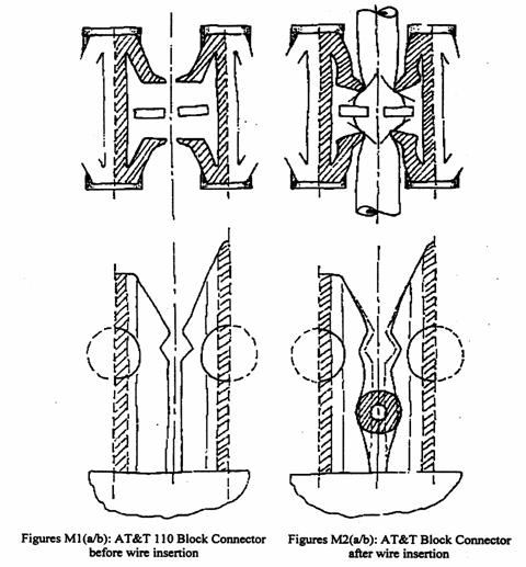
70 There are clear similarities between the idea which underlies the flanges in the AT&T connector and that which underlies the Patent. Much may depend upon the question of whether or not the AT&T connector was part of common general knowledge at the relevant time. We will return to this matter at a later stage.
His Honour’s reasoning
71 The primary judge considered separately the two aspects of inventiveness referred to above, namely combination in one feature of the wire retention and strain relief functions and the combination of integers in the patent. In summarising his Honour’s argument, we will also deal with these aspects separately.
Combination of wire retention and strain relief
72 His Honour first noted that Mr Douglas, who was called on behalf of 3M, had identified the need for effective strain relief as a constant problem to be addressed by all users of electrical conductors. The primary judge observed that the ITU trade show had provided the impetus for the invention claimed in the Patent. His Honour inferred that Australian representatives probably also attended the show as it was the largest of its kind held in the world. There was evidence that the general standard of engineering education in Australia in 1989 was comparable to that in the United States. From these matters his Honour inferred that the uninventive, but skilled worker in Australia would have appreciated that increases in the use of computers and the volume of data transmission would create greater demands on telecommunications distribution networks. The primary judge also concluded that such a person would have realised that these developments were likely to generate greater use of larger wire gauges in order to facilitate faster transmission of data and a consequential need for smaller wire counts. These conclusions are to some extent based upon the assumption that Mr Seidel’s expectation of increased demand was derived from the ITU trade show. We are not sure that the evidence supported that assumption. Mr Seidel said that he had been directed to produce a new connector by 3M’s senior staff who had attended the trade show and that he had personally identified the trends mentioned above. In any event, his Honour appears to have accepted that Mr Seidel had identified an industry need and that Mr Douglas had identified a similar need in Australia.
73 The primary judge considered that the flanges in the Krone connector performed both wire retention and strain relief functions “albeit not exclusively”. Other features of that connector also performed those functions. The flanges were not flexible in the sense described in the patent as they were made of rigid plastic. The primary judge then referred to the evidence of Mr Hunter. He was an expert in the design and manufacture of moulded plastic products. He also had limited experience in the design of electrical connectors. He said that a U-contact element would itself provide some resistance to both longitudinal and lateral forces as a result of the interaction between the walls of the slot and the cable. A number of approaches might be considered if it were thought necessary to provide additional means for resisting such forces. If size of the connector were a problem, that would tend to militate against the use of separate components to provide such additional resistance. It is a principle of the design of moulded products that the number of components should be minimised. Since the wire would be loaded into the connector from above, it was logical that any “integrally formed retaining element” be in the vertical plane. His Honour apparently also accepted at [210]:
“… that, if it were desired to improve the capacity of the slot to resist axial forces applied to the conductor, the sides of the slot would have to flex in the direction which resulted in resistance to the force. A method where co-planar resilient tongues or fingers hinge was merely one well-known way of achieving the required flexure.”
74 To this point, Mr Hunter appears to have accepted as “given” a number of aspects of 3M’s design criteria and of the ultimate design, namely:
· that connectors should provide increased wire retention and strain relief;
· that any new connector would have to meet certain size criteria;
· that for reasons of size, wire retention and strain relief features should be provided by one design element;
· that the new design should permit the cable to be loaded from above, probably because the above parameters suggested modification of the existing connector rather than an entirely new design; and
· that the starting point for the design should be a slot other than that in any U-contact element and that it should be designed to provide wire retention and strain relief, such re-design to include flexing sides.
75 We suspect that in assuming these things, Mr Hunter assumed the arguably inventive step. We will return to that matter at a later stage. Having directed himself as to the appropriate test for obviousness, the primary judge concluded:-
“212
Nonetheless, I infer from Mr Hunter’s evidence that if a team comprising the skilled persons I have identified were concerned to provide additional means for retaining conductors against both vertical and axial forces, then the idea of combining strain relief and wire retention as a single feature within a module was one that would simply be a logical product of known engineering and design principles. The process might involve some thought (it took Mr Seidel some five hours to come up with the idea) and it would be necessary to consider a number of different approaches. Some of these are exemplified in products forming part of the common general knowledge in 1989. I have referred to the Krone 10-pair modules. Other examples include the outer V-shaped slots in the Mini Picabond connector and the resiliently deformable flanges in the AT&T 110 connector.
213
It seems to me that all of these factors created an environment where the skilled worker would have appreciated the need for improved strain relief and wire retention. The skilled worker would have appreciated that there were a number of possible approaches to the problem. The choice of combining strain relief and wire retention in a single feature in a modular connector was one of the choices which would have been apparent, albeit after some inquiry and consideration, to a non-inventive skilled addressee comprising a team of the kind I have identified.”
76 At [215] his Honour continued:
“It follows that notwithstanding the generous approach to the concept of an inventive step established by the authorities, the idea of combining wire retention and strain relief as a single feature did not involve an inventive step in the relevant sense. It was merely a choice among a number of options that would have been apparent to the notional skilled worker concerned to seek additional means for retaining conductors against both vertical and axial forces.”
Combination of integers
77 Counsel for Tyco submitted to the primary judge that apart from any consideration of the AT&T 110 connector (the status of which as part of common general knowledge was in dispute), the combination embodied in the patent would have been obvious to the notional non-inventive skilled addressee at the priority date. Tyco submitted that the critical features of the combination were the use of flexible retaining elements within a modular connector where the elements form a slot to retain an insulated conductor against outward movement, whether the force be radial or axial, and where the elements deflect towards the contact element on insertion of the conductor. His Honour concluded that each of the components of the combination formed part of common general knowledge prior to 1998, observing that:
“In particular it was known that:
® multi-pair electrical connectors were in use;
® multi-pair connectors could be used to accommodate conductors of different diameters;
® both strain relief and wire retention could be provided by a slot;
® moulded plastics could be used to construct flexible retaining elements, including those operated by a hinge mechanism;
® flexible retaining elements could be used to retain tubular items;
® flexible retaining elements could be designed as an integral feature of a small object such as a connector; and
® flexible retaining elements could be used to provide a locking or gripping function on objects.”
78 His Honour then referred again to Mr Hunter’s evidence, observing:
“As I have noted, Mr Hunter, unlike Mr Douglas and Dr Stark, approached the question from the perspective of a team design. I have already referred to Mr Hunter’s evidence bearing on the inventiveness of the idea of combining strain relief and wire retention in a single feature... .”
79 His Honour’s meaning in speaking of Mr Hunter’s “perspective” is not clear. The notional non-inventive worker may properly be constituted by a team but Mr Hunter, even as a member of that team, could only offer opinions in areas within his personal expertise. It may be that his Honour was merely referring to Mr Hunter’s evidence concerning that area of expertise. However there would then have been no basis for comparing his evidence to that of Mr Douglas whose area of expertise appears to have been quite different.
80 The primary judge continued at [219]:
“Mr Hunter expressed the view that, given that a design team had been asked to implement such an idea, it was logical to employ integrally formed retaining elements in the same plane in which the contact slot is located. He also said that the use of a slot which narrows towards the top in order to impede vertical movement of a wire conductor was a common design practice before 1989.”
81 The expression “such an idea” seems to refer to the combination in one design feature of wire retention and strain relief capacities. The primary judge then referred to Mr Hunter’s evidence that the use of a slot which narrowed towards the top, so impeding vertical movement of the cable, was a common design practice prior to 1989 and cited the following passage from one of Mr Hunter’s affidavits:
“The slot may itself provide some, but perhaps insufficient, resistance to force applied to the conductor in the axial direction away from the point of contact between the conductor and the contact element. If one wished to improve on this then, to a designer, common sense would suggest that the sides of the slot should flex in a direction which results in resistance to such a force. Such flexing can only really be in a way where the flexure occurs in a direction towards the IDC contact when the wire is inserted. If the flexure were in the opposite direction, then this would not resist the conductor pulling away from the contact element and would defeat the object for which the flexure is sought …”.
82 This is a discussion of strain relief rather than wire retention. It assumes a slot with flexible sides. None of the identified common general knowledge (save possibly for the AT&T connector) demonstrated such an idea. The slots were all of metal or rigid plastic. The primary judge then cited Mr Hunter’s opinion that the methods by which flexure was achieved in the Patent and in the allegedly infringing product, “… were, in 1989 logical and routine choices for a designer having regard to the object to be achieved …”. Noting that such opinion could not be determinative of the issue of obviousness, the primary judge continued at [221]:
“Nonetheless, I think that Mr Hunter’s opinion, when considered in the context of all the evidence, supports the proposition that it would have been apparent to the non-inventive skilled worker (comprising the team I have identified) that it was worthwhile to try the combination of the integers ultimately embodied in claim 1 … .”
83 His Honour continued:
“222.
Mr Hunter’s evidence was consistent with the findings I have made as to the nature and extent of common general knowledge before the priority date. In particular, the use of a slot in a connector to provide strain relief and wire retention was, as Mr Yates submitted, an old combination. Mr Hunter’s view that it was a purely routine step for the design team to consider creating the slot by using flexible retaining elements which deform in the direction of the contact element seems to me to be consistent with the knowledge and experience that would be attributed to the members of the team, especially those skilled in the design and development of plastics and injection-moulded components.”
223.
The tapering of the slot was an obvious measure to improve wire retention, even though it may have presented some routine design problems in ensuring that the single feature was effective in providing both wire retention and strain relief.”
84 The primary judge then dealt with the evidence of other witnesses, making clear his preference for that of Mr Hunter. Having concluded that even without regarded to the AT&T 110 connector, obviousness was established, his Honour then considered the matter having regard to that piece of equipment (which he had found to be part of common general knowledge), observing at [227]:
“The AT&T 110 connector, although not having all the features of the patent-in-suit had many of them. In particular, it had resiliently deformable flanges that, as I have found, provided both strain relief and wire retention (although they were not the exclusive sources of strain relief). Each pair of flanges constituted a slot into which the conductor was placed”.
85 At p 228, the primary judge concluded:
“Given these characteristics and having regard to the evidence to which I have referred, it seems to me a very short step for the non-inventive skilled worker to consider it worthwhile to consider the combination of integers embodied in the patent. Making the slot narrower at the top so as to resist vertical forces was, as Mr Yates suggested, self-evident. Using one pair of resiliently deformable flanges or tongues instead of two can hardly be regarded as anything other than an unimaginative modification of an established technique in the same field. Dispensing with the connecting block falls into the same category.”
86 We are inclined to agree with this view, subject to resolution of the question as to whether the AT&T connector was part of common general knowledge at the relevant time.
Grounds of appeal
87 3M made the daunting assertion that the primary judge placed undue weight upon the evidence of some of Tyco’s witnesses, particularly that of Mr Hunter, and inadequate weight upon that of Mr Douglas. This superficially unattractive argument involved some criticism of the use by his Honour of the “team approach” to the question of identifying the skilled worker. However the precise nature of the criticism was not clear. In the end, it seemed to be that the claimed inventive step was not within Mr Hunter’s area of expertise. Superficially, one would expect that such a complaint should not be available, given the team approach and the constitution of the team. Any shortcomings in Mr Hunter’s expertise should have been met by reference to the expertise of other team members. However, in considering obviousness, his Honour relied almost exclusively upon Mr Hunter’s evidence. He may have been well-qualified to comment on the second of the possibly inventive steps identified by the primary judge, assembly of the integers. However the idea of combining wire retention and strain relief in one feature (the first suggested inventive step) appears to have been much more a product of experience in the use of connectors in the communications industry. As we have said, Mr Hunter assumed much of the thinking which had led Mr Seidel to that idea. We will return to this matter. It was submitted that Mr Hunter’s evidence was tainted by extensive reference to items of prior art which were not part of common general knowledge at the priority date. 3M also appealed against the finding that the AT&T connector was part of common general knowledge. Finally, it was submitted that the appropriate inference to be drawn from the admissible evidence was that the invention was not obvious.
The inventive step
88 We have previously referred to the two possibly inventive steps identified at first instance, namely the combination of wire retention and strain relief in one design feature and the combination of integers constituting the eventual claimed invention. The primary judge treated the first step as involving the idea that both functions could be performed by one feature without regard to the form which that feature might take. His Honour concluded that the idea of a combination of functions was obvious because there were numerous examples in common general knowledge of a slot being used to provide wire retention and strain relief. Clearly enough, the claimed invention differs substantially from that relatively crude device. The shoulders of the slot in a 3M2 connector and of that in the Picabond connector are made of metal and could not flex as required in the claimed invention. The “flanges” in the Krone connector are of rigid plastic and therefore are also not flexible. It is not clear from the evidence whether the slot in the Telecom equipment is made of plastic or metal. The Panduit connector is made of plastic which seems to be relatively rigid, but the evidence does not deal with the point. The claimed invention goes far beyond the use of a rigid slot. In particular:
· it involves use of flexible plastic;
· the tapered “slot”, being narrower at the top, provides additional wire retention;
· any difficulties in inserting the cable into the narrowed top of the “slot” are resolved by the tendency of the tongues to diverge; and
· once diverged, the tongues adopt positions which produce the so-called self-locking effect.
89 It should also be noted that the action necessary to produce these results is the same as that required to push a cable into a conventional U-contact element and that all of this is achieved in a way which permits the continued use of existing tools and within size parameters dictated by existing conditions. In our view, the arguably inventive step does not fall clearly into either of the two aspects identified by the primary judge. It rather stands astride the dividing line between them. It is the idea underlying the design of the tongues as a new feature of a connector.
THE SKILLED WORKER
90 3M does not directly challenge his Honour’s use of the team approach. However it argues that some care is necessary in its selection and use. The cases offer little guidance as to how a court should approach selection or subsequent use of such a team. Obviously, it cannot be self-selecting. In some cases, the selection may be at least closely associated with the inventive idea. Much of 3M’s criticism of Mr Hunter’s evidence concerned his assumption of the criteria identified by Mr Seidel, based upon the latter’s experience in the industry. Mr Hunter certainly seems to have assumed that many aspects of 3M’s design were “given”. An alternative view might have been that their identification was part of the inventive process. We also doubt whether Mr Douglas would have been able to develop the idea underlying the claimed invention. Just as Mr Hunter had no experience in using connectors, Mr Douglas had little or none in designing them.
91 The team approach is, of course, designed to solve a problem which requires the joint efforts of experts in more than one field. Such an approach must involve interaction between or amongst the experts so that common general knowledge can be shared. In this case the evidence did not deal with the way in which this process might have occurred. Mr Douglas focussed upon what he knew of connectors while Mr Hunter focussed upon how he would design a connector, given Mr Seidel’s criteria. Mr Douglas appears to have said little or nothing about how he would have gone about designing a connector to meet those criteria, with or without advice from somebody such as Mr Hunter. Mr Hunter seems to have said nothing about how he would have identified and utilized the knowledge of somebody such as Mr Douglas. Unfortunately, this hiatus in the evidence relates to the point at which any inventive step occurred.
92 This problem is a result of the way in the which the parties conducted the case. Obviously enough, 3M chose Mr Douglas because he was without any element of inventiveness. Mr Hunter was content to accept Mr Seidel’s instructions and, perhaps enlightened by hindsight, label his design as obvious. Of course the parties called other witnesses who may well have had something to add of relevance for present purposes. However his Honour appears to have relied, in this aspect of the case, largely upon the evidence of Mr Hunter. Absent evidence as to how the common general knowledge of people such as Mr Douglas and Mr Hunter might have been jointly utilized, his Honour seems to have chosen between the two approaches. In choosing that of Mr Hunter, he inevitably acted upon assumptions about matters which, in our view, lay at the heart of the claimed invention.
COMMON GENERAL KNOWLEDGE
93 We do not understand any aspect of his Honour’s findings in this area to be in dispute other than that concerning the AT&T 110 connector. At [198], the primary judge said:
“The affidavit evidence initially read on behalf of Tyco did not establish that the AT&T 110 connector was available in Australia before the priority date. I permitted Tyco to read an affidavit by Mr Freestone relatively late in the hearing. I did so after giving 3M an opportunity to make enquiries concerning Mr Freestone’s proposed evidence. 3M made diligent enquiries, but did not seek to cross-examine Mr Freestone or to adduce evidence at odds with his. Nor did it seek an adjournment to take its enquiries further.”
94 In par 128 of Mr Weir’s affidavit filed on 26 July 2000 he asserted:
“Exhibited to me and marked are exhibits JGW3 to exhibit JGW10 are examples of IDC connectors which I can say with confidence were available in Australia for purchase and use before the priority date.”
95 Exhibit JGW10 is the AT&T 110 block connector. Similarly, Mr Georgevits said at par 68 of his affidavit sworn on 14 June 2000:
“Now exhibited to me respectively are exhibits GG7 to GG13 which are examples of connectors which I know were available, and in commercial use, before the priority date.”
96 Exhibit GG8 is the AT&T 110 block connector. It seems that the trial proceeded upon the basis that these opinions were not sufficient to establish that this piece of equipment was relevantly part of common general knowledge. Nonetheless the primary judge inferred from the evidence of Mr Freestone and Mr Ward that it:
“formed part of the background knowledge and experience available to all in the relevant field considering the making of new electrical connectors or the making of improvements to old electrical connectors … .”
His Honour considered that this inference was reinforced:
“… by the composition of the hypothetical skilled worker in this case. It is further reinforced by evidence that the AT&T connector was widely known shortly after the priority date. It is a fair inference that the promotional activities of Honeywell Pty Ltd before the priority date were by no means insignificant. Having regard to Mr Douglas’s limited experience, I do not regard the fact that he could not recall seeing the AT&T connector prior to 1989 as being of significant weight on this issue.”
97 Before us, neither 3M nor Tyco suggested that any other evidence in the case supported the conclusion that the AT&T 110 connector was part of common general knowledge at the relevant time.
98 The decision of the High Court in Minnesota Mining and Manufacturing Co v Biersdorf Australia Ltd (1979-1980) 144 CLR 253 (the “3M case”) has long been accepted as defining the basis of obviousness for the purposes of the 1952 Act. Pursuant to par 100(1)(e) of that Act it was a ground of revocation that:
“… the invention, so far as claimed in any claim of the complete specification or in the claim of the petty patent specification, as the case may be, was obvious and did not involve an inventive step having regard to what was known or used in Australia on or before the priority date of that claim … .”
99 The words “what was known or used in Australia on or before the priority date of that claim” describe what is usually called “common general knowledge”. This expression was defined by Aickin J in the 3M case at 292 as follows:
“The notion of common general knowledge itself involves the use of that which is known or used by those in the relevant trade. It forms the background knowledge and experience which is available to all in the trade in considering the making of new products, or the making of improvements in old, and it must be treated as being used by an individual as a general body of knowledge.”
100 In Patents for Inventions and the Protection of Industrial Designs by T A Blanco White (5th ed) at par 4-207, the learned author observed:
“The term ‘common general knowledge’ is used in patent law to mean that which is ‘known to duly qualified persons engaged in that art or science’; or (in different words) that which is ‘part of the mental attitude of a well-instructed representative of the class to whom the specification is addressed’ and nothing else; or again, that which is ‘part of the mental equipment of those concerned in the art under consideration’.
…
Common general knowledge is normally proved by reference to commonly used books; or by reference to what students of the art are taught; or by evidence of expert witnesses generally. It is not sufficient to show that information was published in a document having wide circulation in the art concerned, unless that information is also shown to have been ‘generally accepted without question’ (or at least, ‘generally regarded as a good basis for further action’) by the bulk of those in the art, and this is unlikely unless the information was actually used. A practice established amongst an important section of those in the art is part of the ‘common general knowledge’ for this purpose even though others in the art may not know of it, for a claim is invalid if it claims what was obvious to some, although to others what it claims was not obvious.”
101 In ICI Chemicals and Polymers Ltd v Lubrizol Corporation Inc (1999) 45 IPR 577 at [111] - [112], Emmett J observed:
“111.
The notion of common general knowledge involves the use of that which is known or used by those who are in the relevant field or area. It forms the background knowledge and experience which is available to all in that field in considering the making of new products or making of improvements in old products. It must be treated as being used by an individual as a general body of knowledge … .
112.
The common general knowledge is the technical background to the hypothetical skilled worker in the relevant art. It is not limited to material which might be memorized and retained at the front of the skilled worker’s mind but also includes material in the field in which he is working which he knows exists and to which he would refer as a matter of course. It might, for example, include:
standard texts and handbooks;
standard English dictionaries;
technical dictionaries relevant to the field;
magazines and other publications specific to the field.”
102 The 3M case marked an Australian divergence from the English position concerning the meaning of the expression “what was known or used” for the purposes of determining an assertion of obviousness. In HPM Industries Pty Ltd v Gerard Industries Ltd (1957) 98 CLR 424, Williams J (sitting as a single justice), had held that the words “known” or “used” embraced more than the common general knowledge of a skilled worker in the relevant field at the priority date and included everything disclosed by the literature on the subject, including prior specifications. His Honour had relied upon English decisions in reaching that conclusion. However, in the 3M case, the High Court took a different view.
103 At 294 - 295, Aickin J observed:
“There may be some fields of endeavour in which those who work therein study and make themselves familiar with all patent specifications as they become available for inspection in one or in many countries so that what was contained therein becomes common general knowledge in that particular trade or field of manufacture in the country in question. … But this is not so in all fields or in all countries. There was no evidence in the present case that those working in Australia in the field of adhesives or of surgical tapes followed such a practice or that any of the specifications relied upon was part of the common general knowledge of those working in these fields in Australia.
The respondent relied upon a number of prior specifications which had been available in Australia for public inspection before the priority date as providing a basis for the argument that the invention claimed was obvious. For the reasons which I have set out above I do not regard such specifications as capable of sustaining that argument without evidence that they were part of common general knowledge at that time. There was no such evidence and accordingly it is not necessary for me to examine those specifications.”
104 The difference in approach is demonstrated by the decision of Waddell J in Windsurfing International Inc v Petit (1983) 3 IPR 449 and that of the Court of Appeal in Windsurfing International Inc v Tabru Marine (Great Britain) Ltd (1984) 3 IPR 498. In each case a plea of obviousness was based upon prior public use. Waddell J applied the 3M case and found that the prior use was not relevant to obviousness, primarily because it was not shown to have become part of common general knowledge. In the English case, prior public use was held to establish obviousness without such proof.
105 The evidence on this aspect of the case was at best, equivocal. Out of fairness to Tyco it is appropriate to refer to the affidavits themselves rather than to his Honour’s understandably brief summary. Mr Freestone was the general manager of a large manufacturer of electrical, electronic and data communication products, including electrical connectors. He held a certificate in electrical engineering from a South African college and had lived and worked in South Africa until 1986. He came to Australia in May of that year and from that time until the beginning of 1987 was employed by a firm of electrical engineers as an estimator. This involved him in some telecommunication and data communication work. In January 1987 he joined a company called Shuttle Data Com Pty Ltd, which company distributed Mod-Tap cabling products. He was initially Victorian sales manager and in 1988, he became national sales manager. He held the latter position until December 1989. He was responsible for the distribution in Australia of products which were manufactured by a United States corporation, Mod-Tap System Corporation, including electrical connectors.
106 He participated in regular seminars at which he was informed of new Mod-Tap products and received regular updating by “white papers”. These dealt with the theoretical aspects of structured cabling systems. He was also supplied with information concerning methods of effecting “interface” between the equipment of other manufacturers and the Mod-Tap system. He was familiar with competitors’ products. Mod-Tap System Corporation published a catalogue of its available equipment which was extensively promoted throughout Australia prior to April 1989. There were frequent seminars and workshops, usually attended by about 200 people, including representatives of competitors such as Honeywell. Mr Paul Andres, the International Sales Director of MOD-TAP System Corporation, regularly visited Australia and advised as to new products being developed by that company and its competitors. Mr Freestone said that in 1987 he was aware that Honeywell was promoting the AT&T cabling system known as the Premises Distribution System (“PDS”).
107 At some time in 1987 Mr Freestone attended the annual meeting of the Australian Telecommunications User Group (the “ATUG meeting”) in Sydney. This was a major cabling and trade show for those working in the telecommunication and data communication industry. At that time new cabling standards were being developed for commercial building cables, and there was considerable interest in cabling systems. He thought that between 600 and 1,000 people attended the meeting on each of its three days. Large international and local telecommunications and networking companies were represented and had stands exhibiting their products. He said that the AT&T connector was prominently displayed at the AT&T stand and that the stand was “well attended”. He paid particular attention to the AT&T 110 connector because Mr Andres had previously shown it to him and provided him with relevant literature. It was considered to be in serious competition with a MOD-TAP product. Mr Freestone said that prior to the ATUG meeting he had learnt that Honeywell was the exclusive distributor of the AT&T 110 connector and that it was using it in the PDS. He was also aware that MOD-TAP System Corporation was manufacturing products which were compatible with other manufacturers’ products. AT&T had licensed that company to use the AT&T 110 connector in its products, and it was using the IDC unit from that connector in its systems. In 1988, in Australia, Mr Freestone saw a prototype involving such use. Curiously, he said that in 1988, he was aware of certain aspects of the AT&T 110 connector design, having been shown it by Mr Andres and having seen it at the ATUG meeting. One wonders why he referred to his knowledge in 1988 rather than at any earlier time.
108 Mr Ward was the managing director of Jamsam Ltd, an importer, manufacturer and distributor of electronic goods, holding a degree in electrical engineering from the University of Technology in Sydney. From 1972 until 1979 he was employed at Amalgamated Wireless Australia Pty Ltd in technical positions relating to electrical engineering. From 1979 until October 1987 he was employed as a telecommunications engineer at the Overseas Telecommunications Commission in which capacity he supervised a number of people who installed telecommunications cables in telephone exchanges. In October 1987 he joined the Commonwealth Bank as a project manager in the Information Services Department. One of his roles was to design telecommunications facilities, including a “universal signal reticulation system” for the new computer centre at Burwood in New South Wales. In order to perform this task it was necessary that he be acquainted with the “practices of cabling and connections that were available in Australia at the time”.
109 He said that in early 1988 he became aware of the AT&T 110 connector block and subsequently visited the Honeywell premises at Waterloo in New South Wales to inspect it. During the visit he saw the connector as part of the PDS. He also saw a mock-up of the PDS and slides describing the AT&T 110 connector, as well as several other examples of it. He later incorporated the connector into the system being designed for the Burwood Computer Centre, the plans for which were submitted to the bank “by about May 1988”. In mid-1988 the system was tested on a small scale and then installed. The centre opened on 16 December 1988.
110 It is worth adding that Jane Maree Hogan, a solicitor employed by Freehills, 3M’s solicitors, gave evidence based on her enquiries. She said that the 1987 ATUG meeting was held early in April of that year. She also said that despite inquiries, 3M had been unable to discover any significant evidence as to the marketing of the AT&T connector in Australia at any relevant time. As we have observed, his Honour noted that the material upon which Tyco eventually relied in this regard was introduced into evidence at a late stage. Although 3M had an opportunity to respond, Ms Hogan’s affidavit demonstrates the difficulties which were understandably experienced given the passage of time since the events in question and the late stage at which the matter was raised. It seems that 3M tried to obtain documentation from Honeywell and also from Lucent Technologies Pty Ltd, to which AT&T had transferred some of its business. Honeywell identified Michael Gordon Adcock as an employee who had been involved in the PDS business conducted by that company. Mr Adcock was not aware of any sales records concerning AT&T block connectors. Honeywell “virtually exclusively sold systems, not discrete connectors in PDS.” Connectors were a minor part of such a system which was substantially composed of cabling. Honeywell had been selling the PDS for approximately two years prior to Mr Adcock joining the company in 1991. This suggests that Mr Freestone was in error in his belief that Honeywell was marketing its PDS prior to the ATUG meeting. Mr Adcock said that at the time he joined Honeywell, the revenue from its PDS business was about $10 million per annum.
111 Mr Freestone’s evidence focussed on the 1987 ATUG meeting. By that time he had some knowledge of the AT&T 110 connector and for that reason, paid particular attention to it when he saw it on the stand at the meeting. No doubt, as he suggested, a substantial number of people attended the meeting, but it is difficult to know how significant those numbers were in the absence of any evidence as to the size of the skilled workforce in the industry. It is also impossible to know how many of the 600 to 1,000 people who attended on each day of the meeting would have been relevantly skilled persons or how representative they were of such persons in the industry. Mr Freestone asserted that the AT&T 110 connector was featured on the AT&T stand and that the stand was well patronized, but it is impossible to infer from these subjective assessments that those visiting the stand looked at the product sufficiently closely to have identified the relevant aspects of it. After all, the question must be whether or not the strain relief and wire retention features of the AT&T component became part of common general knowledge as a result of its exhibition. No doubt many people would have looked in a general way at the equipment without necessarily identifying such features.
112 Mr Freestone also referred to a catalogue of Mod-Tap products which was widely distributed within Australia. However there is no evidence to suggest that the relevant features of the AT&T 110 connector were disclosed in it. As to the suggestion in par 16 of his affidavit that Honeywell was distributing their PDS prior to the ATUG meeting and that it contained the AT&T 110 connector, there was really no evidence as to the extent of such distribution. Ms Hogan’s information (derived from Mr Adcock) suggested that it was first marketed in 1989. There was no evidence as to when the Mod-Tap product, which also included the AT&T connector, was first marketed in Australia or as to the extent of such marketing. It is of some significance that notwithstanding Mr Ward’s involvement in the industry prior to 1988, he did not become aware of the AT&T 110 connector until early in that year. This suggests that the disclosure made at the ATUG meeting had no impact upon his share of common general knowledge. If Honeywell was, at that time, marketing the PDS which included the AT&T connector, there was no evidence as to the extent of that marketing, save that Mr Ward acquired the product for the Commonwealth Bank’s use. Such use itself could hardly have resulted in the product becoming widely known throughout the industry.
113 We were not referred to evidence from any of the experts called in this case as to the status of the AT&T connector as part of common general knowledge. Disclosure at a trade meeting may lead to particular information becoming part of common general knowledge. If such information were disclosed in a paper, for example, and if the evidence established wide distribution of the paper thereafter, or even that the relevant group of skilled workers was well-represented at the meeting, there may well be a basis for inferring that the information became so widely known and accepted as to be part of common general knowledge. Public use may be a different matter, especially where the relevant information comprises only one aspect of the equipment in question. Some disclosures will be more likely than others to result in incorporation of relevant information into common general knowledge . Incorporation may be inferred, but it may not be assumed.
114 We are well aware of the need to accord due deference to opinions as to matters of fact formed by a trial judge. He or she has usually seen the witnesses and developed a deep understanding of the case, often over a period of days, if not weeks. It is not always possible for members of an appellate court to acquire the same depth of understanding. However, where the question is one of inference from largely undisputed facts, an appellate court cannot always avoid assessing the trial judge’s view in light of that which it has itself formed. This is such a case. In our view there was insufficient evidence to justify the conclusion that the AT&T connector was part of the relevant common general knowledge as at the priority date. It should have been possible to ascertain the extent to which the AT&T connector had been distributed prior to that date. Similarly, it should have been possible to obtain anecdotal evidence from relevant engineers and technicians as to their knowledge of it, however derived. Such evidence would have had direct bearing upon the question of whether it had become part of common general knowledge.
Was the inventive step obvious?
115 Mr Seidel set out to design a connector which was compatible with existing tooling and available space, had improved wire retention and strain relief and was able to accommodate a range of cable sizes. These criteria suggested modification of the existing connector rather than a wholly new design. The limitation as to size also led to the requirement that wire retention and strain relief functions should be performed by one feature. Tyco’s argument seems to have been that Mr Seidel’s solution was little more than an improvement in the design of the slot found in a U-contact element and similar rigidly formed slots used in the prior art to provide wire retention and strain relief. Perhaps unfortunately, the Patent also refers to the aperture between opposite tongues as a “slot”. Whilst this may be accurate as far as it goes, it has led to a tacit assumption that this aperture is a slot in the same sense as are those in the prior art. Those slots provide wire retention and strain relief by virtue of the way in which their rigid sides interact with the cables. The claimed invention’s capacity to perform those functions depends upon the capacity of the tongues to deflect and then tend to return to their original positions. That is what is meant by the words “resiliently deformed” in Claim 1. It is achieved by the use of plastic and the design of the hinge joining the tongue to the wall of the channel. Metal and rigid plastic would be unsuitable materials for use in the invention.
116 In order to provide wire retention, Mr Seidel identified the (perhaps obvious) idea of making the aperture narrower at its top than at its bottom. This differs from whatever was taught by the use of a rigid slot which either reduced in width from top to bottom or remained of constant width. The Panduit connector was an exception to this, but it did not combine strain relief and wire retention in one feature. Any difficulty in inserting a cable through the narrow mouth of the aperture in the Patent is accommodated by the design of the tongues which causes them to diverge as the cable is inserted, widening the mouth. As to strain relief, the diverged tongues tend to return to their original positions, pressing on the insulation of the cable. If the tongues were to diverge away from the contact element, any longitudinal force applied in that direction would, at least in part, have the effect of forcing the tongues to move in the same direction on their hinges, thus opening the aperture wider and reducing the force applied to the cable by them. On the other hand, if the tongues diverge towards the contact element, then such longitudinal force causes the tongues to move on their hinges towards their original positions, thus clamping them more tightly on to the cable, which clamping effect tends to resist the longitudinal force.
117 The claimed invention is not merely a re-designed slot. It is a new approach to the problem, differing from the approaches demonstrated in the prior art. It is no answer that relevant principles and design techniques were known in the plastics industry. This inventive step is not unlike that underlying the electric frying pan of which Windeyer J said in Sunbeam Corporation v Morphy-Richards (Australia) Pty Ltd supra at 115:
“Approaching the question in this way then, there were, as I have said, before 1953 many forms of electrically heated appliances - some of them, such as kettles, used in cooking; and the use of thermostats to control heat generated by electricity was well known. In one sense, all that was done by Mr Jepson, the inventor of the patented article, was to heat a frying pan standing on legs by electricity and provide it with a thermostat, and to do so he had only to arrange a number of well-known things - that, it may be said, was a matter of design not of invention. That there was a stage at which the final form of the appliance was evolved by work on the drawing board in the design office of the Sunbeam Corporation was proved. This did not, of itself, impress me as evidence of inventiveness. What was being done at that stage was not so much experimenting to solve a problem as designing to get a commercial product. But in cases of this kind inventiveness consists in conceiving an idea and giving it a practical embodiment. It is not a question simply of the degree of mechanical ingenuity needed to produce an article, but rather of the exercise together of imagination and ingenuity. This is not a case of solving an old problem or satisfying a long-felt want. It is rather a case of conceiving that an electric frying pan would be a useful article, envisaging the features it must have to make it practically useful, and by ingenuity in the combination of known devices producing a new and useful thing, a frying pan having the desired features.”
118 Just as there was an ongoing need for means to cook food, so there was an ongoing need for wire retention and strain relief in connectors. The Patent identified a new feature able to provide wire retention and strain relief. It was different from anything previously known in this area, although aspects of it may have been known, and the underlying principles were well-known. The idea was to design a feature which provided both wire retention and strain relief using plastic tongues, designed to deform resiliently. With the benefit of hindsight, it may be possible to say that each of the steps taken in the design was logical, but that does not mean that the claimed inventive step was obvious. The evidence does not lead us to that conclusion. Mr Douglas said that the Patent provided “an elegant solution to the problems posed …” and that the solution was “simple, effective and efficient”. We find no difficulty in adding the epithet “inventive”. In our view the patent does not fail for obviousness.
RESULT OF THE APPEAL
119 It follows that, in so far as 3M appeals from the dismissal of its claims based on alleged infringement of the Patent by Tyco, the appeal should be dismissed. However, in so far as 3M appeals from the order of the primary judge that the Patent be revoked, the appeal should be upheld and, in lieu of that order, there should be an order that the cross claim be dismissed.
120 3M should pay Tyco’s costs of the claim for infringement. Tyco should pay 3M’s costs of the cross claim. There should be no order as to the costs of the appeal.
| I certify that the preceding one hundred and twenty (120) numbered paragraphs are a true copy of the Reasons for Judgment herein of the Court. |
Associate:
Dated: 18 October 2002
| Counsel for the Appellant | Mr D. Catterns QC & Ms K.Howard |
| | |
| Solicitor for the Appellant | Freehills |
| | |
| Counsel for the Respondent: | Mr D. Yates SC & Ms A. Bowne |
| | |
| Solicitor for the Respondent: | Mallesons Stephen Jaques |
| | |
| Date of Hearing: | 8, 9 August 2002 |
| | |
| Date of Judgment: | 18 October 2002 |

