FEDERAL COURT OF AUSTRALIA
Becton Dickinson Pty Ltd v B. Braun Melsungen AG [2018] FCA 1692
Table of Corrections | |
Para [259] first sentence “indication” be amended to read “insertion” | |
ORDERS
DATE OF ORDER: |
THE COURT ORDERS THAT:
1. The originating application be dismissed.
2. The amended notice of cross-claim be dismissed.
3. Claims numbered 14 and 26 in Australian Patent No 2012244163 be revoked.
4. Claim numbered 17 in Australian Patent No 2012244164 be revoked.
5. Claim numbered 10 in Australian Patent No 2013201814 be revoked.
6. The amended notice of further cross-claim be otherwise dismissed.
7. Within 14 days, the parties file and serve (by way of exchange) brief written submissions (limited to 3 pages in length) on questions of costs.
8. Within 21 days, the parties file and serve (by way of exchange) brief written submissions in reply (limited to 2 pages in length) on questions of costs.
9. Upon the respondent, by its counsel, undertaking to the Court during the period of the stay:
A. to prosecute any appeal expeditiously; and
B. forthwith to serve on the Commissioner of Patents copies of these orders pursuant to s 140 of the Patents Act 1990 (Cth) with a request that particulars of Orders 3, 4 and 5 (“the Revocation Orders”) be registered in accordance with section 187 of the Patents Act 1990 (Cth),
the Revocation Orders be stayed:
(a) initially for a period of 21 days from today; and
(b) if an appeal from any of the Revocation Orders is lodged within that period, until the final determination of that appeal or further order.
Note: Entry of orders is dealt with in Rule 39.32 of the Federal Court Rules 2011.
NICHOLAS J:
Background
The proceeding
1 The respondent (“Braun”) is the patentee of three Australian patents (“the Patents”) no AU2012244163 (“the 163 Patent”) filed 23 October 2012, no AU2012244164 (“the 164 Patent”) also filed 23 October 2012, and no AU2013201814 (“the 814 Patent”), filed 22 March 2013. Each of the Patents is entitled “Catheter insertion device” and relates to an intravenous (“IV”) catheter designed to reduce the risk of needle stick injuries and the outflow of a patient’s blood from the catheter. Mr Kevin Woehr is the sole inventor named in the Patents.
2 The applicant (“Becton”) commenced this proceeding against Braun alleging that Braun had made unjustified threats contrary to s 128 of the Patents Act 1990 (Cth) (“the Act”). Braun brought a cross-claim alleging that Becton had infringed various claims (“the relevant claims”) of the Patents by selling in Australia (inter alia) an intravenous catheter known as the “Insyte Autoguard BC” (“the BD device”). Becton has also filed a cross-claim seeking revocation of each of the relevant claims.
3 Braun alleges that Becton has infringed the following claims:
the 163 Patent: claims 14 (in so far as it is dependent on claim 9) and 26;
the 164 Patent: claims 10-12, 15-20, 24-25 and 28-30;
the 814 Patent: claims 1-2, 4-6, 8-13, 17-18 and 21-23.
4 Becton denies that it has infringed any of the relevant claims. In total there are 15 integers in dispute in the infringement case.
5 Becton also contends that each of the relevant claims is invalid and should be revoked. The grounds of invalidity relied upon are lack of novelty, lack of fair basis and lack of inventive step.
6 Each of the Patents claims a priority date of 4 July 2002 through (inter alia) Australian Patent No 2009238275 (“the Parent”). Becton contends that, on the construction of the relevant claims propounded by Braun, none of them is entitled to the priority date claimed on the basis that there is no real and reasonably clear disclosure in the Parent of what is claimed. It is accepted by Braun that if the relevant claims are not entitled to the asserted 4 July 2002 priority date, and if the BD device is within any of the relevant claims, then any such claim will be invalid for lack of novelty based upon the sale of the BD device in the patent area commencing in September 2011.
7 There is also an issue in the proceeding as to whether the relevant claims are not fairly based on the matter described in the complete specification of the Patents in which the relevant claim appears contrary to s 40(3) of the Act as it stood prior to its amendment by the Intellectual Property Laws Amendment (Raising the Bar) Act 2012 (Cth).
Intravenous catheters
8 Intravenous catheters are mainly used for the puncture of superficial veins to provide access to a vein for more than just a single injection or blood withdrawal. These devices usually include a steel needle and a plastic catheter. After accessing the vein with the needle, the needle is removed and discarded and the plastic catheter stays in the patient. The catheter is commonly then hooked up to a drip line to give intravenous therapy to the patient.
9 The usual first step to using an intravenous catheter on the arm of a patient is to put a tourniquet around the upper arm and apply a pressure that makes the superficial veins visible. The patient is asked to close his or her fist two or three times which causes the veins to appear on the back of the hand and on the lower forearm. A vein is then punctured, and the blood runs through the hollow steel needle until blood appears at the rear end of the transparent needle hub. The appearance of blood in the needle hub (sometimes called “blood flashback”) indicates to the user that the vein has been successfully punctured. At this stage, the catheter (that is the catheter system with the needle) is not inserted with its full length completely in the vein, because pushing it forward risks further perforation of the vein with the steel needle. After the vein has been successfully punctured, the steel needle is then drawn back and the plastic catheter alone is pushed forward into the vein. Normally the user puts his or her finger on the tip of the catheter to avoid blood flowing out of the catheter and then takes out the steel needle and places it down or discards it. If infusion therapy is to be administered, the user then takes the drip line, connects it to the catheter, and fixes the drip line in place by applying an adhesive bandage or a film to the patient’s arm.
10 There is a particular risk with needle stick injuries from intravenous catheters. Because the needle becomes filled with the blood of the patient, and the needle is relatively large, the risk of infection from contact with a patient's blood is much higher than with normal hypodermic needles.
11 Safety intravenous catheters are devices which, in some manner, protect the needle tip of the used needle of the intravenous catheter.
The Witnesses
Dr Hans Haindl
12 Dr Haindl was called by Braun. He is a medical device consultant who is both a medical doctor and a mechanical engineer. He has worked in the medical devices field since the early 1980’s including for Braun, its affiliated companies and various competitors. Much of his practical work and advisory work involves solving problems relating to medical devices in collaboration with device manufacturers and medical personnel.
13 Dr Haindl holds a degree in mechanical engineering conferred in 1974 by the University of Hannover, Germany, and an MD (Doctor of Medicine) conferred in 1979 by the Hannover Medical School Germany. His thesis for his medical degree, published in 1972, is entitled “Central Venous Catheters Compared” and compares different venous catheters that were on the market in Europe at that time. He practiced as a medical doctor between 1980 and 1986 and designed or developed various medical devices during that period.
14 Between 1987 and 1990 Dr Haindl was employed by Braun as its head of research and development for “medical disposables”. During this period he worked on the development of various catheters and related devices including a new type of needle bevel to be used with port catheters for which he received royalty payments from Braun until about 2012.
15 Dr Haindl has worked on a large number of design projects for various companies since 1991 including Johnson & Johnson, Baxter, Braun and Fresenius. He first became involved with safety intravenous catheters while working for Johnson & Johnson in about 1991 or 1992 when Johnson & Johnson launched a product known as “Protect IV”. According to Dr Haindl, this product was an “active” safety catheter which the user was required to activate in order to obtain protection from needle stick injuries.
16 Although Dr Haindl was not familiar with any of the Patents in suit until he was retained to act as an expert witness for Braun in this proceeding, he was familiar with the detailed description of the invention (including the drawings) in the Patents which appears in various other Braun patents in relation to which he has given evidence in other proceedings.
Mr Mark Crawford
17 Mr Crawford was called by Becton and gave evidence on the issues of construction, infringement and inventive step.
18 Mr Crawford obtained his qualifications and experience in the USA. Mr Crawford has a Bachelor of Arts Degree in Biology from the University of Utah and began his career working as a cardiovascular technician. His role expanded into project management and product development when Becton Dickinson in the USA (“Becton USA”) purchased his employer Deseret Medical in 1986. Mr Crawford worked for Becton USA from 1987 until 2007.
19 In his role at Becton USA, Mr Crawford was responsible for project management and product development of products including IV catheters, arterial catheters, accessor devices, adapters, plugs, central venous catheters and peripherally inserted central catheters. He was also responsible for working with Becton’s patent attorneys in relation to IV catheters and related areas. In early 2002, Mr Crawford qualified as a US patent agent.
Mr Chris Cindrich
20 Mr Cindrich was called by Becton. He gave evidence on the issues of construction, infringement and common general knowledge.
21 Mr Cindrich obtained his qualifications and experience in the USA. Mr Cindrich obtained a Bachelor of Industrial Design in 1995. He worked for Becton USA from 1996 until 2007 as an industrial designer in research and development in the field of infusion therapy, where he was involved in the design of IV catheters as well as peripherally inserted central catheters and mid-line IV catheters.
Professor David Bihari
22 Professor Bihari was called by Becton, and gave evidence on issues of common general knowledge.
23 Professor Bihari is qualified medical doctor and specialist intensive care physician. He has worked as a doctor in the United Kingdom (from 1978 to 1987) and in Australia (since 1987).
24 As an intensive care specialist, Professor Bihari is highly skilled in the use of IV catheters within the specialised environment of a hospital’s intensive care unit.
25 Between 1989 and 2002, Professor Bihari was part of a clinical trial team focused on providing clinical feedback and assessment on arterial and central venous catheters being developed in Munich by a company called Pulsion Medical Systems.
26 Professor Bihari’s evidence addressed the types of catheters used in medical practice in Australia as at July 2002 and also the areas of concern for clinicians using IV catheters at that time.
Mr Craig Wilson
27 Mr Wilson was called by Becton, and gave evidence on issues of common general knowledge.
28 Mr Wilson has a Bachelor of Applied Science and a Bachelor of Industrial Design. He has worked as a medical device design consultant since 1989 including for two years in the United Kingdom. Since 1991 he has been based in Australia.
29 In 2002 Mr Wilson ran an industrial design consultancy firm based in Sydney and was involved in the design of a wide range of medical devices including “sharps” protection devices such as trays for passing “sharps” devices between medical personnel. His company designed the DonorCare needle guard for use in relation to blood collection needles on blood bags, and the Platypus needle guard for apheresis dialysis needle applications.
Dr Philip Esnouf
30 Dr Esnouf was called by Braun. He gave evidence on issues of construction and inventive step.
31 Dr Esnouf has been an Australian qualified medical doctor since 1979 and since that time has worked in various hospitals in Australia in surgical roles and also in private practice as a general practitioner. Throughout his time working in hospitals, a regular part of his daily duties involved inserting intravenous catheters into patients.
32 Dr Esnouf has invented and designed a number of products in the medical field, and between around 1994 and 2004 he invented or co-invented a range of medical devices. During his career Dr Esnouf developed a practical understanding of tooling for the manufacture of medical devices, including maintaining his own laboratory with equipment to make moulds and prototypes.
33 If Dr Esnouf had been approached in around July 2002 and asked to develop an IV catheter which mitigated the risk of needle stick injuries occurring as a result of use of the catheter, he would have considered himself qualified to take on this project based on his medical training, his background knowledge of engineering, his experience in developing medical devices, and his experience in using IV catheters and observing others who did so.
Mr Leones and Mr North
34 Mr Leones and Mr North are both patent attorneys employed by Freehills Patent Attorneys who gave evidence for Becton concerning patent searches conducted by them at Becton’s request that were relied upon by Becton on the issue of inventive step. Neither of them was cross-examined.
The Patents
35 There is a large measure of uniformity in what appears in the complete specification of each of the Patents. It is common ground that the text and drawings in each of the Patents are almost exactly the same except that the claims and matching consistory statements are quite different.
36 Each of the Patents commences with a statement incorporating by reference the disclosure of the complete specification of Australian Patent Application No 2004238275 as originally filed. It is common ground that this is a reference to the Parent. Accordingly, the contents of the Parent form part of the disclosure in the body of each of the Patents.
The Parent
37 The Parent is entitled “Catheter Insertion Device”. The invention is said to relate to such a device. This is followed by the brief description of prior art and a problem associated with it. The Parent states at page 1 lines 5 to 10:
A device of this kind is known from EP 352 928, wherein in a hollow catheter hub a needle guard element is arranged. On withdrawal of the hollow needle from the catheter over an engaging means near the tip of the hollow needle, the needle guard element engages with the engaging means and covers the tip when the hollow needle is separated from the catheter. In this design, after withdrawal of the hollow needle from the catheter, through this catheter blood can issue with which the operating personnel can come into contact.
The Parent also states at lines 11 to 14:
An object of the invention is to provide a catheter insertion device of the type described above such that an outflow of blood from the catheter is prevented after removal of the hollow needle with the needle guard element.
38 I will return to the European Patent No 352 928 (“the 928 Patent”) later in these reasons. It is sufficient to note at this point that there is a dispute between the parties as to whether it is permissible to have regard to the 928 Patent for the purpose of interpreting the Patents.
39 The Parent includes the following consistory statement at page 1, lines 16 to 31:
Accordingly, this invention provides a catheter insertion device comprising
an approximately hollow-cylindrical catheter hub to whose distal end a catheter is attached,
a needle hub having a hollow needle attached thereon and extending in the ready position through the catheter hub and the catheter,
a check valve through which the hollow needle extends in the ready position and which automatically closes after the needle is removed, and
a needle guard element arranged displaceably on the needle and engaging with the needle near the needle tip when the hollow needle is removed from the catheter hub,
a valve actuating element displaceably guided in the catheter hub and arranged proximally of the check valve arranged in the catheter hub and having a hollow cylindrical space for receiving the needle,
wherein the needle guard element is arranged in the hollow cylindrical space of the valve actuating element and has an engaging section which engages with an engaging means provided on the inner circumference of the valve actuating element when the hollow needle is removed from the catheter hub.
40 This is followed by two further passages at page 2, lines 1-6 and lines 7-9 that state:
It will be apparent that in accordance with the invention after withdrawal of the hollow needle from the catheter the latter can be reliably closed such that an outflow of blood is prevented, while simultaneously the tip of the hollow needle is securely covered by the needle guard element so that the operating personnel cannot injure themselves on the needle tip.
Exemplary embodiments of the invention are explained in more detail below with reference to the drawing …
41 The opening words of the corresponding passage in the Patents makes express reference to preferred embodiments. They state “[i]t will be apparent that in accordance with preferred embodiments of the invention [etc] …”.
42 There was a debate as to whether the statement at page 2, lines 1-6 constitutes a statement of the invention or a statement of an advantage or advantages of the invention. This is a significant question that I will return to later in these reasons.
43 The statement at page 2 lines 1 to 6 is followed by a reference to “exemplary embodiments of the invention” explained in more detail by reference to 10 drawings. I shall refer to this more detailed explanation as the detailed description. It is important to recognise, of course, that what is described in the detailed description are preferred (or “exemplary”) embodiments of the invention which may take other forms.
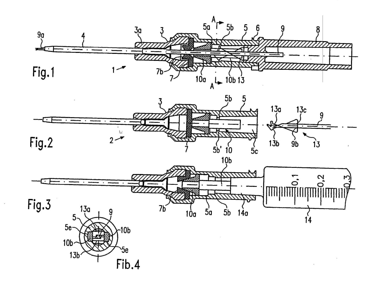
44 The Parent identifies drawings at page 2, lines 11 to 21 as follows:
Fig. 1 shows a longitudinal section through a catheter insertion device in the ready position,
Fig. 2 shows the catheter insertion device with the hollow needle removed,
Fig. 3 shows the device with an attached syringe,
Fig. 4 shows a sectional view along the line A-A in Fig. 1,
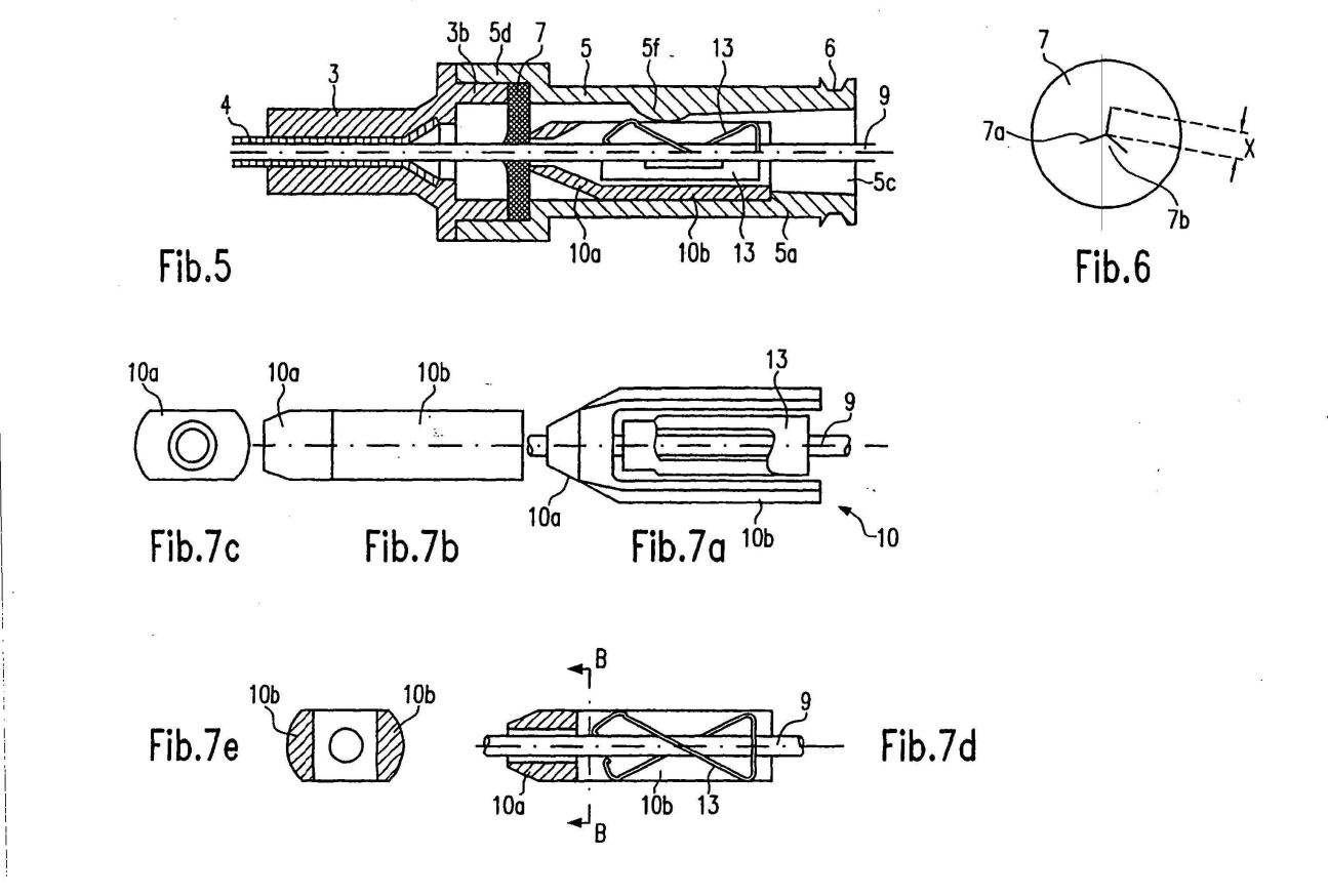
Fig. 5 shows a longitudinal section through another embodiment,
Fig. 6 shows a view of the valve disc,
Fig. 7 shows different views of a valve actuating element,
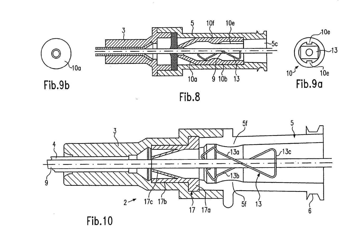
Fig. 8 shows a longitudinal section through a further embodiment,
Fig. 9 shows front views of the valve actuating element of Fig. 8, and
Fig. 10 shows a longitudinal section through a further embodiment.
Copies of the drawings (Fig 1-Fig 10) are also reproduced in Annexure A to these reasons.
45 After the detailed description of the preferred embodiments, the following statements appear at page 7, lines 19 to 28:
Throughout this specification and the claims which follow, unless the context requires otherwise, the word “comprise”, and variations such as “comprises” and “comprising”, will be understood to imply the inclusion of a stated integer or step or group of integers or steps but not the exclusion of any other integer or step or group of integers or steps.
The reference in this specification to any prior publication (or information derived from it), or to any matter which is known, is not, and should not be taken as an acknowledgment or admission or any form of suggestion that that prior publication (or information derived from it) or known matter forms part of the common general knowledge in the field of endeavour to which this specification relates.
The Detailed Description
46 Except where otherwise stated, the page and line numbers cited in these reasons are to the page and line numbers for the Parent.
47 The complete specification for each of the Patents and the Parent are virtually identical except for the consistory statements and the claims.
48 The detailed description in the body of the specification describes four embodiments of the invention. The first (“Embodiment 1”) is described at page 2 line 23 to page 5 line 9, the second (“Embodiment 2”) at page 5 line 11 to page 6 line 4, the third (“Embodiment 3”) page 6 lines 6 to 14 and the fourth (“Embodiment 4”) at page 6 line 16 to page 7 line 17.
49 With reference to Fig 1 and Fig 2, the catheter insertion device (1) of Embodiment 1 includes a catheter hub (2) of two parts consisting of a distal hub element (3) and a proximal hub element (5). The catheter (4) is fitted into a holding section (3a) of the distal hub element. The proximal end of this element (3) has an enlarged diameter which is overlapped by the distal end of the proximal hub element (5). At the proximal end of this element (5) is an attachment means known as a Luer thread (6).
50 Between the distal and proximal hub elements (3, 5) is a check valve in the form of a valve disc (7) fixed in place by these two hub elements. Figure 6 shows a valve disc with three slits (7a) that form elastic flaps (7b) which can be expanded by the hollow needle.
51 In the ready position, the hollow needle (9) extends through the proximal hub element, the check valve, the distal hub element, and the catheter, with the needle tip (9a) located at the distal end of the device. At its proximal end, the needle is fixed to a needle hub (8) inserted into the proximal end of the proximal hub element (5).
52 Within the proximal hub element, between the needle hub and the valve disc, there is a displacably arranged valve actuating element (10) with a truncated cone shaped locating section (10a) which opens the valve disk (as shown in Fig 3) and a plunger section (10b) that has a hollow space which receives the needle guard element (13). The plunger section (10b) is in the form of two spaced plungers into which a spring clip is inserted as shown in the cross-sectional view in Fig 4.
53 The needle guard element is in the form of the spring clip (13) with two spring arms (13a, 13b) as shown in Fig 1 when in the ready position. Upon engagement of the spring clip following withdrawal of the needle, the two spring arms cover the needle tip as shown in Fig 2.
54 After insertion of the catheter into the vein, the needle is withdrawn through the catheter and the catheter hub as the user pulls the needle hub in the proximal direction. An engaging means (9b) shown in Fig 2 located near the needle tip (which may consist of a lightly crimped radical projection on the needle) engages with the outer circumference of a bore in the rear wall (13c) of the spring clip. This allows the spring clip to be removed from the catheter hub with the needle, and with the needle tip completely covered and protected by the two spring arms of the spring clip. In this way the catheter insertion device provides protection against needle stick injury.
55 Once the needle tip has been withdrawn through the valve disc in the catheter hub, the elasticity of the valve disc causes it to close. This prevents blood flowing through the valve disc and into the proximal hub element in the direction of the user. In this way the catheter insertion device provides blood control protection by reducing the risk of contamination from infected blood that would otherwise spill out of the proximal end of the catheter hub.
56 Once the needle is fully withdrawn and the needle tip is protected and covered by the spring clip, it may be disposed of. A syringe or tube with a suitable fitting may then be connected to the catheter hub by means of the Luer thread.
57 Figure 3 shows a syringe that has been inserted into the proximal end of the catheter hub. The neck of the syringe (14) pushes against the valve actuating element (10) and presses it against the disc valve which displaces the flaps (7b) so as to open the valve. The contents of the syringe can then pass through the valve disc, into the distal hub element via the catheter and into the vein of the patient. When the syringe is withdrawn the valve disc will once again close.
58 With reference to Figs 5-7e, Embodiment 2 includes a modified catheter hub consisting of two modified hub elements (3, 5) and a modified valve actuating element (10). The valve actuating element is in a U-shaped form with a spring clip (13) inserted in it. The valve actuating element includes two plunger sections (10b) that extend into a locating section 10(a) at its distal end. As shown in the sectional view in Fig 7d, the needle (9) passes between the plunger elements, the spring clip, and into the locating section. It then passes through the valve disk (7) and into the catheter (3). In this embodiment, the hub element (5) includes a projection (5f) which, as shown in figure 5, projects inwards at diametrically opposite positions on the bore (5c) of the hub element and fixes the spring clip in the hub element until the spring arms spring over the needle tip when the needle is removed from the catheter hub.
59 Embodiment 3, as shown in Figs 8-9b, has a modified valve actuating element (10) in which the spring clip (13) is positioned. The valve actuating element (10), in this embodiment, incorporates inwardly projecting ribs (10e) which protrude radially into the bore (5c) of the hub element (5) as shown in Figs 8 and 9a.
60 Embodiment 4 includes a modified check valve (17) in the form of a “duck-bill” valve which includes two opposite flaps (17c) that are elastically deformable and which close when the needle is withdrawn. In this embodiment, there is no actuating element for opening the valve. The valve is instead opened by the pressure of fluid from the syringe (14). As illustrated in figure 10, the proximal hub element (5) in this embodiment includes a projection (5f) which extend radially inwards and hold the spring clip (13) until the spring arms spring back radially inwards to cover the needle tip.
61 There are a number of observations worth recording at this point in relation to the described preferred embodiments.
62 First, all of the described devices are of the “over the needle” variety in which the hollow needle extends through the interior of a catheter and a catheter hub assembly. This arrangement allows for the needle to be pulled along its longitudinal axis in the catheter and the catheter hub assembly, and for the needle tip to be withdrawn through the catheter and the catheter hub assembly.
63 Secondly, all of the described devices provide a form of needle stick protection that is achieved automatically by the withdrawal of the needle (ie. without any additional action by the operator) through the catheter and catheter hub assembly where the needle tip is covered by a needle guard element. They are all what I shall refer to as “passive” devices in which the needle stick protection is achieved by the operator drawing the needle through the catheter and catheter hub assembly. There were numerous other well-known devices available before the priority date that required the user to take some additional step to activate the needle stick protection mechanism. I shall refer to these devices as “active” devices.
64 Thirdly, in all of the described devices the needle tip protection is achieved by the withdrawal of the needle through the catheter hub assembly where the needle tip is protected by a needle guard element before the needle is fully withdrawn from the catheter hub assembly.
65 Fourthly, the embodiments described are all similar in arrangement and operation to the catheter insertion device described at page 1, lines 5 to 10 and said to be known from the 928 Patent but without providing any blood control protection. In particular, they all utilise a form of needle tip protection that involves covering a needle tip with a guard.
66 I should note that Mr Shavin QC (who appeared with Mr Heerey QC for Braun) made the point that the terms “passive” and “active” are not used in any of the Patents. That is true. However, the distinction between passive and active devices is one that was made by the expert witnesses when explaining how various prior art devices operate.
The Claims
The 163 Patent
67 The 163 Patent includes a number of consistory statements that mirror the language of various claims including 9, 14 and 26 for:
9. A catheter insertion device comprising:
a catheter hub comprising an interior cavity, an opening at a proximal end, and a catheter tube attached thereto and extending from a distal end;
a needle having a needle shaft defining a needle axis projecting distally of an end of a needle hub, said needle projecting through the catheter tube and comprising a needle tip;
a valve for regulating fluid flow positioned inside the interior cavity of the catheter hub for regulating fluid flow into the interior cavity; said valve remaining inside the interior cavity of the catheter hub when the needle is removed from the catheter tube and the catheter hub and said valve being in contact with a valve actuating element when in an open position for fluid flow; and
a needle protective device for preventing unintended needle sticks, said needle protective device positioned in-line with the catheter hub and the needle hub and having at least a portion extending distally of the proximal end of the catheter hub.
…
14. The catheter insertion device of any one of claims 9 to 13, wherein the needle protective device comprises a resilient portion made from a metal material for moving the needle protective device from a ready position to a protected position.
…
26. A catheter insertion device comprising a catheter hub comprising an interior cavity, an opening at a proximal end, and a catheter tube attached thereto and extending from a distal end; a needle having a needle shaft defining a needle axis projecting distally of an end of a needle hub, said needle projecting through the catheter tube and comprising a needle tip; a valve for regulating fluid flow positioned inside the interior cavity of the catheter hub for regulating fluid flow into the interior cavity; said valve remaining inside the interior cavity of the catheter hub when the needle is removed from the catheter tube and the catheter hub; a needle protective device for preventing unintended needle sticks, said needle protective device positioned in-line with the catheter hub and the needle hub and having at least a portion extending distally of the proximal end of the catheter hub; and wherein the needle protective device comprises a resilient portion for moving the needle protective device from a ready position to a protected position.
The 164 Patent
68 The 164 Patent also includes a number of consistory statements that mirror the language of various claims. These claims include 10-12, 15-20, 24-25 and 28-30 for:
10. A catheter insertion device comprising:
a catheter hub comprising an interior cavity, a perimeter defining an opening at a proximal end, and a catheter tube having a distal end opening extending distally of the catheter hub;
a needle having a needle shaft defining a needle axis projecting distally of an end of a needle hub, said needle projecting through the catheter tube and comprising a needle tip;
a valve configured to obstruct fluid flow comprising a slit positioned inside the interior cavity of the catheter hub and having a distal surface pushed against a shoulder in the interior cavity; said valve remaining inside the interior cavity when the needle is removed from the catheter tube and the catheter hub;
a valve actuating element slidingly disposed in the catheter hub configured to actuate the valve, the valve actuating element comprising a nose section having a tapered end with an opening configured to push the valve to open the slit and at least two plunger elements extending proximally of the nose section and having a gap therebetween; wherein the at least two plunger elements with the gap therebetween are disposed distally of the proximal end of the catheter hub and are slidable distally when a male implement projects into the opening of the catheter hub to transfer a distally 10 directed force to the nose section to push the valve to open the slit;
a needle protective device positioned proximal of the valve and at least in part around the needle and distal of the proximal end of the needle hub in a ready position and configured to prevent unintended needle sticks in a protective position.
11. The catheter insertion device of claim 10, wherein the valve has a radial outer perimeter abutting the interior cavity of the catheter hub.
12. The catheter insertion device of claim 10 or claim 11, wherein the valve comprises three slits that converge at a single point.
…
15. The catheter insertion device of any one of claims 10 to 14, wherein the valve actuating element further comprises a projection located proximally of the tapered nose section and projects radially outwardly of the nose section and engaging a shoulder of the catheter hub.
16. The catheter insertion device of claim 15, wherein the projection is distal of the two plunger elements.
17. The catheter insertion device of any one of claims 10 to 16, wherein the needle protective device comprises an arm that is located, at least in part, in the catheter hub.
18. A catheter insertion device comprising:
a catheter hub comprising an interior cavity comprising a shoulder, an opening at a proximal end, and a catheter tube attached thereto and extending from a distal end;
a needle having a needle shaft defining a needle axis projecting distally of an end of a needle hub, said needle projecting through the catheter tube and comprising a needle tip;
a valve configured to obstruct fluid flow positioned inside the interior cavity of the catheter hub; said valve remaining inside the interior cavity of the catheter hub when the needle is removed from the catheter tube and the catheter hub;
a valve actuating element slidingly disposed in the catheter hub for actuating the valve, the valve actuating element comprising a nose section having a tapered end configured to open the valve, a projection on the valve actuating element located proximally of the tapered nose section engaging the shoulder of the catheter hub, and a plunger end extending proximally of the nose section having one or more gaps to permit fluid flow to flow therebetween and to transfer a distally directed force to the nose section to open the valve;
a needle protective device positioned, at least in part, around the needle between the valve and the proximal end of the needle hub in a ready position and configured to prevent unintended needle sticks in a protective position.
19. The catheter insertion device of claim 18, wherein the plunger end comprises at least two plunger elements defining the at least one or more gaps.
20. The catheter insertion device of claim 18 or claim 19, wherein the valve comprises three slits that converge at a single point.
…
24. The catheter insertion device of claim 19 or any one of claims 20 to 23 when dependent on claim 19, wherein the projection is distal of the at least two plunger elements.
25. A catheter insertion device comprising:
a catheter hub comprising an interior cavity comprising a shoulder, an opening at a proximal end, and a catheter tube attached thereto and extending from a distal end;
a needle having a needle shaft defining a needle axis projecting distally of an end of a needle hub, said needle projecting through the catheter tube and comprising a needle tip;
a valve comprising one or more slits configured to obstruct fluid flow positioned inside the interior cavity of the catheter hub; said valve remaining inside the interior cavity of the catheter hub when the needle is removed from the catheter tube and the catheter hub;
a valve actuating element slidingly disposed in the catheter hub for opening the one or more slits and actuating the valve, the valve actuating element comprising a nose section having a tapered end configured to open the valve and a plunger end extending proximally of the nose section having at least one gap to permit fluid flow to flow thereacross and to transfer a distally directed force to the nose section to open the valve;
a needle protective device positioned, at least in part, around the needle between the valve and the proximal end of the needle hub in a ready position and configured to prevent unintended needle sticks in a protective position.
…
28. The catheter insertion device of any one of claims 25 to 27, further comprising a fluid path between a distal most end of the valve actuating element and a proximal most end of the valve actuating element.
29. The catheter insertion device of any one of claims 25 to 28, further comprising a second gap in the plunger end.
30. The catheter insertion device of any one of claims 25 to 29, further comprising a projection that extends radially outwardly of the valve actuating element for engaging a shoulder in the catheter hub.
The 814 Patent
69 The 814 Patent also includes various consistory statements the language of which mirror various claims including 1-2, 4-6, 8-13, 17-18 and 21-23 for:
1. A catheter insertion device including:
a catheter hub comprising an interior cavity, an opening at a proximal end, and a catheter tube attached thereto and extending from a distal end;
a needle having a needle shaft defining a needle axis projecting distally of an end of a needle hub, said needle projecting through the catheter tube and comprising a needle tip;
a valve sized and shaped to obstruct fluid flow through the catheter hub comprising a wall surface comprising a slit positioned inside the interior cavity of the catheter hub and abutting a shoulder in the interior cavity of the catheter hub; said valve remaining inside the interior cavity when the needle is removed from the catheter tube and the catheter hub;
a valve actuating element slidingly disposed in the catheter hub to actuate the valve and having a longitudinal passage therethrough for the needle shaft, the valve actuating element comprising a nose section having a tapered end for pushing the valve to open the slit of the valve and at least two plunger elements extending proximally of the nose section, the plunger elements having a gap therebetween to permit fluid flow to flow therethrough; the two plunger elements structured to transfer a distally directed force to the nose section to push the valve to open the slit;
a needle protective device spaced from the needle tip in a ready position and movable relative to the needle tip to a protective position, at least in part, distally of the needle tip to prevent unintended needle sticks.
2. The catheter insertion device of claim 1, wherein the valve is generally round.
…
4. The catheter insertion device of claim 1, wherein the valve actuating element further includes a projection located proximally of the tapered nose section and projects radially outwardly of the nose section and abuts a shoulder of the catheter hub.
5. A catheter insertion device including:
a first hub comprising an interior cavity, a perimeter defining an opening at a proximal end, and a catheter tube having a distal end opening extending distally of the first hub:
a needle having a needle shaft defining a needle axis projecting distally of an end of a second hub, said needle projecting through the catheter tube and comprising a needle tip;
a valve sized and shaped to obstruct fluid flow comprising a slit positioned inside the interior cavity of the first hub and having a distal surface pushed against a shoulder in the interior cavity; said valve remaining inside the interior cavity when the needle is removed from the catheter tube and the first hub;
a valve actuating element slidingly disposed in the first hub to actuate the valve and having a longitudinal passage therethrough for the needle shaft, the valve actuating element comprising a projection, a nose section having a tapered end with an opening structured to push the valve to open the slit, and at least two plunger elements extending proximally of the nose section, the plunger elements having a gap therebetween; wherein the at least two plunger elements with the gap therebetween are disposed distally of the proximal end of the first hub and are slidable distally when a male implement projects into the opening of the first hub to transfer a distally directed force to the nose section to push the valve to open the slit;
a needle protective device positioned proximal of the valve and at least in part around the needle and distal of the proximal end of the second hub in a ready position, the needle protective device is moveable to prevent unintended needle sticks in a protective position.
6. The catheter insertion device of claim 5, wherein the valve has a radial outer perimeter abutting the interior cavity of the catheter hub.
…
8. The catheter insertion device of claim 5, wherein the projection is located proximally of the tapered nose section and projects radially outwardly of the nose section and abuts a shoulder of the catheter hub.
9. The catheter insertion device of claim 4 or claim 8, wherein the projection is distal of the two plunger elements.
10. The catheter insertion device of claim 1 or claim 5, wherein the needle protective device has an arm that is located, at least in part, in the catheter hub.
11. A catheter insertion device comprising:
a catheter hub comprising an interior cavity comprising a shoulder, an opening at a proximal end, and a catheter tube attached thereto and extending from a distal end;
a needle having a needle shaft defining a needle axis projecting distally of an end of a needle hub, said needle projecting through the catheter tube and comprising a needle tip;
a valve comprising a slit and sized and shaped to obstruct fluid flow through the catheter positioned inside the interior cavity of the catheter hub; said valve remaining inside the interior cavity of the catheter hub when the needle is removed from the catheter tube and the catheter hub;
a valve actuating element slidingly disposed in the catheter hub for actuating the valve and having a longitudinal passage therethrough for the needle shaft, the valve actuating element comprising a nose section having a tapered end being sufficiently rigid to open the valve, a projection on the valve actuating element located proximally of the tapered nose section abutting the shoulder of the catheter hub, and a plunger end extending proximally of the nose section, the plunger end having one or more gaps therein to permit fluid flow to flow therethrough and to transfer a distally directed force to the nose section to open the valve;
a needle protective device positioned, at least in part, around the needle between the valve and the proximal end of the needle hub in a ready position, the needle protective device being moveable to prevent unintended needle sticks in a protective position.
12. The catheter insertion device of claim 11, wherein the plunger end has at least two plunger elements defining the at least one or more gaps.
13. The catheter insertion device of any one of claims 1, 5 or 11, wherein the valve has three slits that converge at a single point.
…
17. The catheter insertion device of claim 11, wherein the projection is distal of the two plunger elements.
18. A catheter insertion device comprising:
a catheter hub comprising an interior cavity comprising a shoulder, an opening at a proximal end, and a catheter tube attached thereto and extending from a distal end;
a needle having a needle shaft defining a needle axis projecting distally of an end of a needle hub, said needle projecting through the catheter tube and comprising a needle tip;
a valve comprising one or more slits movable to obstruct fluid flow positioned inside the interior cavity of the catheter hub; said valve remaining inside the interior cavity of the catheter hub when the needle is removed from the catheter tube and the catheter hub;
a valve actuating element slidingly disposed in the catheter hub for opening the one or more slits and actuating the valve, the valve actuating element having a longitudinal passage therethrough for the needle shaft and comprising a nose section having a tapered end made of a sufficiently rigid material to open the valve, a projection extending in a radial direction relative to a longitudinal length of the valve actuating element, and a plunger end extending proximally of the nose section, the plunger end having at least one gap therein to permit fluid flow to flow therethrough and to transfer a distally directed force to the nose section to open the valve; a needle protective device positioned, at least in part, around the needle between the valve and the proximal end of the needle hub in a ready position, the needle protective device being moveable to prevent unintended needle sticks in a protective position.
…
21. The catheter insertion device of claim 18, further comprising a fluid path between a distal most end of the valve actuating element and a proximal most end of the valve actuating element.
22. The catheter insertion device of claim 21, further comprising a second gap at the proximal plunger section.
23. The catheter insertion device of claim 22, wherein the projection abuts a shoulder in the catheter hub.
The Construction Issues
The relevant principles
70 There was no dispute between the parties as to the relevant principles of construction. These were summarised by the Full Court (Hill, Finn and Gyles JJ) in Jupiters Ltd v Neurizon Pty Ltd (2005) 222 ALR 155 at [67]:
…
(i) the proper construction of a specification is a matter of law: Décor Corporation Pty Ltd v Dart Industries Inc (1988) 13 IPR 385 at 400;
(ii) a patent specification should be given a purposive, not a purely literal, construction: Flexible Steel Lacing Co v Beltreco Ltd (2000) 49 IPR 331; [2000] FCA 890 at [81] (Flexible Steel Lacing); and it is not to be read in the abstract but is to be construed in the light of the common general knowledge and the art before the priority date: Kimberley-Clark Australia Pty Ltd v Arico Trading International Pty Ltd (2001) 207 CLR 1; 177 ALR 460; 50 IPR 513; [2001] HCA 8 at [24];
(iii) the words used in a specification are to be given the meaning which the normal person skilled in the art would attach to them, having regard to his or her own general knowledge and to what is disclosed in the body of the specification: Décor Corporation Pty Ltd at 391;
(iv) while the claims are to be construed in the context of the specification as a whole, it is not legitimate to narrow or expand the boundaries of monopoly as fixed by the words of a claim by adding to those words glosses drawn from other parts of the specification, although terms in the claim which are unclear may be defined by reference to the body of the specification: Kimberley-Clark v Arico at [15]; Welch Perrin & Co Pty Ltd v Worrel (1961) 106 CLR 588 at 610; Interlego AG v Toltoys Pty Ltd (1973) 130 CLR 461 at 478; the body of a specification cannot be used to change a clear claim for one subject matter into a claim for another and different subject matter: Electric & Musical Industries Ltd v Lissen Ltd [1938] 4 All ER 221 at 224–5; (1938) 56 RPC 23 at 39;
(v) experts can give evidence on the meaning which those skilled in the art would give to technical or scientific terms and phrases and on unusual or special meanings to be given by skilled addressees to words which might otherwise bear their ordinary meaning: Sartas No 1 Pty Ltd v Koukourou & Partners Pty Ltd (1994) 30 IPR 479 at 485–6 (Sartas No 1 Pty Ltd); the court is to place itself in the position of some person acquainted with the surrounding circumstances as to the state of the art and manufacture at the time (Kimberley-Clark v Arico at [24]); and
(vi) it is for the court, not for any witness however expert, to construe the specification; Sartas No 1 Pty Ltd at 485–6.
71 Plain language must be given its plain meaning, and clear words in a claim must not be given an unnatural meaning by imposing glosses drawn from the body of the specification. However, the context in which the relevant language is used is of crucial significance to the ascertainment of its meaning. When construing a patent specification the Court seeks to give the document a purposive construction by reading the document as it would be understood by a person skilled in the art and without engaging in overly meticulous verbal analysis. It is worth repeating what Lord Hoffman said on the topic of purposive construction in Kirin-Amgen Inc v Hoechst Marion Roussel Ltd (2004) 64 IPR 444 at [34]:
“Purposive construction” does not mean that one is extending or going beyond the definition of the technical matter for which the patentee seeks protection in the claims. The question is always what the person skilled in the art would have understood the patentee to be using the language of the claim to mean. And for this purpose, the language he has chosen is usually of critical importance. The conventions of word meaning and syntax enable us to express our meanings with great accuracy and subtlety and the skilled man will ordinarily assume that the patentee has chosen his language accordingly. As a number of judges have pointed out, the specification is a unilateral document in words of the patentee’s own choosing. Furthermore, the words will usually have been chosen upon skilled advice. The specification is not a document inter rusticos for which broad allowances must be made. On the other hand, it must be recognised that the patentee is trying to describe something which, at any rate in his opinion, is new; which has not existed before and of which there may be no generally accepted definition. There will be occasions upon which it will be obvious to the skilled man that the patentee must in some respect have departed from conventional use of language or included in his description of the invention some element which he did not mean to be essential. But one would not expect that to happen very often.
72 There is a danger that in seeking to give a claim a purposive construction, or in seeking to read it in context, an impermissible gloss might be imposed upon the language used based on material found in the body of the specification: see Sachtler GmbH & Co KG v RE Miller Pty Ltd (2005) 65 IPR 605 at [42], Tramanco Pty Ltd v BPW Transpec Pty Ltd (2014) 105 IPR 18 (“Tramanco”) at [175]. However, as was noted in Kimberly-Clark Australia Pty Limited v Multigate Medical Products Pty Limited (2011) 92 IPR 21 at [47]:
The part of a patent specification which is put forward by the patentee as a general description or summary of the invention may have a significant role to play in the construction of a claim which is open to different interpretations. This is because the general description or summary of the invention will often describe the invention by reference to features that the skilled addressee would understand to be common to all possible embodiments of the invention.
73 There are three further principles to which I should also refer.
74 First, in a combination patent, the invention resides not merely in the collocation of particular integers, but also in the manner in which those integers interact. In Welsh Perrin & Co Pty Ltd v Worrell (1961) 106 CLR 588 Dixon CJ, Kitto and Windeyer JJ said at 612 that in a patent for a combination:
.. the most important function of the body of the specification is to show what are the mechanical means which, operating together, produce the result claimed; and how they so operate.
Each of the Patents is for a combination in the sense explained by Aickin J in Minnesota Mining and Manufacturing Company v Beiersdorf (Australia) Limited (1980) 144 CLR 253 (“3M”) at 266 because it:
… combines a number of elements which interact with each other to produce a new result or product. Such a combination may be one constituted by integers each of which is old, or by integers some of which are new, the interaction being the essential requirement.
75 Secondly, a construction according to which the invention will work is to be preferred to one according to which it will not work: Martin v Scribal Pty Ltd (1954) 92 CLR 17 at 97.
76 Thirdly, in construing a claim, the Court should disregard the alleged infringing article and not construe a patent claim with an eye to the alleged infringement.
77 Both parties relied on Crennan J’s statement of the relevant principles in Pharmacia Italia SPA v Mayne Pharma Pty Ltd (2005) 222 ALR 552. The question in that case was what did “reconstituted from a lyophilizate” mean. After referring to the judgment of Sheppard J in Decor Corp Pty Ltd v Dart Industries Inc (1988) 13 IPR 285, her Honour said at [56]-[59]:
[56] Particularly relevant are the principles that the specification as a whole must be read and the context of a specification may qualify the prima facie meaning of a word or expression in a claim. If a word used in a claim is not a term of art, by reference to the technical knowledge possessed by persons skilled in the art, and is used in a plain, clear and unambiguous way in a claim, there should be no resort to the body of the specification to aid in the construction of the claim: Welch Perrin and Co Pty Ltd v Worrel (1961) 106 CLR 588 at 610; Electric & Musical Industries Ltd v Lissen Ltd (1936) 54 RPC 23 at 41. That principle is subject to the proviso that any lack of clarity or ambiguity in a claim can be resolved by resort to the body of the specification: Interlego AG v Toltoys Pty Ltd (1973) 130 CLR 461 at 457–8 (per Barwick CJ and Mason J); Décor at 391; Marconi v Mullard (1923) 40 RPC 159 at 175.
[57] There is no inconsistency in the principles governing construction of patent specifications as explained by Hely J in Flexible Steel Lacing Co v Beltreco Ltd (2000) 49 IPR 331; [2000] FCA 890 at [73]–[76] and especially [78]. It is as true of patent specifications, as of statutes (or any documents), as noted by Viscount Simonds in Attorney-General v Prince Ernest Augustus of Hanover [1957] AC 436; [1957] 1 All ER 49:
... words, and particularly general words, cannot be read in isolation: their colour and context are derived from context [at AC 461; All ER 53] ... the elementary rule must be observed that no one should profess to understand any part of a statute or of any other document before he has read the whole of it. Until he has done so he is not entitled to say that it or any part of it is clear and unambiguous [at AC 463; All ER 55].
[58] Similarly, the meaning of a word in a particular context may involve some limitation on its application in a patent claim, but such a meaning can only be derived from the context in which the word is used: see some examples, Henriksen v Tallon [1965] RPC 434 at 445 (per Reid LJ); Minnesota Mining at CLR 261ff; ALR 32; IPR 233–4, esp CLR 272; ALR 41–2; IPR 241–2 (per Aickin J) and Décor at 410–11 (per Sheppard J).
[59] The word “reconstituted” as it appears in the relevant expression in claim 1 is not a term of art used to refer to the dissolution of a lyophilized product so as to produce a solution suitable for intravenous injection shortly thereafter. It is clear however that both the word “reconstituted” and the expression of which it forms a part in claim 1 are used in a special sense in the specification. Alternatively, because the word is capable of more than one meaning it lacks clarity. It is permissible to have resort to the body of the specification both to see whether a word or expression has a special meaning or whether it requires clarification because the ordinary, or usual, meaning is not sufficiently precise. To find a word or expression is used in a special sense it is only necessary that an intention to so use the word or expression is plainly indicated in the specification: Minerals Separation North American Corporation v Noranda Mines (1952) 69 RPC 81 at 96.
The 928 Patent
78 In its submissions on construction, Becton made extensive reference to a copy of the 928 Patent that was admitted into evidence in the absence of any objection by Braun. However, it is important to point out that the 928 Patent is neither incorporated by reference nor shown to be common general knowledge as at the claimed priority date.
79 Becton was unable to refer me to any authority which supports its reliance on the 928 Patent for the purpose of construction. Braun submitted that it is not permissible to refer to the 928 Patent for that purpose. I agree. In the circumstances, I will ignore the 928 Patent except insofar as its contents are disclosed at page 1, lines 5-10 as that passage would be understood by the notional skilled addressee armed only with the Patents, the Parent (which is incorporated by reference) and the common general knowledge.
The fifteen construction issues
80 There is a total of fifteen construction issues to be resolved each of which are gathered around five topics:
(a) the meaning of “needle protective device”;
(b) the location of the needle protective device;
(c) the movement of the needle protective device;
(d) the valve;
(e) the valve actuating elements.
Needle protective device
Construction Issue 1
81 The first construction issue concerns the meaning of the words “needle protective device” as used in claim 26 of the 163 Patent.
82 The same issue arises in relation to:
claim 14 (as dependent on claim 9) of the 163 Patent;
claims 10 (and claims 11-12 and 15-17 as dependent on claim 10), 18 (and claims 19-20 and 24 as dependent on claim 18) and 25 (and claims 28-30 as dependent on claim 25) of the 164 Patent;
claims 1 (and claims 2, 4, 9, 10 and 13 as dependent on claim 1), 5 (and claims 6, 8-10 and 13 as dependent on claim 5), 11 (and claims 12-13 and 17 as dependent on claim 11) and 18 (and claims 21-23 as dependent on claim 18) of the 814 Patent.
83 The term “needle protective device” is not used anywhere in the Parent. It uses the term “needle guard element”. The Patents use both terms, however, the term “needle protective device” appears only in the consistory statements and the claims including claims 14 and 26 of the 163 Patent, claims 10, 18 and 25 of the 164 Patent and claims 1, 5, 11 and 18 of the 814 Patent. The consistory statements also use the term needle protective element.
84 Braun submitted that a “needle protective device” is a device which operates to cover or otherwise preclude accidental access to the needle tip to prevent a healthcare worker from pricking him or herself on the needle tip (needle stick injuries) after the needle is withdrawn from the patient and the catheter hub. It submitted that needle guard element and needle protective device were interchangeable terms that have the same meaning.
85 It was submitted by Braun that the word “element” did not qualify the words “needle guard” except to say that the needle guard is an element of the catheter insertion device claimed. It submitted that the term needle guard element describes a needle guard that is an element of the catheter insertion devices described. I accept that submission.
86 Becton submitted that the term needle guard element has a special meaning that derives from the introductory passages at page 1 of the 163 Patent. In particular, it relied on the use of the term needle guard element:
in the 275 Patent that is said in the first paragraph of the 163 Patent to be incorporated by reference;
the discussion of the 928 Patent in the third paragraph of the 163 Patent and the reference to needle guard element in that paragraph;
the statement of the object of the invention appearing in the fourth paragraph on page 1 of the 163 Patent and its reference to the needle guard element.
87 Becton also relied on the passage at page 3 lines 11-15 of the 163 Patent, which is the same as what appears at page 3 lines 1-6 of the Parent quoted above.
88 Becton submitted that these passages suggested that the term needle guard element was used to describe a particular type of needle guard that covers the needle tip after the needle is withdrawn from the catheter.
89 However, the question for present purposes is what do the words needle protective device as used in the relevant claims mean. These words are different from those used to describe the needle guard element referred to in the Parent. While there is no reason to think that these differences in language do not reflect deliberate choices on the part of those who drafted the Patents, it does not necessarily follow that two different terms should not be given the same meaning.
90 I accept Braun’s submission that the term needle guard element describes a needle guard that is an element of a catheter insertion device. But I do not consider that has any significance for the purpose of ascertaining the meaning of the term needle protective device. Needle protective device is not a term of art nor is it a term that has any special meaning to the notional skilled addressee beyond the meaning conveyed when read in the context of a description of a catheter insertion device.
91 I do not think it is permissible to read down the words needle protective device by reference to the words needle guard element and the use made of the latter term in the Patents.
92 So far as the question of construction is concerned I am satisfied that the term needle protective device as used in the relevant claims refers to a device that provides protection from needle sticks. This reflects the plain and ordinary meaning of the language used.
Location
Construction Issue 2
93 The second construction issue concerns the meaning of the following words as used in claim 17 (as dependent on 10) of the 164 Patent:
… the needle protective device comprises an arm that is located, at least in part, in the catheter hub …
94 The same issue arises in relation to claim 10 (as dependent on 5) of the 814 Patent although in that claim the word “has” appears instead of the word “comprises”.
95 Each of the relevant claims require that the needle protective device comprise an arm that is located, at least in part in the catheter hub.
96 Ultimately there was little difference between the parties as to what the word “arm” means in the context of the relevant claims. Braun submitted that the word arm should be given its ordinary meaning which, in the present context, refers to something that resembles an arm in form or function. Becton relied on the Shorter Oxford English Dictionary which defines an arm, relevantly, as “a part of an apparatus which resembles an arm in shape, disposition, or function”. I am satisfied that the word “arm” is used in the relevant claims in accordance with that definition.
Construction Issue 3
97 The third construction issue relates to the meaning of the following words as used in claims 14 (as dependent on 9) and 26 of the 163 Patent:
… a needle protective device … having at least a portion extending distally of the proximal end of the catheter hub …
98 The issue is whether in the context of the relevant claims, the term “proximal end” means the proximal end plane or face of the catheter hub, or the proximal end region of the catheter hub.
99 Braun submitted that the relevant claims also refer to the “proximal end” of “an opening” and that, in context, the “proximal end” of such an opening is the most proximal plane or face of the opening. Braun relied on oral evidence of Dr Haindl who considers the point at which there is such an opening is a “definitive frontier”. At that point, as Dr Haindl explained, the “opening” divides the space at the “proximal end” into two alternatives, being either outside the opening, or inside it. Dr Esnouf similarly considers that in the context of the relevant claims, it makes more sense for the proximal end to be a point or face, otherwise the starting point for determining when a part of the needle protective device is said to extend distally at the proximal end would be “indeterminate”.
100 Claim 26 of the 163 Patent uses the term “proximal end” twice, once to refer to an opening at a proximal end of an interior cavity, and once to refer to the proximal end of the catheter hub. The expert evidence relied on Braun focused on the first of these references, it being suggested that the proximal end of an opening was the most proximal plane or face of the opening. It was submitted that the second reference to proximal end should likewise be understood as referring to the most proximal plane or face of the catheter hub.
101 Becton submitted that the “proximal end” of the catheter hub refers to a region rather than a specific plane or face. This is how Mr Crawford and Mr Cindrich understand “proximal end of the catheter hub”. Becton submitted that the patent specification provides some assistance as what these words mean. At page 4 lines 3-6 of the 163 Patent it is stated:
The proximal end of the hub element 3 has an enlarged diameter with regard to the distal end and forms a connecting section with a hub element 5 whose distal end overlaps the proximal end of the hub element 3 and which is provided at its proximal end with a Luer thread 6.
(emphasis added)
102 Becton submitted that the patent specification, by contemplating that the “ends” of elements could overlap, is using the word “end” to mean an “end region”.
103 In his oral evidence Dr Haindl said in relation to the passage at page 4 lines 3-6 of the patent specification:
There is no general rule what a formulation like a proximal end means. The meaning must be defined from the context. To give an example, 163 says on page 4, line 5 to 6, which is provided at is proximal end with a Luer thread 6. That means the hub is provided at its proximal end with a thread. This thread has a certain length. So the proximal end cannot be understood as a definite point. It must be understood as a region.
104 However, Dr Haindl went on to say that the reference to the “opening” in the relevant claims “at a proximal end” was referring to a specific plane or face of the opening. Dr Esnouf made the same point.
105 One difficulty with Braun’s submission is that the relevant claims do not refer to a proximal end of an opening. Rather, they refer to an opening at a proximal end of the catheter hub. It is not the position of the opening (or the face or place of the opening) that defines the location of the proximal end.
106 The relevant claims also refer to the “distal end” and, in particular, a catheter tube attached to the catheter hub “and extending from a distal end”. I note that the catheter tube in the preferred embodiment depicted in the drawings (Fig 2(4)) does not extend from the most distal point of the device which is located where at the tip of the needle (9a). This also suggests that when the claim refers to the “proximal end” or the “distal end” that it is referring to a region rather than a precisely defined end-point.
107 In my view Becton’s construction of the relevant claims is to be preferred. The relevant claims should be understood as referring to an opening in the region of the “proximal end” of the interior cavity. Similarly, the “proximal end” of the catheter hub should be understood as referring to that same region rather than a definite point defined by the face of the opening. In my view the passage in the specification at page 4 lines 3-6 supports this construction.
Construction Issue 4
108 The fourth construction issue concerns the meaning of the following words as used in claim 10 (and 11-12 and 15-17 as dependent on 10) of the 164 Patent:
… a needle protective device positioned proximal of the valve and at least in part around the needle and distal of the proximal end of the needle hub …
109 The same issue arises in relation to claim 5 (and 6, 8-9 and 10, 13 as dependent on 5) of the 814 Patent except that it uses the words “second hub” rather than “needle hub”.
110 The words are readily understandable when applied to the preferred embodiments. The needle protective device, which in the detailed description of the preferred embodiment is in the form of a spring clip (referred to as the needle guard element) is positioned around the circumference of the needle between the valve and the proximal end of the needle hub when the catheter insertion device is in the ready position. The words “at least in part” make it clear that the needle protective device need not wholly surround the circumference of the needle. This is consistent with the arrangement depicted in the drawings.
111 Braun submitted that the qualifying words “at least in part” qualify not only the words “around the needle” but also the words “and distal of the proximal end of the needle hub”. In other words, Braun submitted that the relevant integer should be read as requiring that only part of the needle protective device had to be positioned distal of the proximal end of the needle hub.
112 Braun submitted that the relevant claims require the needle protective device to be both at least in part around the needle and at least in part distal of the proximal end of the needle hub in a ready position. Braun submitted that claim 18 of the 164 Patent supports this construction of the relevant claims. For the reasons stated below in relation to the meaning of that claim I do not think this submission should be accepted.
113 In my view the words “at least in part” as they appear in the relevant claims qualify the words “around the needle” but not “distal of the proximal end”. This reflects what I consider to be the preferable construction of those words as used in the relevant claims.
Construction Issue 5
114 The fifth construction issue concerns the meaning of the following words as used in claims 18 (and 19-20 and 24 as dependent on 18) and 25 (and 28-30 as dependent on 25) of the 164 Patent:
… a needle protective device positioned, at least in part, around the needle between the valve and the proximal end of the needle hub in a ready position …
115 The same issue arises in relation to claim 11 (and 12-13 and 17 as dependent on 11) and claim 18 (and 21-23 as dependent on 18) of the 814 Patent.
116 Braun submitted that as a matter of grammar, the preferable construction of this integer is that the words “at least in part” qualify the words that follow this phrase. It submitted that the commas before and after the words “at least in part” demonstrate that what is qualified by these words is the position of the needle protective device in relation to the needle, the valve and the proximal end of the needle hub when the device is in a ready position.
117 Becton submitted that the words “at least in part” qualify the words “around the needle” but not the other words. It submitted that this construction of claim 18 was consistent with the proper construction of claim 10 of the 164 Patent. It also sought to support its construction of claim 18 by reference to the configuration and functionality of the needle protective device disclosed in the body of the specification.
118 In my view claim 18 is ambiguous in so far as it defines the position of the needle protective device relative to the needle, the valve and the proximal end of the needle hub. In particular, it is not clear from the language of claim 18 whether the whole of the needle protective device, or merely some part of it, must be positioned between the valve and the proximal end of the needle hub.
119 There are two reasons why I think claim 18 should be understood as requiring that the whole of the needle protective device be positioned between the valve and proximal end of the needle hub.
120 First, this construction of the relevant integer is consistent with the proper meaning of the corresponding integer in claim 10 (similarly, claims 5 and 11 in the 814 Patent). When I say that, I do not mean to suggest that the language and punctuation used to describe the relevant integer is the same in both claims, merely that both integers seek to define the location of the needle protective device when the catheter insertion device is in the ready position. There is no obvious reason for attributing to the draftsperson an intention to describe that location in claim 18 differently from what is described in claim 10.
121 Secondly, the skilled addressee seeking to understand claim 18 would look to the description of the preferred embodiments and notice that the needle guard element (13) is quite clearly positioned partly around the needle (9) but wholly between valve (7) and the proximal end of the needle hub (8). In the type of needle protective device described generally at page 5 lines 5 to 14, and more specifically in the description of preferred embodiments, it is apparent that the whole of the needle protective device is between the valve and the proximal end of the needle hub when the device is in the ready position.
Action
Construction Issue 6
122 The sixth construction issue concerns the meaning of the following words as appearing in claim 5 (and 6, 8-10 and 13 as dependent on 5) of the 814 Patent:
… the needle protective device is movable to prevent unintended needle sticks in a protective position.
123 The same issues arises in relation to claims 11 (and 12-13 and 17 as dependent on 11) and 18 (and 21-23 as dependent on 18) of the 814 Patent although those claims use the word “being” rather than “is”.
124 Becton submitted that claim 5 requires that the needle protective device is moveable to prevent unintended needle sticks in a protective position. It submitted that this requires the needle protective device being capable of moving into a “protective” position so that it protects the needle tip, and thereby prevents unintended needle sticks. On this construction of the claim, it is necessary to identify a part of the needle protective device which moves into a position in which it protects the needle.
125 Braun submitted that there is no requirement for the whole of the needle protective device to change position in a physical sense and that it is sufficient if only a part of the device moves so that the device changes from being in a ready position to being in a protective position. Braun also submitted that when the relevant words are considered in the context of the specification as a whole, what is required is that some part of the needle protective device move with the consequence that the device changes from the ready position to the protective position.
126 I accept that the relevant words do not require that the whole of the needle protective device move when the device changes from the ready position to the protective position and that it will be sufficient if some part of the needle protective device moves. However, in my opinion the relevant words require that the needle protective device, or at least that part of it, be capable of moving relative to the needle tip into a protective position in which it protects against unintended needle sticks.
Construction Issue 7
127 The seventh construction issue concerns the meaning of the following words as used in claim 1 (and 2, 4, 9-10 and 13 as dependent on 1) of the 814 Patent:
… a needle protective device … movable relative to the needle tip to a protective position, at least in part, distally of the needle tip to prevent unintended needle sticks.
128 Braun submitted that this integer is concerned with relative movement as between the needle protective device and the needle tip. It submitted that although these things must be moveable in relation to each other, it was not necessary for the needle protective device to move, and that the relative movement could be achieved by movement of the needle tip. This interpretation of the requirements of the integer is supported by Dr Haindl and Dr Esnouf’s interpretation of the relevant claims.
129 Mr Cindrich and Mr Crawford consider that the needle protective device must be moveable. But I think it is fair to say that their view of the claim is heavily influenced by their understanding of the invention and the description of the preferred embodiments. They look at the embodiments of the invention described in the body of the specification and see a needle protective device that moves into a protective position when the spring arms of the needle guard element move to block the needle tip as the needle is withdrawn through the plunger elements. In that situation the spring arms move relative to the needle tip to put the device into the protective position.
130 Relative movement between two objects may imply that either or both objects move in relation to the other. This is the sense in which Mr Haindl and Dr Esnouf understand the relative movement referred to in the claim. However, there is another interpretation of the claim that is open, which is that it requires that there be physical movement by the needle protective device relative to the needle tip. On this view of the claim there would be no relative movement by the needle protective device in relation to the needle tip if the needle tip also moved physically in a corresponding direction and over a corresponding distance.
131 When the language of the relevant integer is read in the context of claim 1 and the specification as a whole, I think it requires relative movement in the latter sense, that is to say, there must be physical movement by the needle protective device relative to the needle tip.
Construction Issue 8
132 The eighth construction issue concerns the meaning of the following words as used in claim 26 of the 163 Patent:
… the needle protective device comprises a resilient portion for moving the needle protective device from a ready to a protected position.
133 The word resilient in this context means:
1. springing back; rebounding. 2. Returning to the original form or position after being bent, compressed or stretched …
(Macquarie Dictionary, 2nd Ed (“Macquarie”) at p 1495).
134 Dr Haindl’s understanding was that a “resilient portion” is a part which can be placed in a “loaded” position by an external force, and which, when that load is removed, moves to a neutral position. He explained that this movement releases energy which changes the state or condition of the needle protective device, as it moves from a ready position to a protective position. His view was that the resilient portion of the needle protective device must move to change the configuration of the needle protective device from a ready to a protective position. Dr Esnouf was of the same opinion.
135 Mr Crawford understood the relevant words to require that there be a resilient portion of the needle protective device which moves the needle protective device from a ready position to a protected position. But he did not consider it sufficient that the resilient portion move the needle protective device from the ready position into the protective position; the resilient portion must itself move the needle protective device from a ready to a protective position.
136 Braun submitted there is no requirement for the resilient portion itself to move the needle protective device from a ready to a protected position. It submitted that it was sufficient if the resilient portion moves as the needle protective device changes from a ready position to a protective position.
137 I think the meaning of the relevant words is clear. They require that the needle protective device comprise or include a resilient portion that moves the needle protective device from a ready position to a protective position.
Construction Issue 9
138 The ninth construction issue concerns the meaning of the following words as used in claim 14 (as dependent on 9) of the 163 Patent:
… the needle protective device comprises a resilient portion made from a metal material for moving the needle protective device from a ready position to a protected position.
139 All I have said in relation to construction issue 8 applies to these words except that, in the case of claim 14, the resilient portion must be made from a metal material.
Valve
Construction Issue 10
140 The tenth construction issue concerns the meaning of the following words and as used in claim 11 (as dependent on 10) of the 164 Patent:
… the valve has a radial outer perimeter abutting the interior cavity of the catheter hub
141 The same issues arise in relation to claim 6 (as dependent on 5) of the 814 Patent.
142 Becton submitted that the relevant words of claim 11 require that the valve should abut (ie. touch) the interior cavity of the catheter hub along the entire length of the valve’s outer perimeter. The purpose of this arrangement, according to Becton, is to prevent blood leakage, which is also the purpose of the valve. Braun submitted that “abutting” should be given its ordinary English meaning of being in contact with or touching, but the relevant words do not require that each and every part of the outer perimeter of the valve must touch the interior of the catheter hub.
143 Dr Esnouf considered that if the face of the valve forms a blood-tight seal, then small areas of non-contact around the perimeter of the valve will not affect the functioning of the valve and accordingly the valve would still be considered to be “abutting”. He considered that what is required by the relevant words of claim 11 is contact between the valve and the interior cavity of the catheter hub sufficient to stop blood from passing from the distal side of the valve to the proximal side of the valve. Dr Haindl agreed with this.
144 Dr Haindl also considered that the relevant words of the claim require that the valve have a radial outer periphery that contacts the interior of the catheter hub. He suggested that the radial outer perimeter of the valve in the case of an irregularly shaped structure would be that formed by the outermost surface. He endeavoured to illustrate this point by suggesting that the radial outer perimeter of a component such as a gear wheel is defined by a circular line extending around the outermost surfaces of the projecting teeth. I do not find the analogy helpful because, firstly, it does not confirm with the ordinary meaning of the language used and, secondly, it seems to me to have been developed with an eye toward what is said to be the infringing catheter insertion device. That does not make Dr Haindl wrong, but it does affect the weight I am inclined to give his views on this point.
145 Mr Crawford considered that the relevant words of claim 11 require the entire outer surface of the valve to touch the interior cavity of the catheter hub. He considers that the function of the valve is to prevent blood backflow, and that the valve must be sealed within the catheter hub with continuous contact between the two components to prevent blood leakage. He accepted that at a molecular level there would not be continuous contact around the whole perimeter of the valve and thus the question of whether there is the required contact raises a question of degree.
146 The object of the invention in each of the 164 and 814 Patents is to prevent an outflow of blood after removal of the hollow needle. Claim 10 of the 164 patent (on which claim 11 is dependent) and claim 5 of the 814 patent (on which claim 6 is dependent) both claim a valve that is configured to obstruct blood flow.
147 Braun submitted that what is required by this integer is that the valve contact the interior cavity of the catheter hub in such a manner that the valve will prevent blood from passing through any gaps between the valve and the catheter hub in the short time it takes for the needle to be withdrawn and the IV line to be attached. It submitted that the presence of small gaps between the valve and the interior cavity of the catheter hub would not preclude a valve from “abutting” the interior cavity of the catheter hub within the meaning of claim 10, as long as blood could not pass through them.
148 The relevant claims must be construed in a practical manner as they would be read by the notional skilled addressee. On that basis I consider that the outside perimeter of a valve may be in continuous contact with the interior cavity of the catheter hub even if there are slight imperfections or variations in such contact that do not compromise the ability of valve to prevent the escape of blood.
Valve actuating element
Construction Issue 11
149 The eleventh construction issue concerns the meaning of the following words as used in claims 18 (and 19-20 and 24 as dependent on 18) and 25 (and 28-30 as dependent on 25) of the 164 Patent:
… the plunger end [of the valve actuating element] having one or more gaps …
150 The same issue arises in relation to claims 11 (and 12-13 and 17 as dependent on 11) and 18 (and 21-23 as dependent on 18) of the 814 Patent although 18 uses the words “at least one gap therein” rather than “having one or more gaps”.
151 The relevant integer in claim 18 is as follows:
a valve actuating element slidingly disposed in the catheter hub for opening the one or more slits and actuating the valve, the valve actuating element having a longitudinal passage therethrough for the needle shaft and comprising a nose section having a tapered end made of a sufficiently rigid material to open the valve, a projection extending in a radial direction relative to a longitudinal length of the valve actuating element, and a plunger end extending proximally of the nose section, the plunger end having at least one gap therein to permit fluid flow to flow therethrough and to transfer a distally directed force to the nose section to open the valve; a needle protective device positioned, at least in part, around the needle between the valve and the proximal end of the needle hub in a ready position, the needle protective device being moveable to prevent unintended needle sticks in a protective position.
“plunger end”
152 There are various terms used in the 164 Patent that include the word plunger, ie. “plunger end”, “plunger sections”, “plunger elements” and “spaced plungers”.
153 Becton submitted that there cannot be a plunger end unless there is a plunger. In my opinion that is correct. The relevant claims require that there be a valve actuating element that consists of a number of parts including a plunger end. The word plunger describes that part of the valve actuating element that acts as a plunger.
154 Becton also submitted that in the context of the invention fully described in the body of the specification, it was apparent that the word plunger was used to refer to a particular kind of actuating element with a particular function. It submitted that a plunger is required rather than some other form of actuating element, because it is necessary for at least two elements to plunge past the needle guard element (ie. the needle protective device) so as to transfer a force from the male Luer to the nose section.
155 To plunge means (relevantly):
to cast or thrust forcibly or suddenly into a liquid; a penetrable substance, a place, etc., immerse; submerge …
(Macquarie at p 1362)
A plunger is (relevantly):
a device or a part of a machine which acts with a plunging or thrusting motion; a piston; a ram …
(Macquarie at p 1362)
156 I think this is how the word plunger is used in the relevant claims and in the detailed description of the invention.
157 When read in the context of the detailed description of the invention the meaning of the word “plunger” as used in the patent specification is understandable.
158 The “truncated cone-shaped locating section” (10a) and the “plunger section” from the “valve actuating element” (10) serves to open the valve disc (7). The “plunger section” (10b) proximal to the locating section transfers force that is applied to the locating section which then pushes the locating section through the valve disk.
159 The valve actuating element plunges (or thrusts) through the valve disk. The plunger section is that part of the valve actuating element that transmits the force that enable the locating section to penetrate the apertures (eg. “radial slits” as shown in Fig 6, 7(a)) in the valve. This meaning of the word “plunger” also finds support in claim 18 itself which refers to the plunger end that transfers a distally directed force to the nose section (ie. the locating section (10a) in the detailed description) to open the valve.
160 Dr Haindl considered that “plunger end” refers to the proximal end of the valve actuating element (Fig 2, (10)) which transfers the distally-directed force to open the valve. He considered that the “plunger end” in the preferred embodiments defines a region consisting of the portion of the valve actuating element that transmits the force from the male Luer to the nose of the element to enable it to actuate the valve.
161 Dr Haindl also considered that it is the function of the plunger end to transfer the distally-directed force from the male Luer to the nose section of the valve actuating element to push open the valve. He considered that the plunger end can take different configurations as long as it fulfils this purpose.
162 Dr Haindl considered that “plunger end” should be interpreted to mean “plunger section” of the valve actuating element.
163 Becton submitted that if “plunger end” and “plunger section” referred to the same thing, then one would expect to see the same term used to describe them throughout the specification. It submitted that “plunger section” and “plunger end” were different things and that “plunger end” should be understood as referring to the proximal end of the plunger.
164 It is clear from the drawings (especially Fig 2) that the plunger is a part of the valve actuating element which includes a locating (or nose) section and a plunger section. The “plunger end” referred to in claim 18 is described as a “plunger end extending proximally of the nose section having one or more gaps”.
165 The locating section and the nose section together comprise the valve actuating element (Fig 1, 10). The plunger sections shown in the drawings are the part of the valve actuating element that extends proximally of the nose section. There are two “plunger sections” identified in the drawings (Fig 4, 10b) which are located on two opposing sides of the needle guard element (Fig 1, 13).
166 In my view the terms “plunger section” and “plunger end” both describe the same thing, ie. that portion of the valve actuating element that forces open the valve using a plunging or thrusting movement.
“gap”
167 The plunger end referred to in claim 18 must have one or more “gaps” to permit fluid flow. A “gap” is:
1. a break or opening, as in a fence, or the like; breach. 2. a vacant space or interval …
(Macquarie at p 719)
168 In a preferred embodiment there is a gap between the two plunger sections which allow them to slide in a distal direction around the needle and the needle guard element (ie. the spring clip) that are accommodated in a space between the two plunger sections. This is clearly explained in the body of the specification as follows at page 3, lines 1-10:
In the ready position according to Fig. 1, there is inserted in the catheter hub 2 a needle hub 8 to which a hollow needle 9 is fixed which extends through the valve disc 7 and the catheter 4 so that the needle tip 9a is exposed. Between needle hub 8 and valve disc 7 there is displaceably arranged in the proximal hub element 5 a valve actuating element 10 which has a truncated cone-shaped locating section 10a which serves to open the valve disc 7, as Fig. 3 shows. On the proximal side, a plunger section 10b adjoins the locating section 10a and has a hollow space for receiving a needle guard element 13. In the embodiment shown, the plunger section 10b is formed by two spaced plungers between which the needle guard element in the form of a spring clip 13 is inserted, as shown in the cross-sectional view in Fig. 4.
169 What claim 10 refers to as two plunger elements with a gap therebetween in the preferred embodiment is an arrangement in which the two elements are spaced apart so as to create a “hollow space” which will accommodate the spring clip.
170 The claim requires that there be two plunger elements and that there be a gap between them. As a matter of language, if there is an element with a single continuous face abutting the Luer, one would not say there are two plunger elements with a gap between them. That is further supported by a functional consideration of those requirements, because the proximal end face of the actuator must be open to receive the needle protective device, which is installed through that end. Mr Cindrich put it this way:
At page 6 of line 10 of the 163, it details that the spring clip together with the needle are inserted into the hollow bore of the catheter hub, and by this time the plunger will have already been installed into the interior cavity of the catheter hub, and thus by design the tip shield is inserted from the proximal opening of the catheter hub, thus the valve actuator must have relief for the spring clip, which is accommodated by the gap, and the gap must extend through the proximal end face of the actuator. The two plungers result from the creation of this required gap
Construction Issue 12
171 The twelfth construction issue concerns the meaning of the words “… a second gap in the plunger end” as used in claim 29 (as dependent on 25) of the 164 Patent.
172 This construction issue does not raise any additional issue.
Construction Issue 13
173 The thirteenth construction issue concerns the meaning of the following words as used in claim 10 (and 11-12 and 15-17 as dependent on 10) of the 164 Patent:
… a valve actuating element comprising … at least two plunger elements extending proximally of the nose section and having a gap therebetween
174 The same issue arises in relation to claims 1 (and 2, 4, 9, 10 and 13 as dependent on 1) and 5 (and 6, 8-10 and 13 as dependent on 5) of the 814 Patent.
175 I have already explained in what sense the word “plunger” is used. The question here is what does the term “plunger elements” mean.
176 Dr Haindl considered that plunger elements are structures which transfer a (pushing) force to open the valve.
177 In my view Dr Haindl’s definition of “plunging elements” is too broad. An element that transfers a force to open something, even if it uses a pushing motion, does not necessarily do so with a plunging or thrusting motion. A mechanical arm that pushes a door open would be a plunger on this broad view of that word.
178 In my view the “plunger elements” referred to in claim 10 are structures that transfer force to open the valve using a plunging or thrusting motion. There must be a gap between each of the plunger elements.
Construction Issue 14
179 The fourteenth construction issue concerns the following words as used in claim 19 (as dependent on 18) of the 164 Patent:
… the plunger end [of the valve actuating element] comprises at least two plunger elements defining the at least one or more gaps.
180 The same issue arises in relation to claim 12 (as dependent on 11) of the 814 Patent except that it uses the words “has” rather than “comprises”.
181 This construction issue does not raise any additional issue.
Construction Issue 15
182 The fifteenth construction issue concerns the meaning of the following words as used in claim 16 (as dependent on 10) and 24 (as dependent on 18) of the 164 Patent:
… the projection [of the valve actuating element] is distal of the two plunger elements.
Claim 24 uses the words “at least two” rather than “two” as in claim 16.
183 The same issue arises in relation to claim 9 (as dependent on 5) and 17 (as dependent on 11) of the 814 Patent.
184 This construction issue does not raise any additional issue.
Infringement
The BD Device
185 The BD Device is depicted in Photographs A and B in the ready position without its safety cap attached. The safety cap (which must be removed prior to use) covers the needle tip, catheter tube and catheter hub (the component coloured pink). The safety cap is not relevant to any issue in the proceeding.
DISTAL | PROXIMAL |
| |
Photo A | |
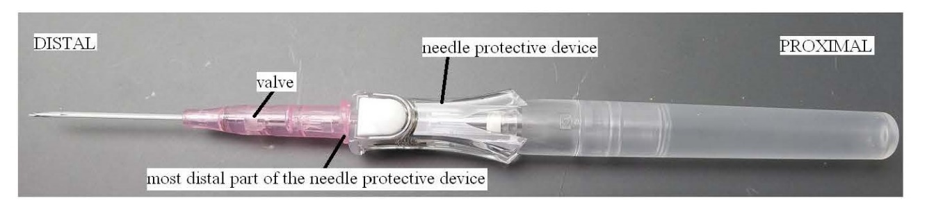
DISTAL | PROXIMAL |
| |
Photo B | |
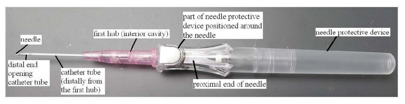
186 Inside the catheter hub is a small valve that controls blood flow. The needle extends through the centre of the valve when the device is in the ready position. The valve closes when the needle tip is withdrawn through the valve so as to restrict the passage of blood from the one (distal) region of the catheter hub into the other (proximal) region which are defined by the location of the valve. I discuss the configuration of the valve in the BD Device in more detail later in these reasons.
187 When the activation button (the white button near the proximal end of the catheter hub) is pressed, the needle is propelled longitudinally into and along the interior of the outer housing by the release of a compression spring to which the proximal end of the needle is (indirectly) attached. The forces generated by the spring push the needle in the proximal direction into and along the inside of the outer housing and into the protective position.
188 Photograph C shows the BD Device in the protective position after insertion of the catheter. In the protective position, the whole of the needle (including both the tip and the proximal end) is surrounded by the spring and the outer housing.
189 The activation button is connected to a small extension (also coloured white) which can be seen at the distal end of the device as shown in Photograph C. That extension, which Braun refers to as an “arm” in its infringement submissions, extends in a distal direction a very small distance into the catheter hub (not shown in Photograph C) when the device is in the ready position.
PROXIMAL | DISTAL |
| |
Photo C | |
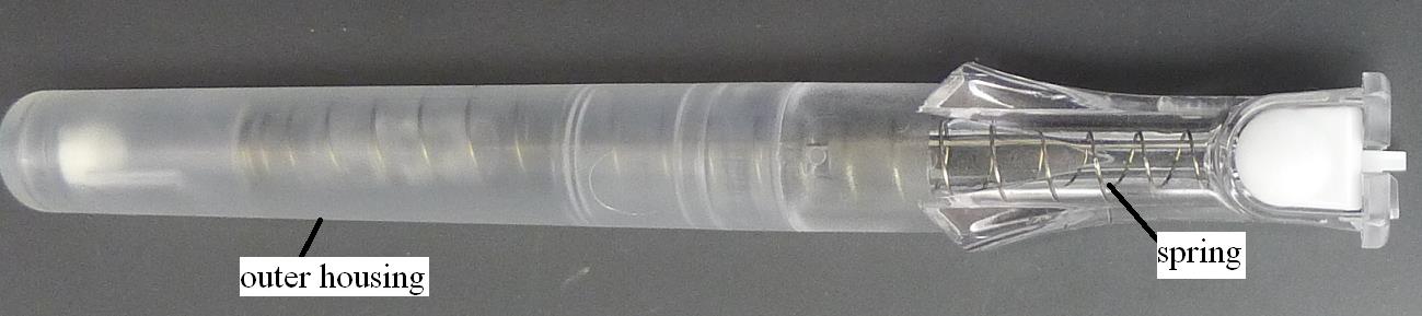
The 163 Patent (claims 14 and 26)
190 Braun alleges that the BD Device infringes claim 14 (as dependent on 9) and claim 26 of the 163 Patent. Whether or not the BD Device infringes these claims depends on the answer to the three questions that I will now address.
Infringement Issue 1: Needle protective device (Relevant Claims 14 and 26)
191 The first question is whether the BD Device includes a “needle protective device”. As previously explained, this term is used in the relevant claims to refer to a device that provides protection from unintended needle sticks.
192 Becton submitted that the needle protective device in the BD Device included only the outer housing. It submitted that the spring and the trigger mechanism were not part of the needle protective device because these particular components do not shield the needle. I think that submission reflects too narrow a view of the term needle protective device. There is no reason to think that a component such as the activation button cannot form part of a needle protective device.
193 I find that the BD Device includes a needle protective device consisting of the outer housing, the spring, and the trigger mechanism. The trigger mechanism includes the activation button and what Braun refers to as the arm.
Infringement Issue 3: Location of the needle protective device (Relevant Claims 14 and 26)
194 The second question is whether the needle protective device in the BD Device has “at least a portion extending distally of the proximal end of the catheter hub”. The answer to this question depends on what the term “proximal end” means. As previously discussed, the “proximal end” refers to the proximal end region of the catheter hub.
195 Braun accepted that on this construction of the term “proximal end” neither claim 14 nor claim 26 is infringed. This is because if the proximal end of the catheter hub includes the Luer thread in the BD Device, then no portion of the needle protective device extends distally beyond that region.
Infringement Issues 8 and 9: Resilient portion for moving the needle protective device (Relevant Claims 26 and 14 as dependent on 9)
196 The third question is whether the BD Device has a needle protective device including “a resilient portion … for moving the needle protective device from a ready position to a protected position.”
197 For reasons previously stated I consider that the metal spring forms part of the needle protective device in the BD Device. However, the metal spring in the BD Device does not move the needle protective device from the ready position to the protective position. The metal spring moves the needle from the ready position to the protective position. It does this by pushing the needle through the catheter hub, and into the outer housing, which shields the whole of the needle including the needle tip. The outer housing, which is a part of the needle protective device, remains stationary. In my opinion the spring moves the needle, but not the needle protective device, from the ready position to the protective position.
The 164 Patent (Claims 10-12, 15-20, 24-25 and 28-30)
Infringement Issue 1: Needle protective device
198 I refer to my previous findings.
Infringement Issue 2: Needle protective device comprises an arm that is located, at least in part, in the catheter hub (Relevant Claim 17 as dependent on 10)
199 The BD Device includes an arm (comprising the activation arm) that is part located in the catheter hub. Its location is shown in Photo A where reference is made to “most distal part of the needle protective device”.
Infringement Issue 4: Needle protective device positioned proximal of the valve and at least in part around the needle and distal of the proximal end of the needle hub (Relevant Claims 10-12, 15-17)
200 In the BD Device a part of the needle protective device (ie. the outer housing) is positioned proximal of the proximal end of the needle hub. On my construction of this integer, none of claims 10-12 and 15-17 is infringed.
Infringement Issue 5: A needle protective device positioned, at least in part, around the needle between the valve and the proximal end of the needle hub in a ready position (Relevant Claims 18, 19-20 as dependent on 18, 25, 28-30 as dependent on 25)
201 On my construction of this integer, the words used require that the needle protective device be positioned between the valve and the proximal end of the needle hub. As I have explained, this is not true of the BD Device.
Infringement Issue 10: The valve has a radial outer permitter abutting the interior cavity of the catheter hub (Relevant Claim 11, as dependent on 10)
202 As previously explained, what is required by this integer is that the radial outer perimeter of the valve make continuous contact with the interior cavity of the catheter hub so as to prevent the escape of blood.
203 Photograph D is of the valve in the BD Device. The radial outer perimeter had eight grooves. There is a dispute between the parties as to their significance and effect.
|
Photo D |

204 Dr Haindl was of the opinion that the relevant feature is present in the BD Device because the perimeter of the valve is snuggly fitted into the catheter hub, preventing blood flow past the perimeter. He agreed that there are small grooves or notches in the outer perimeter of the valve of the BD Device, but said that the grooves are too small to allow blood to flow past the valve’s outer perimeter. Braun submitted that, if this were not the case, blood would leak from the catheter hub.
205 It is apparent from the evidence that there are some catheter insertion devices that are not designed to completely block the flow of blood, but merely to reduce or retard it so that it does not pose a threat to the clinician through the uncontrolled escape of blood. As Mr Crawford explained in relation to the BD Device:
… it has little grooves down the outside of the perimeter. And so it – the full perimeter of the BD valve does not abut the catheter hub like, I believe, what is intended by the claim. Rather, the valve of the BD device is intended to leak in a controlled manner, to – there’s multiple reasons for that.
One is that, if the BD device – and this happens in multiple catheter insertion devices – is that when you – and the BD device has a notch in the needle so that blood begins to fill up the catheter and begins to fill up the distal end of the catheter hub. And the clinicians use that as an indication that the needle is in the vein.
(emphasis added)
206 Mr Crawford’s view is that the catheter insertion device disclosed in the specification was one in which there are no gaps along the area between the outer perimeter of the valve, and the interior cavity of the catheter hub in order to prevent leakage of blood. As I understand Mr Crawford’s evidence, which I accept, the catheter insertion device of the invention is not designed to allow for the controlled release of blood in the way that the BD Device is.
207 Mr Crawford and Mr Cindrich tested whether fluid would pass through those grooves by using water coloured with a dye, and ascertained that the water did so. Although blood is more viscous than water, in oral evidence the expert witnesses agreed that there was a risk that blood could out leak from the catheter hub. Of course, it is necessary to distinguish a situation in which blood spills out of the catheter hub from one in which there is some small and contained leakage of blood on the proximal side of the valve. The fact that some leakage will occur does not mean that the blood will spill out of the end of the catheter hub.
208 Dr Haindl said:
Mr Moore: … You would agree, wouldn’t you, that if, as a result of the grooves, a very small amount of blood was to ooze past the seal through the grooves, then it would be unlikely that that blood would – if it was a very small amount – would spill out the end of the catheter hub?
Dr Haindl: I think it’s very difficult to make a prognosis on the quantity of blood that will pass because the pressure of blood is different between patients, the clotting state is different.
Mr Moore: Yes.
Dr Haindl: It makes quite a difference if a patient gets Heparin or something against blood clotting.
Mr Moore: Yes.
Dr Haindl: And so I think if you have notches, you have also the risk that blood could outflow from the hub.
209 Similarly, Mr Crawford said:
Mr Shavin: Yes. And you understand that the valve in the BD device has that effect as well; it prevents blood coming through to come into contact with the healthcare worker?
Mr Crawford: I don’t know that. I mean, all I’ve experimented with is water – coloured water – so I do not know the – just like Dr Haindl says, not experienced it. I don’t know.
Mr Shavin: Yes. Yes. You’ve no reason to ---
Mr Crawford: My personal opinion, if you would like that ---
Mr Shavin: Yes, I would.
Mr Crawford: --- for clarification, is that I think it’s entirely possible that blood, at a very slow, slow rate, could leak through those
210 There was no other experimental evidence directed to the effectiveness of the valve in the BD Device in preventing blood leakage.
211 Mr Cindrich did not consider this integer to be present in the BD Device because the abutment of the perimeter against the interior cavity of the catheter hub is not continuous so as to prevent an outflow of blood from the catheter. But he agreed that the valve would effectively retard the passage of blood at least for a time sufficient to allow a clinician to connect an IV unit to the catheter hub after removing the needle.
212 It was submitted by Braun that the grooves in the outer perimeter of the BD Device were an “immaterial variation” that did not avoid infringement. In support of this submission Braun cited Commonwealth Industrial Gases Ltd v MWA Holdings Pty Ltd (1970) 180 CLR 160 at 168, (1970) 44 ALJR 385 at 388 per Menzies J and Rehm Pty Ltd v Webster Security System (International) Pty Ltd (1988) 81 ALR 79 (“Rehm”) at 92 per Gummow J. In the latter case, Gummow J said at 91-92:
Nor, in my view, is this a case where the differences … may be characterised as a subterfuge and an attempt to take full advantage of the invention while avoiding trespass upon the literal meaning of the claim by a modification so small as to be insignificant and to have no material effect upon the way the invention … works Commonwealth Industrial Gases Ltd v MWA Holdings Pty Ltd (1970) 44 ALJR 385 at 388 per Menzies J. As senior counsel for the respondents pointed out, the facts in Catnic Components Ltd v Hill and Smith Ltd [1982] RPC 183, are illustrative of the type of situation with which Menzies J had been dealing in the Australian case. The remarks of Lord Diplock ([1982] RPC at 242-3) as to "purposive" rather than "purely literal" construction, may be understood in that light. It may be for this reason that in Populin v HB Nominess Pty Ltd (1982) 41 ALR 471 at 475-6; 59 FLR 37 at 42-3, the Full Court of this court in essence treated the House of Lords as having confirmed that what is called for in construing claims is a common sense assessment of what the words used convey, in the context of the then-existing published knowledge, and did not treat their Lordships as having propounded any novel principle or new category of "non-textual" infringement …
213 I do not accept that Becton has sought to take advantage of the invention while avoiding trespassing upon the literal meaning of the claims. In relation to the particular integer with respect to which it was directed, Braun’s submission is answered by the evidence of Mr Crawford which I previously highlighted and which I accept. In any event, this is not a case in which it could be said that Becton has engaged in a subterfuge aimed at taking advantage of the invention while avoiding textual infringement.
214 In my opinion, it has not been established that the outer perimeter of the valve abuts the interior cavity of the catheter hub so as to prevent blood leakage.
Infringement Issues 11 and 12: A plunger end extending proximally of the nose section having one or more gaps to permit fluid flow (Relevant Claims 18-20, 24-25, 28-30)
215 Given my views as to what constitutes a “plunger” and a “plunger end” (as explained above) I consider that the plunger section in the BD Device is a “plunger end” extending proximally of the nose section having more than one gap to permit fluid flow as required by claims 18 and 25 and their dependent claims.
Infringement Issue 13: At least two plunger elements … having a gap therebetween (Relevant Claims 10-12 and 15-17)
216 Braun submitted that the valve actuating element of the BD Device has four elongated structures which constitute plunger elements with a gap between each of them. It submitted that the four elongated structures are plunger elements because they transfer a (pushing) force to open the valve.
217 Dr Haindl produced the following photographs of what he identified in the BD Device as the valve actuating element (Photo E) and four plunger elements with gaps between them (Photo F):
DISTAL | PROXIMAL |
| |
Photo E | |
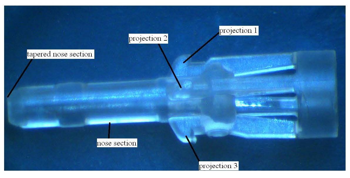
DISTAL | PROXIMAL |
| |
Photo F | |
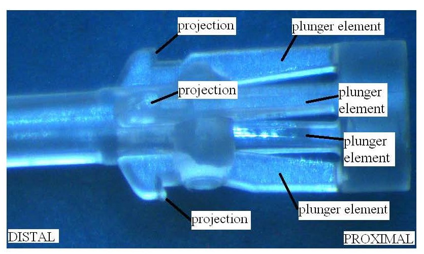
218 In my opinion what Dr Haindl identifies as plunger elements are not plunger elements in the sense that term is used in the relevant claims. If there is any plunger element in the valve actuating element of the BD Device, it consists of the whole of that part of the valve actuating element extending proximal of the nose section. This is what I would describe as the plunger section of the valve actuating element. The plunger section includes four struts together with a cylindrical element to which they are connected at their most proximal end that constitute a single “plunger element” within the meaning of the relevant claims. That section of the valve actuating device in the BD Device is in my opinion a plunger because it is thrust though the outer housing forcibly by the action of the spring in a manner similar to a piston or ram.
Infringement Issue 14: The plunger end comprises at least two plunger elements defining the at least one or more gaps (Relevant Claim 19 as dependent on 18)
219 The BD Device includes only one plunger end. Accordingly, neither of the relevant claims is infringed.
Infringement Issue 15: The projection is distal of the two plunger elements (Relevant Claims 16 and 24)
220 The BD Device does not have two plunger elements. For this reason it does not infringe the relevant claims.
The 814 Patent
Infringement Issue 1: Needle protective device
221 I refer to my previous findings.
Infringement Issue 2: Needle protective device has an arm that is located, at least in part, in the catheter hub (Relevant Claim 10)
222 I refer to my previous findings. This integer of claim 10 is present in the BD Device.
Infringement Issue 4: A needle protective device positioned proximal of the valve at least in part around the needle and distal of the proximal end of the needle hub in a ready position (Relevant Claims 5 and 6, 8, 9, 10 and 13 as dependent on 5)
223 The BD Device does not have a needle protective device that is positioned distal of the proximal end of the needle hub in a ready position. Most of the needle protective device in the BD Device (ie. the outer housing) is located proximal of the proximal end of the needle hub when the device is in the ready position.
Infringement Issue 5: A needle protective device positioned, at least in part, around the needle between the valve and the proximal end of the needle hub in a ready position (Relevant Claims 11, 12, as dependent on 11, 13 as dependent on 11, 17, as dependent on 11, 18, 21, as dependent on 18, 22, as dependent on 21, and 23, as dependent on 22)
224 On my construction of this integer, the words used require that the needle protective device be positioned between the valve and the proximal end of the needle hub. As I have explained, this is not true of the BD Device.
Infringement Issue 6: The needle protective device is movable to prevent unintended needle sticks in a protective position (Relevant Claims 5, 6, 8, 9, 10, 11, 12, as dependent on 11, 13 as dependent on 5 or 11, 17 as dependent on 11, 18, 21 as dependent on 18, 22 as dependent on 21, and 23 as dependent on 22)
225 This requirement of the relevant claims is not satisfied. As previously explained, in the BD Device the outer housing remains stationary when the needle moves into the protective position.
Infringement Issue 7: A needle protective device … moveable relative to the needle tip to a protective position (Relevant Claims 1, 2, 4, 9-10 and 13 as dependent on 1)
226 I previously found that this integer requires that the needle protective device be capable of physical movement relative to the needle tip into a position, at least in part, distal of the needle tip.
227 In the BD Device the outer housing remains stationary when the needle moves into the protective position. The needle protective device is not capable of physical movement relative to the needle tip into a position, at least in part, distal of the needle tip. For this reason none of the relevant claims is infringed.
Infringement Issue 10: The valve has a radial outer permitter abutting the interior cavity of the catheter hub (Relevant Claim 6, as dependent on 5)
228 I refer to my previous findings.
Infringement Issue 11: A plunger end extending proximally of the nose section having one or more gaps to permit fluid flow (Relevant Claims 11, 12, 13, 17, 18, 21, 22, and 23)
229 I refer to my previous findings.
Infringement Issue 13: A valve actuating element comprising at least two plunger elements extending proximally of the nose and having a gap therebetween (Relevant Claims 1, 2, 4, 5, 6 , 8, 9, 10 and 13)
230 I refer to my previous findings. The BD Device includes only one plunger element. For this reason none of the relevant claims is infringed.
Infringement Issue 14: The plunger end comprises at least two plunger elements defining the (sic) at least one or more gaps (Relevant Claim 12 as dependent on 11)
231 I refer to my previous findings. Since the BD Device has only one plunger element, the relevant claim is not infringed.
Infringement Issue 15: wherein the projection is distal of the two plunger elements (Relevant Claims 9 and 17, as dependent on 11)
232 The BD Device does not have two plunger elements. For this reason it does not infringe the relevant claims.
Validity
Fair Basis
233 Becton challenges the validity of each of the claims on which it is sued on fair basis grounds. Becton contends that none of the relevant claims is entitled to the priority date claimed because they are not fairly based on matter disclosed in the Parent (external fair basis). Becton also contends that none of the relevant claims complies with s 40(3) which requires (inter alia) that they be fairly based on the matter described in the specification (internal fair basis).
234 Braun accepted that if the claims on which it sues are not entitled to the priority date claimed then they will be invalid for lack of novelty based on the sale of the BD Device in Australia if (but only if) the BD Device is found to infringe any one or more of those claims. Although I have found that the BD Device does not infringe any of the claims on which Becton is sued, I propose to consider the external fair basis issues that were raised by Becton in case any of my findings on the infringement issues is overturned on appeal.
Priority Date and External Fair Basis
235 At all material times s 43 of the Act relevantly provided:
43 Priority dates
(1) Each claim of a specification must have a priority date.
(2) The priority date of a claim is:
(a) the date of filing of the specification; or
(b) where the regulations provide for the determination of a different date as the priority date – the date determined under the regulations.
(3) Where a claim defines more than one form of an invention, then, for the purposes of determining the priority date of the claim, it must be treated as if it were a separate claim for each form of the invention that is defined.
(4) The priority date of a claim of a specification may be different from the priority date of any other claim of the specification.
236 At the relevant dates, s 79B(1) provided:
79B Divisional applications prior to grant of patent
(1) If a complete patent application for a patent is made (but has not lapsed or been refused or withdrawn), the applicant may, in accordance with the regulations, make a further complete application for a patent for an invention:
(a) disclosed in the specification filed in respect of the first mentioned application; and
(b) where the first mentioned application is for a standard patent and at least 3 months have elapsed since the publication of a notice of acceptance of the relevant patent request and specification in the Office Journal—falling within the scope of the claims of the accepted specification.
237 At the relevant dates, reg 3.12 of the Patent Regulations 1991 (Cth) (“the Regulations”) relevantly provided:
3.12 Priority dates generally
(1) Subject to regulations 3.13 and 3.14 and sub-regulation (2), the priority date of a claim of a specification is the earliest of the following dates:
…
(b) if the claim is fairly based on matter disclosed in 1 or more priority documents, the date of filing the priority document in which the matter was first disclosed;
(c) if the specification is a complete specification filed in respect of a divisional application under section 79B of the Act and the claim is fairly based on matter disclosed in the specification referred to in paragraph 79B(1)(a) of the Act—the date mentioned in sub-regulation (2C);
…
…
(2C) The date for a specification to which paragraph 3.12(1)(c) applies is the date that would have been the priority date of the claim if it had been included in the specification referred to in paragraph 79B(1)(a) of the Act.
238 Each of the Patents was filed pursuant to s 79B(1) of the Act. The “first mentioned application” for the purposes of s 79B(1) is the application for what later became the 275 Patent. It is common ground that the specification filed in respect of that application (ie. the Parent) includes the disclosures of the 275 Patent.
239 Both parties referred me to the Full Court’s decision in Multigate Medical Devices Pty Ltd v B Braun Melsungen AG (2016) 117 IPR 1 (“Multigate”) at [188]-[189] drawing attention to the subtle difference in some of the language used in the legislative tests for internal fair basis (under s 40(3)) and external fair basis (under reg 3.12(1)(c)). The former requires that the claim be “fairly based on the matter described in the specification” whereas the latter requires that the claim be “fairly based on the matter described in the specification”. In Multigate the Full Court said at [188]-[189]:
[188] One conceptual issue that the parties debated before us was whether there was a difference between the concept of “fair basis” arising from the requirement in reg 3.12(1)(c) that the claim be “fairly based on matter disclosed” in the specification of the ancestor, and the concept of “fair basis” arising under s 40(3). Multigate contended that the effect of reg 3.12(2C) was to make clear that reg 3.12(1)(c) did not create a different test as between external and internal fair basis by providing that the date for a specification under reg 3.12(1)(c) is the date that would have been the priority date “if it had been included” in the specification referred to in s 79(B)(1)(a). We generally agree (see Sigma Pharmaceuticals (Australia) Pty Ltd v Wyeth [2011] FCAFC 132 at [65] per Bennett J referring to Inverness Medical Switzerland GmbH v MDS Diagnostics Pty Ltd (ACN 090 764 702) (2010) 85 IPR 525; [2010] FCA 108 at [142]). The parties agreed that whether a claim is “fairly based on matter disclosed” depends upon whether there was “a real and reasonably clear disclosure” in the ancestor (cf Lockwood Security Products Pty Ltd v Doric Products Pty Ltd (2004) 217 CLR 274; 212 ALR 1; 62 IPR 461; [2004] HCA 58 (Lockwood No 1) at [69] per Gleeson CJ, McHugh, Gummow, Hayne and Heydon JJ). We have proceeded on the basis that this is the practical test to be applied.
[189] But there is a subtlety that should not be overlooked. For internal fair basis (s 40(3)), what is required is that “the claim … must be … fairly based on the matter described in the specification” (our emphasis). Contrastingly, for external fair basis, reg 3.12(1)(c) uses the language “the claim is fairly based on matter disclosed in the specification” (our emphasis). There are two linguistic differences in the phrase used for external fair basis. First, the definite article is omitted. Second, the reference is to what is disclosed rather than what is described. So, the absence of the definite article makes it plain that external fair basis can arise if some part of the overall disclosure made in the prior specification discloses relevant matter (see Vehicle Monitoring Systems Pty Ltd (ACN 107 396 136) v Sarb Management Group Pty Ltd (t/as Database Consultants Australia) (ACN 106 549 722) (No 2) (2013) 101 IPR 496; [2013] FCA 395 at [125] and [126] per Yates J, applying Leonardis v Sartas No 1 Pty Ltd (1996) 67 FCR 126 at 139; 35 IPR 23 at 37 (Leonardis) per Burchett, Hill and Tamberlin JJ). Further, the use of “disclosed” rather than “described” connotes greater flexibility in the test for external fair basis in terms of ascertaining from the prior specification the requisite disclosure.
240 Braun relied on the Multigate decision in support of the proposition that “matter” in the priority document in issue in that case disclosing “needle protecting means” was not limited to the exemplary embodiment disclosed. In that case, there was only one exemplary configuration of a needle protecting means disclosed in the priority document, which also happened to be a spring clip. Nevertheless, the Full Court held at [237] that the person skilled in the art was taught by the priority document that the particular needle protecting means disclosed was only an example, and that the disclosure was not limited to it.
241 Multigate was concerned with a different patent and a different priority document. Except in so far as it contains some relevant statements of general principle, I do not find the decision of any real assistance in resolving the issues in this case. This is particularly true of the fair basis issues given the presence of an express statement in the specification of the patent in suit in Multigate that the needle protecting means may be of different configurations (including numerous configurations suggested by the prior art) and that “… the needle protecting means need not comprise any clamping means for clamping the needle in the locked position” (as did the spring clip in the exemplary embodiment).
242 In the present case there is only one exemplary embodiment of a needle guard element (ie. the spring clip (13)) disclosed in the specifications. Importantly, the specifications do not include any express statements comparable to those to which the Full Court drew attention in Multigate.
243 The fair basis issues in this case come down to the question of whether there is a “real and reasonably clear disclosure” of what has been claimed, for internal fair basis, in the patent in which the relevant claim is included or, for external fair basis, in the priority document, ie. the Parent. The relevant disclosures may be made by either words or drawings and may also be found in matter found in different parts of the same document. What is essential, however, is that the disclosure relied in support of the claimed priority date be a real and reasonably clear disclosure of what is claimed.
244 In Lockwood Security Products Pty Ltd v Doric Products Pty Ltd (2004) 217 CLR 274 (“Lockwood”) the High Court said at [68]-[69]:
[68] Erroneous principles. The comparison which s 40(3) calls for is not analogous to that between a claim and an alleged anticipation or infringement. It is wrong to employ “an over meticulous verbal analysis”. It is wrong to seek to isolate in the body of the specification “essential integers” or “essential features” of an alleged invention and to ask whether they correspond with the essential integers of the claim in question [CCOM Pty Ltd v Jiejing Pty Ltd (1994) 51 FCR 260 at 281, per Spender, Gummow and Heerey JJ].
[69] “Real and reasonably clear disclosure”. Section 40(3) requires, in Fullagar J’s words, “a real and reasonably clear disclosure” [Société des Usines Chimiques Rhône-Poulenc v Commissioner of Patents (1958) 100 CLR 5 at 11]. But those words, when used in connection with s 40(3), do not limit disclosures to preferred embodiments.
“The circumstance that something is a requirement for the best method of performing an invention does not make it necessarily a requirement for all claims; likewise, the circumstance that material is part of the description of the invention does not mean that it must be included as an integer of each claim. Rather, the question is whether there is a real and reasonably clear disclosure in the body of the specification of what is then claimed, so that the alleged invention as claimed is broadly, that is to say in a general sense, described in the body of the specification.” [Rehm Pty Ltd v Websters Security Systems (International) Pty Ltd (1988) 81 ALR 79 at 95, per Gummow J]
Fullagar J’s phrase serves the function of compelling attention to the construction of the specification as a whole, putting aside particular parts which, although in isolation they might appear to point against the “real” disclosure, are in truth only loose or stray remarks.
(some citations omitted)
245 The High Court also said at [87]:
[87] Finally, it is necessary to consider the trial judge’s citation of Atlantis Corporation Pty Ltd v Schindler [(1997) 39 IPR 29] for the proposition that to couch a claim “in the same terms as the description of the invention in the specification” did not of itself, by that mere “coincidence of language”, establish fair basing. That proposition is correct, but it is not fatal to the Patentee’s position in this case. A “coincidence of language” between a claim and part of the body of a specification does not establish fair basing if that part of the language of the specification does not reflect the description of the invention in the light of the specification as a whole. In the Atlantis Case, the specification, read as a whole, described an apparatus limited to a particular use as a sub-soil drainage system. The claims, however, were “pure apparatus” claims without that limitation on use. The Full Court of the Federal Court of Australia refused to construe them narrowly so as to conform with the description in the specification. A statement in the specification of a description of the invention in similar language to the first claim was not treated as the description of the invention. While the Full Court did not engage in close textual analysis, it did distinctly hold that the statement in the specification [at 50]:
“should not be allowed to disguise the fact that the invention disclosed in the body of the specification is truly ‘a sub-soil drainage method based on a particular apparatus’ or ‘a particular apparatus in its application to sub-soil drainage’. The claims, however, are ‘pure apparatus claims’. They are not subject to any limitation as to use. They travel beyond, and are not fairly based on, the matter described in the specification.”
In short, the case is distinguishable. Here, the Patentee does not rely on mere “coincidence of language”: it contends that the language used, unlike that employed in the Atlantis Case, does describe the invention.
(some citations omitted)
246 A consistory clause may provide a fair basis for a claim which mirrors its language but not if there are other matters disclosed in the specification which show that the invention is narrower than the consistory clause suggests. The High Court said in Doric at [99]:
[99] ... the correct position is that a claim based on what has been cast in the form of a consistory clause is not fairly based if other parts of the matter in the specification show that the invention is narrower than that consistory clause. The inquiry is into what the body of the specification read as a whole discloses as the invention [Welch Perrin & Co Pty Ltd v Worrel (1961) 106 CLR 588 at 612–613]. An assertion by the inventor in a consistory clause of that of which the invention consists does not compel the conclusion by the court that the claims are fairly based nor is the assertion determinative of the identity of the invention. The consistory clause is to be considered by the court with the rest of the specification.
External Fair Basis Issue 1: Disclosure of needle protective device (Relevant to all claims sued on)
247 Becton submitted that the disclosure of the Parent is limited to a type of needle guard element which:
is located in the catheter hub in a ready position;
is arranged displaceably on the needle (ie., it sits in contact with the needle and slides over the needle);
engages with an engaging means on the needle near the needle tip; and
covers the needle tip when engaged with the engaging means as it is removed from the catheter hub.
248 Becton submitted that if the term “needle protective device” in the claims of the Patents is not limited to a device of that type, or is broader than the term “needle guard element” used in the Parent, then the claims of the Patents are not fairly based on the 275 Patent because they omit limitations of the disclosure and travel beyond it.
249 It is convenient to begin with the second limb of Becton’s submission. Does the term “needle protective device” have a meaning different from “needle guard element” as these terms are used in the Parent and the Patents?
250 As I have previously said in relation to needle protective device, it is not a term that has a special meaning. It refers to a device that provides protection from unintended needle sticks. The term needle guard element is also a term that does not have a special meaning. When given its plain and ordinary meaning and when read in the context of a description of a catheter insertion device, it means a device that protects against needle sticks. So I think the first question I posed should be answered in the negative.
251 That brings me to the second limb of Becton’s submission. Is the term “needle protective device” limited to a type of device having the four limitations referred to by Becton? That question must also be answered in the negative. The plain and ordinary meaning of the term needle protective device, read in the context of a description of a catheter insertion device, does not carry with it any of Becton’s four limitations.
252 The next question is whether the claims that refer to a needle protective device that is not specifically limited to a needle protective device in the form of a spring clip similar to that shown in the relevant drawings of the preferred embodiments, is the subject of any real and reasonably clear disclosure in the Parent. In answering this question it is important to recall Lockwood at [69] where the High Court referred to what Gummow J said in Rehm at 95. What is required is that the invention as claimed be broadly, that is say, in a general sense, described in the body of the specification.
253 In the present case Braun relied on what appears at page 2, lines 1-9 of the Parent in support of the submission that the combination of these passages (which I have previously set out) explains to the person skilled in the art that the invention is not confined to the express disclosures.
254 Braun submitted that the passage at page 2, lines 1-6 constitutes a broad description of the invention, and that what appears in the immediately following passage makes clear that the detailed description of the exemplary embodiments should not be understood as limiting the invention to those embodiments.
255 It is important to read the passage at page 2, lines 1-6 with what is said on the preceding page which provides context for the disclosure at page 2, lines 1-6. At page 1, lines 11-14 there is a discussion of what is said to be an objective of the invention, which is to provide a catheter insertion device of the type described in the preceding paragraph at page 1, lines 5-10 such that an outflow of blood from the catheter is prevented after removal of the needle with the needle guard element. The type of device referred to in this passage is one with an engaging means near the tip of the needle that engages with the needle guard element as the needle is withdrawn from the catheter.
256 The statement at page 1, lines 11-14 is then followed by the consistory clause appearing in the Parent at page 1, lines 16-31 which I have previously set out. The consistory clause describes the invention as providing a catheter insertion device that has (inter alia):
a needle guard element arranged displaceably on the needle and engaging with the needle near the needle tip when the hollow needle is removed from the catheter hub;
a valve actuating element displaceably guided in the catheter hub and arranged proximally of the check valve arranged in the catheter hub and having a hollow cylindrical space for receiving the needle; and
wherein the needle guard element is arranged in the hollow cylindrical space of the valve actuating element and has an engaging section which engages with an engaging means provided on the inner circumference of the valve actuating element when the hollow needle is removed from the catheter hub.
257 It is clear that the consistory clause of the Parent describes a needle guard element that is not necessarily comprised of a spring clip. But what is described by the consistory clause is a needle guard element arranged displaceably on a needle that engages with the needle near the needle tip and which is positioned within a valve actuating element that is itself positioned inside a catheter hub.
258 It is important to observe that the passage at page 2, lines 1-6 on which Braun places reliance appears immediately after the consistory clause. In my view, contrary to Braun’s submission, this passage is not a statement of the scope of the invention but a statement of the advantages of the invention described in the consistory clause which immediately precedes it.
259 The Parent does not contain any matter that discloses, even in the most general sense, a catheter insertion device having a needle guard element that is not arranged displaceably on the needle or not positioned inside the catheter hub when the device is in the ready position. Nor would any matter disclosed in the Parent convey any suggestion to the notional skilled addressee that a needle guard element of some different configuration to that which I have just described could be used in its place. My view on this latter point is reinforced by the absence of any evidence from any of the expert witnesses to the contrary effect.
260 There are two other points to make that follow from my conclusion with respect to this issue.
261 First, the lack of external fair basis arises not from the use of the term needle protective device in the claims. My conclusion would have been the same if they had used the term needle guard element in its place. The real problem for the patentee in this case is that the catheter insertion device disclosed in the Parent has three fundamental design characteristics (see [257] above) that necessarily limit the scope of the invention and the type of needle guard element that can be used to perform the invention.
262 Secondly, I should not be understood as having found that the disclosure of the Parent is limited to the use of a needle guard element comprising a spring clip as in the preferred embodiments. The consistory clause of the Parent does not limit the disclosure to a spring clip. Nevertheless, it does describe an arrangement that necessarily imposes other limitations relating to the needle guard element that can be used to perform the invention.
External Fair Basis Issue 2: Disclosure of “at least a portion [of a needle protective device] extending distally of the proximal end of the catheter hub (Relevant claims 14, as dependent on 9, and 26 of the 163 Patent)
263 It is clear from the drawings of the preferred embodiments in the Parent that the needle guard element (ie. the spring clip) extends distally of the proximal end of the catheter hub.
264 The real point that Becton was seeking to make under the guise of this issue was that there was no disclosure anywhere in the Parent of a needle guard element that ends proximally of the proximal end of the catheter hub when the device is in the ready position.
265 Braun’s response to that submission was that if its construction of the term “needle protective device” is accepted, then there is a disclosure of a needle protective device which can also extend proximally of the proximal end of the catheter hub. This proposition does not follow and is incorrect. The Parent contains no such disclosure.
External Fair Basis Issue 3: Disclosure of “a needle protective device positioned proximal of the valve and at least in part around the needle and distal of the proximal end of the [second hub/needle hub] in a ready position” (Relevant claims 10-12 and 15-17 of the 164 Patent, and claims 5-6, 8-9 and 13 of the 814 Patent)
266 On my construction of this integer these words do not in themselves raise a fair basis issue. If, contrary to my construction of this integer, the claim defines an invention in which only a part of the needle protective device need be positioned distal of the proximal end of the relevant hub, then the claim is not fairly based on matter disclosed in the Parent.
External Fair Basis Issue 4: Disclosure of a needle protective device positioned, at least in part, around the needle between the valve and the proximal end of the needle hub in a ready position” (Relevant claims 18-20, 24-25, 28-30 of the 164 Patent, and claims 11-13, 17-18, 21-23 of the 814 Patent)
267 What I have said at [266] also applies to this integer.
External Fair Basis Issue 5: Disclosure of “an arm [of a needle protective device] that is located, at least in part, in the catheter hub” (Relevant claims 17 of the 164 Patent and claim 10 of the 814 Patent)
268 Becton submitted that the only disclosure of an “arm” of the needle protective device is a member which has the purpose of covering the needle tip. It further submitted that there is no disclosure of any other function performed by this member, the form such a function would require it to take, and how it would co-operate with the valve actuating element. It further submitted that there was no disclosure in the Parent of an arm which extends proximally of the catheter hub.
269 Braun submitted that Becton was seeking to confine the scope of the disclosure in the Parent to the description of the preferred embodiments. I agree. The disclosure of the Parent is not limited to a catheter insertion device having a needle guard element comprising a spring clip with spring arms.
270 However, the use of words “at least in part” in this integer is problematic. There is no disclosure in the Parent suggesting that the invention provides a needle guard element that is only partly located in the catheter hub. As the consistory clause of the Parent shows, the valve actuating element is located in the catheter hub, and the needle guard element is arranged in the hollow cylindrical space of the valve actuating element. In my view this disclosure is inconsistent with an arrangement in which a part of the needle guard element is located outside the catheter hub.
External Fair Basis Issue 6: Disclosure of [a valve actuating element having] at least two plunger elements” (Relevant Claims 10-12, 15-17, 19-20 of the 164 Patent, and claims 1-2, 4-5, 7-10, 12-13 and 13 of the 814 Patent)
271 Becton submitted that there is no real and reasonably clear disclosure of a valve actuating element having more than two plunger elements. It submitted that the Parent discloses a needle guard element arranged in the hollow cylindrical space of the valve actuating element, and describes an embodiment in which it is inserted between two plunger elements. This was said to limit the disclosure to a device that included no more than two plunger elements.
272 I do not accept Becton’s submission.
273 There is a disclosure in the Parent of what may be described as two plunger elements that make up the plunger section referred to in the detailed description of preferred embodiments (Fig 4, 10b). These take the form of two projections extending longitudinally in a proximal direction along opposite sides of the needle and the spring clip.
274 The question is whether this disclosure of the Parent supports the use of the words “at least”. Although the consistory clause refers to the valve actuating element, it does not specifically describe the plunger section. In particular, it does not expressly or impliedly convey any suggestion that the valve actuating element might not include a plunger section that consists of more than two plunger elements.
Internal Fair Basis
Internal Fair Basis Issue 1: Disclosure of needle protective device (Relevant to all claims sued on)
275 Each of the Patents begin by expressly incorporating the Parent by reference. It follows that, when reading each of the Patents as a whole for the purpose of ascertaining the nature and scope of the invention disclosed, the notional skilled addressee must be taken to be familiar with what appears in the Parent.
276 Each of the Patents then refers to a type of catheter insertion device that uses a needle guard said to be known from the 928 Patent. According to the brief description of this type of catheter insertion device then given, the needle is withdrawn from the catheter over an engaging means near the needle tip that engages a needle guard element which covers the needle tip when the needle is withdrawn from the catheter.
277 Each of the Patents then includes a sentence stating that it is an object of the invention to provide a catheter insertion device of the type described that also prevents the outflow of blood after the needle and the needle guard element are removed from the catheter.
278 Mr Shavin QC placed emphasis on the use of the indefinite article in this sentence, suggesting that it would be wrong to treat this as an exhaustive statement of the objects of the invention. Perhaps that is so, but it does seem to me that when this general statement is read with what appears at page 2, lines 1-6 (remembering that the Patents refer here not to “the invention” but to “the preferred embodiments of the invention”) it is difficult to see what advantage the invention would be understood to provide other than by providing blood outflow prevention in a catheter insertion device of the known kind (or a device with a configuration similar thereto) that provided needle tip protection.
279 Nowhere in the description of the invention is there any suggestion that the patent applicant was seeking protection for some broader invention that encompassed a new type of needle guard element that was fundamentally different to that used in the devices of the known kind.
280 It is necessary when considering external fair basis to give some weight to the presence of the various consistory clauses in each of the Patents. But in my opinion it is apparent from a reading of the Patents as a whole that the invention that is both generally and specifically described may be broadly characterised as a catheter insertion device that provides both needle tip protection and blood outflow prevention in the type of catheter insertion device said to be known from the 928 Patent.
281 When read in the context of each of the Patents in which they appear it seems to me that none of them provide any clear or reasonable disclosure of a catheter insertion device that is different to that described generally in the consistory clause of the Parent or as exemplified in the detailed description of the preferred embodiments.
282 The use of the term “needle protective device” in the relevant claims is supported by the disclosures in the Patents. However, in spite of what appears in the mirroring language used in the consistory clauses, the invention described in the specification is in each case limited to a catheter insertion device that has each of the three fundamental design characteristics to which I previously referred.
Internal Fair Basis Issue 2: Disclosure of “at least a portion [of a needle protective device] extending distally of the proximal end of the catheter hub (Relevant claims 14, as dependent on 9, and 26 of the 163 Patent)
283 I refer to the discussion at [97]-[107] above.
284 Claims 9 and 26 of the 163 Patent define the needle protective device in the catheter insertion device of the invention as one that has (inter alia) “at least a portion extending distally of the proximal end of the catheter hub.” What the claim does not expressly address is whether the needle protective device can also extend proximally of the proximal end of the catheter hub.
285 As a matter of construction, there is nothing in the claims that would prohibit the needle protective device having at least a portion that extends distally of the proximal end of the catheter hub. In my view the claims 9 and 26 properly construed, do not impose any such prohibition.
286 In my opinion there is no real or reasonably clear disclosure in any of the Patents of a catheter insertion device in which the needle protective device is located outside the catheter hub. Accordingly, the relevant claims are invalid on the ground that they are not fairly based on the matter described in the specification.
Internal Fair Basis Issue 3: Disclosure of “a needle protective device positioned proximal of the valve and at least in part around the needle and distal of the proximal end of the [second hub/needle hub] in a ready position” (Relevant claims 10-12 and 15-17 of the 164 Patent, and claims 5-6, 8-9, 10 and 13 of the 814 Patent)
287 What I have said at [266] applies here.
288 Each of the relevant claims would be invalid on Braun’s construction of them (which I have rejected) on the basis that the claim is not fairly based on the matter described in the specification.
Internal Fair Basis Issue 4: Disclosure of a needle protective device positioned, at least in part, around the needle between the valve and the proximal end of the needle hub in a ready position” (Relevant Claims 18-20, 24-25, 28-30 of the 164 Patent, and claims 11-13, 17-18, 21-23 of the 814 Patent)
289 What I have said in relation to Internal Fair Basis Issue 3 also applies here.
Internal Fair Basis Issue 5: Disclosure of “an arm [of a needle protective device] that is located, at least in part, in the catheter hub” (Relevant Claims 17 of the 164 Patent and 10 of the 814 Patent)
290 There is no disclosure in any of the Patents suggesting that the invention provides a needle guard element that is only partly located in the catheter hub. By claiming a device which includes a needle protective device that need not be located within the catheter hub, the relevant claims travel beyond the matter described in the specification and lack fair basis.
Internal Fair Basis Issue 6: Disclosure of [a valve actuating element having] at least two plunger elements” (Relevant Claims 10-12, 15-17, 19-20 of the 164 Patent, and claims 1-2, 4-5, 7-10, 12-13 and 13 of the 814 Patent)
291 For the reasons stated at [271]-[274] the relevant disclosures are not limited to a device having no more than two plunger elements.
Inventive Step
The person skilled in the art
292 The notional person skilled in the art (the “PSA”) will possess the common general knowledge in the relevant field in so far as it is relevant to the subject matter of the Patents. This will include the background knowledge and experience available to all those persons engaged in the relevant field within the patent area including publications to which they would refer as a matter of course: 3M at 292 per Aickin J, ICI Chemicals & Polymers Ltd v Lubrizol Corporation Inc (1999) 45 IPR 577 at [112] per Emmett J. The High Court emphasised in Aktiebolaget Hassle v Alphapharm Pty Ltd (2002) 212 CLR 411 (“Alphapharm”) at [31] that information cannot be treated as part of the common general knowledge in the absence of evidence of its general acceptance and assimilation by persons skilled in the art.
293 In this case it is not in dispute that the PSA is a team (“the hypothetical team”) engaged in the design of medical devices (including IV catheters) and that it includes people with relevant skill and experience in mechanical engineering, industrial design, manufacturing and clinical work.
294 Braun emphasised, correctly, that the team and its various members, although highly skilled, are non-inventive. That is of course correct. But it does not follow that the team is taken to be incapable of finding a solution to a known problem that does not require inventive ingenuity or some contribution to the art that is not “beyond the skill of the calling”: Allsop Inc v Bintang Ltd (1989) 15 IPR 686 at 701. Nevertheless, as Braun also emphasised, the level of inventiveness required to sustain a patent is quite small; a “scintilla” of inventiveness is all that is required: Alphapharm at [195].
295 Braun also emphasised the judicial warnings as to the danger that an ex post facto analysis of an invention may pose especially in cases involving a claim to a new combination. As the plurality explained in Alphapharm at [21]:
[21] The defendant to an infringement action who cross-claims for revocation on the ground of obviousness bears the onus of establishing that case. This obliges the defendant to lead evidence looking back to the priority date, sometimes, as here, many years before trial. In those circumstances, the warnings in the authorities against the misuse of hindsight are not to be repeated as but prefatory averments and statements of trite law. The danger of such misuse will be particularly acute where what is claimed is a new and inventive combination for the interaction of integers, some or all of which are known. It is worth repeating what was said by Lord Diplock in Technograph Printed Circuits Ltd v Mills & Rockley (Electronics) Ltd [1972] RPC 346 at 362:
“Once an invention has been made it is generally possible to postulate a combination of steps by which the inventor might have arrived at the invention that he claims in his specification if he started from something that was already known. But it is only because the invention has been made and has proved successful that it is possible to postulate from what starting point and by what particular combination of steps the inventor could have arrived at his invention. It may be that taken in isolation none of the steps which it is now possible to postulate, if taken in isolation, appears to call for any inventive ingenuity. It is improbable that this reconstruction a posteriori represents the mental process by which the inventor in fact arrived at his invention, but, even if it were, inventive ingenuity lay in perceiving that the final result which it was the object of the inventor to achieve was attainable from the particular starting point and in his selection of the particular combination of steps which would lead to that result.”
296 An ex post facto analysis of an invention can be particularly unfair to the inventor of a new combination which involves selecting a number of known integers from a large range of possible alternatives: see the observations of Aickin J in 3M at 293-294.
The relevant statutory provisions
297 Section 18(1)(b)(ii) of the Act provides that an invention is a patentable invention for the purposes of a standard patent if the invention, so far as claimed in any claim, involves an inventive step when compared with the prior art base as it existed before the priority date of that claim. At the relevant times subs 7(2) and (3) of the Act provided:
(2) For the purposes of this Act, an invention is to be taken to involve an inventive step when compared with the prior art base unless the invention would have been obvious to a person skilled in the relevant art in the light of the common general knowledge as it existed in the patent area before the priority date of the relevant claim, whether that knowledge is considered separately or together with the information mentioned in subsection (3).
(3) The information for the purposes of subsection (2) is:
(a) any single piece of prior art information; or
(b) a combination of any 2 or more pieces of prior art information;
being information that the skilled person mentioned in subsection (2) could, before the priority date of the relevant claim, be reasonably expected to have ascertained, understood, regarded as relevant and, in the case of information mentioned in paragraph (b), combined as mentioned in that paragraph.
298 The expression “patent area” is relevantly defined in Sch 1 to mean Australia. The expression “prior art information” is relevantly defined to mean information that is part of the prior art base for the purposes of subs 7(3) in relation to deciding whether an invention does or does not involve an inventive step. At the relevant times the expression “prior art base” was defined in para (a) of the definition as:
in relation to deciding whether an invention does or does not involve an inventive step or an innovative step:
(i) information in a document that is publicly available, whether in or out of the patent area; and
(ii) information made publicly available through doing an act, whether in or out of the patent area.
299 The operation of s 7 was considered by the Full Court in AstraZeneca AB v Apotex Pty Ltd (2014) 226 FCR 324. In that case the plurality said at [199]-[201]:
[199] A central purpose of the relevant provisions is to delineate the information that the Court may have regard to for the purposes of determining whether an invention, so far as claimed, is a patentable invention. In particular, the purpose of s 7(3) was explained by the High Court in Lockwood Security Products Pty Ltd v Doric Products Pty Ltd (No 2) (2007) 235 CLR 173 (Doric No 2) at [49]:
Previously, only common general knowledge was taken into account when assessing an inventive step. Now, additional information which was publicly available as at the priority date must also be taken into account. Broadly speaking, s 7(3) has as its purpose the specification of the additional publicly available information (s 7(3) information) which must be added to common general knowledge for the purposes of deciding whether an alleged invention is obvious when compared with the prior art base.
[200] To be patentable, an invention, so far as claimed, must involve an inventive step when compared with the prior art base as it existed before the priority date: s 18(1)(b)(ii). Section 7(2) requires that the question whether the invention involves an inventive step be assessed by reference to the common general knowledge as it existed in Australia before the priority date of the claim supplemented by the prior art information (if any) available for that purpose in accordance with s 7(3) (“s 7(3) information”). In particular, s 7(2) requires that an invention be taken to involve an inventive step when compared with the prior art base unless it would be obvious to the hypothetical person skilled in the relevant art in light of the common general knowledge and any s 7(3) information. Put another way, the invention is deemed to involve an inventive step when compared with the prior art base unless it would be obvious to the hypothetical skilled addressee having regard to such knowledge and information.
[201] Except to the extent that any two or more documents or acts may be treated as a single source of information pursuant to s 7(3)(b), the combining of individual documents or acts that constitute s 7(3) information is prohibited. There may be many documents and acts that qualify as s 7(3) information in any particular case. However, unless s 7(3)(b) is engaged, the question arising under s 7(2) must be addressed by reference to the common general knowledge considered separately from, or together with, what will necessarily be a single piece of prior art information.
300 In dismissing the appeal brought by the patentee in that case (AstraZeneca AB v Apotex Pty Ltd (2015) 257 CLR 356), the High Court focused on both the role of s 7(3) and that of the PSA.
301 French J said at [18]:
[18] The text of s 7(2) required, in unambiguous language, that “the onus to establish the absence of an inventive step rests upon the party challenging validity”. It was, as Jessup J correctly observed in the Full Court, a deeming provision. Section 7(2) would defeat a claim for want of inventive step unless one of the alternative conditions set out in s 7(2), read with s 7(3), was satisfied. Those conditions involved the following elements:
1. An hypothetical person skilled in the relevant art.
2. The person being, therefore, notionally possessed of the common general knowledge as it existed in the relevant area before the priority date of the impugned claim.
3. The invention being obvious to that person in the light of the common general knowledge.
4. Alternatively, that person being provided with prior art information made publicly available in a single document or through doing a single act, or made publicly available in two or more related documents or through doing two or more related acts if the relationship between them satisfied the requirement of s 7(3)(b).
5. That prior art information, as defined by s 7(3), being information that the person could, before the priority date of the relevant claim, be reasonably expected to have ascertained, understood and regarded as relevant to work in the relevant art in the patent area (the relevance requirement). “Ascertained”, in this context, means “discovered or found out”. “Understood” means that, having discovered the information, the person would have “comprehended it” or “appreciated its meaning or import”.
6. The invention being obvious to the person in the light of the common general knowledge considered together with either of the classes of prior art information defined in s 7(3).
The judicial determination whether want of inventive step is established pursuant to s 7 is mediated through the legal construct of the hypothetical person skilled in the relevant art. The construct is of a kind well-known to the law and used for setting parameters for evaluative judgments. It is a tool of analysis and is given statutory recognition, for that limited purpose, in s 7.
(footnotes omitted)
302 Kiefel J (as her Honour then was) said at [68]:
[68] Before a document containing prior art information can be used along with the common general knowledge for the purposes of the s 7(2) inquiry, it is necessary that it meet the requirements of s 7(3). In Lockwood Security Products Pty Ltd v Doric Products Pty Ltd [No 2] it was explained that prior art information which is publicly available in a single document is “ascertained” if it is discovered or found out, and “understood” means that, having discovered the information, the skilled person would have comprehended it or appreciated its meaning or import. The Court also explained that the phrase “relevant to work in the relevant art” is directed to publicly available information, not part of the common general knowledge, which the skilled person could be expected to have regarded as relevant to solving a particular problem, or meeting a long-felt want or need, as the patentee claims to have done.
[69] Lockwood [No 2] also explains that, in answering the question of obviousness, the information referred to in s 7(3), like that part of the prior art base which is the common general knowledge, is considered for a particular purpose. That purpose is to look forward from the prior art base to see what the skilled person is likely to have done when faced with a problem similar to that which the patentee claims to have solved with the claimed invention. It is this aspect of the s 7(2) inquiry which assumes particular importance on these appeals.
[70] In addressing s 7(2), it is to be borne in mind that the skilled person is an artificial construct, intended as an aid to the courts in addressing the hypothetical question of whether a person, with the same knowledge in the field and aware of the problem to which the patent was directed, would be led directly to the claimed invention. The statute’s creation of the skilled person construct for this purpose is not to be taken as an invitation to deal with the question posed by s 7(2) entirely in the abstract. Whilst the question remains one for the courts to determine, the courts do so by reference to the available evidence including that of persons who might be representative of the skilled person.
(footnotes omitted)
303 Section 7(2) of the Act uses the word “obvious” in describing what must be established before an invention can be held not to involve an inventive step. Something may be “obvious” in light of the common general knowledge, or the common general knowledge coupled with relevant s 7(3) information, if it is “plain or open to the eye or mind, something which is perfectly evident to the person thinking on the subject” (Olin Mathieson Chemical Corp v Biorex Laboratories Ltd [1970] RPC 157 at 188) or something which “would at once occur to anyone acquainted with the subject and desirous of accomplishing the end” (Vickers, Sons & Co Ltd v Siddell (1890) LR 15 App Cas 496). An invention may also be obvious in light of the common general knowledge if the PSA faced with the same problem as the inventor would have taken as a matter of routine whatever steps might have led from the prior art to the invention, whether they be the steps of the inventor or not (Wellcome Foundation Ltd v VR Laboratories (Aust) Pty Ltd (1981) 148 CLR 262 (“Wellcome”) at 286 per Aickin J) if the PSA would be directly led as a matter of course to take such steps in the expectation that doing so might well produce a useful or better alternative to the prior art (Alphapharm at [50]-[53]).
Becton’s Inventive Step Analysis
304 Becton’s inventive step case is founded on the following propositions:
Proposition 1: It would be obvious to the hypothetical team to attempt to design an IV catheter incorporating needle-stick protection and blood control.
Proposition 2: The hypothetical team engaged in the design of such a device, would have ascertained the B Braun Introcan Safety IV catheter (“the Braun Introcan”) and considered it a good option for an IV catheter incorporating needle-stick protection, in particular because it was a passive design rather than an active design. It was a commercially successful product in the United States that had been approved and sold there in large numbers.
Proposition 3: The hypothetical team would then have considered incorporating a blood control mechanism based on US Patent No. 4,387,879 (“Tauschinski”) and/or a product made by the Fresenius Group of companies (“Fresenius”) embodying the teachings of Tauschinski. This blood control mechanism had a cylindrical sliding valve actuator which was activated by the Luer, and which actuated a pre-slit elastomeric disc valve. This was an obvious choice because it was embodied in a product used as a Luer access device or connector for an IV catheter and known globally in the field (and was off-patent by July 2002).
Proposition 4: It would have been necessary to modify the mechanism to accommodate the Braun Introcan spring clip. In particular, it would have been necessary to bifurcate the cylindrical valve actuator so as to produce two elongated members between which the spring clip was accommodated. These modifications would have been straightforward.
Proposition 5: The resulting design would embody the claims in suit, which are repetitive combinations of a limited set of distinctive integers, and which are inevitably embodied in a design which combines the Braun Introcan with a bifurcated Fresenius blood control mechanism.
305 Becton contended that at the claimed priority date the Fresenius blood control mechanism was common general knowledge and that Tauschinski was relevant as s 7(3) information. It was also contended that the Braun Introcan was “readily ascertainable” implying, as I understood Becton’s submission, that it too was relevant as s 7(3) information. I will say more about these contentions shortly.
306 Becton also contended that US Patent No. 5,954,698 (“Pike”), US Patent No. 5,053,014 (“Van Heugten”) and US Patent No. US 4,842,591 (“Luther”) were relevant to inventive step as “secondary indicia”.
307 I can say at once that I do not think Pike, Van Heugten or Luther is relevant to inventive step on that or any other basis. They are not said by Becton to form part of the common general knowledge or to constitute s 7(3) information. They could perhaps be relevant as evidence of “secondary indicia” of a lack of inventiveness if they tended to show that there were persons working in the relevant field in the patent area at the claimed priority date that knew of a need for a catheter insertion device that combined needle stick and blood outflow protection.
Blood control protection
308 Proposition 1 is supported by the evidence of Professor Bihari and Mr Wilson, who I considered to be impressive witnesses.
309 Professor Bihari, whose evidence on this point I accept, said:
… there’s always a risk of blood spillage during IV cannulation in 2002, and this technique described by my colleague of occluding the vein, having placed the cannula with your non-dominant hand, releasing the tourniquet, occluding the vein and then withdrawing the needle requires a certain amount of practice. And we used to see many medical students or interns or residents and nurses in training who found this difficult to do and would contaminate the area of the bed space. You can walk into an emergency department and see IV cannulation going on and see blood dropping onto the floor, you know, from where the cannula has disconnected from the device for a period of time and contamination of the environment.
310 Professor Bihari said that in 2002 the avoidance of blood spillage was a major priority in Australia and that “… it was clear that if there was a device that would cut down contamination, then that would be a device that we would want to see brought into clinical practice.”
311 Mr Wilson, whose evidence on this point I also accept, said that if he had been asked to design an IV catheter in 2002, he would have assumed that it would need to provide needle stick and blood spillage protection.
312 I agree with Becton that as at the claimed priority date it would have been obvious to the hypothetical team seeking to design an IV catheter to attempt to design one incorporating needle stick protection and blood control.
Mr Crawford’s hypothetical design task
313 Becton’s inventive step analysis was largely based on the evidence of Mr Crawford who gave evidence of a hypothetical design task that he was said by Becton in its opening submissions to have undertaken before reviewing the Patents and without prior knowledge of the Braun Introcan with blood control, the latter referring to a commercial embodiment of the invention described in the Parent.
314 Mr Crawford’s affidavit evidence with respect to the hypothetical design task he performed was, in summary, as follows:
He said that the problems of needle stick injury and blood control formed part of the background knowledge, and that it was desirable to design a safety IV catheter addressing both of these problems as at the claimed priority date. In fact, he said he had undertaken design work within Becton on a device addressing both problems at an earlier point of time.
He said that he would take as his point of departure (or what could be described as his starting point) the Braun Introcan, which was a catheter insertion device with a spring clip form of needle protection with which he was familiar. He said that the needle-stick protection of that device was small and passive, which he considered to be an advantage.
He said that he would also feel confident that the Braun Introcan, having been launched onto the market several years before by Braun, would be sufficiently effective and reliable. He said that using pre-existing device that had already been commercialised by a large company as his point of departure would provide a degree of comfort with respect to the design safety, manufacturability and ease of use.
He said he would have sought to incorporate a blood control valve in the Braun Introcan. He said he would have considered a range of different valves, but would have had a preference for a valve with a slit disc septum because it would be simple, effective, bi-directional and easy to manufacture.
He said he was well aware of valves with a slit disc septum, including those shown in Luther and Tauschinski.
He said that to combine needle and blood control protection in a catheter insertion device he would have incorporated the spring clip of the Braun Introcan inside the sliding element of the valve actuator.
Braun Introcan
315 Becton submitted that the PSA seeking to develop a new catheter insertion device providing needle stick and blood outflow protection would have ascertained the Braun Introcan, and chosen it as a starting point over other IV catheters that had needle-stick protection. This is because it was a passive device, which required no change in technique by the user. It was also compact, and a commercially successful product.
316 The Braun Introcan was launched in the USA in July 1999. By July 2002 it had sold over 30 million units. Braun admitted that the Braun Introcan formed part of the background knowledge in the field in the United States as at July 2002 as follows:
B Braun accepts that, for the purposes of this proceeding, as at 4 July 2002, the B Braun Introcan Safety IV Catheter … including its features and manner of operation, formed part of the background knowledge and experience of persons in the United States of America in the trade of making new, or making improvements in old, IV catheter devices within the understanding of Australian Patent Law.
317 Mr Cindrich, Mr Crawford and Dr Haindl knew of the Braun Introcan prior to July 2002. However, neither Dr Esnouf nor Mr Wilson (the Australian designers) knew of the Braun Introcan as at that date.
318 Becton submitted that the evidence of Dr Esnouf and Mr Wilson showed that, when given a design task, they would research products on the market, including, in particular, the United States market, and the products of the major manufacturers. This would include attending, or otherwise obtaining materials from, trade shows, obtaining sample products, and reviewing manufacturers’ websites. Dr Esnouf in particular had a practice of obtaining samples which he said he found “very helpful”.
319 Becton submitted that the Braun Introcan was readily ascertainable by these means, and that it would have been ascertained, understood and regarded as relevant by the hypothetical team engaged in the design and development of a catheter insertion device that provided needle stick and blood outflow protection. I accept that submission. I think it is borne out by Braun’s admission coupled with the evidence of Dr Esnouf and Mr Wilson. Accordingly, I am satisfied that the Braun Introcan qualifies as s 7(3) information.
Tauschinski Patent
320 Becton submitted that Tauschinski constituted s 7(3) information because it would have been ascertained by a patent search undertaken by or at the request of the hypothetical team.
321 The expert evidence in relation to patent searches was not totally consistent. Some of the witnesses would invariably conduct patent searches as part of the design process to generate ideas (Dr Haindl and Mr Crawford). However, others would do so not to generate ideas but for the purpose of identifying areas where they would be free to invent (Dr Esnouf and Mr Cindrich). It was accepted by these witnesses that searches conducted for that purpose would extend to both existing and expired patents.
322 The evidence showed that one way of conducting patent searches was to include the name of a particular medical device company in the field of interest. Dr Haindl, Dr Cindrich and Dr Crawford agreed that searching by company name was a strategy they used. Mr Wilson also said that this was a strategy he used. The evidence of Mr Leones and Mr North was relied upon by Becton to show that Tauschinski would have been found in a search for the word “Fresenius”.
323 But none of this evidence assists Becton’s inventive step analysis. Tauschinski cannot be relevant as s 7(3) information in combination with the Braun Introcan unless the Braun Introcan was common general knowledge in Australia, which it was not. Tauschinski and the Braun Introcan must be considered separately. If Becton wishes to rely on the Braun Introcan as s 7(3) information then it cannot also, as part of the same inventive step analysis, rely on Tauschinski as s 7(3) information.
324 In circumstances where Becton’s inventive step analysis takes the Braun Introcan as its starting point, there is no scope for it to rely on the information in Tauschinski except in so far as it is proven to be common general knowledge. Becton sought to prove this through the evidence of Dr Esnouf and Mr Wilson concerning the blood control mechanism said to embody the teaching of Tauschinski.
Fresenius blood control mechanism
325 Dr Haindl’s and Mr Crawford’s evidence establishes that the Fresenius blood control mechanism uses a sliding actuator that activates a pre-slit elastomeric disc valve. It was used in Luer access devices made by Fresenius that were designed to be connected to an IV catheter.
326 Becton submitted that the evidence demonstrated that the blood control mechanism of the kind found in Tauschinski was common general knowledge at the priority date. In support of this submission it relied on evidence given by Dr Esnouf (who had not seen Tauschinski until it was provided to him by Braun’s solicitors) who said:
I was aware of the Tauschinski device (or a very similar device) prior to 2002. This device (or a similar device) features in many of the luer-activated devices that I have seen.
327 He was not asked to expand on this statement in his oral evidence. It is therefore not possible to identify any of the devices that he was referring to or to what extent they were known or used in Australia.
328 Mr Wilson appears to have known of Fresenius but his evidence did not disclose whether he was familiar with the Fresenius blood control mechanism or any similar device as at the priority date.
329 In my view the evidence does not establish that the Fresenius blood control mechanism formed part of the common general knowledge in Australia as at the priority date. It follows that Becton’s challenge to the validity of the relevant claims for lack of inventive step fails.
Criticism of Mr Crawford’s evidence
330 Braun submitted that Mr Crawford’s evidence in relation to his hypothetical design task should be given little weight. It submitted that he had prior knowledge of the invention described in the Patents, and that his description of the hypothetical design task that he says he would have performed was the product of a large measure of hindsight.
331 Mr Crawford worked on a special project at Becton in the late 1980s or early 1990s to develop what he referred to as the “Combined Device” which was an IV catheter device providing needle protection and a valve for blood outflow control. In the course of working on various features which were included in Becton’s prototype product, Mr Crawford and his colleagues at Becton developed at least three patented inventions. They also developed functional prototypes of the Combined Device.
332 Although the product was the subject of a clinical trial, it was not published or released for sale. Mr Crawford said that the decision by Becton’s management not to commercialise the product was, for him, disappointing but understandable. He said that there were issues with the way the product worked.
333 Mr Crawford worked with the inventor, Mr Woehr, for several years prior to 1989 in Becton’s research and development department before Mr Woehr left Becton to work for Braun. I think it is likely that Mr Crawford showed continuing interest in Mr Woehr’s research and development work while Mr Woehr was working for Braun.
334 While working for Becton, Mr Crawford made a practice of reviewing patent applications for the purpose of monitoring the research and development activities of Becton’s competitors. These patent applications included Braun’s application for the US equivalent of the Parent which was published on 13 July 2006 at a time when Mr Crawford was still working for Becton and after Mr Woehr had left Becton to work for Braun. In his oral evidence Mr Crawford agreed that it was more likely than not that he reviewed the US application. I am satisfied that he read the US application soon after it was published. I am also satisfied that he would have studied it very closely.
335 Mr Crawford said it was “a remarkable coincidence” that his design was so close to Mr Woehr’s design. When asked if this coincidence might be explained on the basis that the two designs were an obvious way to do something, Mr Crawford said:
… it’s just engineering. There are just obvious solutions to a problem of co-locating a valve actuating element inside of a catheter adapter with a tip shield … I don’t know how else you would do it. It seems obvious to me that that is the engineering solution.
336 Mr Crawford gave similar evidence in re-examination as to why he and Mr Woehr arrived at what was essentially the same design. He said, in effect, that the prior art provided good solutions for the design problem involving straightforward modifications to known elements.
337 The principal difficulty with this evidence is that it assumes that the hypothetical team would make the Braun Introcan the starting point. Other expert witnesses accepted that the Braun Introcan was an option but certainly not the only option. Dr Esnouf, for example, said:
… I would have initially looked for a solution that would address the issues of needle stick injury and blood control, and potentially other issues, in an integrated fashion. So, while Mr Crawford appears to have jumped directly to a very specific design task solution, I think I would have engaged in more research and postulated a number of concepts before arriving at what I thought was the best solution.
… Mr Crawford seems to immediately select a mechanism that protects only the needle tip. I would have been inclined to seek a solution that also provided greater needle coverage. This is because my personal experience with needles being removed from catheters is that they can flick blood that has coated the needle or is inside the needle when the needle is removed from the hub.
…
… Unlike Mr Crawford, I would have not automatically assumed the needle stick protection mechanism or the valve had to be located within the catheter hub.
Because of the small size of the catheter hub, I would have considered solutions that did not require trying to accommodate both components within a very small space.
338 Dr Haindl said:
… Mr Crawford also proposes that the needle guard to be located within the catheter hub. On the other hand, the competitors of B. Braun mostly had, to my knowledge, the needle protective devices out of the catheter hub. So from the German perspective, I have some doubts if I would have come to the same conclusion as Mr Crawford at that time …
339 Dr Haindl, referring to the Braun Introcan, also said:
… As I said already, I do think I would have considered it as an option, but on the other hand, the idea of full needle protection to avoid blood splashing from the needle that is drawn out of the catheter would also been an aspect.
340 Becton relied on business records produced by Braun which suggested that the inventor, Mr Woehr, took the Bruan Introcan as his starting point when developing the invention and modified it so that it would accommodate a Fresenius blood control mechanism (or a device very similar to it) in the catheter hub assembly. The evidence does not show why Mr Woehr selected the Braun Introcan for this purpose ahead of the other devices that would have been known to him but I would infer that the fact he worked for Braun had a significant part to play in his selection of that particular device. For that reason I do not consider that the route taken by Mr Woehr in arriving at his invention is helpful evidence of lack of inventive step: see Wellcome at 286.
341 Given Mr Crawford’s particular circumstances, including his work for Becton, his prior knowledge of the US application, and his relationship with Mr Woehr, I think there is a substantial risk that his evidence relating to this hypothetical design task was heavily influenced by hindsight. For that reason, I do not give it any significant weight.
342 Even if the Fresenius blood control mechanism formed part of the common general knowledge at the claimed priority date, I am not persuaded that the idea of taking the Braun Introcan and incorporating such a mechanism into it would have been an obvious way of achieving needle stick and blood outflow prevention in a catheter insertion device. In particular, I am not persuaded that the hypothetical team tasked with formulating a device having those attributes would have been directly led, as a matter of course, to combine the features of the Braun Introcan and the Fresenius blood control mechanism.
Unjustified Threats
343 Becton commenced this proceeding by an originating application seeking relief in respect of an unjustified threat. The threat was said to have been conveyed by a letter from Braun’s solicitors to Becton dated 27 November 2014. There is no evidence to suggest that Becton modified its conduct in any way as a result of the alleged threat nor that it caused Becton any loss or damage.
344 In its originating application Becton sought injunctive relief under s 128(1)(b) of the Act. Becton did not advance any written or oral argument in support of its claim for injunctive or any other relief under s 128 of the Act. Presumably the letter of 27 November 2014 (which is not in evidence) was nothing more than a letter before action of the customary kind. In the circumstances I would not be inclined to grant injunctive relief even if Becton were to have pressed for it in final submissions. I propose to dismiss the originating application.
Disposition
345 None of the claims of the 163, the 164 and 814 Patents on which Braun sued Becton is infringed by the BD Device. Accordingly, Braun’s amended notice of cross-claim will be dismissed. Further, with respect to Becton’s amended notice of further cross-claim, claims 14 and 26 of the 163 Patent, claim 17 of the 164 Patent, and claim 10 of the 814 Patent are invalid and will be revoked. Becton’s amended notice of cross-claim will be otherwise dismissed. As I have said, Becton’s originating application will also be dismissed. The parties will be given an opportunity to file written submissions in relation to the question of costs.
346 There will be orders accordingly.
I certify that the preceding three hundred and forty-six (346) numbered paragraphs are a true copy of the Reasons for Judgment herein of the Honourable Justice Nicholas. |
Annexure A