
FEDERAL COURT OF AUSTRALIA
Ronneby Road Pty Ltd v ESCO Corporation [2016] FCA 588
ORDERS
RONNEBY ROAD PTY LTD (ACN 144 764 125) Applicant | ||
AND: | Respondent | |
DATE OF ORDER: |
THE COURT ORDERS THAT:
1. The proceeding be listed for further hearing at 10:15 am on 14 June 2016.
Note: Entry of orders is dealt with in Rule 39.32 of the Federal Court Rules 2011.
JESSUP J:
1 This is an appeal, pursuant to s 60(4) of the Patents Act 1990 (Cth) (“the Act”), from a decision of a delegate of the Commissioner of Patents on 5 February 2015 to reject the opposition of the applicant, Ronneby Road Pty Ltd, to the grant of a standard patent in the name of the respondent, ESCO Corporation.
THE PATENT APPLICATION
2 The patent application, which has a priority date of 30 March 2006 is for an invention described as “a wear assembly for securing a wear member to excavating equipment.” The relevant field of engineering is, as that description suggests, the protection of the digging edge of heavy excavation equipment by replaceable “wear members”. According to the specification:
Wear parts are commonly attached to excavating equipment, such as excavating buckets or cutterheads, to protect the equipment from wear and to enhance the digging operation. The wear parts may include excavating teeth, shrouds, etc. Such wear parts typically include a base, a wear member, and a lock to releasably hold the wear member to the base.
3 The invention relates to excavating teeth, as distinct from shrouds. Such “teeth”, as they are metaphorically called, fit over the corresponding forward-facing cutting teeth in the bucket of the excavator, either directly or in co-operation with an “adaptor” which is secured to the bucket for the purpose. Whichever method is used, the apparatus onto which the wear member is secured is described as the “base”. According to the specification:
In regard to excavating teeth, the base includes a forwardly projecting nose for supporting the wear member. The base may be formed as an integral part of the digging edge or may be formed as one or more adapters that are fixed to the digging edge by welding or mechanical attachment. The wear member is a point which fits over the nose. The point narrows to a front digging edge for penetrating and breaking up the ground. The assembled nose and point cooperatively define an opening into which the lock is received to releasably hold the point to the nose.
4 In practice, some issues arise in the use of wear members, and some attempts have been made to resolve them. The specification continues:
Such wear members are commonly subjected to harsh conditions and heavy loading. Accordingly, the wear members wear out over a period of time and need to be replaced. Many designs have been developed in an effort to enhance the strength, stability, durability, penetration, safety, and/or ease of replacement of such wear members with varying degrees of success.
5 The inventors provided the following abstract of the disclosure in the patent:
A wear assembly for excavating equipment which includes a wear member and a base each with upper and lower stabilizing surfaces that are offset and at overlapping depths to reduce the overall depth of the assembly while maintaining high strength and a stable coupling. The nose and socket each includes a generally triangular-shaped front stabilizing end to provide a highly stable front connection between the nose and wear member for both vertical and side loading. The lock is movable between hold and release positions to accommodate replacing of the wear member when needed, and secured to the wear member for shipping and storage purposes.
Consistently with this abstract, the invention relates to two main characteristics of a wear assembly: first, the design and geometry of the stabilising surfaces along which the wear member is fitted to the base, and by which the forces experienced by the wear member are transferred to the base, and secondly, the movable lock by which the wear member is secured to the base. However, at least to the extent that they make any pretence of travelling beyond the prior art, the claims relate only to the second of these characteristics.
6 It is provided in the specification, under “Summary of the Invention”, as follows:
The present invention pertains to an improved wear assembly for securing wear members to excavating equipment for enhanced stability, strength, durability, penetration, safety, and ease of replacement.
There are then identified 14 aspects of the invention, the first eight of which relate to the design and geometry of the stabilising surfaces and the remaining six of which relate to the lock. Those six are as follows:
[15] In one other aspect of the invention, the lock is integrally secured to the wear member for shipping and storage as a single integral component. The lock is maintained within the lock opening irrespective of the insertion of the nose into the cavity, which results in less shipping costs, reduced storage needs, and less inventory concerns.
[16] In another aspect of the invention, the lock is releasably securable in the lock opening in the wear member in both hold and release positions to reduce the risk of dropping or losing the lock during installation. Such an assembly involves fewer independent components and an easier installation procedure.
[17] In a further aspect of the invention, the lock and wear member can be maintained as a single integral component through shipping, storage, installation and use through an easily movable system without reliance on threaded members. This arrangement enables improved part management and easier installation of the wear member with less risk of losing the lock.
[18] In another aspect of the invention, the lock is swung about an axis that extends generally longitudinally for easy use and stability. In the hold position, the lock fits within a cavity defined in a sidewall of the nose, which avoids the conventional through-hole and provides increased nose strength. Moreover, the sides of the lock form a secure and stable locking arrangement without substantial loading of the hinge or latch portions of the lock. In addition, the lock is operable without a hammer for ease of use and enhanced safety.
[19] In another aspect of the invention, the lock is formed with a pivot support and a biasing member to permit not only pivotal movement of the lock between hold and release positions, but also a shifting movement to permit latching in the hold position and/or release positions. In one preferred embodiment of the invention, the lock body defines at least one pry slot whereby a pry tool can securely engage the lock to shift and pivot the lock for easy installation and removal.
[20] In another aspect of the invention, the lock is provided with a latch formation which includes a centrally positional formation to be used to release the lock from the lock position.
The above aspects of the invention are described in great detail in the specification by reference to drawings. Those descriptions and drawings are not, of course, confining apropos the reach of the claims, but they assist the reader in understanding the true nature of the apparatus which the inventors claim to have invented.
7 The patent application makes the following claims:
(1) A wear member for attachment to excavating equipment comprising a front end to contact materials being excavated and protect the excavating equipment, a rear end, a socket that opens in the rear end to receive a base fixed to the excavating equipment, a through-hole in communication with the socket, and a lock integrally connected in the through-hole and movable without a hammer between a hold position where the lock can secure the wear member to the base and a release position where the wear member can be released from the base, the lock and the through-hole being cooperatively structured to retain the lock in the through-hole in each of said hold and release positions irrespective of the receipt of the base in the socket or the orientation of the wear member.
(2) A wear member in accordance with claim 1 wherein lock is secured in the through-hole for pivotal movement about a pivot axis.
(3) A wear member in accordance with claim 2 wherein the pivot axis extends generally in a direction generally parallel to the receipt of the base into the socket.
(4) A wear member in accordance with any one of claims 1-3 wherein the lock is free of a threaded adjustment for movement between the hold and release positions.
(5) A wear member for attachment to excavating equipment comprising a front end defining a narrow front edge for penetrating into the ground, a rear end, a socket defined by top, bottom and side walls that opens in the rear end to receive a nose fixed to the excavating equipment to define an excavating tooth, a through-hole in communication with the socket, and a lock received in the through-hole for pivotal movement between a hold position where the lock secures the wear member to the nose and a release position where the wear member can be released from the nose, wherein the pivotal axis extends in a direction generally parallel to the receipt of the base into the socket.
(6) A wear member for attachment to excavating equipment comprising a front end to contact materials being excavated and protect the excavating equipment, a rear end to mount to a base fixed to the excavating equipment, and a lock movable between a hold position where the lock secures the wear member to the base and a release position where the wear member can be released from the base, wherein the lock remains secured to the wear member in the release position irrespective of whether the wear member is mounted to the base or the orientation of the wear member.
(7) A wear member in accordance with claim 6 including a socket that opens in the rear end to receive a base fixed to the excavating equipment, and a through-hole in communication with the socket, wherein the lock is positioned within the through-hole.
(8) A wear member in accordance with claim 6 or 7 wherein the lock is free of a threaded adjustment for movement between the hold and release positions.
(9) A wear member for excavating equipment comprising:
a wearable body having a wear surface to contact materials being excavated and protect the excavating equipment, and a cavity to receive a base fixed to the excavating equipment; and
a lock integrally secured to the wearable body for movement between a hold position wherein the lock engages the base to hold the wearable body to the base and a release position wherein the lock permits installation and removal of the wearable body on and from the base, the lock being secured to the wearable body in both the hold and release positions irrespective of whether the base is in the cavity or the orientation of the wear member.
(10) A wear member in accordance with claim 9 wherein the lock turns about an axis less than a full turn to move between the hold and release positions.
(11) A wear member in accordance with claim 9 or 10 wherein the lock is movable without a hammer between the hold and release positions.
(12) A wear member in accordance with any one of claims 9-11 wherein the lock is free of a threaded connection with the wearable body.
(13) A wear assembly for attachment to excavating equipment comprising:
a base fixed to the excavating equipment;
a wear member including a front end to contact materials being excavated and protect the excavating equipment, and a rear end to mount to the base fixed to the excavating equipment; and
a lock integrally connected to the wear member and movable without a hammer between a hold position where the lock contacts the base and the wear member to secure the wear member to the base and a release position where the wear member can be released from the base, wherein the lock remains secured to the wear member in the release position.
(14) A wear assembly in accordance with claim 13 including a rear wall portion that defines a socket in the rear end to receive the base, and a through-hole that communicates with the socket, wherein the lock is movable in the through-hole between the hold and release positions.
(15) A wear assembly in accordance with claim 14 wherein the lock is alternatively secured to the wear member in the hold and release positions regardless of whether the base is received in the socket or the orientation of the wear member.
(16) A wear assembly in accordance with any one of claims 13-15 wherein the lock is free of a threaded adjustment for movement between the hold and release positions.
(17) A wear assembly in accordance with claim 13 or 14 wherein the base is a one piece member free of movable components.
(18) A wear assembly in accordance with claim 13 or 14 wherein the base has a lock-engaging formation that is a fixed and immovable portion of the base against which the lock contacts in the hold position to secure the wear member to the base.
(19) A wear assembly for excavating equipment comprising a base fixed to the excavating equipment and a wear member having (i) a wearable body having a wear surface to contact materials being excavated and protect the excavating equipment, and a cavity to receive a base fixed to the excavating equipment, and (ii) a lock integrally secured to the wearable body for movement between a hold position wherein the lock engages the base to hold the wearable body to the base and a release position wherein the lock permits installation and removal of the wearable body on and from the base, the lock being secured to the wearable body in both the hold and release positions irrespective of whether the base is in the cavity or the orientation of the wearable body.
(20) A wear assembly in accordance with claim 19 wherein the lock turns about an axis less than a full turn to move between the hold and release positions.
(21) A wear assembly in accordance with claim 19 or 20 wherein the lock is movable without a hammer between the hold and release positions.
(22) A wear assembly in accordance with any one of claims 19-21 wherein the lock is free of a threaded connection with the wearable body.
(23) A wear assembly in accordance with claim 19 wherein the base has a lock-engaging formation that is a fixed and immovable portion of the base against which the lock contacts in the hold position to secure the wear member to the base.
(24) A wear assembly in accordance with claim 19 wherein the base is a one piece member free of movable components.
(25) A wear assembly for excavating equipment comprising: a base fixed to the excavating equipment, the base having a nose free of moving components; a wear member including a front end to contact materials being excavated and protect the excavating equipment, and a rear end having a socket for receiving the nose to support the wear member on the base; and a lock movably secured to the wear member for movement between a hold position where the lock engages the base and the wear member to secure the wear member to the base, and a release position where the wear member can be released from the base, the lock remaining secured to the wear member irrespective of receipt of the nose into the cavity or the orientation of the wear member.
(26) A wear assembly in accordance with claim 25 wherein the wear member includes a through-hole extending through a wall defining the socket such that the through-hole communicates with the socket, and the lock being secured within the through-hole to contact the base in the hold position.
THE NATURE OF THIS PROCEEDING
8 An appeal such as the present one proceeds in this court by way of a hearing de novo: New England Biolabs Inc v F Hoffman-La Roche AG (2004) 141 FCR 1, 14 [44]; Commissioner of Patents v Sherman (2008) 172 FCR 394, 399 [18]. The question for the court, as it was for the delegate, is whether the applicant’s opposition to the grant of a patent in the name of the respondent should be upheld.
9 Section 60(3A) of the Act has no application to this proceeding. Thus, only if the court is clearly satisfied that the patent applied for, if granted, would be invalid should the applicant’s opposition be upheld: Sherman, 172 FCR at 399 [18].
10 The grounds upon which the applicant relies are want of novelty in relation to certain claims, want of fair basis and inutility.
NOVELTY
11 The applicant’s want of novelty case relates to Claims 1, 2, 6, 7, 9-16, and 18-23.
12 It is a ground of opposition that the invention is not a patentable one (s 59(b)), and that would be the situation if the invention, so far as claimed in the claim concerned, were not novel (s 18(1)(b)(i)). Under s 7(1), the matter of want of novelty is to be considered in the light of, amongst other things, prior art information made publicly available through doing a single act, or through doing two or more related acts if the relationship between them is such that a person skilled in the relevant art would treat them as a single source of that information. For these purposes, “prior art information” is “information that is part of the prior art base in relation to deciding whether an invention is or is not novel”, the prior art base comprising, relevantly to the present case, “information made publicly available through doing an act, whether in or out of the patent area”.
13 On its novelty case, the applicant called two witnesses of fact, Desmond Erickson and Benjamin David Hughes. Mr Erikson is a metallurgical engineer who was employed by Quality Steel Foundries Ltd (“Quality Steel”) of Nisku, Canada, from 2 February 1997 until 1 July 2005. At the times which are presently relevant, his position was Metallurgical Engineer, IT Manager and Specialist. He was responsible for all foundry metallurgical operations, supervision of the melt lab and quality control, failure analysis and root cause analysis. His office overlooked the foundry floor, and he was on the floor “multiple times every day”. He was very familiar with all aspects of the manufacture of products by Quality Steel, including the development of those products from concept to pattern-making to casting, heat treatment and finishing.
14 Mr Hughes is a mechanical engineer with experience in the area of engineering which is relevant to this case. From 1998 to 2000, he was employed by ANI Wear Resistant Products, then the exclusive distributor for ESCO branded products in Australia. He was employed initially as a graduate engineer (responsible for product design and analysis), and then as an engineering supervisor (responsible for product management and management of the product design team in relation to ground engaging tools).
15 Between 2000 and 2010 Mr Hughes was employed by Shark Abrasion Systems Pty Ltd (“Shark”): as a Design Engineer until 2003 (responsible for the design and development of parts for Shark), then as an Engineering Manager until 2008 (responsible, additionally to the responsibilities of his role as Design Engineer, for supervising the graduate engineer employed by Shark), and finally as Research and Development Manager until 2010 (now responsible also for several new projects and for the supervision of manufacturing in Malaysia). Shark’s primary business involved the development and production of components for use in the mining industry, particularly proprietary systems for the attachment of ground engaging tools to mining equipment such as excavators. Shark did not manufacture its own products, but used third parties to manufacture products to its design and specifications. A major part of Mr Hughes’ roles as Design Engineer and Engineering Manager was working with the third party manufacturers on these products.
16 In September 2003, Mr Hughes and a director of Shark travelled to the premises of Quality Steel in Nisku. Quality Steel had been engaged by Shark to develop a shroud, a project which involved creating the necessary tooling and manufacturing and heat treating the finished product. Over the course of a week, Mr Hughes attended the foundry on “at least three or four days”. During that time, he was commonly on the production floor, where there was a large number of products being manufactured, stored and prepared for shipment.
17 One of the products which Mr Hughes noticed was a wear attachment adapted to be secured to a lip adaptor on an excavator bucket by means of a locking pin. In the examples which Mr Hughes saw, the locking pins were fitted to the attachments. He noticed the locking pin because it was different to other locking pins available on the market at the time, and he thought it was “an easier and simpler solution to the problem of how to secure the teeth onto the lip adaptor, as being hammerless it would take less time and require less labour.” The locking pin was threadably mated with a polymer retainer, such that the pin could be inserted into the retainer and secured by turning. Mr Hughes touched, picked up, and closely inspected the locking pin. He understood from his inspection of the pin that it was a very tight fit in the retainer, as the pin did not move when he picked it up.
18 Mr Hughes also saw a number of locking pins located within teeth (wear attachments used on excavator buckets). Here he could see the top of the pin, but could not see the retainer as it was within the cavity in the teeth. The head of the pin was proud of the surface of the teeth, which meant (to him) that the pin was not in the secured position. Had it been in the secured position, as Mr Hughes understood the situation, the pin would have been rotated such that the top would be approximately flush with the surface of the teeth, while the bottom would be protruding into the cavity of the teeth. The teeth which Mr Hughes saw were painted blue, and secured to a pallet located in the dispatch area of the foundry.
19 Mr Hughes discussed these wear attachments with employees of Quality Steel. They were “very open” in discussing the locking pin and in explaining how it worked. What Mr Hughes understood from his examination of the product was confirmed to him by those discussions, namely, that the polymer retainer was fitted to a recess in the cavity in the teeth and the locking pin was “inserted from the other side of the tooth, through the tooth and into the polymer retainer”.
20 The locking pin/retainer arrangements which Mr Hughes saw at Quality Steel were the “Torq Lok” product of that company. Mr Erickson said, in his evidence, that the Torq Lok had been developed by Quality Steel prior to 2000, a process in which he was not directly involved, but which he observed. He described the Torq Lok as “a hammerless method of fitting a wear component” to an excavator. He said the Torq Lok was a screw that fitted through the wear component and into a polymer retainer. When the screw was tightened with a ratchet, the Torq Lok caused the wear component to be held in place. The wear component was manufactured with a cavity for locating the polymer retainer. When assembling the Torq Lok, the first step was to fit the polymer retainer, which was interference fitted to the cavity of the wear component. The screw was then securely threaded into the retainer (there was a very tight fit between them) but was not, at its distal end, protruding beyond it. Originally (in July or August 2000), according to Mr Erickson, some screws were inserted too far, such that they did protrude beyond the retainer, and Quality Steel received multiple complaints from customers that it was necessary to back the screw off in order to fit the wear attachment to the corresponding base on an excavator. This issue was resolved by the development of a “gauge” into which the distal end of the screw would come into contact at the point of alignment with the underside of the retainer and which would provide the workers with an indication of when to stop screwing. The wear attachment was shipped to customers with the Tork Lok in this position.
21 While at Quality Steel in September 2003, Mr Hughes took some photographs of the Torq Lok which he observed. I set out below three of those photographs, the first and second of which show the locking pin/retainer arrangement as such on a bench, and the third of which shows wear attachments, with the Torq Lok incorporated, stacked on a pallet ready for shipment. Corresponding photographs (without the identifying letters) were shown to Mr Erickson (after he had provided the information on which so much of his affidavit as is referred to in the previous paragraph was based), and he confirmed that they showed the Torq Lok product of Quality Steel.
22 The photographs follow below:
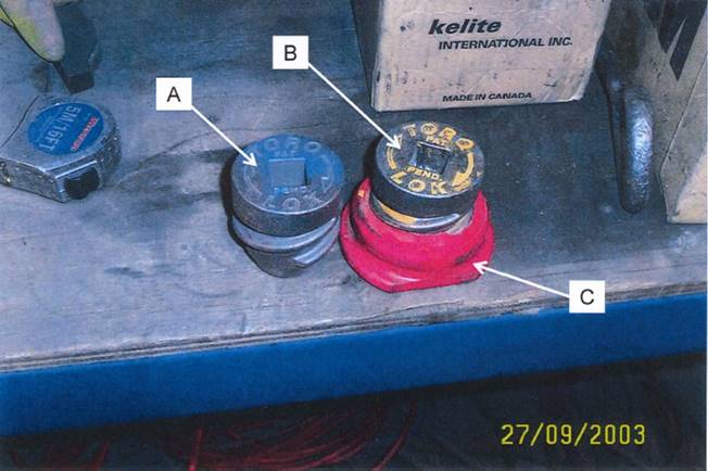
This photograph shows two locking pins (A and B). The one on the left (A) is the locking pin itself. The one on the right (B) is the locking pin as threaded into the polymer container (C), coloured red in the photograph. The pin on the right has been threaded into the retainer to the extent that about one turn of thread is visible above the retainer.
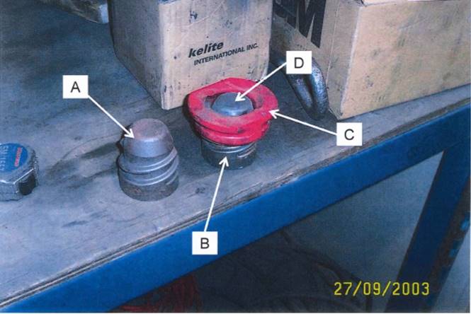
This photograph shows the same components as the previous one, save that the locking pins have been turned upside down. Mr Hughes noted that it may here be seen that the surface of the locking pin on the right (D) which is now visible is “generally flush with the level of the polymer retainer.” He understood that this represented the unlocked position, in which the attachment would not be secured to the equipment but could be placed over, or removed from, the corresponding engaging member on the equipment. In the locked position, the pin would have been threaded further into the retainer (ie further “up” as depicted on the right), such that point (D) would now be proud of the retainer.
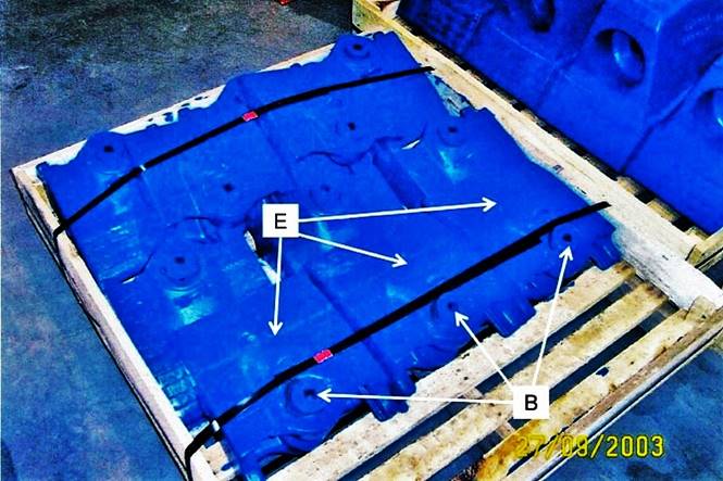
This photograph shows excavator teeth (E) with locking pins (B) located in them. These were manufactured by the foundry and placed on, and secured to, a pallet. Mr Hughes understood that the locking pins, shown here in the unlocked position, were of the same kind as shown in the two previous photographs, save that, here, they have been fitted to the teeth and painted blue.
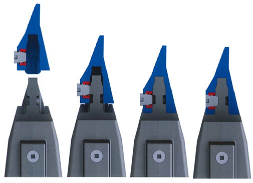
23 At the request of the applicant’s solicitors, Mr Hughes caused some drawings to be made of the wear attachment and locking pin arrangement that he viewed at Quality Steel. Reproduced below are four of those drawings, showing, from left to right, the stages of the attachment of the wear member to the base on the equipment and the engagement of the locking pin.
24 Mr Erickson said that, from its launch until the time that he left the employ of Quality Steel in July 2005, about 500 teeth units, and about about 100 shrouds and adaptors, incorporating the Torq Lok were sold per month. The arrangement was marketed with an emphasis upon the simplicity, safety and ease of installation of the wear member on the excavator which it made possible. One of Quality Steel’s major selling points was the fact that it was not necessary for anything to be done to the attachment before installation.
25 In its novelty case, the applicant relies, first, on the public display of the Quality Steel wear members, with the Torq Lok incorporated, on the pallet in the third photograph above (a single act); secondly, on the display of the Torq Lok itself on the foundry bench as shown in the first and second photographs above together with the display of the wear components on the pallet (two, or possibly three, related acts); thirdly, on all of those displays together with oral descriptions of the Torq Lok provided to Mr Hughes by employees of Quality Steel; fourthly, on the sale and supply by Quality Steel to the public of the Torq Lok assembly incorporated into wear members (a number of related acts); and fifthly, on the sale and supply by Quality Steel to the public of the Torq Lok assembly incorporated into wear members and the installation of those members, using the Torq Lok, by the public (also a number of related acts).
26 The respondent had two main lines of attack on this aspect of the applicant’s case. First, it was said that the Torq Lok did not fall within Claim 1. To a large extent, this involved an issue of the construction of the claim, but it also involved reliance on certain functional features of the Torq Lok. Secondly, the applicant’s proposition that the acts laid out in the previous paragraph were not sufficient to make “publicly available” information that would be sufficient to constitute anticipation under s 7(1) of the Act.
27 As to the first matter, it was submitted on behalf of the respondent that the Torq Lok stood outside Claim 1 in the patent as applied for because it did not have “a hold position where the lock can secure the wear member to the base and a release position where the wear member can be released from the base”. It was said that these words required that there be two unique, predetermined, positions between which the lock would be moved - one position for when the wear member was held to the base for operation and the other position for when it was to be removed from the base. On behalf of the applicant, it was submitted that a construction which proceeded from an understanding of the function of the lock would require only that the lock could be moved to a position in which the wear member was held to the base (during operation) and to a position in which the wear member could be released from the base.
28 This issue of construction is important in the context of the Torq Lok because, as the respondent emphasised, the precise location of what was said (by the applicant) to be the hold position would depend to a large extent upon the condition of the cavity in the base which received the pin - whether it be new or worn, clean or dirty, etc. The so-called hold position, it was said, was no more than the limit to which the pin could be inserted into the cavity in the base. Likewise, the precise location of what was said (by the applicant) to be the release position would depend to a large extent upon how far the particular operator found it necessary to unscrew, or chose to unscrew, the pin in the course of removing the wear member from the base. The so-called release position was no more than some point reached, ad hoc as it were, by the manipulations of the operator. So it was submitted by the respondent.
29 The description of the invention in the specification and the associated diagrams are, regrettably, of little assistance on this constructional question because they are substantially concerned with specific aspects of the invention which are much narrower than those covered by Claim 1. Otherwise, the reader is told, in the Abstract, that –
… [t]he lock is movable between hold and release positions to accommodate replacing of the wear member when needed, and secured to the wear member for shipping and storage purposes.
In the “Background of the Invention”, the reader is told, apropos arrangements commonly found in the prior art, that “[t]he assembled nose and point cooperatively define an opening into which the lock is received to releasably hold the point to the nose”.
30 In the “Summary of the Invention”, the following appears:
In one other aspect of the invention, the lock is integrally secured to the wear member for shipping and storage as a single integral component. The lock is maintained within the lock opening irrespective of the insertion of the nose into the cavity, which results in less shipping costs, reduced storage needs, and less inventory concerns.
In another aspect of the invention, the lock is releasably securable in the lock opening in the wear member in both hold and release positions to reduce the risk of dropping or losing the lock during installation. Such an assembly involves fewer independent components and an easier installation procedure.
This latter passage looks as though it might be directed to the problem of present interest, but the reference to “releasably” relates not to a release position of the lock apropos the removal of the wear member from the base but to the ability to remove the lock from the opening in the wear member where it is, in both the hold and release positions, normally secured.
31 The experts called by the parties – William Hunter by the applicant and Howard Robinson by the respondent, both mechanical engineers of considerable experience – said nothing of any value about the present controversy. In his first affidavit, Mr Robinson said that the Torq Lok “was not an integral lock having a hold position and a release position as described in the Opposed Application”; and “did not have a clearly defined hold position and release position for the lock”. He was not cross-examined on those opinions and, in an affidavit filed subsequently, Mr Hunter made no reference to them. Notwithstanding those omissions, however, I am bound to say that Mr Robinson here appears to have assumed a particular construction of Claim 1 rather than given the matter any specific consideration. The qualifier “clearly defined” appears neither in the claim nor elsewhere in the specification.
32 All of which means, for better or for worse, that the constructional question arising with respect to Claim 1 must be resolved within the four corners of the claim itself, against an understanding, of course, of the relevant field of engineering and the industrial settings in which arrangements of the kind proposed by the inventors would be used.
33 To the extent that the hold position and the release position are given definition in Claim 1, those definitions are functional ones. The hold position is “where the lock can secure the wear member to the base”, and the release position is “where the wear member can be released from the base”. In my view, a lock which could be moved between a position where the wear member would be secured to the base and a position where it could be released from the base would come within these words in Claim 1. So long as those two functional criteria are satisfied, the claim is, in my view, unconcerned with the precise location of the two positions referred to. That is not to say, of course, that an arrangement that operated other than by reference to two positions, such as one that involved the progressive application of force, for example, would come within the claim. The construction I prefer would not airbrush out of the claim the need for the lock to operate in a way which might broadly be described as binary. But it is to say that the pre-determination of exact positions, abstracted from the industrial usage of the lock, is not, in my view, a requirement of the claim.
34 The Torq Lok of Quality Steel had a hold position and a release position in this sense. Once the wear member was engaged with the base, the lock would be moved to a position where it would “secure the wear member to the base”. When the wear member needed to be replaced, the lock would be moved to a position where “the wear member [could] be released from the base”.
35 The respondent placed a deal of store by difficulties which had been encountered by Quality Steel in the assembly of wear members containing the Torq Lok before the “gauge” was introduced into the operation. This was said to demonstrate the absence of a singular “release position” at which the lock could be set before being shipped to the customer. Once the gauge was introduced – and this occurred before Mr Hughes’ visit – however, there was such a position. I cannot understand why the necessity to use the “gauge”, a workshop tool like any other, to fix this position should make any difference to the matter under consideration. As it happens, little or nothing turns on considerations at this level of detail: as I have held above, Claim 1 does not require the presence of a precise, pre-determined, position as the release one.
36 It might also be said, with some force, that the claim is concerned not with the position of the lock ex works, as it were, but with the position to which it would be moved for the purposes of releasing the wear member from the corresponding base on some excavating equipment. So long as there is such a position - and I have held that there was in the case of the Torq Lok - it is neither here nor there that the lock might not have been in that position at the point of shipment from the supplier.
37 The respondent also sought to make some point of the risk that, when the Torq Lok was being assembled the thread as between the pin and the retainer might be crossed, as Mr Erickson accepted had happened on occasion. But I should not resolve the applicant’s novelty point by reference to isolated, aberrant, occurrences in the manufacturing process. The point must be determined in the context of the undoubted fact that Quality Steel did produce wear members with the Torq Lok properly fitted according to specification.
38 For the above reasons, and applying the reverse infringement test, I conclude that the Torq Lok fell within the terms of Claim 1 in the patent applied for.
39 The other main area of contest under s 7(1) of the Act in relation to Claim 1 related to the matter of “publicly available”. In Insta Image Pty Ltd v KD Kanopy Australasia Pty Ltd (2008) 78 IPR 20, 44 [124], the Full Court said:
In respect of the issue whether information was “publicly available” before the priority date, the following principles emerge from the cases:
• The information must have been made available to at least one member of the public who, in that capacity, was free, in law and equity, to make use of it: PLG Research Ltd v Ardon International Ltd [1993] FSR 197 at 226 per Aldous J cited in Jupiters Ltd v Neurizon Pty Ltd (2005) 222 ALR 155, 183] at [141]. (This test of communication to a member of the public who is free in law or equity to use the information as he or she pleases had been enunciated by the English Court of Appeal as early as 1887 in Humpherson v Syer (1887) 4 RPC 407 at 413 per Bowen LJ.)
• It is immaterial whether or not the invention has become known to many people or a few people (Sunbeam Corporation v Morphy-Richards (Aust) Pty Ltd (1961) 180 CLR 98 at 111 … per Windeyer J). As long as it was made available to persons as members of the public, the number of those persons is not relevant. Availability to one or two people as members of the public is sufficient in the absence of any associated obligation of confidentiality: Formento Industrial SA & Biro Swan Ltd v Mentmore Manufacturing Co Ltd [1956] RPC 87 at 99-100; Re Bristol-Myers Co’s Application [1969] RPC 146 at 155 per Parker LJ.
• The question is not whether access to an invented product was actually availed of but whether the product was made available to the public without restraint at law or in equity: Merck & Co Inc v Arrow Pharmaceuticals Ltd (2006) 154 FCR 31 ….
• In order to be “available”, information said to destroy novelty must be of a kind that would disclose to a person skilled in the relevant art all of the essential features or integers of the invention: compare RD Werner & Co Inc v Bailey Aluminium Products Pty Ltd (1989) 25 FCR 565 at 593-4 ….
• In order to be “available”, information said to destroy novelty must “enable” the notional person skilled in the art at once to perceive, to understand, and to be able practically to apply the discovery, without the need to carry out further experiments in order to arrive at that point (Stanway Oyster Cylinders Pty Ltd v Marks (1996) FCR 577] at 581-2).
40 As to the facts of the matter here, it was submitted on behalf of the respondent that the evidence of Mr Hughes and Mr Erickson should be “scrutinised with care”. I agree, and shall do so. It was submitted that the evidence of Mr Hughes should be “treated with caution insofar as he attempts to characterise the Torq Lok as having certain features in language reminiscent of the claims of the Patent Application (eg, a locked position or locked position).” That relates to the question with which I have already dealt, and I have done so without paying any regard to the particular terminology of Mr Hughes’ evidence. It was submitted that Mr Hughes should have disclosed, in his affidavit, that he was “not only a director but also a shareholder (through a trust) of the [a]pplicant and also a good friend of another director and shareholder of the [a]pplicant.” This was said to be especially important to the extent that Mr Hughes purported to give expert evidence. I accept that submission so far as it goes, but, on pure questions of fact, Mr Hughes was a competent and credible witness and there appears to be no doubt as to the truth of his evidence insofar as it relates to the events of September 2003 at the premises of Quality Steel. In important respects, that evidence derives, of course, strong corroboration from that given by Mr Erickson, as to objectivity of whom there could be no question.
41 Putting those essentially adjectival matters to one side, it was accepted by the respondent that the information conveyed by the display of the Torq Lok components on the bench, and by the palletised wear members containing Torq Loks, at the Quality Steel premises in Septemer 2003 was publicly available within the meaning of s 7(1) of the Act. No serious attempt was made by the respondent to contend that the information was not sufficient to satisfy the various conditions set out in Insta Image. I would hold that it was sufficient. It follows that I accept the applicant’s case in relation to the first, second and third of the circumstances laid out in para 25 above.
42 With respect to the fourth and fifth of those circumstances, I have Mr Erickson’s direct evidence as to the approximate number of the teeth and shrouds that were sold, with the Torq Lok fitted, by Quality Steel per month. Prima facie at least, each sale was a public act in accordance with the principles which apply in this area of the law. From there, it is plainly to be inferred that, for the most part as a minimum (and one instance would be sufficient), once supplied to customers the wear members were put to their intended use, that is, they were installed on excavation equipment and secured thereto by operation of the Torq Lok; and, again inferentially, eventually removed as the occasion required. These events - sale, supply, installation, use and removal - would, in my view, have given the notional person skilled in the relevant art information sufficient to satisfy the conditions set out in Insta Image.
43 That prima facie position was, however, put in contest by the respondent in this way. It was said that there was no evidence that each customer of Quality Steel was “free in law and equity” to make use of the information as he or she thought fit. The only basis upon which he or she might not have been so free, as proposed by the respondent, was that the prospect of the wear members in question having been purchased from Quality Steel subject to confidentiality or like restrictions, whether contractual or rooted in equity, was not excluded by the applicant’s evidentiary case. In my view, the applicant was not bound to have led evidence on this specific aspect. There is nothing in the evidence to suggest that the sale of these wear members by Quality Steel was other than a normal transaction in the way of the sale of goods in which the complete, untrammelled, property in the goods passed to the purchaser. Had the respondent wished to make good a special defence that the purchasers were not free in law and equity to use the wear members as they thought fit, it was for itself to do so.
44 For the reasons I have given, I would uphold the applicant’s novelty case in relation to Claim 1.
45 With respect to Claim 2, it was submitted on behalf of the respondent that the action of the pin being turned inside the retainer in the Torq Lok could not be described as “pivotal movement”, and that the notional centre line of the pin as it was turned could not be described as a “pivot axis”. By contrast, it was submitted on behalf of the applicant that to “pivot” was “quite simply to turn or twist”. This contest concerned, therefore, the meaning of the words “pivot” and “pivotal” in context. Here two things should be said at the outset. First, Mr Hunter and Mr Robinson were agreed that there was no part of the specification, including the claims, that used words in senses other than their normal, everyday, ones. Secondly, although the “pivotal” action of the form of the lock described in the specification is there exposed in great detail, the relevant passages, if anything, teach away from the position for which the applicant contends. As it seems to me, the applicant’s position is at its strongest when the wording of Claim 2 is considered in isolation against what the applicant contends is the normal meaning of the words.
46 But that normal meaning does not take the applicant the required distance. According to the Oxford English Dictionary, 2nd ed, a “pivot” is “a short shaft or pin, usually of metal and pointed, forming the centre on which a mechanism turns or oscillates, as the pin of a hinge, or the end of an axle or spindle; a fulcrum”; and the adjective “pivotal” is “of, relating to, or acting as a pivot”. In the expression “pivot axis”, the first word is used adjectivally, but the expression is not amongst the substantial number of compound expressions in the OED in which the word has been so used over the ages. I take it from that that the expression is not one of art in this field of technology and has, therefore, what I would take to be its normal meaning as a synonym for a pivot as such, ie, the short shaft or pin referred to.
47 The pin in the Torq Lok is not, in my view, a pivot; when screwed into place it does not move pivotally; and its notional centre line is not a pivotal axis. The Torq Lok moves pivotally no more than does, for instance, a screw fastener inserted by a carpenter, a bolt inserted by a motor mechanic or the lid of a drink bottle replaced by a consumer.
48 It follows that I would reject the applicant’s novelty case in relation to Claim 2.
49 Although the language of Claim 6 varies in minor respects from that of Claim 1, there are no presently material differences. For the reasons I gave in relation to Claim 1, I would uphold the applicant’s novelty case in relation to Claim 6.
50 Neither does Claim 7 involve any presently material differences from Claim 1. For the reasons I gave in relation to Claim 1, I would uphold the applicant’s novelty case in relation to Claim 7.
51 Neither does Claim 9 involve any presently material differences from Claim 1. For the reasons I gave in relation to Claim 1, I would uphold the applicant’s novelty case in relation to Claim 9.
52 Claims 10, 11 and 12 depend, directly or indirectly, on Claim 9, and do not otherwise introduce any integer (of present relevance) differing materially from those dealt with above in relation to Claim 1. Thus the applicant’s novelty case in relation to those claims should also be upheld.
53 For the reasons I have given in relation to Claim 1, the invention, in so far as claimed in Claim 13, was anticipated by the Torq Lok. Thus the applicant’s novelty case in relation to Claim 13 should also be upheld.
54 Claims 14, 15, 16 and 18 depend, directly or indirectly, on Claim 13, and do not otherwise introduce any integer (of present relevance) differing materially from those dealt with above in relation to Claim 1. Thus the applicant’s novelty case in relation to those claims should also be upheld.
55 Although using different language, Claim 19 is relevantly indistinguishable from Claim 1, save in one relatively minor respect. Whereas Claim 1 describes the release position as one in which “the wear member can be released from the base”, Claim 19 describes that position as one in which “the lock permits installation and removal of the wearable body on and from the base”. That is to say, Claim 19 requires there to be a position at which the wear member not only may be released from the base but also may be installed on to the base. This means that the comment I made in para 35 above in the context of Claim 1 cannot be made here. However, taking the view, as I do, that the existence of a pre-determined, precise, position, either hold or release, is not a requirement of Claim 1, and likewise taking the view that Claim 19 should be similarly understood, I would also hold that the Torq Lok fell within the terms of the latter because the pin was, as observed by Mr Hughes and as inferentially supplied to customers, in the position in which the wear member would be installed on the base, being the same position as the pin would occupy when the wear member was subsequently released from the base. Thus the applicant’s novelty case in relation to Claim 19 should also be upheld.
56 Claims 20, 21, 22 and 23 depend, directly or indirectly, on Claim 19, and do not otherwise introduce any integer (of present relevance) differing materially from those dealt with above in relation to Claim 1. Thus the applicant’s novelty case in relation to those claims should also be upheld.
FAIR BASIS
57 The applicant’s fair basis case relates to Claims 4, 8 and 16. The integer that they have in common, and which, in the applicant’s submission, is not fairly based in the specification, is that “the lock is free of a threaded adjustment for movement between the hold and release positions”.
58 In the joint report of the experts, Mr Hunter said:
As described in my first affidavit at paragraph 27, the Patent Application describes two forms of lock. There is a first form, described in paragraphs [76]-[82] of the Patent, and shown in Figures 18-32. There is also a second form, described in paragraphs [87]-[90] of the Patents and shown in Figures 34-37.
The first form of lock has a pivoting movement and latching elements to latch the lock in either the hold or the release positions.
It uses a pry tool to actuate the pivoting movement. Accordingly, this first form of lock is free of a threaded adjustment for movement between a hold and release position. The second form of lock relies on a threaded wedge to move the lock from a hold to the release position. Accordingly, this second form of lock is not free of a threaded adjustment for movement between a hold and release position.
Mr Robinson agreed.
59 It was submitted on behalf of the applicant that the description in the specification of the non-threaded first form of the lock was confined to a lock with a very specific kind action, as described by Mr Hunter. That would not, it was submitted, provide a fair basis for a claim which extended generally to all forms of lock which did not involve a threaded adjustment for movement between the hold and release positions. So far as it went, this submission was not, as I understand it, resisted by the respondent. It did, however, have two arguments as to why the applicant’s fair basis point should not be accepted by the court.
60 The respondent’s first argument was a logical one: the applicant made no fair basis objection to Claim 1, Claim 4 was a subset of, and narrower than, Claim 1, ergo Claim 4 too must be taken to be fairly based. Put differently, it was submitted on behalf of the respondent that the invention, in so far as claimed in Claim 1, necessarily included locks which moved between the hold and release positions otherwise than by way of a threaded adjustment, and all Claim 4 did was to claim those locks specifically.
61 I do not think that the applicant’s fair basis objection is to be sidestepped so readily. By limiting Claim 4 in the way that they did, the inventors obtained a measure of additional protection against novelty objections of the kind, for instance, that have succeeded in this case in relation to Claim 1. Likewise, although the point does not arise here, they would have the more readily resisted an inventive step case that might have succeeded in relation to Claim 1. Although more limited as a matter of language, there is a clear sense in which the invention, in so far as claimed in Claim 4, should be recognised as more inventive, and as more likely to be novel, than the broader form claimed in Claim 1. The situation is analogous to one in which a carpenter, for example, claimed to have invented a means of fixing A to B without the use of nails or screws: that would be more inventive than, and in that sense more than a mere subset of, a simple claim by him or her to have invented a means of fixing A to B.
62 It was submitted on behalf of the respondent that the present case differed from AstraZeneca AB v Apotex Pty Ltd (2014) 226 FCR 324, 381-382 [242]-[247] in that Claim 4 did not change the nature of so much of the invention disclosed in the specification as was disclosed in Claim 1. It did not do so, it was submitted, because of the following passage in the specification:
In a further aspect of the invention, the lock and wear member can be maintained as a single integral component through shipping, storage, installation and use through an easily movable system without reliance on threaded members. This arrangement enables improved part management and easier installation of the wear member with less risk of losing the lock.
This submission was the second of the respondent’s two arguments to which I have referred.
63 Counsel for the applicant submitted that this passage was concerned only with the absence of threaded members apropos the attachment of the lock to the wear member, and had nothing to do with what was claimed in Claim 4. However, in the joint report of the experts, Mr Hunter said (with the agreement of Mr Robinson):
Taking the first sentence of this paragraph, it is clear that the lock and the wear member are to be maintained as a single integral component through four different cases. These are (i) shipping; (ii) storage; (iii) installation; and (iv) use. The integral component is to be an easily movable system without reliance on threaded members.
In the first case (shipping), this is referring to the fact that the assembly of the lock to the wear member should be one which does not rely on a threaded connection between the two. Otherwise, there is a risk that the lock could fall out of the wear member as described in risk 1 for issue B4 when the system is being moved during shipping.
In the second case (storage), this is referring to the fact that that the assembly of the lock to the wear member should be one which does not rely on a threaded connection between the two. Otherwise, there is a small risk in storage that the lock threads could be contaminated with particulates or corrode as described in risk 7 for issue B4. Also if “storage” has the equivalent of “warehousing” (which I think it does), then during warehousing, parts may be moved from one storage location to another for logistics reasons. During these movements, the same risks of a threadedly connected lock falling out of the wear member apply as for shipping.
In the third case (installation), this is referring to the fact that operation of the lock (to go from the hold to the release position) should be one which does not rely on threaded members. This avoids risk 2 as I described for issue B4, that otherwise the lock might be over or under tightened.
In the fourth case (use), this is referring to the fact that the lock has to secure the wear member to the base during use, that is when excavation is occurring. In the case of a lock which was secured to the wear member using a threaded member, there is a possibility of the threaded member becoming loose, and the lock falling out of the wear member, so this is to be avoided. Also, in the case of a lock which which was operated using a threaded connection (going from the release to the hold position) with a threaded member, there is also a risk of the lock being released because the threaded connection became loose - again resulting in the wear member falling off.
Taking the second sentence in paragraph [17] of the Patent Application, the arrangement (non-reliance on threaded members in the case of a lock and wear member maintained as a single integral component) is said to provide improved part management and easier installation of the wear member with less risk of losing the lock. All of those advantages would be obtained in the case of a lock which both; (a) did not require a threaded member to connect the lock to the wear member; and (b) did not require a threaded member to install the wear member (ie move the lock from the release to the hold position).
This lengthy passage contains a number of cross references which will make little sense to the reader of these reasons, but those matters are not presently material. What is of significance is the experts’ understanding that the passage in the specification now under discussion related both to the attachment of the lock to the wear member and to the means by which the lock moved between the hold and the release positions. To the extent that the matter of the construction of the specification is the responsibility of the court, I record that I agree with the experts on this point.
64 Save for the submission dealt with in the previous paragraph, it was not submitted on behalf of the applicant that the passage in the specification on which the respondent relied was insufficient as “a real and reasonably clear disclosure” (Lockwood Security Products Pty Ltd v Doric Products Pty Ltd (2004) 217 CLR 274, 300 [69]) of Claim 4. It follows that the applicant’s fair basis case should be rejected in relation to that claim; as should the like case in relation to Claims 8 and 16, which are indistinguishable, in this respect, from Claim 4.
UTILITY
65 In Artcraft Urban Group Pty Ltd v Streetworx Pty Ltd [2016] FCAFC 29 at [120]-[121], Greenwood J said (with the assent of Rares J):
120 The “basic principle” of inutility is that if an invention “does what it is intended by the patentee to do, and the end attained is itself useful, the invention is a useful invention”: Fawcett v Homan (1896) 13 RPC 398, Lindley LJ at 405, adopted by Gummow J as a correct statement of principle in Rehm Pty Ltd v Websters Security Systems (International) Pty Ltd (1988) 81 ALR 79 at 96 (“Rehm”). What the invention is “intended” to do is a matter to be gathered from “title and the whole of the specification”: Rehm, Gummow J at 96.
121 Put another way, the two questions are: first, what is the promise of the invention derived from the whole of the specification?; second, by following the teaching of the specification, does the invention, as claimed in the patent, attain the result promised for it by the patentee?: Décor Corporation Pty Ltd v Dart Industries Inc (1988) 13 IPR 385 at 394 (“Décor v Dart”), Lockhart J (in the Full Court); Welcome Real-Time SA v Catuity Inc (2001) 113 FCR 110 at 144 [160], Heerey J; H Lundbeck A/S v Alphapharm Pty Ltd … (2009) 177 FCR 151 at 198 [217] (“Lundbeck”), Bennett J; Ranbaxy Australia Pty Ltd v Warner-Lanbert Co LLC (2008) 77 IPR 449 at 479 [141], Emmett, Weinberg and Bennett JJ. Further, “everything” that is within the scope of a claim must be useful, that is, attain the result promised for the invention by the patentee: Lundbeck at 172 [81], Emmett J.
In the same case at first instance (Streetworx Pty Ltd v Artcraft Urban Group Pty Ltd [2014] FCA 1366 at [340]), Beach J put the matter succinctly and, with respect, helpfully as follows: “Generally, three questions may be posed. What has the patentee promised for the invention as described in the relevant claim? Is the promise useful? Has that promise been met?”
66 It is the applicant’s case that the advantages promised by the inventors are those set out in the passages from the specification extracted in paras 4 and 6 above (paras 5 and 6 of the specification respectively), namely, “enhanced stability, strength, durability, penetration, safety, and ease of replacement” (the form of words used in para 5). As will appear, it is fundamental to the applicant’s argument that these advantages are expressed cumulatively, that is to say, the relevant promise was that they were all delivered by the invention in so far as claimed in every claim.
67 From there the applicant moved to the joint report of the experts. The experts were asked:
What is meant by the following statements in paragraphs 5 and 6 of the Patent Application:
Many designs have been developed in an effort to enhance the strength, stability, durability, penetration, safety, and/or ease of replacement of such wear members with varying degrees of success.
...
The present invention pertains to an improved wear assembly for securing wear members to excavating equipment for enhanced stability, strength, durability, penetration, safety, and ease of replacement.
68 In an answer with which Mr Robinson agreed, Mr Hunter commenced by explaining what he understood a wear member and a wear assembly to be. He continued:
Hence, in relation to the first paragraph above, this means that in the past the patentee acknowledges that wear members have been developed with different designs in an attempt to improve them in the following ways:
1. Enhanced strength. This would mean that it could be expected that in operation the wear member would be less likely to fail or break as a result of the loads or stresses to which it was subjected during excavation than would otherwise be the case.
2. Enhanced stability. This would mean that it could be expected that in operation the wear member would be more resistant to being displaced by the loads to which it was subjected during excavation than would otherwise be the case.
3. Enhanced durability. This would mean that it could be expected that in operation the wear member would have a longer life, and would wear less rapidly during excavation than would otherwise be the case.
4. Enhanced penetration. This would mean that it could be expected that in operation the wear member would more easily penetrate the ground during excavation than would otherwise be the case. It would also be expected that as a result of better penetration into the ground, the flow of earthen materials into the bucket during excavation would be improved.
5. Enhanced safety. This would mean that when installing or removing the wear member, it would be more safe to install or remove the wear member to or from the base with less risk of injury to the installer. It would also be expected that the lock would hold the wear member to the base more securely than would otherwise be the case. The experts agree that a wear member that becomes loose and is dislodged from the base during excavation poses an additional safety risk.
6. Enhanced ease of replacement. This would mean that it would be easier to remove a wear member from the base, and to fit a wear member to the base than would otherwise be the case.
In relation to the second paragraph above, this means that the invention is also seeking to improve the six (6) parameters of strength, stability, durability, penetration, safety and ease of replacement via an improved wear assembly, that is via improvements to the wear member, the base, and the lock.
69 Next, the experts were asked:
What are the advantages that, collectively, the aspects of the invention described in the Patent Application are said to achieve?
In an answer with which Mr Robinson again agreed, Mr Hunter summarised the “aspects” of the invention to which I have referred in para 6 above (although he combined two of them to come up with a list of 13). He structured his response by reference to the advantages listed in para 6 of the specification, namely, the enhancement of stability, strength, durability, penetration, safety, and ease of replacement. Mr Hunter explained that the first seven aspects on his list (eight as described in paras 7-14 of the specification) “related to the geometry of the nose and the wear member … [and were] stated to have benefits related to strength, stability, penetration, and durability.” He expressed the view that those benefits “would appear to only be achieved when the wear member is fitted, and the assembled wear member is being used for excavation.” Referring to the six aspects set out in para 6 above, Mr Hunter said that they “related to the inclusion of a lock integrally secured to the wear member [and were] said to have benefits of ease of replacement and safety.” He expressed the view that those benefits “would appear to be achieved either prior to the wear member being fitted (for example when stored in inventory), or during installation of the wear member.” He concluded: “All of the aspects of the invention would need to be combined together … to allow all of the advantages of the invention described in paragraph [6] of the Patent Application to be obtained.”
70 Next, the experts were asked:
For each claim of the Patent Application:
a) what advantage(s) does the Patent Application identify for the features of the wear member or wear assembly in that claim?
b) for any other advantages identified in question 2, would a wear member or wear assembly having the features in that claim necessarily achieve that advantage? Why or why not?
In an answer with which Mr Robinson again agreed, Mr Hunter devised a detailed table setting out the “features” of each claim and identifying the advantages achieved by the features respectively. It will be sufficient to set out below Mr Hunter’s summary of the opinions he expressed in the table:
In relation to enhanced strength, none of the claims would achieve this advantage.
In relation to enhanced stability, claims 3 and 5 may provide a minor stability advantage as set out in paragraphs 14-21 of my first affidavit. [sic - this was clearly an intended reference to Mr Hunter’s second affidavit sworn on 21 October 2015]
In relation to enhanced durability, none of the claims would achieve this advantage.
In relation to enhanced penetration, none of the claims would achieve this advantage.
In relation to enhanced safety, claims 1, 11, 13, 21, and 22 would achieve this advantage.
In relation to enhanced ease of replacement, claims 1, 4, 6, 8, 9, 12, 13, 16, 19, 22, and 25 would achieve this advantage.
71 Although the experts were not required for oral evidence, there are two additional things that may be said about these conclusions. The first is that, consistently with the authorities, I should hold a “minor advantage” to be enough for the respondent in an appeal under s 60(4). The second is that, of the claims not mentioned at all in Mr Hunter’s summary above, Claim 2 is dependent on Claim 1, Claim 7 is dependent on Claim 6, Claim 10 is dependent on Claim 9, Claims 14, 15, 17 and 18 are, directly or indirectly, dependent on Claim 13, Claims 20, 23 and 24 are dependent on Claim 19 and Claim 26 is dependent on Claim 25. In each case the independent claim would achieve an advantage by way of enhanced ease of replacement (and, in the case of Claim 13, also by way of enhanced safety). Since each dependent claim will, by its terms, contain all of the integers of the relevant independent claim, I am in no position to conclude – and the experts’ report does not clearly state – that those dependent claims do not likewise achieve that advantage (or, in the case of Claims 14, 15, 17 and 18, advantages).
72 It was submitted on behalf of the applicant that all of the claims were bad for want of utility because none of them delivered on the promise made in the specification, namely, that the invention would bring all of the six named advantages. On behalf of the respondent, it was submitted (1) that, in identifying what had been promised by the inventors, it was necessary to consider the specification as a whole, and the title of the invention (Rehm Pty Ltd v Websters Security Systems (International) Pty Ltd (1988) 81 ALR 79, 96) rather than focusing on one paragraph which did no more than state the matters to which the invention “pertained”; and (2) (alternatively) that the advantages set out in para 6 of the specification were to be understood distributively apropos the claims that related to them respectively, rather than as a composite promise which conveyed the sense that all six advantages would be delivered by the invention so far as claimed in every claim.
73 Both parties left me with the impression that the decided cases were unhelpful in resolving the problem of how a promise which was textually composite would feed into the court’s consideration of the utility of a claim which did not deliver on each and every one of the advantages contained in it. I was not referred to what I have found to be a valuable treatment of the subject in Bodkin, C, Patent Law in Australia, Law Book Co, 2008, at pp 265-266:
Where a patent promises more than one result, it is somewhat unclear whether what is claimed must attain all of them. Early English authority is to the effect that all of the promised results must be attained by the invention as claimed, [Alsop’s Patent (1907) 24 RPC 733 (English High Court of Justice, Chancery Division); Flour Oxidising Co Ltd v Hutchinson (1909) 26 RPC 597 at 629 (English High Court of Justice, Chancery Division); see also Turner v Winter (1787) 1 Websters Patent Cases 77; 99 ER 1274, and Hatmaker v Joseph Nathan & Co Ltd (1919) 36 RPC 231 (House of Lords) for an example of a patent that was held to be invalid because one of two promised results was not achievable.] and this appears to have been taken to be the law in at least one Australian case. [In Pracdes Pty Ltd v Stanilite Electronics Pty Ltd (1995) 35 IPR 259 at 272-275 (Supreme Court of NSW), Windeyer J held that the claimed invention lacked utility even though it was not disputed that four of the six “promised results” were obtainable by the invention.] There are also judicial dicta in England [Horville Engineering Co Ltd v Clares (Engineering) Co Ltd [1975] FSR 196 at 210 (English High Court of Justice, Chancery Division); an appeal to the Court of Appeal was dismissed but the members of the Court of Appeal did not comment on this aspect of Whitford J’s reasoning (Horville Engineering Co Ltd v Clares (Engineering) Co Ltd [1976] RPC 411).] and in Australia, [Townsend Controls Pty Ltd v Gilead (1989) 16 IPR 469 at 490; however, von Doussa J also cited Alsop’s Patent … with approval.] however, to the effect that there will be utility if one of the promised results is attained. In view of the origins of the utility requirement in the prohibition of inventions that are “mischievous to the state”, it is difficult to see why an invention that in fact provides some benefit should not be regarded as useful, even if [it] does not provide all the benefits that the patent promises.
74 Taking the two most recent instances of what Mr Bodkin refers to as early English authority, in In The Matter of Alsop’s Patent (1907) 24 RPC 733, 752-753 Parker J said:
If the patentee claims protection for a process for producing a result, and that result cannot be produced by the process, in my opinion the consideration fails. Similarly if the patentee claims for a process producing two results combined and only one of these results is in fact produced by the process, there is a partial failure of consideration, just as there is in the case of a Patent containing one valid and one invalid Claim; and such partial failure of consideration is sufficient to avoid the Patent, “If” said Mr. Justice Buller in Turner v. Winter (1 Webst. P.C. 82) “the Patentee says that by one process he can produce three things and he fails in any one, the consideration of his merit, and for which the Patent was granted, fails, and the Crown has been deceived in the grant.”
In Flour Oxidising Company Ltd v Hutchinson (1909) 26 RPC 597, 629 Warrington J said:
I think it comes to this, that, if the patentee claims certain results from his invention, and in fact the invention does not produce those results, or even if it fails to produce any one of those results out of many, then the Crown has been deceived and the grant is void.
75 These cases were decided under the common law, and it may be a question whether they state the correct law under the “so far as claimed in any claim” approach taken by s 18(1) of the Act. Alsop’s Patent was cited with approval by Lockhart J in Prestige Group Australia Pty Ltd v Dart Industries Inc (1990) 26 FCR 197, 199, although it must be said that want of utility was not the specific ground of objection with which the court was there concerned. Also of some relevance to the present discussion is Townsend Controls Pty Ltd v Gilead (1989) 16 IPR 469, in which von Doussa J also referred, as Mr Bodkin notes, to Alsop’s Patent. At the general level, his Honour said (16 IPR at 490):
Inutility in this context is concerned solely with the scope of each claim, and means that the claim covers an apparatus or a process which is useless for the purposes indicated by the patentee, ie which does not produce the result or one of the results claimed in the specification: Terrell on The Law of Patents, 13th ed, para 5.39.
Mr Bodkin seems to have understood his Honour as proposing, positively, that “there will be utility if one of the promised results is attained”. An alternative and, with respect, more attractive (ie in the light of his Honour’s citation of Alsop’s Patent) understanding of this passage is that an inutility objection will be sustained if one of several results claimed in the specification is not produced. That was apparently the view of the authors of the 13th edition of Terrell, referred to by his Honour, who set out a lengthy passage from Alsop’s Patent, as applicable under s 32(1)(g) of the Patents Act 1949 (UK).
76 The authority which is most directly in line with the present case is Pracdes Pty Ltd v Stanilite Electronics Pty Ltd (1995) 35 IPR 259. There, the inventors listed six disadvantages of the control circuits for gas discharge lamps as known in the prior art (35 IPR at 261). The specification continued (35 IPR at 261):
The present invention seeks to eliminate the conventional form of inductive ballast, the replaceable starter switch, the starter socket, and the capacitor used for power factor correction to overcome the lagging effect of the current due to the inductive ballast, and thereby largely avoid the above disadvantages.
On the matter of utility, Windeyer J said (35 IPR at 273):
The promised result here (there being no suggestion that four of the six promised results are not obtained by the invention) is that the disadvantage in the prior circuitry using an inductive ballast alone of “heat generated in the ballast” would be “largely avoided”. There was a considerable body of evidence adduced on the question of heat generation and power loss and the question whether or not the promise made was fulfilled. If it were not then there was a partial failure of the consideration given for the patent and the claim for revocation would succeed.
His Honour found that the promised result here referred to was not delivered by the invention as claimed, and that this amounted to a ground for revocation.
77 Notwithstanding the view expressed by Mr Bodkin towards the end of the passage referred to above, I consider that the weight of authority favours the applicant on this point. In particular, Pracdes is a directly applicable superior court judgment which I should follow unless persuaded that it was plainly wrong. Where the controversial question arises under federal statutory law, there is the strongest of reasons to adhere to that principle. By contrast, Townsend Controls (a case decided, I would add, without the benefit of a contribution from a contradictor) did not involve the same issue: there was, it seems, a single embodiment apropos of which all of the challenged claims lacked utility (see 16 IPR at 490).
78 It follows that I would uphold the applicant’s utility objection in relation to all of the claims in the patent.
DISPOSITION OF THE PROCEEDING
79 The parties are agreed that I should publish my reasons determining the questions of substance which the appeal from the delegate presented, and give them the opportunity to address the court further on the orders that should be made, and as to costs. I shall follow that course.
I certify that the preceding seventy-nine (79) numbered paragraphs are a true copy of the Reasons for Judgment herein of the Honourable Justice Jessup. |

