
FEDERAL COURT OF AUSTRALIA
Sandvik Intellectual Property AB v Quarry Mining & Construction Equipment Pty Ltd [2016] FCA 236
Table of Corrections | |
Windsurfing International Inc v Petit [1984] 2 NSWLR 196 has been added to the cases cited on the cover page. | |
8 November 2016 | The number of paragraphs on the cover page has been updated from “279” to “282”. |
8 November 2016 | In para 13, third sentence, the word “always” has been replaced with “generally”. |
8 November 2016 | In para 28, the sixth sentence commencing “An opening of this axial passage…” has been deleted. |
8 November 2016 | In para 64, fifth sentence, the word “items” has been replaced with “item”. |
8 November 2016 | In para 83, last sentence, the word “in” has been replaced with “of”. |
8 November 2016 | In para 103, third sentence, the words “of the gravity” have been deleted. |
8 November 2016 | In para 111, second sentence, the words “those of” have been inserted before the words “the parties” and the word “to” has been replaced with “in” immediately after the word “parties”. |
8 November 2016 | Three new paragraphs have been inserted at para 126. |
8 November 2016 | In previous para 153 (now 156) the para cross-reference to “145” has been updated to “148”. |
8 November 2016 | In previous para 156 (now 159), the two para cross-references have been updated from “137” to “140”, and “139” to “142”. |
8 November 2016 | In previous para 170 (now 173), the first two sentences have been re-worded. |
8 November 2016 | In previous para 178 (now 181), third sentence, the word “edges” has been replaced with the words “flat faces”. |
8 November 2016 | In previous para 180 (now 183), the description between the two figures has been re-worded. |
8 November 2016 | In previous para 193 (now 196), the para cross-reference has been updated from “176” to “179”. |
8 November 2016 | In previous para 195 (now 198) the words “As I have indicated” have been deleted from the first sentence. |
8 November 2016 | In previous para 216 (now 219), in the seventh sentence, the word “respect” has been replaced with “extent”. |
8 November 2016 | In previous para 230 (now 233) the two para cross-references have been updated from “171 and 172” to “174 and 175”. |
8 November 2016 | In previous para 233 (now 236), the words “Likewise, in one of his affidavits” through to “absence of this assumption” have been replaced with “Here Mr Charlton was, as I would understand him, equating usefulness with the notion of something working “well”. But the threshold of utility is not a particularly high one and, in the context of a claim for a system, if what is claimed attains the result promised by the inventor and works, it is not, in my view, fatal under s 18(1)(c) of the Act that the resulting system does not work “well”. In the case at hand, the inventors made no promise as to the efficacy of their system for improving, or even maintaining, water pressure along the drill string, and it may be that the skilled addressee would perceive in so much of the system as is claimed in Claim 1 the making of significant compromises in that department. But, as I say, utility can only be assessed by reference to what was claimed. The circumstance that a more satisfactory system might have been invented is not tantamount to a conclusion that the invention, as claimed, is not useful.” |
8 November 2016 | In previous para 234 (now 237), the first two sentences have been deleted. The words at the start of the third sentence “In such a setting” have been replaced with “For these reasons”. |
8 November 2016 | In previous para 247 (now 250), last sentence, the word “are” has been replaced with “were” and the word “is” has been replaced with “was”. |
8 November 2016 | In previous para 275 (now 278), fifth sentence, the para cross-reference has been updated from “249” to “252”. |
8 November 2016 | In previous para 276 (now 279), second sentence, the para cross-references have been updated from “265-266” to “268-269”. |
8 November 2016 | In previous para 278 (now 281), first sentence, the words “in so far as it relates to Claims 1-4 and 6-7,” have been inserted after the word “Patent” and the word “wholly” has been deleted. |
8 November 2016 | The certification at the end of the reasons has been updated from “279” paragraphs, to “282” paragraphs. |
DATE OF ORDER: |
THE COURT ORDERS THAT:
1. The Amended Originating Application be dismissed.
2. So far as it relates to Claims 1, 2, 3, 4, 6 and 7, Australian Patent No 744870 be revoked.
3. The parties file and serve written submissions as to costs as follows:
(a) the respondent, within 14 days;
(b) the applicants, within a further 14 days;
(c) the respondent in reply, if necessary, within a further seven days.
Note: Entry of orders is dealt with in Rule 39.32 of the Federal Court Rules 2011.
JESSUP J
1 In this proceeding, the applicants, Sandvik Intellectual Property AB and Sandvik Mining and Construction Australia (Production/Supply) Pty Ltd, allege that the respondent, Quarry Mining & Construction Equipment Pty Ltd, has infringed Claims 1-4 of Australian Patent No 744870 (“the Patent”), of which the applicants are the proprietor and the exclusive licensee in Australia respectively. They seek declarations, injunctions, orders for delivery up and damages or, at their election, an account of profits. They also allege that the respondent’s conduct of which they complain amounted to contraventions of s 52 of the Trade Practices Act 1974 (Cth) (“the TP Act”) and of s 18 of the Australian Consumer Law (“the ACL”), Sch 2 to the Competition and Consumer Act 2010 (Cth); and they seek corresponding remedies under those provisions.
2 The respondent cross-claims for the revocation of the Patent, in relation to Claims 1-4, 6 and 7, on grounds to which I shall refer, but which include lack of novelty, lack of inventive step, lack of utility, and failure to describe the best known method. I shall elaborate upon those grounds in due course.
THE RELEVANT FIELD OF TECHNOLOGY
3 The field of technology with which the case is concerned is what is described as extension drilling in underground mines, specifically coal mines. The description of the background technology which follows below is substantially taken from the evidence of Paul Charlton, an engineering consultant working in the mining machinery industry called by the applicants.
4 Traditionally, the structural integrity of the roofs of underground roadways in coal mines was secured by the use of timber supports. Since the 1970’s, however, bolting systems have been used for this purpose. In the presently relevant context, I need mention only roof bolting and cable bolting. Both of these systems work to prevent roofs from collapsing by clamping together the layers of sedimentary material above the void constituting the roadway.
5 Typically, a seam of coal is about 3-5 m thick. The layers of sedimentary material above the coal seam often lack internal integrity. Roof bolting involves the insertion of a series of long solid bolts into the roof of the roadway. In order to do this, it is first necessary to drill holes into the roof of appropriate diameter and length to cater for the bolts. The length of roof bolts is typically within the range 1.5-2.4 m. The lower end of the bolt will be threaded to take a nut. The bolt is inserted into the drilled hole and secured, either by a mechanical means or using adhesive. The nut is then tightened against the surface of the roof. Often there will be a metal plate or washer between the nut and the roof surface to spread the load against the roof surface. The tensioned roof bolts lock, or key, the strata material together.
6 Cable bolts are long flexible bolts, typically in the order of 4-12 m in length. They comprise a series of twisted wire strands. Cable bolts are used in the same way as roof bolts in that they are inserted into the roof of an underground roadway in a mine. Although they will typically be used at the intersections of roadways, they are also used wherever the use of standard roof bolts alone is insufficient to support the roof adequately and additional reinforcement is required.
7 The present case is concerned not with roof bolts and cable bolts as such, but with drilling systems for making the holes into which these bolts will be inserted. The case is specifically concerned with systems for making the long holes required for the insertion of cable bolts, but, since the same power source is commonly used for each, it is convenient to move next to a generic explanation of the technology which is used for drilling roof holes in mines.
8 There are two types of drilling techniques (and associated machinery and equipment) used in mining, namely, rotary percussive drilling and non-percussive rotary drilling. Rotary percussive drilling is utilised where the strata to be drilled typically has a compressive strength greater than 60 Mpa, and involves a rotating drill bit which is hit with a high frequency hammer to burst the strata. Rotary (ie non-percussive) drilling does not involve percussion, but the strata are cut away in a manner which is similar to drilling timber with a hand drill. In percussive drilling, the drilling rotation is anticlockwise. In (non-percussive) rotary drilling, the rotation is clockwise. Coal is relatively soft, thus percussive drilling is rarely required. The drilling of holes for roof bolts, rib bolts and cable bolts in coal mines is almost always done using (non-percussive) rotary drilling equipment.
9 The types of equipment used in the drilling process may be either hand-held or machine-mounted roof bolters. Hand-held roof bolters are lightweight portable units, the vast majority of which are pneumatically powered. They are relatively low-powered units operating at around 100 to 150 psi, being the realistic maximum compressed air pressure available underground due to reticulation losses. In practice, this relatively low power capacity means that the drilling power (feed force, torque and rotational speed) able to be generated is also quite low. Thus units of this kind are limited in their ability to drill quickly and efficiently. There are also hydraulically powered hand-held portable roof bolters, but such units are also low-powered. For a number of presently irrelevant reasons, over time the use of hand-held bolters has become increasingly rare.
10 There are two types of machine-mounted roof bolters, namely, stand-alone roof bolters and bolters incorporated as a part of a continuous miner. Typically stand-alone roof bolters are mounted on vehicles which run on caterpillar tracks and can be driven to position. They carry one or more bolters, or “drilling rigs”. Usually the machine is operated by one or more operators who can drive the machine and operate the roof bolter. Another type of stand-alone roof bolter is a longwall face bolter. In longwall mining it is necessary to install roof and cable bolts in the final section of the longwall, to protect that part of the roof against collapse when the longwall machinery is disassembled and removed. The longwall face bolter is a stand-alone piece of equipment, but it runs on the longwall conveyor system. Longwall face bolters typically have two hydraulic roof bolters, and are used specifically at the end of the longwall block to install roof bolts, rib bolts and cable bolts so that the longwall can be relocated.
11 In the case of a roof bolter which is incorporated into a continuous miner, the bolter itself is essentially the same as a rig found on a mobile bolter. There will normally be at least two bolters, one on each side of the machine, so that a row of bolts can be inserted into the roof across the width of the roadway roof. The bolters can be angled so that one bolt can be inserted vertically and a second inserted at an angle.
12 Machine-mounted bolters are hydraulically powered, typically with an operating pressure in the order of 3000 psi. This provides far greater torque and drilling speed compared with pneumatically-powered hand-held bolters.
13 The main components of a machine-mounted bolter are the rig itself, or mast, and the drill. For a layperson, the best starting-point is to imagine a common handyman’s electric drill, which drives through a chuck into which a drilling bit is inserted and secured. In roof bolt drilling, there is likewise a drill with a chuck, and the chuck receives the drill bit, referred to as a “rod” since it will generally be at least long enough to facilitate the drilling of a hole to receive a roof bolt of 1.5 m in length. This drill, with chuck and rod, is mounted on a mast the top portion of which, called the headplate, is pressed against the roof of the mine where the hole is to be drilled. In the drilling operation, the drill is moved upwards along the mast as the rotating drill rod cuts the required hole into the strata above.
14 In his affidavit, Mr Charlton presented the following diagrammatic representation of the various stages of the drilling operation:
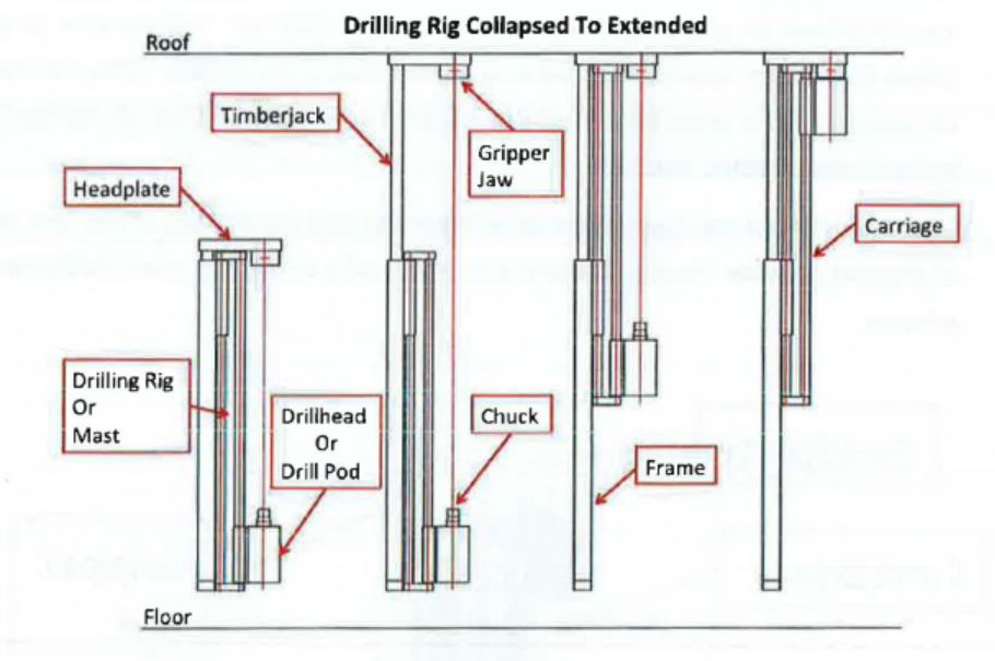
15 The mast is shown in its collapsed state on the left hand side with the drillhead, or drill pod, at its lowermost position. In the next stage the timberjack is raised so that the headplate makes contact with the roof. The headplate steadies the drilling rig and provides a guide for the drill rod once it has been placed in the chuck. Attached to the headplate are “gripper jaws”, the purpose of which will become clear presently but which do not perform a function in single-pass drilling. It is sufficient here to note that the drill rod will pass through these jaws. At this stage, the drill rod has been placed in the chuck, its alignment being indicated by the thin red line running between the chuck at the lower end and the jaw at the upper end. In the third stage, drilling has commenced. The drill chuck apparatus has moved about halfway up the mast. The cutting end of the drill is doing its work in the strata above. When the drill chuck apparatus reaches the underside of the headplate, the drilling process is complete (the diagram on the right-hand side), and the process is reversed. The apparatus is lowered, and the drill rod withdrawn from the roof of the mine. An operation such as that outlined here is referred to as “single-pass” drilling.
16 The drill rods used in single-pass drilling are metal, typically of either hexagonal or round section. They do not include an integral cutting/drilling tip but will be threaded at one end to accommodate the attachment of a cutting tip. The other end of the drill rod forms the drive shaft of the rod. The drive shaft of single-pass drill rods is configured to fit into and be driven by the drive chuck of the drill machine. The standard drive chuck used in hydraulically-powered bolters is the “square locking chuck”. This chuck, and complementary square drive drill rods, were developed in Australia in the mid-1980s, and have been the standard in conjunction with hydraulic roof bolters in the coal mining industry since the early 1990s.
17 An example of a standard 25 mm square locking chuck is shown below, from above (left-hand photograph) and from below (right-hand photograph).
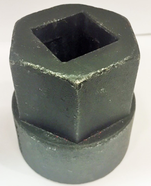
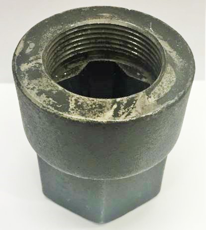
18 The chuck has an upper, a middle and a lower part. The upper part consists of a square opening (as shown on the left-hand photograph above) slightly larger than the cross section of the square section of the drill rod. The lower part consists of an internally-threaded cylindrical section (as shown on the right-hand photograph above) which screws onto the matingly threaded upper end of the driven shaft of the drill motor. The middle part (not visible in the photographs above) consists of the drive chamber of the chuck.
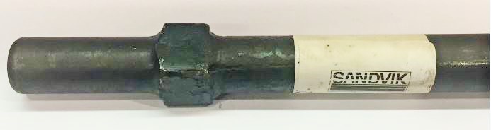
19 An example of the driven end of a single-pass drill rod of the kind used in connection with the chuck described above is shown below.
20 With the chuck installed on the drill and ready for use, the drill rod is inserted into the chuck by passing first the round section and then the flat-sided, or square, section through the hole in the upper part of the chuck, to the point where the square section lies wholly within the middle part, or drive chamber, of the chuck. The drive chamber has a series of 12 angled faces in a cross-like configuration and is slightly larger than the square section of the rod, such that the rod may rotate relative to the chamber by about 20 degrees. Once rotated relative to the chuck, the square section of the rod is no longer aligned with the opening of the chuck and is prevented from pulling out of the chuck by the lip of the chuck opening. The configuration of the chuck and the drive shaft is such that when the chuck is operating, the drill rod is locked in place and cannot come out of the chuck. This is a safety measure, as it ensures that, when the drill/chuck apparatus is lowered after the completion of drilling, it does not leave the rod dangling in the roof hole with the risk that it may fall on to operators below: the rod remains secured in the chuck until removed manually.
21 The round section at the lowermost end of the rod – below the square section – is referred to as a “spigot”. It has at least three relevant functions. First, it sits on the base of the chuck and takes the weight of the rod. Secondly, it fits into a corresponding piece in the chuck from which flushing fluid is passed into it and up the drill rod, an important subject which I do no more than introduce at this stage. Thirdly, it fits inside, and thus forms a seal with, an O-ring in that corresponding piece to prevent leakage of the flushing fluid at this point. For that purpose, self-evidently, this spigot must be circular in profile.
22 What I have said to date relates to single-pass drilling. However, where cable bolts are to be used, drill rods of the kind described above are not long enough to drill holes of the required depth. Because of limitations imposed by the height of the mine roadway, to use a single drill rod long enough to drill a hole of up to 12 m in depth would be out of the question. Thus the drill rod used is in fact a string made from round or hexagonal sections of drill rod with complementary male and female threaded ends – by convention the upper and lower ends of each rod respectively. The thread employed in the technology relevant to the present proceeding is right-hand rope thread. Individual rods come in varying lengths, typically from about 0.5 m to 2 m. The first, or uppermost, rod is adapted to receive the drill bit.
23 Ignoring for the moment the means by which the driven end of the lowermost rod communicates with the chuck, at the general level it may be said that drilling for cable bolts involves using a first drill rod with the bit attached to its uppermost end to drill into the mine strata until the length of that rod has been exhausted (in much the same way as done in single-pass drilling), then connecting a second rod between the chuck and the first drill rod, drilling again until the length of the second drill rod is used up, then connecting a third drill rod between the chuck and the second drill rod, and so on until a hole of the length required to accommodate the cable bolt intended to be used has been made. Each time a new rod is connected to its predecessor (ie the one that has been almost wholly driven into the roof strata), the drill/chuck apparatus must be lowered down the drill mast to make room for the new rod. Because the drill string consists of a series of rods built up as drilling proceeds, this technology is referred to as “extension drilling”.
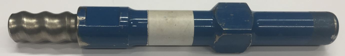
24 It will be immediately apparent that, since each rod must have, at its lower end, an internal female thread adapted to receive the upper male-threaded end of the next rod, the lower end of the any one of these rods could not be fitted with a spigot arrangement of the kind commonly found on rods used in single-pass drilling, as referred to above. The expedient which, some time before the priority date, had come to be used to deal with this issue was the inclusion of an “adaptor” (or “chuck extension” as such things are sometimes called) between the chuck and the lowermost drill rod. At its lower end, such an adaptor had the same cube-and-spigot arrangement as was used on single-pass drill rods. At its upper end, it was fitted with a male thread to engage with the lowermost rod. It was an important aspect of the applicants’ case that roof bolting contractors in the coal mining industry saw this expedient as more convenient than having to change the chuck on a drilling machine each time it was necessary to undertake extension, as opposed to single-pass, drilling. Indeed, the mining experts called by both parties (one of whom was Mr Charlton) were agreed that, as a generalisation, contractors would not contemplate changing a chuck underground during the course of a roof bolting program. An example of an adaptor such as that described above is the following:
25 Using the equipment referred to, the process for extension drilling, as explained by Mr Charlton, involves the following steps:
(a) Insert a drive adaptor into the drill chuck;
(b) Attach a first extension rod (with drill bit included) to the drive adaptor;
(c) Raise the drill chuck, commence drilling and drill to the full length of the first extension rod;
(d) Cease drilling and clamp the gripper jaws onto the lower end of the first extension rod just above the coupling of that rod and the adaptor;
(e) Reverse the rotation of the chuck to uncouple the first extension rod from the adaptor;
(f) Lower the drill chuck;
(g) Attach the top of a second extension rod to the lower end of the first extension rod to create a drill string of (at this point two) extension rods;
(h) Couple the adaptor to the bottom of the second extension rod;
(i) Recommence drilling and drill to the full length of the second extension rod;
(j) Repeat steps (d) to (i), adding additional extension rods to the drill string until the desired length of hole has been drilled.
With respect to steps (d) and (e), the use to which the gripper jaws, first mentioned in para 15 above, are put should now be evident: to uncouple the first (and subsequently each lowermost) rod from the adaptor requires an unscrewing action in which the rod must be held firmly in place while the machine causes the chuck, and therefore the adaptor, to rotate in the reverse direction.
26 Once the drill hole has reached the required depth, it is necessary to remove the drill string, which now consists of a number of rods connected together. Essentially, this process requires the sequential removal of each rod from the string. This must be done in stages. First, the chuck is lowered, bringing the drill string with it. To remove the lowest extension rod from the string requires that rod to be disconnected from the rod immediately above it. The string is lowered to a point where the connection between the lowest rod and the rod above it is immediately below the gripper jaws, such that, when those jaws are engaged, they grip the lower end of the upper rod. The drill is then operated in reverse, imparting an unscrewing action upon the drill string. Because the upper rod is held firm by the gripper jaws, it will not move. Between those jaws and the drill chuck, there are now two points of threaded connection in the string, one between the adaptor and the lower rod and the second between the lower rod and the rod above it. When the direction of the rotation of the chuck is reversed, one of those connections will come unscrewed. It may be either of them. The other connection must then be unscrewed manually, using a spanner.
27 Once the lowermost drill rod has been removed in the way described, the drill/chuck/adaptor apparatus is raised again along the mast to make connection with, and to screw into, the female end of the next rod which, it will be recalled, is just below the gripper jaws. The jaws are then released, the drill/chuck/adaptor apparatus, now with the drill string attached again, is lowered until the lower end of the next rod in line appears below the gripper jaws, the jaws are engaged at that point, and the process described above commences again. And so on, until all the sections of the drill string have been removed.
28 One further common feature of extension (and, according to Mr Charlton, single-pass) drilling which should be mentioned at this stage is the means by which cuttings from the action of the drill bit are cleared away. Here it must be understood that the bit is operating in a confined space and, absent some such means, would soon become clogged with debris from its own action and would jam. Although there are some other methods employed, the most common method in Australia is flushing with water continuously pumped through an axial passage in the drill rod or rods. This is the flushing fluid to which I referred in para 21 above. The drill rods which I have been discussing above, and the adaptors used in conjunction with them, are not solid but have a pipe-like configuration, allowing for the passage of flushing water. In order to inhibit the outflow of water contained inside existing rods on the drill string at the point when the lowest connection is broken to facilitate the insertion of the next rod, some or all of the rods will be internally equipped with a non-return ball-valve arrangement.
29 While on the subject of flushing water, I should also mention a practical issue of some importance which intruded into the evidence, and the submissions, in the case. This water must be supplied to the drill string at a sufficient pressure to cause it to rise vertically, in a narrow tube, over a distance of anything up to about 12 m, and then to carry out the necessary flushing. In a system which involves so many joins, the potential for leakage, and loss of pressure, is apparent. There appears to be little practical difficulty at each male/female threaded connection between the various rods: the connection itself is sufficiently watertight to suit the purposes required. But there is a need for an effective seal at the point where a single-pass rod or an adaptor sits in the chuck. The spigot-and-O-ring arrangement to which I referred in para 21 above was the means by which this problem had been addressed both in the case of single-pass drilling, where the spigot was on the end of the drill rod itself, and in the case of extension drilling, where the spigot was part of the adaptor.
30 What I have described above represents the state of the art, and the common general knowledge, in the industry as at the priority date for the Patent, 11 June 1997.
THE PATENT
31 According to the specification:
This invention relates to an extension drilling system, and more particularly, but not exclusively, to extension drilling systems for use on a semi-automatic drilling rig and used to drill holes (bores) in subterranium [sic] mining operations such as coal mining where the structure of the roof of a tunnel is to be rendered more secure by the insertion of rock bolts into holes drilled into the roof structure.
32 The specification refers to two problems in the existing art, in the following terms:
The primary problem with conventional drill rods for extension drilling systems, when used with semi-automatic drill rigs is that, when the drill string (a series of drill rods coupled together) are to be uncoupled there are two threaded couplings between the grippers and the chuck. As the grippers are operated, and the chuck spun slowly in reverse, the threaded joint between the drive adaptor and the bottom extension rod can become uncoupled which is undesirable as distinct from the desired uncoupling between the bottom and second bottom extension rods.
A secondary problem is that the use of a drive adaptor takes up valuable boom height on the rig thus reducing the length of the extension rods that can be used.
33 The invention is then disclosed in the following terms:
According to the present invention there is provided an extension drilling system for use with a semi-automatic drilling rig, said drilling system including a plurality of extension rods connected together to constitute a drill rod string and each extension rod having co-operating a male and female right-hand rope threaded couplings at one end and a female right-hand rope threaded coupling at the other end, whereby the extension rods are connected together by coupling of the male coupling of one extension rod with the female coupling of another extension rod to create a male/female coupling between connected extension rods therebetween, a drive chuck of a drilling rig for driving the outside surface of a female threaded end coupling of an extension rod at one end of the drill rod string, selectively in either forward or and reverse directions, a set of grippers for preventing rotation of clamping an extension rod being arranged to clamp an extension rod at a location so such that only one male/female threaded coupling is provided located between the drive chuck and the set of grippers and so that with the grippers clamping the extension rod, and with the drive chuck being driven in the reverse direction, only the male/female coupling between the grippers and the drive chuck is uncoupled.
According to the present invention there is further provided an extension drilling system for use with a semi-automatic drilling rig, said drilling system including a plurality of extension rods connectable together to constitute a drill rod string and each extension rod having a male right-hand rope threaded coupling at a male end and a female right-hand rope threaded coupling at a female end, whereby the extension rods are connectable together by coupling of the male end coupling of one extension rod with the female end coupling of another extension rod to create a male/female coupling between connected extension rods and wherein the external surface shape of the female end has a profile for engagement by a drive chuck of a drilling rig to drive the female end of an extension rod at one end of the drill rod string, and wherein the external surface shape of the extension rods between the female end and the male end is of a different and substantially uniform profile.
34 To a large extent, these passages in the specification amount to a recital of the prior art, as outlined above. Central to the applicants’ case is the proposition that they depart from the prior art to the extent that they require that the drive chuck drive “the outside surface of a female threaded end coupling of an extension rod” and that “the external surface shape of the female end has a profile for engagement by a drive chuck”. So far as may be discerned from these passages, therefore, the essence of the invention lies in the direct mechanical engagement of the chuck with the lower end of the lowermost drill rod in the string, thereby dispensing with the need for an adaptor. The “primary problem” identified in the specification is overcome because, at the stage of the removal of a rod from the string, there is now only one threaded connection between the gripper jaws and the chuck, namely, the connection between the rod being removed and the next rod above it which is held firm by the jaws. The “secondary problem” referred to is overcome in the sense that it is no longer necessary to use an adaptor. As will appear presently, however, in one of two preferred embodiments of the invention, the use of an adaptor is in fact prescribed by the specification.
35 The specification continues:
Preferably the extension rods have axial passages therethrough in communication with each other and through which flushing fluid is delivered to an associated drill bit. Preferably a non-return valve is incorporated in at least one of the extension rods to shorten the delay time in delivering flushing fluid to the drill bit before re-commencement of drilling after an extension rod is added to the extension rod string.
Preferably the extension rods are of hexagonal, cross-section or any other suitable cross-section and may be forged or welded rods which are selectively or fully heat treated.
36 Under the heading, “Best Modes for Carrying out the Invention”, the specification describes two preferred embodiments. It does so by reference to diagrams, as follows:
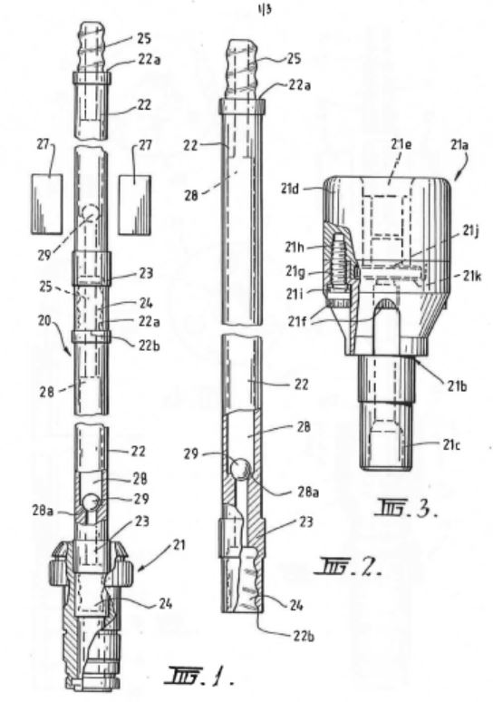
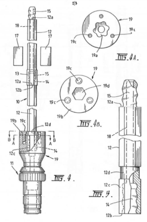
37 According to the specification, Fig 1 is a longitudinal side elevational view of an extension drilling system in accordance with a first preferred embodiment of the invention. Figure 2 is a longitudinal side elevational view of an extension rod as used in the system of Fig 1. Figure 3 is a longitudinal side elevational view, partly sectioned, of an alternative direct drive chuck for use in the extension drilling system of Figs 4-5. Figure 4 is a longitudinal side elevational view, partly sectioned, of an extension drilling system in accordance with a second preferred embodiment of the invention. Figure 4A is a cross-sectional view taken along the line A-A of Fig 4. Figure 4B is a cross-sectional view taken along the line B-B of Fig 4. Figure 5 is a longitudinal side elevational view of an extension drill rod as used in the system of Fig 4.
38 As thus explained in the specification, there are two preferred embodiments of the invention. The first is the subject of Figs 1 and 2, while the second is the subject of Figs 3, 4 and 5. The systems as a whole are depicted in Figs 1 and 4 respectively. The rods to be used in those systems are depicted in Figs 2 and 5 respectively. Greater detail of what is described as a chuck in Fig 4 is given in Figs 4A and 4B, the effect of which is to provide a locking mechanism similar, it seems, to that described earlier in these reasons. What is said to be “an alternative direct drive chuck”, shown in Fig 3, is in fact an adaptor, or “chuck extension”. Apparently, it is presented as an alternative to the chuck depicted in Fig 4 (that chuck itself being described elsewhere in the specification as an adaptor).
39 With reference to Figs 1 and 2, the specification states that the chuck may be “a TL2 drive chuck as manufactured by McSweeney’s, Inc of the USA”. That chuck, to which I shall refer as the “McSweeney TL2 chuck” is the same as the 25 mm square locking chuck, save that the dimensions of the square opening are 28 mm rather than 25 mm. The specification continues that the chuck, which may be the McSweeney TL2 chuck, “directly rotatably drives” a string of extension rods. The means of connection between various rods is described, but is presently uncontroversial. An axial passage is provided through the respective extension rods, it being stepped to provide a transition between larger and smaller diameter portions of the passage whereby to provide valve seats for the ball valve mechanisms.
40 The specification continues:
As illustrated in Figure 2, the external or outside surface of the female socket 24 is engaged by the drive chuck 21 for driving the string of extension rods 22. The surface of the female socket 24 that the drive chuck 21 engages therefore has a profile suitable for that engagement. Figure 2 shows that the surface which is engaged by the drive chuck 21 includes a portion of greater diameter at the position to which the lead line for the reference numeral 23 extends. Extending from the engagement position of the drive chuck 21 to the male member 25, the surface of the extension rod 22 is of a substantially uniform profile and of reduced diameter compared to the diameter at the engagement position of the drive chuck 21. Thus there is a difference in surface profile between the engagement position of the drive chuck 21 at the female socket 24 and the section of the extension rod between the female socket 24 and the male member 25.
41 It should be noted that all but the first two sentences in this passage was added by amendment on 30 August 2006. It should also be noted that, if the McSweeney TL2 chuck were to be used in the system described above by reference to Figs 1 and 2, and since it is a requirement that “the external surface shape of the female end has a profile for engagement by a drive chuck”, then, at “the position to which the lead line for the reference numeral 23 extends”, the rod would have to be of a square profile.
42 What the specification says about Fig 3 is as follows:
Figure 3 of the drawings shows a modified (alternative) direct drive chuck for use in the extension drilling systems of Figures 4 to 5, and is in fact the drive chuck preferred, and which is a modular assembly 21a comprising a male drive member 21b having a drive shaft 21c and coupled to a female drive member 21d with a socket 21e. The drive members are coupled by bolts 21f through holes 21g in the male drive member 21b and into threaded blind holes 21h in the female drive member 21d with interposed spring washers 21i. The male and female members may also be “dogged” together, that is Interlocked. The socket 21e receives a sealing member 21j which may be formed from polyurethane, moulded around a stainless steel washer body, and which seats on a step 21k in the end of the male drive member 21b. The modular drive chuck of this embodiment, in being formed in two separable parts, allows the drive members 21b and 21d to be interchangeable for different drive configurations, and also allows for the sealing member 21j to be replaced when worn.
43 With respect to Fig 4, it is made clear that the chuck itself, which again may be the McSweeney TL2 chuck, is the lowermost portion on the diagram, marked 11. The adaptor is the portion marked 19. After referring to the rods and the connections between them, the specification continues:
With reference to Figures 4 and 5 of the drawings, the internal detail of the chuck adaptor 19 is according to that shown in Figure 4A of the drawings and is shaped as a hexagon 19a offset by 20° of rotation. A chuck adaptor cover 19b as shown in Figure 4B is bolted to the remainder of the chuck adaptor by bolts 19c. The cover provides a hole 19d for the extension rod to fit into and which has a normal hexagonal shape. The end of the extension rod which fits into the chuck adaptor 19, and incorporating the female socket 14 which is not drivingly engaged by the chuck adaptor, has an [sic] hexagonal exterior 12c and above that a round section 12d. When the extension rod end is fitted into the chuck adaptor, the hexagon 12c on the end of the rod is aligned with the hexagonal hole 19d through the chuck adaptor cover 19b. The rod is then slid down into the chuck adaptor to its full extent, and as positive rotation is commenced the chuck adaptor rotates 20° in relation to the rod and the drive flats of the hexagonal 19a in the chuck adaptor engage against the hexagonal shaped end 12c on the rod to thus rotatably drive the rod. The round section 12d on the rod is provided so that, as the rod is rotated through 20°, the hexagon through the chuck adaptor cover 19b does not bind on the rod. As long as positive rotation is maintained in the chuck adaptor the rod cannot be removed as the two hexagons are misaligned by 20° and the rod needs to be rotated through 20° so that the corners of the hexagon 12c will clear the hexagonal hole 19d through the chuck adaptor cover 19b in order for the rod to be removed. The drive chuck as described above in providing a twist locking action between the chuck and the rod improves the safety of the drilling system because of the locking of the rod in the drive chuck whilst maintaining positive rotation.
44 The burden of this passage is to explain the means by which a rod with a female threaded lower end may form a locking engagement which the adaptor into which it is placed, but to which it is not threaded. The principle is similar to that employed in the square locking chuck, but here the engagement is between the rod and the adaptor, rather than being between the adaptor and the chuck. It is apparent, and is expressly required in this embodiment, that the lowermost section of the rod be of hexagonal profile – it is here that the driving force will be imparted to the rod by the adaptor – while, immediately above that, there must be a section which is round in profile to accommodate turning the rod through 20 degrees to bring about the intended locking effect.
45 Whether the remainder of the rod – above the round section – will also be round is the concern of the following paragraph in the specification:
In the case of both embodiments of the invention, the extension rods are of hexagonal cross-section, as previously described with reference to the embodiment of Figure 4 to 5, or of round cross-section or of any other suitable cross-sectional shape whereby they can be driven by the chuck adaptor 19 in the case of the embodiment of Figures 4 to 5 or directly by the drive chuck 21 or 21a in the embodiment of Figures 1, 2 and 3. The extension rods may be forged or welded rods which are selectively or fully heat treated.
46 The specification includes the following claims:
1. An extension drilling system for use with a semi-automatic drilling rig, said drilling system including a plurality of extension rods connected together to constitute a drill rod string and each extension rod having a male right-hand rope threaded coupling at one end and a female right-hand rope threaded coupling at the other end, whereby the extension rods are connected together by coupling of the male coupling of one extension rod with the female coupling of another extension rod to create a male/female coupling between connected extension to rods, a drive chuck of a drilling rig for driving the outside surface of a female coupling of an extension rod at one end of the drill rod string, in either forward or reverse direction, a set of grippers for preventing rotation of an extension rod being arranged to clamp an extension rod at a location such that only one male/female coupling is located between the drive chuck and the set of grippers and so that with the grippers clamping the extension rod, and with the drive chuck being driven in the reverse direction, the male/female coupling between the grippers and the drive chuck is uncoupled.
2. An extension drilling system as claimed in claim 1 wherein the extension rods have axial passages therethrough in communication with each other and through which flushing fluid is delivered to an associated drill bit.
3. An extension drilling system as claimed in claim 2, wherein the axial passage through at least one of the drill rods incorporates a non-return valve to shorten the delay time in delivering flushing fluid to the drill bit before recommencement of drilling after a drill rod is added to the drill rod string.
4. An extension drilling system as claimed in any one of the preceding claims, wherein the extension rods are of hexagonal or round cross-section or of any other suitable cross-section whereby they can be driven by the drive chuck either directly or via an adaptor having a socket therein of similar cross-section to the extension rods.
5. An extension drilling system as claimed in claim 4, wherein the co-operation between the drive chuck or the adaptor and the extension rod directly associated therewith is such that limited relative rotational movement therebetween misaligns the respective cross-sections to prevent separation of the extension rod whilst maintaining driving engagement.
6. An extension drilling system substantially as hereinbefore described with reference to figures 1 and 2, or figures 3, and 4 as modified by figure 5, of the accompanying drawings.
7. An extension drilling system for use with a semi-automatic drilling rig, said drilling system including a plurality of extension rods connectable together to constitute a drill rod string and each extension rod having a male right-hand rope threaded coupling at a male end and a female right-hand rope threaded coupling at a female end, whereby the extension rods are connectable together by coupling of the male end coupling of one extension rod with the female end coupling of another extension rod to create a male/female coupling between connected extension rods and wherein the external surface of the female end has a profile for engagement by a drive chuck of a drilling rig to drive the female end of an extension rod at one end of the drill rod string, and wherein the external surface of the extension rods between the female end and the male end is of a different and substantially uniform profile.
NOVELTY
47 The respondent contends that the invention the subject of the Patent, so far as claimed in claims 1, 2, 4, 6 and 7, was not novel in June 1997. Here the question which arises under s 7(1) of the Patents Act 1990 (Cth) (“the Act”) is whether the invention was not novel in the light of two kinds of prior art information relied on by the respondent, namely (1) the public use of an extension drilling system by Colrok Mining Pty Ltd (“Colrok”) at collieries in New South Wales, including Ellalong and Macquarie, between 1989 and 1994, and (2) the public use of an extension drilling system at the West Wallsend, Gretley and Wyee Mines by an entity described in the evidence (and in the respondent’s Particulars of Invalidity) only as “Wilson Mining”.
48 Darrell Geatches was the respondent’s principal witness called to provide evidence of the extension drilling system used by Colrok. He worked in the mining industry in New South Wales between 1956 and 1994. From 1976 to 1994 he was a co-owner and director of Colrok, a service contractor to the coal mining industry. He was directly involved in the day-to-day management of Colrok’s business and the provision of its services throughout that period. Because his lack of engineering qualifications was highlighted during his cross-examination by counsel for the applicants, I shall refer to the nature of his experience in the mining industry. In 1962, he started work at Newstan Colliery at Lake Macquarie, where he worked as an electrician and leading hand electrician from 1964 to 1969. During that time, he returned to technical college where he obtained his third class certificate of competency in coal mining. His employer then promoted him to Deputy in Charge - Maintenance, Production Units (with continuous miners). This role involved him overseeing a full production crew, he being primarily responsible for safety in the relevant section of the mine. His role included overseeing roof control, gas testing and shot firing. He was Deputy in Charge between 1969 and 1976.
49 In 1976, Mr Geatches left Newstan Colliery and joined Barry Webb as a co-owner and director of Colrok. Mr Webb had been a project manager for some of the larger mining companies before that time, including Allied Construction and Dravo. He had a background in metalliferous mining, which included hard rock and mineral extraction. It was Colrok’s intention to provide support services to companies carrying out stone excavation in coal mines, such as by drilling through igneous intrusions, which were very hard intrusions formed by molten stone coming up through coal steams, which had to be drilled and blasted rather than cut.
50 One of Colrok’s first contracts after he joined it involved drilling holes for roof bolts at the Liddell Colliery. Because of the presence of igneous intrusions, it was necessary to use rotary percussive drilling. Mr Geatches was in charge of overseeing that contract, and was also the site manager for the project.
51 In 1978, Colrok was contracted to undertake what was described as “long hole firing” at the Liddell Colliery. This contract involved not the drilling of holes for roof or cable bolts, but the drilling of holes running between seams, generally of about 25 m in length, for the placement of explosives in the construction of interseam storage bins. The rotary percussive drilling method was used for this project. They used a Roc 601 Airtrack drill rig supplied by Atlas Copco to drive vertical holes from the lower seam to the upper seam. The drill string was made up of rods with male threads on both ends, joined together female/female-threaded couplings. A drill rod was coupled to a “shank adapter” attached to the drive head of the drill. This adapter drove through a male rope-threaded protrusion which connected to the female/female-threaded coupling attached to the first rod.
52 Drilling was commenced and, when the lower end of that first rod was close to the roof of the mine, the rotation of the drill head was stopped, and the rod clamp (effectively what has been described above as the gripper jaw) was engaged so that it gripped the existing rod (at its lower end, near the roof) and held it in place. The drive head was then engaged in reverse, uncoupling the female/female coupling between the shank adapter and the bottom end of the rod. The male end of a second rod was then threaded into the coupling on the lower end of the first drill rod. The lower end of the second rod was then coupled to the male coupling of the shank adapter using another female/female coupling. The drilling process then resumed. Additional rods were added in the same way.
53 Once the hole was drilled to the required length, the rods had to be removed. The percussion function in the drill was used to hit the drill string to loosen the tension in the couplings. The drive head was lowered, and the rod clamp was engaged to clamp the second last rod so as to hold it in place. At this point, there were two female/female couplings between the rod clamp and the shank adapter: the first being the coupling between the shank adapter and the lowermost rod, and the second being the coupling between the lowermost rod and the one above it. The drive head was then operated in the reverse direction, uncoupling one of the two female/female couplings. The other coupling was then uncoupled manually, and the lowermost rod removed.
54 Mr Geatches and his colleagues found this to be a time-consuming process. In order to save time, they usually left one female/female coupling on one end of each male/male-threaded drill rod, and stored them as such. The result was that the drill rods were effectively like male/female-ended rods, each having a female thread at one end and a male thread at the other. Subsequent drill strings were assembled using components stored as such. This practice later led to Mr Geatches’ development of “speed rods”, which were male/female rods like this, but with right-hand rope threads (unlike the rods actually used in the long hole firing operation at the Liddell Colliery which, because percussive rotary drilling was used, were conventionally left-hand threaded). I shall refer to that development in its proper order presently.
55 After the completion of the project at Liddell Colliery, Colrok bought the Roc 601 Airtrack machine and carried out a similar project at West Wallsend Colliery creating an interseam bin.
56 In the mid-1980s, Colrok began installing cable bolts, an early instance being at the Stockton Borehole Colliery at Teralba. In Mr Geatches’ understanding, cable bolts were already then being extensively used in metalliferous mines to support main roadways, but not in coal mines. For the project at the Stockton Borehole Colliery, Colrok had to decide what equipment was best suited to drill the 55 mm diameter holes required to accommodate the cable bolts. Previously, they had drilled 29 mm holes for standard rock bolts. The seam at Stockton gave them only about 1.5-1.8 m within which to work, which meant that they had to use shorter drill rods, but many of them. They commenced by using the Roc 601 Airtrack with a rotary percussive drive head, but this was, Mr Geatches said, “quite savage on the roof strata and started to cause breaks in the roof from the hammering motion”.
57 Mr Geatches and Mr Webb decided that using a (non-percussive) rotary drive head was more likely to be successful in this situation. That required them to source suitable rotary drill rods. It was also on this project that they started to develop suitable rotary drill rig machines. Confident in the future of cable bolting in coal mines, Colrok purchased a number of additional (second-hand) drill rigs, namely, two Joy drill rigs, two Gardner Denver drill rigs and two Atlas Copco drill rigs which were generally similar to its existing Roc 601 Airtrack machine. Those rigs all included rotary percussive motors and were designed to be used on the surface for drilling downwards, rather than drilling upwards. Colrok converted some (Mr Geatches thought three) of these rigs so that they could be used underground to drill vertically into the roof. They also built new drill masts for these drill rigs, as the existing masts were too long. The new masts were fitted with drill rod clamps and feed mechanisms for chain or screw feeds (so that the drive head could be moved up and down the mast). They trialled different types of drill rods with different types of couplings, to see what rods could be coupled and uncoupled most quickly. To increase the speed of uncoupling the drill rods, Mr Geatches thought to use rope-threaded connections. He tried to source suitable drill rods with right-hand rope threads, but without success. In his evidence-in-chief, Mr Geatches said that he did find drill rods with right hand rope thread (male at both ends) available, but they were 19 mm or 20 mm only across the flats, and thus too small for driving the big rotary drill bits that were to be used for the installation of the cable bolts at Stockton. It was put to him in cross-examination that he was mistaken in his recollection that he had found these drill rods, a subject to which I shall return.
58 In the result, Messrs Geatches and Webb, and Brian Woolnough, a mining engineer at Colrok, decided to make their own set of male/female right-hand rope-threaded drill rods with a diameter of 25 mm. Mr Geatches sourced Q7 steel from Roy Gambly (now deceased) at Awaba Road in Toronto. Mr Gambly was, according to Mr Geatches, “a fine precision machinist” who did a lot of machining for Colrok. He made the ends for the new drill rods: an end with a male right-hand rope thread, and an end having a hexagonal outer profile (32 mm across the flats) with an internal female right-hand rope thread. They were made to specifications provided by Mr Geatches, although it became clear, under cross-examination, that he could not recall the actual form of the instructions which he gave to Mr Gambly. That is a subject to which I shall return in due course below. Mr Gambly made about ten sets of the drill rod ends in that first batch. Then, in Colrok’s own workshop, Murray Pearson, a leading hand fitter employed by Colrok, inserted the spigots for the ends into a section of drill pipe and welded around both ends to make the drill rods.
59 In operation, the female end of a drill rod was inserted (and here I quote from Mr Geatches’ affidavit) “directly into the drive chuck (which was in effect an adaptor) on the drill rig, which had a hexagonal shaped socket.” The chuck drove the rod by engaging with the hexagonal external surface of the female end of the drill rod. The new drill rods proved very successful. Being easy to extend and to uncouple, their use led to an increase in the speed at which rods could be inserted into and removed from a drill string. In part, this was because there was no longer the need to uncouple (ie by unscrewing) the lowermost rod from a male shank adapter when building or dissembling the drill string. These were the rods that Mr Geatches and his colleagues described as “speed rods”. In Mr Geatches’ recollection, it was in the mid to late 1980s that Colrok reached this point.
60 At some stage after Colrok had trialled its speed rods, it was visited by Kell Kellstad, the owner of a small drilling equipment and consumables company called Quarry Mining and Construction Pty Ltd (“QMC”), at its (Colrok’s) premises at Toronto. Mr Geatches showed one of the rods to Mr Kellstad, and told him that he had to start making the rods, because they worked. Because of this conversation, which he did recall, Mr Geatches thought that it may have been QMC which subsequently made the rods for Colrok. But Mr Geatches could not say positively that it was.
61 Colrok used these rods in the late 1980s at Ellalong Colliery to drill the holes required to install cable bolts for the establishment of secondary roof support in restitution work after a roof collapse on a conveyor road. Based on his own observation, Mr Geatches described the process in which they were used as follows (in which the rods are referred to as “Geatches rods”):
Step 1 A drill bit was connected to the male end of the first (top) Geatches Rod in the drill string. This was done via a drill bit adaptor. The adaptor had a female right hand rope threaded end that coupled with the right hand rope thread at the male end of the Geatches Rod. The drill bit was connected to the drill bit adaptor.
Step 2 The female end of the top Geatches Rod was placed into the drive chuck socket. It fitted snuggly into the socket, because the socket was of the same hexagonal shape and approximately the same measurement across the flats (i.e., 32 mm).
Step 3 The top Geatches Rod was drilled into the strata. This was done by feeding the drill motor and drive chuck up the drill mast with the right hand rotation and water flushing turned on.
Step 4 Once the top Geatches Rod was drilled into the strata to a point near to its female end, a pair of clamps (fixed to the drill mast) were clamped onto the external surface of the female end of the top Geatches Rod. This provided the support necessary to retain the first rod in the bore hole. The drive motor and chuck were then dropped back down the drill mast to near the ground level.
Step 5 The female end of the second Geatches Rod was placed into the drive chuck socket. The drive motor and drill chuck were raised up the drill mast so that the male end of the second Geatches Rod entered the female end of first (top) Geatches rod.
Step 6 The pair of clamps on the top Geatches Rod were released and the right hand rotation turned on to screw the male end of the second Geatches Rod into the female end.
Step 7 The drill string (i.e., the first and second Geatches Rods) was drilled into the strata by feeding the drill motor and drive chuck up the drill mast with the right hand rotation and water flushing on.
Step 8 Once the second Geatches Rod had entered the bore hole to a point near its female end, steps 4 to 7 above were repeated in order to extend the drill string. At Ellalong, the bore holes were about 8 meters [sic] deep. 6 or 7 Geatches Rods were used per hole.
Step 9 Once the last (bottom) Geatches Rod had been connected to the drill string and drilled into the strata to a point near to its female end, the drive motor and drive chuck were dropped back down the drill mast to a position above ground level. This lowered the drill string such that the last (bottom) and second last (i.e., second from the bottom) Geatches Rods were removed from the bore hole.
Step 10 The pair of clamps was engaged to grip the second last (i.e., second from the bottom) Geatches Rod at its hexagonally shaped female end.
Step 11 The drive motor was driven in reverse (left hand rotation). This broke the threaded connection between the male threaded end of the bottom Geatches Rod, and the female threaded end of the second bottom Geatches Rod. The drill motor and drive chuck were then lowered further down the drill mast and the motor disengaged from the hex drive end.
Step 12 The bottom Geatches Rod was then removed manually by the drill operator.
Step 13 The drive motor and drive chuck were raised up the drill mast and the female end of the second bottom Geatches Rod fitted into the socket of the drive chuck.
Step 14 The pair of clamps on the second bottom Geatches Rod were released.
Step 15 The drive motor and drive chuck were dropped back down the drill mast to a position above ground level. Again, this lowered the drill string. Steps 10 to 14 were then repeated until all of the Geatches Rods had been removed from the bore hole.
62 Colrok subsequently used the new drill rods made by QMC in a number of other projects, including a project at Macquarie Colliery at Teralba between 1987 and 1993. The work carried out by Colrok under that project involved the drilling of holes from inside the underground seam vertically or on an angle to create a methane drainage hole. The methane trapped in the strata would be released into the seam through the drilled holes, and would then be carried out of the mine by the return airway. The drilling at Macquarie Colliery was conducted with Colrok’s rotary drill rigs, using male/female right-hand rope-threaded drill rods, the lowermost of which was seated directly in the chuck.
63 Mr Geatches believes that, before he retired from Colrok in 1994, the drilling rods described above were also used at other projects including secondary support work at each of Wallarah Colliery, Chain Valley Colliery and Wyee Colliery, but he did not recall seeing the rods in use in those places, which he visited less frequently than Macquarie and Ellalong. It was submitted on behalf of the applicants that there was, in the circumstances, no evidence of the use of these rods other than at Ellalong and Macquarie collieries. I am prepared to proceed on that basis.
64 The applicants go further, however, and say that Mr Geatches’ evidence, to the extent that it related to the development and use of the rods described above, should not be accepted at all. They point out, correctly, that that evidence was not supported by the production of any of the chucks or drill rods used, of any contemporaneous drawings or sketches of the rods, of the specifications provided to Mr Gambly, of any photographs of the components that Mr Gambly supplied to Colrok, of any drawings, sketches or photographs of the rods that Colrok assembled from those components, or of any drawings, sketches or photographs of the components actually used at Ellalong. In a number of respects, the applicants’ use of the word “any” in these criticisms reflects the fact that it has not been established that there ever were artefacts of the kind mentioned. It was not suggested on behalf of the applicants that either Mr Geatches or the respondent had selectively opted to withhold from the eye of the court objects, photographs or drawings which might have been led in evidence. Elsewhere in his evidence, Mr Geatches made it clear that he did not regard his rods as inventive (unlike another, in some respects similar, item which he devised, and for which he applied for a patent), and he had, I would hold, no reason, before he retired from Colrok in 1994, to anticipate that a record of their development or use might later be useful in litigation. I regard the absence of the things referred to by the applicants from the evidentiary record as relevantly neutral in its impact on the task in which the court is engaged: the fact is that there is no such evidence, but that fact should not introduce an additional element of unreliability into the evidence which was led.
65 The applicants also drew attention to what they described as five “errors” in Mr Geatches’ recollection of the events of the late 1980s and early 1990s. The first related to the following paragraph in his first affidavit:
Annexed hereto and marked “DWG-2” are photos of me and other Colrok employees working on the West Wallsend Colliery project in around 1978 and a range of other photographs of various dates showing drill rigs that drove extension drill strings directly on the external surface of square and hexagonal profile drill rods, also taken by Brian R Andrews.
This paragraph came before Mr Geatches’ first mention of the installation of cable bolts by Colrok in the mid-1980s. It came well before his first mention of the development of rods which were driven via the external surface of a female-threaded lower end. Of that paragraph, the applicants made the following submission in their written outline:
In cross-examination, however, he identified only one photograph which showed extension drill strings and this was a photograph which showed:
(iii) male/male extension rods joined together by female/female couplings; and
(iv) which engaged with the drive motor via male shank adaptor – the male shank adaptor screwing into the bottom-most female coupling and driving it on the internal surface,
not a male/female extension rod being driven on the outside surface of the female end at all.
66 A number of things may be said about this submission made on behalf of the applicants. First, the passage, “he identified only one photograph” should not be understood as implying that Mr Geatches was invited to identify any photograph which showed an extension drill string: he was taken to the photographs in the annexure and answered the questions that were put to him about them. Secondly, responding to one such question, Mr Geatches accepted that the drill string which he did identify was (using cross-examining counsel’s words) “a left-hand percussion device”. He did so readily and in a way which, to my observation, reflected a thorough command of the subject. Thirdly, to the extent that the cross-examination of Mr Geatches in these respects was intended to underline the absence from the evidence of any photographic representation of the rods that Mr Geatches and his colleagues later developed, it was legitimate and justified. What might otherwise have been the impression left by the corresponding paragraph in Mr Geatches’ affidavit as such was thereby corrected. But the additional step of building upon that cross-examination a submission that the reliability of Mr Geatches’ evidence generally was undermined because of this “error” was not, with respect to those involved, legitimately taken. Mr Geatches was not cross-examined along that axis. Self-evidently the error arose in the compilation of the annexures to the affidavit and, while Mr Geatches might legitimately be criticised for failing to check the annexures for accuracy, that was not the thrust of the cross-examination and, further, it does not, in my view, reflect adversely upon his ability to recall, and to describe, the events of which he gave evidence.
67 The second error which, according to counsel for the applicants, Mr Geatches had made in his evidence was to state that he had, in the mid to late 1980s, found 19 mm or 20 mm right-hand threaded drill rods (see para 57 above). In his affidavit, he had said that, to the best of his recollection, he had seen these rods at a supplier to the industry called “Atlas Copco”. In cross-examination, it was put to him that he must have been mistaken in this regard because Atlas Copco only sold the applicants’ products, and the applicants’ range did not include rods of this specification. In response to this, Mr Geatches enquired of counsel whether another company, called “Coromant” might have made these rods. Counsel’s response was that Coromant was owned by the applicants (or, I presume, one of them or a company in the same group). Mr Geatches’ answer to that was to say that, as he understood it, Coromant was not, in those days, a Sandvik company. And there the matter remained, until the final submissions made on behalf of the applicants, which contained the proposition, not developed orally, that Mr Geatches must have been mistaken in his understanding of when one of the applicants or a related company bought out Coromant because of what was to be found in two documents placed into the evidence for other purposes. The first was a “Sandvik Coromant” rock drilling tools catalogue produced in 1989. Because of the date of that catalogue, the name appearing on the cover cannot be regarded as inconsistent with Mr Geatches’ evidence that, in the mid-1980s or perhaps later, Coromant was not part of the Sandvik group. The second was an exhibit to one of the affidavits of Murray Clair, managing director of Nupress Tools Pty Ltd, and was described as “a set of technical drawings … provided to me by Phillips Ormonde Fitzpatrick Lawyers”. These drawings were provided to Mr Clair so that he might “comment on the threads shown in the drawings, including as to the nature of the thread, the relative ease of manufacture and whether I am aware of that thread having been used on products in the past, including mining products.” The corporate heading on the drawings was “Sandvik Coromant”, and the page to which my attention was drawn carried the date 17 February 1982. The difficulty here is that the assignment of that date to the occasion when this drawing was first done on a paper carrying that heading is not otherwise the subject of evidence. The court is being asked to make an inference, favourably to the party who tendered the document for an unrelated purpose and did not lead any evidence about the timing of the adoption of this corporate name, as a means of controverting the direct oral evidence of another witness. By the time of Mr Geatches’ cross-examination about this matter, Mr Clair had left the witness box. I do not suggest that it need have been otherwise, since the “Coromant” connection was raised only by Mr Geatches in response to questions from counsel for the applicants. But the problem for the court remains: there is no reliable evidence of when it was that one of the applicants or a related company acquired Coromant. Although the latter of these documents was put to Mr Geatches under cross-examination in connection with the purpose for which it was tendered (referred to in detail below), the significance of the corporate name and date shown on the header was not raised with him. The former document was not put to him at all.
68 In the circumstances, all I need to say is that Mr Geatches’ evidence was not undermined by this approach on the part of the applicants. He was quite firm in his recollection that he had found these small diameter right-hand rope-threaded rods; and he was convincing in the way he gave that evidence. It is, moreover, no more than part of the narrative apropos the development of the rods which are said to have anticipated the invention in suit. The real issue is whether he did build and use those rods, in relation to which the matter of Mr Geatches’ sighting of these small-diameter rods is tangential at best.
69 The third error is related to the second. It was said that Mr Geatches’ evidence about whether Colrok had used, or he had only “found”, such rods was “extremely confused”. To consider this submission, it is necessary to set out what Mr Geatches actually said on the subject. In his first affidavit, he said:
I tried to source suitable drill rods with right hand rope thread at that time, but was not able to do so from suppliers. I did find drill rods with right-hand rope thread available, but they were only 20 mm rods which were too small for driving the big rotary drill bits we needed to use for the installation of the cable bolts.
In his second affidavit, he said:
I do not have a clear recollection whether the right-hand rope-threaded rods that I found at the time (the mid-1980s) were 19 mm or 20 mm across the flats. To the best of my recollection, it was Atlas Copco who were offering these rods in right hand rope thread at the time. The rods had male connections at both ends.
At the time, we used these rods for advanced exploratory extension drilling of the dyke stone with hand held rotary percussive drills. The bore holes we made in the exploratory drilling were about 32 mm in size.
I did not regard the 19 mm or 20 mm rods to be suitable for drilling the larger (55 mm) holes we used for cable bolting. I considered them too small for attaching a 55 mm drill bit, and also too flexible to withstand the drilling thrust required to drill the larger size bore holes.
To this point, Mr Geatches had said nothing further than that he had found the 19 mm or 20 mm rods at Atlas Copco. He had not said that he had purchased any.
70 Under cross-examination on this aspect, counsel commenced by reiterating the effect of Mr Geatches’ affidavit evidence. Cross-examination continued as follows:
And you say you found them but they were too small?---Yes.
And you purchased them, you say, from Atlas Copco?---We purchased them .....
You found them but you didn’t acquire them?---Didn’t acquire them, no.
Okay. In the mid to late 1980s, what I want to put to you is that Atlas Copco didn’t offer 19 or 20 millimetre right-hand rope thread rods?---Well, it’s unfortunate a man called Ron Levitsch is not here because - - -
Well, I’m asking you what you know, Mr Geatches, not someone who’s not here?---All I know is that we did acquire rope thread rods from Atlas Copco - right-hand rope thread rods, either 20 or 19 mil, and I had used them. In fact, I probably had some at the workshop at the time.
Well, just pausing there, I thought you just told his Honour that you found them but you didn’t acquire any?---Well, I didn’t, no.
Be clear. You did not acquire any right-hand rope threaded rods?---No, I did not.
With respect to those involved, it does seem a bit rich, if I may put it that way, to accuse Mr Geatches of giving “extremely confused” evidence on this subject. The point of the cross-examination was to challenge his evidence-in-chief that he had found these rods at Atlas Copco. That was a perfectly legitimate project. It was counsel who first introduced the possibility that the rods might have been purchased and, for a moment, Mr Geatches went along with that. Some confusion undoubtedly followed. It was counsel himself who sought to clarify the position and, in my view, rightly so. Whether the rods had been acquired or only found was never the issue. Importantly, I could not, and do not, feel any heightened sense of disquiet as to the reliability of Mr Geatches’ evidence generally by reason of such minor confusion as appears from the extract from his cross-examination set out above.
71 The fourth error related to an adjustment which Mr Geatches made to the evidence to which he had sworn in his first affidavit when he came to swear his second. It concerns the matter covered in para 61 above. In his first affidavit, he swore as follows:
One of Colrok’s first uses of the male/female right hand rope thread drill rods made by [QMC] took place at Ellalong Colliery near Cessnock in the late 1980s. To the best of my recollection, this took place in about 1989.
In his second affidavit, Mr Geatches swore as follows:
Having reflected further, I cannot now recall with certainty that additional Geatches Rods were manufactured and supplied to [Colrok] by Quarry Mining. I believe it is likely that Quarry Mining supplied [Colrok] with additional Geatches Rods, because [Colrok] sourced various different rods from Quarry Mining at the time and I cannot now recall any other company who may have supplied additional Geatches Rods.
The difficulty which this submission on the part of the applicants presents is that the divergence between Mr Geatches’ two affidavits was not the subject of the cross-examination of him by their counsel. One of the consequences of litigation being framed around the sequential filing of affidavit evidence well in advance of trial is that the preparation of evidence-in-chief often lacks the focus associated with the immediacy of the hearing at which the evidence is to be presented. It is not unknown for a witness to swear a later affidavit which contains corrections to things previously said. By proceeding this way the witness does, of course, expose himself or herself to the criticism of inconsistency, and might well anticipate an uncomfortable time in the witness box. But it is another thing altogether for a party with interests opposed to those involved in calling the witness to allow the inconsistency to pass untested in cross-examination and then to submit that the witness’s evidence generally (ie not only in relation to the subject of the inconsistency) should be treated as less reliable because of the inconsistency. The witness ought at least to have had the opportunity to provide a benign explanation for it.
72 The fifth error was said to be Mr Geatches’ mistaken recollection that, at the Ellalong Colliery, Colrok’s air track machine was used only to drill 55 mm holes for cable bolts. That evidence was given under cross-examination, as was his related evidence that the drilling of holes of smaller diameter, and all single-pass drilling, was done with “hand-held bolters” (counsel’s term). It was submitted on behalf of the applicants that other evidence demonstrated that the air track machine had indeed been used for single-pass drilling and to drill 44 mm holes for the later insertion of polyurethane resin (“PUR”) for strata stabilisation (a form of extension drilling).
73 As to the former, the other evidence on which the applicants relied was given by two of the respondent’s witnesses who were concerned in the PUR process, Messrs Yates and Nielsen. I shall refer to their evidence, in a broader context, presently. The passage in the evidence of Mr Yates referred to in the applicants’ outline in their challenge to this aspect of Mr Geatches’ evidence had nothing to do with single-pass drilling. The passage in the evidence of Mr Nielsen did, but, although (as will become apparent) he took particular interest in the drill rods being used by Colrok at Ellalong, he did not in fact ever see a drilling operation being undertaken. Further, the evidence as to the use of the air track machine for single-pass drilling was led from him under cross-examination in way which suggested that counsel knew what he was talking about:
Now, at Ellalong Colrok was concerned with both single pass drilling and extension drilling, was it not?---Yes, it was.
And how many rigs did Colrok use?---At Ellalong?
Yes?---I only seen the one there.
And it was used, I take it, for both single pass drilling and extension drilling?---Correct.
The applicants were, of course, fully entitled to take that evidence at face value, but it would be another matter altogether to use it as an uncontroversial platform from which to challenge the accuracy of the evidence given, on the same subject, by Mr Geatches.
74 As to the latter (drilling for the later insertion of PUR), the applicants’ submission was that “to drill extension holes 44 mm in diameter for PUR injection … would be too small for rods the size claimed by Geatches”. The evidentiary reference for that submission was the affidavit of Murray Clair, the managing director of Nupress Tools Pty Limited, at the time a manufacturer of tooling used in the mining industry. In the last three paragraphs of a lengthy affidavit, Mr Clair said:
127 I note that Mr Geatches says that he was drilling 55 mm holes.
128 As far as I am aware, the standard size hole for cable bolts is, and always has been, 42 mm. Nupress has been making components for DSI and Jennmar, the two suppliers of cable bolts in Australia, for many years and all components Nupress has made for those companies have been for cable bolts to fit that size of hole.
129 If the rods described by Mr Geatches were used in the standard 42 mm bore hole, the size of the hexagonal section referred to by Mr Geatches would not allow any room for the cuttings to be flushed out.
It was para 129 on which the applicants relied. The simple answer to their submission is that there is no suggestion in the respondent’s evidence that Colrok used 42 mm drill bits in extension drilling for cable bolts. When Mr Geatches himself was under cross-examination, that was not put to him. Indeed, it was treated as uncontroversial that Colrok used 55 mm drill bits for that purpose. Furthermore, what Mr Clair’s evidence had to do with the drilling of holes for PUR insertion is not apparent. Indeed, in his affidavit he said nothing about PUR. If the court is supposed to perceive that the applicant’s point is that it was established otherwise that holes of 44 mm were used for PUR insertion, and that the use of Colrok’s 32 mm rods in holes of that diameter would not “allow any room for the cuttings to be flushed out”, I can but say that this would require the joining of a number of dots in a technical area where the matter was not dealt with while Mr Geatches was under cross-examination. I would not be prepared to take that step.
75 For the reasons I have given, I do not accept that Mr Geatches’ evidence should be regarded as likely to be the less reliable on account of what the applicants referred to as “errors” made by him. To the extent that the matters canvassed above might be viewed as errors – and for the most part they were not – I consider that they were either irrelevant, or at most tangential, to any assessment of the reliability of his evidence. I am also bound to add that, in a number of respects to which I have drawn attention, the applicants appear here to be taking advantage of dimensions of Mr Geatches’ evidence that were not, it seems, considered, at the time, to be of sufficient importance to warrant a direct challenge while he was under cross-examination.
76 But Mr Geatches was not the only witness on whose evidence the respondent relied for the proposition that, at Ellalong Colliery, Colrok used a system of extension drilling that had the features later claimed in Claim 1 of the Patent, and specifically the utilisation of a method which involved the external hexagonal profile of the lower end of the lowermost rod in the string being directly driven by a hexagonally-shaped socket in the chuck of the drill. The other two witnesses were Messrs Yates and Nielsen, to whom I have already referred.
77 Ian Yates started as a coal miner in 1969 at South Bulli Colliery. In about 1970 he worked for Swift MIP (“Swift”), an importer of longwall equipment. In about 1981 he transferred into the chemical division of Swift, where he worked on the possible application of chemicals to coal mining conditions. Between 1985 and 1988, he worked for Delta Control Systems, a division of Genkem Pty Ltd the importer and supplier of PUR. In about 1988 he was working at both Liddell Collieries (Liddell State owned by the electricity commission and Liddell Colliery owned by Coal and Allied) to assist in recovering a collapsed longwall. It was there that he first met Barry Webb, one of the owners of Colrok. In 1989, Carbo Tech, the manufacturer of PUR, and Colrok collaborated to create a new division of Colrok called “Colrok Grouting”. In about 1991, Carbo Tech and Colrok formed a new company, Ground Consolidation.
78 In about 1990, Colrok and Colrok Grouting were engaged by Ellalong Colliery to increase the height of a conveyor belt that was, at the time, located in a heading that was so low as to limit the inspection, maintenance and repair of the conveyor, particularly where a roller jammed leading to damage to the belt and down time of the conveyor. Over the course of about 5 months, Colrok worked to stabilize the roof strata at the Ellalong Colliery with cable bolts, to lift the conveyor structure and suspend it above the floor, to dig out the floor to a lower depth of 1-2 m, and then to reposition the conveyor to that lowered height. The purpose of the PUR injection process was to bind the broken roof strata prior to cabling in order to improve the effectiveness of the cable bolting process.
79 Colrok used a number of small hand bolters and air track machines to drill holes at various angles of 8-10 m in depth. Colrok then installed flexible cable bolt strands and pumped cementious grout into the holes to anchor the cables to the strata. The size of the holes drilled by Colrok for cable bolts was about 52 mm in diameter. At the same time that Colrok was installing cable bolts in the roof strata above the conveyor, they drilled holes, of 6-8 m in depth, for the installation of PUR. These holes were 44 mm in diameter, which was the optimal diameter for PUR high pressure packers to install, expand and stay in place.
80 During the first few weeks of Mr Yates’ involvement with the Ellalong project, he observed, on at least three occasions, the drilling of cable bolt holes and PUR holes by Colrok operators at Ellalong using semi-automatic drilling rigs with extension drill rods. Throughout the project, he estimated that he observed Colrok drilling operators using a semi-automatic drilling rig, with extension drill rods, a total of approximately 10 times.
81 The extension drill rods being used at Ellalong by Colrok in 1990 featured a male rope threaded end and a hexagonal shaped female end. The process observed by Mr Yates was described by him as follows:
A. The drive motor with hexagonal drive chuck of the semi-automatic drill rig sat empty at the bottom of the mast.
B. The female hexagonal end of the drill rod was placed manually into the drive chuck.
C. The operator then controlled the drive chuck to rise up the mast so that the male end of the drill rod with the drill bit attached was almost touching the roof of the mine.
D. The operator then rotated the drive chuck while at the same time turning on the water and raising the drive chuck further up the mast causing the drill bit to drill into the strata.
E. When the first extension drill rod had drilled almost the full length of that drill rod into the strata, the operator stopped the drive chuck from rotating and applied the gripper jaws to clamp onto the flat surface of the drill rod on the hexagonal female end.
F. The operator then lowered the drive chuck down, which slipped off the end of the hexagonal drill rod and came down empty.
G. The operator then loaded a second drill rod directly into the drive chuck by placing the female end of the drill rod into the empty drive chuck.
H. The operator then operated the drive chuck so as to rise up the mast and insert the male end of the second drill rod into the female end of the drill rod held by the gripper jaws.
I. The operator then rotated the drive chuck so as to screw the second drill rod into the first by way of the rope threaded components.
J. The operator then released the gripper jaws and recommenced drilling (rotating the drive chuck and raising the drive chuck further up the mast) with the now connected together drill rods forming a drill string.
K. The process described at steps A through to J was repeated as many times as needed to achieve a drilled hole of the depth required.
L. To uncouple an extension drill rod from the drill string now in the strata, the operator lowered the drive chuck which by operation of gravity brought the last drill rod out of the strata. That drill rod was lowered beneath the gripper jaws.
M. The operator then applied the gripper jaws to clamp the extension drill rod directly above the coupling with the lowest drill rod.
N. The operator then reverse rotated the drive chuck which uncoupled the lowest drill rod and allowed another operator to remove the drill rod.
O. The now empty drive chuck was then raised to fit the bottom of the clamped drill rod on the hexagonal end.
P. The operator then released the gripper jaws and process described at steps L and O were repeated until all the drill rods forming the drill string were removed from the strata and uncoupled.
82 This evidence, which was contained in Mr Yates’ affidavit, supports that of Mr Geatches, and favours the respondent’s case. But, for the reasons to which I shall now turn, it was submitted on behalf of the applicants that the evidence should not be accepted.
83 It was said that Mr Yates’ evidence was based “purely on recollection of events occurring some 25 years in the past.” That is true so far as it goes, but the question remains whether the recollection, when held up to the light and placed in the context of other evidence available to the court, is seen to be reliable. The fact that 25 years have passed is relevant to, but by no means determinative of, the answer to that question.
84 It was next said on behalf of the applicants that, as a technician concerned in the PUR process, Mr Yates was not directly concerned, and therefore not particularly interested, in the details of the system that was employed to drill the holes required for the PUR, or for the associated cable bolts for that matter. Indeed, under cross-examination he accepted that the aspects of the drilling operation that specifically caught his attention were the use of grippers to hold a drill rod steady while the rod beneath it was inserted or removed (which he had not seen before) and the facility of being able to adjust the angle of the mast on Colrok’s machine, a most important benefit in a working environment with such a limited height.
85 Under cross-examination, Mr Yates said:
[W]hen it comes to drilling my principal interest is to get the holes that I need to pump resin into so I don’t particularly spend a lot of time trying to understand too much about how the holes get there so long as I get the holes that I need.
Asked to describe “the configuration of the rods”, Mr Yates said:
The rods I think were a metre, maybe a metre and a half, in length but I could well be wrong on that. The – to my way of [thinking] it was a pretty clever system because we could really get down to a one man operation. But I recall there being two men. I think that may have had something to do with safety requirements or union requirements. The – the guy running the Air Track had a control bag in front of him. He would simply take one of the rods. There was very little hands-on stuff but this was one time he would have to get involved, and he would take a rod, put it into – into the chuck, put the drill screw – this drill bit on top. Normally you would just run a bit of water at that stage to make sure the holes – the centre of the rod is clear. I’ve seen him do that. He would run the rod up through – along the mast to the clamping arrangement and get it up close to the hole, and again squirt water; once the water was flowing, rotate the drill and just push it into the – into the –into the coal roof. It was predominantly coal roof when I was there, and in fact I think it was always coal roof. And then the – the – I call them the grippers – the [grippers] would come out and grab the flats at the bottom end of the drill rod, hold it in place so it stayed up the hole. And that to me was clever because normally you would have to have somebody involved with a pair of Stillsons or something like that. At Ellalong we working [sic] at various different heights. Basically, where the conveyor belt was there was very minimal height. The idea was we were going to bob the floor out, cut the floor out, and given height so this drilling mast had the capability of getting into areas that would be difficult for a man to go in with Stillsons. So that’s the reason I could remember it. Then the mast – the – well, the rod was grabbed by the grippers, the chuck would come back down, another rod put in place. So that’s where the driller would come in, have to pick this rod up and put it back in place and then just slowly roll it up the mast, find the bottom of the drill rod, run it in and just keep on going.
Mr Yates was specifically tested on whether he had spoken to anyone else about the subject of this evidence, or consulted any records or resources, and he said that he had not. It is true that his focus of concern did not relate to drilling technology, but he observed the way the drilling operation was carried out and, subject to the qualifications which he expressed, and to the matter referred to in the next paragraph below, the clarity of his recollection could not be fairly criticised. His oral evidence under cross-examination, like that set out in his affidavit, is consistent with that of Mr Geatches.
86 At the end of his cross-examination, Mr Yates performed what could only be described as a stumble. Unrelated to the general drift of the evidence leading up to this point, he was asked the following question, and gave the answer indicated:
What I want to put to you is that the rods were engaged with the drive chuck via a threaded adaptor which was inserted into the drive chuck and threaded into the bottom of the rods?---Yes, I can recall that.
That answer was, and struck me at the time as, conspicuously inconsistent with all the evidence which Mr Yates had hitherto given, including that set out above. Over the objection of counsel for the respondent, I permitted the re-examination of Mr Yates on this subject. That proceeded as follows:
Please describe for his Honour your recollection of how the lowermost drill rod, the end of the lowermost drill rod, engaged with the drive chuck?---With the chuck?
Just describe how that arrangement worked and your recollection of it?---Okay.
Well, the – even though it had the – the – the rope female thread, the outside of the area at the bottom of drill rod was where the hexagonal flats were. And they were not only just for the gripper at the top, they were also the – the drive chuck itself was hexed to drive the rod. So when the hex flats were grabbed by the grippers there was – at the bottom of the rod it was just a matter of lowering the middle weight, the – the drive mast down the – the chuck down the drive mask to allow it to come away.
So can you describe precisely what was the engagement between the chuck and the hexagonal shape at the lower – at the end of the drill rod?---Well, it was a hex – a hex section at the bottom of the drill shaft that would – the female hex section would take the drill bit – the – the drill rod.
Yes. And are you able to describe for his Honour your recollection of how an operator would remove the drill rod from the drive chuck?
[Further objection made at this point. Not upheld.]
So please explain to his Honour your recollection as to how an operator would remove a drill rod from the drive chuck at the Ellalong project when they wanted to take it out?---Just from the driveshaft?
Yes?---Just pull it out. Just lift it out.
It was submitted on behalf of the applicants that this evidence given in re-examination should be disregarded. I do not propose to do that.
87 Counsel for the respondents had, and took, the opportunity to cross-examine Mr Yates further on this evidence, and it was not undermined. This was, in my view, a fairly vivid instance of a witness misunderstanding a question put to him in cross-examination, a question which came, more or less, out of the blue. It would have been fortuitous for the applicants, and unfair for the respondent, had the subject been allowed to remain where it rested at the point where Mr Yates answered that question. He was independent of the respondent, and had no reason to craft his answers in ways that would favour its perceived case. I was assisted by having the point clarified in re-examination, and was left with a firm satisfaction that the evidence set out in his affidavit fairly reflected his own recollection of the drilling method which he observed at Ellalong, including the absence of an adaptor in the chuck with a threaded connection to the lowermost rod.
88 Ron Nielsen works as a consultant in the mining industry and manages an underground equipment leasing company. In about 1983, he started his diesel fitting apprenticeship with Max Turners in Camden, and he worked there until 1989. Between April 1989 and 2004 he worked for Colrok as a fitter, and later for Ground Consolidation as a supervisor and manager. Between April 1989 and December 1989 he worked for Colrok at Tower Colliery building an underground workshop, excavating the floor, shotcreting the ribs, installing benches and installing bolts for the installation of a crane and digging a pit for working on machines. In 1990, while working at Tahmoor, he repaired some DP35 PUR grout pumps that had failed and were causing trouble for the PUR injection side of the Colrok business, known as Colrok Grouting. While he was repairing the pumps he met Mr Yates, who was then the manager of Colrok Grouting. He began work for the Colrok Grouting division of Colrok as well as the main Colrok operation, including at Metropolitan Colliery at South Sydney, Angus Place Colliery at Lithgow and then at Ellalong Colliery in Newcastle. His role at Colrok Grouting was as a supervisor of PUR injection workers. This involved organising the logistics, liaising with customers and working with the Colrok bolting operators who were drilling the holes into which the PUR was injected.
89 Mr Nielsen’s involvement in the Colrok project at Ellalong – the details of which have been sufficiently summarised above – was on the PUR side of the roof strata stabilisation. He was one of four personnel, including Mr Yates, who were so involved. He would enter the mine with the Colrok Grouting crew over the weekend and inject PUR into holes that had already been drilled in the roof strata by the Colrok drilling operators on the previous shift, a sequence which limited the number of people exposed to the chemical vapours from the PUR injection process. Thus he rarely observed the Colrok drilling operators actually drilling the holes, because most of the drilling had occurred prior to the Colrok Grouting team arriving to inject the PUR into the roof strata.
90 But Mr Nielsen did observe that Colrok’s semi-automatic drilling machine at Ellalong Colliery featured a hexagonal drive chuck. When he did so, the drive chuck was empty in that it did not have an adaptor in it. To Mr Nielsen, this was unusual, because the other semi-automatic drilling rigs that he had observed in other mines either had a male shank adaptor in the drive chuck (which, he agreed under cross-examination, involved the chuck having inserted into it an adaptor that was then threadably engaged into the bottom of the female end of the drill rod) or a male left-hand rope thread as part of the drive chuck. Questioned by counsel for the applicants about the care with which he examined this chuck, Mr Nielsen said that he was “an inquisitive guy [who liked] to see what’s new out there and it stood out.” It stood out because it was hexagonal. Mr Nielsen also observed the drill rods that were used in the machine at Ellalong Colliery. They were stored underground close to the machine. He noticed that they were “different” in that they “were hexagonal and they drove … in the chuck, itself.” He noticed that each rod had an enlarged end with a female internal thread.
91 Annexed to Mr Nielsen’s affidavit were drawings which he prepared of the drill rod and the drive chuck that he recalled seeing at Ellalong Colliery. When it was put to him that, although he had given the drawing careful consideration, it might not be perfect, he responded that he had “spent a lot of time in getting my evidence right for this affidavit” and that he believed that it was correct. When it was put to him that he could not say that the matters in his drawing were necessarily what he saw at the time, his response was, “It is very, very close, if it’s not.” Mr Nielsen also affirmed that the thread which he saw on the rods at Ellalong was a rope thread.
92 Mr Nielsen’s drawing was as follows:
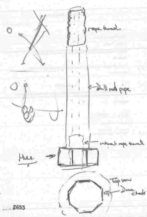
93 In submissions made on its behalf, the applicants were unable to go further than to point to some possible explanations for Mr Nielsen having been mistaken about what he saw at Ellalong. They referred to the passage of time since the events in question, to the fact that he was not directly involved in drilling and did not physically handle or closely inspect the rods and chuck which he saw, to the dim lighting conditions in the mine, and to his imperfect recollection of the outside profile of the chuck. It was suggested that Mr Nielsen might in fact have seen a chuck into which an adaptor was to be inserted, but failed, in the dimly lit conditions, to notice any adaptor nearby. But Mr Nielsen’s credibility, and the reliability of his recollection, were not undermined by indirect considerations of these kinds. I was left with the firm impression that he had a clear recollection of what he had seen at Ellalong, as stated in chief and as generally depicted in his drawing reproduced above.
94 I turn next to so much of the applicants’ submission as proposed “what did happen” on the probabilities at Ellalong. It was submitted that, contrary to the evidence of Messrs Geatches, Yates and Nielsen to which I have referred, Colrok used the then conventional system of interposing an adaptor between the chuck on the drill and the lowermost rod. The applicants were not categorical as to the means by which the adaptor engaged with the chuck: some of their cross-examination implied that the court should allow for the possibility that it was by way of a hexagonal socket in the chuck, while at other times it seemed to be hypothesised that it was by way of a standard 25 mm square socket. The applicants would say, of course, that this was not their evidentiary case – it was for the respondent to prove, specifically and firmly, the existence of the prior acts that would defeat novelty. But one aspect upon which the applicants did advance a positive submission was the nature of the engagement between the adaptor which they said was present and the lower end of the lowermost rod: the adaptor had a male protrusion which threaded into the corresponding female thread on that end of that rod. In other words, the applicants proposed that Colrok was using the system of extension drilling that was uncontroversially part of the prior art described in the Patent.
95 There were two circumstances which, according to the applicants, warrant the inference that, on the probabilities, Colrok was not using a system whereby the chuck directly drove the outside, hexagonally-profiled, surface of the female end of the lowermost rod. The first was the configuration of the chuck as depicted in the following rather grainy photograph which was annexed to Mr Geatches’ first affidavit.
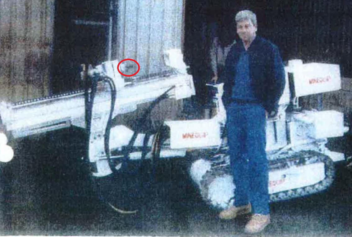
The circle shown on the apparatus to the left of the man in this photograph has been added (for the purposes of these reasons) to identify what the applicants contended was a male-threaded protrusion on the top of the chuck (remembering that the mast on this machine, as shown, is in a close to horizontal position, and that the normal direction of drilling would be from left to right).
96 In his affidavit, Mr Geatches described this photograph in the following terms:
[A] photograph of Vince Martin at the [Colrok] Toronto workshop in front of a drill rig created by Mineequip (a related entity to [Colrok]) taken in around 1989 which shows the hydraulic drive head with the drive chuck before the female adaptor has been screwed on it for use in the extension drilling system.
This passage was not associated with Mr Geatches’ description of Colrok’s method of work at Ellalong: indeed, it floated, in effect, at the end of the affidavit without any explanation of its relevance. Although not taken up in cross-examination, the concluding words in the passage – “… before the female …” – are confusing when read alongside Mr Geatches’ categorical insistence in his second affidavit that an adaptor was not used in the Colrok system. Ultimately, however, nothing turns on this point of confusion: as appears below, under cross-examination Mr Geatches did not seek to identify the contentious aspect of the photograph as representing the drive head before a chuck was screwed onto it.
97 Mr Geatches was not able to affirm that the machine shown in this photograph was the one used by Colrok at Ellalong. But he allowed for the possibility. Under cross-examination, however, he rejected the suggestion that the machine which was used had (in counsel’s words) “a male-threaded end of an adaptor … screwed into the female end of the lowest rod to connect the machine and the rod”. Describing what he saw in the photograph, he said:
[T]hat thread, to me, looks like it would screw into another set of drill rods – a different type of drill rods. But if you wanted to convert it to use as a hexagon drive, you would turn the thread inside of the hexagon drive chuck to suit that particular thread.
Mr Geatches’ evidence as to the kind of system which Colrok employed at Ellalong was not shaken by his having been referred to this photograph.
98 Mr Yates was also taken to the photograph during cross-examination. Before it was shown to him, he said that the machine he recalls being used at Ellalong was track-mounted with a single mast and a control panel. Shown the photograph, he agreed with counsel that the machine there depicted was a Colrok rig on caterpillar treads, that its mast was lying on a horizontal angle, that its drill head was fed by hydraulic lines, that it had a water line and swivel, and that “to the right of the drill head there [was] a drill chuck with a protrusion”. Counsel himself then added an aside, to which Mr Yates was not asked to respond, “And there’s evidence that that’s a threaded protrusion”, and then asked the witness, “Is that the sort of device that you saw at Ellalong?”. Mr Yates’ response was, “it looks the same, yes.”
99 Of Mr Yates’ evidence, it was submitted on behalf of the applicants as follows:
Yates confirmed that the drilling rig he saw was the same as the machine shown in DWG-5. As shown in that photograph, this machine was used with a male adaptor when engaged in extension drilling.
That was neither an accurate nor a fair description of Mr Yates’ evidence. Under cross-examination, it was never directly put to him that the setup of the chuck on the machine shown in the photograph implied a system of drilling which differed materially from that which he had described in detail in his evidence-in-chief. Counsel went no further than to have him accept that the machine was “the sort of device” that he saw at Ellalong, and I can well understand that he would have recognised it as such. It is not, however, established by Mr Yates’ evidence that the chuck as actually used at Ellalong had an adaptor with a male-threaded protrusion for engagement with the female thread on the lowermost rod. On no view does that evidence compromise Mr Geatches’ evidence that it did not. Taken overall, Mr Yates’ evidence is strongly consistent with that of Mr Geatches.
100 The second circumstance relied on by the applicants was that the system described by Mr Geatches would have been unworkable in practice because it had no adequate water seal at the point where the lowermost rod engaged with the chuck. Here I need to return to the aspect of extension drilling which I introduced at para 28 above: the necessity for the drill string to be adapted to accommodate the passage of water to flush the cuttings away from the environment where the drill bit is operating. In what the applicants submit I should find was the system employed by Colrok at Ellalong, there would be no water-leaking issue at the point where the upper male end of the adaptor (internal to which was the water passage) was threaded into the female end of the lowermost rod. But, according to the respondent, that was not the system in fact employed by Colrok. This raised the question: if the engagement between the chuck and the lowermost rod was no more watertight than would result from the placement of the hexagonal end of the rod into the correspondingly-shaped socket built into the chuck, why would not the water, presumptively being supplied by a pump of sufficient pressure to propel it up a drill string of as much as 12 m in height, leak at this point of engagement?
101 I should make it clear, at the outset of my treatment of this issue, that the question is not whether the presence or absence of some effective water sealing means in Mr Geatches’ system would directly affect the matter of whether that system anticipated the present invention in so far as claimed in Claim 1. If the system could be employed only at the expense of water leaking all over the place it might still have anticipated the invention. Rather, the present question is the purely factual one whether Colrok is likely to have used the system described by Mr Geatches when, according to the applicants, it would not have been viable in practice.
102 In his first affidavit, Mr Geatches said nothing about this water sealing issue. Neither need he have, of course, since (as the respondent stressed in its submissions) Claim 1 in the Patent does not touch upon the matter. But the issue was recognised by Mr Charlton when he read that affidavit. In his own responding affidavit, Mr Charlton noted that there was, in MrGeatches’ affidavit, no discussion about the prevention of water leakage at the point of engagement as between the chuck and the lowermost rod. He said that the sealing of that point, under such a system as Mr Geatches described, would not have been straightforward. He referred to the serious reservations which he had expressed, elsewhere in his affidavit, about the quite different sealing principle involved in a system which incorporated a square locking chuck with a spigot, and to attempts, of which he was aware, by participants in the industry to combine effective water sealing with the direct engagement of (single pass) drilling rods with corresponding chucks. Mr Charlton concluded: “Given the water leakage problems that would have arisen with the system as described by Mr Geatches, I consider it very unlikely that such a system was ever used. Certainly, it would have been much less efficient than the conventional system Mr Geatches said he was trying to improve on.”
103 In his second affidavit, and in response to Mr Charlton on this point, Mr Geatches said that water did not leak at the point because of the presence of a ring-shaped hard rubber seal in the bottom of the socket in the drive chuck. The lowermost rod simply sat on that seal. The weight of the drill string, and the upward thrust of the drive chuck during drilling, compressed the rubber and provided an effective seal. From time to time, Mr Geatches said, it was necessary to replace the rubber seals due to wear, but he could not remember how often this occurred.
104 It was at this stage that Steven Weaver, Vice President of Product Line (Mineral Ground Tools) of Sandvik Mining and Construction BV, and one of the inventors under the Patent, swore what was his third affidavit. Without objection, he there offered the opinion that the sealing arrangement described by Mr Geatches “would not provide an effective seal” for the system which he said he used. Mr Weaver said that, in the development of the applicants’ extension drilling system which became the subject of the Patent, designing of an effective water seal was a real issue which needed to be overcome. In the initial prototypes and testing, there was no seal in the socket of the chuck adaptor, and “a great deal of water sprayed out from the top of the adaptor”. So they placed a “hard rubber wad” in the bottom of the socket of the adaptor, in the form of a square washer (because the profile of the socket was, at that time, square) with a central hole. There were two problems with that. First, if the water was, for any reason, turned on when there was no rod in the adaptor, the washer was “blown out of its seat”. Secondly, “the washer was quickly destroyed in the course of the drilling operation” because of the downwards force exerted on it by the combination of the weight of the drill string and the upwards thrust of the chuck – a combined thrust, Mr Weaver said, of 2-2½ tons. This second problem was exacerbated by the nature of drilling operations, which Mr Weaver said was “not smooth”. The lowermost rod does not sit precisely in the one position in its socket in the adaptor (or, I presume, chuck), but moves around in response to the changing conditions and forces being experienced by the drill string above it, the result of which was the application of uneven forces to the rubber washer, “causing greater stresses and exacerbating wear and tear.” Although Mr Weaver was cross-examined extensively and in great detail, he was not challenged on this aspect of his evidence.
105 Under cross-examination, Mr Geatches withdrew the suggestion, made in his second affidavit, that some additional pressure as between the drill string and the rubber seal was brought about by the upward thrust of the drive chuck during drilling. He asserted that, once the drilling process began, the torque generated between the internal hexagonal faces of the chuck and the corresponding external faces of the lowermost rod would be considerable, and would of itself support the upwards thrust exerted by the chuck. The pressure exerted on the seal would be no more than that which existed before the rotation of the chuck commenced, that is, that contributed by the weight of the drill string as such. Mr Geatches rejected the suggestion, put to him in cross-examination, that “the forces involved would quickly destroy the seal” which he claimed to have used at Ellalong. Indeed, he made it clear that, in point of fact, those forces did not quickly destroy the seal.
106 Mr Charlton was not led to give any further evidence-in-chief with respect to the torque effect proposed by Mr Geatches, but the subject was covered in his cross-examination in the context of a corresponding disagreement between him (Charlton) and Peter Fuller, a consultant geotechnical engineer called by the respondent, principally on the question of obviousness. In that context, Mr Charlton said that, in practice, the relationship between the lowermost rod and the socket into which it sat was neither a precise nor an unchanging one. Under conditions of the kind encountered in extension drilling, the bottom of the rod tended to wobble about in response to the uneven nature of the task being carried out by the drill string. He accepted only that a “very small proportion” of the downwards force on a seal of the kind proposed by Dr Fuller was transferred to the side walls of the chuck.
107 Dr Fuller himself supported what had been Mr Geatches’ empirical experience, namely, that, once the chuck was in rotation, the forces of torque would be considerable. Responding to a suggestion put in cross-examination that there would be some inevitable misalignment between the rod and the chuck, such that the bottom end of the rod would not stay in constant contact with the horizontal surface of the bottom of the chuck, Dr Fuller said:
[S]tatically with it not rotating, yes. Once the thrust is applied on the chuck onto the driven surfaces of the rod there will be an aligning effect as a result of that. And I guess an analogy of that effect is that if you take a ring spanner and put it on the … hexagonal head of a bolt and you apply a torque to the ring spanner it’s very difficult even at small torque to remove the ring spanner. So even though you might start off … with the ring spanner being misaligned [a]s soon as the torque is applied, the mating surfaces will align. And the effect of that will be that the drive has the effect of actually gripping on the driven surfaces. So then the forces that are operating as I would see it as an engineer at the driven end of this rod would be axial force coming from whatever drive system is applied to the drill motor. In addition there is a gripping effect – and it’s frictional – due to the torque applied by the chuck on the external surface of the drill rod.
The size of the applied torque at the driven end of the rod would depend to an extent on the resistance being encountered by the drill bit: in softer drilling conditions, the torque would be less than if drilling in rock, for example.
108 The result of my consideration of all of this evidence is that, if otherwise Mr Geatches’ evidence about the system used at Ellalong is to be accepted, it was not undermined by the proposition that that system would not have worked because of the leaking of water at the point of engagement between the chuck and the lowermost rod. He explained the sealing arrangement which he used, and there was a sufficient, credible, engineering response to the applicants’ contention that that arrangement would not have worked. The practical viability of a similar arrangement may not have been Mr Weaver’s experience, but the fact that his arrangement did not work does not persuade me that Mr Geatches’ arrangement could not have worked, or most likely did not work.
109 Additionally to the two circumstances said to warrant the conclusion that, at Ellalong, Colrok was not using a system whereby the chuck directly drove the outside, hexagonally-profiled, surface of the female end of the lowermost rod, the applicants advanced a third reason why the system used there did not anticipate Claim 1 of the Patent. It is, they say, quite unlikely that Colrok’s system involved the use of rope-threaded connections between the rods. It is the respondent’s case that rods with such connections were not commercially available in right-hand configuration, and that Mr Geatches had to have the ends for his “speed rods” specially made by Mr Gambly. For the purposes of this argument, the applicants accept that case. But they say that, with the technology which he had available to him in his workshop at the time, it is most improbable that Mr Gambly was able to build rope threads. It is more likely that he built ends with another coarse, wave-like, thread, such as what was described as the “T-thread”, but which was not a rope thread as such and which, therefore, would not have come within the terms of Claim 1. Indeed, it was the T-thread which counsel for the applicants put to Mr Geatches had most likely been the thread used by Mr Gambly.
110 In para 67 above, I have referred to Mr Clair from Nupress Tools. It is now necessary to refer to his evidence about rope threads, and to do so in some detail. He said that a rope thread was a broad thread which got its name because (in the case of an external thread) it looked somewhat like a piece of rope loosely wound around the shaft. Rope threads had a particular configuration which was set by an international standard. They were unlike other conventional threads commonly seen in everyday components in that they were curved in all three dimensions. Also, a rope thread had a very large cross section width (or pitch) at 12.7 mm. As far as Mr Clair was aware, rope threads were used solely in the mining industry.
111 Mr Clair said that the machining of rope threads was a very specialised skill, one that was known (even when he made his affidavit in May 2015) to only a few in Australia. He named only five business in Australia, including his own and those of the parties in this case, who had ever made rope-threaded components. He said that there were three ways to make such components: on a manual lathe, on an off-centre copy lathe and on a computer numerical control (“CNC”) lathe (the latter of which, it became clear under cross-examination, was to be understood as including also a numerical control (or “NC”) lathe). He explained that lathes worked by rotating the component being machined at speed and applying a cutting tool to the surface of the component to cut away metal from it. The cutting tool is moved both along the axis of rotation and perpendicular to that axis to cut the required profile. Cutting tools took one of two forms: a form tool (a tool that had the form or shape of the thread to be cut), and a single point tool (a tool with a sharp point or tip which did the cutting).
112 Mr Clair said that, in the case of a threaded component, there would be matching male and female components. The machining of an external rope thread was reasonably straightforward as it could be done with a form tool. No specific machine was required for that, only a precision ground form tool. The machining of an internal thread was, however, more difficult because the cutting tool would be working inside a narrow space. In this situation, the cutting tool needed to extend longitudinally into the bore of the component, and then press laterally into the wall of the bore to cut the thread. The diameter of the bore limited the thickness of the tool. Also, the pressure applied to the cutting tool to machine the thread was high, such that the cutting tool would tend to bend as it was pressed against the wall of the bore. An additional difficulty arose as a result of the large 12.7 mm pitch length. The large cross section of a rope thread made a huge surface contact area on which it was very difficult to get the required surface finish using a form tool.
113 Mr Clair said that one way in which it might have been possible to machine a rope thread was to use a manual lathe and a form tool. Such a tool would have had a cutting blade with a contour that matched the thread, being long enough to cover a single pitch length (12.7 mm). Because the rope thread had an asymmetric shape in cross section (viewed axially) the form tool had to move longitudinally along the length of the work as the component rotated. That is, on a standard engine lathe, for every revolution of the component, the cutting tool would have moved longitudinally the length of one pitch (12.7 mm). The result was that machining a rope thread would have required the cutting tool to move much faster than in the case of machining a conventional thread with a pitch of 2-3 mm. For any given rate of rotation of the component in the lathe, the speed of the surface being machined would depend on the size of the bore: the surface of a small bore would be travelling more slowly than the surface of a larger bore rotating at the same number of revolutions per minute (“rpm”). Consequently, for smaller thread sizes the lathe would have been spinning at a higher rpm rate than for larger thread sizes. However, the rate at which the cutting tool moved in and out of the bore longitudinally was the same regardless of the size of the bore: 12.7 mm per revolution. This meant that, for smaller threads, the cutting tool had to move in and out longitudinally very rapidly, at a rate which was beyond the capacity of standard engine lathes.
114 Mr Clair said that, as a result of the inability to use sufficiently rigid cutting tools and the limitations of lathes, the machining of small diameter, internal, rope threads with form tools on manual lathes was extremely difficult. He was not aware of anyone who had actually machined a rope thread by this technique other than a rod supplier in Melbourne called Goldfields Diamond Drilling Co Pty Ltd. He described what I understood him to regard as a highly idiosyncratic approach to machining which was taken by that company. The method was “long and tedious and required special in house form grinding.” Stephen Fleming, employed by that company during the period to which Mr Clair’s evidence relates, was not aware of this approach or method, and it is unnecessary for me to make any finding about this aspect of the latter’s evidence.
115 Mr Clair said that, as at the mid-late 1980’s, it would have been theoretically possible for someone to machine right-handed rope-threaded components of 32 mm or larger diameter. He expressed the opinion, however, that it would not have been possible to produce smaller right-hand rope threads, such as those of 25 mm diameter, “because of the difficulty involved in using small form tools, and the fact that several pieces of expensive toolmaking equipment would be required.”
116 Mr Fleming, to whose evidence I have briefly referred, took issue with Mr Clair’s evidence in a number of respects, specifically in areas where the latter had emphasised the difficulty of machining rope threads. However, Mr Fleming’s evidence related wholly to NC and CNC machining, where, he said, the making of rope-threaded components, even where the diameter was less than what Mr Clair proposed as the absolute minimum for internal machining, was conventional and, as I understand it, commonplace. But, to the extent that I have referred to Mr Clair’s evidence to date in these reasons, it has been in the context of the use of a manual lathe. Mr Fleming’s evidence did not touch upon that area. With respect to the production of rope-threaded components on a manual lathe, Mr Clair’s evidence remains unchallenged by Mr Fleming. And, as counsel for the applicants pointed out, at least relevantly to the matter presently under discussion, it was not challenged during cross-examination. The significance of Mr Clair’s evidence about machining with a manual lathe, of course, lies in the circumstance that, according to Mr Geatches who gave the only evidence on the subject, Mr Gambly’s lathe was a manual one.
117 If there were no evidence from persons who had physically viewed Colrok’s “speed rods”, and the question were the subject of inference from indirect indications, I would be disposed to the position that the respondent had not established that the connections on those rods were rope-threaded ones. Mr Clair’s evidence in particular would have influenced me to that result.
118 But there is evidence from persons who had physically viewed those rods. The first of these was Mr Geatches himself. He could not recall the actual terms in which he provided instructions to Mr Gambly. He thought that he “would have” shown Mr Gambly a (then commercially available) left-hand threaded rod (as used in percussive rotary drilling) and asked him to make the same item, but in right-handed configuration.
119 It was suggested to Mr Geatches under cross-examination that he mistook the threads produced by Mr Gambly for rope threads, something with which he was familiar in their left-handed configuration. It was put to him that the threads actually machined by Mr Gambly were “T-threads”, a coarse wave-like thread that was much easier to produce and, according to Mr Clair, could readily have been achieved on a manual lathe. Under cross-examination, Mr Geatches said that he thought that he had heard of a thread identified as “T”, but he was not familiar with it. He was taken to the set of technical drawings to which I have referred in para 67 above, which related to T-threads. Mr Geatches appeared to understand the drawings, but he was manifestly unfamiliar with the product there identified. It was put to Mr Geatches that T-threads provided extremely quick coupling and uncoupling, to which his response was, “No experience with them so I can’t comment.” It was put to him that T-threads were suitable for rod diameters of 25 mm or thereabouts, to which his response was, “If you say.” He said that he had “never seen them”. He was shown a marketing brochure, not in evidence but marked “MFI-1”, with a very clear, close-up, photograph of a male T-thread on the end of a rod or shaft of some kind, and he said that it was not a thread with which he was familiar in 1989. He was shown what purported to be one of the respondent’s own catalogues, also not in evidence but marked “MFI-2”, depicting what counsel suggested were T-threaded items, and he reiterated that, in 1989, he was not familiar with “coarse threads of that type” (counsel’s words). When it was put to him that what Mr Gambly made was “a coarse wave-like thread that was a T-thread, not a rope thread”, Mr Geatches’ response was, “incorrect”.
120 It was made quite clear on behalf of the applicants that they made no suggestion that Mr Geatches was doing otherwise than genuinely attempting to recall events of about 25 years ago. The honesty of his evidence was not challenged. From his evidence summarised above, I gathered that Mr Geatches knew enough about his subject, and recalled enough of the events of which he spoke, to be able to affirm the proposition that the threads made by Mr Gambly were rope threads rather than some other kind of threads, specifically T-threads. When he was under cross-examination, he gave me no impression that he did not know what he was talking about, or that he was unable to make distinctions at the level required by the nature of the matters with which he was required to deal.
121 Turning next to the evidence of Mr Nielsen, I have referred above to the drawing which he made of the rods which he observed at Ellalong, and to his evidence that the threads on the rods were rope threads. When asked under cross-examination about T-threads, he said that he was “not too sure” about them. He said that he did not know the difference between a rope thread and a T-thread. But he was familiar with rope threads, because left-handed configurations of them had been used at one of his previous workplaces, Tahmoor Colliery. When it was put to him that he could not, with any certainty, say that the coarse thread that he drew was a rope thread rather than a coarse wave-like thread such as a T-thread, his response was, “No, it was a rope thread. That there was a rope thread. I … don’t know what … you say is a T-thread but that was definitely a rope thread.” Mr Nielsen was a diesel fitter by trade, and his firm recollection of what he saw at Ellalong deserves, on account of that circumstance, to be given some weight. I should add that there was nothing in the way that he gave his evidence that would cast any question upon the reliability of his recollection.
122 Mr Yates also gave some evidence on this subject. Additionally to this evidence as set out in para 80 above, under cross-examination he said that, at Ellalong, “the drill rod had a female rope thread on the bottom of it which took the male rope thread at the top of the next rod”. That evidence was not, as it happened, responsive to the question which he had been asked, but, for whatever reason, Mr Yates was not challenged on it.
123 When the evidence of Messrs Geatches, Nielsen and Yates is taken together, the respondent’s factual case that rope-threaded connections were used between the drilling rods used by Colrok at Ellalong is a strong one. Those witnesses, particularly Mr Geatches, were legitimately cross-examined by reference to circumstantial factors which might be thought to raise problems with that case, and which may well have been fatal if the case were wholly an inferential one. But it is not. None of these witnesses had any interest in the outcome of this proceeding, and it was not suggested that they proceeded otherwise than conscientiously in the giving of their evidence. Each was asked whether he had consulted with the others before making his affidavit, and answered in the negative. The two who were cross-examined on the subject of rope threads remained positive and convincing in affirming that that is what they saw at Ellalong. The evidence of all three should be accepted.
124 I find, accordingly, that, in the system of extension drilling used by Colrok at Ellalong Colliery, the connections between the drilling rods were right-hand rope-threaded ones.
125 In the result, I accept Mr Geatches’ evidence about the extension drilling system which Colrok used at Ellalong Colliery. In a number of specific respects above, I have made clear why I do so. Subject to the matters there mentioned, I would say that there was nothing in his evidence, or in the way that he dealt with the questions put to him under cross-examination, that would provide any basis to doubt the reliability of his recollection.
126 It remains to consider an overarching submission which the applicants made with respect to the respondent’s evidence about the system used by Colrok at Ellalong Colliery. Mr Woolnough, to whom I have referred at para 58 above, was a co-owner of Colrok, and was the person who had the day-to-day supervision of Colrok’s operations at times which are presently relevant. An affidavit by Mr Woolnough was filed on behalf of the respondent and, in its Statement of Facts and Contentions filed before the trial, it was foreshadowed that he would be one of four witnesses who would give evidence of the system used at Ellalong. As it happened, and without explanation by the respondent, his affidavit was not read and he was not called.
127 Quite correctly in my view, it was not submitted on behalf of the applicants that the respondent’s failure to call Mr Woolnough justified the court in supposing that any evidence which he might have given would not have been helpful to it. Rather, the applicants’ point was a more limited one. It was submitted on their behalves that the respondent had failed to avail itself of an opportunity to corroborate the evidence of Messrs Geatches, Yates and Nielsen on a subject which, because of the passage of time and the absence of documentary records, would manifestly have benefited from further exposure: see Windsurfing International Inc v Petit [1984] 2 NSWLR 196, 231. As that authority demonstrates, an allegation of prior public use should be strictly proved.
128 The applicants’ point is well-made. The respondent’s unexplained failure to call Mr Woolnough has given me substantial cause to pause. However, having paused, I find that the situation remains that I have the direct observation of three then workers in the industry whose evidence is credible. The court is not required to act upon inference, and in that sense the respondent’s allegation has been strictly proved. By limiting its evidentiary case in the way that it did, the respondent ran the risk that, for one reason or another, that case might not have crossed the bar. But the view I take is that it did cross the bar, and I would not be justified in turning away from that view by reason of what was, apparently, the respondent’s choice not to conduct a more comprehensive evidentiary case. In short, I would hold that the belt was sufficient for the respondent’s purposes. It did not also need the braces.
129 Although the situation at Ellalong Colliery provided the basis for much of the factual debate about the Colrok system, and about Mr Geatches’ recollection of it, his evidence-in-chief was that the same system was used, at around the same time, at Macquarie Colliery. The applicants advanced no challenge to that evidence, separate from their challenges in respect of Ellalong with which I have dealt above in detail. In the circumstances, I formally find that the system used at Macquarie was substantially the same as that used at Ellalong.
130 The uses of the Colrok system at Ellalong and Macquarie collieries were, of course, some time before the priority date of the Patent.
131 Subject only to the resolution of the factual issues which I have decided against them, I do not understand the applicants to contest the respondent’s proposition that, in so far as claimed in Claims 1, 2, 4 and 7, the invention was anticipated by the system used by Colrok at the Ellalong and Macquarie collieries. That leaves Claim 6. The specific relevance of the Colrok system to the validity of that claim was not the subject of any submission made on behalf of the applicants. In a summary of the respondent’s novelty case which accompanied its final written submission, the following was said:
The extension drilling system used at Colrok was substantially in accordance with the system described by reference to figures 1 and 2 in the patent, because it too is an embodiment where the flat outer surface of the bottom extension rod are [sic] driven on their [sic] outer surface by the socket of a drive chuck. See the comparison with claim 1, above. The Colrok system is not substantially in accordance with figures 3, 4 or 5 of the patent, because it does not utilise a twist lock mechanism and/or a drive chuck adaptor. However, this is not needed to establish anticipation. It is enough that the Colrok system was substantially in accordance with an embodiment (figures 1 and 2) falling within the scope of claim 6.
The applicants did not respond to this submission, but, for reasons which follow, I am not disposed to accept it.
132 Claim 6 is an omnibus claim. Where such a claim is expressed to be limited by reference to one or other (or more than one) of the diagrams set out in the specification, there will, depending on the language used of course, usually be discernible as many separate notional claims as there are alternatives referred to: Britax Childcare Pty Ltd v Infa-Secure Pty Ltd (No 4) (2015) 113 IPR 280 at 305, [168]. The claim refers to two embodiments, namely, one which conforms with Figs 1 and 2 and the other which conforms with Figs 3, 4 (including 4A and 4B) and 5. Although grammatically clumsy, it is clear from the specification that Fig 3 represents an alternative adaptor that may be used in place of that depicted in Figs 4, 4A and 4B. Overall, the claim does, therefore, include three alternatives: (1) Figs 1 and 2; (2) Figs 4 and 5 and (3) Fig 4 with the chuck replaced by that shown in Fig 3, and Fig 5.
133 It was not suggested on behalf of the respondent that Mr Geatches’ system anticipated the second of these alternatives. Neither, so far as I can see, is it suggested that that system anticipated the third. In that latter respect, there is a controversy as to the detail of the sealing member disclosed in Fig 3, and therefore claimed in this third alternative under Claim 6, but, assuming for the moment that nothing more than a flat washer-type arrangement is disclosed, the modular construction of the adaptor in Fig 3 is, of itself, sufficient to set the invention apart from Mr Geatches’ system.
134 On the other hand, on the basis of the findings which I have made, it is clear that Mr Geatches’ system did anticipate the first. That leaves the court with a procedural issue of some delicacy. Subject to the respondent’s other grounds of invalidity, it would not, in my view, be just to revoke Claim 6 in its entirety on the basis of those findings. But neither, so far as I am aware, is there any precedent for attempting to revoke only a notional compartment of a claim as printed. The solution, if there be one, lies in s 105 of the Act. If want of novelty based on Mr Geatches’ system were the only reason for the revocation of Claim 6, before making a final order adverse to the applicants on this aspect of the Cross-claim, I would allow them time to apply for an amendment which would confine the claim to the second and third alternatives as I have identified them.
135 Turning now to the extension drilling system used by Wilson Mining, the respondent called Bill Goodwin to give evidence about that system. At the time when he swore his affidavit in this proceeding, 11 August 2015, he was Operations Manager and co-owner of Bolt Up Mining Pty Ltd, a contracting support company supplying secondary support, ventilation and mining services to the underground coal mining sector. He commenced work as a first year apprentice electrician at Munmorah Colliery in 1990. After completing his electrical trade course, he worked as a mine electrician/production worker at the Dartbrook Mine, where his primary role was to ensure electrical compliance in its production process. During the miners’ crib breaks, and at each shift changeover, Mr Goodwin and a fitter who worked with him would, as he put it in his affidavit, “regularly start the continuous miner up and cut a bit of coal while awaiting for the miners to return from their break”. During this process, he would (as he put it) “also occasionally install primary support (7 foot roof bolts) and secondary support (flexi bolts) when required”.
136 Between May 1995 and March 1997, Mr Goodwin worked at Cumnock Colliery and then at the South Walker Creek Open Cut Mine in central Queensland.
137 In about March 1997, Mr Goodwin took up employment at Wilson Mining as an underground miner. His role covered secondary support, ventilation, long hole drilling, PUR application and fall recovery. In time, he was promoted to the positions of shift supervisor, site supervisor, and eventually operations manager for Wilson Mining. He moved on to other employment in 2002, but it is unnecessary here to recount the details of that other employment.
138 When Mr Goodwin commenced working at Wilson Mining, the drilling machines which they owned included about three “CRAM Proram” machines and about two “CRAM Ramtrak” machines, the latter being, functionally a Proram machine mounted on tracks. These machines featured a “through the spindle” drive chuck that gripped the external surface of round drill rods. Unlike the chucks referred to previously in these reasons, the chuck used in a system of this kind was not a socket into which the base of the lowermost rod sat. Rather, the rod passed right through the chuck and extended beneath it. The rod, which was either round or hexagonal in the system described by Mr Goodwin (he observed both at Wilson Mining), was held firm in the chuck by jaws within the chuck, which could be applied or released as the occasion required.
139 The drill rods used by Wilson Mining were fitted with male and female threaded connections. For those of a smaller diameter (18 mm – 25 mm) the thread type was mainly rope thread, while for those of a larger diameter (43 mm) the thread type was generally what Mr Goodwin described as “an AW thread”. All the drill rods featured an internal hollow passage to allow water to be pumped to the end of the drill string where the drill bit made contact with the strata. The water entered the drill string through a water swivel that was attached, by a matching thread, to the lower end of the lowermost rod (ie where that end protruded below the chuck).
140 In his affidavit, Mr Goodwin described the process used for drilling PUR holes at the West Wallsend Colliery using the Proram drilling machine, which he observed during the first two months of his employment by Wilson Mining, in the following terms:
1. A male female drill rod with a right hand rope thread and a drill bit attached to the male end (possibly by use of bit adaptor) was inserted into the drive chuck of the CRAM drilling machine. The drive chuck was a “through” drive chuck …. It had a hole in which the drill rod would sit, containing jaws to clamp the external surface of the drill rod.
2. The external surface of the drill rods used at Wallsend were round …. The drive chuck clamped the external surface at the female end of the drill rod, so that the maximum length of the rod above the female end was available for drilling.
3. A water swivel was fitted into the internal female coupling at the female end of the drill rod to allow for flushing water to pumped up the drill bit end of the drill rod.
4. The rotation motor rotated the drive chuck which gripped the drill rod on its external surface.
5. The rotating drive chuck was then moved up the drill mast, forcing the drill bit to drill into the strata and created the drilled hole.
6. When most of the length of the drill rod had been drilled into the strata, the rotation of the drive chuck was stopped. The rod grippers were then engaged. The water flushing was turned off and the water swivel was removed.
7. The jaws of the drive chuck were then released from around the drill rod (which was held in place by the rod grippers).
8. A new drill rod was partially screwed into the bottom of the drill rod being held by the rod grippers.
9. The drive chuck was then lowered down over the new drill rod to the female end of the rod.
10. The jaws of the drive chuck were then engaged to grip the external surface of the new rod.
11. The water swivel was connected to the female end of the new drill rod.
12. The drive chuck was then used to tighten the partial coupling between the new drill rod and the drill rod held in place by the rod gripper, by rotating the drive chuck.
13. When the two drill rods were completely coupled the rod grippers were released and drilling of the hole recommenced.
14. The process described above … of adding another drill rod to the drill string was then repeated, until the desired length of hole had been drilled.
141 Mr Goodwin described the process used for dismantling the drill string in the following terms:
1. The rod rippers [sic - grippers] were deactivated.
2. The drive chuck lowered with the lowest drill rod so that the female end of the next lowest drill rod was equal with or slightly lower than the rod grippers.
3. The rod grippers were engaged and clamped the second lowest drill rod.
4. The drive chuck was then reverse rotated to break the coupling between the male end of the lowest drill rod and the female end of the second lowest drill rod.
5. The drive chuck jaws were then released and the drive chuck moved up the mast to the female end of the second lowest rod and gripped the external surface of that rod.
6. The lowest drill rod was removed.
7. The process of lowering and uncoupling … was repeated, until all drill rods had been removed.
142 In a later affidavit, Mr Goodwin provided more detail about step 5 in the dismantling process, specifically with regard to the point on the second lowest rod where the jaws gripped as described in that step. He said that the jaws “were capable of gripping the drill rod … at any location between the very bottom of the … rod, through to about half way up the rod”. He said that “sometimes” this gripping was done “almost immediately after the female end of the second lowest drill rod entered the drive chuck”. In such a case, he added, “the jaws of the chuck gripped the drill rod on the external surface of the female rope threaded coupling at the bottom of the rod.”
143 Subject only to some clarification of points of detail, Mr Goodwin’s evidence was not challenged in cross-examination.
144 The respondent submitted that the Proram through-the-chuck system satisfied every integer of Claim 1. Specifically, according to the respondent, the system involved “a drive chuck … for driving the outside surface of a female coupling of an extension rod at one end of the drill rod string, in either forward or reverse direction ….”
145 The applicants contested this submission. Their first point was that, as a matter of construction, Claim 1 was confined to a “socket-type” chuck, that is to say, a chuck which acted as a kind of a socket into which the base of the lowermost drill rod would sit, and which did not, by jaws, grip the rod. In his affidavit sworn or affirmed (it does not state which) on 31 August 2015, Mr Charlton explained that this would be his understanding of the invention disclosed in the specification in the Patent, and claimed in the claims.
146 In this respect, Mr Charlton referred first to the “primary problem” in the existing art as identified in the specification: see para 32 above. He pointed out that, in a through-the-spindle system, there would not, by definition, be two threaded couplings between the grippers and the chuck. Having read this early passage in the specification, Mr Charlton would have been aware that the field of technology in which the inventors were operating did not include a through-the-spindle system. That perception of things was reinforced by the “secondary problem” referred to: a through-the-spindle system did not use an adaptor.
147 Mr Charlton next noted that the discussion in the specification, and the accompanying drawings, were concerned solely with socket-type chucks.
148 With respect to the claims, Mr Charlton noted that Claim 1 required that the chuck be able to drive the outside surface of the female coupling of the relevant extension rod in either a forward or a reverse direction. In the case of a through-the-spindle system, he said, when the rod is being driven in a forward direction (ie during drilling), the water swivel will be connected to the bottom end of the rod. From the photographs of the Proram machine used by Wilson Mining placed into evidence, it is apparent that, at this point, the jaws of the chuck could not have engaged with the rod at the point of the female coupling: the end of the rod would have had to have been at least a little proud of the bottom of the chuck motor to facilitate the fitting of the swivel, the length of the female thread was only about 50 mm, the chuck itself was mounted on top of the motor, and the total height of the motor/chuck arrangement was about 500 mm. Although Mr Charlton himself did not descend to this level of detail – it was made possible only after the evidence of Mr Goodwin – it reflects what he understood. From that understanding, he proposed that, at least apropos operation in the forward direction, Claim 1 could only have been referring to a system which incorporated a socket-type chuck.
149 Mr Charlton next referred to the requirement in Claim 4 that the chuck or adaptor have “a socket therein of similar cross-section to the extension rods”. Additionally to the specific mention of a “socket”, and to the possibility of using an adaptor, these words implied that the chuck or adaptor would have a “cross-section”, a notion which would make no sense in the context of a chuck used in a through-the-spindle system. Mr Charlton made a similar point with respect to the wording of Claim 5.
150 Additionally, in final submissions, counsel for the applicants drew my attention to parts of the specification which, it was submitted, compelled the conclusion that the invention related only to a system which employed a socket-type chuck. All but one of those references were, I would have to say, utterly irrelevant to the matter presently under discussion: they used the word “socket” with reference to the space or cavity in the female end of each drill rod into which the male end of an adjoining rod would be screwed, not with reference to the space or cavity in the chuck in which the lower end of the lowermost rod was presumptively placed. The remaining reference was to so much of the lengthy passage set out in para 43 above as commences, “the rod is then slid down”. I am, with respect, unable to accept counsel’s submission, which followed immediately, that this was language which could only be describing a system with a chuck having “an internal socket, that is, it stands beneath the bottom of the rod, and it receives the rod either in circumstances where the socket is the chuck itself or where the socket is that of an adaptor inserted into the chuck.”
151 However, based on Mr Charlton’s exposition of how he, as an expert in the area, would understand the problem confronted by the inventors, and how they sought to resolve it – evidence which was not seriously challenged so far as it went – I regard it as clear that they did not have through-the-spindle systems in mind at all. I accept and, with respect, agree with what Mr Charlton said in this respect. The question remains: is it permissible for the court to read down Claim 1, which, in terms, neither confines itself to socket-type chucks nor excludes through-the-spindle systems, by reference to how a person skilled in the art would understand the invention from his or her reading of the specification as a whole? For the moment, I am not concerned with what was the applicants’ next point, namely, whether Claim 1, internally construed, excluded a through-the-spindle system.
152 In Jupiters Ltd v Neurizon Pty Ltd (2005) 222 ALR 155, the Full Court said (at 168 [67]):
[W]hile the claims are to be construed in the context of the specification as a whole, it is not legitimate to narrow or expand the boundaries of monopoly as fixed by the words of a claim by adding to those words glosses drawn from other parts of the specification, although terms in the claim which are unclear may be defined by reference to the body of the specification: Kimberley-Clark v Arico at [15]; Welch Perrin & Co Pty Ltd v Worrel (1961) 106 CLR 588 at 610; Interlego AG v Toltoys Pty Ltd (1973) 130 CLR 461 at 478; the body of a specification cannot be used to change a clear claim for one subject matter into a claim for another and different subject matter: Electric & Musical Industries Ltd v Lissen Ltd [1938] 4 All ER 221 at 224-5; (1938) 56 RPC 23 at 39 ….
153 In H Lundbeck A/S v Alphapharm Pty Ltd (2009) 177 FCR 151, 179-180 [120], Bennett J said (with the agreement of Middleton J):
It is not permissible to read into a claim an additional integer or limitation to vary or qualify the claim by reference to the body of the specification (Kimberly-Clark at [15]; Welch Perrin at 610). This is particularly relevant when the question concerns infringement of a claim or the sufficiency of a claim to define the invention. However, terms in the claim which are unclear may be defined or clarified by reference to the body of the specification (Welch Perrin at 610; Kimberly-Clark at [15]). The language of the claims may have no positive meaning when read apart from the specification but the meaning may become clear and the invention sufficiently defined when read using the body of the specification as a dictionary of the jargon and ascertaining the nature of the invention (Welch Perrin at 616).
154 These principles, which are not in dispute, have been referred to by the Full Court on a number of other occasions, some of which were mentioned in PAC Mining Pty Ltd v Esco Corporation (2009) 80 IPR 1, 13-15 [26]-[29].
155 The position is, therefore, that, if the meaning of Claim 1 in the Patent is clear, the scope of the claim cannot be narrowed by reference to the language used elsewhere in the specification. This is so even if, as appears to be the case, the inventors had in mind only the narrower form of the invention. It would be otherwise, of course, if Claim 1 were, in some respects, ambiguous, obscure or, for example, excessively compendious. Then it would be permissible to have resort to the specification as a whole to understand what the wording of the claim conveyed. But a perceived discordance between the terms of the claim, clear in themselves, and what the inventors apparently intended is not enough. This is an important distinction, since the claims in a patent go further than merely tracing out the nature of the invention: they assert the statutory monopoly which the inventors claimed for themselves. Whatever they actually had in mind, the validity of the claims must stand or fall by reference to the terms actually used in them, subject, of course, to the accepted principles of construction to which I have referred.
156 There is nothing in Claim 1 which, as a matter of language, would confine it to socket-type chuck systems. The point made about the claim by Mr Charlton, as laid out in para 148 above, valid though it may be in its own right (and I discuss it further below), is not, in my view, sufficient to impress upon the claim a meaning, applicable in all situations, which would confine it in this way. The conclusion I reach, therefore, is that, as a matter of construction, Claim 1 is not so confined.
157 The applicants’ next point in this area of the case was that the system used by Wilson Mining, as described in the evidence of Mr Goodwin, did not anticipate the invention in so far as claimed in Claim 1. They submitted that the Wilson system did not incorporate a drive chuck for driving the outside surface of the female coupling of the lowermost extension rod in both a forward and a reverse direction. Apropos the forward direction, this submission must be accepted: as noted above, the presence of the water swivel made it inevitable that the jaws of the chuck would not engage at the point on the rod representing the outside surface of the female coupling thereof. The only real debate related to the question whether the chuck used by Wilson Mining engaged with the rod at that point when operating in reverse.
158 Before coming to that question, I would say that, in my opinion, the answer does not matter. In Claim 1, the sense conveyed by the phrase “in either forward or reverse direction” is that the rod may be driven, as the occasion demands, either way. That is to say, operation in both directions (albeit not at the same time) must be possible, in the way described. The claim is not, in my view, concerned to claim any system which involves operation in the forward direction only, and cannot be used in reverse; or vice-versa. It follows that, whether or not the chuck engaged with the outside surface of the female coupling when operating in reverse, the Proram system used by Wilson Mining did not anticipate the invention so far as claimed in Claim 1 because the chuck did not do so when operating in the forward direction.
159 As to the question which I have identified, the respondents focussed upon the stage in the dismantling of the drill string represented by step 5 in the list in para 140 above, and upon Mr Goodwin’s second affidavit, referred to in para 142 above. They submitted that, when the chuck was raised to engage with the second-last drill rod, the lower end of which was protruding below the grippers, it so engaged at the very lowest point of that rod, that is, the point of the female coupling. The difficulty for the respondents here, however, is that Mr Goodwin himself said no more in chief than that “sometimes” this engagement came about “almost immediately after the female end of the second lowest drill rod entered the drive chuck”. There was no mechanical or other operational necessity for the chuck jaws to engage with, and therefore to drive, the very end of the rod corresponding to the location of the female coupling. It seems to have been very much a matter of the technique of the person who happened to be operating the machine at the particular time, and perhaps of the conditions under which the drilling was being undertaken. When Claim 1 speaks of a chuck “for driving the outside surface” of the female coupling, it requires, in my view, a chuck which operates (in reverse) by driving that surface specifically. The claim is, after all, speaking of a system, not of day-to-day operational choices which correspond with what is claimed only “sometimes”.
160 As has frequently been stressed, anticipation requires close correspondence with the invention as claimed. For the reasons given above, and to the extent that it matters, I would hold that the Proram system used by Wilson Mining did not anticipate the invention so far as claimed in Claim 1 because it did not incorporate a chuck for driving the outside surface of the female coupling on a drill rod in the reverse direction.
161 Counsel dealt with this aspect of the respondent’s anticipation case as though a favourable result for the applicants under Claim 1 would carry through to all other relevant claims. I have no reason to depart from that approach.
INVENTIVE STEP
162 The respondent contends that the invention the subject of the Patent, so far as claimed in claims 1, 2, 4, 6 and 7, did not involve an inventive step. By s 7(2) of the Act, the respondent here needs to establish that the invention, so far as claimed in those claims, would have been obvious to a person skilled in the relevant art in the light of the common general knowledge as it existed in June 1997.
163 The silent premise by reference to which both sides in this proceeding dealt with the respondent’s inventive step case was that the debate was to be conducted wholly in the context of a socket chuck system of the kind referred to in the explanation of the prior art, and of the problem to be solved, laid out in the specification in the Patent. That is to say, for example, there was no suggestion by the applicants that the invention would not have been obvious to the skilled addressee because he or she would have opted for a different system of extension drilling altogether, such as the through-the-spindle system used by Wilson Mining.
164 From that starting point, it was uncontroversial that the system for undertaking extension drilling, as I have outlined it in paras 23-29 above, formed part of the common general knowledge, at least at a high level, immediately before the priority date. So too would it have been commonly and generally known that the use of a male-threaded adaptor to connect to the lower, female, end of the lowermost rod in a drill string would leave two threaded connections between the chuck and the gripper, either of which might have become unscrewed when the rotation of the chuck was reversed, and the remaining one of which would have to be unscrewed manually. From that uncontroversial starting point, the focus of the parties’ submissions on common general knowledge tended to be on the question whether it would have been obvious to the skilled addressee to devise a system which involved placing a drill rod directly into the chuck, there to be driven by engagement with its outer surface.
165 It was submitted on behalf of the applicants that it was common general knowledge that semi-automatic drilling rigs were generally used for both single pass drilling and extension drilling, and that “the predominant form of drilling was single pass drilling, in the order of a ratio 15:1 compared to extension drilling.” The applicants submitted that it was also commonly and generally known that the standard chuck used in both situations was the 25 mm square locking chuck, with which “the standard single pass drill rods” were configured to be engaged. They submitted that it was “not feasible” to change the chuck once the semi-automatic drilling rig was underground – the result being that the chuck fitted to the rig needed to be used for both single pass drilling and extension drilling.
166 As I understand the reason for the applicants stressing these aspects of the common general knowledge, it was to lay the foundation for a submission that the skilled addressee would be unlikely to have contemplated any modification to the system of extension drilling that would have involved dispensing with the 25 mm square locking chuck, and therefore with a form of engagement between the chuck and the lowermost rod that involved an adaptor which sat in such a chuck. I shall return to that submission presently.
167 For the respondent, it was submitted that a range of hand-held roof bolters (ie drilling machines) formed part of the common general knowledge. They included the “Wombat” hand-held roof-bolter (to which I refer below), which could be, and was, used to perform both single-pass drilling operations and extension drilling. It was submitted that there was “a range of different drive chucks [that] could be used in both single pass and extension drilling systems”. These included not only the 25 mm square locking chuck relied on by the applicants, but also the McSweeney TL2 chuck and hexagonal socket chucks with no twist lock, such as the 19 mm and 22 mm hex chucks used on handheld roof bolters such as the “Wombat” and the “Alminco Gopher” (to which I refer below). Chucks of the latter kind, according to the respondent, were configured to receive, and to drive the outside surface of, a component at the bottom end of the drill string, “be it a single pass drill rod or another component such as the chuck adaptors that were used in the conventional extension drilling systems”.
168 In its submissions, the respondent emphasised that, in single-pass drilling, the drill rod was placed directly into the drive chuck socket, the square or hexagonal profile of the drive chuck socket being configured to engage with, and to drive, the outer surface at the bottom end of the drill rod at a location on the rod having a corresponding square or hexagonal profile. In the conventional extension drilling systems, the adaptor, rather than the lowermost drill rod, was placed into the drive chuck socket, but, again, the square or hexagonal profile of the drive chuck socket engaged with and drove the outer surface at the bottom end of the adaptor at a location on the adaptor having a corresponding square or hexagonal profile.
169 The respondent also submitted that the commercially available extension drilling rods included rods that were hexagonally shaped along their full length, apart from having a protruding male right handed rope thread at one end, and, at the opposite end, had an internal socket with a female right-handed rope thread.
170 The question whether the invention, so far as claimed in Claim 1, involved an inventive step must, of course, be answered by reference to the invention there claimed in its entirety. However, there is only one respect in which there could be any doubt as to the answer to that question, namely, whether it would have been obvious to the notional skilled addressee to incorporate into his or her system “a drive chuck … for driving the outside surface of a female coupling of an extension rod at one end of the drill rod string … such that only one male/female coupling is located between the drive chuck and the set of grippers ….” Otherwise, the features of the system claimed in Claim 1 were, at the priority date, not only within the common general knowledge but commonly and conventionally used in extension drilling.
171 The second limb, as it were, of the passage lifted from Claim 1 and quoted in the previous paragraph – the “such that” part – states the result of the solution to what was, implicitly, the problem which confronted the inventors, and which was identified explicitly in the specification. The solution itself was stated in the first limb: to cause the outside surface of the end of the rod which incorporated the female coupling to be driven by the chuck. That is to say, instead of there being a threaded connection between the end of this rod and the top of the adaptor, the adaptor would be eliminated from the system and the end of the rod placed into the chuck. Would this expedient have been obvious to the skilled addressee?
172 On one view, the expedient amounted to a reversion to technology which, it appears, predated extension drilling. The respondent so submitted. It pointed to two pre-existing hand-held single-pass drilling machines, the “Wombat” and the “Alminco Gopher”. It is clear from the evidence that the former incorporated a chuck adapted to receive, and to drive, the hexagonally-profiled lower end of the single drill rod intended to be used with it. It is not so clear from the evidence that the latter did so, but, under cross-examination, Mr Charlton accepted that the machine, which was depicted in his affidavit as an example of a hand-held pneumatic roof bolter, did involve such an engagement with the lower end of the drill rod. The system employed by both of these machines was, before the priority date, part of the common general knowledge.
173 Turning from there to the expert evidence on the subject, before he had seen the Patent, Dr Fuller (a consultant geotechnical engineer of considerable experience) was asked by the respondent’s solicitors to consider two problems expressed as follows:
The primary problem with conventional drill rods for extension drilling systems, when used with semi-automatic drill rigs is that, when the drill string (a series of drill rods coupled together) are to be uncoupled there are two threaded couplings between the grippers and the chuck. As the grippers are operated, and the chuck spun slowly in reverse, the threaded joint between the drive adaptor and the bottom extension rod can become uncoupled which is undesirable as distinct from the desired uncoupling between the bottom and second bottom extension rods.
A secondary problem is that the use of a drive adaptor takes up valuable boom height on the rig thus reducing the length of the extension rods that can be used.
174 Dr Fuller initially focused on the primary problem. He immediately recognised that the problem of the lower threaded joint becoming uncoupled could be addressed by “temporarily locking the connection between the drilling rig and the bottom drill rod to allow the desired uncoupling to take place, after which the lock could be undone in order to allow the bottom drill rod to be removed”. He had three ideas for addressing this problem, which he expressed in his affidavit as follows:
First, I considered that this could be achieved by using a locking nut, which would press up against the lower surface of the female end of the bottom drill rod and lock it in place by means of friction. Secondly, I considered that it would be possible to incorporate a drive flange to frictionally engage the lower surface of the female end of the bottom drill rod. Thirdly, I considered that it would be possible to re-design the drive chuck on the driving end of the drill motor to be larger and to allow a clearance fit around the external hexagonal surface of the female coupling of the bottom drill rod.
175 Dr Fuller recognised that, of these three approaches, the third had certain advantages over the others, namely:
(a) in the third approach, unlike the first two, the torque transfer of the lowest rod is not via friction but via mechanical interlock between the drive chuck and the relatively larger hexagonal end of the drill rod;
(b) this would eliminate the need for the short drive rod and minimise the “valuable boom height” taken up by the drive, thus addressing the “secondary problem” and well as the “primary problem” of uncoupling; and
(c) the change to the design of the drive chuck associated with the third approach does not involve any new technology but rather is an extension of what was done as at June 1997, in that the drive chuck drives the external hexagonal surface of the female coupling of the bottom drill rod directly, rather than via the drive adaptor, but otherwise operates in the same way.
176 Dr Fuller spent about 30 minutes devising these three expedients, including the third which, for the reasons stated, he preferred.
177 In an affidavit in response to Dr Fuller, Mr Charlton said that there were “a number of negative aspects” to the third proposal made by the former. The first was that the proposal proceeded on the basis that the fit between the extension rod and the chuck would be dry. A critical aspect, therefore, was the provision of an adequate water seal (ie because the standard system, as used in Australia, was for water to be supplied through that chuck and the drill string to the drill bit). In his affidavit, Mr Charlton proceeded as follows:
Water flushing capability requires an adequate seal between the components in the system, including and particularly between the chuck and the rod (and any adaptor). In the systems used at that time there was always an adequate seal between the chuck and the adaptors or rods. Examples of these are shown in the chuck and shaft drawings of the Wombat hand held bolters in the Nielson affidavit. Although that is a hand held device the same applied for the chucks and rods/adaptors used in machine mounted drill rigs, both manually operated and semi-automatic. The most widely used chuck in Australia at the time, and since, is the 25 square locking chuck. This is used to drive drill rods, extension rods, roof bolts and cable bolts. When the 25 square locking chuck is used, the chuck is connected to the drill motor. The drill motor has a central female spigot which extends down below the chuck. That female spigot accepts the spigot of the drive shaft of the drill rod or drive adaptor. The female spigot also contains a seal to prevent water leakage. Other drive shafts, such as those shown in the Wombat drawings also have spigots with water seals in the form of a-rings on either the shaft or the chuck or both.
Simply fitting an extension rod into the chuck as proposed by Dr Fuller would not provide an adequate seal. The proposal presented by Dr Fuller is to have a “clearance fit” between the extension rod and the chuck. A clearance fit is a relatively loose fit and is necessary to ensure the rod does not jam. However, a clearance fit would not provide a water seal. The water required for flushing would be pumped up through the bottom of the chuck at significant pressure sufficient to get the required amount of water up though the drill string to the drill bit (typically 15 bar – by way of comparison domestic water is delivered at about 3 bar). Without some sealing arrangement the fit between the metal surfaces of the extension rod and the chuck would not be tight enough to prevent significant leakage.
There had previously been attempts to develop a sealing arrangement in a single pass drill rod that did not have a spigot arrangement, where the rod fitted directly into the chuck. In that system the chuck included a needle which fitted up into the bore of the rod. That attempt was unsuccessful because the needle was quite fine (approximately 6 mm at the top where it fitted into the rod) and frequently broke. That design was abandoned in favour of the spigot arrangement which by June 1997 was the industry standard in Australia.
It would not be an easy matter to provide an effective water seal to Dr Fuller’s proposal (if an axial bore were included).
178 The second negative aspect of Dr Fuller’s third proposal, according to Mr Charlton, was the loss of the versatility provided by the 25 mm square locking chuck. Since this chuck was used directly with single-pass drill rods and, indirectly via an adaptor, in extension drilling, changing from one to the other was a simple matter, and could be done in the mine. If the chuck were redesigned to conform to the hexagonal female end of the lowermost rod in a drill string in extension drilling, it would not then be able to receive the rods commonly used in single-pass drilling. Since single-pass drilling was the more common form of drilling used in mines, such a redesign would be self-evidently inconvenient. Neither would it be feasible to change the chuck itself whenever extension drilling was to be undertaken: removal of a chuck was neither a straightforward nor a simple process and was, according to Mr Charlton, rarely done other than above ground in a suitably equipped workshop.
179 The third negative aspect of Dr Fuller’s third proposal, according to Mr Charlton, was that it would involve “a reversion to a system in which the rods were not locked into the chuck”. Such a system had been superseded with the development and adoption of the 25 mm square locking chuck in the mid-1980’s. The industry would be “extremely reluctant” to reintroduce the potential for workplace health and safety issues associated with the possibility that a rod may, by reason of the drill string not being secured in the chuck, present a risk to workers in the area.
180 Mr Charlton concluded that, as at June 1997, these negative aspects would have been “readily apparent to those engaged in underground coal mining”, and “would have provided compelling reasons not to pursue the third idea proposed by Dr Fuller.”
181 The first of these “negative aspects” concerned an issue which assumed central importance at the trial of this proceeding: water sealing. I have opened that issue earlier in these reasons, and the passage from Mr Charlton’s affidavit set out above contains an explanation of the significance of the spigot in this regard in a system which employs, for example, the 25 mm square locking chuck. In short, while the mechanical action of driving a drill rod – either in single-pass drilling or in extension drilling – requires an engagement between the rod and the chuck (or adaptor) which involves flat faces, any system of water sealing which employs an O-ring must have a circular engagement at that point. Thus the spigot at the lower end of a single-pass drill rod driven by a 25 mm square locking chuck is round in profile (see para 21 above). As explained by Mr Charlton, it sits into its female counterpart in the chuck, which in turn is fitted with an O-ring.
182 The “Wombat” machine is an example of a system which, before the priority date, used either a 25 mm square locking chuck or, of more present interest, a chuck with an internal hexagonal profile for engagement with the drill rod. In the relevant Operations and Safety Manual dated December 1993, this machine was depicted as follows:
183 In the same manual, the engagement between the chuck and the drill rod (in the case of a 19 mm hexagonal system) was depicted as follows:
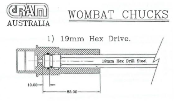
What appear as two small black circles is the O-ring (shown in cross-section) seated in the female receival point for the spigot in the chuck. It was Mr Charlton’s evidence, and the respondent’s case, that the O-ring was essential for an effective seal of the flushing water system at this point of engagement. The same manual contained a depiction of an engagement between a 25 mm square locking chuck and a corresponding drill rod, as follows:
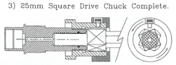
184 Of the importance of the O-ring to the effectiveness of the water seal, it was stated in the manual as follows:
This chuck allows rapid drill steel changes and good alignment. The o’ring is positioned in the chuck so that drill steels with or without o’ring can be used. A high degree of sealing occurs between the drill steel and the base of the chuck while drilling. The o’ring is a secondary seal only.
Under cross-examination, Mr Charlton was emphatic in his disagreement with the two final sentences in this passage. He said that there was, in practice, so much movement as between the base of the drill rod and the chuck into which it had been placed that an effective water seal would never be achieved by reliance only on the fit between “the drill steel and the base of the chuck”, and, whatever the authors of the manual may have thought, it was inevitably the O-ring which provided the seal in the Wombat system. However, Graeme Wolfenden, a fitter and turner by trade called by the applicants who was, in June 1997 (as he put it in his affidavit) “thoroughly familiar with underground coal mining operations and equipment”, gave evidence in cross-examination that the passage set out above from the Wombat manual reflected his understanding of the way in which the machine was used before June 1997, that it was, at that time, possible to use the machine to drill a hole without using an O-ring seal in the drive chuck, and that that was in fact done.
185 Notwithstanding that evidence, I do not accept that the use of the Wombat machine justifies the conclusion that some specific means of water sealing would not have been required in an arrangement of the kind proposed in Dr Fuller’s third approach. Whatever may have been the situation in a hand-held single-pass context, in extension drilling it was necessary to propel the flushing water upwards, in a narrow passage, over a distance of, say, 12 m. The evidence is not sufficient to justify the conclusion that the methods employed in the Wombat system would necessarily provide a reliable indication of what might be expected in extension drilling. In my view, the notional skilled addressee would not regard it as obvious that the two situations were, in a practical sense, indistinguishable.
186 The matter is really put beyond doubt by the evidence given by Dr Fuller in response to Mr Charlton. Dr Fuller agreed with Mr Charlton’s proposition that “simply fitting an extension rod into the chuck as proposed by Dr Fuller would not provide an adequate seal.” He (Dr Fuller) continued:
I did not refer to the issue of water sealing when discussing my approach to the Problem, because the Problem did not refer to any difficulty with existing water sealing systems. However, I did have in mind that the drilling system in my third approach would have a water sealing mechanism. I did not refer to this in my first or second affidavit, because I regarded water sealing between the drive end of the drill motor and the extension rod to be a standard feature of drilling systems. I did not consider it necessary to address this in my response to the Problem.
Dr Fuller also said:
I remain confident that effective water sealing would have been achieved using my third approach as at June 1997. As I have stated above, the existing extension drilling systems had a water sealing mechanism. Having regard to what I knew before June 1997, and applying basic engineering principles, the following three sealing mechanisms immediately come to my mind as approaches that could have been pursued:
(a) An o-ring could be fitted in a groove in the bottom of the drive chuck that mates with the smooth, flat base of the bottom of the female end of the extension rod. An o-ring is a round cross-section, circular shaped sealing ring.
(b) An o-ring could be fitted into a groove of an inner spigot located within the drive chuck to mate against the smooth, flat surface at the upper end of the female threaded socket within the drilling rod.
(c) An o-ring could be fitted within a groove on the outside of a spigot within the drive chuck of suitable size to mate with the smooth, round surface of the axial passage of the extension rod at the female end.
The position with which both experts agreed, therefore, is that an O-ring would have been necessary for water sealing.
187 From there the debate as between Mr Charlton and Dr Fuller moved to the question whether the O-ring expedients suggested by the latter would have worked in practice. The former suggested that they would not. That position was supported by the applicants in their final submissions. At this point, however, the combatants were, I would have to say, engaging on a field further and further away from the issue of whether the invention, so far as claimed in Claim 1, would have been obvious to the skilled addressee.
188 As the respondent pointed out in its submissions, Claim 1 says nothing about water sealing. No integer of the claim either requires or contemplates any means of water sealing in the system said to have been invented. In describing what is said to be the preferred chuck (actually an adaptor), the specification refers to a sealing member as shown in Fig 3 (see para 36 above), but that is not limiting apropos the scope of Claim 1. If the invention actually claimed is obvious, it will not be saved by the non-obviousness of a more specific preferred embodiment of it described in the specification.
189 It cannot, therefore, be an answer to Dr Fuller to propose that he did not incorporate any means of water sealing in the solution which he devised inside 30 minutes. The question for the court is not whether the skilled addressee would, without inventiveness, have readily come up with a system with every mechanical characteristic required to provide the ideal piece of machinery for the purposes intended. It is whether he or she would, without inventiveness, have come up with what is claimed. If Dr Fuller’s third approach provides support for an affirmative answer to that question, that support is not undermined by his omission to refer to any means of water sealing, or to address such water sealing issues as might arise.
190 I turn next to the second of the negative aspects of Dr Fuller’s third approach identified by Mr Charlton (see para 178 above). Dr Fuller’s response was as follows:
It would have been a simple matter to design a drive rod/adaptor that fitted into my redesigned chuck and drove, via the drive rod/adaptor, single pass rods. Such a drive rod/adaptor would have a hexagonal shape at one end (for engaging with the redesigned chuck) and a socket at the opposite end shaped to fit the square drive end of a single pass rod, together with a form of water sealing. While the use of a drive rod/adaptor would increase the length of the drill string, head room is generally less of a concern in single pass drilling (multi-pass drilling is used when it is necessary to drill deeper than the head room at the drilling site).
191 What Dr Fuller described as a “drive rod/adaptor” would, in the lexicon of the parties in this case, have been an adaptor. While the adaptor described in some areas of the specification would make it possible to use the 25 mm square locking chuck in extension drilling when the lowermost rod in the drill string was of a hexagonal outer profile, Dr Fuller’s expedient would make it possible to use his proposed chuck, with a hexagonal socket, in single-pass drilling when the driven part of the drill rod had a 25 mm square profile.
192 The applicants criticised this aspect of Dr Fuller’s reasoning on three grounds: that, as was the fact, when he came to the problems presented to him by the respondent’s solicitors, he was unaware of the use in the industry of the 25 mm square locking chuck, that the need to introduce an adaptor in single-pass drilling would involve “the tail wagging the dog” and that, by the time he responded to Mr Charlton’s “negative aspects”, he had read the Patent. These are valid criticisms, but they should not be taken too far.
193 As to the first criticism, counsel for the applicant submitted that, because of Dr Fuller’s lack of awareness of the 25 mm square locking chuck, his views could not be treated as those of the notional skilled addressee, who undoubtedly would have been aware of that chuck. But what the skilled addressee would have made of the problem which confronted the inventors, and led to the invention, is an objective matter to be resolved by reference to all of the relevant evidence. So too is the state of the common general knowledge. That one engineer who found it obvious to solve the problem by recourse to the solution described in Claim 1 was not aware of the existence of a chuck arrangement commonly used in the industry should lead the court to consider the significance of his solution carefully, but not to disregard his evidence altogether.
194 As to the applicants’ second criticism, it was pointed out that, in a typical roof bolting operation, single-pass drilling predominated to a substantial degree: indeed, it was Dr Fuller himself who estimated that, for every cable-bolt hole that was drilled, about 15 of the shorter, single-pass, holes were drilled. I accept that the introduction of an adaptor for use with a chuck configured to drive the outside of a hexagonally-profiled rod used in extension drilling would be inconvenient and, therefore, most likely more costly than the system then (ie at the priority date) used in existing single-pass operations. However, the question for the court is whether the invention as claimed would have been obvious to the notional addressee. The invention was for a system for improved extension drilling. Whether the adoption of such a system would have introduced operational or financial issues in drilling other than extension drilling is not, it seems to me, a consideration of relevance to the present inquiry.
195 As to the applicants’ third criticism, it is not as though Dr Fuller was using his knowledge of the invention to assert that some dimension of it was obvious. Indeed, Claim 1 says nothing about an adaptor. Rather, he was drawing upon his understanding of a practice commonly used in roof bolting – and part of the common general knowledge – to bear on the task of resolving the negative aspect referred to by Mr Charlton. In that respect, Mr Charlton himself was not proposing that Dr Fuller’s third approach failed to grapple with one of the integers of Claim 1, and Dr Fuller likewise sought to address the issue there raised by reference to concepts and practices which themselves lay outside Claim 1.
196 I turn next to the third of the negative aspects of Dr Fuller’s third approach identified by Mr Charlton (see para 179 above). Dr Fuller responded to it as follows:
I was not aware of the particular health and safety issues associated with non-locking chucks before June 1997. In any case, I disagree that the mechanical interlock arrangement in my third approach would give rise to occupational health and safety risks, compared with a chuck lock mechanism. Further, on my reading of the Patent, the drive chuck shown in Figure 1, and the alternative (preferred) drive chuck shown in Figure 3, do not have any chuck lock mechanism of the kind that Mr Charlton refers to. I also note that the Problem does not refer to any difficulty with occupational health and safety in the existing drilling extension rod systems.
This response is of little assistance to the court. It is not clear – and this was not resolved by Dr Fuller in his oral evidence – what Dr Fuller meant by “the mechanical interlock arrangement in my third approach”. Neither did Dr Fuller state that basis of his disagreement with Mr Charlton. Otherwise, Dr Fuller’s response is argumentative.
197 Notwithstanding those reservations, I do not consider that Mr Charlton’s third negative aspect undermines such contribution as Dr Fuller’s work made to a conclusion that the invention, so far as claimed in Claim 1, was obvious. The fact is that the Patent is agnostic as to such health and safety issues as might arise if the invention were put into practice. Neither does Claim 1 refer to a locking means as between the chuck and the lowermost rod: relevantly, it is required only that the chuck drive the outside coupling of the rod. Further, under cross-examination Mr Charlton accepted that chuck or adaptor arrangements which did not involve a locking mechanism were in use in the industry as at the priority date and, if it matters, for some years thereafter. It seems clear that, although the locking chuck had, at the priority date, become a standard means of avoiding the dangers presented by dropping rods, its use was not universal.
198 Dr Fuller himself is not to be taken as the personification of the notional skilled addressee. But his evidence, and the applicants’ criticisms of it, are relevant to the matter of obviousness. For the reasons I have given, I accept that evidence so far as it goes.
199 With respect to obviousness, the respondent relied also on the development by Mr Geatches of the rod-in-chuck system to which I have referred in connection with its novelty objection. In his evidence, Mr Geatches himself said that it never occurred to him to file a patent application for his rods. He did not consider that there was anything novel about those rods. These views are neither binding on the court nor, strictly, relevant, in the sense that the Patent is for a system of extension drilling rather than for the rods used in it. However, Mr Geatches’ evidence goes at least part of the way to answering another of the submissions made by the applicants, namely, that the omission, over a period of about 20 years since the introduction of extension drilling in the 1970s, of anyone else in the industry to devise a system such as that claimed in Claim 1 was a fair indication that such a system would not have been obvious to the skilled addressee. As I have found earlier in these reasons, Mr Geatches did devise such a system.
200 Everything considered, I have come to the conclusion that the invention, so far as claimed in Claim 1, would have been obvious to a person skilled in the relevant art in the light of the common general knowledge as it existed before the priority date. Fundamental to this conclusion is the very limited respect in which Claim 1 took a step which went beyond what was already commonly and generally used in the industry, and self-evidently so from the terms of the specification itself (see para 46 above). To take that step would, in my view, have been obvious to the skilled addressee. Faced with the problems of the presence of two threaded connections between the chuck and the grippers and of the space occupied by the adaptor, the skilled addressee would have recommended the employment of a system in which the chuck drove the outside of the lowermost rod. He or she may not have come to that solution instantly, but, examining the range of possibilities and employing no more than his or her normal uninventive skills and experience, he or she would, in my view, have readily suggested doing exactly what Claim 1 requires, namely, making use of “a drive chuck … for driving the outside surface of a female coupling of an extension rod at one end of the drill rod string”.
201 That is not to say, I stress, that the skilled addressee would have recommended the use of a system which did not involve any means of water sealing. Indeed, it is probable that he or she would not have – as Dr Fuller himself would not have – contemplated any such recommendation. Some form of water sealing would have been necessary for any practical application of a system along the lines of that which I consider would have been obvious to the skilled addressee. But the invention so far as claimed in Claim 1 did not travel that extra distance. The question arising under s 7(2) of the Act is not to be resolved by reference to the inventiveness of an integer which the inventors did not claim.
202 With respect to Claim 1, therefore, I uphold the respondent’s obviousness case.
203 Turning to the other claims, the only additional element introduced by Claim 2 is the axial passage for flushing fluid. That was clearly within the common general knowledge as at the priority date.
204 The additional element introduced by Claim 3 is the non-return valve in the axial passage incorporated into “at least one” of the drill rods. Under cross-examination, Mr Charlton was taken to a passage in a CRAM Proram brochure which, it now seems to me, could have had nothing to do with extension drilling in coal mines – it related to drilling in stone and was relevant to a situation in which an “up-hole” was being drilled over a distance of more than 50 m – but, in the course of answering counsel for the respondent, he (Charlton) said that a “check valve” was “a ball or a ball-bearing … – it’s either glass or steel, I suspect – that allows this column of water, that has been pumped into each drill rod, to remain in column when you … raise the drill string to add another one.” He was familiar with such an arrangement before 1997. Likewise Mr Wolfenden, also called by the applicants, was aware of the use of non-return valves in extension drilling systems before 1997. None of this was put in issue by the applicants. To the extent that Claim 3 travels beyond Claim 1, what is claimed was within the common general knowledge before the priority date.
205 With respect to Claim 4, there is a construction issue which bears particularly upon the respondent’s inutility case, to which I shall return in due course. But, accepting for the moment what the applicants say in this regard – that the claim refers to a system which uses rods which, whatever be their cross-sections along the length of them, are driven by a chuck having a similar cross-section to that of the driven ends of them – the claim adds nothing to Claim 1 which was not part of the common general knowledge as at the priority date.
206 With respect to Claim 6, the first preferred embodiment, covered by Figs 1 and 2, adds nothing to what is conveyed by Claim 1. The second preferred embodiment, covered by Figs 3, 4 and 5, is not to be dismissed so readily. That embodiment itself encompasses two alternatives: a an adaptor with a locking arrangement as shown in Figs 4, 4A and 4B, and an adaptor without such an arrangement as shown in Fig 3. In both respects (albeit in the latter respect with qualifications), I am not persuaded that the invention was obvious.
207 As to the Fig 4 arrangement as such, the use of a locking chuck was, of course, part of the common general knowledge as at the priority date. But an extension drilling system which employed rods of the kind described in para 24 above was not. The inventiveness in this system was that every rod (1) could be placed directly into the adaptor to be driven by contact with its outside surface, (2) incorporated a female-threaded lower end for connection to the male-threaded end of any other rod, (3) could be used anywhere in the drill string and (4) was configured at the lower end to lock into the adaptor. Each of these features could be found in different single-pass and extension drilling systems that were within the common general knowledge, but no single system incorporated all of them. That would not be fatal to the respondent’s obviousness case, of course, but it constitutes a hurdle for them of some height. Dr Fuller’s evidence, to which I have referred in the context of Claim 1, does not come close to making good the respondent’s case on obviousness with respect to this aspect of Claim 6.
208 In my view, to someone skilled in the relevant art equipped with the common general knowledge as it has been presented in the evidence in this case, the combination of integers conveyed by the first alternative of the second preferred embodiment claimed in Claim 6 would have been self-evidently inventive. Looking at the matter from the perspective of such a skilled addressee, it could not be said that this combination was obvious.
209 As to Fig 4 notionally adjusted to incorporate the adaptor shown in Fig 3, there is no locking mechanism incorporated into this embodiment of the invention claimed in Claim 6. If that were all there were to it, this embodiment would be, in effect, Claim 1 with an adaptor. That would have been no less obvious to the skilled addressee than the invention claimed in Claim 1 itself. However, the Fig 3 adaptor was more than a simple socket arrangement internally configured to drive the flat-sided external profile of the lowermost drill rod. It was of modular construction and incorporated a polyurethane water seal held firmly in place between its two component parts. With respect to the detail of the sealing member, the conclusion which I reach here on obviousness is based on the more confined understanding of Fig 3 for which the respondent contended, and which is addressed in detail in the next section of my reasons. Even on that understanding of the diagram, I would hold that the invention, so far as claimed in this aspect of Claim 6, was not obvious.
210 As in the case of so much of my reasons above as have dealt with the matter of novelty, so too here, if Claim 6 were not to be revoked on a basis other than obviousness, I would allow the applicants time to apply for an amendment which would confine the claim to the second and third alternatives as I earlier identified them.
211 For the reasons given above in relation to Claim 1, I consider that, in so far as claimed in Claim 7 too, the invention would have been obvious to the skilled addressee in the light of the common general knowledge at the priority date.
BEST METHOD KNOWN TO THE APPLICANTS
212 By s 40(2)(a) of the Act in its then terms, a complete specification was required to “describe the invention fully, including the best method known to the applicant of performance of the invention”. It should be noted that, insofar as s 40 is concerned, the requirement relates to the invention as such. In this aspect, the section does not take the “so far as claimed in any claim” approach prescribed by s 18(1). Somewhat different considerations may be brought into play under s 138(3) of the Act, and I shall refer to them in due course below.
213 It is contended on behalf of the respondent that, when the inventors filed the complete specification for the invention the subject of the Patent on 29 May 1998, they did not disclose what was then known to them as the best method of performing the invention. In the specification, it is stated that Fig 3 “shows a modified (alternative) direct drive chuck for use in the extension drilling systems of Figures 4 to 5, and is in fact the drive chuck preferred ….” Thus, according to the respondent, it is to Fig 3 that one naturally looks to find the best method of performing the invention known to the applicants, at least with respect to so much of it that relates to the chuck and the detail of its engagement with the lower end of the lowermost drill rod. The circumstance that Fig 3 shows an adaptor rather than a chuck as such is, in this respect, a distinction without a difference.
214 The respondent next points to so much of the specification as makes it clear that Fig 3 discloses the use of a water seal, at least to a limited extent: “The socket 21e receives a sealing member 21j which may be formed from polyurethane, moulded around a stainless steel washer body, and which seats on a step 21k in the end of the male drive member 21b.” Thus, the respondent says, the inventors disclosed that the best method known to them incorporated a sealing member, but this was no more than what is shown at 21j on the diagram, namely, a flat (horizontally-oriented as shown) washer-type seal such as might be made from coating a stainless steel washer with polyurethane.
215 The applicants do not accept that, in the eyes of the skilled addressee, the sealing member in Fig 3 would be read in this limited way. They submit that he or she would understand that the sealing member included both the flat part mentioned above and an upwardly extending cylindrical part as shown in red in the enlarged diagram below:
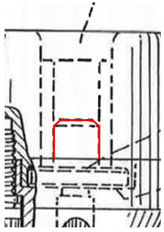
216 In the applicants’ submission, the skilled addressee would understand that that the upper of the two closely-spaced dashed horizontal lines at the top of what they say is the cylindrical part was in fact chamfered at its left and right ends, to slope from the alignment of that line to the alignment of the lower of those lines, as shown in red on the diagram above. Further, he or she would understand that this cylindrical part was integral with the flat part of the sealing member shown at 21j. It must be said that there is no support for this view of things in the text in the specification, but, according to the applicants, the skilled addressee would understand these things from the diagram itself.
217 Mr Charlton – under cross-examination I would add – explained that this was his understanding of the sealing member shown in Fig 3. He said that the diagram had been done on a computer, and that the “line scale was too coarse” to show, explicitly, the chamfered upper profile of the cylindrical part of the member, which he identified as a spigot. But it was implied, and was quite clear to him. This view of things was, Mr Charlton said, based on his own “generally very high understanding of mechanical drawings”. Pressed to elaborate, Mr Charlton said that the circumstance that the upper of the two closely-spaced dashed horizontal lines – shown as red above – was not shown as extending fully to meet the vertical dashed lines to the left and right indicated to him the presence of a chamfered edge on the top of the spigot.
218 In his affidavit sworn on 3 September 2015, Dr Fuller explained how he understood the water sealing member shown in Fig 3. He referred only to the stainless steel washer body and to the polyurethane coating around that. When taken to Fig 3 during cross-examination, Dr Fuller readily understood the position for which Mr Charlton contended, but said that, before then, he had not understood what these two horizontal lines – the one shown in red above and the one beneath it – represented. He responded in the negative to counsel’s question whether they showed “a chamfered upper section of the seal”.
219 Did the specification describe a method of performing water sealing in the adaptor shown in Fig 3 by means of a sealing member which included an upwardly-extending spigot integral with the flat part of the member? The starting point, of course, is the text of the specification. The sealing member described there is confined to the stainless steel washer body coated in polyurethane. The sealing member is numbered 21j and, while there is some ambiguity about the matter, most obviously this is a reference to the horizontal element. That was Dr Fuller’s understanding. Mr Charlton was able to discern what the inventors were about in this aspect of Fig 3, but his understanding of the subject depended to an important extent on what he regarded as implicit: in a metaphorical as well as a literal sense, he was required to join the dots. In my view, for the inventors to have communicated in this way to the skilled addressee did not amount to a description within the meaning of s 40(2)(a) of the Act: no more so in the case of the best method than it would have been in the case of the invention itself.
220 It is uncontroversial that, in May 1998, the inventors had developed a form of sealing member that, in its central and upper sections, conformed with Mr Charlton’s understanding of what was conveyed by Fig 3. I say “central and upper sections” because there was also a lower section which had by then been incorporated into the sealing member which the inventors knew to be the best method of performing the invention in presently relevant respects.
221 Stephen Weaver is one of the inventors named on the Patent. He has been employed in the Sandvik group since 1989. In an affidavit sworn on 25 August 2015 in response to Mr Geatches’ evidence, Mr Weaver said that, in the development of the applicants’ extension drilling system which is the subject of the Patent, “designing an effective water seal was a real issue which needed to be overcome”. He explained that the seal ultimately designed had –
… a flat disc with a central hole. The flat disc is a stainless steel washer with a thick coating of polyurethane. Rising from the flat disc is a short hollow cylindrical body of polyurethane. The seal fits inside the bore of the extension rod (being the female thread) and directs water flow into the bore of the seal and up through the extension rod. The stainless steel was used to provide strength. The polyurethane coating provides some sealing and a connection point to the hollow polyurethane section above this, which seals against the female thread of the extension rod.
And:
The two sealing areas, being the washer base and the cylindrical part, give a “belt and braces” approach. As long as one of them is intact there will be an adequate seal. The primary seal, however, is provided by the cylindrical section, which is not being squashed by the drilling thrust.
222 In evidence is a technical drawing prepared in the development of the applicants’ system which was drawn on 9 September 1997 and checked by Mr Weaver on 26 September 1997. It shows the sealing member in profile as follows:
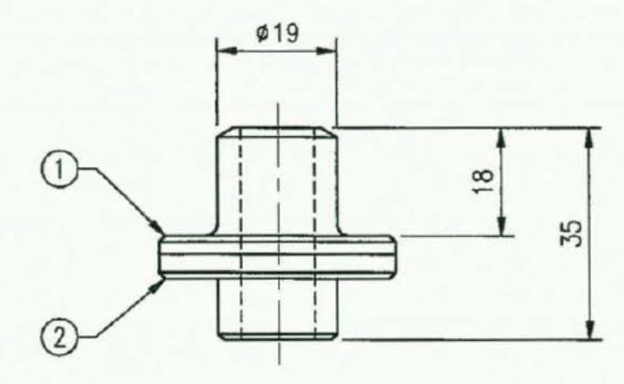
From this drawing what I have described as the upper, central and lower sections of the sealing member are clearly to be seen.
223 Under cross-examination, Mr Weaver described this as “the ultimate evolution of the seal” and as “a superior design”. Mr Weaver said that the lower section performed two functions: “sealing between the bottom half of the chuck adaptor and the seal” and acting “as a locator for assembly purposes”. He accepted that this part of the sealing member was not shown in Fig 3.
224 We are not here dealing with some minor or incidental dimension of what was perceived by the inventors as the best method of performing the invention: as Mr Weaver said, this sealing aspect was “a real issue which needed to be overcome”. Subject only to the applicants’ argument dealt with next, it seems clear that the complete specification did not describe the best method of performing the invention known to the applicants.
225 That argument was, in short, that the detailed characteristics of the seal member did not relate to a method of performing the invention at all. Here the applicants relied on the judgment of the Full Court in Firebelt Pty Ltd v Brambles Australia Ltd (2000) 51 IPR 531. That case concerned an automated system for the loading and receival of refuse and recycling materials from a bifurcated bin into a correspondingly bifurcated hopper on the collection truck. Relevantly to the applicants’ point here, the primary Judge had held that the best known method to cause the lid of the bin to open automatically, at just the right stage to permit the refuse and recycling materials to drop into their intended compartments, was not described in the specification. That aspect of his Honour’s determination was not disturbed on appeal.
226 But their Honours held that this did not amount to a failure to describe the best method of performing the invention. They said (51 IPR at 544-545 [52]-[55]):
The invention claimed is not of a particular type of lid opening device operating at any particular time. There is therefore no statutory obligation to describe which of the contemplated lid opening devices was considered to be the best, nor the preferred timing, contrary to his Honour’s understanding of the section.
The requirement of s 40(2) of the Act is that the patentee is required to give the best information in his power as to how to carry out the invention. That requirement is ordinarily satisfied by including in the specification a detailed description of one or more preferred embodiments of the invention offered, with reference to drawings of specific mechanisms or structures or examples of specific process conditions or chemical formulations, depending on the field of the invention and the nature of the instruction to be conveyed. It is necessary to have regard to what is the invention claimed in the petty patent. The invention here claimed is not a particular type of lid opening device operating at any particular time. It is only if it were such a claim that there might be a failure such as the primary judge found.
The text of the complete specification of the petty patent leaves no doubt that the figures 4, 5 and 8 referred to in that specification depict an embodiment of the lid opening device, and the description of figures 4 and 5 includes:
… a jet of water shown at 30 fired from nozzle 31 on the loading mechanism 19 opens the lid 32 of the bin 20 prior to the contents of the bin 20 being discharged. This will be slightly delayed due to the inertia of the bin being raised through its arc of movement to the final stop position illustrated in figure 5. In other words, the combined effect of the movement of the bin through its arc followed by the jet of water discharged from nozzle 31 followed by raising of the ramp into the aligned position illustrated in figure 5 will ensure that minimum recyclables from compartment 27 end up in the wrong tank section. As an alternative to the jet of water, other mechanically equivalent contrivances can be employed including air jets or directly acting mechanical lid openers.
In our respectful view there has been no failure of the duty to disclose the best method of performing the invention known to the applicant, as required by s 40(2) of the Act.
227 As I have noted in another part of these reasons, and as counsel for the applicants submitted in this department of the case, the presence of a sealing member forms no part of Claim 1 (nor of the other independent claim, Claim 7). But the claims in a patent must relate to one invention only (s 40(4)). In a passage from Vidal Dyes Syndicate Ltd v Levenstein Ltd (1912) 29 RPC 245 cited by the Full Court in Firebelt, Fletcher Moulton LJ said (29 RPC at 269):
It is settled law that a patentee must act towards the public uberrima fide, and must give the best information in his power as to how to carry out the invention. He is therefore bound to tell the public all the steps that can advantageously be taken in carrying out the invention. But he is not limited to claiming only the best way of carrying it out.
That is to say, the best way of carrying out the invention need not be claimed. But it must be described. In the present case, the inventors did claim what was, ostensibly at least, the best way of carrying out the invention claimed in Claims 1-5: the use of the device set out in Fig 3 was incorporated into Claim 6. Importantly, the inventors made it clear in the specification that this was the “drive chuck preferred”: a formula, I take it, intended to equate to what was the best known method.
228 The difficulty was (and is), of course, that what was thereby described was not the best method known to the inventors. When the complete specification was filed in May 1998, the applicants had developed, to the detailed technical drawing stage, a sealing member that was better than any described in the specification.
229 For the above reasons, I accept the respondent’s case that the complete specification for the Patent did not describe the best method known to the inventors for performing the invention, as required by s 40(2)(a) of the Act.
230 That brings me to s 138(3)(f) of the Act, which empowers the court to revoke the Patent, “either wholly or so far as it relates to a claim” on grounds which include “that the specification does not comply with subsection 40(2) ….” I was not addressed on the question whether s 138(3)(f) contemplates the revocation of a patent wholly where the respect in which something less than the best method known to the inventor was confined to a particular claim. At the general level, I would be disposed to the view that “the invention” referred to in s 40(2)(a) is the “one invention” referred to in s 40(4), and that the formula in the opening words of s 138(3) “or so far as it relates to a claim” is intended to perform service (at least) in the setting of para (b) of the subsection where the claim-based approach mandated by s 18(1) would be relevant. When dealing with para (f), the presence of that formula need not require the taking of a claim-based approach.
231 In the present case it is clear that the inventors themselves took the view that the particular water-sealing arrangement described above was critical to the efficacy and quality of the ultimate form of the invention developed by them as at the date of the filing of the complete specification. This was not merely the optimisation of what was claimed in Claim 6: it was the optimisation of the invention as such. Whatever may be the situation in other cases, here the best method of performing the invention known to the inventors included that arrangement. Subject to what I say in the following paragraph, the better view seems to be that, in a case such as the present one, the omission of any description of the best known method in the complete specification should lead to the revocation of the Patent as a whole.
232 The respondent’s Third Further Amended Particulars of Invalidity, however, confined its best method contention to Claims 1, 2, 3, 4, 6 and 7. Neither was I addressed, in any respect, on Claim 5. In the circumstances, the Patent should not be revoked so far as it relates to that claim. Otherwise, this aspect of the Cross-claim has been made good.
UTILITY
233 There are two limbs to the respondent’s utility case. The first is advanced, as counsel put it, to present the applicants and the court with “a logical dilemma” apropos the matter of inventive step. If Dr Fuller’s third approach, either as such or in its more developed forms (see paras 174 and 175 above), is to be dismissed on account of lacking any effective means of water sealing, and if any expedient that involved nothing more than a hard rubber base seal of the kind used by Mr Geatches is likewise to be rejected, it must follow that what was claimed in Claim 1 was for a system of extension drilling that would not be useful. Self-evidently, this point of the respondent’s relates only to Claims 1-4.
234 In Ranbaxy Australia Pty Ltd v Warner-Lambert Co LLC (2008) 77 IPR 449, 479 [141], the Full Court said:
Under ss 138 and 18(1)(c) of the 1990 Act, it is a ground of invalidity if the claimed invention is not useful “so far as claimed in any claim”. If the claimed invention does what it is intended by the patentee to do and the end obtained is itself useful, the invention is useful within the meaning of s 18(1)(c) (see Rehm Pty Ltd v Webster’s Security Systems (International) Pty Ltd (1981) 81 ALR 79 at 96; 11 IPR 289 at 305–6; Welcome Real-Time SA v Catuity Inc (2001) 113 FCR 110; 51 IPR 327; [2001] FCA 445 at [157]–[161]; and Fawcett v Homan (1896) 13 RPC 398 at 405). As to the first aspect, the invention as claimed must attain the result promised by the patentee (Advanced Building Systems Pty Ltd v Ramset Fasteners (Aust) Pty Ltd (1998) 194 CLR 171; 152 ALR 604; 40 IPR 243; [1998] HCA 19 at [21]–[26]).
235 It was submitted on behalf of the applicants that Claim 1 made no promise about water sealing, and that the only question on utility was whether an extension drilling system which did not incorporate a water seal would be useful. Although the subject was not made entirely clear in those submissions, I understand that counsel for the applicants would wish to be associated with the proposition that, although not referred to in the claim, the use of a simple seal of the kind used by Mr Geatches was within the range of uninventive steps that the skilled addressee might be expected to take if his or her concern was, as presumptively it had to be, to make the invention work. If so, the applicants are entitled to assume the use of such a simple seal in resisting the respondent’s inutility case.
236 It was uncontroversial that any system of extension drilling would have to incorporate a means of flushing the debris from around the drill bit during operation, and that this would be by way of water being pumped from the chuck to the drill bit via an axial passage in the drill rods. A system which did not do so certainly would not work. Under cross-examination, Mr Charlton said that a system which did not contain a water seal, “would probably work, but it would not work well”, and that “to be useful, [the system] needs a water seal”. Here Mr Charlton was, as I would understand him, equating usefulness with the notion of something working “well”. But the threshold of utility is not a particularly high one and, in the context of a claim for a system, if what is claimed attains the result promised by the inventor and works, it is not, in my view, fatal under s 18(1)(c) of the Act that the resulting system does not work “well”. In the case at hand, the inventors made no promise as to the efficacy of their system for improving, or even maintaining, water pressure along the drill string, and it may be that the skilled addressee would perceive in so much of the system as is claimed in Claim 1 the making of significant compromises in that department. But, as I say, utility can only be assessed by reference to what was claimed. The circumstance that a more satisfactory system might have been invented is not tantamount to a conclusion that the invention, as claimed, is not useful.
237 For these reasons, the invention, so far as claimed in Claim 1, was, in my view, useful. This conclusion carries over into the respondent’s inutility case in relation to Claims 2-4. I am not sure whether (and if so how) the respondent seeks to advance such a case in relation to Claim 6, but, to the extent that it incorporates Fig 3, and subject to the respondent’s other objections, that claim would have to survive any inutility objection based on the absence of a water sealing arrangement.
238 The second aspect of the respondent’s utility case relates to Claims 1-4. It is said that Claims 1-3 permit, and that Claim 4 in one of its alternatives requires, the drill rods to be of round cross-section. If the female-threaded end of the lowermost rod were of round cross-section, however, it could not be driven (save, possibly, by a through-the-spindle chuck, the relevance of which to the present point was eschewed by the applicants). That last proposition was common ground. However, the applicants contended that, as a matter of construction, Claim 4 should not be understood as proposing that the driven end of a rod might be round. The skilled addressee, it was said, would know that that was nonsense. Rather, when that claim referred to a rod as being of round cross-section, it was speaking of the main body of the rod, not including the end intended to be driven (when the rod concerned was lowermost in the string).
239 Grammatically, to the extent that it relates to Claim 4, the applicants’ contention must be rejected. That the passage “whereby they can be driven by the drive chuck” conveys the idea that, by reason of being of round cross-section, the rods can be driven by the chuck is, in my view, beyond argument. On any view, such an invention would not be useful.
240 But it was this very circumstance that, according to the applicants, would have led the skilled addressee not to read Claim 4 in this way. In one of his affidavits, Mr Charlton said:
As at June 1997, … there were essentially two types of extension rods: round rods and hexagonal rods. I read the reference in claim 4 to “hexagonal or round cross-section or any suitable cross-section” as referring to the cross-section of the body of the extension rod not the female end. As at June 1997, it would have been obvious to those engaged in underground coal mine drilling that a round profile of the female end could not be driven by the chuck or chuck adaptor and it would have been absurd to read the claim in that way. This is confirmed by the description in the body of the specification. The last paragraph on page 7 describes the extension rods by reference in the case of extension rods of hexagonal cross-section to Figures 4 to 5 and, in the case of round rods by reference to Figures 1, 2 and 3. Figure 1, in particular, shows round rods having a thickened portion 23 which engages with the socket in the chuck or chuck adaptor.
The specification states at page 5 line 5:
“As illustrated in Figure 2, the external or outside surface of the female socket 24 is engaged by the drive chuck 21 for driving the string of extension rods 22. The surface of the female socket 24 that the drive chuck 21 engages therefore has a profile suitable for that engagement. Figure 2 shows that the surface which is engaged by the drive chuck 21 includes a portion of greater diameter at the position to which the lead line for the reference numeral 23 extends.”
The reference to female socket 24 as shown in Figure 1, is to the female end of the rod. To work as described in the passage quoted above, the surface engaged by the drive chuck must be flat. In my opinion, that would have been plain to those involved in underground coal mine drilling as at June 1997.
However, as Mr Charlton acknowledged, Dr Fuller read Claim 4 in what I have suggested is the natural grammatical sense.
241 A claim must, of course, be read through the eyes of the notional skilled addressee, but one can go only so far in this respect. Ultimately, construction is a matter for the court. In the present case, how Claim 4 would be understood is itself a matter of disagreement as between the experts. In this state of things, I have reached the view that the applicants’, and Mr Charlton’s, reading of the claim does not involve construction at all. Rather, it involves the invocation of the closest available alternative reading of the words of the claim that would save it from inutility. There is no support in the terms of the claim for such an approach.
242 In my view Claim 4 is bad for want of utility.
243 I would not say the same about Claims 1-3. Claim 1, which is foundational, uses the expression, “for driving the outside surface of a female coupling of an extension rod”. To the skilled addressee, this unadorned expression would imply a flat-sided profile at the driven end. These claims do not, in my view, suffer from the same weakness as does Claim 4.
INFRINGEMENT
244 The Patent is for a system of extension drilling, and there is no suggestion by the applicants that the respondent itself has operated such a system. The respondent is neither a miner nor a mining contractor. Rather, the respondent sells components for drilling systems. In particular, the respondent promotes the sale of, and sells, drill rods and adaptors for use in extension drilling.
245 In this context, the applicants rely on s 117 of the Act, which provides as follows:
(1) If the use of a product by a person would infringe a patent, the supply of that product by one person to another is an infringement of the patent by the supplier unless the supplier is the patentee or licensee of the patent.
(2) A reference in subsection (1) to the use of a product by a person is a reference to:
(a) if the product is capable of only one reasonable use, having regard to its nature or design—that use; or
(b) if the product is not a staple commercial product—any use of the product, if the supplier had reason to believe that the person would put it to that use; or
(c) in any case—the use of the product in accordance with any instructions for the use of the product, or any inducement to use the product, given to the person by the supplier or contained in an advertisement published by or with the authority of the supplier.
246 The applicants’ infringement case involves allegations under Claims 1-4 of the Patent.
247 The respondent denies that it has infringed any of these claims by way of s 117 of the Act. Its omnibus submission in this regard is that Claims 1-4 are invalid and, therefore, that the use of any of its products by a person would not infringe them, or any of them. I have upheld the respondent’s case on validity in relation to each of these claims, the result of which must be that the applicants’ case under s 117 fails.
248 For the sake of completeness, and because findings of fact are required in a number of respects, I deal below with the infringement controversy in this proceeding, or so much of it as remains after noting the admissions which the respondent has made in the course of the conduct of its case. In what follows below, when I note, or hold, that something “would infringe” a claim, or use a similar expression, I intend a reference to what the position would be if the claim in question were valid.
249 The respondent’s pleaded case has undergone some modifications over the period during which this proceeding has been on foot. Additionally, in its final submissions at trial, the respondent made further admissions which went beyond those then contained in the Third Further Amended Defence.
250 It is established on the pleadings that the respondent kept for sale and supply, promoted, offered for sale and supply, sold and supplied its “R18” and “R22” drill rods. The evidence discloses that the numbers 18 and 22 are references to the diameter, in millimetres, of the threaded part at which rods are joined to make a drill string. In each of these categories, rods came in different lengths – on the evidence, from as little as 300 mm to as much as 2 m. In at least one instance, the rod of 1000 mm length, the R18 rod was of hexagonal external profile over its entire length. Otherwise, the R18 rods were round in profile with a short hexagonally-profiled section at the driven end (ie where the female thread was situated internally). All R22 rods, it seems, were of a round profile save for a short section at the driven end which was square.
251 The applicants alleged that, in supplying and offering to supply its rods, the respondent had reason to believe that end users thereof would use them in extension drilling systems as claimed in Claims 1, 2 and 4 of the Patent. The respondent admitted that it had reason to believe that “some (but not all)” of those users would so use the rods. Together with the respondent’s acceptance, by the stage of final submissions at trial, that its rods were not staple commercial products within the meaning of s 117(2)(b) of the Act, these admissions, according to the applicants, made good their liability case under that paragraph in relation to Claims 1, 2 and 4: see Upaid Systems Ltd v Telstra Corporation Ltd (2013) 220 FCR 182, 190 [33]. At a high level, I accept that proposition, but the question of the discrimen by reference to which the respondent would, or would not, have reason to believe remains.
252 A characteristic of all the presently relevant rods is that they are threaded at both ends. It is to be inferred, therefore, that they were supplied for use in extension drilling, and that the respondent had reason to believe that they would be so used. From there, the only issue arising under s 117(2)(b) in the context of Claim 1 would be whether the respondent had reason to believe that the rotation would be imparted to the drill string by the lowermost rod being driven on its outside surface. Here I need to distinguish between rods with an external hexagonal profile along their whole lengths, on the one hand, and rods which are generally of a round profile, but which have a hexagonal or square profile at the driven end, on the other hand. In the case of the latter, it is to be inferred that the purpose of the respondent going to the trouble of making the driven end different from the body of the rod was to provide flat faces for positive engagement with the chuck, thereby driving the rod on its outside surface. Here, I cannot perceive how the respondent would not have reason to believe that customers who purchased such rods would use them in a way which came within Claims 1, 2 and 4 of the Patent. In the case of the former, by contrast, since the whole body of the rod is hexagonal, it is not to be inferred that the purpose of the faces on the rod was to impart rotation. Such a rod was adapted to that purpose, but not designed for it. By choosing to buy such a rod, the customer would not necessarily impart to the respondent an awareness of his or her intention to use the rod in direct drive, as distinct from conventional, extension drilling.
253 As it happens, the respondent has made admissions that take the applicants’ case further than would appear from the kind of conceptual exercise which I undertook in the previous paragraph. The respondent admits that there was at least one instance where it supplied each of the following drill rods used in circumstances that would constitute an infringement of Claims 1, 2 and 4 by the operation of s 117(2)(b) of the Act:
“R18” rods of 18 mm thread diameter, of 1000 mm in length and having a hexagonal external profile over the whole length (an example being Ex GJW-36.1 to Mr Wolfenden’s affidavit affirmed on 30 October 2014);
“R18” rods of 18 mm thread diameter, of 500 mm in length, having a hexagonal external profile at the end of the female coupling and otherwise having a round external profile (an example being Ex GJW-36.3 to the said affidavit);
“R22” rods of 22 mm thread diameter, of 300 mm in length, having a square (28 mm) external profile at the end of the female coupling and otherwise having a round external profile (an example being Ex GJW-36.5 to the said affidavit);
“R22” rods of 22 mm thread diameter, of 1000 mm in length, having a square (28 mm) external profile at the end of the female coupling and otherwise having a round external profile (an example being Ex GJW-36.8 to the said affidavit).
254 Of the rod types referred to, I find it hard to understand how the very physical characteristics of the second, third and fourth would not give the respondent reason to believe that such rods would be used in a system in which the outside surface of the lowermost rod was driven by the chuck (or adaptor). I would not say the same about the first, but, as appears, the respondent has admitted that it did have reason to believe that the rod would be used in a system of that kind, at least on one occasion.
255 The applicants also alleged that, in supplying and offering to supply its rods, the respondent had reason to believe that end users thereof would use them in extension drilling systems as claimed in Claim 3 of the Patent. The respondent admitted that it had reason to believe that “some (but not all)” of those users would so use its round R22 rods in lengths of 1000 mm or greater, such as rods of the kind referred to in the fourth item in the list above. The reason for this admission is that all of those rods were equipped with a non-return valve. Given that these rods are generally round in profile but with a square profile at the female-threaded end, I would, for the reasons I have given above in relation to Claims 1, 2 and 4, find that in all cases the respondent had reason to believe that they would be used as claimed in Claim 3.
256 At trial, the respondent also admitted that there was at least one instance of a supply of rods of the kind referred to in the third item in the list above (ie rods which did not have a non-return valve) to a customer who also purchased a rod, or rods, of the kind referred to in the fourth item in that list (ie rods which did have a non-return valve). In such a case, it was admitted that the circumstances would be such as would attract the operation of s 117(2)(b) of the Act, even in relation to the 300 mm rod. To what is established on these admissions, I would add that, by reference to the evidence in the case, I consider it improbable that a miner or contractor would obtain a 300 mm rod for use on its own, ie in single-pass drilling. In extension drilling, only if it were used in combination with another 300 mm rod, or other such rods, would Claim 3 not be engaged. That might be the case, I suppose, where the use of short rods was made necessary by severe height limitations, for example. For that reason, I cannot go beyond the respondent’s admission that there was “at least one” instance of a supply that would engage the claim, but I would not be at all surprised if, at the quantification stage of this proceeding (assuming it is reached), this 300 mm rod was found to be involved in infringements of Claim 3.
257 It is established on the pleadings that the respondent kept for sale and supply, promoted, offered for sale and supply, sold and supplied chuck adaptors referred to by it as “Hex direct drive”, “Fat Boy”, “Slim Boy”, “Hex Female Slim Boy” and “Square Female Slim Boy”. Not all of those were the subject of evidence at trial. The following were:
“Fat Boy” adaptors designed to drive the outside surface of R18 hexagonal drive rods (an example being Ex GJW-36.9 to Mr Wolfenden’s affidavit affirmed on 30 October 2014);
“Slim Boy” adaptors designed to drive the outside surface of R18 hexagonal drive rods (an example being Ex GJW-36.10 to the said affidavit);
“Fat Boy” adaptors designed to drive the outside surface of R22 (28 mm) square drive rods (an example being Ex GJW-36.11 to the said affidavit);
“Slim Boy” adaptors designed to drive the outside surface of R22 (28 mm) square drive rods (an example being Ex GJW-36.12 to the said affidavit).
258 It is also established that the respondent had reason to believe that the end users of each of these adaptors (whether or not the subject of evidence) would use them in extension drilling systems as claimed in Claims 1, 2 and 4 of the Patent; and that “some (but not all)” of the end users of adaptors of the kinds referred to in the third and fourth items in the list above would use them in extension drilling systems as claimed in Claim 3 of the Patent. The point of discrimination here, in the respondent’s pleading, was whether the purchaser also purchased a rod with a non-return valve. However, that at least some of those who purchased those two adaptors would have done so in circumstances where the respondent had reason to believe that they would be used in a way that would engage Claim 3. Beyond that, the evidence does not go. The applicants appear to accept that the supply of adaptors of the kinds referred to in the first and second items in the list above would not, of itself, give the respondent reason to believe that they would be so used.
259 Turning then to para (c) of s 117(2), the applicants rely on certain catalogues and promotional materials produced by the respondent. By reference to one of the respondent’s catalogues which the applicants described as the “first catalogue”, the respondent admits that there was at least one instance where the use of the following of its products happened in circumstances that would attract the operation of s 117(2)(c) of the Act in the context of Claims 1, 2 and 4:
Part No RR18-MF-0500; R18 M/F ROD 22 mm DIRECT DRIVE 500 mm
Part No RR18-MF-1000; R18 M/F ROD 22 mm DIRECT DRIVE 1000 mm
Part No RR18-MF-1500; R18 M/F ROD 22 mm DIRECT DRIVE 1500 mm
Part No RR18-MF-2000; R18 M/F ROD 22 mm DIRECT DRIVE 2000 mm
Part No HR18-MF-1000; R18 M/F ROD 22 mm DIRECT DRIVE 1000 mm
Part No HR18-MF-1500; R18 M/F ROD 22 mm DIRECT DRIVE 1500 mm
Part No HR18-MF-2000; R18 M/F ROD 22 mm DIRECT DRIVE 2000 mm
Part No RR22-MF-0300; R22 M/F ROD 28 mm DIRECT DRIVE 300 mm
Part No RR22-MF-1000; R22 M/F ROD 28 mm DIRECT DRIVE 1000 mm
Part No RR22-MF-1200; R22 M/F ROD 28 mm DIRECT DRIVE 1200 mm
Part No RR22-MF-1650; R22 M/F ROD 28 mm DIRECT DRIVE 1650 mm
Part No RR22-MF-2000; R22 M/F ROD 28 mm DIRECT DRIVE 2000 mm
Part No HR22-MF-1000; R22 M/F ROD 28 mm DIRECT DRIVE 1000 mm
Part No HR22-MF-1200; R22 M/F ROD 28 mm DIRECT DRIVE 1200 mm
Part No HR22-MF-1650; R22 M/F ROD 28 mm DIRECT DRIVE 1650 mm
Part No HR22-MF-2000; R22 M/F ROD 28 mm DIRECT DRIVE 2000 mm
Part No CA-25SQ-22H; 25 SQDR Adaptor 22 mm Hex Direct Drive
Part No CA-25S-28DD-DD; 25 SQDR Adaptor 28 mm Direct Drive - FAT BOY
Part No CA-25S-28-SL; 25 SQDR Adaptor 28 mm Direct Drive - SLIM BOY
260 The first seven parts listed above – numbered “RR18…” and “HR18…” – were drill rods mentioned on p 12 of the first catalogue. The third-last part on the list above – numbered “CA-25SQ-22H” – was an adaptor mentioned, and illustrated, on that page. The heading to that page was “DIRECT DRIVE VS CONVENTIONAL DRILLING - R18”. On the left of the page were exploded views of two drill strings, beneath the left-hand one of which was that adaptor and beneath the right-hand one of which was a conventional adaptor (ie having a male rope thread on the top end). Self-evidently, the diagrams were calculated to show the components that would be used in direct-drive and conventional extension drilling respectively. In the case of the rods, and adaptor, covered by the respondent’s admissions above, the diagrams amounted, in my view, to inducements, if not also instructions, within the terms of s 117(2)(c) of the Act.
261 The 8th-16th parts listed above – numbered “RR22…” and “HR22…” – were drill rods mentioned on p 14 of the first catalogue. The second-last and last parts on the list above – numbered “CA-25S-28DD-DD” and “CA-25S-28-SL” – were adaptors mentioned, and illustrated, on that page (Fat Boy and Slim Boy respectively). The heading to that page was “DIRECT DRIVE VS CONVENTIONAL DRILLING - R22”. On the left of the page were exploded views of two drill strings, beneath the left-hand one of which was the Fat Boy adaptor and beneath the right-hand one of which was the Slim Boy adaptor. To one side, beneath neither of the drill strings, were two conventional adaptors. Self-evidently, the exploded-view diagrams were calculated to show the components that would be used in direct-drive extension drilling. In the case of the rods, and the Fat Boy and Slim Boy adaptors, covered by the respondent’s admissions above, the diagrams amounted, in my view, to inducements, if not also instructions, within the terms of s 117(2)(c) of the Act.
262 Turning to the second catalogue, in a submission not resisted by counsel for the respondent, it was put on behalf of the applicants that this document was an iteration of the first catalogue that had undergone some slight editorial modifications subsequent to correspondence from themselves to the respondent. That appears to be the case, although I do not suggest that the only changes were those made in consequence of this correspondence.
263 Page 12 of the second catalogue – corresponding with p 12 of the first catalogue – was now headed “EXTENSION DRILLING - R18”. Relevantly to the present matter, the parts that had appeared in the first catalogue were still there, although the rods were no longer described as “direct drive”. Additionally, the following drill rod was mentioned:
Part No HR18-MF-0500; R18 M/F ROD - 500 mm
Further, the direct drive adaptor part No CA-25SQ-22H no longer appeared on this page, either as an entry or in diagrammatic form: beneath the two exploded-view drill strings was a conventional drive adaptor only, centrally-located so as to convey the idea that it could be used with either string. In his affidavit, Mr Wolfenden said of p 12 that there was “no doubt that this page relates to the same direct drive system as page 12 of the First Catalogue.” He was not challenged on that evidence.
264 Page 15 of the second catalogue – corresponding with p 14 of the first catalogue – was now headed “EXTENSION DRILLING - R22”. The rods were listed as follows:
Part No HR22-MF-0500; R22 M/F 22HEX ROD - 500 mm 1.79 Kg
Part No HR22-MF-1000; R22 M/F 22HEX ROD - 1000 mm 3.15 Kg
Part No HR22-MF-1500; R22 M/F 22HEX ROD - 1500 mm 4.51 Kg
Part No RR22-MF-2000; R22 M/F 22HEX ROD - 2000 mm 5.87 Kg
Part No RR22-MF-0300-28; R22 M/F ROD 28 mm - 300 mm 1.27 Kg
Part No RR22-MF-1000-28; R22 M/F ROD 28 mm - 1000 mm 3.75 Kg
Part No RR22-MF-1600-28; R22 M/F ROD 28 mm - 1600 mm 5.8 Kg
Part No RR22-MF-1650-28; R22 M/F ROD 28 mm - 1650 mm 6.0 Kg
Part No M22-MF-2000-28; R22 M/F ROD 28 mm - 2000 mm 7.25 Kg
Further, the direct drive adaptors parts Nos CA-25S-28DD-DD and CA-25S-28-SL no longer appeared on this page, either as entries or in diagrammatic form: beneath each of the two exploded-view drill strings was a conventional drive adaptor only. In his affidavit, Mr Wolfenden said:
[I]n my opinion the positioning of the adaptor immediately beneath the rod is somewhat misleading. In practice that adaptor would very rarely, if ever, be used with the rod shown. That rod has a configuration specifically suited for external direct drive. The lower end of the rod has an internal thread and a square outer profile. The only reason the rod has a square outer profile is so that it can be used with complementary chuck adaptor, that is a drive adaptor which has an internal socket which will drive the outside surface of the rod. If the rod was not intended for such a use there would be no need for the end to have that external profile. It would simply be left with a round profile.
Mr Wolfenden also said of p 15 of the second catalogue that there was “no doubt that this page relates to the same direct drive system as does page 14 of the First Catalogue.” He was not challenged on that evidence.
265 The direct drive adaptors which were relevant to the drill rods referred to on pp 12 and 15 of the second catalogue were to be found on p 21, headed “CHUCK ADAPTORS”. There were two such adaptors, as follows:
Part No CA-25SQ-22H-SL; 25 SQDR Adaptor - 22 mm Hex Female (one piece) - SLIM BOY; 1.93 Kg
Part No CA-25SQ-28-SL; 25 SQDR Adaptor - 28 mm Square Female (one piece) - SLIM BOY; 1.8 Kg
It was Mr Wolfenden’s evidence that, from his review of the second catalogue, the adaptors shown on p 21 would only be used with the direct drive rods shown elsewhere in that catalogue. He was not challenged on that evidence.
266 There was a third catalogue placed into evidence by the applicants, but I was assured by their counsel that it added nothing of relevance to what was set out in the second catalogue.
267 There is only one aspect of the presentation of the respondent’s parts in the second catalogue that might, arguably, make inapplicable to it the conclusions which I reached above in relation to the first catalogue: the direct drive adaptors are not graphically represented beneath, and in alignment with, rod strings in conjunction with which they might be used. That would, in my view, be a distinction without a difference. We are here dealing with a trade market which was, I would infer, knowledgeable about the relevant field of technology and the parts and equipment that were useful in it. The applicants had been supplying direct drive extension drilling rods and adaptors to that market for a number of years before the respondent commenced to do so, in which respect I accept the submission made by counsel for the applicants that the market might be regarded, in relevant respects, as “tutored”. On a fair reading of the second catalogue, a participant in that market would, like Mr Wolfenden, readily perceive that the rods and adaptors referred to above were for use in a direct drive system of extension drilling. Such a use would have infringed Claims 1, 2 and 4, and in some cases 3, of the Patent. By the contents of the catalogue the respondent did, in my view, induce persons to whom the rods and adaptors were supplied to use them in this way.
268 Moving away from the catalogues, in evidence are what appear to be two series of slides produced by the respondent about the use of its products in direct drive extension drilling. They are titled, “R18 Direct Drive System Demonstration” and “R22 Direct Drive System Familiarization Generic”. They clearly amount to sets of instructions for the use of the respondent’s rods and adaptors in a way that would infringe Claims 1, 2 and 4, and in some cases 3, of the Patent. The respondent admits that they were provided to one customer, Anglo Coal, on 26 September 2011 (the “Demonstration”) and 12 July 2011 (the “Generic”). Otherwise, there is no evidence that these series of slides were actually used by the respondent. I accept, of course, that only to the extent that they were actually used could they be regarded as instructions for the purposes of s 117(2)(c) of the Act. In the limited respects covered by the respondent’s admissions, however, the operation of that provision is attracted.
269 There is also a similar set of instructions, this time in the form of a video, to much the same effect. Its title page reads, “Direct Drive Drilling – Fast Efficient Effective”. Here the instructions are conveyed by moving images – the idea, no doubt, being that a picture is worth a thousand words – but they are instructions nonetheless. The respondent admits that it was displayed at “Asia-Pacific’s International Mining Exhibition”, held in Sydney between 6 and 9 September 2011. Otherwise, there is no evidence that this video was actually used by the respondent. The conclusions which I reached in the previous paragraph apply here too.
270 From the admissions to which I have referred, and the findings I have made, above, it is apparent that the applicants have made good their case that the supply of rods and adaptors by the respondent would have given rise to infringements of Claims 1, 2 and 4 and, in some situations, 3 of the Patent by the operation of s 117 of the Act.
JOINT LIABILITY WITH PRIMARY INFRINGERS
271 The applicants next submitted that the respondent was a “joint tortfeasor” apropos the infringing acts of its customers on the principle enunciated by the Full Court in Ramset Fasteners (Aust) Pty Ltd v Advanced Building Systems Pty Ltd (1999) 164 ALR 239, 258-259 [41]. As the reasons of the Full Court demonstrate, the line which defines the practical scope of the application of this principle, and separates it from the kind of situation dealt with by Dixon J in Walker v Alemite Corp (1933) 49 CLR 643, 658, will often be a very fine one. However, one thing is clear: someone cannot be a joint tortfeasor unless there is a tort. In the present case, the applicants have not established that anyone directly infringed the Patent. Their case under s 117 is viable, since it is concerned with the situation arising “if the use of a product by a person would infringe a patent”. There does not have to be any such infringement. But the applicants’ cause of action by way of joint tortfeasorship requires a primary infringer.
272 It was submitted on behalf of the applicants that proof of facts amounting to direct infringements of the Patent could await the second stage of the proceeding (assuming it would be reached), when the court would deal with questions of quantum in accordance with an order made by the court on 17 May 2013. I reject that submission. The gap in the evidence on the applicants’ joint tortfeasorship case is a matter of liability, not of quantum.
273 If all the relevant claims in the Patent were valid, I would, for the reasons given above, reject the applicants’ case that the respondent was liable as a joint tortfeasor.
274 The applicants’ case also involves reliance on s 13 of the Act, which includes in the patentee’s exclusives rights the right to “authorise another person to exploit the invention”. Counsel for the applicants accepted that their clients’ case in this respect suffered from “the same difficulty” as that which I have most recently discussed above in relation to joint tortfeasorship. Their submission under s 13 was, in the circumstances, little more than a formality. I would reject this aspect of the applicants’ case.
MISLEADING OR DECEPTIVE CONDUCT
275 The applicants’ case under the TP Act and the ACL was that, if the use of the respondent’s drill rods and/or adaptors by a miner or contractor would have infringed the Patent, it was misleading (at least) for the respondent not to have warned its customers about that prospect. It is common ground that no such warning was given.
276 Failure to warn may amount to misleading conduct under s 52 of the TP Act and s 18 of the ACL: Winterton Constructions Pty Ltd v Hambros (1992) 39 FCR 97, 114. In the context of a patent case, in Ramset the Full Court said (164 ALR at 268 [67]):
… Whether or not Ramset's conduct should be analysed as conveying an implicit misrepresentation, it acted misleadingly when it promoted and sold face-lift tilt-up equipment in the way that it did, without informing its customers of the liability it was inducing them to incur. This was conduct calculated to cause a mistaken impression about a significant consequence of the transaction proposed to those customers. In our opinion, in such a case, it is unnecessary, and may be artificial, to speak of a representation. The orthodox theory would find one, but it is more realistic to see the conduct as misleading, without resorting to a sophisticated analysis in which no one would have engaged at the time.
277 Subject to the specific points made by the respondent to which I next refer, this is a case in which those principles should be applied. On the premise that the claims in the Patent were valid, the use of the respondent’s drill rods and adaptors in direct drive extension drilling would have infringed Claims 1, 2 and 4 and, in some situations, 3. The proposition that the respondent’s customers would have made their purchases in the realisation that, by using the products that they bought, they were infringing the Patent needs only to be stated to be rejected. In my view, the presumptive circumstances were such that it was misleading for the respondent not to have associated the sale, or at least the promotion, of its products with an appropriate warning (even, if it thought the position not altogether clear, one which was expressed in terms of a possibility, rather than the certainty, of infringement).
278 The respondent’s two points in opposition to this aspect of the applicants’ case were as follows. First, it submitted that its rods (but not its adaptors) were capable of being used in a conventional extension drilling system, and that would be a non-infringing use. This submission, of course, implicitly invites the court to envisage a commercial transaction as between the respondent and one of its customers that was agnostic as to the circumstances in which the rods in question would be used. So to proceed would be to travel beyond anything in the evidence. As noted in para 252 above, the respondent’s rods were, by their construction, especially, albeit not exclusively, adapted for use in direct drive extension drilling. Merely to sell one to a customer who was knowledgeable as to the technology of roof bolting, as the notional customer would surely have been, would be to imply that the rod could be used in such drilling. That would be sufficient for the applicants’ case under the TP Act and the ACL.
279 Secondly, it submitted that -
… the evidence does not support any finding that the First Catalogue was “intended to encourage consumers of [the Quarry Drill Rods or the Quarry Adaptors] to buy them and use them in direct drive systems; in infringement of the patent”. The contents of the First Catalogue do not in any way address the issue of patent infringement. No representation of any kind was made that use of the Quarry Drill Rods or the Quarry Adaptors would not infringe Sandvik’s patent.
The quoted passage in this submission was lifted from the applicants’ opening outline which in this respect was concerned not with the first catalogue but with the promotional materials dealt with at paras 268-269 above. It will be clear by now that I would regard those materials as containing an encouragement of the kind referred to. As to the second and third sentences in this passage, I would say that they bespeak a misunderstanding of the applicants’ case. That case was based not upon the presence of a positive representation, but upon the absence of a warning in circumstances where the purchaser of rods and/or adaptors would have no reason to be alert to the prospect that the use of what he or she had purchased would, or might, expose him or her to allegations of patent infringement.
280 In my view, the promotion and sale of the respondent’s rods and adaptors in the absence of a warning as to the prospect of the Patent being infringed by the use thereof as intended would amount to a contravention of s 52 of the TP Act and s 18 of the ACL.
DISPOSITION OF THE PROCEEDING
281 The result of the various determinations which I have made in these reasons is, at its widest, that the Patent, in so far as it relates to Claims 1-4 and 6-7, must be revoked under s 138(3)(f) because of the omission from the complete specification of a description of the best method known to the inventors. It follows that, for this reason if for no other, the applicants’ infringement case must be rejected. Since the existence of a valid patent was foundational for their joint tortfeasorship case and for their case under the TP Act and the ACL, those cases too must be rejected.
282 I shall dismiss the Application, make an order under s 138(3)(f) in relation to Claims 1, 2, 3, 4, 6 and 7 of the Patent on the Cross-claim, and lay out a timetable for the filing of written submissions on the question of costs.
I certify that the preceding two hundred and eighty-two (282) numbered paragraphs are a true copy of the Reasons for Judgment herein of the Honourable Justice Jessup. |
Dated: 11 March 2016

