
FEDERAL COURT OF AUSTRALIA
BLH Engineering and Construction Pty Ltd v Pro 3 Products Pty Ltd [2015] FCA 833
IN THE FEDERAL COURT OF AUSTRALIA | |
BLH ENGINEERING AND CONSTRUCTION PTY LTD (ACN 133 867 875) First Applicant BLH SAFETY SOLUTIONS PTY LTD (ACN 152 247 792) Second Applicant | |
AND: | PRO 3 PRODUCTS PTY LTD (ACN 147 825 885) Respondent |
DATE OF ORDER: | |
WHERE MADE: |
THE COURT DECLARES THAT:
1. By the letter dated 2 September 2011 from the respondent’s patent and trade mark attorneys to the first applicant, the respondent threatened the first applicant with proceedings for the infringement of Australian Innovation Patent No 2011100489.
2. The threat referred to in Declaration 1 above was unjustifiable.
3. By the letter dated 27 January 2012 from the respondent’s patent and trade mark attorneys to the applicants’ patent and trade mark attorneys, the respondent threatened the applicants with proceedings for the infringement of Australian Innovation Patent No 2011100489.
4. The threat referred to in Declaration 3 above was unjustifiable.
AND THE COURT ORDERS THAT:
5. The respondent be restrained, whether by itself, it servants or agents, from continuing the said threats or either of them.
6. Save as aforesaid, and save as to costs, the Originating Application be dismissed.
7. The proceeding be listed at 9:30 am on 19 August 2015 for the purpose of receiving the parties’ submissions on costs.
AND THE COURT CERTIFIES THAT:
8. In this proceeding, the validity of Claim 1 of Australian Innovation Patent No 2011100489 was questioned.
Note: Entry of orders is dealt with in Rule 39.32 of the Federal Court Rules 2011.
VICTORIA DISTRICT REGISTRY | |
GENERAL DIVISION | VID 294 of 2012 |
BETWEEN: | BLH ENGINEERING AND CONSTRUCTION PTY LTD (ACN 133 867 875) First Applicant BLH SAFETY SOLUTIONS PTY LTD (ACN 152 247 792) Second Applicant |
AND: | PRO 3 PRODUCTS PTY LTD (ACN 147 825 885) Respondent |
JUDGE: | JESSUP J |
DATE: | 14 AUGUST 2015 |
PLACE: | MELBOURNE |
REASONS FOR JUDGMENT
1 The respondent, Pro 3 Products Pty Ltd, is the owner of Australian Innovation Patent No 2011100489 (“the Patent”) for an invention described as “System and components for safely enclosing handrails, stairways, walkways and platforms”. The applicants, BLH Engineering and Construction Pty Ltd (“BLHEC”) and BLH Safety Solutions Pty Ltd (“BLHSS”), are engaged in the manufacture, promotion and sale of what they describe as “The BLH Stop Drop Barricading System” (“the BLH system”). In September and October 2011, and in January and February 2012, the respondent corresponded with the applicants, and with one of their customers, about that system in terms which, the applicants allege, amounted to threats to take infringement proceedings within the meaning of s 128 of the Patents Act 1990 (Cth) (“the Act”). By the present proceeding, the applicants claim declarations, injunctions and damages as referred to in subs (1) of s 128.
2 As part of their case under s 128, the applicants allege that, in relation to all of its claims, the Patent is, and was at all material times, invalid and liable to be revoked on account of lack of novelty and absence of an innovative step. They also allege that, in relation to all claims, the invention is not a manner of manufacture and that the patentee is not entitled to the invention because the named inventors were not the actual inventors of the invention.
3 The applicants also allege that the threats on which they rely under s 128 of the Act amounted to false and misleading representations in trade and commerce, actionable under ss 18 and 29(1)(m) of the Australian Consumer Law (“the ACL”), Sch 2 to the Competition and Consumer Act 2010 (Cth).
4 There was, at one point, a cross-claim in this proceeding but it was, on 20 April 2015, discontinued by leave.
5 Expert evidence which related both to the applicants’ invalidity case and to the respondent’s infringement case (the latter being, as explained below, central to its defence to the applicants’ allegations under s 128) was led by both parties. The applicants called Dr Paul Sincock, Technical Director of AMOG Pty Ltd, consulting engineers. He is a Fellow of Engineers Australia with more than 30 years’ experience as an engineer across a range of disciplines and industry sectors. The respondent called William Hunter, a self-employed mechanical design engineer. He is a Member of Engineers Australia with more than 25 years’ experience in engineering, specialising in mechanical engineering, in areas which include product development, analysis, testing and design across a number of industries. Their evidence on the engineering questions which arose in the case has been of considerable assistance to the court.
THE PATENT
6 The specification for the Patent commences by referring to guardrail and handrail systems used in association with platforms, walkways, stairways and the like in a variety of industrial situations. It is said that these systems commonly involve “an open framework of horizontal, vertical or inclined pipes or tubes”. A limitation of “such open systems”, however, is that they –
… do not provide a sufficient barrier to prevent people, or carried objects such as tools or products, from escaping the confines of the handrail system. This can create hazards for both people on the walkways, who can slip out of, or may be forced to lean out over the handrail or through gaps into potentially unsafe areas to retrieve lost objects, as well as to persons below them who may be hit by falling objects.
According to the specification, there is, thus –
… a need to provide systems and components to at least partially enclose open barrier systems, or at least provide installers with a useful alternative.
7 Addressing this need, in a first aspect of the invention the subject of the Patent –
… there is provided a bracket for use in mounting a guard panel to a post having a predefined profile, including:
a post engaging portion wherein the post engaging portion has an open configuration to allow the bracket to be removably clipped onto the post and retained around the post whilst in the open configuration, and a closed configuration to allow clamping of the post engaging portion to the post;
a clamping portion including:
a first clamping portion; and
a second clamping portion wherein in the closed configuration the second clamping portion is brought towards the first clamping portion to clamp the bracket to the post and are fastened in the closed configuration by a first set of one or more fasteners passing through apertures in the first and second clamping portions; and
a mounting portion including a mounting plate to allow mounting of the guard panel to the bracket with a second set of one or more fasteners.
8 In a second aspect of the invention -
… the post engaging portion is located between the mounting portion and the clamping portion and includes a profile matching at least a portion of the predefined profile of the post to allow clipping of the bracket to the post when in the open configuration and the first and second clamping portions extend from the first and second ends of the post engaging portion so that movement of the first clamping portion towards the second clamping portion clamps the bracket around the post to form the closed configuration.
9 In a third aspect of the invention -
… the bracket may be is [sic] formed from a single sheet of material (such as steel or plastic) and the post engaging portion includes a clip portion having a profile matching at least a portion of the predefined profile of the post to allow clipping of the bracket to the post when in the open configuration and a slot to allow the moveable portion to be deformed to allow the bracket to be reconfigured from the open configuration to the closed configuration.
10 In a fourth aspect of the invention -
… the mounting plate includes a plurality of apertures to allow a guard panel to be mounted at a range of locations and inclinations with respect to the plate.
11 By way of illustrative examples, the specification contains a number of figures, the two represented next below, Figs 1A and 1B, being an isometric view of an unenclosed walkway and an isometric view of the walkway enclosed according to an embodiment of the invention, respectively.
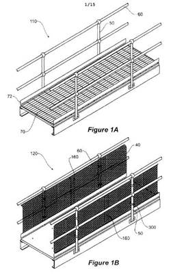
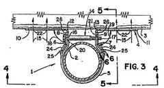
12 The respects in which the Patent is presently controversial are not apparent from Figs 1A and 1B, set out above. The controversial respects are best seen in Figs 2, 3, 4, 5 and 6, which are described in the specification as “various views of a bracket for use in mounting a guard panel to post according to an embodiment of the invention”.
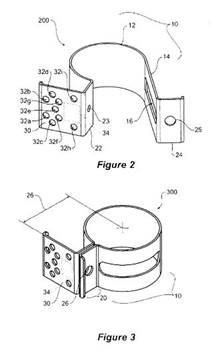
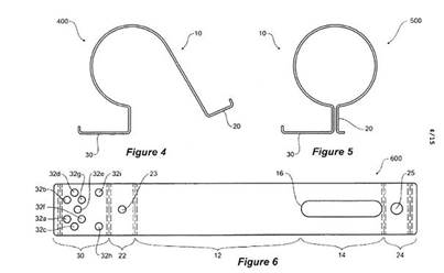
13 Of these figures, the specification states:
As would be understood by the person skilled in the art the dimensions and materials described are representative only and may be varied according to the requirements of the specific application. In this embodiment the post the bracket is designed to be mounted to is a vertical cylindrical post or stanchion constructed from 250 grade steel and having an outer diameter of 48.3mm or similar. Such posts are often used in handrails, footrails, kneerails, guardrails or walkways found in industrial and mining sites. Figure 2 illustrates an isometric view 200 of the bracket in an open configuration for clipping the bracket onto such a post and Figure 3 illustrates an isometric view 300 of the bracket in a closed or clamping configuration. Figures 4 and 5 show respective top views 400 500 with dimensions for use in fixing to a post with an outer diameter of 48.3mm. Figure 6 illustrates a flat pattern 600 of the bracket indicating required folds, and cut outs and finishing for manufacturing the bracket from a flat strip of 316 stainless steel 1.2mm thick. In Figures 4, 5, and 6 the general tolerances are 0.5mm. However the bracket could be constructed of any suitable material such as steel, aluminium, alloys, plastics etc having the properties described herein.
14 The product claims in the Patent are as follows:
1. A bracket for use in mounting a guard panel to a post having a predefined profile, including:
a post engaging portion wherein the post engaging portion has an open configuration to allow the bracket to be removably clipped onto and retained around the post whilst in the open configuration, and a closed configuration to allow clamping of the post engaging portion to the post;
a clamping portion including:
a first clamping portion; and
a second clamping portion wherein in the closed configuration the second clamping portion is brought towards the first clamping portion to clamp the bracket to the post and are fastened in the closed configuration by a first set of one or more fasteners passing through apertures in the first and second clamping portions; and
a mounting portion including a mounting plate to allow mounting of the guard panel to the bracket with a second set of one or more fasteners.
2. The bracket as claimed in claim 1, wherein the post engaging portion is located between the mounting portion and the clamping portion and includes:
a profile matching at least a portion of the predefined profile of the post to allow clipping of the bracket to the post when in the open configuration and the first and second clamping portions extend from the first and second ends of the post engaging portion so that movement of the first clamping portion towards the second clamping portion clamps the bracket around the post to form the closed configuration.
3. The bracket as claimed in claim 1, wherein the bracket is formed from a single sheet of material and the post engaging portion includes:
a clip portion having a profile matching at least a portion of the predefined profile of the post to allow clipping of the bracket to the post when in the open configuration; and
a moveable portion including a slot to allow the moveable portion to be deformed to allow the bracket to be reconfigured from the open configuration to the closed configuration.
4. The bracket as claimed in any previous claim, wherein the mounting plate includes a plurality of apertures to allow a guard panel to be mounted at a range of locations and inclinations with respect to the plate.
VALIDITY OF THE PATENT
15 In the present case, the applicants rely on s 129A(3) of the Act. A major focus of the respondent’s project has been to satisfy the court that the applicants’ acts, to which I shall refer in due course below, infringed Claim 1 of the Patent. In turn, as the subsection contemplates, a project of the applicants has been to show that that claim is invalid. It is convenient to commence with that aspect of the applicants’ case since, if Claim 1 is invalid, they would appear to have gone a long way to making good their case under the subsection.
16 The applicants first contend that the invention the subject of the Patent is not novel, and does not involve an innovative step, in the light of United States patent No 5,297,890 (“the US Patent”).
17 The US Patent relates to an invention for a wood-to-pipe connection in which a single sheet metal connector and a single threaded straight bolt are used to connect a wood frame member to an elongated pipe member. This device is said to be especially useful for attaching wood fencing to metal pipe used for fence posts.
18 The following figures, Figs 1 and 2 in the US Patent, show perspective views of the connector itself and of the connector being applied in a typical installation, respectively:
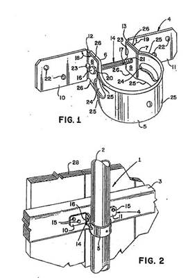
19 Figure 3 shows a top plan view of a portion of the connection illustrated in Fig 2, with the pipe in cross section:
20 The description of the preferred embodiment of the invention in the US patent states that the connector includes –
… a curvilinear portion 5 dimensioned for registering with and partially encircling the elongated pipe member 2 and having ends 6 and 7 spaced one from the other; first and second lug members 8 and 9, each integrally and respectively connected to the spaced ends 6 and 7 of the curvilinear member 5; foot members 10 and 11 respectively integrally connected to the first and second lug members 8 and 9 along bend lines 12 and 13; and cinching means 14 releasably attached to the first and second lug members 8 and 9 for drawing the lug members toward one another thereby decreasing the radius dimension of the curvilinear portion 5 and causing the curvilinear portion to frictionally engage the elongated pipe member 2; and fastener means 15 attaching the foot members 10 and 11 to the wood frame member 3.
21 In a “typical installation” -
… elongated pipe member 2 is set into a concrete foundation in a generally vertical attitude. The sheet metal connector 4 with threaded bolt 14 is either slipped over the elongated wood [sic] pipe member 2 or threaded bolt 14 is removed and sheet metal connector 4 is then snapped around elongated wood [sic] pipe member 2 and held in the selected position. Wood frame member 3 is then placed against at least one foot member 10 or 11 and either temporarily or permanently affixed by one or more fasteners 15. Threaded bolt member 14 is then placed through opening 20 and threaded distal end 17 is threaded into threaded opening 21. Preferably head 16 is formed as a hex head so that threaded bolt may then be tightened with a wrench until first and second lug members 8 and 9 are brought together causing the curvilinear portion 5 to frictionally engage elongated pipe member 2.
22 To the extent presently relevant, the main claim in the US Patent is for –
[a] wood-to-pipe connection comprising:
a. an elongated pipe member having a radius dimension;
b. a wood frame member disposed closely adjacent to said elongated pipe member;
c. a single piece sheet metal connector … for attaching said wood frame member and said elongated pipe member including:
(1) a curvilinear portion having a radius dimension substantially equal to or greater than said radius dimension of said elongated pipe member for registering with and partly encircling said elongated pipe member and having first and second ends spaced one from the other and having edges formed with stiffening flanges on portions adjacent said first and second ends and mid portion indentations formed in said curvilinear portion adjacent said first and second ends for holding said first and second lug members generally planar and parallel ….
23 The question which arises under s 7(1) of the Act in the present case is whether the invention the subject of the Patent is not novel in the light of the information conveyed by the US patent. Applying the reverse infringement test, that question becomes whether a device made conformably with that patent would amount to an infringement of the Patent: Meyers Taylor Pty Limited v Vicarr Industries Ltd (1977) 137 CLR 228, 235. For that question to be answered in the affirmative in a documentary case such as the present, the publication said to be anticipatory must contain “clear and unmistakable directions to do what the patentee claims to have invented”: General Tire & Rubber Company v Firestone Tire and Rubber Company Ltd (1971) 1A IPR 121, 138.
24 The respondent’s primary submission in relation to the US Patent was that it did not disclose a bracket with a post-engaging portion which, in an open configuration, allowed the bracket to be clipped onto and retained around the post. The applicants’ submission to the contrary was based on so much of the description of the preferred embodiment of the bracket in the US Patent as allowed for it to be “snapped around the elongated … pipe member” before cinching. Philip Ooyendyk, one of the inventors under the US Patent, agreed with counsel for the applicants that this “snapping” aspect of the installation of the bracket would occur when the bracket had first elastically deformed as it was pushed over the post, from the side as it were, and then snapped back into its original position.
25 In the joint experts’ report, Dr Sincock said:
…
(ii) In the second mode of installation the bracket with bolt removed is to be “snapped” around the post. The use of the word “snapped” indicates that in this second mode the bracket is to be clipped around the post. In this condition the preformed curvilinear portion of the bracket would be retained on the post by virtue of its resilience, but could be slid up and down the post. This is consistent with the definition of removably clipped (refer response to Construction question) where it is agreed that a first object clipped to and retained around a second object is not necessarily fixed to that second object, but may move (for example by sliding) with respect to the second object after clipping.
Whilst Figure 3 of the 890 patent might be taken as indicating that the curvilinear portion (the post engaging portion) of the 890 bracket is intended to be a loose fit on the post (the figure shows a gap between the curvilinear portion and the post) the text of the patent states that the curvilinear portion is to have a radius dimension substantially equal to or greater than the radius of the pipe, indicating that the curvilinear portion may be a close fit on the pipe in the open configuration.
26 Mr Hunter did not agree with Dr Sincock in this area of the case. He said that the US patent did not disclose “a bracket able to be removably clipped onto and retained around the post in the open configuration” (Mr Hunter’s emphasis). He said that the reference in the specification to the sheet metal connector being “held in the selected position” once it had been snapped around the post after removal of the bolt implied human intervention to hold the connector in that position, not a tightness of fit around the post sufficient, of itself, to achieve that result. He had three reasons for taking this view. First, the reference in the specification to the lug members being drawn one towards the other by the action of the cinching means (ie the bolt) “thereby decreasing the radius of curvature of the curvilinear portion” implied that, before cinching, there should be no frictional engagement as between the connector and the post. Secondly, for the connector to be self-supporting after “snapping” over the post, it would have to be of a very slightly smaller diameter than the post. But, for it to be possible to install the connector in the other mode of “typical installation”, that of slipping it over the top of the post and sliding it down to the desired location, it would have to be of a larger diameter than the post. This would not make sense to Mr Hunter, as it would imply “a different type of bracket for the second way of installation”. Thirdly, Fig 3 in the specification “shows a clearance between the internal diameter of the bracket and the external diameter of the post”, and thus does not “teach a bracket which is retained around the post after clipping”.
27 Mr Hunter’s third reason was accepted by Dr Sincock as far as it went, but, as the extract from his contribution to the joint experts’ report set out above shows, he considered that the reference in the claim to the curvilinear portion having a radius substantially equal to that of the pipe member (ie the post) disclosed a frictional fit sufficient to hold the connector in place before any cinching action had been applied. In his evidence, Dr Sincock did not engage with Mr Hunter’s first reason. Neither did he engage with the second reason, but, for myself, I would not regard that reason as a very persuasive basis for the conclusion that the US Patent did not teach a bracket that, when placed around the post by some means, held itself in position. Dr Sincock adhered to the position that, even where the radius of the connector was at least “substantially” equal to that of the post, it might be moved downwards on the post by the application of force: indeed, this might be recognised as the very situation in which the connector would be self-supporting.
28 In my view, what is most significant about the US Patent in this area of debate is the absence of any requirement that the connector be retained on the post after placement thereon, whether by clipping or otherwise. I accept Mr Hunter’s evidence that “held in the selected position” refers to some act of human intervention. His reasons for that were engineering ones. Mine is a grammatical one. The relevant passage in the specification refers to a number of things that must be done by humans: “set into a concrete foundation”, “slipped over the … pipe member”, “threaded bolt … is removed”, “connector … is … snapped around … pipe member”, “connector is … held in the selected position”, and so on. These are instructions as to what should be done, not descriptions of how materials behave.
29 Furthermore, to envisage a situation in which the radius of the connector might be equal to that of the post and in which the connector would thereby stay fast on the post after “snapping” is to do no more than to predict what might happen if a device which falls within the terms of the main claim in the US patent is used in conjunction with a post of a particular radius. That things must be thus is neither required nor taught by that patent. To the contrary, the claim is indifferent as to whether the radius of the connector should be substantially equal to that of the post, on the one hand, or greater than that of the post, on the other hand. There is nothing disclosed which would point to any particular advantage in the former configuration. Indeed, the prospect that such a configuration might be employed is suggested only in the claim: in the specification, every beneficial aspect of the invention is explained by reference to the latter configuration.
30 Returning to General Tire, I cannot perceive, in the US Patent, even a tolerably clear signpost upon the road to a bracket with a post-engaging portion which, in an open configuration, allows the bracket to be clipped onto and retained around the post to which it will be attached. Much less did that patent involve the planting of the inventors’ flag at that precise destination.
31 A further submission made by the respondent with respect to novelty issues arising under the US Patent was that it did not disclose a bracket for use in mounting a guard panel to a post. Although both the US Patent and the Patent dealt with means of attaching, or mounting, something to a post, pipe or the like, what was attached or mounted was not the same in each case. Under the US Patent, it was a “wood frame member” that was attached. Under the Patent, it was a “guard panel” that was mounted. As a matter of terminology, this is a valid distinction for the respondent to have made.
32 The applicants’ response to this submission was to point out, correctly in my view, that, under the Patent, the “guard panel” might be made from wood. Having referred to various sizes of perforated sheets that might be used as guard panels, the specification for the Patent proceeds to note that “[o]ther sheets such as those manufactured from plastic, wood, or other materials could be used”. The respondent’s point, however, is not simply that the US patent discloses only the attachment of something made from wood. It is that that patent discloses specifically the attachment of a “wood frame member”. That is to say, it is limited to an attachment which is to be used as a frame member for some other component, typically fencing panels, boards, pickets or the like. By contrast, the invention under the Patent assumes the existence of what might be considered the analogue of the frame member presumptively being erected conformably with the US Patent. While both the US Patent and the Patent assume the existence of a generally vertical post or pipe, the former teaches the attachment thereto of a generally horizontal frame member, while the latter claims a means of attaching a guard panel thereto, and/or to other existing framing elements, the very point of which is to fill in the entirety of the space or spaces that would otherwise exist between these various posts, pipes, rails and other framing elements.
33 I accept the respondent’s case that, in this further respect also, the invention under the Patent was not anticipated by the US Patent.
34 For the reasons set out above, I reject the applicants’ case on novelty.
35 The applicants’ other point on validity is that the invention the subject of the Patent did not involve an innovative step, in the sense that the invention would not, to a person skilled in the relevant art, in the light of the common general knowledge as it existed in the patent area before the priority date for the Patent, vary from the US Patent in ways that made a substantial contribution to the working of the invention (the Act, s 7(4)).
36 The applicants’ innovative step point is confined to the second of the two novelty issues dealt with above, that is, the frame member versus guard panel issue. It was submitted that, if the invention under the Patent varied from so much of the prior art as was constituted by the US Patent only by requiring that the purpose of the bracket be the mounting of a guard panel to a post rather than the mounting of a wood frame member to a steel pipe, this was a variation that made no substantial contribution to the working of the invention. The first thing that must be said here is that the applicants made no attempt to demonstrate that, in the area concerned in the first of the two novelty issues dealt with above – the “clipped onto and retained around” point – there was no innovative step involved in the invention under the Patent. For that reason if for no other, I would have to reject so much of the applicants’ challenge to the validity of the Patent as proposed that the invention did not involve an innovative step.
37 Dealing with the merits of the challenge in fact made by the applicants, I would describe that challenge as desultory at best. There were two validity questions put to Mr Hunter and Dr Sincock for the purposes of the preparation of the joint experts’ report. The first asked whether each of three identified integers of Claim 1 in the Patent was present in the system disclosed in the US Patent. Mr Hunter expressed the view that none of them was. Dr Sincock expressed the view that each of them was. The second question asked, in relation to any integer which was not so present, whether that integer would make a substantial contribution to the working of the invention claimed in Claim 1 in the Patent. Mr Hunter expressed the view that each of the integers would make such a contribution. Dr Sincock’s response was that he “does not make a response to this task, as he considers the three integers to be present”. In the result, the joint experts’ report contained no evidence that was helpful for this aspect of the applicants’ case.
38 Neither was there any other evidence given in the case that would be helpful in this context. In their final written submissions, counsel for the applicants contented themselves with submitting that Mr Hunter was not representative of “the skilled addressee”, and that it was “apparent that a sheet metal connector, or bracket, for making a wood-to-pipe connection [was] equally well adapted ‘as a bracket for use in mounting a guard panel to a post’.” That is to say, having led no evidence from Dr Sincock on the subject, the applicants invited the court to form its own conclusion on this engineering question. That invitation should not be accepted. I am not qualified to rule that the device disclosed in the US Patent, being specifically intended to attach a frame member to a post (and, as I pointed out to counsel during argument, apparently contemplating the employment of at least two personnel in the task of undertaking that attachment), is, to use the words of counsel, equally well adapted as a bracket for mounting a guard panel of the kind, and in the circumstances, envisaged in Claim 1 in the Patent.
39 It was for the applicants to make good the case that, on this frame member versus guard panel issue, the invention under the Patent would vary from the US Patent only in ways that made no substantial contribution to the working of that invention. They have not done so.
40 For the reasons set out above, I reject the applicants’ case on innovative step.
41 The respondent is entitled to a certificate under s 19(1) of the Act in relation to Claim 1 in the Patent. I note that, although the allegations of invalidity in the Amended Statement of Claim related to all of the claims in the Patent, and none of those allegations was made good, in its final submissions in the case the respondent sought a certificate in relation to Claim 1 only.
INFRINGEMENT
42 It is now possible to consider the applicants’ case under s 128 of the Act in the context of the Patent being valid. By s 129A(3), it is for the respondent to satisfy the court that the acts about which the threats were made infringed, or would have infringed, a claim in the Patent. The respondent’s case in this area focussed upon Claim 1.
43 It is here that I must lay out the facts of the case, and particularly the details of the applicants’ product which, it is said, gave rise to an infringement of Claim 1.
44 Before the events which have become controversial in this proceeding, BLHEC provided skilled labour to the mining, construction, oil and gas sectors throughout Australia. In recent years, it has diversified into the design, fabrication, manufacture and installation of equipment for those sectors. The BLH system is an example of that diversification. That system had its genesis in 2009 when BHP Billiton (“BHP”), raised concerns in respect of safety issues presented by the risk of objects falling from elevated walkways, stairways and the like at its Olympic Dam mine site in South Australia, where BLHEC was, at the time, engaged to provide labour. Various expedients were employed to cover, or fence off, the open spaces that gave rise to this risk, but they were unsatisfactory for cost and other reasons. Over the next 12 months or so, the managing director of BLHEC, Shane Gill, and others in his company, undertook some conceptual, design and prototype work for a system that would meet the concerns raised by BHP and be cost effective. When, in October 2010, BHP management learned of this, they encouraged Mr Gill “to accelerate the project”, as he put it in his affidavit sworn on 17 December 2013.
45 After experimenting with metal prototypes, Mr Gill and his team at BLHEC settled on using a plastic polymer for their guarding system. While it was a mesh panel that would perform the function of preventing objects falling from the walkways etc to which it would be attached, what has become important in the present proceeding is the means of attachment as such. The means which Mr Gill ultimately adopted involved clips to be attached to the rails and stanchions of which handrail systems are commonly comprised, and a means for the attachment of the mesh panel to such clips.
46 Represented below is a sample of a clip made by BLHEC in April 2011.
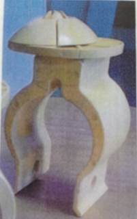
The uppermost portion of the object in this photograph – the part which has the appearance of a mushroom-top sitting on a disc – is what Mr Gill described as an “eccentric pin joiner and mesh clip”. It has the purpose of facilitating the joining of the clip to square-section mesh without the need for a precise alignment as between the pin and some special point of anchorage in the mesh.
47 An exploded perspective view of the clip shown in the above photograph, as included in an innovation patent application lodged in the name of Mr Gill and BLHEC on 9 May 2011, follows below:
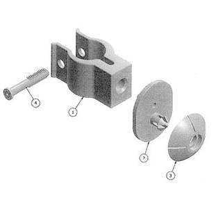
The eccentric pin joiner and mesh clip are the part marked with a question mark and the part numbered 3. The clip itself is the part marked numbered 1. Part numbered 4 is a pin, made from the same polymer plastic material as the clip, with barbs, or teeth, on the distal end as shown. In use, this pin is inserted through the holes in the two arms of the open end of the clip, in general alignment with which it is shown above.
48 Parts numbered 1 and 4 are of direct interest in the present proceeding. Henceforth, I shall refer to the former as the BLH clip, or simply as the clip, and to the latter as the barbed pin.
49 As mentioned above, on 9 May 2011 Mr Gill and BLHEC applied for an innovation patent in relation to the BLH system. This application was given the number 2011100520. It was granted on 13 July 2011, but not examined. I shall refer to the granted patent as “the BLH Patent”.
50 On 25 July 2011, BLHSS was incorporated. BLHEC licensed BLHSS to manufacture the BLH system, and to market that system in Australia and overseas. Since that date, BLHSS has manufactured and marketed the BLH system, and has offered that system for sale throughout Australia and overseas. If the BLH system comes within the terms of Claim 1 of the Patent, on any view the activities of BLHSS would amount to an exploitation of the invention there claimed, and thus to an infringement of the Patent.
51 As described in the evidence, the way the clip aspect of the BLH system works is as follows. The open end of the clip is placed against, and then pressed over, the rail, for example, to which it is to be attached. As it is passing over the rail, the two arms of the clip will move apart, making use of the elasticity of the material from which the clip is constructed. At the point where the clip has been moved completely on to the rail, the rail will be received into the circular section of the clip, and the two arms of the clip will move back to something approaching their original orientation. In the result, the clip will be clipped around, and thus attached to, the rail. From what was demonstrated in the evidence, this procedure resulted in the clip being firmly attached to the rail.
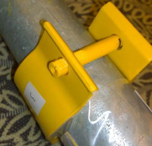
52 A photograph showing a BLH clip attached to a rail, after the procedure followed above, follows below.
53 The barbed pin is then inserted, from side to side, through the holes in the arms of the clip. It is designed to be fully inserted, that is to say, until the head of the pin makes contact with the arm through which it was first inserted. At this point, the barbs on the distal end of the pin will have moved, partly or wholly, through the hole in the other arm. The barbing function is intended to cause the pin to be held firm in these two holes, or at least to make it impossible or very difficult to remove by being drawn back in the direction from which it was inserted. At least from the applicants’ point of view, it is immaterial whether the barbs pass wholly, or only partly, through the second hole. BLHSS appears to have manufactured some barbed pins with fewer barbs, such that, by the time the head of the pin makes contact with the first arm of the clip into which the pin was inserted, all the barbs have passed completely through the second hole, thereby producing the result that there are no barbs in communication with that hole and that the pin is not, at that point, a tight fit. I shall return to this point in due course below.
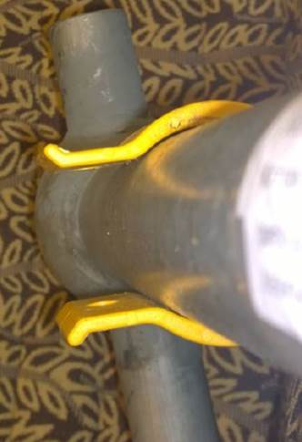
54 A photograph showing a BLH clip attached to a rail, with the barbed pin inserted, follows below.
55 With the support of Mr Hunter, the respondent submitted that the clip/barbed pin arrangement in the BLH system embodied all of the integers of Claim 1 in the Patent. Mr Hunter identified the first integer as “a bracket for use in mounting a guard panel to a post having a predefined profile”. Dr Sincock accepted that the BLH clip was such a bracket.
56 Mr Hunter identified the second integer as “a post engaging portion wherein the post engaging portion has an open configuration to allow the bracket to be removably clipped onto and retained around the post whilst in the open configuration”. He said that the BLH clip had a post engaging portion, namely, the generally circular part of the clip that, when the clip was in place, made firm contact with the post. He said that, “prior to use, the bracket appears to be in an open configuration in which the bracket would be able to be clipped around the post”. By pushing the clip on to rail assemblies provided for the purpose, Mr Hunter made use, he said, of the open configuration to enable him to clip the clip on to the post. Dr Sincock did not accept this, but, before coming to his view of the subject, it is convenient to proceed to the third integer identified by Mr Hunter.
57 Mr Hunter identified that integer as “a closed configuration to allow clamping of the post engaging portion to the post”. He said that the closed configuration was “that in which the post engaging portion is tightly fixed or held fast around the post”. He said that he had tested this by inserting an 11-barb pin into the BLH clip as mounted on a post, and found that “the arms … of the [clip] … moved inwardly … and were held in a clamped configuration”. That is to say, Mr Hunter would regard the BLH clip after being placed on to the post as still being in an open configuration, and that the closed configuration was achieved by the insertion of the barbed pin. By reference to measurements which he and Dr Sincock carried out, Mr Hunter noted that, after the insertion of the 11-barb pin, the arms of the clip were very slightly closer together than they had been before insertion of the pin. On the other hand, before the pin was inserted the clip was only “removably” on the post: in his oral evidence, Mr Hunter said that he had been able to remove the clip at this stage, albeit with difficulty.
58 By reference to the application for the BLH Patent, Dr Sincock expressed the view that the BLH clip, as such, did not have “distinct open and closed configurations ..., other than the elastic deformation resulting from clipping the … [clip] onto the guardrail ….” I accept that evidence, and would apply it also to the BLH clip itself, as in evidence in the case. Looking only at the clip itself, Mr Hunter would accept, of course, that it had only one configuration: for him, the “closed” configuration was constituted by the clip with the barbed pin in place. As I shall mention in a moment, it was the insertion of the pin that provided both the closed configuration of the bracket and the clamping action described in the Patent, on Mr Hunter’s approach. For the moment, I am concerned to accept Dr Sincock’s view that, at least before the pin was inserted, there were not two identifiably separate configurations of the BLH clip. Indeed, as pointed out by counsel for the applicants, because tightness of fit of the bracket itself to the post was a characteristic engineered into the BLH clip, if anything that clip would be very slightly more “open” once it had been placed on to the post than before that operation.
59 The fourth, fifth and sixth integers of Claim 1 of the Patent, as identified by Mr Hunter, may be taken together. They were a clamping portion (fourth integer) including a first clamping portion (fifth integer) and a second clamping portion (sixth integer). Mr Hunter said that the two arms of the BLH clip constituted the first and second clamping portions – either arm could be either portion – and that the two of them together were the clamping portion required in the fourth integer. Although, apparently, required for the action of clamping, the barbed pin was not treated as part of the clamping portion referred to in the Patent. Save to note that this represents Mr Hunter’s alignment of the BLH clip with these integers of Claim 1 of the Patent, nothing further needs to be said about these aspects of the analysis at this stage.
60 Mr Hunter identified the seventh integer as, “in the closed configuration the second clamping portion [being] brought towards the first clamping portion to clamp the bracket to the post”. He said that, after insertion of the barbed pin, the arms of the BLH clip were slightly closer to each other than they had been after the clip was placed on to the post. That is to say, it was the action, and the result, of the insertion of the pin that caused one of the arms, considered as “the second clamping portion” to be brought towards the other arm, considered as “the first clamping portion”. I shall comment further upon that approach to the relationship between the BLH clip and this integer in Claim 1 of the Patent presently, but it is first convenient to move directly to what Mr Hunter said about the eighth integer.
61 He identified the eighth integer as the first and second clamping portions being “fastened in the closed configuration by a first set of one or more fasteners passing through apertures” in those clamping portions. He noted that, because of the action of the barbs on the barbed pin, once fully inserted, the pin could not be withdrawn. That met his interpretation of “fastened”.
62 Mr Hunter identified the ninth integer as “a mounting portion including a mounting plate to allow mounting of the guard panel to the bracket with a second set of one or more fasteners”. The end of the BLH clip with which the eccentric pin joiner and mesh clip communicated was, according to Mr Hunter, a mounting portion and plate within the terms of this integer. Dr Sincock did not take issue with that conclusion.
63 While I do not criticise the experts for their identification of the integers of Claim 1 of the Patent in the way that they did, it must be said that this process of analysis tended to emphasise the internal textual components of the claim, at the risk of losing sight of the invention as a whole and understanding what was being claimed in a practical sense. Standing back, and reading the claim against an understanding of the invention as explained in the specification, I would say that the invention involved a bracket which was accommodated to be fixed to a post in three stages. The first was the clipping of the bracket to the post using the post engaging portion. This is reflected in the second integer of the claim as identified by Mr Hunter. Here the bracket was retained around the post, but was removable therefrom. The second was bringing the two clamping portions towards each other. While this part of the operation is reflected specifically in the second integer, the skilled addressee would understand that these are the clamping portions referred to in the fourth, fifth and sixth integers. He or she would also understand that this movement resulted in the post engaging portion changing from the open configuration (the second integer) to the closed configuration (the third and seventh integers). I have parenthetically linked the third and seventh integers because the words of the third, “to allow clamping of the post engaging portion to the post”, and the words of the seventh, “to clamp the bracket to the post”, are referring to the same thing. The third stage was the fastening of the arrangement as a whole to the post by one or more fasteners passing through the clamping portions. This is reflected in the eighth integer of the claim as identified by Mr Hunter.
64 It is as clear as may be that the invention as claimed in Claim 1 of the Patent has two distinct configurations, an open one and a closed one. This is not simply an observation of what happens, or might happen, when a bracket that was not constructed with two configurations is pressed on to a post with which it has a tight fit. It is an essential feature of the bracket as a product. The claim refers to a bracket which, before being placed anywhere near a post, has two configurations which would be observable to the skilled addressee. Further, the bracket claimed in Claim 1 is intended to be placed on to the post in such a way as to be removably retained there, whilst still in the open configuration. There follows a distinct movement of the clamping portions together, to bring about the closed configuration before the fasteners are passed through the holes in those portions, and presumably then fastened tight.
65 In my view, the BLH clip stands apart from anything that is claimed in Claim 1 in the Patent by a considerable distance. As a bracket, it does not have two configurations. It is a single, moulded plastic, product designed to fit firmly on a post of a known diameter. I accept that the skilled addressee would appreciate that, to achieve that firm fit, there will have been some slight enlargement of the BLH clip in its position on the post compared with its original situation. As I shall relate presently, the experts were agreed that the arms after attachment to the post were slightly further apart, or more outwardly angled, than they had been originally. But it would be quite artificial to regard this circumstance as marking out the difference between two configurations of the bracket itself. I realise that these two states of the BLH clip – before attachment and after attachment – do not correspond with the open and closed configurations identified by Mr Hunter. However, the achievement of an open configuration by the elastic deformation of the clip – a clip which, of itself, does not have two different configurations – during the process of placing it on the post bears no relation to anything in Claim 1 of the Patent. A skilled addressee who had read the specification would understand that the bracket claimed in Claim 1 was in the open configuration before, and not as the result of, being clipped on to the post.
66 The skilled addressee would also understand that Claim 1 claimed a bracket which was to be changed from an open to a closed configuration, thereby bringing the two clamping portions towards each other, as separate from, and anterior to, the operation of passing the fasteners through the apertures in the clamping portions. The claim does not comprehend a situation in which the state of being in a closed configuration is itself achieved by the latter operation. Assuming, for the moment, that the barbed pin in the BLH system may be described as a fastener which holds the arms of the clip in what Mr Hunter would identify as a closed configuration, it is, on the respondent’s case, the action of inserting the pin, fully to the point where the barbs are engaged, that, of itself, achieves that configuration. There is no movement of different parts of the clip prior to the insertion of the pin that would correspond with the operation required by the seventh integer in Claim 1.
67 To date in this part of my reasons, I have not considered what came, in the concurrent evidence of the experts, to be a significant aspect of the controversy about the relationship between Claim 1 of the Patent and the BLH clip. That involved the requirement in the claim for a “clamping” to be achieved when the fastener or fasteners was or were passed through the hole or holes in the two clamping portions. In the case of the BLH clip, that requirement was, according to Mr Hunter, satisfied when the barbed pin was passed through the holes in the arms of the clip and pressed home into its intended position. Dr Sincock did not accept that this involved “clamping” as contemplated in the claim. In an attempt to resolve this controversy, the two experts took, in collaboration, some measurements of various dimensions of two of the clips at various stages of a notional operation in which those clips would be fitted to posts to which they were adapted.
68 Dr Sincock and Mr Hunter took their measurements of clips which were sized to fit on the midrail and the stanchion of a conventional handrail system. For the results set out below, their points of reference are as indicated on the following marked-up photograph of a clip:
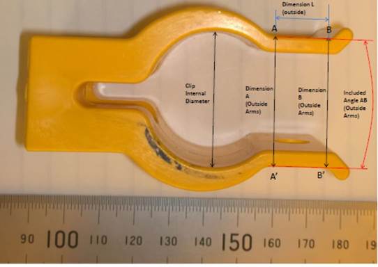
69 In each case (ie the midrail clip and the stanchion clip) Dr Sincock and Mr Hunter measured the outside diameter of the rail, the inside diameter of the curved part of the clip, the dimensions A and B shown on the photograph above and the included angle AB as there shown. Taking the averages of the measurements which they recorded, those which relate to the midrail clip are as follows:
Rail | Clip itself | Clip on rail | Clip on rail with pin | |
Outside diameter mm | 34.17 | |||
Inside diameter mm | 33.06 | |||
Dimension A mm | 23.88 | 25.33 | 25.27 | |
Dimension B mm | 23.95 | 25.98 | 25.60 | |
Angle AB deg | 0.24 | 2.21 | 1.14 |
70 The measurements which relate to the stanchion clip are as follows:
Rail | Clip itself | Clip on rail | Clip on rail with pin | |
Outside diameter mm | 48.44 | |||
Inside diameter mm | 46.93 | |||
Dimension A mm | 32.75 | 36.60 | 36.35 | |
Dimension B mm | 32.12 | 37.10 | 36.45 | |
Angle AB deg | -1.96 | 1.60 | 0.35 |
71 From these measurements, it may be seen that the inside diameter of the curved part of the clip was smaller than the outside diameter of the rail to which the clip was designed to be attached, by 1.11 mm and 1.51 mm respectively. Thus it would be expected that, when attached, the arms of each clip would be spread out somewhat, compared with their original orientations. At the same time, each clip would be a tight fit on the rail. And thus it was. Dr Sincock said that it was an interference fit. Likewise, the angle between the arms increased in each case after the clip was fitted to the rail: from 0.24 deg to 2.21 deg in the case of the midrail clip and from -1.96 deg to 1.60 deg in the case of the stanchion clip. In the case of the midrail clip, Dimension A increased by 1.45 mm and Dimension B increased by 2.03 mm. In the case of the stanchion clip, Dimension A increased by 3.85 mm and Dimension B increased by 4.98 mm. It will be remembered that it was Mr Hunter’s view, and it was the respondent’s case, that the clip, as fitted, now corresponded with the situation described in the second integer of Claim 1 in the Patent, that is, the bracket had been (removably) clipped on to the post, but remained in the open configuration.
72 An 11-barb pin was next inserted into the holes provided in the two arms of each of the clips on their respective rails. Further measurements were then taken, and they showed that, in the case of the midrail clip, by comparison with the state of affairs obtaining after the clip had been placed on the rail, Dimension A had now decreased by .06 mm and Dimension B had decreased by 0.38 mm. The arms were now angled at 1.14 deg one in relation to the other. In the case of the stanchion clip, Dimension A had decreased by 0.25 mm, Dimension B had decreased by 0.65 mm, and the arms were angled at 0.35 deg one in relation to the other.
73 As part of the process of inserting the pins into the holes in the arms of the clips, Mr Hunter – and it was, it seems, he who carried out this part of the exercise – first used his thumb and fingers to squeeze the arms inwards to the extent that he was able. He then inserted the pin, and pushed it home. The experts were agreed, however, that this was not a necessary part of this process. The barbed pin could be inserted into its intended place without any manipulation of the arms of the clip on the midrail or stanchion. That was because, although the arms were not perfectly parallel at this stage, the fit of the pin in the holes was not an exact one.
74 In the view of Mr Hunter, it was the single operation of inserting the pin into the holes of a BLH clip and pushing it home in the way I have described which satisfied the requirements of both the seventh and the eighth integers of Claim 1 in the Patent. That is to say, by this operation the two clamping portions (ie the two arms) were brought towards each other, the closed configuration was achieved and the clamping portions were fastened in that configuration by the fastener (ie the barbed pin).
75 Dr Sincock did not agree with Mr Hunter’s appreciation of the relationship between Claim 1 of the Patent and the BLH clip being installed as intended. In relation to the midrail clip, he said:
[W]hilst there is some effect on the separation distance between the anti-tamper pin mounting plates due to inserting an anti-tamper pin, the effect is mainly to bring the outer ends of the anti-tamper plates closer together (the B dimension). There is minimal reduction in the distance between the inner ends of the anti-tamper pin mounting plates (the A dimension). In order to generate a clamping action in the clip the inner end of the anti-tamper mounting plates must be drawn together, to generate hoop stress in the clip circumference. Instead the small amount of axial load being carried in the eleven barb pins is being dissipated by causing bending at a location near the point of measurement of dimension A, rather than hoop stresses in the clip circumference.
It should be stated that the measurements taken are not a direct measure of either clipping or clamping action. The small reduction in distance between the inner ends of the anti-tamper pin mounting plates may or may not indicate the mobilisation of some degree of clamping action.
If in the absence of the detailed numerical modelling or physical testing approaches which would be required to investigate this in detail, the plate to plate distance measurements presented in Figure 1 are taken as a proxy measure of the mobilisation of clipping and clamping forces, it can be seen that the greatest change in dimension A (around 1.5 mm) occurs between the pre-installed and on middle rail conditions, resulting in the mobilisation of clipping forces generated by the spreading of the arms of the clip necessary for it to fit onto the rail (the clip is an interference fit on the rail). Insertion of the pin results in a change of at most around 0.1 mm in this dimension to generate (potentially) hoop stresses and thereby clamping effort.
Such a change is of a similar order as the measurement error and the variability which results from removing and replacing the clip at a slightly different point on the rail. Any clamping action which it generates would likely be a secondary or tertiary contribution compared to the clipping action mobilised, and is consistent with the pin being an anti-tamper device, fitted on an as required basis, rather than an essential component necessary or purposed to achieve the required holding capacity.
76 In relation to the stanchion clip, Dr Sincock made a like statement, save to add to the fourth sentence the observation that the axial load there referred to was “a result of friction between the tops of the last two barbs and the inside of the pin hole in the anti-tamper mounting plate ….”
77 Dr Sincock’s reference to hoop stress prompted Mr Hunter to calculate, by reference to what he described as “some simplifying assumptions”, how much hoop strain would be generated if the arms of the BLH clip on the stanchion moved towards each other at Dimension A by a distance of 0.1 mm. His conclusion was that an inward radial clamping force of 4,444 N, the equivalent of 444 kg, would then be generated. He opined that “when the bracket is in full contact with the stanchion, very high clamping loads are able to be generated by very small inward displacement of the arms” along Dimension A. In his oral evidence, however, he readily accepted that these calculations were highly theoretical, and took no account of a number of factors, including the prospect that the curved part of the clip was not, before insertion of the pin, in perfect contact with the stanchion at all points. He said that “most of [the movement]” at Dimension A was “probably just bringing the surfaces into contact with one another.” Dr Sincock said that Mr Hunter’s calculations were “so over-simplified under the circumstances as to not be meaningful”. Additionally, he made the point that the barbs on the pin would not be able to support a clamping force of the order calculated by Mr Hunter.
78 Notwithstanding those reservations, Dr Sincock accepted that the insertion of the barbed pin into the BLH clip may have produced some clamping effect as between the pin and the rail to which it had been clipped. The difference between him and Mr Hunter was, I consider, one of emphasis in an area of the case where no direct measurements had been taken and where, because of the materials with which the experts were working, probably no really exact measurements would be possible.
79 Relevantly to the matter presently under discussion, the question was whether the BLH clip would be “clamped” to a post when attached as intended, which would include the insertion of the barbed pin, as required by Claim 1 in the Patent. From the evidence of the experts, I would find, on the probabilities, that the full insertion of the pin would produce some very slight clamping of the clip to the post, additional to the attachment force achieved by placing the clip on the post as such. I make that finding because there was some decrease in the A Dimension when the appropriate clip was placed on each of the midrail and the stanchion in the tests performed by Dr Sincock and Mr Hunter, because Mr Hunter’s evidence that some small amount of hoop strain might be expected to be contributed by that circumstance, although heavily qualified, was not wholly undermined, and because Dr Sincock allowed for that possibility.
80 It does not follow, however, that the BLH clip satisfies so much of the requirements of Claim 1 of the Patent as relate to clamping. In that claim, clamping is a purpose, and an essential feature, of the invention. The terms “to allow clamping” and “to clamp the bracket” would convey to the skilled addressee that it was a purpose of the invention to produce a bracket which was constructed, and which would work, in a way that would achieve a clamping of the bracket to the post. He or she would understand that, absent clamping, the bracket described in the claim could never work as intended.
81 By contrast, I would find that the achievement of clamping is neither the purpose nor a necessary feature of the barbed pin when inserted into the BLH clip. Such clamping effect as might be produced would be incidental in function and insignificant in degree. “To clamp the bracket to the post” would not be an accurate description of the purpose, or, other than incidentally and insignificantly, the effect, of the full insertion of the barbed pin in its intended position.
82 For the above reasons, I hold that the BLH clip does not have the clamping requirement of Claim 1 of the Patent.
83 It follows from this conclusion, and from those expressed at paras 64-66 above, that the respondent’s infringement case must be rejected.
THREATS
84 I turn next to the applicants’ positive case under s 128 of the Act.
85 On 2 September 2011, the respondent’s patent attorneys sent BLHEC a letter in the following terms:
Infringement of Certified Australian Innovation Patent No 2011100489 SYSTEM AND COMPONENTS FOR SAFELY ENCLOSING HANDRAILS, STAIRWAYS, WALKWAYS AND PLATFORMS PRO 3 Products Pty Ltd
Our Ref: 38381M TAM:CRW:MM
We act for Pro 3 Products Pty Ltd.
Our client is the proprietor of the above Certified Australian Innovation Patent No 2011100489. We enclose a copy of the certified innovation patent for your information.
It has come to our client’s attention that your company is developing and promoting a “a stop drop barricading system” – which includes a clip on bracket for mounting guard panels to stanchions, such as that described in your recent innovation patent 2011100520.
The manufacture, use, installation (including trial installations), promotion or other exploitation of your stop drop barricading system using such clip on brackets infringes the claims of our client’s certified innovation patent.
Accordingly, we have been instructed to request that you provide an undertaking in writing that you will cease and desist from manufacturing, installing, promoting or otherwise exploiting your above described stop drop barricading system, and immediately take steps to remove any existing installations of your system, or otherwise come to an acceptable commercial agreement with our client such as licensing our client’s intellectual property.
You can provide this undertaking by signing the enclosed copy of this correspondence and returning it to us within 10 working days from the date of this correspondence. If you do not provide the requested undertaking within this time, or provide the undertaking and do not comply with it, our client reserves the right to take action against you without further notice to you.
In the meantime, all of our client’s rights (including those related to costs and damages) are expressly reserved.
In its submissions made to the court, the respondent accepted that this letter amounted to a threat within the meaning of s 128 of the Act.
86 As I understand the respondent’s position, however, it is that the reference in the third paragraph of the text of the letter to the BLH patent compelled the conclusion that the threat related only to a product which complied in every detail with that patent. Specifically, the threat related only to a product that incorporated a barbed pin with the number of barbs as was represented in part numbered 4 in the exploded perspective view of the BLH clip in the BLH patent: see para 47 above. The respondent’s case appears to be that it never made a threat which related to a barbed pin which had fewer barbs than were necessary for there to be any kind of firm mechanical contact between any barb and the hole in the second arm of the clip, such as a pin with only eight barbs.
87 I reject the respondent’s submission in this compartment of the case. The letter of 2 September 2011 was not limited by reference to the number of barbs on a pin. That letter threatened proceedings in relation to a system which included “a clip on bracket for mounting guard panels to stanchions, such as that described” in the BLH Patent. It related to any such system, regardless of the number of barbs that might be on the pin, and regardless of whether one or more barbs would be in mechanical contact with the second arm. Indeed, I consider that a reader of the letter would be justified in concluding that it was the clip as such which lay at the centre of the respondent’s concern.
88 Also on 2 September 2011, the respondent’s patent attorneys sent BHP a letter in the following terms:
Certified Australian Innovation Patent No 2011100489
SYSTEM AND COMPONENTS FOR SAFELY ENCLOSING HANDRAILS, STAIRWAYS, WALKWAYS AND PLATFORMS
PRO 3 Products Pty Ltd
Our Ref: 38381M TAM:CRW:MM
We act for Pro 3 Products who have recently developed a Dropped Object Prevention System, an example installation which has been on display in the PPO building of Olympic Dam since March 2011.
Our client takes protection of its IP seriously, and we are pleased to inform you that our client’s innovation patent 2011100489 relating to clip on brackets for use in this and other similar systems (including plastic systems) has recently been examined and certified by IP Australia. We enclose a copy of the Certified Innovation Patent for your information.
Please do not hesitate to contact us if you would like any further information on this Certified Innovation Patent.
This letter did not, in my view, amount to a threat of infringement proceedings within the meaning of s 128 of the Act.
89 On 22 September 2011, the applicants’ patent attorneys replied to the respondent’s letter to BLHEC of 2 September 2011. They denied the allegation of infringement. They drew particular attention to s 119 of the Act, and said that BLHEC had developed its invention, and taken definite steps to exploit it, before the priority date for the Patent. They added that there was “a multitude of prior published documents that disclose all of the features of one or more of the claims” in the Patent. They reserved their client’s rights under s 128.
90 On 28 September 2011, one of the directors of the respondent sent an email to two of the managers at BHP known to be responsible for working environments of the kind that would require some kind of system to avoid the dangers of dropped objects, in which it was said:
Whilst suitability evaluation of our “Dropped Object Prevention System” is underway, I wanted to ensure you and make you aware our company has been granted a certified innovations patient [sic] by IP Australia pertaining to the installation of the “Dropped Object Prevention System” to walkways. A letter and IP details (copy attached) has been sent to BHP Billiton to ensure there is no confusion as to the legal ownership of this system, therefore hopefully avoiding any IP issues that may arise if another company was to falsely claim ownership or promote a similar product.
Neither this statement nor anything else in this email was, in my view, a threat of the kind referred to in s 128 of the Act.
91 On 4 October 2011, the respondent’s patent attorneys responded to the letter of 22 September 2011. They rejected the notion that s 119 would avail BLHEC, and they asserted that the invention the subject of the Patent had not been anticipated. They said:
In relation to unjustified threats, we consider that our certified innovation patent is valid and that your client is, or plans to, infringe our patent and thus our threats are justified.
This letter should not, in my view, be regarded as a threat additional to that made on 2 September 2011. Rather, it amounted to an affirmation of that threat, notwithstanding the points that had been made in the applicants’ patent attorneys’ letter of 22 September 2011.
92 On 27 January 2012, the respondent’s patent attorneys sent a letter to the applicants’ patent attorneys, which included the following:
Infringement of Certified Australian Innovation Patent No 2011100489
SYSTEM AND COMPONENTS FOR SAFELY ENCLOSING HANDRAILS, STAIRWAYS, WALKWAYS AND PLATFORMS
PRO 3 Products Pty Ltd
Our Ref: 38381M CRW:TAM:NH
Your Ref: BLHG001-PRO3
We refer to our letters of 2 September 2011 and 4 October 2011 and would like to invite your client to enter into discussions with our client to seek a commercial agreement to resolve this matter.
It has come to our client’s attention that BLH have launched a website at http://blhsafetysolutions.com/ which promotes the BLH stop drop barricading system. Further we understand that representatives from BLH propose to promote the system both in Australian [sic] and overseas such as the Offshore Technology Conference in Houston, USA in April 2012.
We wish to remind you that our client’s Innovation Patent No 2011100489 is still in force, and manufacture, importation, use, installation (including trial installations), promotion or other exploitation of the clip on brackets used in the BLH stop drop barricading system in Australia infringes at least claim 1 of our client’s certified innovation patent.
Whilst a re-examination Report has been issued based on prior art outlined in your letter of 22 September 2011, we have filed a detailed response to this and consider that the claims (as amended) are valid and infringed by your client’s clip on bracket used in their stop drop barricading system. Your client’s decision to launch their website, perform installations, and promote their system at various conferences in spite of our previous letters, and the knowledge that our patent is still in force has been noted.
93 Unlike the letter of 4 October 2011, that of 27 January 2012 was not in response to correspondence from the applicants’ patent attorneys. Rather, it seems to have been prompted by the applicants’ moves further to commercialise the BLH system. Nothing came of the intended amendments to the Patent parenthetically referred to the in the last paragraph in the passage above, but the letter referred at least to the Patent in its then terms. In a concluding paragraph, the writers of the letter suggested that the parties might “come to a commercial agreement” by way of BLHEC licensing the respondent’s intellectual property, or that BLHEC might “make an offer to buy the IP”. These suggestions, however, followed a statement that the respondent was “prepared to take further action if required”, and concluded with the comment that a commercial outcome “would avoid the significant costs, time and effort associated with Court action”.
94 In my view, the letter of 27 January 2012 was a further threat of the kind covered by s 128 of the Act.
95 On 9 February 2012, the applicants’ solicitors sent a letter to the respondent’s patent attorneys, referring to the previous correspondence between the parties going back to 2 September 2011. Aside from reiterating their clients’ previous denials in relation to infringement of the Patent, the solicitors alleged that the respondent’s correspondence and other actions amounted to unjustified threats within the meaning of s 128 and misleading conduct proscribed by the ACL. They set out the terms of undertakings which the applicants required to be given by the respondent, in the absence of which they reserved the applicants’ rights to commence proceedings.
96 That letter produced an open response from the respondent’s solicitors dated 21 February 2012. Nothing in that letter amounted to a threat of legal proceedings. However, on the same date the respondent’s solicitors sent a without prejudice letter to the applicants’ solicitors, which contained the following passage:
Following re-examination, the Pro 3 Products Patent has been amended and our client is confident that it will be re-certified.
Our client’s advisors have conveyed their view in previous correspondence that the re-certified Pro 3 Products Patent will be valid and enforceable, and that your client’s product infringes one or more of its claims.
Given the above, we have recommended to our client that it takes action against your client to enforce its rights, following re-certification of the Pro 3 Products Patent.
As it happens, the Patent as amended was not re-certified. The letter concluded by re-inviting the applicants to consider a commercial resolution of their dispute with the respondent, identified as involving “a licence that will provide certainty for both parties”.
97 I regard the concluding sentence in the passage from the without prejudice letter of 21 February 2012 set out above as tying off, in effect, the threat made on 27 January 2012: the respondent had now been advised to commence the proceeding which had previously been threatened. This letter should not be viewed as making a new and separate threat.
98 It follows that I would hold that the respondent’s communications to the applicants of 2 September 2011 and 27 January 2012 contained threats which fell within the terms of s 128 of the Act. None of the other communications upon which the applicants relied, however, involved such a threat.
THE APPLICANTS’ CASE UNDER THE ACL
99 Largely, the applicants’ case under the ACL shadowed its case under s 128 of the Act. It contended that each of the letters sent on behalf of the respondent, as referred to above, involved representations which were misleading within the meaning of s 18 and s 29(1)(m) of the ACL – the latter in the sense that the representations concerned the existence of a “right”, namely, the right to supply products or (I suppose, conversely) the right to obtain products from a supplier of one’s choice.
100 The applicants submitted that the respondent’s patent attorneys’ letter to BHP on 2 September 2011 was misleading in these contexts in that it conveyed the idea that, because of the Patent, the respondent alone had the right to supply dropped object prevention systems which incorporated “clip on brackets”. I do not accept that submission. No such statement was made in the letter, and no such implication arises from the terms of the letter. Nothing in the letter amounted to a misleading representation.
101 I would say the same about the email of 28 September 2011 to the two BHP managers. While the email darkly hinted at some issues that might arise if another company falsely claimed ownership or promoted a similar product, the fact is that the respondent did have a patent for its product and, even if the addressees of the email made a mental link with the BLH system, the email itself went no further than to foreshadow the prospect of “IP issues that may arise”. However, those issues – if they did arise – would have been resolved may be a question, but the email was not, because of that insinuation, misleading.
102 All of the other communications said to involve contraventions of the ACL were sent either to the applicants themselves (or to BLHEC) or to their professional advisers. The first of them was the letter to BLHEC on 2 September 2011. It was accepted on behalf of the respondent that the sending of this and the other relevant letters amounted to conduct in trade or commerce. The terms of the letter were not, however, misleading, either in the general sense proscribed by s 18 or in the specific sense arising under s 29(1)(m).
103 The applicants’ concern is with the fourth paragraph of the text of the letter. Reasonably understood, this paragraph contained an accusation of an infringement of the respondent’s legal rights. When one trader causes his or her professional advisers to make such an accusation in formal correspondence, it should not, in my view, be regarded as misleading merely because it turns out that the advisers were wrong on the law or the facts. That view is based on the terms and the purposes of ss 18 and 29(1)(m) themselves; but it takes into account also the policy consequences of a holding that a letter of demand of the kind sent on 2 September 2011 may be employed only under peril of contravening the ACL should the contention on which the letter is based turn out to be other than that held to be correct in the litigation which follows.
104 I would reach the same conclusion with respect to all of the correspondence, passing from the respondent or its advisers to the applicants or their advisers, on which the applicants rely under the ACL. I emphasise that the reasoning which sustains this conclusion would have no application to correspondence passing from a patentee to a third party, that is, correspondence alleging that some other trader is infringing, or is proposing to infringe, the patent in question. I have rejected the applicants’ ACL claims in relation to the letter and email sent to BHP for reasons other than those expressed in the previous paragraph.
105 It follows that the applicants’ claims under the ACL must be rejected.
REMEDIES
106 The applicants have made good their case under s 128 of the Act in two respects: the respondent’s patent attorneys’ letters of 2 September 2011 and 27 January 2012. The applicants submitted that they were both persons aggrieved within the meaning of s 128(1), and the respondent was not heard to resist that proposition.
107 The respondent resisted the making of any declaration upon the ground that it would produce no foreseeable consequences. While I accept that, generally, a declaration should not be made for no better reason than to record the measure of an applicant’s success, there are two reasons why the present is an appropriate occasion for declaratory relief. First, it is not as though the court is being asked to exercise a power referable only to s 21 of the Federal Court of Australia Act 1976 (Cth). Neither is it as though the applicants had a cause of action on which they succeeded, the question now being how their limited measure of success should be expressed as a formal outcome of the proceeding. Rather the applicants had recourse to a specific statutory cause of action defined by reference to the outcomes which they sought, and were permitted to seek. A declaration was one of these. Secondly, there is, in my view, some utility in marking out which, of the various communications upon which the applicants relied in this part of their case, constituted unjustified threats actionable under the section, and the respects in which the threats were unjustifiable.
108 Section 128(1)(b) likewise provides for an aggrieved person to apply for an injunction against the continuance of the threats. Prima facie at least, the applicants have made good their title to a permanent injunction. But the respondent advances a number of reasons why an injunction should not, in the exercise of the court’s discretion, be granted.
109 First, the respondent says that the threats related only to what they describe as the applicants’ “original system”, that is to say, one which incorporated a barbed pin with 11 barbs. I have rejected the proposition that the threats were so confined. I have also rejected the respondent’s case that a system which incorporated an 11-barb pin would infringe the Patent. Indeed, my rejection of the respondent’s infringement case was unrelated to the number of barbs that might be used on the pin in the BLH system. The respondent conducted its case in a way that involved an assertion of an entitlement to continue to threaten the applicants with infringement proceedings insofar as they employed a pin with 11 or more barbs. Absent some other forceful discretionary consideration coming into play, these circumstances entitle the applicants to the remedy for which s 128(1)(b) provides.
110 Secondly, the respondent says that the enactment of the Civil Dispute Resolution Act 2011 (Cth) (“the Civil Dispute Act”) has changed the discretionary balance under s 128(1)(b), and has done so significantly. Each of the threats which I have held to have been unjustified was made after that Act commenced on 1 August 2011. But the respondent’s submission did not contain any explanation as to why, and how, this legislation should be regarded as providing a new discretionary basis for declining to give effect to the policy objectives apparent in s 128(1)(b) of the Act. The main operative provision of the Civil Dispute Act, s 6 thereof, requires an applicant who institutes civil proceedings to file a genuine steps statement specifying either the steps that were taken to try to resolve the issues in dispute or, if no such steps were taken, the reasons for that omission. On the facts of the present case, the respondent did not institute a proceeding to make good, in effect, on the threats which it addressed to the applicants. Indeed, according to the applicants, that is the very problem which s 128 of the Act seeks to address. The Civil Dispute Act does, therefore, present no additional discretionary consideration why an injunction should not be granted as the conventional outcome of the case which the applicants conducted, and on which they succeeded.
111 Thirdly, the respondent says that the threats on which the applicants sue were made more than three years ago, and that there is no proper basis upon which to suppose that those, or any similar, threats would now be made inconsistently with final judgment presumptively adverse to itself. There was a certain confusion in this aspect of the respondent’s case, since it involved a crossover, of sorts, between a submission in those uncomplicated terms and the submission, with which I have already dealt, that the threats related only to the so-called “original system”. But, unembarrassed by elements of the latter kind, I would still regard the submission as propounding an insubstantial basis upon which to deny the applicants the relief to which they are prima facie entitled. We are not here dealing with a dispute which arose from some genuine difference of opinion as to the construction of a commercial document, for example, or from some misguided understanding of the limits of a public official’s powers. The dispute, rather, arose because of the respondent’s firm and categorical accusation that the applicants were infringing the Patent, its own document. The second of the threats held to have been actionable was made on 27 January 2012, and the present proceeding was commenced on 5 April 2012. In its Defence filed on 13 June 2012, the respondent alleged that the offer, supply or use of the applicants’ “original system” constituted an infringement of the Patent. The respondent maintained that position consistently in the proceeding. It is a position which has been rejected in these reasons.
112 That is to say, the respondent maintained, to the end, the right to engage in conduct which the applicants seek to have the court enjoin under s 128(1)(b). I consider that the applicants have made good their title to the grant of an injunction under that provision.
113 Only BLHSS claimed damages under s 128(1)(c) of the Act. It quantified those damages as the amount of its net loss, as disclosed in its financial statements, for the fiscal year 2011/2012. But the evidence to relate this net loss to the infringing threats of the respondent was all but entirely lacking. Neither did the financial statements, or any other evidence led by the applicants, for that matter, disclose the gross profit that BLHSS made, or would have made, on the sale of each unit of the BLH system. It must be recalled that BLHSS was not incorporated until 25 July 2011. The evidence of Mr Gill, which provided some very high-level, almost intuitive, support for the thesis that BLHSS lost sales as a result of the conduct of the respondent, focussed on what he understood to be communications with third parties. Such communications formed no part of so much of the applicants’ case as has been upheld under s 128: indeed, save in relation to communications with BHP, they formed no part of the applicants’ case under that section at all.
114 In the nature of things, it would be expected that any loss of sales that BLHSS might have sustained as a result of the respondent’s patent attorneys’ letters of 2 September 2011 and 27 January 2012 could only have resulted from the applicants’ own decision to withhold from commercialising the BLH system until its dispute with the respondent was resolved. And there was some support for this notion in the evidence of Mr Gill given under cross-examination. He said that it was not until the respondent’s undertaking given on 1 May 2012 that BLHSS resumed its efforts to achieve sales of the BLH system. But there is nothing in the evidence from which I could infer that sales which, on the probabilities, would have been made in the previous eight months or so were permanently lost to BLHSS because it chose to close down its sales efforts after receipt of the letter of 2 September 2011. These were matters upon which the applicants were best placed to lead evidence, but they did not do so.
115 I hold, therefore, that the applicants have not made good their title to an award of damages under s 128(1)(c) of the Act.
DISPOSITION OF THE PROCEEDING
116 For the reasons given above, I propose to make declarations, and to grant an injunction, in favour of the applicants under s 128 of the Act. Otherwise, the application will be dismissed. The respondent will get the certificate under s 19(1) of the Act to which I have referred.
I certify that the preceding one hundred and sixteen (116) numbered paragraphs are a true copy of the Reasons for Judgment herein of the Honourable Justice Jessup. |
Associate:

