FEDERAL COURT OF AUSTRALIA
N & E Bowder Pty Ltd v Australian Keg Company Pty Ltd [2013] FCA 1436
|
QUEENSLAND DISTRICT REGISTRY |
|
|
GENERAL DIVISION |
QUD 311 of 2012 |
|
BETWEEN: |
N & E BOWDER PTY LTD ACN 097 150 742 First Applicant BELMARK RURAL PTY LTD ACN 111 679 693 Second Applicant HAY QUEENSLAND PTY LTD ACN 110 494 454 Third Applicant AUSTRALIAN KEG COMPANY PTY LTD ACN 115 412 774 Cross-Claimant |
|
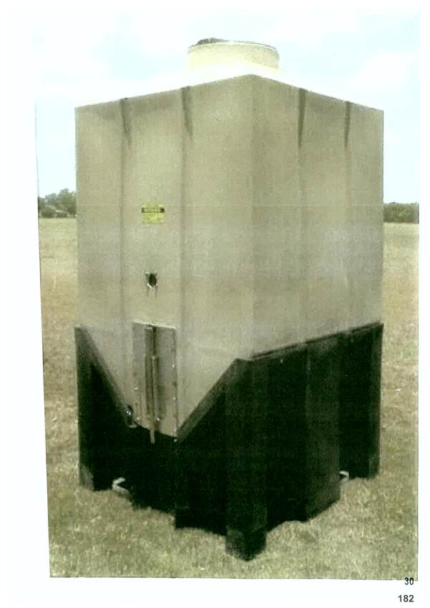
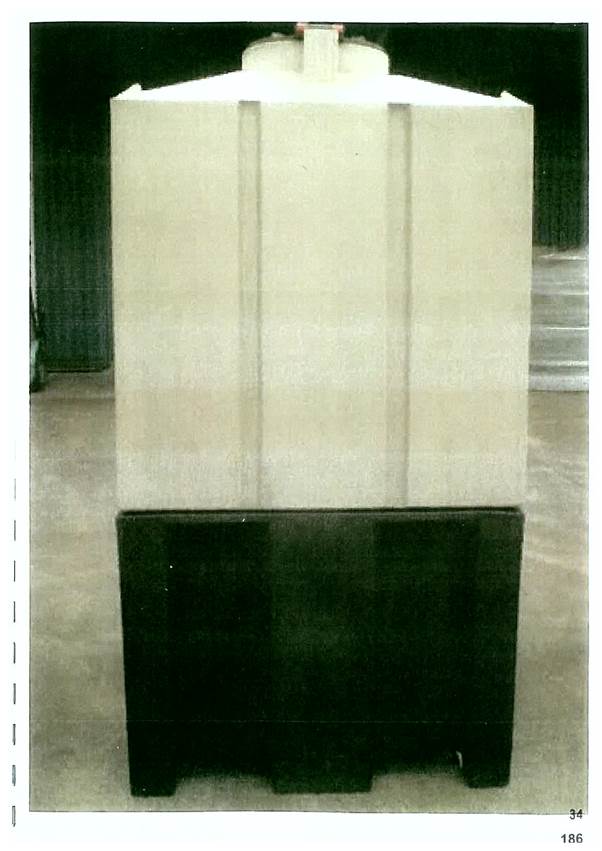
AND: |
AUSTRALIAN KEG COMPANY PTY LTD ACN 115 412 774 Respondent N & E BOWDER PTY LTD ACN 097 150 742 First Cross-Respondent BELMARK RURAL PTY LTD ACN 111 679 693 Second Cross-Respondent HAY QUEENSLAND PTY LTD ACN 110 494 454 Third Cross-Respondent |
|
JUDGE: |
DOWSETT J |
|
DATE: |
24 DECEMBER 2013 |
|
PLACE: |
BRISBANE |
REASONS FOR JUDGMENT
INTRODUCTION
1 Australian Keg Company Pty Ltd (the “respondent”) is the holder of Australian Innovation Patent No 2011101654 (the “Patent”); the patented invention is a “modular storage bin”. The field of the invention is said to be “a field bin for storage of grain, such as wheat. The priority date of the patent is 8 September 2004.
2 On 19 June 2012, the respondent’s patent attorneys wrote to the first applicant’s patent attorneys, alleging that the applicants had infringed claims 1 to 5 of the Patent by the manufacture, marketing, sale and hiring of a product known as “Stor-Cube”. The respondent threatened legal proceedings against the applicants if they did not provide certain undertakings. There had previously been correspondence concerning the alleged infringement of a registered design held by the respondent. Those allegations were subsequently withdrawn.
2 The applicants allege that the letter of 19 June and a subsequent letter of 22 June contained “unjustified threats” within the meaning of s 128(1) of the Patents Act 1990 (Cth) (the “Act”). The respondent denies the allegation and cross-claims for damages for infringement. The applicants do not allege invalidity. The respondent concedes that if the Stor-Cube does not infringe the patent, then the letters of 19 and 22 June were unjustified threats.
3 These reasons concern only the question of infringement. The quantum of damages (if any) is to be determined separately.
THE PATENT
4 The description of the background art describes the limitations of other types of field bin used to store grain. I need not discuss in detail the prior art or the difficulty overcome by the respondent’s invention. I simply note that previous field bins suffered from various defects arising from their metal construction. The invention uses plastic.
5 The claims are as follows:
1. An animal feed storage bin comprising a body formed of plastics material, the body comprising an upper section defining a storage chamber for animal feed material and a lower section providing a base below the upper section to provide support for the upper section, the base having an exterior side wall, the upper section having a top portion incorporating an inlet for introduction of feed material into the storage chamber, a side portion configured for structural rigidity, and a bottom portion adapted to be received by the base, the bottom portion incorporating an outlet for selective discharge of feed material from the storage chamber, the base being adapted to provide access to the outlet through the exterior side wall of the base, and a control means operable for selectively opening and closing the outlet, wherein the control means comprises a gate slidable with respect to the outlet between open and closed conditions, whereby the gate when in the closed condition blocks the outlet to prevent discharge of feed material from the storage chamber and whereby the gate when in the open condition permits gravity discharge of feed material from the storage chamber (emphasis added).
2. The animal feed storage bin according to claim 1 wherein the base comprises a recess opening onto the exterior side wall of the base, the outlet communicating with the recess at a location adjacent the exterior side wall whereby the outlet is accessible through the recess for discharge of feed material from the storage chamber.
3. The animal feed storage bin according to claim 1 or 2 wherein the bottom portion comprises a downwardly sloping section so configured that when the bottom portion is received by the base the outlet is disposed closer to said exterior side wall than to an opposed side wall of the base.
4. The animal feed storage bin according to claim 2 or 3 wherein the outlet is accommodated within the confines of the base and wherein the control means is accessible for operation thereof through the recess.
5. The animal feed storage bin according to any one of the preceding claims wherein the base comprises a cradle section adapted to support the bottom portion of the storage chamber and wherein the base further comprises a plurality of pads on the underside thereof for contacting a support surface, the pads being arranged in an array defining spaces for receiving lifting elements, and cross members associated with the spaces to, in use, be disposed below lifting elements received in the spaces to thereby stabilise the base on the lifting elements to prevent toppling thereof.
6 The dispute focusses on the emphasized words in claim 1, namely:
“the bottom portion incorporating an outlet for selective discharge of feed material from the storage chamber” (“feature 10”); and
“the base being adapted to provide access to the outlet through the exterior side wall of the base” (“feature 11”).
7 Dr Gilmore who gave evidence on behalf of the applicants identified 15 separate features or integers in claim 1 as follows:
|
Feature Number |
Feature of Claim 1 |
|
1 |
An animal feed storage bin |
|
2 |
comprising a body formed of plastics material |
|
3 |
the body comprising an upper section defining a storage chambers for animal feed material |
|
4 |
and a lower section providing a base below the upper section |
|
5 |
to provide support for the upper section |
|
6 |
the base having an exterior side wall |
|
7 |
the upper section having a top portion incorporating an inlet for introduction of feed material into the storage chamber |
|
8 |
a side portion configured for structural rigidity |
|
9 |
and a bottom portion adapted to be received by the base |
|
10 |
the bottom portion incorporating an outlet for selective discharge of feed material from the storage chamber |
|
11 |
the base being adapted to provide access to the outlet through the exterior side wall of the base |
|
12 |
and a control means operable for selectively opening and closing the outlet |
|
13 |
wherein the control means comprises a gate slidable with respect to the outlet between open and closed conditions |
|
14 |
whereby the gate when in the closed condition blocks the outlet to prevent discharge of feed material from the storage chamber |
|
15 |
and whereby the gate when in the open condition permits gravity discharge of feed material from the storage chamber |
8 Mr Reid who gave evidence for the respondent identified seven features or integers as follows:
|
[Feature 1] |
An animal feed storage bin | |
|
[Feature 2] |
The bin comprising a body formed of plastics material | |
|
[Feature 3] |
The body comprising an upper section and a lower section | |
|
[Feature 4] |
The upper section defining a storage chamber for animal feed material: | |
|
(a) |
having a top portion incorporating an inlet for introduction of feed material into the storage chamber, the top portion having a side portion configured for structural rigidity; and | |
|
(b) |
having a bottom portion adapted to be received by the base and incorporating an outlet (with control means) for selective discharge of feed material from the storage chamber. | |
|
[Feature 5] |
The control means comprising a gate slidable with respect to the outlet between open and closed conditions, whereby: | |
|
(a) |
the gate when in the closed condition blocks the outlet to prevent discharge of feed material from the storage chamber | |
|
(b) |
the gate when in the open condition permits gravity discharge of feed material from the storage chamber | |
|
[Feature 6] |
The lower section providing a base below the upper section to provide support for the upper section | |
|
[Feature 7] |
The base: | |
|
(a) |
having an exterior side wall | |
|
(b) |
being adapted to provide access to the outlet through the exterior side wall of the base | |
9 It may be there is little difference between the two analyses, however I am inclined to prefer that of Dr Gilmore as more clearly identifying the matters in dispute. Dr Gilmore’s approach seems also to be closer to the language and structure of claim 1 itself than is Mr Reid’s analysis. In particular I consider that Dr Gilmore is correct in his identification of the various parts of the upper section, namely a top portion, a side portion and a bottom portion. Mr Reid’s analysis conflates the top portion and the side portion. In his feature 4(b), Mr Reid includes as an aspect of the bottom portion of the upper section, an outlet “with control means for selective discharge of feed material from the storage chamber”. Dr Gilmore’s treatment of that feature is unclear. However, to my mind the preferable construction of claim 1 is that the device is to have three discrete parts, the first being the upper section, the second being the base or lower section and the third being the control means. The structure of claim 1 is as follows:
first, the claim identifies the distinction between the upper section (a storage chamber) and the lower section, a base having an external side wall;
then the claim identifies three parts of the upper section, namely the top portion, the side portion and the bottom portion, describing characteristics of each;
then the claim provides that the base is to be adapted to provide access to the outlet through the external side wall; and
then the claim identifies a control means without identifying the section of the device on which it is to be located.
10 It seems at least possible that it could be located on the base or on the bottom portion of the upper section.
INFRINGEMENT
11 Although the respondent alleges that the applicants have infringed all of the claims in the patent, it concedes that as claims two to five are dependent on claim one, its infringement case stands or falls on the alleged infringement of that claim. At least in part, the respondent’s case relies on s 117 of the Act.
12 As will be apparent from the photographs attached to these reasons, the Stor-Cube consists of a container for the storage of grain, which container rests on a base section. The container has a top, containing an inlet, apparently for filling. There is, below the top, a more or less square space, apparently designed to be the principal storage area. Below that area, three of the four walls slope inwardly to a base. The fourth wall of this section of the Stor-Cube is a vertical extension of the “front” wall of the principal storage area. Thus the front elevation of the container tapers at the bottom to a flat bottom, reflecting the taper of the two adjoining sides. Those three sides and the tapered rear side meet at the four edges of a floor section which must be either square or rectangular, depending upon the actual slope of each wall.
13 The base is more or less square and made of plastic. On all but the front side, the walls commence at or near ground level and extend up to about the point at which the tapering of the sides of the container commences. On the front side of the base, the top of the wall is a truncated V-shape. Its highest points are at the same level as the top of each of the other three sides of the base. On either side of the front wall of the container, the top of the base runs parallel to the ground for a few centimetres from each side, and then forms the truncated V-shape to which I have referred. The closing mechanism is a sliding door, situated substantially in the V-Section of the front wall, but extending to a point just above the highest point of the base. The door may be slightly narrower than the truncated base of the V.
14 The plastic members which form the sides of the V in the front wall of the base seem to be a few centimetres in depth, from the front of the base to the front of the container. All four sides of the container have strengthening features. On the front wall, those features extend down to the lower edge of that wall. On each of the other walls, the strengthening feature goes only to the point at which the taper commences. All four sides of the base have strengthening features.
15 Mr Reid addressed in detail the forces acting on the walls of the container at the point at which the taper starts, stressing the need for support from the base at that point. The emphasis on this point may have been the result of his initial instructions which were, to some extent, directed at performance of the invention. The question of support has only marginal relevance in the construction of the claims, but it was dealt with exhaustively in the submissions.
CONSTRUCTION OF CLAIM 1
16 In construing a claim, the Court gives the meaning which would be given it by a skilled addressee at the priority date of the patent, and in the context of the specification as a whole (see for example Kirin- Amgen Inc v Hoechst Marion Russell Ltd (2004) 64 IPR 444 and Bennett J in H Lundbeck A/S v Alphapharm Pty Ltd & Anor (2009) 177 FCR 151 at [118]).
17 The parties have led expert evidence going to the construction question. Dr Gilmore is an engineer with considerable experience as an academic and consultant. He is presently the managing director and president of Gilmore Engineers Pty Ltd, a firm of mechanical engineering consultants. Mr Reid is also an engineer. Prior to studying mechanical engineering, he worked as a farmer. He is presently a director and principal design engineer with Haald Engineering Pty Ltd. Both men have experience in the engineering of plastic materials. I consider that to be the relevant field in which the skilled addressee must be placed. I accept that both witnesses are skilled addressees. Counsel for the applicants suggested that the solicitors for the respondent may have compromised Mr Reid’s standing as an independent witness. I see no reason to take that view. Although I have considered the experts’ evidence, it is probably of only marginal relevance. The construction question does not involve any technical engineering concept or term of art. As Middleton J said in Britax Childcare Pty Ltd v Infa-Secure Pty Ltd (2012) 96 IPR 1 at [225]:
A court may be in the position to construe a patent without the aid of any expert evidence, if it is clear that the patent is to be read according to its ordinary meaning and no special meaning is to be given to any word or phrase, and the court does not need assistance in understanding the context of the patent in suit … . If, for instance, the only issue involved the grammatical interpretation of a phrase for which it was accepted contained words of ordinary meaning, the task of construction could be undertaken by a judge without the aid of expert evidence.
18 I should make two more observations concerning the expert evidence in this case. Neither expert has physically inspected the allegedly infringing product. Both have relied upon photographs supplied to them (as to which see Dr Gilmore’s cross examination at ts 70 ll 12-3 and Mr Reid’s affidavit at para 105). Nor is any precise diagram of the Stor-Cube in evidence. The expert evidence rests substantially on appearance and engineering concepts. As to appearance, my own observations, informed by theirs, will necessarily be the basis of my judgment. As to the engineering concepts, I shall take them into account where it seems appropriate to do so.
19 Before turning to the Patent, I should stress the importance of maintaining consistency in nomenclature. I shall adopt that of claim 1 so that there is:
a “storage bin” comprising a “body”, having an “upper section” or “storage chamber”;
a “lower section” or “base” which has an exterior side wall, meaning plastic walls on all four sides; and
a control means for opening and closing the outlet.
20 The “upper section” or “storage chamber” has:
a top portion incorporating an inlet;
a “side portion” configured for structural rigidity; and
a “bottom portion”, adapted to be received by the “base” and incorporating an “outlet” for the discharge of feed material.
21 The “lower section” or “base” is adapted to provide access to the outlet through an exterior side wall of the base.
22 The “control means” allows selective opening and closing of the outlet by opening and closing a steel gate to permit or prevent the discharge of feed material through the outlet.
FEATURE 10
23 The primary question here is the meaning of the words “the bottom portion incorporating an outlet for selective discharge”, in particular as to the location of the outlet. The applicants’ case seems to be that the outlet must be located on the bottom portion of the upper section, which portion is adapted to be received by the base. The applicants also submit that any strengthening features are only to be located in the side portion of the upper section, so that any wall having such features must be part of the side portion. They also submit that the requirement that the bottom portion of the upper section be received by the base requires that the bottom portion be entirely surrounded by the base.
24 As to the first submission, it is no doubt true that the sides of the side portion of the upper section must provide structural rigidity. It does not follow that any wall having that quality must be part of the side portion. As to the second submission, the concept of “reception” no doubt implies that the bottom portion of the upper section will, when in place on the base, be within the discernible boundaries of the base, but I doubt whether it is possible to say more. In this context, “receive” means “serve as a receptacle or containing space for; allow to enter or penetrate; be able to hold (contents or a specified amount) conveniently” (the Shorter Oxford English Dictionary (4th ed, Oxford University Press, 1993).
25 The applicants’ case concerning the Stor-Cube, as it emerged from Dr Gilmore’s evidence and in submissions, is that the front wall of the container, which extends from the top portion of the upper section to the bottom of the V in the base, is part of the side portion of the container and no part of the bottom portion as those terms are used in claim 1. Hence it is said that the outlet is in the side portion, and not the bottom portion. The applicants also submit that the front wall of the container is not “received” by the base, and that the V-shaped section of the front wall of the base shows that the strengthening feature in the front wall of the container continues to the bottom of the wall. It is submitted that, as a result, the whole of the front wall of the container is part of the side portion.
26 It may be that in considering allegedly infringing devices, identification of the dividing line between the side portion and the bottom portion poses difficulties. However it is clear that claim 1 contemplates it being possible to distinguish between them. It does so by reference to the structural rigidity provided by the walls in the side portion, the capacity of the bottom portion to be received by the base and the presence in it of the outlet. To my mind, the portion of the container which sits above the highest point of the base, which is the point at which the taper of the sides of the upper section commences, has the required characteristic in that such sides, above the commencement of the taper, contain strengthening features. As to accommodation of the bottom portion of the container, the base clearly does so. That portion of the container has been adapted to be received by the base in that three sides have been tapered, and it is otherwise of an appropriate size. The front of the container may be close to the front of the base, but the former is, in my view, held by the latter. In that sense, at least, it is received by it. It is irrelevant that the lower part of the front wall also has a strengthening feature. That feature is simply an extra feature not required by claim 1. Its presence does not disqualify that part of the container which is received by the base from being the bottom portion as contemplated in claim 1. Thus the outlet is located on the bottom portion of the upper section. It follows that the Stor-Cube contains feature 10.
FEATURE 11
27 The parties have focussed upon the word “through”. I suspect that such emphasis arises out of the particular form of the Stor-Cube. One must be careful not to construe a patent with an eye to an allegedly infringing product. It seems to be accepted that claim 1 describes the base as having a wall which surrounds the bottom portion of the upper section. Thus the base must be “adapted” in order to provide access to the outlet which is located on the bottom portion.
28 The Shorter Oxford English Dictionary defines “adapt” to mean “Fit, adjust, make suitable … Alter or modify to fit for a new use, new conditions …”. The word “access” means “a way or means of approach or entrance”. The Oxford English Dictionary (2nd ed, Oxford University Press, 1989) states that as a preposition, the word “through” expresses:
the relation or transition or direction within something from one limit of it to the other: primarily in reference to motion in space, hence in various derived senses.
… From one end, side or surface to the other or opposite end, side or surface of (a body or a space) by passing within it, usually implying in to, at one end, side etc and out of at the other.
29 It is the base which must be adapted. Such adaptation must accommodate the supporting role of the base and the need for access to the outlet. In my view the reference to access “through the wall” identifies an outcome to be achieved rather than a limit on the method to be adopted. I consider that the expression “through the wall” includes any direct means for passing from one side to the other.
30 If my purposive approach to construction is accepted, then I need say no more. By so adapting the wall (to incorporate the V-shaped aperture) direct access has been provided from one side of the wall to the other. If more is needed, then I consider that usages such as passing “through” a canyon or “through” the Suez Canal strongly suggest the appropriateness of the use of the word “through” in describing the access to the outlet provided in the Stor-Cube device.
31 I conclude that the Stor-Cube provides access to the outlet through the wall of the base.
32 It follows that infringement is proven.
|
I certify that the preceding thirty-two (32) numbered paragraphs are a true copy of the Reasons for Judgment herein of the Honourable Justice Dowsett. |
Associate: