
FEDERAL COURT OF AUSTRALIA
Davies v Lazer Safe Pty Ltd [2019] FCAFC 65
ORDERS
First Appellant/First Cross-Respondent TRICLOPS TECHNOLOGIES PTY LTD Second Appellant/Second Cross-Respondent | ||
AND: | Respondent/Cross-Appellant | |
DATE OF ORDER: | 26 APRIL 2019 |
THE COURT ORDERS THAT:
1. The appeal and the cross-appeal be dismissed.
2. Within 14 days, the parties are to file and serve any written submissions they wish to make on the question of costs, of no more than 3 pages.
3. Any submissions in answer, of no more than 3 pages, should be filed and served within a further 14 days.
Note: Entry of orders is dealt with in Rule 39.32 of the Federal Court Rules 2011.
THE COURT:
1. INTRODUCTION
1 The appellants, Kevin Stephen Davies and Triclops Technologies Pty Ltd, are respectively the owner and exclusive licensee of Australian Patent No 2003229135 entitled “A Safety System”. They commenced proceedings against the respondent, Lazer Safe Pty Ltd, alleging that its Lazer Safe Systems infringed each of claims 1 – 5, 8, 12, 14, 21, 22, 28-31, 38, 44 and 46 (asserted claims) of the Patent, pursuant to the terms of the Patents Act 1990 (Cth). Those proceedings were dismissed by the learned primary judge in Davies v Lazer Safe Pty Ltd [2018] FCA 702 and the appellants appeal against that decision. In response to the infringement claim, Lazer Safe brought a cross-claim, alleging that the asserted claims were invalid on a number of different grounds available under the Act. The cross-claim was also dismissed by the primary judge, and Lazer Safe has filed a cross-appeal against that decision.
2 The substantial issue in the appeal concerns the findings made by the primary judge in relation to the construction of claim 1 of the Patent. Although 10 separate grounds of appeal are set out in the Amended Notice of Appeal, the central findings the subject of challenge concern the construction of integers (1.5) and (1.6) of claim 1 (as identified below) (grounds 3 – 6) and the finding, dependent on construction, that the impugned Lazer Safe Systems did not infringe any of the asserted claims (grounds 7 – 10). Grounds 1 and 2 of the appeal concern the primary judge’s findings preferring the evidence of the respondent’s expert witness, Mr Appleyard, over the evidence of the appellants’ expert, Mr Acheson. During the course of the hearing of the appeal, those grounds were abandoned.
3 Lazer Safe defends the construction adopted by the learned primary judge and advances its cross-appeal only in the event that the primary judge’s decision is overturned. It contends that if that event arises, then the breadth of the claims must be such that they are invalid for want of novelty, lack of inventive step, lack of fair basis and lack of clarity. Lazer Safe accepts, however, that if the conclusion reached by the primary judge that the Lazer Safe products do not infringe the claims is upheld, then the cross-appeal should be dismissed.
4 For the reasons set out below, we consider that the learned primary judge was correct in his conclusions as to the construction of claim 1 of the patent, although we disagree with aspects of the way in which he arrived at his conclusion. The result is that the appeal must be dismissed and the finding that the Lazer Safe products do not infringe the asserted claims is upheld. As a consequence, the cross-appeal must also be dismissed.
2. THE PATENT
5 To understand the nature of the construction dispute, it is convenient to summarise something of the background to the invention as set out in the Patent.
6 The Patent relates to a safety system, in particular a system for use with machinery having moving parts, such as press brakes, to detect the presence of an obstruction in the path of a moving part. The “Field of the Invention” describes some of the prior art. It states that in the past, various mechanisms have been used to prevent the operators of industrial machinery, such as press brakes, from placing their hands beneath the moving tool during operation. One involves the use of physical guards that are placed between the operator and the tool. The use of such guards, however, can obstruct the view of the operator during use and impede access to the work, making it difficult for the operator to perform his or her job in the most efficient manner. Also, physical tethers have been used to keep the operator at a safe distance from the moving tool. These make holding and manipulation of the work difficult and therefore decrease the efficiency of operation. Various alternative arrangements have also been used. One described is to create a light curtain, which surrounds the path of the moving tool. The light beams are projected onto detectors which are able to sense when the beam is broken and trigger either a halt or a slowing down of the movement of the tool. However, such devices are said to have disadvantages in that the operator is kept away from the work area, and it is generally necessary also to reset the position of the light curtains between production batches. Also, they define only one area around the tool which, if obstructed by any object (whether part of the operator or not) will deactivate the machinery. Further, the use of individual light beams also results in small gaps in the light curtain, into which small objects like fingers can be placed without triggering deactivation of the machine. A further method of providing safety protection described in the Field of the Invention is with the use of one or more light beams projected along the leading edge of the tool. The light beams are arranged to move with the tool and slow or stop the tool if an obstruction breaks the beam. In such arrangements the beam must be deactivated as the tool approaches the work, and the light beam must be set at a sufficient distance from the tool to stop it in time. The minimum permissible distance of the beam from the tool is therefore dependent on the maximum speed of movement of the tool. In some cases, multiple light beams may be used at varying distances from the tool. However, the Patent states that known problems with these types of arrangements include the need to re-align the light beams when tools are changed, and the possibility that an operator may move his or her hand under the tool just as the beams are deactivated. Also, as with light curtains, all parts of the work must be kept clear of the beams, because operator confirmation is required every time a new obstruction is encountered.
7 The Patent states that the present invention attempts to overcome, at least in part, some of these disadvantages.
8 After the Field of the Invention, the Patent sets out in the Summary of the Invention a consistory clause which is in the form of claim 1.
9 Claim 1 provides (integer numbers added):
(1.1) A safety system for use with a machine having a moving part arranged to move through a known path of movement, the safety system characterised by comprising: (1.2) at least one light emitting means arranged to emit light; (1.3) the axis of the emitted light being generally perpendicular to the path of movement of the part such that a region including at least a portion of said path is illuminated; (1.4) at least one light receiving means arranged to receive light from the or one or more of the light emitting means which has passed through said region; and (1.5) a processing and control means arranged to receive image information from the light receiving means and thereby recognise the presence of one or more shadowed regions on the light receiving means cast by obstructions in the region; (1.6) wherein the illumination of the region is such that the processing and control means has sufficient image information to determine the boundaries of the or each shadowed region and control movement of the part dependent on said image information.
10 There was no substantial dispute between the parties as to the meaning of integers (1.1) – (1.4), and Lazer Safe accepted that the impugned Lazer Safe Systems possessed each of these integers. The primary judge’s findings in relation to these (which are discussed further below) are not the subject of challenge.
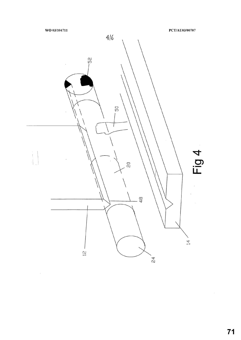
11 Following the consistory clause, there is a “Description of the Drawings” which commences by stating that the invention will be described “by way of example” with reference to the drawings. Figures 1a, 1b, 2a and 2b depict examples of light emitting and light receiving means and lens arrangements. Figure 3 is a perspective view of a charge coupled device (CCD) used as the light receiving means. Figure 4 is a perspective view of a press brake with a region around the tool edge illuminated in accordance with the present invention. Figure 5 is a cross-sectional view of the illuminated region created by the light emitting means showing a shadow mask used for checking purposes, Figure 6 is a view of a shadow map, Figure 7 is a view of a region having a stop-zone defined around the tool, and Figure 8 is a view of the illuminated region of Figure 7 as the tool approaches the anvil.
12 Aspects of the “Description of the Invention”, which is the next section of the specification, may be understood having regard to Figure 4:
13 It provides (page 4, lines 17 – 24):
Referring to the Figures, there is shown a safety system for use with machinery having moving parts to detect the presence of an obstruction in the path of the moving part. In the embodiment shown, the safety system is employed on a press brake comprising a tool 12 arranged to move relative to an anvil 14 and to strike work placed on the anvil 14. The safety system includes a light emitting means 16 and a light receiving means 18 [not depicted in Figure 4]. The light emitting means 16 is arranged to illuminate a region 20 around a portion of the path of movement of the tool 12 in order to detect obstructions in said region 20.
14 The Patent then describes the details of the figures depicting the light arrangements, before providing the following further information (page 6, lines 15 – 22):
As shown in Figure 4, the light emitting means 16 is mounted at one end of the tool 12 of the press brake such that the parallel light beam 24 illuminates a region 20 around the path of movement of the tool 12 which includes the forward edge 48 of the tool 12. The light receiving means 18 is mounted at the opposite end of the tool 12 to receive the light beam 24. If an obstruction 50, such as the hand of the operator, enters the region 20, a corresponding shadow 52 will be cast on the image detection device 46. The light emitting means 16 and light receiving means 18 are mounted to be stationary relative to the tool 12.
15 The primary judge at [234] places particular reliance on the following passage in the Description of the Invention from page 6 line 23 to page 7 line 14 (emphasis added):
The safety system also includes a processing and control means (not shown) connected such that the processing and control means receives information from the light receiving means 18 and processes this information and controls operation of the press brake. The processing and control means may be in the form of a software program residing on a digital signal processor, a computer or embedded into a microcomputer which receives input from the output of the light receiving means 18. The processing and control means captures the images received by the image detection device 46 and processes the images to search for any unknown shadows.
The processing and control means stores in memory the image received by the image detection device 46 in which no obstructions are present. In the case where the light emitting means 16 and light receiving means 18 are mounted stationary relative to the tool 12, the image includes the forward edge of the tool 12. The processing and control means compares the current image received by the image detection device 46 with this stored image to determine the presence of any shadows on the image detection device 46 created by obstructions in the region 20. If any new obstructions are detected, the processing and control means may either stop or slow the movement of the tool 12.
16 In the first paragraph in this passage, the processing and control means is described by reference to the information that it receives. It is described as capturing the images received from the image detection device and processing the images to search for any unknown shadows. In the second paragraph, the processing and control means is described as storing the image received in which no obstructions are present (stored image) and an example is given of a setup whereby the light emitting means and light receiving means are mounted stationary relative to the tool. The processing and control means compares the “current image” received by the image detection device with the “stored image” to determine the presence of any “shadows” on the image detection device. If any new obstructions are detected, the processing and control means may either stop or slow the movement of the tool. We refer to this below as the store and compare method.
17 The Patent then goes on at page 7, lines 15 –24 (emphasis added):
In one method of controlling the movement of the tool 12 where an obstruction is detected, the processing and control means determines the vertical distance between the tool 12 and the obstruction and allows continued movement of the tool 12 while the distance determined is greater than the distance required to stop the tool 12. The processing and control means may also determine the thickness of the shadow cast by the obstruction and allow continued movement of the tool 12 if the thickness is determined to be such that the obstruction could not be part of the operator’s body. If the tool 12 is to be stopped, the operator may confirm that continued operation of the tool 12 is safe by an input means, such as a button, arranged to provide a signal to the processing and control means.
18 In this passage another two methods of controlling movement of the tool where an obstruction is ‘detected’ are described. In the first, the processing and control means determines the vertical distance between the tool and the obstruction and permits continued movement of the tool in the distance calculated. We refer to this below as the distance measurement method. In the second, the processing and control means determines the thickness of the shadow cast by the obstruction and allows continued movement of the tool if the thickness is such that the obstruction could not be part of the operator’s body (the thickness measurement method). Furthermore, an operator may manually override the stop command by pressing a button or the like.
19 The passage that immediately follows, at page 8, lines 1 – 13, was also emphasised by the primary judge at [234] (emphasis added):
The processing and control means may also create a total picture made up of the image information received by the light receiving means 18 as the tool 12 moves through its path of movement. The picture is created and stored in a memory means by the processing and control means. This total picture will be referred to as a shadow map. A shadow map 54 is shown in Figure 6 in which no shadows other than those of the tool 12 and anvil 14 are detected. Such a shadow map 54 would be created on a first pass of the tool.
The processing and control means can store in the memory means a number of known safe shadow maps. The known safe shadow maps being shadow maps 54 where no obstruction is detected which would require stopping or slowing of the press brake. For example, the shadow map 54 in which the only shadow cast is that of the forward edge of the tool 12 and the anvil would be a known safe shadow map 54.
20 Figure 6 is as follows:
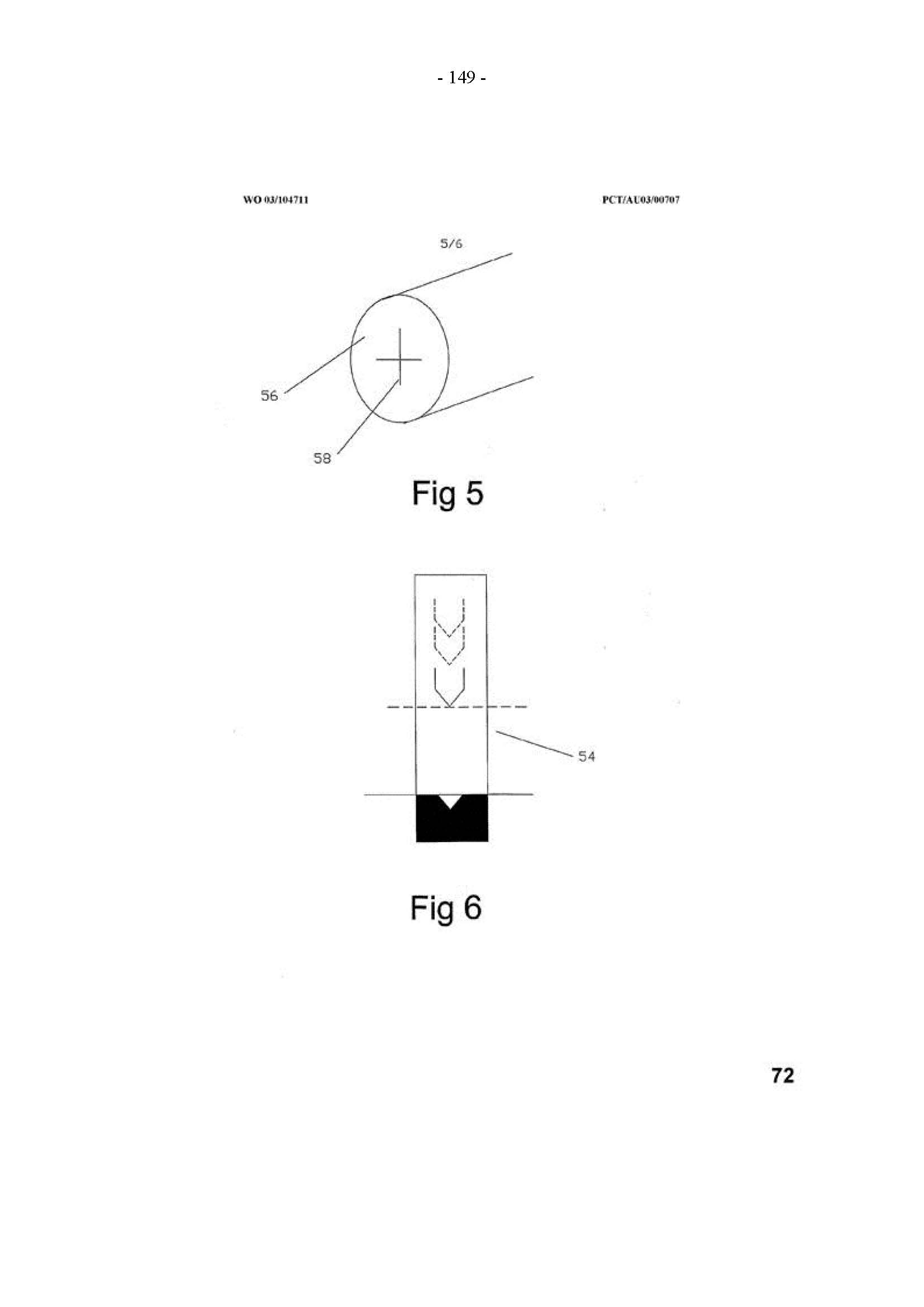
21 We refer to the requirement described in this passage as the shadow map method.
22 The specification at page 8 line 13 to page 9 line 2 then provides (emphasis added):
In use, if an obstruction is placed in the path of the light beam 24, a shadow 52 is cast on the image detection device 46. The processing means recognises the presence of an unknown shadowed area in the shadow map 54 and halts or slows the movement of the tool until either the shadow disappears by removal of the obstruction or the operator confirms that operation of the press brake is safe to continue by operation of the input means. Further the processing and control means could allow the tool 12 to descend to a point adjacent the obstruction before stopping in order to assist the operator to identify the location of the obstruction which has triggered the deactivation of the press brake.
In the case where the obstruction detected by the safety system is one deemed to be safe to continue operation, such as the edge of work which has previously been bent up, the processing and control means stores that shadow map as a known safe shadow map. Therefore, when this work is repeated, the processing and control means automatically recognises the obstruction as being non-hazardous and allows continued operation of the press brake.
23 Further detail of various examples and embodiments is then set out. A description is given of the requirement for there to be a “tool position detector” in order to create shadow maps during operation, but this is optional. Several aspects of the processing and control means are identified, such as: means to reduce the possibility of false triggering; means for shadow expansion whereby the shadow is expanded by a sufficient number of pixels to allow for vibration or other inaccuracies; and means for ignoring the action of the press brake back gauge. Furthermore, the safety system is described preferably to be provided with a shadow mask (as described in Figure 5) for checking that the safety system is receiving the light beam correctly. Other additional aspects are also described.
24 Claim 1 (set out in paragraph [9] above) is the only independent claim. There are 47 claims in total. The dependent claims add integers to the safety system that is the subject of claim 1.
25 Claim 2 is for:
A safety system in accordance with claim 1, characterised in that the processing and control means either slows or stops the movement of the part if the processing and control means determines the presence of an obstruction in a predetermined or calculated area of the region.
26 The appellants rely on dependent claims 8 – 11 in their argument:
8. A safety system in accordance with any one of claims 2 to 7, characterised in that an input means is provided such that when the processing and control means slows or stops the movement of the part, actuation of the input means by the operator informs the processing and control means that continued movement of the part is safe and the processing and control means resumes movement of the part.
9. A safety system in accordance with claim 8, characterised in that when the processing and control means is informed that continued movement is safe, the processing and control means stores in a memory means one or more maps made up of image information received by the light receiving means as the part moves through the path of movement.
10. A safety system in accordance with claim 9, characterised in that the processing and control means compares the current image received by the light receiving means to the maps stored in the memory means and allows continued operation of the part if sufficiently similar.
11. A safety system in accordance with claim 9 or 10, characterised in that the processing and control means compares the current image map being created as the part moves through the path of movement to the maps stored in the memory means and allows continued operation of the part if sufficiently similar.
27 It will be seen that claim 9 provides for an additional feature whereby the processing and control means stores in a memory means one or more “maps” made up of image information received by the light receiving means as the part moves through the path of movement. This is the first reference in the claims to maps, which might be considered to be corresponding with “shadow maps” as described in the specification.
3. CONSTRUCTION OF THE CLAIMS
3.1 The Primary Judge’s Findings
28 As indicated above, the primary judge’s findings in relation to integers (1.1) - (1.4) are not the subject of challenge.
29 In relation to integer (1.1) of claim 1, his Honour found at [224] that the term ‘safety system’ means a system, as further set out in the claim, which is designed to protect operators of the machinery from injury while the machinery is in use. For a press brake, this use is usually while the blade (or tool) is pressing downwards to engage a work piece, until that work piece is bent and the blade rises again. It means anything which functions in any way at any time to protect the operator. A ‘safety system’ is directed to the protection of the operator of the press brake from injury, caused by, for example, getting a finger trapped between the blade of the tool and the work piece. It can be differentiated from a control or productivity system which is concerned with other aspects of use of the press brake (for example, determining the correct angle of bending the work piece). The ‘moving part’ is usually the tool. It is not the work piece.
30 In relation to integer (1.2), his Honour found at [225] that a ‘light emitting means’, taken in context, is an arrangement to emit a large area of parallel beams of light from a device, or the beams described as modifications in the Patent.
31 In relation to integer (1.3), his Honour found at [226] that the ‘axis’ is shown in Figure 4 of the Patent (which is reproduced above) as being across the path of the downward moving press blade of a press brake in operation. The ‘illuminated region’ is also shown in Figure 4 to be a light beam 24 that illuminates the region 20 in the downward path of the forward edge 48 of the tool 12 (the press brake).
32 In relation to integer (1.4), his Honour found at [227] that the ‘light receiving means’ is described as comprising an aperture in a screen, and an image detection device such as a CCD or a projection screen with a camera ‘to observe the projected image’: see page 6, lines 7 – 9 of the Patent.
33 In relation to controversial integer (1.5), his Honour made the following findings:
Integer 1.5: a processing and control means arranged to receive image information from the light receiving means and thereby recognise the presence of one or more shadowed regions on the light receiving means cast by obstructions in the region
228 The ‘processing and control means’ is described as being in the form of ‘a software program residing on a digital signal processor, a computer or embedded into a microcomputer which receives input from the output of the light receiving means’: Patent p 7 lines 1-3.
229 The ‘image information’ is received from the light receiving means (such as a CCD or a projection screen), but it is information used to ‘recognise the presence of one or more shadowed regions’ on the CCD or projection screen. In my view, this is an important factor. As the respondent says, it does not mean any information whatsoever about an ‘image’. ‘Image information’ means that the shape of the obstruction must be capable of being determined and sufficient to be used by the system.
230 Equally on this topic, in my view, the use of the word ‘recognise’, in context, is important, and means that the system is not just detecting a shadowed region, but the system recognises, that is, compares the shadowed region detected with what is previously known – the shape of obstructions. This is consistent with the recitation in the Patent (at p 6 line 23 to p 7 line 14), particularly the comparison of ‘the current image’ with the ‘stored image to determine the presence of any shadows’ (at p 7 lines 9-11). The reference in integer 1.5 to the ‘one or more shadowed regions’ accords with the notion that the system can determine the shape of the obstruction.
231 The emphasis is on obstructions when the machinery such as press brakes is descending.
232 Moreover, by the terms of claim 1 itself, it is quite clear that the blade itself cannot be an obstruction. It is the ‘moving part’ from integer 1.1 and the ‘part’ from integer 1.6, the movement of which is controlled. As Mr Appleyard said on behalf of the respondent, it cannot be both an obstruction and the moving part obstructing itself. Obstructions are something which is in the way of the blade of the tool and which should not be there during the descent of the tool towards the workpiece. Neither the blade nor the workpiece can be obstructions.
34 In relation to controversial integer (1.6) the primary judge found as follows:
Integer 1.6: wherein the illumination of the region is such that the processing and control means has sufficient image information to determine the boundaries of the or each shadowed region and control movement of the part dependent on said image information
233 I accept the respondent’s submission that the reference to the processing and control means having ‘sufficient image information to determine the boundaries of the, or each, shadowed region’ is consistent in a common sense way with the focus of the claim on shape/outline recognition.
234 Specifically, the reference to ‘boundaries’ reinforces that the shapes or outlines of the obstructions must be determined sufficiently to be used by the system to control the movement of the tool. This is confirmed by the recitation at p 6 line 22 to p 7 line 14 and by the references to the processing and control means creating ‘a total picture made up of the image information’, which is referred to as a ‘shadow map’ and which is compared to ‘known safe shadow maps’ (at p 8 lines 1-12). I also prefer the respondent’s evidence and submission, in context, that an ‘edge’ is not a boundary, although it might be part of a boundary; a boundary encloses a region or area, extending around the entire perimeter of an object.
35 In his Conclusions on Construction, the primary judge found:
235 Integer 1.5 and integer 1.6 of claim 1 require the safety system as claimed to engage in recognition of regions of obstructions by reference to shadow maps and their shapes, and require the comparison with either stored known safe or unstored unknown hazardous shadows of obstructions.
236 This reading is based on references to ‘recognition’, ‘boundaries’ and ‘regions’ in the claim, the disclosures in the specification discussed above and is also supported by Mr Appleyard’s evidence.
237 The construction was also supported in part by Mr Acheson’s acceptance in cross-examination that:
(a) a ‘shadowed region’ is an ‘area’ and that an area is a two-dimensional construct;
(b) the word ‘boundary’ or ‘boundaries’ of a shadowed region involves establishing the perimeter or outline of the shadowed region; and
(c) an ‘edge’ is part of a boundary.
238 Further, and even if this construction, which is narrower than that advanced by the applicants, is wrong, the proper construction of claim 1 requires the boundary determination of an obstruction claimed by recognising a realistically substantial portion or part of the shadowed region, so as to determine a sizable portion of the outline or shape of the obstruction, in contrast to a dot, spot, point or edge of any such region.
36 The central issue in the appeal is whether the learned primary judge erred in his construction of the claims, and in particular in relation to integers (1.5) and (1.6). We turn to that question first, which is raised in grounds 3 – 6, before moving on to consider the question of infringement, which is raised in grounds 7 – 10.
3.2 Consideration
37 In relation to integer (1.5), the appellants submit that a “processing and control means arranged to receive image information from the light receiving means” should be understood to refer broadly to the processing and control means receiving any output from the light receiving means, such as the output from the sensors of a CCD or a camera. The term “recognise the presence of” means no more than the ability to identify the existence of a shadowed region which has been “cast by obstructions in the region”. They submit that the word “obstructions” in this context means any object which blocks light from the light emitter, thereby creating a “shadowed region” on the light receiving means. Insofar as the primary judge took a contrary view, the appellants submit that he fell into error.
38 In our view, there is force in the criticisms of this aspect of the learned primary judge’s reasoning.
39 His Honour accepted that “image information” is received from the light receiving means, such as a CCD or a projection screen, and considered that such information is used to “recognise the presence of one or more shadowed regions”. This, he considered, does not mean any information whatsoever about an image, but that “the shape of the obstruction must be capable of being determined and sufficient to be used by the system” (at [229]). The primary judge said, that “recognise” in context (at [230]):
...means that the system is not just detecting a shadowed region, but the system recognises, that is, compares the shadowed region detected with what is previously known – the shape of the obstructions. This is consistent with the recitation in the Patent (at p 6 line 23 to p 7 line 14), particularly the comparison of the ‘current image’ with the ‘stored image to determine the presence of any shadows’ (at p 7 lines 9-11). The reference in integer 1.5 to the ‘one or more shadowed regions’ accords with the notion that the system can determine the shape of the obstruction.
40 We respectfully disagree with the learned primary judge’s construction in this respect. No language in claim 1 indicates that the words “image information” and “recognise” are to be understood as inviting a comparison between the detected shadowed region and a previously known shape or obstruction. The words “image information”, “recognise” and “obstruction” are not terms defined in the body of the specification so as to invite that conclusion. The words are of ordinary English. No party submitted that they involve terms of art that warrant, as aids to construction, evidence from a person skilled in the art. Accordingly, this Court on appeal is able to consider the question of construction.
41 The words “recognise the presence of one or more shadowed regions” indicate that “recognise” is to be understood as “to perceive as existing” rather than as inviting comparison with something previously known. It is simply the presence of the shadowed region that is required. This accords with the third definition of “recognise” in the Macquarie Dictionary, quoted by the primary judge at [200]. The first definition, which the primary judge preferred, is “to know again; perceive to be identical with something previously known”. However, to adopt that meaning is to set to one side the words “the presence of” that immediately follow.
42 In our respectful view, the learned primary judge in this respect fell into error by adding a gloss to the language of the claim by incorporating the concept identified in the body of the specification at page 6 line 23 to page 7 line 14, which we have quoted in [15] above and to which his Honour referred. In this regard, the additional references by his Honour in [234] and [235] indicate an assumption that the scope of claim 1 is confined to the scope of the store and compare method and/or the shadow map method. The principles of patent and claim construction have been set out in many authorities, and it is not necessary to repeat them here; see Martin v Scribal Pty Ltd (1954) 92 CLR 17 at 59, Welch Perrin & Co Pty Ltd v Worrel (1961) 106 CLR 588 at 610, Populin v HB Nominees Pty Ltd (1982) 41 ALR 471 at 476, Fisher & Paykel Healthcare Pty Ltd v Avion Engineering Pty Ltd (1991) 103 ALR 239 at 255, Decor Corporation Pty Ltd v Dart Industries Inc (1988) 13 IPR 385 at 400. Although the claims are to be construed in the context of the specification as a whole, it is not legitimate to narrow or expand the boundaries of monopoly as fixed by the words of a claim by adding to those words glosses drawn from other parts of the specification; Welch Perrin at 610.
43 Whilst it is legitimate to refer to the rest of the specification to explain the background to the claims, to ascertain the meaning of technical terms and resolve ambiguities in the construction of the claims, it is not legitimate to narrow or expand the boundaries of monopoly as fixed by the words of a claim by adding to those words glosses taken from other parts of the specification; Welch Perrin at 610; Flexible Steel Lacing Co v Beltreco Ltd [2000] FCA 890 at [74], [75], and authorities there cited.
44 The importance of the actual language used in the claim to define the invention was emphasised by the Full Court in Fresenius Medical Care Australia Pty Limited v Gambro Pty Limited [2005] FCAFC 220 at [94]:
The whole of the specification must be read in order to construe the claim. So much is not in dispute. However, that does not mean that the words of the claim are to be ignored. Nor can it be ignored that the patentee has chosen not to include in a claim matters, integers or aspects of the invention that have been referred to in the body of the specification. This accords with the well-accepted principle enunciated in Welch Perrin at 610 that glosses drawn from the body of the specification cannot be used to narrow or expand the boundaries of the monopoly as fixed by the words of a claim.
45 Claim 1 makes no reference to a comparison of shapes or of shadow maps. The learned primary judge incorporated those concepts into the claim by having regard to the language used in relation to two of the embodiments described in the body of the specification, the store and compare method and the shadow map method. But, in our respectful view, it strains the language used by the patentee to import those concepts into claim 1. That claim requires that the processing and control means be arranged to receive “image information” from the light receiving means and “thereby recognise the presence of one or more shadowed regions”. In context, as we have said, “recognise” does not equate to “compare” in the sense that one compares, as the primary judge says, the shadowed region detected with what is previously known – the shape of the obstructions.
46 Lazer Safe defends the construction adopted by the primary judge by contending that the passages identified in the specification are not simply an expression of a preferred embodiment, but must be read to be part of the statement of the invention, mandating the primary judge’s construction of claim 1.
47 In our view, this submission is not supported by the language used in the specification. The Figures are introduced as describing the invention “by way of example”, not definitively. The Description of the Invention introduces, by reference to the elements of Figure 4, “the embodiment shown”. The scope of the invention the subject of the monopoly is determined by the claims. They delimit the boundary of the conception that represents the invention. In the present specification, the portion of the Patent that gives a description of the invention in the form of “the embodiment shown” is to be understood to be a description of a part or the whole of a product that could fall within the conception of the invention as claimed in one or more claims. The broadest aspect of the invention described is set out in the “Summary of the Invention”, which, as we have noted, is set out in language corresponding with claim 1. Taken together, these matters direct the reader to an understanding that whilst the Description of the Invention provides the function of describing aspects of the invention and how they may be implemented, those aspects do not constrain the scope of the claims. Furthermore, as the bolded words within the passage identified at page 6 line 23 to page 7 line 14 set out above at [15] indicate, various alternatives are expressed as reflecting different ways in which the invention may be implemented. These provide a further indication that the body of the specification does not there purport to set out the scope of the invention.
48 Having regard to these considerations, in our view integer (1.5) does not require more than the safety system to include a processing and control means arranged to receive image information from the light receiving means and thereby detect the presence of the one or more shadowed regions on the light receiving means cast by obstructions in the illuminated region.
49 The appellants next challenge the primary judge’s findings in relation to integer (1.6). In this regard, it is important to note that his Honour’s reasoning involved a primary finding and a secondary or alternative finding, both of which he took into account when considering the question of infringement.
50 In his primary finding, his Honour concluded that the reference in integer (1.6) to “sufficient image information to determine the boundaries of the or each shadowed region and control movement of the part dependent on said image information” is to be understood to be consistent in a common sense way with the focus of the claim on “shape/outline recognition” (at [233]) and that the reference to “boundaries” reinforces “that the shapes or outlines of the obstructions must be determined sufficiently to be used by the system to control the tool” (at [234]). This was, in his Honour’s view, confirmed by the passage at page 6 line 22 to page 7 line 14 and by the references to the processing and control means “creating ‘a total picture made up of the image information’ which is referred to as a ‘shadow map’ and which is compared to ‘known safe shadow maps’” (at page 8 lines 1 – 12). These matters led the primary judge to the conclusion at [235] that:
Integer 1.5 and 1.6 of claim 1 require the safety system as claimed to engage in recognition of regions of obstructions by reference to shadow maps and their shapes, and require the comparison with either stored known safe or unstored unknown hazardous shadows of obstructions.
51 The secondary or alternative construction is that a boundary “encloses a region or area, extending around the entire perimeter of an object”. Thus, his Honour found at [238] that even if his primary construction was wrong:
...the proper construction of claim 1 requires the boundary determination of an obstruction claimed by recognising a realistically substantial portion or part of the shadowed region, so as to determine a sizable portion of the outline or shape of the obstruction, in contrast to a dot, spot, point or edge of any such region.
52 The appellants contend that both of these constructions reflect error. We agree as to the primary construction, but not in relation to the secondary construction.
53 The appellants submit that integer (1.6) directs attention to the quality of the image information that is made available to the processing and control means and that the image information must be “sufficient” to determine the boundaries of the or each shadowed region. The integer is said to direct attention to the illumination of the region. This requires the image receiver being illuminated with light of sufficient intensity that a distinction can be made between the output from “light” pixels. The appellants contend that the determination of a boundary involves the identification of a transition from “light” to “dark” pixels (referred to as finding a “gradient”). Where a gradient is found between two adjacent pixels, an “edge” exists. The appellants submit that an edge is part of a boundary, but an edge alone is not sufficient to constitute a boundary within the proper construction of that term in claim 1. A boundary of a shadowed region is a line that demarcates the area of the shadow that is cast. As an area is two-dimensional, it must be possible to find gradients and determine the boundary in two dimensions. Therefore, the appellants submit, the phrase “sufficient image information to determine the boundaries of the or each shadowed region” in integer (1.6) requires that there be sufficient image information (that is, enough pixels at a suitable resolution and spacing) to allow the gradients (that is, the transition from light to dark pixels) to be found around the perimeter of the shadowed region. If the shadowed region comprises only one “dark” pixel, this requirement is met if there is sufficient image information to identify this transition from light to dark between one darkened pixel and the surrounding pixels.
54 In their written reply submissions, the appellants contend that the steps required by integer (1.6) are exemplified as follows:
(1) The output of the image receiver (such as a camera) being a two dimensional pixel matrix of adequate resolution for boundary determination;
(2) This output being provided from the light receiver to a processor;
(3) The image receiver being illuminated with light of sufficient intensity that a distinction can be made between the output from “light” pixels (i.e. not shadowed) and the output of “dark” pixels (i.e. shadowed); and
(4) The output from the light receiver being sufficient to be used in the control of the moving part (i.e. the tool of a press brake).
55 Lazer Safe submits that the requirement in integer (1.6) that there be “sufficient” image information to determine the boundaries of the or each shadowed region does not, as the appellants contend, set a standard purely on the quality of information. Rather, it involves the actual determination of the boundaries. It submits that the primary construction adopted by the Court below was consistent, as the learned primary judge said, in “a common sense way” with the focus of the claim on shape recognition. Further, Lazer Safe relies on the alternative or secondary construction adopted by the primary judge.
56 In our view, the material construction issue in relation to this aspect of integer (1.6) is: what is meant by the requirement that the illumination of the region is such that the processing and control means has sufficient image information to determine the boundaries of the or each shadowed region?
57 During the course of oral argument on the appeal, it became apparent that there was no real dispute between the parties as to the meaning of “boundaries”. Mr Holler, who appeared for the appellants, accepted that in accordance with the dictionary definition, the “boundary” is something that serves to indicate the bounds or limits of something. Mr Fitzgerald QC, who appeared for Lazer Safe, relied on the evidence of Mr Acheson to the effect that the integer referred to a system capable of determining the perimeter of the shadow regions by finding the gradient in two dimensions between adjacent pixels or segments.
58 The primary construction adopted by the learned primary judge was influenced by his view that the words “sufficient image information” in integer (1.6) required enough information to determine the outline of the obstruction to enable it to be compared with either stored safe or unstored, unknown, hazardous shadows of obstructions; at [235]. However, that construction relies on the proposition that words “recognise the presence” in the context of integer (1.5) import the requirement of a comparison to be made between a stored known image and the shadowed region. We have rejected that approach for the reasons stated above. We do not consider that the language of integer (1.6) would justify the implication of such a comparison.
59 However, in our view the requirement of integer (1.6) that the illumination of the region be such that the processing and control means has sufficient information to determine the boundaries of the or each of the shadowed regions indicates that the processing means must have sufficient information to be capable of controlling the movement of the part dependent on identifying the bounds or limits of the shadowed region.
60 Accordingly, in our view there is force in the appellants’ criticism of the first of the findings of the primary judge, but not the second. We have explained our view that integer (1.5) does not import with it a requirement that there be a comparison between the shape or a shadow map and the image of a shadowed region. The first construction of integer (1.6) advanced by the primary judge reiterates the requirement applied to integer (1.5) that there be a recognition of obstructions by reference to shadow maps and their shapes and requires a comparison with stored, known, safe or unstored, unknown, hazardous shadows of obstructions (at [235]). The requirement of a comparison is not present in integer (1.5) and cannot be discerned from the language used in integer (1.6). In our respectful view, the error that we have identified in relation to integer (1.5) permeates integer (1.6).
61 However, that error is not apparent in the second, alternative construction that the learned primary judge adopts for integer (1.6). The language of this integer requires that the illumination of the region be such that the processing and control means has sufficient information to first, determine the boundaries of the or each shadowed region, and secondly, control movement of the part dependent on the image information. The word “boundaries” has no antecedent in the language of the specification and is to be understood in the sense identified by the primary judge. Namely, as requiring identification of a realistically substantial portion or part of the shadowed region so as to determine the outline or shape of the obstruction.
62 Having regard to the construction that we consider to be correct, it is appropriate to turn to the 3 grounds of appeal that address this subject.
63 Ground 3 contends that the learned primary judge was in error insofar as he found that the invention claimed in the Patent concerned, and was limited to, a safety system involving the recognition of and comparison with stored images. Ground 4 is in materially the same form, in that it contends that the primary judge erred in construing claim 1, and in particular integers (1.5) and (1.6), as requiring comparison between regions of obstructions by reference to stored known safe obstructions. For the reasons explained, we find that these grounds have been established.
64 However, in ground 5 the appellants contend that the learned primary judge erred by requiring the boundary determination of an obstruction to involve the recognition of a “realistically substantial portion or part of the shadowed region” so as to determine a sizeable portion to the outline or shape of the obstruction “in contrast to a dot, spot, point or edge of any such region”. In our view the appellants have not demonstrated error on the part of the primary judge in this respect. This was the alternative or secondary construction adopted by the primary judge in construing integer (1.6).
65 Finally, in ground 6 the appellants contend that in construing claim 1, the primary judge erred at [239] by failing to construe claim 1 in the context of the dependent claims, and in particular in the context of claim 2. Having regard to the conclusion that we have reached in relation to grounds 3, 4 and 5, it is unnecessary to address this ground in detail. The appellants submit that the primary judge’s construction of integers (1.5) and (1.6) is not “harmonious” with the scope of dependent claims 2 and 8 – 11. The appellants do not, however, submit that the construction adopted by the primary judge renders those claims redundant. If that were the case, then the Court would endeavour to construe claim 1 in a manner that avoided redundancy; see Bodkin, Patent Law in Australia, 3rd ed, 2019, at [21910]. This is consistent with the proper approach to claim construction that construes claims in the context of the specification as a whole, including the other claims. Nevertheless, if the plain meaning of a claim has the effect that one or more dependent claims are redundant, then the consequence of redundancy would not drive the construction of the claim itself. In Nichia Corporation v Arrow Electronics Australia Pty Ltd [2019] FCAFC 2 (Besanko, Jagot and Nicholas JJ), Jagot J noted (Besanko and Nicholas JJ agreeing) that there was a degree of overlap (or redundancy) between two claims, but declined to use this as a basis to prefer a particular construction. Her Honour held at [41]:
Nor do I consider that the existence of a degree of overlap between claims 3 and 6 provides a sound basis to prefer one construction of claims over another. Even if, as the primary judge said at [97], claim 6 is “largely redundant” because claim 3 also covers two or more fluorescent materials of different compositions represented by the general formula, the redundancy is not complete as claim 6 specifically defines and claims a sub-set of claim 3 devices. In any event, some, even extensive, redundancy in the drafting of patent claims seems more an indicator of an abundance of caution than a guide to the meaning of “contains” which appears in both claims 3 and 6 (and other claims) and thus should generally be construed as having the same meaning wherever it is used.
66 It may be that the particular language of an earlier claim has the consequence that later claims were poorly drafted and are accordingly redundant.
67 It is in this legal context that the appellant’s submission that the construction adopted by the learned primary judge is not “harmonious” with the dependent claims must be viewed. The appellants do not point to any particular discord (to extend the metaphor) between the construction and the dependent claims that renders the construction adopted by the primary judge incorrect. For the reasons given, we consider that the alternative construction adopted by the primary judge of integer (1.6) reflects a proper understanding of the meaning of the language of claim 1, read in the context of the entirety of the specification including the dependent claims. Furthermore, we consider that it does not place a gloss on the language of that claim by placing undue emphasis on the language of the specification, and in particular by selecting one or other of the preferred embodiments.
68 We now turn to address the question of infringement, having regard to the construction of claim 1 that we have found to be correct.
4. INFRINGEMENT
69 The impugned Lazer Safe systems in suit were identified by the following:
(1) an LZS-005;
(2) an IRIS; and
(3) an IRIS Plus (or IRIS +).
70 The primary judge noted at [7] that the main difference between the 3 laser systems is that the IRIS and IRIS Plus systems contain additional functionalities to the LZS-005. IRIS has additional functionality known as ‘bend speed management’ (BSM). IRIS Plus also has BSM, together with an additional functionality. However, on appeal the case advanced by the appellant was confined to the contention that each of these devices infringed claim 1 by reference to a “guarding function” that is common to all three.
71 There was no dispute between the parties as to the means by which the guarding function operated, although there were permutations of difference between each of the three devices, none of which is presently material. The primary judge noted that a Product Description was filed by Lazer Safe detailing the Lazer Safe Systems and their functionalities, which was discussed in an annexure to the second affidavit of Mr Appleyard. As we have noted, there was no dispute that the Lazer Safe Systems possessed each of the features set out in integers (1.1) – (1.4). The dispute lay with integers (1.5) and (1.6).
72 The guarding function was described by the primary judge at [244] as follows (emphasis added):
Guarding function
• Each of the Lazer Safe Systems provides what is described as a ‘guarding’ function while the tool descends towards the workpiece. The Lazer Safe Systems have a transmitter that transmits a beam of light (i.e. light emitting means) and a light receiver that incorporates a camera (i.e. light receiving means). The light beam illuminates a zone ahead of the tool as it descends. Interruption of the light beam by an obstruction can cause the tool to stop.
• While the tool is descending, a processor located in the light receiver unit receives a raw 45 x 45 pixel matrix (for LZS-005 and IRIS), or 150 x 150 pixel matrix (for IRIS Plus). The processor then subdivides this matrix into blocks of pixels called ‘segments’. For LZS-005 and IRIS, each segment comprises a 3 x 3 array of pixels. For IRIS Plus, each segment comprises a 10 x 10 array of pixels. Both of these correspond to a 2 millimetre x 2 millimetre segment, and create a 15 x 15 array of ‘segments’.
• Each Lazer Safe System then determines each segment to be ‘obstructed’ or ‘unobstructed’. This is based on whether the combined output of all pixels in the segment exceeds a pre-defined threshold. The obstructed/unobstructed value of each of the segments is called the ‘obstruction matrix’.
• If any of the segments are deemed ‘obstructed’, the tool may be stopped. Depending on where the obstructed segment is located, and whether various filtering modes are being used, one obstructed segment may cause the tool to stop, or multiple adjacent segments may be required to be detected as obstructed before the tool is stopped. These filtering modes are described in more detail under the heading ‘Flexible Guarding’.
• As the tool approaches the die, rows of segments beginning at the bottom of the matrix are progressively ‘muted’ (or blanked). An obstructed segment in this ‘muted’ area will not cause the tool to stop. This is done so that as the shadow that is cast by the die as the tool (and the beam of light) descends does not cause the tool to stop. Once the tip of the tool reaches the ‘mute point’ (approximately 2-3 millimetres above the workpiece), the guarding system is rendered mute and ceases to operate.
73 Mr Appleyard, a director and the founder of Lazer Safe provided a further (and to some degree overlapping) description in his second affidavit as follows:
31. The Safety or guarding system of each of the Lazer Safe products works substantially in the same way. In summary:
(a) A camera with an array of pixels detects light emitted by the light emitter with each pixel producing a voltage output.
(b) The array of pixels is divided into segments consisting of a number of pixels in each segment (called an “obstruction matrix” in the Product Description). The number of pixels in the IRIS Plus system is 10 by 10 pixels in a 2 mm by 2mm square. This compares with 3 by 3 pixels in a 2 mm by 2mm square in the LZS and IIRIS systems.
(c) If there is an obstruction such that less light is received by a pixel, this will result in a drop in the voltage output from that pixel.
(d) If the total voltage output from a segment of pixels (converted into a digital signal) is less than a set threshold (and therefore deemed to be “obstructed”) this will immediately trigger the system to stop the descent of the blade.
32. In short, if one segment is obstructed, the system will immediately trigger.
74 The primary judge summarised the appellants’ submissions below regarding the function of the Lazer Safe Systems. In relation to integer (1.5), the primary judge noted the appellants’ submission that the information that is available to the processing and control means is ‘image information’ and that (relevantly for present purposes) the determination during guarding of whether each segment is obstructed or unobstructed involves ‘recognising the presence’ of a shadowed region.
75 The primary judge at [268] rejected that submission on the basis that (emphasis added):
268 ...The system does not receive ‘image information’ (i.e. information about the shape of the obstruction). The Lazer Safe Systems do not ‘recognise’ the presence of the, or any, shadowed region. There is no comparison with any stored image. It simply detects that a single segment is deemed obstructed and stops the descent of the blade.
76 For the reasons that we have identified, the construction of integer (1.5) as requiring the comparison of the stored image with the recognised shadowed region imports into claim 1 a requirement that is not present in the claim. On the basis of the correct construction of that integer, we find that his Honour ought to have found that it was present in the Lazer Safe Systems in guard mode.
77 However, in considering the operation of those systems, his Honour expressly accepted the evidence of Mr Appleyard as to the means of their operation. In particular his Honour accepted that the system is triggered if one segment of the obstruction matrix is deemed obstructed. His Honour said (emphasis added):
269 The safety system for the Lazer Safe Systems does not have any information ‘to determine the boundaries of the or each shadowed region’. The systems do not determine the boundaries of the shadowed regions, instead, if one segment is deemed obstructed, the system will trigger and stop the descent of the blade.
78 His Honour also accepted the evidence of Mr Berry (an electronics and software engineer who gave evidence on infringement, on behalf of Lazer Safe) concerning the operation of the Lazer Safe Systems. Although these findings were made in the context of his consideration of integer (1.5), they are relevant to the question of whether or not, within integer (1.6) the illumination of the region is such that the processing and control means has sufficient image information to determine the boundaries of the, or each, shadowed region. At [272], his Honour summarised Mr Berry’s evidence as follows:
... The Lazer Safe Systems instead use a ‘relatively simple method to determine the presence of an obstruction by monitoring a list of binary values which convey the “obstructed” or “clear” state of pre-determined areas’ (referred to as the ‘segments’ and ‘obstruction matrix’). He summarised the difference between the system described in the Patent and the Lazer Safe Systems as follows:
… The Lazer Safe products on the other hand divide the area into a grid, and then view a fixed sub-set of the cells of that grid as binary values, and then determine an obstruction to be present if any one of those binary values is true.
79 No challenge is made on appeal to the findings of fact summarised above.
80 The appellants contend that the determination of a boundary involves the identification of a transition from “light” to “dark” pixels (referred to a finding a “gradient”). Where a gradient is found between two adjacent pixels, an “edge” exists. A boundary of a shadowed region is a line that demarcates the area of the shadow that is cast. The phrase “sufficient image information to determine the boundaries of the or each shadowed region” in integer (1.6) requires that there be sufficient image information (that is, enough pixels at a suitable resolution and spacing) to allow the gradients (that is the transition from light to dark pixels) to be found around the perimeter of the shadowed region. Most relevantly, as a final aspect to their infringement case, the appellants contend that if the shadowed region comprises only one “dark” pixel, the integer is satisfied if there is sufficient image information to identify this transition from light to dark between one darkened pixel and the surrounding pixels.
81 This final aspect in our view reflects an insurmountable obstacle to the success of the appellants in this appeal. The argument advanced distils to the proposition, accepted by counsel for the appellants in oral argument, that if a shadow obscures the light on the light receiving means within the guarding function and a sufficient number of pixels change from light to dark, then that is sufficient to fall within the claim provided that the processing means causes the movement of the tool to stop. Put another way, by causing the change in light to occur, when sufficient pixels change to dark, the movement will be halted. However, this means of operation requires no determination by the system of the boundaries of the shadowed region or regions.
82 The primary judge correctly rejected the equivalent argument below. As we have noted, his Honour found at [268] that the systems do not determine the boundaries of the shadowed regions. The consequence is that the requirements of integer (1.6) are not satisfied. It is uncontroversial that a claim will not be infringed unless the impugned product possesses all of the integers of the claim; Fresenius at [49]. The consequence is that the learned primary judge’s conclusion of non-infringement must be upheld.
83 Turning now to the grounds of appeal, in grounds 7 and 8 the appellants contend, in effect, that the primary judge erred by finding that none of the Lazer Safe Systems infringe claim 1. For the reasons given, this ground must be dismissed.
84 In ground 9, the appellants contend that the primary judge erred by finding that none of the dependent claims sued upon were infringed, and that he ought to have found that at least claim 2 was infringed. In ground 10 the appellants contend that the primary judge erred by failing to find infringement of claim 2 after he found at [272] that the Lazer Safe Systems used a method to determine the presence of an obstruction by monitoring “pre-determined areas” known as “segments”. However, to infringe any of the dependent claims the impugned products had to possess all of the integers of claim 1. Accordingly, grounds 9 and 10 of the Notice of Appeal must also be dismissed.
5. THE CROSS-APPEAL
85 Lazer Safe relies on the cross-appeal only in the event that this Court concludes that the primary judge erred in finding that the Lazer Safe Systems did not infringe the Patent. Lazer Safe accepts that in the event that we uphold the non-infringement finding, then the appropriate order is that the cross-appeal be dismissed, although it wishes to reserve its position on the question of costs.
86 We have considered whether, notwithstanding the approach of Lazer Safe, it is appropriate for us nevertheless to consider the detail of the cross-appeal. If we did so, we would be obliged to hypothesise, contrary to our conclusion and to the conclusion of the learned primary judge, that the scope of claim 1 was in fact broad enough to include the Lazer Safe Products, in circumstances where the precise scope of that claim, given our findings, is not clear and where neither the primary judge nor this Court made such a finding. In doing so, we would also be obliged to consider the hypothetical validity of the Patent, which at present remains valid and subsisting. In our view, it is not necessary or appropriate to address these issues; see Kuru v State of New South Wales [2008] HCA 26; (2008) 236 CLR 1 at [12].
6. DISPOSITION
87 For the reasons set out above, the appeal and the cross-appeal should be dismissed. It appears to us that the appropriate orders as to costs should be that the appellants pay the costs of the appeal and that Lazer Safe pay the costs of the cross-appeal. However, the parties have not addressed us on the subject and they should be provided with an opportunity to do so. Accordingly, the parties should each within 14 days file and serve written submissions of no more than 3 pages going to the question of costs (if they wish to do so). Responsive submissions of no more than 3 pages in answer should be filed and served within a further 14 days. We will then determine the question of costs on the papers.
I certify that the preceding eighty-seven (87) numbered paragraphs are a true copy of the Reasons for Judgment herein of the Honourable Justices Greenwood, White and Burley. |
Associate:
Dated: 26 April 2019

