
FEDERAL COURT OF AUSTRALIA
Sandvik Intellectual Property AB v Quarry Mining & Construction Equipment Pty Ltd [2017] FCAFC 138
ORDERS
DATE OF ORDER: |
THE COURT ORDERS THAT:
2. Within seven days, each party file an outline of submissions (of no more than three pages) on costs.
Note: Entry of orders is dealt with in Rule 39.32 of the Federal Court Rules 2011.
THE COURT:
Introduction
1 The first appellant is the patentee of Australian Patent No 744870 (the Patent) titled “Extension Drilling System”. The second appellant is the exclusive licensee of the Patent in Australia. For the purpose of these reasons, we will refer to the appellants collectively as Sandvik. The alleged invention relates to an extension drilling system (for use on a semi-automatic drilling rig) used to drill holes in subterranean mining operations, such as coal mining, where the structure of the roof of a tunnel is to be rendered more secure by the insertion of rock bolts into holes drilled into the roof structure. Extension drilling systems generally involve a number of extension rods which can be connected together to form a drill rod string. Each extension rod has a ‘male’ threaded coupling at the upper end and a ‘female’ threaded coupling at the lower end, with the ‘male’ end of one extension rod screwing into the ‘female’ end of another. In brief terms, the alleged invention involves a drive chuck, or an adaptor fitted to a drive chuck, attaching to and turning the outside surface of the female coupling of the extension rod at the bottom end of the drill rod string, in either forward or reverse direction. As explained below, this was said to overcome a problem associated with the removal of extension rods from the drill rod string after drilling had been completed.
2 In the proceeding below, Sandvik alleged that the respondent (Quarry Mining) had infringed claims 1-4 of the Patent. Sandvik sought declarations, injunctions, orders for delivery up, and damages or an account of profits. Sandvik also alleged that Quarry Mining’s conduct amounted to contraventions of s 52 of the Trade Practices Act 1974 (Cth) and of s 18 of the Australian Consumer Law (being Sch 2 to the Competition and Consumer Act 2010 (Cth)) and sought corresponding remedies under those provisions.
3 Quarry Mining cross-claimed for revocation of the Patent, in relation to claims 1, 2, 3, 4, 6 and 7, on grounds including lack of novelty, lack of inventive step, lack of utility, and failure to describe the best known method.
4 The primary judge held that Sandvik’s application should be dismissed and the cross-claim upheld. An order was made that, so far as it related to claims 1, 2, 3, 4, 6 and 7, the Patent be revoked.
5 Sandvik has appealed from part of the judgment and orders of the primary judge. Quarry Mining has filed a notice of contention. It is convenient to deal with the issues raised in the notice of appeal, and the notice of contention, in the following order:
(a) failure to describe the best method known to Sandvik;
(b) lack of novelty;
(c) lack of inventive step; and
(d) lack of utility.
6 In relation to each of those issues, our conclusions can be summarised as follows:
(a) In relation to the failure to describe the best known method issue, Sandvik has not established error by the primary judge.
(b) In relation to the lack of novelty issue, save in one respect, Sandvik has not established error by the primary judge.
(c) In relation to the lack of inventive step issue, we would uphold Sandvik’s grounds of appeal.
(d) In relation to the lack of utility issue, we would reject Sandvik’s grounds of appeal and reject the notice of contention.
7 Although Sandvik has been successful in respect of some issues, these do not affect the overall result. Accordingly, the appeal is to be dismissed.
8 It is useful to note at the outset that, throughout these reasons, reference will be made to the version of the reasons of the primary judge as published by the Court (and available for download on the Court’s website): Sandvik Intellectual Property AB v Quarry Mining & Construction Equipment Pty Ltd [2016] FCA 236 (the Reasons). The version published in the Intellectual Property Reports is, in some respects, not in the same form.
The relevant field of technology
9 The following description of the relevant field of technology is substantially drawn from the Reasons.
Overview, roof bolts and cable bolts
10 The field of technology with which the appeal is concerned is what is described as extension drilling in underground mines, specifically coal mines. Traditionally, the structural integrity of the roofs of underground roadways in coal mines was secured by the use of timber supports. Since the 1970s, however, bolting systems have been used for this purpose. For present purposes, it is only necessary to mention roof bolting and cable bolting. Both of these systems work to prevent roofs from collapsing by clamping together the layers of sedimentary material above the void constituting the roadway.
11 Typically, a seam of coal is about 3-5 m thick. The layers of sedimentary material above the coal seam often lack internal integrity. Roof bolting involves the insertion of a series of long solid bolts into the roof above the roadway. In order to do this, it is first necessary to drill holes into the roof of appropriate diameter and length to cater for the bolts. The length of roof bolts is typically within the range of 1.5-2.4 m. The lower end of the bolt is threaded to take a nut. The bolt is inserted into the drilled hole and secured, either by a mechanical means or using adhesive. The nut is then tightened against the surface of the roof. Often there will be a metal plate or washer between the nut and the roof surface to spread the load against the roof surface. The tensioned roof bolts lock, or ‘key’, the strata material together.
12 Cable bolts are long flexible bolts, typically in the order of 4-12 m in length. They comprise a series of twisted wire strands. Cable bolts are used in the same way as roof bolts in that they are inserted into the roof of an underground roadway in a mine. Although they are typically used at the intersections of roadways, cable bolts are also used wherever the use of standard roof bolts alone is insufficient to support the roof adequately and additional reinforcement is required.
13 The present appeal is concerned not with roof bolts and cable bolts as such, but with drilling systems for making the holes into which these bolts can be inserted. The appeal is specifically concerned with systems for making the long holes required for the insertion of cable bolts but, since the same power source is commonly used for each, it is convenient to move next to a generic explanation of the technology which is used for drilling roof holes in underground mines.
14 There are two types of drilling techniques (and associated machinery and equipment) used in mining, namely, rotary percussive drilling and non-percussive rotary drilling (often referred to simply as ‘rotary drilling’). Rotary percussive drilling is typically utilised where the strata to be drilled has a compressive strength greater than 60 MPa, and involves a rotating drill bit which is hit with a high frequency hammer to burst the strata. Rotary (ie, non-percussive) drilling does not involve percussion, but the strata are cut away in a manner which is similar to drilling timber with a hand drill. In percussive drilling, the drilling rotation is anticlockwise. In (non-percussive) rotary drilling, the rotation is clockwise. Coal is relatively soft, thus percussive drilling is rarely required. The drilling of holes for roof bolts, rib bolts and cable bolts in coal mines is almost always done using (non-percussive) rotary drilling equipment.
15 The types of equipment used in the drilling process may be either hand-held or machine-mounted roof bolters. Hand-held roof bolters are lightweight portable units, the vast majority of which are pneumatically powered. They are relatively low powered units operating at around 100 to 150 psi, being the realistic maximum compressed air pressure available underground due to reticulation losses. In practice, this relatively low power capacity means that the drilling power (feed force, torque and rotational speed) able to be generated is also quite low. Thus units of this kind are limited in their ability to drill quickly and efficiently. There are also hydraulically powered hand-held portable roof bolters, but such units are also low-powered. For a number of presently irrelevant reasons, over time the use of hand-held bolters has become increasingly rare.
16 There are two types of machine-mounted roof bolters, namely, stand-alone roof bolters and bolters incorporated as a part of a continuous miner. Typically stand-alone roof bolters are mounted on vehicles which run on caterpillar tracks and can be driven to position. These vehicles may carry one or more bolters, or ‘drilling rigs’. Usually the machine is operated by one or more operators who can drive the machine and operate the roof bolter.
17 In the case of a roof bolter which is incorporated into a continuous miner, the bolter itself is essentially the same as that found on a stand-alone bolter. There will normally be at least two bolters, one on each side of the machine, so that a row of bolts can be inserted into the roof across the width of the roadway. The bolters can be angled so that one bolt is inserted vertically and a second inserted at an angle.
18 Machine-mounted bolters are hydraulically powered, typically with an operating pressure in the order of 3000 psi. This provides far greater torque and drilling speed compared with pneumatically powered hand-held bolters.
19 Having set out the relevant technology in general terms, it is convenient first to describe ‘single-pass’ drilling, and then to describe extension drilling.
Single-pass drilling
20 The main components of a machine-mounted roof bolter are the drilling rig, or mast, and the drill. For a layperson, the best starting-point is to imagine a common maintenance person’s electric drill, which drives through a chuck into which a drilling bit is inserted and secured. In roof bolt drilling, there is likewise a drill with a chuck, and the chuck receives the drill bit, referred to as a ‘rod’ since it will generally be at least long enough to facilitate the drilling of a hole to receive a roof bolt of 1.5 m in length. This drill, with chuck and rod, is mounted on a mast the top portion of which, called the headplate, is pressed against the roof of the mine where the hole is to be drilled. In the drilling operation, the drill is moved upwards along the mast as the rotating drill rod cuts the required hole into the strata above.
21 In his affidavit at trial, Mr Charlton presented the following diagrammatic representation of the various stages of the drilling operation:
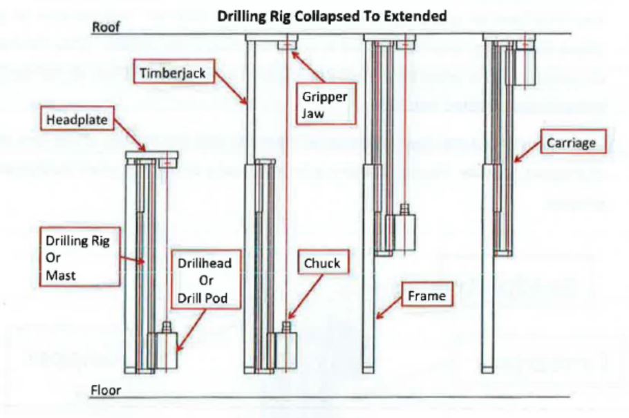
The above diagram is also relevant for the explanation of extension drilling, set out below.
22 The mast is shown in its collapsed state on the left hand side with the drillhead, or drill pod, at its lowermost position. In the next stage, the timberjack is raised so that the headplate makes contact with the roof. The headplate steadies the drilling rig and provides a guide for the drill rod once it has been placed in the chuck. Attached to the headplate are ‘gripper jaws’, the purpose of which will become clear below, but which do not perform a function in single-pass drilling. It is sufficient here to note that the drill rod will pass through these jaws. At this stage, the drill rod has been placed in the chuck, its alignment being indicated by the thin red line running between the chuck at the lower end and the gripper jaws at the upper end. In the third stage, drilling has commenced. The ‘drill chuck apparatus’ has moved about halfway up the mast. The cutting end of the drill is doing its work in the strata above. When the drill chuck apparatus reaches the underside of the headplate, the drilling process is complete (the diagram on the right-hand side), and the process is reversed. The apparatus is lowered, and the drill rod withdrawn from the roof of the mine. An operation such as that outlined here is referred to as single-pass drilling.
23 The drill rods used in single-pass drilling are metal, typically of either hexagonal or round cross-section. They do not include an integral cutting/drilling tip; rather, they are threaded at one end to accommodate the attachment of a cutting tip. The other end of the drill rod forms the drive shaft of the rod. The drive shaft of single-pass drill rods is configured to fit into, and be driven by, the drive chuck of the drill machine. The standard drive chuck used in hydraulically powered roof bolters is the ‘square locking chuck’. This chuck, and complementary square drive drill rods, were developed in Australia in the mid-1980s, and have been the standard in conjunction with hydraulic roof bolters in the coal mining industry since the early 1990s.
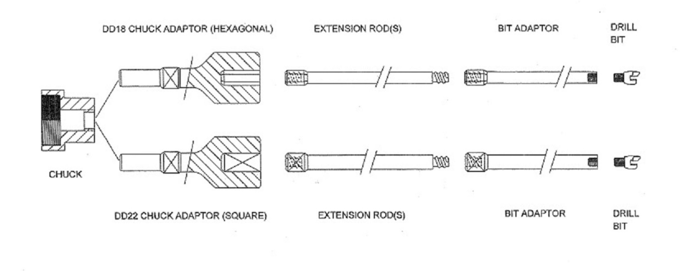
24 An example of a standard 25 mm square locking chuck is shown below, from above (left-hand photograph) and from below (right-hand photograph).
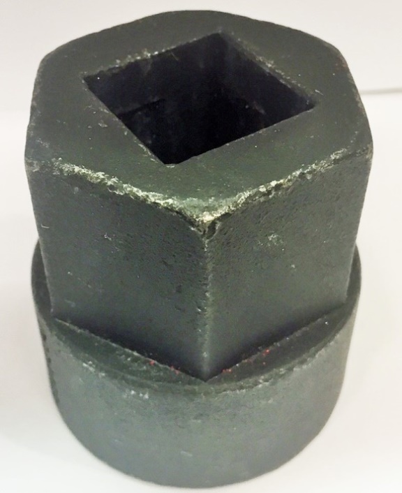
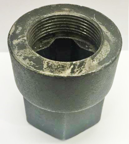
25 The chuck has an upper, a middle and a lower part. The upper part consists of a square opening (as shown on the left-hand photograph above) slightly larger than the cross section of the square section of the drill rod. The lower part consists of an internally-threaded cylindrical section (as shown on the right-hand photograph above) which screws onto the matingly-threaded upper end of the driven shaft of the drill motor. The middle part (not fully visible in the photographs above) consists of the drive chamber of the chuck.
26 An example of the driven end of a single-pass drill rod of the kind used in connection with the chuck described above is shown below.
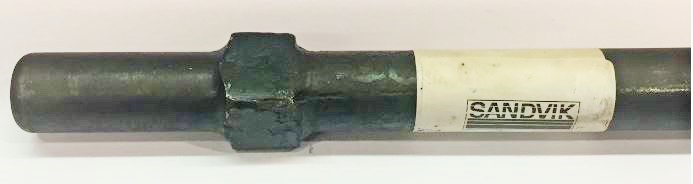
In the above photograph, the spigot (discussed below) appears on the left.
27 With the chuck installed on the drill and ready for use, the drill rod is inserted into the chuck by passing first the round section and then the flat-sided, or square-shaped, section through the hole in the upper part of the chuck, to the point where the square section lies wholly within the middle part, or drive chamber, of the chuck. The drive chamber has a series of 12 angled faces in a cross-like configuration and is slightly larger than the square section of the rod, such that the rod may rotate relative to the chamber by about 20 degrees. Once rotated relative to the chuck, the square section of the rod is no longer aligned with the opening of the chuck and is prevented from pulling out of the chuck by the lip of the chuck opening. The configuration of the chuck and the drive shaft is such that, when the chuck is operating, the drill rod is locked in place and cannot come out of the chuck. This is a safety measure as it ensures that, when the drill chuck apparatus is lowered after the completion of drilling, the rod is not left dangling in the roof hole with the risk that it might fall onto operators below; the rod remains secured in the chuck until removed manually.
28 The round section at the lowermost end of the rod (ie, below the square section) is referred to as the ‘spigot’. It has at least three relevant functions. First, it sits on the base of the chuck and takes the weight of the rod. Secondly, it fits into a corresponding piece in the chuck from which flushing fluid is passed into it and up the drill rod, an important subject which we refer to in more detail below. Thirdly, it fits inside, and thus forms a seal with, an O-ring in that corresponding piece to prevent leakage of the flushing fluid at this point. For that purpose, self-evidently, this spigot must be circular in profile.
Extension drilling
29 Where cable bolts are to be used, drill rods of the kind described above are not long enough to drill holes of the required depth. Because of limitations imposed by the height of the mine roadway, to use a single drill rod long enough to drill a hole of up to 12 m in depth would be out of the question. Thus the drill rod used is in fact a string made from round or hexagonal sections of drill rod attached together at their complementary male and female threaded ends. By convention, the upper end of each rod is male threaded and the lower end of each rod is female threaded. The thread employed in the technology relevant to the present proceeding is right-hand rope thread. Individual rods come in varying lengths, typically from about 0.5 m to 2 m. The first, or uppermost, rod is adapted to receive the drill bit.
30 Ignoring for the moment the means by which the driven end of the lowermost rod communicates with the chuck, at a general level it may be said that drilling for cable bolts involves: using a first drill rod with the bit attached to its uppermost end to drill into the mine strata until the length of that rod has been exhausted (in much the same way as done in single-pass drilling); then connecting a second rod between the chuck and the first drill rod and drilling again until the length of the second drill rod is used up; then connecting a third drill rod between the chuck and the second drill rod, and so on, until a hole of the length required to accommodate the cable bolt intended to be used has been made. Each time a new rod is connected to its predecessor (ie, the one that has been almost wholly driven into the roof strata), the drill chuck apparatus must be lowered down the drill mast to make room for the new rod. Because the drill string consists of a series of rods built up as drilling proceeds, this technology is referred to as ‘extension drilling’.
31 It will be immediately apparent that, since each rod must have, at its lower end, an internal female thread shaped to receive the upper male-threaded end of the next rod, the lower end of any one of these rods could not be fitted with a spigot arrangement of the kind commonly found on rods used in single-pass drilling, as depicted above in the photograph at [26]. The expedient which, sometime before the priority date (11 June 1997), had come to be used to deal with this issue was the inclusion of an ‘adaptor’ (or ‘drive adaptor’ or ‘chuck extension’) between the chuck and the lowermost drill rod. At its lower end, such an adaptor had the same cube-and-spigot arrangement as was used on single-pass drill rods. At its upper end, it was fitted with a male thread to engage with the lowermost rod. It was an important aspect of Sandvik’s case at trial that roof bolting contractors in the coal mining industry saw this expedient as more convenient than having to change the chuck on a drilling machine each time it was necessary to undertake extension, as opposed to single-pass, drilling. Indeed, the mining experts called by both parties were agreed that, as a generalisation, contractors would not contemplate changing a chuck underground during the course of a roof bolting program. An example of an adaptor, such as that described above, is the following:
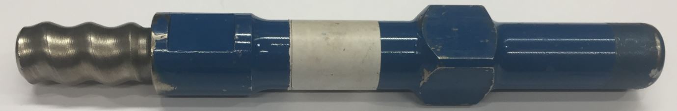
In the above photograph, the upper end of the adaptor (with male thread) appears on the left, and the lower end of the adaptor (with the cube-and-spigot arrangement) appears on the right.
32 Using the equipment referred to above, the process for extension drilling involves the following steps:
(a) insert a drive adaptor into the drill chuck;
(b) attach a first extension rod (with drill bit included) to the drive adaptor;
(c) raise the drill chuck, commence drilling and drill to the full length of the first extension rod;
(d) cease drilling and clamp the gripper jaws onto the lower end of the first extension rod just above the coupling of that rod and the adaptor;
(e) reverse the rotation of the chuck to uncouple the first extension rod from the adaptor;
(f) lower the drill chuck;
(g) attach the top of a second extension rod to the lower end of the first extension rod to create a drill string of (at this point two) extension rods;
(h) couple the adaptor to the bottom of the second extension rod;
(i) recommence drilling and drill to the full length of the second extension rod; and
(j) repeat steps (d) to (i), adding additional extension rods to the drill string until the desired length of hole has been drilled.
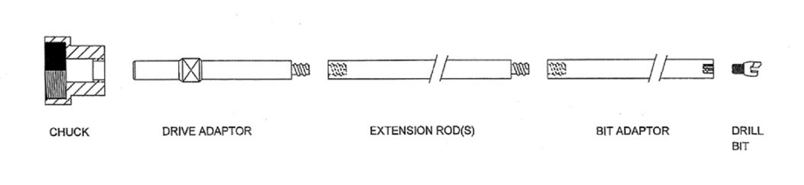
33 The following diagram, drawn from the evidence and provided to the Court at the hearing of the appeal, illustrates a conventional extension drilling system:
34 With respect to steps (d) and (e) in [32] above, the use to which the gripper jaws are put should now be evident. To uncouple the first (and subsequently each lowermost) extension rod from the drive adaptor requires an unscrewing action in which the rod must be held firmly in place while the machine causes the chuck, and therefore the adaptor, to rotate in the reverse direction. This point is illustrated by the following diagram, drawn from the evidence and provided to the Court at the appeal hearing:
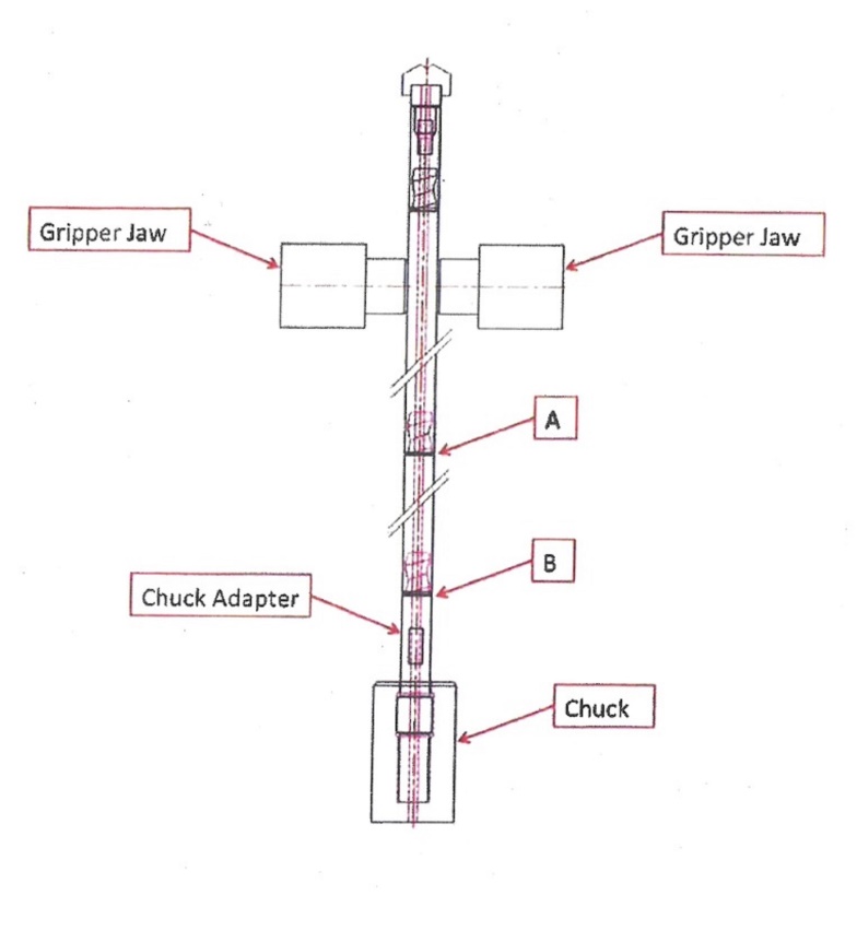
As is apparent from this diagram, there are two threaded connections, marked ‘A’ and ‘B’, between the gripper jaws and the chuck. We return to this matter in the next paragraph.
35 Once the drill hole has reached the required depth, it is necessary to remove the drill string, which now consists of a number of extension rods connected together. Essentially, this process requires the sequential removal of each rod from the string. This must be done in stages. First, the chuck is lowered, bringing the drill string with it. To remove the lowest extension rod from the string requires that rod to be disconnected from the rod immediately above it. The string is lowered to a point where the connection between the lowest rod and the rod above it is immediately below the gripper jaws, such that, when those jaws are engaged, they grip the lower end of the upper rod. The drill is then operated in reverse, imparting an unscrewing action upon the drill string. Because the upper rod is held firm by the gripper jaws, it will not move. The following aspect of the removal process is important for the purposes of understanding the alleged invention. Between the gripper jaws and the chuck, there are now two points of threaded connection in the string, one between the adaptor and the lower rod (marked “B” in the above diagram) and the second between the lower rod and the rod above it (marked “A” in the above diagram). When the direction of the rotation of the chuck is reversed, one of those connections will come unscrewed. It may be either of them. The other connection must then be unscrewed manually, using a spanner.
36 Once the lowermost drill rod has been removed in the way described, the drill chuck apparatus is raised again along the mast to make connection with, and to screw into, the female end of the next rod which, it will be recalled, is just below the gripper jaws. The jaws are then released, the drill chuck apparatus, now with the remaining drill string attached, is lowered until the lower end of the next rod in line appears below the gripper jaws, the jaws are engaged at that point, and the process described above commences again. This pattern is repeated until all the sections of the drill string have been removed.
Other aspects of single-pass and extension drilling
37 One further common feature of extension (and single-pass) drilling which should be mentioned at this stage is the means by which cuttings from the action of the drill bit are cleared away. Here it must be understood that the bit is operating in a confined space and, absent some mechanism to prevent it, would soon become clogged with debris from its own action and would jam. Although there are some other methods employed, the most common method for addressing this problem in Australia is flushing with water continuously pumped through an axial passage in the drill rod or rods. This is the flushing fluid referred to in [28] above. On account of this feature, the drill rods which we have been discussing above, and the adaptors used in conjunction with them, are not solid but have a pipe-like configuration, allowing for the passage of flushing water. In order to inhibit the outflow of water contained inside the existing rods on the drill string at the point when the lowest connection is broken (to facilitate the insertion of the next rod), some or all of the rods are internally equipped with a non-return ball-valve arrangement.
38 While on the subject of flushing water, a practical issue of some importance should be mentioned. This water must be supplied to the drill string at a sufficient pressure to cause it to rise vertically, in a narrow tube, over a distance of anything up to about 12 m, and then to carry out the necessary flushing. In a system which involves so many joins, the potential for leakage, and loss of pressure, is apparent. There appears to be little practical difficulty with leakage at each male/female threaded connection between the various rods; the connection itself is sufficiently watertight to suit the purposes required. But there is a need for an effective seal at the point where a single-pass rod or an adaptor sits in the chuck. The spigot-and-O-ring arrangement referred to in [28] above was the means by which this problem had been addressed, both in the case of single-pass drilling, where the spigot was on the end of the drill rod itself, and in the case of extension drilling, where the spigot was part of the adaptor.
39 The primary judge stated, at [30] of the Reasons, that the matters set out in the paragraphs above represented the state of the art, and the common general knowledge, in the industry as at the priority date for the Patent, being 11 June 1997.
The Patent
40 The following description of the Patent is drawn substantially from the Reasons.
41 According to the specification:
This invention relates to an extension drilling system, and more particularly, but not exclusively, to extension drilling systems for use on a semi-automatic drilling rig and used to drill holes (bores) in subterranium [sic] mining operations such as coal mining where the structure of the roof of a tunnel is to be rendered more secure by the insertion of rock bolts into holes drilled into the roof structure.
42 The specification refers to two problems in the existing art, in the following terms:
The primary problem with conventional drill rods for extension drilling systems, when used with semi-automatic drill rigs is that, when the drill string (a series of drill rods coupled together) are to be uncoupled there are two threaded couplings between the grippers and the chuck. As the grippers are operated, and the chuck spun slowly in reverse, the threaded joint between the drive adaptor and the bottom extension rod can become uncoupled which is undesirable as distinct from the desired uncoupling between the bottom and second bottom extension rods.
A secondary problem is that the use of a drive adaptor takes up valuable boom height on the rig thus reducing the length of the extension rods that can be used.
(Emphasis added.)
43 The invention is then disclosed in the following terms:
According to the present invention there is provided an extension drilling system for use with a semi-automatic drilling rig, said drilling system including a plurality of extension rods connected together to constitute a drill rod string and each extension rod having co-operating a male and female right-hand rope threaded couplings at one end and a female right-hand rope threaded coupling at the other end, whereby the extension rods are connected together by coupling of the male coupling of one extension rod with the female coupling of another extension rod to create a male/female coupling between connected extension rods therebetween, a drive chuck of a drilling rig for driving the outside surface of a female threaded end coupling of an extension rod at one end of the drill rod string, selectively in either forward or and reverse directions, a set of grippers for preventing rotation of clamping an extension rod being arranged to clamp an extension rod at a location so such that only one male/female threaded coupling is provided located between the drive chuck and the set of grippers and so that with the grippers clamping the extension rod, and with the drive chuck being driven in the reverse direction, only the male/female coupling between the grippers and the drive chuck is uncoupled.
According to the present invention there is further provided an extension drilling system for use with a semi-automatic drilling rig, said drilling system including a plurality of extension rods connectable together to constitute a drill rod string and each extension rod having a male right-hand rope threaded coupling at a male end and a female right-hand rope threaded coupling at a female end, whereby the extension rods are connectable together by coupling of the male end coupling of one extension rod with the female end coupling of another extension rod to create a male/female coupling between connected extension rods and wherein the external surface shape of the female end has a profile for engagement by a drive chuck of a drilling rig to drive the female end of an extension rod at one end of the drill rod string, and wherein the external surface shape of the extension rods between the female end and the male end is of a different and substantially uniform profile.
(Emphasis added.)
44 To a large extent, these passages in the specification amount to a recital of the prior art, as outlined above. Central to Sandvik’s case below and on appeal was the proposition that the invention departs from the prior art to the extent that it requires: the drive chuck (either directly or indirectly, using an adaptor) to drive “the outside surface of a female threaded end coupling of an extension rod”; and “the external surface shape of the female end [to have] a profile for engagement by a drive chuck”. So far as may be discerned from these passages, the essence of the invention lies in the mechanical engagement by the chuck of the lower end of the lowermost drill rod in the string. The “primary problem” identified in the specification is overcome because, at the stage of the removal of a rod from the string, there is now only one threaded connection between the gripper jaws and the chuck, namely, the connection between the rod being removed and the next rod above it which is held firm by the gripper jaws. The following diagram, drawn from the evidence and provided to the Court at the appeal hearing, illustrates the direct drive extension drilling system:
45 As noted in [42] above, a “secondary problem” referred to in the specification is that the use of a drive adaptor takes up valuable boom height on the drilling rig, thus reducing the length of the extension rods that can be used. While the invention described in the specification is capable of overcoming this, we note that in one of two preferred embodiments of the invention (discussed below), the use of an adaptor is prescribed by the specification.
46 The specification continues:
Preferably the extension rods have axial passages therethrough in communication with each other and through which flushing fluid is delivered to an associated drill bit. Preferably a non-return valve is incorporated in at least one of the extension rods to shorten the delay time in delivering flushing fluid to the drill bit before re-commencement of drilling after an extension rod is added to the extension rod string.
Preferably the extension rods are of hexagonal, cross-section or any other suitable cross-section and may be forged or welded rods which are selectively or fully heat treated.
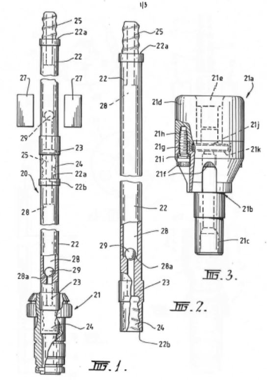
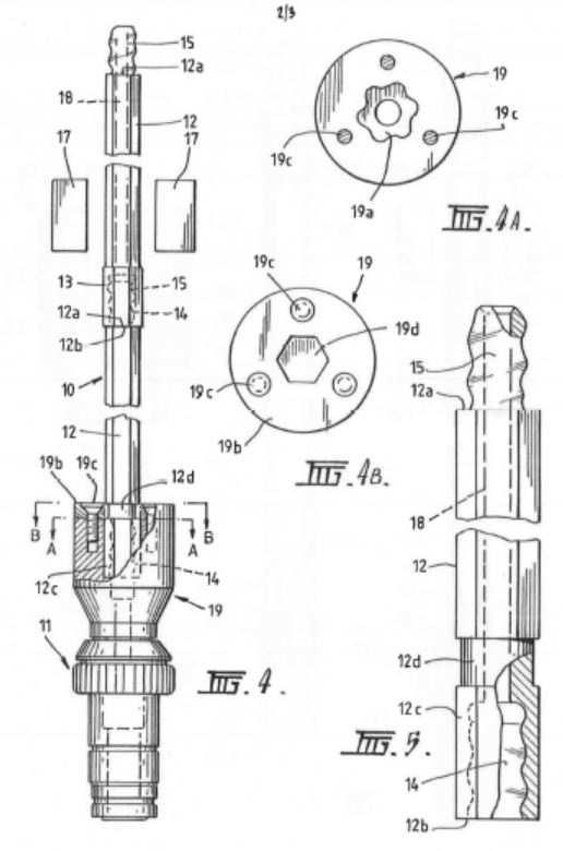
47 Under the heading “Brief Description of the Drawings”, the specification states that two preferred embodiments of the invention will now be described. It is convenient to set out, at this point, Figures 1 to 5 from the specification:
48 It is apparent from the description of the diagrams that the two preferred embodiments are represented, respectively, as follows:
(a) the first preferred embodiment is the subject of Figs 1 and 2; and
(b) the second preferred embodiment is the subject of Figs 3, 4 and 5.
49 However, as Fig 3 sets out an alternative adaptor (referred to as a “direct drive chuck”) to the one used in Figs 4 and 5, there are, in fact, three alternatives described in the diagrams, with the second preferred embodiment always involving the use of an adaptor.
50 According to the specification:
(a) Fig 1 is a longitudinal side elevational view of an extension drilling system in accordance with a first preferred embodiment of the invention;
(b) Fig 2 is a longitudinal side elevational view of an extension rod as used in the system of Fig 1;
(c) Fig 3 is a longitudinal side elevational view, partly sectioned, of an alternative direct drive chuck for use in the extension drilling system of Figs 4-5;
(d) Fig 4 is a longitudinal side elevational view, partly sectioned, of an extension drilling system in accordance with a second preferred embodiment of the invention;
(e) Fig 4A is a cross-sectional view taken along the line A-A of Fig 4;
(f) Fig 4B is a cross-sectional view taken along the line B-B of Fig 4; and
(g) Fig 5 is a longitudinal side elevational view of an extension drill rod as used in the system of Fig 4.
51 Thus the extension drilling systems as a whole are depicted in Figs 1 and 4 respectively. The rods to be used in those systems are depicted in Figs 2 and 5 respectively.
52 Greater detail of the adaptor in use in Fig 4 is given in Figs 4A and 4B, the effect of which is to illustrate a locking mechanism similar to that described above.
53 The next section of the specification is headed “Best Modes for Carrying out the Invention”. With reference to Figs 1 and 2, the specification states that the chuck used in that extension drilling system may be “a TL2 drive chuck as manufactured by McSweeney’s, Inc of the USA”. That chuck, which will be referred to as the “McSweeney TL2 chuck”, is the same as the 25 mm square locking chuck (depicted above at [24]), save that the dimensions of the square opening are 28 mm rather than 25 mm. The specification continues that the chuck, which may be the McSweeney TL2 chuck, “directly rotatably drives” a string of extension rods. The means of connection between various rods is then described, but is uncontroversial. An axial passage is provided through the respective extension rods, it being stepped to provide a transition between larger and smaller diameter portions of the passage in order to provide valve seats for the ball-valve mechanisms (as discussed above at [37]).
54 The specification continues:
As illustrated in Figure 2, the external or outside surface of the female socket 24 is engaged by the drive chuck 21 for driving the string of extension rods 22. The surface of the female socket 24 that the drive chuck 21 engages therefore has a profile suitable for that engagement. Figure 2 shows that the surface which is engaged by the drive chuck 21 includes a portion of greater diameter at the position to which the lead line for the reference numeral 23 extends. Extending from the engagement position of the drive chuck 21 to the male member 25, the surface of the extension rod 22 is of a substantially uniform profile and of reduced diameter compared to the diameter at the engagement position of the drive chuck 21. Thus there is a difference in surface profile between the engagement position of the drive chuck 21 at the female socket 24 and the section of the extension rod between the female socket 24 and the male member 25.
(Emphasis added.)
55 It should be noted that all but the first two sentences in this passage were added by amendment on 30 August 2006. It should also be noted that, if the McSweeney TL2 chuck were to be used in the first preferred embodiment of the invention (described above by reference to Figs 1 and 2), since it is a requirement that “the external surface shape of the female end has a profile for engagement by a drive chuck” (see [43] above), then at “the position to which the lead line for the reference numeral 23 extends” (see [54] above), the rod would have to be of a square profile. In essence, without the use of an adaptor (which is not a feature of the first preferred embodiment), a square drive drill rod is needed to fit a square locking chuck.
56 What the specification says about Fig 3 is as follows:
Figure 3 of the drawings shows a modified (alternative) direct drive chuck for use in the extension drilling systems of Figures 4 to 5, and is in fact the drive chuck preferred, and which is a modular assembly 21a comprising a male drive member 21b having a drive shaft 21c and coupled to a female drive member 21d with a socket 21e. The drive members are coupled by bolts 21f through holes 21g in the male drive member 21b and into threaded blind holes 21h in the female drive member 21d with interposed spring washers 21i. The male and female members may also be “dogged” together, that is interlocked. The socket 21e receives a sealing member 21j which may be formed from polyurethane, moulded around a stainless steel washer body, and which seats on a step 21k in the end of the male drive member 21b. The modular drive chuck of this embodiment, in being formed in two separable parts, allows the drive members 21b and 21d to be interchangeable for different drive configurations, and also allows for the sealing member 21j to be replaced when worn.
(Emphasis added.)
57 With respect to Fig 4, it is made clear that the chuck itself, which again may be the McSweeney TL2 chuck, is the lowermost portion on the diagram, marked 11. The adaptor (which has been inserted into the chuck) is the portion marked 19. After referring to the rods and the connections between them, the specification continues:
With reference to Figures 4 and 5 of the drawings, the internal detail of the chuck adaptor 19 is according to that shown in Figure 4A of the drawings and is shaped as a hexagon 19a offset by 20° of rotation. A chuck adaptor cover 19b as shown in Figure 4B is bolted to the remainder of the chuck adaptor by bolts 19c. The cover provides a hole 19d for the extension rod to fit into and which has a normal hexagonal shape. The end of the extension rod which fits into the chuck adaptor 19, and incorporating the female socket 14 which is not drivingly engaged by the chuck adaptor, has an [sic] hexagonal exterior 12c and above that a round section 12d. When the extension rod end is fitted into the chuck adaptor, the hexagon 12c on the end of the rod is aligned with the hexagonal hole 19d through the chuck adaptor cover 19b. The rod is then slid down into the chuck adaptor to its full extent, and as positive rotation is commenced the chuck adaptor rotates 20° in relation to the rod and the drive flats of the hexagonal 19a in the chuck adaptor engage against the hexagonal shaped end 12c on the rod to thus rotatably drive the rod. The round section 12d on the rod is provided so that, as the rod is rotated through 20°, the hexagon through the chuck adaptor cover 19b does not bind on the rod. As long as positive rotation is maintained in the chuck adaptor the rod cannot be removed as the two hexagons are misaligned by 20° and the rod needs to be rotated through 20° so that the corners of the hexagon 12c will clear the hexagonal hole 19d through the chuck adaptor cover 19b in order for the rod to be removed. The drive chuck as described above in providing a twist locking action between the chuck and the rod improves the safety of the drilling system because of the locking of the rod in the drive chuck whilst maintaining positive rotation.
(Emphasis added.)
58 The burden of this passage is to explain the means by which a rod with a female threaded lower end may form a locking engagement with the adaptor into which it is placed, but to which it is not threaded. The principle is similar to that employed in the square locking chuck (as described above at [27]), but here the engagement is between the rod and the adaptor, rather than being directly between the rod and the chuck. It is apparent, and is expressly required in this second preferred embodiment, that the lowermost section of the rod be of hexagonal profile (so that it can fit into the aperture of the adaptor) while, immediately above that, there must be a section which is round in profile to accommodate turning the rod through 20 degrees to bring about the intended locking effect.
59 Whether the remainder of the rod (above the rounded section referred to in the paragraph above) is also round, is the concern of the following paragraph in the specification:
In the case of both embodiments of the invention, the extension rods are of hexagonal cross-section, as previously described with reference to the embodiment of Figure 4 to 5, or of round cross-section or of any other suitable cross-sectional shape whereby they can be driven by the chuck adaptor 19 in the case of the embodiment of Figures 4 to 5 or directly by the drive chuck 21 or 21a in the embodiment of Figures 1, 2 and 3. The extension rods may be forged or welded rods which are selectively or fully heat treated.
60 The specification includes the following claims:
1. An extension drilling system for use with a semi-automatic drilling rig, said drilling system including a plurality of extension rods connected together to constitute a drill rod string and each extension rod having a male right-hand rope threaded coupling at one end and a female right-hand rope threaded coupling at the other end, whereby the extension rods are connected together by coupling of the male coupling of one extension rod with the female coupling of another extension rod to create a male/female coupling between extension rods, a drive chuck of a drilling rig for driving the outside surface of a female coupling of an extension rod at one end of the drill rod string, in either forward or reverse direction, a set of grippers for preventing rotation of an extension rod being arranged to clamp an extension rod at a location such that only one male/female coupling is located between the drive chuck and the set of grippers and so that with the grippers clamping the extension rod, and with the drive chuck being driven in the reverse direction, the male/female coupling between the grippers and the drive chuck is uncoupled.
2. An extension drilling system as claimed in claim 1 wherein the extension rods have axial passages therethrough in communication with each other and through which flushing fluid is delivered to an associated drill bit.
3. An extension drilling system as claimed in claim 2, wherein the axial passage through at least one of the drill rods incorporates a non-return valve to shorten the delay time in delivering flushing fluid to the drill bit before recommencement of drilling after a drill rod is added to the drill rod string.
4. An extension drilling system as claimed in any one of the preceding claims, wherein the extension rods are of hexagonal or round cross-section or of any other suitable cross-section whereby they can be driven by the drive chuck either directly or via an adaptor having a socket therein of similar cross-section to the extension rods.
5. An extension drilling system as claimed in claim 4, wherein the co-operation between the drive chuck or the adaptor and the extension rod directly associated therewith is such that limited relative rotational movement therebetween misaligns the respective cross-sections to prevent separation of the extension rod whilst maintaining driving engagement.
6. An extension drilling system substantially as hereinbefore described with reference to figures 1 and 2, or figures 3, and 4 as modified by figure 5, of the accompanying drawings.
7. An extension drilling system for use with a semi-automatic drilling rig, said drilling system including a plurality of extension rods connectable together to constitute a drill rod string and each extension rod having a male right-hand rope threaded coupling at a male end and a female right-hand rope threaded coupling at a female end, whereby the extension rods are connectable together by coupling of the male end coupling of one extension rod with the female end coupling of another extension rod to create a male/female coupling between connected extension rods and wherein the external surface of the female end has a profile for engagement by a drive chuck of a drilling rig to drive the female end of an extension rod at one end of the drill rod string, and wherein the external surface of the extension rods between the female end and the male end is of a different and substantially uniform profile.
61 Claim 6 is an ‘omnibus’ claim, which refers to the preferred embodiments described in Figures 1-5, discussed above.
The decision of the primary judge
62 The primary judge considered the issues under the following headings:
(a) novelty;
(b) inventive step;
(c) best method known to Sandvik;
(d) utility;
(e) infringement;
(f) joint liability with primary infringers; and
(g) misleading or deceptive conduct.
63 For present purposes, it is sufficient to refer only to the first four of these sections of the Reasons.
Novelty
64 The primary judge considered the issue of novelty at [47]-[161] of the Reasons. Quarry Mining contended below that the invention the subject of the Patent, so far as claimed in claims 1, 2, 4, 6 and 7, was not novel in June 1997. The question which arose under s 7(1) of the Patents Act 1990 (Cth) as applicable at the relevant time (Patents Act) was whether the invention was not novel in the light of two kinds of prior art information relied on by Quarry Mining, being:
(a) the public use of an extension drilling system by Colrok Mining Pty Ltd (Colrok) at collieries in New South Wales, including Ellalong and Macquarie, between 1989 and 1994; and
(b) the public use of an extension drilling system at the West Wallsend, Gretley and Wyee Mines by an entity described in the evidence (and in Quarry Mining’s Particulars of Invalidity) only as “Wilson Mining”.
65 In relation to the first kind of prior art, the primary judge considered the evidence in detail including, in particular, the evidence of Darrell Geatches, Quarry Mining’s principal witness called to provide evidence of the extension drilling system used by Colrok. Mr Geatches referred in his evidence to Roy Gambly (now deceased) (see [58] of the Reasons). Mr Geatches gave evidence that Mr Gambly made the ends for certain new drill rods, being an end with a male right-hand rope thread, and an end having a hexagonal outer profile (32 mm across the flats) with an internal female right-hand rope thread. The primary judge summarised the effect of Mr Geatches’ evidence at [59] as follows:
In operation, the female end of a drill rod was inserted (and here I quote from Mr Geatches’ affidavit) “directly into the drive chuck (which was in effect an adaptor) on the drill rig, which had a hexagonal shaped socket.” The chuck drove the rod by engaging with the hexagonal external surface of the female end of the drill rod. The new drill rods proved very successful. Being easy to extend and to uncouple, their use led to an increase in the speed at which rods could be inserted into and removed from a drill string. In part, this was because there was no longer the need to uncouple (ie by unscrewing) the lowermost rod from a male shank adapter when building or dissembling the drill string. These were the rods that Mr Geatches and his colleagues described as “speed rods”. In Mr Geatches’ recollection, it was in the mid to late 1980s that Colrok reached this point.
66 The primary judge stated (at [61]) that Colrok used these rods in the late 1980s at Ellalong Colliery to drill the holes required to install cable bolts for the establishment of secondary roof support in restitution work after a roof collapse on a conveyor road. The primary judge then quoted Mr Geatches’ description of the process in which the rods were used (at [61]). That description included the following steps (in which the rods were referred to as “Geatches Rods”):
Step 9 Once the last (bottom) Geatches Rod had been connected to the drill string and drilled into the strata to a point near to its female end, the drive motor and drive chuck were dropped back down the drill mast to a position above ground level. This lowered the drill string such that the last (bottom) and second last (i.e., second from the bottom) Geatches Rods were removed from the bore hole.
Step 10 The pair of clamps was engaged to grip the second last (i.e., second from the bottom) Geatches Rod at its hexagonally shaped female end.
Step 11 The drive motor was driven in reverse (left hand rotation). This broke the threaded connection between the male threaded end of the bottom Geatches Rod, and the female threaded end of the second bottom Geatches Rod. The drill motor and drive chuck were then lowered further down the drill mast and the motor disengaged from the hex drive end.
67 The primary judge referred, at [64], to Sandvik’s contention that Mr Geatches’ evidence, to the extent that it related to the development and use of the rods described above, should not be accepted at all. His Honour stated that Sandvik had pointed out, correctly, that this evidence was not supported by the production of: any of the chucks or drill rods used; any contemporaneous drawings or sketches of the rods; the specifications provided to Mr Gambly; any photographs of the components that Mr Gambly supplied to Colrok; any drawings, sketches or photographs of the rods that Colrok assembled from those components; or any drawings, sketches or photographs of the components actually used at Ellalong. The primary judge considered Sandvik’s submissions about what it described as the five “errors” in Mr Geatches’ evidence but did not accept that Mr Geatches’ evidence should be regarded as likely to be the less reliable on account of those matters (at [75]). The primary judge considered other evidence relied on by Quarry Mining. One factual issue concerned whether, in the system of extension drilling used by Colrok at Ellalong Colliery, the connections between the drilling rods were right-hand rope-threaded connections. The primary judge concluded that they were (at [124]).
68 Ultimately, the primary judge accepted Mr Geatches’ evidence about the extension drilling system which Colrok used at Ellalong Colliery (at [125]). His Honour also concluded that the same system was used at Macquarie Colliery (at [129]). Accordingly, so far as claimed in claims 1, 2, 4 and 7, the invention was anticipated by the system used by Colrok at the Ellalong and Macquarie Collieries (at [131]).
69 In relation to claim 6, the primary judge concluded that the Colrok drilling system did not anticipate the second embodiment of the invention (which included two alternatives – with and without the alternative adaptor shown in Fig 3) described in the Figures (at [133]). This aspect of the primary judge’s conclusions does not form part of the appeal and can be put to one side. However, in relation to the first embodiment described in the Figures, the primary judge held that, on the basis of the factual findings he had made, the Colrok drilling system did anticipate this embodiment (at [134]).
70 In relation to the second kind of prior art information referred to in [64] above, the primary judge concluded (at [160]) that the system used by Wilson Mining did not anticipate the invention so far as claimed in claim 1 because it did not incorporate a chuck for driving the outside surface of the female coupling on a drill rod in the reverse direction. The primary judge applied the same approach to the other claims (at [161]). The primary judge’s conclusion in relation to the second kind of prior art does not form part of the appeal and can be put to one side.
Inventive step
71 The primary judge considered the issue of lack of inventive step at [162]-[211] of the Reasons. Quarry Mining contended below that the invention the subject of the Patent, so far as claimed in claims 1, 2, 3, 4, 6 and 7, did not involve an inventive step. By s 7(2) of the Patents Act, Quarry Mining needed to establish that the invention, so far as claimed in those claims, would have been obvious to a person skilled in the relevant art in the light of the common general knowledge as it existed in June 1997.
72 The primary judge concluded that the invention, so far as claimed in claim 1, would have been obvious to a person skilled in the relevant art in the light of the common general knowledge as it existed before the priority date. The primary judge’s conclusion in this regard was set out as follows (at [200]):
Everything considered, I have come to the conclusion that the invention, so far as claimed in Claim 1, would have been obvious to a person skilled in the relevant art in the light of the common general knowledge as it existed before the priority date. Fundamental to this conclusion is the very limited respect in which Claim 1 took a step which went beyond what was already commonly and generally used in the industry, and self-evidently so from the terms of the specification itself … To take that step would, in my view, have been obvious to the skilled addressee. Faced with the problems of the presence of two threaded connections between the chuck and the grippers and of the space occupied by the adaptor, the skilled addressee would have recommended the employment of a system in which the chuck drove the outside of the lowermost rod. He or she may not have come to that solution instantly, but, examining the range of possibilities and employing no more than his or her normal uninventive skills and experience, he or she would, in my view, have readily suggested doing exactly what Claim 1 requires, namely, making use of “a drive chuck … for driving the outside surface of a female coupling of an extension rod at one end of the drill rod string”.
73 The primary judge came to the same conclusion in respect of claims 2, 3 and 4 (at [203]-[205]). With respect to claim 6, the primary judge came to the same conclusion in relation to the first preferred embodiment (ie, Figs 1 and 2) (at [206]), but was not persuaded that the second preferred embodiment (ie, Figs 3, 4 and 5) was obvious (at [206]). The primary judge considered that the invention, so far as claimed in claim 7, was obvious for the same reasons as claim 1 (at [211]).
Best method known to Sandvik
74 The primary judge considered the best method issue at [212]-[232] of the Reasons. By s 40(2)(a) of the Patents Act, a complete specification was required to “describe the invention fully, including the best method known to the applicant of performing the invention”. Quarry Mining contended below that, when Sandvik filed the complete specification for the invention the subject of the Patent on 29 May 1998, it did not disclose what was then known to it as the best method of performing the invention.
75 One aspect of this issue was whether Fig 3 disclosed only a sealing member with a flat washer-type seal, such as might be made from coating a stainless steel washer with polyurethane (as contended by Quarry Mining), or a sealing member that included both a flat part and an upwardly-extending cylindrical part as shown in red in the enlarged diagram below (as contended by Sandvik):
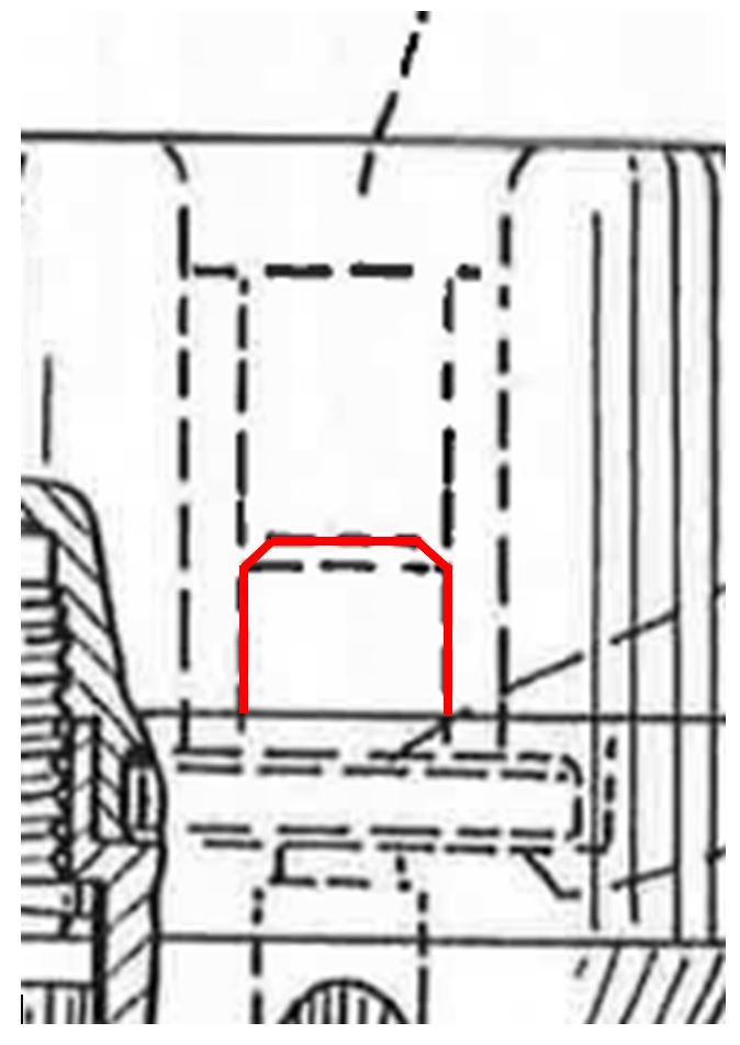
76 The primary judge concluded, at [219], that the specification did not disclose a sealing member which included an upwardly-extended spigot integral with the flat part of the member as follows:
Did the specification describe a method of performing water sealing in the adaptor shown in Fig 3 by means of a sealing member which included an upwardly-extending spigot integral with the flat part of the member? The starting point, of course, is the text of the specification. The sealing member described there is confined to the stainless steel washer body coated in polyurethane. The sealing member is numbered 21j and, while there is some ambiguity about the matter, most obviously this is a reference to the horizontal element. That was Dr Fuller’s understanding. Mr Charlton was able to discern what the inventors were about in this aspect of Fig 3, but his understanding of the subject depended to an important extent on what he regarded as implicit: in a metaphorical as well as a literal sense, he was required to join the dots. In my view, for the inventors to have communicated in this way to the skilled addressee did not amount to a description within the meaning of s 40(2)(a) of the Act: no more so in the case of the best method than it would have been in the case of the invention itself.
77 The primary judge found that the inventors had developed a form of sealing member that incorporated upper, middle and lower sections, depicted as follows (at [222]):
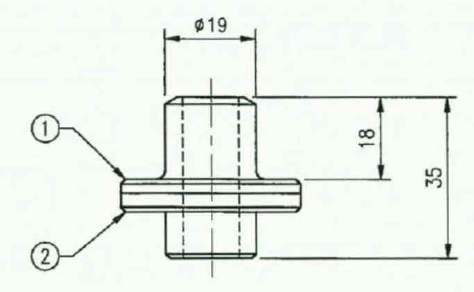
78 The primary judge stated (at [224]): “We are not here dealing with some minor or incidental dimension of what was perceived by the inventors as the best method of performing the invention: as Mr Weaver said, this sealing aspect was ‘a real issue which needed to be overcome’.”
79 The primary judge next considered an argument put by Sandvik that the detailed characteristics of the sealing member did not relate to a method of performing the invention at all. In support of this argument, Sandvik relied on the judgment of the Full Court in Firebelt Pty Ltd v Brambles Australia Ltd (2000) 51 IPR 531 (Firebelt) at [51]-[55].
80 The primary judge considered that, while the best way of carrying out the invention need not be claimed (but must be described), in the present case Sandvik had in fact claimed what was, ostensibly at least, the best way of carrying out the invention, namely the extension drilling system using the device set out in Fig 3 (stated to be the “drive chuck preferred”) (at [227]). In the primary judge’s view, the difficulty faced by Sandvik was that the description in Fig 3 was not the best method known to it. His Honour stated (at [228]): “When the complete specification was filed in May 1998, [Sandvik] had developed, to the detailed technical drawing stage, a sealing member that was better than any described in the specification.”
81 Accordingly, the primary judge accepted Quarry Mining’s case that the complete specification for the Patent did not describe the best method known to Sandvik of performing the invention, as required by s 40(2)(a) of the Patents Act (at [229]). As Quarry Mining’s best method contention was confined to claims 1, 2, 3, 4, 6 and 7 (ie, it did not extend to claim 5), the primary judge considered that the Patent should not be revoked so far as it relates to claim 5. Otherwise, his Honour found that this aspect of the cross-claim had been made good (at [232]).
Utility
82 The primary judge considered the issue of lack of utility at [233]-[243] of the Reasons. Quarry Mining challenged claims 1-4 on this basis, and put forward two contentions in this regard.
83 Quarry Mining’s first contention related to the absence of a water seal in claims 1-4. The primary judge accepted Sandvik’s proposition that, although not referred to in the claims, the use of a simple seal was within the range of uninventive steps that the skilled addressee might be expected to take if his or her concern was, as presumptively it had to be, to make the invention work (at [235]). Assuming the use of a simple seal, the primary judge held the invention, so far as claimed in claims 1-4, to be useful (at [237]).
84 The second aspect of Quarry Mining’s utility case was as follows. It was said that claims 1-3 permit, and that claim 4 in one of its alternatives requires, the drill rods to be of round cross-section. It was common ground, however, that if the female-threaded end of the lowermost rod was of round cross-section, it could not be driven (save, possibly, by a through-the-spindle chuck, the relevance of which to the present point was eschewed below by Sandvik). Insofar as this issue related to claim 4, it turned on a question of construction. Sandvik contended that, as a matter of construction, claim 4 should not be understood as proposing that the driven end of a rod might be round; the skilled addressee, it was said, would know that that was nonsense. Grammatically, the primary judge stated, Sandvik’s contention had to be rejected. His Honour stated: “That the passage ‘whereby they can be driven by the drive chuck’ conveys the idea that, by reason of being of round cross-section, the rods can be driven by the chuck is, in my view, beyond argument” (at [239]). After referring to disagreement between the experts, his Honour stated that he had reached the view that Sandvik’s contention did not involve construction at all; rather, it involved the invocation of the closest available alternative reading of the words of the claim that would save it from inutility. His Honour held that there was no support in the terms of the claim for such a construction (at [241]). It followed that the invention, so far as claimed in claim 4, would not be useful (at [242]).
85 However, the primary judge did not reach the same conclusion in relation to claims 1-3 (at [243]). To the skilled addressee, the primary judge said, the unadorned expression “for driving the outside surface of a female coupling of an extension rod” in claim 1 would imply a flat-sided profile at the driven end. Claims 1-3 did not, in the primary judge’s view, suffer from the same weakness as claim 4.
The appeal
86 The grounds set out in the amended notice of appeal (apart from ground 8, which was abandoned, and the ground relating to costs) are as follows:
Novelty
1. The primary judge erred in finding that claims 1, 2, 4, 6 and 7 of Australian Patent No 744870 (the Patent) lacked novelty by reason of the public use before the priority date of the Colrok system at Ellalong Colliery and Macquarie Colliery.
2. The primary judge’s finding that the Colrok system used at Ellalong Colliery and Macquarie Colliery (the Colrok Use) anticipated all the features of the first embodiment in claim 6 (Figs 1 and 2) was contrary to the evidence and against the weight of the evidence.
3. The primary judge should have found that the Colrok Use did not disclose the use of the ball valve mechanism 29 as described and depicted in the first embodiment of claim 6.
4. The primary judge’s finding that the Colrok Use included male/female right-hand rope threaded drill rods as claimed in claims 1, 2, 4, 6 and 7 of the Patent was contrary to the evidence and against the weight of the evidence.
5. The primary judge erred in failing to find and should have found on the evidence before him that the Colrok Use did not include male/female right-hand rope threaded drill rods as claimed in claims 1, 2, 4, 6 and 7 of the Patent.
Inventive step
6. The primary judge erred in finding at [200] - [206] and [211] that claims 1, 2, 3, 4, the first embodiment of claim 6 and claim 7 of the Patent were obvious and lacked an inventive step in light of the common general knowledge.
7. The primary judge erred in finding at [200] that the person skilled in the art at the priority date would have recommended an extension drilling system in which the drive chuck drove the outside surface of the female end of the lowermost drill rod in a drill string.
…
9. The primary judge erred in his consideration of inventive step in giving no, or no sufficient, weight to the evidence that:
(a) Dr Fuller (the Respondent’s expert witness) had expertise in the design and installation of cable bolts, but did not have expertise in the use or design of extension drilling systems. In particular:
(i) Dr Fuller had not been personally involved in designing either single pass or extension rods, either at the priority date or since;
(ii) Dr Fuller had not been personally involved in designing adaptors for use with a drill rig chuck;
(iii) Dr Fuller had not been personally involved in designing drilling rigs for the purpose of drilling using either single pass drill rods or extension drill rods;
(iv) Dr Fuller had not operated a drilling rig in the course of either single pass or extension drilling;
(v) Dr Fuller had no personal experience in the design or testing of water seals for use in single pass or extension drilling; and
(b) Dr Fuller was unaware of significant matters which formed part of common general knowledge in Australia at the priority date including:
(i) Dr Fuller was not aware of the two most common extension rod types – round rods in which the profile of the female coupling was also round and hexagonal rods which had a round female coupling;
(ii) Dr Fuller was not aware that, in the years since he prepared a report in 1994 (around 4 years before the priority date), the industry had ceased using male-male rods with female couplings and instead used male-female rods;
(iii) Dr Fuller did not know that the standard chuck used in single pass and extension drilling at the priority date was the 25mm square locking chuck (which he had not seen before trial);
(iv) Dr Fuller was unaware of the health and safety issues caused by “non-locking chucks” before the priority date;
(c) the “typical” components of the system from which Dr Fuller developed his proposed solution did not exist or were not in use in extension drilling systems;
(d) the solution proposed by Dr Fuller would require “an industry wide change” and involved the “tail wagging the dog”; and
(e) those who were actually involved in developing extension drilling and cable bolting machines at or shortly before the priority date did not perceive the problem addressed in the Patent as a problem which required to be addressed nor did they develop the solution claimed in the Patent.
(f) the commercial embodiment of the claimed invention reduced drill withdrawal times by 40% and was taken up rapidly by the industry following its introduction into the market.
10. The primary judge erred in failing to find and should have found on the evidence before him that claims 1, 2, 3, 4, the first embodiment of claim 6 and claim 7 of the Patent were not obvious in light of the common general knowledge.
Best method
11. The primary judge erred in finding at [231]-[232] that claims 1, 2, 3, 4, 6 and 7 should be revoked as the Applicant failed to describe the best method known to it of performing the invention.
12. The primary judge erred in finding at [219]-[224] that the sealing member depicted at [222] was part of the invention.
Utility
13. The primary judge erred in finding at [239]-[242] that the invention so far as claimed in claim 4 was not useful.
14. The primary judge erred in finding that claim 4 included within its scope drill rods the female ends of which were round in cross-section.
15. The primary judge erred in failing to find and should have found on the evidence before him that:
(a) the words “are of hexagonal or round cross-section or of any other suitable cross-section” in claim 4 refer to the cross-section of the body of the drill rod, not the cross-section of the female end of the rod which must be configured to be capable of being driven on the outside by the drive chuck or chuck adaptor; and
(b) the invention so far as claimed in claim 4 was useful.
87 Quarry Mining did not cross-appeal from any part of the judgment. It filed a notice of contention by which it contended that the judgment of the primary judge should be affirmed on an additional ground to those relied on by the Court. The additional ground was that the invention, so far as claimed in each of claims 1-4, is not useful as required by s 18(1)(c) of the Patents Act, because it includes embodiments which do not work. In the notice of contention, Quarry Mining advanced two propositions by way of particulars. However, it indicated at the appeal hearing that it did not press the second of these contentions. The first contention set out in the particulars was as follows. Quarry Mining contended that: the primary judge correctly held that the invention as claimed in claim 4 lacked utility because it used extension rods with a round cross-section at the female end; and having so held, his Honour ought to have further held that the invention claimed in claims 1-3 lacked utility, because those claims too encompassed within their scope extension rods with a round cross-section at the female end.
Failure to describe best method
88 It is convenient to deal first with the issue raised by grounds 11 and 12 of the amended notice of appeal. Sandvik challenges the primary judge’s conclusion that the complete specification for the Patent did not describe the best method known to Sandvik of performing the invention as required by s 40(2)(a) of the Patents Act. On this basis, the primary judge ordered that, so far as it relates to claims 1, 2, 3, 4, 6 and 7, the Patent should be revoked.
89 We note at the outset the confined scope of Sandvik’s appeal in relation to the best method issue. In particular:
(a) Sandvik does not challenge the primary judge’s conclusion that the specification does not describe a sealing member which includes an upwardly-extending spigot (Reasons, [219]); and
(b) Sandvik does not challenge the primary judge’s conclusion that, at the time when the specification was filed, Sandvik had developed a better form of sealing member, namely a sealing member with an upper section and a lower section (Reasons, [220]-[222]).
Sandvik’s submissions
90 Sandvik’s contention on appeal (which reflects one of its contentions before the primary judge) is, in substance, that the detailed characteristics of the sealing member did not relate to a method of performing the invention, and therefore were not required by s 40(2)(a) of the Patents Act to be disclosed in the specification.
91 Sandvik’s written submissions on this part of the appeal can be summarised as follows:
(a) Whether the complete specification meets the best method requirement of s 40(2)(a) requires an identification of what constitutes the invention: Firebelt at [53]. (Although in its written submissions Sandvik submitted that identification of the invention “must be determined from the claims”, in oral submissions senior counsel for Sandvik accepted that the nature of the invention is as described in the whole of the specification: see Les Laboratoires Servier v Apotex Pty Ltd (2016) 247 FCR 61 (Servier) at [124]).
(b) In Firebelt, claim 1 expressly included as a feature a lid opening device (see Firebelt at [18]). The body of the specification did not disclose the detail of Firebelt’s preferred lid opening mechanism. In Firebelt at [50], the Full Court approved the following statement in Blanco White TA, Patents for Inventions and the Protection of Industrial Designs (4th ed, Stevens & Sons, 1974) at [4-516]:
There would seem to be no obligation under this provision to include information not strictly relating to “the invention,” however necessary to anyone needing to work the invention.
(c) In Firebelt, the Full Court rejected the best method attack because (at [53]):
The invention here claimed is not a particular type of lid opening device operating at any particular time. It is only if it were such a claim that there might be a failure such as the primary judge found.
(d) The “lid opening device” in Firebelt was a feature of the claim. It appears also to have been the subject of a separate patent application: Firebelt Pty Ltd v Brambles Australia Ltd (1998) 43 IPR 83 (Firebelt (first instance)) at 90. The evidence was that the claimed invention would not work without a lid opening device: the lid opening device was “an essential part of the claimed invention”: Firebelt (first instance) at 89. The lid opening device was disclosed only in the most general terms which failed to disclose important details: Firebelt (first instance) at 89-90. As noted above, the Full Court overturned the primary judge’s finding that the best method had not been disclosed, on the basis that the invention was not concerned with any particular lid opening device operating at any particular time. Firebelt is on all fours with the present case.
(e) In this case, the invention is directed to the configuration of extension drilling rods such that they are capable of use with a drive chuck or chuck adaptor which drives the external surface of the female coupling. The water seal is no part of the invention claimed (see, eg, Reasons at [188]).
(f) Servier approved and applied Firebelt: see Servier at [124]. Servier is, however, a very different situation to the present. The invention claimed was perindopril arginine. The specification claimed it had particular advantages of long-term stability: Servier at [7]-[8]. Those stability features depended on the particular method of production which was not disclosed by the term “a classical method of salification”: Servier at [32], [42]-[44], [137], [141]. Hence, the best method known to Servier was not disclosed.
92 In oral submissions, senior counsel for Sandvik emphasised that details of the sealing member did not relate to the promised advantages of the invention. He submitted that the seal, or sealing member, was not a feature of any claim except the omnibus claim (claim 6). The correct approach, he submitted, was to look at the promise of the invention; that is, the way in which the invention as claimed solves the problem for which it was designed. In this case, it was submitted, the solution was to configure the external surface of the female end of each extension rod so that it could be driven by the drive chuck or adaptor; it was not directed to any particular form of water seal.
Applicable principles
93 Section 40(2)(a) of the Patents Act provided that the complete specification must “describe the invention fully, including the best method known to the applicant of performing the invention”.
94 In the context of s 40(2)(a), the “invention” is the embodiment which is described and around which the claims are drawn (cf the invention so far as claimed in any claim): see Kimberly-Clark Australia Pty Ltd v Arico Trading International Pty Ltd (2001) 207 CLR 1 at [21] per Gleeson CJ, McHugh, Gummow, Hayne and Callinan JJ.
95 The circumstance that something is a requirement for the best method of performing an invention does not make it necessarily a requirement for all claims: see Lockwood Security Products Pty Ltd v Doric Products Pty Ltd (2004) 217 CLR 274 at [69] per Gleeson CJ, McHugh, Gummow, Hayne and Heydon JJ.
96 The principles applicable to the best method requirement in s 40(2)(a) of the Patents Act were recently considered by the Full Court of this Court (Bennett, Besanko and Beach JJ) in Servier at [59]-[108], [112]-[115], [123]-[135]. Although those paragraphs were in part directed to issues that are not presently relevant, the judgment contains a useful survey and discussion of the principal cases relating to the best method requirement. The Full Court in Servier made the following preliminary points concerning the construction of s 40(2)(a) (at [59]):
First, it must be assumed that all of the words of the section are given meaning. Secondly, fulfilment of the requirements must take into account the invention being described and claimed. That does not lend itself to the apparently easy, but superficial, distinction advanced by Servier, whereby inventions are divided into the categories of product and process. Thirdly, perhaps because the requirement involves a question of fact, being the knowledge of the patent applicant, there are not many cases that have centred on the principles of this aspect of the test compared to those that have considered the requirement of what is commonly called sufficiency, such as Kimberly-Clark. Accordingly, fourthly, in applying principles from decided cases on s 40(2)(a) and its equivalents, it is necessary to understand the issues there discussed and whether or not the reasons extended to a consideration of a statutory provision referring to the best method known to the applicant. Fifthly, there are a number of cases in the United Kingdom where this question and the principles behind the application of the best method requirement have been discussed. Clearly, they are not binding and are based on different statutory provisions. However, much of Australian patent jurisprudence on this and other patent issues was derived from British jurisprudence.
97 At [64], the Full Court explained the proposition underlying the best method requirement in s 40(2)(a) as follows:
The proposition underlying a separate and additional obligation on the part of the inventor filing a complete specification is that where an inventor in fact knows of a method at the time of filing the complete patent application, which has taken the methodology to a more satisfactory stage or provides more certainty so that the public may more quickly and easily utilise the invention for which a monopoly is granted, the inventor is under an obligation to disclose that method.
98 The Full Court, at [67], explained that many of the authorities dealing with s 40(2)(a) and its predecessors, when properly understood, were considering the obligation to describe the invention fully (ie, the sufficiency requirement); rarely were these cases specifically directed to the question of an obligation to provide the best method known to the applicant of performing the invention. The Full Court noted that, as Mr Blanco White QC has pointed out, the best method requirement is not commonly advanced as a ground for revocation: Blanco White TA, Patents for Inventions and the Protection of Industrial Designs (5th ed, Stevens & Sons, 1983) (Blanco White (5th ed)) at [4-514].
99 At [72], the Full Court said that the link between the extent of the obligations of disclosure and the nature of the invention was made early. The Full Court referred, by way of example, to Edison and Swan Electric Light Co v Holland (1889) 6 RPC 243 at 279. In that case, the English Court of Appeal said that the patentee must state “in what manner the patented invention is to be performed” so that others know how practically to avail themselves of the invention when the patent is expired: “how they are to do what is necessary to carry out the new invention”, that is, how the invention is to be performed.
100 At [73], the Full Court referred to Vidal Dyes Syndicate Ltd v Levinstein Ltd (1912) 29 RPC 245 (a case cited by the Full Court in Firebelt). In Vidal Dyes, the English Court of Appeal differentiated between two duties incumbent upon a patentee, as provided in the statute. First, the obligation by which the patentee must “particularly describe and ascertain the nature of the invention” and, secondly, that by which the patentee must “particularly describe and ascertain ‘in what manner the same is to be performed’”. In relation to the second duty, the Court of Appeal said (at 269):
It is settled law that a patentee must act towards the public uberrima fide, and must give the best information in his power as to how to carry out the invention. He is therefore bound to tell the public all the steps that can advantageously be taken in carrying out the invention. But he is not limited to claiming only the best way of carrying it out.
101 After setting out the above passage, the Full Court said (at [75]):
That is, a patentee was held to be bound to give the best information in his (or her) power as to how to carry out the invention. This was an element of the required good faith on the part of the patentee and the requirement to give to the public the consideration of knowledge of the best method that corresponds with the obtaining of the benefit of monopoly.
102 The Full Court then referred (at [76]) to Blanco White (5th ed), including the paragraph dealing with the best method requirement. It is convenient to set out, at this point, three relevant paragraphs from Blanco White:
Non-disclosure of best method
4-514 It is an objection to the validity of a patent when granted “that the complete specification ... does not disclose the best method of performing [the invention] which was known to the applicant for a patent and for which he was entitled to claim protection.” This is not a common objection, for the relevant facts are seldom known to any but the applicant himself and those associated with him. There is consequently little authority on the precise limits of the objection.
“The invention”
4-515 There would seem to be no obligation under this provision to include information not strictly relating to “the invention,” however necessary to anyone needing to work the invention. Thus it would seem unnecessary to disclose how starting materials for a process are to be obtained; whilst it has been held that the patentee of a new article need not disclose the best method of making it, “performing” here going only to the design of the article and not to techniques for manufacturing it.
Meaning of “best method”
4-516 The practice is to disclose the most perfect or most complex embodiment known, irrespective of commercial merit. In the absence of direct authority, this must be taken to be proper.
(Footnotes omitted, emphasis added.)
103 At [81], the Full Court referred to C Van Der Lely NV v Ruston’s Engineering Co Ltd [1993] RPC 45 (which related to s 4(3) of the Patents Act 1949 (UK), which provided in part that every complete specification “shall disclose the best method of performing the invention which is known to the applicant and for which he is entitled to claim protection”). In that case, as noted by the Full Court, Nicholls LJ said (at 56) that, where the claim in issue was to a product (being a power harrow), the best method of performing the invention within the meaning of s 4(3)(b) was “the best example of the implement known to the applicant at the relevant time”, where “best” means what is best in practice and not in theory.
104 The Full Court referred at [88] to the judgment of Gummow J in Rescare Ltd v Anaesthetic Supplies Pty Ltd (1992) 111 ALR 205, in which his Honour traced the history of the best method requirement as set out in various statutes in Australia and the United Kingdom. In that case, as cited by the Full Court, Gummow J noted (at 221-222) that the requirement to disclose the best method persisted despite legislation omitting particular reference to “best method” and had been a ground of appeal under general law even before legislative provision for the inclusion of the best method. This, his Honour said:
appeared to have been on the footing both that the requirement of making known the best method ensured good faith on the part of the applicant so that grants would not be obtained on false suggestions or representations, and that the patentee should not get the benefit of a monopoly without giving to the public the corresponding consideration for the best method of performing the invention.
105 At [94], the Full Court referred to Firebelt, noting that the Full Court in that case had explained (at [48]), in relation to the requirement to disclose the best method of performing the invention, that:
This requirement is to ensure good faith on the part of the patentee, and to protect the public against a patentee who deliberately keeps to himself something novel and not previously published which he knows of or has found out gives the best results, with a view to getting the benefit of monopoly without giving to the public the corresponding consideration of knowledge of the best method of performing the invention.
106 The Full Court in Servier referred (at [98]-[100]) to the judgment of Bennett J in Expo-Net Danmark A/S v Buono-Net Australia Pty Ltd (No 2) [2011] FCA 710, in which her Honour said (at [18]):
The Full Court [in Firebelt] emphasised (at [48]) that a patentee acting uberima fide must give the best information in his or her power on how best to carry out the invention and noted that the inventor is not limited to claiming only the best way of carrying out the invention. The Full Court reiterated that it is part of the consideration for the grant of a statutory monopoly that the inventor give to the public sufficient instruction to work the invention without the need for any new inventions or inventive additions, which of itself obliges the inventor to disclose the best method of performing that invention of which he or she knows. This last requirement has been noted over time (see e.g. Blanco White in Patents for Inventions, 4th ed, Stevens, 1974 at para 4-502). As French and Lindgren JJ (with whom Crennan J agreed) observed in Pfizer Overseas Pharmaceuticals & Ors v Eli Lilly & Co (2005) 225 ALR 416 at [374], the requirement that an applicant disclose the best method known to him or her of performing the invention safeguards against an applicant’s holding back with a view to getting the benefit of a patent monopoly without conferring on the public the full consideration for the grant of that monopoly.
107 The Full Court said at [103]-[106]:
103 The authorities that have dealt with s 40(2)(a), its precedents and equivalents, must be understood in context. The first, and most important, factor is the nature of the invention being described and claimed. Servier divides this simply into products and processes but that is not sufficient. It is necessary to understand the invention itself in order to appreciate what is required of an inventor by way of disclosure in the specification in order to secure a monopoly from the public. In some cases, the claim to a product will require no description of the method of obtaining it and it can be left to the skilled worker (as in AMP v Utilux). In other cases, the product claim, properly understood, will require sufficient directions in order to obtain the monopoly.
104 The Full Court in Firebelt observed that the statutory obligation was an obligation to disclose the best method of performing the invention. Their Honours also said (at [53]), referring to the requirement of s 40(2) of the Act (in its totality), that the patentee is required to give the best information in his (or now her) power as to how to carry out the invention (emphasis in the original). The Full Court was of the view that the requirement is ordinarily satisfied by including a detailed description of one or more preferred embodiments of the invention and concluded in that case that, by taking account of the rest of the specification together with the figures, an embodiment was depicted of the claimed device.
105 In Patent Law in Australia Dr Bodkin says (at [5270]) that the requirement to describe the best method known to the Patentee:
is to supplement the necessity for a full description by requiring the patentee to disclose additional information which, if not available to potential users of the invention, could place the patentee in a stronger competitive position even though no patent protection existed [i.e. when the patent ceases to be in force]. It is included to help ensure good faith on behalf of the patentee.
106 Citing Firebelt (at [48]), the author continues (at [5280]) to give the opinion that the patentee must disclose what it, subjectively, perceives to be the best embodiment of the invention known to it at the relevant time, whether or not a different embodiment is later shown to be better. Further, what must be disclosed is the best practical method of carrying out the invention as distinct from the best method in theory (citing Van der Lely at 56). That is, the requirement is to disclose the most effective means of carrying out the invention known to the patentee at the relevant time. The view is also expressed that it appears not to be necessary to describe the best method for making an apparatus or the best method of using an apparatus (citing Illinois Tool Works and Van der Lely).
(Emphasis added.)
108 The Full Court set out the following principles at [108]:
From the above authorities the following principles may be gleaned:
• Different policy reasons support the obligation to describe the invention fully and the obligation to provide the best method known to the patentee of performing the invention. The purpose of the former obligation is to circumscribe the monopoly granted to the patentee; the purpose of the latter is to allow the public the full benefit of that invention when the monopoly expires.
• Although a patentee might not be explicitly required to act in good faith, principles of good faith underlie the best method requirement.
• Even where legislation has not included an explicit “best method” requirement, courts have considered it to be a separate and additional requirement to the obligation to provide a sufficient description of the invention.
• The nature and extent of the disclosure required to satisfy the best method requirement will depend on the nature of the invention itself. Accordingly, a distinction between products and processes that ignores the specific features of the invention claimed is unhelpful.
(Emphasis added.)
109 No issue arises as to timing in the present case, that is, the issue of whether the applicant must describe the best method known to him, her or it at the date of filing the patent application or the date of grant of the patent (discussed by the Full Court in Servier at [111]-[116]).
110 In a subsequent section of the reasons in Servier, the Full Court referred to dictionary definitions of the word “perform” (at [123]):
Section 40(2)(a) requires that the best method of performing the invention be provided. Perform is relevantly defined in the Macquarie Dictionary to include: “to carry out; execute, do”; and “to carry into effect; fulfil”. The meanings of “perform” in the Shorter Oxford English Dictionary are relevantly “execute, accomplish, do, (any action, operation or process undertaken or ordered)” and “make or construct (an object)”.
111 The Full Court then emphasised the centrality of the invention in determining the extent of the obligation to disclose in the following passages:
124 The key to understanding the obligation of the patentee is to understand that the section is directed to the method of performance of the invention. The monopoly is circumscribed by the claims but the nature of the invention is as described in the whole of the specification. This approach accords with that adopted by Lord Nicholls in Van der Lely and by the Full Court in Firebelt.
125 Section 40(2)(a) expressly uses the word “method”. Method is relevantly defined in the Macquarie Dictionary as: “a mode of procedure” and “a way of doing something”.
126 There is no distinction drawn in the language of the statute between a product and a process in providing for the obligation to provide the best method of performing the invention.
…
129 It can be accepted that there are cases where the claim is to a product or class of products and the best method requirement is satisfied by a description of the best embodiment known to the patentee at the relevant time. It can also be accepted that there are cases where the claim is to a product and there is no requirement to provide a method of using that product. It is also the case that there is no requirement actually to have carried out the best method and that a prediction will suffice (New England Biolabs Inc v Hoffmann-La Roche AG (2004) 63 IPR 524 at [33]). However, it is necessary to understand the invention itself (Expo-Net). As was succinctly stated by Lord Hoffman in Kirin-Amgen Inc v Hoechst Marion Roussel Ltd (2004) 64 IPR 444 at [104]:
in order to decide whether the invention has been fully enabled, you first have to decide what the invention is.
Lord Hoffman was there addressing the sufficiency requirement, but the observation applies equally to the best method requirement. The nature of the invention will determine what is “best” in the circumstances.
(Second emphasis added.)
112 In oral submissions on the appeal, senior counsel for Sandvik placed emphasis on the following paragraphs of the judgment of the Full Court in Servier:
134 Perindopril arginine is generally a more stable product than perindopril erbumine and the claim is not to a specific form of the arginine salt. If Servier knew of a method that provides a form of the salt with the characteristics exemplified in the Patent, which characteristics provided the stated advantages of the invention over the prior art, it was incumbent on it to provide that method. This would relieve the skilled worker from making the choices within those necessarily made or available in a classical salification. The disclosure of the method known to Servier would not only have relieved the skilled addressee of confronting blind alleys and pitfalls which may not be uncommon in a general sense but also, and importantly, would tell the skilled addressee the methodology to achieve the form that obtains the result which constitutes the invention, that is increased stability and storage length. While claim 1 does not refer to any particular form of perindopril arginine, crystalline or otherwise, if Servier had a method that produced a product that was at least sufficiently crystalline or in a sufficiently good form so that it could be used in the API for the tablets used in the stability study described in the specification, that is precisely what should have been disclosed.
135 Accepting that there was no lack of sufficiency, the mere fact that a complete specification described a method which conveyed sufficient information to a skilled addressee to enable him or her to work the invention does not necessarily satisfy the Patentee’s additional obligation to describe the best method. The patentee has an obligation to include aspects of the method of manufacture that are material to the advantages it is claimed the invention brings.
…
141 The Patent expressly asserts that different forms of perindopril arginine can exist (see page 2 of the specification); and they would be included within claim 1. It is relevant that a crystalline form will be preferable for the purposes of the use as described in the specification, by reason of its properties. Servier relies upon the breadth of claim 1 and the fact that no particular form is specified. However, when the claim is read in the context of the specification as a whole, it is clear that the claimed class of compounds are described as a patentable invention because of their properties, including the use, as set out in claim 2, as a pharmaceutical composition comprising the arginine salt of perindopril and its hydrates. In these circumstances, there is an obligation on the Patentee to provide the best method for producing a form of perindopril arginine that will best fulfil the promises of the invention.
(Emphasis added.)
113 A number of cases have stated that, if a specification describes more than one embodiment of the invention, it is not necessary for it to state which of the embodiments is the “best”: Aktiebolaget Hässle v Alphapharm Pty Ltd (1999) 44 IPR 593 at [210] per Lehane J (issues of “best method” were not considered by the Full Court); see also C Van Der Lely NV v Ruston’s Engineering Co Ltd [1993] RPC 45 at 56 per Nicholls LJ, with whom Fox LJ agreed.
114 As noted above, the Full Court in Servier referred to Bodkin C, Patent Law in Australia (2nd ed, Thomson Reuters, 2014) at [5270] and [5280]. The learned author also gave the following description of what must be disclosed in the specification to satisfy the requirement to describe the best method of performing the invention at [5280] (which it is helpful to set out in full):
What must be disclosed is the best practical means of carrying out the invention, as distinct from the best means in theory. Commercial value or profitability is not of itself a relevant criterion for determining what is “best”: what is required is disclosure of the most effective means of carrying out the invention known to the patentee at the relevant time. Thus, where the invention is an apparatus, the description of the best method should include a description of any optional features that are required to make it work in the best way known at the relevant time. It appears that it is not necessary, however, to describe the best method for making the apparatus, or the best method of using it. Where the invention is a method or process, any optional steps or other details necessary for it to produce the best results must be described.
(Footnotes omitted; emphasis in original.)
115 For present purposes, the following key principles may be stated on the basis of the authorities set out above:
(a) The purpose of the requirement in s 40(2)(a) to disclose the best method known to the applicant of performing the invention is to allow the public the full benefit of the invention when the monopoly expires: Servier at [108].
(b) Although a patentee might not be explicitly required to act in good faith, principles of good faith underlie the best method requirement: Servier at [108].
(c) The nature and extent of the disclosure required to satisfy the best method requirement will depend on the nature of the invention itself: Firebelt at [52]-[53]; Servier at [108].
(d) The key to understanding the obligation of the patentee is to understand that the section is directed to the method of performance of the invention. The monopoly is circumscribed by the claims, but the nature of the invention is as described in the whole of the specification: Servier at [124].
(e) The requirement to describe the best method of performing the invention is ordinarily satisfied by including in the specification a detailed description of one or more preferred embodiments of the invention: Firebelt at [53]; Servier at [104]. See also Blanco White (5th ed) at [4-516]; Bodkin C, Patent Law in Australia (2nd ed, Thomson Reuters, 2014) at [5280].
Consideration
116 Did the primary judge err in concluding that Sandvik failed to describe the best method known to it of performing the invention, in circumstances where his Honour had found (and these findings are not challenged on appeal) that: (a) Sandvik had developed, at the time of filing the complete specification, a sealing member with upper and lower sections, which was an improvement on a purely horizontal sealing member; and (b) the specification did not disclose a sealing member with upper and lower sections, but only a horizontal sealing member?
117 The appropriate starting point, in light of the authorities and principles discussed above, is to identify the invention described by the specification as a whole. In the present case, the invention may be described as an extension drilling system for use on a semi-automatic drilling rig, that is used to drill holes in subterranean mining operations such as coal mining, where each extension rod has a male right-hand rope-threaded connection at one end and a female right-hand rope-threaded connection at the other end, where the rods are connected together by coupling the male end to the female end, and where a drive chuck (or an adaptor) drives the outside surface of the female end of the rod at the bottom end of the drill rod string, such that during the process of uncoupling the drill rod string, there is only one threaded connection between the gripper jaws and the drive chuck (or adaptor).
118 The findings of the primary judge establish that, in the development of the invention, the designing of an effective sealing mechanism (in the socket of the adaptor) was a real issue that needed to be overcome.
119 His Honour explained the role of the flushing fluid in [28] of the Reasons, which is in substance reproduced in [37] above. His Honour also explained the potential for leakage and the need for an effective seal at [29] of the Reasons, which is substantially reproduced in [38] above. His Honour returned to the issue of water sealing in the course of his treatment of the novelty issue at [100] of the Reasons. Here, his Honour referred to “the necessity for the drill string to be adapted to accommodate the passage of water to flush the cuttings away from the environment where the drill bit is operating”. In [104], his Honour referred to the evidence of Mr Weaver, one of the inventors of the Patent. The primary judge described his evidence in the following passage in [104] of the Reasons:
Mr Weaver said that, in the development of the applicants’ extension drilling system which became the subject of the Patent, designing of an effective water seal was a real issue which needed to be overcome. In the initial prototypes and testing, there was no seal in the socket of the chuck adaptor, and “a great deal of water sprayed out from the top of the adaptor”. So they placed a “hard rubber wad” in the bottom of the socket of the adaptor, in the form of a square washer (because the profile of the socket was, at that time, square) with a central hole. There were two problems with that. First, if the water was, for any reason, turned on when there was no rod in the adaptor, the washer was “blown out of its seat”. Secondly, “the washer was quickly destroyed in the course of the drilling operation” because of the downwards force exerted on it by the combination of the weight of the drill string and the upwards thrust of the chuck – a combined thrust, Mr Weaver said, of 2-2½ tons. This second problem was exacerbated by the nature of drilling operations, which Mr Weaver said was “not smooth”. The lowermost rod does not sit precisely in the one position in its socket in the adaptor (or, I presume, chuck), but moves around in response to the changing conditions and forces being experienced by the drill string above it, the result of which was the application of uneven forces to the rubber washer, “causing greater stresses and exacerbating wear and tear.” Although Mr Weaver was cross-examined extensively and in great detail, he was not challenged on this aspect of his evidence.
(Emphasis added.)
120 During the appeal hearing, we were taken to the affidavit of Mr Weaver from which that summary was drawn. It is not necessary, for present purposes, to set this out. The above is an accurate reflection of the relevant part of Mr Weaver’s evidence.
121 Later, at [177] of the Reasons, in the context of the inventive step part of the case, the primary judge referred to the provision of an adequate water seal as a “critical aspect” in the development of an extension drilling system.
122 In the part of the Reasons dealing with the best method issue, the primary judge stated in connection with the sealing member: “[w]e are not here dealing with some minor or incidental dimension of what was perceived by the inventors as the best method of performing the invention: as Mr Weaver said, this sealing aspect was ‘a real issue which needed to be overcome’” (Reasons, [224]). This was clearly a reference back to the evidence of Mr Weaver described in [104] of the Reasons (and set out at [119] above). In light of that evidence, it was certainly open to his Honour to conclude that the use of an adequate water seal was a critical (rather than a minor or incidental) aspect of the best method of performing the invention.
123 It is relevant to note that the specification purports to set out the best method of performing the invention. In the section of the specification headed “Best Modes for Carrying out the Invention”, at pages 4 to 7, the specification describes in detail the two preferred embodiments, the first being depicted in Figs 1 and 2, the second in Figs 3, 4 and 5. The drawing in Fig 3 is described as setting out “the drive chuck preferred” (although it actually depicts an adaptor). In relation to the sealing member (item 21j) for this preferred version of the adaptor, the specification states that it “may be formed from polyurethane, moulded around a stainless steel washer body” and that it “seats on a step 21k in the end of the male drive member 21b”. Thus the specification purports to describe the preferred version of the adaptor, including the sealing member for the socket. The specification does not, however, describe the superior sealing member which the inventors had developed.
124 In light of the above facts and matters, we consider that the primary judge was correct to conclude that Sandvik had failed to describe the best method known to it of performing the invention. The invention described in the specification has been set out in [117] above. The best method of performing that invention (or carrying it into effect) known to Sandvik was to use a sealing member with upper and lower sections (that is, the sealing member depicted in [77] above) rather than a purely horizontal sealing member. The specification purported to describe the best method of performing the invention by describing two preferred embodiments. But these descriptions did not include the best embodiment known to Sandvik; in particular, the drawing of the “preferred” drive chuck (actually, an adaptor) did not depict the best sealing member known to the inventors. (In this regard, the observations of Gummow J in Rescare, set out in [104] above, are apposite.)
125 We do not accept Sandvik’s submission that it was unnecessary to describe the sealing member because the water seal was not part of the claimed invention. First, as discussed above, for present purposes it is necessary to identify the invention described in the specification as a whole, as distinct from the invention as claimed in the claims. Secondly, accepting that the water seal is not itself part of the invention described in the specification, the use of an effective water seal is nevertheless necessary and important to perform the invention (or carry it into effect). This is made clear by the evidence of Mr Weaver to the effect that, in the development of Sandvik’s extension drilling system which became the subject of the Patent, designing an effective water seal was a real issue which needed to be overcome. Thirdly, in circumstances where the specification purported to address the best method requirement by providing a detailed description of two preferred embodiments, it was incumbent on Sandvik to describe the best embodiment known to it.
126 Sandvik contends that the conclusion that the specification failed to describe the best method of performing the invention is inconsistent with the outcome in Firebelt. In Firebelt, the Full Court held that the specification did not need to describe the best lid opening mechanism known to the inventors because the invention was “not of a particular type of lid opening device operating at any particular time” (at [52]). Sandvik submits that, by parity of reasoning, it was unnecessary for it to describe the best form of sealing member known to it. However, in determining whether the requirement to describe the best method known to the applicant of performing the invention has been satisfied, it is necessary to examine carefully the facts and circumstances of the particular case. In the present case, the invention as described in the specification is an extension drilling system as set out in [117] above. The use of an effective sealing member was necessary and important to carry that invention into effect. The same may not have been true of the lid opening mechanism in Firebelt in light of the way in which the invention was identified by the Full Court. Further, in the present case, the specification put forward, in the drawing of one of the two preferred embodiments, a particular type of sealing member. But the description did not depict the best sealing member known to Sandvik. In contrast, the specification in Firebelt did not purport to describe a particular type of lid opening mechanism. Further and in any event, there is a limit to what can usefully be drawn from the factual outcome of another case on an issue such as this. That outcome will necessarily depend on a range of facts and circumstances pertaining to the particular case. That said, we do not see any necessary inconsistency between the two outcomes.
127 Sandvik places emphasis in its submissions on the promise of the invention, the way in which the invention as claimed solved the problem. Sandvik submits that, in this case, the solution was to configure the external surface of the female end of each extension rod so that it could be driven by the drive chuck or adaptor; the invention was not directed to any particular form of water seal. However, we do not think the requirement to describe the best method known to the applicant of performing the invention is to be assessed by reference merely to the promise of the invention (in relation to the problem). Although the Full Court in Servier referred, in the passage extracted in [112] above, to the “promises of the invention”, the judgment as a whole emphasised the relationship between the obligation on the patentee and the invention as described in the whole of the specification (see, eg, Servier at [124]). Thus, in assessing whether it was incumbent on Sandvik to describe the best form of sealing member known to it, one looks to the invention described in the specification. The invention is an extension drilling system as set out in [117] above. The question is whether the specification described the best method known to Sandvik of performing that invention. For the reasons given above, in our view, it did not.
128 For these reasons, we reject Sandvik’s grounds of appeal in relation to the best method issue. It follows that the appeal is to be dismissed (as the failure to satisfy the best method requirement formed an independent basis for revocation of the Patent in relation to claims 1, 2, 3, 4, 6 and 7). It is therefore strictly unnecessary to consider the other appeal grounds. Nevertheless, as these were the subject of full argument, we will address each of those grounds.
Lack of novelty
129 The primary judge found that the extension drilling system used by Colrok at Ellalong Colliery and Macquarie Colliery between 1989 and 1994 anticipated:
(a) claims 1, 2, 4 and 7; and
(b) the first embodiment in claim 6.
Sandvik challenges each of these conclusions.
The first embodiment in claim 6
130 It is convenient to deal first with the aspect of Sandvik’s appeal that challenges the primary judge’s conclusion in relation to the first embodiment in claim 6. Sandvik submits that there is no suggestion that the rods developed by Mr Geatches (Geatches rods) employed a ball valve, and that the primary judge erred in finding that the first embodiment in claim 6 was anticipated (Reasons at [134]) as Figs 1 and 2 in the Patent specification clearly disclose ball valves (item 29) in the axial passages. In oral submissions on the appeal, Quarry Mining accepted that the Colrok drilling system did not contain ball valves as depicted in Figs 1 and 2 in the specification (T113). Quarry Mining submitted that this issue was of limited practical significance as it had not been alleged by Sandvik that claim 6 had been infringed. In light of these matters, we accept Sandvik’s contention that the primary judge’s conclusion that the first embodiment in claim 6 was anticipated cannot stand. In fairness to the primary judge, it does not appear that any submission was made below that the first embodiment in claim 6 was not anticipated on this basis.
Sandvik’s submissions in relation to claims 1, 2, 4 and 7
131 We turn then to the broader aspect of Sandvik’s appeal in relation to the lack of novelty issue, which relates to the primary judge’s conclusion that claims 1, 2, 4 and 7 were anticipated. Sandvik’s written submissions can be summarised as follows:
(a) In the Reasons at [115]-[116], the primary judge accepted the unchallenged evidence of Mr Clair that it would not have been possible to produce manually the internal female rope threads in rods of the small size claimed by Mr Geatches. This is significant as Mr Geatches’ evidence was that his rods were made by Mr Gambly, who had only a manual lathe: Reasons, [116].
(b) Inconsistently with this evidence, however, the primary judge accepted the evidence of Messrs Geatches, Yates and Nielsen that they had seen right-hand rope-threaded extension rods used in a direct drive system at Ellalong Colliery: Reasons, [117]-[118], [123]-[124]. The evidence of these witnesses purports to be the unaided recollection of events occurring 25 years in the past, uncorroborated by evidence of any chucks or rods said to have been used, or any contemporaneous documentary records such as sketches, drawings, photographs or specifications.
(c) Mr Geatches’ evidence was shown to be unreliable in a number of respects:
(i) annexure DWG–2 did not show extension rods being driven on the outside face;
(ii) his evidence that he found or used 19 mm or 20 mm right-hand rope-threaded rods from Atlas Copco was confused and wrong;
(iii) his evidence about the source of the Geatches rods used at the Ellalong Colliery was contradictory; and
(iv) his evidence that the drilling rig was used only for extension drilling 52 mm holes was contradicted by Messrs Yates and Nielsen. (Although Sandvik’s written submissions referred to 52 mm holes, it appears that this should be a reference to 55 mm holes: see the Reasons at [72].)
(d) The unreliability of Mr Geatches’ recollection about events occurring 25 years earlier is further demonstrated by his evidence about the instructions he gave to Mr Gambly for the production of the rods.
(e) Mr Yates was concerned with installing the cable bolts after the holes were drilled and was not generally present when drilling was taking place. He saw drilling operations on three or four occasions only, and then without any particular care. The matters which particularly struck Mr Yates about the drilling operations were the use of ‘grippers’, which he had not previously seen, and the ability to adjust the angle of the mast. In cross-examination, he agreed that what he saw was a male-threaded adaptor being threaded into the bottom of the extension rods. His ‘correction’ in re-examination should be disregarded.
(f) Mr Nielsen was also present to install cable bolts, not to drill holes. The particular event he gave evidence about did not involve a drilling rig in operation, or even one with extension rods fitted in the chuck. He did not see a drive adaptor, but said that he recalled seeing rods nearby the drilling rig with a hexagonal profile and that the chuck had a hexagonal socket. However, the lighting was poor (“It’s all dark down there”) and he could not recall the shape of the chuck’s body.
132 In oral submissions on the hearing of the appeal, senior counsel for Sandvik indicated that Sandvik did not challenge the primary judge’s finding that the Colrok drilling system involved the chuck directly driving the outside surface of the female end of the lowermost rod (see T82; compare Sandvik’s argument below at [95] of the Reasons). The focus of Sandvik’s oral submissions was its challenge to the primary judge’s finding that, in the Colrok drilling system, the extension rods had right-hand rope thread (see the Reasons at [109]-[124]). (This is the subject of grounds 4 and 5 in the amended notice of appeal, set out above.) It was submitted on behalf of Sandvik that the primary judge had fallen into error in concluding that the Colrok drilling system used right-hand rope thread in circumstances where the unchallenged evidence of Mr Clair was that it was not possible for the Geatches rods to have right-hand rope thread. Sandvik relied on: the fact that Mr Gambly was the toolmaker who made the rods; the fact that Mr Gambly used a manual lathe; and the unchallenged evidence of Mr Clair that it was not possible to produce right-hand rope thread (on rods of the relevant size) on a manual lathe. In light of these matters, it was submitted that his Honour should not have accepted the unaided recollections of Messrs Geatches, Nielsen and Yates about the events of 25 years earlier. It was ‘trite law’, Sandvik submitted, that lack of novelty needed to be strictly proved.
133 Sandvik’s appeal submissions proceeded on the basis that, if the appeal court were to reject its challenge to that factual finding, then its appeal in relation of the lack of novelty issue (with respect to claims 1, 2, 4 and 7) would fail.
Applicable principles
134 The principles applicable to appellate review of the findings of fact of a trial judge, particularly where those findings depend on the judge’s observations of witnesses, have been discussed in a number of High Court cases. In Robinson Helicopter Company Inc v McDermott (2016) 331 ALR 550, French CJ, Bell, Keane, Nettle and Gordon JJ said (at [43]):
The fact that the judge and the majority of the Court of Appeal came to different conclusions is in itself unremarkable. A court of appeal conducting an appeal by way of rehearing is bound to conduct a “real review” of the evidence given at first instance and of the judge’s reasons for judgment to determine whether the judge has erred in fact or law. If the court of appeal concludes that the judge has erred in fact, it is required to make its own findings of fact and to formulate its own reasoning based on those findings. But a court of appeal should not interfere with a judge’s findings of fact unless they are demonstrated to be wrong by “incontrovertible facts or uncontested testimony”, or they are “glaringly improbable” or “contrary to compelling inferences”. In this case, they were not. The judge’s findings of fact accorded to the weight of lay and expert evidence and to the range of permissible inferences. The majority of the Court of Appeal should not have overturned them.
(Footnotes omitted.)
135 The footnotes to the above passage refer to several cases, including Fox v Percy (2003) 214 CLR 118. In that case, Gleeson CJ, Gummow and Kirby JJ stated at [25]:
Within the constraints marked out by the nature of the appellate process, the appellate court is obliged to conduct a real review of the trial and, in cases where the trial was conducted before a judge sitting alone, of that judge’s reasons. Appellate courts are not excused from the task of “weighing conflicting evidence and drawing [their] own inferences and conclusions, though [they] should always bear in mind that [they have] neither seen nor heard the witnesses, and should make due allowance in this respect”. In Warren v Coombes [(1979) 142 CLR 531 at 551], the majority of this Court reiterated the rule that:
“[I]n general an appellate court is in as good a position as the trial judge to decide on the proper inference to be drawn from facts which are undisputed or which, having been disputed, are established by the findings of the trial judge. In deciding what is the proper inference to be drawn, the appellate court will give respect and weight to the conclusion of the trial judge but, once having reached its own conclusion, will not shrink from giving effect to it.”
As this Court there said, that approach was “not only sound in law, but beneficial in … operation”.
(Footnotes omitted.)
136 In Fox v Percy, Gleeson CJ, Gummow and Kirby JJ referred (at [26]) to a trilogy of cases that followed Warren v Coombes (1979) 142 CLR 531 (namely Jones v Hyde (1989) 85 ALR 23; Abalos v Australian Postal Commission (1990) 171 CLR 167; and Devries v Australian National Railways Commission (1993) 177 CLR 472). Their Honours stated that the trilogy of cases did not constitute a departure from established doctrine; the decisions were simply a reminder of the limits under which appellate judges typically operate when compared with trial judges. Gleeson CJ, Gummow and Kirby JJ continued (at [27]-[29]):
27 The continuing application of the corrective expressed in the trilogy of cases was not questioned in this appeal. The cases mentioned remain the instruction of this Court to appellate decision-making throughout Australia. However, that instruction did not, and could not, derogate from the obligation of courts of appeal, in accordance with legislation such as the Supreme Court Act applicable in this case, to perform the appellate function as established by Parliament. Such courts must conduct the appeal by way of rehearing. If, making proper allowance for the advantages of the trial judge, they conclude that an error has been shown, they are authorised, and obliged, to discharge their appellate duties in accordance with the statute.
28 Over more than a century, this Court, and courts like it, have given instruction on how to resolve the dichotomy between the foregoing appellate obligations and appellate restraint. From time to time, by reference to considerations particular to each case, different emphasis appears in such reasons. However, the mere fact that a trial judge necessarily reached a conclusion favouring the witnesses of one party over those of another does not, and cannot, prevent the performance by a court of appeal of the functions imposed on it by statute. In particular cases incontrovertible facts or uncontested testimony will demonstrate that the trial judge’s conclusions are erroneous, even when they appear to be, or are stated to be, based on credibility findings.
29 That this is so is demonstrated in several recent decisions of this Court. In some, quite rare, cases, although the facts fall short of being “incontrovertible”, an appellate conclusion may be reached that the decision at trial is “glaringly improbable” or “contrary to compelling inferences” in the case. In such circumstances, the appellate court is not relieved of its statutory functions by the fact that the trial judge has, expressly or implicitly, reached a conclusion influenced by an opinion concerning the credibility of witnesses. In such a case, making all due allowances for the advantages available to the trial judge, the appellate court must “not shrink from giving effect to” its own conclusion. Finality in litigation is highly desirable. Litigation beyond a trial is costly and usually upsetting. But in every appeal by way of rehearing, a judgment of the appellate court is required both on the facts and the law. It is not forbidden (nor in the face of the statutory requirement could it be) by ritual incantation about witness credibility, nor by judicial reference to the desirability of finality in litigation or reminders of the general advantages of the trial over the appellate process.
(Footnotes omitted.)
137 In Devries v Australian National Railways Commission, another case referred to by the High Court in Robinson Helicopter, Brennan, Gaudron and McHugh JJ said (at 479):
More than once in recent years, this Court has pointed out that a finding of fact by a trial judge, based on the credibility of a witness, is not to be set aside because an appellate court thinks that the probabilities of the case are against — even strongly against — that finding of fact. If the trial judge’s finding depends to any substantial degree on the credibility of the witness, the finding must stand unless it can be shown that the trial judge “has failed to use or has palpably misused his advantage” or has acted on evidence which was “inconsistent with facts incontrovertibly established by the evidence” or which was “glaringly improbable”.
(Footnotes omitted.)
138 In the same case, Deane and Dawson JJ said (at 479-480):
An appellate court which is entrusted with jurisdiction to entertain an appeal by way of rehearing from the decision of a trial judge on questions of fact must set aside a challenged finding of fact made by the trial judge which is shown to be wrong. When such a finding is wholly or partly based on the trial judge’s assessment of the trustworthiness of witnesses who have given oral testimony, allowance must be made for the advantage which the trial judge has enjoyed in seeing and hearing the witnesses give their evidence. The “value and importance” of that advantage “will vary according to the class of case, and, … [the circumstances of] the individual case”. If the challenged finding is affected by identified error of principle or demonstrated mistake or misapprehension about relevant facts, the advantage may, depending on the circumstances, be of little significance or even irrelevant. If the finding is unaffected by such error or mistake, it will be necessary for the appellate court to assess the extent to which it was based on the trial judge’s conclusions about the credibility of witnesses and the extent to which those conclusions were themselves based on observation of the witnesses as they gave their evidence as distinct from a consideration of the content of their evidence. …
In a case where it appears that a challenged finding of fact has, to a significant extent, been based on the trial judge’s observation of the demeanour of the witnesses, the members of an appellate court are inevitably placed in a position of real disadvantage compared with the trial judge. Even in such a case, however, the “court cannot excuse itself from the task of weighing conflicting evidence and drawing its own inferences and conclusions”.
(Footnotes omitted.)
Consideration
139 In the present case, the primary judge considered the issue of lack of novelty at [47]-[161] of the Reasons. Although the focus of Sandvik’s challenge is to the primary judge’s finding that the Colrok drilling system used right-hand rope thread (dealt with specifically at [109]-[124]), it is necessary to consider the treatment of that aspect in the context of the primary judge’s consideration of the lack of novelty issue as a whole. This is because the other parts of this section of the Reasons contain relevant findings and observations regarding the evidence of the witnesses.
140 The following is an outline of the way in which the primary judge approached the factual issues concerning the Colrok drilling system:
(a) The primary judge introduced the evidence of Mr Geatches at [48]-[55]. At [56], the primary judge described that, in the mid-1980s, Colrok began installing cable bolts. At [57], the primary judge said that Messrs Geatches and Webb decided that using a (non-percussive) rotary drive head was more likely to be successful in the particular mining environment they were facing. The primary judge went on to state that:
To increase the speed of uncoupling the drill rods, Mr Geatches thought to use rope-threaded connections. He tried to source suitable drill rods with right-hand rope threads, but without success. In his evidence-in-chief, Mr Geatches said that he did find drill rods with right hand rope thread (male at both ends) available, but they were 19 mm or 20 mm only across the flats, and thus too small for driving the big rotary drill bits that were to be used for the installation of the cable bolts at Stockton. It was put to him in cross-examination that he was mistaken in his recollection that he had found these drill rods, a subject to which I shall return.
(b) The primary judge stated, at [58], that:
In the result, Messrs Geatches and Webb, and Brian Woolnough, a mining engineer at Colrok, decided to make their own set of male/female right-hand rope-threaded drill rods with a diameter of 25 mm. Mr Geatches sourced Q7 steel from Roy Gambly (now deceased) at Awaba Road in Toronto. Mr Gambly was, according to Mr Geatches, “a fine precision machinist” who did a lot of machining for Colrok. He made the ends for the new drill rods: an end with a male right-hand rope thread, and an end having a hexagonal outer profile (32 mm across the flats) with an internal female right-hand rope thread. They were made to specifications provided by Mr Geatches, although it became clear, under cross-examination, that he could not recall the actual form of the instructions which he gave to Mr Gambly. That is a subject to which I shall return in due course below. Mr Gambly made about ten sets of the drill rod ends in that first batch. Then, in Colrok’s own workshop, Murray Pearson, a leading hand fitter employed by Colrok, inserted the spigots for the ends into a section of drill pipe and welded around both ends to make the drill rods.
(c) The primary judge stated (at [59]) that, in operation, the female end of a drill rod was inserted (and here he quoted from Mr Geatches’ affidavit) “directly into the drive chuck (which was in effect an adaptor) on the drill rig, which had a hexagonal shaped socket.” His Honour stated that:
The chuck drove the rod by engaging with the hexagonal external surface of the female end of the drill rod. The new drill rods proved very successful. Being easy to extend and to uncouple, their use led to an increase in the speed at which rods could be inserted into and removed from a drill string. In part, this was because there was no longer the need to uncouple (ie by unscrewing) the lowermost rod from a male shank adapter when building or [disassembling] the drill string. These were the rods that Mr Geatches and his colleagues described as “speed rods”. In Mr Geatches’ recollection, it was in the mid to late 1980s that Colrok reached this point.
(d) At [61], the primary judge stated that Colrok used these rods in the late 1980s at Ellalong Colliery to drill the holes required to install cable bolts for the establishment of secondary roof support in restitution work after a roof collapse on a conveyor road. His Honour set out an extract from Mr Geatches’ second affidavit which identified, step by step, the process of assembling and disassembling a drill rod string using the method that had been developed. This description included a reference to right-hand rope thread in step 1:
Step 1 A drill bit was connected to the male end of the first (top) Geatches Rod in the drill string. This was done via a drill bit adaptor. The adaptor had a female right hand rope threaded end that coupled with the right hand rope thread at the male end of the Geatches Rod. The drill bit was connected to the drill bit adaptor.
(e) Having set out Mr Geatches’ evidence, the primary judge referred, at [64], to Sandvik’s submission that Mr Geatches’ evidence, to the extent that it related to the development and use of the rods described above, should not be accepted at all. The primary judge noted the following points made by Sandvik:
They point out, correctly, that that evidence was not supported by the production of any of the chucks or drill rods used, of any contemporaneous drawings or sketches of the rods, of the specifications provided to Mr Gambly, of any photographs of the components that Mr Gambly supplied to Colrok, of any drawings, sketches or photographs of the rods that Colrok assembled from those components, or of any drawings, sketches or photographs of the components actually used at Ellalong.
(f) The primary judge stated the following by way of response to those submissions (at [64]):
In a number of respects, the applicants’ use of the word “any” in these criticisms reflects the fact that it has not been established that there ever were artefacts of the kind mentioned. It was not suggested on behalf of the applicants that either Mr Geatches or the respondent had selectively opted to withhold from the eye of the court objects, photographs or drawings which might have been led in evidence. Elsewhere in his evidence, Mr Geatches made it clear that he did not regard his rods as inventive (unlike another, in some respects similar, item which he devised, and for which he applied for a patent), and he had, I would hold, no reason, before he retired from Colrok in 1994, to anticipate that a record of their development or use might later be useful in litigation. I regard the absence of the things referred to by the applicants from the evidentiary record as relevantly neutral in its impact on the task in which the court is engaged: the fact is that there is no such evidence, but that fact should not introduce an additional element of unreliability into the evidence which was led.
(g) The primary judge then considered, at [65]-[75], what were said by Sandvik to be five “errors” in Mr Geatches’ evidence. These “errors” are repeated in Sandvik’s written submissions on appeal referred to in [131](c) above (the second and third “errors” in the submissions at trial having been combined into the second “error” in the appeal submissions). The primary judge rejected each of the alleged errors for the reasons given in this section of the Reasons. In a number of cases, the point was made that Sandvik had not cross-examined Mr Geatches upon the particular area of inconsistency which it subsequently sought to raise by way of criticism of his evidence (see, eg, [66], [71], [74]). The primary judge summarised his conclusions in relation to the five alleged errors at [75]:
For the reasons I have given, I do not accept that Mr Geatches’ evidence should be regarded as likely to be the less reliable on account of what the applicants referred to as “errors” made by him. To the extent that the matters canvassed above might be viewed as errors – and for the most part they were not – I consider that they were either irrelevant, or at most tangential, to any assessment of the reliability of his evidence. I am also bound to add that, in a number of respects to which I have drawn attention, the applicants appear here to be taking advantage of dimensions of Mr Geatches’ evidence that were not, it seems, considered, at the time, to be of sufficient importance to warrant a direct challenge while he was under cross-examination.
(h) The primary judge then turned to consider the evidence of two other witnesses – Messrs Yates and Nielsen – whose evidence supported that of Mr Geatches.
(i) Mr Yates’ evidence was considered at [77]-[87]. As recorded at [81], he gave evidence that the extension drill rods being used at Ellalong Colliery by Colrok in 1990 featured a male rope-threaded end and a hexagonal-shaped female end. The primary judge then set out an extract from Mr Yates’ affidavit detailing the drilling process he had observed. At [82], the primary judge noted that it was submitted on behalf of Sandvik that Mr Yates’ affidavit evidence, which supported that of Mr Geatches, should not be accepted. At [83], the primary judge noted Sandvik’s submission that Mr Yates’ evidence was based “purely on recollection of events occurring some 25 years in the past”. The primary judge observed, in relation to that submission:
That is true so far as it goes, but the question remains whether the recollection, when held up to the light and placed in the context of other evidence available to the court, is seen to be reliable. The fact that 25 years have passed is relevant to, but by no means determinative of, the answer to that question.
(j) The primary judge then considered a number of other submissions regarding the reliability of Mr Yates’ evidence (at [84]-[87]). One particular issue concerned (what his Honour described as) a “stumble” in the course of Mr Yates’ evidence during cross-examination. The point was clarified during re-examination (which his Honour permitted over objection). There was also further cross-examination, which his Honour permitted, following re-examination. His Honour stated that he “was left with a firm satisfaction that the evidence set out in [Mr Yates’] affidavit fairly reflected his own recollection of the drilling method which he observed at Ellalong” (at [87]).
(k) Next, his Honour considered the evidence of Mr Nielsen (at [88]-[93]). In addition to giving evidence that the Colrok drilling system featured a hexagonal drive chuck, Mr Nielsen gave evidence that the thread which he saw on the rods at Ellalong Colliery was a rope thread (at [91]). Also, the drawing which formed part of his evidence (set out at [92] of the Reasons) identified the thread as “rope thread”. The primary judge summed up Sandvik’s submissions, and his conclusions, on Mr Nielsen’s evidence at [93]:
In submissions made on its behalf, the applicants were unable to go further than to point to some possible explanations for Mr Nielsen having been mistaken about what he saw at Ellalong. They referred to the passage of time since the events in question, to the fact that he was not directly involved in drilling and did not physically handle or closely inspect the rods and chuck which he saw, to the dim lighting conditions in the mine, and to his imperfect recollection of the outside profile of the chuck. It was suggested that Mr Nielsen might in fact have seen a chuck into which an adaptor was to be inserted, but failed, in the dimly lit conditions, to notice any adaptor nearby. But Mr Nielsen’s credibility, and the reliability of his recollection, were not undermined by indirect considerations of these kinds. I was left with the firm impression that he had a clear recollection of what he had seen at Ellalong, as stated in chief and as generally depicted in his drawing reproduced above.
(l) The primary judge then turned to consider Sandvik’s submissions regarding the nature of the drilling system utilised by Colrok. At [95]-[99], the primary judge considered Sandvik’s submissions based on the photograph reproduced at [95] of the Reasons. At the conclusion of this discussion, the primary judge stated (at [99]) that “[t]aken overall, Mr Yates’ evidence is strongly consistent with that of Mr Geatches”.
(m) The primary judge then considered submissions made by Sandvik regarding water sealing (at [100]-[108]). The issue here was a factual one, namely whether Colrok was likely to have used the system described by Mr Geatches when, according to Sandvik, it would not have been viable in practice due to the lack of an adequate water sealing system. It was in this context that his Honour considered the evidence of Mr Weaver in some detail, as noted above. Ultimately, in relation to this issue, the primary judge concluded at [108]:
The result of my consideration of all of this evidence is that, if otherwise Mr Geatches’ evidence about the system used at Ellalong is to be accepted, it was not undermined by the proposition that that system would not have worked because of the leaking of water at the point of engagement between the chuck and the lowermost rod. He explained the sealing arrangement which he used, and there was a sufficient, credible, engineering response to the applicants’ contention that that arrangement would not have worked. The practical viability of a similar arrangement may not have been Mr Weaver’s experience, but the fact that his arrangement did not work does not persuade me that Mr Geatches’ arrangement could not have worked, or most likely did not work.
(n) The primary judge then came to the issue concerning whether the Colrok drilling system used right-hand rope-threaded connections, which is the focus of Sandvik’s submissions on appeal. This issue was addressed at [109]-[124] of the Reasons. We consider this section of the Reasons in more detail below.
(o) The primary judge concluded at [125] that he accepted Mr Geatches’ evidence about the extension drilling system which Colrok used at Ellalong Colliery, stating that, subject to the matters referred to earlier in the Reasons, “there was nothing in his evidence, or in the way that he dealt with the questions put to him under cross-examination, that would provide any basis to doubt the reliability of his recollection”.
(p) The primary judge considered Sandvik’s submission that, in circumstances where Quarry Mining had not called Mr Woolnough (a foreshadowed witness who had prepared an affidavit which had been filed) and had not provided an explanation for its failure to call him, prior public use had not been strictly proven (at [126]-[128]). The primary judge stated that Sandvik’s point was well made, and that Quarry Mining’s unexplained failure to call Mr Woolnough had given him substantial cause to pause. The primary judge then stated at [128]:
However, having paused, I find that the situation remains that I have the direct observation of three then workers in the industry whose evidence is credible. The court is not required to act upon inference, and in that sense the respondent’s allegation has been strictly proved. By limiting its evidentiary case in the way that it did, the respondent ran the risk that, for one reason or another, that case might not have crossed the bar. But the view I take is that it did cross the bar, and I would not be justified in turning away from that view by reason of what was, apparently, the respondent’s choice not to conduct a more comprehensive evidentiary case. In short, I would hold that the belt was sufficient for the respondent’s purposes. It did not also need the braces.
(q) The primary judge also concluded that the same drilling system was used at Macquarie Colliery (at [129]).
141 We now focus on the section of the Reasons ([109]-[124]) which specifically addressed whether Quarry Mining had established that right-hand rope thread was used in the Colrok drilling system. The primary judge explained the way the issue arose at [109]:
It is, [the applicants] say, quite unlikely that Colrok’s system involved the use of rope-threaded connections between the rods. It is the respondent’s case that rods with such connections were not commercially available in right-hand configuration, and that Mr Geatches had to have the ends for his “speed rods” specially made by Mr Gambly. For the purposes of this argument, the applicants accept that case. But they say that, with the technology which he had available to him in his workshop at the time, it is most improbable that Mr Gambly was able to build rope threads. It is more likely that he built ends with another coarse, wave-like, thread, such as what was described as the “T-thread”, but which was not a rope thread as such and which, therefore, would not have come within the terms of Claim 1. Indeed, it was the T-thread which counsel for the applicants put to Mr Geatches had most likely been the thread used by Mr Gambly.
142 The primary judge referred in some detail to the evidence of Mr Clair at [110]-[115]. This included the following description of what rope thread is, and the ways of making it:
110 In para 67 above, I have referred to Mr Clair from Nupress Tools. It is now necessary to refer to his evidence about rope threads, and to do so in some detail. He said that a rope thread was a broad thread which got its name because (in the case of an external thread) it looked somewhat like a piece of rope loosely wound around the shaft. Rope threads had a particular configuration which was set by an international standard. They were unlike other conventional threads commonly seen in everyday components in that they were curved in all three dimensions. Also, a rope thread had a very large cross section width (or pitch) at 12.7 mm. As far as Mr Clair was aware, rope threads were used solely in the mining industry.
111 Mr Clair said that the machining of rope threads was a very specialised skill, one that was known (even when he made his affidavit in May 2015) to only a few in Australia. He named only five business[es] in Australia, including his own and those of the parties in this case, who had ever made rope-threaded components. He said that there were three ways to make such components: on a manual lathe, on an off-centre copy lathe and on a computer numerical control (“CNC”) lathe (the latter of which, it became clear under cross-examination, was to be understood as including also a numerical control (or “NC”) lathe). He explained that lathes worked by rotating the component being machined at speed and applying a cutting tool to the surface of the component to cut away metal from it. The cutting tool is moved both along the axis of rotation and perpendicular to that axis to cut the required profile. Cutting tools took one of two forms: a form tool (a tool that had the form or shape of the thread to be cut), and a single point tool (a tool with a sharp point or tip which did the cutting).
143 The primary judge then outlined Mr Clair’s evidence regarding the machining of an internal female rope thread of the relevant size (being 25 mm in diameter: see the Reasons at [58]). We set out the relevant passage in full, given the centrality of this aspect of the evidence to Sandvik’s arguments on appeal:
112 Mr Clair said that, in the case of a threaded component, there would be matching male and female components. The machining of an external rope thread was reasonably straightforward as it could be done with a form tool. No specific machine was required for that, only a precision ground form tool. The machining of an internal thread was, however, more difficult because the cutting tool would be working inside a narrow space. In this situation, the cutting tool needed to extend longitudinally into the bore of the component, and then press laterally into the wall of the bore to cut the thread. The diameter of the bore limited the thickness of the tool. Also, the pressure applied to the cutting tool to machine the thread was high, such that the cutting tool would tend to bend as it was pressed against the wall of the bore. An additional difficulty arose as a result of the large 12.7 mm pitch length. The large cross section of a rope thread made a huge surface contact area on which it was very difficult to get the required surface finish using a form tool.
113 Mr Clair said that one way in which it might have been possible to machine a rope thread was to use a manual lathe and a form tool. Such a tool would have had a cutting blade with a contour that matched the thread, being long enough to cover a single pitch length (12.7 mm). Because the rope thread had an asymmetric shape in cross section (viewed axially) the form tool had to move longitudinally along the length of the work as the component rotated. That is, on a standard engine lathe, for every revolution of the component, the cutting tool would have moved longitudinally the length of one pitch (12.7 mm). The result was that machining a rope thread would have required the cutting tool to move much faster than in the case of machining a conventional thread with a pitch of 2-3 mm. For any given rate of rotation of the component in the lathe, the speed of the surface being machined would depend on the size of the bore: the surface of a small bore would be travelling more slowly than the surface of a larger bore rotating at the same number of revolutions per minute (“rpm”). Consequently, for smaller thread sizes the lathe would have been spinning at a higher rpm rate than for larger thread sizes. However, the rate at which the cutting tool moved in and out of the bore longitudinally was the same regardless of the size of the bore: 12.7 mm per revolution. This meant that, for smaller threads, the cutting tool had to move in and out longitudinally very rapidly, at a rate which was beyond the capacity of standard engine lathes.
114 Mr Clair said that, as a result of the inability to use sufficiently rigid cutting tools and the limitations of lathes, the machining of small diameter, internal, rope threads with form tools on manual lathes was extremely difficult. He was not aware of anyone who had actually machined a rope thread by this technique other than a rod supplier in Melbourne called Goldfields Diamond Drilling Co Pty Ltd. He described what I understood him to regard as a highly idiosyncratic approach to machining which was taken by that company. The method was “long and tedious and required special in house form grinding.” Stephen Fleming, employed by that company during the period to which Mr Clair’s evidence relates, was not aware of this approach or method, and it is unnecessary for me to make any finding about this aspect of the latter’s evidence.
115 Mr Clair said that, as at the mid-late 1980’s, it would have been theoretically possible for someone to machine right-handed rope-threaded components of 32 mm or larger diameter. He expressed the opinion, however, that it would not have been possible to produce smaller right-hand rope threads, such as those of 25 mm diameter, “because of the difficulty involved in using small form tools, and the fact that several pieces of expensive toolmaking equipment would be required.”
116 Mr Fleming, to whose evidence I have briefly referred, took issue with Mr Clair’s evidence in a number of respects, specifically in areas where the latter had emphasised the difficulty of machining rope threads. However, Mr Fleming’s evidence related wholly to NC and CNC machining, where, he said, the making of rope-threaded components, even where the diameter was less than what Mr Clair proposed as the absolute minimum for internal machining, was conventional and, as I understand it, commonplace. But, to the extent that I have referred to Mr Clair’s evidence to date in these reasons, it has been in the context of the use of a manual lathe. Mr Fleming’s evidence did not touch upon that area. With respect to the production of rope-threaded components on a manual lathe, Mr Clair’s evidence remains unchallenged by Mr Fleming. And, as counsel for the applicants pointed out, at least relevantly to the matter presently under discussion, it was not challenged during cross-examination. The significance of Mr Clair’s evidence about machining with a manual lathe, of course, lies in the circumstance that, according to Mr Geatches who gave the only evidence on the subject, Mr Gambly’s lathe was a manual one.
(Emphasis added.)
144 The primary judge’s reasoning in relation to the issue was as follows. Again, we set out these paragraphs in full given their significance to the arguments on appeal:
117 If there were no evidence from persons who had physically viewed Colrok’s “speed rods”, and the question were the subject of inference from indirect indications, I would be disposed to the position that the respondent had not established that the connections on those rods were rope-threaded ones. Mr Clair’s evidence in particular would have influenced me to that result.
118 But there is evidence from persons who had physically viewed those rods. The first of these was Mr Geatches himself. He could not recall the actual terms in which he provided instructions to Mr Gambly. He thought that he “would have” shown Mr Gambly a (then commercially available) left-hand threaded rod (as used in percussive rotary drilling) and asked him to make the same item, but in right-handed configuration.
119 It was suggested to Mr Geatches under cross-examination that he mistook the threads produced by Mr Gambly for rope threads, something with which he was familiar in their left-handed configuration. It was put to him that the threads actually machined by Mr Gambly were “T-threads”, a coarse wave-like thread that was much easier to produce and, according to Mr Clair, could readily have been achieved on a manual lathe. Under cross-examination, Mr Geatches said that he thought that he had heard of a thread identified as “T”, but he was not familiar with it. He was taken to the set of technical drawings to which I have referred in para 67 above, which related to T-threads. Mr Geatches appeared to understand the drawings, but he was manifestly unfamiliar with the product there identified. It was put to Mr Geatches that T-threads provided extremely quick coupling and uncoupling, to which his response was, “No experience with them so I can’t comment.” It was put to him that T-threads were suitable for rod diameters of 25 mm or thereabouts, to which his response was, “If you say.” He said that he had “never seen them”. He was shown a marketing brochure, not in evidence but marked “MFI-1”, with a very clear, close-up, photograph of a male T-thread on the end of a rod or shaft of some kind, and he said that it was not a thread with which he was familiar in 1989. He was shown what purported to be one of the respondent’s own catalogues, also not in evidence but marked “MFI-2”, depicting what counsel suggested were T-threaded items, and he reiterated that, in 1989, he was not familiar with “coarse threads of that type” (counsel’s words). When it was put to him that what Mr Gambly made was “a coarse wave-like thread that was a T-thread, not a rope thread”, Mr Geatches’ response was, “incorrect”.
120 It was made quite clear on behalf of the applicants that they made no suggestion that Mr Geatches was doing otherwise than genuinely attempting to recall events of about 25 years ago. The honesty of his evidence was not challenged. From his evidence summarised above, I gathered that Mr Geatches knew enough about his subject, and recalled enough of the events of which he spoke, to be able to affirm the proposition that the threads made by Mr Gambly were rope threads rather than some other kind of threads, specifically T-threads. When he was under cross-examination, he gave me no impression that he did not know what he was talking about, or that he was unable to make distinctions at the level required by the nature of the matters with which he was required to deal.
121 Turning next to the evidence of Mr Nielsen, I have referred above to the drawing which he made of the rods which he observed at Ellalong, and to his evidence that the threads on the rods were rope threads. When asked under cross-examination about T-threads, he said that he was “not too sure” about them. He said that he did not know the difference between a rope thread and a T-thread. But he was familiar with rope threads, because left-handed configurations of them had been used at one of his previous workplaces, Tahmoor Colliery. When it was put to him that he could not, with any certainty, say that the coarse thread that he drew was a rope thread rather than a coarse wave-like thread such as a T thread, his response was, “No, it was a rope thread. That there was a rope thread. I … don’t know what … you say is a T-thread but that was definitely a rope thread.” Mr Nielsen was a diesel fitter by trade, and his firm recollection of what he saw at Ellalong deserves, on account of that circumstance, to be given some weight. I should add that there was nothing in the way that he gave his evidence that would cast any question upon the reliability of his recollection.
122 Mr Yates also gave some evidence on this subject. Additionally to this evidence as set out in para 80 above, under cross-examination he said that, at Ellalong, “the drill rod had a female rope thread on the bottom of it which took the male rope thread at the top of the next rod”. That evidence was not, as it happened, responsive to the question which he had been asked, but, for whatever reason, Mr Yates was not challenged on it.
123 When the evidence of Messrs Geatches, Nielsen and Yates is taken together, the respondent’s factual case that rope-threaded connections were used between the drilling rods used by Colrok at Ellalong is a strong one. Those witnesses, particularly Mr Geatches, were legitimately cross-examined by reference to circumstantial factors which might be thought to raise problems with that case, and which may well have been fatal if the case were wholly an inferential one. But it is not. None of these witnesses had any interest in the outcome of this proceeding, and it was not suggested that they proceeded otherwise than conscientiously in the giving of their evidence. Each was asked whether he had consulted with the others before making his affidavit, and answered in the negative. The two who were cross-examined on the subject of rope threads remained positive and convincing in affirming that that is what they saw at Ellalong. The evidence of all three should be accepted.
124 I find, accordingly, that, in the system of extension drilling used by Colrok at Ellalong Colliery, the connections between the drilling rods were right-hand rope-threaded ones.
(Emphasis added.)
145 It is not suggested by Sandvik that the primary judge’s summary of Mr Clair’s evidence was inaccurate in any way. Sandvik’s contention is that, given Mr Clair’s evidence regarding the difficulty of machining internal female rope thread of the relevant size on a manual lathe (which, Sandvik submits, the primary judge accepted), and given that Mr Gambly had only a manual lathe, the primary judge ought not to have accepted Mr Geatches’ evidence that right-hand rope thread was used in the Colrok drilling system.
146 For the following reasons, we do not accept Sandvik’s contention that the primary judge erred in his findings in relation to the Colrok drilling system and, in particular, in finding that right-hand rope thread was used in that system.
147 First, each of Messrs Geatches, Yates and Nielsen gave evidence to the effect that right-hand rope thread was used in the Colrok drilling system. As noted by the primary judge, none of these witnesses had any interest in the outcome of the proceeding, and it was not suggested that they acted otherwise than conscientiously in the giving of their evidence. The evidence of Mr Geatches to this effect is referred to in the Reasons at [58], [61] (Step 1), [118]. The evidence of Mr Yates to this effect is referred to in the Reasons at [81], [122]. The evidence of Mr Nielsen to this effect is referred to in the Reasons at [91], [121]. There was no suggestion that these paragraphs did not accurately reflect the evidence of these witnesses.
148 Second, the primary judge formed a favourable view of the evidence of these witnesses, based on his observations of the giving of their evidence during the trial. In the course of discussing the first alleged error in Mr Geatches’ evidence, the primary judge said (at [66]) that Mr Geatches answered a question “in a way which, to my observation, reflected a thorough command of the subject”. In the context of the right-hand rope thread issue, the primary judge referred in some detail to the cross-examination of Mr Geatches (at [119]). The primary judge said that he “gathered that Mr Geatches knew enough about his subject, and recalled enough of the events of which he spoke, to be able to affirm the proposition that the threads made by Mr Gambly were rope threads rather than some other kind of threads” (at [120]). The primary judge also stated: “When he was under cross-examination, he gave me no impression that he did not know what he was talking about, or that he was unable to make distinctions at the level required by the nature of the matters with which he was required to deal.” In relation to Mr Yates’ evidence, after discussing the “stumble” during cross-examination, and the clarification during re-examination, the primary judge stated that he “was left with a firm satisfaction that the evidence set out in [Mr Yates’] affidavit fairly reflected his own recollection of the drilling method which he observed at Ellalong” (at [87]). In relation to Mr Nielsen, in the context of discussing submissions to the effect that Mr Nielsen may have been mistaken about what he saw at Ellalong Colliery due to the passage of time and the fact that he was not directly involved, the primary judge said that “Mr Nielsen’s credibility, and the reliability of his recollection, were not undermined by indirect considerations of these kinds. I was left with the firm impression that he had a clear recollection of what he had seen at Ellalong, as stated in chief and as generally depicted in his drawing reproduced above” (at [93]). In the context of the right-hand rope thread issue, the primary judge referred to Mr Nielsen’s evidence during cross-examination and stated that “there was nothing in the way that he gave his evidence that would cast any question upon the reliability of his recollection” (at [121]). Thus, this is a case where the findings at first instance were based, in part, upon the primary judge’s observations of the witnesses giving evidence at trial. Moreover, the primary judge was immersed in the evidence as a whole during the course of an eight-day trial. The appellate court is not in a comparable position.
149 Third, the primary judge addressed the evidence of Mr Clair in some detail and was alive to the tension between that evidence and the evidence of Messrs Geatches, Yates and Nielsen that right-hand rope thread was used by Colrok. The primary judge said that, if there were no direct evidence from persons who had viewed Colrok’s “speed rods” and the question were the subject of inference, he would be disposed to the position that Quarry Mining had not established that the connections on the rods were rope-threaded ones. His Honour stated that Mr Clair’s evidence in particular would have influenced him to that result (at [117]). However, there was direct evidence from Messrs Geatches, Yates and Nielsen to the effect that right-hand rope thread was used. That evidence was (at least in the case of Messrs Geatches and Nielsen) tested during cross-examination. In our view, it was open to the primary judge to reason in the way that he did, namely to prefer the direct evidence of Messrs Geatches, Yates and Nielsen over the, in effect, circumstantial evidence of Mr Clair.
150 Although Sandvik’s written submissions on appeal stated that Mr Clair had given evidence that it “would not have been possible” to produce manually the internal female rope threads in rods of the small size claimed by Mr Geatches, Sandvik’s submissions to the primary judge were expressed in terms of “extremely difficult” rather than “impossible”. We were taken to the transcript of final submissions, in which senior counsel for Sandvik said (at trial transcript 658):
The next point was that the notion of right-hand rope threads being brought into existence by Mr Gambly, we say, your Honour, is unlikely, very unlikely. The net effect of the evidence – the unchallenged evidence of Mr Clair, the toolmaker that your Honour heard evidence from – is that it’s extremely difficult – he couldn’t say impossible, but extremely difficult – to machine a thread such as that on a hand lathe.
We think this is an accurate characterisation of the overall effect of Mr Clair’s evidence. In [115] of the Reasons, although the primary judge notes that Mr Clair said that it would not have been possible to produce smaller right-hand rope threads, this statement was followed with the quotation from his evidence: “because of the difficulty involved in using small form tools, and the fact that several pieces of expensive toolmaking equipment would be required”. Also, in [114] of the Reasons, the primary judge referred to Mr Clair’s evidence that the machining of small diameter, internal rope threads with form tools on manual lathes was “extremely difficult”.
151 One of the points relied upon by Sandvik, both before the primary judge and on appeal, was that the affidavit and oral evidence of Messrs Geatches, Yates and Nielsen was not supported by any objective contemporaneous evidence, such as examples of the extension rods or drive chucks, or drawings or photographs of these items. The primary judge referred to this submission at [64], noting that it was not suggested that either Mr Geatches or Quarry Mining had selectively opted to withhold from the Court objects, photographs or drawings which might have been led in evidence. The primary judge found that there was no reason for Mr Geatches to have retained objects, drawings or photographs of this kind when he retired from Colrok in 1994. The primary judge considered that the absence of such evidence was relevantly “neutral” in its impact on the task in which the Court was engaged: “the fact is that there is no such evidence, but that fact should not introduce an additional element of unreliability into the evidence that was led” (at [64]). This passage demonstrates that the primary judge was mindful of the absence of contemporaneous objective evidence to support the evidence of Messrs Geatches, Yates and Nielsen. We consider that it was open to the primary judge to reason in the way that he did in relation to the absence of such material.
152 To the extent that Sandvik relies on the alleged errors in Mr Geatches’ evidence referred to in [131](c) above, we consider that each of these points was appropriately dealt with by the primary judge in the Reasons at [65]-[75]. It was open to the primary judge to reject each of these submissions for the reasons that he gave in that section of the Reasons.
153 Sandvik also submitted, in its written submissions in reply, that the unreliability of Mr Geatches’ recollection about events occurring 25 years earlier was further demonstrated by his evidence about the instructions he gave to Mr Gambly for the production of the rods, referring to trial transcript 290-292. This is not one of the alleged errors referred to in [131](c) above. The evidence relating to Mr Geatches’ instructions to Mr Gambly is referred to in the Reasons at [118]. The primary judge evidently did not consider that Mr Geatches’ recollection should be treated as unreliable on the basis of this evidence: see the Reasons at [120]. Having reviewed the pages of the transcript relied upon, we do not consider that this provides a basis to disturb the primary judge’s findings.
154 It follows from the above that we reject Sandvik’s challenge to the primary judge’s conclusion that claims 1, 2, 4 and 7 were anticipated.
Lack of inventive step
155 The primary judge concluded that the invention, so far as claimed in claims 1, 2, 3, 4 and 7, and the first embodiment in claim 6, was obvious and lacked an inventive step in light of the common general knowledge. By grounds 6, 7, 9 and 10 of its amended notice of appeal, Sandvik challenges these conclusions.
Submissions
156 Sandvik submits that, in finding that the claims were obvious, the primary judge gave undue weight to the evidence of Dr Fuller (an expert witness called by Quarry Mining at trial; see Reasons at [173]-[198]) and failed to give sufficient weight to:
(a) Dr Fuller’s lack of knowledge about extension drilling equipment and practices at the priority date; and
(b) what those actually engaged in extension drilling and designing extension drilling systems did and would have done at the priority date.
157 Sandvik submits that the question of inventive step is not resolved by what appears obvious to the Court; it is to be determined by reference to the hypothetical person skilled in the relevant art: Lockwood Security Products Pty Ltd v Doric Products Pty Ltd (No 2) (2007) 235 CLR 173 (Lockwood (No 2)) at [51], [56]. Sandvik further submits that, in forming its judgment, the Court must consider and weigh all the relevant evidence: Lockwood (No 2) at [103], [111]. Sandvik made detailed submissions on appeal regarding the evidence of Dr Fuller. In summary, Sandvik submitted that Dr Fuller’s evidence did not place the Court in the position of the skilled addressee at the priority date. Sandvik made further detailed submissions about the evidence of Mr Charlton (who was called by Sandvik at trial). In summary, Sandvik submitted that: the most direct evidence of the thinking of the skilled addressee at the priority date was the evidence of Mr Charlton; his evidence clearly established that the skilled addressee would not have contemplated a solution which moved away from the 25 mm square locking chuck and which introduced complications for single-pass drilling; and, having regard to the state of common general knowledge at the priority date, it would not have been obvious to arrive at the claimed invention.
158 Quarry Mining’s submissions in relation to the lack of inventive step issue can be summarised as follows:
(a) Obviousness is quintessentially “a question of fact”: Lockwood (No 2) at [51]. Thus, as Lord Hoffman remarked in Biogen Inc v Medeva plc (1996) 36 IPR 438 at 452:
The question of whether an invention was obvious has been called “a kind of jury question” … and should be treated with appropriate respect by an appellate court ... Where the application of a legal standard such as negligence or obviousness involves no question of principle but is simply a matter of degree, an appellate court should be very cautious in differing from the judge’s evaluation.
(b) Subsequent authorities in this Court have applied Biogen and emphasised that, consistently with the established approach to the role of the Full Court as an appellate court, a trial judge’s decision on such questions should not be overturned unless it is shown to be erroneous in principle or plainly and obviously wrong, or a sufficiently clear difference of opinion emerges: see, eg, Eagle Homes Pty Ltd v Austec Homes Pty Ltd (1999) 87 FCR 415 at [113]-[125]; Metricon Homes Pty Ltd v Barrett Property Group Pty Ltd (2008) 248 ALR 364 at [17]-[20]; Optical 88 Ltd v Optical 88 Pty Ltd (2011) 197 FCR 67 at [30]-[34].
(c) Here, the primary judge made no error of principle, and his findings were amply supported by the evidence. As his Honour recognised, the only mechanical difference between the claimed invention and conventional extension drilling systems was that, in the invention, the bottom rod of the drill string is driven on its outside surface by a drive chuck or chuck adaptor. Yet this is precisely what had already been done for years with single-pass (ie, non-extension) drilling systems, and the necessary components were common general knowledge: see Reasons, [170]-[172]. It was in this context that the expert evidence, which is the focus of Sandvik’s submissions, fell to be considered. That evidence was strongly indicative of obviousness, as was the objective evidence of the drilling system used by Colrok, which showed that others had in fact come up with and practised the invention.
(d) Significantly, Sandvik has jettisoned the primary basis upon which it sought to avoid a finding of obviousness at trial, which was its contention that the invention as claimed was non-obvious due to the difficulties it contended the skilled person would have encountered in devising an effective water seal with the bottom drill rod: see Reasons [177], [180]-[189]. It is apparent that Sandvik has done this in order to support its appeal on the issue of best method.
(e) His Honour found that the “very limited respect” in which the claimed invention “went beyond what was already commonly and generally used in the industry” was obvious: Reasons [200]. That finding was open, supported by the evidence and in accordance with long-standing principle, as submitted below.
(f) His Honour made unchallenged findings as to the features of the common general knowledge, which included the following:
(i) single-pass drilling systems (used to drill short holes, using a single drill rod) formed part of the common general knowledge: Reasons, [15];
(ii) a single-pass drill rod was placed directly into the drive chuck socket; as such, it was driven on the outer surface at the bottom end of the drill rod at a location on the rod having a square or hexagonal shape corresponding to the shape of the drive chuck socket: Reasons, [17]-[20], [172];
(iii) extension drilling systems (used to drill longer holes, up to 12 metres in depth) formed part of the common general knowledge: Reasons, [22]-[30];
(iv) in extension drilling systems, instead of placing the drill rod directly into the drive chuck (as in single-pass drilling), the female end of the bottom drill rod was threaded onto a male chuck adaptor, which was placed in the drive chuck: Reasons, [24]-[25];
(v) this presented the problem that, each time a drill rod was removed from the drill string during disassembly, there were two threaded connections that needed to be unscrewed, only one of which was broken by reversing the direction of rotation of the drive chuck: Reasons, [26];
(vi) the drive chucks included chucks with either square or hexagonal sockets, with and without twist locks (the 25 mm square twist locking chuck being the industry standard): Reasons, [16]-[17], [172], [197]; and
(vii) the extension drill rods included rods made of either round or hexagonal sections: Reasons, [22].
(g) On these facts, as his Honour recognised, there was “only one respect” in which the invention claimed in claim 1 of the Patent could be said to have differed from conventional prior art extension drilling systems: the feature of driving the outside surface of the end of the bottom drill rod. Otherwise, “the features of the system claimed in Claim 1 were, at the priority date, not only within the common general knowledge but commonly and conventionally used in extension drilling”: Reasons, [170]. However, as his Honour also recognised, this very limited difference was an expedient that had long been used in single-pass drilling: Reasons, [172]. It is, with respect, entirely unremarkable that his Honour held that the evidence as a whole made out a case of obviousness in these circumstances.
(h) Sandvik’s argument on appeal is, in essence, that the primary judge gave undue weight to the evidence of Dr Fuller, and insufficient weight to “what those actually engaged in drilling and designing extension drilling systems did and would have done”. This argument is misplaced on both counts, including for the following reasons.
(i) First, contrary to what may be suggested in Sandvik’s submissions, obviousness is a question for the Court. The Court must consider the evidence and ask whether the invention would have been obvious to the notional skilled person in light of the common general knowledge, but the answer is not dictated by the evidence of any particular expert. As French CJ explained in AstraZeneca AB v Apotex Pty Ltd (2015) 257 CLR 356 at [23]:
The notional person is not an avatar for expert witnesses whose testimony is accepted by the court. It is a pale shadow of a real person – a tool of analysis which guides the court in determining, by reference to expert and other evidence, whether an invention as claimed does not involve an inventive step.
(Emphasis added.)
(j) Secondly, Sandvik’s submissions fail to engage with the primary judge’s assessment of the very limited nature of the departure of the claimed invention from conventional drilling systems. That assessment formed the context of his Honour’s consideration of the rest of the evidence, including the expert evidence of Dr Fuller.
(k) Thirdly, Sandvik’s criticisms of his Honour’s treatment of Dr Fuller’s evidence are unfounded. This evidence was strongly indicative of obviousness: with no prior knowledge of the invention, Dr Fuller came up with an extension drilling system that fell within the scope of the claims within just 30 minutes: Reasons, [176]. The essence of Sandvik’s complaint appears to be that he did so without full knowledge of all of the common general knowledge. The fact that Dr Fuller did it with less than the common general knowledge simply underscores how obvious the invention was. It cannot be suggested that he was asked the wrong question, or took into account matters that were not part of the common general knowledge. The criticisms in Sandvik’s submissions, directed to the “negative aspects” of the loss of versatility and introduction of safety issues said to be associated with Dr Fuller’s system, were addressed by his Honour, and in any event these matters involve factual findings of a kind with which the Full Court would not interfere: Reasons, [178]-[179], [190]-[197]. His Honour was entitled to take into account Dr Fuller’s evidence on the question of obviousness.
(l) Fourthly, Sandvik’s submissions as to the so-called “objective” evidence should not be accepted. The failure of its expert, Mr Charlton, to adopt the solution claimed in the Patent does not assist its case. His project did not involve the design of an improved system for extension drilling generally, but rather a particular design responsive to instructions to produce a hollow spindle drill head for a very specific application. As his Honour recognised, the telling objective evidence is that of the drilling system used by Colrok in which skilled persons at two mine sites did in fact use the claimed invention: Reasons, [199]. Contrary to Sandvik’s submissions, these uses cannot be dismissed as irrelevant on the basis that they were not “widespread”. There was also evidence from one of the inventors (Mr Weaver) that Sandvik did no more, to arrive at the first embodiment falling within claim 1, than take a commercially available drive chuck (the McSweeney TL2) and make a drill rod with a profile shaped to fit directly into that chuck.
(m) Finally, Sandvik’s submission that the claimed invention involved a “difficulty overcome” or “barrier crossed” requires examination. In fact, none of the matters referred to in Sandvik’s submissions suggest that any technical “difficulty” or “barrier” had to be overcome in developing the claimed invention. The only matter of this kind raised below was the suggested difficulty in developing an effective water seal for the extension drilling system, but this is no longer pressed by Sandvik as an answer to obviousness. In the circumstances, his Honour’s finding of obviousness was open and correct.
Applicable principles
159 Section 18(1)(b)(ii) of the Patents Act provided that a patentable invention is an invention that, so far as claimed in any claim, involves an inventive step. Section 7(2) provided that, for the purposes of the Act, an invention is taken to involve an inventive step when compared with the prior art base unless the invention would have been obvious to a person skilled in the relevant art in the light of the common general knowledge as it existed in the patent area before the priority date of the relevant claim, whether that knowledge is considered separately or together with either of the kinds of information mentioned in subsection (3), each of which must be considered separately. It is unnecessary, for present purposes, to refer to subsection (3).
160 In Lockwood (No 2), the High Court (Gummow, Hayne, Callinan, Heydon and Crennan JJ) traced the historical development of the requirement for an inventive step at [38]-[49]. Their Honours then set out general principles concerning inventive step at [50]-[58] and considered the issue of the patentability of ideas at [59]-[66], referring to, among other cases, the decision of the High Court in Aktiebolaget Hässle v Alphapharm Pty Ltd (2002) 212 CLR 411. The High Court in Lockwood (No 2) referred at [54] to the judgment of Aickin J in Wellcome Foundation Ltd v VR Laboratories (Aust) Pty Ltd (1981) 148 CLR 262 at 270, where his Honour said:
It is as well to bear in mind that the question of obviousness involves asking the question whether the invention would have been obvious to a non-inventive worker in the field, equipped with the common general knowledge in that particular field as at the priority date, without regard to documents in existence but not part of such common general knowledge.
(Emphasis added by the High Court in Lockwood (No 2).)
161 The High Court in Lockwood (No 2) noted that “common general knowledge” was well understood as being “part of the mental equipment of those concerned in the art under consideration” (citing Lektophone Corporation v S G Brown Ltd (1929) 46 RPC 203 at 225), and referred to Aickin J’s explanation of “common general knowledge” in Minnesota Mining and Manufacturing Company v Beiersdorf (Australia) Ltd (1980) 144 CLR 253 at 292, namely:
The background knowledge and experience which is available to all in the trade in considering the making of new products, or the making of improvements in old.
162 The High Court in Lockwood (No 2) then said at [56]:
Whether a patent is obvious under the Act is still to be determined by reference to the hypothetical non-inventive worker in the field (now a “person skilled in the relevant art” (s 7(2) and (3)) equipped with common general knowledge, as stated by Aickin J in Minnesota Mining and followed since. Therefore it is irrelevant whether the invention was arrived at as a matter of chance or luck or the result of long experiment or great intellectual effort. However, reference to and use of prior disclosures, in existence but not part of the common general knowledge, has now been extended. This has the result that the limitation in Aickin J’s statement of principle, emphasised above, no longer applies, a topic about which more will be said later. The objective approach to determining obviousness is equally applicable to a combination patent.
(Footnotes omitted.)
163 Later in the judgment, in the context of considering the issue of admissions in a specification, the High Court said (at [111]):
The Full Court implied that it was obvious to conceive the reverse of a statement in the specification which noted the absence of a feature in a prior art product. But the question of whether the concept of adding integer (vi) to integers (i)-(v) (claim 1) or to the combination of integers (i)-(v), and (vii)-(x) (claim 13) is inventive will turn on what a person skilled in the relevant art, possessed with that person's knowledge, would have regarded, at the time, as technically possible in terms of mechanics, and also as practical. That is the sense in which an idea can involve an inventive insight about a known product. A court cannot substitute its own deduction or proposition for that objective touchstone, except in the rarest of circumstances, such as where an expressly admitted matter of common general knowledge is the precise matter in respect of which a monopoly is claimed. Even if an idea of combining integers, which individually may be considered mere design choices, is simple, its simplicity does not necessarily make it obvious. Older cases concerning simple mechanical combinations illustrate this point, as does Haberman v Jackel International Ltd. Common general knowledge has negative as well as positive aspects. Practical and technical issues can affect the means by which a concept may be implemented in respect of an already known vendible product, and scepticism can inhibit recognition of the utility of applying a concept or idea to a known set of integers. …
(Footnotes omitted, emphasis added.)
164 In the footnotes to the above paragraph, the High Court cited Technograph Printed Circuits Ltd v Mills & Rockley (Electronics) Ltd [1972] RPC 346, where Lord Reid said (at 355):
Whether or not it was obvious to take a particular step is a question of fact; it was formerly left to a jury. But the question is not whether it is now obvious to the court (or to the jury) but whether at the relevant date it would have been obvious to the unimaginative skilled technician. A thing which now seems obvious to anyone may at that date have been far from obvious to him.
165 The High Court also cited, in the footnotes to the above paragraph, Dyson Appliances Ltd v Hoover Ltd [2002] RPC 22 at [87]-[88]. In that case, Sedley LJ referred to the propositions that: obvious modifications are those which technically or practically would be obvious to the unimaginative skilled addressee in the art; and “[the skilled addressee] does not and should not have to look further and consider whether the step he is taking is obvious or not for commercial reasons”. His Lordship then said (at [87]-[88]):
Accepting this unreservedly, it remains the case that the perceived limits of technical practicability are a matter of mindset, and that mindset is characteristically affected by awareness of need, of which commercial potential is both a function and an index. Just as it is highly improbable that the idea of the wheel would have occurred to anyone in a society which had no need to move loads, it is hard to believe that either the heretical idea of a heliocentric universe or the observations and calculations which eventually demonstrated its existence would have happened in a society to which chronology and marine navigation were unimportant. Historically there is always something which makes the inventive think the unthinkable and by the same token inhibits the unimaginative from doing so.
If then the intellectual horizon of practical research and innovation is in part set by the economic milieu, commercial realities cannot necessarily be divorced from the kinds of practical outcome which might occur to the law’s skilled addressee as potentially worthwhile. It is one thing to accept that this technologically skilled but wholly unimaginative person is a lawyer’s construct—a ventriloquist’s dummy, Mr Hobbs calls him—who thinks only of how things work or could be made to work. It is another to expel him altogether from the real world, where ideas do not occur to people in (so to speak) a vacuum.
166 In AstraZeneca AB v Apotex Pty Ltd (2015) 257 CLR 356, French CJ (with whom Gageler, Keane and Nettle JJ agreed) discussed the principles relating to obviousness or inventive step at [9]-[18]. His Honour stated at [18] that: the judicial determination whether want of inventive step is established pursuant to s 7 is “mediated through the legal construct of the hypothetical person skilled in the relevant art”; this construct “is of a kind well-known to the law and used for setting parameters for evaluative judgments”; and the construct is a tool of analysis that is given statutory recognition, for that limited purpose, in s 7.
167 In the same case, Kiefel J (as her Honour then was), with whom Gageler, Keane and Nettle JJ also agreed, considered the issue of obviousness and the question posed by s 7(2) of the Patents Act at [61]-[70]. Her Honour said (at [70]):
In addressing s 7(2), it is to be borne in mind that the skilled person is an artificial construct, intended as an aid to the courts in addressing the hypothetical question of whether a person, with the same knowledge in the field and aware of the problem to which the patent was directed, would be led directly to the claimed invention. The statute’s creation of the skilled person construct for this purpose is not to be taken as an invitation to deal with the question posed by s 7(2) entirely in the abstract. Whilst the question remains one for the courts to determine, the courts do so by reference to the available evidence including that of persons who might be representative of the skilled person.
(Footnote omitted.)
Consideration
168 In order to evaluate the parties’ submissions on the inventive step issue, it is necessary to describe in some further detail the primary judge’s reasoning in relation to this issue.
169 At [162], his Honour framed the issue, stating that, by s 7(2) of the Patents Act, Quarry Mining needed to establish that the invention, so far as claimed in the relevant claims, would have been obvious to a person skilled in the relevant art in light of the common general knowledge as it existed in June 1997. His Honour did not in terms identify the relevant art, but it is apparent that this was considered to be the field of technology described in the first part of the Reasons, namely extension drilling systems for use in underground mines, specifically coal mines (see the Reasons at [3], [7]).
170 The primary judge stated (at [164]) that it was uncontroversial that the system for undertaking extension drilling that he had outlined at [23]-[29] (which paragraphs are substantially reproduced in [30]-[38] above) formed part of the common general knowledge. The primary judge outlined, at [165]-[169], Sandvik’s and Quarry Mining’s submissions relating to the common general knowledge. His Honour then said (at [170]-[171):
170 The question whether the invention, so far as claimed in Claim 1, involved an inventive step must, of course, be answered by reference to the invention there claimed in its entirety. However, there is only one respect in which there could be any doubt as to the answer to that question, namely, whether it would have been obvious to the notional skilled addressee to incorporate into his or her system “a drive chuck … for driving the outside surface of a female coupling of an extension rod at one end of the drill rod string … such that only one male/female coupling is located between the drive chuck and the set of grippers ….” Otherwise, the features of the system claimed in Claim 1 were, at the priority date, not only within the common general knowledge but commonly and conventionally used in extension drilling.
171 The second limb, as it were, of the passage lifted from Claim 1 and quoted in the previous paragraph – the “such that” part – states the result of the solution to what was, implicitly, the problem which confronted the inventors, and which was identified explicitly in the specification. The solution itself was stated in the first limb: to cause the outside surface of the end of the rod which incorporated the female coupling to be driven by the chuck. That is to say, instead of there being a threaded connection between the end of this rod and the top of the adaptor, the adaptor would be eliminated from the system and the end of the rod placed into the chuck. Would this expedient have been obvious to the skilled addressee?
171 In [172], the primary judge referred to certain technology which predated extension drilling, namely two pre-existing hand-held single-pass drilling machines, the “Wombat” and the “Alminco Gopher”. In relation to the former, his Honour said that it was clear from the evidence that it incorporated a chuck adapted to receive, and to drive, the hexagonally-profiled lower end of the single drill rod intended to be used with it. In relation to the latter, the primary judge said that, while it was not so clear from the evidence, Mr Charlton had accepted under cross-examination that the machine, which was depicted in his affidavit as an example of a hand-held pneumatic roof bolter, also involved direct engagement between the chuck and the lower end of the drill rod. His Honour concluded that paragraph with the statement, not challenged on appeal, that “[t]he system employed by both of these machines was, before the priority date, part of the common general knowledge”.
172 The primary judge then turned to the expert evidence. In the section of the Reasons comprising [173]-[198], his Honour considered the evidence of Dr Fuller and the responding evidence of Mr Charlton in some detail. Dr Fuller was, as the primary judge noted, a consultant geotechnical engineer of considerable experience. He had been presented with the two problems set out in the specification (see [42] above), but not the Patent, and been asked to consider these. He had three ideas for addressing these problems. Of these three, the third idea was his preferred approach. This involved, in summary, “re-design[ing] the drive chuck on the driving end of the drill motor to be larger and to allow a clearance fit around the external hexagonal surface of the female coupling of the bottom drill rod”. This was premised on extension drill rods having a hexagonal external surface. It took Dr Fuller about 30 minutes to devise the three approaches.
173 The primary judge outlined, at [177]-[180], what were said by Mr Charlton to be three “negative aspects” of Dr Fuller’s third approach. His Honour then examined each of these aspects (at [181]-[197]). In summary:
(a) The first “negative aspect” was said to be the failure to provide an adequate water seal. In relation to this matter, Dr Fuller accepted that water sealing was necessary and gave evidence that he was confident that effective water sealing would have been achieved using his third approach. His Honour concluded, in relation to this issue, that given claim 1 did not incorporate a water seal, it was no answer to Dr Fuller’s evidence that he did not incorporate a water seal (at [188]-[189]).
(b) The second “negative aspect” was said to be a loss of versatility. This arose because, at the relevant date, a 25 mm square locking chuck was commonly used both in single-pass drilling and (via an adaptor) in extension drilling. If the chuck were redesigned (as proposed by Dr Fuller) to conform to the hexagonal female end of the lowermost rod in a drill string in extension drilling, it would not then be able to receive the rods commonly used in single-pass drilling. Accordingly, Dr Fuller’s redesign would require the chuck to be changed, as between single-pass and extension drilling, which was neither a straightforward nor a simple process. Mr Fuller acknowledged in his evidence that he was not familiar with the 25 mm square locking chuck. In response to this issue, Dr Fuller proposed using an adaptor to make it possible to use his proposed chuck, with a hexagonal socket, with the square rods commonly used in single-pass drilling. This aspect of Dr Fuller’s reasoning was criticised by Sandvik; his Honour dealt with each of those criticisms.
(c) The third “negative aspect” was said to be the absence of a locking mechanism (in the chuck proposed by Dr Fuller), which raised health and safety concerns. In this way, Dr Fuller’s proposal was said to involve a reversion to a system which predated the introduction of the 25 mm square locking chuck. The primary judge considered Dr Fuller’s response to this point to be of little assistance and to be argumentative. However, the primary judge did not consider that this criticism by Mr Charlton undermined “such contribution as Dr Fuller’s work made” to a conclusion that the invention, so far as claimed in claim 1, was obvious because “the Patent is agnostic as to such health and safety issues” (at [197]). His Honour noted that claim 1 does not refer to a locking mechanism. He also noted the evidence that, although the locking chuck had, at the priority date, become a standard means of avoiding the dangers presented by dropping rods, its use was not universal.
174 His Honour concluded his consideration of Dr Fuller’s evidence at [198]:
Dr Fuller himself is not to be taken as the personification of the notional skilled addressee. But his evidence, and the applicants’ criticisms of it, are relevant to the matter of obviousness. For the reasons I have given, I accept that evidence so far as it goes.
175 His Honour referred to the system developed by Mr Geatches (at [199]), before setting out his key reasoning on the inventive step issue in relation to claim 1 at [200] (quoted in [72] above). It is not necessary, for present purposes, to describe in any detail his Honour’s reasons in relation to claims 2, 3, 4 and 7 and the first embodiment of claim 6. This essentially involved an application of the reasoning in relation to claim 1.
176 For the following reasons, in our respectful opinion, his Honour erred in his consideration of the inventive step issue.
177 His Honour appears to have placed significant weight on the evidence of Dr Fuller, but Dr Fuller did not have the background knowledge and experience of the notional person skilled in the relevant art. As such, Dr Fuller’s evidence was of very little, if any, assistance as to how the notional person skilled in the relevant art would address the problems identified in the specification. (There is no dispute that the problems in the specification, or at least the first problem, formed part of the common general knowledge.)
178 Dr Fuller’s evidence proceeded upon the premise that there were three “typical” features of extension drilling systems at the priority date. He gave evidence that:
(a) the typical extension rod used in extension drilling had a hexagonal-shaped profile, with a flared or larger hexagonal section at the female threaded end of the rod (first affidavit, paragraph 18(a) and annexure “PF-3” (first page); cf trial transcript 357-359);
(b) the typical drive chuck had a hexagonal socket (first affidavit, paragraph 18(b) and annexure “PF-3” (second page)); and
(c) the typical adaptor (labelled “drive rod” in the drawing) had a hexagonal profile section at the bottom which fitted into the socket of the typical drive chuck and a male threaded section at the top which fitted into the female threaded socket of the typical extension rod (first affidavit, paragraph 18(b) and annexure “PF-3” (second page); cf trial transcript 364-369).
179 However, it appears that each of these premises was incorrect. As Sandvik pointed out, which was common ground, no other witness gave evidence that any of these products was in use at the priority date, let alone that they were “typical”. Moreover, Dr Fuller conceded that he was “not specifically” aware of any commercial product having the features of the adaptor that he considered to be typical (trial transcript, 365, 368-369).
180 Likewise, Dr Fuller was unaware of five features of the common general knowledge that would have been material to a hypothetical skilled person in considering the problems set out in the specification and in coming upon the solution the subject of the claimed invention in the Patent, namely:
(a) the 25 mm square locking chuck (trial transcript 363, 364, 372-373), which Mr Charlton said was the most widely used chuck in Australia at the time;
(b) the health and safety issues that had led to the development and adoption of the 25 mm square locking chuck (Fuller third affidavit, paragraph 36);
(c) the configuration of the adaptor used to connect extension rods to the 25 mm square locking chuck (trial transcript, 364);
(d) the configuration of the drive chucks used with hand-held bolters (trial transcript, 373-374); and
(e) the two most common forms of extension rod, namely a round pipe with a round flared female end and, secondly, a hexagonal section with a round flared female end (Fuller third affidavit, paragraphs 12-13; trial transcript 358-359).
181 Dr Fuller was not an engineer with any experience in constructing or operating drilling machines, as opposed to his specialty which was the use and insertion of the bolts for which drilling machines were used to make holes in the roofing in underground coal mines (trial transcript 355-356). Thus, when Dr Fuller came up with his drawings after 30 minutes, he proceeded without any knowledge of the five matters of common general knowledge to which we have referred, and on the false assumption that the three features referred to above were “typical” at the priority date.
182 Throughout the relevant part of his Honour’s reasons, his Honour gave weight to Dr Fuller’s intuitive solution while explaining that, in respect of the difficulties encountered by persons skilled in the relevant art, Dr Fuller’s lack of particular knowledge or his false assumptions about the common general knowledge in that respect, did not detract from his Honour being able to give Dr Fuller’s evidence some weight. It seems to us that, at least by the end of his evidence, it was apparent that Dr Fuller was not a person skilled in the relevant art capable of offering any real assistance for the purposes of s 7(2) because of each of his lack of knowledge of important aspects of the common general knowledge and of his erroneous three premises about typical features of extension drilling systems at the priority date.
183 It is true that, at various parts of his Honour’s reasons in relation to inventive step, he left open the extent to which Dr Fuller’s evidence offered assistance (see, eg, [189], [197]). However, it appears from the detailed treatment of Dr Fuller’s evidence, the comparatively brief treatment of other evidence which may have supported a conclusion of obviousness, and the statement in [198] that his Honour accepted Dr Fuller’s evidence “so far as it goes”, that his Honour placed significant weight on Dr Fuller’s evidence.
184 It may be said that, if a person without experience in the relevant art and without knowledge of aspects of the common general knowledge can develop a solution to the problem within a short amount of time, then this provides strong support for a conclusion that the solution would be obvious to the notional person skilled in the art. The difficulty, however, is that in some instances, and in our view the present is such a case, there may be aspects of the common general knowledge that may act as inhibiters in developing the solution (see the principles discussed in [163]-[165] above). For example, the fact that the standard chuck used in practice, both for single-pass and extension drilling, was the 25 mm square locking chuck, was a material matter that may well have inhibited the notional skilled person from developing the solution proposed in Dr Fuller’s third approach. Likewise, the fact that the industry standard involved (for health and safety reasons) the use of a locking mechanism (such that the drill rod was locked in the chuck) may well have inhibited the development of that solution. His Honour did not, however, consider the issue from this perspective. The reasons in relation to Dr Fuller’s evidence were structured around the three “negative aspects” said to arise with his third approach. This focussed attention on whether there were technical or practical problems with Dr Fuller’s proposed solution; it did not address, or at least did not squarely address, whether the notional person skilled in the relevant art, in light of the common general knowledge (including aspects that may have acted as inhibiters), would have approached the matter in that way.
185 It is true that his Honour delineated between Dr Fuller and the notional person skilled in the relevant art and, with respect correctly, framed both the relevant question, and his conclusion in relation to that question, in terms of the notional skilled person. However, we do not think this overcomes the issues discussed above. His Honour placed reliance, at [200], on “the very limited respect in which Claim 1 took a step which went beyond what was already commonly and generally used in the industry”. However, it is important to emphasise that the question is to be addressed in light of the common general knowledge and, as we have discussed above, this may well have inhibited the consideration of what may, at first blush, appear to be a simple solution. His Honour concluded, at [200], that faced with the problems identified in the specification, “the skilled addressee would have recommended the employment of a system in which the chuck drove the outside of the lowermost rod”. Apart from the evidence of Dr Fuller, there appears to have been little other evidence to support such a conclusion. His Honour did discuss such other evidence in [172] and [199], but it is not clear whether, if the evidence of Dr Fuller is largely put to one side, this evidence would have been considered sufficient to sustain the conclusion.
186 Accordingly, had it been necessary to determine this issue, we would have set aside his Honour’s conclusion that the invention, so far as claimed in claims 1, 2, 3, 4 and 7, and the first embodiment of claim 6, lacked an inventive step. However, we would not have been in a position to make a final determination as to whether, in light of all of the evidence led at trial, this ground of Quarry Mining’s challenge to the Patent would have been established. Clearly, there was some evidence capable of supporting a conclusion that the invention as claimed in the relevant claims was obvious, namely the evidence of pre-existing technology and the evidence of Mr Geatches’ system. In regard to the latter, however, Mr Geatches’ equipment remained, in effect, ‘underground’, being used only at two collieries; the idea to construct equipment that was similar to it had not apparently occurred to anyone else in the world, there being no evidence of any such development other than the invention which was the subject of the Patent. Had it been necessary to decide this issue, we would have remitted the issue of lack of inventive step for reconsideration. But, for the reasons we have given in respect of both best method and novelty, the relevant claims in the Patent must be revoked in any event and there is, therefore, no purpose in having this issue redetermined.
Lack of utility
187 In relation to lack of utility, the primary judge concluded that claim 4 was bad for want of utility, but claims 1-3 were not. By grounds 13-15 of the amended notice of appeal, Sandvik challenges that conclusion. By its notice of contention, Quarry Mining contends that: the primary judge correctly held that the invention as claimed in claim 4 lacked utility because it used extension rods with a round cross-section at the female end; and, having so held, his Honour ought to have further held that the invention claimed in claims 1-3 lacked utility, because those claims too encompassed within their scope extension rods with a round cross-section at the female end.
Submissions
188 Sandvik’s submissions can be summarised as follows:
(a) The primary judge held that claim 4 (set out at [60] above) was not useful because it would not be possible to drive the external face of an extension rod with a round profile at the female end: Reasons, [238].
(b) Whether some asserted consequence said to be unworkable falls within the scope of the claim is a matter for the construction of the claim. The claim must be construed in light of the specification of which it forms part and understood through the eyes of the skilled addressee in a common sense way: Welch Perrin and Company Pty Ltd v Worrel (1961) 106 CLR 588 at 602; Austal Ships Pty Ltd v Stena Rederi Aktiebolag (2005) 66 IPR 420 at [237]-[238].
(c) The interpretation advanced by Quarry Mining and accepted by the primary judge is inconsistent with how the skilled addressee would read the claim and leads to a nonsense.
(d) There are two features to claim 4. First, the extension rods must be of a suitable cross-section to perform the drilling task. Secondly, the extension rods must have a cross-section at the drive end which allows them to be driven by the drive chuck, or by an adaptor which has a socket of suitable cross-section.
(e) Having regard to the intended use, the skilled addressee would appreciate that the external profile of the female end of the extension rod cannot be round. This was supported by the evidence of Mr Charlton (cf the evidence of Dr Fuller).
189 Quarry Mining’s submissions can be summarised as follows:
(a) The applicable principle was summarised by Lindgren J in Alphapharm Pty Ltd v H Lundbeck A/S (2008) 76 IPR 618 at [468] (upheld in H Lundbeck A/S v Alphapharm Pty Ltd (2009) 177 FCR 151 at [217], [250]):
There is a principle that all that is within the scope of a claim must be useful if the claim is not to fail for inutility, or, to express the matter differently, a claim is bad if it covers means that will not produce the desired result even if a skilful person would know which means to avoid: WM Wrigley Jr Co v Cadbury Schweppes Pty Ltd (2006) 66 IPR 298; [2007] FCA 1035 at [138] and authorities there cited.
(b) The appeal on this issue raises a discrete question of construction, in relation to claim 4. Plainly, the cross-section of the extension rod referred to in this claim relates to the part of the rod that is to be engaged by the drive chuck or adaptor. This is emphasised by the words “suitable cross-section” and “whereby they can be driven by the drive chuck …”: Reasons, [239]. It was common ground that if the end of the bottom rod was of round cross-section, it could not be driven so as to enable the system to work: Reasons, [238]. It followed that the claim encompassed embodiments that were not useful and failed to meet the requirement referred to above.
(c) Sandvik’s answer is to submit that the claim should be construed so as to exclude such an embodiment. As a matter of construction, this is not open. It also disregards the recognition in the authorities that a claim may be bad for want of utility “even if a skilful person would know which means to avoid”: Alphapharm Pty Ltd v H Lundbeck A/S (2008) 76 IPR 618 at [468]. Sandvik’s approach does not involve claim construction at all, but rather “the invocation of the closest available alternative reading of the words of the claim that would save it from inutility”: Reasons, [241].
(d) Since claim 4 lacks utility, so must claims 1 to 3 on which it is dependent. Claim 4 seeks to narrow the monopoly of claims 1 to 3 by including a feature that limits the cross-section of the rods used, one alternative of which has been held to result in an extension drilling system that would not work. That same alternative is also necessarily within claims 1 to 3, which impose no limitation on the cross-section of the rods used, noting that those claims are to be construed in the context of the whole of the specification, including claim 4: cf Reasons, [243].
Applicable principles
190 The principles concerning claim construction are well established. A claim is to be construed from the perspective of a person skilled in the relevant art, in light of the common general knowledge at the priority date. The following principles were conveniently summarised by Kenny and Beach JJ in Product Management Group Pty Ltd v Blue Gentian LLC (2015) 240 FCR 85 at [36]-[37] and [39]-[42]:
36 In construing the claims, a generous measure of common sense should be used (Ranbaxy Laboratories Ltd v AstraZeneca AB (2013) 101 IPR 11 at [108] per Middleton J and Streetworx Pty Ltd v Artcraft Urban Group Pty Ltd (2014) 110 IPR 82 at [58]-[69] per Beach J). Further, ordinary words should be given their ordinary meaning unless a person skilled in the art would give them a technical meaning or the specification ascribes a special meaning (Kimberly-Clark Australia Pty Ltd v Multigate Medical Products Pty Ltd (2011) 92 IPR 21 at [39] per Greenwood and Nicholas JJ).
37 The body of the specification may be used in the following fashion in construing a claim:
• The claim should be construed in the context of the specification as a whole even if there is no apparent ambiguity in the claim (Britax Childcare Pty Ltd v Infa-Secure Pty Ltd (2012) 290 ALR 47 at [222] per Middleton J and more generally Welch Perrin & Company Pty Ltd v Worrel (1961) 106 CLR 588 at 616); even the ordinary meaning of words may vary depending on the context, which the specification may provide;
• Nevertheless, it is not legitimate to narrow or expand the boundaries of the monopoly as fixed by the words of a claim by adding to these words glosses drawn from other parts of the specification (Jupiters Ltd v Neurizon Pty Ltd (2005) 222 ALR 155 at [67]; Kinabalu Investments Pty Ltd v Barron & Rawson Pty Ltd [2008] FCAFC 178 at [44]); and
• More particularly, if a claim is clear and unambiguous, to say that it is to be read in the context of the specification as a whole does not justify it being varied or made obscure by statements found in other parts of the specification.
…
39 A claim should be given a “purposive” construction. Words should be read in their proper context. Further, a too technical or narrow construction should be avoided. A “purposive rather than a purely literal construction” is to be given (Kimberly-Clark Australia Pty Ltd v Multigate Medical Products Pty Ltd at [41] per Greenwood and Nicholas JJ). Further, the integers of a claim should not be considered individually and in isolation. Further, a construction according to which the invention will work is to be preferred to one in which it may not (Pfizer Overseas Pharmaceuticals v Eli Lilly & Company (2005) 225 ALR 416 at [250]).
40 But to give a claim a “purposive” construction “does not involve extending or going beyond the definition of the technical matter for which the patentee seeks protection in the claims” (Sachtler GmbH & Company KG v RE Miller Pty Ltd (2005) 221 ALR 373 at [42] per Bennett J). To apply a “purposive” construction does not justify extending the patentee’s monopoly to the “ideas” disclosed in the specification (GlaxoSmithKline Australia Pty Ltd v Reckitt Benckiser Healthcare (UK) Ltd (2013) 305 ALR 363 at [60]).
41 Finally on this aspect, it is useful to set out Lord Hoffmann’s observation in Kirin-Amgen Inc v Hoechst Marion Roussel Ltd (2004) 64 IPR 444 at [34] where he said:
“Purposive construction” does not mean that one is extending or going beyond the definition of the technical matter for which the patentee seeks protection in the claims. The question is always what the person skilled in the art would have understood the patentee to be using the language of the claim to mean. And for this purpose, the language he has chosen is usually of critical importance. The conventions of word meaning and syntax enable us to express our meanings with great accuracy and subtlety and the skilled man will ordinarily assume that the patentee has chosen his language accordingly. As a number of judges have pointed out, the specification is a unilateral document in words of the patentee’s own choosing. Furthermore, the words will usually have been chosen upon skilled advice. The specification is not a document inter rusticos for which broad allowances must be made. On the other hand, it must be recognised that the patentee is trying to describe something which, at any rate in his opinion, is new; which has not existed before and of which there may be no generally accepted definition. There will be occasions upon which it will be obvious to the skilled man that the patentee must in some respect have departed from conventional use of language or included in his description of the invention some element which he did not mean to be essential. But one would not expect that to happen very often.
42 His Lordship also said at [35] that:
I do not think that it is sensible to have presumptions about what people must be taken to have meant, but a conclusion that they have departed from conventional usage obviously needs some rational basis.
191 In the same case, Nicholas J stated at [274]:
It is not permissible to vary or qualify the plain and unambiguous meaning of a claim by reference to the body of the specification: Welch Perrin & Company Pty Ltd v Worrel (1961) 106 CLR 588 at 610; Interlego AG v Toltoys Pty Ltd (1973) 130 CLR 461 at 478; Kimberly-Clark Australia Pty Ltd v Arico Trading International Pty Ltd (2001) 207 CLR 1 at [15].
Although his Honour was in dissent, the principle there stated is well established and consistent with the reasoning of the majority.
192 In Austal Ships Pty Ltd v Stena Rederi Aktiebolag (2005) 66 IPR 420, Bennett J considered issues of claim construction in the context of an issue of lack of utility. Her Honour’s discussion included the following passage (at [235]-[238]):
235 In Welch Perrin (at 602), the alleged lack of utility was that the claims were so general that an unworkable machine could be made in conformity therewith, although a most useful machine could also be made within the claim. Menzies J (at 601) considered the principle that all within the scope of the claim must be useful if the claim is not to fail for inutility. His Honour refined the principle in Norton [and Gregory Ltd v Jacobs (1937) 54 RPC 271] and held that a specification should not be “construed in a way that any sensible person would appreciate would lead to unworkability when by construction it could be given a more limited meaning”: at 602.
236 It is apparent that in Washex Machinery [Corporation v Roy Burton & Co Pty Ltd (1974) 49 ALJR 12] (at 18), Stephen J was of the view that the claim did not need to specify a limitation that was common knowledge in the art for that limitation to apply. Further, to postulate “a quite purposeful adoption” of a form which would obviously malfunction was “not an appropriate mode of testing validity of a patent specification”.
237 In Martin Engineering Co v Trison Holdings Pty Ltd (1989) 14 IPR 330 at 336–8 (Martin Engineering), Burchett J discussed lack of utility, both in the sense of the claims asserting a monopoly, over the useful and the non-useful and also in the failure of the range of claimed devices to fulfil the promise of the specification, to overcome the identified problem. As to the former, Burchett J accepted that if, on its correct construction a claim asserts a monopoly in respect of something useful and also in something not useful, the patent is bad. However, his Honour observed that Norton was decided on the proper construction of the claims. Burchett J distinguished the reasoning [in] Norton in cases where the words of the claim were not “clear words”: at 337–8. Rather than adopt Lord Greene’s concept of a rigid separation of claim and body of the specification, his Honour said that the claims are not to be construed without regard to the specification of which they form part. He also affirmed the necessity to consider the claims as would the person skilled in the art desirous of making use of the invention. This included “limitations dictated by common sense after a perusal of the whole of the specification including the claims”: at 338. That approval is, in my opinion, consistent with proper claim construction in Australia.
238 Austal accepted that a claim should not be construed so as to arrive at a ridiculous or concocted result but submitted that both Martin Engineering and Welch Perrin accepted the correctness of Norton. I must say, this is not how I read those decisions. Rather, it seemed to me that Norton was distinguished and a different statement of principle adopted.
193 The above passage was cited with approval in H Lundbeck A/S v Alphapharm Pty Ltd (2009) 177 FCR 151 at [217] by Bennett J, with whom Middleton J agreed at [250]. We respectfully agree with her Honour’s observations and statements of principle.
Consideration
194 The primary judge found that claim 4 was bad for want of utility because, grammatically, the clause “whereby they can be driven by the drive chuck” conveyed the idea that “by reason of being of round cross-section, the rods can be driven by the chuck” (at [239]). His Honour said that, on any view, such an invention would not be useful. We note that it is common ground that a drill rod with a round end cannot be driven by a drive chuck or an adaptor.
195 His Honour rejected the evidence of Mr Charlton, a skilled addressee, and accepted Dr Fuller’s evidence that claim 4 was to be read in (what his Honour considered to be) its natural grammatical sense (at [240]). Mr Charlton’s evidence (set out at [240] of the Reasons) was that:
As at June 1997, … there were essentially two types of extension rods: round rods and hexagonal rods. I read the reference in claim 4 to “hexagonal or round cross-section or any suitable cross-section” as referring to the cross-section of the body of the extension rod not the female end. As at June 1997, it would have been obvious to those engaged in underground coal mine drilling that a round profile of the female end could not be driven by the chuck or chuck adaptor and it would have been absurd to read the claim in that way. This is confirmed by the description in the body of the specification.
196 The specification contains two passages of potential relevance for present purposes. At the end of the description of the two preferred embodiments, it states (on page 7):
In the case of both embodiments of the invention, the extension rods are of hexagonal cross-section, as previously described with reference to the embodiment of Figure 4 to 5, or of round cross-section or of any other suitable cross-sectional shape whereby they can be driven by the chuck adaptor 19 in the case of the embodiment of Figures 4 to 5 or directly by the drive chuck 21 or 21a in the embodiment of Figures 1, 2 and 3. The extension rods may be forged or welded rods which are selectively or fully heat treated.
197 Further, in the context of describing the first preferred embodiment (depicted in Figs 1 and 2), the specification states (on page 5):
As illustrated in Figure 2, the external or outside surface of the female socket 24 is engaged by the drive chuck 21 for driving the string of extension rods 22. The surface of the female socket 24 that the drive chuck 21 engages therefore has a profile suitable for that engagement. Figure 2 shows that the surface which is engaged by the drive chuck 21 includes a portion of greater diameter at the position to which the lead line for the reference numeral 23 extends. Extending from the engagement position of the drive chuck 21 to the male member 25, the surface of the extension rod 22 is of a substantially uniform profile and of reduced diameter compared to the diameter at the engagement position of the drive chuck 21. Thus there is a difference in surface profile between the engagement position of the drive chuck 21 at the female socket 24 and the section of the extension rod between the female socket 24 and the male member 25.
198 After referring to this passage from the specification, Mr Charlton said (as quoted in the Reasons at [240]):
To work as described in the passage quoted above, the surface engaged by the drive chuck must be flat. In my opinion, that would have been plain to those involved in underground coal mine drilling as at June 1997.
199 As noted earlier in these reasons, the primary judge concluded that Sandvik’s, and Mr Charlton’s, reading of the claim “did not involve construction at all”. Rather, his Honour considered that “it involves the invocation of the closest available alternative reading of the words of the claim that would save it from inutility. There is no support in the terms of the claim for such an approach” (at [241]). Accordingly, his Honour concluded that claim 4 was bad for want of utility.
200 For the following reasons, we consider that his Honour was correct so to conclude.
201 We accept that the Patent is not to be read in a vacuum and that the language used by the patentee is addressed to a person skilled in the relevant art. Further, we accept that the skilled addressee would understand that a drill rod with a round end cannot be driven by a drive chuck or an adaptor. Given these matters, we would strive to construe the language of claim 4, specifically the reference to an extension rod of round cross-section, in a way that makes practical sense. The difficulty, however, is that the language of claim 4 is, in our opinion, intractable. For ease of reference, we set out claim 4 again:
4. An extension drilling system as claimed in any one of the preceding claims, wherein the extension rods are of hexagonal or round cross-section or of any other suitable cross-section whereby they can be driven by the drive chuck either directly or via an adaptor having a socket therein of similar cross-section to the extension rods.
202 The reference to “extension rods … of … round cross-section” is not, to our mind, determinative, in that it does not necessarily indicate that the rods have the same cross-section for the whole length of the rod. The words “or of any other suitable cross-section” are immediately followed by “whereby they can be driven …”. This suggests a relationship between the shape of the cross-section and the rod being driven. Although Sandvik in its submissions said that the word “suitable” means suitable to perform the drilling task, the natural way to read the word “suitable” in the context of the words that follow is that it means suitable for being driven. Nevertheless, up until this point, we think the language of claim 4 is not necessarily determinative. However, in our view, the matter is put beyond doubt by the reference to the socket of the drive chuck or adaptor being “of similar cross-section” to the extension rods. This can only be a reference back to the cross-section of the rods as referred to earlier in the claim. Thus we do not think it is open to construe the claim as referring, for example, as was suggested by Sandvik in oral argument, to a rod with a round body and a different shape (such as square or hexagonal) at the female end of the rod. This is a case where the principle that it is not permissible to vary or qualify the plain and unambiguous meaning of a claim by reference to the body of the specification, is applicable.
203 In relation to claims 1 to 3 (raised by the notice of contention), we consider his Honour was correct to conclude that these claims did not lack utility. In contrast with claim 4, which specifically refers to extension rods of a round cross-section, claims 1 to 3 do not in terms refer to such rods. Given this, consistently with the principles discussed above, the skilled addressee would not read the claims as including extension rods with a round end.
204 For these reasons, we reject both the grounds of appeal, and the notice of contention, in relation to the lack of utility issue.
Conclusion
205 It follows from the above that the appeal is to be dismissed. We will provide a period of time for the parties to file and serve written submissions on costs.
I certify that the preceding two hundred and five (205) numbered paragraphs are a true copy of the Reasons for Judgment herein of the Honourable Justice Greenwood, Rares and Moshinsky. |
Associate:

